Embed Size (px)
Citation preview
4W30 ooI" estAk/be C
AD-A233 430
A POSTPROCESSOR FOR THE MATSUURA1000V CNC MACHINE AND A FANUC
CONTROLLER (U)by
DJ. Hidson
;•IC•:.'q 2V90
DEFENCE RESEARCH ESTABLISHMENT OTTAWAREPORT NO.1055
February 1990Canada' Ottawa
91~1.0 139
,k.A ... j-
Nat~o-a Dtfense •Defe•ice nawiale . . -
!Dist jA) I
A POSTPROCESSOR FOR THE MATSUURAIOOOV CNC MACHINE AND A FANUC
CONTROLLER (U)by
DJ. HidsonChemical Protection SectionProtective Sciences Division
DEFENCE RESEARCH ESTABLISHMENT OTTAWAREPORT NO. 1055
PCN February 1990051LD Ottawa
This paper describes the building of a postprocessor for a
Matsuura 1000V three-axis computer numerical control milling
machine and its Fanuc System 6B controller. The Matsuura machine
parameters such as travel, axes of freedom, tool banks, and
interpolation techniques are assessed and those that are required
ara programmed into a machine data file generator sub-program. The
appropriate command functions that are needed by simultaneous
three-axis motion, the valid major and minor APT commands, and the
site-specific machine control commands, are also included in the
ostprocessor software. Punch file data editing software was
written and was used to ready the data files for the shop floor.
RtSUM
Ce rapport d~crit la construction d'un postprocesseur pour un
machine-outil h contr6le num6rique Matsuura OOOV et son contr~leur
Fanuc Systhme 6B. Les parambtres de la Matsuura, tels que les
d6placements, les degrds de libert6, les outils et les techniquesd'interpolation sont dvaluds et ceux qui sont requis sontprogrammds dans un sous programme d'un g~ndrateur banque dedonndes. Les fonctions de ccmmande approprides qui sont requisespour le mouvement simultand des trois axes, les commandes APTmineures et majeures valides, et les commandes spdcifiques sontaussi inclus dans le logiciel. Un logiciel de modification defichier fut dcrit et utilisd pour preparer les fichiers de donndespour l'atelier d'usinage.
iMi
EXECUTIVE SUMMARY
This paper describes the construction of a postprocessor fora computer-numerical control (CNC) milling machine/controllerinterface. This software enables the cutter location source filesgenerated in the computer-aided design process to be translatedinto APT machine code. The major and minor words are defined andthe relevant parameters determined from a knowledge of the Matsuura1000V three-axis CNC machine and the Fanuc System 6B controller.Site-specific preparation software for the data files was writtenand is included in the description.
V
TABLE OF CONTENTS
I3STRRCT/RESUMi . A . . . A . . . . . . .. . .. . . . . A i,
NXZCUTIVZ SUMIARY . . . o .. . . .. .. .. .. .. . . v
1.0 INTRODUCTION . . . . . . . . . . . .. . . . . o . . . 1
2.0 BACKGROUND ...................... 2
3.0 DATA AND COMMAND STRUCTURES FOR THE MATSUURA/FANUCMACHINE/CONTROLLER COMBINATION . . A . . . . . . . . . 5
3.1 Formats . . . ...... . 53.2 Logical and Physical'Differentials" . ...... 63.3 Controlled Axes .* .. . ., . ., . ... o . . 63.4 Positioning and Interpolation . . .0. . . . . . . 6
4.0 COMPENSATION COMMENDS A. . . . .. • . . ... A., A 7
4.1 Tool Length Compensation ............ 7
5.0 SPINDLE ND TOOL FUNCTIONS . . . A . . . . . . . .. . 7
5.1 spindle Speed . . A . .. . . . . . . . . ..0. . 75.2 Tool Function . . . .. ... . . . .. .. . . 7
6.0 MISCELLANEOUS FUNCTIONS ............... 8
6.1 N-Codes . . . A A . . . . . . . . . . . 0 . . 8
7.0 POSTPROCESSOR FUNICTIONS . .............. 8
7.1 Function Definition . . . . . . . & . . . A. . A 8
8.0 POSTPROCESSOR PROPERTIES ... . . . . . . . . . .. 14
8.1 MDF Template . ..... 148.2 Postprocessor .............. 14
9.0 CONCLUSION . . . A A .. A. . . . . . . . . . . A .. . 14
10.0 ACKNOWLEDGEMENTS . . ........ A A, . . . . . . 15
11.0 REFERENCES A A 6 . . . 0 . . A . 0 A . A . A . . . . 15
APPENDIX A: APPROXIMATION FUR SURFACE CURVATURE . . . A . . A-iE
APPENDIX B: FILE EDITING SOFTWARE . . . . . . . . ... . B-1
APPENDIX C: EXTRA CNC MILL COMMANDS. . ........... . C-1
vii
1.0 INTRODUCTION
Computer-aided design and manufacturing (CAD/CAM) techniquesare a rapidly growing part of engineering design. The CAD segmentof CAD/CAM allows the engineer to construct a geometric model ofthe part in the computer memory and the CAM segment helps generatecode that directs a computer-numerical control (CNC) machine to cutthe part. One of the major requirements in any computer-aideddesign and manufacturing process is the capability of the designsegment of the process to communicate effectively with themachining segment.
The computer-aided design process consists of the constructionand manipulation of geometric models in the CAD database.Surfaces, splines and other curves define the shape and nature ofthe model itself. Surface parameters such as curve structure,gradients, continuity, and curve mesh density are used to generatethe paths a machine cutter would have to take to cut the part froma blank.
In the machining segment, a computer-numerical controlmachine cuts the part. This machine is usually a three-axismilling machine that can perform cuts with simultaneous motion inthe x-, y- or z- axes. It can be a four- or five-axis CNC machineor a CNC lathe. Whatever combination is employed, the machine isconnected to a controller at its input that funnels the incomingdata to the main machine memory. These input instructions are inAPT (Automated Programming of Tools) language.
The data that are produced by the CAM process which containsgeneric machine instructions must be translated into an APT formthat may be read by the CNC machine/controller combination. Thistranslation is a software function and is performed by means of apostprocessor. This work reports the construction of apostprocessor for a ?4atsuura 1000V/Fanuc controller.
A study was made of the manuals of the Matsuura CNC machineand Fanuc controller. This enabled us to see the extent ofavailable functions and commands. Many thousands of functions canbe con--rolled by the command words to be defined and/or enabled toallow the machine to cut the part. An exact and detailed knowledgeof the part geometry is required coupled with an understanding ofthe CNC machine and how the coupling between the two takes place.
Commands such as canned cycles, absolute and incrementalcoordinates, spindle speed, loads, feed rates and a host of otherswere extracted from the available APT command set and fed into theavailable command list in the postprocessor. Data formatting andtransmission protocols all were defined. All active commands in
1
the postprocessor were explicitly chosen and activated to give thebest results for our Matsuura/Fanuc CNC machine/controllercombination.
G-codes and M-codes have little universal applicability andmust be defined in a way that suits the controller. Some areuniversal, others are globally defined and still others are locallydefined. Many G-codes and M-codes can be defined covering most ofthe tool cycles that a three-axis CNC machine would use. Thosedefined in our program include those necessary to performsimultaneous three-axis movement for complex, three-dimensionalsurfaces. The same arguments apply to the linear and circulationinterpolation functions, preparatory functions and tape functions,etc.
Machine controllers are known to be meticulous about dataformat and every care was taken to ensure that the correct numberand size of fields were constructed coupled with the correctprotocols required to transfer the data from a CNC minifile at theCAD/CAM site to a sister minifile on the shop floor.
The minifile device is a diskette device which may be set upto receive data that would be transmitted to a paper tape punch.The protocol set up for the input port makes the device appear asa paper tape punch to the ouptut port of the MicroVAX II computer.By this means, the ASCII data output by the postprocessor is loadeddirectly on to diskette. The diskette is loaded into a similarminifile device at the font-end of the Matsuura/Fanuc CNC device.A parallel post reader allows the controller to read the disketteby making the minifile appear like an infinite memory. Data areread of f the diskette at any rate suited to the machine and .
controller.
2.0 BACKGROUND
The problems of generating complex sculptured surfaces areintimately linked to the evolution of numerical control (NC)technology itself. In the early 1960s, APT had progressed to thepoint that lines, circles and planes could be programmed and astart was being made on more complex surfaces like conics andquadrics. Work on these projects continued throughout the 1960sbut little progress was made in the development of machiningcapabilities for free-flowing surfaces. As a result of this, aSculptured Surfaces Project was initiated at the IllinoisInstitute of Technology Research Institute (sic) (IITRI) in 1968(1). The Sculptured Surfaces Experimental (SSX) program wasintended to develop the capability for three-dimensional surfacemachining for CNC technology. It was not until the end of the1970s that the program brought forth major successes. Even in1982, it was noted that much work remained to be done on sculpturedsurface machining problems (2).
2
Major software vendors for the CAD/CAM market such as IBM andMcDonnell Douglas have invested heavily in the development ofsophisticated three-dimensional CNC machining technology and todayrepresent the state-of-the-art in the field. In sculpturedsurfaces technology, complex surfaces are built up as a network ofpatches which are defined mathematically as points, vectors andcurves. The points form the basis of spline curves which, whencombined in orthogonal sets, define the surfaces.
The surface definition is used as the basis for the computer-aided machining package. The cutting tools may be defined as flatend-mills, ballnose cutters, tapered-end tools and a host ofothers, but each has a specific geometric relationship with thepart being machined. As the cutter moves over the surface of thepart, the location of the center of the cutting tool moves on andoff the surface depending on the gradient of the surface of thepart at that point, tnat is, different segments of the cutting edgewill be tangential to the part at different positions on thesurface. From this, we can see that offset curves, which aredifferent from the contour of the surface, have to be generated.Other factors are also present such as tool vibration, depth ofcut, deformation and wear.
For any cutter location file (CL file or cutter locationsource file CLSF) the programming of cutter motion always concernsitself with a specific part of the tool: in the case of rotatingcutters this is the center of the tool end. The offset curves arethus described by the locus of the center of the tool end.Actually, any sufficiently complex curve is made up of a largenumber of small line segments. CNC machines do have the capabilityto move in small line segments or in arcs (circular interpolation).Other curves have to be cut in increments of line segments. Thesesegments may be made to approximate any other curve to an arbitrarydegree of accuracy. The algorithm for generating the toolpositions from parametric representations of curves and their linesegments is shown in Appendix A.
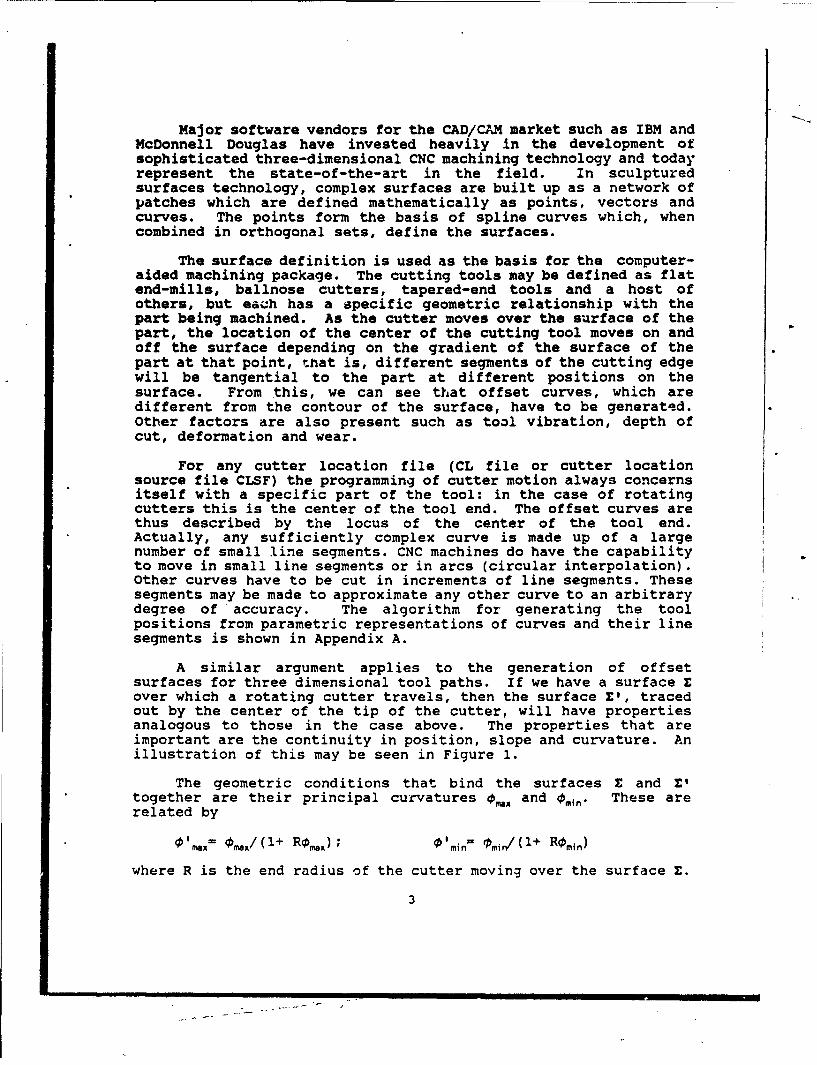
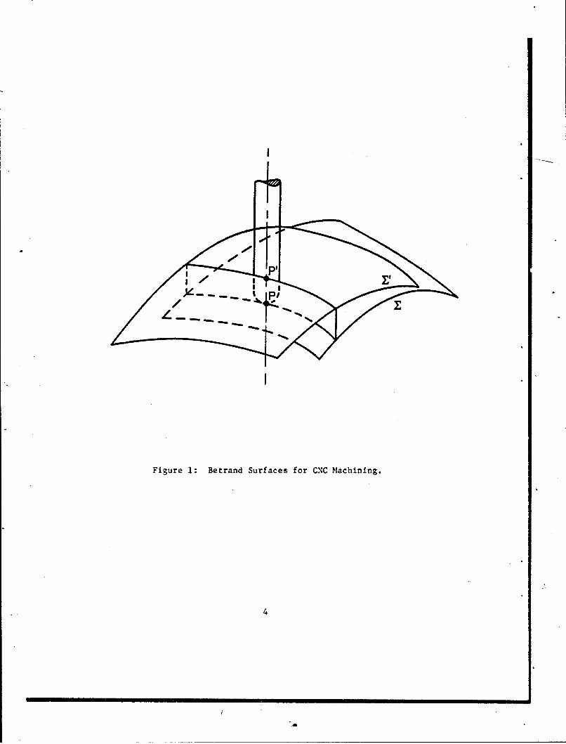
A similar argument applies to the generation of offsetsurfaces for three dimensional tool paths. If we have a surface Eover which a rotating cutter travels, then the surface E', tracedout by the center of the tip of the cutter, will have propertiesanalogous to those in the case above. The properties that areimportant are the continuity in position, slope and curvature. Anillustration of this may be seen in Figure 1.
The geometric conditions that bind the surfaces E and E'together are their principal curvatures 0a and 0m,-, These arerelated by
( 'Max= 0m./(1+ Rom); ofmi.n mi,/( 1 + Romid)
where R is the end radius of the cutter moving over the surface E.
3
I
Figure 1: Betrand Surfaces for CNC Machining.
4
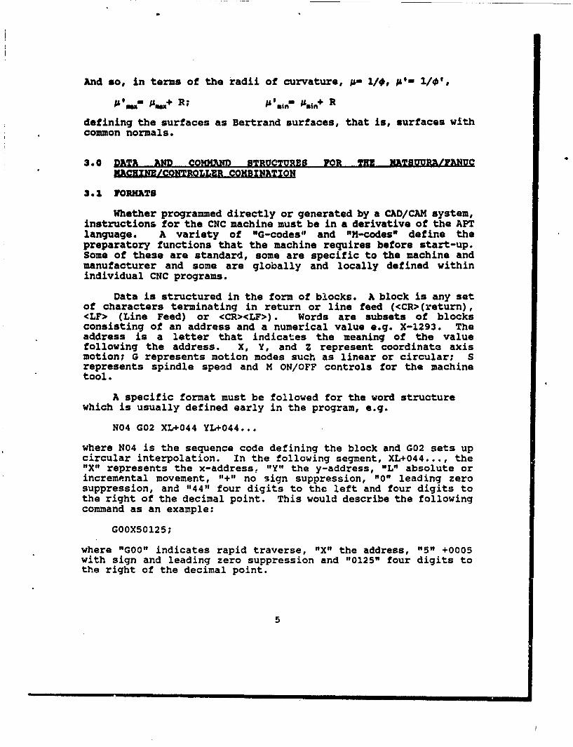
And so, in terms of the radii of curvature, ;L 1/, i'- Il#',;& Ia7 ism,+ R; N'in- ;tijn+ R
defining the surfaces as Bertrand surfaces, that is, surfaces withcommon normals.
3.0 DATA AND COMMND STRUCTURES FOR MME MATSUUP.ISIFNUC
MACHINE/CONTROLLER COMBINATION
3.1 FORMATS
Whether programmed directly or generated by a CAD/CAM system,instructions for the CNC machine must be in a derivative of the APTlanguage. A variety of "G-codes" and "H-codes" define thepreparatory functions that the machine requires before start-up.Some of these are standard, some are specific to the machine andmanufacturer and some are globally and locally defined withinindividual CNC programs.
Data is structured in the form of blocks. A block is any setof characters terminating in return or line feed (<CR>(return),<LF> (Line Feed) or <CR><LF>). Words are subsets of blocksconsisting of an address and a numerical value e.g. X-1293. Theaddress is a letter that indicates the meaning of the valuefollowing the address. X, Y, and Z represent coordinate axismotion; G represents motion modes such as linear or circular; Srepresents spindle speed and M ON/OFF controls for the machinetool.
A specific format must be followed for the word structurewhich is usually defined early in the program, e.g.
N04 G02 XL+044 YL+044...
where N04 is the sequence code defining the block and G02 sets upcircular interpolation. In the following segment, XL+044..., the"X" represents the x-address, "Y" the y-address, "L" absolute orincremental movement, "+" no sign suppression, "0" leading zerosuppression, and "44" four digits to the left and four digits tothe right of the decimal point. This would describe the followingcommand as an example:
G00X50125;
where "GOO" indicates rapid traverse, "X" the address, "5" +0005with sign and leading zero suppression and "0125" four digits tothe right of the decimal point.
5
3.2 LOGICAL AMID PHYSICAL DIFFERENTIALS
With regard to the maximum and minimum programmabledimensions, there are physical and logical varieties. Those givenin the manual represent the maximum numerical limit, not thephysical limit of the machine tool. Programmable maximum traversemight be 100 m along the x-, y- or z-axes but the actual distancepossible may be 2 m. The same argument affects machine speedsettings and other variables. The postprocessor must take thesephysical functions into account.
3.3 CONTROLLED AXES
The x-, y- and z-axes of a three-axis machine are thecontrolled axes. They may all be controlled simultaneously or, aswith 2-1/2D machining, only the x- and y-axes. Four and fivecontrollable axes are possible (for the Fanuc controller, not theMatsuura mill) and these are designated by A, B, C, U, V or W.
A maximum of four axes may be controlled simultaneously.There are six variables as one of the axes is a rotary axisinvolving an extra degree of freedom.
3.4 POSITIONING AND INTERPOLATION
G-codes are used to specify in which planes circularinterpolation or cutter compensation will be used e.g. G17 for thexy-plana, G18 for the zx-plane and G19 for the yz-plane. Note thatthis command, G17Z50125, will move the z-axis.
The positioning function, Goo, will have a different structuredepending on whether absolute or incremental commands are used. Ifabsolute, the co-ordinates must be commanded, if incremental, thedistance from start point to end point. Usually, G90 will defineabsolute commands and G91 incremental. Positioning commands areimportant for starting paths over complex surfaces and are of theform: GOOX...Y...Z...
G60 is used for positioning without backlash. This means thatthe positioning will be executed such that the tool approaches theco-ordinate from the same direction. This is important only at thelimits of accuracy of the machine, that is, at dimensions ofapproximately 0.02Vmm (0.001 inch.)
Further positioning criteria may be specified including theaddition of reference points. G-codes 27 through 30 govern thisparameter. Reference points are points that are fixed on themachining plane to which and from which positioning commands aremeasured. What co-ordinate values are written after the G-codes
6
depend on whether absolute or incremental movement has previouslybeen specified (G90 or G91).
Various work co-ordinate systems may be set up for differentmachining tasks on the work but to relate all of these an absolutezero point is established by the G92 command. G92X...Y...Z... willestablish a co-ordinate system that is based a specific distancefrom the tool position. After this, any absolute commands refer tothe co-ordinate value in the work system.
4.0 COMPENSATION COMIM S
4.1 TOOL LENGTH COMPENSATION
The tool length is that part of the tool that projects belowthe quill on the machine spindle. This may vary according to whatsize of cutter is being used and how it is mounted. As differenttools will ]ikely be used on the same part, a compensation functiondefined by a G-code (G43, G44, or G49) enables the terminal pointof the movement commands in the z-axis to be shifted by an amountset in the offset memory. The value of this parameter is set afterthe G-code by neans of an H-code e.g. G43 Z7.5547 H2.000. Clearly,this can set the difference between the actual tool length and thevalue used in the program. Compensation may thus be achievedwithout re-programming.
Offsets other than tool length compensation can be offsets inother axes and here codes G45 to G48 operate. However, thesecommands are not modal and refer only to the block in which theyare defined.
5.0 SPINDLE AND TOOL FUNCTIONS
5.1 SPINDLE SPEED
S-codes apply to the spindle and its functions. Speed isspecified by a four-digit number after the "S". Constant surfacespeed may also be specified. This function calculates thecorrespondence between tool position changes on the surface and thespindle rotation speed so that a feedback correction will besupplied to the spindle if the surface speed varies. This isrequired for some types of surface .achining. G-codes G96 and G97call the constant surface speed function ON or OFF. This functiononly applies to the rotary fourth axis.
5.2 TOOL FUNCTION
The command "T" is followed by a two-digit number specifyingthe tool to be used.
7
6.0 X18CILLANEOU8 FUNCTIONS
S.1 N-CODES
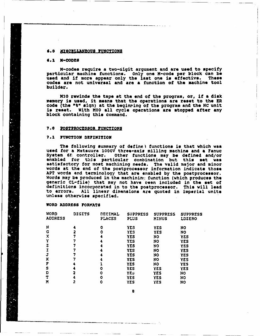
M-codes require a two-digit argument and are used to specifyparticular machine functions. Only one M-code per block can beused and if more appear only the last one is effective. Thesecodes are not universal and are a function of the machine toolbuilder.
M30 rewinds the tape at the end of the program, or, if a diskmemory is used, it means that the operations are reset to the ERcode (the "%" sign) at the beginring of the program and the NC unitis reset. With MOO all cycle operations are stopped after anyblock containing this command.
7.0 ZOSTPROC2SSOR FUNCTIONS
7.1 FUNCTION DEFINITION
The following summary of defin,- functions is that which wasused for a Matsuura 1OOOV three-axis milling machine and a FanucSystem 6T controller. Other functions may be defined and/orenabled for this particular combination but this set wassatisfactory for most machining needs. The valid major and minorwords at the end of the postprocessor information indicate thoseAPT words and terminology that are enabled by the postprocessor.Words may be produced in the machinint; function (which produces thegeneric CL-file) that may not have teen included in the set ofdefinitions incorporated in to the postprocessor. This will leadto errors. All linear dimensions are quoted in imperial unitsunless otherwise specified.
WORD ADDRESS FORMATS
WORD DIGITS DECIMAL SUPPRESS SUPPRESS SUPPRESS
ADDRESS PLACES PLUS MINUS LDZERO
N 4 0 YES YES NOG 2 0 YES YES NOX 7 4 YES NO YESY 7 4 YES NO YESZ 7 4 YES NO YESI 7 4 YES NO YESJ 7 4 YES NO YESK 7 4 YES NO YESF 4 1 YES NO YESS 4 0 YES YES YESD 2 0 YEts YES NOT 4 0 YES YES NOM 2 0 YES YES NO
8
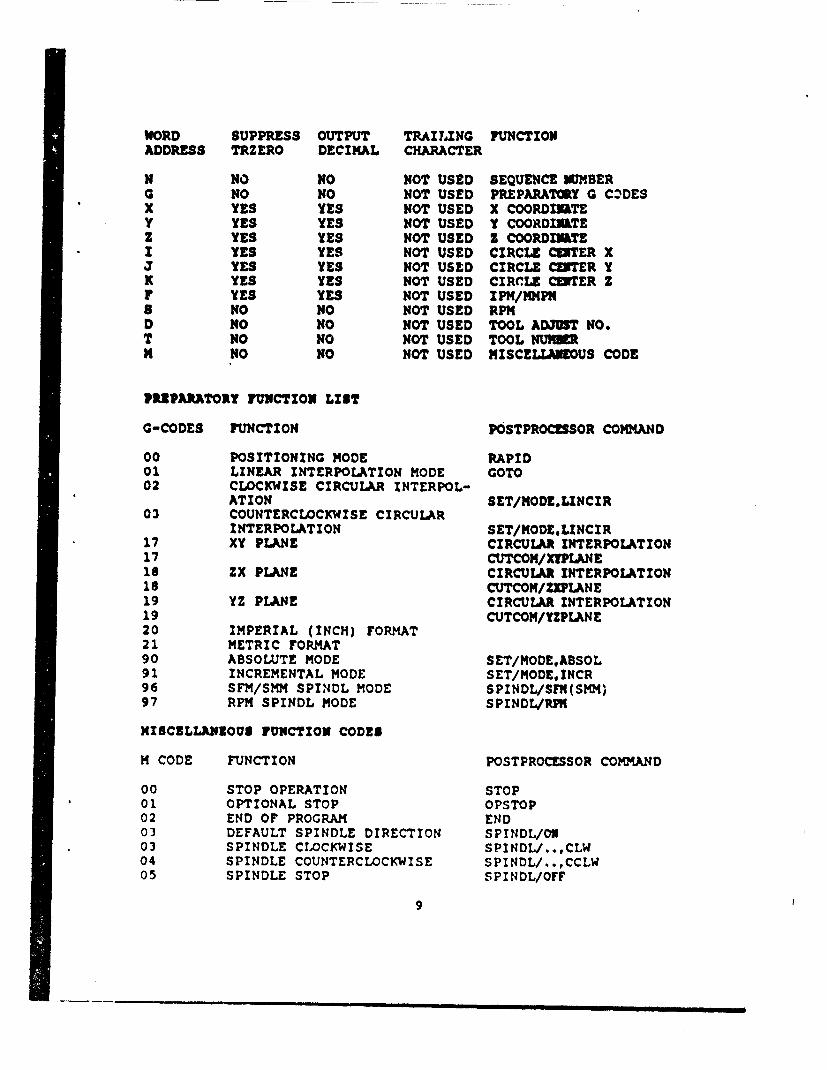
WORD SUPPRESS OUTPUT TRAILING FUNCTIONADDRESS TRZERO DECIMAL CHARACTER
N NO NO NOT USED SEQUENCE MWMBER0 NO NO NOT USED PREPARATORY G CZDESX YES YES NOT USED X COORDINATEY YES YES NOT USED Y COORDINATEz YES YES NOT USED Z COORDMINTEI YES YES NOT USED CIRCLE CENTER X3 YES YES NOT USED CIRCLE CUITER YK YES YES NOT USED CIRCLE CWTER ZF YES YES NOT USED IPM/MMPNS NO NO NOT USED RPMD NO NO NOT USED TOOL AD3UST NO.T NO NO NOT USED TOOL NUN=M NO NO NOT USED MISCELLANEOUS CODE
PRUPARATORY FUNCTION LIST
G-CODES FUNCTION POSTPROCESSOR COMMAND
00 POSITIONING MODE RAPID01 LINEAR INTERPOLATION MODE GOTO02 CLOCKWISE CIRCULAR INTERPOL-
ATION SET/MODE.LINCIR03 COUNTERCLOCKWISE CIRCULAR
INTERPOLATION SET/MODELINCIR17 XY PLANE CIRCULAR INTERPOLATION17 CUTCOM/X!PLANE18 ZX PLANE CIRCULAR INTERPOLATION18 CUTCOM/ZIPLANE19 YZ PLANE CIRCULAR INTERPOLATION19 CUTCOM/YZPLANE20 IMPERIAL (INCH) FORMAT21 METRIC FORMAT90 ABSOLUTE MODE SET/MODE.ABSOL91 INCREMENTAL MODE SET/MODEINCR96 SFM/SMM SPINDL MODE SPINDL/SFN(SMM)97 RPM SPINDL MODE SPINDL/Rf%
MISCELLANEOUS FUNCTION CODES
M CODE FUNCTION POSTPROCESSOR COMMAND
00 STOP OPERATION STOP01 OPTIONAL STOP OPSTOP02 END OF PROGRAM END03 DEFAULT SPINDLE DIRECTION SPINDL/OW03 SPINDLE CLOCKWISE SPINDL/..,CLW04 SPINDLE COUNTERCLOCKWISE SPINDL/.,CCLW05 SPINDLE STOP SPINDL/OFF
9
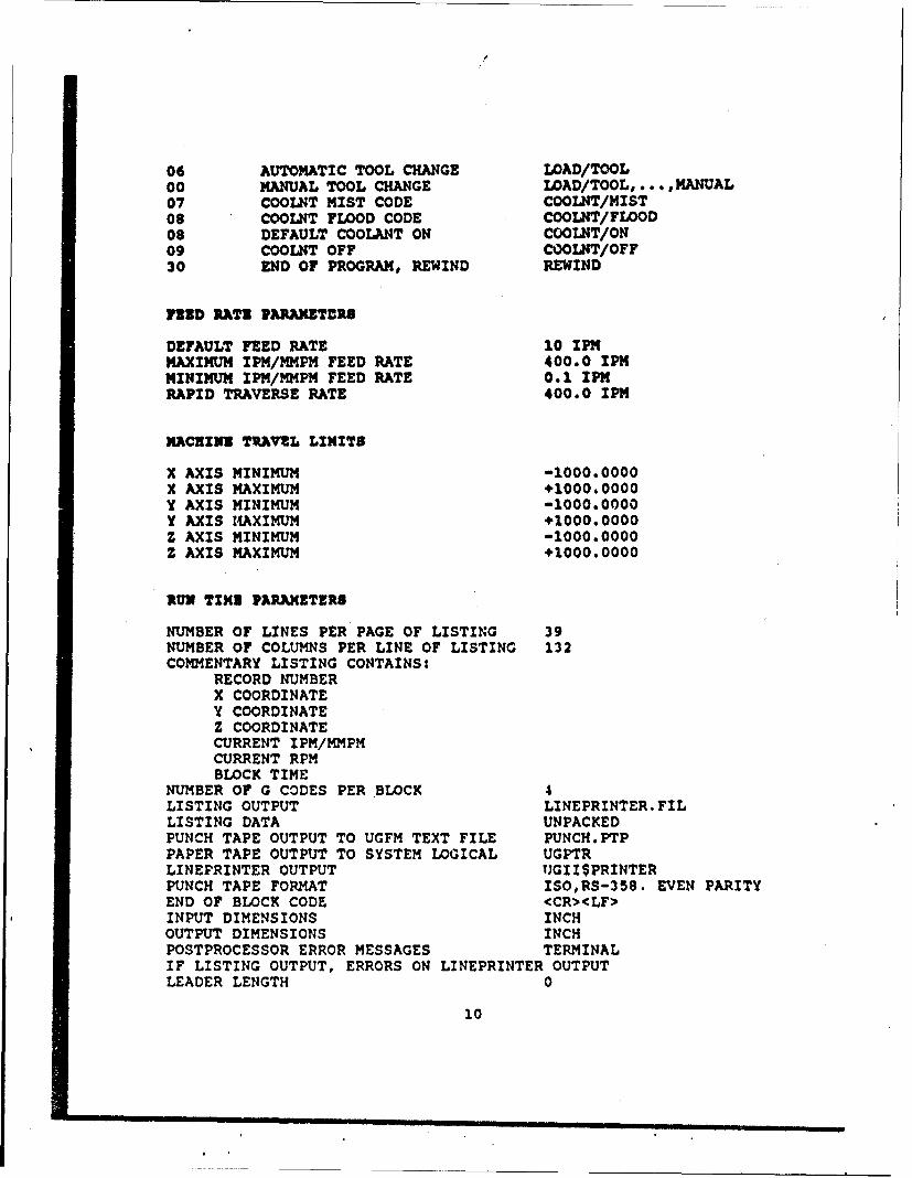
06 AUTOMATIC TOOL CHANGE LOAD/TOOL00 MANUAL TOOL CHANGE LOAD/TOOL, ... ,MANUAL07 COOLNT MIST CODE COOLNT/MIST08 COOLNT FLOOD CODE COOLNT/FLOOD08 DEFAULT COOLANT ON COOLNT/ON09 COOLNT OFF COOLNT/OFF30 END OF PROGRAM, REWIND REWIND
flED RATZ PARAMETERS
DEFAULT FEED RATE 10 IPMMAXIMUM IPM/MMPM FEED RATE 400.0 IPMMINIMUM IPM/MMPM FEED RATE 0.1 IPMRAPID TRAVERSE RATE 400.0 IPM
MACNINE TRAVZL LIMITS
X AXIS MINIMUM -1000.0000X AXIS MAXIMUM +1000.0000Y AXIS MINIMUM -1000.0000Y AXIS 14AXIMUM +1000.0000Z AXIS MINIMUM -1000.0000Z AXIS MAXIMUM +1000.0000
RUN TIME PARAMETERS
NUMBER OF LINES PER PAGE OF LISTING 39NUMBER OF COLUMNS PER LINE OF LISTING 132COMMENTARY LISTING CONTAINS:
RECORD NUMBERX COORDINATEY COORDINATEZ COORDINATECURRENT IPM/MMPMCURRENT RPMBLOCK TIME
NUMBER OF G CODES PER BLOCK 4LISTING OUTPUT LINEPRINTER. FILLISTING DATA UNPACKEDPUNCH TAPE OUTPUT TO UGFM TEXT FILE PUNCH.PTPPAPER TAPE OUTPUT TO SYSTEM LOGICAL UGPTRLINEPRINTER OUTPUT UGIISPRINTERPUNCH TAPE FORMAT ISO,RS-358. EVEN PARITYEND OF BLOCK CODE <CR><LF>INPUT DIMENSIONS INCHOUTPUT DIMENSIONS INCHPOSTPROCESSOR ERROR MESSAGES TERMINALIF LISTING OUTPUT, ERRORS ON LINEPRINTER OUTPUTLEADER LENGTH 0
10
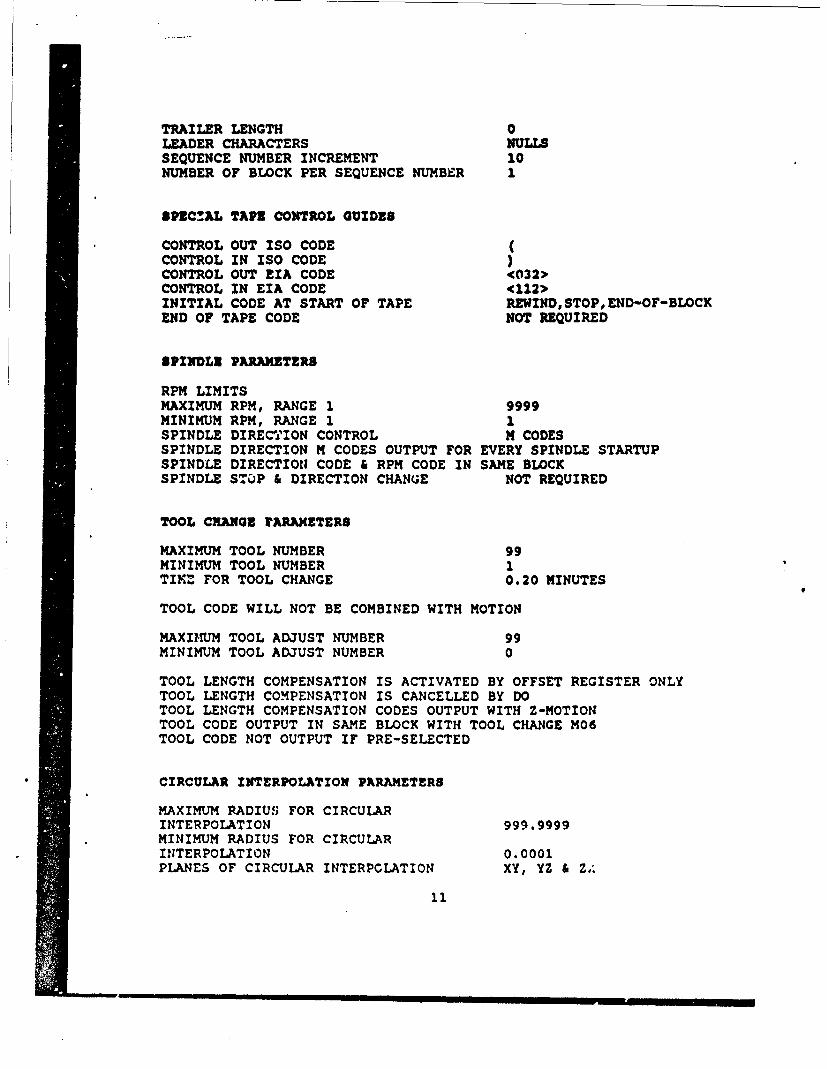
TRAILER LENGTH 0LEADER CHARACTERS NULLSSEQUENCE NUMBER INCREMENT 10NUMBER OF BLOCK PER SEQUENCE NUMBER 1
$PZC!AL TAP2 CONTROL GUIDES
CONTROL OUT ISO CODE (CONTROL IN ISO CODE )CONTROL OUT EIA CODE <(032>CONTROL IN EIA CODE <112>INITIAL CODE AT START OF TAPE REWIND, STOP,END-OF-BLOCKEND OF TAPE CODE NOT REQUIRED
8PINDLE PARAMETERS
RPM LIMITSMAXIMUM RPM, RANGE 1 9999MINIMUM RPM, RANGE 1 1SPINDLE DIREC0,ION CONTROL M CODESSPINDLE DIRECTION M CODES OUTPUT FOR EVERY SPINDLE STARTUPSPINDLE DIRECTION CODE & RPM CODE IN SAME BLOCKSPINDLE STOP & DIRECTION CHANGE NOT REQUIRED
TOOL CRANQG rARAMETERS
MAXIMUM TOOL NUMBER 99MINIMUM TOOL NUMBER 1TIM4 FOR TOOL CHANGE 0.20 MINUTES
TOOL CODE WILL NOT BE COMBINED WITH MOTION
MAXIMUM TOOL ADJUST NUMBER 99MINIMUM TOOL ADJUST NUMBER 0
TOOL LENGTH COMPENSATION IS ACTIVATED BY OFFSET REGISTER ONLYTOOL LENGTH COMPENSATION IS CANCELLED BY DOTOOL LENGTH COMPENSATION CODES OUTPUT WITH Z-MOTIONTOOL CODE OUTPUT IN SAME BLOCK WITH TOOL CHANGE M06TOOL CODE NOT OUTPUT IF PRE-SELECTED
CIRCULAR INTERPOLATION PARAMETERS
MAXIMUM RADIUS FOR CIRCULARINTERPOLATION 999.9999MINIMUM RADIUS FOR CIRCULARINTERPOLATION 0.0001PLANES OF CIRCULAR INTERPCLATION XY, UZ & Z.'
11
i I I
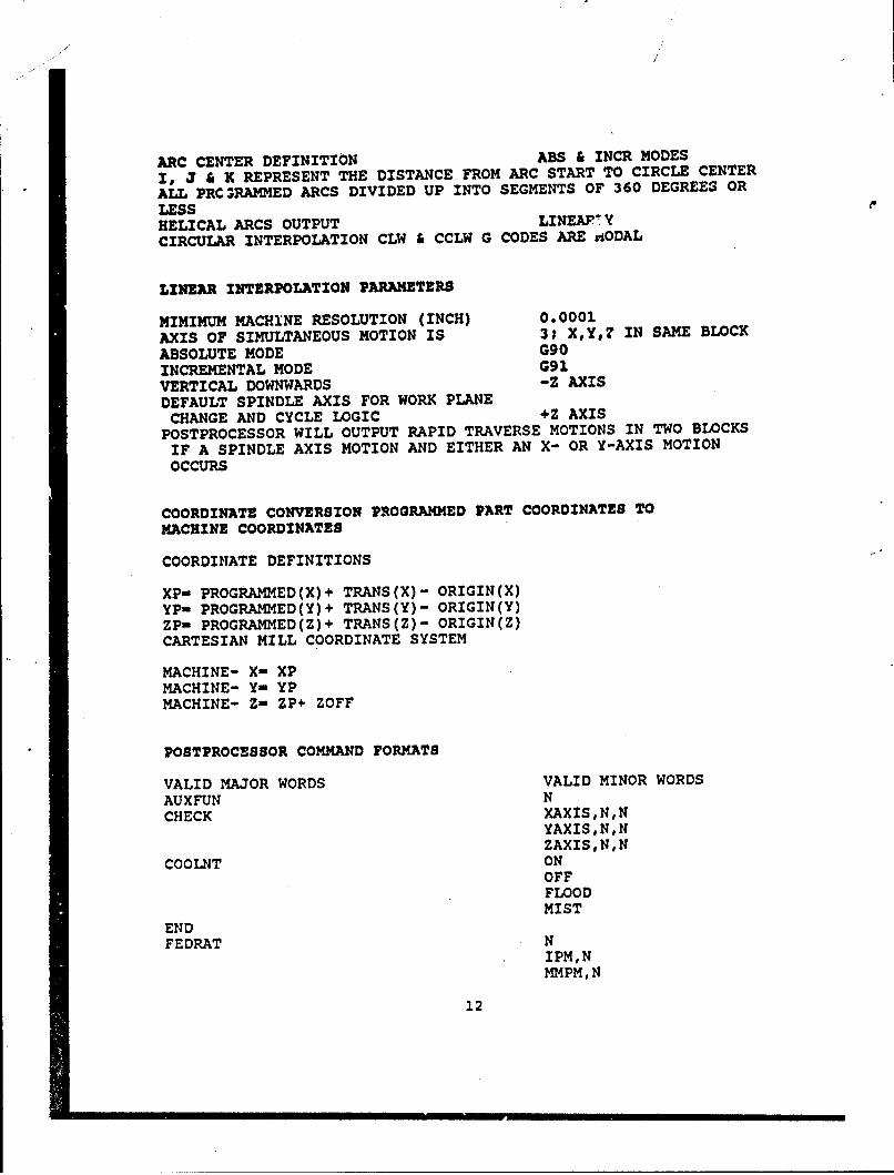
ARC CENTER DEFINITION ABS & INCR MODES
I, J & K REPRESENT THE DISTANCE FROM ARC START TO CIRCLE CENTER
ALL PRC RAMMED ARCS DIVIDED UP INTO SEGMENTS OF 360 DEGREES OR
LESSHELICAL ARCS OUTPUT LINEAPF YCIRCULAR INTERPOLATION CLW & CCLW G CODES ARE a.iODAL
LINEAR INTERPOLATION PARAMETERS
MIMIMUM MACHINE RESOLUTION (INCH) 0.0001AXIS OF SIMULTANEOUS MOTION IS 3; XY,? IN SAME BLOCK
ABSOLUTE MODE G90INCREMENTAL MODE G91
VERTICAL DOWNWARDS -Z AXISDEFAULT SPINDLE AXIS FOR WORK PLANE
CHANGE AND CYCLE LOGIC +Z AXISPOSTPROCESSOR WILL OUTPUT RAPID TRAVERSE MOTIONS IN TWO BLOCKS
IF A SPINDLE AXIS MOTION AND EITHER AN X- OR Y-AXIS MOTIONOCCURS
COORDINATE CONVERSION PROGRAMMED PART COORDINATES TO
MACHINE COORDINATES
COORDINATE DEFINITIONS
XP- PROGRAMMED(X)+ TRANS(X)- ORIGIN(X)YP- PROGRAMMED(Y)+ TRANS(Y)- ORIGIN(Y)ZP- PROGRAMMED(Z)+ TRANS(Z)- ORIGIN(Z)CARTESIAN MILL COORDINATE SYSTEM
MACHINE- X- XPMACHINE- Y- YPMACHINE- Z- ZP+ ZOFF
POSTPROCESSOR COMMAND FORMATS
VALID MAJOR WORDS VALID MINOR WORDS
AUXFUN NCHECK XAXIS,N,N
YAXIS,N,NZAXISN,N
COOLNT ONOFFFLOODMIST
ENDFEDRAT N
IPM,NMMPM,N
12
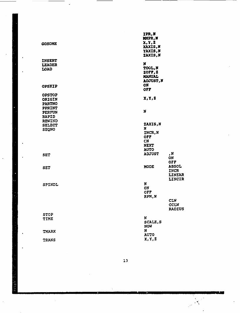
IPR, NNMPR, N
GOHOME X,YZXAxISI NYAXIS,NZAXISN
INSERTLEADER NLOAD TOOL, N
ZOFF,ZMANUALAD3UST, N
OPSKIP ONOFF
OPSTOPORIGIN X,Y,ZPARTNOPPRINTPERFUN NRAPIDREWINDSELECT ZAXISNSEQNO N
INCR,NOFFCNNEXTAUTO
SET ADJUST NONOFF
SET MODE ABSOLINCRLINEARLINCIR
SPINDL NONOFFRPM, N
CLWCCLWRADIUS
STOPTIME N
SCALESNOW
TMARK NAUTO
TRANS X,Y,Z
13
6.0 POSTPROCESSOR ?ROPERTIES
8.1 MDF TEMPLATE
The MDF template is a skeleton machine data file (MDF)generator resident in Unigraphics. Parameters for themachine/controller combination used may be fed into the templateinteractively. These values are compiled into a file, FILE.MDF,which is then the active file that will take the *.CLS filegenerated by the tool path function in Unigraphics and translatethe GOTO statements of generic tool motion into x-, y- and z- axiscoordinate motion in APT instruction code for the machine.
6.2 POSTPROCESSOR OUTPUT
Three files are output by the postprocessor for every CLSFinput. They are FILE.LPT, FILE.CLF, FILE.PTP, and the *.PTP filesare the paper tape-ready files. They may be punched directly onpaper tape by means of the program "XLATOR" or downloaded to afloppy disk device. The output of XLATOR is a standard ASCII file.
Before the ASCII file is ready for downloading on to thefloppy disk drive, more editing is required. The APT commandstructure is determined by the postprocessor when the *.PTP punchfile is generated, but this may still not contain all theinformation required by the CNC shop floor operator. Variouscommands are necessary to set the machine in a start-up mode,determine the tools used, the motion limits, the origin positioningand other preparatory functions. These commands are written out indetail and stored in a file, HEADER.TXT in the GRIP (GraphicsInteractive Programming Language) module. The similar command setused to shut down the machina after use is likewise contained ina file, FOOTER.TXT. These must be added to each machining fileprior to downloading.
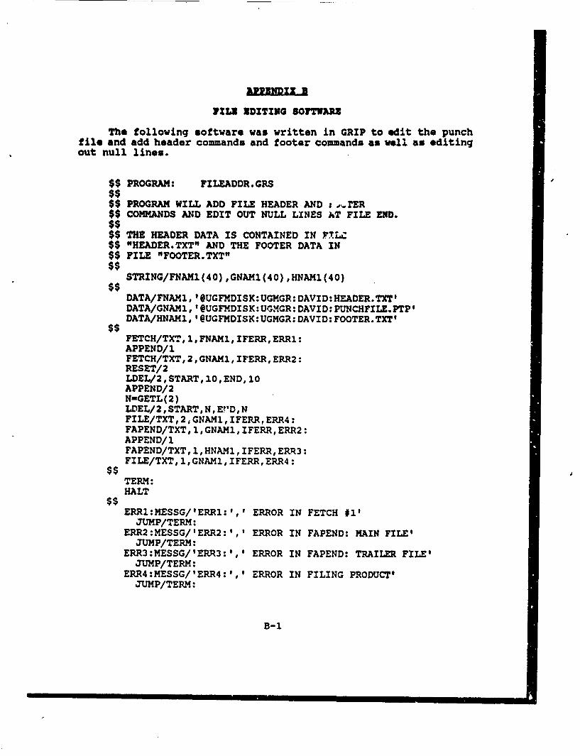
The software to perform this task is contained in the program,FILEADDR.GRS, which is shown in Appendix B. The program adds thesecommands, deletes unwanted lines, cleans up the format and storesthe file as the punch file ready for downloading. The preliminarycommands and the file closure commands may be seen in Appendix C.
9.0 CONCLUSION
Postprocessors are an important part of the CAM link to CAD.They take the data produced by the CAM machining module andgenerate a file of APT command instructions for the CNC machine andcontroller. Each postprocessor is specific for a particular CNCmachine/controller combination of which there are many. Thedescription of the postprocessor contained herein is completelysatisfactory for the Matsuura 100OV/Fanuc 6B system and may be used
14
with very little modification on other Matsuura CNC machines andtheir Fanuc System 6 controllers.
10*0 0CKNOWLEDGEMNTS
I would like to thank Peter Clark of the CommunicationsResearch Center Model Shop for many helpful discussions concerningthe CNC machine and controller.
11.0 R
1. Krouse J. K. "What Every Engineer should know about Computer-Aided Design and Computer-Aided Manufacturing", M. DekkerInc., New York, 1982, p. 93.
2. Ibid, p. 94.
15
APPROIIMATIONS FOR SURFACE CURVATURE
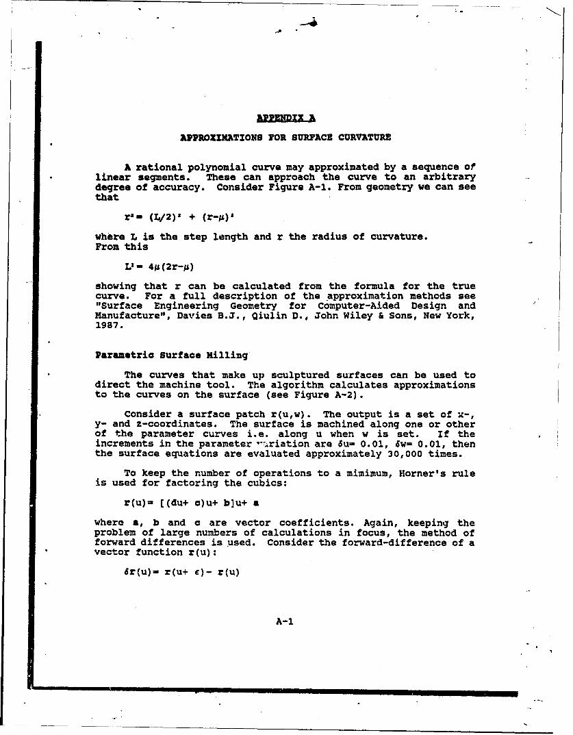
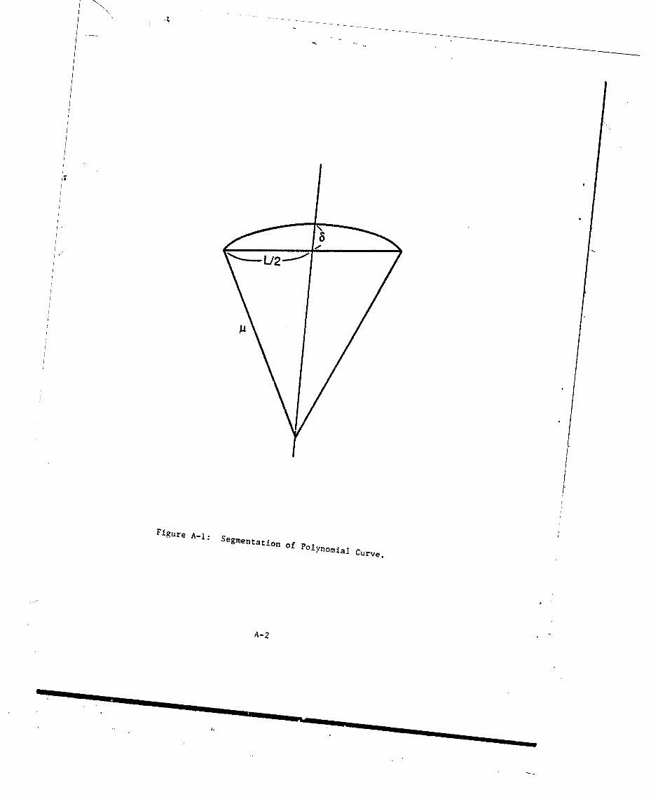
A rational polynomial curve may approximated by a sequence oflinear segments. These can approach the curve to an arbitrarydegree of accuracy. Consider Figure A-1. From geometry we can seethat
r'- (L/2)' + (r-p)l
where L is the step length and r the radius of curvature.From this
Liin 4g(2r-gL)
showing that r can be calculated from the formula for the truecurve. For a full description of the approximation methods see"Surface Engineering Geometry for Computer-Aided Design andManufacture", Davies B.J., Qiulin D., John Wiley & Sons, New York,1987.
Parametric Surface Milling
The curves that make up sculptured surfaces can be used todirect the machine tool. The algorithm calculates approximationsto the curves on the surface (see Figure A-2).
Consider a surface patch r(u,w). The output is a set of x-,y- and z-coordinates. The surface is machined along one or otherof the parameter curves i.e. along u when w is set. If theincrements in the parameter -.,riation are 6u= 0.01, 6w= 0.01, thenthe surface equations are evaluated approximately 30,000 times.
To keep the number of operations to a mimimum, Homer's ruleis used for factoring the cubics:
r(u)= ((du+ c)u+ b]u+ a
where a, b and a are vector coefficients. Again, keeping theproblem of large numbers of calculations in focus, the method offorward differences is used. Consider the forward-difference of avector function r(u):
6r(u)- r(u+ e)- r(u)
A-1
/
Figure A-1: Segmentation of P•OlYnOmial
Curve.
A-2
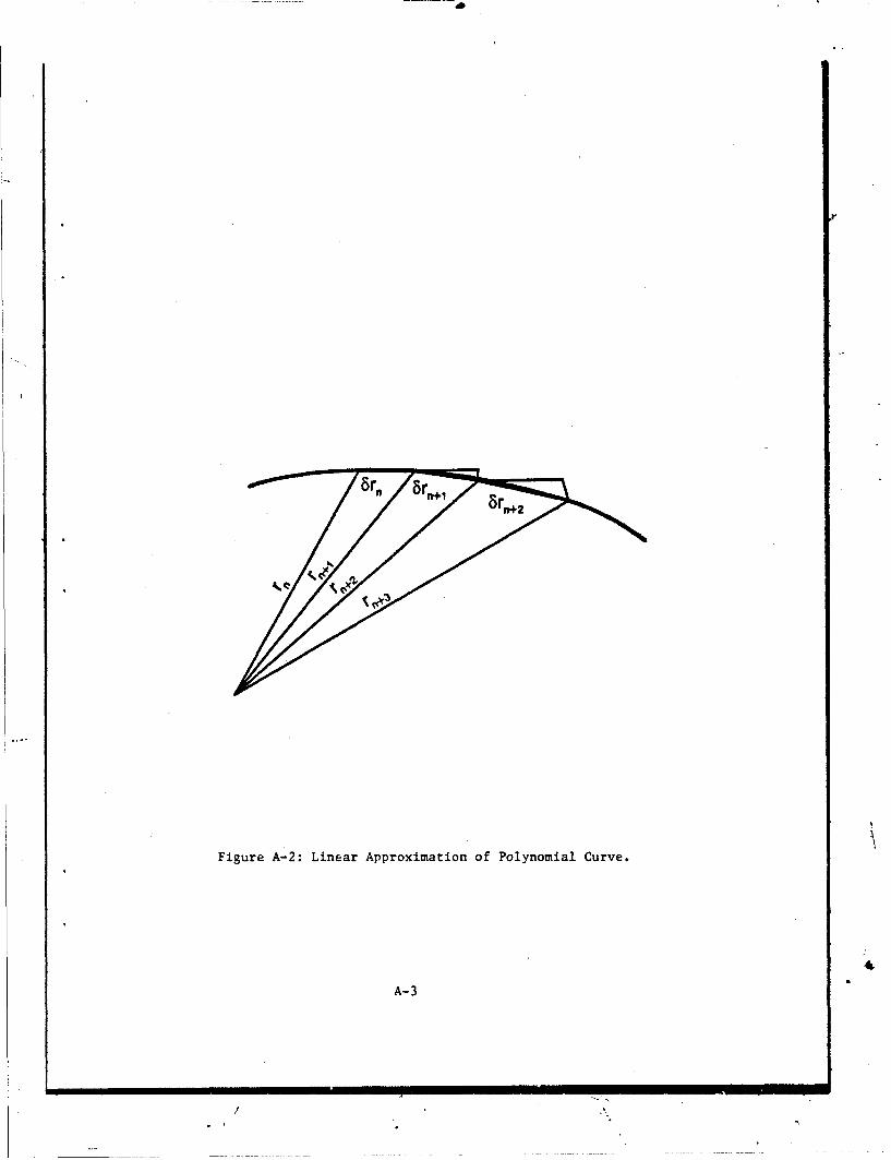
Figure A-2: Linear Approximation of Polynomial Curve.
A-3
/ I
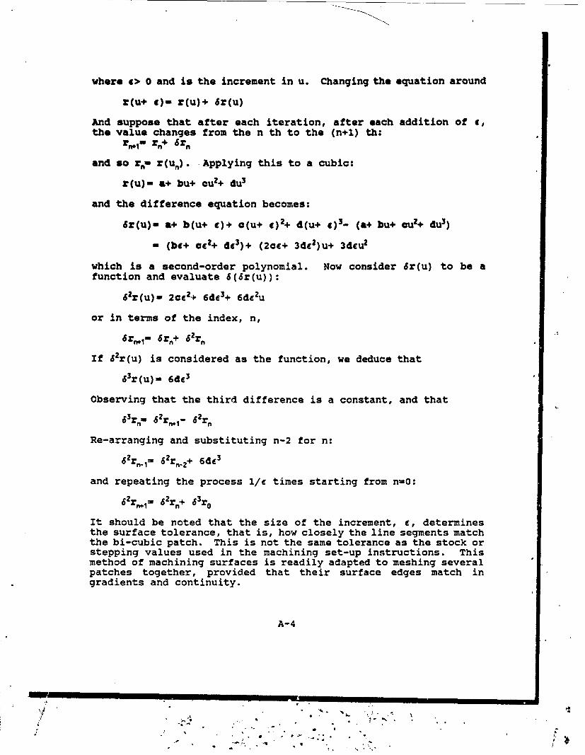
where e> 0 and is the increment in u. Changing the equation around
Z(u+ e)- r(u)+ Sr(u)
And suppose that after each iteration, after each addition of e,the value changes from the n th to the (n+l) th:
rro- rn+ Srn
and so rn- r(un). Applying this to a cubic:
r(u)- a+ bu+ cu2+ du3
and the difference equation becomes:
6r(u)- a+ b(u+ c)+ o(u+ g)2+ d(u+ e)3- (a+ bu+ cu2+ du3)
- (be+ CC2+ de3)+ (20c+ 3d82)u+ 3d4u 2
which is a second-order polynomial. Now consider 6r(u) to be afunction and evaluate 6(6r(u)):
62r(u)- 2cC2.- 6de3+ 6de2u
or in terms of the index, n,
6r,1" 6r.+ 62rn
If 62r(u) is considered as the function, we deduce that
63r(u)_- 6dC3
Observing that the third difference is a constant, and that
63r"_ 62rn 1 _- 652r
Re-arranging and substituting n-2 for n:
62rn.=, 62rn.2+ 6de3
and repeating the process 1/c times starting from n=0:
62r n= 62r,+ 63r,
It should be noted that the size of the increment, c, determinesthe surface tolerance, that is, how closely the line segments matchthe bi-cubic patch. This is not the same tolerance as the stock orstepping values used in the machining set-up instructions. Thismethod of machining surfaces is readily adapted to meshing severalpatches together, provided that their surface edges match ingradients and continuity.
A-4
? w p-..
. . , .
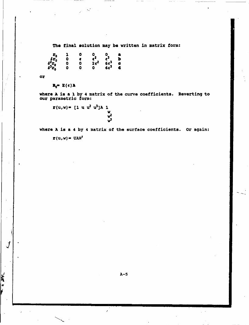
The final solution may be written in matrix form:
ro 1 0 0 0 aSfro° 0 9 92 93 b
62r0 0 0 2e2 6C3 a£3r0 0 0 0 63 4
or
where A is a 1 by 4 matrix of the curve coefficients. Reverting toour parametric form:
r(u,w)- (1 u u 2 u3 ]A 1
wz
where A is a 4 by 4 matrix of the surface coefficients. Or again:
r(u,w)- UAWT
A-5
1213 RDITING SOITIARM
The following software was written in GRIP to edit the punchtile and add header commands and footer commands as well as editingout null lines..
$$PROGRAM: FILEADDR.GRS
$$PROGRAM WILL ADD FILE HEADER AND j, 1 r.ER$$COMMANDS AND EDIT OUT NULL LINES AT FILE END.
$$THE HEADER DATA IS CONTAINED IN F7LZ$$ HEADER.TXT" AND THE FOOTER DATA IN$$FILE "FOOTER.TXT"
STRING/FNAM1(40) ,GNAM1(40) ,HNAM1(40)
DATA/FNAM1, 'OUGFMDISK:UGMGR: DAVID:HEADER.TXTIDATA/GNAM1, 'QUGFMDISK:UGMGR: DAVID: PUNCHFIIE.PTPIDATA/HNAM1, 'QUGFMDISK: UGMGR: DAVID: FOOTER.TXTI
FETCH/TXT, l,FNAM1, IFERR,ERR1:APPEND/iFETCH/TXT, 2,GNAMi, IFERR, ERR2:RESET/2LDEL/2, START, 10, END, 10APPEND/ 2N-GETL (2)LDEL/2, START, N, E?'D, NFILE/TXT, 2,GNAM1, IFERR, ERR4:FAPEND/TXT,1, GNAM1, IFERR, ERR2:APPEND/iFAPEND/TXT, 1,HNAM1, IFERR, ERR3:FILE/TXT, l,GNAMi,IFERR,ERR4:
TERM:HALT
ERRI:MESSG/'ERR1:',' ERROR IN FETCH #1'JUMP/TERM:
ERR2: MESSG/'IERR2:1, 1 ERROR IN FAPEND: MAIN FILE'IJUMP/TERM:
ERR3: MESSG/ IERR3:1, 1 ERROR IN FAPEND: TRAILER FILE'JUMP/TERM:
ERR4:MESSG/'ERR4:',' ERROR IN FILING PRODUCT'JUMP/TERM:
B-1
The program uses the two scratch file areas in GRIP to read,sort and edit the punch files so that the sets of commands in theheader and footer files may be added on. The strings FNAMl etccontain the file names as character strings so that in order toprocess another punch file, only one file name has to be changed.It is stored under the original name in the corrected form.
B-2
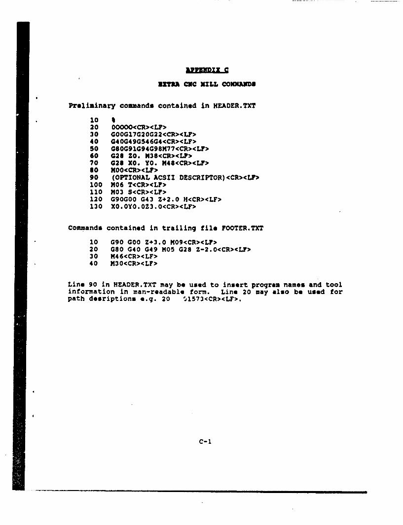
nIT3t& eC =ILL cGOmmNDa
Preliminary commands contained in HEADER.TXT
10 %20 OOOOO<CR><LF>30 G00G17G20G22<CR><LF>40 G40G49G546G4<CR><LF>50 GS0G9gG94G98M77<CR><LF>60 028 ZO. M38<CR><L?>70 028 X0. YO. M48<CRLF>80 MOO<CR><LF>90 (OPTIONAL ACSII DESCRIPTOR)<CR><LF,>100 M06 T<CR><LF>110 M03 S<CR><LF>120 G90GO0 G43 Z+2.0 H<CR><LF>130 X0.0Y0.0Z3.0<CR><LF>
Commands contained in trailing file FOOTER.TXT
10 G90 G00 Z+3.0 M09<CR><LF>20 G80 G40 G49 M05 G28 Z-2.0<CR><LF>30 M46<CR><LF>40 M30<CR><LF>
Line 90 in HEADER.TXT may be used to insert program names and toolinformation in man-readable form. Line 20 may also be used forpath desriptions e.g. 20 ý#l573<CR><LF>.
C-1
II'Jr A~T T~fl-27-UICRIAIY CLASSIFICATION OF FORM
60mes cimsificstio o Titmle. Abstul.c Keywerds)
DOCUMEN CONTROL DATAalietwlow 61aealffoatieft of title. be*y *f abstract and Aoden~iine antation must be *$"*rd WPAS the ewerlI 4eaWme61 1a eataf.ledl
1. ORIGINATOR ifte romemshe address of the argmzation preparing me document, 2. SECURITY CLASSIFICATIONOrganizations for whomt the document wans prepared, sg, Establishm elt sponsoring wotrall security classification of the documenta comovperis ?epf i. or tasking agency, we enoterd in sectio 5.I inficdilng special woerming ter ms if Upolicablel
DEFENCE RESEARCH ESTABLISHMENT OTTAWANational Defence UNCLASSIFIEDOLtawa, Ontario KiA OZZ
3. TITLE (fte complete document title as indicated en she title pog Its classification sholeid be Indicated by mhe appropriateswerwyoicin (S.C at LO in parentheses after the title.)
A POSTPROCESSOR FOR THE MATSUURA 1000V CNC MACHINE AND A FANUC CONTROLLER (U)
4. AUTHORS (Lagi tome* fWirt hip". middle Iintial)
HIDSON, David
5 DATE OF PUBJLICATION (monith end vow of puplicatiso of 6& NO. OF PAGES (total 6b. NO. OF REPS (tetal cited Indocument) containing information. Includle document)
NOVEMBER 1990 Annexes. Appendices. Ift.)k8 2
7. DESCRIPTIVE NOTES lite category of the document,.so. technical rpoort, technical note or memorandum. if appopriate, enter the' type ofreport. e.# in',Progress. summrnay. annual Or final Give mhe Inclusive dotes when a specific reporting petriod is coveted.)
RLPORT
8. SPONS:)RING ACTIVITY fthe nMe cin th *dWatmen project off(ice or laboratory Sponsoring tn@ research and development Include theaddres) DEFENCE RESEARCH ESTABLISHMENT OTTAWA
National DefenceOttawa, Ontario K1A 0Z4
9a, PROJECT OR GRANT NO. Iif aoprooritme, the *plicabile research 9b CONTRACT NO. lif 00cpropriate, the applicable numberuneand developmert prolezi or grant numbOer under which the documn which the document was writtenl*8" written Pleene Speicify whether protect Or grartit
051LD11
10s. ORIGINATOR'S DOCUMENT NUMBER lthe offticial document 10b. OTHER DOCUMENT NOS. (Any other numnbers which maynumber by wh00ichth document is identified by the orilinatling be assigned tis, document either by the origintor or by fthactivity, This number must be unique to this documeneto soonsorl
DREO REPORT NO. 1055
11. DIOCUMENT AVAILABILITY (any limitations on furmtherdilseminatien of %.o document, other than those impossed by Iecurity clsif~ifcation)
IX) Unlifflted disitibutiontI Dstribuition limited ito defence deparments and defence contrctors: further isttribution only is approved
D istrioution limited to defence depaortments arid Canadian defence contractors: further distiibution only as approvedfIDistribution limited to governMen departments and ageoncies: futrtlho distribution only as approvedI)Distribution limited to defence 0epartmenit: further distribution only as approved
(I Other (please tspeifyi:
12. DOCUMENT ANNOUNCEMENT (41nY i'mitauo" to th b~bliograhic anntounceement of this document This will nor molly correspond tothe Document Availatilty f1ll. However. whe" further distribution (beyond the audlience specified in 11) is possible, a widerannouncement audience moy be selected.)
SICLAi1Y CLA55IPICAIOPI OfFPORM
OC003 2/061B,
-28- UNCLASSIFIEDMUcwgT, CLASSIPICATIOW1 of FOOM
13. ABSTRACT I a brief anud factuog gujmmwy of fth daogvw. it MRu alse Iliwa elsowleino M so body of Old, document itslOf. ht is highlydesiraible diet the abrnct of classified docuieents be unclessifiet Each pworarh of the Soabsc shell begin with on indication of thesowirty clousillizotien of the informai" n ft thegporpep Junless the docunlen itself is uinclessif 'mdl represented as W5. (c), or I4W.It IS net necesoy to intClude here ab6vect 10 both offiCel lWWgue Unless the text Is b111i11011el).
This paper describes the building of a postprocessor for aMatsuura 1000V three-axis computer numerical control millingmachine and its Fanuc System 68 controller. The Matsuura machineparameters such as travel, axes of freedom, tool banks, and
interpolation techniques are assessed and -those that are requiredare programmed into a machine data f ile generator sub-program. Theappropriate command functions that are needed by simultaneousthree-axis motion, the valid major and minor APT commands, and thesite-specific machine control commands, are also included in thle
fostprocessor software. Punch file data editing software was
written and was used to ready the data files for the shop floor.
14. K(EYWORDS. DESCRIPTORS or IDENTIFIERS litechnic011y mineei~nfiM i' Or short phrases tht chdroctorill 0 document end could behelp111ful in catalouings the document. Th#, Should be Selected so I tha SqloI sciy~ossifstiCtn is reouirtd. Identifiers. such as leytpment
Model deignation, treeSt homne' Military Prole"ct ode netie. feoprenhic loetoV may1114 be included If possible keywwrds should be selectedfrom I Published thesilurus1. e0g Thsa~urus Of ("ngneering Sol Scientific Terms (TEST) and tha th~uu-dn ifidf it i nt RlPossible toSelec indexing terms Which are Unclassified. the Clossilitia¶on of each Shoold be Indicated aS with the tItleJ
COMPUTER-AIDED DESIGNCOM1PUTER-AIDED MANXFACTURIN:GPOSTPROCESSORSCNC MACHININGAPT SOFTWARE
t. CLASSIFIrD
5ICURIY CLASSIPICATIOd 00 1100M