Embed Size (px)
Citation preview

Es
the
Essential VHDL for ASICs
A brief introduction to design with VHDL for ASIC design.
Roger Traylor
9/7/01
Version 0.1
All rights reserved. No part of this publication may be reproduced, withoutprior written permission of the author.
Copyright 2001, Roger Traylor
sential VHDL for ASICs 1

Es
Revision Record
rev 0.1 : Initial rough entry of material. 9/7/01 RLT
sential VHDL for ASICs 2
Es
HDL Design
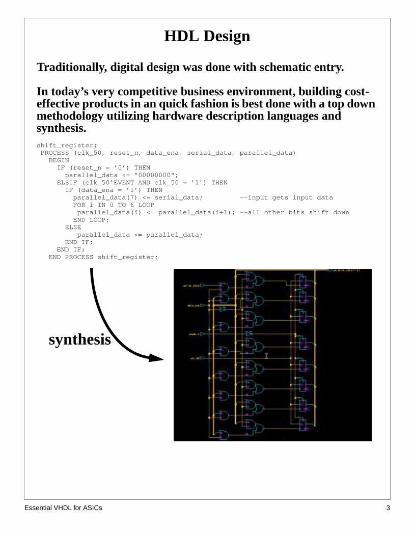
Traditionally, digital design was done with schematic entry.
In today’s very competitive business environment, building cost-effective products in an quick fashion is best done with a top downmethodology utilizing hardware description languages andsynthesis.shift_register: PROCESS (clk_50, reset_n, data_ena, serial_data, parallel_data) BEGIN IF (reset_n = ’0’) THEN parallel_data <= "00000000"; ELSIF (clk_50’EVENT AND clk_50 = ’1’) THEN IF (data_ena = ’1’) THEN parallel_data(7) <= serial_data; --input gets input data FOR i IN 0 TO 6 LOOP parallel_data(i) <= parallel_data(i+1); --all other bits shift down END LOOP; ELSE parallel_data <= parallel_data; END IF; END IF; END PROCESS shift_register;
synthesis
sential VHDL for ASICs 3

Es
y
HDLs - Motivation
Increased productivityshorter development cycles, more features, but........still shorter time-to-market, 10-20K gates/day/engineer
Flexible modeling capabilities.can represent designs of gates or systemsdescription can be very abstract or very structuraltop-down, bottom-up, complexity hiding (abstraction)
Design reuse is enabled.packages, libraries, support reusable, portable code
Design changes are fast and easily doneconvert a 8-bit register to 64-bits........four key strokes, and its done!exploration of alternative architectures can be done quickl
Use of various design methodologies.top-down, bottom-up, complexity hiding (abstraction)
Technology and vendor independence.same code can be targeted to CMOS, ECL, GaAssame code for: TI, NEC, LSI, TMSC....no changes!
Enables use of logic synthesis which allows a investigation of thearea and timing space.
ripple adder or CLA?, How many stages of look ahead?
HDLs can leverage software design environment tools.source code control, make files
Using a standard language promotes clear communication ofideas and designs.
schematic standards?... what’s that... a tower of Babel.
sential VHDL for ASICs 4
Es
HDLs - What are they? How do we use them?
A Hardware Description Language (HDL) is a programminglanguage used to model the intended operation of a piece ofhardware.
An HDL can facilitate:abstract behavioral modeling
-no structural or design aspect involvedhardware structure modeling
-a hardware structure is explicitly implied
In this class we will use an HDL to describe the structure of ahardware design.
When we use an HDL, we will do so at what is called theRegisterTransfer Language Level (RTL). At this level we are implyingcertain hardware structures when we understand apriori.
When programming at the RTL level, we are not describing analgorithm which some hardware will execute, we are describing ahardware structure.
Without knowing beforehand what the structure is we want tobuild, use of an HDL will probably produce a steaming pile (thinkmanure) of gates which may or may not function as desired.
You must know what you want to buildbefore you describe it inan HDL.
Knowing an HDL does not relieve you of thoroughlyunderstanding digital design. An HDL will not design for you.
sential VHDL for ASICs 5

Es
s
HDL’s- VHDL or Verilog
We will use VHDL as our HDL.
VHDLmore capable in modeling abstract behaviormore difficult to learnstrongly typed85% of FPGA designs done in VHDL
Verilogeasier and simpler to learnweakly typed85% of ASIC designs done with Verilog (1993)
The choice of which to use is not based solely on technicalcapability, but on:
personal preferencesEDA tool availabilitycommercial business and marketing issues
We use VHDL becausestrong typing keeps students from getting into troubleif you know VHDL, Verilog can be picked up in few weeksIf you know Verilog, learning VHDL can take several month
The Bottom line...Either language is viable.
sential VHDL for ASICs 6

Es
its
eres a
e
as the
l
VHDL - Origins
Roots of VHDL are in the Very High Speed Integrated Circuit(VHSIC) Program launched in 1980 by the US Department ofDefense (DOD).
The VHSIC program was an initiative by the DOD to extendintegration levels and performance capabilities for military integrated circuto meet or exceed those available in commercial ICs.
The project was successful in that very large, high-speed circuits wable to be fabricated successfully. However, it became clear that there waneed for a standard programming language to describe and document thfunction and structure of these very complex digital circuits.
Therefore, under the VHSIC program, the DOD launched anotherprogram to create a standard hardware description language. The result wVHSIC hardware description language or VHDL.
The rest is history...
In 1983, IBM, TI and Intermetrics were awarded the contract todevelop VHDL.
In 1985, VHDL V7.2 released to government.
In 1987, VHDL became IEEE Standard 1076-1987.
In 1993, VHDL restandardized to clarify and enhance thelanguage resulting in VHDL Standard 1076-1993.
In 1993, development began on the analog extension to VHDL,(VHDL-AMS).
Extends VHDL to non-digital devices and micro electromechanicacomponents. This includes synthesis of analog circuits.
sential VHDL for ASICs 7

Es
Some Facts of Life (For ASIC designers)
The majority of costs are determined by decisions made early inthe design process.
“Hurry up and make all the mistakes. Get them out of the way!”
“Typical” ASIC project: concept to first silicon about 9 months.
95% of designs work as the specification states.
60% of designs fail when integrated into the system.The design was not the right one, but it “works”.
Technology is changing so fast, the only competitive advantage isto learn faster than your competitors.
To design more “stuff” faster, your level of design abstractionmust increase.
Using HDLs will help to make digital designers successful. (andemployed!)
sential VHDL for ASICs 8

Es
VHDL Modeling
A VHDL models consist of anEntity Declaration and aArchitecture Body.
The entity defines theinterface, the architecture defines thefunction.
The entity declaration names the entity and defines the interfaceto its environment.
Entity Declaration Format:
ENTITY entity_name IS[GENERIC (generic_list);][PORT (port_list);]
END ENTITY [entity_name];
There is a direct correspondence between a ENTITY and a blockdiagram symbol. For example:
ENTITY nand_gate ISPORT( a : in std_logic; b : in std_logic; c : in std_logic; z : out std_logic);END ENTITY nand_gate;
a
b
cz
nand_gate
sential VHDL for ASICs 9

Es
Port Statement
The entity’s port statement identifies the ports used by the entityto communicate with its environment
Port Statement Format:
PORT( name_list : mode type;
name_list : mode type;name_list : mode type;name_list : mode type);
This is legal but poor form:
ENTITY nand_gate IS PORT(a,d,e,f : in std_logic; b,j,q,l,y,v : in std_logic; w,k : in std_logic; z : out: std_logic);END nand_gate;
This is much less error prone:Use one line per signal. This allows adequate comments.Capitalize reserved names.
ENTITY nand_gate IS PORT( a : IN STD_LOGIC; --a input b : IN STD_LOGIC; --b input c : IN STD_LOGIC; --c input z : OUT STD_LOGIC); --nand outputEND ENTITY nand_gate;
sential VHDL for ASICs 10

Es
.
Port Mode:
Identifies the direction of data flow through the port.
The PORT statement is optional. At the top level, none is needed
All ports must have an identified mode.
Allowable Modes:
• IN Flow is into the entity
• OUT Flow is out of the entity
• INOUT Flow may be either in or out
• BUFFER An OUTPUT that can be read from
(mode: in)
(mode: inout)
ram_wr_n
(mode: buffer)
bobs_block
state_0
(mode:out)
clock
data
sential VHDL for ASICs 11

Es
Architecture Body
The architecture body describes the operation of the component.
Format:
ARCHITECTURE body_name OF entity_name IS --this is the ->declarative area<- --declare signals, variables, components, --subprogramsBEGIN --this is the ->statement area<- --in here go statements that describe --organization or functional operation of --the component --this is the “execution part” of the modelEND [body_name]
The entity_name in the architecture statement must be the sameas the entity declaration that describes the interface to the outsideworld.
ENTITY entity_name IS
ARCHITECTURE body_name OF entity_name IS
The “body_name” is a user-defined name that should uniquelydescribe the particular architecture model.
ARCHITECTURE beh OF nand_gate IS
ARCHITECTURE struct OF nand_gate IS
Note: multiple architectures are allowed.
sential VHDL for ASICs 12

Es
firstn ateote.
Commenting Code
A double hyphen (--) indicates everything from that point on inthat line is to be treated as a comment.
ARCHITECTURE example OF xor_gate IS--The following is a silly example of how
--to write comments in VHDL.BEGIN --comment from the beginning of a line a <= b XOR c; --or...comment from here on -- --each line must have its own --comment marker unlike “C” --END [body_name] -- -- --this is the end and there ain’t no more!
Comments can be put anywhere except in the middle of a line ofcode.
Important Note: The tool used to prepare this document sometimes changes theof a pair of quotes. In VHDL, only the quote marks that lean to the right or don’t leaall are used. For example,‘1’ should only have single quotes that lean to the right likthe second one does. The quote mark we use is on the same key as the double qu
sential VHDL for ASICs 13
Es
Entity and Architecture for a NAND gate Model
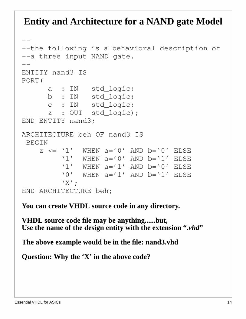
----the following is a behavioral description of--a three input NAND gate.--ENTITY nand3 ISPORT( a : IN std_logic; b : IN std_logic; c : IN std_logic; z : OUT std_logic);END ENTITY nand3;
ARCHITECTURE beh OF nand3 IS BEGIN z <= ‘1’ WHEN a=’0’ AND b=‘0’ ELSE ‘1’ WHEN a=’0’ AND b=‘1’ ELSE ‘1’ WHEN a=’1’ AND b=‘0’ ELSE ‘0’ WHEN a=’1’ AND b=‘1’ ELSE ‘X’;END ARCHITECTURE beh;
You can create VHDL source code in any directory.
VHDL source code file may be anything......but,Use the name of the design entity with the extension “.vhd”
The above example would be in the file: nand3.vhd
Question: Why the ‘X’ in the above code?
sential VHDL for ASICs 14

Es
Signal Assignment
The assignment operator (<=) is used to assign a waveform valueto a signal.
Format:
target_object <= waveform;
Examples:
my_signal <= ‘0’; --ties my_signal to “ground”his_signal <= my_signal; --connects two wires
--vector signal assignment
data_bus <= “0010”; -- note double quotebigger_bus <= X”a5”; -- hexadecimal numbers
sential VHDL for ASICs 15

Es
Declaring Objects
Declaration Format:
OBJECT_CLASS identifier: TYPE [:= init_val];
Examples:
CONSTANT delay : TIME:= 10ns;CONSTANT size : REAL:=5.25;VARIABLE sum : REAL;VARIABLE voltage : INTEGER:=0;SIGNAL clock : BIT;SIGNAL spam : std_logic:=’X’;
Objects in the port statement are classified as signals by default.
Objects may be initialized at declaration time.
If an object is not initialized, it assumes the left-most or minimumvalue for the type
sential VHDL for ASICs 16

Es
Naming Objects
Valid characters:
• alpha characters (a-z)
• numeric characters (0-9)
• underscore (_)
Names must consist of any number of alpha, numeric, orunderline characters.
Underscore must be proceeded and followed by alpha or numericcharacters.
The underscore can be used to separate adjacent digits in bitstrings:CONSTANT big_0 : STD_LOGIC_VECTOR(15 DOWNTO 0) :=B"0000_0000_0000_0000";
Names are not case sensitive. (be consistent!, use lowercase!)
Coding hints:
Use good names that are meaningful to others. If your code is good,somebody else will want to read it.
Name signals by their function. For example, if you have a multiplexorselect line that selects addresses, give it a name like “address_select ”instead of “sel_32a” .
Name blocks by their function. If a block generates control signals for aDRAM controller, call the block “dram_ctl ” not something obscure like“block_d ”.
sential VHDL for ASICs 17

Es
A Simple Example to Recap
--------------------------------------------and-or-invert gate model--Jane Engineer--3/13/01--version 0.5------------------------------------------LIBRARY ieee;USE ieee.std_logic_1164.ALL;
ENTITY aoi4 ISPORT( a : IN std_logic; b : IN std_logic; c : IN std_logic; d : IN std_logic; z : OUT std_logic);END ENTITY aoi4;
ARCHITECTURE data_flow OF aoi4 IS SIGNAL temp1, temp2 : std_logic; BEGIN temp1 <= a AND b; temp2 <= c AND d; z <= temp1 NOR temp2;END ARCHITECTURE data_flow;
sential VHDL for ASICs 18

Es
ine
ate a
inlt
IX
Simulating VHDL code
The Simulator
The simulator we will be using is the Model Technologies’ModelSim. It willbe referred to asvsim. Vsim is a full featured VHDL and/or Verilog simulatorwith best-in-class VHDL simulation. It is also very easy to learn and use.
VHDL Libraries
Before a VHDL design can be simulated, it must be compiled into a machexecutable form. The compiled image is placed into a library where thesimulator expects to find the executable image. Therefore we must first crespecial directory called “work”.
The Library work
The library named work has special attributes within vsim; it is predefinedthe compiler. It is also the library name used by the compiler as the defaudestination of compiled design units. In other words the work library is theworking library.
Creating work
At the desired location in your directory tree, type:
vlib work
You will see a directory work created. You cannot create work with the UNmkdir command.
sential VHDL for ASICs 19

Es
e
Simulating VHDL Code (cont.)
Compile the code
Suppose our example code is in a file calledaoi4.vhd. At the level at which youcan see the directorywork with anls command, simply type:
vcom -93 aoi4.vhd
Then you will see:
brilthor.ECE.ORST.EDU:vcom -93 src/aoi4.vhdModel Technology ModelSim SE/EE vcom 5.4c Compiler 2000.08 Jul 29 2000-- Loading package standard-- Loading package std_logic_1164-- Compiling entity aoi4-- Compiling architecture data_flow of aoi4brilthor.ECE.ORST.EDU:
If you look in the work directory, you will see a subdirectory in work with thentity nameaoi4. In there are the files necessary to simulate the design.
With a clean compilation, we are ready to simulate.
sential VHDL for ASICs 20
Es
Simulating VHDL Code (cont.)
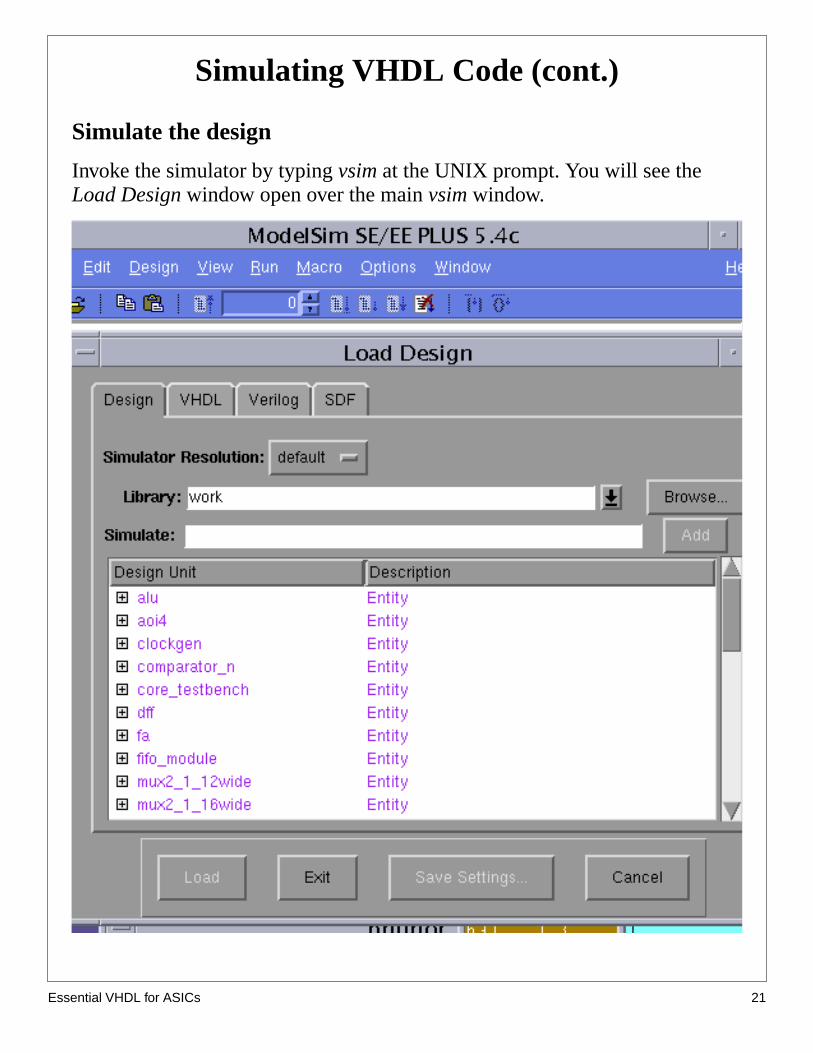
Simulate the design
Invoke the simulator by typingvsim at the UNIX prompt. You will see theLoad Design window open over the mainvsim window.
sential VHDL for ASICs 21
Es
or.
e
run
itherthe
L.DL
Simulating VHDL code (cont.)
TheDesign Unit is the name of the entity you want to load into the simulatIn this example, there are many other entities in the work directory, eachcorresponding to a different entity/architecture pair.
To load the design, click onaoi4 and thenLoad. Note thataoi4 this is not thefile name, but the entity name.
The design will then load. To run a simulation, first type view * in theModelSim window. This will open all the windows available for thesimulation. You will probably want to close all but the wave, signals, sourcand structure windows.
To observe the signals, in theSignals window select:View > Wave > Signals in RegionAll the signals in the design are then visible in the Wave window.
To provide stimulation to our model we can just force the input signals andfor a short time. To do this, in the ModelSim window we can type:
force a 0force b 0force c 0force d 0run 100force a 1force b 1run 100
According to our model we should see the z output assert to a zero when ea and b or c and d both become true. We can see the correct behavior in wave window.
HW: make 2-3 complex algebraic equations and implement them in VHDStudents simulate and check them. Synthesize them and recheck with VHsimulator. Print out gate level schematics.
sential VHDL for ASICs 22

Es
or.
a to
Simulating VHDL Code
The output from the wave window looks like this:
We will make heavy usage of thevsim simulator. You are encouraged toexplore and discover the different options and way to operate the simulat
For example, the force commands may be applied from a “do file”. This istext file containing all the force and run commands. Try to use a force fileexhaustively test the aoi4 design.
The documentation for the Model Technology tools may be found at:http://www.ece.orst.edu/comp/doc/tools/mti/mti_documentation.html
sential VHDL for ASICs 23