Embed Size (px)
Citation preview

ESI Communications Servers ESI-1000 • ESI-600 • ESI-200 • ESI-100
Hardware Installation Manual
0450-1049 Rev. C
Copyright © 2007 ESI (Estech Systems, Inc.). IVX is a registered trademark of Estech Systems, Inc. Ethernet is a registered trademark of Xerox Corporation. Motorola and ColdFire are registered trademarks of Motorola, Inc. Rayovac is a registered trademark of Rayovac Corporation. Act! is a registered trademark of Symantec Corporation. Goldmine is a trademark of Goldmine Software Corporation. Microsoft, Windows, NT and Outlook are registered trademarks of Microsoft Corporation. Panasonic and DBS are registered trademarks of Matsushita Electric Corporation of America. Novell and Netware are registered trademarks of Novell, Inc. Smart Jack is a trademark of Westell Technologies, Inc. Information contained herein is subject to change without notice. Certain features described herein may not be available at initial release. ESI products are protected by various U.S. Patents, granted and pending. ESI is an ISO 9001:2000-certified company. Visit ESI on the Web at www.esi-estech.com.

Contents
Overview........................................................................A.1 Cabinet components.............................................................. A.1 Base Cabinet ......................................................................... A.1 Expansion Cabinets............................................................... A.1 Main board............................................................................. A.2 Backplane.............................................................................. A.2 Memory Module..................................................................... A.2 Power supply ......................................................................... A.2 Port card options.................................................................... A.3 NSP....................................................................................... A.5
Phones...........................................................................B.1 Digital phone models ............................................................. B.1 IP Phone models ................................................................... B.2 ESI Cordless Handsets.......................................................... B.2 Expansion Consoles .............................................................. B.3 Feature Phone overlays......................................................... B.3 VIP Softphone........................................................................ B.3
Licensing.......................................................................C.1
System capacities.........................................................D.1
Cautions and regulatory information.......................... E.1 Cautions ................................................................................ E.1 Regulatory information........................................................... E.2
Hardware installation: ESI-1000, ESI-600, ESI-200 .... F.1 Site location ............................................................................F.1 Mounting the cabinet(s)...........................................................F.1 Expansion Cabinet installation ................................................F.2 Port card installation................................................................F.2 About replacing port cards ......................................................F.4 Memory Module installation or replacement............................F.5 Removing the Memory Module from the main board..............F.8 Mirrored Memory Module........................................................F.9 LED functions .......................................................................F.15 ESI Presence Management installation ................................F.15
Hardware installation: ESI-100.................................... G.1 Site location........................................................................... G.1 Opening the Base Cabinet .................................................... G.2 Mounting the Base Cabinet ................................................... G.2 Expansion Cabinet installation............................................... G.3 Port card installation.............................................................. G.3 Memory Module installation or replacement .......................... G.5 LED functions........................................................................ G.6 ESI Presence Management installation................................. G.6
External connections................................................... H.1 Grounding instructions ...........................................................H.1 Power.....................................................................................H.1 MOH port ...............................................................................H.3 Maintenance/SMDR serial port...............................................H.3 External paging device connection.........................................H.4 Amphenol cable connections..................................................H.4 CO line connection.................................................................H.5 Station connection..................................................................H.7 Installing the TAPI Phone.......................................................H.8 Testing TAPI ..........................................................................H.9 Proceeding to use TAPI .........................................................H.9 60-Key Expansion Console connection................................H.10 60-Key Second Expansion Console connection...................H.11 Installing ESI’s Cordless Handsets.......................................H.12 Port card connections...........................................................H.15 Cabinet worksheets..............................................................H.22
Index
Important: For information concerning the programming of an ESI Communications Server (the ESI-1000, ESI-600,
ESI-200, or ESI-100), see the ESI Communications Servers Programming Manual (ESI document #0450-1050).

ESI Communications Servers Hardware Installation Manual Overview
A.1
Overview
Cabinet components
ESI-1000, ESI-600, and ESI-200
Cabinet components1 for the ESI-1000, ESI-600, and ESI-200 consist of:
• Base Cabinet
– Main board
– Backplane
– Memory Module
– Seven port card slots
– External wall-mounted power supply
• Expansion Cabinet (optional)
– Backplane
– Seven port card slots
– Expansion cable
– Expansion Card2
– External wall-mounted power supply
ESI-100
The ESI-100’s cabinet components1 consist of:
• Base Cabinet
– Main board
– Memory Module
– Two port card slots
– External wall-mounted power supply
• Expansion Cabinet (optional)
– Two port card slots
Base Cabinet
The ESI Communications Server Base Cabinet is designed for easy installation and component access. Regardless of model, each ESI Communications Server Base Cabinet houses the main board, Memory Module, Network Services Processor (NSP), one multi-purpose serial port, and an MOH connector.
ESI-1000, ESI-600, and ESI-200
The Base Cabinet for the ESI-1000, ESI-600, and ESI-200, which measures 19″ W 10.5″ H 10.5″ D, also
houses the Mirrored Memory Module (M3)3 and seven port card slots (see “Port card options,” page A.3).
ESI-100
The Base Cabinet for the ESI-100, which measures 8.5″ W 11″ H 3″ D, it also houses two port card slots
(see “Port card options,” page A.3).
Expansion Cabinets
Each ESI Communications Server can be expanded to increase the number of port cards. The ESI-1000 and ESI-600 each accept the same Expansion Cabinet, while the ESI-200 and ESI-100 have their own unique Expansion Cabinets.
System Maximum
Expansion Cabinets
Maximum port cards
per Expansion Cabinet
Total system capacity
(port cards)
ESI-1000 5 7 42
ESI-600 3 7 28
ESI-200 1 7 14
ESI-100 1 2 4
1 Memory Modules and port cards are packaged separately and are mounted in each system’s cabinet during installation.
2 The ESI-200 uses cables rather than an Expansion Card.
3 The M3 interface is standard on the ESI-1000, optional on the ESI-600 and ESI-200. Each requires an optional second Memory Module.
ESI Communications Servers Hardware Installation Manual Overview
A.2
Main board
The main board combines leading-edge hardware components — including a Motorola® ColdFire
® processor
and DSP structure — along with proprietary operating system software. The board provides: system control of the Memory Module and port cards; a standard RS-232C DB9 serial port; a built-in modem for remote access; an external paging-device interface; MOH interface; an NSP, which provides remote access via TCP/IP and
supports certain optional ESI PC software applications; and (except on the ESI-100) a mount for the Mirrored Memory Module.
1
Backplane
On the ESI-1000, ESI-600, and ESI-200, each cabinet (Base or Expansion) is equipped with a backplane that supports up to seven port cards.
Memory Module
The Memory Module — a hard disk drive with proprietary formatting — contains all system programming and configuration data, and pre-loaded voice prompts. The Memory Module provides voice storage at 64 kilobits per second — the industry's highest-quality sampling rate. Here are the capacities by system model:
Memory Module type ESI-1000 ESI-600 ESI-200 ESI-100
CompactFlash® n/a n/a 140-hr. 140-hr.
Hard-disk drive 1,200-hr. 1,200-hr. 600-hr. n/a
Optional Mirrored Memory Module (M3)
Note: Not available on the ESI-100.
Using RAID-1 hard drive technology, the optional Mirrored Memory Module (M3) maintains system operation on a separate disk drive in the event of a hard drive failure. M3 is required when redundancy of system programming, speed-dial entries, and voice mail messages and prompts is desired.
Note: M3 use on the ESI-200 requires that both Memory Modules be the 600-hour (hard-disk drive) model.
Power supply
All power supplies are included at purchase.
• ESI-1000, ESI-600, or ESI-200 — Uses a 7.5-amp, 24 VAC power supply on the Base Cabinet and each Expansion Cabinet.
• ESI-100 — Uses a 5-amp, 24 VAC power supply.
Optional rack-mount Power Distribution Shelf
The optional Power Distribution Shelf can be mounted in a standard 19-inch rack. Each Power Distribution Shelf, which can hold up to four power supplies, includes a six-outlet power strip with on/off switch and 15'
power cord.
1 The M3 interface is standard on the ESI-1000, optional on the ESI-600 and ESI-200. Each requires an optional second Memory Module.

ESI Communications Servers Hardware Installation Manual Overview
A.3
Port card options
ESI Communications Servers support a wide range of port cards. Any E2 port card can be used on any ESI Communications Server with the use of an additional E2 Port Card “Hot Swap” Adapter (except on the ESI-100).
1
The CS port cards (not for use with the ESI-100) are full-size cards with built-in “hot-swap” capability, along with a special “ejector-handle” mechanism that makes them literally a snap to install or uninstall. The following port
cards are supported:
Ports System maximums (port cards)
Port card COs Stations2
Analog stations
Esi-Link channels
ESI-1000 ESI-600 ESI-200 ESI-100
CS-684 6 8 digital 4 42 28 14
CS-612 6 12 digital 42 28 14
CS-6ALC 6 42 28 14
CS-A12 12 32 15 4
CS-D12 12 digital 42 28 14
CS-DLC12 24 (T1) or 23B +1D (PRI) 12 digital 10 6 3
CS-DLC 24 (T1) or 23B +1D (PRI) 10 6 3
CS-IVC 24R 24 IP 34 17 8
CS-IVC 24EL 24 4 2 1
CS-IVC 12R12EL 12 IP 12 4 2 1
E2-684 6 8 digital 4 42 28 14 4
E2-612 6 12 digital 42 28 14 4
ESI-6ALC 6 42 28 14 4
E2-A12 12 32 15 4 2
E2-D12 12 digital 42 28 14 4
E2-DLC12 24 (T1) or 23B +1D (PRI) 12 digital 10 6 3 1
ESI-DLC 24 (T1) or 23B +1D (PRI) 10 6 3 1
IVC 24R3 24 IP 34 17 8 3
IVC 24EL 24 4 2 1 1
IVC 12R12EL 12 IP 12 4 2 1 1
The cards are described beginning on the next page.
Warning: Any port card shipped prior to March 16, 2007, will NOT boot on the second cabinet of an ESI-200.
However, these cards can be updated. For details and the update procedure, see Technical Update 264, available from www.esiresellers.com/tech.
1 See “Hot-swap operations,” page A.5.
2 For each IVC, the quantity of IP stations is a combination of locally and remotely installed IP phones.
3 Previously called IVCR24.

ESI Communications Servers Hardware Installation Manual Overview
A.4
Port card descriptions
• CS-684, E2-684 — Connects up to six analog loop-start CO lines, eight Digital Feature Phones and four
analog station ports. The CO line ports support standard CO and Centrex loop-start lines (but not ground-start CO lines). The analog ports provide a standard 24-volt, two-wire connection to fax machines, courtesy phones, modems, etc. Only one device can be connected to each analog station port. This card uses 12 station ports and six CO ports.
• CS-612, E2-612 — Provides circuits to connect up to six analog loop-start CO lines and 12 Digital Feature Phones. Ground-start CO lines are not supported. This card uses 12 station ports and six CO ports.
• CS-6ALC, ESI-6ALC — Similar to the CS-612 and E2-612, but connects only up to six analog loop-start CO lines (and no stations).
• CS-A12, E2-A12 — Connects up to 12 analog devices (only), such as fax machines and cordless phones. This card uses 12 station ports and no CO ports. Each port provides a standard 24-volt, two-wire phone connection. Only one analog device can be connected to each port.
• CS-D12, E2-D12 — Connects up to 12 Digital Feature Phones (only). This card uses 12 station ports and no CO ports.
• CS-DLC12, E2-DLC12 (Digital Line Card) — Provides either a T1 interface supporting 24 DS0 channels and 12 digital stations or an ISDN PRI interface supporting 23 B (bearer) channels, one D (datalink) channel and 12 digital stations.
A jumper on this card must be plugged onto pins 7 and 8 of J3 to enable ISDN PRI functions. Any (or all) of the available channels of the T1/PRI span (24 on T1, 23 on PRI) can be assigned, and the card supports loop-start, ground-start, E&M and DNIS/DID trunk types with immediate, wink-start or dial-tone-start signaling. This card is equipped with a built-in CSU that can be connected directly to a network interface unit, SmartJack or ISDN PRI. Up to 12 Digital Feature Phones can be connected to the card. All 24 CO ports are allocated (regardless of whether they are assigned or used).
• CS-DLC, ESI-DLC — Similar to the CS-DLC12 and E2-DLC12, but supports only a T1 or PRI circuit (and no phones).
• CS-IVC, IVC (Intelligent VoIP Card) — Supports standards-compliant IP telephony service and features, including VoIP to the desktop and Esi-Link. It features highly configurable DSP technology that manages
the flow of traffic among the port cards and converts IP packets into PCM (pulse-code modulation) traffic for transmission over the PSTN. The physical connection is a 10/100Base-T, RJ-45 Ethernet
® interface
that allows the system to connect to an IP-based local area network (LAN). The IVC is offered in three versions: • IVC 24R — Provides 24 IP stations (local or remote).
1
• IVC 24EL — Provides 24 channels for Esi-Link. • IVC 12R12EL — Provides 12 IP stations (local or remote) and 12 Esi-Link channels; does not support SIP phones.
Each ESI Communications Server model has a specific maximum of each type of IVC (see the table on page A.3). The system automatically designates the first IVC station card (lowest-numbered slot) as the primary IVC — which acts as the “master” that, when an IP Phone first comes on line, identifies the IVC station card to which the IP Phone connects (IVC Esi-Link cards are excluded from this operation). Licensing is required to support each IP Feature Phone or SIP phone. The following table shows the maximum number of IP Phones and Esi-Link channels for each system.
Maximums ESI-1000 ESI-600 ESI-200 ESI-100
IP stations 816 408 192 72
Esi-Link channels 96 48 24 242
1 SIP phones are supported on only the IVC 24R.
2 With (E2) IVC 24EL.

ESI Communications Servers Hardware Installation Manual Overview
A.5
Hot-swap operations
“CS” port cards — full-sized cards for use on only the ESI-1000, ESI-600, and ESI-200 — have built-in
hot-swap capability, allowing you to replace them while the system is powered-up.
For hot-swap capability, an “E2” port card must be mounted onto a “Hot Swap” Port Card Adapter (ESI part #5000-0462) prior to being installed on the ESI-1000, ESI-600, or ESI-200. However, installing a new port card requires power-cycling the system to allow it to recognize the new card.
The following rules apply to hot-swap operations on ESI Communications Servers:
• The ESI-100 does not support hot-swapping; this capability is available on only the ESI-1000, ESI-600, and ESI-200.
• When you replace a port card with a new one, the system will detect the port card type.
• If the new port card’s type is different than that of the original port card, the newly installed port card won’t come on-line.
• If the new port card’s type is the same as that of the original port card, the system will automatically upload software to the new port card. This upload process can take from four minutes to one hour, depending on the type of port card and how busy the system is at the time.
For details, refer to the procedure in “About replacing port cards,” page F.4.
NSP
Built into the main board, the NSP (Network Services Processor) serves as a bridge between an Ethernet-based network and the ESI Communications Server. Using TCP/IP, the NSP communicates directly with specific PC applications for maintenance of, and integration with, the ESI phone system. The NSP manages optional features such as VIP and phone control via TAPI PC applications; it also provides access to not only maintenance and administration (through use of ESI System Programmer software) but also an Installer-selectable SMDR interface.
The NSP hardware interface consists of a dedicated Ethernet port. Its external RJ-45 jack provides a 10/100Base-T connection to the LAN. The NSP consumes no call-processing ports.

ESI Communications Servers Hardware Installation Manual Phones
B.1
Phones
Digital phone models
An ESI Communications Server supports several different models of ESI digital phones, each of which connects to the cabinet via standard two-wire twisted pair:
• 48-Key Digital Feature Phone — Three-line, 56-character1 display; speakerphone; headset jack
2; 30
programmable feature keys; the only one of the three Digital Feature Phones that supports VIP, TAPI (see “TAPI Phone,” below), or the 60-Key Expansion Consoles.
Note: Not all modular headsets will work on the 48-Key Feature Phone’s headset jack. ESI has tested and can
recommend the following headset models:
Manufacturer: Plantronics — P51-U10P sound tube microphone — P51N-U10P noise-cancelling microphone — P251-U10P sound tube microphone
— P251N-U10P noise-cancelling microphone Manufacturer: GN Netcom
— GN2120 NCD 01 “over-the-head” — GN2127 NCD 01 “on-the-ear”
Note that GN Netcom models also are available in a “-02” configuration, which wires differently and won’t work with ESI phones. Therefore, when ordering GN Netcom headsets for use with ESI phones, be sure to specify the “-01” configuration.
• 24-Key Digital Feature Phone — Two-line, 32-character display; speakerphone; 12 programmable feature keys.
• 12-Key Digital Feature Phone — One-line, 16-character display; nine programmable feature keys.
• Cordless Handset — Two sizes; two-line, 32-character display; four programmable feature keys.
Note: When a desktop phone is in the highest upright position, use the wall-mount hook located under the
handset to secure the handset when you’re not using the phone.
TAPI Phone
The TAPI Phone is an optional version of the 48-Key Digital Feature Phone. It provides a TAPI cable and adapter for connection to a PC serial port for Basic Telephony Integration to such standard packages as Act!
®,
Goldmine!®, and Microsoft Outlook. A Digital Feature Phone cannot be field-upgraded to a TAPI Phone.
1 The top two lines each have 16 characters, as on the 24-Key Digital Feature Phone; the bottom line has 24 characters.
2 Headset jack only on 48-Key Feature Phones (Digital, Digital TAPI, [local] IP, or Remote IP) manufactured after March, 2004.

ESI Communications Servers Hardware Installation Manual Phones
B.2
IP Phone models
An ESI Communications Server supports the IP Feature Phone II, Local IP Cordless Handset, and Remote IP Cordless Handset. (See “ESI Cordless Handsets,” below.)
The desktop IP Feature Phone II1 looks and works like a 48-Key Digital Feature Phone as described on page B.1,
but connects from within the local premises via an IP local area network (LAN) rather than twisted-pair cabling.
If used on-premises, the IP Feature Phone II derives its operating power directly over the LAN from Power over Ethernet (PoE). If used remotely, the IP Feature Phone II connects to the cabinet from a remote location via an IP network (either a WAN or the public Internet) and derives its power from an AC adapter “brick.”
The IP Feature Phone II supports the following features and standards:
• IEEE 802.3af Power over Ethernet (PoE).
• Power via PoE or optional 48VDC adapter.
• Can be configured for either local or remote (off-site) operation.
• Uses a G.711 codec in its “local” mode of operation and a G.726 codec in its “remote” mode.
• Can use DHCP2 to obtain an IP address:
– In “local” operation, DHCP can be enabled or disabled3 for the IP Phones on each IVC. Alternatively, a
“static” IP address may be assigned by the Installer (in Function 31; see the ESI Communications Servers Programming Manual, ESI document #0450-1050).
– In “remote” operation, the IP Feature Phone II automatically uses DHCP to obtain an IP address and default gateway.
• Complies with IEEE 802.1q and 802.1p (VLAN) Layer 2 switching and prioritization.
• Complies with differentiated services (DiffServ; RFC 2475) Layer 3 Quality of Service (QoS) implementations.
Notes: If connecting the IP Feature Phone II to a Power over Ethernet source, the PoE cable must be connected to
the jack labeled NETWORK on the base of the phone. The jack labeled PC does NOT support or provide Power over Ethernet.
ESI has tested the IP Feature Phone II with several Power over Ethernet sources. For a current list of tested devices, see www.esiresellers.com/PoE.
Important: The ESI IP Feature Phone II doesn’t work with ESI’s IP E-Class or IVX systems; it is for use with only ESI
Communications Servers. Similarly, previous IP Feature Phone models (including the Remote IP Feature Phone) don’t work with ESI Communications Servers. Instead, they are intended for use with only IP E-Class and appropriate, IP-enabled IVX systems.
ESI Cordless Handsets
An ESI Communications Server also supports ESI’s digital, Local IP, and Remote IP Cordless Handsets. Each comes in two sizes — small and large — and includes four familiar fixed feature keys, four programmable feature keys, and a headset jack. The Base Station for each ESI digital Cordless Handset uses a standard line cord and is line-powered; and the Base Station for each ESI IP Cordless Handset uses Ethernet cabling and receives (and requires) Power over Ethernet (PoE). The ESI Remote IP Cordless Handset base station also includes a jack into which the user can plug an analog CO line. This gives the home-based teleworker the convenience of using both home and business lines with the ESI Remote IP Cordless Handset.
Important: The 48-Key IP Feature Phone II, Local IP Cordless Handset, and Remote IP Cordless Handset each draw up to 7.25 watts
4 at 48 volts DC; therefore, they advertise themselves to a Power over Ethernet switch as Class 3
devices per the 802.3af standard. Most PoE switches adhering to this standard will provide up to 12.5 watts for
each Class 3 device.
1 ESI’s desktop IP Feature Phone comes only in a 48-key model.
2 Dynamic Host Configuration Protocol, an IP standard described in RFC 2131 (http://www.ietf.org/rfc/rfc2131.txt).
3 Default setting for DHCP is disabled.
4 The 48-Key IP Feature Phone II’s power consumption takes into account an optional 60-Key Expansion Console.

ESI Communications Servers Hardware Installation Manual Phones
B.3
Expansion Consoles
The 60-Key Expansion Console gives a designated user 60 additional programmable feature keys. The Expansion Console is connected to its host 48-Key Feature Phone via a special cable (provided) and doesn’t require a separate station port of its own. Additionally, it may be connected to a 60-Key Second Expansion Console via a special cable (provided with the 60-Key Second Expansion Console) so that one 48-Key Feature
Phone can have a total of 150 programmable feature keys.
Each ESI Communications Server has a maximum number of stations that can have one or two Expansion Consoles (60-Key and 60-Key Second) installed in a fully configured system:
Maximum Expansion Consoles
ESI-1000 ESI-600 ESI-200 ESI-100
128 80 32 8
Note: Regardless of ESI Communications Server model, a Base Cabinet can support a maximum of eight
Expansion Consoles, and each Expansion Cabinet can support a maximum of 24 Expansion Consoles.
Feature Phone overlays
Each Feature Phone comes with one overlay for the programmable feature keys. To order additional overlays, visit the DESI
™ Web site, www.desi.com. While there, you may also want to download the free Windows-based
software, DESI Lite, which allows you to print on the overlays. For assistance with DESI products, contact DESI (the DESI Web site contains contact information).
Tip: Remember that ESI System Programmer software, available from www.esiresellers.com, also lets you print on the overlays as well as perform many other programming tasks.
VIP Softphone
VIP Softphone integrates the features of VIP Professional and an IP Feature Phone II into a PC-based, full-
audio phone. With the appropriate license, VIP Softphone can be configured for use locally or remotely. This product requires a third-party USB headset.
Note: For details, see the VIP Product Overview (ESI document #0450-0608) and the VIP Setup and User’s Guide (ESI document # 0450-0513).

ESI Communications Servers Hardware Installation Manual Licensing
C.1
Licensing
There are various types of licenses needed to activate certain features and functionality. The following ESI Communications Server-supported features, products, and capabilities require license activation:
• IP Feature Phones (including cordless) — Two license types:
– Local (LAN) operation.
– Remote (off-site) operation.1
• VIP.
• VIP Professional.
• VIP PC Attendant Console.
• VIP ACD Supervisor.
• VIP ACD Agent.
• VIP Softphone (also requires purchase of local or remote IP station license).
• SIP.
License activation
To have licenses activated by ESI Technical Support:
1. Licenses must already have been ordered from ESI.
2. The ESI Communications Server must have either:
• A CO line connected to it (analog, PRI, or T1); or
• The NSP, which is connected to a LAN with a public IP address, “port-forwarded”2 to it.
3. You’ll need the following to provide to the ESI representative:
• The ESI sales order number.
• The customer (site) name.
• The phone number of the CO line or the public IP address of the NSP.
• The quantity of VIP Professional and VIP ACD Agent licenses.3
IP Phone licenses
Before an IVC will connect to an IP Phone4, the phone will require an available IVC port and the activation within
the system of a local or remote license. When an IP Phone is programmed in the system (Function 31), this consumes a license.
A new compatible ESI IP Phone, when connected to a LAN with an ESI Communications Server connected to it, can be configured in setup mode. However, if a new extension number is assigned to the phone and there are no local IP Phone licenses available, the phone will display LICENSE EXCEEDED (but play no prompt).
1 IP Feature Phones II programmed for remote operation can still operate as local stations on the LAN.
2 For more information about the NSP, refer to NSP Installation Made Simple (ESI #0450-0669).
3 VIP ACD Agent uses the same license part numbers as VIP Professional, allowing mixing and matching as the customer may require; e.g., 100 such
licenses could be used for 60 VIP Professional installations and 40 VIP ACD Agent installations. For licensing information for VIP PC Attendant Console and VIP ACD Supervisor, refer to their respective Product Overviews (ESI document #0450-0914 for VIP PC Attendant Console and #0450-0988 for VIP ACD). VIP Softphone is sold as a single license (part #5000-0434), which provides one user with VIP Professional features and Softphone-specific capabilities. The VIP Softphone license is selected at the time of purchase for local or remote operation.
4 An IP Feature Phone II, IP Cordless Handset (Local or Remote), VIP Softphone, or SIP phone.

ESI Communications Servers Hardware Installation Manual System capacities
D.1
System capacities
Important: Each ESI Presence Management RFID Reader uses one digital station.
Stations and trunks
The specifications shown below reflect maximum capacities and configurations. Not all of the station and trunk maximums can be reached simultaneously.
Example: The ESI-100 can’t achieve 72 IP stations and 48 digital stations and 28 analog stations and 42 trunks and 24 Esi-Link stations at the same time, because the system’s four-port-card limit makes such a configuration
impossible. The maximum configuration for this system is 108 ports, which could be achieved by one DLC12 card (24 T1 trunks, 12 digital stations), two IVC 24Rs (48 IP stations), and one IVC EL24 (24 Esi-Link channels).
ESI-1000 ESI-600 ESI-200 ESI-100
Dialing plans (-digits) Four Three Four Three Four Three Four Three
Max. port cards 42 14 28 14 14 14 4 4
Max. port configuration1 1,128 276 624 276 300 276 108 108
– Max. stations 816 168 408 168 192 168 84 84
– Max. IP stations 816 168 408 168 192 168 72 72
– Max. digital stations 504 168 336 168 168 168 48 48
– Max. analog stations 384 56 188 56 56 56 28 28
Max. CO lines 240 84 168 84 84 84 42 42
Max. DLCs (T1/PRI) 10 3 6 3 3 3 1 1
Max. IVCs 34 7 17 7 8 7 3 3
Max. Esi-Link port cards (up to 24 Esi-Link channels
2 per card)
4 4 2 2 1 1 1 1
Dedicated ports ESI-1000 ESI-600 ESI-200 ESI-100
Dialing plans (-digits) Four Three Four Three Four Three Four Three
Voice mail/auto attendant ports3 128 128 32 32 16 or 24 16 or 24 8 8
Conference ports (max. of 16 members per conference)
64 64 64 64 24 24 16 16
NSP4 1 1 1 1 1 1 1 1
Overhead paging ports5 1 1 1 1 1 1 1 1
Serial/SMDR ports 1 1 1 1 1 1 1 1
Voice mail capacities ESI-1000 ESI-600 ESI-200 ESI-100
Dialing plans (-digits) Four Three Four Three Four Three Four Three
Voice mail storage (hours) 1,200 1,200 1,200 1,200 140 or 600 140 or 600 140 140
Broadcast mailbox (one to all extensions)
Yes Yes Yes Yes Yes Yes Yes Yes
Cascade notification mailboxes 40 10 20 10 10 10 10 10
Group mailboxes/max. members 64/200 32/200 32/64 32/64 16/48 16/48 16/32 16/32
Guest/info mailboxes 1,000 190 1,000 190 1,000 190 1,000 190
Maximum station mailboxes 816 168 408 168 192 168 84 84
Q & A mailboxes 20 10 20 10 10 10 10 10
1 Includes Esi-Link channels.
2 Esi-Link channels are allocated to “reserved” ports; i.e. Esi-Link channels do not reduce CO or station capacity.
3 On the ESI-200: 16 ports for 140-hr. model, 24 ports for 600-hr. model.
4 Network Services Processor; see page A.5.
5 On the ESI-200: A non-IVC card must be installed in slot 1 or 2. On the ESI-100: An IVC can’t be installed in slot 1. See also p. H.4.

ESI Communications Servers Hardware Installation Manual System capacities
D.2
Departments ESI-1000 ESI-600 ESI-200 ESI-100
Dialing plans (-digits) Four Three Four Three Four Three Four Three
Max. departments 128 20 64 20 20 20 10 10
Department types: Ring-all, ACD, UCD, in-order, pick-up, attendant
Yes Yes Yes Yes Yes Yes Yes Yes
Max. members, non-ring-all depts. 64 64 64 64 48 48 32 32
Max members, ring-all depts. 48 48 48 48 48 48 32 32
Shared-office tenanting ESI-1000 ESI-600 ESI-200 ESI-100
Dialing plans (-digits) Four Three Four Three Four Three Four Three
Tenants 8 8 8 8 4 4 2 2
CO line groups ESI-1000 ESI-600 ESI-200 ESI-100
Dialing plans (-digits) Four Three Four Three Four Three Four Three
Line groups 9, 8, 71–76 Yes Yes Yes Yes Yes Yes Yes Yes
Max. members, CO ring assignment list
48 48 48 48 48 48 32 32
Translation tables ESI-1000 ESI-600 ESI-200 ESI-100
Dialing plans (-digits) Four Three Four Three Four Three Four Three
PRI pilot numbers 80 80 40 40 20 20 10 10
Max. DID entries 1,200 1,200 600 600 300 300 300 300
System speed-dial numbers ESI-1000 ESI-600 ESI-200 ESI-100
Dialing plans (-digits) Four Three Four Three Four Three Four Three
System speed-dial numbers 1,000 100 1,000 100 1,000 100 1,000 100
Maximum installations of VIP applications ESI-1000 ESI-600 ESI-200 ESI-100
Dialing plans (-digits) Four Three Four Three Four Three Four Three
Installations, VIP PC Attendant Console
16 16 8 8 4 4 2 2
Installations, VIP auto-recording
32 32 16 16 8 8 4 4
Installations, VIP ACD Supervisor
16 16 8 8 4 4 2 2
ESI Presence Management features ESI-1000 ESI-600 ESI-200 ESI-100
Dialing plans (-digits) Four Three Four Three Four Three Four Three
RFID Reader access door records
50,000 50,000 10,000 10,000 10,000 10,000 10,000 10,000
RFID Reader entries in Function 372
1
64 64 32 32 32 32 16 16
Max. RFID tags (“electronic keys”)
2,000 2,000 500 500 500 500 500 500
1 See the ESI Communications Servers Programming Manual (ESI document #0450-1050) or the ESI Presence Management Installation Manual
(ESI document #0450-0792).

ESI Communications Servers Hardware Installation Manual Cautions and regulatory information
E.1
Cautions and regulatory information
Cautions
Important: This information complies with the requirements of Underwriters’ Laboratories (UL) and UL Standard 60950.
When using this telephone equipment, always exercise basic safety precautions in order to minimize the risk of fire, electric shock or injury to persons. Before proceeding, please read the following:
• Do not use liquids or aerosols to clean any system equipment; rather, use a cloth that is only slightly damp.
• An ESI Communications Server contains no components that are serviceable by either non-Resellers or non-manufacturer technicians. All service must be referred to the Reseller for further handling.
• Do not install the cabinet in areas with extreme heat or improper ventilation.
• Install the cabinet only in “low-traffic” or “non-public” areas.
• To reduce the risk of fire, use only 26 AWG or larger telecom wire.
Power supply
Heed all warnings and instructions in documentation or marked on the cabinet or peripheral equipment.
Fuse
Contact the factory before attempting to replace the fuse. The fuse is located on the main board in the Base Cabinet, and (for the ESI-1000, ESI-600, and ESI-200) on the backplane in the Expansion Cabinet.
Battery (located on the main board)
“Caution: There is a danger of explosion if the onboard lithium battery is incorrectly replaced. Replace only with Ray-O-Vac BR1225 (or equivalent). Dispose of used batteries according to the battery manufacturer’s instructions.”
“Notice: This product is intended to be supplied by a Listed Direct Plug-In Power Unit marked ‘Class 2’ and provided
with electrical ratings.”

ESI Communications Servers Hardware Installation Manual Cautions and regulatory information
E.2
Regulatory information
United States of America
Registration
The CO line telephone numbers, FCC registration number, and ringer equivalence number (REN) of this equipment must be provided to the telephone company before installation. (See below for FCC registration number and ringer equivalence number.)
FCC Part 15
This equipment has been tested and found to comply with the limits for a Class A digital device, pursuant to Part 15 of the FCC Rules. These limits are designed to provide reasonable protection against harmful interference when the equipment is operated in a commercial environment. This equipment generates, uses and can radiate radio frequency energy and — if not installed and used in accordance with the instruction manual — may cause harmful interference to radio communications (in which case, the user will be required to correct the interference at his/her own expense).
FCC Part 68
This equipment complies with Part 68 of the FCC Rules. On the bottom of this equipment is a label that contains, among other information, the FCC Registration Number and Ringer Equivalence Number (REN) for this equipment. You must, upon request, provide this information to your telephone company.
The REN is helpful to determine the quantity of devices you say connect to your telephone line and still have
all of those devices ring when your telephone number is called. In most, but not all, areas, the sum of the RENs of all devices connected to one line should not exceed five (5.0). To be certain of the number of devices you may connect to your line, as determined by the REN, you should contact your local telephone company to determine the maximum REN for your calling area.
If your telephone equipment causes harm to the telephone network, the telephone company may discontinue your service temporarily. If possible, the telephone company will notify you in advance but, if advance notice is not practical, you will be notified as soon as possible. You will be informed of your right to file a complaint with the FCC.
Your telephone company may make changes to its facilities, equipment, operations or procedures that could
affect the proper functioning of your equipment. If so, you will be notified in advance, to give you an opportunity to maintain uninterrupted telephone service.
If you experience trouble with this telephone equipment, the telephone company may ask that you disconnect this equipment from the network until the problem has been corrected or until you are sure that the equipment is not malfunctioning.
This equipment may not be used on coin service provided by the telephone company. Connection to party lines is subject to state tariffs.
Installation: The device is equipped with a USOC connector.
Registration Number: 1T1MF08B33727. Ringer equivalence number (REN): 0.8
Hearing-aid compatibility
This equipment, utilizing telephone station equipment manufactured by ESI, meets all FCC requirements for hearing-aid compatibility.

ESI Communications Servers Hardware Installation Manual ESI-1000, ESI-600, ESI-200
F.1
Hardware installation: ESI-1000, ESI-600, ESI-200
Site location
As with most electronic equipment, the environmental considerations for this site need to observe good common sense. Provide a dry, clean, and accessible area.
Locate space in the telephone equipment room, which will provide easy connection to the termination blocks and 110 VAC power. The location should be no further than 1,000 feet from the farthest station.
Ambient room temperature must be 400 –80
0 (F.), and relative humidity no higher than 90%.
Notes: Do not place the equipment or run station cabling near high voltage electrical equipment or electrical lines susceptible to high voltage surges from air conditioner compressors, etc.
Do not mount the equipment in a place that receives direct sunlight.
Mounting the cabinet(s)
If wall-mounted, the system and supporting components should be mounted to a half-inch (or thicker)
plywood backboard. To wall-mount a Base Cabinet or Expansion Cabinet, use the five tabs located at the rear of the cabinet. The center tab has an enlarged hole and slot, to allow you to fix the screw on the wall before hanging the cabinet onto the screw. Once you’ve done so, fasten the other screws into the four remaining holes to finish securing the cabinet onto the wall.
To rack-mount a Base Cabinet or Expansion Cabinet, use the forward-facing screw holes on the sides of the cabinet. Only two screws are needed per side (in fact, on most server racks, you can’t use all four screws on each side).
Allow room for installation of the Expansion Cabinet either now or in the future; the Expansion Cabinet must be
installed directly below the Base Cabinet. Allow about two inches of clearance between the units, for cabling.
Attach the power transformer to the wall or rack, allowing sufficient length in both cords to reach the power connector on the front side of the cabinet and to reach a UPS or a dedicated 110 VAC outlet.
ESI-1000, ESI-600, or ESI-200 typical installation

ESI Communications Servers Hardware Installation Manual ESI-1000, ESI-600, ESI-200
F.2
Expansion Cabinet installation
To expand the system, you must add the Expansion Cabinet.
1. Use the expansion cable (supplied with the Expansion Cabinet) to connect the Input jack of the Expansion Cabinet to the Expansion jack of the Base Cabinet.
2. ESI-1000 and ESI-600 only: Add additional Expansion Cabinets by using the expansion cable to connect
the Input jack of the next Expansion Cabinet to the Expansion jack of the previous cabinet.
3. Connect the ground of all units to the system ground. (See also “Grounding instructions,” page H.1)
4. Connect both power supplies to the standard power strip and then connect to the UPS.
Important: Always apply power to all cabinets simultaneously by using the power strip’s switch.
Do not apply power until all hardware connections have been made.
Port card installation
“CS” port cards
“CS” port cards should be inserted from left to right, without skipping any slots. (If there are any empty slots between port cards, any cards to the right of the empty slot won’t be operational.)
Important: Although all “CS” cards are hot-swappable1, ALWAYS power down the entire system (ALL cabinets)
BEFORE adding a new port card or permanently removing an existing port card. Also, be sure to
observe all proper procedures regarding the prevention of electrostatic discharge (ESD) when performing the following procedures; otherwise, circuit boards may suffer damage.
1. On the desired slot in the cabinet, press the release buttons on the top and bottom to release the blank faceplate (Fig. 1).
2. Slide the port card into the card guides at the top and bottom of the cabinet. Then, gently push the port card into the cabinet (Fig. 2).
3. When you feel some resistance, apply a little more pressure until you feel the port card’s edge connectors “click” into the connector on the backplane. At this point, the port card’s faceplate should be in contact with the front of the cabinet.
4. Press the port card’s ejector handles into
the locking position (Fig. 2), so that they click into place behind the release buttons.
5. If you have no more cards to install at this time, power-up and program the system.
1 If using an “E2” port card in the ESI-200, ESI-600, or ESI-1000, you must also use a Hot-Swap Adapter (ESI part #5000-0462) for hot-swap operations.
Fig. 1
Fig. 2

ESI Communications Servers Hardware Installation Manual ESI-1000, ESI-600, ESI-200
F.3
“E2” port cards
Each “E2” port card must be mounted onto a “Hot Swap” Port Card Adapter (ESI part #5000-0462) prior to
being installed on the ESI Communication Server. Using “Hot Swap” Port Card Adapters allows you to “hot-swap” port cards — i.e., replace them while the system is powered-up. However, installing a new port card requires power-cycling the system to allow it to recognize the new card.
Important: While they are physically similar to the Port Card Adapters for the IVX X-Class system, “Hot-Swap” Port Card Adapters are for use with only ESI Communications Servers. Similarly, you should use only “Hot-
Swap” Port Card Adapters on ESI Communications Servers.
Wear a grounding strap and avoid unnecessary movement while handling the circuit boards and Port Card Adapters.
To install the port card on the Port Card Adapter:
1. Place the port card’s Amphenol connector through the opening of the Port Card Adapter’s faceplate, while simultaneously aligning the port card’s screw holes with the Port Card Adapter’s standoffs.
2. Screw the port card to the Port Card Adapter, using the five provided Phillips-head machine screws.
3. Plug one end of the gray flat ribbon cable into the Port Card Adapter connector.
4. Fold the gray flat cable as shown, and plug its other end
into the port card connector.
5. Install the assembled port card/Port Card Adapter into the Base Cabinet, following the instructions under “CS port cards,” page F.2.

ESI Communications Servers Hardware Installation Manual ESI-1000, ESI-600, ESI-200
F.4
About replacing port cards
Important: The main board, expansion board, and expansion cable cannot be removed or replaced under power. The entire system must be powered-down when you install, remove, or replace any of these components.
Notes regarding hot-swapping:
When you replace a port card with a new one, the system will detect the port card type.
If the new port card’s type is different than that of the original port card, the newly installed port card won’t
come on-line.
If the new port card’s type is the same as that of the original port card, the system will automatically upload software to the new port card. This upload process can take from four minutes to one hour, depending on
the type of port card and how busy the system is at the time.
Hot-swap is not supported during system boot.
If you’re hot-swapping identical cards between two slots, the upload process can take more than twice as
long as when you hot-swap one card at a time.
A port card that’s removed and inserted can’t be removed and inserted again within five minutes.
When replacing port cards, you must observe the following rules and limitations:
1. The replacement port card must be identical to the port card being removed (i.e.: an E2-612 must be replaced with an E2-612; an ESI-DLC must be replaced with an ESI-DLC; etc.) — with the following exception: because each “E2” card is functionally identical to its corresponding “CS” version, you could (for example) remove an E2-684 and replace with a CS-684.
2. BEFORE you remove the port card:
• The port card must be completely idle.
• You must remove the cable from the front of the card (25-pair amphenol or Ethernet cable).
3. When removing the port card, follow the instructions under “Port card installation,” beginning on page F.2.
4. Before inserting a replacement port card into a slot, wait at least 15 seconds after removing the previous
port card.
5. When inserting a port card, don’t re-connect the cable to the front connector until the inserted card is on-line.

ESI Communications Servers Hardware Installation Manual ESI-1000, ESI-600, ESI-200
F.5
Fig. MM-2
Memory Module installation or replacement
Important: Always power-down the system (all cabinets) before adding or replacing the Memory Module. Also, be sure to observe all proper procedures regarding the prevention of electrostatic discharge (ESD)
when performing the following procedures; otherwise, circuit boards may suffer damage.
First, remove the main board from the system . . .
1. In the Base Cabinet, disconnect all cables (such as power, MOH, and LAN cables) from the front panel of the main board faceplate.
2. Press the release buttons (Fig. MM-1) on the top and bottom of the faceplate to release the ejector handles.
3. Pull on the ejector handles (Fig. MM-1) to pull the main board from the cabinet.
Next, install the Memory Module . . .
Note: The Memory Module installation procedure varies, depending on whether the Memory Module is a
hard drive or a CompactFlash®. (An ESI-1000 or ESI-600 Memory Module is always a hard drive.)
Procedure for two hard-drive Memory Modules (ESI-1000)
Note: The installation of these drives enables M3 operation on the ESI-1000; no other hardware is required, due to the ESI-1000’s built-in M3 interface. (See “Mirrored Memory Module (M3),” page F.9.)
1. Place the mirrored (secondary) hard drive on the work surface with the printed circuit board up and the connector facing you (Fig. MM-2). Place a nylon spacer (washer) over each of the threaded mounting holes.
2. Place the right side of the drive mounting plate over the hard drive, aligning the holes in the plate with the threaded holes on the hard drive.
(Continued)
Fig. MM-1

ESI Communications Servers Hardware Installation Manual ESI-1000, ESI-600, ESI-200
F.6
3. Screw two of the standoffs through the drive mounting plate into the top-right and bottom-right threaded holes with the spacers. Screw two of the screws that came with the hard drive into the remaining holes (Fig. MM-3).
4. Using the primary hard drive, repeat steps 1–2.
5. Screw the remaining standoffs through the
drive mounting plate into the top-left and bottom-left threaded holes with the spacers. When you’re done, the hard drive subassembly should look like Fig. MM-4.
6. Use the remaining screws to attach the
assembly to the main board through the main board’s four holes to the standoffs. Be sure to align the hard drive pins so that they’re next to the hard drive connectors on the main board.
7. Connect the two hard drive cables — the primary drive should be connected to J6 and the
secondary drive should be connected to J7. Be sure to tuck the excess ribbon cable between the main board and hard drives. The full assembly should look like Fig. MM-5.
Fig. MM-3
Fig. MM-4
Fig. MM-5

ESI Communications Servers Hardware Installation Manual ESI-1000, ESI-600, ESI-200
F.7
Procedure for a hard-drive Memory Module (ESI-600 • ESI-200)
1. Install onto the new Memory Module the standoffs provided with it.
Important: Be careful not to over-tighten the standoffs.
2. Position the Memory Module over the four screwholes and install the four screws provided with the Memory Module.
Important: Be careful not to over-tighten the screws into the Memory Module standoffs.
3. Connect the cable provided with the Memory Module to either J5 (ESI-200) or J6 (ESI-600) on the main board (Fig. MM-6). Verify that the cable is fully seated at both ends. Fold excess cable back over the top of the Memory Module.
Procedure for a CompactFlash Memory Module (ESI-200 only)
1. Attach the two standoffs to the main board by using two of the four provided screws. Locate the two holes closest to J5 on the main board (Fig. MM-7); then, place the two screws through the holes from the bottom
and loosely attach the standoffs to the screws.
2. Use the two remaining screws to install the CompactFlash adapter onto the two standoffs.
Important: Be careful not to over-tighten the standoffs.
3. Connect the cable provided with the CompactFlash
Memory Module to J5 on the main board (Fig. MM-7). Verify that the cable is fully seated at both ends. Fold excess cable back into the open space between the main board and the CompactFlash adapter.
4. Slide the CompactFlash Memory Module into the adapter.
Finally, reinstall the main board in the system . . .
1. Slide the main board into the card guides at the top and bottom of the cabinet, and push the main board gently into the cabinet.
2. When you feel some resistance, apply a little more pressure until you feel the main board “click” into the connector on the backplane. At this point, the faceplate should be in contact with the front of the cabinet.
3. Push the ejector handles into their locking position, so that they click into place behind the release buttons.
4. Reconnect to the faceplate’s front panel the cables you removed in step 1 under “First, remove the
main board from the system . . .” (page F.5).
5. Power-up the system.
Important: Remember that, if you have multiple cabinets in the system, you must power-up all of them at the same time.
Fig. MM-6
Fig. MM-7

ESI Communications Servers Hardware Installation Manual ESI-1000, ESI-600, ESI-200
F.8
Removing the Memory Module from the main board
1. Follow steps 1–3 under “First, remove the main board from the system . . .” (page F.5).
2. Remove the Memory Module cable connected to either J5
(ESI-200) or J6 (ESI-1000/ESI-600) at the rear of the main board (Figs. MM-6 and MM-7, page F.7).
Note: On the ESI-1000, be sure also to remove the cable for the secondary Memory Module from J7.
3. From the back of the main board (Fig. MM-8), remove the four Philips screws securing the Memory Module standoffs. Remove the Memory Module with the standoffs attached.
4. Remove the four standoffs from the Memory Module.
5. Follow the steps under “Next, install the Memory Module . . .” (page F.5) and “Finally, reinstall the main board in the system . . .” (this page) to (a.) install a replacement Memory Module onto the main board and then (b.) reinstall the main board in (and power-up) the system.
Fig. MM-8

ESI Communications Servers Hardware Installation Manual ESI-1000, ESI-600, ESI-200
F.9
Mirrored Memory Module
Note: For full instructions on installing the M3, see its Installation Guide (ESI #0450-0912).
The Mirrored Memory Module (M3) ensures reliability and survivability of compatible ESI Communications Servers. Using RAID
1-1 hard-disk drive technology, mirrored hard drives are intended to maintain system operation on
one disk drive in the event a hard drive fails. No system programming is required for the M3 to function.
Note: The ESI-1000 has all M3 components built-in, so the installation on the ESI-1000 of the hard-drive Memory Modules (see “Procedure for two hard-drive Memory Modules (ESI-1000),” page F.5) enables M3 operation
on that system. M3 components are optional for the ESI-600 and ESI-200, and must be installed onto the ESI Communications Server main board.
The M3 is a printed circuit assembly that supports two identically configured hard drives, mounted on standoffs.
It also has LED indicators, an audible alarm, alarm reset button, and an IDE cable connector for connection to the main board.
For the mirroring operation to function properly on the ESI Communications Server, each hard drive must be formatted and prepared by ESI.
Installing the M3 (ESI-600 • ESI-200)
The M3 kit consists of an M3 printed circuit board, hard drive mounting plate, faceplate, four (4) 1 -inch standoffs, 12 nylon spacers (washers), eight (8) screws, and an IDE cable for connection to the main board. Refer to Fig. M3-1, below, to identify and locate where these components will be installed.
Memory Modules (hard drives, or HDDs) are obtained separately. Note that each hard drive must be an ESI-formatted drive for the mirroring operation to function properly.
The M3 board itself includes LED indicators, cable connectors, an audible alarm, and alarm reset button.
Fig. M3-1: Mounting locations of M3 hardware
Important: If the M3 is being installed on a system that already has an existing Memory Module (hard disk drive), the existing Memory Module must be installed in the M3 as the primary HDD (see Fig. M3-3). If it is not, then the drive synchronization will not operate correctly, and the system will have to be initialized
and reprogrammed.
Fig. M3-2: M3 faceplate Fig. M3-3: Hard-disk drive positions on M3
1 Stands for redundant array of independent drives.

ESI Communications Servers Hardware Installation Manual ESI-1000, ESI-600, ESI-200
F.10
What you’ll need
Here’s what you’ll need to install the M3:
• -inch nut driver.
• #1 Phillips screwdriver.
• A well-lit, clean and static-free1 work area.
. . . along with these specific additional items:
ESI Communications
Server
Additional items required for
installing the M3
ESI-600 • ESI-600 main board
• A second ESI-600 Memory Module
ESI-200 • ESI-200 main board
• A second ESI-200 Memory Module
Important: To successfully install the M3, you must follow, in the correct order, the steps listed beginning below. If the main board is already installed in the system, you’ll need to power down the system and remove the
main board as explained in “Memory Module installation or replacement” (beginning on page F.5).
M3 installation: Prepare the main board
1. If there is a hard drive already mounted on the main board, follow the instructions in the Memory Module installation instructions (beginning on page F.5). Set aside the four screws and three of the -inch standoffs; you’ll be using them later to secure the hard drive to the M3 mounting plate.
2. Unscrew the two screws holding the cover over the rectangular opening on the main board faceplate. Set aside the two screws; you’ll be using them later to secure the M3 faceplate to the main board faceplate.
3. Unplug the expansion cable from the main board (there is no need to remove the expansion cable connector from the faceplate).
4. Set aside the main board.
(Continued)
1 ESI strongly recommends that an approved ESD wrist strap be worn when working with electronic equipment.
Fig. M3-4: Main board template (ESI-600 shown)

ESI Communications Servers Hardware Installation Manual ESI-1000, ESI-600, ESI-200
F.11
Fig. M3-5: Mount standoffs to M3 board
Fig. M3-6: Place nylon spacers on HDD screw-holes
M3 installation: Prepare the M3 board
There are two sets of mounting holes on the M3 board. One set is for mounting the M3 on the ESI-200 main board (referenced by the gray arrows marked “X” in Fig. M3-5); and the other set aligns with the holes on the ESI-600 main board (the white arrows marked “ES” in Fig. M3-5).
1. Locate the four mounting holes on the M3 board.
2. Using four of the screws and four of the nylon washers that came with the M3 kit, install the four 1 -inch standoffs onto the M3 board. The nylon washers should be placed between the M3 board and the standoffs. The standoffs should be mounted on the side of
the M3 board without the cable connectors. Refer to Fig. M3-5.
3. Set aside the M3 board.
M3 installation: Assemble the hard drives to the
mounting plate
For this assembly, you’ll be using six of the -inch standoffs, and one of the screws, included with the hard drives.
1. Place the mirrored (secondary) hard drive on the work surface with the printed circuit board up and the connector facing you (as shown in Fig. M3-6, right). Place a nylon spacer (washer) over each of the threaded mounting holes.
2. Place the right side of drive mounting plate over the hard drive, aligning the holes in the plate with the threaded holes on the hard drive (see Fig. M3-7, below).
3. Screw three of the -inch standoffs through the drive mounting
plate into the top-left, top-right, and bottom-right threaded holes with the spacers. Screw one of the screws that came with the hard drive into the remaining hole (see Fig. M3-7, below).
Fig. M3-7: Attach the hard drive mounting plate
(Continued)

ESI Communications Servers Hardware Installation Manual ESI-1000, ESI-600, ESI-200
F.12
4. Using the primary hard drive, repeat steps 1 and 2 (under “Assemble the hard drives to the mounting plate,” page F.11).
5. Screw the remaining -inch standoffs through the drive mounting plate into the top-left, top-right, and bottom-left-threaded holes with the spacers. When done, the hard drive subassembly should look like Fig. M3-8, below.
Fig. M3-8: Completed hard drive subassembly
M3 assembly: Attach the hard drive subassembly to the M3 board
1. Align the threaded holes at the end of the standoffs of the hard drive subassembly to the six holes on the M3 board. The connectors on the hard drives should be facing towards the connectors on the M3 board (see Fig. M3-3, page F.9).
2. Using the remaining screws1 that came with the hard drives, attach the hard drive subassembly to
the M3 board. See Fig. M-9, below, for the locations of the screws. Note that you’ll be using only six screws.
Fig. M3-9: Mount hard drive subassembly on M3
(Continued)
1 If you’re using a drive that was already installed, use the screws you removed in step 1 of “M3 installation: Prepare the main board” (page F.10).
ESI Communications Servers Hardware Installation Manual ESI-1000, ESI-600, ESI-200
F.13
M3 assembly: Attach the M3 assembly to the main board
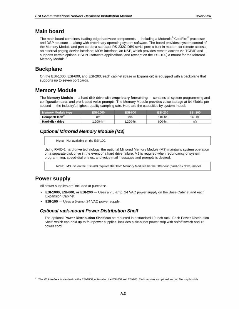
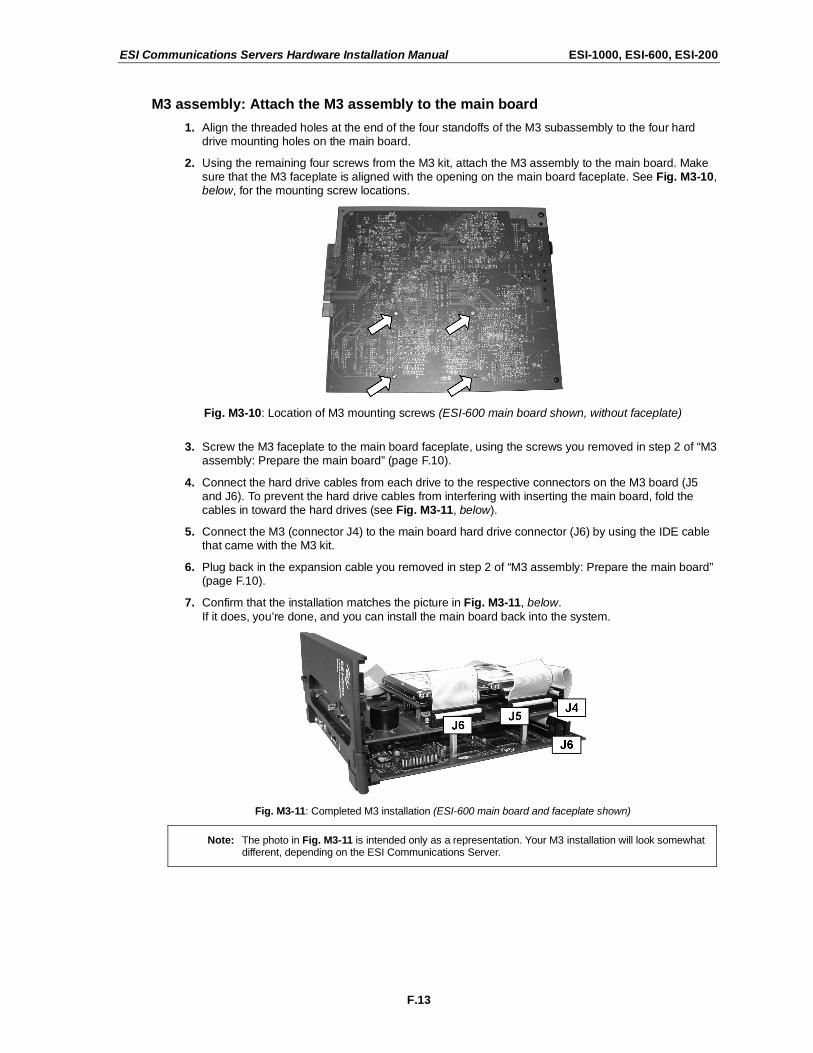
1. Align the threaded holes at the end of the four standoffs of the M3 subassembly to the four hard drive mounting holes on the main board.
2. Using the remaining four screws from the M3 kit, attach the M3 assembly to the main board. Make sure that the M3 faceplate is aligned with the opening on the main board faceplate. See Fig. M3-10, below, for the mounting screw locations.
Fig. M3-10: Location of M3 mounting screws (ESI-600 main board shown, without faceplate)
3. Screw the M3 faceplate to the main board faceplate, using the screws you removed in step 2 of “M3 assembly: Prepare the main board” (page F.10).
4. Connect the hard drive cables from each drive to the respective connectors on the M3 board (J5 and J6). To prevent the hard drive cables from interfering with inserting the main board, fold the cables in toward the hard drives (see Fig. M3-11, below).
5. Connect the M3 (connector J4) to the main board hard drive connector (J6) by using the IDE cable that came with the M3 kit.
6. Plug back in the expansion cable you removed in step 2 of “M3 assembly: Prepare the main board” (page F.10).
7. Confirm that the installation matches the picture in Fig. M3-11, below.
If it does, you’re done, and you can install the main board back into the system.
Fig. M3-11: Completed M3 installation (ESI-600 main board and faceplate shown)
Note: The photo in Fig. M3-11 is intended only as a representation. Your M3 installation will look somewhat different, depending on the ESI Communications Server.
ESI Communications Servers Hardware Installation Manual ESI-1000, ESI-600, ESI-200
F.14
Mirroring operation
On system power-up — e.g., at initial installation or whenever a drive is replaced — the M3 will first verify that
each drive is an ESI-formatted drive. If so, it then will transfer all data from the primary drive to the mirroring drive. This process can take anywhere from a few minutes to one hour, depending on system activity, amount of voice message storage, and configuration. System operation won’t be affected during the data transfer, because this transfer will occur only when call-processing is making no disk drive access requests.
If a primary drive is replaced, data will be copied in the same fashion from the mirror drive to the new primary drive. Again, the replacement drive must be a new, unprogrammed ESI drive. If it’s not, the system may copy all data in the wrong direction — i.e., from the new (mostly empty) primary drive to the mirror drive! Therefore, ESI recommends that the mirror drive be moved to the primary drive mounting position and the
new drive be mounted on the mirror drive mounting position.
Note: Once a hard drive has been copied, if it is removed and installed on a different system, the system will automatically initialize the drive, erasing all data and voice messages.
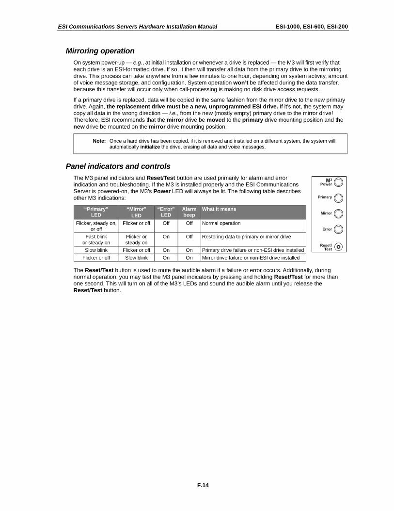
Panel indicators and controls
The M3 panel indicators and Reset/Test button are used primarily for alarm and error indication and troubleshooting. If the M3 is installed properly and the ESI Communications Server is powered-on, the M3’s Power LED will always be lit. The following table describes other M3 indications:
“Primary” LED
“Mirror”
LED
“Error” LED
Alarm beep
What it means
Flicker, steady on, or off
Flicker or off Off Off Normal operation
Fast blink or steady on
Flicker or steady on
On Off Restoring data to primary or mirror drive
Slow blink Flicker or off On On Primary drive failure or non-ESI drive installed
Flicker or off Slow blink On On Mirror drive failure or non-ESI drive installed
The Reset/Test button is used to mute the audible alarm if a failure or error occurs. Additionally, during normal operation, you may test the M3 panel indicators by pressing and holding Reset/Test for more than one second. This will turn on all of the M3’s LEDs and sound the audible alarm until you release the Reset/Test button.

ESI Communications Servers Hardware Installation Manual ESI-1000, ESI-600, ESI-200
F.15
LED functions
The unit's various LEDs are designed to provide visual feedback as follows:
Power LED
The Power LED is located on the right side of the main board’s faceplace, and is illuminated when power is being applied to the system. This LED blinks periodically to indicate that the main processor is operational.
Port LEDs
The Port LEDs are located above their respective connectors on each installed port card. Each LED is
illuminated when any port on its associated port card is in use.
Note: Disconnecting a connector when its respective LED is lit will disconnect any of its ports that are in use.
Upon power-up, approximately five minutes are required for the system to configure. The Power and Port LEDs will blink three times to indicate that the power-up sequence has been completed.
Note: When a DLC’s LED is . . .
• . . . blinking, the T1/PRI circuit is out of service. • . . . not lit at all, the T1/PRI circuit is in service but is idle. • . . . lit solidly, the T1/PRI circuit and/or a station on the card are in use.
Memory Transfer LED
This LED is located inside the cabinet under the Memory Module, at the back of the main board. It serves as
a diagnostic aid by flashing as data is transferred to and from the Memory Module.
ESI Presence Management installation
For information on installing ESI Presence Management, see its Installation Manual (ESI # 0450-0792).

ESI Communications Servers Hardware Installation Manual ESI-100
G.1
Hardware installation: ESI-100
Site location
As with most electronic equipment, the environmental considerations for this site need to observe good common sense. Provide a dry, clean, and accessible area.
Locate space in the telephone equipment room, which will provide easy connection to the 66 blocks and 110 VAC power. The location should be no further than 1,000 feet from the farthest station.
Ambient room temperature must be 400 –80
0 (F.), and relative humidity no higher than 90%.
Notes: Do not place the equipment or run station cabling near high voltage electrical equipment or electrical lines susceptible to high voltage surges from air conditioner compressors, etc.
Do not mount the equipment in a place that receives direct sunlight.
The system and supporting components should be mounted to a half-inch (or thicker) plywood backboard. Here is the layout of a typical Base Cabinet installation.
ESI-100 Base Cabinet typical installation

ESI Communications Servers Hardware Installation Manual ESI-100
G.2
Opening the Base Cabinet
The lid on the Base Cabinet is held in place by two tabs that rest in slots in the bottom of the case, and a release tab that snaps into an opening in the top-center of the cabinet and is secured by a retaining screw.
To remove the lid:
1. Remove the retaining screw and depress the release tab at the top of the cabinet.
2. Rock the lid back from the top.
3. Lift and pull the lid free from the slots in the bottom of the cabinet.
Mounting the Base Cabinet
To mount the ESI-100 Base Cabinet, use the three provided #8 Phillips screws. Note the position of the three mounting holes in the cabinet. Allow room for installation of the Expansion Cabinet (see page G.3) either now or, if required, in the future.
1. Screw in the top screw to the backboard (at least half-inch thick
plywood) leaving about one-eighth-inch clearance between the screw head and the plywood.
2. Hang the unit using the keyhole at the top of the case.
3. Level the unit and install the bottom two screws.
Attach the power transformer to the wall, allowing sufficient length in both cords to reach the power connector on the upper right side of the cabinet and to reach a UPS or a dedicated 110 VAC outlet.
Base Cabinet

ESI Communications Servers Hardware Installation Manual ESI-100
G.3
Expansion Cabinet installation
The Expansion Cabinet allows the ESI-100’s capacity to grow by up to two additional port cards. The cards are connected via ribbon cables, through the opening in the back of the Expansion Cabinet, to the Base Cabinet.
Note: You can add only one Expansion Cabinet to an ESI-100.
To install an Expansion Cabinet:
1. Wear a grounding strap and avoid unnecessary movement while handling the circuit boards.
2. Unplug the power to the ESI-100 system.
3. Remove the Base Cabinet lid by pressing the release tab at the top of the cabinet and rock back the lid from the bottom of the cabinet.
4. Install the Expansion Cabinet on the front of the Base Cabinet in place of the Base Cabinet's lid.
5. Lock the Expansion Cabinet to the Base Cabinet by snapping the top in place and reinstalling the retaining screw.
6. Connect the grounding strap from the Expansion Cabinet's grounding lug (located on the bottom of the cabinet) to the Base Cabinet's grounding lug. (See also “Grounding instructions,” page H.1).
7. Through the large opening in the back of the Expansion Cabinet,
connect the ribbon cable(s) from the port card(s) to the card directly below.
8. Re-install the original lid from the Base Cabinet on the face of the Expansion Cabinet.
Port card installation
Adding or replacing port cards will require the system to be taken out of service (the ESI-100 doesn’t support “hot-swapping” of its port cards).
Notes: The ESI-100 can use only E2 port cards (see “Port card options,” beginning on page A.3).
ALWAYS power down the system BEFORE adding or replacing any hardware. Also, be sure to observe all proper procedures regarding the prevention of electrostatic discharge (ESD) when performing the
following procedures; otherwise, circuit boards may suffer damage.
Whenever you change the port card configuration, you must create a backup file for the new configuration to be able to perform the Restore function later.
After removing the E2 port card from the box, install it as follows:
1. Unplug the power supply to the system.
2. Remove the locking screw (at the top of the cabinet, securing
the cover), and then remove the top cover by pressing down the locking tab and pulling the top cover forward (Fig. PC-1).
Note: Port cards are added to an existing Base Cabinet in a “piggyback”
fashion — i.e., port card 2 (J1) plugs into port card 1 (J2), port card 3 (J1) plugs into port card 2 (J2), etc.
(Continued)
Fig. PC-1

ESI Communications Servers Hardware Installation Manual ESI-100
G.4
3. A cable is attached to Connector J1 of the E2 port card. Connect the cable’s other end to Connector J2 of the cabinet’s existing port card.
4. Secure the E2 port card to the cabinet (Fig. PC-2).
If it’s going into the top slot, use five screws. If it’s going into the bottom slot, use five standoffs appropriately:
• 7/16-in. standoffs — Between the Base Cabinet and the first card.
• 3/4-in. standoffs — Between the first and second card in the Base Cabinet.
• 1-in. standoffs — Between port cards in the Expansion Cabinet.
Use the screws that ship with the E2 port card to secure the card to the standoffs. (You may have leftover screws.) DON’T overtighten the standoffs; it will strip the plastic bosses.
5. Put the top cover back on the cabinet, and then replace the locking screw to secure the cover on the cabinet. (In other words, perform the reverse of Step 2.)
6. To remove the E2 port card, follow steps 2–5 in reverse order.
Fig. PC-3 (right) shows the configuration of a fully loaded ESI-100.
Fig. PC-2
Fig. PC-3

ESI Communications Servers Hardware Installation Manual ESI-100
G.5
Memory Module installation or replacement
Note: The Memory Module has a proprietary formatting scheme — do not attempt to install a non-ESI drive. Contact ESI for a replacement Memory Module, if needed.
Adding or replacing the Memory Module will require that the ESI-100 be taken out of service. All of the ESI-100’s configuration data and customer recordings are stored in the Memory Module. Replacing it, therefore, requires re-programming and re-recording, unless you have previously performed a backup using ESI System Programmer software. (Prompts stay intact, however.)
Note: Be sure to observe all proper procedures regarding the prevention of electrostatic discharge (ESD) when
performing the following procedures; otherwise, circuit boards may suffer damage.
Install the CompactFlash Memory Module
1. Open the lid of the cabinet (you must remove the screw on the top that secures the lid).
2. Power down the system.
3. Plug the Memory Module into the J14 connector on the main board (see diagram, right).
4. Secure the lid to the KSU.
Remove the CompactFlash Memory Module (if replacing)
1. Open the lid of the cabinet (you must remove the screw on the top that secures the lid).
2. Power down the system.
3. Remove the Memory Module from the J14 connector on the main board (see diagram, right).
4. To install the Memory Module, follow the steps in “Install the CompactFlash Memory Module,” above.

ESI Communications Servers Hardware Installation Manual ESI-100
G.6
LED functions
The unit's various LEDs are designed to provide visual feedback as follows:
Power LED
The Power LED is located on the right side of the Base Cabinet, and is illuminated when power is being applied to the system. This LED blinks periodically to indicate that the main processor is operational.
Port LEDs
The Port LEDs are located above their respective connectors on each installed port card. Each LED is
illuminated when any port on its associated port card is in use.
Note: Disconnecting a connector when its respective LED is lit will disconnect any of its ports that are in use.
Upon power-up, approximately five minutes are required for the system to configure. The Power and Port LEDs will blink three times to indicate that the power-up sequence has been completed.
Note: When a DLC’s LED is . . .
• . . . blinking, the T1/PRI circuit is out of service. • . . . not lit at all, the T1/PRI circuit is in service but is idle. • . . . lit solidly, the T1/PRI circuit and/or a station on the card are in use.
ESI Presence Management installation
For information on installing ESI Presence Management, see its Installation Manual (ESI # 0450-0792).

ESI Communications Servers Hardware Installation Manual External connections
H.1
External connections
Grounding instructions
System grounding (supplemental ground) is as follows:
• The conductor wires can be no smaller than the ungrounded branch-circuit supply conductors (usually 16-gauge or higher).
• Acceptable wire: bare or covered with green (or green-and-yellow-striped) jacket.
• Conductors (and power receptacles) shall connect to earth ground at the service equipment (usually a cold water pipe or copper ground rod).
• The supplemental ground must: be used regardless of power cord ground, be connected to the ground lug on the bottom of the cabinet, and retain ground connection when the power supply module is unplugged.
• Connect the grounding lugs of all units to system ground
Note: ESI Communications Server lines are protected against a 10 KV surge only if the earth ground procedures described above are followed.
Power
Each cabinet requires a 110 VAC outlet (if possible, a dedicated outlet). Use only the Class-2 power supply module provided. A clean, isolated power source in conjunction with a UPS is STRONGLY recommended.
The following table shows the power consumption of each ESI Communications Server when fully loaded:
System Cabinets (Base and Expansion) in fully loaded system
Power consumption (in watts)
ESI-1000 6 1,080
ESI-600 4 720
ESI-200 2 360
ESI-100 2 125
If AC power is interrupted, the system will drop all connections. When power is restored, the system will resume
normal operation in approximately five minutes, having retained its full programming and clock setting.
UPS
For system protection and to maintain uninterrupted operation, an uninterruptible power supply is STRONGLY recommended. Here are the recommended UPS ratings for each system:
System Recommended UPS minimum rating
PER INSTALLED CABINET (in VA)
ESI-1000 230
ESI-600 230
ESI-200 230
ESI-100 125
Refer to the particular UPS unit’s specifications to determine expected backup duration during a power outage.
Note: The remaining information under “UPS” comes from Technical Update #216.
Most people have heard about UPSs, but seem to think that there is just one kind of device that goes by that name. In fact, there are several different major designs in use by today’s major UPS manufacturers. These makers share much of the blame for confusing UPSs’ end users by, far too often, lumping different designs
under the “UPS” name.
(Continued)

ESI Communications Servers Hardware Installation Manual External connections
H.2
UPSs can first be broken down into system types:
• Stand-by — A very simple design that affects power only when either a lag/brownout occurs below, or a spike/surge occurs above, a certain threshold. When either occurs, the unit trips — i.e., goes into battery mode. This "cleans" the voltage and helps to keep any load safe. Industry average "trip" times are 2–8 ms. No other filtration of AC power is performed.
• Line interactive — Constantly monitors inbound voltages, and uses special circuitry to boost low voltages and clamp high voltages without having to use the batteries. Indeed, the batteries are used only if the input voltage drops below acceptable levels (typically about 12% below normal), goes out completely or rises to dangerous levels (typically about 14% above normal) at which components will be damaged if line voltage is not removed. Industry average transfer time is 1–3 ms. (If voltage stays within its normal window, this unit continues to pass voltage, unaltered, from the wall.)
• On-line (or full on-line) — Constantly filters the power and performs a function known as double conversion (AC to DC to AC). This assures that the load — in this case, phone equipment — will receive not only uninterrupted, true sine wave output but also the cleanest, steadiest power possible throughout any foreseeable power disruptions or voltage irregularities. According to industry specs, it is not unusual
for these types of units to be able to regulate utility power, even when it drops to 27% below or rises to 33% above normal, all without using their batteries.
From this point, UPSs can be further broken down by inverter types, which determine output. These are:
• Square wave.
• Modified sine wave (or quasi sine wave).
• Sine wave.
Most devices with wall-mounted chargers, such as cordless drills or screwdrivers, can behave erratically —
sometimes not allowing the charge circuit to engage at all — when operating with modified sine or square wave inverters. Small wall-based transformer-style power supplies, similar to those ESI phone systems use, can experience overheating problems with modified sine or square wave outputs, which occur while some UPSs are operating in battery mode. This overheating could eventually cause damage to the power supplies;
and, in time, the damage could cause a spike through the phone system — seriously damaging some of the static-sensitive components inside the casing.
While the true sine wave UPS output power curve smoothly increases to its peak, then smoothly decreases (allowing connected loads and equipment to operate the same as they would from utility supplied wall power), the modified sine wave and square wave UPS output power curve will shoot straight up, level off at peak voltage and then drop straight down. Additionally troublesome is that the modified sine wave sits at zero voltage for a short period during the transition to or from batteries — which is the main difference between it and the square wave output of some UPS. Please note that this short interval during which the
modified sine wave UPS sits at zero voltage can directly affect the transfer time of the UPS and could, theoretically, be enough to cause the phone equipment to reset or even “freeze.”
Though it is hard to predict exactly when different ESI systems will have problems with modified sine wave or square waveform UPSs (meaning during a power failure event or the recovery from one), it’s fair to assume that a problem will eventually arise from the use of such UPSs. Therefore, ESI recommends that only true sine wave output UPSs provide backup power to our phone systems and equipment.

ESI Communications Servers Hardware Installation Manual External connections
H.3
MOH port
The MOH (messages-, or music-, on-hold) connector — located on the main board faceplate (ESI-1000, ESI-600, and ESI-200) or the Base Cabinet’s right side (ESI-100) — is a standard
1/8″ monophonic mini-jack, used for
loading custom MOH recordings or for playing live music-on-hold from an external source such as a CD player.
Maintenance/SMDR serial port
The Maintenance/SMDR port is a standard DB9 serial connector, located on the main board faceplate (ESI-1000, ESI-600, and ESI-200) or the Base Cabinet’s right side (ESI-100). Use a standard shielded serial cable,
DB9-to-DB9, for printer-to-computer; this is usually male-to-female.
Note: The maximum distance from the cabinet is 100 ft.
The output from the Maintenance/SMDR port is, 8 data bits, 1 stop bit, and no parity. The pinout is:
Data Transmit Pin 2
Receive Pin 3
Ground Pin 5
To program this port, use Function 18 as described in the ESI Communications Servers Programming Manual (ESI #0450-1050).
Range: Programmable for 300, 1,200, 2,400, 4,800, 9,600, 19,200, 38,400, 57,600, or 115,200 bps. Default: 38.4K.
Maintenance
Connect a PC (such as a laptop) to the port to perform on-line programming and diagnostics. Also, the system sends reports to this port.
SMDR
The ESI Communications Server continuously outputs real-time SMDR call records to the port.
Note: The system will buffer up to a specific limit of SMDR records (60,000 on the ESI-1000, or 1,000 on other ESI Communications Servers) in non-volatile memory when the Maintenance/ SMDR serial port is in use for programming or uploading (such as during use of ESI System Programmer). If the buffer
becomes full, the system will discard the oldest records.
For more information about the Maintenance/SMDR port, see “SMDR” in the ESI Communications Servers Programming Manual (ESI #0450-1050).

ESI Communications Servers Hardware Installation Manual External connections
H.4
External paging device connection
ESI-1000 and ESI-600
On either of these systems, a dry-contact overhead-paging device can be connected through the RJ-11 OH Paging connector, which is located on the front of the main board faceplate just below the NSP’s Ethernet connector. Although this is a six-pin connector, only two pairs are needed between the paging device and the connector:
• To pin-out the connector for normally open operation, connect the audio wires to pins 3 and 4 and the control pair to pins 1 and 2.
• To pin-out the connector for normally closed operation, connect the audio wires to pins 3 and 4 and the control pair to pins 5 and 6.
ESI-200 and ESI-100
A dry contact overhead-paging device can be connected to the system through the first port card's 66 block.1
The overhead paging port is fixed (located on the main board) as code 599 for programming purposes and
user access. (See “Worksheet” wiring charts, page H.22.)
Audio connection
The audio pair is connected to the 66 block at terminal 33 and 34. The pair’s impedance is 600 ohms.
Note: The port doesn’t support talk-back paging (which requires a CO port), nor does it support CO ring through the port.
Dry-contact control
The manner in which the dry-contact pair is punched down on the 66 block sets the pair as normally open (sending a page to the port will close the contacts) or normally closed (sending a page to the port will open the contacts).
Connect the dry-contact pair of the device to the ESI Communications Server as follows:
• Terminals 35 and 36 to provide normally open operation; or
• Terminals 36 and 38 to provide normally closed operation.
The port can be used with zone paging units.
Note: ESI doesn’t recommend the use of paging contacts for door-unlocking mechanisms.
Programming
To access the overhead paging port, assign feature code 5 9 9 to a programmable feature key.
Amphenol cable connections
Connect a standard 66 block to each digital port card by using a male 50-pin amphenol cable to each port card female connector located on the cabinet. On the ESI-100, the connector closest to the wall is the first card; on other ESI Communications Servers, the connector in the leftmost slot is the first card.
1 If an IVC is installed in slot 1 on the ESI-1000, ESI-600, or ESI-200, the audio connection and dry-contact control connect via the second port card.
(On an ESI-200, a non-IVC card must be in slot 1 or 2; on an ESI-100, a non-IVC card must be in slot 1.)

ESI Communications Servers Hardware Installation Manual External connections
H.5
CO line connection
Note: For greatest simplicity, this section mentions each port card without the use of an “ESI,” “E2-,“ or “CS-“ prefix, as cards otherwise are functionally identical — e.g., we refer to an E2-684 or CS-684 as just a “684.”
Local loop
An ESI Communication Server’s advanced CO line circuitry provides for open loop detection and the
system’s built-in Caller ID interface. Loop start lines are connected via the last 6 pairs on each 66 block on the 612 and 684 cards.
Note: Observe correct order of connection to preserve proper rotary hunting of the CO lines.
T1/PRI
For T1 or PRI applications, an ESI Communications Server can use either of the compatible digital line cards (DLCs): the DLC or the DLC12.
1 Depending on how you configure it, each supports either (a.) a single T1
circuit at 24 DS0 channels or (b.) a PRI circuit supporting 23 “B” (bearer) channels and one “D” (data link) channel. The DLC12 also supports 12 digital stations. The T1 or PRI line is connected via the last two pairs of the industry-standard 50-pin amphenol cable connector on the front of the DLC.
Each ESI Communications Server has a different maximum number of system-wide DLCs (see “Port card options,” page A.3). Partial T1 or PRI applications are supported through line programming.
Each DLC has built-in CSU functionality. The integrated CSU can be enabled or disabled via system programming
2. The following functionality is provided: line, payload, DTE and none (normal operation)
loopback modes with the ability to respond back controlled via system programming; alarm conditions, and both ANSI T1.403 and TR 54016 performance messages for ESF only.
Important: If you’re installing more than one T1 or PRI, the DLC in the lowest number slot will synchronize (“slave”)
the system with the public network. The system will synchronize to only one clock source. Therefore, ESI strongly recommends that the first DLC in the system be connected to the T1 or PRI that’s connected either to the local CO or the nationwide long-distance provider, either of which typically will provide very-high-accuracy clocking (Strata 3). The DLC doesn’t provide master or sub-master clocking for private-
network T1 spans.
(Continued)
1 You may wish to review “Port card options,” page A.3.
2 See the explanation of Function 2124 in the ESI Communications Servers Programming Manual (ESI #0450-1050).

ESI Communications Servers Hardware Installation Manual External connections
H.6
When working with a T1 line, the DLC card supports these trunk types:
• Loop start
• Ground start
• E&M (including E&M–DID/DNIS/ANI) — When an E&M trunk is selected, the choices for outgoing signaling type are immediate start, wink start and dial tone start; and the incoming signaling type choices are immediate start and wink start. The E&M trunk can be set for 2-way traffic, inbound traffic only or outbound traffic only.
The DID and DNIS/ANI translation table allows the translation of DID/DNIS digits to an ID, mailbox, extension
or department. See below for the number of entries that can be programmed in the table:
System Maximum DID entries
ESI-1000 1,200
ESI-600 600
ESI-200 300
ESI-100 300
There is also an entry for exceptions in the table. This allows reroutes of any DID/DNIS calls that aren’t programmed or detected to an ID, mailbox, extension or department and defaults to the operator.
The card supports the following framing format and line coding:
• ESF/B8ZS (default)
• SF(D4)/AMI
• ESF/AMI
• SF/B8ZS
Line compensation (or line build-out) is provided as necessary between the CSU or Smart Jack™ and the
ESI Communications Server. There won’t be any support for pulse dialing; all incoming dialing will default to
DTMF digits.
When working with a PRI line, the DLC supports these switch protocols:
• National-NI2 (default)
• Nortel-DMS100
• AT&T/Lucent-5ESS
• Siemens-EWSD
DID for the PRI is an enable/disable field. When DID is enabled, the PRI pilot table becomes active and works in combination with the DID tables.

ESI Communications Servers Hardware Installation Manual External connections
H.7
Station connection
The first 12 pairs on each Amphenol are station ports (12 digital stations on the 612, D12, or DLC12 card; eight digital stations and four analog ports on the 684 port card; 12 analog ports on the A12 card).
All stations are connected using a single pair. Each port position is pre-numbered and fixed as indicated in the 66 block wiring diagram shown for each port card type.
Note: The station runs can be up to 1,000 ft.
Digital stations
Digital stations for the ESI Communications Server include:
• ESI Digital Feature Phones
• ESI Digital Cordless Handsets
• ESI Presence Management RFID Readers1
The digital station wiring is not polarity-sensitive. Only one phone can be connected per digital port.
For proper operation, the combined length of feed cables, backbone cabling, cross-connect, and station cable must not exceed 1000 feet (304 meters) for digital stations. Station line cord length should not
exceed 12 feet (note that this is the length of the line cord ESI provides with each Digital Feature Phone).
Each digital station can have no more than two cross-connects or splices in the cable distribution. Cable construction, termination blocks, and modular jacks must meet
at minimum Category 3 cabling requirements. Additional splices or terminations will further reduce the maximum cable length at which the digital station will operate reliably.
Because of potential interference caused by electrical noise, ESI strongly recommends against distribution of digital stations with analog stations, T1 circuits, PRI circuits, or other circuits in the same cable binder or station run.
Analog ports
The analog ports do not require that tip-and-ring polarity be observed. The analog ports can be used for 2500-type sets or for devices such as fax machines, modems, etc., that can be connected via a normal tip-and-ring pair. Each analog port will support only a single analog device. (For total analog port capacity on each ESI Communications Server, see “System capacities,” page D.1.)
All analog ports provide Type I Caller ID information (Caller ID with call waiting is not supported).
1 For information on installing ESI Presence Management, see its Installation Manual (ESI # 0450-0792).

ESI Communications Servers Hardware Installation Manual External connections
H.8
Installing the TAPI Phone
Important: To install the TAPI drivers to a PC with Windows NT 4.0 where Service Pack 3 (or greater) hasn’t been installed, please obtain the latest Service Pack — currently, Service Pack 6a, or “SP6a” — from the
Microsoft Web site and install it before continuing. To reach a instructions for obtaining the needed Service Pack, visit http://support.microsoft.com/kb/152734.
Requirements
To perform this installation, you will need:
• A TAPI Phone (48-Key Digital Feature Phone with TAPI interface).
• A PC running Windows 95, 98, ME, NT, 2000 or XP and with an unused COM (serial) port.
• TAPI cable and adapter (shipped with each TAPI Phone).1
Also, if Caller ID integration is desired, you should confirm that (a) Caller ID is enabled on the ESI phone system and (b) the telephone company is providing Caller ID service.
Procedure
Note: If using the CD-ROM shipped with the TAPI Phone (first purchase only), proceed to Step 1. Otherwise, skip to Step 2.
1. Insert into the PC’s CD-ROM drive the CD-ROM you received with your first purchase of one or more TAPI Phones; then browse to the CD-ROM drive and locate the Esiivx.exe file. (Depending on your settings, the file may appear as just Esiivx.
2) Skip to Step 5.
2. Use your Web browser to reach www.esiresellers.com/software. (You’ll need your ESI Resellers’ site password, which is different from your Tech Support password.)
3. To download the software, scroll to and then click the link to the TAPI 2000 software listed under
“ESI/IVX TAPI Phones, both current and legacy.”
4. When prompted, select a folder in which to save the software. (We suggest C:\Windows\Temp.)
5. The software is a self-extracting installer. To launch the installation process, browse to the Esiivx.exe file and double-click it.
6. If asked whether you wish to continue, click Yes. Then, follow the instructions that appear.
7. At the end of the installation, you’ll be prompted whether you wish to restart the PC. Click Finish.
8. As the PC restarts, a window will appear asking you to select the COM (serial) port that will be used for TAPI activity. Select the appropriate port and click OK.
9. Connect one end of the provided serial cable to the PC serial port selected in Step 8. Connect the other end to the bottom of the TAPI Phone (see diagram, right).
You have now successfully installed the TAPI 2000 Windows telephony driver. Continue to the next page to test the operation of the TAPI interface.
1 If the PC has a 25-pin serial connector, you’ll need to obtain a DB9-male-to-DB25-female adapter (such as Radio Shack
® model # 26-287).
2 We suggest that you change your Windows Explorer settings so that the file extension always appears in file listings. Here’s how:
a. In Windows Explorer, click the View menu and select Folder Options. b. In the Folder Options window, click the View tab. c. Locate the item entitled Hide extensions for known file types and make sure that this item isn’t checked (if it is, uncheck it). d. Click OK to finish.
Connectors on bottom of TAPI Phone
Line cord to wall
To 60-Key Console
Handset
(TAPI) to PC
To headset

ESI Communications Servers Hardware Installation Manual External connections
H.9
Testing TAPI
Windows includes a simple TAPI application, Phone Dialer1. It can be used to test the TAPI interface by dialing a
phone number. Two versions of Phone Dialer are currently available. Depending on which version of Windows you have, follow the appropriate test procedure for the Phone Dialer software on your PC.
Testing with Phone Dialer (Windows 95/98/ME)
1. Click the Windows Start button; then click Run, type Dialer in the Run window and click OK. This will start the file Dialer.exe.
2. In the Phone Dialer window, click the Tools menu; then click Connect Using...
3. In the Line field, select ESI IVX Telephony Service Provider and click OK.
4. Once again, click Tools; then click Dialing Properties...
5. Enter the local area code and the appropriate access codes for an outside line; to insert a pause, use a comma (e.g., for local calls, you might use 9,).
6. Make sure the To disable call waiting, dial: box is not checked. Then, click OK.
7. In the Phone Dialer window, enter the number to dial and click Dial.
8. If the TAPI installation was successful, the phone’s SPEAKER key will light up and you’ll hear the phone number being dialed. If the call can’t be completed, add one or more commas to the outside access codes; also, verify that the other dialing properties are correct for the area from which you’re calling.
Testing with Phone Dialer 1.0 (Windows NT/2000/XP)
1. Click the Windows Start button; then click Run, then click Run, type Dialer in the Run window and click OK. This will start the file Dialer.exe.
2. In the Phone Dialer window, click the Edit menu; then click Options.
3. In the Options window, click Phone and Modems Option.
4. In the Phone and Modems window, a location entry should be highlighted. Click Edit.
5. In the Edit Locations window, enter the local area code and the appropriate access codes for an
outside line; to insert a pause, use a comma (e.g., for local calls, you might use 9,).
6. Make sure the To disable call waiting, dial: box is not checked. Then, click OK.
7. In the Phone and Modem Options window, click OK.
8. In the Options window, under Line Used For..., select ESI IVX Telephony Service Provider and click OK.
9. In the Phone Dialer window, click Dial and enter the number to dial in the Dial window. Then, click the Phone Call radio button, followed by the Place Call button.
10. If the TAPI installation was successful, the phone’s SPEAKER key will light up and you’ll hear the phone
number being dialed. If the call can’t be completed, add one or more commas to the outside access codes; also, verify that the other dialing properties are correct for the area from which you’re calling.
Proceeding to use TAPI
The TAPI interface is now ready to be integrated with the user’s preferred TAPI-enabled application. For instructions on connecting to the TAPI driver, refer to the documentation for that application.
1 If Phone Dialer isn’t installed on the PC, have the customer’s IT System Administrator install (or re-install) Phone Dialer from the original Windows
installation CD-ROM.
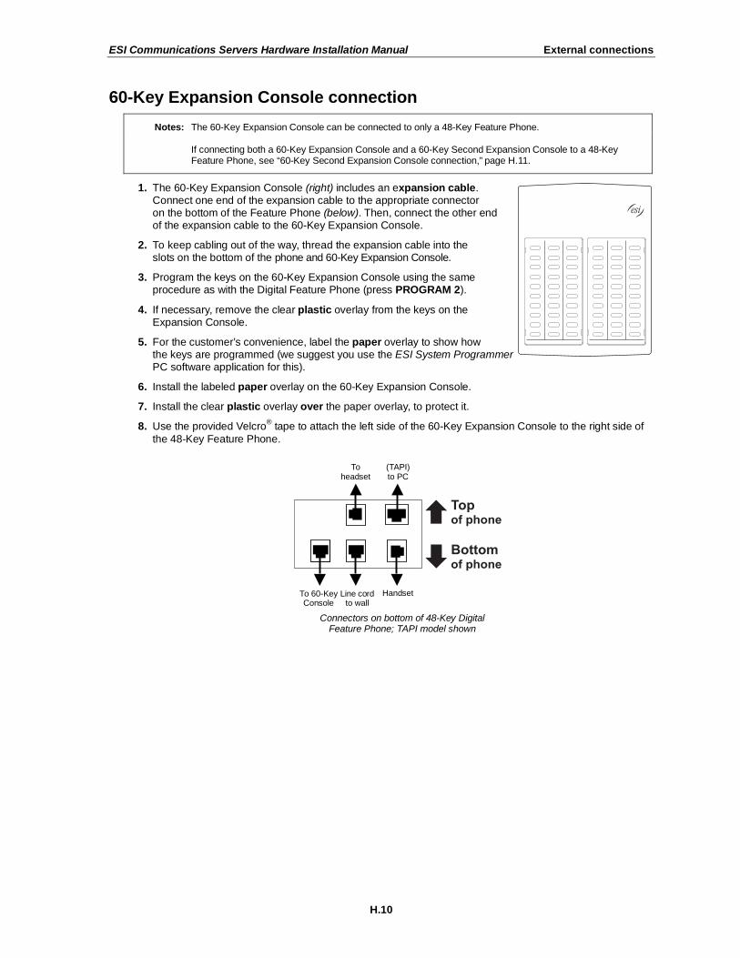
ESI Communications Servers Hardware Installation Manual External connections
H.10
60-Key Expansion Console connection
Notes: The 60-Key Expansion Console can be connected to only a 48-Key Feature Phone.
If connecting both a 60-Key Expansion Console and a 60-Key Second Expansion Console to a 48-Key Feature Phone, see “60-Key Second Expansion Console connection,” page H.11.
1. The 60-Key Expansion Console (right) includes an expansion cable. Connect one end of the expansion cable to the appropriate connector on the bottom of the Feature Phone (below). Then, connect the other end of the expansion cable to the 60-Key Expansion Console.
2. To keep cabling out of the way, thread the expansion cable into the slots on the bottom of the phone and 60-Key Expansion Console.
3. Program the keys on the 60-Key Expansion Console using the same procedure as with the Digital Feature Phone (press PROGRAM 2).
4. If necessary, remove the clear plastic overlay from the keys on the Expansion Console.
5. For the customer’s convenience, label the paper overlay to show how the keys are programmed (we suggest you use the ESI System Programmer PC software application for this).
6. Install the labeled paper overlay on the 60-Key Expansion Console.
7. Install the clear plastic overlay over the paper overlay, to protect it.
8. Use the provided Velcro® tape to attach the left side of the 60-Key Expansion Console to the right side of
the 48-Key Feature Phone.
Connectors on bottom of 48-Key Digital Feature Phone; TAPI model shown
Line cord to wall
To 60-Key Console
Handset
(TAPI) to PC
To headset

ESI Communications Servers Hardware Installation Manual External connections
H.11
60-Key Second Expansion Console connection
Notes: If connecting only one Expansion Console to a 48-Key Feature Phone, see “60-Key Expansion Console connection,” page H.10.
The 60-Key Second Expansion Console connects to the 60-Key Expansion Console and cannot connect directly to the 48-Key Feature Phone (the only phone to which you can connect a 60-Key Expansion Console).
1. The Second Expansion Console (which is physically identical to a 60-Key Expansion Console) includes an expansion “Y” cable (right)
1.
Lay out the cable across the back
of the equipment so that the AC adapter is on left and the end of the cable is on the right.
2. Connect the right end of the expansion “Y” cable to the appropriate connector on the bottom of the 48-Key Feature Phone (below).
3. Then, connect the expansion “Y” cable’s middle plug to the 60-Key Expansion Console, the left plug to the Second Expansion Console, and the AC adapter to an appropriate 110 VAC outlet to provide power to
the Second Expansion Console (above).
4. To keep cabling out of the way, thread the expansion “Y” cable into the slots on the bottom of the phone and the two Expansion Consoles.
5. Program the keys on the two Expansion Consoles using the same procedure as with the Digital Feature Phone (press PROGRAM 2).
6. If necessary, remove the clear plastic overlay from the keys on the two 60-Key Expansion Consoles.
7. For the customer’s convenience, label the paper overlay to show how the keys are programmed (we suggest you use the ESI System Programmer PC software application for this).
8. Install the labeled paper overlays on the two 60-Key Expansion Consoles.
9. Install the clear plastic overlays over the paper overlays, to protect them.
10. Use the provided Velcro® tape to attach the left side of the 60-Key Expansion Console to the right side of
the 48-Key Feature Phone, and the right side of the 60-Key Expansion Console to the left side of the Second Expansion Console).
1 This diagram shows the backs of the Expansion Consoles.
Connectors on bottom of 48-Key Digital Feature Phone; TAPI model shown
Line cord to wall
To 60-Key Console
Handset
(TAPI) to PC
To headset

ESI Communications Servers Hardware Installation Manual External connections
H.12
Installing ESI’s Cordless Handsets
Each ESI Cordless Handset comes with:
• A charger/cradle to charge the Handset.
• An AC adapter for use with only the charger.
• A base station to provide a digital interface between the ESI phone system and ESI Cordless Handset.
This base station needs no AC power: if the Cordless Handset is digital, the base station is line-powered; if the Cordless Handset is IP, the base station uses Power over Ethernet (PoE).
• Wall-mount(s), a belt clip, and a Quick Reference Guide.
Each ESI Cordless Handset is keyed to only one base station and takes up one port (digital or IP) on a port card.
Base station installation
Due to each site’s unique characteristics, the range and distance information we’ll provide herein is only approximate.
Characteristics that positively affect performance:
• The base station should be installed so it has a clear line-of-sight with the Cordless Handset.
• The base station antenna should always be pointed in its uppermost vertical position.
Characteristics that negatively affect performance:
• Large amounts of metal shelving (such as in manufacturing or warehouse areas).
• Close proximity to (within one mile of) a radio tower.
• Concrete walls that divide spaces where Cordless Handsets are used (assuming the base stations are in one location).
Don’t install the base station:
• Close to a wall with metal studs.
• On a metal wall.
• Next to a device that emits RFI or EMI1 — e.g., a television, radio, computer, computer printer,
fluorescent light fixture, or fax machine.
• Next to any other 900 MHz device — e.g., a hand-held inventory control device.
• In a ceiling that has foil-backed insulation.
• Behind doors that typically are closed, tinted windows, one-way glass, or other areas that limit or cut off transmission to the Cordless Handset.
Base stations must be installed at least 10 feet apart, regardless of whether the base station is for the small-model or large-model Cordless Handset. Don’t install more than six base stations in one area
(such as a network room). Choose a location at least 30 feet away if more than six base stations are needed in a building.
(Continued)
1 RFI is radio frequency interference. EMI is electromagnetic interference.

ESI Communications Servers Hardware Installation Manual External connections
H.13
A Digital Cordless Handset base station requires only a line cord to the phone system; AC power isn’t needed because the base station receives power from the phone system via the line cord.
An IP Cordless Handset base station receives PoE. If PoE isn’t already being supplied, you’ll need to install a separately purchased PoE adapter. ESI recommends the 3Com 3CNJPSE PoE adapter (see diagram, right; Remote IP Cordless Handset base station shown). Such an adapter also will require an additional Ethernet cable, another separate
purchase, for connecting the PoE adapter to the base station.
Note: If the PoE equipment plugs into AC outlets and a power failure occurs, all IP Cordless Handsets on the system will be unable to originate or receive phone calls. Therefore, either: (a.) use an appropriately
sized uninterruptible power supply (UPS) to power all the IP equipment (base station, PoE adapter, router, etc.) involved in making phone calls or (b.) have a traditional POTS (“plain old telephone service”) phone available for originating and receiving analog CO calls.
Once the base stations are installed and the Cordless Handsets charged, change each Handset’s channel by pressing its CH key. Each Handset should have its own channel. There are 30 available channels on the small Cordless Handset and 10 on the large Cordless Handset.
Note: Feedback may result if the Cordless Handset is within three inches of an ESI desktop Feature Phone.
In case of trouble
If you have followed the guidelines described herein and still encounter problems with ESI Cordless Handsets, please call ESI Technical Support at 800 491-3609 or e-mail to [email protected]. When contacting ESI Technical Support, be sure to have as much of the following site and usage information as possible:
• Square footage of the building.
• Layout of building/offices, and locations of base stations. This can be a hand-drawn diagram with locations of base stations (you can fax it to ESI at 972 422-9705; be sure to indicate that it goes to Technical Support). The objective is to give the ESI technician an idea of the site’s layout.
• Number of large and small Cordless Handsets, and how many are of each type (digital, Local IP, or Remote IP).
• How the troublesome Cordless Handset is being used. For example:
– A large handset at the site may be used by a supervisor who travels the entire area of the building many times per day.
– A small handset may be used only by an administrative assistant to go a short distance from an office to a copy room.
• Where the problem occurs — e.g., if a Cordless Handset cuts in and out when used in a certain area of the building.
(Continued)

ESI Communications Servers Hardware Installation Manual External connections
H.14
ESI Cordless Handset specifications
Small Handset Large Handset
Fully charged battery life Approx. 7 hrs. Approx. 10 hrs.
Recharge time Approx. 5 hrs. Approx. 5 hrs.
Standby time Approx. 5 days Approx. 4 days
Approximate range1 200 ft. 400 ft.
Weight (including battery) 5.2 oz. 8.8 oz.
Size, W D H (in.) 2 1.25 5.5 without antenna 2.2 1.67 8.67 with antenna
Accessories
ESI sells separately a headset for both ESI Cordless Handset models, and this is the only headset ESI supports for use with the ESI Cordless Handset.
For more information on accessories for the ESI Cordless Handset, refer to your appropriate Price Schedule or the ESI Cordless Handset Product Overview (ESI # 0450-0840).
1 Interference may result if cordless base stations are installed within 10 feet of each other. Ranges are approximate, and are dependent on each
site’s unique characteristics. Feedback may result if the Cordless Handset is within three inches of the ESI desktop phone.

ESI Communications Servers Hardware Installation Manual External connections
H.15
Port card connections
E2-A12 port card • CS-A12 port card
Term Wire color Signal RJ11 Port
1 White-Blue Tip Green
2 Blue-White Ring Red
Analog
3 White-Orange Tip Green
4 Orange-White Ring Red
Analog
5 White-Green Tip Green
6 Green-White Ring Red
Analog
7 White-Brown Tip Green
8 Brown-White Ring Red
Analog
9 White-Slate Tip Green
10 Slate-White Ring Red
Analog
11 Red-Blue Tip Green
12 Blue-Red Ring Red
Analog
13 Red-Orange Tip Green
14 Orange-Red Ring Red
Analog
15 Red-Green Tip Green
16 Green-Red Ring Red
Analog
17 Red-Brown Tip Green
18 Brown-Red Ring Red
Analog
19 Red-Slate Tip Green
20 Slate-Red Ring Red
Analog
21 Black-Blue Tip Green
22 Blue-Black Ring Red
Analog
23 Black-Orange Tip Green
24 Orange-Black Ring Red
Analog
25 Black-Green
26 Green-Black
27 Black-Brown
28 Brown-Black
29 Black-Slate
30 Slate-Black
31 Yellow-Blue
32 Blue-Yellow
33 Yellow-Orange
34 Orange-Yellow
35 Yellow-Green
36 Green-Yellow
37 Yellow-Brown
38 Brown-Yellow
39 Yellow-Slate
40 Slate-Yellow
41 Violet-Blue
42 Blue-Violet
43 Violet-Orange
44 Orange-Violet
45 Violet-Green
46 Green-Violet
47 Violet-Brown
48 Brown-Violet
49 Violet-Slate
50 Slate-Violet

ESI Communications Servers Hardware Installation Manual External connections
H.16
E2-D12 port card • CS-D12 port card
Term Wire color Signal RJ11 Port
1 White-Blue Data+ Green
2 Blue-White Data- Red
Digital
3 White-Orange Data+ Green
4 Orange-White Data- Red
Digital
5 White-Green Data+ Green
6 Green-White Data- Red
Digital
7 White-Brown Data+ Green
8 Brown-White Data- Red
Digital
9 White-Slate Data+ Green
10 Slate-White Data- Red
Digital
11 Red-Blue Data+ Green
12 Blue-Red Data- Red
Digital
13 Red-Orange Data+ Green
14 Orange-Red Data- Red
Digital
15 Red-Green Data+ Green
16 Green-Red Data- Red
Digital
17 Red-Brown Data+ Green
18 Brown-Red Data- Red
Digital
19 Red-Slate Data+ Green
20 Slate-Red Data- Red
Digital
21 Black-Blue Data+ Green
22 Blue-Black Data- Red
Digital
23 Black-Orange Data+ Green
24 Orange-Black Data- Red
Digital
25 Black-Green
26 Green-Black
27 Black-Brown
28 Brown-Black
29 Black-Slate
30 Slate-Black
31 Yellow-Blue
32 Blue-Yellow
33 Yellow-Orange
34 Orange-Yellow
35 Yellow-Green
36 Green-Yellow
37 Yellow-Brown
38 Brown-Yellow
39 Yellow-Slate
40 Slate-Yellow
41 Violet-Blue
42 Blue-Violet
43 Violet-Orange
44 Orange-Violet
45 Violet-Green
46 Green-Violet
47 Violet-Brown
48 Brown-Violet
49 Violet-Slate
50 Slate-Violet

ESI Communications Servers Hardware Installation Manual External connections
H.17
E2-612 port card • CS-612 port card
Term Wire color Signal RJ11 Port
1 White-Blue Data+ Green
2 Blue-White Data- Red
Digital
3 White-Orange Data+ Green
4 Orange-White Data- Red
Digital
5 White-Green Data+ Green
6 Green-White Data- Red
Digital
7 White-Brown Data+ Green
8 Brown-White Data- Red
Digital
9 White-Slate Data+ Green
10 Slate-White Data- Red
Digital
11 Red-Blue Data+ Green
12 Blue-Red Data- Red
Digital
13 Red-Orange Data+ Green
14 Orange-Red Data- Red
Digital
15 Red-Green Data+ Green
16 Green-Red Data- Red
Digital
17 Red-Brown Data+ Green
18 Brown-Red Data- Red
Digital
19 Red-Slate Data+ Green
20 Slate-Red Data- Red
Digital
21 Black-Blue Data+ Green
22 Blue-Black Data- Red
Digital
23 Black-Orange Data+ Green
24 Orange-Black Data- Red
Digital
25 Black-Green
26 Green-Black
27 Black-Brown
28 Brown-Black
29 Black-Slate
30 Slate-Black
31 Yellow-Blue
32 Blue-Yellow
33 Yellow-Orange
34 Orange-Yellow
35 Yellow-Green
36 Green-Yellow
37 Yellow-Brown
38 Brown-Yellow
39 Yellow-Slate Tip Green
40 Slate-Yellow Ring Red
CO
41 Violet-Blue Tip Green
42 Blue-Violet Ring Red
CO
43 Violet-Orange Tip Green
44 Orange-Violet Ring Red
CO
45 Violet-Green Tip Green
46 Green-Violet Ring Red
CO
47 Violet-Brown Tip Green
48 Brown-Violet Ring Red
CO
49 Violet-Slate Tip Green
50 Slate-Violet Ring Red
CO

ESI Communications Servers Hardware Installation Manual External connections
H.18
ESI-6ALC port card • CS-6ALC port card
Term Wire color
1 White-Blue
2 Blue-White
3 White-Orange
4 Orange-White
5 White-Green
6 Green-White
7 White-Brown
8 Brown-White
9 White-Slate
10 Slate-White
11 Red-Blue
12 Blue-Red
13 Red-Orange
14 Orange-Red
15 Red-Green
16 Green-Red
17 Red-Brown
18 Brown-Red
19 Red-Slate
20 Slate-Red
21 Black-Blue
22 Blue-Black
23 Black-Orange
24 Orange-Black
25 Black-Green
26 Green-Black
27 Black-Brown
28 Brown-Black
29 Black-Slate
30 Slate-Black
31 Yellow-Blue
32 Blue-Yellow
33 Yellow-Orange
34 Orange-Yellow
35 Yellow-Green
36 Green-Yellow
37 Yellow-Brown
38 Brown-Yellow Signal RJ11 Port
39 Yellow-Slate Tip Green
40 Slate-Yellow Ring Red
CO
41 Violet-Blue Tip Green
42 Blue-Violet Ring Red
CO
43 Violet-Orange Tip Green
44 Orange-Violet Ring Red
CO
45 Violet-Green Tip Green
46 Green-Violet Ring Red
CO
47 Violet-Brown Tip Green
48 Brown-Violet Ring Red
CO
49 Violet-Slate Tip Green
50 Slate-Violet Ring Red
CO

ESI Communications Servers Hardware Installation Manual External connections
H.19
E2-684 port card • CS-684 port card
Term Wire color Signal RJ11 Port
1 White-Blue Data+ Green
2 Blue-White Data- Red
Digital
3 White-Orange Data+ Green
4 Orange-White Data- Red
Digital
5 White-Green Data+ Green
6 Green-White Data- Red
Digital
7 White-Brown Data+ Green
8 Brown-White Data- Red
Digital
9 White-Slate Data+ Green
10 Slate-White Data- Red
Digital
11 Red-Blue Data+ Green
12 Blue-Red Data- Red
Digital
13 Red-Orange Data+ Green
14 Orange-Red Data- Red
Digital
15 Red-Green Data+ Green
16 Green-Red Data- Red
Digital
17 Red-Brown Tip Green
18 Brown-Red Ring Red
Analog
19 Red-Slate Tip Green
20 Slate-Red Ring Red
Analog
21 Black-Blue Tip Green
22 Blue-Black Ring Red
Analog
23 Black-Orange Tip Green
24 Orange-Black Ring Red
Analog
25 Black-Green
26 Green-Black
27 Black-Brown
28 Brown-Black
29 Black-Slate
30 Slate-Black
31 Yellow-Blue
32 Blue-Yellow
33 Yellow-Orange
34 Orange-Yellow
35 Yellow-Green
36 Green-Yellow
37 Yellow-Brown
38 Brown-Yellow
39 Yellow-Slate Tip Green
40 Slate-Yellow Ring Red
CO
41 Violet-Blue Tip Green
42 Blue-Violet Ring Red
CO
43 Violet-Orange Tip Green
44 Orange-Violet Ring Red
CO
45 Violet-Green Tip Green
46 Green-Violet Ring Red
CO
47 Violet-Brown Tip Green
48 Brown-Violet Ring Red
CO
49 Violet-Slate Tip Green
50 Slate-Violet Ring Red
CO

ESI Communications Servers Hardware Installation Manual External connections
H.20
E2-DLC12 port card • CS-DLC12 port card
(to 66 Block)
Term Wire color Signal RJ11 Port
1 White-Blue Data+ Green
2 Blue-White Data- Red Digital
3 White-Orange Data+ Green
4 Orange-White Data- Red Digital
5 White-Green Data+ Green
6 Green-White Data- Red Digital
7 White-Brown Data+ Green
8 Brown-White Data- Red Digital
9 White-Slate Data+ Green
10 Slate-White Data- Red Digital
11 Red-Blue Data+ Green
12 Blue-Red Data- Red Digital
13 Red-Orange Data+ Green
14 Orange-Red Data- Red Digital
15 Red-Green Data+ Green
16 Green-Red Data- Red Digital
17 Red-Brown Data+ Green
18 Brown-Red Data- Red Digital
19 Red-Slate Data+ Green
20 Slate-Red Data- Red Digital
21 Black-Blue Data+ Green
22 Blue-Black Data- Red Digital
23 Black-Orange Data+ Green
24 Orange-Black Data- Red Digital
25 Black-Green
26 Green-Black
27 Black-Brown
28 Brown-Black
29 Black-Slate
30 Slate-Black
31 Yellow-Blue
32 Blue-Yellow
33 Yellow-Orange
34 Orange-Yellow
35 Yellow-Green
36 Green-Yellow
37 Yellow-Brown
38 Brown-Yellow
39 Yellow-Slate
40 Slate-Yellow
41 Violet-Blue
42 Blue-Violet
43 Violet-Orange
44 Orange-Violet
45 Violet-Green
46 Green-Violet Signal Cable pair1 RJ48 pinout
47 Violet-Brown Transmit T White-Orange 1
48 Brown-Violet Transmit R Orange-White 2
49 Violet-Slate Receive T White-Blue 5
50 Slate-Violet Receive R Blue-White 4
1 RJ48 labeled as EIA/TIA 568B (AT&T 258A). If RJ48 is labeled as EIA/TIA 568A, connect the violet-slate pair to the white-green pair at the jack.

ESI Communications Servers Hardware Installation Manual External connections
H.21
ESI-DLC port card • CS-DLC port card
(to 66 Block)
Term Wire color
1 White-Blue
2 Blue-White
3 White-Orange
4 Orange-White
5 White-Green
6 Green-White
7 White-Brown
8 Brown-White
9 White-Slate
10 Slate-White
11 Red-Blue
12 Blue-Red
13 Red-Orange
14 Orange-Red
15 Red-Green
16 Green-Red
17 Red-Brown
18 Brown-Red
19 Red-Slate
20 Slate-Red
21 Black-Blue
22 Blue-Black
23 Black-Orange
24 Orange-Black
25 Black-Green
26 Green-Black
27 Black-Brown
28 Brown-Black
29 Black-Slate
30 Slate-Black
31 Yellow-Blue
32 Blue-Yellow
33 Yellow-Orange
34 Orange-Yellow
35 Yellow-Green
36 Green-Yellow
37 Yellow-Brown
38 Brown-Yellow
39 Yellow-Slate
40 Slate-Yellow
41 Violet-Blue
42 Blue-Violet
43 Violet-Orange
44 Orange-Violet
45 Violet-Green
46 Green-Violet Signal Cable pair1 RJ48 pinout
47 Violet-Brown Transmit T White-Orange 1
48 Brown-Violet Transmit R Orange-White 2
49 Violet-Slate Receive T White-Blue 5
50 Slate-Violet Receive R Blue-White 4
1 RJ48 labeled as EIA/TIA 568B (AT&T 258A). If RJ48 is labeled as EIA/TIA 568A, connect the violet-slate pair to the white-green pair at the jack.

ESI Communications Servers Hardware Installation Manual External connections
H.22
Cabinet worksheets
ESI-100 • Base and Expansion Cabinets
Base Cabinet Expansion Cabinet
Term. Wire color Signal RJ11 Pt. Crd. 1 Pt. Crd. 2 Pt. Crd. 3 Pt. Crd. 4
Card type
1 White-Blue Data+ Green
2 Blue-White Data- Red
Dig/Ana 100
Dig/Ana 112
Dig/Ana 124
Dig/Ana 136
3 White-Orange Data+ Green
4 Orange-White Data- Red
Dig/Ana 101
Dig/Ana 113
Dig/Ana 125
Dig/Ana 137
5 White-Green Data+ Green
6 Green-White Data- Red
Dig/Ana 102
Dig/Ana 114
Dig/Ana 126
Dig/Ana 138
7 White-Brown Data+ Green
8 Brown-White Data- Red
Dig/Ana 103
Dig/Ana 115
Dig/Ana 127
Dig/Ana 139
9 White-Slate Data+ Green
10 Slate-White Data- Red
Dig/Ana
104
Dig/Ana
116
Dig/Ana
128
Dig/Ana
140
11 Red-Blue Data+ Green
12 Blue-Red Data- Red
Dig/Ana
105
Dig/Ana
117
Dig/Ana
129
Dig/Ana
141
13 Red-Orange Data+ Green
14 Orange-Red Data- Red
Dig/Ana
106
Dig/Ana
118
Dig/Ana
130
Dig/Ana
142
15 Red-Green Data+ Green
16 Green-Red Data- Red
Dig/Ana
107
Dig/Ana
119
Dig/Ana
131
Dig/Ana
143
17 Red-Brown Data+/Tip Green
18 Brown-Red Data-/Ring Red
Dig/Ana 108
Dig/Ana 120
Dig/Ana 132
Dig/Ana 144
19 Red-Slate Data+/Tip Green
20 Slate-Red Data-/Ring Red
Dig/Ana 109
Dig/Ana 121
Dig/Ana 133
Dig/Ana 145
21 Black-Blue Data+/Tip Green
22 Blue-Black Data-/Ring Red
Dig/Ana 110
Dig/Ana 122
Dig/Ana 134
Dig/Ana 146
23 Black-Orange Data+/Tip Green
24 Orange-Black Data-/Ring Red
Dig/Ana 111
Dig/Ana 123
Dig/Ana 135
Dig/Ana 147
25 Black-Green
26 Green-Black
27 Black-Brown
28 Brown-Black
29 Black-Slate
30 Slate-Black
31 Yellow-Blue
32 Blue-Yellow
33 Yellow-Orange OH Page Audio A 34 Orange-Yellow OH Page Audio B
35 Yellow-Green OH Page Relay Normally Open
36 Green-Yellow Relay Common
37 Yellow-Brown
Paging controls on second port card
are active only if IVC is installed in slot 1.
38 Brown-Yellow Relay Normally Closed
39 Yellow-Slate Tip Green
40 Slate-Yellow Ring Red CO
* CO* CO* CO*
41 Violet-Blue Tip Green
42 Blue-Violet Ring Red CO* CO* CO* CO*
43 Violet-Orange Tip Green
44 Orange-Violet Ring Red CO* CO* CO* CO*
45 Violet-Green Tip Green
46 Green-Violet Ring Red CO* CO* CO* CO*
47 Violet-Brown Tip Green
48 Brown-Violet Ring Red
CO*/T1/PRI TX
CO*/T1/PRI TX
CO*/T1/PRI TX
CO*/T1/PRI TX
49 Violet-Slate Tip Green
50 Slate-Violet Ring Red
CO*/T1/PRI RX
CO*/T1/PRI RX
CO*/T1/PRI RX
CO*/T1/PRI RX
Note: Extension numbers shown are valid only if “100” flexible numbering template is in use.
* CO lines’ numerical designations vary, depending on whether there is a DLC installed.

ESI Communications Servers Hardware Installation Manual External connections
H.23
ESI-200 • Base Cabinet
Term. Wire color Signal RJ11 Pt. Crd. 1 Pt. Crd. 2 Pt. Crd. 3 Pt. Crd. 4 Pt. Crd. 5 Pt. Crd. 6 Pt. Crd. 7
Card type
1 White-Blue Data+ Green
2 Blue-White Data- Red
Dig/Ana 100
Dig/Ana 112
Dig/Ana 124
Dig/Ana 136
Dig/Ana 148
Dig/Ana 160
Dig/Ana 172
3 White-Orange Data+ Green
4 Orange-White Data- Red
Dig/Ana
101
Dig/Ana
113
Dig/Ana
125
Dig/Ana
137
Dig/Ana
149
Dig/Ana
161
Dig/Ana
173
5 White-Green Data+ Green
6 Green-White Data- Red
Dig/Ana
102
Dig/Ana
114
Dig/Ana
126
Dig/Ana
138
Dig/Ana
150
Dig/Ana
162
Dig/Ana
174
7 White-Brown Data+ Green
8 Brown-White Data- Red
Dig/Ana
103
Dig/Ana
115
Dig/Ana
127
Dig/Ana
139
Dig/Ana
151
Dig/Ana
163
Dig/Ana
175
9 White-Slate Data+ Green
10 Slate-White Data- Red
Dig/Ana
104
Dig/Ana
116
Dig/Ana
128
Dig/Ana
140
Dig/Ana
152
Dig/Ana
164
Dig/Ana
176
11 Red-Blue Data+ Green
12 Blue-Red Data- Red
Dig/Ana 105
Dig/Ana 117
Dig/Ana 129
Dig/Ana 141
Dig/Ana 153
Dig/Ana 165
Dig/Ana 177
13 Red-Orange Data+ Green
14 Orange-Red Data- Red
Dig/Ana 106
Dig/Ana 118
Dig/Ana 130
Dig/Ana 142
Dig/Ana 154
Dig/Ana 166
Dig/Ana 178
15 Red-Green Data+ Green
16 Green-Red Data- Red
Dig/Ana 107
Dig/Ana 119
Dig/Ana 131
Dig/Ana 143
Dig/Ana 155
Dig/Ana 167
Dig/Ana 179
17 Red-Brown Data+/Tip Green
18 Brown-Red Data-/Ring Red
Dig/Ana 108
Dig/Ana 120
Dig/Ana 132
Dig/Ana 144
Dig/Ana 156
Dig/Ana 168
Dig/Ana 180
19 Red-Slate Data+/Tip Green
20 Slate-Red Data-/Ring Red
Dig/Ana 109
Dig/Ana 121
Dig/Ana 133
Dig/Ana 145
Dig/Ana 157
Dig/Ana 169
Dig/Ana 181
21 Black-Blue Data+/Tip Green
22 Blue-Black Data-/Ring Red
Dig/Ana 110
Dig/Ana 122
Dig/Ana 134
Dig/Ana 146
Dig/Ana 158
Dig/Ana 170
Dig/Ana 182
23 Black-Orange Data+/Tip Green
24 Orange-Black Data-/Ring Red
Dig/Ana 111
Dig/Ana 123
Dig/Ana 135
Dig/Ana 147
Dig/Ana 159
Dig/Ana 171
Dig/Ana 183
25 Black-Green
26 Green-Black
27 Black-Brown
28 Brown-Black
29 Black-Slate
30 Slate-Black
31 Yellow-Blue
32 Blue-Yellow
33 Yellow-Orange OH Page Audio A
34 Orange-Yellow OH Page Audio B
35 Yellow-Green OH Page Relay Normally Open Paging controls on second port card
36 Green-Yellow Relay Common are active only if IVC is installed
37 Yellow-Brown in slot 1.
38 Brown-Yellow Relay Normally Closed
39 Yellow-Slate Tip Green
40 Slate-Yellow Ring Red CO
* CO* CO* CO* CO* CO* CO*
41 Violet-Blue Tip Green
42 Blue-Violet Ring Red CO* CO* CO* CO* CO* CO* CO*
43 Violet-Orange Tip Green
44 Orange-Violet Ring Red CO* CO* CO* CO* CO* CO* CO*
45 Violet-Green Tip Green
46 Green-Violet Ring Red CO* CO* CO* CO* CO* CO* CO*
47 Violet-Brown Tip Green
48 Brown-Violet Ring Red
CO*/T1/PRI TX
CO*/T1/PRI TX
CO*/T1/PRI TX
CO*/T1/PRI TX
CO*/T1/PRI TX
CO*/T1/PRI TX
CO*/T1/PRI TX
49 Violet-Slate Tip Green
50 Slate-Violet Ring Red
CO*/T1/PRI RX
CO*/T1/PRI RX
CO*/T1/PRI RX
CO*/T1/PRI RX
CO*/T1/PRI RX
CO*/T1/PRI RX
CO*/T1/PRI RX
Note: Extension numbers shown are valid only if “100” flexible numbering template is in use.
* CO lines’ numerical designations vary, depending on whether there is a DLC installed.
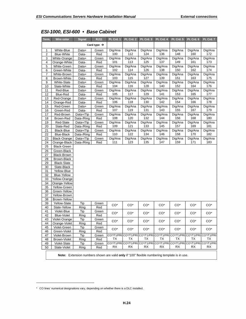
ESI Communications Servers Hardware Installation Manual External connections
H.24
ESI-1000, ESI-600 • Base Cabinet
Term. Wire color Signal RJ11 Pt. Crd. 1 Pt. Crd. 2 Pt. Crd. 3 Pt. Crd. 4 Pt. Crd. 5 Pt. Crd. 6 Pt. Crd. 7
Card type
1 White-Blue Data+ Green
2 Blue-White Data- Red
Dig/Ana 100
Dig/Ana 112
Dig/Ana 124
Dig/Ana 136
Dig/Ana 148
Dig/Ana 160
Dig/Ana 172
3 White-Orange Data+ Green
4 Orange-White Data- Red
Dig/Ana 101
Dig/Ana 113
Dig/Ana 125
Dig/Ana 137
Dig/Ana 149
Dig/Ana 161
Dig/Ana 173
5 White-Green Data+ Green
6 Green-White Data- Red
Dig/Ana 102
Dig/Ana 114
Dig/Ana 126
Dig/Ana 138
Dig/Ana 150
Dig/Ana 162
Dig/Ana 174
7 White-Brown Data+ Green
8 Brown-White Data- Red
Dig/Ana
103
Dig/Ana
115
Dig/Ana
127
Dig/Ana
139
Dig/Ana
151
Dig/Ana
163
Dig/Ana
175
9 White-Slate Data+ Green
10 Slate-White Data- Red
Dig/Ana
104
Dig/Ana
116
Dig/Ana
128
Dig/Ana
140
Dig/Ana
152
Dig/Ana
164
Dig/Ana
176
11 Red-Blue Data+ Green
12 Blue-Red Data- Red
Dig/Ana
105
Dig/Ana
117
Dig/Ana
129
Dig/Ana
141
Dig/Ana
153
Dig/Ana
165
Dig/Ana
177
13 Red-Orange Data+ Green
14 Orange-Red Data- Red
Dig/Ana 106
Dig/Ana 118
Dig/Ana 130
Dig/Ana 142
Dig/Ana 154
Dig/Ana 166
Dig/Ana 178
15 Red-Green Data+ Green
16 Green-Red Data- Red
Dig/Ana 107
Dig/Ana 119
Dig/Ana 131
Dig/Ana 143
Dig/Ana 155
Dig/Ana 167
Dig/Ana 179
17 Red-Brown Data+/Tip Green
18 Brown-Red Data-/Ring Red
Dig/Ana 108
Dig/Ana 120
Dig/Ana 132
Dig/Ana 144
Dig/Ana 156
Dig/Ana 168
Dig/Ana 180
19 Red-Slate Data+/Tip Green
20 Slate-Red Data-/Ring Red
Dig/Ana 109
Dig/Ana 121
Dig/Ana 133
Dig/Ana 145
Dig/Ana 157
Dig/Ana 169
Dig/Ana 181
21 Black-Blue Data+/Tip Green
22 Blue-Black Data-/Ring Red
Dig/Ana 110
Dig/Ana 122
Dig/Ana 134
Dig/Ana 146
Dig/Ana 158
Dig/Ana 170
Dig/Ana 182
23 Black-Orange Data+/Tip Green
24 Orange-Black Data-/Ring Red
Dig/Ana 111
Dig/Ana 123
Dig/Ana 135
Dig/Ana 147
Dig/Ana 159
Dig/Ana 171
Dig/Ana 183
25 Black-Green
26 Green-Black
27 Black-Brown
28 Brown-Black
29 Black-Slate
30 Slate-Black
31 Yellow-Blue
32 Blue-Yellow
33 Yellow-Orange
34 Orange-Yellow
35 Yellow-Green
36 Green-Yellow
37 Yellow-Brown
38 Brown-Yellow
39 Yellow-Slate Tip Green
40 Slate-Yellow Ring Red CO* CO* CO* CO* CO* CO* CO*
41 Violet-Blue Tip Green
42 Blue-Violet Ring Red CO* CO* CO* CO* CO* CO* CO*
43 Violet-Orange Tip Green
44 Orange-Violet Ring Red CO* CO* CO* CO* CO* CO* CO*
45 Violet-Green Tip Green
46 Green-Violet Ring Red CO* CO* CO* CO* CO* CO* CO*
47 Violet-Brown Tip Green
48 Brown-Violet Ring Red
CO*/T1/PRI TX
CO*/T1/PRI TX
CO*/T1/PRI TX
CO*/T1/PRI TX
CO*/T1/PRI TX
CO*/T1/PRI TX
CO*/T1/PRI TX
49 Violet-Slate Tip Green
50 Slate-Violet Ring Red
CO*/T1/PRI RX
CO*/T1/PRI RX
CO*/T1/PRI RX
CO*/T1/PRI RX
CO*/T1/PRI RX
CO*/T1/PRI RX
CO*/T1/PRI RX
Note: Extension numbers shown are valid only if “100” flexible numbering template is in use.
* CO lines’ numerical designations vary, depending on whether there is a DLC installed.

ESI Communications Servers Hardware Installation Manual External connections
H.25
ESI-1000, ESI-600, ESI-200 • Expansion Cabinet
Term. Wire color Signal RJ11 Pt. Crd. 1 Pt. Crd. 2 Pt. Crd. 3 Pt. Crd. 4 Pt. Crd. 5 Pt. Crd. 6 Pt. Crd. 7
Card type
1 White-Blue Data+ Green
2 Blue-White Data- Red
Dig/Ana 184
Dig/Ana 196
Dig/Ana 208
Dig/Ana 220
Dig/Ana 232
Dig/Ana 244
Dig/Ana 256
3 White-Orange Data+ Green
4 Orange-White Data- Red
Dig/Ana 185
Dig/Ana 197
Dig/Ana 209
Dig/Ana 221
Dig/Ana 233
Dig/Ana 245
Dig/Ana 257
5 White-Green Data+ Green
6 Green-White Data- Red
Dig/Ana 186
Dig/Ana 198
Dig/Ana 210
Dig/Ana 222
Dig/Ana 234
Dig/Ana 246
Dig/Ana 258
7 White-Brown Data+ Green
8 Brown-White Data- Red
Dig/Ana 187
Dig/Ana 199
Dig/Ana 211
Dig/Ana 223
Dig/Ana 235
Dig/Ana 247
Dig/Ana 259
9 White-Slate Data+ Green
10 Slate-White Data- Red
Dig/Ana 188
Dig/Ana 200
Dig/Ana 212
Dig/Ana 224
Dig/Ana 236
Dig/Ana 248
Dig/Ana 260
11 Red-Blue Data+ Green
12 Blue-Red Data- Red
Dig/Ana 189
Dig/Ana 201
Dig/Ana 213
Dig/Ana 225
Dig/Ana 237
Dig/Ana 249
Dig/Ana 261
13 Red-Orange Data+ Green
14 Orange-Red Data- Red
Dig/Ana 190
Dig/Ana 202
Dig/Ana 214
Dig/Ana 226
Dig/Ana 238
Dig/Ana 250
Dig/Ana 262
15 Red-Green Data+ Green
16 Green-Red Data- Red
Dig/Ana
191
Dig/Ana
203
Dig/Ana
215
Dig/Ana
227
Dig/Ana
239
Dig/Ana
251
Dig/Ana
263
17 Red-Brown Data+/Tip Green
18 Brown-Red Data-/Ring Red
Dig/Ana
192
Dig/Ana
204
Dig/Ana
216
Dig/Ana
228
Dig/Ana
240
Dig/Ana
252
Dig/Ana
264
19 Red-Slate Data+/Tip Green
20 Slate-Red Data-/Ring Red
Dig/Ana
193
Dig/Ana
205
Dig/Ana
217
Dig/Ana
229
Dig/Ana
241
Dig/Ana
253
Dig/Ana
265
21 Black-Blue Data+/Tip Green
22 Blue-Black Data-/Ring Red
Dig/Ana 194
Dig/Ana 206
Dig/Ana 218
Dig/Ana 230
Dig/Ana 242
Dig/Ana 254
Dig/Ana 266
23 Black-Orange Data+/Tip Green
24 Orange-Black Data-/Ring Red
Dig/Ana 195
Dig/Ana 207
Dig/Ana 219
Dig/Ana 231
Dig/Ana 243
Dig/Ana 255
Dig/Ana 267
25 Black-Green
26 Green-Black
27 Black-Brown
28 Brown-Black
29 Black-Slate
30 Slate-Black
31 Yellow-Blue
32 Blue-Yellow
33 Yellow-Orange
34 Orange-Yellow
35 Yellow-Green
36 Green-Yellow
37 Yellow-Brown
38 Brown-Yellow
39 Yellow-Slate Tip Green
40 Slate-Yellow Ring Red CO* CO* CO* CO* CO* CO* CO*
41 Violet-Blue Tip Green
42 Blue-Violet Ring Red CO* CO* CO* CO* CO* CO* CO*
43 Violet-Orange Tip Green
44 Orange-Violet Ring Red CO* CO* CO* CO* CO* CO* CO*
45 Violet-Green Tip Green
46 Green-Violet Ring Red CO* CO* CO* CO* CO* CO* CO*
47 Violet-Brown Tip Green
48 Brown-Violet Ring Red
CO*/T1/PRI TX
CO*/T1/PRI TX
CO*/T1/PRI TX
CO*/T1/PRI TX
CO*/T1/PRI TX
CO*/T1/PRI TX
CO*/T1/PRI TX
49 Violet-Slate Tip Green
50 Slate-Violet Ring Red
CO*/T1/PRI RX
CO*/T1/PRI RX
CO*/T1/PRI RX
CO*/T1/PRI RX
CO*/T1/PRI RX
CO*/T1/PRI RX
CO*/T1/PRI RX
Note: Extension numbers shown are valid only if “100” flexible numbering template is in use.
* CO lines’ numerical designations vary, depending on whether there is a DLC installed.

Index
60-Key Expansion Console, B.3, H.10, H.11 60-Key Second Expansion Console, B.3, H.10, H.11 Analog ports, H.7 Battery. See Cautions Cabinets
Expansion, F.2 Cautions, E.1
Battery, E.1 Fuse, E.1 Power supply, E.1
CO lines Capacities. See System capacities Connecting, H.5
Console, B.3, H.10, H.11 ESI Cordless Handsets. See Phones ESI Presence Management, D.1 Expansion Cabinet, F.2 Expansion Console, B.3, H.10, H.11 Fuse. See Cautions Grounding, F.2, H.1, H.3 Hardware installation, E.2–F.15 LED functions, F.15, G.6 Main board, A.2 Memory Module, A.2
Installation or replacement, F.5–F.8, G.5 Mirrored Memory Module (M3), A.2
Installation, F.9–F.13
MOH, H.3 NSP (Network Services Processor), A.5 Overlays, B.3 Paging, H.4 Phones
Digital Feature Phones, B.1 ESI Cordless Handsets, B.2 IP Phones, B.2 TAPI Phones, B.1 VIP Softphone, B.3
Port cards Capacities, A.3 Charts, H.15–H.21 Installation, G.3–G.4 Installation, F.2 Port card adapter, F.3
Power, H.1 Power Distribution Shelf, A.2 Power supply. See Cautions Transformers, wall-mount, A.2
PRI, H.5 Regulatory information (U.S. and Canada), E.2 Ringer equivalence number (REN), E.2 Serial ports, H.3 Site location, F.1 SMDR, H.3 System capacities, D.1 T1, H.5 TAPI, B.1 UL (Underwriters’ Laboratories), E.1 UPS (uninterruptible power supply), H.1 VIP Softphone. See Phones
www.esi-estech.com