Embed Size (px)
Citation preview
ESCORT MEMORY SYSTEMS
COBALT C0405-USB-01 RFID CONTROLLER High Frequency Passive Radio Frequency Identification Controller
INSTALLATION GUIDE
How to Install and Configure
Escort Memory Systems’
Cobalt C0405-USB-01 RFID Controller
C0405-USB-01 INSTALLATION GUIDE – REV. 03
Copyright © 2008 Datalogic Automation S.r.l., all rights reserved
F C C , C E & T E L E C C O M P L I A N C E
FCC PART 15.105
This equipment has been tested and found to comply with the limits for a Class A digital device, pursuant to part 15 of the FCC Rules. These limits are designed to provide reasonable protection against harmful interference in a residential installation. This equipment uses, generates, and can radiate radio frequency energy and, if not installed and used in accordance with these instructions, may cause harmful interference to radio communications. However, there is no guarantee that interference will not occur in a particular installation. If this equipment does cause harmful interference to radio or television reception, which can be determined by turning the equipment off and on, the user is encouraged to try to correct the interference by one or more of the following measures:
• Reorient or relocate the receiving antenna.
• Increase the separation between the equipment and receiver.
• Connect the equipment into an outlet on a circuit different from that to which the receiver is connected.
• Consult the dealer or an experienced radio/TV technician for help.
FCC PART 15.21 Users are cautioned that changes or modifications to the unit not expressly approved by Escort Memory Systems may void the user’s authority to operate the equipment. Operation is subject to the following two conditions: (1) This device may not cause harmful interference, and (2) this device must accept any interference that may cause undesired operation. This product complies with CFR (Code of Federal Regulations) Title 21 Part 15.225.
CE This product complies with the following regulatory specifications: EN-300-330, EN-300-683, EN 60950, IEC 68-2-1, IEC 68-2-6, IEC 68-2-27 and IEC 68-2-28.
TELEC This product has been certified under: Regulations for Enforcement of the Radio Law Article 6, section 1, No. 1.
1 : C O N T R O L L E R I N F O R M A T I O N
C0405-USB-01 INSTALLATION GUIDE – REV. 03 P A G E 3 O F 8
CHAPTER 1: CONTROLLER INFORMATION
1.1 POWER & COMMUNICATIONS INTERFACE Connection Type: USB 2.0
Communication Interface:
Point-to-Point (Host/Controller)
Interface Connector: 5-pin, male, reverse keyed M12 connector
Maximum Cable Length: 5 Meters
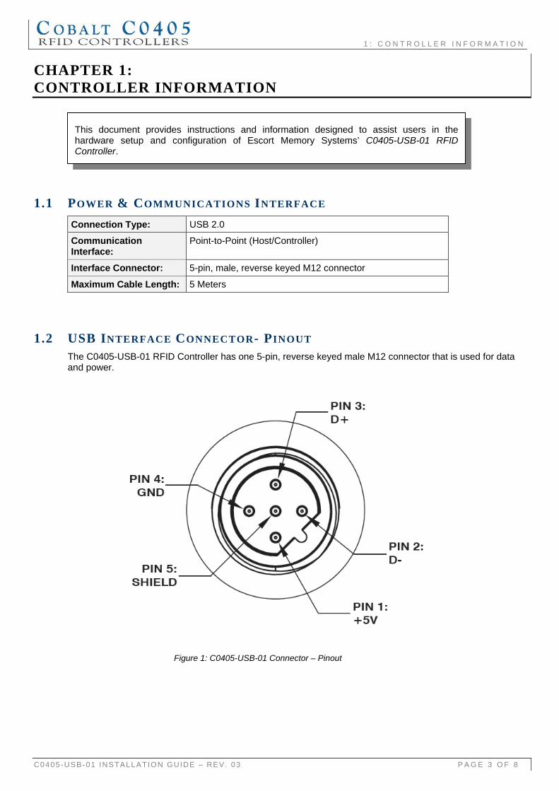
1.2 USB INTERFACE CONNECTOR- PINOUT The C0405-USB-01 RFID Controller has one 5-pin, reverse keyed male M12 connector that is used for data and power.
Figure 1: C0405-USB-01 Connector – Pinout
This document provides instructions and information designed to assist users in thehardware setup and configuration of Escort Memory Systems’ C0405-USB-01 RFIDController.
1 : C O N T R O L L E R I N F O R M A T I O N
C0405-USB-01 INSTALLATION GUIDE – REV. 03 P A G E 4 O F 8
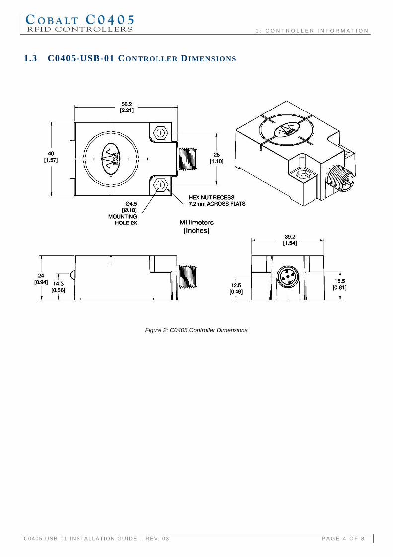
1.3 C0405-USB-01 CONTROLLER DIMENSIONS
Figure 2: C0405 Controller Dimensions
2 : C O N T R O L L E R I N S T A L L A T I O N
C0405-USB-01 INSTALLATION GUIDE – REV. 03 P A G E 5 O F 8
CHAPTER 2: CONTROLLER INSTALLATION
2.1 INSTALLATION GUIDELINES • RFID devices can be negatively affected by the presence of metallic objects near its RF field.
Avoid mounting the C0405 within 5cm (2 inches) of metallic surfaces.
• Avoid mounting the RFID controller near sources of EMI (electro-magnetic interference) or near devices that generate high ESD (electro-static discharge) levels.
• Do not route the C0405’s cables near unshielded cables or near wiring that is carrying high voltage or high current (such as for motors or solenoids). Cross cables only at perpendicular intersections.
• Use the included polycarbonate mounting bracket or a similar non-metallic bracket. The bracket is provided to help reduce electrically conducted spurious noise by isolating the RFID controller from metallic surfaces.
• When installing multiple RFID controllers that operate at the same frequency (13.56 MHz), maintain a minimum distance of 20cm (8 inches) between adjacent RF devices.
2.2 POWER REQUIREMENTS The C0405-USB-01 Controller obtains power directly from the USB bus and requires 250mA.
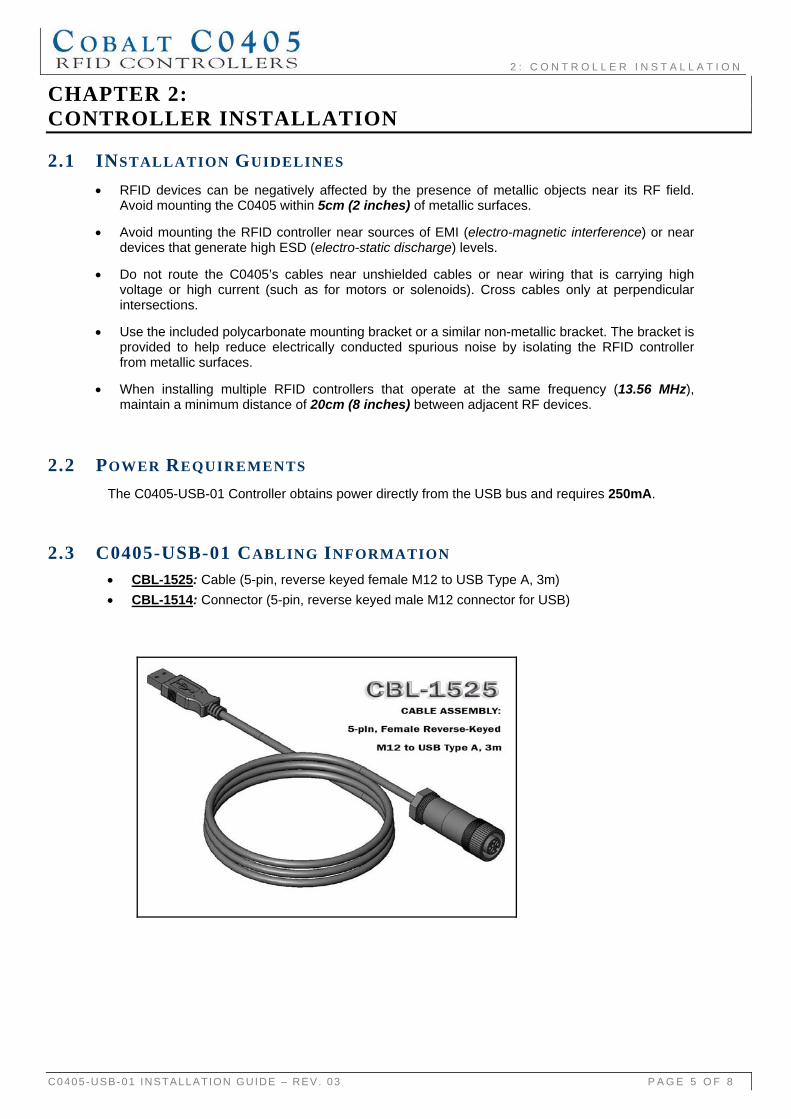
2.3 C0405-USB-01 CABLING INFORMATION • CBL-1525: Cable (5-pin, reverse keyed female M12 to USB Type A, 3m) • CBL-1514: Connector (5-pin, reverse keyed male M12 connector for USB)
2 : C O N T R O L L E R I N S T A L L A T I O N
C0405-USB-01 INSTALLATION GUIDE – REV. 03 P A G E 6 O F 8
2.4 INSTALLING THE C0405-USB-01 RFID CONTROLLER C0405-Series RFID Controllers can be mounted to wood or plastic fixtures. The units’ ship with an L-shaped, polycarbonate, mounting bracket and the necessary hardware required to fasten the controller to the bracket. The bracket is designed to help isolate the RFID controller from metal surfaces and the affect of spurious noise electronically conducted through metal.
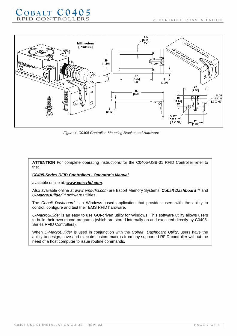
1. Attach the controller to the mounting bracket using the two sets of M4 screws, washers and nuts provided. Place the nuts in each of the hex-shaped recessed cavities at the rear of the C0405.
2. Align the mounting bracket with the two mounting holes on the controller, then insert both M4 screws (with washers) into the controller from the underside and secure completely using a standard Phillips #2 head screwdriver. Tighten screws to 0.7 Nm (6 lbs / inch) ±10%.
3. Fasten the other end of the mounting bracket to your work area. The C0405 may be mounted horizontally or vertically, but should be aligned in such a manner that the LED indicators can be seen during operation.
4. Download the Cobalt USB driver software bundle from the Escort Memory Systems website (www.ems-rfid.com). Extract the .zip file archive to a separate folder on the desktop of the host computer.
5. Browse to the folder containing the Cobalt USB driver files. Refer to the Cobalt USB Driver Installation Instructions (EMS Publication P/N: 17-3128), included with the Cobalt USB driver download, to complete the installation of the Cobalt USB driver.
6. Attach the 5-pin, reverse keyed female M12 interface connector from a suitable USB interface cable (EMS P/N: CBL-1525, not included) to the 5-pin, reverse keyed male M12 connector on the C0405-USB-01.
7. Plug the remaining end of the USB interface cable into a USB port on the host computer. The LEDs on the controller will flash. At this point, Windows™ will detect the new hardware device and request the location of the Cobalt USB driver files.
8. To verify operations, download the Cobalt Dashboard Utility from Escort Memory Systems’ website (www.ems-rfid.com). The Cobalt Dashboard Utility allows users to configure and control their C0405 controllers and send RFID commands for testing purposes.
2 : C O N T R O L L E R I N S T A L L A T I O N
C0405-USB-01 INSTALLATION GUIDE – REV. 03 P A G E 7 O F 8
Figure 4: C0405 Controller, Mounting Bracket and Hardware
ATTENTION For complete operating instructions for the C0405-USB-01 RFID Controller refer to the:
C0405-Series RFID Controllers - Operator’s Manual
available online at: www.ems-rfid.com.
Also available online at www.ems-rfid.com are Escort Memory Systems’ Cobalt Dashboard™ and C-MacroBuilder™ software utilities.
The Cobalt Dashboard is a Windows-based application that provides users with the ability to control, configure and test their EMS RFID hardware.
C-MacroBuilder is an easy to use GUI-driven utility for Windows. This software utility allows users to build their own macro programs (which are stored internally on and executed directly by C0405-Series RFID Controllers).
When C-MacroBuilder is used in conjunction with the Cobalt Dashboard Utility, users have the ability to design, save and execute custom macros from any supported RFID controller without the need of a host computer to issue routine commands.
W A R R A N T Y
C0405-USB-01 INSTALLATION GUIDE – REV. 03 P A G E 8 O F 8
WARRANTY
Datalogic Automation warrants that all products of its own manufacturing conform to Datalogic Automation’s specifications and are free from defects in material and workmanship when used under normal operating conditions and within the service conditions for which they were furnished. The obligation of Datalogic Automation hereunder shall expire one (1) year after delivery, unless otherwise specified, and is limited to repairing, or at its option, replacing without charge, any such product that in Datalogic Automation’s sole opinion proves to be defective within the scope of this Warranty. In the event Datalogic Automation is not able to repair or replace defective products or components within a reasonable time after receipt thereof, Buyers shall be credited for their value at the original purchase price. Datalogic Automation must be notified in writing of the defect or nonconformity within the warranty period and the affected product returned to Datalogic Automation factory or to an authorized service center within thirty (30) days after discovery of such defect or nonconformity. Shipment shall not be made without prior authorization by Datalogic Automation.
This is Datalogic Automation's sole warranty with respect to the products delivered hereunder. No statement, representation, agreement or understanding oral or written, made by an agent, distributor, representative, or employee of Datalogic Automation which is not contained in this warranty, will be binding upon Datalogic Automation, unless made in writing and executed by an authorized Datalogic Automation employee.
Datalogic Automation makes no other warranty of any kind what so ever, expressed or implied, and all implied warranties of merchantability and fitness for a particular use which exceed the aforementioned obligation are here by disclaimed by Datalogic Automation and excluded from this agreement. Under no circumstances shall Datalogic Automation be liable to Buyer, in contract or in tort, for any special, indirect, incidental, or consequential damages, expenses, losses or delay however caused. Equipment or parts that have been subjected to abuse, misuse, accident, alteration, neglect, unauthorized repair or installation are not covered by warranty. Datalogic Automation shall make the final determination as to the existence and cause of any alleged defect. No liability is assumed for expendable items such as lamps and fuses. No warranty is made with respect to equipment or products produced to Buyer’s specification except as specifically stated in writing by Datalogic Automation in the contract for such custom equipment. This warranty is the only warranty made by Datalogic Automation with respect to the goods delivered hereunder, and may be modified or amended only by a written instrument signed by a duly authorized officer of Datalogic Automation and accepted by the Buyer.
Extended warranties of up to five years are available for purchase for most Escort Memory Systems products. Contact Datalogic Automation or your distributor for more information.
Copyright © 2008 DATALOGIC AUTOMATION S.R.L., ALL RIGHTS RESERVED