Embed Size (px)
Citation preview
maxon motor ag Brünigstrasse 220 P.O.Box 263 CH-6072 Sachseln Phone +41 41 666 15 00 Fax +41 41 666 16 50 www.maxonmotor.com
Edition November 2015
ESCON Servo Controller
Hardware Reference
maxon motor control
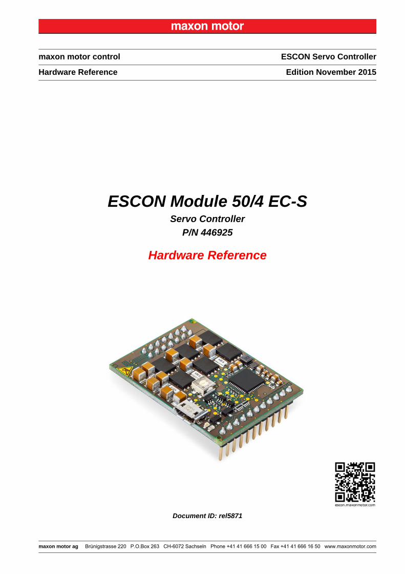
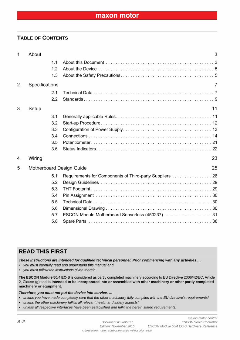
ESCON Module 50/4 EC-SServo Controller
P/N 446925
Hardware Reference
Document ID: rel5871
maxon motor controlA-2 Document ID: rel5871 ESCON Servo Controller
Edition: November 2015 ESCON Module 50/4 EC-S Hardware Reference© 2015 maxon motor. Subject to change without prior notice.
1 About 3
1.1 About this Document . . . . . . . . . . . . . . . . . . . . . . . . . . . . . . . . . . . . . . . . . . . . 3
1.2 About the Device . . . . . . . . . . . . . . . . . . . . . . . . . . . . . . . . . . . . . . . . . . . . . . . 5
1.3 About the Safety Precautions. . . . . . . . . . . . . . . . . . . . . . . . . . . . . . . . . . . . . . 5
2 Specifications 7
2.1 Technical Data . . . . . . . . . . . . . . . . . . . . . . . . . . . . . . . . . . . . . . . . . . . . . . . . . 7
2.2 Standards . . . . . . . . . . . . . . . . . . . . . . . . . . . . . . . . . . . . . . . . . . . . . . . . . . . . . 9
3 Setup 11
3.1 Generally applicable Rules. . . . . . . . . . . . . . . . . . . . . . . . . . . . . . . . . . . . . . . 11
3.2 Start-up Procedure . . . . . . . . . . . . . . . . . . . . . . . . . . . . . . . . . . . . . . . . . . . . . 12
3.3 Configuration of Power Supply. . . . . . . . . . . . . . . . . . . . . . . . . . . . . . . . . . . . 13
3.4 Connections . . . . . . . . . . . . . . . . . . . . . . . . . . . . . . . . . . . . . . . . . . . . . . . . . . 14
3.5 Potentiometer . . . . . . . . . . . . . . . . . . . . . . . . . . . . . . . . . . . . . . . . . . . . . . . . . 21
3.6 Status Indicators. . . . . . . . . . . . . . . . . . . . . . . . . . . . . . . . . . . . . . . . . . . . . . . 22
4 Wiring 23
5 Motherboard Design Guide 25
5.1 Requirements for Components of Third-party Suppliers . . . . . . . . . . . . . . . . 26
5.2 Design Guidelines . . . . . . . . . . . . . . . . . . . . . . . . . . . . . . . . . . . . . . . . . . . . . 29
5.3 THT Footprint . . . . . . . . . . . . . . . . . . . . . . . . . . . . . . . . . . . . . . . . . . . . . . . . . 29
5.4 Pin Assignment . . . . . . . . . . . . . . . . . . . . . . . . . . . . . . . . . . . . . . . . . . . . . . . 30
5.5 Technical Data . . . . . . . . . . . . . . . . . . . . . . . . . . . . . . . . . . . . . . . . . . . . . . . . 30
5.6 Dimensional Drawing . . . . . . . . . . . . . . . . . . . . . . . . . . . . . . . . . . . . . . . . . . . 30
5.7 ESCON Module Motherboard Sensorless (450237) . . . . . . . . . . . . . . . . . . . 31
5.8 Spare Parts . . . . . . . . . . . . . . . . . . . . . . . . . . . . . . . . . . . . . . . . . . . . . . . . . . 38
TABLE OF CONTENTS
READ THIS FIRST
These instructions are intended for qualified technical personnel. Prior commencing with any activities …• you must carefully read and understand this manual and• you must follow the instructions given therein.
The ESCON Module 50/4 EC-S is considered as partly completed machinery according to EU Directive 2006/42/EC, Article 2, Clause (g) and is intended to be incorporated into or assembled with other machinery or other partly completed machinery or equipment.
Therefore, you must not put the device into service, …• unless you have made completely sure that the other machinery fully complies with the EU directive’s requirements!• unless the other machinery fulfills all relevant health and safety aspects!• unless all respective interfaces have been established and fulfill the herein stated requirements!
AboutAbout this Document
maxon motor controlESCON Servo Controller Document ID: rel5871 1-3ESCON Module 50/4 EC-S Hardware Reference Edition: November 2015
© 2015 maxon motor. Subject to change without prior notice.
1 About
1.1 About this Document
1.1.1 Intended Purpose
The purpose of the present document is to familiarize you with the ESCON Module 50/4 EC-S Servo Controller. It will highlight the tasks for safe and adequate installation and/or commissioning. Follow the described instructions …
• to avoid dangerous situations,
• to keep installation and/or commissioning time at a minimum,
• to increase reliability and service life of the described equipment.
The document contains performance data and specifications, information on fulfilled standards, details on connections and pin assignment, and wiring examples. In addition, the document also includes a Motherboard Design Guide and detailed information on the optionally available «ESCON Module Motherboard Sensorless».
1.1.2 Target Audience
The present document is intended for trained and skilled personnel. It conveys information on how to understand and fulfill the respective work and duties.
1.1.3 How to use
Take note of the following notations and codes which will be used throughout the document.
Table 1-1 Notation used
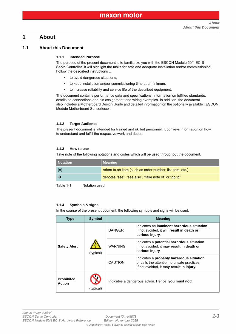
1.1.4 Symbols & signs
In the course of the present document, the following symbols and signs will be used.
Notation Meaning
(n) refers to an item (such as order number, list item, etc.)
denotes “see”, “see also”, “take note of” or “go to”
Type Symbol Meaning
Safety Alert
(typical)
DANGERIndicates an imminent hazardous situation. If not avoided, it will result in death or serious injury.
WARNINGIndicates a potential hazardous situation. If not avoided, it may result in death or serious injury.
CAUTIONIndicates a probably hazardous situation or calls the attention to unsafe practices. If not avoided, it may result in injury.
ProhibitedAction
(typical)
Indicates a dangerous action. Hence, you must not!
AboutAbout this Document
maxon motor control1-4 Document ID: rel5871 ESCON Servo Controller
Edition: November 2015 ESCON Module 50/4 EC-S Hardware Reference© 2015 maxon motor. Subject to change without prior notice.
Table 1-2 Symbols & Signs
1.1.5 Trademarks and Brand Names
For easier legibility, registered brand names are listed below and will not be further tagged with their respective trademark. It must be understood that the brands (the list below is not necessarily conclud-ing) are protected by copyright and/or other intellectual property rights even if their legal trademarks are omitted in the later course of this document.
Table 1-3 Brand Names and Trademark Owners
1.1.6 Copyright
© 2015 maxon motor. All rights reserved.
The present document – including all parts thereof – is protected by copyright. Any use (including repro-duction, translation, microfilming, and other means of electronic data processing) beyond the narrow restrictions of the copyright law without the prior approval of maxon motor ag, is not permitted and sub-ject to prosecution under the applicable law.
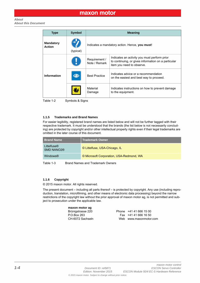
MandatoryAction
(typical)
Indicates a mandatory action. Hence, you must!
Information
Requirement / Note / Remark
Indicates an activity you must perform prior to continuing, or gives information on a particular item you need to observe.
Best PracticeIndicates advice or a recommendation on the easiest and best way to proceed.
Material Damage
Indicates instructions on how to prevent damage to the equipment.
Brand Name Trademark Owner
Littelfuse®SMD NANO2®
© Littelfuse, USA-Chicago, IL
Windows® © Microsoft Corporation, USA-Redmond, WA
maxon motor agBrünigstrasse 220P.O.Box 263CH-6072 Sachseln
PhoneFax
Web
+41 41 666 15 00+41 41 666 16 50www.maxonmotor.com
Type Symbol Meaning
AboutAbout the Device
maxon motor controlESCON Servo Controller Document ID: rel5871 1-5ESCON Module 50/4 EC-S Hardware Reference Edition: November 2015
© 2015 maxon motor. Subject to change without prior notice.
1.2 About the DeviceThe ESCON Module 50/4 EC-S is a small-sized, powerful 4-quadrant PWM servo controller for the highly efficient control of permanent magnet-activated brushless, sensorless EC motors without Hall sensors up to approximately 200 Watts.
The featured operating modes – speed control (closed loop) and speed control (open loop) – meet the highest requirements. The ESCON Module 50/4 EC-S is designed being commanded by an analog set value and features extensive analog and digital I/O functionality.
The miniaturized OEM plug-in module can be seamlessly integrated in complex customer applications. A suitable motherboard is available for the initial commissioning.
The device is designed to be configured via USB interface using the graphical user interface «ESCON Studio» for Windows PCs.
You can download the latest ESCON software version (as well as the latest edition of the documenta-tion) from the Internet under http://escon.maxonmotor.com.
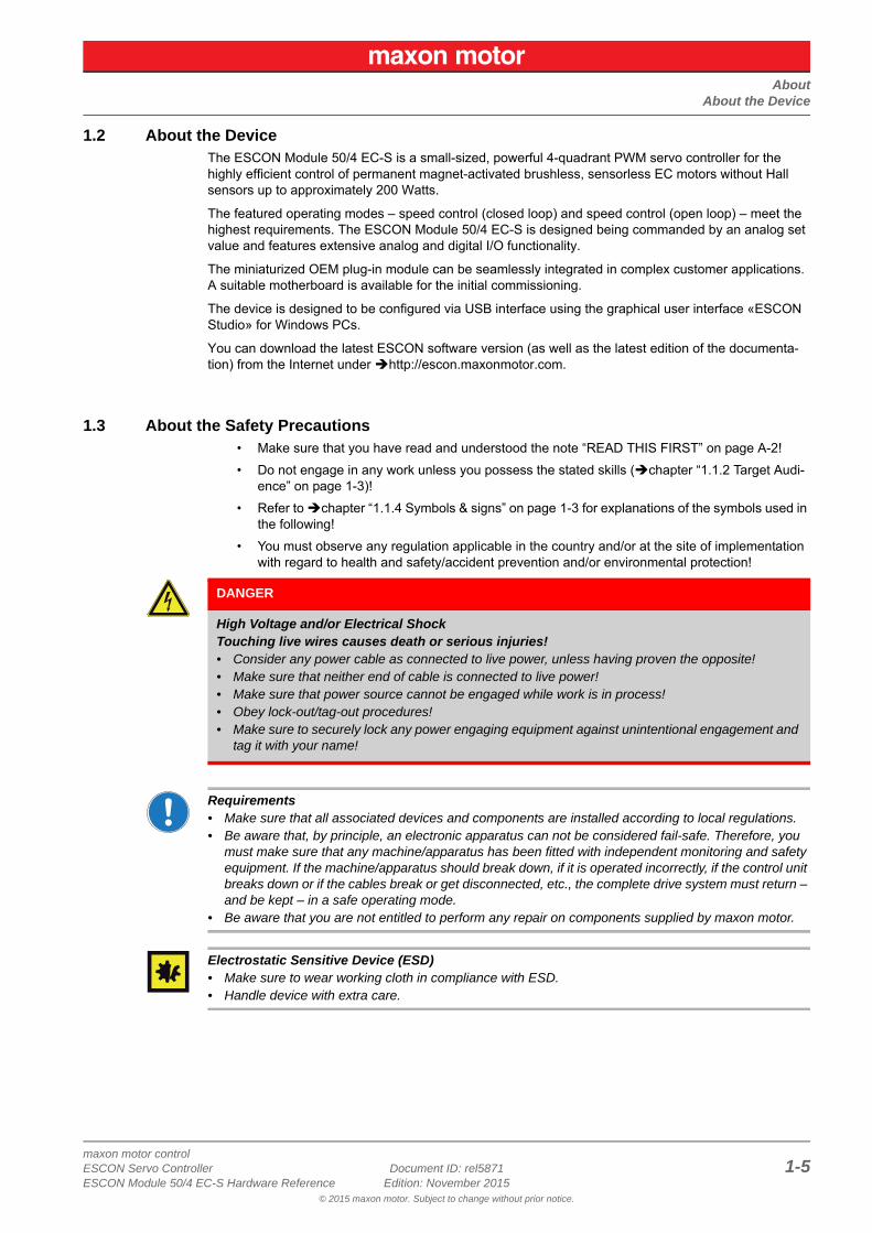
1.3 About the Safety Precautions• Make sure that you have read and understood the note “READ THIS FIRST” on page A-2!
• Do not engage in any work unless you possess the stated skills (chapter “1.1.2 Target Audi-ence” on page 1-3)!
• Refer to chapter “1.1.4 Symbols & signs” on page 1-3 for explanations of the symbols used in the following!
• You must observe any regulation applicable in the country and/or at the site of implementation with regard to health and safety/accident prevention and/or environmental protection!
Requirements• Make sure that all associated devices and components are installed according to local regulations.• Be aware that, by principle, an electronic apparatus can not be considered fail-safe. Therefore, you
must make sure that any machine/apparatus has been fitted with independent monitoring and safety equipment. If the machine/apparatus should break down, if it is operated incorrectly, if the control unit breaks down or if the cables break or get disconnected, etc., the complete drive system must return – and be kept – in a safe operating mode.
• Be aware that you are not entitled to perform any repair on components supplied by maxon motor.
Electrostatic Sensitive Device (ESD)• Make sure to wear working cloth in compliance with ESD.• Handle device with extra care.
DANGER
High Voltage and/or Electrical ShockTouching live wires causes death or serious injuries!• Consider any power cable as connected to live power, unless having proven the opposite!• Make sure that neither end of cable is connected to live power!• Make sure that power source cannot be engaged while work is in process!• Obey lock-out/tag-out procedures!• Make sure to securely lock any power engaging equipment against unintentional engagement and
tag it with your name!
AboutAbout the Safety Precautions
maxon motor control1-6 Document ID: rel5871 ESCON Servo Controller
Edition: November 2015 ESCON Module 50/4 EC-S Hardware Reference© 2015 maxon motor. Subject to change without prior notice.
• • p a g e i n t e n t i o n a l l y l e f t b l a n k • •
SpecificationsTechnical Data
maxon motor controlESCON Servo Controller Document ID: rel5871 2-7ESCON Module 50/4 EC-S Hardware Reference Edition: November 2015
© 2015 maxon motor. Subject to change without prior notice.
2 Specifications
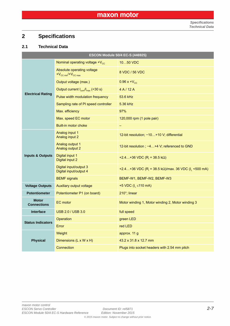
2.1 Technical Data
ESCON Module 50/4 EC-S (446925)
Electrical Rating
Nominal operating voltage +VCC 10…50 VDC
Absolute operating voltage +VCC min/+VCC max
8 VDC / 56 VDC
Output voltage (max.) 0.96 x +VCC
Output current Icont/Imax (<30 s) 4 A / 12 A
Pulse width modulation frequency 53.6 kHz
Sampling rate of PI speed controller 5.36 kHz
Max. efficiency 97%
Max. speed EC motor 120,000 rpm (1 pole pair)
Built-in motor choke –
Inputs & Outputs
Analog input 1Analog input 2
12-bit resolution; −10…+10 V; differential
Analog output 1Analog output 2
12-bit resolution ; −4…+4 V; referenced to GND
Digital input 1Digital input 2
+2.4…+36 VDC (Ri = 38.5 kΩ)
Digital input/output 3Digital input/output 4
+2.4…+36 VDC (Ri = 38.5 kΩ)/max. 36 VDC (IL <500 mA)
BEMF signals BEMF-W1, BEMF-W2, BEMF-W3
Voltage Outputs Auxiliary output voltage +5 VDC (IL ≤110 mA)
Potentiometer Potentiometer P1 (on board) 210°; linear
Motor Connections
EC motor Motor winding 1, Motor winding 2, Motor winding 3
Interface USB 2.0 / USB 3.0 full speed
Status IndicatorsOperation green LED
Error red LED
Physical
Weight approx. 11 g
Dimensions (L x W x H) 43.2 x 31.8 x 12.7 mm
Connection Plugs into socket headers with 2.54 mm pitch
SpecificationsTechnical Data
maxon motor control2-8 Document ID: rel5871 ESCON Servo Controller
Edition: November 2015 ESCON Module 50/4 EC-S Hardware Reference© 2015 maxon motor. Subject to change without prior notice.
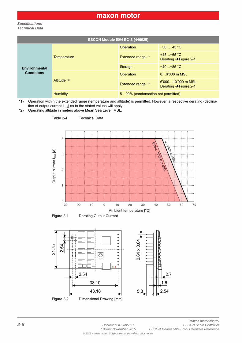
Table 2-4 Technical Data
Figure 2-1 Derating Output Current
Figure 2-2 Dimensional Drawing [mm]
Environmental Conditions
Temperature
Operation −30…+45 °C
Extended range *1) +45…+65 °CDerating Figure 2-1
Storage −40…+85 °C
Altitude *2)
Operation 0…6’000 m MSL
Extended range *1) 6’000…10’000 m MSLDerating Figure 2-1
Humidity 5…90% (condensation not permitted)
*1) Operation within the extended range (temperature and altitude) is permitted. However, a respective derating (declina-tion of output current Icont) as to the stated values will apply.
*2) Operating altitude in meters above Mean Sea Level, MSL.
ESCON Module 50/4 EC-S (446925)
SpecificationsStandards
maxon motor controlESCON Servo Controller Document ID: rel5871 2-9ESCON Module 50/4 EC-S Hardware Reference Edition: November 2015
© 2015 maxon motor. Subject to change without prior notice.
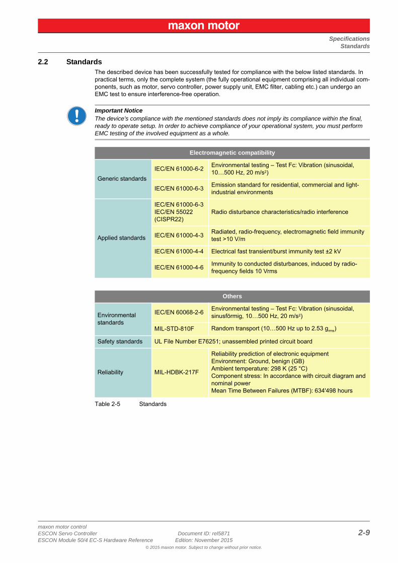
2.2 StandardsThe described device has been successfully tested for compliance with the below listed standards. In practical terms, only the complete system (the fully operational equipment comprising all individual com-ponents, such as motor, servo controller, power supply unit, EMC filter, cabling etc.) can undergo an EMC test to ensure interference-free operation.
Important NoticeThe device’s compliance with the mentioned standards does not imply its compliance within the final, ready to operate setup. In order to achieve compliance of your operational system, you must perform EMC testing of the involved equipment as a whole.
Table 2-5 Standards
Electromagnetic compatibility
Generic standards
IEC/EN 61000-6-2Environmental testing – Test Fc: Vibration (sinusoidal, 10…500 Hz, 20 m/s2)
IEC/EN 61000-6-3Emission standard for residential, commercial and light-industrial environments
Applied standards
IEC/EN 61000-6-3IEC/EN 55022(CISPR22)
Radio disturbance characteristics/radio interference
IEC/EN 61000-4-3Radiated, radio-frequency, electromagnetic field immunity test >10 V/m
IEC/EN 61000-4-4 Electrical fast transient/burst immunity test ±2 kV
IEC/EN 61000-4-6 Immunity to conducted disturbances, induced by radio-frequency fields 10 Vrms
Others
Environmental standards
IEC/EN 60068-2-6Environmental testing – Test Fc: Vibration (sinusoidal, sinusförmig, 10…500 Hz, 20 m/s2)
MIL-STD-810F Random transport (10…500 Hz up to 2.53 grms)
Safety standards UL File Number E76251; unassembled printed circuit board
Reliability MIL-HDBK-217F
Reliability prediction of electronic equipmentEnvironment: Ground, benign (GB)Ambient temperature: 298 K (25 °C)Component stress: In accordance with circuit diagram and nominal powerMean Time Between Failures (MTBF): 634'498 hours

SpecificationsStandards
maxon motor control2-10 Document ID: rel5871 ESCON Servo Controller
Edition: November 2015 ESCON Module 50/4 EC-S Hardware Reference© 2015 maxon motor. Subject to change without prior notice.
• • p a g e i n t e n t i o n a l l y l e f t b l a n k • •
SetupGenerally applicable Rules
maxon motor controlESCON Servo Controller Document ID: rel5871 3-11ESCON Module 50/4 EC-S Hardware Reference Edition: November 2015
© 2015 maxon motor. Subject to change without prior notice.
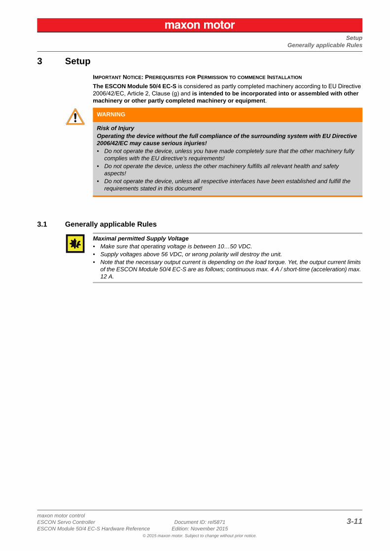
3 Setup
IMPORTANT NOTICE: PREREQUISITES FOR PERMISSION TO COMMENCE INSTALLATION
The ESCON Module 50/4 EC-S is considered as partly completed machinery according to EU Directive 2006/42/EC, Article 2, Clause (g) and is intended to be incorporated into or assembled with other machinery or other partly completed machinery or equipment.
3.1 Generally applicable Rules
Maximal permitted Supply Voltage• Make sure that operating voltage is between 10…50 VDC.• Supply voltages above 56 VDC, or wrong polarity will destroy the unit.• Note that the necessary output current is depending on the load torque. Yet, the output current limits
of the ESCON Module 50/4 EC-S are as follows; continuous max. 4 A / short-time (acceleration) max. 12 A.
WARNING
Risk of InjuryOperating the device without the full compliance of the surrounding system with EU Directive 2006/42/EC may cause serious injuries!• Do not operate the device, unless you have made completely sure that the other machinery fully
complies with the EU directive’s requirements!• Do not operate the device, unless the other machinery fulfills all relevant health and safety
aspects!• Do not operate the device, unless all respective interfaces have been established and fulfill the
requirements stated in this document!
SetupStart-up Procedure
maxon motor control3-12 Document ID: rel5871 ESCON Servo Controller
Edition: November 2015 ESCON Module 50/4 EC-S Hardware Reference© 2015 maxon motor. Subject to change without prior notice.
3.2 Start-up Procedure
A successful sensorless start-up procedure consists of two phases; the alignment phase and the accel-eration phase.
ALIGNMENT PHASE
The motor shaft will be brought to and stabilized in a defined rotor position. This will be accomplished by applying a motor current ramp with a fixed step configuration without rotating stator field. During the alignment phase the motor current Istart rises.
ACCELERATION PHASE
A synchronous rotation of the motor with a constant acceleration α is being forced until the speed is suf-ficiently high for Back-EMF sampling. The motor current is limited to Istart.
NoteUnder unfavorable conditions, the sensorless commutation principle can lead to start-up problems. Thereby, the following aspects can have a negative effect on the reliable start-up:
• high friction torques• high moment of inertia in combination with low friction• unsuitably defined start-up parameter
CAUTION
Risk of injuryDuring the starting operation, the motor shaft will temporarily move in both directions• Do not take the device into operation unless all protective devices on moving parts have been
completely attached and checked for proper function.• Make sure that no loose objects are in the vicinity of any moving parts. Keep any objects which
could get caught away.
SetupConfiguration of Power Supply
maxon motor controlESCON Servo Controller Document ID: rel5871 3-13ESCON Module 50/4 EC-S Hardware Reference Edition: November 2015
© 2015 maxon motor. Subject to change without prior notice.
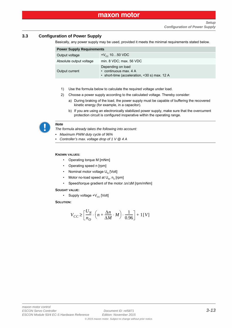
3.3 Configuration of Power SupplyBasically, any power supply may be used, provided it meets the minimal requirements stated below.
1) Use the formula below to calculate the required voltage under load.
2) Choose a power supply according to the calculated voltage. Thereby consider:
a) During braking of the load, the power supply must be capable of buffering the recovered kinetic energy (for example, in a capacitor).
b) If you are using an electronically stabilized power supply, make sure that the overcurrent protection circuit is configured inoperative within the operating range.
NoteThe formula already takes the following into account:
• Maximum PWM duty cycle of 96%• Controller’s max. voltage drop of 1 V @ 4 A
KNOWN VALUES:
• Operating torque M [mNm]
• Operating speed n [rpm]
• Nominal motor voltage UN [Volt]
• Motor no-load speed at UN, n0 [rpm]
• Speed/torque gradient of the motor Δn/ΔM [rpm/mNm]
SOUGHT VALUE:
• Supply voltage +VCC [Volt]
SOLUTION:
Power Supply Requirements
Output voltage +VCC 10…50 VDC
Absolute output voltage min. 8 VDC; max. 56 VDC
Output currentDepending on load • continuous max. 4 A• short-time (acceleration, <30 s) max. 12 A
VCCUNnO------- n Δn
ΔM--------- M⋅+
10.96----------⋅ ⋅ 1 V[ ]+≥
SetupConnections
maxon motor control3-14 Document ID: rel5871 ESCON Servo Controller
Edition: November 2015 ESCON Module 50/4 EC-S Hardware Reference© 2015 maxon motor. Subject to change without prior notice.
3.4 ConnectionsThe actual connection will depend on the overall configuration of your drive system and the type of motor you will be using.
Follow the description in the given order and choose the wiring diagram that best suits the components you are using. For corresponding wiring diagrams Chapter “4 Wiring” on page 4-23.
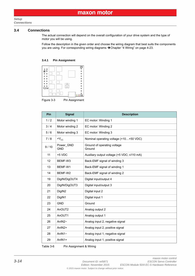
3.4.1 Pin Assignment
Figure 3-3 Pin Assignment
Table 3-6 Pin Assignment & Wiring
Pin Signal Description
1 / 2 Motor winding 1 EC motor: Winding 1
3 / 4 Motor winding 2 EC motor: Winding 2
5 / 6 Motor winding 3 EC motor: Winding 3
7 / 8 +VCC Nominal operating voltage (+10…+50 VDC)
9 / 10Power_GNDGND
Ground of operating voltageGround
11 +5 VDC Auxiliary output voltage (+5 VDC; ≤110 mA)
12 BEMF-W3 Back-EMF signal of winding 3
13 BEMF-W1 Back-EMF signal of winding 1
14 BEMF-W2 Back-EMF signal of winding 2
19 DigIN/DigOUT4 Digital input/output 4
20 DigIN/DigOUT3 Digital input/output 3
21 DigIN2 Digital input 2
22 DigIN1 Digital input 1
23 GND Ground
24 AnOUT2 Analog output 2
25 AnOUT1 Analog output 1
26 AnIN2− Analog input 2, negative signal
27 AnIN2+ Analog input 2, positive signal
28 AnIN1− Analog input 1, negative signal
29 AnIN1+ Analog input 1, positive signal
SetupConnections
maxon motor controlESCON Servo Controller Document ID: rel5871 3-15ESCON Module 50/4 EC-S Hardware Reference Edition: November 2015
© 2015 maxon motor. Subject to change without prior notice.
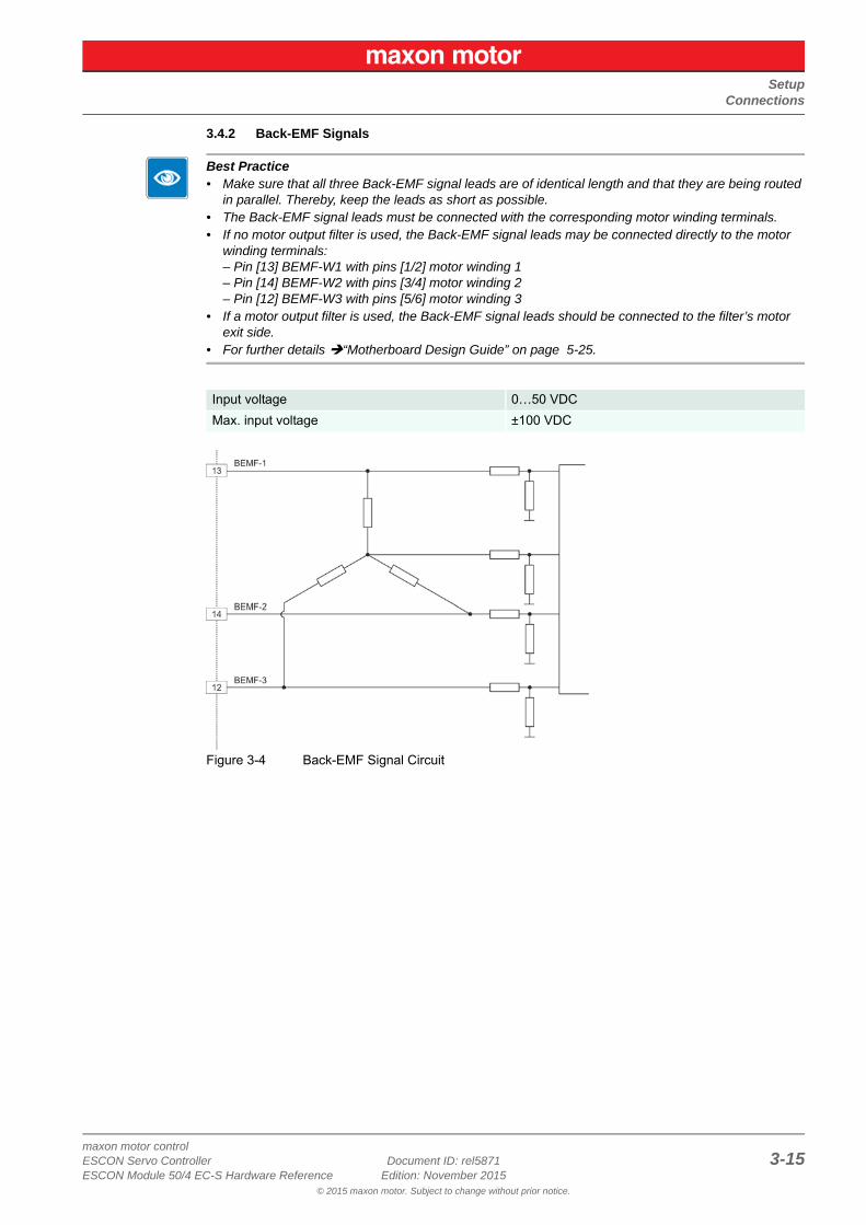
3.4.2 Back-EMF Signals
Best Practice• Make sure that all three Back-EMF signal leads are of identical length and that they are being routed
in parallel. Thereby, keep the leads as short as possible.• The Back-EMF signal leads must be connected with the corresponding motor winding terminals.• If no motor output filter is used, the Back-EMF signal leads may be connected directly to the motor
winding terminals:– Pin [13] BEMF-W1 with pins [1/2] motor winding 1– Pin [14] BEMF-W2 with pins [3/4] motor winding 2– Pin [12] BEMF-W3 with pins [5/6] motor winding 3
• If a motor output filter is used, the Back-EMF signal leads should be connected to the filter’s motor exit side.
• For further details “Motherboard Design Guide” on page 5-25.
Figure 3-4 Back-EMF Signal Circuit
Input voltage 0…50 VDC
Max. input voltage ±100 VDC
SetupConnections
maxon motor control3-16 Document ID: rel5871 ESCON Servo Controller
Edition: November 2015 ESCON Module 50/4 EC-S Hardware Reference© 2015 maxon motor. Subject to change without prior notice.
3.4.3 Digital I/Os
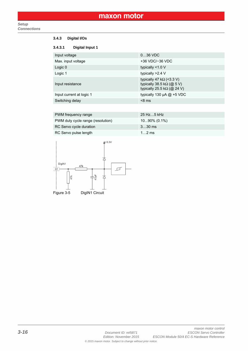
3.4.3.1 Digital Input 1
Figure 3-5 DigIN1 Circuit
Input voltage 0…36 VDC
Max. input voltage +36 VDC/−36 VDC
Logic 0 typically <1.0 V
Logic 1 typically >2.4 V
Input resistancetypically 47 kΩ (<3.3 V)typically 38.5 kΩ (@ 5 V)typically 25.5 kΩ (@ 24 V)
Input current at logic 1 typically 130 µA @ +5 VDC
Switching delay <8 ms
PWM frequency range 25 Hz…5 kHz
PWM duty cycle range (resolution) 10...90% (0.1%)
RC Servo cycle duration 3…30 ms
RC Servo pulse length 1…2 ms
SetupConnections
maxon motor controlESCON Servo Controller Document ID: rel5871 3-17ESCON Module 50/4 EC-S Hardware Reference Edition: November 2015
© 2015 maxon motor. Subject to change without prior notice.
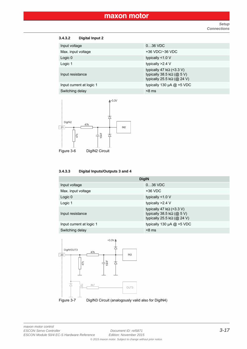
3.4.3.2 Digital Input 2
Figure 3-6 DigIN2 Circuit
3.4.3.3 Digital Inputs/Outputs 3 and 4
Figure 3-7 DigIN3 Circuit (analogously valid also for DigIN4)
Input voltage 0…36 VDC
Max. input voltage +36 VDC/−36 VDC
Logic 0 typically <1.0 V
Logic 1 typically >2.4 V
Input resistancetypically 47 kΩ (<3.3 V)typically 38.5 kΩ (@ 5 V)typically 25.5 kΩ (@ 24 V)
Input current at logic 1 typically 130 µA @ +5 VDC
Switching delay <8 ms
DigIN
Input voltage 0…36 VDC
Max. input voltage +36 VDC
Logic 0 typically <1.0 V
Logic 1 typically >2.4 V
Input resistancetypically 47 kΩ (<3.3 V)typically 38.5 kΩ (@ 5 V)typically 25.5 kΩ (@ 24 V)
Input current at logic 1 typically 130 µA @ +5 VDC
Switching delay <8 ms
SetupConnections
maxon motor control3-18 Document ID: rel5871 ESCON Servo Controller
Edition: November 2015 ESCON Module 50/4 EC-S Hardware Reference© 2015 maxon motor. Subject to change without prior notice.
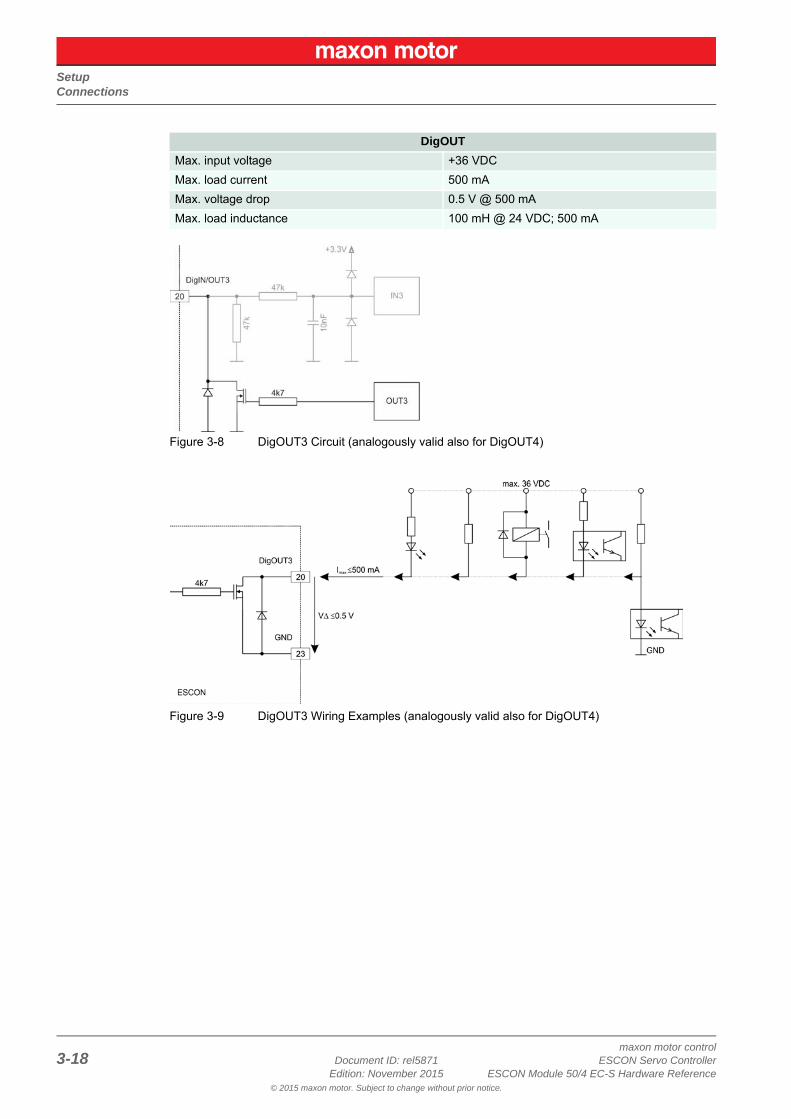
Figure 3-8 DigOUT3 Circuit (analogously valid also for DigOUT4)
Figure 3-9 DigOUT3 Wiring Examples (analogously valid also for DigOUT4)
DigOUT
Max. input voltage +36 VDC
Max. load current 500 mA
Max. voltage drop 0.5 V @ 500 mA
Max. load inductance 100 mH @ 24 VDC; 500 mA
SetupConnections
maxon motor controlESCON Servo Controller Document ID: rel5871 3-19ESCON Module 50/4 EC-S Hardware Reference Edition: November 2015
© 2015 maxon motor. Subject to change without prior notice.
3.4.4 Analog I/Os
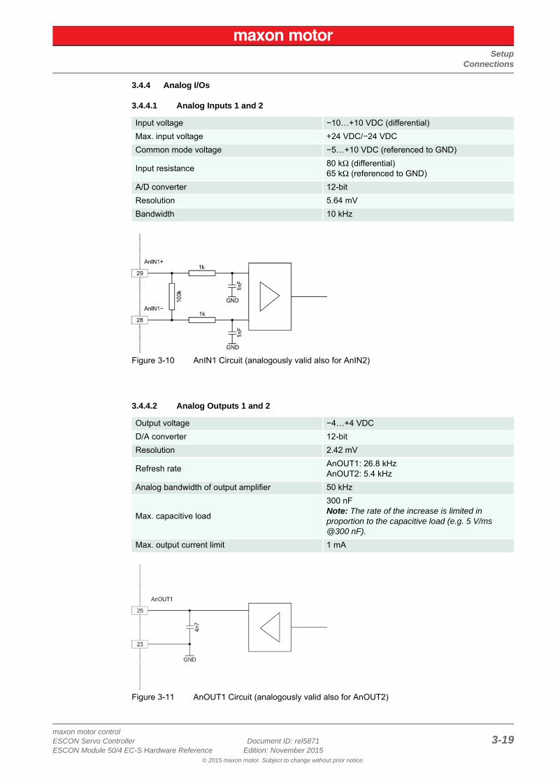
3.4.4.1 Analog Inputs 1 and 2
Figure 3-10 AnIN1 Circuit (analogously valid also for AnIN2)
3.4.4.2 Analog Outputs 1 and 2
Figure 3-11 AnOUT1 Circuit (analogously valid also for AnOUT2)
Input voltage −10…+10 VDC (differential)
Max. input voltage +24 VDC/−24 VDC
Common mode voltage −5…+10 VDC (referenced to GND)
Input resistance80 kΩ (differential)65 kΩ (referenced to GND)
A/D converter 12-bit
Resolution 5.64 mV
Bandwidth 10 kHz
Output voltage −4…+4 VDC
D/A converter 12-bit
Resolution 2.42 mV
Refresh rateAnOUT1: 26.8 kHzAnOUT2: 5.4 kHz
Analog bandwidth of output amplifier 50 kHz
Max. capacitive load
300 nFNote: The rate of the increase is limited in proportion to the capacitive load (e.g. 5 V/ms @300 nF).
Max. output current limit 1 mA
SetupConnections
maxon motor control3-20 Document ID: rel5871 ESCON Servo Controller
Edition: November 2015 ESCON Module 50/4 EC-S Hardware Reference© 2015 maxon motor. Subject to change without prior notice.
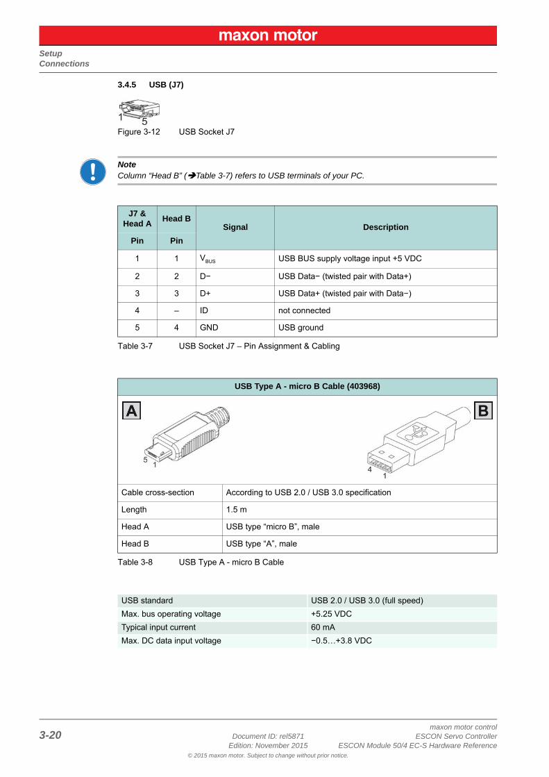
3.4.5 USB (J7)
Figure 3-12 USB Socket J7
NoteColumn “Head B” (Table 3-7) refers to USB terminals of your PC.
Table 3-7 USB Socket J7 – Pin Assignment & Cabling
Table 3-8 USB Type A - micro B Cable
J7 & Head A
Head BSignal Description
Pin Pin
1 1 VBUS USB BUS supply voltage input +5 VDC
2 2 D− USB Data− (twisted pair with Data+)
3 3 D+ USB Data+ (twisted pair with Data−)
4 – ID not connected
5 4 GND USB ground
USB Type A - micro B Cable (403968)
Cable cross-section According to USB 2.0 / USB 3.0 specification
Length 1.5 m
Head A USB type “micro B”, male
Head B USB type “A”, male
USB standard USB 2.0 / USB 3.0 (full speed)
Max. bus operating voltage +5.25 VDC
Typical input current 60 mA
Max. DC data input voltage −0.5…+3.8 VDC
SetupPotentiometer
maxon motor controlESCON Servo Controller Document ID: rel5871 3-21ESCON Module 50/4 EC-S Hardware Reference Edition: November 2015
© 2015 maxon motor. Subject to change without prior notice.
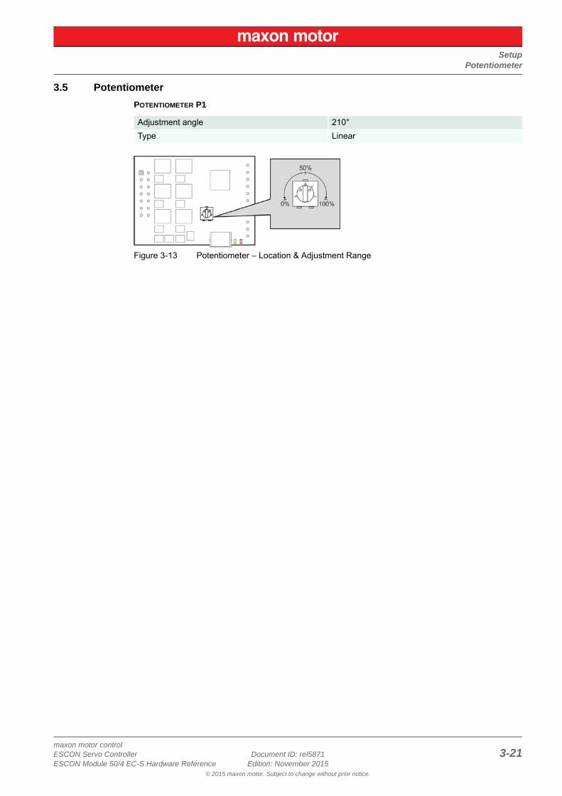
3.5 Potentiometer
POTENTIOMETER P1
Figure 3-13 Potentiometer – Location & Adjustment Range
Adjustment angle 210°
Type Linear
SetupStatus Indicators
maxon motor control3-22 Document ID: rel5871 ESCON Servo Controller
Edition: November 2015 ESCON Module 50/4 EC-S Hardware Reference© 2015 maxon motor. Subject to change without prior notice.
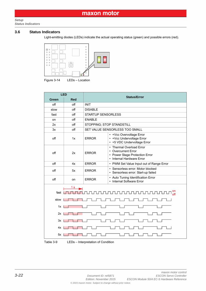
3.6 Status IndicatorsLight-emitting diodes (LEDs) indicate the actual operating status (green) and possible errors (red).
Figure 3-14 LEDs – Location
Table 3-9 LEDs – Interpretation of Condition
LEDStatus/Error
Green Red
off off INIT
slow off DISABLE
fast off STARTUP SENSORLESS
on off ENABLE
2x off STOPPING; STOP STANDSTILL
3x off SET VALUE SENSORLESS TOO SMALL
off 1x ERROR• +Vcc Overvoltage Error• +Vcc Undervoltage Error• +5 VDC Undervoltage Error
off 2x ERROR
• Thermal Overload Error• Overcurrent Error• Power Stage Protection Error• Internal Hardware Error
off 4x ERROR • PWM Set Value Input out of Range Error
off 5x ERROR• Sensorless error: Motor blocked• Sensorless error: Start-up failed
off on ERROR• Auto Tuning Identification Error• Internal Software Error
Wiring
maxon motor controlESCON Servo Controller Document ID: rel5871 4-23ESCON Module 50/4 EC-S Hardware Reference Edition: November 2015
© 2015 maxon motor. Subject to change without prior notice.
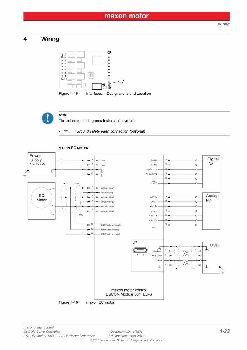
4 Wiring
Figure 4-15 Interfaces – Designations and Location
Note
The subsequent diagrams feature this symbol:
• Ground safety earth connection (optional)
MAXON EC MOTOR
Figure 4-16 maxon EC motor

Wiring
maxon motor control4-24 Document ID: rel5871 ESCON Servo Controller
Edition: November 2015 ESCON Module 50/4 EC-S Hardware Reference© 2015 maxon motor. Subject to change without prior notice.
• • p a g e i n t e n t i o n a l l y l e f t b l a n k • •
Motherboard Design Guide
maxon motor controlESCON Servo Controller Document ID: rel5871 5-25ESCON Module 50/4 EC-S Hardware Reference Edition: November 2015
© 2015 maxon motor. Subject to change without prior notice.
5 Motherboard Design Guide
The following provides helpful information on integrating the ESCON Module 50/4 EC-S on a printed cir-cuit board. The «Motherboard Design Guide» contains recommendations for the layout of the mother-board and specifies external components that may be required, pin assignments, and connection exam-ples.
Bring in additional Support:If you are not trained in the design and development of printed circuit boards, you will need additional support for this point.maxon motor will be happy to provide you with a quote for designing and manufacturing a motherboard for your specific application.
CAUTION
Dangerous ActionErrors in implementing the Design can result in serious Injury!• Only proceed if you are skilled in electronics design!• Designing a printed circuit board requires special skills and knowledge and may only be performed
by experienced electronic developers!• This quick guide is only intended as an aid, does not make any claim to completeness, and will not
automatically result in a functional component!
Motherboard Design GuideRequirements for Components of Third-party Suppliers
maxon motor control5-26 Document ID: rel5871 ESCON Servo Controller
Edition: November 2015 ESCON Module 50/4 EC-S Hardware Reference© 2015 maxon motor. Subject to change without prior notice.
5.1 Requirements for Components of Third-party Suppliers
5.1.1 Socket Headers
The ESCON Module 50/4 EC-S’s implementation with pin headers permits mounting in two different ways. The module can either be plugged onto a socket header (Table 5-10) or be directly soldered to a printed circuit board.
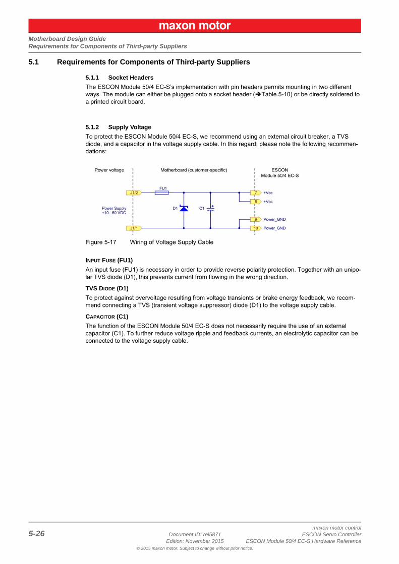
5.1.2 Supply Voltage
To protect the ESCON Module 50/4 EC-S, we recommend using an external circuit breaker, a TVS diode, and a capacitor in the voltage supply cable. In this regard, please note the following recommen-dations:
Figure 5-17 Wiring of Voltage Supply Cable
INPUT FUSE (FU1)
An input fuse (FU1) is necessary in order to provide reverse polarity protection. Together with an unipo-lar TVS diode (D1), this prevents current from flowing in the wrong direction.
TVS DIODE (D1)
To protect against overvoltage resulting from voltage transients or brake energy feedback, we recom-mend connecting a TVS (transient voltage suppressor) diode (D1) to the voltage supply cable.
CAPACITOR (C1)
The function of the ESCON Module 50/4 EC-S does not necessarily require the use of an external capacitor (C1). To further reduce voltage ripple and feedback currents, an electrolytic capacitor can be connected to the voltage supply cable.
Motherboard Design GuideRequirements for Components of Third-party Suppliers
maxon motor controlESCON Servo Controller Document ID: rel5871 5-27ESCON Module 50/4 EC-S Hardware Reference Edition: November 2015
© 2015 maxon motor. Subject to change without prior notice.
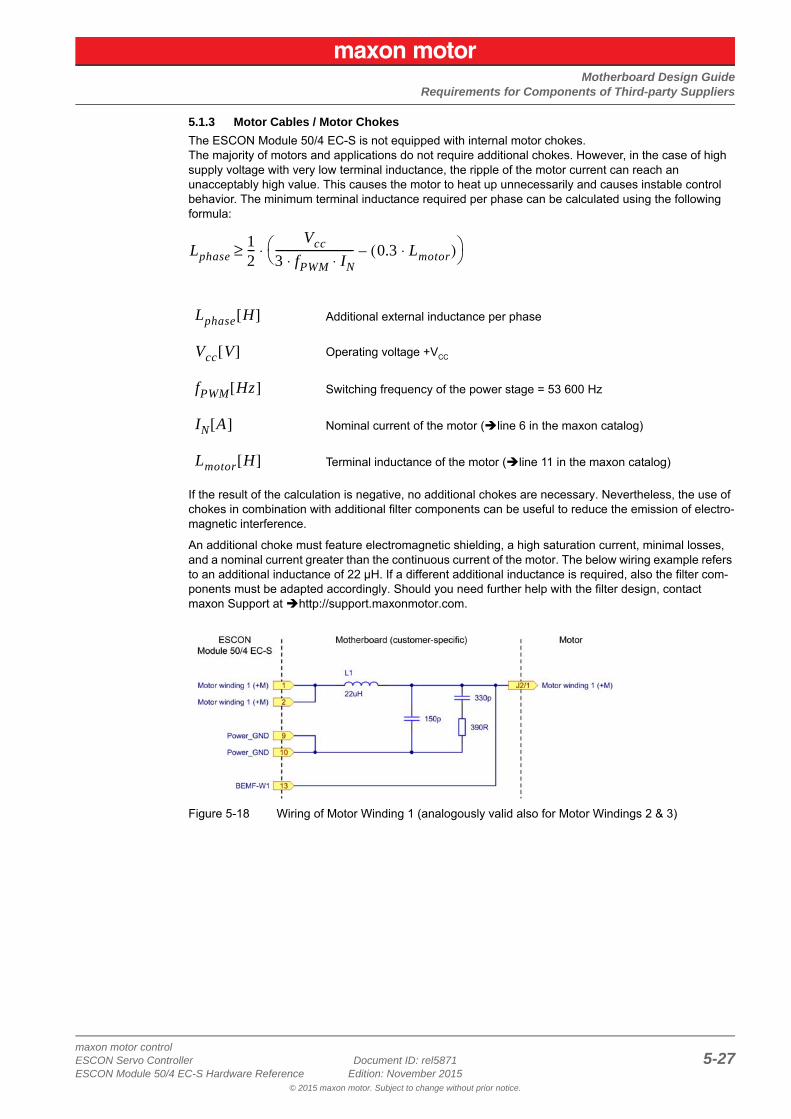
5.1.3 Motor Cables / Motor Chokes
The ESCON Module 50/4 EC-S is not equipped with internal motor chokes.The majority of motors and applications do not require additional chokes. However, in the case of high supply voltage with very low terminal inductance, the ripple of the motor current can reach an unacceptably high value. This causes the motor to heat up unnecessarily and causes instable control behavior. The minimum terminal inductance required per phase can be calculated using the following formula:
If the result of the calculation is negative, no additional chokes are necessary. Nevertheless, the use of chokes in combination with additional filter components can be useful to reduce the emission of electro-magnetic interference.
An additional choke must feature electromagnetic shielding, a high saturation current, minimal losses, and a nominal current greater than the continuous current of the motor. The below wiring example refers to an additional inductance of 22 μH. If a different additional inductance is required, also the filter com-ponents must be adapted accordingly. Should you need further help with the filter design, contact maxon Support at http://support.maxonmotor.com.
Figure 5-18 Wiring of Motor Winding 1 (analogously valid also for Motor Windings 2 & 3)
Additional external inductance per phase
Operating voltage +VCC
Switching frequency of the power stage = 53 600 Hz
Nominal current of the motor (line 6 in the maxon catalog)
Terminal inductance of the motor (line 11 in the maxon catalog)
Lphase12---
Vcc3 fPWM IN⋅ ⋅----------------------------- 0.3 Lmotor⋅( )– ⋅≥
Lphase H[ ]
Vcc V[ ]
fPWM Hz[ ]
IN A[ ]
Lmotor H[ ]
Motherboard Design GuideRequirements for Components of Third-party Suppliers
maxon motor control5-28 Document ID: rel5871 ESCON Servo Controller
Edition: November 2015 ESCON Module 50/4 EC-S Hardware Reference© 2015 maxon motor. Subject to change without prior notice.
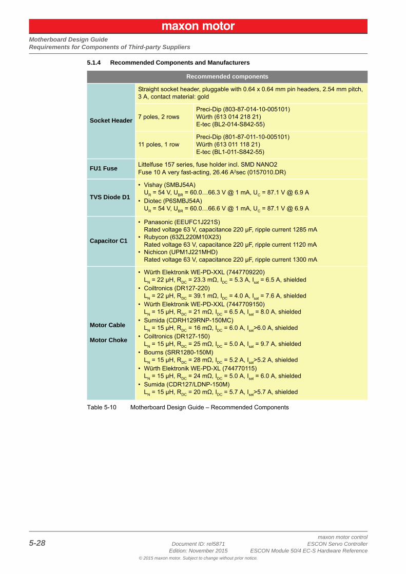
5.1.4 Recommended Components and Manufacturers
Table 5-10 Motherboard Design Guide – Recommended Components
Recommended components
Socket Header
Straight socket header, pluggable with 0.64 x 0.64 mm pin headers, 2.54 mm pitch, 3 A, contact material: gold
7 poles, 2 rowsPreci-Dip (803-87-014-10-005101)Würth (613 014 218 21)E-tec (BL2-014-S842-55)
11 poles, 1 rowPreci-Dip (801-87-011-10-005101)Würth (613 011 118 21)E-tec (BL1-011-S842-55)
FU1 FuseLittelfuse 157 series, fuse holder incl. SMD NANO2Fuse 10 A very fast-acting, 26.46 A2sec (0157010.DR)
TVS Diode D1
• Vishay (SMBJ54A)UR = 54 V, UBR = 60.0…66.3 V @ 1 mA, UC = 87.1 V @ 6.9 A
• Diotec (P6SMBJ54A)UR = 54 V, UBR = 60.0…66.6 V @ 1 mA, UC = 87.1 V @ 6.9 A
Capacitor C1
• Panasonic (EEUFC1J221S)Rated voltage 63 V, capacitance 220 μF, ripple current 1285 mA
• Rubycon (63ZL220M10X23)Rated voltage 63 V, capacitance 220 μF, ripple current 1120 mA
• Nichicon (UPM1J221MHD)Rated voltage 63 V, capacitance 220 μF, ripple current 1300 mA
Motor Cable
Motor Choke
• Würth Elektronik WE-PD-XXL (7447709220)LN = 22 μH, RDC = 23.3 mΩ, IDC = 5.3 A, Isat = 6.5 A, shielded
• Coiltronics (DR127-220)LN = 22 μH, RDC = 39.1 mΩ, IDC = 4.0 A, Isat = 7.6 A, shielded
• Würth Elektronik WE-PD-XXL (7447709150)LN = 15 μH, RDC = 21 mΩ, IDC = 6.5 A, Isat = 8.0 A, shielded
• Sumida (CDRH129RNP-150MC)LN = 15 μH, RDC = 16 mΩ, IDC = 6.0 A, Isat>6.0 A, shielded
• Coiltronics (DR127-150)LN = 15 μH, RDC = 25 mΩ, IDC = 5.0 A, Isat = 9.7 A, shielded
• Bourns (SRR1280-150M)LN = 15 μH, RDC = 28 mΩ, IDC = 5.2 A, Isat>5.2 A, shielded
• Würth Elektronik WE-PD-XL (744770115)LN = 15 μH, RDC = 24 mΩ, IDC = 5.0 A, Isat = 6.0 A, shielded
• Sumida (CDR127/LDNP-150M)LN = 15 μH, RDC = 20 mΩ, IDC = 5.7 A, Isat>5.7 A, shielded
Motherboard Design GuideDesign Guidelines
maxon motor controlESCON Servo Controller Document ID: rel5871 5-29ESCON Module 50/4 EC-S Hardware Reference Edition: November 2015
© 2015 maxon motor. Subject to change without prior notice.
5.2 Design GuidelinesThe following instructions are intended to serve as an aid for designing an application-specific mother-board and ensuring the correct and reliable integration of the ESCON Module 50/4 EC-S.
5.2.1 Ground
All ground connections (GND) should be internally connected to the ESCON Module 50/4 EC-S (equal potential). It is customary to equip the motherboard with a ground plane. All ground connections should be connected to the voltage supply ground via wide conductive tracks.
Table 5-11 Motherboard Design Guide – Grounding
If an earth potential is in place or required, the ground plane should be connected to the earth potential via one or more capacitors. The use of ceramic capacitors with 100 nF and 100 V is recommended.
5.2.2 Layout
Guidelines for the layout of the motherboard:
• Connector pins [7] and [8] +VCC operating voltage:The pins should be connected to the fuse via wide conductive tracks.
• Connector pins [9], [10] and [23] ground: All pins should be connected with the ground of the operating voltage via wide conductive tracks.
• The width of the conductive track and the copper coating thickness of the conductors for supply voltage and motor depend on the current required for the application. A minimum width of 75 mil is recommended for the track and a minimum thickness of 35 μm for the copper coating.
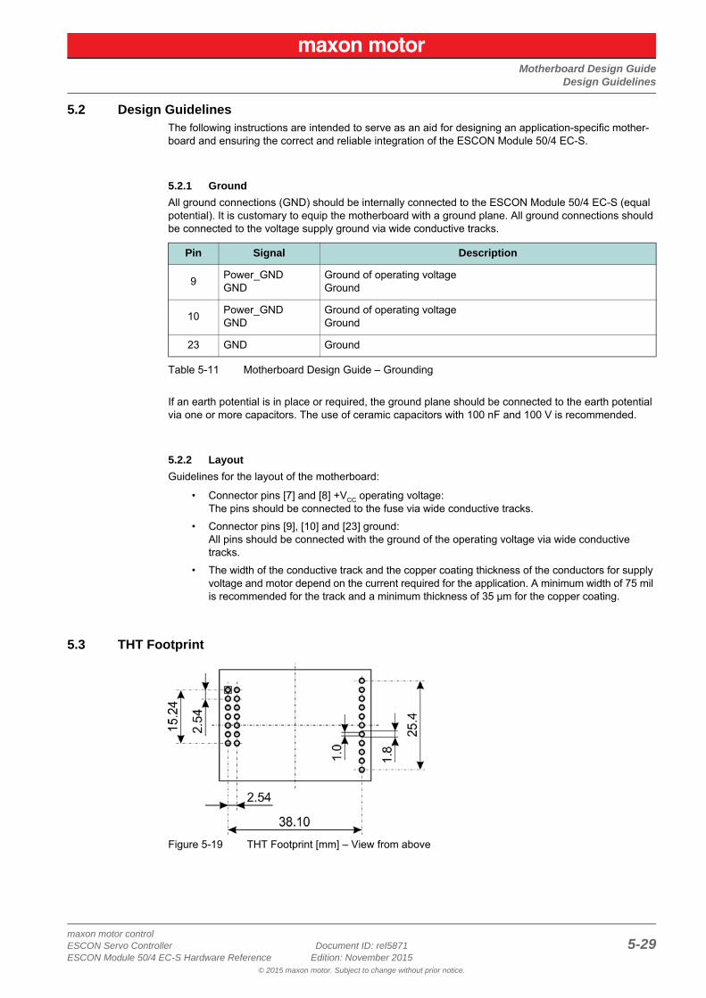
5.3 THT Footprint
Figure 5-19 THT Footprint [mm] – View from above
Pin Signal Description
9Power_GNDGND
Ground of operating voltageGround
10Power_GNDGND
Ground of operating voltageGround
23 GND Ground
Motherboard Design GuidePin Assignment
maxon motor control5-30 Document ID: rel5871 ESCON Servo Controller
Edition: November 2015 ESCON Module 50/4 EC-S Hardware Reference© 2015 maxon motor. Subject to change without prior notice.
5.4 Pin AssignmentFor detailed specifications chapter “3.4 Connections” on page 3-14.
5.5 Technical DataFor detailed specifications chapter “2 Specifications” on page 2-7.
5.6 Dimensional DrawingFor the dimensional drawing Figure 2-2 on page 2-8.
Motherboard Design GuideESCON Module Motherboard Sensorless (450237)
maxon motor controlESCON Servo Controller Document ID: rel5871 5-31ESCON Module 50/4 EC-S Hardware Reference Edition: November 2015
© 2015 maxon motor. Subject to change without prior notice.
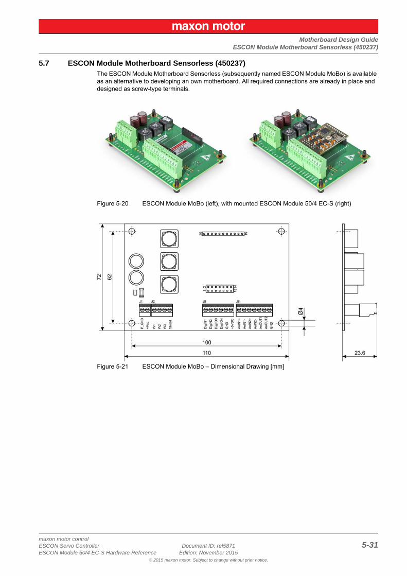
5.7 ESCON Module Motherboard Sensorless (450237)The ESCON Module Motherboard Sensorless (subsequently named ESCON Module MoBo) is available as an alternative to developing an own motherboard. All required connections are already in place and designed as screw-type terminals.
Figure 5-20 ESCON Module MoBo (left), with mounted ESCON Module 50/4 EC-S (right)
Figure 5-21 ESCON Module MoBo – Dimensional Drawing [mm]
Motherboard Design GuideESCON Module Motherboard Sensorless (450237)
maxon motor control5-32 Document ID: rel5871 ESCON Servo Controller
Edition: November 2015 ESCON Module 50/4 EC-S Hardware Reference© 2015 maxon motor. Subject to change without prior notice.
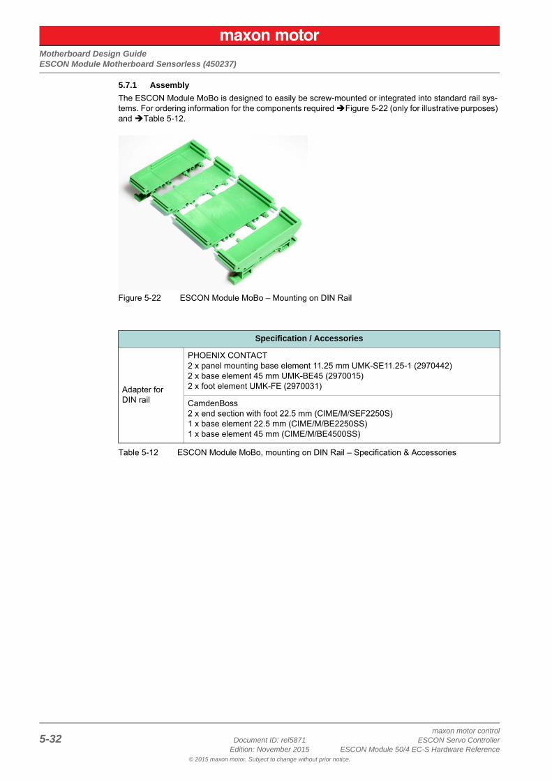
5.7.1 Assembly
The ESCON Module MoBo is designed to easily be screw-mounted or integrated into standard rail sys-tems. For ordering information for the components required Figure 5-22 (only for illustrative purposes) and Table 5-12.
Figure 5-22 ESCON Module MoBo – Mounting on DIN Rail
Table 5-12 ESCON Module MoBo, mounting on DIN Rail – Specification & Accessories
Specification / Accessories
Adapter for DIN rail
PHOENIX CONTACT2 x panel mounting base element 11.25 mm UMK-SE11.25-1 (2970442)2 x base element 45 mm UMK-BE45 (2970015)2 x foot element UMK-FE (2970031)
CamdenBoss2 x end section with foot 22.5 mm (CIME/M/SEF2250S)1 x base element 22.5 mm (CIME/M/BE2250SS)1 x base element 45 mm (CIME/M/BE4500SS)
Motherboard Design GuideESCON Module Motherboard Sensorless (450237)
maxon motor controlESCON Servo Controller Document ID: rel5871 5-33ESCON Module 50/4 EC-S Hardware Reference Edition: November 2015
© 2015 maxon motor. Subject to change without prior notice.
5.7.2 Connections
NoteThe USB interface is located directly at the ESCON Module 50/4 EC-S.
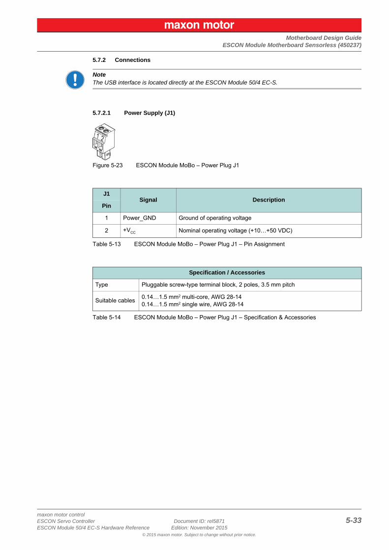
5.7.2.1 Power Supply (J1)
Figure 5-23 ESCON Module MoBo – Power Plug J1
Table 5-13 ESCON Module MoBo – Power Plug J1 – Pin Assignment
Table 5-14 ESCON Module MoBo – Power Plug J1 – Specification & Accessories
J1Signal Description
Pin
1 Power_GND Ground of operating voltage
2 +VCC Nominal operating voltage (+10…+50 VDC)
Specification / Accessories
Type Pluggable screw-type terminal block, 2 poles, 3.5 mm pitch
Suitable cables0.14…1.5 mm2 multi-core, AWG 28-140.14…1.5 mm2 single wire, AWG 28-14
Motherboard Design GuideESCON Module Motherboard Sensorless (450237)
maxon motor control5-34 Document ID: rel5871 ESCON Servo Controller
Edition: November 2015 ESCON Module 50/4 EC-S Hardware Reference© 2015 maxon motor. Subject to change without prior notice.
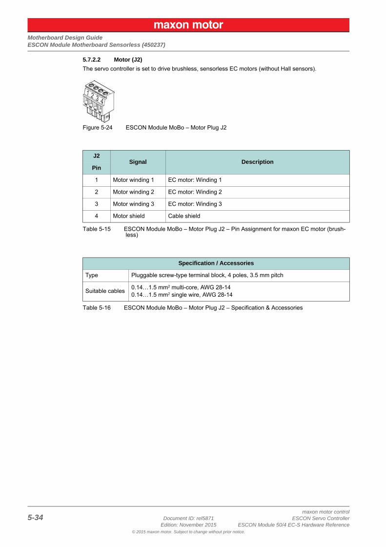
5.7.2.2 Motor (J2)
The servo controller is set to drive brushless, sensorless EC motors (without Hall sensors).
Figure 5-24 ESCON Module MoBo – Motor Plug J2
Table 5-15 ESCON Module MoBo – Motor Plug J2 – Pin Assignment for maxon EC motor (brush-less)
Table 5-16 ESCON Module MoBo – Motor Plug J2 – Specification & Accessories
J2Signal Description
Pin
1 Motor winding 1 EC motor: Winding 1
2 Motor winding 2 EC motor: Winding 2
3 Motor winding 3 EC motor: Winding 3
4 Motor shield Cable shield
Specification / Accessories
Type Pluggable screw-type terminal block, 4 poles, 3.5 mm pitch
Suitable cables0.14…1.5 mm2 multi-core, AWG 28-140.14…1.5 mm2 single wire, AWG 28-14
Motherboard Design GuideESCON Module Motherboard Sensorless (450237)
maxon motor controlESCON Servo Controller Document ID: rel5871 5-35ESCON Module 50/4 EC-S Hardware Reference Edition: November 2015
© 2015 maxon motor. Subject to change without prior notice.
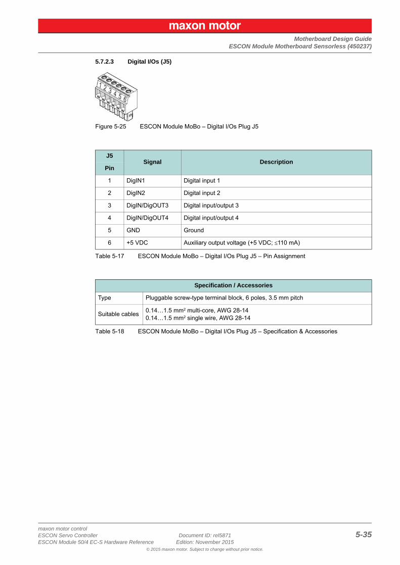
5.7.2.3 Digital I/Os (J5)
Figure 5-25 ESCON Module MoBo – Digital I/Os Plug J5
Table 5-17 ESCON Module MoBo – Digital I/Os Plug J5 – Pin Assignment
Table 5-18 ESCON Module MoBo – Digital I/Os Plug J5 – Specification & Accessories
J5Signal Description
Pin
1 DigIN1 Digital input 1
2 DigIN2 Digital input 2
3 DigIN/DigOUT3 Digital input/output 3
4 DigIN/DigOUT4 Digital input/output 4
5 GND Ground
6 +5 VDC Auxiliary output voltage (+5 VDC; ≤110 mA)
Specification / Accessories
Type Pluggable screw-type terminal block, 6 poles, 3.5 mm pitch
Suitable cables0.14…1.5 mm2 multi-core, AWG 28-140.14…1.5 mm2 single wire, AWG 28-14
Motherboard Design GuideESCON Module Motherboard Sensorless (450237)
maxon motor control5-36 Document ID: rel5871 ESCON Servo Controller
Edition: November 2015 ESCON Module 50/4 EC-S Hardware Reference© 2015 maxon motor. Subject to change without prior notice.
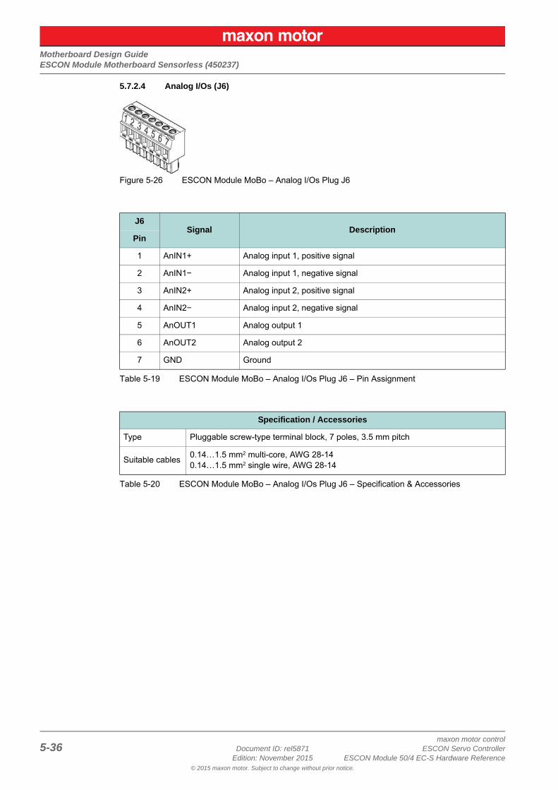
5.7.2.4 Analog I/Os (J6)
Figure 5-26 ESCON Module MoBo – Analog I/Os Plug J6
Table 5-19 ESCON Module MoBo – Analog I/Os Plug J6 – Pin Assignment
Table 5-20 ESCON Module MoBo – Analog I/Os Plug J6 – Specification & Accessories
J6Signal Description
Pin
1 AnIN1+ Analog input 1, positive signal
2 AnIN1− Analog input 1, negative signal
3 AnIN2+ Analog input 2, positive signal
4 AnIN2− Analog input 2, negative signal
5 AnOUT1 Analog output 1
6 AnOUT2 Analog output 2
7 GND Ground
Specification / Accessories
Type Pluggable screw-type terminal block, 7 poles, 3.5 mm pitch
Suitable cables0.14…1.5 mm2 multi-core, AWG 28-140.14…1.5 mm2 single wire, AWG 28-14
Motherboard Design GuideESCON Module Motherboard Sensorless (450237)
maxon motor controlESCON Servo Controller Document ID: rel5871 5-37ESCON Module 50/4 EC-S Hardware Reference Edition: November 2015
© 2015 maxon motor. Subject to change without prior notice.
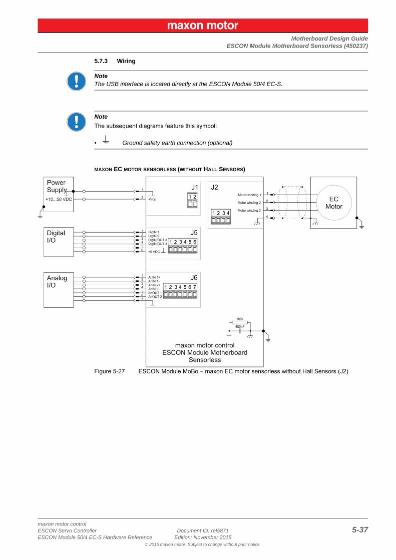
5.7.3 Wiring
NoteThe USB interface is located directly at the ESCON Module 50/4 EC-S.
Note
The subsequent diagrams feature this symbol:
• Ground safety earth connection (optional)
MAXON EC MOTOR SENSORLESS (WITHOUT HALL SENSORS)
Figure 5-27 ESCON Module MoBo – maxon EC motor sensorless without Hall Sensors (J2)
Motherboard Design GuideSpare Parts
maxon motor control5-38 Document ID: rel5871 ESCON Servo Controller
Edition: November 2015 ESCON Module 50/4 EC-S Hardware Reference© 2015 maxon motor. Subject to change without prior notice.
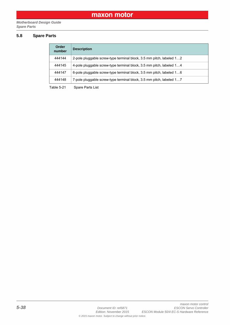
5.8 Spare Parts
Table 5-21 Spare Parts List
Order number
Description
444144 2-pole pluggable screw-type terminal block, 3.5 mm pitch, labeled 1…2
444145 4-pole pluggable screw-type terminal block, 3.5 mm pitch, labeled 1…4
444147 6-pole pluggable screw-type terminal block, 3.5 mm pitch, labeled 1…6
444148 7-pole pluggable screw-type terminal block, 3.5 mm pitch, labeled 1…7
maxon motor controlESCON Servo Controller Document ID: rel5871 Z-39ESCON Module 50/4 EC-S Hardware Reference Edition: November 2015
© 2015 maxon motor. Subject to change without prior notice.
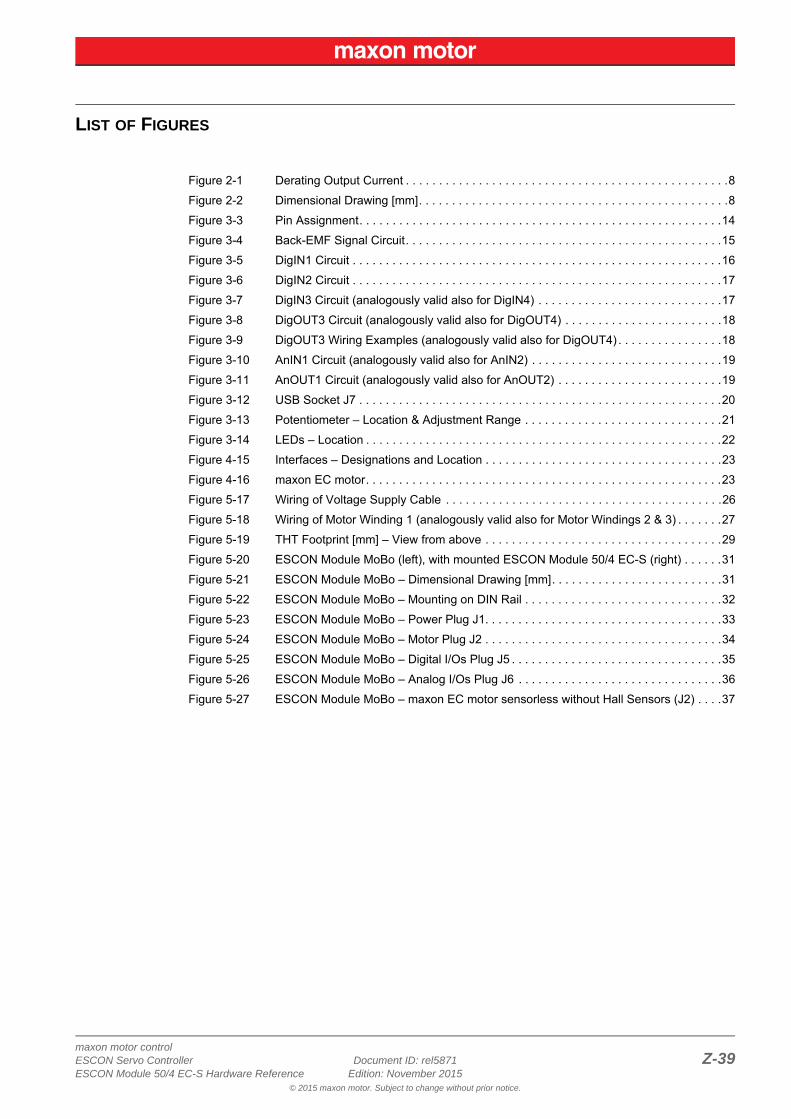
Figure 2-1 Derating Output Current . . . . . . . . . . . . . . . . . . . . . . . . . . . . . . . . . . . . . . . . . . . . . . . . .8
Figure 2-2 Dimensional Drawing [mm]. . . . . . . . . . . . . . . . . . . . . . . . . . . . . . . . . . . . . . . . . . . . . . .8
Figure 3-3 Pin Assignment. . . . . . . . . . . . . . . . . . . . . . . . . . . . . . . . . . . . . . . . . . . . . . . . . . . . . . .14
Figure 3-4 Back-EMF Signal Circuit. . . . . . . . . . . . . . . . . . . . . . . . . . . . . . . . . . . . . . . . . . . . . . . .15
Figure 3-5 DigIN1 Circuit . . . . . . . . . . . . . . . . . . . . . . . . . . . . . . . . . . . . . . . . . . . . . . . . . . . . . . . .16
Figure 3-6 DigIN2 Circuit . . . . . . . . . . . . . . . . . . . . . . . . . . . . . . . . . . . . . . . . . . . . . . . . . . . . . . . .17
Figure 3-7 DigIN3 Circuit (analogously valid also for DigIN4) . . . . . . . . . . . . . . . . . . . . . . . . . . . .17
Figure 3-8 DigOUT3 Circuit (analogously valid also for DigOUT4) . . . . . . . . . . . . . . . . . . . . . . . .18
Figure 3-9 DigOUT3 Wiring Examples (analogously valid also for DigOUT4) . . . . . . . . . . . . . . . .18
Figure 3-10 AnIN1 Circuit (analogously valid also for AnIN2) . . . . . . . . . . . . . . . . . . . . . . . . . . . . .19
Figure 3-11 AnOUT1 Circuit (analogously valid also for AnOUT2) . . . . . . . . . . . . . . . . . . . . . . . . .19
Figure 3-12 USB Socket J7 . . . . . . . . . . . . . . . . . . . . . . . . . . . . . . . . . . . . . . . . . . . . . . . . . . . . . . .20
Figure 3-13 Potentiometer – Location & Adjustment Range . . . . . . . . . . . . . . . . . . . . . . . . . . . . . .21
Figure 3-14 LEDs – Location . . . . . . . . . . . . . . . . . . . . . . . . . . . . . . . . . . . . . . . . . . . . . . . . . . . . . .22
Figure 4-15 Interfaces – Designations and Location . . . . . . . . . . . . . . . . . . . . . . . . . . . . . . . . . . . .23
Figure 4-16 maxon EC motor. . . . . . . . . . . . . . . . . . . . . . . . . . . . . . . . . . . . . . . . . . . . . . . . . . . . . .23
Figure 5-17 Wiring of Voltage Supply Cable . . . . . . . . . . . . . . . . . . . . . . . . . . . . . . . . . . . . . . . . . .26
Figure 5-18 Wiring of Motor Winding 1 (analogously valid also for Motor Windings 2 & 3) . . . . . . .27
Figure 5-19 THT Footprint [mm] – View from above . . . . . . . . . . . . . . . . . . . . . . . . . . . . . . . . . . . .29
Figure 5-20 ESCON Module MoBo (left), with mounted ESCON Module 50/4 EC-S (right) . . . . . .31
Figure 5-21 ESCON Module MoBo – Dimensional Drawing [mm]. . . . . . . . . . . . . . . . . . . . . . . . . .31
Figure 5-22 ESCON Module MoBo – Mounting on DIN Rail . . . . . . . . . . . . . . . . . . . . . . . . . . . . . .32
Figure 5-23 ESCON Module MoBo – Power Plug J1. . . . . . . . . . . . . . . . . . . . . . . . . . . . . . . . . . . .33
Figure 5-24 ESCON Module MoBo – Motor Plug J2 . . . . . . . . . . . . . . . . . . . . . . . . . . . . . . . . . . . .34
Figure 5-25 ESCON Module MoBo – Digital I/Os Plug J5 . . . . . . . . . . . . . . . . . . . . . . . . . . . . . . . .35
Figure 5-26 ESCON Module MoBo – Analog I/Os Plug J6 . . . . . . . . . . . . . . . . . . . . . . . . . . . . . . .36
Figure 5-27 ESCON Module MoBo – maxon EC motor sensorless without Hall Sensors (J2) . . . .37
LIST OF FIGURES
maxon motor controlZ-40 Document ID: rel5871 ESCON Servo Controller
Edition: November 2015 ESCON Module 50/4 EC-S Hardware Reference© 2015 maxon motor. Subject to change without prior notice.
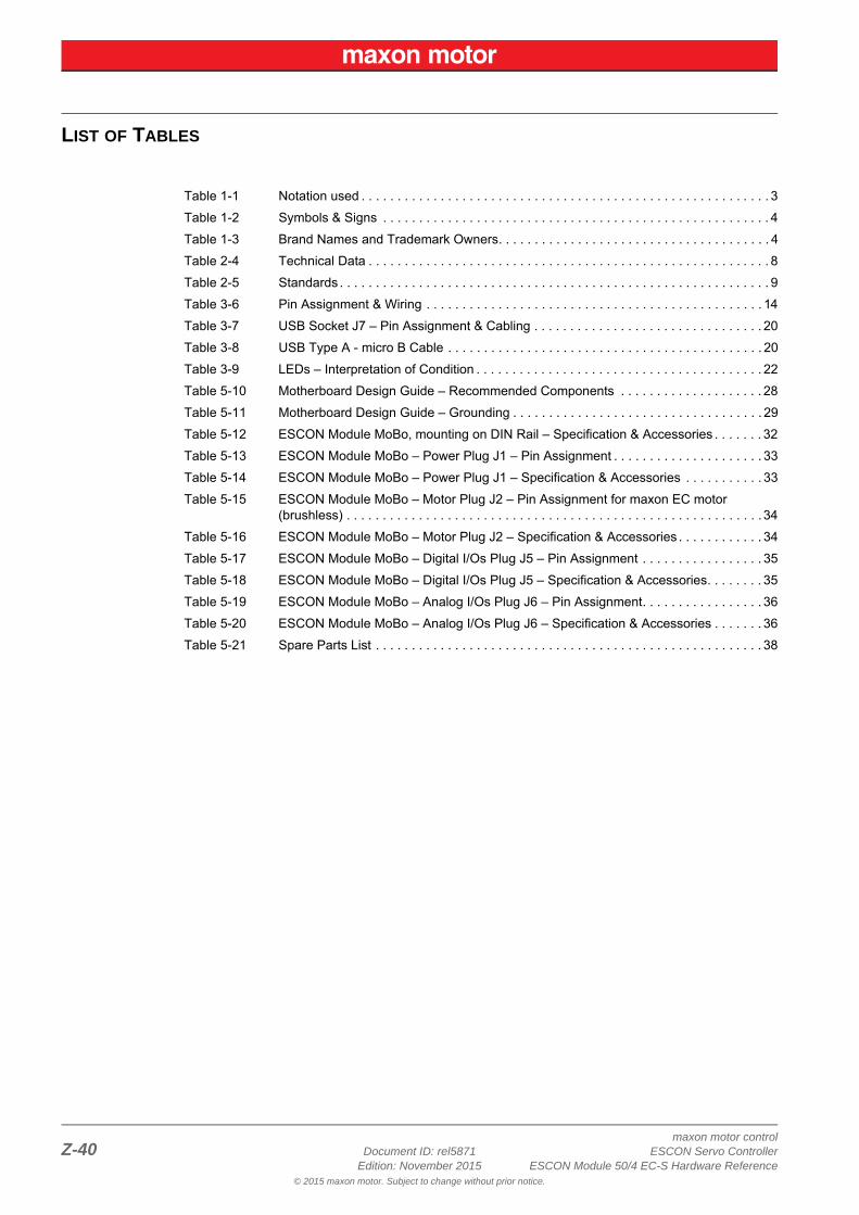
Table 1-1 Notation used . . . . . . . . . . . . . . . . . . . . . . . . . . . . . . . . . . . . . . . . . . . . . . . . . . . . . . . . . 3
Table 1-2 Symbols & Signs . . . . . . . . . . . . . . . . . . . . . . . . . . . . . . . . . . . . . . . . . . . . . . . . . . . . . . 4
Table 1-3 Brand Names and Trademark Owners. . . . . . . . . . . . . . . . . . . . . . . . . . . . . . . . . . . . . . 4
Table 2-4 Technical Data . . . . . . . . . . . . . . . . . . . . . . . . . . . . . . . . . . . . . . . . . . . . . . . . . . . . . . . . 8
Table 2-5 Standards . . . . . . . . . . . . . . . . . . . . . . . . . . . . . . . . . . . . . . . . . . . . . . . . . . . . . . . . . . . . 9
Table 3-6 Pin Assignment & Wiring . . . . . . . . . . . . . . . . . . . . . . . . . . . . . . . . . . . . . . . . . . . . . . . 14
Table 3-7 USB Socket J7 – Pin Assignment & Cabling . . . . . . . . . . . . . . . . . . . . . . . . . . . . . . . . 20
Table 3-8 USB Type A - micro B Cable . . . . . . . . . . . . . . . . . . . . . . . . . . . . . . . . . . . . . . . . . . . . 20
Table 3-9 LEDs – Interpretation of Condition . . . . . . . . . . . . . . . . . . . . . . . . . . . . . . . . . . . . . . . . 22
Table 5-10 Motherboard Design Guide – Recommended Components . . . . . . . . . . . . . . . . . . . . 28
Table 5-11 Motherboard Design Guide – Grounding . . . . . . . . . . . . . . . . . . . . . . . . . . . . . . . . . . . 29
Table 5-12 ESCON Module MoBo, mounting on DIN Rail – Specification & Accessories . . . . . . . 32
Table 5-13 ESCON Module MoBo – Power Plug J1 – Pin Assignment . . . . . . . . . . . . . . . . . . . . . 33
Table 5-14 ESCON Module MoBo – Power Plug J1 – Specification & Accessories . . . . . . . . . . . 33
Table 5-15 ESCON Module MoBo – Motor Plug J2 – Pin Assignment for maxon EC motor (brushless) . . . . . . . . . . . . . . . . . . . . . . . . . . . . . . . . . . . . . . . . . . . . . . . . . . . . . . . . . . 34
Table 5-16 ESCON Module MoBo – Motor Plug J2 – Specification & Accessories . . . . . . . . . . . . 34
Table 5-17 ESCON Module MoBo – Digital I/Os Plug J5 – Pin Assignment . . . . . . . . . . . . . . . . . 35
Table 5-18 ESCON Module MoBo – Digital I/Os Plug J5 – Specification & Accessories. . . . . . . . 35
Table 5-19 ESCON Module MoBo – Analog I/Os Plug J6 – Pin Assignment. . . . . . . . . . . . . . . . . 36
Table 5-20 ESCON Module MoBo – Analog I/Os Plug J6 – Specification & Accessories . . . . . . . 36
Table 5-21 Spare Parts List . . . . . . . . . . . . . . . . . . . . . . . . . . . . . . . . . . . . . . . . . . . . . . . . . . . . . . 38
LIST OF TABLES
maxon motor controlESCON Servo Controller Document ID: rel5871 Z-41ESCON Module 50/4 EC-S Hardware Reference Edition: November 2015
© 2015 maxon motor. Subject to change without prior notice.
Aacceleration phase (sensorless start-up) 12additionally applicable regulations 5alignment phase (sensorless start-up) 12analog inputs 19applicable EU directive 11assignment of the connections 14
BBack-EMF signals 15
Ccables (prefab)
USB Type A - micro B Cable 20country-specific regulations 5
Ddigital inputs 16, 17
Eerror display 22ESD 5EU directive, applicable 11
Hhow to
calculate required supply voltage 13interpret icons (and signs) used in the document 3start-up a sensorles motor 12support for designing the motherboard 25
Iincorporation into surrounding system 11informatory signs 4intended purpose
of the device 5of this document 3
interfaces, location and designation 23
LLEDs 22
Mmandatory action signs 4MoBo (ESCON Module Motherboard Sensorless) 31
Nnotations used 3
Ooperating license 11operating status, display 22order numbers
403968 20438725 7444144 38444145 38444147 38444148 38450237 31
Pperformance data 7pin assignment 14potentiometer 21precautions 5prerequisites prior installation 11prohibitive signs 3purpose
of the device 5
Rregulations, additionally applicable 5
Ssafety alerts 3safety first! 5signs used 3sockets
J1 33J2 34J5 35J6 36J7 20
standards, fulfilled 9start-up procedure, sensorless 12status display 22status LEDs 22supply voltage, required 13symbols used 3
Ttechnical data 7
UUSB interface 20
INDEX
maxon motor controlZ-42 Document ID: rel5871 ESCON Servo Controller
Edition: November 2015 ESCON Module 50/4 EC-S Hardware Reference© 2015 maxon motor. Subject to change without prior notice.
© 2015 maxon motor. All rights reserved.
The present document – including all parts thereof – is protected by copyright. Any use (including reproduction, translation, microfilming, and other means of electronic data processing) beyond the narrow restrictions of the copyright law is not permit-ted without the prior approval of maxon motor ag and will be subject to prosecution under the applicable law.
maxon motor agBrünigstrasse 220P.O.Box 263CH-6072 SachselnSwitzerland
Phone +41 41 666 15 00Fax +41 41 666 16 50
www.maxonmotor.com