Embed Size (px)
Citation preview
maxon motor ag Brünigstrasse 220 P.O.Box 263 CH-6072 Sachseln Phone +41 41 666 15 00 Fax +41 41 666 16 50 www.maxonmotor.com
Edition September 2011
ESCON Servo Controller
Hardware Reference
maxon motor control
ESCON 36/2 DCServo Controller
P/N 403112
Hardware Reference
Document ID: rel2472
maxon motor controlA-2 Document ID: rel2472 ESCON Servo Controller
Edition: September 2011 ESCON 36/2 DC Hardware Reference© 2011 maxon motor. Subject to change without prior notice.
1 About 3
1.1 About this Document . . . . . . . . . . . . . . . . . . . . . . . . . . . . . . . . . . . . . . . . . . . . 3
1.2 About the Device . . . . . . . . . . . . . . . . . . . . . . . . . . . . . . . . . . . . . . . . . . . . . . . 4
1.3 About the Safety Precautions. . . . . . . . . . . . . . . . . . . . . . . . . . . . . . . . . . . . . . 5
2 Specifications 7
2.1 Technical Data . . . . . . . . . . . . . . . . . . . . . . . . . . . . . . . . . . . . . . . . . . . . . . . . . 7
2.2 Standards . . . . . . . . . . . . . . . . . . . . . . . . . . . . . . . . . . . . . . . . . . . . . . . . . . . . . 9
3 Setup 11
3.1 Generally applicable Rules. . . . . . . . . . . . . . . . . . . . . . . . . . . . . . . . . . . . . . . 11
3.2 Determination of Power Supply . . . . . . . . . . . . . . . . . . . . . . . . . . . . . . . . . . . 12
3.3 Cabling . . . . . . . . . . . . . . . . . . . . . . . . . . . . . . . . . . . . . . . . . . . . . . . . . . . . . . 13
3.4 Connections . . . . . . . . . . . . . . . . . . . . . . . . . . . . . . . . . . . . . . . . . . . . . . . . . . 14
3.5 Jumpers . . . . . . . . . . . . . . . . . . . . . . . . . . . . . . . . . . . . . . . . . . . . . . . . . . . . . 29
3.6 Potentiometers . . . . . . . . . . . . . . . . . . . . . . . . . . . . . . . . . . . . . . . . . . . . . . . . 29
3.7 Status Indicators. . . . . . . . . . . . . . . . . . . . . . . . . . . . . . . . . . . . . . . . . . . . . . . 30
4 Wiring 31
List of Figures 39
List of Tables 40
Index 41
TABLE OF CONTENTS
READ THIS FIRST
These instructions are intended for qualified technical personnel. Prior commencing with any activities …• you must carefully read and understand this manual and• you must follow the instructions given therein.
The ESCON 36/2 DC is considered as partly completed machinery according to EU Directive 2006/42/EC, Article 2, Clause (g) and is intended to be incorporated into or assembled with other machinery or other partly completed machinery or equipment.
Therefore, you must not put the device into service, …• unless you have made completely sure that the other machinery fully complies with the EU directive’s requirements!• unless the other machinery fulfills all relevant health and safety aspects!• unless all respective interfaces have been established and fulfill the herein stated requirements!
AboutAbout this Document
maxon motor controlESCON Servo Controller Document ID: rel2472 1-3ESCON 36/2 DC Hardware Reference Edition: September 2011
© 2011 maxon motor. Subject to change without prior notice.
1 About
1.1 About this Document
1.1.1 Intended Purpose
The purpose of the present document is to familiarize you with the ESCON 36/2 DC Servo Controller. It will highlight the tasks for safe and adequate installation and/or commissioning. Follow the described instructions …
• to avoid dangerous situations,
• to keep installation and/or commissioning time at a minimum,
• to increase reliability and service life of the described equipment.
The document contains performance data and specifications, information on fulfilled standards, details on connections and pin assignment, and wiring examples.
1.1.2 Target Audience
The present document is intended for trained and skilled personnel. It conveys information on how to understand and fulfill the respective work and duties.
1.1.3 How to use
Take note of the following notations and codes which will be used throughout the document.
Table 1-1 Notation used
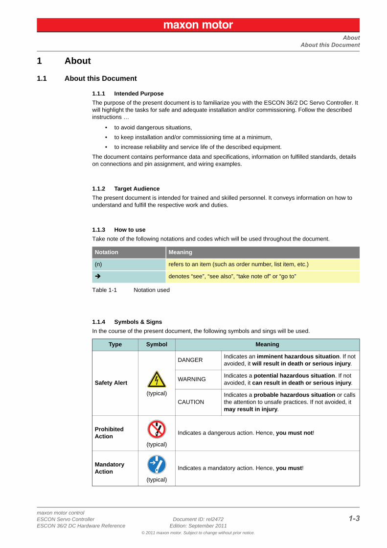
1.1.4 Symbols & Signs
In the course of the present document, the following symbols and sings will be used.
Notation Meaning
(n) refers to an item (such as order number, list item, etc.)
denotes “see”, “see also”, “take note of” or “go to”
Type Symbol Meaning
Safety Alert
(typical)
DANGERIndicates an imminent hazardous situation. If not avoided, it will result in death or serious injury.
WARNINGIndicates a potential hazardous situation. If not avoided, it can result in death or serious injury.
CAUTIONIndicates a probable hazardous situation or calls the attention to unsafe practices. If not avoided, it may result in injury.
ProhibitedAction
(typical)
Indicates a dangerous action. Hence, you must not!
MandatoryAction
(typical)
Indicates a mandatory action. Hence, you must!
AboutAbout the Device
maxon motor control1-4 Document ID: rel2472 ESCON Servo Controller
Edition: September 2011 ESCON 36/2 DC Hardware Reference© 2011 maxon motor. Subject to change without prior notice.
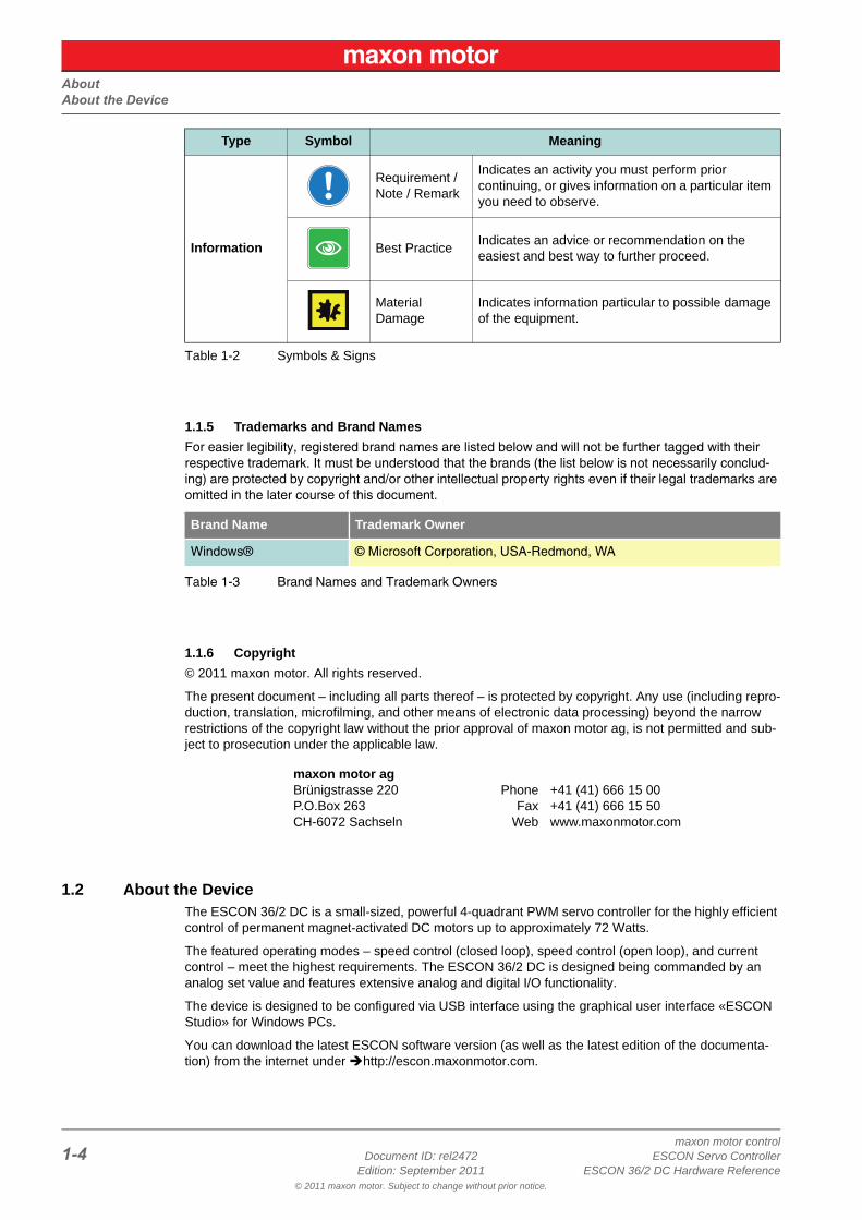
Table 1-2 Symbols & Signs
1.1.5 Trademarks and Brand Names
For easier legibility, registered brand names are listed below and will not be further tagged with their respective trademark. It must be understood that the brands (the list below is not necessarily conclud-ing) are protected by copyright and/or other intellectual property rights even if their legal trademarks are omitted in the later course of this document.
Table 1-3 Brand Names and Trademark Owners
1.1.6 Copyright
© 2011 maxon motor. All rights reserved.
The present document – including all parts thereof – is protected by copyright. Any use (including repro-duction, translation, microfilming, and other means of electronic data processing) beyond the narrow restrictions of the copyright law without the prior approval of maxon motor ag, is not permitted and sub-ject to prosecution under the applicable law.
1.2 About the DeviceThe ESCON 36/2 DC is a small-sized, powerful 4-quadrant PWM servo controller for the highly efficient control of permanent magnet-activated DC motors up to approximately 72 Watts.
The featured operating modes – speed control (closed loop), speed control (open loop), and current control – meet the highest requirements. The ESCON 36/2 DC is designed being commanded by an analog set value and features extensive analog and digital I/O functionality.
The device is designed to be configured via USB interface using the graphical user interface «ESCON Studio» for Windows PCs.
You can download the latest ESCON software version (as well as the latest edition of the documenta-tion) from the internet under http://escon.maxonmotor.com.
Information
Requirement / Note / Remark
Indicates an activity you must perform prior continuing, or gives information on a particular item you need to observe.
Best PracticeIndicates an advice or recommendation on the easiest and best way to further proceed.
Material Damage
Indicates information particular to possible damage of the equipment.
Brand Name Trademark Owner
Windows® © Microsoft Corporation, USA-Redmond, WA
maxon motor agBrünigstrasse 220P.O.Box 263CH-6072 Sachseln
PhoneFax
Web
+41 (41) 666 15 00+41 (41) 666 15 50www.maxonmotor.com
Type Symbol Meaning
AboutAbout the Safety Precautions
maxon motor controlESCON Servo Controller Document ID: rel2472 1-5ESCON 36/2 DC Hardware Reference Edition: September 2011
© 2011 maxon motor. Subject to change without prior notice.
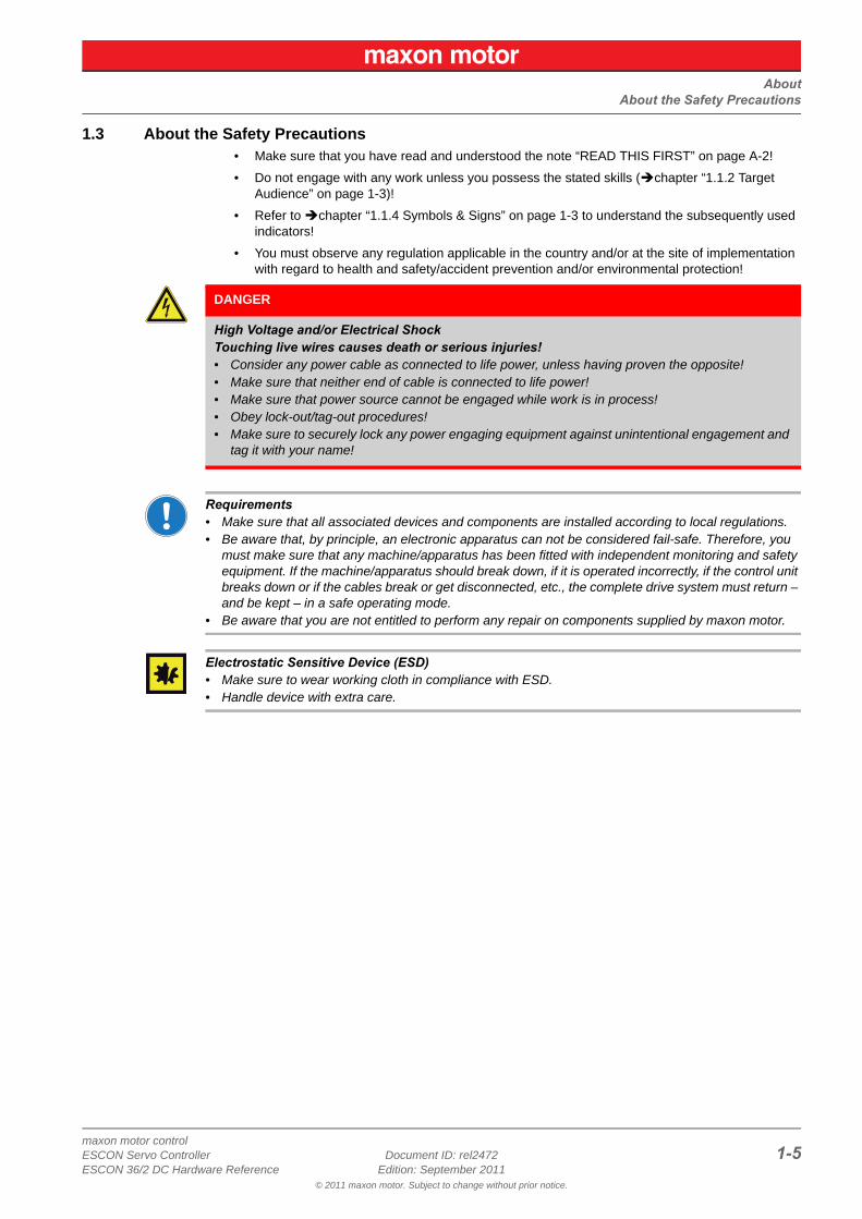
1.3 About the Safety Precautions• Make sure that you have read and understood the note “READ THIS FIRST” on page A-2!
• Do not engage with any work unless you possess the stated skills (chapter “1.1.2 Target Audience” on page 1-3)!
• Refer to chapter “1.1.4 Symbols & Signs” on page 1-3 to understand the subsequently used indicators!
• You must observe any regulation applicable in the country and/or at the site of implementation with regard to health and safety/accident prevention and/or environmental protection!
Requirements• Make sure that all associated devices and components are installed according to local regulations.• Be aware that, by principle, an electronic apparatus can not be considered fail-safe. Therefore, you
must make sure that any machine/apparatus has been fitted with independent monitoring and safety equipment. If the machine/apparatus should break down, if it is operated incorrectly, if the control unit breaks down or if the cables break or get disconnected, etc., the complete drive system must return – and be kept – in a safe operating mode.
• Be aware that you are not entitled to perform any repair on components supplied by maxon motor.
Electrostatic Sensitive Device (ESD)• Make sure to wear working cloth in compliance with ESD.• Handle device with extra care.
DANGER
High Voltage and/or Electrical ShockTouching live wires causes death or serious injuries!• Consider any power cable as connected to life power, unless having proven the opposite!• Make sure that neither end of cable is connected to life power!• Make sure that power source cannot be engaged while work is in process!• Obey lock-out/tag-out procedures!• Make sure to securely lock any power engaging equipment against unintentional engagement and
tag it with your name!

AboutAbout the Safety Precautions
maxon motor control1-6 Document ID: rel2472 ESCON Servo Controller
Edition: September 2011 ESCON 36/2 DC Hardware Reference© 2011 maxon motor. Subject to change without prior notice.
• • p a g e i n t e n t i o n a l l y l e f t b l a n k • •
SpecificationsTechnical Data
maxon motor controlESCON Servo Controller Document ID: rel2472 2-7ESCON 36/2 DC Hardware Reference Edition: September 2011
© 2011 maxon motor. Subject to change without prior notice.
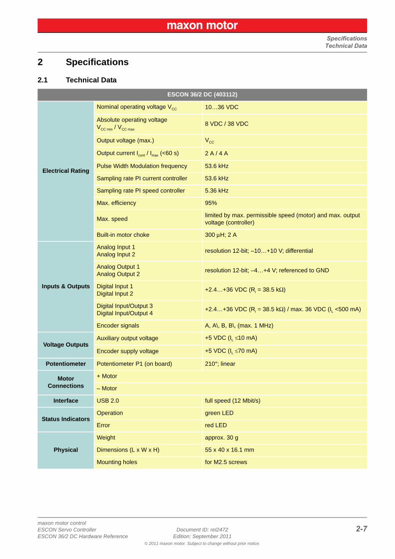
2 Specifications
2.1 Technical Data
ESCON 36/2 DC (403112)
Electrical Rating
Nominal operating voltage VCC 10…36 VDC
Absolute operating voltageVCC min / VCC max
8 VDC / 38 VDC
Output voltage (max.) VCC
Output current Icont / Imax (<60 s) 2 A / 4 A
Pulse Width Modulation frequency 53.6 kHz
Sampling rate PI current controller 53.6 kHz
Sampling rate PI speed controller 5.36 kHz
Max. efficiency 95%
Max. speedlimited by max. permissible speed (motor) and max. output voltage (controller)
Built-in motor choke 300 μH; 2 A
Inputs & Outputs
Analog Input 1Analog Input 2
resolution 12-bit; –10…+10 V; differential
Analog Output 1Analog Output 2
resolution 12-bit; –4…+4 V; referenced to GND
Digital Input 1Digital Input 2
+2.4…+36 VDC (Ri = 38.5 kΩ)
Digital Input/Output 3Digital Input/Output 4
+2.4…+36 VDC (Ri = 38.5 kΩ) / max. 36 VDC (IL <500 mA)
Encoder signals A, A\, B, B\, (max. 1 MHz)
Voltage OutputsAuxiliary output voltage +5 VDC (IL ≤10 mA)
Encoder supply voltage +5 VDC (IL ≤70 mA)
Potentiometer Potentiometer P1 (on board) 210°; linear
Motor Connections
+ Motor
– Motor
Interface USB 2.0 full speed (12 Mbit/s)
Status IndicatorsOperation green LED
Error red LED
Physical
Weight approx. 30 g
Dimensions (L x W x H) 55 x 40 x 16.1 mm
Mounting holes for M2.5 screws
SpecificationsTechnical Data
maxon motor control2-8 Document ID: rel2472 ESCON Servo Controller
Edition: September 2011 ESCON 36/2 DC Hardware Reference© 2011 maxon motor. Subject to change without prior notice.
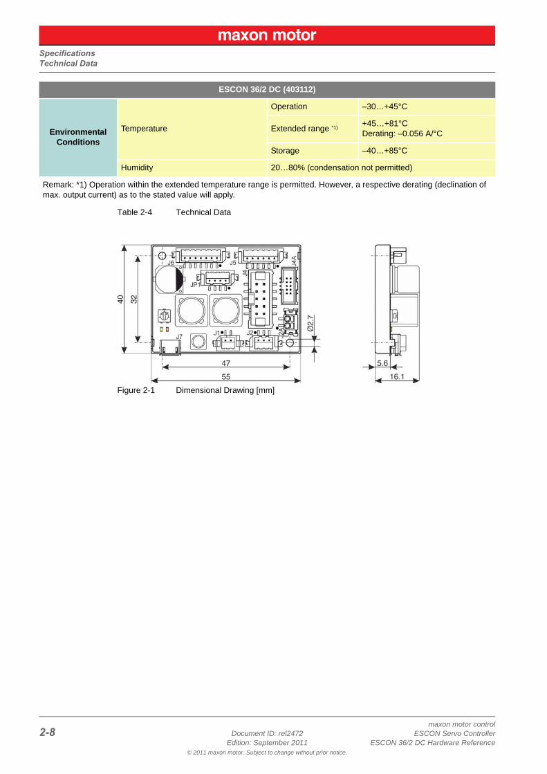
Table 2-4 Technical Data
Figure 2-1 Dimensional Drawing [mm]
Environmental Conditions
Temperature
Operation –30…+45°C
Extended range *1) +45…+81°CDerating: –0.056 A/°C
Storage –40…+85°C
Humidity 20…80% (condensation not permitted)
Remark: *1) Operation within the extended temperature range is permitted. However, a respective derating (declination of max. output current) as to the stated value will apply.
ESCON 36/2 DC (403112)
SpecificationsStandards
maxon motor controlESCON Servo Controller Document ID: rel2472 2-9ESCON 36/2 DC Hardware Reference Edition: September 2011
© 2011 maxon motor. Subject to change without prior notice.
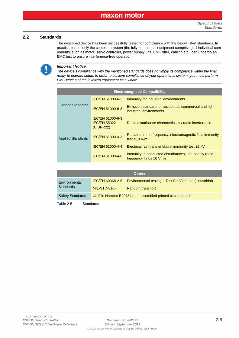
2.2 StandardsThe described device has been successfully tested for compliance with the below listed standards. In practical terms, only the complete system (the fully operational equipment comprising all individual com-ponents, such as motor, servo controller, power supply unit, EMC filter, cabling etc.) can undergo an EMC test to ensure interference-free operation.
Important NoticeThe device’s compliance with the mentioned standards does not imply its compliance within the final, ready to operate setup. In order to achieve compliance of your operational system, you must perform EMC testing of the involved equipment as a whole.
Table 2-5 Standards
Electromagnetic Compatibility
Generic Standards
IEC/EN 61000-6-2 Immunity for industrial environments
IEC/EN 61000-6-3Emission standard for residential, commercial and light-industrial environments
Applied Standards
IEC/EN 61000-6-3IEC/EN 55022(CISPR22)
Radio disturbance characteristics / radio interference
IEC/EN 61000-4-3Radiated, radio-frequency, electromagnetic field immunity test >10 V/m
IEC/EN 61000-4-4 Electrical fast transient/burst immunity test ±2 kV
IEC/EN 61000-4-6 Immunity to conducted disturbances, induced by radio-frequency fields 10 Vrms
Others
Environmental Standards
IEC/EN 60068-2-6 Environmental testing – Test Fc: Vibration (sinusoidal)
MIL-STD-810F Random transport
Safety Standards UL File Number E207844; unassembled printed circuit board
SpecificationsStandards
maxon motor control2-10 Document ID: rel2472 ESCON Servo Controller
Edition: September 2011 ESCON 36/2 DC Hardware Reference© 2011 maxon motor. Subject to change without prior notice.
• • p a g e i n t e n t i o n a l l y l e f t b l a n k • •
SetupGenerally applicable Rules
maxon motor controlESCON Servo Controller Document ID: rel2472 3-11ESCON 36/2 DC Hardware Reference Edition: September 2011
© 2011 maxon motor. Subject to change without prior notice.
3 Setup
IMPORTANT NOTICE: PREREQUISITES FOR PERMISSION TO COMMENCE INSTALLATION
The ESCON 36/2 DC is considered as partly completed machinery according to EU Directive 2006/42/EC, Article 2, Clause (g) and is intended to be incorporated into or assembled with other machin-ery or other partly completed machinery or equipment.
3.1 Generally applicable RulesFor each possible motor variant you will find information on the from/to connections and the cables you will require. If you should decide not to use the ready-made maxon cables, you must establish the respective connections as to chapter “3.4.7 ESCON 36/2 DC Connector Set” on page 3-28 and chapter “4 Wiring” on page 4-31.
Maximal permitted Supply Voltage• Make sure that supply power is between 10…36 VDC.• Supply voltages above 38 VDC, or wrong polarity will destroy the unit.• Note that the necessary output current is depending on the load torque. Yet, the output current limits
of the ESCON 36/2 DC are as follows; continuous max. 2 A / short-time (acceleration) max. 4 A.
How to read the Wiring DetailsThe subsequent description follows this scheme:
• Column “J… & Head A”: Pin number…– of the socket,– of the corresponding plug, and– of Head A of the matching prefab maxon cable.
• Column “Prefab Cable”: Wire color of the prefab maxon cable.• Column “Head B”: Pin number of Head B of the matching prefab maxon cable.
WARNING
Risk of InjuryOperating the device without the full compliance of the surrounding system with the EU Direc-tive 2006/42/EC may cause serious injuries!• Do not operate the device, unless you have made completely sure that the other machinery fully
complies with the EU directive’s requirements!• Do not operate the device, unless the other machinery fulfills all relevant health and safety
aspects!• Do not operate the device, unless all respective interfaces have been established and fulfill the
requirements stated in this document!
SetupDetermination of Power Supply
maxon motor control3-12 Document ID: rel2472 ESCON Servo Controller
Edition: September 2011 ESCON 36/2 DC Hardware Reference© 2011 maxon motor. Subject to change without prior notice.
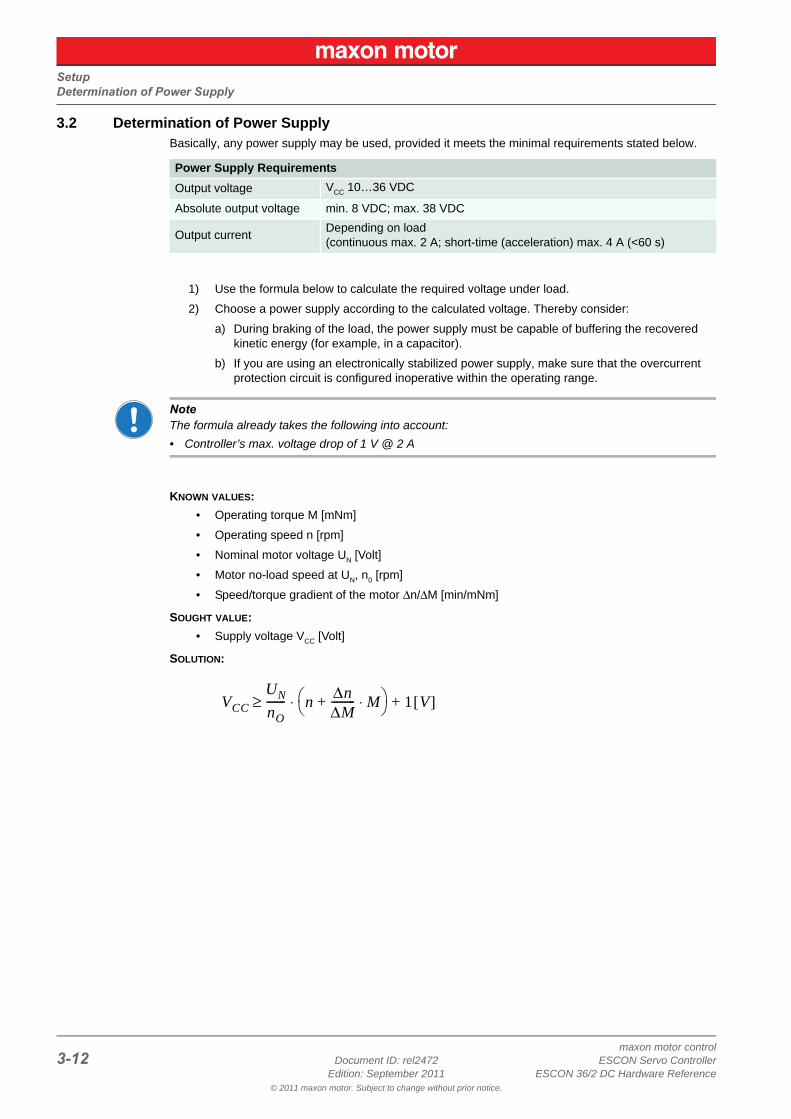
3.2 Determination of Power SupplyBasically, any power supply may be used, provided it meets the minimal requirements stated below.
1) Use the formula below to calculate the required voltage under load.
2) Choose a power supply according to the calculated voltage. Thereby consider:
a) During braking of the load, the power supply must be capable of buffering the recovered kinetic energy (for example, in a capacitor).
b) If you are using an electronically stabilized power supply, make sure that the overcurrent protection circuit is configured inoperative within the operating range.
NoteThe formula already takes the following into account:
• Controller’s max. voltage drop of 1 V @ 2 A
KNOWN VALUES:
• Operating torque M [mNm]
• Operating speed n [rpm]
• Nominal motor voltage UN [Volt]
• Motor no-load speed at UN, n0 [rpm]
• Speed/torque gradient of the motor Δn/ΔM [min/mNm]
SOUGHT VALUE:
• Supply voltage VCC [Volt]
SOLUTION:
Power Supply Requirements
Output voltage VCC 10…36 VDC
Absolute output voltage min. 8 VDC; max. 38 VDC
Output currentDepending on load (continuous max. 2 A; short-time (acceleration) max. 4 A (<60 s)
VCCUNnO------- n Δn
ΔM--------- M⋅+
⋅ 1 V[ ]+≥
SetupCabling
maxon motor controlESCON Servo Controller Document ID: rel2472 3-13ESCON 36/2 DC Hardware Reference Edition: September 2011
© 2011 maxon motor. Subject to change without prior notice.
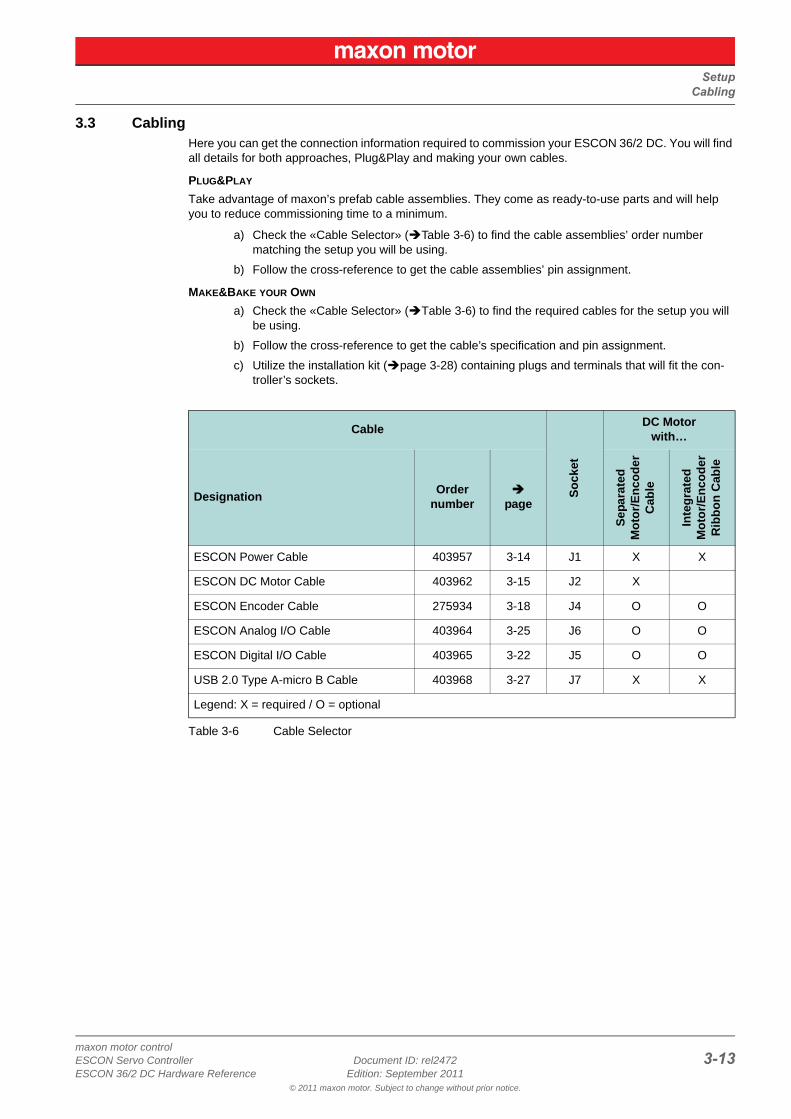
3.3 CablingHere you can get the connection information required to commission your ESCON 36/2 DC. You will find all details for both approaches, Plug&Play and making your own cables.
PLUG&PLAY
Take advantage of maxon’s prefab cable assemblies. They come as ready-to-use parts and will help you to reduce commissioning time to a minimum.
a) Check the «Cable Selector» (Table 3-6) to find the cable assemblies’ order number matching the setup you will be using.
b) Follow the cross-reference to get the cable assemblies’ pin assignment.
MAKE&BAKE YOUR OWN
a) Check the «Cable Selector» (Table 3-6) to find the required cables for the setup you will be using.
b) Follow the cross-reference to get the cable’s specification and pin assignment.
c) Utilize the installation kit (page 3-28) containing plugs and terminals that will fit the con-troller’s sockets.
Table 3-6 Cable Selector
Cable
So
cke
t
DC Motorwith…
DesignationOrder
number
page
Sep
ara
ted
Mo
tor/
En
cod
erC
able
Inte
gra
ted
Mo
tor/
En
cod
erR
ibb
on
Cab
le
ESCON Power Cable 403957 3-14 J1 X X
ESCON DC Motor Cable 403962 3-15 J2 X
ESCON Encoder Cable 275934 3-18 J4 O O
ESCON Analog I/O Cable 403964 3-25 J6 O O
ESCON Digital I/O Cable 403965 3-22 J5 O O
USB 2.0 Type A-micro B Cable 403968 3-27 J7 X X
Legend: X = required / O = optional
SetupConnections
maxon motor control3-14 Document ID: rel2472 ESCON Servo Controller
Edition: September 2011 ESCON 36/2 DC Hardware Reference© 2011 maxon motor. Subject to change without prior notice.
3.4 ConnectionsThe actual connection will depend on the overall configuration of your drive system and the type of motor you will be using. Some connections must be established in a given way, while for motor (J2/J2A and encoder (J4/J4A) alternative plug-in locations can be chosen from.
Follow the description in given order and choose the connection scheme that suits the respective com-ponents you are using. For corresponding wiring diagrams chapter “4 Wiring” on page 4-31.
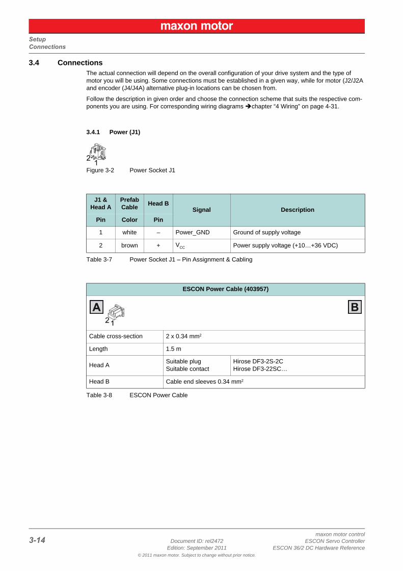
3.4.1 Power (J1)
Figure 3-2 Power Socket J1
Table 3-7 Power Socket J1 – Pin Assignment & Cabling
Table 3-8 ESCON Power Cable
J1 &Head A
PrefabCable
Head BSignal Description
Pin Color Pin
1 white – Power_GND Ground of supply voltage
2 brown + VCC Power supply voltage (+10…+36 VDC)
ESCON Power Cable (403957)
Cable cross-section 2 x 0.34 mm2
Length 1.5 m
Head ASuitable plugSuitable contact
Hirose DF3-2S-2CHirose DF3-22SC…
Head B Cable end sleeves 0.34 mm2
SetupConnections
maxon motor controlESCON Servo Controller Document ID: rel2472 3-15ESCON 36/2 DC Hardware Reference Edition: September 2011
© 2011 maxon motor. Subject to change without prior notice.
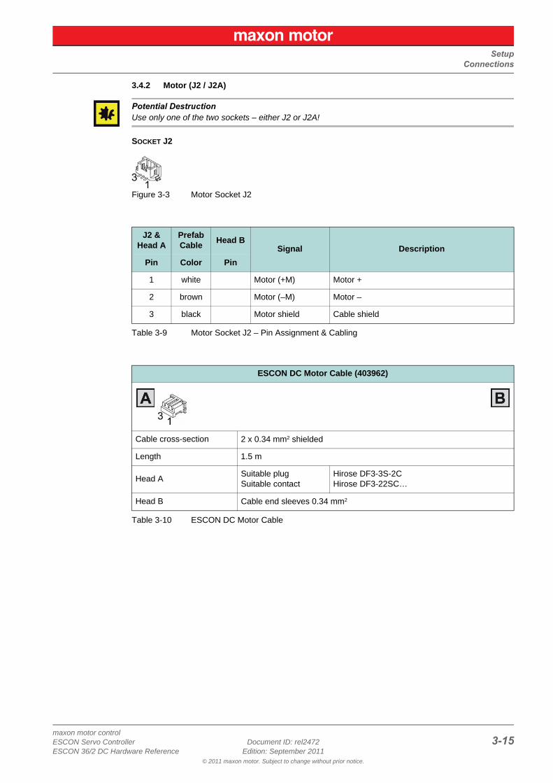
3.4.2 Motor (J2 / J2A)
Potential DestructionUse only one of the two sockets – either J2 or J2A!
SOCKET J2
Figure 3-3 Motor Socket J2
Table 3-9 Motor Socket J2 – Pin Assignment & Cabling
Table 3-10 ESCON DC Motor Cable
J2 &Head A
PrefabCable
Head BSignal Description
Pin Color Pin
1 white Motor (+M) Motor +
2 brown Motor (–M) Motor –
3 black Motor shield Cable shield
ESCON DC Motor Cable (403962)
Cable cross-section 2 x 0.34 mm2 shielded
Length 1.5 m
Head ASuitable plugSuitable contact
Hirose DF3-3S-2CHirose DF3-22SC…
Head B Cable end sleeves 0.34 mm2
SetupConnections
maxon motor control3-16 Document ID: rel2472 ESCON Servo Controller
Edition: September 2011 ESCON 36/2 DC Hardware Reference© 2011 maxon motor. Subject to change without prior notice.
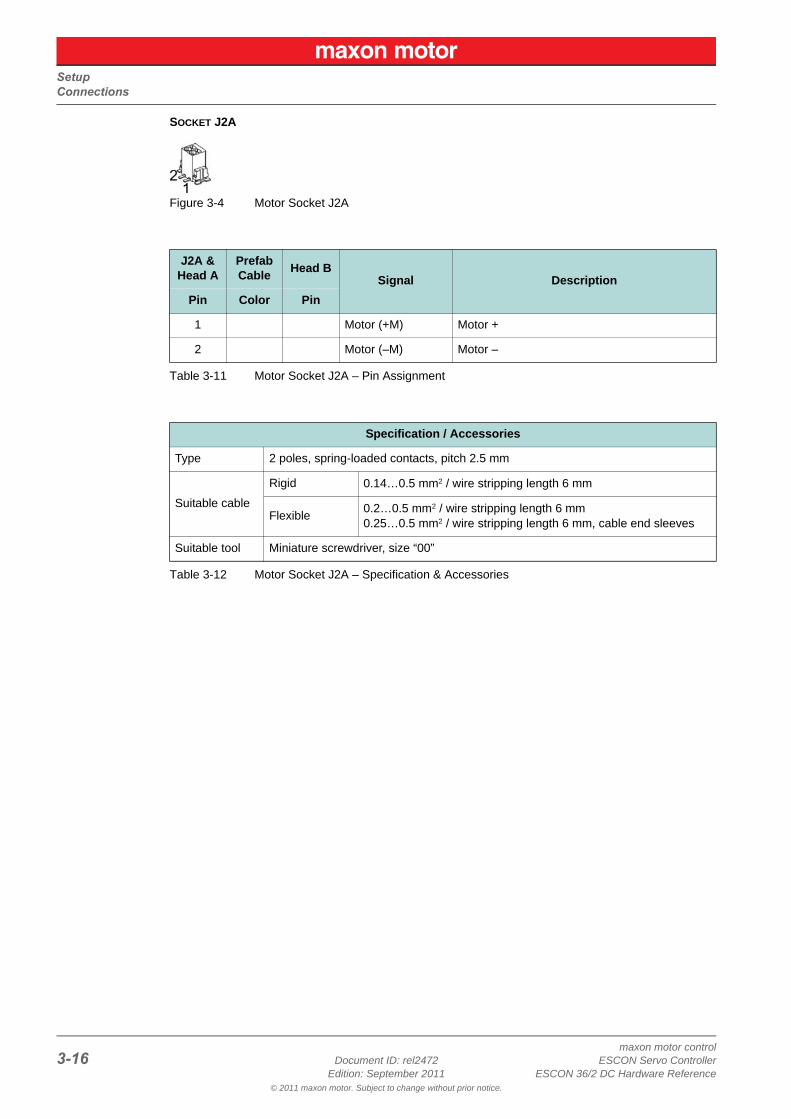
SOCKET J2A
Figure 3-4 Motor Socket J2A
Table 3-11 Motor Socket J2A – Pin Assignment
Table 3-12 Motor Socket J2A – Specification & Accessories
J2A &Head A
PrefabCable
Head BSignal Description
Pin Color Pin
1 Motor (+M) Motor +
2 Motor (–M) Motor –
Specification / Accessories
Type 2 poles, spring-loaded contacts, pitch 2.5 mm
Suitable cable
Rigid 0.14…0.5 mm2 / wire stripping length 6 mm
Flexible0.2…0.5 mm2 / wire stripping length 6 mm0.25…0.5 mm2 / wire stripping length 6 mm, cable end sleeves
Suitable tool Miniature screwdriver, size “00”
SetupConnections
maxon motor controlESCON Servo Controller Document ID: rel2472 3-17ESCON 36/2 DC Hardware Reference Edition: September 2011
© 2011 maxon motor. Subject to change without prior notice.
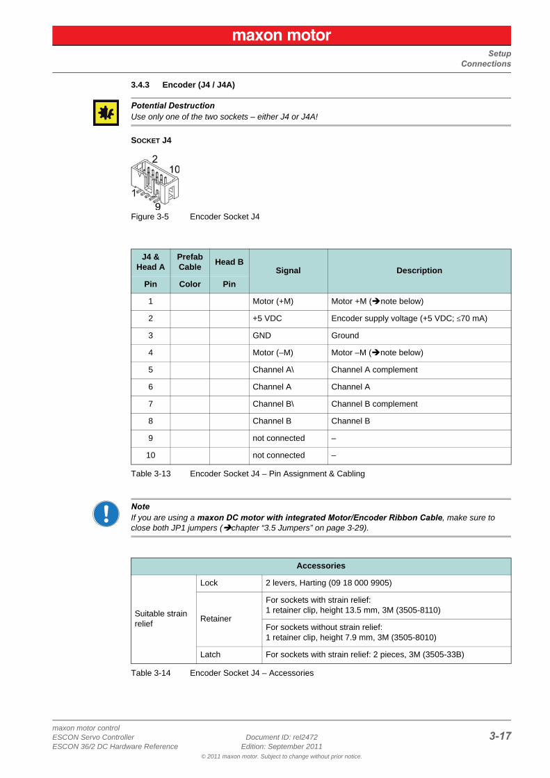
3.4.3 Encoder (J4 / J4A)
Potential DestructionUse only one of the two sockets – either J4 or J4A!
SOCKET J4
Figure 3-5 Encoder Socket J4
Table 3-13 Encoder Socket J4 – Pin Assignment & Cabling
NoteIf you are using a maxon DC motor with integrated Motor/Encoder Ribbon Cable, make sure to close both JP1 jumpers (chapter “3.5 Jumpers” on page 3-29).
Table 3-14 Encoder Socket J4 – Accessories
J4 &Head A
PrefabCable
Head BSignal Description
Pin Color Pin
1 Motor (+M) Motor +M (note below)
2 +5 VDC Encoder supply voltage (+5 VDC; ≤70 mA)
3 GND Ground
4 Motor (–M) Motor –M (note below)
5 Channel A\ Channel A complement
6 Channel A Channel A
7 Channel B\ Channel B complement
8 Channel B Channel B
9 not connected –
10 not connected –
Accessories
Suitable strain relief
Lock 2 levers, Harting (09 18 000 9905)
Retainer
For sockets with strain relief:1 retainer clip, height 13.5 mm, 3M (3505-8110)
For sockets without strain relief:1 retainer clip, height 7.9 mm, 3M (3505-8010)
Latch For sockets with strain relief: 2 pieces, 3M (3505-33B)
SetupConnections
maxon motor control3-18 Document ID: rel2472 ESCON Servo Controller
Edition: September 2011 ESCON 36/2 DC Hardware Reference© 2011 maxon motor. Subject to change without prior notice.
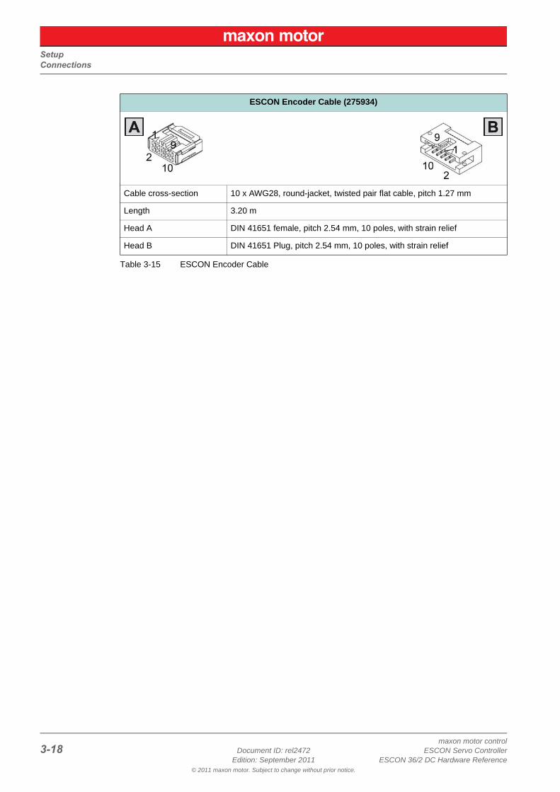
Table 3-15 ESCON Encoder Cable
ESCON Encoder Cable (275934)
Cable cross-section 10 x AWG28, round-jacket, twisted pair flat cable, pitch 1.27 mm
Length 3.20 m
Head A DIN 41651 female, pitch 2.54 mm, 10 poles, with strain relief
Head B DIN 41651 Plug, pitch 2.54 mm, 10 poles, with strain relief
SetupConnections
maxon motor controlESCON Servo Controller Document ID: rel2472 3-19ESCON 36/2 DC Hardware Reference Edition: September 2011
© 2011 maxon motor. Subject to change without prior notice.
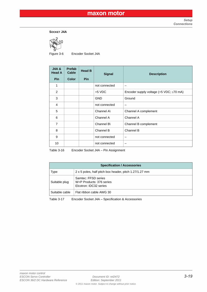
SOCKET J4A
Figure 3-6 Encoder Socket J4A
Table 3-16 Encoder Socket J4A – Pin Assignment
Table 3-17 Encoder Socket J4A – Specification & Accessories
J4A &Head A
PrefabCable
Head BSignal Description
Pin Color Pin
1 not connected –
2 +5 VDC Encoder supply voltage (+5 VDC; ≤70 mA)
3 GND Ground
4 not connected –
5 Channel A\ Channel A complement
6 Channel A Channel A
7 Channel B\ Channel B complement
8 Channel B Channel B
9 not connected –
10 not connected –
Specification / Accessories
Type 2 x 5 poles, half pitch box header, pitch 1.27/1.27 mm
Suitable plugSamtec: FFSD seriesW+P Products: 376 seriesElcotron: IDC32 series
Suitable cable Flat ribbon cable AWG 30
SetupConnections
maxon motor control3-20 Document ID: rel2472 ESCON Servo Controller
Edition: September 2011 ESCON 36/2 DC Hardware Reference© 2011 maxon motor. Subject to change without prior notice.
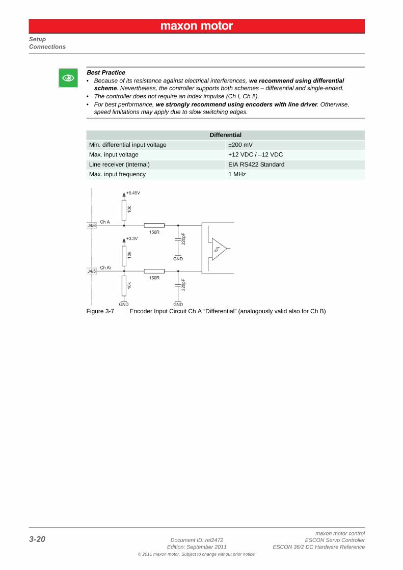
Best Practice• Because of its resistance against electrical interferences, we recommend using differential
scheme. Nevertheless, the controller supports both schemes – differential and single-ended.• The controller does not require an index impulse (Ch I, Ch I\).• For best performance, we strongly recommend using encoders with line driver. Otherwise,
speed limitations may apply due to slow switching edges.
Figure 3-7 Encoder Input Circuit Ch A “Differential” (analogously valid also for Ch B)
Differential
Min. differential input voltage ±200 mV
Max. input voltage +12 VDC / –12 VDC
Line receiver (internal) EIA RS422 Standard
Max. input frequency 1 MHz
SetupConnections
maxon motor controlESCON Servo Controller Document ID: rel2472 3-21ESCON 36/2 DC Hardware Reference Edition: September 2011
© 2011 maxon motor. Subject to change without prior notice.
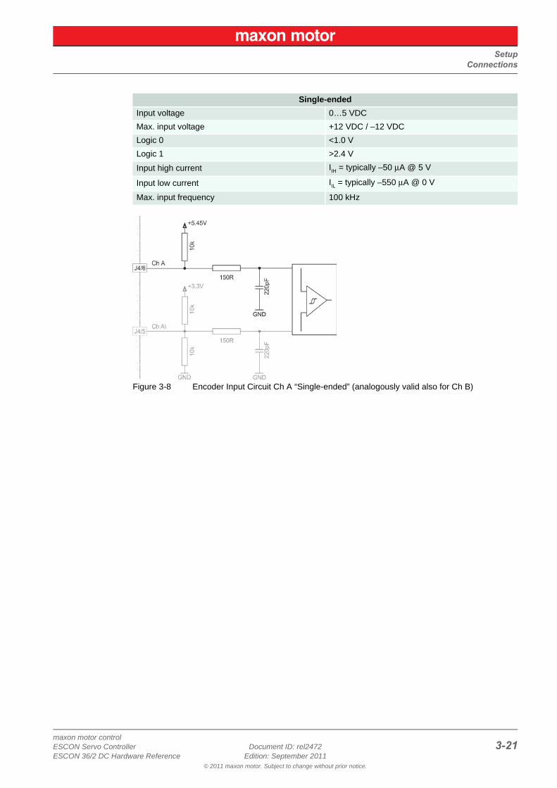
Figure 3-8 Encoder Input Circuit Ch A “Single-ended” (analogously valid also for Ch B)
Single-ended
Input voltage 0…5 VDC
Max. input voltage +12 VDC / –12 VDC
Logic 0 <1.0 V
Logic 1 >2.4 V
Input high current IIH = typically –50 μA @ 5 V
Input low current IIL = typically –550 μA @ 0 V
Max. input frequency 100 kHz
SetupConnections
maxon motor control3-22 Document ID: rel2472 ESCON Servo Controller
Edition: September 2011 ESCON 36/2 DC Hardware Reference© 2011 maxon motor. Subject to change without prior notice.
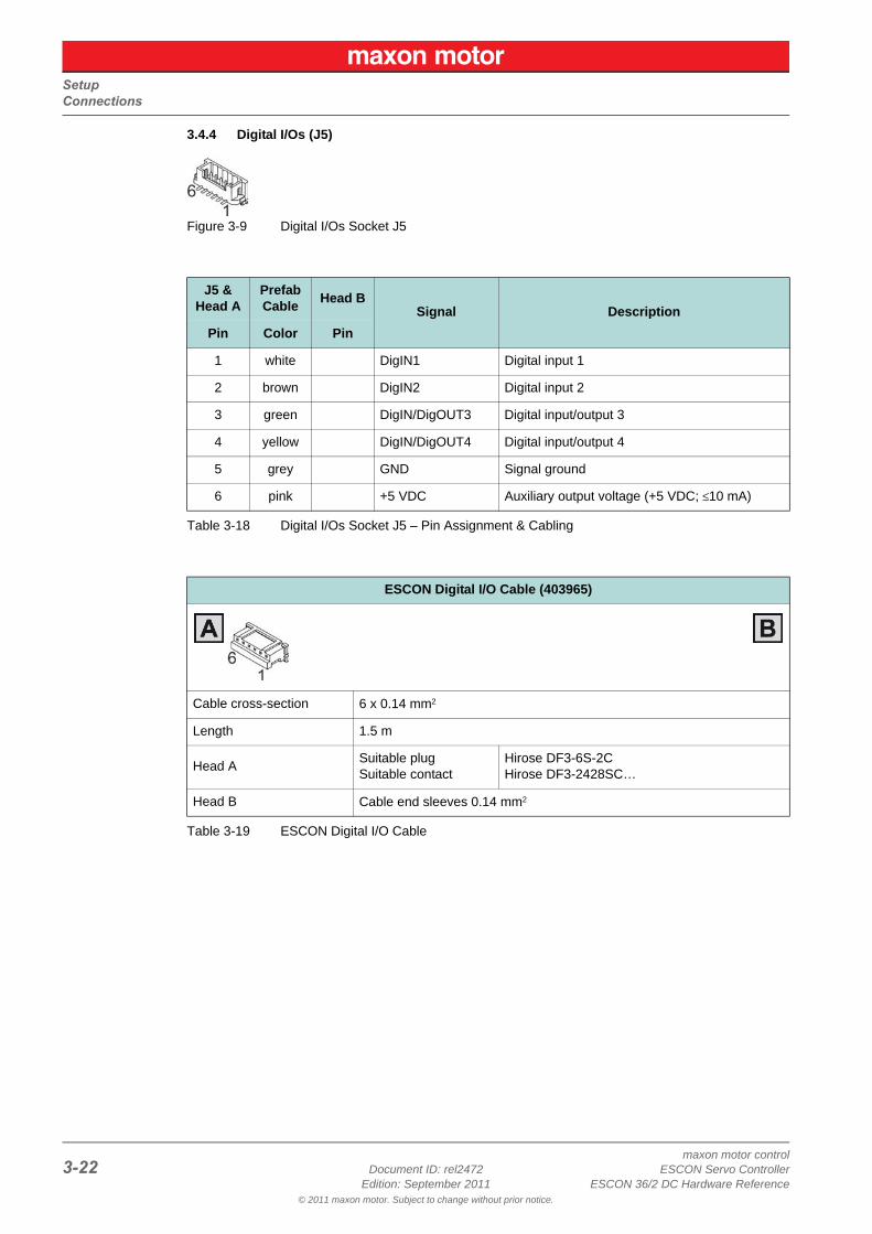
3.4.4 Digital I/Os (J5)
Figure 3-9 Digital I/Os Socket J5
Table 3-18 Digital I/Os Socket J5 – Pin Assignment & Cabling
Table 3-19 ESCON Digital I/O Cable
J5 &Head A
PrefabCable
Head BSignal Description
Pin Color Pin
1 white DigIN1 Digital input 1
2 brown DigIN2 Digital input 2
3 green DigIN/DigOUT3 Digital input/output 3
4 yellow DigIN/DigOUT4 Digital input/output 4
5 grey GND Signal ground
6 pink +5 VDC Auxiliary output voltage (+5 VDC; ≤10 mA)
ESCON Digital I/O Cable (403965)
Cable cross-section 6 x 0.14 mm2
Length 1.5 m
Head ASuitable plugSuitable contact
Hirose DF3-6S-2CHirose DF3-2428SC…
Head B Cable end sleeves 0.14 mm2
SetupConnections
maxon motor controlESCON Servo Controller Document ID: rel2472 3-23ESCON 36/2 DC Hardware Reference Edition: September 2011
© 2011 maxon motor. Subject to change without prior notice.
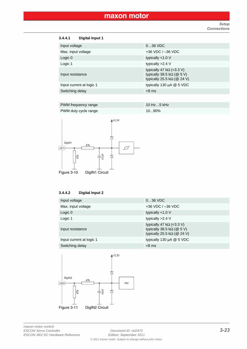
3.4.4.1 Digital Input 1
Figure 3-10 DigIN1 Circuit
3.4.4.2 Digital Input 2
Figure 3-11 DigIN2 Circuit
Input voltage 0…36 VDC
Max. input voltage +36 VDC / –36 VDC
Logic 0 typically <1.0 V
Logic 1 typically >2.4 V
Input resistancetypically 47 kΩ (<3.3 V)typically 38.5 kΩ (@ 5 V)typically 25.5 kΩ (@ 24 V)
Input current at logic 1 typically 130 µA @ 5 VDC
Switching delay <8 ms
PWM frequency range 10 Hz…5 kHz
PWM duty cycle range 10...90%
Input voltage 0…36 VDC
Max. input voltage +36 VDC / –36 VDC
Logic 0 typically <1.0 V
Logic 1 typically >2.4 V
Input resistancetypically 47 kΩ (<3.3 V)typically 38.5 kΩ (@ 5 V)typically 25.5 kΩ (@ 24 V)
Input current at logic 1 typically 130 µA @ 5 VDC
Switching delay <8 ms
SetupConnections
maxon motor control3-24 Document ID: rel2472 ESCON Servo Controller
Edition: September 2011 ESCON 36/2 DC Hardware Reference© 2011 maxon motor. Subject to change without prior notice.
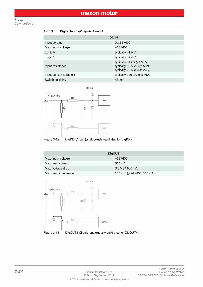
3.4.4.3 Digital Inputs/Outputs 3 and 4
Figure 3-12 DigIN3 Circuit (analogously valid also for DigIN4)
Figure 3-13 DigOUT3 Circuit (analogously valid also for DigOUT4)
DigIN
Input voltage 0…36 VDC
Max. input voltage +36 VDC
Logic 0 typically <1.0 V
Logic 1 typically >2.4 V
Input resistancetypically 47 kΩ (<3.3 V)typically 38.5 kΩ (@ 5 V)typically 25.5 kΩ (@ 24 V)
Input current at logic 1 typically 130 µA @ 5 VDC
Switching delay <8 ms
DigOUT
Max. input voltage +36 VDC
Max. load current 500 mA
Max. voltage drop 0.5 V @ 500 mA
Max. load inductance 100 mH @ 24 VDC; 500 mA
SetupConnections
maxon motor controlESCON Servo Controller Document ID: rel2472 3-25ESCON 36/2 DC Hardware Reference Edition: September 2011
© 2011 maxon motor. Subject to change without prior notice.
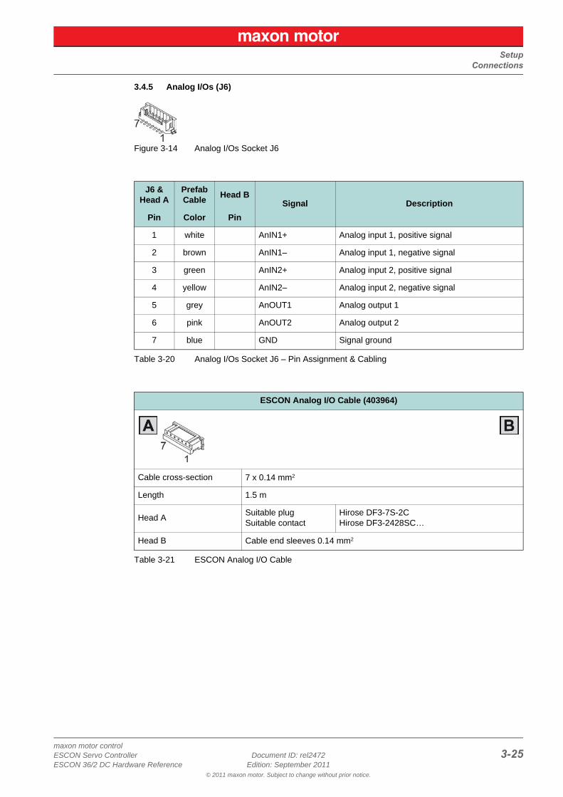
3.4.5 Analog I/Os (J6)
Figure 3-14 Analog I/Os Socket J6
Table 3-20 Analog I/Os Socket J6 – Pin Assignment & Cabling
Table 3-21 ESCON Analog I/O Cable
J6 &Head A
PrefabCable
Head BSignal Description
Pin Color Pin
1 white AnIN1+ Analog input 1, positive signal
2 brown AnIN1– Analog input 1, negative signal
3 green AnIN2+ Analog input 2, positive signal
4 yellow AnIN2– Analog input 2, negative signal
5 grey AnOUT1 Analog output 1
6 pink AnOUT2 Analog output 2
7 blue GND Signal ground
ESCON Analog I/O Cable (403964)
Cable cross-section 7 x 0.14 mm2
Length 1.5 m
Head ASuitable plugSuitable contact
Hirose DF3-7S-2CHirose DF3-2428SC…
Head B Cable end sleeves 0.14 mm2
SetupConnections
maxon motor control3-26 Document ID: rel2472 ESCON Servo Controller
Edition: September 2011 ESCON 36/2 DC Hardware Reference© 2011 maxon motor. Subject to change without prior notice.
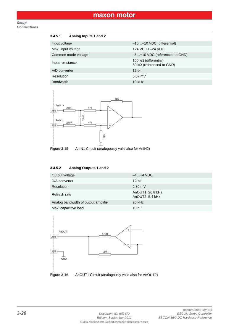
3.4.5.1 Analog Inputs 1 and 2
Figure 3-15 AnIN1 Circuit (analogously valid also for AnIN2)
3.4.5.2 Analog Outputs 1 and 2
Figure 3-16 AnOUT1 Circuit (analogously valid also for AnOUT2)
Input voltage –10…+10 VDC (differential)
Max. input voltage +24 VDC / –24 VDC
Common mode voltage –5…+10 VDC (referenced to GND)
Input resistance100 kΩ (differential)50 kΩ (referenced to GND)
A/D converter 12-bit
Resolution 5.07 mV
Bandwidth 10 kHz
Output voltage –4…+4 VDC
D/A converter 12-bit
Resolution 2.30 mV
Refresh rateAnOUT1: 26.8 kHzAnOUT2: 5.4 kHz
Analog bandwidth of output amplifier 20 kHz
Max. capacitive load 10 nF
SetupConnections
maxon motor controlESCON Servo Controller Document ID: rel2472 3-27ESCON 36/2 DC Hardware Reference Edition: September 2011
© 2011 maxon motor. Subject to change without prior notice.
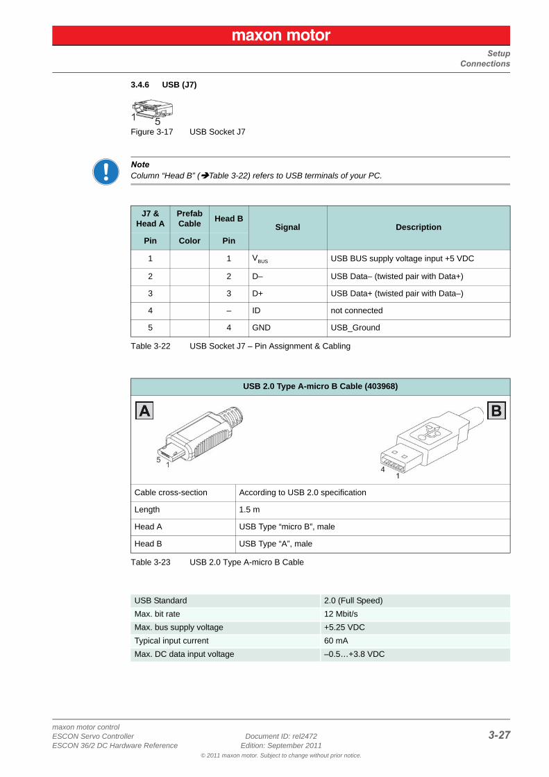
3.4.6 USB (J7)
Figure 3-17 USB Socket J7
NoteColumn “Head B” (Table 3-22) refers to USB terminals of your PC.
Table 3-22 USB Socket J7 – Pin Assignment & Cabling
Table 3-23 USB 2.0 Type A-micro B Cable
J7 &Head A
PrefabCable
Head BSignal Description
Pin Color Pin
1 1 VBUS USB BUS supply voltage input +5 VDC
2 2 D– USB Data– (twisted pair with Data+)
3 3 D+ USB Data+ (twisted pair with Data–)
4 – ID not connected
5 4 GND USB_Ground
USB 2.0 Type A-micro B Cable (403968)
Cable cross-section According to USB 2.0 specification
Length 1.5 m
Head A USB Type “micro B”, male
Head B USB Type “A”, male
USB Standard 2.0 (Full Speed)
Max. bit rate 12 Mbit/s
Max. bus supply voltage +5.25 VDC
Typical input current 60 mA
Max. DC data input voltage –0.5…+3.8 VDC
SetupConnections
maxon motor control3-28 Document ID: rel2472 ESCON Servo Controller
Edition: September 2011 ESCON 36/2 DC Hardware Reference© 2011 maxon motor. Subject to change without prior notice.
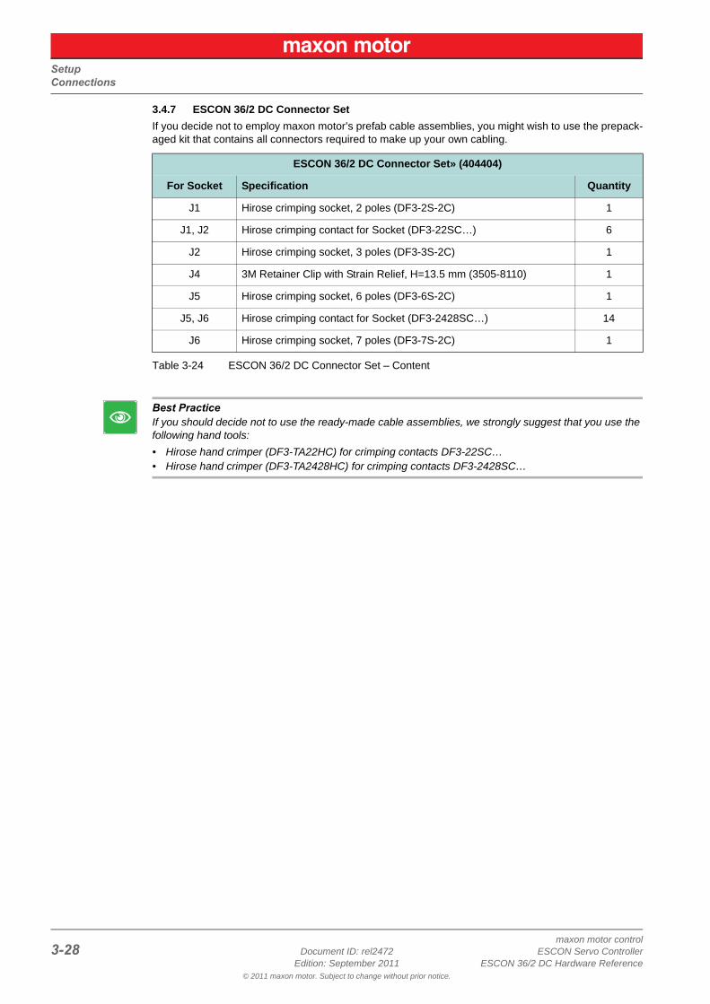
3.4.7 ESCON 36/2 DC Connector Set
If you decide not to employ maxon motor’s prefab cable assemblies, you might wish to use the prepack-aged kit that contains all connectors required to make up your own cabling.
Table 3-24 ESCON 36/2 DC Connector Set – Content
Best PracticeIf you should decide not to use the ready-made cable assemblies, we strongly suggest that you use the following hand tools:
• Hirose hand crimper (DF3-TA22HC) for crimping contacts DF3-22SC…• Hirose hand crimper (DF3-TA2428HC) for crimping contacts DF3-2428SC…
ESCON 36/2 DC Connector Set» (404404)
For Socket Specification Quantity
J1 Hirose crimping socket, 2 poles (DF3-2S-2C) 1
J1, J2 Hirose crimping contact for Socket (DF3-22SC…) 6
J2 Hirose crimping socket, 3 poles (DF3-3S-2C) 1
J4 3M Retainer Clip with Strain Relief, H=13.5 mm (3505-8110) 1
J5 Hirose crimping socket, 6 poles (DF3-6S-2C) 1
J5, J6 Hirose crimping contact for Socket (DF3-2428SC…) 14
J6 Hirose crimping socket, 7 poles (DF3-7S-2C) 1
SetupJumpers
maxon motor controlESCON Servo Controller Document ID: rel2472 3-29ESCON 36/2 DC Hardware Reference Edition: September 2011
© 2011 maxon motor. Subject to change without prior notice.
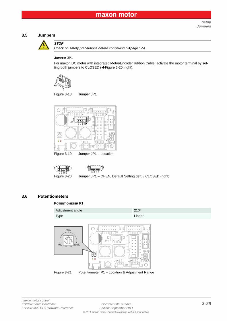
3.5 Jumpers
STOPCheck on safety precautions before continuing (page 1-5).
JUMPER JP1
For maxon DC motor with integrated Motor/Encoder Ribbon Cable, activate the motor terminal by set-ting both jumpers to CLOSED (Figure 3-20, right).
Figure 3-18 Jumper JP1
Figure 3-19 Jumper JP1 – Location
Figure 3-20 Jumper JP1 – OPEN, Default Setting (left) / CLOSED (right)
3.6 Potentiometers
POTENTIOMETER P1
Figure 3-21 Potentiometer P1 – Location & Adjustment Range
Adjustment angle 210°
Type Linear
SetupStatus Indicators
maxon motor control3-30 Document ID: rel2472 ESCON Servo Controller
Edition: September 2011 ESCON 36/2 DC Hardware Reference© 2011 maxon motor. Subject to change without prior notice.
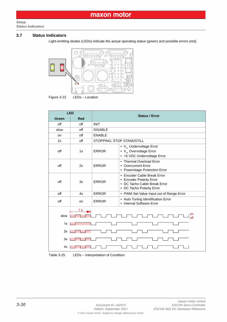
3.7 Status IndicatorsLight-emitting diodes (LEDs) indicate the actual operating status (green) and possible errors (red).
Figure 3-22 LEDs – Location
Table 3-25 LEDs – Interpretation of Condition
LEDStatus / Error
Green Red
off off INIT
slow off DISABLE
on off ENABLE
2x off STOPPING; STOP STANDSTILL
off 1x ERROR• Vcc Undervoltage Error• Vcc Overvoltage Error• +5 VDC Undervoltage Error
off 2x ERROR• Thermal Overload Error• Overcurrent Error• Powerstage Protection Error
off 3x ERROR
• Encoder Cable Break Error• Encoder Polarity Error• DC Tacho Cable Break Error• DC Tacho Polarity Error
off 4x ERROR • PWM Set Value Input out of Range Error
off on ERROR• Auto Tuning Identification Error• Internal Software Error
Wiring
maxon motor controlESCON Servo Controller Document ID: rel2472 4-31ESCON 36/2 DC Hardware Reference Edition: September 2011
© 2011 maxon motor. Subject to change without prior notice.
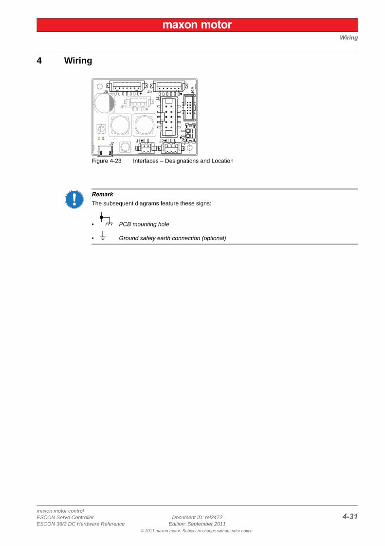
4 Wiring
Figure 4-23 Interfaces – Designations and Location
RemarkThe subsequent diagrams feature these signs:
• PCB mounting hole
• Ground safety earth connection (optional)
Wiring
maxon motor control4-32 Document ID: rel2472 ESCON Servo Controller
Edition: September 2011 ESCON 36/2 DC Hardware Reference© 2011 maxon motor. Subject to change without prior notice.
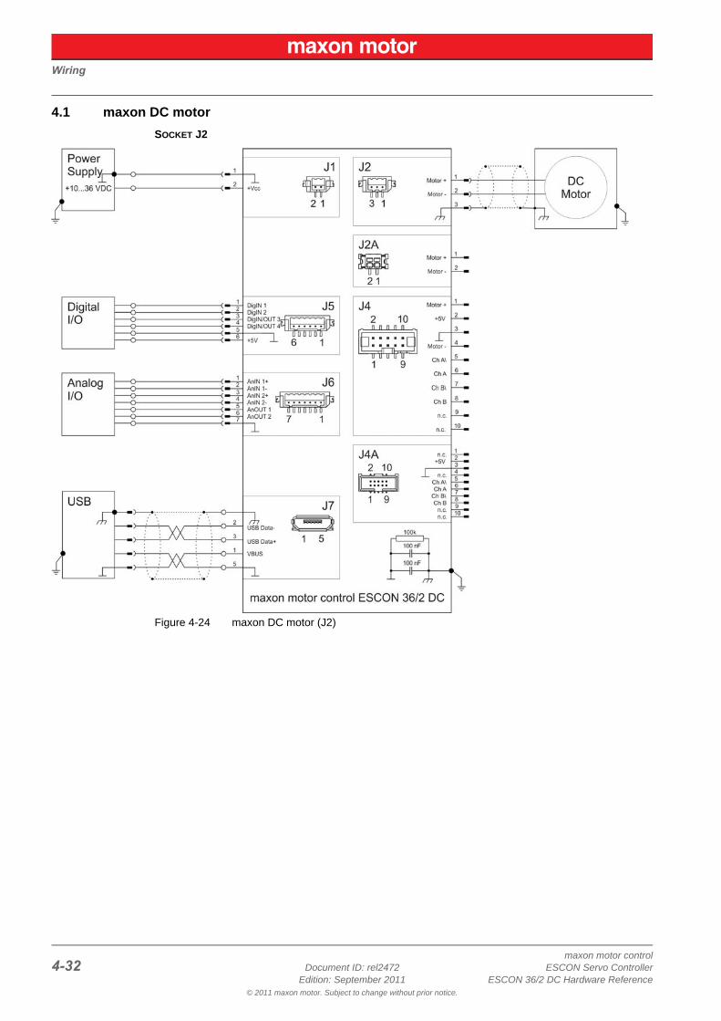
4.1 maxon DC motor
SOCKET J2
Figure 4-24 maxon DC motor (J2)
Wiring
maxon motor controlESCON Servo Controller Document ID: rel2472 4-33ESCON 36/2 DC Hardware Reference Edition: September 2011
© 2011 maxon motor. Subject to change without prior notice.
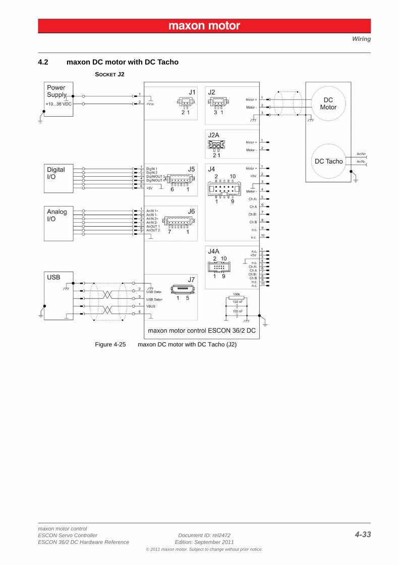
4.2 maxon DC motor with DC Tacho
SOCKET J2
Figure 4-25 maxon DC motor with DC Tacho (J2)
Wiring
maxon motor control4-34 Document ID: rel2472 ESCON Servo Controller
Edition: September 2011 ESCON 36/2 DC Hardware Reference© 2011 maxon motor. Subject to change without prior notice.
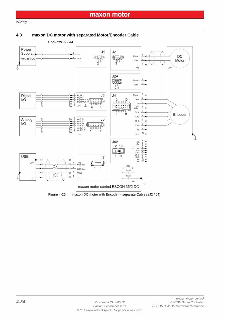
4.3 maxon DC motor with separated Motor/Encoder Cable
SOCKETS J2 / J4
Figure 4-26 maxon DC motor with Encoder – separate Cables (J2 / J4)
Wiring
maxon motor controlESCON Servo Controller Document ID: rel2472 4-35ESCON 36/2 DC Hardware Reference Edition: September 2011
© 2011 maxon motor. Subject to change without prior notice.
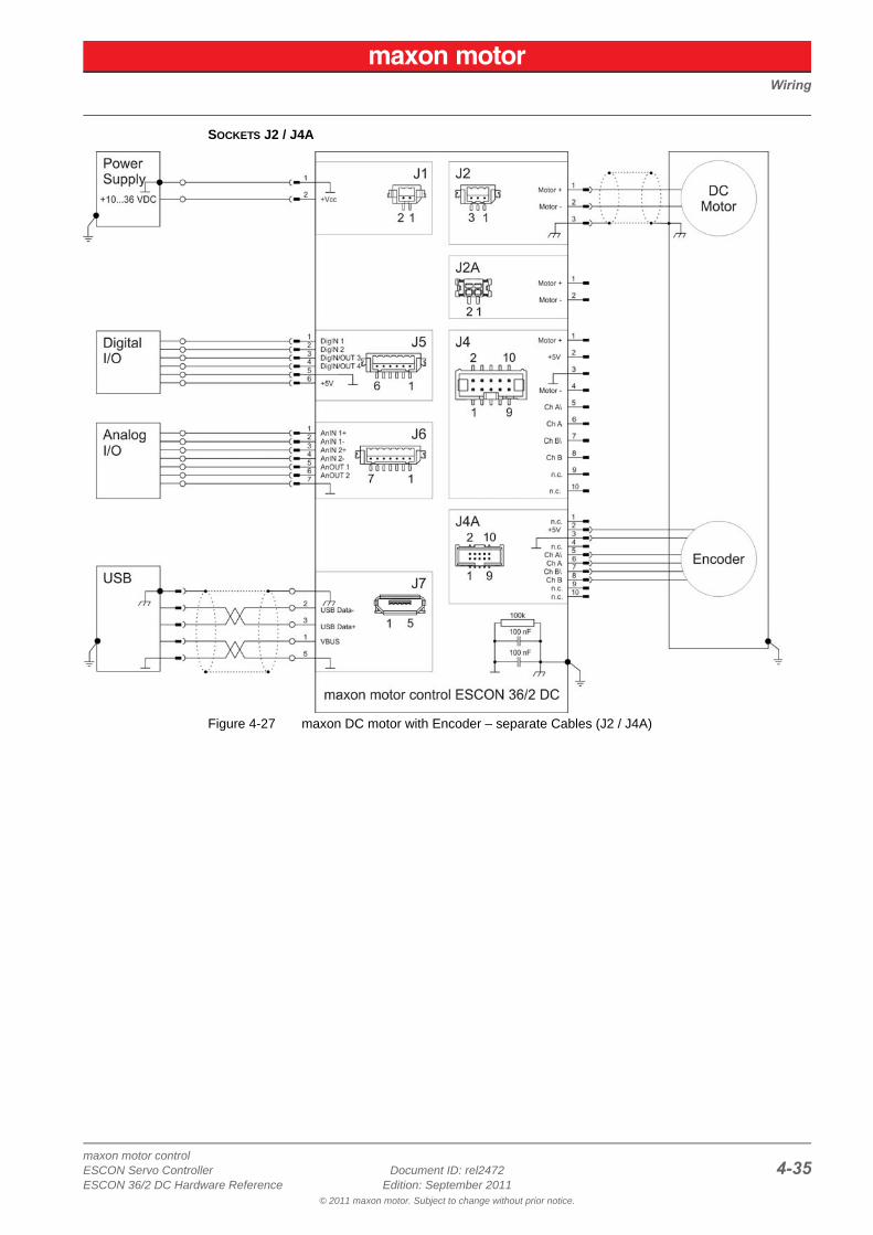
SOCKETS J2 / J4A
Figure 4-27 maxon DC motor with Encoder – separate Cables (J2 / J4A)
Wiring
maxon motor control4-36 Document ID: rel2472 ESCON Servo Controller
Edition: September 2011 ESCON 36/2 DC Hardware Reference© 2011 maxon motor. Subject to change without prior notice.
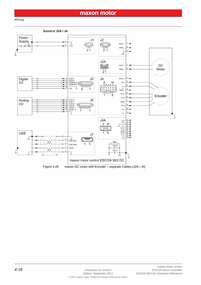
SOCKETS J2A / J4
Figure 4-28 maxon DC motor with Encoder – separate Cables (J2A / J4)
Wiring
maxon motor controlESCON Servo Controller Document ID: rel2472 4-37ESCON 36/2 DC Hardware Reference Edition: September 2011
© 2011 maxon motor. Subject to change without prior notice.
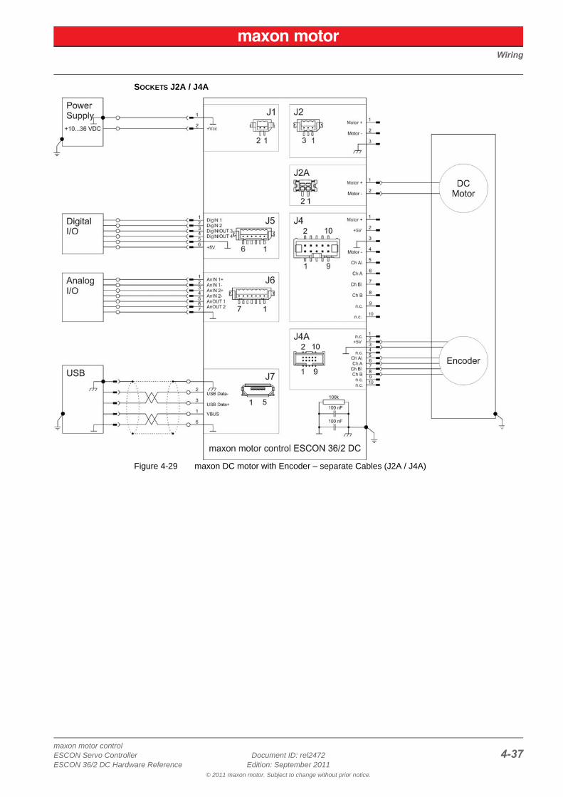
SOCKETS J2A / J4A
Figure 4-29 maxon DC motor with Encoder – separate Cables (J2A / J4A)
Wiring
maxon motor control4-38 Document ID: rel2472 ESCON Servo Controller
Edition: September 2011 ESCON 36/2 DC Hardware Reference© 2011 maxon motor. Subject to change without prior notice.
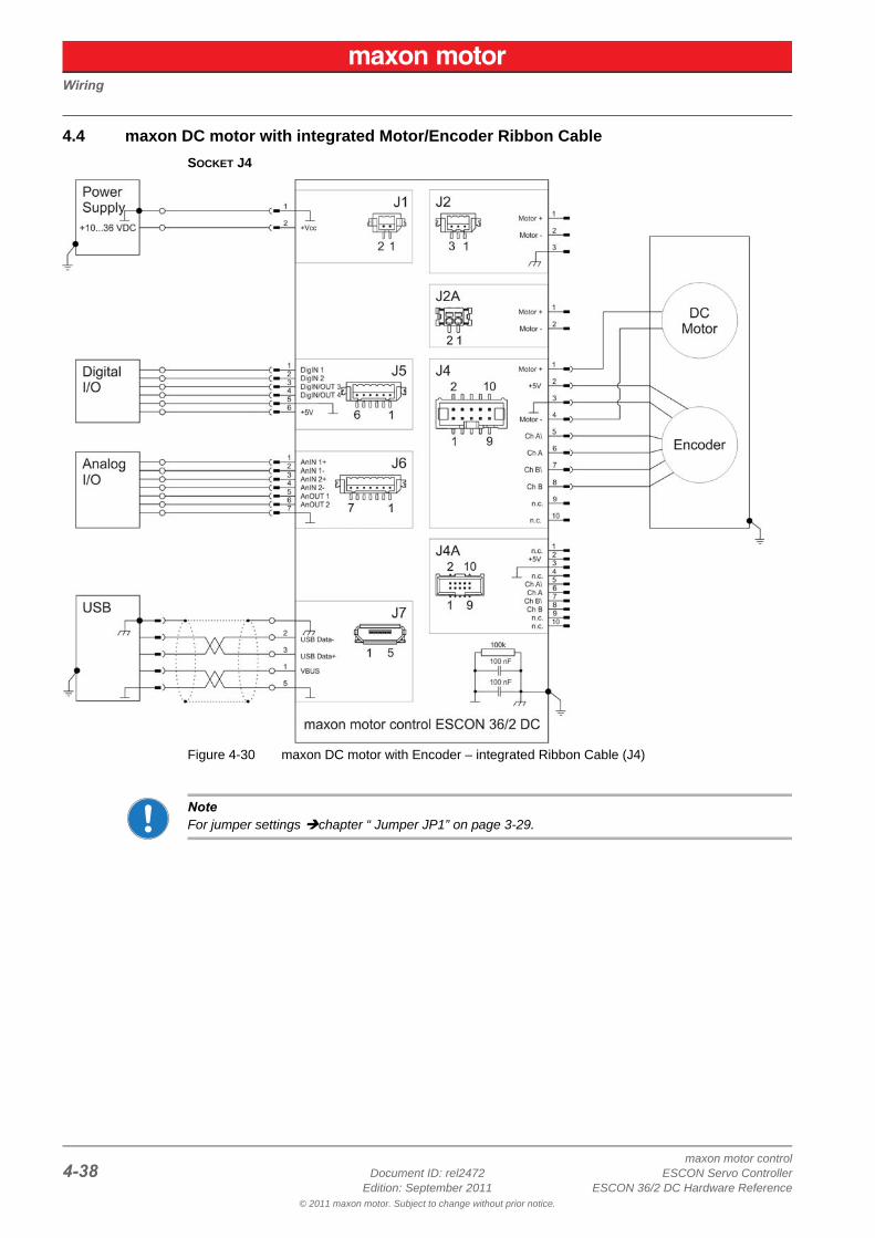
4.4 maxon DC motor with integrated Motor/Encoder Ribbon Cable
SOCKET J4
Figure 4-30 maxon DC motor with Encoder – integrated Ribbon Cable (J4)
NoteFor jumper settings chapter “ Jumper JP1” on page 3-29.
maxon motor controlESCON Servo Controller Document ID: rel2472 Z-39ESCON 36/2 DC Hardware Reference Edition: September 2011
© 2011 maxon motor. Subject to change without prior notice.
Figure 2-1 Dimensional Drawing [mm]. . . . . . . . . . . . . . . . . . . . . . . . . . . . . . . . . . . . . . . . . . . . . . .8
Figure 3-2 Power Socket J1. . . . . . . . . . . . . . . . . . . . . . . . . . . . . . . . . . . . . . . . . . . . . . . . . . . . . .14
Figure 3-3 Motor Socket J2 . . . . . . . . . . . . . . . . . . . . . . . . . . . . . . . . . . . . . . . . . . . . . . . . . . . . . .15
Figure 3-4 Motor Socket J2A . . . . . . . . . . . . . . . . . . . . . . . . . . . . . . . . . . . . . . . . . . . . . . . . . . . . .16
Figure 3-5 Encoder Socket J4 . . . . . . . . . . . . . . . . . . . . . . . . . . . . . . . . . . . . . . . . . . . . . . . . . . . .17
Figure 3-6 Encoder Socket J4A . . . . . . . . . . . . . . . . . . . . . . . . . . . . . . . . . . . . . . . . . . . . . . . . . . .19
Figure 3-7 Encoder Input Circuit Ch A “Differential” (analogously valid also for Ch B) . . . . . . . . .20
Figure 3-8 Encoder Input Circuit Ch A “Single-ended” (analogously valid also for Ch B) . . . . . . .21
Figure 3-9 Digital I/Os Socket J5 . . . . . . . . . . . . . . . . . . . . . . . . . . . . . . . . . . . . . . . . . . . . . . . . . .22
Figure 3-10 DigIN1 Circuit . . . . . . . . . . . . . . . . . . . . . . . . . . . . . . . . . . . . . . . . . . . . . . . . . . . . . . . .23
Figure 3-11 DigIN2 Circuit . . . . . . . . . . . . . . . . . . . . . . . . . . . . . . . . . . . . . . . . . . . . . . . . . . . . . . . .23
Figure 3-12 DigIN3 Circuit (analogously valid also for DigIN4) . . . . . . . . . . . . . . . . . . . . . . . . . . . .24
Figure 3-13 DigOUT3 Circuit (analogously valid also for DigOUT4) . . . . . . . . . . . . . . . . . . . . . . . .24
Figure 3-14 Analog I/Os Socket J6 . . . . . . . . . . . . . . . . . . . . . . . . . . . . . . . . . . . . . . . . . . . . . . . . .25
Figure 3-15 AnIN1 Circuit (analogously valid also for AnIN2) . . . . . . . . . . . . . . . . . . . . . . . . . . . . .26
Figure 3-16 AnOUT1 Circuit (analogously valid also for AnOUT2) . . . . . . . . . . . . . . . . . . . . . . . . .26
Figure 3-17 USB Socket J7 . . . . . . . . . . . . . . . . . . . . . . . . . . . . . . . . . . . . . . . . . . . . . . . . . . . . . . .27
Figure 3-18 Jumper JP1 . . . . . . . . . . . . . . . . . . . . . . . . . . . . . . . . . . . . . . . . . . . . . . . . . . . . . . . . .29
Figure 3-19 Jumper JP1 – Location. . . . . . . . . . . . . . . . . . . . . . . . . . . . . . . . . . . . . . . . . . . . . . . . .29
Figure 3-20 Jumper JP1 – OPEN, Default Setting (left) / CLOSED (right) . . . . . . . . . . . . . . . . . . .29
Figure 3-21 Potentiometer P1 – Location & Adjustment Range . . . . . . . . . . . . . . . . . . . . . . . . . . .29
Figure 3-22 LEDs – Location . . . . . . . . . . . . . . . . . . . . . . . . . . . . . . . . . . . . . . . . . . . . . . . . . . . . . .30
Figure 4-23 Interfaces – Designations and Location . . . . . . . . . . . . . . . . . . . . . . . . . . . . . . . . . . . .31
Figure 4-24 maxon DC motor (J2) . . . . . . . . . . . . . . . . . . . . . . . . . . . . . . . . . . . . . . . . . . . . . . . . . .32
Figure 4-25 maxon DC motor with DC Tacho (J2). . . . . . . . . . . . . . . . . . . . . . . . . . . . . . . . . . . . . .33
Figure 4-26 maxon DC motor with Encoder – separate Cables (J2 / J4). . . . . . . . . . . . . . . . . . . . .34
Figure 4-27 maxon DC motor with Encoder – separate Cables (J2 / J4A) . . . . . . . . . . . . . . . . . . .35
Figure 4-28 maxon DC motor with Encoder – separate Cables (J2A / J4) . . . . . . . . . . . . . . . . . . .36
Figure 4-29 maxon DC motor with Encoder – separate Cables (J2A / J4A) . . . . . . . . . . . . . . . . . .37
Figure 4-30 maxon DC motor with Encoder – integrated Ribbon Cable (J4). . . . . . . . . . . . . . . . . .38
LIST OF FIGURES
maxon motor controlZ-40 Document ID: rel2472 ESCON Servo Controller
Edition: September 2011 ESCON 36/2 DC Hardware Reference© 2011 maxon motor. Subject to change without prior notice.
Table 1-1 Notation used . . . . . . . . . . . . . . . . . . . . . . . . . . . . . . . . . . . . . . . . . . . . . . . . . . . . . . . . . 3
Table 1-2 Symbols & Signs . . . . . . . . . . . . . . . . . . . . . . . . . . . . . . . . . . . . . . . . . . . . . . . . . . . . . . 4
Table 1-3 Brand Names and Trademark Owners. . . . . . . . . . . . . . . . . . . . . . . . . . . . . . . . . . . . . . 4
Table 2-4 Technical Data . . . . . . . . . . . . . . . . . . . . . . . . . . . . . . . . . . . . . . . . . . . . . . . . . . . . . . . . 8
Table 2-5 Standards . . . . . . . . . . . . . . . . . . . . . . . . . . . . . . . . . . . . . . . . . . . . . . . . . . . . . . . . . . . . 9
Table 3-6 Cable Selector . . . . . . . . . . . . . . . . . . . . . . . . . . . . . . . . . . . . . . . . . . . . . . . . . . . . . . . 13
Table 3-7 Power Socket J1 – Pin Assignment & Cabling. . . . . . . . . . . . . . . . . . . . . . . . . . . . . . . 14
Table 3-8 ESCON Power Cable . . . . . . . . . . . . . . . . . . . . . . . . . . . . . . . . . . . . . . . . . . . . . . . . . . 14
Table 3-9 Motor Socket J2 – Pin Assignment & Cabling . . . . . . . . . . . . . . . . . . . . . . . . . . . . . . . 15
Table 3-10 ESCON DC Motor Cable . . . . . . . . . . . . . . . . . . . . . . . . . . . . . . . . . . . . . . . . . . . . . . . 15
Table 3-11 Motor Socket J2A – Pin Assignment . . . . . . . . . . . . . . . . . . . . . . . . . . . . . . . . . . . . . . 16
Table 3-12 Motor Socket J2A – Specification & Accessories. . . . . . . . . . . . . . . . . . . . . . . . . . . . . 16
Table 3-13 Encoder Socket J4 – Pin Assignment & Cabling . . . . . . . . . . . . . . . . . . . . . . . . . . . . . 17
Table 3-14 Encoder Socket J4 – Accessories . . . . . . . . . . . . . . . . . . . . . . . . . . . . . . . . . . . . . . . . 17
Table 3-15 ESCON Encoder Cable . . . . . . . . . . . . . . . . . . . . . . . . . . . . . . . . . . . . . . . . . . . . . . . . 18
Table 3-16 Encoder Socket J4A – Pin Assignment . . . . . . . . . . . . . . . . . . . . . . . . . . . . . . . . . . . . 19
Table 3-17 Encoder Socket J4A – Specification & Accessories. . . . . . . . . . . . . . . . . . . . . . . . . . . 19
Table 3-18 Digital I/Os Socket J5 – Pin Assignment & Cabling . . . . . . . . . . . . . . . . . . . . . . . . . . . 22
Table 3-19 ESCON Digital I/O Cable . . . . . . . . . . . . . . . . . . . . . . . . . . . . . . . . . . . . . . . . . . . . . . . 22
Table 3-20 Analog I/Os Socket J6 – Pin Assignment & Cabling . . . . . . . . . . . . . . . . . . . . . . . . . . 25
Table 3-21 ESCON Analog I/O Cable . . . . . . . . . . . . . . . . . . . . . . . . . . . . . . . . . . . . . . . . . . . . . . 25
Table 3-22 USB Socket J7 – Pin Assignment & Cabling . . . . . . . . . . . . . . . . . . . . . . . . . . . . . . . . 27
Table 3-23 USB 2.0 Type A-micro B Cable . . . . . . . . . . . . . . . . . . . . . . . . . . . . . . . . . . . . . . . . . . 27
Table 3-24 ESCON 36/2 DC Connector Set – Content . . . . . . . . . . . . . . . . . . . . . . . . . . . . . . . . . 28
Table 3-25 LEDs – Interpretation of Condition . . . . . . . . . . . . . . . . . . . . . . . . . . . . . . . . . . . . . . . . 30
LIST OF TABLES
maxon motor controlESCON Servo Controller Document ID: rel2472 Z-41ESCON 36/2 DC Hardware Reference Edition: September 2011
© 2011 maxon motor. Subject to change without prior notice.
Aadditionally applicable regulations 5alerts 3analog inputs 26applicable EU directive 11
Ccables (prefab)
ESCON Analog I/O Cable 25ESCON DC Motor Cable 15ESCON Digital I/O Cable 22ESCON Encoder Cable 18ESCON Power Cable 14USB 2.0 Type A-micro B Cable 27
country-specific regulations 5
Ddigital inputs 23, 24
Eerror display 30ESD 5EU directive, applicable 11
Hhow to
calculate required supply voltage 12find information on wiring 13interpret icons (and signs) used in the document 3
Iincorporation into surrounding system 11informatory signs 4intended purpose of the device 4interfaces, location and designation 31
Jjumper JP1 29
LLEDs 30
Mmandatory action signs 3
Nnotations used 3
Ooperating license 11operating status, display 30order numbers
275934 18403112 7403957 14403962 15403964 25403965 22403968 27404404 28
Pperformance data 7potentiometer P1 29precautions 5prerequisites prior installation 11prohibitive signs 3purpose
of the device 4of this document 3
Rregulations, additionally applicable 5
Ssafety alerts 3safety first! 5signs used 3sockets
J1 14J2 15J2A 16J4 17J4A 19J5 22J6 25J7 27
standards, fulfilled 9status display 30status LEDs 30supply voltage, required 12symbols used 3
Ttechnical data 7tools, recommended 28
UUSB interface 27
INDEX
maxon motor controlZ-42 Document ID: rel2472 ESCON Servo Controller
Edition: September 2011 ESCON 36/2 DC Hardware Reference© 2011 maxon motor. Subject to change without prior notice.
© 2011 maxon motor. All rights reserved.
The present document – including all parts thereof – is protected by copyright. Any use (including reproduction, translation, microfilming, and other means of electronic data processing) beyond the narrow restrictions of the copyright law without the prior approval of maxon motor ag, is not permitted and subject to prosecution under the applicable law.
maxon motor agBrünigstrasse 220P.O.Box 263CH-6072 SachselnSwitzerland
Phone +41 (41) 666 15 00Fax +41 (41) 666 15 50
www.maxonmotor.com