Embed Size (px)
Citation preview
ES 230 Strengths – Intro to Finite Element Modeling & Analysis Homework Assignment 5 The GREAT Combined Load Problem – Moving on to Principal Stresses and von Mises Failure Criteria Open up your ANSYS model from HW Assignment 4 and change to the Mechanical model window.
In the ANSYS HW 5 you will calculate principal stresses and maximum shear stresses using ANSYS and then compare the ANSYS results you obtain with a set of hand calculated principal stress and maximum shear stress values. The problem you will determine these values for is the same as the combined load 3D bar that you created for HW 4. The solid bar made out of ‘Lafayette Steel’ has a diameter of 1” and a length of 8 inches along the x-axis and 4 inches along the z-axis. This loading is 800 lb at the free end of the bar. This axial load creates a bending moment about the z-axis, a torque about the x-axis and a shear force in the y-axis direction. These force and moment effects will create normal stress and shear stress on the bar cross-section.
You will determine the stresses acting on 2D x-y stress elements location at four cross-section points (A, B, C and D) on a particular section cut plane located 2 inches from the fixed support end by hand. Using the 2D x-y stress elements you will calculate by hand the maximum principal stress, minimum principal stress and maximum shear stress acting at each cross-section point (A, B, C and D) using Stress Transformation Equations or Mohr’s Circle. Then you will compare your values calculated by hand with the corresponding ANSYS stress results for maximum and minimum principal stress and maximum shear stress. As a final step you will calculate the von Mises failure criteria stress and determine if failure will occur at any of the points A, B, C, or D on this specific cross-section in the 3D bar. Modification of the Homework 4 Model
In the Mechanical Model window check that the mesh setting is a Coarse mesh with the element size set to 0.14 as specified in HW 4. If it is not, then set the element size to 0.14 in in the Coarse Mesh Element Size box as shown below. A refined mesh will give more accurate ANSYS stress results. Generate a Coarse Mesh for the bar using the Mesh options, if it was not already setup.
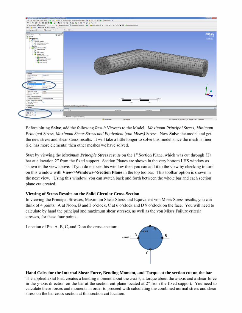
Before hitting Solve, add the following Result Viewers to the Model: Maximum Principal Stress, Minimum Principal Stress, Maximum Shear Stress and Equivalent (von Mises) Stress. Now Solve the model and get the new stress and shear stress results. It will take a little longer to solve this model since the mesh is finer (i.e. has more elements) then other meshes we have solved.
Start by viewing the Maximum Principle Stress results on the 1st Section Plane, which was cut through 3D bar at a location 2” from the fixed support. Section Planes are shown in the very bottom LHS window as shown in the view above. If you do not see this window then you can add it to the view by checking to turn on this window with View->Windows->Section Plane in the top toolbar. This toolbar option is shown in the next view. Using this window, you can switch back and forth between the whole bar and each section plane cut created.
Viewing of Stress Results on the Solid Circular Cross-Section In viewing the Principal Stresses, Maximum Shear Stress and Equivalent von Mises Stress results, you can think of 4 points: A at Noon, B and 3 o’clock, C at 6 o’clock and D 9 o’clock on the face. You will need to calculate by hand the principal and maximum shear stresses, as well as the von Mises Failure criteria stresses, for these four points.
Location of Pts. A, B, C, and D on the cross-section: Hand Calcs for the Internal Shear Force, Bending Moment, and Torque at the section cut on the bar The applied axial load creates a bending moment about the z-axis, a torque about the x-axis and a shear force in the y-axis direction on the bar at the section cut plane located at 2” from the fixed support. You need to calculate these forces and moments in order to proceed with calculating the combined normal stress and shear stress on the bar cross-section at this section cut location.
A
B
C
DZ‐axis
Y‐axis
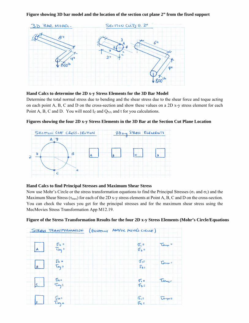
Figure showing 3D bar model and the location of the section cut plane 2” from the fixed support
Hand Calcs to determine the 2D x-y Stress Elements for the 3D Bar Model Determine the total normal stress due to bending and the shear stress due to the shear force and toque acting on each point A, B, C and D on the cross-section and show these values on a 2D x-y stress element for each Point A, B, C and D. You will need IZ and QNA and t for you calculations.
Figures showing the four 2D x-y Stress Elements in the 3D Bar at the Section Cut Plane Location
Hand Calcs to find Principal Stresses and Maximum Shear Stress Now use Mohr’s Circle or the stress transformation equations to find the Principal Stresses (σ1 and σ2) and the Maximum Shear Stress (τmax) for each of the 2D x-y stress elements at Point A, B, C and D on the cross-section. You can check the values you get for the principal stresses and for the maximum shear stress using the MecMovies Stress Transformation App M12.19.
Figure of the Stress Transformation Results for the four 2D x-y Stress Elements (Mohr’s Circle/Equations
Hand Calcs to find the Equivalent von Mises Failure Stress Based on the maximum distortional energy failure criteria discussed in class for ductile materials, calculate the equivalent von Mises failure stress using the following equation.
Compare this equivalent stress to the allowable yield stress limit of the ductile Lafayette Steel material by considering the σyield = 85 ksi in an uniaxial test, a F.S. of 1.6, and the following von Mises Failure Criteria check.
For each point A, B, C or D determine if failure will occur.
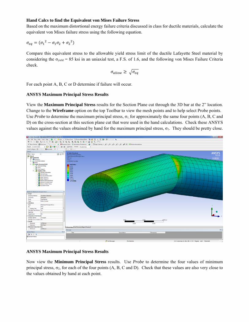
ANSYS Maximum Principal Stress Results
View the Maximum Principal Stress results for the Section Plane cut through the 3D bar at the 2” location. Change to the Wireframe option on the top Toolbar to view the mesh points and to help select Probe points. Use Probe to determine the maximum principal stress, σ1, for approximately the same four points (A, B, C and D) on the cross-section at this section plane cut that were used in the hand calculations. Check these ANSYS values against the values obtained by hand for the maximum principal stress, σ1. They should be pretty close.
ANSYS Maximum Principal Stress Results
Now view the Minimum Principal Stress results. Use Probe to determine the four values of minimum principal stress, σ2, for each of the four points (A, B, C and D). Check that these values are also very close to the values obtained by hand at each point.
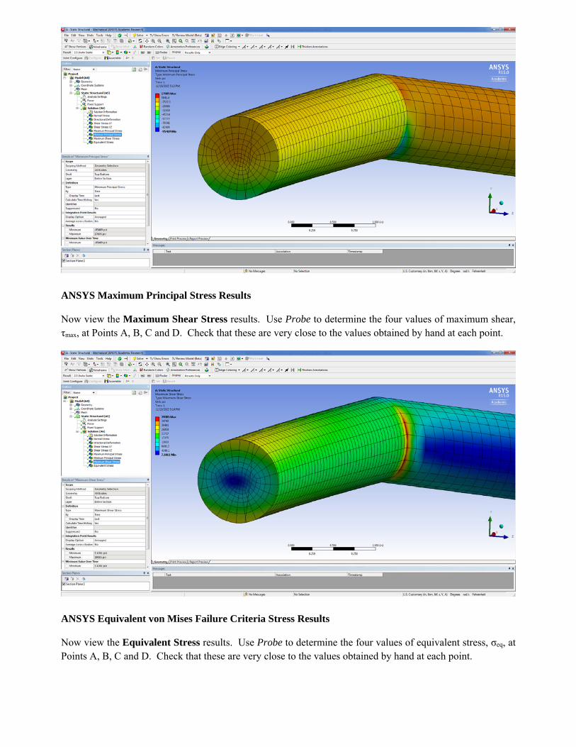
ANSYS Maximum Principal Stress Results
Now view the Maximum Shear Stress results. Use Probe to determine the four values of maximum shear, τmax, at Points A, B, C and D. Check that these are very close to the values obtained by hand at each point.
ANSYS Equivalent von Mises Failure Criteria Stress Results
Now view the Equivalent Stress results. Use Probe to determine the four values of equivalent stress, σeq, at Points A, B, C and D. Check that these are very close to the values obtained by hand at each point.
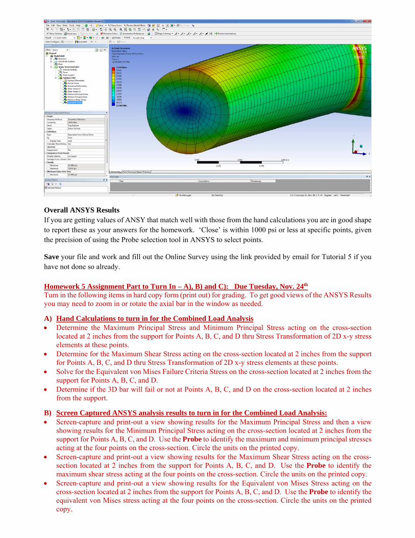
Overall ANSYS Results If you are getting values of ANSY that match well with those from the hand calculations you are in good shape to report these as your answers for the homework. ‘Close’ is within 1000 psi or less at specific points, given the precision of using the Probe selection tool in ANSYS to select points.
Save your file and work and fill out the Online Survey using the link provided by email for Tutorial 5 if you have not done so already. Homework 5 Assignment Part to Turn In – A), B) and C): Due Tuesday, Nov. 24th Turn in the following items in hard copy form (print out) for grading. To get good views of the ANSYS Results you may need to zoom in or rotate the axial bar in the window as needed.
A) Hand Calculations to turn in for the Combined Load Analysis Determine the Maximum Principal Stress and Minimum Principal Stress acting on the cross-section
located at 2 inches from the support for Points A, B, C, and D thru Stress Transformation of 2D x-y stress elements at these points.
Determine for the Maximum Shear Stress acting on the cross-section located at 2 inches from the support for Points A, B, C, and D thru Stress Transformation of 2D x-y stress elements at these points.
Solve for the Equivalent von Mises Failure Criteria Stress on the cross-section located at 2 inches from the support for Points A, B, C, and D.
Determine if the 3D bar will fail or not at Points A, B, C, and D on the cross-section located at 2 inches from the support.
B) Screen Captured ANSYS analysis results to turn in for the Combined Load Analysis: Screen-capture and print-out a view showing results for the Maximum Principal Stress and then a view
showing results for the Minimum Principal Stress acting on the cross-section located at 2 inches from the support for Points A, B, C, and D. Use the Probe to identify the maximum and minimum principal stresses acting at the four points on the cross-section. Circle the units on the printed copy.
Screen-capture and print-out a view showing results for the Maximum Shear Stress acting on the cross-section located at 2 inches from the support for Points A, B, C, and D. Use the Probe to identify the maximum shear stress acting at the four points on the cross-section. Circle the units on the printed copy.
Screen-capture and print-out a view showing results for the Equivalent von Mises Stress acting on the cross-section located at 2 inches from the support for Points A, B, C, and D. Use the Probe to identify the equivalent von Mises stress acting at the four points on the cross-section. Circle the units on the printed copy.
C) Comparison of the Hand Calculations and ANSYS Analysis Results to turn in for the Combined
Load Analysis: Compare the Maximum Principal Stress and the Minimum Principal Stress values obtained at Points A, B,
C and D on the cross-section located 2 inches from the support that you found using hand calculations and using ANSYS. Discuss any difference in these values.
Compare the Maximum Shear Stress values obtained at Points A, B, C and D on the cross-section located 2 inches from the support that you found using hand calculations and using ANSYS. Discuss any difference in these values.
Compare the Equivalent von Mises Failure Criteria Stress values obtained at Points A, B, C and D on the cross-section located 2 inches from the support that you found using hand calculations and using ANSYS. Discuss any difference in these values.


![References - link.springer.com978-3-662-21535-7/1.pdf · Some finite dimensional integrable systems and their scattering behavior, Comm. Math. Phys., 55 (1977) 195-230 [Adl2] ADLER,](https://img.pdfslide.us/doc/110x75/5f15cec52fc1b81a1a0b2da4/references-link-978-3-662-21535-71pdf-some-finite-dimensional-integrable.jpg)