Embed Size (px)
Citation preview
Unit 14 1
Relationship of the Units
․Basic unit, latch and F/F (unit 11)․Simple sequential circuits (unit 12)
Registers Counters
․Complex sequential circuits : FSM (finite state machine) Simple one: analysis, Mealy & Moore (unit 13) Complex one:
Derive state graph and tables (unit 14) Reduce state graph and tables (unit 15)
Unit 14 2
Unit 14
Derivation of State Graph and Table
Unit 14 3
Outline․Design of a sequence detector ․More complex design problems ․Guidelines for construction of state graphs ․Alphanumeric state graph notation
Unit 14 4
․Given a problem statement, to design a sequential circuit 1. Construct a state table or state graph (unit 14)
Further simplification (unit 15) 2. Derive F/F input equations and output equations
(unit 12)
Sequential Circuit Design
Unit 14 5
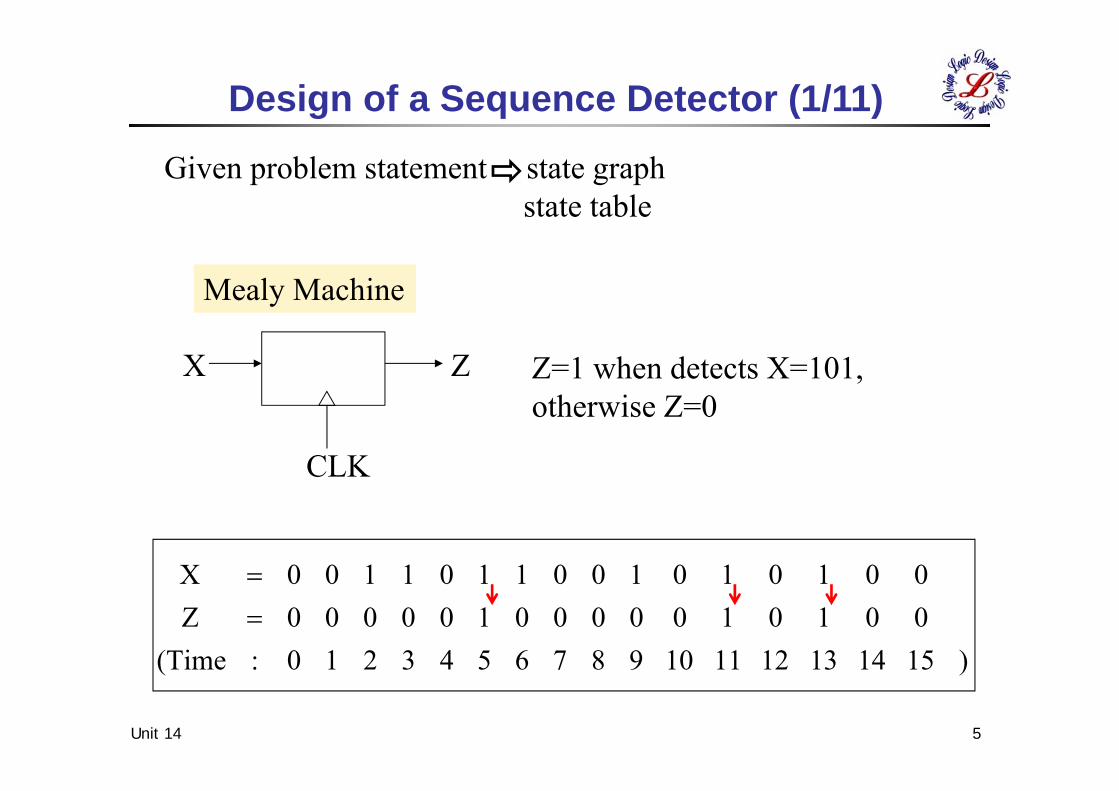
X Z
CLK
)1514131211109876543210:(Time0010100000100000Z0010101001101100X
Design of a Sequence Detector (1/11)
Z=1 when detects X=101, otherwise Z=0
Given problem statement state graphstate table
Mealy Machine
Unit 14 6
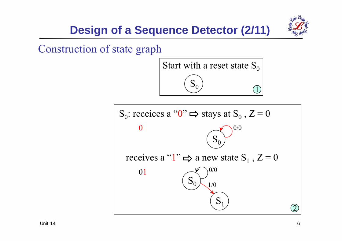
Construction of state graph
Design of a Sequence Detector (2/11)
Start with a reset state S0
S0 1
S0: receices a “0” stays at S0 , Z = 0
S0
receives a “1” a new state S1 , Z = 0
0/00
S0
S1
0/0011/0
2
Unit 14 7
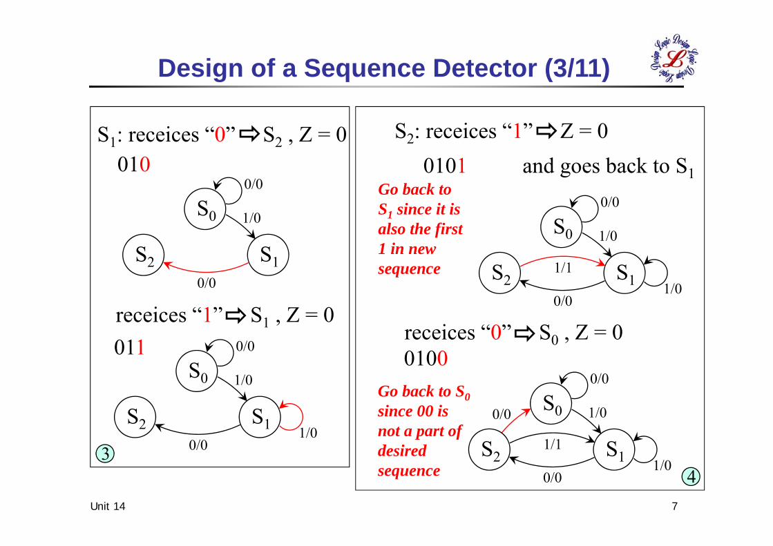
Design of a Sequence Detector (3/11)
S0
S1
0/0
1/0
S21/1
0/01/0
0/0
S0
S1
0/0
1/0
S21/1
0/01/0
S0
S1
0/0
1/0
S20/0
1/0
S0
S1
0/0
1/0
S20/0
34
S1: receices “0” S2 , Z = 0
receices “1” S1 , Z = 0
S2: receices “1” Z = 00101 and goes back to S1
Go back toS1 since it isalso the first 1 in newsequence
Go back to S0since 00 isnot a part ofdesiredsequence
receices “0” S0 , Z = 00100011
010
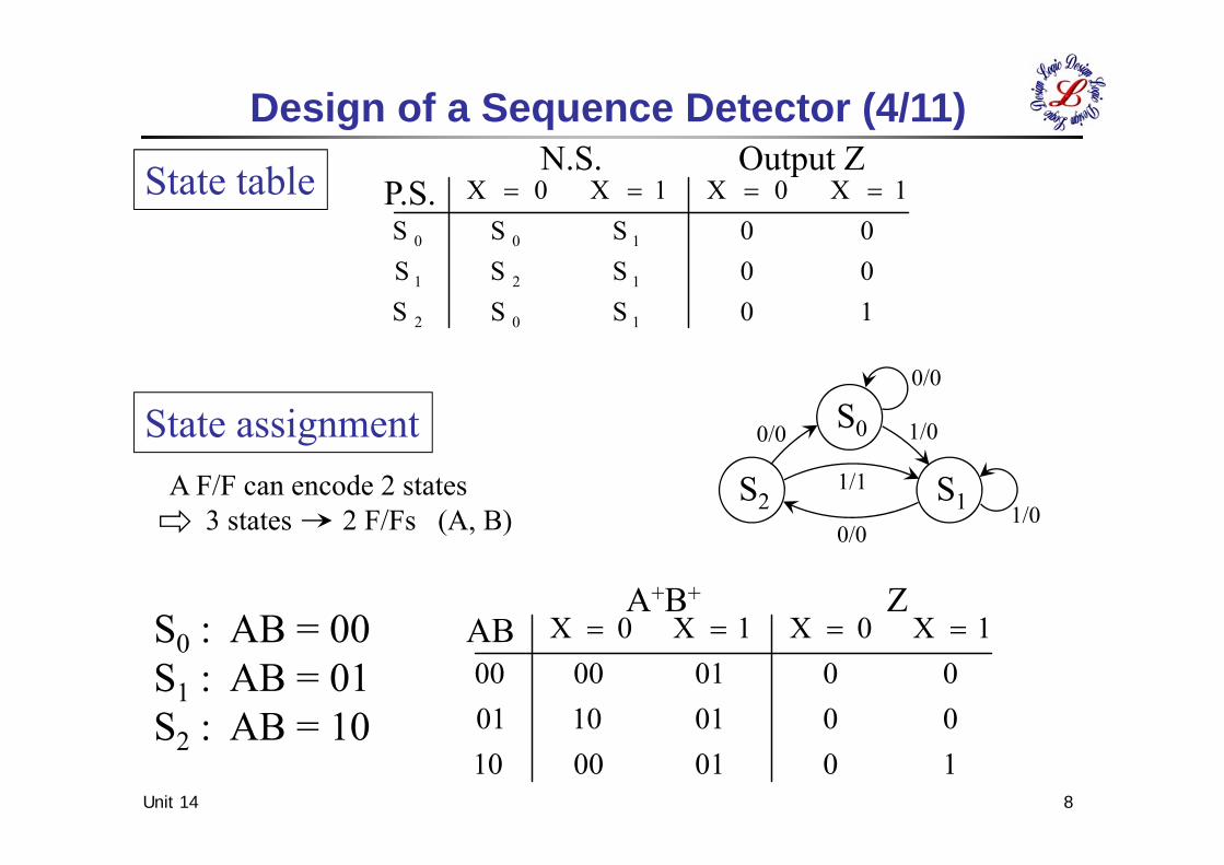
State table
Unit 14 8
10SSS00SSS00SSS
1X0X1X0X
102
121
100
P.S.N.S. Output Z
100100100001100100010000
1X0X1X0X ABA+B+ Z
Design of a Sequence Detector (4/11)
S0
S1
0/0
1/0
S21/1
0/01/0
0/0State assignmentA F/F can encode 2 states
3 states 2 F/Fs (A, B)
S0 : AB = 00S1 : AB = 01S2 : AB = 10
Z = XA
00
0100
Unit 14 9
XAB 0 100011110
XAB 0 100011110
XAB 0 100011110
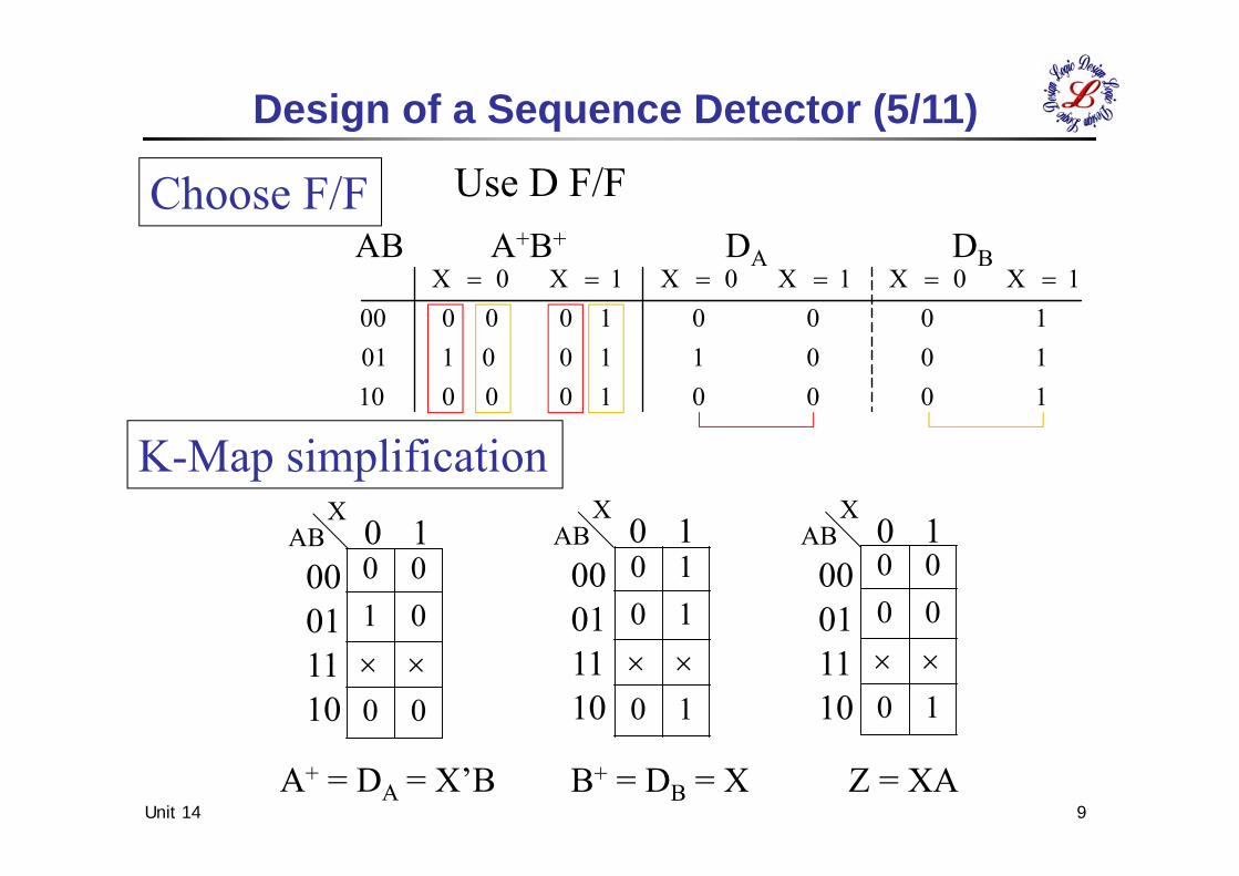
Design of a Sequence Detector (5/11)
Choose F/F Use D F/F
10001 00 01010011 00 10110001 00 000
1X0X1X0X1X0X
K-Map simplification
AB A+B+ DA DB
10
1010
10
0000
A+ = DA = X’B B+ = DB = X
Unit 14 10
Aʼ A
D
Bʼ B
D
B AX
CLK
Z
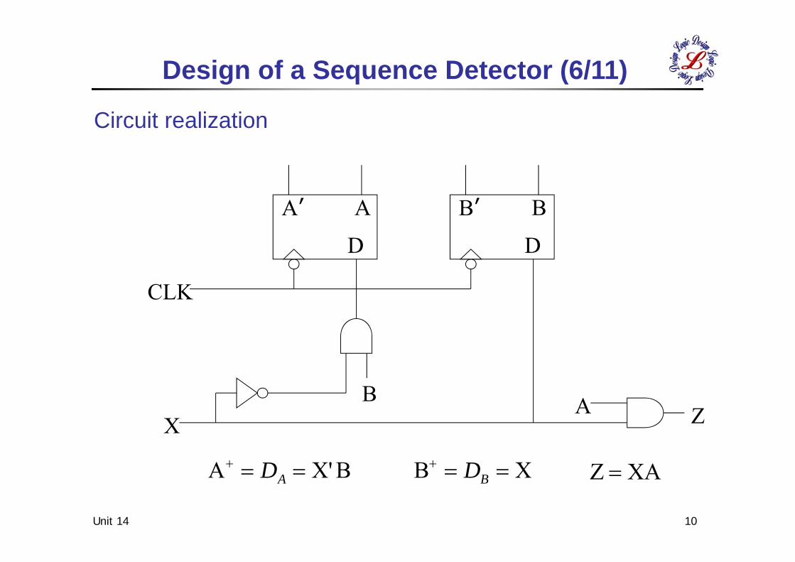
Circuit realization
BX'A AD XB
BD XAZ
Design of a Sequence Detector (6/11)
Unit 14 11
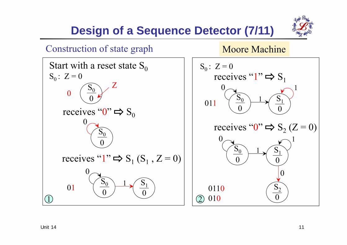
Construction of state graph
Design of a Sequence Detector (7/11)Moore Machine
0
01
1S0 S1
S2
0 0
0
01
1S0 S10 0
01S0 S1
0 0
0S0
0
S0
0
Start with a reset state S0S0 : Z = 0
Z0
receives “0” S0
receives “1” S1 (S1 , Z = 0)
011
S0 : Z = 0receives “1” S1
011
receives “0” S2 (Z = 0)
01100102
Unit 14 12
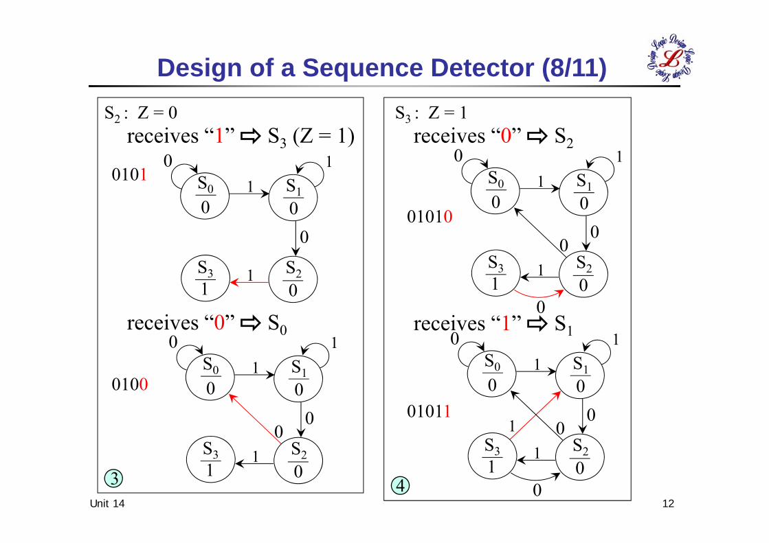
Design of a Sequence Detector (8/11)
01
1
0
10
0
1
S0 S1
S2S3
0 0
01
01
1
0
10
0
S0 S1
S2S3
0 0
01
01
1
0
10
S0 S1
S2S3
0 0
01
01
1
0
1
S0 S1
S2S3
0 0
01
S2 : Z = 0receives “1” S3 (Z = 1)
0101
receives “0” S0
0100
3
S3 : Z = 1receives “0” S2
01010
receives “1” S1
01011
4
1011110S0100011S0011101S0010000SZ1X0X
3
2
1
0
Unit 14 13
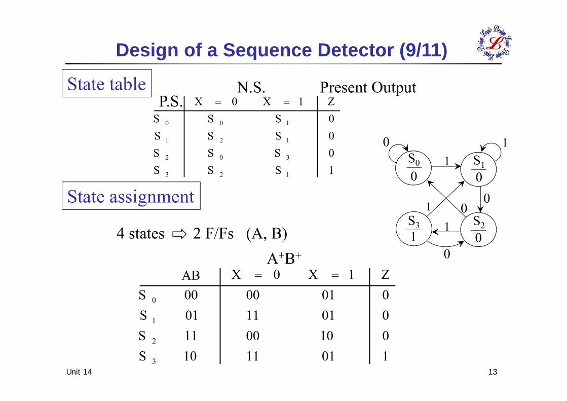
P.S.N.S. Present Output
Design of a Sequence Detector (9/11)
01
1
0
10
0
1
S0 S1
S2S3
0 0
01
1SSS0SSS0SSS0SSSZ1X0X
123
302
121
100
A+B+
AB
4 states 2 F/Fs (A, B)
State table
State assignment
Unit 14 14
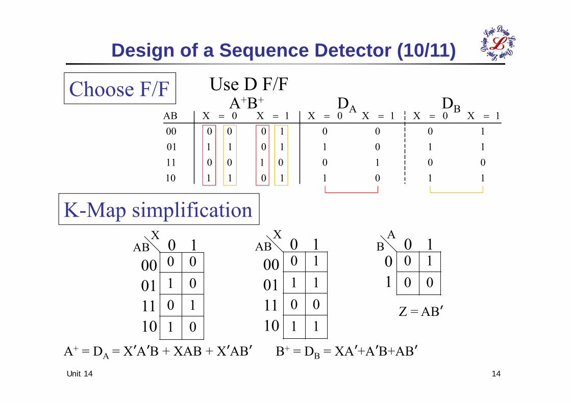
Design of a Sequence Detector (10/11)
Z = ABʼ01100100
XAB 0 100011110
XAB 0 100011110
AB 0 101
Choose F/F Use D F/F
11011 01 11000100 10 01111011 01 10110001 00 000
1X0X1X0X1X0XAB
K-Map simplification
A+B+ DA DB
11001110
0010
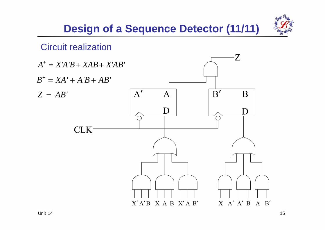
A+ = DA = XʼAʼB + XAB + XʼABʼ B+ = DB = XAʼ+AʼB+ABʼ
Unit 14 15
Aʼ A
D
Bʼ B
D
CLK
Z
Xʼ AʼB X A B Xʼ A Bʼ X Aʼ Aʼ B A Bʼ
Circuit realization
X'AB'XABX'A'BA
AB'A'BXA'B
AB'Z
Design of a Sequence Detector (11/11)
Unit 14 16
X Z
CLK
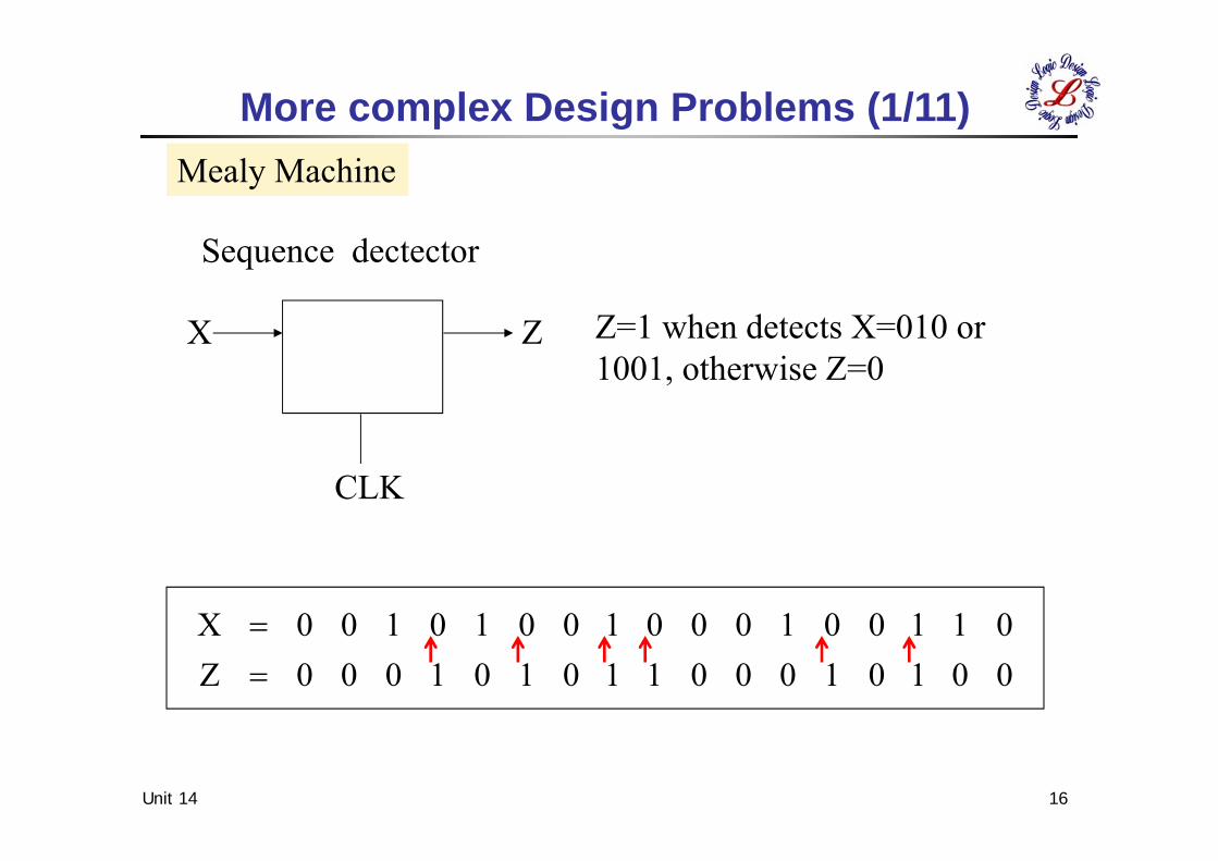
00101000110101000Z01100100010010100X
More complex Design Problems (1/11)
Z=1 when detects X=010 or 1001, otherwise Z=0
Mealy Machine
Sequence dectector
Unit 14 17
3
2
1
0
SSSS
State
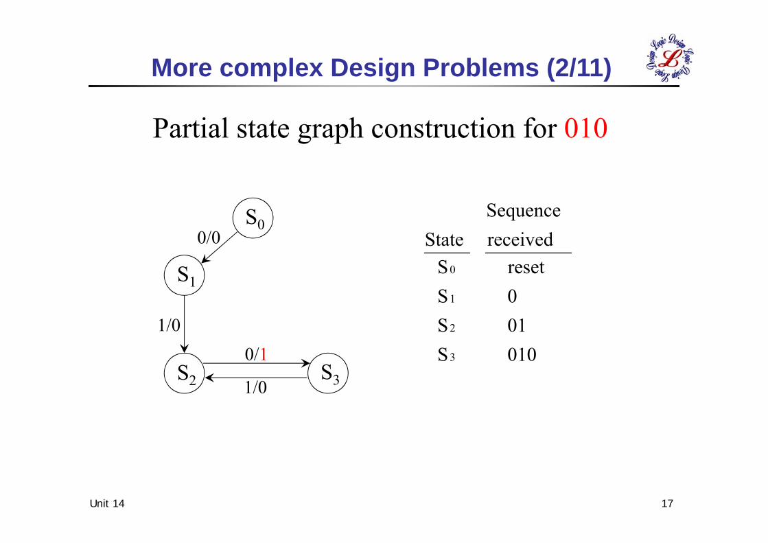
010010reset
receivedSequence
More complex Design Problems (2/11)
Partial state graph construction for 010
S0
S1
S3S2
1/0
1/0
0/1
0/0
Unit 14 18
2
1
0
SSS
State
010010reset
receivedSequence
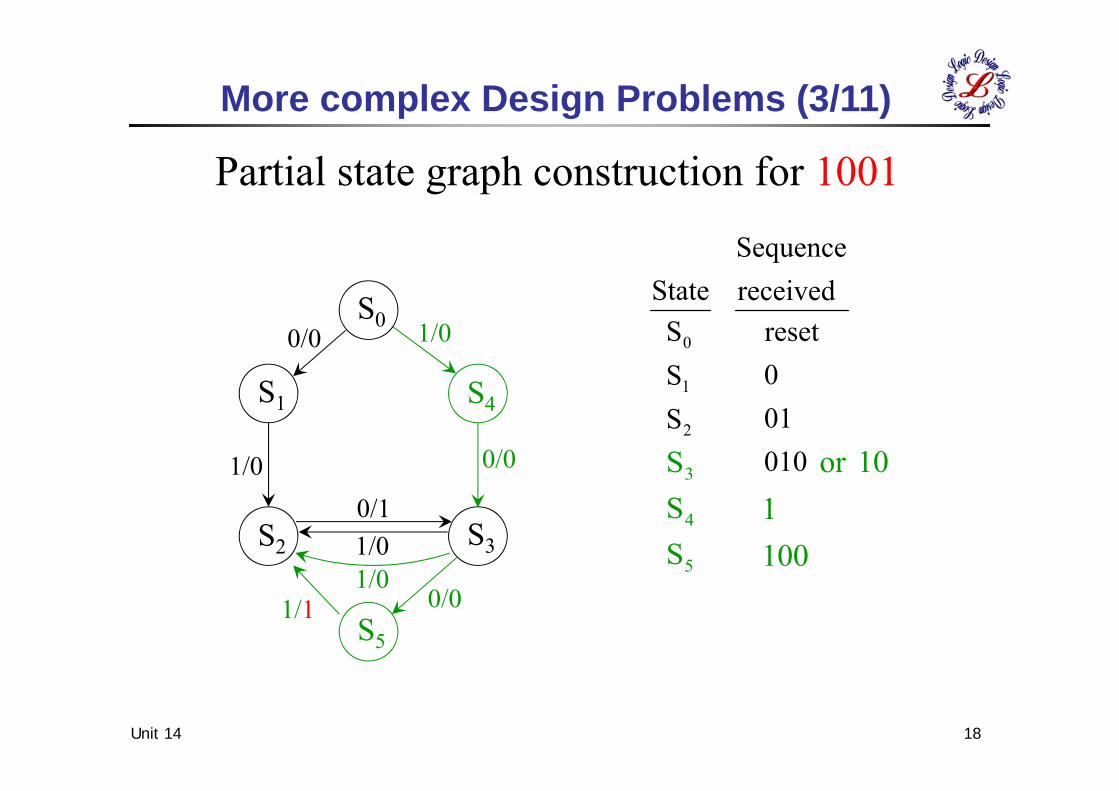
5
4
3
SSS
1001
10or
More complex Design Problems (3/11)
Partial state graph construction for 1001
S0
S5
S4S1
S3S2
1/0
1/0
1/00/1
0/0
0/0
0/01/11/0
Unit 14 19
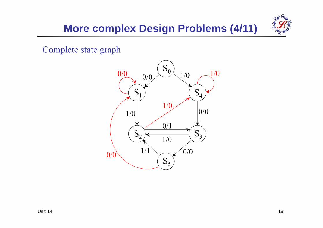
Complete state graph
More complex Design Problems (4/11)
S0
S5
S4S1
S3S2
1/0 1/0
1/01/0
1/0
0/1
0/0
0/0 0/0
0/0
0/01/1
Unit 14 20
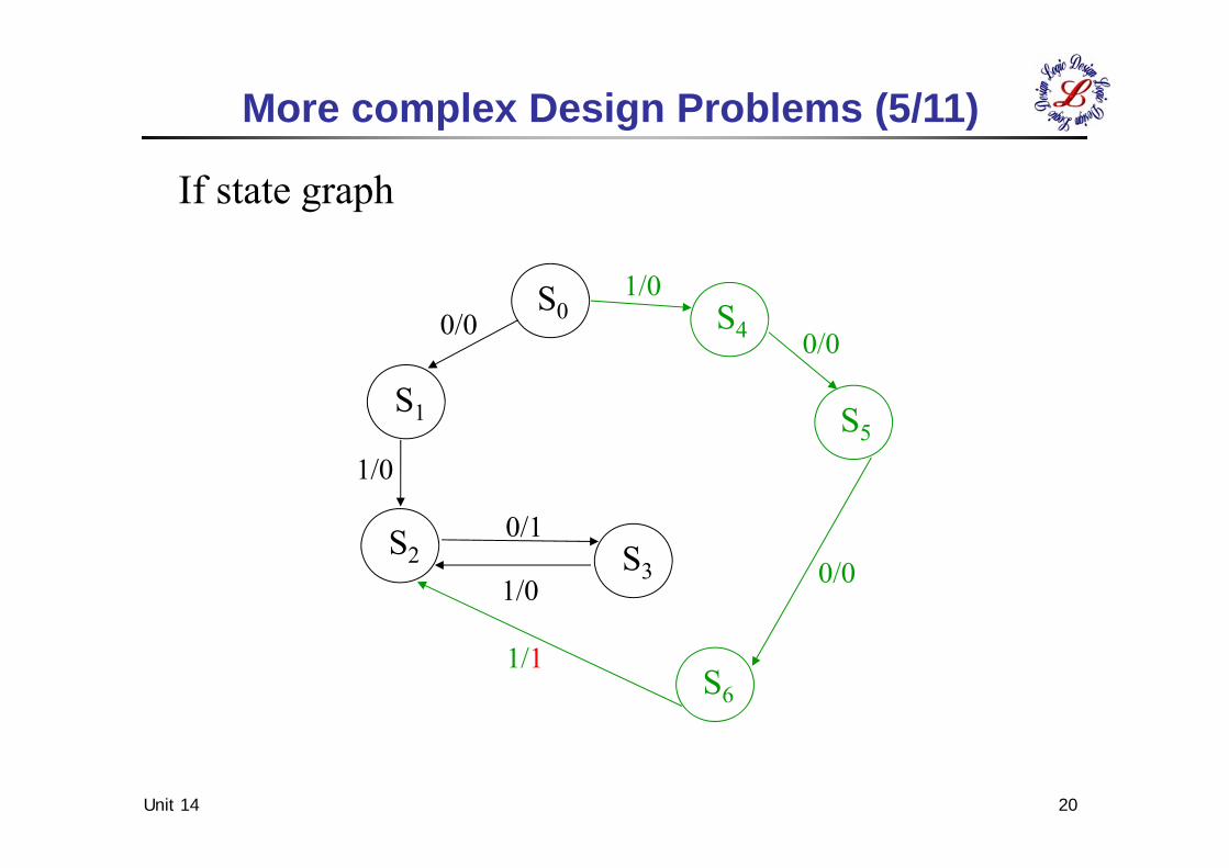
If state graph
More complex Design Problems (5/11)
S0
S5
S6
S3S2
S1
S40/0 0/0
0/0
1/1
1/0
1/0
1/0
0/1
Unit 14 21
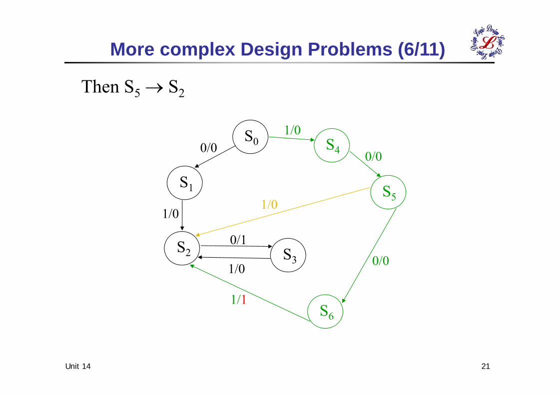
More complex Design Problems (6/11)
Then S5 S2
S0
S5
S6
S3S2
S1
S40/0 0/0
0/0
1/1
1/0
1/01/0
1/0
0/1
Unit 14 22
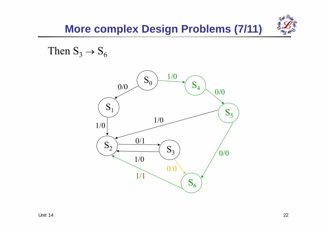
More complex Design Problems (7/11)
Then S3 S6
S0
S5
S6
S3S2
S1
S40/0 0/0
0/0
0/0
1/1
1/0
1/01/0
1/0
0/1
Unit 14 23
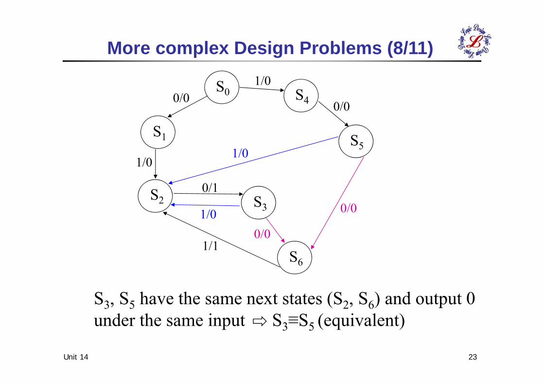
More complex Design Problems (8/11)
S3, S5 have the same next states (S2, S6) and output 0under the same input S3≡S5 (equivalent)
S0
S5
S6
S3S2
S1
S40/00/0
0/0
0/0
1/1
1/0
1/01/0
1/0
0/1
Unit 14 24
X Z
CLK
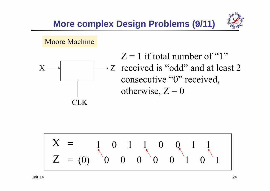
ZX 1 1 0 0 1 1 0 1
1 0 1 0 0 0 0 0 (0)
More complex Design Problems (9/11)
Moore Machine
Z = 1 if total number of “1”received is “odd” and at least 2consecutive “0” received,otherwise, Z = 0
Unit 14 25
11
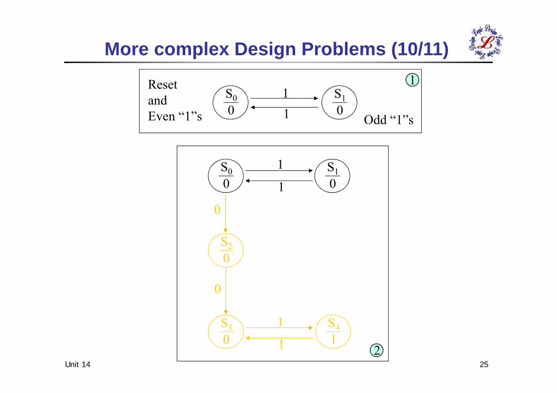
More complex Design Problems (10/11)
S10
S00
Resetand Even “1”s Odd “1”s
1
2
1
1
0
0
1
1
S10
S00
S20
S30
S41
Unit 14 26
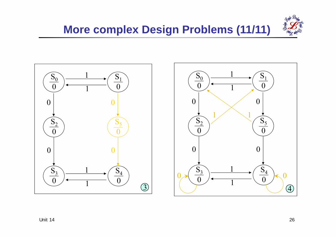
More complex Design Problems (11/11)
3
1
1
0
0
1
1
0
0
S10
S00
S20
S50
S30
S40
4
1
1
0
0
1
1
0
0
1 1
00
S10
S00
S20
S50
S30
S40
Unit 14 27
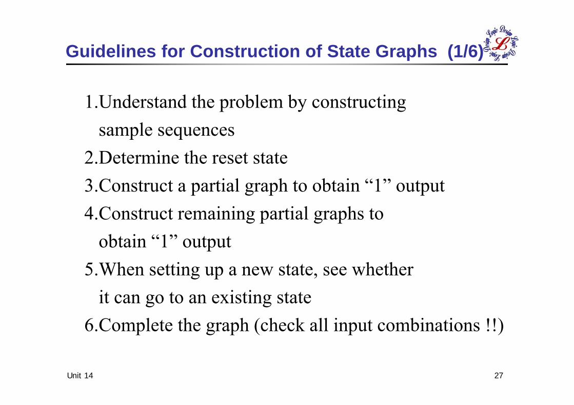
Guidelines for Construction of State Graphs (1/6)
1.Understand the problem by constructingsample sequences
2.Determine the reset state3.Construct a partial graph to obtain “1” output4.Construct remaining partial graphs to
obtain “1” output5.When setting up a new state, see whether
it can go to an existing state6.Complete the graph (check all input combinations !!)
Unit 14 28
X Z
CLK
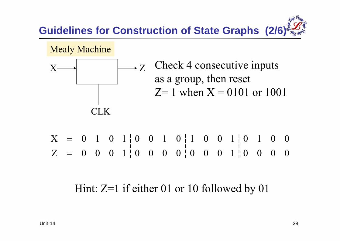
0000100000001000Z0010100101001010X
Guidelines for Construction of State Graphs (2/6)Mealy Machine
Check 4 consecutive inputsas a group, then resetZ= 1 when X = 0101 or 1001
Hint: Z=1 if either 01 or 10 followed by 01
Unit 14 29
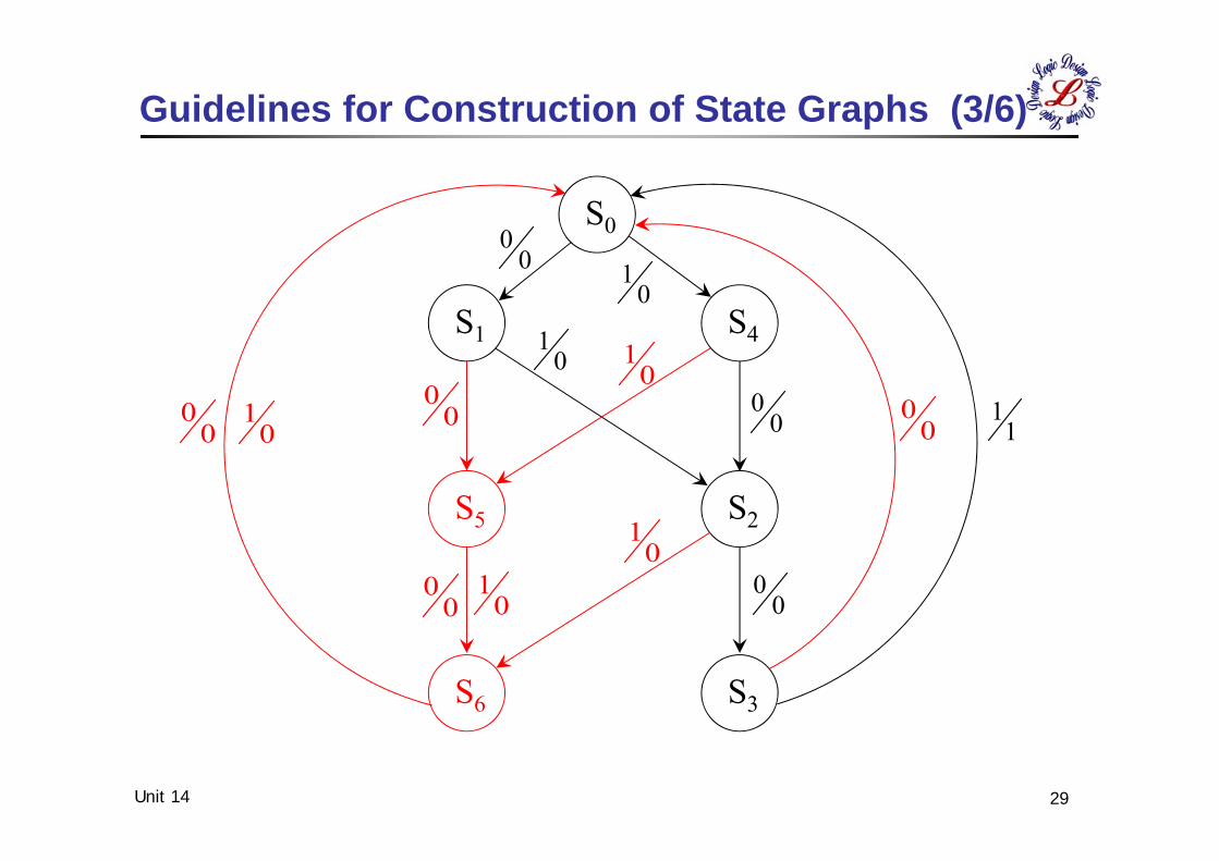
Guidelines for Construction of State Graphs (3/6)
00
00
01
01
00
11
00
01
000
00
1
01
00
01
S0
S4S1
S2S5
S6 S3
Unit 14 30
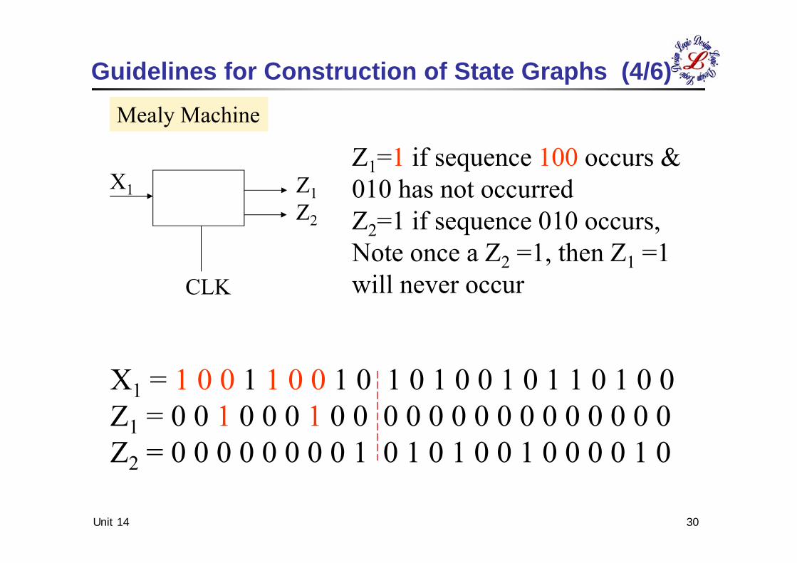
Z1=1 if sequence 100 occurs & 010 has not occurredZ2=1 if sequence 010 occurs, Note once a Z2 =1, then Z1 =1 will never occur
X1 = 1 0 0 1 1 0 0 1 0 1 0 1 0 0 1 0 1 1 0 1 0 0Z1 = 0 0 1 0 0 0 1 0 0 0 0 0 0 0 0 0 0 0 0 0 0 0Z2 = 0 0 0 0 0 0 0 0 1 0 1 0 1 0 0 1 0 0 0 0 1 0
Guidelines for Construction of State Graphs (4/6)
Z1Z2
X1
CLK
Mealy Machine
Unit 14 31
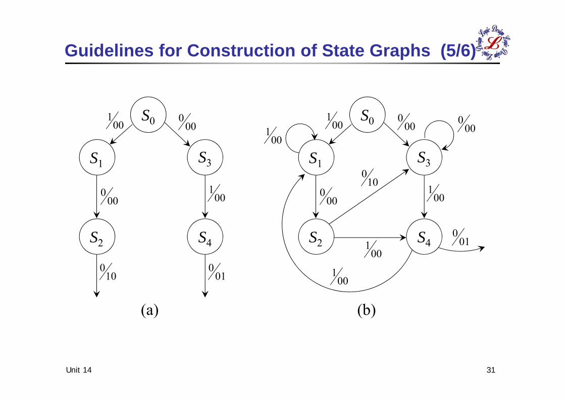
Guidelines for Construction of State Graphs (5/6)
S0
S3S1
S2 S4
001
000
001
010
100
000
(a) (b)
S0
S3S1
S2 S4
001
000
001
000
001 00
0
010
001
001
100
Unit 14 32
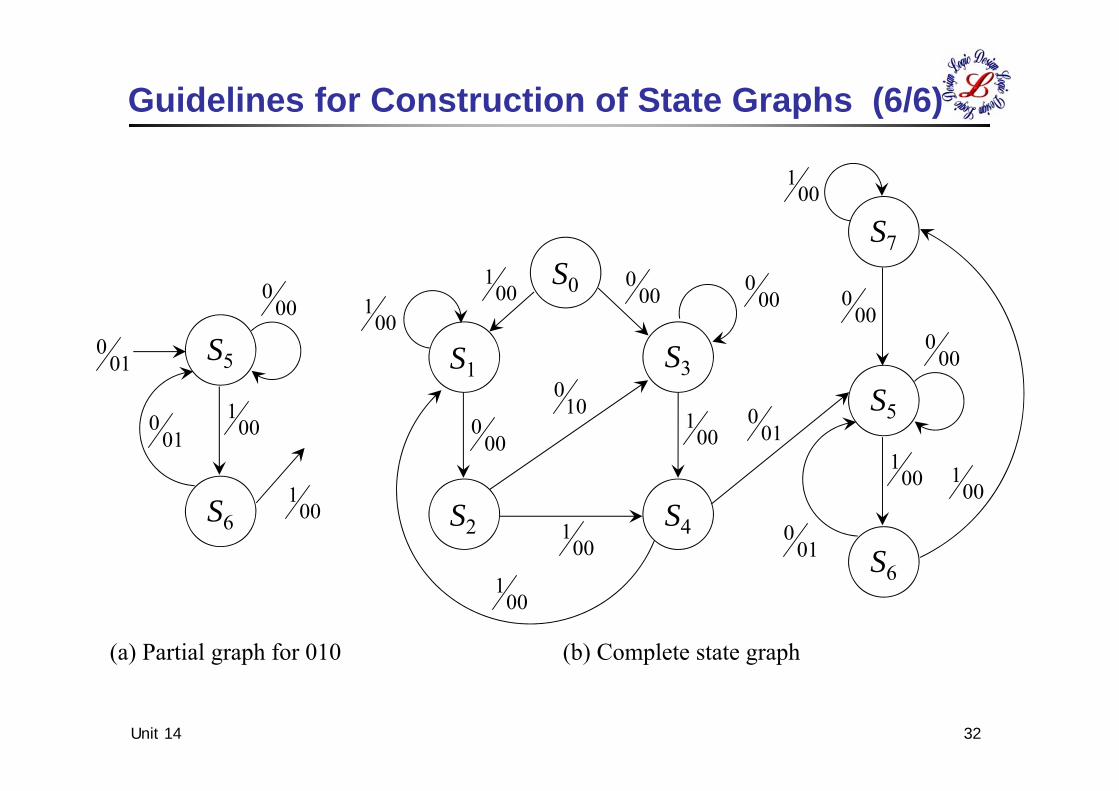
Guidelines for Construction of State Graphs (6/6)
S0
S3S1
S2 S4
001
000
001
000
001 00
0
010
001
001
100 S5
S7
S6
000
000
001
00100
1
010
010 S5
S6
000
001
001
010
(a) Partial graph for 010 (b) Complete state graph
100SSSSS010SSSSS001SSSSS
ZZZ11100100FRPS
00122
22011
11200
321
Unit 14 33
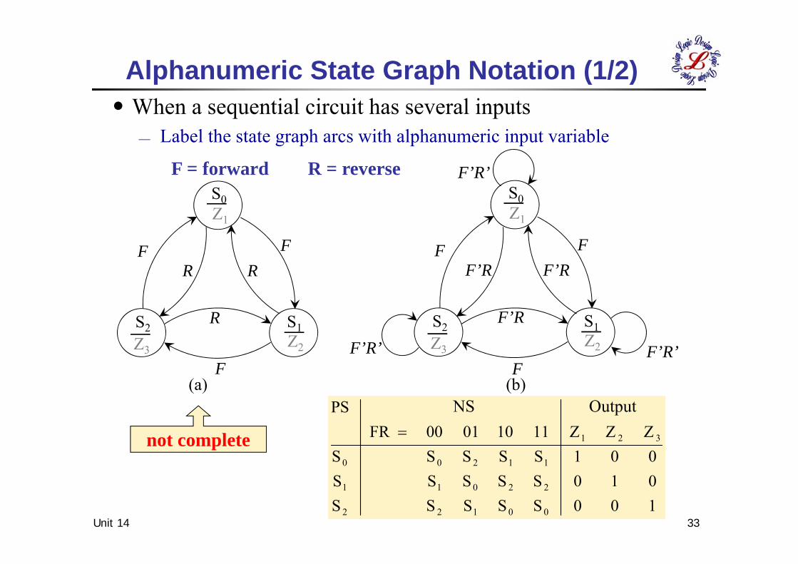
․When a sequential circuit has several inputs Label the state graph arcs with alphanumeric input variable
F = forward R = reverse
not complete
Alphanumeric State Graph Notation (1/2)
S0
S1S2
Z1
Z2Z3
RF
F
FR
R
(a) (b)F
S0
S1S2
Z1
Z2Z3
F’RFF
F’R
F’R
F’R’F’R’
F’R’
NS Output
Unit 14 34
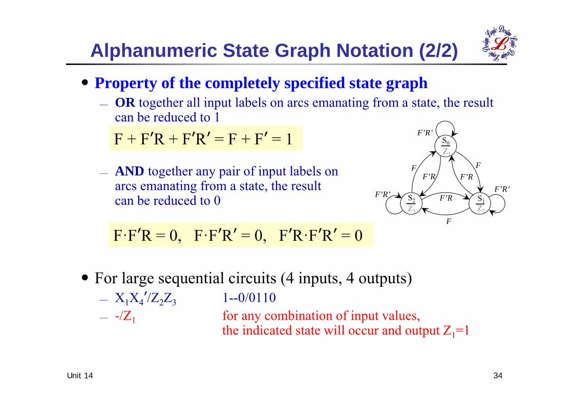
․Property of the completely specified state graph OR together all input labels on arcs emanating from a state, the result
can be reduced to 1
AND together any pair of input labels onarcs emanating from a state, the result can be reduced to 0
․For large sequential circuits (4 inputs, 4 outputs) X1X4ʼ/Z2Z3 1--0/0110 -/Z1 for any combination of input values,
the indicated state will occur and output Z1=1
Alphanumeric State Graph Notation (2/2)
F
S0
S1S2
Z1
Z2Z3
F’RFF
F’R
F’RF’R’
F’R’
F’R’F + FʼR + FʼRʼ = F + Fʼ = 1
F·FʼR = 0, F·FʼRʼ = 0, FʼR·FʼRʼ = 0


![S N S N - ocw.nthu.edu.twocw.nthu.edu.tw/ocw/upload/124/news/[電動機械L16補充教材]IIT... · 2 Synchronous Machine Armature Windings 2.1 Winding Types b SB SC SA FB FC FA SB](https://img.pdfslide.us/doc/110x75/5f2690e44c6efd13c03c115d/s-n-s-n-ocwnthuedutwocwnthuedutwocwupload124newsel16eoeiit.jpg)


![Synchronous Machines - ocw.nthu.edu.twocw.nthu.edu.tw/ocw/upload/124/news/[電動機械L12補充教材]VT... · 7 tells us that the speed of a synchronous motor will be constant](https://img.pdfslide.us/doc/110x75/5aac71a27f8b9a2b4c8d354b/synchronous-machines-ocwnthuedutwocwnthuedutwocwupload124newsl12vt7.jpg)