Embed Size (px)
Citation preview

Erik Jonsson School of Engineering and Th U i it f T t D ll g gComputer ScienceThe University of Texas at Dallas
The Pipelined MIPS ProcessorThe Pipelined MIPS Processor• We complete our study of computer architecture by investigating an
approach providing even higher performance for the MIPS CPU. • We first saw how the MIPS CPU performance could be improvedWe first saw how the MIPS CPU performance could be improved
by converting the so-called single-cycle CPU to a multi-cycle design. – In the multi-cycle approach, instead of using a single clock cycle for the
whole instruction, the clock is accelerated, and instructions execute in phases over several clock cycles.
– Each instruction phase takes one clock cycle.– This means that as each instruction executes, only one section of the
CPU will be active per clock cycle -- the one executing that phase of the instruction.
• This suggests that perhaps we might redesign the CPU slightly so th t CPU ti t i d d tl i t ti
© N. B. Dodge 09/121 Lecture #20: The Pipeline MIPS Processor
that every CPU section can operate independently on an instruction at the same time.

Erik Jonsson School of Engineering and Th U i it f T t D ll g gComputer ScienceThe University of Texas at Dallas
The “Laundry Example”The “Laundry Example”• As an introduction to the concept of pipelining, Patterson and
Hennessy use the example of doing one’s laundry. • Most people have – or have access to – a washer and dryer.Most people have or have access to a washer and dryer. • Assume that you need to wash several washer loads of clothing. • Would anyone divide the clothing into washer loads and then
wash dry fold and put away the first load before starting thewash, dry, fold and put away the first load before starting the second?
• No, if you were washing clothes, you would finish washing the first load put it in the dryer and start the second load washingload, put it in the dryer, and start the second load washing.
• If there were more loads to wash, you would begin to fold and put away finished clothing while the later loads were washing and drying
© N. B. Dodge 09/122 Lecture #20: The Pipeline MIPS Processor
drying. • We can see this schematically on the next slide.

Erik Jonsson School of Engineering and Th U i it f T t D ll g gComputer ScienceThe University of Texas at Dallas
Graphical Example of the Laundry CycleGraphical Example of the Laundry Cycle
© N. B. Dodge 09/123 Lecture #20: The Pipeline MIPS Processor

Erik Jonsson School of Engineering and Th U i it f T t D ll g gComputer ScienceThe University of Texas at Dallas
The “Pipeline” ProcessorThe “Pipeline” Processor• Patterson and Hennessy applied this “simultaneous wash-dry-fold-
put away concept” to the single-cycle computer model. • The idea was to “wash dry fold and put away” instructions• The idea was to wash, dry, fold, and put away instructions
simultaneously so that the instruction throughput – the number of clock cycles per instructions – could be dramatically decreased.
• In the case of the single cycle model one instruction is done per clock• In the case of the single cycle model, one instruction is done per clock cycle, but the clock must be as slow as the slowest instruction.
• In the multi-cycle implementation, the clock runs faster, instructions takes 3 5 cycles but only one instruction is processed at a timetakes 3-5 cycles, but only one instruction is processed at a time.
• What if, each time the clock ticked, we could process an instruction in each section of the multicycle processor? Then we could process several instructions simultaneously approaching the goal of
© N. B. Dodge 09/124 Lecture #20: The Pipeline MIPS Processor
several instructions simultaneously, approaching the goal of completing an instruction every clock cycle.
Erik Jonsson School of Engineering and Th U i it f T t D ll g gComputer ScienceThe University of Texas at Dallas
Pipeline ArchitecturePipeline Architecture
• A pipelined computer executes instructions concurrently. • Hardware units are organized into stages:
– Execution in each stage takes exactly 1 clock period. – Stages are separated by pipeline registers that preserve and passStages are separated by pipeline registers that preserve and pass
partial results to the next stage.
• Unfortunately, as noted earlier, speed = complexity + cost. Th i li h b i dditi l l itThe pipeline approach brings additional expense plus its own set of problems and complications, called hazards, which we will also study.
© N. B. Dodge 09/125 Lecture #20: The Pipeline MIPS Processor
Erik Jonsson School of Engineering and Th U i it f T t D ll g gComputer ScienceThe University of Texas at Dallas
Sequential Versus Pipelined ExecutionSequential Versus Pipelined ExecutionTimelineTimeline
(clockcycles) 0 1 2 3 4 5 6 7 8 9 10
lw $t0, 16($a3) Instruc.Fetch
Reg.Fetch
ALUProcess
Mem. R/Wor ALU Out
Reg.Write
lw $t1, 32($a3)
lw $t2, 48($a3)
Instruc.Fetch
Reg.Fetch
ALUProcess
Mem. R/Wor ALU Out
Reg.Write
Instruc.Fetch
Reg.Fetch
ALProc
4 clock cycles
4 clock cycles
i i etc.Timeline(clockcycles) 0 1 2 3 4 5 6 7 8 9 10
5 clock cycles
lw $t0, 16($a3)
lw $t1, 32($a3)
$ $
Instruc.Fetch
Reg.Fetch
ALUProcess
Mem. R/Wor ALU Out
Reg.Write
Instruc.Fetch
Reg.Fetch
ALUProcess
Mem. R/Wor ALU Out
Reg.Write
Instruc.Fetch
Reg.Fetch
ALUProcess
Mem. R/Wor ALU Out
Reg.Write
© N. B. Dodge 09/126 Lecture #20: The Pipeline MIPS Processor
lw $t2, 48($a3)etc.
Fetch Fetch Process or ALU Out Write

Erik Jonsson School of Engineering and Th U i it f T t D ll g gComputer ScienceThe University of Texas at Dallas
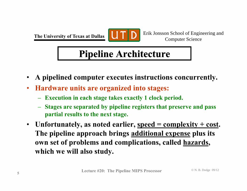
Speed Advantage of the PipelineSpeed Advantage of the PipelineTh l i l i l h di d l l• The multicycle, serial processor that we studied last lecture can execute n instructions in ns clock periods, or ETS = ns, where
ET is the execution time and s is the number of stages.ET is the execution time and s is the number of stages.
• A pipelined processor with s stages can execute n instructions in
ETP = s + (n ─ 1) clock periods.P ( ) p• The ideal pipeline speedup depends on the number of stages, and
can be greater for more stages (hence Intel’s choice of a 20-stage pipeline for the current P-IV). p p )
• Thus the speed advantage of pipeline over multicycle can be defined as:
( 1)s n sP
ET nsS sET
© N. B. Dodge 09/127 Lecture #20: The Pipeline MIPS Processor
( 1) n sPPET s n

Erik Jonsson School of Engineering and Th U i it f T t D ll g gComputer ScienceThe University of Texas at Dallas
Pipeline StagesPipeline StagesCl k l
0 1 2 3 4 5
ALUIF ID/ MEM WB
Clock cycles
• The MIPS R2000 pipeline processor is divided into five processing
ALUIF RF MEM WB
stages: 1. Instruction fetch (IF)2. Instruction decode (ID) and register fetch (RF)3. ALU instruction execution (ALU) – ALU processing, branch
condition evaluation, memory address computation, etc. This is also referred to as execution (EX)
4 Memory access (MEM)
© N. B. Dodge 09/128 Lecture #20: The Pipeline MIPS Processor
4. Memory access (MEM)5. Write back (WB) to register file
Erik Jonsson School of Engineering and Th U i it f T t D ll g gComputer ScienceThe University of Texas at Dallas
Overlapped Pipeline ExecutionOverlapped Pipeline Execution
0 1 2 3 4 5 6 7
Clock cycles
ALUIF ID/RF MEM WB
ID/
Instruction 1
ALUIF ID/RF MEM WB
ALUIF ID/ MEM WB
Instruction 2
Instruction 3 ALUIF RF MEM WBInstruction 3
© N. B. Dodge 09/129 Lecture #20: The Pipeline MIPS Processor
Instruction execution order
Erik Jonsson School of Engineering and Th U i it f T t D ll g gComputer ScienceThe University of Texas at Dallas
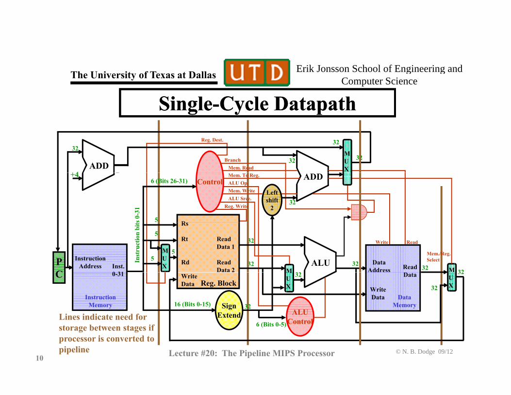
Single-Cycle DatapathSingle-Cycle Datapath
ADDBranch
Mem. Read+4
32
32
3232
Reg. Dest.
MUX
ADDMem. To Reg.ALU Op.
Reg. WriteALU Srce.
+4
Leftshift
2
Rs 0-3
1
32
5
ControlMem. Write
6 (Bits 26-31)
ALUPC
InstructionAddress
MData
AddressInst. 0 31 M
Rs
Rt
Rd
Read Data 1
ReadData 2 Read
Inst
ruct
ion
bits
32
32
32
32 32 32
5
5
MUX
5
ReadWrite
Mem./Reg.Select
Lines indicate need for
C MUX
0-31 UXReg. Block
WriteData
SignExtend
32
WriteData
Data
16 (Bits 0-15)
32
32
32
ALUControl
InstructionMemory
DataMemory
6 ( i 0 )
© N. B. Dodge 09/1210 Lecture #20: The Pipeline MIPS Processor
storage between stages ifprocessor is converted to pipeline
Control6 (Bits 0-5)

Erik Jonsson School of Engineering and Th U i it f T t D ll g gComputer ScienceThe University of Texas at Dallas
Single-Cycle Datapath with Pipeline RegistersSingle-Cycle Datapath with Pipeline Registers
MUX
Inter-stage registers are master-slave D flip-flops; the master canbe receiving new data from the previous stage of the instructionwhile the slave flip-flop is providing data to the next stage
ADDADD
+4
I t ti
MemoryLeftshift
2Compare
resultRs
Reg. Block
ALU
PC
InstructionAddress Memory
MUX
DataAddress
Inst. 0-31
Rs
Rt
Rd MUX
Read Data 1
ReadData 2
ReadData
SignExtend
XWriteData
16
X
32
WriteData
Master side of register
Slave side
© N. B. Dodge 09/1211 Lecture #20: The Pipeline MIPS Processor
IF/ID ID/EX EX/MEM MEM/WBof register
Note: Control lines and logic not shown for clarity After David A. Patterson and John L. Hennessy, Computer Organization and Design, 2nd Edition
Erik Jonsson School of Engineering and Th U i it f T t D ll g gComputer ScienceThe University of Texas at Dallas
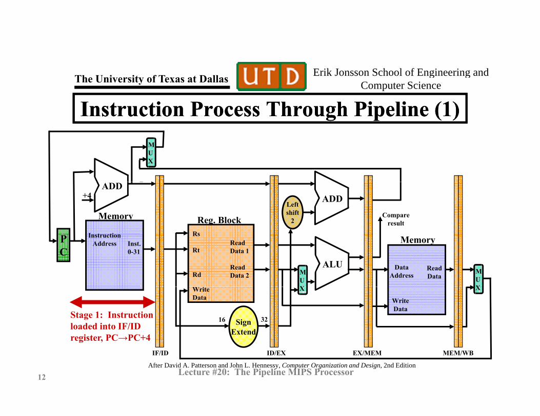
Instruction Process Through Pipeline (1)Instruction Process Through Pipeline (1)MUX
ADDADD
+4
I t ti
MemoryLeftshift
2Compare
resultRs
Reg. Block
ALU
PC
InstructionAddress Memory
MUX
DataAddress
Inst. 0-31
Rs
Rt
Rd MUX
Read Data 1
ReadData 2
ReadData
Stage 1: Instructionloaded into IF/IDregister, PC→PC+4
SignExtend
XWriteData
16
X
32
WriteData
© N. B. Dodge 09/1212 Lecture #20: The Pipeline MIPS Processor
register, PC→PC+4
After David A. Patterson and John L. Hennessy, Computer Organization and Design, 2nd Edition
IF/ID ID/EX EX/MEM MEM/WB

Erik Jonsson School of Engineering and Th U i it f T t D ll g gComputer ScienceThe University of Texas at Dallas
Instruction Process Through Pipeline (2)Instruction Process Through Pipeline (2)St 2 I t tiStage 2: Instructiondecoded, register dataaccessed, immediatessign-extended
MUX
ADDADD
+4
MemoryLeftshift
2Compare
resultR
Reg. Block
ALU
PC
InstructionAddress Memory
MU
DataAddress
Inst. 0-31
Rs
Rt
Rd MU
Read Data 1
ReadData 2
ReadData
SignExtend
XWriteData
16
X
32
WriteData
© N. B. Dodge 09/1213 Lecture #20: The Pipeline MIPS Processor
After David A. Patterson and John L. Hennessy, Computer Organization and Design, 2nd EditionIF/ID ID/EX EX/MEM MEM/WB
Erik Jonsson School of Engineering and Th U i it f T t D ll g gComputer ScienceThe University of Texas at Dallas
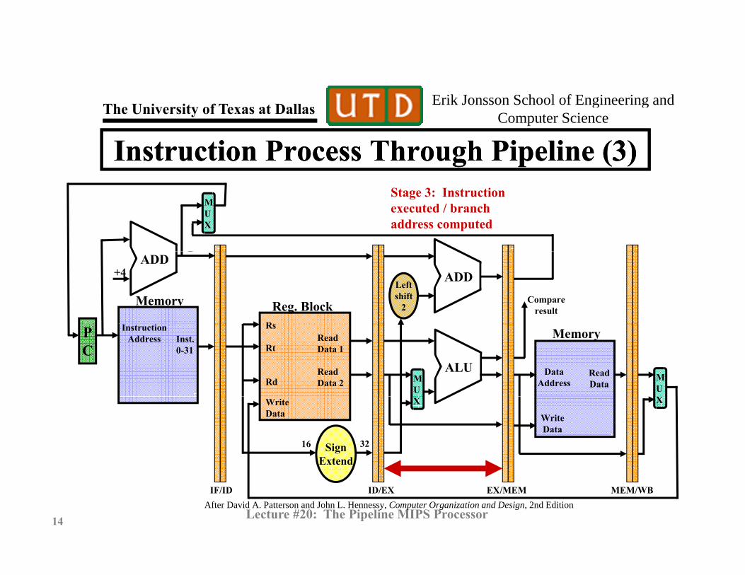
Instruction Process Through Pipeline (3)Instruction Process Through Pipeline (3)Stage 3: Instructionexecuted / branch address computed
MUX
ADDADD
+4
MemoryLeftshift
2Compare
resultR
Reg. Block
ALU
PC
InstructionAddress Memory
MU
DataAddress
Inst. 0-31
Rs
Rt
Rd MU
Read Data 1
ReadData 2
ReadData
SignExtend
XWriteData
16
X
32
WriteData
© N. B. Dodge 09/1214 Lecture #20: The Pipeline MIPS Processor
After David A. Patterson and John L. Hennessy, Computer Organization and Design, 2nd EditionIF/ID ID/EX EX/MEM MEM/WB
Erik Jonsson School of Engineering and Th U i it f T t D ll g gComputer ScienceThe University of Texas at Dallas
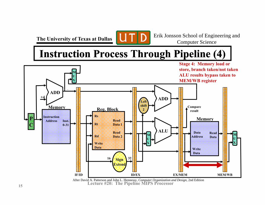
Instruction Process Through Pipeline (4)Instruction Process Through Pipeline (4)Stage 4: Memory load orStage 4: Memory load or store, branch taken/not takenALU results bypass taken to MEM/WB register
MUX
ADDADD
+4
MemoryLeftshift
2Compare
resultR
Reg. Block
ALU
PC
InstructionAddress Memory
MU
DataAddress
Inst. 0-31
Rs
Rt
Rd MU
Read Data 1
ReadData 2
ReadData
SignExtend
XWriteData
16
X
32
WriteData
© N. B. Dodge 09/1215 Lecture #20: The Pipeline MIPS Processor
After David A. Patterson and John L. Hennessy, Computer Organization and Design, 2nd EditionIF/ID ID/EX EX/MEM MEM/WB

Erik Jonsson School of Engineering and Th U i it f T t D ll g gComputer ScienceThe University of Texas at Dallas
Instruction Process Through Pipeline (5)Instruction Process Through Pipeline (5)MUX
ADDADD
+4
MemoryLeftshift
2Compare
resultR
Reg. Block
ALU
PC
InstructionAddress Memory
MU
DataAddress
Inst. 0-31
Rs
Rt
Rd MU
Read Data 1
ReadData 2
ReadData
Stage 5: Result write-back to
SignExtend
XWriteData
16
X
32
WriteData
© N. B. Dodge 09/1216 Lecture #20: The Pipeline MIPS Processor
dest. register
After David A. Patterson and John L. Hennessy, Computer Organization and Design, 2nd EditionIF/ID ID/EX EX/MEM MEM/WB
Erik Jonsson School of Engineering and Th U i it f T t D ll g gComputer ScienceThe University of Texas at Dallas
Adding ControlAdding Control• Control information must be carried along as a part of
the instruction, since this information is required at diff f h i lidifferent stages of the pipeline.
• This can be done by adding more inter-stage storage register bits to forward control data yet to be used.register bits to forward control data yet to be used.
• The result is very large inter-stage registers. For example, the storage capacity required between the instruction decode and ALU execution stages (ID/EX register) is more than 120 bits.
• The resulting processor with full control functionality
© N. B. Dodge 09/1217 Lecture #20: The Pipeline MIPS Processor
The resulting processor with full control functionality is shown on the next slide

Erik Jonsson School of Engineering and Th U i it f T t D ll g gComputer ScienceThe University of Texas at Dallas
M
ID/EX EX/MEM MEM/WB
iteADD
ADD+4
MUX
IF/ID
0-31
ControlDecode
ite ad
Reg
iste
r W
rADD
PC
InstructionAddress
MemoryLeftshift
2
Inst. 0 31
Reg. BlockRs
Rt Read Data 1In
stru
ctio
n bi
ts 0
ALU Srce
Branch
Mem
ory
Wri
Mem
ory
Rea
emor
y/A
LU
Res
ult
ALUC
MUX
DataAddress
0-31
MUX
Rd
WriteData
ReadData 2
Write
ReadData
M
Full PipelineDesign with
Control Lines
MemorySign
Extend32 DataBits 0-15
Bits 16-20
Bits 11-15
ALUCont.
MUX
ALU Op
© N. B. Dodge 09/1218 Lecture #20: The Pipeline MIPS Processor
Control Lines
After David A. Patterson and John L. Hennessy, Computer Organization and Design, 2nd Edition
XReg. Dst.
Erik Jonsson School of Engineering and Th U i it f T t D ll g gComputer ScienceThe University of Texas at Dallas
The Pipeline in ActionThe Pipeline in Action• The following instruction sequence from the P&H text
illustrates the pipeline in action. l $10 20($1)lw $10, 20($1)sub $11, $2, $3and $12 $4 $5and $12, $4, $5or $13, $6, $7add $14, $8, $9$ , $ , $
• Note that registers are identified by number rather than the letter id’s, since that is the way they appear in th MIPS A i d $1 $ t $8 14 $t0
© N. B. Dodge 09/1219 Lecture #20: The Pipeline MIPS Processor
the MIPS processor. As a reminder, $1=$at, $8-14=$t0-t6, $2-3=$v0-v1, $4-7=$a0-a3, etc.
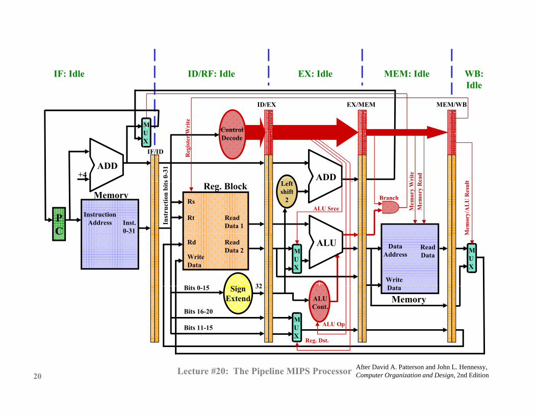
IF: Idle ID/RF: Idle EX: Idle MEM: Idle WB: IF: Idle ID/RF: Idle EX: Idle MEM: Idle WB: Idle
M
ID/EX EX/MEM MEM/WB
ControlWri
teADD
ADD+4
L f
UX
IF/ID
s 0-3
1
ControlDecode
Wri
teea
d
Reg
iste
r W
t
PC
InstructionAddress
MemoryLeftshift
2
Inst. 0-31
Reg. BlockRs
Rt Read Data 1In
stru
ctio
n bi
ts
ALU Srce
Branch
Mem
ory
WM
emor
y R
e
Mem
ory/
AL
U R
esul
t
ALUC
MUX
DataAddress M
UX
Rd
WriteData
ReadData 2
Si 32WriteD t
ReadData
Bit 0 15
M
MemorySign
Extend32 DataBits 0-15
Bits 16-20
Bits 11-15
ALUCont.
MUX
ALU Op
R D
After David A. Patterson and John L. Hennessy, Computer Organization and Design, 2nd Edition20
Reg. Dst.
Lecture #20: The Pipeline MIPS Processor
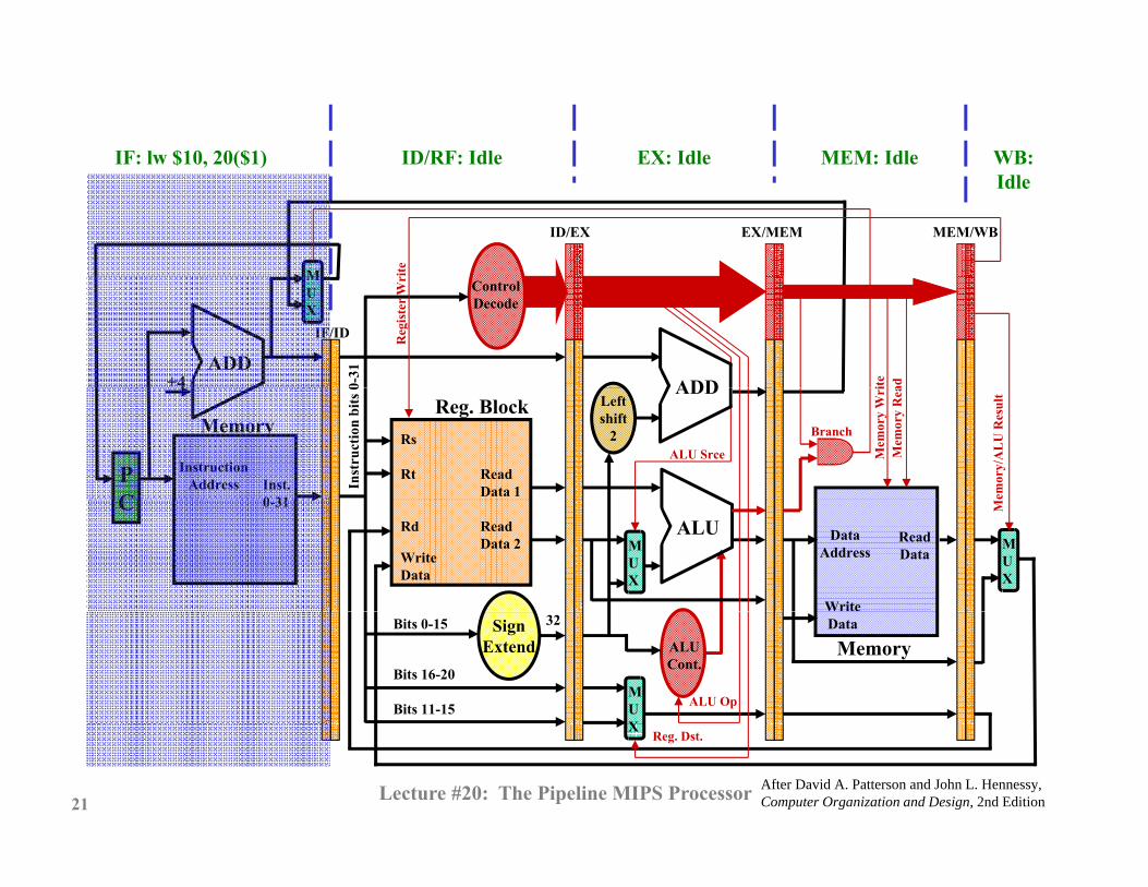
IF: lw $10, 20($1) ID/RF: Idle EX: Idle MEM: Idle WB:IF: lw $10, 20($1) ID/RF: Idle EX: Idle MEM: Idle WB:Idle
M
ID/EX EX/MEM MEM/WB
iteADD
ADD+4
MUX
IF/ID0-
31
ControlDecode
ite ad
Reg
iste
r W
rADD
PC
InstructionAddress
MemoryLeftshift
2
Inst. 0 31
Reg. BlockRs
Rt Read Data 1In
stru
ctio
n bi
ts 0
ALU Srce
Branch
Mem
ory
Wri
Mem
ory
Rea
emor
y/A
LU
Res
ult
ALUC
MUX
DataAddress
0-31
MUX
Rd
WriteData
ReadData 2
Write
ReadData
M
MemorySign
Extend32 DataBits 0-15
Bits 16-20
Bits 11-15
ALUCont.
MUX
ALU Op
After David A. Patterson and John L. Hennessy, Computer Organization and Design, 2nd Edition21
XReg. Dst.
Lecture #20: The Pipeline MIPS Processor
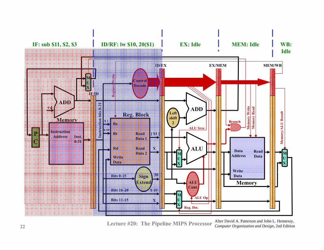
IF: sub $11, $2, $3 ID/RF: lw $10, 20($1) EX: Idle MEM: Idle WB:IF: sub $11, $2, $3 ID/RF: lw $10, 20($1) EX: Idle MEM: Idle WB:Idle
M
ID/EX EX/MEM MEM/WB
iteADD
ADD+4
MUX
IF/ID0-
31
ControlDecode
ite ad
Reg
iste
r W
r
[ $1 ]
$ 1
$ 10
ADD
PC
InstructionAddress
MemoryLeftshift
2
Inst. 0 31
Reg. BlockRs
Rt Read Data 1In
stru
ctio
n bi
ts 0
ALU Srce
Branch
Mem
ory
Wri
Mem
ory
Rea
emor
y/A
LU
Res
ult
X ALUC
MUX
DataAddress
0-31
MUX
Rd
WriteData
ReadData 2
Write
ReadData
M
$ 10
X
20
MemorySign
ExtendDataBits 0-15
Bits 16-20
Bits 11-15
ALUCont.
MUX
ALU Op
After David A. Patterson and John L. Hennessy, Computer Organization and Design, 2nd Edition22
XReg. Dst.
Lecture #20: The Pipeline MIPS Processor

IF: and $12, $4, $5 MEM: Idle WB: ID/RF: sub $11, $2, $3 EX: lw $10, 20($1)IF: and $12, $4, $5 MEM: Idle WB: Idle
ID/RF: sub $11, $2, $3 EX: lw $10, 20($1)
M
ID/EX EX/MEM MEM/WB
iteADD
ADD+4
MUX
IF/ID0-
31
ControlDecode
ite ad
Reg
iste
r W
r
[ $ 2 ] [ $1 ]$ 3
$ 2
ADD
PC
InstructionAddress
MemoryLeftshift
2
Inst. 0 31
Reg. BlockRs
Rt Read Data 1In
stru
ctio
n bi
ts 0
ALU Srce
Branch
Mem
ory
Wri
Mem
ory
Rea
emor
y/A
LU
Res
ult
[ $ 3 ]
add20
ALUC
MUX
DataAddress
0-31
MUX
Rd
WriteData
ReadData 2
Write
ReadData
M
$ 11
X
X
20
$ 10
$ 10
MemorySign
ExtendDataBits 0-15
Bits 16-20
Bits 11-15
ALUCont.
MUX
ALU Op
After David A. Patterson and John L. Hennessy, Computer Organization and Design, 2nd Edition23
XReg. Dst.
Lecture #20: The Pipeline MIPS Processor

IF: or $13, $6, $7 WB:ID/RF: and $12, $4, $5 EX: sub $11, $2, $3 MEM: lw $10, 20($1)IF: or $13, $6, $7 WB:Idle
ID/RF: and $12, $4, $5 EX: sub $11, $2, $3
M
ID/EX EX/MEM MEM/WB
ite
MEM: lw $10, 20($1)
ADDADD
+4
MUX
IF/ID0-
31
ControlDecode
ite ad
Reg
iste
r W
r
[ $2 ]
$ 4
$ 5
ADD
PC
InstructionAddress
MemoryLeftshift
2
Inst. 0 31
Reg. BlockRs
Rt Read Data 1In
stru
ctio
n bi
ts 0
ALU Srce
Branch
Mem
ory
Wri
Mem
ory
Rea
emor
y/A
LU
Res
ult
[$3]
[ $3 ]sub
ALUC
MUX
DataAddress
0-31
MUX
Rd
WriteData
ReadData 2
Write
ReadData
M
X
X
$ 12 $ 11$ 11 $ 10
MemorySign
ExtendDataBits 0-15
Bits 16-20
Bits 11-15
ALUCont.
MUX
ALU Op
After David A. Patterson and John L. Hennessy, Computer Organization and Design, 2nd Edition24
XReg. Dst.
Lecture #20: The Pipeline MIPS Processor
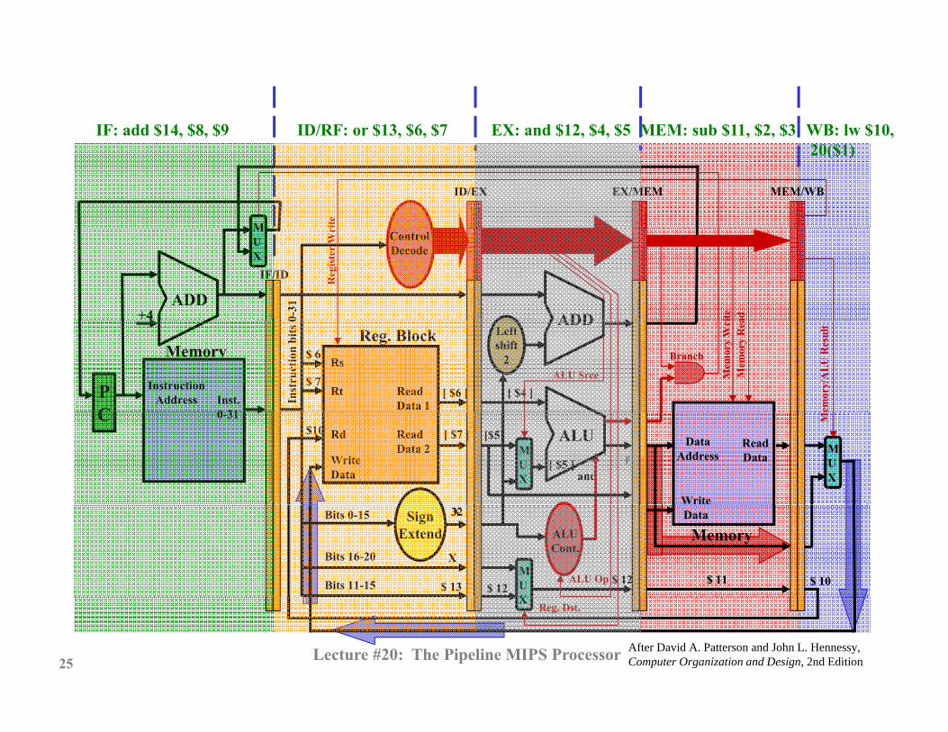
IF: add $14, $8, $9 ID/RF: or $13, $6, $7 EX: and $12, $4, $5 MEM: sub $11, $2, $3 WB: lw $10,IF: add $14, $8, $9 ID/RF: or $13, $6, $7 EX: and $12, $4, $5 MEM: sub $11, $2, $3 WB: lw $10,20($1)
M
ID/EX EX/MEM MEM/WB
iteADD
ADD+4
MUX
IF/ID0-
31
ControlDecode
ite ad
Reg
iste
r W
r
[ $6 ]
$ 6
$ 7[ $4 ]
ADD
PC
InstructionAddress
MemoryLeftshift
2
Inst. 0 31
Reg. BlockRs
Rt Read Data 1In
stru
ctio
n bi
ts 0
ALU Srce
Branch
Mem
ory
Wri
Mem
ory
Rea
emor
y/A
LU
Res
ult
[ $7 ] [$5]
[ $5 ]and
$10 ALUC
MUX
DataAddress
0-31
MUX
Rd
WriteData
ReadData 2
Write
ReadData
M
X
X
$ 13 $ 12$ 12 $ 11 $ 10
MemorySign
Extend32 DataBits 0-15
Bits 16-20
Bits 11-15
ALUCont.
MUX
ALU Op
After David A. Patterson and John L. Hennessy, Computer Organization and Design, 2nd Edition25
XReg. Dst.
Lecture #20: The Pipeline MIPS Processor
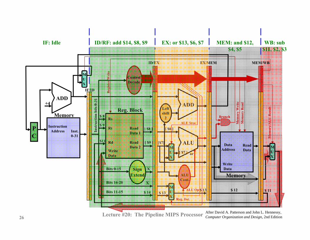
IF: Idle ID/RF: add $14, $8, $9 EX: or $13, $6, $7 MEM: and $12, WB: sub IF: Idle ID/RF: add $14, $8, $9 EX: or $13, $6, $7 MEM: and $12, $4, $5
WB: sub $11, $2, $3
M
ID/EX EX/MEM MEM/WB
iteADD
ADD+4
MUX
IF/ID0-
31
ControlDecode
ite ad
Reg
iste
r W
r
[ $8 ]
$ 8
$ 9[ $6 ]
ADD
PC
InstructionAddress
MemoryLeftshift
2
Inst. 0 31
Reg. BlockRs
Rt Read Data 1In
stru
ctio
n bi
ts 0
ALU Srce
Branch
Mem
ory
Wri
Mem
ory
Rea
emor
y/A
LU
Res
ult
[ $9 ]$11 [$7]
[ $7 ] or
ALUC
MUX
DataAddress
0-31
MUX
Rd
WriteData
ReadData 2
Write
ReadData
M
X
X
$ 14 $ 13$ 13 $ 12 $ 11
MemorySign
ExtendDataBits 0-15
Bits 16-20
Bits 11-15
ALUCont.
MUX
ALU Op
After David A. Patterson and John L. Hennessy, Computer Organization and Design, 2nd Edition26
XReg. Dst.
Lecture #20: The Pipeline MIPS Processor

IF: Idle ID/RF: Idle (WB) EX: add $14, $8, $9 MEM: or $13, $6, $7 WB: andIF: Idle ID/RF: Idle (WB) EX: add $14, $8, $9 MEM: or $13, $6, $7 WB: and $12, $4, $5
M
ID/EX EX/MEM MEM/WB
iteADD
ADD+4
MUX
IF/ID0-
31
ControlDecode
ite ad
Reg
iste
r W
r
[ $8 ]
ADD
PC
InstructionAddress
MemoryLeftshift
2
Inst. 0 31
Reg. BlockRs
Rt Read Data 1In
stru
ctio
n bi
ts 0
ALU Srce
Branch
Mem
ory
Wri
Mem
ory
Rea
emor
y/A
LU
Res
ult
[$9]
[ $9 ]add
$12 ALUC
MUX
DataAddress
0-31
MUX
Rd
WriteData
ReadData 2
Write
ReadData
M
$ 14$ 14 $ 13 $ 12
MemorySign
Extend32 DataBits 0-15
Bits 16-20
Bits 11-15
ALUCont.
MUX
ALU Op
After David A. Patterson and John L. Hennessy, Computer Organization and Design, 2nd Edition27
XReg. Dst.
Lecture #20: The Pipeline MIPS Processor

IF: Idle ID/RF: Idle (WB) EX: Idle MEM: add $14, $8, $9 WB: orIF: Idle ID/RF: Idle (WB) EX: Idle MEM: add $14, $8, $9 WB: or $13, $6, $7
M
ID/EX EX/MEM MEM/WB
iteADD
ADD+4
MUX
IF/ID0-
31
ControlDecode
ite ad
Reg
iste
r W
rADD
PC
InstructionAddress
MemoryLeftshift
2
Inst. 0 31
Reg. BlockRs
Rt Read Data 1In
stru
ctio
n bi
ts 0
ALU Srce
Branch
Mem
ory
Wri
Mem
ory
Rea
emor
y/A
LU
Res
ult
$13 ALUC
MUX
DataAddress
0-31
MUX
Rd
WriteData
ReadData 2
Write
ReadData
M
$ 14 $ 13
MemorySign
Extend32 DataBits 0-15
Bits 16-20
Bits 11-15
ALUCont.
MUX
ALU Op
After David A. Patterson and John L. Hennessy, Computer Organization and Design, 2nd Edition28
XReg. Dst.
Lecture #20: The Pipeline MIPS Processor

IF: Idle ID/RF: Idle (WB) EX: Idle MEM: Idle WB: addIF: Idle ID/RF: Idle (WB) EX: Idle MEM: Idle WB: add $14, $8, $9
M
ID/EX EX/MEM MEM/WB
iteADD
ADD+4
MUX
IF/ID0-
31
ControlDecode
ite ad
Reg
iste
r W
rADD
PC
InstructionAddress
MemoryLeftshift
2
Inst. 0 31
Reg. BlockRs
Rt Read Data 1In
stru
ctio
n bi
ts 0
ALU Srce
Branch
Mem
ory
Wri
Mem
ory
Rea
emor
y/A
LU
Res
ult
$14 ALUC
MUX
DataAddress
0-31
MUX
Rd
WriteData
ReadData 2
Write
ReadData
M
$ 14
MemorySign
Extend32 DataBits 0-15
Bits 16-20
Bits 11-15
ALUCont.
MUX
ALU Op
After David A. Patterson and John L. Hennessy, Computer Organization and Design, 2nd Edition29
XReg. Dst.
Lecture #20: The Pipeline MIPS Processor
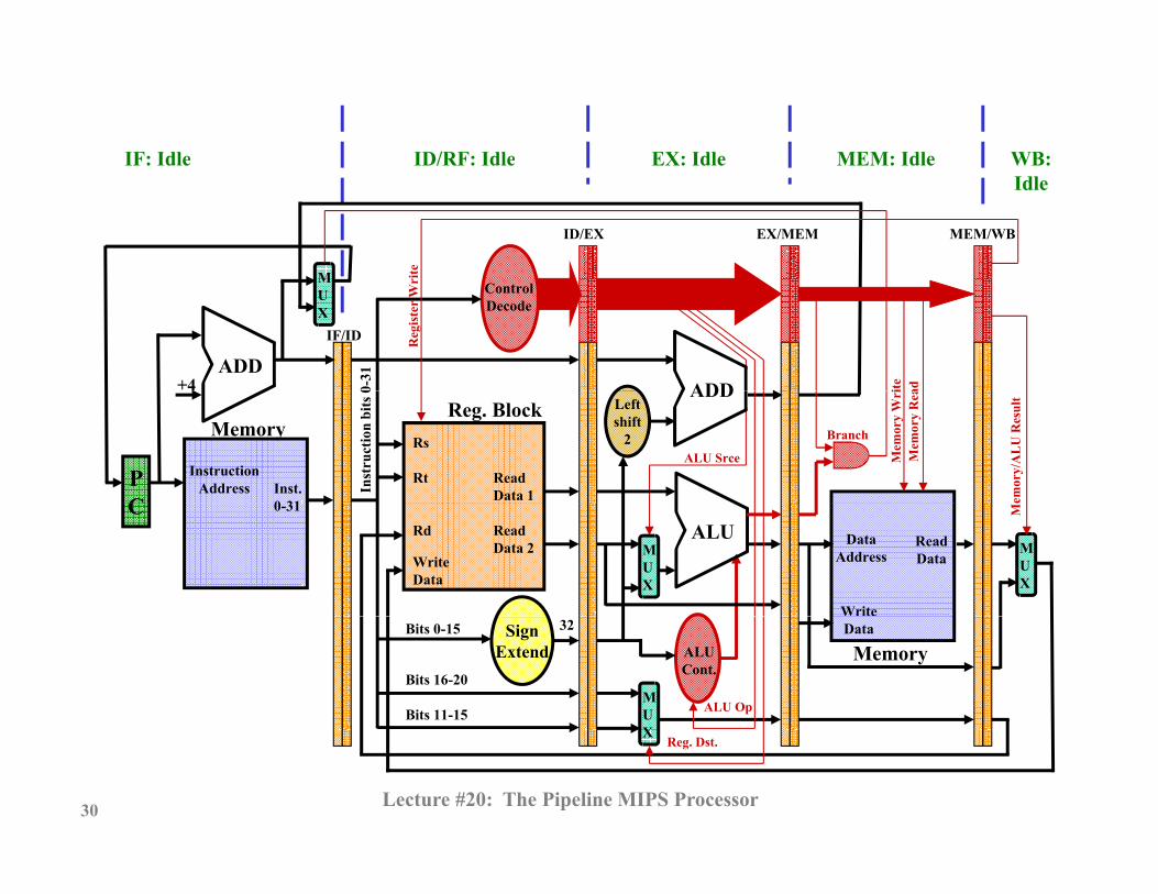
IF: Idle ID/RF: Idle EX: Idle MEM: Idle WB: IF: Idle ID/RF: Idle EX: Idle MEM: Idle WB: Idle
M
ID/EX EX/MEM MEM/WB
iteADD
ADD+4
MUX
IF/ID
0-31
ControlDecode
ite ad
Reg
iste
r W
rADD
PC
InstructionAddress
MemoryLeftshift
2
Inst. 0 31
Reg. BlockRs
Rt Read Data 1In
stru
ctio
n bi
ts 0
ALU Srce
Branch
Mem
ory
Wri
Mem
ory
Rea
emor
y/A
LU
Res
ult
ALUC
MUX
DataAddress
0-31
MUX
Rd
WriteData
ReadData 2
Write
ReadData
M
MemorySign
Extend32 DataBits 0-15
Bits 16-20
Bits 11-15
ALUCont.
MUX
ALU Op
30
XReg. Dst.
Lecture #20: The Pipeline MIPS Processor

Erik Jonsson School of Engineering and Th U i it f T t D ll g gComputer ScienceThe University of Texas at Dallas
Pipeline Processor Operation SummaryPipeline Processor Operation Summary
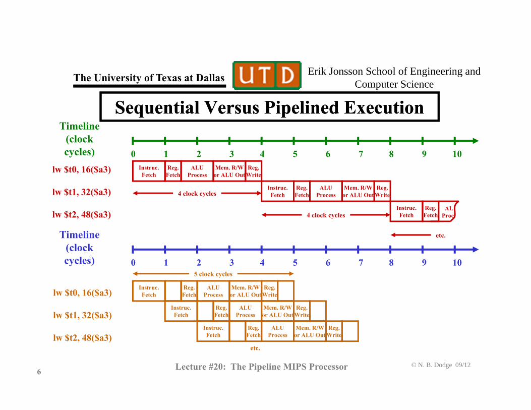
• Pipelining replaces the “single-cycle” processor with a row of five “mini-processors ” each capable ofrow of five mini processors, each capable of completing one part of each instruction.
• A new instruction is started every clock cycle. • Inter-process registers store instruction information
(data, write register, branch conditions) between cycles so that the entire “instruction envelope” is passedso that the entire instruction envelope is passed between the pipeline stages.
• When the pipeline is filled with instructions, an
© N. B. Dodge 09/1231 Lecture #20: The Pipeline MIPS Processor
instruction completes every clock cycle.

Erik Jonsson School of Engineering and Th U i it f T t D ll g gComputer ScienceThe University of Texas at Dallas
Exercise 1Exercise 1
• On the diagram on the next page, identify the f ifollowing:1. Highlight all the control lines that must be active during a load
word instruction. 2. As in our exercise in Lecture 20, identify the decoder
locations. 3. The ID/EX Register interface stores the most bits of any of the g y
pipeline section interfaces. Approximately how many bits is that, according to the diagram?
© N. B. Dodge 09/1232 Lecture #20: The Pipeline MIPS Processor

Print out a copy of this diagram and bring to class.
MUX
IF/ID
ID/EX EX/MEM MEM/WB
ControlDecode
gist
er W
rite
ADDADD
+4
MemoryLeftshift
2
Reg. BlockRs
IF/ID
tion
bits
0-3
1
Branch mor
y W
rite
mor
y R
ead
Reg
U R
esul
t
ALU
PC
InstructionAddress
M
2
DataAddress
Inst. 0-31
M
Rs
Rt
Rd
Read Data 1
ReadData 2 Read
D t
Inst
ruct ALU Srce Mem
Me
Mem
ory/
AL
U
Memory
UX
Address UX
WriteData
SignExtend
32WriteData
Data
Bits 0-15ALUCont
Bits 16-20
Bits 11-15
Cont.
MUX
ALU Op
Reg. Dst.
Lecture #20: The Pipeline MIPS Processor
Erik Jonsson School of Engineering and Th U i it f T t D ll g gComputer ScienceThe University of Texas at Dallas
HazardsHazards
• Hazards occur because data required for executing the current instruction may not be availablecurrent instruction may not be available.
• An instruction in the “register fetch” cycle may need data from a register whose value will be changed by an instruction “downstream” but still in process in the pipeline (in the ALU, memory/memory bypass or writeback cycle). w eb c cyc e).
• Thus an “upstream” instruction could access a register and get incorrect data because the register data has not
t b d t d b “d t ” i t ti© N. B. Dodge 09/12
35 Lecture #20: The Pipeline MIPS Processor
yet been updated by a “downstream” instruction.

Erik Jonsson School of Engineering and Th U i it f T t D ll g gComputer ScienceThe University of Texas at Dallas
Hazards (2)Hazards (2)• There are two types of hazards, data hazards, and
control hazards. • Both occur because an instruction in the ID/RF stage of
the MIPS pipeline needs register data that will be shortly updated by instructions in the EX orshortly updated by instructions in the EX or MEM/Bypass, or WB stage.
• Data hazards occur when an instruction needs register contents for an arithmetic/ logical/memory instruction.
• Control hazards occur when a branch instruction is pending and the data necessary to initiate/bypass the
© N. B. Dodge 09/1236 Lecture #20: The Pipeline MIPS Processor
pending and the data necessary to initiate/bypass the branch is not yet available in the same sort of scenario.

Erik Jonsson School of Engineering and Th U i it f T t D ll g gComputer ScienceThe University of Texas at Dallas
Data Hazard in the PipelineData Hazard in the PipelineTi liTimeline
(clockcycles) 0 1 2 3 4 5 6 7 8 9 10
5 clock cycles
sub $2, $1, $3
and $12, $2, $5
or $13, $6, $2 Instruc.Fetch
Reg.Fetch
ALUProcess
Mem. R/Wor ALU Out
Reg.Write
Instruc.Fetch
Reg.Fetch
ALUProcess
Mem. R/Wor ALU Out
Reg.Write
Instruc.Fetch
Reg.Fetch
ALUProcess
Mem. R/Wor ALU Out
Reg.Write
$ , $ , $
add $14, $2, $2
sw $15, 100($2) Instruc.Fetch
Reg.Fetch
ALUProcess
Mem. R/Wor ALU Out
Reg.Write
Instruc.Fetch
Reg.Fetch
ALUProcess
Mem. R/Wor ALU Out
Reg.Write
Fetch Fetch Process or ALU Out Write
• In the instruction sequence above, the last four instructions require data from $2, which is changed in the first instruction.
• The $2 data will not be rewritten until cycle 4, so the AND and OR (2nd d 3rd i t ti ) ill f t h i t d t f $2
© N. B. Dodge 09/1237 Lecture #20: The Pipeline MIPS Processor
(2nd and 3rd instructions) will fetch incorrect data from $2. • Even the add may not get the correct information (sw is okay).

Erik Jonsson School of Engineering and Th U i it f T t D ll g gComputer ScienceThe University of Texas at Dallas
Control Hazards in the PipelineControl Hazards in the PipelineTi liTimeline
(clockcycles) 0 1 2 3 4 5 6 7 8 9 10
5 clock cycles
sub $2, $1, $3
blt $2, $8, wait
bgt $2, $7, go Instruc.Fetch
Reg.Fetch
ALUProcess
Mem. R/Wor ALU Out
Reg.Write
Instruc.Fetch
Reg.Fetch
ALUProcess
Mem. R/Wor ALU Out
Reg.Write
Instruc.Fetch
Reg.Fetch
ALUProcess
Mem. R/Wor ALU Out
Reg.Write
g $ , $ , g
add $14, $2, $2
sw $15, 100($2) Instruc.Fetch
Reg.Fetch
ALUProcess
Mem. R/Wor ALU Out
Reg.Write
Instruc.Fetch
Reg.Fetch
ALUProcess
Mem. R/Wor ALU Out
Reg.Write
Fetch Fetch Process or ALU Out Write
• Here the problem is changed, with two branch instructions added. • Neither branch instruction may be executed correctly, once again
because the new $2 data will not be ready
© N. B. Dodge 09/1238 Lecture #20: The Pipeline MIPS Processor
because the new $2 data will not be ready. • This wrong data could cause an incorrect branch.

Erik Jonsson School of Engineering and Th U i it f T t D ll g gComputer ScienceThe University of Texas at Dallas
Forwarding as a Solution to Data HazardsForwarding as a Solution to Data HazardsCl k l
0 1 2 3 4 5
Clock cycles
ALUIF ID/ MEM WB1 ALUIF RF MEM WB
ALUIF ID/ MEM WB
1
2
• One solution to the problem of data hazards is forwarding.
ALUIF RF MEM WB2
• Forwarding uses the fact that although instruction 2 needs register data two clock cycles before instruction 1 enters the WB stage, thatdata is already available as the output of the ALU.
© N. B. Dodge 09/1239 Lecture #20: The Pipeline MIPS Processor
• If a mechanism were available, instruction 1 could forward required register data after its ALU cycle to the ID/RF cycle of instruction 2.
Erik Jonsson School of Engineering and Th U i it f T t D ll g gComputer ScienceThe University of Texas at Dallas
Forwarding Unit in the PipelineForwarding Unit in the Pipeline
Rs
Rt
Read Data 1
ID/EX EX/MEM MEM/WB
MU
ALU MUX
Reg. Block
Rd
WriteData
ReadData 2
DataAddress
W it
ReadData
MU
X
Forward A
Reg. Block
Memory
WriteData
MU
X
Rs
Rt
RdEX/MEM Register Rd
Forward B
UX
ForwardingUnit
Rd
MEM/WB Register Rd
© N. B. Dodge 09/1240 Lecture #20: The Pipeline MIPS Processor
After David A. Patterson and John L. Hennessy, Computer Organization and Design, 2nd Edition
Erik Jonsson School of Engineering and Th U i it f T t D ll g gComputer ScienceThe University of Texas at Dallas
Forwarding Unit OperationForwarding Unit Operation
ALU
Reg. Block
Memory
ForwardingUnit
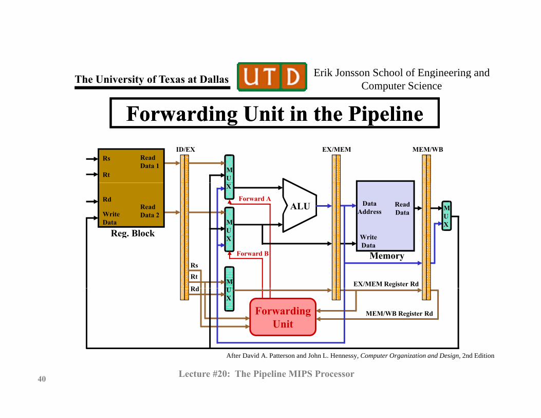
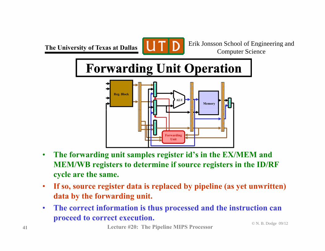
• The forwarding unit samples register id’s in the EX/MEM and MEM/WB registers to determine if source registers in the ID/RF
l thcycle are the same. • If so, source register data is replaced by pipeline (as yet unwritten)
data by the forwarding unit.
© N. B. Dodge 09/1241 Lecture #20: The Pipeline MIPS Processor
• The correct information is thus processed and the instruction can proceed to correct execution.
Erik Jonsson School of Engineering and Th U i it f T t D ll g gComputer ScienceThe University of Texas at Dallas
StallsStalls• Forwarding will not always solve the problems of data hazards. • For example, suppose an add instruction follows a load word (lw),For example, suppose an add instruction follows a load word (lw),
and the add involves the register that receives the memory data. • In this case, forwarding will not work.• The reason is that the data must be read from memory and so it• The reason is that the data must be read from memory, and so it
will not be available until the end of the MEM cycle. Thus the required data is not available for a forward, and the add instruction. if it proceeds, will process the wrong data. s uc o . p oceeds, w p ocess e w o g d .
• A solution to this problem is the stall. • A stall halts the instruction awaiting data, while the key
instruction (a lw in this case) proceeds to the end of the MEM
© N. B. Dodge 09/1242 Lecture #20: The Pipeline MIPS Processor
instruction (a lw in this case) proceeds to the end of the MEM cycle, after which the desired data is available to the add.
Erik Jonsson School of Engineering and Th U i it f T t D ll g gComputer ScienceThe University of Texas at Dallas
Result of Stall ApproachResult of Stall ApproachTi liTimeline
(clockcycles) 0 1 2 3 4 5 6 7 8 9 10
5 clock cycles
lw $2, 32($3)
add $14, $6, $2
sw $15, 80($2) Instruc.Fetch
Reg.Fetch
ALUProcess
Mem. R/Wor ALU Out
Reg.Write
Instruc.Fetch
Reg.Fetch
ALUProcess
Mem. R/Wor ALU Out
Reg.Write
Instruc.Fetch
Reg.Fetch
ALUProcess
Mem. R/Wor ALU Out
Reg.Write
$ , ($ ) Fetch Fetch Process or ALU Out Write
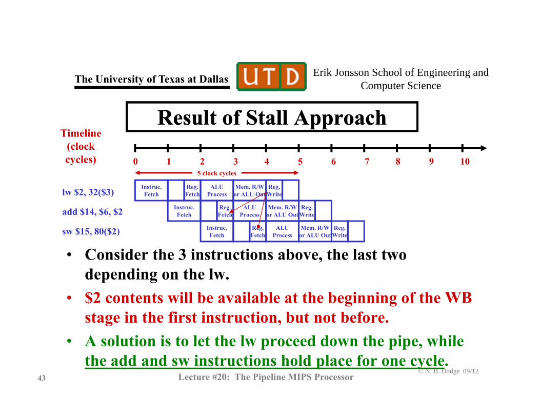
• Consider the 3 instructions above, the last two depending on the lw.
• $2 contents will be available at the beginning of the WB stage in the first instruction, but not before.
• A solution is to let the lw proceed down the pipe while
© N. B. Dodge 09/1243 Lecture #20: The Pipeline MIPS Processor
• A solution is to let the lw proceed down the pipe, while the add and sw instructions hold place for one cycle.
Erik Jonsson School of Engineering and Th U i it f T t D ll g gComputer ScienceThe University of Texas at Dallas
Result of Stall Approach (2)Result of Stall Approach (2)TimelineTimeline(clockcycles) 0 1 2 3 4 5 6 7 8 9 10
5 clock cycles
Instruc Reg ALU Mem R/W Reglw $2, 32($3)
add $14, $6, $2 (delayed 1 count)
sw $15, 80($2) (delayed 1 count) Instruc.Fetch
Reg.Fetch
ALUProcess
Mem. R/Wor ALU Out
Reg.Write
Instruc.Fetch
Reg.Fetch
ALUProcess
Mem. R/Wor ALU Out
Reg.Write
Instruc.Fetch
Reg.Fetch
ALUProcess
Mem. R/Wor ALU Out
Reg.Write
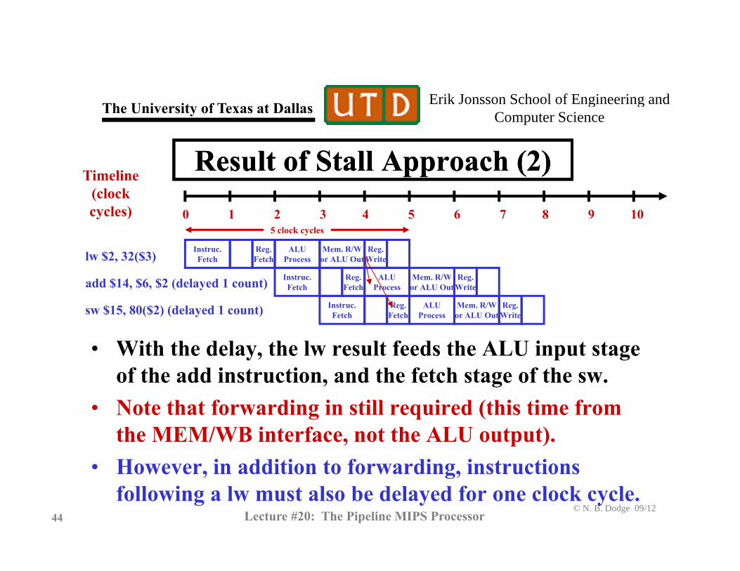
• With the delay, the lw result feeds the ALU input stage of the add instruction, and the fetch stage of the sw.
• Note that forwarding in still required (this time from the MEM/WB interface, not the ALU output).
• However in addition to forwarding instructions
© N. B. Dodge 09/1244 Lecture #20: The Pipeline MIPS Processor
• However, in addition to forwarding, instructions following a lw must also be delayed for one clock cycle.

Erik Jonsson School of Engineering and Th U i it f T t D ll g gComputer ScienceThe University of Texas at Dallas
Other Problems With BranchesOther Problems With Branches
• A remaining problem is what to do about instructions following a branch. Even assuming forwarding and stalls, the branch/no branch decision is not made until the third stage. This means that in the MIPS pipeline, two following instructions will enter the pipe before the branch/no branch decision is made. What if:– The following instructions were for the case of “branch taken” and
the branch was not taken.– The following instructions were for “branch not taken” and it was
t ktaken. • In either case, the wrong instructions are in the pipe and they must
be eliminated (“flushed”). How can this problem be prevented? A f h h bl h i h f ll i lid
© N. B. Dodge 09/1245 Lecture #20: The Pipeline MIPS Processor
• A few approaches to the problem are shown in the following slides.
Erik Jonsson School of Engineering and Th U i it f T t D ll g gComputer ScienceThe University of Texas at Dallas
Control Hazard Approaches (1)Control Hazard Approaches (1)MIPS R-2000 Pipeline Processor
WBALU/EX
(Branch)ID/RFIFMEM/Bypass
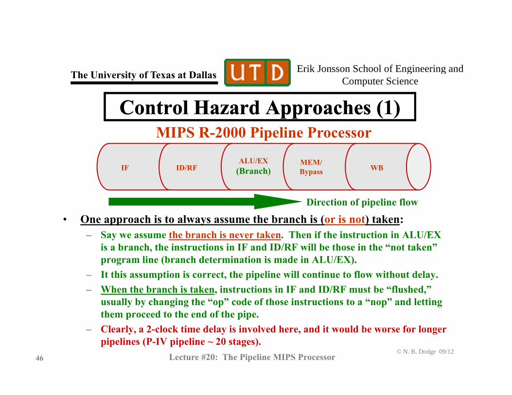
• One approach is to always assume the branch is (or is not) taken:
(Branch) Bypass
Direction of pipeline flow
One approach is to always assume the branch is (or is not) taken:– Say we assume the branch is never taken. Then if the instruction in ALU/EX
is a branch, the instructions in IF and ID/RF will be those in the “not taken” program line (branch determination is made in ALU/EX). It thi ti i t th i li ill ti t fl ith t d l– It this assumption is correct, the pipeline will continue to flow without delay.
– When the branch is taken, instructions in IF and ID/RF must be “flushed,” usually by changing the “op” code of those instructions to a “nop” and letting them proceed to the end of the pipe.
© N. B. Dodge 09/1246 Lecture #20: The Pipeline MIPS Processor
– Clearly, a 2-clock time delay is involved here, and it would be worse for longer pipelines (P-IV pipeline ~ 20 stages).

Erik Jonsson School of Engineering and Th U i it f T t D ll g gComputer ScienceThe University of Texas at Dallas
Control Hazard Approaches (2)Control Hazard Approaches (2)MIPS R-2000 Pipeline Processor
WBALU/EXID/RF
BranchIFMEM/BypassBranch Bypass
BranchComparator
• Reducing the cost of taking the branch: – In this case, a branch assumption is still made (taken or not taken).
The difference is that since register contents (and/or immediates) are– The difference is that since register contents (and/or immediates) are identified in the ID/RF stage, a comparator can be added there to do the branch/no-branch determination.
– With the branch determination made in this early stage, only one
© N. B. Dodge 09/1247 Lecture #20: The Pipeline MIPS Processor
W e b c de e o de s e y s ge, o y o einstruction must be flushed, in the IF stage (only a 1-instruction delay).
Erik Jonsson School of Engineering and Th U i it f T t D ll g gComputer ScienceThe University of Texas at Dallas
Control Hazard Approaches (3)Control Hazard Approaches (3)MIPS R-2000 Pipeline Processor
WBALU/EXID/RF
BranchIFMEM/Bypass
D i b h di ti b d t b h hi t
Branch Bypass
Branch feedback based on HistoryBranchHistory
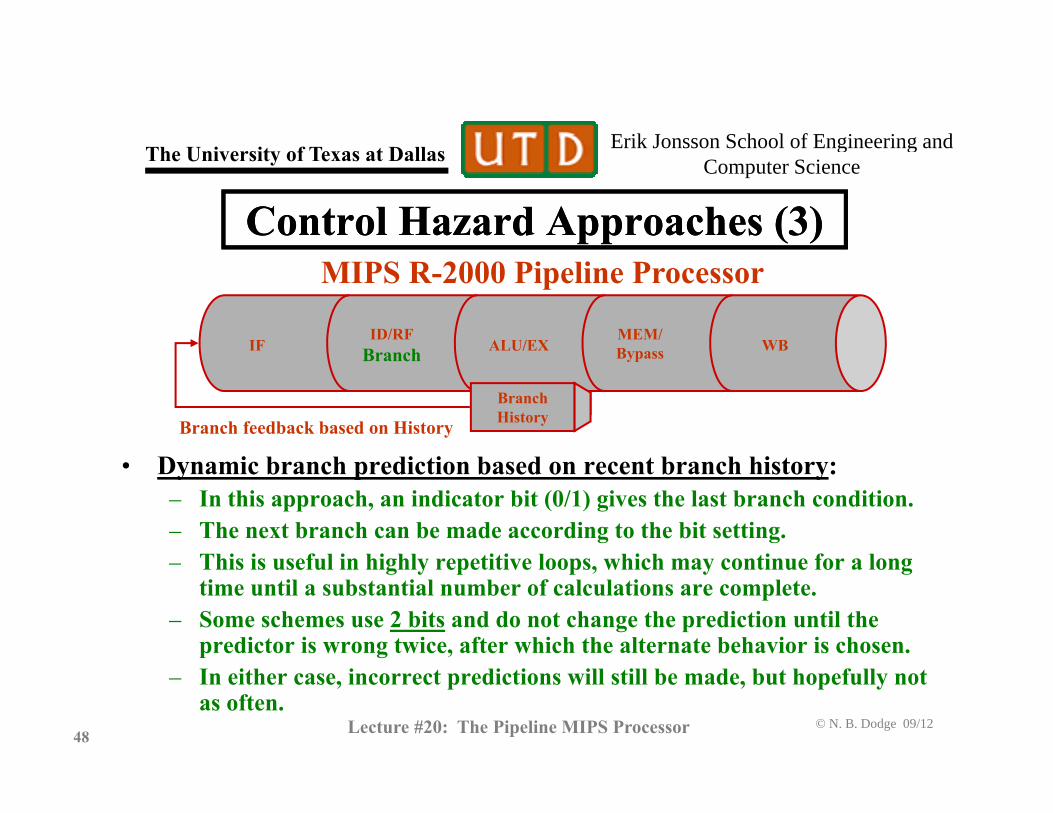
• Dynamic branch prediction based on recent branch history: – In this approach, an indicator bit (0/1) gives the last branch condition. – The next branch can be made according to the bit setting.
This is useful in highly repetitive loops which may continue for a long– This is useful in highly repetitive loops, which may continue for a long time until a substantial number of calculations are complete.
– Some schemes use 2 bits and do not change the prediction until the predictor is wrong twice, after which the alternate behavior is chosen.
© N. B. Dodge 09/1248 Lecture #20: The Pipeline MIPS Processor
– In either case, incorrect predictions will still be made, but hopefully not as often.

Erik Jonsson School of Engineering and Th U i it f T t D ll g gComputer ScienceThe University of Texas at Dallas
Exercise 2Exercise 21. Explain forwarding in your own words. 2 Why doesn’t forwarding always work? How can this2. Why doesn’t forwarding always work? How can this
problem be solved? 3. Why could 2-bit dynamic branch prediction work to y y p
ensure about a 1% error rate in branch prediction in a subroutine that loops about 100 times before completion? Hint: Assume that the subroutine iscompletion? Hint: Assume that the subroutine is called frequently, and that it always executes 100 or more loop traversals before returning to the calling
© N. B. Dodge 09/1249 Lecture #20: The Pipeline MIPS Processor
program.