Embed Size (px)
Citation preview

1
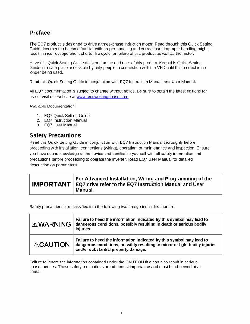
Preface The EQ7 product is designed to drive a three-phase induction motor. Read through this Quick Setting Guide document to become familiar with proper handling and correct use. Improper handling might result in incorrect operation, shorter life cycle, or failure of this product as well as the motor. Have this Quick Setting Guide delivered to the end user of this product. Keep this Quick Setting Guide in a safe place accessible by only people in connection with the VFD until this product is no longer being used. Read this Quick Setting Guide in conjunction with EQ7 Instruction Manual and User Manual. All EQ7 documentation is subject to change without notice. Be sure to obtain the latest editions for
use or visit our website at www.tecowestinghouse.com. Available Documentation:
1. EQ7 Quick Setting Guide 2. EQ7 Instruction Manual 3. EQ7 User Manual
Safety Precautions Read this Quick Setting Guide in conjunction with EQ7 Instruction Manual thoroughly before
proceeding with installation, connections (wiring), operation, or maintenance and inspection. Ensure
you have sound knowledge of the device and familiarize yourself with all safety information and
precautions before proceeding to operate the inverter. Read EQ7 User Manual for detailed
description on parameters.
IMPORTANT For Advanced Installation, Wiring and Programming of the EQ7 drive refer to the EQ7 Instruction Manual and User Manual.
Safety precautions are classified into the following two categories in this manual.
Failure to heed the information indicated by this symbol may lead to dangerous conditions, possibly resulting in death or serious bodily injuries.
Failure to heed the information indicated by this symbol may lead to dangerous conditions, possibly resulting in minor or light bodily injuries and/or substantial property damage.
Failure to ignore the information contained under the CAUTION title can also result in serious consequences. These safety precautions are of utmost importance and must be observed at all times.
2
IMPORTANT For Advanced Installation, Wiring and Programming of the EQ7 drive refer to the EQ7 Instruction Manual and User Manual.
Table of Contents 1. Drive Models Constant Torque (CT) / Variable Torque (VT) HP Ratings .............. 3
2. Mounting and Wiring ................................................................................................. 4
2.1 Mounting Notes ..................................................................................................... 4
2.2 Wiring .................................................................................................................... 5
3. Input Power and Motor Connection ......................................................................... 6
4. LED Monitor, LCD Monitor and Keys ....................................................................... 8
5. Check Motor Rotation and Direction ..................................................................... 11
6. User Wiring Diagram ............................................................................................... 12
7. Speed Reference Command Configuration .......................................................... 14
7.1 Reference from the Keypad ................................................................................ 15
7.2 Reference from an Analog Signal (0-10V / 0-20mA / 4-20mA) / Speed Pot ........ 16
7.3 Reference from Serial Communication – RS485 ................................................. 17
8. Operation Method Configuration (Run / Stop) ...................................................... 19
8.1 Run / Stop from the Keypad ................................................................................ 19
8.2 Run / Stop from External Switch / Contact or Pushbutton ................................... 20
8.3 Run / Stop from Serial Communication – RS485 ................................................ 22
9. Motor and Application Specific Settings ............................................................... 24
9.1 Set Motor Nameplate Data .................................................................................. 24
Appendix: EQ7 Parameter Overview (Fundamental Functions).............................. 25
3
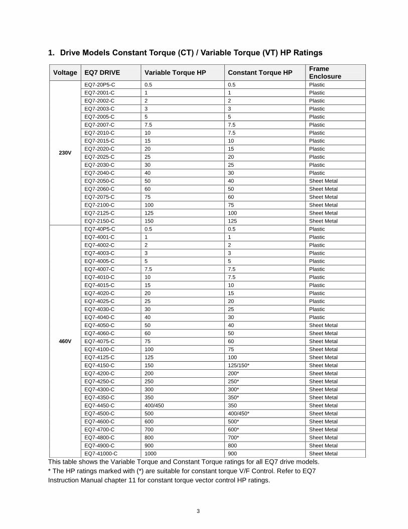
1. Drive Models Constant Torque (CT) / Variable Torque (VT) HP Ratings
This table shows the Variable Torque and Constant Torque ratings for all EQ7 drive models. * The HP ratings marked with (*) are suitable for constant torque V/F Control. Refer to EQ7
Instruction Manual chapter 11 for constant torque vector control HP ratings.
Voltage EQ7 DRIVE Variable Torque HP Constant Torque HP Frame Enclosure
230V
EQ7-20P5-C 0.5 0.5 Plastic
EQ7-2001-C 1 1 Plastic
EQ7-2002-C 2 2 Plastic
EQ7-2003-C 3 3 Plastic
EQ7-2005-C 5 5 Plastic
EQ7-2007-C 7.5 7.5 Plastic
EQ7-2010-C 10 7.5 Plastic
EQ7-2015-C 15 10 Plastic
EQ7-2020-C 20 15 Plastic
EQ7-2025-C 25 20 Plastic
EQ7-2030-C 30 25 Plastic
EQ7-2040-C 40 30 Plastic
EQ7-2050-C 50 40 Sheet Metal
EQ7-2060-C 60 50 Sheet Metal
EQ7-2075-C 75 60 Sheet Metal
EQ7-2100-C 100 75 Sheet Metal
EQ7-2125-C 125 100 Sheet Metal
EQ7-2150-C 150 125 Sheet Metal
460V
EQ7-40P5-C 0.5 0.5 Plastic
EQ7-4001-C 1 1 Plastic
EQ7-4002-C 2 2 Plastic
EQ7-4003-C 3 3 Plastic
EQ7-4005-C 5 5 Plastic
EQ7-4007-C 7.5 7.5 Plastic
EQ7-4010-C 10 7.5 Plastic
EQ7-4015-C 15 10 Plastic
EQ7-4020-C 20 15 Plastic
EQ7-4025-C 25 20 Plastic
EQ7-4030-C 30 25 Plastic
EQ7-4040-C 40 30 Plastic
EQ7-4050-C 50 40 Sheet Metal
EQ7-4060-C 60 50 Sheet Metal
EQ7-4075-C 75 60 Sheet Metal
EQ7-4100-C 100 75 Sheet Metal
EQ7-4125-C 125 100 Sheet Metal
EQ7-4150-C 150 125/150* Sheet Metal
EQ7-4200-C 200 200* Sheet Metal
EQ7-4250-C 250 250* Sheet Metal
EQ7-4300-C 300 300* Sheet Metal
EQ7-4350-C 350 350* Sheet Metal
EQ7-4450-C 400/450 350 Sheet Metal
EQ7-4500-C 500 400/450* Sheet Metal
EQ7-4600-C 600 500* Sheet Metal
EQ7-4700-C 700 600* Sheet Metal
EQ7-4800-C 800 700* Sheet Metal
EQ7-4900-C 900 800 Sheet Metal
EQ7-41000-C 1000 900 Sheet Metal
4
2. Mounting and Wiring
2.1 Mounting Notes
Mounting the EQ7 in a control cabinet
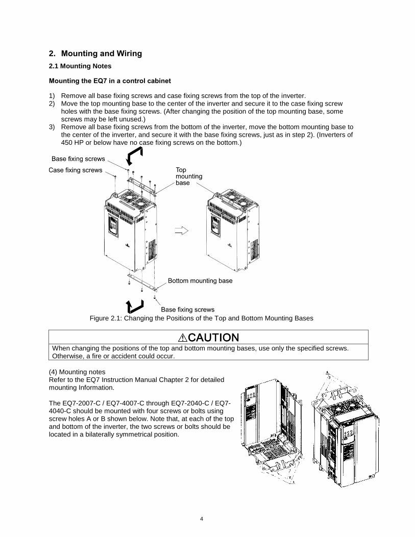
1) Remove all base fixing screws and case fixing screws from the top of the inverter. 2) Move the top mounting base to the center of the inverter and secure it to the case fixing screw
holes with the base fixing screws. (After changing the position of the top mounting base, some screws may be left unused.)
3) Remove all base fixing screws from the bottom of the inverter, move the bottom mounting base to the center of the inverter, and secure it with the base fixing screws, just as in step 2). (Inverters of 450 HP or below have no case fixing screws on the bottom.)
Figure 2.1: Changing the Positions of the Top and Bottom Mounting Bases
When changing the positions of the top and bottom mounting bases, use only the specified screws. Otherwise, a fire or accident could occur.
(4) Mounting notes Refer to the EQ7 Instruction Manual Chapter 2 for detailed mounting Information. The EQ7-2007-C / EQ7-4007-C through EQ7-2040-C / EQ7-4040-C should be mounted with four screws or bolts using screw holes A or B shown below. Note that, at each of the top and bottom of the inverter, the two screws or bolts should be located in a bilaterally symmetrical position.
5
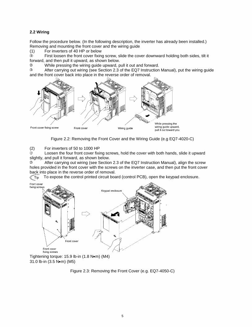
2.2 Wiring Follow the procedure below. (In the following description, the inverter has already been installed.) Removing and mounting the front cover and the wiring guide (1) For inverters of 40 HP or below
First loosen the front cover fixing screw, slide the cover downward holding both sides, tilt it forward, and then pull it upward, as shown below.
While pressing the wiring guide upward, pull it out and forward. After carrying out wiring (see Section 2.3 of the EQ7 Instruction Manual), put the wiring guide
and the front cover back into place in the reverse order of removal.
Figure 2.2: Removing the Front Cover and the Wiring Guide (e.g EQ7-4020-C) (2) For inverters of 50 to 1000 HP
Loosen the four front cover fixing screws, hold the cover with both hands, slide it upward slightly, and pull it forward, as shown below.
After carrying out wiring (see Section 2.3 of the EQ7 Instruction Manual), align the screw holes provided in the front cover with the screws on the inverter case, and then put the front cover back into place in the reverse order of removal.
To expose the control printed circuit board (control PCB), open the keypad enclosure.
Tightening torque: 15.9 lb-in (1.8 Nm) (M4)
31.0 lb-in (3.5 Nm) (M5)
Figure 2.3: Removing the Front Cover (e.g. EQ7-4050-C)
6
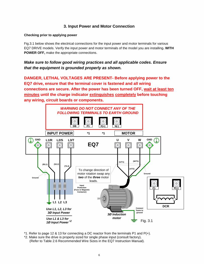
3. Input Power and Motor Connection
Checking prior to applying power
Fig.3.1 below shows the electrical connections for the input power and motor terminals for various
EQ7 DRIVE models. Verify the input power and motor terminals of the model you are installing. WITH
POWER OFF, make the appropriate connections.
Make sure to follow good wiring practices and all applicable codes. Ensure
that the equipment is grounded properly as shown.
DANGER, LETHAL VOLTAGES ARE PRESENT- Before applying power to the
EQ7 drive, ensure that the terminal cover is fastened and all wiring
connections are secure. After the power has been turned OFF, wait at least ten
minutes until the charge indicator extinguishes completely before touching
any wiring, circuit boards or components.
MOTOR
U V W
3Ø Induction
motor
Use L1, L2, L3 for
3Ø Input Power
Connect
frame to
ground
Input
Protection
(Fuse or Magnetic
Contactor)
To change direction of
motor rotation swap any
two of the three motor
leads.
L1 L2 L3
(R/L1) (S/L2)(T/L3)
(U/T1)
(V/T2)
(W/T3)
Ground
Use L1 & L3 for
1Ø Input Power
Ground
2
INPUT POWER
L1/R L2/S L3/T
P1 P(+) N(-)DB
WARNING DO NOT CONNECT ANY OF THE
FOLLOWING TERMINALS TO EARTH GROUND
Fig. 3.1
GND GND
*1 *1
*
DCR
P(+)P1
EQ7
*1. Refer to page 12 & 13 for connecting a DC reactor from the terminals P1 and P(+). *2. Make sure the drive is properly sized for single phase input (consult factory).
(Refer to Table 2.6 Recommended Wire Sizes in the EQ7 Instruction Manual).
7
Never connect power supply wires to the EQ7 drive output terminals U, V, and W. Doing so and turning the power ON damages the inverter.
Be sure to connect the grounding wires of the EQ7 drive and the motor to the ground electrodes. Otherwise, an electric shock could occur.
Check the following before powering on the EQ7 drive.
1) Check that the wiring is correct. In particular check the wiring to the EQ7 drive input terminals
L1/R, L2/S and L3/T and output terminals U, V, and W. Also check that the grounding wires are
connected to the grounding terminals ( G) correctly. See Figure 3.1.
2) Check the control circuit terminals and main circuit terminals for short circuits or ground faults.
3) Check for loose terminals, connectors and screws.
4) Check that the motor is separated from mechanical equipment.
5) Make sure that all switches of devices connected to the inverter are turned OFF. Powering on
the inverter with any of those switches being ON may cause an unexpected motor operation.
6) Check that safety measures are taken against runaway of the equipment. Also ensure that all
safety guards are in place to prevent human injury.
8
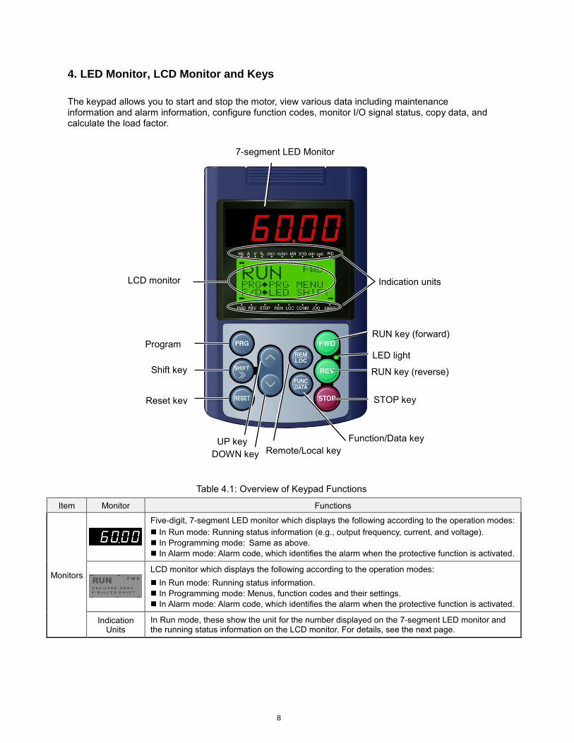
4. LED Monitor, LCD Monitor and Keys
The keypad allows you to start and stop the motor, view various data including maintenance information and alarm information, configure function codes, monitor I/O signal status, copy data, and calculate the load factor.
Table 4.1: Overview of Keypad Functions
Item Monitor Functions
Monitors
Five-digit, 7-segment LED monitor which displays the following according to the operation modes:
In Run mode: Running status information (e.g., output frequency, current, and voltage).
In Programming mode: Same as above.
In Alarm mode: Alarm code, which identifies the alarm when the protective function is activated.
LCD monitor which displays the following according to the operation modes:
In Run mode: Running status information.
In Programming mode: Menus, function codes and their settings.
In Alarm mode: Alarm code, which identifies the alarm when the protective function is activated.
Indication Units
In Run mode, these show the unit for the number displayed on the 7-segment LED monitor and the running status information on the LCD monitor. For details, see the next page.
7-segment LED Monitor
Program
key
Indication units
STOP key
RUN key (forward)
RUN key (reverse)
Reset key
Shift key
LED light
LCD monitor
DOWN key
UP key Function/Data key
Remote/Local key
9
Item Keys Functions
Programming keys
Switches the operation modes of the inverter.
Shifts the cursor to the right for entry of a numerical value.
Pressing this key after removing the cause of an alarm switches the inverter to
Run mode. This key is used to reset settings or screen transition.
and UP and DOWN keys, which are used to select the setting items or change the function code data.
Function/Data key, which switches the operation mode as follows:
In Run mode: Pressing this key switches the information to be displayed
concerning the status of the inverter (output frequency (Hz),
output current (A), output voltage (V), etc.).
In Programming mode: Pressing this key displays the function code and
establishes the newly entered data.
In Alarm mode: Pressing this key displays the details of the problem
indicated by the alarm code that has come up on the LED
monitor.
Operation keys
Starts running the motor in the forward rotation.
Starts running the motor in the reverse rotation.
Stops the motor.
Holding down this key for more than 1 second toggles between local and remote
modes.
LED lamp
Lights while a run command is supplied to the inverter.
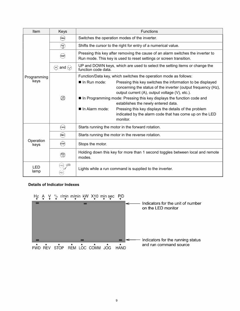
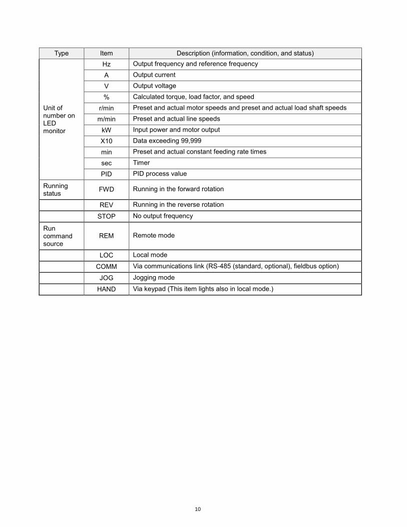
Details of Indicator Indexes
10
Type Item Description (information, condition, and status)
Unit of number on LED monitor
Hz Output frequency and reference frequency
A Output current
V Output voltage
% Calculated torque, load factor, and speed
r/min Preset and actual motor speeds and preset and actual load shaft speeds
m/min Preset and actual line speeds
kW Input power and motor output
X10 Data exceeding 99,999
min Preset and actual constant feeding rate times
sec Timer
PID PID process value
Running status
FWD Running in the forward rotation
REV Running in the reverse rotation
STOP No output frequency
Run command source
REM Remote mode
LOC Local mode
COMM Via communications link (RS-485 (standard, optional), fieldbus option)
JOG Jogging mode
HAND Via keypad (This item lights also in local mode.)
11
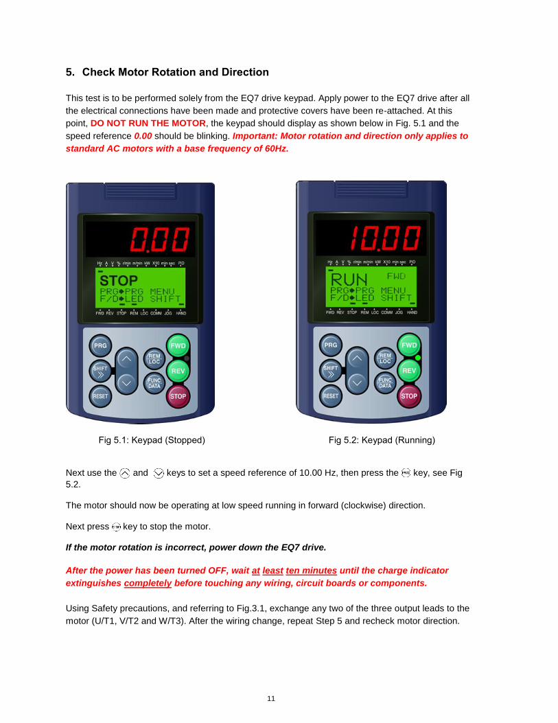
5. Check Motor Rotation and Direction
This test is to be performed solely from the EQ7 drive keypad. Apply power to the EQ7 drive after all
the electrical connections have been made and protective covers have been re-attached. At this
point, DO NOT RUN THE MOTOR, the keypad should display as shown below in Fig. 5.1 and the
speed reference 0.00 should be blinking. Important: Motor rotation and direction only applies to
standard AC motors with a base frequency of 60Hz.
Fig 5.1: Keypad (Stopped) Fig 5.2: Keypad (Running)
Next use the and keys to set a speed reference of 10.00 Hz, then press the key, see Fig
5.2. The motor should now be operating at low speed running in forward (clockwise) direction. Next press key to stop the motor. If the motor rotation is incorrect, power down the EQ7 drive.
After the power has been turned OFF, wait at least ten minutes until the charge indicator
extinguishes completely before touching any wiring, circuit boards or components.
Using Safety precautions, and referring to Fig.3.1, exchange any two of the three output leads to the
motor (U/T1, V/T2 and W/T3). After the wiring change, repeat Step 5 and recheck motor direction.
12
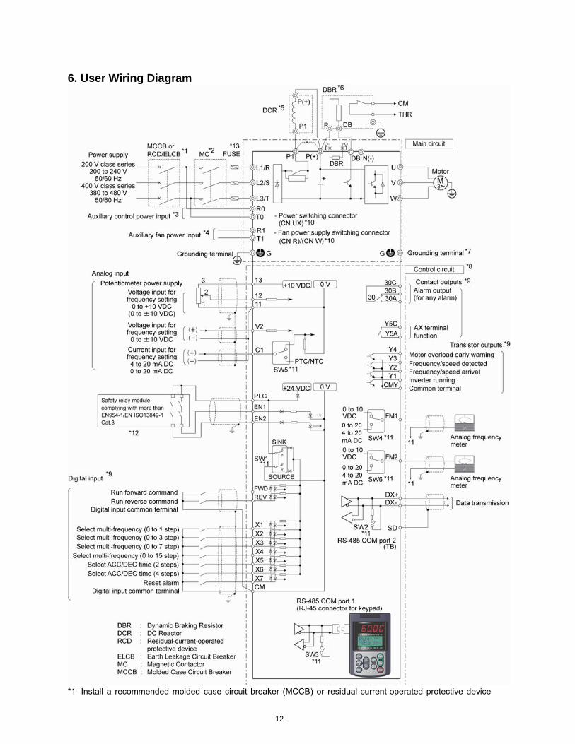
6. User Wiring Diagram
*1 Install a recommended molded case circuit breaker (MCCB) or residual-current-operated protective device
13
(RCD)/earth leakage circuit breaker (ELCB) (with overcurrent protection function) in the primary circuit of the
inverter to protect wiring. Ensure that the circuit breaker capacity is equivalent to or lower than the
recommended capacity.
*2 Install a magnetic contactor (MC) for each inverter to separate the inverter from the power supply, apart from
the MCCB or RCD/ELCB, when necessary.
Connect a surge absorber in parallel when installing a coil such as the MC or solenoid near the inverter.
*3 The R0 and T0 terminals are provided for inverters with a capacity of 2HP or above.
To retain an alarm output signal ALM issued on inverter's programmable output terminals by the protective
function or to keep the keypad alive even if the main power has shut down, connect these terminals to the
power supply lines. Without power supply to these terminals, the inverter can run.
*4 Normally no need to be connected. Use these terminals when the inverter is equipped with a high power-
factor, regenerative PWM converter (RHC series).
*5 When connecting an optional DC reactor (DCR), remove the jumper bar from the terminals P1 and P(+).
EQ7-2100-C / EQ7-4100-C and larger HP models require a DCR (packed with the EQ7) to be connected.
Use a DCR when the capacity of the power supply transformer exceeds 500 kVA and is 10 times or more the
inverter rated capacity, or when there are thyristor-driven loads in the same power supply line.
*6 EQ7-2015-C/EQ7-4015-C and smaller HP models have a built-in braking resistor (DBR) between the
terminals P(+) and DB.
When connecting an external braking resistor (DBR), be sure to disconnect the built-in one.
*7 A grounding terminal for a motor. Use this terminal if needed.
*8 For control signal wires, use twisted or shielded-twisted wires. When using shielded-twisted wires, connect
the shield of them to the common terminals of the control circuit. To prevent malfunction due to noise, keep
the control circuit wiring away from the main circuit wiring as far as possible (recommended: 10 cm/3.9 inches
or more). Never install them in the same wire duct. When crossing the control circuit wiring with the main
circuit wiring, set them at right angles.
*9 The connection diagram shows factory default functions assigned to digital input terminals [X1] to [X7], [FWD]
and [REV], transistor output terminals [Y1] to [Y4], and relay contact output terminals [Y5A/C] and [30A/B/C].
*10 Switching connectors in the main circuits. For details, refer to "Instruction manual section 2.3.4 Switching
connectors" later in this section.
*11 Slide switches on the control printed circuit board (control PCB). Use these switches to customize the inverter
operations. For details, refer to Section 2.3.6 of the instruction manual "Setting up the slide switches."
*12 When the Enable input function is not to be used, keep terminals [EN1]-[PLC] and terminals [EN2]-[PLC]
short-circuited using jumper wires. For opening and closing the hardware circuit between terminals [EN1] and
[PLC] and between [EN2] and [PLC], use safety components such as safety relays and safety switches that
comply with EN954-1 or EN ISO13849-1 Category 3 or higher.
*13 To bring the inverter into compliance with the European Standard, Low Voltage Directive EN61800-5-1, be
sure to insert the specified fuse in the primary circuit of the inverter.
14
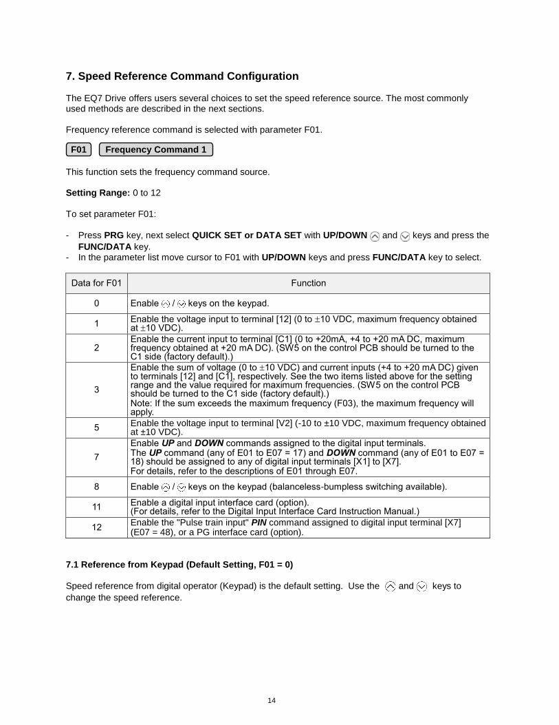
7. Speed Reference Command Configuration The EQ7 Drive offers users several choices to set the speed reference source. The most commonly used methods are described in the next sections. Frequency reference command is selected with parameter F01. This function sets the frequency command source. Setting Range: 0 to 12 To set parameter F01:
- Press PRG key, next select QUICK SET or DATA SET with UP/DOWN and keys and press the
FUNC/DATA key. - In the parameter list move cursor to F01 with UP/DOWN keys and press FUNC/DATA key to select.
Data for F01 Function
0 Enable / keys on the keypad.
1 Enable the voltage input to terminal [12] (0 to 10 VDC, maximum frequency obtained at 10 VDC).
2 Enable the current input to terminal [C1] (0 to +20mA, +4 to +20 mA DC, maximum frequency obtained at +20 mA DC). (SW5 on the control PCB should be turned to the C1 side (factory default).)
3
Enable the sum of voltage (0 to 10 VDC) and current inputs (+4 to +20 mA DC) given to terminals [12] and [C1], respectively. See the two items listed above for the setting range and the value required for maximum frequencies. (SW5 on the control PCB should be turned to the C1 side (factory default).) Note: If the sum exceeds the maximum frequency (F03), the maximum frequency will apply.
5 Enable the voltage input to terminal [V2] (-10 to ±10 VDC, maximum frequency obtained at ±10 VDC).
7
Enable UP and DOWN commands assigned to the digital input terminals. The UP command (any of E01 to E07 = 17) and DOWN command (any of E01 to E07 = 18) should be assigned to any of digital input terminals [X1] to [X7]. For details, refer to the descriptions of E01 through E07.
8 Enable / keys on the keypad (balanceless-bumpless switching available).
11 Enable a digital input interface card (option). (For details, refer to the Digital Input Interface Card Instruction Manual.)
12 Enable the "Pulse train input" PIN command assigned to digital input terminal [X7] (E07 = 48), or a PG interface card (option).
7.1 Reference from Keypad (Default Setting, F01 = 0) Speed reference from digital operator (Keypad) is the default setting. Use the and keys to
change the speed reference.
F01 Frequency Command 1
15
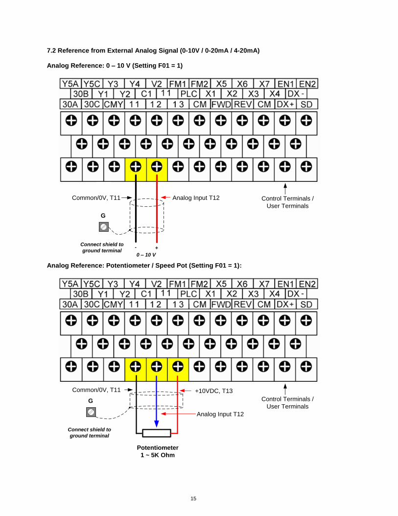
7.2 Reference from External Analog Signal (0-10V / 0-20mA / 4-20mA) Analog Reference: 0 – 10 V (Setting F01 = 1)
G
Connect shield to
ground terminal0 – 10 V
+-
Analog Input T12Common/0V, T11 Control Terminals /
User Terminals
Analog Reference: Potentiometer / Speed Pot (Setting F01 = 1):
G
Connect shield to
ground terminal
Potentiometer
1 ~ 5K Ohm
+10VDC, T13Common/0V, T11
Analog Input T12
Control Terminals /
User Terminals

16
Analog Reference: 0 – 20mA / 4 – 20mA (Setting F01 = 2)
G
Connect shield to
ground terminal
0 – 20mA / 4 – 20mA
+-
Analog Input C1Common/0V, T11 Control Terminals /
User Terminals
Note: When using a 0 – 20mA signal set parameter C40 to 1.
17
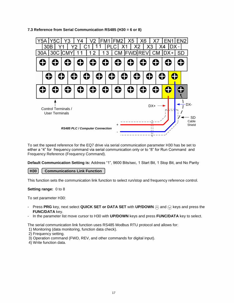
7.3 Reference from Serial Communication RS485 (H30 = 6 or 8)
RS485 PLC / Computer Connection+
-
DX+ DX-
SDCable
Shield
Control Terminals /
User Terminals
To set the speed reference for the EQ7 drive via serial communication parameter H30 has be set to either a “4” for frequency command via serial communication only or to “8” for Run Command and Frequency Reference (Frequency Command). Default Communication Setting is: Address “1”, 9600 Bits/sec, 1 Start Bit, 1 Stop Bit, and No Parity This function sets the communication link function to select run/stop and frequency reference control. Setting range: 0 to 8 To set parameter H30:
- Press PRG key, next select QUICK SET or DATA SET with UP/DOWN and keys and press the
FUNC/DATA key. - In the parameter list move cursor to H30 with UP/DOWN keys and press FUNC/DATA key to select. The serial communication link function uses RS485 Modbus RTU protocol and allows for: 1) Monitoring (data monitoring, function data check). 2) Frequency setting. 3) Operation command (FWD, REV, and other commands for digital input). 4) Write function data.
H30 Communications Link Function
18
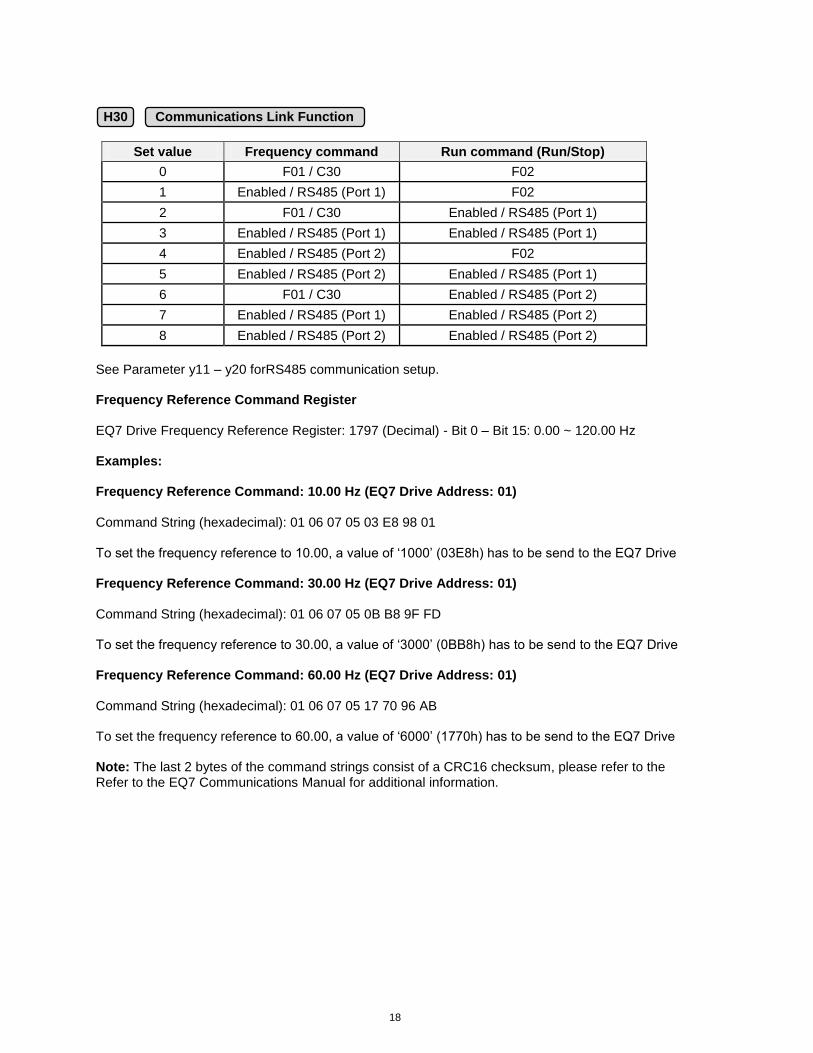
Set value Frequency command Run command (Run/Stop)
0 F01 / C30 F02
1 Enabled / RS485 (Port 1) F02
2 F01 / C30 Enabled / RS485 (Port 1)
3 Enabled / RS485 (Port 1) Enabled / RS485 (Port 1)
4 Enabled / RS485 (Port 2) F02
5 Enabled / RS485 (Port 2) Enabled / RS485 (Port 1)
6 F01 / C30 Enabled / RS485 (Port 2)
7 Enabled / RS485 (Port 1) Enabled / RS485 (Port 2)
8 Enabled / RS485 (Port 2) Enabled / RS485 (Port 2)
See Parameter y11 – y20 forRS485 communication setup. Frequency Reference Command Register EQ7 Drive Frequency Reference Register: 1797 (Decimal) - Bit 0 – Bit 15: 0.00 ~ 120.00 Hz Examples: Frequency Reference Command: 10.00 Hz (EQ7 Drive Address: 01) Command String (hexadecimal): 01 06 07 05 03 E8 98 01 To set the frequency reference to 10.00, a value of ‘1000’ (03E8h) has to be send to the EQ7 Drive Frequency Reference Command: 30.00 Hz (EQ7 Drive Address: 01) Command String (hexadecimal): 01 06 07 05 0B B8 9F FD To set the frequency reference to 30.00, a value of ‘3000’ (0BB8h) has to be send to the EQ7 Drive Frequency Reference Command: 60.00 Hz (EQ7 Drive Address: 01) Command String (hexadecimal): 01 06 07 05 17 70 96 AB To set the frequency reference to 60.00, a value of ‘6000’ (1770h) has to be send to the EQ7 Drive Note: The last 2 bytes of the command strings consist of a CRC16 checksum, please refer to the Refer to the EQ7 Communications Manual for additional information.
H30 Communications Link Function
19
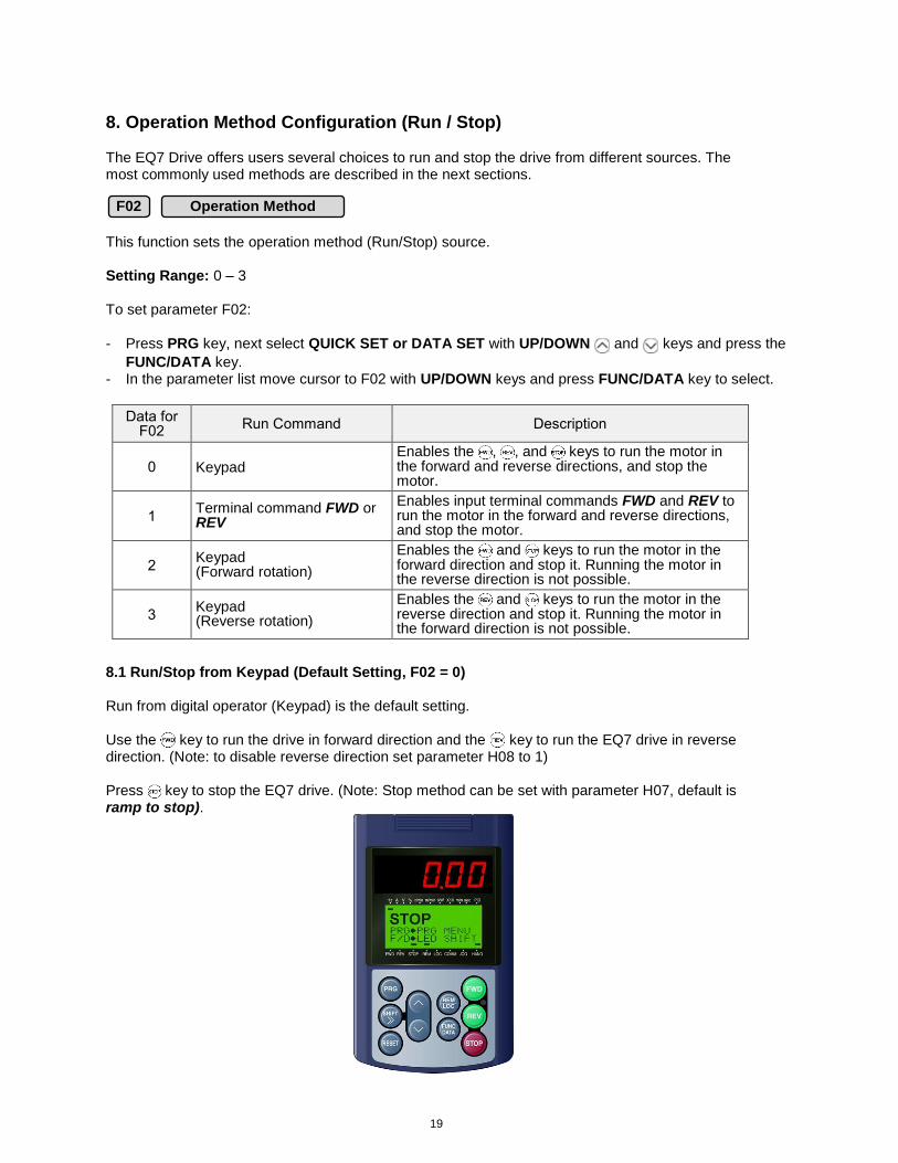
8. Operation Method Configuration (Run / Stop) The EQ7 Drive offers users several choices to run and stop the drive from different sources. The most commonly used methods are described in the next sections. This function sets the operation method (Run/Stop) source. Setting Range: 0 – 3 To set parameter F02:
- Press PRG key, next select QUICK SET or DATA SET with UP/DOWN and keys and press the
FUNC/DATA key. - In the parameter list move cursor to F02 with UP/DOWN keys and press FUNC/DATA key to select.
Data for F02
Run Command Description
0 Keypad Enables the , , and keys to run the motor in the forward and reverse directions, and stop the motor.
1 Terminal command FWD or REV
Enables input terminal commands FWD and REV to run the motor in the forward and reverse directions, and stop the motor.
2 Keypad (Forward rotation)
Enables the and keys to run the motor in the forward direction and stop it. Running the motor in the reverse direction is not possible.
3 Keypad (Reverse rotation)
Enables the and keys to run the motor in the reverse direction and stop it. Running the motor in the forward direction is not possible.
8.1 Run/Stop from Keypad (Default Setting, F02 = 0) Run from digital operator (Keypad) is the default setting. Use the key to run the drive in forward direction and the key to run the EQ7 drive in reverse direction. (Note: to disable reverse direction set parameter H08 to 1) Press key to stop the EQ7 drive. (Note: Stop method can be set with parameter H07, default is ramp to stop).
F02 Operation Method
20
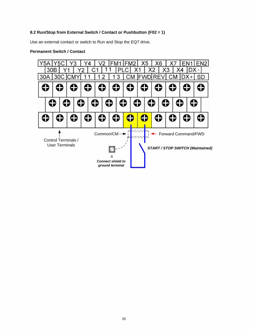
8.2 Run/Stop from External Switch / Contact or Pushbutton (F02 = 1) Use an external contact or switch to Run and Stop the EQ7 drive. Permanent Switch / Contact
G
START / STOP SWITCH (Maintained)
Connect shield to
ground terminal
Forward Command/FWDCommon/CM
Control Terminals /
User Terminals
21
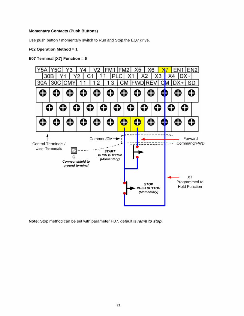
Momentary Contacts (Push Buttons) Use push button / momentary switch to Run and Stop the EQ7 drive. F02 Operation Method = 1 E07 Terminal [X7] Function = 6
GConnect shield to
ground terminal
START
PUSH BUTTON
(Momentary)
STOP
PUSH BUTTON
(Momentary)
Forward
Command/FWDCommon/CM
X7
Programmed to
Hold Function
Control Terminals /
User Terminals
Note: Stop method can be set with parameter H07, default is ramp to stop.
22
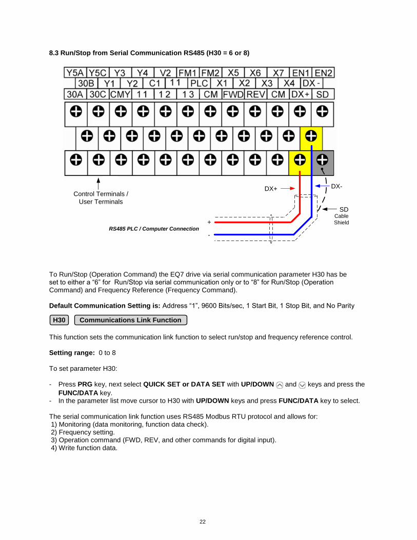
8.3 Run/Stop from Serial Communication RS485 (H30 = 6 or 8)
RS485 PLC / Computer Connection+
-
DX+ DX-
SDCable
Shield
Control Terminals /
User Terminals
To Run/Stop (Operation Command) the EQ7 drive via serial communication parameter H30 has be set to either a “6” for Run/Stop via serial communication only or to “8” for Run/Stop (Operation Command) and Frequency Reference (Frequency Command). Default Communication Setting is: Address “1”, 9600 Bits/sec, 1 Start Bit, 1 Stop Bit, and No Parity This function sets the communication link function to select run/stop and frequency reference control. Setting range: 0 to 8 To set parameter H30:
- Press PRG key, next select QUICK SET or DATA SET with UP/DOWN and keys and press the
FUNC/DATA key. - In the parameter list move cursor to H30 with UP/DOWN keys and press FUNC/DATA key to select. The serial communication link function uses RS485 Modbus RTU protocol and allows for: 1) Monitoring (data monitoring, function data check). 2) Frequency setting. 3) Operation command (FWD, REV, and other commands for digital input). 4) Write function data.
H30 Communications Link Function
23
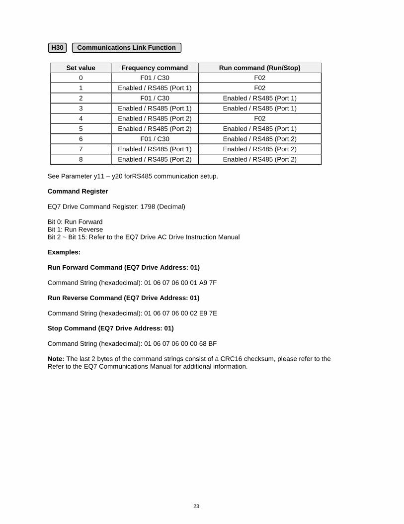
Set value Frequency command Run command (Run/Stop)
0 F01 / C30 F02
1 Enabled / RS485 (Port 1) F02
2 F01 / C30 Enabled / RS485 (Port 1)
3 Enabled / RS485 (Port 1) Enabled / RS485 (Port 1)
4 Enabled / RS485 (Port 2) F02
5 Enabled / RS485 (Port 2) Enabled / RS485 (Port 1)
6 F01 / C30 Enabled / RS485 (Port 2)
7 Enabled / RS485 (Port 1) Enabled / RS485 (Port 2)
8 Enabled / RS485 (Port 2) Enabled / RS485 (Port 2)
See Parameter y11 – y20 forRS485 communication setup. Command Register EQ7 Drive Command Register: 1798 (Decimal) Bit 0: Run Forward Bit 1: Run Reverse Bit 2 ~ Bit 15: Refer to the EQ7 Drive AC Drive Instruction Manual Examples: Run Forward Command (EQ7 Drive Address: 01) Command String (hexadecimal): 01 06 07 06 00 01 A9 7F Run Reverse Command (EQ7 Drive Address: 01) Command String (hexadecimal): 01 06 07 06 00 02 E9 7E Stop Command (EQ7 Drive Address: 01) Command String (hexadecimal): 01 06 07 06 00 00 68 BF Note: The last 2 bytes of the command strings consist of a CRC16 checksum, please refer to the Refer to the EQ7 Communications Manual for additional information.
H30 Communications Link Function
24
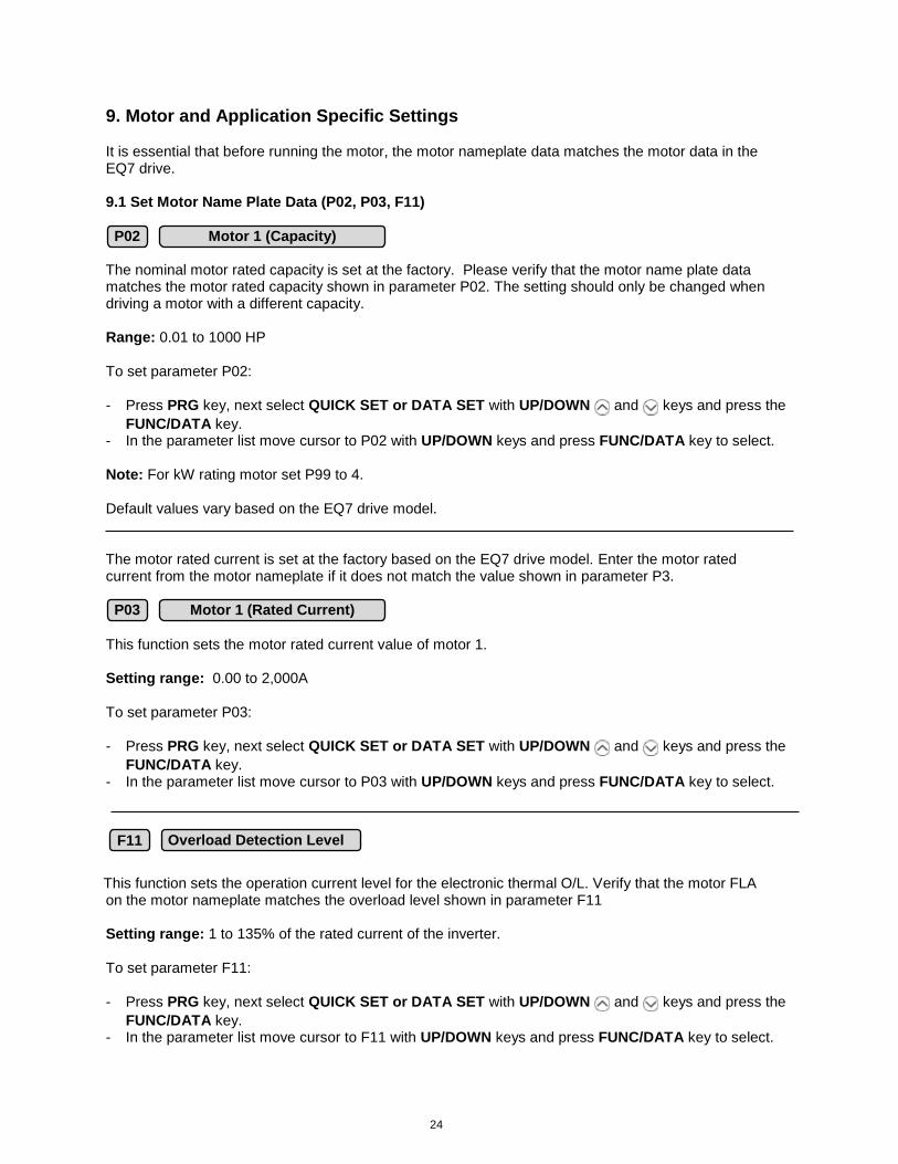
9. Motor and Application Specific Settings It is essential that before running the motor, the motor nameplate data matches the motor data in the EQ7 drive. 9.1 Set Motor Name Plate Data (P02, P03, F11) The nominal motor rated capacity is set at the factory. Please verify that the motor name plate data matches the motor rated capacity shown in parameter P02. The setting should only be changed when driving a motor with a different capacity. Range: 0.01 to 1000 HP To set parameter P02:
- Press PRG key, next select QUICK SET or DATA SET with UP/DOWN and keys and press the
FUNC/DATA key. - In the parameter list move cursor to P02 with UP/DOWN keys and press FUNC/DATA key to select. Note: For kW rating motor set P99 to 4. Default values vary based on the EQ7 drive model.
The motor rated current is set at the factory based on the EQ7 drive model. Enter the motor rated current from the motor nameplate if it does not match the value shown in parameter P3.
This function sets the motor rated current value of motor 1. Setting range: 0.00 to 2,000A To set parameter P03: - Press PRG key, next select QUICK SET or DATA SET with UP/DOWN and keys and press the
FUNC/DATA key. - In the parameter list move cursor to P03 with UP/DOWN keys and press FUNC/DATA key to select.
This function sets the operation current level for the electronic thermal O/L. Verify that the motor FLA
on the motor nameplate matches the overload level shown in parameter F11 Setting range: 1 to 135% of the rated current of the inverter. To set parameter F11:
- Press PRG key, next select QUICK SET or DATA SET with UP/DOWN and keys and press the
FUNC/DATA key. - In the parameter list move cursor to F11 with UP/DOWN keys and press FUNC/DATA key to select.
P03 Motor 1 (Rated Current)
F11 Overload Detection Level
P02 Motor 1 (Capacity)
25
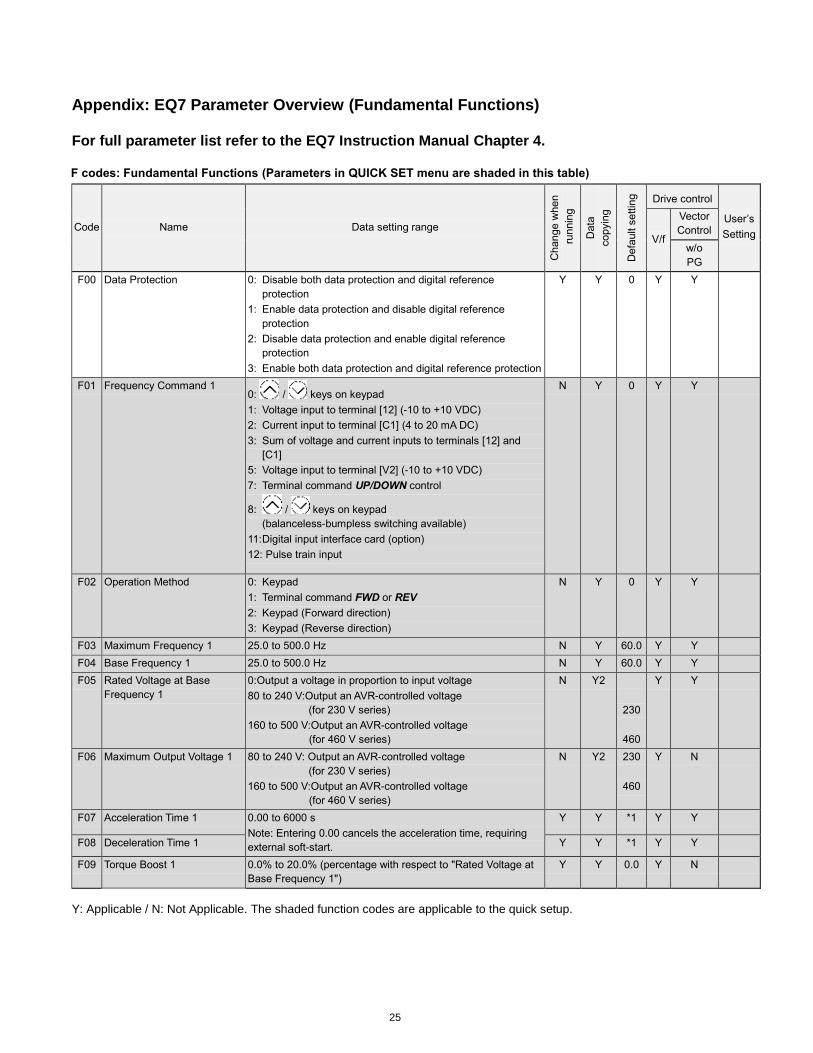
Appendix: EQ7 Parameter Overview (Fundamental Functions) For full parameter list refer to the EQ7 Instruction Manual Chapter 4.
F codes: Fundamental Functions (Parameters in QUICK SET menu are shaded in this table)
Code Name Data setting range
Change w
hen
runnin
g
Data
copyin
g
Defa
ult s
ettin
g
Drive control
User’s
Setting V/f
Vector
Control
w/o
PG
F00 Data Protection 0: Disable both data protection and digital reference
protection
1: Enable data protection and disable digital reference
protection
2: Disable data protection and enable digital reference
protection
3: Enable both data protection and digital reference protection
Y Y 0 Y Y
F01 Frequency Command 1 0: / keys on keypad
1: Voltage input to terminal [12] (-10 to +10 VDC)
2: Current input to terminal [C1] (4 to 20 mA DC)
3: Sum of voltage and current inputs to terminals [12] and
[C1]
5: Voltage input to terminal [V2] (-10 to +10 VDC)
7: Terminal command UP/DOWN control
8: / keys on keypad
(balanceless-bumpless switching available)
11: Digital input interface card (option)
12: Pulse train input
N Y 0 Y Y
F02 Operation Method 0: Keypad
1: Terminal command FWD or REV
2: Keypad (Forward direction)
3: Keypad (Reverse direction)
N Y 0 Y Y
F03 Maximum Frequency 1 25.0 to 500.0 Hz N Y 60.0 Y Y
F04 Base Frequency 1 25.0 to 500.0 Hz N Y 60.0 Y Y
F05 Rated Voltage at Base
Frequency 1
0:Output a voltage in proportion to input voltage
80 to 240 V:Output an AVR-controlled voltage
(for 230 V series)
160 to 500 V:Output an AVR-controlled voltage
(for 460 V series)
N Y2
230
460
Y Y
F06 Maximum Output Voltage 1 80 to 240 V: Output an AVR-controlled voltage
(for 230 V series)
160 to 500 V:Output an AVR-controlled voltage
(for 460 V series)
N Y2 230
460
Y N
F07 Acceleration Time 1 0.00 to 6000 s
Note: Entering 0.00 cancels the acceleration time, requiring
external soft-start.
Y Y *1 Y Y
F08 Deceleration Time 1 Y Y *1 Y Y
F09 Torque Boost 1 0.0% to 20.0% (percentage with respect to "Rated Voltage at
Base Frequency 1")
Y Y 0.0 Y N
Y: Applicable / N: Not Applicable. The shaded function codes are applicable to the quick setup.
26
Code Name Data setting range
Change w
hen
runnin
g
Data
copyin
g
Defa
ult s
ett
ing
Drive control
User’s
Setting V/f
Vector
Control
w/o
PG
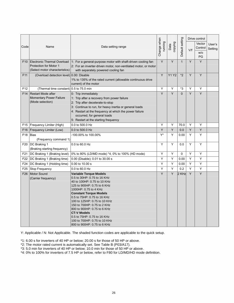
F10 Electronic Thermal Overload
Protection for Motor 1
(Select motor characteristics)
1: For a general-purpose motor with shaft-driven cooling fan
2: For an inverter-driven motor, non-ventilated motor, or motor
with separately powered cooling fan
Y Y 1 Y Y
F11 (Overload detection level) 0.00: Disable
1% to 135% of the rated current (allowable continuous drive
current) of the motor
Y Y1 Y2 *2 Y Y
F12 (Thermal time constant) 0.5 to 75.0 min Y Y *3 Y Y
F14 Restart Mode after
Momentary Power Failure
(Mode selection)
0: Trip immediately
1: Trip after a recovery from power failure
2: Trip after decelerate-to-stop
3: Continue to run, for heavy inertia or general loads
4: Restart at the frequency at which the power failure
occurred, for general loads
5: Restart at the starting frequency
Y Y 0 Y Y
F15 Frequency Limiter (High) 0.0 to 500.0 Hz Y Y 70.0 Y Y
F16 Frequency Limiter (Low) 0.0 to 500.0 Hz Y Y 0.0 Y Y
F18 Bias
(Frequency command 1)
-100.00% to 100.00% Y* Y 0.00 Y Y
F20 DC Braking 1
(Braking starting frequency)
0.0 to 60.0 Hz Y Y 0.0 Y Y
F21 DC Braking 1 (Braking level) 0% to 80% (LD/MD mode) *4, 0% to 100% (HD mode) Y Y 0 Y Y
F22 DC Braking 1 (Braking time) 0.00 (Disable); 0.01 to 30.00 s Y Y 0.00 Y Y
F24 DC Braking 1 (Holding time) 0.00 to 10.00 s Y Y 0.00 Y Y
F25 Stop Frequency 0.0 to 60.0 Hz Y Y 0.2 Y Y
F26 Motor Sound
(Carrier frequency)
Variable Torque Models
0.5 to 30HP: 0.75 to 16 KHz
40 to 100HP: 0.75 to 10 KHz
125 to 900HP: 0.75 to 6 KHz
1000HP: 0.75 to 4 KHz
Constant Torque Models
0.5 to 75HP: 0.75 to 16 KHz
100 to 125HP: 0.75 to 10 KHz
150 to 700HP: 0.75 to 2 KHz
800 to 900HP: 0.75 to 6 KHz
CT-V Models
0.5 to 75HP: 0.75 to 16 KHz
100 to 700HP: 0.75 to 10 KHz
800 to 900HP: 0.75 to 6 KHz
Y Y 2 KHz Y Y
Y: Applicable / N: Not Applicable. The shaded function codes are applicable to the quick setup. *1: 6.00 s for inverters of 40 HP or below; 20.00 s for those of 50 HP or above. *2: The motor rated current is automatically set. See Table B (P03/A17). *3: 5.0 min for inverters of 40 HP or below; 10.0 min for those of 50 HP or above. *4: 0% to 100% for inverters of 7.5 HP or below, refer to F80 for LD/MD/HD mode definition.
27
Code Name Data setting range
Change w
hen
runnin
g
Data
copyin
g
Defa
ult s
ettin
g
Drive control
User’s
Setting V/f
Vector
Control
w/o
PG
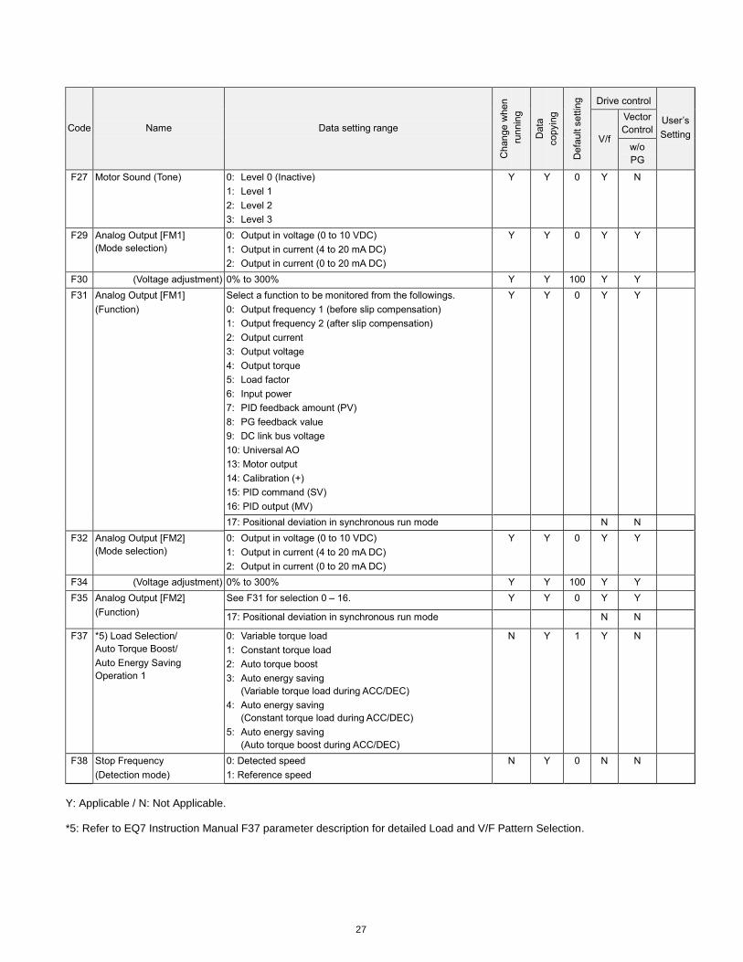
F27 Motor Sound (Tone) 0: Level 0 (Inactive)
1: Level 1
2: Level 2
3: Level 3
Y Y 0 Y N
F29 Analog Output [FM1]
(Mode selection)
0: Output in voltage (0 to 10 VDC)
1: Output in current (4 to 20 mA DC)
2: Output in current (0 to 20 mA DC)
Y Y 0 Y Y
F30 (Voltage adjustment) 0% to 300% Y Y 100 Y Y
F31 Analog Output [FM1]
(Function)
Select a function to be monitored from the followings.
0: Output frequency 1 (before slip compensation)
1: Output frequency 2 (after slip compensation)
2: Output current
3: Output voltage
4: Output torque
5: Load factor
6: Input power
7: PID feedback amount (PV)
8: PG feedback value
9: DC link bus voltage
10: Universal AO
13: Motor output
14: Calibration (+)
15: PID command (SV)
16: PID output (MV)
Y Y 0 Y Y
17: Positional deviation in synchronous run mode N N
F32 Analog Output [FM2]
(Mode selection)
0: Output in voltage (0 to 10 VDC)
1: Output in current (4 to 20 mA DC)
2: Output in current (0 to 20 mA DC)
Y Y 0 Y Y
F34 (Voltage adjustment) 0% to 300% Y Y 100 Y Y
F35 Analog Output [FM2]
(Function)
See F31 for selection 0 – 16. Y Y 0 Y Y
17: Positional deviation in synchronous run mode N N
F37 *5) Load Selection/
Auto Torque Boost/
Auto Energy Saving
Operation 1
0: Variable torque load
1: Constant torque load
2: Auto torque boost
3: Auto energy saving
(Variable torque load during ACC/DEC)
4: Auto energy saving
(Constant torque load during ACC/DEC)
5: Auto energy saving
(Auto torque boost during ACC/DEC)
N Y 1 Y N
F38 Stop Frequency
(Detection mode)
0: Detected speed
1: Reference speed
N Y 0 N N
Y: Applicable / N: Not Applicable. *5: Refer to EQ7 Instruction Manual F37 parameter description for detailed Load and V/F Pattern Selection.
28
Code Name Data setting range
Change w
hen
runnin
g
Data
copyin
g
Defa
ult s
ettin
g
Drive control
User’s
Setting V/f
Vector
Control
w/o
PG
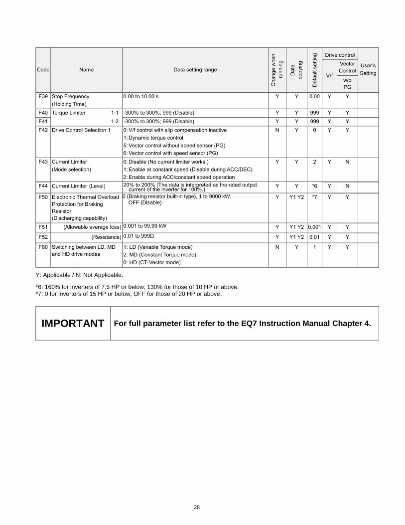
F39 Stop Frequency
(Holding Time)
0.00 to 10.00 s Y Y 0.00 Y Y
F40 Torque Limiter 1-1 -300% to 300%; 999 (Disable) Y Y 999 Y Y
F41 1-2 -300% to 300%; 999 (Disable) Y Y 999 Y Y
F42 Drive Control Selection 1 0: V/f control with slip compensation inactive
1: Dynamic torque control
5: Vector control without speed sensor (PG)
6: Vector control with speed sensor (PG)
N Y 0 Y Y
F43 Current Limiter
(Mode selection)
0: Disable (No current limiter works.)
1: Enable at constant speed (Disable during ACC/DEC)
2: Enable during ACC/constant speed operation
Y Y 2
Y N
F44 Current Limiter (Level) 20% to 200% (The data is interpreted as the rated output current of the inverter for 100%.)
Y Y *6 Y N
F50 Electronic Thermal Overload
Protection for Braking
Resistor
(Discharging capability)
0 (Braking resistor built-in type), 1 to 9000 kW, OFF (Disable)
Y Y1 Y2 *7 Y Y
F51 (Allowable average loss) 0.001 to 99.99 kW Y Y1 Y2 0.001 Y Y
F52 (Resistance) 0.01 to 999Ω Y Y1 Y2 0.01 Y Y
F80 Switching between LD, MD
and HD drive modes
1: LD (Variable Torque mode)
2: MD (Constant Torque mode)
0: HD (CT-Vector mode)
N Y 1 Y Y
Y: Applicable / N: Not Applicable.
*6: 160% for inverters of 7.5 HP or below; 130% for those of 10 HP or above. *7: 0 for inverters of 15 HP or below; OFF for those of 20 HP or above.
IMPORTANT For full parameter list refer to the EQ7 Instruction Manual Chapter 4.