Embed Size (px)
Citation preview
EPON Architecture and Testing
2© 2018 VIAVI Solutions Inc.viavisolutions.com
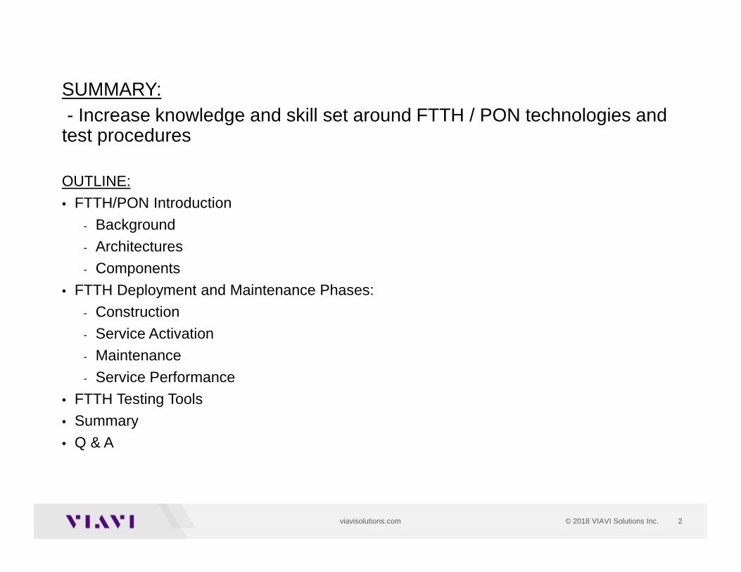
SUMMARY: - Increase knowledge and skill set around FTTH / PON technologies and test procedures
OUTLINE:
• FTTH/PON Introduction
- Background
- Architectures
- Components
• FTTH Deployment and Maintenance Phases:
- Construction
- Service Activation
- Maintenance
- Service Performance
• FTTH Testing Tools
• Summary
• Q & A
3
FTTH / PON Introduction:- Background- Architectures- Components
4© 2018 VIAVI Solutions Inc.viavisolutions.com
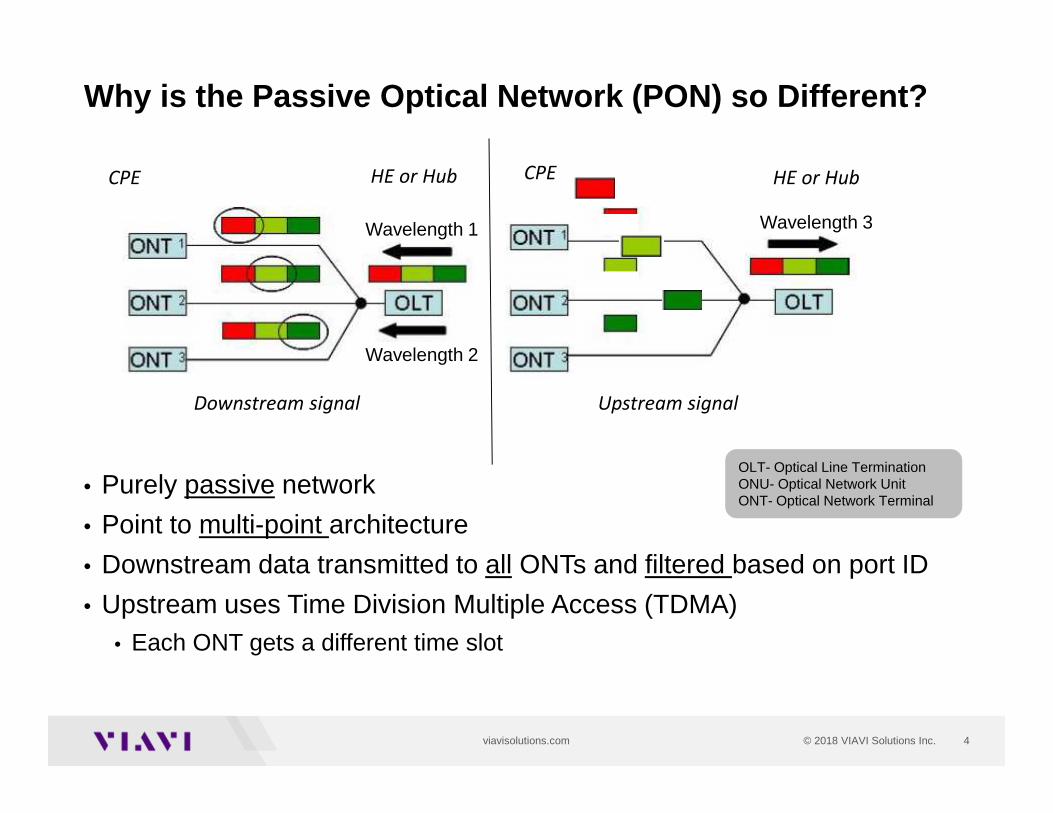
• Purely passive network
• Point to multi-point architecture
• Downstream data transmitted to all ONTs and filtered based on port ID
• Upstream uses Time Division Multiple Access (TDMA)• Each ONT gets a different time slot
Why is the Passive Optical Network (PON) so Differe nt?
OLT- Optical Line TerminationONU- Optical Network UnitONT- Optical Network Terminal
Wavelength 1 Wavelength 3
Downstream signal Upstream signal
Wavelength 2
HE or Hub HE or HubCPE CPE
5© 2018 VIAVI Solutions Inc.viavisolutions.com
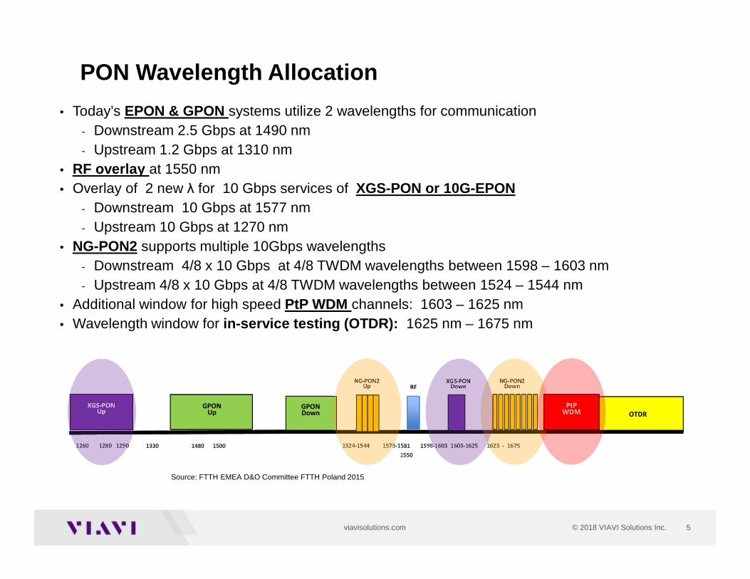
PON Wavelength Allocation
Source: FTTH EMEA D&O Committee FTTH Poland 2015
1260 1280 1290 1330 1480 1500 1524-1544 1575-1581 1598-1603 1603-1625 1625 - 1675
OTDRGPON
UpGPONDown
1550
RFNG-PON2
UpNG-PON2
Down
PtPWDM
XGS-PONDown
XGS-PONUp
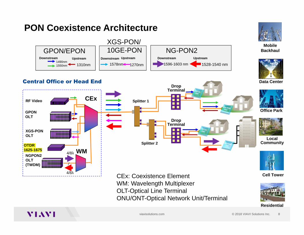
• Today’s EPON & GPON systems utilize 2 wavelengths for communication- Downstream 2.5 Gbps at 1490 nm - Upstream 1.2 Gbps at 1310 nm
• RF overlay at 1550 nm• Overlay of 2 new λ for 10 Gbps services of XGS-PON or 10G-EPON
- Downstream 10 Gbps at 1577 nm - Upstream 10 Gbps at 1270 nm
• NG-PON2 supports multiple 10Gbps wavelengths - Downstream 4/8 x 10 Gbps at 4/8 TWDM wavelengths between 1598 – 1603 nm- Upstream 4/8 x 10 Gbps at 4/8 TWDM wavelengths between 1524 – 1544 nm
• Additional window for high speed PtP WDM channels: 1603 – 1625 nm • Wavelength window for in-service testing (OTDR): 1625 nm – 1675 nm
6© 2018 VIAVI Solutions Inc.viavisolutions.com
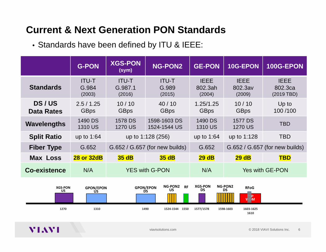
• Standards have been defined by ITU & IEEE:
Current & Next Generation PON Standards
G-PON XGS-PON(sym)
NG-PON2 GE-PON 10G-EPON 100G-EPON
StandardsITU-TG.984(2003)
ITU-T G.987.1
(2016)
ITU-T G.989(2015)
IEEE802.3ah
(2004)
IEEE802.3av
(2009)
IEEE802.3ca
(2019 TBD)
DS / USData Rates
2.5 / 1.25GBps
10 / 10GBps
40 / 10GBps
1.25/1.25GBps
10 / 10GBps
Up to100 /100
Wavelengths 1490 DS1310 US
1578 DS1270 US
1598-1603 DS1524-1544 US
1490 DS1310 US
1577 DS1270 US
TBD
Split Ratio up to 1:64 up to 1:128 (256) up to 1:64 up to 1:128 TBD
Fiber Type G.652 G.652 / G.657 (for new builds) G.652 G.652 / G.657 (for new builds)
Max Loss 28 or 32dB 35 dB 35 dB 29 dB 29 dB TBD
Co-existence N/A YES with G-PON N/A Yes with GE-PON
1270 1310 1490 1524-1544 1550 1577/1578 1598-1603 1603-1625
GPON/EPONUS
GPON/EPONDS
RFNG-PON2US
NG-PON2DS
XGS-PONDS
XGS-PONUS
1610
RFoG
PtPWDM
7© 2018 VIAVI Solutions Inc.viavisolutions.com
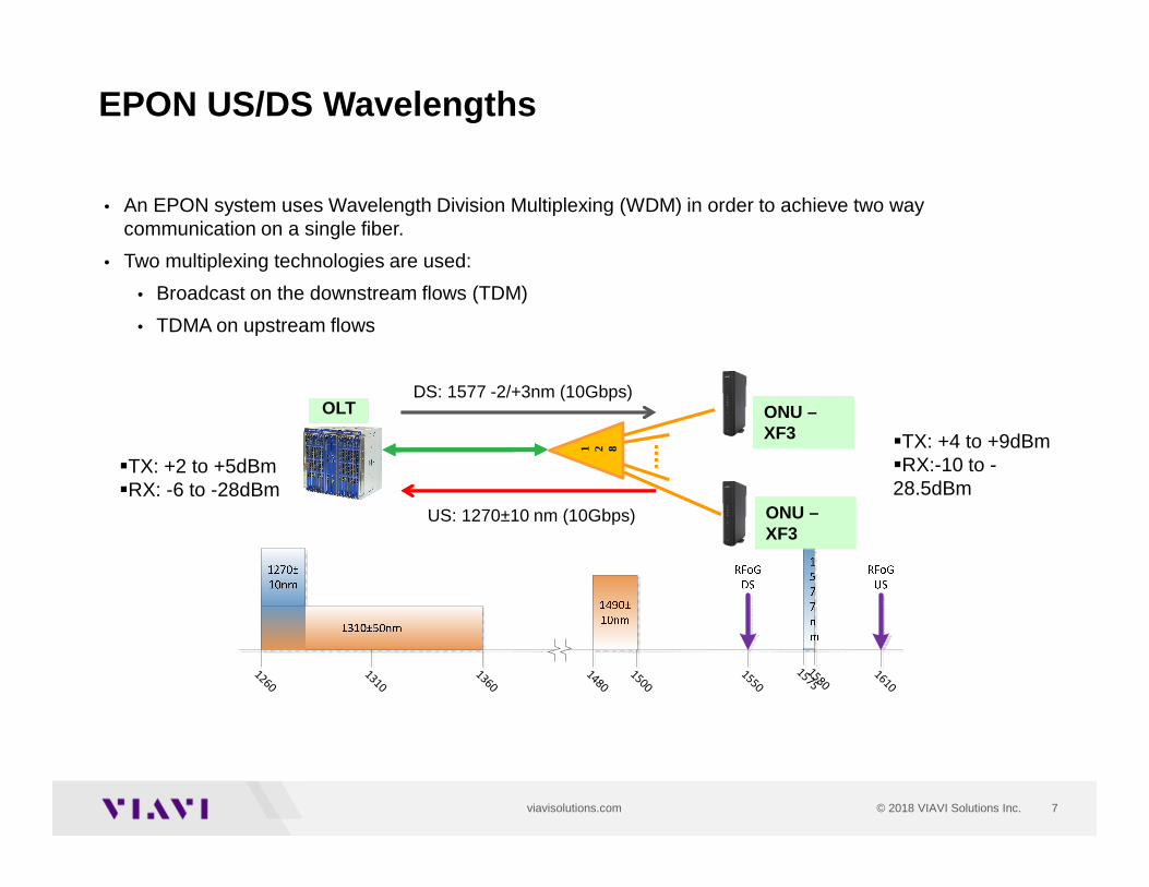
EPON US/DS Wavelengths
• An EPON system uses Wavelength Division Multiplexing (WDM) in order to achieve two waycommunication on a single fiber.
• Two multiplexing technologies are used:
• Broadcast on the downstream flows (TDM)
• TDMA on upstream flows
OLT
1 2 8
ONU –XF3
DS: 1577 -2/+3nm (10Gbps)
US: 1270±10 nm (10Gbps)
1260
1310
1360
1480
1500
1550
15751580
1610
ONU –XF3
�TX: +2 to +5dBm�RX: -6 to -28dBm
�TX: +4 to +9dBm�RX:-10 to -28.5dBm
8© 2018 VIAVI Solutions Inc.viavisolutions.com
PON Coexistence Architecture
CEx: Coexistence ElementWM: Wavelength MultiplexerOLT-Optical Line TerminalONU/ONT-Optical Network Unit/Terminal
8
1490nm1550nm
Downstream
1310nm
Upstream
1596-1603 nm
Downstream
1528-1540 nm
Upstream
CEx Splitter 1
GPON OLT
XGS-PON OLT
Central Office or Head EndDrop
Terminal
Drop Terminal
NGPON2 OLT(TWDM)
WM4/8λ
4/8λ
Splitter 2
GPON/EPON
1578nm
Downstream
1270nm
Upstream
XGS-PON/ 10GE-PON NG-PON2
RF Video
LocalCommunity
Residential
Cell Tower
Office Park
Mobile Backhaul
Data Center
OTDR 1625-1675
9© 2018 VIAVI Solutions Inc.viavisolutions.com
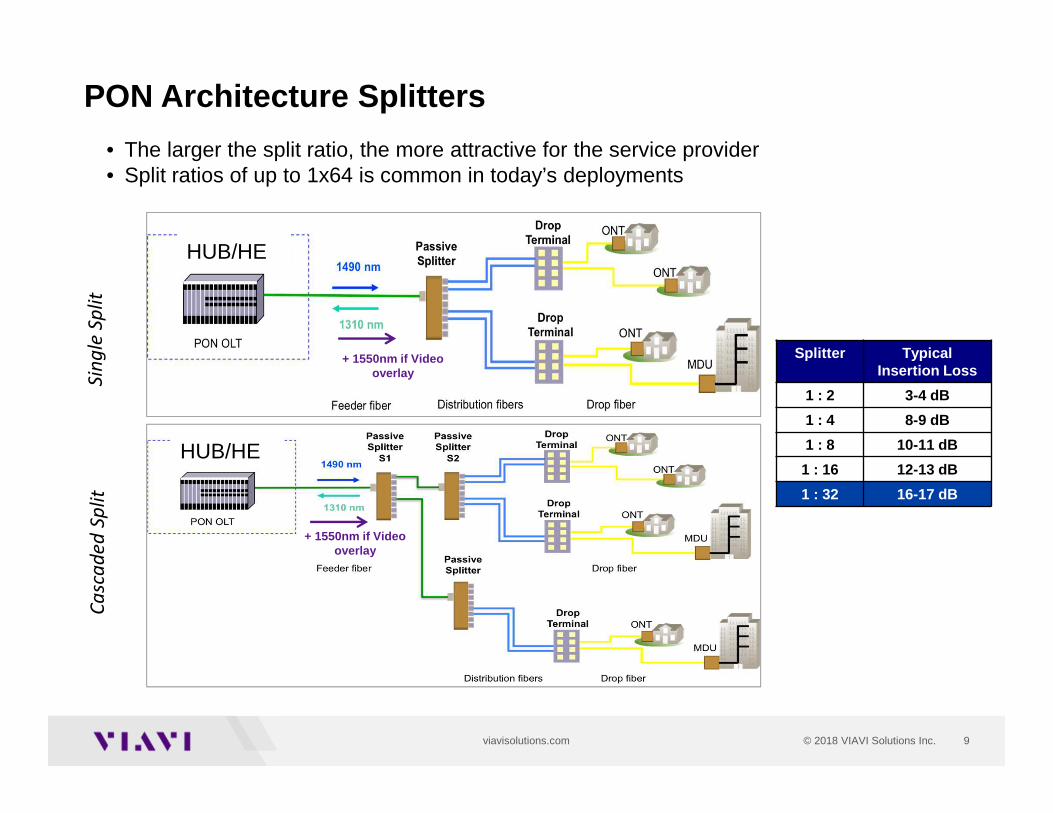
PON Architecture Splitters
+ 1550nm if Video overlay
Sin
gle
Sp
lit
Ca
sca
de
d S
pli
t
+ 1550nm if Video overlay
• The larger the split ratio, the more attractive for the service provider• Split ratios of up to 1x64 is common in today’s deployments
Splitter TypicalInsertion Loss
1 : 2 3-4 dB
1 : 4 8-9 dB
1 : 8 10-11 dB
1 : 16 12-13 dB
1 : 32 16-17 dB
HUB/HE
HUB/HE
10© 2018 VIAVI Solutions Inc.viavisolutions.com
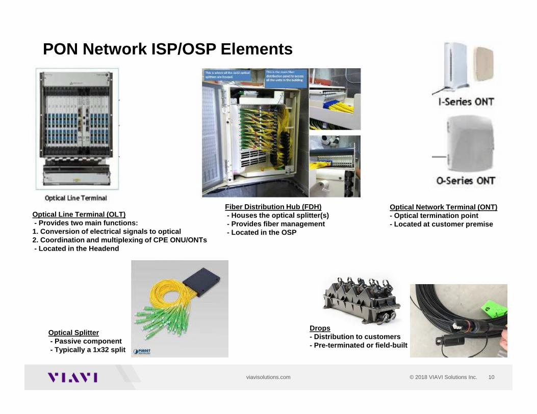
PON Network ISP/OSP Elements
Fiber Distribution Hub (FDH)- Houses the optical splitter(s)- Provides fiber management- Located in the OSP
Optical Splitter- Passive component- Typically a 1x32 split
Optical Line Terminal (OLT)- Provides two main functions: 1. Conversion of electrical signals to optical 2. Coordination and multiplexing of CPE ONU/ONTs- Located in the Headend
Drops- Distribution to customers- Pre-terminated or field-built
Optical Network Terminal (ONT)- Optical termination point- Located at customer premise
11© 2018 VIAVI Solutions Inc.viavisolutions.com
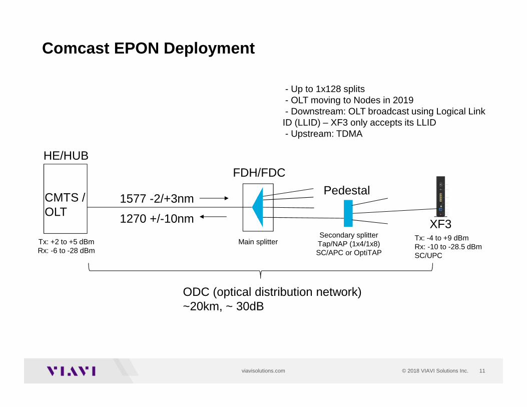
Comcast EPON Deployment
1577 -2/+3nm
1270 +/-10nm
HE/HUB
Tx: -4 to +9 dBmRx: -10 to -28.5 dBmSC/UPC
Tx: +2 to +5 dBmRx: -6 to -28 dBm
FDH/FDC
Main splitterSecondary splitterTap/NAP (1x4/1x8)SC/APC or OptiTAP
Pedestal
XF3
CMTS / OLT
ODC (optical distribution network)~20km, ~ 30dB
- Up to 1x128 splits- OLT moving to Nodes in 2019- Downstream: OLT broadcast using Logical Link ID (LLID) – XF3 only accepts its LLID- Upstream: TDMA
12© 2018 VIAVI Solutions Inc.viavisolutions.com
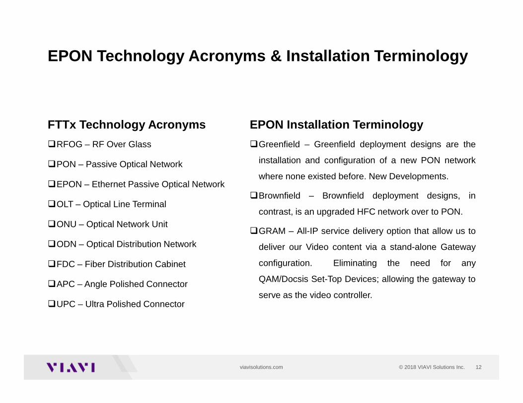
FTTx Technology Acronyms
�RFOG – RF Over Glass
�PON – Passive Optical Network
�EPON – Ethernet Passive Optical Network
�OLT – Optical Line Terminal
�ONU – Optical Network Unit
�ODN – Optical Distribution Network
�FDC – Fiber Distribution Cabinet
�APC – Angle Polished Connector
�UPC – Ultra Polished Connector
EPON Technology Acronyms & Installation Terminology
EPON Installation Terminology
�Greenfield – Greenfield deployment designs are the
installation and configuration of a new PON network
where none existed before. New Developments.
�Brownfield – Brownfield deployment designs, in
contrast, is an upgraded HFC network over to PON.
�GRAM – All-IP service delivery option that allow us to
deliver our Video content via a stand-alone Gateway
configuration. Eliminating the need for any
QAM/Docsis Set-Top Devices; allowing the gateway to
serve as the video controller.
13
Decisions & Challenges in Deployments
14© 2018 VIAVI Solutions Inc.viavisolutions.com
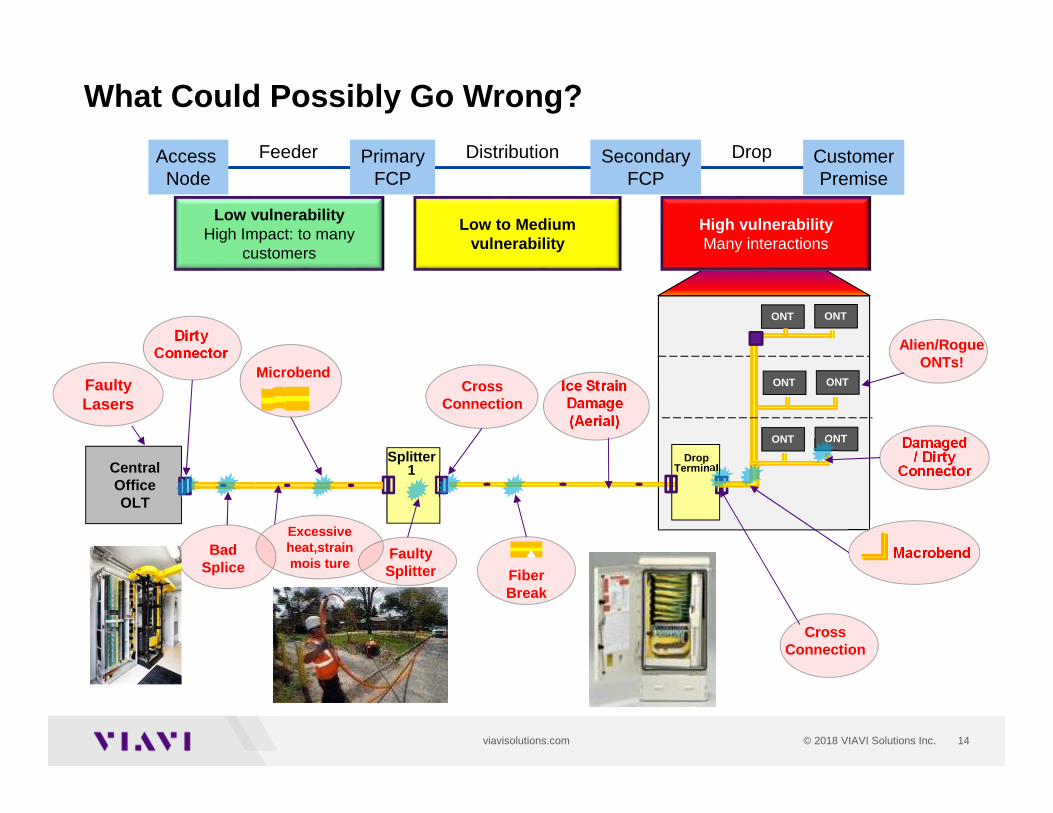
What Could Possibly Go Wrong?
Splitter1Central
OfficeOLT
DropTerminal
ONT ONT
ONT ONT
ONT ONT
Low vulnerabilityHigh Impact: to many
customers
Low to Medium vulnerability
High vulnerabilityMany interactions
PrimaryFCP
SecondaryFCP
Access Node
CustomerPremise
Feeder Distribution Drop
Damaged/ Dirty
Connector
Macrobend
Cross Connection
DirtyConnector
Microbend
BadSplice
FaultySplitter Fiber
Break
CrossConnection
Alien/RogueONTs!
Faulty Lasers
Excessive heat,strainmois ture
Ice Strain Damage (Aerial)
15© 2018 VIAVI Solutions Inc.viavisolutions.com
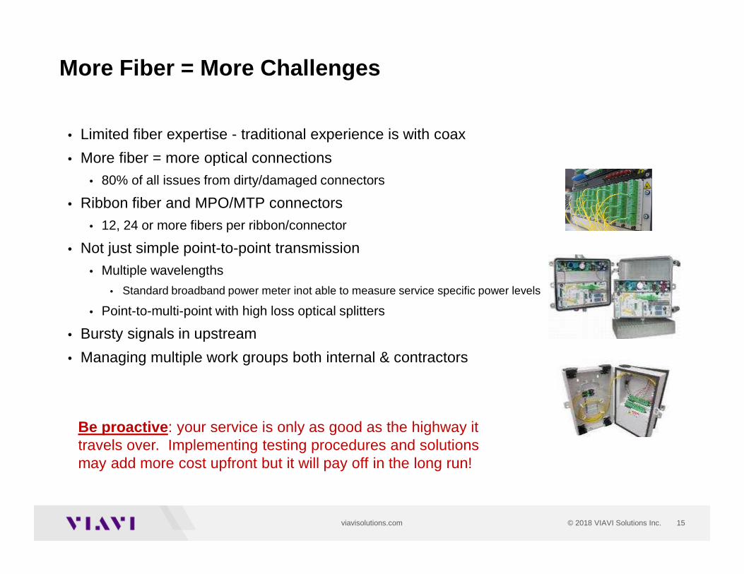
• Limited fiber expertise - traditional experience is with coax
• More fiber = more optical connections
• 80% of all issues from dirty/damaged connectors
• Ribbon fiber and MPO/MTP connectors
• 12, 24 or more fibers per ribbon/connector
• Not just simple point-to-point transmission
• Multiple wavelengths
• Standard broadband power meter inot able to measure service specific power levels
• Point-to-multi-point with high loss optical splitters
• Bursty signals in upstream
• Managing multiple work groups both internal & contractors
More Fiber = More Challenges
Be proactive: your service is only as good as the highway it travels over. Implementing testing procedures and solutions may add more cost upfront but it will pay off in the long run!
16© 2018 VIAVI Solutions Inc.viavisolutions.com
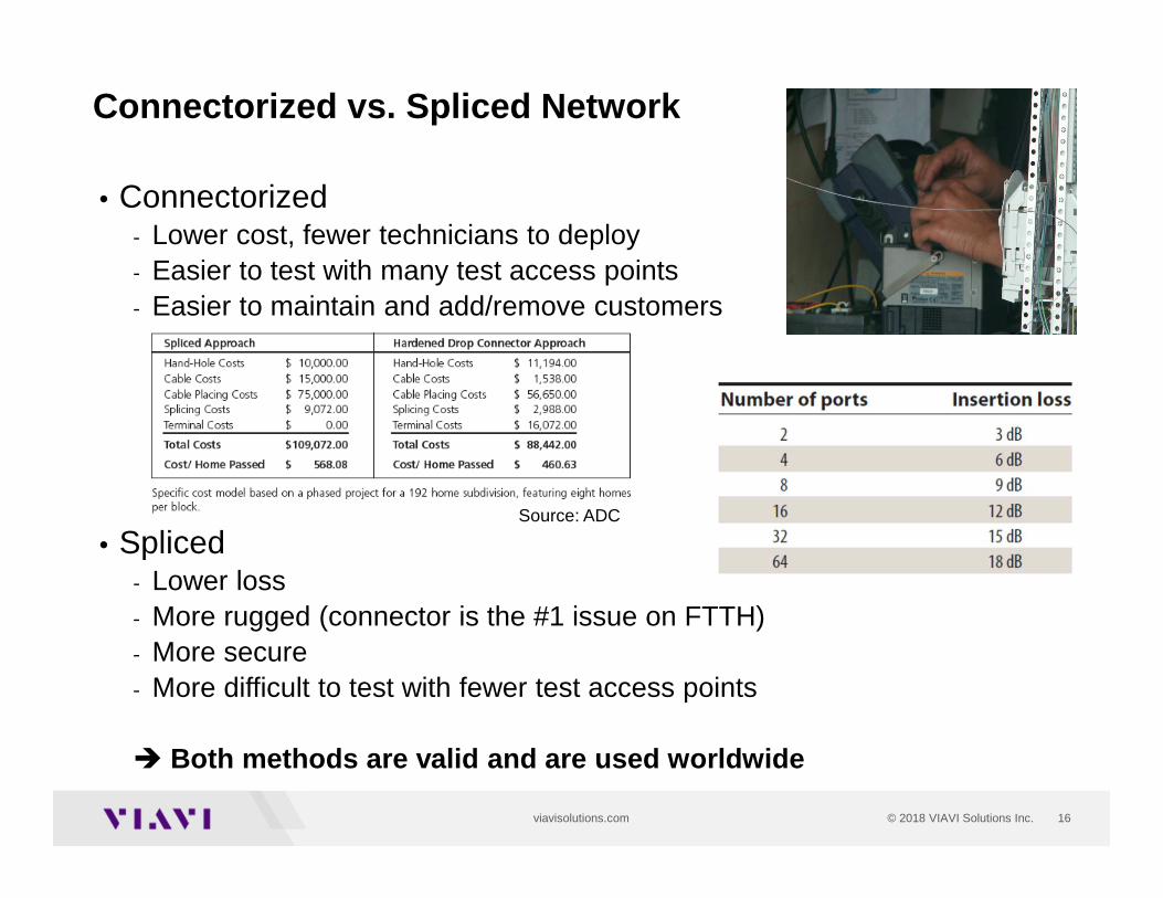
Connectorized vs. Spliced Network
• Connectorized- Lower cost, fewer technicians to deploy- Easier to test with many test access points- Easier to maintain and add/remove customers
• Spliced- Lower loss- More rugged (connector is the #1 issue on FTTH)- More secure- More difficult to test with fewer test access points
� Both methods are valid and are used worldwide
Source: ADC
17© 2018 VIAVI Solutions Inc.viavisolutions.com
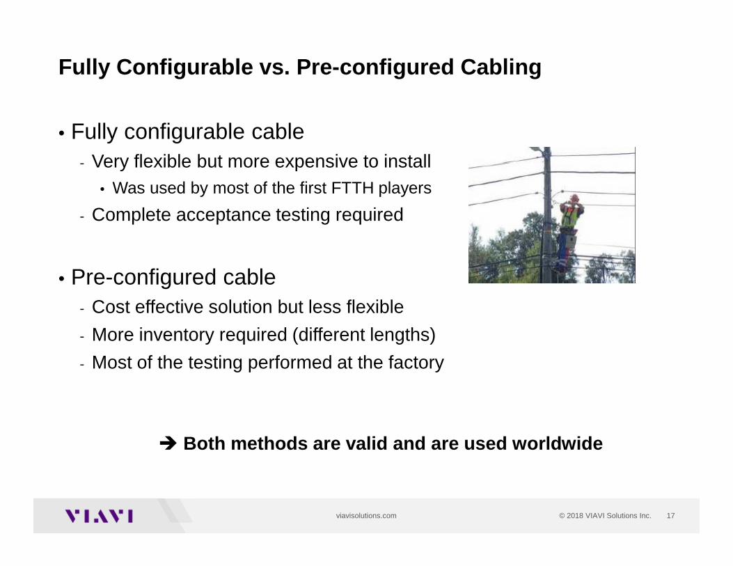
Fully Configurable vs. Pre-configured Cabling
• Fully configurable cable- Very flexible but more expensive to install
• Was used by most of the first FTTH players
- Complete acceptance testing required
• Pre-configured cable- Cost effective solution but less flexible
- More inventory required (different lengths)
- Most of the testing performed at the factory
� Both methods are valid and are used worldwide
18© 2018 VIAVI Solutions Inc.viavisolutions.com
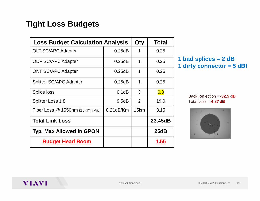
Tight Loss Budgets
Loss Budget Calculation Analysis Qty TotalOLT SC/APC Adapter 0.25dB 1 0.25
ODF SC/APC Adapter 0.25dB 1 0.25
ONT SC/APC Adapter 0.25dB 1 0.25
Splitter SC/APC Adapter 0.25dB 1 0.25
Splice loss 0.1dB 3 0.3
Splitter Loss 1:8 9.5dB 2 19.0
Fiber Loss @ 1550nm (15Km Typ.) 0.21dB/Km 15km 3.15
Total Link Loss 23.45dB
Typ. Max Allowed in GPON 25dB
Budget Head Room 1.55
Back Reflection = -32.5 dBTotal Loss = 4.87 dB
1 bad splices = 2 dB1 dirty connector = 5 dB!
19© 2018 VIAVI Solutions Inc.viavisolutions.com
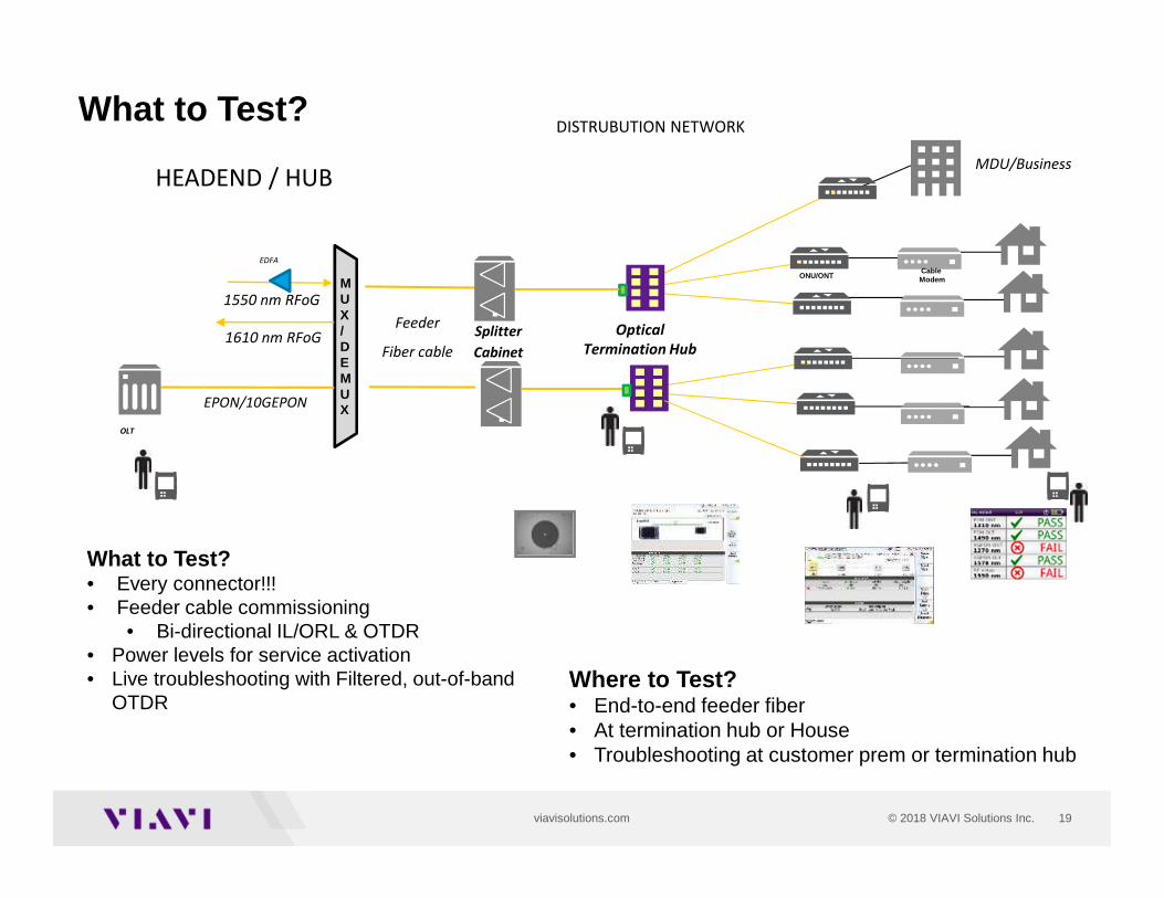
What to Test?
What to Test? • Every connector!!!• Feeder cable commissioning
• Bi-directional IL/ORL & OTDR • Power levels for service activation• Live troubleshooting with Filtered, out-of-band
OTDR
Splitter
Cabinet
Optical
Termination Hub
MDU/Business
Feeder
Fiber cable1610 nm RFoG
EDFA
1550 nm RFoGMUX/DEMUX
Cable Modem
OLT
ONU/ONT
EPON/10GEPON
DISTRUBUTION NETWORK
HEADEND / HUB
Where to Test? • End-to-end feeder fiber• At termination hub or House• Troubleshooting at customer prem or termination hub
20© 2018 VIAVI Solutions Inc.viavisolutions.com
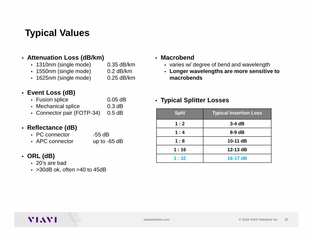
• Attenuation Loss (dB/km)• 1310nm (single mode) 0.35 dB/km• 1550nm (single mode) 0.2 dB/km• 1625nm (single mode) 0.25 dB/km
• Event Loss (dB)• Fusion splice 0.05 dB • Mechanical splice 0.3 dB • Connector pair (FOTP-34) 0.5 dB
• Reflectance (dB)• PC connector -55 dB• APC connector up to -65 dB
• ORL (dB)• 20’s are bad• >30dB ok, often >40 to 45dB
Typical Values
Split Typical Insertion Loss
1 : 2 3-4 dB
1 : 4 8-9 dB
1 : 8 10-11 dB
1 : 16 12-13 dB
1 : 32 16-17 dB
• Macrobend• varies w/ degree of bend and wavelength• Longer wavelengths are more sensitive to
macrobends
• Typical Splitter Losses
21
Connector InspectionAll Phases

22© 2018 VIAVI Solutions Inc.viavisolutions.com
Connectors
Blue = SC/UPCGreen = SC/APCBlue = Green!
SC/UPC
DROP CABLES
OptiTap
23© 2018 VIAVI Solutions Inc.viavisolutions.com
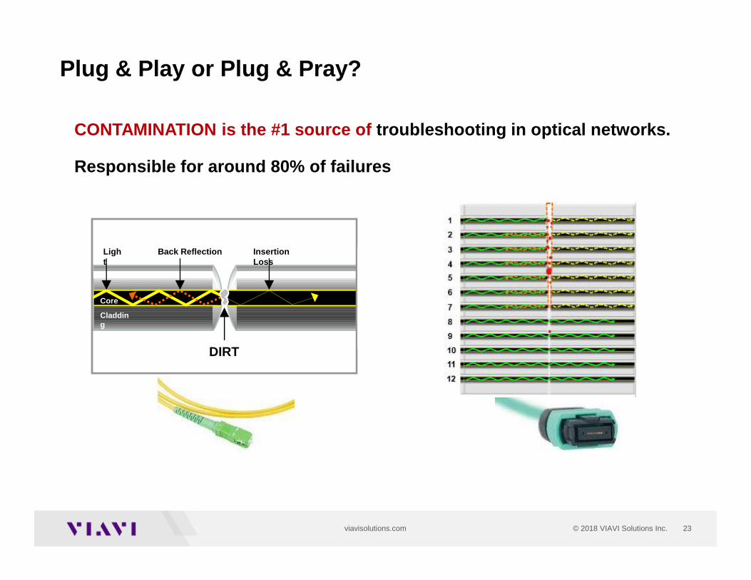
CONTAMINATION is the #1 source of troubleshooting in optical networks.
Responsible for around 80% of failures
DIRT
Core
Cladding
Back Reflection Insertion Loss
Light
Plug & Play or Plug & Pray?
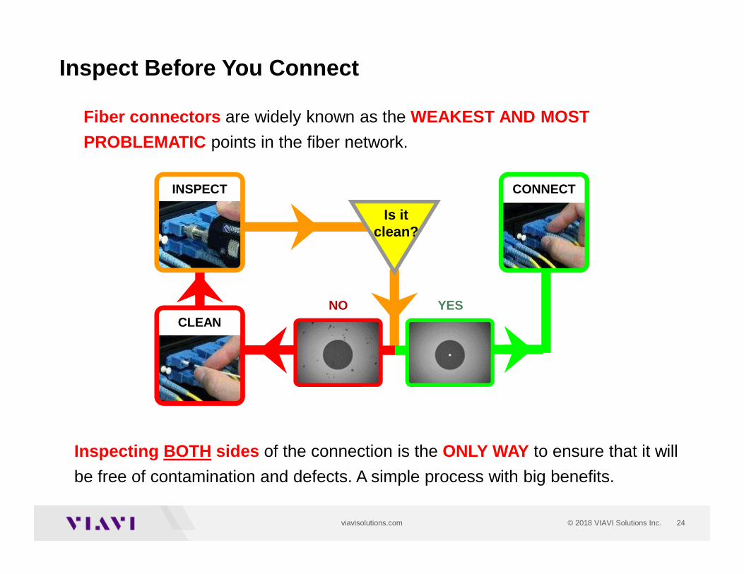
24© 2018 VIAVI Solutions Inc.viavisolutions.com
CONNECTINSPECT
CLEAN
Is itclean?
NO YES
Inspect Before You Connect
Inspecting BOTH sides of the connection is the ONLY WAY to ensure that it will
be free of contamination and defects. A simple process with big benefits.
Fiber connectors are widely known as the WEAKEST AND MOST
PROBLEMATIC points in the fiber network.
25© 2018 VIAVI Solutions Inc.viavisolutions.com
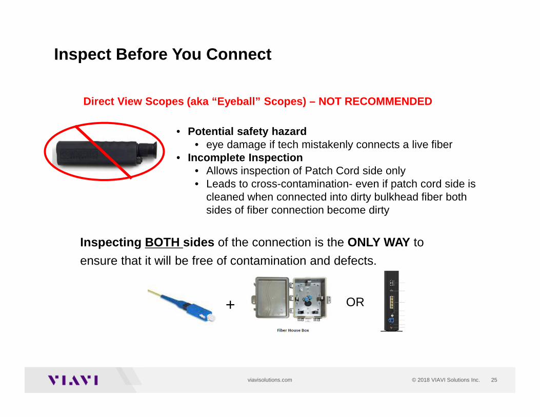
Inspect Before You Connect
• Potential safety hazard • eye damage if tech mistakenly connects a live fiber
• Incomplete Inspection• Allows inspection of Patch Cord side only• Leads to cross-contamination- even if patch cord side is
cleaned when connected into dirty bulkhead fiber both sides of fiber connection become dirty
Direct View Scopes (aka “Eyeball” Scopes) – NOT RECO MMENDED
Inspecting BOTH sides of the connection is the ONLY WAY to
ensure that it will be free of contamination and defects.
+ OR
26© 2018 VIAVI Solutions Inc.viavisolutions.com
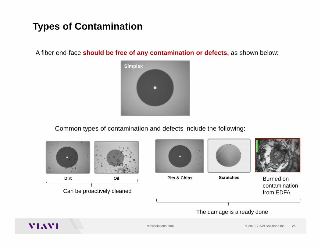
Types of Contamination
A fiber end-face should be free of any contamination or defects, as shown below:
Common types of contamination and defects include the following:
Dirt Oil Pits & Chips Scratches
Simplex
Can be proactively cleaned
The damage is already done
Burned on contamination from EDFA
27© 2018 VIAVI Solutions Inc.viavisolutions.com
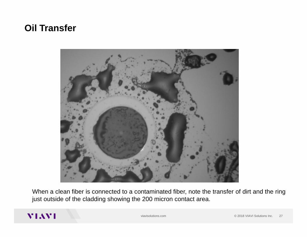
Oil Transfer
When a clean fiber is connected to a contaminated fiber, note the transfer of dirt and the ring just outside of the cladding showing the 200 micron contact area.
28© 2018 VIAVI Solutions Inc.viavisolutions.com
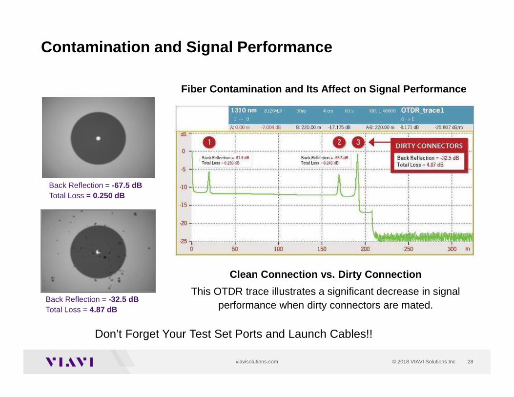
Contamination and Signal Performance
CLEAN CONNECTION1
DIRTY CONNECTION3
Back Reflection = -67.5 dBTotal Loss = 0.250 dB
Back Reflection = -32.5 dBTotal Loss = 4.87 dB
Fiber Contamination and Its Affect on Signal Perfor mance
Clean Connection vs. Dirty Connection
This OTDR trace illustrates a significant decrease in signal performance when dirty connectors are mated.
Don’t Forget Your Test Set Ports and Launch Cables!!
29© 2018 VIAVI Solutions Inc.viavisolutions.com
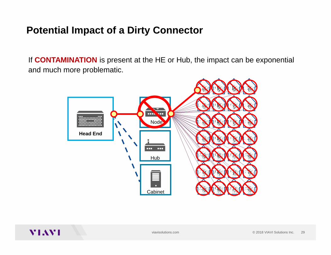
Potential Impact of a Dirty Connector
Head End
Cabinet
Node
Hub
If CONTAMINATION is present at the HE or Hub, the impact can be exponential and much more problematic.
30© 2018 VIAVI Solutions Inc.viavisolutions.com
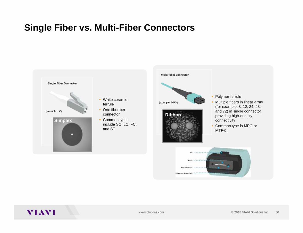
Single Fiber vs. Multi-Fiber Connectors
� White ceramic ferrule
� One fiber per connector
� Common types include SC, LC, FC, and ST
� Polymer ferrule
� Multiple fibers in linear array (for example, 8, 12, 24, 48, and 72) in single connector providing high-density connectivity
� Common type is MPO or MTP®
(example: LC)
(example: MPO)
SimplexRibbon
31© 2018 VIAVI Solutions Inc.viavisolutions.com
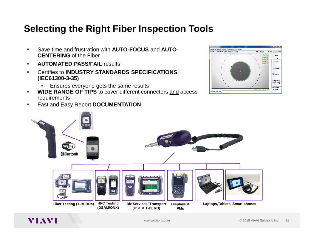
Selecting the Right Fiber Inspection Tools
� Save time and frustration with AUTO-FOCUS and AUTO-CENTERING of the Fiber
� AUTOMATED PASS/FAIL results
� Certifies to INDUSTRY STANDARDS SPECIFICATIONS (IEC61300-3-35)
• Ensures everyone gets the same results� WIDE RANGE OF TIPS to cover different connectors and access
requirements� Fast and Easy Report DOCUMENTATION
Fiber Testing (T-BERDs) HFC Testing (DSAM/ONX)
Biz Services/ Transport (HST & T-BERD)
Displays & PMs
Laptops,Tablets, Smart phones
32
Power Meters for PON/FTTH- Construction- Turn -up / Service Activation- Maintenance
33© 2018 VIAVI Solutions Inc.viavisolutions.com
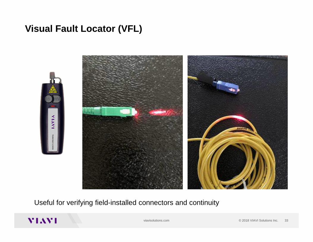
Visual Fault Locator (VFL)
Useful for verifying field-installed connectors and continuity
34© 2018 VIAVI Solutions Inc.viavisolutions.com
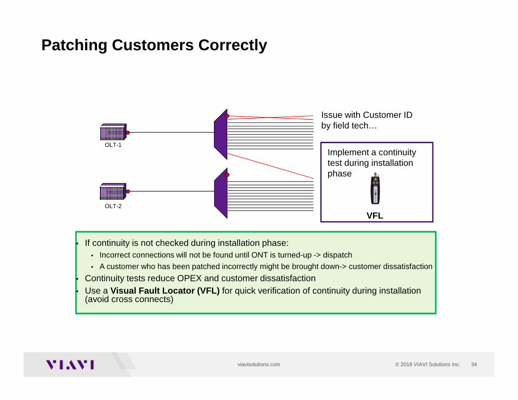
Patching Customers Correctly
• If continuity is not checked during installation phase:• Incorrect connections will not be found until ONT is turned-up -> dispatch
• A customer who has been patched incorrectly might be brought down-> customer dissatisfaction
• Continuity tests reduce OPEX and customer dissatisfaction• Use a Visual Fault Locator (VFL) for quick verification of continuity during installation
(avoid cross connects)
Issue with Customer ID by field tech…
Implement a continuitytest during installation phase
OLT-1
OLT-2
VFL
35© 2018 VIAVI Solutions Inc.viavisolutions.com
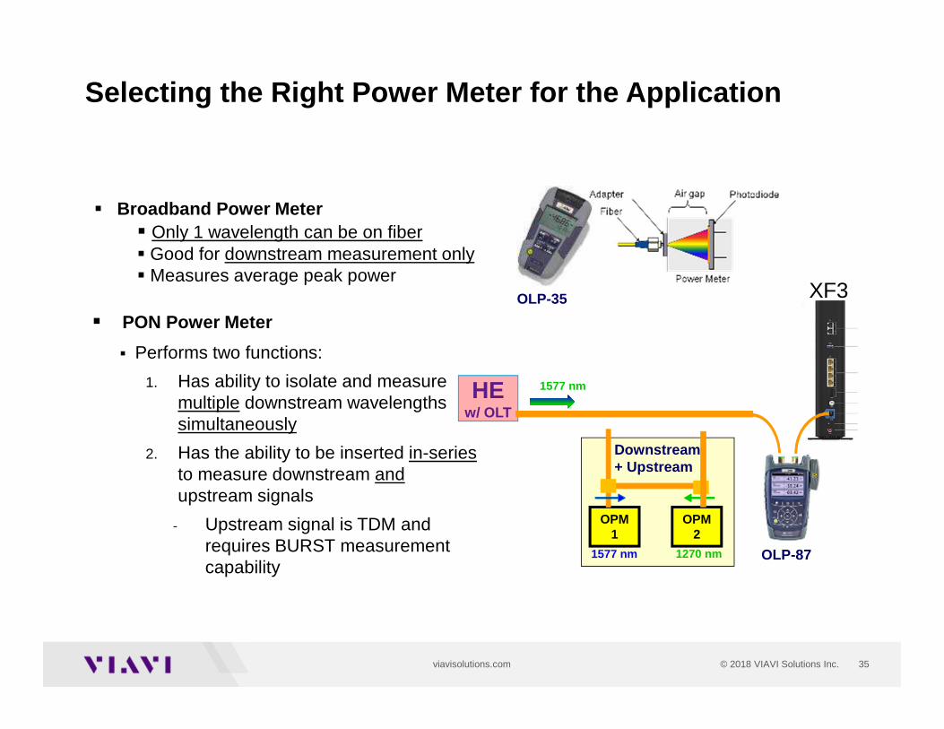
Selecting the Right Power Meter for the Application
� PON Power Meter
� Performs two functions:
1. Has ability to isolate and measure multiple downstream wavelengths simultaneously
2. Has the ability to be inserted in-seriesto measure downstream andupstream signals
- Upstream signal is TDM and requires BURST measurement capability
HE w/ OLT
1577 nm
� Broadband Power Meter� Only 1 wavelength can be on fiber� Good for downstream measurement only� Measures average peak power
OLP-35 XF3
OPM1
OPM2
1577 nm 1270 nm
Downstream+ Upstream
OLP-87
36© 2018 VIAVI Solutions Inc.viavisolutions.com
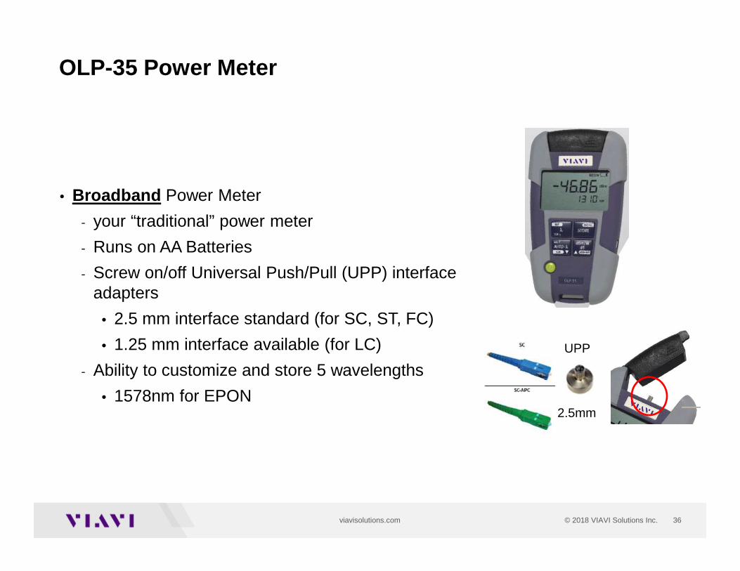
OLP-35 Power Meter
• Broadband Power Meter
- your “traditional” power meter
- Runs on AA Batteries
- Screw on/off Universal Push/Pull (UPP) interface adapters
• 2.5 mm interface standard (for SC, ST, FC)
• 1.25 mm interface available (for LC)
- Ability to customize and store 5 wavelengths
• 1578nm for EPON
UPP
2.5mm
37© 2018 VIAVI Solutions Inc.viavisolutions.com
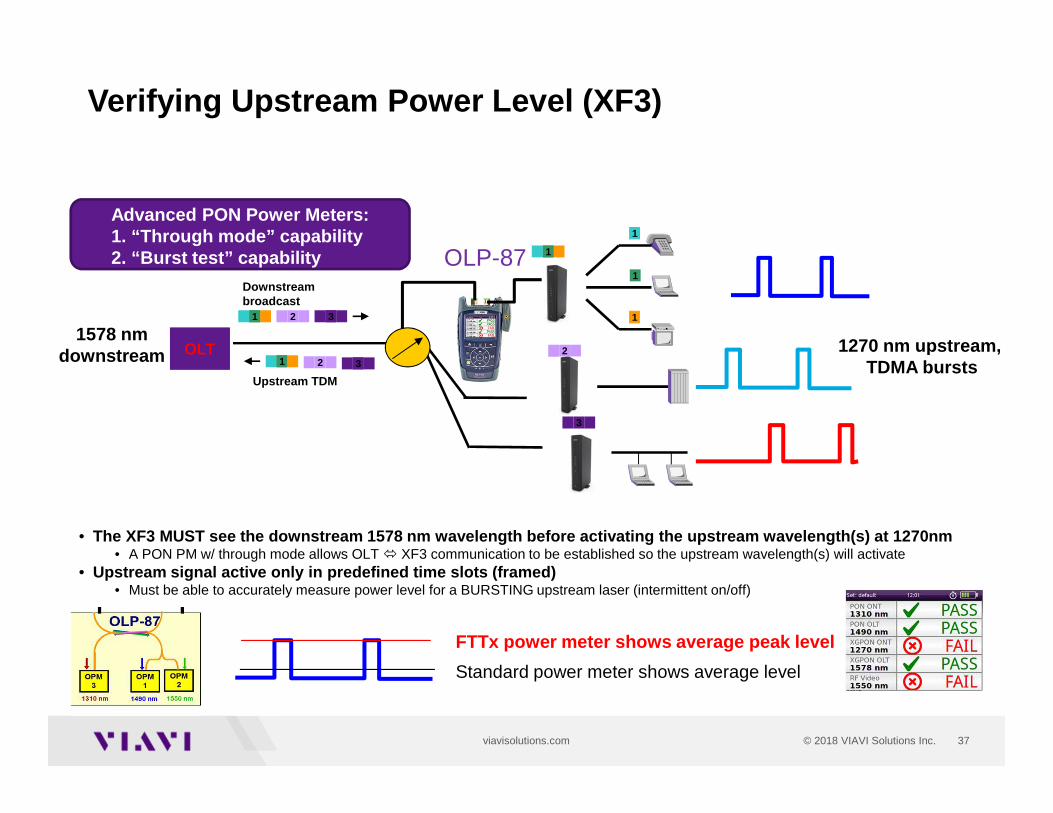
Verifying Upstream Power Level (XF3)
OLTOLT
Downstream broadcast
2 31
2
3
Upstream TDM
2 31
1
1
1
1
1270 nm upstream, TDMA bursts
Standard power meter shows average level
FTTx power meter shows average peak level
• The XF3 MUST see the downstream 1578 nm wavelength bef ore activating the upstream wavelength(s) at 1270nm• A PON PM w/ through mode allows OLT � XF3 communication to be established so the upstream wavelength(s) will activate
• Upstream signal active only in predefined time slots ( framed)• Must be able to accurately measure power level for a BURSTING upstream laser (intermittent on/off)
Advanced PON Power Meters:1. “Through mode” capability2. “Burst test” capability OLP-87
1578 nm downstream
38© 2018 VIAVI Solutions Inc.viavisolutions.com
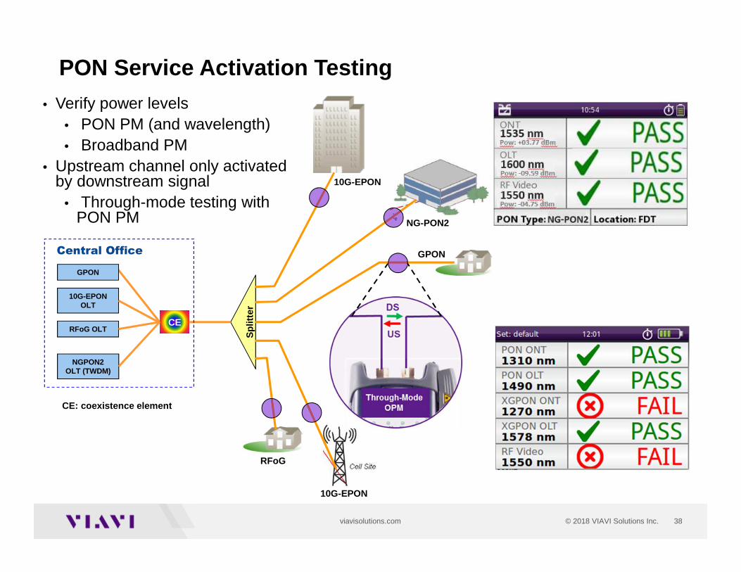
PON Service Activation Testing
10G-EPONOLT
RFoG OLT
NGPON2OLT (TWDM)
CE: coexistence element
GPON
CE
Spl
itter
RFoG
10G-EPON
GPON
NG-PON2
10G-EPON
Central Office
• Verify power levels • PON PM (and wavelength)• Broadband PM
• Upstream channel only activated by downstream signal
• Through-mode testing with PON PM
39© 2018 VIAVI Solutions Inc.viavisolutions.com
FTTH Maintenance
• Level 1: Verify power level at ONU/ONT
- Connector microscope
- Broadband power meter
• Level 2: Verify individual service power levels and ONU/ONT operation
- Connector microscope
- PON power meter
• Level 3: Troubleshooting no power and fiber issues
- Connector microscope
- PON OTDR with 1650nm
40© 2018 VIAVI Solutions Inc.viavisolutions.com
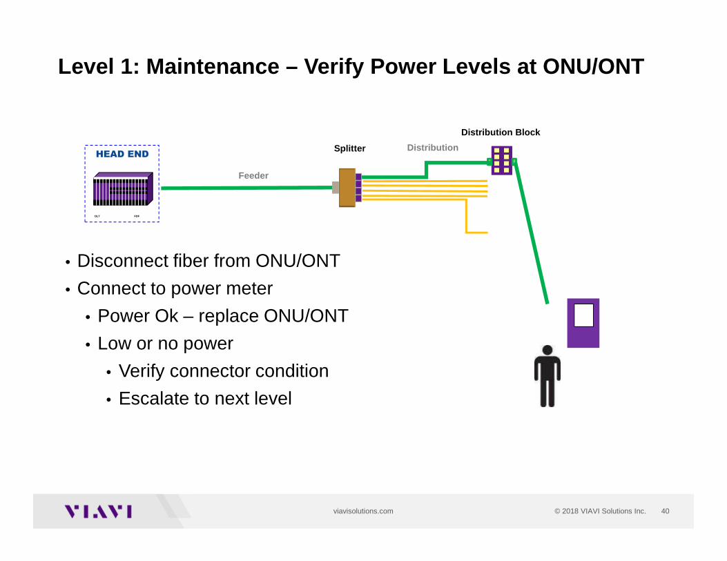
• Disconnect fiber from ONU/ONT
• Connect to power meter
• Power Ok – replace ONU/ONT
• Low or no power
• Verify connector condition
• Escalate to next level
Feeder
Distribution Block
SplitterHEAD END
OLT FDF
Distribution
Level 1: Maintenance – Verify Power Levels at ONU/ON T
41© 2018 VIAVI Solutions Inc.viavisolutions.com
1490/1550/1577 nm
OLT1610 nm
PONONT
1270/1310 nm
1490/1550/1577 nm
Block Diagram
RFoGCPE
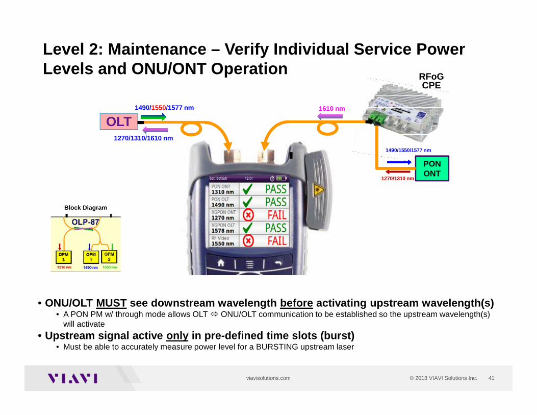
Level 2: Maintenance – Verify Individual Service Pow er Levels and ONU/ONT Operation
1270/1310/1610 nm
• ONU/OLT MUST see downstream wavelength before activating upstream wavelength(s)• A PON PM w/ through mode allows OLT � ONU/OLT communication to be established so the upstream wavelength(s)
will activate
• Upstream signal active only in pre-defined time slots (burst)• Must be able to accurately measure power level for a BURSTING upstream laser
42© 2018 VIAVI Solutions Inc.viavisolutions.com
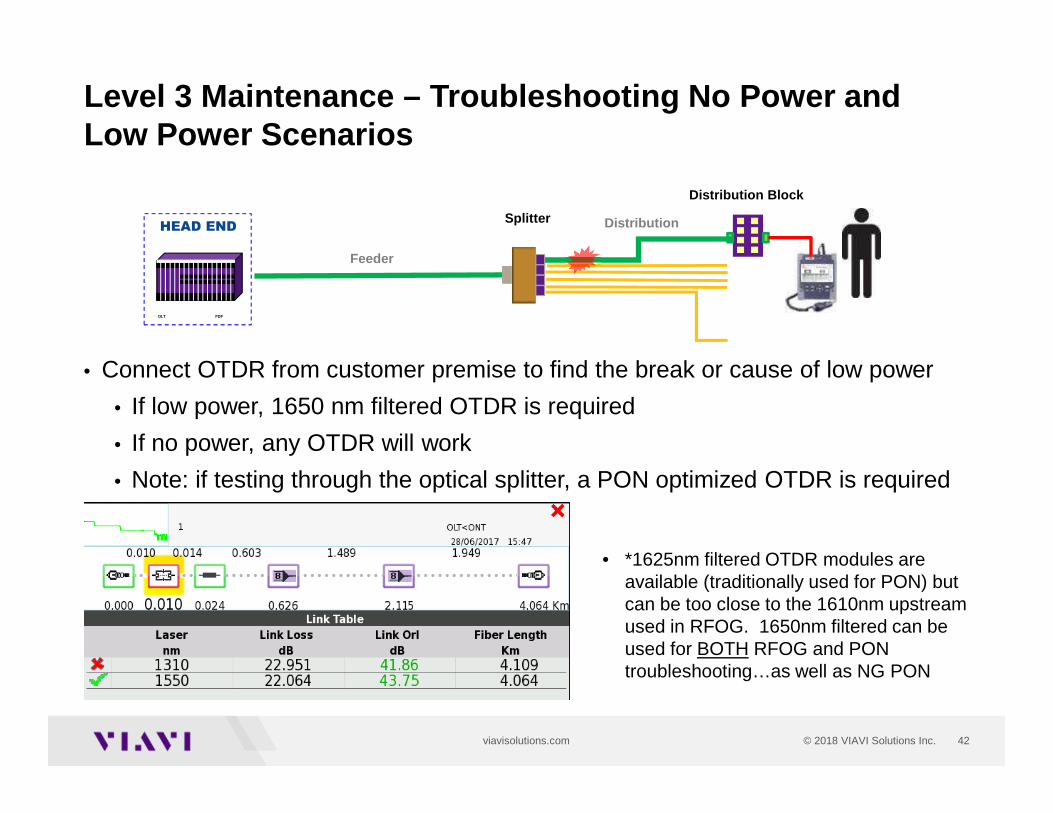
Level 3 Maintenance – Troubleshooting No Power and Low Power Scenarios
Feeder
Distribution Block
SplitterHEAD END
OLT FDF
Distribution
• Connect OTDR from customer premise to find the break or cause of low power
• If low power, 1650 nm filtered OTDR is required
• If no power, any OTDR will work
• Note: if testing through the optical splitter, a PON optimized OTDR is required
• *1625nm filtered OTDR modules are available (traditionally used for PON) but can be too close to the 1610nm upstream used in RFOG. 1650nm filtered can be used for BOTH RFOG and PON troubleshooting…as well as NG PON
43
OTDRs for PON/FTTH- Construction- Maintenance
44© 2018 VIAVI Solutions Inc.viavisolutions.com
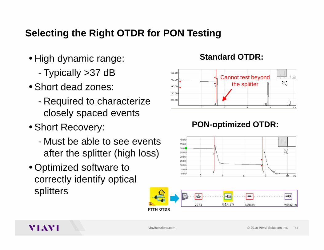
Selecting the Right OTDR for PON Testing
• High dynamic range:
- Typically >37 dB
• Short dead zones:
- Required to characterize closely spaced events
• Short Recovery:
- Must be able to see events after the splitter (high loss)
• Optimized software to correctly identify optical splitters
PON-optimized OTDR:
Standard OTDR:
Cannot test beyond the splitter
45© 2018 VIAVI Solutions Inc.viavisolutions.com
Selecting the Right OTDR for PON Testing
• Wavelengths:
- Construction: 1310/1550nm
- In-Service Maintenance:
• Filtered OTDR port
• Out-of-band 1625nm or 1650nm (preferred)
• Does not disrupt other customers
• Ability to generate pdf reports
46© 2018 VIAVI Solutions Inc.viavisolutions.com
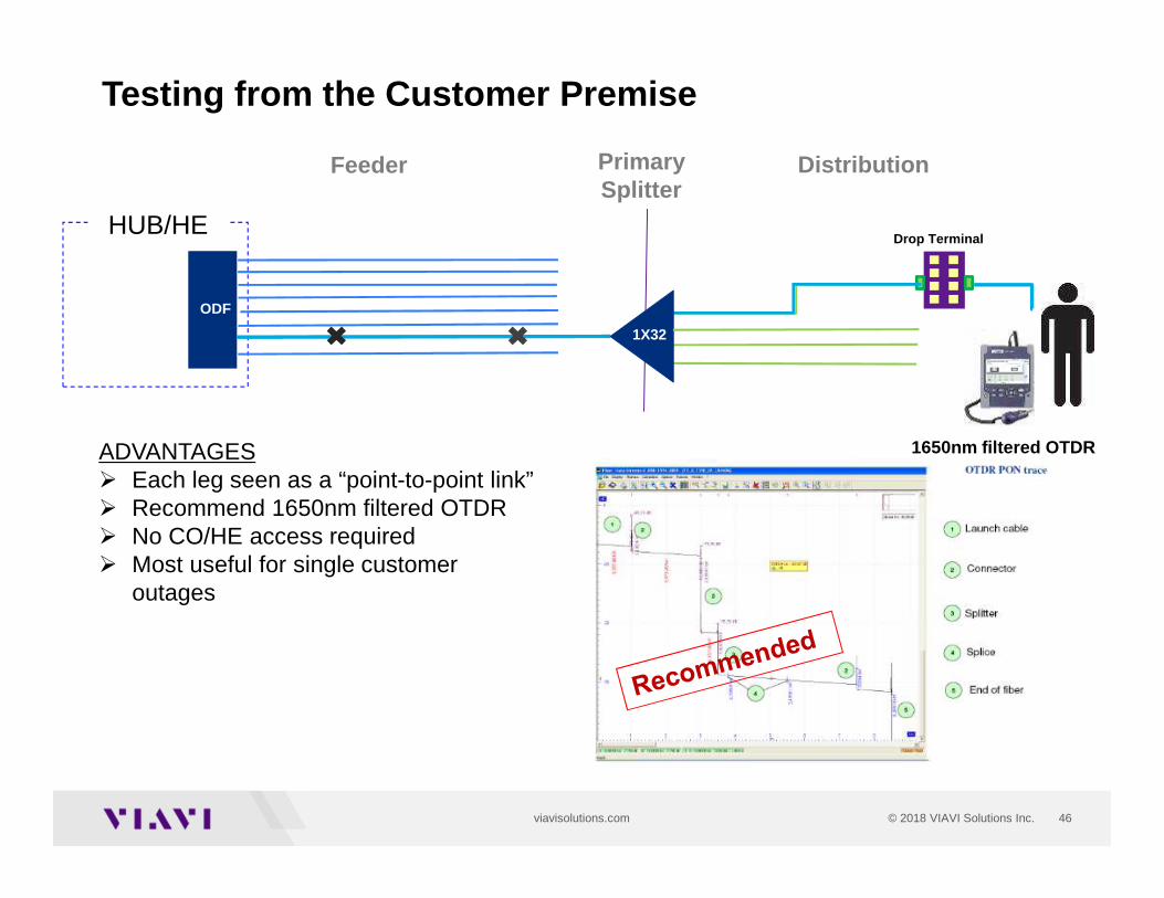
Testing from the Customer Premise
Feeder
Drop Terminal
PrimarySplitter
Central Office
ODF
Distribution
1X32
ADVANTAGES� Each leg seen as a “point-to-point link” � Recommend 1650nm filtered OTDR� No CO/HE access required� Most useful for single customer
outages
1650nm filtered OTDR
HUB/HE
47© 2018 VIAVI Solutions Inc.viavisolutions.com
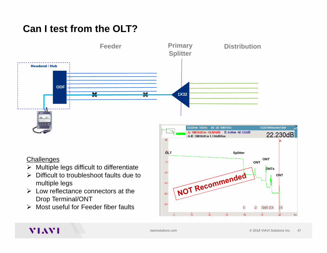
PrimarySplitter
Can I test from the OLT?
Feeder
Headend / Hub
ODF
Distribution
1X32
OLT Splitter
ONT
ONTs
ONTONTChallenges
� Multiple legs difficult to differentiate� Difficult to troubleshoot faults due to
multiple legs� Low reflectance connectors at the
Drop Terminal/ONT � Most useful for Feeder fiber faults
48© 2018 VIAVI Solutions Inc.viavisolutions.com
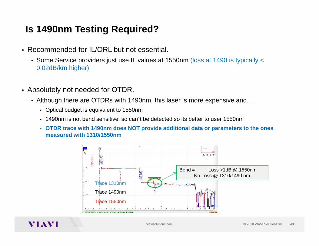
• Recommended for IL/ORL but not essential.• Some Service providers just use IL values at 1550nm (loss at 1490 is typically <
0.02dB/km higher)
• Absolutely not needed for OTDR.• Although there are OTDRs with 1490nm, this laser is more expensive and…
• Optical budget is equivalent to 1550nm
• 1490nm is not bend sensitive, so can´t be detected so its better to user 1550nm
• OTDR trace with 1490nm does NOT provide additional data or parameters to the ones measured with 1310/1550nm
Is 1490nm Testing Required?
Trace 1310nm
Trace 1490nm
Trace 1550nm
Bend = Loss >1dB @ 1550nmNo Loss @ 1310/1490 nm
49
Service Verification:- PON- Ethernet- Wifi
50© 2018 VIAVI Solutions Inc.viavisolutions.com
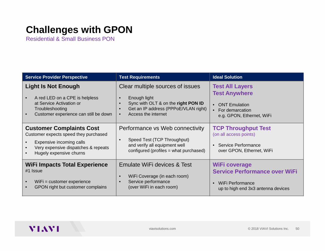
Challenges with GPONResidential & Small Business PON
Service Provider Perspective Test Requirements Ideal Solution
Light Is Not Enough
• A red LED on a CPE is helplessat Service Activation or Troubleshooting
• Customer experience can still be down
Clear multiple sources of issues
• Enough light• Sync with OLT & on the right PON ID• Get an IP address (PPPoE/VLAN right)• Access the internet
Test All LayersTest Anywhere
• ONT Emulation• For demarcation
e.g. GPON, Ethernet, WiFi
Customer Complaints CostCustomer expects speed they purchased
• Expensive incoming calls• Very expensive dispatches & repeats• Hugely expensive churns
Performance vs Web connectivity
• Speed Test (TCP Throughput)and verify all equipment well configured (profiles = what purchased)
TCP Throughput Test(on all access points)
• Service Performance over GPON, Ethernet, WiFi
WiFi Impacts Total Experience#1 Issue
• WiFi = customer experience• GPON right but customer complains
Emulate WiFi devices & Test
• WiFi Coverage (in each room)• Service performance
(over WiFi in each room)
WiFi coverageService Performance over WiFi
• WiFi Performance up to high end 3x3 antenna devices
51© 2018 VIAVI Solutions Inc.viavisolutions.com
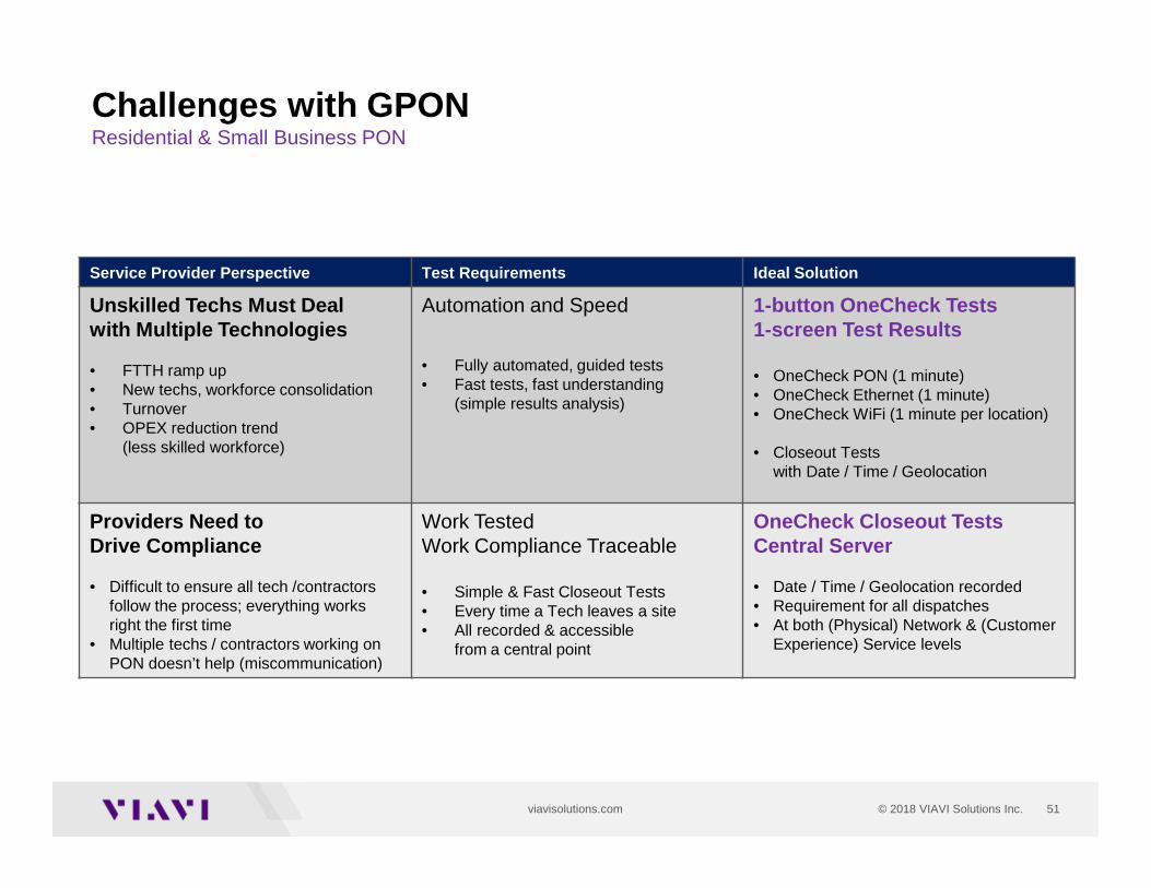
Challenges with GPONResidential & Small Business PON
Service Provider Perspective Test Requirements Ideal Solution
Unskilled Techs Must Deal with Multiple Technologies
• FTTH ramp up• New techs, workforce consolidation• Turnover• OPEX reduction trend
(less skilled workforce)
Automation and Speed
• Fully automated, guided tests• Fast tests, fast understanding
(simple results analysis)
1-button OneCheck Tests1-screen Test Results
• OneCheck PON (1 minute)• OneCheck Ethernet (1 minute) • OneCheck WiFi (1 minute per location)
• Closeout Tests with Date / Time / Geolocation
Providers Need to Drive Compliance
• Difficult to ensure all tech /contractors follow the process; everything works right the first time
• Multiple techs / contractors working on PON doesn’t help (miscommunication)
Work Tested Work Compliance Traceable
• Simple & Fast Closeout Tests • Every time a Tech leaves a site• All recorded & accessible
from a central point
OneCheck Closeout TestsCentral Server
• Date / Time / Geolocation recorded• Requirement for all dispatches• At both (Physical) Network & (Customer
Experience) Service levels
52© 2018 VIAVI Solutions Inc.viavisolutions.com
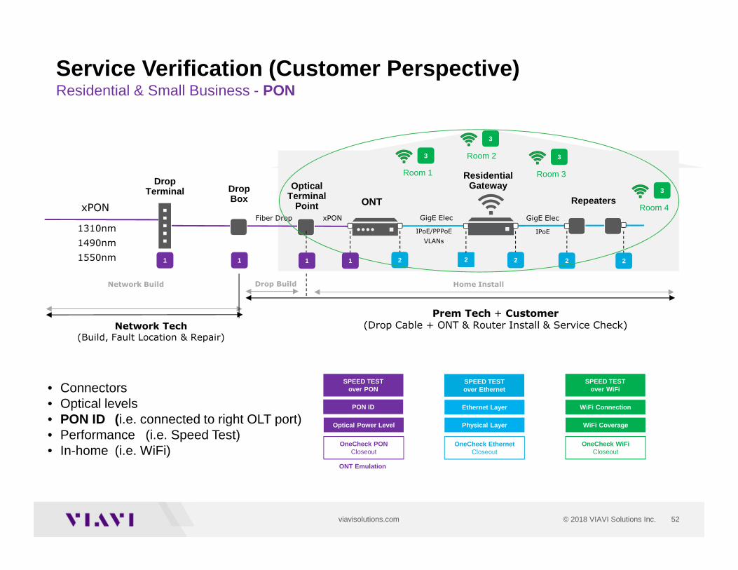
ONT Emulation
Network Tech
(Build, Fault Location & Repair)
Drop Build
Service Verification (Customer Perspective)Residential & Small Business - PON
ONT
IPoE/PPPoE
VLANs
GigE Elec
xPON
IPoE
Fiber Drop
SPEED TESTover Ethernet
Home Install
xPON
Network Build
Prem Tech + Customer(Drop Cable + ONT & Router Install & Service Check)
PON ID
SPEED TESTover PON
Optical Power Level
OneCheck PONCloseout
1310nm
1490nm
1550nm
OpticalTerminal
Point
Drop Terminal
Repeaters
``
OneCheck EthernetCloseout
WiFi Coverage
SPEED TESTover WiFi
OneCheck WiFiCloseout
Residential Gateway
GigE Elec
11 1 2 22 2 2
3
DropBox
1
Room 3
3
Room 23
Room 1
3
Room 4
Ethernet Layer
Physical Layer
WiFi Connection
• Connectors• Optical levels• PON ID (i.e. connected to right OLT port)• Performance (i.e. Speed Test)• In-home (i.e. WiFi)
53© 2018 VIAVI Solutions Inc.viavisolutions.com
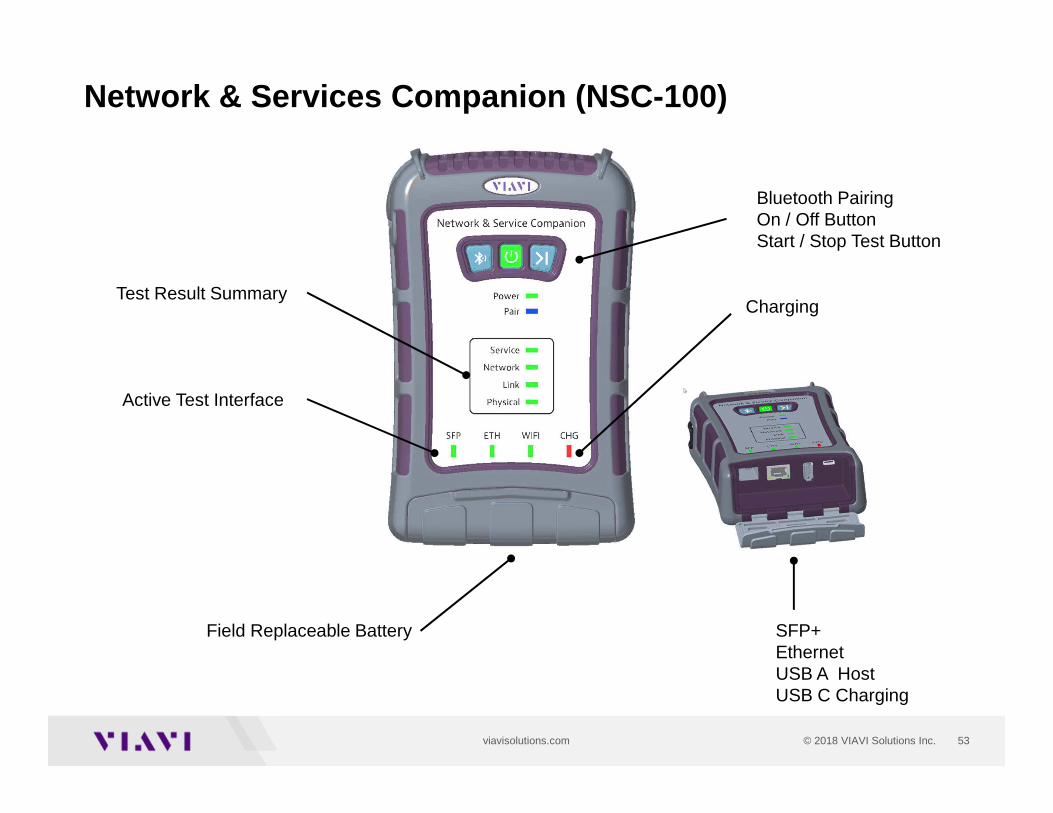
Active Test Interface
Test Result Summary
Bluetooth PairingOn / Off ButtonStart / Stop Test Button
Charging
Field Replaceable Battery SFP+Ethernet USB A Host USB C Charging
Network & Services Companion (NSC -100)
54© 2018 VIAVI Solutions Inc.viavisolutions.com
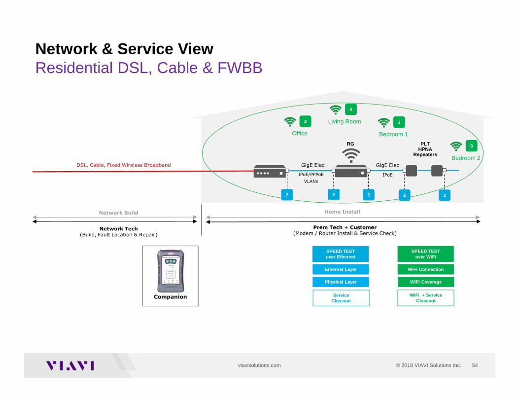
Network Tech(Build, Fault Location & Repair)
Network & Service ViewResidential DSL, Cable & FWBB
IPoE/PPPoE
VLANs
GigE Elec
IPoE
Home InstallNetwork Build
Prem Tech + Customer(Modem / Router Install & Service Check)
GigE Elec
3
Bedroom 1
3
Living Room3
Office
3
Bedroom 2DSL, Cable, Fixed Wireless Broadband
SPEED TESTover Ethernet
Service Closeout
WiFi Coverage
SPEED TESTover WiFi
WiFi + ServiceCloseout
2 22 2 2
``
PLTHPNA
Repeaters
RG
Companion
Ethernet Layer
Physical Layer
WiFi Connection
55© 2018 VIAVI Solutions Inc.viavisolutions.com
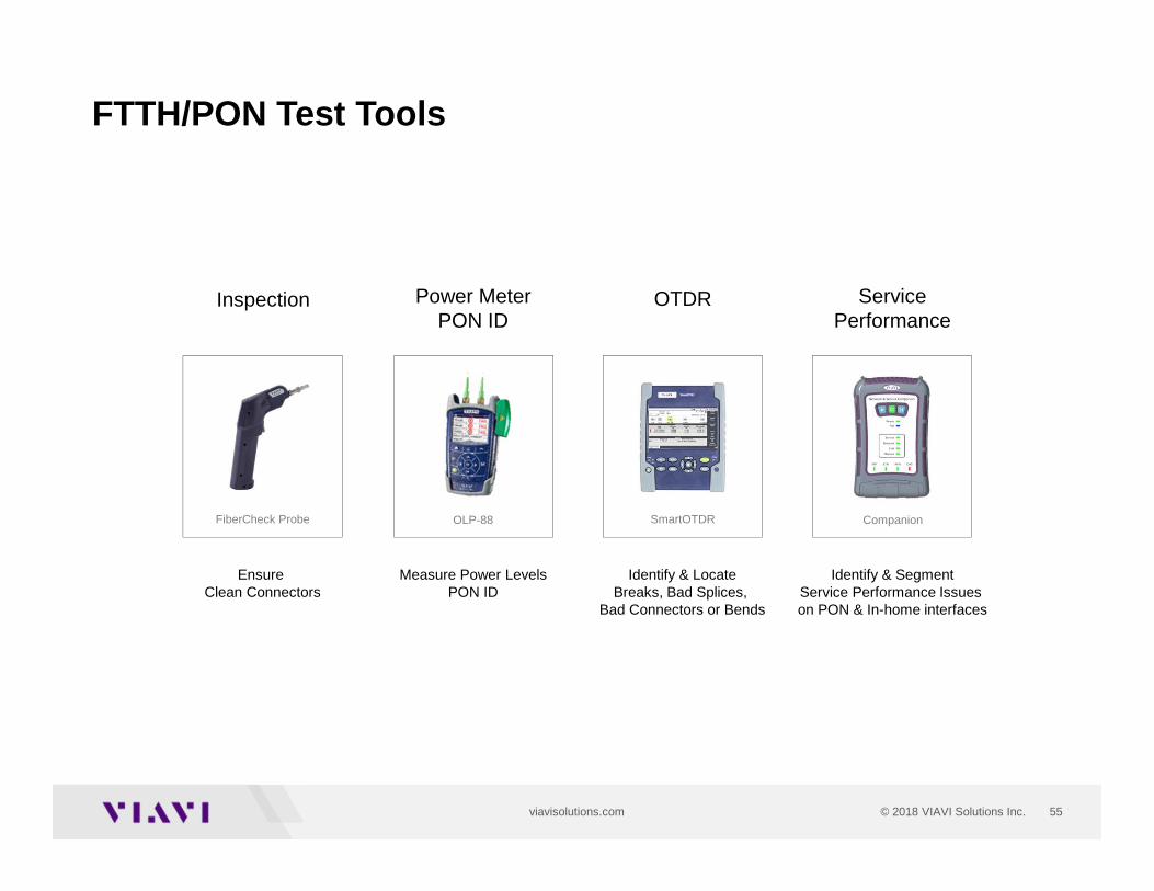
Inspection Power MeterPON ID
OTDR
Ensure Clean Connectors
Measure Power LevelsPON ID
Identify & LocateBreaks, Bad Splices,
Bad Connectors or Bends
FiberCheck Probe SmartOTDROLP-88
ServicePerformance
Identify & SegmentService Performance Issues on PON & In-home interfaces
Companion
FTTH/PON Test Tools
56© 2018 VIAVI Solutions Inc.viavisolutions.com
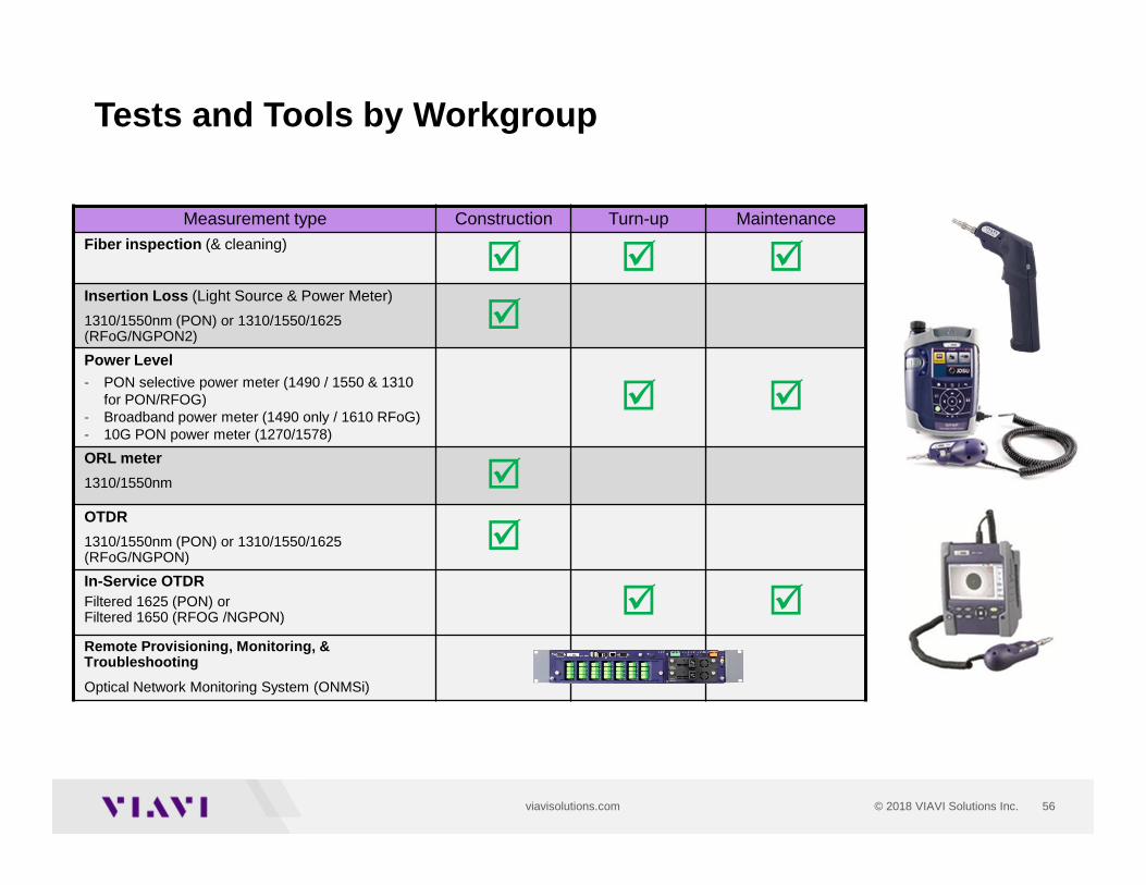
Tests and Tools by Workgroup
Measurement type Construction Turn-up MaintenanceFiber inspection (& cleaning)
� � �Insertion Loss (Light Source & Power Meter)
1310/1550nm (PON) or 1310/1550/1625 (RFoG/NGPON2)
�Power Level- PON selective power meter (1490 / 1550 & 1310
for PON/RFOG)- Broadband power meter (1490 only / 1610 RFoG)- 10G PON power meter (1270/1578)
� �
ORL meter
1310/1550nm �OTDR
1310/1550nm (PON) or 1310/1550/1625 (RFoG/NGPON)
�In-Service OTDRFiltered 1625 (PON) or Filtered 1650 (RFOG /NGPON) � �Remote Provisioning, Monitoring, & Troubleshooting
Optical Network Monitoring System (ONMSi)
viavisolutions.com