Embed Size (px)
Citation preview

ePlan Handbook Version 2.2
May 2019

Photo credit
The photo in the front sheet has been downloaded from the following link and edited:
https://pixabay.com/en/blogging-blogger-office-business-336376/
© The State of Victoria Department of Environment, Land, Water and Planning 2019
This work is licensed under a Creative Commons Attribution 4.0 International licence. You are free to re-use the work under that licence, on the condition that you credit the State of Victoria as author. The licence does not apply to any images, photographs or branding, including the Victorian Coat of Arms, the Victorian Government logo and the
Department of Environment, Land, Water and Planning (DELWP) logo. To view a copy of this licence, visit http://creativecommons.org/licenses/by/4.0/
Disclaimer
This publication may be of assistance to you but the State of Victoria and its employees do not guarantee that the publication is without flaw of any kind or is wholly appropriate for your particular purposes and therefore disclaims all liability for any error, loss or other consequence which may arise from you relying on any information in this publication.
Accessibility
If you would like to receive this publication in an alternative format, please telephone the
DELWP Customer Service Centre on 136186, email [email protected],
or via the National Relay Service on 133 677 www.relayservice.com.au. This document is
also available on the internet at www.delwp.vic.gov.au.

ePlan Handbook
Version 2.2
i
ePlan Handbook Version 2.2
May 2019
ii ePlan Handbook
Version 2.2
Contents
1. Introduction ................................................................................................................... 1
2. Element Naming Conventions ..................................................................................... 2
2.1 Parcels ........................................................................................................................................................ 2
2.2 Geometry, Points and Monuments .......................................................................................................... 3
2.3 Observations and Instruments ................................................................................................................. 3
2.4 Plan Feature ............................................................................................................................................... 4
2.5 Annotation .................................................................................................................................................. 4
3. Administrative Information .......................................................................................... 5
3.1 Annotations ................................................................................................................................................ 5
3.1.1 Annotation Types ................................................................................................................................. 5
3.2 General ePlan Information ........................................................................................................................ 6
3.3 Coordinate System .................................................................................................................................... 7
3.4 Survey Header ............................................................................................................................................ 7
3.4.1 Survey Header Attributes .................................................................................................................... 7
3.4.2 SurveyHeader Components ................................................................................................................ 7
4. Point and Line Definition ............................................................................................ 11
4.1 Traverses and Radiations ....................................................................................................................... 11
4.2 Plan Features ........................................................................................................................................... 13
4.3 Survey Marks ........................................................................................................................................... 15
5. Parcel Definition.......................................................................................................... 19
5.1 Primary Parcels ........................................................................................................................................ 19
5.1.1 Lots ...................................................................................................................................................... 19
5.1.2 Stage Lots ........................................................................................................................................... 20
5.1.3 Roads .................................................................................................................................................. 20
5.1.4 Reserves ............................................................................................................................................. 21
5.1.5 Common Property .............................................................................................................................. 21
5.1.6 Crown Parcels .................................................................................................................................... 21
5.2 Secondary Interest .................................................................................................................................. 22
5.2.1 Easements .......................................................................................................................................... 22
5.2.2 Restrictions ........................................................................................................................................ 25
5.2.3 Depth Limitation ................................................................................................................................. 27
5.2.4 Owners Corporation .......................................................................................................................... 28
5.3 Considerations in ePlan Creation .......................................................................................................... 29
5.3.1 Title Connection for Primary Parcels ............................................................................................... 29
5.3.2 Road Splays ........................................................................................................................................ 33
5.3.3 Secondary Interest Geometry Rules ................................................................................................ 33
5.3.4 Multipart Parcels ................................................................................................................................ 36
5.3.5 Donut Parcels ..................................................................................................................................... 37
5.3.6 Closure ................................................................................................................................................ 39

ePlan Handbook
Version 2.2
iii
6. Victorian Reference Data List .................................................................................... 41
6.1 Easement Purposes ................................................................................................................................ 41
6.2 Road Type ................................................................................................................................................ 42
6.3 Road Name Suffix .................................................................................................................................... 43
6.4 Survey Mark Type .................................................................................................................................... 43
6.5 Survey Mark Condition ........................................................................................................................... 43
6.6 Survey Mark State.................................................................................................................................... 43
6.7 Observations ............................................................................................................................................ 43


ePlan Handbook
Version 2.2
1
1. Introduction
This document provides an overview of ePlan components, and the requirements for creating a valid ePlan
file based on the Victorian ePlan LandXML Protocol.
2 ePlan Handbook
Version 2.2
2. Element Naming Conventions
Elements in Victorian ePlans must follow specified naming convention. According to the schema, all ePlan elements must have a unique identifier stored in elements @name attribute.
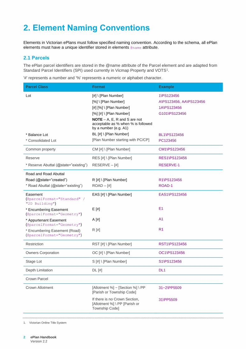
2.1 Parcels
The ePlan parcel identifiers are stored in the @name attribute of the Parcel element and are adapted from
Standard Parcel Identifiers (SPI) used currently in Vicmap Property and VOTS1.
'#' represents a number and '%' represents a numeric or alphabet character.
Parcel Class Format Example
Lot
* Balance Lot
* Consolidated Lot
[#] \ [Plan Number]
[%] \ [Plan Number]
[#] [%] \ [Plan Number]
[%] [#] \ [Plan Number]
NOTE – A, E, R and S are not acceptable as % when % is followed by a number (e.g. A1)
BL [#] \ [Plan Number]
[Plan Number starting with PC/CP]
1\PS123456
A\PS123456, AA\PS123456
1A\PS123456
G101\PS123456
BL1\PS123456
PC123456
Common property CM [#] \ [Plan Number] CM1\PS123456
Reserve
* Reserve Abuttal (@state=”existing”)
RES [#] \ [Plan Number]
RESERVE – [#]
RES1\PS123456
RESERVE-1
Road and Road Abuttal
Road (@state=”created”)
* Road Abuttal (@state=”existing”)
R [#] \ [Plan Number]
ROAD – [#]
R1\PS123456
ROAD-1
Easement (@parcelFormat="Standard" /
"2D Building")
* Encumbering Easement (@parcelFormat="Geometry")
* Appurtenant Easement (@parcelFormat="Geometry")
* Encumbering Easement (Road) (@parcelFormat="Geometry")
EAS [#] \ [Plan Number]
E [#]
A [#]
R [#]
EAS1\PS123456
E1
A1
R1
Restriction RST [#] \ [Plan Number] RST1\PS123456
Owners Corporation OC [#] \ [Plan Number] OC1\PS123456
Stage Lot S [#] \ [Plan Number] S1\PS123456
Depth Limitation DL [#] DL1
Crown Parcel
Crown Allotment [Allotment %] ~ [Section %] \ PP
[Parish or Township Code]
If there is no Crown Section,
[Allotment %] \ PP [Parish or
Township Code]
31~2\PP5509
31\PP5509
1. Victorian Online Title System
ePlan Handbook
Version 2.2
3
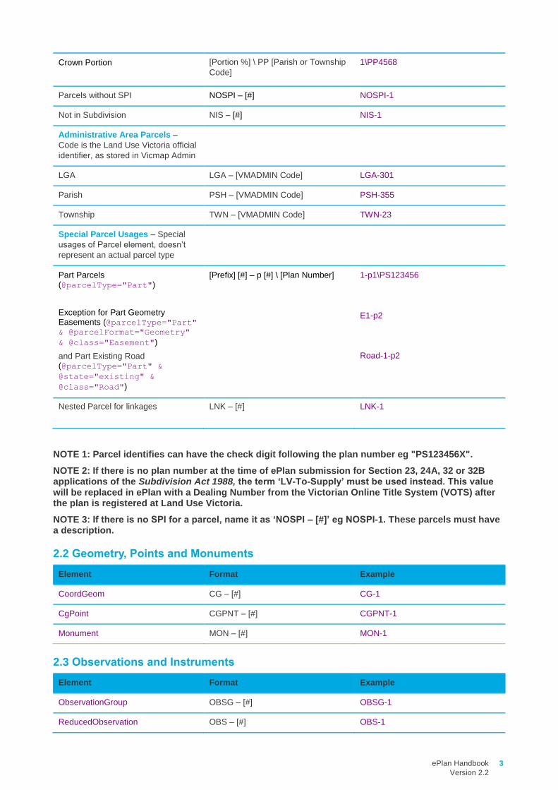
Crown Portion
[Portion %] \ PP [Parish or Township
Code]
1\PP4568
Parcels without SPI NOSPI – [#] NOSPI-1
Not in Subdivision NIS – [#] NIS-1
Administrative Area Parcels –
Code is the Land Use Victoria official
identifier, as stored in Vicmap Admin
LGA LGA – [VMADMIN Code] LGA-301
Parish PSH – [VMADMIN Code] PSH-355
Township TWN – [VMADMIN Code] TWN-23
Special Parcel Usages – Special
usages of Parcel element, doesn’t
represent an actual parcel type
Part Parcels (@parcelType="Part")
Exception for Part Geometry Easements (@parcelType="Part" & @parcelFormat="Geometry"
& @class="Easement")
and Part Existing Road (@parcelType="Part" &
@state="existing" &
@class="Road")
[Prefix] [#] – p [#] \ [Plan Number]
1-p1\PS123456
E1-p2
Road-1-p2
Nested Parcel for linkages LNK – [#] LNK-1
NOTE 1: Parcel identifies can have the check digit following the plan number eg "PS123456X".
NOTE 2: If there is no plan number at the time of ePlan submission for Section 23, 24A, 32 or 32B applications of the Subdivision Act 1988, the term ‘LV-To-Supply’ must be used instead. This value will be replaced in ePlan with a Dealing Number from the Victorian Online Title System (VOTS) after the plan is registered at Land Use Victoria.
NOTE 3: If there is no SPI for a parcel, name it as ‘NOSPI – [#]’ eg NOSPI-1. These parcels must have a description.
2.2 Geometry, Points and Monuments
Element Format Example
CoordGeom CG – [#] CG-1
CgPoint CGPNT – [#] CGPNT-1
Monument MON – [#] MON-1
2.3 Observations and Instruments
Element Format Example
ObservationGroup OBSG – [#] OBSG-1
ReducedObservation OBS – [#] OBS-1
4 ePlan Handbook
Version 2.2
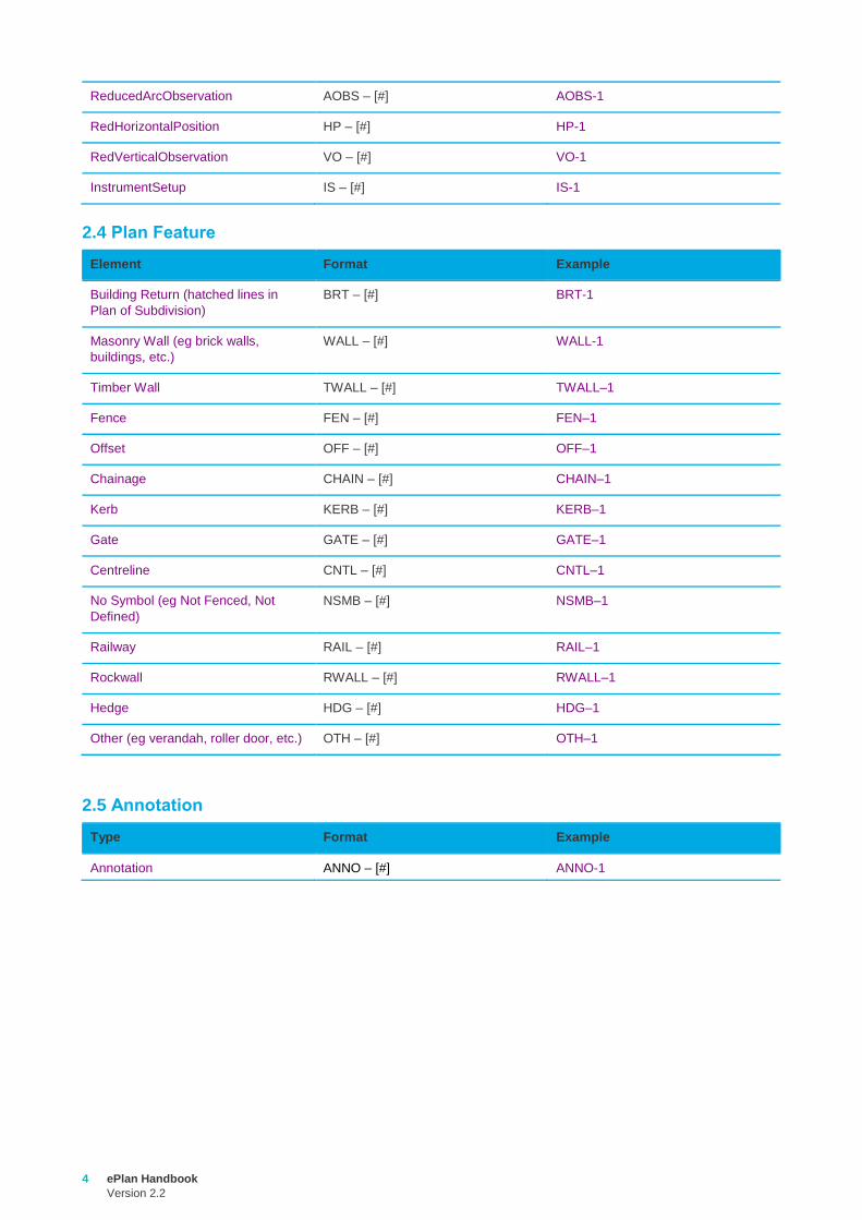
ReducedArcObservation AOBS – [#] AOBS-1
RedHorizontalPosition HP – [#] HP-1
RedVerticalObservation VO – [#] VO-1
InstrumentSetup IS – [#] IS-1
2.4 Plan Feature
Element Format Example
Building Return (hatched lines in
Plan of Subdivision)
BRT – [#] BRT-1
Masonry Wall (eg brick walls,
buildings, etc.)
WALL – [#] WALL-1
Timber Wall TWALL – [#] TWALL–1
Fence FEN – [#] FEN–1
Offset OFF – [#] OFF–1
Chainage CHAIN – [#] CHAIN–1
Kerb KERB – [#] KERB–1
Gate GATE – [#] GATE–1
Centreline CNTL – [#] CNTL–1
No Symbol (eg Not Fenced, Not
Defined)
NSMB – [#] NSMB–1
Railway RAIL – [#] RAIL–1
Rockwall RWALL – [#] RWALL–1
Hedge HDG – [#] HDG–1
Other (eg verandah, roller door, etc.) OTH – [#] OTH–1
2.5 Annotation
Type Format Example
Annotation ANNO – [#] ANNO-1
ePlan Handbook
Version 2.2
5
3. Administrative Information
3.1 Annotations
The Annotations element is used to capture various pieces of textual information. This is mainly for the
benefit of future surveyors, examiners and auditors where additional textual information about the plan may
be required for specific situations.
Depending on the Annotation, the requirements for each field differs. In addition, annotation types have been
created for free text annotations that can be used at will by the surveyor.
Attribute Expected Value
name ANNO - [#] eg ANNO-1
type See section 3.1.1 Annotation Types below
desc Textual description
pclRef Parcel reference
3.1.1 Annotation Types
Textual Annotation Types
The following annotations require the surveyor to qualify the annotation with text in the @desc field. The following
types do not require @pclRef:
◼ Planning Permit
◼ Report on Datum
◼ Instrument and Calibration Details
◼ Crown Section
◼ Crown Allotment
◼ Crown Portion
◼ Other Crown Description
◼ Section 12(2) of the Subdivision Act 1988 applies vide this plan
◼ Section 12(2) of the Subdivision Act 1988 does not apply vide this plan
◼ Purpose of Plan
◼ Additional Purpose of Plan
◼ Grounds for Removal
◼ Grounds for Variation
◼ Grounds for Vesting
◼ Future Plan Number
◼ Prior Survey
LandXML Example:
<Annotation name="ANNO-1"
type="Planning Permit" desc="2002/338" />
Textual + Parcel Reference Annotation Types
The following annotations require the surveyor to qualify the annotation with text in the @desc field and @pclRef
to identify which parcel the description applies to:
◼ Easement Qualification
◼ Easement Purpose
◼ Easement Beneficiary
◼ Easement Width
◼ Easement Origin
◼ Building Boundary Notation If a line @desc attribute contains the value of
"Other", the parcel must have a building
boundary annotation attached to it.
◼ Restriction Expiry Date
A date in valid UTC format to define the expiry
date of a restriction. eg "2019-01-10". The @pclRef attribute must be used to link to a valid
restriction parcel.
◼ Purpose of The Owners Corporation
◼ Owners Corporation Notation
◼ The Basis For Allocation of Lot Entitlement And
Liability
◼ Details Of The Limitations of The Owners
Corporation
◼ Functions or Obligations Referred By The
Limited Owners Corporation

6 ePlan Handbook
Version 2.2
Parcel Reference Annotation Types
The following annotation requires @pclRef as it is
intended to refer to specific parcel. Text in the @desc
attribute should be a copy of the @type attribute.
◼ Parcel with Area by Deduction
LandXML Example:
<Annotation name="ANNO-1"
pclRef="BL1\PS123456"
type="Parcel with Area by Deduction"
desc="Parcel with Area by Deduction" />
◼ Functions or Obligations Referred To The
Unlimited Owners Corporation
◼ Balance Of Existing OC Entitlement
◼ Balance Of Existing OC Liability
◼ Section 35 Compulsory
◼ Section 35 Agreement
LandXML Example: <Annotation name="ANNO-1"
pclRef="1\PS123456"
type="Building Boundary Notation"
desc="The boundary is a party wall" />
General Annotation Types
The following annotation types are for general use where the surveyor wishes to annotate information on the plan that is not covered by one of the textual and parcel reference types. @desc should be filled in to provide the details
of the annotation. @pclRef attribute is optional.
◼ General Plan Notation
◼ Abstract of Field Records Notation
◼ Surveyor's Report Notation
◼ Title Closure Justification
◼ Supply of Supplementary Field Record Notation
◼ General Easement Notation
◼ Section 35 – See Recording of Vesting Table Attached
◼ Implied Easement Notation
NOTE: @desc attribute is mandatory in LandXML therefore text must be inserted into the attribute
value. Use the same text as annotation type if user’s description is optional.
3.2 General ePlan Information
The complete information on attributes and elements can be found in the Victorian ePlan Protocol. The table
below describes the information that is more commonly entered and used by surveyors:
Attribute Expected Value
date Date this version of the ePlan was created. ISO 8601 format, eg 2019-01-14
time Time this version of the ePlan was created. ISO 8601 format, eg 13:56:48
Application / name The name of the software application that created the ePlan. eg LISCAD,
Stringer ePlan, ePSALON
Application / version The version of the software application eg 12.2
Author / createdBy The name of the person who created the ePlan
FeatureDictionary / name Set to the name of the jurisdictional ePlan schema. For Victoria the value is:
xml-gov-au-vic-icsm-eplan-cif-protocol
FeatureDictionary / version The version number of the Victorian ePlan Protocol Schema as stated in the
"version" attribute of schema header.
ePlan Handbook
Version 2.2
7
LandXML Example
<LandXML date="2019-01-14" time="22:57:21" version="1.0"
xmlns="http://www.landxml.org/schema/LandXML-1.2"
xmlns:xsi="http://www.w3.org/2001/XMLSchema-instance"
xsi:schemaLocation="http://www.landxml.org/schema/LandXML-1.2
http://www.landxml.org/schema/LandXML-1.2/LandXML-1.2.xsd">
<Application name="LISCAD" version="12.2">
<Author createdBy="John Smith"/>
</Application>
<FeatureDictionary name="xml-gov-au-vic-icsm-eplan-cif-protocol" version="1.10"/>
</LandXML>
3.3 Coordinate System
The CoordinateSystem element defines the coordinate system used for CgPoint coordinate system and the datum
used for observation bearings and distances. The coordinate system is captured in the horizontalDatum attribute and
the bearing datum in the @datum attribute. Both fields have prescribed values set out in the enumerations schema. The
@desc attribute is a free text field used to describe the coordinate system if it is "Local”.
3.4 Survey Header
3.4.1 Survey Header Attributes
name
The plan number with the check digit eg
PS123456X.
For Staged Subdivisions, the plan number looks
like below:
PS123456X/S2
And compiled plans as:
PS123456X/C2
surveyorReference
The surveying firms internal reference and version.
Format is REF-VerXX, the reference and version are
separated by “-Ver”.
Type
Maps to Survey/Non-Survey notation in the notations panel.
◼ Computed = Non-Survey;
◼ Surveyed = Survey;
◼ Compiled = Partial Survey.
surveyorFirm
The name of the surveying firm. All text from the surveyor’s stamp goes here, formatted in the following way:
{Trading Name} 

{Company Name} 

{Office Address} 

{Mailing Address} 

{Phone} 

{Fax} 

{ABN} 

{Website URL}
NOTE: Each field can contain any characteristics including spaces. 
 is the XML code for new line. This is optional but will be used in visualisation of ePlans.
3.4.2 SurveyHeader Components
Plan administrative components are stored within the SurveyHeader element and child elements. These
include:
8 ePlan Handbook
Version 2.2
Element Description
HeadOfPower HeadOfPower specifies the legislation this plan is based
on. Several head of power values can be specified. Currently ePlan provides for the following:
◼ Subdivision Act 1988
◼ Owners Corporation Act 2006
◼ Transfer of Land Act 1958
PurposeOfSurvey PurposeOfSurvey captures the application type eg
"Section 22-Plan of Subdivision". Multiple purposes can
be listed however there are rules about which purposes
can be mixed, see PurposeOfSurvey
Personnel The name of the licensed surveyor who surveyed the
plan.
AdministrativeArea The municipalities (LGA), Parish and Township the plan
is in.
AdministrativeDate "Date of Survey" to be provided if plan is fully or partially
surveyed.
Annotation (Optional) See Section 3-1 Annotations.
Amendments (Optional) Used to track amendments post registration.
PurposeofSurvey
Purpose of Survey in ePlan refers to the sections of the act or application types of the survey plan.
Purpose of Survey
“Section 6(1)(K)”
“Section 22-Plan of Subdivision”
“Section 22-Plan of Consolidation”
“Section 23–Creation of Easement”
“Section 23–Removal of Easement”
“Section 23-Variation of Easement”
“Section 23-Creation and Removal of Easement”
“Section 23-Creation and Variation of Easement”
“Section 23-Removal and Variation of Easement”
“Section 23-Creation and Removal and Variation of Easement”
“Section 23-Variation of Condition in Crown Grant”
“Section 23-Removal of Condition in Crown Grant”
“Section 23-Creation of Restriction”
“Section 23-Removal of Restriction”
“Section 23-Variation of Restriction”
“Section 24a-Vesting of a Reserve”
“Section 24a-Removal of a Reserve (Plan of Subdivision)”

ePlan Handbook
Version 2.2
9
“Section 24a-Removal of a Reserve (Plan of Consolidation)”
“Section 24a-Removal and Vesting of a Reserve (Plan of Subdivision)”
“Section 24a-Removal and Vesting of a Reserve (Plan of Consolidation)”
“Section 26”
“Section 32-Plan to alter land affected by an owners corporation (Plan of Subdivision)”
“Section 32-Plan to alter land affected by an owners corporation (Registered Plan)”
“Section 32-Plan to alter land affected by an owners corporation (Strata Plan)”
“Section 32-Plan to alter land affected by an owners corporation (Cluster Subdivision)”
“Section 32a–Plan of Subdivision of land if an owners corporation is affected”
“Section 32a-Plan of Consolidation of land if an owners corporation is affected”
“Section 32b-Plan to create an owners corporation (Existing Plan)”
“Section 32b-Plan to create an owners corporation (New Plan)”
“Section 35-Acquisition of land by acquiring authority”
“Section 35-Acquisition of land if an owners corporation is affected (Plan of Subdivision)”
“Section 35-Acquisition of land if an owners corporation is affected (Registered Plan)”
“Section 35-Acquisition of land if an owners corporation is affected (Strata Plan)”
“Section 35-Acquisition of land if an owners corporation is affected (Cluster Subdivision)”
“Section 35(8)-Subdivision of land vested or registered in authority”
“Section 35(8)-Consolidation of land vested or registered in authority”
“Section 37-Plan of Subdivision (Staged Plan)”
“Section 37-Acquisition of land (Plan of Subdivision (Staged))”
“Section 37(8)”

10 ePlan Handbook
Version 2.2
All plans must specify one primary purpose and can have additional secondary purposes. In ePlan, primary
and secondary purposes are not separately specified. However, it must state one of the primary purposes listed below using the PurposeOfSurvey element. The following table shows a combination of secondary
purposes that can be used with each of the primary purposes:
Primary Purpose Additional Secondary Purpose(s)
Section 22 Section 6(1)(K), Section 23, Section 24A, Section 32B, Section 37(8)
Section 23 -
Section 24A Section 6(1)(K), Section 23
Section 26 -
Section 32 Section 6(1)(K), Section 23, Section 24A, Section 35, Section 37(8)
Section 32A Section 6(1)(K), Section 23, Section 24A
Section 32B -
Section 35 Section 6(1)(K), Section 23, Section 24A
Section 35(8) Section 6(1)(K), Section 23, Section 24A
Section 37 Section 6(1)(K), Section 23, Section 24A, Section 35, Section 37(8)
Personnel
Attribute Expected Value
name Full name of the surveyor as registered
role “Surveyed By”
regType “Licensed Cadastral Surveyor”
regNumber Surveyor’s registration board member number
Administrative Area
Attribute Expected Value
adminAreaType The administrative area type eg LGA, Parish, Township
adminAreaName The full name of the administrative area
adminAreaCode The code or identifier of the administrative area if applicable
ePlan Handbook
Version 2.2
11
4. Point and Line Definition
Every point has coordinate information. However, in Victoria coordinate information on points is used for
visualisation purposes only, providing shape to the coordinate geometry. Dimension data attached to lines
provide the legal representation of the boundaries (except in the case of building boundaries). See the
Victorian ePlan Protocol for full elements and attributes details.
Point
The CgPoint element is the basic point container for ePlan. CgPoints are referenced from CoordGeom and
Observation elements to construct lines and dimensions.
<CgPoint name="CGPNT-1" pntSurv="boundary" state="existing">northing
easting</CgPoint>
Line, Curve, Irregular Line
A Line is defined with a start and end CgPoint reference. Curves have a start, end and centre CgPoint
reference and a @radius and @rot direction. An IrregularLine is used to capture natural boundaries. It
consists of a start and end CgPoint and a string of coordinates.
<Line>
<Start pntRef="CGPNT-1"/><End pntRef="CGPNT-2"/>
</Line>
<IrregularLine>
<Start pntRef="CGPNT-1"/><End pntRef="CGPNT-2"/><PntList2D/>
</IrregularLine>
Survey information in ePlan encompasses the traverses, radiations, survey marks and reference marks.
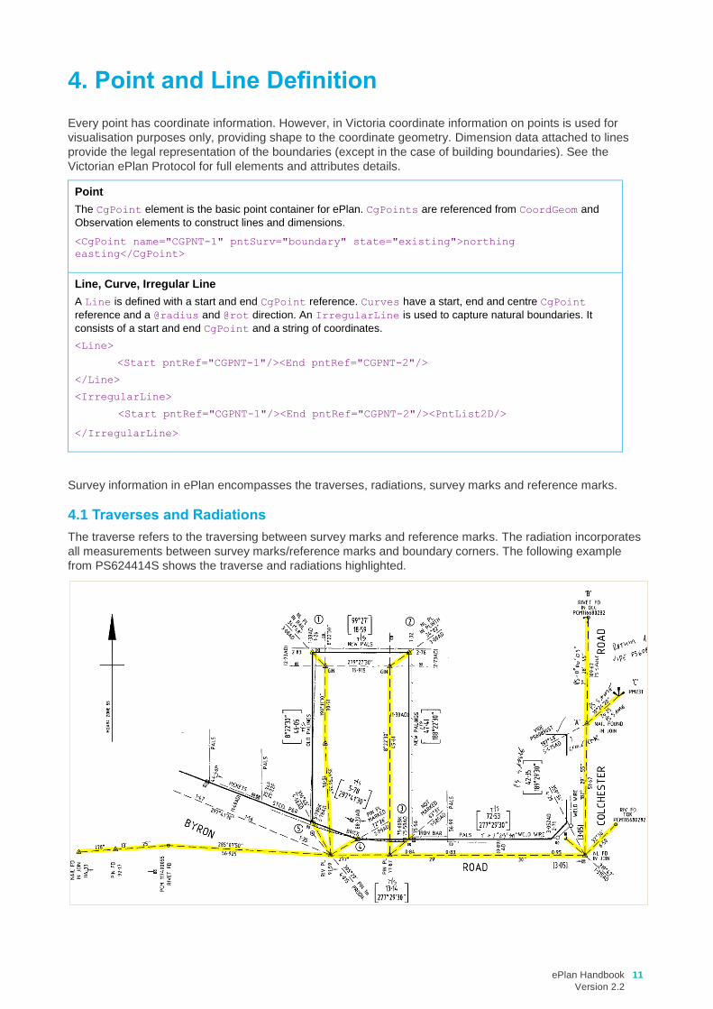
4.1 Traverses and Radiations
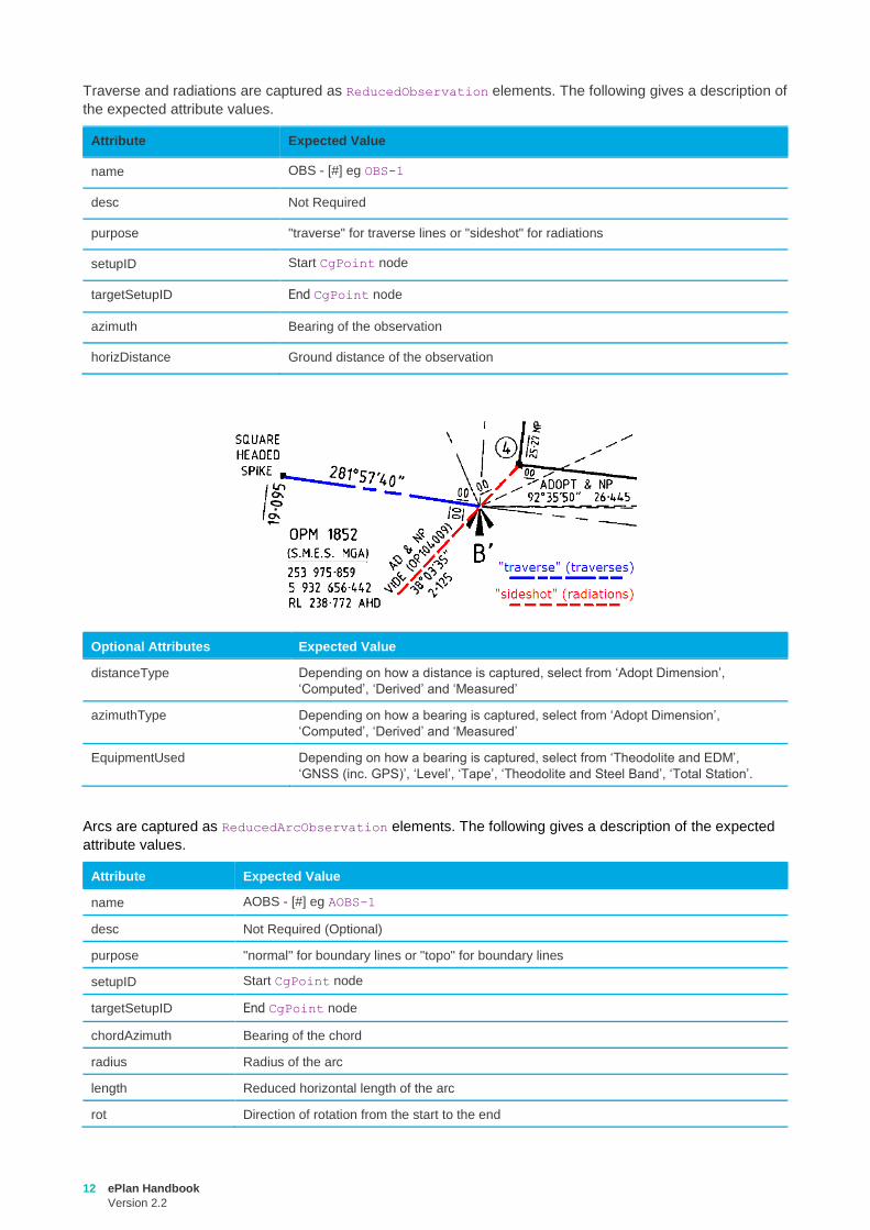
The traverse refers to the traversing between survey marks and reference marks. The radiation incorporates
all measurements between survey marks/reference marks and boundary corners. The following example
from PS624414S shows the traverse and radiations highlighted.
12 ePlan Handbook
Version 2.2
Traverse and radiations are captured as ReducedObservation elements. The following gives a description of
the expected attribute values.
Attribute Expected Value
name OBS - [#] eg OBS-1
desc Not Required
purpose "traverse" for traverse lines or "sideshot" for radiations
setupID Start CgPoint node
targetSetupID End CgPoint node
azimuth Bearing of the observation
horizDistance Ground distance of the observation
Optional Attributes Expected Value
distanceType Depending on how a distance is captured, select from ‘Adopt Dimension’,
‘Computed’, ‘Derived’ and ‘Measured’
azimuthType Depending on how a bearing is captured, select from ‘Adopt Dimension’,
‘Computed’, ‘Derived’ and ‘Measured’
EquipmentUsed Depending on how a bearing is captured, select from ‘Theodolite and EDM’,
‘GNSS (inc. GPS)’, ‘Level’, ‘Tape’, ‘Theodolite and Steel Band’, ‘Total Station’.
Arcs are captured as ReducedArcObservation elements. The following gives a description of the expected
attribute values.
Attribute Expected Value
name AOBS - [#] eg AOBS-1
desc Not Required (Optional)
purpose "normal" for boundary lines or "topo" for boundary lines
setupID Start CgPoint node
targetSetupID End CgPoint node
chordAzimuth Bearing of the chord
radius Radius of the arc
length Reduced horizontal length of the arc
rot Direction of rotation from the start to the end
ePlan Handbook
Version 2.2
13
Attribute Expected Value
equipmentUsed Equipment used for observation (Optional)
arcLengthAccuracy Chord length (Optional)
arcType Type of arc which can be Adopt Dimension, Computed, Derived or Measured (Optional)
4.2 Plan Features
Features are captured using the PlanFeature element, as shown below:
Attributes Expected Values
name BRT – [#] eg BRT-1 (for Building Return - hatched lines in Plan of Subdivision)
WALL – [#] eg WALL-1 (for Masonry Wall eg brick walls, buildings, etc.)
TWALL – [#] eg TWALL-1 (for Timber Wall)
FEN – [#] eg FEN-1 (for Fence)
OFF – [#] eg OFF-1 (for Offset)
CHAIN – [#] eg CHAIN-1 (for Chainage)
KERB – [#] eg KERB-1 (for Kerb)
GATE – [#] eg GATE-1 (for Gate)
CNTL – [#] eg CNTL-1 (for Centreline)
NSMB – [#] eg NSMB-1 (for No Symbol eg Not Fenced, Not Defined, etc.)
RAIL – [#] eg RAIL-1 (for Railway)
RWALL – [#] eg RWALL-1 (for Rock Wall)
HDG – [#] eg HDG-1 (for Hedge)
OTH – [#] eg OTH-1 (for Other eg verandah, roller door, etc.)
desc Description of the feature eg GAL. IRON (20+), etc.
14 ePlan Handbook
Version 2.2
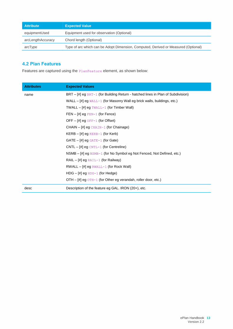
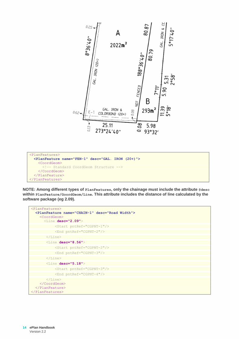
NOTE: Among different types of PlanFeatures, only the chainage must include the attribute @desc
within PlanFeature/GoordGeom/Line. This attribute includes the distance of line calculated by the
software package (eg 2.09).
<PlanFeatures>
<PlanFeature name="FEN-1" desc="GAL. IRON (20+)">
<CoordGeom>
<!-- Standard CoordGeom Structure -->
</CoordGeom>
</PlanFeature>
</PlanFeatures>
<PlanFeatures>
<PlanFeature name="CHAIN-1" desc="Road Width">
<CoordGeom>
<Line desc="2.09">
<Start pntRef="CGPNT-1"/>
<End pntRef="CGPNT-2"/>
</Line>
<Line desc="8.56">
<Start pntRef="CGPNT-2"/>
<End pntRef="CGPNT-3"/>
</Line>
<Line desc="5.18">
<Start pntRef="CGPNT-3"/>
<End pntRef="CGPNT-4"/>
</Line>
</CoordGeom>
</PlanFeature>
</PlanFeatures>
ePlan Handbook
Version 2.2
15
The points included in Plan Features are created based on the table below:
Attribute Expected Value
Name CGPNT – [#] eg CGPNT-1
(sequentially numbered)
State “Existing”
pntSurv “monument” (“boundary” for BRT)
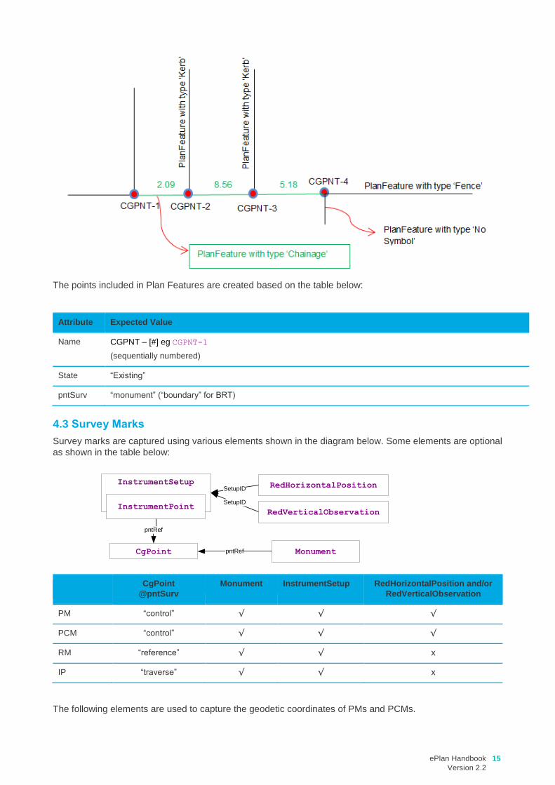
4.3 Survey Marks
Survey marks are captured using various elements shown in the diagram below. Some elements are optional
as shown in the table below:
CgPoint
@pntSurv
Monument InstrumentSetup RedHorizontalPosition and/or
RedVerticalObservation
PM “control” √ √ √
PCM “control” √ √ √
RM “reference” √ √ x
IP “traverse” √ √ x
The following elements are used to capture the geodetic coordinates of PMs and PCMs.
RedHorizontalPosition
RedVerticalObservation
CgPoint
InstrumentSetup
Monument
InstrumentPoint
SetupID
SetupID
pntRef
pntRef
16 ePlan Handbook
Version 2.2
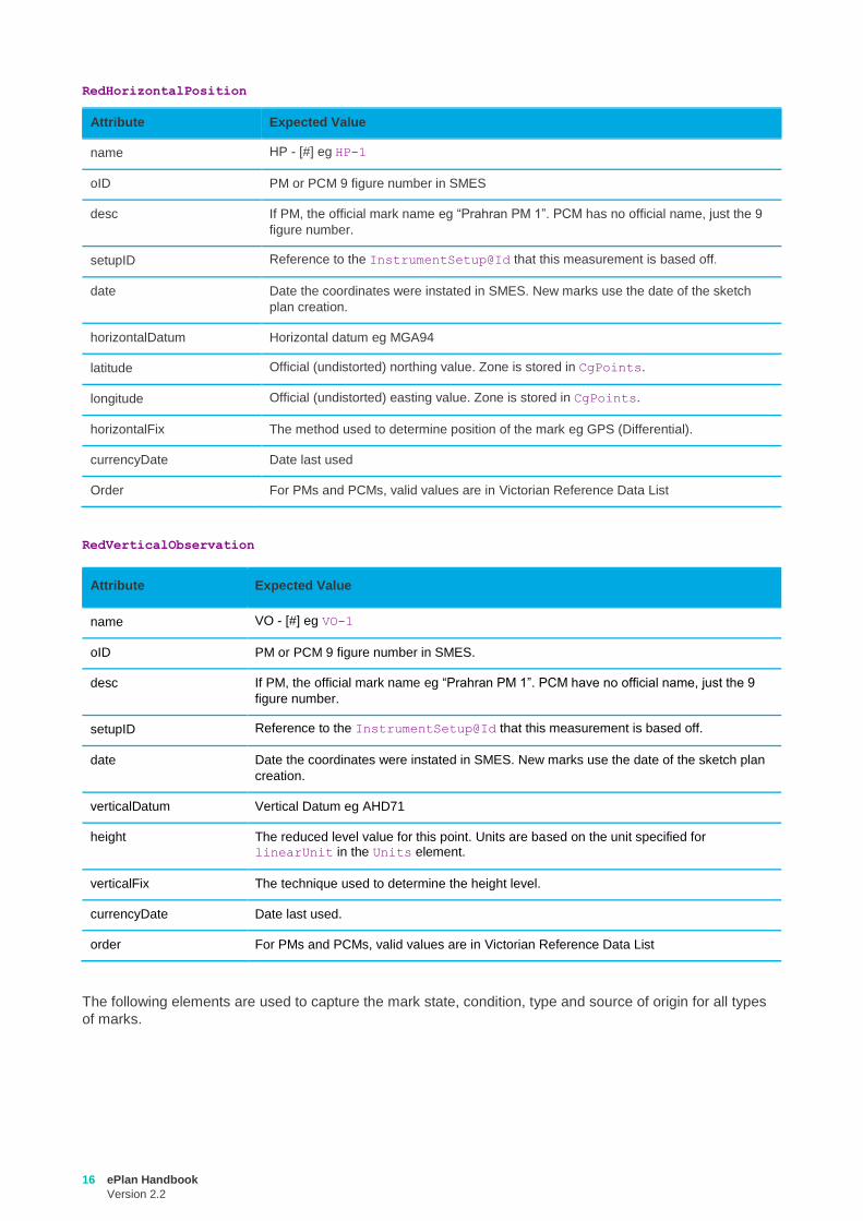
RedHorizontalPosition
Attribute Expected Value
name HP - [#] eg HP-1
oID PM or PCM 9 figure number in SMES
desc If PM, the official mark name eg “Prahran PM 1”. PCM has no official name, just the 9
figure number.
setupID Reference to the InstrumentSetup@Id that this measurement is based off.
date Date the coordinates were instated in SMES. New marks use the date of the sketch
plan creation.
horizontalDatum Horizontal datum eg MGA94
latitude Official (undistorted) northing value. Zone is stored in CgPoints.
longitude Official (undistorted) easting value. Zone is stored in CgPoints.
horizontalFix The method used to determine position of the mark eg GPS (Differential).
currencyDate Date last used
Order For PMs and PCMs, valid values are in Victorian Reference Data List
RedVerticalObservation
Attribute Expected Value
name VO - [#] eg VO-1
oID PM or PCM 9 figure number in SMES.
desc If PM, the official mark name eg “Prahran PM 1”. PCM have no official name, just the 9
figure number.
setupID Reference to the InstrumentSetup@Id that this measurement is based off.
date Date the coordinates were instated in SMES. New marks use the date of the sketch plan
creation.
verticalDatum Vertical Datum eg AHD71
height The reduced level value for this point. Units are based on the unit specified for linearUnit in the Units element.
verticalFix The technique used to determine the height level.
currencyDate Date last used.
order For PMs and PCMs, valid values are in Victorian Reference Data List
The following elements are used to capture the mark state, condition, type and source of origin for all types
of marks.

ePlan Handbook
Version 2.2
17
Monument
Attribute Expected Value
name MON - [#] eg MON-1
desc Surveyor's description of the monument if type does not fully describe the monument. eg
"Brass plaque in concrete with beacon".
pntRef Reference to the name attribute of the linked CgPoint.
type See Victorian Reference Data List
state See Victorian Reference Data List
condition See Victorian Reference Data List
originSurvey Record plan number for reference marks found from previous plan. Refer to the current
Plan Number if this is a new mark.
InstrumentSetup
Attribute Expected Value
id IS - [#] eg IS-1
stationName Same as id
instrumentHeight Not used in Victoria, default to 0
InstrumentPoint
Attribute Expected Value
pntRef Reference to the CgPoint for this InstrumentPoint
18 ePlan Handbook
Version 2.2
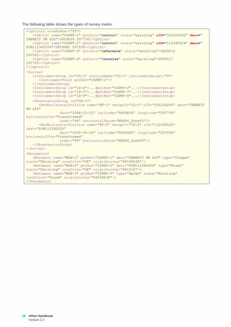
The following table shows the types of survey marks:
<CgPoints zoneNumber="55">
<CgPoint name="CGPNT-1" pntSurv="control" state="existing" oID="355206260" desc="
TARNEIT PM 626">5809834 297734</CgPoint>
<CgPoint name="CGPNT-2" pntSurv="control" state="existing" oID="112340524" desc="
PCM112340524">5809482 297556</CgPoint>
<CgPoint name="CGPNT-3" pntSurv="reference" state="existing">5809516
297562</CgPoint>
<CgPoint name="CGPNT-4" pntSurv="traverse" state="existing">5809517
297763</CgPoint>
</CgPoints>
<Survey>
<InstrumentSetup id="IS-1" stationName="IS-1" instrumentHeight="0">
<InstrumentPoint pntRef="CGPNT-1"/>
</InstrumentSetup>
<InstrumentSetup id="IS-2">...@pntRef="CGPNT-2"...</InstrumentSetup>
<InstrumentSetup id="IS-3">...@pntRef="CGPNT-3"...</InstrumentSetup>
<InstrumentSetup id="IS-4">...@pntRef="CGPNT-4"...</InstrumentSetup>
<ObservationGroup id="OG-1">
<RedHorizontalPosition name="HP-1" setupID="IS-1" oID="355206260" desc="TARNEIT
PM 626"
date="2008-12-12" latitude="5809834" longitude="297734"
horizontalFix="Transformed"
order="99" horizontalDatum="MGA94_Zone55"/>
<RedHorizontalPosition name="HP-2" setupID="IS-2" oID="112340524"
desc="PCM112340524"
date="2005-05-18" latitude="5809482" longitude="297556"
horizontalFix="Transformed"
order="99" horizontalDatum="MGA94_Zone55"/>
</ObservationGroup>
</Survey>
<Monuments>
<Monument name="MON-1" pntRef="CGPNT-1" desc="TARNEIT PM 626" type="Plaque"
state="Existing" condition="OK" originSurvey="PS536638"/>
<Monument name="MON-2" pntRef="CGPNT-2" desc="PCM112340524" type="Rivet"
state="Existing" condition="OK" originSurvey="BP1532"/>
<Monument name="MON-3" pntRef="CGPNT-3" type="Spike" state="Existing"
condition="Found" originSurvey="PS536638"/>
</Monuments>
ePlan Handbook
Version 2.2
19
5. Parcel Definition
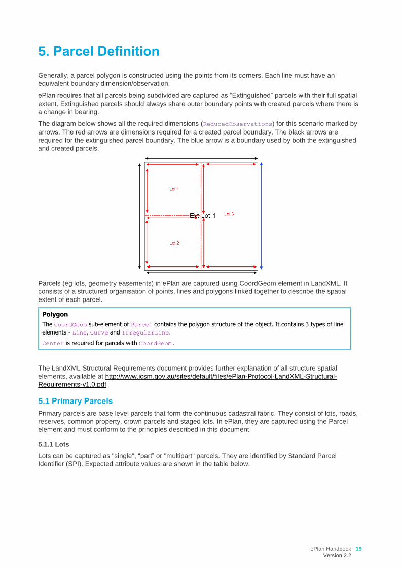
Generally, a parcel polygon is constructed using the points from its corners. Each line must have an
equivalent boundary dimension/observation.
ePlan requires that all parcels being subdivided are captured as “Extinguished” parcels with their full spatial
extent. Extinguished parcels should always share outer boundary points with created parcels where there is
a change in bearing.
The diagram below shows all the required dimensions (ReducedObservations) for this scenario marked by
arrows. The red arrows are dimensions required for a created parcel boundary. The black arrows are
required for the extinguished parcel boundary. The blue arrow is a boundary used by both the extinguished
and created parcels.
Parcels (eg lots, geometry easements) in ePlan are captured using CoordGeom element in LandXML. It
consists of a structured organisation of points, lines and polygons linked together to describe the spatial
extent of each parcel.
Polygon
The CoordGeom sub-element of Parcel contains the polygon structure of the object. It contains 3 types of line
elements - Line, Curve and IrregularLine.
Center is required for parcels with CoordGeom.
The LandXML Structural Requirements document provides further explanation of all structure spatial
elements, available at http://www.icsm.gov.au/sites/default/files/ePlan-Protocol-LandXML-Structural-
Requirements-v1.0.pdf
5.1 Primary Parcels
Primary parcels are base level parcels that form the continuous cadastral fabric. They consist of lots, roads,
reserves, common property, crown parcels and staged lots. In ePlan, they are captured using the Parcel
element and must conform to the principles described in this document.
5.1.1 Lots
Lots can be captured as "single", “part” or "multipart" parcels. They are identified by Standard Parcel
Identifier (SPI). Expected attribute values are shown in the table below.
20 ePlan Handbook
Version 2.2
5.1.2 Stage Lots
Stage lots can be captured in Staged Subdivisions similar to lots.
5.1.3 Roads
Roads in ePlan are represented by a Parcel element with a class of "Road". The common states for a
Road are:
1. New: a road parcel created by the survey. Must have closed geometry.
2. Existing: an abutting or adjoining road used to fix the subdivision or provide reference. Geometry does
not need to close.
The following guidelines apply to road parcels:
• The @name attribute of a road parcel must be unique in the file. Where available, an existing SPI should be
used for existing roads. If a SPI is not available, the generic name of "ROAD-#" can be used. New roads
must use a SPI. In addition, roads must specify an official or gazetted name (eg "Bourke Street") in the @desc attribute.
• Roads can be "single", "part" or "multipart" parcels. Each parcel should be associated with one road name (@desc). Where the road name changes at an intersection, a separate parcel should be used for the
adjoining road. In situations where the road is split across several intersections, multipart parcels should be used each with their own SPI showing the part number (eg R1-p1), but the @desc value can be the same.
The part parcels should be associated to a multipart parcel.
• All "created" and "affected" roads must contain the vesting authority in the @owner attribute.
• If the road is an abuttal, it must follow the guidelines outlined for title connections in Section 5.3.1.
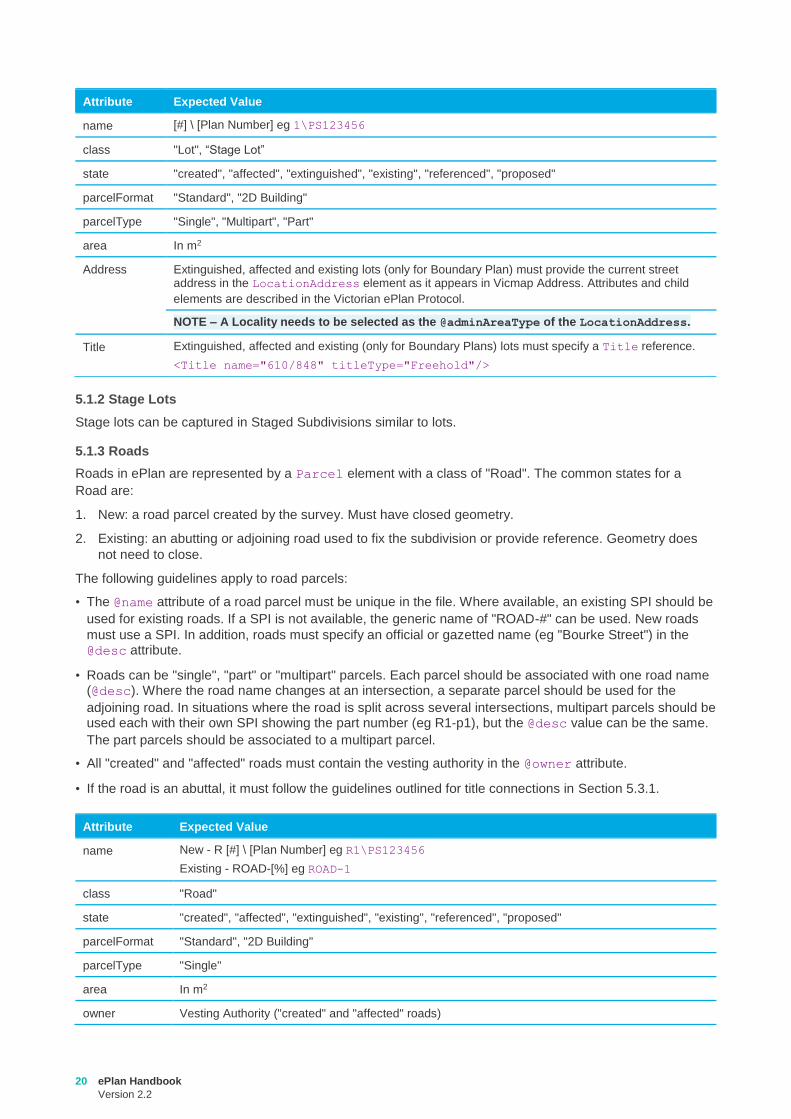
Attribute Expected Value
name [#] \ [Plan Number] eg 1\PS123456
class "Lot", “Stage Lot”
state "created", "affected", "extinguished", "existing", "referenced", "proposed"
parcelFormat "Standard", "2D Building"
parcelType "Single", "Multipart", "Part"
area In m2
Address Extinguished, affected and existing lots (only for Boundary Plan) must provide the current street address in the LocationAddress element as it appears in Vicmap Address. Attributes and child
elements are described in the Victorian ePlan Protocol.
NOTE – A Locality needs to be selected as the @adminAreaType of the LocationAddress.
Title Extinguished, affected and existing (only for Boundary Plans) lots must specify a Title reference.
<Title name="610/848" titleType="Freehold"/>
Attribute Expected Value
name New - R [#] \ [Plan Number] eg R1\PS123456
Existing - ROAD-[%] eg ROAD-1
class "Road"
state "created", "affected", "extinguished", "existing", "referenced", "proposed"
parcelFormat "Standard", "2D Building"
parcelType "Single"
area In m2
owner Vesting Authority ("created" and "affected" roads)
ePlan Handbook
Version 2.2
21
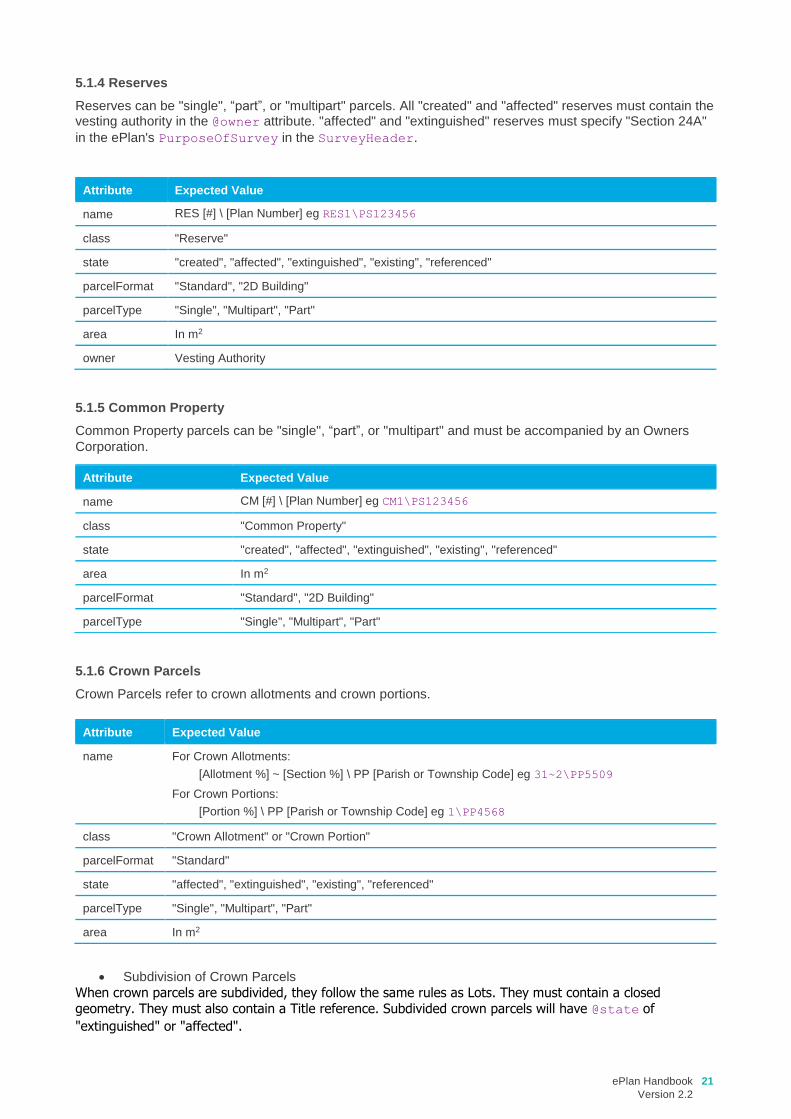
5.1.4 Reserves
Reserves can be "single", “part”, or "multipart" parcels. All "created" and "affected" reserves must contain the vesting authority in the @owner attribute. "affected" and "extinguished" reserves must specify "Section 24A"
in the ePlan's PurposeOfSurvey in the SurveyHeader.
5.1.5 Common Property
Common Property parcels can be "single", “part”, or "multipart" and must be accompanied by an Owners
Corporation.
5.1.6 Crown Parcels
Crown Parcels refer to crown allotments and crown portions.
• Subdivision of Crown Parcels
When crown parcels are subdivided, they follow the same rules as Lots. They must contain a closed geometry. They must also contain a Title reference. Subdivided crown parcels will have @state of
"extinguished" or "affected".
Attribute Expected Value
name RES [#] \ [Plan Number] eg RES1\PS123456
class "Reserve"
state "created", "affected", "extinguished", "existing", "referenced"
parcelFormat "Standard", "2D Building"
parcelType "Single", "Multipart", "Part"
area In m2
owner Vesting Authority
Attribute Expected Value
name CM [#] \ [Plan Number] eg CM1\PS123456
class "Common Property"
state "created", "affected", "extinguished", "existing", "referenced"
area In m2
parcelFormat "Standard", "2D Building"
parcelType "Single", "Multipart", "Part"
Attribute Expected Value
name For Crown Allotments:
[Allotment %] ~ [Section %] \ PP [Parish or Township Code] eg 31~2\PP5509
For Crown Portions:
[Portion %] \ PP [Parish or Township Code] eg 1\PP4568
class "Crown Allotment" or "Crown Portion"
parcelFormat "Standard"
state "affected", "extinguished", "existing", "referenced"
parcelType "Single", "Multipart", "Part"
area In m2
22 ePlan Handbook
Version 2.2
• Crown Abuttals
Crown abuttals are captured according to Section 5.3.1. Crown abuttals will have @state of either "existing"
or "referenced".
5.2 Secondary Interest
Secondary interests in cadastral survey plans provide benefits and/or pose restrictions on primary cadastral
parcels. These include easements, and restrictions. In ePlan, they are presented as special ‘Parcels’ that
must conform to the principles described below.
5.2.1 Easements
In ePlan, the following two steps must be carried out for creating easements:
1. Create a "Geometry" easement for each geometry segment on diagram, and
2. Create a "Standard"/"2D Building" easement for each unique combination of “purpose/origin/land
benefitted” that includes the references to the geometry segments created in Step 1.
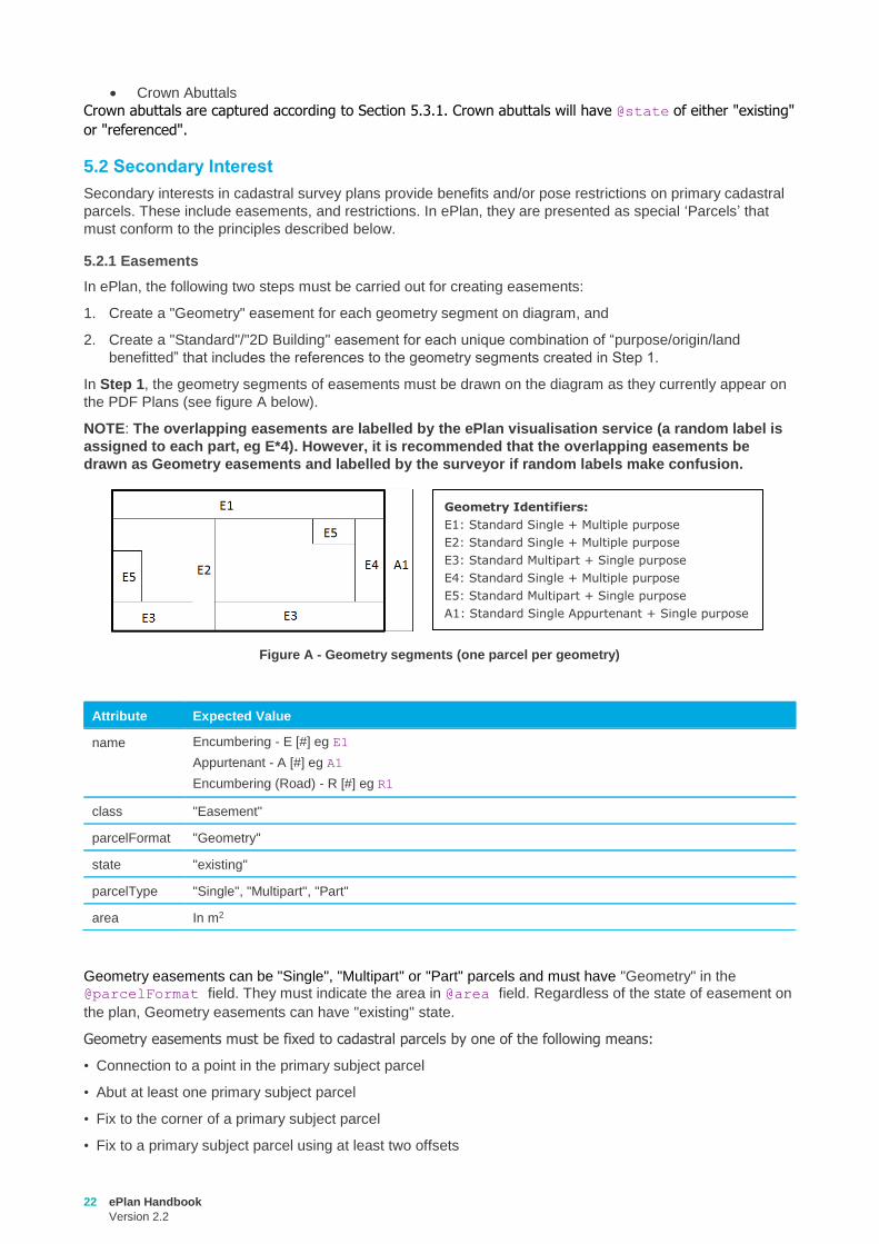
In Step 1, the geometry segments of easements must be drawn on the diagram as they currently appear on
the PDF Plans (see figure A below).
NOTE: The overlapping easements are labelled by the ePlan visualisation service (a random label is
assigned to each part, eg E*4). However, it is recommended that the overlapping easements be
drawn as Geometry easements and labelled by the surveyor if random labels make confusion.
Figure A - Geometry segments (one parcel per geometry)
Geometry easements can be "Single", "Multipart" or "Part" parcels and must have "Geometry" in the @parcelFormat field. They must indicate the area in @area field. Regardless of the state of easement on
the plan, Geometry easements can have "existing" state.
Geometry easements must be fixed to cadastral parcels by one of the following means:
• Connection to a point in the primary subject parcel
• Abut at least one primary subject parcel
• Fix to the corner of a primary subject parcel
• Fix to a primary subject parcel using at least two offsets
Attribute Expected Value
name Encumbering - E [#] eg E1
Appurtenant - A [#] eg A1
Encumbering (Road) - R [#] eg R1
class "Easement"
parcelFormat "Geometry"
state "existing"
parcelType "Single", "Multipart", "Part"
area In m2
Geometry Identifiers:
E1: Standard Single + Multiple purpose
E2: Standard Single + Multiple purpose
E3: Standard Multipart + Single purpose
E4: Standard Single + Multiple purpose
E5: Standard Multipart + Single purpose
A1: Standard Single Appurtenant + Single purpose
ePlan Handbook
Version 2.2
23
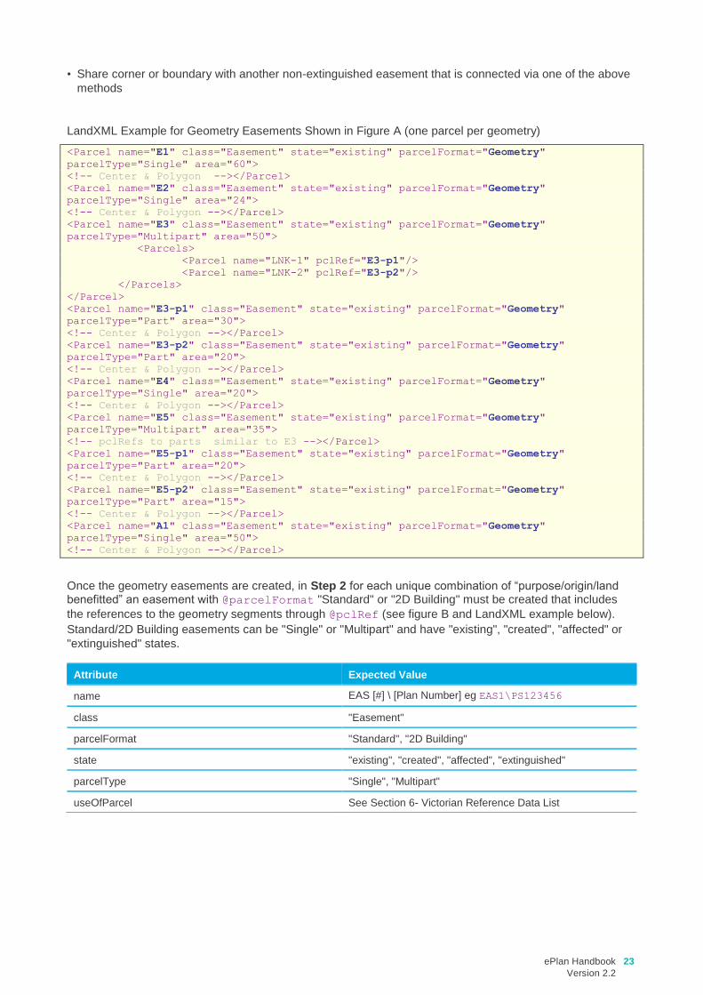
• Share corner or boundary with another non-extinguished easement that is connected via one of the above
methods
LandXML Example for Geometry Easements Shown in Figure A (one parcel per geometry)
<Parcel name="E1" class="Easement" state="existing" parcelFormat="Geometry"
parcelType="Single" area="60">
<!-- Center & Polygon --></Parcel>
<Parcel name="E2" class="Easement" state="existing" parcelFormat="Geometry"
parcelType="Single" area="24">
<!-- Center & Polygon --></Parcel>
<Parcel name="E3" class="Easement" state="existing" parcelFormat="Geometry"
parcelType="Multipart" area="50">
<Parcels>
<Parcel name="LNK-1" pclRef="E3-p1"/>
<Parcel name="LNK-2" pclRef="E3-p2"/>
</Parcels>
</Parcel>
<Parcel name="E3-p1" class="Easement" state="existing" parcelFormat="Geometry"
parcelType="Part" area="30">
<!-- Center & Polygon --></Parcel>
<Parcel name="E3-p2" class="Easement" state="existing" parcelFormat="Geometry"
parcelType="Part" area="20">
<!-- Center & Polygon --></Parcel>
<Parcel name="E4" class="Easement" state="existing" parcelFormat="Geometry"
parcelType="Single" area="20">
<!-- Center & Polygon --></Parcel>
<Parcel name="E5" class="Easement" state="existing" parcelFormat="Geometry"
parcelType="Multipart" area="35">
<!-- pclRefs to parts similar to E3 --></Parcel>
<Parcel name="E5-p1" class="Easement" state="existing" parcelFormat="Geometry"
parcelType="Part" area="20">
<!-- Center & Polygon --></Parcel>
<Parcel name="E5-p2" class="Easement" state="existing" parcelFormat="Geometry"
parcelType="Part" area="15">
<!-- Center & Polygon --></Parcel>
<Parcel name="A1" class="Easement" state="existing" parcelFormat="Geometry"
parcelType="Single" area="50">
<!-- Center & Polygon --></Parcel>
Once the geometry easements are created, in Step 2 for each unique combination of “purpose/origin/land benefitted” an easement with @parcelFormat "Standard" or "2D Building" must be created that includes
the references to the geometry segments through @pclRef (see figure B and LandXML example below).
Standard/2D Building easements can be "Single" or "Multipart" and have "existing", "created", "affected" or
"extinguished" states.
Attribute Expected Value
name EAS [#] \ [Plan Number] eg EAS1\PS123456
class "Easement"
parcelFormat "Standard", "2D Building"
state "existing", "created", "affected", "extinguished"
parcelType "Single", "Multipart"
useOfParcel See Section 6- Victorian Reference Data List
24 ePlan Handbook
Version 2.2
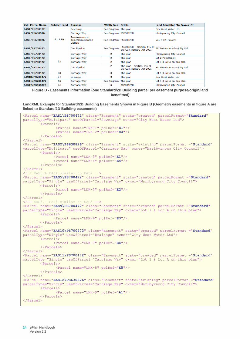
Figure B - Easements information (one Standard/2D Building parcel per easement purpose/origin/land
benefitted)
LandXML Example for Standard/2D Building Easements Shown in Figure B (Geometry easements in figure A are
linked to Standard/2D Building easements)
<Parcel name="EAS1\PS700472" class="Easement" state="created" parcelFormat="Standard"
parcelType="Multipart" useOfParcel="Sewerage" owner="City West Water Ltd">
<Parcels>
<Parcel name="LNK-1" pclRef="E1"/>
<Parcel name="LNK-2" pclRef="E4"/>
</Parcels>
</Parcel>
<Parcel name="EAS2\PS630826" class="Easement" state="existing" parcelFormat ="Standard"
parcelType="Multipart" useOfParcel="Carriage Way" owner="Maribyrnong City Council">
<Parcels>
<Parcel name="LNK-3" pclRef="E1"/>
<Parcel name="LNK-4" pclRef="E4"/>
</Parcels>
</Parcel>
<!-- EAS3 & EAS4 similar to EAS2 -->
<Parcel name="EAS5\PS700472" class="Easement" state="created" parcelFormat ="Standard"
parcelType="Single" useOfParcel="Carriage Way" owner="Maribyrnong City Council">
<Parcels>
<Parcel name="LNK-5" pclRef="E2"/>
</Parcels>
</Parcel>
<!-- EAS6 - EAS8 similar to EAS5 -->
<Parcel name="EAS9\PS700472" class="Easement" state="created" parcelFormat ="Standard"
parcelType="Single" useOfParcel="Carriage Way" owner="Lot 1 & Lot A on this plan">
<Parcels>
<Parcel name="LNK-6" pclRef="E3"/>
</Parcels>
</Parcel>
<Parcel name="EAS10\PS700472" class="Easement" state="created" parcelFormat ="Standard"
parcelType="Single" useOfParcel="Drainage" owner="City West Water Ltd">
<Parcels>
<Parcel name="LNK-7" pclRef="E4"/>
</Parcels>
</Parcel>
<Parcel name="EAS11\PS700472" class="Easement" state="created" parcelFormat ="Standard"
parcelType="Single" useOfParcel="Carriage Way" owner="Lot 1 & Lot A on this plan">
<Parcels>
<Parcel name="LNK-8" pclRef="E5"/>
</Parcels>
</Parcel>
<Parcel name="EAS12\PS630826" class="Easement" state="existing" parcelFormat ="Standard"
parcelType="Single" useOfParcel="Carriage Way" owner="Maribyrnong City Council">
<Parcels>
<Parcel name="LNK-9" pclRef="A1"/>
</Parcels>
</Parcel>
ePlan Handbook
Version 2.2
25
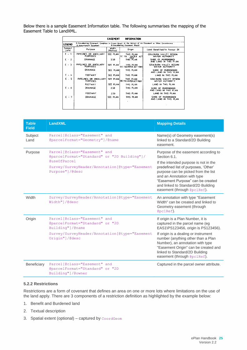
Below there is a sample Easement Information table. The following summarises the mapping of the
Easement Table to LandXML.
Table
Field
LandXML Mapping Details
Subject
Land
Parcel[@class="Easement" and
@parcelFormat="Geometry"]/@name
Name(s) of Geometry easement(s)
linked to a Standard/2D Building
easement.
Purpose Parcel[@class="Easement" and
@parcelFormat="Standard" or "2D Building"]/
@useOfParcel
Survey/SurveyHeader/Annotation[@type="Easement
Purpose"]/@desc
Purpose of the easement according to
Section 6.1.
If the intended purpose is not in the
predefined list of purposes, ‘Other’
purpose can be picked from the list
and an Annotation with type
“Easement Purpose” can be created
and linked to Standard/2D Building easement (through @pclRef).
Width Survey/SurveyHeader/Annotation[@type="Easement
Width"]/@desc
An annotation with type "Easement
Width" can be created and linked to
Geometry easement (through @pclRef).
Origin Parcel[@class="Easement" and
@parcelFormat="Standard" or "2D
Building"]/@name
Survey/SurveyHeader/Annotation[@type="Easement
Origin"]/@desc
If origin is a Plan Number, it is
captured in the parcel name (eg
EAS1\PS123456, origin is PS123456).
If origin is a dealing or instrument
number (anything other than a Plan
Number), an annotation with type
"Easement Origin" can be created and
linked to Standard/2D Building easement (through @pclRef).
Beneficiary Parcel[@class="Easement" and
@parcelFormat="Standard" or "2D
Building"]/@owner
Captured in the parcel owner attribute.
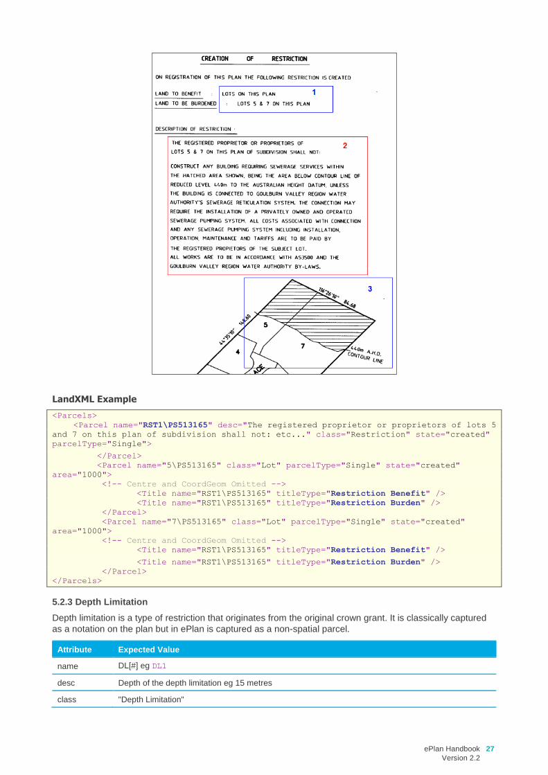
5.2.2 Restrictions
Restrictions are a form of covenant that defines an area on one or more lots where limitations on the use of
the land apply. There are 3 components of a restriction definition as highlighted by the example below:
1. Benefit and Burdened land
2. Textual description
3. Spatial extent (optional) – captured by CoordGeom

26 ePlan Handbook
Version 2.2
Where the spatial description consists of multiple polygons, multipart parcels are used. The textual
description resides in the parent parcel and is not duplicated to the parts.
If a restriction specifies an expiry date, the date is stored in a linked annotation with a type of:
"Restriction Expiry Date"
The annotation must be linked to the restriction parcel using the @pclRef attribute. The following is an
example:
<Annotation name="ANNO-1" type="Restriction Expiry Date" desc="2020-01-01"
pclRef="RST1\PS513165"/>
Restriction benefits and burdens are captured as title references. The Title element with type of
"Restriction Benefit" or "Restriction Burden" is associated with the lot the restriction is benefitting/burdening.
The LandXML Example is shown below.
For multipart restrictions, the benefit and burden can be allocated to individual "part" parcels. This is used in
situations with several repeating footprints where the benefit or burden is the adjoining lots.
Attribute Expected Value
name RST [#] \ [Plan Number] eg RST1\PS123456
desc Textual description of the restriction
class "Restriction"
state "created", "affected", "extinguished"
parcelFormat "Standard", "2D Building"
parcelType "Single", "Multipart", "Part"
ePlan Handbook
Version 2.2
27
LandXML Example
<Parcels>
<Parcel name="RST1\PS513165" desc="The registered proprietor or proprietors of lots 5
and 7 on this plan of subdivision shall not: etc..." class="Restriction" state="created"
parcelType="Single">
</Parcel>
<Parcel name="5\PS513165" class="Lot" parcelType="Single" state="created"
area="1000">
<!-- Centre and CoordGeom Omitted -->
<Title name="RST1\PS513165" titleType="Restriction Benefit" />
<Title name="RST1\PS513165" titleType="Restriction Burden" />
</Parcel>
<Parcel name="7\PS513165" class="Lot" parcelType="Single" state="created"
area="1000">
<!-- Centre and CoordGeom Omitted -->
<Title name="RST1\PS513165" titleType="Restriction Benefit" />
<Title name="RST1\PS513165" titleType="Restriction Burden" />
</Parcel>
</Parcels>
5.2.3 Depth Limitation
Depth limitation is a type of restriction that originates from the original crown grant. It is classically captured
as a notation on the plan but in ePlan is captured as a non-spatial parcel.
Attribute Expected Value
name DL[#] eg DL1
desc Depth of the depth limitation eg 15 metres
class "Depth Limitation"

28 ePlan Handbook
Version 2.2
LandXML Example
<Parcels>
<Parcel name="DL1" desc="15 metres" class="Depth Limitation" state="existing"
parcelType="Single"/>
</Parcels>
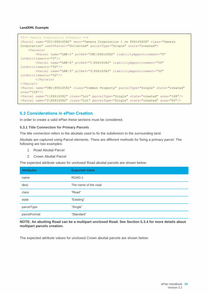
5.2.4 Owners Corporation
An Owners Corporation Schedule is captured using a non-spatial Parcel element. It does not require
coordinate geometry or title references. The table below shows the expected attribute values for an Owners Corporation Parcel.
Owners Corporations must be linked to their member lots and common property.
The following rules apply when capturing Owners Corporations:
• All plans with Owners Corporations must specify "Owners Corporation Act 2006" in the HeadOfPower
element.
• If lots or common property affected by an existing Owners Corporation are being varied ("affected") or "extinguished", "Section 32" or "Section 32A" must be shown as a PurposeOfSurvey value.
• "Section 32" plans must have at least one Owners Corporation with @state of "affected" or "extinguished".
• "Section 32A" plans must have an owners Corporation with @state of "extinguished".
• "Section 32B" plans must have an Owners Corporation with @state of "created".
• "Unlimited" and "Limited" Owners Corporation must be linked to at least two lots. "Limited to CP" Owners
Corporations be linked to at least two lots and a common property.
• A "created" Common Property @parcel must be linked to a "created" Owners Corporation with a
@useOfParcel of "Limited to CP" or "Unlimited".
• A lot cannot be linked to more than one Owners Corporation unless one is "Unlimited" and all the others
linked to the lot are "Limited" or "Limited to CP".
• Liability and entitlement values must be recorded against all linked parcels. Entitlement and liability values
for lots must be greater than 0 and for common property must be 0.
• Address must be assigned to Owners Corporation.
• Some annotations are required once an Owners Corporation is included in a plan.
• Member lots and common property are linked in the Owners Corporation Parcel using nested Parcels.
Each nested Parcel contains a parcel reference (@pclRef) to the linked Parcel and values for
@lotEntitlement and @liabilityApportionment values.
state "Existing" (cannot be "Created")
parcelFormat "Standard"
parcelType "Single"
Attribute Expected Value
name OC [#] \ [Plan Number] eg OC1\PS123456
class "Owners Corporation"
state "created", "affected", "extinguished", "existing"
parcelType "Single"
useOfParcel "Unlimited", "Limited to CP", "Limited"
ePlan Handbook
Version 2.2
29
LandXML Example
5.3 Considerations in ePlan Creation
In order to create a valid ePlan these sections must be considered.
5.3.1 Title Connection for Primary Parcels
The title connection refers to the abuttals used to fix the subdivision to the surrounding land.
Abuttals are captured using Parcel elements. There are different methods for fixing a primary parcel. The
following are two examples:
1. Road Abuttal Parcel
2. Crown Abuttal Parcel
The expected attribute values for unclosed Road abuttal parcels are shown below:
Attributes Expected Value
name ROAD-1
desc The name of the road
class “Road”
state “Existing”
parcelType “Single”
parcelFormat “Standard”
NOTE: An abutting Road can be a multipart unclosed Road. See Section 5.3.4 for more details about
multipart parcels creation.
The expected attribute values for unclosed Crown abuttal parcels are shown below:
<!-- Owners Corporation Schedule -->
<Parcel name="OC1\PS616582" desc="Owners Corporation 1 on PS616582X" class="Owners
Corporation" useOfParcel="Unlimited" parcelType="Single" state="created">
<Parcels>
<Parcel name="LNK-1" pclRef="CM1\PS616582" liabilityApportionment="0"
lotEntitlements="0"/>
<Parcel name="LNK-2" pclRef="1\PS616582" liabilityApportionment="50"
lotEntitlements="50"/>
<Parcel name="LNK-3" pclRef="2\PS616582" liabilityApportionment="50"
lotEntitlements="50"/>
</Parcels>
</Parcel>
<Parcel name="CM1\PS616582" class="Common Property" parcelType="Single" state="created"
area="106"/>
<Parcel name="1\PS616582" class="Lot" parcelType="Single" state="created" area="168"/>
<Parcel name="2\PS616582" class="Lot" parcelType="Single" state="created" area="60"/>
30 ePlan Handbook
Version 2.2
Attribute Expected Value
name Crown SPI eg 6~3\PP1234
class “Crown Allotment” or “Crown Portion”
state “Existing” or “Referenced”
parcelType “Single”
parcelFormat “Standard”
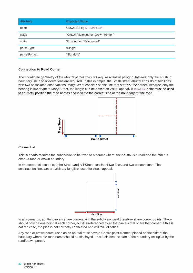
Connection to Road Corner
The coordinate geometry of the abuttal parcel does not require a closed polygon. Instead, only the abutting
boundary line and observations are required. In this example, the Smith Street abuttal consists of two lines
with two associated observations. Mary Street consists of one line that starts at the corner. Because only the
bearing is important to Mary Street, the length can be based on visual appeal. A Center point must be used
to correctly position the road names and indicate the correct side of the boundary for the road.
Corner Lot
This scenario requires the subdivision to be fixed to a corner where one abuttal is a road and the other is
either a road or crown boundary.
In the corner lot scenario, John Street and Bill Street consist of two lines and two observations. The
continuation lines are an arbitrary length chosen for visual appeal.
In all scenarios, abuttal parcels share corners with the subdivision and therefore share corner points. There
should only be one point at each corner, but it is referenced by all the parcels that share that corner. If this is
not the case, the plan is not correctly connected and will fail validation.
Any road or crown parcel used as an abuttal must have a Centre point element placed on the side of the
boundary where the road name should be displayed. This indicates the side of the boundary occupied by the
road/crown parcel.
ePlan Handbook
Version 2.2
31
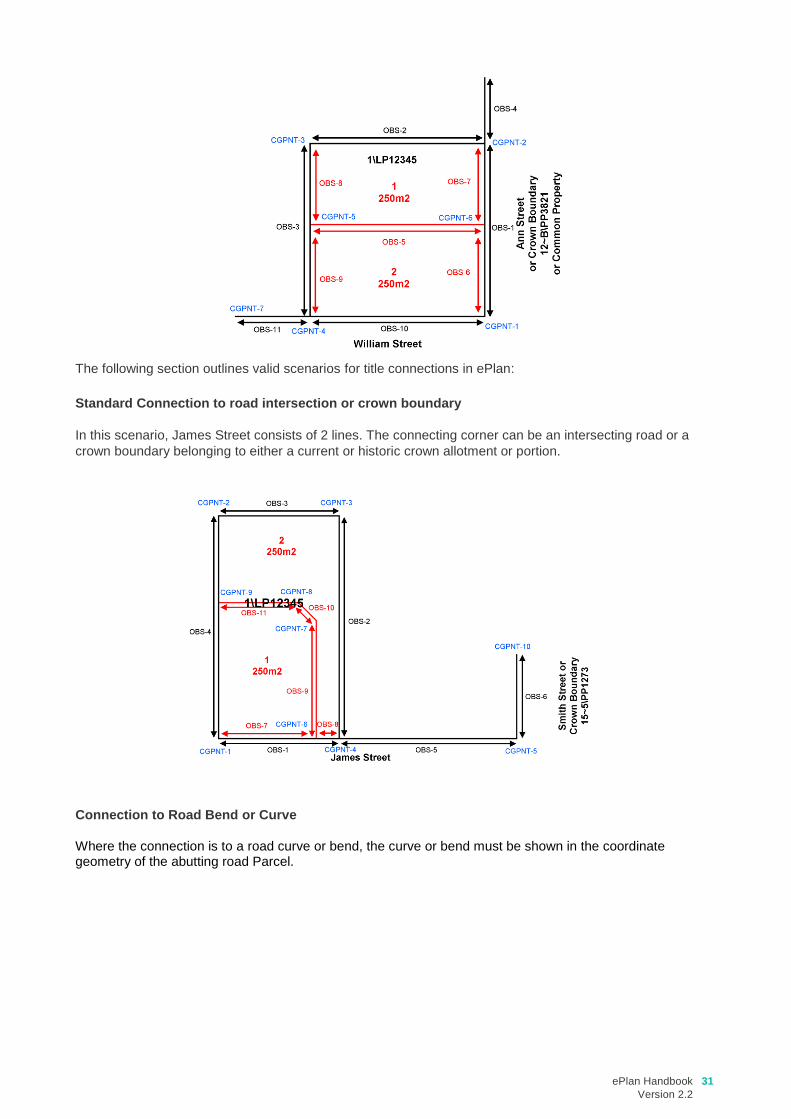
The following section outlines valid scenarios for title connections in ePlan:
Standard Connection to road intersection or crown boundary
In this scenario, James Street consists of 2 lines. The connecting corner can be an intersecting road or a
crown boundary belonging to either a current or historic crown allotment or portion.
Connection to Road Bend or Curve
Where the connection is to a road curve or bend, the curve or bend must be shown in the coordinate geometry of the abutting road Parcel.
32 ePlan Handbook
Version 2.2
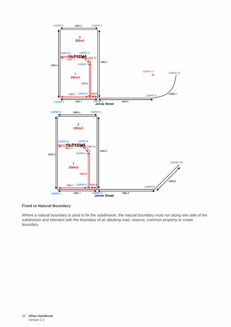
Fixed to Natural Boundary
Where a natural boundary is used to fix the subdivision, the natural boundary must run along one side of the
subdivision and intersect with the boundary of an abutting road, reserve, common property or crown
boundary.
ePlan Handbook
Version 2.2
33
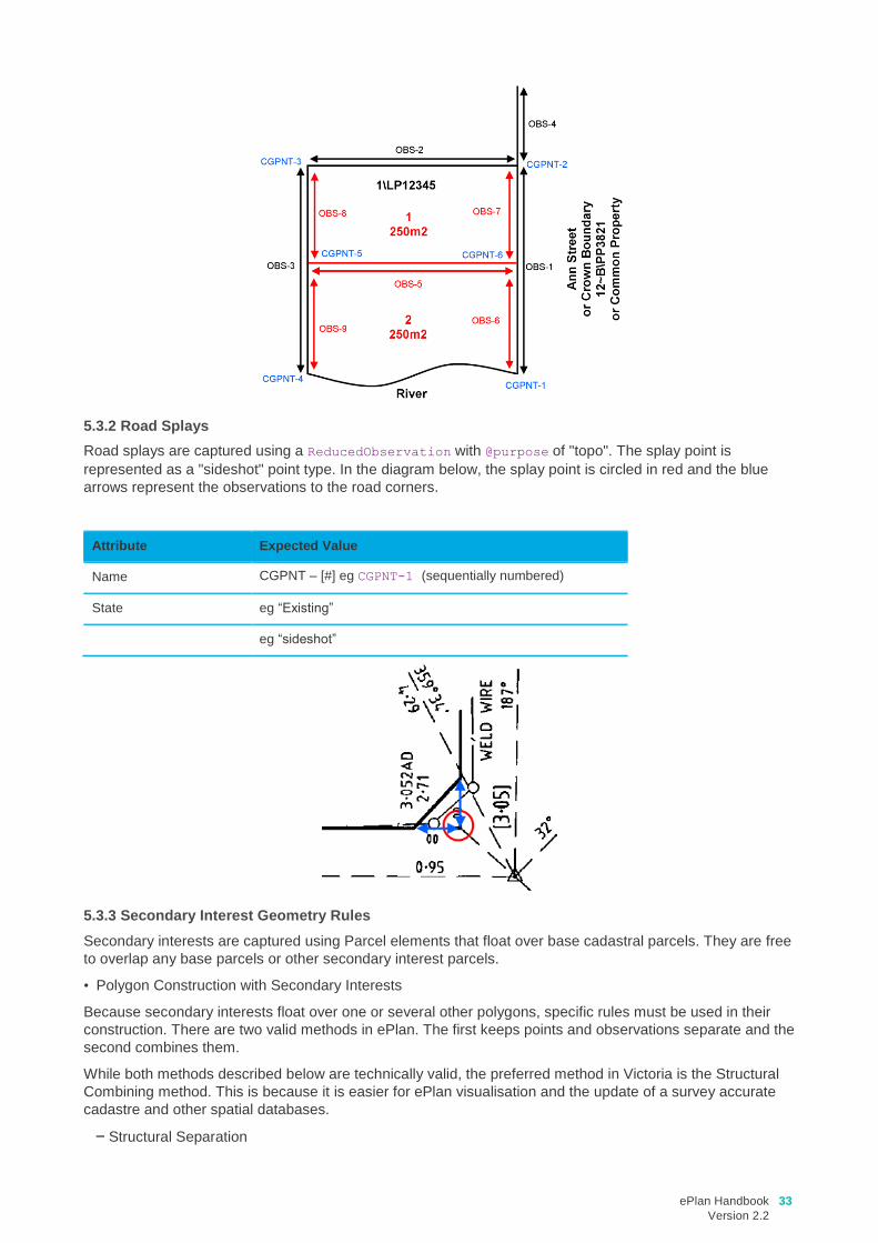
5.3.2 Road Splays
Road splays are captured using a ReducedObservation with @purpose of "topo". The splay point is
represented as a "sideshot" point type. In the diagram below, the splay point is circled in red and the blue
arrows represent the observations to the road corners.
Attribute Expected Value
Name CGPNT – [#] eg CGPNT-1 (sequentially numbered)
State eg “Existing”
eg “sideshot”
5.3.3 Secondary Interest Geometry Rules
Secondary interests are captured using Parcel elements that float over base cadastral parcels. They are free
to overlap any base parcels or other secondary interest parcels.
• Polygon Construction with Secondary Interests
Because secondary interests float over one or several other polygons, specific rules must be used in their
construction. There are two valid methods in ePlan. The first keeps points and observations separate and the
second combines them.
While both methods described below are technically valid, the preferred method in Victoria is the Structural
Combining method. This is because it is easier for ePlan visualisation and the update of a survey accurate
cadastre and other spatial databases.
– Structural Separation
34 ePlan Handbook
Version 2.2
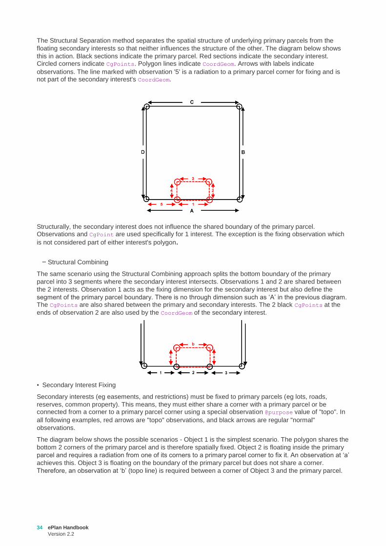
The Structural Separation method separates the spatial structure of underlying primary parcels from the
floating secondary interests so that neither influences the structure of the other. The diagram below shows
this in action. Black sections indicate the primary parcel. Red sections indicate the secondary interest. Circled corners indicate CgPoints. Polygon lines indicate CoordGeom. Arrows with labels indicate
observations. The line marked with observation '5' is a radiation to a primary parcel corner for fixing and is not part of the secondary interest's CoordGeom.
Structurally, the secondary interest does not influence the shared boundary of the primary parcel. Observations and CgPoint are used specifically for 1 interest. The exception is the fixing observation which
is not considered part of either interest's polygon.
– Structural Combining
The same scenario using the Structural Combining approach splits the bottom boundary of the primary
parcel into 3 segments where the secondary interest intersects. Observations 1 and 2 are shared between
the 2 interests. Observation 1 acts as the fixing dimension for the secondary interest but also define the
segment of the primary parcel boundary. There is no through dimension such as ‘A’ in the previous diagram. The CgPoints are also shared between the primary and secondary interests. The 2 black CgPoints at the
ends of observation 2 are also used by the CoordGeom of the secondary interest.
• Secondary Interest Fixing
Secondary interests (eg easements, and restrictions) must be fixed to primary parcels (eg lots, roads,
reserves, common property). This means, they must either share a corner with a primary parcel or be connected from a corner to a primary parcel corner using a special observation @purpose value of "topo". In
all following examples, red arrows are "topo" observations, and black arrows are regular "normal"
observations.
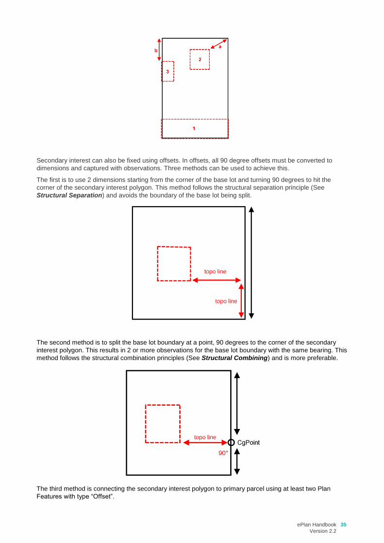
The diagram below shows the possible scenarios - Object 1 is the simplest scenario. The polygon shares the
bottom 2 corners of the primary parcel and is therefore spatially fixed. Object 2 is floating inside the primary
parcel and requires a radiation from one of its corners to a primary parcel corner to fix it. An observation at ‘a’
achieves this. Object 3 is floating on the boundary of the primary parcel but does not share a corner.
Therefore, an observation at ‘b’ (topo line) is required between a corner of Object 3 and the primary parcel.
ePlan Handbook
Version 2.2
35
Secondary interest can also be fixed using offsets. In offsets, all 90 degree offsets must be converted to
dimensions and captured with observations. Three methods can be used to achieve this.
The first is to use 2 dimensions starting from the corner of the base lot and turning 90 degrees to hit the
corner of the secondary interest polygon. This method follows the structural separation principle (See
Structural Separation) and avoids the boundary of the base lot being split.
The second method is to split the base lot boundary at a point, 90 degrees to the corner of the secondary
interest polygon. This results in 2 or more observations for the base lot boundary with the same bearing. This
method follows the structural combination principles (See Structural Combining) and is more preferable.
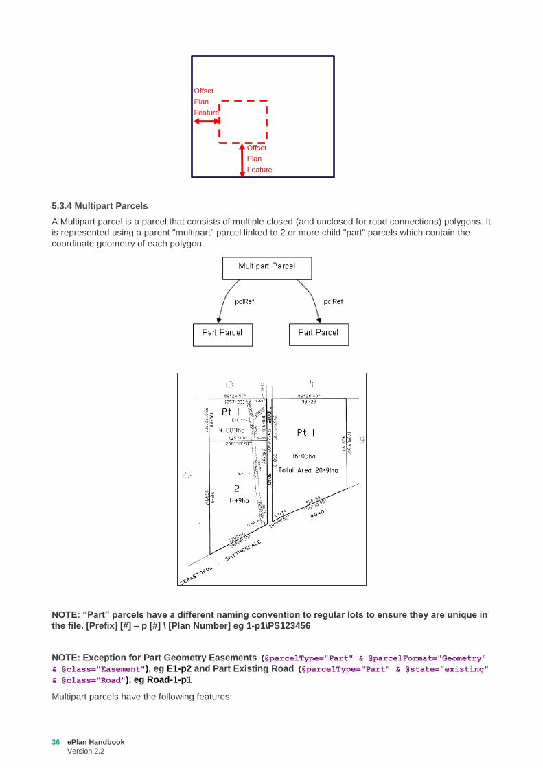
The third method is connecting the secondary interest polygon to primary parcel using at least two Plan
Features with type “Offset”.
topo line
topo line
topo line
36 ePlan Handbook
Version 2.2
5.3.4 Multipart Parcels
A Multipart parcel is a parcel that consists of multiple closed (and unclosed for road connections) polygons. It
is represented using a parent "multipart" parcel linked to 2 or more child "part" parcels which contain the
coordinate geometry of each polygon.
NOTE: “Part” parcels have a different naming convention to regular lots to ensure they are unique in
the file. [Prefix] [#] – p [#] \ [Plan Number] eg 1-p1\PS123456
NOTE: Exception for Part Geometry Easements (@parcelType="Part" & @parcelFormat="Geometry"
& @class="Easement"), eg E1-p2 and Part Existing Road (@parcelType="Part" & @state="existing"
& @class="Road"), eg Road-1-p1
Multipart parcels have the following features:
Offset
Plan
Feature
Offset
Plan
Feature
ePlan Handbook
Version 2.2
37
• The parent multipart parcel contains a @parcelType attribute value of "multipart". The child part parcels
contain a @parcelType attribute value of "part".
• The "multipart" parcel contains parcel linkages to all the "part" parcels.
• CoordGeom and Center are required sub-elements of "part" parcels but not the parent "multipart" parcel.
• @area attribute is required for either all the "part" parcels or the "multipart" parcel, unless the "part" parcel
contains a building boundary. If area is specified for both, then the "multipart" area must equal the sum of
its "parts".
• The parent/child LandXML structure is created using parcel linkages in the "multipart" parcel element that links to each "part" parcel element. Parcel linkages are done using nested Parcel elements as shown in
the example below.
LandXML Example
Parcel name="1\PS123456" class="Lot" state="created" parcelType="multipart"
parcelFormat="Standard" area="1000">
<Parcels>
<Parcel name="LNK-1" pclRef="1-p1\PS123456"/>
<Parcel name="LNK-2" pclRef="1-p2\PS123456"/>
</Parcels>
</Parcel>
<Parcel name="1-p1\PS123456" class="Lot" state="created" parcelType="part"
parcelFormat="Standard" area="500">...</Parcel>
<Parcel name="1-p2\PS123456" class="Lot" state="created" parcelType="part"
parcelFormat="Standard" area="500">...</Parcel>
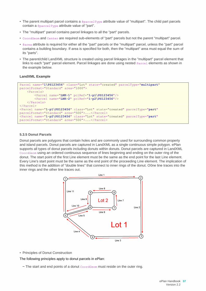
5.3.5 Donut Parcels
Donut parcels are polygons that contain holes and are commonly used for surrounding common property
and island parcels. Donut parcels are captured in LandXML as a single continuous simple polygon. ePlan
supports all types of donut parcels including donuts within donuts. Donut parcels are captured in LandXML CoordGeom using an ordered continuous sequence of lines beginning and ending on the outer ring of the
donut. The start point of the first Line element must be the same as the end point for the last Line element.
Every Line's start point must be the same as the end point of the proceeding Line element. The implication of
this method is the addition of "double lines" that connect to inner rings of the donut. O0ne line traces into the
inner rings and the other line traces out.
• Principles of Donut Construction
The following principles apply to donut parcels in ePlan:
– The start and end points of a donut CoordGeom must reside on the outer ring.
38 ePlan Handbook
Version 2.2
– All CgPoint nodes must be referenced an even number of times by the donut CoordGeom for the donut to
close.
– If a node is used more than twice (eg 4 or 6 times), it indicates the presence of a connection line(s) to an
inner ring.
– The direction of inner rings reverses with each level of internal ring. If the outer ring is clockwise, then the
first level internal ring will be anticlockwise, the second level internal ring will be clockwise, and so on.
•
• Example Donut Construction Algorithm
This algorithm is an example of how to approach constructing a donut CoordGeom from raw line work. It is by
no means the only way and should serve as a guide only. To commence follow the steps below:
4. Set the rotation flag to clockwise.
5. Set the starting point to the north of the most westerly point, referenced by a max of 2 lines.
6. From the start point, follow the line that is the first line to the east of north (i.e. clockwise from North).
7. For each next line
a. If one or more double line leaves the end point, follow each in order of "rotation" from the current
line's bearing.
i. If another double line leaves the end point, repeat a.
ii. (After all double lines have been followed) If single lines leave the end point of the double line,
mark this point as the point of inflection and reverse rotation flag. Then follow the first line in the
direction of the rotation flag from the current line's bearing.
iii. Reverse the direction of rotation flag when the last line from a point of inflection has been
followed.
b. (After all double lines have been followed) If a single line leaves the end point, follow it. If there is
more than one single line, then follow the first line in the direction of rotation.
c. Continue until all lines have been followed once. Do not follow lines more than once except double
lines.
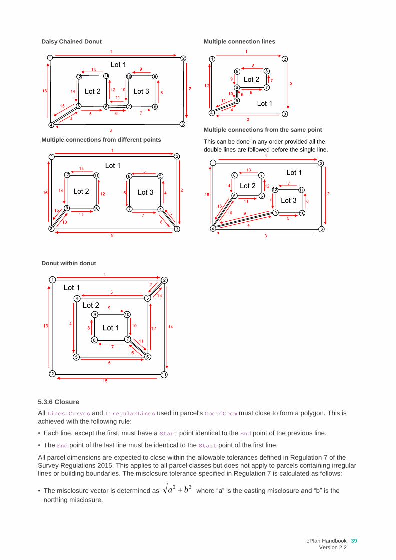
• Examples of complex donut constructions
In the examples below, numbered circles represent CgPoints and numbered red lines indicate CoordGeom
Lines. The arrow head represents the end point of the line. Only the line numbering for Lot 1 has been
shown. XML examples can be provided by contacting the ePlan support team.
ePlan Handbook
Version 2.2
39
Daisy Chained Donut
Multiple connections from different points
Multiple connection lines
Multiple connections from the same point
This can be done in any order provided all the
double lines are followed before the single line.
Donut within donut
5.3.6 Closure
All Lines, Curves and IrregularLines used in parcel's CoordGeom must close to form a polygon. This is
achieved with the following rule:
• Each line, except the first, must have a Start point identical to the End point of the previous line.
• The End point of the last line must be identical to the Start point of the first line.
All parcel dimensions are expected to close within the allowable tolerances defined in Regulation 7 of the
Survey Regulations 2015. This applies to all parcel classes but does not apply to parcels containing irregular
lines or building boundaries. The misclosure tolerance specified in Regulation 7 is calculated as follows:
• The misclosure vector is determined as 22 ba + where “a” is the easting misclosure and “b” is the
northing misclosure.

40 ePlan Handbook
Version 2.2
• Length of the misclosure vector must not exceed 15 millimetres + 100 parts per million of the perimeter.
For example, the misclosure tolerance for a parcel with perimeter of 600m is calculated as 15 mm + 100 x
600 x 1000 / 1000000 = 75 mm

ePlan Handbook
Version 2.2
41
6. Victorian Reference Data List
6.1 Easement Purposes
Group 1 - Easements that can be accepted without
further qualification
◼ Air Supply ◼ Flow of Air ◼ Passage of Air ◼ Air Exhaust and Ventilation ◼ Carriageway ◼ Drainage ◼ Drainage and Floodway ◼ Drainage and Sewerage ◼ Drainage and Waterway ◼ Erosion ◼ Fire Access ◼ Fire Escape ◼ Fire Egress ◼ Floodway ◼ Flooding ◼ Flow of Light and Air ◼ Footway ◼ Gas Distribution Pipeline ◼ Gas Transmission Pipeline ◼ Supply of Gas ◼ Flow of Light ◼ Passage of Light ◼ Other???? ◼ Overhanging Eaves ◼ Overhanging Spouting ◼ Overhanging Balcony ◼ Party Wall ◼ Chimney ◼ Passage of Light and Air ◼ Pipeline or Ancillary Purposes ◼ Powerline ◼ Right of Entry ◼ Sewerage ◼ Soakage by Water ◼ Submergence ◼ Walkway ◼ Walkway in the event of ‘activity’ in ‘specific location’ ◼ Waterway ◼ Waterway Management ◼ Way
Group 2 - Easements that can be accepted with
further qualification
◼ Channel ◼ Data Transmission ◼ Supply of Electricity ◼ Transmission of Electricity ◼ Ground Water Monitoring ◼ Irrigation ◼ Loading and Unloading Heavy Equipment ◼ Mail Collection ◼ Overhanging Projections ◼ Sanitary Convenience ◼ Supply of Recycled Water ◼ Supply of Water ◼ Support ◼ Telecommunications ◼ Underground Effluent Disposal ◼ Use of Stairway ◼ Vehicle Parking ◼ Waste Disposal ◼ Wetland
Group 3 - Easement purposes that should be
referred to Legal Branch for opinion
◼ Bore, Windmill and Tank ◼ Garbage Collection/Garbage ◼ Laying Water Pipes ◼ Nuisance or Annoyance ◼ Public Conveniences ◼ Public Highway ◼ Quarrying and Blasting ◼ Recreation and Garden ◼ Signboard, Signage ◼ Tree Planting
Group 4 - One off type easements
◼ Air Exhaust, Ventilation and Access ◼ Vehicle Parking ◼ Carriageway (with Limitation and Obligation) ◼ Right of Access
NOTE: When easement purposes in groups 2, 3 or 4 are used in an ePlan, they will be flagged for
attention during validation to indicate further qualification, notations or clarification may be required.
For more information also see this link.

42 ePlan Handbook
Version 2.2
6.2 Road Type
A
◼ Access ◼ Alley ◼ Alleyway ◼ Amble ◼ Anchorage ◼ Apartments ◼ Approach ◼ Arcade ◼ Arch ◼ Arterial ◼ Artery ◼ Avenue B
◼ Banan ◼ Bank ◼ Basin ◼ Bay ◼ Beach ◼ Belt ◼ Bend ◼ Block ◼ Bluff ◼ Boardwalk ◼ Boulevard ◼ Boulevarde ◼ Bowl ◼ Brace ◼ Brae ◼ Branchline ◼ Break ◼ Bridge ◼ Broadway ◼ Brow ◼ Bypass ◼ Byway C
◼ Causeway ◼ Centre ◼ Centreway ◼ Chase ◼ Circle ◼ Circlet ◼ Circuit
◼ Circus ◼ Claim ◼ Close ◼ Cluster ◼ Colonnade ◼ Common ◼ Concourse ◼ Connection ◼ Connector ◼ Copse ◼ Corner
◼ Corseo ◼ Corso ◼ Course ◼ Court ◼ Courts ◼ Courtyard ◼ Cove ◼ Crescent ◼ Crest ◼ Crief ◼ Crook ◼ Cross ◼ Crossing ◼ Crossroad
◼ Crossway ◼ Cruiseway ◼ Cul ◼ Cul-De-Sac ◼ Cutting D
◼ Dale ◼ Dash ◼ Dell ◼ Dene ◼ Deviation ◼ Dip ◼ Distributor ◼ Divide ◼ Dock ◼ Domain ◼ Down ◼ Downs ◼ Drift ◼ Drive ◼ Driveway E
◼ Edge ◼ Elbow ◼ Elm ◼ End ◼ Entrance ◼ Esplanade ◼ Estate ◼ Expressway ◼ Extension F
◼ Fairway ◼ Fall ◼ Fare ◼ Farms ◼ Fen ◼ Fern ◼ Firebreak ◼ Fireline ◼ Firetrack
◼ Firetrail ◼ Flat ◼ Flats ◼ Follow ◼ Footway ◼ Ford ◼ Foreshore ◼ Fork ◼ Formation ◼ Freeway ◼ Front ◼ Frontage G
◼ Gap
◼ Garden ◼ Gardens ◼ Gate ◼ Gates ◼ Gateway ◼ Glade ◼ Glades ◼ Glen ◼ Grange ◼ Green ◼ Ground ◼ Grove ◼ Gully H
◼ Haven ◼ Head ◼ Heath ◼ Heights ◼ Highroad ◼ Highway ◼ Hill ◼ Hollow ◼ Hub I
◼ Interchange ◼ Intersection ◼ Island J
◼ Junction
K
◼ Key ◼ Keys ◼ Knob L
◼ Ladder ◼ Lagoon ◼ Landing ◼ Lane ◼ Laneway ◼ Lea ◼ Leader
◼ Lees ◼ Leigh ◼ Line ◼ Link ◼ Lookout ◼ Loop ◼ Loops M
◼ Mall ◼ Manor ◼ Mead ◼ Meander ◼ Mew ◼ Mews
◼ Mile ◼ Motorway ◼ Motu ◼ Mount N
◼ Neaves ◼ Nook O
◼ Oaks ◼ Outlet ◼ Outlook ◼ Overbridge P
◼ Paddock ◼ Paku
◼ Parade ◼ Park ◼ Parklands ◼ Parkway ◼ Part ◼ Pass ◼ Passage ◼ Path ◼ Pathway ◼ Piazza ◼ Place ◼ Plateau ◼ Plaza ◼ Pocket ◼ Point
◼ Port ◼ Priors ◼ Promenade ◼ Pursuit Q
◼ Quad ◼ Quadrangle ◼ Quadrant ◼ Quay ◼ Quays
R
◼ Ramble ◼ Ramp ◼ Ranae ◼ Range ◼ Reach ◼ Reef ◼ Reserve ◼ Rest ◼ Retreat ◼ Return ◼ Ride ◼ Ridge ◼ Ridgeway
◼ Right Of Way ◼ Ring ◼ Rise ◼ Rising ◼ River ◼ Riverway ◼ Riviera ◼ Road ◼ Roads ◼ Roadside ◼ Roadway ◼ Ronde ◼ Rosebowl ◼ Rotary ◼ Round ◼ Route ◼ Row ◼ Rua ◼ Rue ◼ Run S
◼ Serviceway ◼ Shore ◼ Shunt ◼ Siding ◼ Slope ◼ Sound ◼ Spa ◼ Spur ◼ Square ◼ Stairs ◼ State High ◼ Steep ◼ Steps ◼ Straat ◼ Straight ◼ Strand ◼ Street ◼ Strip ◼ Subway
T
◼ Tarn ◼ Tee ◼ Terrace ◼ Throughfair ◼ Throughway ◼ Tollway ◼ Top ◼ Tor ◼ Tower ◼ Towers ◼ Track ◼ Trail ◼ Trailer
◼ Tram ◼ Tramway ◼ Traverse ◼ Trees ◼ Triangle ◼ Trunkway ◼ Tunnel ◼ Turn ◼ Twist U
◼ Underpass V
◼ Vale ◼ Valley ◼ Venus ◼ Viaduct ◼ View ◼ Views ◼ Village ◼ Villas ◼ Vista ◼ Vue W
◼ Wade ◼ Walk ◼ Walkway ◼ Waters ◼ Waterway ◼ Way ◼ Wharf
◼ Whenua ◼ Wood ◼ Woods ◼ Wynd XYZ
◼ Yard
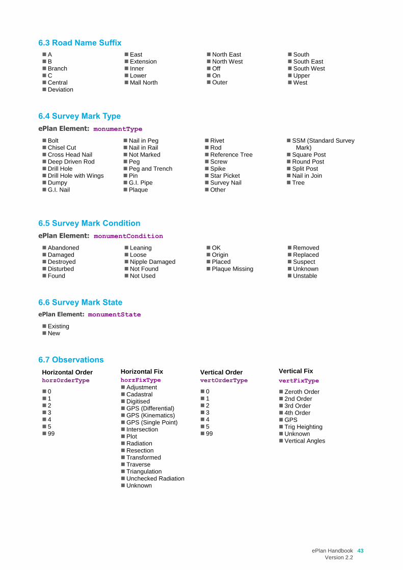
ePlan Handbook
Version 2.2
43
6.3 Road Name Suffix
◼ A ◼ B ◼ Branch ◼ C ◼ Central ◼ Deviation
◼ East ◼ Extension ◼ Inner ◼ Lower ◼ Mall North
◼ North East ◼ North West ◼ Off ◼ On ◼ Outer
◼ South ◼ South East ◼ South West ◼ Upper ◼ West
6.4 Survey Mark Type
ePlan Element: monumentType
◼ Bolt ◼ Chisel Cut ◼ Cross Head Nail ◼ Deep Driven Rod ◼ Drill Hole ◼ Drill Hole with Wings ◼ Dumpy ◼ G.I. Nail
◼ Nail in Peg ◼ Nail in Rail ◼ Not Marked ◼ Peg ◼ Peg and Trench ◼ Pin ◼ G.I. Pipe ◼ Plaque
◼ Rivet ◼ Rod ◼ Reference Tree ◼ Screw ◼ Spike ◼ Star Picket ◼ Survey Nail ◼ Other
◼ SSM (Standard Survey Mark)
◼ Square Post ◼ Round Post ◼ Split Post ◼ Nail in Join ◼ Tree
6.5 Survey Mark Condition
ePlan Element: monumentCondition
◼ Abandoned ◼ Damaged ◼ Destroyed ◼ Disturbed ◼ Found
◼ Leaning ◼ Loose ◼ Nipple Damaged ◼ Not Found ◼ Not Used
◼ OK ◼ Origin ◼ Placed ◼ Plaque Missing
◼ Removed ◼ Replaced ◼ Suspect ◼ Unknown ◼ Unstable
6.6 Survey Mark State
ePlan Element: monumentState
◼ Existing ◼ New
6.7 Observations
Horizontal Order
horzOrderType
◼ 0 ◼ 1 ◼ 2 ◼ 3 ◼ 4 ◼ 5 ◼ 99
Horizontal Fix
horzFixType
◼ Adjustment ◼ Cadastral ◼ Digitised ◼ GPS (Differential) ◼ GPS (Kinematics) ◼ GPS (Single Point) ◼ Intersection ◼ Plot ◼ Radiation ◼ Resection ◼ Transformed ◼ Traverse ◼ Triangulation ◼ Unchecked Radiation ◼ Unknown
Vertical Order
vertOrderType
◼ 0 ◼ 1 ◼ 2 ◼ 3 ◼ 4 ◼ 5 ◼ 99
Vertical Fix
vertFixType
◼ Zeroth Order ◼ 2nd Order ◼ 3rd Order ◼ 4th Order ◼ GPS ◼ Trig Heighting ◼ Unknown ◼ Vertical Angles