Embed Size (px)
Citation preview

Specification for RFID Air Interface
EPC™ Radio-Frequency Identity Protocols Class-1 Generation-2 UHF RFID
Protocol for Communications at 860 MHz – 960 MHz Version 1.1.0
right notice Copy
© 2004, 2005, 2006, EPCglobal Inc.
Unauthorized reproduction, modification and/or use of this Specification is prohibited. Any reproduction, modifi-cation and/or use of this Specification is subject to the licensing obligations of the EPCglobal Intellectual Prop-erty Policy and enforcement of the terms thereof.
Requests for permission to reproduce should be addressed to [email protected].
Violators may be prosecuted.
© 2004, 2005, 2006, EPCglobal Inc. Page 1 of 100 17 December 2005
Contents INDEX OF FIGURES .................................................................................................................................................5 INDEX OF TABLES ...................................................................................................................................................6 FOREWORD ..............................................................................................................................................................8 INTRODUCTION........................................................................................................................................................9 1. SCOPE..............................................................................................................................................................10 2. CONFORMANCE .............................................................................................................................................10
2.1 CLAIMING CONFORMANCE.............................................................................................................................10 2.2 GENERAL CONFORMANCE REQUIREMENTS.....................................................................................................10
2.2.1 Interrogators .......................................................................................................................................10 2.2.2 Tags....................................................................................................................................................10
2.3 COMMAND STRUCTURE AND EXTENSIBILITY....................................................................................................11 2.3.1 Mandatory commands ........................................................................................................................11 2.3.2 Optional commands............................................................................................................................11 2.3.3 Proprietary commands .......................................................................................................................11 2.3.4 Custom commands.............................................................................................................................11
3. NORMATIVE REFERENCES...........................................................................................................................11 4. TERMS AND DEFINITIONS.............................................................................................................................13
4.1 ADDITIONAL TERMS AND DEFINITIONS ............................................................................................................13 5. SYMBOLS, ABBREVIATED TERMS, AND NOTATION.................................................................................15
5.1 SYMBOLS.....................................................................................................................................................15 5.2 ABBREVIATED TERMS ...................................................................................................................................15 5.3 NOTATION....................................................................................................................................................16
6. PROTOCOL REQUIREMENTS........................................................................................................................17 6.1 PROTOCOL OVERVIEW ..................................................................................................................................17
6.1.1 Physical layer......................................................................................................................................17 6.1.2 Tag-identification layer .......................................................................................................................17
6.2 PROTOCOL PARAMETERS..............................................................................................................................17 6.2.1 Signaling – Physical and media access control (MAC) parameters...................................................17 6.2.2 Logical – Operating procedure parameters........................................................................................21
6.3 DESCRIPTION OF OPERATING PROCEDURE.....................................................................................................22 6.3.1 Signaling .............................................................................................................................................22
6.3.1.1 Operational frequencies ..............................................................................................................22 6.3.1.2 Interrogator-to-Tag (R=>T) communications...............................................................................22
6.3.1.2.1 Interrogator frequency accuracy ...............................................................................................22 6.3.1.2.2 Modulation ................................................................................................................................22 6.3.1.2.3 Data encoding...........................................................................................................................22 6.3.1.2.4 Tari values ................................................................................................................................23 6.3.1.2.5 R=>T RF envelope....................................................................................................................23 6.3.1.2.6 Interrogator power-up waveform...............................................................................................23 6.3.1.2.7 Interrogator power-down waveform..........................................................................................23 6.3.1.2.8 R=>T preamble and frame-sync ...............................................................................................24 6.3.1.2.9 Frequency-hopping spread-spectrum waveform......................................................................25 6.3.1.2.10 Frequency-hopping spread-spectrum channelization...............................................................25 6.3.1.2.11 Transmit mask ..........................................................................................................................25
6.3.1.3 Tag-to-Interrogator (T=>R) communications...............................................................................27 6.3.1.3.1 Modulation ................................................................................................................................27 6.3.1.3.2 Data encoding...........................................................................................................................27
6.3.1.3.2.1 FM0 baseband....................................................................................................................28 6.3.1.3.2.2 FM0 preamble ....................................................................................................................28 6.3.1.3.2.3 Miller-modulated subcarrier................................................................................................29 6.3.1.3.2.4 Miller subcarrier preamble..................................................................................................30
6.3.1.3.3 Tag supported Tari values and backscatter link rates ..............................................................32 6.3.1.3.4 Tag power-up timing .................................................................................................................32
© 2004, 2005, 2006, EPCglobal Inc. Page 2 of 100 17 December 2005
6.3.1.3.5 Minimum operating field strength and backscatter strength.....................................................32 6.3.1.4 Transmission order......................................................................................................................33 6.3.1.5 Cyclic-redundancy check (CRC) .................................................................................................33 6.3.1.6 Link timing ...................................................................................................................................33
6.3.2 Tag selection, inventory, and access .................................................................................................35 6.3.2.1 Tag memory ................................................................................................................................35
6.3.2.1.1 Reserved Memory.....................................................................................................................36 6.3.2.1.1.1 Kill password ......................................................................................................................36 6.3.2.1.1.2 Access password................................................................................................................36
6.3.2.1.2 EPC Memory.............................................................................................................................36 6.3.2.1.2.1 CRC-16...............................................................................................................................36 6.3.2.1.2.2 Protocol-control (PC) bits ...................................................................................................36 6.3.2.1.2.3 EPC for an EPCglobal™ Application..................................................................................37 6.3.2.1.2.4 EPC for a non-EPCglobal™ Application ............................................................................37
6.3.2.1.3 TID Memory ..............................................................................................................................37 6.3.2.1.4 User Memory ............................................................................................................................37
6.3.2.1.4.1 User memory for an EPCglobal™ Application ...................................................................37 6.3.2.1.4.2 User memory for a non-EPCglobal™ Application ..............................................................37
6.3.2.2 Sessions and inventoried flags....................................................................................................38 6.3.2.3 Selected flag................................................................................................................................38 6.3.2.4 Tag states and slot counter .........................................................................................................39
6.3.2.4.1 Ready state...............................................................................................................................39 6.3.2.4.2 Arbitrate state............................................................................................................................40 6.3.2.4.3 Reply state ................................................................................................................................40 6.3.2.4.4 Acknowledged state..................................................................................................................40 6.3.2.4.5 Open state ................................................................................................................................40 6.3.2.4.6 Secured state............................................................................................................................40 6.3.2.4.7 Killed state ................................................................................................................................40 6.3.2.4.8 Slot counter...............................................................................................................................41
6.3.2.5 Tag random or pseudo-random number generator.....................................................................41 6.3.2.6 Managing Tag populations ..........................................................................................................43 6.3.2.7 Selecting Tag populations ...........................................................................................................43 6.3.2.8 Inventorying Tag populations ......................................................................................................43 6.3.2.9 Accessing individual Tags ...........................................................................................................45 6.3.2.10 Interrogator commands and Tag replies .....................................................................................47
6.3.2.10.1 Select commands .....................................................................................................................49 6.3.2.10.1.1 Select (mandatory) .............................................................................................................49
6.3.2.10.2 Inventory commands ................................................................................................................51 6.3.2.10.2.1 Query (mandatory) .............................................................................................................51 6.3.2.10.2.2 QueryAdjust (mandatory) ...................................................................................................52 6.3.2.10.2.3 QueryRep (mandatory).......................................................................................................53 6.3.2.10.2.4 ACK (mandatory)................................................................................................................54 6.3.2.10.2.5 NAK (mandatory)................................................................................................................55
6.3.2.10.3 Access commands....................................................................................................................56 6.3.2.10.3.1 Req_RN (mandatory) .........................................................................................................57 6.3.2.10.3.2 Read (mandatory)...............................................................................................................58 6.3.2.10.3.3 Write (mandatory)...............................................................................................................59 6.3.2.10.3.4 Kill (mandatory) ..................................................................................................................60 6.3.2.10.3.5 Lock (mandatory)................................................................................................................63 6.3.2.10.3.6 Access (optional) ................................................................................................................65 6.3.2.10.3.7 BlockWrite (optional) ..........................................................................................................67 6.3.2.10.3.8 BlockErase (optional) .........................................................................................................68
7. INTELLECTUAL PROPERTY RIGHTS INTRINSIC TO THIS SPECIFICATION............................................69 ANNEX A (NORMATIVE) EXTENSIBLE BIT VECTORS (EBV) ............................................................................70 ANNEX B (NORMATIVE) STATE-TRANSITION TABLES ....................................................................................71
B.1 PRESENT STATE: READY...............................................................................................................................71 B.2 PRESENT STATE: ARBITRATE ........................................................................................................................72 B.3 PRESENT STATE: REPLY ...............................................................................................................................73
© 2004, 2005, 2006, EPCglobal Inc. Page 3 of 100 17 December 2005

B.4 PRESENT STATE: ACKNOWLEDGED................................................................................................................74 B.5 PRESENT STATE: OPEN ................................................................................................................................75 B.6 PRESENT STATE: SECURED ..........................................................................................................................76 B.7 PRESENT STATE: KILLED...............................................................................................................................77
ANNEX C (NORMATIVE) COMMAND-RESPONSE TABLES ...............................................................................78 C.1 COMMAND RESPONSE: POWER-UP................................................................................................................78 C.2 COMMAND RESPONSE: QUERY......................................................................................................................78 C.3 COMMAND RESPONSE: QUERYREP ...............................................................................................................79 C.4 COMMAND RESPONSE: QUERYADJUST ..........................................................................................................79 C.5 COMMAND RESPONSE: ACK .........................................................................................................................79 C.6 COMMAND RESPONSE: NAK .........................................................................................................................80 C.7 COMMAND RESPONSE: REQ_RN...................................................................................................................80 C.8 COMMAND RESPONSE: SELECT .....................................................................................................................80 C.9 COMMAND RESPONSE: READ ........................................................................................................................81 C.10 COMMAND RESPONSE: WRITE ...................................................................................................................81 C.11 COMMAND RESPONSE: KILL.......................................................................................................................82 C.12 COMMAND RESPONSE: LOCK.....................................................................................................................82 C.13 COMMAND RESPONSE: ACCESS.................................................................................................................83 C.14 COMMAND RESPONSE: BLOCKWRITE.........................................................................................................83 C.15 COMMAND RESPONSE: BLOCKERASE ........................................................................................................84 C.16 COMMAND RESPONSE: T2 TIMEOUT............................................................................................................84 C.17 COMMAND RESPONSE: INVALID COMMAND .................................................................................................85
ANNEX D (INFORMATIVE) EXAMPLE SLOT-COUNT (Q) SELECTION ALGORITHM.......................................86 D.1 EXAMPLE ALGORITHM AN INTERROGATOR MIGHT USE TO CHOOSE Q ...............................................................86
ANNEX E (INFORMATIVE) EXAMPLE OF TAG INVENTORY AND ACCESS.....................................................87 E.1 EXAMPLE INVENTORY AND ACCESS OF A SINGLE TAG .....................................................................................87
ANNEX F (INFORMATIVE) CALCULATION OF 5-BIT AND 16-BIT CYCLIC REDUNDANCY CHECKS............88 F.1 EXAMPLE CRC-5 ENCODER/DECODER ..........................................................................................................88 F.2 EXAMPLE CRC-16 ENCODER/DECODER ........................................................................................................88 F.3 EXAMPLE CRC-16 CALCULATIONS ................................................................................................................89
ANNEX G (NORMATIVE) MULTIPLE- AND DENSE-INTERROGATOR CHANNELIZED SIGNALING...............90 G.1 DENSE-INTERROGATOR MODE ......................................................................................................................90 G.1.1 EXAMPLES OF DENSE-INTERROGATOR-MODE OPERATION (INFORMATIVE) ....................................................90 G.2 CHANNELIZATION IN MULTIPLE- AND DENSE-INTERROGATOR ENVIRONMENTS...................................................91 G.2.1 EXAMPLE CHANNELIZATION (INFORMATIVE) ................................................................................................91
ANNEX H (INFORMATIVE) INTERROGATOR-TO-TAG LINK MODULATION ....................................................94 H.1 BASEBAND WAVEFORMS, MODULATED RF, AND DETECTED WAVEFORMS .........................................................94
ANNEX I (NORMATIVE) ERROR CODES..............................................................................................................95 I.1 TAG ERROR CODES AND THEIR USAGE ...........................................................................................................95
ANNEX J (NORMATIVE) SLOT COUNTER ...........................................................................................................96 J.1 SLOT-COUNTER OPERATION..........................................................................................................................96
ANNEX K (INFORMATIVE) EXAMPLE DATA-FLOW EXCHANGE......................................................................97 K.1 OVERVIEW OF THE DATA-FLOW EXCHANGE ....................................................................................................97 K.2 TAG MEMORY CONTENTS AND LOCK-FIELD VALUES.........................................................................................97 K.3 DATA-FLOW EXCHANGE AND COMMAND SEQUENCE ........................................................................................98
ANNEX L (INFORMATIVE) OPTIONAL TAG FEATURES ....................................................................................99 L.1 OPTIONAL TAG PASSWORDS .........................................................................................................................99 L.2 OPTIONAL TAG MEMORY BANKS AND MEMORY-BANK SIZES .............................................................................99 L.3 OPTIONAL TAG COMMANDS...........................................................................................................................99 L.4 OPTIONAL TAG ERROR-CODE REPORTING FORMAT.........................................................................................99 L.5 OPTIONAL TAG BACKSCATTER MODULATION FORMAT .....................................................................................99
ANNEX M (INFORMATIVE) REVISION HISTORY ...............................................................................................100
© 2004, 2005, 2006, EPCglobal Inc. Page 4 of 100 17 December 2005
Index of Figures FIGURE 6.1 – PIE SYMBOLS ........................................................................................................................................22 FIGURE 6.2 – INTERROGATOR-TO-TAG RF ENVELOPE ..................................................................................................23 FIGURE 6.3 – INTERROGATOR POWER-UP AND POWER-DOWN RF ENVELOPE .................................................................24 FIGURE 6.4 – R=>T PREAMBLE AND FRAME-SYNC ........................................................................................................25 FIGURE 6.5 – FHSS INTERROGATOR RF ENVELOPE.....................................................................................................26 FIGURE 6.6 – TRANSMIT MASK FOR MULTIPLE-INTERROGATOR ENVIRONMENTS..............................................................27 FIGURE 6.7 – TRANSMIT MASK FOR DENSE-INTERROGATOR ENVIRONMENTS..................................................................27 FIGURE 6.8 – FM0 BASIS FUNCTIONS AND GENERATOR STATE DIAGRAM........................................................................28 FIGURE 6.9 – FM0 SYMBOLS AND SEQUENCES.............................................................................................................28 FIGURE 6.10 – TERMINATING FM0 TRANSMISSIONS......................................................................................................29 FIGURE 6.11 – FM0 T=>R PREAMBLE .........................................................................................................................29 FIGURE 6.12 – MILLER BASIS FUNCTIONS AND GENERATOR STATE DIAGRAM ..................................................................29 FIGURE 6.13 – SUBCARRIER SEQUENCES ....................................................................................................................30 FIGURE 6.14 – TERMINATING SUBCARRIER TRANSMISSIONS..........................................................................................31 FIGURE 6.15 – SUBCARRIER T=>R PREAMBLE.............................................................................................................31 FIGURE 6.16 – LINK TIMING .........................................................................................................................................34 FIGURE 6.17 – LOGICAL MEMORY MAP.........................................................................................................................35 FIGURE 6.18 – SESSION DIAGRAM ...............................................................................................................................39 FIGURE 6.19 – TAG STATE DIAGRAM............................................................................................................................42 FIGURE 6.20 – INTERROGATOR/TAG OPERATIONS AND TAG STATE................................................................................43 FIGURE 6.21 – ONE TAG REPLY ..................................................................................................................................45 FIGURE 6.22 – SUCCESSFUL WRITE SEQUENCE...........................................................................................................59 FIGURE 6.23 – KILL PROCEDURE .................................................................................................................................62 FIGURE 6.24 – LOCK PAYLOAD AND USAGE ..................................................................................................................64 FIGURE 6.25 – ACCESS PROCEDURE ...........................................................................................................................66 FIGURE D.1 – EXAMPLE ALGORITHM FOR CHOOSING THE SLOT-COUNT PARAMETER Q....................................................86 FIGURE E.1 – EXAMPLE OF TAG INVENTORY AND ACCESS.............................................................................................87 FIGURE F.1 – EXAMPLE CRC-5 CIRCUIT ......................................................................................................................88 FIGURE F.2 – EXAMPLE CRC-16 CIRCUIT ....................................................................................................................89 FIGURE G.1 – ALGORITHM FOR DETERMINING CHANNELIZATION AND DENSE-INTERROGATOR-MODE PARAMETERS ...........91 FIGURE G.2 – EXAMPLES OF DENSE-INTERROGATOR-MODE OPERATION........................................................................92 FIGURE G.3 – CHANNEL NUMBERING FOR EXAMPLE 3 ..................................................................................................93 FIGURE H.1 – INTERROGATOR-TO-TAG MODULATION....................................................................................................94 FIGURE J.1 – SLOT-COUNTER STATE DIAGRAM.............................................................................................................96
© 2004, 2005, 2006, EPCglobal Inc. Page 5 of 100 17 December 2005

Index of Tables TABLE 6.1 – INTERROGATOR-TO-TAG (R=>T) COMMUNICATIONS ..................................................................................18 TABLE 6.2 – TAG-TO-INTERROGATOR (T=>R) COMMUNICATIONS ..................................................................................19 TABLE 6.3 – TAG INVENTORY AND ACCESS PARAMETERS ..............................................................................................21 TABLE 6.4 – COLLISION MANAGEMENT PARAMETERS ....................................................................................................21 TABLE 6.5 – RF ENVELOPE PARAMETERS ....................................................................................................................23 TABLE 6.6 – INTERROGATOR POWER-UP WAVEFORM PARAMETERS ...............................................................................24 TABLE 6.7 – INTERROGATOR POWER-DOWN WAVEFORM PARAMETERS ..........................................................................24 TABLE 6.8 – FHSS WAVEFORM PARAMETERS ..............................................................................................................26 TABLE 6.9 – TAG-TO-INTERROGATOR LINK FREQUENCIES .............................................................................................32 TABLE 6.10 – TAG-TO-INTERROGATOR DATA RATES .....................................................................................................32 TABLE 6.11 – CRC-16 PRECURSOR ............................................................................................................................33 TABLE 6.12 – CRC-5 DEFINITION. SEE ALSO ANNEX F .................................................................................................33 TABLE 6.13 – LINK TIMING PARAMETERS ......................................................................................................................34 TABLE 6.14 – TAG FLAGS AND PERSISTENCE VALUES ...................................................................................................39 TABLE 6.15 – ACCESS COMMANDS AND TAG STATES IN WHICH THEY ARE PERMITTED.....................................................46 TABLE 6.16 – COMMANDS...........................................................................................................................................48 TABLE 6.17 – SELECT COMMAND.................................................................................................................................50 TABLE 6.18 – TAG RESPONSE TO ACTION PARAMETER .................................................................................................50 TABLE 6.19 – QUERY COMMAND..................................................................................................................................51 TABLE 6.20 – TAG REPLY TO A QUERY COMMAND ........................................................................................................51 TABLE 6.21 – QUERYADJUST COMMAND......................................................................................................................52 TABLE 6.22 – TAG REPLY TO A QUERYADJUST COMMAND.............................................................................................52 TABLE 6.23 – QUERYREP COMMAND ...........................................................................................................................53 TABLE 6.24 – TAG REPLY TO A QUERYREP COMMAND ..................................................................................................53 TABLE 6.25 – ACK COMMAND .....................................................................................................................................54 TABLE 6.26 – TAG REPLY TO A SUCCESSFUL ACK COMMAND........................................................................................54 TABLE 6.27 – NAK COMMAND .....................................................................................................................................55 TABLE 6.28 – REQ_RN COMMAND ..............................................................................................................................57 TABLE 6.29 – TAG REPLY TO A REQ_RN COMMAND .....................................................................................................57 TABLE 6.30 – READ COMMAND....................................................................................................................................58 TABLE 6.31 – TAG REPLY TO A SUCCESSFUL READ COMMAND ......................................................................................58 TABLE 6.32 – WRITE COMMAND ..................................................................................................................................59 TABLE 6.33 – TAG REPLY TO A SUCCESSFUL WRITE COMMAND .....................................................................................59 TABLE 6.34 – KILL COMMAND ......................................................................................................................................61 TABLE 6.35 – TAG REPLY TO THE FIRST KILL COMMAND................................................................................................61 TABLE 6.36 – TAG REPLY TO A SUCCESSFUL KILL PROCEDURE .....................................................................................61 TABLE 6.37 – LOCK COMMAND ....................................................................................................................................64 TABLE 6.38 – TAG REPLY TO A LOCK COMMAND ...........................................................................................................64 TABLE 6.39 – LOCK ACTION-FIELD FUNCTIONALITY.......................................................................................................64 TABLE 6.40 – ACCESS COMMAND ................................................................................................................................65 TABLE 6.41 – TAG REPLY TO AN ACCESS COMMAND.....................................................................................................65 TABLE 6.42 – BLOCKWRITE COMMAND ........................................................................................................................67 TABLE 6.43 – TAG REPLY TO A SUCCESSFUL BLOCKWRITE COMMAND...........................................................................67 TABLE 6.44 – BLOCKERASE COMMAND........................................................................................................................68 TABLE 6.45 – TAG REPLY TO A SUCCESSFUL BLOCKERASE COMMAND ..........................................................................68 TABLE A.1 – EBV-8 WORD FORMAT.............................................................................................................................70 TABLE B.1 – READY STATE-TRANSITION TABLE.............................................................................................................71 TABLE B.2 – ARBITRATE STATE-TRANSITION TABLE ......................................................................................................72 TABLE B.3 – REPLY STATE-TRANSITION TABLE .............................................................................................................73 TABLE B.4 – ACKNOWLEDGED STATE-TRANSITION TABLE..............................................................................................74 TABLE B.5 – OPEN STATE-TRANSITION TABLE ..............................................................................................................75 TABLE B.6 – SECURED STATE-TRANSITION TABLE.........................................................................................................76 TABLE B.7 – KILLED STATE-TRANSITION TABLE.............................................................................................................77 TABLE C.1 – POWER-UP COMMAND-RESPONSE TABLE..................................................................................................78 TABLE C.2 – QUERY 1 COMMAND-RESPONSE TABLE......................................................................................................78 TABLE C.3 – QUERYREP COMMAND-RESPONSE TABLE1 ................................................................................................79
© 2004, 2005, 2006, EPCglobal Inc. Page 6 of 100 17 December 2005
TABLE C.4 – QUERYADJUST 1 COMMAND-RESPONSE TABLE2.........................................................................................79 TABLE C.5 – ACK COMMAND-RESPONSE TABLE ...........................................................................................................79 TABLE C.6 – NAK COMMAND-RESPONSE TABLE ...........................................................................................................80 TABLE C.7 – REQ_RN COMMAND-RESPONSE TABLE.....................................................................................................80 TABLE C.8 – SELECT COMMAND-RESPONSE TABLE.......................................................................................................80 TABLE C.9 – READ COMMAND-RESPONSE TABLE ..........................................................................................................81 TABLE C.10 – WRITE COMMAND-RESPONSE TABLE.......................................................................................................81 TABLE C.11 – KILL 1 COMMAND-RESPONSE TABLE ........................................................................................................82 TABLE C.12 – LOCK COMMAND-RESPONSE TABLE ........................................................................................................82 TABLE C.13 – ACCESS 1 COMMAND-RESPONSE TABLE ..................................................................................................83 TABLE C.14 – BLOCKWRITE COMMAND-RESPONSE TABLE ............................................................................................83 TABLE C.15 – BLOCKERASE COMMAND-RESPONSE TABLE............................................................................................84 TABLE C.16 – T2 TIMEOUT COMMAND-RESPONSE TABLE ...............................................................................................84 TABLE C.17 – INVALID COMMAND-RESPONSE TABLE .....................................................................................................85 TABLE F.1 – CRC-5 REGISTER PRELOAD VALUES.........................................................................................................88 TABLE F.2 – EPC MEMORY CONTENTS FOR AN EXAMPLE TAG.......................................................................................89 TABLE G.1 – CHANNELIZATION FOR EXAMPLE 2 ...........................................................................................................93 TABLE I.1 – TAG-ERROR REPLY FORMAT ......................................................................................................................95 TABLE I.2 – TAG ERROR CODES...................................................................................................................................95 TABLE K.1 – TAG MEMORY CONTENTS .........................................................................................................................97 TABLE K.2 – LOCK-FIELD VALUES ................................................................................................................................97 TABLE K.3 – INTERROGATOR COMMANDS AND TAG REPLIES .........................................................................................98 TABLE M.1 – REVISION HISTORY ...............................................................................................................................100
© 2004, 2005, 2006, EPCglobal Inc. Page 7 of 100 17 December 2005
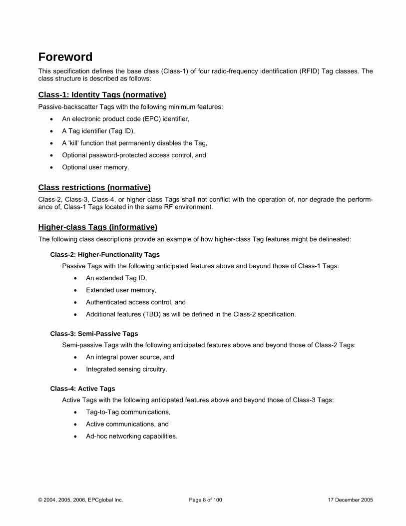
Foreword This specification defines the base class (Class-1) of four radio-frequency identification (RFID) Tag classes. The class structure is described as follows:
Class-1: Identity Tags (normative) Passive-backscatter Tags with the following minimum features:
• An electronic product code (EPC) identifier,
• A Tag identifier (Tag ID),
• A 'kill' function that permanently disables the Tag,
• Optional password-protected access control, and
• Optional user memory.
Class restrictions (normative) Class-2, Class-3, Class-4, or higher class Tags shall not conflict with the operation of, nor degrade the perform-ance of, Class-1 Tags located in the same RF environment.
Higher-class Tags (informative) The following class descriptions provide an example of how higher-class Tag features might be delineated:
Class-2: Higher-Functionality Tags Passive Tags with the following anticipated features above and beyond those of Class-1 Tags:
• An extended Tag ID,
• Extended user memory,
• Authenticated access control, and
• Additional features (TBD) as will be defined in the Class-2 specification.
Class-3: Semi-Passive Tags Semi-passive Tags with the following anticipated features above and beyond those of Class-2 Tags:
• An integral power source, and
• Integrated sensing circuitry.
Class-4: Active Tags Active Tags with the following anticipated features above and beyond those of Class-3 Tags:
• Tag-to-Tag communications,
• Active communications, and
• Ad-hoc networking capabilities.
© 2004, 2005, 2006, EPCglobal Inc. Page 8 of 100 17 December 2005
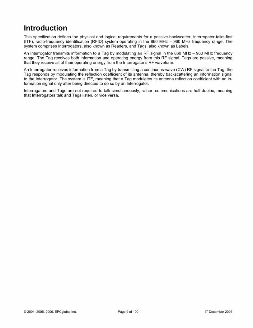
Introduction This specification defines the physical and logical requirements for a passive-backscatter, Interrogator-talks-first (ITF), radio-frequency identification (RFID) system operating in the 860 MHz – 960 MHz frequency range. The system comprises Interrogators, also known as Readers, and Tags, also known as Labels.
An Interrogator transmits information to a Tag by modulating an RF signal in the 860 MHz – 960 MHz frequency range. The Tag receives both information and operating energy from this RF signal. Tags are passive, meaning that they receive all of their operating energy from the Interrogator’s RF waveform.
An Interrogator receives information from a Tag by transmitting a continuous-wave (CW) RF signal to the Tag; the Tag responds by modulating the reflection coefficient of its antenna, thereby backscattering an information signal to the Interrogator. The system is ITF, meaning that a Tag modulates its antenna reflection coefficient with an in-formation signal only after being directed to do so by an Interrogator.
Interrogators and Tags are not required to talk simultaneously; rather, communications are half-duplex, meaning that Interrogators talk and Tags listen, or vice versa.
© 2004, 2005, 2006, EPCglobal Inc. Page 9 of 100 17 December 2005
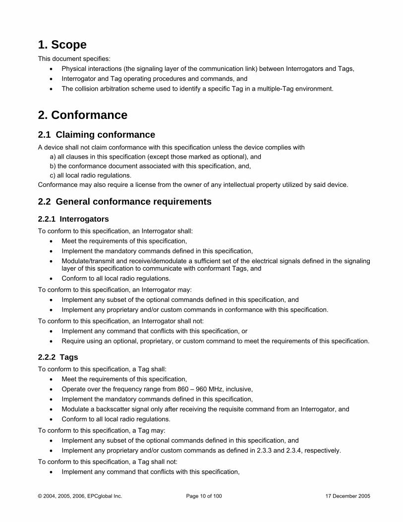
1. Scope This document specifies:
• Physical interactions (the signaling layer of the communication link) between Interrogators and Tags, • Interrogator and Tag operating procedures and commands, and • The collision arbitration scheme used to identify a specific Tag in a multiple-Tag environment.
2. Conformance 2.1 Claiming conformance A device shall not claim conformance with this specification unless the device complies with
a) all clauses in this specification (except those marked as optional), and b) the conformance document associated with this specification, and, c) all local radio regulations.
Conformance may also require a license from the owner of any intellectual property utilized by said device.
2.2 General conformance requirements
2.2.1 Interrogators To conform to this specification, an Interrogator shall:
• Meet the requirements of this specification, • Implement the mandatory commands defined in this specification, • Modulate/transmit and receive/demodulate a sufficient set of the electrical signals defined in the signaling
layer of this specification to communicate with conformant Tags, and • Conform to all local radio regulations.
To conform to this specification, an Interrogator may: • Implement any subset of the optional commands defined in this specification, and • Implement any proprietary and/or custom commands in conformance with this specification.
To conform to this specification, an Interrogator shall not: • Implement any command that conflicts with this specification, or • Require using an optional, proprietary, or custom command to meet the requirements of this specification.
2.2.2 Tags To conform to this specification, a Tag shall:
• Meet the requirements of this specification, • Operate over the frequency range from 860 – 960 MHz, inclusive, • Implement the mandatory commands defined in this specification, • Modulate a backscatter signal only after receiving the requisite command from an Interrogator, and • Conform to all local radio regulations.
To conform to this specification, a Tag may: • Implement any subset of the optional commands defined in this specification, and • Implement any proprietary and/or custom commands as defined in 2.3.3 and 2.3.4, respectively.
To conform to this specification, a Tag shall not: • Implement any command that conflicts with this specification,
© 2004, 2005, 2006, EPCglobal Inc. Page 10 of 100 17 December 2005
• Require using an optional, proprietary, or custom command to meet the requirements of this specification, or
• Modulate a backscatter signal unless commanded to do so by an Interrogator using the signaling layer defined in this specification.
2.3 Command structure and extensibility This specification allows four command types: (1) mandatory, (2) optional, (3) proprietary, and (4) custom. Subclause 6.3.2.10 and Table 6.16 define the structure of the command codes used by Interrogators and Tags for each of the four types, as well as the availability of future extensions.
All commands defined by this specification are either mandatory or optional.
Proprietary or custom commands are vendor-defined.
2.3.1 Mandatory commands Conforming Tags shall support all mandatory commands. Conforming Interrogators shall support all manda-tory commands.
2.3.2 Optional commands Conforming Tags may or may not support optional commands. Conforming Interrogators may or may not support optional commands. If a Tag or an Interrogator implements an optional command, it shall implement it in the manner specified in this specification.
2.3.3 Proprietary commands Proprietary commands may be enabled in conformance with this specification, but are not specified herein. All proprietary commands shall be capable of being permanently disabled. Proprietary commands are in-tended for manufacturing purposes and shall not be used in field-deployed RFID systems.
2.3.4 Custom commands Custom commands may be enabled in conformance with this specification, but are not specified herein. An Interrogator shall issue a custom command only after (i) singulating a Tag, and (ii) reading (or having prior knowledge of) the Tag manufacturer’s identification in the Tag’s TID memory. An Interrogator shall use a custom command only in accordance with the specifications of the Tag manufacturer identified in the Tag ID. A custom command shall not solely duplicate the functionality of any mandatory or optional command defined in this specification by a different method.
3. Normative references The following referenced documents are indispensable to the application of this specification. For dated references, only the edition cited applies. For undated references, the latest edition (including any amendments) applies.
EPCglobal™: EPC™ Tag Data Standards (versions 1.3 and above)
EPCglobal™ (2004): FMCG RFID Physical Requirements Document (draft)
EPCglobal™: Class-1 Generation-2 UHF RFID Implementation Reference (draft)
European Telecommunications Standards Institute (ETSI), EN 300 220 (all parts): Electromagnetic compatibility and Radio spectrum Matters (ERM); Short Range Devices (SRD); Radio equipment to be used in the 25 MHz to 1000 MHz frequency range with power levels ranging up to 500 mW
European Telecommunications Standards Institute (ETSI), EN 302 208: Electromagnetic compatibility and radio spectrum matters (ERM) – Radio-frequency identification equipment operating in the band 865 MHz to 868 MHz with power levels up to 2 W, Part 1 – Technical characteristics and test methods
© 2004, 2005, 2006, EPCglobal Inc. Page 11 of 100 17 December 2005
European Telecommunications Standards Institute (ETSI), EN 302 208: Electromagnetic compatibility and radio spectrum matters (ERM) – Radio-frequency identification equipment operating in the band 865 MHz to 868 MHz with power levels up to 2 W, Part 2 – Harmonized EN under article 3.2 of the R&TTE directive
ISO/IEC Directives, Part 2: Rules for the structure and drafting of International Standards
ISO/IEC 3309: Information technology – Telecommunications and information exchange between systems – High-level data link control (HDLC) procedures – Frame structure
ISO/IEC 15961: Information technology, Automatic identification and data capture – Radio frequency identification (RFID) for item management – Data protocol: application interface
ISO/IEC 15962: Information technology, Automatic identification and data capture techniques – Radio frequency identification (RFID) for item management – Data protocol: data encoding rules and logical memory functions
ISO/IEC 15963: Information technology — Radiofrequency identification for item management — Unique identifi-cation for RF tags
ISO/IEC 18000-1: Information technology — Radio frequency identification for item management — Part 1: Ref-erence architecture and definition of parameters to be standardized
ISO/IEC 18000-6: Information technology automatic identification and data capture techniques — Radio fre-quency identification for item management air interface — Part 6: Parameters for air interface communications at 860–960 MHz
ISO/IEC 19762: Information technology AIDC techniques – Harmonized vocabulary – Part 3: radio-frequency identification (RFID)
U.S. Code of Federal Regulations (CFR), Title 47, Chapter I, Part 15: Radio-frequency devices, U.S. Federal Communications Commission
© 2004, 2005, 2006, EPCglobal Inc. Page 12 of 100 17 December 2005
4. Terms and definitions The principal terms and definitions used in this specification are described in ISO/IEC 19762.
4.1 Additional terms and definitions Terms and definitions specific to this document that supersede any normative references are as follows:
• Air interface The complete communication link between an Interrogator and a Tag including the physical layer, collision ar-bitration algorithm, command and response structure, and data-coding methodology.
• Command set The set of commands used to explore and modify a Tag population.
• Continuous wave Typically a sinusoid at a given frequency, but more generally any Interrogator waveform suitable for powering a passive Tag without amplitude and/or phase modulation of sufficient magnitude to be interpreted by a Tag as transmitted data.
• Cover-coding A method by which an Interrogator obscures information that it is transmitting to a Tag. To cover-code data or a password, an Interrogator first requests a random number from the Tag. The Interrogator then performs a bit-wise EXOR of the data or password with this random number, and transmits the cover-coded (also called ciphertext) string to the Tag. The Tag uncovers the data or password by performing a bit-wise EXOR of the received cover-coded string with the original random number.
• Dense-Interrogator environment An operating environment (defined below) within which most or all of the available channels are occupied by active Interrogators (for example, 25 active Interrogators operating in 25 available channels).
• Dense-Interrogator mode A set of Interrogator-to-Tag and Tag-to-Interrogator signaling parameters used in dense-Interrogator envi-ronments.
• Extended temperature range –40 °C to +65 °C (see nominal temperature range).
• EPCglobal™ Application An application whose usage denotes an acceptance of EPCglobal™ standards and policies (see non-EPCglobal™ Application).
• Full-duplex communications A communications channel that carries data in both directions at once. See also half-duplex communications.
• Half-duplex communications A communications channel that carries data in one direction at a time rather than in both directions at once. See also full-duplex communications.
• Inventoried flag A flag that indicates whether a Tag may respond to an Interrogator. Tags maintain a separate inventoried flag for each of four sessions; each flag has symmetric A and B values. Within any given session, Interroga-tors typically inventory Tags from A to B followed by a re-inventory of Tags from B back to A (or vice versa).
• Inventory round The period initiated by a Query command and terminated by either a subsequent Query command (which also starts a new inventory round) or a Select command.
• Multiple-Interrogator environment An operating environment (defined below) within which a modest number of the available channels are occu-pied by active Interrogators (for example, 5 active Interrogators operating in 25 available channels).
© 2004, 2005, 2006, EPCglobal Inc. Page 13 of 100 17 December 2005
• Nominal temperature range –25 °C to +40 °C (see extended temperature range).
• Non-EPCglobal™ Application An application whose usage does not denote an acceptance of EPCglobal™ standards and policies (see EP-Cglobal™ Application).
• Operating environment A region within which an Interrogator’s RF transmissions are attenuated by less than 90dB. In free space, the operating environment is a sphere whose radius is approximately 1000m, with the Interrogator located at the center. In a building or other enclosure, the size and shape of the operating environment depends on factors such as the material properties and shape of the building, and may be less than 1000m in certain directions and greater than 1000m in other directions.
• Operating procedure Collectively, the set of functions and commands used by an Interrogator to identify and modify Tags. (Also known as the Tag-identification layer.)
• Passive Tag (or passive Label) A Tag (or Label) whose transceiver is powered by the RF field.
• Permalock or Permalocked A memory location whose lock status is unchangeable (i.e. the memory location is permanently locked or per-manently unlocked) is said to be permalocked.
• Persistent memory or persistent flag A memory or flag value whose state is maintained during a brief loss of Tag power.
• Physical layer The data coding and modulation waveforms used in Interrogator-to-Tag and Tag-to-Interrogator signaling.
• Protocol Collectively, a physical layer and a Tag-identification layer specification.
• Q A parameter that an Interrogator uses to regulate the probability of Tag response. An Interrogator commands Tags in an inventory round to load a Q-bit random (or pseudo-random) number into their slot counter; the In-terrogator may also command Tags to decrement their slot counter. Tags reply when the value in their slot counter (i.e. their slot – see below) is zero. Q is an integer in the range (0,15); the corresponding Tag-response probabilities range from 20 = 1 to 2–15 = 0.000031.
• Random-slotted collision arbitration A collision-arbitration algorithm where Tags load a random (or pseudo-random) number into a slot counter, decrement this slot counter based on Interrogator commands, and reply to the Interrogator when their slot counter reaches zero.
• Session An inventory process comprising an Interrogator and an associated Tag population. An Interrogator chooses one of four sessions and inventories Tags within that session. The Interrogator and associated Tag population operate in one and only one session for the duration of an inventory round (defined above). For each session, Tags maintain a corresponding inventoried flag. Sessions allow Tags to keep track of their inventoried status separately for each of four possible time-interleaved inventory processes, using an independent inventoried flag for each process.
• Single-Interrogator environment An operating environment (defined above) within which there is a single active Interrogator at any given time.
• Singulation Identifying an individual Tag in a multiple-Tag environment.
© 2004, 2005, 2006, EPCglobal Inc. Page 14 of 100 17 December 2005
• Slot Slot corresponds to the point in an inventory round at which a Tag may respond. Slot is the value output by a Tag’s slot counter; Tags reply when their slot (i.e. the value in their slot counter) is zero. See also Q (above).
• Tag-identification layer Collectively, the set of functions and commands used by an Interrogator to identify and modify Tags (also known as the operating procedure).
• Tari Reference time interval for a data-0 in Interrogator-to-Tag signaling. The mnemonic “Tari” derives from the ISO/IEC 18000-6 (part A) specification, in which Tari is an abbreviation for Type A Reference Interval.
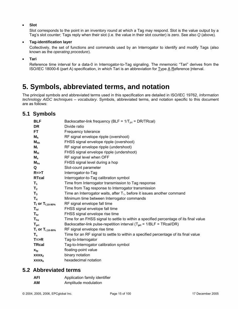
5. Symbols, abbreviated terms, and notation The principal symbols and abbreviated terms used in this specification are detailed in ISO/IEC 19762, Information technology AIDC techniques – vocabulary. Symbols, abbreviated terms, and notation specific to this document are as follows:
5.1 Symbols BLF Backscatter-link frequency (BLF = 1/Tpri = DR/TRcal) DR Divide ratio FT Frequency tolerance Mh RF signal envelope ripple (overshoot) Mhh FHSS signal envelope ripple (overshoot) Ml RF signal envelope ripple (undershoot) Mhl FHSS signal envelope ripple (undershoot) Ms RF signal level when OFF Mhs FHSS signal level during a hop Q Slot-count parameter R=>T Interrogator-to-Tag RTcal Interrogator-to-Tag calibration symbolT1 Time from Interrogator transmission to Tag response T2 Time from Tag response to Interrogator transmission T3 Time an Interrogator waits, after T1, before it issues another command T4 Minimum time between Interrogator commands Tf or Tf,10-90% RF signal envelope fall time Thf FHSS signal envelope fall time Thr FHSS signal envelope rise time Ths Time for an FHSS signal to settle to within a specified percentage of its final value Tpri Backscatter-link pulse-repetition interval (Tpri = 1/BLF = TRcal/DR) Tr or Tr,10-90% RF signal envelope rise time Ts Time for an RF signal to settle to within a specified percentage of its final value T=>R Tag-to-Interrogator TRcal Tag-to-Interrogator calibration symbol xfp floating-point value xxxx2 binary notation xxxxh hexadecimal notation
5.2 Abbreviated terms AFI Application family identifier AM Amplitude modulation
© 2004, 2005, 2006, EPCglobal Inc. Page 15 of 100 17 December 2005

ASK Amplitude shift keying CEPT Conference of European Posts and Telecommunications Ciphertext Information that is cover-coded CRC Cyclic redundancy check CW Continuous wave dBch Decibels referenced to the integrated power in the reference channel DSB Double sideband DSB-ASK Double-sideband amplitude-shift keying EPC Electronic product code ETSI European Telecommunications Standards Institute FCC Federal Communications Commission FDM Frequency-Division Multiplexing FHSS Frequency-hopping spread spectrum Handle 16-bit Tag-authentication number NSI Numbering system identifier PIE Pulse-interval encoding Pivot Decision threshold differentiating an R=>T data-0 symbol from a data-1 symbol Plaintext Information that is not cover-coded ppm Parts-per-million PSK Phase shift keying or phase shift keyed PR-ASK Phase-reversal amplitude shift keying RF Radio frequency RFID Radio-frequency identification RFU Reserved for future use RN16 16-bit random or pseudo-random number RNG Random or pseudo-random number generator ITF Interrogator talks first (reader talks first) SSB Single sideband SSB-ASK Single-sideband amplitude-shift keying TDM Time-division multiplexing or time-division multiplexed (as appropriate) Tag ID Tag-identification or Tag identifier, depending on context Word 16 bits
5.3 Notation This specification uses the following notational conventions:
• States and flags are denoted in bold. Example: ready.
• Commands are denoted in italics. Variables are also denoted in italics. Where there might be confusion between commands and variables, this specification will make an explicit statement. Example: Query.
• Command parameters are underlined. Example: Pointer.
• For logical negation, labels are preceded by ‘~’. Example: If flag is true, then ~flag is false.
• The symbol, R=>T, refers to commands or signaling from an Interrogator to a Tag (Reader-to-Tag).
• The symbol, T=>R, refers to commands or signaling from a Tag to an Interrogator (Tag-to-Reader).
© 2004, 2005, 2006, EPCglobal Inc. Page 16 of 100 17 December 2005
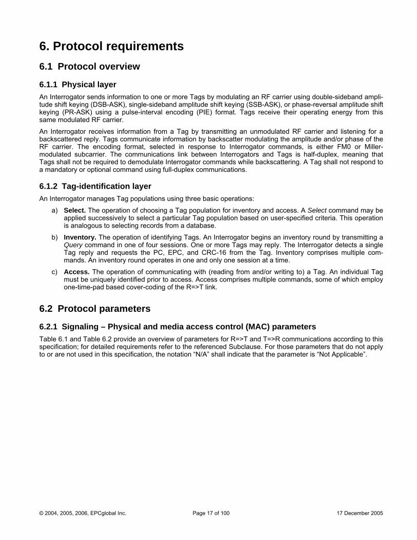
6. Protocol requirements 6.1 Protocol overview
6.1.1 Physical layer An Interrogator sends information to one or more Tags by modulating an RF carrier using double-sideband ampli-tude shift keying (DSB-ASK), single-sideband amplitude shift keying (SSB-ASK), or phase-reversal amplitude shift keying (PR-ASK) using a pulse-interval encoding (PIE) format. Tags receive their operating energy from this same modulated RF carrier.
An Interrogator receives information from a Tag by transmitting an unmodulated RF carrier and listening for a backscattered reply. Tags communicate information by backscatter modulating the amplitude and/or phase of the RF carrier. The encoding format, selected in response to Interrogator commands, is either FM0 or Miller-modulated subcarrier. The communications link between Interrogators and Tags is half-duplex, meaning that Tags shall not be required to demodulate Interrogator commands while backscattering. A Tag shall not respond to a mandatory or optional command using full-duplex communications.
6.1.2 Tag-identification layer An Interrogator manages Tag populations using three basic operations:
a) Select. The operation of choosing a Tag population for inventory and access. A Select command may be applied successively to select a particular Tag population based on user-specified criteria. This operation is analogous to selecting records from a database.
b) Inventory. The operation of identifying Tags. An Interrogator begins an inventory round by transmitting a Query command in one of four sessions. One or more Tags may reply. The Interrogator detects a single Tag reply and requests the PC, EPC, and CRC-16 from the Tag. Inventory comprises multiple com-mands. An inventory round operates in one and only one session at a time.
c) Access. The operation of communicating with (reading from and/or writing to) a Tag. An individual Tag must be uniquely identified prior to access. Access comprises multiple commands, some of which employ one-time-pad based cover-coding of the R=>T link.
6.2 Protocol parameters
6.2.1 Signaling – Physical and media access control (MAC) parameters Table 6.1 and Table 6.2 provide an overview of parameters for R=>T and T=>R communications according to this specification; for detailed requirements refer to the referenced Subclause. For those parameters that do not apply to or are not used in this specification, the notation “N/A” shall indicate that the parameter is “Not Applicable”.
© 2004, 2005, 2006, EPCglobal Inc. Page 17 of 100 17 December 2005
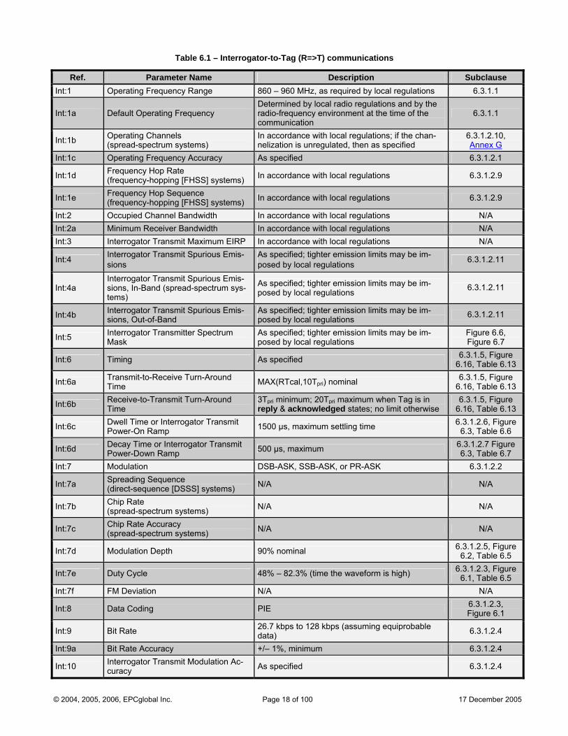
Table 6.1 – Interrogator-to-Tag (R=>T) communications
Ref. Parameter Name Description Subclause Int:1 Operating Frequency Range 860 – 960 MHz, as required by local regulations 6.3.1.1
Int:1a Default Operating Frequency Determined by local radio regulations and by the radio-frequency environment at the time of the communication
6.3.1.1
Int:1b Operating Channels (spread-spectrum systems)
In accordance with local regulations; if the chan-nelization is unregulated, then as specified
6.3.1.2.10, Annex G
Int:1c Operating Frequency Accuracy As specified 6.3.1.2.1
Int:1d Frequency Hop Rate (frequency-hopping [FHSS] systems) In accordance with local regulations 6.3.1.2.9
Int:1e Frequency Hop Sequence (frequency-hopping [FHSS] systems) In accordance with local regulations 6.3.1.2.9
Int:2 Occupied Channel Bandwidth In accordance with local regulations N/A Int:2a Minimum Receiver Bandwidth In accordance with local regulations N/A Int:3 Interrogator Transmit Maximum EIRP In accordance with local regulations N/A
Int:4 Interrogator Transmit Spurious Emis-sions
As specified; tighter emission limits may be im-posed by local regulations 6.3.1.2.11
Int:4a Interrogator Transmit Spurious Emis-sions, In-Band (spread-spectrum sys-tems)
As specified; tighter emission limits may be im-posed by local regulations 6.3.1.2.11
Int:4b Interrogator Transmit Spurious Emis-sions, Out-of-Band
As specified; tighter emission limits may be im-posed by local regulations 6.3.1.2.11
Int:5 Interrogator Transmitter Spectrum Mask
As specified; tighter emission limits may be im-posed by local regulations
Figure 6.6, Figure 6.7
Int:6 Timing As specified 6.3.1.5, Figure 6.16, Table 6.13
Int:6a Transmit-to-Receive Turn-Around Time MAX(RTcal,10Tpri) nominal 6.3.1.5, Figure
6.16, Table 6.13
Int:6b Receive-to-Transmit Turn-Around Time
3Tpri minimum; 20Tpri maximum when Tag is in reply & acknowledged states; no limit otherwise
6.3.1.5, Figure 6.16, Table 6.13
Int:6c Dwell Time or Interrogator Transmit Power-On Ramp 1500 µs, maximum settling time 6.3.1.2.6, Figure
6.3, Table 6.6
Int:6d Decay Time or Interrogator Transmit Power-Down Ramp 500 µs, maximum 6.3.1.2.7 Figure
6.3, Table 6.7 Int:7 Modulation DSB-ASK, SSB-ASK, or PR-ASK 6.3.1.2.2
Int:7a Spreading Sequence (direct-sequence [DSSS] systems) N/A N/A
Int:7b Chip Rate (spread-spectrum systems) N/A N/A
Int:7c Chip Rate Accuracy (spread-spectrum systems) N/A N/A
Int:7d Modulation Depth 90% nominal 6.3.1.2.5, Figure 6.2, Table 6.5
Int:7e Duty Cycle 48% – 82.3% (time the waveform is high) 6.3.1.2.3, Figure 6.1, Table 6.5
Int:7f FM Deviation N/A N/A
Int:8 Data Coding PIE 6.3.1.2.3, Figure 6.1
Int:9 Bit Rate 26.7 kbps to 128 kbps (assuming equiprobable data) 6.3.1.2.4
Int:9a Bit Rate Accuracy +/– 1%, minimum 6.3.1.2.4
Int:10 Interrogator Transmit Modulation Ac-curacy As specified 6.3.1.2.4
© 2004, 2005, 2006, EPCglobal Inc. Page 18 of 100 17 December 2005
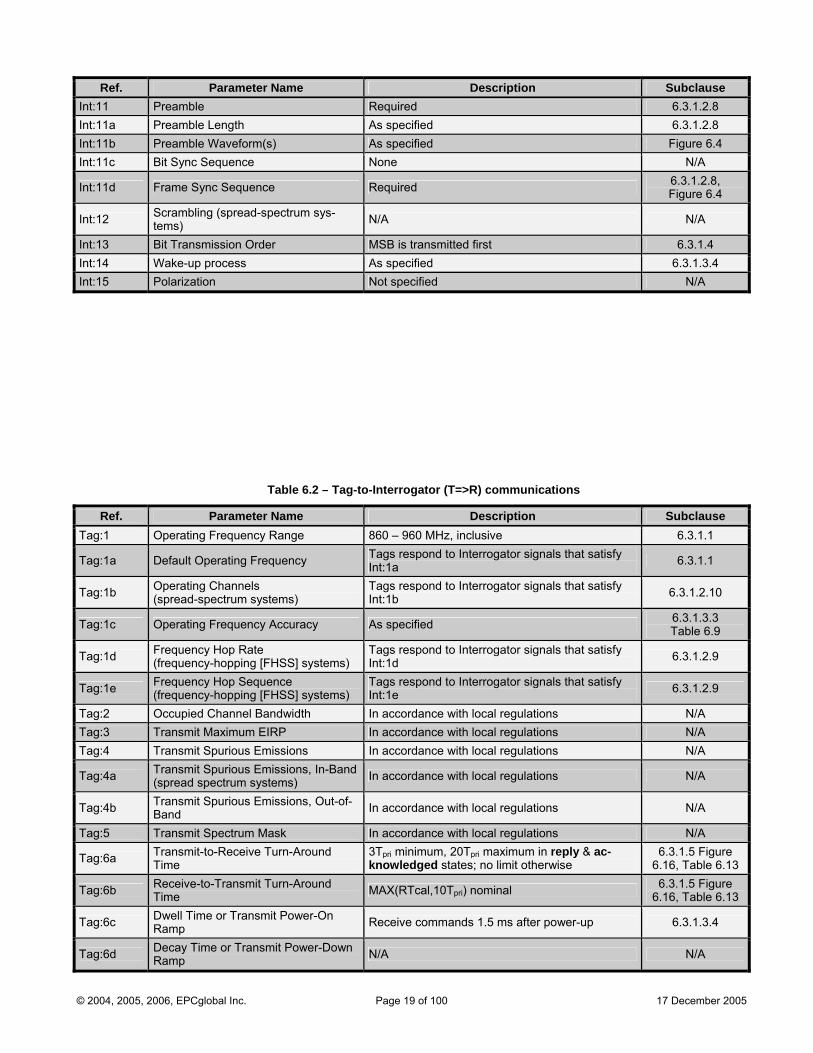
Ref. Parameter Name Description Subclause Int:11 Preamble Required 6.3.1.2.8 Int:11a Preamble Length As specified 6.3.1.2.8 Int:11b Preamble Waveform(s) As specified Figure 6.4 Int:11c Bit Sync Sequence None N/A
Int:11d Frame Sync Sequence Required 6.3.1.2.8, Figure 6.4
Int:12 Scrambling (spread-spectrum sys-tems) N/A N/A
Int:13 Bit Transmission Order MSB is transmitted first 6.3.1.4 Int:14 Wake-up process As specified 6.3.1.3.4 Int:15 Polarization Not specified N/A
Table 6.2 – Tag-to-Interrogator (T=>R) communications
Ref. Parameter Name Description Subclause Tag:1 Operating Frequency Range 860 – 960 MHz, inclusive 6.3.1.1
Tag:1a Default Operating Frequency Tags respond to Interrogator signals that satisfy Int:1a 6.3.1.1
Tag:1b Operating Channels (spread-spectrum systems)
Tags respond to Interrogator signals that satisfy Int:1b 6.3.1.2.10
Tag:1c Operating Frequency Accuracy As specified 6.3.1.3.3 Table 6.9
Tag:1d Frequency Hop Rate (frequency-hopping [FHSS] systems)
Tags respond to Interrogator signals that satisfy Int:1d 6.3.1.2.9
Tag:1e Frequency Hop Sequence (frequency-hopping [FHSS] systems)
Tags respond to Interrogator signals that satisfy Int:1e 6.3.1.2.9
Tag:2 Occupied Channel Bandwidth In accordance with local regulations N/A Tag:3 Transmit Maximum EIRP In accordance with local regulations N/A Tag:4 Transmit Spurious Emissions In accordance with local regulations N/A
Tag:4a Transmit Spurious Emissions, In-Band(spread spectrum systems) In accordance with local regulations N/A
Tag:4b Transmit Spurious Emissions, Out-of-Band In accordance with local regulations N/A
Tag:5 Transmit Spectrum Mask In accordance with local regulations N/A
Tag:6a Transmit-to-Receive Turn-Around Time
3Tpri minimum, 20Tpri maximum in reply & ac-knowledged states; no limit otherwise
6.3.1.5 Figure 6.16, Table 6.13
Tag:6b Receive-to-Transmit Turn-Around Time MAX(RTcal,10Tpri) nominal 6.3.1.5 Figure
6.16, Table 6.13
Tag:6c Dwell Time or Transmit Power-On Ramp Receive commands 1.5 ms after power-up 6.3.1.3.4
Tag:6d Decay Time or Transmit Power-Down Ramp N/A N/A
© 2004, 2005, 2006, EPCglobal Inc. Page 19 of 100 17 December 2005
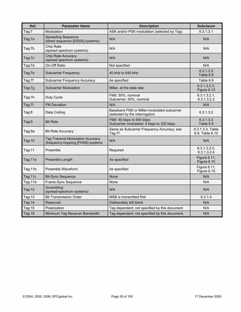
Ref. Parameter Name Description Subclause Tag:7 Modulation ASK and/or PSK modulation (selected by Tag) 6.3.1.3.1
Tag:7a Spreading Sequence (direct sequence [DSSS] systems) N/A N/A
Tag:7b Chip Rate (spread spectrum systems) N/A N/A
Tag:7c Chip Rate Accuracy (spread spectrum systems) N/A N/A
Tag:7d On-Off Ratio Not specified N/A
Tag:7e Subcarrier Frequency 40 kHz to 640 kHz 6.3.1.3.3 Table 6.9
Tag:7f Subcarrier Frequency Accuracy As specified Table 6.9
Tag:7g Subcarrier Modulation Miller, at the data rate 6.3.1.3.2.3, Figure 6.13
Tag:7h Duty Cycle FM0: 50%, nominal Subcarrier: 50%, nominal
6.3.1.3.2.1, 6.3.1.3.2.3
Tag:7I FM Deviation N/A N/A
Tag:8 Data Coding Baseband FM0 or Miller-modulated subcarrier (selected by the Interrogator) 6.3.1.3.2
Tag:9 Bit Rate FM0: 40 kbps to 640 kbps Subcarrier modulated: 5 kbps to 320 kbps
6.3.1.3.3 Table 6.9
Tag:9a Bit Rate Accuracy Same as Subcarrier Frequency Accuracy; see Tag:7f
6.3.1.3.3, Table 6.9, Table 6.10
Tag:10 Tag Transmit Modulation Accuracy (frequency-hopping [FHSS] systems N/A N/A
Tag:11 Preamble Required 6.3.1.3.2.2, 6.3.1.3.2.4
Tag:11a Preamble Length As specified Figure 6.11, Figure 6.15
Tag:11b Preamble Waveform As specified Figure 6.11, Figure 6.15
Tag:11c Bit-Sync Sequence None N/A Tag:11d Frame-Sync Sequence None N/A
Tag:12 Scrambling (spread-spectrum systems) N/A N/A
Tag:13 Bit Transmission Order MSB is transmitted first 6.3.1.4 Tag:14 Reserved Deliberately left blank N/A Tag:15 Polarization Tag dependent; not specified by this document N/A Tag:16 Minimum Tag Receiver Bandwidth Tag dependent; not specified by this document. N/A
© 2004, 2005, 2006, EPCglobal Inc. Page 20 of 100 17 December 2005
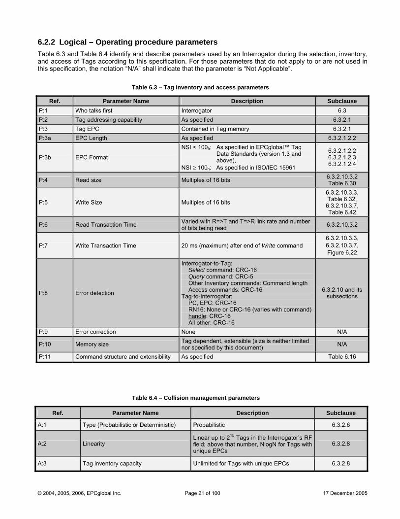
6.2.2 Logical – Operating procedure parameters Table 6.3 and Table 6.4 identify and describe parameters used by an Interrogator during the selection, inventory, and access of Tags according to this specification. For those parameters that do not apply to or are not used in this specification, the notation “N/A” shall indicate that the parameter is “Not Applicable”.
Table 6.3 – Tag inventory and access parameters
Ref. Parameter Name Description Subclause P:1 Who talks first Interrogator 6.3 P:2 Tag addressing capability As specified 6.3.2.1 P:3 Tag EPC Contained in Tag memory 6.3.2.1 P:3a EPC Length As specified 6.3.2.1.2.2
P:3b EPC Format
NSI < 100h: As specified in EPCglobal™ Tag Data Standards (version 1.3 and above),
NSI ≥ 100h: As specified in ISO/IEC 15961
6.3.2.1.2.2 6.3.2.1.2.3 6.3.2.1.2.4
P:4 Read size Multiples of 16 bits 6.3.2.10.3.2 Table 6.30
P:5 Write Size Multiples of 16 bits
6.3.2.10.3.3, Table 6.32,
6.3.2.10.3.7, Table 6.42
P:6 Read Transaction Time Varied with R=>T and T=>R link rate and number of bits being read 6.3.2.10.3.2
P:7 Write Transaction Time 20 ms (maximum) after end of Write command 6.3.2.10.3.3, 6.3.2.10.3.7, Figure 6.22
P:8 Error detection
Interrogator-to-Tag: Select command: CRC-16 Query command: CRC-5 Other Inventory commands: Command length Access commands: CRC-16 Tag-to-Interrogator: PC, EPC: CRC-16 RN16: None or CRC-16 (varies with command) handle: CRC-16 All other: CRC-16
6.3.2.10 and its subsections
P:9 Error correction None N/A
P:10 Memory size Tag dependent, extensible (size is neither limited nor specified by this document) N/A
P:11 Command structure and extensibility As specified Table 6.16
Table 6.4 – Collision management parameters
Ref. Parameter Name Description Subclause
A:1 Type (Probabilistic or Deterministic) Probabilistic 6.3.2.6
A:2 Linearity Linear up to 215 Tags in the Interrogator’s RF field; above that number, NlogN for Tags with unique EPCs
6.3.2.8
A:3 Tag inventory capacity Unlimited for Tags with unique EPCs 6.3.2.8
© 2004, 2005, 2006, EPCglobal Inc. Page 21 of 100 17 December 2005
6.3 Description of operating procedure The operating procedure defines the physical and logical requirements for an Interrogator-talks-first (ITF), ran-dom-slotted collision arbitration, RFID system operating in the 860 MHz – 960 MHz frequency range.
6.3.1 Signaling The signaling interface between an Interrogator and a Tag may be viewed as the physical layer in a layered net-work communication system. The signaling interface defines frequencies, modulation, data coding, RF envelope, data rates, and other parameters required for RF communications.
6.3.1.1 Operational frequencies Tags shall receive power from and communicate with Interrogators within the frequency range from 860 MHz to 960 MHz, inclusive. An Interrogator’s choice of operational frequency will be determined by local radio regulations and by the local radio-frequency environment. Interrogators certified for operation in dense-Interrogator environ-ments shall support, but are not required to always use, the optional dense-Interrogator mode described in Annex G.
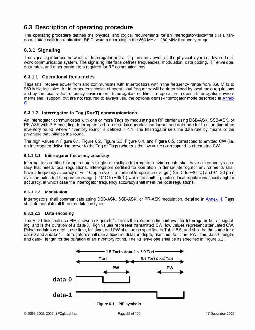
6.3.1.2 Interrogator-to-Tag (R=>T) communications An Interrogator communicates with one or more Tags by modulating an RF carrier using DSB-ASK, SSB-ASK, or PR-ASK with PIE encoding. Interrogators shall use a fixed modulation format and data rate for the duration of an inventory round, where “inventory round” is defined in 4.1. The Interrogator sets the data rate by means of the preamble that initiates the round.
The high values in Figure 6.1, Figure 6.2, Figure 6.3, Figure 6.4, and Figure 6.5, correspond to emitted CW (i.e. an Interrogator delivering power to the Tag or Tags) whereas the low values correspond to attenuated CW.
6.3.1.2.1 Interrogator frequency accuracy Interrogators certified for operation in single- or multiple-Interrogator environments shall have a frequency accu-racy that meets local regulations. Interrogators certified for operation in dense-Interrogator environments shall have a frequency accuracy of +/– 10 ppm over the nominal temperature range (–25 °C to +40 °C) and +/– 20 ppm over the extended temperature range (–40°C to +65°C) while transmitting, unless local regulations specify tighter accuracy, in which case the Interrogator frequency accuracy shall meet the local regulations.
6.3.1.2.2 Modulation Interrogators shall communicate using DSB-ASK, SSB-ASK, or PR-ASK modulation, detailed in Annex H. Tags shall demodulate all three modulation types.
6.3.1.2.3 Data encoding The R=>T link shall use PIE, shown in Figure 6.1. Tari is the reference time interval for Interrogator-to-Tag signal-ing, and is the duration of a data-0. High values represent transmitted CW; low values represent attenuated CW. Pulse modulation depth, rise time, fall time, and PW shall be as specified in Table 6.5, and shall be the same for a data-0 and a data-1. Interrogators shall use a fixed modulation depth, rise time, fall time, PW, Tari, data-0 length, and data-1 length for the duration of an inventory round. The RF envelope shall be as specified in Figure 6.2.
data-0
data-1
Tari 0.5 Tari ≤ x ≤ Tari
PW
1.5 Tari ≤ data-1 ≤ 2.0 Tari
PW
Figure 6.1 – PIE symbols
© 2004, 2005, 2006, EPCglobal Inc. Page 22 of 100 17 December 2005

6.3.1.2.4 Tari values Interrogators shall communicate using Tari values in the range of 6.25µs to 25µs. Interrogator compliance shall be evaluated using at least one Tari value between 6.25µs and 25µs with at least one value of the parameter x. The tolerance on all parameters specified in units of Tari shall be +/–1%. The choice of Tari value and x shall be in accordance with local radio regulations.
6.3.1.2.5 R=>T RF envelope The R=>T RF envelope shall comply with Figure 6.2 and Table 6.5. The electric field strength A is the maximum amplitude of the RF envelope. Tari is defined in Figure 6.1. The pulsewidth is measured at the 50% point on the pulse. An Interrogator shall not change the R=>T modulation type (i.e. shall not switch between DSB-ASK, SSB-ASK, or PR-ASK) without first powering down its RF waveform (see 6.3.1.2.7).
6.3.1.2.6 Interrogator power-up waveform The Interrogator power-up RF envelope shall comply with Figure 6.3 and Table 6.6. Once the carrier level has risen above the 10% level, the power-up envelope shall rise monotonically until at least the ripple limit Ml. The RF envelope shall not fall below the 90% point in Figure 6.3 during interval Ts. Interrogators shall not issue com-mands before the end of the maximum settling-time interval in Table 6.6 (i.e. before Ts).
6.3.1.2.7 Interrogator power-down waveform The Interrogator power-down RF envelope shall comply with Figure 6.3 and Table 6.7. Once the carrier level has fallen below the 90% level, the power-down envelope shall fall monotonically until the power-off limit Ms. Once powered off, an Interrogator shall remain powered off for a least 1ms before powering up again.
Electric field strength
0 time
tf tr
Ml
Mh
A
Ml
Mh
B
PW
0.5×(A + B)
Electric field strength
0 time
tf tr
Ml
Mh
A
MlMhB
PW
0.5×(A + B)
ASK Modulation PR-ASK Modulation
Figure 6.2 – Interrogator-to-Tag RF envelope
Table 6.5 – RF envelope parameters
Tari Parameter Symbol Minimum Nominal Maximum Units
Modulation Depth (A–B)/A 80 90 100 %
RF Envelope Ripple Mh = Ml 0 0.05(A–B) V/m
RF Envelope Rise Time tr,10–90% 0 0.33Tari µs
RF Envelope Fall Time tf,10–90% 0 0.33Tari µs
6.25 µs to
25 µs
RF Pulsewidth PW MAX(0.265Tari, 2) 0.525Tari µs
© 2004, 2005, 2006, EPCglobal Inc. Page 23 of 100 17 December 2005
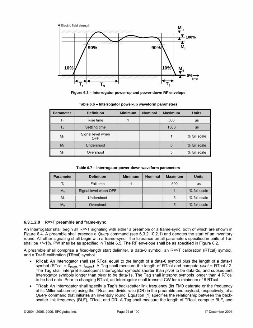
100%
0%
Tr Ts
Mh
Ml
Ms
Tf
10%
90% 90%
10%
Electric field strength
time
Figure 6.3 – Interrogator power-up and power-down RF envelope
Table 6.6 – Interrogator power-up waveform parameters
Parameter Definition Minimum Nominal Maximum Units
Tr Rise time 1 500 µs
Ts Settling time 1500 µs
MsSignal level when
OFF 1 % full scale
Ml Undershoot 5 % full scale
Mh Overshoot 5 % full scale
Table 6.7 – Interrogator power-down waveform parameters
Parameter Definition Minimum Nominal Maximum Units
Tf Fall time 1 500 µs
Ms Signal level when OFF 1 % full scale
Ml Undershoot 5 % full scale
Mh Overshoot 5 % full scale
6.3.1.2.8 R=>T preamble and frame-sync An tFigureroundshall b
A preaand
•
• TRcal: An Interrogator shall specify a Tag’s backscatter link freqof its Miller subcarrier) using the TRcal and divide ratio (DR) in the
F, and
In errogator shall begin all R=>T signaling with either a preamble or a frame-sync, both of which are shown in 6.4. A preamble shall precede a Query command (see 6.3.2.10.2.1) and denotes the start of an inventory
. All other signaling shall begin with a frame-sync. The tolerance on all parameters specified in units of Tari e +/–1%. PW shall be as specified in Table 6.5. The RF envelope shall be as specified in Figure 6.2.
mble shall comprise a fixed-length start delimiter, a data-0 symbol, an R=>T calibration (RTcal) symbol, a T=>R calibration (TRcal) symbol.
RTcal: An Interrogator shall set RTcal equal to the length of a data-0 symbol plus the length of a data-1 symbol (RTcal = 0length + 1length). A Tag shall measure the length of RTcal and compute pivot = RTcal / 2. The Tag shall interpret subsequent Interrogator symbols shorter than pivot to be data-0s, and subsequent Interrogator symbols longer than pivot to be data-1s. The Tag shall interpret symbols longer than 4 RTcal to be bad data. Prior to changing RTcal, an Interrogator shall transmit CW for a minimum of 8 RTcal.
uency (its FM0 datarate or the frequency preamble and payload, respectively, of a
Query command that initiates an inventory round. Equation (1) specifies the relationship between the back-scatter link frequency (BLF), TRcal, and DR. A Tag shall measure the length of TRcal, compute BL
© 2004, 2005, 2006, EPCglobal Inc. Page 24 of 100 17 December 2005
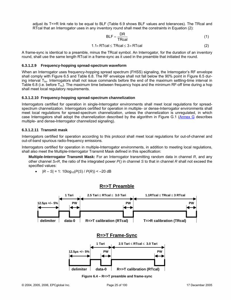
adjust its T=>R link rate to be equal to BLF (Table 6.9 shows BLF values and tolerances). The TRcal and RTcal that an Interrogator uses in any inventory round shall meet the constraints in Equation (2):
=DRBLF
TRcal (1)
1.1 RTcal TRcal 3 RTcal× ≤ ≤ × (2)
A frame-sync is identical to a preamble, minus the TRcal symbol. An Interrogator, for the duration of an inventory he preamble that initiated the round.
before the end of the maximum settling-time interval in Table 6.8 (i.e. before T ). The maximum time between frequency hops and the minimum RF-off time during a hop
uirements.
cas
round, shall use the same length RTcal in a frame-sync as it used in t
6.3.1.2.9 Frequency-hopping spread-spectrum waveform When an Interrogator uses frequency-hopping spread spectrum (FHSS) signaling, the Interrogator’s RF envelope shall comply with Figure 6.5 and Table 6.8. The RF envelope shall not fall below the 90% point in Figure 6.5 dur-ing interval Ths. Interrogators shall not issue commands
hsshall meet local regulatory req
6.3.1.2.10 Frequency-hopping spread-spectrum channelization Interrogators certified for operation in single-Interrogator environments shall meet local regulations for spread-spectrum channelization. Interrogators certified for operation in multiple- or dense-Interrogator environments shall meet local regulations for spread-spectrum channelization, unless the channelization is unregulated, in which
e Interrogators shall adopt the channelization described by the algorithm in Figure G.1 (Annex G describes tiple- and dense-Interrogator channelized signaling). mul
6.3.1.2.Interrog rotocol shall meet local regulations for out-of-channel and out-of-b
Interrog ator environments, in addition to meeting local regulations, shall also meet the Multiple-Interrogator Transmit Mask defined in this specification:
Multiple-Interrogator Transmit Mask: For an Interrogator transmitting random data in channel R, and any other channel S≠R, the ratio of the integrated power P() in channel S to that in channel R shall not exceed the specified values:
• |R – S| = 1: 10log10(P(S) / P(R)) < –20 dB
11 Transmit mask ators certified for operation according to this pand spurious radio-frequency emissions.
ators certified for operation in multiple-Interrog
12.5µs +/
delim
– 5%
R=>T calibration (RTcal)iter
1.1RTcal ≤ TRcal ≤ 3 RTcal
PW
T=>R calibration (TRcal)
PW
2.5 Tari ≤ RTcal ≤ 3.0 Tari1 Tari
PW
data-0
12.5µs +/– 5%
R=>T calibration (RTcal)delimiter
PW
2.5 Tari ≤ RTcal ≤ 3.0 Tari1 Tari
PW
data-0
R=>T Preamble
R=>T Frame-Sync
Figure 6.4 – R=>T preamble and frame-sync
© 2004, 2005, 2006, EPCglobal Inc. Page 25 of 100 17 December 2005
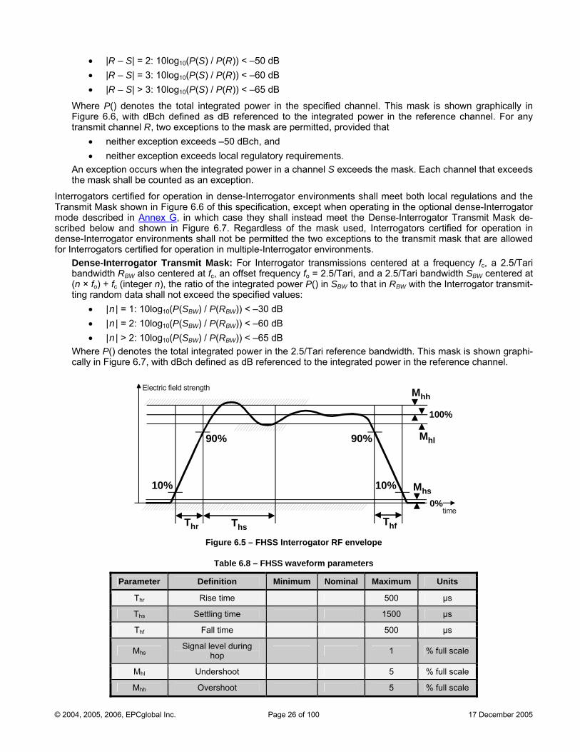
• |R – S| = 2: 10log10(P(S) / P(R)) < –50 dB • |R – S| = 3: 10log10(P(S) / P(R)) < –60 dB • |R – S| > 3: 10log10(P(S) / P(R)) < –65 dB
Wh annel. This mask is shown graphically in
ng in the optional dense-Interrogator mod
ere P() denotes the total integrated power in the specified chre 6.6, with dBch defined as dB referenced to the integratedFigu power in the reference channel. For any
transmit channel R, two exceptions to the mask are permitted, provided that • neither exception exceeds –50 dBch, and • neither exception exceeds local regulatory requirements.
An exception occurs when the integrated power in a channel S exceeds the mask. Each channel that exceeds the mask shall be counted as an exception.
Interrogators certified for operation in dense-Interrogator environments shall meet both local regulations and the Transmit Mask shown in Figure 6.6 of this specification, except when operati
e described in Annex G, in which case they shall instead meet the Dense-Interrogator Transmit Mask de-bed below and shown in Figure 6.7. Regardless of the mask used, Interrogators certified for operation in se-Interrogator environments shall not be permitted the two exceptions to the transmit mask that are allowed Interrogators certified for operation in multiple-Interrogato
scridenfor r environments.
Den - ator transmissions centered at a frequency fc, a 2.5/Tari ban cy fo = 2.5/Tari, and a 2.5/Tari bandwidth SBW centered at (n × ) + wer P() in SBW to that in RBW with the Interrogator transmit-ting n es:
10 BW BW
• |n | > 2: 10log10(P(SBW) / P(RBW)) < –65 dB Where P() denotes the total integrated power in the 2.5/Tari reference bandwidth. This mask is shown graphi-cally in Figure 6.7, with dBch defined as dB referenced to the integrated power in the reference channel.
se Interrogator Transmit Mask: For Interrogdwidth RBW also centered at fc, an offset frequen
), the e info fc (integer n ratio of th tegrated po ra dom data shall not exceed the specified valu• |n | = 1: 10log10(P(SBW) / P(RBW)) < –30 dB • |n | = 2: 10log (P(S ) / P(R )) < –60 dB
100%
0%
Thr Ths
Mhh
Mhl
Mhs
Thf
10%
90% 90%
10%
Electric field strength
time
Figure 6.5 – FHSS Interrogator RF envelope
Table 6.8 – FHSS waveform parameters
Parameter Definition Minimum Nominal Maximum Units
Thr Rise time 500 µs
Ths Settling time 1500 µs
Thf Fall time 500 µs
MhsSignal level during
hop 1 % full scale
Mhl Undershoot 5 % full scale
Mhh Overshoot 5 % full scale
© 2004, 2005, 2006, EPCglobal Inc. Page 26 of 100 17 December 2005
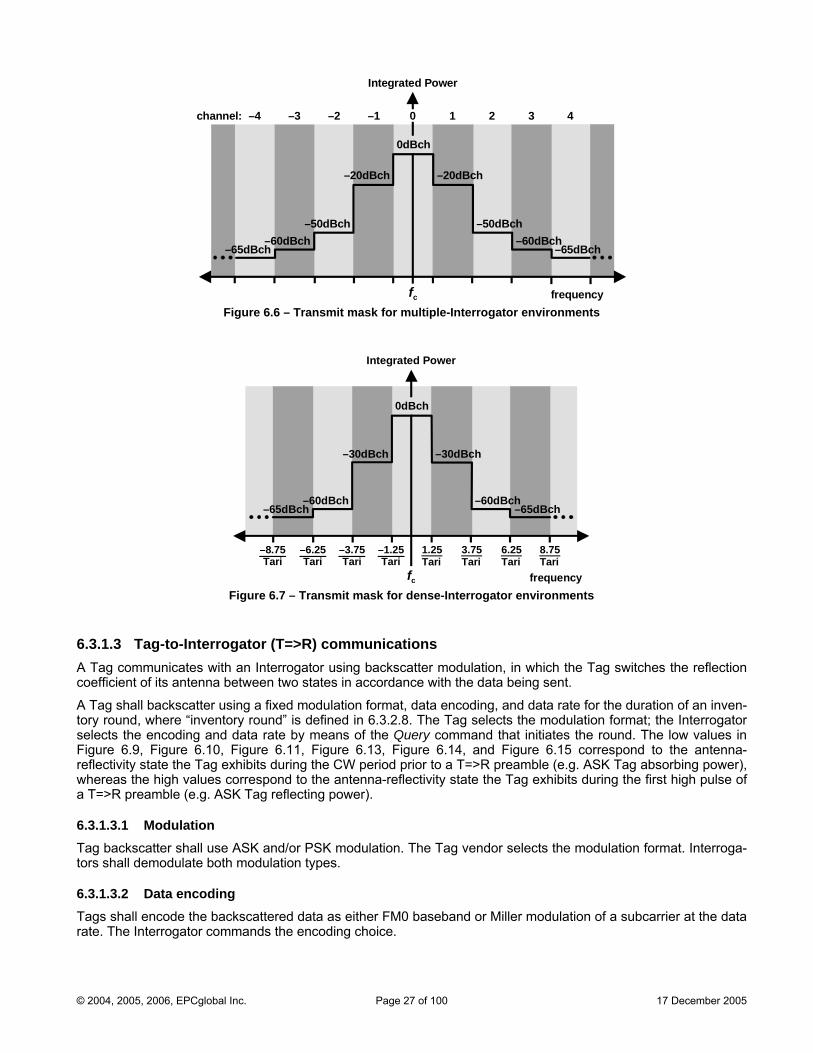
Integrated Power
6.3.1.3 Tag-to-Interrogator (T=>R) communications A Tag communicates with an Interrogator using backscatter modulation, in which the Tag switches the reflection coefficient of its antenna between two states in accordance with the data being sent.
a fixed modulation format, data encoding, and data rate for the duration of an inven-
ery command that initiates the round. The low values in Figure 6.9, Figure 6.10, Figure 6.11, Figure 6.13, Figure 6.14, and Figure 6.15 correspond to the antenna-reflectivity state the Tag exhibits during the CW period prior to a T=>R preamble (e.g. ASK Tag absorbing power), whereas the high values correspond to the antenna-reflectivity state the Tag exhibits during the first high pulse of a T=>R preamble (e.g. ASK Tag reflecting power).
6.3.1.3.1 Modulation Tag backscatter shall use ASK and/or PSK modulation. The Tag vendor selects the modulation format. Interroga-tors shall demodulate both modulation types.
6.3.1.3.2 Data encoding Tags shall encode the backscattered data as either FM0 baseband or Miller modulation of a subcarrier at the data rate. The Interrogator commands the encoding choice.
A Tag shall backscatter using tory round, where “inventory round” is defined in 6.3.2.8. The Tag selects the modulation format; the Interrogator selects the encoding and data rate by means of the Qu
fc
channel: 1 2
0dBch
0 3 4–4 –3 –2 –1
–20dBch –20dBch
frequency
–50dBch–50dBch–60dBch –60dBch
–65dBch–65dBch
Figure 6.6 – Transmit mask for multiple-Interrogator environments
Integrated Power
fc frequency
0dBch
–30dBch –30dBch
–60dBch–60dBch–65dBch –65dBch
–1.25Tari
1.25Tari
3.75Tari
6.25Tari
–3.75Tari
–6.25Tari
8.75Tari
–8.75Tari
Figure 6.7 – Transmit mask for dense-Interrogator environments
© 2004, 2005, 2006, EPCglobal Inc. Page 27 of 100 17 December 2005
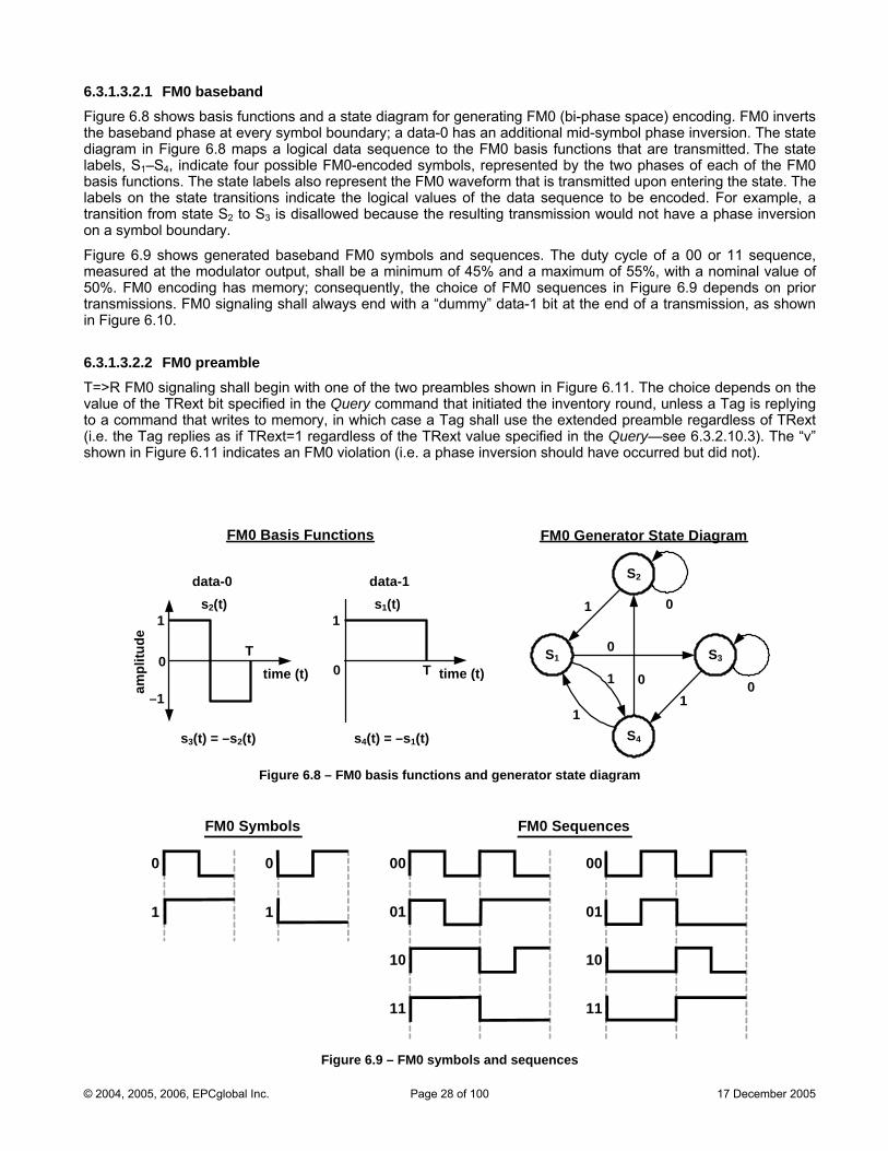
6.3.1.3.2.1 FM0 baseband Figure 6.8 shows basis functions and a state diagram for gen inverts the baseband phase at every symbol boundary; a data-0 has an additional mid-symbol phase inversion. The state
logical data sequence to the FM0 basis functions that are transmitted. The state
memory; consequently, the choice of FM0 sequences in Figure 6.9 depends on prior
ling shall begin with one of the two preambles shown in Figure 6.11. The choice depends on the value of the TRext bit specified in the Query command that initiated the inventory round, unless a Tag is replying
emory, in which case a Tag shall use the extended preamble regardless of TRext
erating FM0 (bi-phase space) encoding. FM0
diagram in Figure 6.8 maps alabels, S1–S4, indicate four possible FM0-encoded symbols, represented by the two phases of each of the FM0 basis functions. The state labels also represent the FM0 waveform that is transmitted upon entering the state. The labels on the state transitions indicate the logical values of the data sequence to be encoded. For example, a transition from state S2 to S3 is disallowed because the resulting transmission would not have a phase inversion on a symbol boundary.
Figure 6.9 shows generated baseband FM0 symbols and sequences. The duty cycle of a 00 or 11 sequence, measured at the modulator output, shall be a minimum of 45% and a maximum of 55%, with a nominal value of 50%. FM0 encoding has transmissions. FM0 signaling shall always end with a “dummy” data-1 bit at the end of a transmission, as shown in Figure 6.10.
6.3.1.3.2.2 FM0 preamble T=>R FM0 signa
to a command that writes to m(i.e. the Tag replies as if TRext=1 regardless of the TRext value specified in the Query—see 6.3.2.10.3). The “v” shown in Figure 6.11 indicates an FM0 violation (i.e. a phase inversion should have occurred but did not).
FM0 Generator State DiagramFM0 Basis Functions
S2
S3S1
S4
0
1
0
1
0
11time (t)
1
0 T
data-1
s4(t) = –s1(t)
s1(t)1
–1
0T
data-0
s3(t) = –s2(t)
s2(t)
time (t)
0
ampl
itude
Figure 6.8 – FM0 basis functions and generator state diagram
1
0
1
00
01
10
11
00
01
10
11
FM0 Symbols FM0 Sequences
Figure 6.9 – FM0 symbols and sequences
0
© 2004, 2005, 2006, EPCglobal Inc. Page 28 of 100 17 December 2005
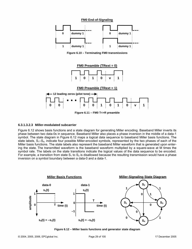
FM0 End-of-Signaling
0 0
1
dummy 1 dummy 1
dummy 1dummy 1 1
Figure 6.10 – Terminating FM0 transmissions
1 0 1 0 v 1
FM0 Preamble (TRext = 0)
12 leading zero
0 0
s (pilot tone)
1 0 1 0 v 1
FM0 Preamble (TRext = 1)
0 0
Figure 6.11 – FM0 T preamble =>R
6.3.1.3.2.3 Miller-modulated subcarrier Figure 6.12 shows basis functions and a state diagram for generating Miller encoding. Baseband Miller inverts its phase between two data-0s in sequence. Baseband Miller also places a phase inversion in the middle of a data-1 symbol. The state diagram in Figure 6.12 maps a logical data sequence to baseband Miller basis functions. The state labels, S1–S4, indicate four possible Miller-encoded symbols, represented by the two phases of each of the Miller basis functions. The state labels also represent the baseband Miller waveform that is generated upon enter-ing the state. The transmitted waveform is the baseband waveform multiplied by a square-wave at M times the symbol rate. The labels on the state transitions indicate the logical values of the data sequence to be encoded. For example, a transition from state S1 to S3 is disallowed because the resulting transmission would have a phase inversion on a symbol boundary between a data-0 and a data-1.
S2
S3S1
S4
1
0
1
10
0
0
1
Miller-Signaling State DiagramMiller Basis Functions
1
–1
0T
data-1
s3(t) = –s2(t)
s2(t)
time (t)time (t)
1
0 T
data-0
s4(t) = –s1(t)
s1(t)
ampl
itude
Figure 6.12 – Miller basis functions and generator state diagram
© 2004, 2005, 2006, EPCglobal Inc. Page 29 of 100 17 December 2005

Figure 6.13 shows Miller-modulated subcarrier sequences; the Miller sequence shall contain exactly two, four, or eight subcarrier cycles per bit, depending on the M value specified in the Query command that initiated the inven-tory round (see Table 6.10). The d odulator output, shall be a minimum of 45% and a maximum of 55%, with a nominal value of 50%. Miller encoding has memory; conse-
6.3.1.3.2.4 Miller subcarrier preamble h one of the two preambles shown in Figure 6.15. The choice depends
uty cycle of a 0 or 1 symbol, measured at the m
quently, the choice of Miller sequences in Figure 6.13 depends on prior transmissions. Miller signaling shall al-ways end with a “dummy” data-1 bit at the end of a transmission, as shown in Figure 6.14.
T=>R subcarrier signaling shall begin witon the value of the TRext bit specified in the Query command that initiated the inventory round, unless a Tag is replying to a command that writes to memory, in which case a Tag shall use the extended preamble regardless of TRext (i.e. the Tag replies as if TRext=1 regardless of the TRext value specified in the Query—see 6.3.2.10.3).
000
001
010
011
100
101
110
111
Miller Subcarrier Sequences000
001
010
011
100
101
110
111
M=4
8M=
000
001
010
011
100
101
110
111
2M=
Figure 6.13 – Subcarrier sequences
© 2004, 2005, 2006, EPCglobal Inc. Page 30 of 100 17 December 2005
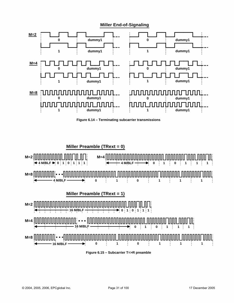
dummy10
dummy11 dummy11
dummy10
dummy11
dummy10
dummy11
lingMiller End-of-Signa
M=2
dummy10
M=4
M=8
dummy10
dummy11
dummy10
dummy11
Fi s gure 6.14 – Terminating subcarrier transmission
Miller Preamble (TRext = 0)
Miller Preamble (TRext = 1)
M=2
M=8
M=2
M=4
M=8
M=4
16 M/BLF
1 0 0 1 1 1 4 M/BLF 0 1 0 1 1 4 M/BLF 1
4 M/BLF
16 M/BLF
16 M/BLF
1 0 0 1 1 1
1 0 0 1 1 1
0 1 0 1 1 1
1 0 0 1 1 1
Figure 6.15 – Subcarrier T=>R preamble
© 2004, 2005, 2006, EPCglobal Inc. Page 31 of 100 17 December 2005
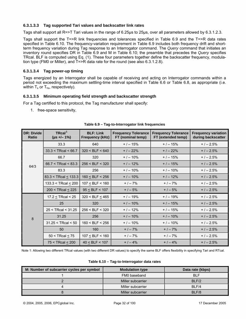
6.3.Tags sh range of 6.25µs to 25µs, over all parameters allowed by 6.3.1.2.3.
Tag nces specified in Table 6.9 and the T=>R data rates .9 includes both frequency drift and short-
term frequency variation during Tag response to an Interrogator command. The Query command that initiates an e 6.9 and M in Table 6.10; the preamble that precedes the Query specifies
1). These four parameters together define the backscatter frequency, modula-
of receiving and acting on Interrogator commands within a rval specified in Table 6.6 or Table 6.8, as appropriate (i.e.
l, the Tag manufacturer shall specify:
1.3.3 Tag supported Tari values and backscatter link rates all support all R=>T Tari values in the
s shall support the T=>R link frequencies and toleraspecified in Table 6.10. The frequency-variation requirement in Table 6
inventory round specifies DR in TablTRcal. BLF is computed using Eq. (tion type (FM0 or Miller), and T=>R data rate for the round (see also 6.3.1.2.8).
6.3.1.3.4 Tag power-up timing Tags energized by an Interrogator shall be capable period not exceeding the maximum settling-time intewithin Ts or Ths, respectively).
6.3.1.3.5 Minimum operating field strength and backscatter strength For a Tag certified to this protoco
1. free-space sensitivity,
Table 6.9 – Tag-to-Interrogator link frequencies
TRcal1 DR: Divide BLF: Link Frequency Tolerance Frequency Tolerance Frequency variation Ratio (µs +/– 1%) Frequency (kHz) FT (nominal temp) FT (extended temp) during backscatter
33.3 640 + / – 15% + / – 15% + / – 2.5%
33.3 < TRcal < 66.7 320 < BLF < 640 + / – 22% + / – 22% + / – 2.5%
66.7 320 + / – 10% + / – 15% + / – 2.5%
66.7 < TRcal < 83.3 256 < BLF < 320 + / – 12% + / – 15% + / – 2.5%
83.3 256 + / – 10% + / – 10% + / – 2.5%
83.3 < TRcal < 133.3 160 < BLF < 256 + / – 10% + / – 12% + / – 2.5%
133.3 < TRcal < 200 107 < BLF < 160 + / – 7% + / – 7% + / – 2.5%
64/3
200 < TRcal < 225 95 < BLF < 107 + / – 5% + / – 5% + / – 2.5%
17.2 < TRcal < 25 320 < BLF < 465 + / – 19% + / – 19% + / – 2.5%
25 320 + / – 10% + / – 15% + / – 2.5%
25 < TRcal < 31.25 256 < BLF < 320 + / – 12% + / – 15% + / – 2.5%
31.25 256 + / – 10% + / – 10% + / – 2.5%
31.25 < TRcal < 50 160 < BLF < 256 + / – 10% + / – 10% + / – 2.5%
50 160 + / – 7% + / – 7% + / – 2.5%
50 < TRcal < 75 107 < BLF < 160 + / – 7% + / – 7% + / – 2.5%
8
75 < TRcal < 200 40 < BLF < 107 + / – 4% + / – 4% + / – 2.5%
Note 1: Allowi cal values different D the same B exibility in sp Tari and RTcal. ng two different TR (with two R values) to specify LF offers fl ecifying
Table 6.10 – Tag-to-Interrogator data rates
M: Number of subcarrier cycles per symbol Modulation type Data rate (kbps) 1 FM0 baseband BLF 2 Miller subcarrier BLF/2 4 Miller subcarrier BLF/4 8 Miller subcarrier BLF/8
© 2004, 2005, 2006, EPCglobal Inc. Page 32 of 100 17 December 2005
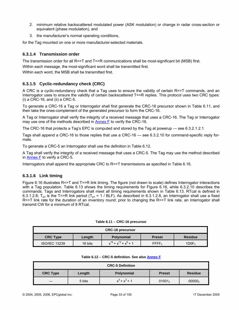
2. minimum relative backscattered modulated power (ASK modulation) or change in radar cross-section or equivalent (phase modulation), and
3. the manufacturer’s normal operating conditions,
for the Tag mounted on one or more manufacturer-selected materials.
6.3.1.4 Transmission order The transmission order for all R=>T and T=>R communications shall be most-significant bit (MSB) first. Within each message, the most-significant word shall be transmitted first. Within each word, the MSB shall be transmitted first.
6.3.1.5 Cyclic-redundancy check (CRC) A CRC is a cyclic-redundancy check that a Tag uses to ensure the validity of certain R=>T commands, and an Interrogator uses to ensure the validity of certain backscattered T=>R replies. This protocol uses two CRC types: (i) a CRC-16, and (ii) a CRC-5.
To generate a CRC-16 a Tag or Interrogator shall first generate the CRC-16 precursor shown in Table 6.11, and then take the ones-complement of the generated precursor to form the CRC-16.
A Tag or Interrogator shall verify the integrity of a received message that uses a CRC-16. The Tag or Interrogator may use one of the methods described in Annex F to verify the CRC-16.
The CRC-16 that protects a Tag’s EPC is computed and stored by the Tag at powerup — see 6.3.2.1.2.1.
Tags shall append a CRC-16 to those replies that use a CRC-16 — see 6.3.2.10 for command-specific reply for-mats.
To generate a CRC-5 an Interrogator shall use the definition in Table 6.12.
A Tag shall verify the integrity of a received message that uses a CRC-5. The Tag may use the method described in Annex F to verify a CRC-5.
Interrogators shall append the appropriate CRC to R=>T transmissions as specified in Table 6.16.
6.3.1.6 Link timing Fig 6.16 nwith a Tag p 3 shows the timing commands. Tags and Interrogators shall meet all timing requirem l is defined in 6.3.1.2.8; Tpri is the T=>R link period (Tpri = 1 / BLF). As describeR=>T link rate for the duration of an inventory round; prior to chatransmit CW for a minimum of 8 RTcal.
Table 6.11
ure illustrates R=>T aopulation. Table 6.1
nd T=>R link timi g. The figure (not d requirement
rawn to scale) defines Interrogator interactions s for Figure 6.16, while 6.3.2.10 describes theents shown in Table 6.13. RTcad in 6.3.1.2.8, an Interrogator shall use a fixed nging the R=>T link rate, an Interrogator shall
– CRC-16 precursor
CRC-16 precursor
CRC Type Length Polynomial Preset Residue
ISO/IEC 13239 16 bits x + x + x + 1 FFFFh 1D0Fh16 12 5
Table 6.12 – CRC-5 definition. See also Annex F
CRC-5 Definition
CRC Type Length Polynomial Preset Residue
— 5 bits x5 + x3 + 1 010012 000002
© 2004, 2005, 2006, EPCglobal Inc. Page 33 of 100 17 December 2005
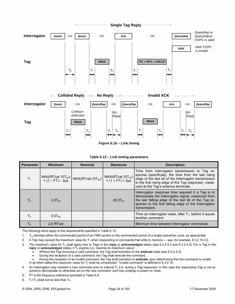
Sing
The following items apply to the requirements specified in Table 6.13: 1. Tpri denotes either the commanded period of an FM0 symbol or the commanded period of a single subcarrier cycle, as appropriate. 2. A Tag may exceed the maximum value for T1 when responding to commands that write to memory — see, for example, 6.3.2.10.3.3. 3. The maximum value for T2 shall apply only to Tags in the reply or acknowledged states (see 6.3.2.4.3 and 6.3.2.4.4). For a Tag in the
reply or acknowledged states, if T2 expires (i.e. reaches its maximum value): • Without the Tag receiving a valid command, the Tag shall transition to the arbitrate state (see 6.3.2.4.2), • During the reception of a valid command, the Tag shall execute the command, • During the reception of an invalid command, the Tag shall transition to arbitrate upon determining that the command is invalid.
In all other states the maximum value for T2 shall be unrestricted. “Invalid command” is defined in 6.3.2.10. 4. An Interrogator may transmit a new command prior to interval T2 (i.e. during a Tag response). In this case the responding Tag is not re-
quired to demodulate or otherwise act on the new command, and may undergo a power-on reset. 5. FT is the frequency tolerance specified in Table 6.9 6. T1+T3 shall not be less than T4.
T1 T2
g
T1
Ta
Interrogator
le Tag Reply
CW CW
NAK if EPC
QueryAdjust if EPC is valid
T2
is invalid
QueryRep or
T2
Interrogator
Tag
Collided Reply
CW
T3
Collision Detected
NoReply
T1
No Reply
CWCW
Invalid ACK
T1 T3
NoReply
CW
T4
T1
CW
RN16 PC + EPC + CRC16
RN16 RN16
QueryRepQuery
Query Ack
Ack QueryRep
QueryRepSelect
NAK
QueryRep
T1 T2
Figure 6.16 – Link timing
Table 6.13 – Link timing parameters
Parameter Minimum Nominal Maximum Description
T1MAX(RTcal,10Tpri) × (1 – FT) – 2µs MAX(RTcal,10Tpri)
MAX(RTcal,10Tpri) × (1 + FT) + 2µs
Time from Interrogator transmission to Tag re-sponse (specifically, the time from the last rising edge of the last bit of the Interrogator transmission to the first rising edge of the Tag response), meas-ured at the Tag’s antenna terminals.
T2 3.0Tpri 20.0Tpri
Interrogator response time required if a Tag is to demodulate the Interrogator signal, measured from the last falling edge of the last bit of the Tag re-sponse to the first falling edge of the Interrogator transmission.
T3 0.0Tpri Time an Interrogator waits, after T1, before it issues another command
T4 2.0 RTcal Minimum time between Interrogator commands
© 2004, 2005, 2006, EPCglobal Inc. Page 34 of 100 17 December 2005
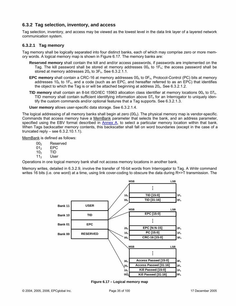
6.3.2 Tag selection, inventory, and access Tag selection, inventory, and access may be viewed as the lowest level in the data link layer of a layered network communication system.
6.3.2.1 Tag memory Tag memory shall be logically separated into four distinct banks, each of which may comprise zero or more mem-ory words. A logical memory map is shown in Figure 6.17. The memory banks are:
Reserved memory shall contain the kill and and/or access passwords, if passwords are implemented on the Tag. The kill password shall be stored at memory addresses 00h to 1Fh; the access password shall be
s 20h to 3Fh. See 6.3.2.1.1.
t memory locations 00h to 07h. sufficient identifying information above 07h for an Interrogator to uniquely iden-
ands and/or optional features that a Tag supports. See 6.3.2.1.3.
stored at memory addresseEPC memory shall contain a CRC-16 at memory addresses 00h to 0Fh, Protocol-Control (PC) bits at memory
addresses 10h to 1Fh, and a code (such as an EPC, and hereafter referred to as an EPC) that identifies the object to which the Tag is or will be attached beginning at address 20h. See 6.3.2.1.2.
TID memory shall contain an 8-bit ISO/IEC 15963 allocation class identifier aTID memory shall containtify the custom comm
User memory allows user-specific data storage. See 6.3.2.1.4.
The logical addressing of all memory banks shall begin at zero (00h). The physical memory map is vendor-specific. Commands that access memory have a MemBank parameter that selects the bank, and an address parameter, specified using the EBV format described in Annex A, to select a particular memory location within that bank.
contents, this backscatter shall fall on word boundaries (except in the case of a ).
When Tags backscatter memorytruncated reply – see 6.3.2.10.1.1
MemBank is defined as follows: 002 Reserved 012 EPC 102 TID
. one word) at a time, using link cover-coding to obscure the data during R=>T transmission. The
112 User Operations in one logical memory bank shall not access memory locations in another bank.
Memory writes, detailed in 6.3.2.9, involve the transfer of 16-bit words from Interrogator to Tag. A Write command writes 16 bits (i.e
00h
00h
10h
20h
0Fh
1Fh
2Fh
Bank 00
MSB LSBBank 11
Bank 10
Bank 01
RESERVED
EPC
TID
USER
CRC-16 [15:0]
EPC [15:0]
EPC [N:N-15]
20h 2Fh
MSB LSB
…
0Fh
1Fh
30h 3Fh
10h
Access Passwd [15:0]
Kill Passwd [15:0]Access Passwd [31:16]
Kill Passwd [31:16]
…
00h
10h
0Fh
1Fh
MSB LSB
TID [31:16]TID [15:0]
…
PC [15:0]
Figure 6.17 – Logical memory map
© 2004, 2005, 2006, EPCglobal Inc. Page 35 of 100 17 December 2005
optional BlockWrite command writes one or more 16-bit words at a time, without link cover-coding. The optional Blo , or BlockErase shall not alter a Tag’ ecified in the command.
Interrogator ry, thereby preventing or allowing subsequent iled description of memory locking and unlocking. The kill and access passwords are individually lockable, as are EPC, TID, and User memory. If the kill and/or acces asswords are locked they are usable by only the Kill and Access commands, respectively, and are rendere EPC, TID, and User memory banks are
6.3.Reserveimplemeoperate 2.10.3.5), and
d memory need not exist.
ntly read/write locked.
eserved memory 20h to 3Fh, MSB first. The default (unpro-access password shall require an Interrogator to issue this
s as if it has a zero-valued access password that is permanently read/write locked
EPC memory contains a CRC-16 at memory addresses 00h to 0Fh, PC bits at memory locations 10h to 1Fh, and ss 20h. The CRC-16, PC, and EPC shall be stored MSB first (the EPC’s MSB is stored
h h
6.3.2.1.2.1 CRC-16 ted by the CRC-16 that a Tag backscatters during an inventory operation. Because
in the mask, and may issue a pped into EPC memory.
ory location 10h to the end of the EPC (not neces-
oundaries, this CRC-16 shall be computed on word boundaries. Tags shall finish s or Ths (as appropriate) in Figure 6.3 or
The PC bits contain physical-layer information that a Tag backscatters with its EPC during an inventory operation.
ckErase command erases one or more 16-bit words at a time. A Write, BlockWrites r invalid) sp killed status regardless of the memory address (whether valid o
s may lock, permanently lock, unlock, or permanently unlock memo cha ppropriate). See 6.3.2.9 and 6.3.2.10.3.5 for a detanges (as a
s pd both unwriteable and unreadable by any other command. The
always readable regardless of their lock status.
2.1.1 Reserved Memory d memory contains the kill (see 6.3.2.1.1.1) and/or access (see 6.3.2.1.1.2) passwords, if passwords are nted on the Tag. If a Tag does not implement the kill and/or access password(s), the Tag shall logically
as though it has zero-valued password(s) that are permanently read/write locked (see 6.3.the corresponding physical memory locations in Reserve
6.3.2.1.1.1 Kill password The kill password is a 32-bit value stored in Reserved memory 00h to 1Fh, MSB first. The default (unprogrammed) value shall be zero. An Interrogator shall use a kill password once, to kill the Tag and render it nonresponsive thereafter. A Tag shall not execute a kill operation if its kill password is zero. A Tag that does not implement a kill password operates as if it has a zero-valued kill password that is permane
6.3.2.1.1.2 Access password The access password is a 32-bit value stored in Rgrammed) value shall be zero. A Tag with a nonzero password before transitioning to the secured state. A Tag that does not implement an access password operate
6.3.2.1.2 EPC Memory
an EPC beginning at addrein location 20h).
The CRC-16 is described in 6.3.2.1.2.1.
The PC, as described in 6.3.2.1.2.2, is subdivided into an EPC length field in memory locations 10h to 14h, RFU bits in memory locations 15h and 16h, and a Numbering System Identifier (NSI) in memory locations 17 to 1F .
The EPC is a code that identifies the object to which a Tag is affixed. The EPC for EPCglobal™ Applications is described in 6.3.2.1.2.3; the EPC for non-EPCglobal™ Applications is described in 6.3.2.1.2.4. Interrogators may issue a Select command that includes all or part of the EPC in the mask. Interrogators may issue an ACK com-mand to cause a Tag to backscatter its PC, EPC, and CRC-16 (under certain circumstances the Tag may trun-cate its reply — see 6.3.2.10.1.1). An Interrogator may issue a Read command to read all or part of the EPC.
The PC and EPC are protecInterrogators may issue a Select command that includes all or part of this CRC-16 Read command to cause the Tag to backscatter this CRC-16, this CRC-16 is logically maAt power-up a Tag shall compute this CRC-16 over EPC memsarily to the end of EPC memory, but to the end of the EPC specified by the length field in the PC — see 6.3.2.1.2.2) and map the computed CRC-16 into EPC memory 00h to 0Fh, MSB first. Because the {PC+EPC} is stored in EPC memory on word bthis CRC-16 computation and memory mapping by the end of interval TFigure 6.5, respectively. Tags shall not recalculate this CRC-16 for a truncated reply (see 6.3.2.10.1.1).
6.3.2.1.2.2 Protocol-control (PC) bits
© 2004, 2005, 2006, EPCglobal Inc. Page 36 of 100 17 December 2005

There are 16 PC bits, stored in EPC memory at addresses 10h to 1Fh, with bit values defined as follows:
Bits 17h – 1Fh: A numbering system identifier (NSI). The MSB of the NSI is stored in memory location 17h.
herred to as a non-EPCglobal™ Application and PC bits 18 – 1F shall contain
During tru
If an Interro o EPC length during a memory write, and it wishes the Tag to subsequently back-sca r ite the length of the new or updated (PC + EPC) into the first 5 bits of the Tag
• Bits 10h – 14h: The length of the (PC + EPC) that a Tag backscatters, in words: o 000002: One word (addresses 10h to 1Fh in EPC memory). o 000012: Two words (addresses 10h to 2Fh in EPC memory).
00010 : Three words (addresses 10 to 3F in EPC memory). o 2 h h ● ● ●
o 111112: 32 words (addresses 10h to 20Fh in EPC memory). • Bits 15h – 16h: RFU (shall be set to 002 for Class-1 Tags). •
If bit 17h contains a logical 0, then the application is referred to as an EPCglobal™ Application and PC bits 18h – 1Fh shall be as defined in the EPCglobal™ Tag Data Standards. If bit 17 contains a logical 1, then the application is ref h hthe entire AFI defined in ISO/IEC 15961. The default value for bits 18h – 1Fh is 000000002.
The default (unprogrammed) PC value shall be 0000h.
ncated replies a Tag substitutes 000002 for the PC bits — see 6.3.2.10.1.1.
gat r modifies thette the modified EPC, then it must wr’s PC. A Tag shall backscatter an error code (see Annex I) if an Interrogator attempts to write
s not supported by the Tag to the first 5 bits of the Tag’s PC. a (PC + EPC)
length that i
At poweof th
6.3.The s.
The n shall be as defined in ISO/IEC 15961.
6.3.2.1.TID meE2h. TID be defined according to the registration authority defined by this class-idenidentify and ven e, a Tag serial number). NoteThe classturer iden hTag ID (i. ue among all classes of Tags defined in ISO/IEC 15693, and TID memory is permalocked at the
ay contain User memory. User memory allows user-specific data storage.
or an EPCglobal™ Application
r-up ute its CRC-16 over the number of (PC + EPC) words designated by the first 5 bits e PC rather than over the length of the entire EPC memory (see 6.3.2.1.2.1).
2.1.2.3 EPC for an EPCglobal™ Application EPC structure for an EPCglobal™ Application shall be as defined in the EPCglobal™ Tag Data Standard
a Tag shall comp
6.3.2.1.2.4 EPC for a non-EPCglobal™ Application EPC structure for a non-EPCglobal™ Applicatio
3 TID Memory mory locations 00h to 07h shall contain one of two ISO/IEC 15963 class-identifier values — either E0h or memory locations above 07 shall h
tifier value and shall contain, at a minimum, sufficient identifying information for an Interrogator to uniquely the custom commands and/or optional features that a Tag supports. TID memory may also contain Tag- dor-specific data (for exampl
: The Tag manufacturer assigns the class-identifier value (i.e. E0h or E2h), for which ISO/IEC 15963 defines the registration authorities. -identifier does not specify the Application. If the class identifier is E0h, TID memory locations 08h to 0Fh contain an 8-bit manufac-tifier, TID memory locations 10h to 3F contain a 48-bit Tag serial number (assigned by the Tag manufacturer), the composite 64-bit e. TID memory 00 to 3F ) is uniqh h
time of manufacture. If the class identifier is E2h, TID memory locations 08h to 13h contain a 12-bit Tag mask-designer identifier (obtainable from the registration authority), TID memory locations 14h to 1Fh contain a vendor-defined 12-bit Tag model number, and the usage of Tag memory locations above 1Fh is defined in version 1.3 and above of the EPCglobal™ Tag Data Standards.
6.3.2.1.4 User Memory A Tag m
6.3.2.1.4.1 User memory fIf User memory is included on a Tag then its encoding shall be as defined in the EPCglobal™ Tag Data Stan-dards (version 1.3 and above).
6.3.2.1.4.2 User memory for a non-EPCglobal™ Application If User memory is included on a Tag then User memory locations 00h to 07h shall be the DSFID defined in ISO/IEC 15961. The encoding of User memory locations above 07h shall be as defined in ISO/IEC 15962.
© 2004, 2005, 2006, EPCglobal Inc. Page 37 of 100 17 December 2005
6.3.2.2 Sessions and inventoried flags Interrogators shall support and Tags shall 0, S1, S2, and S3). Tags shall participate in one and only one session during an inventory round. Two or more Interrogators can use sessions to independ-ently inventory a common Tag population. The sessions concept is illustrated in Figure 6.18.
the four sessions. Tags participating in an inventory round in one session shall nei-ther use nor modify the inventoried flag for a different session. The inventoried flags are the only resource a
y to a given session; all other Tag resources are shared among ses-
trates how two Interrogators can use sessions and inventoried flags to independently
o It powers off. l Interrogator #1 has placed all Tags in session S2 into B, after which it inventories
• The S1 inventoried flag shall be set to either A or B, depending on its stored value, unless the flag was set longer in the past than its persistence time, in which case the Tag shall power-up with its S1 invento-ried flag set to A. Because refreshed, it may revert from B to A even when the Tag is po
• The S2 inve d flag shall be set to either A or B, value, unless the Tag has lost power for a time greater th which case the Tag shall power-up with the S2 inven
• The S3 inventoried flag shall A or B, depending on its stored value, unless the Tag has lost power for a time greater th power-up with its S3 inventoried A.
A Tag shall set any of its inventoried fTag shall refresh its S2 and S3 flags w il power its S2 and S3 inventoried flags shall have the persi lue of the S1 inventoried flag shall not change as a result of a persis ag is participating in an inventory round. If the S1 persistence ti n inv A at the end of the round.
6.3.2.3 Selected flag Tags shall im flag, SL, ert using a Select command. The Sel
provide 4 sessions (denoted S
Tags shall maintain an independent inventoried flag for each session. Each of the four inventoried flags has two values, denoted A and B. At the beginning of each and every inventory round an Interrogator chooses to inventory either A or B Tags in one of
Tag provides separately and independentlsions.
After singulating a Tag an Interrogator may issue a command that causes the Tag to invert its inventoried flag for that session (i.e. A→B or B→A).
The following example illusand completely inventory a common Tag population, on a time-interleaved basis:
• Interrogator #1 powers-on, then o It initiates an inventory round during which it singulates A Tags in session S2 to B, o It powers off.
• Interrogator #2 powers-on, then o It initiates an inventory round during which it singulates B Tags in session S3 to A,
This process repeats untithe Tags in session S2 from B back to A. Similarly, Interrogator #2 places all Tags in session S3 into A, after which it inventories the Tags in session S3 from A back to B. By this multi-step procedure each Interrogator can independently inventory all Tags in its field, regardless of the initial state of their inventoried flags.
A Tag’s inventoried flags shall have the persistence times shown in Table 6.14. A Tag shall power-up with its inventoried flags set as follows:
• The S0 inventoried flag shall be set to A.
the S1 inventoried flag is not automaticallywered.
ntorie depending on its storedan its persistence time, in
toried flag set to A. be set to either
n a its persistence time, in which case the Tag shall flag set to
lags to either A or B in 2 ms or less, regardless of the initial flag value. A Tag loses h e powered, meaning that every time a
stence times shown in Table 6.14. The vatence timeout while a T
me expires during a entory round then the Tag shall change its S1 flag to
plement a selected which an Interrogator may assert or deass parameter in the Query comm s that have SL either asserted
or deasserted (i.e. SL or ~SL), or to ign ry Tags regardless of their SL value. SL is not as-sociated with any particula n; SL ssion, and is common to all sessions.
A Tag’s SL flag shall have the persiste e wer-up with its SL flag either asserted or deasserted, depending on the wer for a time greater than the SL persi all be
and allows an Interrogator to inventory Tagore the flag and invento
y ser sessio may be used in an
nc times shown in Table 6.14. A Tag shall stored value, unless the Tag has lost po
po
stence time, in which case the Tag shall power-up with its SL flag deasserted (set to ~SL). A Tag sh
© 2004, 2005, 2006, EPCglobal Inc. Page 38 of 100 17 December 2005
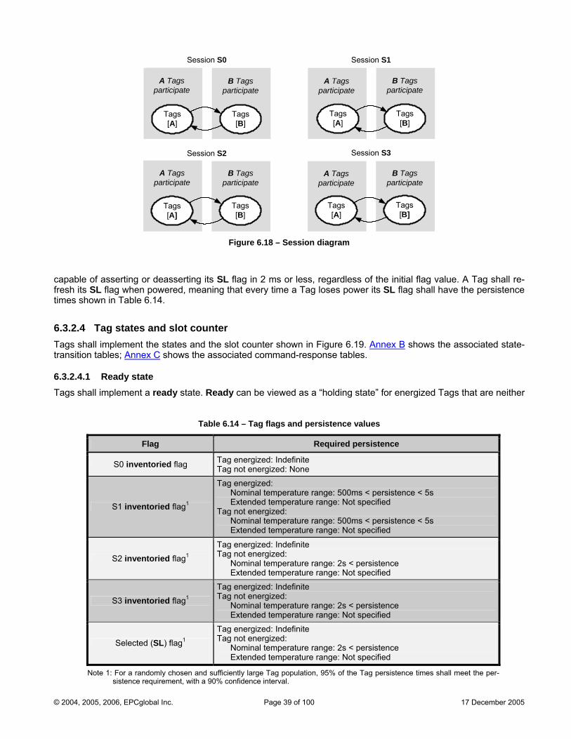
Session S0
Tags[A]
Session S1
A Tags participate
Tags[B]
B Tags participate
Tags[A]
A Tags participate
Tags[B]
B Tags participate
Session S3Session S2
Tags[A]
Tags[B]
Tags[B]
Tags[A]
A Tags participate
B Tags participate
B Tags participate
A Tags participate
Figure 6.18 – Session diagram
capable of asserting or deasserting its SL flag in 2 ms or less, regardless of the initial flag value. A Tag shall re-fresh its SL flag when powered, meaning that every time a Tag loses power its SL flag shall have the persistence times shown in Table 6.14.
6.3.2.4 Tag states and slot counter Tags shall implement the states and the slot counter shown in Figure 6.19. Annex B shows the associated state-transition tables; Annex C shows the associated command-response tables.
6.3.2.4.1 Ready state Tags shall implement a ready state. Ready can be viewed as a “holding state” for energized Tags that are neither
Table 6.14 – Tag flags and persistence values
Flag Required persistence
d flag Tag energized: Indefinite S0 inventorie Tag not energized: None
S1 inventoried flag1
Tag energized: Nominal temperature range: 500ms < persistence < 5s Extended temperature range: Not specified Tag not energized: Nominal temperature range: 500ms < persistence < 5s Extended temperature range: Not specified
S2 inventoried flag1
Tag energized: Indefinite Tag not energized: Nominal temperature range: 2s < persistence Extended temperature range: Not specified
Tag energized: Indefinite
S3 inventoried flag1 Tag not energized: Nominal temperature range: 2s < persistence Extended temperature range: Not specified
Selected (SL) flag1
Tag energized: Indefinite Tag not energized: Nominal temperature range: 2s < persistence Extended temperature range: Not specified
Note 1: For a randomly chosen and sufficiently large Tag population, 95% of the Tag persistence times shall meet the per-sistence requirement, with a 90% confidence interval.
© 2004, 2005, 2006, EPCglobal Inc. Page 39 of 100 17 December 2005
killed nor currently participating in an inventory round. Upon entering an energizing RF field a Tag that is not killed shall enter ready. The Tag shall remain in ready until it receives a Query command (see 6.3.2.10.2.1) whose in-ventoried parameter (for the session specified in the Query) and sel parameter match its current flag values. Matching Tags shall draw a Q-bit number from their RNG (see 6.3.2.5), load this number into their slot counter, and transition to the arbitrate state if the number is nonzero, or to the reply state if the number is zero. If a Tag in any state except killed loses power it shall return to ready upon regaining power.
6.3.2.4.2 Arbitrate state Tags shing in thshall de
all implement an arbitrate state. Arbitrate can be viewed as a “holding state” for Tags that are participat-e current inventory round but whose slot counters (see 6.3.2.4.8) hold nonzero values. A Tag in arbitrate crement its slot counter every time it receives a QueryRep command (see 6.3.2.10.2.3) whose session ter matches the session for the inventory round currently in progress, and it shall transition to the reply d backscatter an RN16 when its slot counter reaches 0000
paramestate an . Tags that return to (for example, from theQueryR
h arbitrate reply state) with a slot value of 0000h shall decrement their slot counter from 0000h to 7FFFh at the next ep (with matching session) and, because their slot value is now nonzero, shall remain in arbitrate.
6.3.2.4.3 Reply state Tags shall implement a reply state. Upon entering reply a Tag shall backscatter an RN16. If the Tag receives a valid acknowledgement (ACK) it shall transition to the acknowledged state, backscattering its PC, EPC and CRC-16. If the Tag fails to receive an ACK within time T2(max), or receives an invalid ACK or an ACK with an erro-neous RN16, it shall return to arbitrate. Tag and Interrogator shall meet all timing requirements specified in Table 6.13.
6.3.2.4.4 Acknowledged state Tags shall implement an acknowledged state. A Tag in acknowledged may transition to any state except killed, depending on the received command (see Figure 6.19). If a Tag in the acknowledged state receives a valid ACK containing the correct RN16 it shall re-backscatter its PC, EPC, and CRC-16. If a Tag in the acknowledged state fails to receive a valid command within time T2(max) it shall return to arbitrate. Tag and Interrogator shall meet all timing requirements specified in Table 6.13.
6.3.2.4.5 Open state Tags shall implement an open state. A Tag in the acknowledged state whose access password is nonzero shall transition to open upon receiving a Req_RN command, backscattering a new RN16 (denoted handle) that the Interrogator shall use in subsequent commands and the Tag shall use in subsequent replies. Tags in the open state can execute all access commands except Lock. A Tag in open may transition to any state except acknowl-edged, depending on the received command (see Figure 6.19). If a Tag in the open state receives a valid ACK containing the correct handle it shall re-backscatter its PC, EPC, and CRC-16. Tag and Interrogator shall meet all timing requirements specified in Table 6.13 except T2(max); in the open state the maximum delay between Tag re-sponse and Interrogator transmission is unrestricted.
6.3.2.4.6 Secured state Tags shall implement a secured state. A Tag in the acknowledged state whose access password is zero shall transition to secured upon receiving a Req_RN command, backscattering a new RN16 (denoted handle) that the Interrogator shall use in subsequent commands and the Tag shall use in subsequent replies. A Tag in the open state whose access password is nonzero shall transition to secured upon receiving a valid Access command se-quence, maintaining the same handle that it previously backscattered when it transitioned from the acknowl-edged to the open state. Tags in the secured state can execute all access commands. A Tag in secured may transition to any state except open or acknowledged, depending on the received command (see Figure 6.19). If a Tag in the secured state receives a valid ACK containing the correct handle it shall re-backscatter its PC, EPC, and CRC-16. Tag and Interrogator shall meet all timing requirements specified in Table 6.13 except T2(max); in the secured state the maximum delay between Tag response and Interrogator transmission is unrestricted.
6.3.2.4.7 Killed state Tags shall implement a killed state. A Tag in either the open or secured states shall enter the killed state upon receiving a Kill command sequence (see 6.3.2.10.3.4) with a valid nonzero kill password and valid handle. Kill permanently disables a Tag. Upon entering the killed state a Tag shall notify the Interrogator that the kill opera-
© 2004, 2005, 2006, EPCglobal Inc. Page 40 of 100 17 December 2005
tion was successful, and shall not respond to an Interrogator thereafter. Killed Tags shall remain in the killed state under all circumstances, and shall immediately enter killed upon subsequent power-ups. A kill operation is not reversible.
6.3.2.4.8 Slot counter Tags shall implement a 15-bit slot counter. Upon receiving a Query or QueryAdjust command a Tag shall preload into its slot counter a value between 0 and 2Q–1, drawn from the Tag’s RNG (see 6.3.2.5). Q is an integer in the range (0, 15). A Query specifies Q; a QueryAdjust may modify Q from the prior Query.
Tags in the arbitrate state shall decrement their slot counter every time they receive a QueryRep, transitioning to the reply state and backscattering an RN16 when their slot counter reaches 0000h. Tags whose slot counter reached 0000h, who replied, and who were not acknowledged (including Tags that responded to an original Query and were not acknowledged) shall return to arbitrate with a slot value of 0000h and shall decrement this slot value from 0000h to 7FFFh at the next QueryRep. The slot counter shall be capable of continuous counting, meaning that, after the slot counter rolls over to 7FFFh it begins counting down again, thereby effectively preventing subse-quent replies until the Tag loads a new random value into its slot counter. See also Annex J.
6.3.2.5 Tag random or pseudo-random number generator Tags shall implement a random or pseudo-random number generator (RNG). The RNG shall meet the following randomness criteria independent of the strength of the energizing field, the R=>T link rate, and the data stored in the Tag (including the PC, EPC, and CRC-16). Tags shall generate 16-bit random or pseudo-random numbers (RN16) using the RNG, and shall have the ability to extract Q-bit subsets from an RN16 to preload the Tag’s slot counter (see 6.3.2.4.8). Tags shall have the ability to temporarily store at least two RN16s while powered, to use, for example, as a handle and a 16-bit cover-code during password transactions (see Figure 6.23 or Figure 6.25).
Probability of a single RN16: The probability that any RN16 drawn from the RNG has value RN16 = j, for any j, shall be bounded by 0.8/216 < P(RN16 = j) < 1.25/216. Probability of simultaneously identical sequences: For a Tag population of up to 10,000 Tags, the probability that any two or more Tags simultaneously generate the same sequence of RN16s shall be less than 0.1%, regardless of when the Tags are energized. Probability of predicting an RN16: An RN16 drawn from a Tag’s RNG 10ms after the end of Tr in Figure 6.3 shall not be predictable with a probability greater than 0.025% if the outcomes of prior draws from the RNG, performed under identical conditions, are known.
This protocol recommends that Interrogators wait 10ms after Tr in Figure 6.3 or Thr in Figure 6.5 before issuing passwords to Tags.
© 2004, 2005, 2006, EPCglobal Inc. Page 41 of 100 17 December 2005
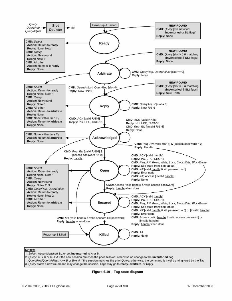
NOTES 1. c 2. . 3.
Sele t: Assert/deassert SL or set inventoried to A or B.Query: A→ B or B→ A if the new session matches the prior session; otherwise no change to the inventoried flag
→ → QueryRep/QueryAdjust: A B or B A if the session matches the prior Query; otherwise, the command is invalid and ignored by the Tag.Query starts a new round and may change the session. Tags may go to ready, arbitrate, or reply.
Arbitrate
Acknowledged
Open
Killed
Power-up & ~killed
Reply
CMD: ACK [valid RN16]Reply: PC, EPC, CRC-16CMD: Req_RN [invalid RN16]Reply: None
CMD: Req_RN [valid RN16] & {access password <> 0}Reply: handle
CMD: ACK [valid handle]Reply: PC, EPC, CRC-16CMD: Req_RN, Read, Write, Lock, BlockWrite, BlockEraseReply: See state-transition tablesCMD: Kill [valid handle & kill password = 0]Reply: Error codeCMD: Kill, Access [invalid handle]Reply: None
CMD: All Reply: None
CMD: QueryAdjust [slot = 0]Reply: New RN16
NEW ROUND
Ready
Secured
CMD: Access [valid handle & valid access password] Reply: handle when done
Power-up & killed
CMD: Kill [valid handle & valid nonzero kill password] Reply: handle when done
CMD: Req_RN [valid RN16] & {access password = 0}Reply: Handle
CMD: Query [mismatched inventoried or SL flags]Reply: None
Query SlotCounterQueryRep
QueryAdjustslot
NEW ROUNDCMD: Query [slot > 0 & matching (inventoried & SL) flags]Reply: None
NEW ROUNDCMD: Query [slot = 0 & matching (inventoried & SL) flags]Reply: New RN16
C S A ReplyC Q A ReplyCMD: A Actio Reply
MD: electction: Return to ready
: None. Note 1MD: ueryction: New round
: Note 3ll other
n: Remain in ready: None
CMD: S A o ReplyCMD: Q Actio Reply
electcti n: Return to ready
: None. Note 1uery
n: New round: Notes 2, 3
CMD: QueryRep, QueryAdjust Action: Return to ready Reply: None. Note 2CMD: All other Action: Return to arbitrate Reply: None.
CMD: QueryAdjust, QueryRep [slot=0]
Reply: None
Reply: New RN16
CMD: QueryRep, QueryAdjust [slot <> 0]
CMD: S Action: Return to ready Reply: None. Note 1CMD: Query Action: New round Reply: Note 3
elect
CMD: All other Action: Return to arbitrate
CMD: ACK [valid RN16]Reply: PC, EPC, CRC-16
Reply: None.CMD: None within time T2 Action: Return to arbitrate Reply: None.
CMD: None within time T2 A o Reply
cti n: Return to arbitrate: None.
CMD: ACK [valid handle]
CMD: Kill [valid handle
Reply: PC, EPC, CRC-16CMD: Req_RN, Read, Write, Lock, BlockWrite, BlockEraseReply: See state-transition tables
& kill password = 0] or [invalid handle]Reply: Error codeCMD: Access [valid handle & valid access password] or [invalid handle]Reply: handle when done
Figure 6.19 – Tag state diagram
© 2004, 2005, 2006, EPCglobal Inc. Page 42 of 100 17 December 2005
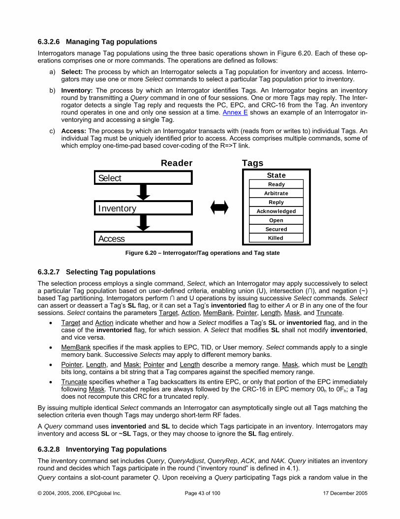
6.3.2.6
mmands. The operations are defined as follows:
egins an inventory
e PC, EPC, and CRC-16 from the Tag. An inventory
Managing Tag populations Interrogators manage Tag populations using the three basic operations shown in Figure 6.20. Each of these op-erations comprises one or more co
a) Select: The process by which an Interrogator selects a Tag population for inventory and access. Interro-gators may use one or more Select commands to select a particular Tag population prior to inventory.
b) Inventory: The process by which an Interrogator identifies Tags. An Interrogator bround by transmitting a Query command in one of four sessions. One or more Tags may reply. The Inter-rogator detects a single Tag reply and requests thround operates in one and only one session at a time. Annex E shows an example of an Interrogator in-ventorying and accessing a single Tag.
c) Access: The process by which an Interrogator transacts with (reads from or writes to) individual Tags. An individual Tag must be uniquely identified prior to access. Access comprises multiple commands, some of which employ one-time-pad based cover-coding of the R=>T link.
Reader Tags
6.3.2.7 Selecting Tag populations The selection process employs a single command, Select, which an Interrogator may apply successively to select a particular Tag population based on user-defined criteria, enabling union (U), intersection (∩), and negation (~) based Tag partitioning. Interrogators perform ∩ and U operations by issuing successive Select commands. Select can assert or deassert a Tag’s SL flag, or it can set a Tag’s inventoried flag to either A or B in any one of the four sessions. Select contains the parameters Target, Action, MemBank, Pointer, Length, Mask, and Truncate.
• Target and Action indicate whether and how a Select modifies a Tag’s SL or inventoried flag, and in the case of the inventoried flag, for which session. A Select that modifies SL shall not modify inventoried, and vice versa.
• MemBank specifies if the mask applies to EPC, TID, or User memory. Select commands apply to a single memory bank. Successive Selects may apply to different memory banks.
nter• Poi , Length, and Mask: Pointer and Length describe a memory range. Mask, which must be Length
• rubits long, contains a bit string that a Tag compares against the specified memory range. T ncate specifies whether a Tag backscatters its entire EPC, or only that portion of the EPC immediately
wing follo Mask. Truncated replies are always followed by the CRC-16 in EPC memory 00h to 0Fh; a Tag
By issuiselectio
A Queryinventor
6.3.2.8 InThe invento es an inventory
does not recompute this CRC for a truncated reply.
ng multiple identical Select commands an Interrogator can asymptotically single out all Tags matching the n criteria even though Tags may undergo short-term RF fades.
command uses inventoried and SL to decide which Tags participate in an inventory. Interrogators may y and access SL or ~SL Tags, or they may choose to ignore the SL flag entirely.
ventorying Tag populations ry command set includes Query, QueryAdjust, QueryRep, ACK, and NAK. Query initiat
round and decides which Tags participate in the round (“inventory round” is defined in 4.1). Query contains a slot-count parameter Q. Upon receiving a Query participating Tags pick a random value in the
Inventory
Select State
Access
Acknowledged
Open
Killed
Reply
Ready
Arbitrate
Secured
Figure 6.20 – Interrogator/Tag operations and Tag state
© 2004, 2005, 2006, EPCglobal Inc. Page 43 of 100 17 December 2005
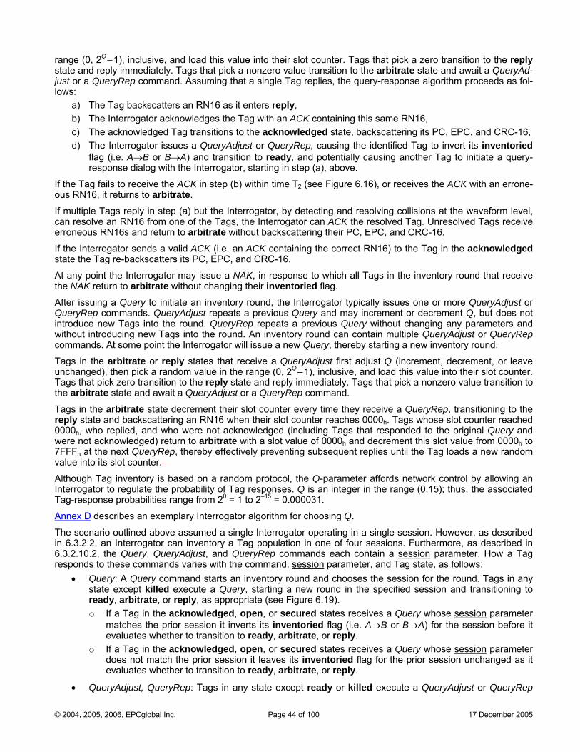
range (0, 2Q–1), inclusive, and load this value into their slot counter. Tags that pick a zero transition to the reply state and reply immediately. Tags that pick a nonzero value transition to the arbitrate state and await a QueryAd-just or a QueryRep command. Assuming that a single Tag replies, the query-response algorithm proceeds as fol-lows:
a) The Tag backscatters an RN16 as it enters reply,
d)
If the Taous RN
If multiple Tags reply in step (a) but the Interrogator, by detecting and resolving collisions at the waveform level, can erro
If the Instate th
At any point t receive the NAK return to arbitrate without changing their inventoried flag.
ry round, the Interrogator typically issues one or more QueryAdjust or QueryRep commands. QueryAdjust repeats a previous Query and may increment or decrement Q, but does not introduce new Tags into the round. QueryRep repeats a previous Query without changing any parameters and without introducing new Tags into the round. An inventory round can contain multiple QueryAdjust or QueryRep commands. At some point the Interrogator will issue a new Query, thereby starting a new inventory round.
Tags in the arbitrate or reply states that receive a QueryAdjust first adjust Q (increment, decrement, or leave unchanged), then pick a random value in the range (0, 2Q–1), inclusive, and load this value into their slot counter. Tags that pick zero transition to the reply state and reply immediately. Tags that pick a nonzero value transition to the arbitrate state and await a QueryAdjust or a QueryRep command.
Tags in the arbitrate state decrement their slo ceive a QueryRep, transitioning to the
by effectively preventing subsequent replies until the Tag loads a new random
b) The Interrogator acknowledges the Tag with an ACK containing this same RN16, c) The acknowledged Tag transitions to the acknowledged state, backscattering its PC, EPC, and CRC-16,
The Interrogator issues a QueryAdjust or QueryRep, causing the identified Tag to invert its inventoried flag (i.e. A→B or B→A) and transition to ready, and potentially causing another Tag to initiate a query-response dialog with the Interrogator, starting in step (a), above.
g fails to receive the ACK in step (b) within time T2 (see Figure 6.16), or receives the ACK with an errone-16, it returns to arbitrate.
resolve an RN16 from one of the Tags, the Interrogator can ACK the resolved Tag. Unresolved Tags receive neous RN16s and return to arbitrate without backscattering their PC, EPC, and CRC-16.
terrogator sends a valid ACK (i.e. an ACK containing the correct RN16) to the Tag in the acknowledged e Tag re-backscatters its PC, EPC, and CRC-16.
he Interrogator may issue a NAK, in response to which all Tags in the inventory round that
After issuing a Query to initiate an invento
t counter every time they rereply state and backscattering an RN16 when their slot counter reaches 0000h. Tags whose slot counter reached 0000h, who replied, and who were not acknowledged (including Tags that responded to the original Query and were not acknowledged) return to arbitrate with a slot value of 0000h and decrement this slot value from 0000h to 7FFF at the next QueryRep, therehvalue into its slot counter.
Alth affords network control by allowing an InteTag
ough Tag inventory is based on a random protocol, the Q-parameter rrogator to regulate the probability of Tag responses. Q is an integer in the range (0,15); thus, the associated -response probabilities range from 20 = 1 to 2–15 = 0.000031.
ex DAnn describes an exemplary Interrogator algorithm for choosing Q.
The scenario outlined above assumed a single Interrogator operating in a single session. However, as described in 6.3.2.2, an Interrogator can inventory a Tag population in one of four sessions. Furthermore, as described in 6.3.2.10.2, the Query, QueryAdjust, and QueryRep commands each contain a session parameter. How a Tag responds to these commands varies with the command, session parameter, and Tag state, as follows:
• Query: A Query command starts an inventory round and chooses the session for the round. Tags in any state except killed execute a Query, starting a new round in the specified session and transitioning to ready, arbitrate, or reply, as appropriate (see Figure 6.19). o If a Tag in the acknowledged, open, or secured states receives a Query whose session parameter
matches the prior session it inverts its inventoried flag (i.e. A→B or B→A) for the session before it evaluates whether to transition to ready, arbitrate, or reply.
o If a Tag in the acknowledged, open, or secured states receives a Query whose session parameter does not match the prior session it leaves its inventoried flag for the prior session unchanged as it evaluates whether to transition to ready, arbitrate, or reply.
• QueryAdjust, QueryRep: Tags in any state except ready or killed execute a QueryAdjust or QueryRep
© 2004, 2005, 2006, EPCglobal Inc. Page 44 of 100 17 December 2005
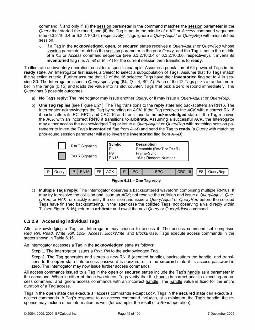
command if, and only if, (i) the session parameter in the command matches the session parameter in the Query that started the round, and (ii) the Tag is not in the middle of a Kill or Access command sequence
10.3.4 or 6.3.2.10.3.6, respectively). Tags ignore a QueryAdjust or Query mismatched
o If a Tag in the acknowledged, open, or secured states re a QueryAdjust or QueryRep whose
(see 6.3.2.session.
Rep with
ceivessession paramete sessr matches the ion parameter in the ry, and the Tag i ot in the middle
Kill or Access c mand seque .3.2.10.3 nverts its ntoried flag (i.e. →B or B→A) for t ssion then transitions to ready
To illustrate a peratio nsider a spe e: Assume a ulation of 64 in the ready state Interrogator first s a Select a subpop Tags. A match the selecti eria. Further assume that 12 of the cted Tag inventoried flag set to A in ses-sion S0. T errogator issues uery specifying ( , Q = 4, S0, A f the 12 Tags picks a random num-ber in the (0,15) and loads the value into nter. Tags that pick a zero ly. The Query has 3 e outcomes:
a) ply: The Inte gator may iss r Query, o sue a Qu Rep.
b) plies (see Fi 1): The ions to th ate and b 16. The Interrogator acknowledges the Tag by sending an ACK. If the Tag receives the ACK with a correct RN16
prior Que s nof a inve
omA
nce (see 6he current se
.4 or 6.3.2.10.3.6, respectively), it i.
n inventory o n, co cific exampl pop powered Tags. An issue to select ulation of ssume that 16 Tags
on crithe Int
16 seleSL
s have their ). Each oa Q
range possibl
its slot cou respond immediate
No Tags re rro ue anothe r it may is eryAdjust or Query
One Tag re gure 6.2 Tag transit e reply st ackscatters an RN
it backscatters its PC, EPC, and CRC-16 and transitions to the acknowledged state. If the Tag receives the ACK with an incorrect RN16 it transitions to arbitrate. Assuming a successful ACK, the Interrogator may either access the acknowledged Tag or issue a QueryAdjust or QueryRep with matching session pa-rameter to invert the Tag’s inventoried flag from A→B and send the Tag to ready (a Query with matching prior-round session parameter will also invert the inventoried A B flag from → ).
e collision and issue an ACK; not resolve the collision and issue a QueryAdjust, Que-
itrate and await the next Query or QueryAdjust command.
a Req_RN to the acknowledged Tag.
Symbol DescriptionR=>T Signaling
T=>R Signaling
P Preamble (R=>T or T=>R)FS Frame-SyncRN16 16-bit Random Number
Query P RN16 ACK P EPC CRC-16P FS PC QueryRepFS
Figure 6.21 – One Tag reply
c) Multiple Tags reply: The Interrogator observes a backscattered waveform comprising multiple RN16s. It may try to resolve thryRep, or NAK; or quickly identify the collision and issue a QueryAdjust or QueryRep before the collided Tags have finished backscattering. In the latter case the collided Tags, not observing a valid reply within T (see Figure 6.16), return to arb2
6.3.2.9 Accessing individual Tags After acknowledging a Tag, an Interrogator may choose to access it. The access command set comprises Req_RN, Read, Write, Kill, Lock, Access, BlockWrite, and BlockErase. Tags execute access commands in the states shown in Table 6.15.
An Interrogator accesses a Tag in the acknowledged state as follows: Step 1. The Interrogator issuesStep 2. The Tag generates and stores a new RN16 (denoted handle), backscatters the handle, and transi-tions to the open state if its access password is nonzero, or to the secured state if its access password is zero. The Interrogator may now issue further access commands.
All access commands issued to a Tag in the open or secured states include the Tag’s handle as a parameter in the command. When in either of these two states, Tags verify that the handle is correct prior to executing an ac-cess command, and ignore access commands with an incorrect handle. The handle value is fixed for the entire duration of a Tag access.
Tags in the open state can execute all access commands except Lock. Tags in the secured state can execute all access commands. A Tag’s response to an access command includes, at a minimum, the Tag’s handle; the re-sponse may include other information as well (for example, the result of a Read operation).
© 2004, 2005, 2006, EPCglobal Inc. Page 45 of 100 17 December 2005
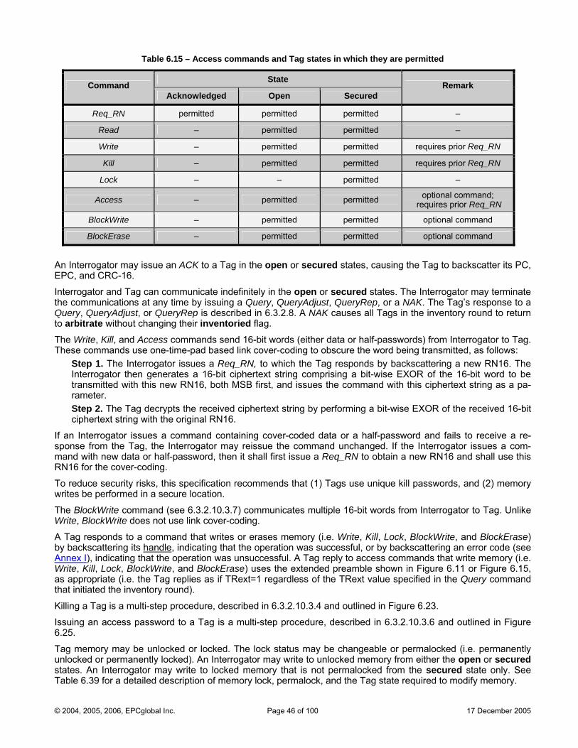
Table 6.15 – Access commands and Tag states in which they are permitted
State Command
Acknowledged Open Secured Remark
Req_RN permitted permitted permitted –
Read – permitted permitted –
Write – permitted permitted requires prior Req_RN
Kill – permitted permitted requires prior Req_RN
Lock – – permitted –
Access – permitted permitted optional command; requires prior Req_RN
BlockWrite – permitted permitted optional command
BlockErase – permitted permitted optional command
An rEPC, an
Interrogthe comQuery, to arbitThe Write, Kill, and Access commands send 16-bit words (either data or half-passwords) from Interrogator to Tag. These commands use one-time-pad based link cover-coding to obscure the word being transmitted, as follows:
Step 1. The Interrogator issues a Req_RN, to which the Tag responds by backscattering a new RN16. The Interrogator then generates a 16-bit ciphertext string comprising a bit-wise EXOR of the 16-bit word to be transmitted with this new RN16, both MSB first, and issues the command with this ciphertext string as a pa-rameter. Step 2. The Tag decrypts the received ciphertext string by performing a bit-wise EXOR of the received 16-bit ciphertext string with the original RN16.
If an Interrogator issues a command containing cover-coded data or a half-password and fails to receive a re-sponse from the Tag, the Interrogator may reissue the command unchanged. If the Interrogator issues a com-mand with new data or half-password, then it shall first issue a Req_RN to obtain a new RN16 and shall use this RN16 for the cover-coding.
To reduce security risks, this specification recommends that (1) Tags use unique kill passwords, and (2) memory writes be performed in a secure location.
The BlockWrite command (see 6.3.2.10.3.7) communicates multiple 16-bit words from Interrogator to Tag. Unlike Write, BlockWrite does not use link cover-coding.
A Tag responds to a command that writes or erases memory (i.e. Write, Kill, Lock, BlockWrite, and BlockErase) by backscattering its handle
Inte rogator may issue an ACK to a Tag in the open or secured states, causing the Tag to backscatter its PC, d CRC-16.
ator and Tag can communicate indefinitely in the open or secured states. The Interrogator may terminate munications at any time by issuing a Query, QueryAdjust, QueryRep, or a NAK. The Tag’s response to a
QueryAdjust, or QueryRep is described in 6.3.2.8. A NAK causes all Tags in the inventory round to return rate without changing their inventoried flag.
, indicating that the operation was successful, or by backscattering an error code (see Annex I), indicating that the operation was unsuccessful. A Tag reply to access commands that write memory (i.e. Write, Kill, Lock, BlockWrite, and BlockErase) uses the extended preamble shown in Figure 6.11 or Figure 6.15, as appropriate (i.e. the Tag replies as if TRext=1 regardless of the TRext value specified in the Query command that initiated the inventory round).
Killing a Tag is a multi-step procedure, described in 6.3.2.10.3.4 and outlined in Figure 6.23.
Issuing an access password to a Tag is a multi-step procedure, described in 6.3.2.10.3.6 and outlined in Figure 6.25.
Tag memory may be unlocked or locked. The lock status may be changeable or permalocked (i.e. permanently unlocked or permanently locked). An Interrogator may write to unlocked memory from either the open or secured states. An Interrogator may write to locked memory that is not permalocked from the secured state only. See Table 6.39 for a detailed description of memory lock, permalock, and the Tag state required to modify memory.
© 2004, 2005, 2006, EPCglobal Inc. Page 46 of 100 17 December 2005
This protocol recommends that Interrogators a Tag is in the reply, acknowledged, open or secured st ng off, leaving t ag in either the re trate state.
.10 Interrogator commands and Tag replies gator-to-Tag commands sha the format shown in le 6.16.
and ACK have 2-bit command codes beginning with 02. , QueryAdjust, and Se -bit command s beginning with 102.
commands h mmand codes ning with 110ands ha mmand codes beginning with 1110 .
, ACK, Query, Q t, and NAK have the unique command lengths sh . other commands shall lengths. If a Tag receives one o e commands correct
length it shall ignore the coQuery, QueryAdjust, and Q ain a session
avoid powering-off whileates. Rather, Interrogators should
ady or arbi end their dialog with a Tag before poweri he T
6.3.2Interro ll have Tab
• QueryRep Query• lect have 4 code
begin• All other base All extended comm
ave 8-bit co 2. • ve 16-bit co 2
• QueryRepNo
ueryAdjushave these
own in 6Table 6.1with an inf thes
mmand. • ueryRep cont parameter. • Query is protected by a CR n in Table 6.12 and detailed in Annex FC-5, show .
Select, Req_RN, Read, Wr ck, Access, Bloc ite and Bloc se are protect RC-16, defined in 6.3.2.1.2.1 and Annex F
• ite, Kill, Lo kWr kEra ed by a Cdetailed in .
>T commands begin wit preamble or a frame-sync, as de n 6.3.1.2.8 mand-e lengths specified in T o not include th mble or fra c. s shall ignore invalid c In general, “inva eans a com d that (1) is incorrect given the
current Tag state, (2) is u by the Tag, (3) has incorrect parameters, (4) has a CRC error, (5) correct sess s in any other way not recognized not executable by e Tag. The
actual definition of “invalid” is state-specific and defined, for each Tag state, in Annex B
• R=cod
h either a able 6.16 d
scribed ime-syn
. The come prea
• Tag ommands. lid” m mannsupported
specifies an in ion, or (6) i or th and Annex C.
© 2004, 2005, 2006, EPCglobal Inc. Page 47 of 100 17 December 2005
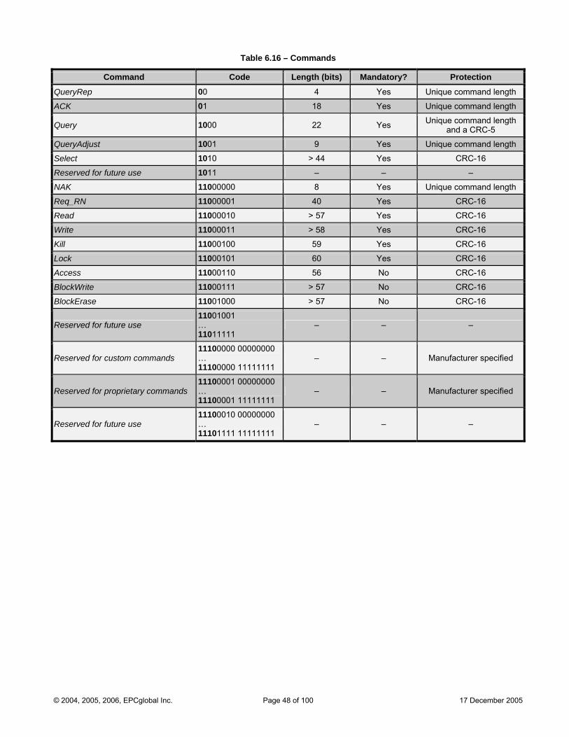
Table 6.16 – Commands
Command Code Length (bits) Mandatory? Protection
QueryRep 00 4 Yes Unique command length
ACK 01 18 Yes Unique command length
Query 1000 22 Yes Unique command length and a CRC-5
QueryAdjust 1001 9 Yes Unique command length
Select 1010 > 44 Yes CRC-16
Reserved for future use 1011 – – –
NAK 11000000 8 Yes Unique command length
Req_RN 11000001 40 Yes CRC-16
Read 11000010 > 57 Yes CRC-16
Write 11000011 > 58 Yes CRC-16
Kill 11000100 59 Yes CRC-16
Lock 11000101 60 Yes CRC-16
Access 11000110 56 No CRC-16
BlockWrite 11000111 > 57 No CRC-16
BlockErase 11001000 > 57 No CRC-16
Reserved for future use 11001001 … 11011111
– – –
Reserve11100000 00000000
d for custom commands … 11100000 11111111
– – Manufacturer specified
Reserved for proprietary commands 11100001 00000000 … 11100001 11111111
– – Manufacturer specified
Reserved for future use 11100010 00000000 … 11101111 11111111
– – –
© 2004, 2005, 2006, EPCglobal Inc. Page 48 of 100 17 December 2005
6.3. 0The Sel
n based on user-defined criteria, enabling union (U), intersection (∩), and negation (~) based Tag partitioning. Interrogators perform ∩ and U operations by issuing successive Select com-mands. Select can assert or deassert a Tag’s SL flag, which applies across all four sessions, or it can set a Tag’s inventoried flag to either A or B in any one of the four sessions.
Interrogators and Tags shall implement th Table 6.17. Target
2.1 .1 Select commands ect command set comprises a single command: Select.
6.3.2.10.1.1 Select (mandatory) Select selects a particular Tag populatio
e Select command shown in shall indicate whether the Select ag’s SL entoried and in the ca , for which session. Action
modifies a T or inv flag, se of the inventoried flag sha respo wn in T g r a t
non-matching ar cified in the emBankll elicit the Tag nse sho able 6.18. The criteria for determinin whethe Tag is ma ching or
e spe M , Pointer, Length and Mask fields. un Tr cate indicwing
ates ether a Tag’s backscattered reply shall be truncated to include only those EPC and Mask
whCRC-16 bits follo . Select passes
p ter Ta
• Target
the following arame s from Interrogator to gs:
indicate o d s a L invent , and in the case of invento s one of ions. A Select command that m does not modify invento vice versa. Class-1 Tags shall ignore Select commands whose Target
s whether the Select c mman modifie Tag’s S flag or its oried flagodifies SLried it further specifie four sess
ried, and is 1012, 1102, or 1112.
• Action indicate matching Tags assert or deassert SL, or set their inventoried flag to A or to B. Tags conforming to the contents of the MemBank
s whether , Pointer, Length, and Mask fields are considered
matching. Tags not conforming to the contents of these fields are considered non-matching.
• MemBank specifies whether Mask applies to EPC, TID, or User memory. Select commands shall apply to a single memory bank. Successive MemBankSelects may apply to different banks. shall not specify Re-served memory; if a Tag receives a Select specifying MemBank = 002 it shall ignore the Select. MemBank parameter v 2 is reserved for future use (RFU).
• Pointer, Length, and Mask: Pointer and Length describe a memory range. Pointer references a memory bit address (Pointer is rie Annex Anot restricted to word bounda s) and uses EBV formatting (see ). Length is 8 bits, allow asking M s from 0 to 255 bits in length. Mask, which is Length bits long, contains a bit string that a Tag compares aga that begins atinst the memory location Pointer and ends Length bits later. If Pointer and Length reference a cation that the Tag shall con-sider the Sel be n
memory lo does not exist on the Tag thenect to on-matching. If Length is zero then all Ta considered matching, unless
Pointergs shall be
refere a m t exist on the ncatences emory location that does no Tag or Tru = 1 and Pointer is out-side the EPC ified the t to be non-matching.
• Truncate: If a rron Inte gator asserts Truncate, and if a subsequen es Selt Query specifi =10 or Sel=11, then a Tag shall truncate its reply to an ately following MaskACK to that portion of the EPC immedi , followed by the CRC-1 red in EPC m h. If an I6 sto emory 00h to 0F nterrogator asserts Truncate, it shall assert it:
o in the l lect that the I issues prior o only if the Select has Target
ast Se nterrogator to sending a Query, = 1002, and
o only if Mask ends in the EPC.
These constraints do not preclude an Interrogator from issuing multiple Select commands that target the SL and/or inventoried flags. They do require that an Interrogator that is requesting Tags to truncate their replies assert Truncate in the last Select, and that this last Select targets the SL flag. Tags shall power-up with Truncate deasserted.
Tags shall decide whether to truncate their backscattered EPC on the basis of the most recently received Select. If a Tag receives a Select with Truncate=1 but Target<>1002 the Tag shall ignore the Select. If a Tag receives a Select in which Truncate=1 but MemBank<>01, the Tag shall consider the Select to be in-valid. If a Tag receives a Select in which Truncate=1, MemBank=01, but Mask ends outside the EPC specified in the PC bits, the Tag shall consider the Select to be not matching.
Mask may end at the last bit of the EPC, in which case a selected Tag shall backscatter its CRC-16.
Truncated replies never include PC bits, because Mask must end in the EPC.
A Tag shall preface its truncated reply with five leading zeros (000002) inserted between the preamble and the truncated reply. A Tag does not recalculate the CRC-16 for a truncated reply.
spec in the PC bits, in which case Tag shall consider the Selec
alue 00
© 2004, 2005, 2006, EPCglobal Inc. Page 49 of 100 17 December 2005

ct command to reset all Tags in a session to inventoried state A, by issuing • Interrogators can use a Selea Select with Action = 0002 and a Length value of zero.
Interrogators shall prepend a Secommand-code bit to the
lect with a frame-sync (see 6.3.1.2.8). The CRC-16 is calculated over the first Truncate bit.
Tags shall not reply to a Select.
Table 6.17 – Select command
Command Target Action MemBank Pointer Length Mask Truncate CRC-16
# of bits 4 3 3 2 EBV 8 Variable 1 16
desc trip ion 1010 000: Inventoried (S0) Mask Mask 0: Disable See 00: RFU Starting
001: Inventoried (S1) 010: Inventoried (S2) 011: Inventoried (S3) 100: SL 101: RFU 110: RFU 111: RFU
Table 6.18
01: EPC 10: TID 11: User
Maskaddress
length (bits)
value truncation1: Enable
truncation
Table 6.18 – Tag response to Action parameter
Action Matching Non-Matching
000 assert SL or inventoried → A deassert SL or inventoried → B
001 assert SL or inventoried → A do nothing
010 do nothing deassert SL or inventoried → B
011 negate SL or (A → B, B → A) do nothing
100 deassert SL or inventoried → B assert SL or inventoried → A
101 deassert SL or inventoried → B do nothing
110 do nothing assert SL or inventoried → A
111 do nothing negate SL or (A → B, B → A)
© 2004, 2005, 2006, EPCglobal Inc. Page 50 of 100 17 December 2005
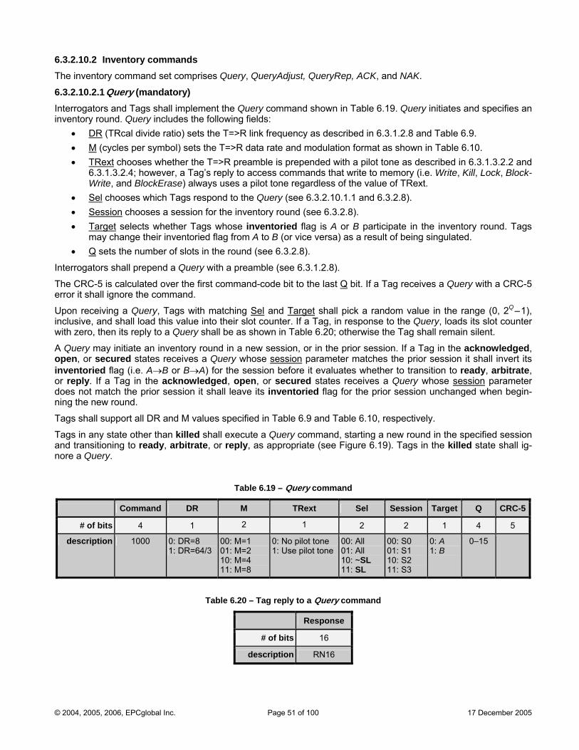
6.3.2.10.2 Inventory commands The inventory command set comprises Query, QueryAdjust, QueryRep, ACK, and NAK.
6.3.2.10.2.1 Query (mandatory) Interrogators and Tags shall implement the Query command shown in Table 6.19. Query initiates and specifies an inve r
• nto y round. Query includes the following fields:
DR (TRcal divide ratio) sets the T=>R link frequency as described in 6.3.1.2.8 and Table 6.9. • M (cycles per symbol) sets the T=>R data rate and modulation format as shown in Table 6.10. • TRext chooses whether the T=>R prea
g’s reply to amble is prepended with a pilot tone as described in 6.3.1.3.2.2 and
6.3. ccess commands that write to memory (i.e. Write, Kill, Lock, Block-Wri ays uses a pilot tone regardless of the value of TRext.
• Sel
1.3.2.4; however, a Tate, and BlockErase) alw chooses which Tags respond to the Query (see 6.3.2.10.1.1 and 6.3.2.8).
• Session chooses a session for the inventory round (see 6.3.2.8). • Target selects whether Tags whose inventoried flag is A or B participate in the inventory round. Tags
may change their inventoried flag from A to B (or vice versa) as a result of being singulated. • Q sets the number of slots in the round (see 6.3.2.8).
Interrogators shall prepend a Query with a preamble (see 6.3.1.2.8).
The CRC-5 is calculated over the first command-code bit to the last Q bit. If a Tag receives a Query with a CRC-5 error it shall ignore the command.
Upon receiving a Query, Tags with matching Sel and Target shall pick a random value in the range (0, 2Q–1), inclusive, and shall load this value into their slot counter. If a Tag, in response to the Query, loads its slot counter with zero, then its reply to a Query shall be as shown in Table 6.20; otherwise the Tag shall remain silent.
A Query may initiate an inventory round in a new session, or in the prior session. If a Tag in the acknowledged, open, or secured states receives a Query whose session parameter matches the prior session it shall invert its inventoried flag (i.e. A→B or B→A) for the session before it evaluates whether to transition to ready, arbitrate, or reply. If a Tag in the acknowledged, open, or secured states receives a Query whose session parameter does not match the prior session it shall leave its inventoried flag for the prior session unchanged when begin-ning the new round.
Tags shall support all DR and M values specified in Table 6.9 and Table 6.10, respectively.
Tags in any state other than killed shall execute a Query command, starting a new round in the specified session and transitioning to ready, arbitrate, or reply, as appropriate (see Figure 6.19). Tags in the killed state shall ig-nore a Query.
Tab .19le 6 – Query command
Command DR M TRext Sel Session Target Q CRC-5
# of bits 4 1 2 1 2 2 1 4 5
description 1000 0: DR=8 1: DR=64/3
00: M=1 01: M=2 10: M=4 11: M=8
0: one No pilot t1: Use pilot tone
00: All 01: All 10: ~SL 11: SL
00: S0 01: S1 10: S2 11: S3
0: A 1: B
0–15
Table 6.20 – T Query command ag reply to a
Re sponse
# of bits 16
description RN16
© 2004, 2005, 2006, EPCglobal Inc. Page 51 of 100 17 December 2005
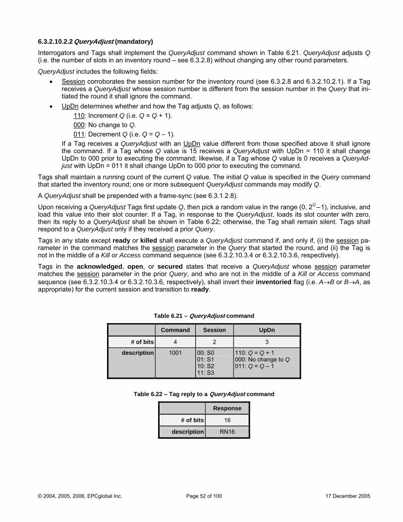
6.3.2.10.2.2 QueryAdjust (mandatory)
:
Interrogators and Tags shall implement the QueryAdjust command shown in Table 6.21. QueryAdjust adjusts Q (i.e. the number of slots in an inventory round – see 6.3.2.8) without changing any other round parameters.
QueryAdjust includes the following fields• Session corroborates the session number for the inventory round (see 6.3.2.8 and 6.3.2.10.2.1). If a Tag
receives a QueryAdjust whose session number is different from the session number in the Query that ini-tiated the round it shall ignore the command.
• UpDn determines whether and how the Tag adjusts Q, as follows: 110: Increment Q (i.e. Q = Q + 1). 000: No change to Q. 011: Decrement Q (i.e. Q = Q – 1).
If a Tag receives a QueryAdjust with an UpDn value different from those specified above it shall ignore the command. If a Tag whose Q value is 15 receives a QueryAdjust with UpDn = 110 it shall change UpDn to 000 prior to executing the command; likewise, if a Tag whose Q value is 0 receives a QueryAd-
Upon receiving a QueryAdjust Tags first update Q, then pick a random value in the range (0, 2Q–1), inclusive, and load this value into their slot counter. If spon ust, loads its slot counter with zero, then its reply to a QueryAdjust shall be , the Tag shall remain silent. Tags shall respond to a QueryAdjust only if they received a prio
Tags in any state except ready or killed shall execute a ueryAdjust command if, and only if, (i) the session
just with UpDn = 011 it shall change UpDn to 000 prior to executing the command.
Tags shall maintain a running count of the current Q value. The initial Q value is specified in the Query command that started the inventory round; one or more subsequent QueryAdjust commands may modify Q.
A QueryAdjust shall be prepended with a frame-sync (see 6.3.1.2.8).
a Tag, in re se to the QueryAdj shown in Table 6.22; otherwise
r Query.
Q pa-rameter in the command matches the session parameter in the Quer at started the round, and (ii) the Tag is not in the middle of a Kill or Access com ence 6.3 4 or 6.3.2.10.3.6, respectively).
Tags in the acknowledged, open, or secured states that re QueryAdjust whose session
y thmand sequ (see .2.10.3.
ceive a parameter matches the session parameter in the prior Query, and who are the middle of a Kill or Access command sequence (see 6.3.2.10.3.4 or 6.3.2.10.3.6, respectively), shall invert their inventoried flag (i.e. A→B or B→A, as appropriate) for the current session and transition to ready.
Table 6.21 – QueryA ddjust comman
not in
Command Session UpDn
# of bits 4 2 3
description 1001 00: S0 01: S1 10: S2 11: S3
110: Q = Q + 1 000: No change to Q 011: Q = Q – 1
Table 6.22 – Tag reply to a QueryAdjust command
Response
# of bits 16
description RN16
© 2004, 2005, 2006, EPCglobal Inc. Page 52 of 100 17 December 2005
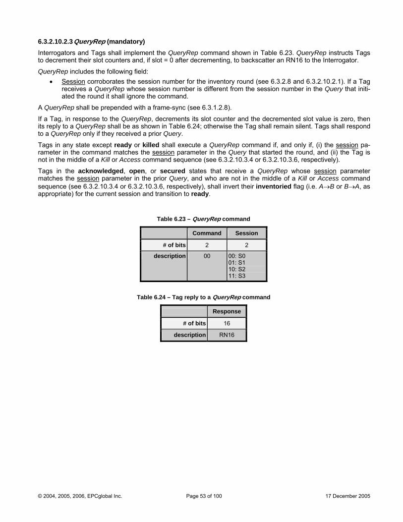
6.3.2.10.2.3 QueryRep (mandatory)
kscatter an RN16 to the Interrogator. Interrogators and Tags shall implement the QueryRep command shown in Table 6.23. QueryRep instructs Tags to decrement their slot counters and, if slot = 0 after decrementing, to bac
QueryRep includes the following field: • Session corroborates the session number for the inventory round (see 6.3.2.8 and 6.3.2.10.2.1). If a Tag
receives a QueryRep whose session number is different from the session number in the Query that initi-ated the round it shall ignore the command.
.8).
execute a QueryRep command if, and only if, (i) the session
A QueryRep shall be prepended with a frame-sync (see 6.3.1.2
If a Tag, in response to the QueryRep, decrements its slot counter and the decremented slot value is zero, then its reply to a QueryRep shall be as shown in Table 6.24; otherwise the Tag shall remain silent. Tags shall respond to a QueryRep only if they received a prior Query.
Tags in any state except ready or killed shall pa-rameter in the command matches the session parameter in the Query that started the round, and (ii) the Tag is not in the middle of a Kill or Access command sequence (see 6.3.2.10.3.4 or 6.3.2.10.3.6, respectively).
Tags in the acknowledged, open, or s a QueryRep whose sessionecured states that receive parameter matches the session parameter in the prior Query, and who are not in the middle of a Kill or Access command sequence (see 6.3.2.10.3.4 or 6.3.2.10.3.6, re shall invert their inventoried flag (i.e. A→B or B→A, as appropriate) for the current session ition t eady.
Table 6.23 – QueryRep command
Command Session
# of bits 2 2
description 00 00: S0 01: S1 10: S2 11: S3
Table 6.24 – Tag reply to a QueryRep command
Response
# of bits 16
description RN16
spectively), and trans o r
© 2004, 2005, 2006, EPCglobal Inc. Page 53 of 100 17 December 2005
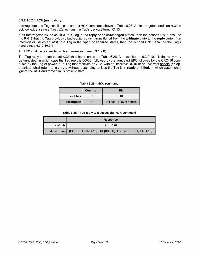
6.3.2.10.2.4 ACK (mandatory) Interrogators and Tags shall implement the ACK command shown in Table 6.25. An Interrogator sends an ACK to acknowledge a single Tag. ACK echoes the Tag’s backscattered RN16.
If an Interrogator issues an ACK to a Tag in the reply or acknowledged states, then the echoed RN16 shall be rom the arbitrate state to the reply state. If an
a Tag in the open or secured states, then the echoed RN16 shall be the Tag’s the RN16 that the Tag previously backscattered as it transitioned fInterrogator issues an ACK to handle (see 6.3.2.10.3.1).
An ACK shall be prepended with a frame-sync (see 6.3.1.2.8).
The Tag reply to a successful ACK shall b s described in 6.3.2.10.1.1, the reply may be truncated, in which case the Tag reply is 000002 followed by the truncated EPC followed by the CRC-16 com-puted by the Tag at powerup. A Tag that receives an ACK rrect RN16 or an incorrect handle
e as shown in Table 6.26. A
with an inco (as ap-propriate) shall return to arbitrate without resp nless t Tag is in ready or killed, in which case it shall ignore the ACK and remain in its present state.
Table 6.25 – ACK command
Command RN
# of bits 2 16
description 01 Echoed RN16 or handle
Table 6.26 – Tag reply to a successful ACK command
Response
# of bits 21 to 528
description {PC, EPC, CRC-16} OR {000002, truncated EPC, CRC-16}
onding, u he
© 2004, 2005, 2006, EPCglobal Inc. Page 54 of 100 17 December 2005
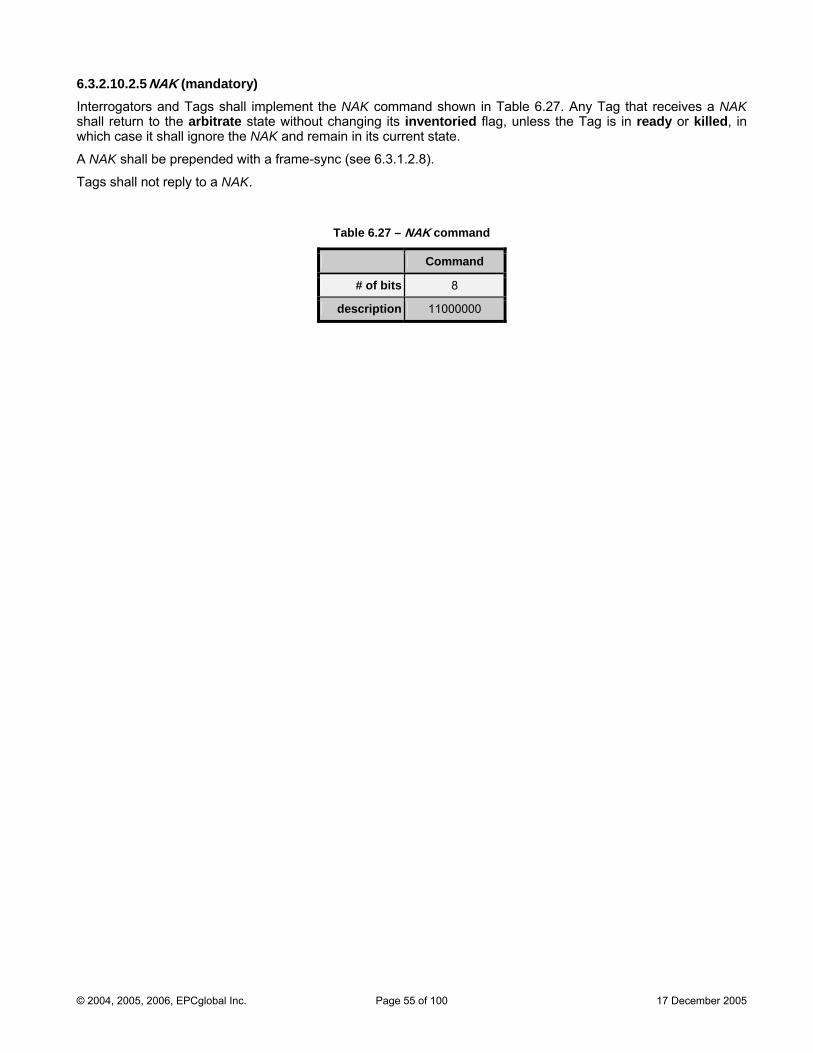
6.3.2.10.2.5 NAK (mandatory) Interrogators and Tags shall implement the NAK command shown in Table 6.27. Any Tag that receives a NAK shall return to the arbitrate state without changing its inventoried flag, unless the Tag is in ready or killed, in which case it shall ignore the NAK and remain in its current state.
A NAK shall be prepended with a frame-sync (see 6.3.1.2.8).
Tags shall not reply to a NAK.
Table 6.27 – NAK command
Command
# of bits 8
description 11000000
© 2004, 2005, 2006, EPCglobal Inc. Page 55 of 100 17 December 2005
6.3.2.10.3 Access commands The set of access commands comprises Req_RN, Read, Write, Kill, Lock, Access, BlockWrite, and BlockErase. As described in 6.3.2.9, Tags execute Req_RN from the acknowledged, open, or secured states. Tags execute Rea Wcation bKill from
All acce
d, rite, BlockWrite, and BlockErase from the secured state; if allowed by the lock status of the memory lo-eing accessed, they may also execute these commands from the open state. Tags execute Access and the open or secured states. Tags execute Lock only from the secured state.
ss commands issued to a Tag in the open or secured states include the Tag’s handle as a parameter in mand. When in either of these two states, Tags shall verify that the the com handle is correct prior to executing an command, and shall ignore access commands with aaccess n incorrect handle. The handle value is fixed for the
entire duration
A Tag’s r . Read, Write, Kill, Lock, BlockWrite, and BlockEr
of a Tag access.
eply to all access commands that read or write memory (i.ease) includes a 1-bit header. Header=0 indicates that the operation was successful and the reply is valid;
header= d the reply is an error code.
A T suse theTRext=
After anwill not Tag compute
1 indicates that the operation was unsuccessful an
ag’ reply to all access commands that write memory (i.e. Write, Kill, Lock, BlockWrite, and BlockErase) shall extended preamble shown in Figure 6.11 or Figure 6.15, as appropriate (i.e. the Tag shall reply as if 1 regardless of the TRext value specified in the Query command that initiated the inventory round).
Interrogator writes part or all of a Tag’s PC or EPC, the CRC-16 stored in Tag EPC memory 00h to 0Fh be valid until the Interrogator first powers-down and then re-powers-up its energizing RF field, because the
s the CRC-16 stored in Tag EPC memory 00 to 0F at powerup. h h
If an Interrogator attempts to write directly to EPC memory 00h to 0Fh using either a Write or a BlockWrite com-mand, the Tag shall respond with an error code (see Annex I for error-code definitions and for the reply format).
Req_RN, Read, Write, Kill, and Lock are required commands; Access, BlockWrite, and BlockErase are optional. Tags shall ignore optional access commands that they do not support.
See Annex K for an example of a data-flow exchange during which an Interrogator accesses a Tag and reads its kill password.
© 2004, 2005, 2006, EPCglobal Inc. Page 56 of 100 17 December 2005
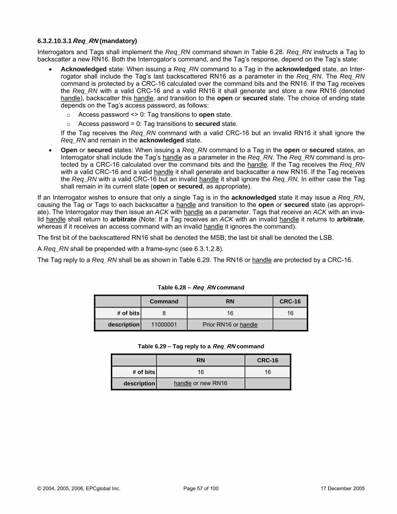
6.3.2.10.3.1 Req_RN (mandatory)
the Tag’s state:
ceives
Interrogators and Tags shall implement the Req_RN command shown in Table 6.28. Req_RN instructs a Tag to backscatter a new RN16. Both the Interrogator’s command, and the Tag’s response, depend on
• Acknowledged state: When issuing a Req_RN command to a Tag in the acknowledged state, an Inter-rogator shall include the Tag’s last backscattered RN16 as a parameter in the Req_RN. The Req_RN command is protected by a CRC-16 calculated over the command bits and the RN16. If the Tag rethe Req_RN with a valid CRC-16 and a valid RN16 it shall generate and store a new RN16 (denoted handle), backscatter this handle, and transition to the open or secured state. The choice of ending state depends on the Tag’s access password, as follows:
o Access password <> 0: Tag transitions to open state. o Access password = 0: Tag transitions to secured state.
If the Tag receives the Req_RN command with a valid CRC-16 but an invalid RN16 it shall ignore the Req_RN and remain in the acknowledged state. Open or secured states: When issuing a Req_RN command to a Tag in the open or secured states, an Interrogator shall include the Tag’s h
• andle as a parameter in the Req_RN. The Req_RN command is pro-
tected by a CRC-16 calculated over the command bits and the handle. If the Tag receives the Req_RN with a valid CRC-16 and a valid handle it shall generate and backscatter a new RN16. If the Tag receives the Req_RN with a valid CRC-16 but an invalid handle it shall ignore the Req_RN. In either case the Tag shall remain in its current state (open or secured, as appropriate).
If an Interrogator wishes to ensure that only a single Tag is incausing the Tag or Tags to each backscatter a
the acknowledged state it may issue a Req_RN, handle and transition to the open or secured state (as appropri-
ate). The Interrogator may then issue an ACK with handle as a parameter. Tags that receive an ACK with an inva-lid handle shall return to arbitrate (Note: If a Tag receives an ACK with an invalid handle it returns to arbitrate, whereas if it receives an access command with an invalid handle it ignores the command).
The first bit of the backscattered RN16 shall be denoted the MSB; the last bit shall be denoted the LSB.
A Req_RN shall be prepended with a frame-sync (see 6.3.1.2.8).
The Tag reply to a Req_RN shall be as shown in Table 6.29. The RN16 or handle are protected by a CRC-16.
bTa le 6.28 – Req_RN command
Command RN CR 6 C-1
# of bits 8 16 16
description 11000001 Pri or handor RN16 le
Table 6.29 – Tag reply to a Req_RN command
RN CRC-16
# of bits 16 16
description handle or new RN16
© 2004, 2005, 2006, EPCglobal Inc. Page 57 of 100 17 December 2005
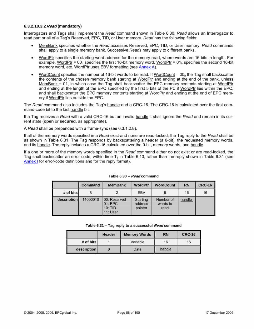
6.3.2.10.3.2 Read (mandatory) Interrogators and Tags shall implement the Read command shown in Table 6.30. Read allows an Interrogator to read part or all of a Tag’s Reserved, EPC, TID, or User memory. Read has the following fields:
• MemBank specifies whether the Read accesses Reserved, EPC, TID, or User memory. Read commands
•
shall apply to a single memory bank. Successive Reads may apply to different banks.
WordPtr specifies the starting word address for the memory read, where words are 16 bits in length. For example, WordPtr = 00 specifies the first 16-bit memoryh word, WordPtr = 01h specifies the second 16-bit memory word, etc. WordPtr uses EBV formatting (see Annex A).
• WordCount specifies the number of 16-bit words to be read. If WordCount = 00 the Tag shall backscatter hthe contents of the chosen memory bank starting at WordPtr and ending at the end of the bank, unless MemBank = 01, in which case the Tag shall backscatter the EPC memory contents starting at WordPtr and ending at the length of the EPC specified by the first 5 bits of the PC if WordPtr lies within the EPC, and shall backscatter the EPC memory contents starting at WordPtr and ending at the end of EPC mem-ory if WordPtr lies outside the EPC.
The Read command also includes the Tag’s handle and a CRC-16. The CRC-16 is calculated over the first com-mand-code bit to the last handle bit.
If a Tag receives a Read with a valid CRC-16 but an invalid handle it shall ignore the Read and remain in its cur-rent state (open or secured, as appropriate).
A Read shall be prepended with a frame-sync (see 6.3.1.2.8).
If al as showand its h
l of the memory words specified in a Read exist and none are read-locked, the Tag reply to the Read shall be n in Table 6.31. The Tag responds by backscattering a header (a 0-bit), the requested memory words, andle. The reply includes a CRC-16 calculated over the 0-bit, memory words, and handle.
If a oneTag shall baAnnex I
or more of the memory words specified in the Read command either do not exist or are read-locked, the ckscatter an error code, within time T1 in Table 6.13, rather than the reply shown in Table 6.31 (see
for error-code definitions and for the reply format).
Table 6.30 – Read command
Command MemBank WordPtr WordCount RN CRC-16
# of bits 8 2 EBV 8 16 16
description 11000010 00: Reserved 01: EPC 10: TID 11: User
Startingaddresspointer
Number of words to
read
handle
Tab ag repl cce ommand le 6.31 – T y to a su ssful Read c
Header Memory Words RN CRC-16
# of bits 1 Variable 16 16
description 0 Data handle
© 2004, 2005, 2006, EPCglobal Inc. Page 58 of 100 17 December 2005
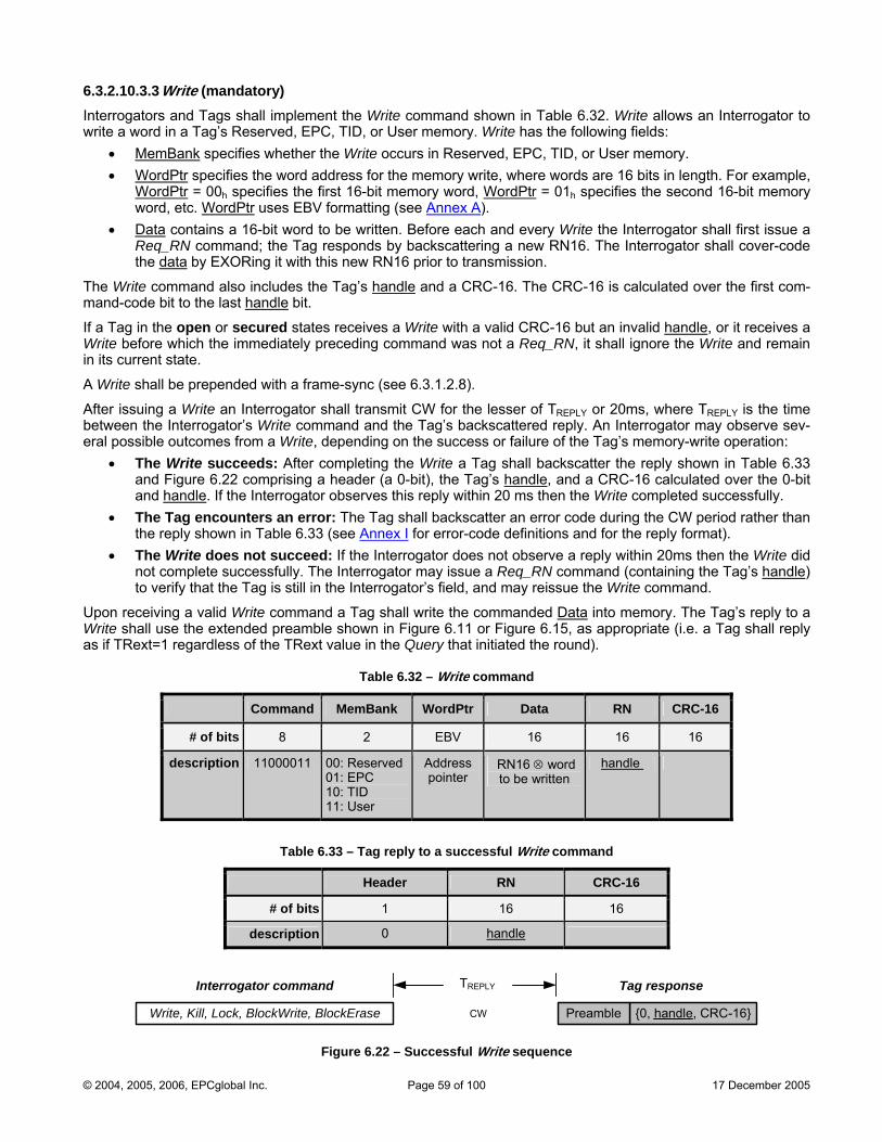
6.3.2.10.3.3 Write (mandatory)
served, EPC, TID, or User memory. Write has the following fields: Interrogators and Tags shall implement the Write command shown in Table 6.32. Write allows an Interrogator to write a word in a Tag’s Re
• MemBank specifies whether the Write occurs in Reserved, EPC, TID, or User memory. • WordPtr specifies the word address for the memory write, where words are 16 bits in length. For example,
WordPtr = 00h specifies the first 16-bit memory word, WordPtr = 01h specifies the second 16-bit memory word, etc. WordPtr uses EBV formatting (see Annex A).
• Data contains a 16-bit word to be written. Before each and every Write the Interrogator shall first issue a Req_RN command; the Tag responds by backscattering a new RN16. The Interrogator shall cover-code the data by EXORing it with this new RN16 prior to transmission.
The Write command also includes the Tag’s handle and a CRC-16. The CRC-16 is calculated over the first com-mand-code bit to the last handle bit.
If a Tag in the open or secured states receives a Write with a valid CRC-16 but an invalid handle, or it receives a Write before which the immediately preceding command was not a Req_RN, it shall ignore the Write and remain in its current state.
A Write shall be prepended with a frame-sync (see 6.3.1.2.8).
After issuing a Write an Interrogator shall transmit CW for the lesser of TREPLY or 20ms, where TREPLY is the time
er t abl
between the Interrogator’s Write command and the Tag’s backscattered reply. An Interrogator may observe sev-eral possible outcomes from a Write, depending on the success or failure of the Tag’s memory-write operation:
• The Write succeeds: After completing the Write a Tag shall backscatt he reply shown in T e 6.33 and Figure 6.22 comprising a header (a 0-bit), the Tag’s handle, and a CRC-16 calculated over the 0-bit and handle. If the Interrogator observes this reply within 20 ms then the Write completed successfully.
• The Tag encounters an error: The Tag shall backscatter an error code during the CW period rather than the reply shown in Table 6.33 (see Annex I for error-code definitions and for the reply format). The Write does not succeed: If the Interrogator does not observe a reply within 20ms then the Write did not complete successfully. The Interrogator may issue a Req_RN command (containing the Tag’s
• handle)
to verify that the Tag is still in the Interrogator’s field, and may reissue the Write command.
ceiving a valid Write command a Tag shall write the commanded Upon re Data into memory. The Tag’s reply to a Wri has if
te s all use the extended preamble shown in Figure 6.11 or Figure 6.15, as appropriate (i.e. a Tag shall reply TRext=1 regardless of the TRext value in the Query that initiated the round).
Table 6.32 – Write command
Command MemBank WordPtr Data RN CRC-16
# of bits 8 2 EBV 16 16 16
description 11000011 00: Reserved 01: EPC 10: TID 11: User
Address pointer
RN16 ⊗ wordto be written
handle
Table 6.33 – Tag reply to a successful Write command
Header RN CRC-16
# of bits 1 16 16
description 0 handle
Write, Kill, Lock, BlockWrite, BlockErase {0, handle, CRC-16}CW
TREPLY
Preamble
Interrogator command Tag response
Figure 6.22 – Successful Write sequence
© 2004, 2005, 2006, EPCglobal Inc. Page 59 of 100 17 December 2005
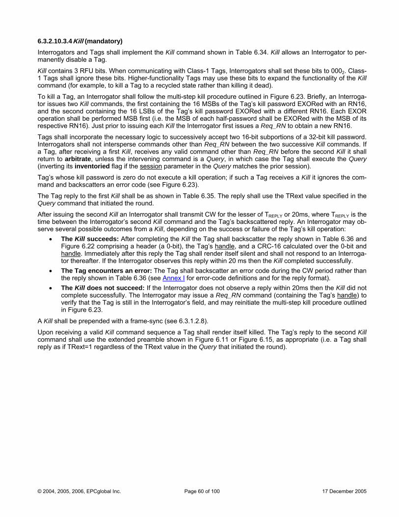
6.3.2.10.3.4 Kill (mandatory) Interrogators and Tags shall implement the able 6.34. Kill allows an Interrogator to per-manently disable a Tag.
Kill contains 3 n communicating with ss-1 Tags, Interrogators shall set these bits to 2. Class-1 Tags shall i er-functionality Tags may use these bits to expand the functionality of the Kill command , to to a n killing it dead).
To kill a Tag, an Interrogator shall follow the multi-step kill procedure outlined in Figure 6.23. Briefly, an Interroga-tor issues two Kill commands, the first containing the 16 MSBs of the Tag’s kill password EXORed with an RN16, and the second containing the 16 LSBs of the Tag’s kill password EXORed with a different RN16. Each EXOR operation shall be performed MSB l be EXORed with the MSB of its respective RN16). Just prior to issuing each Kill the Interrogator first issues a Req_RN to obtain a new RN16.
Tags shall incorporate the necessary logic to successively pt two 16 bportions of a 32-bit kill password. Interrogators shall not intersperse comma r than q_RN betw the two successive Kill commands. If a Tag, after receiving a first Kill, recei co other than Req_RN before the second Kill it shall return to arbitrate, unless the interven d is ery, in whic shall execute the Query (inverting its inventoried flag if the session
Kill command shown in T
RFU bits. Whegnore these bits. High
Cla 000
(for example kill a Tag recycled state rather tha
first (i.e. the MSB of each half-password shal
acce -bit sunds othe Re een
ves any validing comman
mmand a Qu h case the Tag
parameter in the Query matches the prior session).
Tag’s whose kill password is zero do not execute a kill operation; if such a Tag receives a Kill it ignores the com-mand and backscatters an erro
The Tag reply to the first Kill shall be as show e 6.35. T eply sha Rext value specified in the Query command that initiated the round.
After issuing the second Kill an Int shall transmit CW for the lesser of TREPLY or 20ms, where TREPLY is the time between the Interrogator’s comm and the backscattered reply. An Interrogator may ob-serve several possible outcomes from a Kill, depending on the success or failure of the Tag’s kill operation:
• The Kill succeeds: After completing the Kill the Tag shall backscatter the reply shown in Table 6.36 and Figure 6.22 comprising a header (a 0-bit), the Tag’s handle, and a CRC-16 calculated over the 0-bit and handle. Immediately after this reply the Tag shall render itself silent and shall not respond to an Interroga-tor thereafter. If the Interrogator observes this reply within 20 ms then the Kill completed successfully.
• The Tag encounters an error: The Tag shall backscatter an error code during the CW period rather than the reply shown in Table 6.36 (see Annex I for error-code definitions and for the reply format).
• The Kill does not succeed: If the Interrogator does not observe a reply within 20ms then the Kill did not complete successfully. The Interrogator may issue a Req_RN command (containing the Tag’s handle) to verify that the Tag is still in the Interrogator’s field, and may reinitiate the multi-step kill procedure outlined in Figure 6.23.
A Kill shall be prepended with a frame-sync (see 6.3.1.2.8).
Upon receiving a valid Kill command sequence a Tag shall render itself killed. The Tag’s reply to the second Kill command shall use the extended preamble shown in Figure 6.11 or Figure 6.15, as appropriate (i.e. a Tag shall reply as if TRext=1 regardless of the TRext value in the Query that initiated the round).
r code (see Figure 6.23).
n in Tabl he r ll use the T
errogator second Kill and Tag’s
© 2004, 2005, 2006, EPCglobal Inc. Page 60 of 100 17 December 2005
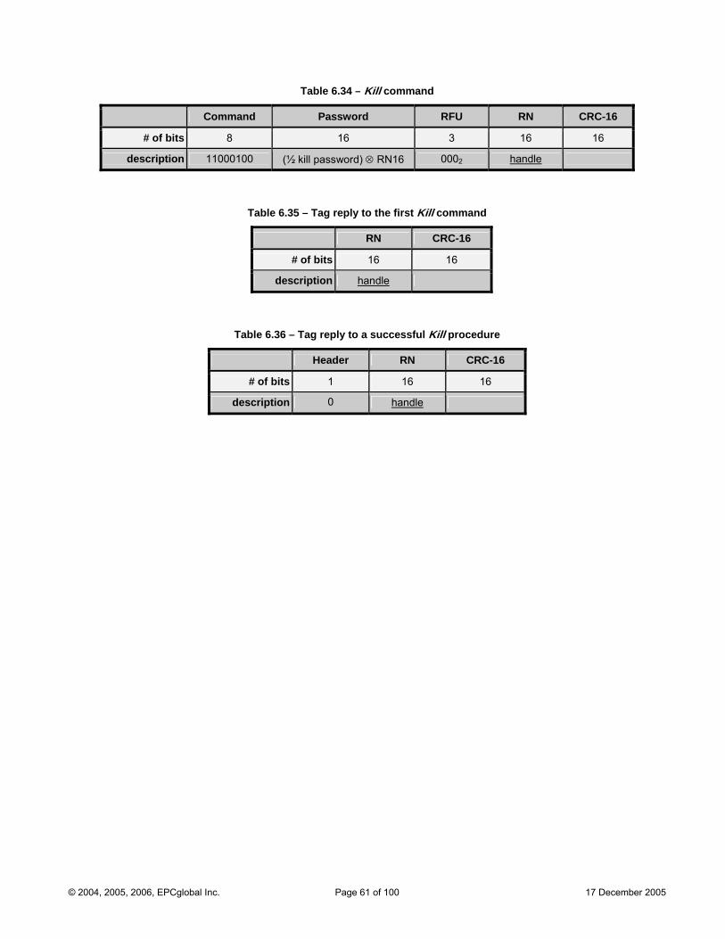
Table 6.34 – Kill command
Command Password RFU RN CRC-16
# of bits 8 16 3 16 16
description 11000100 (½ kill password) ⊗ RN16 0002 handle
Table 6.35 – Tag reply to the first Kill command
RN CRC-16
# of bits 16 16
description handle
Table 6.36 – Tag reply to a successful Kill procedure
Header RN CRC-16
# of bits 1 16 16
description 0 handle
© 2004, 2005, 2006, EPCglobal Inc. Page 61 of 100 17 December 2005
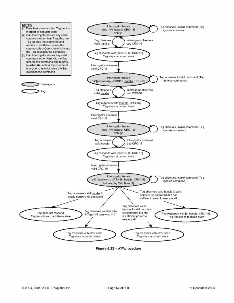
Interrogator issues
Tag responds with error code.Tag stays in current state
Tag does not respond.Tag transitions to arbitrate state
Tag responds with error code.Tag stays in current state
Tag responds with [0, handle, CRC-16].Tag transitions to killed state
Tag observes valid handle & valid nonzero kill password but has insufficient power to execute kill
Tag observes valid handle & Tag’s kill password = 0
Tag observes valid handle & invalid nonzero kill password
Tag responds with [new RN16, CRC-16].Tag stays in current state
Tag responds with [handle, CRC-16].Tag stays in current state
Req_RN [handle, CRC-16]Note [1]
Interrogator issuesKill [password31:16⊗RN16, handle, CRC-16]
Tag observes valid handle
Interrogator observes bad CRC-16
Interrogator observes valid CRC-16
Interrogator issuesKill [password15:0⊗RN16, handle, CRC-16]
followed by CW. Note [3]
Tag observes invalid command (Tag ignores command).
Tag observes invalid comignores command).
mand (Tag
NOTES [1] Flowchart assumes that Tag begins
in open or secured state [2] If an Interrogator issues any valid
c aomm nd other than Req_RN, the ag ig ores the command and
to arbitraT nreturns te, unless the c ath ag
[3] If an Intc a
is uex ut
omm nd is a Query, in which case e T executes the command
errogator issues any valid omm nd other than Kill, the Tag
ignores the command and returns to arbitrate, unless the command
a Q ery, in which case the Tag ec es the command
Tag responds with [new RN16, CRC-16].Tag stays in current state
Interrogator issuesReq_RN [handle, CRC-16]
Note [2]
Tag observes valid handle
Interrogator observes bad CRC-16
ignores command).
Interrogator observes valid CRC-16
Tag observes invalid command (Tag
Tag observes valid handle
Interrogator observbad CRC-16
es
Interrogator observes valid CRC-16
Tag observes invalid command (Tag ignores command).
Tag observes valid handle & valid nonzero kill password and has sufficient power to execute kill
Interrogator
T
ag
Figure 6.23 – Kill procedure
© 2004, 2005, 2006, EPCglobal Inc. Page 62 of 100 17 December 2005
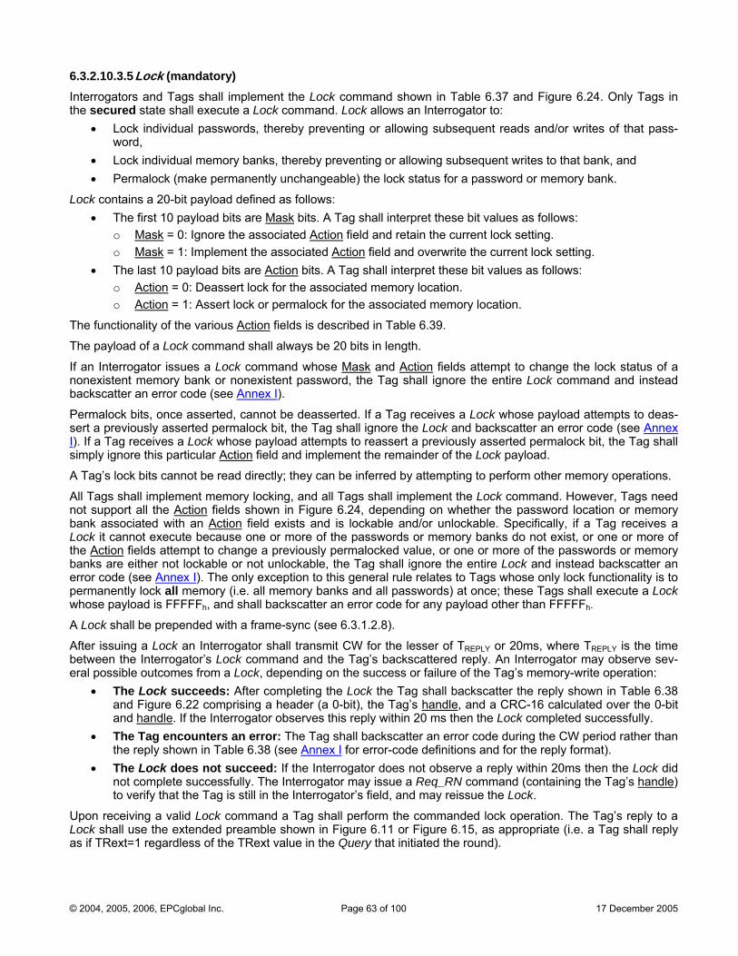
6.3.2.10.3.5 Lock (mandatory) Interrogators and Tags shall he Lock comm n in Table 6.37 and Figure 6.24. Only Tags in the secured state cute a ck command. Lock allo an Interrogator to:
• Lock i ssw by preve equent s of that pass-word,
• Lock individual memory banks, thereby preventing or allowing subsequent writes to that bank, and • Permalock (make permanen sword or memory bank.
Lock contains a 20-bit payload defined a follo• The first 10 payload bits
implement t and show shall exe Lo ws
ndividual pa ords, there nting or allowing subs reads and/or write
tly unchangeable) the lock status for a pas
s ws: are Mask bits. A ag shall interp these bit values as follows:
o Mask T ret
= 0: Ignore the a Actionssociated field and re current lock setting. o Mask
tain the = 1: Implement the a ated tionssoci Ac field and overwrite the current lock setting.
• The last 10 payload bits are Action bits. A Tag shall interpret these bit values as follows: o Action = 0: Deassert lock for the associated memory location. o Action = 1: Assert lock or ocation.
ctionality of the various Action
permalock for the associated memory l
The fun fields is described in Table 6.39.
The payload of a Lock command shall always be 20 bits in length.
If an Interrogator issues a Lock command whose Mask and Action fields attempt to change the lock status of a nonexistent memory bank or nonexistent password, the Tag shall ignore the entire Lock command and instead backscatter an error code (see Annex I).
Permalock bits, once asserted, cannot be deasserted. If a Tag receives a Lock whose payload attempts to deas-sert a previously asserted permalock bit, the Tag shall ignore the Lock and backscatter an error code (see Annex I). If a Tag receives a Lock whose payload attempts to reassert a previously asserted permalock bit, the Tag shall simply ignore this particular Action field and implement the remainder of the Lock payload.
A Tag’s lock bits cannot be read directly; they can be inferred by attempting to perform other memory operations.
All Tags shall implement memory locking, and all Tags shall implement the Lock command. However, Tags need not support all the Action fields shown in Figure 6.24, depending on whether the password location or memory bank associated with an Action field exists and is lockable and/or unlockable. Specifically, if a Tag receives a Lock it cannot execute because one or more of the passwords or memory banks do not exist, or one or more of the Action fields attempt to change a previously permalocked value, or one or more of the passwords or memory banks are either not lockable or not unlockable, the Tag shall ignore the entire Lock and instead backscatter an error code (see Annex I). The only exception to this general rule relates to Tags whose only lock functionality is to permanently lock all memory (i.e. all memory banks and all passwords) at once; these Tags shall execute a Lock whose payload is FFFFFh, and shall backscatter an error code for any payload other than FFFFFh.
A Lock shall be prepended with a fram .
Aft Lo ogator shall transmit CW for the les or 20ms, where TREPLY is the time between the Interrogator’s Loc bserve sev-eral possible outcomes from a
• e Lock succeeds: and Figure 6.22 comp the Tag’s handle
e-sync (see 6 3.1.2.8).
er issuing a ck an Interr ser of TREPLY k command and the Tag’s backscattered reply. An Interrogator may oLock, depending on the success or failure of the Tag’s memory-write operation:
Th After completing the Lock the Tag shall backscatter the reply shown in Table 6.38 rising a header (a 0-bit), , and a CRC-16 calculated over the 0-bit
d handlean . If Inter• e Tag encounters ring the CW period rather than
the reply shown in Table 6.38 (see Annex I
the rogator observes this reply within 20 ms then the Lock completed successfully. Th an error: The Tag shall backscatter an error code du
for error-code definitions and for the reply format). k ucceed: If the Interrogator does no eply within 20ms then the Lock did
t complete s cessf• The Loc does not s t observe a r
no uc ully. The Interrogator may issue a Req_RN command (containing the Tag’s handle) still in to verify that th ag is the Interrogator’s field, and may reissue the Lock.
Upon r iving a valid ck c Lock shall use the extended p .15, as appropriate (i.e. a Tag shall reply as if TRext=1 regardle of the
e T
ece Lo ommand a Tag shall perform the commanded lock operation. The Tag’s reply to areamble shown in Figure 6.11 or Figure 6
ss TRext value in the Query that initiated the round).
© 2004, 2005, 2006, EPCglobal Inc. Page 63 of 100 17 December 2005
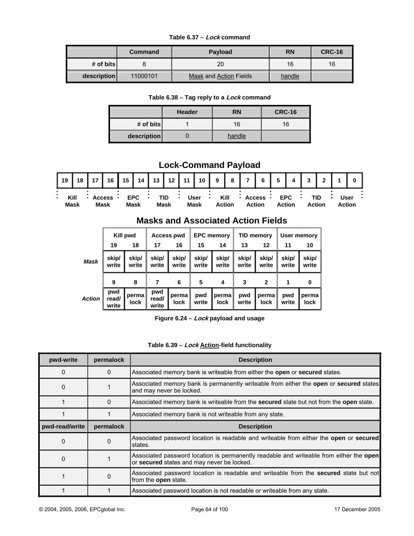
Table 6.37 – Lock command
Command Payload RN CRC-16
# of bits 8 20 16 16
description 11000101 Mask and Action Fields handle
Table 6.38 – Tag reply to a Lock command
Header RN CRC-16
# of bits 1 16 16
description 0 handle
18 17 16 15 14 13 12 11 1019
KillMask
AccessMask
EPCMask
TIDMask
9 8 7 6 5 4 3 2
Lock-Command Payload
UserMask
KillAction
AccessAction
EPCAction
TIDAction
UserAction
1 0
Masks and Associated Action Fields
pwdread/
write
plockerma pw
readd /
write
plockerma pwd
writepermalock
pwd write
permalock
pwd write
permalock
19 18 17 16 15 14 13 12 11 10
8 7 6 5 3 2 0
Mask
Kill pwd d EPC memory TID memory User memoryAccess pw
9 4 1
Action
skip/write
skip/write
skip/write
skip/write
skip/write
skip/write
skip/write
skip/write
skip/write
skip/write
Table
Figure 6.24 – Lock payload and usage
6.39 – Lock Action-field functio tynali
pwd-write permalock Description
0 0 Associated memory bank is writeable from either the open or secured states.
0 1 Associated memory bank is permanently writeable from either the open or secured states and may never be locked.
1 0 Associated memory bank is writeable from the secured state but not from the open state.
1 1 Associated memory bank is not writeable from any state.
pwd-read/write permalock Description
0 0 Associated password location is readable and writeable from either the open or securedstates.
0 1 Associated password location is permanently readable and writeable from either the openor secured states and may never be locked.
1 0 Associated password location is readable and writeable from the secured state but not from the open state.
1 1 Associated password location is not readable or writeable from any state.
© 2004, 2005, 2006, EPCglobal Inc. Page 64 of 100 17 December 2005
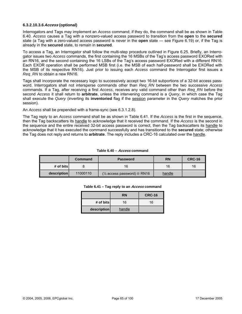
6.3.2.10.3.6 Access (optional) Interrogators and Tags may implement an Access command; if they do, the command shall be as shown in Table 6.40. Access causes a Tag with a nonzero-valued access password to transition from the open to the secured state (a Tag with a zero-valued access password is never in the open state — see Figure 6.19) or, if the Tag is already in the secured state, to remain in secured.
To access a Tag, an Interrogator shall follow the multi-step procedure outlined in Figure 6.25. Briefly, an Interro-gator issues two Access commands, the first containing the 16 MSBs of the Tag’s access password EXORed with an RN16, and the second containing the 16 LSBs of the Tag’s access password EXORed with a different RN16. Each EXOR operation shall be performed MSB first (i.e. the MSB of each half-password shall be EXORed with the MSB of its respective RN16). Just prior to issuing each Access command the Interrogator first issues a Req_RN to obtain a new RN16.
Tags shall incorporate the necessary logic to successively accept two 16-bit subportions of a 32-bit access pass-word. Interrogators shall not intersperse commands other than Req_RN between the two successive Access commands. If a Tag, after receiving a first Access, receives any valid command other than Req_RN before the second Access it shall return to arbitrate, unless the intervening command is a Query, in which case the Tag shall execute the Query (inverting its inventoried flag if the session parameter in the Query matches the prior session).
An Access shall be prepended with a frame-sync (see 6.3.1.2.8).
The Tag reply to an Access command shall be as shown in Table 6.41. If the Access is the first in the sequence, then the Tag backscatters its handle to acknowledge that it received the command. If the Access is the second in the sequence and the entire received 32-bit access password is correct, then the Tag backscatters its handle to acknowledge that it has executed the command successfully and has transitioned to the secured state; otherwise the Tag does not reply and returns to arbitrate. The reply includes a CRC-16 calculated over the handle.
Table 6.40 – Access command
Command Password RN CRC-16
# of bits 8 16 16 16
description 11000110 (½ access password) ⊗ RN16 handle
Table 6.41 – Tag reply to an Access command
RN CRC-16
# of bits 16 16
description handle
© 2004, 2005, 2006, EPCglobal Inc. Page 65 of 100 17 December 2005
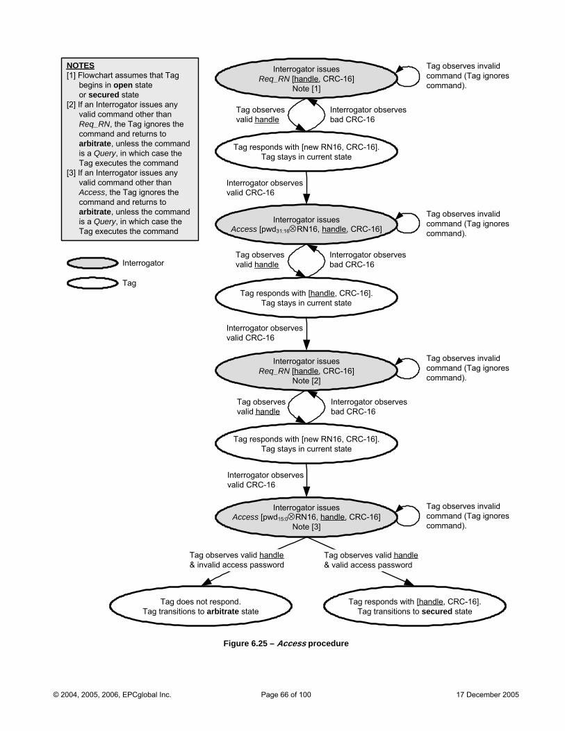
Tag responds with [new RN16, CRC-16].Tag stays in current state
Tag responds with [handle, CRC-16].Tag stays in current state
Tag does not respond.Tag transitions to arbitrate state
Interrogator issuesReq_RN [handle, CRC-16]
Note [1]
Interrogator issuesAccess [pwd31:16⊗RN16, handle, CRC-16]
Tag responds with [handle, CRC-16]. secured stateTag transitions to
Tag observes valid handle
Interrogator observes bad CRC-16
Interrogator observes valid CRC-16
Interrogator i sssues [p 16Acces wd15:0⊗RN , handle, CRC
]-16]
[3Note
Tag observes invalid command (Tag ignores command).
NOTES [1] Flowchart assumes that Tag
begins in open stateor secured state
[ f vaRcoarisT
[ f vaAcoar mmand
2] I an Interrogator issues any lid command other than
eq_RN, the Tag ignores the mmand and returns to bitrate, unless the command a Query, in which case the ag executes the command
3] I an Interrogator issues any lid command other than
ccess, the Tag ignores the mmand and returns to bitrate, unless the co
Tag observes valid handle ord& ess passwinvalid acc
is a Query, in which case the Tag executes the command
Tag observes valid handle ess p& valid acc assword
Tag responds with [new RN16, CRC-16].Tag stays in current state
Interrogator issuesReq_RN [handle, CRC-16]
Note [2]
Tag observes valid handle
Interrogator observes bad CRC-16
Interrogator observes valid CRC-16
Tag observes valid handle
Interrogator observes bad CRC-16
Interrogator observes valid CRC-16
Tag observes invalid
command).
Tag observes invalid command (T command).
e 6.25 Access proc re
command (Tag ignores command).
Interrogator
Tag
Tag observes invalid command (Tag ignores
ag ignores
Figur – edu
© 2004, 2005, 2006, EPCglobal Inc. Page 66 of 100 17 December 2005
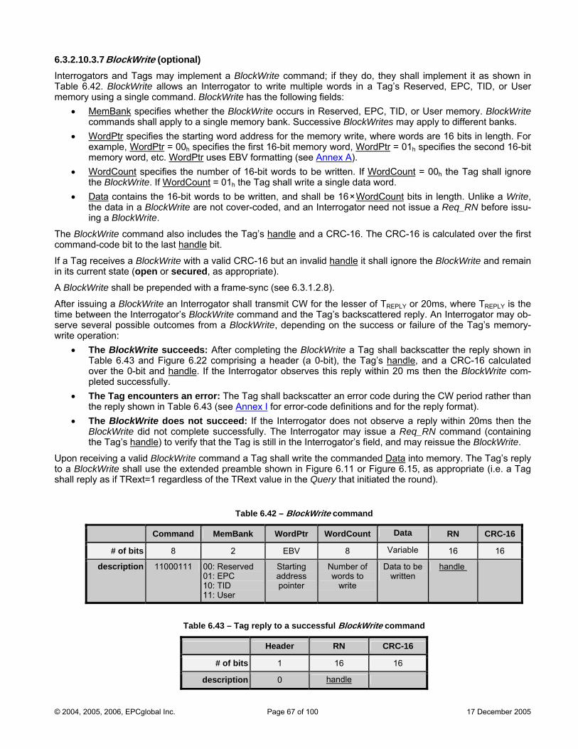
6.3.2.10.3.7 BlockWrite (optional) Interrogators and Tags may implement a BlockWrite command; if they do, they shall implement it as shown in Table 6.42. BlockWrite allows an Interrogator to write multiple words in a Tag’s Reserved, EPC, TID, or User memory using a single command. BlockWrite has the following fields:
• MemBank specifies whether the BlockWrite occurs in Reserved, EPC, TID, or User memory. BlockWrite commands shall apply to a single memory bank. Successive BlockWrites may apply to different banks.
• WordPtr specifies the starting word address for the memory write, where words are 16 bits in length. For example, WordPtr = 00h specifies the first 16-bit memory word, WordPtr = 01h specifies the second 16-bit memory word, etc. WordPtr uses EBV formatting (see Annex A).
• WordCount specifies the number of 16-bit words to be written. If WordCount = 00h the Tag shall ignore the BlockWrite. If WordCount = 01h the Tag shall write a single data word.
• Data contains the 16-bit words to be written, and shall be 16×WordCount bits in length. Unlike a Write, the data in a BlockWrite are not cover-coded, and an Interrogator need not issue a Req_RN before issu-ing a BlockWrite.
The BlockWrite command also includes the Tag’s handle and a CRC-16. The CRC-16 is calculated over the first command-code bit to the last handle bit.
If a Tag receives a BlockWrite with a valid CRC-16 but an invalid handle it shall ignore the BlockWrite and remain in its current state (open or secured, as appropriate).
A BlockWrite shall be prepended with a frame-sync (see 6.3.1.2.8).
After issuing a BlockWrite an Interrogator shall transmit CW for the lesser of T or 20ms, where T is the time eserve swrite op
• ceeds: After completing the BlockWrite a Tag shall backscatter the reply shown in
REPLY REPLY b tween the Interrogator’s BlockWrite command and the Tag’s backscattered reply. An Interrogator may ob-
everal possible outcomes from a BlockWrite, depending on the success or failure of the Tag’s memory-eration: The BlockWrite sucTable 6.43 and Figure 6.22 comprising a header (a 0-bit), the Tag’s handle, and a CRC-16 calculated over the 0-bit and handle. If the Interrogator observes this reply within 20 ms then the BlockWrite com-
• pleted successfully. The Tag encounters an error: The Tag shall backscatter an error code during the CW period rather than the reply shown in Table 6.43 (see Annex I for error-code definitions and for the reply format).
• The BlockWrite does not succeed: If the Interrogator does not observe a reply within 20ms then the BlockWrite did not complete successfully. The Interrogator may issue a Req_RN command (containing the Tag’s handle) to verify that the Tag is still in the Interrogator’s field, and may reissue the BlockWrite.
Upon receiving a valid BlockWrite command a Tag shall write the commanded Data into memory. The Tag’s reply to a BlockWrite shall use the extended preamble shown in Figure 6.11 or Figure 6.15, as appropriate (i.e. a Tag shall reply as if TRext=1 regardless of the i ted the round).
Tabl 42
TRext value n the Query that initia
e 6. – BlockWrite command
Command MemBank WordPtr WordCount Data RN CRC-16
# of bits 8 2 EBV 8 Variable 16 16
description 11000111 00: Reserved 01: EPC 10: TID 11: User
Starting address pointer
Number of words to
write
Data to be written
handle
Table 6. ly t successfu ockWrite co and 43 – Tag rep o a l Bl mm
He er ad RN CRC-16
# of bits 1 16 16
description 0 handle
© 2004, 2005, 2006, EPCglobal Inc. Page 67 of 100 17 December 2005
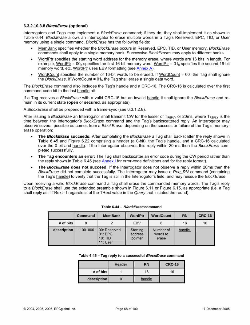
6.3.2.10.3.8 BlockErase (optional) Interrogators and Tags may implement a BlockErase command; if they do, they shall implement it as shown in Table 6.44. BlockErase allows an Interrogator to erase multiple words in a Tag’s Reserved, EPC, TID, or User memory using a single command. BlockErase has the following fields:
• MemBank specifies whether the BlockErase occurs in Reserved, EPC, TID, or User memory. BlockErase commands shall apply to a single memory bank. Successive BlockErases may apply to different banks.
• WordPtr specifies the starting word address for the memory erase, where words are 16 bits in length. For example, WordPtr = 00h specifies the first 16-bit memory word, WordPtr = 01h specifies the second 16-bit memory word, etc. WordPtr uses EBV formatting (see Annex A).
• WordCount specifies the number of 16-bit words to be erased. If WordCount = 00h the Tag shall ignore the BlockErase. If WordCount = 01h the Tag shall erase a single data word.
The BlockErase command also includes the Tag’s handle and a CRC-16. The CRC-16 is calculated over the first command-code bit to the last handle bit.
If a Tag receives a BlockErase with a valid CRC-16 but an invalid handle it shall ignore the BlockErase and re-main in its current state (open or secured, as appropriate).
A BlockErase shall be prepended with a frame-sync (see 6.3.1.2.8).
After issuing a BlockErase an Interrogator shall transmit CW for the lesser of TREPLY or 20ms, where TREPLY is the time between the Interrogator’s BlockErase command and the Tag’s backscattered reply. An Interrogator may observe several possible outcomes from a BlockErase, depending on the success or failure of the Tag’s memory-erase operation:
• The BlockErase succeeds: After completing the BlockErase a Tag shall backscatter the reply shown in Table 6.45 and Figure 6.22 comprising a header (a 0-bit), the Tag’s handle, and a CRC-16 calculated over the 0-bit and handle. If the Interrogator observes this reply within 20 ms then the BlockErase com-pleted successfully.
• The Tag encounters an error: The Tag shall backscatter an error code during the CW period rather than the reply shown in Table 6.45 (see Annex I for error-code definitions and for the reply format).
• The BlockErase does not succeed: If the Interrogator does not observe a reply within 20ms then the BlockErase did not complete successfully. The Interrogator may issue a Req_RN command (containing the Tag’s handle) to verify that the Tag is still in the Interrogator’s field, and may reissue the BlockErase.
Upon receiving a valid BlockErase command a Tag shall erase the commanded memory words. The Tag’s reply to a BlockErase shall use the extended preamble shown in Figure 6.11 or Figure 6.15, as appropriate (i.e. a Tag shall reply as if TRext=1 regardless of the TRext value in the Query that initiated the round).
Table 6.44 – BlockErase command
Command MemBank WordPtr WordCount RN CRC-16
# of bits 8 2 EBV 8 16 16
description 11001000 00: Reserved 01: EPC 10: TID 11: User
Starting address pointer
Number of words to
erase
handle
Table 6.45 – Tag reply to a successful BlockErase command
Header RN CRC-16
# of bits 1 16 16
description 0 handle
© 2004, 2005, 2006, EPCglobal Inc. Page 68 of 100 17 December 2005

7. Intellectual property rights intrinsic to this specification Attention is drawn to the pos ay be the subject of patent and/or other intellectual-prope entifying any or all such pat-ent or intellectual-property rig
sibility that some of the elements of this specification mrty rights. EPCglobal shall not be held responsible for id
hts.
© 2004, 2005, 2006, EPCglobal Inc. Page 69 of 100 17 December 2005
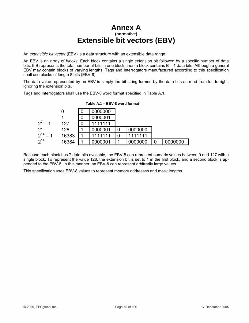
Annex A (normative)
Extensible bit vectors (EBV)
d Interrogators manufactured according to this specification .
V is simply the bit string formed by the data bits as read from left-to-right, ignoring the extension bits.
Tags and Interrogators shall use the EBV- format s
0
An extensible bit vector (EBV) is a data structure with an extensible data range.
An EBV is an array of blocks. Each block contains a single extension bit followed by a specific number of data bits. If B represents the total number of bits in one block, then a block contains B – 1 data bits. Although a general EBV may contain blocks of varying lengths, Tags anshall use blocks of length 8 bits (EBV-8)
The data value represented by an EB
8 word pecified in Table A.1.
0 0000000 1 0 00 0000127 127 0 1111111 – 1 27 28 1 0000001 0 0000000 12 – 1 16383 1 1111111 0 1111111 14
214 16384 1 0000001 1 0000000 0 0000000
Because each block has 7 data bits available, the EBV-8 can repres a single block resent the value 128, the extension bit is set to a se lock is ap-pended to the EBV-8. In this manner, an EBV-8 can represent arbitr
This specification es EBV-8 values to represent memory addresses and mask lengths.
ent numeric values between 0 and 127 with . To rep 1 in the first block, and
arily large values. cond b
us
Table A.1 – EBV-8 word format
© 2005, EPCglobal Inc. Page 70 of 100 17 December 2005
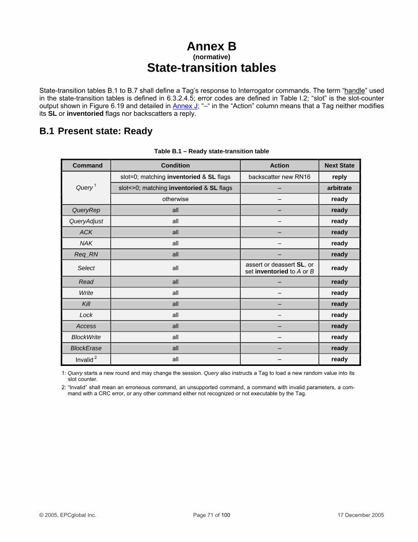
Annex B (normative)
State-transition tables State-transition tables B.1 Inte he te ndleto B.7 shall define a Tag’s response to rrogator commands. T rm “ha ” used in the state n tabl re defined in able I.2; “slot” t-counter output show igure 6.
-transition in F
es is defined in 6.3.2.4.5; error codes a19 and detailed in
T is the sloAnnex J; “–“ in the “Action” column eans that a T modifies
its SL or inventoried flags nor backscatt .
B.1 Pre ate:
Table
m ag neitherers a reply
sent st Ready
B.1 – Ready state-transition table
Co nd mma Condition Ac n tio Next State
slot=0; matching in d & SL flags ventorie backscatter new RN16 reply
slot<>0; matching i ntoried & SL flags nve – arbitrate Query 1
other ise w – ready
QueryRep all – ready
QueryAdjust all – ready
ACK all – ready
NAK all – ready
R eq_RN all – ready
Select all assert or deassert SL, or set inventoried to A or B ready
Read all – ready
Write all – ready
Kill all – ready
Lock all – ready
Access all – ready
BlockWrite all – ready
BlockErase all – ready
Invalid 2 all – ready
1: Query starts a new round and may change the session. Query also instructs a Tag to load a new random value into its slot counter.
2: “Invalid” shall mean an erroneous command, an unsupported command, a command with invalid parameters, a com-mand with a CRC error, or any other command either not recognized or not executable by the Tag.
© 2005, EPCglobal Inc. Page 71 of 100 17 December 2005
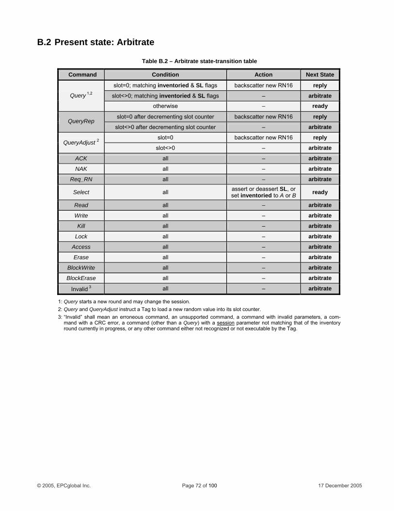
B.2 Present state: Arbitrate
Table B.2 – Arbitrate state-transition table
Command Condition Action Next State
slot=0; matching inventoried & SL flags backscatter new RN16 reply
slot<>0; matching inventoried & SL flags – arbitrate Query 1,2
otherwise – ready
slot=0 after d ementing slot counter ecr backscatter new RN16 reply QueryRep
slot<>0 afte enting slot counter r decrem – arbitrate
slot=0 backscatter new RN16 reply QueryAdjust 2
slot<>0 – arbitrate
ACK all – arbitrate
NAK all – arbitrate
Req_RN all – arbitrate
Select all assert or deassert SL, or set inventoried to A or B ready
Read all – arbitrate
Write all – arbitrate
Kill all – arbitrate
Lock all – arbitrate
Access all – arbitrate
Erase all – arbitrate
BlockWrite all – arbitrate
BlockErase all – arbitrate
Invalid 3 all – arbitrate
1: Query starts a new round and may change the session. er. 2: Query and QueryAdjust instruct a Tag to load a new random value into its slot count
3: “Invalid” shall mean an erroneous command, an unsupported command, a command with invalid parameters, a com-mand with a CRC error, a command (other than a Query) with a session parameter not matching that of the inventory round currently in progress, or any other command either not recognized or not executable by the Tag.
© 2005, EPCglobal Inc. Page 72 of 100 17 December 2005
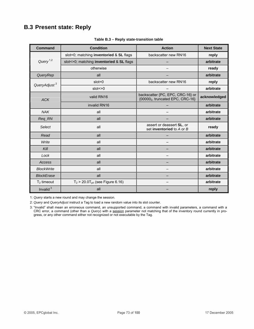
B.3 Present state: Reply
Table B.3 – Reply state-transition table
Command Condition Action Next State
slot=0; matching inventoried & SL flags backscatter new RN16 reply
slot<>0; matching inve d & SLntorie flags – arbitrate Query 1,2
otherwise – ready
QueryRep all – arbitrate
slot=0 backscatter new RN16 reply QueryAdjust 2
slot<>0 – arbitrate
valid RN16 backscatter {PC, EPC, CRC-16} or {000002, truncated EPC, CRC-16} acknowledged
ACK invalid RN16 – arbitrate
NAK all – arbitrate
Req_RN all – arbitrate
Select all assert or deassert SL, or s or B et inventoried to A ready
Read all – arbitrate
Write all – arbitrate
Kill all – arbitrate
Lock all – arbitrate
Access all – arbitrate
BlockWrite all – arbitrate
BlockErase all – arbitrate T2 timeout T2 > 20 pri (see Figure 6.16) .0T – arbitrate
Invalid 3 all – reply
1: Query starts a new round and may change the session. QueryAdjust instruct a Tag to load a new random value into its slot counter.
l mean an er u mmand, a command w nvalid parameters, a command r, a comm ession
2: Query and 3: “Invalid” shal
CRC erroroneo s command, an unsupported co
and (other than a Query) with a ith i with a
s parameter not matching that of the inventory round currey other command either not recognized or not executable by the Tag.
ntly in pro-gress, or an
© 2005, EPCglobal Inc. Page 73 of 100 17 December 2005
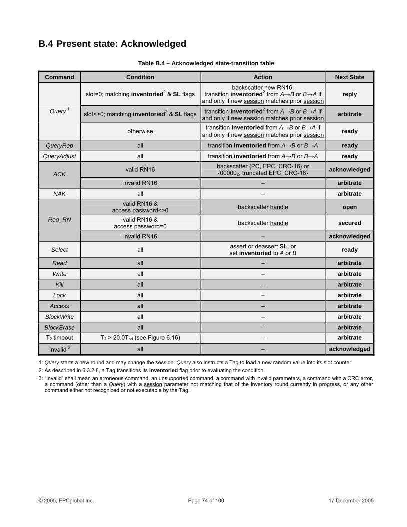
B.4 Present state: Acknowledged
Table B.4 – Acknowledged state-transition table
Command Condition Action Next State
slot=0; matching inventoried2 & SL flags backscatter new RN16;
transition inventoried2 from A→B or B→A if and only if new session matches prior session
reply
slot<>0; matching inventoried & SL flags2 transition inventoried2 from A→B or B→A if and only if new session matches prior session
arbitrate Query 1
otherwise transition inventoried from A→B or B→A if and only if new session matches prior session ready
QueryRep all transition inventoried from A→B or B→A ready
QueryAdjust all transition inventoried from A→B or B→A ready
valid RN16 backscatter {PC, EPC, CRC-16} or {000002, truncated EPC, CRC-16} acknowledged
ACK invalid RN 16 – arbitrate
NAK all – arbitrate valid RN16 &
access password<>0 backscatter handle open
valid RN16 & access password=0 backscatter handle secured Req_RN
invalid RN16 – acknowledged
Select all assert or deassert , or SLset inventoried to A or B ready
Read all – arbitrate
Write all – arbitrate
Kill all – arbitrate
Lock all – arbitrate
Access all – arbitrate
BlockWrite all – arbitrate
BlockErase all – arbitrate T2 timeout T2 > 20.0Tpri (see Figure 6.16) – arbitrate
Invalid 3 all – acknowledged
1: Query starts a new round a so instructs a Tag to slot counter2: in 6.3.2.8, a o evaluating the condi3: “Invalid” shall mean an erroneous com and, a command with invalid par eters, a command with a C r,
a command (other than a Query) with
nd may change the session. Query al load a new random value into its . As described Tag transitions its inventoried flag prior t tion.
mand, an unsupported comm a session
am RC erro parameter not matching that of the inventory rou ently in progress, or an
command either not recognnd curr y other
ized or not executable by the Tag.
© 2005, EPCglobal Inc. Page 74 of 100 17 December 2005
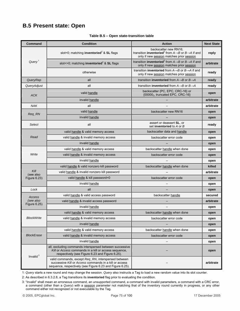
B.5 Present state: Open
Table B.5 – Open state-transition table
Command Condition A tion c Next State
slot=0; matching inventoried2 & SL flags backscatter new RN16;
transition inventoried from A→B or B→A if and 2
only if new session matches prior sessionreply
slot<>0; matchi ried2 & SL flags ng invento transition inventoried from A→B or B→A if and 2
only if new session matches prior session arbitrate Query 1
oth ise erw transition inventoried from A→B or B→A if and only if new session matches prior session ready
QueryRep all transition inventoried from A→B or B→A ready
QueryAdjust all tr →A ansition inventoried from A→B or B ready
valid handle backscatter {P 16} or C, EPC, CRC-{000002, trunc d EPC, CRC-16} ate open
ACK inval andleid h – arbitrate
NAK all – arbitrate
valid handle backscatter new RN16 open Req_RN
inval andleid h – open
Select all assert or deassert SL, or set inventoried to A or B ready
valid handle & valid memory access b dleackscatter data and han open
valid handle & invalid memory access backscatter error code open Read
invalid handle – open
valid handle & valid memory access backscatter handle when done open
valid handle & invalid memory access backsca error code tter open Write
invalid handle – open
valid handle & valid nonzero kill password backscatter ehandl when done killed
valid handle & invalid nonzero kill password – arbitrate
valid handle & kill password=0 backsca error code tter open
Kill (see also
Figure 6.23)
invalid handle – open
Lock all – open
valid handle & valid access password backscatter handle secured
valid handle & invalid access password – arbitrate Access
(see also Figure 6.25)
invalid handle – open
valid handle & valid memory access backscatter ehandl when done open
valid handle & invalid memory access backscatter error code open BlockWrite
invalid handle – open
valid handle & valid memory access backscatter ehandl when done open
valid handle & invalid memory access backscatter error code open BlockErase
invalid handle – open all, excluding comma d between successive nds intersperse
Kill or Access commands in a kill or access sequence, respectively (see Figure 6.23 and Figure 6.25).
– open
Invalid 3
valid een commands, except Req_RN, interspersed betwsuccessive Kill or Access commands in a kill or access
sequence, respectively (see Figure 6.23 and Figure 6.25). – arbitrate
1: Query starts a ne ts a Tag to load a new random value into its slot counter. w round and may change the session. Query also instruc2: As described in 6.3.2.8, a Tag transitions its inventoried flag prior to evaluating the condition. 3: “Invalid” shall mean an erroneous command, an unsupported command, a command with invalid parameters, a command with a CRC error,
a command (other than a Query) with a session parameter not matching that of the inventory round currently in progress, or any other command either not recognized or not executable by the Tag.
© 2005, EPCglobal Inc. Page 75 of 100 17 December 2005

B.6 Present state: Secured Table B.6 – Secured state-transition table
Command Condition Action Next State
slot=0 entoried; matching inv 2 & SL flags backscatter new RN16;
t ventoried r B→A if ransition in 2 from A→B oand o if new sessionnly matches prior session
reply
slot<>0 ventoried2 & S gs ; matching in L fla transi on inventoried2 fr B or B→A if ti om A→and o if new sessionnly matches prior session arbitrate Query 1
otherwise tran on inventoried frsiti om A→B or B→A ifand only if new session matches prior session ready
QueryRep all tra ion inventoried B or B→A nsit from A→ ready
QueryAdjust all tra ion inventoried B or B→A nsit from A→ ready
valid handle backscatter {PC, EPC, CRC-16} or {000002, truncated EPC, CRC-16} secured ACK
invalid handle – arbitrate
NAK all – arbitrate
valid handle backscatter n ew RN16 secured Req_RN
invalid handle – secured
Select all assert or deas or sert SL, set inventorie B d to A or ready
valid handle & valid memory access backscatter data and ehandl secured
valid handle & invalid memory ac s ces backscatter error code secured Read
invalid handle – secured
valid handle & valid memory access backscatter handle when done secured
valid handle & invalid memory access backscatter error code secured Write
invalid handle – secured
valid handle & valid nonzero kill password backscatter handle when done killed
valid handle & invalid nonzero kill password – arbitrate
valid handle & kill password=0 backscatter error code secured
Kill (see also
Figure 6.23)
invalid handle – secured
valid handle & valid lock payload backscatter handle when done secured
valid handle & invalid lock payload backscatter error code secured Lock
invalid handle – secured
valid handle & valid access password backscatter handle secured
valid handle & invalid access password – arbitrate Access
(see also Figure 6.25)
invalid handle – secured
valid handle & valid memory access backscatter handle when done secured
valid handle & invalid memory access backscatter error code secured BlockWrite
invalid handle – secured
valid handle & valid memory access backscatter handle when done secured
valid handle & invalid memory access backscatter error code secured BlockErase
invalid handle – secured all, excluding commands interspersed between successive Kill or Access commands in a kill or access sequence, re-
spectively (see Figure 6.23 and Figure 6.25). – secured
Invalid 3
valid commands, except Req_RN, interspersed between successive Kill or Access commands in a kill or access se-
quence, respectively (see Figure 6.23 and Figure 6.25). – arbitrate
1: Query starts a new round and may change the session. Query also instructs a Tag to load a new random value into its slot counter. 2: As described in 6.3.2.8, a Tag transitions its inventoried flag prior to evaluating the condition. 3: “Invalid” shall mean an erroneous command, an unsupported command, a command with invalid parameters, a command with a CRC error, a command (other than a
Query) with a session parameter not matching that of the inventory round currently in progress, or any other command either not recognized or not executable by the Tag.
© 2005, EPCglobal Inc. Page 76 of 100 17 December 2005
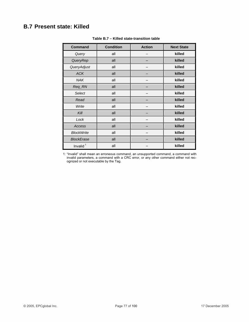
B.7 Present state: Killed
Table B.7 – Killed state-transition table
Command Condition Action Next State
Query all – killed
QueryRep all – killed
QueryAdjust all – killed
ACK all – killed
NAK all – killed
Req_RN all – killed
Select all – killed
Read all – killed
Write all – killed
Kill all – killed
Lock all – killed
Access all – killed
BlockWrite all – killed
BlockErase all – killed
Invalid 1 all – killed
1: “ an an erroneous command, an ommand, a command with i ters, a command with a CRC erro r command either not rec-
cutable by the Tag.
Invalid” shall menvalid parame
unsupported cr, or any othe
ognized or not exe
© 2005, EPCglobal Inc. Page 77 of 100 17 December 2005
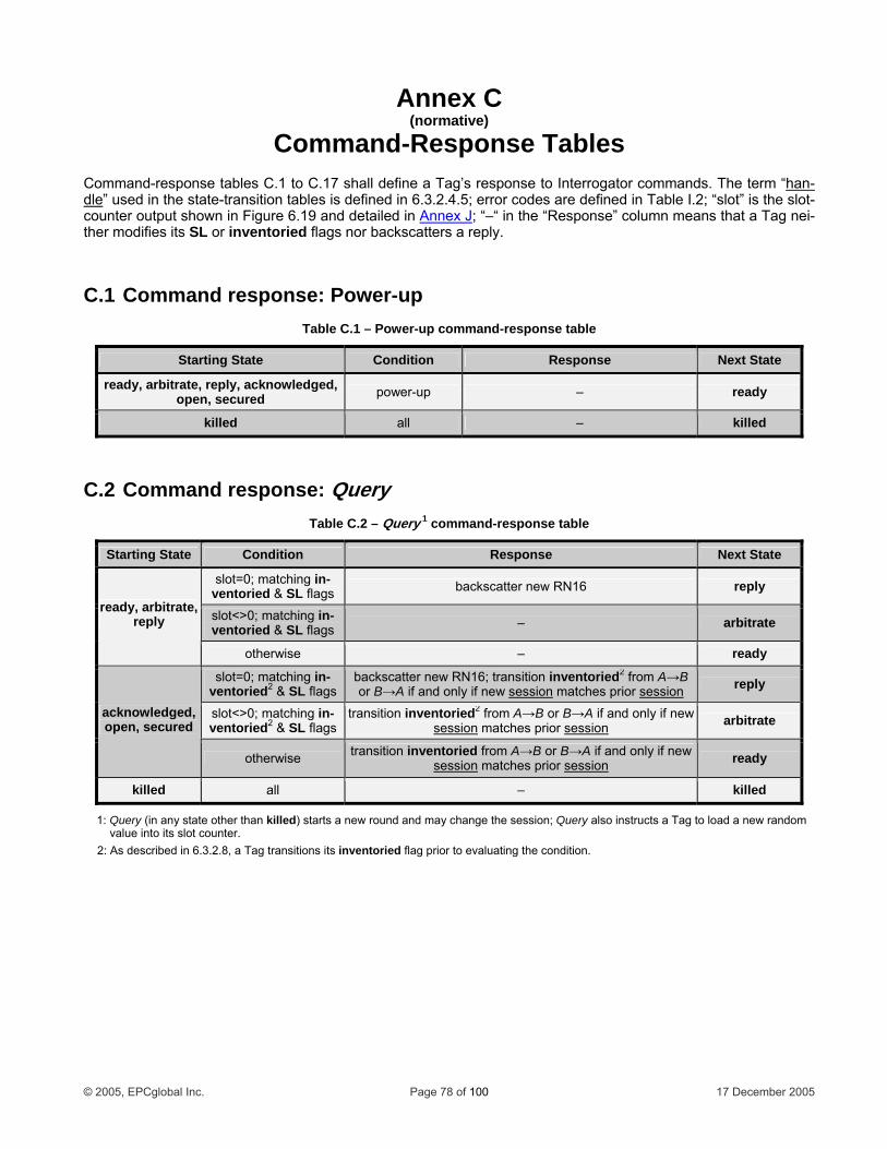
Annex C
Command-Response Tables Comm ponse tables C.1 to C efine a Tag’s response to Interrogator commands. The “han-
(normative)
and-res .17 shall d term dle” used in the state-t error codes are defined in Table I.2; “slot” is thcount how x J
ransition tables is defined in 6.3.2.4.5;n in Figure 6.19 and detailed in
e slot-er output s Anne ; “–“ in the “Resp se” column means th nei-
ther modifie SL o reply.
C. d response ower-up
C.2 Command response
Ta .1
on at a Tag s its r inventoried flags nor backscatters a
1 Comman : Pble C – Power-up command-response table
Starting State Condition Response Next State
ready, arbitrate, reply, acknowledged, open, secured po ew r-up – ready
killed all – killed
: QueryTable C.2 – Query 1 command-response table
Starting State Condition Res Nexponse t State
slot=0; matching in-ventoried & SL flags b reply ackscatter new RN16
slot<>0; matching – arbitrain-ventoried & SL flags te
ready ate, , arbitrreply
otherwise – ready
slot=0; matching in-ventoried2 & SL flags
backscatter new RN16; transition inventoried2 from A→B or B→A if and only if new session matches prior session reply
slot<>0; matching in-ventoried2 & SL flags
transition inventoried2 from A→B or B→A if and only if new session matches prior session arbitrate acknowledged,
open, secured
otherwise transition inventoried from A→B or B→A if and only if new session matches prior session ready
killed all – killed
1: Q te other killed) starts a new round and may change the session; Query also instructs a Tag to load m val lot counter
2: As descri n 6.3. sit
uery (in any staue into its s
than.
a new rando
bed i 2.8, a Tag tran ions its inventoried flag prior to evaluating the condition.
© 2005, EPCglobal Inc. Page 78 of 100 17 December 2005
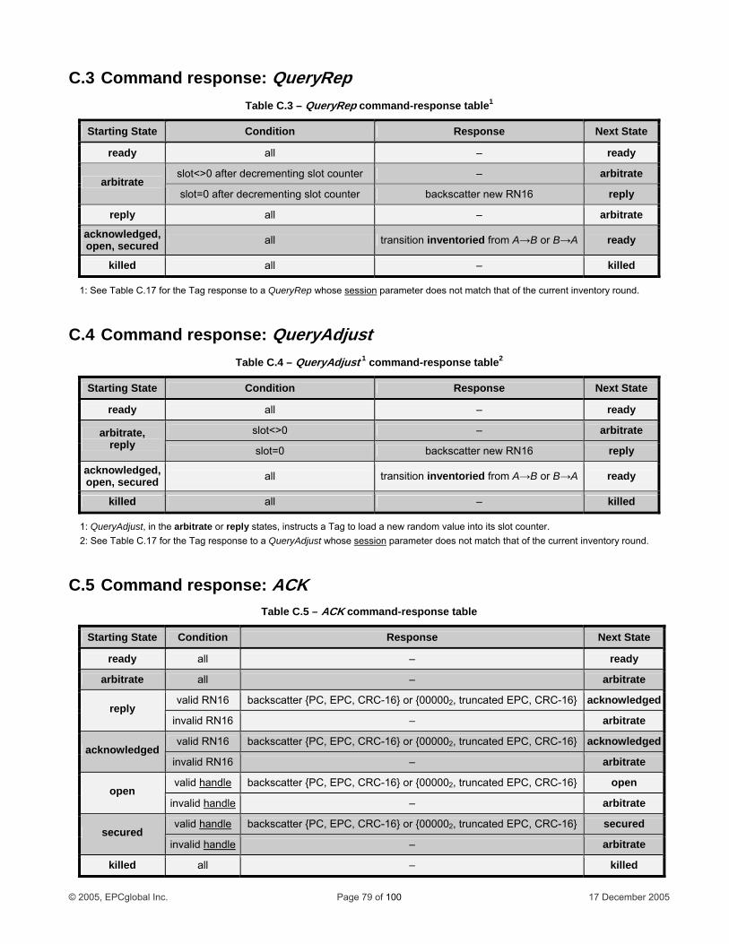
C.3 Command response: QueryRep
C.4 Command response: ueryAdjust
Ta le1ble C.3 – QueryRep command-response tab
Starting Condition Response Next State State
ready all – ready
slot<>0 after decrementing s ounter lot c – arbitrate arbitrate
slot=0 after decrementing sl ounter ot c backscatter new RN16 reply
reply all – arbitrate
acknowledged, open, secured all transition inventoried from A→B or B→A ready
killed all
Q
– killed
1: See Table C.17 for the Tag response to a QueryRep whose session parameter does not match that of the current inventory round.
Table C QueryAdjust 1 command-response t e2.4 – abl
Starting State Condition Response Next State
ready all – ready
slot<>0 – a rbitratearbitrate, reply slot=0 backscatter new RN16 reply
acknowledged, ope d n, secure all transition B→A inventoried from A→B or ready
killed all – killed
1: Que arbitrate or reply state structs a Tag to load a new random value in s slot counter. 2: See Table C.17 for the Tag response to a QueryAdjust whose session parameter does not match that of the current inventory round.
ryAdjust, in the s, in to it
C.5 Command response: ACK Table C.5 – ACK command-response table
Starting State Condition Response Next State
ready all – ready
arbitrate all – arbitrate
valid RN16 backscatter {PC, EPC, CRC-16} or {000002, truncated EPC, CRC-16} acknowledged reply
invalid RN16 – arbitrate
valid RN16 backscatter {PC, EPC, CRC-16} or {000002, truncated EPC, CRC-16} acknowledged acknowledged
invalid RN16 – arbitrate
valid handle backscatter {PC, EPC, CRC-16} or {000002, truncated EPC, CRC-16} open open
invalid handle – arbitrate
valid handle backscatter {PC, EPC, CRC-16} or {000002, truncated EPC, CRC-16} secured secured
invalid handle – arbitrate
killed all – killed
© 2005, EPCglobal Inc. Page 79 of 100 17 December 2005
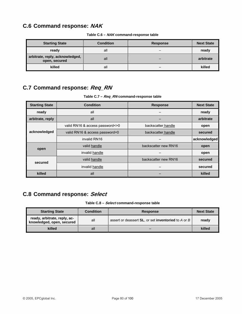
C.6 Command response: NAK Table C.6 – NAK command-response table
Starting State Condition Response Next State
ready all – ready
arbitrate, reply, acknowledged, open, secured all – arbitrate
killed
C.7 Command r
C.8 Command response:
esponse: Req_RN
all – killed
Table C.7 – Req_RN command-response table
Starting State Resp se Next StatCondition on e
ready all – ready
arbitrate, reply all – arbitrate
valid RN16 & access password<>0 backscatter handle open
Select
valid RN16 & access password=0 backscatter handle secured acknowledged
invalid RN16 – acknowledged
valid handle backs N16 catter new R open open
invalid le hand – open
valid dlehan backscatter new RN16 secured secured
invalid handle – secured
killed all – killed
Table C.8 – Select command-response table
Starting State Condition Response Next State
ready, arbitrate, reply, ac-knowledged, open, secured all assert or deassert SL, or set inventoried to A or B ready
killed all – killed
© 2005, EPCglobal Inc. Page 80 of 100 17 December 2005
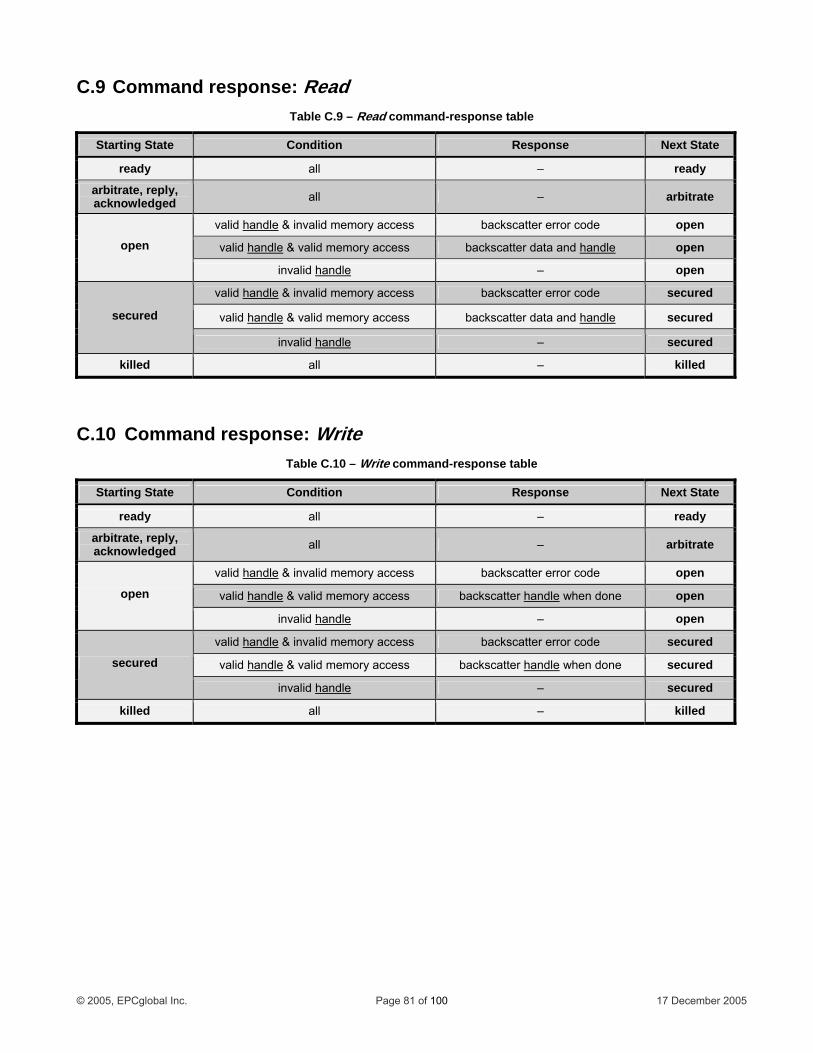
C.9 Command response: Read Table C.9 – Read command-response table
Starting State Condition Response Next State
ready all – ready
arbitrate, reply, acknowledged all – arbitrate
valid handle & invalid memory access backscatter error code open
valid handle & valid memory access backscatter d handleata and open open
invalid handle – open
valid handl ory access backscatter error code s ecurede & invalid mem
va
C.10 Command response: Write
lid handle & valid memory access ba leckscatter data and hand secured secured
invalid handle – secured
killed all – killed
Table C.10 – Write command-response table
Starting State Condition Response Next State
ready all – ready
arbitrate, reply, acknowledged all – arbitrate
valid handle & invalid memory access backs ode catter error c open
valid handle & valid memory access backscatter ha endl when done open open
invali ndled ha – open
valid handle & invalid memory access backscatter error code s ecured
valid handle & valid memory access backscatter handle when done secured secured
invalid handle – secured
killed all – killed
© 2005, EPCglobal Inc. Page 81 of 100 17 December 2005

C.11 Command response: Kill Table C.11 – Kill 1 command-response table
Starting State C Rondition esponse Next State
ready a –ll ready
arbitrate, reply, acknowledged a –ll arbitrate
valid handle & kill password=0 backscatter error code open
valid handle & invalid nonzero kill password – arbitrate
valid handle & ill password backscatter han
C.12 Command respons k e: Loc
valid nonzero k dle when done killed open
invalid handle – open
valid handle & kill password=0 ba ckscatter error code secured
valid handle & i kill password – arbitrate nvalid nonzero
valid handle & valid ero kill password nonz backscatter handle when done killed secu red
invalid handle – secured
killed all – killed
1: See also Figure 6.23.
Tabl .12e C – Lock command-response table
Cond n Resp se NStarting State itio on ext State
ready all – ready
arbit ply, rate, reackn ged owled all – a rbitrate
open –all open
valid handle & invalid lock payload backscatter error code secured
valid handle & valid lock payload backscatter handle when done secured secured
invalid handle – secured
all – killed killed
© 2005, EPCglobal Inc. Page 82 of 100 17 December 2005
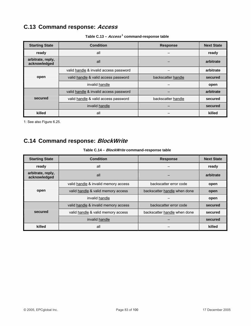
C.13 Command response: Access
C.14 Command response: BlockWrite
Table C.13 – Access 1 command-response table
Starting State Condition Response Next State
ready ready all –
arbitrate, reply, acknowledged arbitrate all –
valid handle & invalid access password a rbitrate–
valid handle & valid access password backscatter handle s ecuredopen
invalid handle open –
valid handle & invalid access password – arbitrate
valid handle & valid access password backscatter handle secured secured
invalid handle secured –
killed killed all –
1: See also Figure 6.25.
Table C.14 – BlockWrite command-response table
Starting Conditio Res se N e State n pon ext Stat
ready all ready –
arbitrate, reply, acknowle all arbitrate – dged
valid handle & invalid memory access backscatter error code open
valid handle & valid m y access backscatter ha eemor ndl when done open open
invalid handle – open
valid handle & invalid memory access backscatter error code secured
valid handle & valid memory access backscatter handle when done secured secured
invalid handle – secured
killed all – killed
© 2005, EPCglobal Inc. Page 83 of 100 17 December 2005
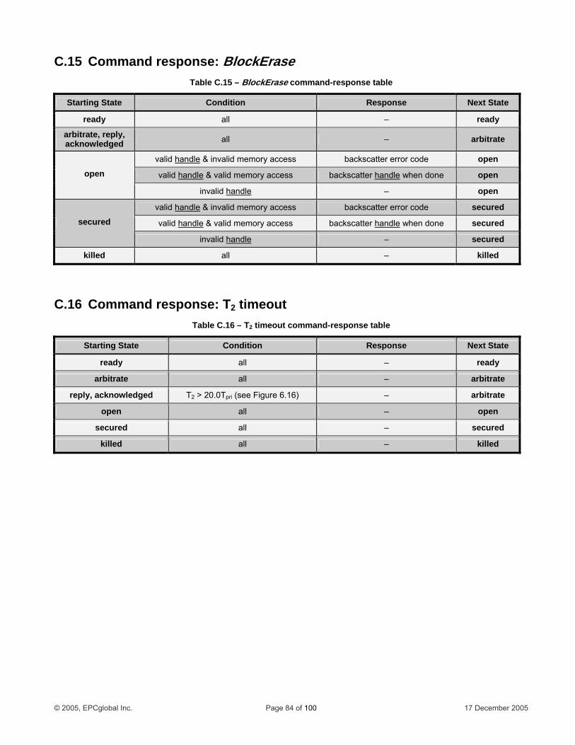
C.15 Command response: BlockErase
C.16 Command response: T2 timeout
Table C.15 – BlockErase command-response table
Cond RespStarting State ition onse Next State
ready all – ready
arbitrate, reply, acknowledged all – arbitrate
valid handle & invalid memory access backscatter erro ode open r c
valid handle & valid m ry access backscatter handle done emo when open open
invalid handle – open
valid handle & invalid memory access backscatter error code secured
valid handle & valid memory access backscatter handle w en done secured hsecured
invalid handle – secured
killed all – killed
Table C.16 – T2 timeout command-response table
Starting State Condition Response Next State
ready all – ready
arbitrate all – arbitrate
reply, acknowledged T2 > 20.0Tpri (see Figure 6.16) – arbitrate
open all – open
secured all – secured
killed all – killed
© 2005, EPCglobal Inc. Page 84 of 100 17 December 2005
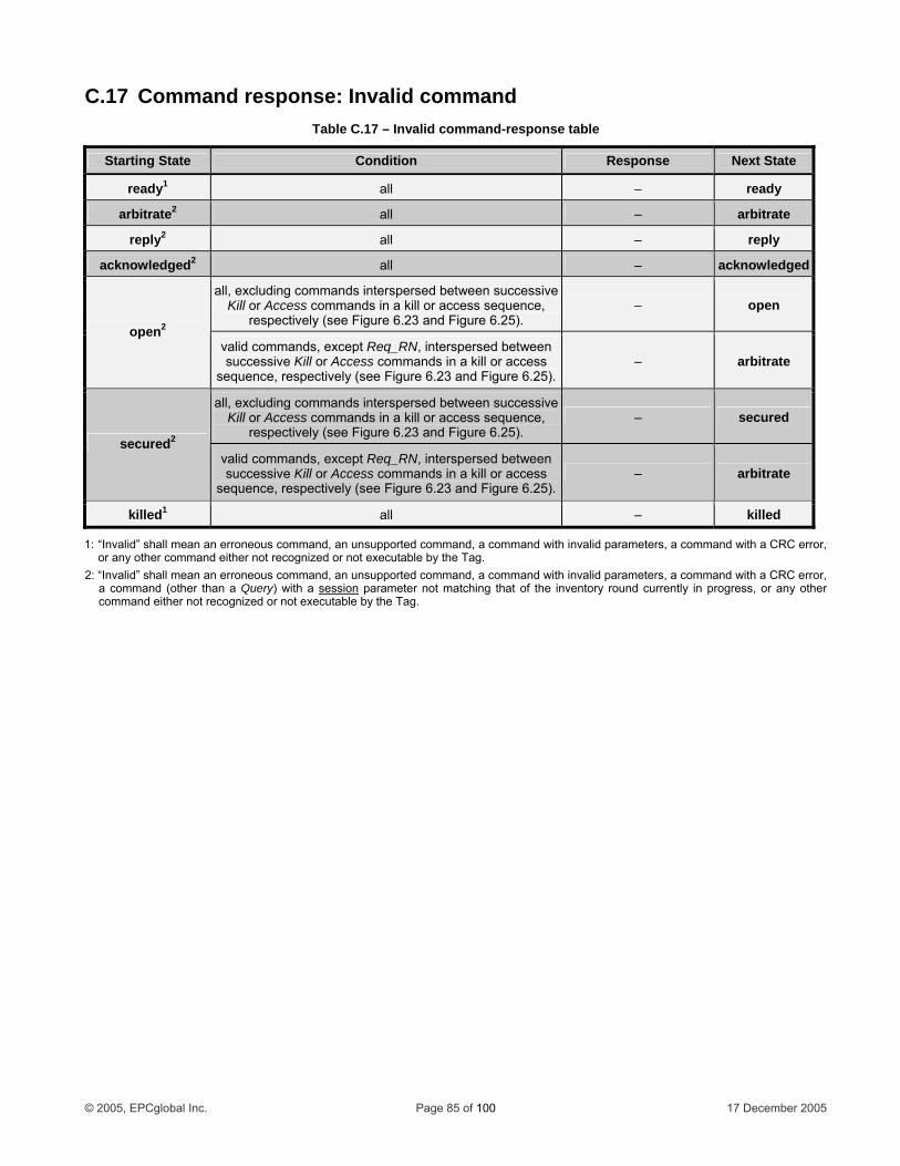
C.17 Command response: Invalid command Table C.17 – Invalid command-response table
Starting State Condition Response Next State
ready1 all – ready
arbitrate2 all – arbitrate
reply2 all – reply
acknowledged2 all – acknowledged
all, excluding commands interspersed between successive Kill or Access commands in a kill or access sequence,
respectively (see Figure 6.23 and Figure 6.25). – open
open2
valid commands, except Req_RN, interspersed between successive Kill or Access commands in a kill or access
sequence, respectively (see Figure 6.23 and Figure 6.25).– arbitrate
all, excluding commands interspersed between successive Kill or Access commands in a kill or access sequence,
respectively (see Figure 6.23 and Figure 6.25). – secured
secured2
valid commands, except Req_RN, interspersed between successive Kill or Access commands in a kill or access
sequence, respectively (see Figure 6.23 and Figure 6.25).– arbitrate
killed1 all – killed
1: “Invalid” shall mean an erroneous command, an unsupported command, a command with invalid parameters, a command with a CRC error, or any other command either not recognized or not executable by the Tag.
2: “Invalid” shall mean an erroneous command, an unsupported command, a command with invalid parameters, a command with a CRC error, a command (other than a Query) with a session parameter not matching that of the inventory round currently in progress, or any other command either not recognized or not executable by the Tag.
© 2005, EPCglobal Inc. Page 85 of 100 17 December 2005
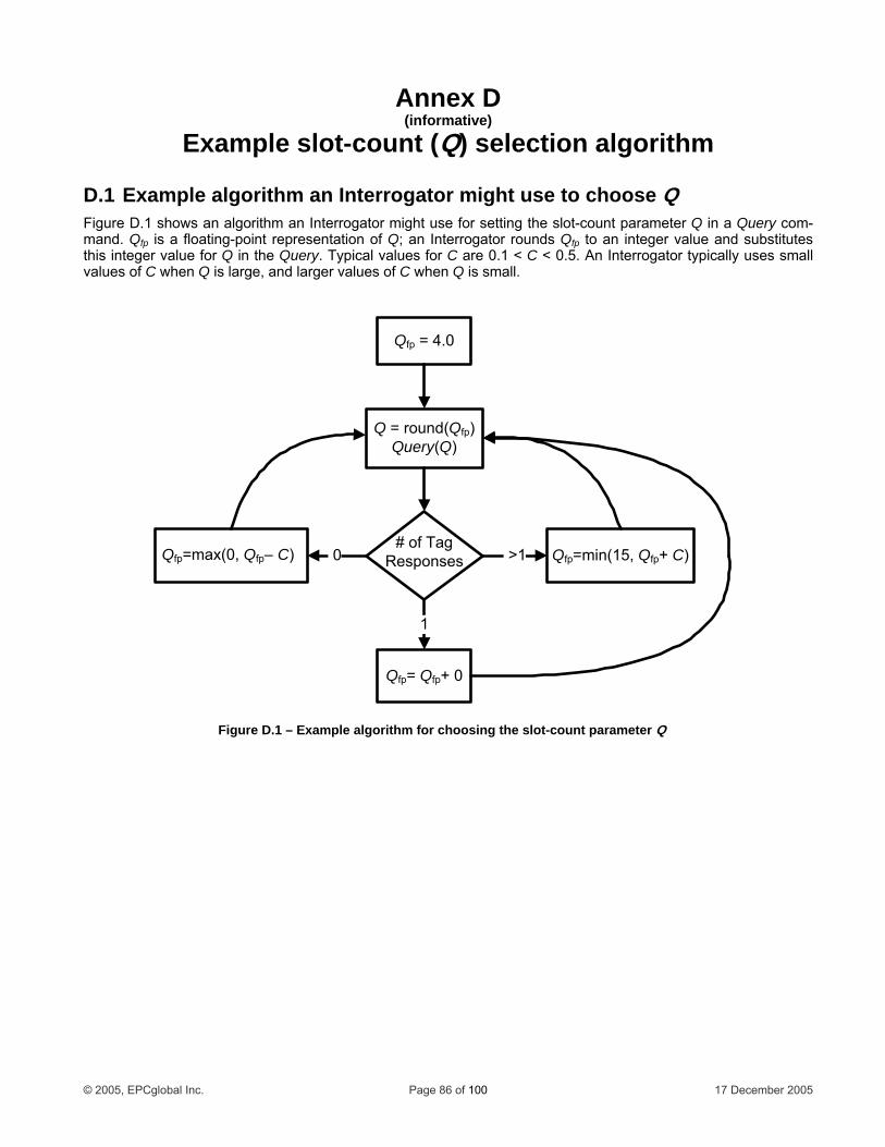
Annex D (informative)
ample slot-count (Q) selection algorithEx m
choose Q Figure D.1 shows an algorithm an Interrogator might use for setting the slot-count parameter Q in a Query com-mand. Qfp is a floating-point representation of Q; an Interrogator rounds Qfp to an integer value and substitutes this integer value for Q in the Query. Typical values for C are 0.1 < C < 0.5. An Interrogator typically uses small values of C when Q is large, and larger values of C when Q is small.
D.1 Example algorithm an Interrogator might use to
Qfp = 4.0
Q = round(Qfp)Query(Q)
# of TagResponses Qfp=max(0, Qfp– C) Qfp=min(15, Qfp+ C) >1
1
Qfp= Qfp+ 0
0
Figure D.1 – Example algorithm for choosing the slot-count parameter Q
© 2005, EPCglobal Inc. Page 86 of 100 17 December 2005
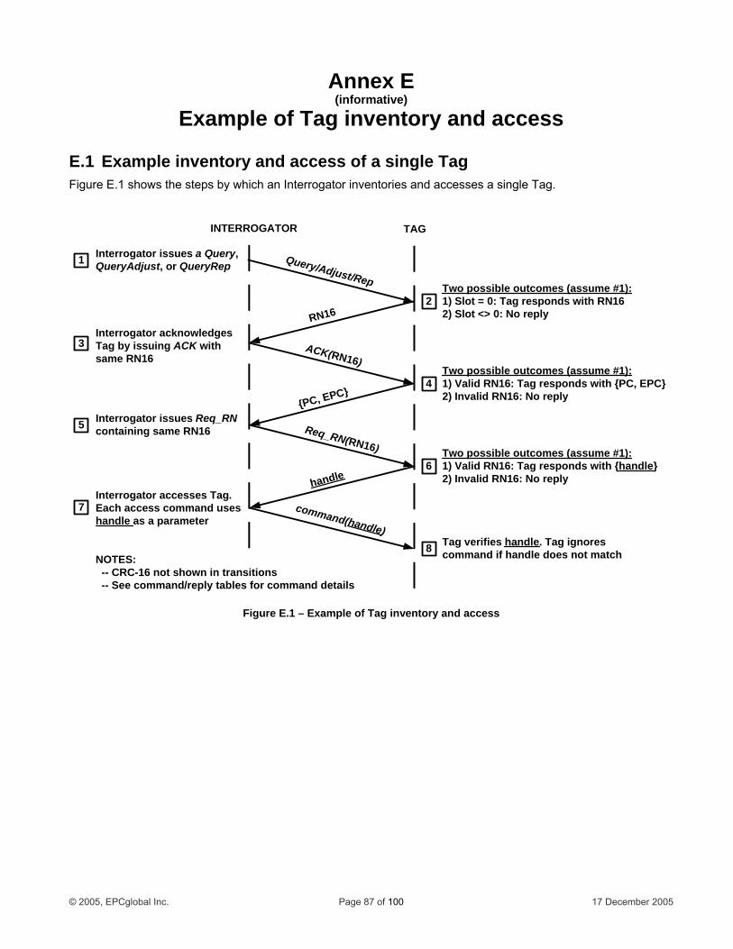
Annex E (informative)
Example of Tag inventory and access
E.1 Example inventory and access of a single Tag Figure E.1 shows the steps by which an Interrogator inventories and accesses a single Tag.
Interrogator issues Req_RN containing same RN16
INTERROGATOR TAG
Each access command uses handle
Interrogator accesses Tag.
as a parameter
Tag verifies handle. Tag ignores command if handle does not match
5
6
7
8
Interrogator acknowledges Tag by issuing ACK with same RN16
3
Two possible outcomes (assume #1):1) Valid RN16: Tag responds with {PC, EPC} 2) Invalid RN16: No reply
4
Interrogator issues a Query, QueryAdjust, or QueryRep1
Two possible outcomes (assume #1):1) Slot = 0: Tag responds with RN16 2) Slot <> 0: No reply
2
ACK(RN16)
RN16
_RN(RN1
Query/Adjust/Rep
{PC
Req
, EPC}
6)
handle
Two possible outcomes (assume #1):1) Valid RN16: Tag responds with {handle} 2) Invalid RN16: No reply
command(handle)
NOTES: -- CRC-16 not shown in transitio -- See command/reply tables for command details
ns
Figure E.1 – Example of Tag inventory a access nd
© 2005, EPCglobal Inc. Page 87 of 100 17 December 2005
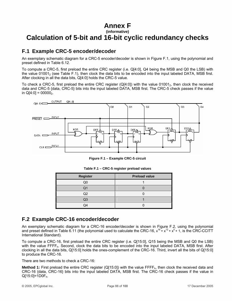
Annex F (informative)
Calculation of 5-bit and 16-bit cyclic redundancy checks
F.1 Example CRC-5 encoder/decoder An exemplary schematic diagram for a CRC-5 encoder/decoder is shown in Figure F.1, using the polynomial and preset defined in Table 6.12.
To compute a CRC-5, first preload the entire CRC register (i.e. Q[4:0], Q4 being the MSB and Q0 the LSB) with the value 010012 (see Table F.1), then clock the data bits to be encoded into the input labeled DATA, MSB first. After clocking in all the data bits, Q[4:0] holds the CRC-5 value.
To check a CRC-5, first preload the entire CRC register (Q[4:0]) with the value 010012, then clock the received data and CRC-5 {data, CRC-5} bits into the input labeled DATA, MSB first. The CRC-5 check passes if the value in Q[4:0] = 000002.
F.2 Example CRC-16 encoder/decoder An exemplary schematic diagram for a CRC-16 encoder/decoder is shown in Figure F.2, using the polynomial and preset defined in Table 6.11 (the polynomial used to calculate the CRC-16, x16 + x12 + x5 + 1, is the CRC-CCITT International Standard).
To compute a CRC-16, first preload the entire CRC register (i.e. Q[15:0], Q15 being the MSB and Q0 the LSB) with the value FFFFh. Second, clock the data bits to be encoded into the input labeled DATA, MSB first. After clocking in all the data bits, Q[15:0] holds the ones-complement of the CRC-16. Third, invert all the bits of Q[15:0] to produce the CRC-16.
There are two methods to check a CRC-16:
Method 1: First preload the entire CRC register (Q[15:0]) with the value FFFFh, then clock the received data and CRC-16 {data, CRC-16} bits into the input labeled DATA, MSB first. The CRC-16 check passes if the value in Q[15:0]=1D0Fh.
Figure F.1 – Example CRC-5 circuit
Table F.1 – CRC-5 register preload values
Register Preload value
Q0 1
Q1 0
Q2 0
Q3 1
Q4 0
© 2005, EPCglobal Inc. Page 88 of 100 17 December 2005
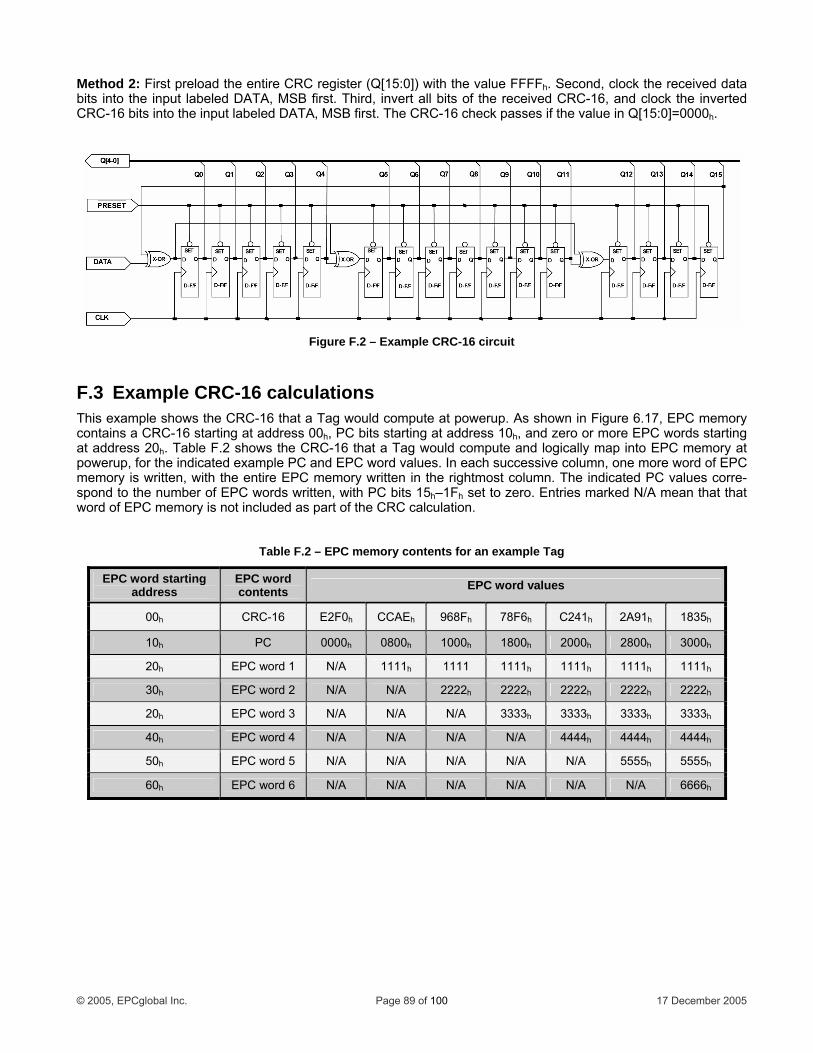
Method 2: First preload the entire CRC register (Q[15:0]) with the value FFFFh. Second, clock the received data bits into the input labeled DATA, MSB first. Third, invert all bits of the received CRC-16, and clock the inverted CRC-16 bits into the input labeled DATA, MSB first. The CRC-16 check passes if the value in Q[15:0]=0000h.
F.3 Example CRC-16 calculations This example shows the CRC-16 that a Tag would compute at powerup. As shown in Figure 6.17, EPC memory contains a CRC-16 starting at address 00h, PC bits starting at address 10h, and zero or more EPC words starting at address 20h. Table F.2 shows the CRC-16 that a Tag would compute and logically map into EPC memory at powerup, for the indicated example PC and EPC word values. In each successive column, one more word of EPC memory is written, with the entire EPC memory written in the rightmost column. The indicated PC values corre-spond to the number of EPC words written, with PC bits 15h–1Fh set to zero. Entries marked N/A mean that that word of EPC memory is not included as part of the CRC calculation.
Figure F.2 – Example CRC-16 circuit
Table F.2 – EPC memory contents for an example Tag
EPC word starting address
EPC word contents EPC word values
00h CRC-16 E2F0h CCAEh 968Fh 78F6h C241h 2A91h 1835h
10h PC 0000h 0800h 1000h 1800h 2000h 2800h 3000h
20h EPC word 1 N/A 1111h 1111 1111h 1111h 1111h 1111h
30h EPC word 2 N/A N/A 2222h 2222h 2222h 2222h 2222h
20h EPC word 3 N/A N/A N/A 3333h 3333h 3333h 3333h
40h EPC word 4 N/A N/A N/A N/A 4444h 4444h 4444h
50h EPC word 5 N/A N/A N/A N/A N/A 5555h 5555h
60h EPC word 6 N/A N/A N/A N/A N/A N/A 6666h
© 2005, EPCglobal Inc. Page 89 of 100 17 December 2005
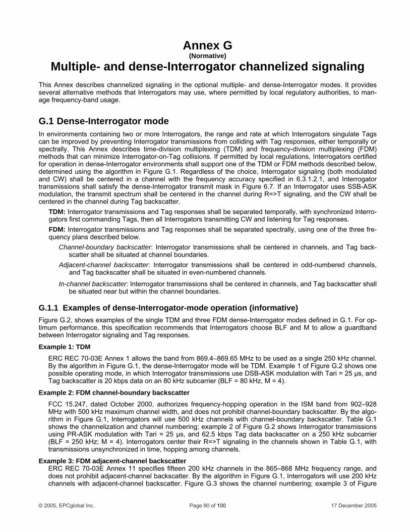
Annex G (Normative)
Multiple- and dense-Interrogator channelized signaling This Annex describes channelized signaling in the optional multiple- and dense-Interrogator modes. It provides several alternative methods that Interrogators may use, where permitted by local regulatory authorities, to man-age frequency-band usage.
G.1 Dense-Interrogator mode In environments containing two or more Interrogators, the range and rate at which Interrogators singulate Tags can be improved by preventing Interrogator transmissions from colliding with Tag responses, either temporally or spectrally. This Annex describes time-division multiplexing (TDM) and frequency-division multiplexing (FDM) methods that can minimize Interrogator-on-Tag collisions. If permitted by local regulations, Interrogators certified for operation in dense-Interrogator environments shall support one of the TDM or FDM methods described below,
s of the choice, Interrogator signaling (both modulated ncy accuracy specified in 6.3.1.2.1, and Interrogator
transmissions shall satisfy the dense-Interrogator transmit mask in Figure 6.7. If an Interrogator uses SSB-ASK modulation, the transmit spectrum shall be centered in the channel during R=>T signaling, and the CW shall be centered in the channel during Tag backscatter.
TDM: Interrogator transmissions and Tag responses shall be separated temporally, with synchronized Interro-gators first commanding Tags, then all Interrogators transmitting CW and listening for Tag responses. FDM: Interrogator transmissions and Tag responses shall be separated spectrally, using one of the three fre-quency plans described below.
Channel-boundary backscatter: Interrogator transmissions shall be centered in channels, and Tag back-scatter shall be situated at channel boundaries.
Adjacent-channel backscatter: Interrogator transmissions shall be centered in odd-numbered channels, and Tag backscatter shall be situated in even-numbered channels.
In-channel backscatter: Interrogator transmissions shall be centered in channels, and Tag backscatter shall be situated near but within the channel boundaries.
G.1.1 Examples of dense-Interrogator-mode operation (informative) Figure G.2, shows examples of the single TDM and three FDM dense-Interrogator modes defined in G.1. For op-timum performance, this specification recommends that Interrogators choose BLF and M to allow a guardband between Interrogator signaling and Tag responses.
Example 1: TDM ERC REC 70-03E Annex 1 allows the band from 869.4–869.65 MHz to be used as a single 250 kHz channel. By the algorithm in Figure G.1, the dense-Interrogator mode will be TDM. Example 1 of Figure G.2 shows one possible operating mode, in which Interrogator transmissions use DSB-ASK modulation with Tari = 25 µs, and Tag backscatter is 20 kbps data on an 80 kHz subcarrier (BLF = 80 kHz, M = 4).
Example 2: FDM channel-boundary backscatter FCC 15.247, dated October 2000, authorizes frequency-hopping operation in the ISM band from 902–928 MHz with 500 kHz maximum channel width, and does not prohibit channel-boundary backscatter. By the algo-rithm in Figure G.1, Interrogators will use 500 kHz channels with channel-boundary backscatter. Table G.1 shows the channelization and channel numbering; example 2 of Figure G.2 shows Interrogator transmissions using PR-ASK modulation with Tari = 25 µs, and 62.5 kbps Tag data backscatter on a 250 kHz subcarrier (BLF = 250 kHz; M = 4). Interrogators center their R=>T signaling in the channels shown in Table G.1, with transmissions unsynchronized in time, hopping among channels.
Example 3: FDM adjacent-channel backscatter ERC REC 70-03E Annex 11 specifies fifteen 200 kHz channels in the 865–868 MHz frequency range, and does not prohibit adjacent-channel backscatter. By the algorithm in Figure G.1, Interrogators will use 200 kHz channels with adjacent-channel backscatter. Figure G.3 shows the channel numbering; example 3 of Figure
determined using the algorithm in Figure G.1. Regardlesand CW) shall be centered in a channel with the freque
© 2005, EPCglobal Inc. Page 90 of 100 17 December 2005
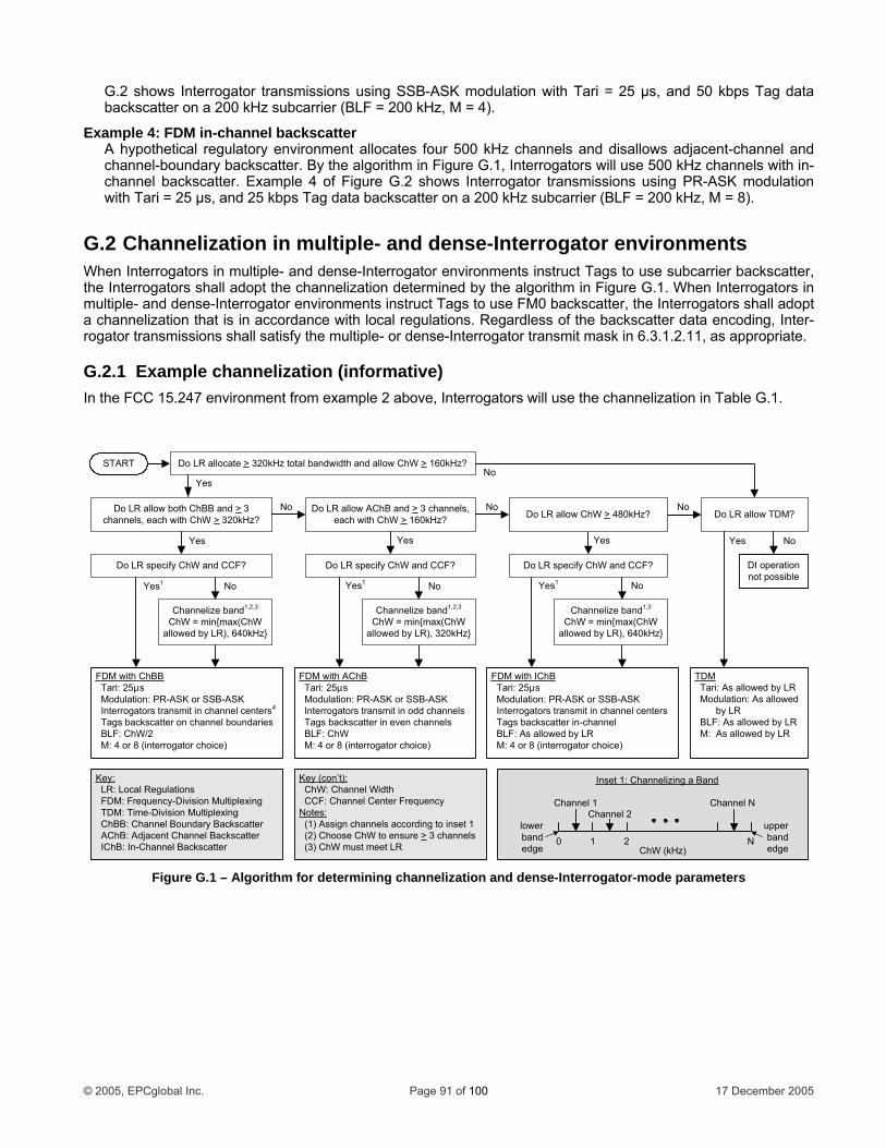
G.2 shows Interrogator transmissions using SSB-ASK modulation with Tari = 25 µs, and 50 kbps Tag data backscatter on a 200 kHz subcarrier (BLF = 200 kHz, M = 4).
Example 4: FDM in-channel backscatter A hypothetical regulatory environment allocates four 500 kHz channels and disallows adjacent-channel and channel-boundary backscatter. By the algorithm in Figure G.1, Interrogators will use 500 kHz channels with in-channel backscatter. Example 4 of Figure G.2 shows Interrogator transmissions using PR-ASK modulation with Tari = 25 µs, and 25 kbps Tag data backscatter on a 200 kHz subcarrier (BLF = 200 kHz, M = 8).
G.2 Channelization in multiple- and dense-Interrogator environments When Interrogators in multiple- and dense-Interrogator environments instruct Tags to use subcarrier backscatter, the Interrogators shall adopt the channelization determined by the algorithm in Figure G.1. When Interrogators in multiple- and dense-Interrogator environments instruct Tags to use FM0 backscatter, the Interrogators shall adopt a channelization that is in accordance with local regulations. Regardless of the backscatter data encoding, Inter-rogator transmissions shall satisfy the multiple- or dense-Interrogator transmit mask in 6.3.1.2.11, as appropriate.
G.2.1 Example channelization (informative) In the FCC 15.247 environment from example 2 above, Interrogators will use the channelization in Table G.1.
Do LR allow TDM?
No
No
DI operation not possible
TDM Tari: As allowed by LR Modulation: As allowed by LR BLF: As allowed by LR M: As allowed by LR
START Do LR allocate > 320kHz total bandwidth and allow ChW > 160kHz?
1 2
Channel 1Channel 2
Channel N
0ChW (kHz)
lower bandedge
upper bandedge
Inset 1: Channelizing a Band
Yes
No
No
Yes
Key: LR: Local Regulations FDM: Frequency-Division Multiplexing TDM: Time-Division Multiplexing ChBB: Channel Boundary Backscatter AChB: Adjacent Channel Backscatter IChB: In-Channel Backscatter
Channelize band1,2,3
ChW = min{max(ChW allowed by LR), 640kHz}
FDM with ChBB Tari: 25µs Modulation: PR-ASK or SSB-ASK Interrogators transmit in channel centers4
Tags backscatter on channel boundaries BLF: ChW/2 M: 4 or 8 (interrogator choice)
Do LR allow both ChBB and > 3 channels, each with ChW > 320kHz?
Do LR allow AChB and > 3 channels, each with ChW > 160kHz?
Do LR specify ChW and CCF?
Yes
No
Yes
Yes1 No
No
Yes
Yes1
Do LR specify ChW and CCF?
Yes1 No
Key (con’t): ChW: Channel Width CCF: Channel Center FrequencyNotes: (1) Assign channels according to inset 1 (2) Choose ChW to ensure > 3 channels (3) ChW must meet LR N
Channelize band1,3
ChW = min{max(ChW allowed by LR), 640kHz}
Channelize band1,2,3
ChW = min{max(ChW allowed by LR), 320kHz}
FDM with IChB Tari: 25µs Modulation: PR-ASK or SSB-ASK Interrogators transmit in channel centers Tags backscatter in-channel BLF: As allowed by LR M: 4 or 8 (interrogator choice)
FDM with AChB Tari: 25µs Modulation: PR-ASK or SSB-ASK Interrogators transmit in odd channels Tags backscatter in even channels BLF: ChW M: 4 or 8 (interrogator choice)
Do LR specify ChW and CCF?
Do LR allow ChW > 480kHz?
Figure G.1 – Algorithm for determining channelization and dense-Interrogator-mode parameters
© 2005, EPCglobal Inc. Page 91 of 100 17 December 2005
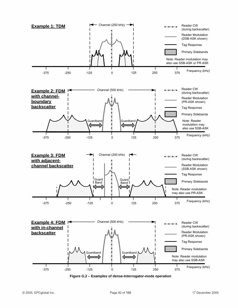
0 125-125Frequency (kHz)
250 375-250-375
Example 2: FDMwith channel-boundary backscatter
Channel (500 kHz)
Reader Modulation(PR-ASK shown)
Tag Response
Primary Sidebands
GuardbandGuardband
Reader CW(during backscatter)
Note: Reader modulation may also use SSB-ASK
0 125-125Frequency (kHz)
250 375-250-375
Example 4: FDMwith in-channel backscatter
Channel (500 kHz)
Reader Modulation(PR-ASK shown)
Tag Response
Primary SidebandsGuardbandGuardband
Reader CW(during backscatter)
Note: Reader modulation may also use SSB-ASK
Example 3: FDM with adjacent-channel backscatter
0 125 250-125-250 Frequency (kHz)
Channel (200 kHz)
Reader Modulation(SSB-ASK shown)
Tag Response
Primary Sidebands
Reader CW(during backscatter)
GuardBand
GuardBand
Note: Reader modulation may also use PR-ASK
375-375
Example 1: TDM
0 125 250-125-250 Frequency (kHz)
Channel (250 kHz)
Reader Modulation(DSB-ASK shown)
Tag Response
Primary Sidebands
Reader CW(during backscatter)
Note: Reader modulation may PR-ASKalso use SSB-ASK or
375-375
Figure G.2 – Examples of dense-Interrogator-mode operation
© 2005, EPCglobal Inc. Page 92 of 100 17 December 2005
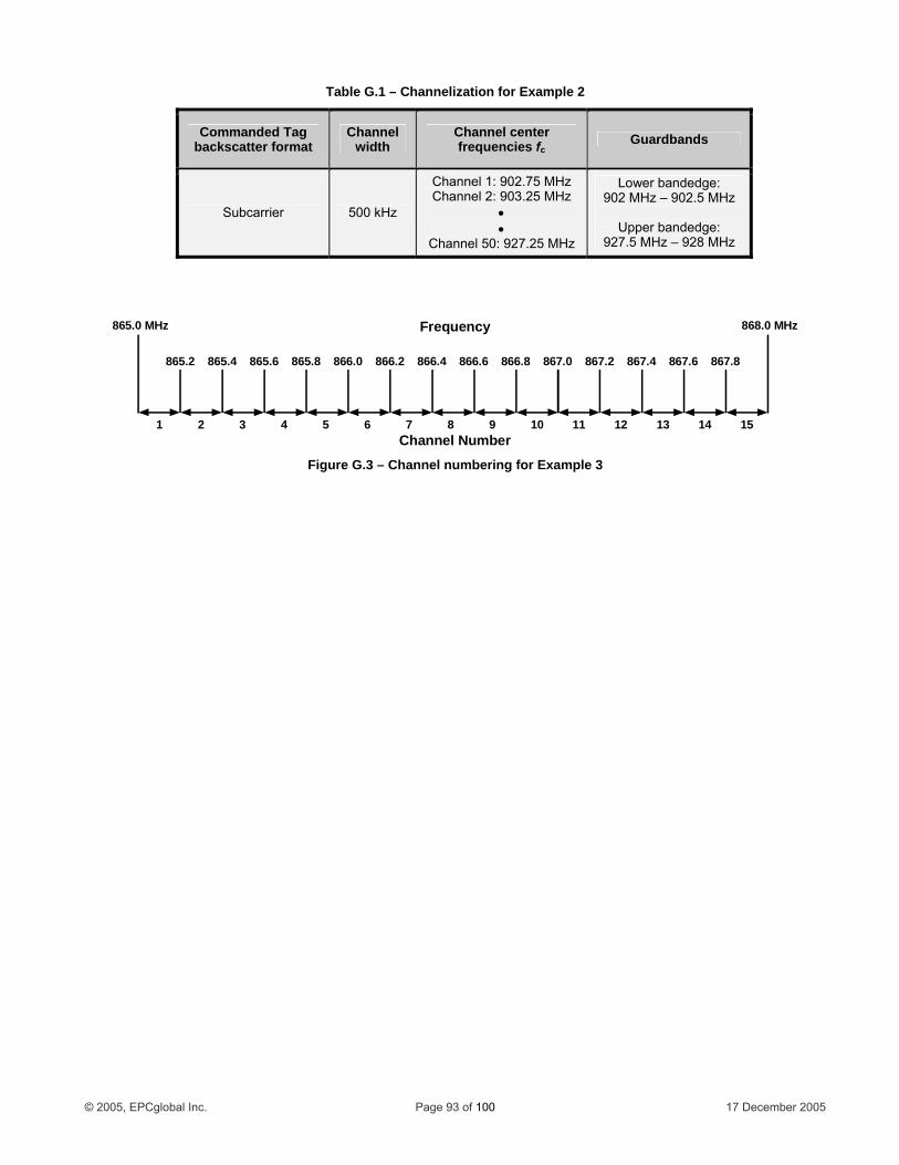
Table G.1 – Channelization for Example 2
Commanded Tag backscatter format
Channel width
Channel center frequencies fc
Guardbands
Subcarrier 500 kHz
Channel 1: 902.75 MHz Channel 2: 903.25 MHz
• •
Channel 50: 927.25 MHz
Lower bandedge: 902 MHz – 902.5 MHz
Upper bandedge:
927.5 MHz – 928 MHz
1
865.0 MHz 868.0 MHz
865.2 865.4 865.6 865.8 866.0 866.2 866.4 866.6 866.8
2 3 4 5 6 7 8 9 10
Frequency
Channel Number
867.0 867.2 867.4 867.6 867.8
11 12 13 14 15
Figure G.3 – Channel numbering for Example 3
© 2005, EPCglobal Inc. Page 93 of 100 17 December 2005
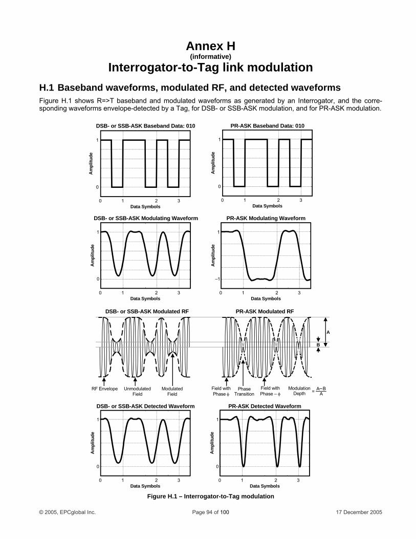
Annex H
Interrogator-to-Tag link modulation RF, and detected waveforms
Figure H.1 shows R=>T baseband and modulated waveforms as generated by an Interrogator, and the corre-sponding waveforms envelope-detected by a Tag, for DSB- or SSB-ASK modulation, and for PR-ASK modulation.
(informative)
H.1 Baseband waveforms, modulated
D0 1
DSB- or SSB-A
1
ude
ata Symbols2 3
SK Baseband Data: 010
0
Am
plit
PR-ASK Modulating Waveform
–1
1
tude
Data Symbols0 1 2 3
0
Am
pli
1
Am
plitu
de
Data Symbols0 1 2 3
DSB- or SSB-ASK Modulating Waveform
Data Symbols0 1 2 3
PR-ASK Baseband Data: 010
1
Aud
em
plit
0
PR-ASK Detected Waveform
0
1
Am
plitu
de
Data Symbols0 1 2 3
DSB- or SSB-ASK Detected Waveform
0
1
Am
plitu
de
Data Symbols0 1 2 3
B
A
FieldModulatedRF Envelope P
Trahasensition
Field withPhase – φ Field
Unmodulated Field withPhase φ
PR-ASK ModulaDSB Modu- or SSB-ASK lated RF ted RF
ModulationDepth
A BA=
Figure H.1 – Interrogator-to-Tag modulation
© 2005, EPCglobal Inc. Page 94 of 100 17 December 2005

Annex I (Normative)
Error codes I.1 Tag error codes and their usage If a Tag encounters an error when executing an access command that reads from or writes to memory, and if the command is a handle-based command (i.e. Read, Write, Kill, Lock, BlockWrite, or BlockErase), then the Tag shall backscatter an error code as shown in Table I.1 instead of its normal reply.
• If the Tag supports error-specific codes, it shall use the error-specific codes shown in Table I.2. • If the Tag does not support error-specific codes, it shall backscatter error code 000011112 (indicating a
non-specific error) as shown in Table I.2. • Tags shall backscatter error codes only from the open or secured states. • A Tag shall not backscatter an error code if it receives an invalid access command; instead, it shall ignore
the command. • If an error is described by more than one error code, the more specific error code shall take precedence
and shall be the code that the Tag backscatters. • The header for an error code is a 1-bit, unlike the header for a normal Tag response, which is a 0-bit.
Table I.1 – Tag-error reply format
Header Error Code RN CRC-16
# of bits 1 8 16 16
description 1 Error code handle
Table I.2 – Tag error codes
Error-Code Support Error Code Error-Code Name Error Description
000000002 Other error Catch-all for errors not covered by other codes
000000112Memory overrun or
unsupported PC value The specified memory location does not exist or the
PC value is not supported by the Tag
000001002 Memory locked The specified memory location is locked and/or per-malocked and is either not writeable or not readable.
Error-specific
000010112 Insufficient power The Tag has insufficient power to perform the mem-ory-write operation
Non-specific 000011112 Non-specific error The Tag does not support error-specific codes
© 2005, EPCglobal Inc. Page 95 of 100 17 December 2005
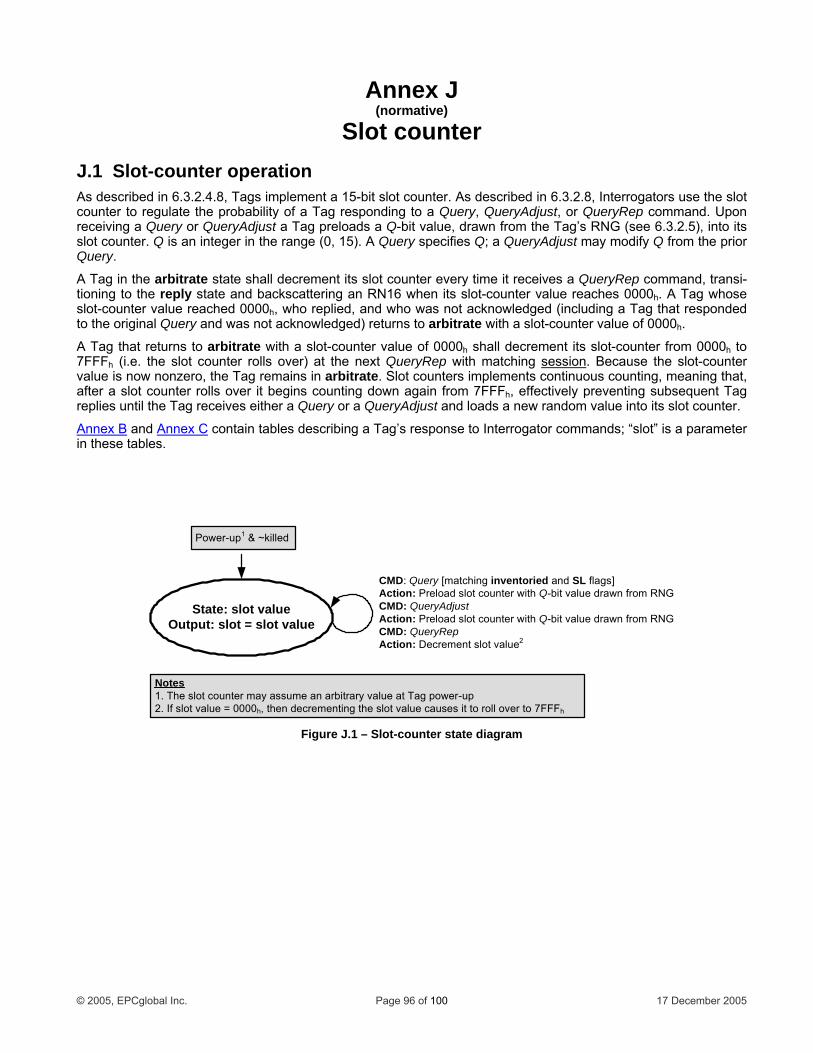
Annex J (normative)
Slot counter J.1 Slot-counter operation
), into its slot cou ueryAdjust may modify Q from the prior Query.
A Tag in the arbitrate state shall decrement its slot counter every time it receives a QueryRep command, transi-tioning to the reply state and backscattering an RN16 when its slot-counter value reaches 0000h. A Tag whose slot-counter value reached 0000h, who replied, and who was not acknowledged (including a Tag that responded to the original Query and was not acknowledged) returns to arbitrate with a slot-counter value of 0000h.
A Tag that returns to arbitrate with a slot-counter value of 0000h shall decrement its slot-counter from 0000h to 7FFFh (i.e. the slot counter rolls over) at the next QueryRep with matching session
As described in 6.3.2.4.8, Tags implement a 15-bit slot counter. As described in 6.3.2.8, Interrogators use the slot counter to regulate the probability of a Tag responding to a Query, QueryAdjust, or QueryRep command. Upon receiving a Query or QueryAdjust a Tag preloads a Q-bit value, drawn from the Tag’s RNG (see 6.3.2.5
nter. Q is an integer in the range (0, 15). A Query specifies Q; a Q
. Because the slot-counter value is now nonzero, the Tag remains in arbitrate. Slot counters implements continuous counting, meaning that, after a slot counter rolls over it begins counting down again from 7FFFh, effectively preventing subsequent Tag replies until the Tag receives either a Query or a QueryAdjust and loads a new random value into its slot counter.
Annex B and Annex C contain tables describing a Tag’s response to Interrogator commands; “slot” is a parameter in these tables.
Stateut: slot = slot value
: slot value
CMD: Query [matching inventoried and Action: Preload slot counter with Q-bit vCMD: QueryAdjustAction: Preload slot counter with Q-bit value drawn from RNGCMD: QueryRepAction: De slot value2
SL flags]alue drawn from RNG
Outpcrement
Power-up1 & ~killed
Notes1. The slot counter may assume an arbitrary value at Tag power-up2 value = 0000h, then decrementing the slot value causes it to roll over to 7FFFh
Figure J.1 – Slot-counter state diagram
. If slot
© 2005, EPCglobal Inc. Page 96 of 100 17 December 2005
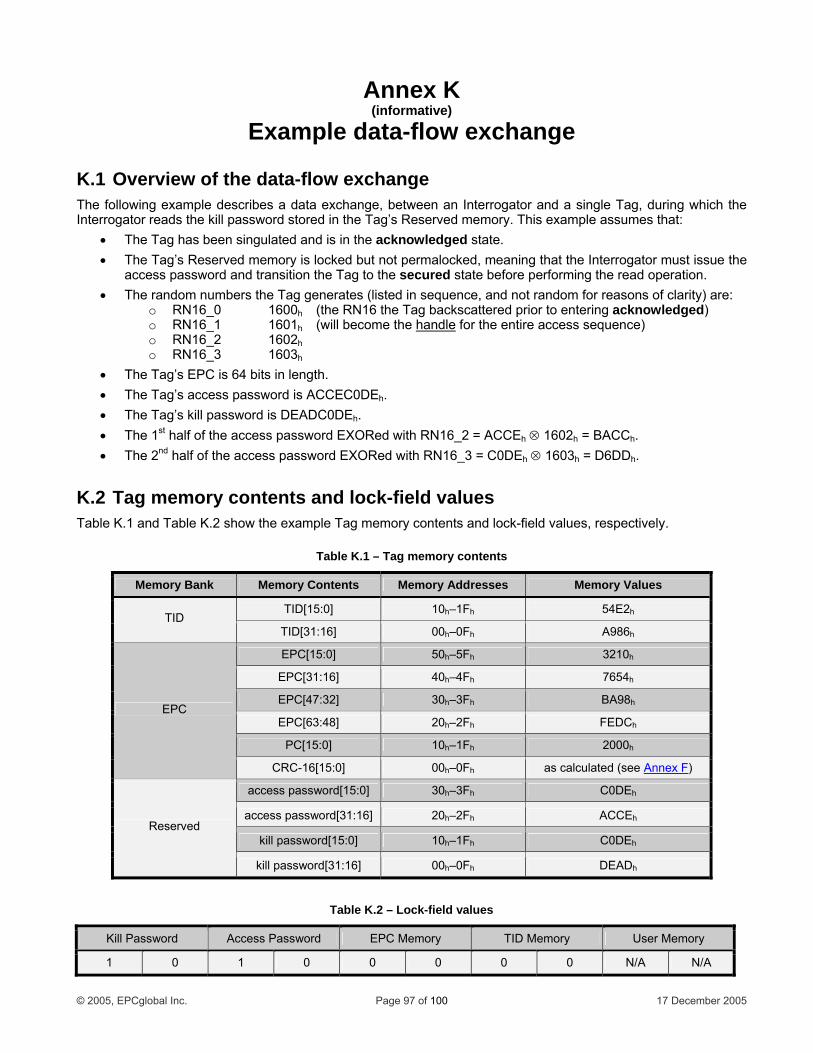
Annex K (informative)
Example data-flow exchange
K.1 Overview of the data-flow exchange The following example describes a data exchange, between an Interrogator and a single Tag, during which the Interrogator reads the kill password stored in the Tag’s Reserved memory. This example assumes that:
• The Tag has been singulated and is in the acknowledged state. • The Tag’s Reserved memory is locked but not permalocked, meaning that the Interrogator must issue the
access password and transition the Tag to the secured state before performing the read operation. • The random numbers the Tag generates (listed in sequence, and not random for reasons of clarity) are:
o RN16_0 1600h (the RN16 the Tag backscattered prior to entering acknowledged) o RN16_1 1601h (will become the handle for the entire access sequence) o RN16_2 1602h o RN16_3 1603h
• The Tag’s EPC is 64 bits in length. • The Tag’s access password is ACCEC0DEh. • The Tag’s kill password is DEADC0DEh. • The 1st half of the access password EXORed with RN16_2 = ACCEh ⊗ 1602h = BACCh. • The 2nd half of the access password EXORed with RN16_3 = C0DEh ⊗ 1603h = D6DDh.
K.2 Tag memory contents and lock-field values Table K.1 and Table K.2 show the example Tag memory contents and lock-field values, respectively.
Table K.1 – Tag memory contents
Memory Bank Memory Contents Memory Addresses Memory Values
TID[15:0] 10h–1Fh 54E2hTID TID[31:16] 00h–0Fh A986h
EPC[15:0] 50h–5Fh 3210h
EPC[31:16] 40h–4Fh 7654h
EPC[47:32] 30h–3Fh BA98h
EPC[63:48] 20h–2Fh FEDCh
PC[15:0] 10h–1Fh 2000h
EPC
CRC-16[15:0] 00h–0Fh as calculated (see Annex F)
access password[15:0] 30h–3Fh C0DEh
access password[31:16] 20h–2Fh ACCEh
kill password[15:0] 10h–1Fh C0DEh
Reserved
kill password[31:16] 00h–0Fh DEADh
Table K.2 – Lock-field values
Kill Password Access Password EPC Memory TID Memory User Memory
1 0 1 0 0 0 0 0 N/A N/A
© 2005, EPCglobal Inc. Page 97 of 100 17 December 2005
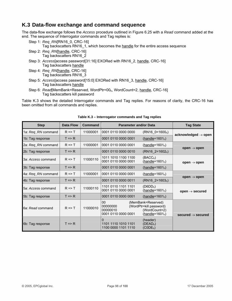
K.3 Data-flow exchange and command sequence The data-flow exchange follows the Access procedure outlined in Figure 6.25 with a Read command added at the end. The sequence of Interrogator commands and Tag replies is:
Step 1: Req_RN[RN16_0, CRC-16] Tag backscatters RN16_1, which becomes the handle for the entire access sequence Step 2: Req_RN[handle, CRC-16] Tag backscatters RN16_2 Step 3: Access[access password[31:16] EXORed with RN16_2, handle, CRC-16] Tag backscatters handleStep 4: Req_RN[handle, CRC-16] Tag backscatters RN16_3 Step 5: Access[access password[15:0] EXORed with RN16_3, handle, CRC-16] Tag backscatters handleStep 6: Read[MemBank=Reserved, WordPtr=00h, WordCount=2, handle, CRC-16] Tag backscatters kill password
Table K.3 shows the detailed Interrogator commands and Tag replies. For reasons of clarity, the CRC-16 has been omitted from all commands and replies.
Table K.3 – Interrogator commands and Tag replies
Step Data Flow Command Parameter and/or Data Tag State
1a: Req_RN command R => T 11000001 0001 0110 0000 0000 (RN16_0=1600h)
1b: Tag response T => R 0001 0110 0000 0001 (handle=1601h) acknowledged → open
2a: Req_RN command R => T 11000001 0001 0110 0000 0001 (handle=1601h)
2b: Tag response T => R 0001 0110 0000 0010 (RN16_2=1602h) open → open
3a: Access command R => T 11000110 1011 1010 1100 1100 (BACCh) 0001 0110 0000 0001 (handle=1601h)
3b: Tag response T => R 0001 0110 0000 0001 (handle=1601h) open → open
4a: Req_RN command R => T 11000001 0001 0110 0000 0001 (handle=1601h)
4b: Tag response T => R 0001 0110 0000 0011 (RN16_2=1603h) open → open
5a: Access command R => T 11000110 1101 0110 1101 1101 (D6DDh) 0001 0110 0000 0001 (handle=1601h)
5b: Tag response T => R 0001 0110 0000 0001 (handle=1601h) open → secured
6a: Read command R => T 11000010
00 (MemBank=Reserved) 00000000 (WordPtr=kill password) 00000010 (WordCount=2) 0001 0110 0000 0001 (handle=1601h)
6b: Tag response T => R 0 (header) 1101 1110 1010 1101 (DEADh) 1100 0000 1101 1110 (C0DEh)
secured → secured
© 2005, EPCglobal Inc. Page 98 of 100 17 December 2005
Annex L (informative)
Optional Tag Features The following options are available to Tags certified to this protocol.
a asswords Kill rd: A Tag may optionally implement a kill password. A Tag that does not implement a kill password o t has a zero-va
A ord: A Tag m lement an access password. A Tag that does not implement c-c operates as if it has a zero-valued access password that is permanently read/write locked. See 6
L al T mRes ory: Reserved memory is optional. If a Tag does not implement either a kill password or an ac-c then e Ta ag with non-im asswo ope d password(s) that are permanently read/write locked, these passwords must still be logically addressable in Reserved memory at the memory locations specified in 6 6.3
E EPC memory is required, but its size is vendor-defined. The minimum size is 32 bits, to contain a 1 d 16 E r-specified le 16 b 6
T ory is required, but its size is vendor-defined. The minimum-size TID memory contains an 8 596 ti nterrogator to u y the custom commands and/or optional features that a Tag supports. TID memory may optionally ontain vendor-specific data. See 6.3.2.1.3.
User memory: User memory is optional. See 6.3.2.1.4, 6.3.2.1.4.1, and 6.3.2.1.4.2.
L.3 Optional Tag commands Proprietary: A Tag may support proprietary commands. See 2.3.3.
Custom: A Tag may support custom commands. See 2.3.4.
Access: A Tag may support the Access command. See 6.3.2.10.3.6.
BlockWrite: A Tag may support the BlockWrite command. See 6.3.2.10.3.7.
BlockErase: A Tag may support the BlockErase command. See 6.3.2.10.3.8.
L.4 Optional Tag error-code reporting format A Tag may support error-specific or non-error-specific error-code reporting. See Annex I
L.1 Option passwo
l Tag p
perates as if i lued kill password that is permanently read/write locked. See 6.3.2.1.1.1.
ay optionally impccess passw an aess password.3.2.1.1.2.
.2 Option ag emory banks and memory-bank sizes erved mem
ess password thrds
g need not physically implement Reserved memory. Because a Trates as if it has zero-valueplemented p
.3.2.1.1.1 and .2.1.1.2.
PC memory:6-bit CRC an -bit PC.
its to 49PC memory may be larger than 32 bits, to contain an EPC whose vendobits in 16-bit increments. See 6.3.2.1.2. ngth may be
ID memory: TID mem-bit ISO/IEC 1niquely identif
3 alloca on class identifier, as well as sufficient identifying information for an I
c
.
L.5 Optional Tag backscatter modulation format A Tag may support ASK and/or PSK backscatter modulation. See 6.3.1.3.1.
© 2005, EPCglobal Inc. Page 99 of 100 17 December 2005
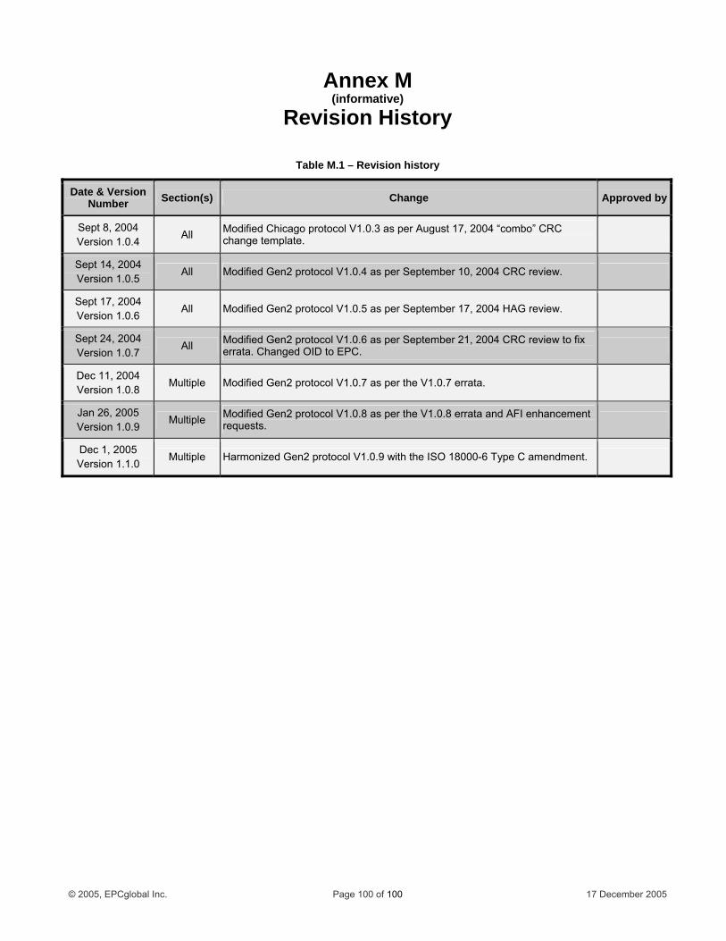
© 2005, EPCglobal Inc. Page 100 of 100 17 December 2005
Annex M (informative)
Revision History
Table M.1 – Revision history
Date & Version Number Section(s) Change Approved by
Sept 8, 2004 Version 1.0.4
All Modified Chicago protocol V1.0.3 as per August 17, 2004 “combo” CRC change template.
Sept 14, 2004 Version 1.0.5
All Modified Gen2 protocol V1.0.4 as per September 10, 2004 CRC review.
Sept 17, 2004 Version 1.0.6
All Modified Gen2 protocol V1.0.5 as per September 17, 2004 HAG review.
Sept 24, 2004 Version 1.0.7
All Modified Gen2 protocol V1.0.6 as per September 21, 2004 CRC review to fix errata. Changed OID to EPC.
Dec 11, 2004 Version 1.0.8
Multiple Modified Gen2 protocol V1.0.7 as per the V1.0.7 errata.
Jan 26, 2005 Version 1.0.9
Multiple Modified Gen2 protocol V1.0.8 as per the V1.0.8 errata and AFI enhancement requests.
Dec 1, 2005 Version 1.1.0
Multiple Harmonized Gen2 protocol V1.0.9 with the ISO 18000-6 Type C amendment.