Embed Size (px)
Citation preview
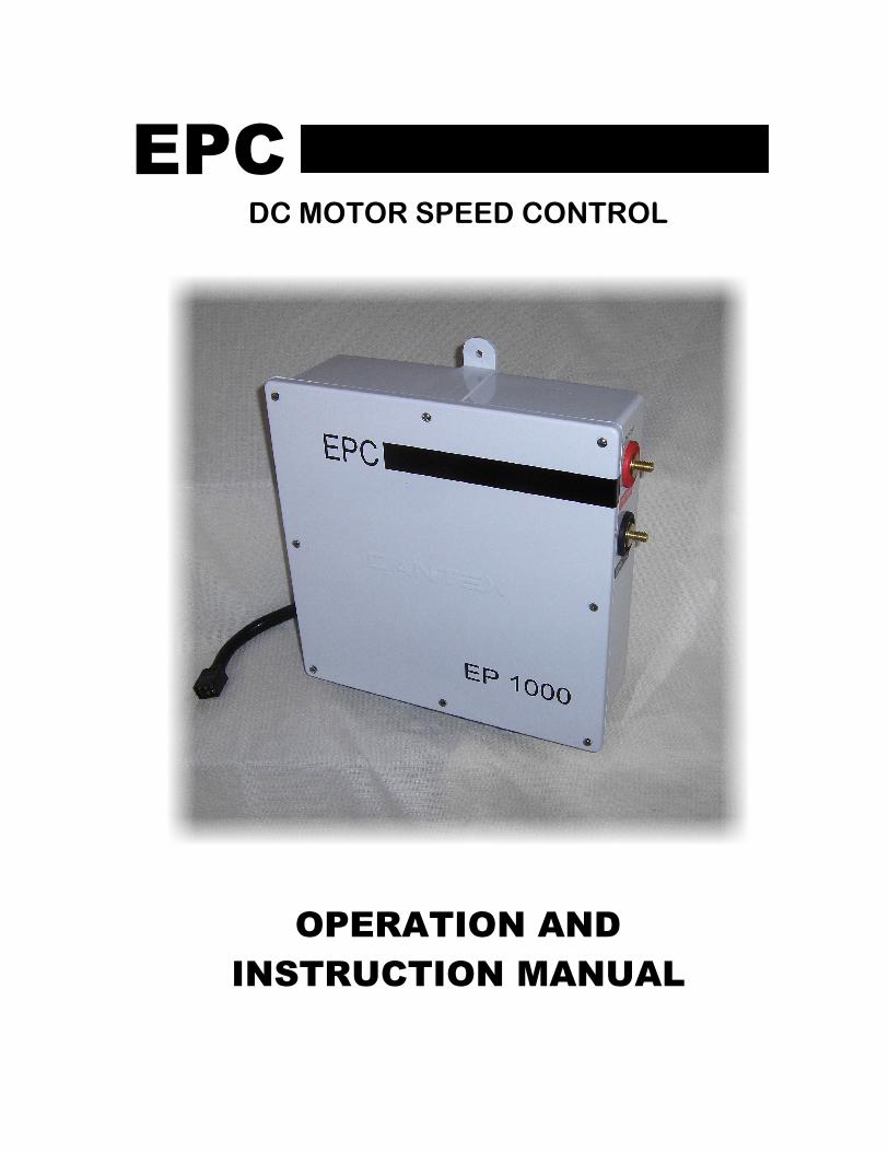
EPC DC MOTOR SPEED CONTROL
OPERATION AND
INSTRUCTION MANUAL
THIS MANUAL IS PUBLISHED BY
EPC CORPORATION
AND IS TO BE DISTRIBUTED ONLY WITH NEW
EPC CONTROLS AND EQUIPMENT
NO OTHER DISTRIBUTION IS PERMITED

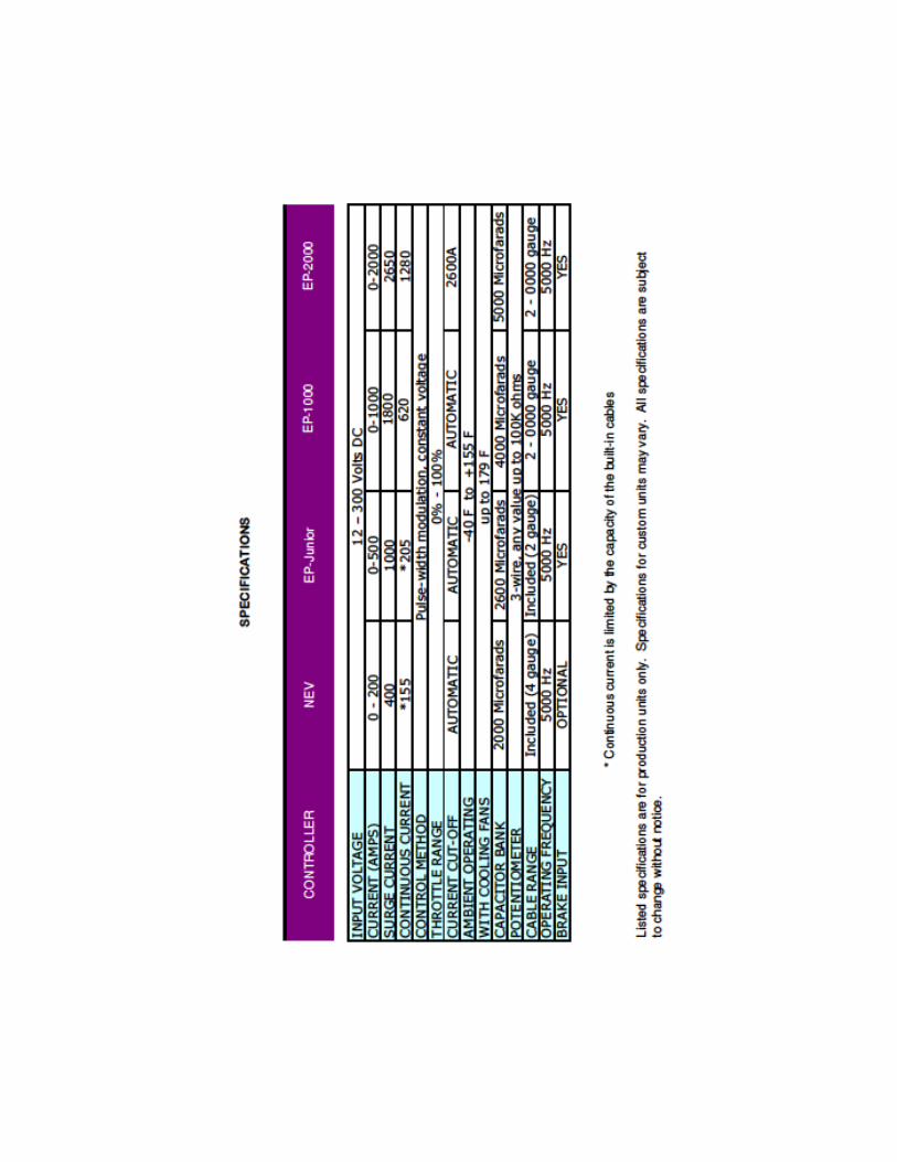
This manual covers the following EPC controllers:
□ EP-2000
□ EP-1000
□ EP-Junior
□ NEV Controller
INTRODUCTION
The EP-Series of motor controllers are suitable for most industrial, automotive, and marine applications. They are designed to drive most brushed DC motors, including series-wound, separately excited, and permanent magnet motors. Some extremely low inductance motors may require software updates to prevent over-current conditions, which could inadvertently shut down your controller. All EP-Series controllers come configured to run off any DC power source, and can also be run from single-phase and three-phase AC power sources with our optional AC Module. All EPC controllers are designed to operate in harsh industrial environments. Installation is residential environments will require that the high voltage terminals of the unit to be shielded with a UL-Listed terminal protector or cover.
All EPC Products are
Manufactured in the United States of America
FEATURES
• True plug-and-play design... simply connect and go!
• Economical design results in an affordable controller - about half the cost of a conventional industrial/automotive controller
• Soft-start technology allows for smoother acceleration
• 100% Waterproof and wet-location compliant
• No programming required
• Fanless, air-cooled design allows offers a very small footprint
• Full optical isolation between high voltage and 12-volt systems
• Efficient heatsink and IGBT modules eliminate the need for liquid cooling
• Wide input voltage range: 24 to 320 volts
• Non-metallic enclosure increases safety and prevents corrosion
• All stainless steel / brass hardware included
• Energy-saving design operates at over 97% efficiency
• Brake pedal input for additional safety in the event of throttle bind / failure
• Built-in contactor delay allows you to turn on the contactors and controller at the same time, without the possibility of damaging the controller
All EPC controllers automatically detect your motor type, battery pack voltage, and potentiometer range. There are no settings to adjust, switches to set, or any type of programming necessary. This allows you to make fast and easy changes to your electrical system without having to worry about re-programming your controller. All EPC controllers also use an interchangeable 6-pin wiring harness, which makes it very easy to swap or upgrade your controller --- without the need to replace your –wiring harness.
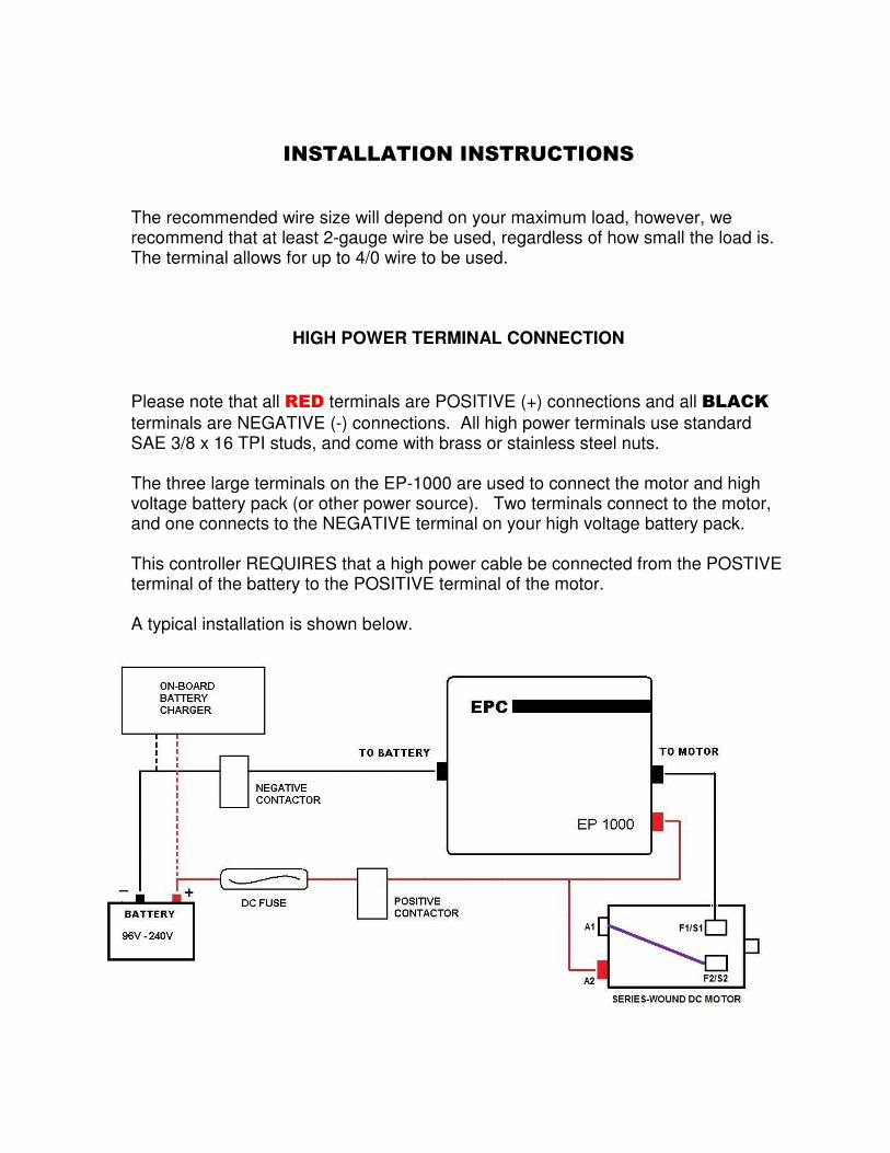
INSTALLATION INSTRUCTIONS The recommended wire size will depend on your maximum load, however, we recommend that at least 2-gauge wire be used, regardless of how small the load is. The terminal allows for up to 4/0 wire to be used.
HIGH POWER TERMINAL CONNECTION
Please note that all RED terminals are POSITIVE (+) connections and all BLACK
terminals are NEGATIVE (-) connections. All high power terminals use standard SAE 3/8 x 16 TPI studs, and come with brass or stainless steel nuts. The three large terminals on the EP-1000 are used to connect the motor and high voltage battery pack (or other power source). Two terminals connect to the motor, and one connects to the NEGATIVE terminal on your high voltage battery pack.
This controller REQUIRES that a high power cable be connected from the POSTIVE terminal of the battery to the POSITIVE terminal of the motor. A typical installation is shown below.
SPECIAL NOTICE
Always verify that NO HIGH VOLTAGE POTENTIAL is present on the 12 volt battery/power supply terminals. This can be dangerous to anyone servicing or using the equipment. Testing for this condition can be done as follows: Connect a high voltage meter between each 12 volt battery terminal (or power supply) and each high voltage battery terminal. The meter should read close to zero volts in all cases. For automotive applications, also check the voltage potential between the chassis/frame of the vehicle and each high voltage battery terminal. The meter should read close to zero volts in all cases. If there is a high voltage leak anywhere in the system, it must be repaired immediately. All EPC controllers are fully isolated, and cannot leak voltage into the 12-volt system.
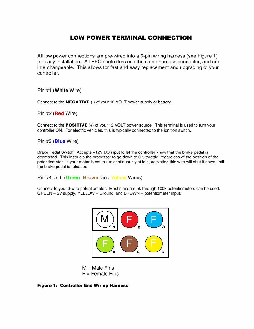
LOW POWER TERMINAL CONNECTION All low power connections are pre-wired into a 6-pin wiring harness (see Figure 1) for easy installation. All EPC controllers use the same harness connector, and are interchangeable. This allows for fast and easy replacement and upgrading of your controller. Pin #1 (White Wire) Connect to the NEGATIVE (-) of your 12 VOLT power supply or battery.
Pin #2 (Red Wire) Connect to the POSITIVE (+) of your 12 VOLT power source. This terminal is used to turn your
controller ON. For electric vehicles, this is typically connected to the ignition switch.
Pin #3 (Blue Wire) Brake Pedal Switch. Accepts +12V DC input to let the controller know that the brake pedal is depressed. This instructs the processor to go down to 0% throttle, regardless of the position of the potentiometer. If your motor is set to run continuously at idle, activating this wire will shut it down until the brake pedal is released
Pin #4, 5, 6 (Green, Brown, and Yellow Wires) Connect to your 3-wire potentiometer. Most standard 5k through 100k potentiometers can be used. GREEN = 5V supply, YELLOW = Ground, and BROWN = potentiometer input.
M = Male Pins F = Female Pins
Figure 1: Controller End Wiring Harness
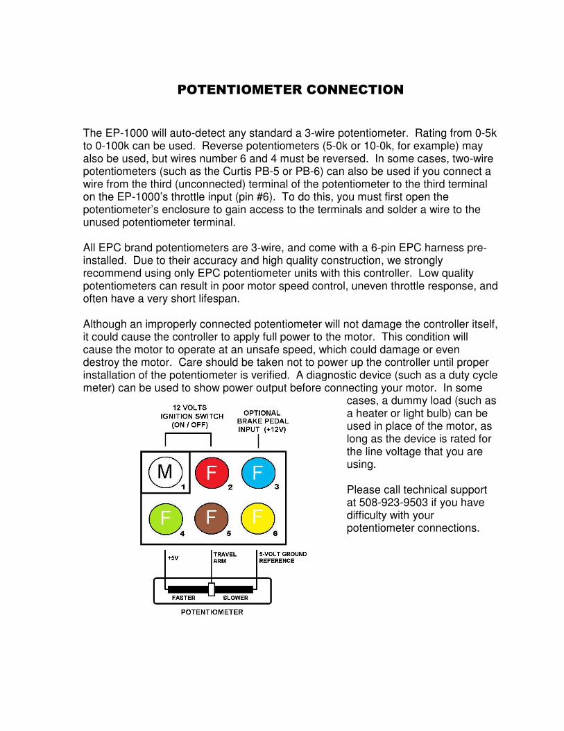
POTENTIOMETER CONNECTION
The EP-1000 will auto-detect any standard a 3-wire potentiometer. Rating from 0-5k to 0-100k can be used. Reverse potentiometers (5-0k or 10-0k, for example) may also be used, but wires number 6 and 4 must be reversed. In some cases, two-wire potentiometers (such as the Curtis PB-5 or PB-6) can also be used if you connect a wire from the third (unconnected) terminal of the potentiometer to the third terminal on the EP-1000’s throttle input (pin #6). To do this, you must first open the potentiometer’s enclosure to gain access to the terminals and solder a wire to the unused potentiometer terminal. All EPC brand potentiometers are 3-wire, and come with a 6-pin EPC harness pre-installed. Due to their accuracy and high quality construction, we strongly recommend using only EPC potentiometer units with this controller. Low quality potentiometers can result in poor motor speed control, uneven throttle response, and often have a very short lifespan. Although an improperly connected potentiometer will not damage the controller itself, it could cause the controller to apply full power to the motor. This condition will cause the motor to operate at an unsafe speed, which could damage or even destroy the motor. Care should be taken not to power up the controller until proper installation of the potentiometer is verified. A diagnostic device (such as a duty cycle meter) can be used to show power output before connecting your motor. In some
cases, a dummy load (such as a heater or light bulb) can be used in place of the motor, as long as the device is rated for the line voltage that you are using. Please call technical support at 508-923-9503 if you have difficulty with your potentiometer connections.
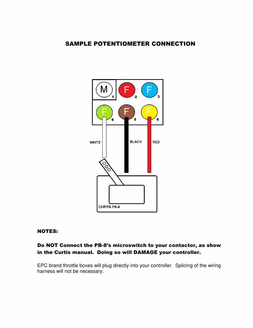
SAMPLE POTENTIOMETER CONNECTION
NOTES:
Do NOT Connect the PB-8’s microswitch to your contactor, as show
in the Curtis manual. Doing so will DAMAGE your controller.
EPC brand throttle boxes will plug directly into your controller. Splicing of the wiring harness will not be necessary.
SPEED CONTROL ADJUSTMENT
The EP-1000 features soft-start technology, which automatically smoothes the controller’s throttle response on take-off and deceleration. Several other factors will affect motor speed and response, including:
- Total Potentiometer travel - Input voltage to the controller - Load on the motor
Changing any of these values will affect the speed of the motor, however, the amount of power applied will always be controlled by the EP-1000 itself, based on the throttle (potentiometer) input. Potentiometers that have a longer travel tend to give more precise control of motor speed. For example, a potentiometer with a 4-inch travel will tend to have a much softer response that one with a 1-inch travel. The EP-1000 is pre-programmed from the factory with a linear throttle curve. This cannot be changed or modified by the end user. However, potentiometers with various output curves are available and can be used to adjust the throttle response.
CONTROLLER PROTECTION
FUSE PROTECTION
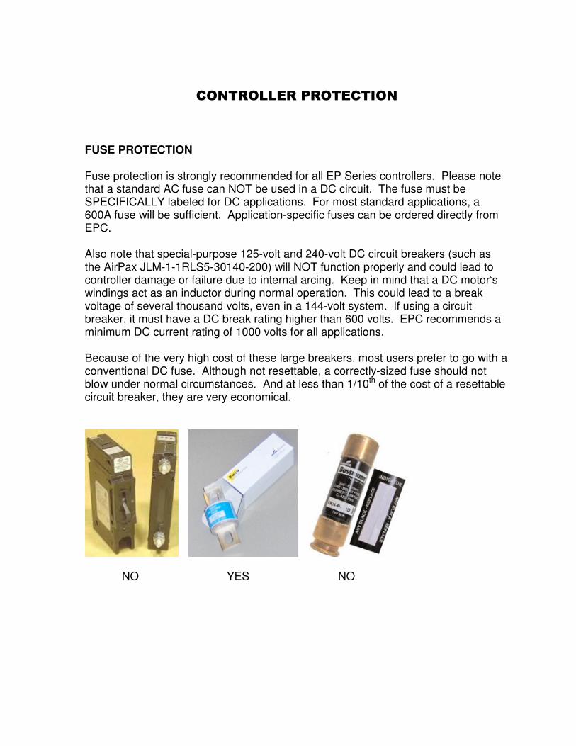
Fuse protection is strongly recommended for all EP Series controllers. Please note that a standard AC fuse can NOT be used in a DC circuit. The fuse must be SPECIFICALLY labeled for DC applications. For most standard applications, a 600A fuse will be sufficient. Application-specific fuses can be ordered directly from EPC. Also note that special-purpose 125-volt and 240-volt DC circuit breakers (such as the AirPax JLM-1-1RLS5-30140-200) will NOT function properly and could lead to controller damage or failure due to internal arcing. Keep in mind that a DC motor‘s windings act as an inductor during normal operation. This could lead to a break voltage of several thousand volts, even in a 144-volt system. If using a circuit breaker, it must have a DC break rating higher than 600 volts. EPC recommends a minimum DC current rating of 1000 volts for all applications. Because of the very high cost of these large breakers, most users prefer to go with a conventional DC fuse. Although not resettable, a correctly-sized fuse should not blow under normal circumstances. And at less than 1/10th of the cost of a resettable circuit breaker, they are very economical.
NO YES NO

CONTROLLER PROTECTION The EP-1000 and EP-Junior controllers feature built-in software protection that prevents damage to the controller, regardless of what type of fault is detected on the output side. This effectively eliminates the possibility of controller damage/failure due to over-current, motor failure, and even dead short conditions on the output side (the EP-1000/EP-Junior can sustain a dead short on the output side indefinitely). With this in mind, it is important to note that DC motor controllers are NOT indestructible. Routinely subjecting controllers to voltages outside of their normal range can damage internal components, and possibly caused a delayed failure.
CAUTION
NEVER disconnect and reconnect the HIGH VOLTAGE power to the controller during operation! Doing so can cause immediate controller damage and/or failure! Any intermittent interruption of power (poor connections, arcing, etc.) between the BATTERY PACK and CONTROLLER during normal operation can destroy the IGBT modules inside the unit. This type of failure is NOT covered under warranty. Due to internal electronic protection, arcing between the CONTROLLER and MOTOR will NOT damage your controller. However, this condition can lead to other problems including melted cables, motor damage/failure, and in some cases can even cause fires. This is why we strongly recommend checking your cables and connections for signs of arcing on a regular basis. Arcing/power interruptions in the system can be caused by: - Loose terminals - Faulty contactor(s) - Bad cables/crimps - Bad connections between batteries in the pack - Short circuiting of battery pack wiring
CONTACTORS
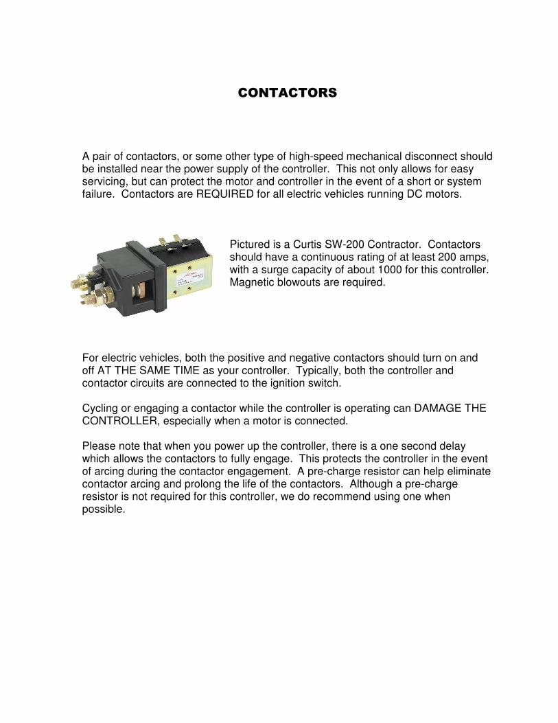
A pair of contactors, or some other type of high-speed mechanical disconnect should be installed near the power supply of the controller. This not only allows for easy servicing, but can protect the motor and controller in the event of a short or system failure. Contactors are REQUIRED for all electric vehicles running DC motors.
Pictured is a Curtis SW-200 Contractor. Contactors should have a continuous rating of at least 200 amps, with a surge capacity of about 1000 for this controller. Magnetic blowouts are required.
For electric vehicles, both the positive and negative contactors should turn on and off AT THE SAME TIME as your controller. Typically, both the controller and contactor circuits are connected to the ignition switch. Cycling or engaging a contactor while the controller is operating can DAMAGE THE CONTROLLER, especially when a motor is connected. Please note that when you power up the controller, there is a one second delay which allows the contactors to fully engage. This protects the controller in the event of arcing during the contactor engagement. A pre-charge resistor can help eliminate contactor arcing and prolong the life of the contactors. Although a pre-charge resistor is not required for this controller, we do recommend using one when possible.
WET LOCATIONS
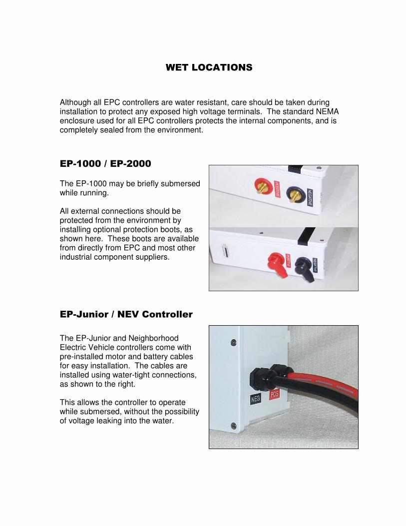
Although all EPC controllers are water resistant, care should be taken during installation to protect any exposed high voltage terminals. The standard NEMA enclosure used for all EPC controllers protects the internal components, and is completely sealed from the environment.
EP-1000 / EP-2000
The EP-1000 may be briefly submersed while running. All external connections should be protected from the environment by installing optional protection boots, as shown here. These boots are available from directly from EPC and most other industrial component suppliers.
EP-Junior / NEV Controller
The EP-Junior and Neighborhood Electric Vehicle controllers come with pre-installed motor and battery cables for easy installation. The cables are installed using water-tight connections, as shown to the right. This allows the controller to operate while submersed, without the possibility of voltage leaking into the water.
OPTIONAL EQUIPMENT
AC LINE KIT Allows use of the EP-1000 with any single-phase or three-phase AC power sources up to 240 volts. Can be used with up to 600 volts for modified units.
EXTERNAL DC FUSE Helps protect both the motor and controller during stall loads and in the event of an external short circuit. DC fuses are available in 200 to 800 amps. Recommended for battery applications that do not have built-in fuse protection.
CAPACITOR BANK An external capacitor bank is recommended for applications that are subject to severe voltage and power fluctuations.