Embed Size (px)
Citation preview
Sup
erse
ded
by T
HR
SS
800
01 S
T v1
.0 &
T H
R S
S 8
0003
ST
v1.0
, 01/
11/2
016
Engi
neer
ing
Spec
ifica
tion
Tunnel Emergency Light Fittings
EP 23 10 30 01 SP
Engineering Specification Electrical
Version 3.1
Issued April 2013
Owner: Chief Engineer, Electrical
Approved by:
Neal Hook Chief Engineer Electrical
Authorised by:
Neal Hook Chief Engineer Electrical
Disclaimer This document was prepared for use on the RailCorp Network only. RailCorp makes no warranties, express or implied, that compliance with the contents of this document shall be sufficient to ensure safe systems or work or operation. It is the document user’s sole responsibility to ensure that the copy of the document it is viewing is the current version of the document as in use by RailCorp. RailCorp accepts no liability whatsoever in relation to the use of this document by any party, and RailCorp excludes any liability which arises in any manner by the use of this document. Copyright The information in this document is protected by Copyright and no part of this document may be reproduced, altered, stored or transmitted by any person without the prior consent of RailCorp.
UNCONTROLLED WHEN PRINTED Page 1 of 13

Sup
erse
ded
by T
HR
SS
800
01 S
T v1
.0 &
T H
R S
S 8
0003
ST
v1.0
, 01/
11/2
016
RailCorp Engineering Specification — Electrical EP 23 10 30 01 SP Tunnel Emergency Light Fittings
© RailCorp Page 2 of 13 Issued April 2013 UNCONTROLLED WHEN PRINTED Version 3.1
Document control
Version Date Summary of change December 2008 Last Technical Review
3.0 May 2010 Application of TMA 400 format 3.1 April 2013 Template update

Sup
erse
ded
by T
HR
SS
800
01 S
T v1
.0 &
T H
R S
S 8
0003
ST
v1.0
, 01/
11/2
016
RailCorp Engineering Specification — Electrical EP 23 10 30 01 SP Tunnel Emergency Light Fittings
© RailCorp Page 3 of 13 Issued April 2013 UNCONTROLLED WHEN PRINTED Version 3.1
Contents
1 Introduction .............................................................................................................................4 2 Scope and Application ...........................................................................................................4 3 References...............................................................................................................................4 3.1 RailCorp Engineering Standards ..............................................................................................4 3.2 Australian Standards.................................................................................................................4 3.3 RailCorp Drawings ....................................................................................................................4 4 Background .............................................................................................................................5 5 Technical Requirements for Light Fittings...........................................................................5 5.1 Standards Compliance..............................................................................................................5 5.2 Light Output and Distribution ....................................................................................................5 5.3 Power Supply ............................................................................................................................6 5.4 Fire Safety Requirements .........................................................................................................6 5.5 Physical Requirements .............................................................................................................6 6 Technical Requirements for Monitoring Equipment ...........................................................7 6.1 Functional Requirements ..........................................................................................................7 6.2 Monitoring Equipment Communications and Interfaces ...........................................................8 7 Electromagnetic Compatibility (EMC)...................................................................................8 8 Maintenance ............................................................................................................................8 9 Documentation ........................................................................................................................8 10 Testing......................................................................................................................................9 10.1 Type Tests ................................................................................................................................9 11 Data Set Associated with the Equipment .............................................................................9 11.1 Technical Schedule Appendix A ...............................................................................................9 11.2 Life cycle costing.......................................................................................................................9 11.3 Documentation ..........................................................................................................................9 Appendix A Technical Schedule ...............................................................................................10 Appendix B RFT Checklist.........................................................................................................12 Appendix C Requirements for Technical Aspects of Tender Evaluation .............................13
Sup
erse
ded
by T
HR
SS
800
01 S
T v1
.0 &
T H
R S
S 8
0003
ST
v1.0
, 01/
11/2
016
RailCorp Engineering Specification — Electrical EP 23 10 30 01 SP Tunnel Emergency Light Fittings
© RailCorp Page 4 of 13 Issued April 2013 UNCONTROLLED WHEN PRINTED Version 3.1
1 Introduction This document describes the minimum mandatory design requirements and practices
2 Scope and Application This document sets out the minimum requirements for Emergency Lighting light fittings for use in rail tunnels as part of an emergency lighting system and for emergency lighting system monitoring equipment to be used with the light fittings.
3 References
3.1 RailCorp Engineering Standards The following RailCorp Standards are either referenced in this document or can provide further information:
EP 00 00 00 12 SP Electrical Power Equipment – Integrated Support Requirements. EP 00 00 00 13 SP Electrical Power Equipment – Design Ranges of Ambient Conditions. EP 17 00 00 06 SP Installation Inspections ESC 340 Tunnels ED-ISG-21 Technical Maintenance Plans for Designs, Systems and Equipment supplied to RailCorp by External Organisations
3.2 Australian Standards The following Australian Standards are either referenced in this document or can provide further information.
AS1102 Graphical Symbols for Electrotechnical Documentation AS 1627.4 Metal Finishing – Preparation and Pre-treatment of Surfaces –
Abrasive Blast Cleaning AS 1680 Interior Lighting AS1939:1990 Degree of Protection provided by Enclosures for Electrical Equipment
(IP Code) AS 2293 Emergency Escape Lighting and Exit Signs AS 2700 Colour Standards for General Purposes AS/NZS 3000:2007 Electrical Installations (known as the Australian/New Zealand Wiring Rules)
3.3 RailCorp Drawings The following drawings form part of this specification.
CV0402653 Sydney Harbour Bridge Northern Railway Approaches Standard Tunnel Sections

Sup
erse
ded
by T
HR
SS
800
01 S
T v1
.0 &
T H
R S
S 8
0003
ST
v1.0
, 01/
11/2
016
RailCorp Engineering Specification — Electrical EP 23 10 30 01 SP Tunnel Emergency Light Fittings
© RailCorp Page 5 of 13 Issued April 2013 UNCONTROLLED WHEN PRINTED Version 3.1
4 Background The RailCorp network includes a number of tunnels, some of which are of a significant length, in some cases connecting underground stations in underground railways and in other cases discrete tunnels connecting surface rail lines. RailCorp’s rail Tunnels are both single and double track configurations. The majority of rail lines in RailCorp’s rail tunnels are electrified. The overhead electric traction system operates at 1500V d.c. with negative return via the rails. The rails are near earth potential but are not earthed.
Emergency lighting is provided in the longer tunnels. The emergency lighting systems are supplied from the tunnel services switchboards and monitoring equipment for emergency lighting is located in the tunnel services switchboards.
Power supplies to tunnel services switchboards will normally be derived from two independent RailCorp supplies or from one RailCorp supply and one supply from the local electricity distributor. The RailCorp supply is normally derived from a RailCorp 11kV feeder which in turn is derived from a RailCorp sub-transmission (traction supply) feeder. The traction rectifier loads result in significant harmonic distortion on some parts of the RailCorp HV network and this may be seen on the LV supply connected to the tunnel services board.
In order to prevent traction leakage current from the rails from flowing in the earth conductor, RailCorp LV distribution systems are generally earthed at one point only and an insulated conductor is reticulated with the phase and neutral conductors.
5 Technical Requirements for Light Fittings
5.1 Standards Compliance Fittings shall be certified for use as emergency exit light fittings.
5.2 Light Output and Distribution Typical cross sections for tunnels are shown on the drawing listed in Section 3.3 above.
While the details of rail tunnels vary, the following standard reference parameters shall be used as the basis of design:
Width of single track tunnel 4572 mm Width of twin track tunnel 8230 mm Width of walkway 800 mm Height of fitting above walkway 1500 mm Distance from back of fitting to tunnel wall 50 mm Reflectance index of tunnel walls 0.1
When installed in the environment described by the above parameters and light output diminished by the 0.65 maintenance factor the illumination of the walkway shall conform with the following:
Minimum illuminance at any point on walkway 3 lux Maximum illuminance at any point 30 lux
Sup
erse
ded
by T
HR
SS
800
01 S
T v1
.0 &
T H
R S
S 8
0003
ST
v1.0
, 01/
11/2
016
RailCorp Engineering Specification — Electrical EP 23 10 30 01 SP Tunnel Emergency Light Fittings
© RailCorp Page 6 of 13 Issued April 2013 UNCONTROLLED WHEN PRINTED Version 3.1
The minimum illuminance level shall be attained at the end of the 4 hour battery autonomy and will be measured on the ground at any point on the walkway. The minimum lighting level shall be attained at the end of life condition of the lamps.
The batteries shall be sized to provide the required lighting level at the end of their design life.
The uniformity in the walkway, that is the ratio of maximum to minimum Illuminance shall be 10:1 or less with all the relevant fittings in the same conditions.
The colour temperature shall be in the range 5000 K to 5500 K.
Light dispersion above the fitting shall be minimised to avoid glare affecting train driver visibility. The fitting shall be equipped with a diffuser.
A strip of phosphorescent material of white colour shall be provided on the fitting at a position where it is normally illuminated by the fitting. The purpose of this material is that in the event of mains power not restored after 4 hours of battery operation the phosphorescent material is to be visible at a distance of 15 metres for 8 hours to define the position of the emergency walkway.
5.3 Power Supply The fitting shall be operable in the maintained mode and under normal conditions will operate from an external 240V 50 Hz supply.
Light fittings shall be designed to operate from a supply with significant harmonic distortion arising from traction rectifiers. Due to the high harmonic content of the power supply, the use of capacitors to correct power factor is not required.
The fitting shall be supplied complete with a battery backup with 4 hours autonomy.
On restoration of power after a 4 hour discharge period, the batteries shall be charged to 90% of their capacity within a period of 12 hours.
5.4 Fire Safety Requirements Light fittings shall be manufactured from low smoke halogen free materials with flame retardant properties. Fitting body shall be of low smoke emission.
The internal wiring shall be halogen free.
5.5 Physical Requirements The form of the light fittings is not critical provided that the other requirements of this specification are met and could be shorter or longer than a 1200mm fluorescent fitting, or even semi-continuous. Existing tunnel wiring provides connection points usually at 5.6metre spacing. However spacing sometimes vary in the range of 5 to 5.6metres. For backward compatibility light fittings should be suitable for connection at spacings of 5.6 metres. It is not essential that every existing connection point be used.
Light fittings will be required to operate in a highly polluted dusty environment. The design of the light fittings shall be flush to minimise the accumulation of dust and to allow for ease of cleaning. The design of heat sinks, if required, requires special attention to ensure that accumulation of dust does not degrade the performance of the light fittings.
Clips shall be used for securing any diffuser.

Sup
erse
ded
by T
HR
SS
800
01 S
T v1
.0 &
T H
R S
S 8
0003
ST
v1.0
, 01/
11/2
016
RailCorp Engineering Specification — Electrical EP 23 10 30 01 SP Tunnel Emergency Light Fittings
© RailCorp Page 7 of 13 Issued April 2013 UNCONTROLLED WHEN PRINTED Version 3.1
The degree of environmental protection of the fittings shall IP65 or better in accordance with AS 1939.
Construction shall be in accordance with AS 2293
The fittings shall have provision for performing a remotely initiated battery discharge test when required in accordance with AS 2293 Emergency Escape Lighting and Exit Signs and report back on battery condition.
Suitable provision for cable entry and termination shall be provided. Due to the lengths of cable runs in tunnels, power cables of up to 16mm2 are used. A fused terminal block of suitable gauge to accommodate the power cables shall be mounted on the rear of the body. Connection to the gear tray shall be by means of quick connection cables.
6 Technical Requirements for Monitoring Equipment
6.1 Functional Requirements The monitoring equipment shall provide the following functions:
• Monitoring the status of the connected light fittings during normal operation and initiating SCADA alarms as appropriate.
• Automatically running system tests and holding the results of the test for download to a computer.
The system shall be capable of being connected to a computer via a USB port, and shall be supplied with a Windows XP compatible certified software.
The software shall be user friendly and shall use the standards MS Windows graphical user interface. It shall display data in colour in easy to read windows and easy to follow pop instructions in pop up windows.
The system control unit together with the dedicated Windows compatible user interface software running on an IBM compatible PC, shall monitor all relevant performance requirements of AS 2293 and provide the following information
a) Battery voltage at start of test and at completion of test.
b) Test status pass/fail
c) Duration of light output if fitting fails to achieve programmed test time
d) Failure attributable to lamp only
e) Faulty or missing mains powered lamps
f) Faulty or missing fittings.
A licensed copy of the software shall be provided to RailCorp. All software licensing agreements shall become the property of RailCorp.
The system shall provide the means of aborting a test.
The system shall be provided with a user programmable database to allow details of location, next test due and any other identification details. The database shall be Microsoft Access compatible. The system software shall allow for user defined grouping of fittings and allow testing of these groups or clusters without the need for additional software, either at the time of commissioning or when additional units are added.

Sup
erse
ded
by T
HR
SS
800
01 S
T v1
.0 &
T H
R S
S 8
0003
ST
v1.0
, 01/
11/2
016
RailCorp Engineering Specification — Electrical EP 23 10 30 01 SP Tunnel Emergency Light Fittings
© RailCorp Page 8 of 13 Issued April 2013 UNCONTROLLED WHEN PRINTED Version 3.1
The system software shall provide the facility to easily set the test duration of all units, or some nominated unit or units in the auto test mode.
The test performed at the selected time by the system control unit command will have the results stored in the fitting until transmitted to the computer.
The system shall not require the installation of additional cards or devices into the user PC.
New or relocated units installed in the emergency fittings shall be able to be programmed or reprogrammed on site. The respective emergency fitting shall respond by acknowledging receipt of signal and programming.
6.2 Monitoring Equipment Communications and Interfaces Communication between the monitoring unit and tunnel lights shall be via the mains cable.
Monitoring shall be by the use of the 240V power circuit (no switched active), not by additional data cable to each fitting. The system shall be capable of monitoring the emergency light fittings to a distance of 700 metres.
The system shall be suitable for connection to a computer via a serial port using a standard communication protocol.
The system control unit shall have the facility to have a built in modem for remote control communication, without the need for an associated computer.
The monitoring unit shall be equipped with an external interface to enable alarms to be re-transmitted to a remote SCADA unit. Alarm outputs shall be potential free and rated at 1Amp 120V dc. Details of the unit shall be supplied with the Tender
7 Electromagnetic Compatibility (EMC) The equipment shall be constructed so as not to cause undue levels of electro-magnetic interference and not to be unduly affected by external electromagnetic interference. Details of compliance to standards, codes or Quality Assurance relating to EMC shall be supplied.
8 Maintenance The equipment must be suitable for operation with only minimum periodic routine maintenance such as cleaning, battery replacement and lamp replacement
The Supplier shall submit a Technical Maintenance Plan in accordance with RailCorp document ED-ISG-21.
9 Documentation • Drawings and documentation shall be supplied in accordance with the
requirements of EP 00 00 00 15 Common Requirements for Electrical Power Equipment
• Detailed documentation relating to the Maintenance tasks listed in Section 8 shall be supplied for inclusion in RailCorp’s Electrical Technical Maintenance Plan.
• Programming Instructions for Monitoring Equipment

Sup
erse
ded
by T
HR
SS
800
01 S
T v1
.0 &
T H
R S
S 8
0003
ST
v1.0
, 01/
11/2
016
RailCorp Engineering Specification — Electrical EP 23 10 30 01 SP Tunnel Emergency Light Fittings
© RailCorp Page 9 of 13 Issued April 2013 UNCONTROLLED WHEN PRINTED Version 3.1
• Maintenance Instructions shall be in accordance with the requirements of EP 00 00 00 12 SP “Electrical Power Equipment – Integrated Support Requirements, where applicable
• Software with license
10 Testing
10.1 Type Tests Photometric test plots shall be provided.
RailCorp will test prototype unit(s) in typical tunnels.
Battery endurance tests to demonstrate that the 4 hour autonomy period can be realised.
11 Data Set Associated with the Equipment The following data shall be supplied by the manufacturer. The data shall remain the property of RailCorp.
11.1 Technical Schedule Appendix A The information listed in the technical schedule at Appendix A, supplied by the manufacturer, shall be maintained for each type of light fitting and for the monitoring equipment.
11.2 Life cycle costing All the data and assumptions pertaining to the determination of the whole-of-life cost calculation shall be recorded.
11.3 Documentation As set out in Section 9.

Sup
erse
ded
by T
HR
SS
800
01 S
T v1
.0 &
T H
R S
S 8
0003
ST
v1.0
, 01/
11/2
016
RailCorp Engineering Specification — Electrical EP 23 10 30 01 SP Tunnel Emergency Light Fittings
© RailCorp Page 10 of 13 Issued April 2013 UNCONTROLLED WHEN PRINTED Version 3.1
Appendix A Technical Schedule The supplier shall complete the following data sheets.
Note STA = Supplier to advise
Description Requirement Tender offer
Type of lamp e.g. LED, cold cathode, fluorescent STA -----------------------------------
Light output per fitting – lumens STA -----------------------------------
Design life 40 years
Power input per fitting STA -----------------------------------
Minimum illuminance on any point on the walkway >3 lux
Ratio max/min illuminance <10
Distance between fittings to achieve required level of illuminance -----------------------------------
Degree of environmental protection (IP rating) IP65 or better -----------------------------------
Design life of battery 10 years
Recommended intervals for battery replacement STA -----------------------------------
Spares and technical support period STA -----------------------------------
Design life of lights based on continuous operation STA -----------------------------------
Energy usage in kWh per 100 metres of tunnel per year
STA -----------------------------------
Number of light fittings/100 metres -----------------------------------
Light colour temperature 5000 K to 5500 K -----------------------------------
Number and size of cable entries STA -----------------------------------
Isolux diagrams To be supplied by Tenderer -----------------------------------
Mounting angle -----------------------------------
Recommended spares STA -----------------------------------
Table 1 - Case 1: Single tunnel
Note 1: Illuminance at the end of 4 hours battery operation
Sup
erse
ded
by T
HR
SS
800
01 S
T v1
.0 &
T H
R S
S 8
0003
ST
v1.0
, 01/
11/2
016
RailCorp Engineering Specification — Electrical EP 23 10 30 01 SP Tunnel Emergency Light Fittings
© RailCorp Page 11 of 13 Issued April 2013 UNCONTROLLED WHEN PRINTED Version 3.1
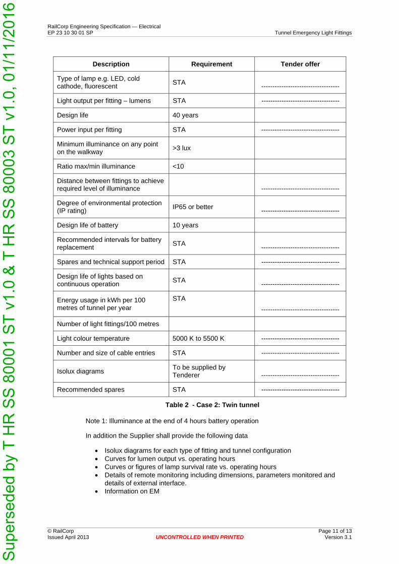
Description Requirement Tender offer
Type of lamp e.g. LED, cold cathode, fluorescent STA -----------------------------------
Light output per fitting – lumens STA -----------------------------------
Design life 40 years
Power input per fitting STA -----------------------------------
Minimum illuminance on any point on the walkway >3 lux
Ratio max/min illuminance <10
Distance between fittings to achieve required level of illuminance -----------------------------------
Degree of environmental protection (IP rating) IP65 or better -----------------------------------
Design life of battery 10 years
Recommended intervals for battery replacement STA -----------------------------------
Spares and technical support period STA -----------------------------------
Design life of lights based on continuous operation STA -----------------------------------
Energy usage in kWh per 100 metres of tunnel per year
STA -----------------------------------
Number of light fittings/100 metres
Light colour temperature 5000 K to 5500 K -----------------------------------
Number and size of cable entries STA -----------------------------------
Isolux diagrams To be supplied by Tenderer -----------------------------------
Recommended spares STA -----------------------------------
Table 2 - Case 2: Twin tunnel
Note 1: Illuminance at the end of 4 hours battery operation
In addition the Supplier shall provide the following data
• Isolux diagrams for each type of fitting and tunnel configuration • Curves for lumen output vs. operating hours • Curves or figures of lamp survival rate vs. operating hours • Details of remote monitoring including dimensions, parameters monitored and
details of external interface. • Information on EM

Sup
erse
ded
by T
HR
SS
800
01 S
T v1
.0 &
T H
R S
S 8
0003
ST
v1.0
, 01/
11/2
016
RailCorp Engineering Specification — Electrical EP 23 10 30 01 SP Tunnel Emergency Light Fittings
© RailCorp Page 12 of 13 Issued April 2013 UNCONTROLLED WHEN PRINTED Version 3.1
Appendix B RFT Checklist Application
The following material is for guidance in the preparation of a Request for Tender for this type of equipment. This checklist itself is not intended to directly form part of any contract.
This section is to be read in conjunction with the RFT Checklist in specification EP 00 00 00 15 SP, Common Requirement for Electrical Power Equipment.
Information to be Supplied to the Tenderer
• Requirements relating to delivery time for each item nominated in the request for tender.
• Formula and RailCorp determined factors for evaluation of whole of life cost.
Information to be Sought from the Tenderer
• Integrated Support information as per RailCorp Standard • Tenders to complete and submit Technical Schedule Appendix A
Information to be supplied at time of order
When needed for procurement of equipment for a particular location, in addition to the general requirements in this specification the following information related to the particular site shall be supplied as part of the order.
• Required number of fully equipped light fittings. • Required number of spare light fittings, lights and batteries. • Number and size of cable entry for each fitting type. • Number of supervisory control units.
Number of sets of documentation required

Sup
erse
ded
by T
HR
SS
800
01 S
T v1
.0 &
T H
R S
S 8
0003
ST
v1.0
, 01/
11/2
016
RailCorp Engineering Specification — Electrical EP 23 10 30 01 SP Tunnel Emergency Light Fittings
© RailCorp Page 13 of 13 Issued April 2013 UNCONTROLLED WHEN PRINTED Version 3.1
Appendix C Requirements for Technical Aspects of Tender Evaluation
Evaluation of tenders
Tender submissions will be evaluated based on a number of criteria. One constant criterion is compliance with this specification. The Chief Engineer Electrical requires that persons evaluating the technical aspects of this tender have sufficient technical competence for the task.
Tender evaluation committees shall forward details of persons evaluating the technical aspects of the tender to the Chief Engineer Electrical for concurrence. This will normally be in the form of an email and is to include sufficient detail of the tender and the person to enable the Chief Engineer Electrical to satisfy themself of the merits of the evaluating person. A minimum of 4 weeks notice is required prior to the evaluation of the Tenders.
The Chief Engineer Electrical will advise within 5 working days only if the person is considered technically unsuitable for the technical evaluation.
Acceptance of product
A number of the specifications require acceptance of product at both the factory and at site. The purchaser is to advise the Chief Engineer Electrical the details of the person carrying out the acceptance testing for the concurrence of the Chief Engineer Electrical. A minimum of 4 weeks notice is required prior to the evaluation of the acceptance testing.
The Chief Engineer Electrical will advise only if the person is considered unsuitable for the acceptance testing.
The Chief Engineer Electrical reserves the right to nominate a representative to review and/or attend such acceptance.
Record Keeping
Where product is purchased against this specification, the Chief Engineer Electrical requires that relevant detail be provided so that it can be logged against this specification.
For RailCorp purchases, all records are recorded in Ariba.
Where this specification is utilised by parties external to RailCorp (Alliance parties, etc) then copies of all relevant technical information and evaluation shall be forwarded to the Chief Engineer Electrical for filing against the specification. In addition copies of selected commercial information pertaining to the ongoing support of the product as follows is also required.
• Warranty details • Spare parts and associated availability • Product support information.