Embed Size (px)
Citation preview
EOI: (CNS-P)-02/2019-20 EOI for SITC of ATM DPDS & ITWS with integrated ASMGCS at
CSMIA Mumbai, HIAL & BIAL
Signature & Seal of Vendor
P a g e 1 | 605
EoI (Expression of Interest)
for Supply, Installation, Testing and Commissioning of ATM Data Processing
& Display System (DPDS) with Integrated Tower Working Position (ITWS) & integrated ASMGCS at CSMIA Mumbai, HIAL & BIAL
EoI No: (CNS-P)-02/2019-20
For Executive Director (CNS-P)-I AAI CHQ, RGB, New Delhi –110003
Date of upload: 09.08.2019
(Signature & Seal of Issuer)
भारतीय विमानपत्तन प्राविकरण
राजीि गााँिी भिन , सफदरजंग हिाई अड्डा,
नई वदल्ली
AIRPORTS AUTHORITY OF INDIA
RAJIV GANDHI BHAWAN, SAFDARJUNG AIRPORT,
NEW DELHI
EOI: (CNS-P)-02/2019-20 EOI for SITC of ATM DPDS & ITWS with integrated ASMGCS at
CSMIA Mumbai, HIAL & BIAL
Signature & Seal of Vendor
P a g e 2 | 605
Intentionally Left Blank
EOI: (CNS-P)-02/2019-20 EOI for SITC of ATM DPDS & ITWS with integrated ASMGCS at
CSMIA Mumbai, HIAL & BIAL
Signature & Seal of Vendor
P a g e 3 | 605
AIRPORTS AUTHORITY OF INDIA
Notice Inviting EoI (Global) EoI No: (CNS-P)-02/2019-20
EoI is invited by Executive Director (CNS-Planning) on behalf of Chairman, Airports Authority of India (AAI) for the work as detailed below: Name of Work : Supply, Installation, Testing and Commissioning of
ATM Data Processing & Display System (DPDS) with Integrated Tower Working Position (ITWS) & integrated ASMGCS at CSMIA Mumbai, HIAL & BIAL
Last date of submission of EOI is 06.09.2019 15:00 hrs
------------------------------------------------------------------- For other details please visit Website:
https://etenders.gov.in/eprocure/app https://www.aai.aero/en/tender/e-tender
Sd/- Executive Director (CNS-P)-I
EOI: (CNS-P)-02/2019-20 EOI for SITC of ATM DPDS & ITWS with integrated ASMGCS at
CSMIA Mumbai, HIAL & BIAL
Signature & Seal of Vendor
P a g e 4 | 605
Intentionally Left Blank
EOI: (CNS-P)-02/2019-20 EOI for SITC of ATM DPDS & ITWS with integrated ASMGCS at
CSMIA Mumbai, HIAL & BIAL
Signature & Seal of Vendor
P a g e 5 | 605
Table of Contents SECTION -A: General Information ....................................................................................................... 7
SECTION – B: Terms & Conditions .................................................................................................... 15
ANNEXURE- A: PROFORMA FOR UNDERTAKING ............................................................................ 24
ANNEXURE – B : Price Schedule ....................................................................................................... 25
Annexure – C: Consignee Details ....................................................................................................... 31
SECTION – C: Operational & Technical requirements ..................................................................... 32
EOI: (CNS-P)-02/2019-20 EOI for SITC of ATM DPDS & ITWS with integrated ASMGCS at
CSMIA Mumbai, HIAL & BIAL
Signature & Seal of Vendor
P a g e 6 | 605
Intentionally Left Blank
EOI: (CNS-P)-02/2019-20 EOI for SITC of ATM DPDS & ITWS with integrated ASMGCS at
CSMIA Mumbai, HIAL & BIAL
Signature & Seal of Vendor
P a g e 7 | 605
SECTION -A: General Information
1 Introduction: Airports Authority of India (AAI), a Miniratna Category-1 Public Sector Enterprise was constituted by an Act of Parliament and came into being on 1st April 1995. As Air Navigation Service Provider (ANSP) of India, the merger brought into existence a single Organization entrusted with the responsibility of creating, upgrading, maintaining and managing civil aviation infrastructure both on the ground and airspace in the country for ensuring safe and efficient aircraft operations. AAI manages 125 airports, which include 11 International Airport, 08 Customs Airports, 81 Domestic Airports and 25 Civil Enclaves at Defence airfields. AAI provides air navigation services over 2.8 million square nautical miles of air space. AAI is planning to procure new ATM Automation System with integrated ASMGCS for Mumbai, HIAl & BIAL. The contractor will be required to deliver multiple plans in accordance with the scope of work for implementation of the new systems and migrating from old without interruption of operations. AAI will invite global tender for Supply, Installation, Testing and Commissioning of ATM DPDS &
ITWS with integrated ASMGCS at CSMIA Mumbai, HIAL & BIAL based on the response of EOI.
2 Definitions:
2.1 For the purpose of this document, AAI defines the following key terms as follows
2.1.1 DPDS & ITWS – The Air Traffic Management Data Processing and Display System (DPDS) and Integrated Tower Work Position (ITWP) is an Integrated ATM Automation System that is able to process all data/information necessary to perform safely and effectively Air Traffic management functions, including airspace management, Air Traffic Flow management and Air Traffic Services at an appropriate level of Automation.
2.1.2 A Proposal is a response to this Expression of Interest (EoI) notice that has been submitted for evaluation of technical bids and estimating the cost of project.
2.1.3 A Vendor/Bidder is a corporation or entity or Manufacturer that has submitted a proposal for the Expression of Interest (EoI) for Supply, Installation, Testing and Commissioning of ATM DPDS & ITWS with integrated ASMGCS at CSMIA Mumbai, HIAL & BIAL.
2.1.4 The Airports Authority of India (AAI) is the procurement authority for the EoI.
2.1.5 The Central Public Procurement Portal (CPPP) specified throughout this document is the online system for Vendors to submit their Tender packages. More information useful for submitting online bids on the Central Public Procurement Portal (CPPP) may be obtained at: https://etenders.gov.in/eprocure/app and https://www.aai.aero/en/tender/e-tender
EOI: (CNS-P)-02/2019-20 EOI for SITC of ATM DPDS & ITWS with integrated ASMGCS at
CSMIA Mumbai, HIAL & BIAL
Signature & Seal of Vendor
P a g e 8 | 605
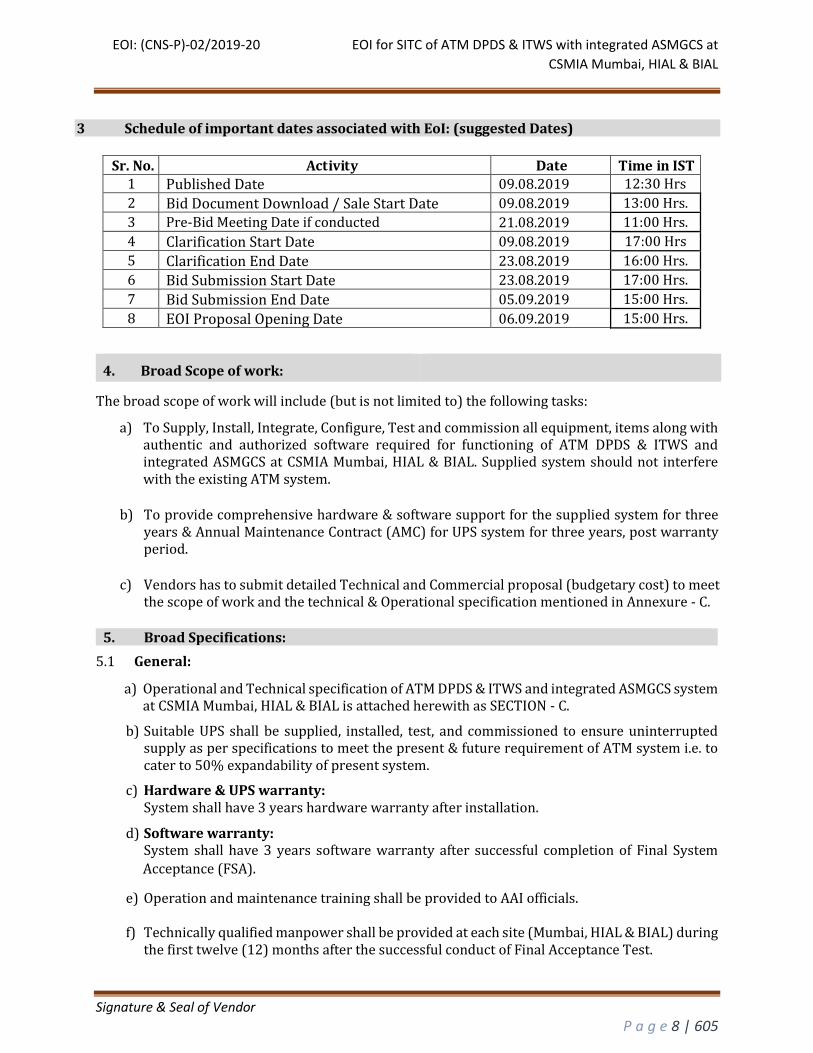
3 Schedule of important dates associated with EoI: (suggested Dates)
Sr. No. Activity Date Time in IST 1 Published Date 09.08.2019 12:30 Hrs
2 Bid Document Download / Sale Start Date 09.08.2019 13:00 Hrs.
3 Pre-Bid Meeting Date if conducted 21.08.2019 11:00 Hrs.
4 Clarification Start Date 09.08.2019 17:00 Hrs
5 Clarification End Date 23.08.2019 16:00 Hrs.
6 Bid Submission Start Date 23.08.2019 17:00 Hrs.
7 Bid Submission End Date 05.09.2019 15:00 Hrs.
8 EOI Proposal Opening Date 06.09.2019 15:00 Hrs.
4. Broad Scope of work:
The broad scope of work will include (but is not limited to) the following tasks:
a) To Supply, Install, Integrate, Configure, Test and commission all equipment, items along with authentic and authorized software required for functioning of ATM DPDS & ITWS and integrated ASMGCS at CSMIA Mumbai, HIAL & BIAL. Supplied system should not interfere with the existing ATM system.
b) To provide comprehensive hardware & software support for the supplied system for three years & Annual Maintenance Contract (AMC) for UPS system for three years, post warranty period.
c) Vendors has to submit detailed Technical and Commercial proposal (budgetary cost) to meet the scope of work and the technical & Operational specification mentioned in Annexure - C.
5. Broad Specifications:
5.1 General:
a) Operational and Technical specification of ATM DPDS & ITWS and integrated ASMGCS system at CSMIA Mumbai, HIAL & BIAL is attached herewith as SECTION - C.
b) Suitable UPS shall be supplied, installed, test, and commissioned to ensure uninterrupted supply as per specifications to meet the present & future requirement of ATM system i.e. to cater to 50% expandability of present system.
c) Hardware & UPS warranty: System shall have 3 years hardware warranty after installation.
d) Software warranty: System shall have 3 years software warranty after successful completion of Final System
Acceptance (FSA).
e) Operation and maintenance training shall be provided to AAI officials. f) Technically qualified manpower shall be provided at each site (Mumbai, HIAL & BIAL) during
the first twelve (12) months after the successful conduct of Final Acceptance Test.
EOI: (CNS-P)-02/2019-20 EOI for SITC of ATM DPDS & ITWS with integrated ASMGCS at
CSMIA Mumbai, HIAL & BIAL
Signature & Seal of Vendor
P a g e 9 | 605
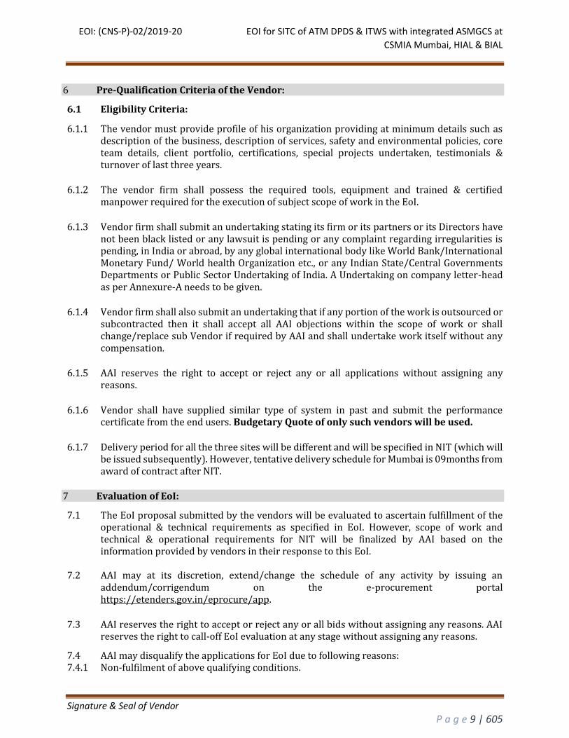
6 Pre-Qualification Criteria of the Vendor:
6.1 Eligibility Criteria:
6.1.1 The vendor must provide profile of his organization providing at minimum details such as description of the business, description of services, safety and environmental policies, core team details, client portfolio, certifications, special projects undertaken, testimonials & turnover of last three years.
6.1.2 The vendor firm shall possess the required tools, equipment and trained & certified manpower required for the execution of subject scope of work in the EoI.
6.1.3 Vendor firm shall submit an undertaking stating its firm or its partners or its Directors have not been black listed or any lawsuit is pending or any complaint regarding irregularities is pending, in India or abroad, by any global international body like World Bank/International Monetary Fund/ World health Organization etc., or any Indian State/Central Governments Departments or Public Sector Undertaking of India. A Undertaking on company letter-head as per Annexure-A needs to be given.
6.1.4 Vendor firm shall also submit an undertaking that if any portion of the work is outsourced or subcontracted then it shall accept all AAI objections within the scope of work or shall change/replace sub Vendor if required by AAI and shall undertake work itself without any compensation.
6.1.5 AAI reserves the right to accept or reject any or all applications without assigning any reasons.
6.1.6 Vendor shall have supplied similar type of system in past and submit the performance certificate from the end users. Budgetary Quote of only such vendors will be used.
6.1.7 Delivery period for all the three sites will be different and will be specified in NIT (which will be issued subsequently). However, tentative delivery schedule for Mumbai is 09months from award of contract after NIT.
7 Evaluation of EoI:
7.1 The EoI proposal submitted by the vendors will be evaluated to ascertain fulfillment of the operational & technical requirements as specified in EoI. However, scope of work and technical & operational requirements for NIT will be finalized by AAI based on the information provided by vendors in their response to this EoI.
7.2 AAI may at its discretion, extend/change the schedule of any activity by issuing an addendum/corrigendum on the e-procurement portal https://etenders.gov.in/eprocure/app.
7.3 AAI reserves the right to accept or reject any or all bids without assigning any reasons. AAI reserves the right to call-off EoI evaluation at any stage without assigning any reasons.
7.4 AAI may disqualify the applications for EoI due to following reasons: 7.4.1 Non-fulfilment of above qualifying conditions.
EOI: (CNS-P)-02/2019-20 EOI for SITC of ATM DPDS & ITWS with integrated ASMGCS at
CSMIA Mumbai, HIAL & BIAL
Signature & Seal of Vendor
P a g e 10 | 605
7.4.2 In-complete/part information/misinformation (without supporting documentary evidence, wherever applicable)
7.4.3 Exerting external pressure. 7.4.4 If EoI is received after the due date and time. 7.5 In order to provide reasonable time for vendors to account for any amendments in preparing
their EoI, AAI may, at its sole discretion, extend the deadline for the submission of EoI suitably. AAI will notify all registered vendors of any extension via the Central Public Procurement Portal (CPPP).
7.6 AAI reserves the right to accept or reject any or all applications without assigning any reasons.
8 REGISTRATION:
i. Vendors are required to enroll on the e-Procurement module of the Central Public Procurement Portal (URL: https://etenders.gov.in/eprocure/app) by clicking on the link “Online Vendor Enrolment” on the CPP Portal which is free of charge.
ii. As part of the enrolment process, the Vendors will be required to choose a unique username
and assign a password for their accounts.
iii. Vendors are advised to register their valid email address and mobile numbers as part of the
registration process. These would be used for any communication from the CPP Portal.
iv. Upon enrolment, the Vendors will be required to register their valid Digital Signature
Certificate (Class II or Class III Certificates with signing key usage) issued by any Certifying
Authority recognized by CCA India (e.g. Sify / nCode / eMudhra etc.), with their profile.
v. Only one valid DSC should be registered by a Vendor. Please note that the Vendors are
responsible to ensure that they do not lend their DSC’s to others which may lead to misuse.
vi. Vendor then logs in to the site through the secured log-in by entering their user ID / password
and the password of the DSC / e-Token.
9 SEARCHING FOR EOI DOCUMENTS:
i. There are various search options built in the CPP Portal, to facilitate Vendors to search active tenders by several parameters. These parameters could include Tender ID, Organization Name, Location, Date, Value, etc. There is also an option of advanced search for tenders, wherein the Vendors may combine a number of search parameters such as Organization Name, Form of Contract, Location, Date, Other keywords etc. to search for a tender published on the CPP Portal.
ii. Once the Vendors have selected the tenders they are interested in, they may download the required documents / tender schedules. These tenders can be moved to the respective ‘My Tenders’ folder. This would enable the CPP Portal to intimate the Vendors through SMS / e-mail in case there is any corrigendum issued to the tender document.
iii. The Vendor should make a note of the unique Tender ID assigned to each tender, in case they want to obtain any clarification / help from the Helpdesk.
10 PREPARATION OF BIDS:
i. Vendor should take into account any corrigendum published on the tender document before submitting their bids.
EOI: (CNS-P)-02/2019-20 EOI for SITC of ATM DPDS & ITWS with integrated ASMGCS at
CSMIA Mumbai, HIAL & BIAL
Signature & Seal of Vendor
P a g e 11 | 605
ii. Please go through the EOI/tender advertisement and the EOI/tender document carefully to understand the documents required to be submitted as part of the bid. Please note the number of covers in which the bid documents have to be submitted, the number of documents – including the names and content of each of the document that need to be submitted. Any deviations from these may lead to rejection of the bid.
iii. Vendor, in advance, should get ready the bid documents to be submitted as indicated in the EOI/tender document / schedule and generally, they can be in PDF / XLS / RAR / DWF/JPG formats. Bid documents may be scanned with 100 dpi with black and white option which helps in reducing size of the scanned document.
iv. To avoid the time and effort required in uploading the same set of standard documents which are required to be submitted as a part of every bid, a provision of uploading such standard documents (e.g. PAN card copy, annual reports, auditor certificates etc.) has been provided to the Vendors. Vendors can use “My Space” or “Other Important Documents” area available to them to upload such documents. These documents may be directly submitted from the “My Space” area while submitting a bid, and need not be uploaded again and again. This will lead to a reduction in the time required for bid submission process.
11 SUBMISSION OF BIDS:
i. Vendor should log into the site well in advance for bid submission so that they can upload the bid in time i.e. on or before the bid submission time. Vendor will be responsible for any delay due to other issues.
ii. The Vendor has to digitally sign and upload the required bid documents one by one as indicated in the tender document.
iii. The server time (which is displayed on the Vendors’ dashboard) will be considered as the standard time for referencing the deadlines for submission of the bids by the Vendors, opening of bids etc. The Vendors should follow this time during bid submission.
iv. All the documents being submitted by the Vendors would be encrypted using PKI encryption techniques to ensure the secrecy of the data. The data entered cannot be viewed by unauthorized persons until the time of bid opening. The confidentiality of the bids is maintained using the secured Socket Layer 128 bit encryption technology. Data storage encryption of sensitive fields is done.
v. Any bid document that is uploaded to the server is subjected to symmetric encryption using a system generated symmetric key. Further this key is subjected to asymmetric encryption using buyers/bid openers public keys. Overall, the uploaded tender documents become readable only after the tender opening by the authorized bid openers.
vi. The uploaded tender documents become readable only after the tender opening by the authorized bid openers.
vii. Upon the successful and timely submission of bids (i.e. after Clicking “Freeze Bid Submission” in the portal), the portal will give a successful bid submission message & a bid summary will be displayed with the bid no. and the date & time of submission of the bid with all other relevant details.
viii. The bid summary has to be printed and kept as an acknowledgement of the submission of the bid. This acknowledgement may be used as an entry pass for any bid opening meetings.
ix. The Following single cover(Bid Pack 1) shall be submitted through online CPP-portal by the Vendors, which contains;
a) Documents in support of EOI SECTION-A para 4.0, 5.0 & 6.0. b) Budgetary quote in compliance to EOI Annexure - C c) Technical information in compliance to Scope of work defined in SECTION-C of EOI.
EOI: (CNS-P)-02/2019-20 EOI for SITC of ATM DPDS & ITWS with integrated ASMGCS at
CSMIA Mumbai, HIAL & BIAL
Signature & Seal of Vendor
P a g e 12 | 605
12 ASSISTANCE TO VENDORS: i. Any queries relating to the tender document and the terms and conditions contained therein
should be addressed to the Tender Inviting Authority for a tender or the relevant contact person indicated in the tender.
ii. Any queries relating to the process of online bid submission or queries relating to CPP Portal in general may be directed to the 24x7 CPP Portal Helpdesk.
iii. For any technical related queries please call the Helpdesk. The 24 x 7 Help Desk
Number 0120-4200462, 0120-4001002, 0120-4001005, and 0120-6277787.
International Vendors are requested to prefix 91 as country code.
Note- Vendors are requested to kindly mention the URL of the Portal and Tender Id in the subject
while emailing any issue along with the Contact details. For any issues/ clarifications relating
the tender(s) published kindly contact the respective Tender Inviting Authority.
Tel: 0120-4200462, 0120-4001002, 0120-4001005, 0120-6277787
E-Mail: [email protected]
iv. For any Policy related matter / Clarifications Please contact Dept of Expenditure, Ministry of Finance. E-Mail: [email protected]
v. For any Issues / Clarifications relating to the publishing and submission of AAI tender(s) a. In order to facilitate the Vendors / Vendors as well as internal users from AAI, Help desk
services have been launched between 0800-2000 hours for the CPPP under GePNIC
http://etenders.gov.in. The help desk services shall be available on all working days (Except
Sunday and Gazetted Holiday) between 0800-2000 hours and shall assist users on issues
related to the use of Central Public Procurement Portal(CPPP).
b. Before submitting queries, Vendors are requested to follow the instructions given in
“Guidelines to Vendors” and get their computer system configured according to the
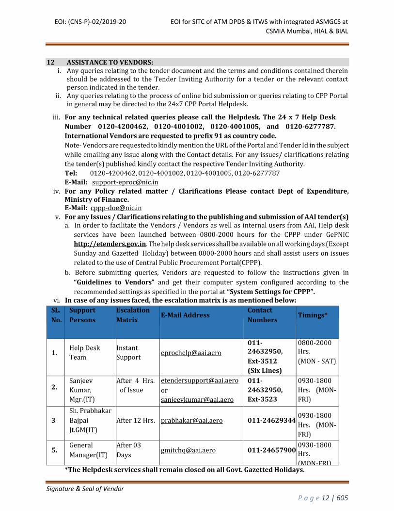
recommended settings as specified in the portal at “System Settings for CPPP”. vi. In case of any issues faced, the escalation matrix is as mentioned below:
SL.
No.
Support
Persons
Escalation
Matrix
E-Mail Address
Contact
Numbers
Timings*
1.
Help Desk
Team
Instant
Support
011-24632950,
Ext-3512
(Six Lines)
0800-2000 Hrs.
(MON - SAT)
2.
Sanjeev
Kumar,
Mgr.(IT)
After 4 Hrs.
of Issue
or
011-
24632950,
Ext-3523
0930-1800
Hrs. (MON-
FRI)
3
Sh. Prabhakar
Bajpai
Jt.GM(IT)
After 12 Hrs.
011-24629344
0930-1800
Hrs. (MON-
FRI) 5.
General
Manager(IT)
After 03
Days
011-24657900
0930-1800 Hrs.
(MON-FRI) *The Helpdesk services shall remain closed on all Govt. Gazetted Holidays.
EOI: (CNS-P)-02/2019-20 EOI for SITC of ATM DPDS & ITWS with integrated ASMGCS at
CSMIA Mumbai, HIAL & BIAL
Signature & Seal of Vendor
P a g e 13 | 605
vii. The above mentioned help desk numbers are intended only for queries related to the issues on
e-procurement portal and help needed on the operation of the portal. For queries related to
the tenders published on the portal, Vendors are advised to contact concerned Bid
Manager of AAI
13 CLARIFICATION
i. The Vendor may request clarification of any aspect of this EOI document by submitting their clarification requests to AAI on Central Public Procurement Portal: Name of Vendor:
Section No. Clause No. Page
No.
Existing Provision
in Clause
Clarification Sought
ii. The AAI shall respond to Clarification Requests (CRs) at the sole discretion of the AAI;
however, the AAI will notify the requesting Vendors in the event that AAI does not intend to respond to a given CR, and may choose to furnish or not furnish a reason for doing so.
iii. The AAI shall respond to CRs until the Closing Date specified in the schedule of this document, unless the date is extended by AAI.
iv. AAI shall respond to CRs by uploading them through the Central Public Procurement Portal. Vendors are advised to visit Central Public Procurement Portal regularly.
v. Clarifications and other documents, if and when issued by the AAI, shall be related to the EOI documents and hence shall be considered an extension of them, and thus part of any eventual contract.
vi. AAI makes no representation or guarantee as to the completeness or accuracy of any response. vii. In order to provide reasonable time for Vendors to account for any amendments in preparing
their EOI, AAI may, at its sole discretion, extend the deadline for the submission of EOI suitably. AAI will notify all registered Vendors of any extension via the Central Public Procurement Portal. NOTE: Vendors are advised to upload their EOI submission well in advance of the Closing date to avoid any last minute issues. Uploaded EOI may be modified at a later date and time, until the Closing date and time.
viii. EOI once uploaded and at the Closing date and time shall be final, and no amendment thereto shall be permitted after the submission date.
ix. Each Vendor shall submit only one EOI. x. Central Public Procurement Portal shall not allow Vendors to submit their EOI after the
scheduled Closing date and time. The AAI will not entertain any post-Closing date clarifications or confirmation of compliance.
xi. The AAI reserves the right to accept or reject any or all applications without assigning any reasons.
14 PRE-BID CONFERENCE:
i. AAI shall hold pre-bid conference (if necessary) with Vendors on 21nd Aug., 2019 11:00 hrs
at AAI premises, Rajiv Gandhi Bhawan, New Delhi.
EOI: (CNS-P)-02/2019-20 EOI for SITC of ATM DPDS & ITWS with integrated ASMGCS at
CSMIA Mumbai, HIAL & BIAL
Signature & Seal of Vendor
P a g e 14 | 605
ii. Vendors must ensure that the points on which clarifications are required by them have already
been submitted to AAI in advance through e-procurement portal
https://etenders.gov.in/eprocure/app as per the schedule mentioned in the tender.
iii. Vendor or his authorized representatives will be permitted to attend the pre-bid meeting. The
representatives attending the pre-bid conference must have proper authority letter to attend
pre-bid conference and must have authority to take decisions then and there, as no further
clarifications will be accepted thereafter and the terms and conditions including scope of work
decided as on the date of pre-bid conference will be frozen for all purposes.
iv. Vendors are advised to restrict number of representatives to not more than two during pre-
bid conference.
v. Vendors may be asked to make presentation about their offered product during pre-bid
meeting.
vi. AAI shall publish the clarifications & their responses made in the pre-bid conference as
corrigendum in the e-procurement portal subsequently.
vii. Please note that AAI expects the Vendors to comply with all tender specifications/ conditions
which have been frozen after Pre-bid Conference and hence non- conforming bids may be
cancelled.
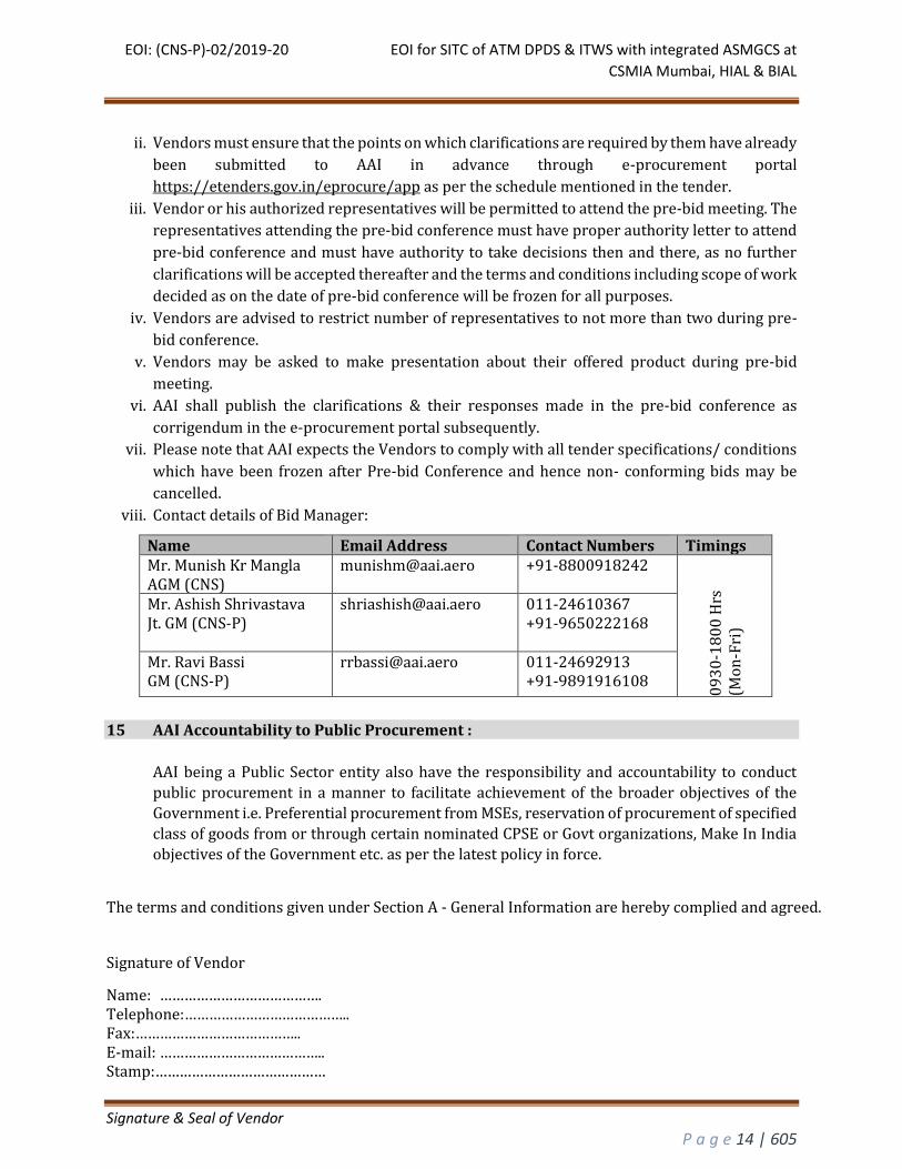
viii. Contact details of Bid Manager:
Name Email Address Contact Numbers Timings Mr. Munish Kr Mangla AGM (CNS)
[email protected] +91-8800918242
09
30
-18
00
Hrs
(M
on
-Fri
)
Mr. Ashish Shrivastava Jt. GM (CNS-P)
[email protected] 011-24610367 +91-9650222168
Mr. Ravi Bassi GM (CNS-P)
[email protected] 011-24692913 +91-9891916108
15 AAI Accountability to Public Procurement :
AAI being a Public Sector entity also have the responsibility and accountability to conduct
public procurement in a manner to facilitate achievement of the broader objectives of the
Government i.e. Preferential procurement from MSEs, reservation of procurement of specified
class of goods from or through certain nominated CPSE or Govt organizations, Make In India
objectives of the Government etc. as per the latest policy in force.
The terms and conditions given under Section A - General Information are hereby complied and agreed.
Signature of Vendor
Name: …………………………………. Telephone:………………………………….. Fax:………………………………….. E-mail: ………………………………….. Stamp:……………………………………
EOI: (CNS-P)-02/2019-20 EOI for SITC of ATM DPDS & ITWS with integrated ASMGCS at
CSMIA Mumbai, HIAL & BIAL
Signature & Seal of Vendor
P a g e 15 | 605
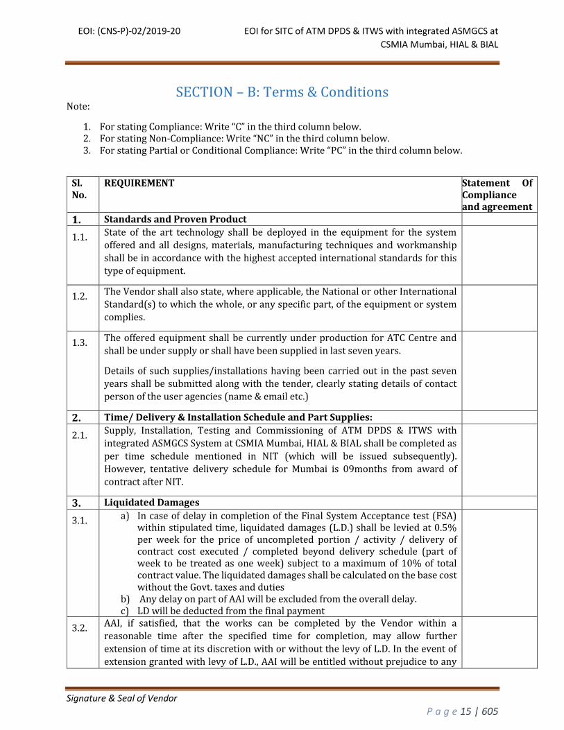
SECTION – B: Terms & Conditions Note:
1. For stating Compliance: Write “C” in the third column below. 2. For stating Non-Compliance: Write “NC” in the third column below. 3. For stating Partial or Conditional Compliance: Write “PC” in the third column below.
Sl. No.
REQUIREMENT Statement Of Compliance and agreement
1. Standards and Proven Product
1.1. State of the art technology shall be deployed in the equipment for the system
offered and all designs, materials, manufacturing techniques and workmanship
shall be in accordance with the highest accepted international standards for this
type of equipment.
1.2. The Vendor shall also state, where applicable, the National or other International
Standard(s) to which the whole, or any specific part, of the equipment or system
complies.
1.3. The offered equipment shall be currently under production for ATC Centre and
shall be under supply or shall have been supplied in last seven years.
Details of such supplies/installations having been carried out in the past seven
years shall be submitted along with the tender, clearly stating details of contact
person of the user agencies (name & email etc.)
2. Time/ Delivery & Installation Schedule and Part Supplies:
2.1. Supply, Installation, Testing and Commissioning of ATM DPDS & ITWS with
integrated ASMGCS System at CSMIA Mumbai, HIAL & BIAL shall be completed as
per time schedule mentioned in NIT (which will be issued subsequently).
However, tentative delivery schedule for Mumbai is 09months from award of
contract after NIT.
3. Liquidated Damages
3.1. a) In case of delay in completion of the Final System Acceptance test (FSA) within stipulated time, liquidated damages (L.D.) shall be levied at 0.5% per week for the price of uncompleted portion / activity / delivery of contract cost executed / completed beyond delivery schedule (part of week to be treated as one week) subject to a maximum of 10% of total contract value. The liquidated damages shall be calculated on the base cost without the Govt. taxes and duties
b) Any delay on part of AAI will be excluded from the overall delay. c) LD will be deducted from the final payment
3.2. AAI, if satisfied, that the works can be completed by the Vendor within a
reasonable time after the specified time for completion, may allow further
extension of time at its discretion with or without the levy of L.D. In the event of
extension granted with levy of L.D., AAI will be entitled without prejudice to any
EOI: (CNS-P)-02/2019-20 EOI for SITC of ATM DPDS & ITWS with integrated ASMGCS at
CSMIA Mumbai, HIAL & BIAL
Signature & Seal of Vendor
P a g e 16 | 605
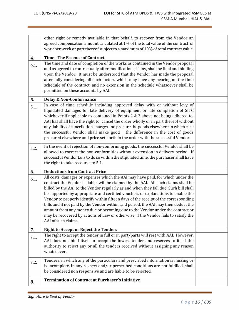
other right or remedy available in that behalf, to recover from the Vendor an
agreed compensation amount calculated at 1% of the total value of the contract of
work per week or part thereof subject to a maximum of 10% of total contract value.
4. Time: The Essence of Contract.
4.1. The time and date of completion of the works as contained in the Vendor proposal
and as agreed to contractually after modifications, if any, shall be final and binding
upon the Vendor. It must be understood that the Vendor has made the proposal
after fully considering all such factors which may have any bearing on the time
schedule of the contract, and no extension in the schedule whatsoever shall be
permitted on these accounts by AAI.
5. Delay & Non-Conformance
5.1. In case of time schedule including approved delay with or without levy of
liquidated damages for late delivery of equipment or late completion of SITC
whichever if applicable as contained in Points 2 & 3 above not being adhered to,
AAI has shall have the right to cancel the order wholly or in part thereof without
any liability of cancellation charges and procure the goods elsewhere in which case
the successful Vendor shall make good the difference in the cost of goods
procured elsewhere and price set forth in the order with the successful Vendor.
5.2. In the event of rejection of non-conforming goods, the successful Vendor shall be
allowed to correct the non-conformities without extension in delivery period. If
successful Vendor fails to do so within the stipulated time, the purchaser shall have
the right to take recourse to 5.1.
6. Deductions from Contract Price
6.1. All costs, damages or expenses which the AAI may have paid, for which under the
contract the Vendor is liable, will be claimed by the AAI. All such claims shall be
billed by the AAI to the Vendor regularly as and when they fall due. Such bill shall
be supported by appropriate and certified vouchers or explanations to enable the
Vendor to properly identify within fifteen days of the receipt of the corresponding
bills and if not paid by the Vendor within said period, the AAI may then deduct the
amount from any money due or becoming due to the Vendor under the contract or
may be recovered by actions of Law or otherwise, if the Vendor fails to satisfy the
AAI of such claims.
7. Right to Accept or Reject the Tenders
7.1. The right to accept the tender in full or in part/parts will rest with AAI. However,
AAI does not bind itself to accept the lowest tender and reserves to itself the
authority to reject any or all the tenders received without assigning any reason
whatsoever.
7.2. Tenders, in which any of the particulars and prescribed information is missing or
is incomplete, in any respect and/or prescribed conditions are not fulfilled, shall be considered non responsive and are liable to be rejected.
8. Termination of Contract at Purchaser’s Initiative
EOI: (CNS-P)-02/2019-20 EOI for SITC of ATM DPDS & ITWS with integrated ASMGCS at
CSMIA Mumbai, HIAL & BIAL
Signature & Seal of Vendor
P a g e 17 | 605
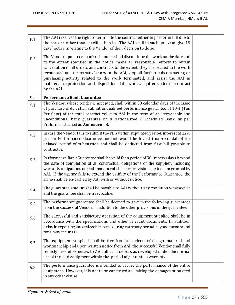
8.1. The AAI reserves the right to terminate the contract either in part or in full due to
the reasons other than specified herein. The AAI shall in such an event give 15
days’ notice in writing to the Vendor of their decision to do so.
8.2. The Vendor upon receipt of such notice shall discontinue the work on the date and
to the extent specified in the notice, make all reasonable efforts to obtain
cancellation of all orders and contracts to the extent they are related to the work
terminated and terms satisfactory to the AAI, stop all further subcontracting or
purchasing activity related to the work terminated, and assist the AAI in
maintenance protection, and disposition of the works acquired under the contract
by the AAI.
9. Performance Bank Guarantee
9.1. The Vendor, whose tender is accepted, shall within 30 calendar days of the issue
of purchase order, shall submit unqualified performance guarantee of 10% (Ten
Per Cent) of the total contract value to AAI in the form of an irrevocable and
unconditional bank guarantee on a Nationalized / Scheduled Bank, as per
Proforma attached as Annexure - B.
9.2. In case the Vendor fails to submit the PBG within stipulated period, interest at 12%
p.a. on Performance Guarantee amount would be levied (non-refundable) for
delayed period of submission and shall be deducted from first bill payable to
contractor.
9.3. Performance Bank Guarantee shall be valid for a period of 90 (ninety) days beyond
the date of completion of all contractual obligations of the supplier, including
warranty obligations or shall remain valid as per provisional extension granted by
AAI. If the agency fails to extend the validity of the Performance Guarantee, the same shall be en-cashed by AAI with or without notice.
9.4. The guarantee amount shall be payable to AAI without any condition whatsoever
and the guarantee shall be irrevocable.
9.5. The performance guarantee shall be deemed to govern the following guarantees
from the successful Vendor, in addition to the other provisions of the guarantee.
9.6. The successful and satisfactory operation of the equipment supplied shall be in
accordance with the specifications and other relevant documents. In addition,
delay in repairing unserviceable items during warranty period beyond turnaround
time may incur LD.
9.7. The equipment supplied shall be free from all defects of design, material and
workmanship and upon written notice from AAI, the successful Vendor shall fully
remedy, free of expenses to AAI, all such defects as developed under the normal
use of the said equipment within the period of guarantee/warranty.
9.8. The performance guarantee is intended to secure the performance of the entire
equipment. However, it is not to be construed as limiting the damages stipulated
in any other clause.

EOI: (CNS-P)-02/2019-20 EOI for SITC of ATM DPDS & ITWS with integrated ASMGCS at
CSMIA Mumbai, HIAL & BIAL
Signature & Seal of Vendor
P a g e 18 | 605
9.9. The Performance Security will be forfeited and credited to the accounts of AAI in
the event of a breach of contract by the contractor.
9.10. The performance guarantee will be returned/refunded to the successful Vendor without interest, after he duly performs and completes the contract in all respects but not later than 90(ninety) days of completion of all such obligations including the warranty under the contract.
10. Force Majeure
10.1. AAI may grant an extension of time limit set for the completion of the work in case
the timely completion of the work is delayed by force majeure beyond the Vendor
control, subject to what is stated in the following sub paragraphs and to the
procedures detailed there. Force majeure is defined as an event of effect that
cannot reasonably be anticipated such as acts of God (like earthquakes, floods,
storms, etc.), acts of states, the direct and indirect consequences of wars (declared
or un declared), hostilities, national emergencies, civil commotions and strikes
(only those which exceed a duration of ten continuous days) at successful Vendor
factory. The successful Vendor right to an extension of the time limit for
completion of the work in above mentioned cases is subject to the following
procedures:
10.1.1. 10.2
That within 10 days after the occurrence of a case of force majeure but before the
expiry of the stipulated date of completion, the Vendor informs the AAI in writing
that the Vendor considers himself entitled to an extension of the time limit.
10.1.2. 10.3
That the Successful Vendor produces evidence of the date of occurrence and the
duration of the force majeure in an adequate manner by means of documents
drawn up by responsible authorities.
10.4 That the Successful Vendor proves that the said conditions have actually been
interfered with the carrying out of the Contract.
10.5 That the Successful Vendor proves that the delay occurred is not due to his own
action or lack of action.
10.6
Apart from the extension of the time limit, force majeure does not entitle the
successful Vendor for any relaxation or to any compensation of damage or loss
suffered.
11. Arbitration and Laws
11.1. Except where otherwise provided for in the contract, all questions and disputes
relating to the meeting of the specifications, designs, drawings, and instructions
herein before mentioned and as to the quality of workmanship or materials used
on the work or as to any other question, claim, right, matter or thing whatsoever
in any way arising out of or relating to the contract, designs, drawings,
specifications, estimates, instructions, orders or these conditions or otherwise
concerning the works, or the execution or failure to execute the same whether
arising during the progress of the work or after the completion or abandonment
EOI: (CNS-P)-02/2019-20 EOI for SITC of ATM DPDS & ITWS with integrated ASMGCS at
CSMIA Mumbai, HIAL & BIAL
Signature & Seal of Vendor
P a g e 19 | 605
thereof shall be settled within thirty (30) days (or such longer period as may be
mutually agreed upon) from the date that either party notifies in writing that such
dispute or disagreement exists. Provided that any dispute that remains unresolved
shall be settled under the Rules of Indian Arbitration and Conciliation Act, 1996,
The venue of Arbitration shall be New Delhi, India. The arbitration award shall be
final and binding upon the parties and judgment may be entered thereon, upon the
application of either party, by any court having jurisdiction.
11.2. Indian laws shall govern this contract.
12. Payment Term
12.1. Payment of supply will be made in 2 parts through Letter of credit to Overseas
and ;
1) 70% of supply cost, including 100% F&I, Custom duty will be paid towards
imported items on delivery at site
2) 30% of supply items will be paid along with 100 % Service charges after
acceptance of system.
13. Guarantee/Warranty:- Hardware supplied shall have three years of warranty after Installation of Hardware and software shall also have 3 years warranty after final system acceptance.
13.1. All goods or material shall be supplied strictly in accordance with the
specifications. No deviation from such specifications of these conditions shall be
made without AAI's agreement in writing must be obtained before any work
against the order is commenced. All materials furnished by the successful Vendor
pursuant to the Order (irrespective of whether engineering/design or other
information has been furnished, reviewed or approved by AAI) are required to be
guaranteed to be of the best quality of their respective kinds (unless otherwise
specifically authorized in writing by AAI) and shall be free from faulty design to
the extent such design is not furnished by AAI. The goods/material used by the
successful Vendor and its workmanship should be of proper quality so as to fulfil
in all respects, the operating conditions and other requirements specified in the
order.
13.2. If any trouble or defect originating from the design, materials, workmanship or
operating characteristic of any materials arise at during warranty period the
Vendor is notified thereof, the Vendor at his own expense (including freight, duty
and customs for items sent for repair) and at no cost to AAI, as promptly as possible
make such alterations, repairs and replacements at the site as may be necessary to
permit facilitate the functioning of the equipment in accordance with the
specifications. The warranty period of repaired or replaced goods shall be extended
for a period equal to the turnaround time (out of service period).
13.3. In the event that the materials supplied do not meet the specifications and/or are
not in accordance with the drawings, data sheets and rectification as required at
site, AAI shall inform the Vendor giving full details of deficiencies. The Vendor
shall, at his own expense, meet and agree with the representatives of AAI the action
EOI: (CNS-P)-02/2019-20 EOI for SITC of ATM DPDS & ITWS with integrated ASMGCS at
CSMIA Mumbai, HIAL & BIAL
Signature & Seal of Vendor
P a g e 20 | 605
required to correct the deficiencies and shall attend to the deficiencies at his own
expense. Replacement under warranty clause shall be made by the Vendor free of
all charges at site including freight, insurance and other incidental charges.
13.4. Successful Vendor shall repair the unserviceable items failed during the warranty
period within turnaround time of 90 days (for foreign Vendors) and 30 days (for
Indian Vendors). Turnaround period is defined as the time period between the
unserviceable item received by the Vendor in factory and time when serviceable
item is dispatched from the factory. Any delay in repairing the unserviceable card
shall attract LD which shall be deducted from the performance Bank Guarantee.
13.5. During the warranty period Vendor shall provide remote Technical and
Operational support on 24 hours basis through telephone and email.
13.6. AAI reserves the right to encash complete value of performance Bank guarantee if
the performance of equipment/system is not satisfactorily without assigning any
reason.
14. Factory Inspection and Factory Acceptance Test (FAT)
14.1. Factory inspection of complete equipment shall be made by Inspectors nominated
by AAI. Their travel, boarding and lodging expenses will be borne by AAI.
14.2. The Vendor shall give written notice of readiness of any material for the purpose
of FAT.
14.3. The completion of these tests or issue of certificate by the inspector shall not bind
AAI to accept the equipment should the equipment, after installation, be found not
complying with the specifications stipulated in the contract.
14.4. AAI will communicate in writing to the Vendor, in case it does not depute the
inspector(s) for Factory Acceptance Tests and in such case the inspection
certificate, issued by the Quality Control Department of the manufacturer will be
considered for acceptance of equipment by AAI.
14.5. The certificate issued by the Quality Control Department, complete with all test
results as contained in the FAT Document, shall be sent to ED (CNS-Planning)
immediately after receiving the advice from AAI that no inspector is being deputed
for FAT. Acceptance of this certificate and advice for dispatch of equipment shall
be issued by AAI within 10 days of the receipt of the certificate. If no advice is
received from AAI within 10 days of receipt of certificate by them, the certificate
may be deemed accepted and equipment may be dispatched.
14.6. In case AAI decides to waive off Factory Acceptance Test at overseas then the cost
component of conducting FAT shall be reduced from the overall price.
15. Operational Maintenance During Warranty Period
15.1 The Vendor shall make available at least one qualified technical staff, experienced
& fully trained in operation, maintenance & administration of the complete system,
along with the required supporting staff, necessary spares, test equipment, tools
etc., at the site every day during the first twelve (12) months after the successful
EOI: (CNS-P)-02/2019-20 EOI for SITC of ATM DPDS & ITWS with integrated ASMGCS at
CSMIA Mumbai, HIAL & BIAL
Signature & Seal of Vendor
P a g e 21 | 605
conduct of Final Acceptance Test to assist in solving critical and catastrophic
failures, to support the resolution of new problems and to support closure of
failures from the main procurement that were deferred to Warranty, and to
provide further training as requested by AAI and as they are available at Mumbai,
HIAL & BIAL.
15.2 The Vendor shall replace any Hardware parts, including the supplied software
found defective during warranty period without any charges whatsoever to AAI.
15.3 During warranty period, the Vendor shall provide free replacement of any
defective spares of the equipment supplied against this work.
16. Site Acceptance Test (SAT)
16.1. It will be the responsibility of the vendor to submit the system test procedure for
conducting the post installation site acceptance testing. The procedure submitted
by the vendor should be drafted in line with the standard practices followed in the
industry and should be in accordance with the test procedures & practices specified
by the original equipment manufacturer (OEM). The acceptance test procedure on
approval by AAI shall become the document for acceptance of the equipment after
installation at the site. The draft copy of system test procedure should be made
available to AAI for approval before 30 days of the schedule site acceptance date.
16.2. Final System Acceptance (FSA) will be conducted, following successful completion of SAT and after AAI and the Bidder have agreed that
1. All deliverables have been submitted and approved, 2. Warranty Plan has been delivered and approved, 3. All Critical Problem Reports have been closed, resolved, or have been
agreed by the AAI and the Bidder. Bidder shall try to close Medium and Low priority issues also before FSA but some of the issues may be deferred to the Warranty period, based on criteria set forth in the Test Plan with mutual agreement between AAI and supplier.
16.3. The system will be commissioned after successful completion of approved SAT,
operational & maintenance training and all the works under the scope of the tender.
17. Packing and Marking
17.1. All packing should be strong enough to withstand rough handling during loading,
un-loading and transporting of the packages. Fragile articles should be packed
with special precaution and should bear markings such as ‘Fragile’, ‘Handle with
care’ ,and 'This Side Up' etc.
17.2. All delicate surfaces of equipment/goods should be carefully protected and
painted with protective paint/compound and wrapped to prevent rusting and
damage.
17.3. Attachments and spare parts of equipment and all small pieces shall be packed in
wooden crates with adequate protection inside the crates and wherever possible
should be sent along with the major equipment. Each item shall be provided an
identification so as to identify it with the main equipment and part number and
reference number shall be indicated.
EOI: (CNS-P)-02/2019-20 EOI for SITC of ATM DPDS & ITWS with integrated ASMGCS at
CSMIA Mumbai, HIAL & BIAL
Signature & Seal of Vendor
P a g e 22 | 605
17.4. All protrusions and threaded fittings shall be suitably protected and openings shall
be blocked by covers. All wires shall be labelled clearly with the system and
interface type that the wires connect to at each end. Vendor shall submit their
labelling strategy – colors, fonts, details – at the Design review or before, and they
are subject to the approval of AAI.
17.5. Wherever required equipment material shall be packed in polyethylene bags and
silica gel or similar dehydrating compound shall be put inside the bags to protect
the equipment. Pipes/tubes made of stainless steel, copper etc. shall be packed in
wooden crates irrespective of their sizes. The Vendor shall be held liable for all
damages or breakage of the goods attributable to defective or insufficient packing
as well as for corrosion due to insufficient protection.
17.6. On three sides and top of package, markings as desired by AAI, shall be provided
with indelible paint.
18. Patents, Successful Vendor Liability & Compliance Of Regulations
18.1. Successful Vendor shall protect and fully indemnify AAI from any claims for
infringement of patents, copy right, trade mark or the like.
18.2. Successful Vendor shall also protect and fully indemnify AAI from any claims from
successful Vendor workmen/employees, their heirs, dependents, representatives
etc. or from any other person(s) or bodies/companies etc. for any act of
commission or omission while executing the order.
18.3. Successful Vendor shall be responsible for compliance with all requirements under
the laws and shall protect and indemnify AAI completely from any
claims/penalties arising out of any infringements.
19. Substitution & Wrong Supplies
19.1. Unauthorized substitution or materials delivered not complying with the
description or quality or supplied in excess quantity or rejected goods shall be
taken back by the Successful Vendor at his cost and risk.
19.2. Vendor shall not substitute any item at the time of delivery against the item
mentioned in purchase order unless the item is no longer available in the market
due to obsolesce or any other reason and OEM issues the certificate to this effect.
AAI shall accept the higher version of item of same make and better Technical
specifications if it is approved by Executive Director (CNS-P).
20. Freight and Insurance
20.1. The Indian supplies shall be quoted inclusive of freight and Insurance charges from
Ex-works to Consignee Airport.
20.2. The Foreign Vendor must indicate the freight and insurance charges for shipment of consignment by Air from the port of dispatch to the Mumbai, Hyderabad &
Bangalore ATS Unit. The charges for Overseas freight and insurance will be paid
by AAI as per the quoted value by the Vendor.
21. TAXES, PERMITS AND LICENCES
EOI: (CNS-P)-02/2019-20 EOI for SITC of ATM DPDS & ITWS with integrated ASMGCS at
CSMIA Mumbai, HIAL & BIAL
Signature & Seal of Vendor
P a g e 23 | 605
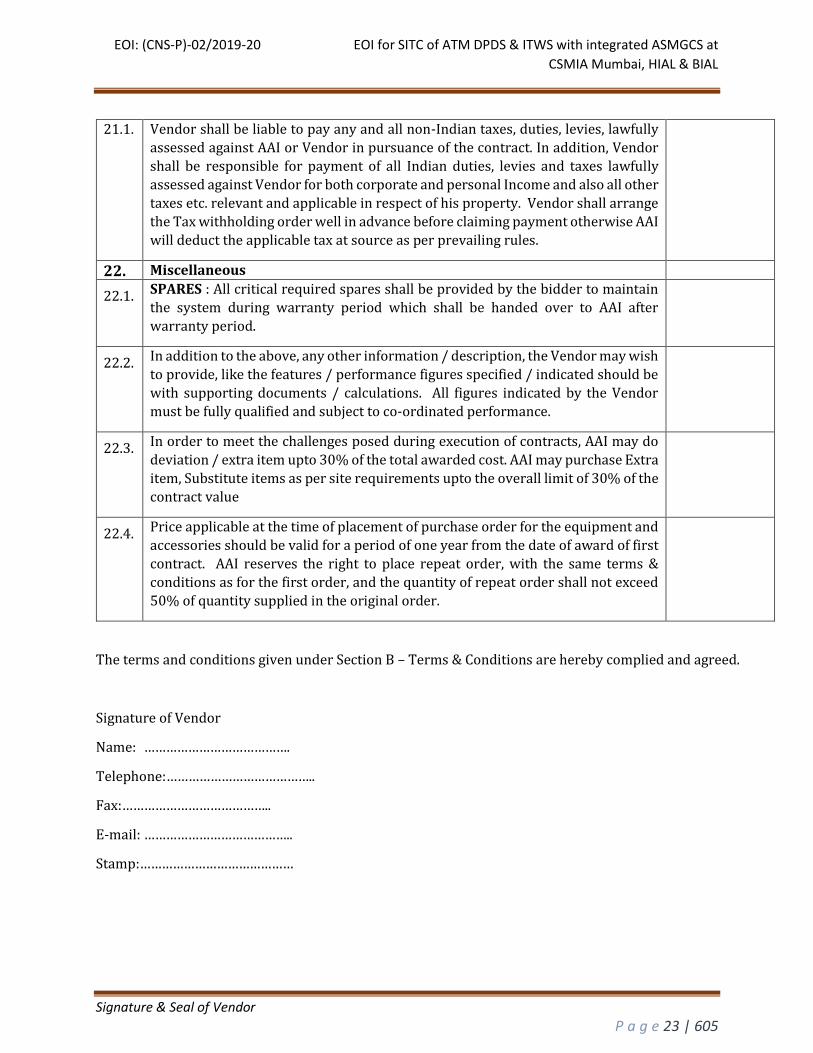
21.1. Vendor shall be liable to pay any and all non-Indian taxes, duties, levies, lawfully
assessed against AAI or Vendor in pursuance of the contract. In addition, Vendor
shall be responsible for payment of all Indian duties, levies and taxes lawfully
assessed against Vendor for both corporate and personal Income and also all other
taxes etc. relevant and applicable in respect of his property. Vendor shall arrange
the Tax withholding order well in advance before claiming payment otherwise AAI
will deduct the applicable tax at source as per prevailing rules.
22. Miscellaneous
22.1. SPARES : All critical required spares shall be provided by the bidder to maintain
the system during warranty period which shall be handed over to AAI after
warranty period.
22.2. In addition to the above, any other information / description, the Vendor may wish
to provide, like the features / performance figures specified / indicated should be
with supporting documents / calculations. All figures indicated by the Vendor
must be fully qualified and subject to co-ordinated performance.
22.3. In order to meet the challenges posed during execution of contracts, AAI may do
deviation / extra item upto 30% of the total awarded cost. AAI may purchase Extra
item, Substitute items as per site requirements upto the overall limit of 30% of the
contract value
22.4. Price applicable at the time of placement of purchase order for the equipment and
accessories should be valid for a period of one year from the date of award of first
contract. AAI reserves the right to place repeat order, with the same terms &
conditions as for the first order, and the quantity of repeat order shall not exceed
50% of quantity supplied in the original order.
The terms and conditions given under Section B – Terms & Conditions are hereby complied and agreed.
Signature of Vendor
Name: ………………………………….
Telephone:…………………………………..
Fax:…………………………………..
E-mail: …………………………………..
Stamp:……………………………………
EOI: (CNS-P)-02/2019-20 EOI for SITC of ATM DPDS & ITWS with integrated ASMGCS at
CSMIA Mumbai, HIAL & BIAL
Signature & Seal of Vendor
P a g e 24 | 605
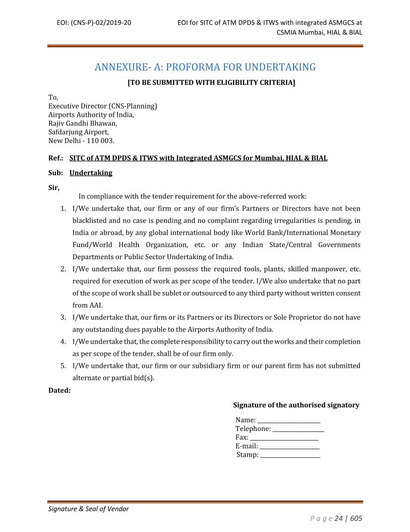
ANNEXURE- A: PROFORMA FOR UNDERTAKING
[TO BE SUBMITTED WITH ELIGIBILITY CRITERIA]
To, Executive Director (CNS-Planning) Airports Authority of India, Rajiv Gandhi Bhawan, Safdarjung Airport, New Delhi - 110 003. Ref.: SITC of ATM DPDS & ITWS with Integrated ASMGCS for Mumbai, HIAL & BIAL
Sub: Undertaking
Sir, In compliance with the tender requirement for the above-referred work:
1. I/We undertake that, our firm or any of our firm’s Partners or Directors have not been
blacklisted and no case is pending and no complaint regarding irregularities is pending, in
India or abroad, by any global international body like World Bank/International Monetary
Fund/World Health Organization, etc. or any Indian State/Central Governments
Departments or Public Sector Undertaking of India.
2. I/We undertake that, our firm possess the required tools, plants, skilled manpower, etc.
required for execution of work as per scope of the tender. I/We also undertake that no part
of the scope of work shall be sublet or outsourced to any third party without written consent
from AAI.
3. I/We undertake that, our firm or its Partners or its Directors or Sole Proprietor do not have
any outstanding dues payable to the Airports Authority of India.
4. I/We undertake that, the complete responsibility to carry out the works and their completion
as per scope of the tender, shall be of our firm only.
5. I/We undertake that, our firm or our subsidiary firm or our parent firm has not submitted
alternate or partial bid(s).
Dated:
Signature of the authorised signatory
Name: _______________________ Telephone: ___________________ Fax: _________________________ E-mail: ______________________ Stamp: ______________________
EOI: (CNS-P)-02/2019-20 EOI for SITC of ATM DPDS & ITWS with integrated ASMGCS at
CSMIA Mumbai, HIAL & BIAL
Signature & Seal of Vendor
P a g e 25 | 605
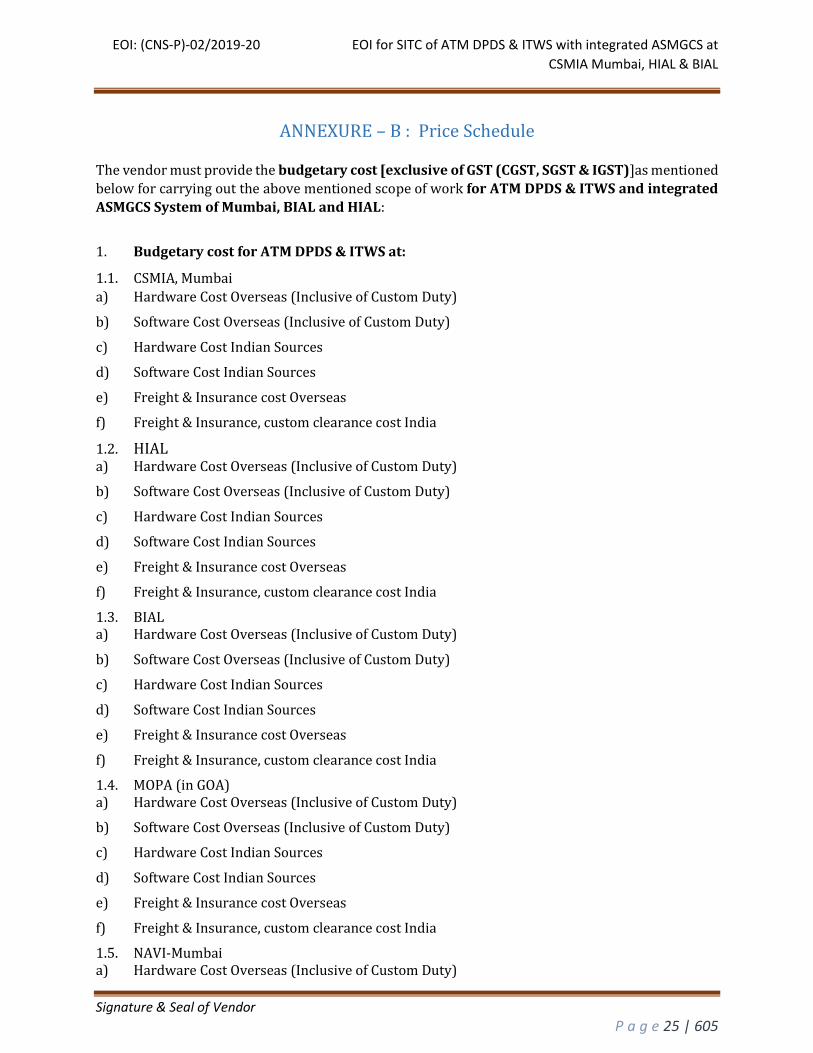
ANNEXURE – B : Price Schedule
The vendor must provide the budgetary cost [exclusive of GST (CGST, SGST & IGST)]as mentioned
below for carrying out the above mentioned scope of work for ATM DPDS & ITWS and integrated
ASMGCS System of Mumbai, BIAL and HIAL:
1. Budgetary cost for ATM DPDS & ITWS at:
1.1. CSMIA, Mumbai
a) Hardware Cost Overseas (Inclusive of Custom Duty)
b) Software Cost Overseas (Inclusive of Custom Duty)
c) Hardware Cost Indian Sources
d) Software Cost Indian Sources
e) Freight & Insurance cost Overseas
f) Freight & Insurance, custom clearance cost India
1.2. HIAL a) Hardware Cost Overseas (Inclusive of Custom Duty)
b) Software Cost Overseas (Inclusive of Custom Duty)
c) Hardware Cost Indian Sources
d) Software Cost Indian Sources
e) Freight & Insurance cost Overseas
f) Freight & Insurance, custom clearance cost India
1.3. BIAL a) Hardware Cost Overseas (Inclusive of Custom Duty)
b) Software Cost Overseas (Inclusive of Custom Duty)
c) Hardware Cost Indian Sources
d) Software Cost Indian Sources
e) Freight & Insurance cost Overseas
f) Freight & Insurance, custom clearance cost India
1.4. MOPA (in GOA) a) Hardware Cost Overseas (Inclusive of Custom Duty)
b) Software Cost Overseas (Inclusive of Custom Duty)
c) Hardware Cost Indian Sources
d) Software Cost Indian Sources
e) Freight & Insurance cost Overseas
f) Freight & Insurance, custom clearance cost India
1.5. NAVI-Mumbai a) Hardware Cost Overseas (Inclusive of Custom Duty)
EOI: (CNS-P)-02/2019-20 EOI for SITC of ATM DPDS & ITWS with integrated ASMGCS at
CSMIA Mumbai, HIAL & BIAL
Signature & Seal of Vendor
P a g e 26 | 605
b) Software Cost Overseas (Inclusive of Custom Duty)
c) Hardware Cost Indian Sources
d) Software Cost Indian Sources
e) Freight & Insurance cost Overseas
f) Freight & Insurance, custom clearance cost India
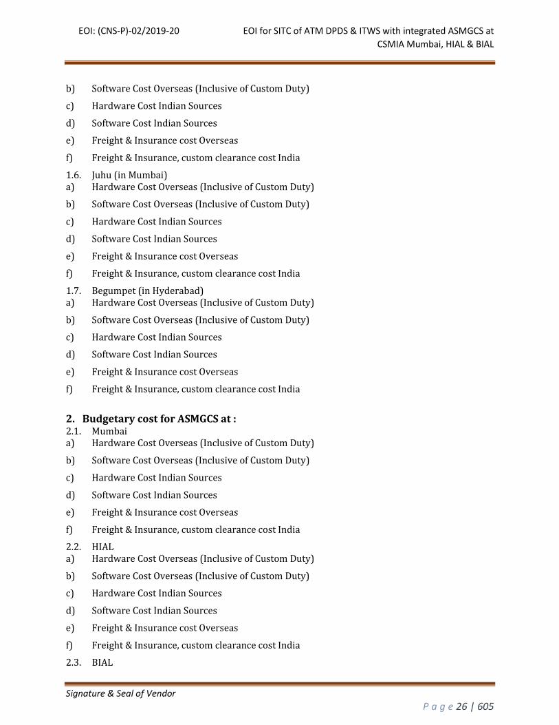
1.6. Juhu (in Mumbai) a) Hardware Cost Overseas (Inclusive of Custom Duty)
b) Software Cost Overseas (Inclusive of Custom Duty)
c) Hardware Cost Indian Sources
d) Software Cost Indian Sources
e) Freight & Insurance cost Overseas
f) Freight & Insurance, custom clearance cost India
1.7. Begumpet (in Hyderabad) a) Hardware Cost Overseas (Inclusive of Custom Duty)
b) Software Cost Overseas (Inclusive of Custom Duty)
c) Hardware Cost Indian Sources
d) Software Cost Indian Sources
e) Freight & Insurance cost Overseas
f) Freight & Insurance, custom clearance cost India
2. Budgetary cost for ASMGCS at : 2.1. Mumbai a) Hardware Cost Overseas (Inclusive of Custom Duty)
b) Software Cost Overseas (Inclusive of Custom Duty)
c) Hardware Cost Indian Sources
d) Software Cost Indian Sources
e) Freight & Insurance cost Overseas
f) Freight & Insurance, custom clearance cost India
2.2. HIAL a) Hardware Cost Overseas (Inclusive of Custom Duty)
b) Software Cost Overseas (Inclusive of Custom Duty)
c) Hardware Cost Indian Sources
d) Software Cost Indian Sources
e) Freight & Insurance cost Overseas
f) Freight & Insurance, custom clearance cost India
2.3. BIAL
EOI: (CNS-P)-02/2019-20 EOI for SITC of ATM DPDS & ITWS with integrated ASMGCS at
CSMIA Mumbai, HIAL & BIAL
Signature & Seal of Vendor
P a g e 27 | 605
a) Hardware Cost Overseas (Inclusive of Custom Duty)
b) Software Cost Overseas (Inclusive of Custom Duty)
c) Hardware Cost Indian Sources
d) Software Cost Indian Sources
e) Freight & Insurance cost Overseas
f) Freight & Insurance, custom clearance cost India
2.4. NAVI-Mumbai a) Hardware Cost Overseas (Inclusive of Custom Duty)
b) Software Cost Overseas (Inclusive of Custom Duty)
c) Hardware Cost Indian Sources
d) Software Cost Indian Sources
e) Freight & Insurance cost Overseas
f) Freight & Insurance, custom clearance cost India
3. UPS Cost with 3-year warranty 3.1. UPS cost Overseas (inclusive of custom duty, freight, insurance & custom clearance) a) CSMIA, Mumbai Airport
b) Juhu Airport
c) Navi Mumbai Airport
d) MOPA
e) HIAL
f) BIAL
g) Begumpet Airport
3.2. UPS cost Indian Sources a) CSMIA, Mumbai Airport
b) Juhu Airport
c) Navi Mumbai Airport
d) MOPA
e) HIAL
f) BIAL
g) Begumpet Airport
4. Console cost (inclusive of custom duty, Freight, Insurance etc.) 4.1. Cost Overseas (inclusive of custom duty, Freight, Insurance & custom clearance) a) Mumbai Airport
b) Juhu Airport
c) Navi Mumbai Airport
EOI: (CNS-P)-02/2019-20 EOI for SITC of ATM DPDS & ITWS with integrated ASMGCS at
CSMIA Mumbai, HIAL & BIAL
Signature & Seal of Vendor
P a g e 28 | 605
d) MOPA
e) Goa
f) HIAL
g) Begumpet Airport
h) Hakimpet
i) BIAL
j) IAF Yelahanka
k) HAL Airport Bangaluaru
4.2. Cost of Indian sources a) Mumbai Airport
b) Juhu Airport
c) Navi Mumbai Airport
d) MOPA
e) Goa
f) HIAL
g) Begumpet Airport
h) Hakimpet
i) BIAL
j) IAF Yelahanka
k) HAL Airport Bangaluaru
5. Training Charges 5.1. Training Charges Overseas a) Maintenance Training
b) HMI Training
c) Operational Training
d) Adaptation and DBM Training
e) System Administration and SSF Training
5.2. Training Charges India a) Maintenance Training
b) HMI Training
c) Operational Training
d) Adaptation and DBM Training
e) System Administration and SSF Training
6. FAT Charges
EOI: (CNS-P)-02/2019-20 EOI for SITC of ATM DPDS & ITWS with integrated ASMGCS at
CSMIA Mumbai, HIAL & BIAL
Signature & Seal of Vendor
P a g e 29 | 605
6.1. FAT Charges for ATM DPDS & ITWS (Mumbai +HIAL +BIAL) a) FAT Charges Overseas
b) FAT Charges Indian Sources
6.2. FAT Charges for ASMGCS (Mumbai +HIAL +BIAL) a) FAT Charges Overseas
b) FAT Charges Indian Sources
7. SSF Cost (at Hyderabad, single facility for all three system) a) Hardware Cost Overseas (Inclusive of Custom Duty, Freight & Insurance)
b) Software Cost Overseas (Inclusive of Custom Duty, Freight & Insurance)
c) Hardware Cost Indian Sources (Inclusive of Freight & Insurance)
d) Software Cost Indian Sources (Inclusive of Freight & Insurance)
8. Source Code cost a) Source code cost Overseas
b) Source code cost India
9. Services charges (Includes Installation, Testing & commissioning, technical manpower support post FSA)
a) Installation, testing and Commissioning Charges Overseas for Mumbai
b) Installation, testing and Commissioning Charges India Sources for Mumbai
c) Installation, testing and Commissioning Charges Overseas for Juhu
d) Installation, testing and Commissioning Charges India Sources for Juhu
e) Installation, testing and Commissioning Charges Overseas for Navi Mumbai
f) Installation, testing and Commissioning Charges India Sources for Navi Mumbai
g) Installation, testing and Commissioning Charges Overseas for Goa
h) Installation, testing and Commissioning Charges India Sources for Goa
i) Installation, testing and Commissioning Charges Overseas for MOPA
j) Installation, testing and Commissioning Charges India Sources for MOPA
k) Installation, testing and Commissioning Charges Overseas for HIAL
l) Installation, testing and Commissioning Charges Indian Sources for HIAL
m) Installation, testing and Commissioning Charges Overseas for Begumpet
n) Installation, testing and Commissioning Charges Indian Sources Begumpet
o) Installation, testing and Commissioning Charges Overseas for Hakimpet
p) Installation, testing and Commissioning Charges Indian Sources for Hakimpet
q) Installation, testing and Commissioning Charges Overseas for BIAL
EOI: (CNS-P)-02/2019-20 EOI for SITC of ATM DPDS & ITWS with integrated ASMGCS at
CSMIA Mumbai, HIAL & BIAL
Signature & Seal of Vendor
P a g e 30 | 605
r) Installation, testing and Commissioning Charges Indian Sources for BIAL
s) Installation, testing and Commissioning Charges Overseas for Yelahanka
t) Installation, testing and Commissioning Charges Indian Sources for Yelahanka
u) Installation, testing and Commissioning Charges Overseas for HAL
v) Installation, testing and Commissioning Charges Indian Sources for HAL
w) Technical Manpower support (one year post FSA) Charges Overseas for Mumbai (including Juhu, Navi Mumbai, Goa & MOPA)
x) Technical Manpower support (one year post FSA) Charges India Sources for Mumbai (including Juhu, Navi Mumbai, Goa & MOPA)
y) Technical Manpower support (one year post FSA) Charges Overseas for HIAL (including Begumpet & Hakimpet)
z) Technical Manpower support (one year post FSA) Charges Indian Sources for HIAL (including Begumpet & Hakimpet)
aa) Technical Manpower support (one year post FSA) Charges Overseas for BIAL (including HAL & Yelahanka)
bb) Technical Manpower support (one year post FSA) Charges Indian Sources for BIAL (including HAL & Yelahanka)
10. UPS AMC cost after 3year warranty 10.1. 4th Year a) CSMIA, Mumbai Airport
b) Juhu Airport
c) Navi Mumbai Airport
d) MOPA
e) HIAL
f) BIAL
g) Begumpet Airport
10.2. 5th Year a) CSMIA, Mumbai Airport b) Juhu Airport c) Navi Mumbai Airport d) MOPA e) HIAL f) BIAL g) Begumpet Airport 10.3. 6th Year a) CSMIA, Mumbai Airport b) Juhu Airport c) Navi Mumbai Airport d) MOPA e) HIAL f) BIAL g) Begumpet Airport
EOI: (CNS-P)-02/2019-20 EOI for SITC of ATM DPDS & ITWS with integrated ASMGCS at
CSMIA Mumbai, HIAL & BIAL
Signature & Seal of Vendor
P a g e 31 | 605
Annexure – C: Consignee Details
PORT CONSIGNEE:
ULTIMATE CONSIGNEE:
1. GM (CNS), Mumbai Airport [for Mumbai, Juhu & Navi Mumbai]
2. GM (CNS), HIAL Airport [for HIAL, Begumpet & Hakimpet]
3. GM (CNS), BIAL Airport [BIAL, Yelahanka & HAL]
4. CNS-Incharge, AAI Goa Airport [MOPA & Goa]
EOI: (CNS-P)-02/2019-20 EOI for SITC of ATM DPDS & ITWS with integrated ASMGCS at
CSMIA Mumbai, HIAL & BIAL
Signature & Seal of Vendor
P a g e 32 | 605
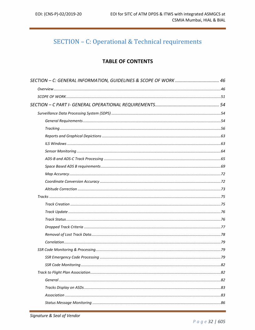
SECTION – C: Operational & Technical requirements
TABLE OF CONTENTS
SECTION – C: GENERAL INFORMATION, GUIDELINES & SCOPE OF WORK ................................... 46
Overview ............................................................................................................................................................... 46
SCOPE OF WORK ................................................................................................................................................... 51
SECTION – C PART I- GENERAL OPERATIONAL REQUIREMENTS ................................................... 54
Surveillance Data Processing System (SDPS) ........................................................................................................ 54
General Requirements ................................................................................................................................... 54
Tracking ......................................................................................................................................................... 56
Reports and Graphical Depictions ................................................................................................................. 63
ILS Windows .................................................................................................................................................. 63
Sensor Monitoring ......................................................................................................................................... 64
ADS-B and ADS-C Track Processing ............................................................................................................... 65
Space Based ADS B requirements .................................................................................................................. 69
Map Accuracy ................................................................................................................................................ 72
Coordinate Conversion Accuracy ................................................................................................................... 72
Altitude Correction ........................................................................................................................................ 73
Tracks ................................................................................................................................................................... 75
Track Creation ............................................................................................................................................... 75
Track Update ................................................................................................................................................. 76
Track Status ................................................................................................................................................... 76
Dropped Track Criteria .................................................................................................................................. 77
Removal of Lost Track Data ........................................................................................................................... 78
Correlation ..................................................................................................................................................... 79
SSR Code Monitoring & Processing ....................................................................................................................... 79
SSR Emergency Code Processing ................................................................................................................... 79
SSR Code Monitoring ..................................................................................................................................... 82
Track to Flight Plan Association ............................................................................................................................ 82
General .......................................................................................................................................................... 82
Tracks Display on ASDs .................................................................................................................................. 83
Association .................................................................................................................................................... 83
Status Message Monitoring .......................................................................................................................... 86
EOI: (CNS-P)-02/2019-20 EOI for SITC of ATM DPDS & ITWS with integrated ASMGCS at
CSMIA Mumbai, HIAL & BIAL
Signature & Seal of Vendor
P a g e 33 | 605
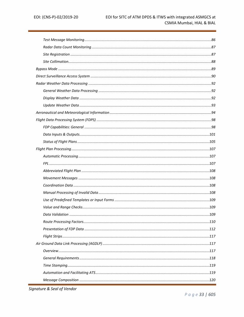
Test Message Monitoring .............................................................................................................................. 86
Radar Data Count Monitoring ....................................................................................................................... 87
Site Registration ............................................................................................................................................ 87
Site Collimation .............................................................................................................................................. 88
Bypass Mode ........................................................................................................................................................ 89
Direct Surveillance Access System ........................................................................................................................ 90
Radar Weather Data Processing .......................................................................................................................... 92
General Weather Data Processing ................................................................................................................ 92
Display Weather Data ................................................................................................................................... 92
Update Weather Data ................................................................................................................................... 93
Aeronautical and Meteorological Information ..................................................................................................... 94
Flight Data Processing System (FDPS) .................................................................................................................. 98
FDP Capabilities: General .............................................................................................................................. 98
Data Inputs & Outputs................................................................................................................................. 101
Status of Flight Plans ................................................................................................................................... 105
Flight Plan Processing ......................................................................................................................................... 107
Automatic Processing .................................................................................................................................. 107
FPL ............................................................................................................................................................... 107
Abbreviated Flight Plan ............................................................................................................................... 108
Movement Messages .................................................................................................................................. 108
Coordination Data ....................................................................................................................................... 108
Manual Processing of Invalid Data .............................................................................................................. 108
Use of Predefined Templates or Input Forms .............................................................................................. 109
Value and Range Checks .............................................................................................................................. 109
Data Validation ........................................................................................................................................... 109
Route Processing Factors ............................................................................................................................. 110
Presentation of FDP Data ............................................................................................................................ 112
Flight Strips .................................................................................................................................................. 117
Air Ground Data Link Processing (AGDLP) .......................................................................................................... 117
Overview ...................................................................................................................................................... 117
General Requirements ................................................................................................................................. 118
Time Stamping ............................................................................................................................................. 119
Automation and Facilitating ATS ................................................................................................................. 119
Message Composition ................................................................................................................................. 120
EOI: (CNS-P)-02/2019-20 EOI for SITC of ATM DPDS & ITWS with integrated ASMGCS at
CSMIA Mumbai, HIAL & BIAL
Signature & Seal of Vendor
P a g e 34 | 605
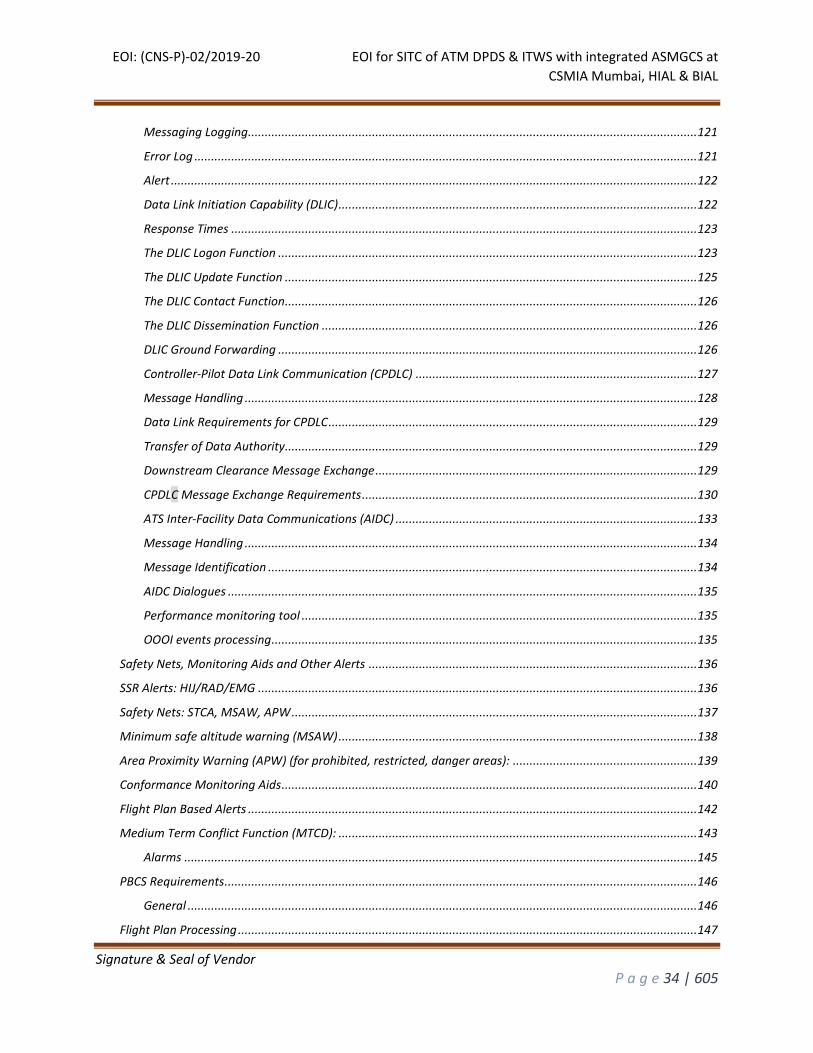
Messaging Logging...................................................................................................................................... 121
Error Log ...................................................................................................................................................... 121
Alert ............................................................................................................................................................. 122
Data Link Initiation Capability (DLIC) ........................................................................................................... 122
Response Times ........................................................................................................................................... 123
The DLIC Logon Function ............................................................................................................................. 123
The DLIC Update Function ........................................................................................................................... 125
The DLIC Contact Function ........................................................................................................................... 126
The DLIC Dissemination Function ................................................................................................................ 126
DLIC Ground Forwarding ............................................................................................................................. 126
Controller-Pilot Data Link Communication (CPDLC) .................................................................................... 127
Message Handling ....................................................................................................................................... 128
Data Link Requirements for CPDLC .............................................................................................................. 129
Transfer of Data Authority ........................................................................................................................... 129
Downstream Clearance Message Exchange ................................................................................................ 129
CPDLC Message Exchange Requirements .................................................................................................... 130
ATS Inter-Facility Data Communications (AIDC) .......................................................................................... 133
Message Handling ....................................................................................................................................... 134
Message Identification ................................................................................................................................ 134
AIDC Dialogues ............................................................................................................................................ 135
Performance monitoring tool ...................................................................................................................... 135
OOOI events processing............................................................................................................................... 135
Safety Nets, Monitoring Aids and Other Alerts .................................................................................................. 136
SSR Alerts: HIJ/RAD/EMG ................................................................................................................................... 136
Safety Nets: STCA, MSAW, APW ......................................................................................................................... 137
Minimum safe altitude warning (MSAW) ........................................................................................................... 138
Area Proximity Warning (APW) (for prohibited, restricted, danger areas): ....................................................... 139
Conformance Monitoring Aids ............................................................................................................................ 140
Flight Plan Based Alerts ...................................................................................................................................... 142
Medium Term Conflict Function (MTCD): ........................................................................................................... 143
Alarms ......................................................................................................................................................... 145
PBCS Requirements ............................................................................................................................................. 146
General ........................................................................................................................................................ 146
Flight Plan Processing ......................................................................................................................................... 147
EOI: (CNS-P)-02/2019-20 EOI for SITC of ATM DPDS & ITWS with integrated ASMGCS at
CSMIA Mumbai, HIAL & BIAL
Signature & Seal of Vendor
P a g e 35 | 605
Controller Working Position / Air Situation Display (ASD) .................................................................................. 147
Medium term Conflict Detection ................................................................................................................. 148
Data Management System adaptations ..................................................................................................... 149
PBCS monitoring .......................................................................................................................................... 149
Decision Support Tool ......................................................................................................................................... 150
AMAN/DMAN .............................................................................................................................................. 150
Time Based Separation (TBS) Tool ............................................................................................................... 152
Tactical Controller Tool (TCT) ...................................................................................................................... 153
NTZ Monitoring Tool.................................................................................................................................... 153
MINSEP Tool ................................................................................................................................................ 153
Predicted Track Line .................................................................................................................................... 154
Predicted Route Line .................................................................................................................................... 154
Highlight Tool .............................................................................................................................................. 154
Conflict Probe .............................................................................................................................................. 154
RBL Alarm .................................................................................................................................................... 155
Time To Touch Down ................................................................................................................................... 155
Separation Aids ........................................................................................................................................... 155
OPERTIONAL POSITIONS ..................................................................................................................................... 156
APPROACH CONTROL: ................................................................................................................................. 156
AREA CONTROL: .......................................................................................................................................... 158
OCEANIC CONTROL (for Mumbai only) ........................................................................................................ 159
SEARCH AND RESCUE CENTER: .................................................................................................................... 161
AERODROME REPORTING OFFICE (ARO): .................................................................................................... 161
AUTOMATED CO-ORDINATION: .................................................................................................................. 161
HF COMMUNICATION CENTER (Requirement for Mumbai only) ....................................................................... 162
ATC CLEARANCES ................................................................................................................................................ 169
BASIC FLIGHT DATA ..................................................................................................................................... 170
DATABASE MANAGEMENT SYSTEM ................................................................................................................... 172
Billing system and data Analysis ........................................................................................................................ 183
Billing System .............................................................................................................................................. 183
Data Analysis and Statistics ......................................................................................................................... 184
Basic Human machine Interface (HMI) Facilities ................................................................................................ 187
General ........................................................................................................................................................ 187
Displays - Textual and Graphical Features .................................................................................................. 190
EOI: (CNS-P)-02/2019-20 EOI for SITC of ATM DPDS & ITWS with integrated ASMGCS at
CSMIA Mumbai, HIAL & BIAL
Signature & Seal of Vendor
P a g e 36 | 605
Hardware Requirements and Display Characteristics ................................................................................. 190
Workstation Requirements ................................................................................................................................. 190
User Input and Selection devices ................................................................................................................. 191
Display Characteristics ................................................................................................................................ 192
HMI Preferences ................................................................................................................................................. 195
Window Management on Displays ..................................................................................................................... 196
Windows to Operate Independently ................................................................................................................... 198
Move Windows between Displays ............................................................................................................... 199
Graphic Interface (Controller Working Position - Air Situation Display) ............................................................. 199
General ........................................................................................................................................................ 199
Functional Controls ...................................................................................................................................... 203
Screen Annotation ....................................................................................................................................... 203
Windows Presentation ................................................................................................................................ 203
Main Surveillance Window ................................................................................................................................. 204
Secondary Surveillance Window .................................................................................................................. 204
System Status Window ................................................................................................................................ 204
General Information Window ...................................................................................................................... 205
Messages Windows ..................................................................................................................................... 206
Images ......................................................................................................................................................... 206
Surveillance Data Display Elements............................................................................................................. 206
Surveillance Data Position Symbols/APS ..................................................................................................... 209
Track History Information............................................................................................................................ 209
Display Range .............................................................................................................................................. 209
Range Rings ................................................................................................................................................. 210
Quick Look ................................................................................................................................................... 210
Range Bearing Line ...................................................................................................................................... 210
Track Data Labels ........................................................................................................................................ 211
Controller Jurisdiction Indicator (CJI) ........................................................................................................... 212
Special Position Indicator (SPI) .................................................................................................................... 212
Track Label Positioning ................................................................................................................................ 212
Contents of Track Label ...................................................................................................................................... 212
Filters .................................................................................................................................................................. 214
Maps ............................................................................................................................................................ 215
Aircraft targets shall be viewable when transiting filled in display areas. .................................................. 217
EOI: (CNS-P)-02/2019-20 EOI for SITC of ATM DPDS & ITWS with integrated ASMGCS at
CSMIA Mumbai, HIAL & BIAL
Signature & Seal of Vendor
P a g e 37 | 605
Weather Surveillance Data: ......................................................................................................................... 218
Flight Plan ........................................................................................................................................................... 218
Flight Strip Window ..................................................................................................................................... 218
Flight Data Displays ..................................................................................................................................... 219
Flight List Presentation ................................................................................................................................ 219
Flight Strip Presentation .............................................................................................................................. 220
Paper flight progress strip ........................................................................................................................... 220
Electronic Flight Strips ................................................................................................................................. 222
Flight Plan Data Handling ................................................................................................................................... 226
Flight Plan Data Retrieval ............................................................................................................................ 226
Flight Plan History ....................................................................................................................................... 226
Free Text Input and Distribution .................................................................................................................. 227
RVSM ........................................................................................................................................................... 227
PBN .............................................................................................................................................................. 227
Controller Tools ........................................................................................................................................... 227
Operational Input Functions ........................................................................................................................ 229
Presentation of Aircraft Targets .................................................................................................................. 231
Aircraft Position Symbol / Radar Position Symbol ........................................................................................ 232
Special Position Identification (SPI) ............................................................................................................. 234
History Trail ................................................................................................................................................. 234
Lost Target History ...................................................................................................................................... 235
Projected Track Vector ................................................................................................................................ 235
Select and Deselect Track Vectors ............................................................................................................... 236
Data Blocks .................................................................................................................................................. 236
Flight Data Blocks ........................................................................................................................................ 236
Data Blocks - Display ................................................................................................................................... 237
Data Block Element ..................................................................................................................................... 237
Data block Linked to APS by Leader Line ..................................................................................................... 239
View Data Blocks of another Sector............................................................................................................. 239
Data Block Modification .............................................................................................................................. 239
Rotation Characteristics .............................................................................................................................. 242
Suppression Filters ....................................................................................................................................... 242
Manual Suppression of Data Blocks ............................................................................................................ 243
Display Maps ............................................................................................................................................... 243
EOI: (CNS-P)-02/2019-20 EOI for SITC of ATM DPDS & ITWS with integrated ASMGCS at
CSMIA Mumbai, HIAL & BIAL
Signature & Seal of Vendor
P a g e 38 | 605
General ........................................................................................................................................................ 243
System Map Characteristics ........................................................................................................................ 244
Special Use Maps Characteristics ................................................................................................................ 244
Private Maps ............................................................................................................................................... 245
Private Mapping Capabilities ...................................................................................................................... 246
Map Items ................................................................................................................................................... 247
Area Fill Tool ................................................................................................................................................ 249
Annotate Map with Text .............................................................................................................................. 249
Map Selection and Creation ........................................................................................................................ 250
General ........................................................................................................................................................ 250
Map Menu ................................................................................................................................................... 251
Map Capacity and Storage .......................................................................................................................... 252
Presentation of Data Lists ............................................................................................................................ 252
Human Machine Interface (HMI) Requirements .......................................................................................... 255
Data Input ................................................................................................................................................... 255
Command Dialogue Characteristics ............................................................................................................ 255
Input Devices ............................................................................................................................................... 255
Interaction Devices and Adjustment Controls ............................................................................................. 255
Keyboard Characteristics ............................................................................................................................. 256
Standardized Operation Across Modes ....................................................................................................... 256
Operate with Multiple Displays ................................................................................................................... 256
Cursor/screen Pointer .................................................................................................................................. 257
Target Jurisdiction ....................................................................................................................................... 258
Display Controls ........................................................................................................................................... 258
Display Setup Controls and Menus .............................................................................................................. 258
Controls to Manage Data ............................................................................................................................ 259
Access Guidelines for Displays ..................................................................................................................... 261
Availability of Display Controls and Functions ............................................................................................. 262
Bearing and Range Vectors ......................................................................................................................... 263
Range Scales ................................................................................................................................................ 265
Pre-set Range Scales for ATM Centres ......................................................................................................... 265
Pre-set Range Scales for Towers .................................................................................................................. 265
Vary Range Settings .................................................................................................................................... 265
Display Offset .............................................................................................................................................. 266
EOI: (CNS-P)-02/2019-20 EOI for SITC of ATM DPDS & ITWS with integrated ASMGCS at
CSMIA Mumbai, HIAL & BIAL
Signature & Seal of Vendor
P a g e 39 | 605
Accuracy of Displayed Information .............................................................................................................. 267
Consistency of Displayed Position ................................................................................................................ 267
Display Discriminability ............................................................................................................................... 267
Display Accuracy .......................................................................................................................................... 268
Speed Accuracy ............................................................................................................................................ 268
Vertical Accuracy ......................................................................................................................................... 268
Displayed Altitude Accuracy ........................................................................................................................ 268
Provide Data to Support Accuracy ............................................................................................................... 268
SSR Site Monitor .......................................................................................................................................... 269
Associate to Special SSR Site Monitor .......................................................................................................... 269
SSR Site Monitor Symbol Displayed at Workstations................................................................................... 269
Suppress SSR Site Monitor ........................................................................................................................... 269
Display of Aerodrome Information .............................................................................................................. 269
Interaction with CPDLC ................................................................................................................................ 271
Interaction with ADS-C ................................................................................................................................ 274
HMI related to Electronic Flight Strips ......................................................................................................... 276
Notification of Error Messages .................................................................................................................... 278
Timestamps and Timers ............................................................................................................................... 278
AFN Logon Functions ................................................................................................................................... 279
Logon ........................................................................................................................................................... 280
Digital Recording and playback .......................................................................................................................... 281
Video and Data Recording ........................................................................................................................... 281
Legal Recording Manager ........................................................................................................................... 284
Archiving ...................................................................................................................................................... 285
Replay (DPDS and ITWP/ Regional Tower) .................................................................................................. 286
Archive Replay ............................................................................................................................................. 289
Voice Recording ........................................................................................................................................... 289
Recording and Data Analysis ....................................................................................................................... 290
Recording the data points for each CPDLC transaction ............................................................................... 291
Recording the data points for each CPDLC transaction / each ADS-C downlink .......................................... 293
Monitoring and Control ...................................................................................................................................... 296
Monitor and Control (M&C) ........................................................................................................................ 296
M&C System Configuration ......................................................................................................................... 296
General M&C Requirements ........................................................................................................................ 296
EOI: (CNS-P)-02/2019-20 EOI for SITC of ATM DPDS & ITWS with integrated ASMGCS at
CSMIA Mumbai, HIAL & BIAL
Signature & Seal of Vendor
P a g e 40 | 605
M&C Interface ............................................................................................................................................. 302
Isolation between M&C system and Elements Supporting Operations ....................................................... 303
M&C Security ............................................................................................................................................... 303
Diagnostics and Fault Isolation Requirements ............................................................................................ 304
Monitoring Requirements ........................................................................................................................... 305
Alert/Alarm Processing ................................................................................................................................ 306
Suppression of Alert and Alarm Indications ................................................................................................ 307
Status Indications ........................................................................................................................................ 308
System Control Requirements ..................................................................................................................... 308
HMI for M&C Display ................................................................................................................................... 309
M&C Printout .............................................................................................................................................. 310
M&C Data Logging ...................................................................................................................................... 310
Response Time ............................................................................................................................................. 311
Surveillance Quality Control (SQC) .............................................................................................................. 311
Real Time Performance ............................................................................................................................... 312
LAN Manager .............................................................................................................................................. 313
System Capacity .................................................................................................................................................. 315
Overview ...................................................................................................................................................... 315
Capacity Requirements ................................................................................................................................ 315
Position Capacity ......................................................................................................................................... 315
Processing Capacity ..................................................................................................................................... 316
Flexibility...................................................................................................................................................... 320
Redundancy ................................................................................................................................................. 321
Performance Requirements ......................................................................................................................... 322
Data Processing ........................................................................................................................................... 322
Tracking Performance ................................................................................................................................. 323
Tracking Performance Tests ........................................................................................................................ 324
Safety Net Performances ............................................................................................................................. 326
Minimum Safe Altitude (MSAW) Performance ............................................................................................ 326
Airspace Intrusion Warning (AIW) Performance ......................................................................................... 326
Short Term Conflict Alert (STCA) Performance ............................................................................................ 327
Response times ............................................................................................................................................ 328
General Response Times .............................................................................................................................. 328
Flight Data Processing times ....................................................................................................................... 329
EOI: (CNS-P)-02/2019-20 EOI for SITC of ATM DPDS & ITWS with integrated ASMGCS at
CSMIA Mumbai, HIAL & BIAL
Signature & Seal of Vendor
P a g e 41 | 605
Display Response Times ............................................................................................................................... 330
Expected peak workload.............................................................................................................................. 331
System Times ............................................................................................................................................... 333
System Start-up Times ................................................................................................................................. 333
System Start over Times .............................................................................................................................. 334
Reassignment .............................................................................................................................................. 334
Dual interface Channel Recovery ................................................................................................................. 334
External Interfaces .............................................................................................................................................. 335
General ........................................................................................................................................................ 335
RADAR data ................................................................................................................................................. 335
ADS-B data .................................................................................................................................................. 336
AMHS data interface ................................................................................................................................... 337
AFTN data interface .................................................................................................................................... 338
External FIR Interface .................................................................................................................................. 338
ADS-C and CPDLC data interface ................................................................................................................. 339
ACARS interface ........................................................................................................................................... 340
MET Interface .............................................................................................................................................. 340
Time reference interface ............................................................................................................................. 340
Billing Interface ........................................................................................................................................... 341
Voice Interface ............................................................................................................................................. 341
System Interfaces ........................................................................................................................................ 341
SECTION C PART II - SPECIFICATIONS FOR THE INTEGRATED TOWER WORKING POSITION (ITWP)
.................................................................................................................................................... 346
Operational Requirements – Functional Positions .............................................................................................. 346
AERODROME CONTROL ............................................................................................................................... 346
Aerodrome Control Functions (DEPARTURES) ............................................................................................. 346
Aerodrome Control Functions (ARRIVALS) ................................................................................................... 348
Operational Positions for Aerodrome Control function. .............................................................................. 348
Management of the ITWP ........................................................................................................................... 349
ITWP Processes ............................................................................................................................................ 350
Variable Taxi-Time: ...................................................................................................................................... 350
Actual Off-Block event: ................................................................................................................................ 350
Standard Instrument Departure: ................................................................................................................. 351
Return-to-Stand: .......................................................................................................................................... 351
EOI: (CNS-P)-02/2019-20 EOI for SITC of ATM DPDS & ITWS with integrated ASMGCS at
CSMIA Mumbai, HIAL & BIAL
Signature & Seal of Vendor
P a g e 42 | 605
Ground Situation Display (GSD) of ITWP ..................................................................................................... 352
Alerts and Error management ..................................................................................................................... 353
Electronic Flight Strips displays ................................................................................................................... 353
Flight Lists .................................................................................................................................................... 355
Management of the traffic .......................................................................................................................... 356
Pre-Departure Clearance (PDC) and Departure Clearance (DCL) ................................................................ 358
Flight Plan Association ................................................................................................................................ 358
Clearance Composition and Exchange ........................................................................................................ 359
Message Handling ....................................................................................................................................... 359
PDC/DCL Closure .......................................................................................................................................... 360
Vehicles and Tows management ................................................................................................................. 361
Management of the airport environment ................................................................................................... 362
Surface Surveillance service ......................................................................................................................... 362
Airport Safety Support Service ..................................................................................................................... 366
Surface Routing Service ............................................................................................................................... 368
Guidance Service ......................................................................................................................................... 369
Management of departure flights ............................................................................................................... 370
System Features .......................................................................................................................................... 372
System Performance and Capacities ........................................................................................................... 372
External interfaces ....................................................................................................................................... 374
Flight Plan to Track Correlation ................................................................................................................... 376
Correlation Criteria ...................................................................................................................................... 376
Ambiguous Correlations .............................................................................................................................. 376
Manual Correlations .................................................................................................................................... 377
Surveillance Based Event Generation (Optional) ......................................................................................... 377
AFTN/AMHS Flight Plan Data ...................................................................................................................... 377
FIC/ADC/YA Requirements (Details provided in Annexure B) ...................................................................... 379
SECTION – C PART III SPECIFICATIONS FOR ARRIVAL/DEPARTURE MANAGER .......................... 380
SECTION – C PART IV SPECIFICATIONS FOR ATC SIMULATOR ..................................................... 390
ATC SIMULATOR .......................................................................................................................................... 390
SECTION – C PART V SPECIFICATIONS FOR THE REGIONAL TOWER ......................................... 398
SECTION – C PART VI OPERATIONAL & TECHNICAL REQUIREMENTS ......................................... 402
Backup System .................................................................................................................................................... 402
EOI: (CNS-P)-02/2019-20 EOI for SITC of ATM DPDS & ITWS with integrated ASMGCS at
CSMIA Mumbai, HIAL & BIAL
Signature & Seal of Vendor
P a g e 43 | 605
Software Support Facility.................................................................................................................................... 404
General Requirements ........................................................................................................................................ 406
POWER................................................................................................................................................................ 406
General ........................................................................................................................................................ 406
Battery ................................................................................................................................................................ 410
Protection system ............................................................................................................................................... 410
Power Distribution .............................................................................................................................................. 411
Monitoring of UPS .............................................................................................................................................. 411
LAN ..................................................................................................................................................................... 412
Timing and Synchronization Requirements ........................................................................................................ 413
Overview ...................................................................................................................................................... 413
System Configuration ......................................................................................................................................... 415
General ........................................................................................................................................................ 416
Technology .................................................................................................................................................. 419
Redundancy ................................................................................................................................................. 419
System Operation with partial failure ......................................................................................................... 420
System Restart ............................................................................................................................................. 420
Interoperability ............................................................................................................................................ 421
Hardware Requirements ..................................................................................................................................... 422
General ........................................................................................................................................................ 422
Servers ......................................................................................................................................................... 425
Controller Working Position (CWP) Hardware Requirements ..................................................................... 425
Displays ....................................................................................................................................................... 426
Input Devices ............................................................................................................................................... 428
Flight Strip Printer ....................................................................................................................................... 428
Colour Laser Printers ................................................................................................................................... 429
Cyber Security ..................................................................................................................................................... 430
General Security Requirements ................................................................................................................... 430
Security Requirements ................................................................................................................................. 430
Identification and Authentication................................................................................................................ 432
Boundary Protection Monitoring & Control ................................................................................................ 434
Audit and Accountability ............................................................................................................................. 437
Reliability, Maintainability, Availability ....................................................................................................... 437
General Requirements ................................................................................................................................. 437
EOI: (CNS-P)-02/2019-20 EOI for SITC of ATM DPDS & ITWS with integrated ASMGCS at
CSMIA Mumbai, HIAL & BIAL
Signature & Seal of Vendor
P a g e 44 | 605
Reliability ..................................................................................................................................................... 439
Maintainability ............................................................................................................................................ 440
Preventive Maintenance .............................................................................................................................. 440
System Availability ...................................................................................................................................... 441
Training............................................................................................................................................................... 442
Documentation ................................................................................................................................................... 454
General Requirements: ................................................................................................................................ 454
Type of documentation and Number of copies required, per site. .............................................................. 455
Operational Software .................................................................................................................................. 457
Automation Equipment Software Functional Specification: ........................................................................ 458
Consoles .............................................................................................................................................................. 459
General Requirements ................................................................................................................................. 459
Console Maintenance .................................................................................................................................. 468
INSTALLATION STANDARD .................................................................................................................................. 469
29 SECTION – C PART VII .......... SPECIFICATIONS FOR THE ASMGCS AS A PART OF INTEGRATED
TOWER WORKING POSITION FOR MUMBAI, BENGALURU & HYDERABAD ................................ 470
System performance requirements .................................................................................................................... 470
QUALIFICATION REQUIREMENTS: ...................................................................................................................... 470
SCOPE OF WORK: ................................................................................................................................................ 471
GENERAL REQUIREMENTS .................................................................................................................................. 475
VISIBILITY CONDITIONS ....................................................................................................................................... 476
ASMGCS COVERAGE VOLUME ............................................................................................................................ 477
REDUNDANCY ..................................................................................................................................................... 479
TARGET DETECTION CAPABILITY ........................................................................................................................ 479
ELECTRICAL PROTECTION SYSTEM: ..................................................................................................................... 482
OPTICAL FIBER CABLE(OFC) AND LAYING OF OFC: ............................................................................................. 483
SMR & MLAT STRUCTURE, EQUIPMENT SHELTERS AND CABINETS: .................................................................. 485
TEST, EVALUATION & MAINTENANCE (TE &M) SYSTEM .................................................................................... 486
ENVIRONMENTAL CONDITIONS.......................................................................................................................... 488
ASMGCS LEVEL OF OPERATION: ......................................................................................................................... 489
SURFACE MOVEMENT RADAR (SMR) SYSTEM (FOR GROUND SURVEILLANCE): ................................................ 490
MULTILATERATION(MLAT) SYSTEM: .................................................................................................................. 500
VEHICLE TRACKING UNITS: ................................................................................................................................. 501
MULTI SENSOR DATA PROCESSOR(MSDP): ........................................................................................................ 502
EOI: (CNS-P)-02/2019-20 EOI for SITC of ATM DPDS & ITWS with integrated ASMGCS at
CSMIA Mumbai, HIAL & BIAL
Signature & Seal of Vendor
P a g e 45 | 605
MAINTENANCE WORKING POSITION(MWP): ..................................................................................................... 506
RECORDING AND PLAYBACK FUNCTION: ............................................................................................................ 508
APPLICATION SOFTWARE AND TOOLS: ............................................................................................................... 510
PROJECT MANAGEMENT ............................................................................................................................. 515
ANNEXURES ................................................................................................................................ 530
Annexure A: List of potential MLAT/SMR sites Mumbai/ Bengaluru/ Hyderabad ...................................... 530
Annexure B: FIC/ADC/YA Number ............................................................................................................. 531
ANNEXURE A1-Controller Working Position for MUMBAI, Sky Tower, Regional Tower Juhu, Goa, Regional
Tower for MOPA & Navi Mumbai ................................................................................................................ 541
ANNEXURE A2 Controller Working Positions for BANGALORE, Yelhanka & HAL......................................... 561
ANNEXURE A3 -Controllers Working Positions at HYDERABAD, Begumpet Tower & Hakimpet Tower ...... 571
Annexure A4 - Aerodrome Layout map for Mumbai Airport ....................................................................... 584
Annexure A5 -Aerodrome layout map of Bengaluru Airport ....................................................................... 585
Annexure A6 - Aerodrome layout map of Hyderabad Airport ..................................................................... 586
Appendix: Terms, Definitions, Abbreviations ............................................................................................... 590
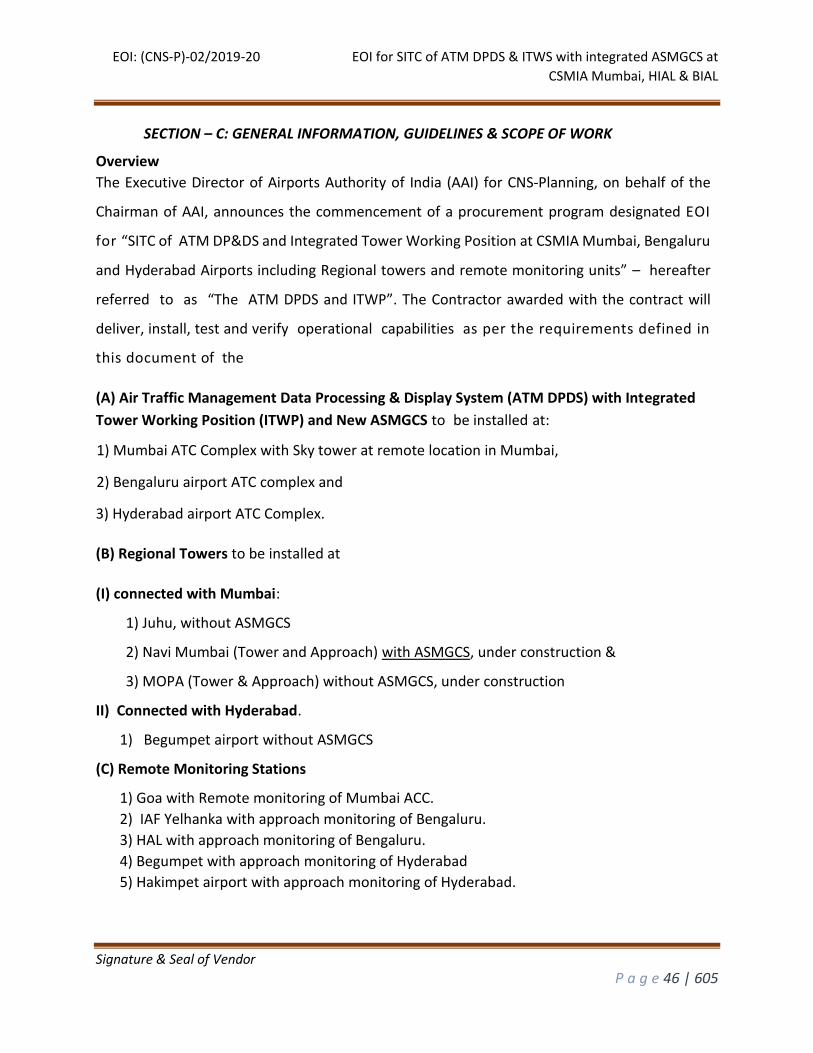
EOI: (CNS-P)-02/2019-20 EOI for SITC of ATM DPDS & ITWS with integrated ASMGCS at
CSMIA Mumbai, HIAL & BIAL
Signature & Seal of Vendor
P a g e 46 | 605
SECTION – C: GENERAL INFORMATION, GUIDELINES & SCOPE OF WORK
Overview
The Executive Director of Airports Authority of India (AAI) for CNS-Planning, on behalf of the
Chairman of AAI, announces the commencement of a procurement program designated EOI
for “SITC of ATM DP&DS and Integrated Tower Working Position at CSMIA Mumbai, Bengaluru
and Hyderabad Airports including Regional towers and remote monitoring units” – hereafter
referred to as “The ATM DPDS and ITWP”. The Contractor awarded with the contract will
deliver, install, test and verify operational capabilities as per the requirements defined in
this document of the
(A) Air Traffic Management Data Processing & Display System (ATM DPDS) with Integrated
Tower Working Position (ITWP) and New ASMGCS to be installed at:
1) Mumbai ATC Complex with Sky tower at remote location in Mumbai,
2) Bengaluru airport ATC complex and
3) Hyderabad airport ATC Complex.
(B) Regional Towers to be installed at
(I) connected with Mumbai:
1) Juhu, without ASMGCS
2) Navi Mumbai (Tower and Approach) with ASMGCS, under construction &
3) MOPA (Tower & Approach) without ASMGCS, under construction
II) Connected with Hyderabad.
1) Begumpet airport without ASMGCS
(C) Remote Monitoring Stations
1) Goa with Remote monitoring of Mumbai ACC.
2) IAF Yelhanka with approach monitoring of Bengaluru.
3) HAL with approach monitoring of Bengaluru.
4) Begumpet with approach monitoring of Hyderabad
5) Hakimpet airport with approach monitoring of Hyderabad.
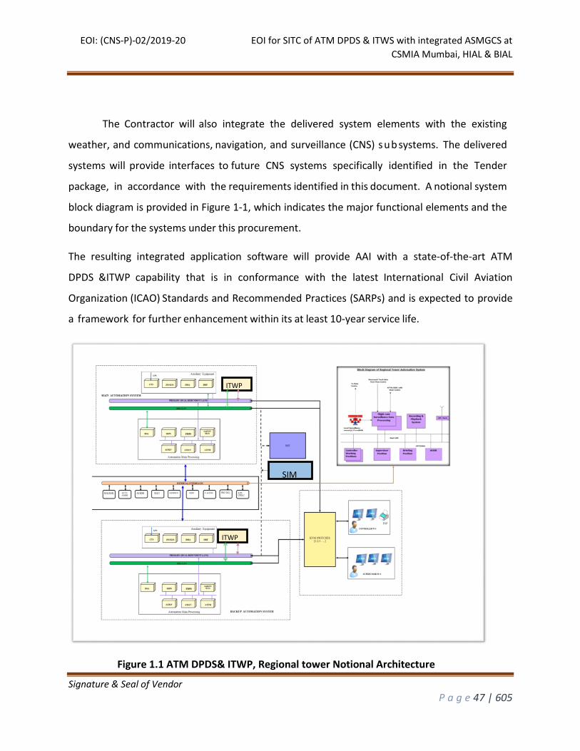
EOI: (CNS-P)-02/2019-20 EOI for SITC of ATM DPDS & ITWS with integrated ASMGCS at
CSMIA Mumbai, HIAL & BIAL
Signature & Seal of Vendor
P a g e 47 | 605
The Contractor will also integrate the delivered system elements with the existing
weather, and communications, navigation, and surveillance (CNS) sub systems. The delivered
systems will provide interfaces to future CNS systems specifically identified in the Tender
package, in accordance with the requirements identified in this document. A notional system
block diagram is provided in Figure 1-1, which indicates the major functional elements and the
boundary for the systems under this procurement.
The resulting integrated application software will provide AAI with a state-of-the-art ATM
DPDS &ITWP capability that is in conformance with the latest International Civil Aviation
Organization (ICAO) Standards and Recommended Practices (SARPs) and is expected to provide
a framework for further enhancement within its at least 10-year service life.
Figure 1.1 ATM DPDS& ITWP, Regional tower Notional Architecture
ITWP
ITWP
SIM
EOI: (CNS-P)-02/2019-20 EOI for SITC of ATM DPDS & ITWS with integrated ASMGCS at
CSMIA Mumbai, HIAL & BIAL
Signature & Seal of Vendor
P a g e 48 | 605
The Contractor will develop a system architecture and system specifications to produce the
system elements procured under this contract, based upon the Technical Specification (TSP)
and Scope of Work (SOW) detailed in this document. This systems architecture will
demonstrate the Contractor’s understanding of the existing ATM systems, Aeronautical
Information System (AIS), CNS infrastructure, as well as the challenges in transitioning to the
new ATM system. The system architecture will include and address issues for the Realism,
logistics support, planned system expansion, technology refresh, reliability, maintainability,
and availability (RMA), and security requirements. Additionally, the system architecture will
serve to demonstrate the Contractor’s knowledge of requirements that must be met for
provisioning the necessary hardware and software covering all subsystems.
The ATM system will be built, tested, and installed at the designated AAI operational sites and
fully integrated with existing supporting systems. An Operational Test and Evaluation (OT&E)
program on the procured ATM system will be conducted by the AAI following Site Acceptance
Test (SAT). The Contractor will conduct a continuous system testing period of 30 days known
as System Reliability and Stability Test (SRST) after all necessary prior tests have been
successfully completed: this SRST will verify that the system can operate continuously, 24 hours
a day for a 30 days’ period without any system failures, using live data and under standard
operations.
Final System Acceptance (FSA) will be conducted following successful completion of SRST and
after AAI and the Contractor have agreed that all deliverables have been submitted
and approved, that the Certification Plan and Warranty Plan has been delivered and approved,
and that all Problem Reports have been closed, resolved, or have been agreed by the AAI and
the Contractor that they will be deferred to the Warranty period or beyond, based on criteria
set forth in the Test Plan.
Upon finalizing successful bidder, a System Design Review meeting will be conducted where
in the acceptability of the required HMI, site adaptability of Controller Working Position and
EOI: (CNS-P)-02/2019-20 EOI for SITC of ATM DPDS & ITWS with integrated ASMGCS at
CSMIA Mumbai, HIAL & BIAL
Signature & Seal of Vendor
P a g e 49 | 605
Surveillance Data Processor System will be reviewed as per the site requirement and specific
detailed requirement will be set out through System Design Document, to be prepared by the
successful bidder. The System Design Review meeting will take place immediately after
contract agreement is signed with the successful bidder. Though requirement for system has
been laid down in the tender document, AAI reserves the right to make required changes
based on system design review. Bidders may offer alternate/applicable functional
capabilities/solutions for any one or more of the requirements placed in EOI. Such offered
alternates will be reviewed/ evaluated on a case to case basis by AAI to determine applicability
to the tender requirement.
A brief idea about the available space can be obtained from the proposed layout diagrams of
Server room, ACC and OCC/FIC for Mumbai airport is provided in Annexure-A7.
At the time of implementing the project, issues related to HMI and application shall be resolved
by Contractor.
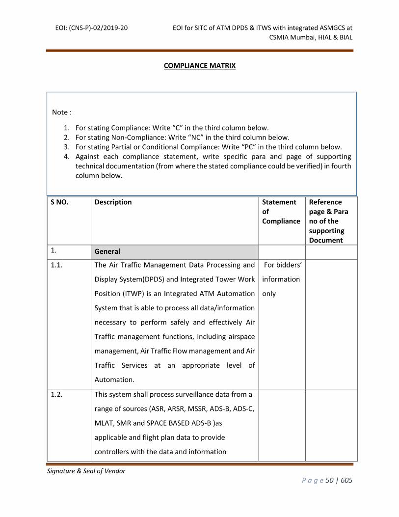
EOI: (CNS-P)-02/2019-20 EOI for SITC of ATM DPDS & ITWS with integrated ASMGCS at
CSMIA Mumbai, HIAL & BIAL
Signature & Seal of Vendor
P a g e 50 | 605
COMPLIANCE MATRIX
S NO. Description Statement of Compliance
Reference page & Para no of the supporting Document
1. General
1.1. The Air Traffic Management Data Processing and
Display System(DPDS) and Integrated Tower Work
Position (ITWP) is an Integrated ATM Automation
System that is able to process all data/information
necessary to perform safely and effectively Air
Traffic management functions, including airspace
management, Air Traffic Flow management and Air
Traffic Services at an appropriate level of
Automation.
For bidders’
information
only
1.2. This system shall process surveillance data from a
range of sources (ASR, ARSR, MSSR, ADS-B, ADS-C,
MLAT, SMR and SPACE BASED ADS-B )as
applicable and flight plan data to provide
controllers with the data and information
Note :
1. For stating Compliance: Write “C” in the third column below. 2. For stating Non-Compliance: Write “NC” in the third column below. 3. For stating Partial or Conditional Compliance: Write “PC” in the third column below. 4. Against each compliance statement, write specific para and page of supporting
technical documentation (from where the stated compliance could be verified) in fourth column below.
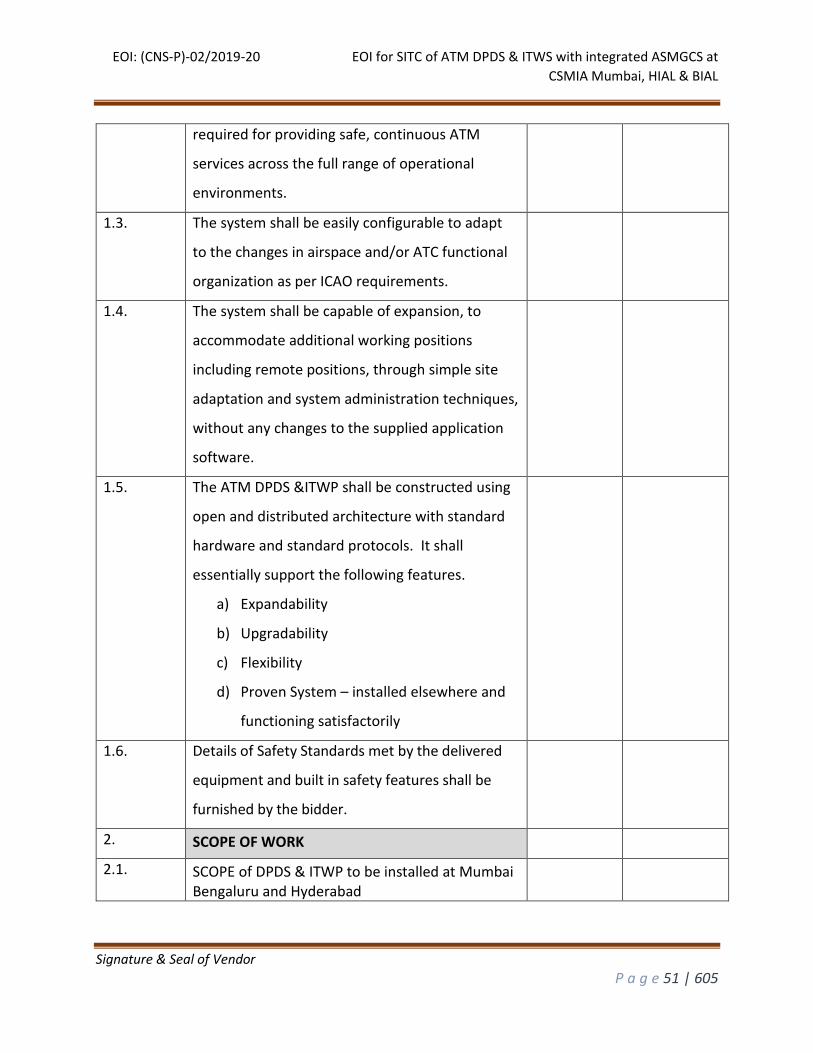
EOI: (CNS-P)-02/2019-20 EOI for SITC of ATM DPDS & ITWS with integrated ASMGCS at
CSMIA Mumbai, HIAL & BIAL
Signature & Seal of Vendor
P a g e 51 | 605
required for providing safe, continuous ATM
services across the full range of operational
environments.
1.3. The system shall be easily configurable to adapt
to the changes in airspace and/or ATC functional
organization as per ICAO requirements.
1.4. The system shall be capable of expansion, to
accommodate additional working positions
including remote positions, through simple site
adaptation and system administration techniques,
without any changes to the supplied application
software.
1.5. The ATM DPDS &ITWP shall be constructed using
open and distributed architecture with standard
hardware and standard protocols. It shall
essentially support the following features.
a) Expandability
b) Upgradability
c) Flexibility
d) Proven System – installed elsewhere and
functioning satisfactorily
1.6. Details of Safety Standards met by the delivered
equipment and built in safety features shall be
furnished by the bidder.
2. SCOPE OF WORK
2.1. SCOPE of DPDS & ITWP to be installed at Mumbai Bengaluru and Hyderabad
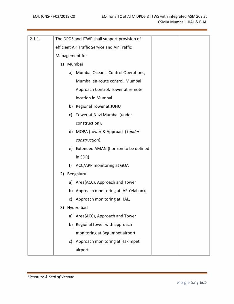
EOI: (CNS-P)-02/2019-20 EOI for SITC of ATM DPDS & ITWS with integrated ASMGCS at
CSMIA Mumbai, HIAL & BIAL
Signature & Seal of Vendor
P a g e 52 | 605
2.1.1. The DPDS and ITWP shall support provision of
efficient Air Traffic Service and Air Traffic
Management for
1) Mumbai
a) Mumbai Oceanic Control Operations,
Mumbai en-route control, Mumbai
Approach Control, Tower at remote
location in Mumbai
b) Regional Tower at JUHU
c) Tower at Navi Mumbai (under
construction),
d) MOPA (tower & Approach) (under
construction).
e) Extended AMAN (horizon to be defined
in SDR)
f) ACC/APP monitoring at GOA
2) Bengaluru:
a) Area(ACC), Approach and Tower
b) Approach monitoring at IAF Yelahanka
c) Approach monitoring at HAL,
3) Hyderabad
a) Area(ACC), Approach and Tower
b) Regional tower with approach
monitoring at Begumpet airport
c) Approach monitoring at Hakimpet
airport
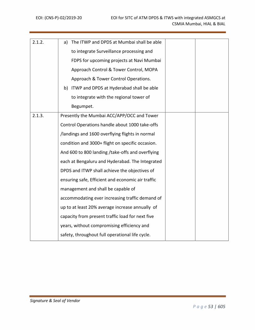
EOI: (CNS-P)-02/2019-20 EOI for SITC of ATM DPDS & ITWS with integrated ASMGCS at
CSMIA Mumbai, HIAL & BIAL
Signature & Seal of Vendor
P a g e 53 | 605
2.1.2. a) The ITWP and DPDS at Mumbai shall be able
to integrate Surveillance processing and
FDPS for upcoming projects at Navi Mumbai
Approach Control & Tower Control, MOPA
Approach & Tower Control Operations.
b) ITWP and DPDS at Hyderabad shall be able
to integrate with the regional tower of
Begumpet.
2.1.3. Presently the Mumbai ACC/APP/OCC and Tower
Control Operations handle about 1000 take-offs
/landings and 1600 overflying flights in normal
condition and 3000+ flight on specific occasion.
And 600 to 800 landing /take-offs and overflying
each at Bengaluru and Hyderabad. The Integrated
DPDS and ITWP shall achieve the objectives of
ensuring safe, Efficient and economic air traffic
management and shall be capable of
accommodating ever increasing traffic demand of
up to at least 20% average increase annually of
capacity from present traffic load for next five
years, without compromising efficiency and
safety, throughout full operational life cycle.
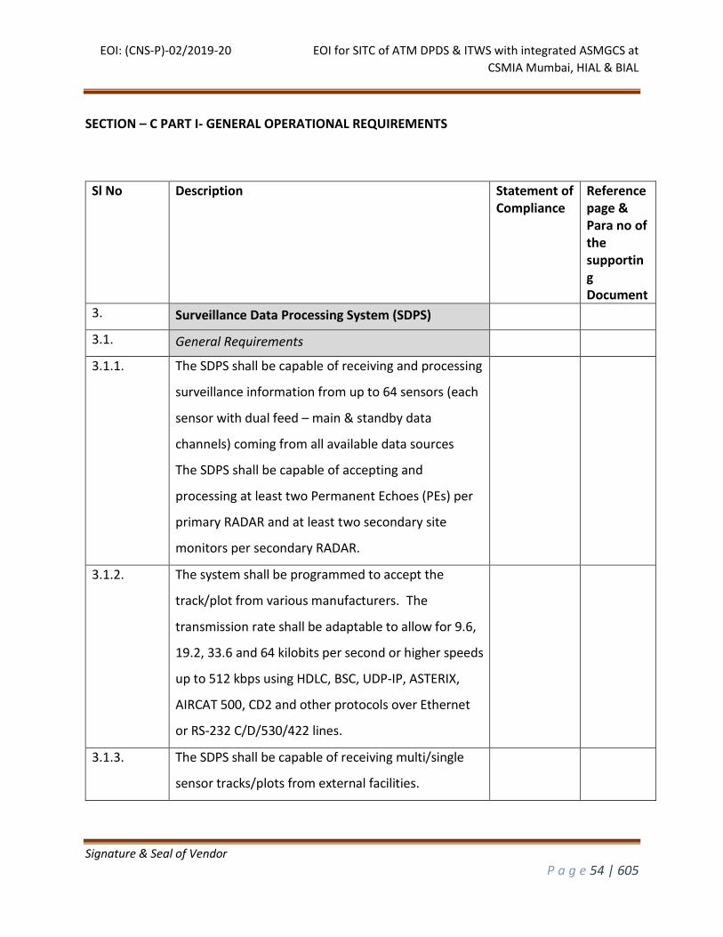
EOI: (CNS-P)-02/2019-20 EOI for SITC of ATM DPDS & ITWS with integrated ASMGCS at
CSMIA Mumbai, HIAL & BIAL
Signature & Seal of Vendor
P a g e 54 | 605
SECTION – C PART I- GENERAL OPERATIONAL REQUIREMENTS
Sl No Description Statement of Compliance
Reference page & Para no of the supporting Document
3. Surveillance Data Processing System (SDPS)
3.1. General Requirements
3.1.1. The SDPS shall be capable of receiving and processing
surveillance information from up to 64 sensors (each
sensor with dual feed – main & standby data
channels) coming from all available data sources
The SDPS shall be capable of accepting and
processing at least two Permanent Echoes (PEs) per
primary RADAR and at least two secondary site
monitors per secondary RADAR.
3.1.2. The system shall be programmed to accept the
track/plot from various manufacturers. The
transmission rate shall be adaptable to allow for 9.6,
19.2, 33.6 and 64 kilobits per second or higher speeds
up to 512 kbps using HDLC, BSC, UDP-IP, ASTERIX,
AIRCAT 500, CD2 and other protocols over Ethernet
or RS-232 C/D/530/422 lines.
3.1.3. The SDPS shall be capable of receiving multi/single
sensor tracks/plots from external facilities.
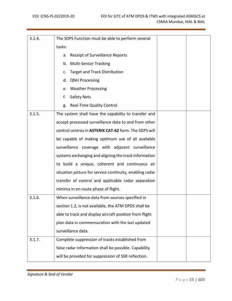
EOI: (CNS-P)-02/2019-20 EOI for SITC of ATM DPDS & ITWS with integrated ASMGCS at
CSMIA Mumbai, HIAL & BIAL
Signature & Seal of Vendor
P a g e 55 | 605
3.1.4. The SDPS Function must be able to perform several
tasks:
a. Receipt of Surveillance Reports
b. Multi-Sensor Tracking
c. Target and Track Distribution
d. QNH Processing
e. Weather Processing
f. Safety Nets
g. Real-Time Quality Control
3.1.5. The system shall have the capability to transfer and
accept processed surveillance data to and from other
control centres in ASTERIX CAT-62 form. The SDPS will
be capable of making optimum use of all available
surveillance coverage with adjacent surveillance
systems exchanging and aligning the track information
to build a unique, coherent and continuous air
situation picture for service continuity, enabling radar
transfer of control and applicable radar separation
minima in en-route phase of flight.
3.1.6. When surveillance data from sources specified in
section 1.2, is not available, the ATM DPDS shall be
able to track and display aircraft position from flight
plan data in commensuration with the last updated
surveillance data.
3.1.7. Complete suppression of tracks established from
false radar information shall be possible. Capability
will be provided for suppression of SSR reflection.
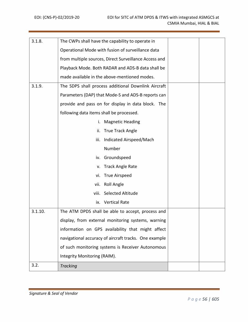
EOI: (CNS-P)-02/2019-20 EOI for SITC of ATM DPDS & ITWS with integrated ASMGCS at
CSMIA Mumbai, HIAL & BIAL
Signature & Seal of Vendor
P a g e 56 | 605
3.1.8. The CWPs shall have the capability to operate in
Operational Mode with fusion of surveillance data
from multiple sources, Direct Surveillance Access and
Playback Mode. Both RADAR and ADS-B data shall be
made available in the above-mentioned modes.
3.1.9. The SDPS shall process additional Downlink Aircraft
Parameters (DAP) that Mode-S and ADS-B reports can
provide and pass on for display in data block. The
following data items shall be processed.
i. Magnetic Heading
ii. True Track Angle
iii. Indicated Airspeed/Mach
Number
iv. Groundspeed
v. Track Angle Rate
vi. True Airspeed
vii. Roll Angle
viii. Selected Altitude
ix. Vertical Rate
3.1.10. The ATM DPDS shall be able to accept, process and
display, from external monitoring systems, warning
information on GPS availability that might affect
navigational accuracy of aircraft tracks. One example
of such monitoring systems is Receiver Autonomous
Integrity Monitoring (RAIM).
3.2. Tracking
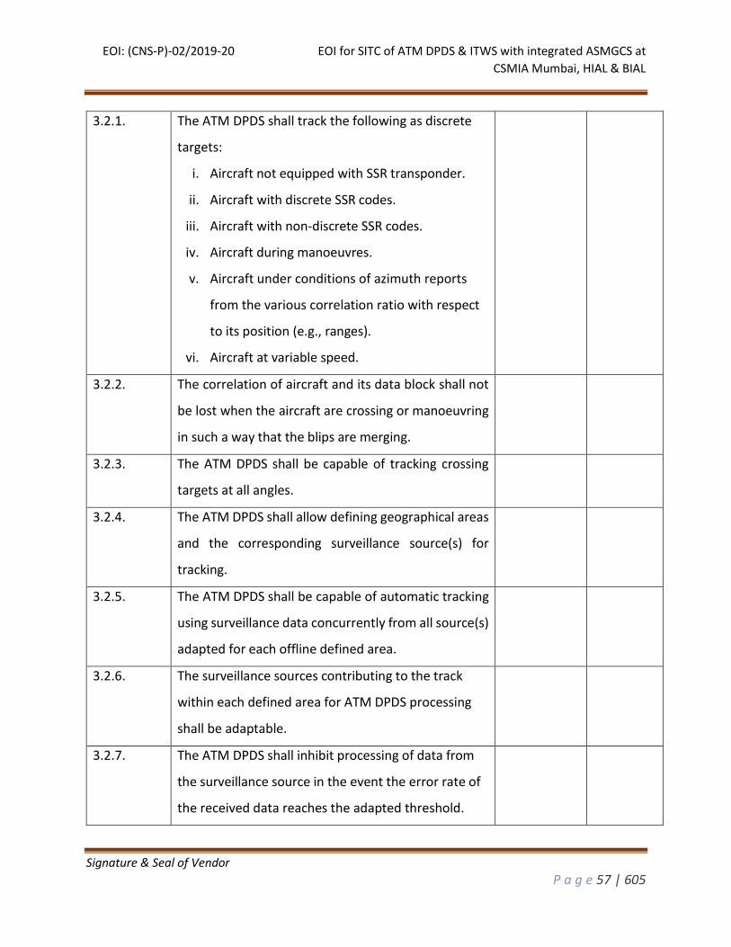
EOI: (CNS-P)-02/2019-20 EOI for SITC of ATM DPDS & ITWS with integrated ASMGCS at
CSMIA Mumbai, HIAL & BIAL
Signature & Seal of Vendor
P a g e 57 | 605
3.2.1. The ATM DPDS shall track the following as discrete
targets:
i. Aircraft not equipped with SSR transponder.
ii. Aircraft with discrete SSR codes.
iii. Aircraft with non-discrete SSR codes.
iv. Aircraft during manoeuvres.
v. Aircraft under conditions of azimuth reports
from the various correlation ratio with respect
to its position (e.g., ranges).
vi. Aircraft at variable speed.
3.2.2. The correlation of aircraft and its data block shall not
be lost when the aircraft are crossing or manoeuvring
in such a way that the blips are merging.
3.2.3. The ATM DPDS shall be capable of tracking crossing
targets at all angles.
3.2.4. The ATM DPDS shall allow defining geographical areas
and the corresponding surveillance source(s) for
tracking.
3.2.5. The ATM DPDS shall be capable of automatic tracking
using surveillance data concurrently from all source(s)
adapted for each offline defined area.
3.2.6. The surveillance sources contributing to the track
within each defined area for ATM DPDS processing
shall be adaptable.
3.2.7. The ATM DPDS shall inhibit processing of data from
the surveillance source in the event the error rate of
the received data reaches the adapted threshold.
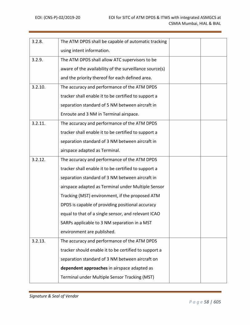
EOI: (CNS-P)-02/2019-20 EOI for SITC of ATM DPDS & ITWS with integrated ASMGCS at
CSMIA Mumbai, HIAL & BIAL
Signature & Seal of Vendor
P a g e 58 | 605
3.2.8. The ATM DPDS shall be capable of automatic tracking
using intent information.
3.2.9. The ATM DPDS shall allow ATC supervisors to be
aware of the availability of the surveillance source(s)
and the priority thereof for each defined area.
3.2.10. The accuracy and performance of the ATM DPDS
tracker shall enable it to be certified to support a
separation standard of 5 NM between aircraft in
Enroute and 3 NM in Terminal airspace.
3.2.11. The accuracy and performance of the ATM DPDS
tracker shall enable it to be certified to support a
separation standard of 3 NM between aircraft in
airspace adapted as Terminal.
3.2.12. The accuracy and performance of the ATM DPDS
tracker shall enable it to be certified to support a
separation standard of 3 NM between aircraft in
airspace adapted as Terminal under Multiple Sensor
Tracking (MST) environment, if the proposed ATM
DPDS is capable of providing positional accuracy
equal to that of a single sensor, and relevant ICAO
SARPs applicable to 3 NM separation in a MST
environment are published.
3.2.13. The accuracy and performance of the ATM DPDS
tracker should enable it to be certified to support a
separation standard of 3 NM between aircraft on
dependent approaches in airspace adapted as
Terminal under Multiple Sensor Tracking (MST)
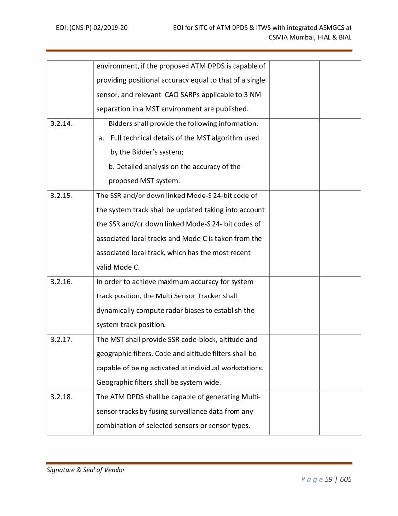
EOI: (CNS-P)-02/2019-20 EOI for SITC of ATM DPDS & ITWS with integrated ASMGCS at
CSMIA Mumbai, HIAL & BIAL
Signature & Seal of Vendor
P a g e 59 | 605
environment, if the proposed ATM DPDS is capable of
providing positional accuracy equal to that of a single
sensor, and relevant ICAO SARPs applicable to 3 NM
separation in a MST environment are published.
3.2.14. Bidders shall provide the following information:
a. Full technical details of the MST algorithm used
by the Bidder’s system;
b. Detailed analysis on the accuracy of the
proposed MST system.
3.2.15. The SSR and/or down linked Mode-S 24-bit code of
the system track shall be updated taking into account
the SSR and/or down linked Mode-S 24- bit codes of
associated local tracks and Mode C is taken from the
associated local track, which has the most recent
valid Mode C.
3.2.16. In order to achieve maximum accuracy for system
track position, the Multi Sensor Tracker shall
dynamically compute radar biases to establish the
system track position.
3.2.17. The MST shall provide SSR code-block, altitude and
geographic filters. Code and altitude filters shall be
capable of being activated at individual workstations.
Geographic filters shall be system wide.
3.2.18. The ATM DPDS shall be capable of generating Multi-
sensor tracks by fusing surveillance data from any
combination of selected sensors or sensor types.
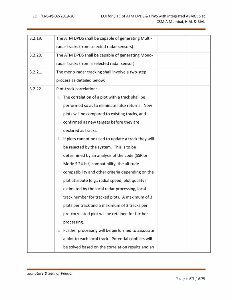
EOI: (CNS-P)-02/2019-20 EOI for SITC of ATM DPDS & ITWS with integrated ASMGCS at
CSMIA Mumbai, HIAL & BIAL
Signature & Seal of Vendor
P a g e 60 | 605
3.2.19. The ATM DPDS shall be capable of generating Multi-
radar tracks (from selected radar sensors).
3.2.20. The ATM DPDS shall be capable of generating Mono-
radar tracks (from a selected radar sensor).
3.2.21. The mono-radar tracking shall involve a two-step
process as detailed below:
3.2.22. Plot-track correlation:
i. The correlation of a plot with a track shall be
performed so as to eliminate false returns. New
plots will be compared to existing tracks, and
confirmed as new targets before they are
declared as tracks.
ii. If plots cannot be used to update a track they will
be rejected by the system. This is to be
determined by an analysis of the code (SSR or
Mode S 24-bit) compatibility, the altitude
compatibility and other criteria depending on the
plot attribute (e.g., radial speed, plot quality if
estimated by the local radar processing, local
track number for tracked plot). A maximum of 3
plots per track and a maximum of 3 tracks per
pre-correlated plot will be retained for further
processing.
iii. Further processing will be performed to associate
a plot to each local track. Potential conflicts will
be solved based on the correlation results and an
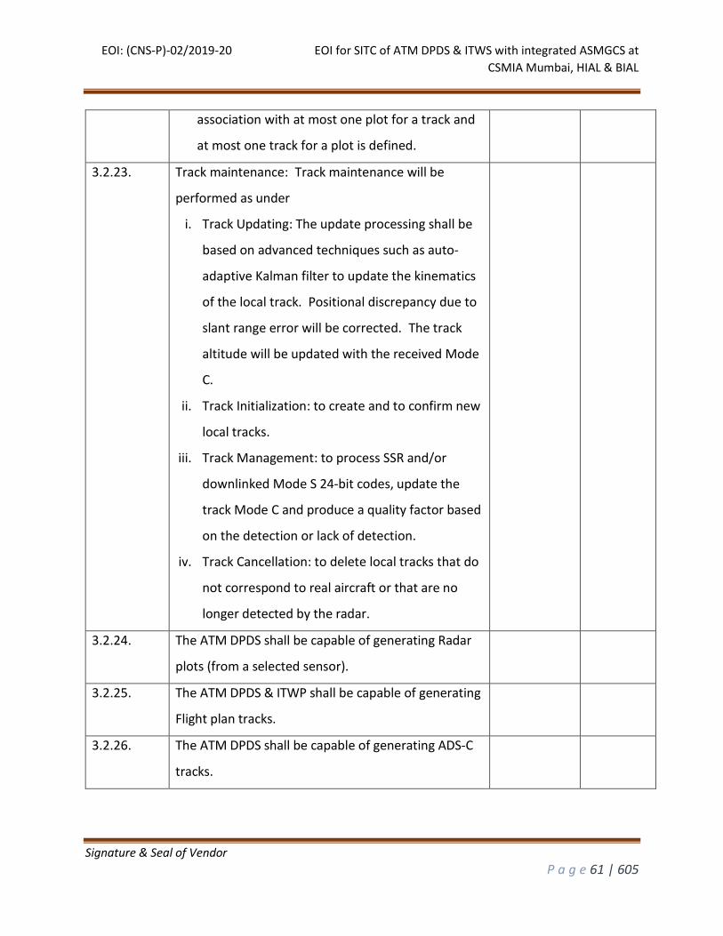
EOI: (CNS-P)-02/2019-20 EOI for SITC of ATM DPDS & ITWS with integrated ASMGCS at
CSMIA Mumbai, HIAL & BIAL
Signature & Seal of Vendor
P a g e 61 | 605
association with at most one plot for a track and
at most one track for a plot is defined.
3.2.23. Track maintenance: Track maintenance will be
performed as under
i. Track Updating: The update processing shall be
based on advanced techniques such as auto-
adaptive Kalman filter to update the kinematics
of the local track. Positional discrepancy due to
slant range error will be corrected. The track
altitude will be updated with the received Mode
C.
ii. Track Initialization: to create and to confirm new
local tracks.
iii. Track Management: to process SSR and/or
downlinked Mode S 24-bit codes, update the
track Mode C and produce a quality factor based
on the detection or lack of detection.
iv. Track Cancellation: to delete local tracks that do
not correspond to real aircraft or that are no
longer detected by the radar.
3.2.24. The ATM DPDS shall be capable of generating Radar
plots (from a selected sensor).
3.2.25. The ATM DPDS & ITWP shall be capable of generating
Flight plan tracks.
3.2.26. The ATM DPDS shall be capable of generating ADS-C
tracks.
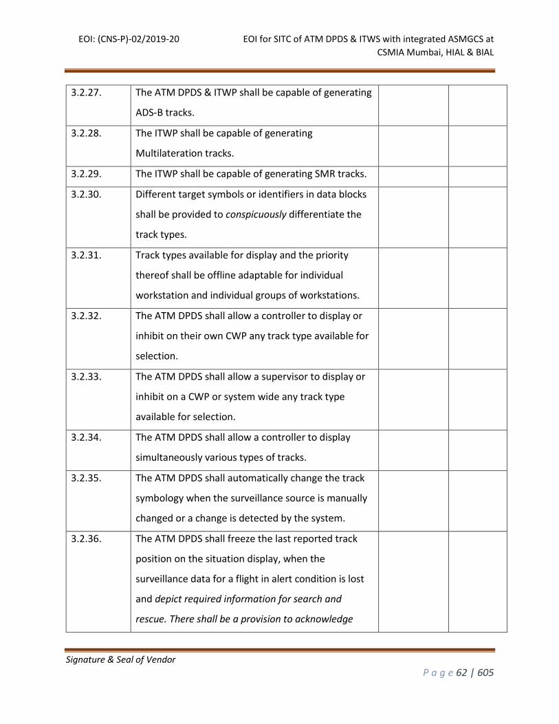
EOI: (CNS-P)-02/2019-20 EOI for SITC of ATM DPDS & ITWS with integrated ASMGCS at
CSMIA Mumbai, HIAL & BIAL
Signature & Seal of Vendor
P a g e 62 | 605
3.2.27. The ATM DPDS & ITWP shall be capable of generating
ADS-B tracks.
3.2.28. The ITWP shall be capable of generating
Multilateration tracks.
3.2.29. The ITWP shall be capable of generating SMR tracks.
3.2.30. Different target symbols or identifiers in data blocks
shall be provided to conspicuously differentiate the
track types.
3.2.31. Track types available for display and the priority
thereof shall be offline adaptable for individual
workstation and individual groups of workstations.
3.2.32. The ATM DPDS shall allow a controller to display or
inhibit on their own CWP any track type available for
selection.
3.2.33. The ATM DPDS shall allow a supervisor to display or
inhibit on a CWP or system wide any track type
available for selection.
3.2.34. The ATM DPDS shall allow a controller to display
simultaneously various types of tracks.
3.2.35. The ATM DPDS shall automatically change the track
symbology when the surveillance source is manually
changed or a change is detected by the system.
3.2.36. The ATM DPDS shall freeze the last reported track
position on the situation display, when the
surveillance data for a flight in alert condition is lost
and depict required information for search and
rescue. There shall be a provision to acknowledge
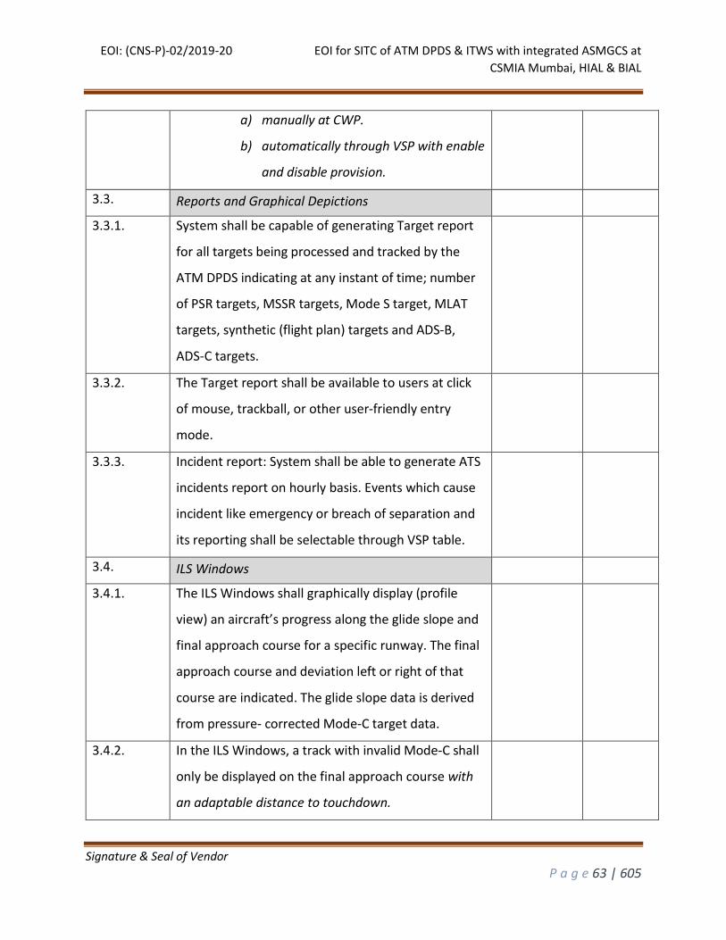
EOI: (CNS-P)-02/2019-20 EOI for SITC of ATM DPDS & ITWS with integrated ASMGCS at
CSMIA Mumbai, HIAL & BIAL
Signature & Seal of Vendor
P a g e 63 | 605
a) manually at CWP.
b) automatically through VSP with enable
and disable provision.
3.3. Reports and Graphical Depictions
3.3.1. System shall be capable of generating Target report
for all targets being processed and tracked by the
ATM DPDS indicating at any instant of time; number
of PSR targets, MSSR targets, Mode S target, MLAT
targets, synthetic (flight plan) targets and ADS-B,
ADS-C targets.
3.3.2. The Target report shall be available to users at click
of mouse, trackball, or other user-friendly entry
mode.
3.3.3. Incident report: System shall be able to generate ATS
incidents report on hourly basis. Events which cause
incident like emergency or breach of separation and
its reporting shall be selectable through VSP table.
3.4. ILS Windows
3.4.1. The ILS Windows shall graphically display (profile
view) an aircraft’s progress along the glide slope and
final approach course for a specific runway. The final
approach course and deviation left or right of that
course are indicated. The glide slope data is derived
from pressure- corrected Mode-C target data.
3.4.2. In the ILS Windows, a track with invalid Mode-C shall
only be displayed on the final approach course with
an adaptable distance to touchdown.

EOI: (CNS-P)-02/2019-20 EOI for SITC of ATM DPDS & ITWS with integrated ASMGCS at
CSMIA Mumbai, HIAL & BIAL
Signature & Seal of Vendor
P a g e 64 | 605
3.4.3. The ILS windows shall be available for all instrument
approach provided runways.
3.4.4. The ILS Window shall be able to be opened, closed,
moved and resized. Orientation of ILS Window should
be in accordance to the relative position of control
tower wrt RWY in use.
3.4.5. Inter Console Marker (M) – ICM function causes a
special marker to appear on another controller
workstation. The position of the marker at the
receiving position is controlled by moving the PED at
the initiating position. ICM should show the CJI.
3.4.6. Point-Of-Closest-Approach – The ATM DPDS shall
graphically display the closest point and time of
passing of two tracks.
3.4.7. The ATM DPDS shall be capable of displaying up to six
(6) simultaneous ILS Windows each CWP.
3.5. Sensor Monitoring
3.5.1. Sensor status shall be made available to M&C and
CWP
3.5.2. The ATM DPDS shall be capable of receiving alerts
from the M&C for each surveillance sensor.
3.5.3. Splitters shall be provided to split surveillance
information from each sensor for dual channel
processing.
3.5.4. The ATM DPDS shall be capable of accepting two
channels of data from each surveillance sensor.
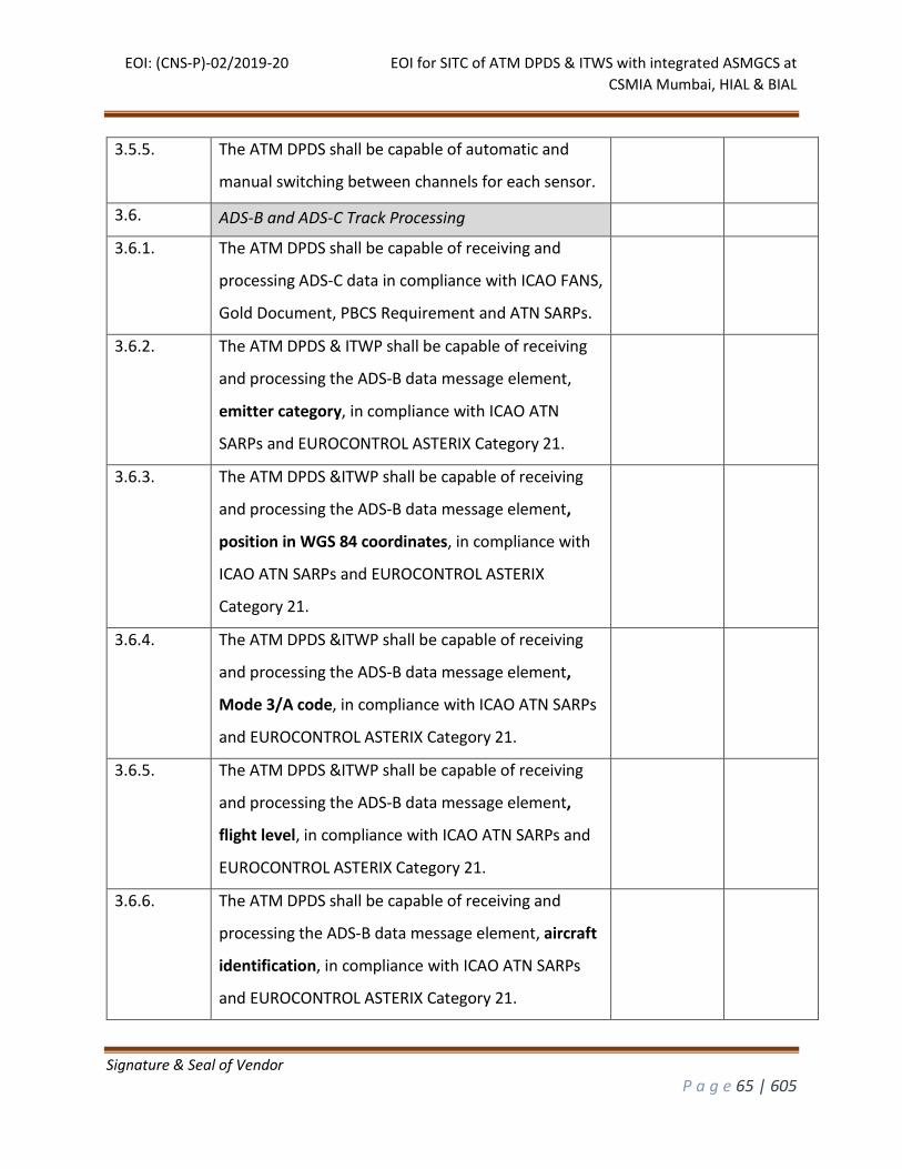
EOI: (CNS-P)-02/2019-20 EOI for SITC of ATM DPDS & ITWS with integrated ASMGCS at
CSMIA Mumbai, HIAL & BIAL
Signature & Seal of Vendor
P a g e 65 | 605
3.5.5. The ATM DPDS shall be capable of automatic and
manual switching between channels for each sensor.
3.6. ADS-B and ADS-C Track Processing
3.6.1. The ATM DPDS shall be capable of receiving and
processing ADS-C data in compliance with ICAO FANS,
Gold Document, PBCS Requirement and ATN SARPs.
3.6.2. The ATM DPDS & ITWP shall be capable of receiving
and processing the ADS-B data message element,
emitter category, in compliance with ICAO ATN
SARPs and EUROCONTROL ASTERIX Category 21.
3.6.3. The ATM DPDS &ITWP shall be capable of receiving
and processing the ADS-B data message element,
position in WGS 84 coordinates, in compliance with
ICAO ATN SARPs and EUROCONTROL ASTERIX
Category 21.
3.6.4. The ATM DPDS &ITWP shall be capable of receiving
and processing the ADS-B data message element,
Mode 3/A code, in compliance with ICAO ATN SARPs
and EUROCONTROL ASTERIX Category 21.
3.6.5. The ATM DPDS &ITWP shall be capable of receiving
and processing the ADS-B data message element,
flight level, in compliance with ICAO ATN SARPs and
EUROCONTROL ASTERIX Category 21.
3.6.6. The ATM DPDS shall be capable of receiving and
processing the ADS-B data message element, aircraft
identification, in compliance with ICAO ATN SARPs
and EUROCONTROL ASTERIX Category 21.
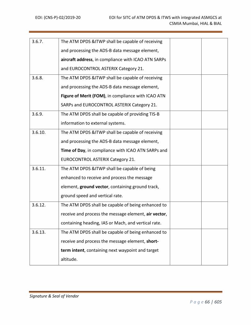
EOI: (CNS-P)-02/2019-20 EOI for SITC of ATM DPDS & ITWS with integrated ASMGCS at
CSMIA Mumbai, HIAL & BIAL
Signature & Seal of Vendor
P a g e 66 | 605
3.6.7. The ATM DPDS &ITWP shall be capable of receiving
and processing the ADS-B data message element,
aircraft address, in compliance with ICAO ATN SARPs
and EUROCONTROL ASTERIX Category 21.
3.6.8. The ATM DPDS &ITWP shall be capable of receiving
and processing the ADS-B data message element,
Figure of Merit (FOM), in compliance with ICAO ATN
SARPs and EUROCONTROL ASTERIX Category 21.
3.6.9. The ATM DPDS shall be capable of providing TIS-B
information to external systems.
3.6.10. The ATM DPDS &ITWP shall be capable of receiving
and processing the ADS-B data message element,
Time of Day, in compliance with ICAO ATN SARPs and
EUROCONTROL ASTERIX Category 21.
3.6.11. The ATM DPDS &ITWP shall be capable of being
enhanced to receive and process the message
element, ground vector, containing ground track,
ground speed and vertical rate.
3.6.12. The ATM DPDS shall be capable of being enhanced to
receive and process the message element, air vector,
containing heading, IAS or Mach, and vertical rate.
3.6.13. The ATM DPDS shall be capable of being enhanced to
receive and process the message element, short-
term intent, containing next waypoint and target
altitude.
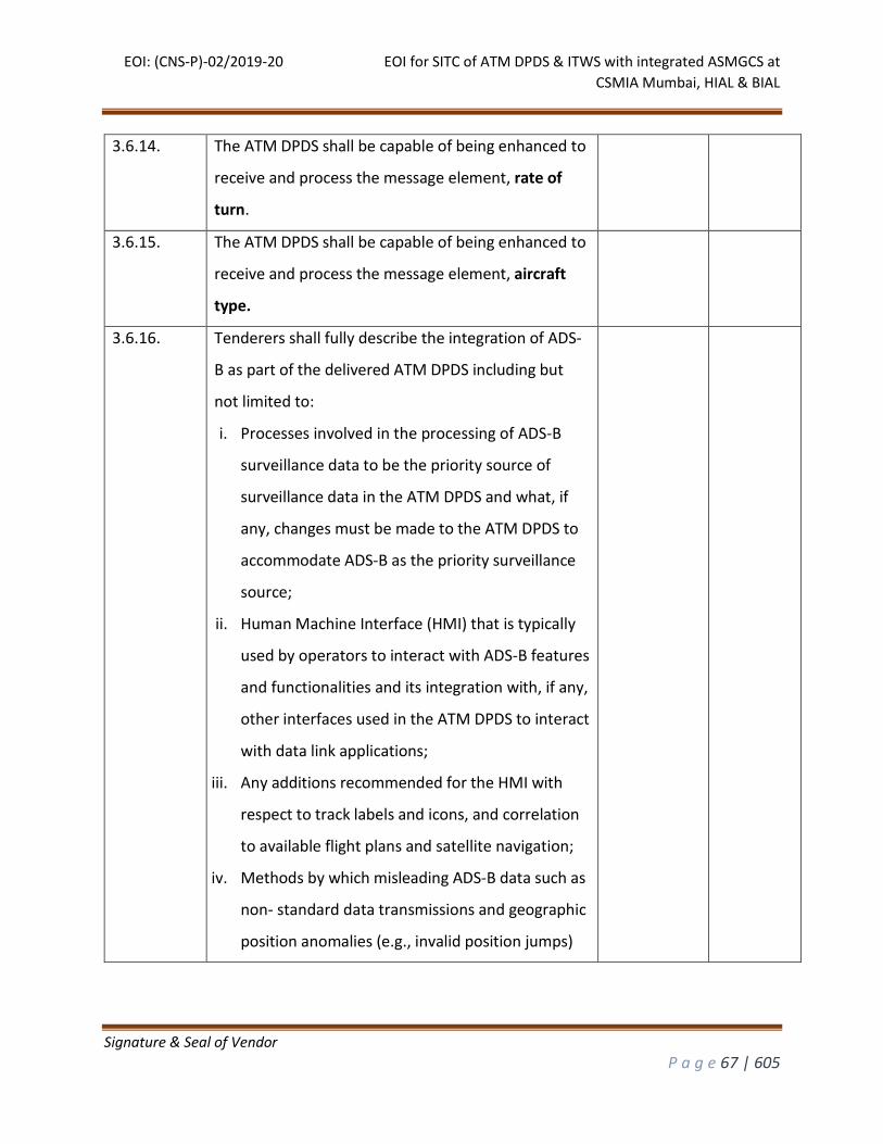
EOI: (CNS-P)-02/2019-20 EOI for SITC of ATM DPDS & ITWS with integrated ASMGCS at
CSMIA Mumbai, HIAL & BIAL
Signature & Seal of Vendor
P a g e 67 | 605
3.6.14. The ATM DPDS shall be capable of being enhanced to
receive and process the message element, rate of
turn.
3.6.15. The ATM DPDS shall be capable of being enhanced to
receive and process the message element, aircraft
type.
3.6.16. Tenderers shall fully describe the integration of ADS-
B as part of the delivered ATM DPDS including but
not limited to:
i. Processes involved in the processing of ADS-B
surveillance data to be the priority source of
surveillance data in the ATM DPDS and what, if
any, changes must be made to the ATM DPDS to
accommodate ADS-B as the priority surveillance
source;
ii. Human Machine Interface (HMI) that is typically
used by operators to interact with ADS-B features
and functionalities and its integration with, if any,
other interfaces used in the ATM DPDS to interact
with data link applications;
iii. Any additions recommended for the HMI with
respect to track labels and icons, and correlation
to available flight plans and satellite navigation;
iv. Methods by which misleading ADS-B data such as
non- standard data transmissions and geographic
position anomalies (e.g., invalid position jumps)
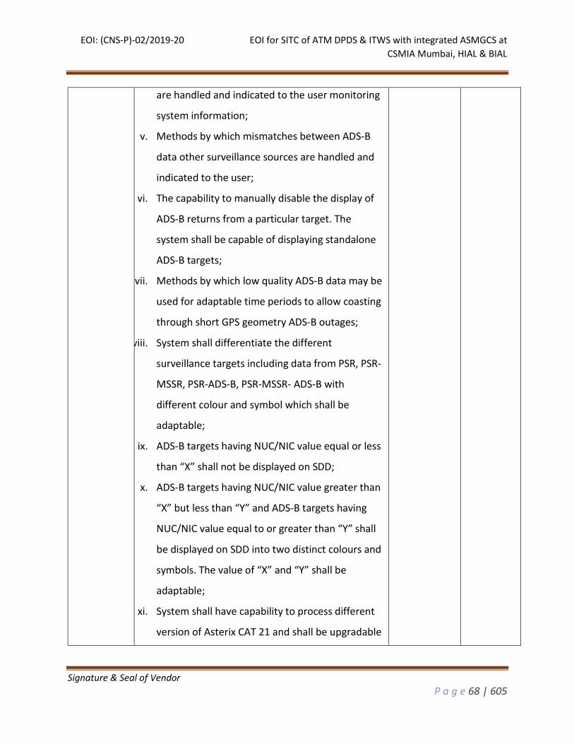
EOI: (CNS-P)-02/2019-20 EOI for SITC of ATM DPDS & ITWS with integrated ASMGCS at
CSMIA Mumbai, HIAL & BIAL
Signature & Seal of Vendor
P a g e 68 | 605
are handled and indicated to the user monitoring
system information;
v. Methods by which mismatches between ADS-B
data other surveillance sources are handled and
indicated to the user;
vi. The capability to manually disable the display of
ADS-B returns from a particular target. The
system shall be capable of displaying standalone
ADS-B targets;
vii. Methods by which low quality ADS-B data may be
used for adaptable time periods to allow coasting
through short GPS geometry ADS-B outages;
viii. System shall differentiate the different
surveillance targets including data from PSR, PSR-
MSSR, PSR-ADS-B, PSR-MSSR- ADS-B with
different colour and symbol which shall be
adaptable;
ix. ADS-B targets having NUC/NIC value equal or less
than “X” shall not be displayed on SDD;
x. ADS-B targets having NUC/NIC value greater than
“X” but less than “Y” and ADS-B targets having
NUC/NIC value equal to or greater than “Y” shall
be displayed on SDD into two distinct colours and
symbols. The value of “X” and “Y” shall be
adaptable;
xi. System shall have capability to process different
version of Asterix CAT 21 and shall be upgradable
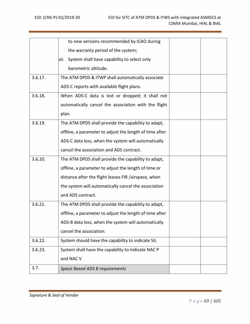
EOI: (CNS-P)-02/2019-20 EOI for SITC of ATM DPDS & ITWS with integrated ASMGCS at
CSMIA Mumbai, HIAL & BIAL
Signature & Seal of Vendor
P a g e 69 | 605
to new versions recommended by ICAO during
the warranty period of the system;
xii. System shall have capability to select only
barometric altitude.
3.6.17. The ATM DPDS & ITWP shall automatically associate
ADS-C reports with available flight plans.
3.6.18. When ADS-C data is lost or dropped; it shall not
automatically cancel the association with the flight
plan.
3.6.19. The ATM DPDS shall provide the capability to adapt,
offline, a parameter to adjust the length of time after
ADS-C data loss, when the system will automatically
cancel the association and ADS contract.
3.6.20. The ATM DPDS shall provide the capability to adapt,
offline, a parameter to adjust the length of time or
distance after the flight leaves FIR /airspace, when
the system will automatically cancel the association
and ADS contract.
3.6.21. The ATM DPDS shall provide the capability to adapt,
offline, a parameter to adjust the length of time after
ADS-B data loss, when the system will automatically
cancel the association.
3.6.22. System should have the capability to indicate SIL
3.6.23. System shall have the capability to indicate NAC P
and NAC V
3.7. Space Based ADS B requirements
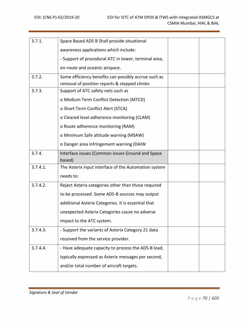
EOI: (CNS-P)-02/2019-20 EOI for SITC of ATM DPDS & ITWS with integrated ASMGCS at
CSMIA Mumbai, HIAL & BIAL
Signature & Seal of Vendor
P a g e 70 | 605
3.7.1. Space Based ADS B Shall provide situational
awareness applications which include:
- Support of procedural ATC in tower, terminal area,
en-route and oceanic airspace.
3.7.2. Some efficiency benefits can possibly accrue such as
removal of position reports & stepped climbs
3.7.3. Support of ATC safety nets such as
o Medium Term Conflict Detection (MTCD)
o Short Term Conflict Alert (STCA)
o Cleared level adherence monitoring (CLAM)
o Route adherence monitoring (RAM)
o Minimum Safe altitude warning (MSAW)
o Danger area infringement warning (DAIW
3.7.4. Interface issues (Common issues Ground and Space
based)
3.7.4.1. The Asterix input interface of the Automation system
needs to:
3.7.4.2. Reject Asterix categories other than those required
to be processed. Some ADS-B sources may output
additional Asterix Categories. It is essential that
unexpected Asterix Categories cause no adverse
impact to the ATC system.
3.7.4.3. - Support the variants of Asterix Category 21 data
received from the service provider.
3.7.4.4. - Have adequate capacity to process the ADS-B load,
typically expressed as Asterix messages per second,
and/or total number of aircraft targets.
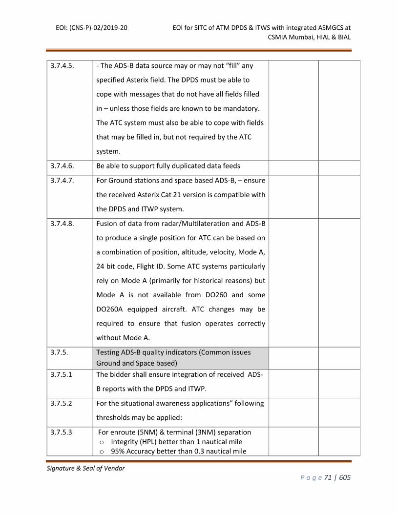
EOI: (CNS-P)-02/2019-20 EOI for SITC of ATM DPDS & ITWS with integrated ASMGCS at
CSMIA Mumbai, HIAL & BIAL
Signature & Seal of Vendor
P a g e 71 | 605
3.7.4.5. - The ADS-B data source may or may not “fill” any
specified Asterix field. The DPDS must be able to
cope with messages that do not have all fields filled
in – unless those fields are known to be mandatory.
The ATC system must also be able to cope with fields
that may be filled in, but not required by the ATC
system.
3.7.4.6. Be able to support fully duplicated data feeds
3.7.4.7. For Ground stations and space based ADS-B, – ensure
the received Asterix Cat 21 version is compatible with
the DPDS and ITWP system.
3.7.4.8. Fusion of data from radar/Multilateration and ADS-B
to produce a single position for ATC can be based on
a combination of position, altitude, velocity, Mode A,
24 bit code, Flight ID. Some ATC systems particularly
rely on Mode A (primarily for historical reasons) but
Mode A is not available from DO260 and some
DO260A equipped aircraft. ATC changes may be
required to ensure that fusion operates correctly
without Mode A.
3.7.5. Testing ADS-B quality indicators (Common issues
Ground and Space based)
3.7.5.1 The bidder shall ensure integration of received ADS-
B reports with the DPDS and ITWP.
3.7.5.2 For the situational awareness applications” following
thresholds may be applied:
3.7.5.3 For enroute (5NM) & terminal (3NM) separation o Integrity (HPL) better than 1 nautical mile o 95% Accuracy better than 0.3 nautical mile
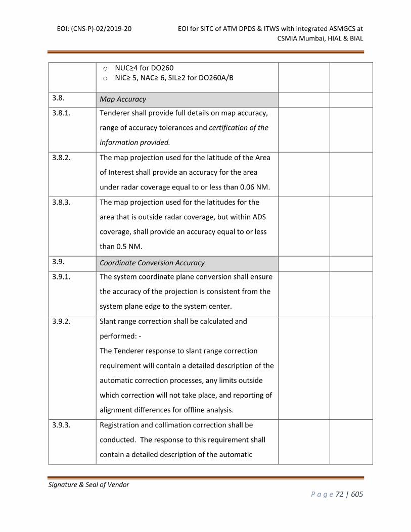
EOI: (CNS-P)-02/2019-20 EOI for SITC of ATM DPDS & ITWS with integrated ASMGCS at
CSMIA Mumbai, HIAL & BIAL
Signature & Seal of Vendor
P a g e 72 | 605
o NUC≥4 for DO260 o NIC≥ 5, NAC≥ 6, SIL≥2 for DO260A/B
3.8. Map Accuracy
3.8.1. Tenderer shall provide full details on map accuracy,
range of accuracy tolerances and certification of the
information provided.
3.8.2. The map projection used for the latitude of the Area
of Interest shall provide an accuracy for the area
under radar coverage equal to or less than 0.06 NM.
3.8.3. The map projection used for the latitudes for the
area that is outside radar coverage, but within ADS
coverage, shall provide an accuracy equal to or less
than 0.5 NM.
3.9. Coordinate Conversion Accuracy
3.9.1. The system coordinate plane conversion shall ensure
the accuracy of the projection is consistent from the
system plane edge to the system center.
3.9.2. Slant range correction shall be calculated and
performed: -
The Tenderer response to slant range correction
requirement will contain a detailed description of the
automatic correction processes, any limits outside
which correction will not take place, and reporting of
alignment differences for offline analysis.
3.9.3. Registration and collimation correction shall be
conducted. The response to this requirement shall
contain a detailed description of the automatic
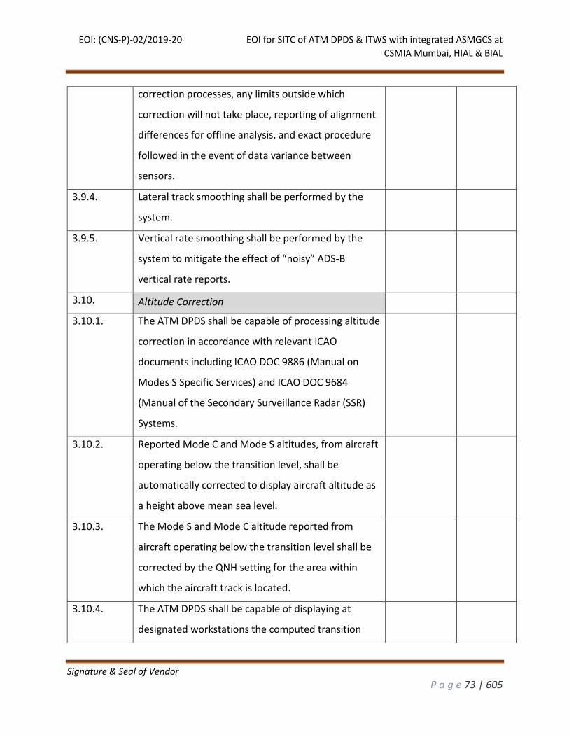
EOI: (CNS-P)-02/2019-20 EOI for SITC of ATM DPDS & ITWS with integrated ASMGCS at
CSMIA Mumbai, HIAL & BIAL
Signature & Seal of Vendor
P a g e 73 | 605
correction processes, any limits outside which
correction will not take place, reporting of alignment
differences for offline analysis, and exact procedure
followed in the event of data variance between
sensors.
3.9.4. Lateral track smoothing shall be performed by the
system.
3.9.5. Vertical rate smoothing shall be performed by the
system to mitigate the effect of “noisy” ADS-B
vertical rate reports.
3.10. Altitude Correction
3.10.1. The ATM DPDS shall be capable of processing altitude
correction in accordance with relevant ICAO
documents including ICAO DOC 9886 (Manual on
Modes S Specific Services) and ICAO DOC 9684
(Manual of the Secondary Surveillance Radar (SSR)
Systems.
3.10.2. Reported Mode C and Mode S altitudes, from aircraft
operating below the transition level, shall be
automatically corrected to display aircraft altitude as
a height above mean sea level.
3.10.3. The Mode S and Mode C altitude reported from
aircraft operating below the transition level shall be
corrected by the QNH setting for the area within
which the aircraft track is located.
3.10.4. The ATM DPDS shall be capable of displaying at
designated workstations the computed transition
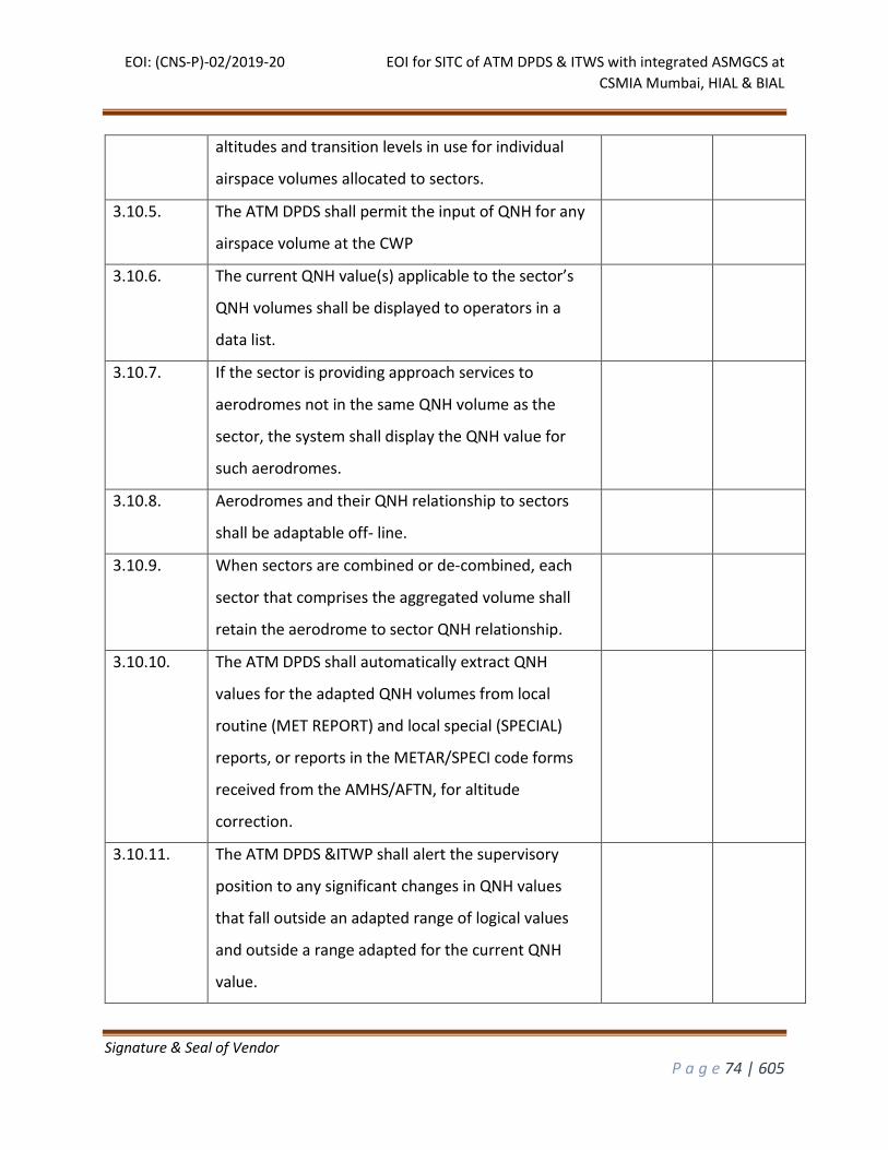
EOI: (CNS-P)-02/2019-20 EOI for SITC of ATM DPDS & ITWS with integrated ASMGCS at
CSMIA Mumbai, HIAL & BIAL
Signature & Seal of Vendor
P a g e 74 | 605
altitudes and transition levels in use for individual
airspace volumes allocated to sectors.
3.10.5. The ATM DPDS shall permit the input of QNH for any
airspace volume at the CWP
3.10.6. The current QNH value(s) applicable to the sector’s
QNH volumes shall be displayed to operators in a
data list.
3.10.7. If the sector is providing approach services to
aerodromes not in the same QNH volume as the
sector, the system shall display the QNH value for
such aerodromes.
3.10.8. Aerodromes and their QNH relationship to sectors
shall be adaptable off- line.
3.10.9. When sectors are combined or de-combined, each
sector that comprises the aggregated volume shall
retain the aerodrome to sector QNH relationship.
3.10.10. The ATM DPDS shall automatically extract QNH
values for the adapted QNH volumes from local
routine (MET REPORT) and local special (SPECIAL)
reports, or reports in the METAR/SPECI code forms
received from the AMHS/AFTN, for altitude
correction.
3.10.11. The ATM DPDS &ITWP shall alert the supervisory
position to any significant changes in QNH values
that fall outside an adapted range of logical values
and outside a range adapted for the current QNH
value.
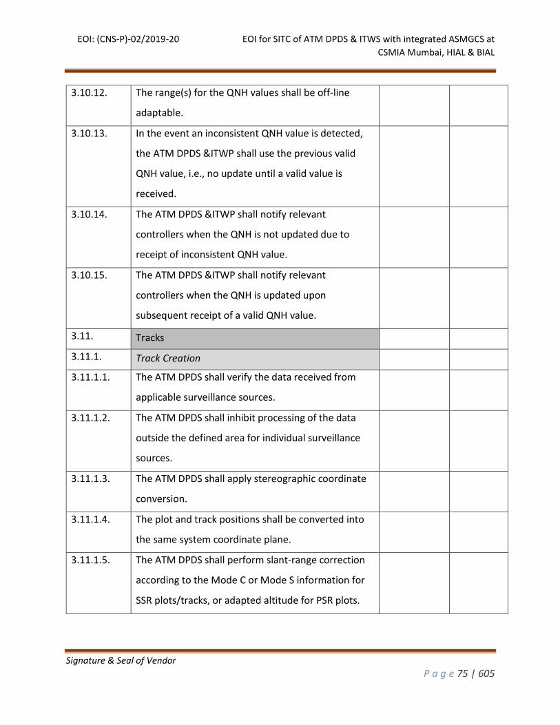
EOI: (CNS-P)-02/2019-20 EOI for SITC of ATM DPDS & ITWS with integrated ASMGCS at
CSMIA Mumbai, HIAL & BIAL
Signature & Seal of Vendor
P a g e 75 | 605
3.10.12. The range(s) for the QNH values shall be off-line
adaptable.
3.10.13. In the event an inconsistent QNH value is detected,
the ATM DPDS &ITWP shall use the previous valid
QNH value, i.e., no update until a valid value is
received.
3.10.14. The ATM DPDS &ITWP shall notify relevant
controllers when the QNH is not updated due to
receipt of inconsistent QNH value.
3.10.15. The ATM DPDS &ITWP shall notify relevant
controllers when the QNH is updated upon
subsequent receipt of a valid QNH value.
3.11. Tracks
3.11.1. Track Creation
3.11.1.1. The ATM DPDS shall verify the data received from
applicable surveillance sources.
3.11.1.2. The ATM DPDS shall inhibit processing of the data
outside the defined area for individual surveillance
sources.
3.11.1.3. The ATM DPDS shall apply stereographic coordinate
conversion.
3.11.1.4. The plot and track positions shall be converted into
the same system coordinate plane.
3.11.1.5. The ATM DPDS shall perform slant-range correction
according to the Mode C or Mode S information for
SSR plots/tracks, or adapted altitude for PSR plots.
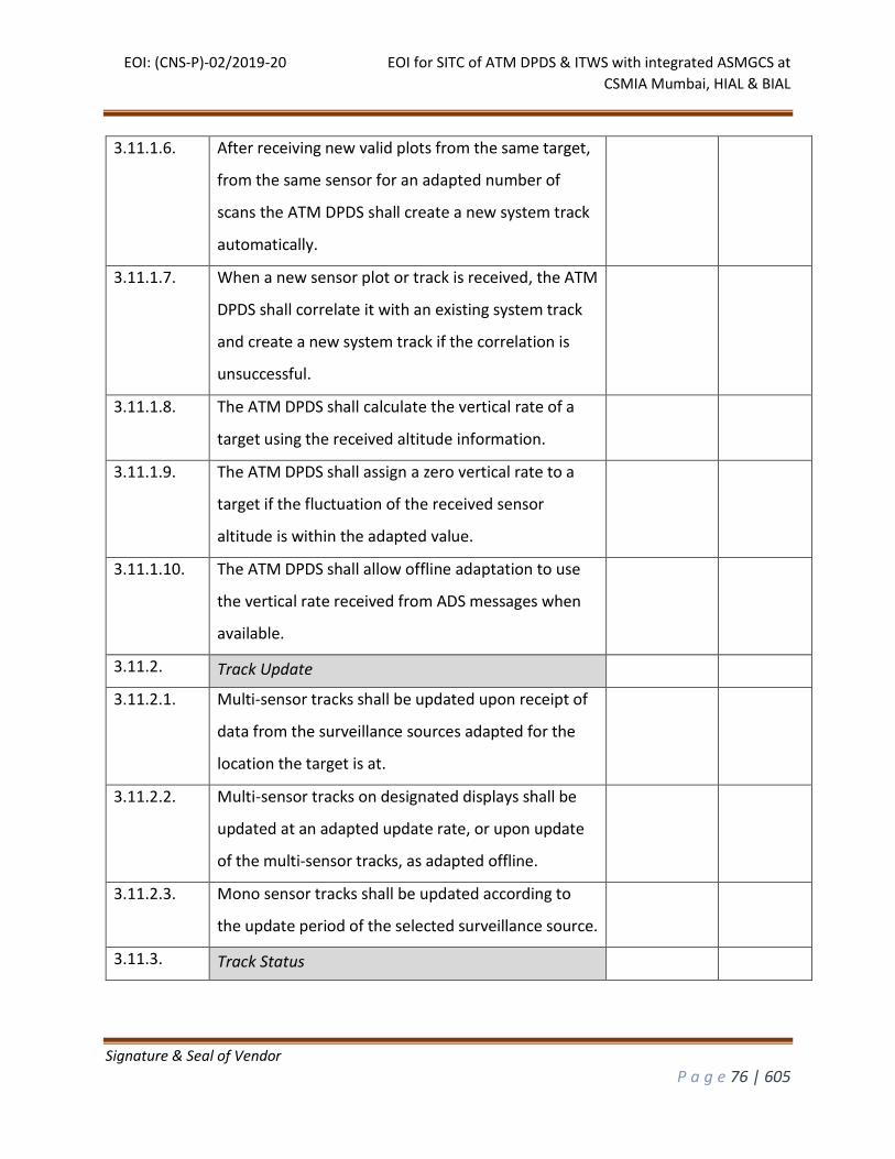
EOI: (CNS-P)-02/2019-20 EOI for SITC of ATM DPDS & ITWS with integrated ASMGCS at
CSMIA Mumbai, HIAL & BIAL
Signature & Seal of Vendor
P a g e 76 | 605
3.11.1.6. After receiving new valid plots from the same target,
from the same sensor for an adapted number of
scans the ATM DPDS shall create a new system track
automatically.
3.11.1.7. When a new sensor plot or track is received, the ATM
DPDS shall correlate it with an existing system track
and create a new system track if the correlation is
unsuccessful.
3.11.1.8. The ATM DPDS shall calculate the vertical rate of a
target using the received altitude information.
3.11.1.9. The ATM DPDS shall assign a zero vertical rate to a
target if the fluctuation of the received sensor
altitude is within the adapted value.
3.11.1.10. The ATM DPDS shall allow offline adaptation to use
the vertical rate received from ADS messages when
available.
3.11.2. Track Update
3.11.2.1. Multi-sensor tracks shall be updated upon receipt of
data from the surveillance sources adapted for the
location the target is at.
3.11.2.2. Multi-sensor tracks on designated displays shall be
updated at an adapted update rate, or upon update
of the multi-sensor tracks, as adapted offline.
3.11.2.3. Mono sensor tracks shall be updated according to
the update period of the selected surveillance source.
3.11.3. Track Status
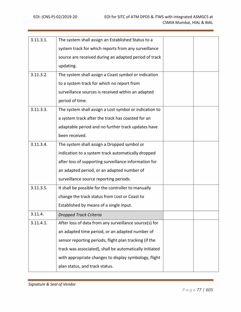
EOI: (CNS-P)-02/2019-20 EOI for SITC of ATM DPDS & ITWS with integrated ASMGCS at
CSMIA Mumbai, HIAL & BIAL
Signature & Seal of Vendor
P a g e 77 | 605
3.11.3.1. The system shall assign an Established Status to a
system track for which reports from any surveillance
source are received during an adapted period of track
updating.
3.11.3.2. The system shall assign a Coast symbol or indication
to a system track for which no report from
surveillance sources is received within an adapted
period of time.
3.11.3.3. The system shall assign a Lost symbol or indication to
a system track after the track has coasted for an
adaptable period and no further track updates have
been received.
3.11.3.4. The system shall assign a Dropped symbol or
indication to a system track automatically dropped
after loss of supporting surveillance information for
an adapted period, or an adapted number of
surveillance source reporting periods.
3.11.3.5. It shall be possible for the controller to manually
change the track status from Lost or Coast to
Established by means of a single input.
3.11.4. Dropped Track Criteria
3.11.4.1. After loss of data from any surveillance source(s) for
an adapted time period, or an adapted number of
sensor reporting periods, flight plan tracking (if the
track was associated), shall be automatically initiated
with appropriate changes to display symbology, flight
plan status, and track status.
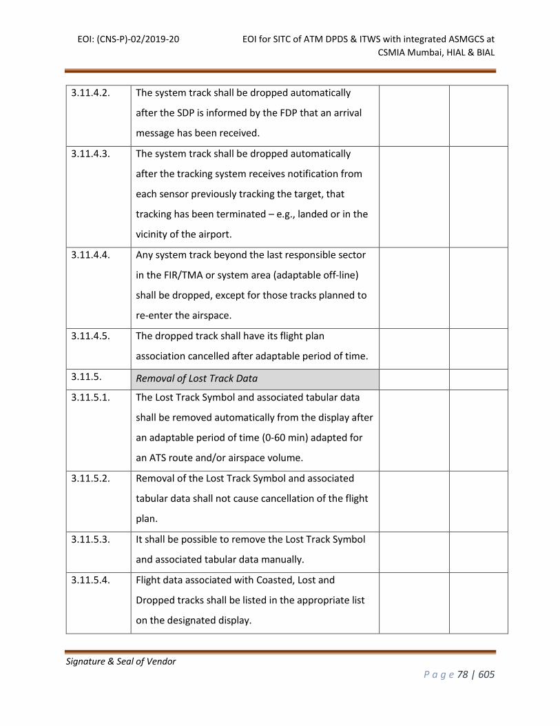
EOI: (CNS-P)-02/2019-20 EOI for SITC of ATM DPDS & ITWS with integrated ASMGCS at
CSMIA Mumbai, HIAL & BIAL
Signature & Seal of Vendor
P a g e 78 | 605
3.11.4.2. The system track shall be dropped automatically
after the SDP is informed by the FDP that an arrival
message has been received.
3.11.4.3. The system track shall be dropped automatically
after the tracking system receives notification from
each sensor previously tracking the target, that
tracking has been terminated – e.g., landed or in the
vicinity of the airport.
3.11.4.4. Any system track beyond the last responsible sector
in the FIR/TMA or system area (adaptable off-line)
shall be dropped, except for those tracks planned to
re-enter the airspace.
3.11.4.5. The dropped track shall have its flight plan
association cancelled after adaptable period of time.
3.11.5. Removal of Lost Track Data
3.11.5.1. The Lost Track Symbol and associated tabular data
shall be removed automatically from the display after
an adaptable period of time (0-60 min) adapted for
an ATS route and/or airspace volume.
3.11.5.2. Removal of the Lost Track Symbol and associated
tabular data shall not cause cancellation of the flight
plan.
3.11.5.3. It shall be possible to remove the Lost Track Symbol
and associated tabular data manually.
3.11.5.4. Flight data associated with Coasted, Lost and
Dropped tracks shall be listed in the appropriate list
on the designated display.
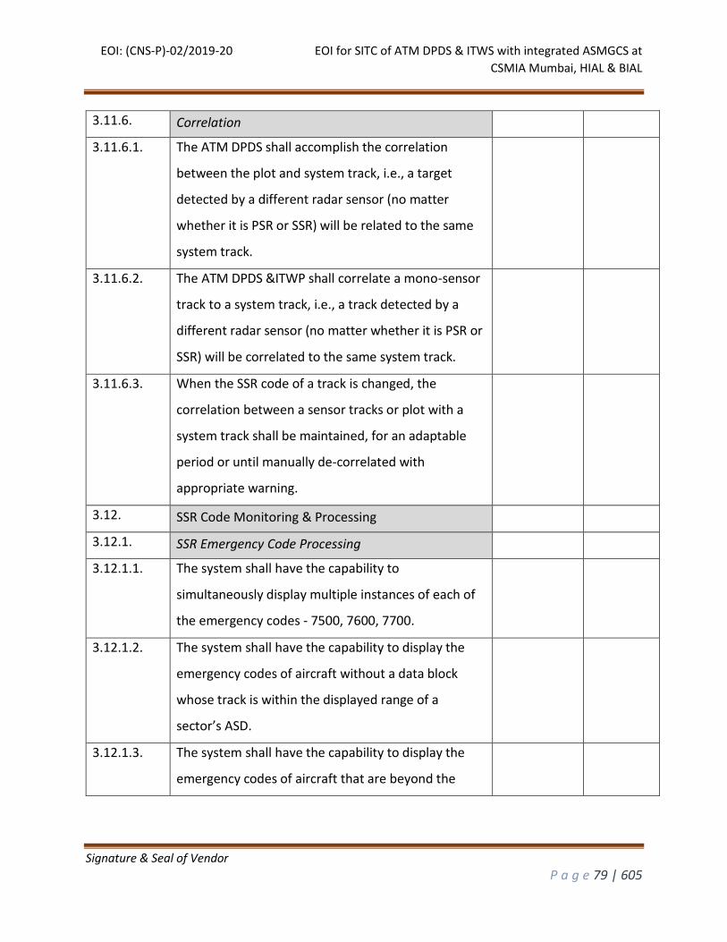
EOI: (CNS-P)-02/2019-20 EOI for SITC of ATM DPDS & ITWS with integrated ASMGCS at
CSMIA Mumbai, HIAL & BIAL
Signature & Seal of Vendor
P a g e 79 | 605
3.11.6. Correlation
3.11.6.1. The ATM DPDS shall accomplish the correlation
between the plot and system track, i.e., a target
detected by a different radar sensor (no matter
whether it is PSR or SSR) will be related to the same
system track.
3.11.6.2. The ATM DPDS &ITWP shall correlate a mono-sensor
track to a system track, i.e., a track detected by a
different radar sensor (no matter whether it is PSR or
SSR) will be correlated to the same system track.
3.11.6.3. When the SSR code of a track is changed, the
correlation between a sensor tracks or plot with a
system track shall be maintained, for an adaptable
period or until manually de-correlated with
appropriate warning.
3.12. SSR Code Monitoring & Processing
3.12.1. SSR Emergency Code Processing
3.12.1.1. The system shall have the capability to
simultaneously display multiple instances of each of
the emergency codes - 7500, 7600, 7700.
3.12.1.2. The system shall have the capability to display the
emergency codes of aircraft without a data block
whose track is within the displayed range of a
sector’s ASD.
3.12.1.3. The system shall have the capability to display the
emergency codes of aircraft that are beyond the
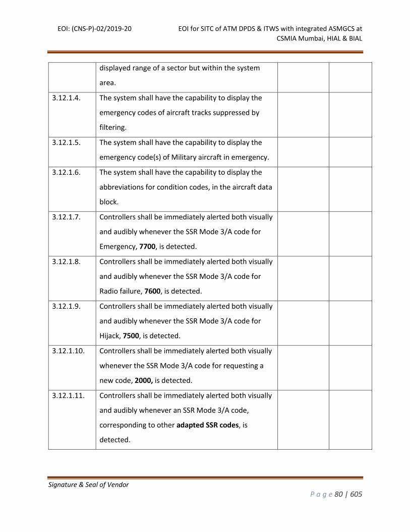
EOI: (CNS-P)-02/2019-20 EOI for SITC of ATM DPDS & ITWS with integrated ASMGCS at
CSMIA Mumbai, HIAL & BIAL
Signature & Seal of Vendor
P a g e 80 | 605
displayed range of a sector but within the system
area.
3.12.1.4. The system shall have the capability to display the
emergency codes of aircraft tracks suppressed by
filtering.
3.12.1.5. The system shall have the capability to display the
emergency code(s) of Military aircraft in emergency.
3.12.1.6. The system shall have the capability to display the
abbreviations for condition codes, in the aircraft data
block.
3.12.1.7. Controllers shall be immediately alerted both visually
and audibly whenever the SSR Mode 3/A code for
Emergency, 7700, is detected.
3.12.1.8. Controllers shall be immediately alerted both visually
and audibly whenever the SSR Mode 3/A code for
Radio failure, 7600, is detected.
3.12.1.9. Controllers shall be immediately alerted both visually
and audibly whenever the SSR Mode 3/A code for
Hijack, 7500, is detected.
3.12.1.10. Controllers shall be immediately alerted both visually
whenever the SSR Mode 3/A code for requesting a
new code, 2000, is detected.
3.12.1.11. Controllers shall be immediately alerted both visually
and audibly whenever an SSR Mode 3/A code,
corresponding to other adapted SSR codes, is
detected.
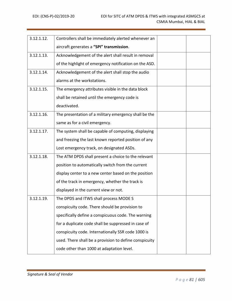
EOI: (CNS-P)-02/2019-20 EOI for SITC of ATM DPDS & ITWS with integrated ASMGCS at
CSMIA Mumbai, HIAL & BIAL
Signature & Seal of Vendor
P a g e 81 | 605
3.12.1.12. Controllers shall be immediately alerted whenever an
aircraft generates a “SPI” transmission.
3.12.1.13. Acknowledgement of the alert shall result in removal
of the highlight of emergency notification on the ASD.
3.12.1.14. Acknowledgement of the alert shall stop the audio
alarms at the workstations.
3.12.1.15. The emergency attributes visible in the data block
shall be retained until the emergency code is
deactivated.
3.12.1.16. The presentation of a military emergency shall be the
same as for a civil emergency.
3.12.1.17. The system shall be capable of computing, displaying
and freezing the last known reported position of any
Lost emergency track, on designated ASDs.
3.12.1.18. The ATM DPDS shall present a choice to the relevant
position to automatically switch from the current
display center to a new center based on the position
of the track in emergency, whether the track is
displayed in the current view or not.
3.12.1.19. The DPDS and ITWS shall process MODE S
conspicuity code. There should be provision to
specifically define a conspicuous code. The warning
for a duplicate code shall be suppressed in case of
conspicuity code. Internationally SSR code 1000 is
used. There shall be a provision to define conspicuity
code other than 1000 at adaptation level.
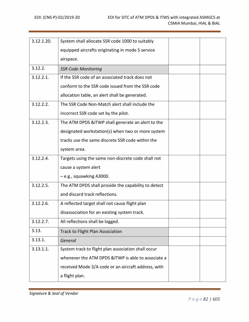
EOI: (CNS-P)-02/2019-20 EOI for SITC of ATM DPDS & ITWS with integrated ASMGCS at
CSMIA Mumbai, HIAL & BIAL
Signature & Seal of Vendor
P a g e 82 | 605
3.12.1.20. System shall allocate SSR code 1000 to suitably
equipped aircrafts originating in mode S service
airspace.
3.12.2. SSR Code Monitoring
3.12.2.1. If the SSR code of an associated track does not
conform to the SSR code issued from the SSR code
allocation table, an alert shall be generated.
3.12.2.2. The SSR Code Non-Match alert shall include the
incorrect SSR code set by the pilot.
3.12.2.3. The ATM DPDS &ITWP shall generate an alert to the
designated workstation(s) when two or more system
tracks use the same discrete SSR code within the
system area.
3.12.2.4. Targets using the same non-discrete code shall not
cause a system alert
– e.g., squawking A3000.
3.12.2.5. The ATM DPDS shall provide the capability to detect
and discard track reflections.
3.12.2.6. A reflected target shall not cause flight plan
disassociation for an existing system track.
3.12.2.7. All reflections shall be logged.
3.13. Track to Flight Plan Association
3.13.1. General
3.13.1.1. System track to flight plan association shall occur
whenever the ATM DPDS &ITWP is able to associate a
received Mode 3/A code or an aircraft address, with
a flight plan.
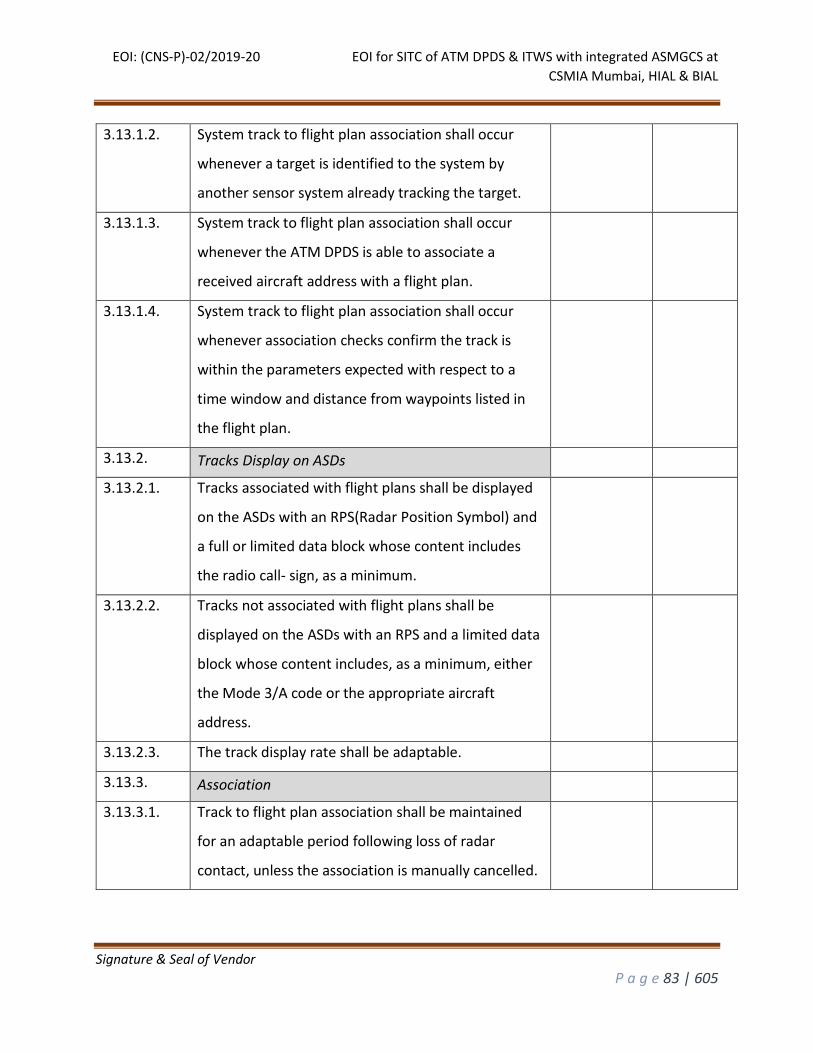
EOI: (CNS-P)-02/2019-20 EOI for SITC of ATM DPDS & ITWS with integrated ASMGCS at
CSMIA Mumbai, HIAL & BIAL
Signature & Seal of Vendor
P a g e 83 | 605
3.13.1.2. System track to flight plan association shall occur
whenever a target is identified to the system by
another sensor system already tracking the target.
3.13.1.3. System track to flight plan association shall occur
whenever the ATM DPDS is able to associate a
received aircraft address with a flight plan.
3.13.1.4. System track to flight plan association shall occur
whenever association checks confirm the track is
within the parameters expected with respect to a
time window and distance from waypoints listed in
the flight plan.
3.13.2. Tracks Display on ASDs
3.13.2.1. Tracks associated with flight plans shall be displayed
on the ASDs with an RPS(Radar Position Symbol) and
a full or limited data block whose content includes
the radio call- sign, as a minimum.
3.13.2.2. Tracks not associated with flight plans shall be
displayed on the ASDs with an RPS and a limited data
block whose content includes, as a minimum, either
the Mode 3/A code or the appropriate aircraft
address.
3.13.2.3. The track display rate shall be adaptable.
3.13.3. Association
3.13.3.1. Track to flight plan association shall be maintained
for an adaptable period following loss of radar
contact, unless the association is manually cancelled.
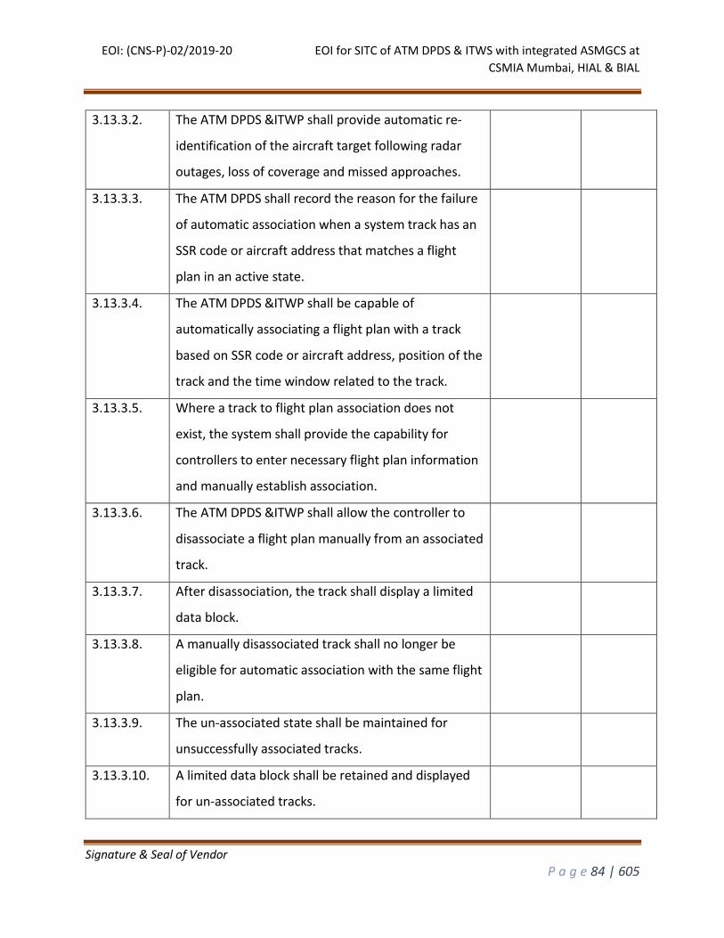
EOI: (CNS-P)-02/2019-20 EOI for SITC of ATM DPDS & ITWS with integrated ASMGCS at
CSMIA Mumbai, HIAL & BIAL
Signature & Seal of Vendor
P a g e 84 | 605
3.13.3.2. The ATM DPDS &ITWP shall provide automatic re-
identification of the aircraft target following radar
outages, loss of coverage and missed approaches.
3.13.3.3. The ATM DPDS shall record the reason for the failure
of automatic association when a system track has an
SSR code or aircraft address that matches a flight
plan in an active state.
3.13.3.4. The ATM DPDS &ITWP shall be capable of
automatically associating a flight plan with a track
based on SSR code or aircraft address, position of the
track and the time window related to the track.
3.13.3.5. Where a track to flight plan association does not
exist, the system shall provide the capability for
controllers to enter necessary flight plan information
and manually establish association.
3.13.3.6. The ATM DPDS &ITWP shall allow the controller to
disassociate a flight plan manually from an associated
track.
3.13.3.7. After disassociation, the track shall display a limited
data block.
3.13.3.8. A manually disassociated track shall no longer be
eligible for automatic association with the same flight
plan.
3.13.3.9. The un-associated state shall be maintained for
unsuccessfully associated tracks.
3.13.3.10. A limited data block shall be retained and displayed
for un-associated tracks.
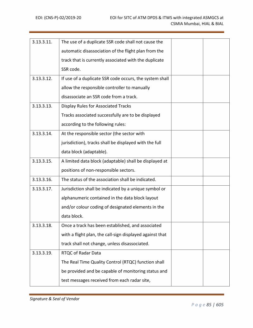
EOI: (CNS-P)-02/2019-20 EOI for SITC of ATM DPDS & ITWS with integrated ASMGCS at
CSMIA Mumbai, HIAL & BIAL
Signature & Seal of Vendor
P a g e 85 | 605
3.13.3.11. The use of a duplicate SSR code shall not cause the
automatic disassociation of the flight plan from the
track that is currently associated with the duplicate
SSR code.
3.13.3.12. If use of a duplicate SSR code occurs, the system shall
allow the responsible controller to manually
disassociate an SSR code from a track.
3.13.3.13. Display Rules for Associated Tracks
Tracks associated successfully are to be displayed
according to the following rules:
3.13.3.14. At the responsible sector (the sector with
jurisdiction), tracks shall be displayed with the full
data block (adaptable).
3.13.3.15. A limited data block (adaptable) shall be displayed at
positions of non-responsible sectors.
3.13.3.16. The status of the association shall be indicated.
3.13.3.17. Jurisdiction shall be indicated by a unique symbol or
alphanumeric contained in the data block layout
and/or colour coding of designated elements in the
data block.
3.13.3.18. Once a track has been established, and associated
with a flight plan, the call-sign displayed against that
track shall not change, unless disassociated.
3.13.3.19. RTQC of Radar Data
The Real Time Quality Control (RTQC) function shall
be provided and be capable of monitoring status and
test messages received from each radar site,

EOI: (CNS-P)-02/2019-20 EOI for SITC of ATM DPDS & ITWS with integrated ASMGCS at
CSMIA Mumbai, HIAL & BIAL
Signature & Seal of Vendor
P a g e 86 | 605
maintaining data counts for each site, and calculating
registration and collimation errors for all sites. The
ATM DPDS shall have the feature for status display
and control over dual external links for surveillance
data.
3.13.4. Status Message Monitoring
3.13.4.1. Status messages from each radar site shall be
received and stored.
3.13.4.2. The status messages shall be processed by the RTQC
function.
3.13.4.3. Status messages shall be monitored to determine
when extraneous messages are received, when
status messages are missing, or when status changes
occur.
3.13.4.4. For positive detection of these conditions, messages
describing the conditions shall be generated and
displayed at designated positions.
3.13.5. Test Message Monitoring
3.13.5.1. Fixed PSR and fixed SSR test messages shall be
received and stored from each radar site.
3.13.5.2. Test messages shall be stored for processing by the
RTQC function.
3.13.5.3. The test message monitoring task shall analyse the
accuracy of the fields in the test message and
determine if more or less than the expected number
(adaptable parameter) of test messages have been
received.
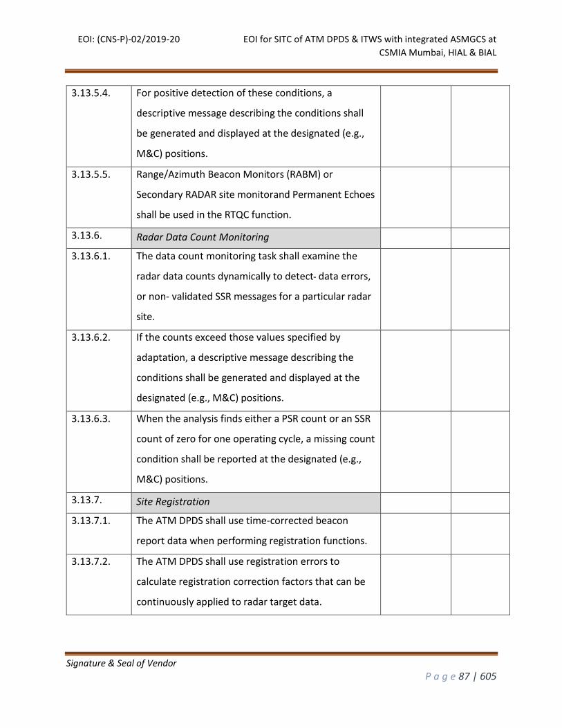
EOI: (CNS-P)-02/2019-20 EOI for SITC of ATM DPDS & ITWS with integrated ASMGCS at
CSMIA Mumbai, HIAL & BIAL
Signature & Seal of Vendor
P a g e 87 | 605
3.13.5.4. For positive detection of these conditions, a
descriptive message describing the conditions shall
be generated and displayed at the designated (e.g.,
M&C) positions.
3.13.5.5. Range/Azimuth Beacon Monitors (RABM) or
Secondary RADAR site monitorand Permanent Echoes
shall be used in the RTQC function.
3.13.6. Radar Data Count Monitoring
3.13.6.1. The data count monitoring task shall examine the
radar data counts dynamically to detect data errors,
or non- validated SSR messages for a particular radar
site.
3.13.6.2. If the counts exceed those values specified by
adaptation, a descriptive message describing the
conditions shall be generated and displayed at the
designated (e.g., M&C) positions.
3.13.6.3. When the analysis finds either a PSR count or an SSR
count of zero for one operating cycle, a missing count
condition shall be reported at the designated (e.g.,
M&C) positions.
3.13.7. Site Registration
3.13.7.1. The ATM DPDS shall use time-corrected beacon
report data when performing registration functions.
3.13.7.2. The ATM DPDS shall use registration errors to
calculate registration correction factors that can be
continuously applied to radar target data.
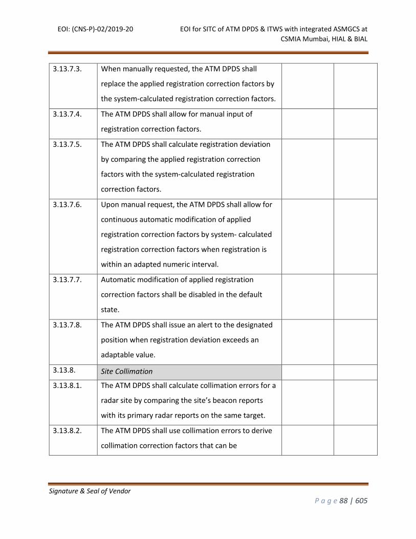
EOI: (CNS-P)-02/2019-20 EOI for SITC of ATM DPDS & ITWS with integrated ASMGCS at
CSMIA Mumbai, HIAL & BIAL
Signature & Seal of Vendor
P a g e 88 | 605
3.13.7.3. When manually requested, the ATM DPDS shall
replace the applied registration correction factors by
the system-calculated registration correction factors.
3.13.7.4. The ATM DPDS shall allow for manual input of
registration correction factors.
3.13.7.5. The ATM DPDS shall calculate registration deviation
by comparing the applied registration correction
factors with the system-calculated registration
correction factors.
3.13.7.6. Upon manual request, the ATM DPDS shall allow for
continuous automatic modification of applied
registration correction factors by system- calculated
registration correction factors when registration is
within an adapted numeric interval.
3.13.7.7. Automatic modification of applied registration
correction factors shall be disabled in the default
state.
3.13.7.8. The ATM DPDS shall issue an alert to the designated
position when registration deviation exceeds an
adaptable value.
3.13.8. Site Collimation
3.13.8.1. The ATM DPDS shall calculate collimation errors for a
radar site by comparing the site’s beacon reports
with its primary radar reports on the same target.
3.13.8.2. The ATM DPDS shall use collimation errors to derive
collimation correction factors that can be
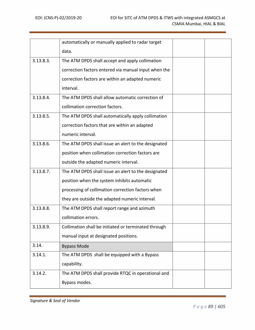
EOI: (CNS-P)-02/2019-20 EOI for SITC of ATM DPDS & ITWS with integrated ASMGCS at
CSMIA Mumbai, HIAL & BIAL
Signature & Seal of Vendor
P a g e 89 | 605
automatically or manually applied to radar target
data.
3.13.8.3. The ATM DPDS shall accept and apply collimation
correction factors entered via manual input when the
correction factors are within an adapted numeric
interval.
3.13.8.4. The ATM DPDS shall allow automatic correction of
collimation correction factors.
3.13.8.5. The ATM DPDS shall automatically apply collimation
correction factors that are within an adapted
numeric interval.
3.13.8.6. The ATM DPDS shall issue an alert to the designated
position when collimation correction factors are
outside the adapted numeric interval.
3.13.8.7. The ATM DPDS shall issue an alert to the designated
position when the system inhibits automatic
processing of collimation correction factors when
they are outside the adapted numeric interval.
3.13.8.8. The ATM DPDS shall report range and azimuth
collimation errors.
3.13.8.9. Collimation shall be initiated or terminated through
manual input at designated positions.
3.14. Bypass Mode
3.14.1. The ATM DPDS shall be equipped with a Bypass
capability.
3.14.2. The ATM DPDS shall provide RTQC in operational and
Bypass modes.
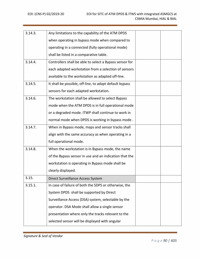
EOI: (CNS-P)-02/2019-20 EOI for SITC of ATM DPDS & ITWS with integrated ASMGCS at
CSMIA Mumbai, HIAL & BIAL
Signature & Seal of Vendor
P a g e 90 | 605
3.14.3. Any limitations to the capability of the ATM DPDS
when operating in bypass mode when compared to
operating in a connected (fully operational mode)
shall be listed in a comparative table.
3.14.4. Controllers shall be able to select a Bypass sensor for
each adapted workstation from a selection of sensors
available to the workstation as adapted off-line.
3.14.5. It shall be possible, off-line, to adapt default bypass
sensors for each adapted workstation.
3.14.6. The workstation shall be allowed to select Bypass
mode when the ATM DPDS is in full operational mode
or a degraded mode. ITWP shall continue to work in
normal mode when DPDS is working in bypass mode .
3.14.7. When in Bypass mode, maps and sensor tracks shall
align with the same accuracy as when operating in a
full operational mode.
3.14.8. When the workstation is in Bypass mode, the name
of the Bypass sensor in use and an indication that the
workstation is operating in Bypass mode shall be
clearly displayed.
3.15. Direct Surveillance Access System
3.15.1. In case of failure of both the SDPS or otherwise, the
System DPDS shall be supported by Direct
Surveillance Access (DSA) system, selectable by the
operator. DSA Mode shall allow a single sensor
presentation where only the tracks relevant to the
selected sensor will be displayed with angular
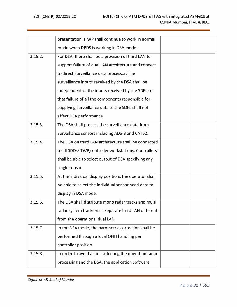
EOI: (CNS-P)-02/2019-20 EOI for SITC of ATM DPDS & ITWS with integrated ASMGCS at
CSMIA Mumbai, HIAL & BIAL
Signature & Seal of Vendor
P a g e 91 | 605
presentation. ITWP shall continue to work in normal
mode when DPDS is working in DSA mode .
3.15.2. For DSA, there shall be a provision of third LAN to
support failure of dual LAN architecture and connect
to direct Surveillance data processor. The
surveillance inputs received by the DSA shall be
independent of the inputs received by the SDPs so
that failure of all the components responsible for
supplying surveillance data to the SDPs shall not
affect DSA performance.
3.15.3. The DSA shall process the surveillance data from
Surveillance sensors including ADS-B and CAT62.
3.15.4. The DSA on third LAN architecture shall be connected
to all SDDs/ITWP controller workstations. Controllers
shall be able to select output of DSA specifying any
single sensor.
3.15.5. At the individual display positions the operator shall
be able to select the individual sensor head data to
display in DSA mode.
3.15.6. The DSA shall distribute mono radar tracks and multi
radar system tracks via a separate third LAN different
from the operational dual LAN.
3.15.7. In the DSA mode, the barometric correction shall be
performed through a local QNH handling per
controller position.
3.15.8. In order to avoid a fault affecting the operation radar
processing and the DSA, the application software
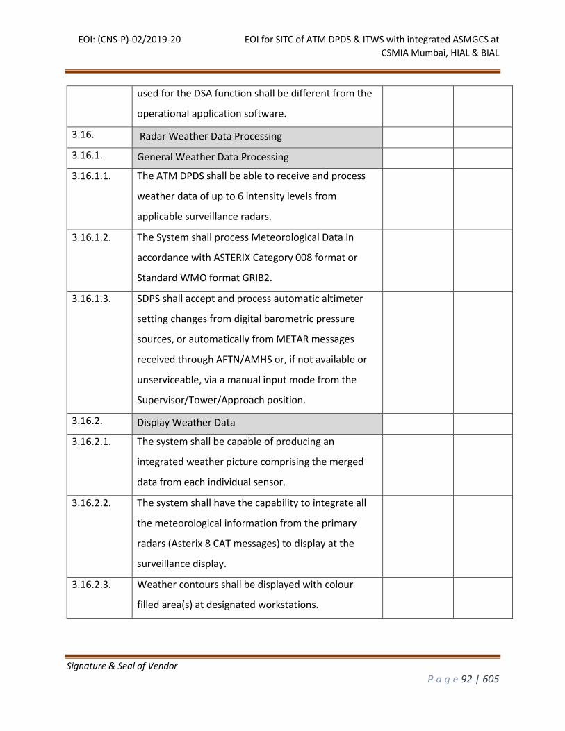
EOI: (CNS-P)-02/2019-20 EOI for SITC of ATM DPDS & ITWS with integrated ASMGCS at
CSMIA Mumbai, HIAL & BIAL
Signature & Seal of Vendor
P a g e 92 | 605
used for the DSA function shall be different from the
operational application software.
3.16. Radar Weather Data Processing
3.16.1. General Weather Data Processing
3.16.1.1. The ATM DPDS shall be able to receive and process
weather data of up to 6 intensity levels from
applicable surveillance radars.
3.16.1.2. The System shall process Meteorological Data in
accordance with ASTERIX Category 008 format or
Standard WMO format GRIB2.
3.16.1.3. SDPS shall accept and process automatic altimeter
setting changes from digital barometric pressure
sources, or automatically from METAR messages
received through AFTN/AMHS or, if not available or
unserviceable, via a manual input mode from the
Supervisor/Tower/Approach position.
3.16.2. Display Weather Data
3.16.2.1. The system shall be capable of producing an
integrated weather picture comprising the merged
data from each individual sensor.
3.16.2.2. The system shall have the capability to integrate all
the meteorological information from the primary
radars (Asterix 8 CAT messages) to display at the
surveillance display.
3.16.2.3. Weather contours shall be displayed with colour
filled area(s) at designated workstations.
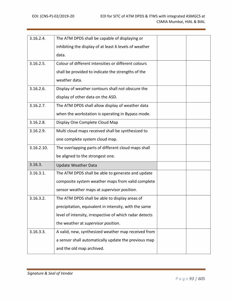
EOI: (CNS-P)-02/2019-20 EOI for SITC of ATM DPDS & ITWS with integrated ASMGCS at
CSMIA Mumbai, HIAL & BIAL
Signature & Seal of Vendor
P a g e 93 | 605
3.16.2.4. The ATM DPDS shall be capable of displaying or
inhibiting the display of at least 6 levels of weather
data.
3.16.2.5. Colour of different intensities or different colours
shall be provided to indicate the strengths of the
weather data.
3.16.2.6. Display of weather contours shall not obscure the
display of other data on the ASD.
3.16.2.7. The ATM DPDS shall allow display of weather data
when the workstation is operating in Bypass mode.
3.16.2.8. Display One Complete Cloud Map
3.16.2.9. Multi cloud maps received shall be synthesized to
one complete system cloud map.
3.16.2.10. The overlapping parts of different cloud maps shall
be aligned to the strongest one.
3.16.3. Update Weather Data
3.16.3.1. The ATM DPDS shall be able to generate and update
composite system weather maps from valid complete
sensor weather maps at supervisor position.
3.16.3.2. The ATM DPDS shall be able to display areas of
precipitation, equivalent in intensity, with the same
level of intensity, irrespective of which radar detects
the weather at supervisor position.
3.16.3.3. A valid, new, synthesized weather map received from
a sensor shall automatically update the previous map
and the old map archived.
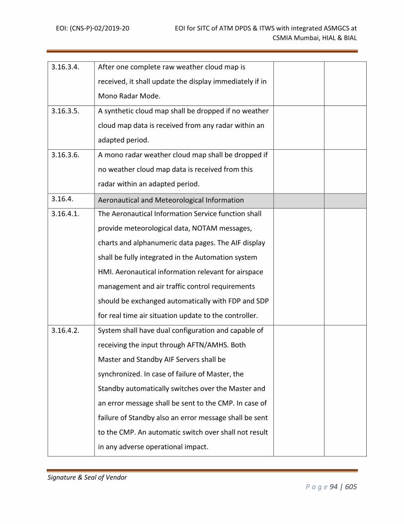
EOI: (CNS-P)-02/2019-20 EOI for SITC of ATM DPDS & ITWS with integrated ASMGCS at
CSMIA Mumbai, HIAL & BIAL
Signature & Seal of Vendor
P a g e 94 | 605
3.16.3.4. After one complete raw weather cloud map is
received, it shall update the display immediately if in
Mono Radar Mode.
3.16.3.5. A synthetic cloud map shall be dropped if no weather
cloud map data is received from any radar within an
adapted period.
3.16.3.6. A mono radar weather cloud map shall be dropped if
no weather cloud map data is received from this
radar within an adapted period.
3.16.4. Aeronautical and Meteorological Information
3.16.4.1. The Aeronautical Information Service function shall
provide meteorological data, NOTAM messages,
charts and alphanumeric data pages. The AIF display
shall be fully integrated in the Automation system
HMI. Aeronautical information relevant for airspace
management and air traffic control requirements
should be exchanged automatically with FDP and SDP
for real time air situation update to the controller.
3.16.4.2. System shall have dual configuration and capable of
receiving the input through AFTN/AMHS. Both
Master and Standby AIF Servers shall be
synchronized. In case of failure of Master, the
Standby automatically switches over the Master and
an error message shall be sent to the CMP. In case of
failure of Standby also an error message shall be sent
to the CMP. An automatic switch over shall not result
in any adverse operational impact.
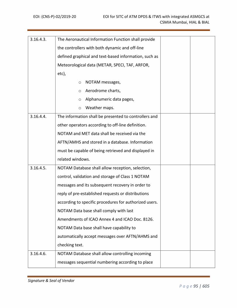
EOI: (CNS-P)-02/2019-20 EOI for SITC of ATM DPDS & ITWS with integrated ASMGCS at
CSMIA Mumbai, HIAL & BIAL
Signature & Seal of Vendor
P a g e 95 | 605
3.16.4.3. The Aeronautical Information Function shall provide
the controllers with both dynamic and off-line
defined graphical and text-based information, such as
Meteorological data (METAR, SPECI, TAF, ARFOR,
etc),
o NOTAM messages,
o Aerodrome charts,
o Alphanumeric data pages,
o Weather maps.
3.16.4.4. The information shall be presented to controllers and
other operators according to off-line definition.
NOTAM and MET data shall be received via the
AFTN/AMHS and stored in a database. Information
must be capable of being retrieved and displayed in
related windows.
3.16.4.5. NOTAM Database shall allow reception, selection,
control, validation and storage of Class 1 NOTAM
messages and its subsequent recovery in order to
reply of pre-established requests or distributions
according to specific procedures for authorized users.
NOTAM Data base shall comply with last
Amendments of ICAO Annex 4 and ICAO Doc. 8126.
NOTAM Data base shall have capability to
automatically accept messages over AFTN/AHMS and
checking text.
3.16.4.6. NOTAM Database shall allow controlling incoming
messages sequential numbering according to place
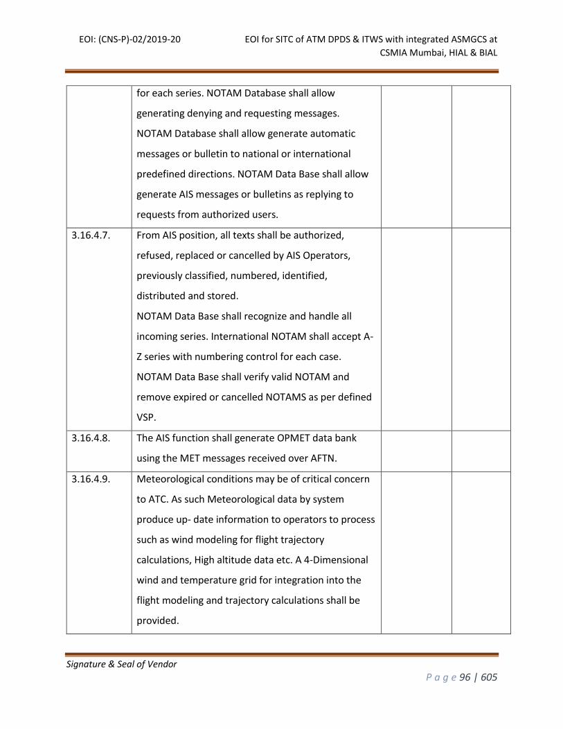
EOI: (CNS-P)-02/2019-20 EOI for SITC of ATM DPDS & ITWS with integrated ASMGCS at
CSMIA Mumbai, HIAL & BIAL
Signature & Seal of Vendor
P a g e 96 | 605
for each series. NOTAM Database shall allow
generating denying and requesting messages.
NOTAM Database shall allow generate automatic
messages or bulletin to national or international
predefined directions. NOTAM Data Base shall allow
generate AIS messages or bulletins as replying to
requests from authorized users.
3.16.4.7. From AIS position, all texts shall be authorized,
refused, replaced or cancelled by AIS Operators,
previously classified, numbered, identified,
distributed and stored.
NOTAM Data Base shall recognize and handle all
incoming series. International NOTAM shall accept A-
Z series with numbering control for each case.
NOTAM Data Base shall verify valid NOTAM and
remove expired or cancelled NOTAMS as per defined
VSP.
3.16.4.8. The AIS function shall generate OPMET data bank
using the MET messages received over AFTN.
3.16.4.9. Meteorological conditions may be of critical concern
to ATC. As such Meteorological data by system
produce up- date information to operators to process
such as wind modeling for flight trajectory
calculations, High altitude data etc. A 4-Dimensional
wind and temperature grid for integration into the
flight modeling and trajectory calculations shall be
provided.
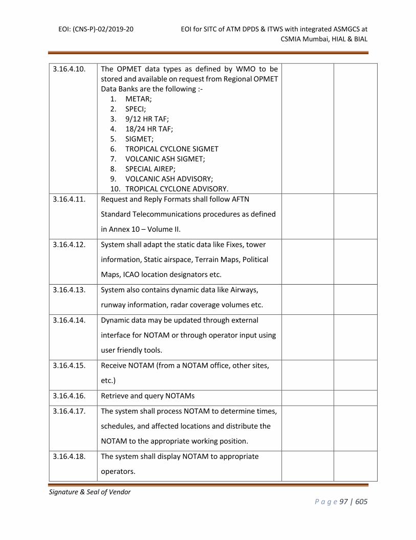
EOI: (CNS-P)-02/2019-20 EOI for SITC of ATM DPDS & ITWS with integrated ASMGCS at
CSMIA Mumbai, HIAL & BIAL
Signature & Seal of Vendor
P a g e 97 | 605
3.16.4.10. The OPMET data types as defined by WMO to be stored and available on request from Regional OPMET Data Banks are the following :-
1. METAR; 2. SPECI; 3. 9/12 HR TAF; 4. 18/24 HR TAF; 5. SIGMET; 6. TROPICAL CYCLONE SIGMET 7. VOLCANIC ASH SIGMET; 8. SPECIAL AIREP; 9. VOLCANIC ASH ADVISORY; 10. TROPICAL CYCLONE ADVISORY.
3.16.4.11. Request and Reply Formats shall follow AFTN
Standard Telecommunications procedures as defined
in Annex 10 – Volume II.
3.16.4.12. System shall adapt the static data like Fixes, tower
information, Static airspace, Terrain Maps, Political
Maps, ICAO location designators etc.
3.16.4.13. System also contains dynamic data like Airways,
runway information, radar coverage volumes etc.
3.16.4.14. Dynamic data may be updated through external
interface for NOTAM or through operator input using
user friendly tools.
3.16.4.15. Receive NOTAM (from a NOTAM office, other sites,
etc.)
3.16.4.16. Retrieve and query NOTAMs
3.16.4.17. The system shall process NOTAM to determine times,
schedules, and affected locations and distribute the
NOTAM to the appropriate working position.
3.16.4.18. The system shall display NOTAM to appropriate
operators.
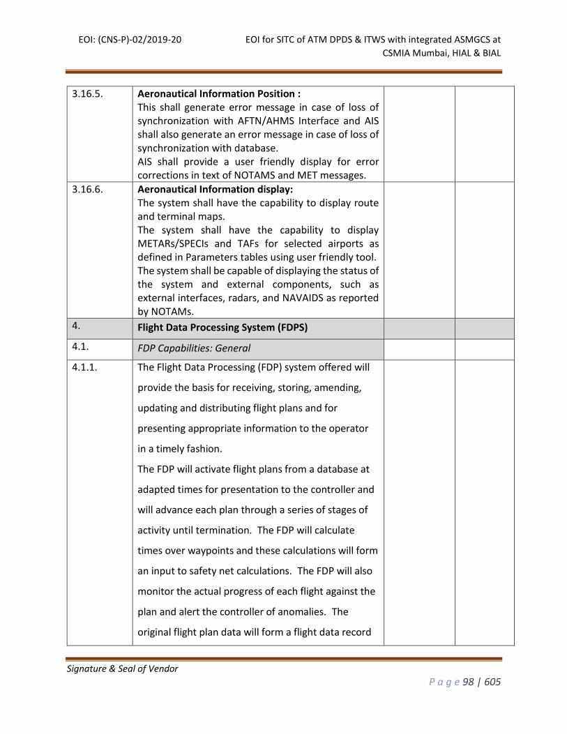
EOI: (CNS-P)-02/2019-20 EOI for SITC of ATM DPDS & ITWS with integrated ASMGCS at
CSMIA Mumbai, HIAL & BIAL
Signature & Seal of Vendor
P a g e 98 | 605
3.16.5. Aeronautical Information Position : This shall generate error message in case of loss of synchronization with AFTN/AHMS Interface and AIS shall also generate an error message in case of loss of synchronization with database. AIS shall provide a user friendly display for error corrections in text of NOTAMS and MET messages.
3.16.6. Aeronautical Information display: The system shall have the capability to display route and terminal maps. The system shall have the capability to display METARs/SPECIs and TAFs for selected airports as defined in Parameters tables using user friendly tool. The system shall be capable of displaying the status of the system and external components, such as external interfaces, radars, and NAVAIDS as reported by NOTAMs.
4. Flight Data Processing System (FDPS)
4.1. FDP Capabilities: General
4.1.1. The Flight Data Processing (FDP) system offered will
provide the basis for receiving, storing, amending,
updating and distributing flight plans and for
presenting appropriate information to the operator
in a timely fashion.
The FDP will activate flight plans from a database at
adapted times for presentation to the controller and
will advance each plan through a series of stages of
activity until termination. The FDP will calculate
times over waypoints and these calculations will form
an input to safety net calculations. The FDP will also
monitor the actual progress of each flight against the
plan and alert the controller of anomalies. The
original flight plan data will form a flight data record
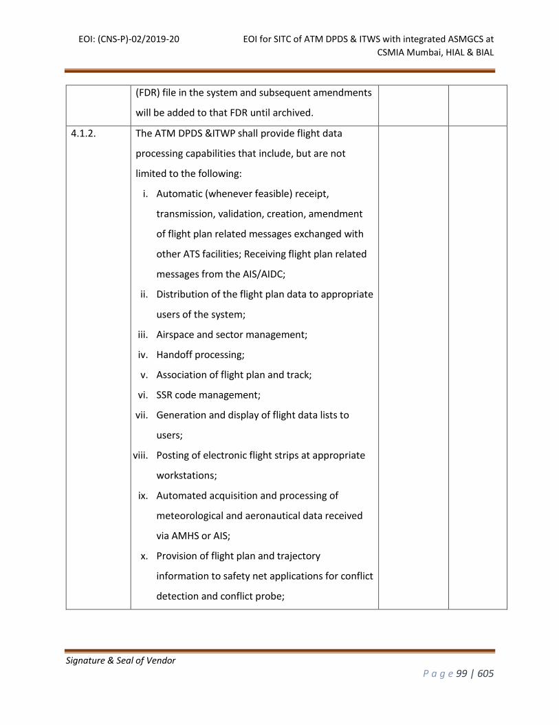
EOI: (CNS-P)-02/2019-20 EOI for SITC of ATM DPDS & ITWS with integrated ASMGCS at
CSMIA Mumbai, HIAL & BIAL
Signature & Seal of Vendor
P a g e 99 | 605
(FDR) file in the system and subsequent amendments
will be added to that FDR until archived.
4.1.2. The ATM DPDS &ITWP shall provide flight data
processing capabilities that include, but are not
limited to the following:
i. Automatic (whenever feasible) receipt,
transmission, validation, creation, amendment
of flight plan related messages exchanged with
other ATS facilities; Receiving flight plan related
messages from the AIS/AIDC;
ii. Distribution of the flight plan data to appropriate
users of the system;
iii. Airspace and sector management;
iv. Handoff processing;
v. Association of flight plan and track;
vi. SSR code management;
vii. Generation and display of flight data lists to
users;
viii. Posting of electronic flight strips at appropriate
workstations;
ix. Automated acquisition and processing of
meteorological and aeronautical data received
via AMHS or AIS;
x. Provision of flight plan and trajectory
information to safety net applications for conflict
detection and conflict probe;
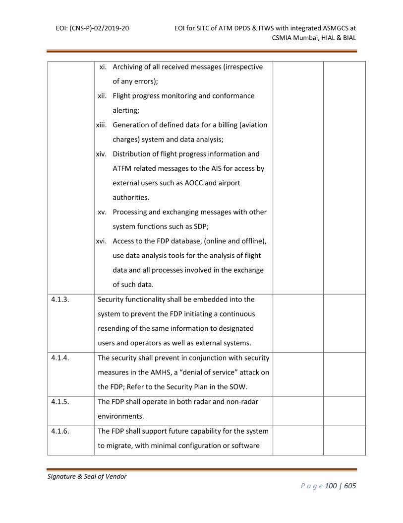
EOI: (CNS-P)-02/2019-20 EOI for SITC of ATM DPDS & ITWS with integrated ASMGCS at
CSMIA Mumbai, HIAL & BIAL
Signature & Seal of Vendor
P a g e 100 | 605
xi. Archiving of all received messages (irrespective
of any errors);
xii. Flight progress monitoring and conformance
alerting;
xiii. Generation of defined data for a billing (aviation
charges) system and data analysis;
xiv. Distribution of flight progress information and
ATFM related messages to the AIS for access by
external users such as AOCC and airport
authorities.
xv. Processing and exchanging messages with other
system functions such as SDP;
xvi. Access to the FDP database, (online and offline),
use data analysis tools for the analysis of flight
data and all processes involved in the exchange
of such data.
4.1.3. Security functionality shall be embedded into the
system to prevent the FDP initiating a continuous
resending of the same information to designated
users and operators as well as external systems.
4.1.4. The security shall prevent in conjunction with security
measures in the AMHS, a “denial of service” attack on
the FDP; Refer to the Security Plan in the SOW.
4.1.5. The FDP shall operate in both radar and non-radar
environments.
4.1.6. The FDP shall support future capability for the system
to migrate, with minimal configuration or software
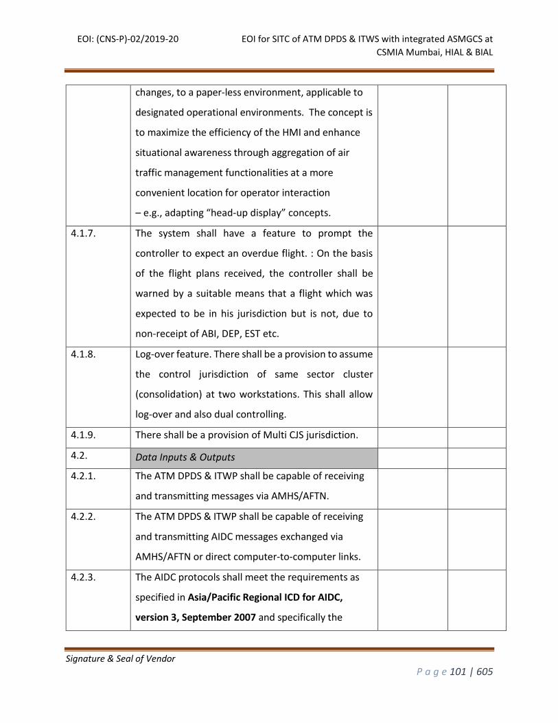
EOI: (CNS-P)-02/2019-20 EOI for SITC of ATM DPDS & ITWS with integrated ASMGCS at
CSMIA Mumbai, HIAL & BIAL
Signature & Seal of Vendor
P a g e 101 | 605
changes, to a paper-less environment, applicable to
designated operational environments. The concept is
to maximize the efficiency of the HMI and enhance
situational awareness through aggregation of air
traffic management functionalities at a more
convenient location for operator interaction
– e.g., adapting “head-up display” concepts.
4.1.7. The system shall have a feature to prompt the
controller to expect an overdue flight. : On the basis
of the flight plans received, the controller shall be
warned by a suitable means that a flight which was
expected to be in his jurisdiction but is not, due to
non-receipt of ABI, DEP, EST etc.
4.1.8. Log-over feature. There shall be a provision to assume
the control jurisdiction of same sector cluster
(consolidation) at two workstations. This shall allow
log-over and also dual controlling.
4.1.9. There shall be a provision of Multi CJS jurisdiction.
4.2. Data Inputs & Outputs
4.2.1. The ATM DPDS & ITWP shall be capable of receiving
and transmitting messages via AMHS/AFTN.
4.2.2. The ATM DPDS & ITWP shall be capable of receiving
and transmitting AIDC messages exchanged via
AMHS/AFTN or direct computer-to-computer links.
4.2.3. The AIDC protocols shall meet the requirements as
specified in Asia/Pacific Regional ICD for AIDC,
version 3, September 2007 and specifically the
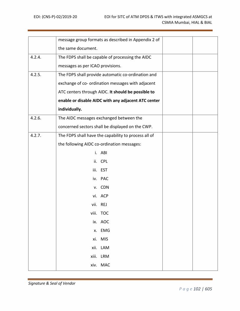
EOI: (CNS-P)-02/2019-20 EOI for SITC of ATM DPDS & ITWS with integrated ASMGCS at
CSMIA Mumbai, HIAL & BIAL
Signature & Seal of Vendor
P a g e 102 | 605
message group formats as described in Appendix 2 of
the same document.
4.2.4. The FDPS shall be capable of processing the AIDC
messages as per ICAO provisions.
4.2.5. The FDPS shall provide automatic co-ordination and
exchange of co- ordination messages with adjacent
ATC centers through AIDC. It should be possible to
enable or disable AIDC with any adjacent ATC center
individually.
4.2.6. The AIDC messages exchanged between the
concerned sectors shall be displayed on the CWP.
4.2.7. The FDPS shall have the capability to process all of
the following AIDC co-ordination messages:
i. ABI
ii. CPL
iii. EST
iv. PAC
v. CDN
vi. ACP
vii. REJ
viii. TOC
ix. AOC
x. EMG
xi. MIS
xii. LAM
xiii. LRM
xiv. MAC
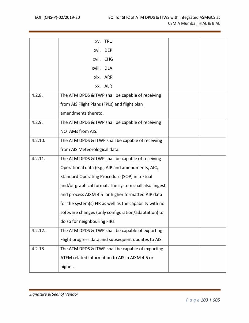
EOI: (CNS-P)-02/2019-20 EOI for SITC of ATM DPDS & ITWS with integrated ASMGCS at
CSMIA Mumbai, HIAL & BIAL
Signature & Seal of Vendor
P a g e 103 | 605
xv. TRU
xvi. DEP
xvii. CHG
xviii. DLA
xix. ARR
xx. ALR
4.2.8. The ATM DPDS &ITWP shall be capable of receiving
from AIS Flight Plans (FPLs) and flight plan
amendments thereto.
4.2.9. The ATM DPDS &ITWP shall be capable of receiving
NOTAMs from AIS.
4.2.10. The ATM DPDS & ITWP shall be capable of receiving
from AIS Meteorological data.
4.2.11. The ATM DPDS &ITWP shall be capable of receiving
Operational data (e.g., AIP and amendments, AIC,
Standard Operating Procedure (SOP) in textual
and/or graphical format. The system shall also ingest
and process AIXM 4.5 or higher formatted AIP data
for the system(s) FIR as well as the capability with no
software changes (only configuration/adaptation) to
do so for neighbouring FIRs.
4.2.12. The ATM DPDS &ITWP shall be capable of exporting
Flight progress data and subsequent updates to AIS.
4.2.13. The ATM DPDS & ITWP shall be capable of exporting
ATFM related information to AIS in AIXM 4.5 or
higher.
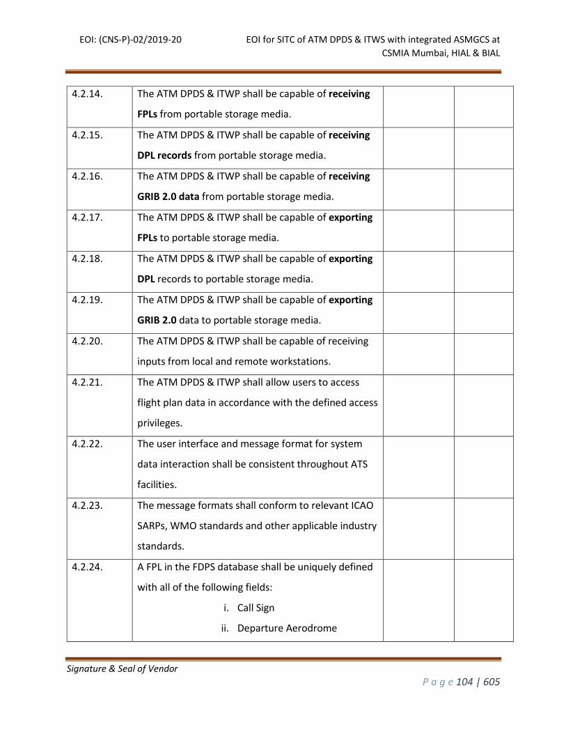
EOI: (CNS-P)-02/2019-20 EOI for SITC of ATM DPDS & ITWS with integrated ASMGCS at
CSMIA Mumbai, HIAL & BIAL
Signature & Seal of Vendor
P a g e 104 | 605
4.2.14. The ATM DPDS & ITWP shall be capable of receiving
FPLs from portable storage media.
4.2.15. The ATM DPDS & ITWP shall be capable of receiving
DPL records from portable storage media.
4.2.16. The ATM DPDS & ITWP shall be capable of receiving
GRIB 2.0 data from portable storage media.
4.2.17. The ATM DPDS & ITWP shall be capable of exporting
FPLs to portable storage media.
4.2.18. The ATM DPDS & ITWP shall be capable of exporting
DPL records to portable storage media.
4.2.19. The ATM DPDS & ITWP shall be capable of exporting
GRIB 2.0 data to portable storage media.
4.2.20. The ATM DPDS & ITWP shall be capable of receiving
inputs from local and remote workstations.
4.2.21. The ATM DPDS & ITWP shall allow users to access
flight plan data in accordance with the defined access
privileges.
4.2.22. The user interface and message format for system
data interaction shall be consistent throughout ATS
facilities.
4.2.23. The message formats shall conform to relevant ICAO
SARPs, WMO standards and other applicable industry
standards.
4.2.24. A FPL in the FDPS database shall be uniquely defined
with all of the following fields:
i. Call Sign
ii. Departure Aerodrome
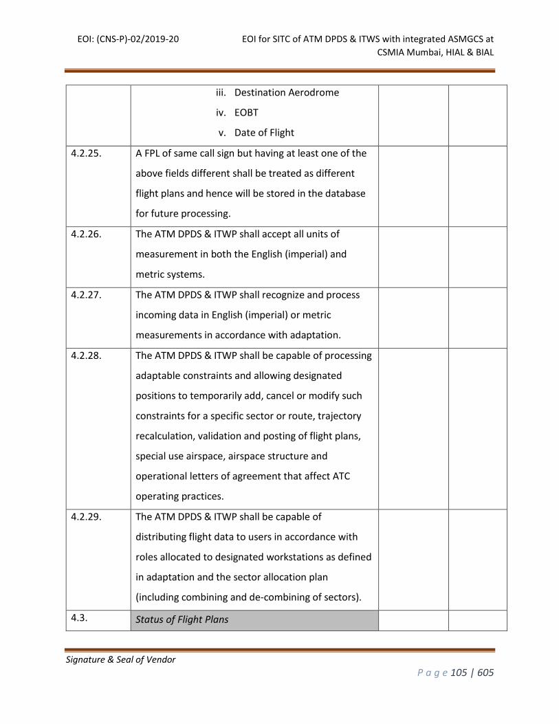
EOI: (CNS-P)-02/2019-20 EOI for SITC of ATM DPDS & ITWS with integrated ASMGCS at
CSMIA Mumbai, HIAL & BIAL
Signature & Seal of Vendor
P a g e 105 | 605
iii. Destination Aerodrome
iv. EOBT
v. Date of Flight
4.2.25. A FPL of same call sign but having at least one of the
above fields different shall be treated as different
flight plans and hence will be stored in the database
for future processing.
4.2.26. The ATM DPDS & ITWP shall accept all units of
measurement in both the English (imperial) and
metric systems.
4.2.27. The ATM DPDS & ITWP shall recognize and process
incoming data in English (imperial) or metric
measurements in accordance with adaptation.
4.2.28. The ATM DPDS & ITWP shall be capable of processing
adaptable constraints and allowing designated
positions to temporarily add, cancel or modify such
constraints for a specific sector or route, trajectory
recalculation, validation and posting of flight plans,
special use airspace, airspace structure and
operational letters of agreement that affect ATC
operating practices.
4.2.29. The ATM DPDS & ITWP shall be capable of
distributing flight data to users in accordance with
roles allocated to designated workstations as defined
in adaptation and the sector allocation plan
(including combining and de-combining of sectors).
4.3. Status of Flight Plans
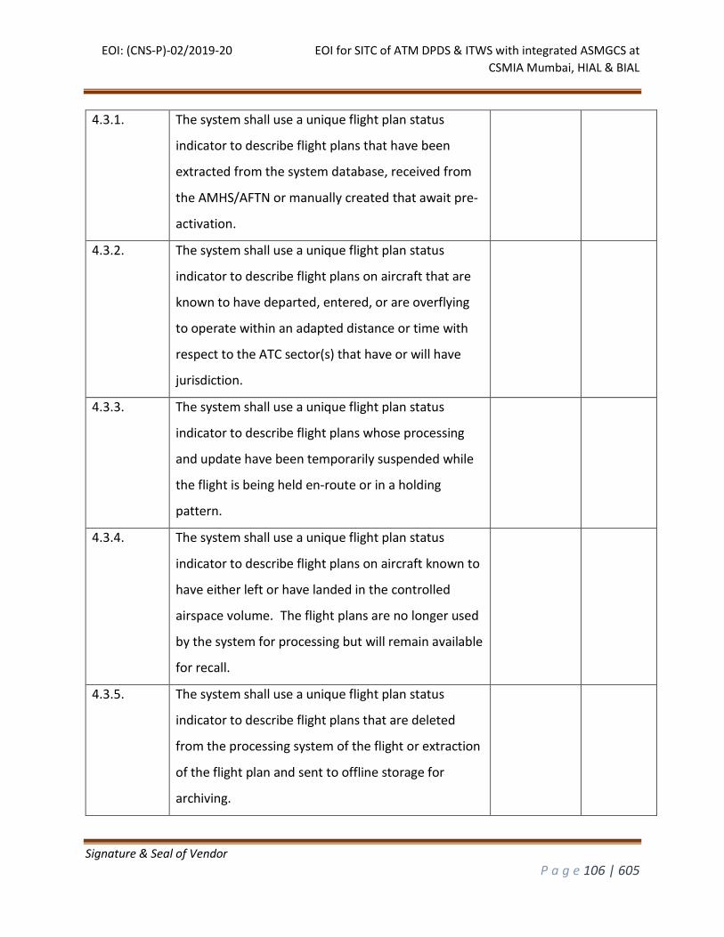
EOI: (CNS-P)-02/2019-20 EOI for SITC of ATM DPDS & ITWS with integrated ASMGCS at
CSMIA Mumbai, HIAL & BIAL
Signature & Seal of Vendor
P a g e 106 | 605
4.3.1. The system shall use a unique flight plan status
indicator to describe flight plans that have been
extracted from the system database, received from
the AMHS/AFTN or manually created that await pre-
activation.
4.3.2. The system shall use a unique flight plan status
indicator to describe flight plans on aircraft that are
known to have departed, entered, or are overflying
to operate within an adapted distance or time with
respect to the ATC sector(s) that have or will have
jurisdiction.
4.3.3. The system shall use a unique flight plan status
indicator to describe flight plans whose processing
and update have been temporarily suspended while
the flight is being held en-route or in a holding
pattern.
4.3.4. The system shall use a unique flight plan status
indicator to describe flight plans on aircraft known to
have either left or have landed in the controlled
airspace volume. The flight plans are no longer used
by the system for processing but will remain available
for recall.
4.3.5. The system shall use a unique flight plan status
indicator to describe flight plans that are deleted
from the processing system of the flight or extraction
of the flight plan and sent to offline storage for
archiving.
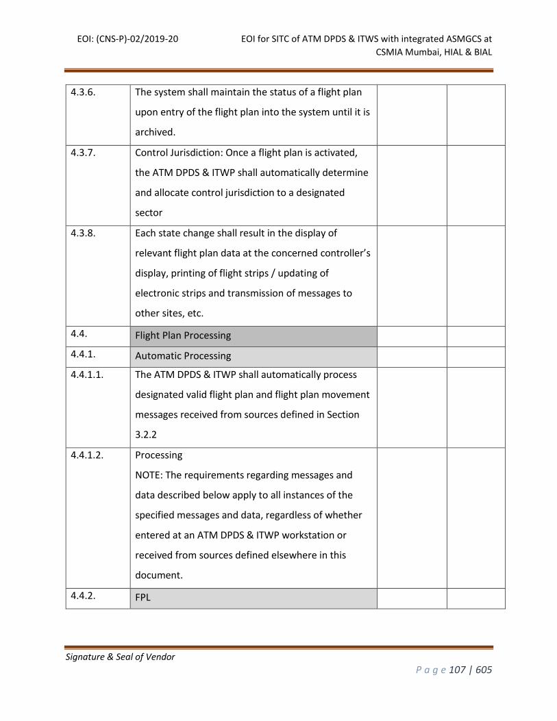
EOI: (CNS-P)-02/2019-20 EOI for SITC of ATM DPDS & ITWS with integrated ASMGCS at
CSMIA Mumbai, HIAL & BIAL
Signature & Seal of Vendor
P a g e 107 | 605
4.3.6. The system shall maintain the status of a flight plan
upon entry of the flight plan into the system until it is
archived.
4.3.7. Control Jurisdiction: Once a flight plan is activated,
the ATM DPDS & ITWP shall automatically determine
and allocate control jurisdiction to a designated
sector
4.3.8. Each state change shall result in the display of
relevant flight plan data at the concerned controller’s
display, printing of flight strips / updating of
electronic strips and transmission of messages to
other sites, etc.
4.4. Flight Plan Processing
4.4.1. Automatic Processing
4.4.1.1. The ATM DPDS & ITWP shall automatically process
designated valid flight plan and flight plan movement
messages received from sources defined in Section
3.2.2
4.4.1.2. Processing
NOTE: The requirements regarding messages and
data described below apply to all instances of the
specified messages and data, regardless of whether
entered at an ATM DPDS & ITWP workstation or
received from sources defined elsewhere in this
document.
4.4.2. FPL
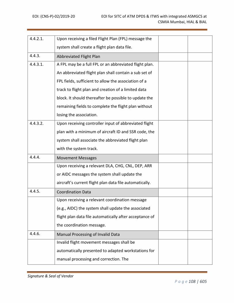
EOI: (CNS-P)-02/2019-20 EOI for SITC of ATM DPDS & ITWS with integrated ASMGCS at
CSMIA Mumbai, HIAL & BIAL
Signature & Seal of Vendor
P a g e 108 | 605
4.4.2.1. Upon receiving a filed Flight Plan (FPL) message the
system shall create a flight plan data file.
4.4.3. Abbreviated Flight Plan
4.4.3.1. A FPL may be a full FPL or an abbreviated flight plan.
An abbreviated flight plan shall contain a sub set of
FPL fields, sufficient to allow the association of a
track to flight plan and creation of a limited data
block. It should thereafter be possible to update the
remaining fields to complete the flight plan without
losing the association.
4.4.3.2. Upon receiving controller input of abbreviated flight
plan with a minimum of aircraft ID and SSR code, the
system shall associate the abbreviated flight plan
with the system track.
4.4.4. Movement Messages
Upon receiving a relevant DLA, CHG, CNL, DEP, ARR
or AIDC messages the system shall update the
aircraft’s current flight plan data file automatically.
4.4.5. Coordination Data
Upon receiving a relevant coordination message
(e.g., AIDC) the system shall update the associated
flight plan data file automatically after acceptance of
the coordination message.
4.4.6. Manual Processing of Invalid Data
Invalid flight movement messages shall be
automatically presented to adapted workstations for
manual processing and correction. The
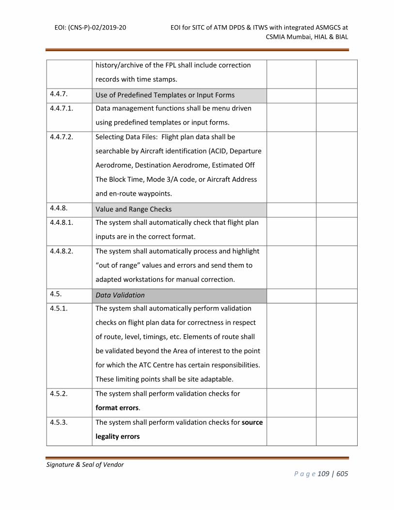
EOI: (CNS-P)-02/2019-20 EOI for SITC of ATM DPDS & ITWS with integrated ASMGCS at
CSMIA Mumbai, HIAL & BIAL
Signature & Seal of Vendor
P a g e 109 | 605
history/archive of the FPL shall include correction
records with time stamps.
4.4.7. Use of Predefined Templates or Input Forms
4.4.7.1. Data management functions shall be menu driven
using predefined templates or input forms.
4.4.7.2. Selecting Data Files: Flight plan data shall be
searchable by Aircraft identification (ACID, Departure
Aerodrome, Destination Aerodrome, Estimated Off
The Block Time, Mode 3/A code, or Aircraft Address
and en-route waypoints.
4.4.8. Value and Range Checks
4.4.8.1. The system shall automatically check that flight plan
inputs are in the correct format.
4.4.8.2. The system shall automatically process and highlight
“out of range” values and errors and send them to
adapted workstations for manual correction.
4.5. Data Validation
4.5.1. The system shall automatically perform validation
checks on flight plan data for correctness in respect
of route, level, timings, etc. Elements of route shall
be validated beyond the Area of interest to the point
for which the ATC Centre has certain responsibilities.
These limiting points shall be site adaptable.
4.5.2. The system shall perform validation checks for
format errors.
4.5.3. The system shall perform validation checks for source
legality errors
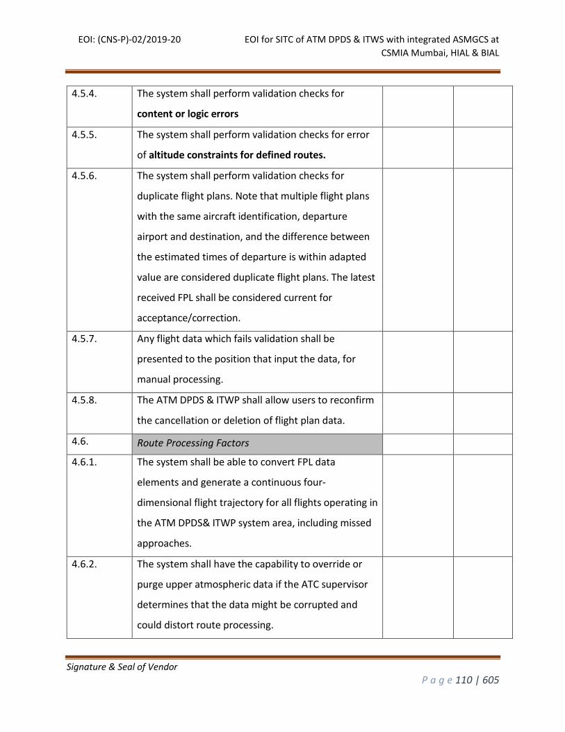
EOI: (CNS-P)-02/2019-20 EOI for SITC of ATM DPDS & ITWS with integrated ASMGCS at
CSMIA Mumbai, HIAL & BIAL
Signature & Seal of Vendor
P a g e 110 | 605
4.5.4. The system shall perform validation checks for
content or logic errors
4.5.5. The system shall perform validation checks for error
of altitude constraints for defined routes.
4.5.6. The system shall perform validation checks for
duplicate flight plans. Note that multiple flight plans
with the same aircraft identification, departure
airport and destination, and the difference between
the estimated times of departure is within adapted
value are considered duplicate flight plans. The latest
received FPL shall be considered current for
acceptance/correction.
4.5.7. Any flight data which fails validation shall be
presented to the position that input the data, for
manual processing.
4.5.8. The ATM DPDS & ITWP shall allow users to reconfirm
the cancellation or deletion of flight plan data.
4.6. Route Processing Factors
4.6.1. The system shall be able to convert FPL data
elements and generate a continuous four-
dimensional flight trajectory for all flights operating in
the ATM DPDS& ITWP system area, including missed
approaches.
4.6.2. The system shall have the capability to override or
purge upper atmospheric data if the ATC supervisor
determines that the data might be corrupted and
could distort route processing.
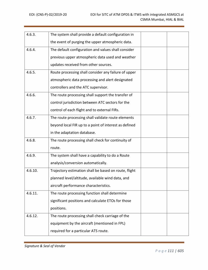
EOI: (CNS-P)-02/2019-20 EOI for SITC of ATM DPDS & ITWS with integrated ASMGCS at
CSMIA Mumbai, HIAL & BIAL
Signature & Seal of Vendor
P a g e 111 | 605
4.6.3. The system shall provide a default configuration in
the event of purging the upper atmospheric data.
4.6.4. The default configuration and values shall consider
previous upper atmospheric data used and weather
updates received from other sources.
4.6.5. Route processing shall consider any failure of upper
atmospheric data processing and alert designated
controllers and the ATC supervisor.
4.6.6. The route processing shall support the transfer of
control jurisdiction between ATC sectors for the
control of each flight and to external FIRs.
4.6.7. The route processing shall validate route elements
beyond local FIR up to a point of interest as defined
in the adaptation database.
4.6.8. The route processing shall check for continuity of
route.
4.6.9. The system shall have a capability to do a Route
analysis/conversion automatically.
4.6.10. Trajectory estimation shall be based on route, flight
planned level/altitude, available wind data, and
aircraft performance characteristics.
4.6.11. The route processing function shall determine
significant positions and calculate ETOs for those
positions.
4.6.12. The route processing shall check carriage of the
equipment by the aircraft (mentioned in FPL)
required for a particular ATS route.
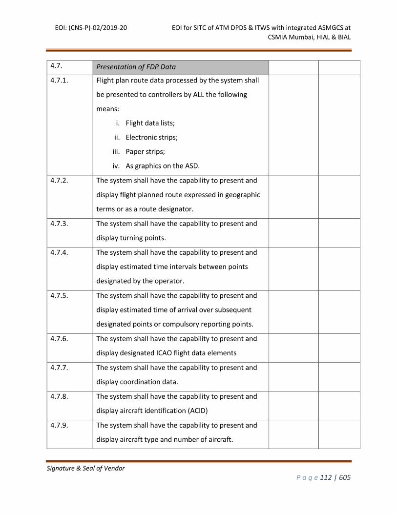
EOI: (CNS-P)-02/2019-20 EOI for SITC of ATM DPDS & ITWS with integrated ASMGCS at
CSMIA Mumbai, HIAL & BIAL
Signature & Seal of Vendor
P a g e 112 | 605
4.7. Presentation of FDP Data
4.7.1. Flight plan route data processed by the system shall
be presented to controllers by ALL the following
means:
i. Flight data lists;
ii. Electronic strips;
iii. Paper strips;
iv. As graphics on the ASD.
4.7.2. The system shall have the capability to present and
display flight planned route expressed in geographic
terms or as a route designator.
4.7.3. The system shall have the capability to present and
display turning points.
4.7.4. The system shall have the capability to present and
display estimated time intervals between points
designated by the operator.
4.7.5. The system shall have the capability to present and
display estimated time of arrival over subsequent
designated points or compulsory reporting points.
4.7.6. The system shall have the capability to present and
display designated ICAO flight data elements
4.7.7. The system shall have the capability to present and
display coordination data.
4.7.8. The system shall have the capability to present and
display aircraft identification (ACID)
4.7.9. The system shall have the capability to present and
display aircraft type and number of aircraft.
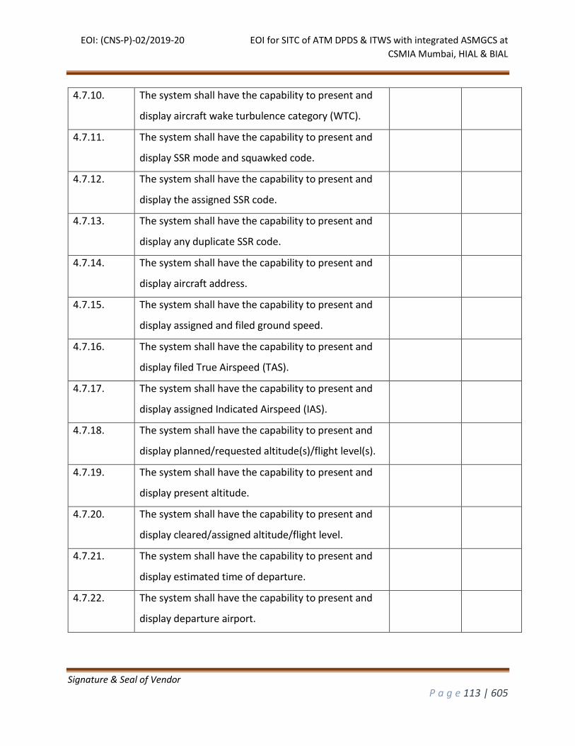
EOI: (CNS-P)-02/2019-20 EOI for SITC of ATM DPDS & ITWS with integrated ASMGCS at
CSMIA Mumbai, HIAL & BIAL
Signature & Seal of Vendor
P a g e 113 | 605
4.7.10. The system shall have the capability to present and
display aircraft wake turbulence category (WTC).
4.7.11. The system shall have the capability to present and
display SSR mode and squawked code.
4.7.12. The system shall have the capability to present and
display the assigned SSR code.
4.7.13. The system shall have the capability to present and
display any duplicate SSR code.
4.7.14. The system shall have the capability to present and
display aircraft address.
4.7.15. The system shall have the capability to present and
display assigned and filed ground speed.
4.7.16. The system shall have the capability to present and
display filed True Airspeed (TAS).
4.7.17. The system shall have the capability to present and
display assigned Indicated Airspeed (IAS).
4.7.18. The system shall have the capability to present and
display planned/requested altitude(s)/flight level(s).
4.7.19. The system shall have the capability to present and
display present altitude.
4.7.20. The system shall have the capability to present and
display cleared/assigned altitude/flight level.
4.7.21. The system shall have the capability to present and
display estimated time of departure.
4.7.22. The system shall have the capability to present and
display departure airport.
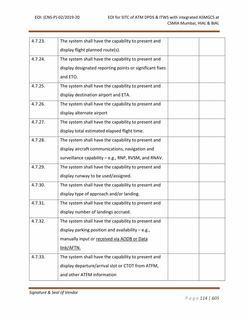
EOI: (CNS-P)-02/2019-20 EOI for SITC of ATM DPDS & ITWS with integrated ASMGCS at
CSMIA Mumbai, HIAL & BIAL
Signature & Seal of Vendor
P a g e 114 | 605
4.7.23. The system shall have the capability to present and
display flight planned route(s).
4.7.24. The system shall have the capability to present and
display designated reporting points or significant fixes
and ETO.
4.7.25. The system shall have the capability to present and
display destination airport and ETA.
4.7.26. The system shall have the capability to present and
display alternate airport
4.7.27. The system shall have the capability to present and
display total estimated elapsed flight time.
4.7.28. The system shall have the capability to present and
display aircraft communications, navigation and
surveillance capability – e.g., RNP, RVSM, and RNAV.
4.7.29. The system shall have the capability to present and
display runway to be used/assigned.
4.7.30. The system shall have the capability to present and
display type of approach and/or landing.
4.7.31. The system shall have the capability to present and
display number of landings accrued.
4.7.32. The system shall have the capability to present and
display parking position and availability – e.g.,
manually input or received via AODB or Data
link/AFTN.
4.7.33. The system shall have the capability to present and
display departure/arrival slot or CTOT from ATFM,
and other ATFM information
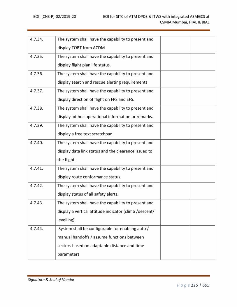
EOI: (CNS-P)-02/2019-20 EOI for SITC of ATM DPDS & ITWS with integrated ASMGCS at
CSMIA Mumbai, HIAL & BIAL
Signature & Seal of Vendor
P a g e 115 | 605
4.7.34. The system shall have the capability to present and
display TOBT from ACDM
4.7.35. The system shall have the capability to present and
display flight plan life status.
4.7.36. The system shall have the capability to present and
display search and rescue alerting requirements
4.7.37. The system shall have the capability to present and
display direction of flight on FPS and EFS.
4.7.38. The system shall have the capability to present and
display ad-hoc operational information or remarks.
4.7.39. The system shall have the capability to present and
display a free text scratchpad.
4.7.40. The system shall have the capability to present and
display data link status and the clearance issued to
the flight.
4.7.41. The system shall have the capability to present and
display route conformance status.
4.7.42. The system shall have the capability to present and
display status of all safety alerts.
4.7.43. The system shall have the capability to present and
display a vertical attitude indicator (climb /descent/
levelling).
4.7.44. System shall be configurable for enabling auto /
manual handoffs / assume functions between
sectors based on adaptable distance and time
parameters
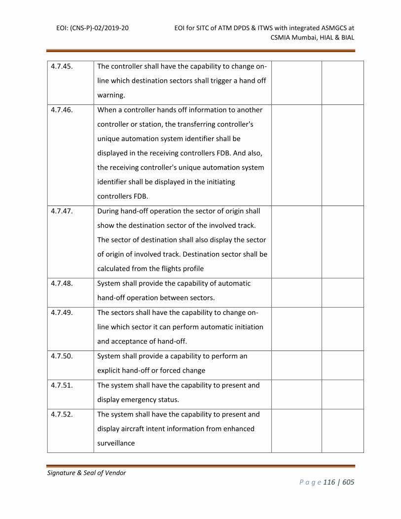
EOI: (CNS-P)-02/2019-20 EOI for SITC of ATM DPDS & ITWS with integrated ASMGCS at
CSMIA Mumbai, HIAL & BIAL
Signature & Seal of Vendor
P a g e 116 | 605
4.7.45. The controller shall have the capability to change on-
line which destination sectors shall trigger a hand off
warning.
4.7.46. When a controller hands off information to another
controller or station, the transferring controller's
unique automation system identifier shall be
displayed in the receiving controllers FDB. And also,
the receiving controller's unique automation system
identifier shall be displayed in the initiating
controllers FDB.
4.7.47. During hand-off operation the sector of origin shall
show the destination sector of the involved track.
The sector of destination shall also display the sector
of origin of involved track. Destination sector shall be
calculated from the flights profile
4.7.48. System shall provide the capability of automatic
hand-off operation between sectors.
4.7.49. The sectors shall have the capability to change on-
line which sector it can perform automatic initiation
and acceptance of hand-off.
4.7.50. System shall provide a capability to perform an
explicit hand-off or forced change
4.7.51. The system shall have the capability to present and
display emergency status.
4.7.52. The system shall have the capability to present and
display aircraft intent information from enhanced
surveillance
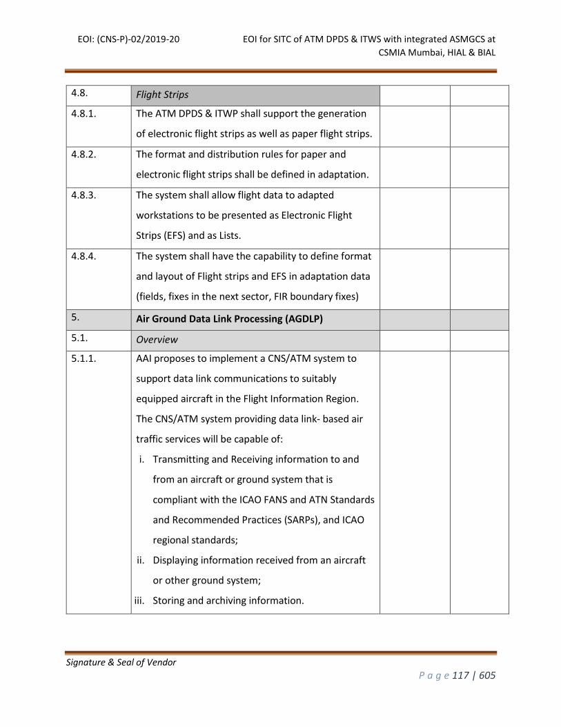
EOI: (CNS-P)-02/2019-20 EOI for SITC of ATM DPDS & ITWS with integrated ASMGCS at
CSMIA Mumbai, HIAL & BIAL
Signature & Seal of Vendor
P a g e 117 | 605
4.8. Flight Strips
4.8.1. The ATM DPDS & ITWP shall support the generation
of electronic flight strips as well as paper flight strips.
4.8.2. The format and distribution rules for paper and
electronic flight strips shall be defined in adaptation.
4.8.3. The system shall allow flight data to adapted
workstations to be presented as Electronic Flight
Strips (EFS) and as Lists.
4.8.4. The system shall have the capability to define format
and layout of Flight strips and EFS in adaptation data
(fields, fixes in the next sector, FIR boundary fixes)
5. Air Ground Data Link Processing (AGDLP)
5.1. Overview
5.1.1. AAI proposes to implement a CNS/ATM system to
support data link communications to suitably
equipped aircraft in the Flight Information Region.
The CNS/ATM system providing data link- based air
traffic services will be capable of:
i. Transmitting and Receiving information to and
from an aircraft or ground system that is
compliant with the ICAO FANS and ATN Standards
and Recommended Practices (SARPs), and ICAO
regional standards;
ii. Displaying information received from an aircraft
or other ground system;
iii. Storing and archiving information.
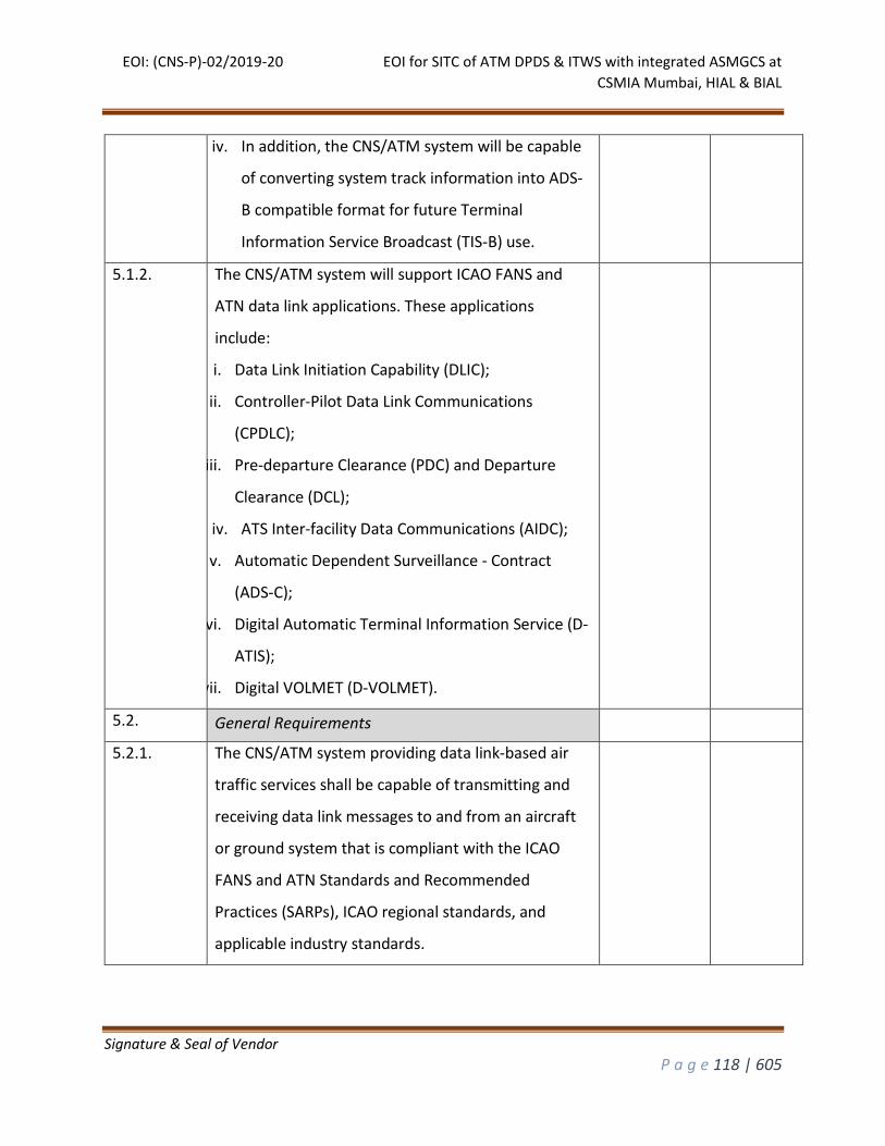
EOI: (CNS-P)-02/2019-20 EOI for SITC of ATM DPDS & ITWS with integrated ASMGCS at
CSMIA Mumbai, HIAL & BIAL
Signature & Seal of Vendor
P a g e 118 | 605
iv. In addition, the CNS/ATM system will be capable
of converting system track information into ADS-
B compatible format for future Terminal
Information Service Broadcast (TIS-B) use.
5.1.2. The CNS/ATM system will support ICAO FANS and
ATN data link applications. These applications
include:
i. Data Link Initiation Capability (DLIC);
ii. Controller-Pilot Data Link Communications
(CPDLC);
iii. Pre-departure Clearance (PDC) and Departure
Clearance (DCL);
iv. ATS Inter-facility Data Communications (AIDC);
v. Automatic Dependent Surveillance - Contract
(ADS-C);
vi. Digital Automatic Terminal Information Service (D-
ATIS);
vii. Digital VOLMET (D-VOLMET).
5.2. General Requirements
5.2.1. The CNS/ATM system providing data link-based air
traffic services shall be capable of transmitting and
receiving data link messages to and from an aircraft
or ground system that is compliant with the ICAO
FANS and ATN Standards and Recommended
Practices (SARPs), ICAO regional standards, and
applicable industry standards.
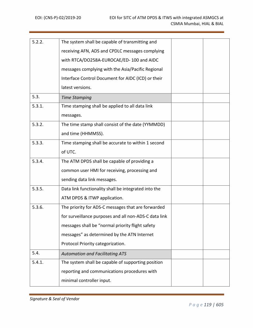
EOI: (CNS-P)-02/2019-20 EOI for SITC of ATM DPDS & ITWS with integrated ASMGCS at
CSMIA Mumbai, HIAL & BIAL
Signature & Seal of Vendor
P a g e 119 | 605
5.2.2. The system shall be capable of transmitting and
receiving AFN, ADS and CPDLC messages complying
with RTCA/DO258A-EUROCAE/ED- 100 and AIDC
messages complying with the Asia/Pacific Regional
Interface Control Document for AIDC (ICD) or their
latest versions.
5.3. Time Stamping
5.3.1. Time stamping shall be applied to all data link
messages.
5.3.2. The time stamp shall consist of the date (YYMMDD)
and time (HHMMSS).
5.3.3. Time stamping shall be accurate to within 1 second
of UTC.
5.3.4. The ATM DPDS shall be capable of providing a
common user HMI for receiving, processing and
sending data link messages.
5.3.5. Data link functionality shall be integrated into the
ATM DPDS & ITWP application.
5.3.6. The priority for ADS-C messages that are forwarded
for surveillance purposes and all non-ADS-C data link
messages shall be “normal priority flight safety
messages” as determined by the ATN Internet
Protocol Priority categorization.
5.4. Automation and Facilitating ATS
5.4.1. The system shall be capable of supporting position
reporting and communications procedures with
minimal controller input.
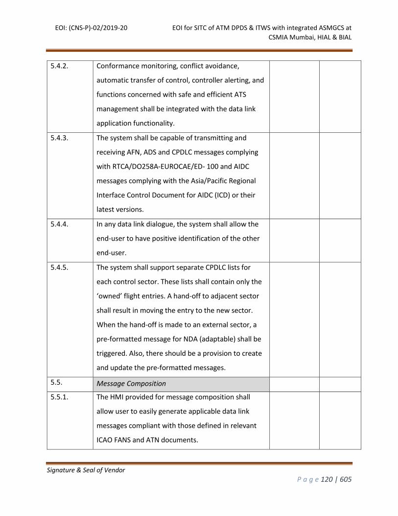
EOI: (CNS-P)-02/2019-20 EOI for SITC of ATM DPDS & ITWS with integrated ASMGCS at
CSMIA Mumbai, HIAL & BIAL
Signature & Seal of Vendor
P a g e 120 | 605
5.4.2. Conformance monitoring, conflict avoidance,
automatic transfer of control, controller alerting, and
functions concerned with safe and efficient ATS
management shall be integrated with the data link
application functionality.
5.4.3. The system shall be capable of transmitting and
receiving AFN, ADS and CPDLC messages complying
with RTCA/DO258A-EUROCAE/ED- 100 and AIDC
messages complying with the Asia/Pacific Regional
Interface Control Document for AIDC (ICD) or their
latest versions.
5.4.4. In any data link dialogue, the system shall allow the
end-user to have positive identification of the other
end-user.
5.4.5. The system shall support separate CPDLC lists for
each control sector. These lists shall contain only the
‘owned’ flight entries. A hand-off to adjacent sector
shall result in moving the entry to the new sector.
When the hand-off is made to an external sector, a
pre-formatted message for NDA (adaptable) shall be
triggered. Also, there should be a provision to create
and update the pre-formatted messages.
5.5. Message Composition
5.5.1. The HMI provided for message composition shall
allow user to easily generate applicable data link
messages compliant with those defined in relevant
ICAO FANS and ATN documents.
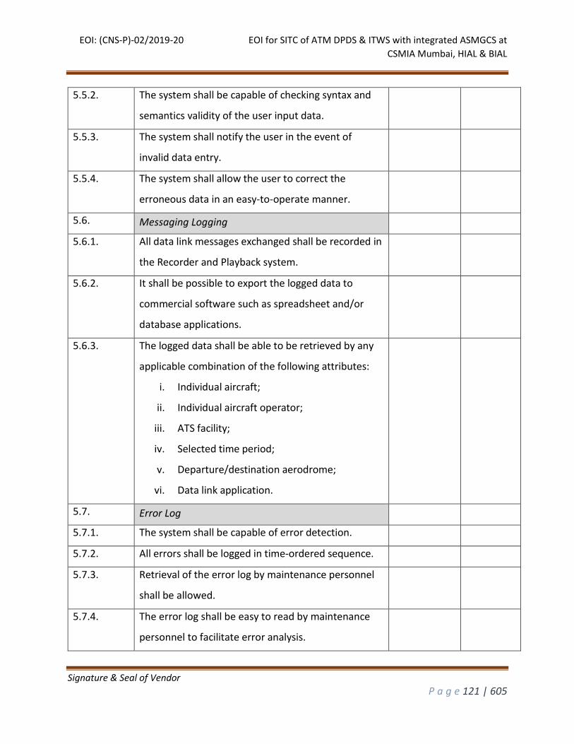
EOI: (CNS-P)-02/2019-20 EOI for SITC of ATM DPDS & ITWS with integrated ASMGCS at
CSMIA Mumbai, HIAL & BIAL
Signature & Seal of Vendor
P a g e 121 | 605
5.5.2. The system shall be capable of checking syntax and
semantics validity of the user input data.
5.5.3. The system shall notify the user in the event of
invalid data entry.
5.5.4. The system shall allow the user to correct the
erroneous data in an easy-to-operate manner.
5.6. Messaging Logging
5.6.1. All data link messages exchanged shall be recorded in
the Recorder and Playback system.
5.6.2. It shall be possible to export the logged data to
commercial software such as spreadsheet and/or
database applications.
5.6.3. The logged data shall be able to be retrieved by any
applicable combination of the following attributes:
i. Individual aircraft;
ii. Individual aircraft operator;
iii. ATS facility;
iv. Selected time period;
v. Departure/destination aerodrome;
vi. Data link application.
5.7. Error Log
5.7.1. The system shall be capable of error detection.
5.7.2. All errors shall be logged in time-ordered sequence.
5.7.3. Retrieval of the error log by maintenance personnel
shall be allowed.
5.7.4. The error log shall be easy to read by maintenance
personnel to facilitate error analysis.
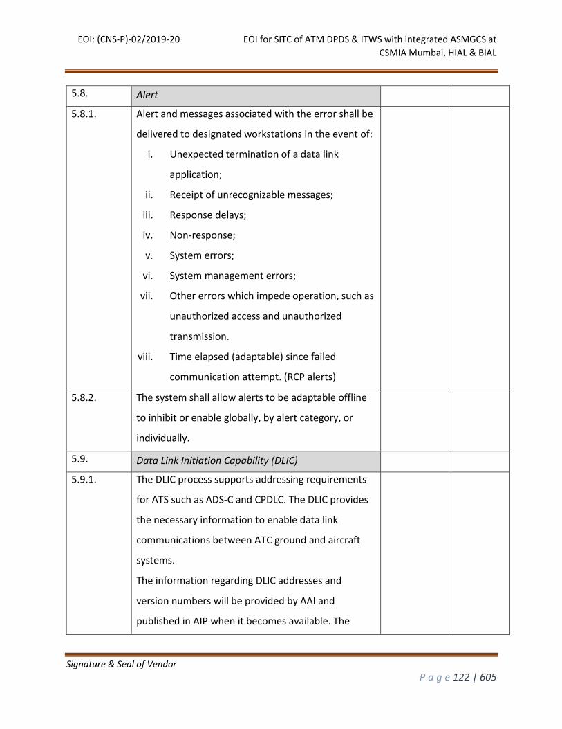
EOI: (CNS-P)-02/2019-20 EOI for SITC of ATM DPDS & ITWS with integrated ASMGCS at
CSMIA Mumbai, HIAL & BIAL
Signature & Seal of Vendor
P a g e 122 | 605
5.8. Alert
5.8.1. Alert and messages associated with the error shall be
delivered to designated workstations in the event of:
i. Unexpected termination of a data link
application;
ii. Receipt of unrecognizable messages;
iii. Response delays;
iv. Non-response;
v. System errors;
vi. System management errors;
vii. Other errors which impede operation, such as
unauthorized access and unauthorized
transmission.
viii. Time elapsed (adaptable) since failed
communication attempt. (RCP alerts)
5.8.2. The system shall allow alerts to be adaptable offline
to inhibit or enable globally, by alert category, or
individually.
5.9. Data Link Initiation Capability (DLIC)
5.9.1. The DLIC process supports addressing requirements
for ATS such as ADS-C and CPDLC. The DLIC provides
the necessary information to enable data link
communications between ATC ground and aircraft
systems.
The information regarding DLIC addresses and
version numbers will be provided by AAI and
published in AIP when it becomes available. The
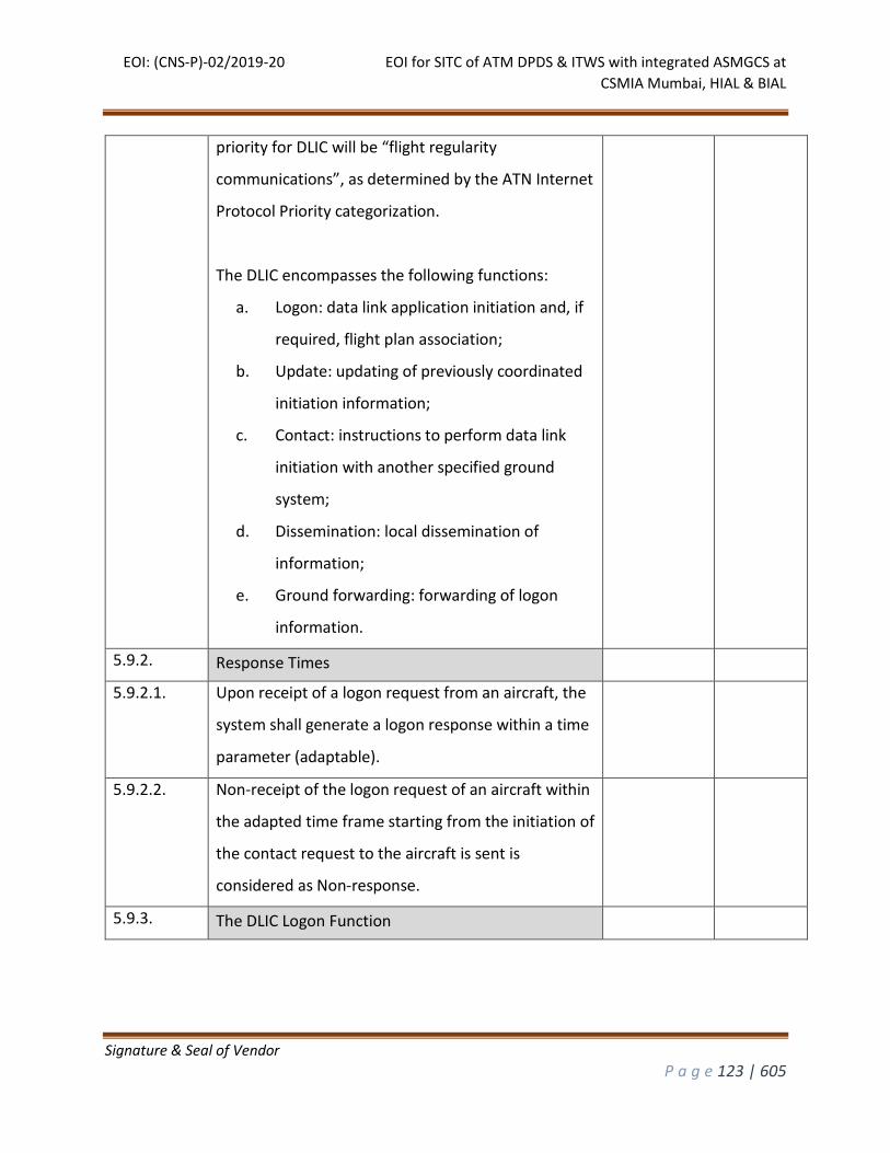
EOI: (CNS-P)-02/2019-20 EOI for SITC of ATM DPDS & ITWS with integrated ASMGCS at
CSMIA Mumbai, HIAL & BIAL
Signature & Seal of Vendor
P a g e 123 | 605
priority for DLIC will be “flight regularity
communications”, as determined by the ATN Internet
Protocol Priority categorization.
The DLIC encompasses the following functions:
a. Logon: data link application initiation and, if
required, flight plan association;
b. Update: updating of previously coordinated
initiation information;
c. Contact: instructions to perform data link
initiation with another specified ground
system;
d. Dissemination: local dissemination of
information;
e. Ground forwarding: forwarding of logon
information.
5.9.2. Response Times
5.9.2.1. Upon receipt of a logon request from an aircraft, the
system shall generate a logon response within a time
parameter (adaptable).
5.9.2.2. Non-receipt of the logon request of an aircraft within
the adapted time frame starting from the initiation of
the contact request to the aircraft is sent is
considered as Non-response.
5.9.3. The DLIC Logon Function
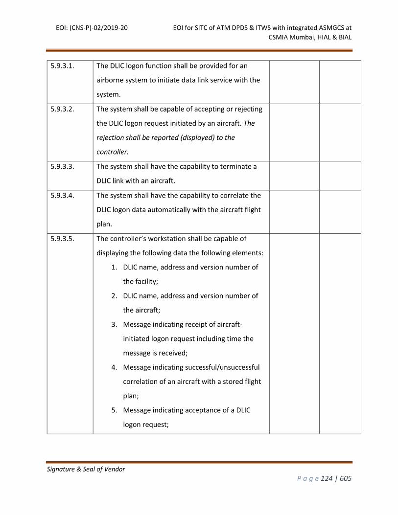
EOI: (CNS-P)-02/2019-20 EOI for SITC of ATM DPDS & ITWS with integrated ASMGCS at
CSMIA Mumbai, HIAL & BIAL
Signature & Seal of Vendor
P a g e 124 | 605
5.9.3.1. The DLIC logon function shall be provided for an
airborne system to initiate data link service with the
system.
5.9.3.2. The system shall be capable of accepting or rejecting
the DLIC logon request initiated by an aircraft. The
rejection shall be reported (displayed) to the
controller.
5.9.3.3. The system shall have the capability to terminate a
DLIC link with an aircraft.
5.9.3.4. The system shall have the capability to correlate the
DLIC logon data automatically with the aircraft flight
plan.
5.9.3.5. The controller’s workstation shall be capable of
displaying the following data the following elements:
1. DLIC name, address and version number of
the facility;
2. DLIC name, address and version number of
the aircraft;
3. Message indicating receipt of aircraft-
initiated logon request including time the
message is received;
4. Message indicating successful/unsuccessful
correlation of an aircraft with a stored flight
plan;
5. Message indicating acceptance of a DLIC
logon request;
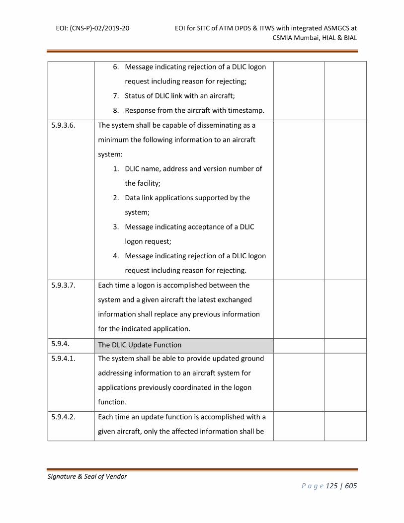
EOI: (CNS-P)-02/2019-20 EOI for SITC of ATM DPDS & ITWS with integrated ASMGCS at
CSMIA Mumbai, HIAL & BIAL
Signature & Seal of Vendor
P a g e 125 | 605
6. Message indicating rejection of a DLIC logon
request including reason for rejecting;
7. Status of DLIC link with an aircraft;
8. Response from the aircraft with timestamp.
5.9.3.6. The system shall be capable of disseminating as a
minimum the following information to an aircraft
system:
1. DLIC name, address and version number of
the facility;
2. Data link applications supported by the
system;
3. Message indicating acceptance of a DLIC
logon request;
4. Message indicating rejection of a DLIC logon
request including reason for rejecting.
5.9.3.7. Each time a logon is accomplished between the
system and a given aircraft the latest exchanged
information shall replace any previous information
for the indicated application.
5.9.4. The DLIC Update Function
5.9.4.1. The system shall be able to provide updated ground
addressing information to an aircraft system for
applications previously coordinated in the logon
function.
5.9.4.2. Each time an update function is accomplished with a
given aircraft, only the affected information shall be
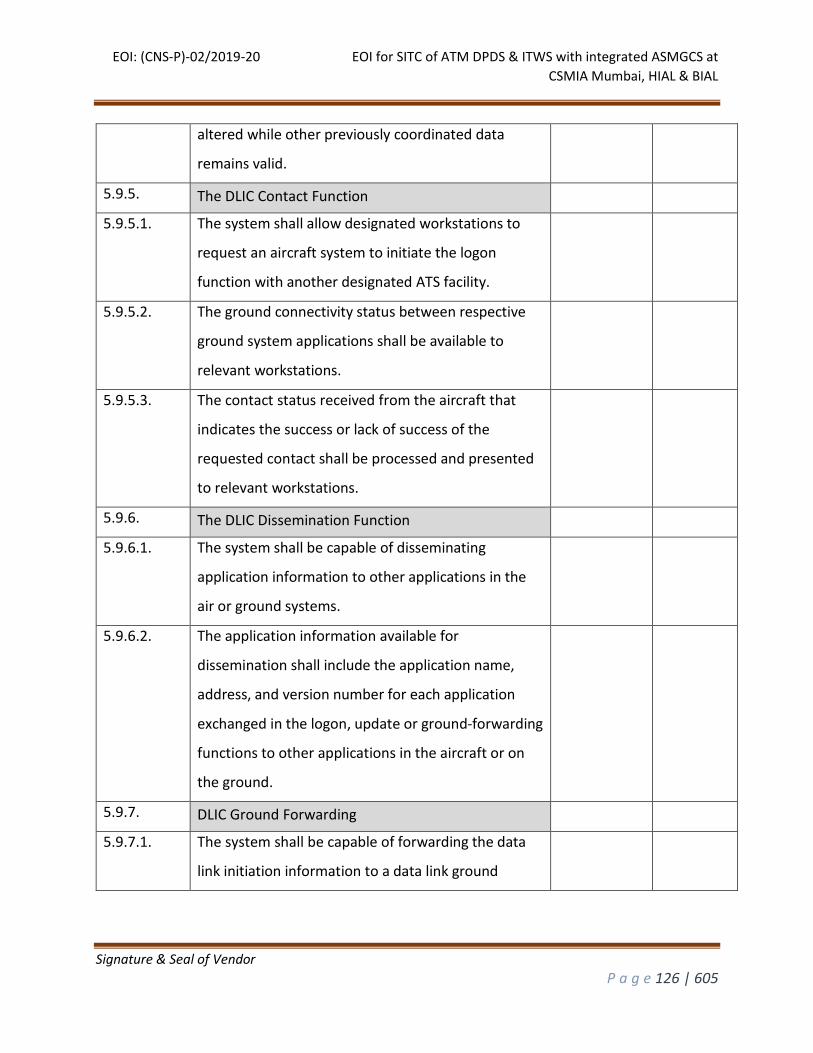
EOI: (CNS-P)-02/2019-20 EOI for SITC of ATM DPDS & ITWS with integrated ASMGCS at
CSMIA Mumbai, HIAL & BIAL
Signature & Seal of Vendor
P a g e 126 | 605
altered while other previously coordinated data
remains valid.
5.9.5. The DLIC Contact Function
5.9.5.1. The system shall allow designated workstations to
request an aircraft system to initiate the logon
function with another designated ATS facility.
5.9.5.2. The ground connectivity status between respective
ground system applications shall be available to
relevant workstations.
5.9.5.3. The contact status received from the aircraft that
indicates the success or lack of success of the
requested contact shall be processed and presented
to relevant workstations.
5.9.6. The DLIC Dissemination Function
5.9.6.1. The system shall be capable of disseminating
application information to other applications in the
air or ground systems.
5.9.6.2. The application information available for
dissemination shall include the application name,
address, and version number for each application
exchanged in the logon, update or ground-forwarding
functions to other applications in the aircraft or on
the ground.
5.9.7. DLIC Ground Forwarding
5.9.7.1. The system shall be capable of forwarding the data
link initiation information to a data link ground
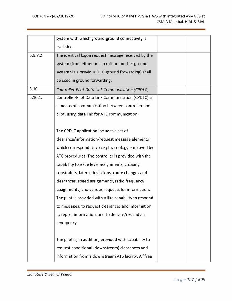
EOI: (CNS-P)-02/2019-20 EOI for SITC of ATM DPDS & ITWS with integrated ASMGCS at
CSMIA Mumbai, HIAL & BIAL
Signature & Seal of Vendor
P a g e 127 | 605
system with which ground-ground connectivity is
available.
5.9.7.2. The identical logon request message received by the
system (from either an aircraft or another ground
system via a previous DLIC ground forwarding) shall
be used in ground forwarding.
5.10. Controller-Pilot Data Link Communication (CPDLC)
5.10.1. Controller-Pilot Data Link Communication (CPDLC) is
a means of communication between controller and
pilot, using data link for ATC communication.
The CPDLC application includes a set of
clearance/information/request message elements
which correspond to voice phraseology employed by
ATC procedures. The controller is provided with the
capability to issue level assignments, crossing
constraints, lateral deviations, route changes and
clearances, speed assignments, radio frequency
assignments, and various requests for information.
The pilot is provided with a like capability to respond
to messages, to request clearances and information,
to report information, and to declare/rescind an
emergency.
The pilot is, in addition, provided with capability to
request conditional (downstream) clearances and
information from a downstream ATS facility. A “free
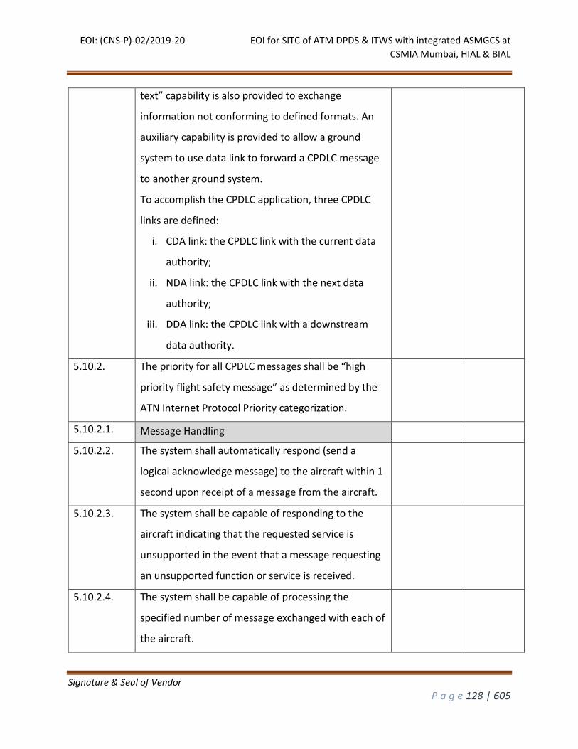
EOI: (CNS-P)-02/2019-20 EOI for SITC of ATM DPDS & ITWS with integrated ASMGCS at
CSMIA Mumbai, HIAL & BIAL
Signature & Seal of Vendor
P a g e 128 | 605
text” capability is also provided to exchange
information not conforming to defined formats. An
auxiliary capability is provided to allow a ground
system to use data link to forward a CPDLC message
to another ground system.
To accomplish the CPDLC application, three CPDLC
links are defined:
i. CDA link: the CPDLC link with the current data
authority;
ii. NDA link: the CPDLC link with the next data
authority;
iii. DDA link: the CPDLC link with a downstream
data authority.
5.10.2. The priority for all CPDLC messages shall be “high
priority flight safety message” as determined by the
ATN Internet Protocol Priority categorization.
5.10.2.1. Message Handling
5.10.2.2. The system shall automatically respond (send a
logical acknowledge message) to the aircraft within 1
second upon receipt of a message from the aircraft.
5.10.2.3. The system shall be capable of responding to the
aircraft indicating that the requested service is
unsupported in the event that a message requesting
an unsupported function or service is received.
5.10.2.4. The system shall be capable of processing the
specified number of message exchanged with each of
the aircraft.
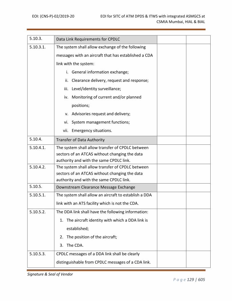
EOI: (CNS-P)-02/2019-20 EOI for SITC of ATM DPDS & ITWS with integrated ASMGCS at
CSMIA Mumbai, HIAL & BIAL
Signature & Seal of Vendor
P a g e 129 | 605
5.10.3. Data Link Requirements for CPDLC
5.10.3.1. The system shall allow exchange of the following
messages with an aircraft that has established a CDA
link with the system:
i. General information exchange;
ii. Clearance delivery, request and response;
iii. Level/identity surveillance;
iv. Monitoring of current and/or planned
positions;
v. Advisories request and delivery;
vi. System management functions;
vii. Emergency situations.
5.10.4. Transfer of Data Authority
5.10.4.1. The system shall allow transfer of CPDLC between
sectors of an ATCAS without changing the data
authority and with the same CPDLC link.
5.10.4.2. The system shall allow transfer of CPDLC between
sectors of an ATCAS without changing the data
authority and with the same CPDLC link.
5.10.5. Downstream Clearance Message Exchange
5.10.5.1. The system shall allow an aircraft to establish a DDA
link with an ATS facility which is not the CDA.
5.10.5.2. The DDA link shall have the following information:
1. The aircraft identity with which a DDA link is
established;
2. The position of the aircraft;
3. The CDA.
5.10.5.3. CPDLC messages of a DDA link shall be clearly
distinguishable from CPDLC messages of a CDA link.
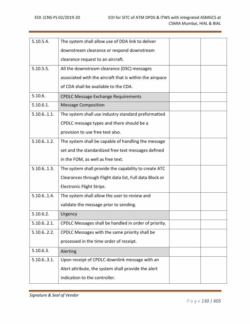
EOI: (CNS-P)-02/2019-20 EOI for SITC of ATM DPDS & ITWS with integrated ASMGCS at
CSMIA Mumbai, HIAL & BIAL
Signature & Seal of Vendor
P a g e 130 | 605
5.10.5.4. The system shall allow use of DDA link to deliver
downstream clearance or respond downstream
clearance request to an aircraft.
5.10.5.5. All the downstream clearance (DSC) messages
associated with the aircraft that is within the airspace
of CDA shall be available to the CDA.
5.10.6. CPDLC Message Exchange Requirements
5.10.6.1. Message Composition
5.10.6..1.1. The system shall use industry standard preformatted
CPDLC message types and there should be a
provision to use free text also.
5.10.6..1.2. The system shall be capable of handling the message
set and the standardized free text messages defined
in the FOM, as well as free text.
5.10.6..1.3. The system shall provide the capability to create ATC
Clearances through Flight data list, Full data Block or
Electronic Flight Strips.
5.10.6..1.4. The system shall allow the user to review and
validate the message prior to sending.
5.10.6.2. Urgency
5.10.6..2.1. CPDLC Messages shall be handled in order of priority.
5.10.6..2.2. CPDLC Messages with the same priority shall be
processed in the time order of receipt.
5.10.6.3. Alerting
5.10.6..3.1. Upon receipt of CPDLC downlink message with an
Alert attribute, the system shall provide the alert
indication to the controller.
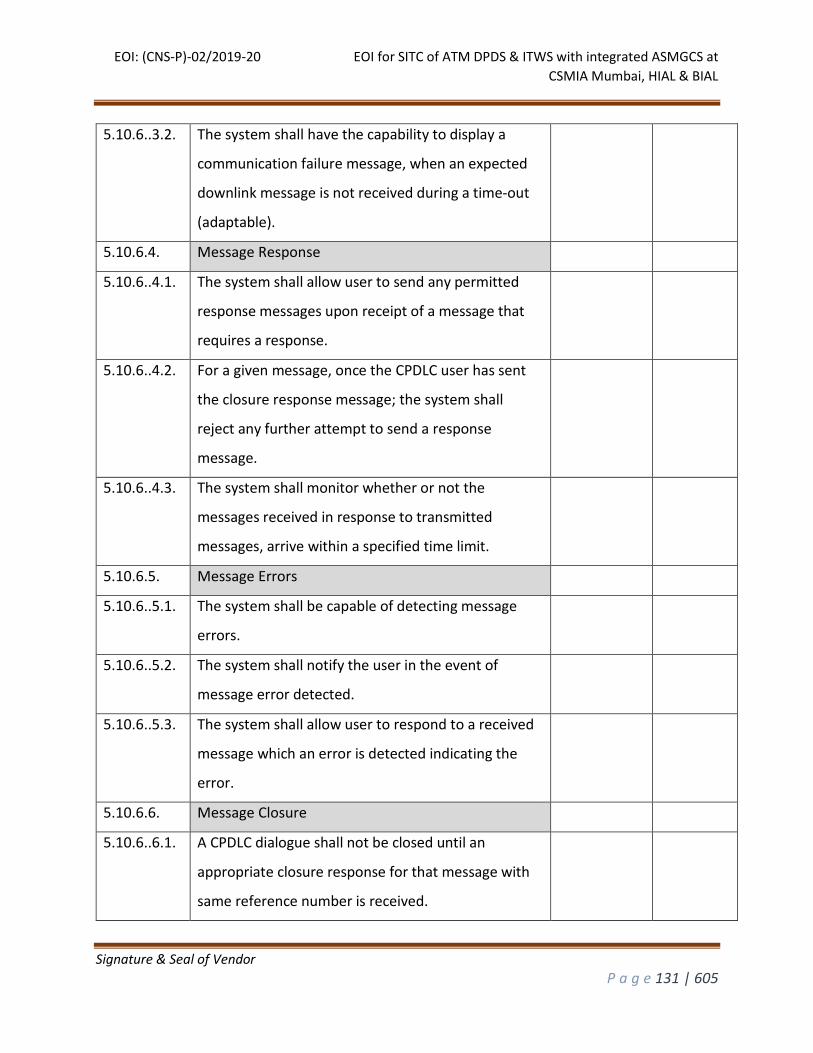
EOI: (CNS-P)-02/2019-20 EOI for SITC of ATM DPDS & ITWS with integrated ASMGCS at
CSMIA Mumbai, HIAL & BIAL
Signature & Seal of Vendor
P a g e 131 | 605
5.10.6..3.2. The system shall have the capability to display a
communication failure message, when an expected
downlink message is not received during a time-out
(adaptable).
5.10.6.4. Message Response
5.10.6..4.1. The system shall allow user to send any permitted
response messages upon receipt of a message that
requires a response.
5.10.6..4.2. For a given message, once the CPDLC user has sent
the closure response message; the system shall
reject any further attempt to send a response
message.
5.10.6..4.3. The system shall monitor whether or not the
messages received in response to transmitted
messages, arrive within a specified time limit.
5.10.6.5. Message Errors
5.10.6..5.1. The system shall be capable of detecting message
errors.
5.10.6..5.2. The system shall notify the user in the event of
message error detected.
5.10.6..5.3. The system shall allow user to respond to a received
message which an error is detected indicating the
error.
5.10.6.6. Message Closure
5.10.6..6.1. A CPDLC dialogue shall not be closed until an
appropriate closure response for that message with
same reference number is received.
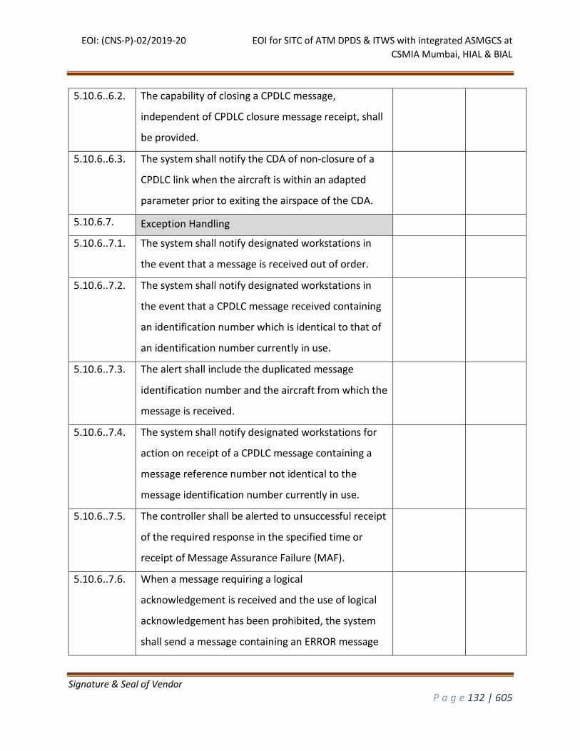
EOI: (CNS-P)-02/2019-20 EOI for SITC of ATM DPDS & ITWS with integrated ASMGCS at
CSMIA Mumbai, HIAL & BIAL
Signature & Seal of Vendor
P a g e 132 | 605
5.10.6..6.2. The capability of closing a CPDLC message,
independent of CPDLC closure message receipt, shall
be provided.
5.10.6..6.3. The system shall notify the CDA of non-closure of a
CPDLC link when the aircraft is within an adapted
parameter prior to exiting the airspace of the CDA.
5.10.6.7. Exception Handling
5.10.6..7.1. The system shall notify designated workstations in
the event that a message is received out of order.
5.10.6..7.2. The system shall notify designated workstations in
the event that a CPDLC message received containing
an identification number which is identical to that of
an identification number currently in use.
5.10.6..7.3. The alert shall include the duplicated message
identification number and the aircraft from which the
message is received.
5.10.6..7.4. The system shall notify designated workstations for
action on receipt of a CPDLC message containing a
message reference number not identical to the
message identification number currently in use.
5.10.6..7.5. The controller shall be alerted to unsuccessful receipt
of the required response in the specified time or
receipt of Message Assurance Failure (MAF).
5.10.6..7.6. When a message requiring a logical
acknowledgement is received and the use of logical
acknowledgement has been prohibited, the system
shall send a message containing an ERROR message
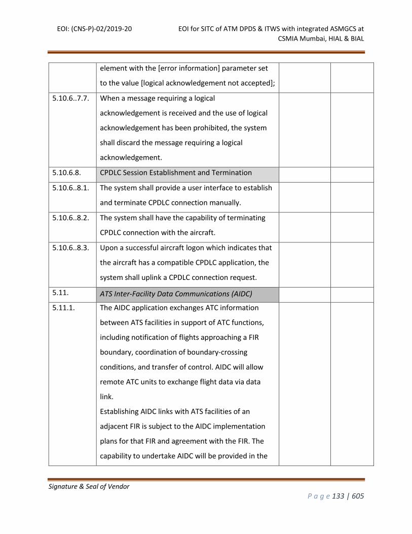
EOI: (CNS-P)-02/2019-20 EOI for SITC of ATM DPDS & ITWS with integrated ASMGCS at
CSMIA Mumbai, HIAL & BIAL
Signature & Seal of Vendor
P a g e 133 | 605
element with the [error information] parameter set
to the value [logical acknowledgement not accepted];
5.10.6..7.7. When a message requiring a logical
acknowledgement is received and the use of logical
acknowledgement has been prohibited, the system
shall discard the message requiring a logical
acknowledgement.
5.10.6.8. CPDLC Session Establishment and Termination
5.10.6..8.1. The system shall provide a user interface to establish
and terminate CPDLC connection manually.
5.10.6..8.2. The system shall have the capability of terminating
CPDLC connection with the aircraft.
5.10.6..8.3. Upon a successful aircraft logon which indicates that
the aircraft has a compatible CPDLC application, the
system shall uplink a CPDLC connection request.
5.11. ATS Inter-Facility Data Communications (AIDC)
5.11.1. The AIDC application exchanges ATC information
between ATS facilities in support of ATC functions,
including notification of flights approaching a FIR
boundary, coordination of boundary-crossing
conditions, and transfer of control. AIDC will allow
remote ATC units to exchange flight data via data
link.
Establishing AIDC links with ATS facilities of an
adjacent FIR is subject to the AIDC implementation
plans for that FIR and agreement with the FIR. The
capability to undertake AIDC will be provided in the
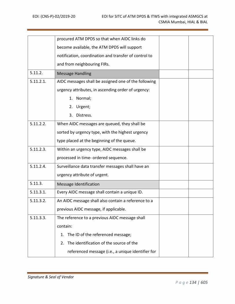
EOI: (CNS-P)-02/2019-20 EOI for SITC of ATM DPDS & ITWS with integrated ASMGCS at
CSMIA Mumbai, HIAL & BIAL
Signature & Seal of Vendor
P a g e 134 | 605
procured ATM DPDS so that when AIDC links do
become available, the ATM DPDS will support
notification, coordination and transfer of control to
and from neighbouring FIRs.
5.11.2. Message Handling
5.11.2.1. AIDC messages shall be assigned one of the following
urgency attributes, in ascending order of urgency:
1. Normal;
2. Urgent;
3. Distress.
5.11.2.2. When AIDC messages are queued, they shall be
sorted by urgency type, with the highest urgency
type placed at the beginning of the queue.
5.11.2.3. Within an urgency type, AIDC messages shall be
processed in time- ordered sequence.
5.11.2.4. Surveillance data transfer messages shall have an
urgency attribute of urgent.
5.11.3. Message Identification
5.11.3.1. Every AIDC message shall contain a unique ID.
5.11.3.2. An AIDC message shall also contain a reference to a
previous AIDC message, if applicable.
5.11.3.3. The reference to a previous AIDC message shall
contain:
1. The ID of the referenced message;
2. The identification of the source of the
referenced message (i.e., a unique identifier for
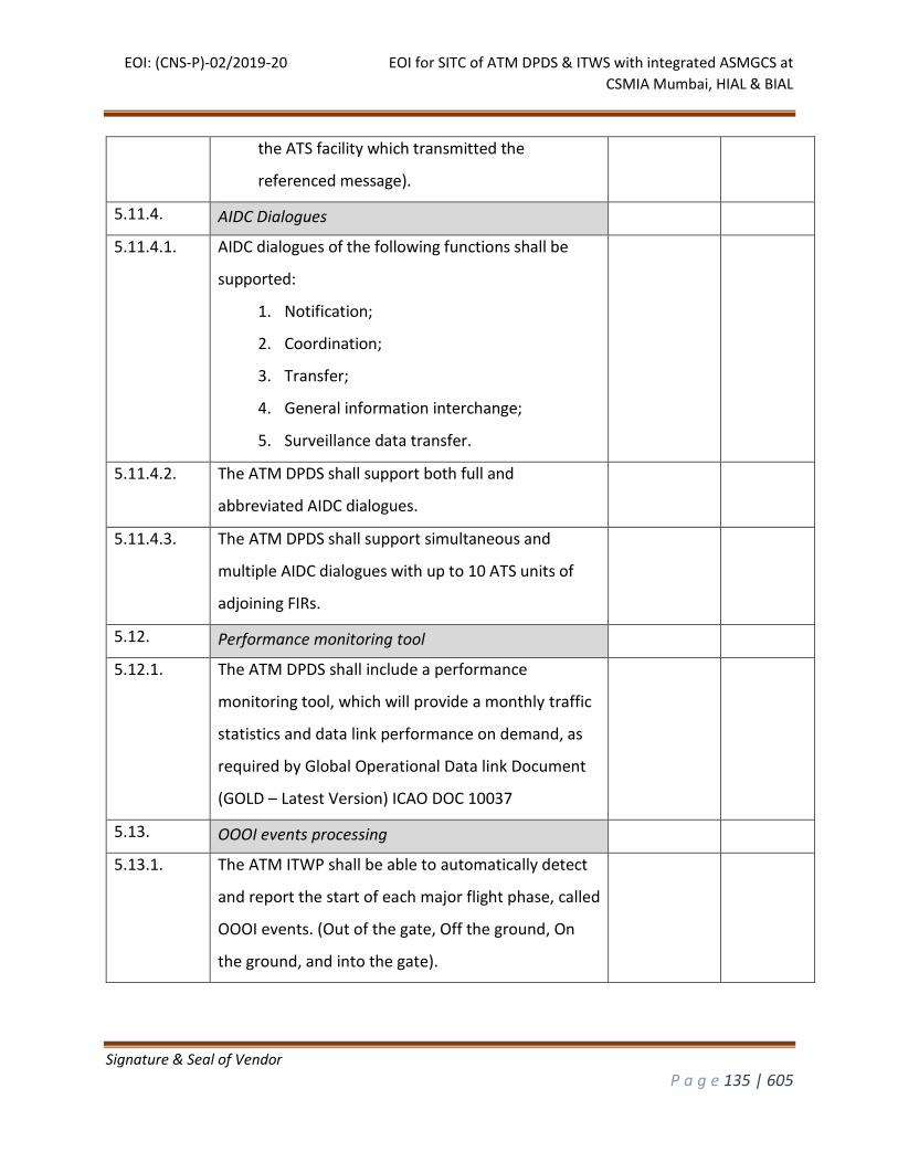
EOI: (CNS-P)-02/2019-20 EOI for SITC of ATM DPDS & ITWS with integrated ASMGCS at
CSMIA Mumbai, HIAL & BIAL
Signature & Seal of Vendor
P a g e 135 | 605
the ATS facility which transmitted the
referenced message).
5.11.4. AIDC Dialogues
5.11.4.1. AIDC dialogues of the following functions shall be
supported:
1. Notification;
2. Coordination;
3. Transfer;
4. General information interchange;
5. Surveillance data transfer.
5.11.4.2. The ATM DPDS shall support both full and
abbreviated AIDC dialogues.
5.11.4.3. The ATM DPDS shall support simultaneous and
multiple AIDC dialogues with up to 10 ATS units of
adjoining FIRs.
5.12. Performance monitoring tool
5.12.1. The ATM DPDS shall include a performance
monitoring tool, which will provide a monthly traffic
statistics and data link performance on demand, as
required by Global Operational Data link Document
(GOLD – Latest Version) ICAO DOC 10037
5.13. OOOI events processing
5.13.1. The ATM ITWP shall be able to automatically detect
and report the start of each major flight phase, called
OOOI events. (Out of the gate, Off the ground, On
the ground, and into the gate).
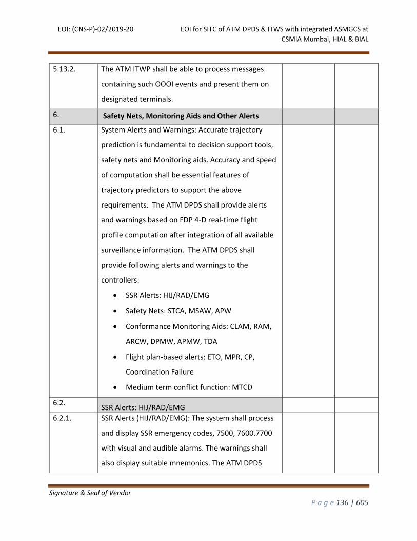
EOI: (CNS-P)-02/2019-20 EOI for SITC of ATM DPDS & ITWS with integrated ASMGCS at
CSMIA Mumbai, HIAL & BIAL
Signature & Seal of Vendor
P a g e 136 | 605
5.13.2. The ATM ITWP shall be able to process messages
containing such OOOI events and present them on
designated terminals.
6. Safety Nets, Monitoring Aids and Other Alerts
6.1. System Alerts and Warnings: Accurate trajectory
prediction is fundamental to decision support tools,
safety nets and Monitoring aids. Accuracy and speed
of computation shall be essential features of
trajectory predictors to support the above
requirements. The ATM DPDS shall provide alerts
and warnings based on FDP 4-D real-time flight
profile computation after integration of all available
surveillance information. The ATM DPDS shall
provide following alerts and warnings to the
controllers:
SSR Alerts: HIJ/RAD/EMG
Safety Nets: STCA, MSAW, APW
Conformance Monitoring Aids: CLAM, RAM,
ARCW, DPMW, APMW, TDA
Flight plan-based alerts: ETO, MPR, CP,
Coordination Failure
Medium term conflict function: MTCD
6.2. SSR Alerts: HIJ/RAD/EMG
6.2.1. SSR Alerts (HIJ/RAD/EMG): The system shall process
and display SSR emergency codes, 7500, 7600.7700
with visual and audible alarms. The warnings shall
also display suitable mnemonics. The ATM DPDS
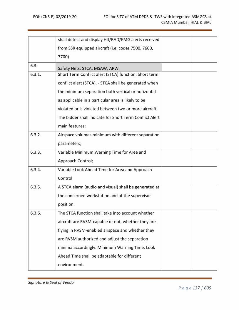
EOI: (CNS-P)-02/2019-20 EOI for SITC of ATM DPDS & ITWS with integrated ASMGCS at
CSMIA Mumbai, HIAL & BIAL
Signature & Seal of Vendor
P a g e 137 | 605
shall detect and display HIJ/RAD/EMG alerts received
from SSR equipped aircraft (i.e. codes 7500, 7600,
7700)
6.3. Safety Nets: STCA, MSAW, APW
6.3.1. Short Term Conflict alert (STCA) function: Short term
conflict alert (STCA), - STCA shall be generated when
the minimum separation both vertical or horizontal
as applicable in a particular area is likely to be
violated or is violated between two or more aircraft.
The bidder shall indicate for Short Term Conflict Alert
main features:
6.3.2. Airspace volumes minimum with different separation
parameters;
6.3.3. Variable Minimum Warning Time for Area and
Approach Control;
6.3.4. Variable Look Ahead Time for Area and Approach
Control
6.3.5. A STCA alarm (audio and visual) shall be generated at
the concerned workstation and at the supervisor
position.
6.3.6. The STCA function shall take into account whether
aircraft are RVSM-capable or not, whether they are
flying in RVSM-enabled airspace and whether they
are RVSM authorized and adjust the separation
minima accordingly. Minimum Warning Time, Look
Ahead Time shall be adaptable for different
environment.
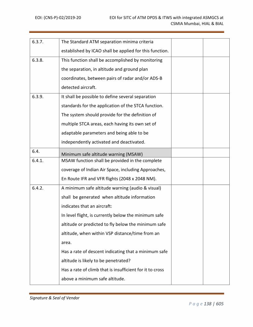
EOI: (CNS-P)-02/2019-20 EOI for SITC of ATM DPDS & ITWS with integrated ASMGCS at
CSMIA Mumbai, HIAL & BIAL
Signature & Seal of Vendor
P a g e 138 | 605
6.3.7. The Standard ATM separation minima criteria
established by ICAO shall be applied for this function.
6.3.8. This function shall be accomplished by monitoring
the separation, in altitude and ground plan
coordinates, between pairs of radar and/or ADS-B
detected aircraft.
6.3.9. It shall be possible to define several separation
standards for the application of the STCA function.
The system should provide for the definition of
multiple STCA areas, each having its own set of
adaptable parameters and being able to be
independently activated and deactivated.
6.4. Minimum safe altitude warning (MSAW)
6.4.1. MSAW function shall be provided in the complete
coverage of Indian Air Space, including Approaches,
En Route IFR and VFR flights (2048 x 2048 NM).
6.4.2. A minimum safe altitude warning (audio & visual)
shall be generated when altitude information
indicates that an aircraft:
In level flight, is currently below the minimum safe
altitude or predicted to fly below the minimum safe
altitude, when within VSP distance/time from an
area.
Has a rate of descent indicating that a minimum safe
altitude is likely to be penetrated?
Has a rate of climb that is insufficient for it to cross
above a minimum safe altitude.
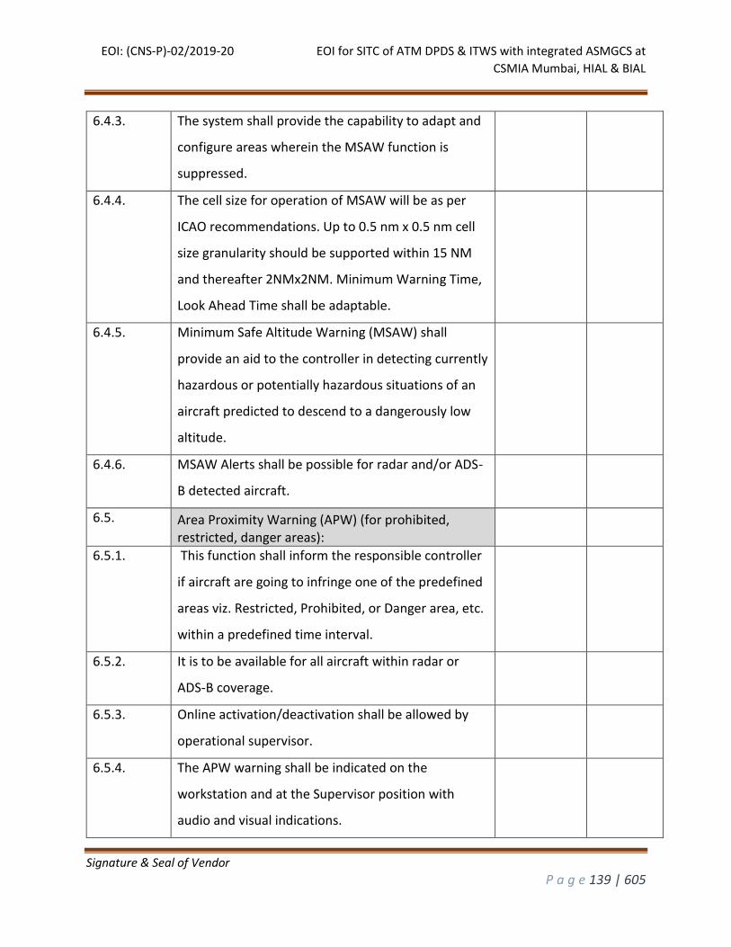
EOI: (CNS-P)-02/2019-20 EOI for SITC of ATM DPDS & ITWS with integrated ASMGCS at
CSMIA Mumbai, HIAL & BIAL
Signature & Seal of Vendor
P a g e 139 | 605
6.4.3. The system shall provide the capability to adapt and
configure areas wherein the MSAW function is
suppressed.
6.4.4. The cell size for operation of MSAW will be as per
ICAO recommendations. Up to 0.5 nm x 0.5 nm cell
size granularity should be supported within 15 NM
and thereafter 2NMx2NM. Minimum Warning Time,
Look Ahead Time shall be adaptable.
6.4.5. Minimum Safe Altitude Warning (MSAW) shall
provide an aid to the controller in detecting currently
hazardous or potentially hazardous situations of an
aircraft predicted to descend to a dangerously low
altitude.
6.4.6. MSAW Alerts shall be possible for radar and/or ADS-
B detected aircraft.
6.5. Area Proximity Warning (APW) (for prohibited, restricted, danger areas):
6.5.1. This function shall inform the responsible controller
if aircraft are going to infringe one of the predefined
areas viz. Restricted, Prohibited, or Danger area, etc.
within a predefined time interval.
6.5.2. It is to be available for all aircraft within radar or
ADS-B coverage.
6.5.3. Online activation/deactivation shall be allowed by
operational supervisor.
6.5.4. The APW warning shall be indicated on the
workstation and at the Supervisor position with
audio and visual indications.
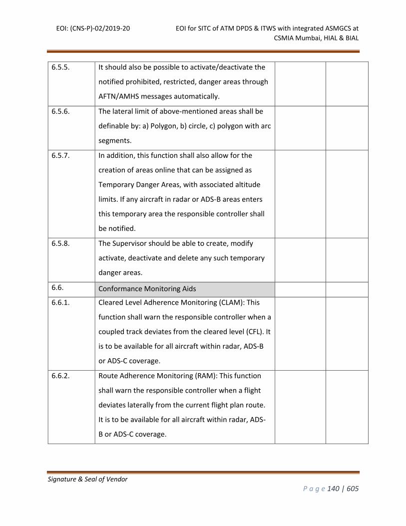
EOI: (CNS-P)-02/2019-20 EOI for SITC of ATM DPDS & ITWS with integrated ASMGCS at
CSMIA Mumbai, HIAL & BIAL
Signature & Seal of Vendor
P a g e 140 | 605
6.5.5. It should also be possible to activate/deactivate the
notified prohibited, restricted, danger areas through
AFTN/AMHS messages automatically.
6.5.6. The lateral limit of above-mentioned areas shall be
definable by: a) Polygon, b) circle, c) polygon with arc
segments.
6.5.7. In addition, this function shall also allow for the
creation of areas online that can be assigned as
Temporary Danger Areas, with associated altitude
limits. If any aircraft in radar or ADS-B areas enters
this temporary area the responsible controller shall
be notified.
6.5.8. The Supervisor should be able to create, modify
activate, deactivate and delete any such temporary
danger areas.
6.6. Conformance Monitoring Aids
6.6.1. Cleared Level Adherence Monitoring (CLAM): This
function shall warn the responsible controller when a
coupled track deviates from the cleared level (CFL). It
is to be available for all aircraft within radar, ADS-B
or ADS-C coverage.
6.6.2. Route Adherence Monitoring (RAM): This function
shall warn the responsible controller when a flight
deviates laterally from the current flight plan route.
It is to be available for all aircraft within radar, ADS-
B or ADS-C coverage.
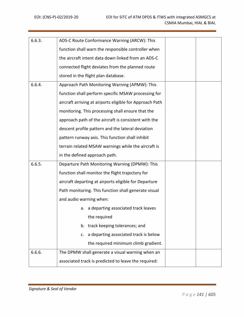
EOI: (CNS-P)-02/2019-20 EOI for SITC of ATM DPDS & ITWS with integrated ASMGCS at
CSMIA Mumbai, HIAL & BIAL
Signature & Seal of Vendor
P a g e 141 | 605
6.6.3. ADS-C Route Conformance Warning (ARCW): This
function shall warn the responsible controller when
the aircraft intent data down linked from an ADS-C
connected flight deviates from the planned route
stored in the flight plan database.
6.6.4. Approach Path Monitoring Warning (APMW): This
function shall perform specific MSAW processing for
aircraft arriving at airports eligible for Approach Path
monitoring. This processing shall ensure that the
approach path of the aircraft is consistent with the
descent profile pattern and the lateral deviation
pattern runway axis. This function shall inhibit
terrain related MSAW warnings while the aircraft is
in the defined approach path.
6.6.5. Departure Path Monitoring Warning (DPMW): This
function shall monitor the flight trajectory for
aircraft departing at airports eligible for Departure
Path monitoring. This function shall generate visual
and audio warning when:
a. a departing associated track leaves
the required
b. track keeping tolerances; and
c. a departing associated track is below
the required minimum climb gradient.
6.6.6. The DPMW shall generate a visual warning when an
associated track is predicted to leave the required:
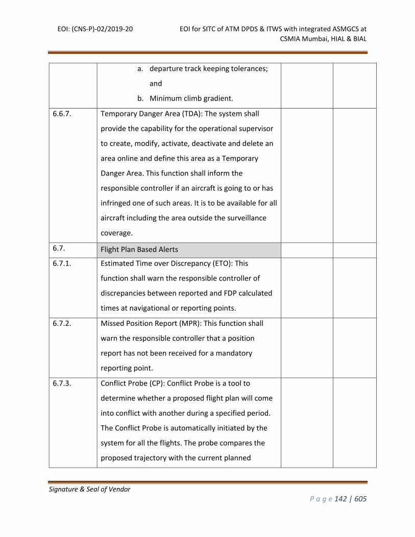
EOI: (CNS-P)-02/2019-20 EOI for SITC of ATM DPDS & ITWS with integrated ASMGCS at
CSMIA Mumbai, HIAL & BIAL
Signature & Seal of Vendor
P a g e 142 | 605
a. departure track keeping tolerances;
and
b. Minimum climb gradient.
6.6.7. Temporary Danger Area (TDA): The system shall
provide the capability for the operational supervisor
to create, modify, activate, deactivate and delete an
area online and define this area as a Temporary
Danger Area. This function shall inform the
responsible controller if an aircraft is going to or has
infringed one of such areas. It is to be available for all
aircraft including the area outside the surveillance
coverage.
6.7. Flight Plan Based Alerts
6.7.1. Estimated Time over Discrepancy (ETO): This
function shall warn the responsible controller of
discrepancies between reported and FDP calculated
times at navigational or reporting points.
6.7.2. Missed Position Report (MPR): This function shall
warn the responsible controller that a position
report has not been received for a mandatory
reporting point.
6.7.3. Conflict Probe (CP): Conflict Probe is a tool to
determine whether a proposed flight plan will come
into conflict with another during a specified period.
The Conflict Probe is automatically initiated by the
system for all the flights. The probe compares the
proposed trajectory with the current planned
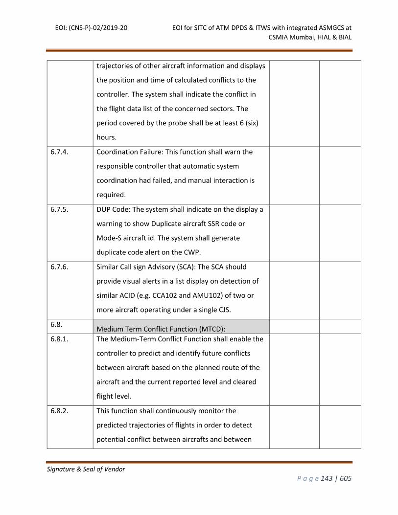
EOI: (CNS-P)-02/2019-20 EOI for SITC of ATM DPDS & ITWS with integrated ASMGCS at
CSMIA Mumbai, HIAL & BIAL
Signature & Seal of Vendor
P a g e 143 | 605
trajectories of other aircraft information and displays
the position and time of calculated conflicts to the
controller. The system shall indicate the conflict in
the flight data list of the concerned sectors. The
period covered by the probe shall be at least 6 (six)
hours.
6.7.4. Coordination Failure: This function shall warn the
responsible controller that automatic system
coordination had failed, and manual interaction is
required.
6.7.5. DUP Code: The system shall indicate on the display a
warning to show Duplicate aircraft SSR code or
Mode-S aircraft id. The system shall generate
duplicate code alert on the CWP.
6.7.6. Similar Call sign Advisory (SCA): The SCA should
provide visual alerts in a list display on detection of
similar ACID (e.g. CCA102 and AMU102) of two or
more aircraft operating under a single CJS.
6.8. Medium Term Conflict Function (MTCD):
6.8.1. The Medium-Term Conflict Function shall enable the
controller to predict and identify future conflicts
between aircraft based on the planned route of the
aircraft and the current reported level and cleared
flight level.
6.8.2. This function shall continuously monitor the
predicted trajectories of flights in order to detect
potential conflict between aircrafts and between

EOI: (CNS-P)-02/2019-20 EOI for SITC of ATM DPDS & ITWS with integrated ASMGCS at
CSMIA Mumbai, HIAL & BIAL
Signature & Seal of Vendor
P a g e 144 | 605
aircraft and special user airspace and provide timely
warning to controllers enabling them to take any
corrective action if required.
6.8.3. The conflict criteria should take into account the
RVSM status of the involved aircrafts.
6.8.4. The system shall also provide a trial probe capability
to check proposed clearances for conflicts and
airspace violations.
6.8.5. Capability to define a number of MTCD areas per
sector and display the different conflicts using
different attributes shall be provided.
6.8.6. The function shall also enable the controller to
predict and identify conflicts between aircraft and
Danger or Restricted areas that are active.
6.8.7. Where a conflict is predicted it shall provide the
responsible controller(s) with a visual indication of
the conflict and if the conflict is not resolved by the
controller(s) then the visual indication of the conflict
is escalated.
6.8.8. The controller shall have the ability to mark a conflict
as solved once some action has been taken.
6.8.9. The controller shall have the ability to highlight the
planned routes and area of conflict on the Air
Situation Display for any pair of aircraft that are in
conflict.
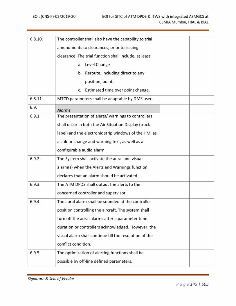
EOI: (CNS-P)-02/2019-20 EOI for SITC of ATM DPDS & ITWS with integrated ASMGCS at
CSMIA Mumbai, HIAL & BIAL
Signature & Seal of Vendor
P a g e 145 | 605
6.8.10. The controller shall also have the capability to trial
amendments to clearances, prior to issuing
clearance. The trial function shall include, at least:
a. Level Change
b. Reroute, including direct to any
position, point;
c. Estimated time over point change.
6.8.11. MTCD parameters shall be adaptable by DMS user.
6.9. Alarms
6.9.1. The presentation of alerts/ warnings to controllers
shall occur in both the Air Situation Display (track
label) and the electronic strip windows of the HMI as
a colour change and warning text, as well as a
configurable audio alarm
6.9.2. The System shall activate the aural and visual
alarm(s) when the Alerts and Warnings function
declares that an alarm should be activated.
6.9.3. The ATM DPDS shall output the alerts to the
concerned controller and supervisor.
6.9.4. The aural alarm shall be sounded at the controller
position controlling the aircraft. The system shall
turn off the aural alarms after a parameter time
duration or controllers acknowledged. However, the
visual alarm shall continue till the resolution of the
conflict condition.
6.9.5. The optimization of alerting functions shall be
possible by off-line defined parameters.
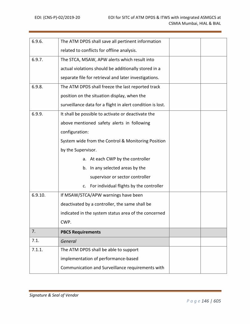
EOI: (CNS-P)-02/2019-20 EOI for SITC of ATM DPDS & ITWS with integrated ASMGCS at
CSMIA Mumbai, HIAL & BIAL
Signature & Seal of Vendor
P a g e 146 | 605
6.9.6. The ATM DPDS shall save all pertinent information
related to conflicts for offline analysis.
6.9.7. The STCA, MSAW, APW alerts which result into
actual violations should be additionally stored in a
separate file for retrieval and later investigations.
6.9.8. The ATM DPDS shall freeze the last reported track
position on the situation display, when the
surveillance data for a flight in alert condition is lost.
6.9.9. It shall be possible to activate or deactivate the
above mentioned safety alerts in following
configuration:
System wide from the Control & Monitoring Position
by the Supervisor.
a. At each CWP by the controller
b. In any selected areas by the
supervisor or sector controller
c. For individual flights by the controller
6.9.10. If MSAW/STCA/APW warnings have been
deactivated by a controller, the same shall be
indicated in the system status area of the concerned
CWP.
7. PBCS Requirements
7.1. General
7.1.1. The ATM DPDS shall be able to support
implementation of performance-based
Communication and Surveillance requirements with
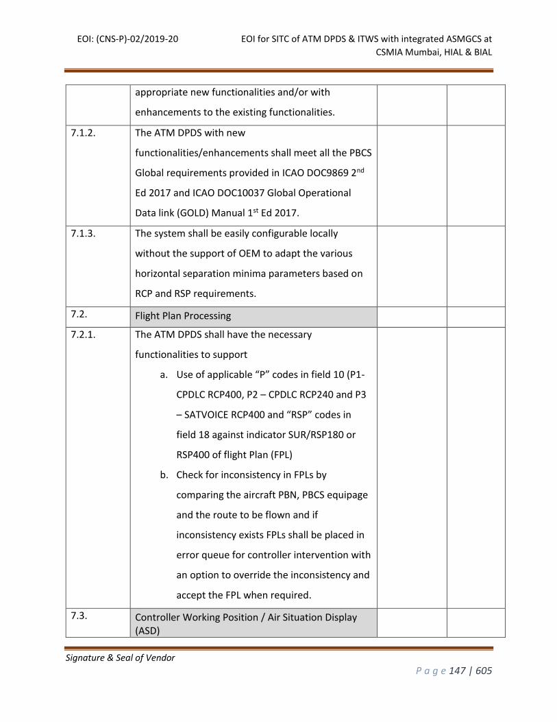
EOI: (CNS-P)-02/2019-20 EOI for SITC of ATM DPDS & ITWS with integrated ASMGCS at
CSMIA Mumbai, HIAL & BIAL
Signature & Seal of Vendor
P a g e 147 | 605
appropriate new functionalities and/or with
enhancements to the existing functionalities.
7.1.2. The ATM DPDS with new
functionalities/enhancements shall meet all the PBCS
Global requirements provided in ICAO DOC9869 2nd
Ed 2017 and ICAO DOC10037 Global Operational
Data link (GOLD) Manual 1st Ed 2017.
7.1.3. The system shall be easily configurable locally
without the support of OEM to adapt the various
horizontal separation minima parameters based on
RCP and RSP requirements.
7.2. Flight Plan Processing
7.2.1. The ATM DPDS shall have the necessary
functionalities to support
a. Use of applicable “P” codes in field 10 (P1-
CPDLC RCP400, P2 – CPDLC RCP240 and P3
– SATVOICE RCP400 and “RSP” codes in
field 18 against indicator SUR/RSP180 or
RSP400 of flight Plan (FPL)
b. Check for inconsistency in FPLs by
comparing the aircraft PBN, PBCS equipage
and the route to be flown and if
inconsistency exists FPLs shall be placed in
error queue for controller intervention with
an option to override the inconsistency and
accept the FPL when required.
7.3. Controller Working Position / Air Situation Display (ASD)
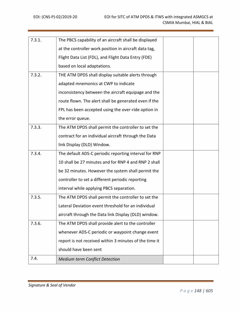
EOI: (CNS-P)-02/2019-20 EOI for SITC of ATM DPDS & ITWS with integrated ASMGCS at
CSMIA Mumbai, HIAL & BIAL
Signature & Seal of Vendor
P a g e 148 | 605
7.3.1. The PBCS capability of an aircraft shall be displayed
at the controller work position in aircraft data tag,
Flight Data List (FDL), and Flight Data Entry (FDE)
based on local adaptations.
7.3.2. THE ATM DPDS shall display suitable alerts through
adapted mnemonics at CWP to indicate
inconsistency between the aircraft equipage and the
route flown. The alert shall be generated even if the
FPL has been accepted using the over-ride option in
the error queue.
7.3.3. The ATM DPDS shall permit the controller to set the
contract for an individual aircraft through the Data
link Display (DLD) Window.
7.3.4. The default ADS-C periodic reporting interval for RNP
10 shall be 27 minutes and for RNP 4 and RNP 2 shall
be 32 minutes. However the system shall permit the
controller to set a different periodic reporting
interval while applying PBCS separation.
7.3.5. The ATM DPDS shall permit the controller to set the
Lateral Deviation event threshold for an individual
aircraft through the Data link Display (DLD) window.
7.3.6. The ATM DPDS shall provide alert to the controller
whenever ADS-C periodic or waypoint change event
report is not received within 3 minutes of the time it
should have been sent
7.4. Medium term Conflict Detection
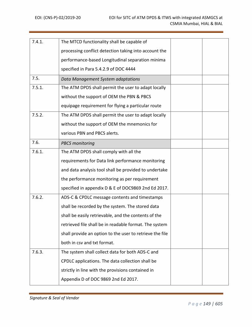
EOI: (CNS-P)-02/2019-20 EOI for SITC of ATM DPDS & ITWS with integrated ASMGCS at
CSMIA Mumbai, HIAL & BIAL
Signature & Seal of Vendor
P a g e 149 | 605
7.4.1. The MTCD functionality shall be capable of
processing conflict detection taking into account the
performance-based Longitudinal separation minima
specified in Para 5.4.2.9 of DOC 4444
7.5. Data Management System adaptations
7.5.1. The ATM DPDS shall permit the user to adapt locally
without the support of OEM the PBN & PBCS
equipage requirement for flying a particular route
7.5.2. The ATM DPDS shall permit the user to adapt locally
without the support of OEM the mnemonics for
various PBN and PBCS alerts.
7.6. PBCS monitoring
7.6.1. The ATM DPDS shall comply with all the
requirements for Data link performance monitoring
and data analysis tool shall be provided to undertake
the performance monitoring as per requirement
specified in appendix D & E of DOC9869 2nd Ed 2017.
7.6.2. ADS-C & CPDLC message contents and timestamps
shall be recorded by the system. The stored data
shall be easily retrievable, and the contents of the
retrieved file shall be in readable format. The system
shall provide an option to the user to retrieve the file
both in csv and txt format.
7.6.3. The system shall collect data for both ADS-C and
CPDLC applications. The data collection shall be
strictly in line with the provisions contained in
Appendix D of DOC 9869 2nd Ed 2017.
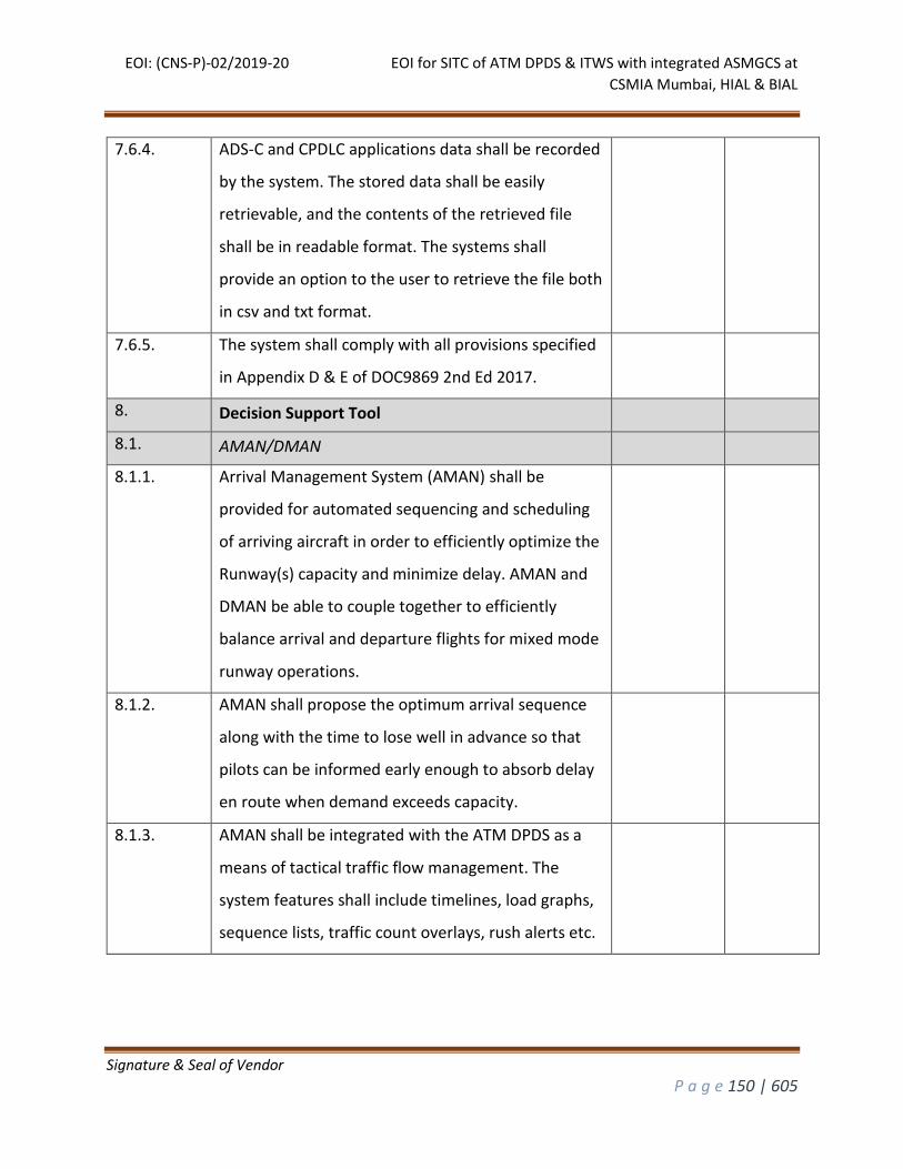
EOI: (CNS-P)-02/2019-20 EOI for SITC of ATM DPDS & ITWS with integrated ASMGCS at
CSMIA Mumbai, HIAL & BIAL
Signature & Seal of Vendor
P a g e 150 | 605
7.6.4. ADS-C and CPDLC applications data shall be recorded
by the system. The stored data shall be easily
retrievable, and the contents of the retrieved file
shall be in readable format. The systems shall
provide an option to the user to retrieve the file both
in csv and txt format.
7.6.5. The system shall comply with all provisions specified
in Appendix D & E of DOC9869 2nd Ed 2017.
8. Decision Support Tool
8.1. AMAN/DMAN
8.1.1. Arrival Management System (AMAN) shall be
provided for automated sequencing and scheduling
of arriving aircraft in order to efficiently optimize the
Runway(s) capacity and minimize delay. AMAN and
DMAN be able to couple together to efficiently
balance arrival and departure flights for mixed mode
runway operations.
8.1.2. AMAN shall propose the optimum arrival sequence
along with the time to lose well in advance so that
pilots can be informed early enough to absorb delay
en route when demand exceeds capacity.
8.1.3. AMAN shall be integrated with the ATM DPDS as a
means of tactical traffic flow management. The
system features shall include timelines, load graphs,
sequence lists, traffic count overlays, rush alerts etc.
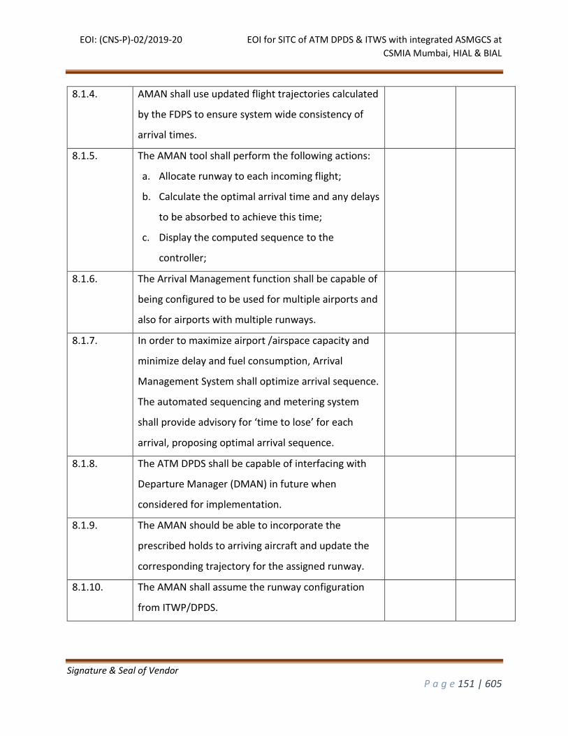
EOI: (CNS-P)-02/2019-20 EOI for SITC of ATM DPDS & ITWS with integrated ASMGCS at
CSMIA Mumbai, HIAL & BIAL
Signature & Seal of Vendor
P a g e 151 | 605
8.1.4. AMAN shall use updated flight trajectories calculated
by the FDPS to ensure system wide consistency of
arrival times.
8.1.5. The AMAN tool shall perform the following actions:
a. Allocate runway to each incoming flight;
b. Calculate the optimal arrival time and any delays
to be absorbed to achieve this time;
c. Display the computed sequence to the
controller;
8.1.6. The Arrival Management function shall be capable of
being configured to be used for multiple airports and
also for airports with multiple runways.
8.1.7. In order to maximize airport /airspace capacity and
minimize delay and fuel consumption, Arrival
Management System shall optimize arrival sequence.
The automated sequencing and metering system
shall provide advisory for ‘time to lose’ for each
arrival, proposing optimal arrival sequence.
8.1.8. The ATM DPDS shall be capable of interfacing with
Departure Manager (DMAN) in future when
considered for implementation.
8.1.9. The AMAN should be able to incorporate the
prescribed holds to arriving aircraft and update the
corresponding trajectory for the assigned runway.
8.1.10. The AMAN shall assume the runway configuration
from ITWP/DPDS.
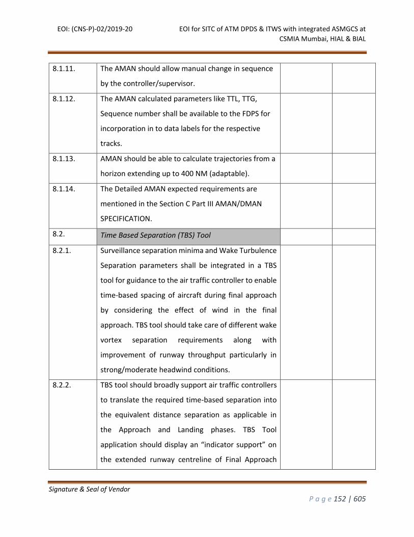
EOI: (CNS-P)-02/2019-20 EOI for SITC of ATM DPDS & ITWS with integrated ASMGCS at
CSMIA Mumbai, HIAL & BIAL
Signature & Seal of Vendor
P a g e 152 | 605
8.1.11. The AMAN should allow manual change in sequence
by the controller/supervisor.
8.1.12. The AMAN calculated parameters like TTL, TTG,
Sequence number shall be available to the FDPS for
incorporation in to data labels for the respective
tracks.
8.1.13. AMAN should be able to calculate trajectories from a
horizon extending up to 400 NM (adaptable).
8.1.14. The Detailed AMAN expected requirements are
mentioned in the Section C Part III AMAN/DMAN
SPECIFICATION.
8.2. Time Based Separation (TBS) Tool
8.2.1. Surveillance separation minima and Wake Turbulence
Separation parameters shall be integrated in a TBS
tool for guidance to the air traffic controller to enable
time-based spacing of aircraft during final approach
by considering the effect of wind in the final
approach. TBS tool should take care of different wake
vortex separation requirements along with
improvement of runway throughput particularly in
strong/moderate headwind conditions.
8.2.2. TBS tool should broadly support air traffic controllers
to translate the required time-based separation into
the equivalent distance separation as applicable in
the Approach and Landing phases. TBS Tool
application should display an “indicator support” on
the extended runway centreline of Final Approach
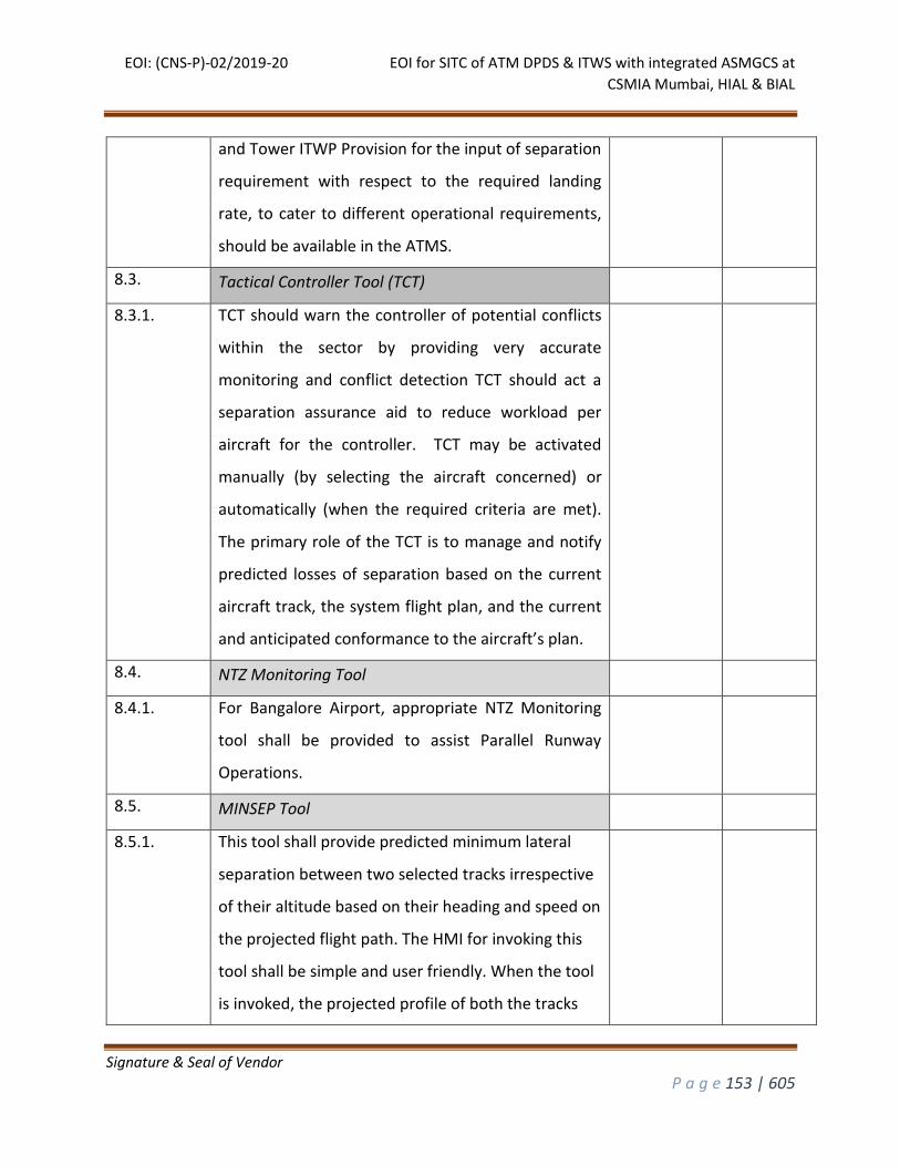
EOI: (CNS-P)-02/2019-20 EOI for SITC of ATM DPDS & ITWS with integrated ASMGCS at
CSMIA Mumbai, HIAL & BIAL
Signature & Seal of Vendor
P a g e 153 | 605
and Tower ITWP Provision for the input of separation
requirement with respect to the required landing
rate, to cater to different operational requirements,
should be available in the ATMS.
8.3. Tactical Controller Tool (TCT)
8.3.1. TCT should warn the controller of potential conflicts
within the sector by providing very accurate
monitoring and conflict detection TCT should act a
separation assurance aid to reduce workload per
aircraft for the controller. TCT may be activated
manually (by selecting the aircraft concerned) or
automatically (when the required criteria are met).
The primary role of the TCT is to manage and notify
predicted losses of separation based on the current
aircraft track, the system flight plan, and the current
and anticipated conformance to the aircraft’s plan.
8.4. NTZ Monitoring Tool
8.4.1. For Bangalore Airport, appropriate NTZ Monitoring
tool shall be provided to assist Parallel Runway
Operations.
8.5. MINSEP Tool
8.5.1. This tool shall provide predicted minimum lateral
separation between two selected tracks irrespective
of their altitude based on their heading and speed on
the projected flight path. The HMI for invoking this
tool shall be simple and user friendly. When the tool
is invoked, the projected profile of both the tracks
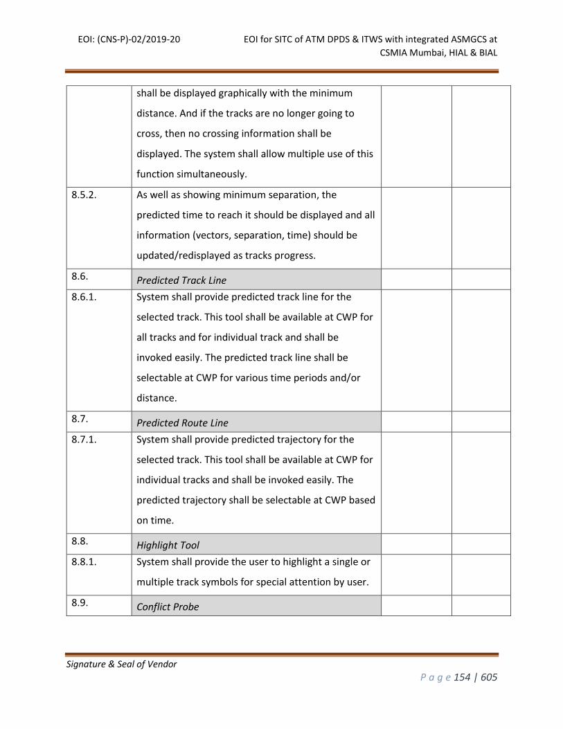
EOI: (CNS-P)-02/2019-20 EOI for SITC of ATM DPDS & ITWS with integrated ASMGCS at
CSMIA Mumbai, HIAL & BIAL
Signature & Seal of Vendor
P a g e 154 | 605
shall be displayed graphically with the minimum
distance. And if the tracks are no longer going to
cross, then no crossing information shall be
displayed. The system shall allow multiple use of this
function simultaneously.
8.5.2. As well as showing minimum separation, the
predicted time to reach it should be displayed and all
information (vectors, separation, time) should be
updated/redisplayed as tracks progress.
8.6. Predicted Track Line
8.6.1. System shall provide predicted track line for the
selected track. This tool shall be available at CWP for
all tracks and for individual track and shall be
invoked easily. The predicted track line shall be
selectable at CWP for various time periods and/or
distance.
8.7. Predicted Route Line
8.7.1. System shall provide predicted trajectory for the
selected track. This tool shall be available at CWP for
individual tracks and shall be invoked easily. The
predicted trajectory shall be selectable at CWP based
on time.
8.8. Highlight Tool
8.8.1. System shall provide the user to highlight a single or
multiple track symbols for special attention by user.
8.9. Conflict Probe
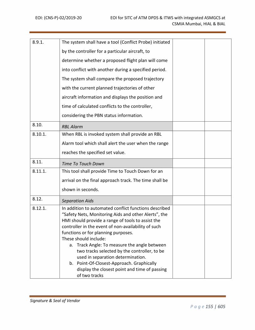
EOI: (CNS-P)-02/2019-20 EOI for SITC of ATM DPDS & ITWS with integrated ASMGCS at
CSMIA Mumbai, HIAL & BIAL
Signature & Seal of Vendor
P a g e 155 | 605
8.9.1. The system shall have a tool (Conflict Probe) initiated
by the controller for a particular aircraft, to
determine whether a proposed flight plan will come
into conflict with another during a specified period.
The system shall compare the proposed trajectory
with the current planned trajectories of other
aircraft information and displays the position and
time of calculated conflicts to the controller,
considering the PBN status information.
8.10. RBL Alarm
8.10.1. When RBL is invoked system shall provide an RBL
Alarm tool which shall alert the user when the range
reaches the specified set value.
8.11. Time To Touch Down
8.11.1. This tool shall provide Time to Touch Down for an
arrival on the final approach track. The time shall be
shown in seconds.
8.12. Separation Aids
8.12.1. In addition to automated conflict functions described “Safety Nets, Monitoring Aids and other Alerts”, the HMI should provide a range of tools to assist the controller in the event of non-availability of such functions or for planning purposes. These should include:
a. Track Angle: To measure the angle between two tracks selected by the controller, to be used in separation determination.
b. Point-Of-Closest-Approach. Graphically display the closest point and time of passing of two tracks
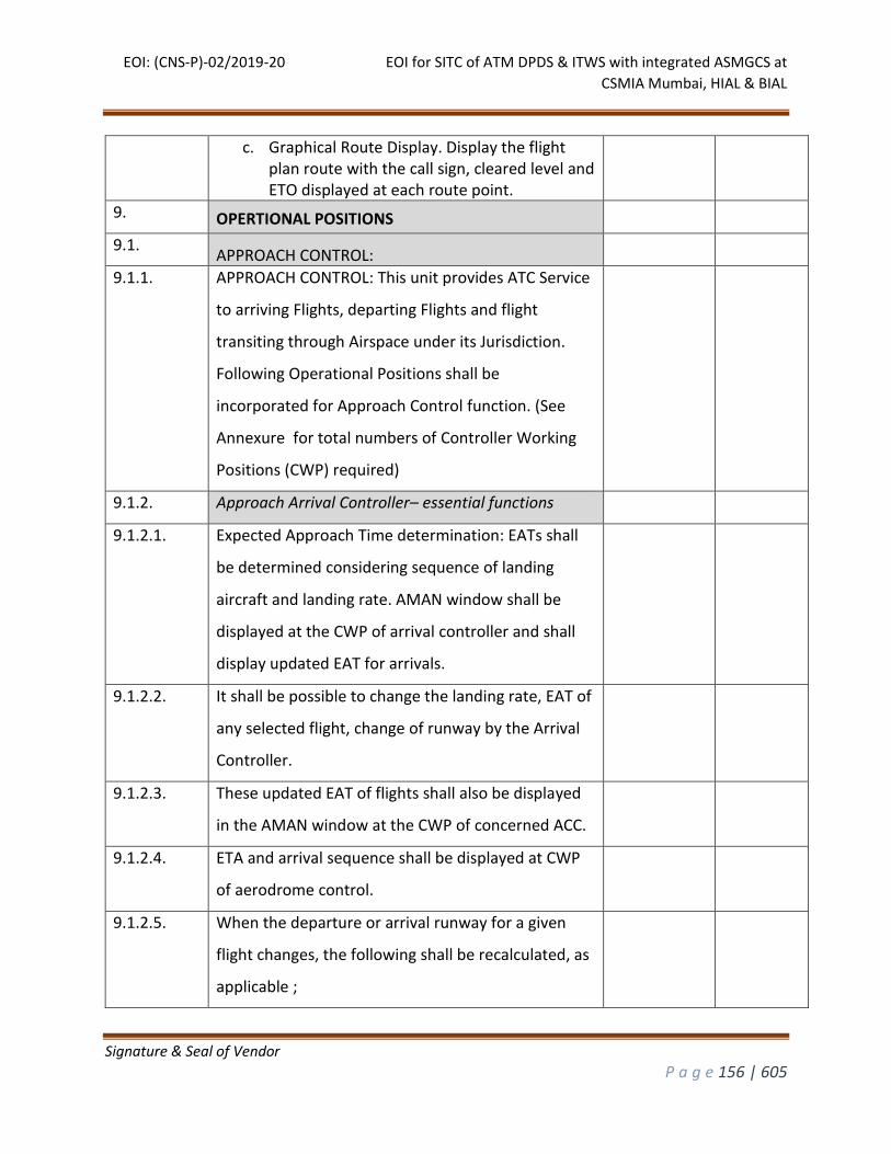
EOI: (CNS-P)-02/2019-20 EOI for SITC of ATM DPDS & ITWS with integrated ASMGCS at
CSMIA Mumbai, HIAL & BIAL
Signature & Seal of Vendor
P a g e 156 | 605
c. Graphical Route Display. Display the flight plan route with the call sign, cleared level and ETO displayed at each route point.
9. OPERTIONAL POSITIONS
9.1. APPROACH CONTROL:
9.1.1. APPROACH CONTROL: This unit provides ATC Service
to arriving Flights, departing Flights and flight
transiting through Airspace under its Jurisdiction.
Following Operational Positions shall be
incorporated for Approach Control function. (See
Annexure for total numbers of Controller Working
Positions (CWP) required)
9.1.2. Approach Arrival Controller– essential functions
9.1.2.1. Expected Approach Time determination: EATs shall
be determined considering sequence of landing
aircraft and landing rate. AMAN window shall be
displayed at the CWP of arrival controller and shall
display updated EAT for arrivals.
9.1.2.2. It shall be possible to change the landing rate, EAT of
any selected flight, change of runway by the Arrival
Controller.
9.1.2.3. These updated EAT of flights shall also be displayed
in the AMAN window at the CWP of concerned ACC.
9.1.2.4. ETA and arrival sequence shall be displayed at CWP
of aerodrome control.
9.1.2.5. When the departure or arrival runway for a given
flight changes, the following shall be recalculated, as
applicable ;
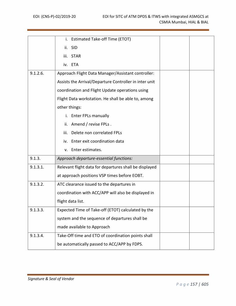
EOI: (CNS-P)-02/2019-20 EOI for SITC of ATM DPDS & ITWS with integrated ASMGCS at
CSMIA Mumbai, HIAL & BIAL
Signature & Seal of Vendor
P a g e 157 | 605
i. Estimated Take-off Time (ETOT)
ii. SID
iii. STAR
iv. ETA
9.1.2.6. Approach Flight Data Manager/Assistant controller:
Assists the Arrival/Departure Controller in inter unit
coordination and Flight Update operations using
Flight Data workstation. He shall be able to, among
other things:
i. Enter FPLs manually
ii. Amend / revise FPLs .
iii. Delete non correlated FPLs
iv. Enter exit coordination data
v. Enter estimates.
9.1.3. Approach departure-essential functions:
9.1.3.1. Relevant flight data for departures shall be displayed
at approach positions VSP times before EOBT.
9.1.3.2. ATC clearance issued to the departures in
coordination with ACC/APP will also be displayed in
flight data list.
9.1.3.3. Expected Time of Take-off (ETOT) calculated by the
system and the sequence of departures shall be
made available to Approach
9.1.3.4. Take-Off time and ETO of coordination points shall
be automatically passed to ACC/APP by FDPS.
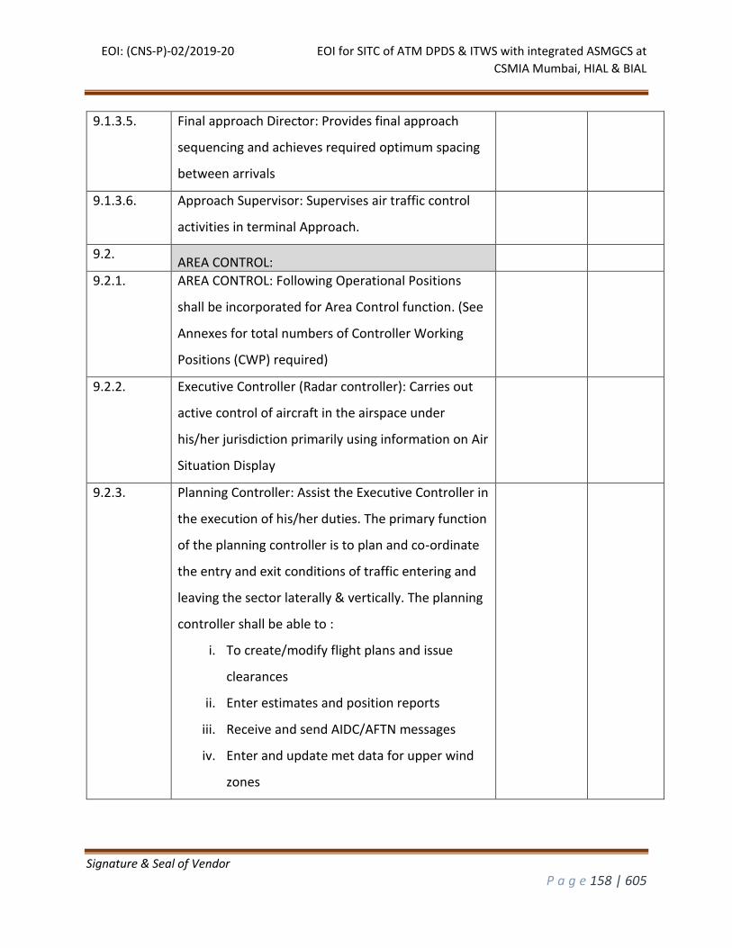
EOI: (CNS-P)-02/2019-20 EOI for SITC of ATM DPDS & ITWS with integrated ASMGCS at
CSMIA Mumbai, HIAL & BIAL
Signature & Seal of Vendor
P a g e 158 | 605
9.1.3.5. Final approach Director: Provides final approach
sequencing and achieves required optimum spacing
between arrivals
9.1.3.6. Approach Supervisor: Supervises air traffic control
activities in terminal Approach.
9.2. AREA CONTROL:
9.2.1. AREA CONTROL: Following Operational Positions
shall be incorporated for Area Control function. (See
Annexes for total numbers of Controller Working
Positions (CWP) required)
9.2.2. Executive Controller (Radar controller): Carries out
active control of aircraft in the airspace under
his/her jurisdiction primarily using information on Air
Situation Display
9.2.3. Planning Controller: Assist the Executive Controller in
the execution of his/her duties. The primary function
of the planning controller is to plan and co-ordinate
the entry and exit conditions of traffic entering and
leaving the sector laterally & vertically. The planning
controller shall be able to :
i. To create/modify flight plans and issue
clearances
ii. Enter estimates and position reports
iii. Receive and send AIDC/AFTN messages
iv. Enter and update met data for upper wind
zones
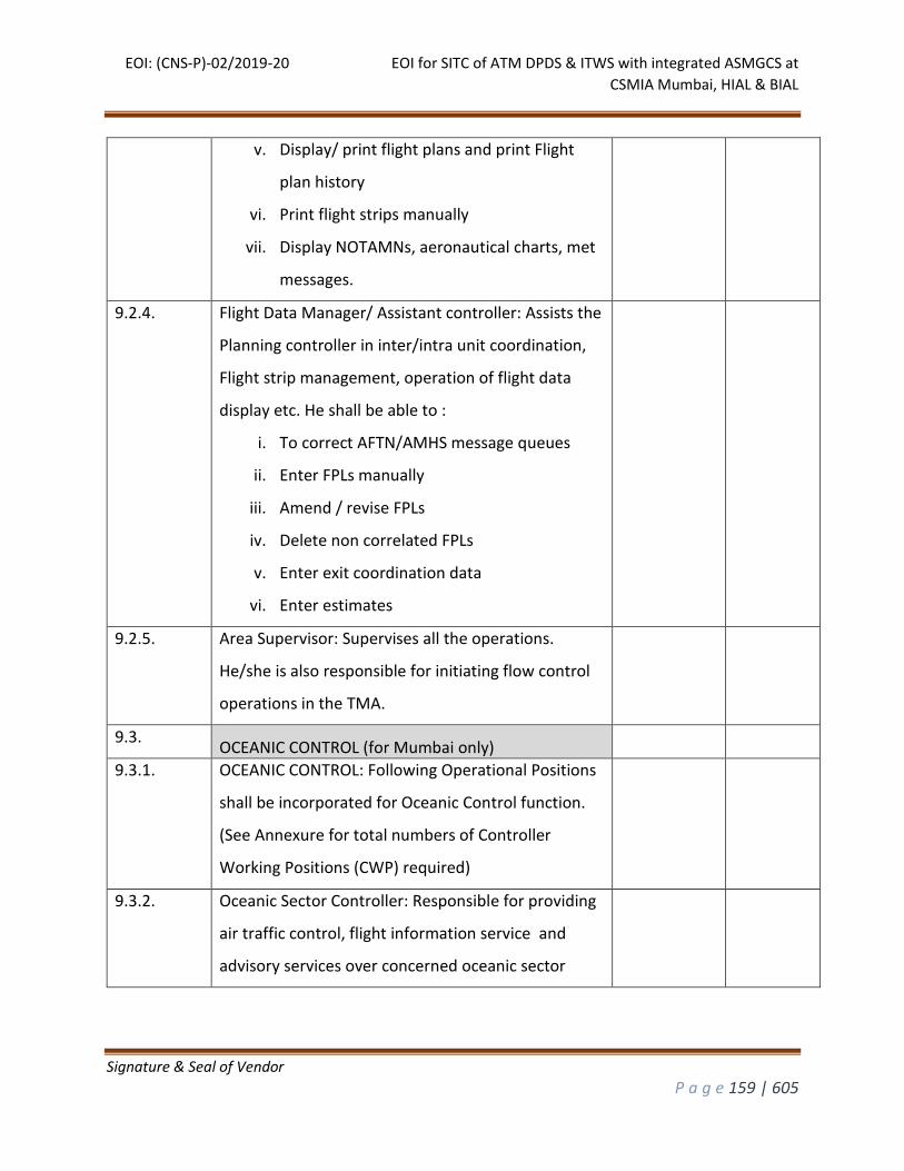
EOI: (CNS-P)-02/2019-20 EOI for SITC of ATM DPDS & ITWS with integrated ASMGCS at
CSMIA Mumbai, HIAL & BIAL
Signature & Seal of Vendor
P a g e 159 | 605
v. Display/ print flight plans and print Flight
plan history
vi. Print flight strips manually
vii. Display NOTAMNs, aeronautical charts, met
messages.
9.2.4. Flight Data Manager/ Assistant controller: Assists the
Planning controller in inter/intra unit coordination,
Flight strip management, operation of flight data
display etc. He shall be able to :
i. To correct AFTN/AMHS message queues
ii. Enter FPLs manually
iii. Amend / revise FPLs
iv. Delete non correlated FPLs
v. Enter exit coordination data
vi. Enter estimates
9.2.5. Area Supervisor: Supervises all the operations.
He/she is also responsible for initiating flow control
operations in the TMA.
9.3. OCEANIC CONTROL (for Mumbai only)
9.3.1. OCEANIC CONTROL: Following Operational Positions
shall be incorporated for Oceanic Control function.
(See Annexure for total numbers of Controller
Working Positions (CWP) required)
9.3.2. Oceanic Sector Controller: Responsible for providing
air traffic control, flight information service and
advisory services over concerned oceanic sector
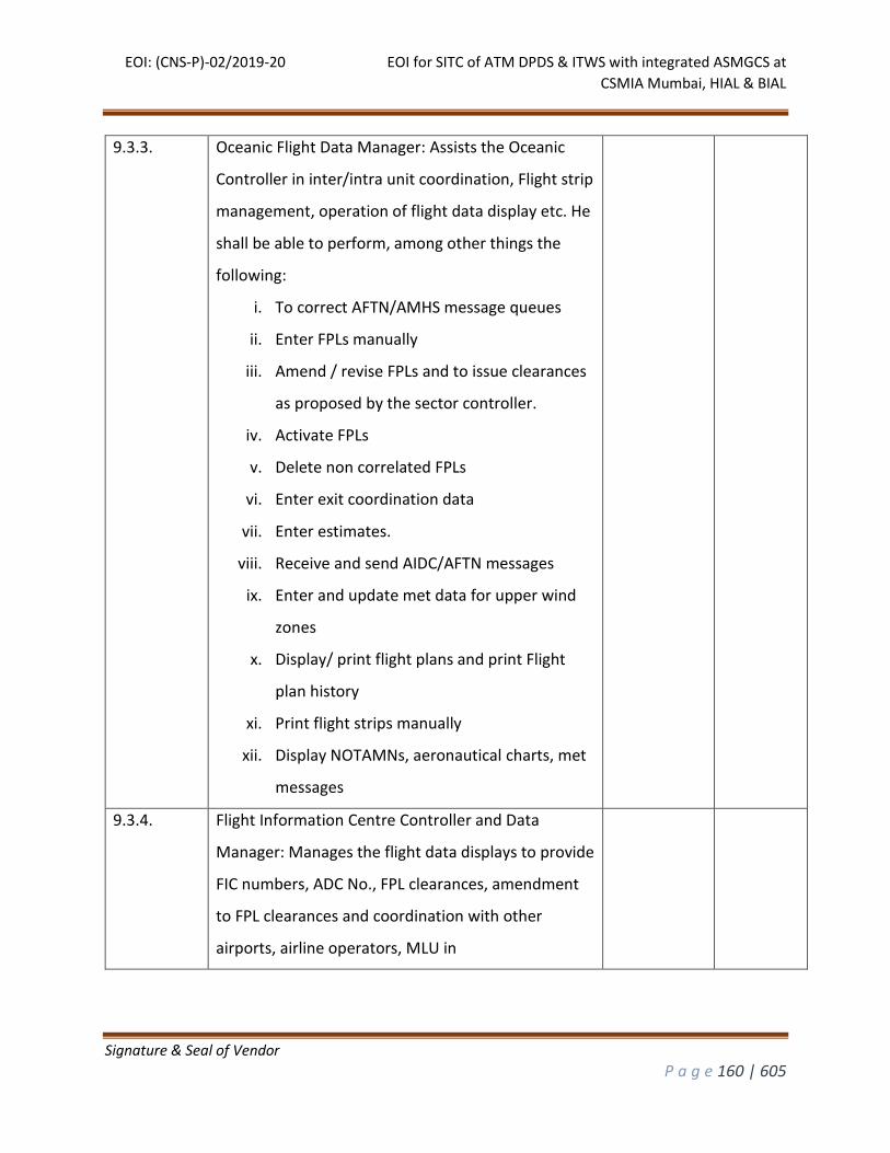
EOI: (CNS-P)-02/2019-20 EOI for SITC of ATM DPDS & ITWS with integrated ASMGCS at
CSMIA Mumbai, HIAL & BIAL
Signature & Seal of Vendor
P a g e 160 | 605
9.3.3. Oceanic Flight Data Manager: Assists the Oceanic
Controller in inter/intra unit coordination, Flight strip
management, operation of flight data display etc. He
shall be able to perform, among other things the
following:
i. To correct AFTN/AMHS message queues
ii. Enter FPLs manually
iii. Amend / revise FPLs and to issue clearances
as proposed by the sector controller.
iv. Activate FPLs
v. Delete non correlated FPLs
vi. Enter exit coordination data
vii. Enter estimates.
viii. Receive and send AIDC/AFTN messages
ix. Enter and update met data for upper wind
zones
x. Display/ print flight plans and print Flight
plan history
xi. Print flight strips manually
xii. Display NOTAMNs, aeronautical charts, met
messages
9.3.4. Flight Information Centre Controller and Data
Manager: Manages the flight data displays to provide
FIC numbers, ADC No., FPL clearances, amendment
to FPL clearances and coordination with other
airports, airline operators, MLU in
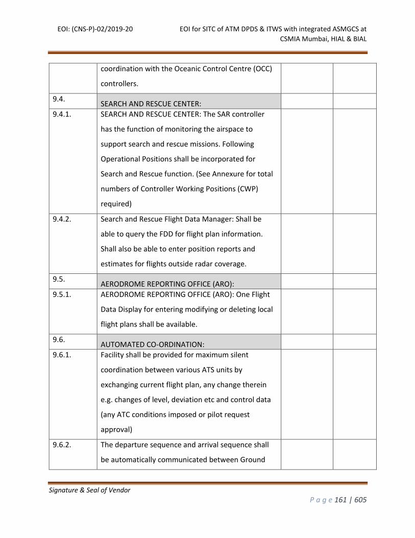
EOI: (CNS-P)-02/2019-20 EOI for SITC of ATM DPDS & ITWS with integrated ASMGCS at
CSMIA Mumbai, HIAL & BIAL
Signature & Seal of Vendor
P a g e 161 | 605
coordination with the Oceanic Control Centre (OCC)
controllers.
9.4. SEARCH AND RESCUE CENTER:
9.4.1. SEARCH AND RESCUE CENTER: The SAR controller
has the function of monitoring the airspace to
support search and rescue missions. Following
Operational Positions shall be incorporated for
Search and Rescue function. (See Annexure for total
numbers of Controller Working Positions (CWP)
required)
9.4.2. Search and Rescue Flight Data Manager: Shall be
able to query the FDD for flight plan information.
Shall also be able to enter position reports and
estimates for flights outside radar coverage.
9.5. AERODROME REPORTING OFFICE (ARO):
9.5.1. AERODROME REPORTING OFFICE (ARO): One Flight
Data Display for entering modifying or deleting local
flight plans shall be available.
9.6. AUTOMATED CO-ORDINATION:
9.6.1. Facility shall be provided for maximum silent
coordination between various ATS units by
exchanging current flight plan, any change therein
e.g. changes of level, deviation etc and control data
(any ATC conditions imposed or pilot request
approval)
9.6.2. The departure sequence and arrival sequence shall
be automatically communicated between Ground
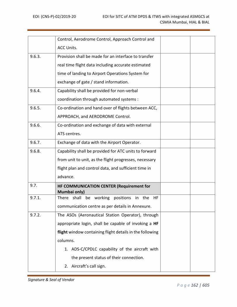
EOI: (CNS-P)-02/2019-20 EOI for SITC of ATM DPDS & ITWS with integrated ASMGCS at
CSMIA Mumbai, HIAL & BIAL
Signature & Seal of Vendor
P a g e 162 | 605
Control, Aerodrome Control, Approach Control and
ACC Units.
9.6.3. Provision shall be made for an interface to transfer
real time flight data including accurate estimated
time of landing to Airport Operations System for
exchange of gate / stand information.
9.6.4. Capability shall be provided for non-verbal
coordination through automated systems :
9.6.5. Co-ordination and hand over of flights between ACC,
APPROACH, and AERODROME Control.
9.6.6. Co-ordination and exchange of data with external
ATS centres.
9.6.7. Exchange of data with the Airport Operator.
9.6.8. Capability shall be provided for ATC units to forward
from unit to unit, as the flight progresses, necessary
flight plan and control data, and sufficient time in
advance.
9.7. HF COMMUNICATION CENTER (Requirement for Mumbai only)
9.7.1. There shall be working positions in the HF
communication centre as per details in Annexure.
9.7.2. The ASOs (Aeronautical Station Operator), through
appropriate login, shall be capable of invoking a HF
flight window containing flight details in the following
columns.
1. ADS-C/CPDLC capability of the aircraft with
the present status of their connection.
2. Aircraft’s call sign.
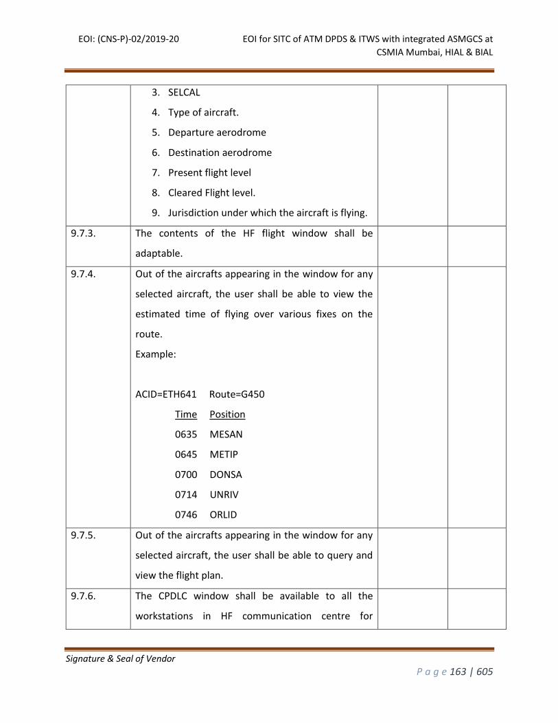
EOI: (CNS-P)-02/2019-20 EOI for SITC of ATM DPDS & ITWS with integrated ASMGCS at
CSMIA Mumbai, HIAL & BIAL
Signature & Seal of Vendor
P a g e 163 | 605
3. SELCAL
4. Type of aircraft.
5. Departure aerodrome
6. Destination aerodrome
7. Present flight level
8. Cleared Flight level.
9. Jurisdiction under which the aircraft is flying.
9.7.3. The contents of the HF flight window shall be
adaptable.
9.7.4. Out of the aircrafts appearing in the window for any
selected aircraft, the user shall be able to view the
estimated time of flying over various fixes on the
route.
Example:
ACID=ETH641 Route=G450
Time Position
0635 MESAN
0645 METIP
0700 DONSA
0714 UNRIV
0746 ORLID
9.7.5. Out of the aircrafts appearing in the window for any
selected aircraft, the user shall be able to query and
view the flight plan.
9.7.6. The CPDLC window shall be available to all the
workstations in HF communication centre for
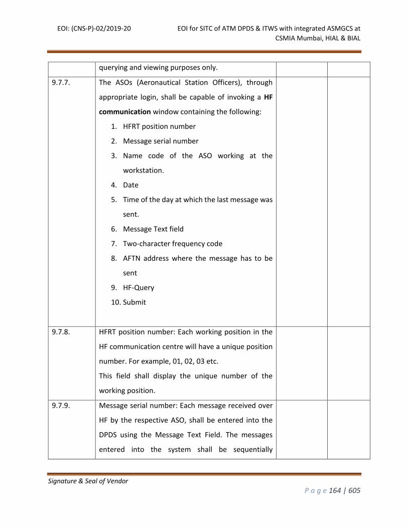
EOI: (CNS-P)-02/2019-20 EOI for SITC of ATM DPDS & ITWS with integrated ASMGCS at
CSMIA Mumbai, HIAL & BIAL
Signature & Seal of Vendor
P a g e 164 | 605
querying and viewing purposes only.
9.7.7. The ASOs (Aeronautical Station Officers), through
appropriate login, shall be capable of invoking a HF
communication window containing the following:
1. HFRT position number
2. Message serial number
3. Name code of the ASO working at the
workstation.
4. Date
5. Time of the day at which the last message was
sent.
6. Message Text field
7. Two-character frequency code
8. AFTN address where the message has to be
sent
9. HF-Query
10. Submit
9.7.8. HFRT position number: Each working position in the
HF communication centre will have a unique position
number. For example, 01, 02, 03 etc.
This field shall display the unique number of the
working position.
9.7.9. Message serial number: Each message received over
HF by the respective ASO, shall be entered into the
DPDS using the Message Text Field. The messages
entered into the system shall be sequentially
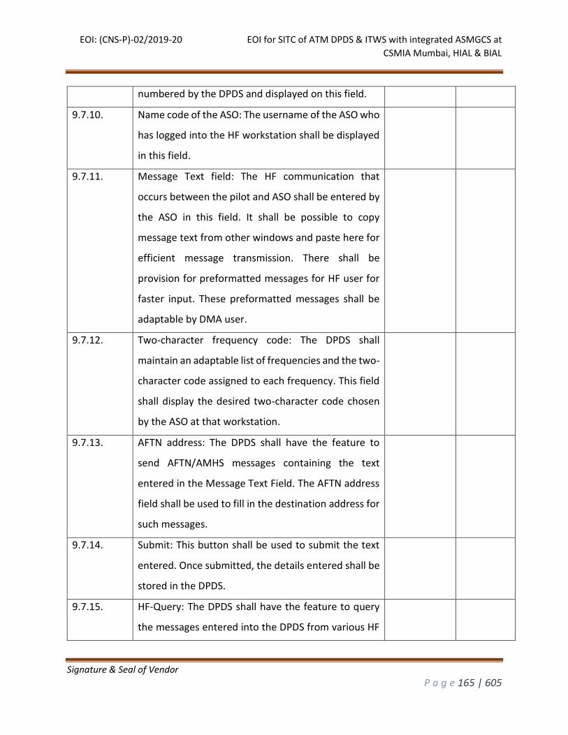
EOI: (CNS-P)-02/2019-20 EOI for SITC of ATM DPDS & ITWS with integrated ASMGCS at
CSMIA Mumbai, HIAL & BIAL
Signature & Seal of Vendor
P a g e 165 | 605
numbered by the DPDS and displayed on this field.
9.7.10. Name code of the ASO: The username of the ASO who
has logged into the HF workstation shall be displayed
in this field.
9.7.11. Message Text field: The HF communication that
occurs between the pilot and ASO shall be entered by
the ASO in this field. It shall be possible to copy
message text from other windows and paste here for
efficient message transmission. There shall be
provision for preformatted messages for HF user for
faster input. These preformatted messages shall be
adaptable by DMA user.
9.7.12. Two-character frequency code: The DPDS shall
maintain an adaptable list of frequencies and the two-
character code assigned to each frequency. This field
shall display the desired two-character code chosen
by the ASO at that workstation.
9.7.13. AFTN address: The DPDS shall have the feature to
send AFTN/AMHS messages containing the text
entered in the Message Text Field. The AFTN address
field shall be used to fill in the destination address for
such messages.
9.7.14. Submit: This button shall be used to submit the text
entered. Once submitted, the details entered shall be
stored in the DPDS.
9.7.15. HF-Query: The DPDS shall have the feature to query
the messages entered into the DPDS from various HF
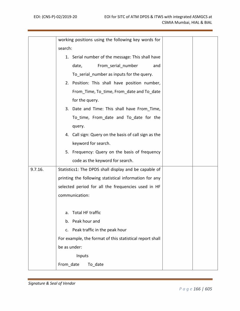
EOI: (CNS-P)-02/2019-20 EOI for SITC of ATM DPDS & ITWS with integrated ASMGCS at
CSMIA Mumbai, HIAL & BIAL
Signature & Seal of Vendor
P a g e 166 | 605
working positions using the following key words for
search:
1. Serial number of the message: This shall have
date, From_serial_number and
To_serial_number as inputs for the query.
2. Position: This shall have position number,
From_Time, To_time, From_date and To_date
for the query.
3. Date and Time: This shall have From_Time,
To_time, From_date and To_date for the
query.
4. Call sign: Query on the basis of call sign as the
keyword for search.
5. Frequency: Query on the basis of frequency
code as the keyword for search.
9.7.16. Statistics1: The DPDS shall display and be capable of
printing the following statistical information for any
selected period for all the frequencies used in HF
communication:
a. Total HF traffic
b. Peak hour and
c. Peak traffic in the peak hour
For example, the format of this statistical report shall
be as under:
Inputs
From_date To_date
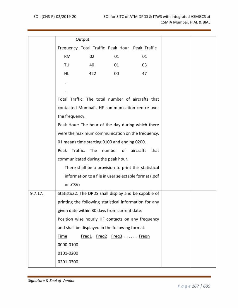
EOI: (CNS-P)-02/2019-20 EOI for SITC of ATM DPDS & ITWS with integrated ASMGCS at
CSMIA Mumbai, HIAL & BIAL
Signature & Seal of Vendor
P a g e 167 | 605
Output
Frequency Total_Traffic Peak_Hour Peak_Traffic
RM 02 01 01
TU 40 01 03
HL 422 00 47
.
.
Total Traffic: The total number of aircrafts that
contacted Mumbai’s HF communication centre over
the frequency.
Peak Hour: The hour of the day during which there
were the maximum communication on the frequency.
01 means time starting 0100 and ending 0200.
Peak Traffic: The number of aircrafts that
communicated during the peak hour.
There shall be a provision to print this statistical
information to a file in user selectable format (.pdf
or .CSV)
9.7.17. Statistics2: The DPDS shall display and be capable of
printing the following statistical information for any
given date within 30 days from current date:
Position wise hourly HF contacts on any frequency
and shall be displayed in the following format:
Time Freq1 Freq2 Freq3 . . . . . . Freqn
0000-0100
0101-0200
0201-0300
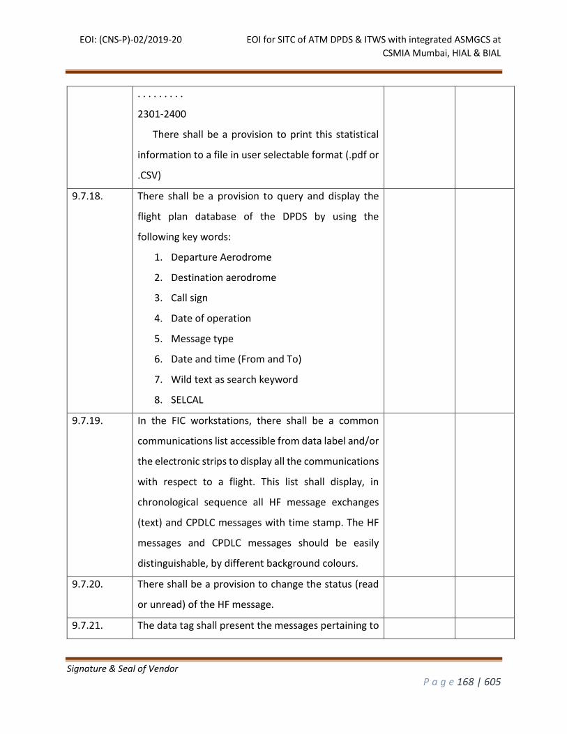
EOI: (CNS-P)-02/2019-20 EOI for SITC of ATM DPDS & ITWS with integrated ASMGCS at
CSMIA Mumbai, HIAL & BIAL
Signature & Seal of Vendor
P a g e 168 | 605
. . . . . . . . .
2301-2400
There shall be a provision to print this statistical
information to a file in user selectable format (.pdf or
.CSV)
9.7.18. There shall be a provision to query and display the
flight plan database of the DPDS by using the
following key words:
1. Departure Aerodrome
2. Destination aerodrome
3. Call sign
4. Date of operation
5. Message type
6. Date and time (From and To)
7. Wild text as search keyword
8. SELCAL
9.7.19. In the FIC workstations, there shall be a common
communications list accessible from data label and/or
the electronic strips to display all the communications
with respect to a flight. This list shall display, in
chronological sequence all HF message exchanges
(text) and CPDLC messages with time stamp. The HF
messages and CPDLC messages should be easily
distinguishable, by different background colours.
9.7.20. There shall be a provision to change the status (read
or unread) of the HF message.
9.7.21. The data tag shall present the messages pertaining to
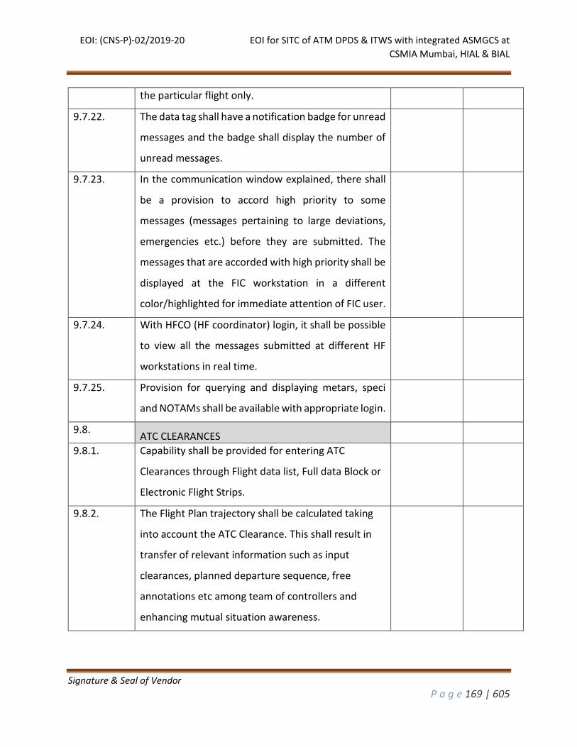
EOI: (CNS-P)-02/2019-20 EOI for SITC of ATM DPDS & ITWS with integrated ASMGCS at
CSMIA Mumbai, HIAL & BIAL
Signature & Seal of Vendor
P a g e 169 | 605
the particular flight only.
9.7.22. The data tag shall have a notification badge for unread
messages and the badge shall display the number of
unread messages.
9.7.23. In the communication window explained, there shall
be a provision to accord high priority to some
messages (messages pertaining to large deviations,
emergencies etc.) before they are submitted. The
messages that are accorded with high priority shall be
displayed at the FIC workstation in a different
color/highlighted for immediate attention of FIC user.
9.7.24. With HFCO (HF coordinator) login, it shall be possible
to view all the messages submitted at different HF
workstations in real time.
9.7.25. Provision for querying and displaying metars, speci
and NOTAMs shall be available with appropriate login.
9.8. ATC CLEARANCES
9.8.1. Capability shall be provided for entering ATC
Clearances through Flight data list, Full data Block or
Electronic Flight Strips.
9.8.2. The Flight Plan trajectory shall be calculated taking
into account the ATC Clearance. This shall result in
transfer of relevant information such as input
clearances, planned departure sequence, free
annotations etc among team of controllers and
enhancing mutual situation awareness.
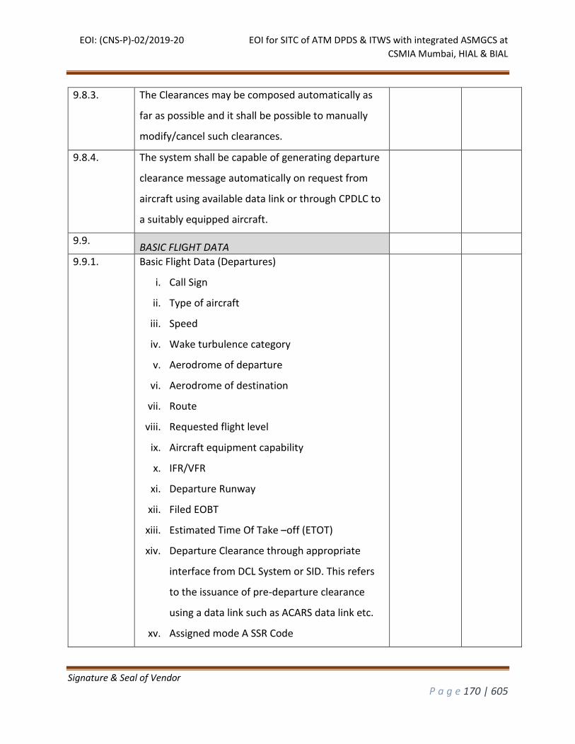
EOI: (CNS-P)-02/2019-20 EOI for SITC of ATM DPDS & ITWS with integrated ASMGCS at
CSMIA Mumbai, HIAL & BIAL
Signature & Seal of Vendor
P a g e 170 | 605
9.8.3. The Clearances may be composed automatically as
far as possible and it shall be possible to manually
modify/cancel such clearances.
9.8.4. The system shall be capable of generating departure
clearance message automatically on request from
aircraft using available data link or through CPDLC to
a suitably equipped aircraft.
9.9. BASIC FLIGHT DATA
9.9.1. Basic Flight Data (Departures)
i. Call Sign
ii. Type of aircraft
iii. Speed
iv. Wake turbulence category
v. Aerodrome of departure
vi. Aerodrome of destination
vii. Route
viii. Requested flight level
ix. Aircraft equipment capability
x. IFR/VFR
xi. Departure Runway
xii. Filed EOBT
xiii. Estimated Time Of Take –off (ETOT)
xiv. Departure Clearance through appropriate
interface from DCL System or SID. This refers
to the issuance of pre-departure clearance
using a data link such as ACARS data link etc.
xv. Assigned mode A SSR Code
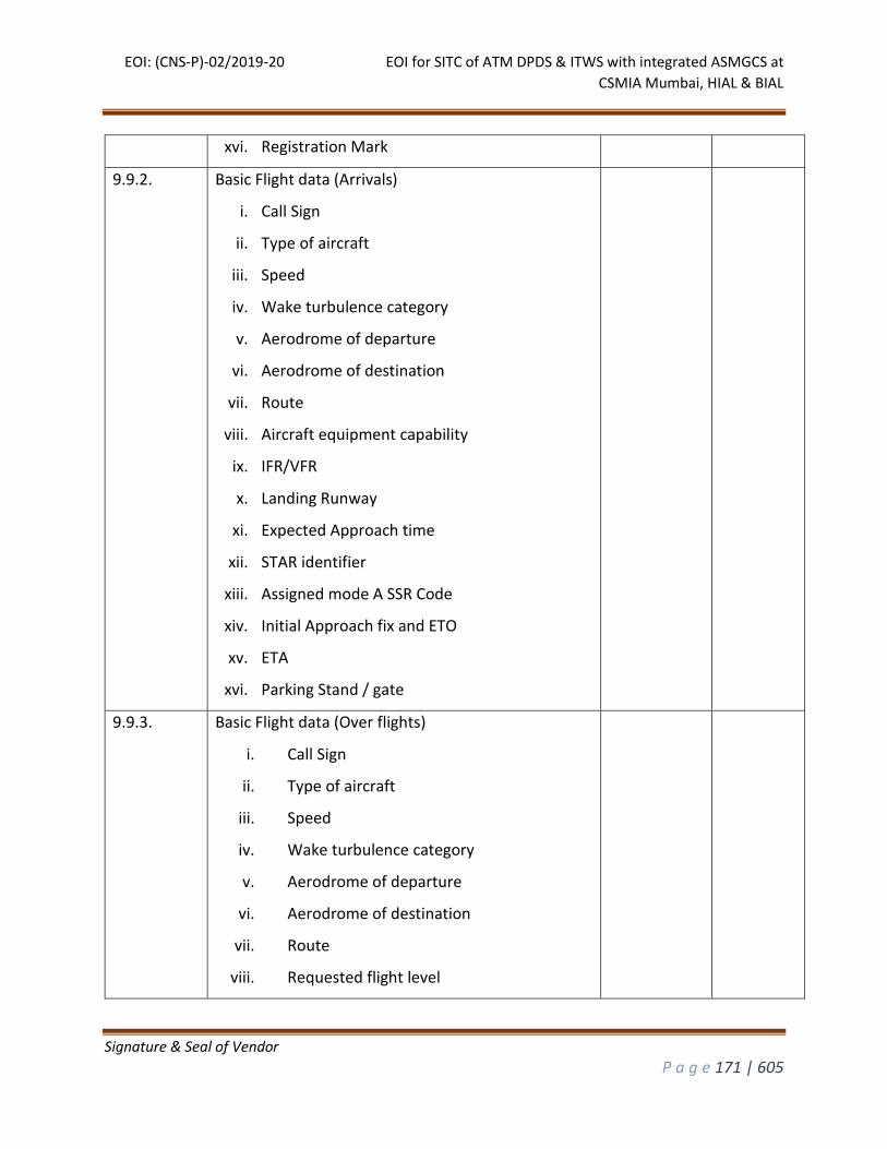
EOI: (CNS-P)-02/2019-20 EOI for SITC of ATM DPDS & ITWS with integrated ASMGCS at
CSMIA Mumbai, HIAL & BIAL
Signature & Seal of Vendor
P a g e 171 | 605
xvi. Registration Mark
9.9.2. Basic Flight data (Arrivals)
i. Call Sign
ii. Type of aircraft
iii. Speed
iv. Wake turbulence category
v. Aerodrome of departure
vi. Aerodrome of destination
vii. Route
viii. Aircraft equipment capability
ix. IFR/VFR
x. Landing Runway
xi. Expected Approach time
xii. STAR identifier
xiii. Assigned mode A SSR Code
xiv. Initial Approach fix and ETO
xv. ETA
xvi. Parking Stand / gate
9.9.3. Basic Flight data (Over flights)
i. Call Sign
ii. Type of aircraft
iii. Speed
iv. Wake turbulence category
v. Aerodrome of departure
vi. Aerodrome of destination
vii. Route
viii. Requested flight level
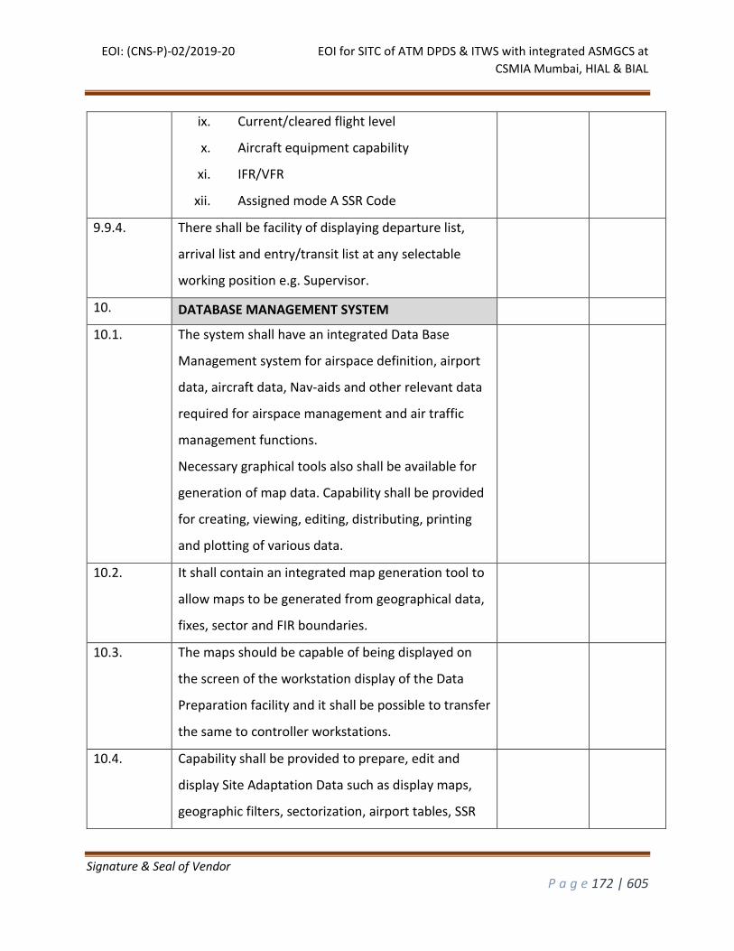
EOI: (CNS-P)-02/2019-20 EOI for SITC of ATM DPDS & ITWS with integrated ASMGCS at
CSMIA Mumbai, HIAL & BIAL
Signature & Seal of Vendor
P a g e 172 | 605
ix. Current/cleared flight level
x. Aircraft equipment capability
xi. IFR/VFR
xii. Assigned mode A SSR Code
9.9.4. There shall be facility of displaying departure list,
arrival list and entry/transit list at any selectable
working position e.g. Supervisor.
10. DATABASE MANAGEMENT SYSTEM
10.1. The system shall have an integrated Data Base
Management system for airspace definition, airport
data, aircraft data, Nav-aids and other relevant data
required for airspace management and air traffic
management functions.
Necessary graphical tools also shall be available for
generation of map data. Capability shall be provided
for creating, viewing, editing, distributing, printing
and plotting of various data.
10.2. It shall contain an integrated map generation tool to
allow maps to be generated from geographical data,
fixes, sector and FIR boundaries.
10.3. The maps should be capable of being displayed on
the screen of the workstation display of the Data
Preparation facility and it shall be possible to transfer
the same to controller workstations.
10.4. Capability shall be provided to prepare, edit and
display Site Adaptation Data such as display maps,
geographic filters, sectorization, airport tables, SSR
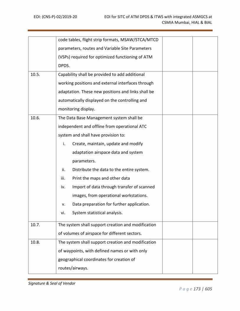
EOI: (CNS-P)-02/2019-20 EOI for SITC of ATM DPDS & ITWS with integrated ASMGCS at
CSMIA Mumbai, HIAL & BIAL
Signature & Seal of Vendor
P a g e 173 | 605
code tables, flight strip formats, MSAW/STCA/MTCD
parameters, routes and Variable Site Parameters
(VSPs) required for optimized functioning of ATM
DPDS.
10.5. Capability shall be provided to add additional
working positions and external interfaces through
adaptation. These new positions and links shall be
automatically displayed on the controlling and
monitoring display.
10.6. The Data Base Management system shall be
independent and offline from operational ATC
system and shall have provision to:
i. Create, maintain, update and modify
adaptation airspace data and system
parameters.
ii. Distribute the data to the entire system.
iii. Print the maps and other data
iv. Import of data through transfer of scanned
images, from operational workstations.
v. Data preparation for further application.
vi. System statistical analysis.
10.7. The system shall support creation and modification
of volumes of airspace for different sectors.
10.8. The system shall support creation and modification
of waypoints, with defined names or with only
geographical coordinates for creation of
routes/airways.
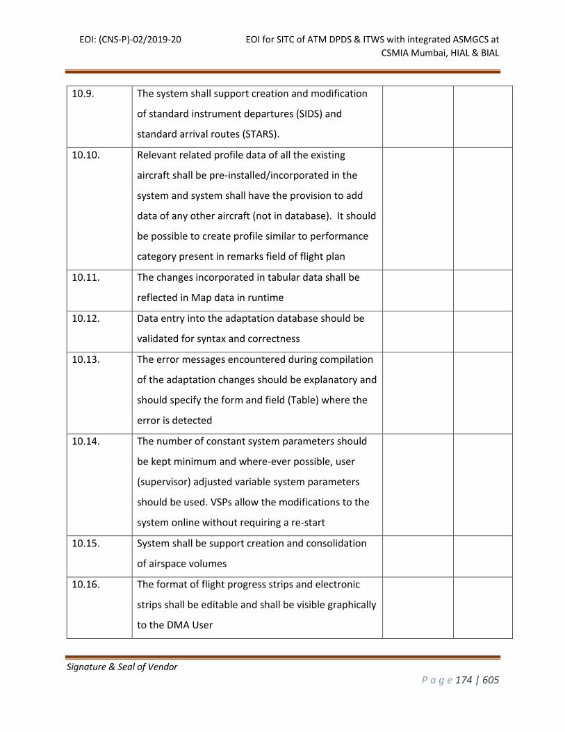
EOI: (CNS-P)-02/2019-20 EOI for SITC of ATM DPDS & ITWS with integrated ASMGCS at
CSMIA Mumbai, HIAL & BIAL
Signature & Seal of Vendor
P a g e 174 | 605
10.9. The system shall support creation and modification
of standard instrument departures (SIDS) and
standard arrival routes (STARS).
10.10. Relevant related profile data of all the existing
aircraft shall be pre-installed/incorporated in the
system and system shall have the provision to add
data of any other aircraft (not in database). It should
be possible to create profile similar to performance
category present in remarks field of flight plan
10.11. The changes incorporated in tabular data shall be
reflected in Map data in runtime
10.12. Data entry into the adaptation database should be
validated for syntax and correctness
10.13. The error messages encountered during compilation
of the adaptation changes should be explanatory and
should specify the form and field (Table) where the
error is detected
10.14. The number of constant system parameters should
be kept minimum and where-ever possible, user
(supervisor) adjusted variable system parameters
should be used. VSPs allow the modifications to the
system online without requiring a re-start
10.15. System shall be support creation and consolidation
of airspace volumes
10.16. The format of flight progress strips and electronic
strips shall be editable and shall be visible graphically
to the DMA User
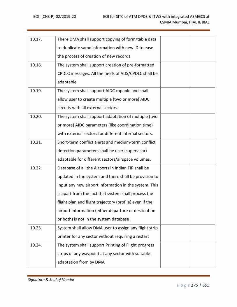
EOI: (CNS-P)-02/2019-20 EOI for SITC of ATM DPDS & ITWS with integrated ASMGCS at
CSMIA Mumbai, HIAL & BIAL
Signature & Seal of Vendor
P a g e 175 | 605
10.17. There DMA shall support copying of form/table data
to duplicate same information with new ID to ease
the process of creation of new records
10.18. The system shall support creation of pre-formatted
CPDLC messages. All the fields of ADS/CPDLC shall be
adaptable
10.19. The system shall support AIDC capable and shall
allow user to create multiple (two or more) AIDC
circuits with all external sectors.
10.20. The system shall support adaptation of multiple (two
or more) AIDC parameters (like coordination time)
with external sectors for different internal sectors.
10.21. Short-term conflict alerts and medium-term conflict
detection parameters shall be user (supervisor)
adaptable for different sectors/airspace volumes.
10.22. Database of all the Airports in Indian FIR shall be
updated in the system and there shall be provision to
input any new airport information in the system. This
is apart from the fact that system shall process the
flight plan and flight trajectory (profile) even if the
airport information (either departure or destination
or both) is not in the system database
10.23. System shall allow DMA user to assign any flight strip
printer for any sector without requiring a restart
10.24. The system shall support Printing of Flight progress
strips of any waypoint at any sector with suitable
adaptation from by DMA
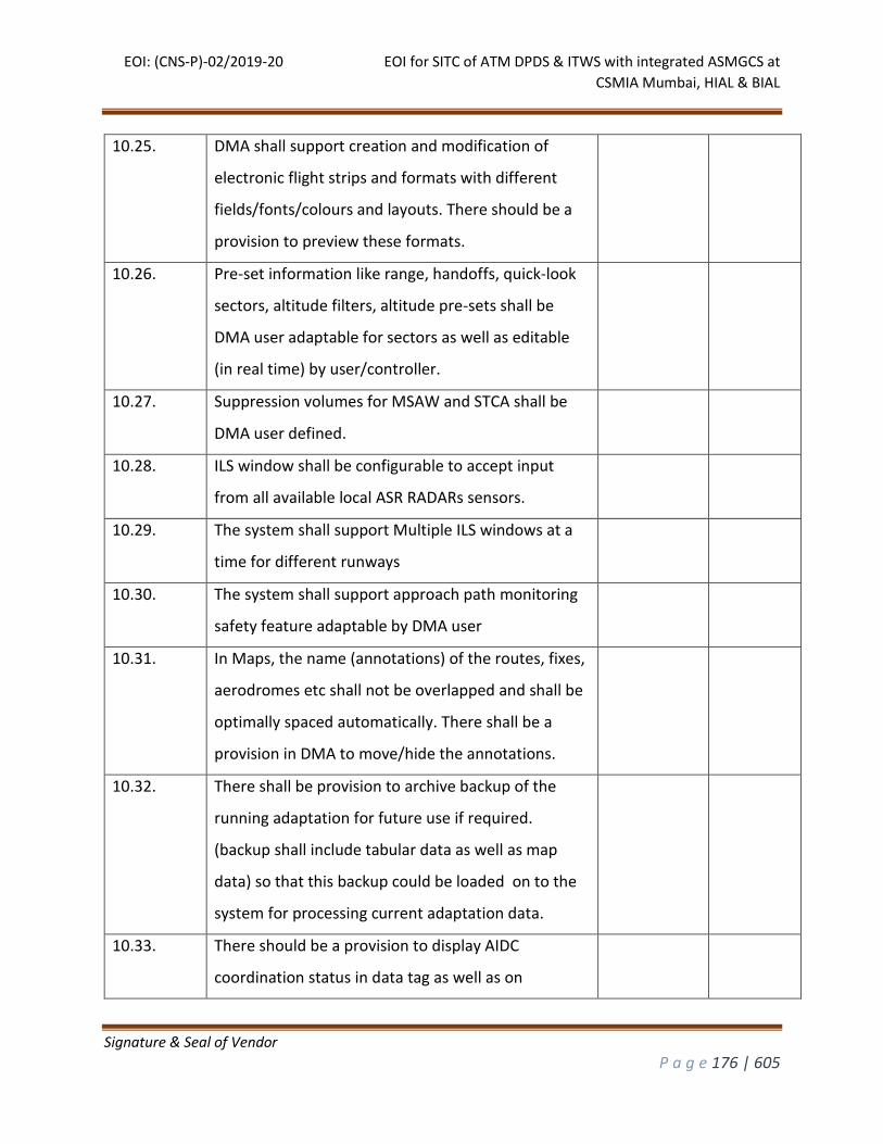
EOI: (CNS-P)-02/2019-20 EOI for SITC of ATM DPDS & ITWS with integrated ASMGCS at
CSMIA Mumbai, HIAL & BIAL
Signature & Seal of Vendor
P a g e 176 | 605
10.25. DMA shall support creation and modification of
electronic flight strips and formats with different
fields/fonts/colours and layouts. There should be a
provision to preview these formats.
10.26. Pre-set information like range, handoffs, quick-look
sectors, altitude filters, altitude pre-sets shall be
DMA user adaptable for sectors as well as editable
(in real time) by user/controller.
10.27. Suppression volumes for MSAW and STCA shall be
DMA user defined.
10.28. ILS window shall be configurable to accept input
from all available local ASR RADARs sensors.
10.29. The system shall support Multiple ILS windows at a
time for different runways
10.30. The system shall support approach path monitoring
safety feature adaptable by DMA user
10.31. In Maps, the name (annotations) of the routes, fixes,
aerodromes etc shall not be overlapped and shall be
optimally spaced automatically. There shall be a
provision in DMA to move/hide the annotations.
10.32. There shall be provision to archive backup of the
running adaptation for future use if required.
(backup shall include tabular data as well as map
data) so that this backup could be loaded on to the
system for processing current adaptation data.
10.33. There should be a provision to display AIDC
coordination status in data tag as well as on
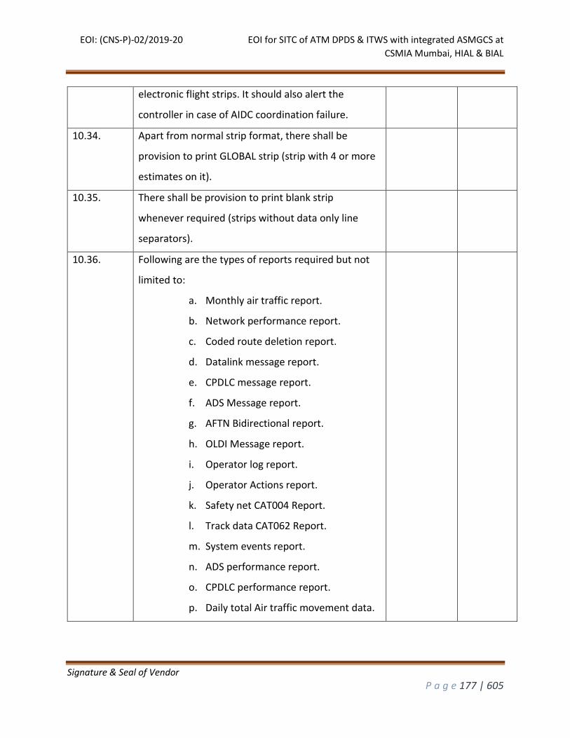
EOI: (CNS-P)-02/2019-20 EOI for SITC of ATM DPDS & ITWS with integrated ASMGCS at
CSMIA Mumbai, HIAL & BIAL
Signature & Seal of Vendor
P a g e 177 | 605
electronic flight strips. It should also alert the
controller in case of AIDC coordination failure.
10.34. Apart from normal strip format, there shall be
provision to print GLOBAL strip (strip with 4 or more
estimates on it).
10.35. There shall be provision to print blank strip
whenever required (strips without data only line
separators).
10.36. Following are the types of reports required but not
limited to:
a. Monthly air traffic report.
b. Network performance report.
c. Coded route deletion report.
d. Datalink message report.
e. CPDLC message report.
f. ADS Message report.
g. AFTN Bidirectional report.
h. OLDI Message report.
i. Operator log report.
j. Operator Actions report.
k. Safety net CAT004 Report.
l. Track data CAT062 Report.
m. System events report.
n. ADS performance report.
o. CPDLC performance report.
p. Daily total Air traffic movement data.
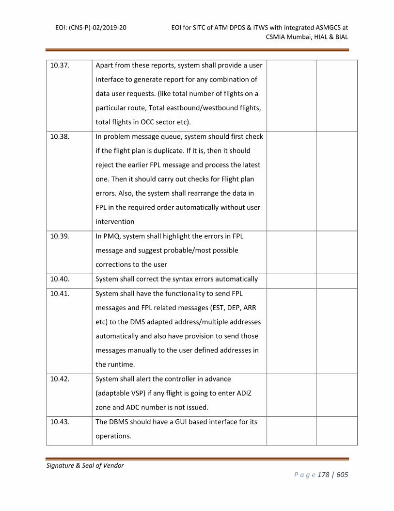
EOI: (CNS-P)-02/2019-20 EOI for SITC of ATM DPDS & ITWS with integrated ASMGCS at
CSMIA Mumbai, HIAL & BIAL
Signature & Seal of Vendor
P a g e 178 | 605
10.37. Apart from these reports, system shall provide a user
interface to generate report for any combination of
data user requests. (like total number of flights on a
particular route, Total eastbound/westbound flights,
total flights in OCC sector etc).
10.38. In problem message queue, system should first check
if the flight plan is duplicate. If it is, then it should
reject the earlier FPL message and process the latest
one. Then it should carry out checks for Flight plan
errors. Also, the system shall rearrange the data in
FPL in the required order automatically without user
intervention
10.39. In PMQ, system shall highlight the errors in FPL
message and suggest probable/most possible
corrections to the user
10.40. System shall correct the syntax errors automatically
10.41. System shall have the functionality to send FPL
messages and FPL related messages (EST, DEP, ARR
etc) to the DMS adapted address/multiple addresses
automatically and also have provision to send those
messages manually to the user defined addresses in
the runtime.
10.42. System shall alert the controller in advance
(adaptable VSP) if any flight is going to enter ADIZ
zone and ADC number is not issued.
10.43. The DBMS should have a GUI based interface for its
operations.
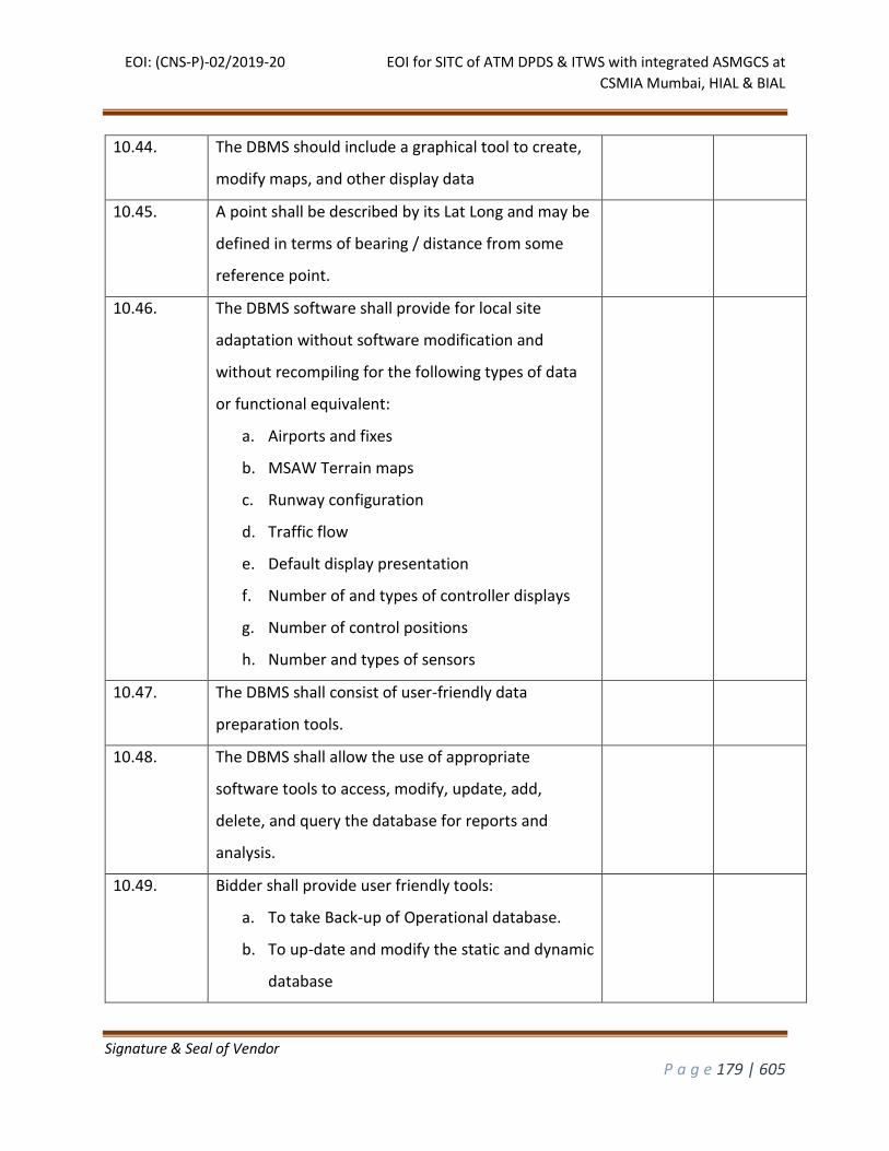
EOI: (CNS-P)-02/2019-20 EOI for SITC of ATM DPDS & ITWS with integrated ASMGCS at
CSMIA Mumbai, HIAL & BIAL
Signature & Seal of Vendor
P a g e 179 | 605
10.44. The DBMS should include a graphical tool to create,
modify maps, and other display data
10.45. A point shall be described by its Lat Long and may be
defined in terms of bearing / distance from some
reference point.
10.46. The DBMS software shall provide for local site
adaptation without software modification and
without recompiling for the following types of data
or functional equivalent:
a. Airports and fixes
b. MSAW Terrain maps
c. Runway configuration
d. Traffic flow
e. Default display presentation
f. Number of and types of controller displays
g. Number of control positions
h. Number and types of sensors
10.47. The DBMS shall consist of user-friendly data
preparation tools.
10.48. The DBMS shall allow the use of appropriate
software tools to access, modify, update, add,
delete, and query the database for reports and
analysis.
10.49. Bidder shall provide user friendly tools:
a. To take Back-up of Operational database.
b. To up-date and modify the static and dynamic
database
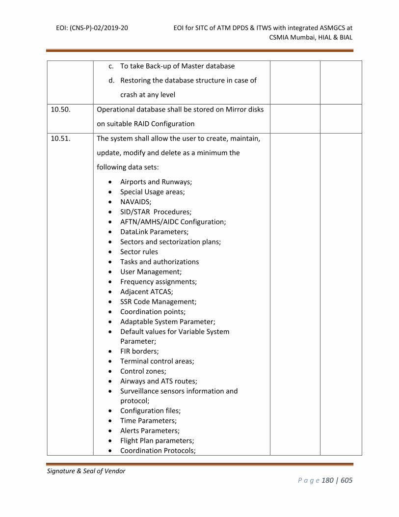
EOI: (CNS-P)-02/2019-20 EOI for SITC of ATM DPDS & ITWS with integrated ASMGCS at
CSMIA Mumbai, HIAL & BIAL
Signature & Seal of Vendor
P a g e 180 | 605
c. To take Back-up of Master database
d. Restoring the database structure in case of
crash at any level
10.50. Operational database shall be stored on Mirror disks
on suitable RAID Configuration
10.51. The system shall allow the user to create, maintain,
update, modify and delete as a minimum the
following data sets:
Airports and Runways;
Special Usage areas;
NAVAIDS;
SID/STAR Procedures;
AFTN/AMHS/AIDC Configuration;
DataLink Parameters;
Sectors and sectorization plans;
Sector rules
Tasks and authorizations
User Management;
Frequency assignments;
Adjacent ATCAS;
SSR Code Management;
Coordination points;
Adaptable System Parameter;
Default values for Variable System Parameter;
FIR borders;
Terminal control areas;
Control zones;
Airways and ATS routes;
Surveillance sensors information and protocol;
Configuration files;
Time Parameters;
Alerts Parameters;
Flight Plan parameters;
Coordination Protocols;
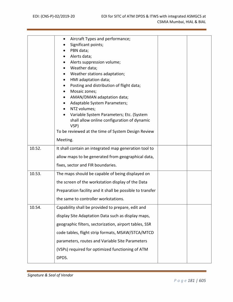
EOI: (CNS-P)-02/2019-20 EOI for SITC of ATM DPDS & ITWS with integrated ASMGCS at
CSMIA Mumbai, HIAL & BIAL
Signature & Seal of Vendor
P a g e 181 | 605
Aircraft Types and performance;
Significant points;
PBN data;
Alerts data;
Alerts suppression volume;
Weather data;
Weather stations adaptation;
HMI adaptation data;
Posting and distribution of flight data;
Mosaic zones;
AMAN/DMAN adaptation data;
Adaptable System Parameters;
NTZ volumes;
Variable System Parameters; Etc. (System shall allow online configuration of dynamic VSP)
To be reviewed at the time of System Design Review
Meeting.
10.52. It shall contain an integrated map generation tool to
allow maps to be generated from geographical data,
fixes, sector and FIR boundaries.
10.53. The maps should be capable of being displayed on
the screen of the workstation display of the Data
Preparation facility and it shall be possible to transfer
the same to controller workstations.
10.54. Capability shall be provided to prepare, edit and
display Site Adaptation Data such as display maps,
geographic filters, sectorization, airport tables, SSR
code tables, flight strip formats, MSAW/STCA/MTCD
parameters, routes and Variable Site Parameters
(VSPs) required for optimized functioning of ATM
DPDS.
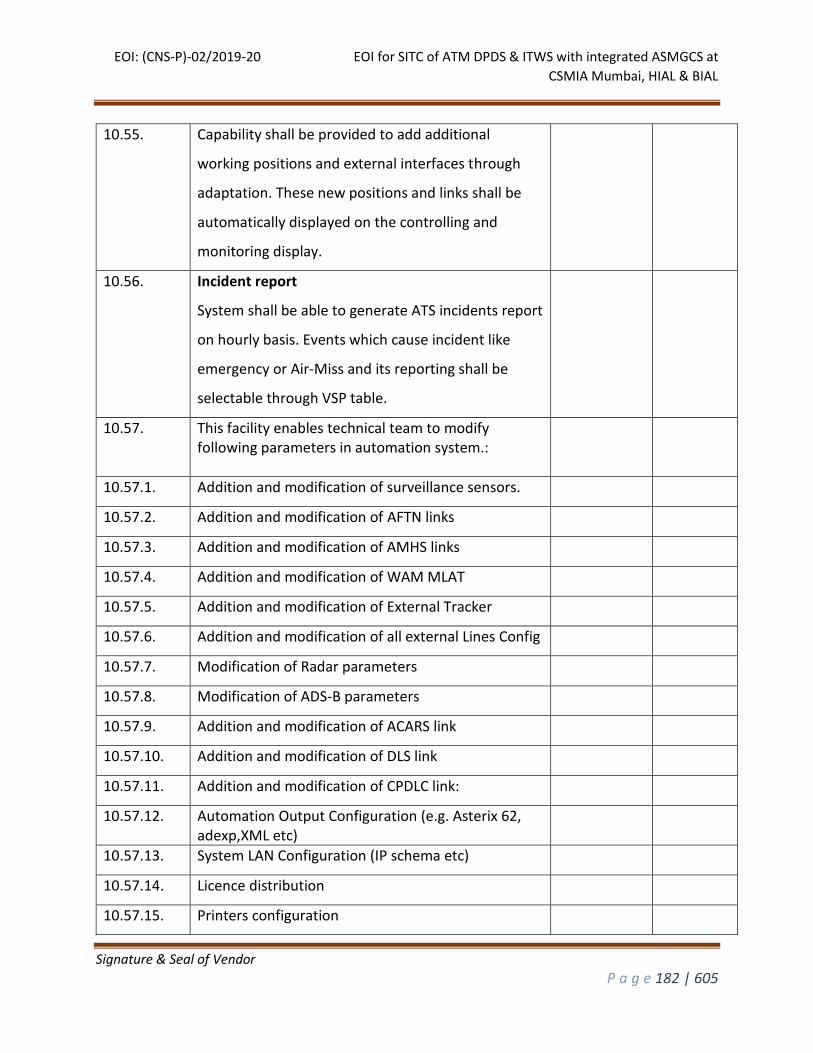
EOI: (CNS-P)-02/2019-20 EOI for SITC of ATM DPDS & ITWS with integrated ASMGCS at
CSMIA Mumbai, HIAL & BIAL
Signature & Seal of Vendor
P a g e 182 | 605
10.55. Capability shall be provided to add additional
working positions and external interfaces through
adaptation. These new positions and links shall be
automatically displayed on the controlling and
monitoring display.
10.56. Incident report
System shall be able to generate ATS incidents report
on hourly basis. Events which cause incident like
emergency or Air-Miss and its reporting shall be
selectable through VSP table.
10.57. This facility enables technical team to modify following parameters in automation system.:
10.57.1. Addition and modification of surveillance sensors.
10.57.2. Addition and modification of AFTN links
10.57.3. Addition and modification of AMHS links
10.57.4. Addition and modification of WAM MLAT
10.57.5. Addition and modification of External Tracker
10.57.6. Addition and modification of all external Lines Config
10.57.7. Modification of Radar parameters
10.57.8. Modification of ADS-B parameters
10.57.9. Addition and modification of ACARS link
10.57.10. Addition and modification of DLS link
10.57.11. Addition and modification of CPDLC link:
10.57.12. Automation Output Configuration (e.g. Asterix 62, adexp,XML etc)
10.57.13. System LAN Configuration (IP schema etc)
10.57.14. Licence distribution
10.57.15. Printers configuration
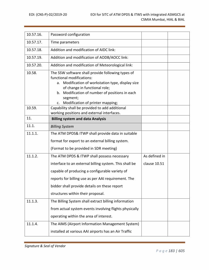
EOI: (CNS-P)-02/2019-20 EOI for SITC of ATM DPDS & ITWS with integrated ASMGCS at
CSMIA Mumbai, HIAL & BIAL
Signature & Seal of Vendor
P a g e 183 | 605
10.57.16. Password configuration
10.57.17. Time parameters
10.57.18. Addition and modification of AIDC link:
10.57.19. Addition and modification of AODB/AOCC link:
10.57.20. Addition and modification of Meteorological link:
10.58. The SSW software shall provide following types of functional modifications:
a. Modification of workstation type, display size of change in functional role;
b. Modification of number of positions in each segment;
c. Modification of printer mapping;
10.59. Capability shall be provided to add additional working positions and external interfaces.
11. Billing system and data Analysis
11.1. Billing System
11.1.1. The ATM DPDS& ITWP shall provide data in suitable
format for export to an external billing system.
(Format to be provided in SDR meeting)
11.1.2. The ATM DPDS & ITWP shall possess necessary
interface to an external billing system. This shall be
capable of producing a configurable variety of
reports for billing use as per AAI requirement. The
bidder shall provide details on these report
structures within their proposal.
As defined in
clause 10.51
11.1.3. The Billing System shall extract billing information
from actual system events involving flights physically
operating within the area of interest.
11.1.4. The AIMS (Airport Information Management System)
installed at various AAI airports has an Air Traffic
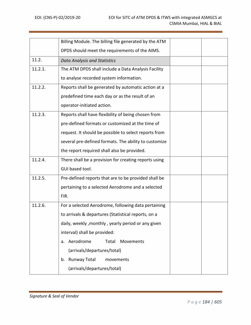
EOI: (CNS-P)-02/2019-20 EOI for SITC of ATM DPDS & ITWS with integrated ASMGCS at
CSMIA Mumbai, HIAL & BIAL
Signature & Seal of Vendor
P a g e 184 | 605
Billing Module. The billing file generated by the ATM
DPDS should meet the requirements of the AIMS.
11.2. Data Analysis and Statistics
11.2.1. The ATM DPDS shall include a Data Analysis Facility
to analyse recorded system information.
11.2.2. Reports shall be generated by automatic action at a
predefined time each day or as the result of an
operator-initiated action.
11.2.3. Reports shall have flexibility of being chosen from
pre-defined formats or customized at the time of
request. It should be possible to select reports from
several pre-defined formats. The ability to customize
the report required shall also be provided.
11.2.4. There shall be a provision for creating reports using
GUI based tool.
11.2.5. Pre-defined reports that are to be provided shall be
pertaining to a selected Aerodrome and a selected
FIR.
11.2.6. For a selected Aerodrome, following data pertaining
to arrivals & departures (Statistical reports, on a
daily, weekly ,monthly , yearly period or any given
interval) shall be provided:
a. Aerodrome Total Movements
(arrivals/departures/total)
b. Runway Total movements
(arrivals/departures/total)
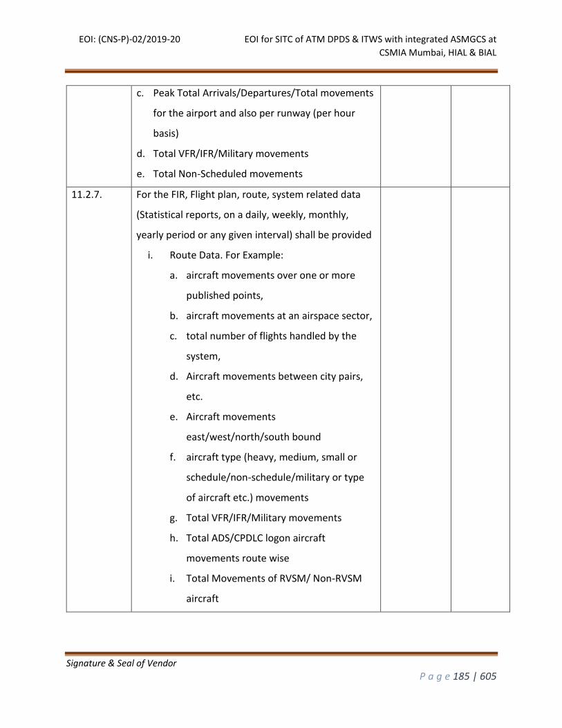
EOI: (CNS-P)-02/2019-20 EOI for SITC of ATM DPDS & ITWS with integrated ASMGCS at
CSMIA Mumbai, HIAL & BIAL
Signature & Seal of Vendor
P a g e 185 | 605
c. Peak Total Arrivals/Departures/Total movements
for the airport and also per runway (per hour
basis)
d. Total VFR/IFR/Military movements
e. Total Non-Scheduled movements
11.2.7. For the FIR, Flight plan, route, system related data
(Statistical reports, on a daily, weekly, monthly,
yearly period or any given interval) shall be provided
i. Route Data. For Example:
a. aircraft movements over one or more
published points,
b. aircraft movements at an airspace sector,
c. total number of flights handled by the
system,
d. Aircraft movements between city pairs,
etc.
e. Aircraft movements
east/west/north/south bound
f. aircraft type (heavy, medium, small or
schedule/non-schedule/military or type
of aircraft etc.) movements
g. Total VFR/IFR/Military movements
h. Total ADS/CPDLC logon aircraft
movements route wise
i. Total Movements of RVSM/ Non-RVSM
aircraft
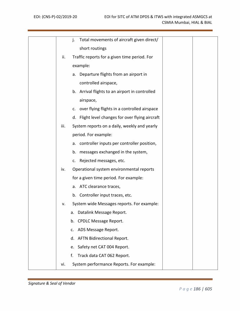
EOI: (CNS-P)-02/2019-20 EOI for SITC of ATM DPDS & ITWS with integrated ASMGCS at
CSMIA Mumbai, HIAL & BIAL
Signature & Seal of Vendor
P a g e 186 | 605
j. Total movements of aircraft given direct/
short routings
ii. Traffic reports for a given time period. For
example:
a. Departure flights from an airport in
controlled airspace,
b. Arrival flights to an airport in controlled
airspace,
c. over flying flights in a controlled airspace
d. Flight level changes for over flying aircraft
iii. System reports on a daily, weekly and yearly
period. For example:
a. controller inputs per controller position,
b. messages exchanged in the system,
c. Rejected messages, etc.
iv. Operational system environmental reports
for a given time period. For example:
a. ATC clearance traces,
b. Controller input traces, etc.
v. System wide Messages reports. For example:
a. Datalink Message Report.
b. CPDLC Message Report.
c. ADS Message Report.
d. AFTN Bidirectional Report.
e. Safety net CAT 004 Report.
f. Track data CAT 062 Report.
vi. System performance Reports. For example:
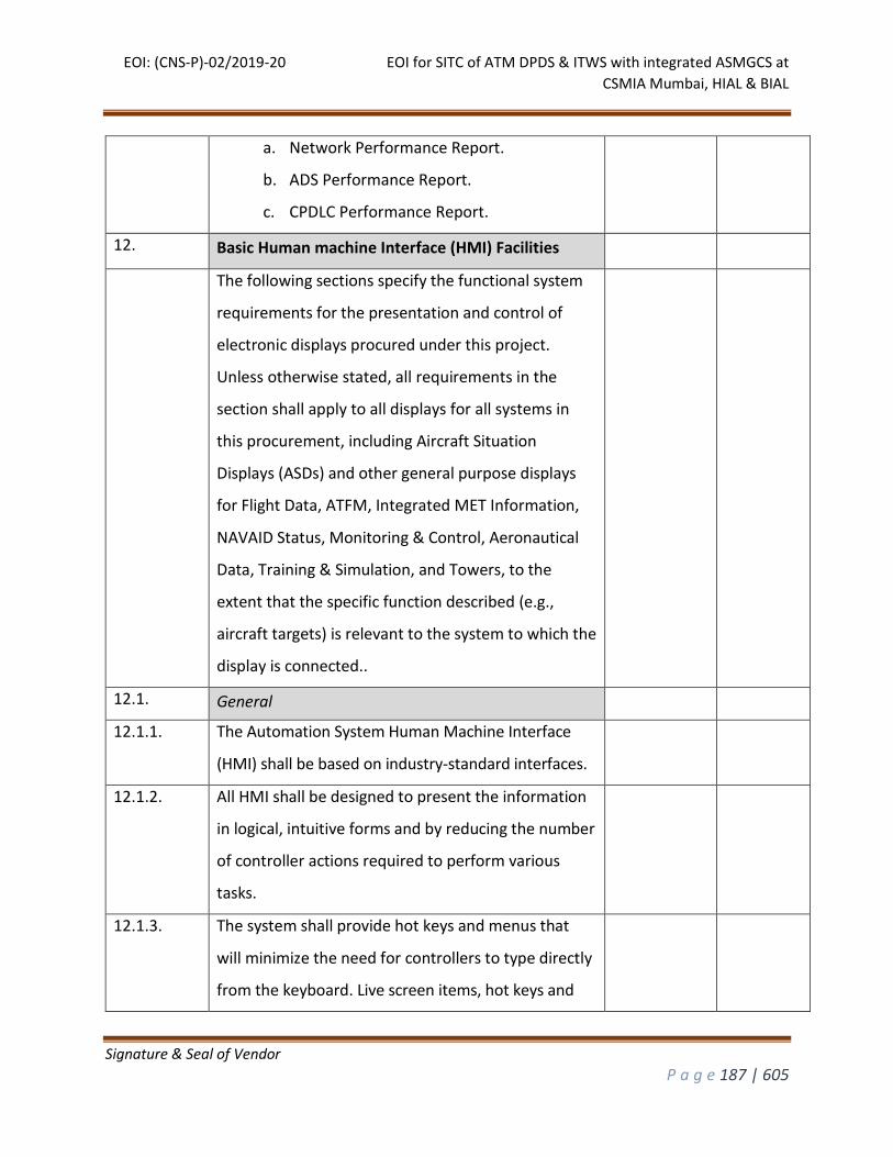
EOI: (CNS-P)-02/2019-20 EOI for SITC of ATM DPDS & ITWS with integrated ASMGCS at
CSMIA Mumbai, HIAL & BIAL
Signature & Seal of Vendor
P a g e 187 | 605
a. Network Performance Report.
b. ADS Performance Report.
c. CPDLC Performance Report.
12. Basic Human machine Interface (HMI) Facilities
The following sections specify the functional system
requirements for the presentation and control of
electronic displays procured under this project.
Unless otherwise stated, all requirements in the
section shall apply to all displays for all systems in
this procurement, including Aircraft Situation
Displays (ASDs) and other general purpose displays
for Flight Data, ATFM, Integrated MET Information,
NAVAID Status, Monitoring & Control, Aeronautical
Data, Training & Simulation, and Towers, to the
extent that the specific function described (e.g.,
aircraft targets) is relevant to the system to which the
display is connected..
12.1. General
12.1.1. The Automation System Human Machine Interface
(HMI) shall be based on industry-standard interfaces.
12.1.2. All HMI shall be designed to present the information
in logical, intuitive forms and by reducing the number
of controller actions required to perform various
tasks.
12.1.3. The system shall provide hot keys and menus that
will minimize the need for controllers to type directly
from the keyboard. Live screen items, hot keys and
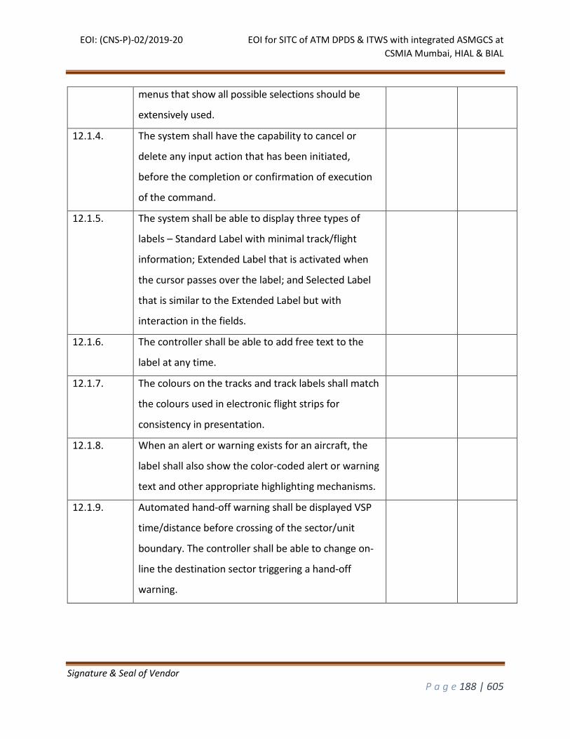
EOI: (CNS-P)-02/2019-20 EOI for SITC of ATM DPDS & ITWS with integrated ASMGCS at
CSMIA Mumbai, HIAL & BIAL
Signature & Seal of Vendor
P a g e 188 | 605
menus that show all possible selections should be
extensively used.
12.1.4. The system shall have the capability to cancel or
delete any input action that has been initiated,
before the completion or confirmation of execution
of the command.
12.1.5. The system shall be able to display three types of
labels – Standard Label with minimal track/flight
information; Extended Label that is activated when
the cursor passes over the label; and Selected Label
that is similar to the Extended Label but with
interaction in the fields.
12.1.6. The controller shall be able to add free text to the
label at any time.
12.1.7. The colours on the tracks and track labels shall match
the colours used in electronic flight strips for
consistency in presentation.
12.1.8. When an alert or warning exists for an aircraft, the
label shall also show the color-coded alert or warning
text and other appropriate highlighting mechanisms.
12.1.9. Automated hand-off warning shall be displayed VSP
time/distance before crossing of the sector/unit
boundary. The controller shall be able to change on-
line the destination sector triggering a hand-off
warning.
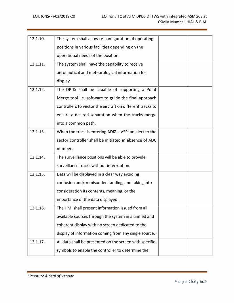
EOI: (CNS-P)-02/2019-20 EOI for SITC of ATM DPDS & ITWS with integrated ASMGCS at
CSMIA Mumbai, HIAL & BIAL
Signature & Seal of Vendor
P a g e 189 | 605
12.1.10. The system shall allow re-configuration of operating
positions in various facilities depending on the
operational needs of the position.
12.1.11. The system shall have the capability to receive
aeronautical and meteorological information for
display
12.1.12. The DPDS shall be capable of supporting a Point
Merge tool i.e. software to guide the final approach
controllers to vector the aircraft on different tracks to
ensure a desired separation when the tracks merge
into a common path.
12.1.13. When the track is entering ADIZ – VSP, an alert to the
sector controller shall be initiated in absence of ADC
number.
12.1.14. The surveillance positions will be able to provide
surveillance tracks without interruption.
12.1.15. Data will be displayed in a clear way avoiding
confusion and/or misunderstanding, and taking into
consideration its contents, meaning, or the
importance of the data displayed.
12.1.16. The HMI shall present information issued from all
available sources through the system in a unified and
coherent display with no screen dedicated to the
display of information coming from any single source.
12.1.17. All data shall be presented on the screen with specific
symbols to enable the controller to determine the
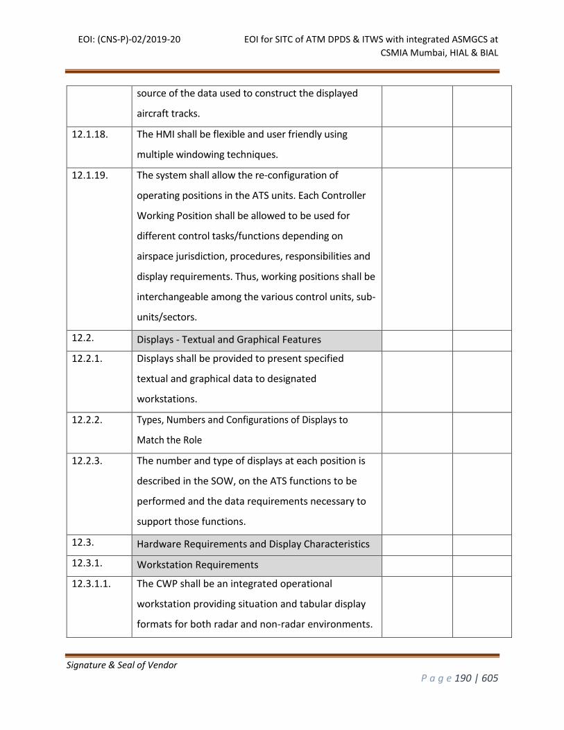
EOI: (CNS-P)-02/2019-20 EOI for SITC of ATM DPDS & ITWS with integrated ASMGCS at
CSMIA Mumbai, HIAL & BIAL
Signature & Seal of Vendor
P a g e 190 | 605
source of the data used to construct the displayed
aircraft tracks.
12.1.18. The HMI shall be flexible and user friendly using
multiple windowing techniques.
12.1.19. The system shall allow the re-configuration of
operating positions in the ATS units. Each Controller
Working Position shall be allowed to be used for
different control tasks/functions depending on
airspace jurisdiction, procedures, responsibilities and
display requirements. Thus, working positions shall be
interchangeable among the various control units, sub-
units/sectors.
12.2. Displays - Textual and Graphical Features
12.2.1. Displays shall be provided to present specified
textual and graphical data to designated
workstations.
12.2.2. Types, Numbers and Configurations of Displays to
Match the Role
12.2.3. The number and type of displays at each position is
described in the SOW, on the ATS functions to be
performed and the data requirements necessary to
support those functions.
12.3. Hardware Requirements and Display Characteristics
12.3.1. Workstation Requirements
12.3.1.1. The CWP shall be an integrated operational
workstation providing situation and tabular display
formats for both radar and non-radar environments.
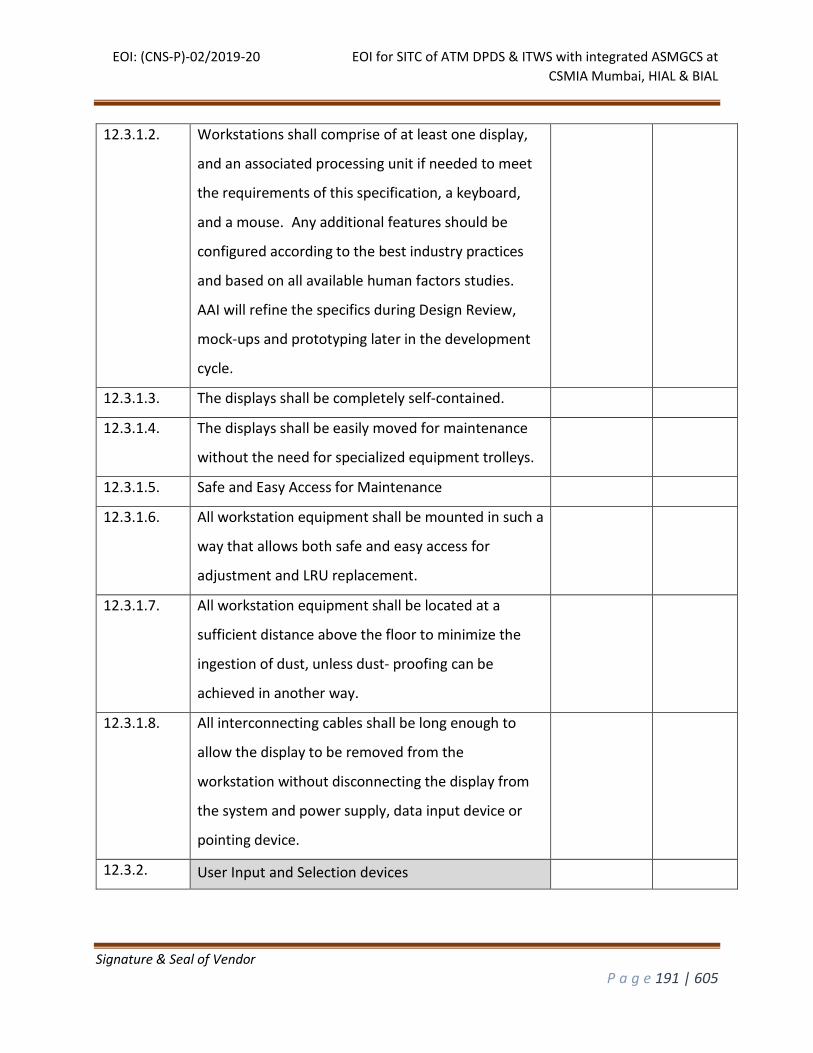
EOI: (CNS-P)-02/2019-20 EOI for SITC of ATM DPDS & ITWS with integrated ASMGCS at
CSMIA Mumbai, HIAL & BIAL
Signature & Seal of Vendor
P a g e 191 | 605
12.3.1.2. Workstations shall comprise of at least one display,
and an associated processing unit if needed to meet
the requirements of this specification, a keyboard,
and a mouse. Any additional features should be
configured according to the best industry practices
and based on all available human factors studies.
AAI will refine the specifics during Design Review,
mock-ups and prototyping later in the development
cycle.
12.3.1.3. The displays shall be completely self-contained.
12.3.1.4. The displays shall be easily moved for maintenance
without the need for specialized equipment trolleys.
12.3.1.5. Safe and Easy Access for Maintenance
12.3.1.6. All workstation equipment shall be mounted in such a
way that allows both safe and easy access for
adjustment and LRU replacement.
12.3.1.7. All workstation equipment shall be located at a
sufficient distance above the floor to minimize the
ingestion of dust, unless dust- proofing can be
achieved in another way.
12.3.1.8. All interconnecting cables shall be long enough to
allow the display to be removed from the
workstation without disconnecting the display from
the system and power supply, data input device or
pointing device.
12.3.2. User Input and Selection devices
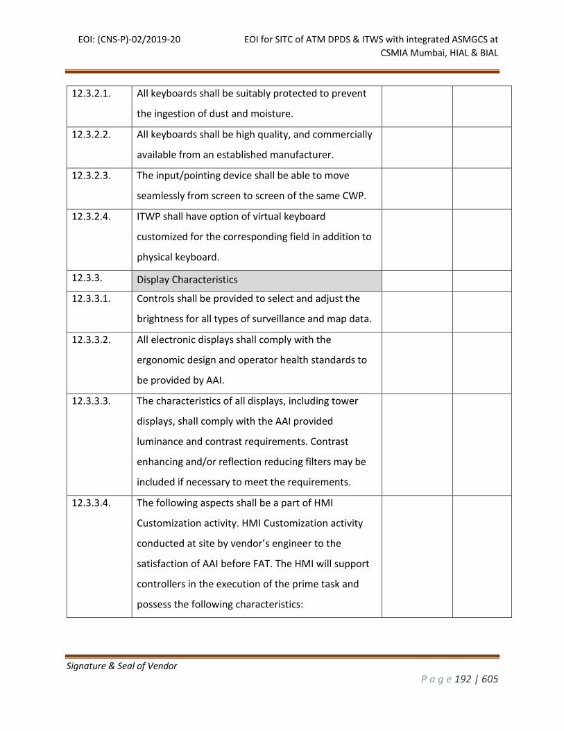
EOI: (CNS-P)-02/2019-20 EOI for SITC of ATM DPDS & ITWS with integrated ASMGCS at
CSMIA Mumbai, HIAL & BIAL
Signature & Seal of Vendor
P a g e 192 | 605
12.3.2.1. All keyboards shall be suitably protected to prevent
the ingestion of dust and moisture.
12.3.2.2. All keyboards shall be high quality, and commercially
available from an established manufacturer.
12.3.2.3. The input/pointing device shall be able to move
seamlessly from screen to screen of the same CWP.
12.3.2.4. ITWP shall have option of virtual keyboard
customized for the corresponding field in addition to
physical keyboard.
12.3.3. Display Characteristics
12.3.3.1. Controls shall be provided to select and adjust the
brightness for all types of surveillance and map data.
12.3.3.2. All electronic displays shall comply with the
ergonomic design and operator health standards to
be provided by AAI.
12.3.3.3. The characteristics of all displays, including tower
displays, shall comply with the AAI provided
luminance and contrast requirements. Contrast
enhancing and/or reflection reducing filters may be
included if necessary to meet the requirements.
12.3.3.4. The following aspects shall be a part of HMI
Customization activity. HMI Customization activity
conducted at site by vendor’s engineer to the
satisfaction of AAI before FAT. The HMI will support
controllers in the execution of the prime task and
possess the following characteristics:
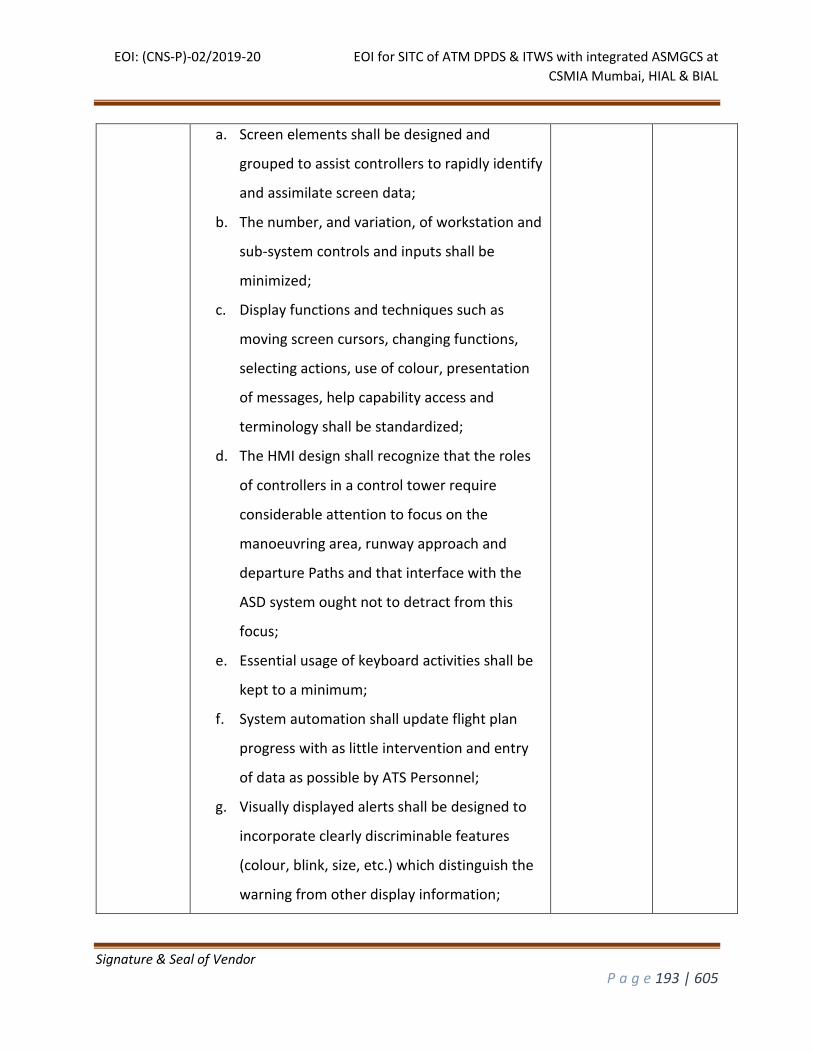
EOI: (CNS-P)-02/2019-20 EOI for SITC of ATM DPDS & ITWS with integrated ASMGCS at
CSMIA Mumbai, HIAL & BIAL
Signature & Seal of Vendor
P a g e 193 | 605
a. Screen elements shall be designed and
grouped to assist controllers to rapidly identify
and assimilate screen data;
b. The number, and variation, of workstation and
sub-system controls and inputs shall be
minimized;
c. Display functions and techniques such as
moving screen cursors, changing functions,
selecting actions, use of colour, presentation
of messages, help capability access and
terminology shall be standardized;
d. The HMI design shall recognize that the roles
of controllers in a control tower require
considerable attention to focus on the
manoeuvring area, runway approach and
departure Paths and that interface with the
ASD system ought not to detract from this
focus;
e. Essential usage of keyboard activities shall be
kept to a minimum;
f. System automation shall update flight plan
progress with as little intervention and entry
of data as possible by ATS Personnel;
g. Visually displayed alerts shall be designed to
incorporate clearly discriminable features
(colour, blink, size, etc.) which distinguish the
warning from other display information;
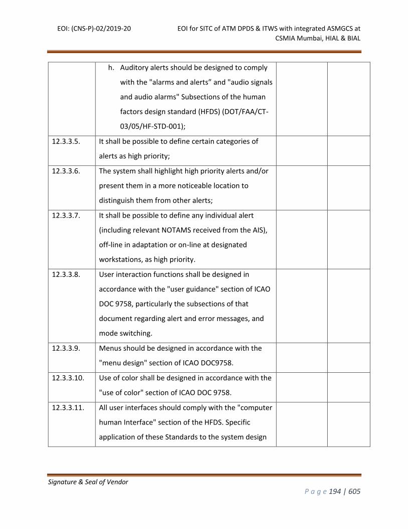
EOI: (CNS-P)-02/2019-20 EOI for SITC of ATM DPDS & ITWS with integrated ASMGCS at
CSMIA Mumbai, HIAL & BIAL
Signature & Seal of Vendor
P a g e 194 | 605
h. Auditory alerts should be designed to comply
with the "alarms and alerts” and "audio signals
and audio alarms" Subsections of the human
factors design standard (HFDS) (DOT/FAA/CT-
03/05/HF-STD-001);
12.3.3.5. It shall be possible to define certain categories of
alerts as high priority;
12.3.3.6. The system shall highlight high priority alerts and/or
present them in a more noticeable location to
distinguish them from other alerts;
12.3.3.7. It shall be possible to define any individual alert
(including relevant NOTAMS received from the AIS),
off-line in adaptation or on-line at designated
workstations, as high priority.
12.3.3.8. User interaction functions shall be designed in
accordance with the "user guidance" section of ICAO
DOC 9758, particularly the subsections of that
document regarding alert and error messages, and
mode switching.
12.3.3.9. Menus should be designed in accordance with the
"menu design" section of ICAO DOC9758.
12.3.3.10. Use of color shall be designed in accordance with the
"use of color" section of ICAO DOC 9758.
12.3.3.11. All user interfaces should comply with the "computer
human Interface" section of the HFDS. Specific
application of these Standards to the system design
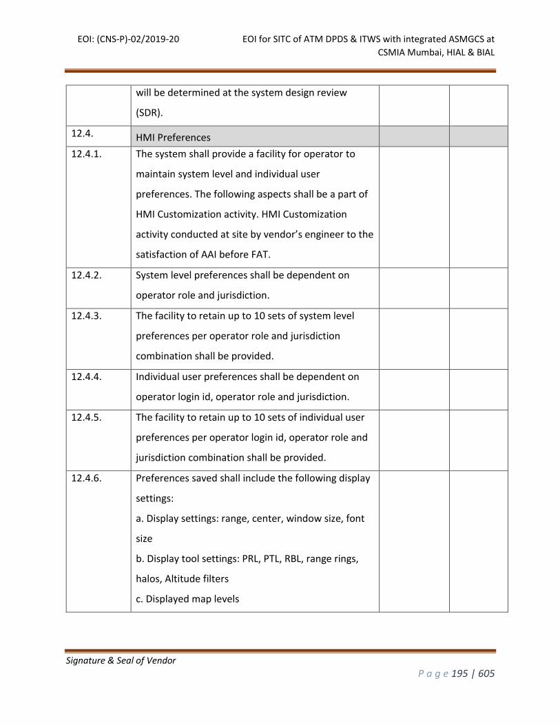
EOI: (CNS-P)-02/2019-20 EOI for SITC of ATM DPDS & ITWS with integrated ASMGCS at
CSMIA Mumbai, HIAL & BIAL
Signature & Seal of Vendor
P a g e 195 | 605
will be determined at the system design review
(SDR).
12.4. HMI Preferences
12.4.1. The system shall provide a facility for operator to
maintain system level and individual user
preferences. The following aspects shall be a part of
HMI Customization activity. HMI Customization
activity conducted at site by vendor’s engineer to the
satisfaction of AAI before FAT.
12.4.2. System level preferences shall be dependent on
operator role and jurisdiction.
12.4.3. The facility to retain up to 10 sets of system level
preferences per operator role and jurisdiction
combination shall be provided.
12.4.4. Individual user preferences shall be dependent on
operator login id, operator role and jurisdiction.
12.4.5. The facility to retain up to 10 sets of individual user
preferences per operator login id, operator role and
jurisdiction combination shall be provided.
12.4.6. Preferences saved shall include the following display
settings:
a. Display settings: range, center, window size, font
size
b. Display tool settings: PRL, PTL, RBL, range rings,
halos, Altitude filters
c. Displayed map levels
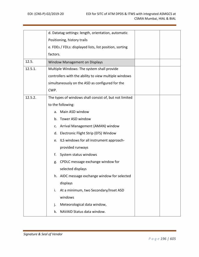
EOI: (CNS-P)-02/2019-20 EOI for SITC of ATM DPDS & ITWS with integrated ASMGCS at
CSMIA Mumbai, HIAL & BIAL
Signature & Seal of Vendor
P a g e 196 | 605
d. Datatag settings: length, orientation, automatic
Positioning, history trails
e. FDEs / FDLs: displayed lists, list position, sorting
factors.
12.5. Window Management on Displays
12.5.1. Multiple Windows: The system shall provide
controllers with the ability to view multiple windows
simultaneously on the ASD as configured for the
CWP.
12.5.2. The types of windows shall consist of, but not limited
to the following:
a. Main ASD window
b. Tower ASD window
c. Arrival Management (AMAN) window
d. Electronic Flight Strip (EFS) Window
e. ILS windows for all instrument approach-
provided runways
f. System status windows
g. CPDLC message exchange window for
selected displays
h. AIDC message exchange window for selected
displays
i. At a minimum, two Secondary/Inset ASD
windows
j. Meteorological data window,
k. NAVAID Status data window.

EOI: (CNS-P)-02/2019-20 EOI for SITC of ATM DPDS & ITWS with integrated ASMGCS at
CSMIA Mumbai, HIAL & BIAL
Signature & Seal of Vendor
P a g e 197 | 605
12.5.3. There shall be an indication if a window obscures any
critical information.
12.5.4. An Arrival Management window shall be an easy
interface to control the Arrival Manager (AMAN)
functions.
12.5.5. The AMAN window shall also present AMAN
generated advisories via appropriate input menus.
12.5.6. ILS windows for all instrument approach-provided
runways shall graphically display the profile view
showing the flight progress along the glide slope and
final approach course for specific runways.
12.5.7. A track with invalid Mode-C shall only be displayed
on the final approach course.
12.5.8. A system status window shall be provided to display
at least but not limited to the following adapted
information:
a. Time in UTC, controller’s jurisdiction,
b. Selected display range,
c. Altitude filter limits,
d. Altimeter reporting stations,
e. QNH and transition level,
f. Filed sensor identifiers,
g. Active STCA/MSAW/AIW conditions,
h. Active code for Hijack, RCF, and emergency,
i. Lat/Long at current cursor position,
j. Presentation Mode,
k. Label Line section.
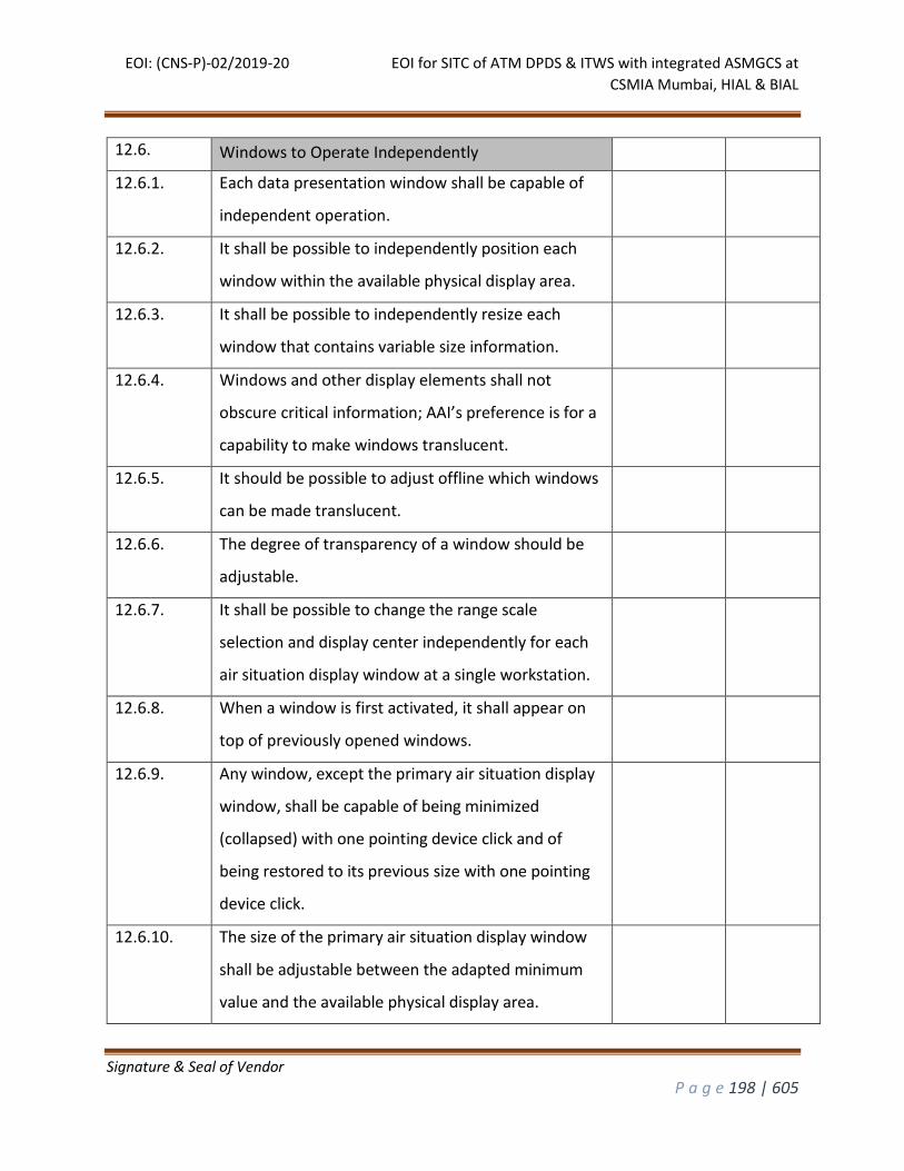
EOI: (CNS-P)-02/2019-20 EOI for SITC of ATM DPDS & ITWS with integrated ASMGCS at
CSMIA Mumbai, HIAL & BIAL
Signature & Seal of Vendor
P a g e 198 | 605
12.6. Windows to Operate Independently
12.6.1. Each data presentation window shall be capable of
independent operation.
12.6.2. It shall be possible to independently position each
window within the available physical display area.
12.6.3. It shall be possible to independently resize each
window that contains variable size information.
12.6.4. Windows and other display elements shall not
obscure critical information; AAI’s preference is for a
capability to make windows translucent.
12.6.5. It should be possible to adjust offline which windows
can be made translucent.
12.6.6. The degree of transparency of a window should be
adjustable.
12.6.7. It shall be possible to change the range scale
selection and display center independently for each
air situation display window at a single workstation.
12.6.8. When a window is first activated, it shall appear on
top of previously opened windows.
12.6.9. Any window, except the primary air situation display
window, shall be capable of being minimized
(collapsed) with one pointing device click and of
being restored to its previous size with one pointing
device click.
12.6.10. The size of the primary air situation display window
shall be adjustable between the adapted minimum
value and the available physical display area.
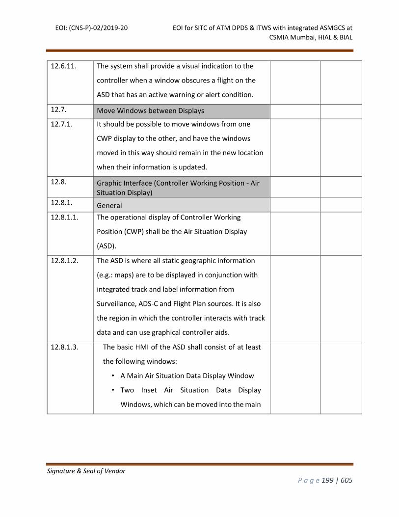
EOI: (CNS-P)-02/2019-20 EOI for SITC of ATM DPDS & ITWS with integrated ASMGCS at
CSMIA Mumbai, HIAL & BIAL
Signature & Seal of Vendor
P a g e 199 | 605
12.6.11. The system shall provide a visual indication to the
controller when a window obscures a flight on the
ASD that has an active warning or alert condition.
12.7. Move Windows between Displays
12.7.1. It should be possible to move windows from one
CWP display to the other, and have the windows
moved in this way should remain in the new location
when their information is updated.
12.8. Graphic Interface (Controller Working Position - Air Situation Display)
12.8.1. General
12.8.1.1. The operational display of Controller Working
Position (CWP) shall be the Air Situation Display
(ASD).
12.8.1.2. The ASD is where all static geographic information
(e.g.: maps) are to be displayed in conjunction with
integrated track and label information from
Surveillance, ADS-C and Flight Plan sources. It is also
the region in which the controller interacts with track
data and can use graphical controller aids.
12.8.1.3. The basic HMI of the ASD shall consist of at least
the following windows:
• A Main Air Situation Data Display Window
• Two Inset Air Situation Data Display
Windows, which can be moved into the main
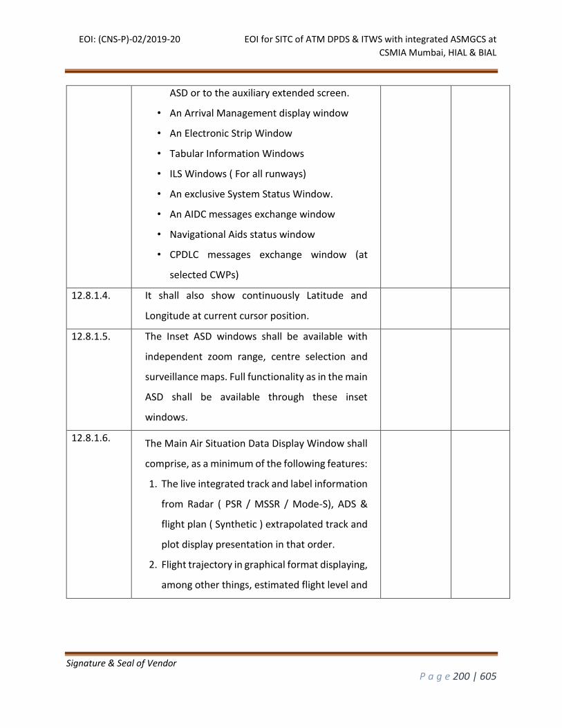
EOI: (CNS-P)-02/2019-20 EOI for SITC of ATM DPDS & ITWS with integrated ASMGCS at
CSMIA Mumbai, HIAL & BIAL
Signature & Seal of Vendor
P a g e 200 | 605
ASD or to the auxiliary extended screen.
• An Arrival Management display window
• An Electronic Strip Window
• Tabular Information Windows
• ILS Windows ( For all runways)
• An exclusive System Status Window.
• An AIDC messages exchange window
• Navigational Aids status window
• CPDLC messages exchange window (at
selected CWPs)
12.8.1.4. It shall also show continuously Latitude and
Longitude at current cursor position.
12.8.1.5. The Inset ASD windows shall be available with
independent zoom range, centre selection and
surveillance maps. Full functionality as in the main
ASD shall be available through these inset
windows.
12.8.1.6. The Main Air Situation Data Display Window shall
comprise, as a minimum of the following features:
1. The live integrated track and label information
from Radar ( PSR / MSSR / Mode-S), ADS &
flight plan ( Synthetic ) extrapolated track and
plot display presentation in that order.
2. Flight trajectory in graphical format displaying,
among other things, estimated flight level and
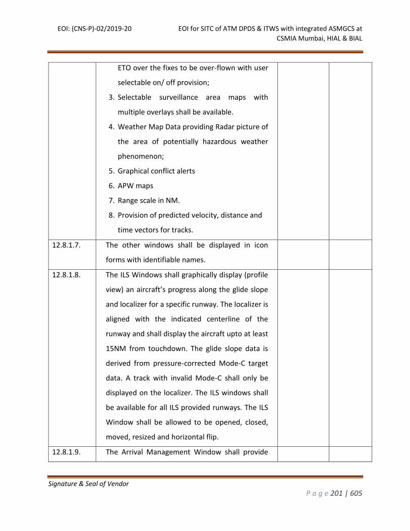
EOI: (CNS-P)-02/2019-20 EOI for SITC of ATM DPDS & ITWS with integrated ASMGCS at
CSMIA Mumbai, HIAL & BIAL
Signature & Seal of Vendor
P a g e 201 | 605
ETO over the fixes to be over-flown with user
selectable on/ off provision;
3. Selectable surveillance area maps with
multiple overlays shall be available.
4. Weather Map Data providing Radar picture of
the area of potentially hazardous weather
phenomenon;
5. Graphical conflict alerts
6. APW maps
7. Range scale in NM.
8. Provision of predicted velocity, distance and
time vectors for tracks.
12.8.1.7. The other windows shall be displayed in icon
forms with identifiable names.
12.8.1.8. The ILS Windows shall graphically display (profile
view) an aircraft’s progress along the glide slope
and localizer for a specific runway. The localizer is
aligned with the indicated centerline of the
runway and shall display the aircraft upto at least
15NM from touchdown. The glide slope data is
derived from pressure-corrected Mode-C target
data. A track with invalid Mode-C shall only be
displayed on the localizer. The ILS windows shall
be available for all ILS provided runways. The ILS
Window shall be allowed to be opened, closed,
moved, resized and horizontal flip.
12.8.1.9. The Arrival Management Window shall provide
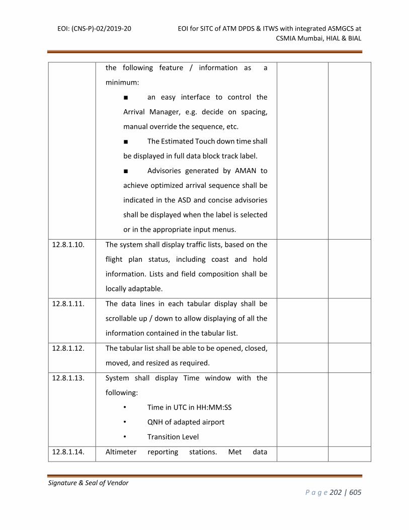
EOI: (CNS-P)-02/2019-20 EOI for SITC of ATM DPDS & ITWS with integrated ASMGCS at
CSMIA Mumbai, HIAL & BIAL
Signature & Seal of Vendor
P a g e 202 | 605
the following feature / information as a
minimum:
■ an easy interface to control the
Arrival Manager, e.g. decide on spacing,
manual override the sequence, etc.
■ The Estimated Touch down time shall
be displayed in full data block track label.
■ Advisories generated by AMAN to
achieve optimized arrival sequence shall be
indicated in the ASD and concise advisories
shall be displayed when the label is selected
or in the appropriate input menus.
12.8.1.10. The system shall display traffic lists, based on the
flight plan status, including coast and hold
information. Lists and field composition shall be
locally adaptable.
12.8.1.11. The data lines in each tabular display shall be
scrollable up / down to allow displaying of all the
information contained in the tabular list.
12.8.1.12. The tabular list shall be able to be opened, closed,
moved, and resized as required.
12.8.1.13. System shall display Time window with the
following:
• Time in UTC in HH:MM:SS
• QNH of adapted airport
• Transition Level
12.8.1.14. Altimeter reporting stations. Met data
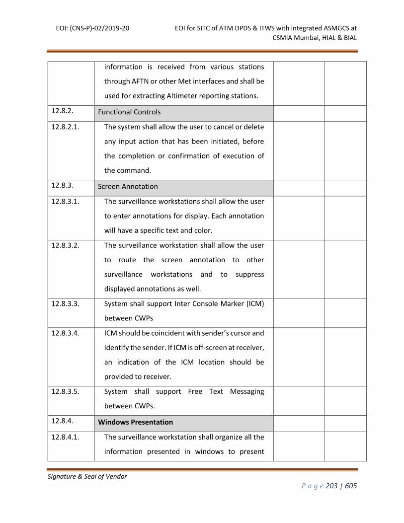
EOI: (CNS-P)-02/2019-20 EOI for SITC of ATM DPDS & ITWS with integrated ASMGCS at
CSMIA Mumbai, HIAL & BIAL
Signature & Seal of Vendor
P a g e 203 | 605
information is received from various stations
through AFTN or other Met interfaces and shall be
used for extracting Altimeter reporting stations.
12.8.2. Functional Controls
12.8.2.1. The system shall allow the user to cancel or delete
any input action that has been initiated, before
the completion or confirmation of execution of
the command.
12.8.3. Screen Annotation
12.8.3.1. The surveillance workstations shall allow the user
to enter annotations for display. Each annotation
will have a specific text and color.
12.8.3.2. The surveillance workstation shall allow the user
to route the screen annotation to other
surveillance workstations and to suppress
displayed annotations as well.
12.8.3.3. System shall support Inter Console Marker (ICM)
between CWPs
12.8.3.4. ICM should be coincident with sender’s cursor and
identify the sender. If ICM is off-screen at receiver,
an indication of the ICM location should be
provided to receiver.
12.8.3.5. System shall support Free Text Messaging
between CWPs.
12.8.4. Windows Presentation
12.8.4.1. The surveillance workstation shall organize all the
information presented in windows to present
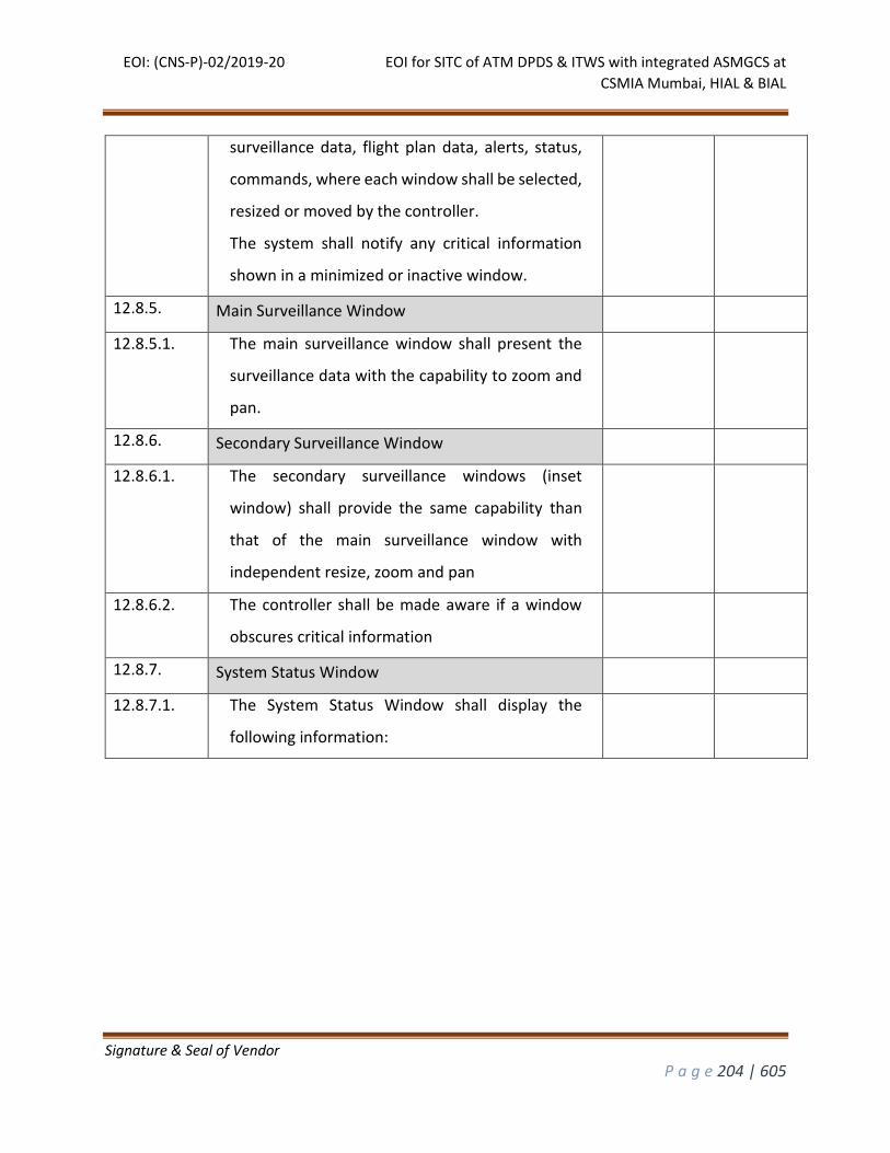
EOI: (CNS-P)-02/2019-20 EOI for SITC of ATM DPDS & ITWS with integrated ASMGCS at
CSMIA Mumbai, HIAL & BIAL
Signature & Seal of Vendor
P a g e 204 | 605
surveillance data, flight plan data, alerts, status,
commands, where each window shall be selected,
resized or moved by the controller.
The system shall notify any critical information
shown in a minimized or inactive window.
12.8.5. Main Surveillance Window
12.8.5.1. The main surveillance window shall present the
surveillance data with the capability to zoom and
pan.
12.8.6. Secondary Surveillance Window
12.8.6.1. The secondary surveillance windows (inset
window) shall provide the same capability than
that of the main surveillance window with
independent resize, zoom and pan
12.8.6.2. The controller shall be made aware if a window
obscures critical information
12.8.7. System Status Window
12.8.7.1. The System Status Window shall display the
following information:
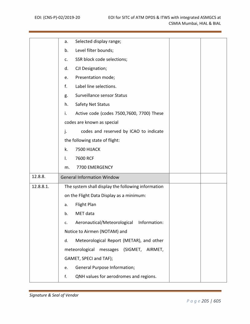
EOI: (CNS-P)-02/2019-20 EOI for SITC of ATM DPDS & ITWS with integrated ASMGCS at
CSMIA Mumbai, HIAL & BIAL
Signature & Seal of Vendor
P a g e 205 | 605
a. Selected display range;
b. Level filter bounds;
c. SSR block code selections;
d. CJI Designation;
e. Presentation mode;
f. Label line selections.
g. Surveillance sensor Status
h. Safety Net Status
i. Active code (codes 7500,7600, 7700) These
codes are known as special
j. codes and reserved by ICAO to indicate
the following state of flight:
k. 7500 HIJACK
l. 7600 RCF
m. 7700 EMERGENCY
12.8.8. General Information Window
12.8.8.1. The system shall display the following information
on the Flight Data Display as a minimum:
a. Flight Plan
b. MET data
c. Aeronautical/Meteorological Information:
Notice to Airmen (NOTAM) and
d. Meteorological Report (METAR), and other
meteorological messages (SIGMET, AIRMET,
GAMET, SPECI and TAF);
e. General Purpose Information;
f. QNH values for aerodromes and regions.
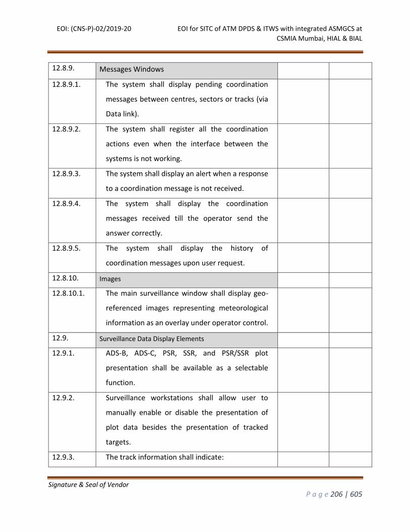
EOI: (CNS-P)-02/2019-20 EOI for SITC of ATM DPDS & ITWS with integrated ASMGCS at
CSMIA Mumbai, HIAL & BIAL
Signature & Seal of Vendor
P a g e 206 | 605
12.8.9. Messages Windows
12.8.9.1. The system shall display pending coordination
messages between centres, sectors or tracks (via
Data link).
12.8.9.2. The system shall register all the coordination
actions even when the interface between the
systems is not working.
12.8.9.3. The system shall display an alert when a response
to a coordination message is not received.
12.8.9.4. The system shall display the coordination
messages received till the operator send the
answer correctly.
12.8.9.5. The system shall display the history of
coordination messages upon user request.
12.8.10. Images
12.8.10.1. The main surveillance window shall display geo-
referenced images representing meteorological
information as an overlay under operator control.
12.9. Surveillance Data Display Elements
12.9.1. ADS-B, ADS-C, PSR, SSR, and PSR/SSR plot
presentation shall be available as a selectable
function.
12.9.2. Surveillance workstations shall allow user to
manually enable or disable the presentation of
plot data besides the presentation of tracked
targets.
12.9.3. The track information shall indicate:
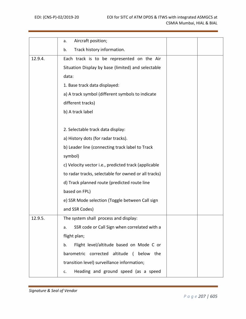
EOI: (CNS-P)-02/2019-20 EOI for SITC of ATM DPDS & ITWS with integrated ASMGCS at
CSMIA Mumbai, HIAL & BIAL
Signature & Seal of Vendor
P a g e 207 | 605
a. Aircraft position;
b. Track history information.
12.9.4. Each track is to be represented on the Air
Situation Display by base (limited) and selectable
data:
1. Base track data displayed:
a) A track symbol (different symbols to indicate
different tracks)
b) A track label
2. Selectable track data display:
a) History dots (for radar tracks).
b) Leader line (connecting track label to Track
symbol)
c) Velocity vector i.e., predicted track (applicable
to radar tracks, selectable for owned or all tracks)
d) Track planned route (predicted route line
based on FPL)
e) SSR Mode selection (Toggle between Call sign
and SSR Codes)
12.9.5. The system shall process and display:
a. SSR code or Call Sign when correlated with a
flight plan;
b. Flight level/altitude based on Mode C or
barometric corrected altitude ( below the
transition level) surveillance information;
c. Heading and ground speed (as a speed
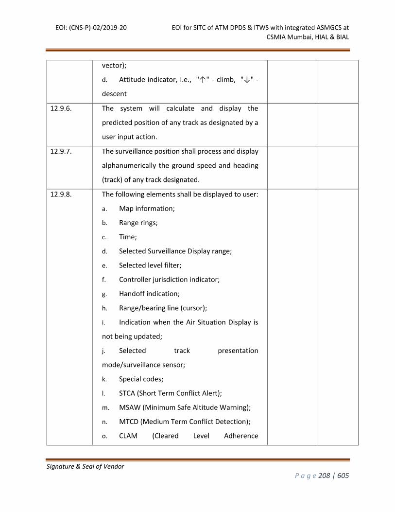
EOI: (CNS-P)-02/2019-20 EOI for SITC of ATM DPDS & ITWS with integrated ASMGCS at
CSMIA Mumbai, HIAL & BIAL
Signature & Seal of Vendor
P a g e 208 | 605
vector);
d. Attitude indicator, i.e., "↑" - climb, "↓" -
descent
12.9.6. The system will calculate and display the
predicted position of any track as designated by a
user input action.
12.9.7. The surveillance position shall process and display
alphanumerically the ground speed and heading
(track) of any track designated.
12.9.8. The following elements shall be displayed to user:
a. Map information;
b. Range rings;
c. Time;
d. Selected Surveillance Display range;
e. Selected level filter;
f. Controller jurisdiction indicator;
g. Handoff indication;
h. Range/bearing line (cursor);
i. Indication when the Air Situation Display is
not being updated;
j. Selected track presentation
mode/surveillance sensor;
k. Special codes;
l. STCA (Short Term Conflict Alert);
m. MSAW (Minimum Safe Altitude Warning);
n. MTCD (Medium Term Conflict Detection);
o. CLAM (Cleared Level Adherence
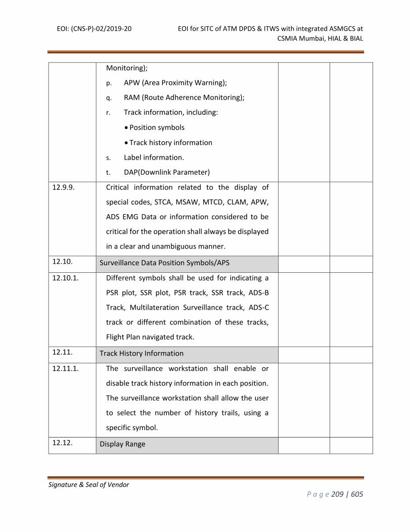
EOI: (CNS-P)-02/2019-20 EOI for SITC of ATM DPDS & ITWS with integrated ASMGCS at
CSMIA Mumbai, HIAL & BIAL
Signature & Seal of Vendor
P a g e 209 | 605
Monitoring);
p. APW (Area Proximity Warning);
q. RAM (Route Adherence Monitoring);
r. Track information, including:
Position symbols
Track history information
s. Label information.
t. DAP(Downlink Parameter)
12.9.9. Critical information related to the display of
special codes, STCA, MSAW, MTCD, CLAM, APW,
ADS EMG Data or information considered to be
critical for the operation shall always be displayed
in a clear and unambiguous manner.
12.10. Surveillance Data Position Symbols/APS
12.10.1. Different symbols shall be used for indicating a
PSR plot, SSR plot, PSR track, SSR track, ADS-B
Track, Multilateration Surveillance track, ADS-C
track or different combination of these tracks,
Flight Plan navigated track.
12.11. Track History Information
12.11.1. The surveillance workstation shall enable or
disable track history information in each position.
The surveillance workstation shall allow the user
to select the number of history trails, using a
specific symbol.
12.12. Display Range
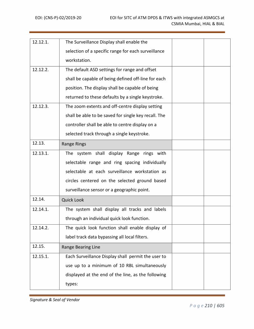
EOI: (CNS-P)-02/2019-20 EOI for SITC of ATM DPDS & ITWS with integrated ASMGCS at
CSMIA Mumbai, HIAL & BIAL
Signature & Seal of Vendor
P a g e 210 | 605
12.12.1. The Surveillance Display shall enable the
selection of a specific range for each surveillance
workstation.
12.12.2. The default ASD settings for range and offset
shall be capable of being defined off-line for each
position. The display shall be capable of being
returned to these defaults by a single keystroke.
12.12.3. The zoom extents and off-centre display setting
shall be able to be saved for single key recall. The
controller shall be able to centre display on a
selected track through a single keystroke.
12.13. Range Rings
12.13.1. The system shall display Range rings with
selectable range and ring spacing individually
selectable at each surveillance workstation as
circles centered on the selected ground based
surveillance sensor or a geographic point.
12.14. Quick Look
12.14.1. The system shall display all tracks and labels
through an individual quick look function.
12.14.2. The quick look function shall enable display of
label track data bypassing all local filters.
12.15. Range Bearing Line
12.15.1. Each Surveillance Display shall permit the user to
use up to a minimum of 10 RBL simultaneously
displayed at the end of the line, as the following
types:
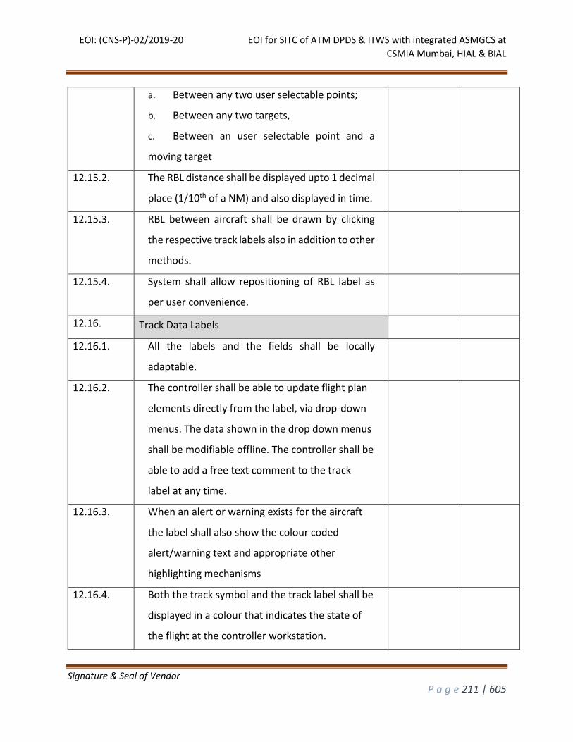
EOI: (CNS-P)-02/2019-20 EOI for SITC of ATM DPDS & ITWS with integrated ASMGCS at
CSMIA Mumbai, HIAL & BIAL
Signature & Seal of Vendor
P a g e 211 | 605
a. Between any two user selectable points;
b. Between any two targets,
c. Between an user selectable point and a
moving target
12.15.2. The RBL distance shall be displayed upto 1 decimal
place (1/10th of a NM) and also displayed in time.
12.15.3. RBL between aircraft shall be drawn by clicking
the respective track labels also in addition to other
methods.
12.15.4. System shall allow repositioning of RBL label as
per user convenience.
12.16. Track Data Labels
12.16.1. All the labels and the fields shall be locally
adaptable.
12.16.2. The controller shall be able to update flight plan
elements directly from the label, via drop-down
menus. The data shown in the drop down menus
shall be modifiable offline. The controller shall be
able to add a free text comment to the track
label at any time.
12.16.3. When an alert or warning exists for the aircraft
the label shall also show the colour coded
alert/warning text and appropriate other
highlighting mechanisms
12.16.4. Both the track symbol and the track label shall be
displayed in a colour that indicates the state of
the flight at the controller workstation.
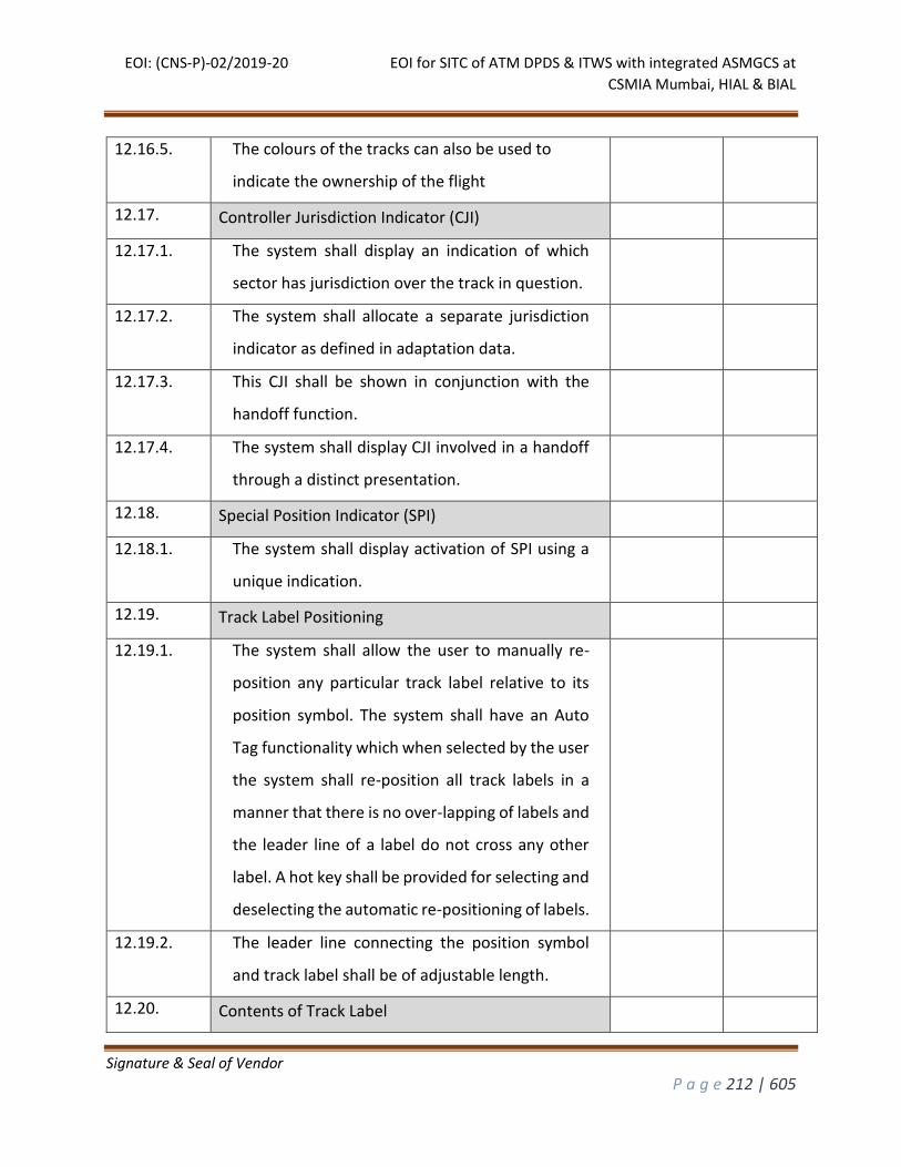
EOI: (CNS-P)-02/2019-20 EOI for SITC of ATM DPDS & ITWS with integrated ASMGCS at
CSMIA Mumbai, HIAL & BIAL
Signature & Seal of Vendor
P a g e 212 | 605
12.16.5. The colours of the tracks can also be used to
indicate the ownership of the flight
12.17. Controller Jurisdiction Indicator (CJI)
12.17.1. The system shall display an indication of which
sector has jurisdiction over the track in question.
12.17.2. The system shall allocate a separate jurisdiction
indicator as defined in adaptation data.
12.17.3. This CJI shall be shown in conjunction with the
handoff function.
12.17.4. The system shall display CJI involved in a handoff
through a distinct presentation.
12.18. Special Position Indicator (SPI)
12.18.1. The system shall display activation of SPI using a
unique indication.
12.19. Track Label Positioning
12.19.1. The system shall allow the user to manually re-
position any particular track label relative to its
position symbol. The system shall have an Auto
Tag functionality which when selected by the user
the system shall re-position all track labels in a
manner that there is no over-lapping of labels and
the leader line of a label do not cross any other
label. A hot key shall be provided for selecting and
deselecting the automatic re-positioning of labels.
12.19.2. The leader line connecting the position symbol
and track label shall be of adjustable length.
12.20. Contents of Track Label
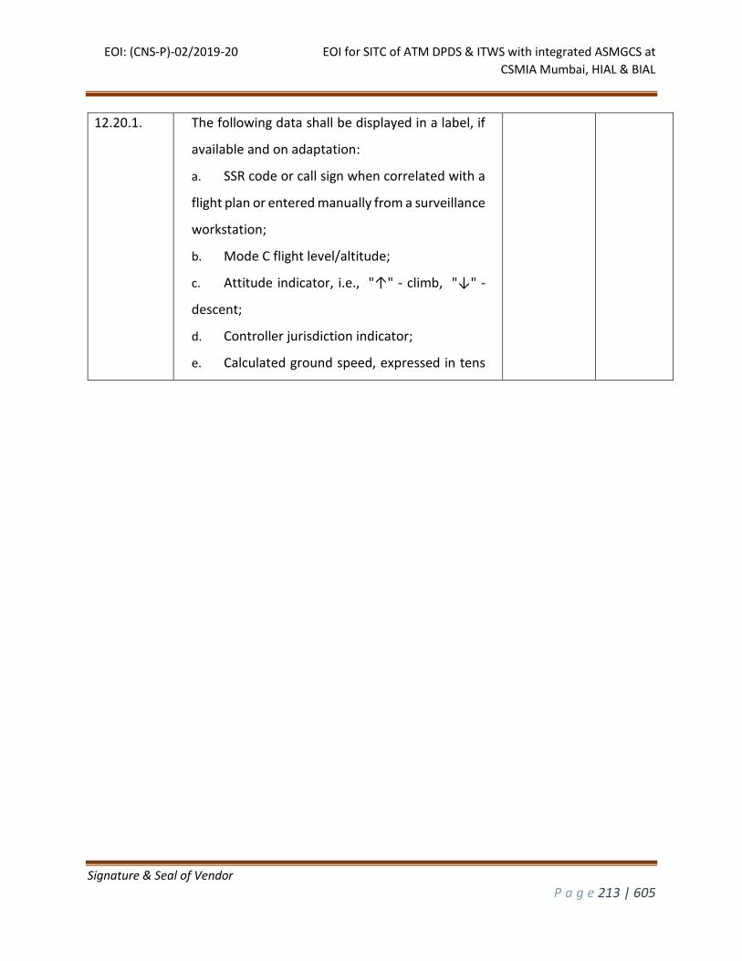
EOI: (CNS-P)-02/2019-20 EOI for SITC of ATM DPDS & ITWS with integrated ASMGCS at
CSMIA Mumbai, HIAL & BIAL
Signature & Seal of Vendor
P a g e 213 | 605
12.20.1. The following data shall be displayed in a label, if
available and on adaptation:
a. SSR code or call sign when correlated with a
flight plan or entered manually from a surveillance
workstation;
b. Mode C flight level/altitude;
c. Attitude indicator, i.e., "↑" - climb, "↓" -
descent;
d. Controller jurisdiction indicator;
e. Calculated ground speed, expressed in tens
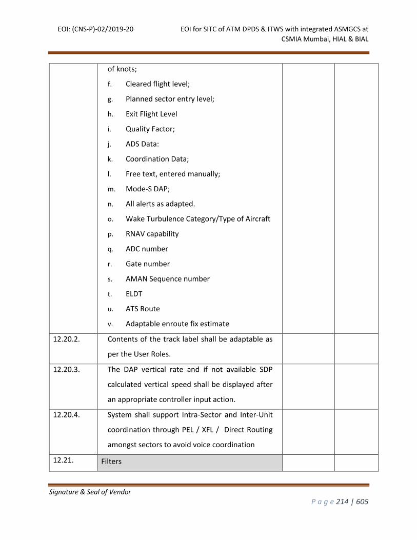
EOI: (CNS-P)-02/2019-20 EOI for SITC of ATM DPDS & ITWS with integrated ASMGCS at
CSMIA Mumbai, HIAL & BIAL
Signature & Seal of Vendor
P a g e 214 | 605
of knots;
f. Cleared flight level;
g. Planned sector entry level;
h. Exit Flight Level
i. Quality Factor;
j. ADS Data:
k. Coordination Data;
l. Free text, entered manually;
m. Mode-S DAP;
n. All alerts as adapted.
o. Wake Turbulence Category/Type of Aircraft
p. RNAV capability
q. ADC number
r. Gate number
s. AMAN Sequence number
t. ELDT
u. ATS Route
v. Adaptable enroute fix estimate
12.20.2. Contents of the track label shall be adaptable as
per the User Roles.
12.20.3. The DAP vertical rate and if not available SDP
calculated vertical speed shall be displayed after
an appropriate controller input action.
12.20.4. System shall support Intra-Sector and Inter-Unit
coordination through PEL / XFL / Direct Routing
amongst sectors to avoid voice coordination
12.21. Filters
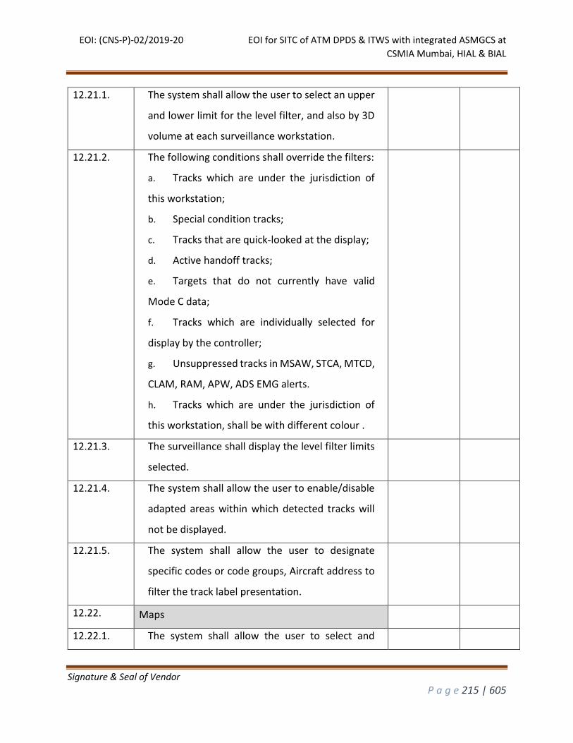
EOI: (CNS-P)-02/2019-20 EOI for SITC of ATM DPDS & ITWS with integrated ASMGCS at
CSMIA Mumbai, HIAL & BIAL
Signature & Seal of Vendor
P a g e 215 | 605
12.21.1. The system shall allow the user to select an upper
and lower limit for the level filter, and also by 3D
volume at each surveillance workstation.
12.21.2. The following conditions shall override the filters:
a. Tracks which are under the jurisdiction of
this workstation;
b. Special condition tracks;
c. Tracks that are quick-looked at the display;
d. Active handoff tracks;
e. Targets that do not currently have valid
Mode C data;
f. Tracks which are individually selected for
display by the controller;
g. Unsuppressed tracks in MSAW, STCA, MTCD,
CLAM, RAM, APW, ADS EMG alerts.
h. Tracks which are under the jurisdiction of
this workstation, shall be with different colour .
12.21.3. The surveillance shall display the level filter limits
selected.
12.21.4. The system shall allow the user to enable/disable
adapted areas within which detected tracks will
not be displayed.
12.21.5. The system shall allow the user to designate
specific codes or code groups, Aircraft address to
filter the track label presentation.
12.22. Maps
12.22.1. The system shall allow the user to select and
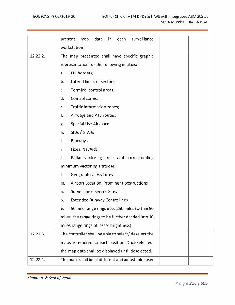
EOI: (CNS-P)-02/2019-20 EOI for SITC of ATM DPDS & ITWS with integrated ASMGCS at
CSMIA Mumbai, HIAL & BIAL
Signature & Seal of Vendor
P a g e 216 | 605
present map data in each surveillance
workstation.
12.22.2. The map presented shall have specific graphic
representation for the following entities:
a. FIR borders;
b. Lateral limits of sectors;
c. Terminal control areas;
d. Control zones;
e. Traffic information zones;
f. Airways and ATS routes;
g. Special Use Airspace
h. SIDs / STARs
i. Runways
j. Fixes, NavAids
k. Radar vectoring areas and corresponding
minimum vectoring altitudes
l. Geographical Features
m. Airport Location, Prominent obstructions
n. Surveillance Sensor Sites
o. Extended Runway Centre lines
p. 50 mile range rings upto 250 miles (within 50
miles, the range rings to be further divided into 10
miles range rings of lesser brightness)
12.22.3. The controller shall be able to select/ deselect the
maps as required for each position. Once selected,
the map data shall be displayed until deselected.
12.22.4. The maps shall be of different and adjustable (user
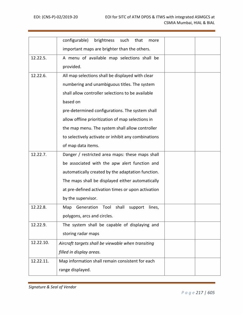
EOI: (CNS-P)-02/2019-20 EOI for SITC of ATM DPDS & ITWS with integrated ASMGCS at
CSMIA Mumbai, HIAL & BIAL
Signature & Seal of Vendor
P a g e 217 | 605
configurable) brightness such that more
important maps are brighter than the others.
12.22.5. A menu of available map selections shall be
provided.
12.22.6. All map selections shall be displayed with clear
numbering and unambiguous titles. The system
shall allow controller selections to be available
based on
pre-determined configurations. The system shall
allow offline prioritization of map selections in
the map menu. The system shall allow controller
to selectively activate or inhibit any combinations
of map data items.
12.22.7. Danger / restricted area maps: these maps shall
be associated with the apw alert function and
automatically created by the adaptation function.
The maps shall be displayed either automatically
at pre-defined activation times or upon activation
by the supervisor.
12.22.8. Map Generation Tool shall support lines,
polygons, arcs and circles.
12.22.9. The system shall be capable of displaying and
storing radar maps
12.22.10. Aircraft targets shall be viewable when transiting
filled in display areas.
12.22.11. Map information shall remain consistent for each
range displayed.
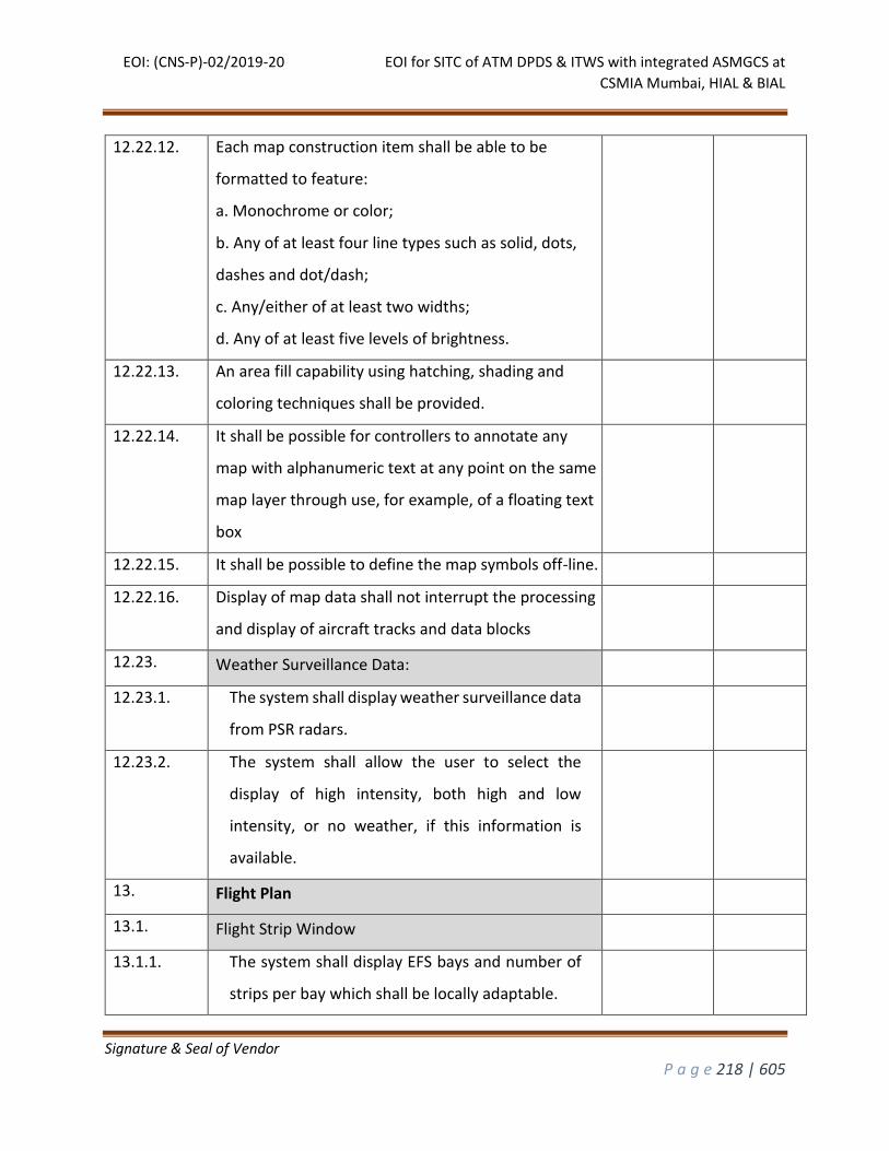
EOI: (CNS-P)-02/2019-20 EOI for SITC of ATM DPDS & ITWS with integrated ASMGCS at
CSMIA Mumbai, HIAL & BIAL
Signature & Seal of Vendor
P a g e 218 | 605
12.22.12. Each map construction item shall be able to be
formatted to feature:
a. Monochrome or color;
b. Any of at least four line types such as solid, dots,
dashes and dot/dash;
c. Any/either of at least two widths;
d. Any of at least five levels of brightness.
12.22.13. An area fill capability using hatching, shading and
coloring techniques shall be provided.
12.22.14. It shall be possible for controllers to annotate any
map with alphanumeric text at any point on the same
map layer through use, for example, of a floating text
box
12.22.15. It shall be possible to define the map symbols off-line.
12.22.16. Display of map data shall not interrupt the processing
and display of aircraft tracks and data blocks
12.23. Weather Surveillance Data:
12.23.1. The system shall display weather surveillance data
from PSR radars.
12.23.2. The system shall allow the user to select the
display of high intensity, both high and low
intensity, or no weather, if this information is
available.
13. Flight Plan
13.1. Flight Strip Window
13.1.1. The system shall display EFS bays and number of
strips per bay which shall be locally adaptable.
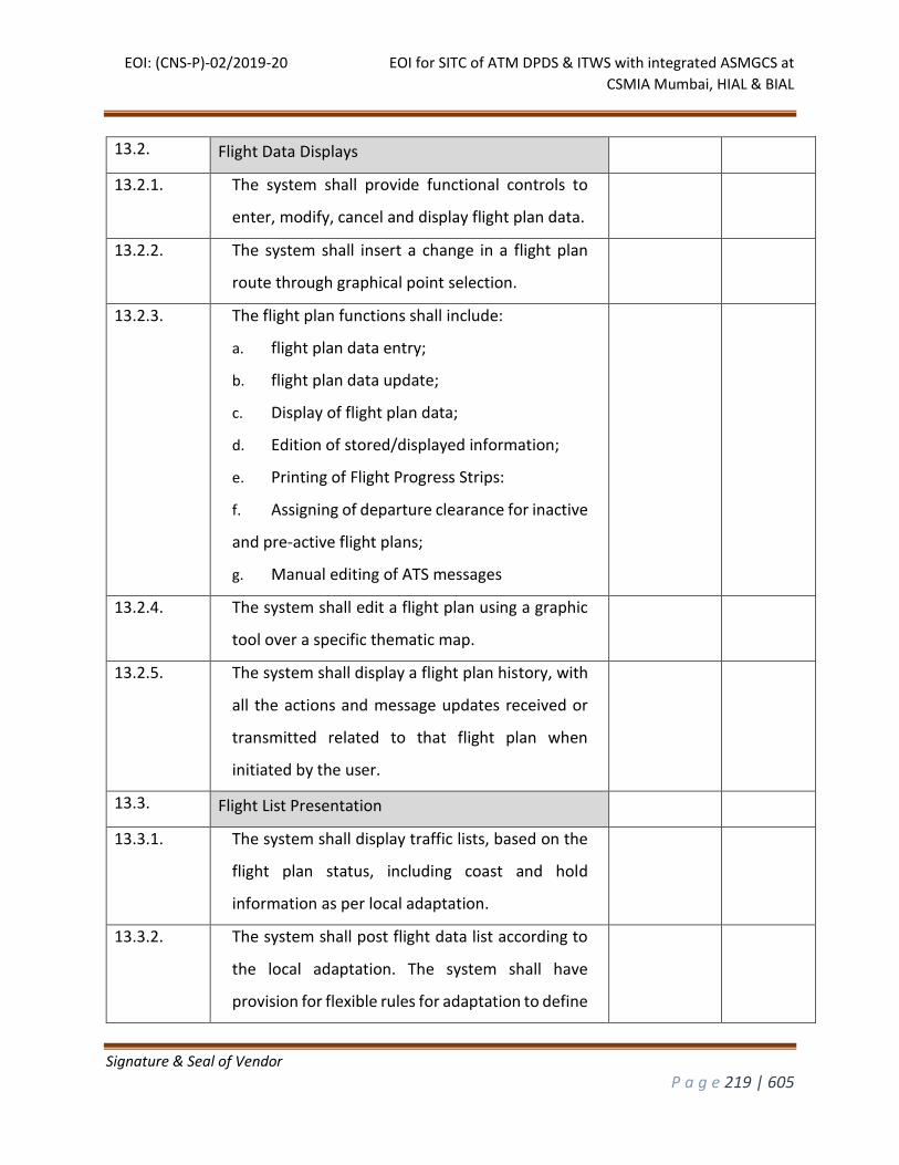
EOI: (CNS-P)-02/2019-20 EOI for SITC of ATM DPDS & ITWS with integrated ASMGCS at
CSMIA Mumbai, HIAL & BIAL
Signature & Seal of Vendor
P a g e 219 | 605
13.2. Flight Data Displays
13.2.1. The system shall provide functional controls to
enter, modify, cancel and display flight plan data.
13.2.2. The system shall insert a change in a flight plan
route through graphical point selection.
13.2.3. The flight plan functions shall include:
a. flight plan data entry;
b. flight plan data update;
c. Display of flight plan data;
d. Edition of stored/displayed information;
e. Printing of Flight Progress Strips:
f. Assigning of departure clearance for inactive
and pre-active flight plans;
g. Manual editing of ATS messages
13.2.4. The system shall edit a flight plan using a graphic
tool over a specific thematic map.
13.2.5. The system shall display a flight plan history, with
all the actions and message updates received or
transmitted related to that flight plan when
initiated by the user.
13.3. Flight List Presentation
13.3.1. The system shall display traffic lists, based on the
flight plan status, including coast and hold
information as per local adaptation.
13.3.2. The system shall post flight data list according to
the local adaptation. The system shall have
provision for flexible rules for adaptation to define
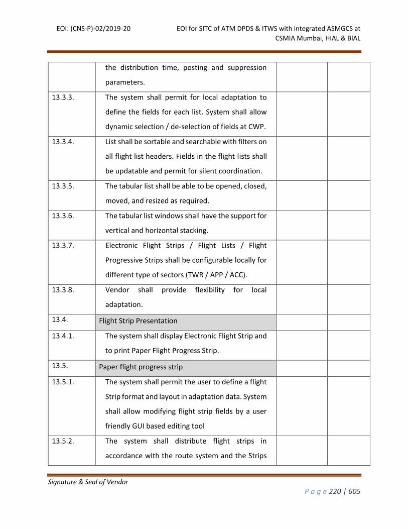
EOI: (CNS-P)-02/2019-20 EOI for SITC of ATM DPDS & ITWS with integrated ASMGCS at
CSMIA Mumbai, HIAL & BIAL
Signature & Seal of Vendor
P a g e 220 | 605
the distribution time, posting and suppression
parameters.
13.3.3. The system shall permit for local adaptation to
define the fields for each list. System shall allow
dynamic selection / de-selection of fields at CWP.
13.3.4. List shall be sortable and searchable with filters on
all flight list headers. Fields in the flight lists shall
be updatable and permit for silent coordination.
13.3.5. The tabular list shall be able to be opened, closed,
moved, and resized as required.
13.3.6. The tabular list windows shall have the support for
vertical and horizontal stacking.
13.3.7. Electronic Flight Strips / Flight Lists / Flight
Progressive Strips shall be configurable locally for
different type of sectors (TWR / APP / ACC).
13.3.8. Vendor shall provide flexibility for local
adaptation.
13.4. Flight Strip Presentation
13.4.1. The system shall display Electronic Flight Strip and
to print Paper Flight Progress Strip.
13.5. Paper flight progress strip
13.5.1. The system shall permit the user to define a flight
Strip format and layout in adaptation data. System
shall allow modifying flight strip fields by a user
friendly GUI based editing tool
13.5.2. The system shall distribute flight strips in
accordance with the route system and the Strips
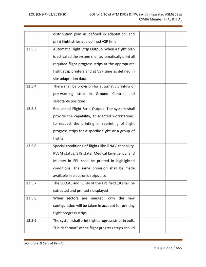
EOI: (CNS-P)-02/2019-20 EOI for SITC of ATM DPDS & ITWS with integrated ASMGCS at
CSMIA Mumbai, HIAL & BIAL
Signature & Seal of Vendor
P a g e 221 | 605
distribution plan as defined in adaptation, and
print flight strips at a defined VSP time.
13.5.3. Automatic Flight Strip Output- When a flight plan
is activated the system shall automatically print all
required flight progress strips at the appropriate
flight strip printers and at VSP time as defined in
site adaptation data.
13.5.4. There shall be provision for automatic printing of
pre-warning strip in Ground Control and
selectable positions.
13.5.5. Requested Flight Strip Output- The system shall
provide the capability, at adapted workstations,
to request the printing or reprinting of flight
progress strips for a specific flight or a group of
flights.
13.5.6. Special conditions of flights like RNAV capability,
RVSM status, STS state, Medical Emergency, and
Military in FPL shall be printed in highlighted
conditions. The same provision shall be made
available in electronic strips also.
13.5.7. The SELCAL and REGN of the FPL field 18 shall be
extracted and printed / displayed
13.5.8. When sectors are merged, only the new
configuration will be taken in account for printing
flight progress strips.
13.5.9. The system shall print flight progress strips in bulk.
“Fields format” of the flight progress strips should
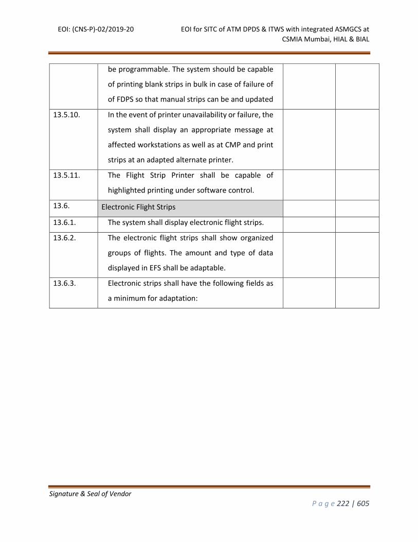
EOI: (CNS-P)-02/2019-20 EOI for SITC of ATM DPDS & ITWS with integrated ASMGCS at
CSMIA Mumbai, HIAL & BIAL
Signature & Seal of Vendor
P a g e 222 | 605
be programmable. The system should be capable
of printing blank strips in bulk in case of failure of
of FDPS so that manual strips can be and updated
13.5.10. In the event of printer unavailability or failure, the
system shall display an appropriate message at
affected workstations as well as at CMP and print
strips at an adapted alternate printer.
13.5.11. The Flight Strip Printer shall be capable of
highlighted printing under software control.
13.6. Electronic Flight Strips
13.6.1. The system shall display electronic flight strips.
13.6.2. The electronic flight strips shall show organized
groups of flights. The amount and type of data
displayed in EFS shall be adaptable.
13.6.3. Electronic strips shall have the following fields as
a minimum for adaptation:
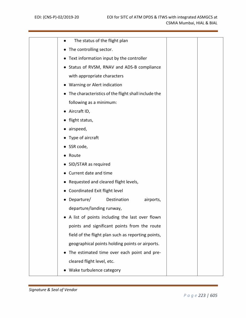
EOI: (CNS-P)-02/2019-20 EOI for SITC of ATM DPDS & ITWS with integrated ASMGCS at
CSMIA Mumbai, HIAL & BIAL
Signature & Seal of Vendor
P a g e 223 | 605
● The status of the flight plan
● The controlling sector.
● Text information input by the controller
● Status of RVSM, RNAV and ADS-B compliance
with appropriate characters
● Warning or Alert indication
● The characteristics of the flight shall include the
following as a minimum:
● Aircraft ID,
● flight status,
● airspeed,
● Type of aircraft
● SSR code,
● Route
● SID/STAR as required
● Current date and time
● Requested and cleared flight levels,
● Coordinated Exit flight level
● Departure/ Destination airports,
departure/landing runway,
● A list of points including the last over flown
points and significant points from the route
field of the flight plan such as reporting points,
geographical points holding points or airports.
● The estimated time over each point and pre-
cleared flight level, etc.
● Wake turbulence category
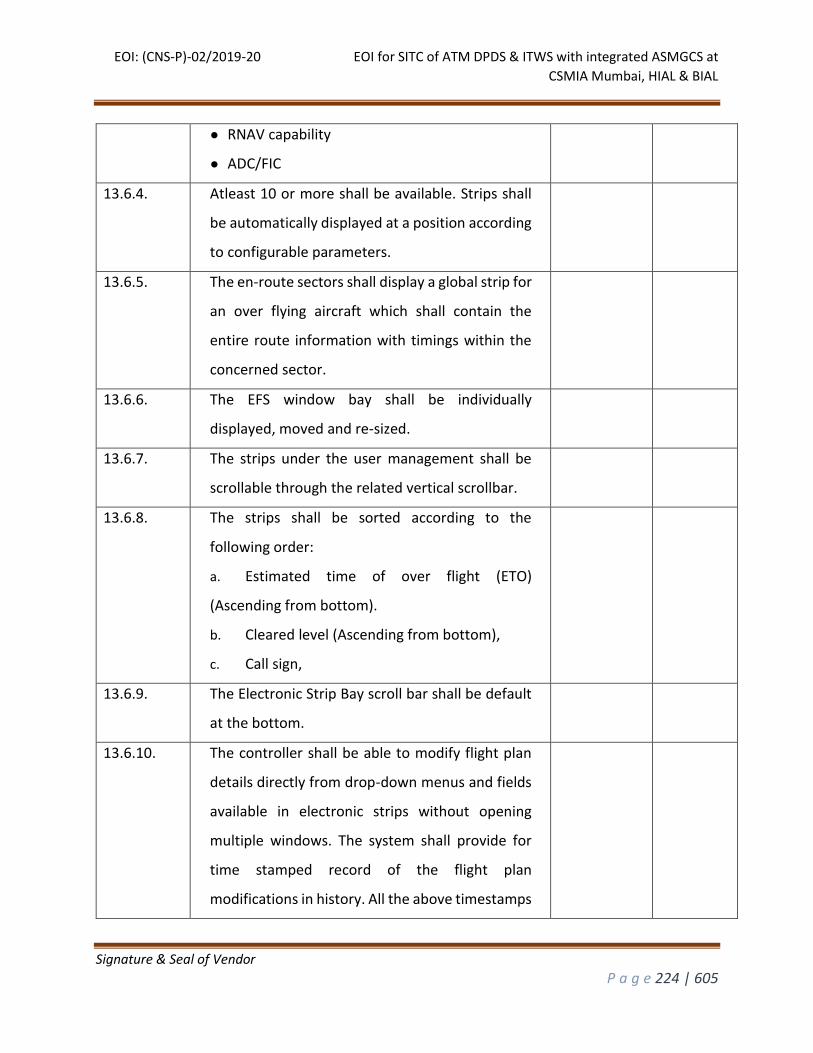
EOI: (CNS-P)-02/2019-20 EOI for SITC of ATM DPDS & ITWS with integrated ASMGCS at
CSMIA Mumbai, HIAL & BIAL
Signature & Seal of Vendor
P a g e 224 | 605
● RNAV capability
● ADC/FIC
13.6.4. Atleast 10 or more shall be available. Strips shall
be automatically displayed at a position according
to configurable parameters.
13.6.5. The en-route sectors shall display a global strip for
an over flying aircraft which shall contain the
entire route information with timings within the
concerned sector.
13.6.6. The EFS window bay shall be individually
displayed, moved and re-sized.
13.6.7. The strips under the user management shall be
scrollable through the related vertical scrollbar.
13.6.8. The strips shall be sorted according to the
following order:
a. Estimated time of over flight (ETO)
(Ascending from bottom).
b. Cleared level (Ascending from bottom),
c. Call sign,
13.6.9. The Electronic Strip Bay scroll bar shall be default
at the bottom.
13.6.10. The controller shall be able to modify flight plan
details directly from drop-down menus and fields
available in electronic strips without opening
multiple windows. The system shall provide for
time stamped record of the flight plan
modifications in history. All the above timestamps
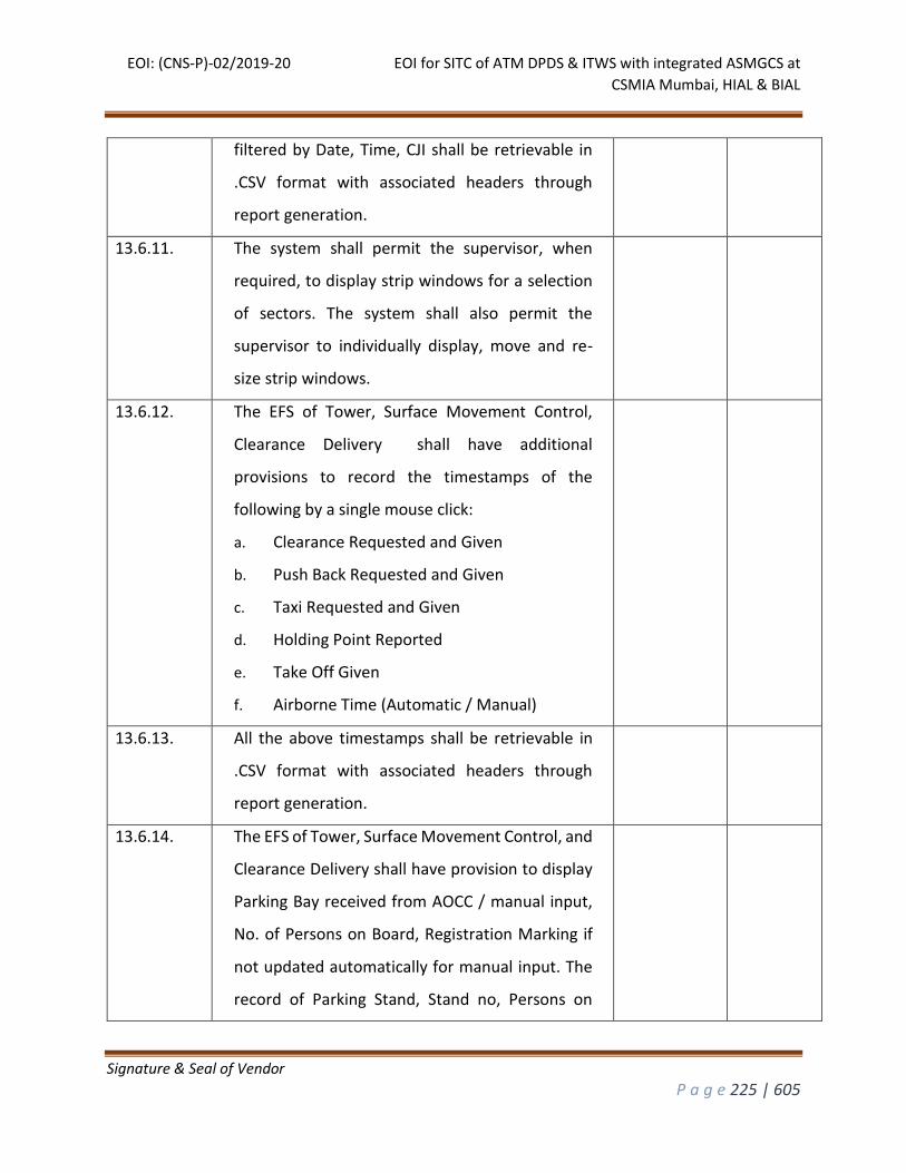
EOI: (CNS-P)-02/2019-20 EOI for SITC of ATM DPDS & ITWS with integrated ASMGCS at
CSMIA Mumbai, HIAL & BIAL
Signature & Seal of Vendor
P a g e 225 | 605
filtered by Date, Time, CJI shall be retrievable in
.CSV format with associated headers through
report generation.
13.6.11. The system shall permit the supervisor, when
required, to display strip windows for a selection
of sectors. The system shall also permit the
supervisor to individually display, move and re-
size strip windows.
13.6.12. The EFS of Tower, Surface Movement Control,
Clearance Delivery shall have additional
provisions to record the timestamps of the
following by a single mouse click:
a. Clearance Requested and Given
b. Push Back Requested and Given
c. Taxi Requested and Given
d. Holding Point Reported
e. Take Off Given
f. Airborne Time (Automatic / Manual)
13.6.13. All the above timestamps shall be retrievable in
.CSV format with associated headers through
report generation.
13.6.14. The EFS of Tower, Surface Movement Control, and
Clearance Delivery shall have provision to display
Parking Bay received from AOCC / manual input,
No. of Persons on Board, Registration Marking if
not updated automatically for manual input. The
record of Parking Stand, Stand no, Persons on
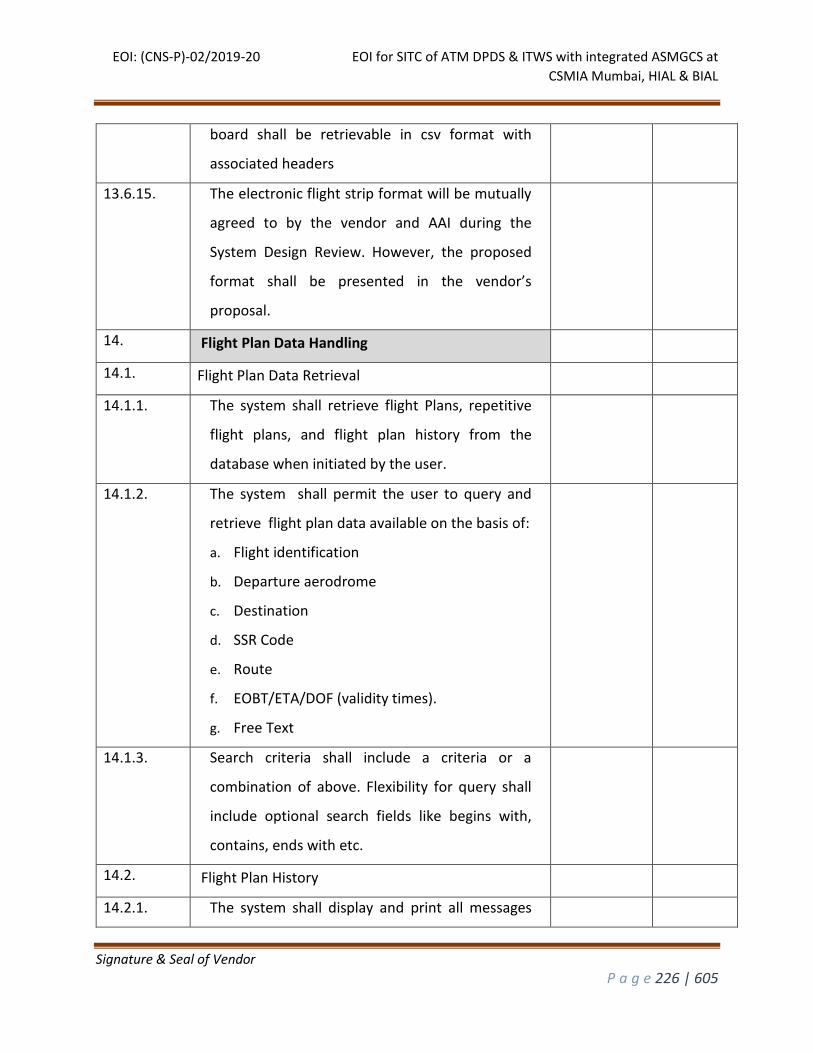
EOI: (CNS-P)-02/2019-20 EOI for SITC of ATM DPDS & ITWS with integrated ASMGCS at
CSMIA Mumbai, HIAL & BIAL
Signature & Seal of Vendor
P a g e 226 | 605
board shall be retrievable in csv format with
associated headers
13.6.15. The electronic flight strip format will be mutually
agreed to by the vendor and AAI during the
System Design Review. However, the proposed
format shall be presented in the vendor’s
proposal.
14. Flight Plan Data Handling
14.1. Flight Plan Data Retrieval
14.1.1. The system shall retrieve flight Plans, repetitive
flight plans, and flight plan history from the
database when initiated by the user.
14.1.2. The system shall permit the user to query and
retrieve flight plan data available on the basis of:
a. Flight identification
b. Departure aerodrome
c. Destination
d. SSR Code
e. Route
f. EOBT/ETA/DOF (validity times).
g. Free Text
14.1.3. Search criteria shall include a criteria or a
combination of above. Flexibility for query shall
include optional search fields like begins with,
contains, ends with etc.
14.2. Flight Plan History
14.2.1. The system shall display and print all messages
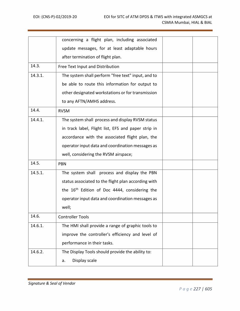
EOI: (CNS-P)-02/2019-20 EOI for SITC of ATM DPDS & ITWS with integrated ASMGCS at
CSMIA Mumbai, HIAL & BIAL
Signature & Seal of Vendor
P a g e 227 | 605
concerning a flight plan, including associated
update messages, for at least adaptable hours
after termination of flight plan.
14.3. Free Text Input and Distribution
14.3.1. The system shall perform "free text" input, and to
be able to route this information for output to
other designated workstations or for transmission
to any AFTN/AMHS address.
14.4. RVSM
14.4.1. The system shall process and display RVSM status
in track label, Flight list, EFS and paper strip in
accordance with the associated flight plan, the
operator input data and coordination messages as
well, considering the RVSM airspace;
14.5. PBN
14.5.1. The system shall process and display the PBN
status associated to the flight plan according with
the 16th Edition of Doc 4444, considering the
operator input data and coordination messages as
well;
14.6. Controller Tools
14.6.1. The HMI shall provide a range of graphic tools to
improve the controller's efficiency and level of
performance in their tasks.
14.6.2. The Display Tools should provide the ability to:
a. Display scale
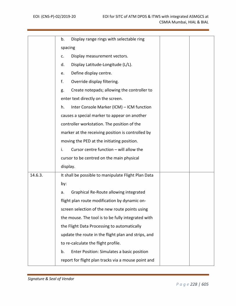
EOI: (CNS-P)-02/2019-20 EOI for SITC of ATM DPDS & ITWS with integrated ASMGCS at
CSMIA Mumbai, HIAL & BIAL
Signature & Seal of Vendor
P a g e 228 | 605
b. Display range rings with selectable ring
spacing
c. Display measurement vectors.
d. Display Latitude-Longitude (L/L).
e. Define display centre.
f. Override display filtering.
g. Create notepads; allowing the controller to
enter text directly on the screen.
h. Inter Console Marker (ICM) – ICM function
causes a special marker to appear on another
controller workstation. The position of the
marker at the receiving position is controlled by
moving the PED at the initiating position.
i. Cursor centre function – will allow the
cursor to be centred on the main physical
display.
14.6.3. It shall be possible to manipulate Flight Plan Data
by:
a. Graphical Re-Route allowing integrated
flight plan route modification by dynamic on-
screen selection of the new route points using
the mouse. The tool is to be fully integrated with
the Flight Data Processing to automatically
update the route in the flight plan and strips, and
to re-calculate the flight profile.
b. Enter Position: Simulates a basic position
report for flight plan tracks via a mouse point and
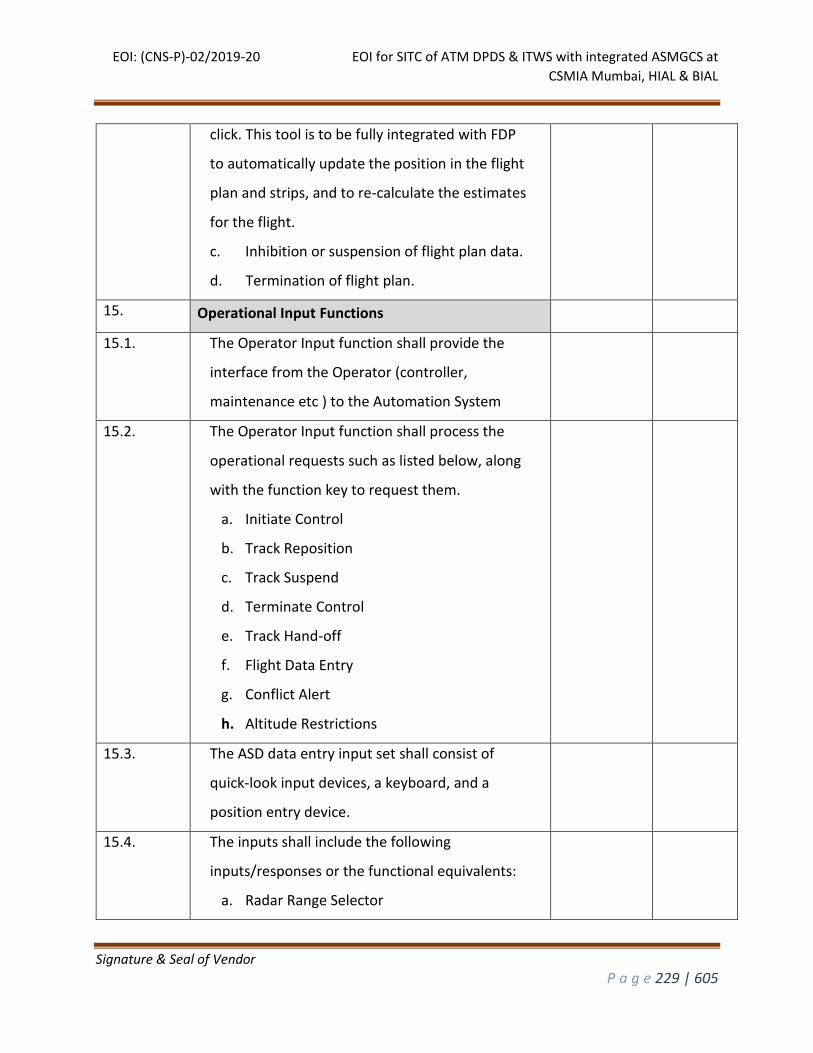
EOI: (CNS-P)-02/2019-20 EOI for SITC of ATM DPDS & ITWS with integrated ASMGCS at
CSMIA Mumbai, HIAL & BIAL
Signature & Seal of Vendor
P a g e 229 | 605
click. This tool is to be fully integrated with FDP
to automatically update the position in the flight
plan and strips, and to re-calculate the estimates
for the flight.
c. Inhibition or suspension of flight plan data.
d. Termination of flight plan.
15. Operational Input Functions
15.1. The Operator Input function shall provide the
interface from the Operator (controller,
maintenance etc ) to the Automation System
15.2. The Operator Input function shall process the
operational requests such as listed below, along
with the function key to request them.
a. Initiate Control
b. Track Reposition
c. Track Suspend
d. Terminate Control
e. Track Hand-off
f. Flight Data Entry
g. Conflict Alert
h. Altitude Restrictions
15.3. The ASD data entry input set shall consist of
quick-look input devices, a keyboard, and a
position entry device.
15.4. The inputs shall include the following
inputs/responses or the functional equivalents:
a. Radar Range Selector

EOI: (CNS-P)-02/2019-20 EOI for SITC of ATM DPDS & ITWS with integrated ASMGCS at
CSMIA Mumbai, HIAL & BIAL
Signature & Seal of Vendor
P a g e 230 | 605
b. Range Mark Selector
c. Map Selector
d. Data Block Field Inhibit Switch
e. Leader Length Selector
f. Leader Direction Selector
g. Centre/ De-centre
h. Centre Adjustments
i. Character Size
j. Map brightness control
k. Display Weather Overlay
15.5. Most operational data shall be available on all
positions for display. However, only the
supervisor shall be entitled to modify data
related to the Automation System operation,
such as:
a. Enabling/disabling of alerts and warnings
b. Operational configuration of the ATM
region sectorization or grouping/de-
grouping process
c. Surveillance of Automation System status
d. Control of Playback function
e. SSR code management
f. Repetitive Flight Plans (RPL) management
g. Enable monitoring of any
sectors/workstations from an authorized
position
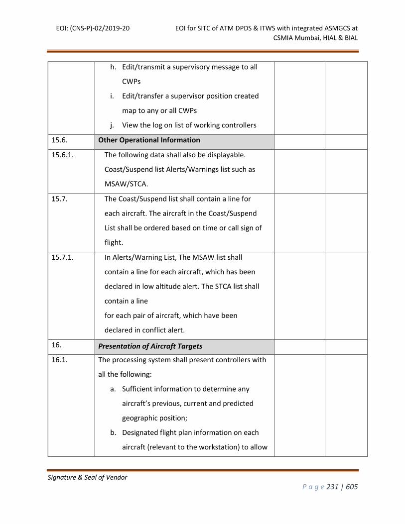
EOI: (CNS-P)-02/2019-20 EOI for SITC of ATM DPDS & ITWS with integrated ASMGCS at
CSMIA Mumbai, HIAL & BIAL
Signature & Seal of Vendor
P a g e 231 | 605
h. Edit/transmit a supervisory message to all
CWPs
i. Edit/transfer a supervisor position created
map to any or all CWPs
j. View the log on list of working controllers
15.6. Other Operational Information
15.6.1. The following data shall also be displayable.
Coast/Suspend list Alerts/Warnings list such as
MSAW/STCA.
15.7. The Coast/Suspend list shall contain a line for
each aircraft. The aircraft in the Coast/Suspend
List shall be ordered based on time or call sign of
flight.
15.7.1. In Alerts/Warning List, The MSAW list shall
contain a line for each aircraft, which has been
declared in low altitude alert. The STCA list shall
contain a line
for each pair of aircraft, which have been
declared in conflict alert.
16. Presentation of Aircraft Targets
16.1. The processing system shall present controllers with
all the following:
a. Sufficient information to determine any
aircraft’s previous, current and predicted
geographic position;
b. Designated flight plan information on each
aircraft (relevant to the workstation) to allow
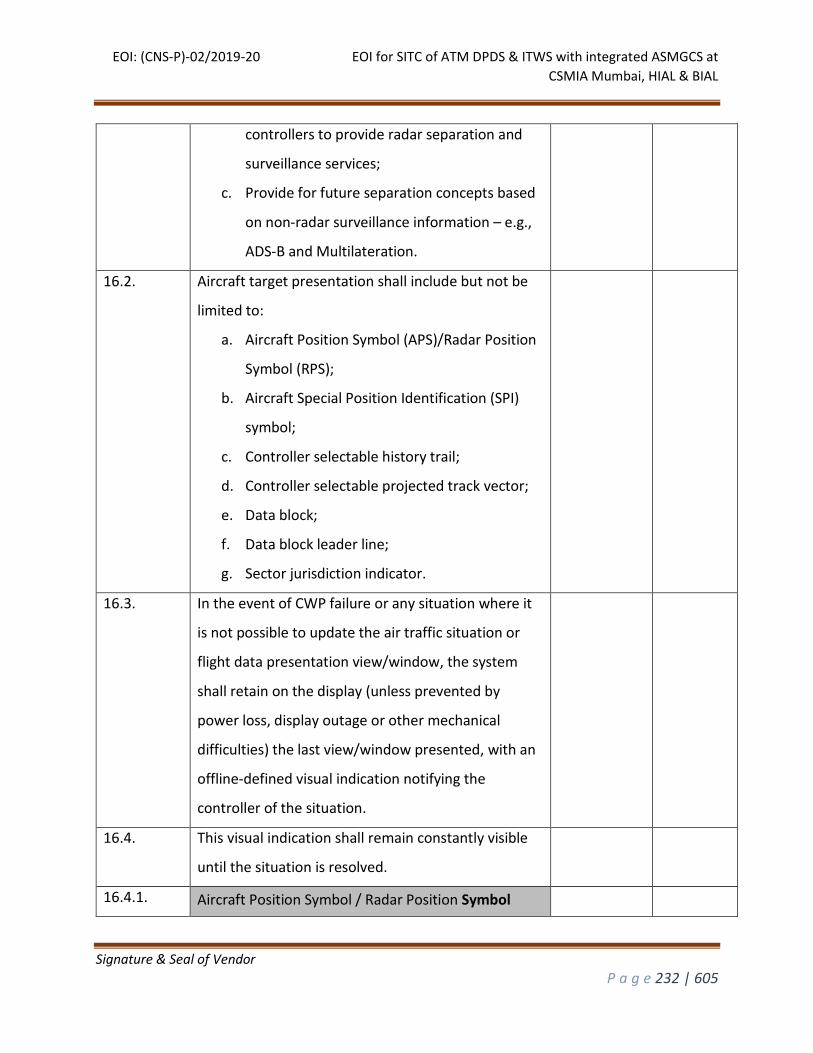
EOI: (CNS-P)-02/2019-20 EOI for SITC of ATM DPDS & ITWS with integrated ASMGCS at
CSMIA Mumbai, HIAL & BIAL
Signature & Seal of Vendor
P a g e 232 | 605
controllers to provide radar separation and
surveillance services;
c. Provide for future separation concepts based
on non-radar surveillance information – e.g.,
ADS-B and Multilateration.
16.2. Aircraft target presentation shall include but not be
limited to:
a. Aircraft Position Symbol (APS)/Radar Position
Symbol (RPS);
b. Aircraft Special Position Identification (SPI)
symbol;
c. Controller selectable history trail;
d. Controller selectable projected track vector;
e. Data block;
f. Data block leader line;
g. Sector jurisdiction indicator.
16.3. In the event of CWP failure or any situation where it
is not possible to update the air traffic situation or
flight data presentation view/window, the system
shall retain on the display (unless prevented by
power loss, display outage or other mechanical
difficulties) the last view/window presented, with an
offline-defined visual indication notifying the
controller of the situation.
16.4. This visual indication shall remain constantly visible
until the situation is resolved.
16.4.1. Aircraft Position Symbol / Radar Position Symbol
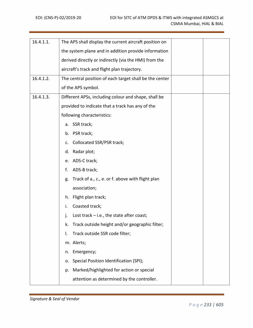
EOI: (CNS-P)-02/2019-20 EOI for SITC of ATM DPDS & ITWS with integrated ASMGCS at
CSMIA Mumbai, HIAL & BIAL
Signature & Seal of Vendor
P a g e 233 | 605
16.4.1.1. The APS shall display the current aircraft position on
the system plane and in addition provide information
derived directly or indirectly (via the HMI) from the
aircraft’s track and flight plan trajectory.
16.4.1.2. The central position of each target shall be the center
of the APS symbol.
16.4.1.3. Different APSs, including colour and shape, shall be
provided to indicate that a track has any of the
following characteristics:
a. SSR track;
b. PSR track;
c. Collocated SSR/PSR track;
d. Radar plot;
e. ADS-C track;
f. ADS-B track;
g. Track of a., c., e. or f. above with flight plan
association;
h. Flight plan track;
i. Coasted track;
j. Lost track – i.e., the state after coast;
k. Track outside height and/or geographic filter;
l. Track outside SSR code filter;
m. Alerts;
n. Emergency;
o. Special Position Identification (SPI);
p. Marked/highlighted for action or special
attention as determined by the controller.

EOI: (CNS-P)-02/2019-20 EOI for SITC of ATM DPDS & ITWS with integrated ASMGCS at
CSMIA Mumbai, HIAL & BIAL
Signature & Seal of Vendor
P a g e 234 | 605
16.4.1.4. It shall be possible to define, off-line, the symbols to
represent the different target characteristics of APSs
16.4.1.5. Bidders shall describe the symbols available in the
offered system to differentiate target characteristics
and how they are used.
16.4.2. Special Position Identification (SPI)
16.4.2.1. The system shall be able to identify specific aircraft
targets, in cooperation with the aircraft’s SSR
transponder equipment.
16.4.2.2. It shall be possible to define, off-line, the symbols to
represent the different target characteristics of APSs
as described
16.4.2.3. Bidders shall describe the symbols available in the
offered system to differentiate target characteristics
and how they are used.
16.4.2.4. The system shall alert controllers whenever an SPI
signal from an aircraft has been received.
16.4.2.5. A visual, on screen alert shall be provided that
enables the controller to unambiguously determine
which aircraft is transmitting the SPI.
16.4.2.6. The visual alert shall be clearly distinguishable from
any other display alert.
16.4.3. History Trail
16.4.3.1. The system shall allow the display of history trails
identifying the target's position over a defined
number of previous screen updates.
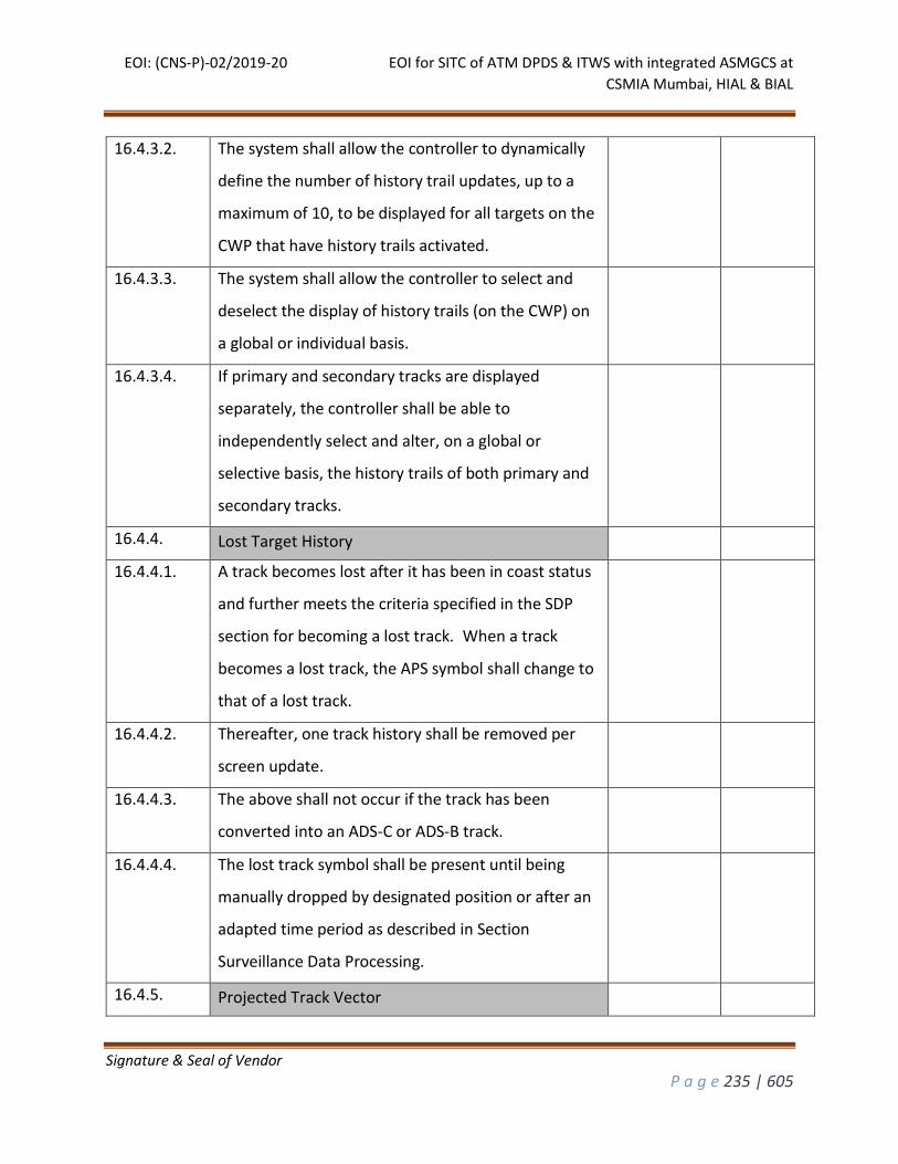
EOI: (CNS-P)-02/2019-20 EOI for SITC of ATM DPDS & ITWS with integrated ASMGCS at
CSMIA Mumbai, HIAL & BIAL
Signature & Seal of Vendor
P a g e 235 | 605
16.4.3.2. The system shall allow the controller to dynamically
define the number of history trail updates, up to a
maximum of 10, to be displayed for all targets on the
CWP that have history trails activated.
16.4.3.3. The system shall allow the controller to select and
deselect the display of history trails (on the CWP) on
a global or individual basis.
16.4.3.4. If primary and secondary tracks are displayed
separately, the controller shall be able to
independently select and alter, on a global or
selective basis, the history trails of both primary and
secondary tracks.
16.4.4. Lost Target History
16.4.4.1. A track becomes lost after it has been in coast status
and further meets the criteria specified in the SDP
section for becoming a lost track. When a track
becomes a lost track, the APS symbol shall change to
that of a lost track.
16.4.4.2. Thereafter, one track history shall be removed per
screen update.
16.4.4.3. The above shall not occur if the track has been
converted into an ADS-C or ADS-B track.
16.4.4.4. The lost track symbol shall be present until being
manually dropped by designated position or after an
adapted time period as described in Section
Surveillance Data Processing.
16.4.5. Projected Track Vector
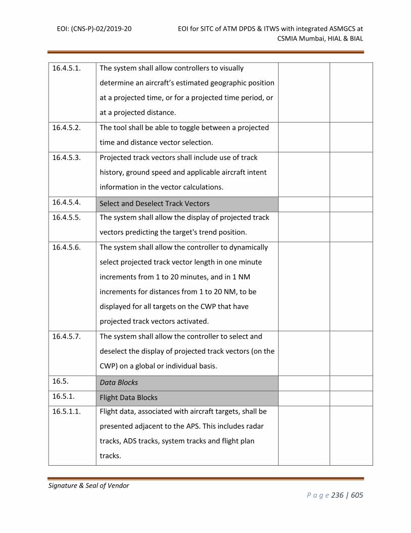
EOI: (CNS-P)-02/2019-20 EOI for SITC of ATM DPDS & ITWS with integrated ASMGCS at
CSMIA Mumbai, HIAL & BIAL
Signature & Seal of Vendor
P a g e 236 | 605
16.4.5.1. The system shall allow controllers to visually
determine an aircraft’s estimated geographic position
at a projected time, or for a projected time period, or
at a projected distance.
16.4.5.2. The tool shall be able to toggle between a projected
time and distance vector selection.
16.4.5.3. Projected track vectors shall include use of track
history, ground speed and applicable aircraft intent
information in the vector calculations.
16.4.5.4. Select and Deselect Track Vectors
16.4.5.5. The system shall allow the display of projected track
vectors predicting the target's trend position.
16.4.5.6. The system shall allow the controller to dynamically
select projected track vector length in one minute
increments from 1 to 20 minutes, and in 1 NM
increments for distances from 1 to 20 NM, to be
displayed for all targets on the CWP that have
projected track vectors activated.
16.4.5.7. The system shall allow the controller to select and
deselect the display of projected track vectors (on the
CWP) on a global or individual basis.
16.5. Data Blocks
16.5.1. Flight Data Blocks
16.5.1.1. Flight data, associated with aircraft targets, shall be
presented adjacent to the APS. This includes radar
tracks, ADS tracks, system tracks and flight plan
tracks.
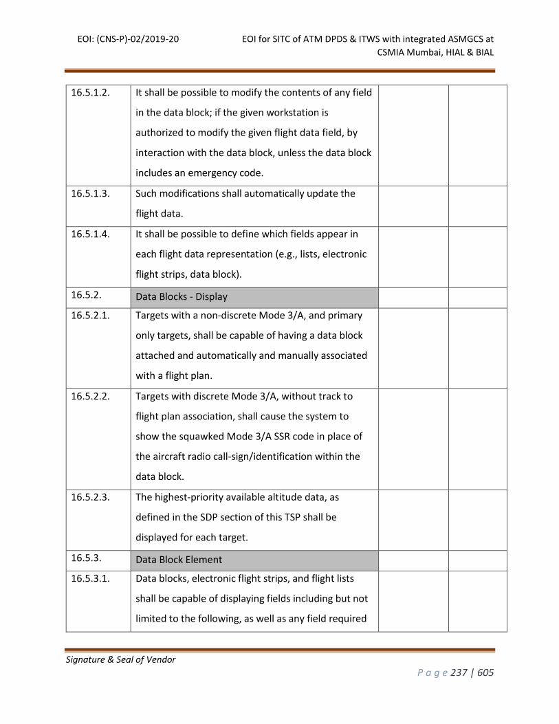
EOI: (CNS-P)-02/2019-20 EOI for SITC of ATM DPDS & ITWS with integrated ASMGCS at
CSMIA Mumbai, HIAL & BIAL
Signature & Seal of Vendor
P a g e 237 | 605
16.5.1.2. It shall be possible to modify the contents of any field
in the data block; if the given workstation is
authorized to modify the given flight data field, by
interaction with the data block, unless the data block
includes an emergency code.
16.5.1.3. Such modifications shall automatically update the
flight data.
16.5.1.4. It shall be possible to define which fields appear in
each flight data representation (e.g., lists, electronic
flight strips, data block).
16.5.2. Data Blocks - Display
16.5.2.1. Targets with a non-discrete Mode 3/A, and primary
only targets, shall be capable of having a data block
attached and automatically and manually associated
with a flight plan.
16.5.2.2. Targets with discrete Mode 3/A, without track to
flight plan association, shall cause the system to
show the squawked Mode 3/A SSR code in place of
the aircraft radio call-sign/identification within the
data block.
16.5.2.3. The highest-priority available altitude data, as
defined in the SDP section of this TSP shall be
displayed for each target.
16.5.3. Data Block Element
16.5.3.1. Data blocks, electronic flight strips, and flight lists
shall be capable of displaying fields including but not
limited to the following, as well as any field required
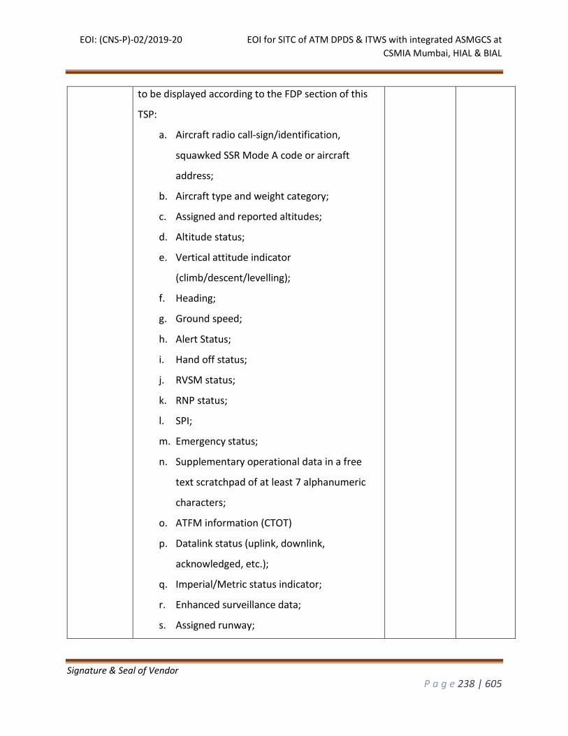
EOI: (CNS-P)-02/2019-20 EOI for SITC of ATM DPDS & ITWS with integrated ASMGCS at
CSMIA Mumbai, HIAL & BIAL
Signature & Seal of Vendor
P a g e 238 | 605
to be displayed according to the FDP section of this
TSP:
a. Aircraft radio call-sign/identification,
squawked SSR Mode A code or aircraft
address;
b. Aircraft type and weight category;
c. Assigned and reported altitudes;
d. Altitude status;
e. Vertical attitude indicator
(climb/descent/levelling);
f. Heading;
g. Ground speed;
h. Alert Status;
i. Hand off status;
j. RVSM status;
k. RNP status;
l. SPI;
m. Emergency status;
n. Supplementary operational data in a free
text scratchpad of at least 7 alphanumeric
characters;
o. ATFM information (CTOT)
p. Datalink status (uplink, downlink,
acknowledged, etc.);
q. Imperial/Metric status indicator;
r. Enhanced surveillance data;
s. Assigned runway;
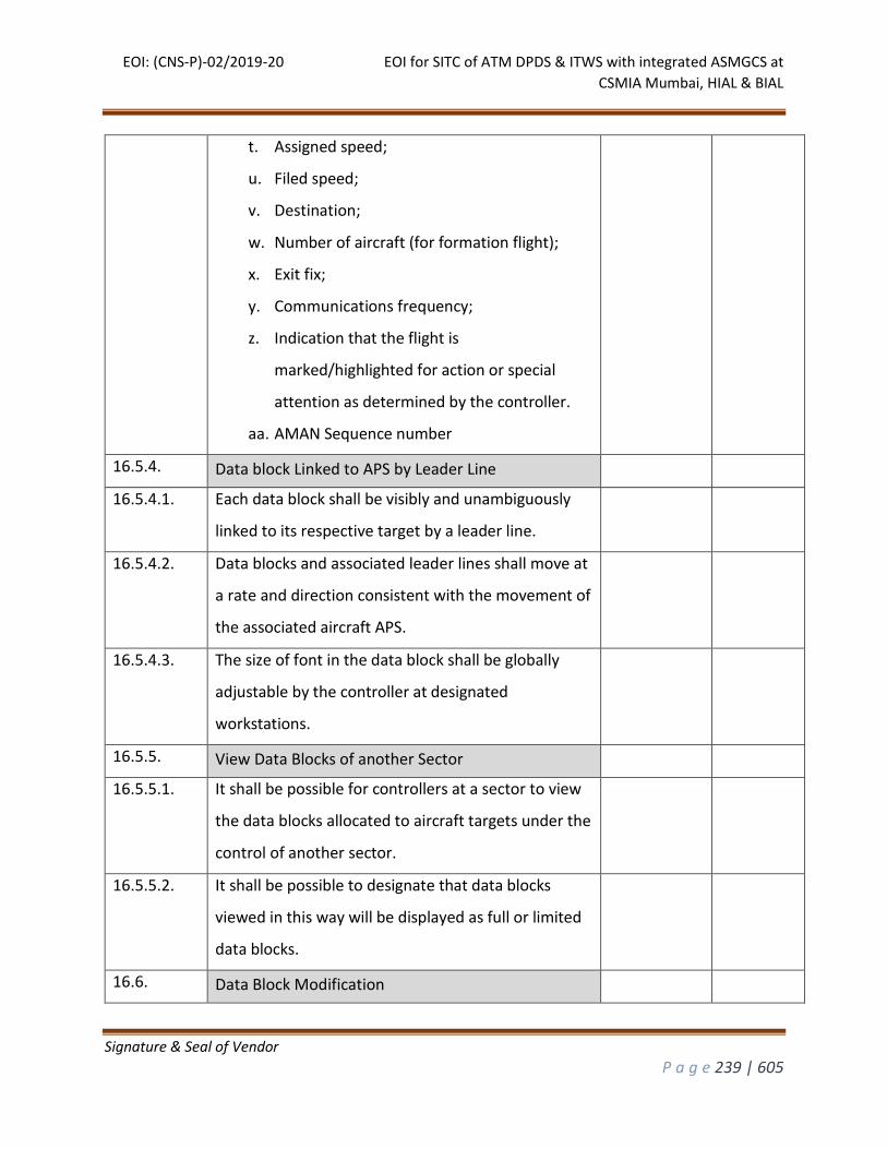
EOI: (CNS-P)-02/2019-20 EOI for SITC of ATM DPDS & ITWS with integrated ASMGCS at
CSMIA Mumbai, HIAL & BIAL
Signature & Seal of Vendor
P a g e 239 | 605
t. Assigned speed;
u. Filed speed;
v. Destination;
w. Number of aircraft (for formation flight);
x. Exit fix;
y. Communications frequency;
z. Indication that the flight is
marked/highlighted for action or special
attention as determined by the controller.
aa. AMAN Sequence number
16.5.4. Data block Linked to APS by Leader Line
16.5.4.1. Each data block shall be visibly and unambiguously
linked to its respective target by a leader line.
16.5.4.2. Data blocks and associated leader lines shall move at
a rate and direction consistent with the movement of
the associated aircraft APS.
16.5.4.3. The size of font in the data block shall be globally
adjustable by the controller at designated
workstations.
16.5.5. View Data Blocks of another Sector
16.5.5.1. It shall be possible for controllers at a sector to view
the data blocks allocated to aircraft targets under the
control of another sector.
16.5.5.2. It shall be possible to designate that data blocks
viewed in this way will be displayed as full or limited
data blocks.
16.6. Data Block Modification
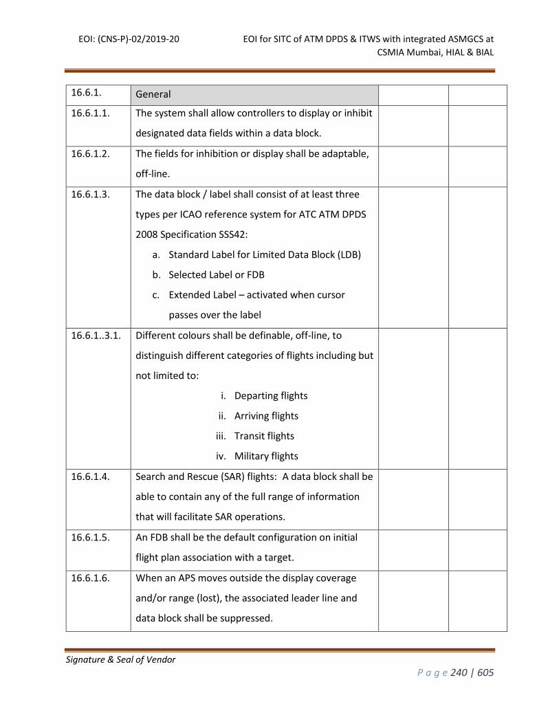
EOI: (CNS-P)-02/2019-20 EOI for SITC of ATM DPDS & ITWS with integrated ASMGCS at
CSMIA Mumbai, HIAL & BIAL
Signature & Seal of Vendor
P a g e 240 | 605
16.6.1. General
16.6.1.1. The system shall allow controllers to display or inhibit
designated data fields within a data block.
16.6.1.2. The fields for inhibition or display shall be adaptable,
off-line.
16.6.1.3. The data block / label shall consist of at least three
types per ICAO reference system for ATC ATM DPDS
2008 Specification SSS42:
a. Standard Label for Limited Data Block (LDB)
b. Selected Label or FDB
c. Extended Label – activated when cursor
passes over the label
16.6.1..3.1. Different colours shall be definable, off-line, to
distinguish different categories of flights including but
not limited to:
i. Departing flights
ii. Arriving flights
iii. Transit flights
iv. Military flights
16.6.1.4. Search and Rescue (SAR) flights: A data block shall be
able to contain any of the full range of information
that will facilitate SAR operations.
16.6.1.5. An FDB shall be the default configuration on initial
flight plan association with a target.
16.6.1.6. When an APS moves outside the display coverage
and/or range (lost), the associated leader line and
data block shall be suppressed.
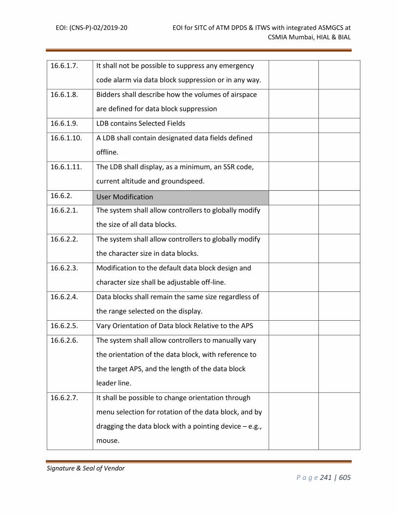
EOI: (CNS-P)-02/2019-20 EOI for SITC of ATM DPDS & ITWS with integrated ASMGCS at
CSMIA Mumbai, HIAL & BIAL
Signature & Seal of Vendor
P a g e 241 | 605
16.6.1.7. It shall not be possible to suppress any emergency
code alarm via data block suppression or in any way.
16.6.1.8. Bidders shall describe how the volumes of airspace
are defined for data block suppression
16.6.1.9. LDB contains Selected Fields
16.6.1.10. A LDB shall contain designated data fields defined
offline.
16.6.1.11. The LDB shall display, as a minimum, an SSR code,
current altitude and groundspeed.
16.6.2. User Modification
16.6.2.1. The system shall allow controllers to globally modify
the size of all data blocks.
16.6.2.2. The system shall allow controllers to globally modify
the character size in data blocks.
16.6.2.3. Modification to the default data block design and
character size shall be adjustable off-line.
16.6.2.4. Data blocks shall remain the same size regardless of
the range selected on the display.
16.6.2.5. Vary Orientation of Data block Relative to the APS
16.6.2.6. The system shall allow controllers to manually vary
the orientation of the data block, with reference to
the target APS, and the length of the data block
leader line.
16.6.2.7. It shall be possible to change orientation through
menu selection for rotation of the data block, and by
dragging the data block with a pointing device – e.g.,
mouse.
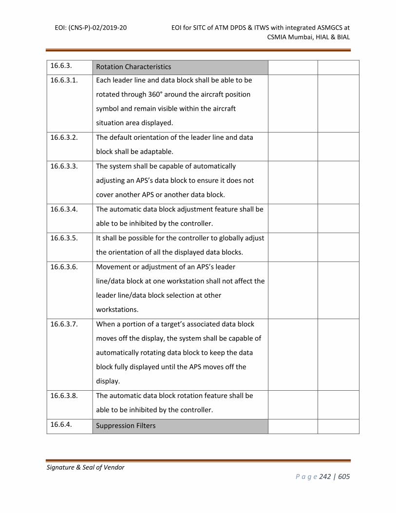
EOI: (CNS-P)-02/2019-20 EOI for SITC of ATM DPDS & ITWS with integrated ASMGCS at
CSMIA Mumbai, HIAL & BIAL
Signature & Seal of Vendor
P a g e 242 | 605
16.6.3. Rotation Characteristics
16.6.3.1. Each leader line and data block shall be able to be
rotated through 360° around the aircraft position
symbol and remain visible within the aircraft
situation area displayed.
16.6.3.2. The default orientation of the leader line and data
block shall be adaptable.
16.6.3.3. The system shall be capable of automatically
adjusting an APS’s data block to ensure it does not
cover another APS or another data block.
16.6.3.4. The automatic data block adjustment feature shall be
able to be inhibited by the controller.
16.6.3.5. It shall be possible for the controller to globally adjust
the orientation of all the displayed data blocks.
16.6.3.6. Movement or adjustment of an APS’s leader
line/data block at one workstation shall not affect the
leader line/data block selection at other
workstations.
16.6.3.7. When a portion of a target’s associated data block
moves off the display, the system shall be capable of
automatically rotating data block to keep the data
block fully displayed until the APS moves off the
display.
16.6.3.8. The automatic data block rotation feature shall be
able to be inhibited by the controller.
16.6.4. Suppression Filters
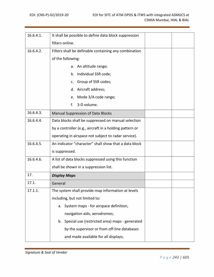
EOI: (CNS-P)-02/2019-20 EOI for SITC of ATM DPDS & ITWS with integrated ASMGCS at
CSMIA Mumbai, HIAL & BIAL
Signature & Seal of Vendor
P a g e 243 | 605
16.6.4.1. It shall be possible to define data block suppression
filters online.
16.6.4.2. Filters shall be definable containing any combination
of the following:
a. An altitude range;
b. Individual SSR code;
c. Group of SSR codes;
d. Aircraft address;
e. Mode 3/A code range;
f. 3-D volume.
16.6.4.3. Manual Suppression of Data Blocks
16.6.4.4. Data blocks shall be suppressed on manual selection
by a controller (e.g., aircraft in a holding pattern or
operating in airspace not subject to radar service).
16.6.4.5. An indicator “character” shall show that a data block
is suppressed.
16.6.4.6. A list of data blocks suppressed using this function
shall be shown in a suppression list.
17. Display Maps
17.1. General
17.1.1. The system shall provide map information at levels
including, but not limited to:
a. System maps - for airspace definition,
navigation aids, aerodromes;
b. Special use (restricted area) maps - generated
by the supervisor or from off-line databases
and made available for all displays;
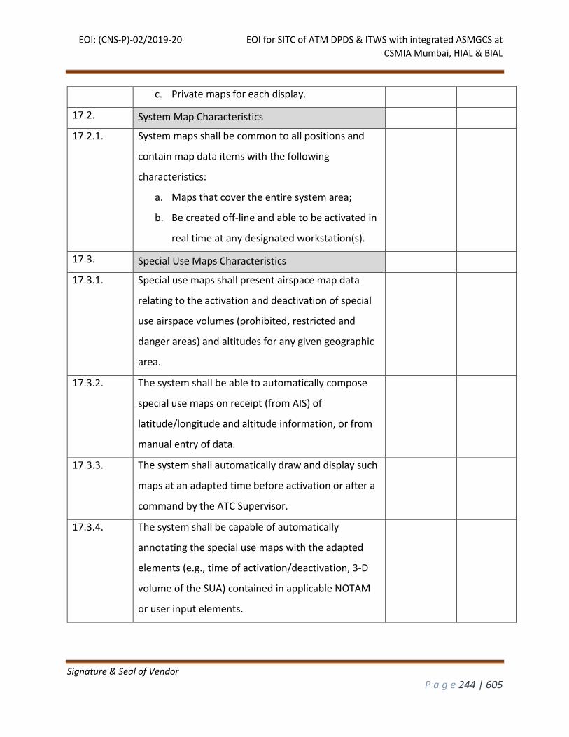
EOI: (CNS-P)-02/2019-20 EOI for SITC of ATM DPDS & ITWS with integrated ASMGCS at
CSMIA Mumbai, HIAL & BIAL
Signature & Seal of Vendor
P a g e 244 | 605
c. Private maps for each display.
17.2. System Map Characteristics
17.2.1. System maps shall be common to all positions and
contain map data items with the following
characteristics:
a. Maps that cover the entire system area;
b. Be created off-line and able to be activated in
real time at any designated workstation(s).
17.3. Special Use Maps Characteristics
17.3.1. Special use maps shall present airspace map data
relating to the activation and deactivation of special
use airspace volumes (prohibited, restricted and
danger areas) and altitudes for any given geographic
area.
17.3.2. The system shall be able to automatically compose
special use maps on receipt (from AIS) of
latitude/longitude and altitude information, or from
manual entry of data.
17.3.3. The system shall automatically draw and display such
maps at an adapted time before activation or after a
command by the ATC Supervisor.
17.3.4. The system shall be capable of automatically
annotating the special use maps with the adapted
elements (e.g., time of activation/deactivation, 3-D
volume of the SUA) contained in applicable NOTAM
or user input elements.
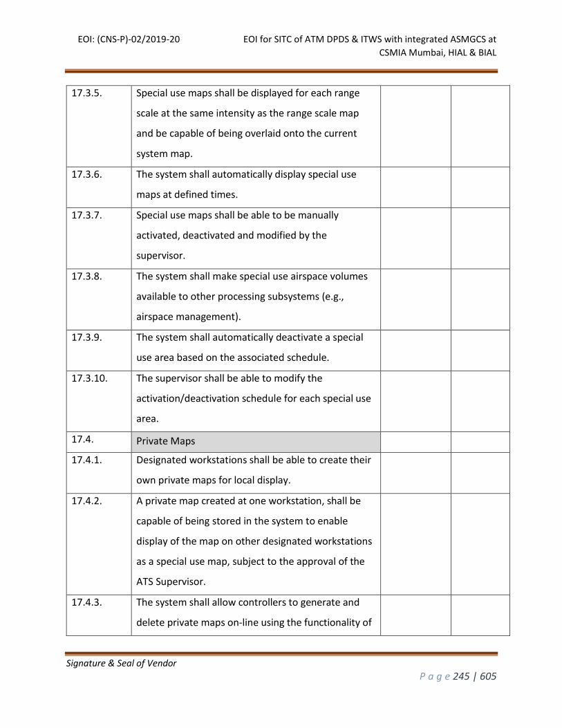
EOI: (CNS-P)-02/2019-20 EOI for SITC of ATM DPDS & ITWS with integrated ASMGCS at
CSMIA Mumbai, HIAL & BIAL
Signature & Seal of Vendor
P a g e 245 | 605
17.3.5. Special use maps shall be displayed for each range
scale at the same intensity as the range scale map
and be capable of being overlaid onto the current
system map.
17.3.6. The system shall automatically display special use
maps at defined times.
17.3.7. Special use maps shall be able to be manually
activated, deactivated and modified by the
supervisor.
17.3.8. The system shall make special use airspace volumes
available to other processing subsystems (e.g.,
airspace management).
17.3.9. The system shall automatically deactivate a special
use area based on the associated schedule.
17.3.10. The supervisor shall be able to modify the
activation/deactivation schedule for each special use
area.
17.4. Private Maps
17.4.1. Designated workstations shall be able to create their
own private maps for local display.
17.4.2. A private map created at one workstation, shall be
capable of being stored in the system to enable
display of the map on other designated workstations
as a special use map, subject to the approval of the
ATS Supervisor.
17.4.3. The system shall allow controllers to generate and
delete private maps on-line using the functionality of
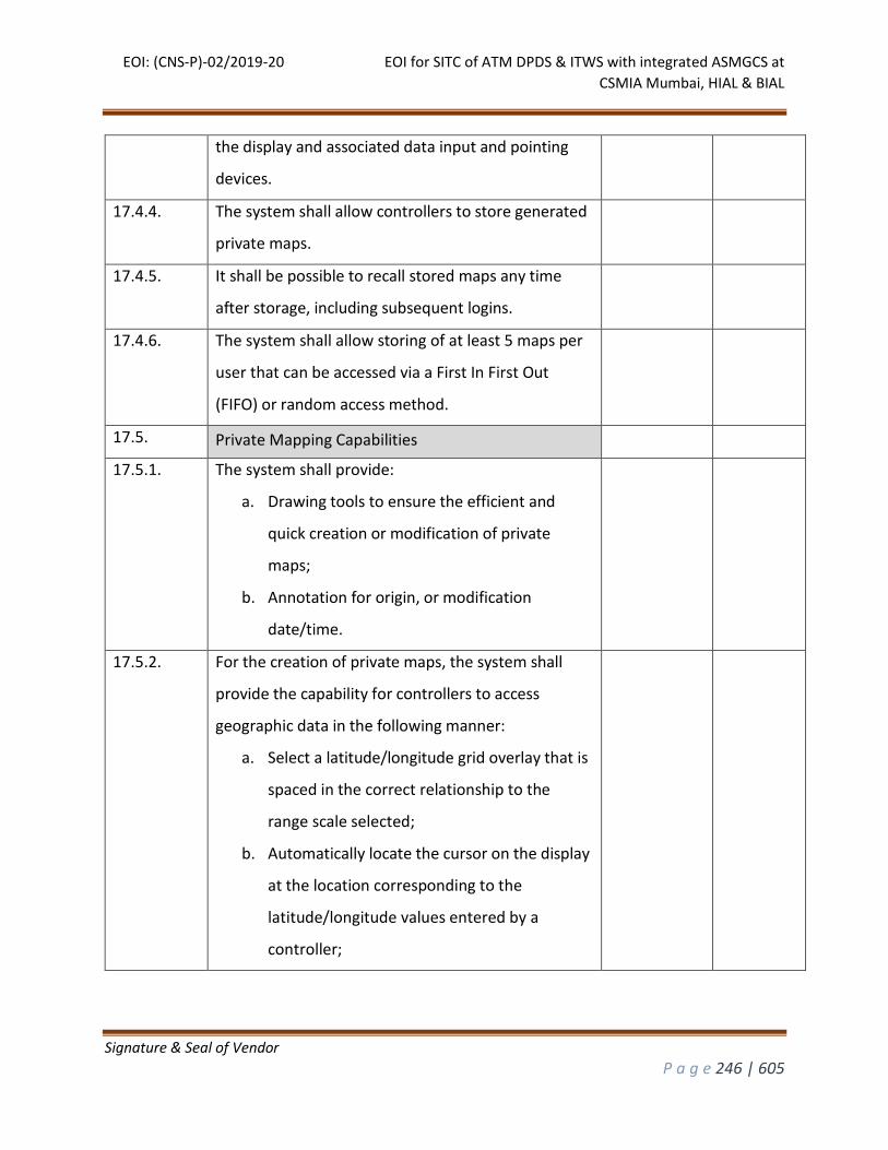
EOI: (CNS-P)-02/2019-20 EOI for SITC of ATM DPDS & ITWS with integrated ASMGCS at
CSMIA Mumbai, HIAL & BIAL
Signature & Seal of Vendor
P a g e 246 | 605
the display and associated data input and pointing
devices.
17.4.4. The system shall allow controllers to store generated
private maps.
17.4.5. It shall be possible to recall stored maps any time
after storage, including subsequent logins.
17.4.6. The system shall allow storing of at least 5 maps per
user that can be accessed via a First In First Out
(FIFO) or random access method.
17.5. Private Mapping Capabilities
17.5.1. The system shall provide:
a. Drawing tools to ensure the efficient and
quick creation or modification of private
maps;
b. Annotation for origin, or modification
date/time.
17.5.2. For the creation of private maps, the system shall
provide the capability for controllers to access
geographic data in the following manner:
a. Select a latitude/longitude grid overlay that is
spaced in the correct relationship to the
range scale selected;
b. Automatically locate the cursor on the display
at the location corresponding to the
latitude/longitude values entered by a
controller;
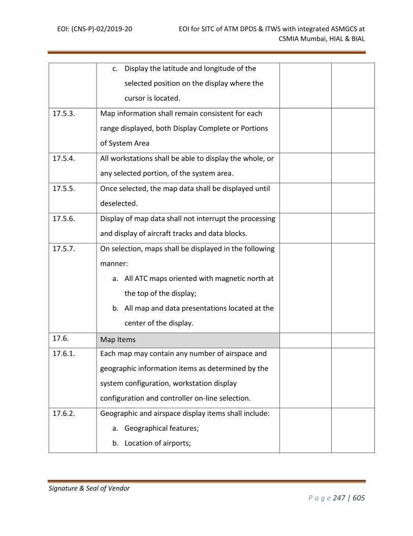
EOI: (CNS-P)-02/2019-20 EOI for SITC of ATM DPDS & ITWS with integrated ASMGCS at
CSMIA Mumbai, HIAL & BIAL
Signature & Seal of Vendor
P a g e 247 | 605
c. Display the latitude and longitude of the
selected position on the display where the
cursor is located.
17.5.3. Map information shall remain consistent for each
range displayed, both Display Complete or Portions
of System Area
17.5.4. All workstations shall be able to display the whole, or
any selected portion, of the system area.
17.5.5. Once selected, the map data shall be displayed until
deselected.
17.5.6. Display of map data shall not interrupt the processing
and display of aircraft tracks and data blocks.
17.5.7. On selection, maps shall be displayed in the following
manner:
a. All ATC maps oriented with magnetic north at
the top of the display;
b. All map and data presentations located at the
center of the display.
17.6. Map Items
17.6.1. Each map may contain any number of airspace and
geographic information items as determined by the
system configuration, workstation display
configuration and controller on-line selection.
17.6.2. Geographic and airspace display items shall include:
a. Geographical features;
b. Location of airports;
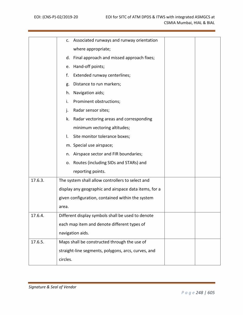
EOI: (CNS-P)-02/2019-20 EOI for SITC of ATM DPDS & ITWS with integrated ASMGCS at
CSMIA Mumbai, HIAL & BIAL
Signature & Seal of Vendor
P a g e 248 | 605
c. Associated runways and runway orientation
where appropriate;
d. Final approach and missed approach fixes;
e. Hand-off points;
f. Extended runway centerlines;
g. Distance to run markers;
h. Navigation aids;
i. Prominent obstructions;
j. Radar sensor sites;
k. Radar vectoring areas and corresponding
minimum vectoring altitudes;
l. Site monitor tolerance boxes;
m. Special use airspace;
n. Airspace sector and FIR boundaries;
o. Routes (including SIDs and STARs) and
reporting points.
17.6.3. The system shall allow controllers to select and
display any geographic and airspace data items, for a
given configuration, contained within the system
area.
17.6.4. Different display symbols shall be used to denote
each map item and denote different types of
navigation aids.
17.6.5. Maps shall be constructed through the use of
straight-line segments, polygons, arcs, curves, and
circles.
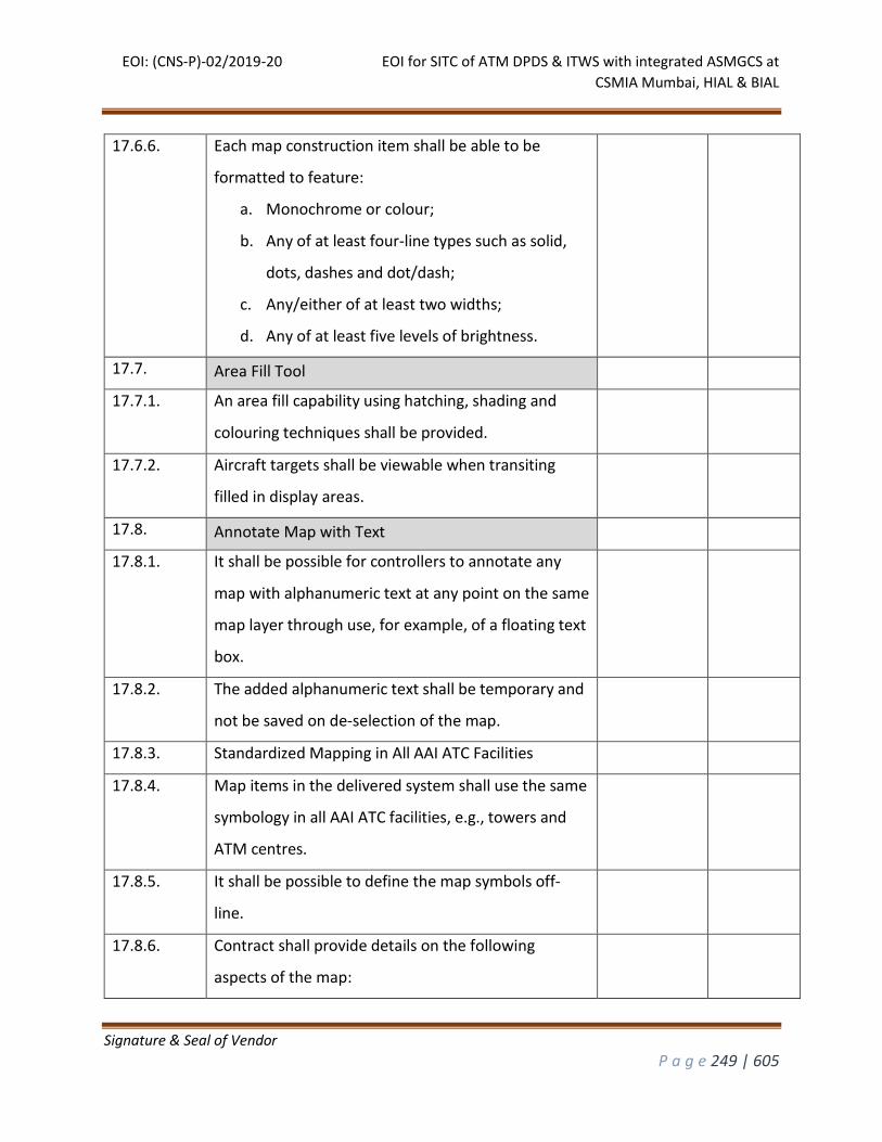
EOI: (CNS-P)-02/2019-20 EOI for SITC of ATM DPDS & ITWS with integrated ASMGCS at
CSMIA Mumbai, HIAL & BIAL
Signature & Seal of Vendor
P a g e 249 | 605
17.6.6. Each map construction item shall be able to be
formatted to feature:
a. Monochrome or colour;
b. Any of at least four-line types such as solid,
dots, dashes and dot/dash;
c. Any/either of at least two widths;
d. Any of at least five levels of brightness.
17.7. Area Fill Tool
17.7.1. An area fill capability using hatching, shading and
colouring techniques shall be provided.
17.7.2. Aircraft targets shall be viewable when transiting
filled in display areas.
17.8. Annotate Map with Text
17.8.1. It shall be possible for controllers to annotate any
map with alphanumeric text at any point on the same
map layer through use, for example, of a floating text
box.
17.8.2. The added alphanumeric text shall be temporary and
not be saved on de-selection of the map.
17.8.3. Standardized Mapping in All AAI ATC Facilities
17.8.4. Map items in the delivered system shall use the same
symbology in all AAI ATC facilities, e.g., towers and
ATM centres.
17.8.5. It shall be possible to define the map symbols off-
line.
17.8.6. Contract shall provide details on the following
aspects of the map:
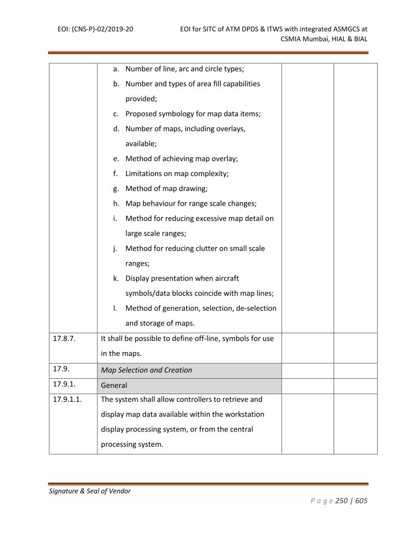
EOI: (CNS-P)-02/2019-20 EOI for SITC of ATM DPDS & ITWS with integrated ASMGCS at
CSMIA Mumbai, HIAL & BIAL
Signature & Seal of Vendor
P a g e 250 | 605
a. Number of line, arc and circle types;
b. Number and types of area fill capabilities
provided;
c. Proposed symbology for map data items;
d. Number of maps, including overlays,
available;
e. Method of achieving map overlay;
f. Limitations on map complexity;
g. Method of map drawing;
h. Map behaviour for range scale changes;
i. Method for reducing excessive map detail on
large scale ranges;
j. Method for reducing clutter on small scale
ranges;
k. Display presentation when aircraft
symbols/data blocks coincide with map lines;
l. Method of generation, selection, de-selection
and storage of maps.
17.8.7. It shall be possible to define off-line, symbols for use
in the maps.
17.9. Map Selection and Creation
17.9.1. General
17.9.1.1. The system shall allow controllers to retrieve and
display map data available within the workstation
display processing system, or from the central
processing system.
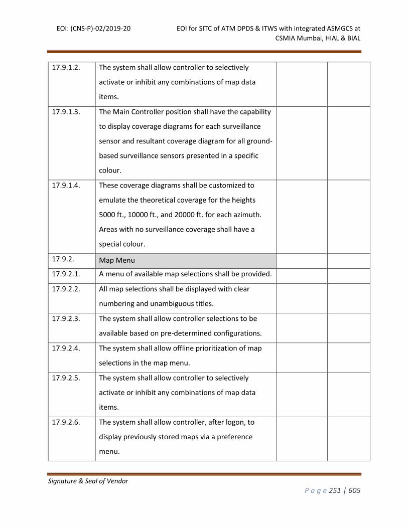
EOI: (CNS-P)-02/2019-20 EOI for SITC of ATM DPDS & ITWS with integrated ASMGCS at
CSMIA Mumbai, HIAL & BIAL
Signature & Seal of Vendor
P a g e 251 | 605
17.9.1.2. The system shall allow controller to selectively
activate or inhibit any combinations of map data
items.
17.9.1.3. The Main Controller position shall have the capability
to display coverage diagrams for each surveillance
sensor and resultant coverage diagram for all ground-
based surveillance sensors presented in a specific
colour.
17.9.1.4. These coverage diagrams shall be customized to
emulate the theoretical coverage for the heights
5000 ft., 10000 ft., and 20000 ft. for each azimuth.
Areas with no surveillance coverage shall have a
special colour.
17.9.2. Map Menu
17.9.2.1. A menu of available map selections shall be provided.
17.9.2.2. All map selections shall be displayed with clear
numbering and unambiguous titles.
17.9.2.3. The system shall allow controller selections to be
available based on pre-determined configurations.
17.9.2.4. The system shall allow offline prioritization of map
selections in the map menu.
17.9.2.5. The system shall allow controller to selectively
activate or inhibit any combinations of map data
items.
17.9.2.6. The system shall allow controller, after logon, to
display previously stored maps via a preference
menu.
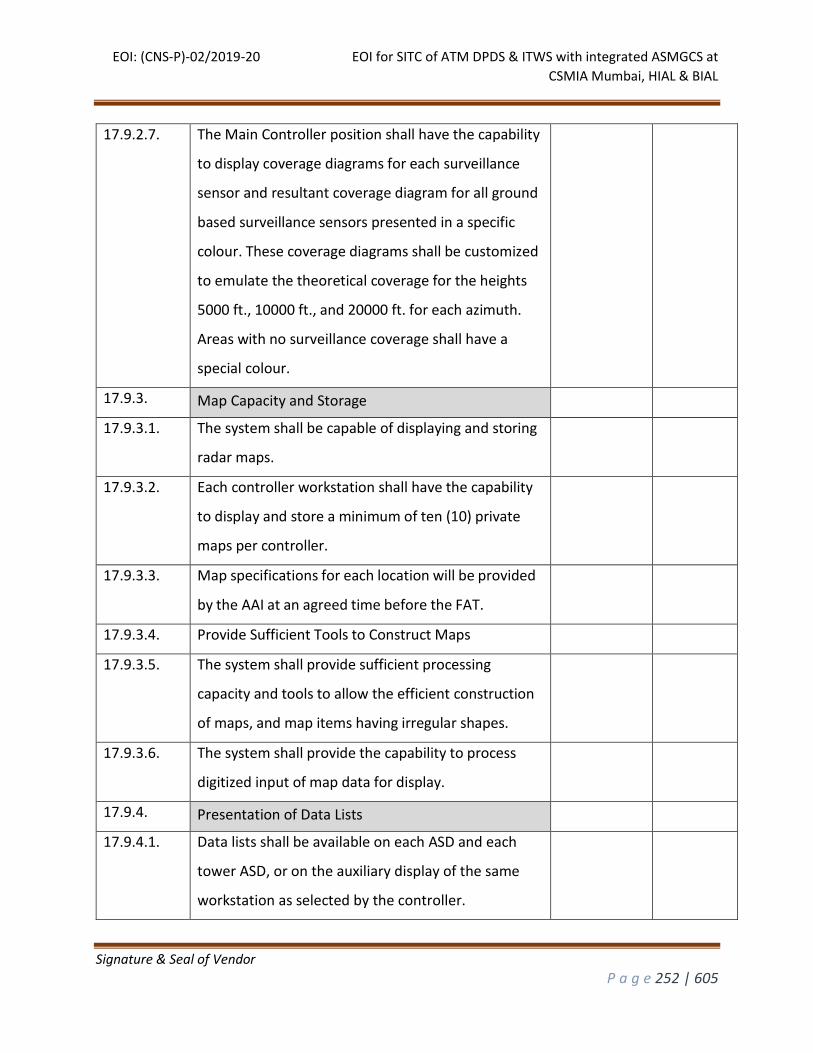
EOI: (CNS-P)-02/2019-20 EOI for SITC of ATM DPDS & ITWS with integrated ASMGCS at
CSMIA Mumbai, HIAL & BIAL
Signature & Seal of Vendor
P a g e 252 | 605
17.9.2.7. The Main Controller position shall have the capability
to display coverage diagrams for each surveillance
sensor and resultant coverage diagram for all ground
based surveillance sensors presented in a specific
colour. These coverage diagrams shall be customized
to emulate the theoretical coverage for the heights
5000 ft., 10000 ft., and 20000 ft. for each azimuth.
Areas with no surveillance coverage shall have a
special colour.
17.9.3. Map Capacity and Storage
17.9.3.1. The system shall be capable of displaying and storing
radar maps.
17.9.3.2. Each controller workstation shall have the capability
to display and store a minimum of ten (10) private
maps per controller.
17.9.3.3. Map specifications for each location will be provided
by the AAI at an agreed time before the FAT.
17.9.3.4. Provide Sufficient Tools to Construct Maps
17.9.3.5. The system shall provide sufficient processing
capacity and tools to allow the efficient construction
of maps, and map items having irregular shapes.
17.9.3.6. The system shall provide the capability to process
digitized input of map data for display.
17.9.4. Presentation of Data Lists
17.9.4.1. Data lists shall be available on each ASD and each
tower ASD, or on the auxiliary display of the same
workstation as selected by the controller.
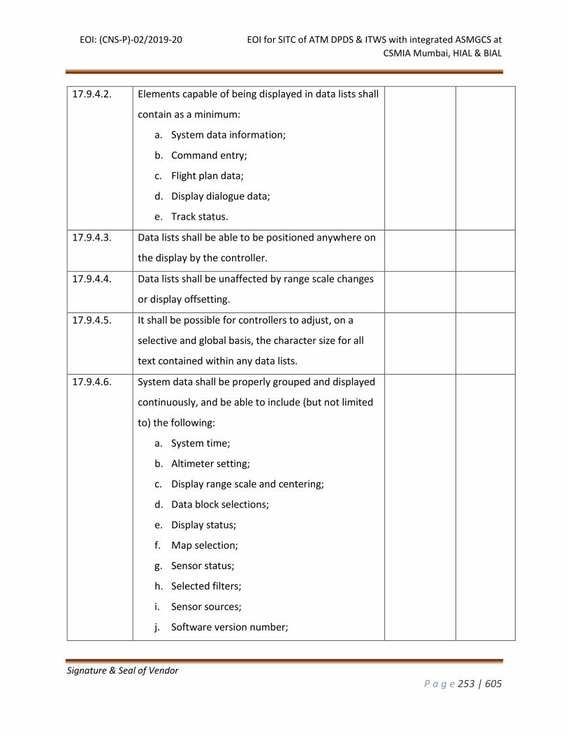
EOI: (CNS-P)-02/2019-20 EOI for SITC of ATM DPDS & ITWS with integrated ASMGCS at
CSMIA Mumbai, HIAL & BIAL
Signature & Seal of Vendor
P a g e 253 | 605
17.9.4.2. Elements capable of being displayed in data lists shall
contain as a minimum:
a. System data information;
b. Command entry;
c. Flight plan data;
d. Display dialogue data;
e. Track status.
17.9.4.3. Data lists shall be able to be positioned anywhere on
the display by the controller.
17.9.4.4. Data lists shall be unaffected by range scale changes
or display offsetting.
17.9.4.5. It shall be possible for controllers to adjust, on a
selective and global basis, the character size for all
text contained within any data lists.
17.9.4.6. System data shall be properly grouped and displayed
continuously, and be able to include (but not limited
to) the following:
a. System time;
b. Altimeter setting;
c. Display range scale and centering;
d. Data block selections;
e. Display status;
f. Map selection;
g. Sensor status;
h. Selected filters;
i. Sensor sources;
j. Software version number;
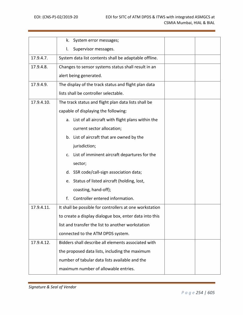
EOI: (CNS-P)-02/2019-20 EOI for SITC of ATM DPDS & ITWS with integrated ASMGCS at
CSMIA Mumbai, HIAL & BIAL
Signature & Seal of Vendor
P a g e 254 | 605
k. System error messages;
l. Supervisor messages.
17.9.4.7. System data list contents shall be adaptable offline.
17.9.4.8. Changes to sensor systems status shall result in an
alert being generated.
17.9.4.9. The display of the track status and flight plan data
lists shall be controller selectable.
17.9.4.10. The track status and flight plan data lists shall be
capable of displaying the following:
a. List of all aircraft with flight plans within the
current sector allocation;
b. List of aircraft that are owned by the
jurisdiction;
c. List of imminent aircraft departures for the
sector;
d. SSR code/call-sign association data;
e. Status of listed aircraft (holding, lost,
coasting, hand-off);
f. Controller entered information.
17.9.4.11. It shall be possible for controllers at one workstation
to create a display dialogue box, enter data into this
list and transfer the list to another workstation
connected to the ATM DPDS system.
17.9.4.12. Bidders shall describe all elements associated with
the proposed data lists, including the maximum
number of tabular data lists available and the
maximum number of allowable entries.
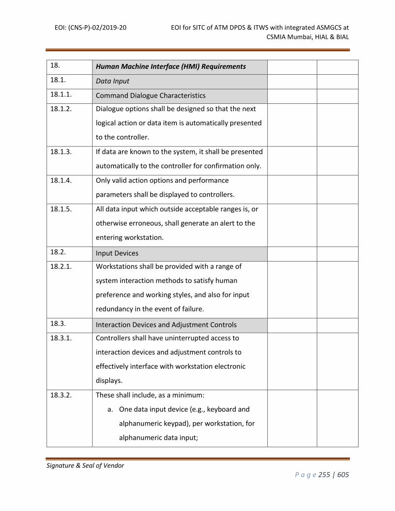
EOI: (CNS-P)-02/2019-20 EOI for SITC of ATM DPDS & ITWS with integrated ASMGCS at
CSMIA Mumbai, HIAL & BIAL
Signature & Seal of Vendor
P a g e 255 | 605
18. Human Machine Interface (HMI) Requirements
18.1. Data Input
18.1.1. Command Dialogue Characteristics
18.1.2. Dialogue options shall be designed so that the next
logical action or data item is automatically presented
to the controller.
18.1.3. If data are known to the system, it shall be presented
automatically to the controller for confirmation only.
18.1.4. Only valid action options and performance
parameters shall be displayed to controllers.
18.1.5. All data input which outside acceptable ranges is, or
otherwise erroneous, shall generate an alert to the
entering workstation.
18.2. Input Devices
18.2.1. Workstations shall be provided with a range of
system interaction methods to satisfy human
preference and working styles, and also for input
redundancy in the event of failure.
18.3. Interaction Devices and Adjustment Controls
18.3.1. Controllers shall have uninterrupted access to
interaction devices and adjustment controls to
effectively interface with workstation electronic
displays.
18.3.2. These shall include, as a minimum:
a. One data input device (e.g., keyboard and
alphanumeric keypad), per workstation, for
alphanumeric data input;
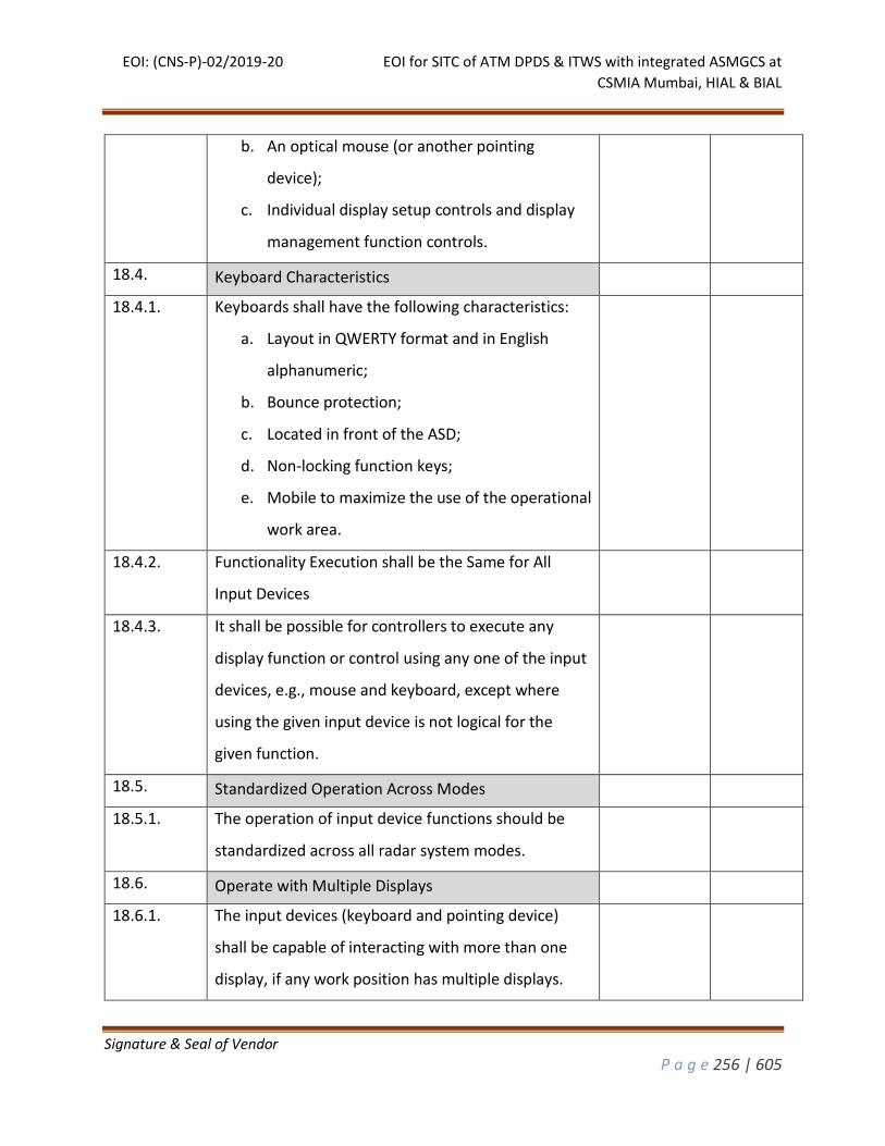
EOI: (CNS-P)-02/2019-20 EOI for SITC of ATM DPDS & ITWS with integrated ASMGCS at
CSMIA Mumbai, HIAL & BIAL
Signature & Seal of Vendor
P a g e 256 | 605
b. An optical mouse (or another pointing
device);
c. Individual display setup controls and display
management function controls.
18.4. Keyboard Characteristics
18.4.1. Keyboards shall have the following characteristics:
a. Layout in QWERTY format and in English
alphanumeric;
b. Bounce protection;
c. Located in front of the ASD;
d. Non-locking function keys;
e. Mobile to maximize the use of the operational
work area.
18.4.2. Functionality Execution shall be the Same for All
Input Devices
18.4.3. It shall be possible for controllers to execute any
display function or control using any one of the input
devices, e.g., mouse and keyboard, except where
using the given input device is not logical for the
given function.
18.5. Standardized Operation Across Modes
18.5.1. The operation of input device functions should be
standardized across all radar system modes.
18.6. Operate with Multiple Displays
18.6.1. The input devices (keyboard and pointing device)
shall be capable of interacting with more than one
display, if any work position has multiple displays.
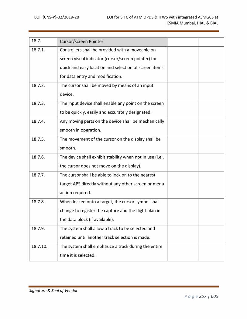
EOI: (CNS-P)-02/2019-20 EOI for SITC of ATM DPDS & ITWS with integrated ASMGCS at
CSMIA Mumbai, HIAL & BIAL
Signature & Seal of Vendor
P a g e 257 | 605
18.7. Cursor/screen Pointer
18.7.1. Controllers shall be provided with a moveable on-
screen visual indicator (cursor/screen pointer) for
quick and easy location and selection of screen items
for data entry and modification.
18.7.2. The cursor shall be moved by means of an input
device.
18.7.3. The input device shall enable any point on the screen
to be quickly, easily and accurately designated.
18.7.4. Any moving parts on the device shall be mechanically
smooth in operation.
18.7.5. The movement of the cursor on the display shall be
smooth.
18.7.6. The device shall exhibit stability when not in use (i.e.,
the cursor does not move on the display).
18.7.7. The cursor shall be able to lock on to the nearest
target APS directly without any other screen or menu
action required.
18.7.8. When locked onto a target, the cursor symbol shall
change to register the capture and the flight plan in
the data block (if available).
18.7.9. The system shall allow a track to be selected and
retained until another track selection is made.
18.7.10. The system shall emphasize a track during the entire
time it is selected.
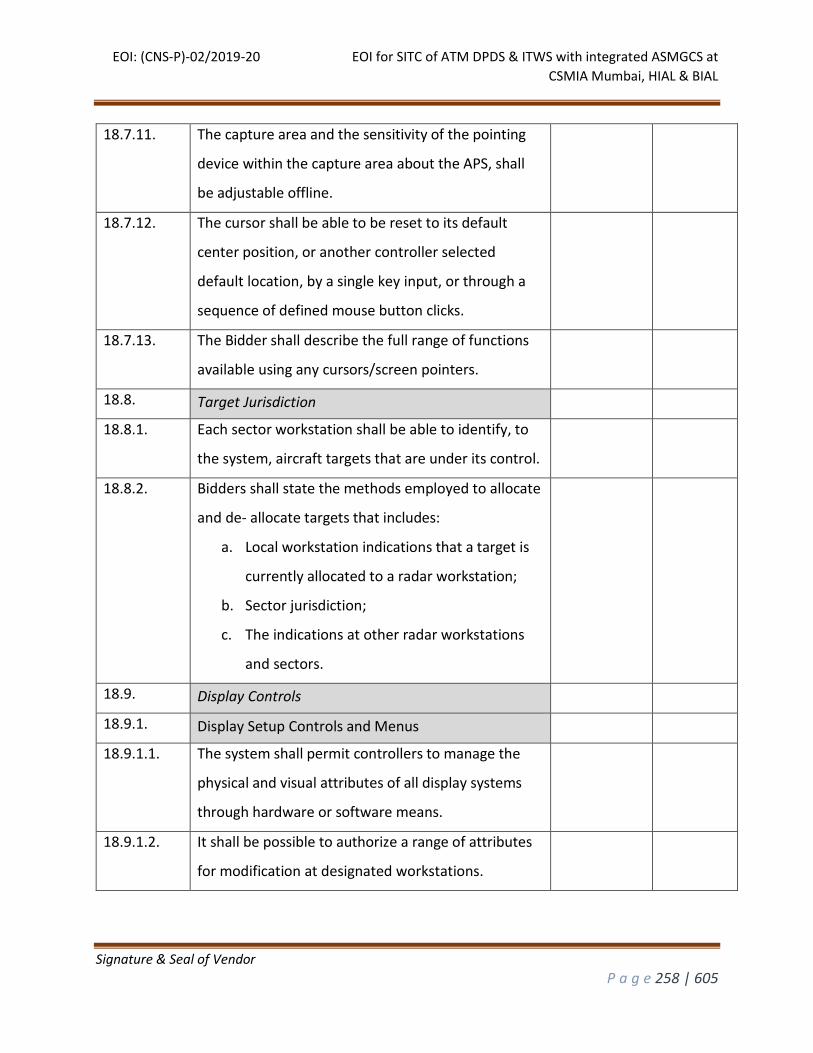
EOI: (CNS-P)-02/2019-20 EOI for SITC of ATM DPDS & ITWS with integrated ASMGCS at
CSMIA Mumbai, HIAL & BIAL
Signature & Seal of Vendor
P a g e 258 | 605
18.7.11. The capture area and the sensitivity of the pointing
device within the capture area about the APS, shall
be adjustable offline.
18.7.12. The cursor shall be able to be reset to its default
center position, or another controller selected
default location, by a single key input, or through a
sequence of defined mouse button clicks.
18.7.13. The Bidder shall describe the full range of functions
available using any cursors/screen pointers.
18.8. Target Jurisdiction
18.8.1. Each sector workstation shall be able to identify, to
the system, aircraft targets that are under its control.
18.8.2. Bidders shall state the methods employed to allocate
and de- allocate targets that includes:
a. Local workstation indications that a target is
currently allocated to a radar workstation;
b. Sector jurisdiction;
c. The indications at other radar workstations
and sectors.
18.9. Display Controls
18.9.1. Display Setup Controls and Menus
18.9.1.1. The system shall permit controllers to manage the
physical and visual attributes of all display systems
through hardware or software means.
18.9.1.2. It shall be possible to authorize a range of attributes
for modification at designated workstations.
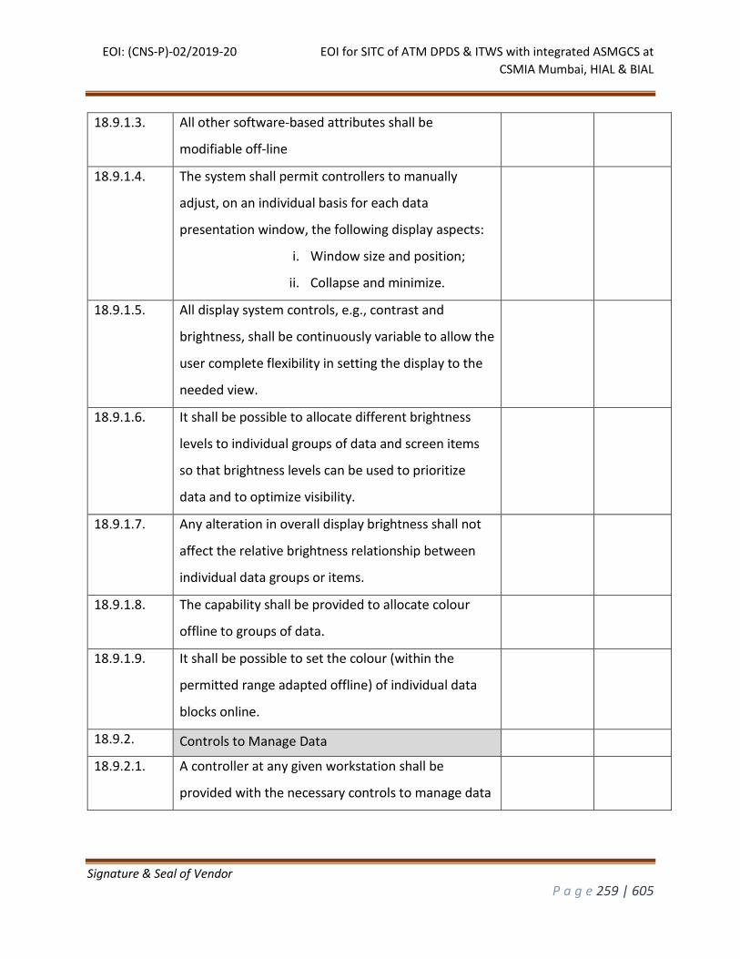
EOI: (CNS-P)-02/2019-20 EOI for SITC of ATM DPDS & ITWS with integrated ASMGCS at
CSMIA Mumbai, HIAL & BIAL
Signature & Seal of Vendor
P a g e 259 | 605
18.9.1.3. All other software-based attributes shall be
modifiable off-line
18.9.1.4. The system shall permit controllers to manually
adjust, on an individual basis for each data
presentation window, the following display aspects:
i. Window size and position;
ii. Collapse and minimize.
18.9.1.5. All display system controls, e.g., contrast and
brightness, shall be continuously variable to allow the
user complete flexibility in setting the display to the
needed view.
18.9.1.6. It shall be possible to allocate different brightness
levels to individual groups of data and screen items
so that brightness levels can be used to prioritize
data and to optimize visibility.
18.9.1.7. Any alteration in overall display brightness shall not
affect the relative brightness relationship between
individual data groups or items.
18.9.1.8. The capability shall be provided to allocate colour
offline to groups of data.
18.9.1.9. It shall be possible to set the colour (within the
permitted range adapted offline) of individual data
blocks online.
18.9.2. Controls to Manage Data
18.9.2.1. A controller at any given workstation shall be
provided with the necessary controls to manage data
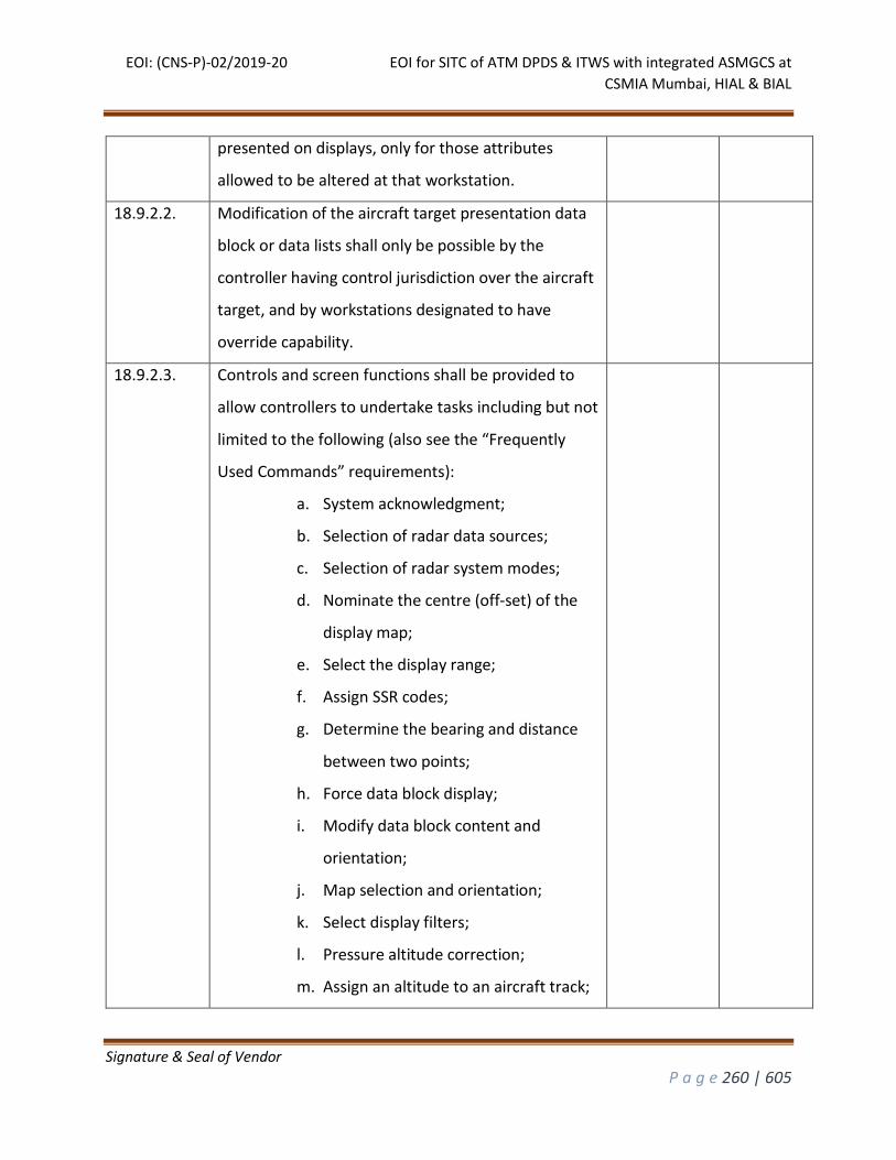
EOI: (CNS-P)-02/2019-20 EOI for SITC of ATM DPDS & ITWS with integrated ASMGCS at
CSMIA Mumbai, HIAL & BIAL
Signature & Seal of Vendor
P a g e 260 | 605
presented on displays, only for those attributes
allowed to be altered at that workstation.
18.9.2.2. Modification of the aircraft target presentation data
block or data lists shall only be possible by the
controller having control jurisdiction over the aircraft
target, and by workstations designated to have
override capability.
18.9.2.3. Controls and screen functions shall be provided to
allow controllers to undertake tasks including but not
limited to the following (also see the “Frequently
Used Commands” requirements):
a. System acknowledgment;
b. Selection of radar data sources;
c. Selection of radar system modes;
d. Nominate the centre (off-set) of the
display map;
e. Select the display range;
f. Assign SSR codes;
g. Determine the bearing and distance
between two points;
h. Force data block display;
i. Modify data block content and
orientation;
j. Map selection and orientation;
k. Select display filters;
l. Pressure altitude correction;
m. Assign an altitude to an aircraft track;
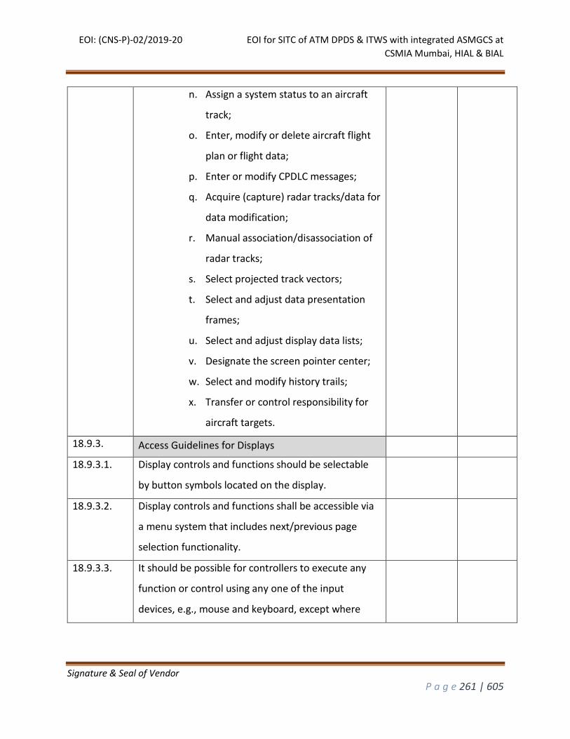
EOI: (CNS-P)-02/2019-20 EOI for SITC of ATM DPDS & ITWS with integrated ASMGCS at
CSMIA Mumbai, HIAL & BIAL
Signature & Seal of Vendor
P a g e 261 | 605
n. Assign a system status to an aircraft
track;
o. Enter, modify or delete aircraft flight
plan or flight data;
p. Enter or modify CPDLC messages;
q. Acquire (capture) radar tracks/data for
data modification;
r. Manual association/disassociation of
radar tracks;
s. Select projected track vectors;
t. Select and adjust data presentation
frames;
u. Select and adjust display data lists;
v. Designate the screen pointer center;
w. Select and modify history trails;
x. Transfer or control responsibility for
aircraft targets.
18.9.3. Access Guidelines for Displays
18.9.3.1. Display controls and functions should be selectable
by button symbols located on the display.
18.9.3.2. Display controls and functions shall be accessible via
a menu system that includes next/previous page
selection functionality.
18.9.3.3. It should be possible for controllers to execute any
function or control using any one of the input
devices, e.g., mouse and keyboard, except where
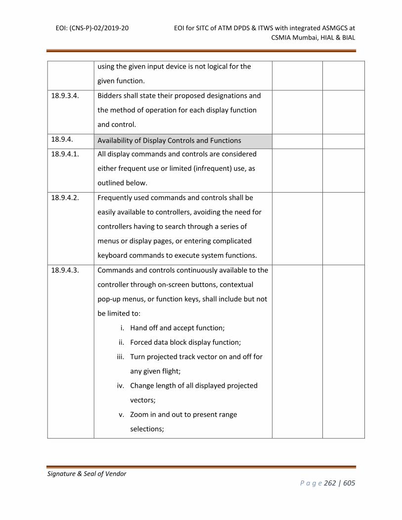
EOI: (CNS-P)-02/2019-20 EOI for SITC of ATM DPDS & ITWS with integrated ASMGCS at
CSMIA Mumbai, HIAL & BIAL
Signature & Seal of Vendor
P a g e 262 | 605
using the given input device is not logical for the
given function.
18.9.3.4. Bidders shall state their proposed designations and
the method of operation for each display function
and control.
18.9.4. Availability of Display Controls and Functions
18.9.4.1. All display commands and controls are considered
either frequent use or limited (infrequent) use, as
outlined below.
18.9.4.2. Frequently used commands and controls shall be
easily available to controllers, avoiding the need for
controllers having to search through a series of
menus or display pages, or entering complicated
keyboard commands to execute system functions.
18.9.4.3. Commands and controls continuously available to the
controller through on-screen buttons, contextual
pop-up menus, or function keys, shall include but not
be limited to:
i. Hand off and accept function;
ii. Forced data block display function;
iii. Turn projected track vector on and off for
any given flight;
iv. Change length of all displayed projected
vectors;
v. Zoom in and out to present range
selections;
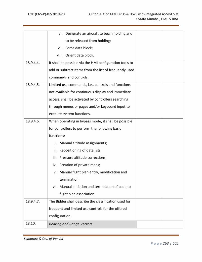
EOI: (CNS-P)-02/2019-20 EOI for SITC of ATM DPDS & ITWS with integrated ASMGCS at
CSMIA Mumbai, HIAL & BIAL
Signature & Seal of Vendor
P a g e 263 | 605
vi. Designate an aircraft to begin holding and
to be released from holding;
vii. Force data block;
viii. Orient data block.
18.9.4.4. It shall be possible via the HMI configuration tools to
add or subtract items from the list of frequently used
commands and controls.
18.9.4.5. Limited use commands, i.e., controls and functions
not available for continuous display and immediate
access, shall be activated by controllers searching
through menus or pages and/or keyboard input to
execute system functions.
18.9.4.6. When operating in bypass mode, it shall be possible
for controllers to perform the following basic
functions:
i. Manual altitude assignments;
ii. Repositioning of data lists;
iii. Pressure altitude corrections;
iv. Creation of private maps;
v. Manual flight plan entry, modification and
termination;
vi. Manual initiation and termination of code to
flight plan association.
18.9.4.7. The Bidder shall describe the classification used for
frequent and limited use controls for the offered
configuration.
18.10. Bearing and Range Vectors
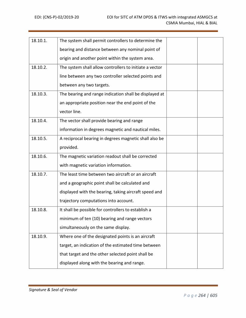
EOI: (CNS-P)-02/2019-20 EOI for SITC of ATM DPDS & ITWS with integrated ASMGCS at
CSMIA Mumbai, HIAL & BIAL
Signature & Seal of Vendor
P a g e 264 | 605
18.10.1. The system shall permit controllers to determine the
bearing and distance between any nominal point of
origin and another point within the system area.
18.10.2. The system shall allow controllers to initiate a vector
line between any two controller selected points and
between any two targets.
18.10.3. The bearing and range indication shall be displayed at
an appropriate position near the end point of the
vector line.
18.10.4. The vector shall provide bearing and range
information in degrees magnetic and nautical miles.
18.10.5. A reciprocal bearing in degrees magnetic shall also be
provided.
18.10.6. The magnetic variation readout shall be corrected
with magnetic variation information.
18.10.7. The least time between two aircraft or an aircraft
and a geographic point shall be calculated and
displayed with the bearing, taking aircraft speed and
trajectory computations into account.
18.10.8. It shall be possible for controllers to establish a
minimum of ten (10) bearing and range vectors
simultaneously on the same display.
18.10.9. Where one of the designated points is an aircraft
target, an indication of the estimated time between
that target and the other selected point shall be
displayed along with the bearing and range.
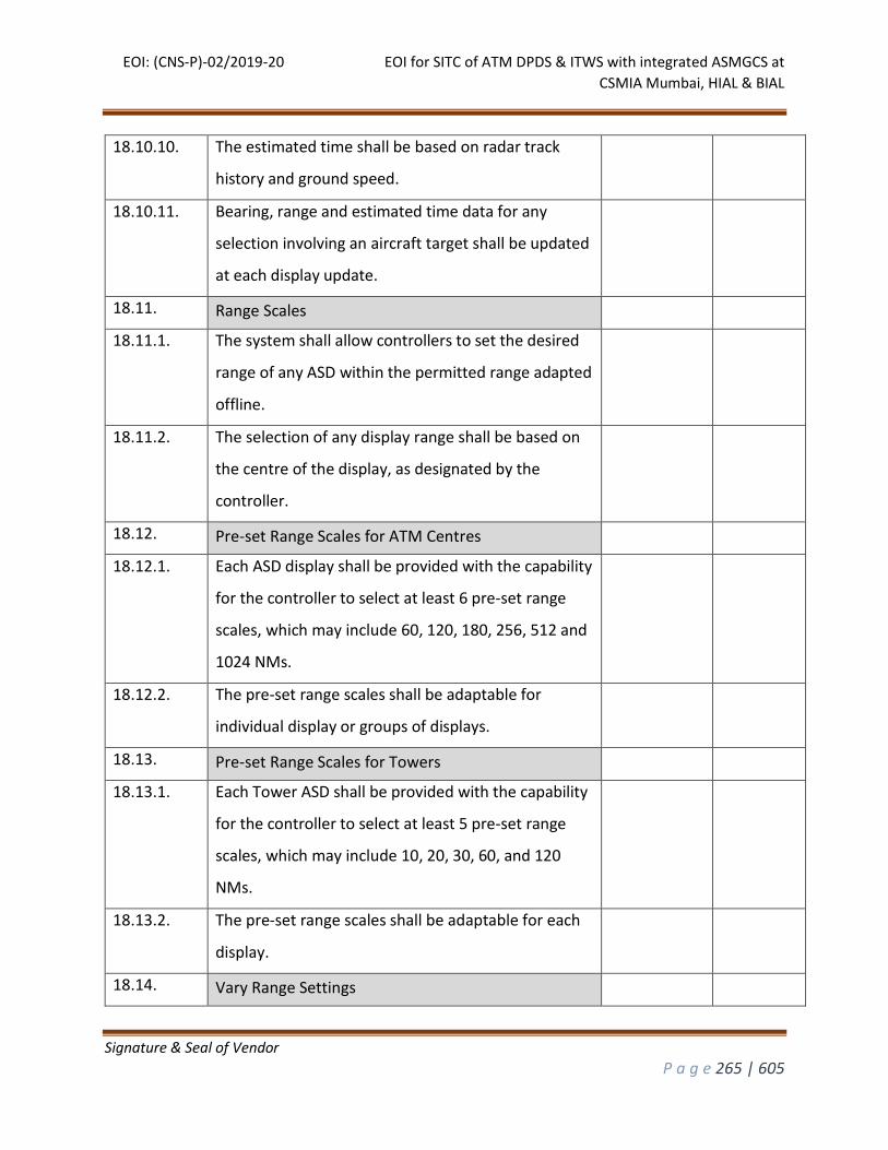
EOI: (CNS-P)-02/2019-20 EOI for SITC of ATM DPDS & ITWS with integrated ASMGCS at
CSMIA Mumbai, HIAL & BIAL
Signature & Seal of Vendor
P a g e 265 | 605
18.10.10. The estimated time shall be based on radar track
history and ground speed.
18.10.11. Bearing, range and estimated time data for any
selection involving an aircraft target shall be updated
at each display update.
18.11. Range Scales
18.11.1. The system shall allow controllers to set the desired
range of any ASD within the permitted range adapted
offline.
18.11.2. The selection of any display range shall be based on
the centre of the display, as designated by the
controller.
18.12. Pre-set Range Scales for ATM Centres
18.12.1. Each ASD display shall be provided with the capability
for the controller to select at least 6 pre-set range
scales, which may include 60, 120, 180, 256, 512 and
1024 NMs.
18.12.2. The pre-set range scales shall be adaptable for
individual display or groups of displays.
18.13. Pre-set Range Scales for Towers
18.13.1. Each Tower ASD shall be provided with the capability
for the controller to select at least 5 pre-set range
scales, which may include 10, 20, 30, 60, and 120
NMs.
18.13.2. The pre-set range scales shall be adaptable for each
display.
18.14. Vary Range Settings
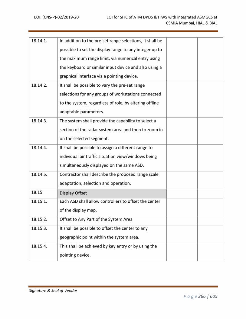
EOI: (CNS-P)-02/2019-20 EOI for SITC of ATM DPDS & ITWS with integrated ASMGCS at
CSMIA Mumbai, HIAL & BIAL
Signature & Seal of Vendor
P a g e 266 | 605
18.14.1. In addition to the pre-set range selections, it shall be
possible to set the display range to any integer up to
the maximum range limit, via numerical entry using
the keyboard or similar input device and also using a
graphical interface via a pointing device.
18.14.2. It shall be possible to vary the pre-set range
selections for any groups of workstations connected
to the system, regardless of role, by altering offline
adaptable parameters.
18.14.3. The system shall provide the capability to select a
section of the radar system area and then to zoom in
on the selected segment.
18.14.4. It shall be possible to assign a different range to
individual air traffic situation view/windows being
simultaneously displayed on the same ASD.
18.14.5. Contractor shall describe the proposed range scale
adaptation, selection and operation.
18.15. Display Offset
18.15.1. Each ASD shall allow controllers to offset the center
of the display map.
18.15.2. Offset to Any Part of the System Area
18.15.3. It shall be possible to offset the center to any
geographic point within the system area.
18.15.4. This shall be achieved by key entry or by using the
pointing device.
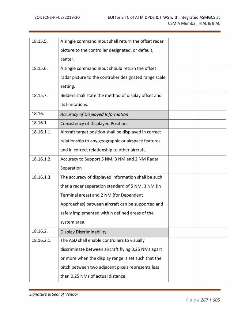
EOI: (CNS-P)-02/2019-20 EOI for SITC of ATM DPDS & ITWS with integrated ASMGCS at
CSMIA Mumbai, HIAL & BIAL
Signature & Seal of Vendor
P a g e 267 | 605
18.15.5. A single command input shall return the offset radar
picture to the controller designated, or default,
center.
18.15.6. A single command input should return the offset
radar picture to the controller designated range scale
setting.
18.15.7. Bidders shall state the method of display offset and
its limitations.
18.16. Accuracy of Displayed Information
18.16.1. Consistency of Displayed Position
18.16.1.1. Aircraft target position shall be displayed in correct
relationship to any geographic or airspace features
and in correct relationship to other aircraft.
18.16.1.2. Accuracy to Support 5 NM, 3 NM and 2 NM Radar
Separation
18.16.1.3. The accuracy of displayed information shall be such
that a radar separation standard of 5 NM, 3 NM (in
Terminal areas) and 2 NM (for Dependent
Approaches) between aircraft can be supported and
safely implemented within defined areas of the
system area.
18.16.2. Display Discriminability
18.16.2.1. The ASD shall enable controllers to visually
discriminate between aircraft flying 0.25 NMs apart
or more when the display range is set such that the
pitch between two adjacent pixels represents less
than 0.25 NMs of actual distance.
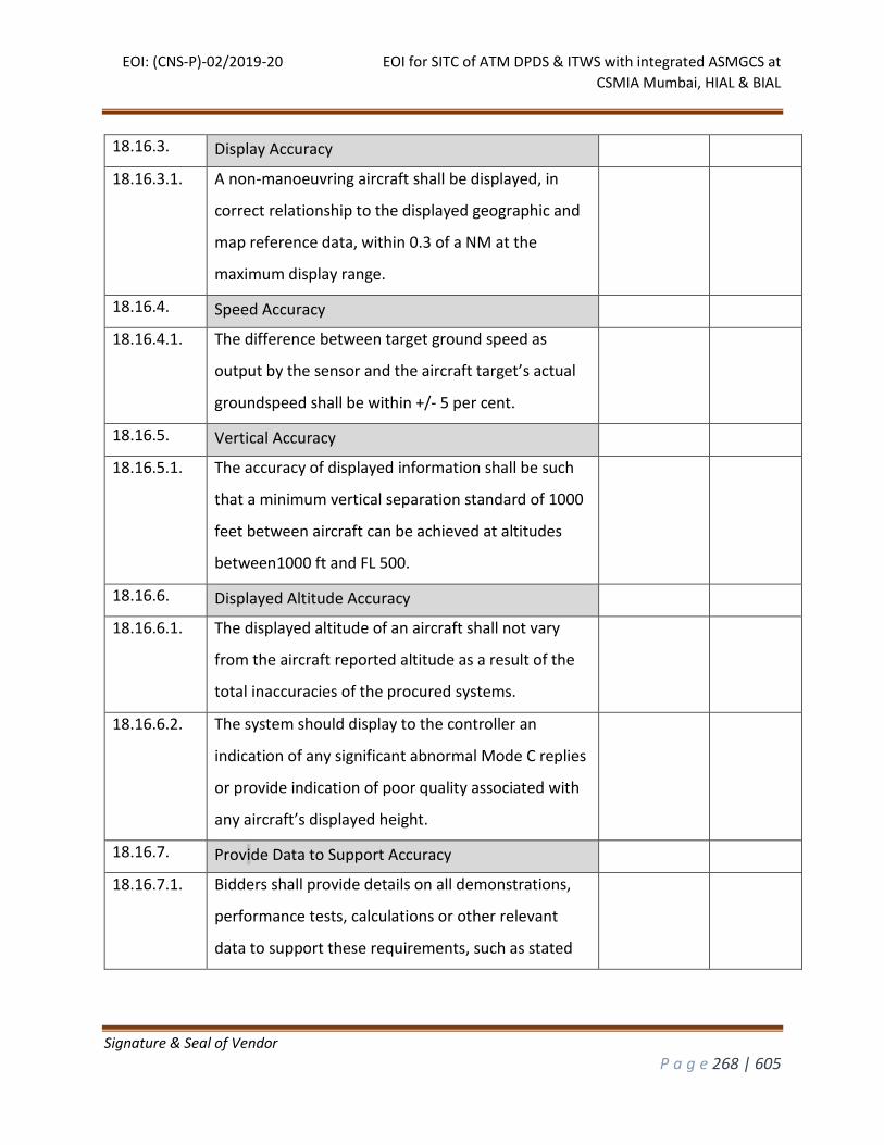
EOI: (CNS-P)-02/2019-20 EOI for SITC of ATM DPDS & ITWS with integrated ASMGCS at
CSMIA Mumbai, HIAL & BIAL
Signature & Seal of Vendor
P a g e 268 | 605
18.16.3. Display Accuracy
18.16.3.1. A non-manoeuvring aircraft shall be displayed, in
correct relationship to the displayed geographic and
map reference data, within 0.3 of a NM at the
maximum display range.
18.16.4. Speed Accuracy
18.16.4.1. The difference between target ground speed as
output by the sensor and the aircraft target’s actual
groundspeed shall be within +/- 5 per cent.
18.16.5. Vertical Accuracy
18.16.5.1. The accuracy of displayed information shall be such
that a minimum vertical separation standard of 1000
feet between aircraft can be achieved at altitudes
between1000 ft and FL 500.
18.16.6. Displayed Altitude Accuracy
18.16.6.1. The displayed altitude of an aircraft shall not vary
from the aircraft reported altitude as a result of the
total inaccuracies of the procured systems.
18.16.6.2. The system should display to the controller an
indication of any significant abnormal Mode C replies
or provide indication of poor quality associated with
any aircraft’s displayed height.
18.16.7. Provide Data to Support Accuracy
18.16.7.1. Bidders shall provide details on all demonstrations,
performance tests, calculations or other relevant
data to support these requirements, such as stated
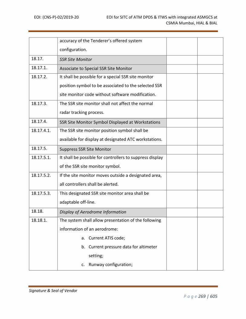
EOI: (CNS-P)-02/2019-20 EOI for SITC of ATM DPDS & ITWS with integrated ASMGCS at
CSMIA Mumbai, HIAL & BIAL
Signature & Seal of Vendor
P a g e 269 | 605
accuracy of the Tenderer’s offered system
configuration.
18.17. SSR Site Monitor
18.17.1. Associate to Special SSR Site Monitor
18.17.2. It shall be possible for a special SSR site monitor
position symbol to be associated to the selected SSR
site monitor code without software modification.
18.17.3. The SSR site monitor shall not affect the normal
radar tracking process.
18.17.4. SSR Site Monitor Symbol Displayed at Workstations
18.17.4.1. The SSR site monitor position symbol shall be
available for display at designated ATC workstations.
18.17.5. Suppress SSR Site Monitor
18.17.5.1. It shall be possible for controllers to suppress display
of the SSR site monitor symbol.
18.17.5.2. If the site monitor moves outside a designated area,
all controllers shall be alerted.
18.17.5.3. This designated SSR site monitor area shall be
adaptable off-line.
18.18. Display of Aerodrome Information
18.18.1. The system shall allow presentation of the following
information of an aerodrome:
a. Current ATIS code;
b. Current pressure data for altimeter
setting;
c. Runway configuration;
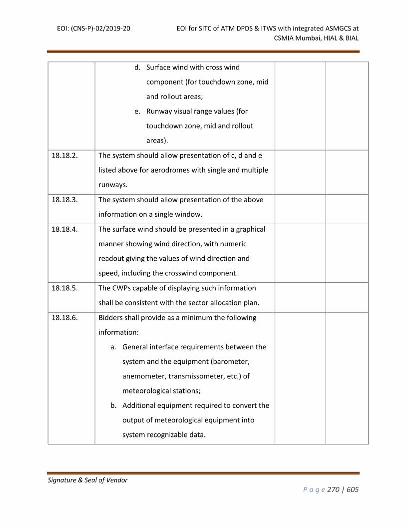
EOI: (CNS-P)-02/2019-20 EOI for SITC of ATM DPDS & ITWS with integrated ASMGCS at
CSMIA Mumbai, HIAL & BIAL
Signature & Seal of Vendor
P a g e 270 | 605
d. Surface wind with cross wind
component (for touchdown zone, mid
and rollout areas;
e. Runway visual range values (for
touchdown zone, mid and rollout
areas).
18.18.2. The system should allow presentation of c, d and e
listed above for aerodromes with single and multiple
runways.
18.18.3. The system should allow presentation of the above
information on a single window.
18.18.4. The surface wind should be presented in a graphical
manner showing wind direction, with numeric
readout giving the values of wind direction and
speed, including the crosswind component.
18.18.5. The CWPs capable of displaying such information
shall be consistent with the sector allocation plan.
18.18.6. Bidders shall provide as a minimum the following
information:
a. General interface requirements between the
system and the equipment (barometer,
anemometer, transmissometer, etc.) of
meteorological stations;
b. Additional equipment required to convert the
output of meteorological equipment into
system recognizable data.
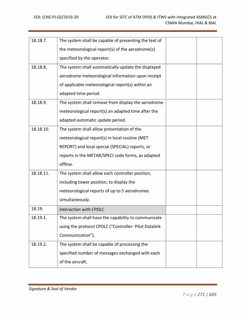
EOI: (CNS-P)-02/2019-20 EOI for SITC of ATM DPDS & ITWS with integrated ASMGCS at
CSMIA Mumbai, HIAL & BIAL
Signature & Seal of Vendor
P a g e 271 | 605
18.18.7. The system shall be capable of presenting the text of
the meteorological report(s) of the aerodrome(s)
specified by the operator.
18.18.8. The system shall automatically update the displayed
aerodrome meteorological information upon receipt
of applicable meteorological report(s) within an
adapted time period.
18.18.9. The system shall remove from display the aerodrome
meteorological report(s) an adapted time after the
adapted automatic update period.
18.18.10. The system shall allow presentation of the
meteorological report(s) in local routine (MET
REPORT) and local special (SPECIAL) reports, or
reports in the METAR/SPECI code forms, as adapted
offline.
18.18.11. The system shall allow each controller position,
including tower position, to display the
meteorological reports of up to 5 aerodromes
simultaneously.
18.19. Interaction with CPDLC
18.19.1. The system shall have the capability to communicate
using the protocol CPDLC (“Controller- Pilot Datalink
Communication”).
18.19.2. The system shall be capable of processing the
specified number of messages exchanged with each
of the aircraft.
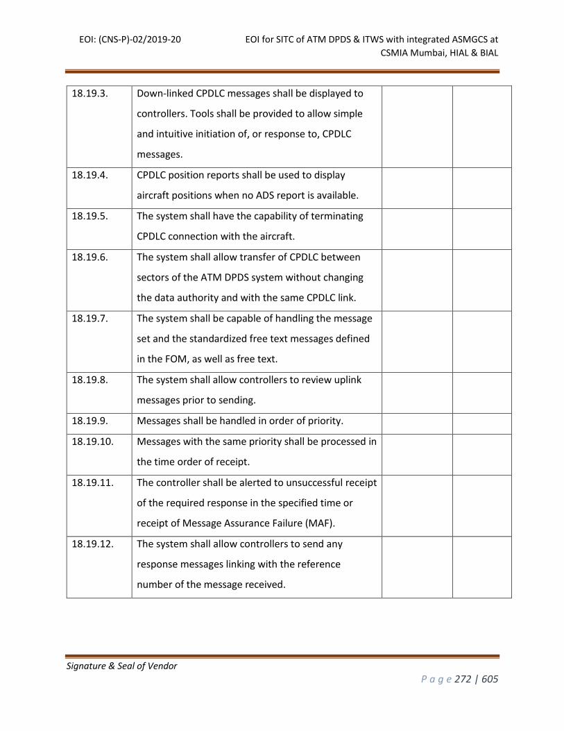
EOI: (CNS-P)-02/2019-20 EOI for SITC of ATM DPDS & ITWS with integrated ASMGCS at
CSMIA Mumbai, HIAL & BIAL
Signature & Seal of Vendor
P a g e 272 | 605
18.19.3. Down-linked CPDLC messages shall be displayed to
controllers. Tools shall be provided to allow simple
and intuitive initiation of, or response to, CPDLC
messages.
18.19.4. CPDLC position reports shall be used to display
aircraft positions when no ADS report is available.
18.19.5. The system shall have the capability of terminating
CPDLC connection with the aircraft.
18.19.6. The system shall allow transfer of CPDLC between
sectors of the ATM DPDS system without changing
the data authority and with the same CPDLC link.
18.19.7. The system shall be capable of handling the message
set and the standardized free text messages defined
in the FOM, as well as free text.
18.19.8. The system shall allow controllers to review uplink
messages prior to sending.
18.19.9. Messages shall be handled in order of priority.
18.19.10. Messages with the same priority shall be processed in
the time order of receipt.
18.19.11. The controller shall be alerted to unsuccessful receipt
of the required response in the specified time or
receipt of Message Assurance Failure (MAF).
18.19.12. The system shall allow controllers to send any
response messages linking with the reference
number of the message received.
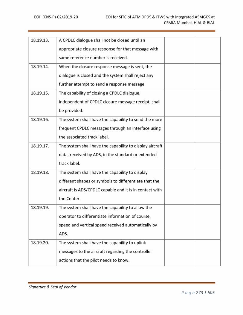
EOI: (CNS-P)-02/2019-20 EOI for SITC of ATM DPDS & ITWS with integrated ASMGCS at
CSMIA Mumbai, HIAL & BIAL
Signature & Seal of Vendor
P a g e 273 | 605
18.19.13. A CPDLC dialogue shall not be closed until an
appropriate closure response for that message with
same reference number is received.
18.19.14. When the closure response message is sent, the
dialogue is closed and the system shall reject any
further attempt to send a response message.
18.19.15. The capability of closing a CPDLC dialogue,
independent of CPDLC closure message receipt, shall
be provided.
18.19.16. The system shall have the capability to send the more
frequent CPDLC messages through an interface using
the associated track label.
18.19.17. The system shall have the capability to display aircraft
data, received by ADS, in the standard or extended
track label.
18.19.18. The system shall have the capability to display
different shapes or symbols to differentiate that the
aircraft is ADS/CPDLC capable and it is in contact with
the Center.
18.19.19. The system shall have the capability to allow the
operator to differentiate information of course,
speed and vertical speed received automatically by
ADS.
18.19.20. The system shall have the capability to uplink
messages to the aircraft regarding the controller
actions that the pilot needs to know.
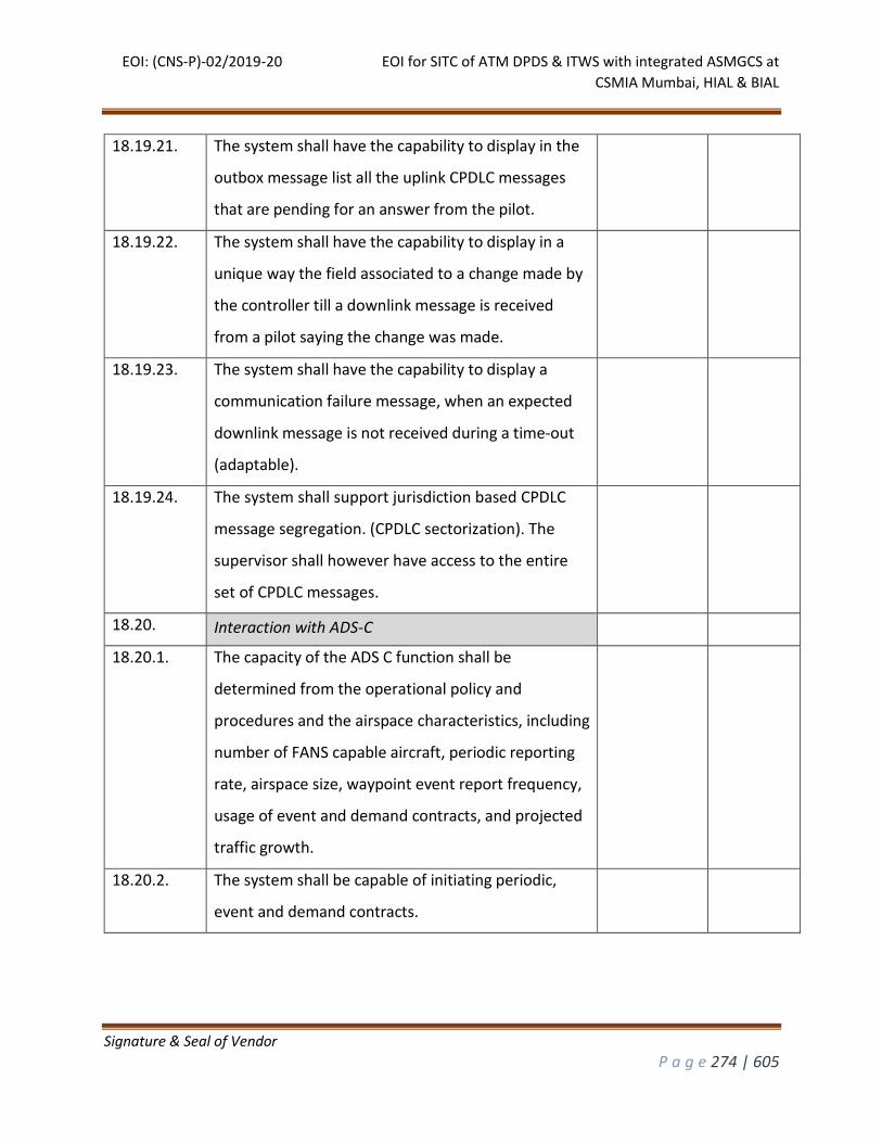
EOI: (CNS-P)-02/2019-20 EOI for SITC of ATM DPDS & ITWS with integrated ASMGCS at
CSMIA Mumbai, HIAL & BIAL
Signature & Seal of Vendor
P a g e 274 | 605
18.19.21. The system shall have the capability to display in the
outbox message list all the uplink CPDLC messages
that are pending for an answer from the pilot.
18.19.22. The system shall have the capability to display in a
unique way the field associated to a change made by
the controller till a downlink message is received
from a pilot saying the change was made.
18.19.23. The system shall have the capability to display a
communication failure message, when an expected
downlink message is not received during a time-out
(adaptable).
18.19.24. The system shall support jurisdiction based CPDLC
message segregation. (CPDLC sectorization). The
supervisor shall however have access to the entire
set of CPDLC messages.
18.20. Interaction with ADS-C
18.20.1. The capacity of the ADS C function shall be
determined from the operational policy and
procedures and the airspace characteristics, including
number of FANS capable aircraft, periodic reporting
rate, airspace size, waypoint event report frequency,
usage of event and demand contracts, and projected
traffic growth.
18.20.2. The system shall be capable of initiating periodic,
event and demand contracts.
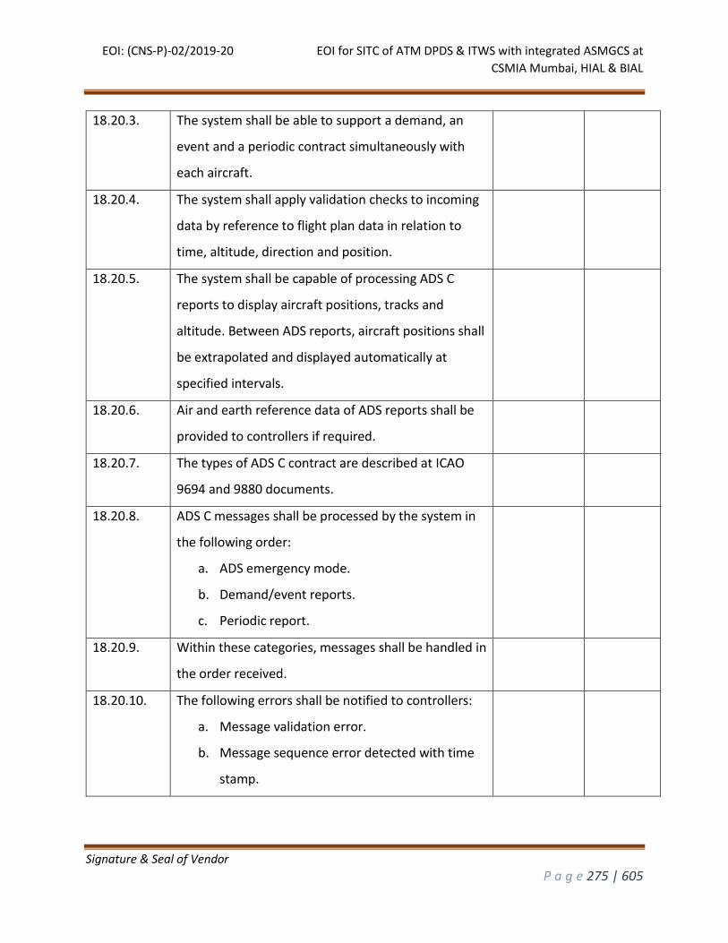
EOI: (CNS-P)-02/2019-20 EOI for SITC of ATM DPDS & ITWS with integrated ASMGCS at
CSMIA Mumbai, HIAL & BIAL
Signature & Seal of Vendor
P a g e 275 | 605
18.20.3. The system shall be able to support a demand, an
event and a periodic contract simultaneously with
each aircraft.
18.20.4. The system shall apply validation checks to incoming
data by reference to flight plan data in relation to
time, altitude, direction and position.
18.20.5. The system shall be capable of processing ADS C
reports to display aircraft positions, tracks and
altitude. Between ADS reports, aircraft positions shall
be extrapolated and displayed automatically at
specified intervals.
18.20.6. Air and earth reference data of ADS reports shall be
provided to controllers if required.
18.20.7. The types of ADS C contract are described at ICAO
9694 and 9880 documents.
18.20.8. ADS C messages shall be processed by the system in
the following order:
a. ADS emergency mode.
b. Demand/event reports.
c. Periodic report.
18.20.9. Within these categories, messages shall be handled in
the order received.
18.20.10. The following errors shall be notified to controllers:
a. Message validation error.
b. Message sequence error detected with time
stamp.
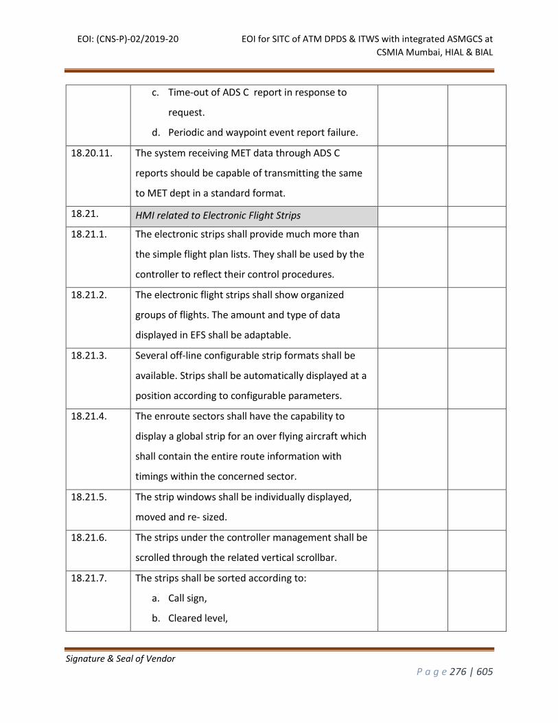
EOI: (CNS-P)-02/2019-20 EOI for SITC of ATM DPDS & ITWS with integrated ASMGCS at
CSMIA Mumbai, HIAL & BIAL
Signature & Seal of Vendor
P a g e 276 | 605
c. Time-out of ADS C report in response to
request.
d. Periodic and waypoint event report failure.
18.20.11. The system receiving MET data through ADS C
reports should be capable of transmitting the same
to MET dept in a standard format.
18.21. HMI related to Electronic Flight Strips
18.21.1. The electronic strips shall provide much more than
the simple flight plan lists. They shall be used by the
controller to reflect their control procedures.
18.21.2. The electronic flight strips shall show organized
groups of flights. The amount and type of data
displayed in EFS shall be adaptable.
18.21.3. Several off-line configurable strip formats shall be
available. Strips shall be automatically displayed at a
position according to configurable parameters.
18.21.4. The enroute sectors shall have the capability to
display a global strip for an over flying aircraft which
shall contain the entire route information with
timings within the concerned sector.
18.21.5. The strip windows shall be individually displayed,
moved and re- sized.
18.21.6. The strips under the controller management shall be
scrolled through the related vertical scrollbar.
18.21.7. The strips shall be sorted according to:
a. Call sign,
b. Cleared level,
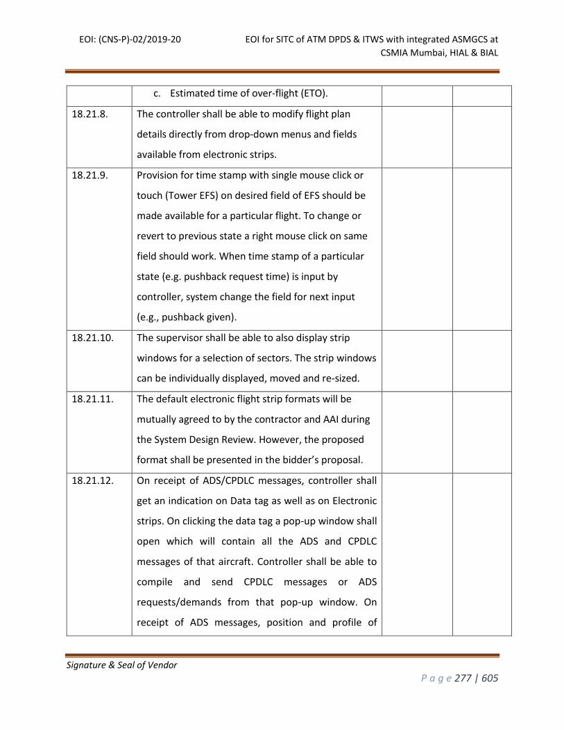
EOI: (CNS-P)-02/2019-20 EOI for SITC of ATM DPDS & ITWS with integrated ASMGCS at
CSMIA Mumbai, HIAL & BIAL
Signature & Seal of Vendor
P a g e 277 | 605
c. Estimated time of over-flight (ETO).
18.21.8. The controller shall be able to modify flight plan
details directly from drop-down menus and fields
available from electronic strips.
18.21.9. Provision for time stamp with single mouse click or
touch (Tower EFS) on desired field of EFS should be
made available for a particular flight. To change or
revert to previous state a right mouse click on same
field should work. When time stamp of a particular
state (e.g. pushback request time) is input by
controller, system change the field for next input
(e.g., pushback given).
18.21.10. The supervisor shall be able to also display strip
windows for a selection of sectors. The strip windows
can be individually displayed, moved and re-sized.
18.21.11. The default electronic flight strip formats will be
mutually agreed to by the contractor and AAI during
the System Design Review. However, the proposed
format shall be presented in the bidder’s proposal.
18.21.12. On receipt of ADS/CPDLC messages, controller shall
get an indication on Data tag as well as on Electronic
strips. On clicking the data tag a pop-up window shall
open which will contain all the ADS and CPDLC
messages of that aircraft. Controller shall be able to
compile and send CPDLC messages or ADS
requests/demands from that pop-up window. On
receipt of ADS messages, position and profile of
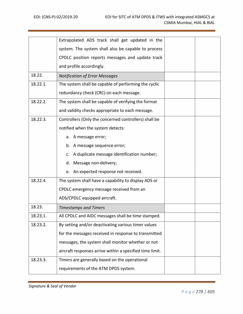
EOI: (CNS-P)-02/2019-20 EOI for SITC of ATM DPDS & ITWS with integrated ASMGCS at
CSMIA Mumbai, HIAL & BIAL
Signature & Seal of Vendor
P a g e 278 | 605
Extrapolated ADS track shall get updated in the
system. The system shall also be capable to process
CPDLC position reports messages and update track
and profile accordingly.
18.22. Notification of Error Messages
18.22.1. The system shall be capable of performing the cyclic
redundancy check (CRC) on each message.
18.22.2. The system shall be capable of verifying the format
and validity checks appropriate to each message.
18.22.3. Controllers (Only the concerned controllers) shall be
notified when the system detects:
a. A message error;
b. A message sequence error;
c. A duplicate message identification number;
d. Message non-delivery;
e. An expected response not received.
18.22.4. The system shall have a capability to display ADS or
CPDLC emergency message received from an
ADS/CPDLC equipped aircraft.
18.23. Timestamps and Timers
18.23.1. All CPDLC and AIDC messages shall be time stamped.
18.23.2. By setting and/or deactivating various timer values
for the messages received in response to transmitted
messages, the system shall monitor whether or not
aircraft responses arrive within a specified time limit.
18.23.3. Timers are generally based on the operational
requirements of the ATM DPDS system.
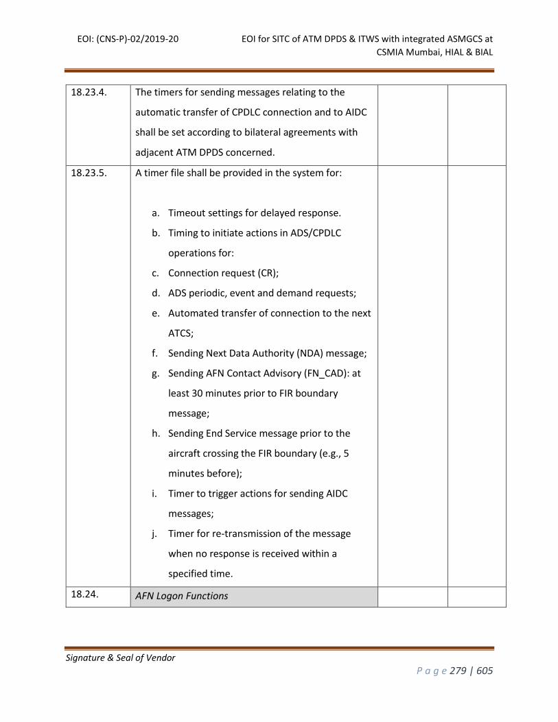
EOI: (CNS-P)-02/2019-20 EOI for SITC of ATM DPDS & ITWS with integrated ASMGCS at
CSMIA Mumbai, HIAL & BIAL
Signature & Seal of Vendor
P a g e 279 | 605
18.23.4. The timers for sending messages relating to the
automatic transfer of CPDLC connection and to AIDC
shall be set according to bilateral agreements with
adjacent ATM DPDS concerned.
18.23.5. A timer file shall be provided in the system for:
a. Timeout settings for delayed response.
b. Timing to initiate actions in ADS/CPDLC
operations for:
c. Connection request (CR);
d. ADS periodic, event and demand requests;
e. Automated transfer of connection to the next
ATCS;
f. Sending Next Data Authority (NDA) message;
g. Sending AFN Contact Advisory (FN_CAD): at
least 30 minutes prior to FIR boundary
message;
h. Sending End Service message prior to the
aircraft crossing the FIR boundary (e.g., 5
minutes before);
i. Timer to trigger actions for sending AIDC
messages;
j. Timer for re-transmission of the message
when no response is received within a
specified time.
18.24. AFN Logon Functions
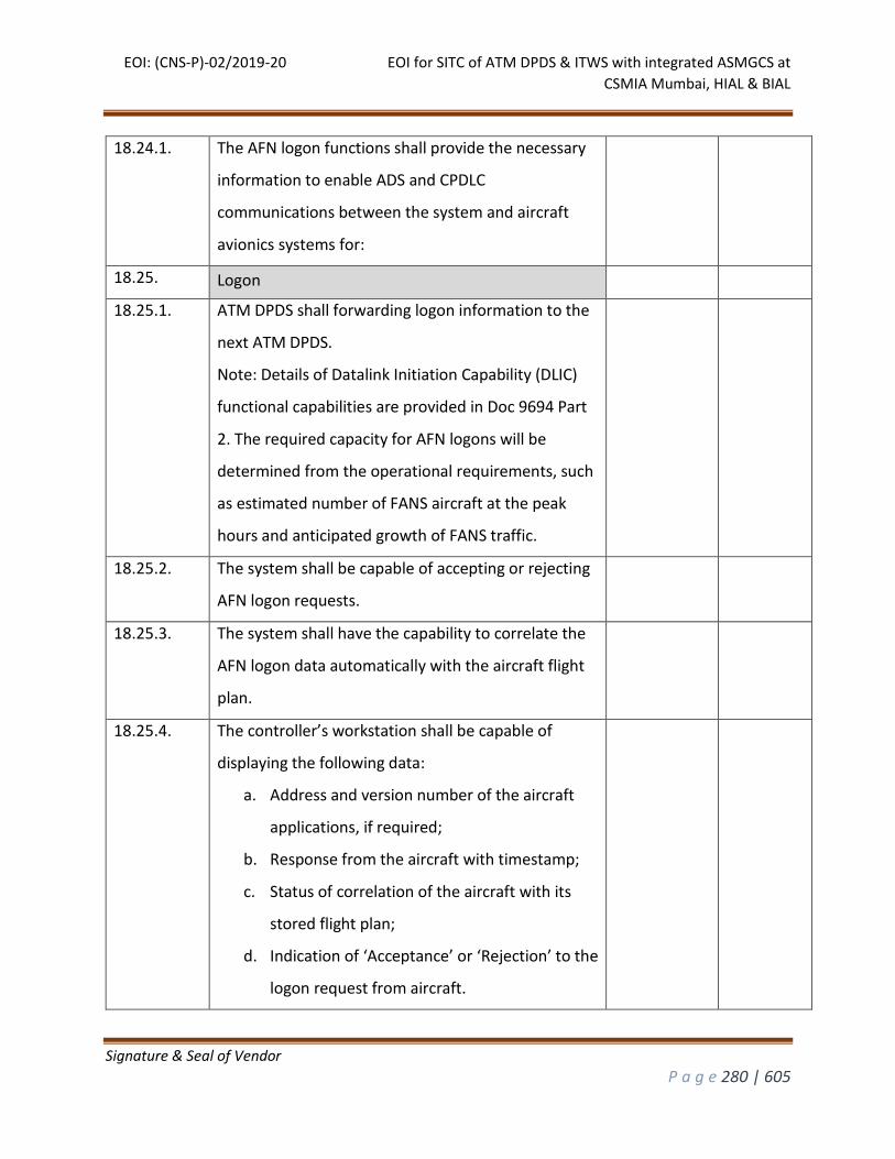
EOI: (CNS-P)-02/2019-20 EOI for SITC of ATM DPDS & ITWS with integrated ASMGCS at
CSMIA Mumbai, HIAL & BIAL
Signature & Seal of Vendor
P a g e 280 | 605
18.24.1. The AFN logon functions shall provide the necessary
information to enable ADS and CPDLC
communications between the system and aircraft
avionics systems for:
18.25. Logon
18.25.1. ATM DPDS shall forwarding logon information to the
next ATM DPDS.
Note: Details of Datalink Initiation Capability (DLIC)
functional capabilities are provided in Doc 9694 Part
2. The required capacity for AFN logons will be
determined from the operational requirements, such
as estimated number of FANS aircraft at the peak
hours and anticipated growth of FANS traffic.
18.25.2. The system shall be capable of accepting or rejecting
AFN logon requests.
18.25.3. The system shall have the capability to correlate the
AFN logon data automatically with the aircraft flight
plan.
18.25.4. The controller’s workstation shall be capable of
displaying the following data:
a. Address and version number of the aircraft
applications, if required;
b. Response from the aircraft with timestamp;
c. Status of correlation of the aircraft with its
stored flight plan;
d. Indication of ‘Acceptance’ or ‘Rejection’ to the
logon request from aircraft.
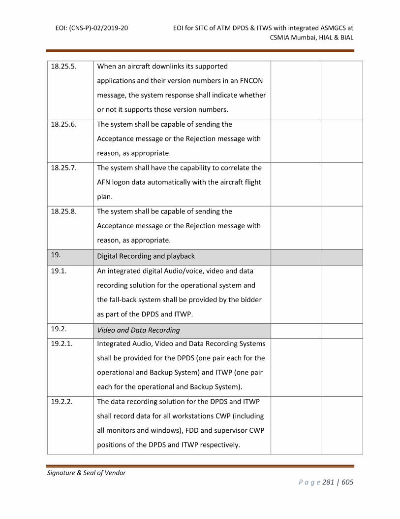
EOI: (CNS-P)-02/2019-20 EOI for SITC of ATM DPDS & ITWS with integrated ASMGCS at
CSMIA Mumbai, HIAL & BIAL
Signature & Seal of Vendor
P a g e 281 | 605
18.25.5. When an aircraft downlinks its supported
applications and their version numbers in an FNCON
message, the system response shall indicate whether
or not it supports those version numbers.
18.25.6. The system shall be capable of sending the
Acceptance message or the Rejection message with
reason, as appropriate.
18.25.7. The system shall have the capability to correlate the
AFN logon data automatically with the aircraft flight
plan.
18.25.8. The system shall be capable of sending the
Acceptance message or the Rejection message with
reason, as appropriate.
19. Digital Recording and playback
19.1. An integrated digital Audio/voice, video and data
recording solution for the operational system and
the fall-back system shall be provided by the bidder
as part of the DPDS and ITWP.
19.2. Video and Data Recording
19.2.1. Integrated Audio, Video and Data Recording Systems
shall be provided for the DPDS (one pair each for the
operational and Backup System) and ITWP (one pair
each for the operational and Backup System).
19.2.2. The data recording solution for the DPDS and ITWP
shall record data for all workstations CWP (including
all monitors and windows), FDD and supervisor CWP
positions of the DPDS and ITWP respectively.
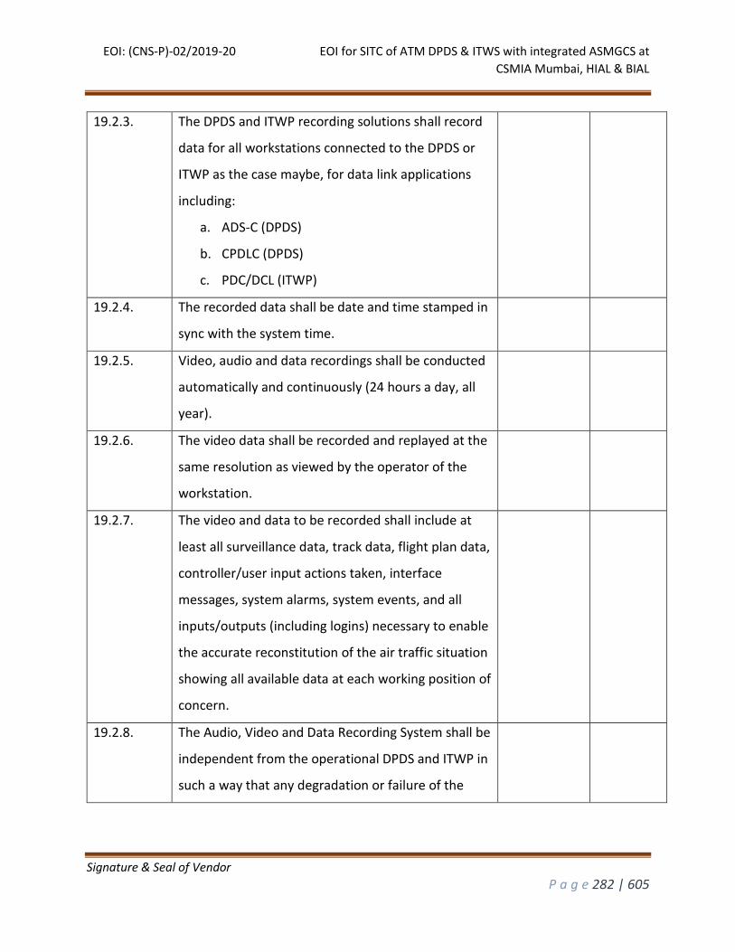
EOI: (CNS-P)-02/2019-20 EOI for SITC of ATM DPDS & ITWS with integrated ASMGCS at
CSMIA Mumbai, HIAL & BIAL
Signature & Seal of Vendor
P a g e 282 | 605
19.2.3. The DPDS and ITWP recording solutions shall record
data for all workstations connected to the DPDS or
ITWP as the case maybe, for data link applications
including:
a. ADS-C (DPDS)
b. CPDLC (DPDS)
c. PDC/DCL (ITWP)
19.2.4. The recorded data shall be date and time stamped in
sync with the system time.
19.2.5. Video, audio and data recordings shall be conducted
automatically and continuously (24 hours a day, all
year).
19.2.6. The video data shall be recorded and replayed at the
same resolution as viewed by the operator of the
workstation.
19.2.7. The video and data to be recorded shall include at
least all surveillance data, track data, flight plan data,
controller/user input actions taken, interface
messages, system alarms, system events, and all
inputs/outputs (including logins) necessary to enable
the accurate reconstitution of the air traffic situation
showing all available data at each working position of
concern.
19.2.8. The Audio, Video and Data Recording System shall be
independent from the operational DPDS and ITWP in
such a way that any degradation or failure of the
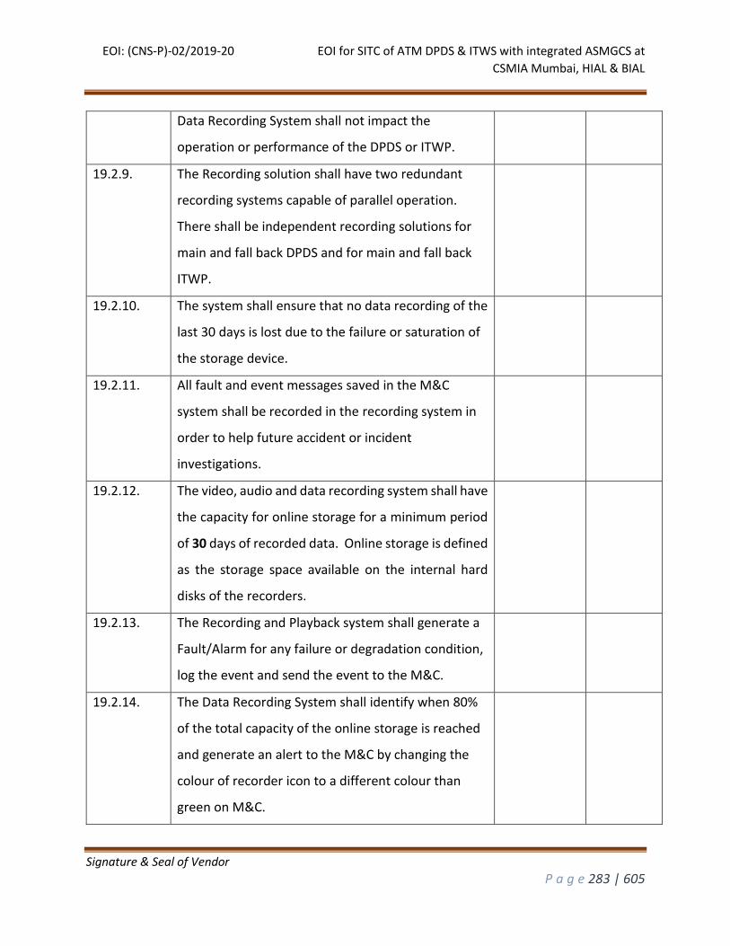
EOI: (CNS-P)-02/2019-20 EOI for SITC of ATM DPDS & ITWS with integrated ASMGCS at
CSMIA Mumbai, HIAL & BIAL
Signature & Seal of Vendor
P a g e 283 | 605
Data Recording System shall not impact the
operation or performance of the DPDS or ITWP.
19.2.9. The Recording solution shall have two redundant
recording systems capable of parallel operation.
There shall be independent recording solutions for
main and fall back DPDS and for main and fall back
ITWP.
19.2.10. The system shall ensure that no data recording of the
last 30 days is lost due to the failure or saturation of
the storage device.
19.2.11. All fault and event messages saved in the M&C
system shall be recorded in the recording system in
order to help future accident or incident
investigations.
19.2.12. The video, audio and data recording system shall have
the capacity for online storage for a minimum period
of 30 days of recorded data. Online storage is defined
as the storage space available on the internal hard
disks of the recorders.
19.2.13. The Recording and Playback system shall generate a
Fault/Alarm for any failure or degradation condition,
log the event and send the event to the M&C.
19.2.14. The Data Recording System shall identify when 80%
of the total capacity of the online storage is reached
and generate an alert to the M&C by changing the
colour of recorder icon to a different colour than
green on M&C.
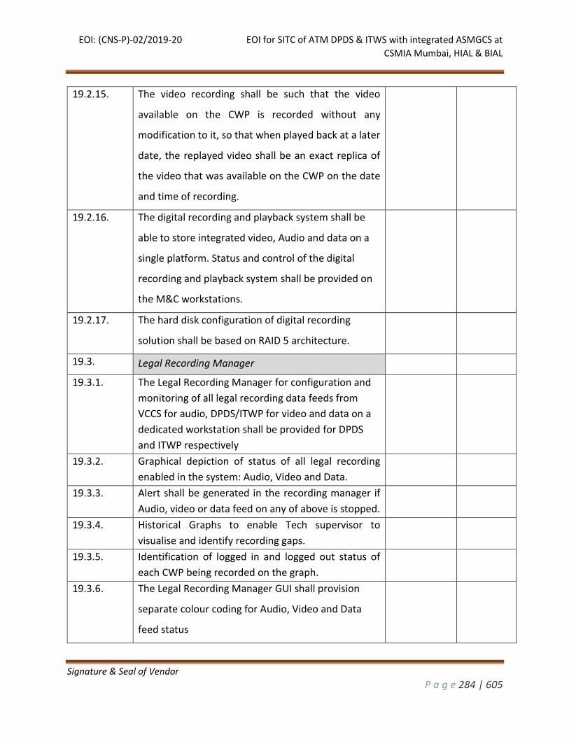
EOI: (CNS-P)-02/2019-20 EOI for SITC of ATM DPDS & ITWS with integrated ASMGCS at
CSMIA Mumbai, HIAL & BIAL
Signature & Seal of Vendor
P a g e 284 | 605
19.2.15. The video recording shall be such that the video
available on the CWP is recorded without any
modification to it, so that when played back at a later
date, the replayed video shall be an exact replica of
the video that was available on the CWP on the date
and time of recording.
19.2.16. The digital recording and playback system shall be
able to store integrated video, Audio and data on a
single platform. Status and control of the digital
recording and playback system shall be provided on
the M&C workstations.
19.2.17. The hard disk configuration of digital recording
solution shall be based on RAID 5 architecture.
19.3. Legal Recording Manager
19.3.1. The Legal Recording Manager for configuration and
monitoring of all legal recording data feeds from
VCCS for audio, DPDS/ITWP for video and data on a
dedicated workstation shall be provided for DPDS
and ITWP respectively
19.3.2. Graphical depiction of status of all legal recording
enabled in the system: Audio, Video and Data.
19.3.3. Alert shall be generated in the recording manager if
Audio, video or data feed on any of above is stopped.
19.3.4. Historical Graphs to enable Tech supervisor to
visualise and identify recording gaps.
19.3.5. Identification of logged in and logged out status of
each CWP being recorded on the graph.
19.3.6. The Legal Recording Manager GUI shall provision
separate colour coding for Audio, Video and Data
feed status
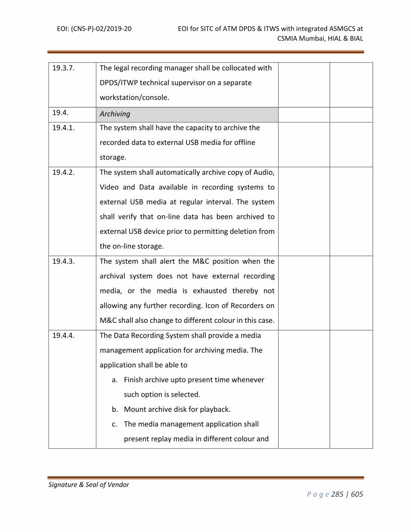
EOI: (CNS-P)-02/2019-20 EOI for SITC of ATM DPDS & ITWS with integrated ASMGCS at
CSMIA Mumbai, HIAL & BIAL
Signature & Seal of Vendor
P a g e 285 | 605
19.3.7. The legal recording manager shall be collocated with
DPDS/ITWP technical supervisor on a separate
workstation/console.
19.4. Archiving
19.4.1. The system shall have the capacity to archive the
recorded data to external USB media for offline
storage.
19.4.2. The system shall automatically archive copy of Audio,
Video and Data available in recording systems to
external USB media at regular interval. The system
shall verify that on-line data has been archived to
external USB device prior to permitting deletion from
the on-line storage.
19.4.3. The system shall alert the M&C position when the
archival system does not have external recording
media, or the media is exhausted thereby not
allowing any further recording. Icon of Recorders on
M&C shall also change to different colour in this case.
19.4.4. The Data Recording System shall provide a media
management application for archiving media. The
application shall be able to
a. Finish archive upto present time whenever
such option is selected.
b. Mount archive disk for playback.
c. The media management application shall
present replay media in different colour and
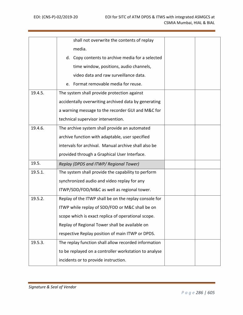
EOI: (CNS-P)-02/2019-20 EOI for SITC of ATM DPDS & ITWS with integrated ASMGCS at
CSMIA Mumbai, HIAL & BIAL
Signature & Seal of Vendor
P a g e 286 | 605
shall not overwrite the contents of replay
media.
d. Copy contents to archive media for a selected
time window, positions, audio channels,
video data and raw surveillance data.
e. Format removable media for reuse.
19.4.5. The system shall provide protection against
accidentally overwriting archived data by generating
a warning message to the recorder GUI and M&C for
technical supervisor intervention.
19.4.6. The archive system shall provide an automated
archive function with adaptable, user specified
intervals for archival. Manual archive shall also be
provided through a Graphical User Interface.
19.5. Replay (DPDS and ITWP/ Regional Tower)
19.5.1. The system shall provide the capability to perform
synchronized audio and video replay for any
ITWP/SDD/FDD/M&C as well as regional tower.
19.5.2. Replay of the ITWP shall be on the replay console for
ITWP while replay of SDD/FDD or M&C shall be on
scope which is exact replica of operational scope.
Replay of Regional Tower shall be available on
respective Replay position of main ITWP or DPDS.
19.5.3. The replay function shall allow recorded information
to be replayed on a controller workstation to analyse
incidents or to provide instruction.
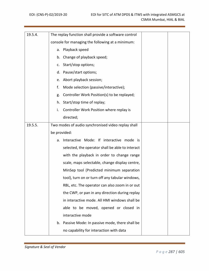
EOI: (CNS-P)-02/2019-20 EOI for SITC of ATM DPDS & ITWS with integrated ASMGCS at
CSMIA Mumbai, HIAL & BIAL
Signature & Seal of Vendor
P a g e 287 | 605
19.5.4. The replay function shall provide a software control
console for managing the following at a minimum:
a. Playback speed
b. Change of playback speed;
c. Start/stop options;
d. Pause/start options;
e. Abort playback session;
f. Mode selection (passive/interactive);
g. Controller Work Position(s) to be replayed;
h. Start/stop time of replay;
i. Controller Work Position where replay is
directed;
19.5.5. Two modes of audio synchronised video replay shall
be provided:
a. Interactive Mode: If interactive mode is
selected, the operator shall be able to interact
with the playback in order to change range
scale, maps selectable, change display centre,
MinSep tool (Predicted minimum separation
tool), turn on or turn off any tabular windows,
RBL, etc. The operator can also zoom in or out
the CWP, or pan in any direction during replay
in interactive mode. All HMI windows shall be
able to be moved, opened or closed in
interactive mode
b. Passive Mode: In passive mode, there shall be
no capability for interaction with data

EOI: (CNS-P)-02/2019-20 EOI for SITC of ATM DPDS & ITWS with integrated ASMGCS at
CSMIA Mumbai, HIAL & BIAL
Signature & Seal of Vendor
P a g e 288 | 605
elements while replaying controller position
during play-back. In this mode of playback,
the video shall be replayed as available on
the CWP at the time of recording.
19.5.6. The date and time at which the data were recorded
shall be visible on the display during replay.
19.5.7. The system shall provide the capability to save a
screen image during the replay mode on operator
selection.
19.5.8. The system shall provide the capability to record in a
generic video format (e.g mpeg, mp4,mkv, avietc),
during the replay mode at the operator selection.
The recorded file can be played back on any generic
video player, which will be demonstrated by bidder
during SAT.
19.5.9. The system shall have the capability to print the
screen image during the replay at the operator
selection.
19.5.10. The system shall support replay of up to 2 controller
work positions simultaneously and shall ensure
synchronization of the work positions.
19.5.11. The execution of the replay shall not affect the
operational environment.
19.5.12. For copying replay files from recorder archive to the
replay position a GUI shall be provided at the
recorders to select file and copy to replay position
based on date, time and position.
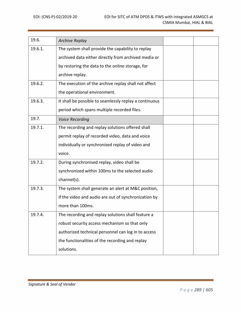
EOI: (CNS-P)-02/2019-20 EOI for SITC of ATM DPDS & ITWS with integrated ASMGCS at
CSMIA Mumbai, HIAL & BIAL
Signature & Seal of Vendor
P a g e 289 | 605
19.6. Archive Replay
19.6.1. The system shall provide the capability to replay
archived data either directly from archived media or
by restoring the data to the online storage, for
archive replay.
19.6.2. The execution of the archive replay shall not affect
the operational environment.
19.6.3. It shall be possible to seamlessly replay a continuous
period which spans multiple recorded files.
19.7. Voice Recording
19.7.1. The recording and replay solutions offered shall
permit replay of recorded video, data and voice
individually or synchronised replay of video and
voice.
19.7.2. During synchronised replay, video shall be
synchronized within 100ms to the selected audio
channel(s).
19.7.3. The system shall generate an alert at M&C position,
if the video and audio are out of synchronization by
more than 100ms.
19.7.4. The recording and replay solutions shall feature a
robust security access mechanism so that only
authorized technical personnel can log in to access
the functionalities of the recording and replay
solutions.
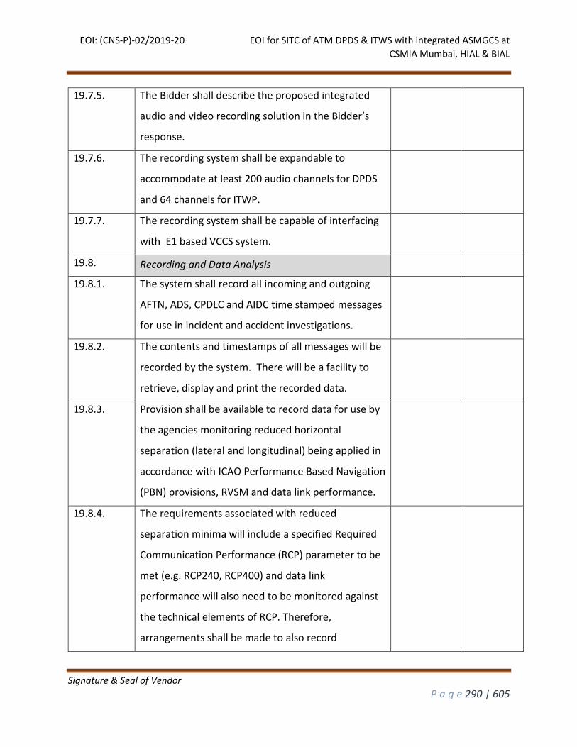
EOI: (CNS-P)-02/2019-20 EOI for SITC of ATM DPDS & ITWS with integrated ASMGCS at
CSMIA Mumbai, HIAL & BIAL
Signature & Seal of Vendor
P a g e 290 | 605
19.7.5. The Bidder shall describe the proposed integrated
audio and video recording solution in the Bidder’s
response.
19.7.6. The recording system shall be expandable to
accommodate at least 200 audio channels for DPDS
and 64 channels for ITWP.
19.7.7. The recording system shall be capable of interfacing
with E1 based VCCS system.
19.8. Recording and Data Analysis
19.8.1. The system shall record all incoming and outgoing
AFTN, ADS, CPDLC and AIDC time stamped messages
for use in incident and accident investigations.
19.8.2. The contents and timestamps of all messages will be
recorded by the system. There will be a facility to
retrieve, display and print the recorded data.
19.8.3. Provision shall be available to record data for use by
the agencies monitoring reduced horizontal
separation (lateral and longitudinal) being applied in
accordance with ICAO Performance Based Navigation
(PBN) provisions, RVSM and data link performance.
19.8.4. The requirements associated with reduced
separation minima will include a specified Required
Communication Performance (RCP) parameter to be
met (e.g. RCP240, RCP400) and data link
performance will also need to be monitored against
the technical elements of RCP. Therefore,
arrangements shall be made to also record
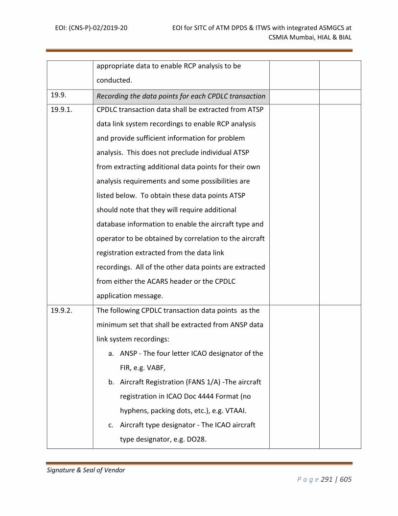
EOI: (CNS-P)-02/2019-20 EOI for SITC of ATM DPDS & ITWS with integrated ASMGCS at
CSMIA Mumbai, HIAL & BIAL
Signature & Seal of Vendor
P a g e 291 | 605
appropriate data to enable RCP analysis to be
conducted.
19.9. Recording the data points for each CPDLC transaction
19.9.1. CPDLC transaction data shall be extracted from ATSP
data link system recordings to enable RCP analysis
and provide sufficient information for problem
analysis. This does not preclude individual ATSP
from extracting additional data points for their own
analysis requirements and some possibilities are
listed below. To obtain these data points ATSP
should note that they will require additional
database information to enable the aircraft type and
operator to be obtained by correlation to the aircraft
registration extracted from the data link
recordings. All of the other data points are extracted
from either the ACARS header or the CPDLC
application message.
19.9.2. The following CPDLC transaction data points as the
minimum set that shall be extracted from ANSP data
link system recordings:
a. ANSP - The four letter ICAO designator of the
FIR, e.g. VABF,
b. Aircraft Registration (FANS 1/A) -The aircraft
registration in ICAO Doc 4444 Format (no
hyphens, packing dots, etc.), e.g. VTAAI.
c. Aircraft type designator - The ICAO aircraft
type designator, e.g. DO28.
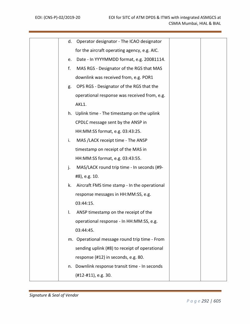
EOI: (CNS-P)-02/2019-20 EOI for SITC of ATM DPDS & ITWS with integrated ASMGCS at
CSMIA Mumbai, HIAL & BIAL
Signature & Seal of Vendor
P a g e 292 | 605
d. Operator designator - The ICAO designator
for the aircraft operating agency, e.g. AIC.
e. Date - In YYYYMMDD format, e.g. 20081114.
f. MAS RGS - Designator of the RGS that MAS
downlink was received from, e.g. POR1
g. OPS RGS - Designator of the RGS that the
operational response was received from, e.g.
AKL1.
h. Uplink time - The timestamp on the uplink
CPDLC message sent by the ANSP in
HH:MM:SS format, e.g. 03:43:25.
i. MAS /LACK receipt time - The ANSP
timestamp on receipt of the MAS in
HH:MM:SS format, e.g. 03:43:55.
j. MAS/LACK round trip time - In seconds (#9-
#8), e.g. 10.
k. Aircraft FMS time stamp - In the operational
response messages in HH:MM:SS, e.g.
03:44:15.
l. ANSP timestamp on the receipt of the
operational response - In HH:MM:SS, e.g.
03:44:45.
m. Operational message round trip time - From
sending uplink (#8) to receipt of operational
response (#12) in seconds, e.g. 80.
n. Downlink response transit time - In seconds
(#12-#11), e.g. 30.
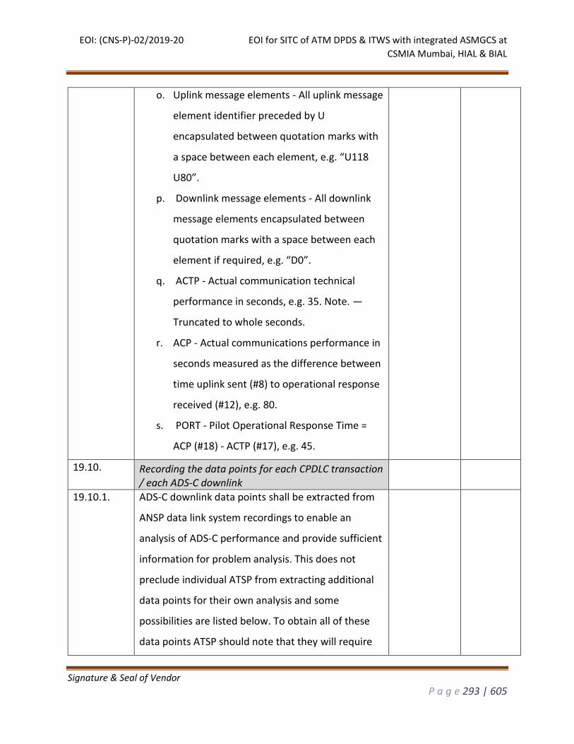
EOI: (CNS-P)-02/2019-20 EOI for SITC of ATM DPDS & ITWS with integrated ASMGCS at
CSMIA Mumbai, HIAL & BIAL
Signature & Seal of Vendor
P a g e 293 | 605
o. Uplink message elements - All uplink message
element identifier preceded by U
encapsulated between quotation marks with
a space between each element, e.g. “U118
U80”.
p. Downlink message elements - All downlink
message elements encapsulated between
quotation marks with a space between each
element if required, e.g. “D0”.
q. ACTP - Actual communication technical
performance in seconds, e.g. 35. Note. —
Truncated to whole seconds.
r. ACP - Actual communications performance in
seconds measured as the difference between
time uplink sent (#8) to operational response
received (#12), e.g. 80.
s. PORT - Pilot Operational Response Time =
ACP (#18) - ACTP (#17), e.g. 45.
19.10. Recording the data points for each CPDLC transaction / each ADS-C downlink
19.10.1. ADS-C downlink data points shall be extracted from
ANSP data link system recordings to enable an
analysis of ADS-C performance and provide sufficient
information for problem analysis. This does not
preclude individual ATSP from extracting additional
data points for their own analysis and some
possibilities are listed below. To obtain all of these
data points ATSP should note that they will require
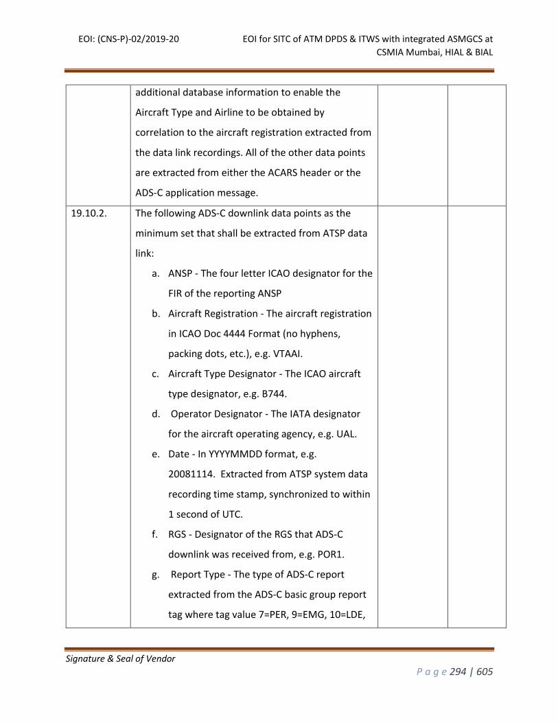
EOI: (CNS-P)-02/2019-20 EOI for SITC of ATM DPDS & ITWS with integrated ASMGCS at
CSMIA Mumbai, HIAL & BIAL
Signature & Seal of Vendor
P a g e 294 | 605
additional database information to enable the
Aircraft Type and Airline to be obtained by
correlation to the aircraft registration extracted from
the data link recordings. All of the other data points
are extracted from either the ACARS header or the
ADS-C application message.
19.10.2. The following ADS-C downlink data points as the
minimum set that shall be extracted from ATSP data
link:
a. ANSP - The four letter ICAO designator for the
FIR of the reporting ANSP
b. Aircraft Registration - The aircraft registration
in ICAO Doc 4444 Format (no hyphens,
packing dots, etc.), e.g. VTAAI.
c. Aircraft Type Designator - The ICAO aircraft
type designator, e.g. B744.
d. Operator Designator - The IATA designator
for the aircraft operating agency, e.g. UAL.
e. Date - In YYYYMMDD format, e.g.
20081114. Extracted from ATSP system data
recording time stamp, synchronized to within
1 second of UTC.
f. RGS - Designator of the RGS that ADS-C
downlink was received from, e.g. POR1.
g. Report Type - The type of ADS-C report
extracted from the ADS-C basic group report
tag where tag value 7=PER, 9=EMG, 10=LDE,
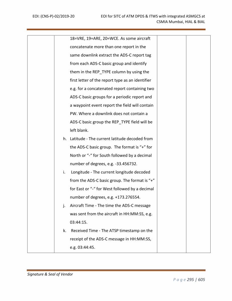
EOI: (CNS-P)-02/2019-20 EOI for SITC of ATM DPDS & ITWS with integrated ASMGCS at
CSMIA Mumbai, HIAL & BIAL
Signature & Seal of Vendor
P a g e 295 | 605
18=VRE, 19=ARE, 20=WCE. As some aircraft
concatenate more than one report in the
same downlink extract the ADS-C report tag
from each ADS-C basic group and identify
them in the REP_TYPE column by using the
first letter of the report type as an identifier
e.g. for a concatenated report containing two
ADS-C basic groups for a periodic report and
a waypoint event report the field will contain
PW. Where a downlink does not contain a
ADS-C basic group the REP_TYPE field will be
left blank.
h. Latitude - The current latitude decoded from
the ADS-C basic group. The format is “+” for
North or “-“ for South followed by a decimal
number of degrees, e.g. -33.456732.
i. Longitude - The current longitude decoded
from the ADS-C basic group. The format is “+”
for East or “-“ for West followed by a decimal
number of degrees, e.g. +173.276554.
j. Aircraft Time - The time the ADS-C message
was sent from the aircraft in HH:MM:SS, e.g.
03:44:15.
k. Received Time - The ATSP timestamp on the
receipt of the ADS-C message in HH:MM:SS,
e.g. 03:44:45.
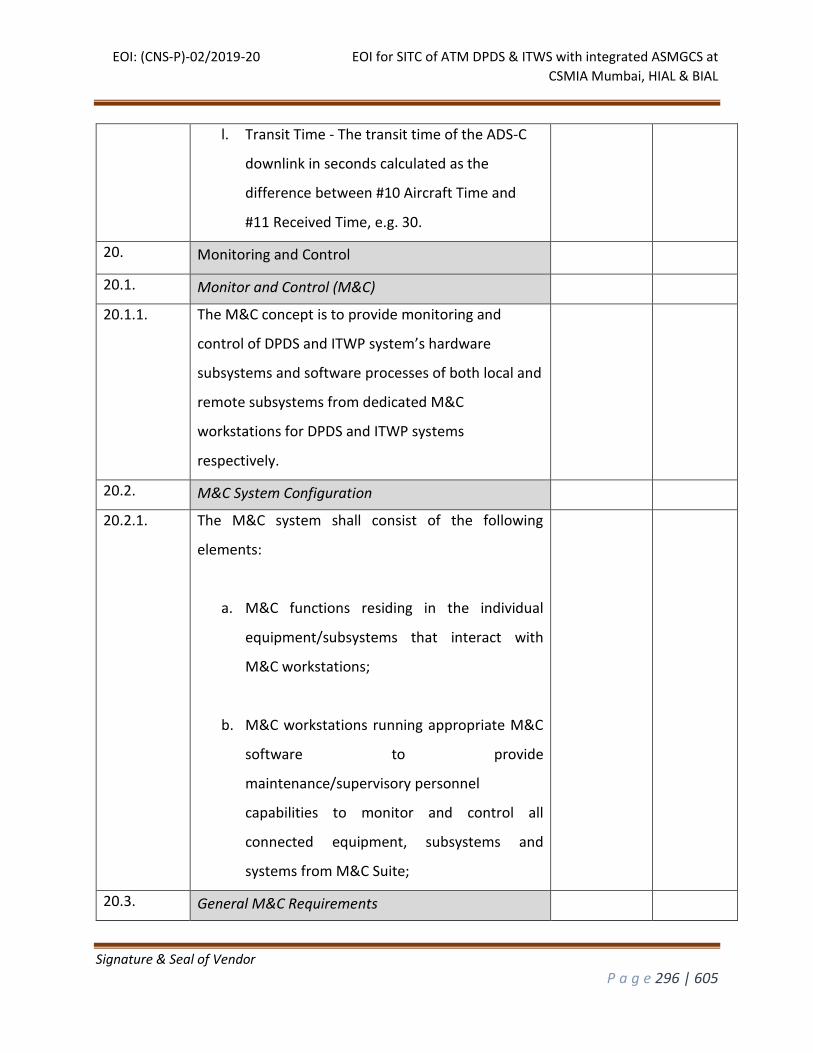
EOI: (CNS-P)-02/2019-20 EOI for SITC of ATM DPDS & ITWS with integrated ASMGCS at
CSMIA Mumbai, HIAL & BIAL
Signature & Seal of Vendor
P a g e 296 | 605
l. Transit Time - The transit time of the ADS-C
downlink in seconds calculated as the
difference between #10 Aircraft Time and
#11 Received Time, e.g. 30.
20. Monitoring and Control
20.1. Monitor and Control (M&C)
20.1.1. The M&C concept is to provide monitoring and
control of DPDS and ITWP system’s hardware
subsystems and software processes of both local and
remote subsystems from dedicated M&C
workstations for DPDS and ITWP systems
respectively.
20.2. M&C System Configuration
20.2.1. The M&C system shall consist of the following
elements:
a. M&C functions residing in the individual
equipment/subsystems that interact with
M&C workstations;
b. M&C workstations running appropriate M&C
software to provide
maintenance/supervisory personnel
capabilities to monitor and control all
connected equipment, subsystems and
systems from M&C Suite;
20.3. General M&C Requirements
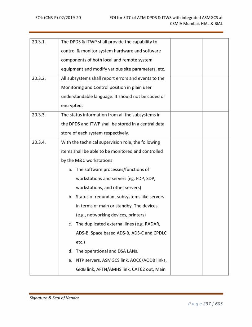
EOI: (CNS-P)-02/2019-20 EOI for SITC of ATM DPDS & ITWS with integrated ASMGCS at
CSMIA Mumbai, HIAL & BIAL
Signature & Seal of Vendor
P a g e 297 | 605
20.3.1. The DPDS & ITWP shall provide the capability to
control & monitor system hardware and software
components of both local and remote system
equipment and modify various site parameters, etc.
20.3.2. All subsystems shall report errors and events to the
Monitoring and Control position in plain user
understandable language. It should not be coded or
encrypted.
20.3.3. The status information from all the subsystems in
the DPDS and ITWP shall be stored in a central data
store of each system respectively.
20.3.4. With the technical supervision role, the following
items shall be able to be monitored and controlled
by the M&C workstations
a. The software processes/functions of
workstations and servers (eg. FDP, SDP,
workstations, and other servers)
b. Status of redundant subsystems like servers
in terms of main or standby. The devices
(e.g., networking devices, printers)
c. The duplicated external lines (e.g. RADAR,
ADS-B, Space based ADS-B, ADS-C and CPDLC
etc.)
d. The operational and DSA LANs.
e. NTP servers, ASMGCS link, AOCC/AODB links,
GRIB link, AFTN/AMHS link, CAT62 out, Main
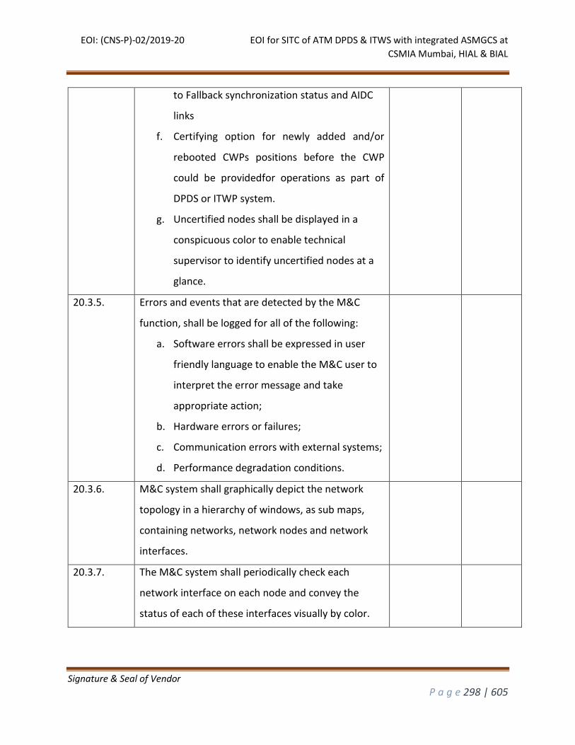
EOI: (CNS-P)-02/2019-20 EOI for SITC of ATM DPDS & ITWS with integrated ASMGCS at
CSMIA Mumbai, HIAL & BIAL
Signature & Seal of Vendor
P a g e 298 | 605
to Fallback synchronization status and AIDC
links
f. Certifying option for newly added and/or
rebooted CWPs positions before the CWP
could be providedfor operations as part of
DPDS or ITWP system.
g. Uncertified nodes shall be displayed in a
conspicuous color to enable technical
supervisor to identify uncertified nodes at a
glance.
20.3.5. Errors and events that are detected by the M&C
function, shall be logged for all of the following:
a. Software errors shall be expressed in user
friendly language to enable the M&C user to
interpret the error message and take
appropriate action;
b. Hardware errors or failures;
c. Communication errors with external systems;
d. Performance degradation conditions.
20.3.6. M&C system shall graphically depict the network
topology in a hierarchy of windows, as sub maps,
containing networks, network nodes and network
interfaces.
20.3.7. The M&C system shall periodically check each
network interface on each node and convey the
status of each of these interfaces visually by color.
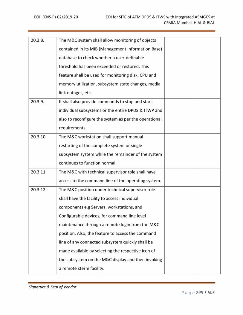
EOI: (CNS-P)-02/2019-20 EOI for SITC of ATM DPDS & ITWS with integrated ASMGCS at
CSMIA Mumbai, HIAL & BIAL
Signature & Seal of Vendor
P a g e 299 | 605
20.3.8. The M&C system shall allow monitoring of objects
contained in its MIB (Management Information Base)
database to check whether a user-definable
threshold has been exceeded or restored. This
feature shall be used for monitoring disk, CPU and
memory utilization, subsystem state changes, media
link outages, etc.
20.3.9. It shall also provide commands to stop and start
individual subsystems or the entire DPDS & ITWP and
also to reconfigure the system as per the operational
requirements.
20.3.10. The M&C workstation shall support manual
restarting of the complete system or single
subsystem system while the remainder of the system
continues to function normal.
20.3.11. The M&C with technical supervisor role shall have
access to the command line of the operating system.
20.3.12. The M&C position under technical supervisor role
shall have the facility to access individual
components e.g Servers, workstations, and
Configurable devices, for command line level
maintenance through a remote login from the M&C
position. Also, the feature to access the command
line of any connected subsystem quickly shall be
made available by selecting the respective icon of
the subsystem on the M&C display and then invoking
a remote xterm facility.
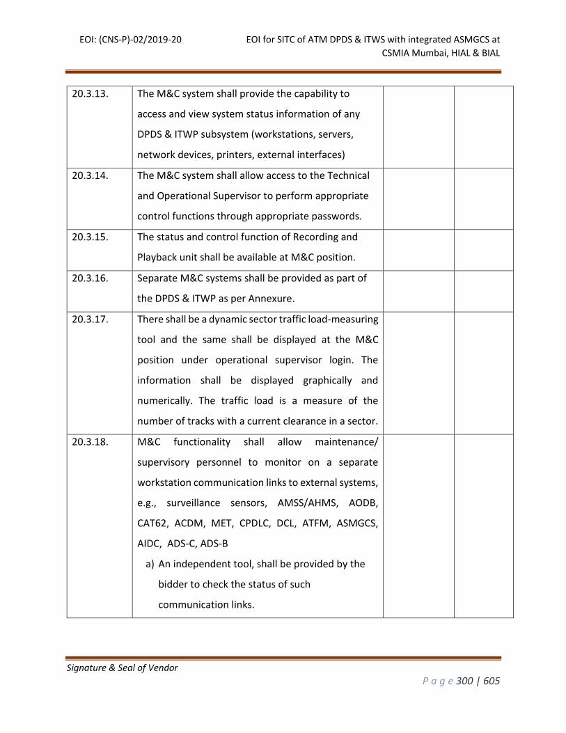
EOI: (CNS-P)-02/2019-20 EOI for SITC of ATM DPDS & ITWS with integrated ASMGCS at
CSMIA Mumbai, HIAL & BIAL
Signature & Seal of Vendor
P a g e 300 | 605
20.3.13. The M&C system shall provide the capability to
access and view system status information of any
DPDS & ITWP subsystem (workstations, servers,
network devices, printers, external interfaces)
20.3.14. The M&C system shall allow access to the Technical
and Operational Supervisor to perform appropriate
control functions through appropriate passwords.
20.3.15. The status and control function of Recording and
Playback unit shall be available at M&C position.
20.3.16. Separate M&C systems shall be provided as part of
the DPDS & ITWP as per Annexure.
20.3.17. There shall be a dynamic sector traffic load-measuring
tool and the same shall be displayed at the M&C
position under operational supervisor login. The
information shall be displayed graphically and
numerically. The traffic load is a measure of the
number of tracks with a current clearance in a sector.
20.3.18. M&C functionality shall allow maintenance/
supervisory personnel to monitor on a separate
workstation communication links to external systems,
e.g., surveillance sensors, AMSS/AHMS, AODB,
CAT62, ACDM, MET, CPDLC, DCL, ATFM, ASMGCS,
AIDC, ADS-C, ADS-B
a) An independent tool, shall be provided by the
bidder to check the status of such
communication links.
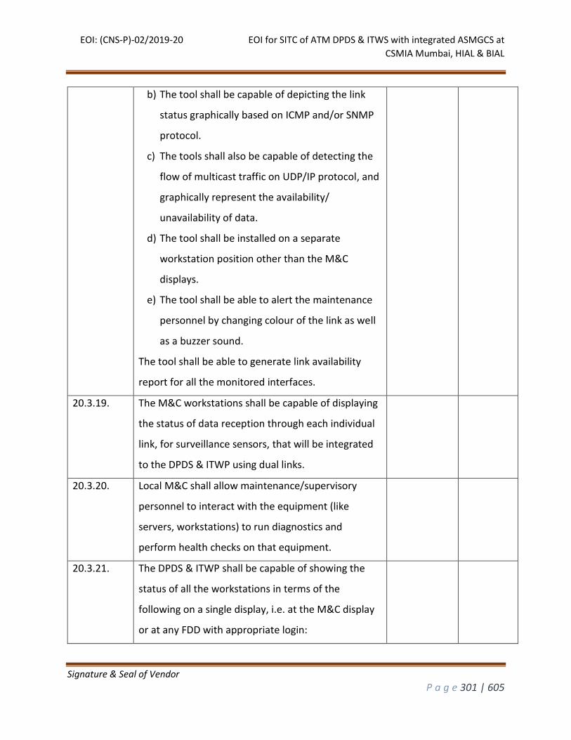
EOI: (CNS-P)-02/2019-20 EOI for SITC of ATM DPDS & ITWS with integrated ASMGCS at
CSMIA Mumbai, HIAL & BIAL
Signature & Seal of Vendor
P a g e 301 | 605
b) The tool shall be capable of depicting the link
status graphically based on ICMP and/or SNMP
protocol.
c) The tools shall also be capable of detecting the
flow of multicast traffic on UDP/IP protocol, and
graphically represent the availability/
unavailability of data.
d) The tool shall be installed on a separate
workstation position other than the M&C
displays.
e) The tool shall be able to alert the maintenance
personnel by changing colour of the link as well
as a buzzer sound.
The tool shall be able to generate link availability
report for all the monitored interfaces.
20.3.19. The M&C workstations shall be capable of displaying
the status of data reception through each individual
link, for surveillance sensors, that will be integrated
to the DPDS & ITWP using dual links.
20.3.20. Local M&C shall allow maintenance/supervisory
personnel to interact with the equipment (like
servers, workstations) to run diagnostics and
perform health checks on that equipment.
20.3.21. The DPDS & ITWP shall be capable of showing the
status of all the workstations in terms of the
following on a single display, i.e. at the M&C display
or at any FDD with appropriate login:
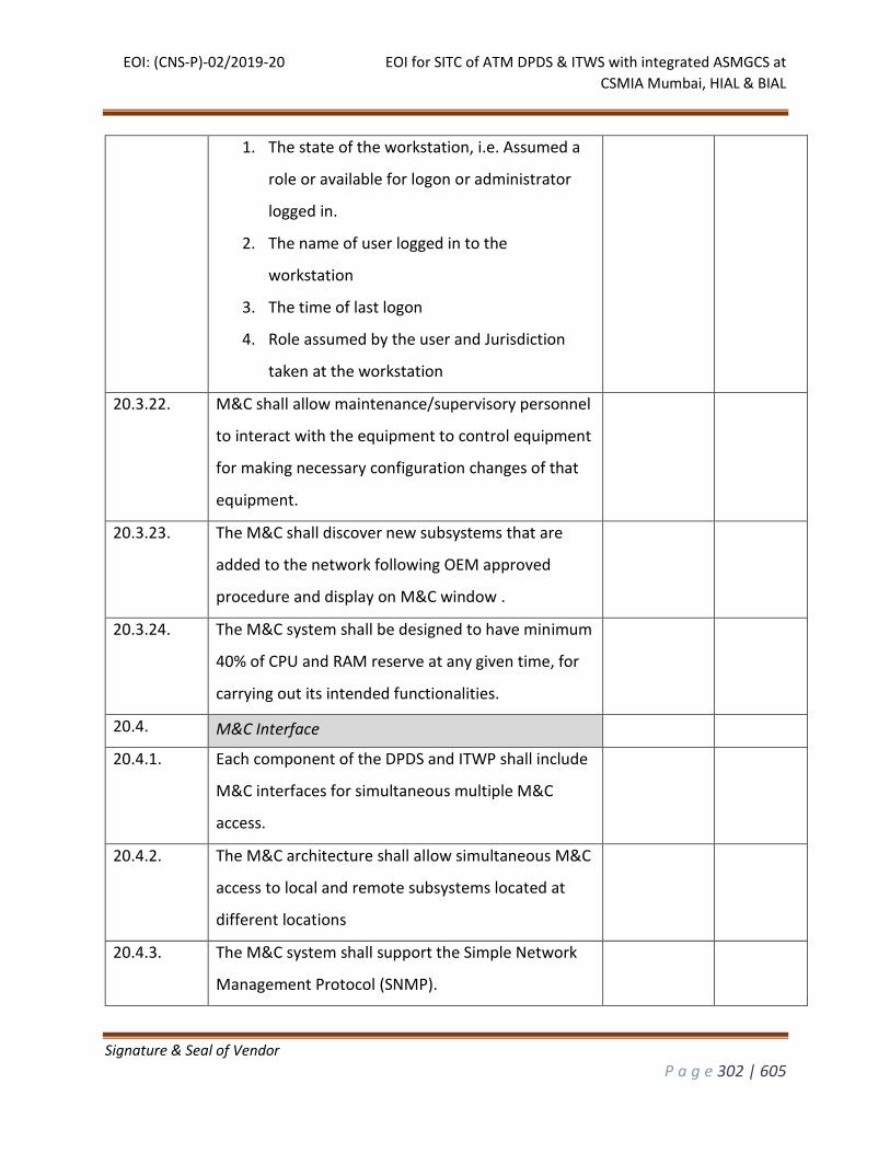
EOI: (CNS-P)-02/2019-20 EOI for SITC of ATM DPDS & ITWS with integrated ASMGCS at
CSMIA Mumbai, HIAL & BIAL
Signature & Seal of Vendor
P a g e 302 | 605
1. The state of the workstation, i.e. Assumed a
role or available for logon or administrator
logged in.
2. The name of user logged in to the
workstation
3. The time of last logon
4. Role assumed by the user and Jurisdiction
taken at the workstation
20.3.22. M&C shall allow maintenance/supervisory personnel
to interact with the equipment to control equipment
for making necessary configuration changes of that
equipment.
20.3.23. The M&C shall discover new subsystems that are
added to the network following OEM approved
procedure and display on M&C window .
20.3.24. The M&C system shall be designed to have minimum
40% of CPU and RAM reserve at any given time, for
carrying out its intended functionalities.
20.4. M&C Interface
20.4.1. Each component of the DPDS and ITWP shall include
M&C interfaces for simultaneous multiple M&C
access.
20.4.2. The M&C architecture shall allow simultaneous M&C
access to local and remote subsystems located at
different locations
20.4.3. The M&C system shall support the Simple Network
Management Protocol (SNMP).
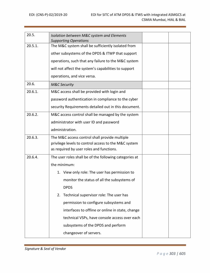
EOI: (CNS-P)-02/2019-20 EOI for SITC of ATM DPDS & ITWS with integrated ASMGCS at
CSMIA Mumbai, HIAL & BIAL
Signature & Seal of Vendor
P a g e 303 | 605
20.5. Isolation between M&C system and Elements Supporting Operations
20.5.1. The M&C system shall be sufficiently isolated from
other subsystems of the DPDS & ITWP that support
operations, such that any failure to the M&C system
will not affect the system’s capabilities to support
operations, and vice versa.
20.6. M&C Security
20.6.1. M&C access shall be provided with login and
password authentication in compliance to the cyber
security Requirements detailed out in this document.
20.6.2. M&C access control shall be managed by the system
administrator with user ID and password
administration.
20.6.3. The M&C access control shall provide multiple
privilege levels to control access to the M&C system
as required by user roles and functions.
20.6.4. The user roles shall be of the following categories at
the minimum:
1. View only role: The user has permission to
monitor the status of all the subsystems of
DPDS
2. Technical supervisor role: The user has
permission to configure subsystems and
interfaces to offline or online in state, change
technical VSPs, have console access over each
subsystems of the DPDS and perform
changeover of servers.
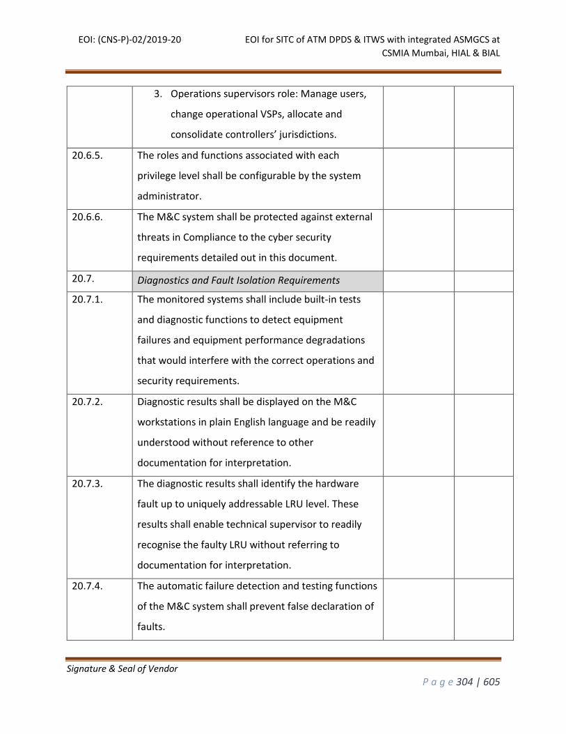
EOI: (CNS-P)-02/2019-20 EOI for SITC of ATM DPDS & ITWS with integrated ASMGCS at
CSMIA Mumbai, HIAL & BIAL
Signature & Seal of Vendor
P a g e 304 | 605
3. Operations supervisors role: Manage users,
change operational VSPs, allocate and
consolidate controllers’ jurisdictions.
20.6.5. The roles and functions associated with each
privilege level shall be configurable by the system
administrator.
20.6.6. The M&C system shall be protected against external
threats in Compliance to the cyber security
requirements detailed out in this document.
20.7. Diagnostics and Fault Isolation Requirements
20.7.1. The monitored systems shall include built-in tests
and diagnostic functions to detect equipment
failures and equipment performance degradations
that would interfere with the correct operations and
security requirements.
20.7.2. Diagnostic results shall be displayed on the M&C
workstations in plain English language and be readily
understood without reference to other
documentation for interpretation.
20.7.3. The diagnostic results shall identify the hardware
fault up to uniquely addressable LRU level. These
results shall enable technical supervisor to readily
recognise the faulty LRU without referring to
documentation for interpretation.
20.7.4. The automatic failure detection and testing functions
of the M&C system shall prevent false declaration of
faults.
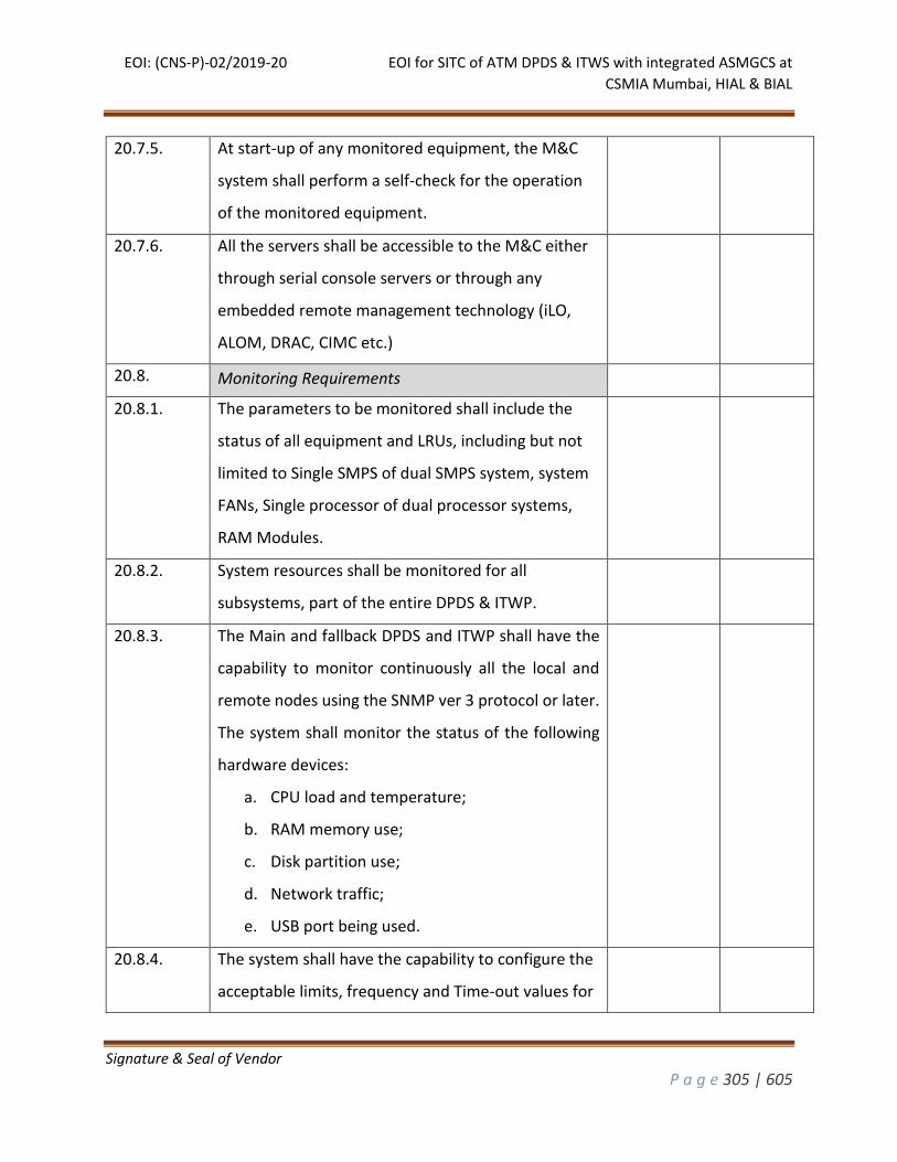
EOI: (CNS-P)-02/2019-20 EOI for SITC of ATM DPDS & ITWS with integrated ASMGCS at
CSMIA Mumbai, HIAL & BIAL
Signature & Seal of Vendor
P a g e 305 | 605
20.7.5. At start-up of any monitored equipment, the M&C
system shall perform a self-check for the operation
of the monitored equipment.
20.7.6. All the servers shall be accessible to the M&C either
through serial console servers or through any
embedded remote management technology (iLO,
ALOM, DRAC, CIMC etc.)
20.8. Monitoring Requirements
20.8.1. The parameters to be monitored shall include the
status of all equipment and LRUs, including but not
limited to Single SMPS of dual SMPS system, system
FANs, Single processor of dual processor systems,
RAM Modules.
20.8.2. System resources shall be monitored for all
subsystems, part of the entire DPDS & ITWP.
20.8.3. The Main and fallback DPDS and ITWP shall have the
capability to monitor continuously all the local and
remote nodes using the SNMP ver 3 protocol or later.
The system shall monitor the status of the following
hardware devices:
a. CPU load and temperature;
b. RAM memory use;
c. Disk partition use;
d. Network traffic;
e. USB port being used.
20.8.4. The system shall have the capability to configure the
acceptable limits, frequency and Time-out values for
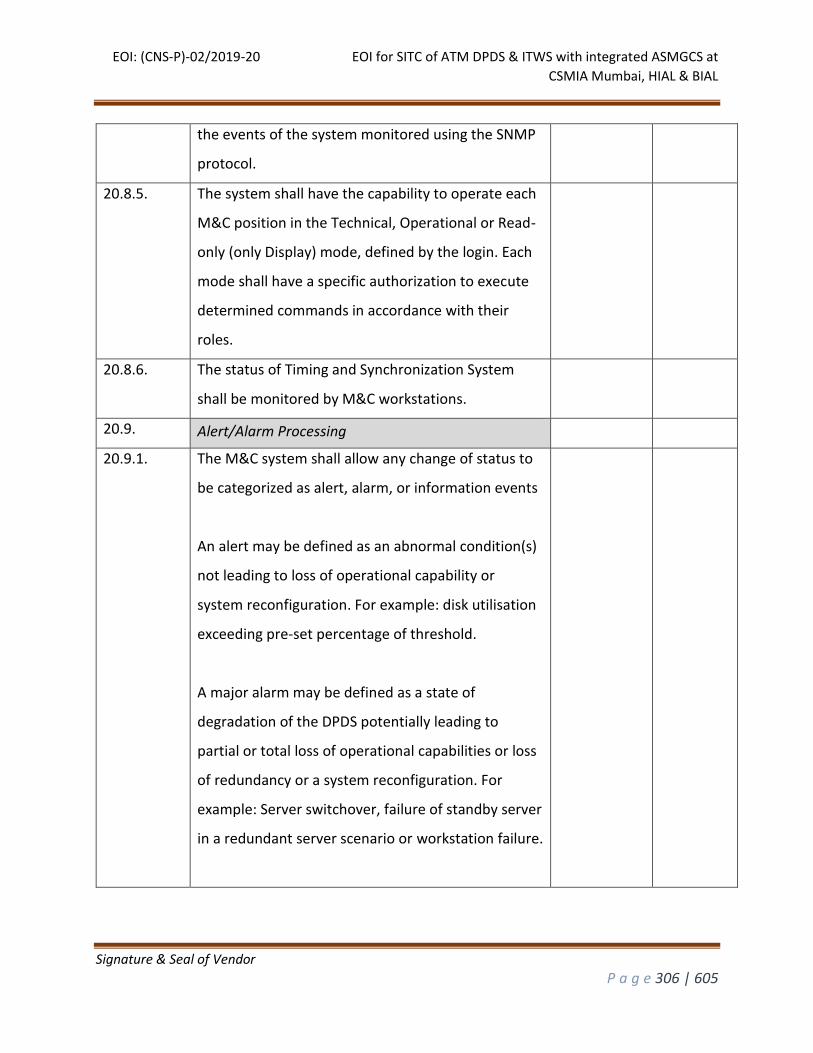
EOI: (CNS-P)-02/2019-20 EOI for SITC of ATM DPDS & ITWS with integrated ASMGCS at
CSMIA Mumbai, HIAL & BIAL
Signature & Seal of Vendor
P a g e 306 | 605
the events of the system monitored using the SNMP
protocol.
20.8.5. The system shall have the capability to operate each
M&C position in the Technical, Operational or Read-
only (only Display) mode, defined by the login. Each
mode shall have a specific authorization to execute
determined commands in accordance with their
roles.
20.8.6. The status of Timing and Synchronization System
shall be monitored by M&C workstations.
20.9. Alert/Alarm Processing
20.9.1. The M&C system shall allow any change of status to
be categorized as alert, alarm, or information events
An alert may be defined as an abnormal condition(s)
not leading to loss of operational capability or
system reconfiguration. For example: disk utilisation
exceeding pre-set percentage of threshold.
A major alarm may be defined as a state of
degradation of the DPDS potentially leading to
partial or total loss of operational capabilities or loss
of redundancy or a system reconfiguration. For
example: Server switchover, failure of standby server
in a redundant server scenario or workstation failure.
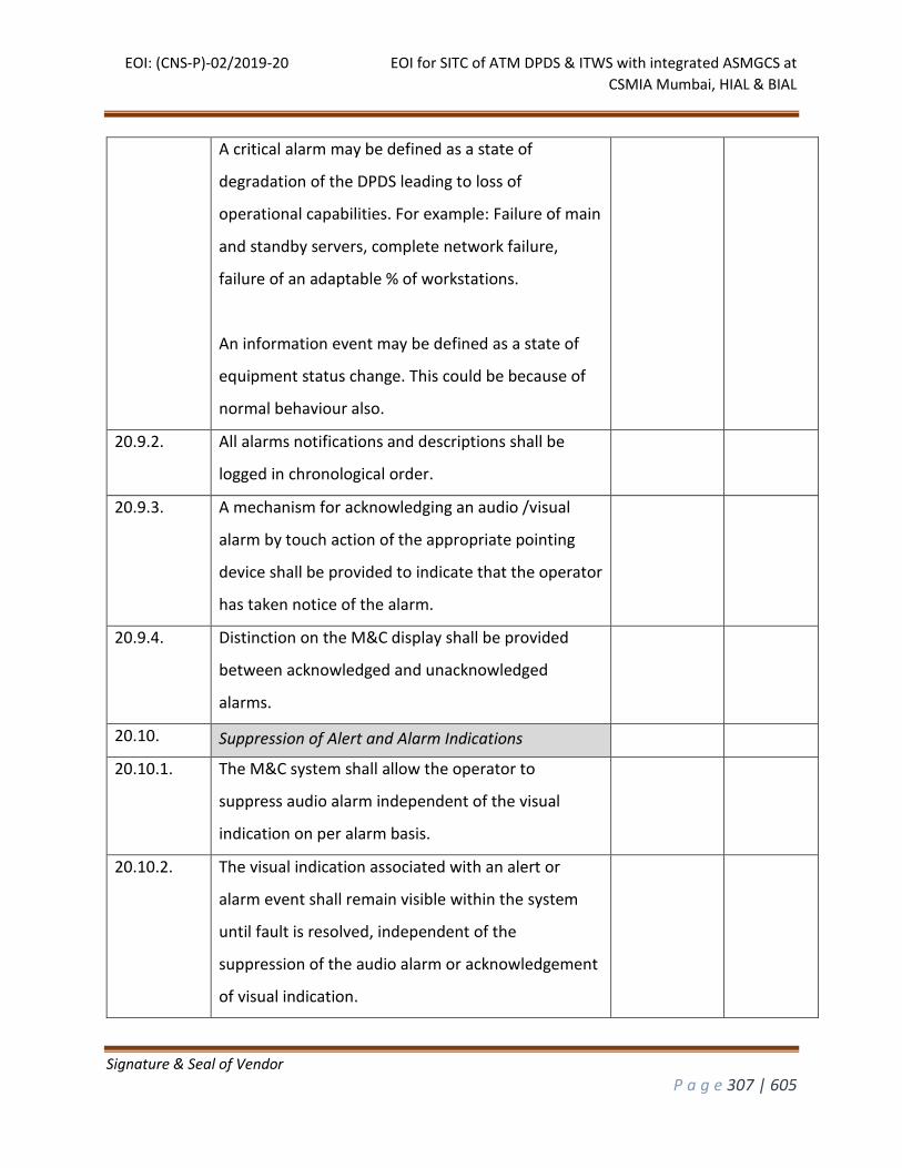
EOI: (CNS-P)-02/2019-20 EOI for SITC of ATM DPDS & ITWS with integrated ASMGCS at
CSMIA Mumbai, HIAL & BIAL
Signature & Seal of Vendor
P a g e 307 | 605
A critical alarm may be defined as a state of
degradation of the DPDS leading to loss of
operational capabilities. For example: Failure of main
and standby servers, complete network failure,
failure of an adaptable % of workstations.
An information event may be defined as a state of
equipment status change. This could be because of
normal behaviour also.
20.9.2. All alarms notifications and descriptions shall be
logged in chronological order.
20.9.3. A mechanism for acknowledging an audio /visual
alarm by touch action of the appropriate pointing
device shall be provided to indicate that the operator
has taken notice of the alarm.
20.9.4. Distinction on the M&C display shall be provided
between acknowledged and unacknowledged
alarms.
20.10. Suppression of Alert and Alarm Indications
20.10.1. The M&C system shall allow the operator to
suppress audio alarm independent of the visual
indication on per alarm basis.
20.10.2. The visual indication associated with an alert or
alarm event shall remain visible within the system
until fault is resolved, independent of the
suppression of the audio alarm or acknowledgement
of visual indication.

EOI: (CNS-P)-02/2019-20 EOI for SITC of ATM DPDS & ITWS with integrated ASMGCS at
CSMIA Mumbai, HIAL & BIAL
Signature & Seal of Vendor
P a g e 308 | 605
20.10.3. The conditions for alarms/alerts associated with all
subsystems of the DPDSand ITWP and alerts
associated with external system interfaces are to be
presented by the bidder at System Design Review
meeting. Changes asked by AAI during this meeting
shall be implemented by the bidder into the DPDS
before commencement of FAT.
20.11. Status Indications
20.11.1. M&C workstations shall indicate the status of the
system equipment, application software and
processes being monitored, including, as a minimum,
the following categories:
a. Serviceable with no faults
b. Serviceable with faults (Hardware or
software)
c. Serviceable with faults acknowledged
d. Fault detected (serviceability status
unknown)
e. Unserviceable.
20.11.2. The above 5 status shall be assigned conspicuous
and unique color coding
20.12. System Control Requirements
20.12.1. The M&C system shall have control functions that
allow authorized personnel to adjust designated
parameters, system configurations, or exercise
designated operational controls for specific
subsystems.
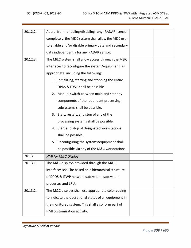
EOI: (CNS-P)-02/2019-20 EOI for SITC of ATM DPDS & ITWS with integrated ASMGCS at
CSMIA Mumbai, HIAL & BIAL
Signature & Seal of Vendor
P a g e 309 | 605
20.12.2. Apart from enabling/disabling any RADAR sensor
completely, the M&C system shall allow the M&C user
to enable and/or disable primary data and secondary
data independently for any RADAR sensor.
20.12.3. The M&C system shall allow access through the M&C
interfaces to reconfigure the system/equipment, as
appropriate, including the following:
1. Initializing, starting and stopping the entire
DPDS & ITWP shall be possible
2. Manual switch between main and standby
components of the redundant processing
subsystems shall be possible.
3. Start, restart, and stop of any of the
processing systems shall be possible.
4. Start and stop of designated workstations
shall be possible.
5. Reconfiguring the systems/equipment shall
be possible via any of the M&C workstations.
20.13. HMI for M&C Display
20.13.1. The M&C displays provided through the M&C
interfaces shall be based on a hierarchical structure
of DPDS & ITWP network subsystem, subsystem
processes and LRU.
20.13.2. The M&C displays shall use appropriate color coding
to indicate the operational status of all equipment in
the monitored system. This shall also form part of
HMI customization activity.
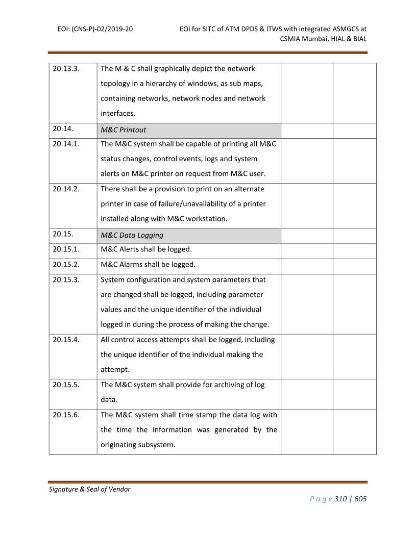
EOI: (CNS-P)-02/2019-20 EOI for SITC of ATM DPDS & ITWS with integrated ASMGCS at
CSMIA Mumbai, HIAL & BIAL
Signature & Seal of Vendor
P a g e 310 | 605
20.13.3. The M & C shall graphically depict the network
topology in a hierarchy of windows, as sub maps,
containing networks, network nodes and network
interfaces.
20.14. M&C Printout
20.14.1. The M&C system shall be capable of printing all M&C
status changes, control events, logs and system
alerts on M&C printer on request from M&C user.
20.14.2. There shall be a provision to print on an alternate
printer in case of failure/unavailability of a printer
installed along with M&C workstation.
20.15. M&C Data Logging
20.15.1. M&C Alerts shall be logged.
20.15.2. M&C Alarms shall be logged.
20.15.3. System configuration and system parameters that
are changed shall be logged, including parameter
values and the unique identifier of the individual
logged in during the process of making the change.
20.15.4. All control access attempts shall be logged, including
the unique identifier of the individual making the
attempt.
20.15.5. The M&C system shall provide for archiving of log
data.
20.15.6. The M&C system shall time stamp the data log with
the time the information was generated by the
originating subsystem.
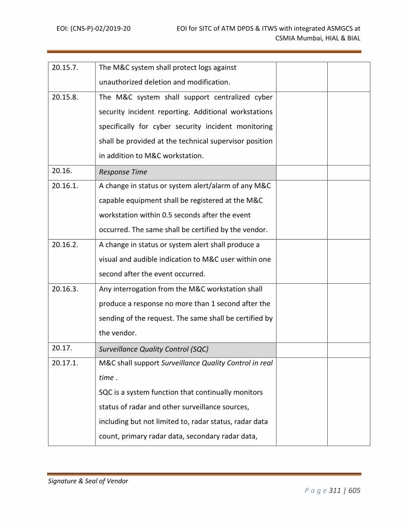
EOI: (CNS-P)-02/2019-20 EOI for SITC of ATM DPDS & ITWS with integrated ASMGCS at
CSMIA Mumbai, HIAL & BIAL
Signature & Seal of Vendor
P a g e 311 | 605
20.15.7. The M&C system shall protect logs against
unauthorized deletion and modification.
20.15.8. The M&C system shall support centralized cyber
security incident reporting. Additional workstations
specifically for cyber security incident monitoring
shall be provided at the technical supervisor position
in addition to M&C workstation.
20.16. Response Time
20.16.1. A change in status or system alert/alarm of any M&C
capable equipment shall be registered at the M&C
workstation within 0.5 seconds after the event
occurred. The same shall be certified by the vendor.
20.16.2. A change in status or system alert shall produce a
visual and audible indication to M&C user within one
second after the event occurred.
20.16.3. Any interrogation from the M&C workstation shall
produce a response no more than 1 second after the
sending of the request. The same shall be certified by
the vendor.
20.17. Surveillance Quality Control (SQC)
20.17.1. M&C shall support Surveillance Quality Control in real
time .
SQC is a system function that continually monitors
status of radar and other surveillance sources,
including but not limited to, radar status, radar data
count, primary radar data, secondary radar data,
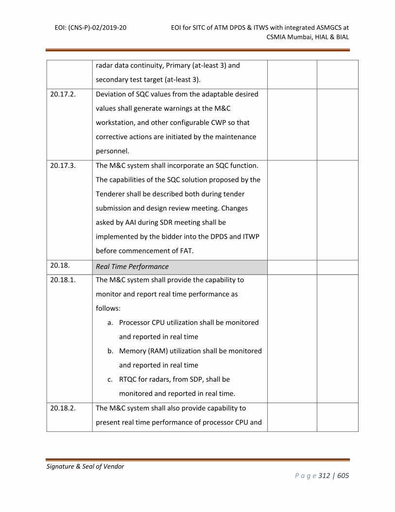
EOI: (CNS-P)-02/2019-20 EOI for SITC of ATM DPDS & ITWS with integrated ASMGCS at
CSMIA Mumbai, HIAL & BIAL
Signature & Seal of Vendor
P a g e 312 | 605
radar data continuity, Primary (at-least 3) and
secondary test target (at-least 3).
20.17.2. Deviation of SQC values from the adaptable desired
values shall generate warnings at the M&C
workstation, and other configurable CWP so that
corrective actions are initiated by the maintenance
personnel.
20.17.3. The M&C system shall incorporate an SQC function.
The capabilities of the SQC solution proposed by the
Tenderer shall be described both during tender
submission and design review meeting. Changes
asked by AAI during SDR meeting shall be
implemented by the bidder into the DPDS and ITWP
before commencement of FAT.
20.18. Real Time Performance
20.18.1. The M&C system shall provide the capability to
monitor and report real time performance as
follows:
a. Processor CPU utilization shall be monitored
and reported in real time
b. Memory (RAM) utilization shall be monitored
and reported in real time
c. RTQC for radars, from SDP, shall be
monitored and reported in real time.
20.18.2. The M&C system shall also provide capability to
present real time performance of processor CPU and
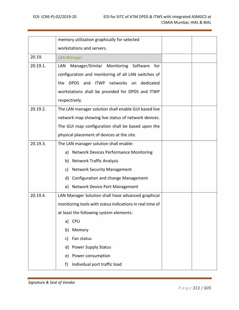
EOI: (CNS-P)-02/2019-20 EOI for SITC of ATM DPDS & ITWS with integrated ASMGCS at
CSMIA Mumbai, HIAL & BIAL
Signature & Seal of Vendor
P a g e 313 | 605
memory utilization graphically for selected
workstations and servers.
20.19. LAN Manager
20.19.1. LAN Manager/Similar Monitoring Software for
configuration and monitoring of all LAN switches of
the DPDS and ITWP networks on dedicated
workstations shall be provided for DPDS and ITWP
respectively.
20.19.2. The LAN manager solution shall enable GUI based live
network map showing live status of network devices.
The GUI map configuration shall be based upon the
physical placement of devices at the site.
20.19.3. The LAN manager solution shall enable:
a) Network Devices Performance Monitoring
b) Network Traffic Analysis
c) Network Security Management
d) Configuration and change Management
e) Network Device Port Management
20.19.4. LAN Manager Solution shall have advanced graphical
monitoring tools with status indications in real time of
at least the following system elements:
a) CPU
b) Memory
c) Fan status
d) Power Supply Status
e) Power consumption
f) Individual port traffic load
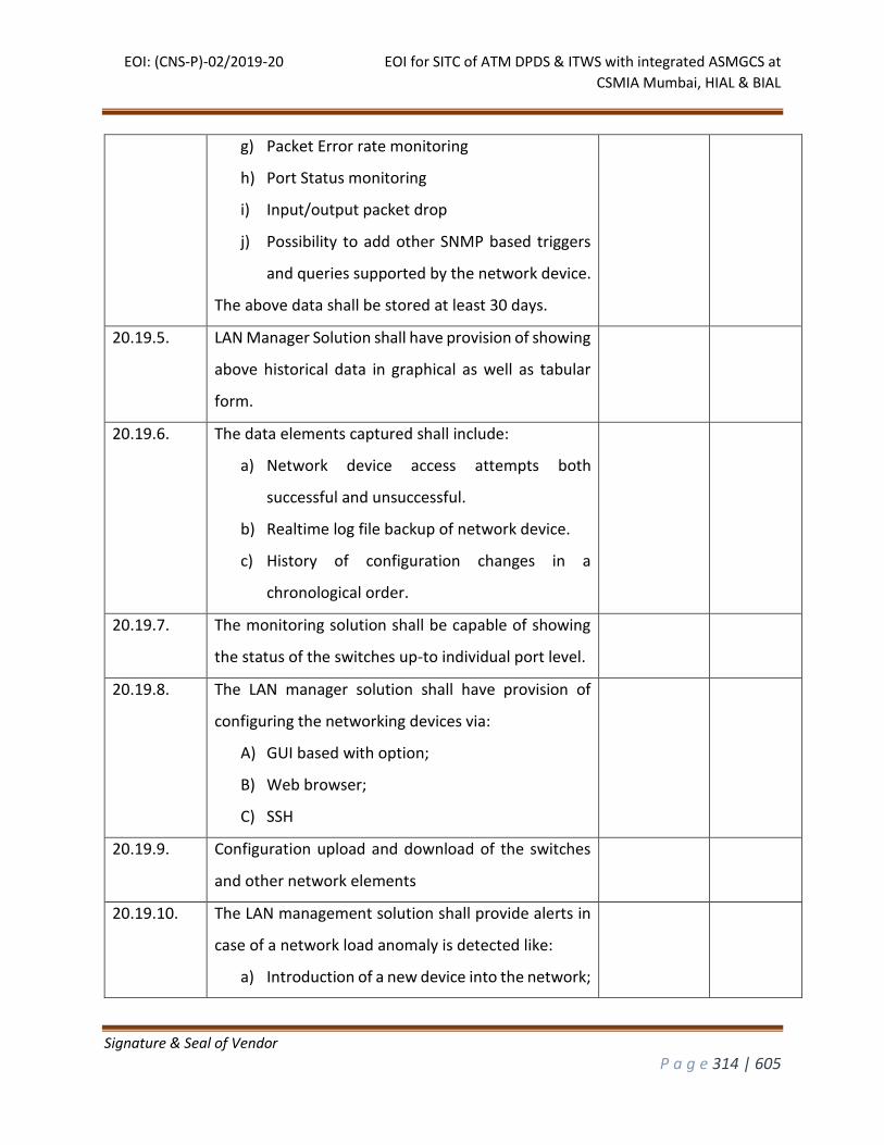
EOI: (CNS-P)-02/2019-20 EOI for SITC of ATM DPDS & ITWS with integrated ASMGCS at
CSMIA Mumbai, HIAL & BIAL
Signature & Seal of Vendor
P a g e 314 | 605
g) Packet Error rate monitoring
h) Port Status monitoring
i) Input/output packet drop
j) Possibility to add other SNMP based triggers
and queries supported by the network device.
The above data shall be stored at least 30 days.
20.19.5. LAN Manager Solution shall have provision of showing
above historical data in graphical as well as tabular
form.
20.19.6. The data elements captured shall include:
a) Network device access attempts both
successful and unsuccessful.
b) Realtime log file backup of network device.
c) History of configuration changes in a
chronological order.
20.19.7. The monitoring solution shall be capable of showing
the status of the switches up-to individual port level.
20.19.8. The LAN manager solution shall have provision of
configuring the networking devices via:
A) GUI based with option;
B) Web browser;
C) SSH
20.19.9. Configuration upload and download of the switches
and other network elements
20.19.10. The LAN management solution shall provide alerts in
case of a network load anomaly is detected like:
a) Introduction of a new device into the network;
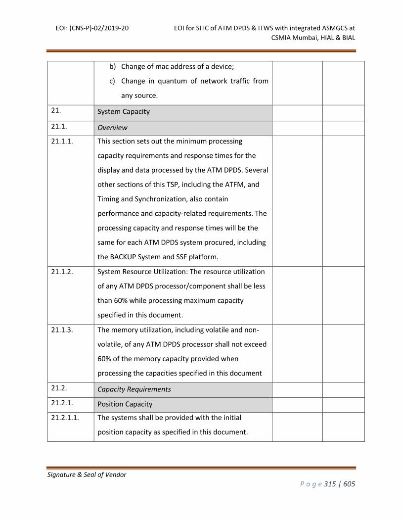
EOI: (CNS-P)-02/2019-20 EOI for SITC of ATM DPDS & ITWS with integrated ASMGCS at
CSMIA Mumbai, HIAL & BIAL
Signature & Seal of Vendor
P a g e 315 | 605
b) Change of mac address of a device;
c) Change in quantum of network traffic from
any source.
21. System Capacity
21.1. Overview
21.1.1. This section sets out the minimum processing
capacity requirements and response times for the
display and data processed by the ATM DPDS. Several
other sections of this TSP, including the ATFM, and
Timing and Synchronization, also contain
performance and capacity-related requirements. The
processing capacity and response times will be the
same for each ATM DPDS system procured, including
the BACKUP System and SSF platform.
21.1.2. System Resource Utilization: The resource utilization
of any ATM DPDS processor/component shall be less
than 60% while processing maximum capacity
specified in this document.
21.1.3. The memory utilization, including volatile and non-
volatile, of any ATM DPDS processor shall not exceed
60% of the memory capacity provided when
processing the capacities specified in this document
21.2. Capacity Requirements
21.2.1. Position Capacity
21.2.1.1. The systems shall be provided with the initial
position capacity as specified in this document.
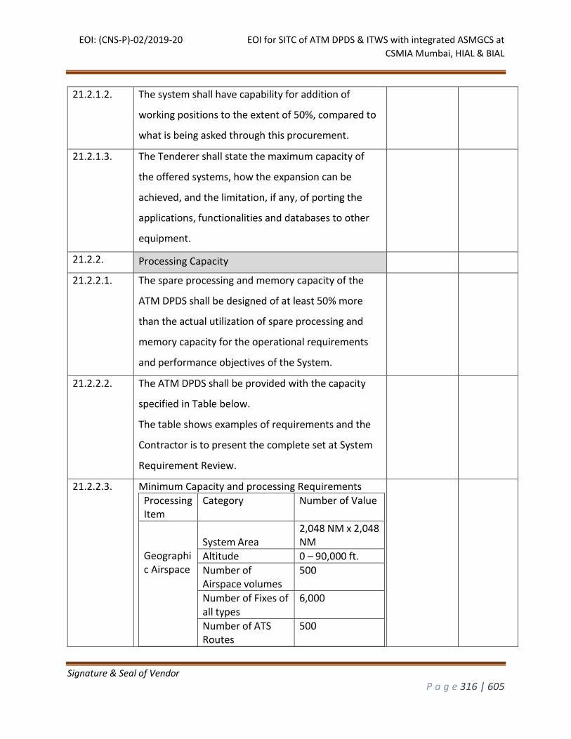
EOI: (CNS-P)-02/2019-20 EOI for SITC of ATM DPDS & ITWS with integrated ASMGCS at
CSMIA Mumbai, HIAL & BIAL
Signature & Seal of Vendor
P a g e 316 | 605
21.2.1.2. The system shall have capability for addition of
working positions to the extent of 50%, compared to
what is being asked through this procurement.
21.2.1.3. The Tenderer shall state the maximum capacity of
the offered systems, how the expansion can be
achieved, and the limitation, if any, of porting the
applications, functionalities and databases to other
equipment.
21.2.2. Processing Capacity
21.2.2.1. The spare processing and memory capacity of the
ATM DPDS shall be designed of at least 50% more
than the actual utilization of spare processing and
memory capacity for the operational requirements
and performance objectives of the System.
21.2.2.2. The ATM DPDS shall be provided with the capacity
specified in Table below.
The table shows examples of requirements and the
Contractor is to present the complete set at System
Requirement Review.
21.2.2.3. Minimum Capacity and processing Requirements
Processing Item
Category Number of Value
Geographic Airspace
System Area
2,048 NM x 2,048 NM
Altitude 0 – 90,000 ft.
Number of Airspace volumes
500
Number of Fixes of all types
6,000
Number of ATS Routes
500
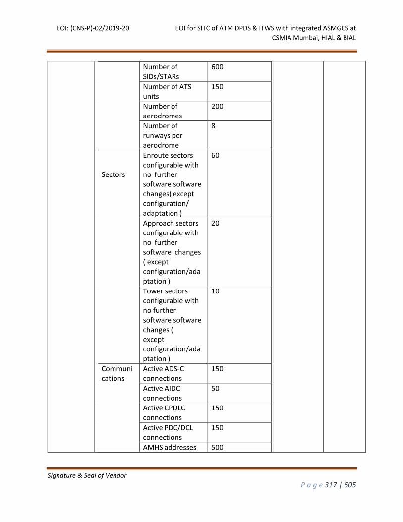
EOI: (CNS-P)-02/2019-20 EOI for SITC of ATM DPDS & ITWS with integrated ASMGCS at
CSMIA Mumbai, HIAL & BIAL
Signature & Seal of Vendor
P a g e 317 | 605
Number of SIDs/STARs
600
Number of ATS units
150
Number of aerodromes
200
Number of runways per aerodrome
8
Sectors
Enroute sectors configurable with no further software software changes( except configuration/ adaptation )
60
Approach sectors configurable with no further software changes ( except configuration/adaptation )
20
Tower sectors configurable with no further software software changes ( except configuration/adaptation )
10
Communications
Active ADS-C connections
150
Active AIDC connections
50
Active CPDLC connections
150
Active PDC/DCL connections
150
AMHS addresses 500
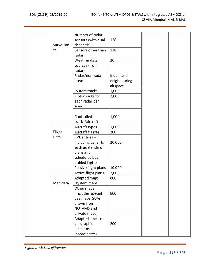
EOI: (CNS-P)-02/2019-20 EOI for SITC of ATM DPDS & ITWS with integrated ASMGCS at
CSMIA Mumbai, HIAL & BIAL
Signature & Seal of Vendor
P a g e 318 | 605
Surveillance
Number of radar sensors (with dual channels)
128
Sensors other than radar
128
Weather data sources (from radar)
20
Radar/non-radar areas
Indian and neighbouring airspace
System tracks 1,000
Plots/tracks for each radar per scan
2,000
Controlled tracks/aircraft
1,000
Flight Data
Aircraft types 1,000
Aircraft classes 200
RPL entries – including variants such as standard plans and scheduled but unfiled flights
20,000
Passive flight plans 10,000
Active flight plans 2,000
Map data
Adapted maps (system maps)
800
Other maps (includes special use maps, SUAs drawn from NOTAMS and private maps)
800
Adapted labels of geographic locations (coordinates)
200
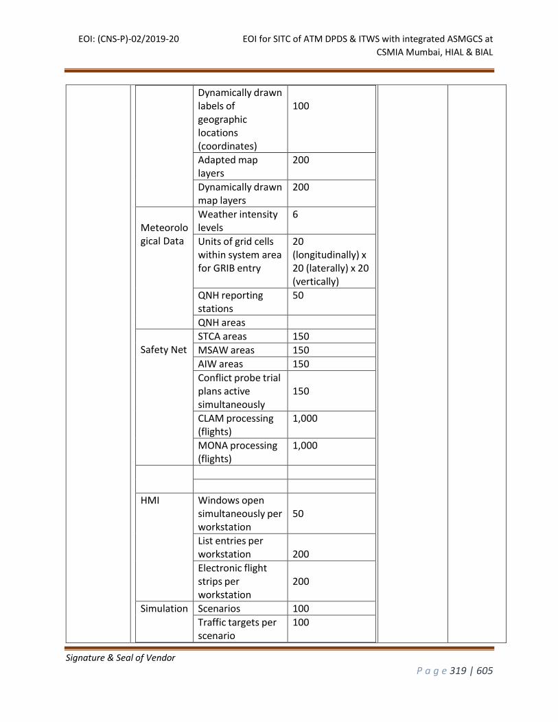
EOI: (CNS-P)-02/2019-20 EOI for SITC of ATM DPDS & ITWS with integrated ASMGCS at
CSMIA Mumbai, HIAL & BIAL
Signature & Seal of Vendor
P a g e 319 | 605
Dynamically drawn labels of geographic locations (coordinates)
100
Adapted map layers
200
Dynamically drawn map layers
200
Meteorological Data
Weather intensity levels
6
Units of grid cells within system area for GRIB entry
20 (longitudinally) x 20 (laterally) x 20 (vertically)
QNH reporting stations
50
QNH areas
Safety Net
STCA areas 150
MSAW areas 150
AIW areas 150
Conflict probe trial plans active simultaneously
150
CLAM processing (flights)
1,000
MONA processing (flights)
1,000
HMI Windows open simultaneously per workstation
50
List entries per workstation
200
Electronic flight strips per workstation
200
Simulation Scenarios 100
Traffic targets per scenario
100
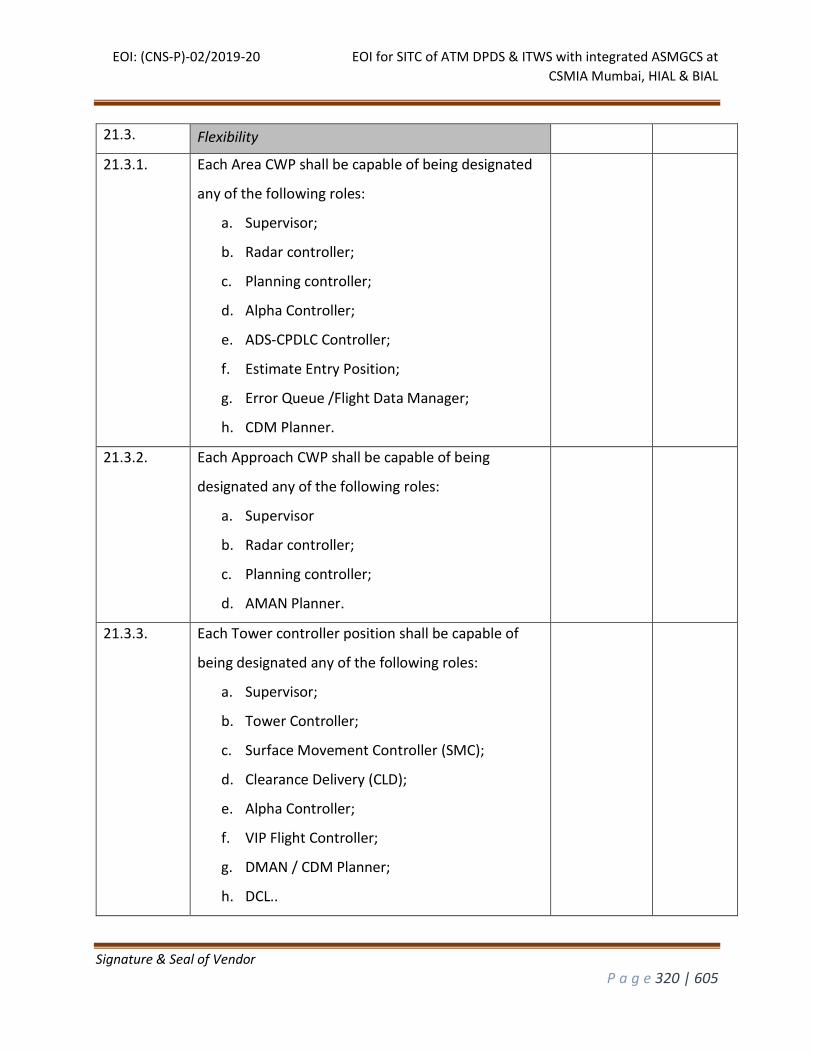
EOI: (CNS-P)-02/2019-20 EOI for SITC of ATM DPDS & ITWS with integrated ASMGCS at
CSMIA Mumbai, HIAL & BIAL
Signature & Seal of Vendor
P a g e 320 | 605
21.3. Flexibility
21.3.1. Each Area CWP shall be capable of being designated
any of the following roles:
a. Supervisor;
b. Radar controller;
c. Planning controller;
d. Alpha Controller;
e. ADS-CPDLC Controller;
f. Estimate Entry Position;
g. Error Queue /Flight Data Manager;
h. CDM Planner.
21.3.2. Each Approach CWP shall be capable of being
designated any of the following roles:
a. Supervisor
b. Radar controller;
c. Planning controller;
d. AMAN Planner.
21.3.3. Each Tower controller position shall be capable of
being designated any of the following roles:
a. Supervisor;
b. Tower Controller;
c. Surface Movement Controller (SMC);
d. Clearance Delivery (CLD);
e. Alpha Controller;
f. VIP Flight Controller;
g. DMAN / CDM Planner;
h. DCL..
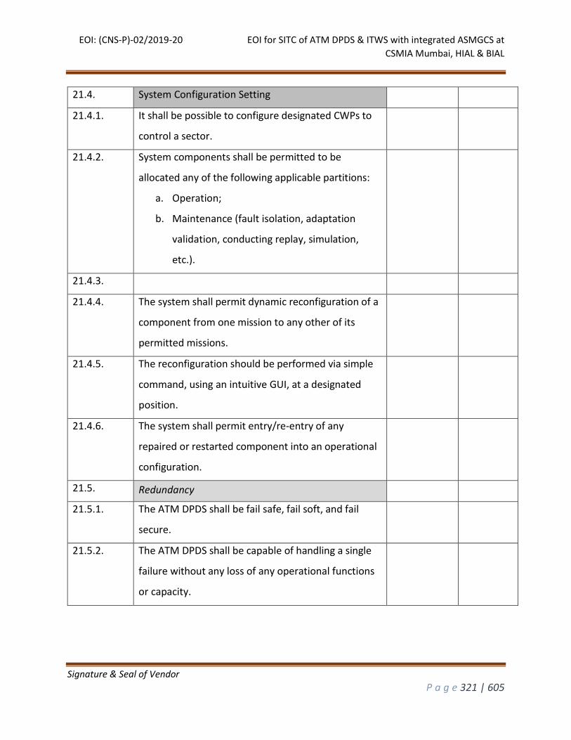
EOI: (CNS-P)-02/2019-20 EOI for SITC of ATM DPDS & ITWS with integrated ASMGCS at
CSMIA Mumbai, HIAL & BIAL
Signature & Seal of Vendor
P a g e 321 | 605
21.4. System Configuration Setting
21.4.1. It shall be possible to configure designated CWPs to
control a sector.
21.4.2. System components shall be permitted to be
allocated any of the following applicable partitions:
a. Operation;
b. Maintenance (fault isolation, adaptation
validation, conducting replay, simulation,
etc.).
21.4.3.
21.4.4. The system shall permit dynamic reconfiguration of a
component from one mission to any other of its
permitted missions.
21.4.5. The reconfiguration should be performed via simple
command, using an intuitive GUI, at a designated
position.
21.4.6. The system shall permit entry/re-entry of any
repaired or restarted component into an operational
configuration.
21.5. Redundancy
21.5.1. The ATM DPDS shall be fail safe, fail soft, and fail
secure.
21.5.2. The ATM DPDS shall be capable of handling a single
failure without any loss of any operational functions
or capacity.
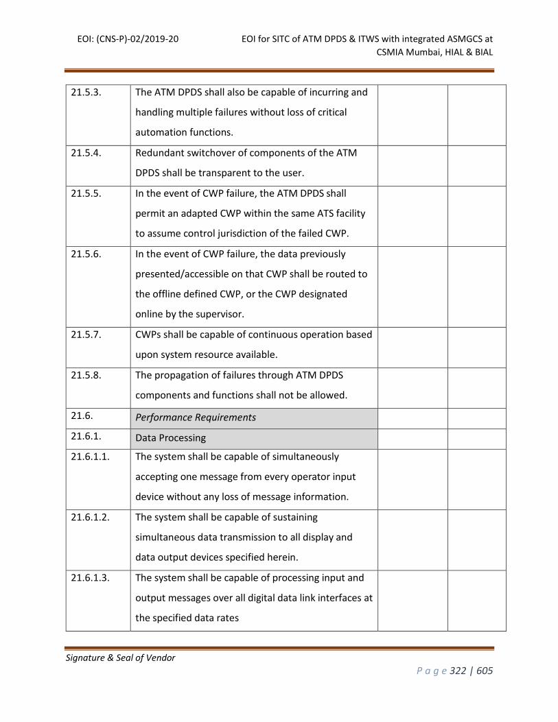
EOI: (CNS-P)-02/2019-20 EOI for SITC of ATM DPDS & ITWS with integrated ASMGCS at
CSMIA Mumbai, HIAL & BIAL
Signature & Seal of Vendor
P a g e 322 | 605
21.5.3. The ATM DPDS shall also be capable of incurring and
handling multiple failures without loss of critical
automation functions.
21.5.4. Redundant switchover of components of the ATM
DPDS shall be transparent to the user.
21.5.5. In the event of CWP failure, the ATM DPDS shall
permit an adapted CWP within the same ATS facility
to assume control jurisdiction of the failed CWP.
21.5.6. In the event of CWP failure, the data previously
presented/accessible on that CWP shall be routed to
the offline defined CWP, or the CWP designated
online by the supervisor.
21.5.7. CWPs shall be capable of continuous operation based
upon system resource available.
21.5.8. The propagation of failures through ATM DPDS
components and functions shall not be allowed.
21.6. Performance Requirements
21.6.1. Data Processing
21.6.1.1. The system shall be capable of simultaneously
accepting one message from every operator input
device without any loss of message information.
21.6.1.2. The system shall be capable of sustaining
simultaneous data transmission to all display and
data output devices specified herein.
21.6.1.3. The system shall be capable of processing input and
output messages over all digital data link interfaces at
the specified data rates
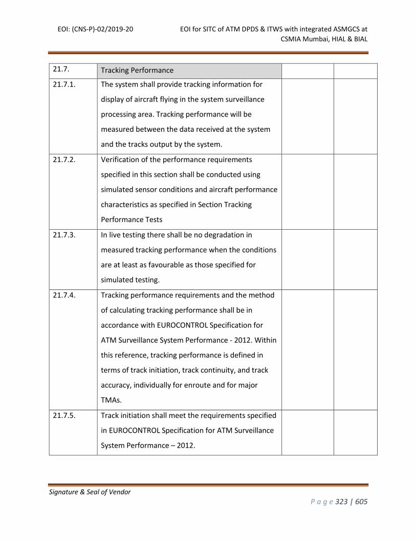
EOI: (CNS-P)-02/2019-20 EOI for SITC of ATM DPDS & ITWS with integrated ASMGCS at
CSMIA Mumbai, HIAL & BIAL
Signature & Seal of Vendor
P a g e 323 | 605
21.7. Tracking Performance
21.7.1. The system shall provide tracking information for
display of aircraft flying in the system surveillance
processing area. Tracking performance will be
measured between the data received at the system
and the tracks output by the system.
21.7.2. Verification of the performance requirements
specified in this section shall be conducted using
simulated sensor conditions and aircraft performance
characteristics as specified in Section Tracking
Performance Tests
21.7.3. In live testing there shall be no degradation in
measured tracking performance when the conditions
are at least as favourable as those specified for
simulated testing.
21.7.4. Tracking performance requirements and the method
of calculating tracking performance shall be in
accordance with EUROCONTROL Specification for
ATM Surveillance System Performance - 2012. Within
this reference, tracking performance is defined in
terms of track initiation, track continuity, and track
accuracy, individually for enroute and for major
TMAs.
21.7.5. Track initiation shall meet the requirements specified
in EUROCONTROL Specification for ATM Surveillance
System Performance – 2012.
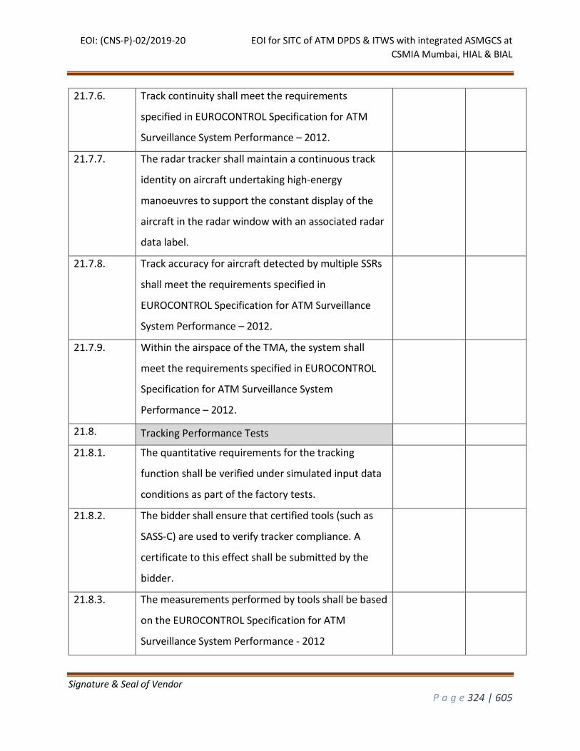
EOI: (CNS-P)-02/2019-20 EOI for SITC of ATM DPDS & ITWS with integrated ASMGCS at
CSMIA Mumbai, HIAL & BIAL
Signature & Seal of Vendor
P a g e 324 | 605
21.7.6. Track continuity shall meet the requirements
specified in EUROCONTROL Specification for ATM
Surveillance System Performance – 2012.
21.7.7. The radar tracker shall maintain a continuous track
identity on aircraft undertaking high-energy
manoeuvres to support the constant display of the
aircraft in the radar window with an associated radar
data label.
21.7.8. Track accuracy for aircraft detected by multiple SSRs
shall meet the requirements specified in
EUROCONTROL Specification for ATM Surveillance
System Performance – 2012.
21.7.9. Within the airspace of the TMA, the system shall
meet the requirements specified in EUROCONTROL
Specification for ATM Surveillance System
Performance – 2012.
21.8. Tracking Performance Tests
21.8.1. The quantitative requirements for the tracking
function shall be verified under simulated input data
conditions as part of the factory tests.
21.8.2. The bidder shall ensure that certified tools (such as
SASS-C) are used to verify tracker compliance. A
certificate to this effect shall be submitted by the
bidder.
21.8.3. The measurements performed by tools shall be based
on the EUROCONTROL Specification for ATM
Surveillance System Performance - 2012
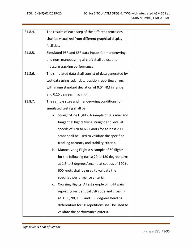
EOI: (CNS-P)-02/2019-20 EOI for SITC of ATM DPDS & ITWS with integrated ASMGCS at
CSMIA Mumbai, HIAL & BIAL
Signature & Seal of Vendor
P a g e 325 | 605
21.8.4. The results of each step of the different processes
shall be visualized from different graphical display
facilities.
21.8.5. Simulated PSR and SSR data inputs for manoeuvring
and non- manoeuvring aircraft shall be used to
measure tracking performance.
21.8.6. The simulated data shall consist of data generated by
test data using radar data position reporting errors
within one standard deviation of 0.04 NM in range
and 0.15 degrees in azimuth.
21.8.7. The sample sizes and manoeuvring conditions for
simulated testing shall be:
a. Straight-Line Flights: A sample of 30 radial and
tangential flights flying straight and level at
speeds of 120 to 650 knots for at least 200
scans shall be used to validate the specified
tracking accuracy and stability criteria.
b. Manoeuvring Flights: A sample of 60 flights
for the following turns: 20 to 180 degree turns
at 1.5 to 3 degrees/second at speeds of 120 to
600 knots shall be used to validate the
specified performance criteria.
c. Crossing Flights: A test sample of flight pairs
reporting on identical SSR code and crossing
at 0, 30, 90, 150, and 180 degrees heading
differentials for 50 repetitions shall be used to
validate the performance criteria.
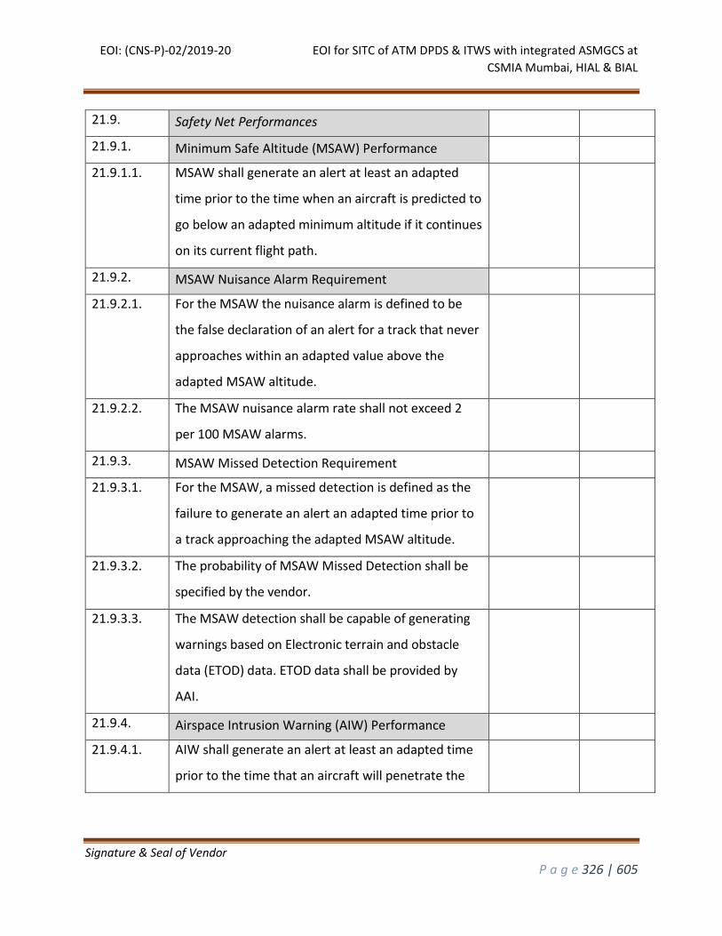
EOI: (CNS-P)-02/2019-20 EOI for SITC of ATM DPDS & ITWS with integrated ASMGCS at
CSMIA Mumbai, HIAL & BIAL
Signature & Seal of Vendor
P a g e 326 | 605
21.9. Safety Net Performances
21.9.1. Minimum Safe Altitude (MSAW) Performance
21.9.1.1. MSAW shall generate an alert at least an adapted
time prior to the time when an aircraft is predicted to
go below an adapted minimum altitude if it continues
on its current flight path.
21.9.2. MSAW Nuisance Alarm Requirement
21.9.2.1. For the MSAW the nuisance alarm is defined to be
the false declaration of an alert for a track that never
approaches within an adapted value above the
adapted MSAW altitude.
21.9.2.2. The MSAW nuisance alarm rate shall not exceed 2
per 100 MSAW alarms.
21.9.3. MSAW Missed Detection Requirement
21.9.3.1. For the MSAW, a missed detection is defined as the
failure to generate an alert an adapted time prior to
a track approaching the adapted MSAW altitude.
21.9.3.2. The probability of MSAW Missed Detection shall be
specified by the vendor.
21.9.3.3. The MSAW detection shall be capable of generating
warnings based on Electronic terrain and obstacle
data (ETOD) data. ETOD data shall be provided by
AAI.
21.9.4. Airspace Intrusion Warning (AIW) Performance
21.9.4.1. AIW shall generate an alert at least an adapted time
prior to the time that an aircraft will penetrate the
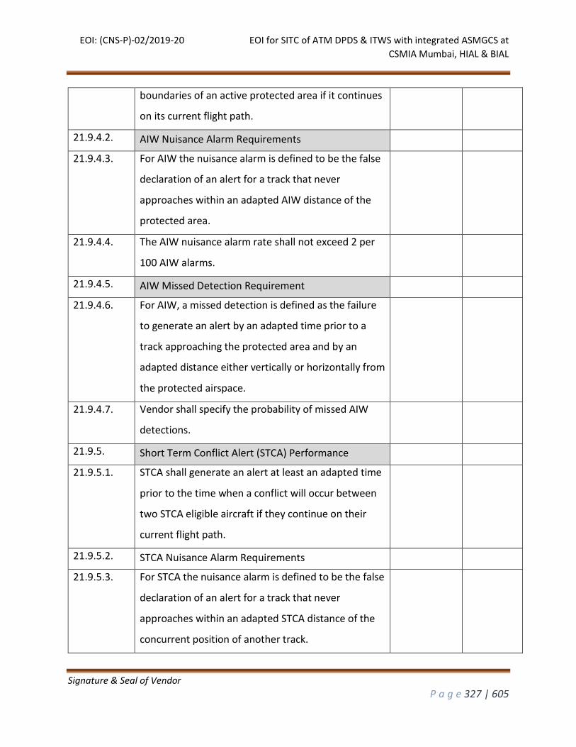
EOI: (CNS-P)-02/2019-20 EOI for SITC of ATM DPDS & ITWS with integrated ASMGCS at
CSMIA Mumbai, HIAL & BIAL
Signature & Seal of Vendor
P a g e 327 | 605
boundaries of an active protected area if it continues
on its current flight path.
21.9.4.2. AIW Nuisance Alarm Requirements
21.9.4.3. For AIW the nuisance alarm is defined to be the false
declaration of an alert for a track that never
approaches within an adapted AIW distance of the
protected area.
21.9.4.4. The AIW nuisance alarm rate shall not exceed 2 per
100 AIW alarms.
21.9.4.5. AIW Missed Detection Requirement
21.9.4.6. For AIW, a missed detection is defined as the failure
to generate an alert by an adapted time prior to a
track approaching the protected area and by an
adapted distance either vertically or horizontally from
the protected airspace.
21.9.4.7. V Vendor shall specify the probability of missed AIW
detections.
21.9.5. Short Term Conflict Alert (STCA) Performance
21.9.5.1. STCA shall generate an alert at least an adapted time
prior to the time when a conflict will occur between
two STCA eligible aircraft if they continue on their
current flight path.
21.9.5.2. STCA Nuisance Alarm Requirements
21.9.5.3. For STCA the nuisance alarm is defined to be the false
declaration of an alert for a track that never
approaches within an adapted STCA distance of the
concurrent position of another track.
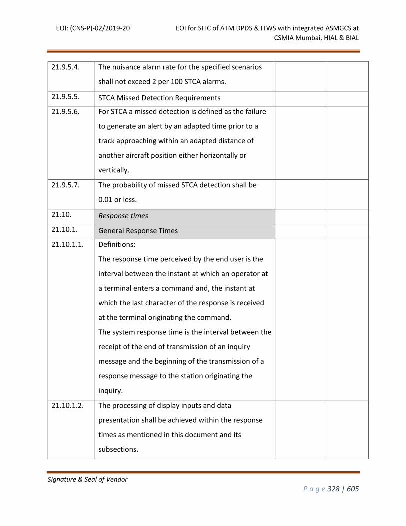
EOI: (CNS-P)-02/2019-20 EOI for SITC of ATM DPDS & ITWS with integrated ASMGCS at
CSMIA Mumbai, HIAL & BIAL
Signature & Seal of Vendor
P a g e 328 | 605
21.9.5.4. The nuisance alarm rate for the specified scenarios
shall not exceed 2 per 100 STCA alarms.
21.9.5.5. STCA Missed Detection Requirements
21.9.5.6. For STCA a missed detection is defined as the failure
to generate an alert by an adapted time prior to a
track approaching within an adapted distance of
another aircraft position either horizontally or
vertically.
21.9.5.7. The probability of missed STCA detection shall be
0.01 or less.
21.10. Response times
21.10.1. General Response Times
21.10.1.1. Definitions:
The response time perceived by the end user is the
interval between the instant at which an operator at
a terminal enters a command and, the instant at
which the last character of the response is received
at the terminal originating the command.
The system response time is the interval between the
receipt of the end of transmission of an inquiry
message and the beginning of the transmission of a
response message to the station originating the
inquiry.
21.10.1.2. The processing of display inputs and data
presentation shall be achieved within the response
times as mentioned in this document and its
subsections.
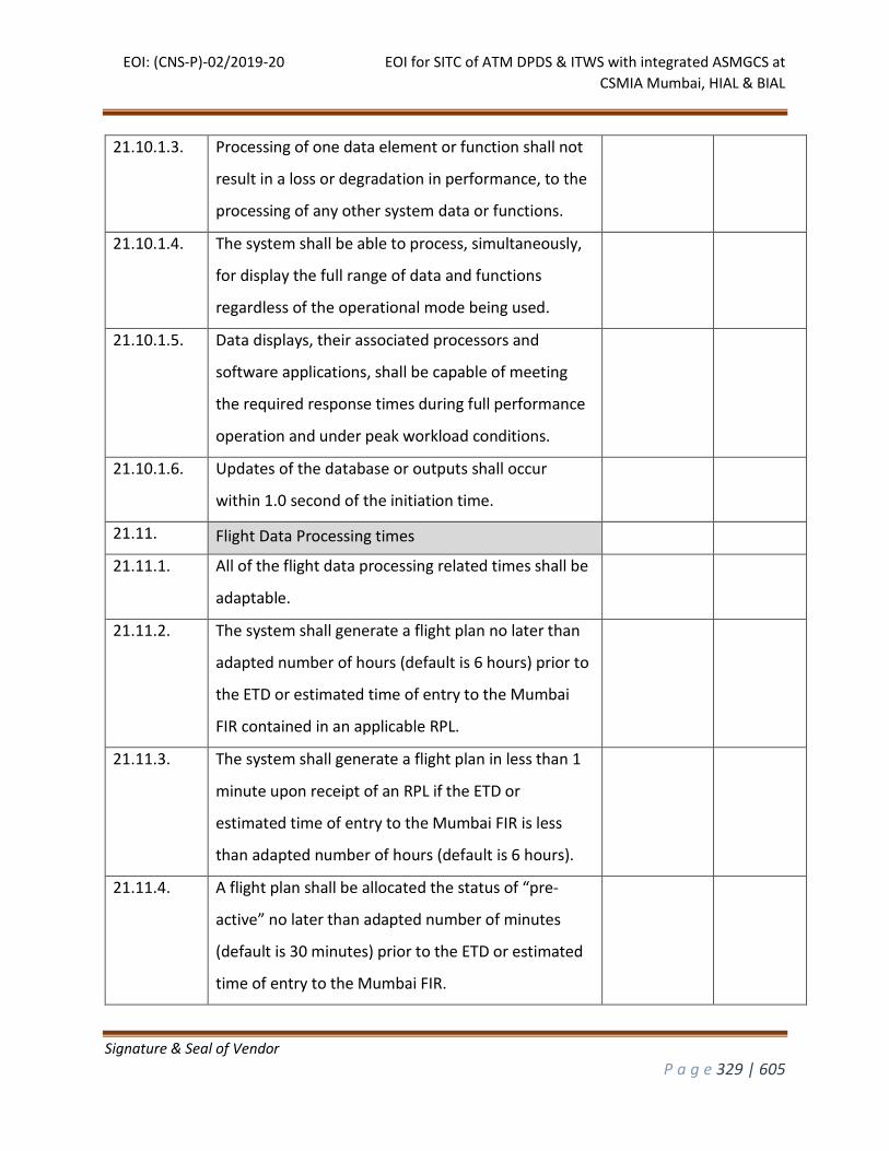
EOI: (CNS-P)-02/2019-20 EOI for SITC of ATM DPDS & ITWS with integrated ASMGCS at
CSMIA Mumbai, HIAL & BIAL
Signature & Seal of Vendor
P a g e 329 | 605
21.10.1.3. Processing of one data element or function shall not
result in a loss or degradation in performance, to the
processing of any other system data or functions.
21.10.1.4. The system shall be able to process, simultaneously,
for display the full range of data and functions
regardless of the operational mode being used.
21.10.1.5. Data displays, their associated processors and
software applications, shall be capable of meeting
the required response times during full performance
operation and under peak workload conditions.
21.10.1.6. Updates of the database or outputs shall occur
within 1.0 second of the initiation time.
21.11. Flight Data Processing times
21.11.1. All of the flight data processing related times shall be
adaptable.
21.11.2. The system shall generate a flight plan no later than
adapted number of hours (default is 6 hours) prior to
the ETD or estimated time of entry to the Mumbai
FIR contained in an applicable RPL.
21.11.3. The system shall generate a flight plan in less than 1
minute upon receipt of an RPL if the ETD or
estimated time of entry to the Mumbai FIR is less
than adapted number of hours (default is 6 hours).
21.11.4. A flight plan shall be allocated the status of “pre-
active” no later than adapted number of minutes
(default is 30 minutes) prior to the ETD or estimated
time of entry to the Mumbai FIR.
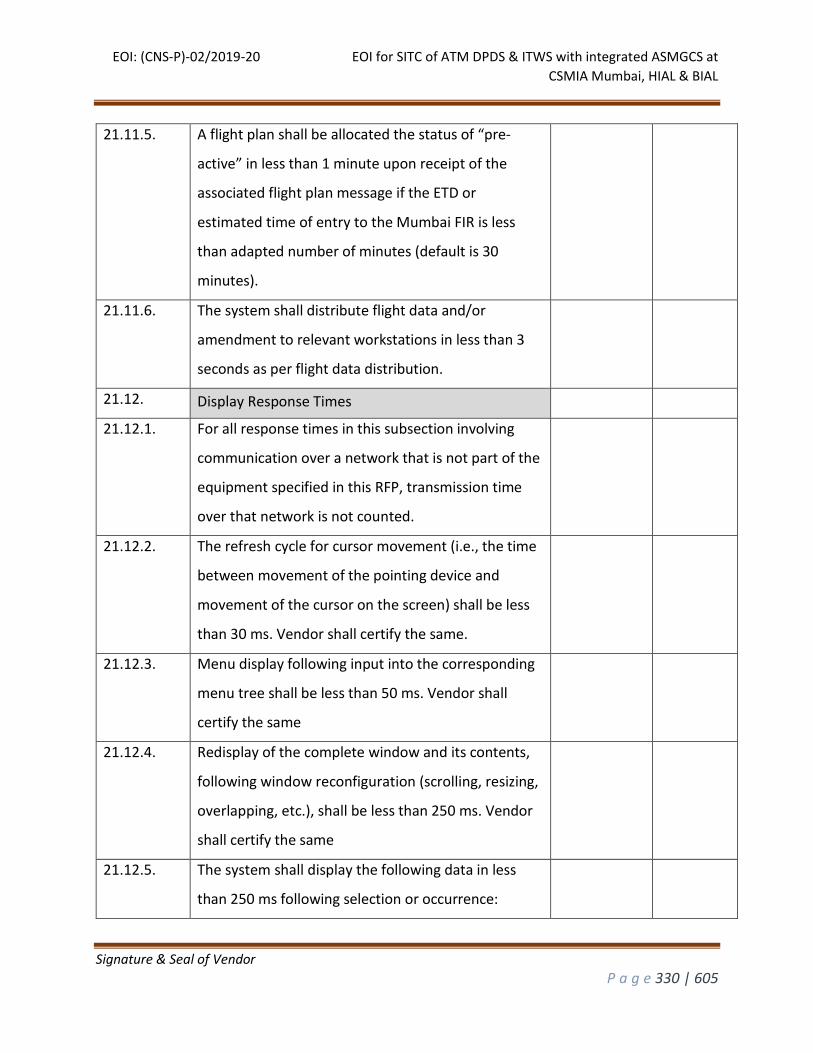
EOI: (CNS-P)-02/2019-20 EOI for SITC of ATM DPDS & ITWS with integrated ASMGCS at
CSMIA Mumbai, HIAL & BIAL
Signature & Seal of Vendor
P a g e 330 | 605
21.11.5. A flight plan shall be allocated the status of “pre-
active” in less than 1 minute upon receipt of the
associated flight plan message if the ETD or
estimated time of entry to the Mumbai FIR is less
than adapted number of minutes (default is 30
minutes).
21.11.6. The system shall distribute flight data and/or
amendment to relevant workstations in less than 3
seconds as per flight data distribution.
21.12. Display Response Times
21.12.1. For all response times in this subsection involving
communication over a network that is not part of the
equipment specified in this RFP, transmission time
over that network is not counted.
21.12.2. The refresh cycle for cursor movement (i.e., the time
between movement of the pointing device and
movement of the cursor on the screen) shall be less
than 30 ms. Vendor shall certify the same.
21.12.3. Menu display following input into the corresponding
menu tree shall be less than 50 ms. Vendor shall
certify the same
21.12.4. Redisplay of the complete window and its contents,
following window reconfiguration (scrolling, resizing,
overlapping, etc.), shall be less than 250 ms. Vendor
shall certify the same
21.12.5. The system shall display the following data in less
than 250 ms following selection or occurrence:
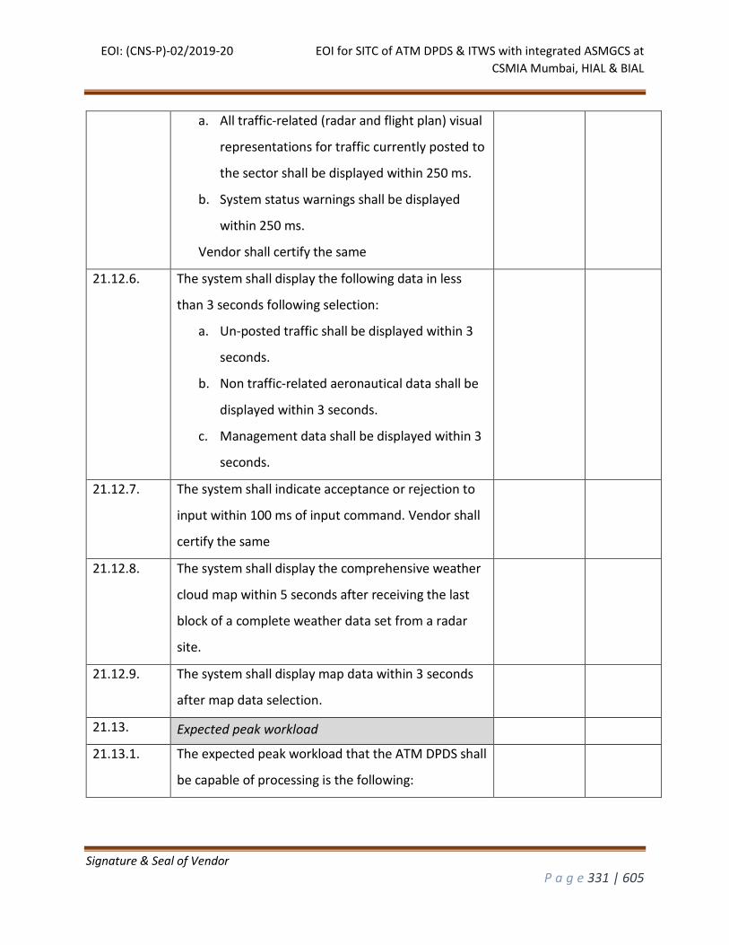
EOI: (CNS-P)-02/2019-20 EOI for SITC of ATM DPDS & ITWS with integrated ASMGCS at
CSMIA Mumbai, HIAL & BIAL
Signature & Seal of Vendor
P a g e 331 | 605
a. All traffic-related (radar and flight plan) visual
representations for traffic currently posted to
the sector shall be displayed within 250 ms.
b. System status warnings shall be displayed
within 250 ms.
Vendor shall certify the same
21.12.6. The system shall display the following data in less
than 3 seconds following selection:
a. Un-posted traffic shall be displayed within 3
seconds.
b. Non traffic-related aeronautical data shall be
displayed within 3 seconds.
c. Management data shall be displayed within 3
seconds.
21.12.7. The system shall indicate acceptance or rejection to
input within 100 ms of input command. Vendor shall
certify the same
21.12.8. The system shall display the comprehensive weather
cloud map within 5 seconds after receiving the last
block of a complete weather data set from a radar
site.
21.12.9. The system shall display map data within 3 seconds
after map data selection.
21.13. Expected peak workload
21.13.1. The expected peak workload that the ATM DPDS shall
be capable of processing is the following:
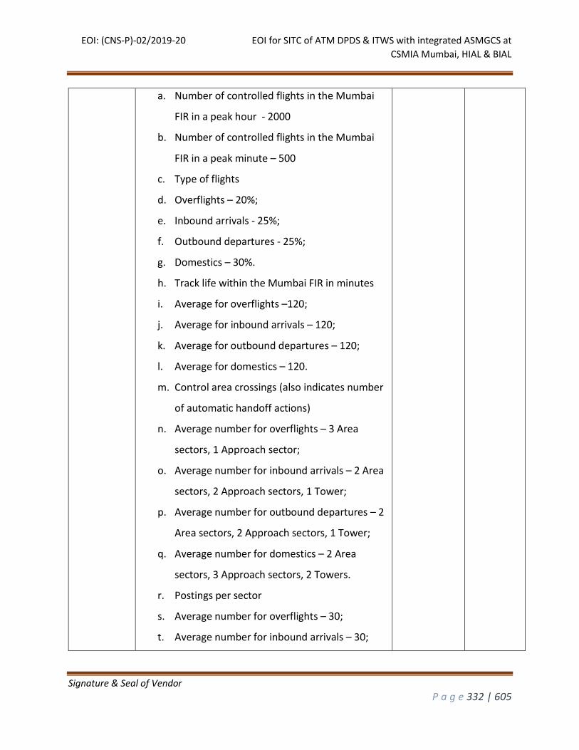
EOI: (CNS-P)-02/2019-20 EOI for SITC of ATM DPDS & ITWS with integrated ASMGCS at
CSMIA Mumbai, HIAL & BIAL
Signature & Seal of Vendor
P a g e 332 | 605
a. Number of controlled flights in the Mumbai
FIR in a peak hour - 2000
b. Number of controlled flights in the Mumbai
FIR in a peak minute – 500
c. Type of flights
d. Overflights – 20%;
e. Inbound arrivals - 25%;
f. Outbound departures - 25%;
g. Domestics – 30%.
h. Track life within the Mumbai FIR in minutes
i. Average for overflights –120;
j. Average for inbound arrivals – 120;
k. Average for outbound departures – 120;
l. Average for domestics – 120.
m. Control area crossings (also indicates number
of automatic handoff actions)
n. Average number for overflights – 3 Area
sectors, 1 Approach sector;
o. Average number for inbound arrivals – 2 Area
sectors, 2 Approach sectors, 1 Tower;
p. Average number for outbound departures – 2
Area sectors, 2 Approach sectors, 1 Tower;
q. Average number for domestics – 2 Area
sectors, 3 Approach sectors, 2 Towers.
r. Postings per sector
s. Average number for overflights – 30;
t. Average number for inbound arrivals – 30;
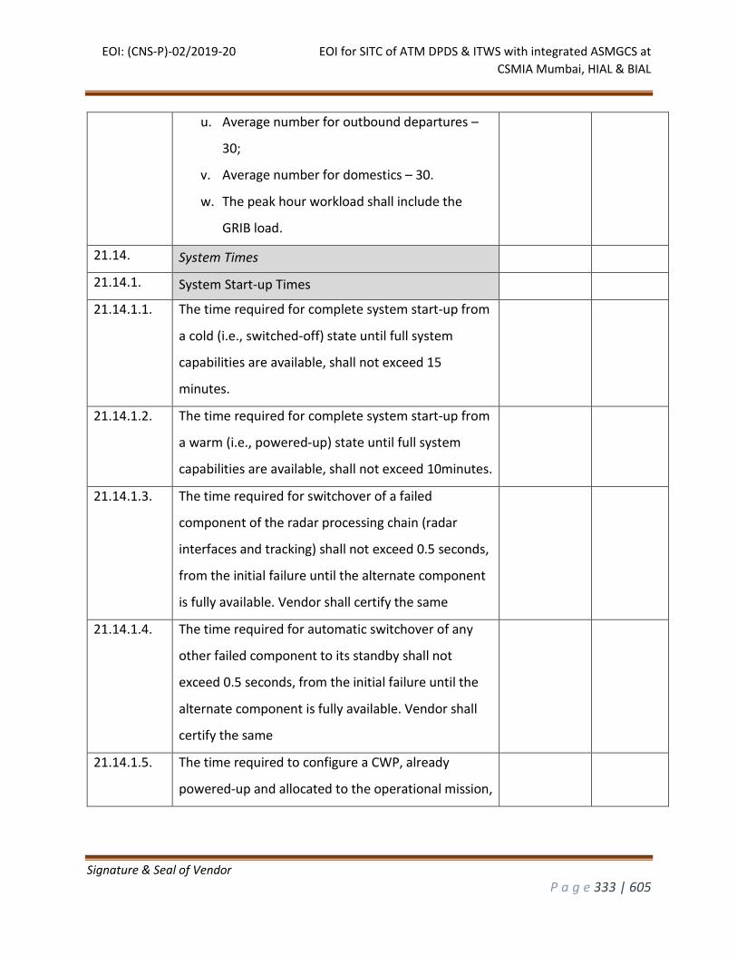
EOI: (CNS-P)-02/2019-20 EOI for SITC of ATM DPDS & ITWS with integrated ASMGCS at
CSMIA Mumbai, HIAL & BIAL
Signature & Seal of Vendor
P a g e 333 | 605
u. Average number for outbound departures –
30;
v. Average number for domestics – 30.
w. The peak hour workload shall include the
GRIB load.
21.14. System Times
21.14.1. System Start-up Times
21.14.1.1. The time required for complete system start-up from
a cold (i.e., switched-off) state until full system
capabilities are available, shall not exceed 15
minutes.
21.14.1.2. The time required for complete system start-up from
a warm (i.e., powered-up) state until full system
capabilities are available, shall not exceed 10minutes.
21.14.1.3. The time required for switchover of a failed
component of the radar processing chain (radar
interfaces and tracking) shall not exceed 0.5 seconds,
from the initial failure until the alternate component
is fully available. Vendor shall certify the same
21.14.1.4. The time required for automatic switchover of any
other failed component to its standby shall not
exceed 0.5 seconds, from the initial failure until the
alternate component is fully available. Vendor shall
certify the same
21.14.1.5. The time required to configure a CWP, already
powered-up and allocated to the operational mission,
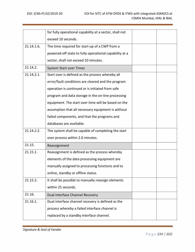
EOI: (CNS-P)-02/2019-20 EOI for SITC of ATM DPDS & ITWS with integrated ASMGCS at
CSMIA Mumbai, HIAL & BIAL
Signature & Seal of Vendor
P a g e 334 | 605
for fully operational capability at a sector, shall not
exceed 10 seconds.
21.14.1.6. The time required for start-up of a CWP from a
powered-off state to fully operational capability at a
sector, shall not exceed 10 minutes.
21.14.2. System Start over Times
21.14.2.1. Start over is defined as the process whereby all
error/fault conditions are cleared and the program
operation is continued or is initiated from safe
program and data storage in the on-line processing
equipment. The start over time will be based on the
assumption that all necessary equipment is without
failed components, and that the programs and
databases are available.
21.14.2.2. The system shall be capable of completing the start
over process within 2.0 minutes.
21.15. Reassignment
21.15.1. Reassignment is defined as the process whereby
elements of the data processing equipment are
manually assigned to processing functions and to
online, standby or offline status.
21.15.2. It shall be possible to manually reassign elements
within 25 seconds.
21.16. Dual interface Channel Recovery
21.16.1. Dual interface channel recovery is defined as the
process whereby a failed interface channel is
replaced by a standby interface channel.
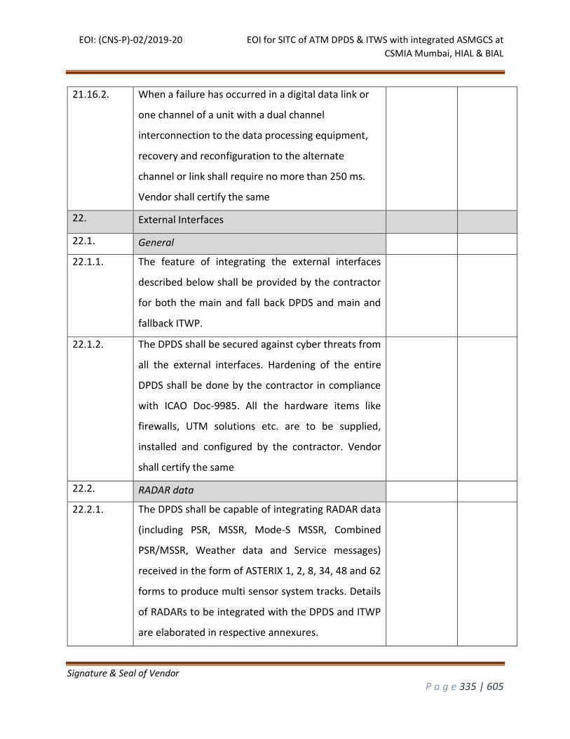
EOI: (CNS-P)-02/2019-20 EOI for SITC of ATM DPDS & ITWS with integrated ASMGCS at
CSMIA Mumbai, HIAL & BIAL
Signature & Seal of Vendor
P a g e 335 | 605
21.16.2. When a failure has occurred in a digital data link or
one channel of a unit with a dual channel
interconnection to the data processing equipment,
recovery and reconfiguration to the alternate
channel or link shall require no more than 250 ms.
Vendor shall certify the same
22. External Interfaces
22.1. General
22.1.1. The feature of integrating the external interfaces
described below shall be provided by the contractor
for both the main and fall back DPDS and main and
fallback ITWP.
22.1.2. The DPDS shall be secured against cyber threats from
all the external interfaces. Hardening of the entire
DPDS shall be done by the contractor in compliance
with ICAO Doc-9985. All the hardware items like
firewalls, UTM solutions etc. are to be supplied,
installed and configured by the contractor. Vendor
shall certify the same
22.2. RADAR data
22.2.1. The DPDS shall be capable of integrating RADAR data
(including PSR, MSSR, Mode-S MSSR, Combined
PSR/MSSR, Weather data and Service messages)
received in the form of ASTERIX 1, 2, 8, 34, 48 and 62
forms to produce multi sensor system tracks. Details
of RADARs to be integrated with the DPDS and ITWP
are elaborated in respective annexures.
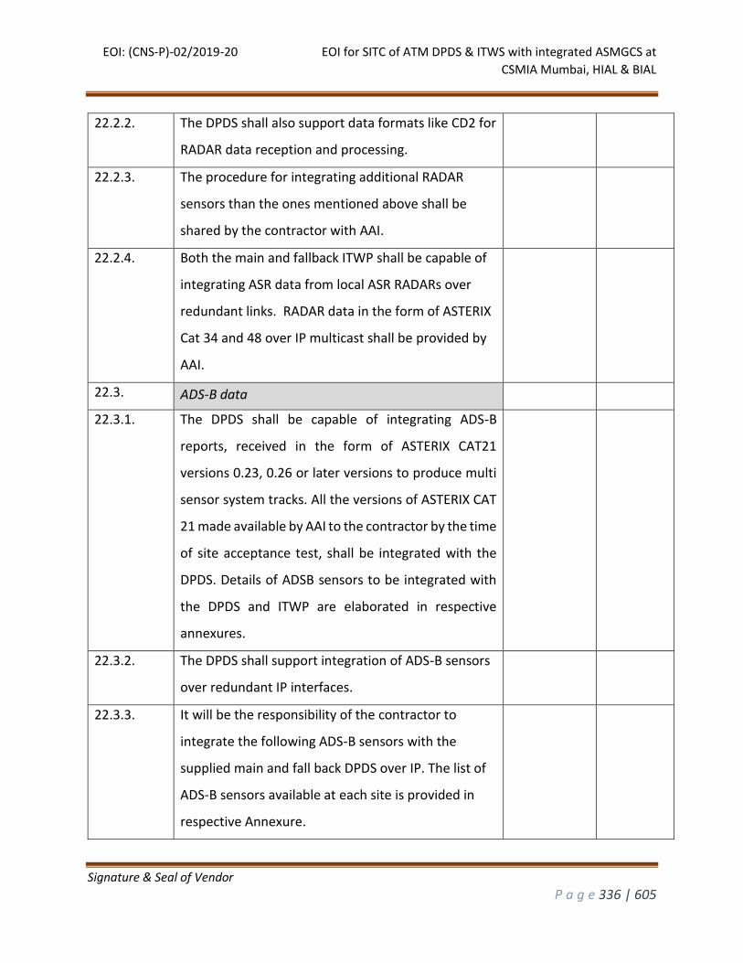
EOI: (CNS-P)-02/2019-20 EOI for SITC of ATM DPDS & ITWS with integrated ASMGCS at
CSMIA Mumbai, HIAL & BIAL
Signature & Seal of Vendor
P a g e 336 | 605
22.2.2. The DPDS shall also support data formats like CD2 for
RADAR data reception and processing.
22.2.3. The procedure for integrating additional RADAR
sensors than the ones mentioned above shall be
shared by the contractor with AAI.
22.2.4. Both the main and fallback ITWP shall be capable of
integrating ASR data from local ASR RADARs over
redundant links. RADAR data in the form of ASTERIX
Cat 34 and 48 over IP multicast shall be provided by
AAI.
22.3. ADS-B data
22.3.1. The DPDS shall be capable of integrating ADS-B
reports, received in the form of ASTERIX CAT21
versions 0.23, 0.26 or later versions to produce multi
sensor system tracks. All the versions of ASTERIX CAT
21 made available by AAI to the contractor by the time
of site acceptance test, shall be integrated with the
DPDS. Details of ADSB sensors to be integrated with
the DPDS and ITWP are elaborated in respective
annexures.
22.3.2. The DPDS shall support integration of ADS-B sensors
over redundant IP interfaces.
22.3.3. It will be the responsibility of the contractor to
integrate the following ADS-B sensors with the
supplied main and fall back DPDS over IP. The list of
ADS-B sensors available at each site is provided in
respective Annexure.
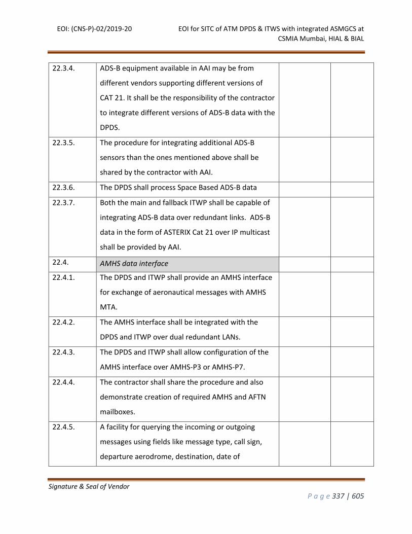
EOI: (CNS-P)-02/2019-20 EOI for SITC of ATM DPDS & ITWS with integrated ASMGCS at
CSMIA Mumbai, HIAL & BIAL
Signature & Seal of Vendor
P a g e 337 | 605
22.3.4. ADS-B equipment available in AAI may be from
different vendors supporting different versions of
CAT 21. It shall be the responsibility of the contractor
to integrate different versions of ADS-B data with the
DPDS.
22.3.5. The procedure for integrating additional ADS-B
sensors than the ones mentioned above shall be
shared by the contractor with AAI.
22.3.6. The DPDS shall process Space Based ADS-B data
22.3.7. Both the main and fallback ITWP shall be capable of
integrating ADS-B data over redundant links. ADS-B
data in the form of ASTERIX Cat 21 over IP multicast
shall be provided by AAI.
22.4. AMHS data interface
22.4.1. The DPDS and ITWP shall provide an AMHS interface
for exchange of aeronautical messages with AMHS
MTA.
22.4.2. The AMHS interface shall be integrated with the
DPDS and ITWP over dual redundant LANs.
22.4.3. The DPDS and ITWP shall allow configuration of the
AMHS interface over AMHS-P3 or AMHS-P7.
22.4.4. The contractor shall share the procedure and also
demonstrate creation of required AMHS and AFTN
mailboxes.
22.4.5. A facility for querying the incoming or outgoing
messages using fields like message type, call sign,
departure aerodrome, destination, date of
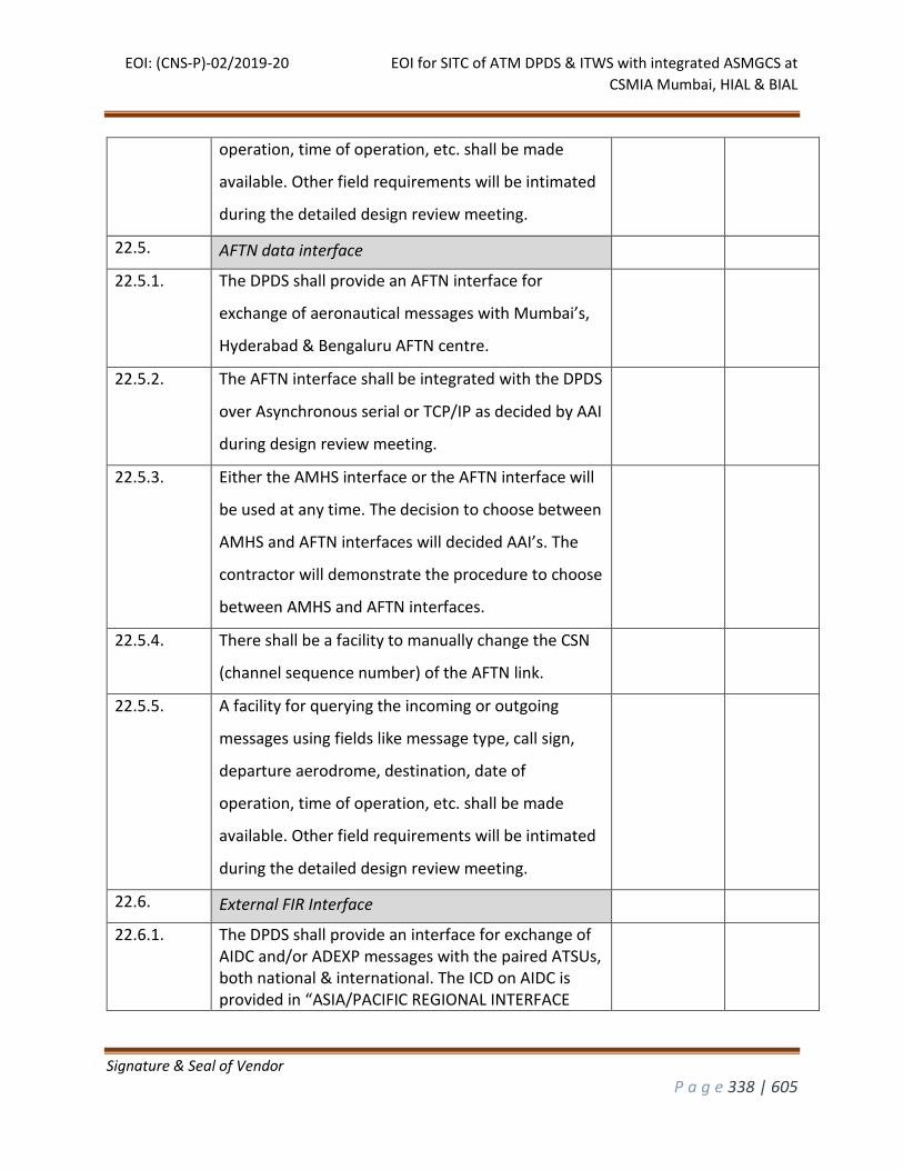
EOI: (CNS-P)-02/2019-20 EOI for SITC of ATM DPDS & ITWS with integrated ASMGCS at
CSMIA Mumbai, HIAL & BIAL
Signature & Seal of Vendor
P a g e 338 | 605
operation, time of operation, etc. shall be made
available. Other field requirements will be intimated
during the detailed design review meeting.
22.5. AFTN data interface
22.5.1. The DPDS shall provide an AFTN interface for
exchange of aeronautical messages with Mumbai’s,
Hyderabad & Bengaluru AFTN centre.
22.5.2. The AFTN interface shall be integrated with the DPDS
over Asynchronous serial or TCP/IP as decided by AAI
during design review meeting.
22.5.3. Either the AMHS interface or the AFTN interface will
be used at any time. The decision to choose between
AMHS and AFTN interfaces will decided AAI’s. The
contractor will demonstrate the procedure to choose
between AMHS and AFTN interfaces.
22.5.4. There shall be a facility to manually change the CSN
(channel sequence number) of the AFTN link.
22.5.5. A facility for querying the incoming or outgoing
messages using fields like message type, call sign,
departure aerodrome, destination, date of
operation, time of operation, etc. shall be made
available. Other field requirements will be intimated
during the detailed design review meeting.
22.6. External FIR Interface
22.6.1. The DPDS shall provide an interface for exchange of AIDC and/or ADEXP messages with the paired ATSUs, both national & international. The ICD on AIDC is provided in “ASIA/PACIFIC REGIONAL INTERFACE
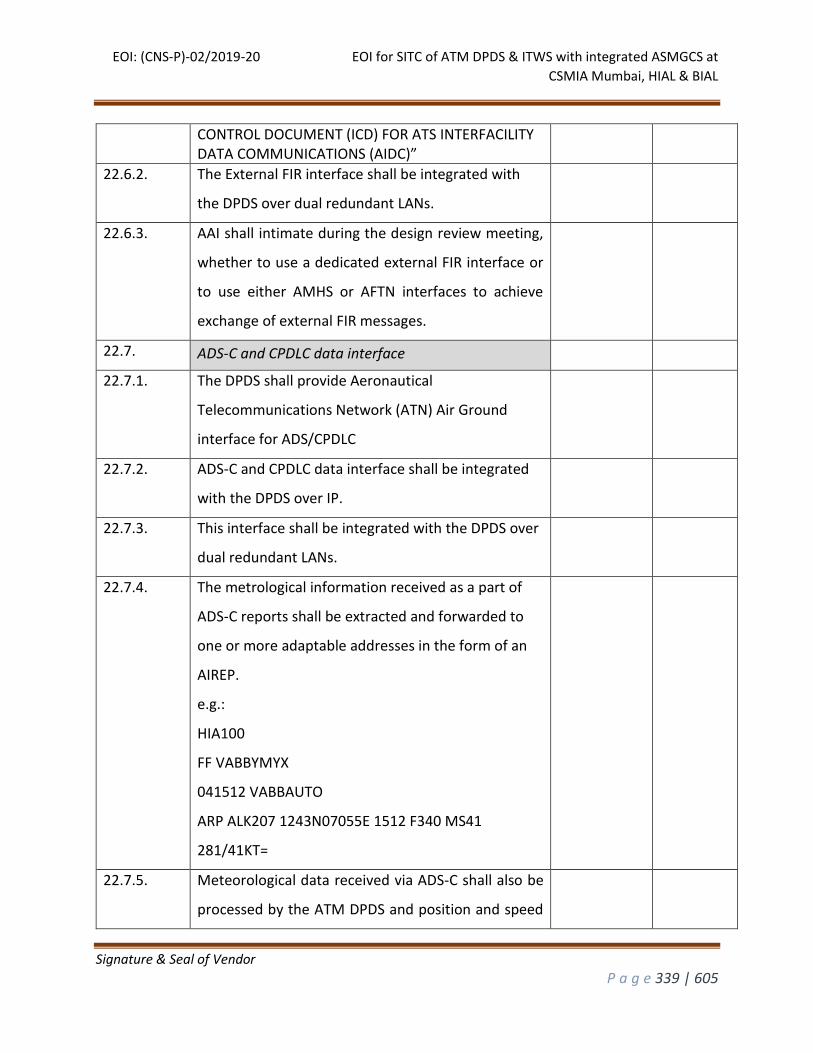
EOI: (CNS-P)-02/2019-20 EOI for SITC of ATM DPDS & ITWS with integrated ASMGCS at
CSMIA Mumbai, HIAL & BIAL
Signature & Seal of Vendor
P a g e 339 | 605
CONTROL DOCUMENT (ICD) FOR ATS INTERFACILITY DATA COMMUNICATIONS (AIDC)”
22.6.2. The External FIR interface shall be integrated with
the DPDS over dual redundant LANs.
22.6.3. AAI shall intimate during the design review meeting,
whether to use a dedicated external FIR interface or
to use either AMHS or AFTN interfaces to achieve
exchange of external FIR messages.
22.7. ADS-C and CPDLC data interface
22.7.1. The DPDS shall provide Aeronautical
Telecommunications Network (ATN) Air Ground
interface for ADS/CPDLC
22.7.2. ADS-C and CPDLC data interface shall be integrated
with the DPDS over IP.
22.7.3. This interface shall be integrated with the DPDS over
dual redundant LANs.
22.7.4. The metrological information received as a part of
ADS-C reports shall be extracted and forwarded to
one or more adaptable addresses in the form of an
AIREP.
e.g.:
HIA100
FF VABBYMYX
041512 VABBAUTO
ARP ALK207 1243N07055E 1512 F340 MS41
281/41KT=
22.7.5. Meteorological data received via ADS-C shall also be
processed by the ATM DPDS and position and speed
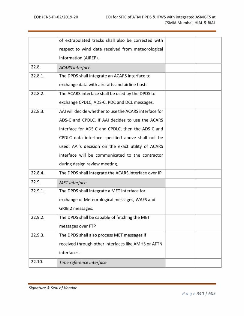
EOI: (CNS-P)-02/2019-20 EOI for SITC of ATM DPDS & ITWS with integrated ASMGCS at
CSMIA Mumbai, HIAL & BIAL
Signature & Seal of Vendor
P a g e 340 | 605
of extrapolated tracks shall also be corrected with
respect to wind data received from meteorological
information (AIREP).
22.8. ACARS interface
22.8.1. The DPDS shall integrate an ACARS interface to
exchange data with aircrafts and airline hosts.
22.8.2. The ACARS interface shall be used by the DPDS to
exchange CPDLC, ADS-C, PDC and DCL messages.
22.8.3. AAI will decide whether to use the ACARS interface for
ADS-C and CPDLC. If AAI decides to use the ACARS
interface for ADS-C and CPDLC, then the ADS-C and
CPDLC data interface specified above shall not be
used. AAI’s decision on the exact utility of ACARS
interface will be communicated to the contractor
during design review meeting.
22.8.4. The DPDS shall integrate the ACARS interface over IP.
22.9. MET Interface
22.9.1. The DPDS shall integrate a MET interface for
exchange of Meteorological messages, WAFS and
GRIB 2 messages.
22.9.2. The DPDS shall be capable of fetching the MET
messages over FTP
22.9.3. The DPDS shall also process MET messages if
received through other interfaces like AMHS or AFTN
interfaces.
22.10. Time reference interface
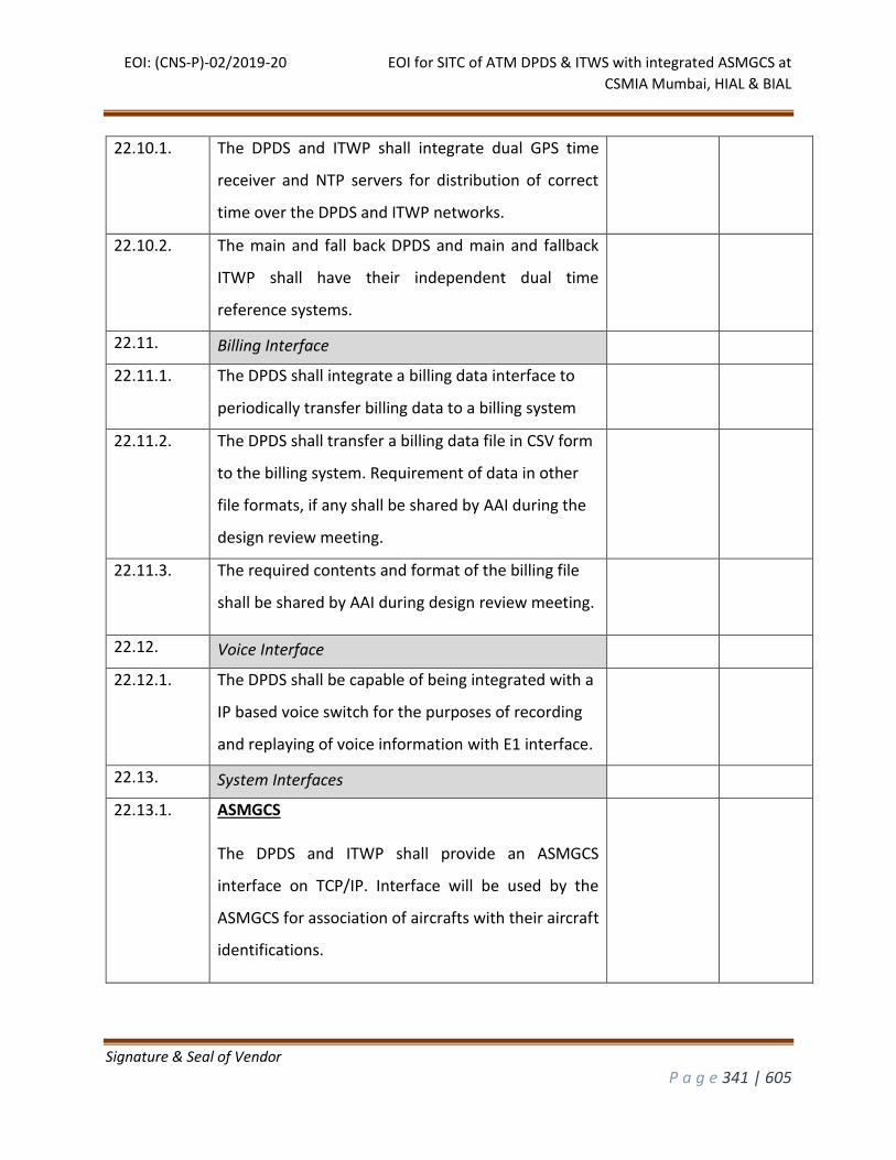
EOI: (CNS-P)-02/2019-20 EOI for SITC of ATM DPDS & ITWS with integrated ASMGCS at
CSMIA Mumbai, HIAL & BIAL
Signature & Seal of Vendor
P a g e 341 | 605
22.10.1. The DPDS and ITWP shall integrate dual GPS time
receiver and NTP servers for distribution of correct
time over the DPDS and ITWP networks.
22.10.2. The main and fall back DPDS and main and fallback
ITWP shall have their independent dual time
reference systems.
22.11. Billing Interface
22.11.1. The DPDS shall integrate a billing data interface to
periodically transfer billing data to a billing system
22.11.2. The DPDS shall transfer a billing data file in CSV form
to the billing system. Requirement of data in other
file formats, if any shall be shared by AAI during the
design review meeting.
22.11.3. The required contents and format of the billing file
shall be shared by AAI during design review meeting.
22.12. Voice Interface
22.12.1. The DPDS shall be capable of being integrated with a
IP based voice switch for the purposes of recording
and replaying of voice information with E1 interface.
22.13. System Interfaces
22.13.1. ASMGCS
The DPDS and ITWP shall provide an ASMGCS
interface on TCP/IP. Interface will be used by the
ASMGCS for association of aircrafts with their aircraft
identifications.
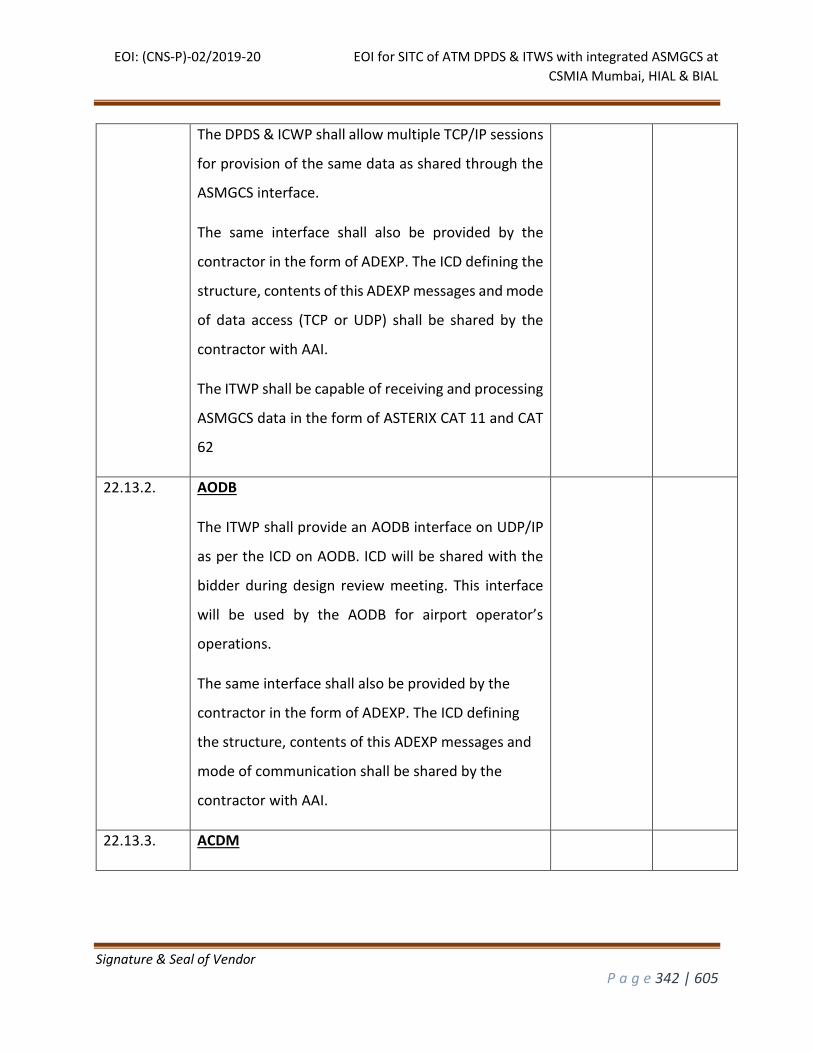
EOI: (CNS-P)-02/2019-20 EOI for SITC of ATM DPDS & ITWS with integrated ASMGCS at
CSMIA Mumbai, HIAL & BIAL
Signature & Seal of Vendor
P a g e 342 | 605
The DPDS & ICWP shall allow multiple TCP/IP sessions
for provision of the same data as shared through the
ASMGCS interface.
The same interface shall also be provided by the
contractor in the form of ADEXP. The ICD defining the
structure, contents of this ADEXP messages and mode
of data access (TCP or UDP) shall be shared by the
contractor with AAI.
The ITWP shall be capable of receiving and processing
ASMGCS data in the form of ASTERIX CAT 11 and CAT
62
22.13.2. AODB
The ITWP shall provide an AODB interface on UDP/IP
as per the ICD on AODB. ICD will be shared with the
bidder during design review meeting. This interface
will be used by the AODB for airport operator’s
operations.
The same interface shall also be provided by the
contractor in the form of ADEXP. The ICD defining
the structure, contents of this ADEXP messages and
mode of communication shall be shared by the
contractor with AAI.
22.13.3. ACDM
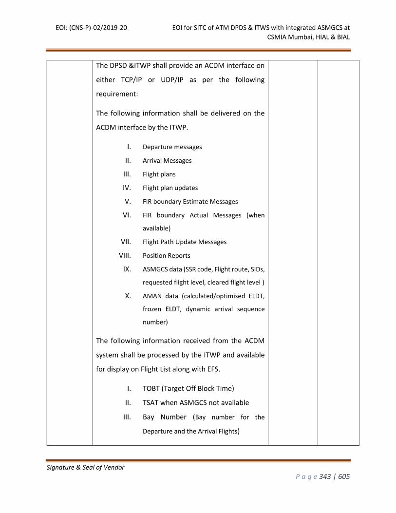
EOI: (CNS-P)-02/2019-20 EOI for SITC of ATM DPDS & ITWS with integrated ASMGCS at
CSMIA Mumbai, HIAL & BIAL
Signature & Seal of Vendor
P a g e 343 | 605
The DPSD &ITWP shall provide an ACDM interface on
either TCP/IP or UDP/IP as per the following
requirement:
The following information shall be delivered on the
ACDM interface by the ITWP.
I. Departure messages
II. Arrival Messages
III. Flight plans
IV. Flight plan updates
V. FIR boundary Estimate Messages
VI. FIR boundary Actual Messages (when
available)
VII. Flight Path Update Messages
VIII. Position Reports
IX. ASMGCS data (SSR code, Flight route, SIDs,
requested flight level, cleared flight level )
X. AMAN data (calculated/optimised ELDT,
frozen ELDT, dynamic arrival sequence
number)
The following information received from the ACDM
system shall be processed by the ITWP and available
for display on Flight List along with EFS.
I. TOBT (Target Off Block Time)
II. TSAT when ASMGCS not available
III. Bay Number (Bay number for the
Departure and the Arrival Flights)
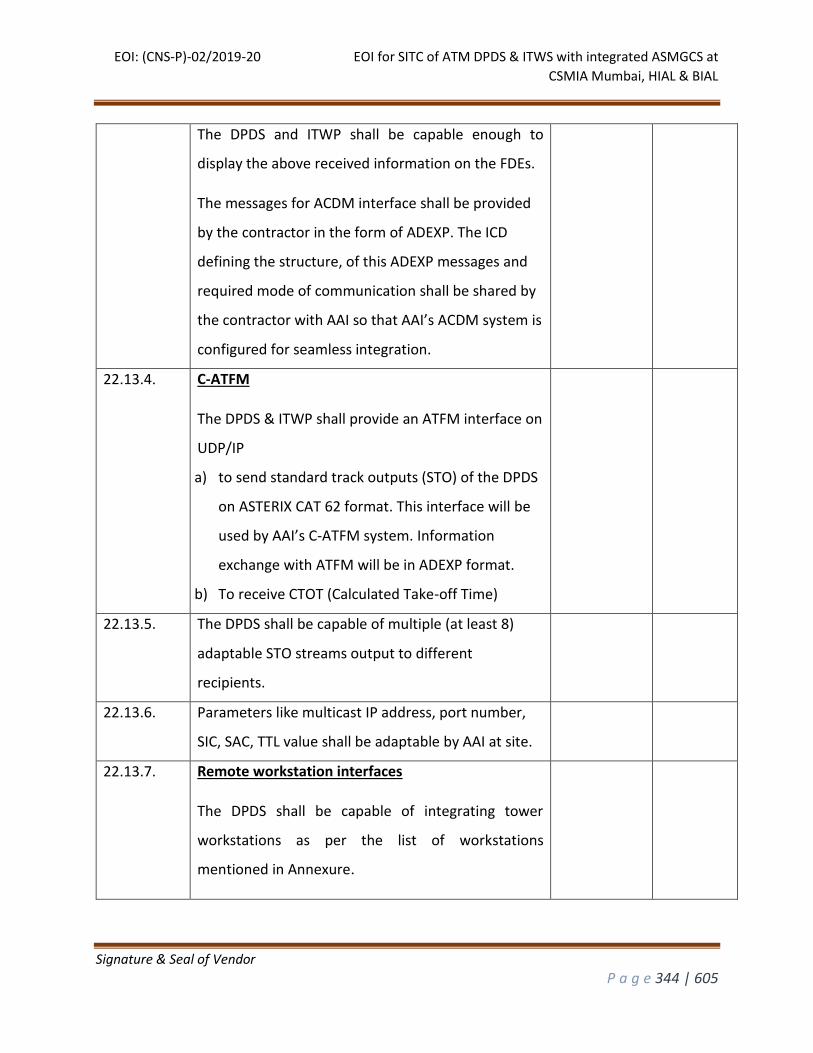
EOI: (CNS-P)-02/2019-20 EOI for SITC of ATM DPDS & ITWS with integrated ASMGCS at
CSMIA Mumbai, HIAL & BIAL
Signature & Seal of Vendor
P a g e 344 | 605
The DPDS and ITWP shall be capable enough to
display the above received information on the FDEs.
The messages for ACDM interface shall be provided
by the contractor in the form of ADEXP. The ICD
defining the structure, of this ADEXP messages and
required mode of communication shall be shared by
the contractor with AAI so that AAI’s ACDM system is
configured for seamless integration.
22.13.4. C-ATFM
The DPDS & ITWP shall provide an ATFM interface on
UDP/IP
a) to send standard track outputs (STO) of the DPDS
on ASTERIX CAT 62 format. This interface will be
used by AAI’s C-ATFM system. Information
exchange with ATFM will be in ADEXP format.
b) To receive CTOT (Calculated Take-off Time)
22.13.5. The DPDS shall be capable of multiple (at least 8)
adaptable STO streams output to different
recipients.
22.13.6. Parameters like multicast IP address, port number,
SIC, SAC, TTL value shall be adaptable by AAI at site.
22.13.7. Remote workstation interfaces
The DPDS shall be capable of integrating tower
workstations as per the list of workstations
mentioned in Annexure.
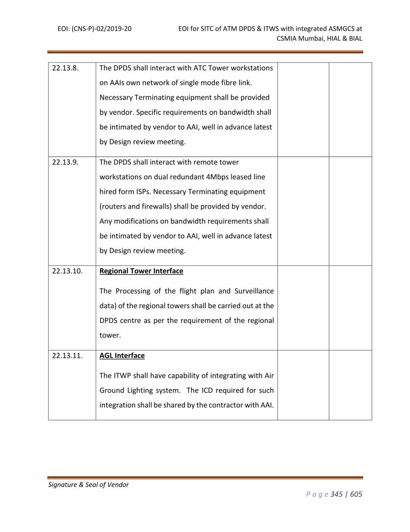
EOI: (CNS-P)-02/2019-20 EOI for SITC of ATM DPDS & ITWS with integrated ASMGCS at
CSMIA Mumbai, HIAL & BIAL
Signature & Seal of Vendor
P a g e 345 | 605
22.13.8. The DPDS shall interact with ATC Tower workstations
on AAIs own network of single mode fibre link.
Necessary Terminating equipment shall be provided
by vendor. Specific requirements on bandwidth shall
be intimated by vendor to AAI, well in advance latest
by Design review meeting.
22.13.9. The DPDS shall interact with remote tower
workstations on dual redundant 4Mbps leased line
hired form ISPs. Necessary Terminating equipment
(routers and firewalls) shall be provided by vendor.
Any modifications on bandwidth requirements shall
be intimated by vendor to AAI, well in advance latest
by Design review meeting.
22.13.10. Regional Tower Interface
The Processing of the flight plan and Surveillance
data) of the regional towers shall be carried out at the
DPDS centre as per the requirement of the regional
tower.
22.13.11. AGL Interface
The ITWP shall have capability of integrating with Air
Ground Lighting system. The ICD required for such
integration shall be shared by the contractor with AAI.
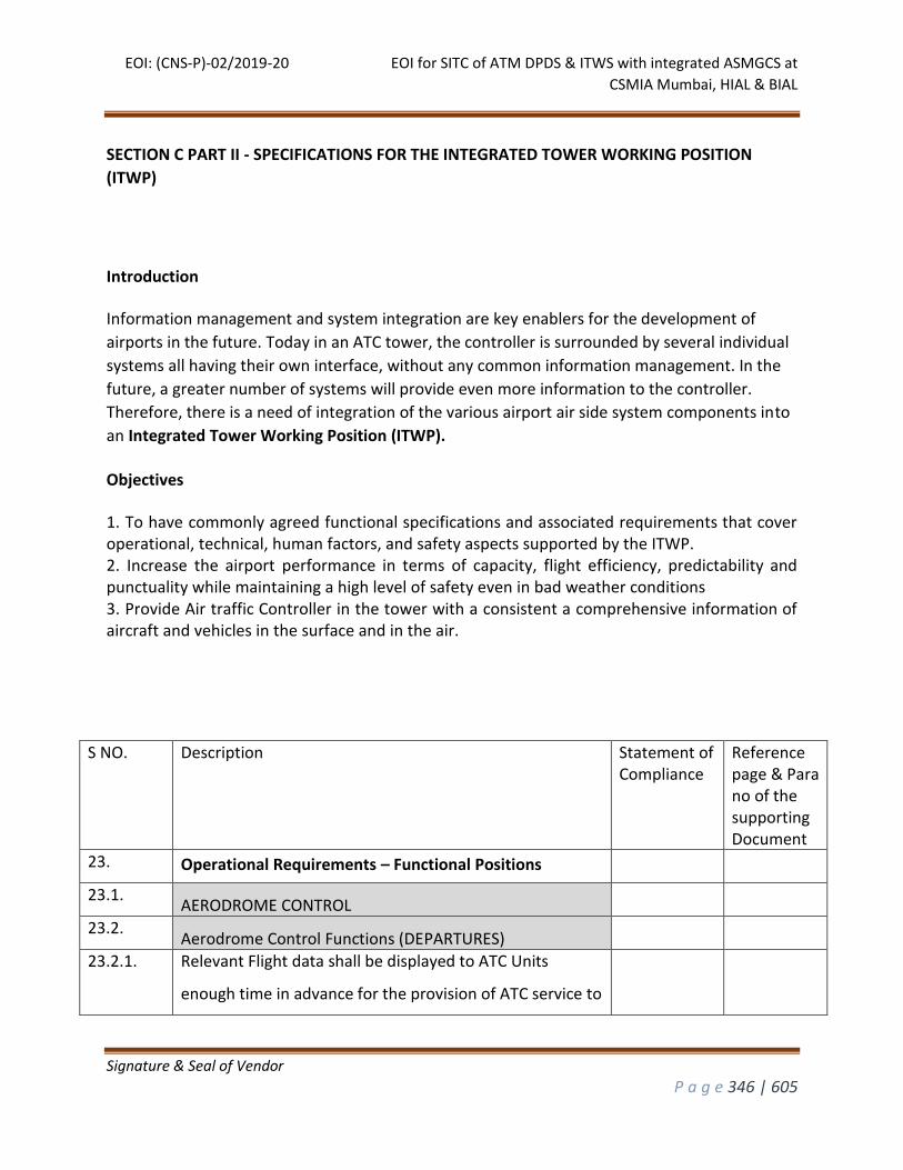
EOI: (CNS-P)-02/2019-20 EOI for SITC of ATM DPDS & ITWS with integrated ASMGCS at
CSMIA Mumbai, HIAL & BIAL
Signature & Seal of Vendor
P a g e 346 | 605
SECTION C PART II - SPECIFICATIONS FOR THE INTEGRATED TOWER WORKING POSITION
(ITWP)
Introduction
Information management and system integration are key enablers for the development of
airports in the future. Today in an ATC tower, the controller is surrounded by several individual
systems all having their own interface, without any common information management. In the
future, a greater number of systems will provide even more information to the controller.
Therefore, there is a need of integration of the various airport air side system components into
an Integrated Tower Working Position (ITWP).
Objectives
1. To have commonly agreed functional specifications and associated requirements that cover operational, technical, human factors, and safety aspects supported by the ITWP. 2. Increase the airport performance in terms of capacity, flight efficiency, predictability and punctuality while maintaining a high level of safety even in bad weather conditions 3. Provide Air traffic Controller in the tower with a consistent a comprehensive information of aircraft and vehicles in the surface and in the air.
S NO.
Description Statement of Compliance
Reference page & Para no of the supporting Document
23. Operational Requirements – Functional Positions
23.1. AERODROME CONTROL
23.2. Aerodrome Control Functions (DEPARTURES)
23.2.1. Relevant Flight data shall be displayed to ATC Units
enough time in advance for the provision of ATC service to
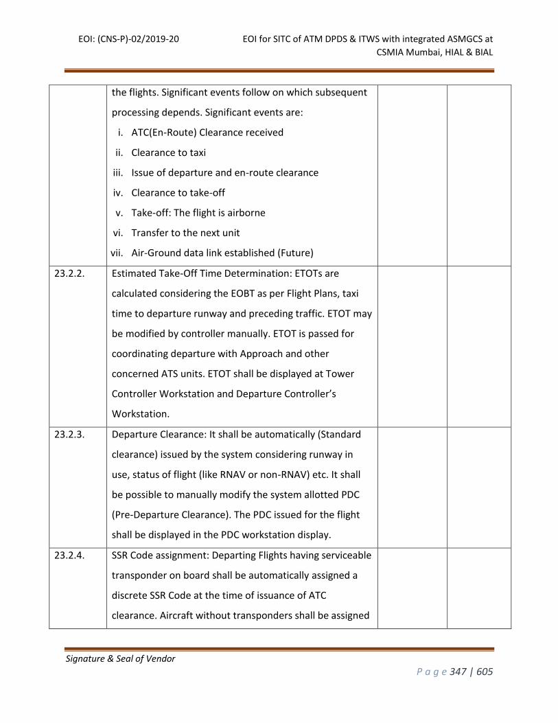
EOI: (CNS-P)-02/2019-20 EOI for SITC of ATM DPDS & ITWS with integrated ASMGCS at
CSMIA Mumbai, HIAL & BIAL
Signature & Seal of Vendor
P a g e 347 | 605
the flights. Significant events follow on which subsequent
processing depends. Significant events are:
i. ATC(En-Route) Clearance received
ii. Clearance to taxi
iii. Issue of departure and en-route clearance
iv. Clearance to take-off
v. Take-off: The flight is airborne
vi. Transfer to the next unit
vii. Air-Ground data link established (Future)
23.2.2. Estimated Take-Off Time Determination: ETOTs are
calculated considering the EOBT as per Flight Plans, taxi
time to departure runway and preceding traffic. ETOT may
be modified by controller manually. ETOT is passed for
coordinating departure with Approach and other
concerned ATS units. ETOT shall be displayed at Tower
Controller Workstation and Departure Controller’s
Workstation.
23.2.3. Departure Clearance: It shall be automatically (Standard
clearance) issued by the system considering runway in
use, status of flight (like RNAV or non-RNAV) etc. It shall
be possible to manually modify the system allotted PDC
(Pre-Departure Clearance). The PDC issued for the flight
shall be displayed in the PDC workstation display.
23.2.4. SSR Code assignment: Departing Flights having serviceable
transponder on board shall be automatically assigned a
discrete SSR Code at the time of issuance of ATC
clearance. Aircraft without transponders shall be assigned
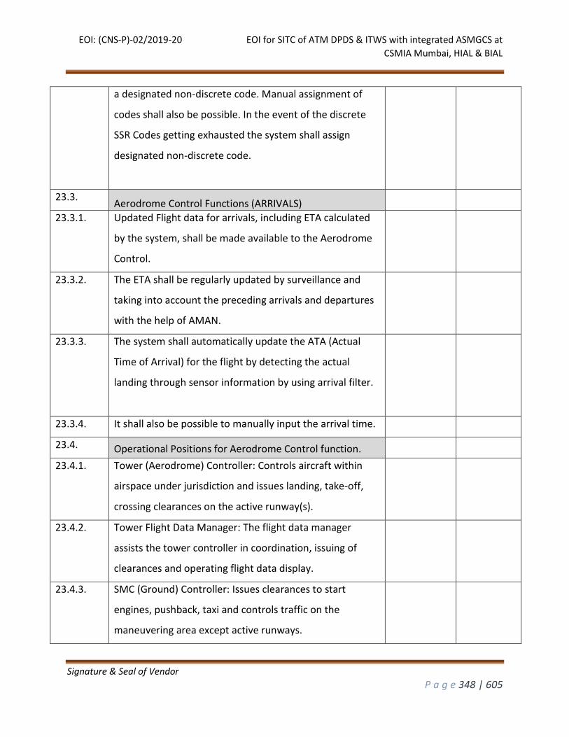
EOI: (CNS-P)-02/2019-20 EOI for SITC of ATM DPDS & ITWS with integrated ASMGCS at
CSMIA Mumbai, HIAL & BIAL
Signature & Seal of Vendor
P a g e 348 | 605
a designated non-discrete code. Manual assignment of
codes shall also be possible. In the event of the discrete
SSR Codes getting exhausted the system shall assign
designated non-discrete code.
23.3. Aerodrome Control Functions (ARRIVALS)
23.3.1. Updated Flight data for arrivals, including ETA calculated
by the system, shall be made available to the Aerodrome
Control.
23.3.2. The ETA shall be regularly updated by surveillance and
taking into account the preceding arrivals and departures
with the help of AMAN.
23.3.3. The system shall automatically update the ATA (Actual
Time of Arrival) for the flight by detecting the actual
landing through sensor information by using arrival filter.
23.3.4. It shall also be possible to manually input the arrival time.
23.4. Operational Positions for Aerodrome Control function.
23.4.1. Tower (Aerodrome) Controller: Controls aircraft within
airspace under jurisdiction and issues landing, take-off,
crossing clearances on the active runway(s).
23.4.2. Tower Flight Data Manager: The flight data manager
assists the tower controller in coordination, issuing of
clearances and operating flight data display.
23.4.3. SMC (Ground) Controller: Issues clearances to start
engines, pushback, taxi and controls traffic on the
maneuvering area except active runways.
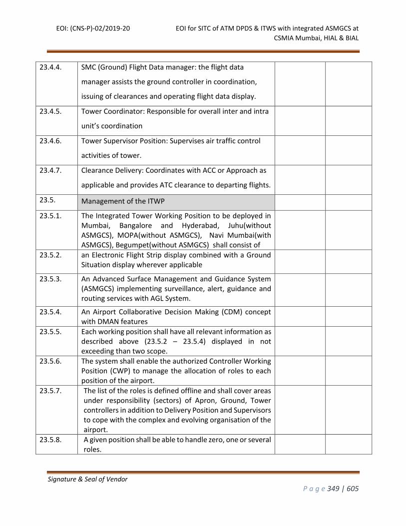
EOI: (CNS-P)-02/2019-20 EOI for SITC of ATM DPDS & ITWS with integrated ASMGCS at
CSMIA Mumbai, HIAL & BIAL
Signature & Seal of Vendor
P a g e 349 | 605
23.4.4. SMC (Ground) Flight Data manager: the flight data
manager assists the ground controller in coordination,
issuing of clearances and operating flight data display.
23.4.5. Tower Coordinator: Responsible for overall inter and intra
unit’s coordination
23.4.6. Tower Supervisor Position: Supervises air traffic control
activities of tower.
23.4.7. Clearance Delivery: Coordinates with ACC or Approach as
applicable and provides ATC clearance to departing flights.
23.5. Management of the ITWP
23.5.1. The Integrated Tower Working Position to be deployed in Mumbai, Bangalore and Hyderabad, Juhu(without ASMGCS), MOPA(without ASMGCS), Navi Mumbai(with ASMGCS), Begumpet(without ASMGCS) shall consist of
23.5.2. an Electronic Flight Strip display combined with a Ground Situation display wherever applicable
23.5.3. An Advanced Surface Management and Guidance System (ASMGCS) implementing surveillance, alert, guidance and routing services with AGL System.
23.5.4. An Airport Collaborative Decision Making (CDM) concept with DMAN features
23.5.5. Each working position shall have all relevant information as described above (23.5.2 – 23.5.4) displayed in not exceeding than two scope.
23.5.6. The system shall enable the authorized Controller Working Position (CWP) to manage the allocation of roles to each position of the airport.
23.5.7. The list of the roles is defined offline and shall cover areas under responsibility (sectors) of Apron, Ground, Tower controllers in addition to Delivery Position and Supervisors to cope with the complex and evolving organisation of the airport.
23.5.8. A given position shall be able to handle zero, one or several roles.
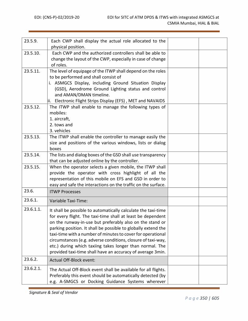
EOI: (CNS-P)-02/2019-20 EOI for SITC of ATM DPDS & ITWS with integrated ASMGCS at
CSMIA Mumbai, HIAL & BIAL
Signature & Seal of Vendor
P a g e 350 | 605
23.5.9. Each CWP shall display the actual role allocated to the physical position.
23.5.10. Each CWP and the authorized controllers shall be able to change the layout of the CWP, especially in case of change of roles.
23.5.11. The level of equipage of the ITWP shall depend on the roles to be performed and shall consist of i. ASMGCS Display, including Ground Situation Display
(GSD), Aerodrome Ground Lighting status and control and AMAN/DMAN timeline.
ii. Electronic Flight Strips Display (EFS) , MET and NAVAIDS
23.5.12. The ITWP shall enable to manage the following types of mobiles: 1. aircraft, 2. tows and 3. vehicles
23.5.13. The ITWP shall enable the controller to manage easily the size and positions of the various windows, lists or dialog boxes
23.5.14. The lists and dialog boxes of the GSD shall use transparency that can be adjusted online by the controller.
23.5.15. When the operator selects a given mobile, the ITWP shall provide the operator with cross highlight of all the representation of this mobile on EFS and GSD in order to easy and safe the interactions on the traffic on the surface.
23.6. ITWP Processes
23.6.1. Variable Taxi-Time:
23.6.1.1. It shall be possible to automatically calculate the taxi-time for every flight. The taxi-time shall at least be dependent on the runway-in-use but preferably also on the stand or parking position. It shall be possible to globally extend the taxi-time with a number of minutes to cover for operational circumstances (e.g. adverse conditions, closure of taxi-way, etc.) during which taxiing takes longer than normal. The provided taxi-time shall have an accuracy of average 3min.
23.6.2. Actual Off-Block event:
23.6.2.1. The Actual Off-Block event shall be available for all flights. Preferably this event should be automatically detected (by e.g. A-SMGCS or Docking Guidance Systems wherever
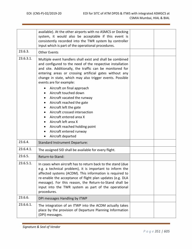
EOI: (CNS-P)-02/2019-20 EOI for SITC of ATM DPDS & ITWS with integrated ASMGCS at
CSMIA Mumbai, HIAL & BIAL
Signature & Seal of Vendor
P a g e 351 | 605
available). At the other airports with no ASMCS or Docking system, it would also be acceptable if this event is consistently recorded into the TWR system by controller input which is part of the operational procedures.
23.6.3. Other Events
23.6.3.1. Multiple event handlers shall exist and shall be combined and configured to the need of the respective installation and site. Additionally, the traffic can be monitored for entering areas or crossing artificial gates without any change in state, which may also trigger events. Possible events are for example:
Aircraft on final approach
Aircraft touched down
Aircraft vacated the runway
Aircraft reached the gate
Aircraft left the gate
Aircraft crossed intersection
Aircraft entered area X
Aircraft left area X
Aircraft reached holding point
Aircraft entered runway
Aircraft departed
23.6.4. Standard Instrument Departure:
23.6.4.1. The assigned SID shall be available for every flight.
23.6.5. Return-to-Stand:
23.6.5.1. In cases when aircraft has to return back to the stand (due e.g. a technical problem), it is important to inform the affected systems (ACDM). This information is required to re-enable the acceptance of flight plan updates (e.g. DLA message). For this reason, the Return-to-Stand shall be input into the TWR system as part of the operational procedures.
23.6.6. DPI messages Handling by ITWP
23.6.6.1. The integration of an ITWP into the ACDM actually takes place by the provision of Departure Planning Information (DPI) messages.

EOI: (CNS-P)-02/2019-20 EOI for SITC of ATM DPDS & ITWS with integrated ASMGCS at
CSMIA Mumbai, HIAL & BIAL
Signature & Seal of Vendor
P a g e 352 | 605
23.6.6.2. ITWP shall provide only the ATC-DPI message at the Actual OffBlock Event. Such a DPI message contains an accurate estimation of the taxi-time and the take-off time (TTOT).
23.6.6.3. In case a flight returns back to the stand, a Cancel-DPI shall be sent.
23.7. Ground Situation Display (GSD) of ITWP
23.7.1. The GSD shall display a view of the airport map and shall enable the operator to zoom out or in, change the centre or rotate the map with immediate redisplay of the map.
23.7.2. The GSD shall allow the operator to select the map layers to be displayed to cope with various details of the airport including and not limited to Runways, Taxiways, Aprons and Terminals.
23.7.3. The GSD shall automatically display or remove the maps of different layers according to the zoom in/out to improve readability of the ground situation.
23.7.4. The GSD shall display the current position, past positions and symbols according to the surveillance sources selected by the operator.
23.7.5. The GSD shall allow the operator to activate or not the display of the raw video signal from the Surface Movement Radar and shall be able to adjust the level of transparency.
23.7.6. The GSD shall display the labels of the mobiles attached to their current position by a leader line. The position of the labels shall be managed automatically if the label anti-overlapping is selected. The operator shall be able to change manually the position of a given label.
23.7.7. The system shall enable the off line definition of layout of the labels for each type of mobile and of flows (arrival, departure, over flight) in terms of colors, fonts, position and size of the fields to be displayed by default.
23.7.8. The GSD shall enable the operator to display, resize, move or minimize up to four (4) additional ground situation sub-windows. The operator shall be able to tune online each sub-window in terms of maps, zoom, pan, rotation, symbols, surveillance sources, history dots, anti-overlapping.
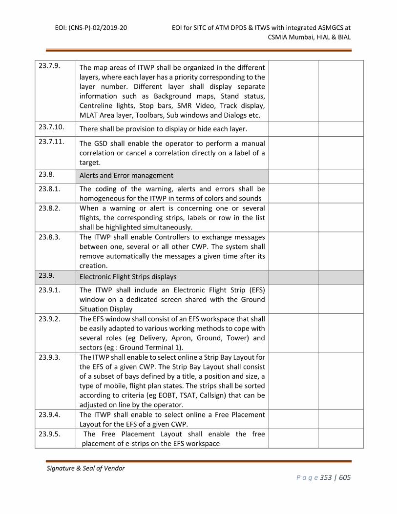
EOI: (CNS-P)-02/2019-20 EOI for SITC of ATM DPDS & ITWS with integrated ASMGCS at
CSMIA Mumbai, HIAL & BIAL
Signature & Seal of Vendor
P a g e 353 | 605
23.7.9. The map areas of ITWP shall be organized in the different layers, where each layer has a priority corresponding to the layer number. Different layer shall display separate information such as Background maps, Stand status, Centreline lights, Stop bars, SMR Video, Track display, MLAT Area layer, Toolbars, Sub windows and Dialogs etc.
23.7.10. There shall be provision to display or hide each layer.
23.7.11. The GSD shall enable the operator to perform a manual correlation or cancel a correlation directly on a label of a target.
23.8. Alerts and Error management
23.8.1. The coding of the warning, alerts and errors shall be homogeneous for the ITWP in terms of colors and sounds
23.8.2. When a warning or alert is concerning one or several flights, the corresponding strips, labels or row in the list shall be highlighted simultaneously.
23.8.3. The ITWP shall enable Controllers to exchange messages between one, several or all other CWP. The system shall remove automatically the messages a given time after its creation.
23.9. Electronic Flight Strips displays
23.9.1. The ITWP shall include an Electronic Flight Strip (EFS) window on a dedicated screen shared with the Ground Situation Display
23.9.2. The EFS window shall consist of an EFS workspace that shall be easily adapted to various working methods to cope with several roles (eg Delivery, Apron, Ground, Tower) and sectors (eg : Ground Terminal 1).
23.9.3. The ITWP shall enable to select online a Strip Bay Layout for the EFS of a given CWP. The Strip Bay Layout shall consist of a subset of bays defined by a title, a position and size, a type of mobile, flight plan states. The strips shall be sorted according to criteria (eg EOBT, TSAT, Callsign) that can be adjusted on line by the operator.
23.9.4. The ITWP shall enable to select online a Free Placement Layout for the EFS of a given CWP.
23.9.5. The Free Placement Layout shall enable the free placement of e-strips on the EFS workspace
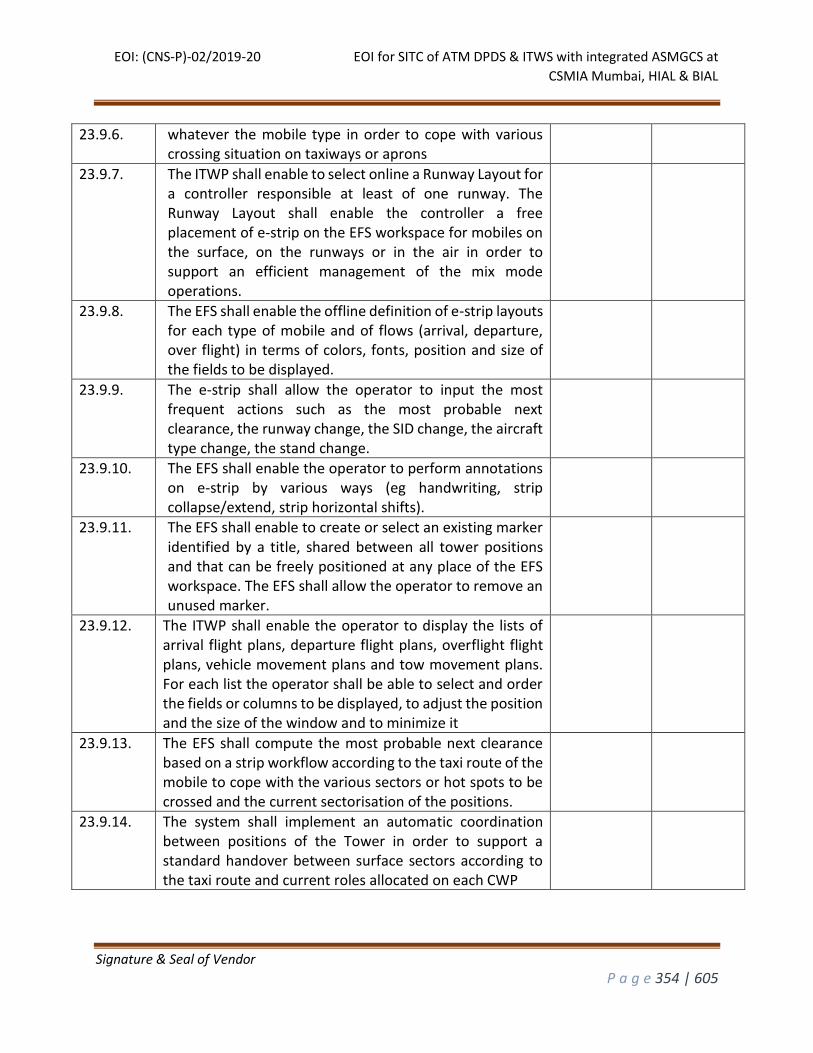
EOI: (CNS-P)-02/2019-20 EOI for SITC of ATM DPDS & ITWS with integrated ASMGCS at
CSMIA Mumbai, HIAL & BIAL
Signature & Seal of Vendor
P a g e 354 | 605
23.9.6. whatever the mobile type in order to cope with various crossing situation on taxiways or aprons
23.9.7. The ITWP shall enable to select online a Runway Layout for a controller responsible at least of one runway. The Runway Layout shall enable the controller a free placement of e-strip on the EFS workspace for mobiles on the surface, on the runways or in the air in order to support an efficient management of the mix mode operations.
23.9.8. The EFS shall enable the offline definition of e-strip layouts for each type of mobile and of flows (arrival, departure, over flight) in terms of colors, fonts, position and size of the fields to be displayed.
23.9.9. The e-strip shall allow the operator to input the most frequent actions such as the most probable next clearance, the runway change, the SID change, the aircraft type change, the stand change.
23.9.10. The EFS shall enable the operator to perform annotations on e-strip by various ways (eg handwriting, strip collapse/extend, strip horizontal shifts).
23.9.11. The EFS shall enable to create or select an existing marker identified by a title, shared between all tower positions and that can be freely positioned at any place of the EFS workspace. The EFS shall allow the operator to remove an unused marker.
23.9.12. The ITWP shall enable the operator to display the lists of arrival flight plans, departure flight plans, overflight flight plans, vehicle movement plans and tow movement plans. For each list the operator shall be able to select and order the fields or columns to be displayed, to adjust the position and the size of the window and to minimize it
23.9.13. The EFS shall compute the most probable next clearance based on a strip workflow according to the taxi route of the mobile to cope with the various sectors or hot spots to be crossed and the current sectorisation of the positions.
23.9.14. The system shall implement an automatic coordination between positions of the Tower in order to support a standard handover between surface sectors according to the taxi route and current roles allocated on each CWP
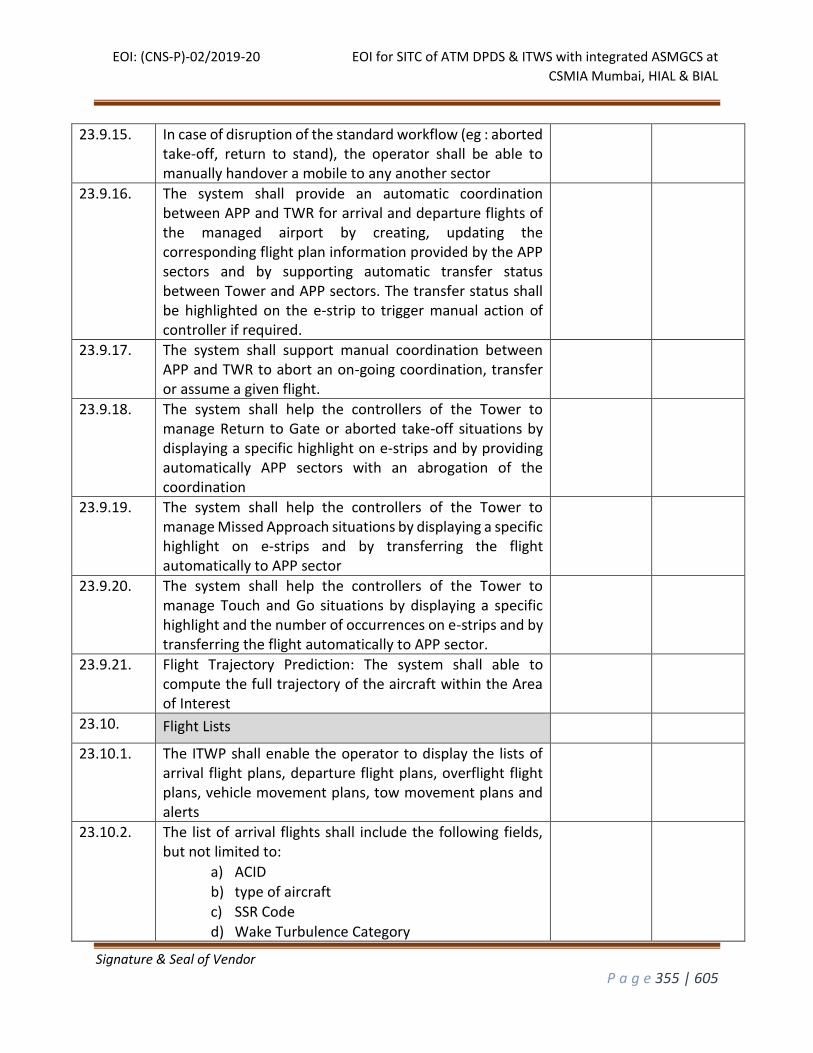
EOI: (CNS-P)-02/2019-20 EOI for SITC of ATM DPDS & ITWS with integrated ASMGCS at
CSMIA Mumbai, HIAL & BIAL
Signature & Seal of Vendor
P a g e 355 | 605
23.9.15. In case of disruption of the standard workflow (eg : aborted take-off, return to stand), the operator shall be able to manually handover a mobile to any another sector
23.9.16. The system shall provide an automatic coordination between APP and TWR for arrival and departure flights of the managed airport by creating, updating the corresponding flight plan information provided by the APP sectors and by supporting automatic transfer status between Tower and APP sectors. The transfer status shall be highlighted on the e-strip to trigger manual action of controller if required.
23.9.17. The system shall support manual coordination between APP and TWR to abort an on-going coordination, transfer or assume a given flight.
23.9.18. The system shall help the controllers of the Tower to manage Return to Gate or aborted take-off situations by displaying a specific highlight on e-strips and by providing automatically APP sectors with an abrogation of the coordination
23.9.19. The system shall help the controllers of the Tower to manage Missed Approach situations by displaying a specific highlight on e-strips and by transferring the flight automatically to APP sector
23.9.20. The system shall help the controllers of the Tower to manage Touch and Go situations by displaying a specific highlight and the number of occurrences on e-strips and by transferring the flight automatically to APP sector.
23.9.21. Flight Trajectory Prediction: The system shall able to compute the full trajectory of the aircraft within the Area of Interest
23.10. Flight Lists
23.10.1. The ITWP shall enable the operator to display the lists of arrival flight plans, departure flight plans, overflight flight plans, vehicle movement plans, tow movement plans and alerts
23.10.2. The list of arrival flights shall include the following fields, but not limited to:
a) ACID b) type of aircraft c) SSR Code d) Wake Turbulence Category
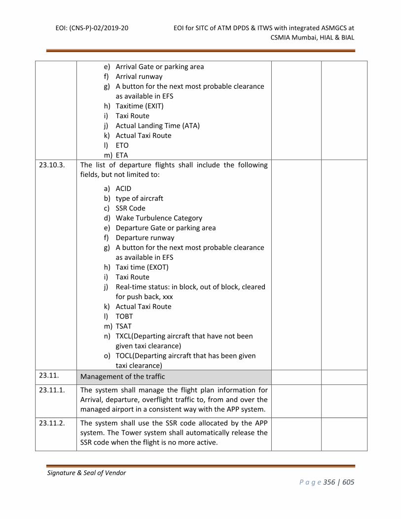
EOI: (CNS-P)-02/2019-20 EOI for SITC of ATM DPDS & ITWS with integrated ASMGCS at
CSMIA Mumbai, HIAL & BIAL
Signature & Seal of Vendor
P a g e 356 | 605
e) Arrival Gate or parking area f) Arrival runway g) A button for the next most probable clearance
as available in EFS h) Taxitime (EXIT) i) Taxi Route j) Actual Landing Time (ATA)
k) Actual Taxi Route l) ETO m) ETA
23.10.3. The list of departure flights shall include the following fields, but not limited to:
a) ACID b) type of aircraft c) SSR Code d) Wake Turbulence Category e) Departure Gate or parking area
f) Departure runway g) A button for the next most probable clearance
as available in EFS h) Taxi time (EXOT) i) Taxi Route j) Real-time status: in block, out of block, cleared
for push back, xxx k) Actual Taxi Route l) TOBT
m) TSAT n) TXCL(Departing aircraft that have not been
given taxi clearance)
o) TOCL(Departing aircraft that has been given taxi clearance)
23.11. Management of the traffic
23.11.1. The system shall manage the flight plan information for Arrival, departure, overflight traffic to, from and over the managed airport in a consistent way with the APP system.
23.11.2. The system shall use the SSR code allocated by the APP system. The Tower system shall automatically release the SSR code when the flight is no more active.
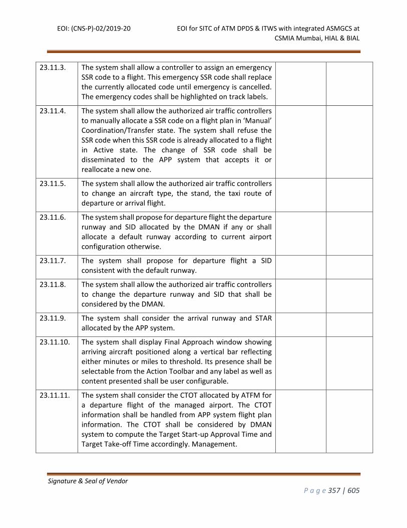
EOI: (CNS-P)-02/2019-20 EOI for SITC of ATM DPDS & ITWS with integrated ASMGCS at
CSMIA Mumbai, HIAL & BIAL
Signature & Seal of Vendor
P a g e 357 | 605
23.11.3. The system shall allow a controller to assign an emergency SSR code to a flight. This emergency SSR code shall replace the currently allocated code until emergency is cancelled. The emergency codes shall be highlighted on track labels.
23.11.4. The system shall allow the authorized air traffic controllers to manually allocate a SSR code on a flight plan in ‘Manual’ Coordination/Transfer state. The system shall refuse the SSR code when this SSR code is already allocated to a flight in Active state. The change of SSR code shall be disseminated to the APP system that accepts it or reallocate a new one.
23.11.5. The system shall allow the authorized air traffic controllers to change an aircraft type, the stand, the taxi route of departure or arrival flight.
23.11.6. The system shall propose for departure flight the departure runway and SID allocated by the DMAN if any or shall allocate a default runway according to current airport configuration otherwise.
23.11.7. The system shall propose for departure flight a SID consistent with the default runway.
23.11.8. The system shall allow the authorized air traffic controllers to change the departure runway and SID that shall be considered by the DMAN.
23.11.9. The system shall consider the arrival runway and STAR allocated by the APP system.
23.11.10. The system shall display Final Approach window showing arriving aircraft positioned along a vertical bar reflecting either minutes or miles to threshold. Its presence shall be selectable from the Action Toolbar and any label as well as content presented shall be user configurable.
23.11.11. The system shall consider the CTOT allocated by ATFM for a departure flight of the managed airport. The CTOT information shall be handled from APP system flight plan information. The CTOT shall be considered by DMAN system to compute the Target Start-up Approval Time and Target Take-off Time accordingly. Management.
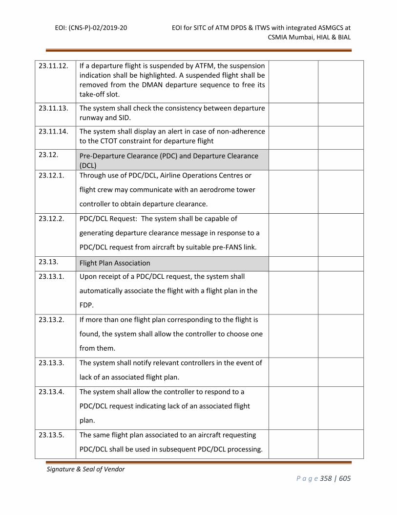
EOI: (CNS-P)-02/2019-20 EOI for SITC of ATM DPDS & ITWS with integrated ASMGCS at
CSMIA Mumbai, HIAL & BIAL
Signature & Seal of Vendor
P a g e 358 | 605
23.11.12. If a departure flight is suspended by ATFM, the suspension indication shall be highlighted. A suspended flight shall be removed from the DMAN departure sequence to free its take-off slot.
23.11.13. The system shall check the consistency between departure runway and SID.
23.11.14. The system shall display an alert in case of non-adherence to the CTOT constraint for departure flight
23.12. Pre-Departure Clearance (PDC) and Departure Clearance (DCL)
23.12.1. Through use of PDC/DCL, Airline Operations Centres or
flight crew may communicate with an aerodrome tower
controller to obtain departure clearance.
23.12.2. PDC/DCL Request: The system shall be capable of
generating departure clearance message in response to a
PDC/DCL request from aircraft by suitable pre-FANS link.
23.13. Flight Plan Association
23.13.1. Upon receipt of a PDC/DCL request, the system shall
automatically associate the flight with a flight plan in the
FDP.
23.13.2. If more than one flight plan corresponding to the flight is
found, the system shall allow the controller to choose one
from them.
23.13.3. The system shall notify relevant controllers in the event of
lack of an associated flight plan.
23.13.4. The system shall allow the controller to respond to a
PDC/DCL request indicating lack of an associated flight
plan.
23.13.5. The same flight plan associated to an aircraft requesting
PDC/DCL shall be used in subsequent PDC/DCL processing.
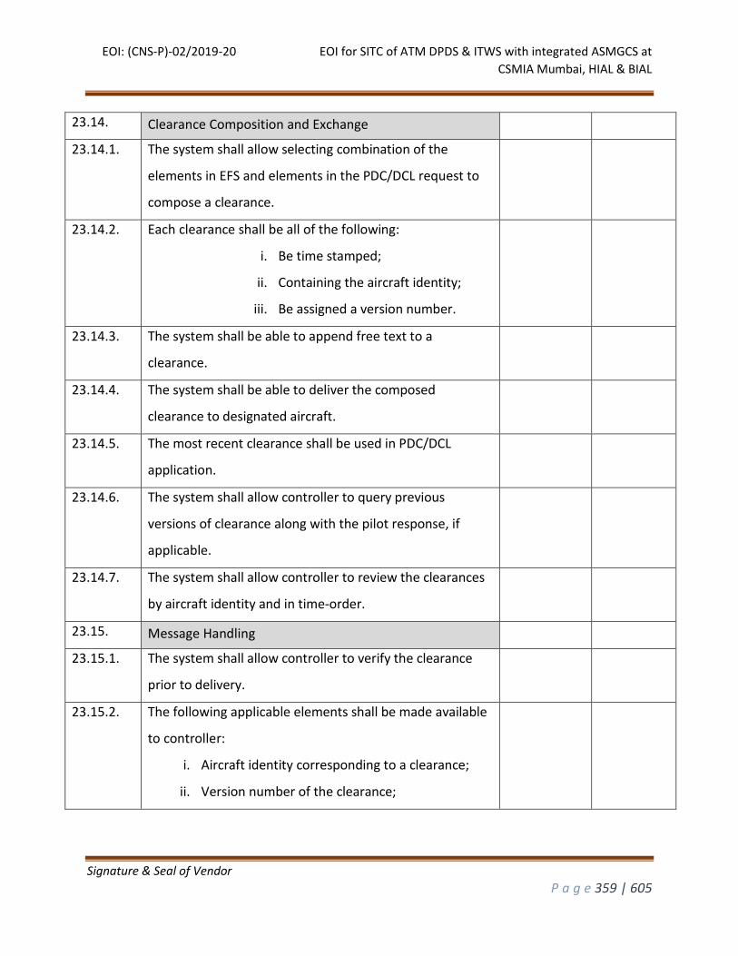
EOI: (CNS-P)-02/2019-20 EOI for SITC of ATM DPDS & ITWS with integrated ASMGCS at
CSMIA Mumbai, HIAL & BIAL
Signature & Seal of Vendor
P a g e 359 | 605
23.14. Clearance Composition and Exchange
23.14.1. The system shall allow selecting combination of the
elements in EFS and elements in the PDC/DCL request to
compose a clearance.
23.14.2. Each clearance shall be all of the following:
i. Be time stamped;
ii. Containing the aircraft identity;
iii. Be assigned a version number.
23.14.3. The system shall be able to append free text to a
clearance.
23.14.4. The system shall be able to deliver the composed
clearance to designated aircraft.
23.14.5. The most recent clearance shall be used in PDC/DCL
application.
23.14.6. The system shall allow controller to query previous
versions of clearance along with the pilot response, if
applicable.
23.14.7. The system shall allow controller to review the clearances
by aircraft identity and in time-order.
23.15. Message Handling
23.15.1. The system shall allow controller to verify the clearance
prior to delivery.
23.15.2. The following applicable elements shall be made available
to controller:
i. Aircraft identity corresponding to a clearance;
ii. Version number of the clearance;
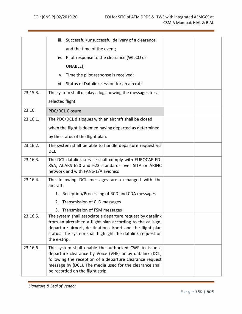
EOI: (CNS-P)-02/2019-20 EOI for SITC of ATM DPDS & ITWS with integrated ASMGCS at
CSMIA Mumbai, HIAL & BIAL
Signature & Seal of Vendor
P a g e 360 | 605
iii. Successful/unsuccessful delivery of a clearance
and the time of the event;
iv. Pilot response to the clearance (WILCO or
UNABLE);
v. Time the pilot response is received;
vi. Status of Datalink session for an aircraft.
23.15.3. The system shall display a log showing the messages for a
selected flight.
23.16. PDC/DCL Closure
23.16.1. The PDC/DCL dialogues with an aircraft shall be closed
when the flight is deemed having departed as determined
by the status of the flight plan.
23.16.2. The system shall be able to handle departure request via DCL
23.16.3. The DCL datalink service shall comply with EUROCAE ED-85A, ACARS 620 and 623 standards over SITA or ARINC network and with FANS-1/A avionics
23.16.4. The following DCL messages are exchanged with the aircraft:
1. Reception/Processing of RCD and CDA messages
2. Transmission of CLD messages
3. Transmission of FSM messages
23.16.5. The system shall associate a departure request by datalink from an aircraft to a flight plan according to the callsign, departure airport, destination airport and the flight plan status. The system shall highlight the datalink request on the e-strip.
23.16.6. The system shall enable the authorized CWP to issue a departure clearance by Voice (VHF) or by datalink (DCL) following the reception of a departure clearance request message by (DCL). The media used for the clearance shall be recorded on the flight strip.
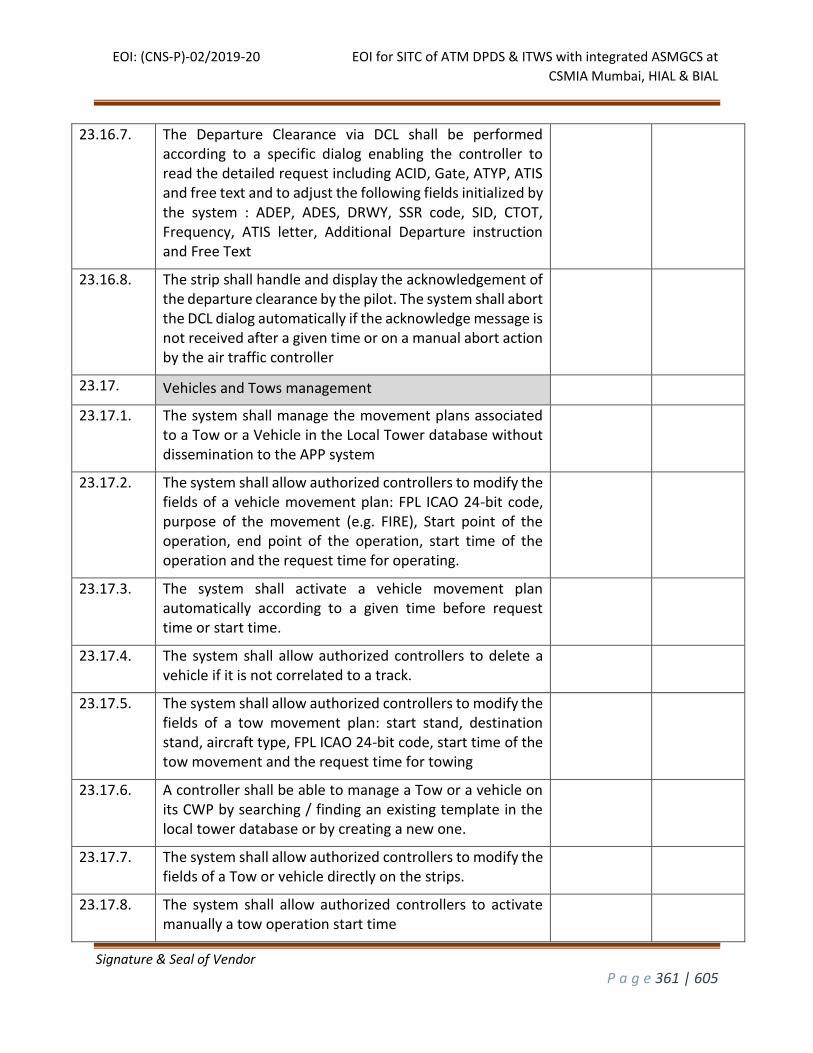
EOI: (CNS-P)-02/2019-20 EOI for SITC of ATM DPDS & ITWS with integrated ASMGCS at
CSMIA Mumbai, HIAL & BIAL
Signature & Seal of Vendor
P a g e 361 | 605
23.16.7. The Departure Clearance via DCL shall be performed according to a specific dialog enabling the controller to read the detailed request including ACID, Gate, ATYP, ATIS and free text and to adjust the following fields initialized by the system : ADEP, ADES, DRWY, SSR code, SID, CTOT, Frequency, ATIS letter, Additional Departure instruction and Free Text
23.16.8. The strip shall handle and display the acknowledgement of the departure clearance by the pilot. The system shall abort the DCL dialog automatically if the acknowledge message is not received after a given time or on a manual abort action by the air traffic controller
23.17. Vehicles and Tows management
23.17.1. The system shall manage the movement plans associated to a Tow or a Vehicle in the Local Tower database without dissemination to the APP system
23.17.2. The system shall allow authorized controllers to modify the fields of a vehicle movement plan: FPL ICAO 24-bit code, purpose of the movement (e.g. FIRE), Start point of the operation, end point of the operation, start time of the operation and the request time for operating.
23.17.3. The system shall activate a vehicle movement plan automatically according to a given time before request time or start time.
23.17.4. The system shall allow authorized controllers to delete a vehicle if it is not correlated to a track.
23.17.5. The system shall allow authorized controllers to modify the fields of a tow movement plan: start stand, destination stand, aircraft type, FPL ICAO 24-bit code, start time of the tow movement and the request time for towing
23.17.6. A controller shall be able to manage a Tow or a vehicle on its CWP by searching / finding an existing template in the local tower database or by creating a new one.
23.17.7. The system shall allow authorized controllers to modify the fields of a Tow or vehicle directly on the strips.
23.17.8. The system shall allow authorized controllers to activate manually a tow operation start time
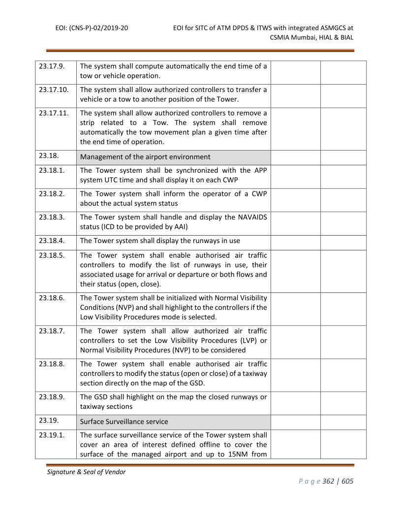
EOI: (CNS-P)-02/2019-20 EOI for SITC of ATM DPDS & ITWS with integrated ASMGCS at
CSMIA Mumbai, HIAL & BIAL
Signature & Seal of Vendor
P a g e 362 | 605
23.17.9. The system shall compute automatically the end time of a tow or vehicle operation.
23.17.10. The system shall allow authorized controllers to transfer a vehicle or a tow to another position of the Tower.
23.17.11. The system shall allow authorized controllers to remove a strip related to a Tow. The system shall remove automatically the tow movement plan a given time after the end time of operation.
23.18. Management of the airport environment
23.18.1. The Tower system shall be synchronized with the APP system UTC time and shall display it on each CWP
23.18.2. The Tower system shall inform the operator of a CWP about the actual system status
23.18.3. The Tower system shall handle and display the NAVAIDS status (ICD to be provided by AAI)
23.18.4. The Tower system shall display the runways in use
23.18.5. The Tower system shall enable authorised air traffic controllers to modify the list of runways in use, their associated usage for arrival or departure or both flows and their status (open, close).
23.18.6. The Tower system shall be initialized with Normal Visibility Conditions (NVP) and shall highlight to the controllers if the Low Visibility Procedures mode is selected.
23.18.7. The Tower system shall allow authorized air traffic controllers to set the Low Visibility Procedures (LVP) or Normal Visibility Procedures (NVP) to be considered
23.18.8. The Tower system shall enable authorised air traffic controllers to modify the status (open or close) of a taxiway section directly on the map of the GSD.
23.18.9. The GSD shall highlight on the map the closed runways or taxiway sections
23.19. Surface Surveillance service
23.19.1. The surface surveillance service of the Tower system shall cover an area of interest defined offline to cover the surface of the managed airport and up to 15NM from
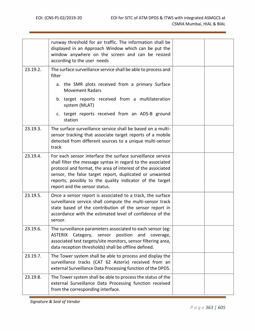
EOI: (CNS-P)-02/2019-20 EOI for SITC of ATM DPDS & ITWS with integrated ASMGCS at
CSMIA Mumbai, HIAL & BIAL
Signature & Seal of Vendor
P a g e 363 | 605
runway threshold for air traffic. The information shall be displayed in an Approach Window which can be put the window anywhere on the screen and can be resized according to the user needs
23.19.2. The surface surveillance service shall be able to process and filter
a. the SMR plots received from a primary Surface Movement Radars
b. target reports received from a multilateration system (MLAT)
c. target reports received from an ADS-B ground station
23.19.3. The surface surveillance service shall be based on a multi-sensor tracking that associate target reports of a mobile detected from different sources to a unique multi-sensor track
23.19.4. For each sensor interface the surface surveillance service shall filter the message syntax in regard to the associated protocol and format, the area of interest of the associated sensor, the false target report, duplicated or unwanted reports, possibly to the quality indicator of the target report and the sensor status.
23.19.5. Once a sensor report is associated to a track, the surface surveillance service shall compute the multi-sensor track state based of the contribution of the sensor report in accordance with the estimated level of confidence of the sensor.
23.19.6. The surveillance parameters associated to each sensor (eg: ASTERIX Category, sensor position and coverage, associated test targets/site monitors, sensor filtering area, data reception thresholds) shall be offline defined.
23.19.7. The Tower system shall be able to process and display the surveillance tracks (CAT 62 Asterix) received from an external Surveillance Data Processing function of the DPDS.
23.19.8. The Tower system shall be able to process the status of the external Surveillance Data Processing function received from the corresponding interface.
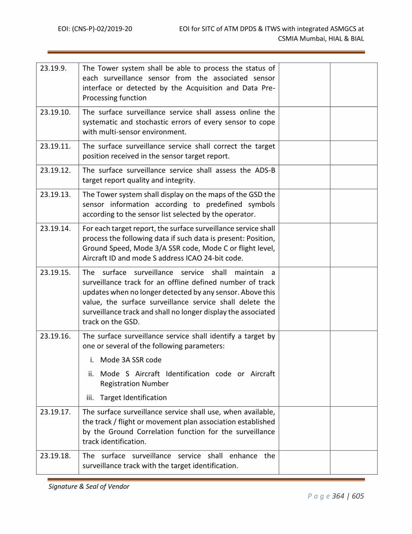
EOI: (CNS-P)-02/2019-20 EOI for SITC of ATM DPDS & ITWS with integrated ASMGCS at
CSMIA Mumbai, HIAL & BIAL
Signature & Seal of Vendor
P a g e 364 | 605
23.19.9. The Tower system shall be able to process the status of each surveillance sensor from the associated sensor interface or detected by the Acquisition and Data Pre-Processing function
23.19.10. The surface surveillance service shall assess online the systematic and stochastic errors of every sensor to cope with multi-sensor environment.
23.19.11. The surface surveillance service shall correct the target position received in the sensor target report.
23.19.12. The surface surveillance service shall assess the ADS-B target report quality and integrity.
23.19.13. The Tower system shall display on the maps of the GSD the sensor information according to predefined symbols according to the sensor list selected by the operator.
23.19.14. For each target report, the surface surveillance service shall process the following data if such data is present: Position, Ground Speed, Mode 3/A SSR code, Mode C or flight level, Aircraft ID and mode S address ICAO 24-bit code.
23.19.15. The surface surveillance service shall maintain a surveillance track for an offline defined number of track updates when no longer detected by any sensor. Above this value, the surface surveillance service shall delete the surveillance track and shall no longer display the associated track on the GSD.
23.19.16. The surface surveillance service shall identify a target by one or several of the following parameters:
i. Mode 3A SSR code
ii. Mode S Aircraft Identification code or Aircraft Registration Number
iii. Target Identification
23.19.17. The surface surveillance service shall use, when available, the track / flight or movement plan association established by the Ground Correlation function for the surveillance track identification.
23.19.18. The surface surveillance service shall enhance the surveillance track with the target identification.
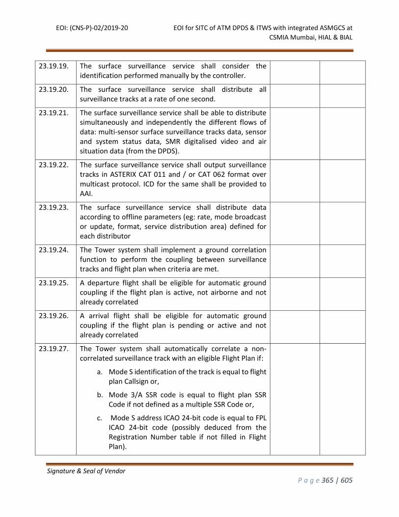
EOI: (CNS-P)-02/2019-20 EOI for SITC of ATM DPDS & ITWS with integrated ASMGCS at
CSMIA Mumbai, HIAL & BIAL
Signature & Seal of Vendor
P a g e 365 | 605
23.19.19. The surface surveillance service shall consider the identification performed manually by the controller.
23.19.20. The surface surveillance service shall distribute all surveillance tracks at a rate of one second.
23.19.21. The surface surveillance service shall be able to distribute simultaneously and independently the different flows of data: multi-sensor surface surveillance tracks data, sensor and system status data, SMR digitalised video and air situation data (from the DPDS).
23.19.22. The surface surveillance service shall output surveillance tracks in ASTERIX CAT 011 and / or CAT 062 format over multicast protocol. ICD for the same shall be provided to AAI.
23.19.23. The surface surveillance service shall distribute data according to offline parameters (eg: rate, mode broadcast or update, format, service distribution area) defined for each distributor
23.19.24. The Tower system shall implement a ground correlation function to perform the coupling between surveillance tracks and flight plan when criteria are met.
23.19.25. A departure flight shall be eligible for automatic ground coupling if the flight plan is active, not airborne and not already correlated
23.19.26. A arrival flight shall be eligible for automatic ground coupling if the flight plan is pending or active and not already correlated
23.19.27. The Tower system shall automatically correlate a non-correlated surveillance track with an eligible Flight Plan if:
a. Mode S identification of the track is equal to flight plan Callsign or,
b. Mode 3/A SSR code is equal to flight plan SSR Code if not defined as a multiple SSR Code or,
c. Mode S address ICAO 24-bit code is equal to FPL ICAO 24-bit code (possibly deduced from the Registration Number table if not filled in Flight Plan).
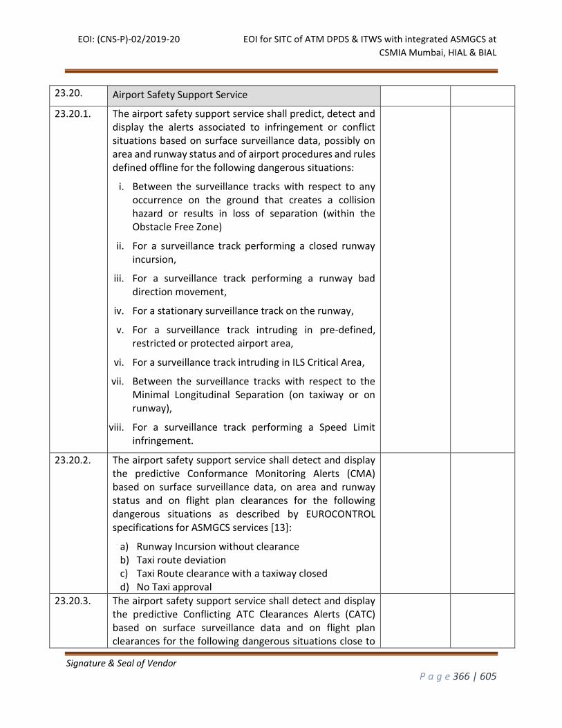
EOI: (CNS-P)-02/2019-20 EOI for SITC of ATM DPDS & ITWS with integrated ASMGCS at
CSMIA Mumbai, HIAL & BIAL
Signature & Seal of Vendor
P a g e 366 | 605
23.20. Airport Safety Support Service
23.20.1. The airport safety support service shall predict, detect and display the alerts associated to infringement or conflict situations based on surface surveillance data, possibly on area and runway status and of airport procedures and rules defined offline for the following dangerous situations:
i. Between the surveillance tracks with respect to any occurrence on the ground that creates a collision hazard or results in loss of separation (within the Obstacle Free Zone)
ii. For a surveillance track performing a closed runway incursion,
iii. For a surveillance track performing a runway bad direction movement,
iv. For a stationary surveillance track on the runway,
v. For a surveillance track intruding in pre-defined, restricted or protected airport area,
vi. For a surveillance track intruding in ILS Critical Area,
vii. Between the surveillance tracks with respect to the Minimal Longitudinal Separation (on taxiway or on runway),
viii. For a surveillance track performing a Speed Limit infringement.
23.20.2. The airport safety support service shall detect and display the predictive Conformance Monitoring Alerts (CMA) based on surface surveillance data, on area and runway status and on flight plan clearances for the following dangerous situations as described by EUROCONTROL specifications for ASMGCS services [13]:
a) Runway Incursion without clearance b) Taxi route deviation c) Taxi Route clearance with a taxiway closed d) No Taxi approval
23.20.3. The airport safety support service shall detect and display the predictive Conflicting ATC Clearances Alerts (CATC) based on surface surveillance data and on flight plan clearances for the following dangerous situations close to
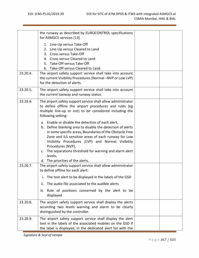
EOI: (CNS-P)-02/2019-20 EOI for SITC of ATM DPDS & ITWS with integrated ASMGCS at
CSMIA Mumbai, HIAL & BIAL
Signature & Seal of Vendor
P a g e 367 | 605
the runway as described by EUROCONTROL specifications for ASMGCS services [13]
1. Line-Up versus Take-Off 2. Line-Up versus Cleared to Land 3. Cross versus Take-Off 4. Cross versus Cleared to Land 5. Take-Off versus Take-Off 6. Take-Off versus Cleared to Land
23.20.4. The airport safety support service shall take into account the current Visibility Procedures (Normal –NVP or Low LVP) for the detection of alerts.
23.20.5. The airport safety support service shall take into account the current taxiway and runway status.
23.20.6. The airport safety support service shall allow administrator to define offline the airport procedures and rules (eg multiple line-up or not) to be considered including the following setting:
a. Enable or disable the detection of each alert, b. Define blanking area to disable the detection of alerts
in some specific areas, Boundaries of the Obstacle Free Zone and ILS sensitive areas of each runway for Low Visibility Procedures (LVP) and Normal Visibility Procedures (NVP),
c. The separations threshold for warning and alarm alert levels,
d. The priorities of the alerts.
23.20.7. The airport safety support service shall allow administrator to define offline for each alert:
i. The text alert to be displayed in the labels of the GSD
ii. The audio file associated to the audible alerts
iii. Role of positions concerned by the alert to be displayed
23.20.8. The airport safety support service shall display the alerts according two levels warning and alarm to be clearly distinguished by the controller.
23.20.9. The airport safety support service shall display the alert text in the labels of the associated mobiles on the GSD if the label is displayed, in the dedicated alert list with the
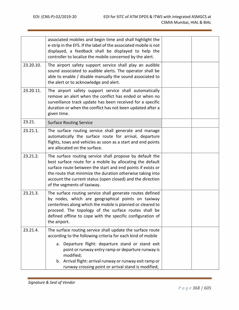
EOI: (CNS-P)-02/2019-20 EOI for SITC of ATM DPDS & ITWS with integrated ASMGCS at
CSMIA Mumbai, HIAL & BIAL
Signature & Seal of Vendor
P a g e 368 | 605
associated mobiles and begin time and shall highlight the e-strip in the EFS. If the label of the associated mobile is not displayed, a feedback shall be displayed to help the controller to localize the mobile concerned by the alert.
23.20.10. The airport safety support service shall play an audible sound associated to audible alerts. The operator shall be able to enable / disable manually the sound associated to the alert or to acknowledge and alert.
23.20.11. The airport safety support service shall automatically remove an alert when the conflict has ended or when no surveillance track update has been received for a specific duration or when the conflict has not been updated after a given time.
23.21. Surface Routing Service
23.21.1. The surface routing service shall generate and manage automatically the surface route for arrival, departure flights, tows and vehicles as soon as a start and end points are allocated on the surface.
23.21.2. The surface routing service shall propose by default the best surface route for a mobile by allocating the default surface route between the start and end points if exists or the route that minimize the duration otherwise taking into account the current status (open closed) and the direction of the segments of taxiway.
23.21.3. The surface routing service shall generate routes defined by nodes, which are geographical points on taxiway centerlines along which the mobile is planned or cleared to proceed. The topology of the surface routes shall be defined offline to cope with the specific configuration of the airport.
23.21.4. The surface routing service shall update the surface route according to the following criteria for each kind of mobile
a. Departure flight: departure stand or stand exit point or runway entry ramp or departure runway is modified;
b. Arrival flight: arrival runway or runway exit ramp or runway crossing point or arrival stand is modified;
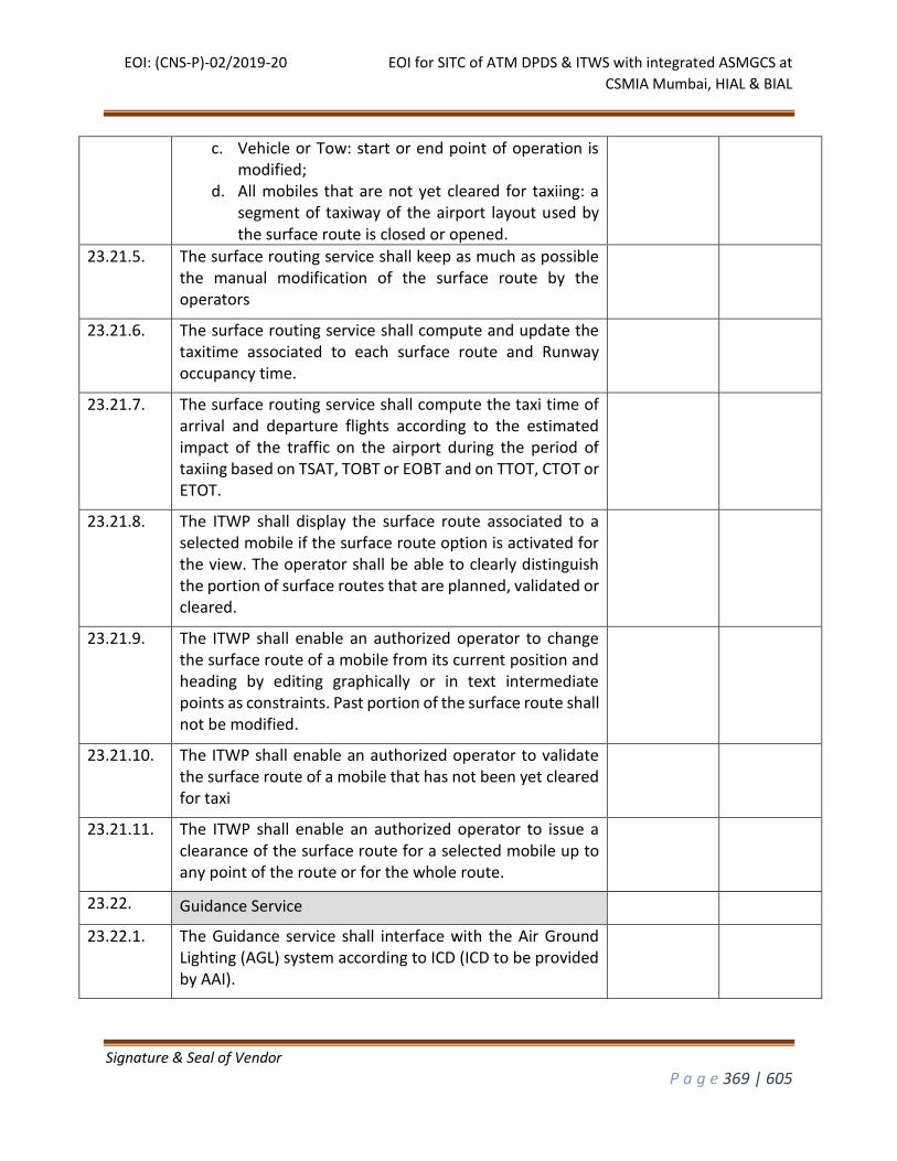
EOI: (CNS-P)-02/2019-20 EOI for SITC of ATM DPDS & ITWS with integrated ASMGCS at
CSMIA Mumbai, HIAL & BIAL
Signature & Seal of Vendor
P a g e 369 | 605
c. Vehicle or Tow: start or end point of operation is modified;
d. All mobiles that are not yet cleared for taxiing: a segment of taxiway of the airport layout used by the surface route is closed or opened.
23.21.5. The surface routing service shall keep as much as possible the manual modification of the surface route by the operators
23.21.6. The surface routing service shall compute and update the taxitime associated to each surface route and Runway occupancy time.
23.21.7. The surface routing service shall compute the taxi time of arrival and departure flights according to the estimated impact of the traffic on the airport during the period of taxiing based on TSAT, TOBT or EOBT and on TTOT, CTOT or ETOT.
23.21.8. The ITWP shall display the surface route associated to a selected mobile if the surface route option is activated for the view. The operator shall be able to clearly distinguish the portion of surface routes that are planned, validated or cleared.
23.21.9. The ITWP shall enable an authorized operator to change the surface route of a mobile from its current position and heading by editing graphically or in text intermediate points as constraints. Past portion of the surface route shall not be modified.
23.21.10. The ITWP shall enable an authorized operator to validate the surface route of a mobile that has not been yet cleared for taxi
23.21.11. The ITWP shall enable an authorized operator to issue a clearance of the surface route for a selected mobile up to any point of the route or for the whole route.
23.22. Guidance Service
23.22.1. The Guidance service shall interface with the Air Ground Lighting (AGL) system according to ICD (ICD to be provided by AAI).
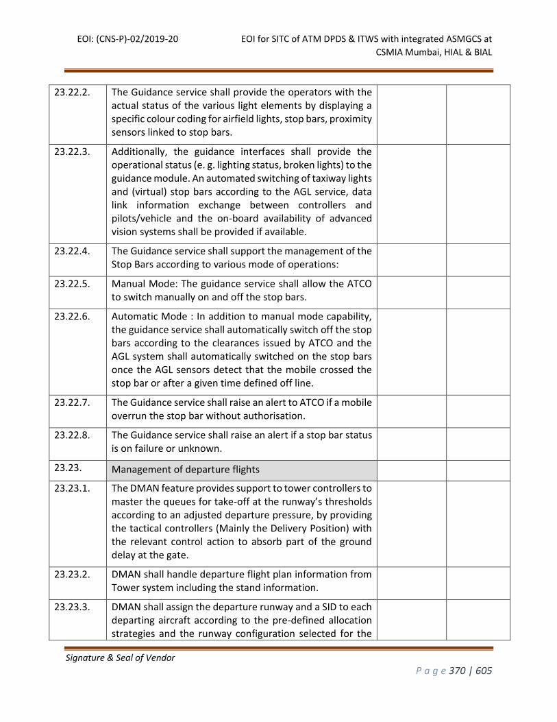
EOI: (CNS-P)-02/2019-20 EOI for SITC of ATM DPDS & ITWS with integrated ASMGCS at
CSMIA Mumbai, HIAL & BIAL
Signature & Seal of Vendor
P a g e 370 | 605
23.22.2. The Guidance service shall provide the operators with the actual status of the various light elements by displaying a specific colour coding for airfield lights, stop bars, proximity sensors linked to stop bars.
23.22.3. Additionally, the guidance interfaces shall provide the operational status (e. g. lighting status, broken lights) to the guidance module. An automated switching of taxiway lights and (virtual) stop bars according to the AGL service, data link information exchange between controllers and pilots/vehicle and the on-board availability of advanced vision systems shall be provided if available.
23.22.4. The Guidance service shall support the management of the Stop Bars according to various mode of operations:
23.22.5. Manual Mode: The guidance service shall allow the ATCO to switch manually on and off the stop bars.
23.22.6. Automatic Mode : In addition to manual mode capability, the guidance service shall automatically switch off the stop bars according to the clearances issued by ATCO and the AGL system shall automatically switched on the stop bars once the AGL sensors detect that the mobile crossed the stop bar or after a given time defined off line.
23.22.7. The Guidance service shall raise an alert to ATCO if a mobile overrun the stop bar without authorisation.
23.22.8. The Guidance service shall raise an alert if a stop bar status is on failure or unknown.
23.23. Management of departure flights
23.23.1. The DMAN feature provides support to tower controllers to master the queues for take-off at the runway’s thresholds according to an adjusted departure pressure, by providing the tactical controllers (Mainly the Delivery Position) with the relevant control action to absorb part of the ground delay at the gate.
23.23.2. DMAN shall handle departure flight plan information from Tower system including the stand information.
23.23.3. DMAN shall assign the departure runway and a SID to each departing aircraft according to the pre-defined allocation strategies and the runway configuration selected for the
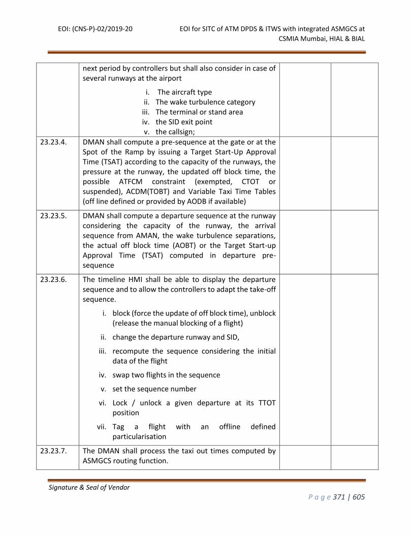
EOI: (CNS-P)-02/2019-20 EOI for SITC of ATM DPDS & ITWS with integrated ASMGCS at
CSMIA Mumbai, HIAL & BIAL
Signature & Seal of Vendor
P a g e 371 | 605
next period by controllers but shall also consider in case of several runways at the airport
i. The aircraft type ii. The wake turbulence category
iii. The terminal or stand area iv. the SID exit point v. the callsign;
23.23.4. DMAN shall compute a pre-sequence at the gate or at the Spot of the Ramp by issuing a Target Start-Up Approval Time (TSAT) according to the capacity of the runways, the pressure at the runway, the updated off block time, the possible ATFCM constraint (exempted, CTOT or suspended), ACDM(TOBT) and Variable Taxi Time Tables (off line defined or provided by AODB if available)
23.23.5. DMAN shall compute a departure sequence at the runway considering the capacity of the runway, the arrival sequence from AMAN, the wake turbulence separations, the actual off block time (AOBT) or the Target Start-up Approval Time (TSAT) computed in departure pre-sequence
23.23.6. The timeline HMI shall be able to display the departure sequence and to allow the controllers to adapt the take-off sequence.
i. block (force the update of off block time), unblock (release the manual blocking of a flight)
ii. change the departure runway and SID,
iii. recompute the sequence considering the initial data of the flight
iv. swap two flights in the sequence
v. set the sequence number
vi. Lock / unlock a given departure at its TTOT position
vii. Tag a flight with an offline defined particularisation
23.23.7. The DMAN shall process the taxi out times computed by ASMGCS routing function.
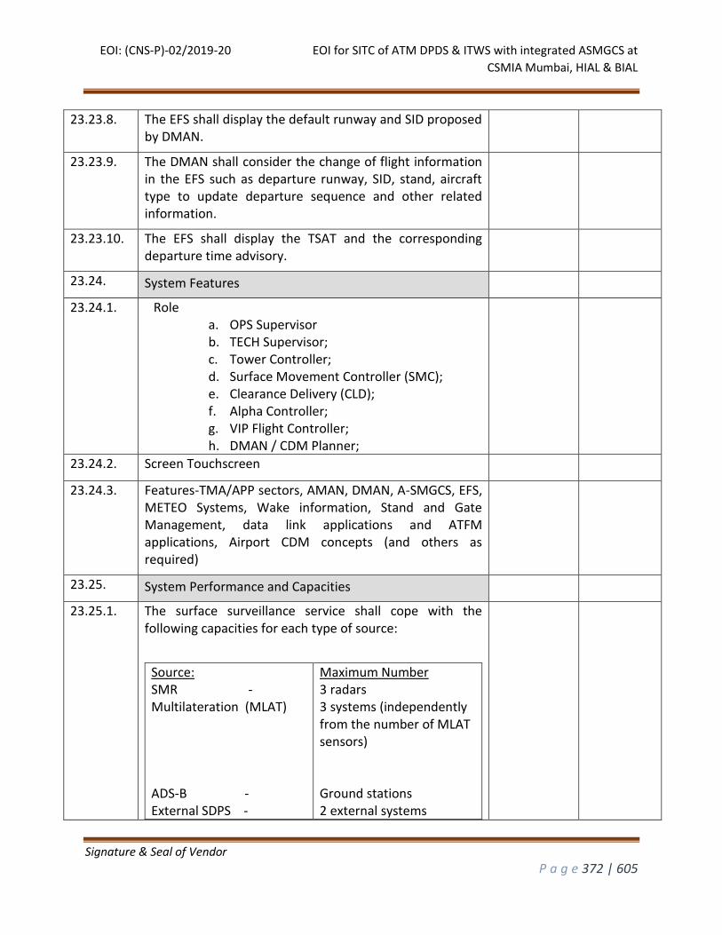
EOI: (CNS-P)-02/2019-20 EOI for SITC of ATM DPDS & ITWS with integrated ASMGCS at
CSMIA Mumbai, HIAL & BIAL
Signature & Seal of Vendor
P a g e 372 | 605
23.23.8. The EFS shall display the default runway and SID proposed by DMAN.
23.23.9. The DMAN shall consider the change of flight information in the EFS such as departure runway, SID, stand, aircraft type to update departure sequence and other related information.
23.23.10. The EFS shall display the TSAT and the corresponding departure time advisory.
23.24. System Features
23.24.1. Role a. OPS Supervisor b. TECH Supervisor; c. Tower Controller; d. Surface Movement Controller (SMC); e. Clearance Delivery (CLD); f. Alpha Controller; g. VIP Flight Controller; h. DMAN / CDM Planner;
23.24.2. Screen Touchscreen
23.24.3. Features-TMA/APP sectors, AMAN, DMAN, A-SMGCS, EFS, METEO Systems, Wake information, Stand and Gate Management, data link applications and ATFM applications, Airport CDM concepts (and others as required)
23.25. System Performance and Capacities
23.25.1. The surface surveillance service shall cope with the following capacities for each type of source:
Source: SMR - Multilateration (MLAT) ADS-B - External SDPS -
Maximum Number 3 radars 3 systems (independently from the number of MLAT sensors) Ground stations 2 external systems
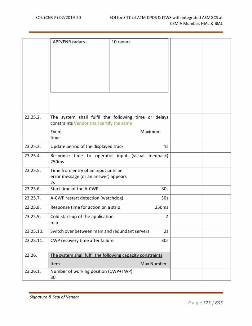
EOI: (CNS-P)-02/2019-20 EOI for SITC of ATM DPDS & ITWS with integrated ASMGCS at
CSMIA Mumbai, HIAL & BIAL
Signature & Seal of Vendor
P a g e 373 | 605
APP/ENR radars - 10 radars
23.25.2. The system shall fulfil the following time or delays constraints Vendor shall certify the same
Event Maximum time
23.25.3. Update period of the displayed track 1s
23.25.4. Response time to operator input (visual feedback) 250ms
23.25.5. Time from entry of an input until an error message (or an answer) appears 2s
23.25.6. Start time of the A-CWP 30s
23.25.7. A-CWP restart detection (watchdog) 30s
23.25.8. Response time for action on a strip 250ms
23.25.9. Cold start-up of the application 2 min
23.25.10. Switch over between main and redundant servers 2s
23.25.11. CWP recovery time after failure 30s
23.26. The system shall fulfil the following capacity constraints
Item Max Number
23.26.1. Number of working position (CWP+TWP) 30
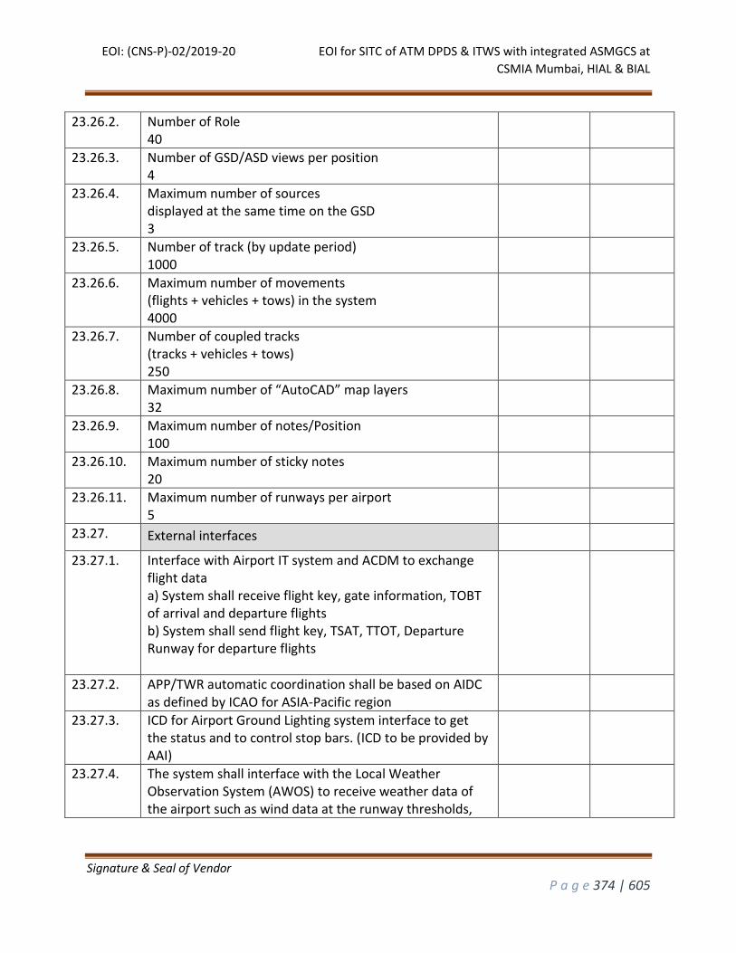
EOI: (CNS-P)-02/2019-20 EOI for SITC of ATM DPDS & ITWS with integrated ASMGCS at
CSMIA Mumbai, HIAL & BIAL
Signature & Seal of Vendor
P a g e 374 | 605
23.26.2. Number of Role 40
23.26.3. Number of GSD/ASD views per position 4
23.26.4. Maximum number of sources displayed at the same time on the GSD 3
23.26.5. Number of track (by update period) 1000
23.26.6. Maximum number of movements (flights + vehicles + tows) in the system 4000
23.26.7. Number of coupled tracks (tracks + vehicles + tows) 250
23.26.8. Maximum number of “AutoCAD” map layers 32
23.26.9. Maximum number of notes/Position 100
23.26.10. Maximum number of sticky notes 20
23.26.11. Maximum number of runways per airport 5
23.27. External interfaces
23.27.1. Interface with Airport IT system and ACDM to exchange flight data a) System shall receive flight key, gate information, TOBT of arrival and departure flights b) System shall send flight key, TSAT, TTOT, Departure Runway for departure flights
23.27.2. APP/TWR automatic coordination shall be based on AIDC as defined by ICAO for ASIA-Pacific region
23.27.3. ICD for Airport Ground Lighting system interface to get the status and to control stop bars. (ICD to be provided by AAI)
23.27.4. The system shall interface with the Local Weather Observation System (AWOS) to receive weather data of the airport such as wind data at the runway thresholds,
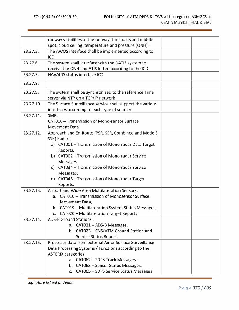
EOI: (CNS-P)-02/2019-20 EOI for SITC of ATM DPDS & ITWS with integrated ASMGCS at
CSMIA Mumbai, HIAL & BIAL
Signature & Seal of Vendor
P a g e 375 | 605
runway visibilities at the runway thresholds and middle spot, cloud ceiling, temperature and pressure (QNH).
23.27.5. The AWOS interface shall be implemented according to ICD
23.27.6. The system shall interface with the DATIS system to receive the QNH and ATIS letter according to the ICD
23.27.7. NAVAIDS status interface ICD
23.27.8.
23.27.9. The system shall be synchronized to the reference Time server via NTP on a TCP/IP network
23.27.10. The Surface Surveillance service shall support the various interfaces according to each type of source:
23.27.11. SMR: CAT010 – Transmission of Mono-sensor Surface Movement Data
23.27.12. Approach and En-Route (PSR, SSR, Combined and Mode S SSR) Radar:
a) CAT001 – Transmission of Mono-radar Data Target Reports,
b) CAT002 – Transmission of Mono-radar Service Messages,
c) CAT034 – Transmission of Mono-radar Service Messages,
d) CAT048 – Transmission of Mono-radar Target Reports.
23.27.13. Airport and Wide Area Multilateration Sensors: a. CAT010 – Transmission of Monosensor Surface
Movement Data, b. CAT019 – Multilateration System Status Messages, c. CAT020 – Multilateration Target Reports
23.27.14. ADS-B Ground Stations : a. CAT021 – ADS-B Messages, b. CAT023 – CNS/ATM Ground Station and
Service Status Report.
23.27.15. Processes data from external Air or Surface Surveillance Data Processing Systems / Functions according to the ASTERIX categories
a. CAT062 – SDPS Track Messages, b. CAT063 – Sensor Status Messages, c. CAT065 – SDPS Service Status Messages
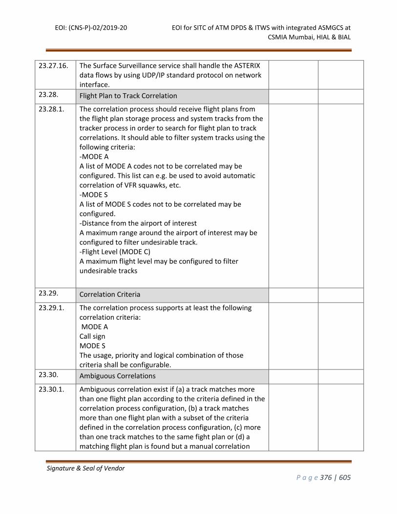
EOI: (CNS-P)-02/2019-20 EOI for SITC of ATM DPDS & ITWS with integrated ASMGCS at
CSMIA Mumbai, HIAL & BIAL
Signature & Seal of Vendor
P a g e 376 | 605
23.27.16. The Surface Surveillance service shall handle the ASTERIX data flows by using UDP/IP standard protocol on network interface.
23.28. Flight Plan to Track Correlation
23.28.1. The correlation process should receive flight plans from the flight plan storage process and system tracks from the tracker process in order to search for flight plan to track correlations. It should able to filter system tracks using the following criteria: -MODE A A list of MODE A codes not to be correlated may be configured. This list can e.g. be used to avoid automatic correlation of VFR squawks, etc. -MODE S A list of MODE S codes not to be correlated may be configured. -Distance from the airport of interest A maximum range around the airport of interest may be configured to filter undesirable track. -Flight Level (MODE C) A maximum flight level may be configured to filter undesirable tracks
23.29. Correlation Criteria
23.29.1. The correlation process supports at least the following correlation criteria: MODE A Call sign MODE S The usage, priority and logical combination of those criteria shall be configurable.
23.30. Ambiguous Correlations
23.30.1. Ambiguous correlation exist if (a) a track matches more than one flight plan according to the criteria defined in the correlation process configuration, (b) a track matches more than one flight plan with a subset of the criteria defined in the correlation process configuration, (c) more than one track matches to the same fight plan or (d) a matching flight plan is found but a manual correlation

EOI: (CNS-P)-02/2019-20 EOI for SITC of ATM DPDS & ITWS with integrated ASMGCS at
CSMIA Mumbai, HIAL & BIAL
Signature & Seal of Vendor
P a g e 377 | 605
already exists. The system should able to resolve all the ambiguous correlation stated above
23.31. Manual Correlations
23.31.1. System should able to perform A manual correlation and/or de-correlation by the user via CWP HMI input. If there is already a manual correlation for a system track, all further automatically found correlations shall be added to the list of potential correlations for the respective track and manual correlation shall never be overridden by an automatic correlation.
23.32. Surveillance Based Event Generation (Optional)
23.32.1. The ITWP should able to generate events based on surveillance data. Possible events listed are for example:
Aircraft on final approach
Aircraft touched down
Aircraft vacated the runway
Aircraft reached the gate
Aircraft left the gate
Aircraft reached holding point
Aircraft departed.
The generated events shall be stored as additional data internally and can be logged in a data base for further analysis.
23.33. AFTN/AMHS Flight Plan Data
23.33.1. The system shall receive, process and transmit the following ATS messages received from AFTN,AMHS and ATN: FPL, DEP, ARR, RQP, ALR, RCF, RQS, AFP, SPL, CPL, DLA, CNL, EST, CHG, CDN, LAM, ACP and AIREP as foresee in the ICAO 4444 Document and include other coordination messages.
23.33.2. The system should have facility to receive, process and transmit both AFTN and AMHS messages. The decision to use AFTN or AMHS will be taken by AAI.
23.33.3. The system shall allow the user to enable or disable via a VSP the automatic processing of ATS messages for each message type. When it is enabled, ATS messages shall be processed for display to specific Flight Plan positions
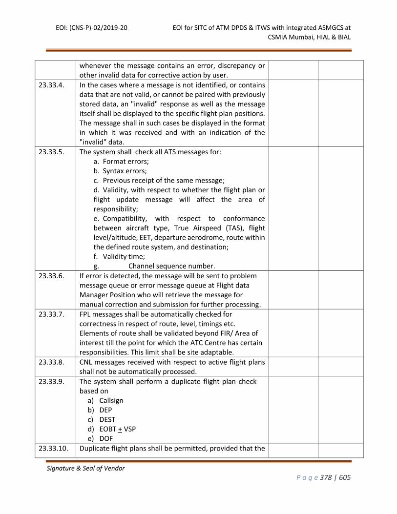
EOI: (CNS-P)-02/2019-20 EOI for SITC of ATM DPDS & ITWS with integrated ASMGCS at
CSMIA Mumbai, HIAL & BIAL
Signature & Seal of Vendor
P a g e 378 | 605
whenever the message contains an error, discrepancy or other invalid data for corrective action by user.
23.33.4. In the cases where a message is not identified, or contains data that are not valid, or cannot be paired with previously stored data, an "invalid" response as well as the message itself shall be displayed to the specific flight plan positions. The message shall in such cases be displayed in the format in which it was received and with an indication of the "invalid" data.
23.33.5. The system shall check all ATS messages for: a. Format errors; b. Syntax errors; c. Previous receipt of the same message; d. Validity, with respect to whether the flight plan or flight update message will affect the area of responsibility; e. Compatibility, with respect to conformance between aircraft type, True Airspeed (TAS), flight level/altitude, EET, departure aerodrome, route within the defined route system, and destination; f. Validity time; g. Channel sequence number.
23.33.6. If error is detected, the message will be sent to problem message queue or error message queue at Flight data Manager Position who will retrieve the message for manual correction and submission for further processing.
23.33.7. FPL messages shall be automatically checked for correctness in respect of route, level, timings etc. Elements of route shall be validated beyond FIR/ Area of interest till the point for which the ATC Centre has certain responsibilities. This limit shall be site adaptable.
23.33.8. CNL messages received with respect to active flight plans shall not be automatically processed.
23.33.9. The system shall perform a duplicate flight plan check based on
a) Callsign b) DEP c) DEST d) EOBT + VSP e) DOF
23.33.10. Duplicate flight plans shall be permitted, provided that the
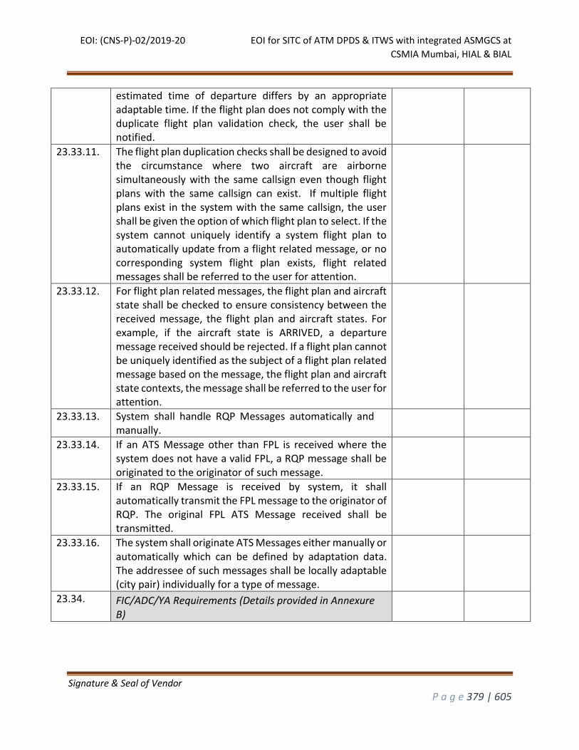
EOI: (CNS-P)-02/2019-20 EOI for SITC of ATM DPDS & ITWS with integrated ASMGCS at
CSMIA Mumbai, HIAL & BIAL
Signature & Seal of Vendor
P a g e 379 | 605
estimated time of departure differs by an appropriate adaptable time. If the flight plan does not comply with the duplicate flight plan validation check, the user shall be notified.
23.33.11. The flight plan duplication checks shall be designed to avoid the circumstance where two aircraft are airborne simultaneously with the same callsign even though flight plans with the same callsign can exist. If multiple flight plans exist in the system with the same callsign, the user shall be given the option of which flight plan to select. If the system cannot uniquely identify a system flight plan to automatically update from a flight related message, or no corresponding system flight plan exists, flight related messages shall be referred to the user for attention.
23.33.12. For flight plan related messages, the flight plan and aircraft state shall be checked to ensure consistency between the received message, the flight plan and aircraft states. For example, if the aircraft state is ARRIVED, a departure message received should be rejected. If a flight plan cannot be uniquely identified as the subject of a flight plan related message based on the message, the flight plan and aircraft state contexts, the message shall be referred to the user for attention.
23.33.13. System shall handle RQP Messages automatically and manually.
23.33.14. If an ATS Message other than FPL is received where the system does not have a valid FPL, a RQP message shall be originated to the originator of such message.
23.33.15. If an RQP Message is received by system, it shall automatically transmit the FPL message to the originator of RQP. The original FPL ATS Message received shall be transmitted.
23.33.16. The system shall originate ATS Messages either manually or automatically which can be defined by adaptation data. The addressee of such messages shall be locally adaptable (city pair) individually for a type of message.
23.34. FIC/ADC/YA Requirements (Details provided in Annexure B)
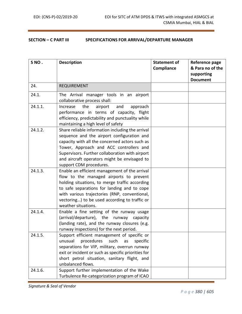
EOI: (CNS-P)-02/2019-20 EOI for SITC of ATM DPDS & ITWS with integrated ASMGCS at
CSMIA Mumbai, HIAL & BIAL
Signature & Seal of Vendor
P a g e 380 | 605
SECTION – C PART III SPECIFICATIONS FOR ARRIVAL/DEPARTURE MANAGER
S NO . Description Statement of Compliance
Reference page & Para no of the supporting Document
24. REQUIREMENT
24.1. The Arrival manager tools in an airport collaborative process shall:
24.1.1. Increase the airport and approach performance in terms of capacity, flight efficiency, predictability and punctuality while maintaining a high level of safety
24.1.2. Share reliable information including the arrival sequence and the airport configuration and capacity with all the concerned actors such as Tower, Approach and ACC controllers and Supervisors. Further collaboration with airport and aircraft operators might be envisaged to support CDM procedures.
24.1.3. Enable an efficient management of the arrival flow to the managed airports to prevent holding situations, to merge traffic according to safe separations for landing and to cope with various trajectories (RNP, conventional, vectoring…) to be used according to traffic or weather situations.
24.1.4. Enable a fine setting of the runway usage (arrival/departure), the runway capacity (landing rate), and the runway closures (e.g. runway inspections) for the next period.
24.1.5. Support efficient management of specific or unusual procedures such as specific separations for VIP, military, overrun runway exit or incident or such as specific priorities for short petrol situation, sanitary flight, and unbalanced flows.
24.1.6. Support further implementation of the Wake Turbulence Re-categorization program of ICAO
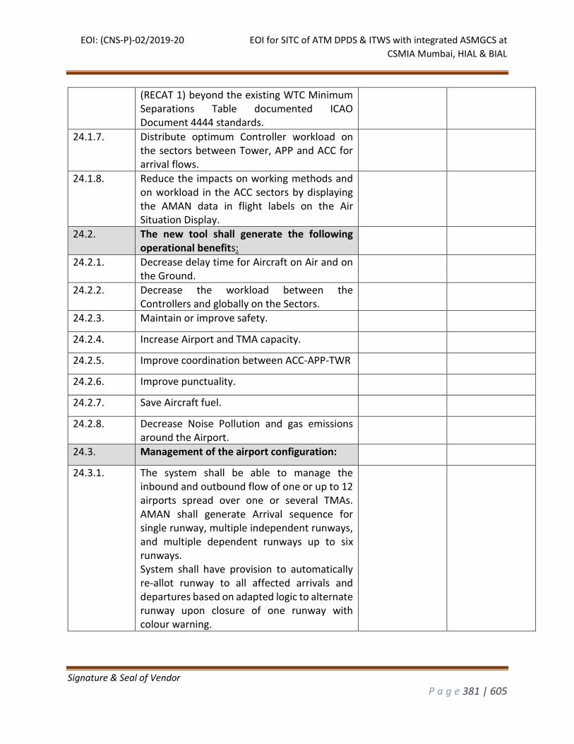
EOI: (CNS-P)-02/2019-20 EOI for SITC of ATM DPDS & ITWS with integrated ASMGCS at
CSMIA Mumbai, HIAL & BIAL
Signature & Seal of Vendor
P a g e 381 | 605
(RECAT 1) beyond the existing WTC Minimum Separations Table documented ICAO Document 4444 standards.
24.1.7. Distribute optimum Controller workload on the sectors between Tower, APP and ACC for arrival flows.
24.1.8. Reduce the impacts on working methods and on workload in the ACC sectors by displaying the AMAN data in flight labels on the Air Situation Display.
24.2. The new tool shall generate the following operational benefits:
24.2.1. Decrease delay time for Aircraft on Air and on the Ground.
24.2.2. Decrease the workload between the Controllers and globally on the Sectors.
24.2.3. Maintain or improve safety.
24.2.4. Increase Airport and TMA capacity.
24.2.5. Improve coordination between ACC-APP-TWR
24.2.6. Improve punctuality.
24.2.7. Save Aircraft fuel.
24.2.8. Decrease Noise Pollution and gas emissions around the Airport.
24.3. Management of the airport configuration:
24.3.1. The system shall be able to manage the inbound and outbound flow of one or up to 12 airports spread over one or several TMAs. AMAN shall generate Arrival sequence for single runway, multiple independent runways, and multiple dependent runways up to six runways. System shall have provision to automatically re-allot runway to all affected arrivals and departures based on adapted logic to alternate runway upon closure of one runway with colour warning.
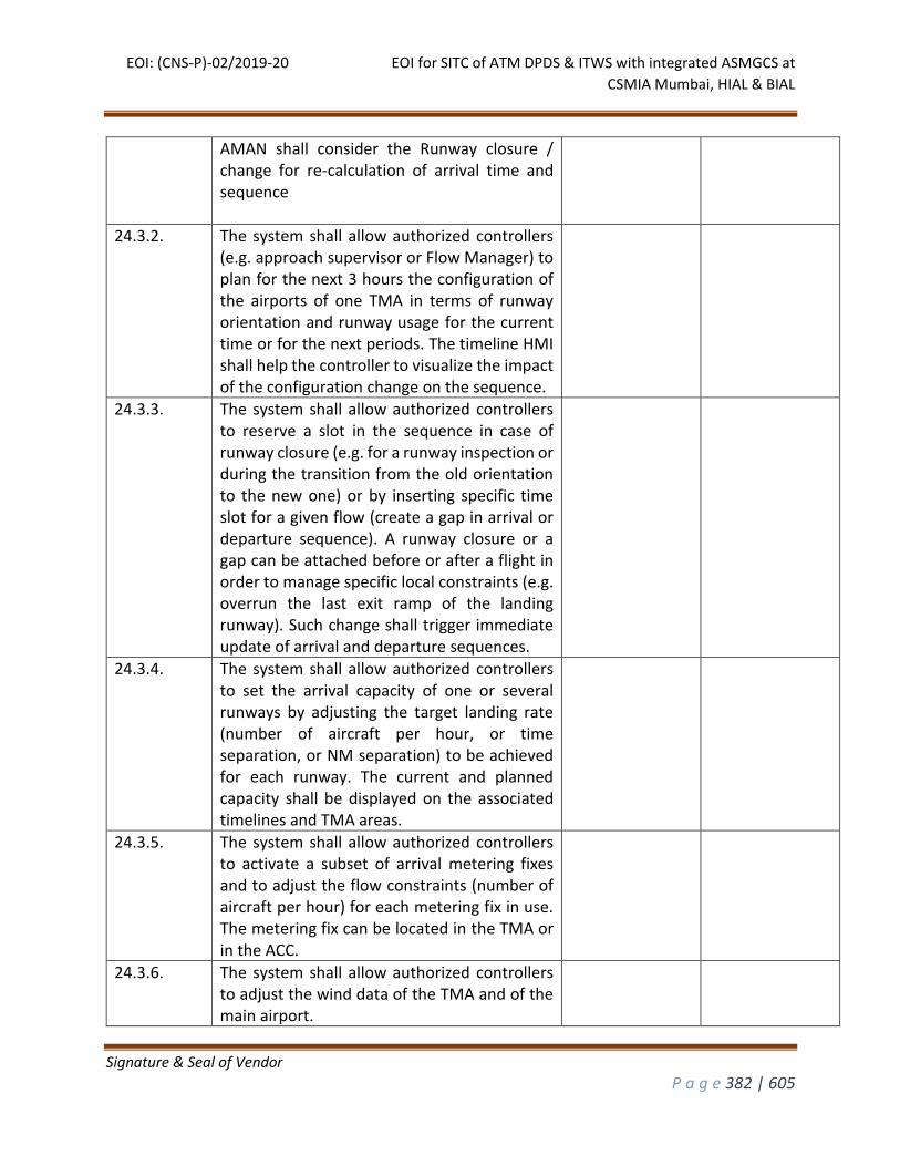
EOI: (CNS-P)-02/2019-20 EOI for SITC of ATM DPDS & ITWS with integrated ASMGCS at
CSMIA Mumbai, HIAL & BIAL
Signature & Seal of Vendor
P a g e 382 | 605
AMAN shall consider the Runway closure / change for re-calculation of arrival time and sequence
24.3.2. The system shall allow authorized controllers (e.g. approach supervisor or Flow Manager) to plan for the next 3 hours the configuration of the airports of one TMA in terms of runway orientation and runway usage for the current time or for the next periods. The timeline HMI shall help the controller to visualize the impact of the configuration change on the sequence.
24.3.3. The system shall allow authorized controllers to reserve a slot in the sequence in case of runway closure (e.g. for a runway inspection or during the transition from the old orientation to the new one) or by inserting specific time slot for a given flow (create a gap in arrival or departure sequence). A runway closure or a gap can be attached before or after a flight in order to manage specific local constraints (e.g. overrun the last exit ramp of the landing runway). Such change shall trigger immediate update of arrival and departure sequences.
24.3.4. The system shall allow authorized controllers to set the arrival capacity of one or several runways by adjusting the target landing rate (number of aircraft per hour, or time separation, or NM separation) to be achieved for each runway. The current and planned capacity shall be displayed on the associated timelines and TMA areas.
24.3.5. The system shall allow authorized controllers to activate a subset of arrival metering fixes and to adjust the flow constraints (number of aircraft per hour) for each metering fix in use. The metering fix can be located in the TMA or in the ACC.
24.3.6. The system shall allow authorized controllers to adjust the wind data of the TMA and of the main airport.
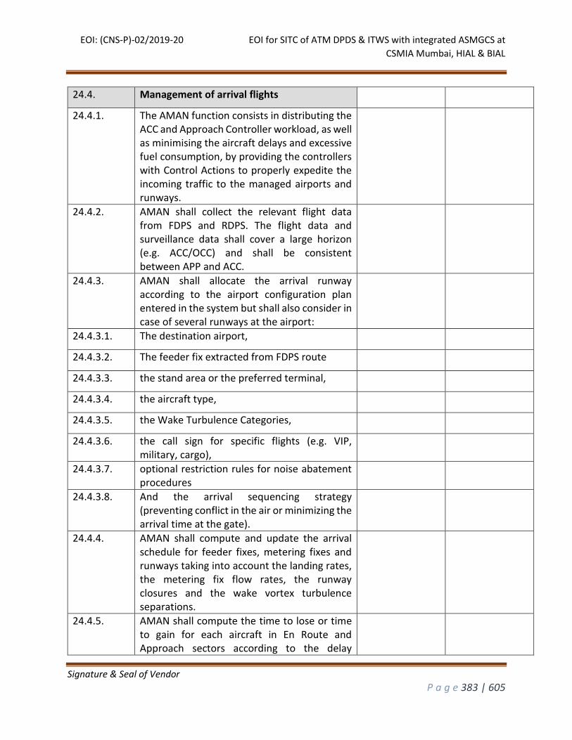
EOI: (CNS-P)-02/2019-20 EOI for SITC of ATM DPDS & ITWS with integrated ASMGCS at
CSMIA Mumbai, HIAL & BIAL
Signature & Seal of Vendor
P a g e 383 | 605
24.4. Management of arrival flights
24.4.1. The AMAN function consists in distributing the ACC and Approach Controller workload, as well as minimising the aircraft delays and excessive fuel consumption, by providing the controllers with Control Actions to properly expedite the incoming traffic to the managed airports and runways.
24.4.2. AMAN shall collect the relevant flight data from FDPS and RDPS. The flight data and surveillance data shall cover a large horizon (e.g. ACC/OCC) and shall be consistent between APP and ACC.
24.4.3. AMAN shall allocate the arrival runway according to the airport configuration plan entered in the system but shall also consider in case of several runways at the airport:
24.4.3.1. The destination airport,
24.4.3.2. The feeder fix extracted from FDPS route
24.4.3.3. the stand area or the preferred terminal,
24.4.3.4. the aircraft type,
24.4.3.5. the Wake Turbulence Categories,
24.4.3.6. the call sign for specific flights (e.g. VIP, military, cargo),
24.4.3.7. optional restriction rules for noise abatement procedures
24.4.3.8. And the arrival sequencing strategy (preventing conflict in the air or minimizing the arrival time at the gate).
24.4.4. AMAN shall compute and update the arrival schedule for feeder fixes, metering fixes and runways taking into account the landing rates, the metering fix flow rates, the runway closures and the wake vortex turbulence separations.
24.4.5. AMAN shall compute the time to lose or time to gain for each aircraft in En Route and Approach sectors according to the delay
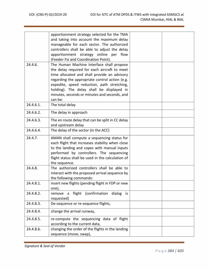
EOI: (CNS-P)-02/2019-20 EOI for SITC of ATM DPDS & ITWS with integrated ASMGCS at
CSMIA Mumbai, HIAL & BIAL
Signature & Seal of Vendor
P a g e 384 | 605
apportionment strategy selected for the TMA and taking into account the maximum delay manageable for each sector. The authorized controllers shall be able to adjust the delay apportionment strategy online per flow (Feeder Fix and Coordination Point).
24.4.6. The Human Machine Interface shall propose the delay required for each aircraft to meet time allocated and shall provide an advisory regarding the appropriate control action (e.g. expedite, speed reduction, path stretching, holding). The delay shall be displayed in minutes, seconds or minutes and seconds, and can be:
24.4.6.1. The total delay
24.4.6.2. The delay in approach
24.4.6.3. The en route delay that can be split in CC delay and upstream delay
24.4.6.4. The delay of the sector (in the ACC)
24.4.7. AMAN shall compute a sequencing status for each flight that increases stability when close to the landing and copes with manual inputs performed by controllers. The sequencing flight status shall be used in the calculation of the sequence.
24.4.8. The authorized controllers shall be able to interact with the proposed arrival sequence by the following commands:
24.4.8.1. insert new flights (pending flight in FDP or new one),
24.4.8.2. remove a flight (confirmation dialog is requested)
24.4.8.3. De-sequence or re-sequence flights,
24.4.8.4. change the arrival runway,
24.4.8.5. re-compute the sequencing data of flight according to the current data,
24.4.8.6. changing the order of the flights in the landing sequence (move, swap),
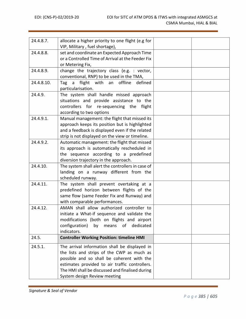
EOI: (CNS-P)-02/2019-20 EOI for SITC of ATM DPDS & ITWS with integrated ASMGCS at
CSMIA Mumbai, HIAL & BIAL
Signature & Seal of Vendor
P a g e 385 | 605
24.4.8.7. allocate a higher priority to one flight (e.g for VIP, Military , fuel shortage),
24.4.8.8. set and coordinate an Expected Approach Time or a Controlled Time of Arrival at the Feeder Fix or Metering Fix,
24.4.8.9. change the trajectory class (e.g. : vector, conventional, RNP) to be used in the TMA,
24.4.8.10. Tag a flight with an offline defined particularisation.
24.4.9. The system shall handle missed approach situations and provide assistance to the controllers for re-sequencing the flight according to two options
24.4.9.1. Manual management: the flight that missed its approach keeps its position but is highlighted and a feedback is displayed even if the related strip is not displayed on the view or timeline.
24.4.9.2. Automatic management: the flight that missed its approach is automatically rescheduled in the sequence according to a predefined diversion trajectory in the approach.
24.4.10. The system shall alert the controllers in case of landing on a runway different from the scheduled runway.
24.4.11. The system shall prevent overtaking at a predefined horizon between flights of the same flow (same Feeder Fix and Runway) and with comparable performances.
24.4.12. AMAN shall allow authorized controller to initiate a What-if sequence and validate the modifications (both on flights and airport configuration) by means of dedicated indicators.
24.5. Controller Working Position: timeline HMI
24.5.1. The arrival information shall be displayed in the lists and strips of the CWP as much as possible and so shall be coherent with the estimates provided to air traffic controllers. The HMI shall be discussed and finalised during System design Review meeting
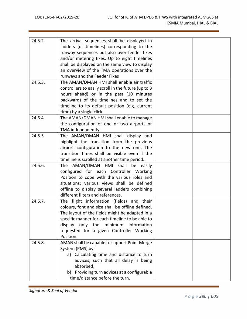
EOI: (CNS-P)-02/2019-20 EOI for SITC of ATM DPDS & ITWS with integrated ASMGCS at
CSMIA Mumbai, HIAL & BIAL
Signature & Seal of Vendor
P a g e 386 | 605
24.5.2. The arrival sequences shall be displayed in ladders (or timelines) corresponding to the runway sequences but also over feeder fixes and/or metering fixes. Up to eight timelines shall be displayed on the same view to display an overview of the TMA operations over the runways and the Feeder Fixes
24.5.3. The AMAN/DMAN HMI shall enable air traffic controllers to easily scroll in the future (up to 3 hours ahead) or in the past (10 minutes backward) of the timelines and to set the timeline to its default position (e.g. current time) by a single click.
24.5.4. The AMAN/DMAN HMI shall enable to manage the configuration of one or two airports or TMA independently.
24.5.5. The AMAN/DMAN HMI shall display and highlight the transition from the previous airport configuration to the new one. The transition times shall be visible even if the timeline is scrolled at another time period.
24.5.6. The AMAN/DMAN HMI shall be easily configured for each Controller Working Position to cope with the various roles and situations: various views shall be defined offline to display several ladders combining different filters and references.
24.5.7. The flight information (fields) and their colours, font and size shall be offline defined. The layout of the fields might be adapted in a specific manner for each timeline to be able to display only the minimum information requested for a given Controller Working Position.
24.5.8. AMAN shall be capable to support Point Merge System (PMS) by
a) Calculating time and distance to turn advices, such that all delay is being absorbed,
b) Providing turn advices at a configurable time/distance before the turn.
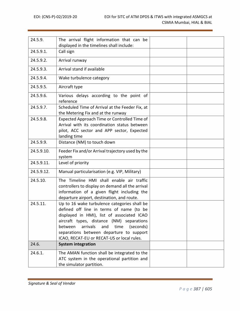
EOI: (CNS-P)-02/2019-20 EOI for SITC of ATM DPDS & ITWS with integrated ASMGCS at
CSMIA Mumbai, HIAL & BIAL
Signature & Seal of Vendor
P a g e 387 | 605
24.5.9. The arrival flight information that can be displayed in the timelines shall include:
24.5.9.1. Call sign
24.5.9.2. Arrival runway
24.5.9.3. Arrival stand if available
24.5.9.4. Wake turbulence category
24.5.9.5. Aircraft type
24.5.9.6. Various delays according to the point of reference
24.5.9.7. Scheduled Time of Arrival at the Feeder Fix, at the Metering Fix and at the runway
24.5.9.8. Expected Approach Time or Controlled Time of Arrival with its coordination status between pilot, ACC sector and APP sector, Expected landing time
24.5.9.9. Distance (NM) to touch down
24.5.9.10. Feeder Fix and/or Arrival trajectory used by the system
24.5.9.11. Level of priority
24.5.9.12. Manual particularisation (e.g. VIP, Military)
24.5.10. The Timeline HMI shall enable air traffic controllers to display on demand all the arrival information of a given flight including the departure airport, destination, and route.
24.5.11. Up to 16 wake turbulence categories shall be defined off line in terms of name (to be displayed in HMI), list of associated ICAO aircraft types, distance (NM) separations between arrivals and time (seconds) separations between departure to support ICAO, RECAT-EU or RECAT-US or local rules.
24.6. System integration
24.6.1. The AMAN function shall be integrated to the ATC system in the operational partition and the simulator partition.
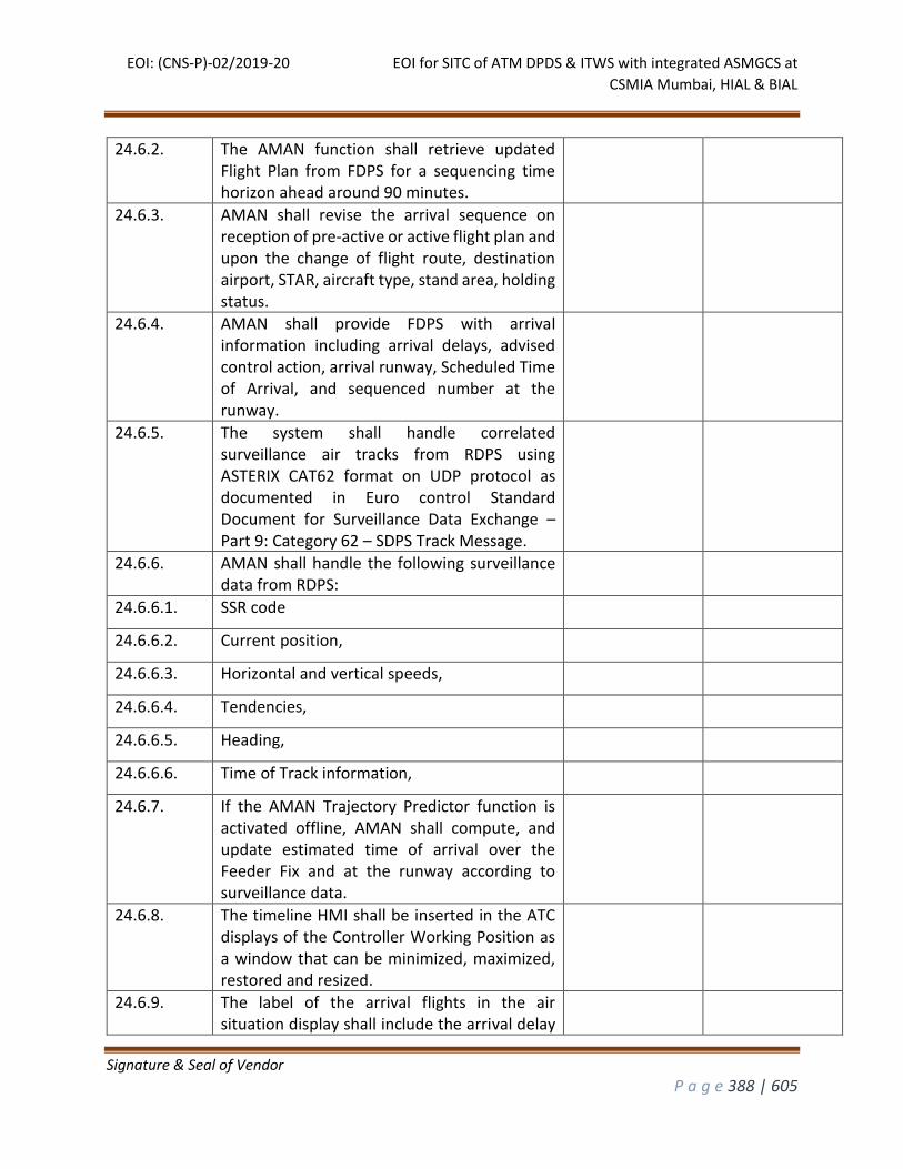
EOI: (CNS-P)-02/2019-20 EOI for SITC of ATM DPDS & ITWS with integrated ASMGCS at
CSMIA Mumbai, HIAL & BIAL
Signature & Seal of Vendor
P a g e 388 | 605
24.6.2. The AMAN function shall retrieve updated Flight Plan from FDPS for a sequencing time horizon ahead around 90 minutes.
24.6.3. AMAN shall revise the arrival sequence on reception of pre-active or active flight plan and upon the change of flight route, destination airport, STAR, aircraft type, stand area, holding status.
24.6.4. AMAN shall provide FDPS with arrival information including arrival delays, advised control action, arrival runway, Scheduled Time of Arrival, and sequenced number at the runway.
24.6.5. The system shall handle correlated surveillance air tracks from RDPS using ASTERIX CAT62 format on UDP protocol as documented in Euro control Standard Document for Surveillance Data Exchange – Part 9: Category 62 – SDPS Track Message.
24.6.6. AMAN shall handle the following surveillance data from RDPS:
24.6.6.1. SSR code
24.6.6.2. Current position,
24.6.6.3. Horizontal and vertical speeds,
24.6.6.4. Tendencies,
24.6.6.5. Heading,
24.6.6.6. Time of Track information,
24.6.7. If the AMAN Trajectory Predictor function is activated offline, AMAN shall compute, and update estimated time of arrival over the Feeder Fix and at the runway according to surveillance data.
24.6.8. The timeline HMI shall be inserted in the ATC displays of the Controller Working Position as a window that can be minimized, maximized, restored and resized.
24.6.9. The label of the arrival flights in the air situation display shall include the arrival delay
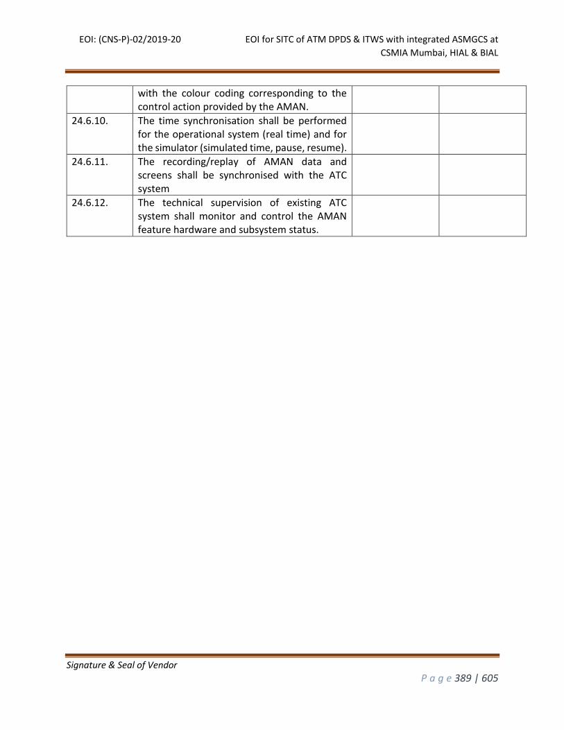
EOI: (CNS-P)-02/2019-20 EOI for SITC of ATM DPDS & ITWS with integrated ASMGCS at
CSMIA Mumbai, HIAL & BIAL
Signature & Seal of Vendor
P a g e 389 | 605
with the colour coding corresponding to the control action provided by the AMAN.
24.6.10. The time synchronisation shall be performed for the operational system (real time) and for the simulator (simulated time, pause, resume).
24.6.11. The recording/replay of AMAN data and screens shall be synchronised with the ATC system
24.6.12. The technical supervision of existing ATC system shall monitor and control the AMAN feature hardware and subsystem status.
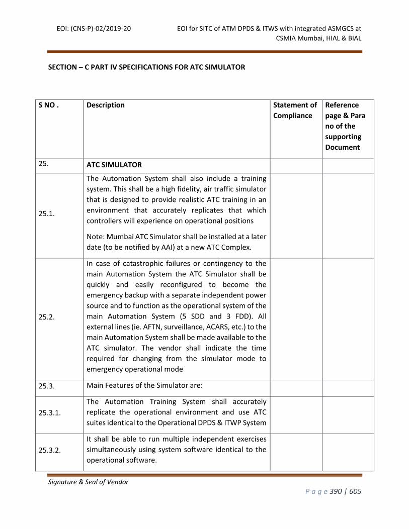
EOI: (CNS-P)-02/2019-20 EOI for SITC of ATM DPDS & ITWS with integrated ASMGCS at
CSMIA Mumbai, HIAL & BIAL
Signature & Seal of Vendor
P a g e 390 | 605
SECTION – C PART IV SPECIFICATIONS FOR ATC SIMULATOR
S NO . Description Statement of
Compliance
Reference
page & Para
no of the
supporting
Document
25. ATC SIMULATOR
25.1.
The Automation System shall also include a training
system. This shall be a high fidelity, air traffic simulator
that is designed to provide realistic ATC training in an
environment that accurately replicates that which
controllers will experience on operational positions
Note: Mumbai ATC Simulator shall be installed at a later
date (to be notified by AAI) at a new ATC Complex.
25.2.
In case of catastrophic failures or contingency to the
main Automation System the ATC Simulator shall be
quickly and easily reconfigured to become the
emergency backup with a separate independent power
source and to function as the operational system of the
main Automation System (5 SDD and 3 FDD). All
external lines (ie. AFTN, surveillance, ACARS, etc.) to the
main Automation System shall be made available to the
ATC simulator. The vendor shall indicate the time
required for changing from the simulator mode to
emergency operational mode
25.3. Main Features of the Simulator are:
25.3.1.
The Automation Training System shall accurately
replicate the operational environment and use ATC
suites identical to the Operational DPDS & ITWP System
25.3.2.
It shall be able to run multiple independent exercises
simultaneously using system software identical to the
operational software.

EOI: (CNS-P)-02/2019-20 EOI for SITC of ATM DPDS & ITWS with integrated ASMGCS at
CSMIA Mumbai, HIAL & BIAL
Signature & Seal of Vendor
P a g e 391 | 605
25.3.3.
The Training system shall comprise Controller Positions,
Flight Data Assistant, Air Traffic Generator, Pilot
Positions and a Simulator Supervisor position
25.3.4.
The training system suit shall also support testing of
new software modules and adaptation data for
validation prior to implement in the operational system
25.3.5.
It shall also be used to test new procedures, new
divisions of the airspace, routes, conflict analysis and
traffic flow besides testing of system hardware and
software.
25.3.6.
The training system shall use any combination of
controller suites and pilot positions required to achieve
specific exercise objectives
25.3.7.
The training system function shall provide simulated
sensor/surveillance inputs for the purpose of controller
training.
25.4. The ATC Simulator System shall consist of the following
constituent positions:
25.4.1.
Trainee Controller Position: These positions shall be
similar to Controller Working Positions as in the
operational system
25.4.2.
Flight Data Assistant - These positions shall be similar to
Flight Data Assistant Positions as in the operational
system
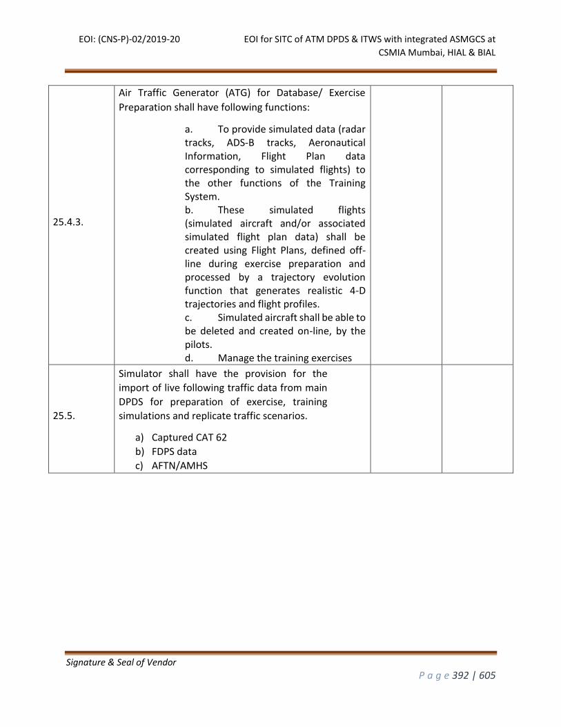
EOI: (CNS-P)-02/2019-20 EOI for SITC of ATM DPDS & ITWS with integrated ASMGCS at
CSMIA Mumbai, HIAL & BIAL
Signature & Seal of Vendor
P a g e 392 | 605
25.4.3.
Air Traffic Generator (ATG) for Database/ Exercise
Preparation shall have following functions:
a. To provide simulated data (radar tracks, ADS-B tracks, Aeronautical Information, Flight Plan data corresponding to simulated flights) to the other functions of the Training System. b. These simulated flights (simulated aircraft and/or associated simulated flight plan data) shall be created using Flight Plans, defined off-line during exercise preparation and processed by a trajectory evolution function that generates realistic 4-D trajectories and flight profiles. c. Simulated aircraft shall be able to be deleted and created on-line, by the pilots. d. Manage the training exercises
25.5.
Simulator shall have the provision for the
import of live following traffic data from main
DPDS for preparation of exercise, training
simulations and replicate traffic scenarios.
a) Captured CAT 62
b) FDPS data
c) AFTN/AMHS
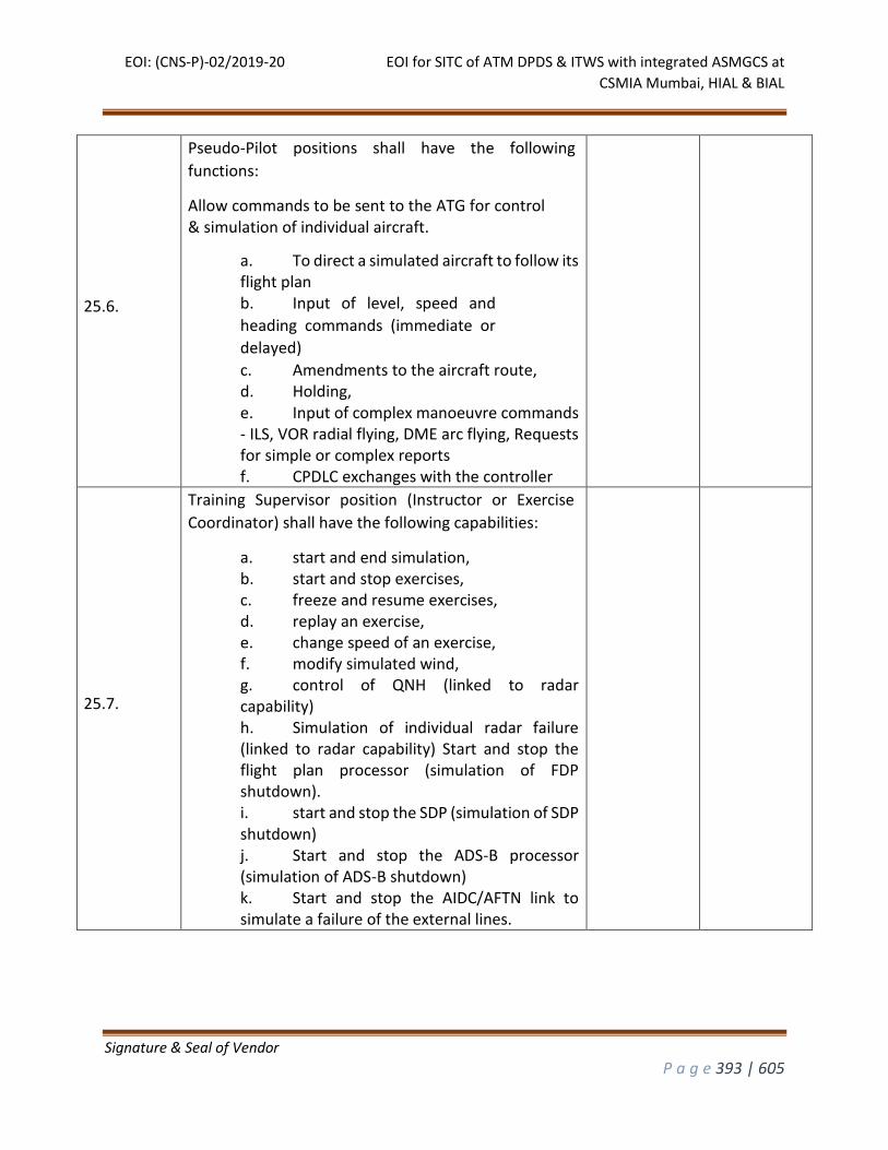
EOI: (CNS-P)-02/2019-20 EOI for SITC of ATM DPDS & ITWS with integrated ASMGCS at
CSMIA Mumbai, HIAL & BIAL
Signature & Seal of Vendor
P a g e 393 | 605
25.6.
Pseudo-Pilot positions shall have the following
functions:
Allow commands to be sent to the ATG for control & simulation of individual aircraft.
a. To direct a simulated aircraft to follow its flight plan b. Input of level, speed and
heading commands (immediate or
delayed)
c. Amendments to the aircraft route, d. Holding, e. Input of complex manoeuvre commands - ILS, VOR radial flying, DME arc flying, Requests for simple or complex reports f. CPDLC exchanges with the controller
25.7.
Training Supervisor position (Instructor or Exercise
Coordinator) shall have the following capabilities:
a. start and end simulation, b. start and stop exercises, c. freeze and resume exercises, d. replay an exercise, e. change speed of an exercise, f. modify simulated wind, g. control of QNH (linked to radar capability) h. Simulation of individual radar failure (linked to radar capability) Start and stop the flight plan processor (simulation of FDP shutdown). i. start and stop the SDP (simulation of SDP shutdown) j. Start and stop the ADS-B processor (simulation of ADS-B shutdown) k. Start and stop the AIDC/AFTN link to simulate a failure of the external lines.
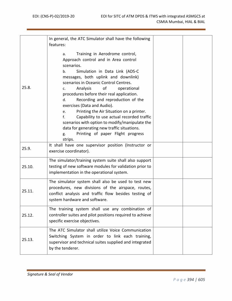
EOI: (CNS-P)-02/2019-20 EOI for SITC of ATM DPDS & ITWS with integrated ASMGCS at
CSMIA Mumbai, HIAL & BIAL
Signature & Seal of Vendor
P a g e 394 | 605
25.8.
In general, the ATC Simulator shall have the following
features:
a. Training in Aerodrome control,
Approach control and in Area control
scenarios.
b. Simulation in Data Link (ADS-C messages, both uplink and downlink) scenarios in Oceanic Control Centres. c. Analysis of operational procedures before their real application. d. Recording and reproduction of the
exercises (Data and Audio).
e. Printing the Air Situation on a printer. f. Capability to use actual recorded traffic scenarios with option to modify/manipulate the data for generating new traffic situations. g. Printing of paper Flight progress strips.
25.9. It shall have one supervisor position (Instructor or
exercise coordinator).
25.10.
The simulator/training system suite shall also support
testing of new software modules for validation prior to
implementation in the operational system.
25.11.
The simulator system shall also be used to test new
procedures, new divisions of the airspace, routes,
conflict analysis and traffic flow besides testing of
system hardware and software.
25.12.
The training system shall use any combination of
controller suites and pilot positions required to achieve
specific exercise objectives.
25.13.
The ATC Simulator shall utilize Voice Communication
Switching System in order to link each training,
supervisor and technical suites supplied and integrated
by the tenderer.
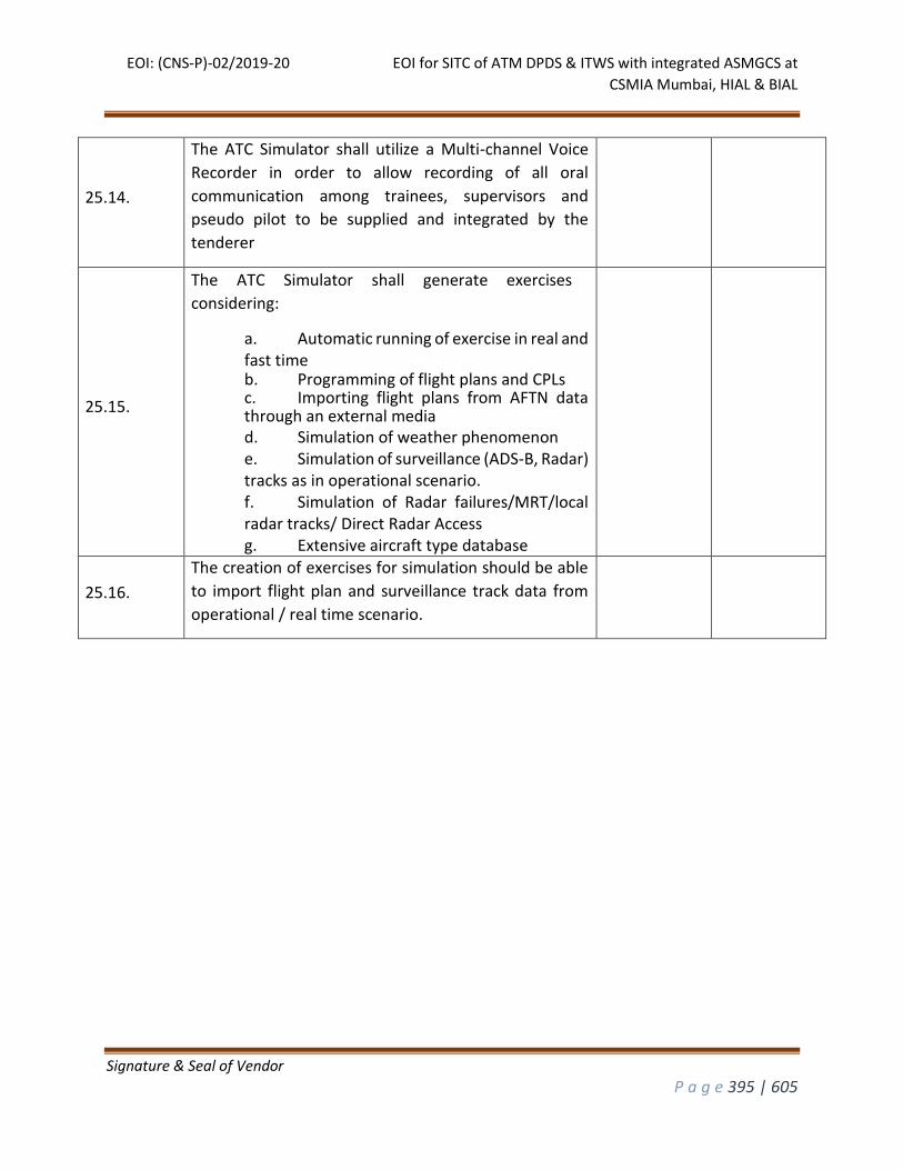
EOI: (CNS-P)-02/2019-20 EOI for SITC of ATM DPDS & ITWS with integrated ASMGCS at
CSMIA Mumbai, HIAL & BIAL
Signature & Seal of Vendor
P a g e 395 | 605
25.14.
The ATC Simulator shall utilize a Multi-channel Voice
Recorder in order to allow recording of all oral
communication among trainees, supervisors and
pseudo pilot to be supplied and integrated by the
tenderer
25.15.
The ATC Simulator shall generate exercises
considering:
a. Automatic running of exercise in real and fast time b. Programming of flight plans and CPLs c. Importing flight plans from AFTN data through an external media d. Simulation of weather phenomenon e. Simulation of surveillance (ADS-B, Radar) tracks as in operational scenario. f. Simulation of Radar failures/MRT/local radar tracks/ Direct Radar Access g. Extensive aircraft type database
25.16.
The creation of exercises for simulation should be able
to import flight plan and surveillance track data from
operational / real time scenario.

EOI: (CNS-P)-02/2019-20 EOI for SITC of ATM DPDS & ITWS with integrated ASMGCS at
CSMIA Mumbai, HIAL & BIAL
Signature & Seal of Vendor
P a g e 396 | 605
25.17.
The exercise scenario editor should
have:
a. A GUI based User friendly tool. b. Easy access to help c. A checking tool for consistence of
data to allow valid and consistent Data
fields
d. A search tool for data and exercise database e. Chronological and Alphabetical order database sorting f. Searching data by cursors and page down/page up commands or first character of the name g. Easy access and updating any field or data without modifying the remaining database. h. All exercise must be checked concerning to their consistence, including flight plans, routes, etc.
It shall be possible to add, modify, print and update
exercises, both offline and on -the fly, i.e., online, during
the running exercise
25.18.
It shall be possible to run, pause, rewind and start from
a given time, restart, and stop the exercises individually
without interfering with others.
25.19. The ATC simulator exercises shall be recorded for later
evaluation and modification in playback mode.
25.20. The ATC simulator shall have the capacity to print the
stored exercise scenario in a text format.
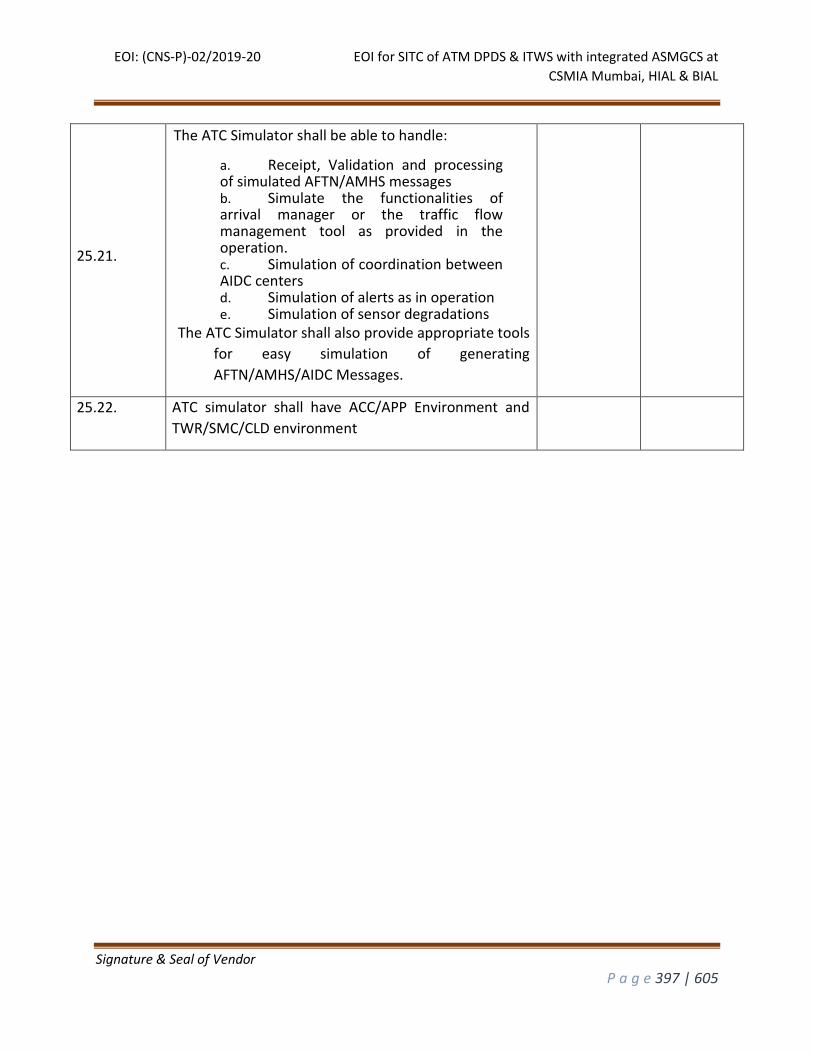
EOI: (CNS-P)-02/2019-20 EOI for SITC of ATM DPDS & ITWS with integrated ASMGCS at
CSMIA Mumbai, HIAL & BIAL
Signature & Seal of Vendor
P a g e 397 | 605
25.21.
The ATC Simulator shall be able to handle:
a. Receipt, Validation and processing of simulated AFTN/AMHS messages b. Simulate the functionalities of arrival manager or the traffic flow management tool as provided in the operation. c. Simulation of coordination between AIDC centers d. Simulation of alerts as in operation e. Simulation of sensor degradations
The ATC Simulator shall also provide appropriate tools
for easy simulation of generating
AFTN/AMHS/AIDC Messages.
25.22. ATC simulator shall have ACC/APP Environment and
TWR/SMC/CLD environment
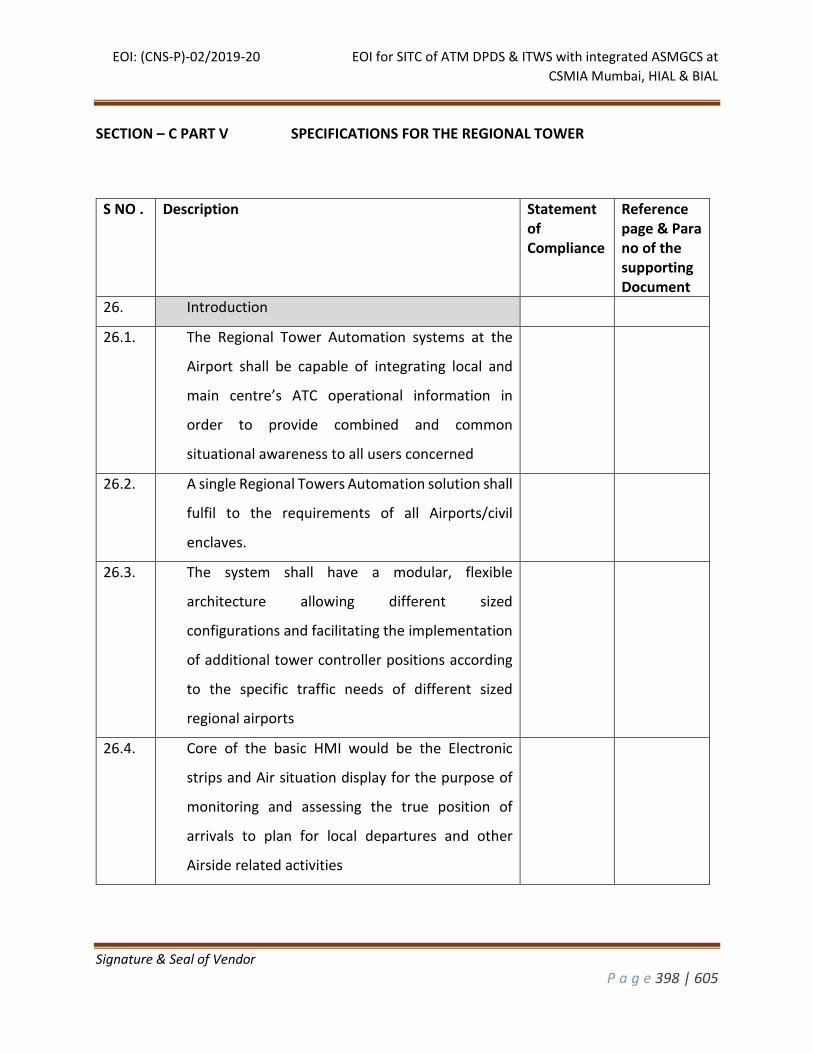
EOI: (CNS-P)-02/2019-20 EOI for SITC of ATM DPDS & ITWS with integrated ASMGCS at
CSMIA Mumbai, HIAL & BIAL
Signature & Seal of Vendor
P a g e 398 | 605
SECTION – C PART V SPECIFICATIONS FOR THE REGIONAL TOWER
S NO . Description Statement of Compliance
Reference page & Para no of the supporting Document
26. Introduction
26.1. The Regional Tower Automation systems at the
Airport shall be capable of integrating local and
main centre’s ATC operational information in
order to provide combined and common
situational awareness to all users concerned
26.2. A single Regional Towers Automation solution shall
fulfil to the requirements of all Airports/civil
enclaves.
26.3. The system shall have a modular, flexible
architecture allowing different sized
configurations and facilitating the implementation
of additional tower controller positions according
to the specific traffic needs of different sized
regional airports
26.4. Core of the basic HMI would be the Electronic
strips and Air situation display for the purpose of
monitoring and assessing the true position of
arrivals to plan for local departures and other
Airside related activities
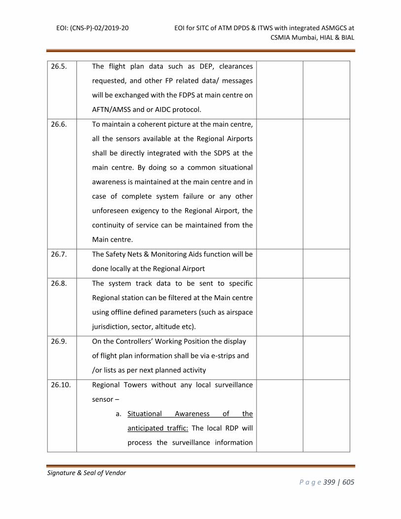
EOI: (CNS-P)-02/2019-20 EOI for SITC of ATM DPDS & ITWS with integrated ASMGCS at
CSMIA Mumbai, HIAL & BIAL
Signature & Seal of Vendor
P a g e 399 | 605
26.5. The flight plan data such as DEP, clearances
requested, and other FP related data/ messages
will be exchanged with the FDPS at main centre on
AFTN/AMSS and or AIDC protocol.
26.6. To maintain a coherent picture at the main centre,
all the sensors available at the Regional Airports
shall be directly integrated with the SDPS at the
main centre. By doing so a common situational
awareness is maintained at the main centre and in
case of complete system failure or any other
unforeseen exigency to the Regional Airport, the
continuity of service can be maintained from the
Main centre.
26.7. The Safety Nets & Monitoring Aids function will be
done locally at the Regional Airport
26.8. The system track data to be sent to specific
Regional station can be filtered at the Main centre
using offline defined parameters (such as airspace
jurisdiction, sector, altitude etc).
26.9. On the Controllers’ Working Position the display
of flight plan information shall be via e-strips and
/or lists as per next planned activity
26.10. Regional Towers without any local surveillance
sensor –
a. Situational Awareness of the
anticipated traffic: The local RDP will
process the surveillance information
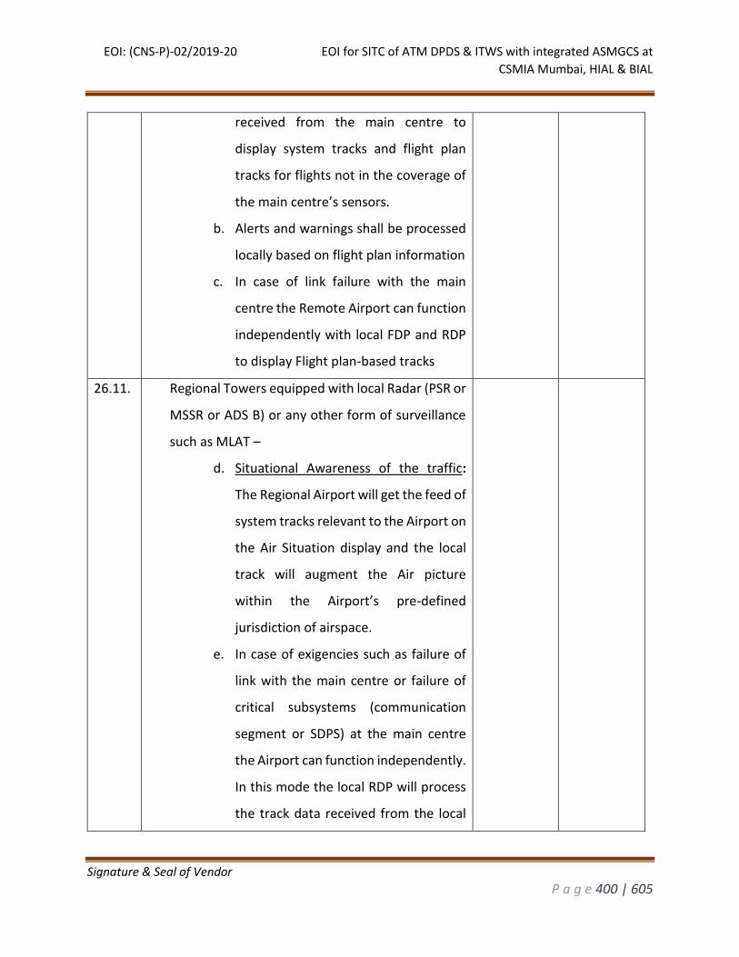
EOI: (CNS-P)-02/2019-20 EOI for SITC of ATM DPDS & ITWS with integrated ASMGCS at
CSMIA Mumbai, HIAL & BIAL
Signature & Seal of Vendor
P a g e 400 | 605
received from the main centre to
display system tracks and flight plan
tracks for flights not in the coverage of
the main centre’s sensors.
b. Alerts and warnings shall be processed
locally based on flight plan information
c. In case of link failure with the main
centre the Remote Airport can function
independently with local FDP and RDP
to display Flight plan-based tracks
26.11. Regional Towers equipped with local Radar (PSR or
MSSR or ADS B) or any other form of surveillance
such as MLAT –
d. Situational Awareness of the traffic:
The Regional Airport will get the feed of
system tracks relevant to the Airport on
the Air Situation display and the local
track will augment the Air picture
within the Airport’s pre-defined
jurisdiction of airspace.
e. In case of exigencies such as failure of
link with the main centre or failure of
critical subsystems (communication
segment or SDPS) at the main centre
the Airport can function independently.
In this mode the local RDP will process
the track data received from the local
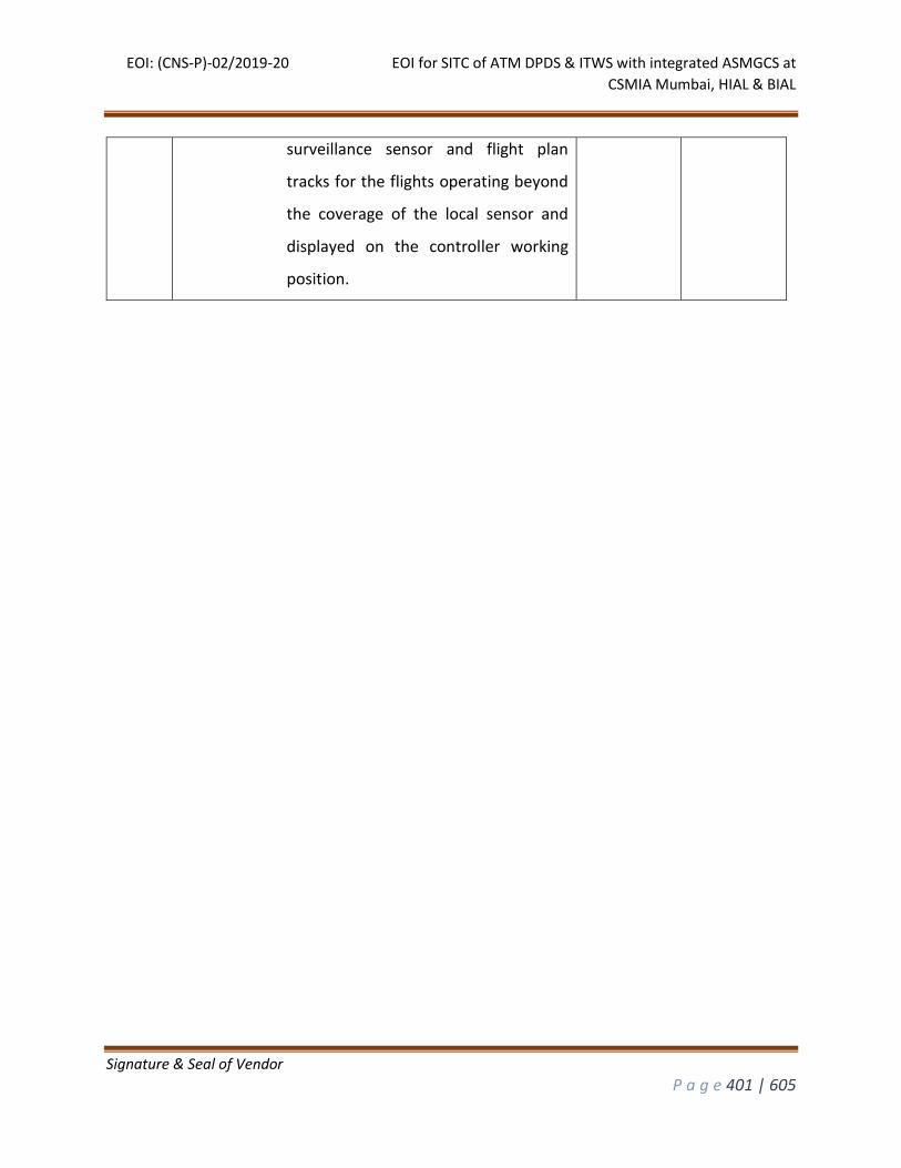
EOI: (CNS-P)-02/2019-20 EOI for SITC of ATM DPDS & ITWS with integrated ASMGCS at
CSMIA Mumbai, HIAL & BIAL
Signature & Seal of Vendor
P a g e 401 | 605
surveillance sensor and flight plan
tracks for the flights operating beyond
the coverage of the local sensor and
displayed on the controller working
position.
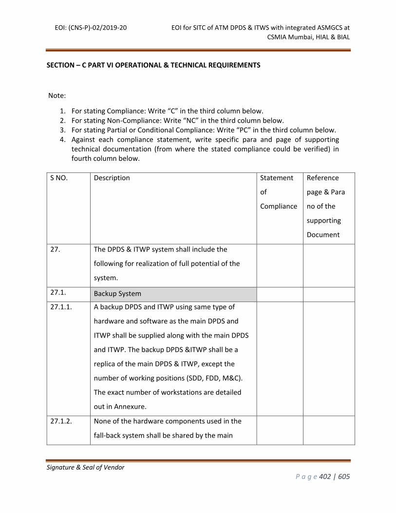
EOI: (CNS-P)-02/2019-20 EOI for SITC of ATM DPDS & ITWS with integrated ASMGCS at
CSMIA Mumbai, HIAL & BIAL
Signature & Seal of Vendor
P a g e 402 | 605
SECTION – C PART VI OPERATIONAL & TECHNICAL REQUIREMENTS
S NO. Description Statement
of
Compliance
Reference
page & Para
no of the
supporting
Document
27. The DPDS & ITWP system shall include the
following for realization of full potential of the
system.
27.1. Backup System
27.1.1. A backup DPDS and ITWP using same type of
hardware and software as the main DPDS and
ITWP shall be supplied along with the main DPDS
and ITWP. The backup DPDS &ITWP shall be a
replica of the main DPDS & ITWP, except the
number of working positions (SDD, FDD, M&C).
The exact number of workstations are detailed
out in Annexure.
27.1.2. None of the hardware components used in the
fall-back system shall be shared by the main
Note:
1. For stating Compliance: Write “C” in the third column below. 2. For stating Non-Compliance: Write “NC” in the third column below. 3. For stating Partial or Conditional Compliance: Write “PC” in the third column below. 4. Against each compliance statement, write specific para and page of supporting
technical documentation (from where the stated compliance could be verified) in fourth column below.
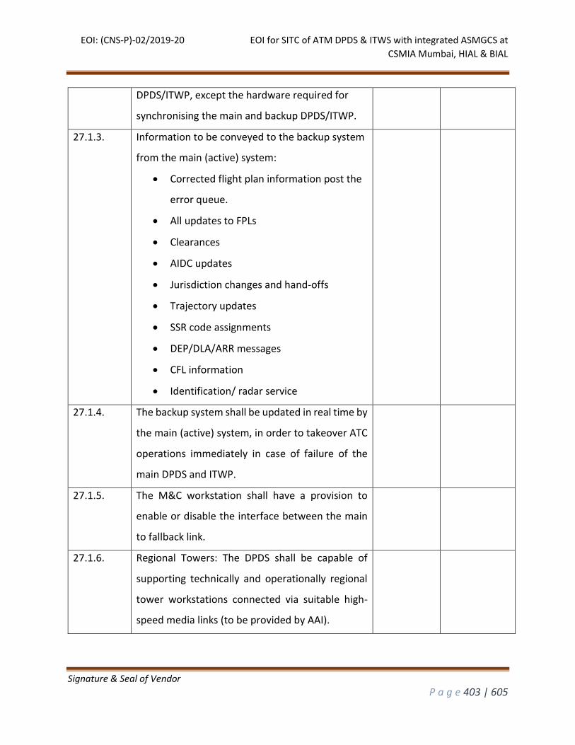
EOI: (CNS-P)-02/2019-20 EOI for SITC of ATM DPDS & ITWS with integrated ASMGCS at
CSMIA Mumbai, HIAL & BIAL
Signature & Seal of Vendor
P a g e 403 | 605
DPDS/ITWP, except the hardware required for
synchronising the main and backup DPDS/ITWP.
27.1.3. Information to be conveyed to the backup system
from the main (active) system:
Corrected flight plan information post the
error queue.
All updates to FPLs
Clearances
AIDC updates
Jurisdiction changes and hand-offs
Trajectory updates
SSR code assignments
DEP/DLA/ARR messages
CFL information
Identification/ radar service
27.1.4. The backup system shall be updated in real time by
the main (active) system, in order to takeover ATC
operations immediately in case of failure of the
main DPDS and ITWP.
27.1.5. The M&C workstation shall have a provision to
enable or disable the interface between the main
to fallback link.
27.1.6. Regional Towers: The DPDS shall be capable of
supporting technically and operationally regional
tower workstations connected via suitable high-
speed media links (to be provided by AAI).
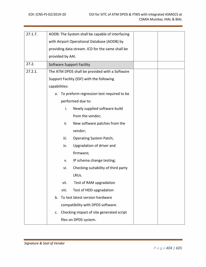
EOI: (CNS-P)-02/2019-20 EOI for SITC of ATM DPDS & ITWS with integrated ASMGCS at
CSMIA Mumbai, HIAL & BIAL
Signature & Seal of Vendor
P a g e 404 | 605
27.1.7. AODB: The System shall be capable of interfacing
with Airport Operational Database (AODB) by
providing data stream. ICD for the same shall be
provided by AAI.
27.2. Software Support Facility
27.2.1. The ATM DPDS shall be provided with a Software
Support Facility (SSF) with the following
capabilities:
a. To preform regression test required to be
performed due to:
i. Newly supplied software build
from the vendor;
ii. New software patches from the
vendor;
iii. Operating System Patch;
iv. Upgradation of driver and
firmware;
v. IP schema change testing;
vi. Checking suitability of third party
LRUs.
vii. Test of RAM upgradation
viii. Test of HDD upgradation
b. To test latest version hardware
compatibility with DPDS software.
c. Checking impact of site generated script
files on DPDS system.
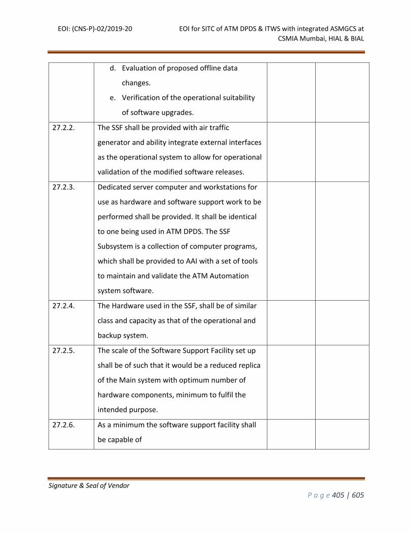
EOI: (CNS-P)-02/2019-20 EOI for SITC of ATM DPDS & ITWS with integrated ASMGCS at
CSMIA Mumbai, HIAL & BIAL
Signature & Seal of Vendor
P a g e 405 | 605
d. Evaluation of proposed offline data
changes.
e. Verification of the operational suitability
of software upgrades.
27.2.2. The SSF shall be provided with air traffic
generator and ability integrate external interfaces
as the operational system to allow for operational
validation of the modified software releases.
27.2.3. Dedicated server computer and workstations for
use as hardware and software support work to be
performed shall be provided. It shall be identical
to one being used in ATM DPDS. The SSF
Subsystem is a collection of computer programs,
which shall be provided to AAI with a set of tools
to maintain and validate the ATM Automation
system software.
27.2.4. The Hardware used in the SSF, shall be of similar
class and capacity as that of the operational and
backup system.
27.2.5. The scale of the Software Support Facility set up
shall be of such that it would be a reduced replica
of the Main system with optimum number of
hardware components, minimum to fulfil the
intended purpose.
27.2.6. As a minimum the software support facility shall
be capable of
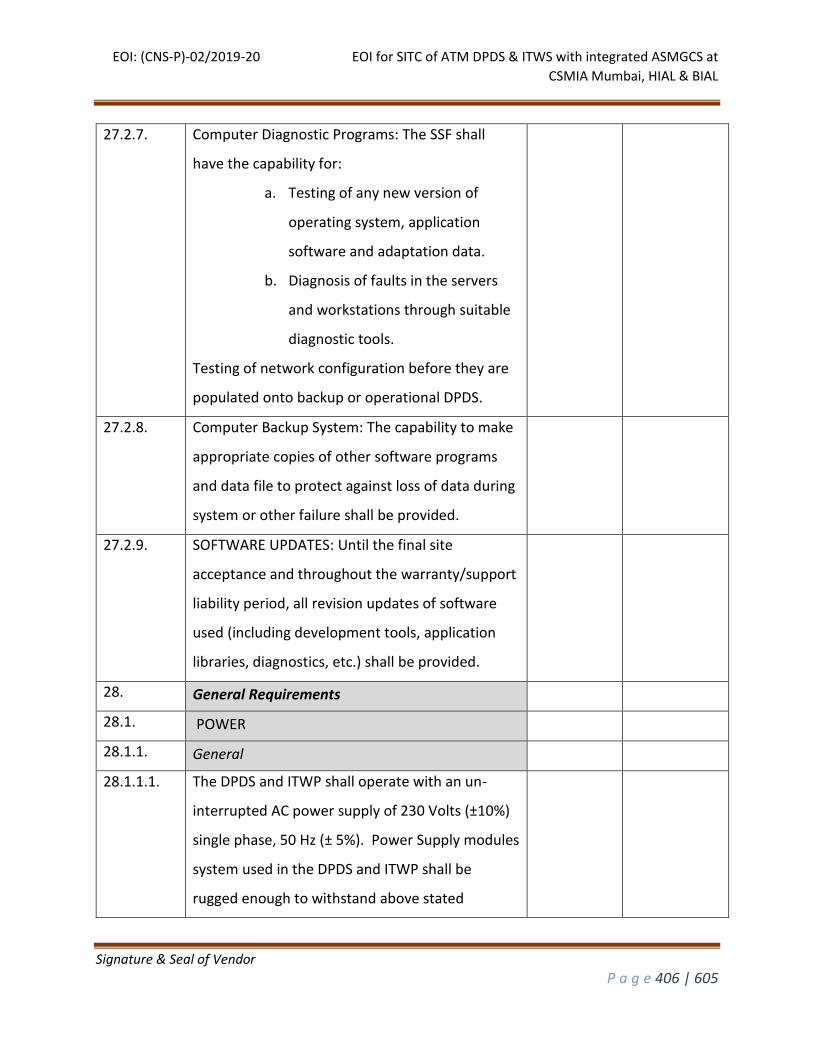
EOI: (CNS-P)-02/2019-20 EOI for SITC of ATM DPDS & ITWS with integrated ASMGCS at
CSMIA Mumbai, HIAL & BIAL
Signature & Seal of Vendor
P a g e 406 | 605
27.2.7. Computer Diagnostic Programs: The SSF shall
have the capability for:
a. Testing of any new version of
operating system, application
software and adaptation data.
b. Diagnosis of faults in the servers
and workstations through suitable
diagnostic tools.
Testing of network configuration before they are
populated onto backup or operational DPDS.
27.2.8. Computer Backup System: The capability to make
appropriate copies of other software programs
and data file to protect against loss of data during
system or other failure shall be provided.
27.2.9. SOFTWARE UPDATES: Until the final site
acceptance and throughout the warranty/support
liability period, all revision updates of software
used (including development tools, application
libraries, diagnostics, etc.) shall be provided.
28. General Requirements
28.1. POWER
28.1.1. General
28.1.1.1. The DPDS and ITWP shall operate with an un-
interrupted AC power supply of 230 Volts (±10%)
single phase, 50 Hz (± 5%). Power Supply modules
system used in the DPDS and ITWP shall be
rugged enough to withstand above stated
EOI: (CNS-P)-02/2019-20 EOI for SITC of ATM DPDS & ITWS with integrated ASMGCS at
CSMIA Mumbai, HIAL & BIAL
Signature & Seal of Vendor
P a g e 407 | 605
variation in mains voltage and frequency over a
long period of time so that the failures in the
equipment due to power supply are minimized.
28.1.1.2. All hardware components shall have dual
SMPS/Power supply modules.
28.1.1.3. For all the 3 locations i.e Bangalore, Hyderabad
and Mumbai the bidder shall ascertain the total
power requirement of the offered systems(DPDS
and ITWP) and the required optimum rating of the
uninterruptible power supply (UPS) which will be
required for safe operation of the offered ystem.
The bidder shall supply Four sets of UPS, each set-
in redundant configuration.
Exception: The power requirements for Mumbai’s
ITWP will be met from AAI’s existing UPS pair. The
distribution of UPS power to all the ITWP
subsystems will be the responsibility of the
bidder. For DPDS of Mumbai, four sets of UPS
shall be installed as described above.
28.1.1.4. The bidder shall propose a design for providing
dual power supply from separate sets of UPS for
the following:
a. Main DPDS and ITWP servers and
workstations shall be driven from
two sets of UPS.
EOI: (CNS-P)-02/2019-20 EOI for SITC of ATM DPDS & ITWS with integrated ASMGCS at
CSMIA Mumbai, HIAL & BIAL
Signature & Seal of Vendor
P a g e 408 | 605
b. Fall Back DPDS and ITWP servers
and workstations shall be driven
from two sets of UPS.
c. All the Networking equipment will
be driven from either the UPS sets
in (a) or (b) above, depending upon
whether the equipment belongs to
the main or fall back DPDS.
d. Only for Mumbai site, Main and
Fallback ITWP servers, workstations
and networking devices shall be
driven from two sets of UPS
provided by AAI.
28.1.1.5. A sample schematic for the proposed UPS
configuration is given.
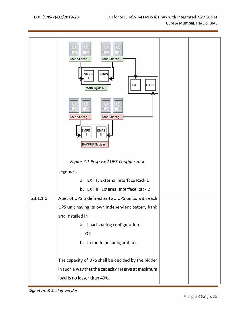
EOI: (CNS-P)-02/2019-20 EOI for SITC of ATM DPDS & ITWS with integrated ASMGCS at
CSMIA Mumbai, HIAL & BIAL
Signature & Seal of Vendor
P a g e 409 | 605
Figure 2.1 Proposed UPS Configuration
Legends :
a. EXT I : External Interface Rack 1
b. EXT II : External Interface Rack 2
28.1.1.6. A set of UPS is defined as two UPS units, with each
UPS unit having its own independent battery bank
and installed in
a. Load sharing configuration.
OR
b. In modular configuration.
The capacity of UPS shall be decided by the bidder
in such a way that the capacity reserve at maximum
load is no lesser than 40%.

EOI: (CNS-P)-02/2019-20 EOI for SITC of ATM DPDS & ITWS with integrated ASMGCS at
CSMIA Mumbai, HIAL & BIAL
Signature & Seal of Vendor
P a g e 410 | 605
28.1.1.7. The UPS units shall be supplied along with their
own isolation transformers for complete electrical
isolation.
28.1.1.8. The power supply units of all the subsystems of the
DPDS and ITWP shall be self-protecting, and
protect connected equipment against conducted
interference, noise, voltage dips and surges &
impulses.
28.1.2. Battery
28.1.2.1. The Battery bank proposed to be used with the UPS
shall be capable of providing a backup of at least 30
minutes at full rated load.
28.1.2.2. All the power cables used for power distribution
shall be fire retardant.
28.1.2.3. The battery racks provided along with the UPS sets
shall use an optimum foot print design.
The battery racks shall be designed in such a way
that each row of battery bank shall be of minimum
height to accommodate batteries plus 6” clearance
above the batteries for convenience of voltage
measurement and maintenance.
The battery banks of UPS units shall be covered
from top with fire retardant covers.
28.1.3. Protection system
28.1.3.1. Reliable over voltage and over current protection
circuits shall be provided in the UPS units.
EOI: (CNS-P)-02/2019-20 EOI for SITC of ATM DPDS & ITWS with integrated ASMGCS at
CSMIA Mumbai, HIAL & BIAL
Signature & Seal of Vendor
P a g e 411 | 605
28.1.3.2. Bidder shall be responsible for providing
conventional grounding system for complete
system, meeting international standard. The
Bidder shall ensure that the grounding system for
UPS is completely segregated from that of DPDS
equipment.
28.1.3.3. Surge suppressors shall be provided and installed
by the contractor at the input and output side of
each UPS.
28.1.3.4. The voltage difference between neutral terminal
to ground shall not be more than one volt.
28.1.4. Power Distribution
28.1.4.1. The bidder shall be responsible for the power
distribution from UPS sets to individual
subsystems.
28.1.4.2. The Bidder shall provide Supervisory Control and
Data Acquisition (SCADA) based MCBs throughout
the power distribution network, which would
facilitate remote monitoring of MCBs.
28.1.4.3. Bidder Shall provide a detailed single line diagram
of power distribution for all the four sets of UPS.
28.1.5. Monitoring of UPS
28.1.5.1. The bidder shall also provide centralised displays
as per Annexure, to display the status of all SCADA
based MCBs.
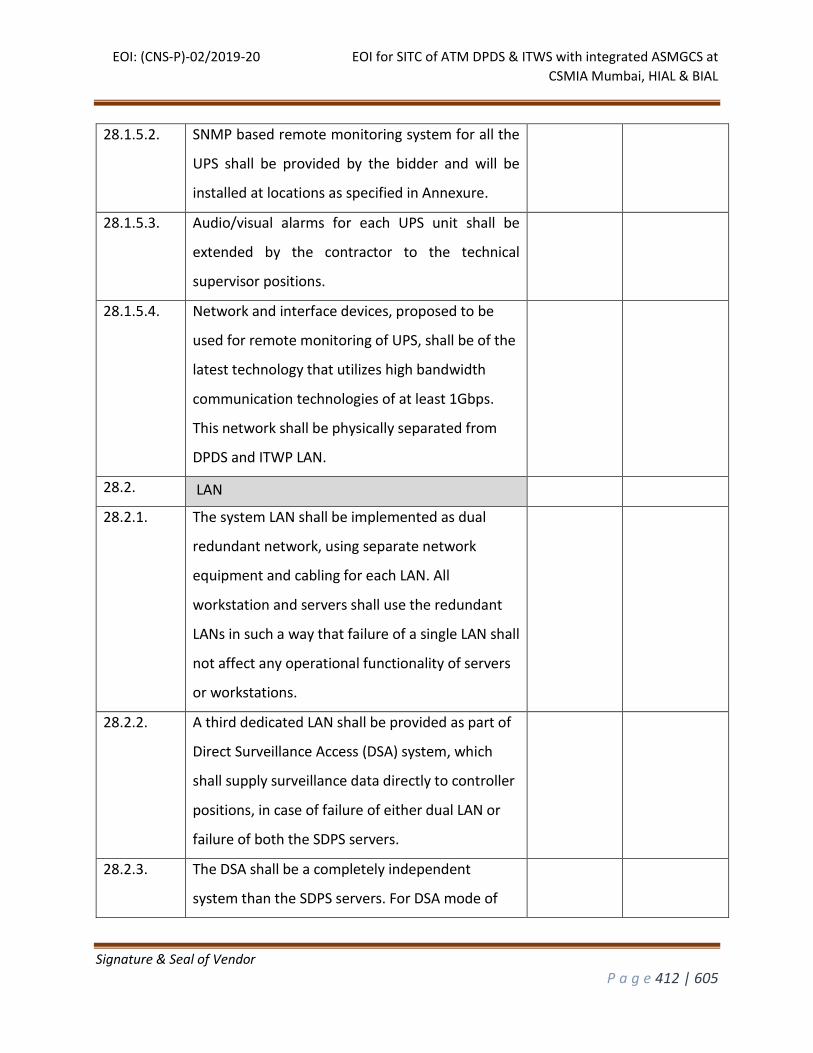
EOI: (CNS-P)-02/2019-20 EOI for SITC of ATM DPDS & ITWS with integrated ASMGCS at
CSMIA Mumbai, HIAL & BIAL
Signature & Seal of Vendor
P a g e 412 | 605
28.1.5.2. SNMP based remote monitoring system for all the
UPS shall be provided by the bidder and will be
installed at locations as specified in Annexure.
28.1.5.3. Audio/visual alarms for each UPS unit shall be
extended by the contractor to the technical
supervisor positions.
28.1.5.4. Network and interface devices, proposed to be
used for remote monitoring of UPS, shall be of the
latest technology that utilizes high bandwidth
communication technologies of at least 1Gbps.
This network shall be physically separated from
DPDS and ITWP LAN.
28.2. LAN
28.2.1. The system LAN shall be implemented as dual
redundant network, using separate network
equipment and cabling for each LAN. All
workstation and servers shall use the redundant
LANs in such a way that failure of a single LAN shall
not affect any operational functionality of servers
or workstations.
28.2.2. A third dedicated LAN shall be provided as part of
Direct Surveillance Access (DSA) system, which
shall supply surveillance data directly to controller
positions, in case of failure of either dual LAN or
failure of both the SDPS servers.
28.2.3. The DSA shall be a completely independent
system than the SDPS servers. For DSA mode of
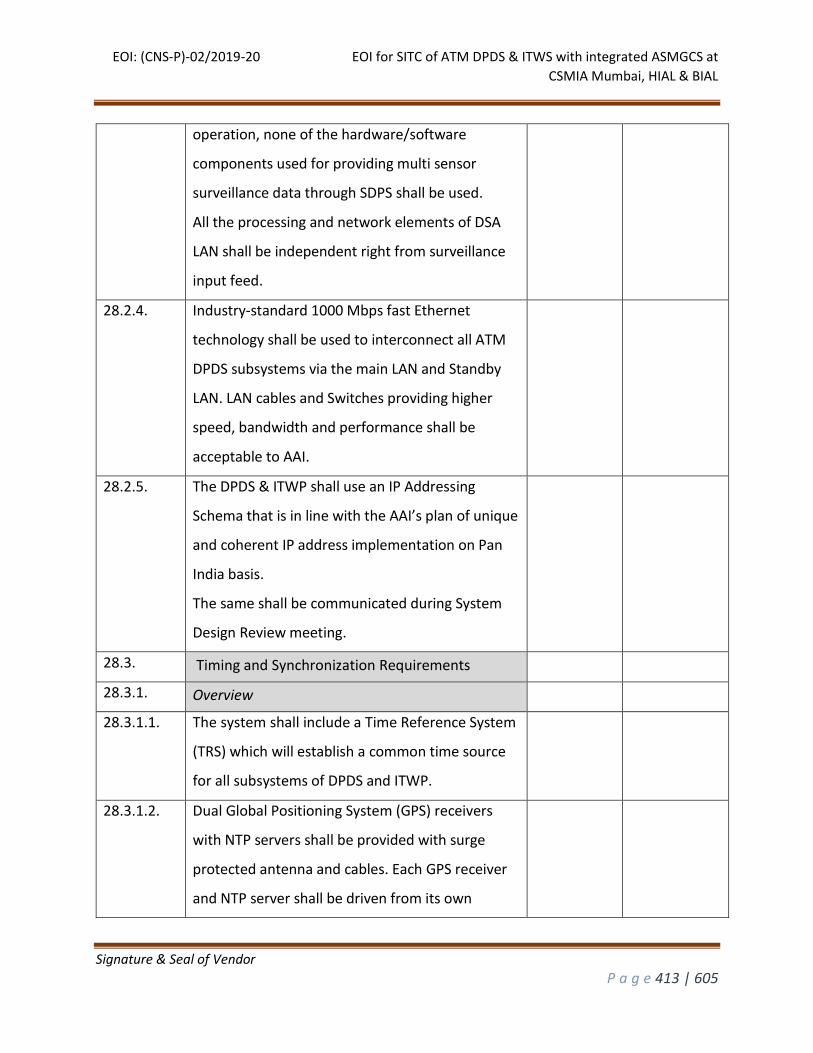
EOI: (CNS-P)-02/2019-20 EOI for SITC of ATM DPDS & ITWS with integrated ASMGCS at
CSMIA Mumbai, HIAL & BIAL
Signature & Seal of Vendor
P a g e 413 | 605
operation, none of the hardware/software
components used for providing multi sensor
surveillance data through SDPS shall be used.
All the processing and network elements of DSA
LAN shall be independent right from surveillance
input feed.
28.2.4. Industry-standard 1000 Mbps fast Ethernet
technology shall be used to interconnect all ATM
DPDS subsystems via the main LAN and Standby
LAN. LAN cables and Switches providing higher
speed, bandwidth and performance shall be
acceptable to AAI.
28.2.5. The DPDS & ITWP shall use an IP Addressing
Schema that is in line with the AAI’s plan of unique
and coherent IP address implementation on Pan
India basis.
The same shall be communicated during System
Design Review meeting.
28.3. Timing and Synchronization Requirements
28.3.1. Overview
28.3.1.1. The system shall include a Time Reference System
(TRS) which will establish a common time source
for all subsystems of DPDS and ITWP.
28.3.1.2. Dual Global Positioning System (GPS) receivers
with NTP servers shall be provided with surge
protected antenna and cables. Each GPS receiver
and NTP server shall be driven from its own
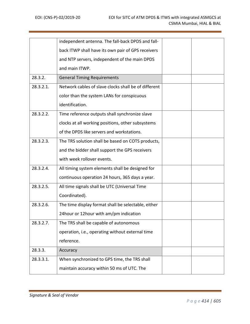
EOI: (CNS-P)-02/2019-20 EOI for SITC of ATM DPDS & ITWS with integrated ASMGCS at
CSMIA Mumbai, HIAL & BIAL
Signature & Seal of Vendor
P a g e 414 | 605
independent antenna. The fall-back DPDS and fall-
back ITWP shall have its own pair of GPS receivers
and NTP servers, independent of the main DPDS
and main ITWP.
28.3.2. General Timing Requirements
28.3.2.1. Network cables of slave clocks shall be of different
color than the system LANs for conspicuous
identification.
28.3.2.2. Time reference outputs shall synchronize slave
clocks at all working positions, other subsystems
of the DPDS like servers and workstations.
28.3.2.3. The TRS solution shall be based on COTS products,
and the bidder shall support the GPS receivers
with week rollover events.
28.3.2.4. All timing system elements shall be designed for
continuous operation 24 hours, 365 days a year.
28.3.2.5. All time signals shall be UTC (Universal Time
Coordinated).
28.3.2.6. The time display format shall be selectable, either
24hour or 12hour with am/pm indication
28.3.2.7. The TRS shall be capable of autonomous
operation, i.e., operating without external time
reference.
28.3.3. Accuracy
28.3.3.1. When synchronized to GPS time, the TRS shall
maintain accuracy within 50 ms of UTC. The
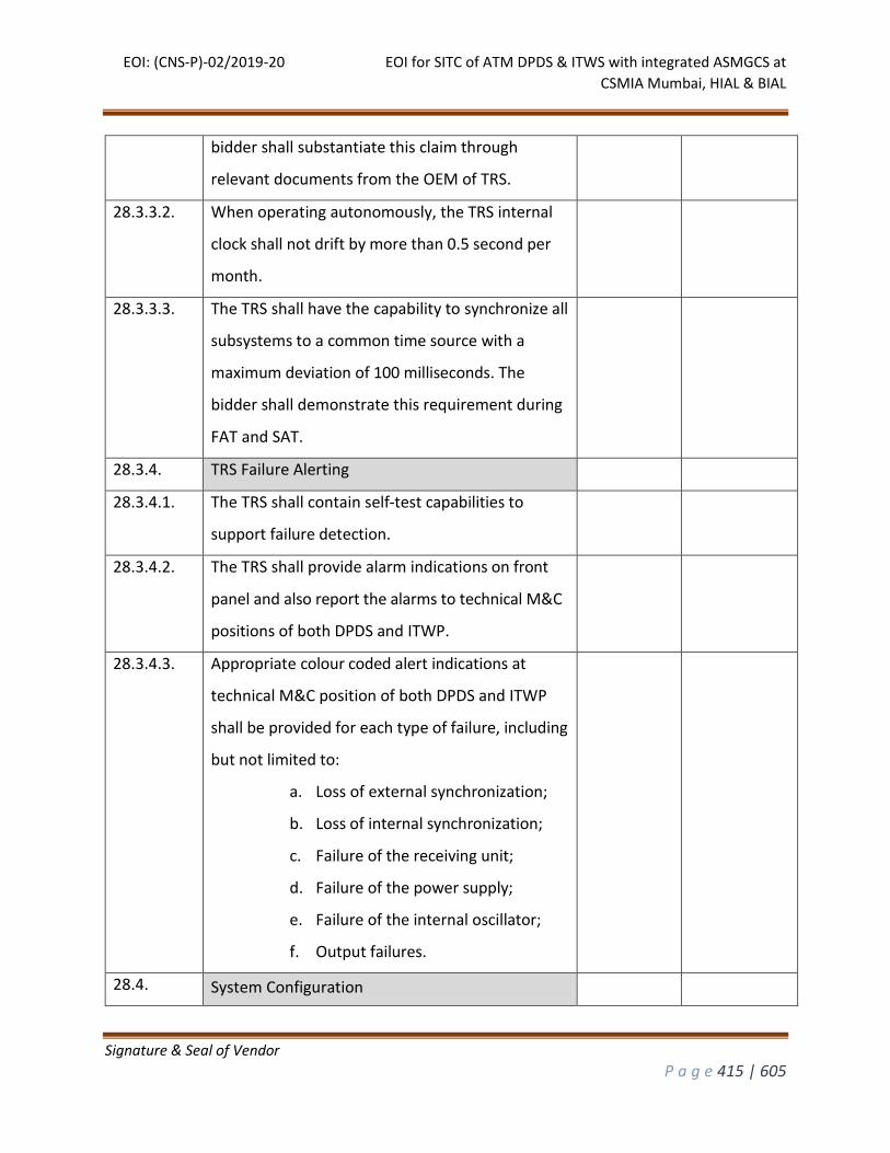
EOI: (CNS-P)-02/2019-20 EOI for SITC of ATM DPDS & ITWS with integrated ASMGCS at
CSMIA Mumbai, HIAL & BIAL
Signature & Seal of Vendor
P a g e 415 | 605
bidder shall substantiate this claim through
relevant documents from the OEM of TRS.
28.3.3.2. When operating autonomously, the TRS internal
clock shall not drift by more than 0.5 second per
month.
28.3.3.3. The TRS shall have the capability to synchronize all
subsystems to a common time source with a
maximum deviation of 100 milliseconds. The
bidder shall demonstrate this requirement during
FAT and SAT.
28.3.4. TRS Failure Alerting
28.3.4.1. The TRS shall contain self-test capabilities to
support failure detection.
28.3.4.2. The TRS shall provide alarm indications on front
panel and also report the alarms to technical M&C
positions of both DPDS and ITWP.
28.3.4.3. Appropriate colour coded alert indications at
technical M&C position of both DPDS and ITWP
shall be provided for each type of failure, including
but not limited to:
a. Loss of external synchronization;
b. Loss of internal synchronization;
c. Failure of the receiving unit;
d. Failure of the power supply;
e. Failure of the internal oscillator;
f. Output failures.
28.4. System Configuration
EOI: (CNS-P)-02/2019-20 EOI for SITC of ATM DPDS & ITWS with integrated ASMGCS at
CSMIA Mumbai, HIAL & BIAL
Signature & Seal of Vendor
P a g e 416 | 605
28.4.1. General
28.4.1.1. The system shall be designed for continuous
operation (24 hours a day and 365 days a year) in
a safe manner without undue heating, vibration,
wear, corrosion, electromagnetic interference or
any similar problems. The design life of the
equipment shall be a minimum of 10 years. This
life shall be achievable through normal and
regular maintenance and without major
dismantling or overhauling etc. The bidder shall
ensure that all types of COTS spares and spare
modules shall be available during lifetime of the
equipment for maintenance, repair and upkeep of
the equipment.
28.4.1.2. Safety and protection of personnel during normal
operation and maintenance or during
malfunctioning of any equipment shall be ensured
as an integrated feature of design, manufacture
and installation. Adequate protection shall be
included for ensuring safety of personnel from
any possible hazards, including EMI radiation, high
voltages etc. The bidder shall furnish the details of
EMI and Safety Standards met by his equipment
and built in safety features.
28.4.1.3. Parts subject to failure, wear, corrosion or other
deteriorations or requiring occasional inspection,
adjustment or replacement by AAI Personnel,
EOI: (CNS-P)-02/2019-20 EOI for SITC of ATM DPDS & ITWS with integrated ASMGCS at
CSMIA Mumbai, HIAL & BIAL
Signature & Seal of Vendor
P a g e 417 | 605
shall be made accessible and capable of
convenient inspection and removal. Connectors
shall be provided with keys to prevent insertions
of units in the wrong way or into a wrong slot.
28.4.1.4. All hardware components shall be commercial off-
the-shelf (COTS), compact, fully solid state, highly
reliable and should use latest state of the art
technology. The design and selection of equipment
shall be consistent with the requirements of long-
term trouble-free operation with highest degree of
reliability and maintainability and their
performance shall meet or exceed the needs of
mentioned airport’s traffic control environment.
28.4.1.5. Dual redundancy shall be provided for all critical
processing elements; whose complete or partial
failure has the capacity to interrupt the provision
of air traffic services. These critical elements may
include but not limited to surveillance data
processing, Air-ground data link processing, Flight
data processing, Flight plan conflict processing and
data recording functions.
28.4.1.6. External interfaces shall be provided for exchange
of operational message with other ATS centres,
reception of surveillance data, air-ground
communication with the aircraft, surveillance track
data export to external systems and reception of
meteorological and aeronautical information.
EOI: (CNS-P)-02/2019-20 EOI for SITC of ATM DPDS & ITWS with integrated ASMGCS at
CSMIA Mumbai, HIAL & BIAL
Signature & Seal of Vendor
P a g e 418 | 605
28.4.1.7. The bidder shall ensure that no disruption occurs
to the present operational DPDS due to activities
involving installation, testing and commissioning of
the supplied DPDS and ITWP in the ATS complex
and tower.
28.4.1.8. All interconnecting cables required to interconnect
the equipment shall be supplied. All cables shall be
fully assembled, connector pre-terminated and
factory tested at the time of supply as part of
overall system check.
28.4.1.9. Input/output termination cables shall be properly
labelled to permit ready identification of the
incoming/outgoing wiring. All interconnecting
cables shall also be appropriately labelled to
facilitate convenient interconnection and minimize
chances of incorrect connection.
28.4.1.10. Add on cards like network cards, video cards etc.,
if used in the DPDS and ITWP, shall be of plug and
play type. If AAI procures another card of same or
better specification, it shall be useable if its driver
is available for the operating system used.
28.4.1.11. All the displays provided as part of the DPDS and
ITWP shall be of plug and play type with no
reservation for a particular make and/or model. If
AAI procures another display of same or better
specification, it shall be readily useable without
any software modification.
EOI: (CNS-P)-02/2019-20 EOI for SITC of ATM DPDS & ITWS with integrated ASMGCS at
CSMIA Mumbai, HIAL & BIAL
Signature & Seal of Vendor
P a g e 419 | 605
28.4.2. Technology
28.4.2.1. The system computers shall utilize the industry
grade operating system accepted world over for
ATM DPDS & ITWP
28.4.2.2. Supplied hardware shall be latest version of
reputed brands having global market and local
support in India. All servers and workstations shall
have dual power supply system having two
separate power modules. Each module shall be
able to take full load of equipment independently.
Such servers and workstations shall be fed through
separate UPS power supply. Each module shall be
of hot swappable type.
28.4.2.3. Network and interface devices shall be of the latest
technology and be capable of high bandwidth
utilization through communication technologies of
at least 1000 Mbps.
28.4.3. Redundancy
28.4.3.1. The DPDS and ITWP shall be configured to be fully
redundant. When the main server fails, it shall
continue on standby server in real time, without
any data loss, through the automatic changeover
process. In case of manual changeover to standby
server, the Air traffic operations shall not be
interrupted.
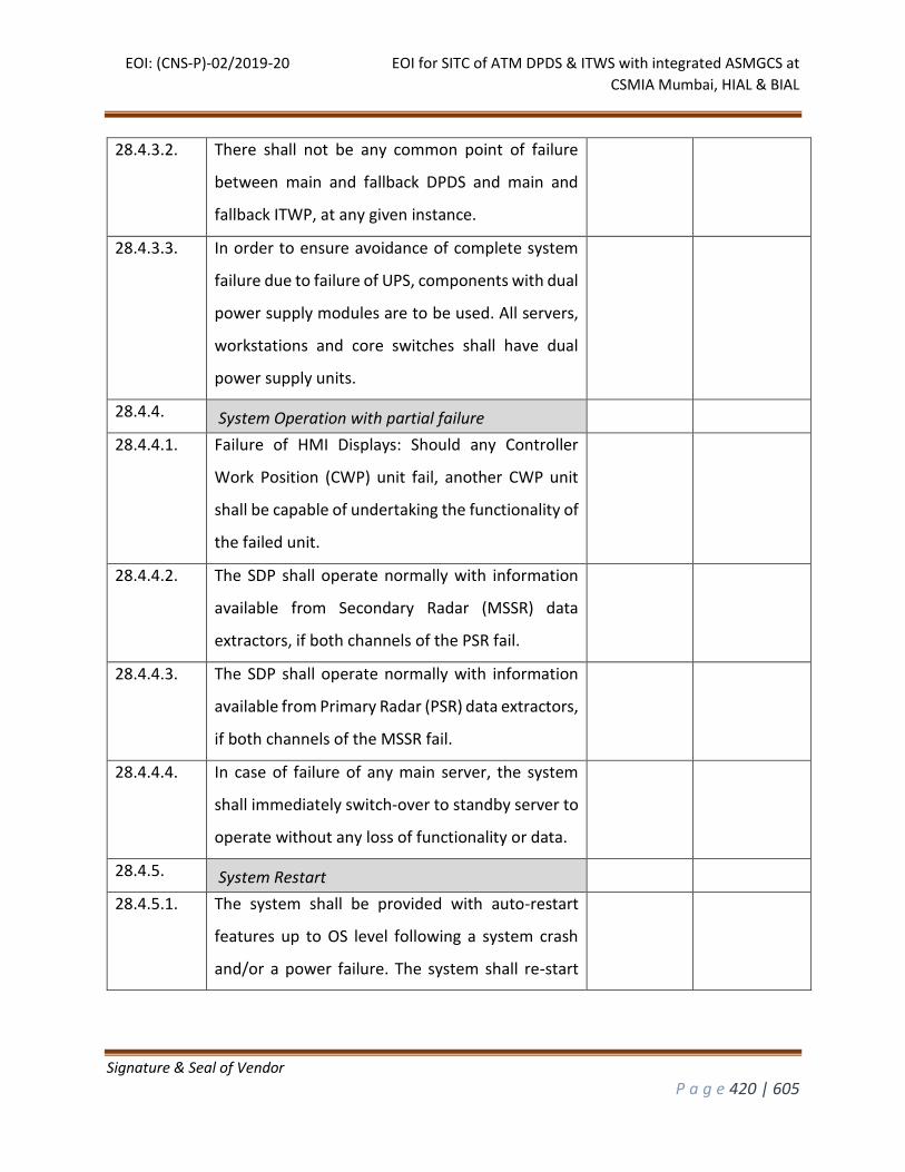
EOI: (CNS-P)-02/2019-20 EOI for SITC of ATM DPDS & ITWS with integrated ASMGCS at
CSMIA Mumbai, HIAL & BIAL
Signature & Seal of Vendor
P a g e 420 | 605
28.4.3.2. There shall not be any common point of failure
between main and fallback DPDS and main and
fallback ITWP, at any given instance.
28.4.3.3. In order to ensure avoidance of complete system
failure due to failure of UPS, components with dual
power supply modules are to be used. All servers,
workstations and core switches shall have dual
power supply units.
28.4.4. System Operation with partial failure
28.4.4.1. Failure of HMI Displays: Should any Controller
Work Position (CWP) unit fail, another CWP unit
shall be capable of undertaking the functionality of
the failed unit.
28.4.4.2. The SDP shall operate normally with information
available from Secondary Radar (MSSR) data
extractors, if both channels of the PSR fail.
28.4.4.3. The SDP shall operate normally with information
available from Primary Radar (PSR) data extractors,
if both channels of the MSSR fail.
28.4.4.4. In case of failure of any main server, the system
shall immediately switch-over to standby server to
operate without any loss of functionality or data.
28.4.5. System Restart
28.4.5.1. The system shall be provided with auto-restart
features up to OS level following a system crash
and/or a power failure. The system shall re-start
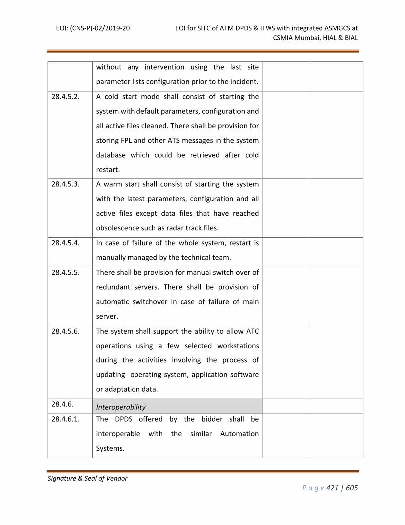
EOI: (CNS-P)-02/2019-20 EOI for SITC of ATM DPDS & ITWS with integrated ASMGCS at
CSMIA Mumbai, HIAL & BIAL
Signature & Seal of Vendor
P a g e 421 | 605
without any intervention using the last site
parameter lists configuration prior to the incident.
28.4.5.2. A cold start mode shall consist of starting the
system with default parameters, configuration and
all active files cleaned. There shall be provision for
storing FPL and other ATS messages in the system
database which could be retrieved after cold
restart.
28.4.5.3. A warm start shall consist of starting the system
with the latest parameters, configuration and all
active files except data files that have reached
obsolescence such as radar track files.
28.4.5.4. In case of failure of the whole system, restart is
manually managed by the technical team.
28.4.5.5. There shall be provision for manual switch over of
redundant servers. There shall be provision of
automatic switchover in case of failure of main
server.
28.4.5.6. The system shall support the ability to allow ATC
operations using a few selected workstations
during the activities involving the process of
updating operating system, application software
or adaptation data.
28.4.6. Interoperability
28.4.6.1. The DPDS offered by the bidder shall be
interoperable with the similar Automation
Systems.
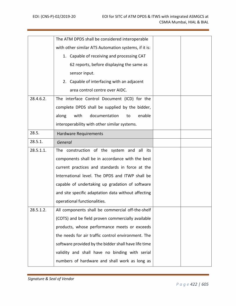
EOI: (CNS-P)-02/2019-20 EOI for SITC of ATM DPDS & ITWS with integrated ASMGCS at
CSMIA Mumbai, HIAL & BIAL
Signature & Seal of Vendor
P a g e 422 | 605
The ATM DPDS shall be considered interoperable
with other similar ATS Automation systems, if it is:
1. Capable of receiving and processing CAT
62 reports, before displaying the same as
sensor input.
2. Capable of interfacing with an adjacent
area control centre over AIDC.
28.4.6.2. The interface Control Document (ICD) for the
complete DPDS shall be supplied by the bidder,
along with documentation to enable
interoperability with other similar systems.
28.5. Hardware Requirements
28.5.1. General
28.5.1.1. The construction of the system and all its
components shall be in accordance with the best
current practices and standards in force at the
International level. The DPDS and ITWP shall be
capable of undertaking up gradation of software
and site specific adaptation data without affecting
operational functionalities.
28.5.1.2. All components shall be commercial off-the-shelf
(COTS) and be field proven commercially available
products, whose performance meets or exceeds
the needs for air traffic control environment. The
software provided by the bidder shall have life time
validity and shall have no binding with serial
numbers of hardware and shall work as long as
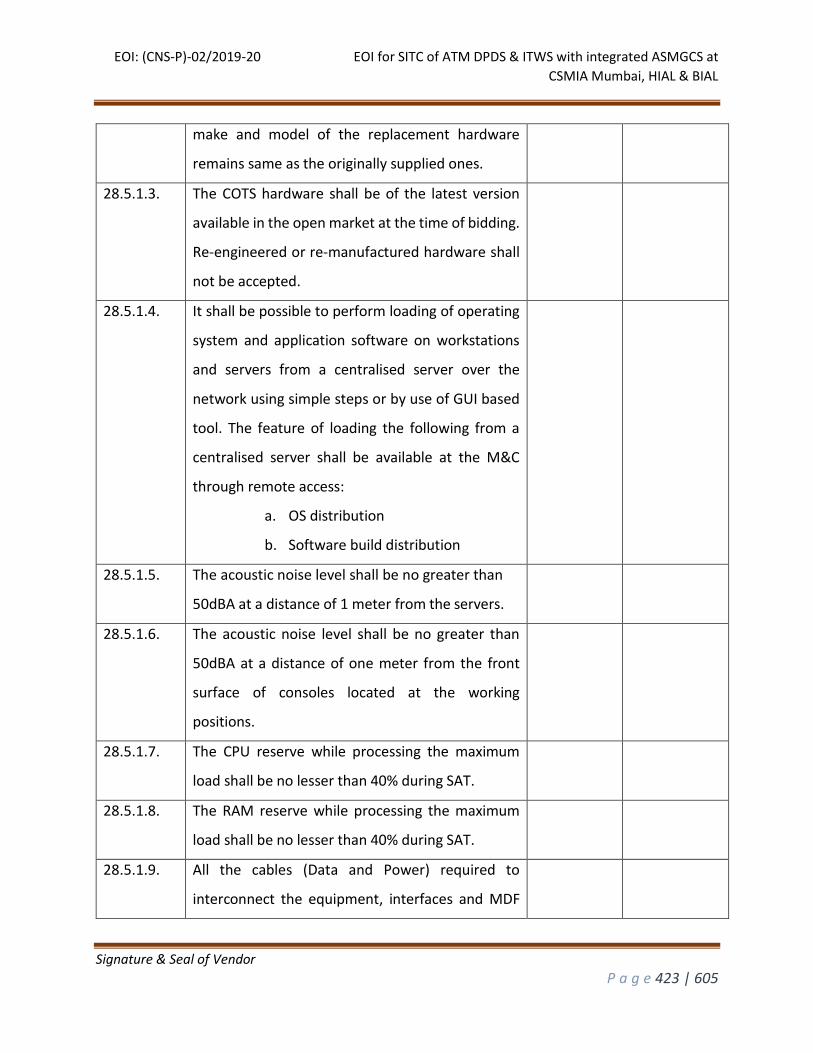
EOI: (CNS-P)-02/2019-20 EOI for SITC of ATM DPDS & ITWS with integrated ASMGCS at
CSMIA Mumbai, HIAL & BIAL
Signature & Seal of Vendor
P a g e 423 | 605
make and model of the replacement hardware
remains same as the originally supplied ones.
28.5.1.3. The COTS hardware shall be of the latest version
available in the open market at the time of bidding.
Re-engineered or re-manufactured hardware shall
not be accepted.
28.5.1.4. It shall be possible to perform loading of operating
system and application software on workstations
and servers from a centralised server over the
network using simple steps or by use of GUI based
tool. The feature of loading the following from a
centralised server shall be available at the M&C
through remote access:
a. OS distribution
b. Software build distribution
28.5.1.5. The acoustic noise level shall be no greater than
50dBA at a distance of 1 meter from the servers.
28.5.1.6. The acoustic noise level shall be no greater than
50dBA at a distance of one meter from the front
surface of consoles located at the working
positions.
28.5.1.7. The CPU reserve while processing the maximum
load shall be no lesser than 40% during SAT.
28.5.1.8. The RAM reserve while processing the maximum
load shall be no lesser than 40% during SAT.
28.5.1.9. All the cables (Data and Power) required to
interconnect the equipment, interfaces and MDF
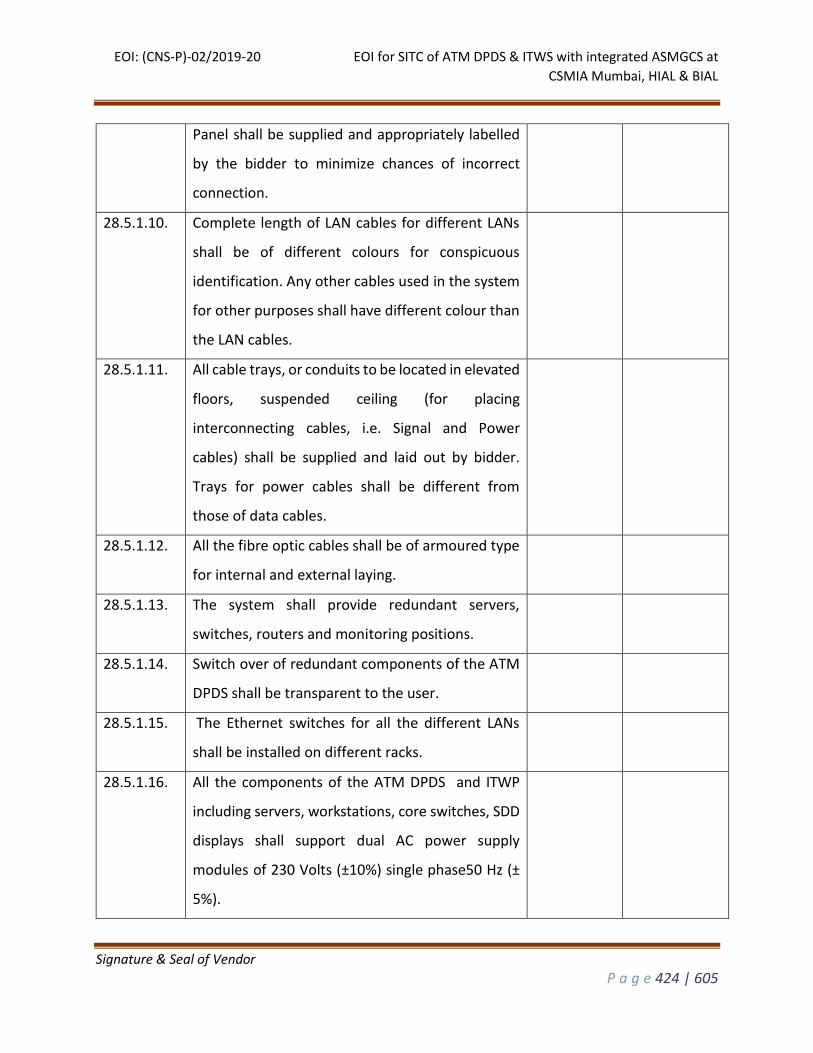
EOI: (CNS-P)-02/2019-20 EOI for SITC of ATM DPDS & ITWS with integrated ASMGCS at
CSMIA Mumbai, HIAL & BIAL
Signature & Seal of Vendor
P a g e 424 | 605
Panel shall be supplied and appropriately labelled
by the bidder to minimize chances of incorrect
connection.
28.5.1.10. Complete length of LAN cables for different LANs
shall be of different colours for conspicuous
identification. Any other cables used in the system
for other purposes shall have different colour than
the LAN cables.
28.5.1.11. All cable trays, or conduits to be located in elevated
floors, suspended ceiling (for placing
interconnecting cables, i.e. Signal and Power
cables) shall be supplied and laid out by bidder.
Trays for power cables shall be different from
those of data cables.
28.5.1.12. All the fibre optic cables shall be of armoured type
for internal and external laying.
28.5.1.13. The system shall provide redundant servers,
switches, routers and monitoring positions.
28.5.1.14. Switch over of redundant components of the ATM
DPDS shall be transparent to the user.
28.5.1.15. The Ethernet switches for all the different LANs
shall be installed on different racks.
28.5.1.16. All the components of the ATM DPDS and ITWP
including servers, workstations, core switches, SDD
displays shall support dual AC power supply
modules of 230 Volts (±10%) single phase50 Hz (±
5%).
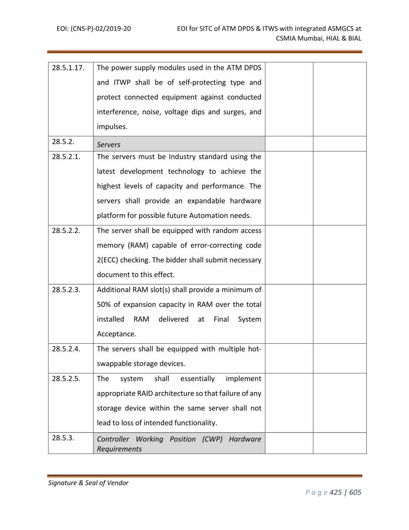
EOI: (CNS-P)-02/2019-20 EOI for SITC of ATM DPDS & ITWS with integrated ASMGCS at
CSMIA Mumbai, HIAL & BIAL
Signature & Seal of Vendor
P a g e 425 | 605
28.5.1.17. The power supply modules used in the ATM DPDS
and ITWP shall be of self-protecting type and
protect connected equipment against conducted
interference, noise, voltage dips and surges, and
impulses.
28.5.2. Servers
28.5.2.1. The servers must be Industry standard using the
latest development technology to achieve the
highest levels of capacity and performance. The
servers shall provide an expandable hardware
platform for possible future Automation needs.
28.5.2.2. The server shall be equipped with random access
memory (RAM) capable of error-correcting code
2(ECC) checking. The bidder shall submit necessary
document to this effect.
28.5.2.3. Additional RAM slot(s) shall provide a minimum of
50% of expansion capacity in RAM over the total
installed RAM delivered at Final System
Acceptance.
28.5.2.4. The servers shall be equipped with multiple hot-
swappable storage devices.
28.5.2.5. The system shall essentially implement
appropriate RAID architecture so that failure of any
storage device within the same server shall not
lead to loss of intended functionality.
28.5.3. Controller Working Position (CWP) Hardware Requirements
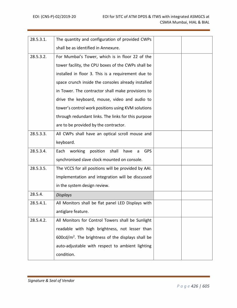
EOI: (CNS-P)-02/2019-20 EOI for SITC of ATM DPDS & ITWS with integrated ASMGCS at
CSMIA Mumbai, HIAL & BIAL
Signature & Seal of Vendor
P a g e 426 | 605
28.5.3.1. The quantity and configuration of provided CWPs
shall be as identified in Annexure.
28.5.3.2. For Mumbai’s Tower, which is in floor 22 of the
tower facility, the CPU boxes of the CWPs shall be
installed in floor 3. This is a requirement due to
space crunch inside the consoles already installed
in Tower. The contractor shall make provisions to
drive the keyboard, mouse, video and audio to
tower’s control work positions using KVM solutions
through redundant links. The links for this purpose
are to be provided by the contractor.
28.5.3.3. All CWPs shall have an optical scroll mouse and
keyboard.
28.5.3.4. Each working position shall have a GPS
synchronised slave clock mounted on console.
28.5.3.5. The VCCS for all positions will be provided by AAI.
Implementation and integration will be discussed
in the system design review.
28.5.4. Displays
28.5.4.1. All Monitors shall be flat panel LED Displays with
antiglare feature.
28.5.4.2. All Monitors for Control Towers shall be Sunlight
readable with high brightness, not lesser than
600cd/m2. The brightness of the displays shall be
auto-adjustable with respect to ambient lighting
condition.
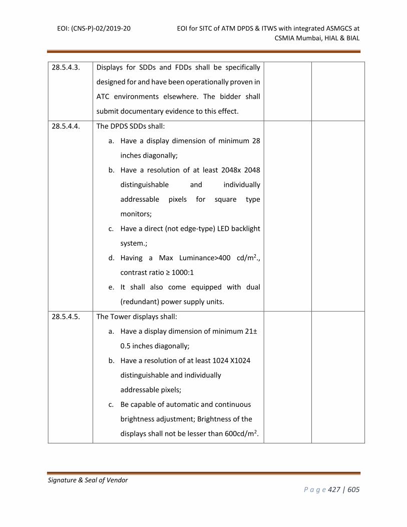
EOI: (CNS-P)-02/2019-20 EOI for SITC of ATM DPDS & ITWS with integrated ASMGCS at
CSMIA Mumbai, HIAL & BIAL
Signature & Seal of Vendor
P a g e 427 | 605
28.5.4.3. Displays for SDDs and FDDs shall be specifically
designed for and have been operationally proven in
ATC environments elsewhere. The bidder shall
submit documentary evidence to this effect.
28.5.4.4. The DPDS SDDs shall:
a. Have a display dimension of minimum 28
inches diagonally;
b. Have a resolution of at least 2048x 2048
distinguishable and individually
addressable pixels for square type
monitors;
c. Have a direct (not edge-type) LED backlight
system.;
d. Having a Max Luminance>400 cd/m2.,
contrast ratio ≥ 1000:1
e. It shall also come equipped with dual
(redundant) power supply units.
28.5.4.5. The Tower displays shall:
a. Have a display dimension of minimum 21±
0.5 inches diagonally;
b. Have a resolution of at least 1024 X1024
distinguishable and individually
addressable pixels;
c. Be capable of automatic and continuous
brightness adjustment; Brightness of the
displays shall not be lesser than 600cd/m2.
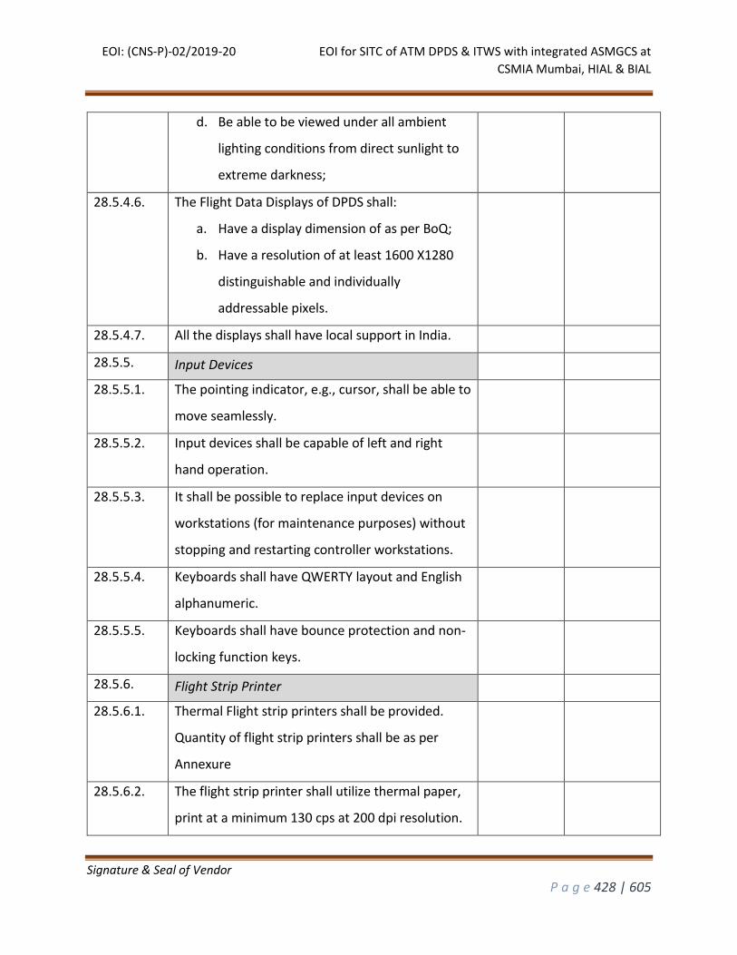
EOI: (CNS-P)-02/2019-20 EOI for SITC of ATM DPDS & ITWS with integrated ASMGCS at
CSMIA Mumbai, HIAL & BIAL
Signature & Seal of Vendor
P a g e 428 | 605
d. Be able to be viewed under all ambient
lighting conditions from direct sunlight to
extreme darkness;
28.5.4.6. The Flight Data Displays of DPDS shall:
a. Have a display dimension of as per BoQ;
b. Have a resolution of at least 1600 X1280
distinguishable and individually
addressable pixels.
28.5.4.7. All the displays shall have local support in India.
28.5.5. Input Devices
28.5.5.1. The pointing indicator, e.g., cursor, shall be able to
move seamlessly.
28.5.5.2. Input devices shall be capable of left and right
hand operation.
28.5.5.3. It shall be possible to replace input devices on
workstations (for maintenance purposes) without
stopping and restarting controller workstations.
28.5.5.4. Keyboards shall have QWERTY layout and English
alphanumeric.
28.5.5.5. Keyboards shall have bounce protection and non-
locking function keys.
28.5.6. Flight Strip Printer
28.5.6.1. Thermal Flight strip printers shall be provided.
Quantity of flight strip printers shall be as per
Annexure
28.5.6.2. The flight strip printer shall utilize thermal paper,
print at a minimum 130 cps at 200 dpi resolution.
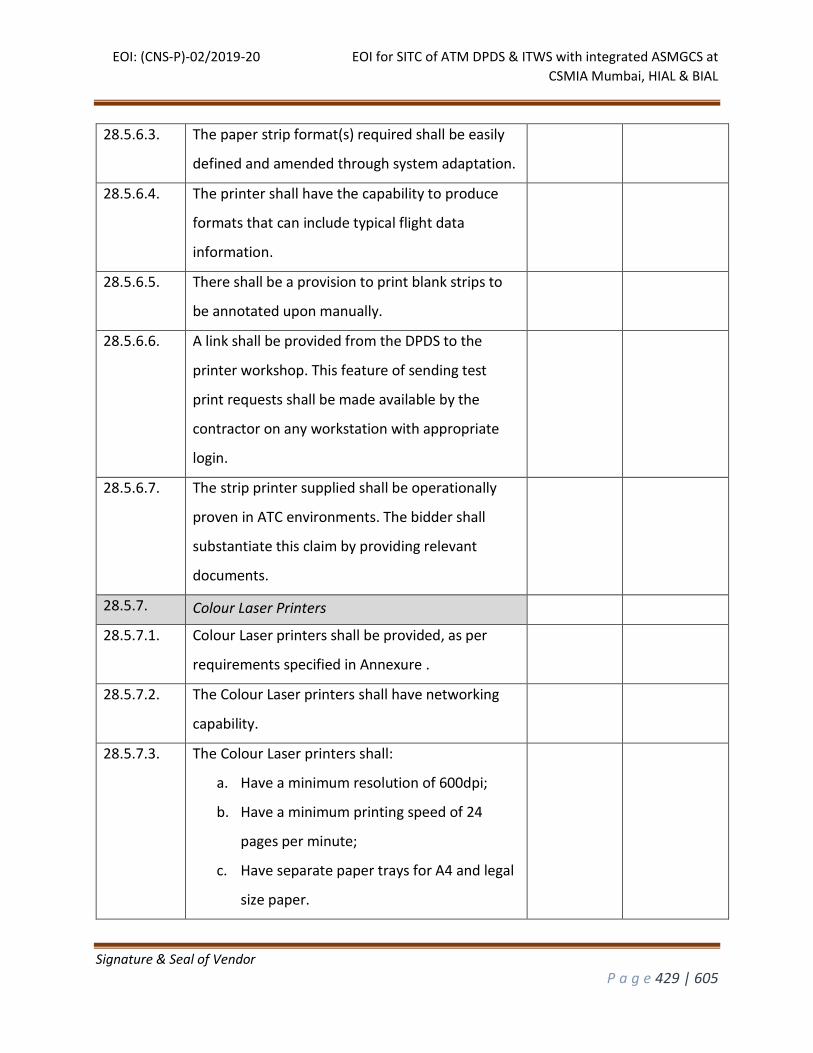
EOI: (CNS-P)-02/2019-20 EOI for SITC of ATM DPDS & ITWS with integrated ASMGCS at
CSMIA Mumbai, HIAL & BIAL
Signature & Seal of Vendor
P a g e 429 | 605
28.5.6.3. The paper strip format(s) required shall be easily
defined and amended through system adaptation.
28.5.6.4. The printer shall have the capability to produce
formats that can include typical flight data
information.
28.5.6.5. There shall be a provision to print blank strips to
be annotated upon manually.
28.5.6.6. A link shall be provided from the DPDS to the
printer workshop. This feature of sending test
print requests shall be made available by the
contractor on any workstation with appropriate
login.
28.5.6.7. The strip printer supplied shall be operationally
proven in ATC environments. The bidder shall
substantiate this claim by providing relevant
documents.
28.5.7. Colour Laser Printers
28.5.7.1. Colour Laser printers shall be provided, as per
requirements specified in Annexure .
28.5.7.2. The Colour Laser printers shall have networking
capability.
28.5.7.3. The Colour Laser printers shall:
a. Have a minimum resolution of 600dpi;
b. Have a minimum printing speed of 24
pages per minute;
c. Have separate paper trays for A4 and legal
size paper.
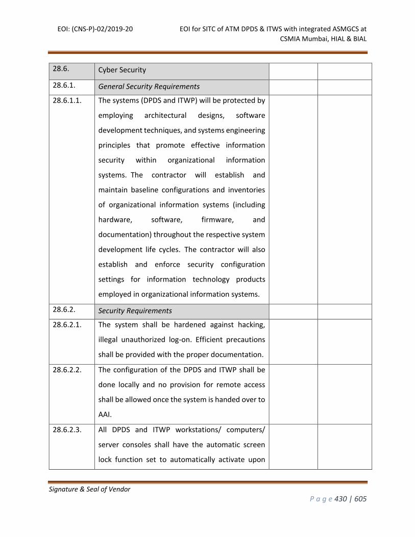
EOI: (CNS-P)-02/2019-20 EOI for SITC of ATM DPDS & ITWS with integrated ASMGCS at
CSMIA Mumbai, HIAL & BIAL
Signature & Seal of Vendor
P a g e 430 | 605
28.6. Cyber Security
28.6.1. General Security Requirements
28.6.1.1. The systems (DPDS and ITWP) will be protected by
employing architectural designs, software
development techniques, and systems engineering
principles that promote effective information
security within organizational information
systems. The contractor will establish and
maintain baseline configurations and inventories
of organizational information systems (including
hardware, software, firmware, and
documentation) throughout the respective system
development life cycles. The contractor will also
establish and enforce security configuration
settings for information technology products
employed in organizational information systems.
28.6.2. Security Requirements
28.6.2.1. The system shall be hardened against hacking,
illegal unauthorized log-on. Efficient precautions
shall be provided with the proper documentation.
28.6.2.2. The configuration of the DPDS and ITWP shall be
done locally and no provision for remote access
shall be allowed once the system is handed over to
AAI.
28.6.2.3. All DPDS and ITWP workstations/ computers/
server consoles shall have the automatic screen
lock function set to automatically activate upon
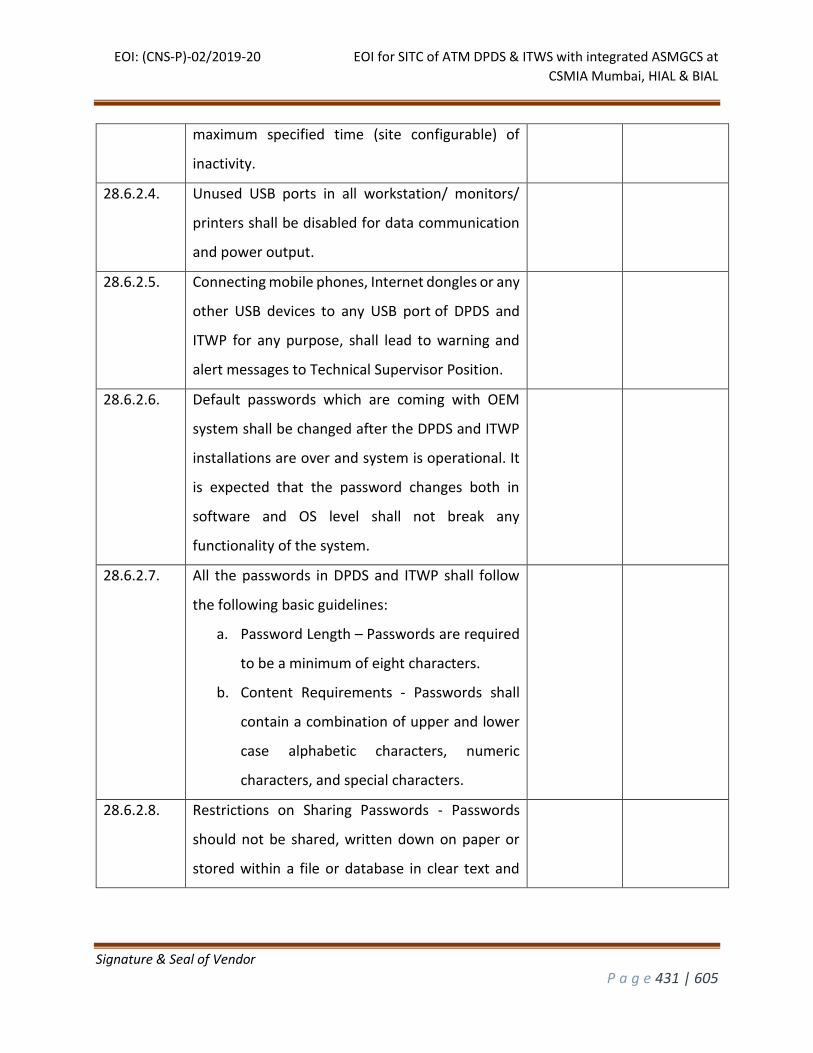
EOI: (CNS-P)-02/2019-20 EOI for SITC of ATM DPDS & ITWS with integrated ASMGCS at
CSMIA Mumbai, HIAL & BIAL
Signature & Seal of Vendor
P a g e 431 | 605
maximum specified time (site configurable) of
inactivity.
28.6.2.4. Unused USB ports in all workstation/ monitors/
printers shall be disabled for data communication
and power output.
28.6.2.5. Connecting mobile phones, Internet dongles or any
other USB devices to any USB port of DPDS and
ITWP for any purpose, shall lead to warning and
alert messages to Technical Supervisor Position.
28.6.2.6. Default passwords which are coming with OEM
system shall be changed after the DPDS and ITWP
installations are over and system is operational. It
is expected that the password changes both in
software and OS level shall not break any
functionality of the system.
28.6.2.7. All the passwords in DPDS and ITWP shall follow
the following basic guidelines:
a. Password Length – Passwords are required
to be a minimum of eight characters.
b. Content Requirements - Passwords shall
contain a combination of upper and lower
case alphabetic characters, numeric
characters, and special characters.
28.6.2.8. Restrictions on Sharing Passwords - Passwords
should not be shared, written down on paper or
stored within a file or database in clear text and
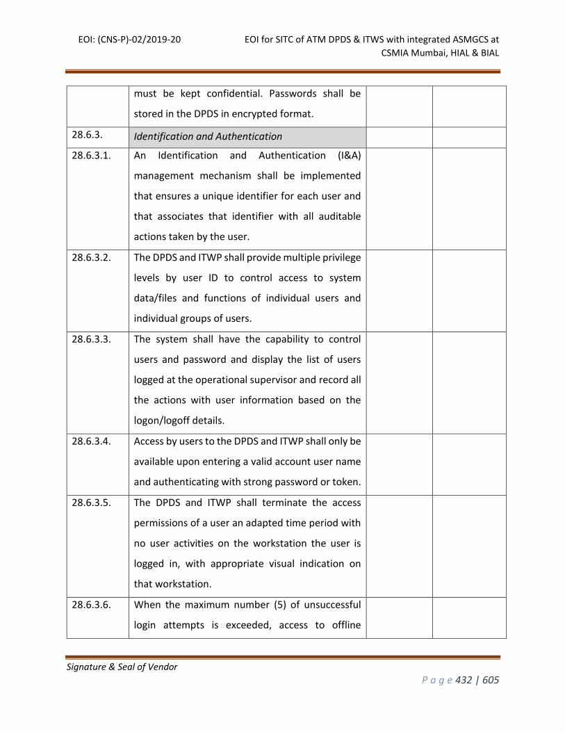
EOI: (CNS-P)-02/2019-20 EOI for SITC of ATM DPDS & ITWS with integrated ASMGCS at
CSMIA Mumbai, HIAL & BIAL
Signature & Seal of Vendor
P a g e 432 | 605
must be kept confidential. Passwords shall be
stored in the DPDS in encrypted format.
28.6.3. Identification and Authentication
28.6.3.1. An Identification and Authentication (I&A)
management mechanism shall be implemented
that ensures a unique identifier for each user and
that associates that identifier with all auditable
actions taken by the user.
28.6.3.2. The DPDS and ITWP shall provide multiple privilege
levels by user ID to control access to system
data/files and functions of individual users and
individual groups of users.
28.6.3.3. The system shall have the capability to control
users and password and display the list of users
logged at the operational supervisor and record all
the actions with user information based on the
logon/logoff details.
28.6.3.4. Access by users to the DPDS and ITWP shall only be
available upon entering a valid account user name
and authenticating with strong password or token.
28.6.3.5. The DPDS and ITWP shall terminate the access
permissions of a user an adapted time period with
no user activities on the workstation the user is
logged in, with appropriate visual indication on
that workstation.
28.6.3.6. When the maximum number (5) of unsuccessful
login attempts is exceeded, access to offline
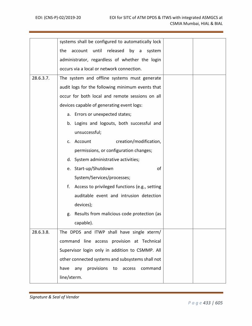
EOI: (CNS-P)-02/2019-20 EOI for SITC of ATM DPDS & ITWS with integrated ASMGCS at
CSMIA Mumbai, HIAL & BIAL
Signature & Seal of Vendor
P a g e 433 | 605
systems shall be configured to automatically lock
the account until released by a system
administrator, regardless of whether the login
occurs via a local or network connection.
28.6.3.7. The system and offline systems must generate
audit logs for the following minimum events that
occur for both local and remote sessions on all
devices capable of generating event logs:
a. Errors or unexpected states;
b. Logins and logouts, both successful and
unsuccessful;
c. Account creation/modification,
permissions, or configuration changes;
d. System administrative activities;
e. Start-up/Shutdown of
System/Services/processes;
f. Access to privileged functions (e.g., setting
auditable event and intrusion detection
devices);
g. Results from malicious code protection (as
capable).
28.6.3.8. The DPDS and ITWP shall have single xterm/
command line access provision at Technical
Supervisor login only in addition to CSMMP. All
other connected systems and subsystems shall not
have any provisions to access command
line/xterm.
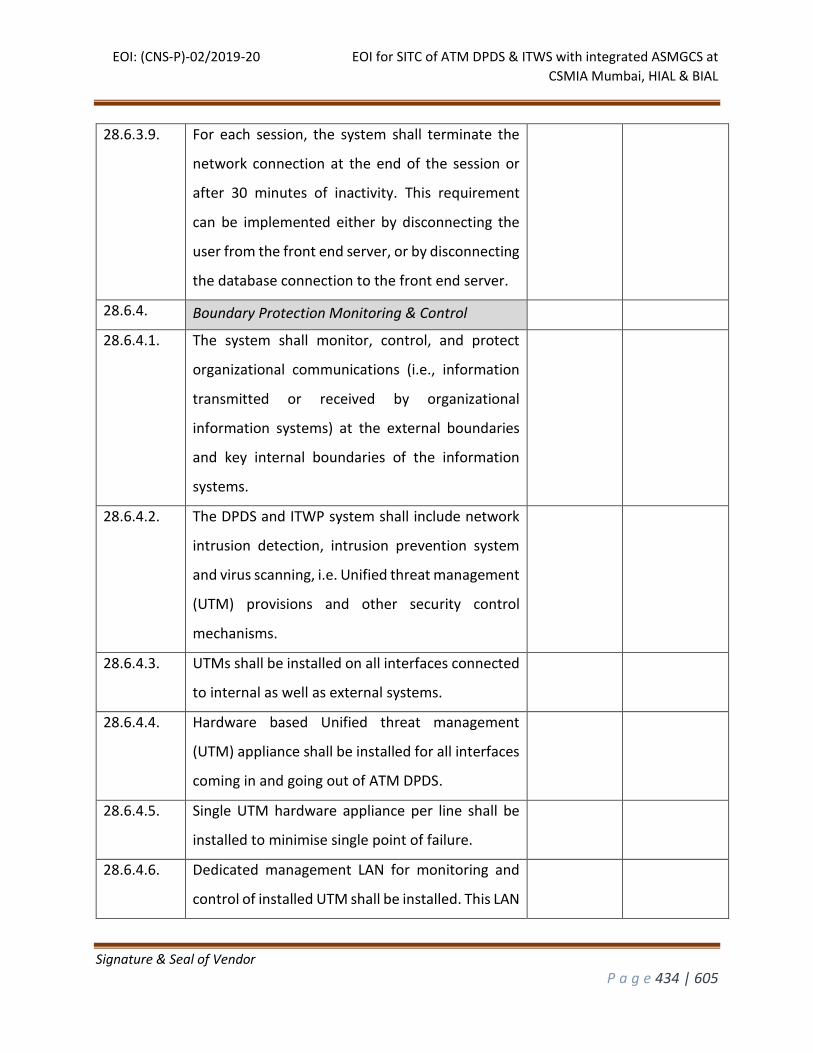
EOI: (CNS-P)-02/2019-20 EOI for SITC of ATM DPDS & ITWS with integrated ASMGCS at
CSMIA Mumbai, HIAL & BIAL
Signature & Seal of Vendor
P a g e 434 | 605
28.6.3.9. For each session, the system shall terminate the
network connection at the end of the session or
after 30 minutes of inactivity. This requirement
can be implemented either by disconnecting the
user from the front end server, or by disconnecting
the database connection to the front end server.
28.6.4. Boundary Protection Monitoring & Control
28.6.4.1. The system shall monitor, control, and protect
organizational communications (i.e., information
transmitted or received by organizational
information systems) at the external boundaries
and key internal boundaries of the information
systems.
28.6.4.2. The DPDS and ITWP system shall include network
intrusion detection, intrusion prevention system
and virus scanning, i.e. Unified threat management
(UTM) provisions and other security control
mechanisms.
28.6.4.3. UTMs shall be installed on all interfaces connected
to internal as well as external systems.
28.6.4.4. Hardware based Unified threat management
(UTM) appliance shall be installed for all interfaces
coming in and going out of ATM DPDS.
28.6.4.5. Single UTM hardware appliance per line shall be
installed to minimise single point of failure.
28.6.4.6. Dedicated management LAN for monitoring and
control of installed UTM shall be installed. This LAN
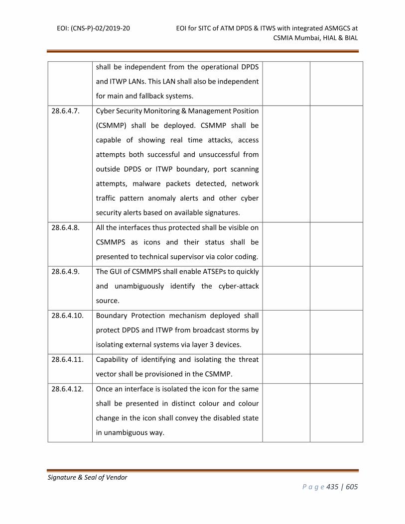
EOI: (CNS-P)-02/2019-20 EOI for SITC of ATM DPDS & ITWS with integrated ASMGCS at
CSMIA Mumbai, HIAL & BIAL
Signature & Seal of Vendor
P a g e 435 | 605
shall be independent from the operational DPDS
and ITWP LANs. This LAN shall also be independent
for main and fallback systems.
28.6.4.7. Cyber Security Monitoring & Management Position
(CSMMP) shall be deployed. CSMMP shall be
capable of showing real time attacks, access
attempts both successful and unsuccessful from
outside DPDS or ITWP boundary, port scanning
attempts, malware packets detected, network
traffic pattern anomaly alerts and other cyber
security alerts based on available signatures.
28.6.4.8. All the interfaces thus protected shall be visible on
CSMMPS as icons and their status shall be
presented to technical supervisor via color coding.
28.6.4.9. The GUI of CSMMPS shall enable ATSEPs to quickly
and unambiguously identify the cyber-attack
source.
28.6.4.10. Boundary Protection mechanism deployed shall
protect DPDS and ITWP from broadcast storms by
isolating external systems via layer 3 devices.
28.6.4.11. Capability of identifying and isolating the threat
vector shall be provisioned in the CSMMP.
28.6.4.12. Once an interface is isolated the icon for the same
shall be presented in distinct colour and colour
change in the icon shall convey the disabled state
in unambiguous way.
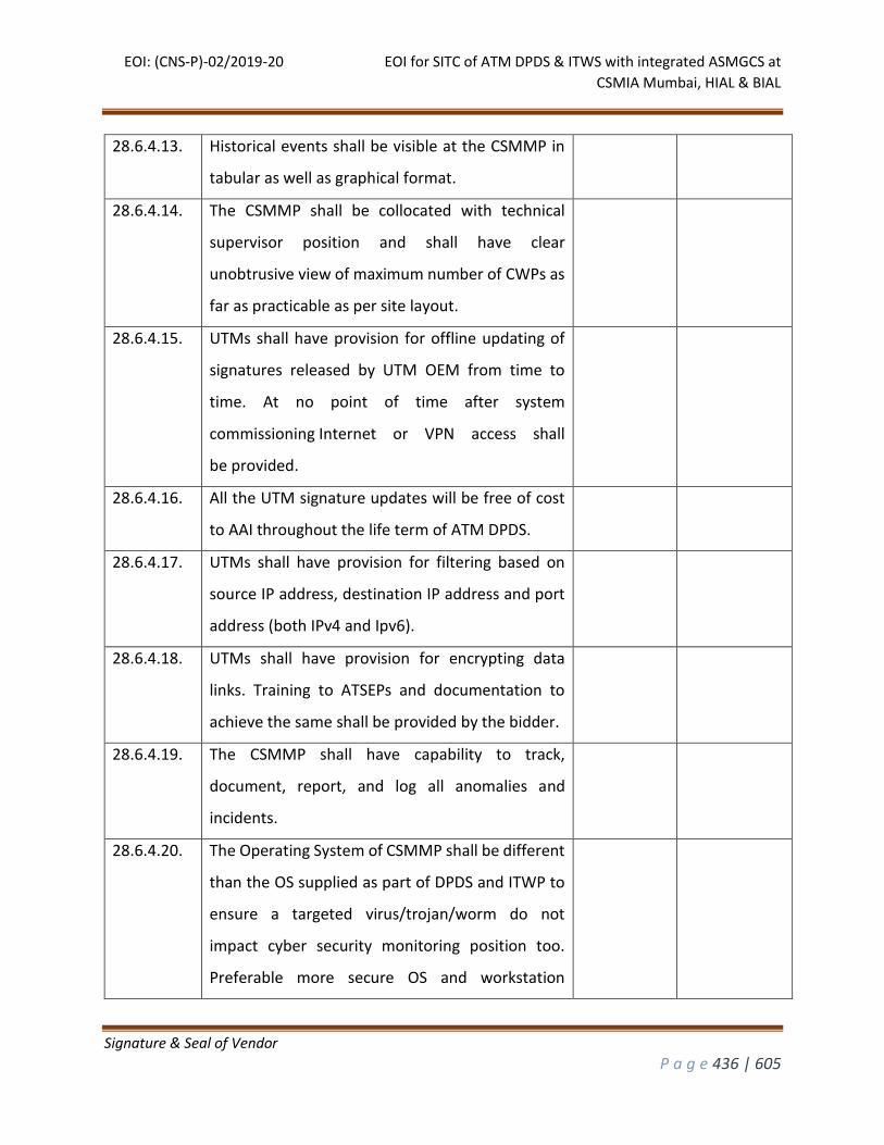
EOI: (CNS-P)-02/2019-20 EOI for SITC of ATM DPDS & ITWS with integrated ASMGCS at
CSMIA Mumbai, HIAL & BIAL
Signature & Seal of Vendor
P a g e 436 | 605
28.6.4.13. Historical events shall be visible at the CSMMP in
tabular as well as graphical format.
28.6.4.14. The CSMMP shall be collocated with technical
supervisor position and shall have clear
unobtrusive view of maximum number of CWPs as
far as practicable as per site layout.
28.6.4.15. UTMs shall have provision for offline updating of
signatures released by UTM OEM from time to
time. At no point of time after system
commissioning Internet or VPN access shall
be provided.
28.6.4.16. All the UTM signature updates will be free of cost
to AAI throughout the life term of ATM DPDS.
28.6.4.17. UTMs shall have provision for filtering based on
source IP address, destination IP address and port
address (both IPv4 and Ipv6).
28.6.4.18. UTMs shall have provision for encrypting data
links. Training to ATSEPs and documentation to
achieve the same shall be provided by the bidder.
28.6.4.19. The CSMMP shall have capability to track,
document, report, and log all anomalies and
incidents.
28.6.4.20. The Operating System of CSMMP shall be different
than the OS supplied as part of DPDS and ITWP to
ensure a targeted virus/trojan/worm do not
impact cyber security monitoring position too.
Preferable more secure OS and workstation
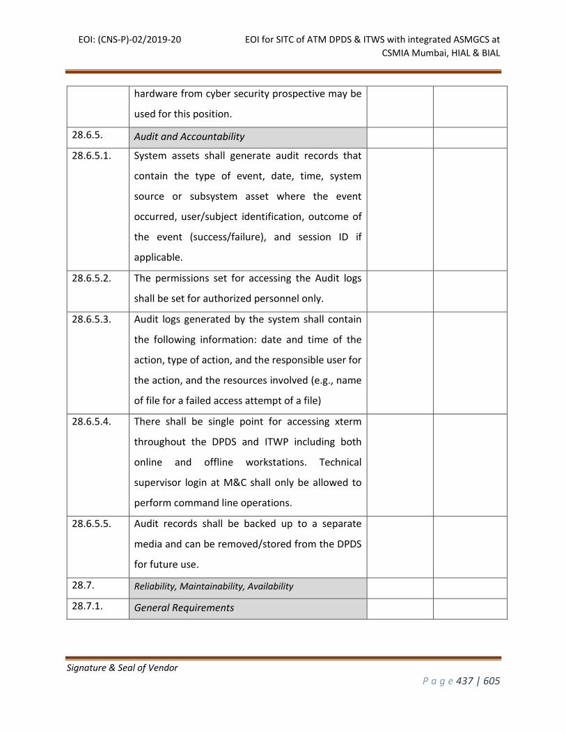
EOI: (CNS-P)-02/2019-20 EOI for SITC of ATM DPDS & ITWS with integrated ASMGCS at
CSMIA Mumbai, HIAL & BIAL
Signature & Seal of Vendor
P a g e 437 | 605
hardware from cyber security prospective may be
used for this position.
28.6.5. Audit and Accountability
28.6.5.1. System assets shall generate audit records that
contain the type of event, date, time, system
source or subsystem asset where the event
occurred, user/subject identification, outcome of
the event (success/failure), and session ID if
applicable.
28.6.5.2. The permissions set for accessing the Audit logs
shall be set for authorized personnel only.
28.6.5.3. Audit logs generated by the system shall contain
the following information: date and time of the
action, type of action, and the responsible user for
the action, and the resources involved (e.g., name
of file for a failed access attempt of a file)
28.6.5.4. There shall be single point for accessing xterm
throughout the DPDS and ITWP including both
online and offline workstations. Technical
supervisor login at M&C shall only be allowed to
perform command line operations.
28.6.5.5. Audit records shall be backed up to a separate
media and can be removed/stored from the DPDS
for future use.
28.7. Reliability, Maintainability, Availability
28.7.1. General Requirements
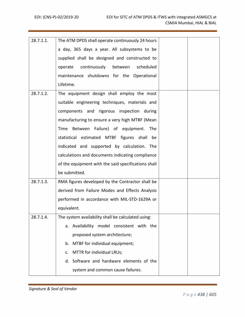
EOI: (CNS-P)-02/2019-20 EOI for SITC of ATM DPDS & ITWS with integrated ASMGCS at
CSMIA Mumbai, HIAL & BIAL
Signature & Seal of Vendor
P a g e 438 | 605
28.7.1.1. The ATM DPDS shall operate continuously 24 hours
a day, 365 days a year. All subsystems to be
supplied shall be designed and constructed to
operate continuously between scheduled
maintenance shutdowns for the Operational
Lifetime.
28.7.1.2. The equipment design shall employ the most
suitable engineering techniques, materials and
components and rigorous inspection during
manufacturing to ensure a very high MTBF (Mean
Time Between Failure) of equipment. The
statistical estimated MTBF figures shall be
indicated and supported by calculation. The
calculations and documents indicating compliance
of the equipment with the said specifications shall
be submitted.
28.7.1.3. RMA figures developed by the Contractor shall be
derived from Failure Modes and Effects Analysis
performed in accordance with MIL-STD-1629A or
equivalent.
28.7.1.4. The system availability shall be calculated using:
a. Availability model consistent with the
proposed system architecture;
b. MTBF for individual equipment;
c. MTTR for individual LRUs;
d. Software and hardware elements of the
system and common cause failures.
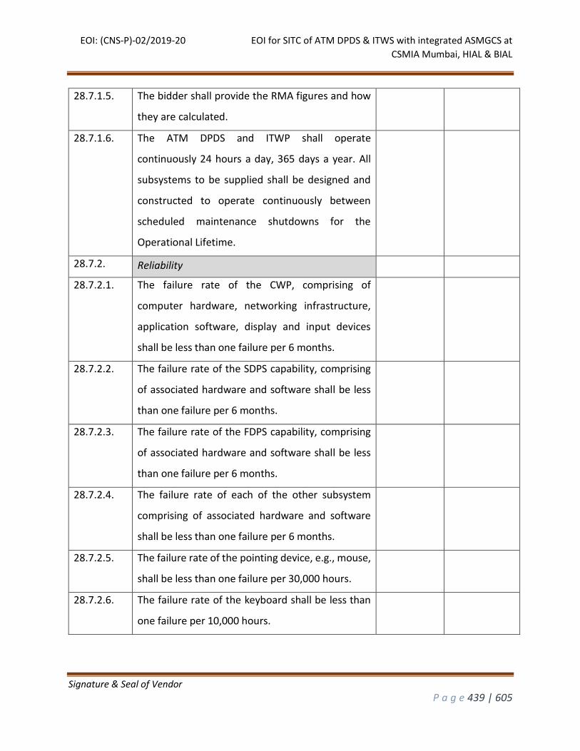
EOI: (CNS-P)-02/2019-20 EOI for SITC of ATM DPDS & ITWS with integrated ASMGCS at
CSMIA Mumbai, HIAL & BIAL
Signature & Seal of Vendor
P a g e 439 | 605
28.7.1.5. The bidder shall provide the RMA figures and how
they are calculated.
28.7.1.6. The ATM DPDS and ITWP shall operate
continuously 24 hours a day, 365 days a year. All
subsystems to be supplied shall be designed and
constructed to operate continuously between
scheduled maintenance shutdowns for the
Operational Lifetime.
28.7.2. Reliability
28.7.2.1. The failure rate of the CWP, comprising of
computer hardware, networking infrastructure,
application software, display and input devices
shall be less than one failure per 6 months.
28.7.2.2. The failure rate of the SDPS capability, comprising
of associated hardware and software shall be less
than one failure per 6 months.
28.7.2.3. The failure rate of the FDPS capability, comprising
of associated hardware and software shall be less
than one failure per 6 months.
28.7.2.4. The failure rate of each of the other subsystem
comprising of associated hardware and software
shall be less than one failure per 6 months.
28.7.2.5. The failure rate of the pointing device, e.g., mouse,
shall be less than one failure per 30,000 hours.
28.7.2.6. The failure rate of the keyboard shall be less than
one failure per 10,000 hours.
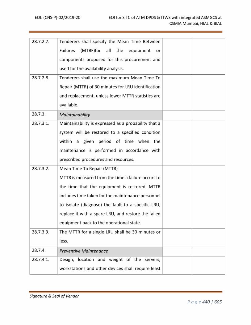
EOI: (CNS-P)-02/2019-20 EOI for SITC of ATM DPDS & ITWS with integrated ASMGCS at
CSMIA Mumbai, HIAL & BIAL
Signature & Seal of Vendor
P a g e 440 | 605
28.7.2.7. Tenderers shall specify the Mean Time Between
Failures (MTBF)for all the equipment or
components proposed for this procurement and
used for the availability analysis.
28.7.2.8. Tenderers shall use the maximum Mean Time To
Repair (MTTR) of 30 minutes for LRU identification
and replacement, unless lower MTTR statistics are
available.
28.7.3. Maintainability
28.7.3.1. Maintainability is expressed as a probability that a
system will be restored to a specified condition
within a given period of time when the
maintenance is performed in accordance with
prescribed procedures and resources.
28.7.3.2. Mean Time To Repair (MTTR)
MTTR is measured from the time a failure occurs to
the time that the equipment is restored. MTTR
includes time taken for the maintenance personnel
to isolate (diagnose) the fault to a specific LRU,
replace it with a spare LRU, and restore the failed
equipment back to the operational state.
28.7.3.3. The MTTR for a single LRU shall be 30 minutes or
less.
28.7.4. Preventive Maintenance
28.7.4.1. Design, location and weight of the servers,
workstations and other devices shall require least
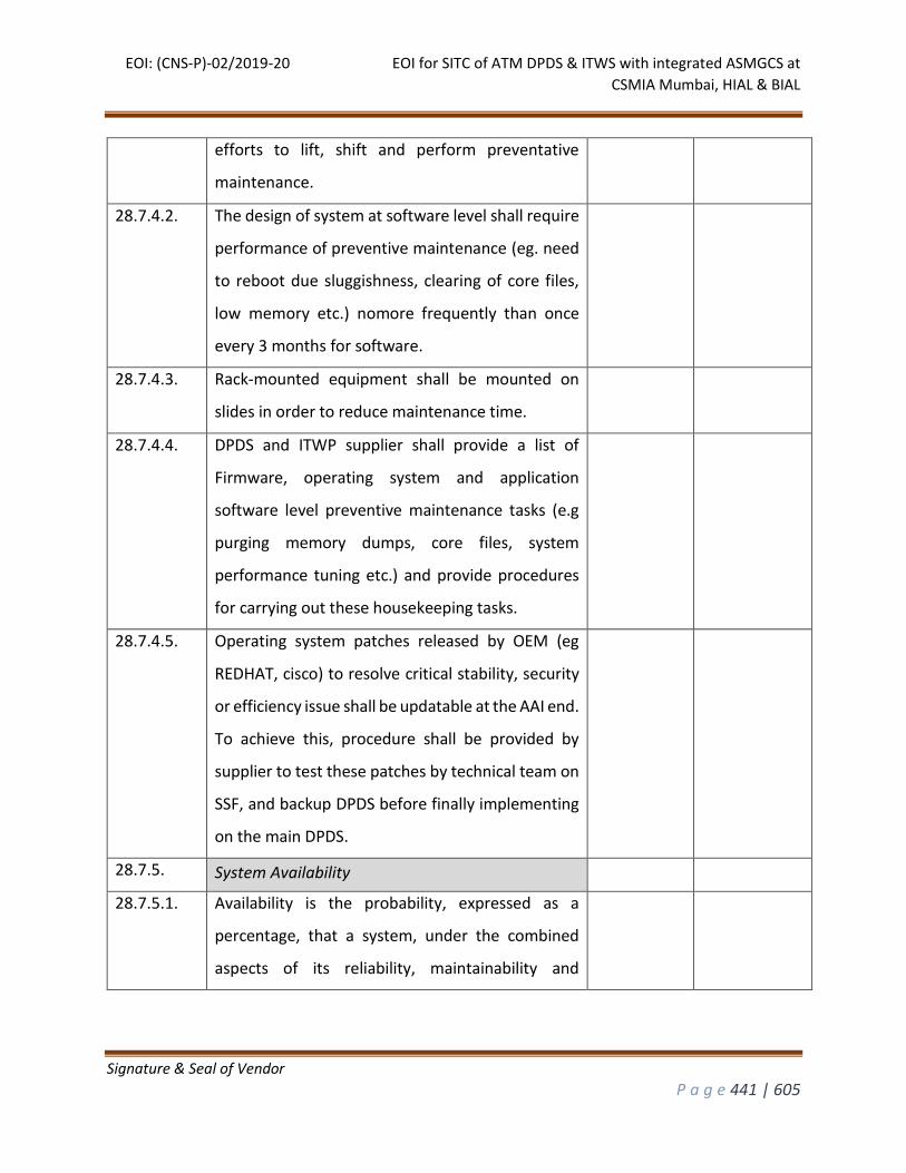
EOI: (CNS-P)-02/2019-20 EOI for SITC of ATM DPDS & ITWS with integrated ASMGCS at
CSMIA Mumbai, HIAL & BIAL
Signature & Seal of Vendor
P a g e 441 | 605
efforts to lift, shift and perform preventative
maintenance.
28.7.4.2. The design of system at software level shall require
performance of preventive maintenance (eg. need
to reboot due sluggishness, clearing of core files,
low memory etc.) nomore frequently than once
every 3 months for software.
28.7.4.3. Rack-mounted equipment shall be mounted on
slides in order to reduce maintenance time.
28.7.4.4. DPDS and ITWP supplier shall provide a list of
Firmware, operating system and application
software level preventive maintenance tasks (e.g
purging memory dumps, core files, system
performance tuning etc.) and provide procedures
for carrying out these housekeeping tasks.
28.7.4.5. Operating system patches released by OEM (eg
REDHAT, cisco) to resolve critical stability, security
or efficiency issue shall be updatable at the AAI end.
To achieve this, procedure shall be provided by
supplier to test these patches by technical team on
SSF, and backup DPDS before finally implementing
on the main DPDS.
28.7.5. System Availability
28.7.5.1. Availability is the probability, expressed as a
percentage, that a system, under the combined
aspects of its reliability, maintainability and
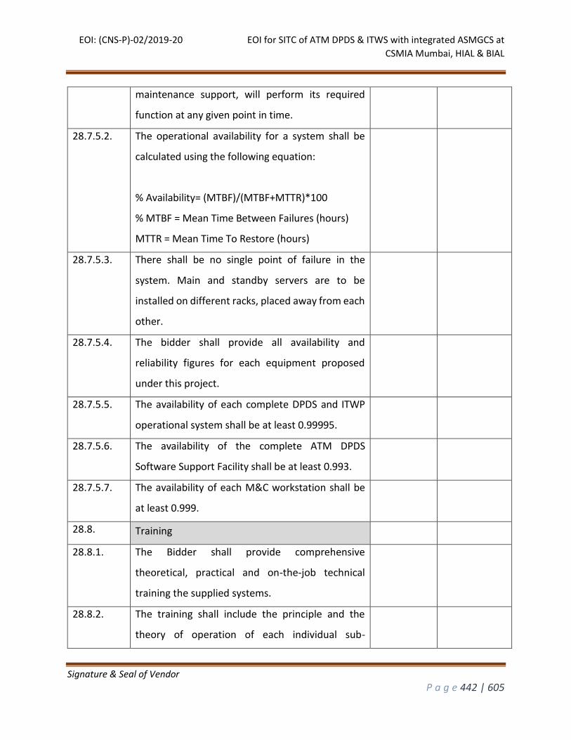
EOI: (CNS-P)-02/2019-20 EOI for SITC of ATM DPDS & ITWS with integrated ASMGCS at
CSMIA Mumbai, HIAL & BIAL
Signature & Seal of Vendor
P a g e 442 | 605
maintenance support, will perform its required
function at any given point in time.
28.7.5.2. The operational availability for a system shall be
calculated using the following equation:
% Availability= (MTBF)/(MTBF+MTTR)*100
% MTBF = Mean Time Between Failures (hours)
MTTR = Mean Time To Restore (hours)
28.7.5.3. There shall be no single point of failure in the
system. Main and standby servers are to be
installed on different racks, placed away from each
other.
28.7.5.4. The bidder shall provide all availability and
reliability figures for each equipment proposed
under this project.
28.7.5.5. The availability of each complete DPDS and ITWP
operational system shall be at least 0.99995.
28.7.5.6. The availability of the complete ATM DPDS
Software Support Facility shall be at least 0.993.
28.7.5.7. The availability of each M&C workstation shall be
at least 0.999.
28.8. Training
28.8.1. The Bidder shall provide comprehensive
theoretical, practical and on-the-job technical
training the supplied systems.
28.8.2. The training shall include the principle and the
theory of operation of each individual sub-
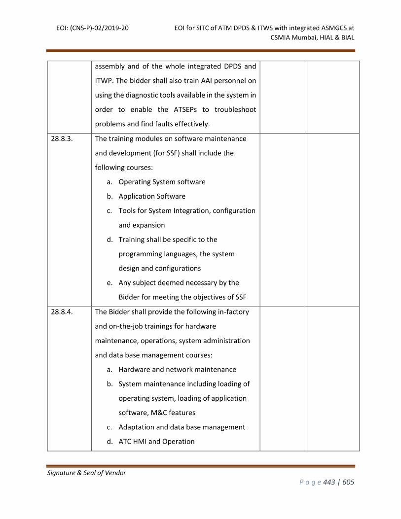
EOI: (CNS-P)-02/2019-20 EOI for SITC of ATM DPDS & ITWS with integrated ASMGCS at
CSMIA Mumbai, HIAL & BIAL
Signature & Seal of Vendor
P a g e 443 | 605
assembly and of the whole integrated DPDS and
ITWP. The bidder shall also train AAI personnel on
using the diagnostic tools available in the system in
order to enable the ATSEPs to troubleshoot
problems and find faults effectively.
28.8.3. The training modules on software maintenance
and development (for SSF) shall include the
following courses:
a. Operating System software
b. Application Software
c. Tools for System Integration, configuration
and expansion
d. Training shall be specific to the
programming languages, the system
design and configurations
e. Any subject deemed necessary by the
Bidder for meeting the objectives of SSF
28.8.4. The Bidder shall provide the following in-factory
and on-the-job trainings for hardware
maintenance, operations, system administration
and data base management courses:
a. Hardware and network maintenance
b. System maintenance including loading of
operating system, loading of application
software, M&C features
c. Adaptation and data base management
d. ATC HMI and Operation
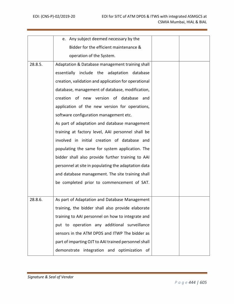
EOI: (CNS-P)-02/2019-20 EOI for SITC of ATM DPDS & ITWS with integrated ASMGCS at
CSMIA Mumbai, HIAL & BIAL
Signature & Seal of Vendor
P a g e 444 | 605
e. Any subject deemed necessary by the
Bidder for the efficient maintenance &
operation of the System.
28.8.5. Adaptation & Database management training shall
essentially include the adaptation database
creation, validation and application for operational
database, management of database, modification,
creation of new version of database and
application of the new version for operations,
software configuration management etc.
As part of adaptation and database management
training at factory level, AAI personnel shall be
involved in initial creation of database and
populating the same for system application. The
bidder shall also provide further training to AAI
personnel at site in populating the adaptation data
and database management. The site training shall
be completed prior to commencement of SAT.
28.8.6. As part of Adaptation and Database Management
training, the bidder shall also provide elaborate
training to AAI personnel on how to integrate and
put to operation any additional surveillance
sensors in the ATM DPDS and ITWP The bidder as
part of imparting OJT to AAI trained personnel shall
demonstrate integration and optimization of
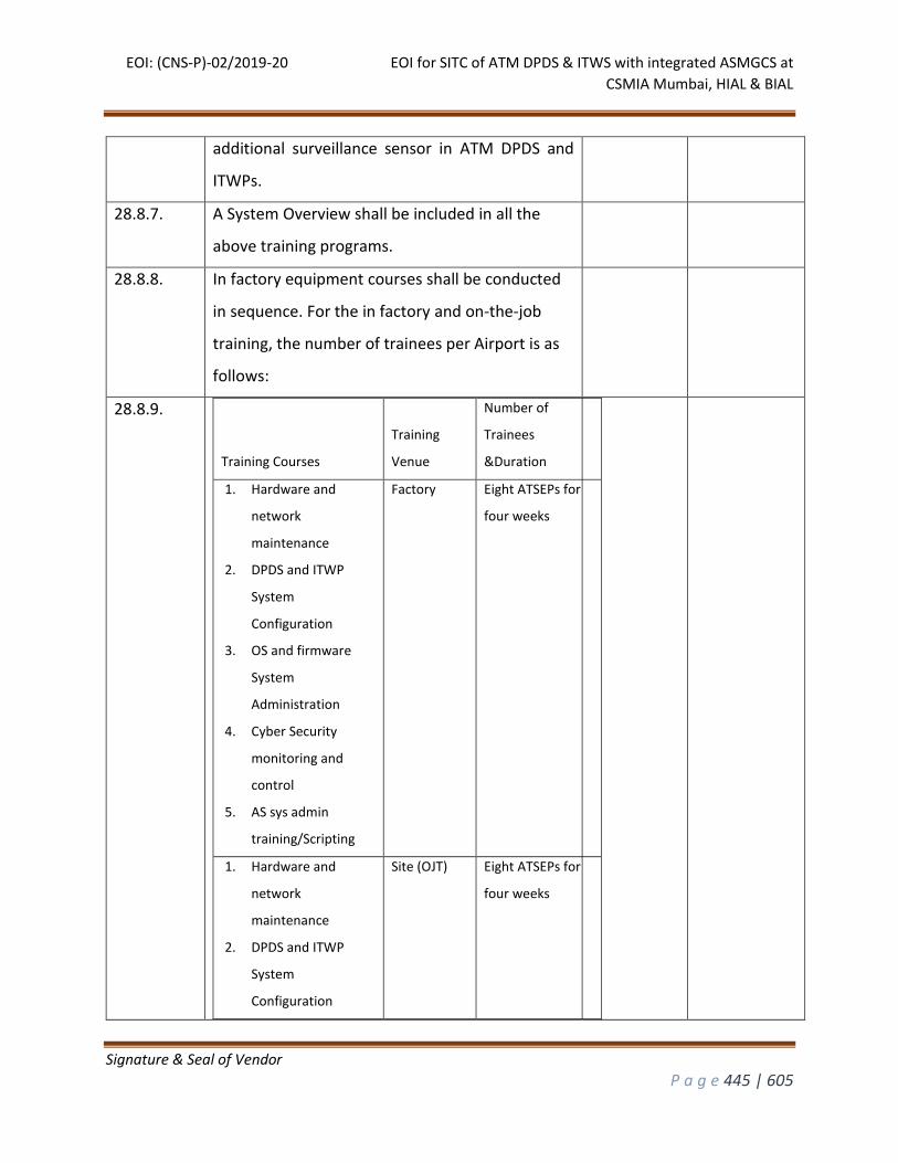
EOI: (CNS-P)-02/2019-20 EOI for SITC of ATM DPDS & ITWS with integrated ASMGCS at
CSMIA Mumbai, HIAL & BIAL
Signature & Seal of Vendor
P a g e 445 | 605
additional surveillance sensor in ATM DPDS and
ITWPs.
28.8.7. A System Overview shall be included in all the
above training programs.
28.8.8. In factory equipment courses shall be conducted
in sequence. For the in factory and on-the-job
training, the number of trainees per Airport is as
follows:
28.8.9.
Training Courses
Training
Venue
Number of
Trainees
&Duration
1. Hardware and
network
maintenance
2. DPDS and ITWP
System
Configuration
3. OS and firmware
System
Administration
4. Cyber Security
monitoring and
control
5. AS sys admin
training/Scripting
Factory Eight ATSEPs for
four weeks
1. Hardware and
network
maintenance
2. DPDS and ITWP
System
Configuration
Site (OJT) Eight ATSEPs for
four weeks
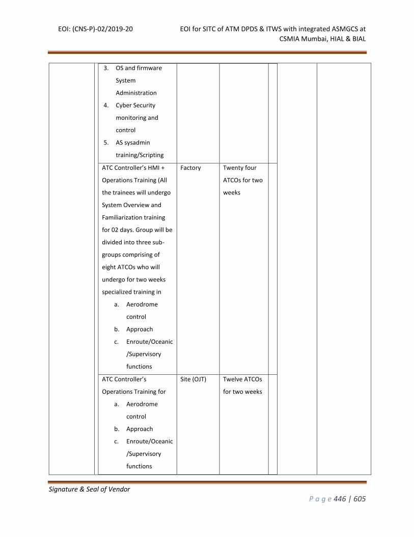
EOI: (CNS-P)-02/2019-20 EOI for SITC of ATM DPDS & ITWS with integrated ASMGCS at
CSMIA Mumbai, HIAL & BIAL
Signature & Seal of Vendor
P a g e 446 | 605
3. OS and firmware
System
Administration
4. Cyber Security
monitoring and
control
5. AS sysadmin
training/Scripting
ATC Controller’s HMI +
Operations Training (All
the trainees will undergo
System Overview and
Familiarization training
for 02 days. Group will be
divided into three sub-
groups comprising of
eight ATCOs who will
undergo for two weeks
specialized training in
a. Aerodrome
control
b. Approach
c. Enroute/Oceanic
/Supervisory
functions
Factory Twenty four
ATCOs for two
weeks
ATC Controller’s
Operations Training for
a. Aerodrome
control
b. Approach
c. Enroute/Oceanic
/Supervisory
functions
Site (OJT) Twelve ATCOs
for two weeks
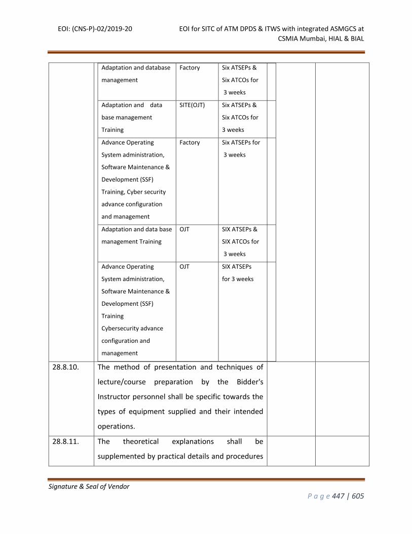
EOI: (CNS-P)-02/2019-20 EOI for SITC of ATM DPDS & ITWS with integrated ASMGCS at
CSMIA Mumbai, HIAL & BIAL
Signature & Seal of Vendor
P a g e 447 | 605
Adaptation and database
management
Factory Six ATSEPs &
Six ATCOs for
3 weeks
Adaptation and data
base management
Training
SITE(OJT) Six ATSEPs &
Six ATCOs for
3 weeks
Advance Operating
System administration,
Software Maintenance &
Development (SSF)
Training, Cyber security
advance configuration
and management
Factory Six ATSEPs for
3 weeks
Adaptation and data base
management Training
OJT SIX ATSEPs &
SIX ATCOs for
3 weeks
Advance Operating
System administration,
Software Maintenance &
Development (SSF)
Training
Cybersecurity advance
configuration and
management
OJT SIX ATSEPs
for 3 weeks
28.8.10. The method of presentation and techniques of
lecture/course preparation by the Bidder's
Instructor personnel shall be specific towards the
types of equipment supplied and their intended
operations.
28.8.11. The theoretical explanations shall be
supplemented by practical details and procedures
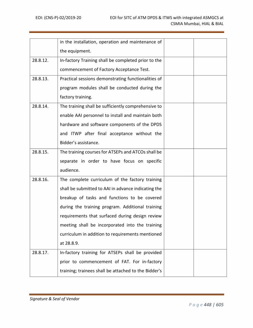
EOI: (CNS-P)-02/2019-20 EOI for SITC of ATM DPDS & ITWS with integrated ASMGCS at
CSMIA Mumbai, HIAL & BIAL
Signature & Seal of Vendor
P a g e 448 | 605
in the installation, operation and maintenance of
the equipment.
28.8.12. In-factory Training shall be completed prior to the
commencement of Factory Acceptance Test.
28.8.13. Practical sessions demonstrating functionalities of
program modules shall be conducted during the
factory training.
28.8.14. The training shall be sufficiently comprehensive to
enable AAI personnel to install and maintain both
hardware and software components of the DPDS
and ITWP after final acceptance without the
Bidder’s assistance.
28.8.15. The training courses for ATSEPs and ATCOs shall be
separate in order to have focus on specific
audience.
28.8.16. The complete curriculum of the factory training
shall be submitted to AAI in advance indicating the
breakup of tasks and functions to be covered
during the training program. Additional training
requirements that surfaced during design review
meeting shall be incorporated into the training
curriculum in addition to requirements mentioned
at 28.8.9.
28.8.17. In-factory training for ATSEPs shall be provided
prior to commencement of FAT. For in-factory
training; trainees shall be attached to the Bidder's
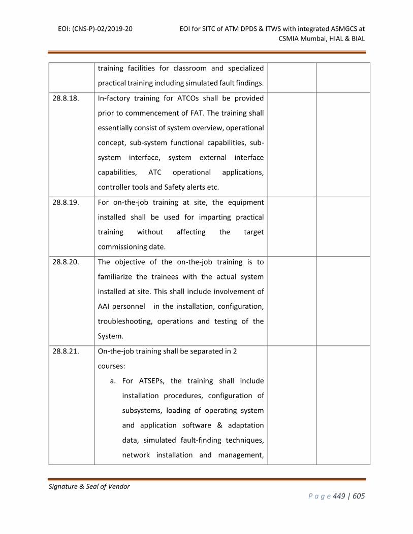
EOI: (CNS-P)-02/2019-20 EOI for SITC of ATM DPDS & ITWS with integrated ASMGCS at
CSMIA Mumbai, HIAL & BIAL
Signature & Seal of Vendor
P a g e 449 | 605
training facilities for classroom and specialized
practical training including simulated fault findings.
28.8.18. In-factory training for ATCOs shall be provided
prior to commencement of FAT. The training shall
essentially consist of system overview, operational
concept, sub-system functional capabilities, sub-
system interface, system external interface
capabilities, ATC operational applications,
controller tools and Safety alerts etc.
28.8.19. For on-the-job training at site, the equipment
installed shall be used for imparting practical
training without affecting the target
commissioning date.
28.8.20. The objective of the on-the-job training is to
familiarize the trainees with the actual system
installed at site. This shall include involvement of
AAI personnel in the installation, configuration,
troubleshooting, operations and testing of the
System.
28.8.21. On-the-job training shall be separated in 2
courses:
a. For ATSEPs, the training shall include
installation procedures, configuration of
subsystems, loading of operating system
and application software & adaptation
data, simulated fault-finding techniques,
network installation and management,
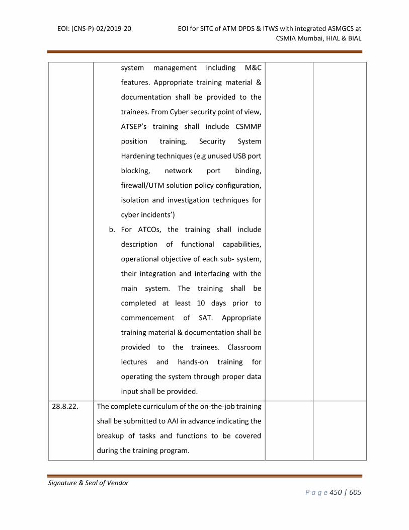
EOI: (CNS-P)-02/2019-20 EOI for SITC of ATM DPDS & ITWS with integrated ASMGCS at
CSMIA Mumbai, HIAL & BIAL
Signature & Seal of Vendor
P a g e 450 | 605
system management including M&C
features. Appropriate training material &
documentation shall be provided to the
trainees. From Cyber security point of view,
ATSEP’s training shall include CSMMP
position training, Security System
Hardening techniques (e.g unused USB port
blocking, network port binding,
firewall/UTM solution policy configuration,
isolation and investigation techniques for
cyber incidents’)
b. For ATCOs, the training shall include
description of functional capabilities,
operational objective of each sub- system,
their integration and interfacing with the
main system. The training shall be
completed at least 10 days prior to
commencement of SAT. Appropriate
training material & documentation shall be
provided to the trainees. Classroom
lectures and hands-on training for
operating the system through proper data
input shall be provided.
28.8.22. The complete curriculum of the on-the-job training
shall be submitted to AAI in advance indicating the
breakup of tasks and functions to be covered
during the training program.
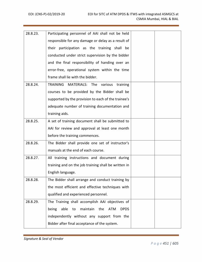
EOI: (CNS-P)-02/2019-20 EOI for SITC of ATM DPDS & ITWS with integrated ASMGCS at
CSMIA Mumbai, HIAL & BIAL
Signature & Seal of Vendor
P a g e 451 | 605
28.8.23. Participating personnel of AAI shall not be held
responsible for any damage or delay as a result of
their participation as the training shall be
conducted under strict supervision by the bidder
and the final responsibility of handing over an
error-free, operational system within the time
frame shall lie with the bidder.
28.8.24. TRAINING MATERIALS: The various training
courses to be provided by the Bidder shall be
supported by the provision to each of the trainee's
adequate number of training documentation and
training aids.
28.8.25. A set of training document shall be submitted to
AAI for review and approval at least one month
before the training commences.
28.8.26. The Bidder shall provide one set of instructor's
manuals at the end of each course.
28.8.27. All training instructions and document during
training and on the job training shall be written in
English language.
28.8.28. The Bidder shall arrange and conduct training by
the most efficient and effective techniques with
qualified and experienced personnel.
28.8.29. The Training shall accomplish AAI objectives of
being able to maintain the ATM DPDS
independently without any support from the
Bidder after final acceptance of the system.
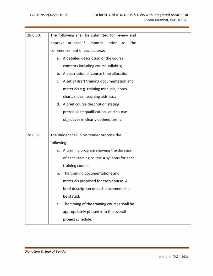
EOI: (CNS-P)-02/2019-20 EOI for SITC of ATM DPDS & ITWS with integrated ASMGCS at
CSMIA Mumbai, HIAL & BIAL
Signature & Seal of Vendor
P a g e 452 | 605
28.8.30. The following shall be submitted for review and
approval at-least 3 months prior to the
commencement of each course:
a. A detailed description of the course
contents including course syllabus;
b. A description of course time allocation;
c. A set of draft training documentation and
materials e.g. training manuals, notes,
chart, slides, teaching aids etc.;
d. A brief course description stating
prerequisite qualifications and course
objectives in clearly defined terms;
28.8.31. The Bidder shall in his tender propose the
following:
a. A training program showing the duration
of each training course A syllabus for each
training course;
b. The training documentations and
materials proposed for each course. A
brief description of each document shall
be stated;
c. The timing of the training courses shall be
appropriately phased into the overall
project schedule.
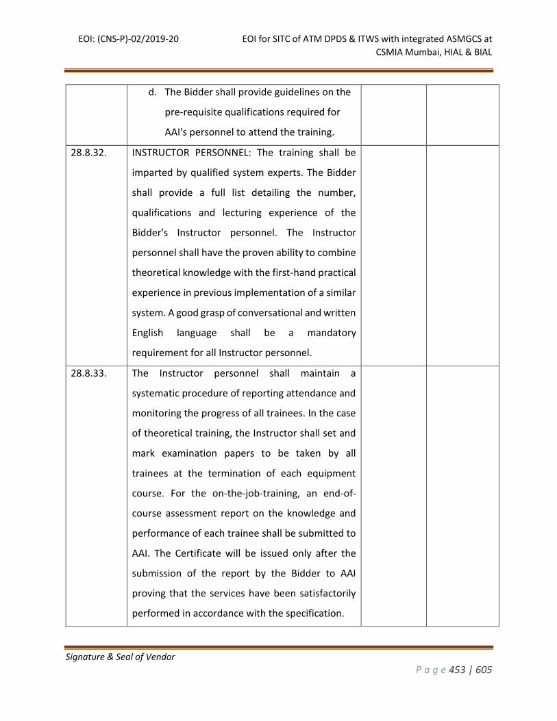
EOI: (CNS-P)-02/2019-20 EOI for SITC of ATM DPDS & ITWS with integrated ASMGCS at
CSMIA Mumbai, HIAL & BIAL
Signature & Seal of Vendor
P a g e 453 | 605
d. The Bidder shall provide guidelines on the
pre-requisite qualifications required for
AAI's personnel to attend the training.
28.8.32. INSTRUCTOR PERSONNEL: The training shall be
imparted by qualified system experts. The Bidder
shall provide a full list detailing the number,
qualifications and lecturing experience of the
Bidder's Instructor personnel. The Instructor
personnel shall have the proven ability to combine
theoretical knowledge with the first-hand practical
experience in previous implementation of a similar
system. A good grasp of conversational and written
English language shall be a mandatory
requirement for all Instructor personnel.
28.8.33. The Instructor personnel shall maintain a
systematic procedure of reporting attendance and
monitoring the progress of all trainees. In the case
of theoretical training, the Instructor shall set and
mark examination papers to be taken by all
trainees at the termination of each equipment
course. For the on-the-job-training, an end-of-
course assessment report on the knowledge and
performance of each trainee shall be submitted to
AAI. The Certificate will be issued only after the
submission of the report by the Bidder to AAI
proving that the services have been satisfactorily
performed in accordance with the specification.
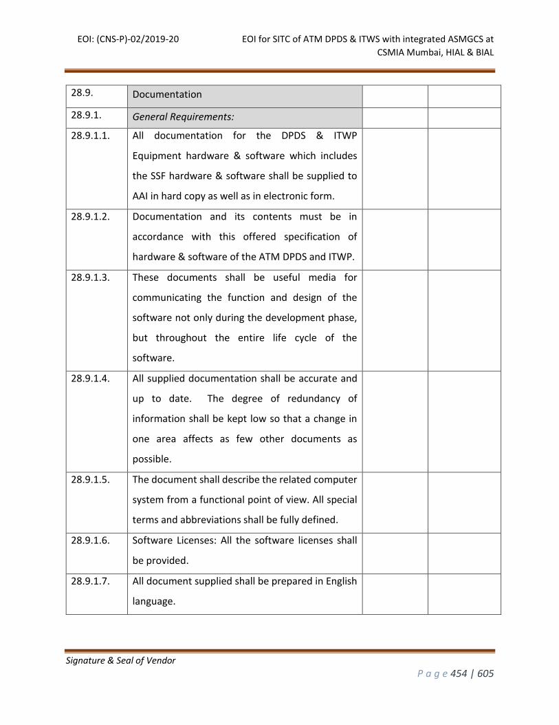
EOI: (CNS-P)-02/2019-20 EOI for SITC of ATM DPDS & ITWS with integrated ASMGCS at
CSMIA Mumbai, HIAL & BIAL
Signature & Seal of Vendor
P a g e 454 | 605
28.9. Documentation
28.9.1. General Requirements:
28.9.1.1. All documentation for the DPDS & ITWP
Equipment hardware & software which includes
the SSF hardware & software shall be supplied to
AAI in hard copy as well as in electronic form.
28.9.1.2. Documentation and its contents must be in
accordance with this offered specification of
hardware & software of the ATM DPDS and ITWP.
28.9.1.3. These documents shall be useful media for
communicating the function and design of the
software not only during the development phase,
but throughout the entire life cycle of the
software.
28.9.1.4. All supplied documentation shall be accurate and
up to date. The degree of redundancy of
information shall be kept low so that a change in
one area affects as few other documents as
possible.
28.9.1.5. The document shall describe the related computer
system from a functional point of view. All special
terms and abbreviations shall be fully defined.
28.9.1.6. Software Licenses: All the software licenses shall
be provided.
28.9.1.7. All document supplied shall be prepared in English
language.

EOI: (CNS-P)-02/2019-20 EOI for SITC of ATM DPDS & ITWS with integrated ASMGCS at
CSMIA Mumbai, HIAL & BIAL
Signature & Seal of Vendor
P a g e 455 | 605
28.9.1.8. All standardized technical terms and concepts shall
be documented.
28.9.1.9. The final edition of all documents and manuals
shall capture all the amendments up to the point
of final acceptance and shall reflect the System as
handed over to AAI. These documents/manuals
shall be provided in both hard copy (paper) and CD-
ROM (document format such as Adobe Acrobat
and Microsoft word). All documents/ manuals shall
comply with the latest ISO900X standards. There
shall be a provision of uploading and accessing
them from the HMI.
28.9.1.10. Every computer unit shall be provided with the real
software copyright licenses certificate.
28.9.2. Type of documentation and Number of copies required, per site.
28.9.2.1. 3 sets of drawings consist of mechanical, electrical,
console, floor plan, which is essential for
installation, maintenance and repair of the
equipment, including such drawings as are needed
to identify the components and cable terminations
within the equipment or its sub-units.
28.9.2.2. 3 sets of comprehensive installation and
equipment instruction manuals, setting out in
detail the procedures for operation, routine
maintenance, repair of equipment, test and
alignment procedures, including schematics and
Inter-cabling diagrams.
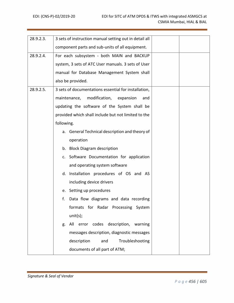
EOI: (CNS-P)-02/2019-20 EOI for SITC of ATM DPDS & ITWS with integrated ASMGCS at
CSMIA Mumbai, HIAL & BIAL
Signature & Seal of Vendor
P a g e 456 | 605
28.9.2.3. 3 sets of instruction manual setting out in detail all
component parts and sub-units of all equipment.
28.9.2.4. For each subsystem - both MAIN and BACKUP
system, 3 sets of ATC User manuals. 3 sets of User
manual for Database Management System shall
also be provided.
28.9.2.5. 3 sets of documentations essential for installation,
maintenance, modification, expansion and
updating the software of the System shall be
provided which shall include but not limited to the
following.
a. General Technical description and theory of
operation
b. Block Diagram description
c. Software Documentation for application
and operating system software
d. Installation procedures of OS and AS
including device drivers
e. Setting up procedures
f. Data flow diagrams and data recording
formats for Radar Processing System
unit(s);
g. All error codes description, warning
messages description, diagnostic messages
description and Troubleshooting
documents of all part of ATM;
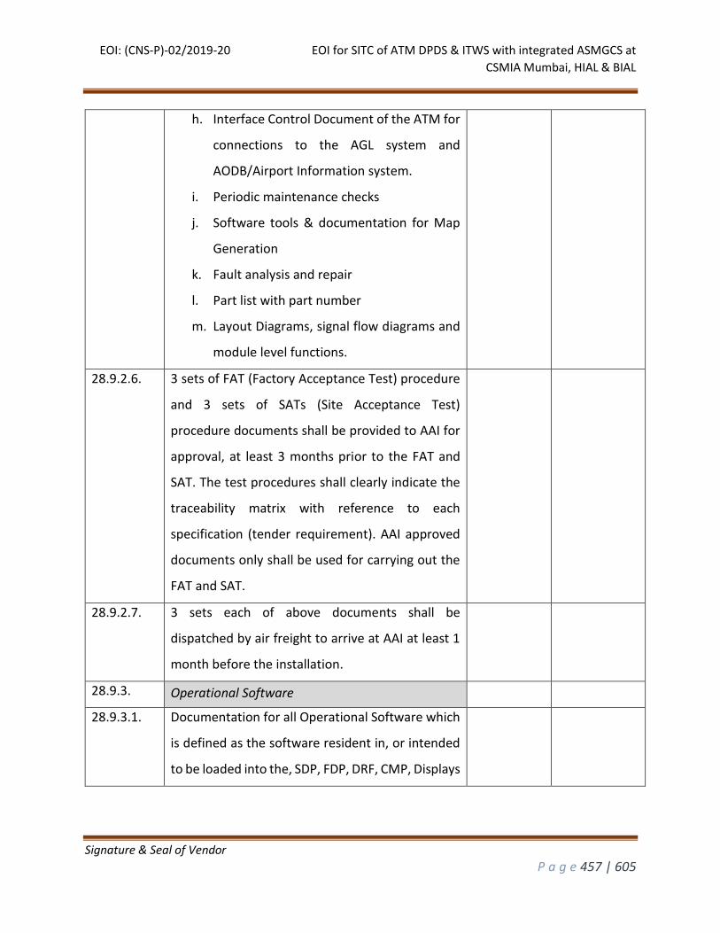
EOI: (CNS-P)-02/2019-20 EOI for SITC of ATM DPDS & ITWS with integrated ASMGCS at
CSMIA Mumbai, HIAL & BIAL
Signature & Seal of Vendor
P a g e 457 | 605
h. Interface Control Document of the ATM for
connections to the AGL system and
AODB/Airport Information system.
i. Periodic maintenance checks
j. Software tools & documentation for Map
Generation
k. Fault analysis and repair
l. Part list with part number
m. Layout Diagrams, signal flow diagrams and
module level functions.
28.9.2.6. 3 sets of FAT (Factory Acceptance Test) procedure
and 3 sets of SATs (Site Acceptance Test)
procedure documents shall be provided to AAI for
approval, at least 3 months prior to the FAT and
SAT. The test procedures shall clearly indicate the
traceability matrix with reference to each
specification (tender requirement). AAI approved
documents only shall be used for carrying out the
FAT and SAT.
28.9.2.7. 3 sets each of above documents shall be
dispatched by air freight to arrive at AAI at least 1
month before the installation.
28.9.3. Operational Software
28.9.3.1. Documentation for all Operational Software which
is defined as the software resident in, or intended
to be loaded into the, SDP, FDP, DRF, CMP, Displays
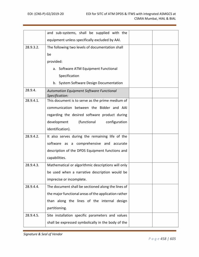
EOI: (CNS-P)-02/2019-20 EOI for SITC of ATM DPDS & ITWS with integrated ASMGCS at
CSMIA Mumbai, HIAL & BIAL
Signature & Seal of Vendor
P a g e 458 | 605
and sub-systems, shall be supplied with the
equipment unless specifically excluded by AAI.
28.9.3.2. The following two levels of documentation shall
be
provided:
a. Software ATM Equipment Functional
Specification
b. System Software Design Documentation
28.9.4. Automation Equipment Software Functional Specification:
28.9.4.1. This document is to serve as the prime medium of
communication between the Bidder and AAI
regarding the desired software product during
development (functional configuration
identification).
28.9.4.2. It also serves during the remaining life of the
software as a comprehensive and accurate
description of the DPDS Equipment functions and
capabilities.
28.9.4.3. Mathematical or algorithmic descriptions will only
be used when a narrative description would be
imprecise or incomplete.
28.9.4.4. The document shall be sectioned along the lines of
the major functional areas of the application rather
than along the lines of the internal design
partitioning.
28.9.4.5. Site installation specific parameters and values
shall be expressed symbolically in the body of the
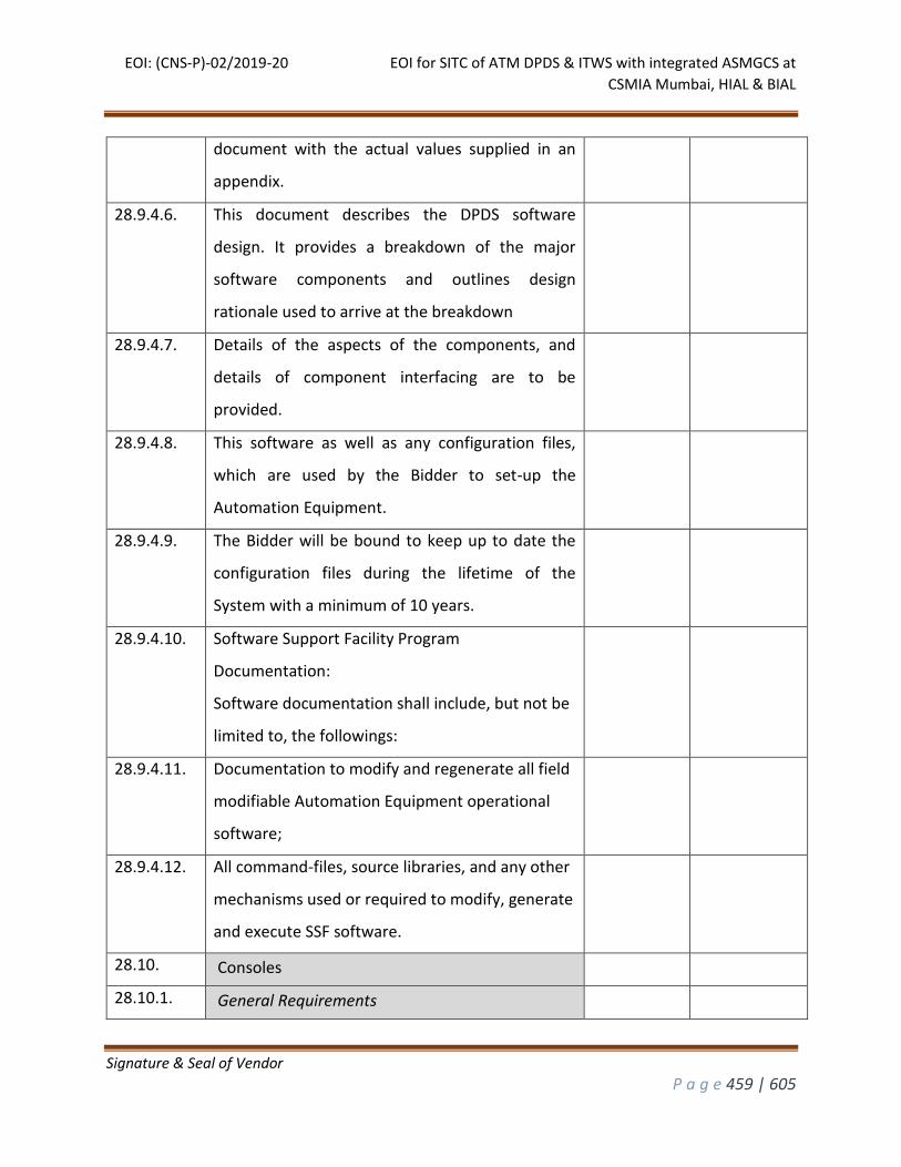
EOI: (CNS-P)-02/2019-20 EOI for SITC of ATM DPDS & ITWS with integrated ASMGCS at
CSMIA Mumbai, HIAL & BIAL
Signature & Seal of Vendor
P a g e 459 | 605
document with the actual values supplied in an
appendix.
28.9.4.6. This document describes the DPDS software
design. It provides a breakdown of the major
software components and outlines design
rationale used to arrive at the breakdown
28.9.4.7. Details of the aspects of the components, and
details of component interfacing are to be
provided.
28.9.4.8. This software as well as any configuration files,
which are used by the Bidder to set-up the
Automation Equipment.
28.9.4.9. The Bidder will be bound to keep up to date the
configuration files during the lifetime of the
System with a minimum of 10 years.
28.9.4.10. Software Support Facility Program
Documentation:
Software documentation shall include, but not be
limited to, the followings:
28.9.4.11. Documentation to modify and regenerate all field
modifiable Automation Equipment operational
software;
28.9.4.12. All command-files, source libraries, and any other
mechanisms used or required to modify, generate
and execute SSF software.
28.10. Consoles
28.10.1. General Requirements
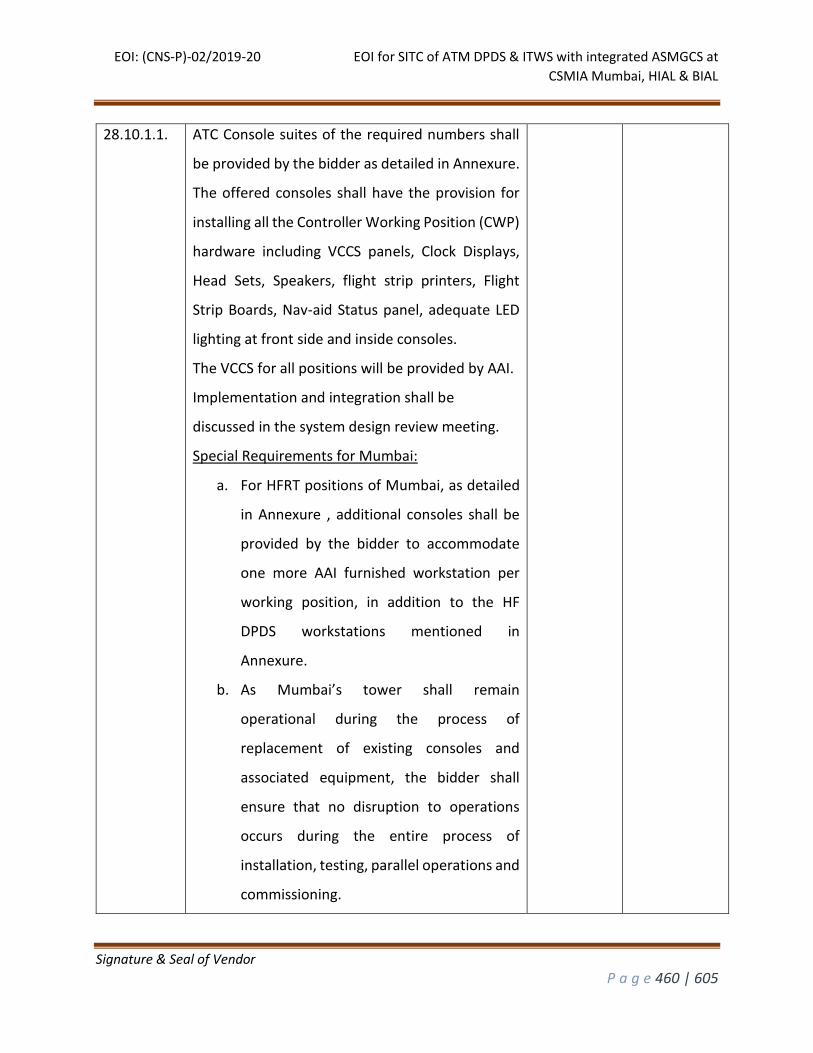
EOI: (CNS-P)-02/2019-20 EOI for SITC of ATM DPDS & ITWS with integrated ASMGCS at
CSMIA Mumbai, HIAL & BIAL
Signature & Seal of Vendor
P a g e 460 | 605
28.10.1.1. ATC Console suites of the required numbers shall
be provided by the bidder as detailed in Annexure.
The offered consoles shall have the provision for
installing all the Controller Working Position (CWP)
hardware including VCCS panels, Clock Displays,
Head Sets, Speakers, flight strip printers, Flight
Strip Boards, Nav-aid Status panel, adequate LED
lighting at front side and inside consoles.
The VCCS for all positions will be provided by AAI.
Implementation and integration shall be
discussed in the system design review meeting.
Special Requirements for Mumbai:
a. For HFRT positions of Mumbai, as detailed
in Annexure , additional consoles shall be
provided by the bidder to accommodate
one more AAI furnished workstation per
working position, in addition to the HF
DPDS workstations mentioned in
Annexure.
b. As Mumbai’s tower shall remain
operational during the process of
replacement of existing consoles and
associated equipment, the bidder shall
ensure that no disruption to operations
occurs during the entire process of
installation, testing, parallel operations and
commissioning.
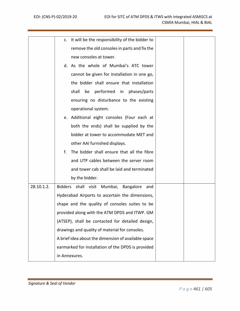
EOI: (CNS-P)-02/2019-20 EOI for SITC of ATM DPDS & ITWS with integrated ASMGCS at
CSMIA Mumbai, HIAL & BIAL
Signature & Seal of Vendor
P a g e 461 | 605
c. It will be the responsibility of the bidder to
remove the old consoles in parts and fix the
new consoles at tower.
d. As the whole of Mumbai’s ATC tower
cannot be given for installation in one go,
the bidder shall ensure that installation
shall be performed in phases/parts
ensuring no disturbance to the existing
operational system.
e. Additional eight consoles (Four each at
both the ends) shall be supplied by the
bidder at tower to accommodate MET and
other AAI furnished displays.
f. The bidder shall ensure that all the fibre
and UTP cables between the server room
and tower cab shall be laid and terminated
by the bidder.
28.10.1.2. Bidders shall visit Mumbai, Bangalore and
Hyderabad Airports to ascertain the dimensions,
shape and the quality of consoles suites to be
provided along with the ATM DPDS and ITWP. GM
(ATSEP), shall be contacted for detailed design,
drawings and quality of material for consoles.
A brief idea about the dimension of available space
earmarked for installation of the DPDS is provided
in Annexures.
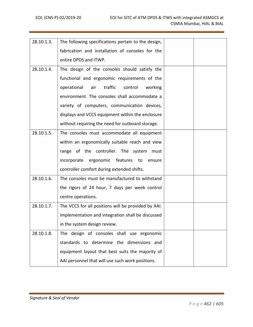
EOI: (CNS-P)-02/2019-20 EOI for SITC of ATM DPDS & ITWS with integrated ASMGCS at
CSMIA Mumbai, HIAL & BIAL
Signature & Seal of Vendor
P a g e 462 | 605
28.10.1.3. The following specifications pertain to the design,
fabrication and installation of consoles for the
entire DPDS and ITWP.
28.10.1.4. The design of the consoles should satisfy the
functional and ergonomic requirements of the
operational air traffic control working
environment. The consoles shall accommodate a
variety of computers, communication devices,
displays and VCCS equipment within the enclosure
without requiring the need for outboard storage.
28.10.1.5. The consoles must accommodate all equipment
within an ergonomically suitable reach and view
range of the controller. The system must
incorporate ergonomic features to ensure
controller comfort during extended shifts.
28.10.1.6. The consoles must be manufactured to withstand
the rigors of 24 hour, 7 days per week control
centre operations.
28.10.1.7. The VCCS for all positions will be provided by AAI.
Implementation and integration shall be discussed
in the system design review.
28.10.1.8. The design of consoles shall use ergonomic
standards to determine the dimensions and
equipment layout that best suits the majority of
AAI personnel that will use such work positions.

EOI: (CNS-P)-02/2019-20 EOI for SITC of ATM DPDS & ITWS with integrated ASMGCS at
CSMIA Mumbai, HIAL & BIAL
Signature & Seal of Vendor
P a g e 463 | 605
28.10.1.9. The machines inside consoles shall be installed on
trays sliding to the rear side of consoles for easier
access during maintenance.
28.10.1.10. Orientation of machines inside consoles shall be
such that the LED indications of the machines are
visible to the maintenance personnel outside
through transparent peep holes either from front
side or back side of console.
28.10.1.11. Console design shall allow proper air flow
management through the consoles so that cool air
goes into the console thereby allowing hot/warm
air to move out.
28.10.1.12. Dust filters shall be provided at the vents to avoid
dust from entering the consoles. There shall be
provision for replacement of these dust filters.
28.10.1.13. For cables entering the console from bottom,
fibre/steel brush shall be used to deter rodent
entry.
28.10.1.14. The bidder shall demonstrate a console prototype
to designated AAI officials for approval before
commencing fabrication of console work.
28.10.1.15. A wide range of colors and materials shall be
available for all exterior panels. Samples shall be
submitted for AAI selection before the start of the
design review meeting and shall be selected at the
sole discretion of AAI. Selected colors and
materials shall be included in the prototype

EOI: (CNS-P)-02/2019-20 EOI for SITC of ATM DPDS & ITWS with integrated ASMGCS at
CSMIA Mumbai, HIAL & BIAL
Signature & Seal of Vendor
P a g e 464 | 605
console. Any initially selected colors and materials
used in the prototype may be changed at the sole
discretion of AAI within one week of the setup of
the prototype at no additional cost.
28.10.1.16. The color of the console shall be such that users
can work for a long duration without eye strain or
other stress.
28.10.1.17. The Console supplier shall Interface with the AAI to
provide design and applications support to:
Confirm the consoles functional design
requirements, compile an equipment-mounting
inventory, requirement analysis and adjacency
study.
Supply detailed drawings of console and
equipment layouts for coordination of site
measurements, architectural, mechanical, and
electrical project elements.
Supply a pre-production review, to include a
drawing submittal and component listing,
complete with samples of selected finish materials.
28.10.1.18. The design and dimension of the consoles shall be
such that the displays and the appropriate
equipment can be enclosed if they require support
and are not “free-standing.”
28.10.1.19. The consoles shall be of modular design, facilitating
future equipment retrofits and full reconfigurations

EOI: (CNS-P)-02/2019-20 EOI for SITC of ATM DPDS & ITWS with integrated ASMGCS at
CSMIA Mumbai, HIAL & BIAL
Signature & Seal of Vendor
P a g e 465 | 605
without major modification to structure or exterior
elements.
28.10.1.20. The consoles shall have rigid independent frames.
28.10.1.21. Mechanical fasteners shall connect adjacent
modules to maintain perfect alignment.
28.10.1.22. The continuity of the structure shall be maintained
through corner module kits, which are inserted to
achieve change in direction as required by the
layout configuration.
28.10.1.23. Depending upon the evolution of needs and
technology, the construction shall provide easy and
fast removal and installation of all equipment
items. Replacement procedure for keyboards,
mice, displays shall be easy thereby taking less
downtime for the workstations.
28.10.1.24. The console frame shall be constructed using a
combination of precision- tooled minimum 14-
gauge sheet metal and formed in such a way as to
provide maximum buckling and torsional
resistance. Extrusions shall be constructed of
thick wall, custom extruded aluminium.
28.10.1.25. The base frame shall be independent of the
console work surface thus allowing for various
work surface options without having the need to
change the base frame structure.
28.10.1.26. The horizontal frame members shall be
constructed with pre-designed ports allowing for

EOI: (CNS-P)-02/2019-20 EOI for SITC of ATM DPDS & ITWS with integrated ASMGCS at
CSMIA Mumbai, HIAL & BIAL
Signature & Seal of Vendor
P a g e 466 | 605
flexible equipment mounting along the length of
each module as well as the addition of accessories
after the installation without having the need to
do additional drilling.
28.10.1.27. The console frame shall have provisions for
leveller legs to be incorporated into the frame.
28.10.1.28. The console frame structure shall have fully
integrated cable management. The base structure
will have a minimum of 3 lateral raceways; the
transition from the base to the work surface will
have a minimum of 2 vertical raceways; and the
work surface will have a lateral raceway location
depending on the size of equipment being
mounted in the console.
28.10.1.29. The cable raceways shall be continuous
throughout the entire console layout thus allowing
uninterrupted cable management.
28.10.1.30. The dimensions of the consoles shall allow
passage through available stairs or lifts at their
respective installation sites.
28.10.1.31. The console design shall be acoustically
acceptable and minimize noise reflection.
28.10.1.32. All major controls associated with displays,
keyboards, VCCS displays, loudspeakers,
information display areas, lighting and other
devices allocated to designated workstations, shall
be appropriately located so that they can be easily

EOI: (CNS-P)-02/2019-20 EOI for SITC of ATM DPDS & ITWS with integrated ASMGCS at
CSMIA Mumbai, HIAL & BIAL
Signature & Seal of Vendor
P a g e 467 | 605
reached without the need for the operator to
move away from the seat.
28.10.1.33. Panels and equipment shall be flush mounted on
the front plate of the control panel. The front
plate will be removable, for replacement in the
event of future equipment changes.
28.10.1.34. Consoles shall be properly finished to prevent
glare and reflection.
28.10.1.35. No sharp edges shall be present that may lead to
injury to the operators.
28.10.1.36. The console finish shall be resistant to rubbing
and liquids, impact-proof and easy to clean.
28.10.1.37. The surface of the work area shall be scratch
resistant and the work surface shall be rigid and
not bendable during any normal operational use.
28.10.1.38. The core of the work surface shall be constructed
using a minimum 1” board with High Pressure
Laminate (HPL) on both topside and under side of
the work surface.
28.10.1.39. The work surface should be smooth and level and
take into consideration all accepted human factor
criteria, including view, reach distances, keyboard
height and knee well space.
28.10.1.40. The console design shall permit left-handed and
right-handed operators to operate with equal
dexterity to the extent possible.
28.10.1.41. The material of the consoles shall be fire resistant.

EOI: (CNS-P)-02/2019-20 EOI for SITC of ATM DPDS & ITWS with integrated ASMGCS at
CSMIA Mumbai, HIAL & BIAL
Signature & Seal of Vendor
P a g e 468 | 605
28.10.1.42. The console lighting shall provide uniform indirect
light.
28.10.1.43. The console lighting shall include a user adjustable
dimmer that controls the intensity of the light
from off to full brightness.
28.10.1.44. Service lights for the console shall be provided
that turn on automatically upon opening of the
access door, and turn off automatically upon
closing of the access door. The illumination of the
service lights inside the consoles shall not
interfere with the vision of the operator sitting in
front of the console.
28.10.2. Console Maintenance
28.10.2.1. Access to the equipment of the CWP for
maintenance actions shall be via the rear of the
console.
28.10.2.2. The workstation hardware to be installed inside
the consoles shall be placed on sliding trays that
could slide outside the console towards rear side
for easy installation and maintenance. These
sliding trays shall be supplied along with the
consoles by the bidder.
28.10.2.3. The Tenderer shall describe how the proposed
consoles system is adaptable, configurable, and
agile so that additional consoles can be added
without any major changes.
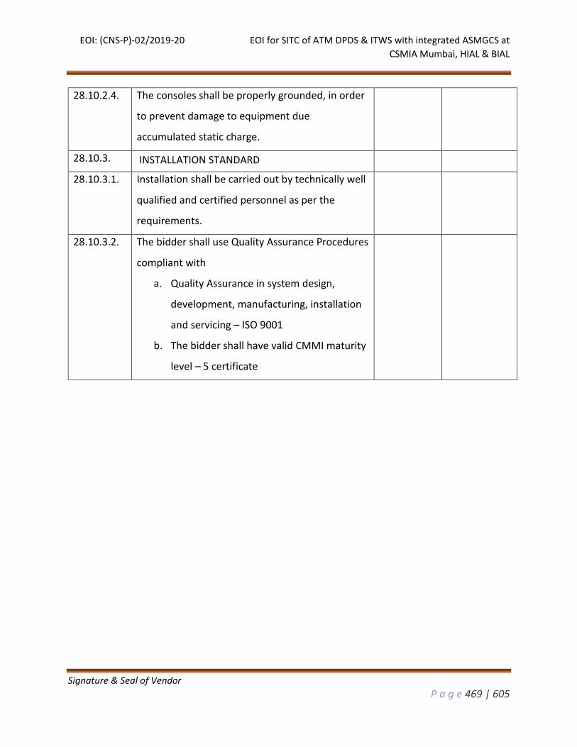
EOI: (CNS-P)-02/2019-20 EOI for SITC of ATM DPDS & ITWS with integrated ASMGCS at
CSMIA Mumbai, HIAL & BIAL
Signature & Seal of Vendor
P a g e 469 | 605
28.10.2.4. The consoles shall be properly grounded, in order
to prevent damage to equipment due
accumulated static charge.
28.10.3. INSTALLATION STANDARD
28.10.3.1. Installation shall be carried out by technically well
qualified and certified personnel as per the
requirements.
28.10.3.2. The bidder shall use Quality Assurance Procedures
compliant with
a. Quality Assurance in system design,
development, manufacturing, installation
and servicing – ISO 9001
b. The bidder shall have valid CMMI maturity
level – 5 certificate
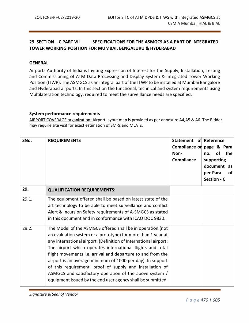
EOI: (CNS-P)-02/2019-20 EOI for SITC of ATM DPDS & ITWS with integrated ASMGCS at
CSMIA Mumbai, HIAL & BIAL
Signature & Seal of Vendor
P a g e 470 | 605
29 SECTION – C PART VII SPECIFICATIONS FOR THE ASMGCS AS A PART OF INTEGRATED
TOWER WORKING POSITION FOR MUMBAI, BENGALURU & HYDERABAD
GENERAL
Airports Authority of India is Inviting Expression of Interest for the Supply, Installation, Testing and Commissioning of ATM Data Processing and Display System & Integrated Tower Working Position (ITWP). The ASMGCS as an integral part of the ITWP to be installed at Mumbai Bangalore and Hyderabad airports. In this section the functional, technical and system requirements using Multilateration technology, required to meet the surveillance needs are specified.
System performance requirements AIRPORT COVERAGE organization: Airport layout map is provided as per annexure A4,A5 & A6. The Bidder may require site visit for exact estimation of SMRs and MLATs.
SNo. REQUIREMENTS
Statement of
Compliance or
Non-
Compliance
Reference
page & Para
no. of the
supporting
document as
per Para --- of
Section - C
29. QUALIFICATION REQUIREMENTS:
29.1. The equipment offered shall be based on latest state of the
art technology to be able to meet surveillance and conflict
Alert & Incursion Safety requirements of A-SMGCS as stated
in this document and in conformance with ICAO DOC 9830.
29.2. The Model of the ASMGCS offered shall be in operation (not
an evaluation system or a prototype) for more than 1 year at
any international airport. (Definition of International airport:
The airport which operates international flights and total
flight movements i.e. arrival and departure to and from the
airport is an average minimum of 1000 per day). In support
of this requirement, proof of supply and installation of
ASMGCS and satisfactory operation of the above system /
equipment issued by the end user agency shall be submitted.
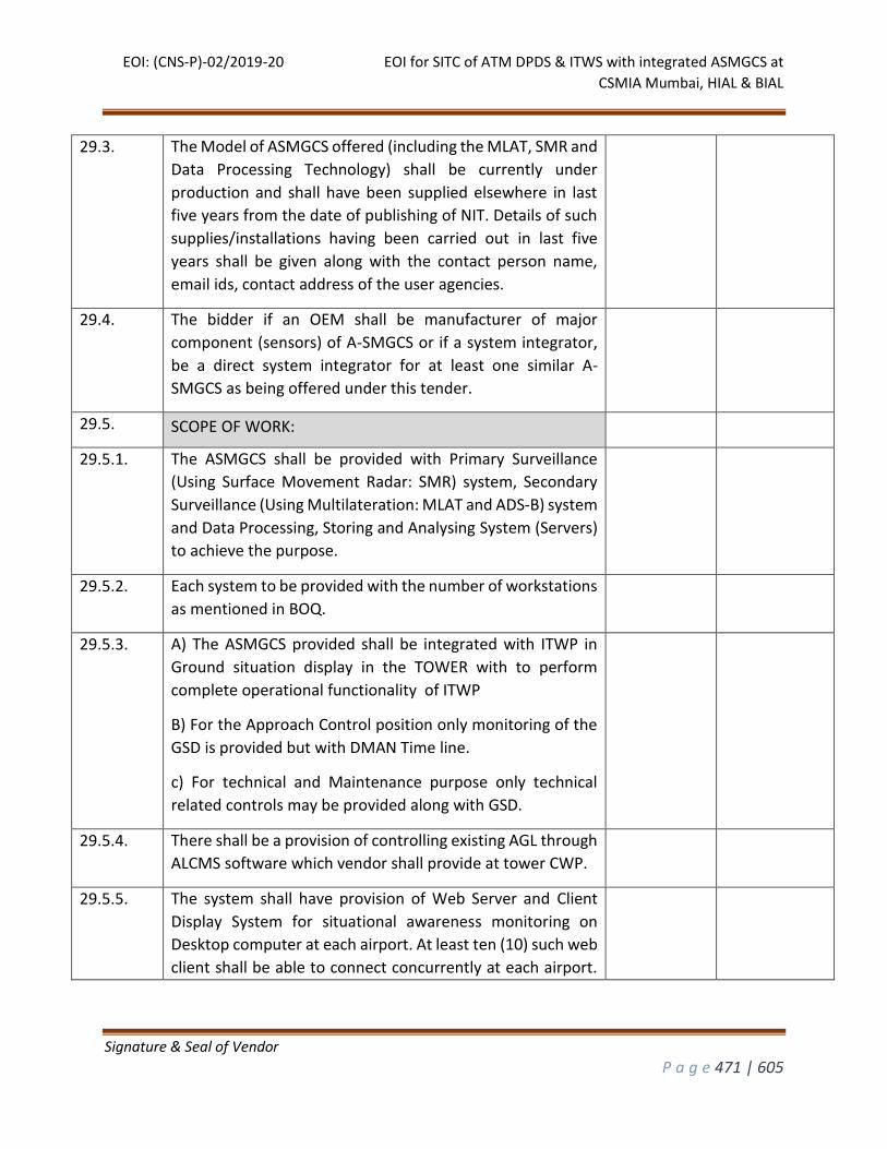
EOI: (CNS-P)-02/2019-20 EOI for SITC of ATM DPDS & ITWS with integrated ASMGCS at
CSMIA Mumbai, HIAL & BIAL
Signature & Seal of Vendor
P a g e 471 | 605
29.3. The Model of ASMGCS offered (including the MLAT, SMR and
Data Processing Technology) shall be currently under
production and shall have been supplied elsewhere in last
five years from the date of publishing of NIT. Details of such
supplies/installations having been carried out in last five
years shall be given along with the contact person name,
email ids, contact address of the user agencies.
29.4. The bidder if an OEM shall be manufacturer of major
component (sensors) of A-SMGCS or if a system integrator,
be a direct system integrator for at least one similar A-
SMGCS as being offered under this tender.
29.5. SCOPE OF WORK:
29.5.1. The ASMGCS shall be provided with Primary Surveillance
(Using Surface Movement Radar: SMR) system, Secondary
Surveillance (Using Multilateration: MLAT and ADS-B) system
and Data Processing, Storing and Analysing System (Servers)
to achieve the purpose.
29.5.2. Each system to be provided with the number of workstations
as mentioned in BOQ.
29.5.3. A) The ASMGCS provided shall be integrated with ITWP in
Ground situation display in the TOWER with to perform
complete operational functionality of ITWP
B) For the Approach Control position only monitoring of the
GSD is provided but with DMAN Time line.
c) For technical and Maintenance purpose only technical
related controls may be provided along with GSD.
29.5.4. There shall be a provision of controlling existing AGL through
ALCMS software which vendor shall provide at tower CWP.
29.5.5. The system shall have provision of Web Server and Client
Display System for situational awareness monitoring on
Desktop computer at each airport. At least ten (10) such web
client shall be able to connect concurrently at each airport.
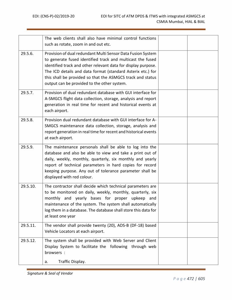
EOI: (CNS-P)-02/2019-20 EOI for SITC of ATM DPDS & ITWS with integrated ASMGCS at
CSMIA Mumbai, HIAL & BIAL
Signature & Seal of Vendor
P a g e 472 | 605
The web clients shall also have minimal control functions
such as rotate, zoom in and out etc.
29.5.6. Provision of dual redundant Multi Sensor Data Fusion System
to generate fused identified track and multicast the fused
identified track and other relevant data for display purpose.
The ICD details and data format (standard Asterix etc.) for
this shall be provided so that the ASMGCS track and status
output can be provided to the other system.
29.5.7. Provision of dual redundant database with GUI interface for
A-SMGCS flight data collection, storage, analysis and report
generation in real time for recent and historical events at
each airport.
29.5.8. Provision dual redundant database with GUI interface for A-
SMGCS maintenance data collection, storage, analysis and
report generation in real time for recent and historical events
at each airport.
29.5.9. The maintenance personals shall be able to log into the
database and also be able to view and take a print out of
daily, weekly, monthly, quarterly, six monthly and yearly
report of technical parameters in hard copies for record
keeping purpose. Any out of tolerance parameter shall be
displayed with red colour.
29.5.10. The contractor shall decide which technical parameters are
to be monitored on daily, weekly, monthly, quarterly, six
monthly and yearly bases for proper upkeep and
maintenance of the system. The system shall automatically
log them in a database. The database shall store this data for
at least one year
29.5.11. The vendor shall provide twenty (20), ADS-B (DF-18) based
Vehicle Locators at each airport.
29.5.12. The system shall be provided with Web Server and Client
Display System to facilitate the following through web
browsers :
a. Traffic Display.
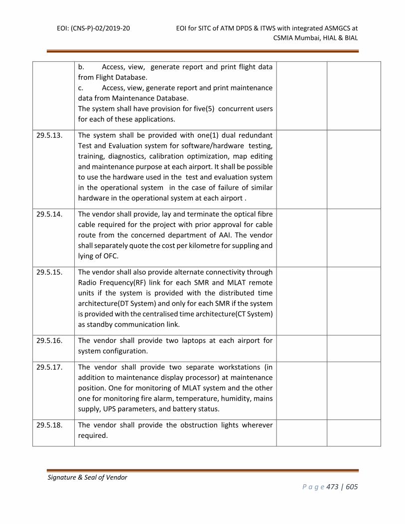
EOI: (CNS-P)-02/2019-20 EOI for SITC of ATM DPDS & ITWS with integrated ASMGCS at
CSMIA Mumbai, HIAL & BIAL
Signature & Seal of Vendor
P a g e 473 | 605
b. Access, view, generate report and print flight data
from Flight Database.
c. Access, view, generate report and print maintenance
data from Maintenance Database.
The system shall have provision for five(5) concurrent users
for each of these applications.
29.5.13. The system shall be provided with one(1) dual redundant
Test and Evaluation system for software/hardware testing,
training, diagnostics, calibration optimization, map editing
and maintenance purpose at each airport. It shall be possible
to use the hardware used in the test and evaluation system
in the operational system in the case of failure of similar
hardware in the operational system at each airport .
29.5.14. The vendor shall provide, lay and terminate the optical fibre
cable required for the project with prior approval for cable
route from the concerned department of AAI. The vendor
shall separately quote the cost per kilometre for suppling and
lying of OFC.
29.5.15. The vendor shall also provide alternate connectivity through
Radio Frequency(RF) link for each SMR and MLAT remote
units if the system is provided with the distributed time
architecture(DT System) and only for each SMR if the system
is provided with the centralised time architecture(CT System)
as standby communication link.
29.5.16. The vendor shall provide two laptops at each airport for
system configuration.
29.5.17. The vendor shall provide two separate workstations (in
addition to maintenance display processor) at maintenance
position. One for monitoring of MLAT system and the other
one for monitoring fire alarm, temperature, humidity, mains
supply, UPS parameters, and battery status.
29.5.18. The vendor shall provide the obstruction lights wherever
required.
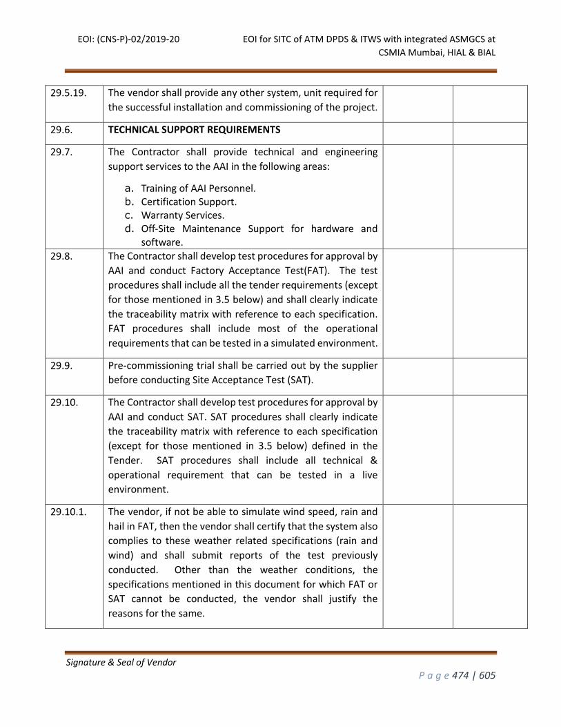
EOI: (CNS-P)-02/2019-20 EOI for SITC of ATM DPDS & ITWS with integrated ASMGCS at
CSMIA Mumbai, HIAL & BIAL
Signature & Seal of Vendor
P a g e 474 | 605
29.5.19. The vendor shall provide any other system, unit required for
the successful installation and commissioning of the project.
29.6. TECHNICAL SUPPORT REQUIREMENTS
29.7. The Contractor shall provide technical and engineering
support services to the AAI in the following areas:
a. Training of AAI Personnel. b. Certification Support. c. Warranty Services. d. Off-Site Maintenance Support for hardware and
software.
29.8. The Contractor shall develop test procedures for approval by
AAI and conduct Factory Acceptance Test(FAT). The test
procedures shall include all the tender requirements (except
for those mentioned in 3.5 below) and shall clearly indicate
the traceability matrix with reference to each specification.
FAT procedures shall include most of the operational
requirements that can be tested in a simulated environment.
29.9. Pre-commissioning trial shall be carried out by the supplier
before conducting Site Acceptance Test (SAT).
29.10. The Contractor shall develop test procedures for approval by
AAI and conduct SAT. SAT procedures shall clearly indicate
the traceability matrix with reference to each specification
(except for those mentioned in 3.5 below) defined in the
Tender. SAT procedures shall include all technical &
operational requirement that can be tested in a live
environment.
29.10.1. The vendor, if not be able to simulate wind speed, rain and
hail in FAT, then the vendor shall certify that the system also
complies to these weather related specifications (rain and
wind) and shall submit reports of the test previously
conducted. Other than the weather conditions, the
specifications mentioned in this document for which FAT or
SAT cannot be conducted, the vendor shall justify the
reasons for the same.
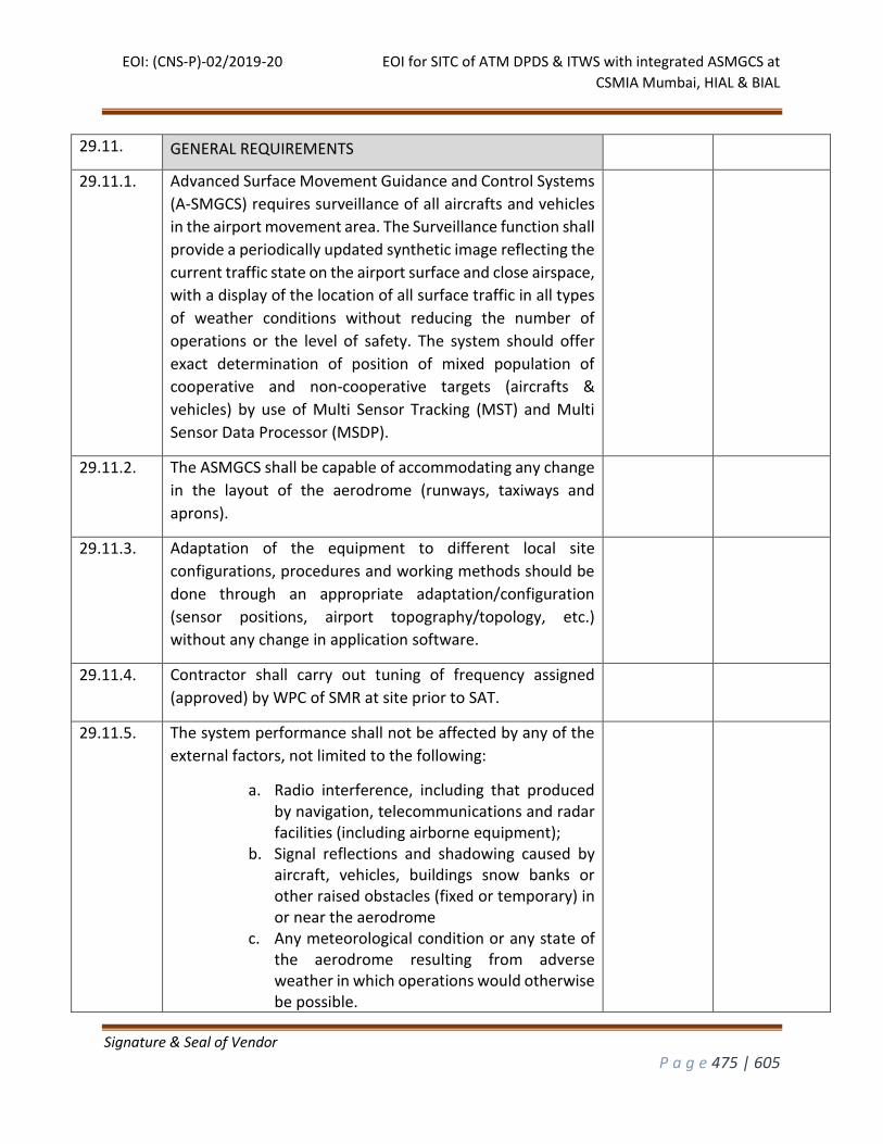
EOI: (CNS-P)-02/2019-20 EOI for SITC of ATM DPDS & ITWS with integrated ASMGCS at
CSMIA Mumbai, HIAL & BIAL
Signature & Seal of Vendor
P a g e 475 | 605
29.11. GENERAL REQUIREMENTS
29.11.1. Advanced Surface Movement Guidance and Control Systems
(A-SMGCS) requires surveillance of all aircrafts and vehicles
in the airport movement area. The Surveillance function shall
provide a periodically updated synthetic image reflecting the
current traffic state on the airport surface and close airspace,
with a display of the location of all surface traffic in all types
of weather conditions without reducing the number of
operations or the level of safety. The system should offer
exact determination of position of mixed population of
cooperative and non-cooperative targets (aircrafts &
vehicles) by use of Multi Sensor Tracking (MST) and Multi
Sensor Data Processor (MSDP).
29.11.2. The ASMGCS shall be capable of accommodating any change
in the layout of the aerodrome (runways, taxiways and
aprons).
29.11.3. Adaptation of the equipment to different local site
configurations, procedures and working methods should be
done through an appropriate adaptation/configuration
(sensor positions, airport topography/topology, etc.)
without any change in application software.
29.11.4. Contractor shall carry out tuning of frequency assigned
(approved) by WPC of SMR at site prior to SAT.
29.11.5. The system performance shall not be affected by any of the
external factors, not limited to the following:
a. Radio interference, including that produced by navigation, telecommunications and radar facilities (including airborne equipment);
b. Signal reflections and shadowing caused by aircraft, vehicles, buildings snow banks or other raised obstacles (fixed or temporary) in or near the aerodrome
c. Any meteorological condition or any state of the aerodrome resulting from adverse weather in which operations would otherwise be possible.
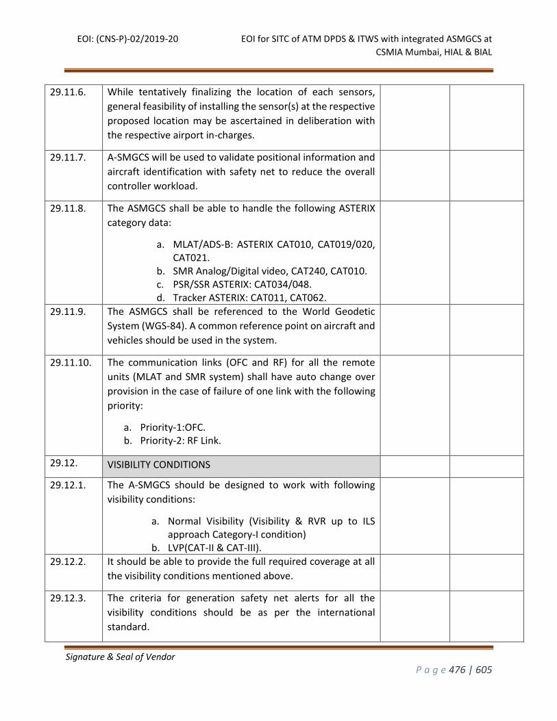
EOI: (CNS-P)-02/2019-20 EOI for SITC of ATM DPDS & ITWS with integrated ASMGCS at
CSMIA Mumbai, HIAL & BIAL
Signature & Seal of Vendor
P a g e 476 | 605
29.11.6. While tentatively finalizing the location of each sensors,
general feasibility of installing the sensor(s) at the respective
proposed location may be ascertained in deliberation with
the respective airport in-charges.
29.11.7. A-SMGCS will be used to validate positional information and
aircraft identification with safety net to reduce the overall
controller workload.
29.11.8. The ASMGCS shall be able to handle the following ASTERIX
category data:
a. MLAT/ADS-B: ASTERIX CAT010, CAT019/020, CAT021.
b. SMR Analog/Digital video, CAT240, CAT010. c. PSR/SSR ASTERIX: CAT034/048. d. Tracker ASTERIX: CAT011, CAT062.
29.11.9. The ASMGCS shall be referenced to the World Geodetic
System (WGS-84). A common reference point on aircraft and
vehicles should be used in the system.
29.11.10. The communication links (OFC and RF) for all the remote
units (MLAT and SMR system) shall have auto change over
provision in the case of failure of one link with the following
priority:
a. Priority-1:OFC. b. Priority-2: RF Link.
29.12. VISIBILITY CONDITIONS
29.12.1. The A-SMGCS should be designed to work with following
visibility conditions:
a. Normal Visibility (Visibility & RVR up to ILS approach Category-I condition)
b. LVP(CAT-II & CAT-III).
29.12.2. It should be able to provide the full required coverage at all
the visibility conditions mentioned above.
29.12.3. The criteria for generation safety net alerts for all the
visibility conditions should be as per the international
standard.
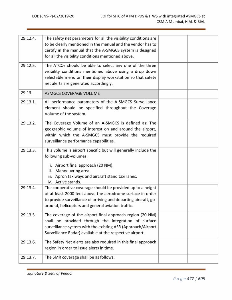
EOI: (CNS-P)-02/2019-20 EOI for SITC of ATM DPDS & ITWS with integrated ASMGCS at
CSMIA Mumbai, HIAL & BIAL
Signature & Seal of Vendor
P a g e 477 | 605
29.12.4. The safety net parameters for all the visibility conditions are
to be clearly mentioned in the manual and the vendor has to
certify in the manual that the A-SMGCS system is designed
for all the visibility conditions mentioned above.
29.12.5. The ATCOs should be able to select any one of the three
visibility conditions mentioned above using a drop down
selectable menu on their display workstation so that safety
net alerts are generated accordingly.
29.13. ASMGCS COVERAGE VOLUME
29.13.1. All performance parameters of the A-SMGCS Surveillance
element should be specified throughout the Coverage
Volume of the system.
29.13.2. The Coverage Volume of an A-SMGCS is defined as: The
geographic volume of interest on and around the airport,
within which the A-SMGCS must provide the required
surveillance performance capabilities.
29.13.3. This volume is airport specific but will generally include the
following sub-volumes:
i. Airport final approach (20 NM). ii. Manoeuvring area.
iii. Apron taxiways and aircraft stand taxi lanes. iv. Active stands.
29.13.4. The cooperative coverage should be provided up to a height
of at least 2000 feet above the aerodrome surface in order
to provide surveillance of arriving and departing aircraft, go-
around, helicopters and general aviation traffic.
29.13.5. The coverage of the airport final approach region (20 NM)
shall be provided through the integration of surface
surveillance system with the existing ASR (Approach/Airport
Surveillance Radar) available at the respective airport.
29.13.6. The Safety Net alerts are also required in this final approach
region in order to issue alerts in time.
29.13.7. The SMR coverage shall be as follows:
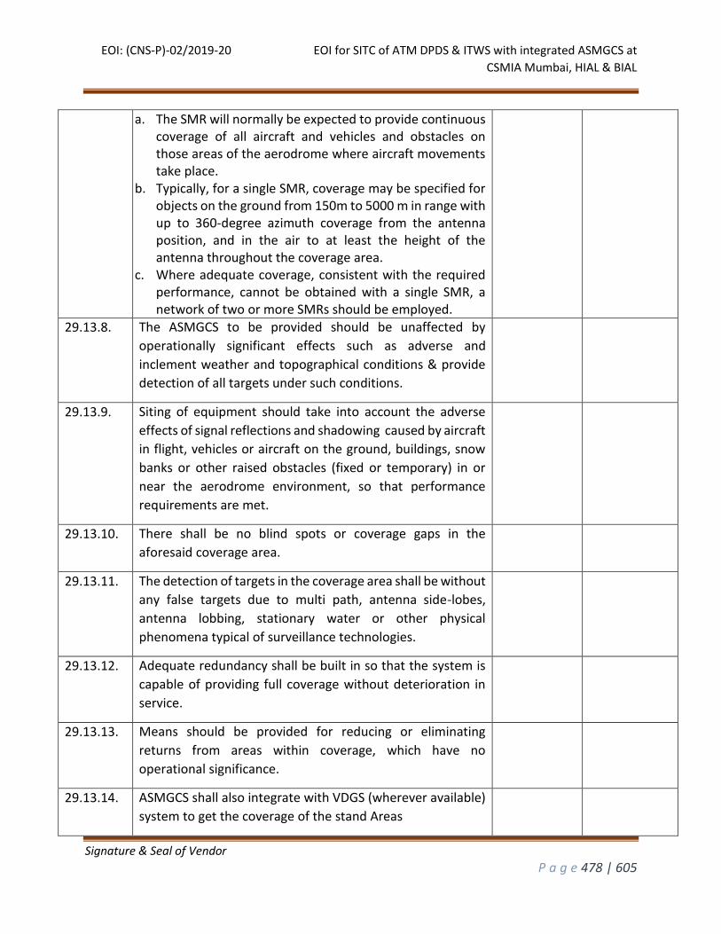
EOI: (CNS-P)-02/2019-20 EOI for SITC of ATM DPDS & ITWS with integrated ASMGCS at
CSMIA Mumbai, HIAL & BIAL
Signature & Seal of Vendor
P a g e 478 | 605
a. The SMR will normally be expected to provide continuous coverage of all aircraft and vehicles and obstacles on those areas of the aerodrome where aircraft movements take place.
b. Typically, for a single SMR, coverage may be specified for objects on the ground from 150m to 5000 m in range with up to 360-degree azimuth coverage from the antenna position, and in the air to at least the height of the antenna throughout the coverage area.
c. Where adequate coverage, consistent with the required performance, cannot be obtained with a single SMR, a network of two or more SMRs should be employed.
29.13.8. The ASMGCS to be provided should be unaffected by
operationally significant effects such as adverse and
inclement weather and topographical conditions & provide
detection of all targets under such conditions.
29.13.9. Siting of equipment should take into account the adverse
effects of signal reflections and shadowing caused by aircraft
in flight, vehicles or aircraft on the ground, buildings, snow
banks or other raised obstacles (fixed or temporary) in or
near the aerodrome environment, so that performance
requirements are met.
29.13.10. There shall be no blind spots or coverage gaps in the
aforesaid coverage area.
29.13.11. The detection of targets in the coverage area shall be without
any false targets due to multi path, antenna side-lobes,
antenna lobbing, stationary water or other physical
phenomena typical of surveillance technologies.
29.13.12. Adequate redundancy shall be built in so that the system is
capable of providing full coverage without deterioration in
service.
29.13.13. Means should be provided for reducing or eliminating
returns from areas within coverage, which have no
operational significance.
29.13.14. ASMGCS shall also integrate with VDGS (wherever available)
system to get the coverage of the stand Areas
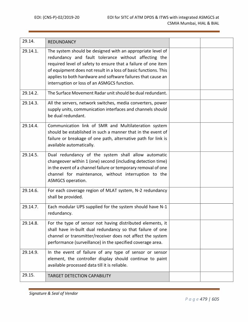
EOI: (CNS-P)-02/2019-20 EOI for SITC of ATM DPDS & ITWS with integrated ASMGCS at
CSMIA Mumbai, HIAL & BIAL
Signature & Seal of Vendor
P a g e 479 | 605
29.14. REDUNDANCY
29.14.1. The system should be designed with an appropriate level of
redundancy and fault tolerance without affecting the
required level of safety to ensure that a failure of one item
of equipment does not result in a loss of basic functions. This
applies to both hardware and software failures that cause an
interruption or loss of an ASMGCS function.
29.14.2. The Surface Movement Radar unit should be dual redundant.
29.14.3. All the servers, network switches, media converters, power
supply units, communication interfaces and channels should
be dual redundant.
29.14.4. Communication link of SMR and Multilateration system
should be established in such a manner that in the event of
failure or breakage of one path, alternative path for link is
available automatically.
29.14.5. Dual redundancy of the system shall allow automatic
changeover within 1 (one) second (including detection time)
in the event of a channel failure or temporary removal of one
channel for maintenance, without interruption to the
ASMGCS operation.
29.14.6. For each coverage region of MLAT system, N-2 redundancy
shall be provided.
29.14.7. Each modular UPS supplied for the system should have N-1
redundancy.
29.14.8. For the type of sensor not having distributed elements, it
shall have in-built dual redundancy so that failure of one
channel or transmitter/receiver does not affect the system
performance (surveillance) in the specified coverage area.
29.14.9. In the event of failure of any type of sensor or sensor
element, the controller display should continue to paint
available processed data till it is reliable.
29.15. TARGET DETECTION CAPABILITY
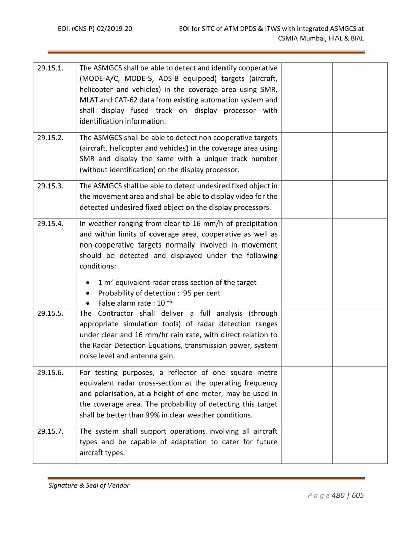
EOI: (CNS-P)-02/2019-20 EOI for SITC of ATM DPDS & ITWS with integrated ASMGCS at
CSMIA Mumbai, HIAL & BIAL
Signature & Seal of Vendor
P a g e 480 | 605
29.15.1. The ASMGCS shall be able to detect and identify cooperative
(MODE-A/C, MODE-S, ADS-B equipped) targets (aircraft,
helicopter and vehicles) in the coverage area using SMR,
MLAT and CAT-62 data from existing automation system and
shall display fused track on display processor with
identification information.
29.15.2. The ASMGCS shall be able to detect non cooperative targets
(aircraft, helicopter and vehicles) in the coverage area using
SMR and display the same with a unique track number
(without identification) on the display processor.
29.15.3. The ASMGCS shall be able to detect undesired fixed object in
the movement area and shall be able to display video for the
detected undesired fixed object on the display processors.
29.15.4. In weather ranging from clear to 16 mm/h of precipitation
and within limits of coverage area, cooperative as well as
non-cooperative targets normally involved in movement
should be detected and displayed under the following
conditions:
1 m2 equivalent radar cross section of the target
Probability of detection : 95 per cent
False alarm rate : 10 –6
29.15.5. The Contractor shall deliver a full analysis (through
appropriate simulation tools) of radar detection ranges
under clear and 16 mm/hr rain rate, with direct relation to
the Radar Detection Equations, transmission power, system
noise level and antenna gain.
29.15.6. For testing purposes, a reflector of one square metre
equivalent radar cross-section at the operating frequency
and polarisation, at a height of one meter, may be used in
the coverage area. The probability of detecting this target
shall be better than 99% in clear weather conditions.
29.15.7. The system shall support operations involving all aircraft
types and be capable of adaptation to cater for future
aircraft types.
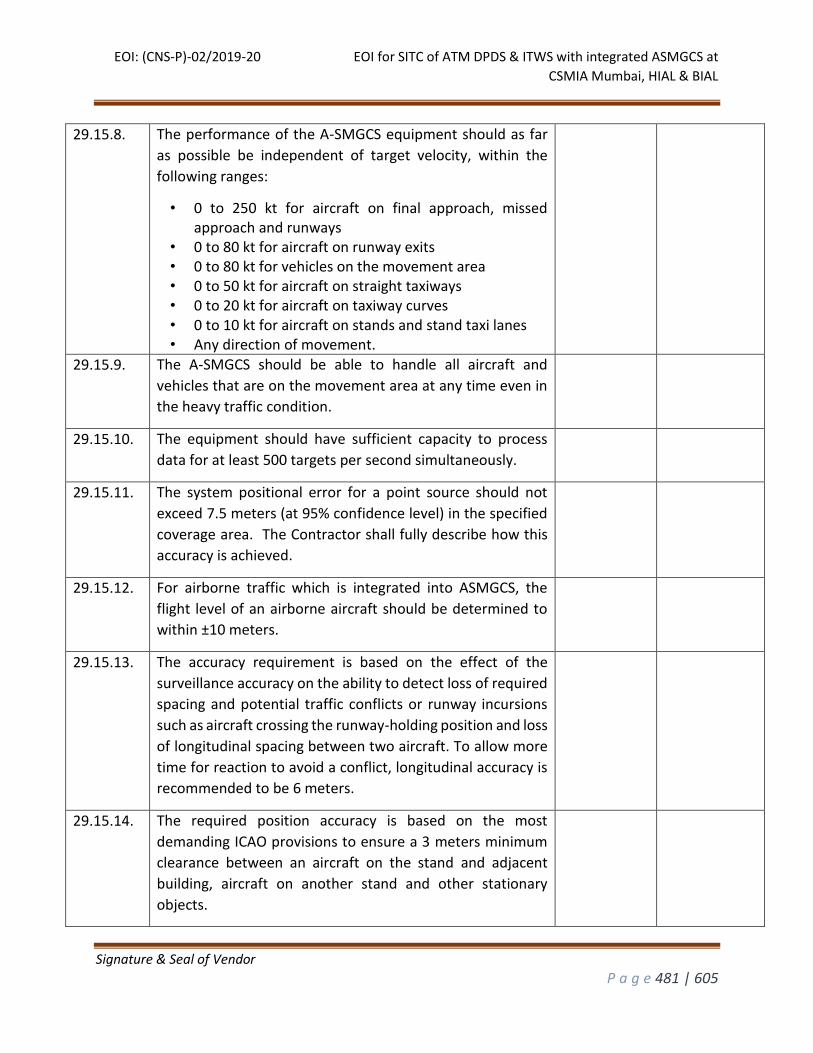
EOI: (CNS-P)-02/2019-20 EOI for SITC of ATM DPDS & ITWS with integrated ASMGCS at
CSMIA Mumbai, HIAL & BIAL
Signature & Seal of Vendor
P a g e 481 | 605
29.15.8. The performance of the A-SMGCS equipment should as far
as possible be independent of target velocity, within the
following ranges:
• 0 to 250 kt for aircraft on final approach, missed approach and runways
• 0 to 80 kt for aircraft on runway exits • 0 to 80 kt for vehicles on the movement area • 0 to 50 kt for aircraft on straight taxiways • 0 to 20 kt for aircraft on taxiway curves • 0 to 10 kt for aircraft on stands and stand taxi lanes • Any direction of movement.
29.15.9. The A-SMGCS should be able to handle all aircraft and
vehicles that are on the movement area at any time even in
the heavy traffic condition.
29.15.10. The equipment should have sufficient capacity to process
data for at least 500 targets per second simultaneously.
29.15.11. The system positional error for a point source should not
exceed 7.5 meters (at 95% confidence level) in the specified
coverage area. The Contractor shall fully describe how this
accuracy is achieved.
29.15.12. For airborne traffic which is integrated into ASMGCS, the
flight level of an airborne aircraft should be determined to
within ±10 meters.
29.15.13. The accuracy requirement is based on the effect of the
surveillance accuracy on the ability to detect loss of required
spacing and potential traffic conflicts or runway incursions
such as aircraft crossing the runway-holding position and loss
of longitudinal spacing between two aircraft. To allow more
time for reaction to avoid a conflict, longitudinal accuracy is
recommended to be 6 meters.
29.15.14. The required position accuracy is based on the most
demanding ICAO provisions to ensure a 3 meters minimum
clearance between an aircraft on the stand and adjacent
building, aircraft on another stand and other stationary
objects.
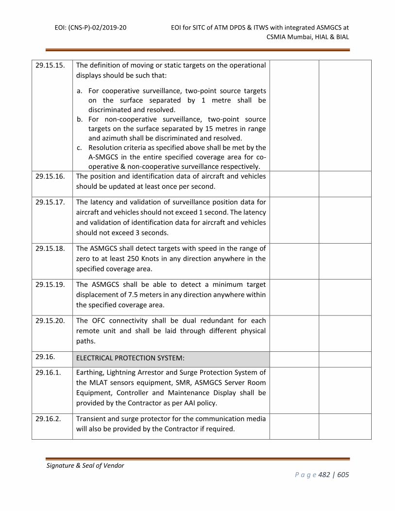
EOI: (CNS-P)-02/2019-20 EOI for SITC of ATM DPDS & ITWS with integrated ASMGCS at
CSMIA Mumbai, HIAL & BIAL
Signature & Seal of Vendor
P a g e 482 | 605
29.15.15. The definition of moving or static targets on the operational
displays should be such that:
a. For cooperative surveillance, two-point source targets on the surface separated by 1 metre shall be discriminated and resolved.
b. For non-cooperative surveillance, two-point source targets on the surface separated by 15 metres in range and azimuth shall be discriminated and resolved.
c. Resolution criteria as specified above shall be met by the A-SMGCS in the entire specified coverage area for co-operative & non-cooperative surveillance respectively.
29.15.16. The position and identification data of aircraft and vehicles
should be updated at least once per second.
29.15.17. The latency and validation of surveillance position data for
aircraft and vehicles should not exceed 1 second. The latency
and validation of identification data for aircraft and vehicles
should not exceed 3 seconds.
29.15.18. The ASMGCS shall detect targets with speed in the range of
zero to at least 250 Knots in any direction anywhere in the
specified coverage area.
29.15.19. The ASMGCS shall be able to detect a minimum target
displacement of 7.5 meters in any direction anywhere within
the specified coverage area.
29.15.20. The OFC connectivity shall be dual redundant for each
remote unit and shall be laid through different physical
paths.
29.16. ELECTRICAL PROTECTION SYSTEM:
29.16.1. Earthing, Lightning Arrestor and Surge Protection System of
the MLAT sensors equipment, SMR, ASMGCS Server Room
Equipment, Controller and Maintenance Display shall be
provided by the Contractor as per AAI policy.
29.16.2. Transient and surge protector for the communication media
will also be provided by the Contractor if required.
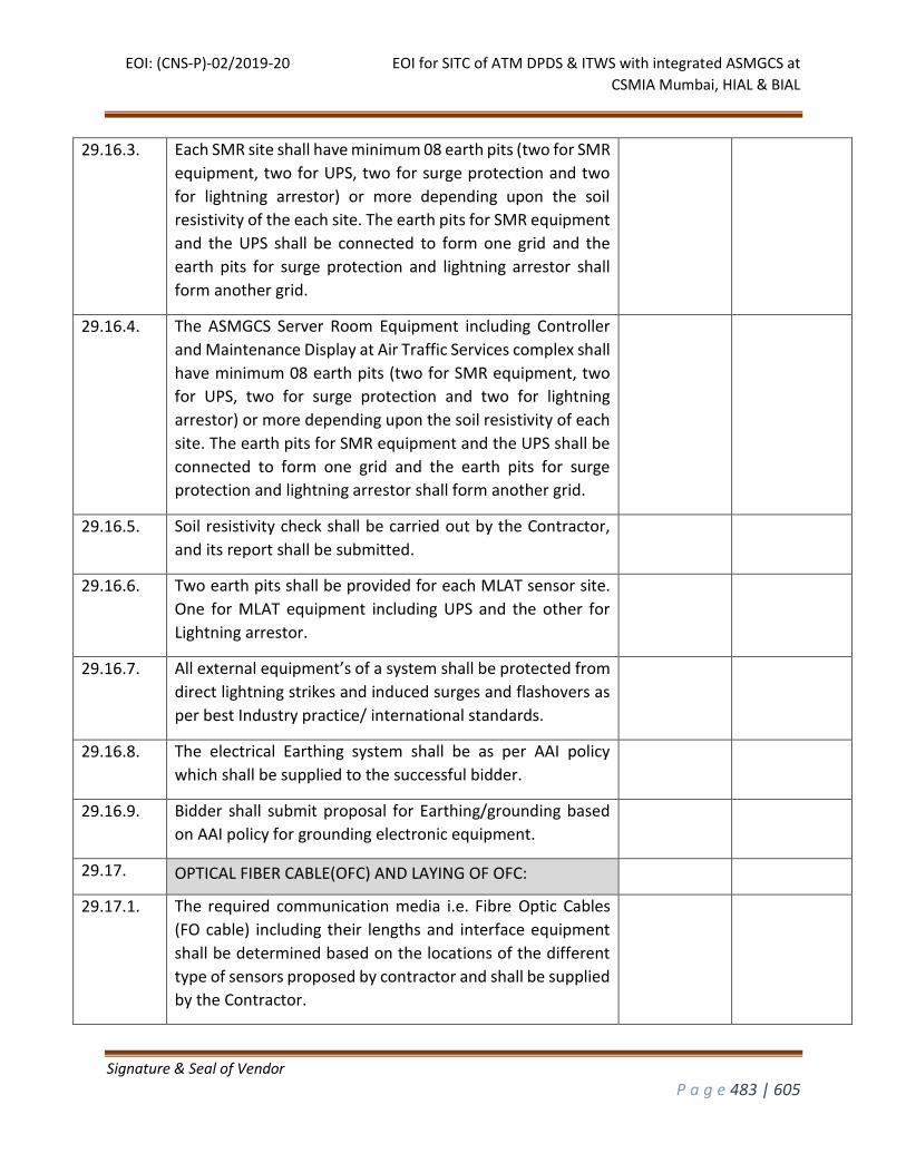
EOI: (CNS-P)-02/2019-20 EOI for SITC of ATM DPDS & ITWS with integrated ASMGCS at
CSMIA Mumbai, HIAL & BIAL
Signature & Seal of Vendor
P a g e 483 | 605
29.16.3. Each SMR site shall have minimum 08 earth pits (two for SMR
equipment, two for UPS, two for surge protection and two
for lightning arrestor) or more depending upon the soil
resistivity of the each site. The earth pits for SMR equipment
and the UPS shall be connected to form one grid and the
earth pits for surge protection and lightning arrestor shall
form another grid.
29.16.4. The ASMGCS Server Room Equipment including Controller
and Maintenance Display at Air Traffic Services complex shall
have minimum 08 earth pits (two for SMR equipment, two
for UPS, two for surge protection and two for lightning
arrestor) or more depending upon the soil resistivity of each
site. The earth pits for SMR equipment and the UPS shall be
connected to form one grid and the earth pits for surge
protection and lightning arrestor shall form another grid.
29.16.5. Soil resistivity check shall be carried out by the Contractor,
and its report shall be submitted.
29.16.6. Two earth pits shall be provided for each MLAT sensor site.
One for MLAT equipment including UPS and the other for
Lightning arrestor.
29.16.7. All external equipment’s of a system shall be protected from
direct lightning strikes and induced surges and flashovers as
per best Industry practice/ international standards.
29.16.8. The electrical Earthing system shall be as per AAI policy
which shall be supplied to the successful bidder.
29.16.9. Bidder shall submit proposal for Earthing/grounding based
on AAI policy for grounding electronic equipment.
29.17. OPTICAL FIBER CABLE(OFC) AND LAYING OF OFC:
29.17.1. The required communication media i.e. Fibre Optic Cables
(FO cable) including their lengths and interface equipment
shall be determined based on the locations of the different
type of sensors proposed by contractor and shall be supplied
by the Contractor.
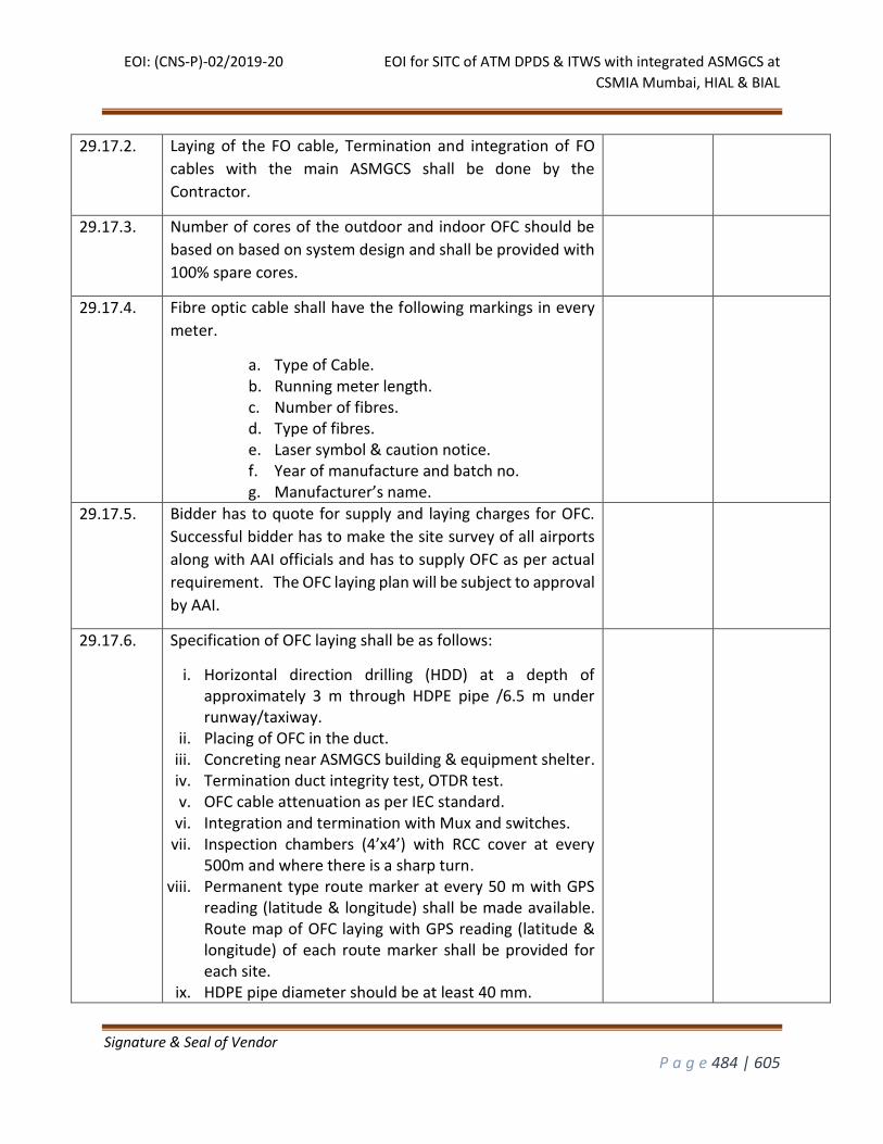
EOI: (CNS-P)-02/2019-20 EOI for SITC of ATM DPDS & ITWS with integrated ASMGCS at
CSMIA Mumbai, HIAL & BIAL
Signature & Seal of Vendor
P a g e 484 | 605
29.17.2. Laying of the FO cable, Termination and integration of FO
cables with the main ASMGCS shall be done by the
Contractor.
29.17.3. Number of cores of the outdoor and indoor OFC should be
based on based on system design and shall be provided with
100% spare cores.
29.17.4. Fibre optic cable shall have the following markings in every
meter.
a. Type of Cable. b. Running meter length. c. Number of fibres. d. Type of fibres. e. Laser symbol & caution notice. f. Year of manufacture and batch no. g. Manufacturer’s name.
29.17.5. Bidder has to quote for supply and laying charges for OFC.
Successful bidder has to make the site survey of all airports
along with AAI officials and has to supply OFC as per actual
requirement. The OFC laying plan will be subject to approval
by AAI.
29.17.6. Specification of OFC laying shall be as follows:
i. Horizontal direction drilling (HDD) at a depth of approximately 3 m through HDPE pipe /6.5 m under runway/taxiway.
ii. Placing of OFC in the duct. iii. Concreting near ASMGCS building & equipment shelter. iv. Termination duct integrity test, OTDR test. v. OFC cable attenuation as per IEC standard.
vi. Integration and termination with Mux and switches. vii. Inspection chambers (4’x4’) with RCC cover at every
500m and where there is a sharp turn. viii. Permanent type route marker at every 50 m with GPS
reading (latitude & longitude) shall be made available. Route map of OFC laying with GPS reading (latitude & longitude) of each route marker shall be provided for each site.
ix. HDPE pipe diameter should be at least 40 mm.
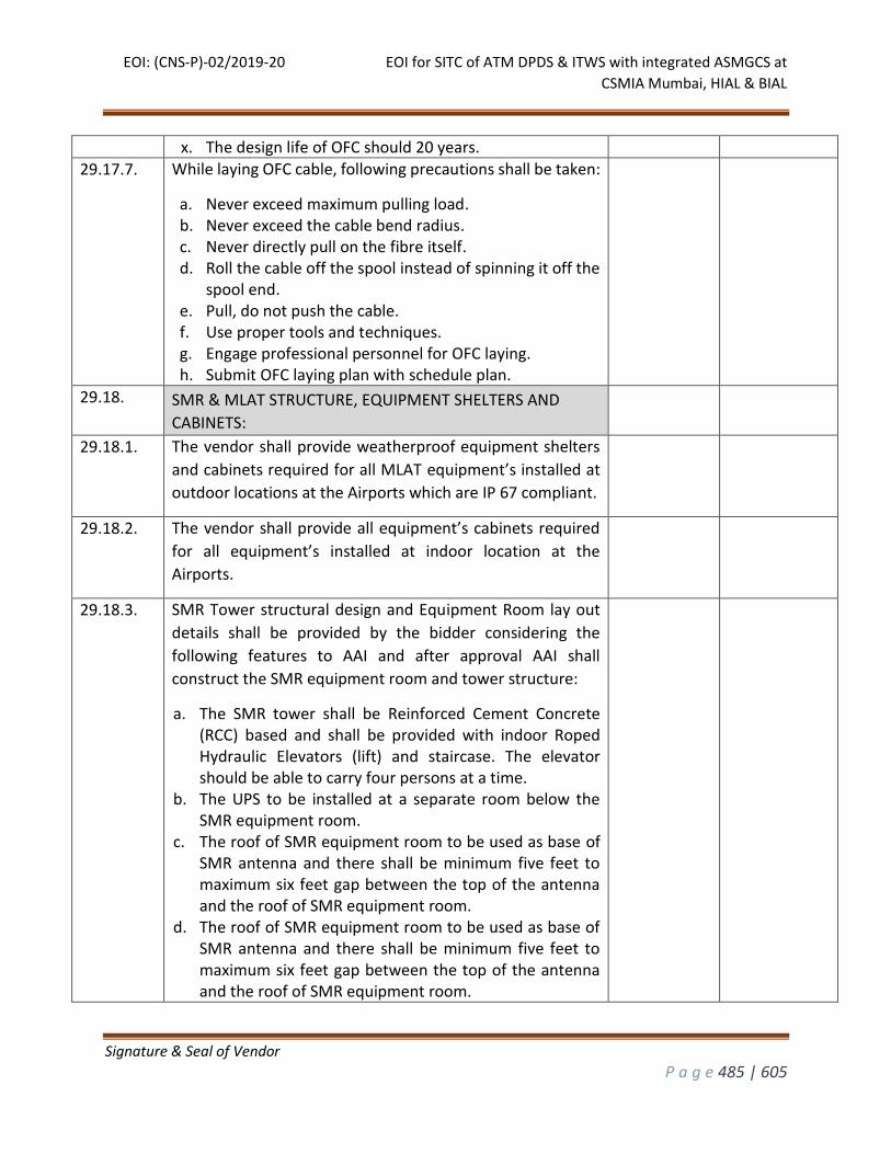
EOI: (CNS-P)-02/2019-20 EOI for SITC of ATM DPDS & ITWS with integrated ASMGCS at
CSMIA Mumbai, HIAL & BIAL
Signature & Seal of Vendor
P a g e 485 | 605
x. The design life of OFC should 20 years.
29.17.7. While laying OFC cable, following precautions shall be taken:
a. Never exceed maximum pulling load. b. Never exceed the cable bend radius. c. Never directly pull on the fibre itself. d. Roll the cable off the spool instead of spinning it off the
spool end. e. Pull, do not push the cable. f. Use proper tools and techniques. g. Engage professional personnel for OFC laying. h. Submit OFC laying plan with schedule plan.
29.18. SMR & MLAT STRUCTURE, EQUIPMENT SHELTERS AND
CABINETS:
29.18.1. The vendor shall provide weatherproof equipment shelters
and cabinets required for all MLAT equipment’s installed at
outdoor locations at the Airports which are IP 67 compliant.
29.18.2. The vendor shall provide all equipment’s cabinets required
for all equipment’s installed at indoor location at the
Airports.
29.18.3. SMR Tower structural design and Equipment Room lay out
details shall be provided by the bidder considering the
following features to AAI and after approval AAI shall
construct the SMR equipment room and tower structure:
a. The SMR tower shall be Reinforced Cement Concrete (RCC) based and shall be provided with indoor Roped Hydraulic Elevators (lift) and staircase. The elevator should be able to carry four persons at a time.
b. The UPS to be installed at a separate room below the SMR equipment room.
c. The roof of SMR equipment room to be used as base of SMR antenna and there shall be minimum five feet to maximum six feet gap between the top of the antenna and the roof of SMR equipment room.
d. The roof of SMR equipment room to be used as base of SMR antenna and there shall be minimum five feet to maximum six feet gap between the top of the antenna and the roof of SMR equipment room.
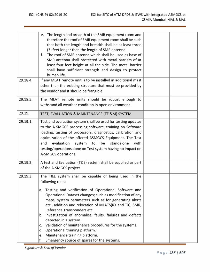
EOI: (CNS-P)-02/2019-20 EOI for SITC of ATM DPDS & ITWS with integrated ASMGCS at
CSMIA Mumbai, HIAL & BIAL
Signature & Seal of Vendor
P a g e 486 | 605
e. The length and breadth of the SMR equipment room and therefore the roof of SMR equipment room shall be such that both the length and breadth shall be at least three (3) feet longer than the length of SMR antenna.
f. The roof of SMR antenna which shall be used as base of SMR antenna shall protected with metal barriers of at least four feet height at all the side. The metal barrier shall have sufficient strength and design to protect human life.
29.18.4. If any MLAT remote unit is to be installed in additional mast
other than the existing structure that must be provided by
the vendor and it should be frangible.
29.18.5. The MLAT remote units should be robust enough to
withstand all weather condition in open environment.
29.19. TEST, EVALUATION & MAINTENANCE (TE &M) SYSTEM
29.19.1. Test and evaluation system shall be used for testing updates
to the A-SMGCS processing software, training on Software
loading, testing of processors, diagnostics, calibration and
optimization of the offered ASMGCS Equipment. The Test
and evaluation system to be standalone with
testing/operations done on Test system having no impact on
A-SMGCS operations.
29.19.2. A test and Evaluation (T&E) system shall be supplied as part
of the A-SMGCS project.
29.19.3. The T&E system shall be capable of being used in the
following roles:
a. Testing and verification of Operational Software and Operational Dataset changes; such as modification of any maps, system parameters such as for generating alerts etc., addition and relocation of MLATS(RX and TX), SMR, Reference Transponders etc.
b. Investigation of anomalies, faults, failures and defects detected in a system.
c. Validation of maintenance procedures for the systems. d. Operational training platform. e. Maintenance training platform. f. Emergency source of spares for the systems.
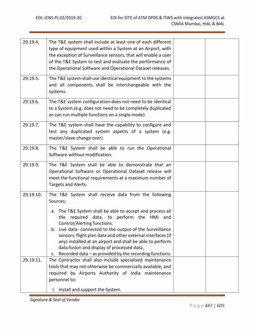
EOI: (CNS-P)-02/2019-20 EOI for SITC of ATM DPDS & ITWS with integrated ASMGCS at
CSMIA Mumbai, HIAL & BIAL
Signature & Seal of Vendor
P a g e 487 | 605
29.19.4. The T&E system shall include at least one of each different
type of equipment used within a System at an Airport, with
the exception of Surveillance sensors, that will enable a user
of the T&E System to test and evaluate the performance of
the Operational Software and Operational Dataset releases.
29.19.5. The T&E system shall use identical equipment to the systems
and all components shall be interchangeable with the
systems.
29.19.6. The T&E system configuration does not need to be identical
to a System (e.g. does not need to be completely duplicated
or can run multiple functions on a single mode)
29.19.7. The T&E system shall have the capability to configure and
test any duplicated system aspects of a system (e.g.
master/slave change over)
29.19.8. The T&E System shall be able to run the Operational
Software without modification.
29.19.9. The T&E System shall be able to demonstrate that an
Operational Software or Operational Dataset release will
meet the functional requirements at a maximum number of
Targets and Alerts.
29.19.10. The T&E System shall receive data from the following
Sources:
a. The T&E System shall be able to accept and process all the required data, to perform the HMI and Control/Alerting functions.
b. Live data- connected to the output of the Surveillance sensors, flight plan data and other external interfaces (if any) installed at an airport and shall be able to perform data fusion and display of processed data.
c. Recorded data – as provided by the recording functions.
29.19.11. The Contractor shall also include specialised maintenance
tools that may not otherwise be commercially available, and
required by Airports Authority of India maintenance
personnel to:
I. Install and support the System.
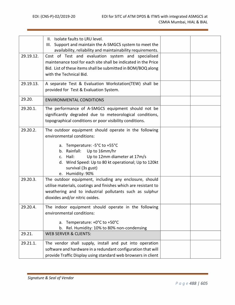
EOI: (CNS-P)-02/2019-20 EOI for SITC of ATM DPDS & ITWS with integrated ASMGCS at
CSMIA Mumbai, HIAL & BIAL
Signature & Seal of Vendor
P a g e 488 | 605
II. Isolate faults to LRU level. III. Support and maintain the A-SMGCS system to meet the
availability, reliability and maintainability requirements.
29.19.12. Cost of Test and evaluation system and specialised
maintenance tool for each site shall be indicated in the Price
Bid. List of these items shall be submitted in BOM/BOQ along
with the Technical Bid.
29.19.13. A separate Test & Evaluation Workstation(TEW) shall be
provided for Test & Evaluation System.
29.20. ENVIRONMENTAL CONDITIONS
29.20.1. The performance of A-SMGCS equipment should not be
significantly degraded due to meteorological conditions,
topographical conditions or poor visibility conditions.
29.20.2. The outdoor equipment should operate in the following
environmental conditions:
a. Temperature: -5°C to +55°C b. Rainfall: Up to 16mm/hr c. Hail: Up to 12mm diameter at 17m/s d. Wind Speed: Up to 80 kt operational; Up to 120kt
survival (3s gust) e. Humidity: 90%
29.20.3. The outdoor equipment, including any enclosure, should
utilise materials, coatings and finishes which are resistant to
weathering and to industrial pollutants such as sulphur
dioxides and/or nitric oxides.
29.20.4. The indoor equipment should operate in the following
environmental conditions:
a. Temperature: +0°C to +50°C b. Rel. Humidity: 10% to 80% non-condensing
29.21. WEB SERVER & CLIENTS:
29.21.1. The vendor shall supply, install and put into operation
software and hardware in a redundant configuration that will
provide Traffic Display using standard web browsers in client
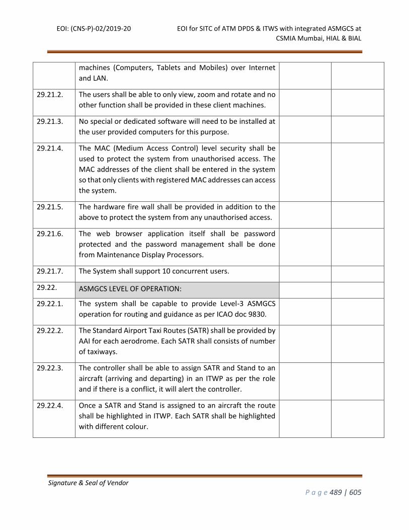
EOI: (CNS-P)-02/2019-20 EOI for SITC of ATM DPDS & ITWS with integrated ASMGCS at
CSMIA Mumbai, HIAL & BIAL
Signature & Seal of Vendor
P a g e 489 | 605
machines (Computers, Tablets and Mobiles) over Internet
and LAN.
29.21.2. The users shall be able to only view, zoom and rotate and no
other function shall be provided in these client machines.
29.21.3. No special or dedicated software will need to be installed at
the user provided computers for this purpose.
29.21.4. The MAC (Medium Access Control) level security shall be
used to protect the system from unauthorised access. The
MAC addresses of the client shall be entered in the system
so that only clients with registered MAC addresses can access
the system.
29.21.5. The hardware fire wall shall be provided in addition to the
above to protect the system from any unauthorised access.
29.21.6. The web browser application itself shall be password
protected and the password management shall be done
from Maintenance Display Processors.
29.21.7. The System shall support 10 concurrent users.
29.22. ASMGCS LEVEL OF OPERATION:
29.22.1. The system shall be capable to provide Level-3 ASMGCS
operation for routing and guidance as per ICAO doc 9830.
29.22.2. The Standard Airport Taxi Routes (SATR) shall be provided by
AAI for each aerodrome. Each SATR shall consists of number
of taxiways.
29.22.3. The controller shall be able to assign SATR and Stand to an
aircraft (arriving and departing) in an ITWP as per the role
and if there is a conflict, it will alert the controller.
29.22.4. Once a SATR and Stand is assigned to an aircraft the route
shall be highlighted in ITWP. Each SATR shall be highlighted
with different colour.
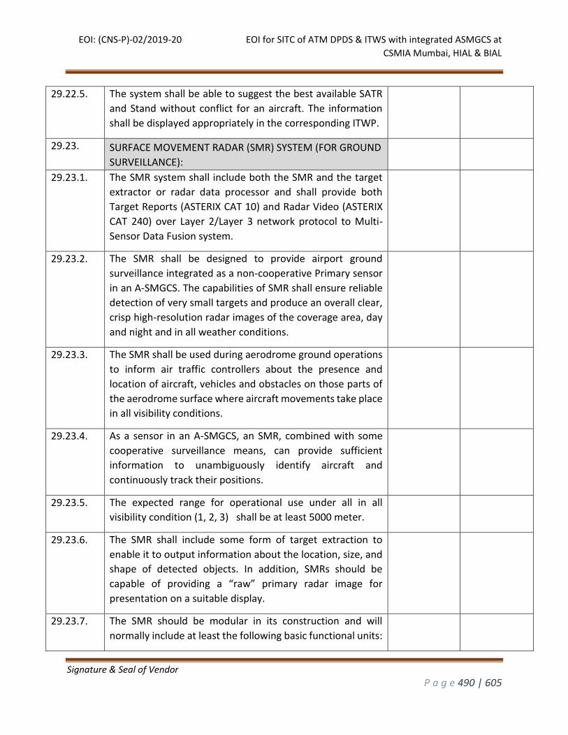
EOI: (CNS-P)-02/2019-20 EOI for SITC of ATM DPDS & ITWS with integrated ASMGCS at
CSMIA Mumbai, HIAL & BIAL
Signature & Seal of Vendor
P a g e 490 | 605
29.22.5. The system shall be able to suggest the best available SATR
and Stand without conflict for an aircraft. The information
shall be displayed appropriately in the corresponding ITWP.
29.23. SURFACE MOVEMENT RADAR (SMR) SYSTEM (FOR GROUND
SURVEILLANCE):
29.23.1. The SMR system shall include both the SMR and the target
extractor or radar data processor and shall provide both
Target Reports (ASTERIX CAT 10) and Radar Video (ASTERIX
CAT 240) over Layer 2/Layer 3 network protocol to Multi-
Sensor Data Fusion system.
29.23.2. The SMR shall be designed to provide airport ground
surveillance integrated as a non-cooperative Primary sensor
in an A-SMGCS. The capabilities of SMR shall ensure reliable
detection of very small targets and produce an overall clear,
crisp high-resolution radar images of the coverage area, day
and night and in all weather conditions.
29.23.3. The SMR shall be used during aerodrome ground operations
to inform air traffic controllers about the presence and
location of aircraft, vehicles and obstacles on those parts of
the aerodrome surface where aircraft movements take place
in all visibility conditions.
29.23.4. As a sensor in an A-SMGCS, an SMR, combined with some
cooperative surveillance means, can provide sufficient
information to unambiguously identify aircraft and
continuously track their positions.
29.23.5. The expected range for operational use under all in all
visibility condition (1, 2, 3) shall be at least 5000 meter.
29.23.6. The SMR shall include some form of target extraction to
enable it to output information about the location, size, and
shape of detected objects. In addition, SMRs should be
capable of providing a “raw” primary radar image for
presentation on a suitable display.
29.23.7. The SMR should be modular in its construction and will
normally include at least the following basic functional units:

EOI: (CNS-P)-02/2019-20 EOI for SITC of ATM DPDS & ITWS with integrated ASMGCS at
CSMIA Mumbai, HIAL & BIAL
Signature & Seal of Vendor
P a g e 491 | 605
Antenna Unit. Transmitter Unit. Receiver Unit. Local Control and Monitoring Unit. Radar Data Processor or Target Extractor Unit. Antenna Control Unit. Remote Control and Monitoring Unit. Waveguide Dehydrating Unit. RADOME.
29.23.8. The antenna unit itself shall be provided with a RADOME and
in addition to that the antenna unit along with motor,
encoder, waveguides etc.
29.23.9. The material used for RADOME should not deteriorate the
intended operation of SMR.
29.23.10. In choosing a site for an SMR antenna, consideration must
also be given to fixed reflecting surfaces and the resulting
location of false returns.
29.23.11. Transmitter and receiver shall be combined into one
(transceiver) unit, and shall be mounted close to the antenna
unit in order to minimise signal attenuation caused by long
waveguides.
29.23.12. A local control and monitoring unit co-located with the SMR
transmitter/receiver shall be provide, as a minimum, a
means to start and stop the SMR and a means to monitor its
performance.
29.23.13. A remote control and monitoring unit (RCMU) provides a
means for maintenance personnel to control and monitor
the SMR from maintenance position.
29.23.14. Target extractor units may be co-located with the SMR
transmitter/receiver or installed at a different location
connected to the receiver by a suitable analogue and/or
digital communication link.
29.23.15. The SMR equipment shall be designed so that controls
intended for use using normal operations cannot be
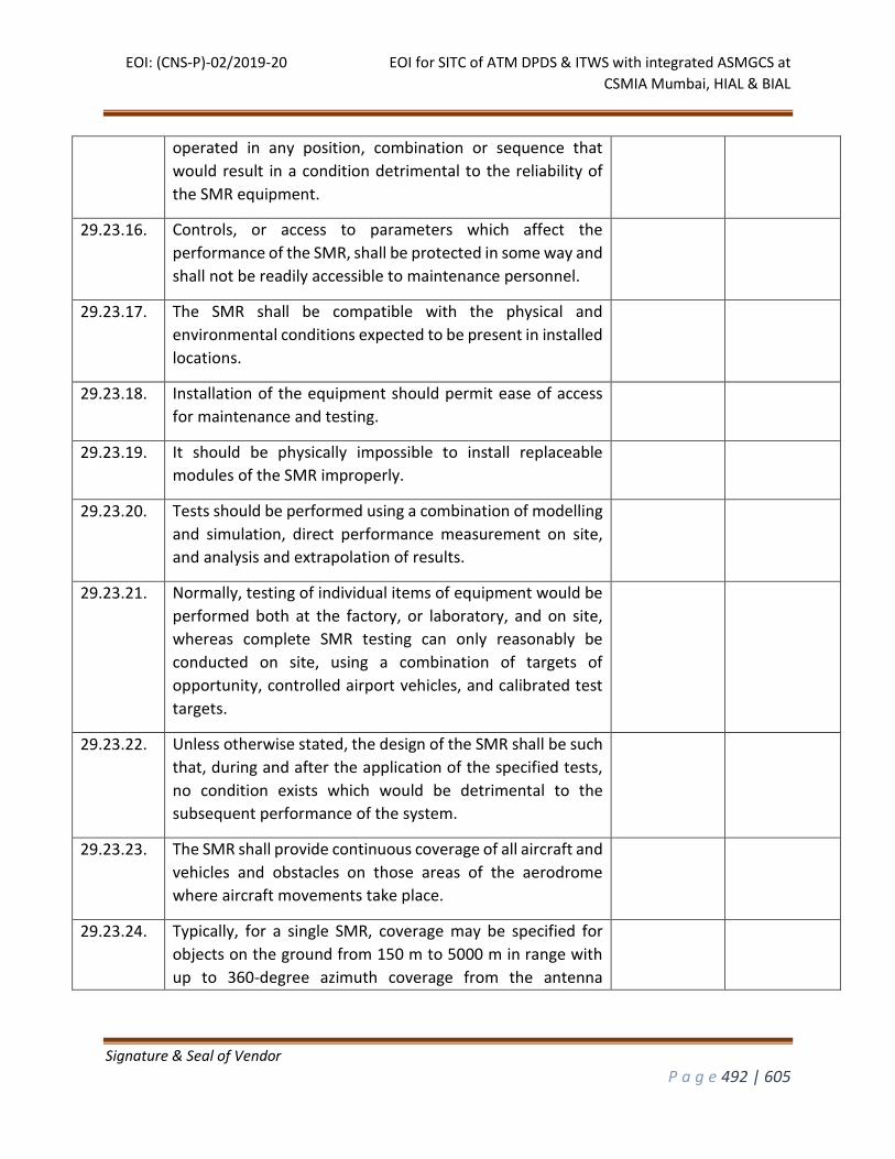
EOI: (CNS-P)-02/2019-20 EOI for SITC of ATM DPDS & ITWS with integrated ASMGCS at
CSMIA Mumbai, HIAL & BIAL
Signature & Seal of Vendor
P a g e 492 | 605
operated in any position, combination or sequence that
would result in a condition detrimental to the reliability of
the SMR equipment.
29.23.16. Controls, or access to parameters which affect the
performance of the SMR, shall be protected in some way and
shall not be readily accessible to maintenance personnel.
29.23.17. The SMR shall be compatible with the physical and
environmental conditions expected to be present in installed
locations.
29.23.18. Installation of the equipment should permit ease of access
for maintenance and testing.
29.23.19. It should be physically impossible to install replaceable
modules of the SMR improperly.
29.23.20. Tests should be performed using a combination of modelling
and simulation, direct performance measurement on site,
and analysis and extrapolation of results.
29.23.21. Normally, testing of individual items of equipment would be
performed both at the factory, or laboratory, and on site,
whereas complete SMR testing can only reasonably be
conducted on site, using a combination of targets of
opportunity, controlled airport vehicles, and calibrated test
targets.
29.23.22. Unless otherwise stated, the design of the SMR shall be such
that, during and after the application of the specified tests,
no condition exists which would be detrimental to the
subsequent performance of the system.
29.23.23. The SMR shall provide continuous coverage of all aircraft and
vehicles and obstacles on those areas of the aerodrome
where aircraft movements take place.
29.23.24. Typically, for a single SMR, coverage may be specified for
objects on the ground from 150 m to 5000 m in range with
up to 360-degree azimuth coverage from the antenna
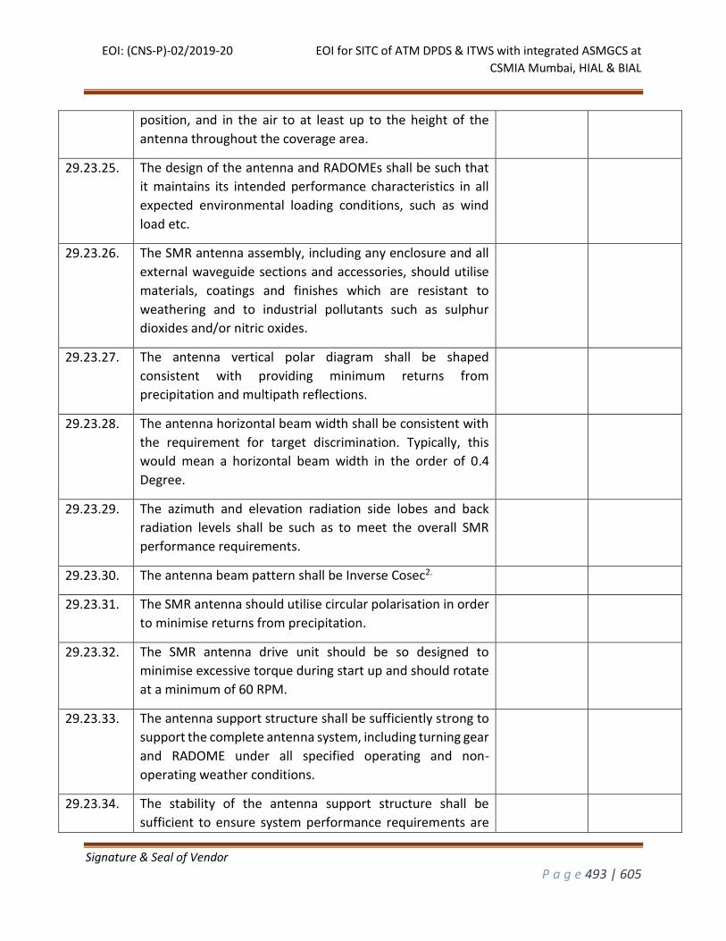
EOI: (CNS-P)-02/2019-20 EOI for SITC of ATM DPDS & ITWS with integrated ASMGCS at
CSMIA Mumbai, HIAL & BIAL
Signature & Seal of Vendor
P a g e 493 | 605
position, and in the air to at least up to the height of the
antenna throughout the coverage area.
29.23.25. The design of the antenna and RADOMEs shall be such that
it maintains its intended performance characteristics in all
expected environmental loading conditions, such as wind
load etc.
29.23.26. The SMR antenna assembly, including any enclosure and all
external waveguide sections and accessories, should utilise
materials, coatings and finishes which are resistant to
weathering and to industrial pollutants such as sulphur
dioxides and/or nitric oxides.
29.23.27. The antenna vertical polar diagram shall be shaped
consistent with providing minimum returns from
precipitation and multipath reflections.
29.23.28. The antenna horizontal beam width shall be consistent with
the requirement for target discrimination. Typically, this
would mean a horizontal beam width in the order of 0.4
Degree.
29.23.29. The azimuth and elevation radiation side lobes and back
radiation levels shall be such as to meet the overall SMR
performance requirements.
29.23.30. The antenna beam pattern shall be Inverse Cosec2.
29.23.31. The SMR antenna should utilise circular polarisation in order
to minimise returns from precipitation.
29.23.32. The SMR antenna drive unit should be so designed to
minimise excessive torque during start up and should rotate
at a minimum of 60 RPM.
29.23.33. The antenna support structure shall be sufficiently strong to
support the complete antenna system, including turning gear
and RADOME under all specified operating and non-
operating weather conditions.
29.23.34. The stability of the antenna support structure shall be
sufficient to ensure system performance requirements are
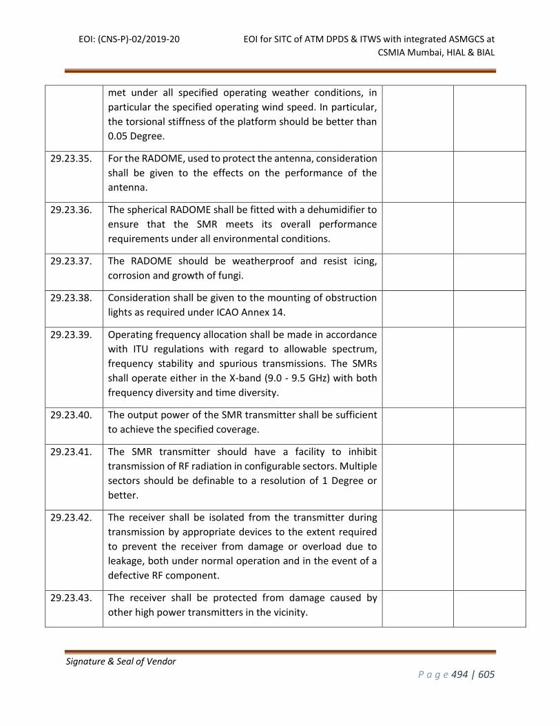
EOI: (CNS-P)-02/2019-20 EOI for SITC of ATM DPDS & ITWS with integrated ASMGCS at
CSMIA Mumbai, HIAL & BIAL
Signature & Seal of Vendor
P a g e 494 | 605
met under all specified operating weather conditions, in
particular the specified operating wind speed. In particular,
the torsional stiffness of the platform should be better than
0.05 Degree.
29.23.35. For the RADOME, used to protect the antenna, consideration
shall be given to the effects on the performance of the
antenna.
29.23.36. The spherical RADOME shall be fitted with a dehumidifier to
ensure that the SMR meets its overall performance
requirements under all environmental conditions.
29.23.37. The RADOME should be weatherproof and resist icing,
corrosion and growth of fungi.
29.23.38. Consideration shall be given to the mounting of obstruction
lights as required under ICAO Annex 14.
29.23.39. Operating frequency allocation shall be made in accordance
with ITU regulations with regard to allowable spectrum,
frequency stability and spurious transmissions. The SMRs
shall operate either in the X-band (9.0 - 9.5 GHz) with both
frequency diversity and time diversity.
29.23.40. The output power of the SMR transmitter shall be sufficient
to achieve the specified coverage.
29.23.41. The SMR transmitter should have a facility to inhibit
transmission of RF radiation in configurable sectors. Multiple
sectors should be definable to a resolution of 1 Degree or
better.
29.23.42. The receiver shall be isolated from the transmitter during
transmission by appropriate devices to the extent required
to prevent the receiver from damage or overload due to
leakage, both under normal operation and in the event of a
defective RF component.
29.23.43. The receiver shall be protected from damage caused by
other high power transmitters in the vicinity.
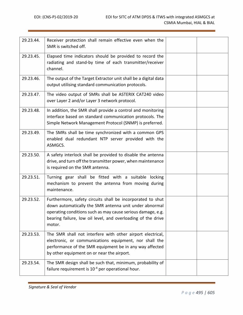
EOI: (CNS-P)-02/2019-20 EOI for SITC of ATM DPDS & ITWS with integrated ASMGCS at
CSMIA Mumbai, HIAL & BIAL
Signature & Seal of Vendor
P a g e 495 | 605
29.23.44. Receiver protection shall remain effective even when the
SMR is switched off.
29.23.45. Elapsed time indicators should be provided to record the
radiating and stand-by time of each transmitter/receiver
channel.
29.23.46. The output of the Target Extractor unit shall be a digital data
output utilising standard communication protocols.
29.23.47. The video output of SMRs shall be ASTERIX CAT240 video
over Layer 2 and/or Layer 3 network protocol.
29.23.48. In addition, the SMR shall provide a control and monitoring
interface based on standard communication protocols. The
Simple Network Management Protocol (SNMP) is preferred.
29.23.49. The SMRs shall be time synchronized with a common GPS
enabled dual redundant NTP server provided with the
ASMGCS.
29.23.50. A safety interlock shall be provided to disable the antenna
drive, and turn off the transmitter power, when maintenance
is required on the SMR antenna.
29.23.51. Turning gear shall be fitted with a suitable locking
mechanism to prevent the antenna from moving during
maintenance.
29.23.52. Furthermore, safety circuits shall be incorporated to shut
down automatically the SMR antenna unit under abnormal
operating conditions such as may cause serious damage, e.g.
bearing failure, low oil level, and overloading of the drive
motor.
29.23.53. The SMR shall not interfere with other airport electrical,
electronic, or communications equipment, nor shall the
performance of the SMR equipment be in any way affected
by other equipment on or near the airport.
29.23.54. The SMR design shall be such that, minimum, probability of
failure requirement is 10-4 per operational hour.
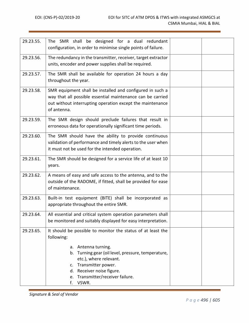
EOI: (CNS-P)-02/2019-20 EOI for SITC of ATM DPDS & ITWS with integrated ASMGCS at
CSMIA Mumbai, HIAL & BIAL
Signature & Seal of Vendor
P a g e 496 | 605
29.23.55. The SMR shall be designed for a dual redundant
configuration, in order to minimise single points of failure.
29.23.56. The redundancy in the transmitter, receiver, target extractor
units, encoder and power supplies shall be required.
29.23.57. The SMR shall be available for operation 24 hours a day
throughout the year.
29.23.58. SMR equipment shall be installed and configured in such a
way that all possible essential maintenance can be carried
out without interrupting operation except the maintenance
of antenna.
29.23.59. The SMR design should preclude failures that result in
erroneous data for operationally significant time periods.
29.23.60. The SMR should have the ability to provide continuous
validation of performance and timely alerts to the user when
it must not be used for the intended operation.
29.23.61. The SMR should be designed for a service life of at least 10
years.
29.23.62. A means of easy and safe access to the antenna, and to the
outside of the RADOME, if fitted, shall be provided for ease
of maintenance.
29.23.63. Built-in test equipment (BITE) shall be incorporated as
appropriate throughout the entire SMR.
29.23.64. All essential and critical system operation parameters shall
be monitored and suitably displayed for easy interpretation.
29.23.65. It should be possible to monitor the status of at least the
following:
a. Antenna turning. b. Turning gear (oil level, pressure, temperature,
etc.), where relevant. c. Transmitter power. d. Receiver noise figure. e. Transmitter/receiver failure. f. VSWR.
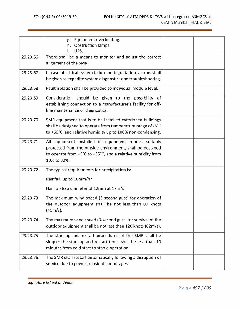
EOI: (CNS-P)-02/2019-20 EOI for SITC of ATM DPDS & ITWS with integrated ASMGCS at
CSMIA Mumbai, HIAL & BIAL
Signature & Seal of Vendor
P a g e 497 | 605
g. Equipment overheating. h. Obstruction lamps. i. UPS.
29.23.66. There shall be a means to monitor and adjust the correct
alignment of the SMR.
29.23.67. In case of critical system failure or degradation, alarms shall
be given to expedite system diagnostics and troubleshooting.
29.23.68. Fault isolation shall be provided to individual module level.
29.23.69. Consideration should be given to the possibility of
establishing connection to a manufacturer’s facility for off-
line maintenance or diagnostics.
29.23.70. SMR equipment that is to be installed exterior to buildings
shall be designed to operate from temperature range of -5°C
to +60°C, and relative humidity up to 100% non-condensing.
29.23.71. All equipment installed in equipment rooms, suitably
protected from the outside environment, shall be designed
to operate from +5°C to +35°C, and a relative humidity from
10% to 80%.
29.23.72. The typical requirements for precipitation is:
Rainfall: up to 16mm/hr
Hail: up to a diameter of 12mm at 17m/s
29.23.73. The maximum wind speed (3-second gust) for operation of
the outdoor equipment shall be not less than 80 knots
(41m/s).
29.23.74. The maximum wind speed (3-second gust) for survival of the
outdoor equipment shall be not less than 120 knots (62m/s).
29.23.75. The start-up and restart procedures of the SMR shall be
simple; the start-up and restart times shall be less than 10
minutes from cold start to stable operation.
29.23.76. The SMR shall restart automatically following a disruption of
service due to power transients or outages.
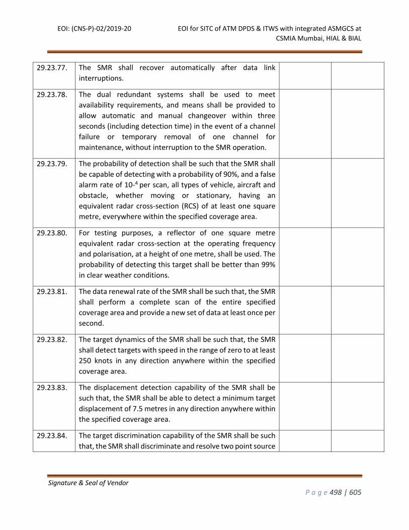
EOI: (CNS-P)-02/2019-20 EOI for SITC of ATM DPDS & ITWS with integrated ASMGCS at
CSMIA Mumbai, HIAL & BIAL
Signature & Seal of Vendor
P a g e 498 | 605
29.23.77. The SMR shall recover automatically after data link
interruptions.
29.23.78. The dual redundant systems shall be used to meet
availability requirements, and means shall be provided to
allow automatic and manual changeover within three
seconds (including detection time) in the event of a channel
failure or temporary removal of one channel for
maintenance, without interruption to the SMR operation.
29.23.79. The probability of detection shall be such that the SMR shall
be capable of detecting with a probability of 90%, and a false
alarm rate of 10-4 per scan, all types of vehicle, aircraft and
obstacle, whether moving or stationary, having an
equivalent radar cross-section (RCS) of at least one square
metre, everywhere within the specified coverage area.
29.23.80. For testing purposes, a reflector of one square metre
equivalent radar cross-section at the operating frequency
and polarisation, at a height of one metre, shall be used. The
probability of detecting this target shall be better than 99%
in clear weather conditions.
29.23.81. The data renewal rate of the SMR shall be such that, the SMR
shall perform a complete scan of the entire specified
coverage area and provide a new set of data at least once per
second.
29.23.82. The target dynamics of the SMR shall be such that, the SMR
shall detect targets with speed in the range of zero to at least
250 knots in any direction anywhere within the specified
coverage area.
29.23.83. The displacement detection capability of the SMR shall be
such that, the SMR shall be able to detect a minimum target
displacement of 7.5 metres in any direction anywhere within
the specified coverage area.
29.23.84. The target discrimination capability of the SMR shall be such
that, the SMR shall discriminate and resolve two point source
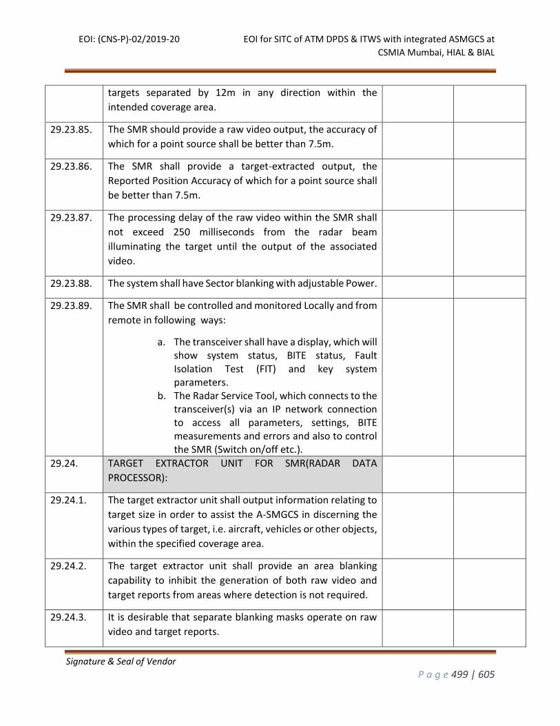
EOI: (CNS-P)-02/2019-20 EOI for SITC of ATM DPDS & ITWS with integrated ASMGCS at
CSMIA Mumbai, HIAL & BIAL
Signature & Seal of Vendor
P a g e 499 | 605
targets separated by 12m in any direction within the
intended coverage area.
29.23.85. The SMR should provide a raw video output, the accuracy of
which for a point source shall be better than 7.5m.
29.23.86. The SMR shall provide a target-extracted output, the
Reported Position Accuracy of which for a point source shall
be better than 7.5m.
29.23.87. The processing delay of the raw video within the SMR shall
not exceed 250 milliseconds from the radar beam
illuminating the target until the output of the associated
video.
29.23.88. The system shall have Sector blanking with adjustable Power.
29.23.89. The SMR shall be controlled and monitored Locally and from
remote in following ways:
a. The transceiver shall have a display, which will show system status, BITE status, Fault Isolation Test (FIT) and key system parameters.
b. The Radar Service Tool, which connects to the transceiver(s) via an IP network connection to access all parameters, settings, BITE measurements and errors and also to control the SMR (Switch on/off etc.).
29.24. TARGET EXTRACTOR UNIT FOR SMR(RADAR DATA
PROCESSOR):
29.24.1. The target extractor unit shall output information relating to
target size in order to assist the A-SMGCS in discerning the
various types of target, i.e. aircraft, vehicles or other objects,
within the specified coverage area.
29.24.2. The target extractor unit shall provide an area blanking
capability to inhibit the generation of both raw video and
target reports from areas where detection is not required.
29.24.3. It is desirable that separate blanking masks operate on raw
video and target reports.
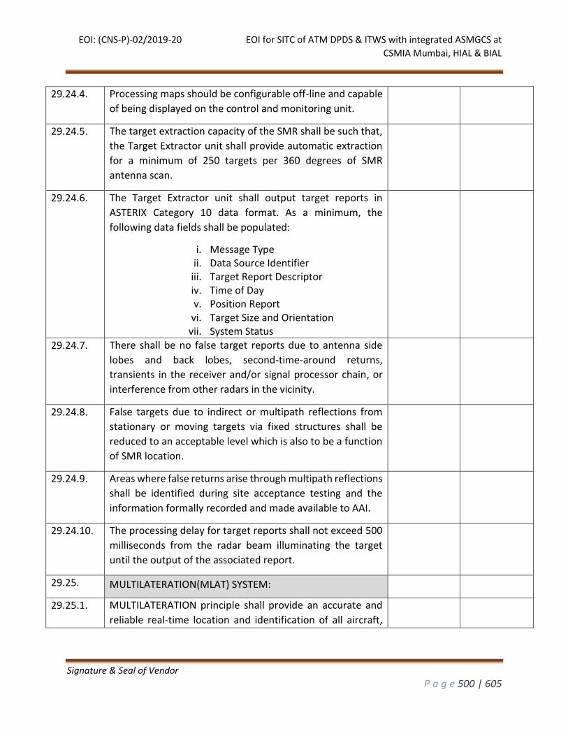
EOI: (CNS-P)-02/2019-20 EOI for SITC of ATM DPDS & ITWS with integrated ASMGCS at
CSMIA Mumbai, HIAL & BIAL
Signature & Seal of Vendor
P a g e 500 | 605
29.24.4. Processing maps should be configurable off-line and capable
of being displayed on the control and monitoring unit.
29.24.5. The target extraction capacity of the SMR shall be such that,
the Target Extractor unit shall provide automatic extraction
for a minimum of 250 targets per 360 degrees of SMR
antenna scan.
29.24.6. The Target Extractor unit shall output target reports in
ASTERIX Category 10 data format. As a minimum, the
following data fields shall be populated:
i. Message Type ii. Data Source Identifier
iii. Target Report Descriptor iv. Time of Day v. Position Report
vi. Target Size and Orientation vii. System Status
29.24.7. There shall be no false target reports due to antenna side
lobes and back lobes, second-time-around returns,
transients in the receiver and/or signal processor chain, or
interference from other radars in the vicinity.
29.24.8. False targets due to indirect or multipath reflections from
stationary or moving targets via fixed structures shall be
reduced to an acceptable level which is also to be a function
of SMR location.
29.24.9. Areas where false returns arise through multipath reflections
shall be identified during site acceptance testing and the
information formally recorded and made available to AAI.
29.24.10. The processing delay for target reports shall not exceed 500
milliseconds from the radar beam illuminating the target
until the output of the associated report.
29.25. MULTILATERATION(MLAT) SYSTEM:
29.25.1. MULTILATERATION principle shall provide an accurate and
reliable real-time location and identification of all aircraft,
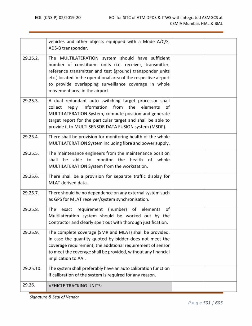
EOI: (CNS-P)-02/2019-20 EOI for SITC of ATM DPDS & ITWS with integrated ASMGCS at
CSMIA Mumbai, HIAL & BIAL
Signature & Seal of Vendor
P a g e 501 | 605
vehicles and other objects equipped with a Mode A/C/S,
ADS-B transponder.
29.25.2. The MULTILATERATION system should have sufficient
number of constituent units (i.e. receiver, transmitter,
reference transmitter and test (ground) transponder units
etc.) located in the operational area of the respective airport
to provide overlapping surveillance coverage in whole
movement area in the airport.
29.25.3. A dual redundant auto switching target processor shall
collect reply information from the elements of
MULTILATERATION System, compute position and generate
target report for the particular target and shall be able to
provide it to MULTI SENSOR DATA FUSION system (MSDP).
29.25.4. There shall be provision for monitoring health of the whole
MULTILATERATION System including fibre and power supply.
29.25.5. The maintenance engineers from the maintenance position
shall be able to monitor the health of whole
MULTILATERATION System from the workstation.
29.25.6. There shall be a provision for separate traffic display for
MLAT derived data.
29.25.7. There should be no dependence on any external system such
as GPS for MLAT receiver/system synchronisation.
29.25.8. The exact requirement (number) of elements of
Multilateration system should be worked out by the
Contractor and clearly spelt out with thorough justification.
29.25.9. The complete coverage (SMR and MLAT) shall be provided.
In case the quantity quoted by bidder does not meet the
coverage requirement, the additional requirement of sensor
to meet the coverage shall be provided, without any financial
implication to AAI.
29.25.10. The system shall preferably have an auto calibration function
if calibration of the system is required for any reason.
29.26. VEHICLE TRACKING UNITS:
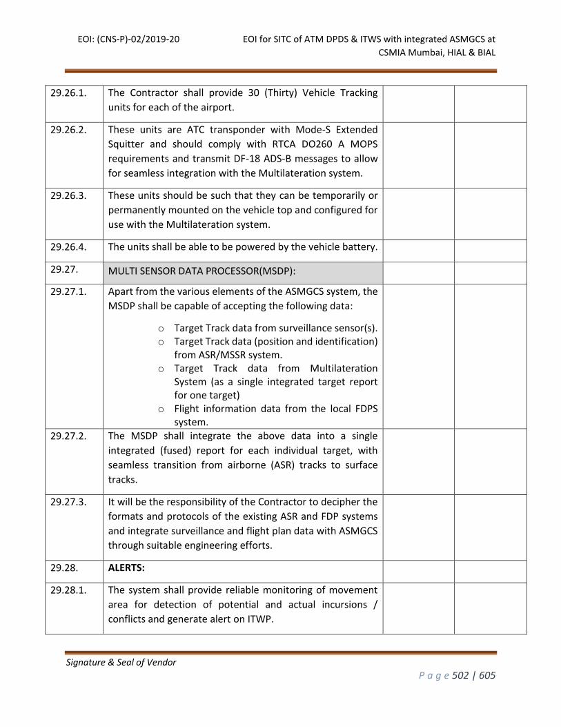
EOI: (CNS-P)-02/2019-20 EOI for SITC of ATM DPDS & ITWS with integrated ASMGCS at
CSMIA Mumbai, HIAL & BIAL
Signature & Seal of Vendor
P a g e 502 | 605
29.26.1. The Contractor shall provide 30 (Thirty) Vehicle Tracking
units for each of the airport.
29.26.2. These units are ATC transponder with Mode-S Extended
Squitter and should comply with RTCA DO260 A MOPS
requirements and transmit DF-18 ADS-B messages to allow
for seamless integration with the Multilateration system.
29.26.3. These units should be such that they can be temporarily or
permanently mounted on the vehicle top and configured for
use with the Multilateration system.
29.26.4. The units shall be able to be powered by the vehicle battery.
29.27. MULTI SENSOR DATA PROCESSOR(MSDP):
29.27.1. Apart from the various elements of the ASMGCS system, the
MSDP shall be capable of accepting the following data:
o Target Track data from surveillance sensor(s). o Target Track data (position and identification)
from ASR/MSSR system. o Target Track data from Multilateration
System (as a single integrated target report for one target)
o Flight information data from the local FDPS system.
29.27.2. The MSDP shall integrate the above data into a single
integrated (fused) report for each individual target, with
seamless transition from airborne (ASR) tracks to surface
tracks.
29.27.3. It will be the responsibility of the Contractor to decipher the
formats and protocols of the existing ASR and FDP systems
and integrate surveillance and flight plan data with ASMGCS
through suitable engineering efforts.
29.28. ALERTS:
29.28.1. The system shall provide reliable monitoring of movement
area for detection of potential and actual incursions /
conflicts and generate alert on ITWP.
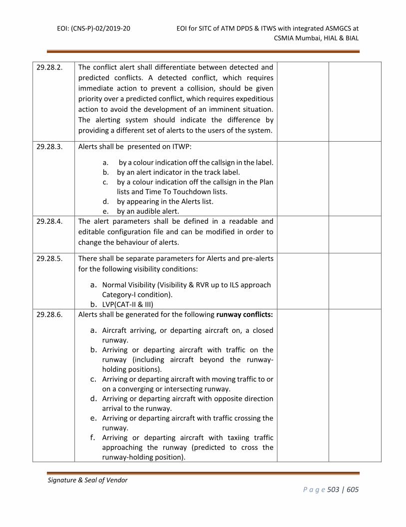
EOI: (CNS-P)-02/2019-20 EOI for SITC of ATM DPDS & ITWS with integrated ASMGCS at
CSMIA Mumbai, HIAL & BIAL
Signature & Seal of Vendor
P a g e 503 | 605
29.28.2. The conflict alert shall differentiate between detected and
predicted conflicts. A detected conflict, which requires
immediate action to prevent a collision, should be given
priority over a predicted conflict, which requires expeditious
action to avoid the development of an imminent situation.
The alerting system should indicate the difference by
providing a different set of alerts to the users of the system.
29.28.3. Alerts shall be presented on ITWP:
a. by a colour indication off the callsign in the label. b. by an alert indicator in the track label. c. by a colour indication off the callsign in the Plan
lists and Time To Touchdown lists. d. by appearing in the Alerts list. e. by an audible alert.
29.28.4. The alert parameters shall be defined in a readable and
editable configuration file and can be modified in order to
change the behaviour of alerts.
29.28.5. There shall be separate parameters for Alerts and pre-alerts
for the following visibility conditions:
a. Normal Visibility (Visibility & RVR up to ILS approach Category-I condition).
b. LVP(CAT-II & III)
29.28.6. Alerts shall be generated for the following runway conflicts:
a. Aircraft arriving, or departing aircraft on, a closed runway.
b. Arriving or departing aircraft with traffic on the runway (including aircraft beyond the runway-holding positions).
c. Arriving or departing aircraft with moving traffic to or on a converging or intersecting runway.
d. Arriving or departing aircraft with opposite direction arrival to the runway.
e. Arriving or departing aircraft with traffic crossing the runway.
f. Arriving or departing aircraft with taxiing traffic approaching the runway (predicted to cross the runway-holding position).
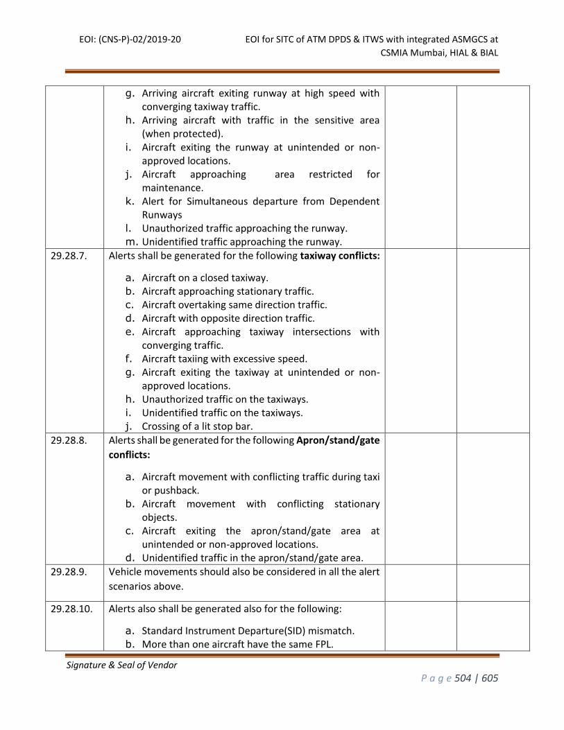
EOI: (CNS-P)-02/2019-20 EOI for SITC of ATM DPDS & ITWS with integrated ASMGCS at
CSMIA Mumbai, HIAL & BIAL
Signature & Seal of Vendor
P a g e 504 | 605
g. Arriving aircraft exiting runway at high speed with converging taxiway traffic.
h. Arriving aircraft with traffic in the sensitive area (when protected).
i. Aircraft exiting the runway at unintended or non-approved locations.
j. Aircraft approaching area restricted for maintenance.
k. Alert for Simultaneous departure from Dependent Runways
l. Unauthorized traffic approaching the runway. m. Unidentified traffic approaching the runway.
29.28.7. Alerts shall be generated for the following taxiway conflicts:
a. Aircraft on a closed taxiway. b. Aircraft approaching stationary traffic. c. Aircraft overtaking same direction traffic. d. Aircraft with opposite direction traffic. e. Aircraft approaching taxiway intersections with
converging traffic. f. Aircraft taxiing with excessive speed. g. Aircraft exiting the taxiway at unintended or non-
approved locations. h. Unauthorized traffic on the taxiways. i. Unidentified traffic on the taxiways. j. Crossing of a lit stop bar.
29.28.8. Alerts shall be generated for the following Apron/stand/gate
conflicts:
a. Aircraft movement with conflicting traffic during taxi or pushback.
b. Aircraft movement with conflicting stationary objects.
c. Aircraft exiting the apron/stand/gate area at unintended or non-approved locations.
d. Unidentified traffic in the apron/stand/gate area.
29.28.9. Vehicle movements should also be considered in all the alert
scenarios above.
29.28.10. Alerts also shall be generated also for the following:
a. Standard Instrument Departure(SID) mismatch. b. More than one aircraft have the same FPL.
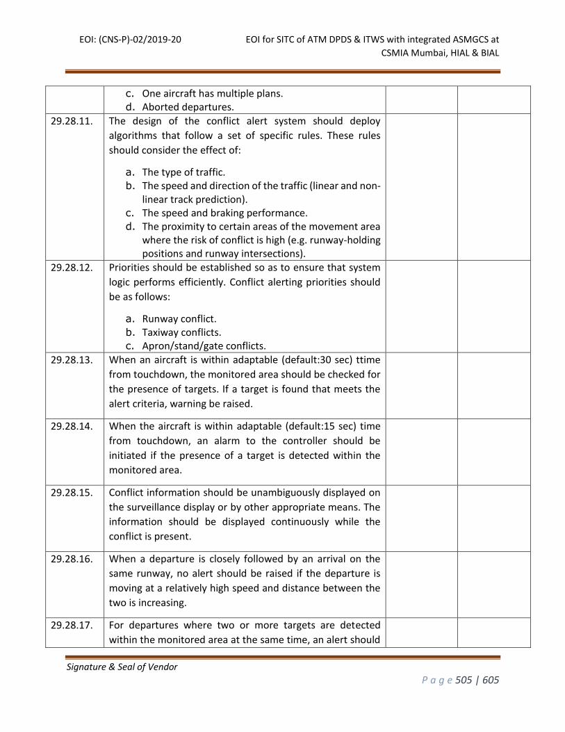
EOI: (CNS-P)-02/2019-20 EOI for SITC of ATM DPDS & ITWS with integrated ASMGCS at
CSMIA Mumbai, HIAL & BIAL
Signature & Seal of Vendor
P a g e 505 | 605
c. One aircraft has multiple plans. d. Aborted departures.
29.28.11. The design of the conflict alert system should deploy
algorithms that follow a set of specific rules. These rules
should consider the effect of:
a. The type of traffic. b. The speed and direction of the traffic (linear and non-
linear track prediction). c. The speed and braking performance. d. The proximity to certain areas of the movement area
where the risk of conflict is high (e.g. runway-holding positions and runway intersections).
29.28.12. Priorities should be established so as to ensure that system
logic performs efficiently. Conflict alerting priorities should
be as follows:
a. Runway conflict. b. Taxiway conflicts. c. Apron/stand/gate conflicts.
29.28.13. When an aircraft is within adaptable (default:30 sec) ttime
from touchdown, the monitored area should be checked for
the presence of targets. If a target is found that meets the
alert criteria, warning be raised.
29.28.14. When the aircraft is within adaptable (default:15 sec) time
from touchdown, an alarm to the controller should be
initiated if the presence of a target is detected within the
monitored area.
29.28.15. Conflict information should be unambiguously displayed on
the surveillance display or by other appropriate means. The
information should be displayed continuously while the
conflict is present.
29.28.16. When a departure is closely followed by an arrival on the
same runway, no alert should be raised if the departure is
moving at a relatively high speed and distance between the
two is increasing.
29.28.17. For departures where two or more targets are detected
within the monitored area at the same time, an alert should
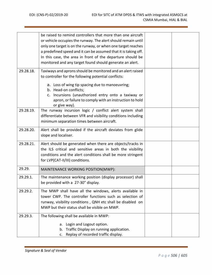
EOI: (CNS-P)-02/2019-20 EOI for SITC of ATM DPDS & ITWS with integrated ASMGCS at
CSMIA Mumbai, HIAL & BIAL
Signature & Seal of Vendor
P a g e 506 | 605
be raised to remind controllers that more than one aircraft
or vehicle occupies the runway. The alert should remain until
only one target is on the runway, or when one target reaches
a predefined speed and it can be assumed that it is taking off.
In this case, the area in front of the departure should be
monitored and any target found should generate an alert.
29.28.18. Taxiways and aprons should be monitored and an alert raised
to controller for the following potential conflicts:
a. Loss of wing tip spacing due to manoeuvring; b. Head-on conflicts; c. Incursions (unauthorized entry onto a taxiway or
apron, or failure to comply with an instruction to hold or give way).
29.28.19. The runway incursion logic / conflict alert system shall
differentiate between VFR and visibility conditions including
minimum separation times between aircraft.
29.28.20. Alert shall be provided if the aircraft deviates from glide
slope and localiser.
29.28.21. Alert should be generated when there are objects/tracks in
the ILS critical and sensitive areas in both the visibility
conditions and the alert conditions shall be more stringent
for LVP(CAT-II/III) conditions.
29.29. MAINTENANCE WORKING POSITION(MWP):
29.29.1. The maintenance working position (display processor) shall
be provided with a 27-30” display.
29.29.2. The MWP shall have all the windows, alerts available in
tower CWP. The controller functions such as selection of
runway, visibility conditions , QNH etc shall be disabled on
MWP but their status shall be visible on MWP.
29.29.3. The following shall be available in MWP:
a. Login and Logout option. b. Traffic Display on running application. c. Replay of recorded traffic display.
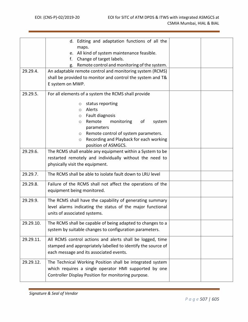
EOI: (CNS-P)-02/2019-20 EOI for SITC of ATM DPDS & ITWS with integrated ASMGCS at
CSMIA Mumbai, HIAL & BIAL
Signature & Seal of Vendor
P a g e 507 | 605
d. Editing and adaptation functions of all the maps.
e. All kind of system maintenance feasible. f. Change of target labels. g. Remote control and monitoring of the system.
29.29.4. An adaptable remote control and monitoring system (RCMS)
shall be provided to monitor and control the system and T&
E system on MWP.
29.29.5. For all elements of a system the RCMS shall provide
o status reporting o Alerts o Fault diagnosis o Remote monitoring of system
parameters o Remote control of system parameters. o Recording and Playback for each working
position of ASMGCS.
29.29.6. The RCMS shall enable any equipment within a System to be
restarted remotely and individually without the need to
physically visit the equipment.
29.29.7. The RCMS shall be able to isolate fault down to LRU level
29.29.8. Failure of the RCMS shall not affect the operations of the
equipment being monitored.
29.29.9. The RCMS shall have the capability of generating summary
level alarms indicating the status of the major functional
units of associated systems.
29.29.10. The RCMS shall be capable of being adapted to changes to a
system by suitable changes to configuration parameters.
29.29.11. All RCMS control actions and alerts shall be logged, time
stamped and appropriately labelled to identify the source of
each message and its associated events.
29.29.12. The Technical Working Position shall be integrated system
which requires a single operator HMI supported by one
Controller Display Position for monitoring purpose.
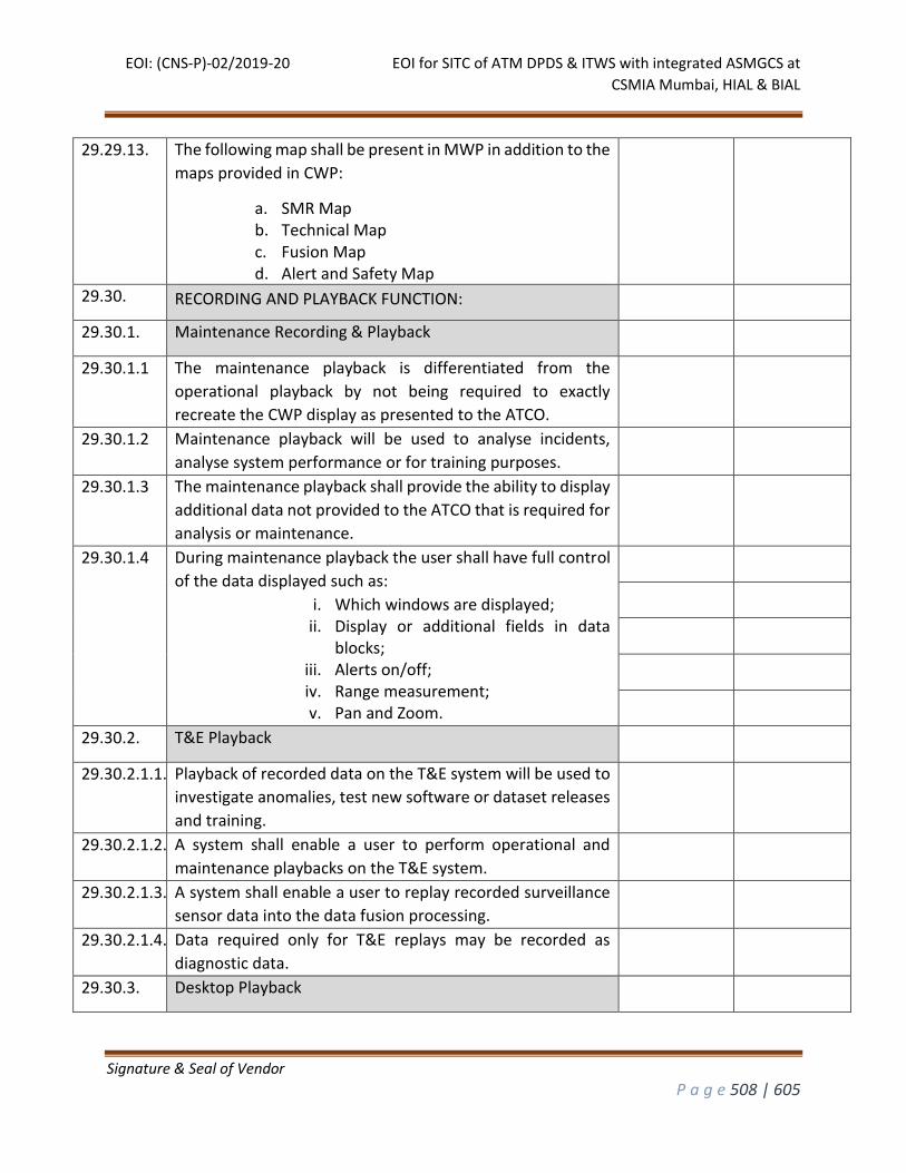
EOI: (CNS-P)-02/2019-20 EOI for SITC of ATM DPDS & ITWS with integrated ASMGCS at
CSMIA Mumbai, HIAL & BIAL
Signature & Seal of Vendor
P a g e 508 | 605
29.29.13. The following map shall be present in MWP in addition to the
maps provided in CWP:
a. SMR Map b. Technical Map c. Fusion Map d. Alert and Safety Map
29.30. RECORDING AND PLAYBACK FUNCTION:
29.30.1. Maintenance Recording & Playback
29.30.1.1 The maintenance playback is differentiated from the
operational playback by not being required to exactly
recreate the CWP display as presented to the ATCO.
29.30.1.2 Maintenance playback will be used to analyse incidents,
analyse system performance or for training purposes.
29.30.1.3 The maintenance playback shall provide the ability to display
additional data not provided to the ATCO that is required for
analysis or maintenance.
29.30.1.4 During maintenance playback the user shall have full control
of the data displayed such as:
i. Which windows are displayed; ii. Display or additional fields in data
blocks; iii. Alerts on/off; iv. Range measurement; v. Pan and Zoom.
29.30.2. T&E Playback
29.30.2.1.1. Playback of recorded data on the T&E system will be used to
investigate anomalies, test new software or dataset releases
and training.
29.30.2.1.2. A system shall enable a user to perform operational and
maintenance playbacks on the T&E system.
29.30.2.1.3. A system shall enable a user to replay recorded surveillance
sensor data into the data fusion processing.
29.30.2.1.4. Data required only for T&E replays may be recorded as
diagnostic data.
29.30.3. Desktop Playback
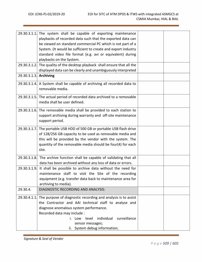
EOI: (CNS-P)-02/2019-20 EOI for SITC of ATM DPDS & ITWS with integrated ASMGCS at
CSMIA Mumbai, HIAL & BIAL
Signature & Seal of Vendor
P a g e 509 | 605
29.30.3.1.1. The system shall be capable of exporting maintenance
playbacks of recorded data such that the exported data can
be viewed on standard commercial PC which is not part of a
System. (It would be sufficient to create and export industry
standard video file format (e.g. avi or equivalent) during
playbacks on the System.
29.30.3.1.2. The quality of the desktop playback shall ensure that all the
displayed data can be clearly and unambiguously interpreted
29.30.3.1.3. Archiving
29.30.3.1.4. A System shall be capable of archiving all recorded data to
removable media.
29.30.3.1.5. The actual period of recorded data archived to a removable
media shall be user defined.
29.30.3.1.6. The removable media shall be provided to each station to
support archiving during warranty and off-site maintenance
support period.
29.30.3.1.7. The portable USB HDD of 500 GB or portable USB flash drive
of 128/256 GB capacity to be used as removable media and
this will be provided by the vendor with the system. The
quantity of the removable media should be four(4) for each
site.
29.30.3.1.8. The archive function shall be capable of validating that all
data has been archived without any loss of data or errors.
29.30.3.1.9. It shall be possible to archive data without the need for
maintenance staff to visit the Site of the recording
equipment (e.g. transfer data back to maintenance area for
archiving to media).
29.30.4. DIAGNOSTIC RECORDING AND ANALYSIS:
29.30.4.1.1. The purpose of diagnostic recording and analysis is to assist
the Contractor and AAI technical staff to analyse and
diagnose anomalous system performance.
Recorded data may include :
i. Low level individual surveillance sensor messages;
ii. System debug information;
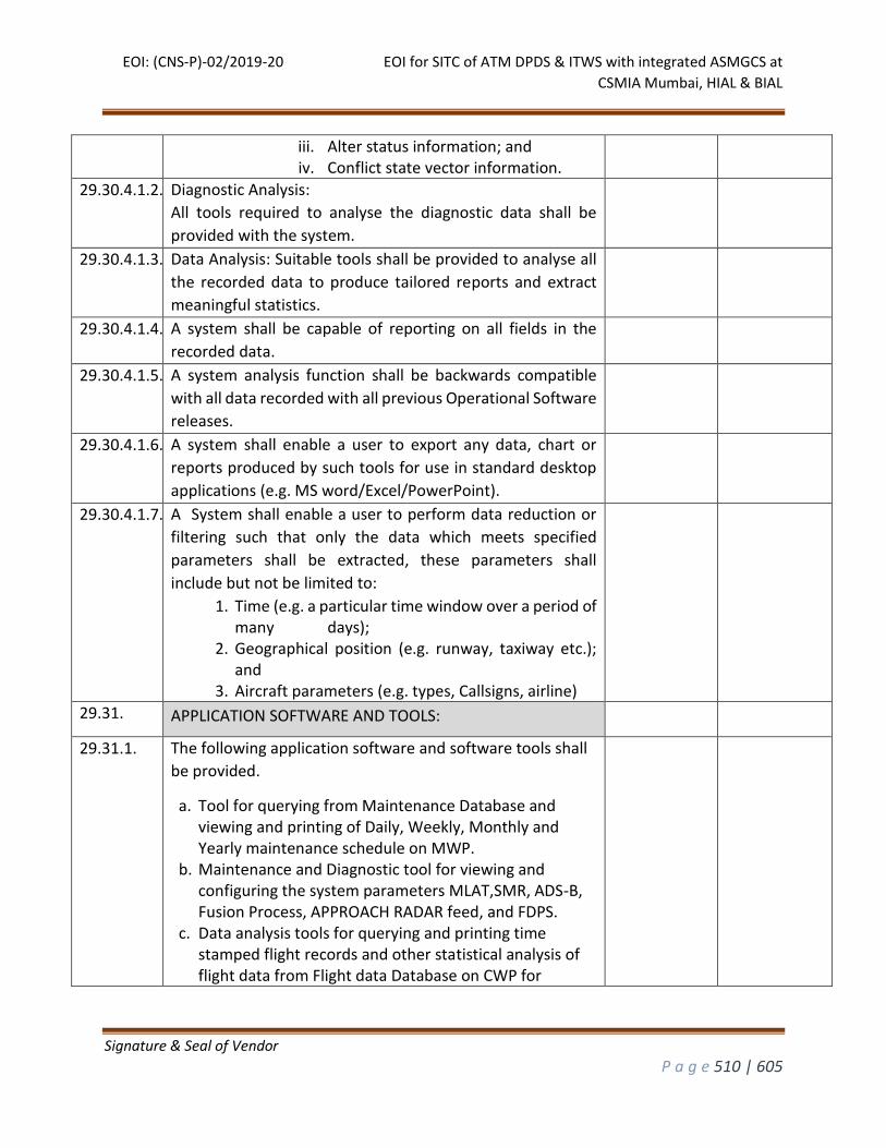
EOI: (CNS-P)-02/2019-20 EOI for SITC of ATM DPDS & ITWS with integrated ASMGCS at
CSMIA Mumbai, HIAL & BIAL
Signature & Seal of Vendor
P a g e 510 | 605
iii. Alter status information; and iv. Conflict state vector information.
29.30.4.1.2. Diagnostic Analysis:
All tools required to analyse the diagnostic data shall be
provided with the system.
29.30.4.1.3. Data Analysis: Suitable tools shall be provided to analyse all
the recorded data to produce tailored reports and extract
meaningful statistics.
29.30.4.1.4. A system shall be capable of reporting on all fields in the
recorded data.
29.30.4.1.5. A system analysis function shall be backwards compatible
with all data recorded with all previous Operational Software
releases.
29.30.4.1.6. A system shall enable a user to export any data, chart or
reports produced by such tools for use in standard desktop
applications (e.g. MS word/Excel/PowerPoint).
29.30.4.1.7. A System shall enable a user to perform data reduction or
filtering such that only the data which meets specified
parameters shall be extracted, these parameters shall
include but not be limited to:
1. Time (e.g. a particular time window over a period of many days);
2. Geographical position (e.g. runway, taxiway etc.); and
3. Aircraft parameters (e.g. types, Callsigns, airline)
29.31. APPLICATION SOFTWARE AND TOOLS:
29.31.1. The following application software and software tools shall
be provided.
a. Tool for querying from Maintenance Database and viewing and printing of Daily, Weekly, Monthly and Yearly maintenance schedule on MWP.
b. Maintenance and Diagnostic tool for viewing and configuring the system parameters MLAT,SMR, ADS-B, Fusion Process, APPROACH RADAR feed, and FDPS.
c. Data analysis tools for querying and printing time stamped flight records and other statistical analysis of flight data from Flight data Database on CWP for
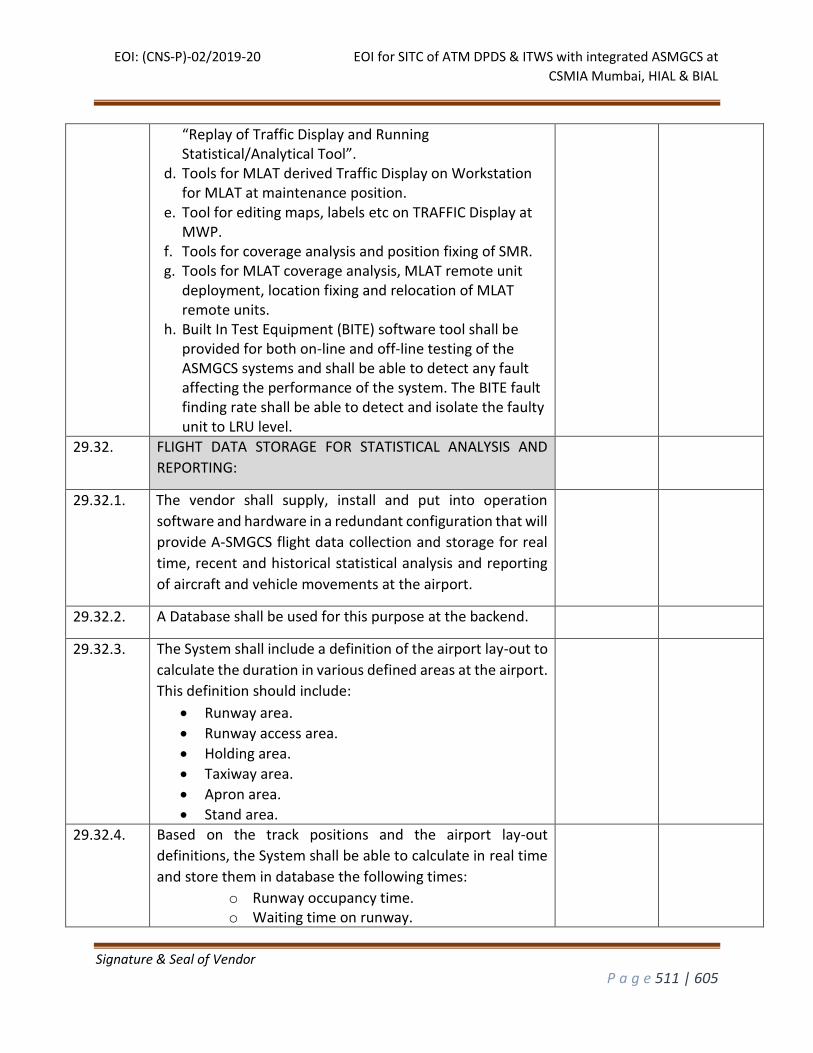
EOI: (CNS-P)-02/2019-20 EOI for SITC of ATM DPDS & ITWS with integrated ASMGCS at
CSMIA Mumbai, HIAL & BIAL
Signature & Seal of Vendor
P a g e 511 | 605
“Replay of Traffic Display and Running Statistical/Analytical Tool”.
d. Tools for MLAT derived Traffic Display on Workstation for MLAT at maintenance position.
e. Tool for editing maps, labels etc on TRAFFIC Display at MWP.
f. Tools for coverage analysis and position fixing of SMR. g. Tools for MLAT coverage analysis, MLAT remote unit
deployment, location fixing and relocation of MLAT remote units.
h. Built In Test Equipment (BITE) software tool shall be provided for both on-line and off-line testing of the ASMGCS systems and shall be able to detect any fault affecting the performance of the system. The BITE fault finding rate shall be able to detect and isolate the faulty unit to LRU level.
29.32. FLIGHT DATA STORAGE FOR STATISTICAL ANALYSIS AND
REPORTING:
29.32.1. The vendor shall supply, install and put into operation
software and hardware in a redundant configuration that will
provide A-SMGCS flight data collection and storage for real
time, recent and historical statistical analysis and reporting
of aircraft and vehicle movements at the airport.
29.32.2. A Database shall be used for this purpose at the backend.
29.32.3. The System shall include a definition of the airport lay-out to
calculate the duration in various defined areas at the airport.
This definition should include:
Runway area.
Runway access area.
Holding area.
Taxiway area.
Apron area.
Stand area.
29.32.4. Based on the track positions and the airport lay-out
definitions, the System shall be able to calculate in real time
and store them in database the following times:
o Runway occupancy time. o Waiting time on runway.
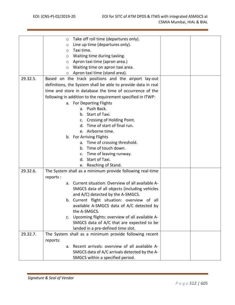
EOI: (CNS-P)-02/2019-20 EOI for SITC of ATM DPDS & ITWS with integrated ASMGCS at
CSMIA Mumbai, HIAL & BIAL
Signature & Seal of Vendor
P a g e 512 | 605
o Take off roll time (departures only). o Line up time (departures only). o Taxi time. o Waiting time during taxiing. o Apron taxi time (apron area.) o Waiting time on apron taxi area. o Apron taxi time (stand area).
29.32.5. Based on the track positions and the airport lay-out
definitions, the System shall be able to provide data in real
time and store in database the time of occurrence of the
following in addition to the requirement specified in ITWP:
a. For Departing Flights a. Push Back. b. Start of Taxi. c. Crossing of Holding Point. d. Time of start of final run. e. Airborne time.
b. For Arriving Flights a. Time of crossing threshold. b. Time of touch down. c. Time of leaving runway. d. Start of Taxi. e. Reaching of Stand.
29.32.6. The System shall as a minimum provide following real-time
reports :
a. Current situation: Overview of all available A-SMGCS data of all objects (including vehicles and A/C) detected by the A-SMGCS.
b. Current flight situation: overview of all available A-SMGCS data of A/C detected by the A-SMGCS.
c. Upcoming flights: overview of all available A-SMGCS data of A/C that are expected to be landed in a pre-defined time slot.
29.32.7. The System shall as a minimum provide following recent
reports:
a. Recent arrivals: overview of all available A-SMGCS data of A/C arrivals detected by the A-SMGCS within a specified period.
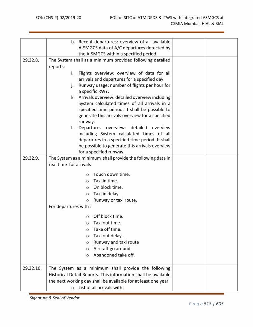
EOI: (CNS-P)-02/2019-20 EOI for SITC of ATM DPDS & ITWS with integrated ASMGCS at
CSMIA Mumbai, HIAL & BIAL
Signature & Seal of Vendor
P a g e 513 | 605
b. Recent departures: overview of all available A-SMGCS data of A/C departures detected by the A-SMGCS within a specified period.
29.32.8. The System shall as a minimum provided following detailed
reports:
i. Flights overview: overview of data for all arrivals and departures for a specified day.
j. Runway usage: number of flights per hour for a specific RWY.
k. Arrivals overview: detailed overview including System calculated times of all arrivals in a specified time period. It shall be possible to generate this arrivals overview for a specified runway.
l. Departures overview: detailed overview including System calculated times of all departures in a specified time period. It shall be possible to generate this arrivals overview for a specified runway.
29.32.9. The System as a minimum shall provide the following data in
real time for arrivals
o Touch down time.
o Taxi in time.
o On block time.
o Taxi in delay.
o Runway or taxi route.
For departures with :
o Off block time.
o Taxi out time.
o Take off time.
o Taxi out delay.
o Runway and taxi route
o Aircraft go around.
o Abandoned take off.
29.32.10. The System as a minimum shall provide the following
Historical Detail Reports. This information shall be available
the next working day shall be available for at least one year.
o List of all arrivals with:
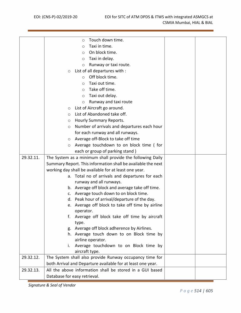
EOI: (CNS-P)-02/2019-20 EOI for SITC of ATM DPDS & ITWS with integrated ASMGCS at
CSMIA Mumbai, HIAL & BIAL
Signature & Seal of Vendor
P a g e 514 | 605
o Touch down time.
o Taxi in time.
o On block time.
o Taxi in delay.
o Runway or taxi route.
o List of all departures with :
o Off block time.
o Taxi out time.
o Take off time.
o Taxi out delay.
o Runway and taxi route
o List of Aircraft go around.
o List of Abandoned take off.
o Hourly Summary Reports.
o Number of arrivals and departures each hour
for each runway and all runways.
o Average off-Block to take off time
o Average touchdown to on block time ( for
each or group of parking stand )
29.32.11. The System as a minimum shall provide the following Daily
Summary Report. This information shall be available the next
working day shall be available for at least one year.
a. Total no of arrivals and departures for each runway and all runways.
b. Average off block and average take off time. c. Average touch down to on block time. d. Peak hour of arrival/departure of the day. e. Average off block to take off time by airline
operator. f. Average off block take off time by aircraft
type. g. Average off block adherence by Airlines. h. Average touch down to on Block time by
airline operator. i. Average touchdown to on Block time by
aircraft type.
29.32.12. The System shall also provide Runway occupancy time for
both Arrival and Departure available for at least one year.
29.32.13. All the above information shall be stored in a GUI based
Database for easy retrieval.
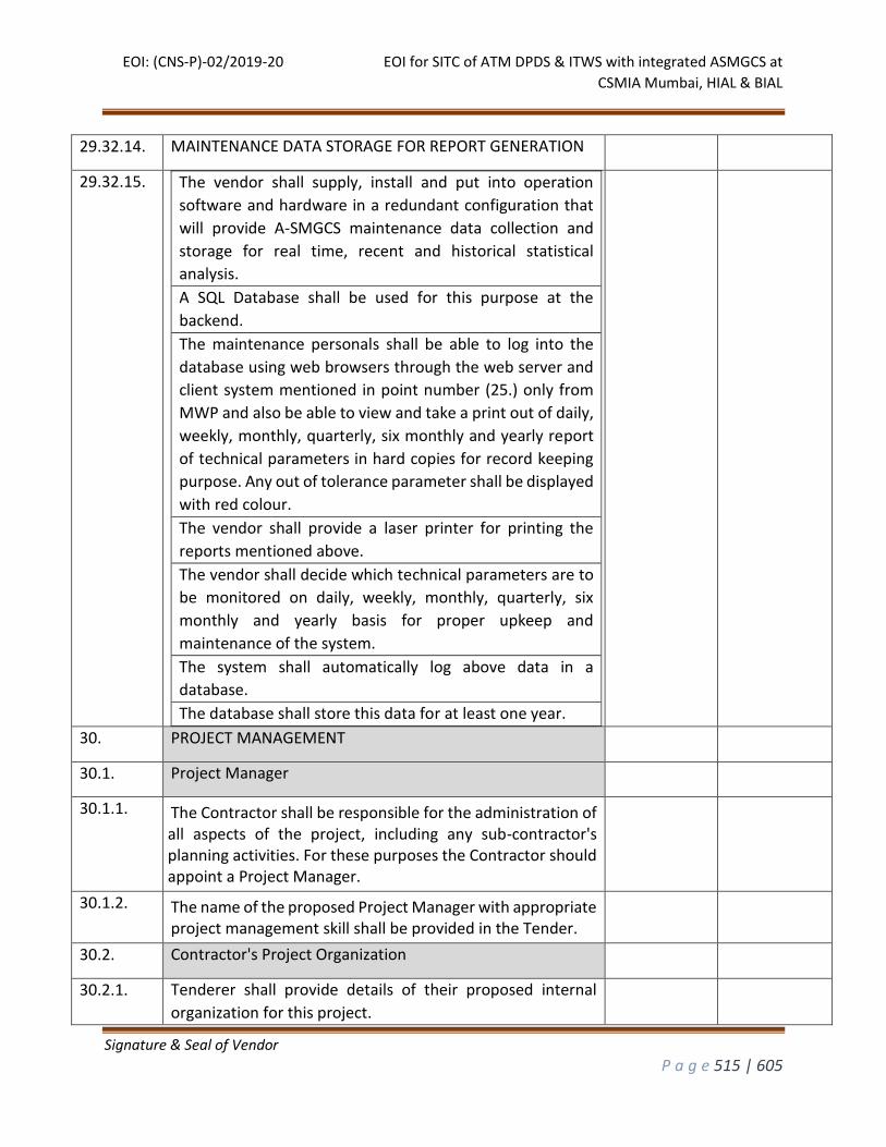
EOI: (CNS-P)-02/2019-20 EOI for SITC of ATM DPDS & ITWS with integrated ASMGCS at
CSMIA Mumbai, HIAL & BIAL
Signature & Seal of Vendor
P a g e 515 | 605
29.32.14. MAINTENANCE DATA STORAGE FOR REPORT GENERATION
29.32.15.
The vendor shall supply, install and put into operation
software and hardware in a redundant configuration that
will provide A-SMGCS maintenance data collection and
storage for real time, recent and historical statistical
analysis.
A SQL Database shall be used for this purpose at the
backend.
The maintenance personals shall be able to log into the
database using web browsers through the web server and
client system mentioned in point number (25.) only from
MWP and also be able to view and take a print out of daily,
weekly, monthly, quarterly, six monthly and yearly report
of technical parameters in hard copies for record keeping
purpose. Any out of tolerance parameter shall be displayed
with red colour.
The vendor shall provide a laser printer for printing the
reports mentioned above.
The vendor shall decide which technical parameters are to
be monitored on daily, weekly, monthly, quarterly, six
monthly and yearly basis for proper upkeep and
maintenance of the system.
The system shall automatically log above data in a
database.
The database shall store this data for at least one year.
30. PROJECT MANAGEMENT
30.1. Project Manager
30.1.1. The Contractor shall be responsible for the administration of all aspects of the project, including any sub-contractor's planning activities. For these purposes the Contractor should appoint a Project Manager.
30.1.2. The name of the proposed Project Manager with appropriate project management skill shall be provided in the Tender.
30.2. Contractor's Project Organization
30.2.1. Tenderer shall provide details of their proposed internal
organization for this project.
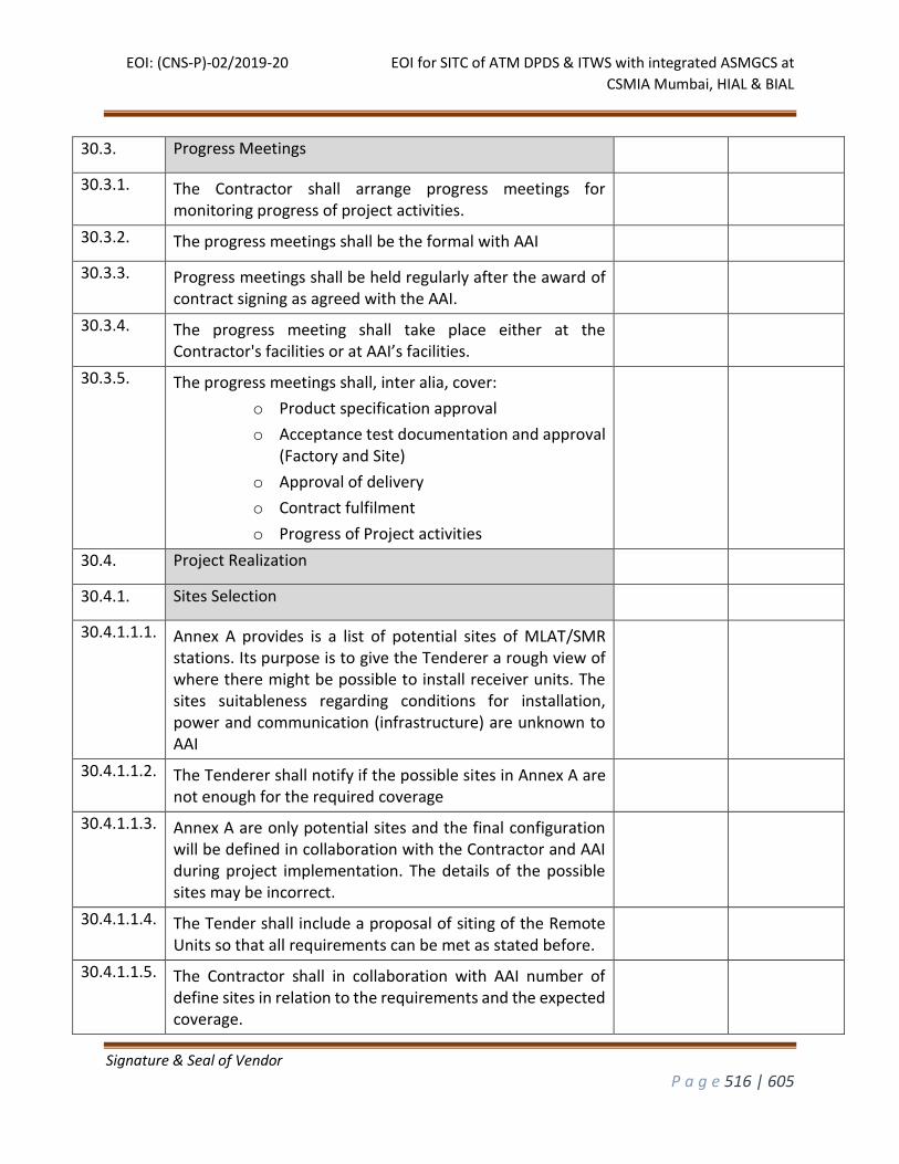
EOI: (CNS-P)-02/2019-20 EOI for SITC of ATM DPDS & ITWS with integrated ASMGCS at
CSMIA Mumbai, HIAL & BIAL
Signature & Seal of Vendor
P a g e 516 | 605
30.3. Progress Meetings
30.3.1. The Contractor shall arrange progress meetings for monitoring progress of project activities.
30.3.2. The progress meetings shall be the formal with AAI
30.3.3. Progress meetings shall be held regularly after the award of contract signing as agreed with the AAI.
30.3.4. The progress meeting shall take place either at the Contractor's facilities or at AAI’s facilities.
30.3.5. The progress meetings shall, inter alia, cover:
o Product specification approval
o Acceptance test documentation and approval (Factory and Site)
o Approval of delivery
o Contract fulfilment
o Progress of Project activities
30.4. Project Realization
30.4.1. Sites Selection
30.4.1.1.1. Annex A provides is a list of potential sites of MLAT/SMR stations. Its purpose is to give the Tenderer a rough view of where there might be possible to install receiver units. The sites suitableness regarding conditions for installation, power and communication (infrastructure) are unknown to AAI
30.4.1.1.2. The Tenderer shall notify if the possible sites in Annex A are not enough for the required coverage
30.4.1.1.3. Annex A are only potential sites and the final configuration will be defined in collaboration with the Contractor and AAI during project implementation. The details of the possible sites may be incorrect.
30.4.1.1.4. The Tender shall include a proposal of siting of the Remote Units so that all requirements can be met as stated before.
30.4.1.1.5. The Contractor shall in collaboration with AAI number of define sites in relation to the requirements and the expected coverage.
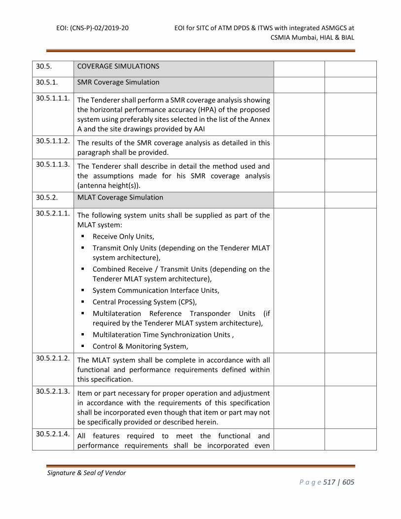
EOI: (CNS-P)-02/2019-20 EOI for SITC of ATM DPDS & ITWS with integrated ASMGCS at
CSMIA Mumbai, HIAL & BIAL
Signature & Seal of Vendor
P a g e 517 | 605
30.5. COVERAGE SIMULATIONS
30.5.1. SMR Coverage Simulation
30.5.1.1.1. The Tenderer shall perform a SMR coverage analysis showing the horizontal performance accuracy (HPA) of the proposed system using preferably sites selected in the list of the Annex A and the site drawings provided by AAI
30.5.1.1.2. The results of the SMR coverage analysis as detailed in this paragraph shall be provided.
30.5.1.1.3. The Tenderer shall describe in detail the method used and the assumptions made for his SMR coverage analysis (antenna height(s)).
30.5.2. MLAT Coverage Simulation
30.5.2.1.1. The following system units shall be supplied as part of the MLAT system:
Receive Only Units,
Transmit Only Units (depending on the Tenderer MLAT system architecture),
Combined Receive / Transmit Units (depending on the Tenderer MLAT system architecture),
System Communication Interface Units,
Central Processing System (CPS),
Multilateration Reference Transponder Units (if required by the Tenderer MLAT system architecture),
Multilateration Time Synchronization Units ,
Control & Monitoring System,
30.5.2.1.2. The MLAT system shall be complete in accordance with all functional and performance requirements defined within this specification.
30.5.2.1.3. Item or part necessary for proper operation and adjustment in accordance with the requirements of this specification shall be incorporated even though that item or part may not be specifically provided or described herein.
30.5.2.1.4. All features required to meet the functional and performance requirements shall be incorporated even

EOI: (CNS-P)-02/2019-20 EOI for SITC of ATM DPDS & ITWS with integrated ASMGCS at
CSMIA Mumbai, HIAL & BIAL
Signature & Seal of Vendor
P a g e 518 | 605
though the features may not be specifically provided for or described herein.
30.5.2.1.5. All necessary facilities, parts and hardware, including receptacles, connectors, cables, cabling (wiring), and outlets shall be incorporated to enable the components of the system to be properly assembled, interconnected, installed and maintained as required herein.
30.6. Elements to be supplied by the Contractor
30.6.1. MLAT Equipment
30.6.1.1.1. The following system units shall be supplied as part of the MLAT system:
o Receive Only Units,
o Transmit Only Units (depending on the Tenderer MLAT system architecture),
o Combined Receive / Transmit Units (depending on the Tenderer MLAT system architecture),
o System Communication Interface Units,
o Central Processing System (CPS),
o Multilateration Reference Transponder Units (if required by the Tenderer MLAT system architecture),
o Multilateration Time Synchronization Units ,
o Control & Monitoring System,
30.6.1.1.2. The MLAT system shall be complete in accordance with all functional and performance requirements defined within this specification.
30.6.1.1.3. Item or part necessary for proper operation and adjustment in accordance with the requirements of this specification shall be incorporated even though that item or part may not be specifically provided or described herein.
30.6.1.1.4. All features required to meet the functional and performance requirements shall be incorporated even though the features may not be specifically provided for or described herein.
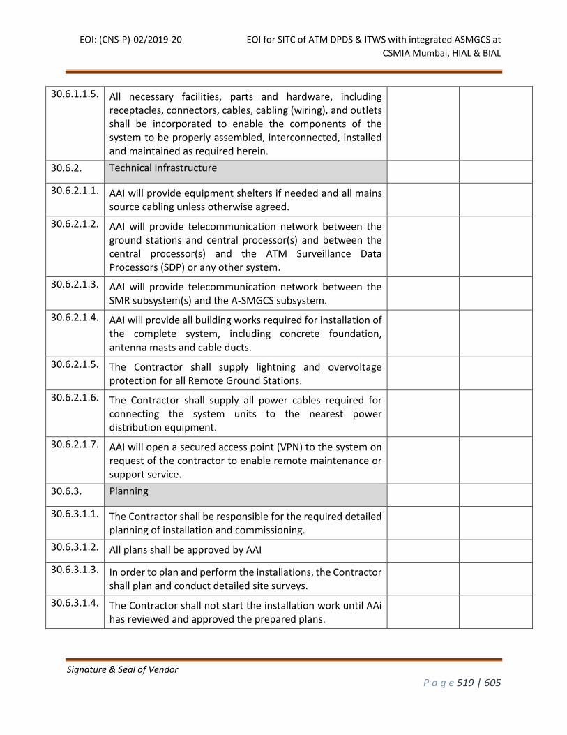
EOI: (CNS-P)-02/2019-20 EOI for SITC of ATM DPDS & ITWS with integrated ASMGCS at
CSMIA Mumbai, HIAL & BIAL
Signature & Seal of Vendor
P a g e 519 | 605
30.6.1.1.5. All necessary facilities, parts and hardware, including receptacles, connectors, cables, cabling (wiring), and outlets shall be incorporated to enable the components of the system to be properly assembled, interconnected, installed and maintained as required herein.
30.6.2. Technical Infrastructure
30.6.2.1.1. AAI will provide equipment shelters if needed and all mains source cabling unless otherwise agreed.
30.6.2.1.2. AAI will provide telecommunication network between the ground stations and central processor(s) and between the central processor(s) and the ATM Surveillance Data Processors (SDP) or any other system.
30.6.2.1.3. AAI will provide telecommunication network between the SMR subsystem(s) and the A-SMGCS subsystem.
30.6.2.1.4. AAI will provide all building works required for installation of the complete system, including concrete foundation, antenna masts and cable ducts.
30.6.2.1.5. The Contractor shall supply lightning and overvoltage protection for all Remote Ground Stations.
30.6.2.1.6. The Contractor shall supply all power cables required for connecting the system units to the nearest power distribution equipment.
30.6.2.1.7. AAI will open a secured access point (VPN) to the system on request of the contractor to enable remote maintenance or support service.
30.6.3. Planning
30.6.3.1.1. The Contractor shall be responsible for the required detailed planning of installation and commissioning.
30.6.3.1.2. All plans shall be approved by AAI
30.6.3.1.3. In order to plan and perform the installations, the Contractor shall plan and conduct detailed site surveys.
30.6.3.1.4. The Contractor shall not start the installation work until AAi has reviewed and approved the prepared plans.
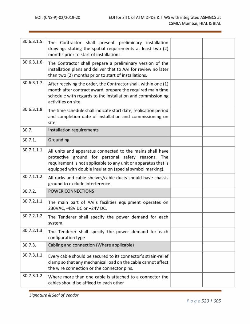
EOI: (CNS-P)-02/2019-20 EOI for SITC of ATM DPDS & ITWS with integrated ASMGCS at
CSMIA Mumbai, HIAL & BIAL
Signature & Seal of Vendor
P a g e 520 | 605
30.6.3.1.5. The Contractor shall present preliminary installation drawings stating the spatial requirements at least two (2) months prior to start of installations.
30.6.3.1.6. The Contractor shall prepare a preliminary version of the installation plans and deliver that to AAI for review no later than two (2) months prior to start of installations.
30.6.3.1.7. After receiving the order, the Contractor shall, within one (1) month after contract award, prepare the required main time schedule with regards to the installation and commissioning activities on site.
30.6.3.1.8. The time schedule shall indicate start date, realisation period and completion date of installation and commissioning on site.
30.7. Installation requirements
30.7.1. Grounding
30.7.1.1.1. All units and apparatus connected to the mains shall have protective ground for personal safety reasons. The requirement is not applicable to any unit or apparatus that is equipped with double insulation (special symbol marking).
30.7.1.1.2. All racks and cable shelves/cable ducts should have chassis ground to exclude interference.
30.7.2. POWER CONNECTIONS
30.7.2.1.1. The main part of AAi`s facilities equipment operates on 230VAC, -48V DC or +24V DC.
30.7.2.1.2. The Tenderer shall specify the power demand for each system.
30.7.2.1.3. The Tenderer shall specify the power demand for each configuration type
30.7.3. Cabling and connection (Where applicable)
30.7.3.1.1. Every cable should be secured to its connector’s strain-relief clamp so that any mechanical load on the cable cannot affect the wire connection or the connector pins.
30.7.3.1.2. Where more than one cable is attached to a connector the cables should be affixed to each other

EOI: (CNS-P)-02/2019-20 EOI for SITC of ATM DPDS & ITWS with integrated ASMGCS at
CSMIA Mumbai, HIAL & BIAL
Signature & Seal of Vendor
P a g e 521 | 605
30.7.3.1.3. The cables should include some reserve wiring.
30.7.3.1.4. The cables should be of such a type (shielded, twisted in pairs, etc.) that the risk of interference is minimised.
30.7.3.1.5. All connectors shall be marked.
30.7.4. MARKINGS
30.7.4.1.1. All marking of the installations at different sites shall be uniform.
30.7.4.1.2. Marking shall be applied to these types of objects:
cables for electrical power, telecommunication and ground systems;
cabinets and racks;
units in cabinets and racks;
trunking.
30.7.4.1.3. The marking shall include:
labels on the equipment units, stating the designation;
cable number and location marking of the cable;
colour marking of the cable shelves or cable ducts that is used to separate trunking for power and telecommunication;
marking of electrical cable conductors, etc.
30.7.4.1.4. The marking shall be visibly placed and flexible.
30.7.4.1.5. Marking and documentation shall correspond.
30.7.5. Cleaning
30.7.5.1.1. The Contractor shall remove wrappings and packaging in an environmentally friendly and statutory way after work has been completed.
30.7.5.1.2. Such material shall not be stored within AAI premises any longer than needed for the related installation activity.
30.8. Verification and Validation
30.8.1. Factory Acceptance Test (FAT)
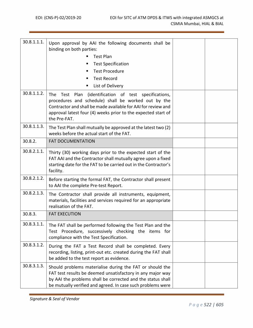
EOI: (CNS-P)-02/2019-20 EOI for SITC of ATM DPDS & ITWS with integrated ASMGCS at
CSMIA Mumbai, HIAL & BIAL
Signature & Seal of Vendor
P a g e 522 | 605
30.8.1.1.1. Upon approval by AAI the following documents shall be binding on both parties:
Test Plan
Test Specification
Test Procedure
Test Record
List of Delivery
30.8.1.1.2. The Test Plan (identification of test specifications, procedures and schedule) shall be worked out by the Contractor and shall be made available for AAI for review and approval latest four (4) weeks prior to the expected start of the Pre-FAT.
30.8.1.1.3. The Test Plan shall mutually be approved at the latest two (2) weeks before the actual start of the FAT.
30.8.2. FAT DOCUMENTATION
30.8.2.1.1. Thirty (30) working days prior to the expected start of the FAT AAI and the Contractor shall mutually agree upon a fixed starting date for the FAT to be carried out in the Contractor’s facility.
30.8.2.1.2. Before starting the formal FAT, the Contractor shall present to AAI the complete Pre-test Report.
30.8.2.1.3. The Contractor shall provide all instruments, equipment, materials, facilities and services required for an appropriate realisation of the FAT.
30.8.3. FAT EXECUTION
30.8.3.1.1. The FAT shall be performed following the Test Plan and the Test Procedure, successively checking the items for compliance with the Test Specification.
30.8.3.1.2. During the FAT a Test Record shall be completed. Every recording, listing, print-out etc. created during the FAT shall be added to the test report as evidence.
30.8.3.1.3. Should problems materialise during the FAT or should the FAT test results be deemed unsatisfactory in any major way by AAI the problems shall be corrected and the status shall be mutually verified and agreed. In case such problems were
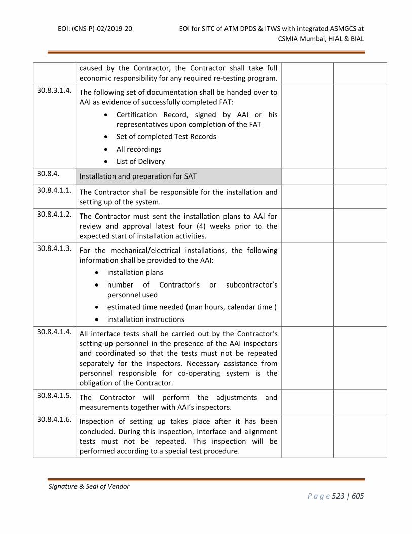
EOI: (CNS-P)-02/2019-20 EOI for SITC of ATM DPDS & ITWS with integrated ASMGCS at
CSMIA Mumbai, HIAL & BIAL
Signature & Seal of Vendor
P a g e 523 | 605
caused by the Contractor, the Contractor shall take full economic responsibility for any required re-testing program.
30.8.3.1.4. The following set of documentation shall be handed over to AAI as evidence of successfully completed FAT:
Certification Record, signed by AAI or his representatives upon completion of the FAT
Set of completed Test Records
All recordings
List of Delivery
30.8.4. Installation and preparation for SAT
30.8.4.1.1. The Contractor shall be responsible for the installation and setting up of the system.
30.8.4.1.2. The Contractor must sent the installation plans to AAI for review and approval latest four (4) weeks prior to the expected start of installation activities.
30.8.4.1.3. For the mechanical/electrical installations, the following information shall be provided to the AAI:
installation plans
number of Contractor's or subcontractor’s personnel used
estimated time needed (man hours, calendar time )
installation instructions
30.8.4.1.4. All interface tests shall be carried out by the Contractor's setting-up personnel in the presence of the AAI inspectors and coordinated so that the tests must not be repeated separately for the inspectors. Necessary assistance from personnel responsible for co-operating system is the obligation of the Contractor.
30.8.4.1.5. The Contractor will perform the adjustments and measurements together with AAI’s inspectors.
30.8.4.1.6. Inspection of setting up takes place after it has been concluded. During this inspection, interface and alignment tests must not be repeated. This inspection will be performed according to a special test procedure.
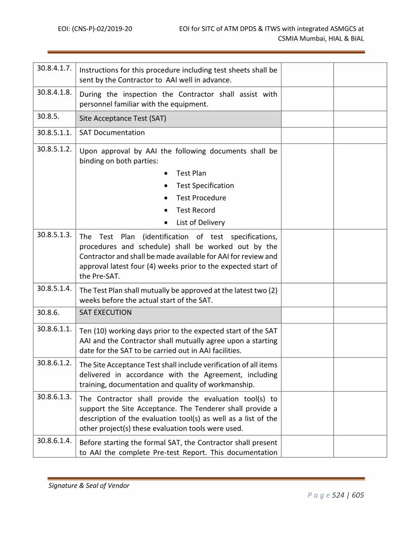
EOI: (CNS-P)-02/2019-20 EOI for SITC of ATM DPDS & ITWS with integrated ASMGCS at
CSMIA Mumbai, HIAL & BIAL
Signature & Seal of Vendor
P a g e 524 | 605
30.8.4.1.7. Instructions for this procedure including test sheets shall be sent by the Contractor to AAI well in advance.
30.8.4.1.8. During the inspection the Contractor shall assist with personnel familiar with the equipment.
30.8.5. Site Acceptance Test (SAT)
30.8.5.1.1. SAT Documentation
30.8.5.1.2. Upon approval by AAI the following documents shall be binding on both parties:
Test Plan
Test Specification
Test Procedure
Test Record
List of Delivery
30.8.5.1.3. The Test Plan (identification of test specifications, procedures and schedule) shall be worked out by the Contractor and shall be made available for AAI for review and approval latest four (4) weeks prior to the expected start of the Pre-SAT.
30.8.5.1.4. The Test Plan shall mutually be approved at the latest two (2) weeks before the actual start of the SAT.
30.8.6. SAT EXECUTION
30.8.6.1.1. Ten (10) working days prior to the expected start of the SAT AAI and the Contractor shall mutually agree upon a starting date for the SAT to be carried out in AAI facilities.
30.8.6.1.2. The Site Acceptance Test shall include verification of all items delivered in accordance with the Agreement, including training, documentation and quality of workmanship.
30.8.6.1.3. The Contractor shall provide the evaluation tool(s) to support the Site Acceptance. The Tenderer shall provide a description of the evaluation tool(s) as well as a list of the other project(s) these evaluation tools were used.
30.8.6.1.4. Before starting the formal SAT, the Contractor shall present to AAI the complete Pre-test Report. This documentation
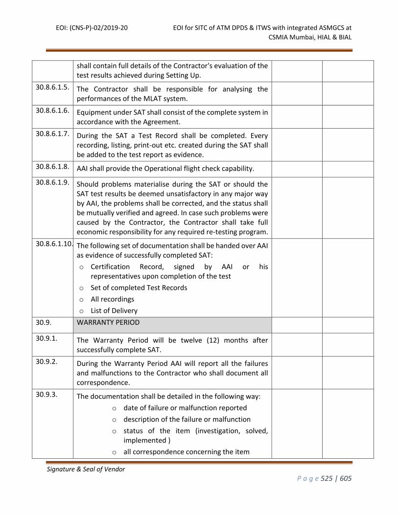
EOI: (CNS-P)-02/2019-20 EOI for SITC of ATM DPDS & ITWS with integrated ASMGCS at
CSMIA Mumbai, HIAL & BIAL
Signature & Seal of Vendor
P a g e 525 | 605
shall contain full details of the Contractor's evaluation of the test results achieved during Setting Up.
30.8.6.1.5. The Contractor shall be responsible for analysing the performances of the MLAT system.
30.8.6.1.6. Equipment under SAT shall consist of the complete system in accordance with the Agreement.
30.8.6.1.7. During the SAT a Test Record shall be completed. Every recording, listing, print-out etc. created during the SAT shall be added to the test report as evidence.
30.8.6.1.8. AAI shall provide the Operational flight check capability.
30.8.6.1.9. Should problems materialise during the SAT or should the SAT test results be deemed unsatisfactory in any major way by AAI, the problems shall be corrected, and the status shall be mutually verified and agreed. In case such problems were caused by the Contractor, the Contractor shall take full economic responsibility for any required re-testing program.
30.8.6.1.10. The following set of documentation shall be handed over AAI as evidence of successfully completed SAT:
o Certification Record, signed by AAI or his representatives upon completion of the test
o Set of completed Test Records
o All recordings
o List of Delivery
30.9. WARRANTY PERIOD
30.9.1. The Warranty Period will be twelve (12) months after successfully complete SAT.
30.9.2. During the Warranty Period AAI will report all the failures and malfunctions to the Contractor who shall document all correspondence.
30.9.3. The documentation shall be detailed in the following way:
o date of failure or malfunction reported
o description of the failure or malfunction
o status of the item (investigation, solved, implemented )
o all correspondence concerning the item

EOI: (CNS-P)-02/2019-20 EOI for SITC of ATM DPDS & ITWS with integrated ASMGCS at
CSMIA Mumbai, HIAL & BIAL
Signature & Seal of Vendor
P a g e 526 | 605
o special, mutually agreed information
30.9.4. To enable the investigation of warranty claims, the Contractor will be provided with all information and material deemed necessary.
30.9.5. Spare parts shall be available 10 years after the start of warranty period.
30.10. LOGISTICS
30.10.1. DOCUMENTATION
30.10.1.1.1. The system documentation shall include complete technical and operational manuals for each equipment and part of the system consisting at least:
System description
Technical data
Complete instructions for operation and maintenance
30.10.1.1.2. The documentation shall be up to date with the system accepted by the AAI
30.10.1.1.3. The documentation shall be provided in English.
30.10.1.1.4. To assist any further modification and use of the documentation it should be available also in electronic data form with suitable media.
30.10.2. ASMGCS TRAINING
30.10.2.1.1. The following categories of training shall be provided:
o Maintenance and Installation Training for maintenance personal.
o System Administration, Calibration and Optimization Training for maintenance personal.
30.10.2.1.2. The Contractor shall provide Installation and Maintenance
Training for One batch consisting of ten(10) CNS Engineers
for not less than two(2) weeks at factory premises of OEM or
SI before the dispatch of the equipment by OEM expert
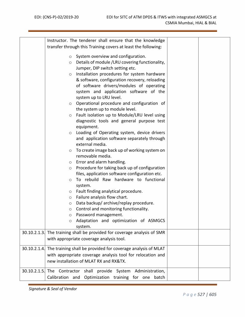
EOI: (CNS-P)-02/2019-20 EOI for SITC of ATM DPDS & ITWS with integrated ASMGCS at
CSMIA Mumbai, HIAL & BIAL
Signature & Seal of Vendor
P a g e 527 | 605
Instructor. The tenderer shall ensure that the knowledge
transfer through this Training covers at least the following:
o System overview and configuration. o Details of module /LRU covering functionality,
Jumper, DIP switch setting etc. o Installation procedures for system hardware
& software, configuration recovery, reloading of software drivers/modules of operating system and application software of the system up to LRU level.
o Operational procedure and configuration of the system up to module level.
o Fault isolation up to Module/LRU level using diagnostic tools and general purpose test equipment.
o Loading of Operating system, device drivers and application software separately through external media.
o To create image back up of working system on removable media.
o Error and alarm handling. o Procedure for taking back up of configuration
files, application software configuration etc. o To rebuild Raw hardware to functional
system. o Fault finding analytical procedure. o Failure analysis flow chart. o Data backup/ archive/replay procedure. o Control and monitoring functionality. o Password management. o Adaptation and optimization of ASMGCS
system.
30.10.2.1.3. The training shall be provided for coverage analysis of SMR
with appropriate coverage analysis tool.
30.10.2.1.4. The training shall be provided for coverage analysis of MLAT
with appropriate coverage analysis tool for relocation and
new installation of MLAT RX and RX&TX.
30.10.2.1.5. The Contractor shall provide System Administration,
Calibration and Optimization training for one batch
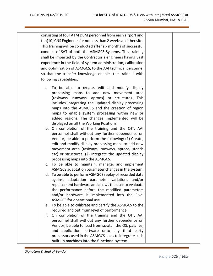
EOI: (CNS-P)-02/2019-20 EOI for SITC of ATM DPDS & ITWS with integrated ASMGCS at
CSMIA Mumbai, HIAL & BIAL
Signature & Seal of Vendor
P a g e 528 | 605
consisting of four ATM DBM personnel from each airport and
ten(10) CNS Engineers for not less than 2 weeks at either site.
This training will be conducted after six months of successful
conduct of SAT of both the ASMGCS Systems. This training
shall be imparted by the Contractor’s engineers having vast
experience in the field of system administration, calibration
and optimization of ASMGCS, to the AAI technical personnel
so that the transfer knowledge enables the trainees with
following capabilities:
a. To be able to create, edit and modify display processing maps to add new movement area (taxiways, runways, aprons) or structures. This includes integrating the updated display processing maps into the ASMGCS and the creation of region maps to enable system processing within new or added regions. The changes implemented will be displayed on all the Working Positions.
b. On completion of the training and the OJT, AAI personnel shall without any further dependence on Vendor, be able to perform the following: (1) Create, edit and modify display processing maps to add new movement area (taxiways, runways, aprons, stands etc) or structures. (2) Integrate the updated display processing maps into the ASMGCS.
c. To be able to maintain, manage, and implement ASMGCS adaptation parameter changes in the system.
d. To be able to perform ASMGCS replay of recorded data against adaptation parameter variations and/or replacement hardware and allows the user to evaluate the performance before the modified parameters and/or hardware is implemented into the ‘live’ ASMGCS for operational use.
e. To be able to calibrate and certify the ASMGCS to the required and optimum level of performance.
f. On completion of the training and the OJT, AAI personnel shall without any further dependence on Vendor, be able to load from scratch the OS, patches, and application software onto any third party processors used in the ASMGCS so as to integrate such built up machines into the functional system.
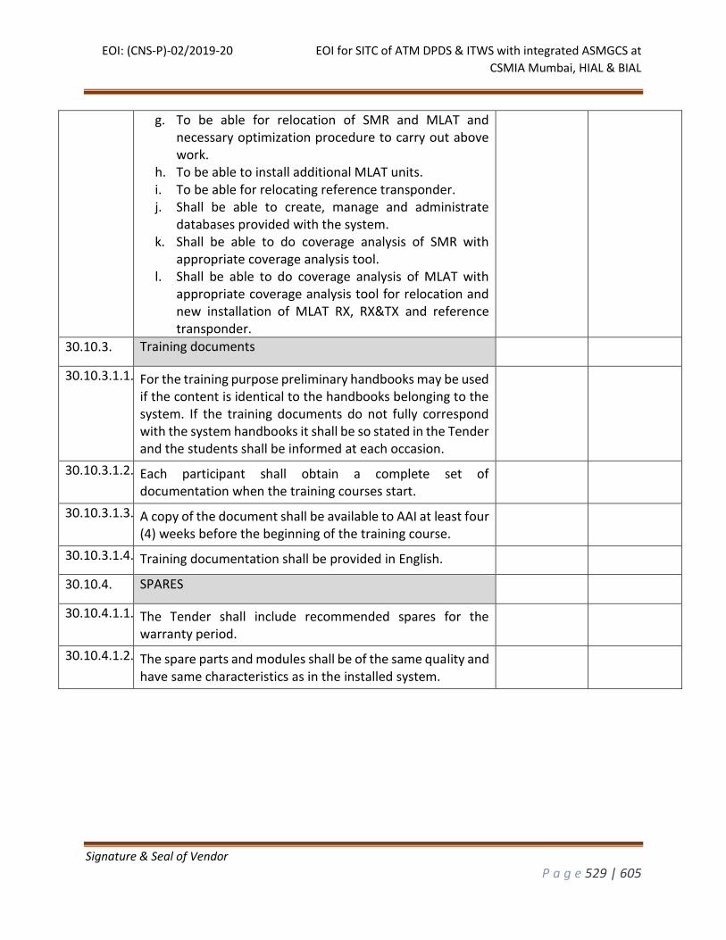
EOI: (CNS-P)-02/2019-20 EOI for SITC of ATM DPDS & ITWS with integrated ASMGCS at
CSMIA Mumbai, HIAL & BIAL
Signature & Seal of Vendor
P a g e 529 | 605
g. To be able for relocation of SMR and MLAT and necessary optimization procedure to carry out above work.
h. To be able to install additional MLAT units. i. To be able for relocating reference transponder. j. Shall be able to create, manage and administrate
databases provided with the system. k. Shall be able to do coverage analysis of SMR with
appropriate coverage analysis tool. l. Shall be able to do coverage analysis of MLAT with
appropriate coverage analysis tool for relocation and new installation of MLAT RX, RX&TX and reference transponder.
30.10.3. Training documents
30.10.3.1.1. For the training purpose preliminary handbooks may be used if the content is identical to the handbooks belonging to the system. If the training documents do not fully correspond with the system handbooks it shall be so stated in the Tender and the students shall be informed at each occasion.
30.10.3.1.2. Each participant shall obtain a complete set of documentation when the training courses start.
30.10.3.1.3. A copy of the document shall be available to AAI at least four (4) weeks before the beginning of the training course.
30.10.3.1.4. Training documentation shall be provided in English.
30.10.4. SPARES
30.10.4.1.1. The Tender shall include recommended spares for the warranty period.
30.10.4.1.2. The spare parts and modules shall be of the same quality and have same characteristics as in the installed system.
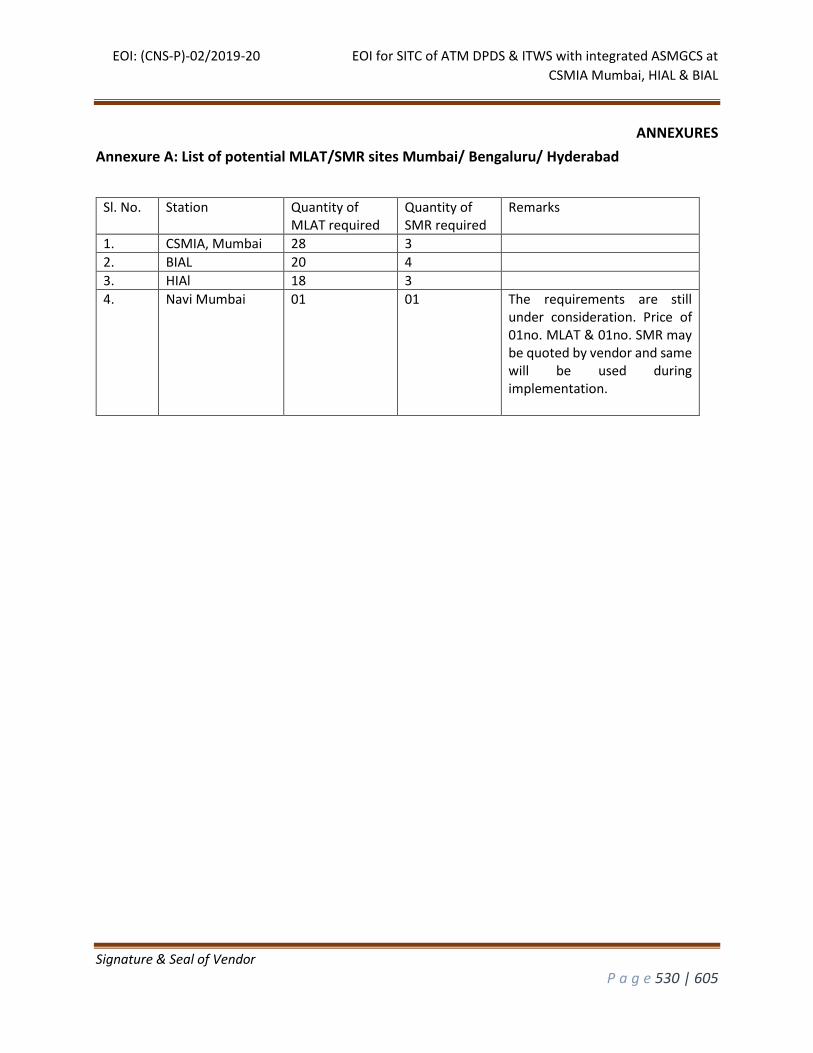
EOI: (CNS-P)-02/2019-20 EOI for SITC of ATM DPDS & ITWS with integrated ASMGCS at
CSMIA Mumbai, HIAL & BIAL
Signature & Seal of Vendor
P a g e 530 | 605
ANNEXURES
Annexure A: List of potential MLAT/SMR sites Mumbai/ Bengaluru/ Hyderabad
Sl. No. Station Quantity of MLAT required
Quantity of SMR required
Remarks
1. CSMIA, Mumbai 28 3
2. BIAL 20 4
3. HIAl 18 3
4. Navi Mumbai 01 01 The requirements are still under consideration. Price of 01no. MLAT & 01no. SMR may be quoted by vendor and same will be used during implementation.
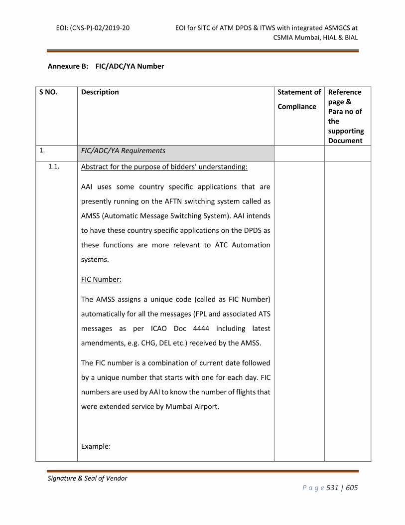
EOI: (CNS-P)-02/2019-20 EOI for SITC of ATM DPDS & ITWS with integrated ASMGCS at
CSMIA Mumbai, HIAL & BIAL
Signature & Seal of Vendor
P a g e 531 | 605
Annexure B: FIC/ADC/YA Number
S NO. Description Statement of
Compliance
Reference page & Para no of the supporting Document
1. FIC/ADC/YA Requirements
1.1. Abstract for the purpose of bidders’ understanding:
AAI uses some country specific applications that are
presently running on the AFTN switching system called as
AMSS (Automatic Message Switching System). AAI intends
to have these country specific applications on the DPDS as
these functions are more relevant to ATC Automation
systems.
FIC Number:
The AMSS assigns a unique code (called as FIC Number)
automatically for all the messages (FPL and associated ATS
messages as per ICAO Doc 4444 including latest
amendments, e.g. CHG, DEL etc.) received by the AMSS.
The FIC number is a combination of current date followed
by a unique number that starts with one for each day. FIC
numbers are used by AAI to know the number of flights that
were extended service by Mumbai Airport.
Example:
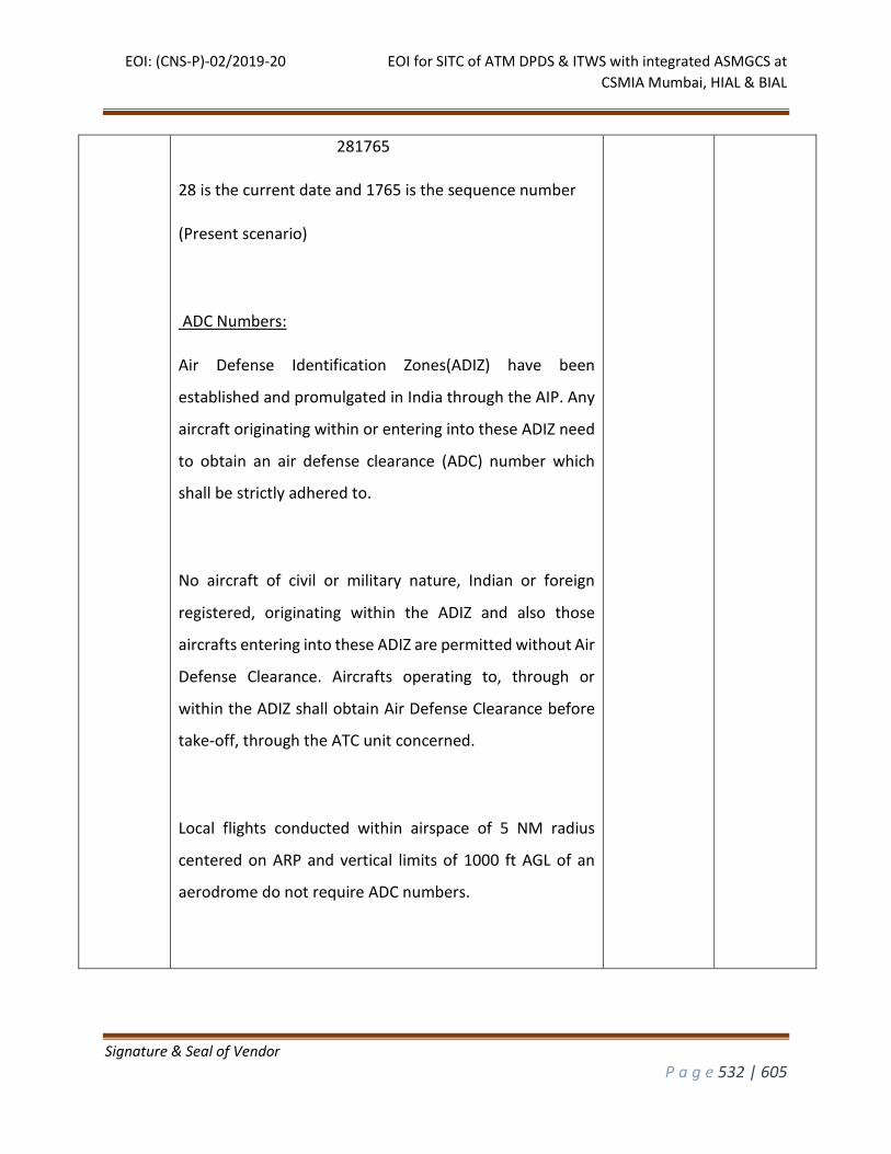
EOI: (CNS-P)-02/2019-20 EOI for SITC of ATM DPDS & ITWS with integrated ASMGCS at
CSMIA Mumbai, HIAL & BIAL
Signature & Seal of Vendor
P a g e 532 | 605
281765
28 is the current date and 1765 is the sequence number
(Present scenario)
ADC Numbers:
Air Defense Identification Zones(ADIZ) have been
established and promulgated in India through the AIP. Any
aircraft originating within or entering into these ADIZ need
to obtain an air defense clearance (ADC) number which
shall be strictly adhered to.
No aircraft of civil or military nature, Indian or foreign
registered, originating within the ADIZ and also those
aircrafts entering into these ADIZ are permitted without Air
Defense Clearance. Aircrafts operating to, through or
within the ADIZ shall obtain Air Defense Clearance before
take-off, through the ATC unit concerned.
Local flights conducted within airspace of 5 NM radius
centered on ARP and vertical limits of 1000 ft AGL of an
aerodrome do not require ADC numbers.
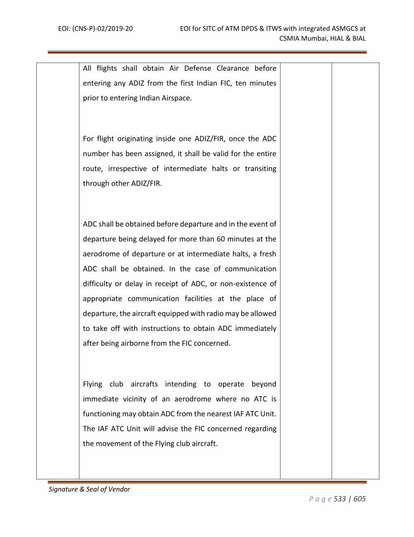
EOI: (CNS-P)-02/2019-20 EOI for SITC of ATM DPDS & ITWS with integrated ASMGCS at
CSMIA Mumbai, HIAL & BIAL
Signature & Seal of Vendor
P a g e 533 | 605
All flights shall obtain Air Defense Clearance before
entering any ADIZ from the first Indian FIC, ten minutes
prior to entering Indian Airspace.
For flight originating inside one ADIZ/FIR, once the ADC
number has been assigned, it shall be valid for the entire
route, irrespective of intermediate halts or transiting
through other ADIZ/FIR.
ADC shall be obtained before departure and in the event of
departure being delayed for more than 60 minutes at the
aerodrome of departure or at intermediate halts, a fresh
ADC shall be obtained. In the case of communication
difficulty or delay in receipt of ADC, or non-existence of
appropriate communication facilities at the place of
departure, the aircraft equipped with radio may be allowed
to take off with instructions to obtain ADC immediately
after being airborne from the FIC concerned.
Flying club aircrafts intending to operate beyond
immediate vicinity of an aerodrome where no ATC is
functioning may obtain ADC from the nearest IAF ATC Unit.
The IAF ATC Unit will advise the FIC concerned regarding
the movement of the Flying club aircraft.
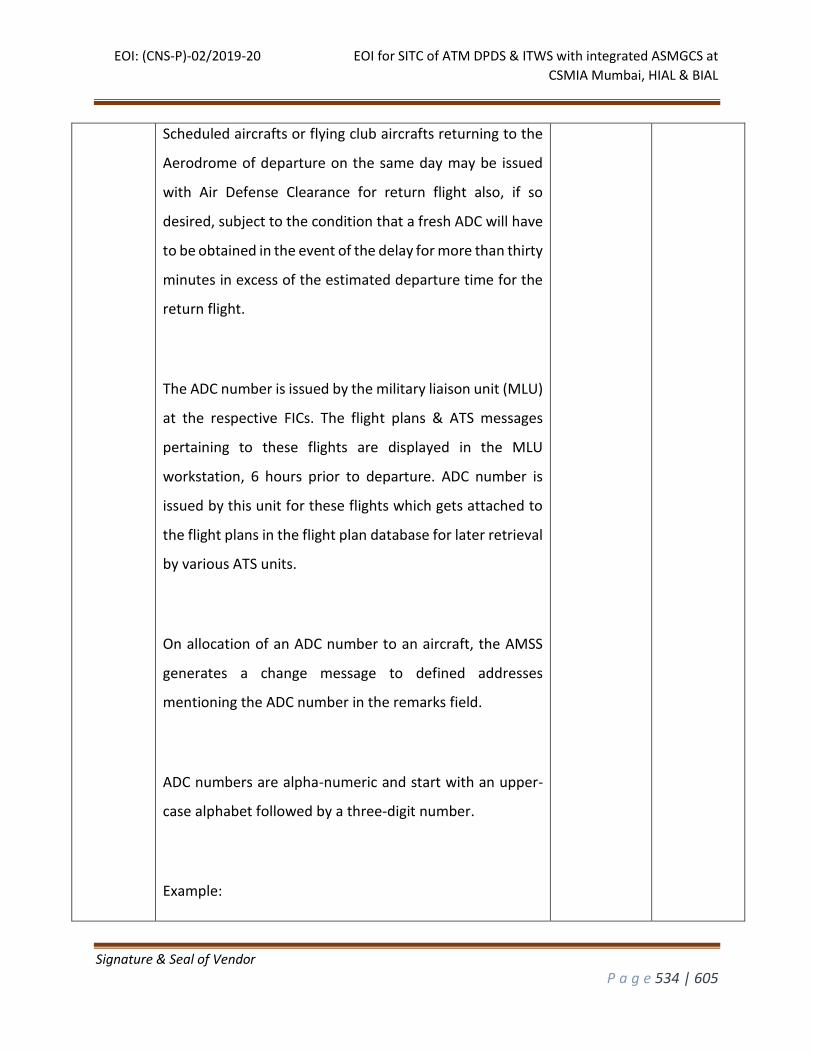
EOI: (CNS-P)-02/2019-20 EOI for SITC of ATM DPDS & ITWS with integrated ASMGCS at
CSMIA Mumbai, HIAL & BIAL
Signature & Seal of Vendor
P a g e 534 | 605
Scheduled aircrafts or flying club aircrafts returning to the
Aerodrome of departure on the same day may be issued
with Air Defense Clearance for return flight also, if so
desired, subject to the condition that a fresh ADC will have
to be obtained in the event of the delay for more than thirty
minutes in excess of the estimated departure time for the
return flight.
The ADC number is issued by the military liaison unit (MLU)
at the respective FICs. The flight plans & ATS messages
pertaining to these flights are displayed in the MLU
workstation, 6 hours prior to departure. ADC number is
issued by this unit for these flights which gets attached to
the flight plans in the flight plan database for later retrieval
by various ATS units.
On allocation of an ADC number to an aircraft, the AMSS
generates a change message to defined addresses
mentioning the ADC number in the remarks field.
ADC numbers are alpha-numeric and start with an upper-
case alphabet followed by a three-digit number.
Example:
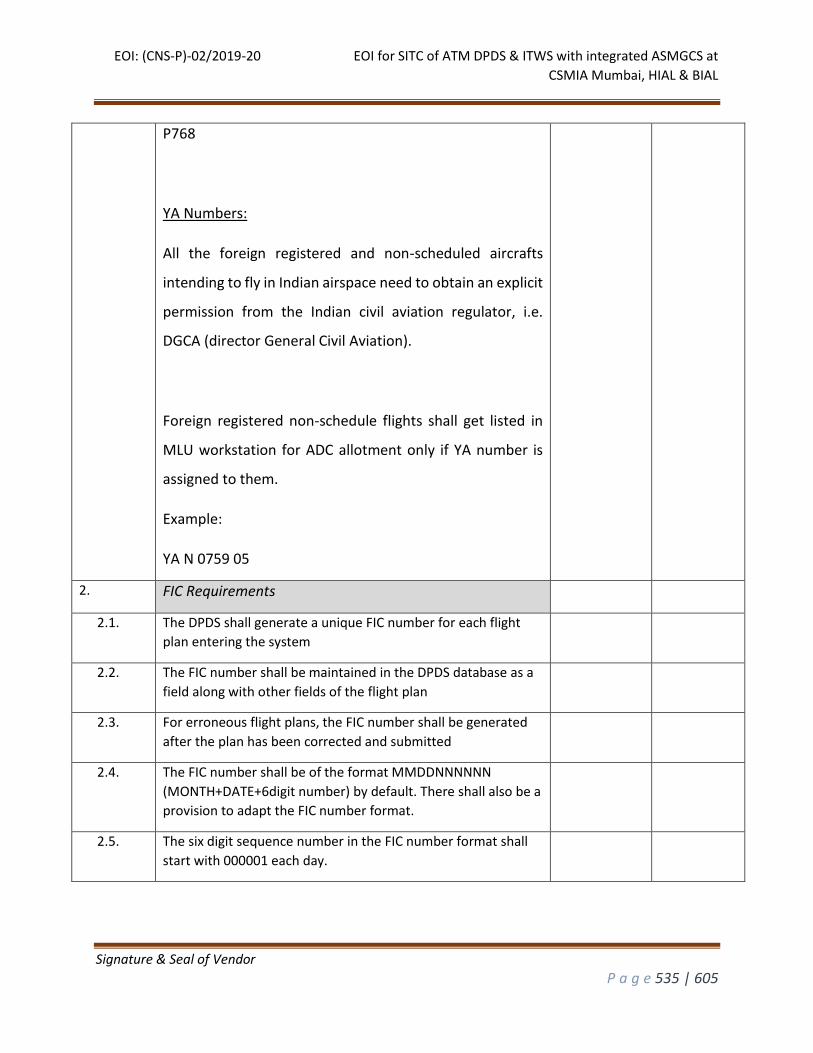
EOI: (CNS-P)-02/2019-20 EOI for SITC of ATM DPDS & ITWS with integrated ASMGCS at
CSMIA Mumbai, HIAL & BIAL
Signature & Seal of Vendor
P a g e 535 | 605
P768
YA Numbers:
All the foreign registered and non-scheduled aircrafts
intending to fly in Indian airspace need to obtain an explicit
permission from the Indian civil aviation regulator, i.e.
DGCA (director General Civil Aviation).
Foreign registered non-schedule flights shall get listed in
MLU workstation for ADC allotment only if YA number is
assigned to them.
Example:
YA N 0759 05
2. FIC Requirements
2.1. The DPDS shall generate a unique FIC number for each flight
plan entering the system
2.2. The FIC number shall be maintained in the DPDS database as a
field along with other fields of the flight plan
2.3. For erroneous flight plans, the FIC number shall be generated
after the plan has been corrected and submitted
2.4. The FIC number shall be of the format MMDDNNNNNN
(MONTH+DATE+6digit number) by default. There shall also be a
provision to adapt the FIC number format.
2.5. The six digit sequence number in the FIC number format shall
start with 000001 each day.
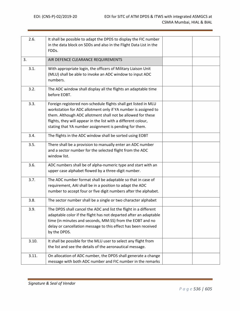
EOI: (CNS-P)-02/2019-20 EOI for SITC of ATM DPDS & ITWS with integrated ASMGCS at
CSMIA Mumbai, HIAL & BIAL
Signature & Seal of Vendor
P a g e 536 | 605
2.6. It shall be possible to adapt the DPDS to display the FIC number
in the data block on SDDs and also in the Flight Data List in the
FDDs.
3. AIR DEFENCE CLEARANCE REQUIREMENTS
3.1. With appropriate login, the officers of Military Liaison Unit
(MLU) shall be able to invoke an ADC window to input ADC
numbers.
3.2. The ADC window shall display all the flights an adaptable time
before EOBT.
3.3. Foreign registered non-schedule flights shall get listed in MLU
workstation for ADC allotment only if YA number is assigned to
them. Although ADC allotment shall not be allowed for these
flights, they will appear in the list with a different colour,
stating that YA number assignment is pending for them.
3.4. The flights in the ADC window shall be sorted using EOBT
3.5. There shall be a provision to manually enter an ADC number
and a sector number for the selected flight from the ADC
window list.
3.6. ADC numbers shall be of alpha-numeric type and start with an
upper case alphabet flowed by a three-digit number.
3.7. The ADC number format shall be adaptable so that in case of
requirement, AAI shall be in a position to adapt the ADC
number to accept four or five digit numbers after the alphabet.
3.8. The sector number shall be a single or two character alphabet
3.9. The DPDS shall cancel the ADC and list the flight in a different
adaptable color if the flight has not departed after an adaptable
time (in minutes and seconds, MM:SS) from the EOBT and no
delay or cancellation message to this effect has been received
by the DPDS.
3.10. It shall be possible for the MLU user to select any flight from
the list and see the details of the aeronautical message.
3.11. On allocation of ADC number, the DPDS shall generate a change
message with both ADC number and FIC number in the remarks
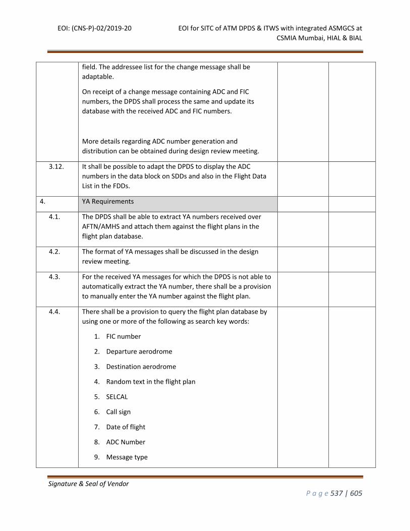
EOI: (CNS-P)-02/2019-20 EOI for SITC of ATM DPDS & ITWS with integrated ASMGCS at
CSMIA Mumbai, HIAL & BIAL
Signature & Seal of Vendor
P a g e 537 | 605
field. The addressee list for the change message shall be
adaptable.
On receipt of a change message containing ADC and FIC
numbers, the DPDS shall process the same and update its
database with the received ADC and FIC numbers.
More details regarding ADC number generation and
distribution can be obtained during design review meeting.
3.12. It shall be possible to adapt the DPDS to display the ADC
numbers in the data block on SDDs and also in the Flight Data
List in the FDDs.
4. YA Requirements
4.1. The DPDS shall be able to extract YA numbers received over
AFTN/AMHS and attach them against the flight plans in the
flight plan database.
4.2. The format of YA messages shall be discussed in the design
review meeting.
4.3. For the received YA messages for which the DPDS is not able to
automatically extract the YA number, there shall be a provision
to manually enter the YA number against the flight plan.
4.4. There shall be a provision to query the flight plan database by
using one or more of the following as search key words:
1. FIC number
2. Departure aerodrome
3. Destination aerodrome
4. Random text in the flight plan
5. SELCAL
6. Call sign
7. Date of flight
8. ADC Number
9. Message type
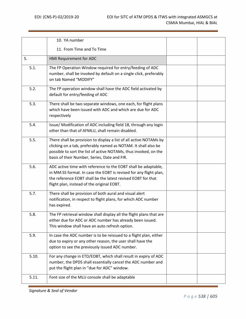
EOI: (CNS-P)-02/2019-20 EOI for SITC of ATM DPDS & ITWS with integrated ASMGCS at
CSMIA Mumbai, HIAL & BIAL
Signature & Seal of Vendor
P a g e 538 | 605
10. YA number
11. From Time and To Time
5. HMI Requirement for ADC
5.1. The FP Operation Window required for entry/feeding of ADC
number, shall be invoked by default on a single click, preferably
on tab Named “MODIFY”
5.2. The FP operation window shall have the ADC field activated by
default for entry/feeding of ADC
5.3. There shall be two separate windows, one each, for flight plans
which have been issued with ADC and which are due for ADC
respectively
5.4. Issue/ Modification of ADC including field 18, through any login
other than that of AFMLU, shall remain disabled.
5.5. There shall be provision to display a list of all active NOTAMs by
clicking on a tab, preferably named as NOTAM. It shall also be
possible to sort the list of active NOTAMs, thus invoked, on the
basis of their Number, Series, Date and FIR.
5.6. ADC active time with reference to the EOBT shall be adaptable,
in MM:SS format. In case the EOBT is revised for any flight plan,
the reference EOBT shall be the latest revised EOBT for that
flight plan, instead of the original EOBT.
5.7. There shall be provision of both aural and visual alert
notification, in respect to flight plans, for which ADC number
has expired.
5.8. The FP retrieval window shall display all the flight plans that are
either due for ADC or ADC number has already been issued.
This window shall have an auto refresh option.
5.9. In case the ADC number is to be reissued to a flight plan, either
due to expiry or any other reason, the user shall have the
option to see the previously issued ADC number.
5.10. For any change in ETD/EOBT, which shall result in expiry of ADC
number, the DPDS shall essentially cancel the ADC number and
put the flight plan in “due for ADC” window.
5.11. Font size of the MLU console shall be adaptable
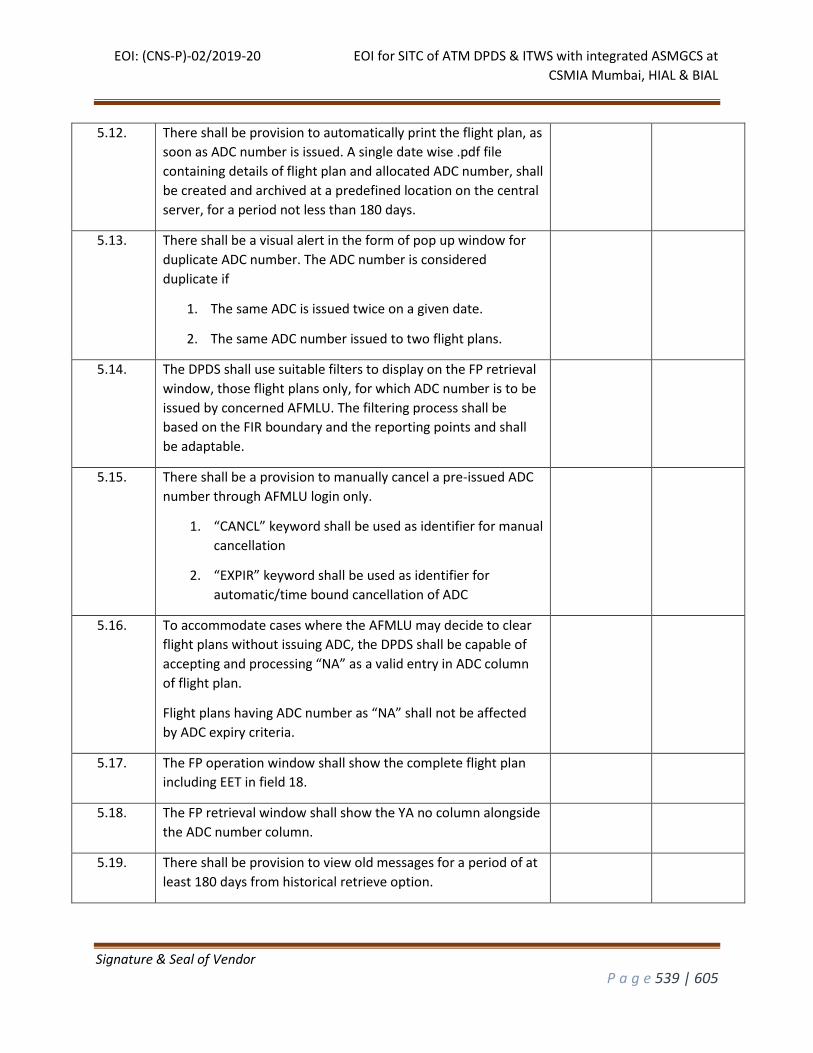
EOI: (CNS-P)-02/2019-20 EOI for SITC of ATM DPDS & ITWS with integrated ASMGCS at
CSMIA Mumbai, HIAL & BIAL
Signature & Seal of Vendor
P a g e 539 | 605
5.12. There shall be provision to automatically print the flight plan, as
soon as ADC number is issued. A single date wise .pdf file
containing details of flight plan and allocated ADC number, shall
be created and archived at a predefined location on the central
server, for a period not less than 180 days.
5.13. There shall be a visual alert in the form of pop up window for
duplicate ADC number. The ADC number is considered
duplicate if
1. The same ADC is issued twice on a given date.
2. The same ADC number issued to two flight plans.
5.14. The DPDS shall use suitable filters to display on the FP retrieval
window, those flight plans only, for which ADC number is to be
issued by concerned AFMLU. The filtering process shall be
based on the FIR boundary and the reporting points and shall
be adaptable.
5.15. There shall be a provision to manually cancel a pre-issued ADC
number through AFMLU login only.
1. “CANCL” keyword shall be used as identifier for manual
cancellation
2. “EXPIR” keyword shall be used as identifier for
automatic/time bound cancellation of ADC
5.16. To accommodate cases where the AFMLU may decide to clear
flight plans without issuing ADC, the DPDS shall be capable of
accepting and processing “NA” as a valid entry in ADC column
of flight plan.
Flight plans having ADC number as “NA” shall not be affected
by ADC expiry criteria.
5.17. The FP operation window shall show the complete flight plan
including EET in field 18.
5.18. The FP retrieval window shall show the YA no column alongside
the ADC number column.
5.19. There shall be provision to view old messages for a period of at
least 180 days from historical retrieve option.
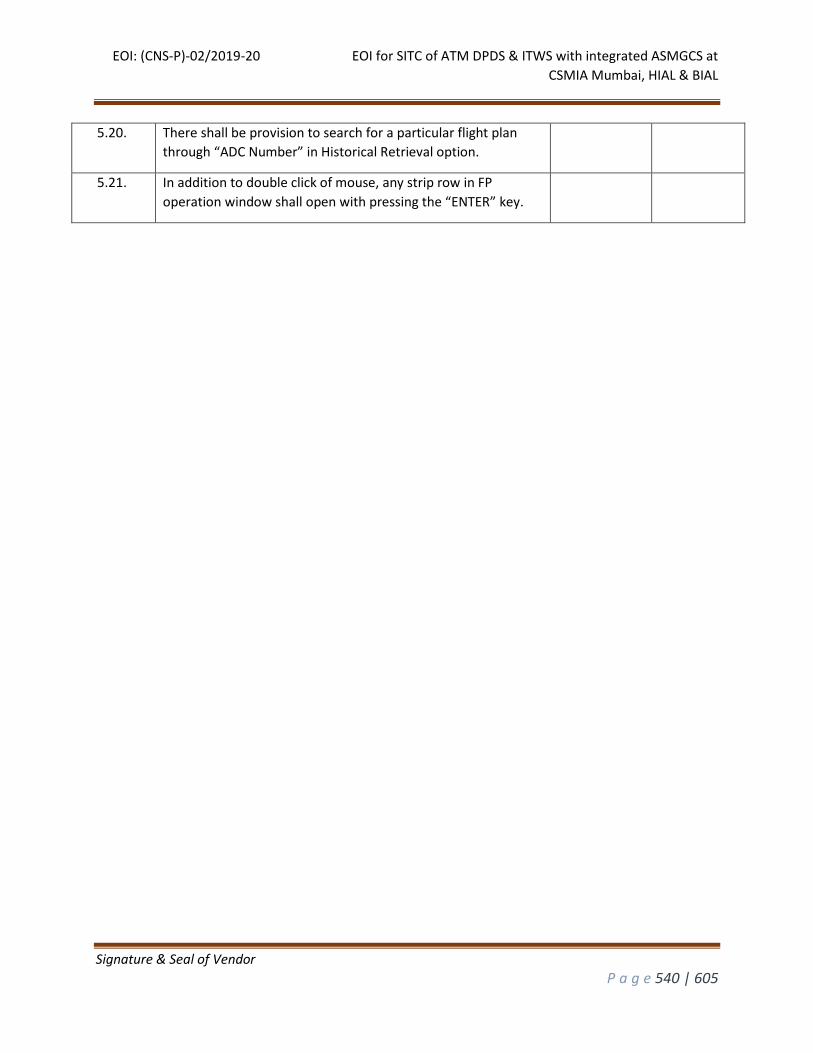
EOI: (CNS-P)-02/2019-20 EOI for SITC of ATM DPDS & ITWS with integrated ASMGCS at
CSMIA Mumbai, HIAL & BIAL
Signature & Seal of Vendor
P a g e 540 | 605
5.20. There shall be provision to search for a particular flight plan
through “ADC Number” in Historical Retrieval option.
5.21. In addition to double click of mouse, any strip row in FP
operation window shall open with pressing the “ENTER” key.
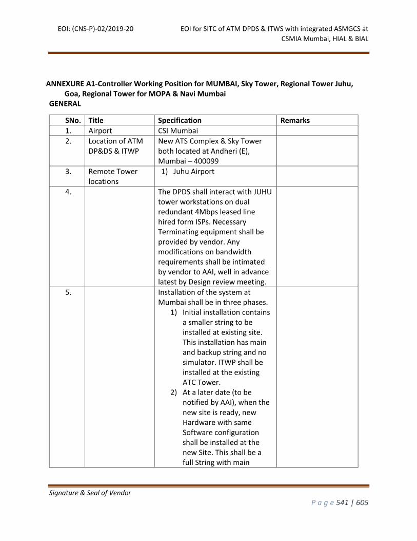
EOI: (CNS-P)-02/2019-20 EOI for SITC of ATM DPDS & ITWS with integrated ASMGCS at
CSMIA Mumbai, HIAL & BIAL
Signature & Seal of Vendor
P a g e 541 | 605
ANNEXURE A1-Controller Working Position for MUMBAI, Sky Tower, Regional Tower Juhu, Goa, Regional Tower for MOPA & Navi Mumbai
GENERAL
SNo. Title Specification Remarks
1. Airport CSI Mumbai
2. Location of ATM DP&DS & ITWP
New ATS Complex & Sky Tower both located at Andheri (E), Mumbai – 400099
3. Remote Tower locations
1) Juhu Airport
4. The DPDS shall interact with JUHU tower workstations on dual redundant 4Mbps leased line hired form ISPs. Necessary Terminating equipment shall be provided by vendor. Any modifications on bandwidth requirements shall be intimated by vendor to AAI, well in advance latest by Design review meeting.
5. Installation of the system at Mumbai shall be in three phases.
1) Initial installation contains a smaller string to be installed at existing site. This installation has main and backup string and no simulator. ITWP shall be installed at the existing ATC Tower.
2) At a later date (to be notified by AAI), when the new site is ready, new Hardware with same Software configuration shall be installed at the new Site. This shall be a full String with main
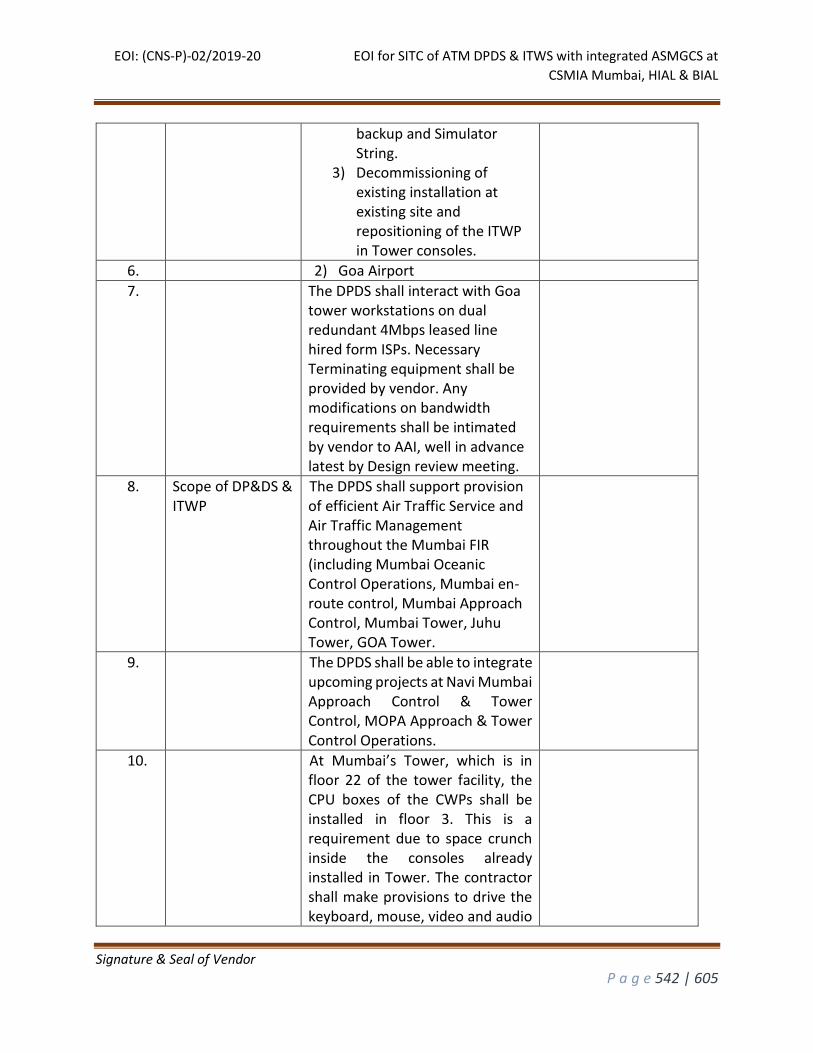
EOI: (CNS-P)-02/2019-20 EOI for SITC of ATM DPDS & ITWS with integrated ASMGCS at
CSMIA Mumbai, HIAL & BIAL
Signature & Seal of Vendor
P a g e 542 | 605
backup and Simulator String.
3) Decommissioning of existing installation at existing site and repositioning of the ITWP in Tower consoles.
6. 2) Goa Airport
7. The DPDS shall interact with Goa tower workstations on dual redundant 4Mbps leased line hired form ISPs. Necessary Terminating equipment shall be provided by vendor. Any modifications on bandwidth requirements shall be intimated by vendor to AAI, well in advance latest by Design review meeting.
8. Scope of DP&DS & ITWP
The DPDS shall support provision of efficient Air Traffic Service and Air Traffic Management throughout the Mumbai FIR (including Mumbai Oceanic Control Operations, Mumbai en-route control, Mumbai Approach Control, Mumbai Tower, Juhu Tower, GOA Tower.
9. The DPDS shall be able to integrate upcoming projects at Navi Mumbai Approach Control & Tower Control, MOPA Approach & Tower Control Operations.
10. At Mumbai’s Tower, which is in floor 22 of the tower facility, the CPU boxes of the CWPs shall be installed in floor 3. This is a requirement due to space crunch inside the consoles already installed in Tower. The contractor shall make provisions to drive the keyboard, mouse, video and audio
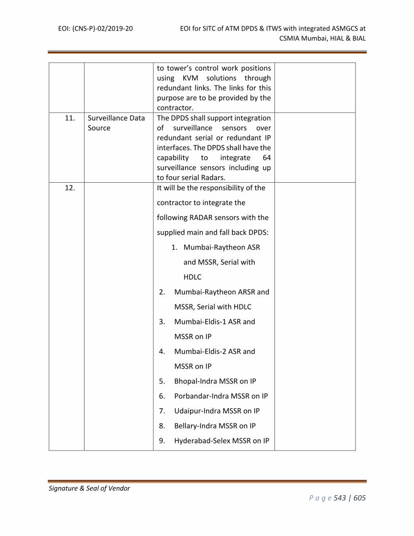
EOI: (CNS-P)-02/2019-20 EOI for SITC of ATM DPDS & ITWS with integrated ASMGCS at
CSMIA Mumbai, HIAL & BIAL
Signature & Seal of Vendor
P a g e 543 | 605
to tower’s control work positions using KVM solutions through redundant links. The links for this purpose are to be provided by the contractor.
11. Surveillance Data Source
The DPDS shall support integration of surveillance sensors over redundant serial or redundant IP interfaces. The DPDS shall have the capability to integrate 64 surveillance sensors including up to four serial Radars.
12. It will be the responsibility of the
contractor to integrate the
following RADAR sensors with the
supplied main and fall back DPDS:
1. Mumbai-Raytheon ASR
and MSSR, Serial with
HDLC
2. Mumbai-Raytheon ARSR and
MSSR, Serial with HDLC
3. Mumbai-Eldis-1 ASR and
MSSR on IP
4. Mumbai-Eldis-2 ASR and
MSSR on IP
5. Bhopal-Indra MSSR on IP
6. Porbandar-Indra MSSR on IP
7. Udaipur-Indra MSSR on IP
8. Bellary-Indra MSSR on IP
9. Hyderabad-Selex MSSR on IP
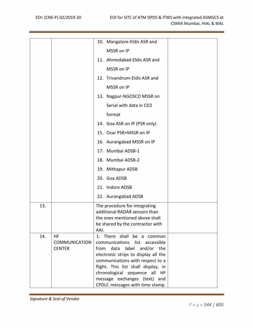
EOI: (CNS-P)-02/2019-20 EOI for SITC of ATM DPDS & ITWS with integrated ASMGCS at
CSMIA Mumbai, HIAL & BIAL
Signature & Seal of Vendor
P a g e 544 | 605
10. Mangalore-Eldis ASR and
MSSR on IP
11. Ahmedabad-Eldis ASR and
MSSR on IP
12. Trivandrum-Eldis ASR and
MSSR on IP
13. Nagpur-NGOSCO MSSR on
Serial with data in CD2
format
14. Goa ASR on IP (PSR only)
15. Ozar PSR+MSSR on IP
16. Aurangabad MSSR on IP
17. Mumbai ADSB-1
18. Mumbai ADSB-2
19. Mithapur ADSB
20. Goa ADSB
21. Indore ADSB
22. Aurangabad ADSB
13. The procedure for integrating additional RADAR sensors than the ones mentioned above shall be shared by the contractor with AAI.
14. HF COMMUNICATION CENTER
1. There shall be a common communications list accessible from data label and/or the electronic strips to display all the communications with respect to a flight. This list shall display, in chronological sequence all HF message exchanges (text) and CPDLC messages with time stamp.
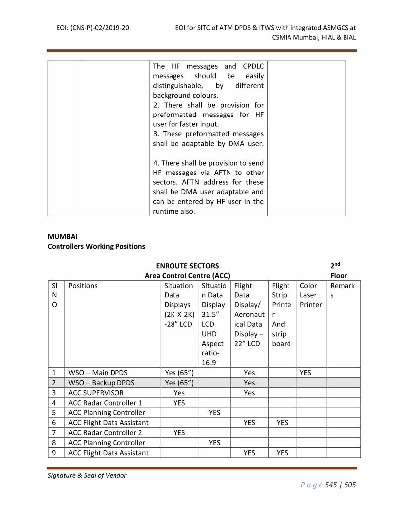
EOI: (CNS-P)-02/2019-20 EOI for SITC of ATM DPDS & ITWS with integrated ASMGCS at
CSMIA Mumbai, HIAL & BIAL
Signature & Seal of Vendor
P a g e 545 | 605
The HF messages and CPDLC messages should be easily distinguishable, by different background colours. 2. There shall be provision for preformatted messages for HF user for faster input. 3. These preformatted messages shall be adaptable by DMA user. 4. There shall be provision to send HF messages via AFTN to other sectors. AFTN address for these shall be DMA user adaptable and can be entered by HF user in the runtime also.
MUMBAI Controllers Working Positions
ENROUTE SECTORS
Area Control Centre (ACC) 2nd Floor
Sl NO
Positions Situation Data Displays (2K X 2K) -28” LCD
Situation Data Display 31.5” LCD UHD Aspect ratio-16:9
Flight Data Display/ Aeronautical Data Display – 22” LCD
Flight Strip Printer And strip board
Color Laser Printer
Remarks
1 WSO – Main DPDS Yes (65”) Yes YES
2 WSO – Backup DPDS Yes (65”) Yes
3 ACC SUPERVISOR Yes Yes
4 ACC Radar Controller 1 YES
5 ACC Planning Controller YES
6 ACC Flight Data Assistant YES YES
7 ACC Radar Controller 2 YES
8 ACC Planning Controller YES
9 ACC Flight Data Assistant YES YES
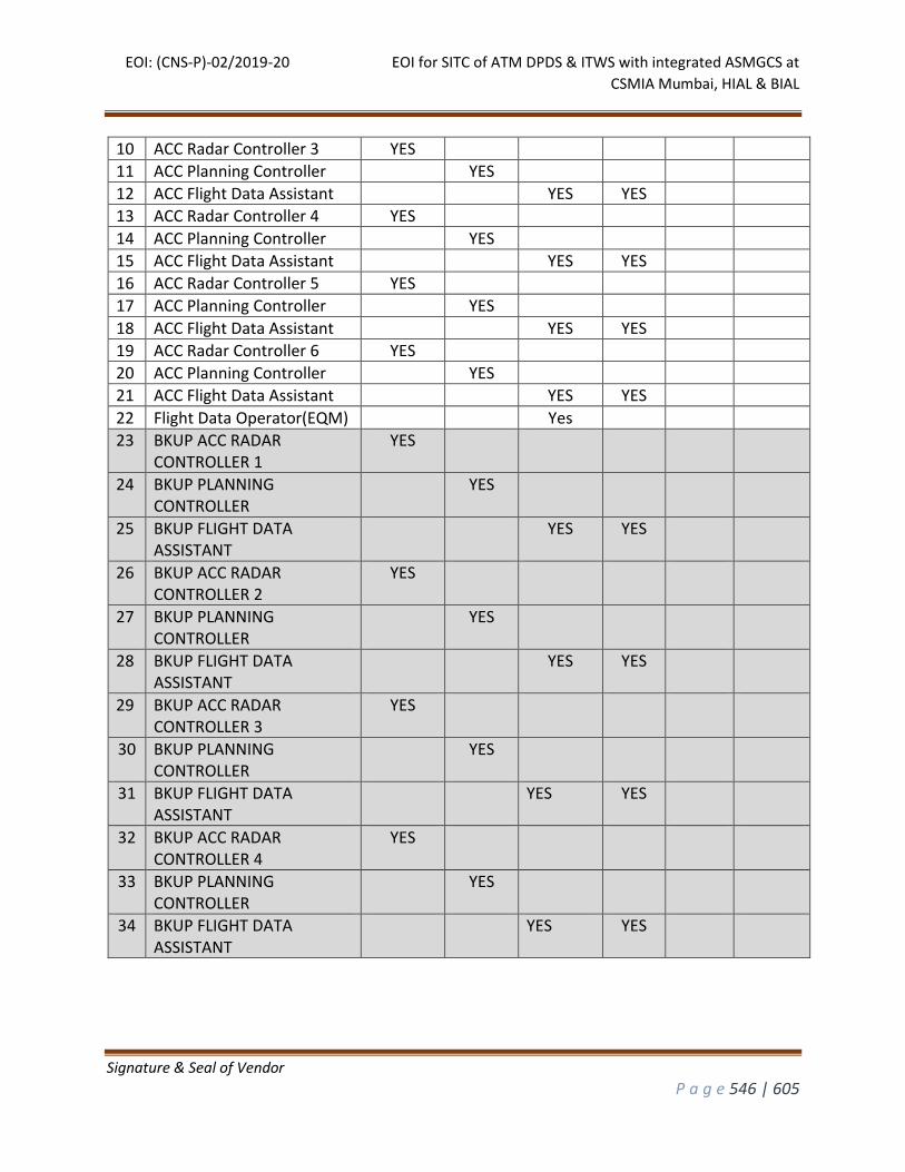
EOI: (CNS-P)-02/2019-20 EOI for SITC of ATM DPDS & ITWS with integrated ASMGCS at
CSMIA Mumbai, HIAL & BIAL
Signature & Seal of Vendor
P a g e 546 | 605
10 ACC Radar Controller 3 YES
11 ACC Planning Controller YES
12 ACC Flight Data Assistant YES YES
13 ACC Radar Controller 4 YES
14 ACC Planning Controller YES
15 ACC Flight Data Assistant YES YES
16 ACC Radar Controller 5 YES
17 ACC Planning Controller YES
18 ACC Flight Data Assistant YES YES
19 ACC Radar Controller 6 YES
20 ACC Planning Controller YES
21 ACC Flight Data Assistant YES YES
22 Flight Data Operator(EQM) Yes
23 BKUP ACC RADAR CONTROLLER 1
YES
24 BKUP PLANNING CONTROLLER
YES
25 BKUP FLIGHT DATA ASSISTANT
YES YES
26 BKUP ACC RADAR CONTROLLER 2
YES
27 BKUP PLANNING CONTROLLER
YES
28 BKUP FLIGHT DATA ASSISTANT
YES YES
29 BKUP ACC RADAR CONTROLLER 3
YES
30 BKUP PLANNING CONTROLLER
YES
31 BKUP FLIGHT DATA ASSISTANT
YES YES
32 BKUP ACC RADAR CONTROLLER 4
YES
33 BKUP PLANNING CONTROLLER
YES
34 BKUP FLIGHT DATA ASSISTANT
YES YES
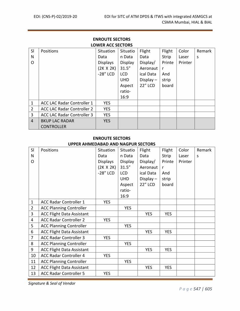
EOI: (CNS-P)-02/2019-20 EOI for SITC of ATM DPDS & ITWS with integrated ASMGCS at
CSMIA Mumbai, HIAL & BIAL
Signature & Seal of Vendor
P a g e 547 | 605
ENROUTE SECTORS LOWER ACC SECTORS
Sl NO
Positions Situation Data Displays (2K X 2K) -28” LCD
Situation Data Display 31.5” LCD UHD Aspect ratio-16:9
Flight Data Display/ Aeronautical Data Display – 22” LCD
Flight Strip Printer And strip board
Color Laser Printer
Remarks
1 ACC LAC Radar Controller 1 YES
2 ACC LAC Radar Controller 2 YES
3 ACC LAC Radar Controller 3 YES
4 BKUP LAC RADAR CONTROLLER
YES
ENROUTE SECTORS
UPPER AHMEDABAD AND NAGPUR SECTORS
Sl NO
Positions Situation Data Displays (2K X 2K) -28” LCD
Situation Data Display 31.5” LCD UHD Aspect ratio-16:9
Flight Data Display/ Aeronautical Data Display – 22” LCD
Flight Strip Printer And strip board
Color Laser Printer
Remarks
1 ACC Radar Controller 1 YES
2 ACC Planning Controller YES
3 ACC Flight Data Assistant YES YES
4 ACC Radar Controller 2 YES
5 ACC Planning Controller YES
6 ACC Flight Data Assistant YES YES
7 ACC Radar Controller 3 YES
8 ACC Planning Controller YES
9 ACC Flight Data Assistant YES YES
10 ACC Radar Controller 4 YES
11 ACC Planning Controller YES
12 ACC Flight Data Assistant YES YES
13 ACC Radar Controller 5 YES
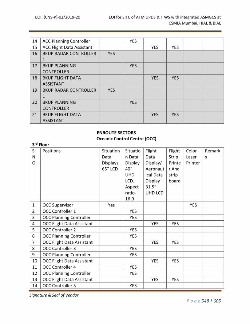
EOI: (CNS-P)-02/2019-20 EOI for SITC of ATM DPDS & ITWS with integrated ASMGCS at
CSMIA Mumbai, HIAL & BIAL
Signature & Seal of Vendor
P a g e 548 | 605
14 ACC Planning Controller YES
15 ACC Flight Data Assistant YES YES
16 BKUP RADAR CONTROLLER 1
YES
17 BKUP PLANNING CONTROLLER
YES
18 BKUP FLIGHT DATA ASSISTANT
YES YES
19 BKUP RADAR CONTROLLER 1
YES
20 BKUP PLANNING CONTROLLER
YES
21 BKUP FLIGHT DATA ASSISTANT
YES YES
ENROUTE SECTORS
Oceanic Control Centre (OCC) 3rd Floor
Sl NO
Positions Situation Data Displays 65” LCD
Situation Data Display 40” UHD LCD. Aspect ratio-16:9
Flight Data Display/ Aeronautical Data Display – 31.5” UHD LCD
Flight Strip Printer And strip board
Color Laser Printer
Remarks
1 OCC Supervisor Yes YES
2 OCC Controller 1 YES
3 OCC Planning Controller YES
4 OCC Flight Data Assistant YES YES
5 OCC Controller 2 YES
6 OCC Planning Controller YES
7 OCC Flight Data Assistant YES YES
8 OCC Controller 3 YES
9 OCC Planning Controller YES
10 OCC Flight Data Assistant YES YES
11 OCC Controller 4 YES
12 OCC Planning Controller YES
13 OCC Flight Data Assistant YES YES
14 OCC Controller 5 YES
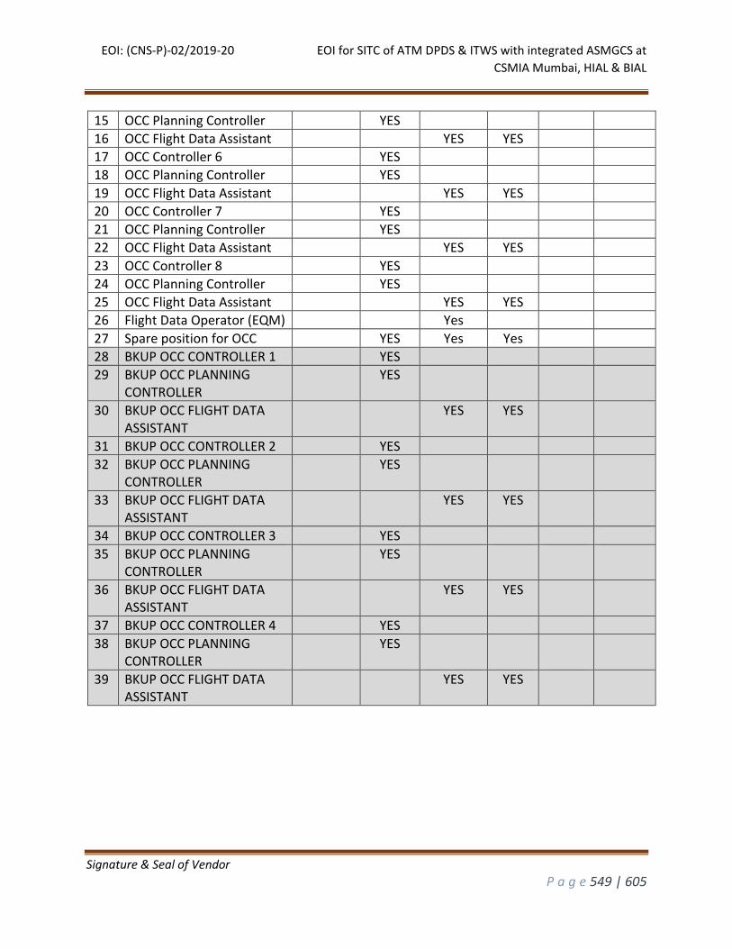
EOI: (CNS-P)-02/2019-20 EOI for SITC of ATM DPDS & ITWS with integrated ASMGCS at
CSMIA Mumbai, HIAL & BIAL
Signature & Seal of Vendor
P a g e 549 | 605
15 OCC Planning Controller YES
16 OCC Flight Data Assistant YES YES
17 OCC Controller 6 YES
18 OCC Planning Controller YES
19 OCC Flight Data Assistant YES YES
20 OCC Controller 7 YES
21 OCC Planning Controller YES
22 OCC Flight Data Assistant YES YES
23 OCC Controller 8 YES
24 OCC Planning Controller YES
25 OCC Flight Data Assistant YES YES
26 Flight Data Operator (EQM) Yes
27 Spare position for OCC YES Yes Yes
28 BKUP OCC CONTROLLER 1 YES
29 BKUP OCC PLANNING CONTROLLER
YES
30 BKUP OCC FLIGHT DATA ASSISTANT
YES YES
31 BKUP OCC CONTROLLER 2 YES
32 BKUP OCC PLANNING CONTROLLER
YES
33 BKUP OCC FLIGHT DATA ASSISTANT
YES YES
34 BKUP OCC CONTROLLER 3 YES
35 BKUP OCC PLANNING CONTROLLER
YES
36 BKUP OCC FLIGHT DATA ASSISTANT
YES YES
37 BKUP OCC CONTROLLER 4 YES
38 BKUP OCC PLANNING CONTROLLER
YES
39 BKUP OCC FLIGHT DATA ASSISTANT
YES YES

EOI: (CNS-P)-02/2019-20 EOI for SITC of ATM DPDS & ITWS with integrated ASMGCS at
CSMIA Mumbai, HIAL & BIAL
Signature & Seal of Vendor
P a g e 550 | 605
Approach Control Sectors 3rd Floor
Sl NO
Positions Situation Data Displays (2K X 2K) -28” LCD
Situation Data Display 31.5” UHD LCD
Flight Data Display/ Aeronautical Data Display – 22” LCD
Flight Strip Printer with flight board
Color Laser Printer
ITWP GSD displays
1 Approach Supervisor Yes Yes M&C 31.5”
2 Approach Controller 1(Arr/Dep)
Yes YES
3 Approach Flight Data Assistant
Yes
4 Approach Controller 2(Arr/Dep)
Yes YES
5 Approach Flight Data Assistant
Yes
6 Approach Controller 3(Arr/Dep)
Yes YES
7 Approach Flight Data Assistant
Yes
8 Approach Controller 4(Arr/Dep)
Yes
9 Approach Flight Data Assistant
Yes
10 Approach Controller 5(Arr/Dep)
Yes
11 Approach Flight Data Assistant
Yes
12 Approach Controller 6(Arr/Dep)
Yes
13 Approach Flight Data Assistant
Yes
14 Spare position for approach
Yes Yes
15 BKUP APPROACH CONTROLLER 1
YES M&C 31.5”
YES
16 BKUP FLIGHT DATA ASSISTANT
YES
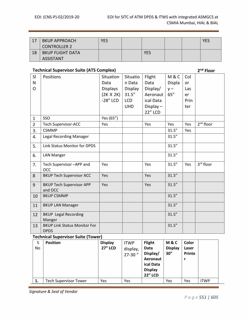
EOI: (CNS-P)-02/2019-20 EOI for SITC of ATM DPDS & ITWS with integrated ASMGCS at
CSMIA Mumbai, HIAL & BIAL
Signature & Seal of Vendor
P a g e 551 | 605
17 BKUP APPROACH CONTROLLER 2
YES YES
18 BKUP FLIGHT DATA ASSISTANT
YES
Technical Supervisor Suite (ATS Complex) 2nd Floor
Sl NO
Positions Situation Data Displays (2K X 2K) -28” LCD
Situation Data Display 31.5” LCD UHD
Flight Data Display/ Aeronautical Data Display – 22” LCD
M & C Display – 65”
Color Laser Printer
1 SSO Yes (65”)
2 Tech Supervisor-ACC Yes Yes Yes Yes 2nd floor
3. CSMMP 31.5” Yes
4. Legal Recording Manager 31.5”
5. Link Status Monitor for DPDS 31.5”
6. LAN Manger 31.5”
7. Tech Supervisor –APP and OCC
Yes Yes 31.5” Yes 3rd floor
8 BKUP Tech Supervisor ACC Yes Yes 31.5”
9 BKUP Tech Supervisor APP and OCC
Yes Yes 31.5”
10 BKUP CSMMP 31.5”
11 BKUP LAN Manager 31.5”
12 BKUP Legal Recording Manger
31.5”
13 BKUP Link Status Monitor For DPDS
31.5”
Technical Supervisor Suite (Tower) S No
Position Display 27” LCD
ITWP display, 27-30 “
Flight Data Display/Aeronautical Data Display 22” LCD
M & C Display 30”
Color Laser Printer
1. Tech Supervisor Tower Yes Yes Yes Yes ITWP
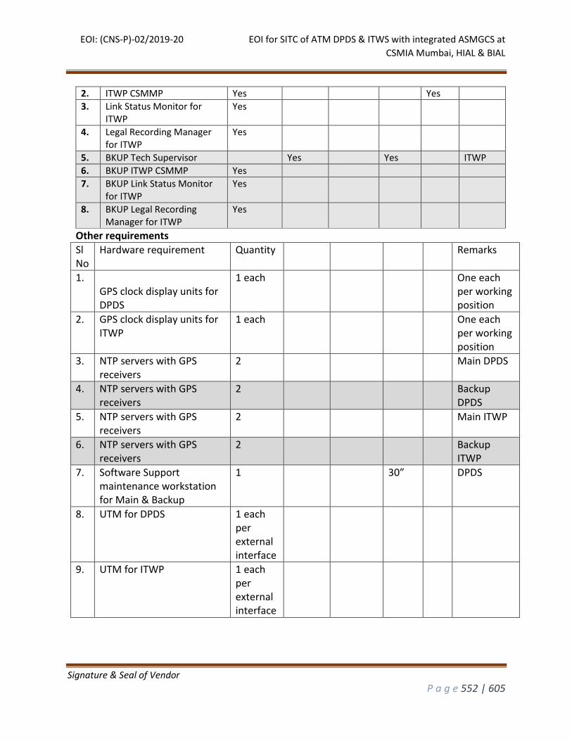
EOI: (CNS-P)-02/2019-20 EOI for SITC of ATM DPDS & ITWS with integrated ASMGCS at
CSMIA Mumbai, HIAL & BIAL
Signature & Seal of Vendor
P a g e 552 | 605
2. ITWP CSMMP Yes Yes
3. Link Status Monitor for ITWP
Yes
4. Legal Recording Manager for ITWP
Yes
5. BKUP Tech Supervisor Yes Yes ITWP
6. BKUP ITWP CSMMP Yes
7. BKUP Link Status Monitor for ITWP
Yes
8. BKUP Legal Recording Manager for ITWP
Yes
Other requirements
Sl No
Hardware requirement Quantity Remarks
1. GPS clock display units for DPDS
1 each One each per working position
2. GPS clock display units for ITWP
1 each One each per working position
3. NTP servers with GPS receivers
2 Main DPDS
4. NTP servers with GPS receivers
2 Backup DPDS
5. NTP servers with GPS receivers
2 Main ITWP
6. NTP servers with GPS receivers
2 Backup ITWP
7. Software Support maintenance workstation for Main & Backup
1 30” DPDS
8. UTM for DPDS 1 each per external interface
9. UTM for ITWP 1 each per external interface
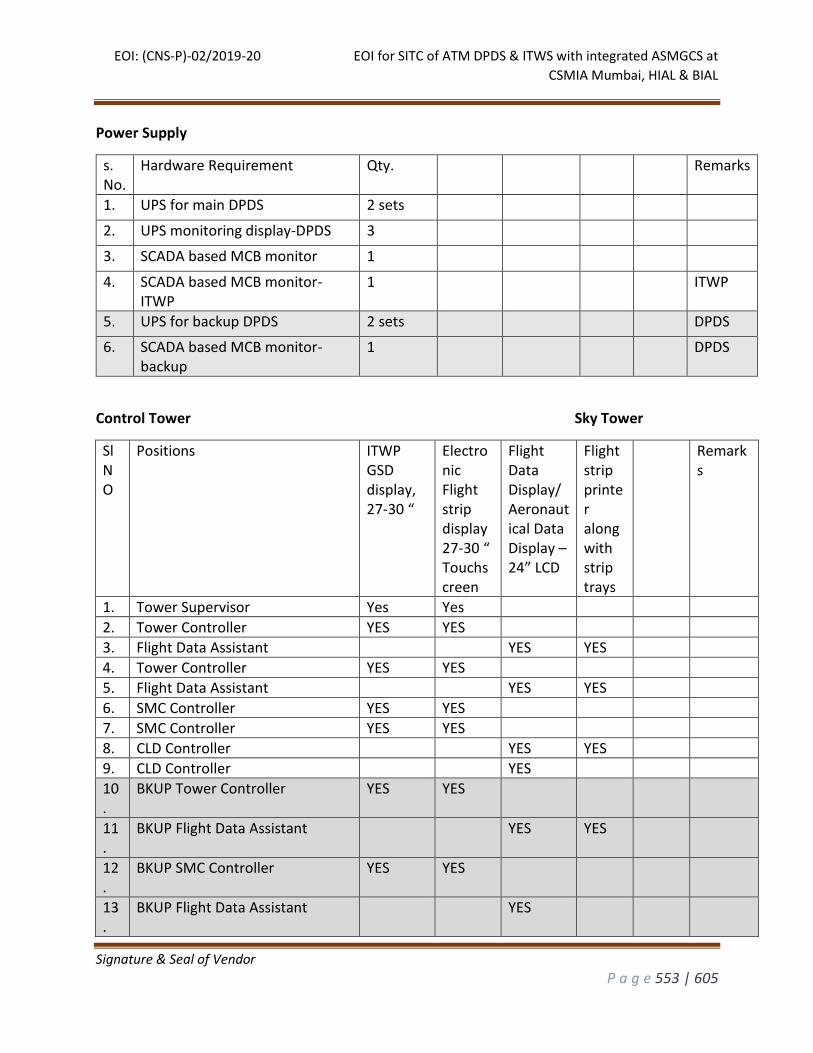
EOI: (CNS-P)-02/2019-20 EOI for SITC of ATM DPDS & ITWS with integrated ASMGCS at
CSMIA Mumbai, HIAL & BIAL
Signature & Seal of Vendor
P a g e 553 | 605
Power Supply
s. No.
Hardware Requirement Qty. Remarks
1. UPS for main DPDS 2 sets
2. UPS monitoring display-DPDS 3
3. SCADA based MCB monitor 1
4. SCADA based MCB monitor-ITWP
1 ITWP
5. UPS for backup DPDS 2 sets DPDS
6. SCADA based MCB monitor-backup
1 DPDS
Control Tower Sky Tower
Sl NO
Positions ITWP GSD display, 27-30 “
Electronic Flight strip display 27-30 “ Touchscreen
Flight Data Display/ Aeronautical Data Display – 24” LCD
Flight strip printer along with strip trays
Remarks
1. Tower Supervisor Yes Yes
2. Tower Controller YES YES
3. Flight Data Assistant YES YES
4. Tower Controller YES YES
5. Flight Data Assistant YES YES
6. SMC Controller YES YES
7. SMC Controller YES YES
8. CLD Controller YES YES
9. CLD Controller YES
10.
BKUP Tower Controller YES YES
11.
BKUP Flight Data Assistant YES YES
12.
BKUP SMC Controller YES YES
13.
BKUP Flight Data Assistant YES
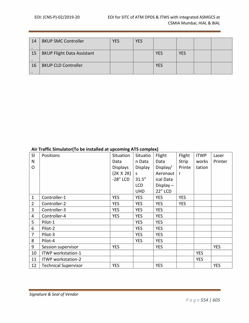
EOI: (CNS-P)-02/2019-20 EOI for SITC of ATM DPDS & ITWS with integrated ASMGCS at
CSMIA Mumbai, HIAL & BIAL
Signature & Seal of Vendor
P a g e 554 | 605
14.
BKUP SMC Controller YES YES
15.
BKUP Flight Data Assistant YES YES
16.
BKUP CLD Controller YES
Air Traffic Simulator(To be installed at upcoming ATS complex)
Sl NO
Positions Situation Data Displays (2K X 2K) -28” LCD
Situation Data Displays 31.5” LCD UHD
Flight Data Display/ Aeronautical Data Display – 22” LCD
Flight Strip Printer
ITWP workstation
Laser Printer
1 Controller-1 YES YES YES YES
2 Controller-2 YES YES YES YES
3 Controller-3 YES YES YES
4 Controller-4 YES YES YES
5 Pilot-1 YES YES
6 Pilot-2 YES YES
7 Pilot-3 YES YES
8 Pilot-4 YES YES
9 Session supervisor YES YES YES
10 ITWP workstation-1 YES
11 ITWP workstation-2 YES
12 Technical Supervisor YES YES YES
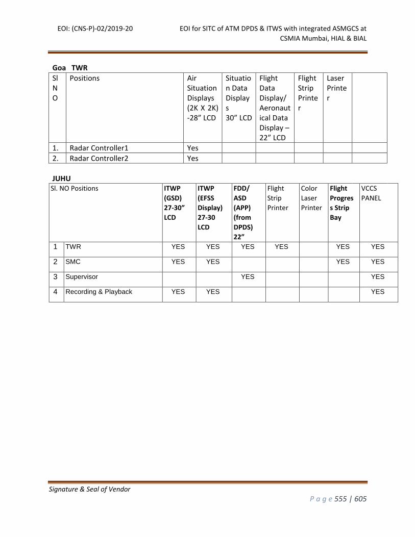
EOI: (CNS-P)-02/2019-20 EOI for SITC of ATM DPDS & ITWS with integrated ASMGCS at
CSMIA Mumbai, HIAL & BIAL
Signature & Seal of Vendor
P a g e 555 | 605
Goa TWR
Sl NO
Positions Air Situation Displays (2K X 2K) -28” LCD
Situation Data Displays 30” LCD
Flight Data Display/ Aeronautical Data Display – 22” LCD
Flight Strip Printer
Laser Printer
1. Radar Controller1 Yes
2. Radar Controller2 Yes
JUHU
Sl. NO Positions ITWP
(GSD)
27-30”
LCD
ITWP
(EFSS
Display)
27-30
LCD
FDD/
ASD
(APP)
(from
DPDS)
22”
Flight
Strip
Printer
Color
Laser
Printer
Flight
Progres
s Strip
Bay
VCCS
PANEL
1 TWR YES YES YES YES YES YES
2 SMC YES YES YES YES
3 Supervisor YES YES
4 Recording & Playback YES YES YES
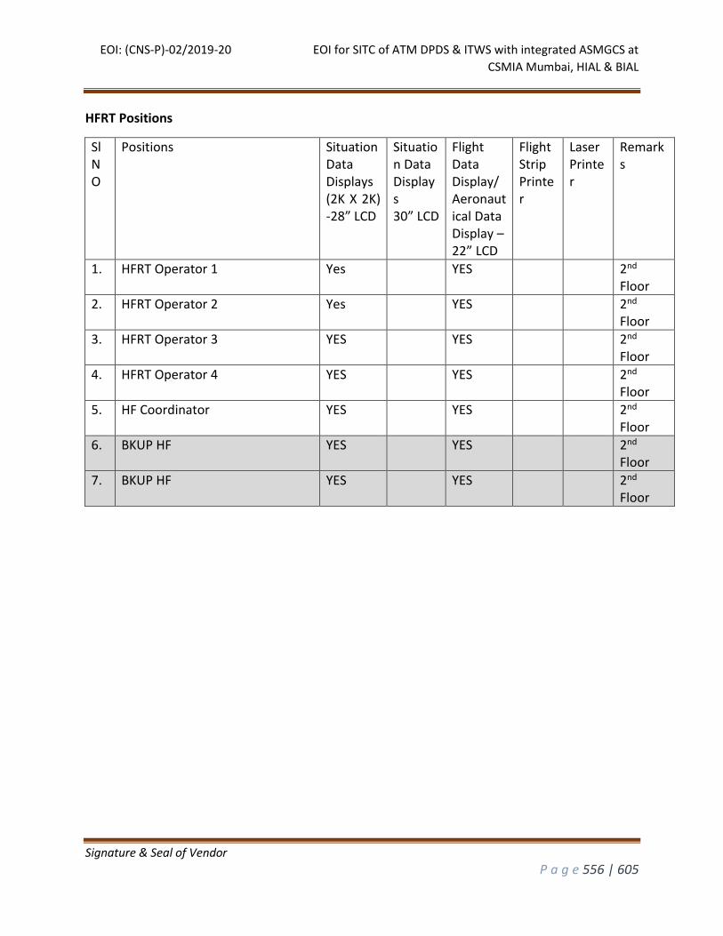
EOI: (CNS-P)-02/2019-20 EOI for SITC of ATM DPDS & ITWS with integrated ASMGCS at
CSMIA Mumbai, HIAL & BIAL
Signature & Seal of Vendor
P a g e 556 | 605
HFRT Positions
Sl NO
Positions Situation Data Displays (2K X 2K) -28” LCD
Situation Data Displays 30” LCD
Flight Data Display/ Aeronautical Data Display – 22” LCD
Flight Strip Printer
Laser Printer
Remarks
1. HFRT Operator 1 Yes YES 2nd Floor
2. HFRT Operator 2 Yes YES 2nd Floor
3. HFRT Operator 3 YES YES 2nd Floor
4. HFRT Operator 4 YES YES 2nd Floor
5. HF Coordinator YES YES 2nd Floor
6. BKUP HF YES YES 2nd Floor
7. BKUP HF YES YES 2nd Floor
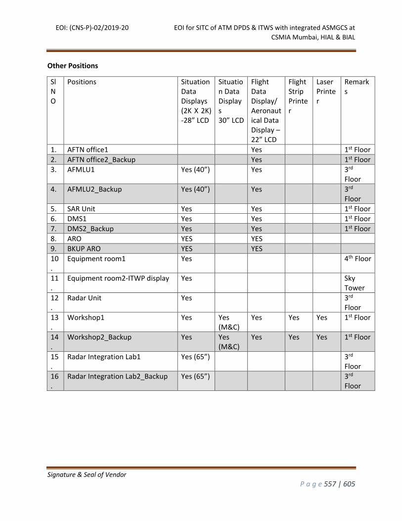
EOI: (CNS-P)-02/2019-20 EOI for SITC of ATM DPDS & ITWS with integrated ASMGCS at
CSMIA Mumbai, HIAL & BIAL
Signature & Seal of Vendor
P a g e 557 | 605
Other Positions
Sl NO
Positions Situation Data Displays (2K X 2K) -28” LCD
Situation Data Displays 30” LCD
Flight Data Display/ Aeronautical Data Display – 22” LCD
Flight Strip Printer
Laser Printer
Remarks
1. AFTN office1 Yes 1st Floor
2. AFTN office2_Backup Yes 1st Floor
3. AFMLU1 Yes (40”) Yes 3rd Floor
4. AFMLU2_Backup Yes (40”) Yes 3rd Floor
5. SAR Unit Yes Yes 1st Floor
6. DMS1 Yes Yes 1st Floor
7. DMS2_Backup Yes Yes 1st Floor
8. ARO YES YES
9. BKUP ARO YES YES
10.
Equipment room1 Yes 4th Floor
11.
Equipment room2-ITWP display Yes Sky Tower
12.
Radar Unit Yes 3rd Floor
13.
Workshop1 Yes Yes (M&C)
Yes Yes Yes 1st Floor
14.
Workshop2_Backup Yes Yes (M&C)
Yes Yes Yes 1st Floor
15.
Radar Integration Lab1 Yes (65”) 3rd Floor
16.
Radar Integration Lab2_Backup Yes (65”) 3rd Floor
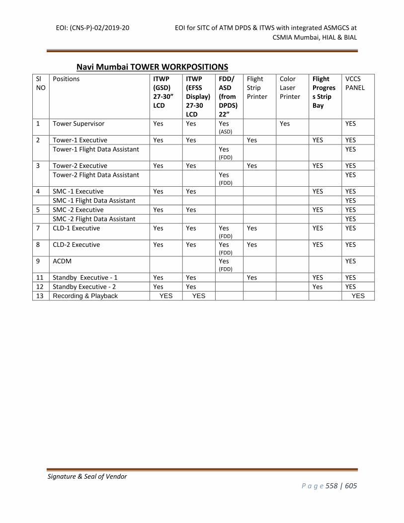
EOI: (CNS-P)-02/2019-20 EOI for SITC of ATM DPDS & ITWS with integrated ASMGCS at
CSMIA Mumbai, HIAL & BIAL
Signature & Seal of Vendor
P a g e 558 | 605
Navi Mumbai TOWER WORKPOSITIONS
Sl NO
Positions ITWP (GSD) 27-30” LCD
ITWP (EFSS Display) 27-30 LCD
FDD/ ASD (from DPDS) 22”
Flight Strip Printer
Color Laser Printer
Flight Progress Strip Bay
VCCS PANEL
1 Tower Supervisor Yes Yes Yes (ASD)
Yes YES
2 Tower-1 Executive Yes Yes Yes YES YES
Tower-1 Flight Data Assistant Yes (FDD)
YES
3 Tower-2 Executive Yes Yes Yes YES YES
Tower-2 Flight Data Assistant Yes (FDD)
YES
4 SMC -1 Executive Yes Yes YES YES
SMC -1 Flight Data Assistant YES
5 SMC -2 Executive Yes Yes YES YES
SMC -2 Flight Data Assistant YES
7 CLD-1 Executive Yes Yes Yes (FDD)
Yes YES YES
8 CLD-2 Executive Yes Yes Yes (FDD)
Yes YES YES
9 ACDM Yes (FDD)
YES
11 Standby Executive - 1 Yes Yes Yes YES YES
12 Standby Executive - 2 Yes Yes Yes YES
13 Recording & Playback YES YES YES
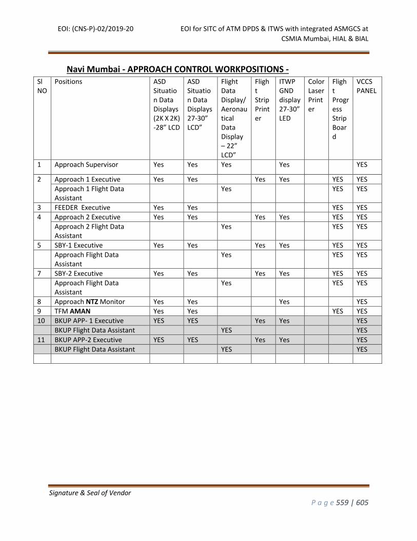
EOI: (CNS-P)-02/2019-20 EOI for SITC of ATM DPDS & ITWS with integrated ASMGCS at
CSMIA Mumbai, HIAL & BIAL
Signature & Seal of Vendor
P a g e 559 | 605
Navi Mumbai - APPROACH CONTROL WORKPOSITIONS - Sl NO
Positions ASD Situation Data Displays (2K X 2K) -28” LCD
ASD Situation Data Displays 27-30” LCD”
Flight Data Display/ Aeronautical Data Display – 22” LCD”
Flight Strip Printer
ITWP GND display 27-30” LED
ColorLaser Printer
Flight Progress Strip Board
VCCS PANEL
1 Approach Supervisor Yes Yes Yes Yes YES
2 Approach 1 Executive Yes Yes Yes Yes YES YES
Approach 1 Flight Data Assistant
Yes YES YES
3 FEEDER Executive Yes Yes YES YES
4 Approach 2 Executive Yes Yes Yes Yes YES YES
Approach 2 Flight Data Assistant
Yes YES YES
5 SBY-1 Executive Yes Yes Yes Yes YES YES
Approach Flight Data Assistant
Yes YES YES
7 SBY-2 Executive Yes Yes Yes Yes YES YES
Approach Flight Data Assistant
Yes YES YES
8 Approach NTZ Monitor Yes Yes Yes YES
9 TFM AMAN Yes Yes YES YES
10 BKUP APP- 1 Executive YES YES Yes Yes YES
BKUP Flight Data Assistant YES YES
11 BKUP APP-2 Executive YES YES Yes Yes YES
BKUP Flight Data Assistant YES YES
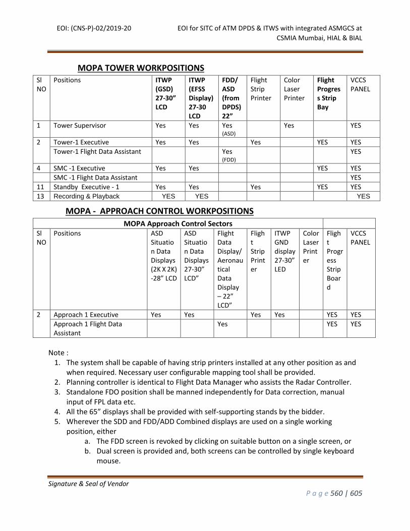
EOI: (CNS-P)-02/2019-20 EOI for SITC of ATM DPDS & ITWS with integrated ASMGCS at
CSMIA Mumbai, HIAL & BIAL
Signature & Seal of Vendor
P a g e 560 | 605
MOPA TOWER WORKPOSITIONS
Sl NO
Positions ITWP (GSD) 27-30” LCD
ITWP (EFSS Display) 27-30 LCD
FDD/ ASD (from DPDS) 22”
Flight Strip Printer
Color Laser Printer
Flight Progress Strip Bay
VCCS PANEL
1 Tower Supervisor Yes Yes Yes (ASD)
Yes YES
2 Tower-1 Executive Yes Yes Yes YES YES
Tower-1 Flight Data Assistant Yes (FDD)
YES
4 SMC -1 Executive Yes Yes YES YES
SMC -1 Flight Data Assistant YES
11 Standby Executive - 1 Yes Yes Yes YES YES
13 Recording & Playback YES YES YES
MOPA - APPROACH CONTROL WORKPOSITIONS
MOPA Approach Control Sectors
Sl NO
Positions ASD Situation Data Displays (2K X 2K) -28” LCD
ASD Situation Data Displays 27-30” LCD”
Flight Data Display/ Aeronautical Data Display – 22” LCD”
Flight Strip Printer
ITWP GND display 27-30” LED
ColorLaser Printer
Flight Progress Strip Board
VCCS PANEL
2 Approach 1 Executive Yes Yes Yes Yes YES YES
Approach 1 Flight Data Assistant
Yes YES YES
Note :
1. The system shall be capable of having strip printers installed at any other position as and when required. Necessary user configurable mapping tool shall be provided.
2. Planning controller is identical to Flight Data Manager who assists the Radar Controller. 3. Standalone FDO position shall be manned independently for Data correction, manual
input of FPL data etc. 4. All the 65” displays shall be provided with self-supporting stands by the bidder. 5. Wherever the SDD and FDD/ADD Combined displays are used on a single working
position, either a. The FDD screen is revoked by clicking on suitable button on a single screen, or b. Dual screen is provided and, both screens can be controlled by single keyboard
mouse.
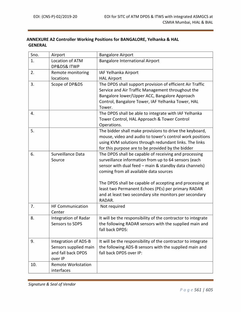
EOI: (CNS-P)-02/2019-20 EOI for SITC of ATM DPDS & ITWS with integrated ASMGCS at
CSMIA Mumbai, HIAL & BIAL
Signature & Seal of Vendor
P a g e 561 | 605
ANNEXURE A2 Controller Working Positions for BANGALORE, Yelhanka & HAL GENERAL
Sno. Airport Bangalore Airport
1. Location of ATM DP&DS& ITWP
Bangalore International Airport
2. Remote monitoring locations
IAF Yelhanka Airport HAL Airport
3. Scope of DP&DS The DPDS shall support provision of efficient Air Traffic Service and Air Traffic Management throughout the Bangalore lower/Upper ACC, Bangalore Approach Control, Bangalore Tower, IAF Yelhanka Tower, HAL Tower.
4. The DPDS shall be able to integrate with IAF Yelhanka Tower Control, HAL Approach & Tower Control Operations.
5. The bidder shall make provisions to drive the keyboard, mouse, video and audio to tower’s control work positions using KVM solutions through redundant links. The links for this purpose are to be provided by the bidder
6. Surveillance Data Source
The DPDS shall be capable of receiving and processing surveillance information from up to 64 sensors (each sensor with dual feed – main & standby data channels) coming from all available data sources The DPDS shall be capable of accepting and processing at least two Permanent Echoes (PEs) per primary RADAR and at least two secondary site monitors per secondary RADAR.
7. HF Communication Center
Not required
8. Integration of Radar Sensors to SDPS
It will be the responsibility of the contractor to integrate the following RADAR sensors with the supplied main and fall back DPDS:
9. Integration of ADS-B Sensors supplied main and fall back DPDS over IP
It will be the responsibility of the contractor to integrate the following ADS-B sensors with the supplied main and fall back DPDS over IP:
10. Remote Workstation interfaces
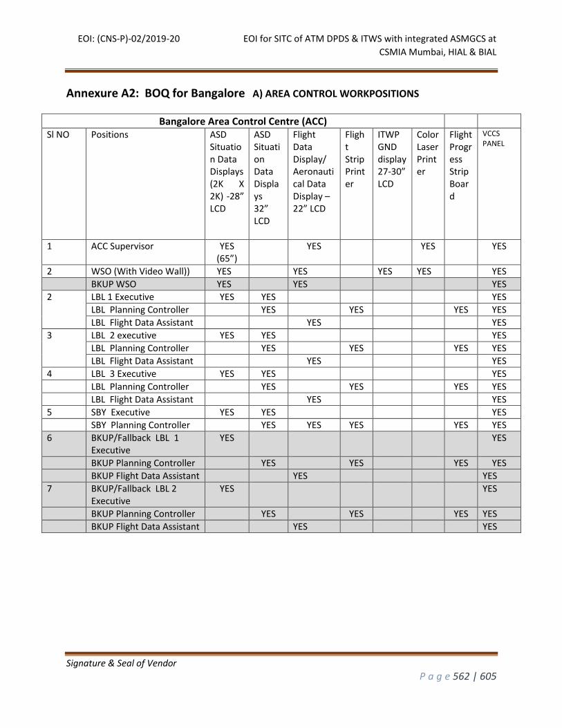
EOI: (CNS-P)-02/2019-20 EOI for SITC of ATM DPDS & ITWS with integrated ASMGCS at
CSMIA Mumbai, HIAL & BIAL
Signature & Seal of Vendor
P a g e 562 | 605
Annexure A2: BOQ for Bangalore A) AREA CONTROL WORKPOSITIONS
Bangalore Area Control Centre (ACC)
Sl NO Positions ASD Situation Data Displays (2K X 2K) -28” LCD
ASD Situation Data Displays 32” LCD
Flight Data Display/ Aeronautical Data Display – 22” LCD
Flight Strip Printer
ITWP GND display 27-30” LCD
Color Laser Printer
Flight Progress Strip Board
VCCS PANEL
1 ACC Supervisor YES (65”)
YES YES YES
2 WSO (With Video Wall)) YES YES YES YES YES
BKUP WSO YES YES YES
2 LBL 1 Executive YES YES YES
LBL Planning Controller YES YES YES YES
LBL Flight Data Assistant YES YES
3 LBL 2 executive YES YES YES
LBL Planning Controller YES YES YES YES
LBL Flight Data Assistant YES YES
4 LBL 3 Executive YES YES YES
LBL Planning Controller YES YES YES YES
LBL Flight Data Assistant YES YES
5 SBY Executive YES YES YES
SBY Planning Controller YES YES YES YES YES
6 BKUP/Fallback LBL 1 Executive
YES YES
BKUP Planning Controller YES YES YES YES
BKUP Flight Data Assistant YES YES
7 BKUP/Fallback LBL 2 Executive
YES YES
BKUP Planning Controller YES YES YES YES
BKUP Flight Data Assistant YES YES
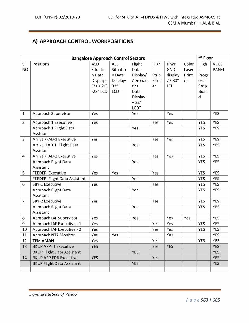
EOI: (CNS-P)-02/2019-20 EOI for SITC of ATM DPDS & ITWS with integrated ASMGCS at
CSMIA Mumbai, HIAL & BIAL
Signature & Seal of Vendor
P a g e 563 | 605
A) APPROACH CONTROL WORKPOSITIONS
Bangalore Approach Control Sectors 1st Floor
Sl NO
Positions ASD Situation Data Displays (2K X 2K) -28” LCD
ASD Situation Data Displays 32” LCD”
Flight Data Display/ Aeronautical Data Display – 22” LCD”
Flight Strip Printer
ITWP GND display 27-30” LED
ColorLaser Printer
Flight Progress Strip Board
VCCS PANEL
1 Approach Supervisor Yes Yes Yes YES
2 Approach 1 Executive Yes Yes Yes YES YES
Approach 1 Flight Data Assistant
Yes YES YES
3 Arrival/FAD-1 Executive Yes Yes Yes YES YES
Arrival FAD-1 Flight Data Assistant
Yes YES YES
4 Arrival/FAD-2 Executive Yes Yes Yes YES YES
Approach Flight Data Assistant
Yes YES YES
5 FEEDER Executive Yes Yes Yes YES YES
FEEDER Flight Data Assistant Yes YES YES
6 SBY-1 Executive Yes Yes YES YES
Approach Flight Data Assistant
Yes YES YES
7 SBY-2 Executive Yes Yes YES YES
Approach Flight Data Assistant
Yes YES YES
8 Approach IAF Supervisor Yes Yes Yes Yes YES
9 Approach IAF Executive - 1 Yes Yes Yes YES YES
10 Approach IAF Executive - 2 Yes Yes Yes YES YES
11 Approach NTZ Monitor Yes Yes Yes YES
12 TFM AMAN Yes Yes YES YES
13 BKUP APP- 1 Executive YES Yes YES YES
BKUP Flight Data Assistant YES YES
14 BKUP APP FDR Executive YES Yes YES
BKUP Flight Data Assistant YES YES
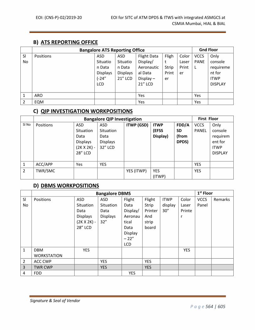
EOI: (CNS-P)-02/2019-20 EOI for SITC of ATM DPDS & ITWS with integrated ASMGCS at
CSMIA Mumbai, HIAL & BIAL
Signature & Seal of Vendor
P a g e 564 | 605
B) ATS REPORTING OFFICE
Bangalore ATS Reporting Office Gnd Floor
Sl No
Positions ASD Situation Data Displays (-24” LCD
ASD Situation Data Displays 21” LCD
Flight Data Display/ Aeronautical Data Display – 21” LCD
Flight Strip Printer
ColorLaser Printer
VCCS PANEL
Only console requirement for ITWP DISPLAY
1 ARO Yes Yes
2 EQM Yes Yes
C) QIP INVESTIGATION WORKPOSITIONS Bangalore QIP Investigation First Floor
Sl No Positions ASD Situation Data Displays (2K X 2K) -28” LCD
ASD Situation Data Displays 32” LCD
ITWP (GSD) ITWP (EFSS Display)
FDD/ASD (from DPDS)
VCCS PANEL
Only console requirement for ITWP DISPLAY
1 ACC/APP Yes YES YES
2 TWR/SMC YES (ITWP) YES (ITWP)
YES
D) DBMS WORKPOSITIONS Bangalore DBMS 1st Floor
Sl No
Positions ASD Situation Data Displays (2K X 2K) -28” LCD
ASD Situation Data Displays 32”
Flight Data Display/ Aeronautical Data Display – 22” LCD
Flight Strip Printer And strip board
ITWP display 30”
Color Laser Printer
VCCS Panel
Remarks
1 DBM WORKSTATION
YES YES
2 ACC CWP YES YES
3 TWR CWP YES YES
4 FDD YES

EOI: (CNS-P)-02/2019-20 EOI for SITC of ATM DPDS & ITWS with integrated ASMGCS at
CSMIA Mumbai, HIAL & BIAL
Signature & Seal of Vendor
P a g e 565 | 605
E) REMOTE MONITORING WORKPOSITIONS
Bangalore Remote Towers YNK & HAL
Sl No
Positions Situation Data Displays 28” LCD
Situation Data Displays 21” LCD
Flight Data Display/ Aeronautical Data Display – 21” LCD
Flight Strip Printer
ColorLaser Printer
Flight Progress Strip
Bay
VCCS Panel
1 YELAHANKA APP ONLY MONITORING
Yes Yes
2 HAL APP ONLY MONITORING Yes
Yes
F) BANGALORE TOWER WORKPOSITIONS
Bangalore Aerodrome Control Control TOWER
Sl NO
Positions ITWP (GSD) 27-30” LCD
ITWP (EFSS Display) 27-30 LCD
FDD/ ASD (from DPDS) 22”
Flight Strip Printer
Color Laser Printer
Flight Progress Strip Bay
VCCS PANEL
1 Tower Supervisor Yes Yes Yes (ASD)
Yes YES
2 Tower-1 Executive Yes Yes Yes YES YES
Tower-1 Flight Data Assistant Yes (FDD)
YES
3 Tower-2 Executive Yes Yes Yes YES YES
Tower-2 Flight Data Assistant Yes (FDD)
YES
4 SMC -1 Executive Yes Yes Yes YES YES
SMC -1 Flight Data Assistant YES
5 SMC -2 Executive Yes Yes Yes YES YES
SMC -2 Flight Data Assistant YES
6 SMC -3 Executive Yes Yes Yes YES YES
SMC -3 Flight Data Assistant YES
7 CLD-1 Executive Yes Yes Yes (FDD)
Yes YES YES
8 CLD-2 Executive Yes Yes Yes (FDD)
Yes YES YES
9 ACDM Yes (FDD)
Yes YES
10 IAF Coordinator Yes Yes (ASD)
Yes YES
11 Standby Executive - 1 Yes Yes Yes YES YES
12 Standby Executive - 2 Yes Yes Yes Yes YES
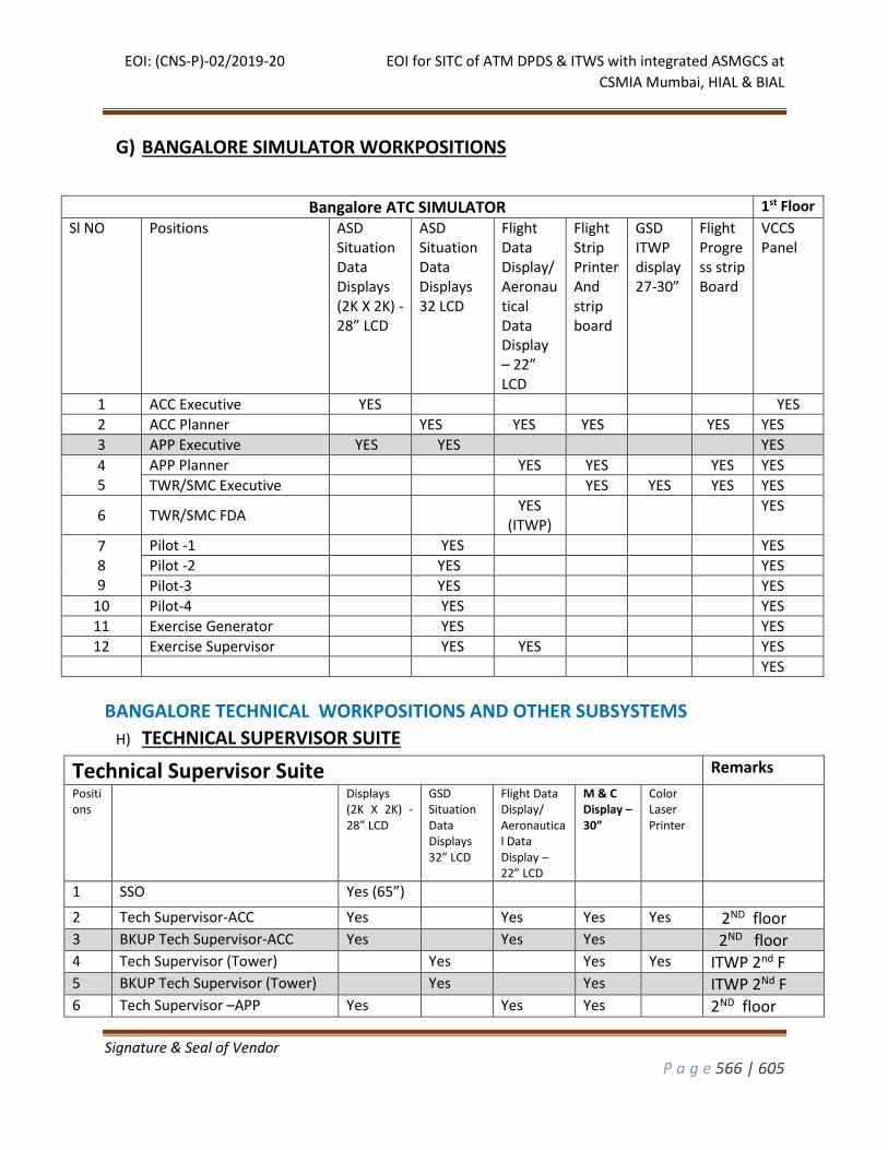
EOI: (CNS-P)-02/2019-20 EOI for SITC of ATM DPDS & ITWS with integrated ASMGCS at
CSMIA Mumbai, HIAL & BIAL
Signature & Seal of Vendor
P a g e 566 | 605
G) BANGALORE SIMULATOR WORKPOSITIONS
Bangalore ATC SIMULATOR 1st Floor
Sl NO Positions ASD Situation Data Displays (2K X 2K) -28” LCD
ASD Situation Data Displays 32 LCD
Flight Data Display/ Aeronautical Data Display – 22” LCD
Flight Strip Printer And strip board
GSD ITWP display 27-30”
Flight Progress strip Board
VCCS Panel
1 ACC Executive YES YES
2 ACC Planner YES YES YES YES YES
3 APP Executive YES YES YES
4 5
APP Planner YES YES YES YES
TWR/SMC Executive YES YES YES YES
6 TWR/SMC FDA YES
(ITWP) YES
7 8 9
Pilot -1 YES YES
Pilot -2 YES YES
Pilot-3 YES YES
10 Pilot-4 YES YES
11 Exercise Generator YES YES
12 Exercise Supervisor YES YES YES
YES
BANGALORE TECHNICAL WORKPOSITIONS AND OTHER SUBSYSTEMS
H) TECHNICAL SUPERVISOR SUITE
Technical Supervisor Suite Remarks Positions
Displays (2K X 2K) -28” LCD
GSD Situation Data Displays 32” LCD
Flight Data Display/ Aeronautical Data Display – 22” LCD
M & C Display – 30”
Color Laser Printer
1 SSO Yes (65”) 2 Tech Supervisor-ACC Yes Yes Yes Yes 2ND floor 3 BKUP Tech Supervisor-ACC Yes Yes Yes 2ND floor 4 Tech Supervisor (Tower) Yes Yes Yes ITWP 2nd F 5 BKUP Tech Supervisor (Tower) Yes Yes ITWP 2Nd F 6 Tech Supervisor –APP Yes Yes Yes 2ND floor
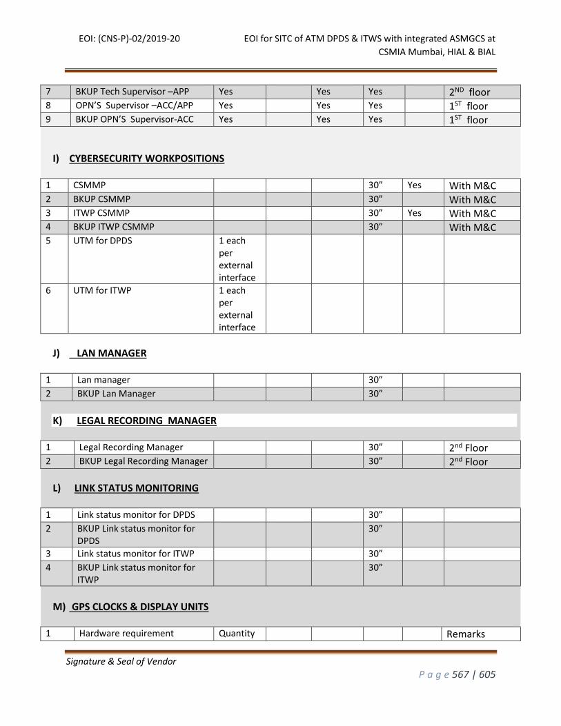
EOI: (CNS-P)-02/2019-20 EOI for SITC of ATM DPDS & ITWS with integrated ASMGCS at
CSMIA Mumbai, HIAL & BIAL
Signature & Seal of Vendor
P a g e 567 | 605
7 BKUP Tech Supervisor –APP Yes Yes Yes 2ND floor 8 OPN’S Supervisor –ACC/APP Yes Yes Yes 1ST floor 9 BKUP OPN’S Supervisor-ACC Yes Yes Yes 1ST floor
I) CYBERSECURITY WORKPOSITIONS 1 CSMMP 30” Yes With M&C 2 BKUP CSMMP 30” With M&C 3 ITWP CSMMP 30” Yes With M&C 4 BKUP ITWP CSMMP 30” With M&C 5 UTM for DPDS 1 each
per external interface
6 UTM for ITWP 1 each per external interface
J) LAN MANAGER 1 Lan manager 30” 2 BKUP Lan Manager 30”
K) LEGAL RECORDING MANAGER 1 Legal Recording Manager 30” 2nd Floor 2 BKUP Legal Recording Manager 30” 2nd Floor
L) LINK STATUS MONITORING 1 Link status monitor for DPDS 30” 2 BKUP Link status monitor for
DPDS 30”
3 Link status monitor for ITWP 30” 4 BKUP Link status monitor for
ITWP 30”
M) GPS CLOCKS & DISPLAY UNITS
1 Hardware requirement Quantity Remarks
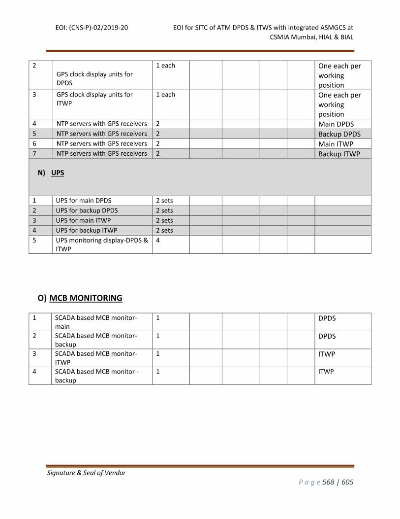
EOI: (CNS-P)-02/2019-20 EOI for SITC of ATM DPDS & ITWS with integrated ASMGCS at
CSMIA Mumbai, HIAL & BIAL
Signature & Seal of Vendor
P a g e 568 | 605
2 GPS clock display units for DPDS
1 each One each per working position
3 GPS clock display units for ITWP
1 each One each per working position
4 NTP servers with GPS receivers 2 Main DPDS 5 NTP servers with GPS receivers 2 Backup DPDS 6 NTP servers with GPS receivers 2 Main ITWP 7 NTP servers with GPS receivers 2 Backup ITWP
N) UPS
1 UPS for main DPDS 2 sets 2 UPS for backup DPDS 2 sets 3 UPS for main ITWP 2 sets 4 UPS for backup ITWP 2 sets 5 UPS monitoring display-DPDS &
ITWP 4
O) MCB MONITORING
1 SCADA based MCB monitor-main
1 DPDS
2 SCADA based MCB monitor-backup
1 DPDS
3 SCADA based MCB monitor-ITWP
1 ITWP
4 SCADA based MCB monitor -backup
1 ITWP
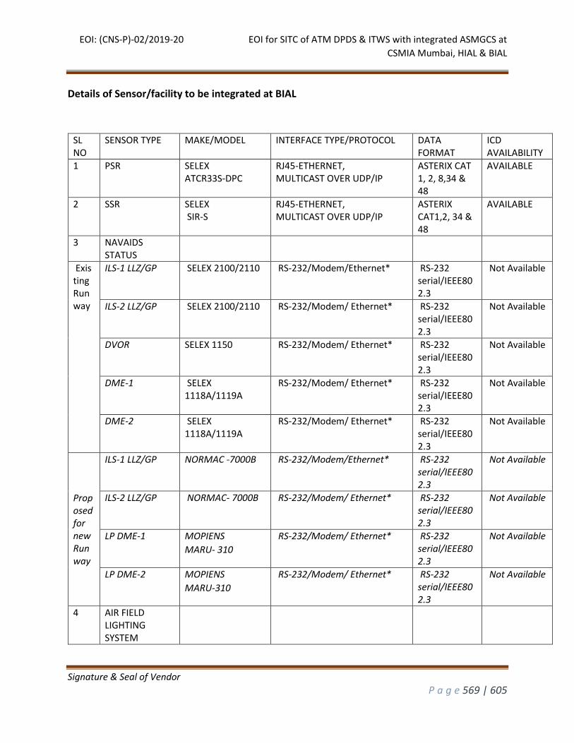
EOI: (CNS-P)-02/2019-20 EOI for SITC of ATM DPDS & ITWS with integrated ASMGCS at
CSMIA Mumbai, HIAL & BIAL
Signature & Seal of Vendor
P a g e 569 | 605
Details of Sensor/facility to be integrated at BIAL
SL NO
SENSOR TYPE MAKE/MODEL INTERFACE TYPE/PROTOCOL DATA FORMAT
ICD AVAILABILITY
1 PSR SELEX ATCR33S-DPC
RJ45-ETHERNET, MULTICAST OVER UDP/IP
ASTERIX CAT 1, 2, 8,34 & 48
AVAILABLE
2 SSR SELEX SIR-S
RJ45-ETHERNET, MULTICAST OVER UDP/IP
ASTERIX CAT1,2, 34 & 48
AVAILABLE
3 NAVAIDS STATUS
Existing Runway
ILS-1 LLZ/GP SELEX 2100/2110 RS-232/Modem/Ethernet* RS-232 serial/IEEE802.3
Not Available
ILS-2 LLZ/GP SELEX 2100/2110 RS-232/Modem/ Ethernet* RS-232 serial/IEEE802.3
Not Available
DVOR SELEX 1150 RS-232/Modem/ Ethernet* RS-232 serial/IEEE802.3
Not Available
DME-1 SELEX 1118A/1119A
RS-232/Modem/ Ethernet* RS-232 serial/IEEE802.3
Not Available
DME-2 SELEX 1118A/1119A
RS-232/Modem/ Ethernet* RS-232 serial/IEEE802.3
Not Available
Proposed for new Runway
ILS-1 LLZ/GP NORMAC -7000B RS-232/Modem/Ethernet* RS-232 serial/IEEE802.3
Not Available
ILS-2 LLZ/GP NORMAC- 7000B RS-232/Modem/ Ethernet* RS-232 serial/IEEE802.3
Not Available
LP DME-1 MOPIENS
MARU- 310
RS-232/Modem/ Ethernet* RS-232 serial/IEEE802.3
Not Available
LP DME-2 MOPIENS
MARU-310
RS-232/Modem/ Ethernet* RS-232 serial/IEEE802.3
Not Available
4 AIR FIELD LIGHTING SYSTEM
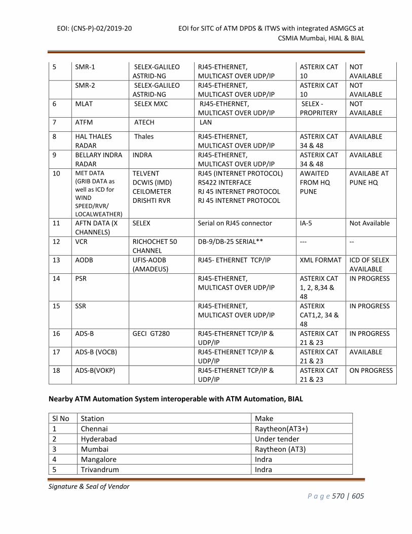
EOI: (CNS-P)-02/2019-20 EOI for SITC of ATM DPDS & ITWS with integrated ASMGCS at
CSMIA Mumbai, HIAL & BIAL
Signature & Seal of Vendor
P a g e 570 | 605
5 SMR-1 SELEX-GALILEO ASTRID-NG
RJ45-ETHERNET, MULTICAST OVER UDP/IP
ASTERIX CAT 10
NOT AVAILABLE
SMR-2 SELEX-GALILEO ASTRID-NG
RJ45-ETHERNET, MULTICAST OVER UDP/IP
ASTERIX CAT 10
NOT AVAILABLE
6 MLAT SELEX MXC RJ45-ETHERNET, MULTICAST OVER UDP/IP
SELEX - PROPRITERY
NOT AVAILABLE
7 ATFM ATECH LAN
8 HAL THALES RADAR
Thales RJ45-ETHERNET, MULTICAST OVER UDP/IP
ASTERIX CAT 34 & 48
AVAILABLE
9 BELLARY INDRA RADAR
INDRA RJ45-ETHERNET, MULTICAST OVER UDP/IP
ASTERIX CAT 34 & 48
AVAILABLE
10 MET DATA (GRIB DATA as well as ICD for WIND SPEED/RVR/ LOCALWEATHER)
TELVENT DCWIS (IMD) CEILOMETER DRISHTI RVR
RJ45 (INTERNET PROTOCOL) RS422 INTERFACE RJ 45 INTERNET PROTOCOL RJ 45 INTERNET PROTOCOL
AWAITED FROM HQ PUNE
AVAILABE AT PUNE HQ
11
AFTN DATA (X CHANNELS)
SELEX Serial on RJ45 connector IA-5 Not Available
12 VCR RICHOCHET 50 CHANNEL
DB-9/DB-25 SERIAL** --- --
13 AODB UFIS-AODB (AMADEUS)
RJ45- ETHERNET TCP/IP XML FORMAT ICD OF SELEX AVAILABLE
14 PSR RJ45-ETHERNET, MULTICAST OVER UDP/IP
ASTERIX CAT 1, 2, 8,34 & 48
IN PROGRESS
15 SSR RJ45-ETHERNET, MULTICAST OVER UDP/IP
ASTERIX CAT1,2, 34 & 48
IN PROGRESS
16 ADS-B GECI GT280 RJ45-ETHERNET TCP/IP & UDP/IP
ASTERIX CAT 21 & 23
IN PROGRESS
17 ADS-B (VOCB) RJ45-ETHERNET TCP/IP & UDP/IP
ASTERIX CAT 21 & 23
AVAILABLE
18 ADS-B(VOKP) RJ45-ETHERNET TCP/IP & UDP/IP
ASTERIX CAT 21 & 23
ON PROGRESS
Nearby ATM Automation System interoperable with ATM Automation, BIAL
Sl No Station Make
1 Chennai Raytheon(AT3+)
2 Hyderabad Under tender
3 Mumbai Raytheon (AT3)
4 Mangalore Indra
5 Trivandrum Indra
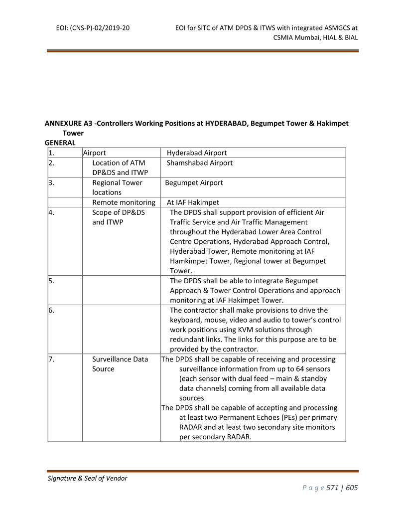
EOI: (CNS-P)-02/2019-20 EOI for SITC of ATM DPDS & ITWS with integrated ASMGCS at
CSMIA Mumbai, HIAL & BIAL
Signature & Seal of Vendor
P a g e 571 | 605
ANNEXURE A3 -Controllers Working Positions at HYDERABAD, Begumpet Tower & Hakimpet Tower
GENERAL
1. Airport Hyderabad Airport
2. Location of ATM DP&DS and ITWP
Shamshabad Airport
3. Regional Tower locations
Begumpet Airport
Remote monitoring At IAF Hakimpet
4. Scope of DP&DS and ITWP
The DPDS shall support provision of efficient Air Traffic Service and Air Traffic Management throughout the Hyderabad Lower Area Control Centre Operations, Hyderabad Approach Control, Hyderabad Tower, Remote monitoring at IAF Hamkimpet Tower, Regional tower at Begumpet Tower.
5. The DPDS shall be able to integrate Begumpet Approach & Tower Control Operations and approach monitoring at IAF Hakimpet Tower.
6. The contractor shall make provisions to drive the keyboard, mouse, video and audio to tower’s control work positions using KVM solutions through redundant links. The links for this purpose are to be provided by the contractor.
7. Surveillance Data Source
The DPDS shall be capable of receiving and processing surveillance information from up to 64 sensors (each sensor with dual feed – main & standby data channels) coming from all available data sources
The DPDS shall be capable of accepting and processing at least two Permanent Echoes (PEs) per primary RADAR and at least two secondary site monitors per secondary RADAR.
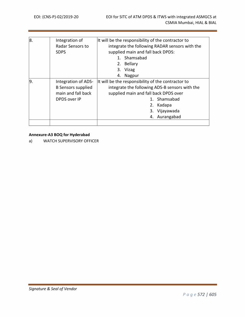
EOI: (CNS-P)-02/2019-20 EOI for SITC of ATM DPDS & ITWS with integrated ASMGCS at
CSMIA Mumbai, HIAL & BIAL
Signature & Seal of Vendor
P a g e 572 | 605
8. Integration of Radar Sensors to SDPS
It will be the responsibility of the contractor to integrate the following RADAR sensors with the supplied main and fall back DPDS:
1. Shamsabad 2. Bellary 3. Vizag 4. Nagpur
9. Integration of ADS-B Sensors supplied main and fall back DPDS over IP
It will be the responsibility of the contractor to integrate the following ADS-B sensors with the supplied main and fall back DPDS over
1. Shamsabad 2. Kadapa 3. Vijayawada 4. Aurangabad
Annexure-A3 BOQ for Hyderabad
a) WATCH SUPERVISORY OFFICER
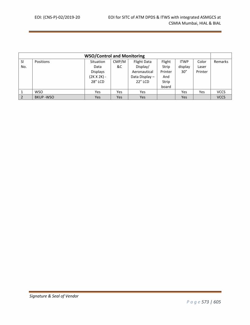
EOI: (CNS-P)-02/2019-20 EOI for SITC of ATM DPDS & ITWS with integrated ASMGCS at
CSMIA Mumbai, HIAL & BIAL
Signature & Seal of Vendor
P a g e 573 | 605
WSO/Control and Monitoring
Sl No.
Positions Situation Data
Displays (2K X 2K) -
28” LCD
CMP/M&C
Flight Data Display/
Aeronautical Data Display –
22” LCD
Flight Strip
Printer And Strip
board
ITWP display
30”
Color Laser
Printer
Remarks
1 WSO Yes Yes Yes Yes Yes VCCS
2 BKUP -WSO Yes Yes Yes Yes VCCS
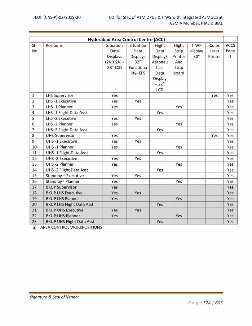
EOI: (CNS-P)-02/2019-20 EOI for SITC of ATM DPDS & ITWS with integrated ASMGCS at
CSMIA Mumbai, HIAL & BIAL
Signature & Seal of Vendor
P a g e 574 | 605
a) AREA CONTROL WORKPOSITIONS
Hyderabad Area Control Centre (ACC)
Sl No.
Positions Situation Data
Displays (2K X 2K) -
28” LCD
Situation Data
Displays 32”
Functionality- EFS
Flight Data
Display/ Aeronau
tical Data
Display – 22” LCD
Flight Strip
Printer And Strip
board
ITWP display
30”
Color Laser
Printer
VCCS Pane
l
1 LHS Supervisor Yes Yes Yes
2 LHS -1 Executive Yes Yes Yes
3 LHS -1 Planner Yes Yes Yes
4 LHS -1 Flight Data Asst Yes Yes
5 LHS -2 Executive Yes Yes Yes
6 LHS -2 Planner Yes Yes Yes
7 LHS -2 Flight Data Asst Yes Yes
8 UHS-Supervisor Yes Yes Yes
9 UHS -1 Executive Yes Yes Yes
10 UHS -1 Planner Yes Yes Yes
11 UHS -1 Flight Data Asst Yes Yes
12 UHS -2 Executive Yes Yes Yes
13 UHS -2 Planner Yes Yes Yes
14 UHS -2 Flight Data Asst Yes Yes
15 Stand by – Executive Yes Yes Yes
16 Stand by - Planner Yes Yes Yes
17 BKUP Supervisor Yes Yes
18 BKUP LHS Executive Yes Yes Yes
19 BKUP LHS Planner Yes Yes Yes
20 BKUP LHS Flight Data Asst Yes Yes
21 BKUP UHS Executive Yes Yes Yes
22 BKUP UHS Planner Yes Yes Yes
23 BKUP UHS Flight Data Asst Yes Yes
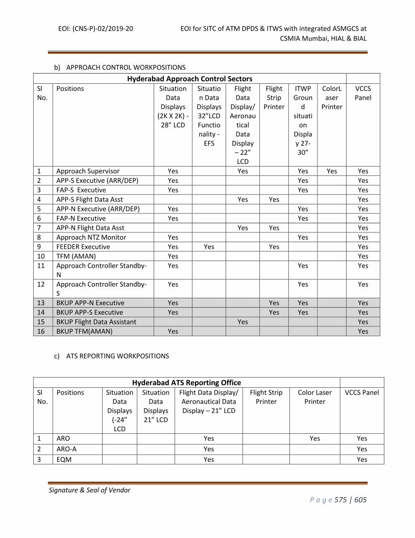
EOI: (CNS-P)-02/2019-20 EOI for SITC of ATM DPDS & ITWS with integrated ASMGCS at
CSMIA Mumbai, HIAL & BIAL
Signature & Seal of Vendor
P a g e 575 | 605
b) APPROACH CONTROL WORKPOSITIONS
Hyderabad Approach Control Sectors
Sl No.
Positions Situation Data
Displays (2K X 2K) -
28” LCD
Situation Data
Displays 32”LCD Functionality -
EFS
Flight Data
Display/ Aeronau
tical Data
Display – 22” LCD
Flight Strip
Printer
ITWP Groun
d situati
on Display 27-30”
ColorLaser
Printer
VCCS Panel
1 Approach Supervisor Yes Yes Yes Yes Yes
2 APP-S Executive (ARR/DEP) Yes Yes Yes
3 FAP-S Executive Yes Yes Yes
4 APP-S Flight Data Asst Yes Yes Yes
5 APP-N Executive (ARR/DEP) Yes Yes Yes
6 FAP-N Executive Yes Yes Yes
7 APP-N Flight Data Asst Yes Yes Yes
8 Approach NTZ Monitor Yes Yes Yes
9 FEEDER Executive Yes Yes Yes Yes
10 TFM (AMAN) Yes Yes
11 Approach Controller Standby-N
Yes Yes Yes
12 Approach Controller Standby-S
Yes Yes Yes
13 BKUP APP-N Executive Yes Yes Yes Yes
14 BKUP APP-S Executive Yes Yes Yes Yes
15 BKUP Flight Data Assistant Yes Yes
16 BKUP TFM(AMAN) Yes Yes
c) ATS REPORTING WORKPOSITIONS
Hyderabad ATS Reporting Office
Sl No.
Positions Situation Data
Displays (-24” LCD
Situation Data
Displays 21” LCD
Flight Data Display/ Aeronautical Data Display – 21” LCD
Flight Strip Printer
Color Laser Printer
VCCS Panel
1 ARO Yes Yes Yes
2 ARO-A Yes Yes
3 EQM Yes Yes
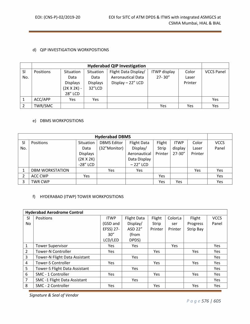
EOI: (CNS-P)-02/2019-20 EOI for SITC of ATM DPDS & ITWS with integrated ASMGCS at
CSMIA Mumbai, HIAL & BIAL
Signature & Seal of Vendor
P a g e 576 | 605
d) QIP INVESTIGATION WORKPOSITIONS
Hyderabad QIP Investigation
Sl No.
Positions Situation Data
Displays (2K X 2K) -
28” LCD
Situation Data
Displays 32”LCD
Flight Data Display/ Aeronautical Data Display – 22” LCD
ITWP display 27- 30”
Color Laser
Printer
VCCS Panel
1 ACC/APP Yes Yes Yes
2 TWR/SMC Yes Yes Yes
e) DBMS WORKPOSITIONS
Hyderabad DBMS
Sl No.
Positions Situation Data
Displays (2K X 2K) -28” LCD
DBMS Editor (32”Monitor)
Flight Data Display/
Aeronautical Data Display
– 22” LCD
Flight Strip
Printer
ITWP display 27-30”
Color Laser
Printer
VCCS Panel
1 DBM WORKSTATION Yes Yes Yes Yes
2 ACC CWP Yes Yes Yes
3 TWR CWP Yes Yes Yes
f) HYDERABAD (ITWP) TOWER WORKPOSITIONS
Hyderabad Aerodrome Control
Sl No
Positions ITWP (GSD and EFSS) 27-
30” LCD/LED
Flight Data Display/ ASD 22”
(from DPDS)
Flight Strip
Printer
ColorLaser
Printer
Flight Progress Strip Bay
VCCS Panel
1 Tower Supervisor Yes Yes Yes Yes
2 Tower-N Controller Yes Yes Yes Yes
3 Tower-N Flight Data Assistant Yes Yes
4 Tower-S Controller Yes Yes Yes Yes
5 Tower-S Flight Data Assistant Yes Yes
6 SMC - 1 Controller Yes Yes Yes Yes
7 SMC -1 Flight Data Assistant Yes Yes
8 SMC - 2 Controller Yes Yes Yes Yes
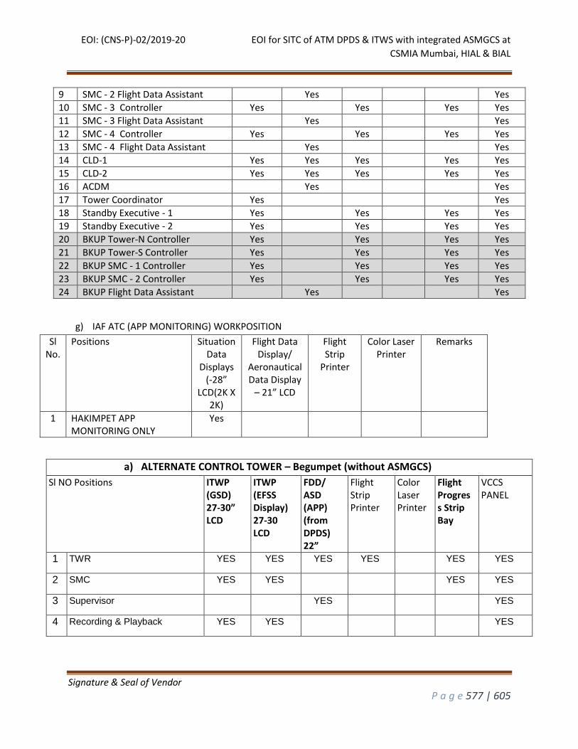
EOI: (CNS-P)-02/2019-20 EOI for SITC of ATM DPDS & ITWS with integrated ASMGCS at
CSMIA Mumbai, HIAL & BIAL
Signature & Seal of Vendor
P a g e 577 | 605
9 SMC - 2 Flight Data Assistant Yes Yes
10 SMC - 3 Controller Yes Yes Yes Yes
11 SMC - 3 Flight Data Assistant Yes Yes
12 SMC - 4 Controller Yes Yes Yes Yes
13 SMC - 4 Flight Data Assistant Yes Yes
14 CLD-1 Yes Yes Yes Yes Yes
15 CLD-2 Yes Yes Yes Yes Yes
16 ACDM Yes Yes
17 Tower Coordinator Yes Yes
18 Standby Executive - 1 Yes Yes Yes Yes
19 Standby Executive - 2 Yes Yes Yes Yes
20 BKUP Tower-N Controller Yes Yes Yes Yes
21 BKUP Tower-S Controller Yes Yes Yes Yes
22 BKUP SMC - 1 Controller Yes Yes Yes Yes
23 BKUP SMC - 2 Controller Yes Yes Yes Yes
24 BKUP Flight Data Assistant Yes Yes
g) IAF ATC (APP MONITORING) WORKPOSITION
Sl No.
Positions Situation Data
Displays (-28”
LCD(2K X 2K)
Flight Data Display/
Aeronautical Data Display
– 21” LCD
Flight Strip
Printer
Color Laser Printer
Remarks
1 HAKIMPET APP MONITORING ONLY
Yes
a) ALTERNATE CONTROL TOWER – Begumpet (without ASMGCS)
Sl NO Positions ITWP (GSD) 27-30” LCD
ITWP (EFSS Display) 27-30 LCD
FDD/ ASD (APP) (from DPDS) 22”
Flight Strip Printer
Color Laser Printer
Flight Progress Strip Bay
VCCS PANEL
1 TWR YES YES YES YES YES YES
2 SMC YES YES YES YES
3 Supervisor YES YES
4 Recording & Playback YES YES YES
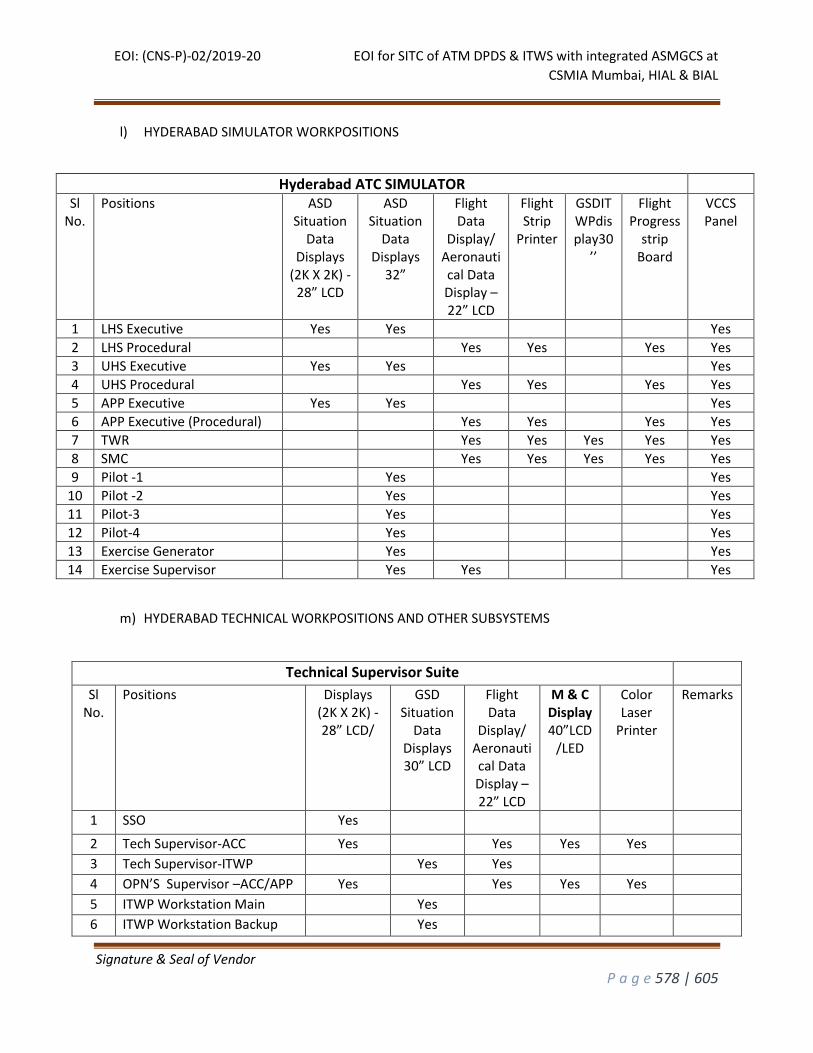
EOI: (CNS-P)-02/2019-20 EOI for SITC of ATM DPDS & ITWS with integrated ASMGCS at
CSMIA Mumbai, HIAL & BIAL
Signature & Seal of Vendor
P a g e 578 | 605
l) HYDERABAD SIMULATOR WORKPOSITIONS
Hyderabad ATC SIMULATOR
Sl No.
Positions ASD Situation
Data Displays
(2K X 2K) -28” LCD
ASD Situation
Data Displays
32”
Flight Data
Display/ Aeronautical Data Display – 22” LCD
Flight Strip
Printer
GSDITWPdisplay30
’’
Flight Progress
strip Board
VCCS Panel
1 LHS Executive Yes Yes Yes
2 LHS Procedural Yes Yes Yes Yes
3 UHS Executive Yes Yes Yes
4 UHS Procedural Yes Yes Yes Yes
5 APP Executive Yes Yes Yes
6 APP Executive (Procedural) Yes Yes Yes Yes
7 TWR Yes Yes Yes Yes Yes
8 SMC Yes Yes Yes Yes Yes
9 Pilot -1 Yes Yes
10 Pilot -2 Yes Yes
11 Pilot-3 Yes Yes
12 Pilot-4 Yes Yes
13 Exercise Generator Yes Yes
14 Exercise Supervisor Yes Yes Yes
m) HYDERABAD TECHNICAL WORKPOSITIONS AND OTHER SUBSYSTEMS
Technical Supervisor Suite Sl
No. Positions Displays
(2K X 2K) -28” LCD/
GSD Situation
Data Displays 30” LCD
Flight Data
Display/ Aeronautical Data Display – 22” LCD
M & C Display40”LCD
/LED
Color Laser
Printer
Remarks
1 SSO Yes 2 Tech Supervisor-ACC Yes Yes Yes Yes 3 Tech Supervisor-ITWP Yes Yes 4 OPN’S Supervisor –ACC/APP Yes Yes Yes Yes 5 ITWP Workstation Main Yes 6 ITWP Workstation Backup Yes
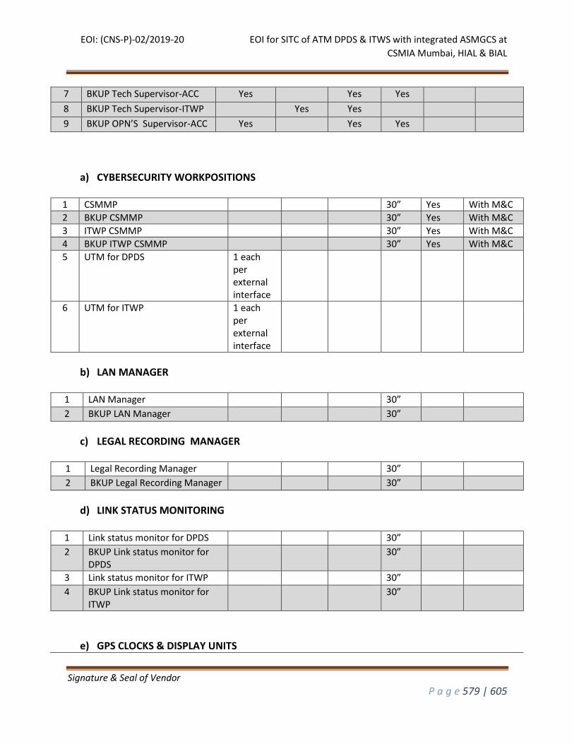
EOI: (CNS-P)-02/2019-20 EOI for SITC of ATM DPDS & ITWS with integrated ASMGCS at
CSMIA Mumbai, HIAL & BIAL
Signature & Seal of Vendor
P a g e 579 | 605
7 BKUP Tech Supervisor-ACC Yes Yes Yes 8 BKUP Tech Supervisor-ITWP Yes Yes 9 BKUP OPN’S Supervisor-ACC Yes Yes Yes
a) CYBERSECURITY WORKPOSITIONS
1 CSMMP 30” Yes With M&C
2 BKUP CSMMP 30” Yes With M&C
3 ITWP CSMMP 30” Yes With M&C
4 BKUP ITWP CSMMP 30” Yes With M&C
5 UTM for DPDS 1 each per external interface
6 UTM for ITWP 1 each per external interface
b) LAN MANAGER
1 LAN Manager 30” 2 BKUP LAN Manager 30”
c) LEGAL RECORDING MANAGER
1 Legal Recording Manager 30” 2 BKUP Legal Recording Manager 30”
d) LINK STATUS MONITORING
1 Link status monitor for DPDS 30” 2 BKUP Link status monitor for
DPDS 30”
3 Link status monitor for ITWP 30” 4 BKUP Link status monitor for
ITWP 30”
e) GPS CLOCKS & DISPLAY UNITS
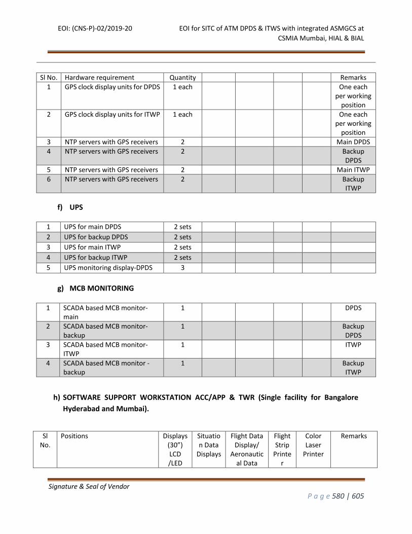
EOI: (CNS-P)-02/2019-20 EOI for SITC of ATM DPDS & ITWS with integrated ASMGCS at
CSMIA Mumbai, HIAL & BIAL
Signature & Seal of Vendor
P a g e 580 | 605
h) SOFTWARE SUPPORT WORKSTATION ACC/APP & TWR (Single facility for Bangalore
Hyderabad and Mumbai).
Sl No.
Positions Displays (30”) LCD /LED
Situation Data
Displays
Flight Data Display/
Aeronautical Data
Flight Strip
Printer
Color Laser
Printer
Remarks
Sl No. Hardware requirement Quantity Remarks
1 GPS clock display units for DPDS 1 each One each per working
position
2 GPS clock display units for ITWP 1 each One each per working
position
3 NTP servers with GPS receivers 2 Main DPDS
4 NTP servers with GPS receivers 2 Backup DPDS
5 NTP servers with GPS receivers 2 Main ITWP
6 NTP servers with GPS receivers 2 Backup ITWP
f) UPS
1 UPS for main DPDS 2 sets 2 UPS for backup DPDS 2 sets 3 UPS for main ITWP 2 sets 4 UPS for backup ITWP 2 sets 5 UPS monitoring display-DPDS 3
g) MCB MONITORING
1 SCADA based MCB monitor-
main 1 DPDS
2 SCADA based MCB monitor-backup
1 Backup DPDS
3 SCADA based MCB monitor-ITWP
1 ITWP
4 SCADA based MCB monitor -backup
1 Backup ITWP
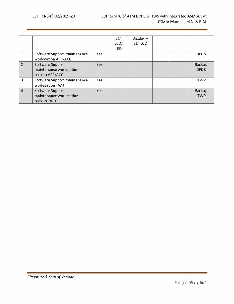
EOI: (CNS-P)-02/2019-20 EOI for SITC of ATM DPDS & ITWS with integrated ASMGCS at
CSMIA Mumbai, HIAL & BIAL
Signature & Seal of Vendor
P a g e 581 | 605
21” LCD/ LED
Display – 21” LCD
1 Software Support maintenance workstation APP/ACC
Yes DPDS
2 Software Support maintenance workstation – backup APP/ACC
Yes Backup DPDS
3 Software Support maintenance workstation TWR
Yes ITWP
4 Software Support maintenance workstation – backup TWR
Yes Backup ITWP
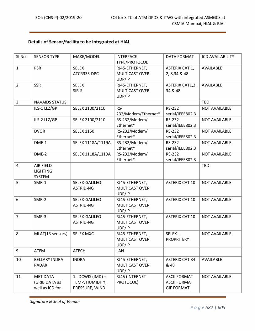
EOI: (CNS-P)-02/2019-20 EOI for SITC of ATM DPDS & ITWS with integrated ASMGCS at
CSMIA Mumbai, HIAL & BIAL
Signature & Seal of Vendor
P a g e 582 | 605
Details of Sensor/facility to be integrated at HIAL
Sl No SENSOR TYPE MAKE/MODEL INTERFACE TYPE/PROTOCOL
DATA FORMAT ICD AVAILABILITY
1 PSR SELEX ATCR33S-DPC
RJ45-ETHERNET, MULTICAST OVER UDP/IP
ASTERIX CAT 1, 2, 8,34 & 48
AVAILABLE
2 SSR SELEX SIR-S
RJ45-ETHERNET, MULTICAST OVER UDP/IP
ASTERIX CAT1,2, 34 & 48
AVAILABLE
3 NAVAIDS STATUS TBD
ILS-1 LLZ/GP SELEX 2100/2110 RS-232/Modem/Ethernet*
RS-232 serial/IEEE802.3
NOT AVAILABLE
ILS-2 LLZ/GP SELEX 2100/2110 RS-232/Modem/ Ethernet*
RS-232 serial/IEEE802.3
NOT AVAILABLE
DVOR SELEX 1150 RS-232/Modem/ Ethernet*
RS-232 serial/IEEE802.3
NOT AVAILABLE
DME-1 SELEX 1118A/1119A RS-232/Modem/ Ethernet*
RS-232 serial/IEEE802.3
NOT AVAILABLE
DME-2 SELEX 1118A/1119A RS-232/Modem/ Ethernet*
RS-232 serial/IEEE802.3
NOT AVAILABLE
4 AIR FIELD LIGHTING SYSTEM
TBD
5 SMR-1 SELEX-GALILEO ASTRID-NG
RJ45-ETHERNET, MULTICAST OVER UDP/IP
ASTERIX CAT 10 NOT AVAILABLE
6 SMR-2 SELEX-GALILEO ASTRID-NG
RJ45-ETHERNET, MULTICAST OVER UDP/IP
ASTERIX CAT 10 NOT AVAILABLE
7 SMR-3 SELEX-GALILEO ASTRID-NG
RJ45-ETHERNET, MULTICAST OVER UDP/IP
ASTERIX CAT 10 NOT AVAILABLE
8 MLAT(13 sensors) SELEX MXC RJ45-ETHERNET, MULTICAST OVER UDP/IP
SELEX - PROPRITERY
NOT AVAILABLE
9 ATFM ATECH LAN
10 BELLARY INDRA RADAR
INDRA RJ45-ETHERNET, MULTICAST OVER UDP/IP
ASTERIX CAT 34 & 48
AVAILABLE
11 MET DATA (GRIB DATA as well as ICD for
1. DCWIS (IMD) – TEMP, HUMIDITY, PRESSURE, WIND
RJ45 (INTERNET PROTOCOL)
ASCII FORMAT ASCII FORMAT GIF FORMAT
NOT AVAILABLE
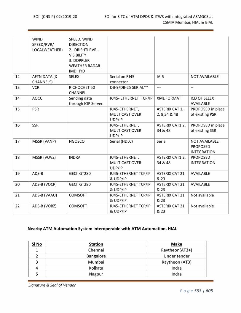
EOI: (CNS-P)-02/2019-20 EOI for SITC of ATM DPDS & ITWS with integrated ASMGCS at
CSMIA Mumbai, HIAL & BIAL
Signature & Seal of Vendor
P a g e 583 | 605
WIND SPEED/RVR/ LOCALWEATHER)
SPEED, WIND DIRECTION 2. DRISHTI RVR - VISIBILITY 3. DOPPLER WEATHER RADAR-IMD HYD
12
AFTN DATA (X CHANNELS)
SELEX Serial on RJ45 connector
IA-5 NOT AVAILABLE
13 VCR RICHOCHET 50 CHANNEL
DB-9/DB-25 SERIAL** --- --
14 AOCC Sending data through IOP Server
RJ45- ETHERNET TCP/IP XML FORMAT ICD OF SELEX AVAILABLE
15 PSR RJ45-ETHERNET, MULTICAST OVER UDP/IP
ASTERIX CAT 1, 2, 8,34 & 48
PROPOSED in place of existing PSR
16 SSR RJ45-ETHERNET, MULTICAST OVER UDP/IP
ASTERIX CAT1,2, 34 & 48
PROPOSED in place of existing SSR
17 MSSR (VANP) NGOSCO Serial (HDLC)
Serial NOT AVAILABLE PROPOSED INTEGRATION
18 MSSR (VOVZ) INDRA RJ45-ETHERNET, MULTICAST OVER UDP/IP
ASTERIX CAT1,2, 34 & 48
PROPOSED INTEGRATION
19 ADS-B GECI GT280 RJ45-ETHERNET TCP/IP & UDP/IP
ASTERIX CAT 21 & 23
AVAILABLE
20 ADS-B (VOCP) GECI GT280 RJ45-ETHERNET TCP/IP & UDP/IP
ASTERIX CAT 21 & 23
AVAILABLE
21 ADS-B (VAAU) COMSOFT RJ45-ETHERNET TCP/IP & UDP/IP
ASTERIX CAT 21 & 23
Not available
22 ADS-B (VOBZ) COMSOFT RJ45-ETHERNET TCP/IP & UDP/IP
ASTERIX CAT 21 & 23
Not available
Nearby ATM Automation System interoperable with ATM Automation, HIAL
Sl No Station Make
1 Chennai Raytheon(AT3+)
2 Bangalore Under tender
3 Mumbai Raytheon (AT3)
4 Kolkata Indra
5 Nagpur Indra
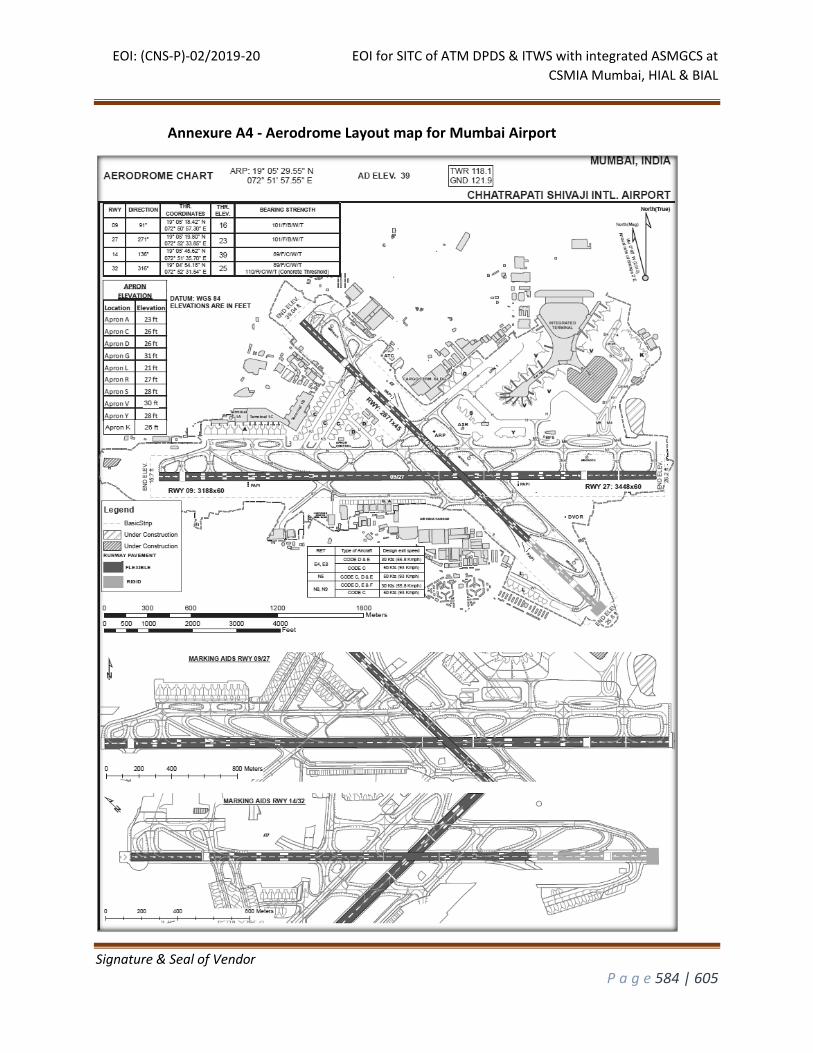
EOI: (CNS-P)-02/2019-20 EOI for SITC of ATM DPDS & ITWS with integrated ASMGCS at
CSMIA Mumbai, HIAL & BIAL
Signature & Seal of Vendor
P a g e 584 | 605
Annexure A4 - Aerodrome Layout map for Mumbai Airport
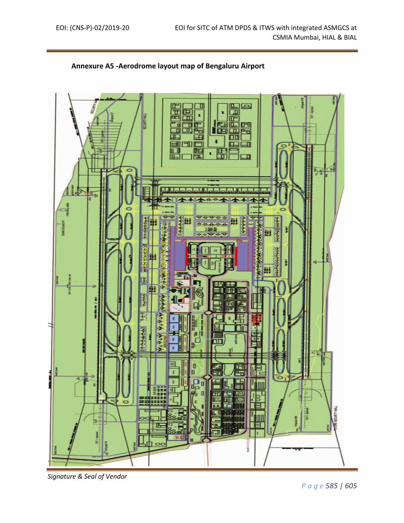
EOI: (CNS-P)-02/2019-20 EOI for SITC of ATM DPDS & ITWS with integrated ASMGCS at
CSMIA Mumbai, HIAL & BIAL
Signature & Seal of Vendor
P a g e 585 | 605
Annexure A5 -Aerodrome layout map of Bengaluru Airport
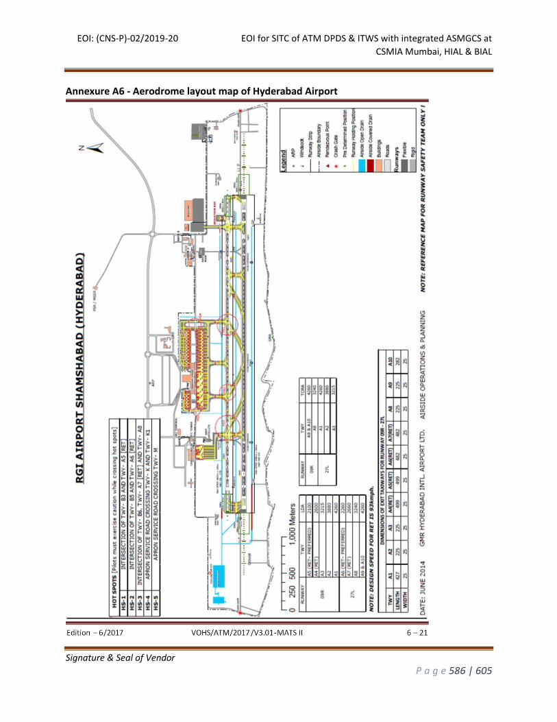
EOI: (CNS-P)-02/2019-20 EOI for SITC of ATM DPDS & ITWS with integrated ASMGCS at
CSMIA Mumbai, HIAL & BIAL
Signature & Seal of Vendor
P a g e 586 | 605
Annexure A6 - Aerodrome layout map of Hyderabad Airport
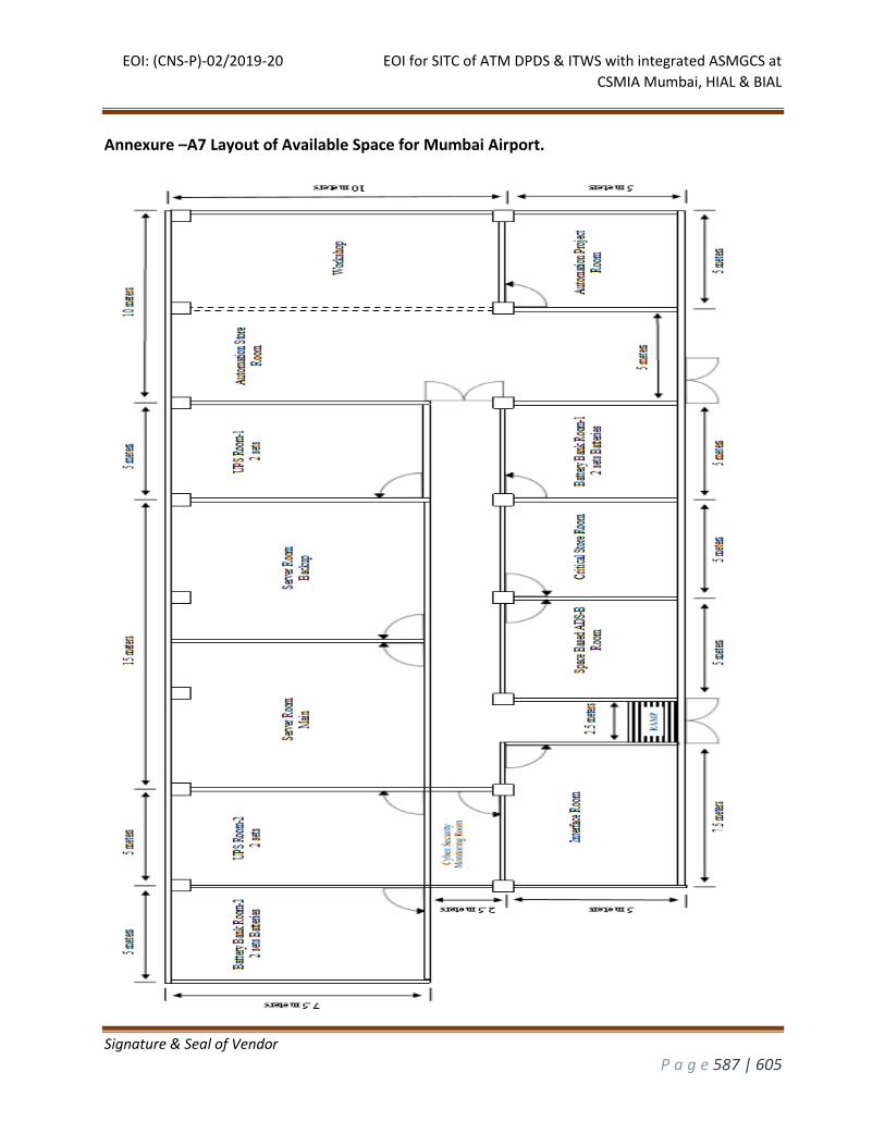
EOI: (CNS-P)-02/2019-20 EOI for SITC of ATM DPDS & ITWS with integrated ASMGCS at
CSMIA Mumbai, HIAL & BIAL
Signature & Seal of Vendor
P a g e 587 | 605
Annexure –A7 Layout of Available Space for Mumbai Airport.
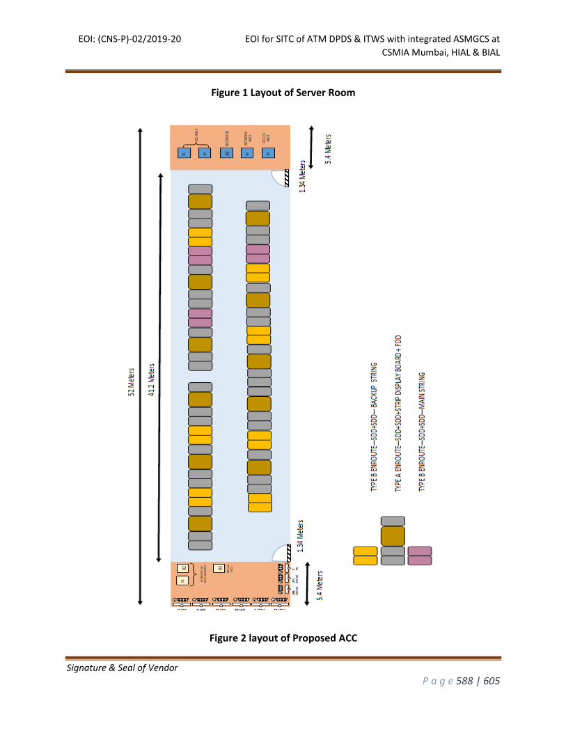
EOI: (CNS-P)-02/2019-20 EOI for SITC of ATM DPDS & ITWS with integrated ASMGCS at
CSMIA Mumbai, HIAL & BIAL
Signature & Seal of Vendor
P a g e 588 | 605
Figure 1 Layout of Server Room
Figure 2 layout of Proposed ACC
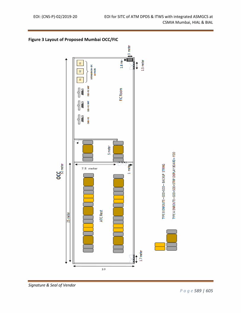
EOI: (CNS-P)-02/2019-20 EOI for SITC of ATM DPDS & ITWS with integrated ASMGCS at
CSMIA Mumbai, HIAL & BIAL
Signature & Seal of Vendor
P a g e 589 | 605
Figure 3 Layout of Proposed Mumbai OCC/FIC
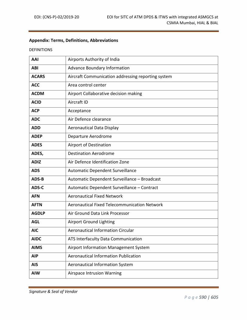
EOI: (CNS-P)-02/2019-20 EOI for SITC of ATM DPDS & ITWS with integrated ASMGCS at
CSMIA Mumbai, HIAL & BIAL
Signature & Seal of Vendor
P a g e 590 | 605
Appendix: Terms, Definitions, Abbreviations
DEFINITIONS
AAI Airports Authority of India
ABI Advance Boundary Information
ACARS Aircraft Communication addressing reporting system
ACC Area control center
ACDM Airport Collaborative decision making
ACID Aircraft ID
ACP Acceptance
ADC Air Defence clearance
ADD Aeronautical Data Display
ADEP Departure Aerodrome
ADES Airport of Destination
ADES, Destination Aerodrome
ADIZ Air Defence Identification Zone
ADS Automatic Dependent Surveillance
ADS-B Automatic Dependent Surveillance – Broadcast
ADS-C Automatic Dependent Surveillance – Contract
AFN Aeronautical Fixed Network
AFTN Aeronautical Fixed Telecommunication Network
AGDLP Air Ground Data Link Processor
AGL Airport Ground Lighting
AIC Aeronautical Information Circular
AIDC ATS Interfaculty Data Communication
AIMS Airport Information Management System
AIP Aeronautical Information Publication
AIS Aeronautical Information System
AIW Airspace Intrusion Warning
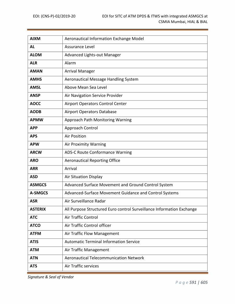
EOI: (CNS-P)-02/2019-20 EOI for SITC of ATM DPDS & ITWS with integrated ASMGCS at
CSMIA Mumbai, HIAL & BIAL
Signature & Seal of Vendor
P a g e 591 | 605
AIXM Aeronautical Information Exchange Model
AL Assurance Level
ALOM Advanced Lights-out Manager
ALR Alarm
AMAN Arrival Manager
AMHS Aeronautical Message Handling System
AMSL Above Mean Sea Level
ANSP Air Navigation Service Provider
AOCC Airport Operators Control Center
AODB Airport Operators Database
APMW Approach Path Monitoring Warning
APP Approach Control
APS Air Position
APW Air Proximity Warning
ARCW ADS-C Route Conformance Warning
ARO Aeronautical Reporting Office
ARR Arrival
ASD Air Situation Display
ASMGCS Advanced Surface Movement and Ground Control System
A-SMGCS Advanced-Surface Movement Guidance and Control Systems
ASR Air Surveillance Radar
ASTERIX All Purpose Structured Euro control Surveillance Information Exchange
ATC Air Traffic Control
ATCO Air Traffic Control officer
ATFM Air Traffic Flow Management
ATIS Automatic Terminal Information Service
ATM Air Traffic Management
ATN Aeronautical Telecommunication Network
ATS Air Traffic services
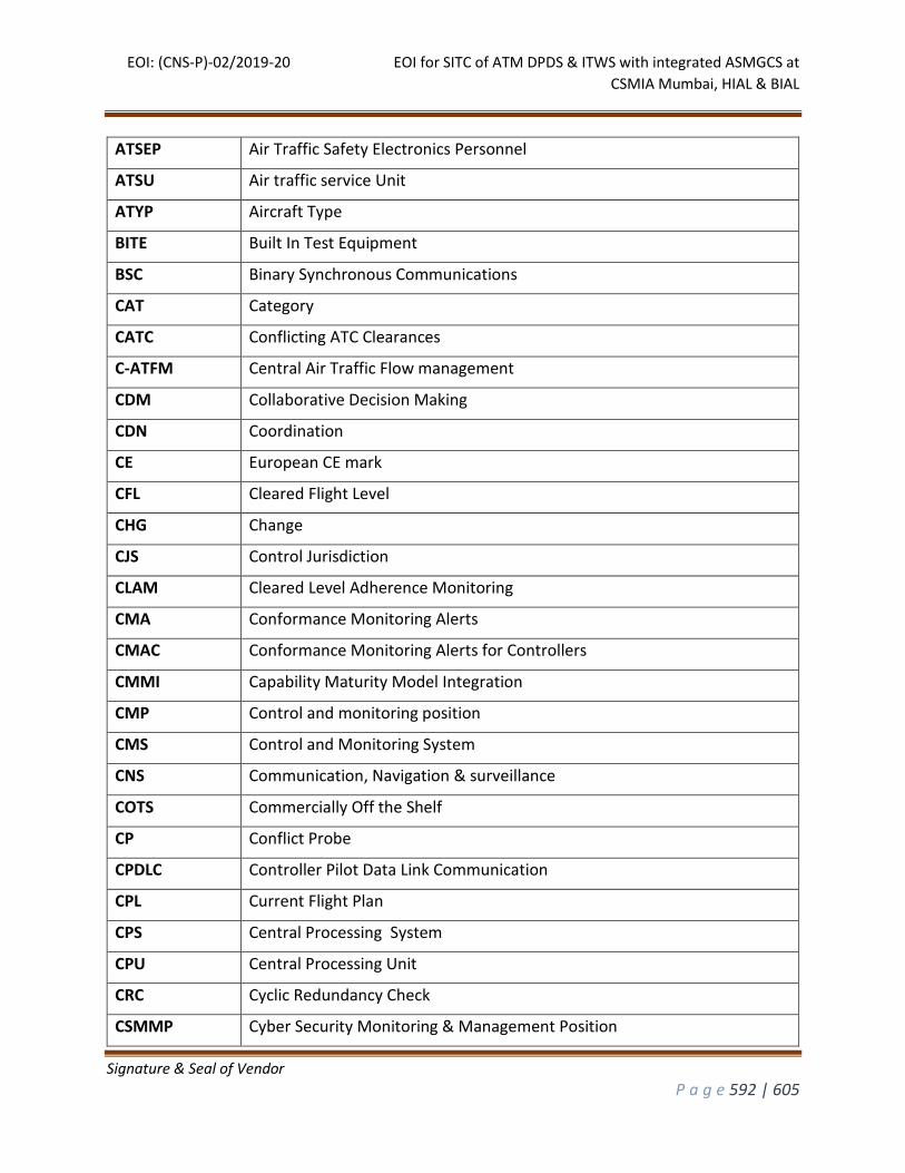
EOI: (CNS-P)-02/2019-20 EOI for SITC of ATM DPDS & ITWS with integrated ASMGCS at
CSMIA Mumbai, HIAL & BIAL
Signature & Seal of Vendor
P a g e 592 | 605
ATSEP Air Traffic Safety Electronics Personnel
ATSU Air traffic service Unit
ATYP Aircraft Type
BITE Built In Test Equipment
BSC Binary Synchronous Communications
CAT Category
CATC Conflicting ATC Clearances
C-ATFM Central Air Traffic Flow management
CDM Collaborative Decision Making
CDN Coordination
CE European CE mark
CFL Cleared Flight Level
CHG Change
CJS Control Jurisdiction
CLAM Cleared Level Adherence Monitoring
CMA Conformance Monitoring Alerts
CMAC Conformance Monitoring Alerts for Controllers
CMMI Capability Maturity Model Integration
CMP Control and monitoring position
CMS Control and Monitoring System
CNS Communication, Navigation & surveillance
COTS Commercially Off the Shelf
CP Conflict Probe
CPDLC Controller Pilot Data Link Communication
CPL Current Flight Plan
CPS Central Processing System
CPU Central Processing Unit
CRC Cyclic Redundancy Check
CSMMP Cyber Security Monitoring & Management Position
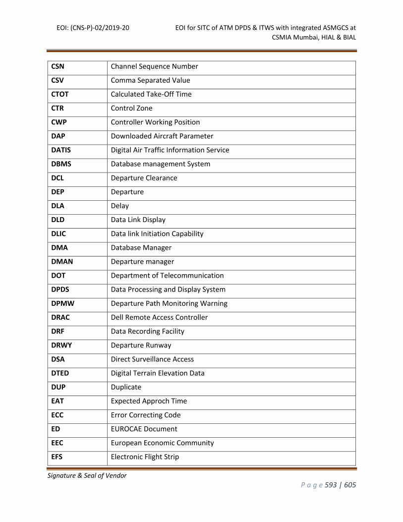
EOI: (CNS-P)-02/2019-20 EOI for SITC of ATM DPDS & ITWS with integrated ASMGCS at
CSMIA Mumbai, HIAL & BIAL
Signature & Seal of Vendor
P a g e 593 | 605
CSN Channel Sequence Number
CSV Comma Separated Value
CTOT Calculated Take-Off Time
CTR Control Zone
CWP Controller Working Position
DAP Downloaded Aircraft Parameter
DATIS Digital Air Traffic Information Service
DBMS Database management System
DCL Departure Clearance
DEP Departure
DLA Delay
DLD Data Link Display
DLIC Data link Initiation Capability
DMA Database Manager
DMAN Departure manager
DOT Department of Telecommunication
DPDS Data Processing and Display System
DPMW Departure Path Monitoring Warning
DRAC Dell Remote Access Controller
DRF Data Recording Facility
DRWY Departure Runway
DSA Direct Surveillance Access
DTED Digital Terrain Elevation Data
DUP Duplicate
EAT Expected Approch Time
ECC Error Correcting Code
ED EUROCAE Document
EEC European Economic Community
EFS Electronic Flight Strip
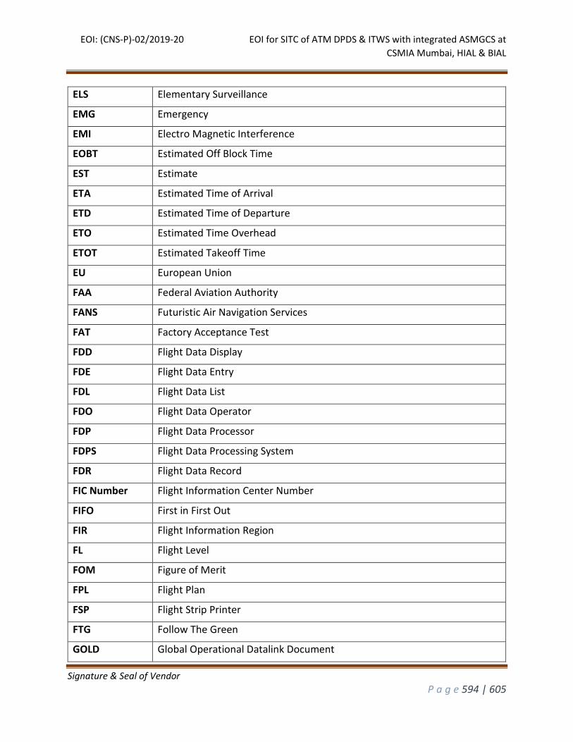
EOI: (CNS-P)-02/2019-20 EOI for SITC of ATM DPDS & ITWS with integrated ASMGCS at
CSMIA Mumbai, HIAL & BIAL
Signature & Seal of Vendor
P a g e 594 | 605
ELS Elementary Surveillance
EMG Emergency
EMI Electro Magnetic Interference
EOBT Estimated Off Block Time
EST Estimate
ETA Estimated Time of Arrival
ETD Estimated Time of Departure
ETO Estimated Time Overhead
ETOT Estimated Takeoff Time
EU European Union
FAA Federal Aviation Authority
FANS Futuristic Air Navigation Services
FAT Factory Acceptance Test
FDD Flight Data Display
FDE Flight Data Entry
FDL Flight Data List
FDO Flight Data Operator
FDP Flight Data Processor
FDPS Flight Data Processing System
FDR Flight Data Record
FIC Number Flight Information Center Number
FIFO First in First Out
FIR Flight Information Region
FL Flight Level
FOM Figure of Merit
FPL Flight Plan
FSP Flight Strip Printer
FTG Follow The Green
GOLD Global Operational Datalink Document
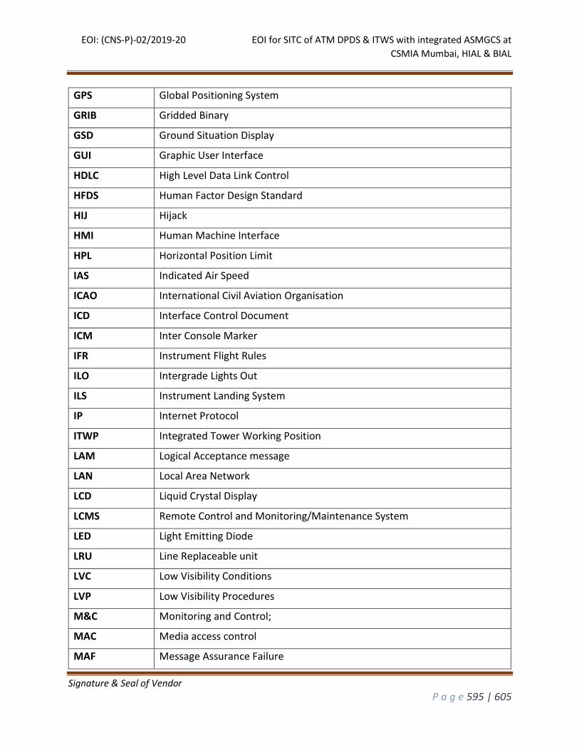
EOI: (CNS-P)-02/2019-20 EOI for SITC of ATM DPDS & ITWS with integrated ASMGCS at
CSMIA Mumbai, HIAL & BIAL
Signature & Seal of Vendor
P a g e 595 | 605
GPS Global Positioning System
GRIB Gridded Binary
GSD Ground Situation Display
GUI Graphic User Interface
HDLC High Level Data Link Control
HFDS Human Factor Design Standard
HIJ Hijack
HMI Human Machine Interface
HPL Horizontal Position Limit
IAS Indicated Air Speed
ICAO International Civil Aviation Organisation
ICD Interface Control Document
ICM Inter Console Marker
IFR Instrument Flight Rules
ILO Intergrade Lights Out
ILS Instrument Landing System
IP Internet Protocol
ITWP Integrated Tower Working Position
LAM Logical Acceptance message
LAN Local Area Network
LCD Liquid Crystal Display
LCMS Remote Control and Monitoring/Maintenance System
LED Light Emitting Diode
LRU Line Replaceable unit
LVC Low Visibility Conditions
LVP Low Visibility Procedures
M&C Monitoring and Control;
MAC Media access control
MAF Message Assurance Failure
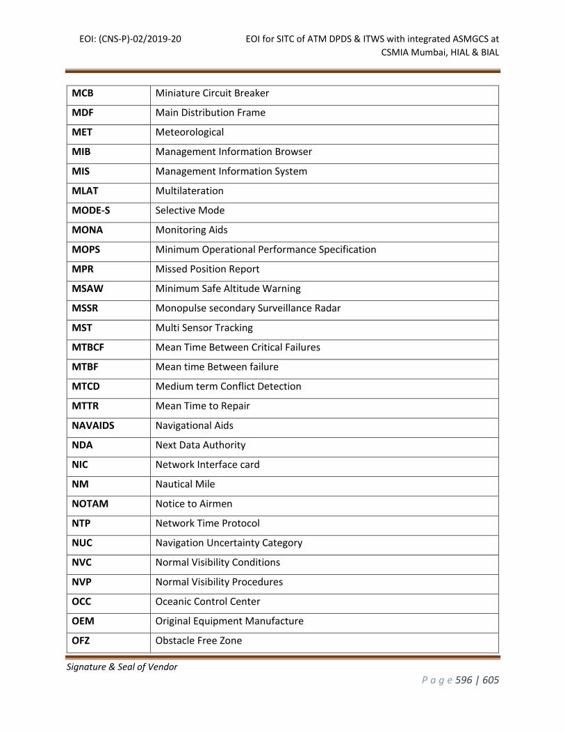
EOI: (CNS-P)-02/2019-20 EOI for SITC of ATM DPDS & ITWS with integrated ASMGCS at
CSMIA Mumbai, HIAL & BIAL
Signature & Seal of Vendor
P a g e 596 | 605
MCB Miniature Circuit Breaker
MDF Main Distribution Frame
MET Meteorological
MIB Management Information Browser
MIS Management Information System
MLAT Multilateration
MODE-S Selective Mode
MONA Monitoring Aids
MOPS Minimum Operational Performance Specification
MPR Missed Position Report
MSAW Minimum Safe Altitude Warning
MSSR Monopulse secondary Surveillance Radar
MST Multi Sensor Tracking
MTBCF Mean Time Between Critical Failures
MTBF Mean time Between failure
MTCD Medium term Conflict Detection
MTTR Mean Time to Repair
NAVAIDS Navigational Aids
NDA Next Data Authority
NIC Network Interface card
NM Nautical Mile
NOTAM Notice to Airmen
NTP Network Time Protocol
NUC Navigation Uncertainty Category
NVC Normal Visibility Conditions
NVP Normal Visibility Procedures
OCC Oceanic Control Center
OEM Original Equipment Manufacture
OFZ Obstacle Free Zone
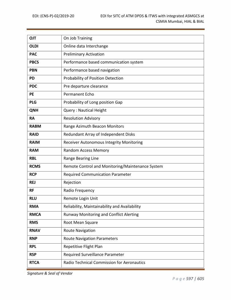
EOI: (CNS-P)-02/2019-20 EOI for SITC of ATM DPDS & ITWS with integrated ASMGCS at
CSMIA Mumbai, HIAL & BIAL
Signature & Seal of Vendor
P a g e 597 | 605
OJT On Job Training
OLDI Online data Interchange
PAC Preliminary Activation
PBCS Performance based communication system
PBN Performance based navigation
PD Probability of Position Detection
PDC Pre departure clearance
PE Permanent Echo
PLG Probability of Long position Gap
QNH Query : Nautical Height
RA Resolution Advisory
RABM Range Azimuth Beacon Monitors
RAID Redundant Array of Independent Disks
RAIM Receiver Autonomous Integrity Monitoring
RAM Random Access Memory
RBL Range Bearing Line
RCMS Remote Control and Monitoring/Maintenance System
RCP Required Communication Parameter
REJ Rejection
RF Radio Frequency
RLU Remote Login Unit
RMA Reliability, Maintainability and Availability
RMCA Runway Monitoring and Conflict Alerting
RMS Root Mean Square
RNAV Route Navigation
RNP Route Navigation Parameters
RPL Repetitive Flight Plan
RSP Required Surveillance Parameter
RTCA Radio Technical Commission for Aeronautics
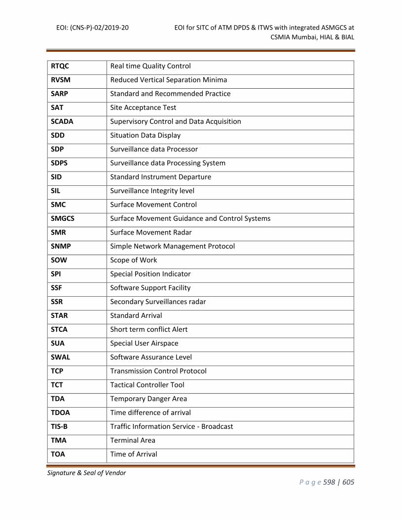
EOI: (CNS-P)-02/2019-20 EOI for SITC of ATM DPDS & ITWS with integrated ASMGCS at
CSMIA Mumbai, HIAL & BIAL
Signature & Seal of Vendor
P a g e 598 | 605
RTQC Real time Quality Control
RVSM Reduced Vertical Separation Minima
SARP Standard and Recommended Practice
SAT Site Acceptance Test
SCADA Supervisory Control and Data Acquisition
SDD Situation Data Display
SDP Surveillance data Processor
SDPS Surveillance data Processing System
SID Standard Instrument Departure
SIL Surveillance Integrity level
SMC Surface Movement Control
SMGCS Surface Movement Guidance and Control Systems
SMR Surface Movement Radar
SNMP Simple Network Management Protocol
SOW Scope of Work
SPI Special Position Indicator
SSF Software Support Facility
SSR Secondary Surveillances radar
STAR Standard Arrival
STCA Short term conflict Alert
SUA Special User Airspace
SWAL Software Assurance Level
TCP Transmission Control Protocol
TCT Tactical Controller Tool
TDA Temporary Danger Area
TDOA Time difference of arrival
TIS-B Traffic Information Service - Broadcast
TMA Terminal Area
TOA Time of Arrival
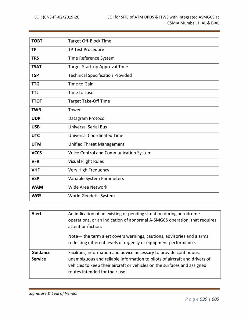
EOI: (CNS-P)-02/2019-20 EOI for SITC of ATM DPDS & ITWS with integrated ASMGCS at
CSMIA Mumbai, HIAL & BIAL
Signature & Seal of Vendor
P a g e 599 | 605
TOBT Target Off-Block Time
TP TP Test Procedure
TRS Time Reference System
TSAT Target Start-up Approval Time
TSP Technical Specification Provided
TTG Time to Gain
TTL Time to Lose
TTOT Target Take-Off Time
TWR Tower
UDP Datagram Protocol
USB Universal Serial Bus
UTC Universal Coordinated Time
UTM Unified Threat Management
VCCS Voice Control and Communication System
VFR Visual Flight Rules
VHF Very High Frequency
VSP Variable System Parameters
WAM Wide Area Network
WGS World Geodetic System
Alert An indication of an existing or pending situation during aerodrome
operations, or an indication of abnormal A-SMGCS operation, that requires
attention/action.
Note— the term alert covers warnings, cautions, advisories and alarms
reflecting different levels of urgency or equipment performance.
Guidance
Service
Facilities, information and advice necessary to provide continuous,
unambiguous and reliable information to pilots of aircraft and drivers of
vehicles to keep their aircraft or vehicles on the surfaces and assigned
routes intended for their use.
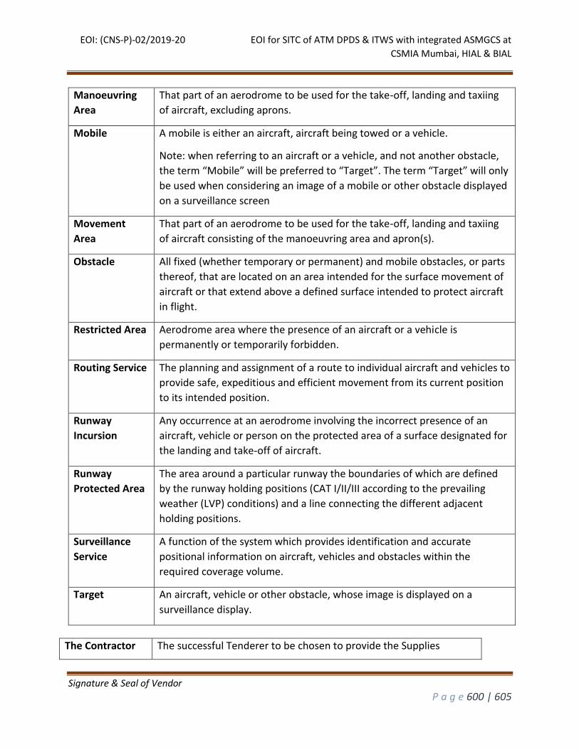
EOI: (CNS-P)-02/2019-20 EOI for SITC of ATM DPDS & ITWS with integrated ASMGCS at
CSMIA Mumbai, HIAL & BIAL
Signature & Seal of Vendor
P a g e 600 | 605
Manoeuvring
Area
That part of an aerodrome to be used for the take-off, landing and taxiing
of aircraft, excluding aprons.
Mobile A mobile is either an aircraft, aircraft being towed or a vehicle.
Note: when referring to an aircraft or a vehicle, and not another obstacle,
the term “Mobile” will be preferred to “Target”. The term “Target” will only
be used when considering an image of a mobile or other obstacle displayed
on a surveillance screen
Movement
Area
That part of an aerodrome to be used for the take-off, landing and taxiing
of aircraft consisting of the manoeuvring area and apron(s).
Obstacle All fixed (whether temporary or permanent) and mobile obstacles, or parts
thereof, that are located on an area intended for the surface movement of
aircraft or that extend above a defined surface intended to protect aircraft
in flight.
Restricted Area Aerodrome area where the presence of an aircraft or a vehicle is
permanently or temporarily forbidden.
Routing Service The planning and assignment of a route to individual aircraft and vehicles to
provide safe, expeditious and efficient movement from its current position
to its intended position.
Runway
Incursion
Any occurrence at an aerodrome involving the incorrect presence of an
aircraft, vehicle or person on the protected area of a surface designated for
the landing and take-off of aircraft.
Runway
Protected Area
The area around a particular runway the boundaries of which are defined
by the runway holding positions (CAT I/II/III according to the prevailing
weather (LVP) conditions) and a line connecting the different adjacent
holding positions.
Surveillance
Service
A function of the system which provides identification and accurate
positional information on aircraft, vehicles and obstacles within the
required coverage volume.
Target An aircraft, vehicle or other obstacle, whose image is displayed on a
surveillance display.
The Contractor The successful Tenderer to be chosen to provide the Supplies
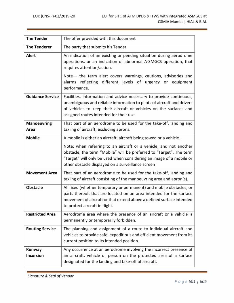
EOI: (CNS-P)-02/2019-20 EOI for SITC of ATM DPDS & ITWS with integrated ASMGCS at
CSMIA Mumbai, HIAL & BIAL
Signature & Seal of Vendor
P a g e 601 | 605
The Tender The offer provided with this document
The Tenderer The party that submits his Tender
Alert An indication of an existing or pending situation during aerodrome
operations, or an indication of abnormal A-SMGCS operation, that
requires attention/action.
Note— the term alert covers warnings, cautions, advisories and
alarms reflecting different levels of urgency or equipment
performance.
Guidance Service Facilities, information and advice necessary to provide continuous,
unambiguous and reliable information to pilots of aircraft and drivers
of vehicles to keep their aircraft or vehicles on the surfaces and
assigned routes intended for their use.
Manoeuvring
Area
That part of an aerodrome to be used for the take-off, landing and
taxiing of aircraft, excluding aprons.
Mobile A mobile is either an aircraft, aircraft being towed or a vehicle.
Note: when referring to an aircraft or a vehicle, and not another
obstacle, the term “Mobile” will be preferred to “Target”. The term
“Target” will only be used when considering an image of a mobile or
other obstacle displayed on a surveillance screen
Movement Area That part of an aerodrome to be used for the take-off, landing and
taxiing of aircraft consisting of the manoeuvring area and apron(s).
Obstacle All fixed (whether temporary or permanent) and mobile obstacles, or
parts thereof, that are located on an area intended for the surface
movement of aircraft or that extend above a defined surface intended
to protect aircraft in flight.
Restricted Area Aerodrome area where the presence of an aircraft or a vehicle is
permanently or temporarily forbidden.
Routing Service The planning and assignment of a route to individual aircraft and
vehicles to provide safe, expeditious and efficient movement from its
current position to its intended position.
Runway
Incursion
Any occurrence at an aerodrome involving the incorrect presence of
an aircraft, vehicle or person on the protected area of a surface
designated for the landing and take-off of aircraft.
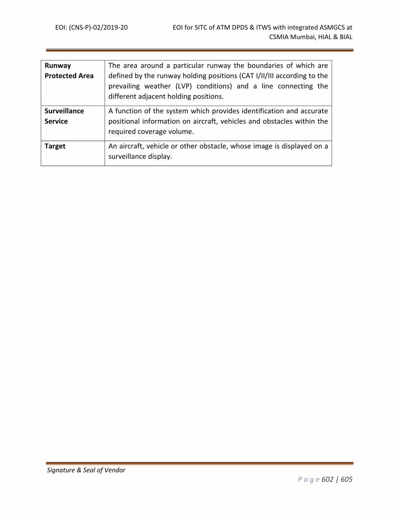
EOI: (CNS-P)-02/2019-20 EOI for SITC of ATM DPDS & ITWS with integrated ASMGCS at
CSMIA Mumbai, HIAL & BIAL
Signature & Seal of Vendor
P a g e 602 | 605
Runway
Protected Area
The area around a particular runway the boundaries of which are
defined by the runway holding positions (CAT I/II/III according to the
prevailing weather (LVP) conditions) and a line connecting the
different adjacent holding positions.
Surveillance
Service
A function of the system which provides identification and accurate
positional information on aircraft, vehicles and obstacles within the
required coverage volume.
Target An aircraft, vehicle or other obstacle, whose image is displayed on a
surveillance display.
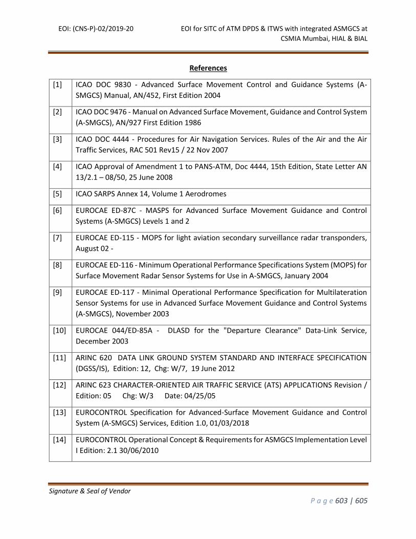
EOI: (CNS-P)-02/2019-20 EOI for SITC of ATM DPDS & ITWS with integrated ASMGCS at
CSMIA Mumbai, HIAL & BIAL
Signature & Seal of Vendor
P a g e 603 | 605
References
[1] ICAO DOC 9830 - Advanced Surface Movement Control and Guidance Systems (A-
SMGCS) Manual, AN/452, First Edition 2004
[2] ICAO DOC 9476 - Manual on Advanced Surface Movement, Guidance and Control System
(A-SMGCS), AN/927 First Edition 1986
[3] ICAO DOC 4444 - Procedures for Air Navigation Services. Rules of the Air and the Air
Traffic Services, RAC 501 Rev15 / 22 Nov 2007
[4] ICAO Approval of Amendment 1 to PANS-ATM, Doc 4444, 15th Edition, State Letter AN
13/2.1 – 08/50, 25 June 2008
[5] ICAO SARPS Annex 14, Volume 1 Aerodromes
[6] EUROCAE ED-87C - MASPS for Advanced Surface Movement Guidance and Control
Systems (A-SMGCS) Levels 1 and 2
[7] EUROCAE ED-115 - MOPS for light aviation secondary surveillance radar transponders,
August 02 -
[8] EUROCAE ED-116 - Minimum Operational Performance Specifications System (MOPS) for
Surface Movement Radar Sensor Systems for Use in A-SMGCS, January 2004
[9] EUROCAE ED-117 - Minimal Operational Performance Specification for Multilateration
Sensor Systems for use in Advanced Surface Movement Guidance and Control Systems
(A-SMGCS), November 2003
[10] EUROCAE 044/ED-85A - DLASD for the "Departure Clearance" Data-Link Service,
December 2003
[11] ARINC 620 DATA LINK GROUND SYSTEM STANDARD AND INTERFACE SPECIFICATION
(DGSS/IS), Edition: 12, Chg: W/7, 19 June 2012
[12] ARINC 623 CHARACTER-ORIENTED AIR TRAFFIC SERVICE (ATS) APPLICATIONS Revision /
Edition: 05 Chg: W/3 Date: 04/25/05
[13] EUROCONTROL Specification for Advanced-Surface Movement Guidance and Control
System (A-SMGCS) Services, Edition 1.0, 01/03/2018
[14] EUROCONTROL Operational Concept & Requirements for ASMGCS Implementation Level
I Edition: 2.1 30/06/2010
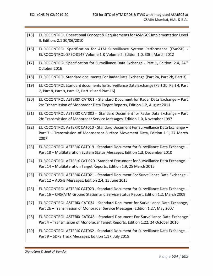
EOI: (CNS-P)-02/2019-20 EOI for SITC of ATM DPDS & ITWS with integrated ASMGCS at
CSMIA Mumbai, HIAL & BIAL
Signature & Seal of Vendor
P a g e 604 | 605
[15] EUROCONTROL Operational Concept & Requirements for ASMGCS Implementation Level
II. Edition: 2.1 30/06/2010
[16] EUROCONTROL Specification for ATM Surveillance System Performance (ESASSP) -
EUROCONTROL-SPEC-0147 Volume 1 & Volume 2, Edition 1.0, 30th March 2012
[17] EUROCONTROL Specification for Surveillance Data Exchange - Part 1, Edition: 2.4, 24th
October 2016
[18] EUROCONTROL Standard documents For Radar Data Exchange (Part 2a, Part 2b, Part 3)
[19] EUROCONTROL Standard documents for Surveillance Data Exchange (Part 2b, Part 4, Part
7, Part 8, Part 9, Part 12, Part 15 and Part 16)
[20] EUROCONTROL ASTERIX CAT001 - Standard Document for Radar Data Exchange – Part
2a: Transmission of Monoradar Data Target Reports, Edition 1.2, August 2011
[21] EUROCONTROL ASTERIX CAT002 - Standard Document for Radar Data Exchange – Part
2b: Transmission of Monoradar Service Messages, Edition 1.0, November 1997
[22] EUROCONTROL ASTERIX CAT010 - Standard Document For Surveillance Data Exchange –
Part 7 – Transmission of Monosensor Surface Movement Data, Edition 1.1, 27 March
2007
[23] EUROCONTROL ASTERIX CAT019 - Standard Document for Surveillance Data Exchange –
Part 18 – Multilateration System Status Messages, Edition 1.3, December 2010
[24] EUROCONTROL ASTERIX CAT 020 - Standard Document for Surveillance Data Exchange –
Part 14 – Multilateration Target Reports, Edition 1.9, 25 March 2015
[25] EUROCONTROL ASTERIX CAT021 - Standard Document For Surveillance Data Exchange -
Part 12 – ADS-B Messages, Edition 2.4, 15 June 2015
[25] EUROCONTROL ASTERIX CAT023 - Standard Document for Surveillance Data Exchange –
Part 16 – CNS/ATM Ground Station and Service Status Report, Edition 1.2, March 2009
[27] EUROCONTROL ASTERIX CAT034 - Standard Document for Surveillance Data Exchange,
Part 2b – Transmission of Monoradar Service Messages, Edition 1.27, May 2007
[28] EUROCONTROL ASTERIX CAT048 - Standard Document For Surveillance Data Exchange
Part 4 – Transmission of Monoradar Target Reports, Edition 1.22, 24 October 2016
[29] EUROCONTROL ASTERIX CAT062 - Standard Document for Surveillance Data Exchange –
Part 9 – SDPS Track Messages, Edition 1.17, July 2015
EOI: (CNS-P)-02/2019-20 EOI for SITC of ATM DPDS & ITWS with integrated ASMGCS at
CSMIA Mumbai, HIAL & BIAL
Signature & Seal of Vendor
P a g e 605 | 605
[30] EUROCONTROL ASTERIX CAT063 - Standard Document for Surveillance Data Exchange –
Part 10 – Sensor Status Messages, Edition 1.4, 1 May 2014
[31] EUROCONTROL ASTERIX CAT065 - Standard Document for Surveillance Data Exchange –
Part 15 – SDPS Service Status Messages, Edition 1.3, April 2007