Embed Size (px)
Citation preview

Shenzhen BST Technology Co., Ltd. Report No.: BST16098032A0001SR-2
Building No.23-24,Zhiheng Industrial Park,Guankouer Road,Nantou,Nanshan District,Shenzhen,Guangdong,ChinaCertificate Search: http://www.bst-lab.com, Tel: 400-882-9628, 8009990305, E-mail:[email protected]
Page 1 of 54
SHENZHEN YUEJIANG TECHNOLOGY CO.,LTD
LVD REPORT
Prepared For : SHENZHEN YUEJIANG TECHNOLOGY CO.,LTD4F, A8, Tanglang Industrial Area, Taoyuan Street, Nanshan District,Shenzhen, China.
Product Name: DOBOT ARM
Trade Name: N.A.
Model : Dobot 2.0
Prepared By : Shenzhen BST Technology Co., Ltd.
Building No.23-24, Zhiheng Industrial Park, Guankouer Road, Nantou,Nanshan District, Shenzhen, Guangdong, China
Test Date: Sep. 06, 2016 - Sep. 22, 2016
Date of Report : Sep. 24, 2016
Report No.: BST16098032A0001SR-2
DRAFT
Shenzhen BST Technology Co., Ltd. Report No.: BST16098032A0001SR-2
Building No.23-24,Zhiheng Industrial Park,Guankouer Road,Nantou,Nanshan District,Shenzhen,Guangdong,ChinaCertificate Search: http://www.bst-lab.com, Tel: 400-882-9628, 8009990305, E-mail:[email protected]
Page 2 of 54
TEST REPORTEN 60204-1
Safety of machinery – Electrical equipment of machines
Testing Laboratory Name ...............: Shenzhen BST Technology Co., Ltd.
Address ................................................ : Building No.23-24, Zhiheng Industrial Park, Guankouer Road,Nantou, Nanshan District, Shenzhen, Guangdong, China
Testing location ................................... : Shenzhen BST Technology Co., Ltd.
Applicant's Name ..............................: SHENZHEN YUEJIANG TECHNOLOGY CO.,LTD
Address ................................................ : 4F, A8, Tanglang Industrial Area, Taoyuan Street, Nanshan District,Shenzhen, China.
Test specification
Standard................................................: EN 60204-1:2006+ A1:2009+AC:2010
Test procedure .................................... :The standard of EN 60204-1:2006+ A1:2009+AC:2010
Non-standard test method .................: N.A.
Test item description .......................: DOBOT ARM
Model and/or type reference ............. : Dobot 2.0
Rating(s)................................................: AC Input:220V~, 50HzDC12V, 1A, 12W
Manufacturer ………………………..: SHENZHEN YUEJIANG TECHNOLOGY CO.,LTD
Address ………………………………: 4F, A8, Tanglang Industrial Area, Taoyuan Street, Nanshan District,Shenzhen, China.DRAFT
Shenzhen BST Technology Co., Ltd. Report No.: BST16098032A0001SR-2
Building No.23-24,Zhiheng Industrial Park,Guankouer Road,Nantou,Nanshan District,Shenzhen,Guangdong,ChinaCertificate Search: http://www.bst-lab.com, Tel: 400-882-9628, 8009990305, E-mail:[email protected]
Page 3 of 54
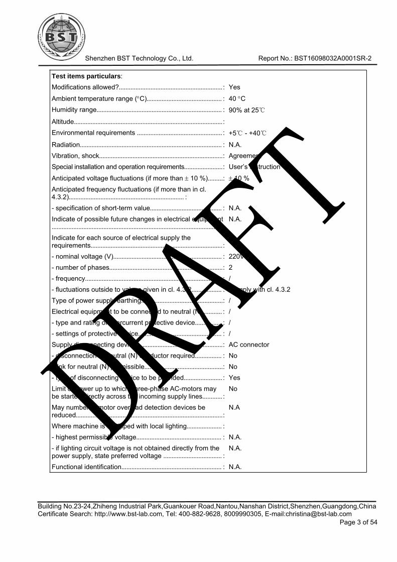
Test items particulars:Modifications allowed?.............................................................. : Yes
Ambient temperature range (°C)............................................. : 40 °CHumidity range........................................................................... : 90% at 25
Altitude.........................................................................................:Environmental requirements ................................................... : +5 - +40
Radiation..................................................................................... : N.A.Vibration, shock..........................................................................: AgreementSpecial installation and operation requirements.......................: User’s Instruction
Anticipated voltage fluctuations (if more than ± 10 %).........: ± 10 %Anticipated frequency fluctuations (if more than in cl.4.3.2)..................................................................... :- specification of short-term value........................................... : N.A.Indicate of possible future changes in electrical equipment...................................................................................................... :
N.A.
Indicate for each source of electrical supply therequirements...............................................................................:- nominal voltage (V)................................................................. : 220V- number of phases....................................................................: 2- frequency.................................................................................. : /- fluctuations outside to values given in cl. 4.3.2.................. : Comply with cl. 4.3.2Type of power supply earthing.................................................: /Electrical equipment to be connected to neutral (N)............ : /- type and rating of overcurrent protective device................ : /- settings of protective device.................................................. : /Supply disconnecting device....................................................: AC connector- disconnection of neutral (N) conductor required................ : No- link for neutral (N) permissible...............................................: No- type of disconnecting device to be provided....................... : YesLimit of power up to which three-phase AC-motors maybe started directly across the incoming supply lines............ :
No
May number of motor overload detection devices bereduced........................................................................................:
N.A
Where machine is equipped with local lighting..................... :- highest permissible voltage................................................... : N.A.- if lighting circuit voltage is not obtained directly from thepower supply, state preferred voltage ................................... :
N.A.
Functional identification............................................................ : N.A.
DRAFT

Shenzhen BST Technology Co., Ltd. Report No.: BST16098032A0001SR-2
Building No.23-24,Zhiheng Industrial Park,Guankouer Road,Nantou,Nanshan District,Shenzhen,Guangdong,ChinaCertificate Search: http://www.bst-lab.com, Tel: 400-882-9628, 8009990305, E-mail:[email protected]
Page 4 of 54
Inscriptions / special markings.................................................:- mark of certification................................................................. : Yes- on electrical equipment...........................................................: Yes- language .................................................................................. : EnglishTechnical documentation (media, language)........................ : EnglishSize, location and purpose of ducts, open cable trays orcable-supports to be provided by the user.............................:
N.A.
For which of following classes of persons is access to theinterior of the switchgear cabinets required during normaloperation of the equipment.......................................................:
skilled electricians / instructed persons /
Locks with removable keys provided for fastening doors orcovers ......................................................................................... :
N.A.
Type of two-hand control to be provided................................:- where it is type III, time limit (max. 0,5 s) within whicheach pair of push-buttons are to be operated....................... :Indicate special limitations on size or weight which affectthe transport of a particular machine or controlgearassemblies to the installation site............................................:
see user’s manual
- maximum dimensions............................................................. :- maximum weight......................................................................:Repetition of manual controlled cycles of operation.............:- length of time expected that machine will be operated atthis rate without subsequent pause........................................ :
Yes
Certificate for operating tests- with the loaded machine to be supplied (specially builtmachines)....................................................................................:
Yes
- on a loaded prototype machine to be supplied (normalmachines)....................................................................................:
Yes
Time delay for cableless control systems.............................. :Specific method of conductor identification to be used ...... : YesTest case verdictsTest case does not apply to the test object .......................... : N/ATest item does meet the requirement ....................................: P(ass)Test item does not meet the requirement ............................. : F(ail)
General remarks
This report shall not be reproduced except in full without the written approval of the testing laboratory.
The test results presented in this report relate only to the item(s) tested.
The series products have the same circuit diagram, PCB layout and functionality. The differences are themodel name, so, we select Dobot 2.0 to test.DR
AFT

Shenzhen BST Technology Co., Ltd. Report No.: BST16098032A0001SR-2
Building No.23-24,Zhiheng Industrial Park,Guankouer Road,Nantou,Nanshan District,Shenzhen,Guangdong,ChinaCertificate Search: http://www.bst-lab.com, Tel: 400-882-9628, 8009990305, E-mail:[email protected]
Page 5 of 54
Copy of marking plate:
Prepared by :Engineer
Reviewer :Supervisor
Approved & Authorized Signer :Christina / Manager
DOBOT ARMModel: Dobot 2.0AC Input:220V~, 50HzDC12V, 1A, 12W
Guangzhou Dinghong Automation Equipment Co.,ltd
DRAFT

Shenzhen BST Technology Co., Ltd. Report No.: BST16098032A0001SR-2
EN 60204-1
Clause Requirement – Test Result - Remark Verdict
Building No.23-24,Zhiheng Industrial Park,Guankouer Road,Nantou,Nanshan District,Shenzhen,Guangdong,ChinaCertificate Search: http://www.bst-lab.com, Tel: 400-882-9628, 8009990305, E-mail:[email protected]
Page 6 of 54
2.2 EN 60204-1:2006 + A1:2009 + AC:2010test reportEN 60204-1:2006 + A1:2009+AC:2010Electrical equipment of machines–Part 1: General requirments4 General requirments4.1 General considerations
This part of IEC 60204 is intended to apply to electrical equipmentused with a wide variety of machines and with a group ofmachines working together in a co-coordinated manner.The risks associated with the hazards relevant to the electricalequipment shall be assessed as part of the overall requirementsfor risk assessment of the machine. This will determine theadequate risk reduction and the necessary protective measuresfor persons who can be exposed to those hazards, while stillmaintaining an acceptable level of performance of the machineand its equipment.
P
4.2 Selection of equipment4.2.1 General
Electrical components and devices shall:—be suitable for their intended use; and—conform to relevant IEC standards where such exist; and—be applied in accordance with the supplier’s instructions riskassessment of the machine.
Be suitable fortheir intendeduse and conformto relevantIEC/ENstandards.
P
4.2.2 Electrical equipment in compliance with the EN 60439 seriesDepending upon the machine, its intended use and its electricalequipment, the designer may select parts of the electricalequipment of the machine that are in compliance with EN 60439-1and, as necessary, other relevant parts of the EN 60439 series(see also Annex F).
P
4.3 Electrical supply4.3.1 General
The electrical equipment shall be designed to operate correctlywith the conditions of the supply:—as specified in 4.3.2 or 4.3.3, or—as otherwise specified by the user (see Annex B), or asspecified by the supplier in the case of a special source ofsupply such as an on-board generator.
Comply withclause 4.3.2. P
4.3.2 AC suppliesVoltage:Steady state voltage: 0,9 to 1,1 of nominal voltage.Frequency:0,99 to 1,01 of nominal frequency continuously;0,98 to 1,02 short time.Harmonics:Harmonic distortion not exceeding 10 % of the total r.m.s. voltagebetween live conductors for the sum of the 2nd through to the 5thharmonic. An additional 2 % of the total r.m.s. voltage betweenlive conductors for the sum of the 6th through to the 30th harmonicis permissible.
AC:220VSum2nd-5th
harmonic<=10%Sum6nd-30th
harmonic<=2%
50Hz
Voltageunbalance<=2%
PDRAFT

Shenzhen BST Technology Co., Ltd. Report No.: BST16098032A0001SR-2
EN 60204-1
Clause Requirement – Test Result - Remark Verdict
Building No.23-24,Zhiheng Industrial Park,Guankouer Road,Nantou,Nanshan District,Shenzhen,Guangdong,ChinaCertificate Search: http://www.bst-lab.com, Tel: 400-882-9628, 8009990305, E-mail:[email protected]
Page 7 of 54
Voltage unbalance:Neither the voltage of the negative sequence component nor thevoltage of the zero sequence components in three-phase suppliesexceeding 2 % of the positive sequence component.Voltage interruption:Supply interrupted or at zero voltage for not more than 3 ms at anyrandom time in the supply cycle with more than 1 s betweensuccessive interruptions.Voltage dips:Voltage dips not exceeding 20 % of the peak voltage of the supplyfor more than one cycle with more than 1 s between successivedips.
Voltageinterruption<=3ms
Voltagedips<=20%
4.3.3 DC suppliesFrom batteries, Voltage 0,85 to 1,15 of nominal voltage 0,7 to 1,2of nominal voltage in the case of battery-operated vehicles .Voltage interruption:Not exceeding 5 ms From converting equipment: Voltage:0,9 to 1,1 of nominal voltage.Voltage interruption:Not exceeding 20 ms with more than 1 s between successiveinterruptions.Ripple (peak-to-peak):Not exceeding 0,15 of nominal voltage.
N
4.3.4 Special supply systemsFor special supply systems such as on-board generators, thelimits given in 4.3.2 and 4.3.3 may be exceeded provided that theequipment is designed to operate correctly with those conditions.
N
4.4 Physical environment and operating conditions4.4.1 General
The electrical equipment shall be suitable for the physicalenvironment and operating conditions of its intended use. Therequirements of 4.4.2 to 4.4.8 cover the physical environment andoperating conditions of the majority of machines covered by thispart of EN 60204. When special conditions apply or the limitsspecified are exceeded, an agreement between user and supplier(see 4.1) is recommended (see Annex B).
P
4.4.3 Ambient air temperatureElectrical equipment shall be capable of operating correctly in theintended ambient air temperature. The minimum requirement forall electrical equipment is correct operation between airtemperatures of +5 °C and +40 °C. For very hot environments (forexample hot climates, steel mills, paper mills) and for coldenvironments, additional measures are recommended (see AnnexB).
P
4.4.4 HumidityThe electrical equipment shall be capable of operating correctlywhen the relative humidity does not exceed 50 % at a maximumtemperature of +40 °C. Higher relative humilities are permitted atlower temperatures (for example 90 % at 20 °C).Harmful effects of occasional condensation shall be avoided by
P
DRAFT
Shenzhen BST Technology Co., Ltd. Report No.: BST16098032A0001SR-2
EN 60204-1
Clause Requirement – Test Result - Remark Verdict
Building No.23-24,Zhiheng Industrial Park,Guankouer Road,Nantou,Nanshan District,Shenzhen,Guangdong,ChinaCertificate Search: http://www.bst-lab.com, Tel: 400-882-9628, 8009990305, E-mail:[email protected]
Page 8 of 54
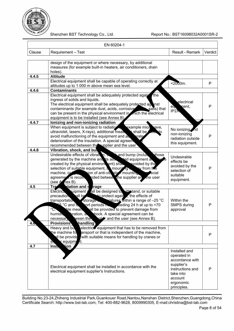
design of the equipment or where necessary, by additionalmeasures (for example built-in heaters, air conditioners, drainholes).
4.4.5 AltitudeElectrical equipment shall be capable of operating correctly ataltitudes up to 1 000 m above mean sea level. <2000m. P
4.4.6 ContaminantsElectrical equipment shall be adequately protected against theingress of solids and liquids.The electrical equipment shall be adequately protected againstcontaminants (for example dust, acids, corrosive gases, salts) thatcan be present in the physical environment in which the electricalequipment is to be installed (see Annex B).
For electricalequipment,IP2X.
P
4.4.7 Ionizing and non-ionizing radiationWhen equipment is subject to radiation (for example microwave,ultraviolet, lasers, X-rays), additional measures shall be taken toavoid malfunctioning of the equipment and accelerateddeterioration of the insulation. A special agreement isrecommended between the supplier and the user
No ionizing andnon-ionizingradiation outsidethis equipment.
P
4.4.8 Vibration, shock, and bumpUndesirable effects of vibration, shock and bump (including thosegenerated by the machine and its associated equipment and thosecreated by the physical environment) shall be avoided by theselection of suitable equipment, by mounting it away from themachine, or by provision of anti-vibration mountings. A specialagreement is recommended between the supplier and the user(see Annex B).
Undesirableeffects beavoided by theselection ofsuitableequipment.
P
4.5 Transportation and storageElectrical equipment shall be designed to withstand, or suitableprecautions shall be taken to protect against, the effects oftransportation and storage temperatures within a range of –25 °Cto +55 °C and for short periods not exceeding 24 h at up to +70°C. Suitable means shall be provided to prevent damage fromhumidity, vibration, and shock. A special agreement can benecessary between the supplier and the user (see Annex B).
Within theSMPS duringapproval
P
4.6 Provisions for handlingHeavy and bulky electrical equipment that has to be removed fromthe machine for transport or that is independent of the machine,shall be provided with suitable means for handling by cranes orsimilar equipment.
P
4.7 Installation
Electrical equipment shall be installed in accordance with theelectrical equipment supplier's Instructions.
Installed andoperated inaccordance withsupplier’sinstructions andtake intoaccountergonomicprinciples.
P
DRAFT

Shenzhen BST Technology Co., Ltd. Report No.: BST16098032A0001SR-2
EN 60204-1
Clause Requirement – Test Result - Remark Verdict
Building No.23-24,Zhiheng Industrial Park,Guankouer Road,Nantou,Nanshan District,Shenzhen,Guangdong,ChinaCertificate Search: http://www.bst-lab.com, Tel: 400-882-9628, 8009990305, E-mail:[email protected]
Page 9 of 54
75 Incoming supply conductor terminations and devices for disconnecting and switching off5.1 Incoming supply conductor terminations
It is recommended that, where practicable, the electricalequipment of a machine is connected to a single incoming supply.Where another supply is necessary for certain parts of theequipment (for example, electronic equipment that operates at adifferent voltage), that supply should be derived, as far as ispracticable, from devices (for example, transformers, converters)forming part of the electrical equipment of the machine. For largecomplex machinery comprising a number of widely-spacedmachines working together in a coordinated manner, there can bea need for more than one incoming supply depending upon thesite supply arrangements (see 5.3.1) Unless a plug is providedwith the machine for the connection to the supply (see 5.3.2 e), itis recommended that the supply conductors are terminated at thesupply disconnecting device where a neutral conductor is used itshall be clearly indicated in the technical documentation of themachine, such as in the installation diagram and in the circuitdiagram, and a separate insulated terminal, labeled N inaccordance with 16.1, shall be provided for the neutral conductor(see also Annex B)There shall be no connection between the neutral conductor andthe protective bonding circuit inside the electrical equipment norshall a combined PEN terminal be providedException: a connection may be made between the neutralterminal and the PE terminal at the point of the connection of thepower supply to the machine for TN-C systems.All terminals for the incoming supply connection shall be clearlyidentified in accordance with IEC 60445 and 16.1. For theidentification of the external protective conductor terminal, see 5.2.See 17.8 for the provision of instructions for maintenance
Control box andcouplers areprovided. Allterminalsmarked correctlabels.
P
5.2 Terminal for connection to the external protective earthing systemFor each incoming supply, a terminal shall be provided in thevicinity of the associated phase conductor terminals for connectionof the machine to the external protective earthing system or to theexternal protective conductor, depending upon the supplydistribution system. The terminal shall be of such a size as toenable the connection of an external protective copper conductorwith a cross-sectional area in accordance with Table
Copperconductor used,cross-sectionalarea S<16mm2,PE label used.
P
5.3 Supply disconnecting (isolating) device5.3.1 General
A supply disconnecting device shall be provided:—for each incoming source of supply to a machine(s);—for each on-board power supply.The supply disconnecting device shall disconnect (isolate) theelectrical equipment of the machine from the supply when required(for example for work on the machine, including the electricalequipment).When two or more supply disconnecting devices are provided,protective interlocks for their correct operation shall also be
P
DRAFT

Shenzhen BST Technology Co., Ltd. Report No.: BST16098032A0001SR-2
EN 60204-1
Clause Requirement – Test Result - Remark Verdict
Building No.23-24,Zhiheng Industrial Park,Guankouer Road,Nantou,Nanshan District,Shenzhen,Guangdong,ChinaCertificate Search: http://www.bst-lab.com, Tel: 400-882-9628, 8009990305, E-mail:[email protected]
Page 10 of 54
provided in order to prevent a hazardous situation, includingdamage to the machine or to the work in progress.
5.3.2 TypeThe supply disconnecting device shall be one of the followingtypes:a) switch-disconnect or, with or without fuses, in accordance withIEC 60947-3, utilization category AC-23B or DC-23B;
b) disconnect or, with or without fuses, in accordance with IEC60947-3, that has an auxiliary contact that in all cases causesswitching devices to break the load circuit before the openingof the main contacts of the disconnector;
c) a circuit-breaker suitable for isolation in accordance with IEC60947-2;
d) any other switching device in accordance with an IEC productstandard for that device and which meets the isolationrequirements of IEC 60947-1 as well as a utilization categorydefined in the product standard as appropriate for on-loadswitching of motors or other inductive loads;
e) a plug/socket combination for a flexible cable supply.
Comply withrequirement e).Contrl box forswitching off andswitching on,and couplersused.
P
5.3.3 RequirementsWhen the supply disconnecting device is one of the typesspecified in 5.3.2 a) to d) it shall fulfill all of the followingrequirements:—isolate the electrical equipment from the supply and have oneOFF (isolated) and oneON position marked with "O" and "I" (symbols IEC 60417-5008(DB:2002-10) and IEC 60417-5007 (DB:2002-10), see 10.2.2);–have a visible contact gap or a position indicator which cannotindicate OFF (isolated) until all contacts are actually open andthe requirements for the isolating function have been satisfied;
—have an external operating means (for example handle),(exception: power-operated switchgear need not be operablefrom outside the enclosure where there are other means toopen it). Where the external operating means is not intended foremergency operations, it is recommended that it be coloredBLACK or GREY (see 10.7.4 and 10.8.4);
—be provided with a means permitting it to be locked in the OFF(isolated) position (for example by padlocks). When so locked,remote as well as local closing shall be prevented;
—disconnect all live conductors of its power supply circuit.However, for TNsupply systems, the neutral conductor may or may not bedisconnectedexcept in countries where disconnection of the neutral conductor(when used) is compulsory;
—have a breaking capacity sufficient to interrupt the current of thelargest motor
when stalled together with the sum of the normal running currentsof all other motors and/or loads. The calculated breaking
The supplydisconnectingdevice controlbox. Seesubclause13.4.5.
PDRAFT
Shenzhen BST Technology Co., Ltd. Report No.: BST16098032A0001SR-2
EN 60204-1
Clause Requirement – Test Result - Remark Verdict
Building No.23-24,Zhiheng Industrial Park,Guankouer Road,Nantou,Nanshan District,Shenzhen,Guangdong,ChinaCertificate Search: http://www.bst-lab.com, Tel: 400-882-9628, 8009990305, E-mail:[email protected]
Page 11 of 54
capacity may be reduced by the use of a proven diversity factor.When the supply disconnecting device is a plug/socketcombination, it shall fulfill the following requirements: have theswitching capability, or be interlocked with a switching device thathas a breaking capacity, sufficient to interrupt the current of thelargest motor when stalled together with the sum of the normalrunning currents of all other motors and/or loads. The calculatedbreaking capacity may be reduced by the use of a proven diversityfactor.When the interlocked switching device is electrically operated (forexample a contactor) it—shall have an appropriate utilization category.Where the supply disconnecting device is a plug/socketcombination, a switching device with an appropriate utilizationcategory shall be provided for switching the machine on and off.This can be achieved by the use of the interlocked switchingdevice described above.
5.3.4 Operating meansThe operating means (for example, a handle) of the supplydisconnecting device shall be easily accessible and locatedbetween 0,6 m and 1,9 m above the servicing level. An upper limitof 1,7 m is recommended.
The supplydisconnectingdevice is easilyaccessible.
P
5.3.5 Excepted circuitsThe following circuits need not be disconnected by the supplydisconnecting device:—lighting circuits for lighting needed during maintenance or repair;—plug and socket outlets for the exclusive connection of repair ormaintenance tools and equipment (for example hand drills, testequipment);
—under voltage protection circuits that are only provided forautomatictripping in the event of supply failure;—circuits supplying equipment that should normally remainenergized forcorrect operation (for example temperature controlled measuringdevices,product (work in progress) heaters, program storage devices);
—control circuits for interlocking.It is recommended, however, that such circuits be provided withtheir own disconnecting device.Where such a circuit is not disconnected by the supply
disconnecting device:—permanent warning label(s) in accordance with 16.1 shall beappropriatelyplaced in proximity to the supply disconnecting device;
—a corresponding statement shall be included in the maintenancemanual, and one or more of the following shall apply;
—a permanent warning label in accordance with 16.1 is affixed inproximity to each excepted circuit, or—the excepted circuit is separated from other circuits, or
No suchdevices. NDR
AFT

Shenzhen BST Technology Co., Ltd. Report No.: BST16098032A0001SR-2
EN 60204-1
Clause Requirement – Test Result - Remark Verdict
Building No.23-24,Zhiheng Industrial Park,Guankouer Road,Nantou,Nanshan District,Shenzhen,Guangdong,ChinaCertificate Search: http://www.bst-lab.com, Tel: 400-882-9628, 8009990305, E-mail:[email protected]
Page 12 of 54
—the conductors are identified by colour taking into account therecommendation of 13.2.4.
5.4 Devices for switching off for prevention of unexpected start-upDevices for switching off for the prevention of unexpected start-upshall be provided (for example where, during maintenance, a start-up of the machine or part of the machine can create a hazard).Such devices shall be appropriate and convenient for the intendeduse, shall be suitably placed, and readily identifiable as to theirfunction and purpose (for example by a durable marking inaccordance with 16.1 where necessary).
No suchdevices. N
5.5 Devices for disconnecting electrical equipmentbe carried out when it is de-energized and isolated. Such devicesshall be:—appropriate and convenient for the intended use;—suitably placed;—readily identifiable as to which part(s) or circuit(s) of theequipment is served (for example by durable marking inaccordance with 16.1 where necessary).
Means shall be provided to prevent inadvertent and/or mistakenclosure of these devices either at the controller or from otherlocations (see also 5.6). The supply disconnecting device (see5.3) may, in some cases, fulfil that function. However where it isnecessary to work on individual parts of the electrical equipment ofa machine, or on one of a number of machines fed by a commonconductor bar, conductor wire or inductive power supply system, adisconnecting device shall be provided for each part, or for eachmachine, requiring separate isolation.In addition to the supply disconnecting device, the followingdevices that fulfil the isolation function may be provided for thispurpose:—devices described in 5.3.2;—disconnectors, withdrawable fuse links and withdrawable linksonly if located in an electrical operating area (see 3.15) andrelevant information is provided with the electrical equipment(see 17.2 b)9) and b)12)).
P
5.6 Protection against unauthorized, inadvertent and/or mistaken connectionThe devices described in 5.4 and 5.5 that are located outside anenclosed electrical operating area shall be equipped with meansto secure them in the OFF position (disconnected state), (forexample by provisions for padlocking, trapped key interlocking).When so secured, remote as well as local reconnection shall beprevented.Where a non-lockable disconnecting device (for examplewithdrawable fuse-links withdrawable links) other means ofprotection against reconnection (for example warning labels inaccordance with 16.1) may be provided. However, when aplug/socket combination according to 5.3.2 e) is so positioned thatit can be kept under the immediate supervision of the personcarrying out the work, means for securing in the disconnectedstate need not be provided.
PDRAFT

Shenzhen BST Technology Co., Ltd. Report No.: BST16098032A0001SR-2
EN 60204-1
Clause Requirement – Test Result - Remark Verdict
Building No.23-24,Zhiheng Industrial Park,Guankouer Road,Nantou,Nanshan District,Shenzhen,Guangdong,ChinaCertificate Search: http://www.bst-lab.com, Tel: 400-882-9628, 8009990305, E-mail:[email protected]
Page 13 of 54
6 Protection against electric shock6.1 General
The electrical equipment shall provide protection of personsagainst electric shock from:—direct contact (see 6.2 and 6.4);—indirect contact (see 6.3 and 6.4).The measures for this protection given in 6.2, 6.3, and, for PELV,in 6.4, are a recommended selection from IEC 60364-4-41. Wherethose recommended measures are not practicable, for exampledue to the physical or operational conditions, other measures fromIEC 60364-4-41 may be used.
See below. P
6.2 Protection against direct contact6.2.1 General
For each circuit or part of the electrical equipment, the measuresof either 6.2.2 or 6.2.3 and where applicable, 6.2.4 shall beapplied.Exception: where those measures are not appropriate, othermeasures for protection against direct contact (for example byusing barriers, by placing out of reach, using obstacles, usingconstruction or installation techniques that prevent access) asdefined in IEC 60364-4-41 may be applied (see 6.2.5 and 6.2.6).When the equipment is located in places open to all persons,which can include children measures of either 6.2.2 with aminimum degree of protection against direct contactcorresponding to IP4X or IPXXD (see IEC 60529), or 6.2.3 shallbe applied.
IP20 P
6.2.2 Protection by enclosuresLive parts shall be located inside enclosures that conform to therelevant requirements of Clauses 4, 11, and 14 and that provideprotection against direct contact of at least IP2X or IPXXB (seeIEC 60529).Where the top surfaces of the enclosure are readily accessible,the minimum degree of protection against direct contact providedby the top surfaces shall be IP4X or IPXXD Opening an enclosure(i.e. opening doors, lids, covers, and the like) shall be possibleonly under one of the following conditions:a): The use of a key or tool is necessary for access. For enclosedelectrical operating areas;b): The disconnection of live parts inside the enclosure before theenclosure can be opened;c): Opening without the use of a key or a tool and withoutdisconnection of live parts shall be possible only when all liveparts are protected against direct contact to at least IP2X orIPXXB.
IP20, protectedby earthed metalenclosure.
P
6.2.3 Protection by insulation of live partsLive parts protected by insulation shall be completely covered withinsulation that can only be removed by destruction. Suchinsulation shall be capable of withstanding the mechanical,chemical, electrical, and thermal stresses to which it can besubjected under normal operating conditions.
P
DRAFT

Shenzhen BST Technology Co., Ltd. Report No.: BST16098032A0001SR-2
EN 60204-1
Clause Requirement – Test Result - Remark Verdict
Building No.23-24,Zhiheng Industrial Park,Guankouer Road,Nantou,Nanshan District,Shenzhen,Guangdong,ChinaCertificate Search: http://www.bst-lab.com, Tel: 400-882-9628, 8009990305, E-mail:[email protected]
Page 14 of 54
6.2.4 Protection against residual voltagesLive parts having a residual voltage greater than 60 V after thesupply has been disconnected shall be discharged to 60 V or lesswithin a time period of 5 s after disconnection of the supply voltageprovided that this rate of discharge does not interfere with theproper functioning of the equipment. Exempted from thisrequirement are components having a stored charge of 60 μC orless. Where this specified rate of discharge would interfere withthe proper functioning of the equipment, a durable warning noticedrawing attention to the hazard and stating the delay requiredbefore the enclosure may be opened shall be displayed at aneasily visible location on or immediately adjacent to the enclosurecontaining the capacitances.In the case of plugs or similar devices, the withdrawal of whichresults in the exposure of conductors (for example pins), thedischarge time shall not exceed 1 s, otherwise such conductorsshall be protected against direct contact to at least IP2X or IPXXB.If neither a discharge time of 1 s nor a protection of at least IP2Xor IPXXB can be achieved (for example in the case of removablecollectors on conductor wires, conductor bars, or slip-ringassemblies, see 12.7.4), additional switching devices or anappropriate warning device (for example a warning notice inaccordance with 16.1) shall be applied
IP20, residualvoltage less than60V after 1s.
P
6.2.5 Protection by barriersFor protection by barriers, 412.2 of IEC 60364-4-41 shall apply. N
6.2.6 Protection by placing out of reach or protection by obstaclesFor protection by placing out of reach, 412.4 of IEC 60364-4-41shall apply. For protection by obstacles, 412.3 of IEC 60364-4-41shall apply. For conductor wire systems or conductor bar systemswith a degree of protection less than IP2X, see 12.7.1.
P
6.3 Protection against indirect contact6.3.1 General
Protection against indirect contact (3.29) is intended to preventhazardous situations due to an insulation fault between live partsand exposed conductive parts.For each circuit or part of the electrical equipment, at least one ofthe measures in accordance with 6.3.2 to 6.3.3 shall be applied:—measures to prevent the occurrence of a touch voltage (6.3.2);or—automatic disconnection of the supply before the time of contactwith a touch voltage can become hazardous (6.3.3).
See below. P
6.3.2 Prevention of the occurrence of a touch voltage6.3.2.1 General
Measures to prevent the occurrence of a touch voltage include thefollowing:—provision of class II equipment or by equivalent insulation;—electrical separation.
Class Iequipment. P
6.3.2.2 Protection by provision of class II equipment or by equivalent insulationThis measure is intended to prevent the occurrence of touchvoltages on the accessible parts through a fault in the basic N
DRAFT

Shenzhen BST Technology Co., Ltd. Report No.: BST16098032A0001SR-2
EN 60204-1
Clause Requirement – Test Result - Remark Verdict
Building No.23-24,Zhiheng Industrial Park,Guankouer Road,Nantou,Nanshan District,Shenzhen,Guangdong,ChinaCertificate Search: http://www.bst-lab.com, Tel: 400-882-9628, 8009990305, E-mail:[email protected]
Page 15 of 54
insulation.This protection is provided by one or more of the following:—class II electrical devices or apparatus (double insulation,reinforced insulation or by equivalent insulation in accordancewith IEC 61140);
—switchgear and control gear assemblies having total insulationin accordance with IEC 60439-1;
—supplementary or reinforced insulation in accordance with 413.2of IEC 60364-4-41.
6.3.2.3 Protection by electrical separationElectrical separation of an individual circuit is intended to preventa touch voltage through contact with exposed conductive partsthat can be energized by a fault in the basic insulation of the liveparts of that circuit.For this type of protection, the requirements of 413.5 of IEC60364-4-41 apply.
P
6.3.3 Protection by automatic disconnection of supplyThis measure consists of the interruption of one or more of the lineconductors by th automatic operation of a protective device incase of a fault. This interruption shall occur within a sufficientlyshort time to limit the duration of a touch voltage to a time withinwhich the touch voltage is not hazardous. Interruption times aregiven in Annex A.
P
6.4 Protection by the use of PELV6.4.1 General requirements
The use of PELV (Protective Extra-Low Voltage) is to protectpersons against electric shock from indirect contact and limitedarea direct contact (see 8.2.5). PELV circuits shall satisfy all of theconditions:
P
6.4.2 Sources for PELVThe source for PELV shall be one of the following:—a safety isolating transformer in accordance with IEC 61558-1and IEC 61558-2-6;
—a source of current providing a degree of safety equivalent tothat of the safety isolating transformer (for example a motorgenerator with winding providing equivalent isolation);
—an electrochemical source (for example a battery) or anothersource independent of a higher voltage circuit (for example adiesel-driven generator);
—an electronic power supply conforming to appropriate standardsspecifying measures to be –taken to ensure that, even in thecase of an internal fault, the voltage at the outgoing terminalscannot exceed the values specified in 6.4.1.
N
7 Protection of equipment7.1 General
This Clause details the measures to be taken to protect equipmentagainst the effects of:—overcurrent arising from a short circuit;—overload and/or loss of cooling of motors;—abnormal temperature;
P
DRAFT

Shenzhen BST Technology Co., Ltd. Report No.: BST16098032A0001SR-2
EN 60204-1
Clause Requirement – Test Result - Remark Verdict
Building No.23-24,Zhiheng Industrial Park,Guankouer Road,Nantou,Nanshan District,Shenzhen,Guangdong,ChinaCertificate Search: http://www.bst-lab.com, Tel: 400-882-9628, 8009990305, E-mail:[email protected]
Page 16 of 54
—loss of or reduction in the supply voltage;—overspeed of machines/machine elements;—earth fault/residual current;—incorrect phase sequence;—overvoltage due to lightning and switching surges.
7.2 Overcurrent protection7.2.1 General
Overcurrent protection shall be provided where the current in amachine circuit can exceed either the rating of any component orthe current carrying capacity of the conductors whichever is thelesser value. The ratings or settings to be selected are detailed in7.2.10.
P
7.2.2 Supply conductorsUnless otherwise specified by the user, the supplier of theelectrical equipment is not responsible for providing theovercurrent protective device for the supply conductors to theelectrical equipment (see Annex B).The supplier of the electrical equipment shall state on theinstallation diagram the data necessary for selecting theovercurrent protective device (see 7.2.10 and 17.4).
P
7.2.3 Power circuitsDevices for detection and interruption of overcurrent, selected inaccordance with 7.2.10 shall be applied to each live conductor.The following conductors, as applicable, shall not be disconnectedwithout disconnecting all associated live conductors:—the neutral conductor of a.c. power circuits;—the earthed conductor of d.c. power circuits;—d.c. power conductors bonded to exposed conductive parts ofmobile machines.
Where the cross-sectional area of the neutral conductor is at leastequal to or equivalent to that of the phase conductors, it is notnecessary to provide over current detection for the neutralconductor nor a disconnecting device for that conductor. For aneutral conductor with a cross-sectional area smaller than that ofthe associated phase conductors, the measures detailed in 524 ofIEC 60364-5-52 shall apply.In IT systems, it is recommended that the neutral conductor is notused. However, where a neutral conductor is used, the measuresdetailed in 431.2.2 of IEC 60364-4-43 shall apply.
The cross-sectional area ofthe neutralconductor isequal to thephaseconductors.
P
7.2.4 Control circuitsConductors of control circuits directly connected to the supplyvoltage and of circuits supplying control circuit transformers shallbe protected against over current in accordance with 7.2.3.Conductors of control circuits supplied by a control circuittransformer or d.c. supply shall be protected against over current(see also 9.4.3.1):—in control circuits connected to the protective bonding circuit, byinserting an over current protective device into the switchedconductor;
—in control circuits not connected to the protective bonding circuit;
PDRAFT

Shenzhen BST Technology Co., Ltd. Report No.: BST16098032A0001SR-2
EN 60204-1
Clause Requirement – Test Result - Remark Verdict
Building No.23-24,Zhiheng Industrial Park,Guankouer Road,Nantou,Nanshan District,Shenzhen,Guangdong,ChinaCertificate Search: http://www.bst-lab.com, Tel: 400-882-9628, 8009990305, E-mail:[email protected]
Page 17 of 54
—where the same cross sectional area conductors are used in allcontrol circuits, by inserting an over current protective deviceinto the switched conductor, and;
—where different cross sectional areas conductors are used indifferent sub-circuits, by inserting an overcurrent protectivedevice into both switched and common conductors of each sub-circuit.
7.2.5 Socket outlets and their associated conductorsOvercurrent protection shall be provided for the circuits feedingthe general purpose socket outlets intended primarily for supplyingpower to maintenance equipment. Overcurrent protective devicesshall be provided in the unearthed live conductors of each circuitfeeding such socket outlets.
No such socketoutlets. N
7.2.6 Lighting circuitsAll unearthed conductors of circuits supplying lighting shall beprotected against the effects of short circuits by the provision ofover current devices separate from those protecting other circuits.
No provided. N
7.2.7 TransformersTransformers shall be protected against over current inaccordance with the manufacturer’s instructions. Such protectionshall (see also 7.2.10):—avoid nuisance tripping due to transformer magnetizing inrushcurrents;—avoid a winding temperature rise in excess of the permittedvalue for the insulation class of transformer when it is subjectedto the effects of a short circuit at its secondary terminals.
The type and setting of the over current protective device shouldbe in accordance with the recommendations of the transformersupplier.
N
7.2.8 Location of over current protective devicesAn over current protective device shall be located at the pointwhere a reduction in the cross-sectional area of the conductors oranother change reduces the current-carrying capacity of theconductors, except where all the following conditions are satisfied:—the current carrying capacity of the conductors is at least equalto that of the load;
—the part of the conductor between the point of reduction ofcurrent-carrying capacity and the position of the over currentprotective device is no longer than 3 m;
—the conductor is installed in such a manner as to reduce thepossibility of a short-circuit for example, protected by anenclosure or duct.
P
7.2.9 Overcurrent protective devicesThe rated short-circuit breaking capacity shall be at least equal tothe prospective fault current at the point of installation. Where theshort-circuit current to an over current protective device caninclude additional currents other than from the supply (for examplefrom motors from power factor correction capacitors), thosecurrents shall be taken into consideration.A lower breaking capacity is permitted where another protective
P
DRAFT
Shenzhen BST Technology Co., Ltd. Report No.: BST16098032A0001SR-2
EN 60204-1
Clause Requirement – Test Result - Remark Verdict
Building No.23-24,Zhiheng Industrial Park,Guankouer Road,Nantou,Nanshan District,Shenzhen,Guangdong,ChinaCertificate Search: http://www.bst-lab.com, Tel: 400-882-9628, 8009990305, E-mail:[email protected]
Page 18 of 54
device (for example the over current protective device for thesupply conductors (see 7.2.2) having the necessary breakingcapacity is installed on the supply side. In that case, thecharacteristics of the two devices shall be co-coordinated so thatthe let-through energy (I2t) of the two devices in series does notexceed that which can be withstood without damage to the overcurrent protective device on the load side and to the conductorsprotected by that device (see Annex A of IEC 60947-2).Where fuses are provided as over current protective devices, atype readily available in the country of use shall be selected, orarrangements shall be made for the supply of spare parts.
7.2.10 Rating and setting of overcurrent protective devicesThe rated current of fuses or the setting current of other overcurrent protective devices shall be selected as low as possible butadequate for the anticipated over currents (for example duringstarting of motors or energizing of transformers). When selectingthose protective devices, consideration shall be given to theprotection of switching devices against damage due to overcurrents (for example welding of the switching device contacts).The rated current or setting of an over current protective device isdetermined by the current carrying capacity of the conductors tobe protected in accordance with 12.4, D.2 and the maximumallowable interrupting time t in accordance with Clause D.3, takinginto account the needs of co-ordination with other electricaldevices in the protected circuit.
N
7.3 Protection of motors against overheating7.3.1 General
Protection of motors against overheating shall be provided foreach motor rated at more than 0,5 kW.Exceptions:In applications where an automatic interruption of the motoroperation is unacceptable (for example fire pumps), the means ofdetection shall give a warning signal to which the operator canrespond.Protection of motors against overheating can be achieved by:—overload protection (7.3.2),—over-temperature protection (7.3.3), or—current-limiting protection (7.3.4).Automatic restarting of any motor after the operation of protectionagainst overheating shall be prevented where this can cause ahazardous situation or damage to the machine or to the work inprogress.
N
7.3.2 Overload protectionWhere overload protection is provided, detection of overload(s)shall be provided in each live conductor except for the neutralconductor. However, where the motor overload detection is notused for cable overload protection (see also Clause D.2), thenumber of overload detection devices may be reduced at therequest of the user (see also Annex B). For motors having single-phase or d.c. power supplies,detection in only one unearthed live
N
DRAFT

Shenzhen BST Technology Co., Ltd. Report No.: BST16098032A0001SR-2
EN 60204-1
Clause Requirement – Test Result - Remark Verdict
Building No.23-24,Zhiheng Industrial Park,Guankouer Road,Nantou,Nanshan District,Shenzhen,Guangdong,ChinaCertificate Search: http://www.bst-lab.com, Tel: 400-882-9628, 8009990305, E-mail:[email protected]
Page 19 of 54
conductor is permitted.Where overload protection is achieved by switching off, theswitching device shall switch off all live conductors. The switchingof the neutral conductor is not necessary for overload protection.Where motors with special duty ratings are required to start or tobrake frequently (for example, motors for rapid traverse, locking,rapid reversal, sensitive drilling) it can be difficult to provideoverload protection with a time constant comparable with that ofthe winding to be protected. Appropriate protective devicesdesigned to accommodate special duty motors or over-temperature protection (see 7.3.3) can be necessary.For motors that cannot be overloaded (for example torque motors,motion drives that either are protected by mechanical overloadprotection devices or are adequately dimensioned) overloadprotection is not required.
7.3.3 Over-temperature protectionThe provision of motors with over-temperature protection (see IEC60034-11) is recommended in situations where the cooling can beimpaired (for example dusty environments). Depending upon thetype of motor, protection under stalled rotor or loss of phaseconditions is not always ensured by over-temperature protection,and additional protection should then be provided.Over-temperature protection is also recommended for motors thatcannot be overloaded (for example torque motors, motion drivesthat are either protected by mechanical overload protectiondevices or are adequately dimensioned), where the possibility ofover-temperature exists (for example due to reduced cooling).
N
7.3.4 Current limiting protectionWhere protection against the effects of overheating in three phasemotors is achieved by current limitation, the number of currentlimitation devices may be reduced from 3 to 2 (see 7.3.2). Formotors having single phase a.c or d.c. power supplies, currentlimitation in only one unearthed live conductor is permitted.
N
7.4 Abnormal temperature protectionResistance heating or other circuits that are capable of attaining orcausing abnormal temperatures (for example, due to short-timerating or loss of cooling medium) and therefore can cause ahazardous situation shall be provided with suitable detection toinitiate an appropriate control response.
N
7.5 Protection against supply interruption or voltage reduction and subsequent restorationWhere a supply interruption or a voltage reduction can cause ahazardous situation, damage to the machine, or to the work inprogress, under voltage protection shall be provided by, forexample, switching off the machine at a predetermined voltagelevel where the operation of the machine can allow for aninterruption or a reduction of the voltage for a short time period,delayed under voltage protection may be provided. The operationof the under voltage device shall not impair the operation of anystopping control of the machine.Upon restoration of the voltage or upon switching on the incoming
NDRAFT

Shenzhen BST Technology Co., Ltd. Report No.: BST16098032A0001SR-2
EN 60204-1
Clause Requirement – Test Result - Remark Verdict
Building No.23-24,Zhiheng Industrial Park,Guankouer Road,Nantou,Nanshan District,Shenzhen,Guangdong,ChinaCertificate Search: http://www.bst-lab.com, Tel: 400-882-9628, 8009990305, E-mail:[email protected]
Page 20 of 54
supply, automatic or unexpected restarting of the machine shall beprevented where such a restart can cause a hazardous situation.Where only a part of the machine or of the group of machinesworking together in a coordinated manner is affected by thevoltage reduction or supply interruption, the under voltageprotection shall initiate appropriate control responses to ensureco-ordination.
7.6 Motor overspeed protectionCause a hazardous situation taking into account measures inaccordance with 9.3.2. Overspeed protection shall initiateappropriate control responses and shall prevent automaticrestarting.The overspeed protection should operate in such a manner thatthe mechanical speed limit of the motor or its load is notexceeded.
N
7.7 Earth fault/residual current protectionIn addition to providing over current protection for automaticdisconnection as described in 6.3, earth fault/residual currentprotection can be provided to reduce damage to equipment due toearth fault currents less than the detection level of the over currentprotection. The setting of the devices shall be as low as possibleconsistent with correct operation of the equipment.
Using copperwires connect tothe earthsystem.
P
7.8 Phase sequence protectionWhere an incorrect phase sequence of the supply voltage cancause a hazardous situation or damage to the machine, protectionshall be provided.
Single phase. N
7.9 Protection against over voltages due to lightning and to switching surgesProtective devices can be provided to protect against the effects ofovervoltage due to lightning or to switching surges.Where provided:—devices for the suppression of over voltages due to lightningshall be connected to the incoming terminals of the supplydisconnecting device.
—devices for the suppression of over voltages due to switchingsurges shall be connected across the terminals of all equipmentrequiring such protection.
N
8 Equipment potential bonding8.1 General
This Clause provides requirements for both protective bondingand functional bonding. P
8.2 Protective bonding circuit8.2.1 General
The protective bonding circuit consists of:—PE terminal(s) (see 5.2);—the protective conductors in the equipment of the machineincluding sliding contacts where they are part of the circuit;
—the exposed conductive parts and conductive structural parts ofthe electrical equipment;
—those extraneous conductive parts which form the structure ofthe machine.
Complied. P
DRAFT

Shenzhen BST Technology Co., Ltd. Report No.: BST16098032A0001SR-2
EN 60204-1
Clause Requirement – Test Result - Remark Verdict
Building No.23-24,Zhiheng Industrial Park,Guankouer Road,Nantou,Nanshan District,Shenzhen,Guangdong,ChinaCertificate Search: http://www.bst-lab.com, Tel: 400-882-9628, 8009990305, E-mail:[email protected]
Page 21 of 54
All parts of the protective bonding circuit shall be so designed thatthey are capable of withstanding the highest thermal andmechanical stresses that can be caused by earth-fault
8.2.2 Protective conductorsProtective conductors shall be identified in accordance with13.2.2.Copper conductors are preferred. Where a conductor materialother than copper is used, its electrical resistance per unit lengthshall not exceed that of the allowable copper conductor and suchconductors shall be not less than 16 mm2 in cross-sectional area.The cross-sectional area of protective conductors shall bedetermined in accordance with the requirements of:—543 of IEC 60364-5-54; or—7.4.3.1.7 of IEC 60439-1, as appropriate.This requirement is met in most cases where the relationshipbetween the cross-sectional area of the phase conductorsassociated with that part of the equipment and the cross-sectionalarea of the associated protective conductor is in accordance withTable 1 (see 5.2) See also 8.2.8.
Copperconductorscomply withrelevant clause
P
8.2.3 Continuity of the protective bonding circuitAll exposed conductive parts shall be connected to the protectivebonding circuit in accordance with 8.2.1.Exception: see 8.2.5.Where a part is removed for any reason (for example routinemaintenance), the protective bonding circuit for the remainingparts shall not be interrupted.Connection and bonding points shall be so designed that theircurrent-carrying capacity is not impaired by mechanical, chemical,or electrochemical influences. Where enclosures and conductorsof aluminum or aluminum alloys are used, particular considerationshould be given to the possibility of electrolytic corrosion.Metal ducts of flexible or rigid construction and metallic cablesheaths shall not be used as protective conductors. Nevertheless,such metal ducts and the metal sheathing of all connecting cables(for example cable armoring, lead sheath) shall be connected tothe protective bonding circuit.Where the electrical equipment is mounted on lids, doors, or coverplates, continuity of the protective bonding circuit shall be ensuredand a protective conductor (see 8.2.2) is recommended.Otherwise fastenings, hinges or sliding contacts designed to havea low resistance shall be used (see 18.2.2, Test 1).The continuity of the protective conductor in cables that areexposed to damage (for example flexible trailing cables) shall beensured by appropriate measures (for example monitoring).For requirements for the continuity of the protective conductorusing conductor wires conductor bars and slip-ring assemblies,see 12.7.2.
See clause 18.2. P
8.2.4 Exclusion of switching devices from the protective bonding circuitThe protective bonding circuit shall not incorporate a switchingdevice or an over current protective device (for example switch, P
DRAFT

Shenzhen BST Technology Co., Ltd. Report No.: BST16098032A0001SR-2
EN 60204-1
Clause Requirement – Test Result - Remark Verdict
Building No.23-24,Zhiheng Industrial Park,Guankouer Road,Nantou,Nanshan District,Shenzhen,Guangdong,ChinaCertificate Search: http://www.bst-lab.com, Tel: 400-882-9628, 8009990305, E-mail:[email protected]
Page 22 of 54
fuse).No means of interruption of the protective bonding conductor shallbe provided.Exception: links for test or measurement purposes that cannot beopened without the use of a tool and that are located in anenclosed electrical operating area.Where the continuity of the protective bonding circuit can beinterrupted by means of removable current collectors orplug/socket combinations, the protective bonding circuit shall beinterrupted by a first make last break contact. This also applies toremovable or withdrawable plug-in units
8.2.5 Parts that need not be connected to the protective bonding circuitIt is not necessary to connect exposed conductive parts to theprotective bonding circuit where those parts are mounted so thatthey do not constitute a hazard because:—they cannot be touched on large surfaces or grasped with thehand and they are small in size (less than approximately 50mm ); or
—they are located so that either contact with live parts, or aninsulation failure, is unlikely.
This applies to small parts such as screws, rivets, and nameplatesand to parts inside an enclosure, irrespective of their size (forexample electromagnets of contactors or relays and mechanicalparts of devices) (see also 410.3.3.5 of IEC 60364-4-41).
P
8.2.6 Protective conductor connecting pointsAll protective conductors shall be terminated in accordance with13.1.1. The protective conductor connecting points shall have noother function and are not intended, for example to attach orconnect appliances or parts.Each protective conductor connecting point shall be marked orlabelled as such using the symbol IEC 60417-5019 or with theletters PE, the graphical symbol being preferred, or by use of thebicolour combination GREEN-AND-YELLOW, or by anycombination of these.
PE circuit notinterruptedexcept fordestructing.
P
8.2.7 Mobile machinesOn mobile machines with on-board power supplies, the protectiveconductors, the conductive structural parts of the electricalequipment, and those extraneous conductive parts which form thestructure of the machine shall all be connected to a protectivebonding terminal to provide protection against electric shock.Where a mobile machine is also capable of being connected to anexternal incoming power supply, this protective bonding terminalshall be the connection point for the external protective conductor.
N
8.2.8 Additional protective bonding requirements for electrical equipment having earthleakage currents higher than 10 mA a.c. or d.c.Where electrical equipment has an earth leakage current (forexample adjustable speed electrical power drive systems andinformation technology equipment) that is greater than 10 mA a.c.or d.c. in any incoming supply, one or more of the followingconditions for the associated protective bonding circuit shall be
P
DRAFT

Shenzhen BST Technology Co., Ltd. Report No.: BST16098032A0001SR-2
EN 60204-1
Clause Requirement – Test Result - Remark Verdict
Building No.23-24,Zhiheng Industrial Park,Guankouer Road,Nantou,Nanshan District,Shenzhen,Guangdong,ChinaCertificate Search: http://www.bst-lab.com, Tel: 400-882-9628, 8009990305, E-mail:[email protected]
Page 23 of 54
satisfied:a) the protective conductor shall have a cross-sectional area of atleast 10 mm2 Cu or 16 mm2 Al, through its total run;
b) where the protective conductor has a cross-sectional area ofless than 10 mm2 Cu or 16 mm2 Al, a second protectiveconductor of at least the same cross-sectional area shall beprovided up to a point where the protective conductor has across-sectional area not less than 10 mm2 Cu or 16 mm2 Al.
c) automatic disconnection of the supply in case of loss ofcontinuity of the protective conductor.
To prevent difficulties associated with electromagneticdisturbances, the requirements of 4.4.2 also apply to theinstallation of duplicate protective conductors.In addition, a warning label shall be provided adjacent to the PEterminal, and where necessary on the nameplate of the electricalequipment. The information provided under 17.2 b)1) shall includeinformation about the leakage current and the minimum cross-sectional area of the external protective conductor.
8.3 Functional bondingProtection against maloperation as a result of insulation failurescan be achieved by connecting to a common conductor inaccordance with 9.4.3.1.For recommendations regarding functional bonding to avoidmaloperation due to electromagnetic disturbances, see 4.4.2.
P
8.4 Measures to limit the effects of high leakage currentThe effects of high leakage current can be restricted to theequipment having high leakage current by connection of thatequipment to a dedicated supply transformer having separatewindings. The protective bonding circuit shall be connected toexposed conductive parts of the equipment and, in addition, to thesecondary winding of the transformer. The protective conductor(s)between the equipment and the secondary winding of thetransformer shall comply with one or more of the arrangementsdescribed in 8.2.8.
<10 mA. P
9 Control circuits and control functions9.1 Control circuits9.1.1 Control circuit supply
Where control circuits are supplied from an a.c. source, controltransformers shall be used for supplying the control circuits. Suchtransformers shall have separate windings. Where severaltransformers are used, it is recommended that the windings ofthose transformers be connected in such a manner that thesecondary voltages are in phase.Where d.c. control circuits derived from an a.c. supply areconnected to the protective bonding circuit (see 8.2.1), they shallbe supplied from a separate winding of the a.c. control circuittransformer or by another control circuit transformer.Transformers are not mandatory for machines with a single motorstarter and/or a maximum of two control devices (for exampleinterlock device, start/stop control station).
PDRAFT

Shenzhen BST Technology Co., Ltd. Report No.: BST16098032A0001SR-2
EN 60204-1
Clause Requirement – Test Result - Remark Verdict
Building No.23-24,Zhiheng Industrial Park,Guankouer Road,Nantou,Nanshan District,Shenzhen,Guangdong,ChinaCertificate Search: http://www.bst-lab.com, Tel: 400-882-9628, 8009990305, E-mail:[email protected]
Page 24 of 54
9.1.2 Control circuit voltagesThe nominal value of the control voltage shall be consistent withthe correct operation of the control circuit. The nominal voltageshall not exceed 277 V when supplied from a transformer.
P
9.1.3 ProtectionControl circuits shall be provided with over current protection inaccordance with 7.2.4 and 7.2.10. P
9.2 Control functions9.2.1 Start functions
Start functions shall operate by energizing the relevant circuit P9.2.2 Stop functions
There are three categories of stop functions as follows:—stop category 0: stopping by immediate removal of power to themachine actuators (i.e. an uncontrolled stop – see 3.56);
—stop category 1: a controlled stop (see 3.11) with poweravailable to the machine actuators to achieve the stop and thenremoval of power when the stop is achieved;
—stop category 2: a controlled stop with power left available to themachine actuators.
N
9.2.3 Operating modesEach machine can have one or more operating modes determinedby the type of machine and its application. When a hazardoussituation can result from a mode selection unauthorized and/orinadvertent selection shall be prevented by suitable means (forexample key operated switch, access code).Mode selection by itself shall not initiate machine operation. Aseparate actuation of the start control shall be required.For each specific operating mode, the relevant safety functionsand/or protective measures shall be implemented.Indication of the selected operating mode shall be provided (forexample the position of a mode selector, the provision of anindicating light, a visual display indication).
Manual modeand auto modeused.
P
9.2.4 Suspension of safety functions and/or protective measuresWhere it is necessary to suspend safety functions and/orprotective measures (for example for setting or maintenancepurposes), protection shall be ensured by:—disabling all other operating (control) modes—other relevant means.
P
9.2.5 Operation9.2.5.1 General
The necessary safety functions and/or protective measures (forexample interlocks (see 9.3) shall be provided for safe operation.Measures shall be taken to prevent movement of the machine inan unintended or unexpected manner after any stopping of themachine (for example due to locked-off condition, power supplyfault, battery replacement, lost signal condition with cablelesscontrol).Where a machine has more than one control station, measuresshall be provided to ensure that initiation of commands fromdifferent control stations do not lead to a hazardous situation.
PDRAFT

Shenzhen BST Technology Co., Ltd. Report No.: BST16098032A0001SR-2
EN 60204-1
Clause Requirement – Test Result - Remark Verdict
Building No.23-24,Zhiheng Industrial Park,Guankouer Road,Nantou,Nanshan District,Shenzhen,Guangdong,ChinaCertificate Search: http://www.bst-lab.com, Tel: 400-882-9628, 8009990305, E-mail:[email protected]
Page 25 of 54
9.2.5.2 StartThe start of an operation shall be possible only when all of therelevant safety functions and/or protective measures are in placeand are operational except for conditions as described in 9.2.4.On those machines (for example mobile machines) where safetyfunctions and/or protective measures cannot be applied for certainoperations, manual control of such operations shall be by hold-to-run controls, together with enabling devices, as appropriate.Suitable interlocks shall be provided to secure correct sequentialstarting.In the case of machines requiring the use of more than one controlstation to initiate a start each of these control stations shall have aseparate manually actuated start control device.The conditions to initiate a start shall be:—all required conditions for machine operation shall be met, and—all start control devices shall be in the released (off) position,then—all start control devices shall be actuated concurrently (see 3.6).
P
9.2.5.3 StopStop category 0 and/or stop category 1 and/or stop category 2stop functions shall be provided as indicated by the riskassessment and the functional requirements of the machine. Stopfunctions shall override related start functions (see 9.2.5.2).Where required, facilities to connect protective devices andinterlocks shall be provided. If such a protective device or interlockcauses a stop of the machine, it may be necessary for thatcondition to be signaled to the logic of the control system. Thereset of the stop function shall not initiate any hazardous situation.Where more than one control station is provided, stop commandsfrom any control station shall be effective when required by therisk assessment of the machine.
P
9.2.5.4 Emergency operations (emergency stop, emergency switching off)9.2.5.4.1 General
Switching off functions of the emergency operations listed inAnnex E, both of which are, in this part of IEC 60204, initiated by asingle human action.Once active operation of an emergency stop (see 10.7) oremergency switching off (see 10.8) actuator has ceased followinga command, the effect of this command shall be sustained until itis reset. This reset shall be possible only by a manual action atthat location
N
9.2.5.4.2 Emergency stopGiven in ISO 13850.The emergency stop shall function either as a stop category 0 oras a stop category 1 (see 9.2.2). The choice of the stop categoryof the emergency stop depends on the results of a riskassessment of the machine.In addition to the requirements for stop (see 9.2.5.3), theemergency stop function has the following requirements:—it shall override all other functions and operations in all modes;
N
DRAFT

Shenzhen BST Technology Co., Ltd. Report No.: BST16098032A0001SR-2
EN 60204-1
Clause Requirement – Test Result - Remark Verdict
Building No.23-24,Zhiheng Industrial Park,Guankouer Road,Nantou,Nanshan District,Shenzhen,Guangdong,ChinaCertificate Search: http://www.bst-lab.com, Tel: 400-882-9628, 8009990305, E-mail:[email protected]
Page 26 of 54
—power to the machine actuators that can cause a hazardoussituation(s) shall be either removed immediately (stop category0) or shall be controlled in such a way to stop the hazardousmotion as quickly as possible (stop category 1) without creatingother hazards;
—reset shall not initiate a restart.9.2.5.4.3 Emergency switching off
The functional aspects of emergency switching off are given in536.4 of IEC 60364-5-53.Emergency switching off should be provided where:—protection against direct contact (for example with conductorwires, conductor bars, slip ring assemblies, control gear inelectrical operating areas) is achieved only by placing out ofreach or by obstacles (see 6.2.6); or
—there is the possibility of other hazards or damage caused byelectricity.
Emergency switching off is accomplished by switching off therelevant incoming supply by electromechanical switching devices,effecting a stop category 0 of machine actuators connected to thisincoming supply. When a machine cannot tolerate this stopcategory 0 stop, it may be necessary to provide other measures,for example protection against direct contact so that emergencyswitching off is not necessary.
N
9.2.5.5 Monitoring of command actionsMovement or action of a machine or part of a machine that canresult in a hazardous situation shall be monitored by providing, forexample, over travel limiters, motor overspeed detection,mechanical overload detection or anti-collision devices.
N
9.2.6 Other control functions9.2.6.1 Hold-to-run controls
Hold-to-run controls shall require continuous actuation of thecontrol device(s) to achieve operation. P
9.2.6.2 Two-hand controlThree types of two-hand control are defined in ISO 13851, theselection of which is determined by the risk assessment. Theseshall have the following features:Type I: this type requires:—the provision of two control devices and their concurrentactuation by both hands;
—continuous concurrent actuation during the hazardous situation;—machine operation shall cease upon the release of either one orboth of the control devices when hazardous situations are stillpresent.
A Type I two-hand control device is not considered to be suitablefor the initiation of hazardous operation.Type II: a type I control requiring the release of both controldevices before machine operation can be reinitiated.Type III: a type II control requiring concurrent actuation of thecontrol devices as follows:—it shall be necessary to actuate the control devices within a
No suchdevices. NDR
AFT

Shenzhen BST Technology Co., Ltd. Report No.: BST16098032A0001SR-2
EN 60204-1
Clause Requirement – Test Result - Remark Verdict
Building No.23-24,Zhiheng Industrial Park,Guankouer Road,Nantou,Nanshan District,Shenzhen,Guangdong,ChinaCertificate Search: http://www.bst-lab.com, Tel: 400-882-9628, 8009990305, E-mail:[email protected]
Page 27 of 54
certain time limit of each other, not exceeding 0,5 s;—where this time limit is exceeded, both control devices shall bereleased before machineoperation can be initiated.
9.2.6.3 Enabling controlEnabling control (see also 10.9) is a manually activated controlfunction interlock that:a) when activated allows a machine operation to be initiated by aseparate start control and b) when de-activated
—initiates a stop function in accordance with 9.2.5.3, and—prevents initiation of machine operation.Enabling control shall be so arranged as to minimize the possibilityof defeating, for example by requiring the de-activation of theenabling control device before machine operation may bereinitiated. It should not be possible to defeat the enabling functionby simple means.
P
9.2.6.4 Combined start and stop controlsPush-buttons and similar control devices that, when operated,alternately initiate and stop motion shall only be provided forfunctions which cannot result in a hazardous situation.
P
9.2.7 Cableless control9.2.7.1 General
This sub clause deals with the functional requirements of controlsystems employing cableless (for example radio, infra-red)techniques for transmitting commands and signals between amachine control system and operator control station(s).Means shall be provided to readily remove or disconnect thepower supply of the operator control station (see also 9.2.7.3).Means (for example key operated switch, access code) shall beprovided, as necessary, to prevent unauthorized use of theoperator control station.Each operator control station shall carry an unambiguousindication of which machine(s) is (are) intended to be controlled bythat operator control station.
N
9.2.7.2 Control limitationMeasures shall be taken to ensure that control commands:—affect only the intended machine;—affect only the intended functions.Measures shall be taken to prevent the machine from respondingto signals other than those from the intended operator controlstation(s).Where necessary, means shall be provided so that the machinecan only be controlled from operator control stations in one ormore predetermined zones or locations.
N
9.2.7.3 StopCableless control stations shall include a separate and clearlyidentifiable means to initiate the stop function of the machine or ofall the operations that can cause a hazardous situation. Theactuating means to initiate this stop function shall not be markedor labelled as an emergency stop device (see10.7). Enabling control shall be so arranged as to minimize the possibility
N
DRAFT

Shenzhen BST Technology Co., Ltd. Report No.: BST16098032A0001SR-2
EN 60204-1
Clause Requirement – Test Result - Remark Verdict
Building No.23-24,Zhiheng Industrial Park,Guankouer Road,Nantou,Nanshan District,Shenzhen,Guangdong,ChinaCertificate Search: http://www.bst-lab.com, Tel: 400-882-9628, 8009990305, E-mail:[email protected]
Page 28 of 54
of defeating, for example by requiring the de-activation of theenabling control device before machine operation may bereinitiated. It should not be possible to defeat the enabling functionby simple means. A machine which is equipped with cableless control shall have ameans of automatically initiating the stopping of the machine andof preventing a potentially hazardous operation, in the followingsituations:—when a stop signal is received;—when a fault is detected in the cableless control system;—when a valid signal (which includes a signal that communicationis established and maintained) has not been detected within aspecified period of time (see Annex B), except when a machine isexecuting a pre-programmed task taking it outside the range of thecableless control where no hazardous situation can occur.
9.2.7.4 Use of more than one operator control stationWhere a machine has more than one operator control station,including one or morecableless control stations, measures shall beprovided to ensure that only one of the control stations can beenabled at a given time. An indication of which operator controlstation is in control of the machine shall be provided at suitablelocations as determined by the risk assessment of the machine.Exception: a stop command from any one of the control stationsshall be effective when required by the risk assessment of themachine.
N
9.2.7.5 Battery-powered operator control stationsA variation in the battery voltage shall not cause a hazardoussituation. If one or more potentially hazardous motions arecontrolled using a battery-powered cableless operator controlstation, a clear warning shall be given to the operator when avariation in battery voltage exceeds specified limits. Under thosecircumstances, the cableless operator control station shall remainfunctional long enough for the operator to put the machine into anonhazardous situation.
N
9.3 Protective interlocks9.3.1 Reclosing or resetting of an interlocking safeguard
The reclosing or resetting of an interlocking safeguard shall notinitiate hazardous machine operation N
9.3.2 Exceeding operating limitsWhere an operating limits (for example speed, pressure, position)can be exceeded leading to a hazardous situation, means shall beprovided to detect when a predetermined limit(s) is exceeded andinitiate an appropriate control action.
N
9.3.3 Operation of auxiliary functionsThe correct operation of auxiliary functions shall be checked byappropriate devices (for example pressure sensors).Where the non-operation of a motor or device for an auxiliaryfunction (for example lubrication, supply of coolant, swarf removal)can cause a hazardous situation, or cause damage to the machineor to the work in progress, appropriate interlocking shall be
N
DRAFT

Shenzhen BST Technology Co., Ltd. Report No.: BST16098032A0001SR-2
EN 60204-1
Clause Requirement – Test Result - Remark Verdict
Building No.23-24,Zhiheng Industrial Park,Guankouer Road,Nantou,Nanshan District,Shenzhen,Guangdong,ChinaCertificate Search: http://www.bst-lab.com, Tel: 400-882-9628, 8009990305, E-mail:[email protected]
Page 29 of 54
provided.9.3.4 Interlocks between different operations and for contrary motions
All contactors, relays, and other control devices that controlelements of the machine and that can cause a hazardous situationwhen actuated at the same time (for example those which initiatecontrary motion), shall be interlocked against incorrect operation.Reversing contactors (for example those controlling the directionof rotation of a motor) shall be interlocked in such a way that innormal service no short circuit can occur when switching.Where, for safety or for continuous operation, certain functions onthe machine are required to be interrelated, proper co-ordinationshall be ensured by suitable interlocks. For a group of machinesworking together in a co-coordinated manner and having morethan one controller provision shall be made to co-ordinate theoperations of the controllers as necessary.Where a failure of a mechanical brake actuator can result in thebrake being applied when the associated machine actuator isenergized and a hazardous situation can result, interlocks shall beprovided to switch off the machine actuator.
N
9.3.5 Reverse current brakingWhere braking of a motor is accomplished by current reversal,measures shall be provided to prevent the motor starting in theopposite direction at the end of braking where that reversal cancause a hazardous situation or damage to the machine or to thework in progress. For this purpose, a device operating exclusivelyas a function of time is not permitted.Control circuits shall be so arranged that rotation of a motor shaft,for example manually shall not result in a hazardous situation.
N
9.4 Control functions in the event of failure9.4.1 General requirements
Where failures or disturbances in the electrical equipment cancause a hazardous situation or damage to the machine or to thework in progress, appropriate measures shall be taken to minimizethe probability of the occurrence of such failures or disturbances.The required measures and the extent to which they areimplemented, either individually or in combination depend on thelevel of risk associated with the respective application (see 4.1).
P
9.4.2 Measures to minimize risk in the event of failure9.4.2.1 Use of proven circuit techniques and components
These measures include but are not limited to:—bonding of control circuits to the protective bonding circuit forfunctional purposes (see 9.4.3.1 and Figure 2);
—connection of control devices in accordance with 9.4.3.1;—stopping by de-energizing (see 9.2.2);—the switching of all control circuit conductors to the device beingcontrolled (see 9.4.3.1);
—switching devices having direct opening action (see IEC 60947-5-1);
—circuit design to reduce the possibility of failures causingundesirable operations.
(See appendedtable) P
DRAFT
Shenzhen BST Technology Co., Ltd. Report No.: BST16098032A0001SR-2
EN 60204-1
Clause Requirement – Test Result - Remark Verdict
Building No.23-24,Zhiheng Industrial Park,Guankouer Road,Nantou,Nanshan District,Shenzhen,Guangdong,ChinaCertificate Search: http://www.bst-lab.com, Tel: 400-882-9628, 8009990305, E-mail:[email protected]
Page 30 of 54
9.4.2.2 Provisions of partial or complete redundancyBy providing partial or complete redundancy, it is possible tominimize the probability that one single failure in the electricalcircuit can result in a hazardous situation. Redundancy can beeffective in normal operation (on-line redundancy) or designed asspecial circuits that take over the protective function (off-lineredundancy) only where the operating function fails.Where off-line redundancy which is not active during normaloperation is provided, suitable measures shall be taken to ensurethat those control circuits are available when required.
N
9.4.2.3 Provision of diversityThe use of control circuits having different principles of operation,or using different types of components or devices can reduce theprobability of hazards resulting from faults and/or failures.Examples include:—the combination of normally open and normally closed contactsoperated by interlocking guards;
—the use of different types of control circuit components in thecircuit;
—the combination of electromechanical and electronic equipmentin redundant configurations.
The combination of electrical and non-electrical systems (forexample mechanical, hydraulic, pneumatic) may perform theredundant function and provide the diversity.
N
9.4.2.4 Provision for functional testsFunctional tests may be carried out automatically by the controlsystem, or manually by inspection or tests at start-up and atpredetermined intervals or a combination as appropriate (see also17.2 and 18.6).
P
9.4.3 Protection against maloperation due to earth faults, voltage interruptions and loss ofcircuit continuity
9.4.3.1 Earth faults
Earth faults on any control circuit shall not cause unintentionalstarting, potentially hazardous motions, or prevent stopping of themachine.Methods to meet these requirements include but are not limited tothe following:Method a): Control circuits, fed by control transformers;Method b): Control circuits fed from a control transformer with acentre-tapped winding, this centre tap connected to the protectivebonding circuit;Method c): Where the control circuit is not fed from a controltransformer and is either:1) directly connected between the phase conductors of an earthedsupply, or;2) directly connected between the phase conductors or between aphase conductor and a neutral conductor of a supply that is notearthed or is earthed through a high impedance.
Method a). P
9.4.3.2 Voltage interruptions
DRAFT

Shenzhen BST Technology Co., Ltd. Report No.: BST16098032A0001SR-2
EN 60204-1
Clause Requirement – Test Result - Remark Verdict
Building No.23-24,Zhiheng Industrial Park,Guankouer Road,Nantou,Nanshan District,Shenzhen,Guangdong,ChinaCertificate Search: http://www.bst-lab.com, Tel: 400-882-9628, 8009990305, E-mail:[email protected]
Page 31 of 54
The requirements detailed in 7.5 shall apply.Where the control system uses a memory device(s), properfunctioning in the event of power failure shall be ensured (forexample by using a non-volatile memory) to prevent any loss ofmemory that can result in a hazardous situation.
No such risk. P
9.4.3.3 Loss of circuit continuityWhere the loss of continuity of safety-related control circuitsdepending upon sliding contacts can result in a hazardoussituation, appropriate measures shall be taken (for example byduplication of the sliding contacts).
P
10 Operator interface and machine-mounted control devices10.1 General10.1.1 General device requirements
This Clause contains requirements for devices mounted outside orpartially outside control enclosures.As far as is practicable, those devices shall be selected, mounted,and identified or coded in accordance with relevant parts of IEC61310.The possibility of inadvertent operation shall be minimized by, forexample, positioning of devices, suitable design, and provision ofadditional protective measures. Particular consideration shall begiven to the selection, arrangement, programming and use ofoperator input devices such as touch screens, keypads andkeyboards, for the control of hazardous machine operations. SeeIEC 60447.
P
10.1.2 Location and mountingAs far as is practicable, machine-mounted control devices shallbe:—readily accessible for service and maintenance;—mounted in such a manner as to minimize the possibility ofdamage from activities such as material handling.
The actuators of hand-operated control devices shall be selectedand installed so that:—they are not less than 0,6 m above the servicing level and arewithin easy reach of the normal working position of the operator;
—the operator is not placed in a hazardous situation whenoperating them.
The actuators of foot-operated control devices shall be selectedand installed so that:—they are within easy reach of the normal working position of theoperator;
—the operator is not placed in a hazardous situation whenoperating them.
Easily reach andcontrol. P
10.1.3 ProtectionThe degree of protection (see IEC 60529) together with otherappropriate measures shall afford protection against:—the effects of aggressive liquids, vapours, or gases found in thephysical environment or used on the machine;
—the ingress of contaminants (for example swarf, dust, particulatematter).
P
DRAFT
Shenzhen BST Technology Co., Ltd. Report No.: BST16098032A0001SR-2
EN 60204-1
Clause Requirement – Test Result - Remark Verdict
Building No.23-24,Zhiheng Industrial Park,Guankouer Road,Nantou,Nanshan District,Shenzhen,Guangdong,ChinaCertificate Search: http://www.bst-lab.com, Tel: 400-882-9628, 8009990305, E-mail:[email protected]
Page 32 of 54
In addition, the operator interface control devices shall have aminimum degree of protection against direct contact of IPXXD(see IEC 60529).
10.1.4 Position sensorsPosition sensors (for example position switches, proximityswitches) shall be so arranged that they will not be damaged inthe event of over travel.Position sensors in circuits with safety-related control functionsshall have direct opening action (see IEC 60947-5-1) or shallprovide similar reliability (see 9.4.2).
P
10.1.5 Portable and pendant control stationsPortable and pendant operator control stations and their controldevices shall be so selected and arranged as to minimize thepossibility of inadvertent machine operations caused by shocksand vibrations (for example if the operator control station isdropped or strikes an obstruction) (see also 4.4.8).
N
10.2 Push-buttons10.2.1 Colors
Push-button actuators shall be color-coded in accordance withTable 2 (see also 9.2 and Annex B).The colors for START/ON actuators should be WHITE, GREY,BLACK or GREEN with a preference for WHITE. RED shall not beused.The color RED shall be used for emergency stop and emergencyswitching off actuators.The colors for STOP/OFF actuators should be BLACK, GREY, orWHITE with a preference for BLACK. GREEN shall not be used.RED is permitted, but it is recommended that RED is not usednear an emergency operation device.WHITE, GREY, or BLACK are the preferred colors for push-buttonactuators that alternately act as START/ON and STOP/OFF push-buttons. The colors RED, YELLOW, or GREEN shall not be used(see also 9.2.6).WHITE, GREY, or BLACK is the preferred colors for push-buttonactuators that cause operation while they are actuated and ceasethe operation when they are released (for example hold-to-run).The colors RED, YELLOW, or GREEN shall not be used.Reset push-buttons shall be BLUE, WHITE, GREY, or BLACK.Where they also act as a STOP/OFF button, the colors WHITE,GREY, or BLACK are preferred with the main preference being forBLACK. GREEN shall not be used.Where the same color WHITE, GREY, or BLACK is used forvarious functions (for example WHITE for START/ON and forSTOP/OFF actuators) a supplementary means of coding (forexample shape, position, symbol) shall be used for theidentification of push-button actuators.
Complied. P
10.2.2 MarkingsIn addition to the functional identification as described in 16.3, it isrecommended that pushbuttons be marked, near to or preferablydirectly on the actuators, with the symbols given in Table 3.
P
DRAFT
Shenzhen BST Technology Co., Ltd. Report No.: BST16098032A0001SR-2
EN 60204-1
Clause Requirement – Test Result - Remark Verdict
Building No.23-24,Zhiheng Industrial Park,Guankouer Road,Nantou,Nanshan District,Shenzhen,Guangdong,ChinaCertificate Search: http://www.bst-lab.com, Tel: 400-882-9628, 8009990305, E-mail:[email protected]
Page 33 of 54
10.3 Indicator lights and displays10.3.1 General
Indicator lights and displays serve to give the following types ofinformation:—Indication: to attract the operator's attention or to indicate that acertain task should be performed. The colors RED, YELLOW,BLUE, and GREEN are normally used in this mode; for flashingindicator lights and displays, see 10.3.3.
—confirmation: to confirm a command, or a condition, or toconfirm the termination of a change or transition period. Thecolors BLUE and WHITE are normally used in this mode andGREEN may be used in some cases.
Indicator lights and displays shall be selected and installed in sucha manner as to be visible from the normal position of the operator.Indicator light circuits used for warning lights shall be fitted withfacilities to check the operability of these lights.
P
10.3.2 ColorsUnless otherwise agreed between the supplier and the user。Indicator lights shall be color-coded with respect to the condition(status) of the machine in accordance with Table 4.Indicating towers on machines should have the applicable colorsin the following order from the top down; RED, YELLOW, BLUE,GREEN and WHITE.
P
10.3.3 Flashing lights and displaysFor further distinction or information and especially to giveadditional emphasis, flashing lights and displays can be providedfor the following purposes:—to attract attention;—to request immediate action;—to indicate a discrepancy between the command and actualstate;—to indicate a change in process (flashing during transition).It is recommended that higher frequency flashing lights or displaybe used for higher priority information (see IEC 60073 forrecommended flashing rates and pulse/pause ratios).Where flashing lights or displays are used to provide higherpriority information, audible warning devices should also beprovided
P
10.4 Illuminated push-buttonsIlluminated push-button actuators shall be color-coded inaccordance with Tables 2 and 4.Where there is difficulty in assigning an appropriate color, WHITEshall be used. The color RED for the emergency stop actuatorshall not depend on the illumination of its light.
P
10.5 Rotary control devicesDevices having a rotational member, such as potentiometers andselector switches, shall have means of prevention of rotation ofthe stationary member. Friction alone shall not be consideredsufficient.
P
10.6 Start devices
DRAFT
Shenzhen BST Technology Co., Ltd. Report No.: BST16098032A0001SR-2
EN 60204-1
Clause Requirement – Test Result - Remark Verdict
Building No.23-24,Zhiheng Industrial Park,Guankouer Road,Nantou,Nanshan District,Shenzhen,Guangdong,ChinaCertificate Search: http://www.bst-lab.com, Tel: 400-882-9628, 8009990305, E-mail:[email protected]
Page 34 of 54
Actuators used to initiate a start function or the movement ofmachine elements (for example slides, spindles, carriers) shall beconstructed and mounted so as to minimize inadvertent operation.However, mushroom-type actuators may be used for two-handcontrol (see also ISO 13851).
P
10.7 Emergency stop devices10.7.1 Location of emergency stop devices
Devices for emergency stop shall be readily accessible.Emergency stop devices shall be located at each operator controlstation and at other locations where the initiation of an emergencystop can be required (exception: see 9.2.7.3).There can be circumstances where confusion can occur betweenactive and inactive emergency stop devices caused by disablingthe operator control station. In such cases means (for example,information for use) shall be provided to minimize confusion.
N
10.7.2 Types of emergency stop deviceThe types of device for emergency stop include:—a push-button operated switch with a palm or mushroom headtype;—a pull-cord operated switch;—a pedal-operated switch without a mechanical guard.The devices shall have direct opening operation (see IEC 60947-5-1, Annex K).
N
10.7.3 Color of actuatorsActuators of emergency stop devices shall be colored RED. If abackground exists immediately around the actuator, then thisbackground shall be colored YELLOW. See also ISO 13850.
N
10.7.4 Local operation of the supply disconnecting device to effect emergency stopThe supply disconnecting device may be locally operated to servethe function of emergency stop when:—it is readily accessible to the operator; and—it is of the type described in 5.3.2 a), b), c), or d).When also intended for such use, the supply disconnecting deviceshall meet the colour requirements of 10.7.3.
N
10.8 Emergency switching off devices10.8.1 Location of emergency switching off devices
Emergency switching off devices shall be located as necessary forthe given application.Normally, those devices will be located separate from operatorcontrol stations. Where it is necessary to provide a control stationwith an emergency stop device and an emergency switching offdevice, means shall be provided to avoid confusion between thesedevices.
N
10.8.2 Types of emergency switching off deviceThe types of device for emergency switching off include:—a push-button operated switch with a palm or mushroom headtype ofactuator;—a pull-cord operated switch. The devices shall have directopening action
N
DRAFT

Shenzhen BST Technology Co., Ltd. Report No.: BST16098032A0001SR-2
EN 60204-1
Clause Requirement – Test Result - Remark Verdict
Building No.23-24,Zhiheng Industrial Park,Guankouer Road,Nantou,Nanshan District,Shenzhen,Guangdong,ChinaCertificate Search: http://www.bst-lab.com, Tel: 400-882-9628, 8009990305, E-mail:[email protected]
Page 35 of 54
(see IEC 60947-5-1, Annex K).The push-button operated switchmay be in abreak-glass enclosure.
10.8.3 Color of actuatorsActuators of emergency switching off devices shall be coloredRED. If a background exists immediately around the actuator, thenthis background shall be colored YELLOW.Where confusion can occur between emergency stop andemergency switching off devices means shall be provided tominimize confusion.
N
10.8.4 Local operation of the supply disconnecting device to effect emergency switching offWhere the supply disconnecting device is to be locally operatedfor emergency switching off, it shall be readily accessible andshould meet the color requirements of 10.8.3.
N
10.9 Enabling control deviceWhen an enabling control device is provided as a part of a system,it shall signal the enabling control to allow operation whenactuated in one position only. In any other position, operation shallbe stopped or prevented.Enabling control devices shall be selected and arranged so as tominimize the possibility of defeating.Enabling control devices shall be selected that have the followingfeatures:—designed in accordance with ergonomic principles;—for a two-position type:—position 1: off-function of the switch (actuator is not operated);—position 2: enabling function (actuator is operated).—for a three-position type:—position 1: off-function of the switch (actuator is not operated);—position 2: enabling function (actuator is operated in its midposition);—position 3: off-function (actuator is operated past its midposition);—when returning from position 3 to position 2, the enablingfunction is not activated.
Obvious tooperator. P
11 Control gear: location, mounting, and enclosures11.1 General requirements
All control gear shall be located and mounted so as to facilitate:—its accessibility and maintenance;—its protection against the external influences or conditions underwhich it is intended to operate;
—operation and maintenance of the machine and its associatedequipment.
P
11.2 Location and mounting11.2.1 Accessibility and maintenance
All items of control gear shall be placed and oriented so that theycan be identified without moving them or the wiring. For items thatrequire checking for correct operation or that are liable to needreplacement, those actions should be possible without dismantlingother equipment or parts of the machine (except opening doors or
P
DRAFT

Shenzhen BST Technology Co., Ltd. Report No.: BST16098032A0001SR-2
EN 60204-1
Clause Requirement – Test Result - Remark Verdict
Building No.23-24,Zhiheng Industrial Park,Guankouer Road,Nantou,Nanshan District,Shenzhen,Guangdong,ChinaCertificate Search: http://www.bst-lab.com, Tel: 400-882-9628, 8009990305, E-mail:[email protected]
Page 36 of 54
removing covers, barriers or obstacles). Terminals not part ofcontrol gear components or devices shall also conform to theserequirements.All control gear shall be mounted so as to facilitate its operationand maintenance from the front. Where a special tool is necessaryto adjust, maintain, or remove a device, such a tool shall besupplied. Where access is required for regular maintenance oradjustment, the relevant devices shall be located between 0,4 mand 2,0 m above the servicing level. It is recommended thatterminals be at least 0,2 m above the servicing level and be soplaced that conductors and cables can be easily connected tothem.No devices except devices for operating, indicating, measuring,and cooling shall be mounted on doors or on normally removableaccess covers of enclosures. Where control devices areconnected through plug-in arrangements, their association shallbe made clear by type (shape), marking or reference designation,singly or in combination (see 13.4.5).Plug-in devices that are handled during normal operation shall beprovided with no interchangeable features where the lack of sucha facility can result in malfunctioning.Plug/socket combinations that are handled during normaloperation shall be located and mounted so as to provideunobstructed access.Test points for connection of test equipment, where provided, shallbe:—mounted so as to provide unobstructed access;—clearly identified to correspond with the documentation (see17.3);—adequately insulated;—Sufficiently spaced.
11.2.2 Physical separation or groupingNon-electrical parts and devices, not directly associated with theelectrical equipment, shall not be located within enclosurescontaining control gear. Devices such as solenoid valves shouldbe separated from the other electrical equipment (for example in aseparate compartment). Control devices mounted in the samelocation and connected to the supply voltage, or to both supplyand control voltages, shall be grouped separately from thoseconnected only to the control voltages.Terminals shall be separated into groups for:—power circuits;—associated control circuits;—other control circuits, fed from external sources (for example forinterlocking). The groups may be mounted adjacently, providedthat each group can be readily identified (for example bymarkings, by use of different sizes, by use of barriers or bycolors). When arranging the location of devices (includinginterconnections), the clearances and creep age distancesspecified for them by the supplier shall be maintained, taking
PDRAFT

Shenzhen BST Technology Co., Ltd. Report No.: BST16098032A0001SR-2
EN 60204-1
Clause Requirement – Test Result - Remark Verdict
Building No.23-24,Zhiheng Industrial Park,Guankouer Road,Nantou,Nanshan District,Shenzhen,Guangdong,ChinaCertificate Search: http://www.bst-lab.com, Tel: 400-882-9628, 8009990305, E-mail:[email protected]
Page 37 of 54
into account the external influences or conditions of the physicalenvironment.
11.2.3 Heating effectsHeat generating components (for example heat sinks, powerresistors) shall be so located that the temperature of eachcomponent in the vicinity remains within the permitted limit.
N
11.3 Degrees of protectionThe protection of control gear against ingress of solid foreignobjects and of liquids shall be adequate taking into account theexternal influences under which the machine is intended tooperate (i.e. the location and the physical environmentalconditions) and shall be sufficient against dust, coolants, andswarf.Enclosures of control gear shall provide a degree of protection ofat least IP22 (see IEC 60529).Exceptions:a) Where an electrical operating area is used as a protectiveenclosure for an appropriate degree of protection against theingress of solid bodies and liquids.
b) Where removable collectors on conductor wire or conductor barsystems are used and IP22 is not achieved, but the measures of6.2.5 are applied.
Degrees ofprotection: IP2X. P
11.4 Enclosures, doors and openings P12 Conductors and cables12.1 General requirements
Conductors and cables shall be selected so as to be suitable forthe operating conditions (for example voltage, current, protectionagainst electric shock, grouping of cables) and external influences(for example ambient temperature, presence of water or corrosivesubstances mechanical stresses (including stresses duringinstallation), fire hazards) that can exist.
Reinforce/double insulation PVCcables provided.
P
12.2 ConductorsIn general, conductors shall be of copper. Where aluminumconductors are used, the cross-sectional area shall be at least 16mm2.To ensure adequate mechanical strength, the cross-sectional areaof conductors should not be less than as shown in Table 5.However, conductors with smaller cross-sectional areas or otherconstructions than shown in Table 5 may be used in equipmentprovided adequate mechanical strength is achieved by othermeans and proper functioning is not impaired.
Copper used,conform torelevant IEC/ENstandards.
P
12.3 InsulationThe types of insulation include (but are not limited to):—polyvinyl chloride (PVC);—rubber, natural and synthetic;—silicone rubber (SiR);—mineral;—cross-linked polyethylene (XLPE);—ethylene propylene compound (EPR).Where the insulation of conductors and cables (for example PVC)
Protectiondegree ofelectricaloperation box:IP55.2000Vac for5min.
P
DRAFT
Shenzhen BST Technology Co., Ltd. Report No.: BST16098032A0001SR-2
EN 60204-1
Clause Requirement – Test Result - Remark Verdict
Building No.23-24,Zhiheng Industrial Park,Guankouer Road,Nantou,Nanshan District,Shenzhen,Guangdong,ChinaCertificate Search: http://www.bst-lab.com, Tel: 400-882-9628, 8009990305, E-mail:[email protected]
Page 38 of 54
can constitute hazards due to the propagation of a fire or theemission of toxic or corrosive fumes, guidance from the cablesupplier should be sought. It is important to give special attentionto the integrity of a circuit having a safety-related function.The insulation of cables and conductors used, shall be suitable fora test voltage:—not less than 2 000 V a.c. for a duration of 5 min for operation atvoltages higher than 50 V a.c. or 120 V d.c., or – not less than500 V a.c. for a duration of 5 min for PELV circuits (see IEC60364-4-41 class III equipment).
The mechanical strength and thickness of the insulation shall besuch that the insulation cannot be damaged in operation or duringlaying, especially for cables pulled into ducts.
12.4 Current-carrying capacity in normal serviceThe current-carrying capacity depends on several factors, forexample insulation material number of conductors in a cable,design (sheath), methods of installation, grouping and ambienttemperature. One typical example of the current-carryingcapacities for PVC insulated wiring between enclosures andindividual items of equipment under steady-state conditions isgiven in Table 6.
P
12.5 Conductor and cable voltage dropThe voltage drop from the point of supply to the load shall notexceed 5 % of the nominal voltage under normal operatingconditions. In order to conform to this requirement, it can benecessary to use conductors having a larger cross-sectional areathan that derived from Table 6.
P
12.6 Flexible cables12.6.1 General
Flexible cables shall have Class 5 or Class 6 conductors. Class 5.12.6.2 Mechanical rating
The cable handling system of the machine shall be so designed tokeep the tensile stress of the conductors as low as is practicableduring machine operations. Where copper conductors are used,the tensile stress applied to the conductors shall not exceed 15N/mm2 of the copper cross-sectional area. Where the demands ofthe application exceed the tensile stress limit of 15 N/mm2, cableswith special construction features should be used and the allowedmaximal tensile stress should be agreed with the cablemanufacturer.The maximum stress applied to the conductors of flexible cableswith material other than copper shall be within the cablemanufacturer’s specification.
Flexible cables:VDE or ULcertificateprovided.
P
12.6.3 Current-carrying capacity of cables wound on drumsCables to be wound on drums shall be selected with conductorshaving a cross-sectional area such that, when fully wound on thedrum and carrying the normal service load, the maximumallowable conductor temperature is not exceeded.For cables of circular cross-sectional area installed on drums, themaximum current-carrying capacity in free air should be derated in
P
DRAFT

Shenzhen BST Technology Co., Ltd. Report No.: BST16098032A0001SR-2
EN 60204-1
Clause Requirement – Test Result - Remark Verdict
Building No.23-24,Zhiheng Industrial Park,Guankouer Road,Nantou,Nanshan District,Shenzhen,Guangdong,ChinaCertificate Search: http://www.bst-lab.com, Tel: 400-882-9628, 8009990305, E-mail:[email protected]
Page 39 of 54
accordance with Table 7 (see also Clause 44 of IEC 60621-3).12.7 Conductor wires, conductor bars and slip-ring assemblies12.7.1 Protection against direct contact
Conductor wires, conductor bars and slip-ring assemblies shall beinstalled or enclosed in such a way that, during normal access tothe machine, protection against direct contact is achieved by theapplication of one of the following protective measures:—protection by partial insulation of live parts, or where this isnotpracticable;
—protection by enclosures or barriers of at least IP2X (see 412.2of IEC 60364-4-41).
Horizontal top surfaces of barriers or enclosures that are readilyaccessible shall provide a degree of protection of at least IP4X(see 412.2.2 of IEC 60364-4-41).Where the required degree of protection is not achieved,protection by placing live parts out of reach in combination withemergency switching off in accordance with 9.2.5.4.3 shall beapplied.Conductor wires and conductor bars shall be so placed and/orprotected as to:—prevent contact, especially for unprotected conductor wires andconductor bars, with conductive items such as the cords of pull-cord switches, strain-relief devices and drive chains;
—prevent damage from a swinging load.
P
12.7.2 Protective conductor circuitWhere conductor wires, conductor bars and slip-ring assembliesare installed as part of the protective bonding circuit, they shall notcarry current in normal operation. Therefore, the protectiveconductor (PE) and the neutral conductor (N) shall each use aseparate conductor wire, conductor bar or slip-ring. The continuityof the protective conductor circuit using sliding contacts shall beensured by taking appropriate measures (for example, duplicationof the current collector continuity monitoring).
P
12.7.3 Protective conductor current collectorsProtective conductor current collectors shall have a shape orconstruction so that they are not interchangeable with the othercurrent collectors. Such current collectors shall be of the slidingcontact type.
N
12.7.4 Removable current collectors with a disconnector functionRemovable current collectors having a disconnector function shallbe so designed that the protective conductor circuit is interruptedonly after the live conductors have been disconnected, and thecontinuity of the protective conductor circuit is re-establishedbefore any live conductor is reconnected (see also 8.2.4).
N
12.7.5 Clearances in airClearances between the respective conductors and betweenadjacent systems, of conductor wires, conductor bars, slip-ringassemblies and their current collectors shall be suitable for at leasta rated impulse voltage of an overvoltage category III inaccordance with IEC 60664-1.
P
DRAFT

Shenzhen BST Technology Co., Ltd. Report No.: BST16098032A0001SR-2
EN 60204-1
Clause Requirement – Test Result - Remark Verdict
Building No.23-24,Zhiheng Industrial Park,Guankouer Road,Nantou,Nanshan District,Shenzhen,Guangdong,ChinaCertificate Search: http://www.bst-lab.com, Tel: 400-882-9628, 8009990305, E-mail:[email protected]
Page 40 of 54
12.7.6 Creepage distancesCreepage distances between the respective conductors, betweenadjacent systems of conductor wires, conductor bars and slip-ringassemblies, and their current collectors shall be suitable foroperation in the intended environment, for example open air (IEC60664-1), inside buildings, protected by enclosures.In abnormally dusty, moist or corrosive environments, thefollowing creepage distance requirements apply:—unprotected conductor wires, conductor bars, and slip-ringassemblies shall be equipped with insulators with a minimumcreepage distance of 60 mm;
—enclosed conductor wires, insulated multipole conductor barsand insulated individual conductor bars shall have a minimumcreepage distance of 30 mm.
The manufacturer's recommendations shall be followed regardingspecial measures to prevent a gradual reduction in the insulationvalues due to unfavorable ambient conditions (for exampledeposits of conductive dust, chemical attack).
>60 mm. P
12.7.7 Conductor system sectioningWhere conductor wires or conductor bars are arranged so thatthey can be divided into isolated sections, suitable designmeasures shall be employed to prevent the energization ofadjacent sections by the current collectors themselves.
P
12.7.8 Construction and installation of conductor wire, conductor bar systems and slip-ringassembliesConductor wires, conductor bars and slip-ring assemblies in powercircuits shall be grouped separately from those in control circuits.Conductor wires, conductor bars and slip-ring assemblies shall becapable of withstanding without damage, the mechanical forcesand thermal effects of short-circuit currents.Removable covers for conductor wire and conductor bar systemslaid underground or under floor shall be so designed that theycannot be opened by one person without the aid of a tool.Where conductor bars are installed in a common metal enclosure,the individual sections of the enclosure shall be bonded togetherand connected to a protective bonding conductor at several pointsdepending upon their length. Metal covers of conductor bars laidunderground or under floor shall also be bonded together andconnected to a protective bonding conductor.The protective bonding circuit shall include the covers or coverplates of metal enclosures or under floor ducts. Where metalhinges form a part of the bonding circuit, their continuity shall beverified (see Clause 18). Underground and under floor conductor bar ducts shall havedrainage facilities.
P
13 Wiring practices13.1 Connections and routing13.1.1 General requirements
All connections, especially those of the protective bonding circuit,shall be secured against accidental loosening. P
DRAFT
Shenzhen BST Technology Co., Ltd. Report No.: BST16098032A0001SR-2
EN 60204-1
Clause Requirement – Test Result - Remark Verdict
Building No.23-24,Zhiheng Industrial Park,Guankouer Road,Nantou,Nanshan District,Shenzhen,Guangdong,ChinaCertificate Search: http://www.bst-lab.com, Tel: 400-882-9628, 8009990305, E-mail:[email protected]
Page 41 of 54
13.1.2 Conductor and cable runsConductors and cables shall be run from terminal to terminalwithout splices or joints.Connections using plug/socket combinations with suitableprotection against accidental disconnection are not considered tobe joints for the purpose of this Sub clause.Exception: Where it is impracticable to provide terminals in ajunction box (for example on mobile machines, on machineshaving long flexible cables; cable connections exceeding a lengthwhich is not practical to be supplied by the cable manufacturer onone cable drum; repair of cable due to mechanical stresses duringinstallation and operation), splices or joints may be used.Where it is necessary to connect and disconnect cables and cableassemblies, a sufficient extra length shall be provided for thatpurpose.The terminations of cables shall be adequately supported toprevent mechanical stresses at the terminations of the conductors.Wherever practicable, the protective conductor shall be placedclose to the associated live conductors in order to decrease theimpedance of the loop.
P
13.1.3 Conductors of different circuitsConductors of different circuits may be laid side by side, mayoccupy the same duct (for example conduit, cable trunkingsystem), or may be in the same multiconductor cable provided thatthe arrangement does not impair the proper functioning of therespective circuits. Where those circuits operate at differentvoltages, the conductors shall be separated by suitable barriers orshall be insulated for the highest voltage to which any conductorwithin the same duct can be subjected, for example line to linevoltage for unearthed systems and phase to earth voltage forearthed systems.
Conductors fordifferent circuitslie side by side oroccupy the sameduct.
P
13.1.4 Connection between pick-up and pick-up converter of an inductive power supplysystemThe cable between the pick-up and the pick-up converter asspecified by the manufacturer of the inductive power supply shallbe:—as short as practicable;—adequately protected against mechanical damage.
Adequatelyprotectedagainstmechanicaldamage.
P
13.2 Identification of conductors13.2.1 General requirements
Each conductor shall be identifiable at each termination inaccordance with the technical documentation (see Clause 17).It isrecommended (for example to facilitate maintenance) thatconductors be identified by number, alphanumeric, color (eithersolid or with one or more stripes), or a combination of color andnumbers or alphanumeric. When numbers are used, they shall beArabic; lettersbvshall be Roman (either upper or lower case).
Identification ateach termination. P
13.2.2 Identification of the protective conductorThe protective conductor shall be readily distinguishable by shape,location, marking, or color. When identification is by color alone,
GREEN-ANDYELLOW P
DRAFT

Shenzhen BST Technology Co., Ltd. Report No.: BST16098032A0001SR-2
EN 60204-1
Clause Requirement – Test Result - Remark Verdict
Building No.23-24,Zhiheng Industrial Park,Guankouer Road,Nantou,Nanshan District,Shenzhen,Guangdong,ChinaCertificate Search: http://www.bst-lab.com, Tel: 400-882-9628, 8009990305, E-mail:[email protected]
Page 42 of 54
the bicolor combination GREEN-ANDYELLOW shall be usedthroughout the length of the conductor. This colour identification isstrictly reserved for the protective conductor.For insulated conductors, the bicolor combination GREEN-AND-YELLOW shall be such that on any 15 mm length, one of thecolors covers at least 30 % and not more than 70 % of the surfaceof the conductor, the other color covering the remainder of thesurface.Where the protective conductor can be easily identified by itsshape, position, or construction (for example a braided conductor,uninsulated stranded conductor), or where the insulated conductoris not readily accessible, color coding throughout its length is notnecessary but the ends or accessible locations shall be clearlyidentified by the graphical symbol IEC 60417-5019 (DB: 2002-10)or by the bicolor combination GREEN-AND-YELLOW.
conductor used.
13.2.3 Identification of the neutral conductorWhere a circuit includes a neutral conductor that is identified bycolor alone, the color used for this conductor shall be BLUE. Inorder to avoid confusion with other colors, it is recommended thatan unsaturated blue be used, called here “light blue” (see 3.2.2 ofIEC 60446). Where the selected color is the sole identification ofthe neutral conductor, that color shall not be used for identifyingany other conductor where confusion is possible.Where identification by color is used, bare conductors used asneutral conductors shall be either colored by a stripe, 15 mm to100 mm wide in each compartment or unit and at each accessiblelocation, or colored throughout their length.
P
13.2.4 Identification by colorWhere color-coding is used for identification of conductors (otherthan the protective conductor (see 13.2.2) and the neutralconductor (see 13.2.3)), the following colors may be used:BLACK, BROWN, RED, ORANGE, YELLOW, GREEN, BLUE(including LIGHT BLUE), VIOLET, GREY, WHITE, PINK,TURQUOISE.
P
13.3 Wiring inside enclosuresConductors inside enclosures shall be supported where necessaryto keep them in place.Non-metallic ducts shall be permitted only when they are madewith a flame-retardant insulating material (see the IEC 60332series).It is recommended that electrical equipment mounted insideenclosures be designed and constructed in such a way as topermit modification of the wiring from the front of the enclosure(see also 11.2.1). Where that is not practicable and controldevices are connected from the rear of the enclosure, accessdoors or swing out panels shall be provided.
Keep in placeand modify fromfront panel ,andagainst flame.
P
13.4 Wiring outside enclosures13.4.1 General requirements
The means of introduction of cables or ducts with their individualglands, bushings, etc., into an enclosure shall ensure that the P
DRAFT
Shenzhen BST Technology Co., Ltd. Report No.: BST16098032A0001SR-2
EN 60204-1
Clause Requirement – Test Result - Remark Verdict
Building No.23-24,Zhiheng Industrial Park,Guankouer Road,Nantou,Nanshan District,Shenzhen,Guangdong,ChinaCertificate Search: http://www.bst-lab.com, Tel: 400-882-9628, 8009990305, E-mail:[email protected]
Page 43 of 54
degree of protection is not reduced (see 11.3).13.4.2 External ducts
Conductors and their connections external to the electricalequipment enclosure(s) shall be enclosed in suitable ducts (i.e.conduit or cable trunking systems) as described in 13.5except forsuitably protected cables that may be installed without ducts andwith or without the use of open cable trays or cable supportmeans. Where devices such as position switches or proximityswitches are supplied with a dedicated cable, their cable need notbe enclosed in a duct when the cable is suitable for the purpose,sufficiently short, and so located or protected, that the risk ofdamage is minimized.Fittings used with ducts or multiconductor cable shall be suitablefor the physical environment.
P
13.4.3 Connection to moving elements of the machineConnections to frequently moving parts shall be made usingconductors in accordance with 12.2 and 12.6. Flexible cable andflexible conduit shall be so installed as to avoid excessive flexingand straining, particularly at the fittings.
P
13.4.4 Interconnection of devices on the machineWhere several machine-mounted switching devices (for exampleposition sensors, pushbuttons) are connected in series or inparallel, it is recommended that the connections between thosedevices be made through terminals forming intermediate testpoints. Such terminals shall be conveniently placed, adequatelyprotected, and shown on the relevant diagrams.
P
13.4.5 Plug/socket combinationsWhere plug/socket combinations are provided, they shall fulfill oneor more of the following requirements as applicable:Exception: The following requirements do not apply tocomponents or devices inside an enclosure, terminated by fixedplug/socket combinations (no flexible cable), or componentsconnected to a bus system by a plug/socket combination.a)/b)/c)/d)/e)/f)/g)/ h)/i)/j)/k)Exception: The requirements of item k) do not apply to controlfunctions using high frequency signals on the power supply.
Comply witha)~f) and i). P
13.4.6 Dismantling for shipmentWhere it is necessary that wiring be disconnected for shipment,terminals or plug/socket combinations shall be provided at thesectional points. Such terminals shall be suitably enclosed andplug/socket combinations shall be protected from the physicalenvironment during transportation and storage.
P
13.4.7 Additional conductorsConsideration should be given to providing additional conductorsfor maintenance or repair.When spare conductors are provided, they shall be connected tospare terminals or isolated in such a manner as to prevent contactwith live parts.
P
13.5 Ducts, connection boxes and other boxes13.5.1 General requirements
DRAFT
Shenzhen BST Technology Co., Ltd. Report No.: BST16098032A0001SR-2
EN 60204-1
Clause Requirement – Test Result - Remark Verdict
Building No.23-24,Zhiheng Industrial Park,Guankouer Road,Nantou,Nanshan District,Shenzhen,Guangdong,ChinaCertificate Search: http://www.bst-lab.com, Tel: 400-882-9628, 8009990305, E-mail:[email protected]
Page 44 of 54
Ducts shall provide a degree of protection suitable for theapplication (see IEC 60529).All sharp edges, flash, burrs, rough surfaces, or threads withwhich the insulation of the conductors can come in contact shallbe removed from ducts and fittings. Where necessary additionalprotection consisting of a flame-retardant, oil-resistant insulatingmaterial shall be provided to protect conductor insulation.Drain holes of 6 mm diameter are permitted in cable trunkingsystems, connection boxes, and other boxes used for wiringpurposes that can be subject to accumulations of oil or moisture.
No sharp edges,flash, burrs,rough surfacesor threads.
P
13.5.2 Percentage fill of ductsConsideration of the percentage fill of ducts should be based onthe straightness and length of the duct and the flexibility of theconductors. It is recommended that the dimensions andarrangement of the ducts be such as to facilitate the insertion ofthe conductors and cables.
P
13.5.3 Rigid metal conduit and fittingsRigid metal conduit and fittings shall be of galvanized steel or of acorrosion-resistant material suitable for the conditions. The use ofdissimilar metals in contact that can cause galvanic action shouldbe avoided.Conduits shall be securely held in place and supported at eachend, Fittings shall be compatible with the conduit and appropriatefor the application. Fittings shall be threaded unless structuraldifficulties prevent assembly. Where threadless fittings are used,the conduit shall be securely fastened to the equipment.Conduit bends shall be made in such a manner that the conduitshall not be damaged and the internal diameter of the conduitshall not be effectively reduced.
N
13.5.4 Flexible metal conduit and fittingsA flexible metal conduit shall consist of a flexible metal tubing orwoven wire amour. It shall be suitable for the expected physicalenvironment.Fittings shall be compatible with the conduit and appropriate forthe application.
N
13.5.5 Flexible non-metallic conduit and fittingsFlexible non-metallic conduit shall be resistant to kinking and shallhave physical characteristics similar to those of the sheath ofmulticonductor cables.The conduit shall be suitable for use in the expected physicalenvironment.Fittings shall be compatible with the conduit and appropriate forthe application.
Comply withrelevantrequirements.
P
13.5.6 Cable trunking systemsCable trunking systems external to enclosures shall be rigidlysupported and clear of all moving or contaminating portions of themachine.Covers shall be shaped to overlap the sides; gaskets shall bepermitted. Covers shall be attached to cable trunking systems bysuitable means. On horizontal cable trunking systems, the cover
P
DRAFT
Shenzhen BST Technology Co., Ltd. Report No.: BST16098032A0001SR-2
EN 60204-1
Clause Requirement – Test Result - Remark Verdict
Building No.23-24,Zhiheng Industrial Park,Guankouer Road,Nantou,Nanshan District,Shenzhen,Guangdong,ChinaCertificate Search: http://www.bst-lab.com, Tel: 400-882-9628, 8009990305, E-mail:[email protected]
Page 45 of 54
shall not be on the bottom unless specifically designed for suchinstallation.Where the cable trunking system is furnished in sections, thejoints between sections shall fit tightly but need not be gasketed.The only openings permitted shall be those required for wiring orfor drainage. Cable trunking systems shall not have opened butunused knockouts.
13.5.7 Machine compartments and cable trunking systemsThe use of compartments or cable trunking systems within thecolumn or base of a machine to enclose conductors is permittedprovided the compartments or cable trunking systems are isolatedfrom coolant or oil reservoirs and are entirely enclosed.Conductors run in enclosed compartments and cable trunkingsystems shall be so secured and arranged that they are notsubject to damage.
P
13.5.8 Connection boxes and other boxesConnection boxes and other boxes used for wiring purposes shallbe accessible for maintenance. Those boxes shall provideprotection against the ingress of solid bodies and liquids, takinginto account the external influences under which the machine isintended to operate (see 11.3).Those boxes shall not have opened but unused knockouts nor anyother openings and shall be so constructed as to excludematerials such as dust, flying, oil, and coolant.
P
13.5.9 Motor connection boxesMotor connection boxes shall enclose only connections to themotor and motor-mounted devices (for example brakes,temperature sensors plugging switches, tachometer generators).
N
14 Electric motors and associated equipment14.1 General requirements
Electric motors should conform to the relevant parts of IEC 60034series.The protection requirements for motors and associated equipmentare given in 7.2 for over current protection, in 7.3 for overloadprotection, and in 7.6 for overspeed protection.As many controllers do not switch off the supply to a motor when itis at rest, care shall be taken to ensure compliance with therequirements of 5.3, 5.4, 5.5, 7.5, 7.6 and 9.4. Motor controlequipment shall be located and mounted in accordance withClause 11.
N
14.2 Motor enclosuresIt is recommended that motor enclosures be chosen from thoseincluded in IEC 60034-5. The degree of protection shall be at leastIP23 (see IEC 60529) for all motors. More stringent requirementscan be needed depending on the application and the physicalenvironment (see 4.4). Motors incorporated as an integral part ofthe machine shall be so mounted that they are adequatelyprotected from mechanical damage.
N
14.3 Motor dimensionsAs far as is practicable, the dimensions of motors shall conform to N
DRAFT
Shenzhen BST Technology Co., Ltd. Report No.: BST16098032A0001SR-2
EN 60204-1
Clause Requirement – Test Result - Remark Verdict
Building No.23-24,Zhiheng Industrial Park,Guankouer Road,Nantou,Nanshan District,Shenzhen,Guangdong,ChinaCertificate Search: http://www.bst-lab.com, Tel: 400-882-9628, 8009990305, E-mail:[email protected]
Page 46 of 54
those given in the IEC 60072 series.14.4 Motor mounting and compartments
Each motor and its associated couplings, belts, pulleys, or chains,shall be so mounted that they are adequately protected and areeasily accessible for inspection, maintenance, adjustment andalignment, lubrication, and replacement. The motor mountingarrangement shall be such that all motor hold-down means can beremoved and all terminal boxes are accessible.Motors shall be so mounted that proper cooling is ensured and thetemperature rise remains within the limits of the insulation class(see IEC 60034-1).Where practicable, motor compartments should be clean and dry,and when required, shall be ventilated directly to the exterior of themachine. The vents shall be such that ingress of swarf, dust, orwater spray is at an acceptable level.There shall be no opening between the motor compartment andany other compartment that does not meet the motor compartmentrequirements. Where a conduit or pipe is run into the motorcompartment from another compartment not meeting the motorcompartment requirements, any clearance around the conduit orpipe shall be sealed.
N
14.5 Criteria for motor selectionThe characteristics of motors and associated equipment shall beselected in accordance with the anticipated service and physicalenvironmental conditions (see 4.4). In this respect, the points thatshall be considered include:—type of motor;—type of duty cycle (see IEC 60034-1);—fixed speed or variable speed operation, (and the consequentvariable influence of the ventilation);
—mechanical vibration;—type of motor control;—influence of the harmonic spectrum of the voltage and/or currentfeeding the motor (particularly when it is supplied from a staticconvertor) on the temperature rise;
—method of starting and the possible influence of the inrushcurrent on the operation of other users of the same powersupply, taking also into account possible special considerationsstipulated by the supply authority;
—variation of counter-torque load with time and speed;—influence of loads with large inertia;—influence of constant torque or constant power operation;—possible need of inductive reactors between motor andconverter.
N
14.6 Protective devices for mechanical brakesOperation of the overload and over current protective devices formechanical brake actuators shall initiate the simultaneous de-energization (release) of the associated machine actuators.
N
15 Accessories and lighting15.1 Accessories
DRAFT
Shenzhen BST Technology Co., Ltd. Report No.: BST16098032A0001SR-2
EN 60204-1
Clause Requirement – Test Result - Remark Verdict
Building No.23-24,Zhiheng Industrial Park,Guankouer Road,Nantou,Nanshan District,Shenzhen,Guangdong,ChinaCertificate Search: http://www.bst-lab.com, Tel: 400-882-9628, 8009990305, E-mail:[email protected]
Page 47 of 54
Where the machine or its associated equipment is provided withsocket-outlets that are intended to be used for accessoryequipment (for example hand-held power tools, test equipment),the following apply:—the socket-outlets should conform to IEC 60309-1. Where that isnot practicable, they should be clearly marked with the voltageand current ratings;
—the continuity of the protective bonding circuit to the socket-outlet shall be ensured except where protection is provided byPELV;
—all unearthed conductors connected to the socket-outlet shall beprotected against over current and, when required, againstoverload in accordance with 7.2 and 7.3 separately from theprotection of other circuits;
—where the power supply to the socket-outlet is not disconnectedby the supply disconnecting device for the machine or thesection of the machine, the requirements of 5.3.5 apply.
N
15.2 Local lighting of the machine and equipment15.2.1 General Connections to the protective
The ON/OFF switch shall not be incorporated in the lampholder orin the flexible connecting cords.Stroboscopic effects from lights shall be avoided by the selectionof appropriate luminaries.Where fixed lighting is provided in an enclosure, electromagneticcompatibility should be taken into account using the principlesoutlined in 4.4.2.
No lamp used. N
15.2.2 SupplyThe nominal voltage of the local lighting circuit shall not exceed250 V between conductors. A voltage not exceeding 50 V betweenconductors is recommended.
N
15.2.3 ProtectionLocal lighting circuits shall be protected in accordance with 7.2.6. N
15.2.4 FittingsAdjustable lighting fittings shall be suitable for the physicalenvironment.The lamp holders shall be:—in accordance with the relevant IEC standard;—constructed with an insulating material protecting the lamp capso as to prevent unintentional contact.
Reflectors shall be supported by a bracket and not by the lampholder.Exception: where fixed lighting is out of reach of operators duringnormal operation, the provisions of this Sub clause do not apply.
N
16 Marking, warning signs and reference designations16.1 General
Warning signs, nameplates, markings, and identification platesshall be of sufficient durability to withstand the physicalenvironment involved.
P
16.2 Warning signs16.2.1 Electric shock hazard
DRAFT
Shenzhen BST Technology Co., Ltd. Report No.: BST16098032A0001SR-2
EN 60204-1
Clause Requirement – Test Result - Remark Verdict
Building No.23-24,Zhiheng Industrial Park,Guankouer Road,Nantou,Nanshan District,Shenzhen,Guangdong,ChinaCertificate Search: http://www.bst-lab.com, Tel: 400-882-9628, 8009990305, E-mail:[email protected]
Page 48 of 54
Enclosures that do not otherwise clearly show that they containelectrical equipment that can give rise to a risk of electric shockshall be marked with the graphical symbol IEC 60417-5036(DB:2002-10).The warning sign shall be plainly visible on the enclosure door orcover.The warning sign may be omitted (see also 6.2.2 b)) for:—an enclosure equipped with a supply disconnecting device;—an operator-machine interface or control station;—a single device with its own enclosure (for example positionsensor).
P
16.2.2 Hot surfaces hazardWhere the risk assessment shows the need to warn against thepossibility of hazardous surface temperatures of the electricalequipment, the graphical symbol IEC 60417-5041 (DB: 2002-10)shall be used.
N
16.3 Functional identificationControl devices, visual indicators, and displays (particularly thoserelated to safety) shall be clearly and durably marked with regardto their functions either on or adjacent to the item.Such markings may be as agreed between the user and thesupplier of the equipment (see Annex B). Preference should begiven to the use of standard symbols given in IEC 60417- DB:2002 and ISO 7000.
P
16.4 Marking of equipmentEquipment (for example control gear assemblies) shall be legiblyand durably marked in a way that is plainly visible after theequipment is installed. A nameplate giving the followinginformation shall be attached to the enclosure adjacent to eachincoming supply:—name or trade mark of supplier;—certification mark, when required;—serial number, where applicable;—rated voltage, number of phases and frequency (if a.c.), and full-load current for each supply;
—short-circuit rating of the equipment;—main document number (see IEC 62023).The full-load current shown on the nameplate shall be not lessthan the running currents for all motors and other equipment thatcan be in operation at the same time under normal conditions.Where only a single motor controller is used, that information mayinstead be provided on the machine nameplate where it is plainlyvisible.
P
16.5 Reference designationsAll enclosures, assemblies, control devices, and components shallbe plainly identified with the same reference designation as shownin the technical documentation.
P
17 Technical documentation17.1 General
The information necessary for installation, operation, and P
DRAFT
Shenzhen BST Technology Co., Ltd. Report No.: BST16098032A0001SR-2
EN 60204-1
Clause Requirement – Test Result - Remark Verdict
Building No.23-24,Zhiheng Industrial Park,Guankouer Road,Nantou,Nanshan District,Shenzhen,Guangdong,ChinaCertificate Search: http://www.bst-lab.com, Tel: 400-882-9628, 8009990305, E-mail:[email protected]
Page 49 of 54
maintenance of the electrical equipment of a machine shall besupplied in the appropriate forms, for example, drawings,diagrams, charts, tables, instructions. The information shall be inan agreed language (see also Annex B). The information providedmay vary with the complexity of the electrical equipment. For verysimple equipment, the relevant information may be contained inone document, provided that the document shows all the devicesof the electrical equipment and enables the connections to thesupply network to be made.
17.2 Information to be providedThe information provided with the electrical equipment shallinclude:a) A main document (parts list or list of documents);b) Complementary documents
P
17.3 Requirements applicable to all documentationUnless otherwise agreed between manufacturer and user:—the documentation shall be in accordance with relevant parts ofIEC 61082;—reference designations shall be in accordance with relevantparts of IEC 61346;
—Instructions/manuals shall be in accordance with IEC 62079.—Parts lists where provided shall be in accordance with IEC62027, class B.
NOTE See item 13 of Annex B.For referencing of the different documents, the supplier shallselect one of the following methods:—where the documentation consists of a small number ofdocuments (for example less than 5) each of the documentsshall carry as a cross-reference the document numbers of allother documents belonging to the electrical equipment; or
—for single level main documents only (see IEC 62023), alldocuments shall be listed with document numbers and titles in adrawing or document list; or
—all documents of a certain level (see IEC 62023) of thedocument structure shall be listed, with document numbers andtitles, in a parts list belonging to the same level.
P
17.4 Installation documentsThe installation documents shall give all information necessary forthe preliminary work of setting up the machine (includingcommissioning). In complex cases, it may be necessary to refer tothe assembly drawings for details.
P
17.5 Overview diagrams and function diagramsWhere it is necessary to facilitate the understanding of theprinciples of operation, an overview diagram shall be provided. Anoverview diagram symbolically represents the electrical equipmenttogether with its functional interrelationships without necessarilyshowing all of the interconnections.NOTE 1 Examples of overview diagrams can be found in IEC61082 series. Function diagrams may be provided as either partof, or in addition to, the overview diagram.
P
DRAFT

Shenzhen BST Technology Co., Ltd. Report No.: BST16098032A0001SR-2
EN 60204-1
Clause Requirement – Test Result - Remark Verdict
Building No.23-24,Zhiheng Industrial Park,Guankouer Road,Nantou,Nanshan District,Shenzhen,Guangdong,ChinaCertificate Search: http://www.bst-lab.com, Tel: 400-882-9628, 8009990305, E-mail:[email protected]
Page 50 of 54
17.6 Circuit diagramsA circuit diagram(s) shall be provided. This diagram(s) shall showthe electrical circuits on the machine and its associated electricalequipment. Any graphical symbol not shown in IEC 60617-DB:2001 shall be separately shown and described on thediagrams or supporting documents. The symbols and identificationof components and devices shall be consistent throughout alldocuments and on the machine.Where appropriate, a diagram showing the terminals for interfaceconnections shall be provided. That diagram may be used inconjunction with the circuit diagram(s) for simplification. Thediagram should contain a reference to the detailed circuit diagramof each unit shown.Switch symbols shall be shown on the electromechanicaldiagrams with all supplies turned off (for example electricity, air,water, lubricant) and with the machine and its electrical equipmentready for a normal start.Conductors shall be identified in accordance with 13.2.Circuits shall be shown in such a way as to facilitate theunderstanding of their function as well as maintenance and faultlocation. Characteristics relating to the function of the controldevices and components which are not evident from their symbolicrepresentation shall be included on the diagrams adjacent to thesymbol or referenced to a footnote.
P
17.7 Operating manualThe technical documentation shall contain an operating manualdetailing proper procedure for set-up and use of the electricalequipment. Particular attention should be given to the safetymeasures provided.Where the operation of the equipment can be programmed,detailed information on methods of programming, equipmentrequired, program verification, and additional safetyprocedures(where required) shall be provided.
Detailing properprocedure forset-up and useof the electricalequipment.
P
17.8 Maintenance manualThe technical documentation shall contain a maintenance manualdetailing proper procedures for adjustment, servicing andpreventive inspection, and repair. Recommendations onMaintenance/service intervals and records should be part of thatmanual. Where methods for the verification of proper operationare provided (for example software testing programs), the use ofthose methods shall be detailed.
P
17.9 Parts listThe parts list, where provided, shall comprise, as a minimum,information necessary for ordering spare or replacement parts (forexample components, devices, software, test equipment, technicaldocumentation) required for preventive or corrective maintenanceincluding those that are recommended to be carried in stock bythe user of the equipment.
P
18 Verification18.2 TABLE: Earth bonding P
DRAFT

Shenzhen BST Technology Co., Ltd. Report No.: BST16098032A0001SR-2
EN 60204-1
Clause Requirement – Test Result - Remark Verdict
Building No.23-24,Zhiheng Industrial Park,Guankouer Road,Nantou,Nanshan District,Shenzhen,Guangdong,ChinaCertificate Search: http://www.bst-lab.com, Tel: 400-882-9628, 8009990305, E-mail:[email protected]
Page 51 of 54
Test Current (A).................................................................. : ⎯
Ambient (°C)........................................................................: 25°C ⎯
Test locations (most unfavorable case) Conductordiameter (mm2)
Measureresistance (mΩ)
PE – enclosure outside 0.75 27.2
PE – inner motor 0.75 23.6
18.3 TABLE: Insulation resistance test P
Test Voltage (V).................................................................. : 500Va.c. ⎯
Ambient (°C)........................................................................: 25 ⎯
Test locations (most unfavorable case) Insulation resistance (MΩ)
PE - L >100
PE - N >100
18.4 TABLE: Dielectric test P
Test Voltage (V).................................................................. : 2000Va.c. ⎯
Test Duration (s)................................................................. : 1 min. ⎯
Test locations (most unfavorable case) Observation
PE - L Puncture Flash-over
PE - N Puncture Flash-over
18.5 Protection against residual voltages
Where appropriate, tests shall be performed toensure compliance with 6.2.4.
See clause 6.2.4. P
18.6 Functional testsThe functions of electrical equipment shall betested. The function of circuits for electrical safety(for example earth fault detection) shall be tested.
PDRAFT

Shenzhen BST Technology Co., Ltd. Report No.: BST16075569A0002SR-2
Building No.23-24,Zhiheng Industrial Park,Guankouer Road,Nantou,Nanshan District,Shenzhen,Guangdong,ChinaCertificate Search: http://www.bst-lab.com, Tel: 400-882-9628, 8009990305, E-mail:[email protected]
Page 52 of 54
A.2 Photo documentationPhoto 1
Photo 2
DRAFT
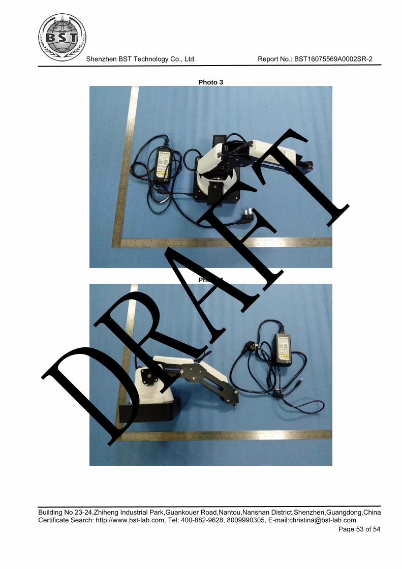
Shenzhen BST Technology Co., Ltd. Report No.: BST16075569A0002SR-2
Building No.23-24,Zhiheng Industrial Park,Guankouer Road,Nantou,Nanshan District,Shenzhen,Guangdong,ChinaCertificate Search: http://www.bst-lab.com, Tel: 400-882-9628, 8009990305, E-mail:[email protected]
Page 53 of 54
Photo 3
Photo 4
DRAFT

Shenzhen BST Technology Co., Ltd. Report No.: BST16075569A0002SR-2
Building No.23-24,Zhiheng Industrial Park,Guankouer Road,Nantou,Nanshan District,Shenzhen,Guangdong,ChinaCertificate Search: http://www.bst-lab.com, Tel: 400-882-9628, 8009990305, E-mail:[email protected]
Page 54 of 54
Photo 5
Photo 6
※※※※※END OF REPORT※※※※※
DRAFT