Embed Size (px)
Citation preview
8/13/2019 eo127_2012
http://slidepdf.com/reader/full/eo1272012 1/9
May 2012 Page 1 of 9
s
SCHOOL OF COMPUTING, ENGINEERING AND MATHEMATICS
SEMESTER-TWO EXAMINATIONS, 2011/2012
ANALOGUE ELECTRONICS – PART B
EO127
DR. D.S. GILL
Time allowed: THREE hours
Answer: FOUR questions from SIX questions
Each question carries 25 marks
Items permitted: Any approved calculator
Items supplied: Linear-linear graph paper
Blank oscilloscope screen diagrams (pp. 8-9)
Marks for whole and part questions are indicated in brackets ( )
8/13/2019 eo127_2012
http://slidepdf.com/reader/full/eo1272012 2/9
EO127 (2011/12) Page 2 of 9
Question 1
(a) Draw a simple block diagram for a general-purpose cathode-ray oscilloscope
(CRO) showing the major elements that are necessary for successful operation.
Marks will also be given for a simple explanation of how the oscilloscope works.
(6 marks)
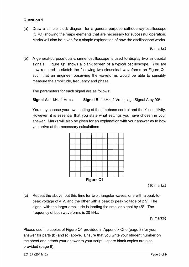
(b) A general-purpose dual-channel oscilloscope is used to display two sinusoidal
signals. Figure Q1 shows a blank screen of a typical oscilloscope. You are
now required to sketch the following two sinusoidal waveforms on Figure Q1
such that an engineer observing the waveforms would be able to sensibly
measure the amplitude, frequency and phase.
The parameters for each signal are as follows:
Signal A: 1 kHz,1 Vrms. Signal B: 1 kHz, 2 Vrms, lags Signal A by 90º.
You may choose your own setting of the timebase control and the Y-sensitivity.
However, it is essential that you state what settings you have chosen in your
answer. Marks will also be given for an explanation with your answer as to how
you arrive at the necessary calculations.
Figure Q1
(10 marks)
(c) Repeat the above, but this time for two triangular waves, one with a peak-to-
peak voltage of 4 V, and the other with a peak to peak voltage of 2 V. The
signal with the larger amplitude is leading the smaller signal by 45º. The
frequency of both waveforms is 20 kHz.
(9 marks)
Please use the copies of Figure Q1 provided in Appendix One (page 8) for your
answer for parts (b) and (c) above. Ensure that you write your student number on
the sheet and attach your answer to your script – spare blank copies are also
provided (page 9).
8/13/2019 eo127_2012
http://slidepdf.com/reader/full/eo1272012 3/9
EO127 (2011/12) Page 3 of 9
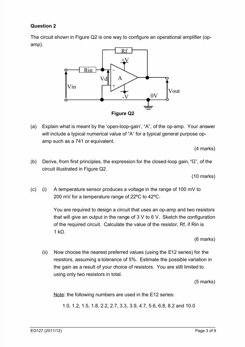
Question 2
The circuit shown in Figure Q2 is one way to configure an operational amplifier (op-
amp).
0V
- + Vin
A Vout
Vd +V
-V
Rin Rf
Figure Q2
(a) Explain what is meant by the ‘open-loop-gain’, “ A”, of the op-amp. Your answer
will include a typical numerical value of “ A” for a typical general purpose op-
amp such as a 741 or equivalent.
(4 marks)
(b) Derive, from first principles, the expression for the closed-loop gain, “G”, of the
circuit illustrated in Figure Q2.
(10 marks)
(c) (i) A temperature sensor produces a voltage in the range of 100 mV to
200 mV for a temperature range of 22ºC to 42ºC.
You are required to design a circuit that uses an op-amp and two resistors
that will give an output in the range of 3 V to 6 V. Sketch the configuration
of the required circuit. Calculate the value of the resistor, Rf, if Rin is
1 kΩ.
(6 marks)
(ii) Now choose the nearest preferred values (using the E12 series) for the
resistors, assuming a tolerance of 5%. Estimate the possible variation in
the gain as a result of your choice of resistors. You are still limited to
using only two resistors in total.
(5 marks)
Note: the following numbers are used in the E12 series:
1.0, 1.2, 1.5, 1.8, 2.2, 2.7, 3.3, 3.9, 4.7, 5.6, 6.8, 8.2 and 10.0

8/13/2019 eo127_2012
http://slidepdf.com/reader/full/eo1272012 4/9
EO127 (2011/12) Page 4 of 9
Question 3
(a) Transducers are used frequently in industrial applications. Describe what is
meant by a transducer and why it is used. Your answer will include a
description of at least four different parameters that can be measured by
transducers (excluding the LVDT).
(8 marks)
(b) Another type of transducer is an “LVDT”. Discuss the operation of the LVDT
with the aid of suitable diagrams. Your answer will include a typical application
of this transducer.
(10 marks)
(c) Instrumentation systems often require the use of an operational amplifier
configured as a voltage follower.
(i) Determine the value of the closed-loop gain for the voltage follower, giving
reasons for your answer.
(4 marks)
(ii) Explain why this configuration of the op-amp is selected. Your answer will
focus on the input and output impedances.
(3 marks)
8/13/2019 eo127_2012
http://slidepdf.com/reader/full/eo1272012 5/9
EO127 (2011/12) Page 5 of 9
Question 4
(a) A 1 kHz analogue signal of amplitude 1 V is to be converted to a digital signal,
where each sample is represented by three bits.
(i) Explain the process required. Your answer will include a discussion ofthe following: minimum sampling rate, sampling process, pulse code
modulation and quantisation. Diagrams should be used to support your
answer.
(10 marks)
(ii) Hence suggest why the system would be improved if the analogue-to-
digital process produces four bits per sample instead of three.
(3 marks)
(b) State briefly why the configuration for a ladder digital-to-analogue converter is
preferable to that of a binary-weighted digital-to-analogue converter.
(3 marks)
(c) Explain how the ‘successive approximation’ algorithm can be used to perform
conversion of an analogue voltage to an 8-bit digital word. You should illustrate
your answer by converting an analogue voltage of 1.9 V. The significance of
the ‘Least Significant Bit (LSB)’ should be 10 mV. Use an appropriate table to
structure your answer.
(9 marks)
8/13/2019 eo127_2012
http://slidepdf.com/reader/full/eo1272012 6/9
EO127 (2011/12) Page 6 of 9
Question 5
(a) The spectrum of a single audio signal was found to contain the following
frequency components (all in kHz):
1, 2, 3, 4, 8, 10 and 15 kHz
The sound engineer would like to design a filter circuit so that when the above
audio signal is fed to the circuit, the spectrum of the signal at the output will
have NO frequency components above 5 kHz.
Suggest what type of filter circuit is required and sketch the frequency response
of that circuit. You may use the graph paper provided if you wish. You should
also show where the above frequency components are in the same sketch.
Marks will be given for an explanation of how you arrived at your sketch.
(5 marks)
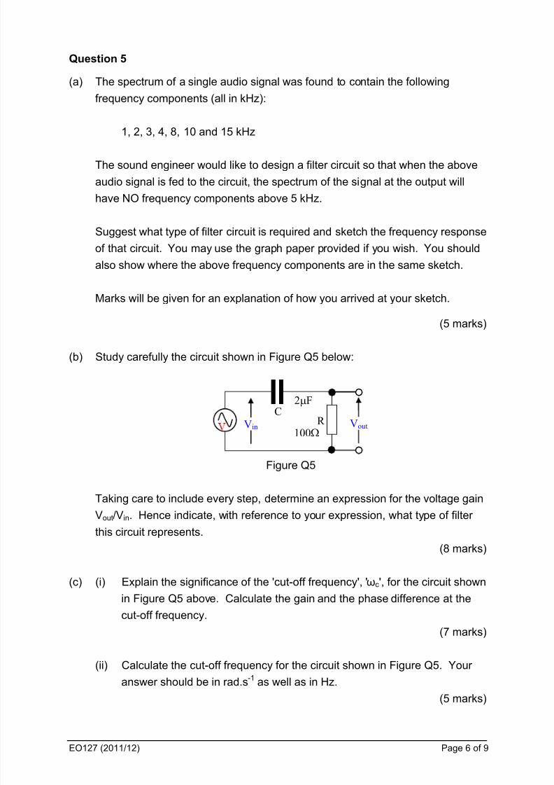
(b) Study carefully the circuit shown in Figure Q5 below:
Figure Q5
Taking care to include every step, determine an expression for the voltage gain
Vout/Vin. Hence indicate, with reference to your expression, what type of filter
this circuit represents.
(8 marks)
(c) (i) Explain the significance of the 'cut-off frequency', 'ωc', for the circuit shown
in Figure Q5 above. Calculate the gain and the phase difference at the
cut-off frequency.
(7 marks)
(ii) Calculate the cut-off frequency for the circuit shown in Figure Q5. Your
answer should be in rad.s
-1
as well as in Hz.(5 marks)
R C Vout Vin
2F
100
8/13/2019 eo127_2012
http://slidepdf.com/reader/full/eo1272012 7/9
EO127 (2011/12) Page 7 of 9
Question 6
(a) A friend has asked you to design a simple circuit to fulfil the following task. He
needs to combine the signals from two electric guitars and one microphone into
one signal as he only has a single input amplifier. Show how this can be
achieved using just one operational amplifier (op-amp) and several resistors.Your answer will include a sketch of the required circuit configuration.
Assume that each of the input signals is to be mixed equally to create the single
output signal. Derive an expression for the output signal of your circuit in terms
of the input signals and the passive components used. Please label your input
signals as V1, V2 and V3 and your output signal as V4.
Your answer should include all working and assumptions made.
(15 marks)
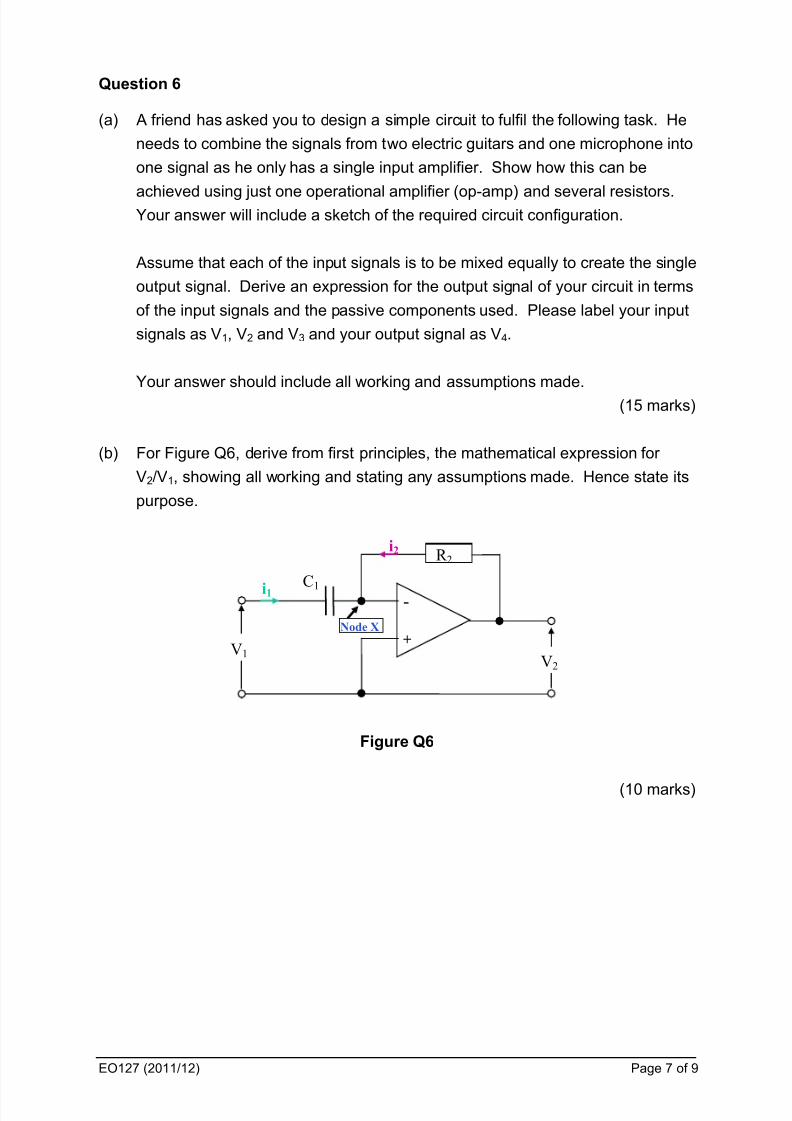
(b) For Figure Q6, derive from first principles, the mathematical expression for
V2/V1, showing all working and stating any assumptions made. Hence state its
purpose.
R 2
C1
-
+
i1
i2
Node X
V1 V2
Figure Q6
(10 marks)

8/13/2019 eo127_2012
http://slidepdf.com/reader/full/eo1272012 8/9
EO127 (2011/12) Page 8 of 9
Appendix 1 – Oscilloscope screen for Question 1 (b) and (c)
Attach to your answer script if used.Student Registration number: ___________________
FIG Q1 for Question 1 (b)
FIG Q1 for Question 1 (c)

8/13/2019 eo127_2012
http://slidepdf.com/reader/full/eo1272012 9/9
EO127 (2011/12) Page 9 of 9
Attach to your answer script if used.Student Registration number: ___________________
Appendix 2 – Oscilloscope screen for Question 1 (b) and (c)
SPARE COPIES
Version 120525.2 dsg


