Embed Size (px)
Citation preview

ENVIRONMENTAL WIND SPEED MEASUREMENTS
ON A WIND TUNNEL MODEL OF THE 459-471 CHURCH STREET, RICHMOND
By
S. Powell
and
M. Eaddy
SUMMARY
Wind tunnel tests have been conducted on a 1/400 scale model of the proposed 459-471
Church Street Development. The model of the Development within surrounding buildings
was tested in a simulated upstream boundary layer of the natural wind to determine likely
environmental wind conditions. These wind conditions have been related to the freestream
mean wind speed at a reference height of 300m and compared with criteria developed for
the Melbourne region as a function of wind direction.
For the Proposed Configuration with wind mitigation strategies at the northwest corner of
the development site (wind break screens and a canopy), the pedestrian level wind
conditions in the streetscapes surrounding the proposed Development have been shown
to be either within or on the criterion for walking comfort for all wind directions, with many
wind directions achieving the stationary activities criteria. The wind effects of the proposed
development have been shown to decrease with increasing distance from the proposed
development site.
The wind conditions outside the Church Street building entrance, East access, and
childcare entry achieve the standing criterion as a minimum, with many wind directions
achieving the sitting criterion.
The wind conditions for the Proposed Configuration in the Private Yard on the south side
of the development site have been shown to be within the standing criterion, with most
wind directions achieving the sitting criterion.
The wind conditions for the Proposed Configuration in the Plaza have been shown to be
within the sitting criterion for all wind directions.

The wind conditions for the Proposed Configuration on the terraces achieve the walking
criterion as a minimum, with many wind directions achieving the standing and sitting criteria
depending on exposure to the prevailing wind directions and location on the building.
The Existing Configuration wind conditions at all Test Locations around the Development
have been provided for comparison.
The wind conditions at all Test Locations in the surrounding streetscapes satisfy the safety
criterion.
The Existing Configuration wind conditions at all Test Locations around the Development
have been provided for comparison.
Report 45-18-WT-ENV-00
June 2018

- 3 -
Report 45-18-WT-ENV-00
459-471 CHURCH STREET, RICHMOND ENVIRONMENTAL WIND TUNNEL MODELLING
MEL CONSULTANTS REPORT NO: 45-18-WT-ENV-00 PREPARED FOR: Salta Properties GPO Box 1700 Melbourne VIC 3000
PREPARED BY: MEL Consultants Pty Ltd 22 Cleeland Road Oakleigh South VIC 3167
Contact: Ms N Paton Contact: M.Eaddy
Ph: +61 431 857 624 Ph: +61 3 8516 9680
PREPARED BY:
M. Eaddy Director Date: 7 June 2018
REVIEWED BY:
J. Kostas Director Date: 7 June 2018
RELEASED BY:
M. Eaddy Director Date: 8 June 2018
REVISION HISTORY Revision No: Date Issued Reason/Comment
0 8 June 2018 Initial Issue Report
DISTRIBUTION Copy No:
1 Copy Location Type
1 Salta Properties Electronic PDF 2 MEL Consultants – Report Library Hardcopy 3 MEL Consultants – Report Library Hardcopy 4 MEL Consultants – Project File Hardcopy
NOTE: This is a controlled document within the document control system. If revised, it must be marked SUPERSEDED and returned to the MEL Consultants Pty Ltd contact.

- 4 -
Report 45-18-WT-ENV-00
CONTENTS
SUMMARY
1 INTRODUCTION ........................................................................................- 5 -
2 ENVIRONMENTAL WIND CRITERIA ........................................................- 6 -
2.1 Suggested Pedestrian Comfort Criteria. ............................................... - 9 -
3 MODEL AND EXPERIMENTAL TECHNIQUES ....................................... - 10 -
4 DISCUSSION OF RESULTS .................................................................... - 12 -
4.1 Summary of Discussion (Figures 7a to 7e) .........................................- 13 -
4.2 Church Street (Figures 8 to 11) ............................................................- 13 -
4.3 Sanders Place and Lesney Street (Figures 11 and 12) .......................- 14 -
4.4 Shamrock Street (Figures 12 and 13) ...................................................- 14 -
4.5 Brighton Street (Figures 13 to 15) ........................................................- 15 -
4.6 East Access, Plaza, and Private Yard (Figures 15 and 16) .................- 15 -
4.7 Terraces and Outdoor Areas (Figures 17 to 21) ..................................- 16 -
5 CONCLUSIONS ....................................................................................... - 17 -
REFERENCES .................................................................................................... - 19 -
FIGURES ............................................................................................................ - 20 -
APPENDIX A

- 5 -
Report 45-18-WT-ENV-00
1 INTRODUCTION
The proposed 459-471 Church Street Development will be a commercial office
development on site with frontages to Church Street, Shamrock Street, and Brighton Street
on the west, north, and east side respectively. The south boundary of the site is against
existing low-rise buildings. The development will consist of 13-level building on the corner
of Church and Shamrock Streets, a 7-level building in the middle of the site, and 3-level
building on Brighton Street. The 13-level and 7-level building are separated by a ground
level plaza with direct access from Shamrock Street. The plaza will have a canopy covering
that was a mitigation strategy developed during an extensive desktop environmental wind
review of the development with the design team during the concept phase so the standing
and sitting criteria would be achieved in this area.
A wind tunnel model study was commissioned by Salta Properties to undertake
measurements of environmental wind conditions around the proposed Development and,
if necessary, to develop wind amelioration features to achieve conditions satisfying the
recommended environmental wind criteria.
These tests were carried out in the MEL Consultants 400kW Boundary Layer Wind Tunnel
during May/June 2018.

- 6 -
Report 45-18-WT-ENV-00
2 ENVIRONMENTAL WIND CRITERIA
The advancement of wind tunnel testing techniques, using large boundary layer flows to
simulate the natural wind, has facilitated the prediction of wind speeds likely to be induced
around a Development. To assess whether the predicted wind conditions are likely to be
acceptable or not, some form of criteria are required. A discussion of criteria for
environmental wind conditions has been made in a paper by Melbourne, Reference 1. This
paper notes that it is the forces caused by the peak gust wind speeds and associated
gradients which people feel most and criteria have been stated in terms of gust wind
speeds. The probabilistic inference of these criteria in relation to hourly mean wind speeds
and frequency of occurrence is discussed. The basic criteria can be summarised as
follows:
In main public access-ways wind conditions are considered
(a) unacceptable (safety) if the peak gust speed during the hourly mean with a
probability of exceedance of 0.1% in any 22.5o wind direction sector exceeds 23ms-
1 (the gust wind speed at which people begin to get blown over);
(b) generally acceptable for walking in urban and suburban areas if the peak gust speed
during the hourly mean with a probability of exceedance of 0.1% in any 22.5o wind
direction sector does not exceed 16 ms-1 (which results in half the wind pressure of
a 23 ms-1 gust).
For more recreational activities wind conditions are considered
(c) generally acceptable for standing stationary short exposure activities (window
shopping, standing or sitting in plazas) if the peak gust speed during the hourly
mean with a probability of exceedance of 0.1% in any 22.5o wind direction sector
does not exceed 13 ms-1;
(d) generally acceptable for sitting stationary, long exposure activities (outdoor
restaurants, theatres) if the peak gust speed during the hourly mean with a
probability of exceedance of 0.1% in any 22.5o wind direction sector does not
exceed 10 ms-1.

- 7 -
Report 45-18-WT-ENV-00
The probability of exceedance of 0.1% relates approximately to the annual maximum mean
wind speed occurrence for each wind direction sector. These criteria can be developed in
terms of hourly mean wind speed versus frequency of occurrence as shown in References
1 and 2.
For the purpose of comparison, or integrating with local wind data, it is necessary to be
able to relate the local velocity measurement to a reference velocity well clear of the
influence of buildings. Because the wind force is related to wind velocity squared, it is
often more convenient to express criteria in terms of velocity ratio squared, or velocity
pressure ratio as this becomes. To this end, two velocity pressure ratios referenced to
conditions at 300m height (as a convenient reference) are defined as,
mean velocity pressure ratio V
V
loca l
m300
2
and
peak velocity pressure ratio V
V
loca l
m300
2
where the peak velocity is the 3-second mean maximum gust wind speed in full scale
conditions.
For wind conditions in Melbourne these criteria can be expressed in terms of velocity
pressure ratios, calculated from hourly mean wind speed data as per the methodology
given in Reference 1.
The criteria in terms of peak velocity pressure ratios are illustrated in Figure 1 and appear
in subsequent figures to enable immediate assessment of the wind conditions as
measured on the model.

- 8 -
Report 45-18-WT-ENV-00
0.0
0.4
0.8
1.2
1.6
2.0
North
long term stationary short term stationary
dangerous/unacceptable
acceptable for walking urban/suburban areas
Vlocal
V300m
2
Figure 1 - Environmental wind criteria for the Melbourne region expressed in terms
of peak velocity pressure ratios
The velocity pressure ratio values considered as unacceptable in Figure 1 are equivalent
to conditions which have existed in some areas in Australian capital cities where people
have been blown over by the wind. The velocity pressure ratios considered as acceptable
for walking in urban and suburban areas are equivalent to conditions existing at corners in
these areas before high rise Development commenced.

- 9 -
Report 45-18-WT-ENV-00
2.1 Suggested Pedestrian Comfort Criteria.
The 459-471 Church Street development will have street frontages to Church, Shamrock,
and Brighton Streets, and the plaza between the buildings. Therefore, the following wind
criteria are suggested for the surrounding streetscapes, plaza, and terraces:
- Pedestrian transit areas (streetscapes) Walking Criterion
- Building/Tenancy entrances Standing Criterion
- Plaza Standing/Sitting Criteria
Terraces/Outdoor Areas Walking Criterion

- 10 -
Report 45-18-WT-ENV-00
3 MODEL AND EXPERIMENTAL TECHNIQUES
A 1/400 scale model of the 459-471 Church Street Development was constructed from
digital information (CAD and Revit) provided by Architectus received 23rd May, 2018.
The 1/400 scale model was inserted into the proximity model of significant buildings of
Richmond model out to a minimum radius of 300m from the site boundaries. Additionally,
MEL Consultants were aware of the future development at 510 Church Street and this
building was added to the model for a future configuration. The 1/400 scale model of the
459-471 Chapel Street Development and surrounding buildings was tested in a model of
the natural wind generated by flow over roughness elements augmented by vorticity
generators at the beginning of the wind tunnel working section. The basic natural wind
model was for flow over suburban terrain, the characteristics of which are given in Figure
2. The surrounding wind tunnel model of all significant buildings modified the approach
wind model for the presence of the surrounding buildings.
Hot-wire anemometry was used to measure the local wind speeds at various locations
around the proposed building. The signals from the hot-wire anemometers were recorded
by a data acquisition system for 30 seconds for each wind direction studied. Previous
investigations by MEL Consultants have found this time period to be sufficient to achieve
piecewise stationarity, i.e. the signal statistics become independent of the sample period.
The data acquisition system uses a high accuracy digital low pass filter to filter the recorded
data to give an effective full scale 3 second peak gust wind speed. MEL Consultants
acknowledge that hot-wire anemometers would measure erroneous mean values in high
turbulence wind environmental such as the urban setting of Richmond. Therefore, MEL
Consultants will only use the gust wind speed measured by the hot-wire anemometer for
the analysis of the environmental wind conditions. Given that only the gust wind speed can
be used from the hot-wire anemometer it is unnecessary to divide this by a factor of 1.85
to obtain a gust equivalent mean (GEM) wind speed to just compare against criteria based
on mean wind speeds. Instead, as discussed in an earlier section, MEL Consultants will
use pedestrian wind comfort criteria based on gust wind speeds.
The techniques used to investigate the environmental wind conditions and the method of
determining the local criteria are given in detail in Reference 2. In these tests
measurements in the Development areas are inside separated regions and peak velocity

- 11 -
Report 45-18-WT-ENV-00
squared ratios were required to make conclusions about likely wind conditions. In
summary, measurements were made of the peak gust wind velocity with a hot wire
anemometer at various stations and expressed as a squared ratio with the mean wind
velocity at a scaled reference height of 300m. This gives the peak velocity squared ratio
( )2300mlocal V/ V̂
Photographs of the model as tested in the wind tunnel are shown in Figures 3 and 4. The
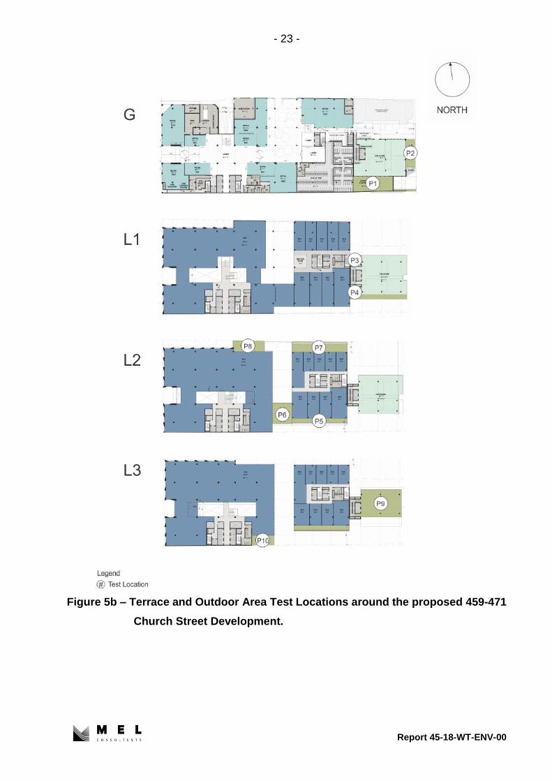
Test Locations in the surrounding streetscapes, terraces and outdoor areas are shown in
Figures 5a, 5b, and 5c. The Test Locations in the surrounding streetscapes have been
chosen out to a radius of approximately half of the building height or width, whichever is
greater, from the site boundaries.
The wind climate data for Melbourne and Laverton Airports have been used for the wind
climate across Richmond in order to account for the topographical effects of the divide to
the north of Melbourne Airport. The effects of the divide are known to decrease with
distance south, so the effects will be greater at Melbourne Airport compared to the urban
area of Melbourne CBD and Richmond.

- 12 -
Report 45-18-WT-ENV-00
4 DISCUSSION OF RESULTS
The wind tunnel study was undertaken for 4 Configurations:
• Existing Configuration
• Proposed Configuration
• Proposed Configuration with Wind Mitigation Strategies
• Proposed Configuration with 510 Church Street
The Existing Configuration is defined as the existing building at 459 - 471 Church Street.
The Proposed Configuration for the 459-471 Church Street Development is as outlined in
the drawings prepared by Architectus, received 23rd May, 2018, with existing surrounding
buildings. The Proposed Configuration with 510 Church Street used the model of 510
Church Street that was submitted for a planning application and included the wind
mitigation strategies for this development along Hutchings Street. Existing and proposed
street trees were not considered for wind mitigation for the 459 - 471 Church Street
development.
Velocity measurements were made at various locations around the 459 - 471 Church
Street Development for different wind directions at 22.5 intervals. The results of these
measurements are presented on polar diagrams against a background plot of the various
criteria for each Test Location as a function of wind direction. The following Sections detail
the results for the various areas tested.
- 13 -
Report 45-18-WT-ENV-00
4.1 Summary of Discussion (Figures 7a to 7e)
To assist with the assessment of the wind conditions, summaries of the highest wind
conditions for the Existing, Proposed, and Proposed with wind mitigation strategies
Configurations at the Test Locations for all wind directions (i.e. 0°→ 360°) have been
provided in Figures 7a to 7c. The wind conditions on the terraces and outdoor areas for
the Proposed Configuration have been summarised in Figures 7d and 7e. Different colours
have been used to represent the wind criteria achieved at the respective Test Locations.
Where the wind conditions at a Test Location were distributed across several criteria, the
criteria colours have been graduated.
4.2 Church Street (Figures 8 to 11)
The wind conditions along Church Street near the intersection with Lesney Street (Test
Locations 1 to 2) for the Proposed Configuration have been shown to be either on or within
the walking criterion for all wind directions. The wind conditions have been shown to
increase at Test Location 2 for the southwest sector wind directions compared to the
Existing Configuration and be similar for the remaining wind directions.
The wind conditions for the Proposed Configuration at the northwest corner of the site
(Test Location 4) have been shown to be within the criterion for walking comfort for all wind
directions. However, the cutout shifts the corner of the building to Test Location 4a and the
wind conditions at this location have been shown to be above the walking criterion for the
north-northwest, north, and north-northeast wind directions. The remaining wind directions
have been shown to be within the criterion for walking comfort. It has been demonstrated
that porous wind break screens in the cutout and a canopy along the north side of the
building mitigate the wind conditions at Test Location 4a to be either on or within the
walking criterion for all wind directions. The installation of the wind break screens has
resulted in the wind conditions at Test Location 4 increasing up to the walking criterion for
the north-northeast wind direction compared to the Proposed Configuration. The Existing
Configuration wind conditions at the northwest corner have been shown to achieve the
standing and sitting criteria.
The wind conditions for the remaining Test Locations (Test Locations 3, 5, 6, and 8 to 14)
have been shown to be either on or within the walking criterion for all wind directions. The

- 14 -
Report 45-18-WT-ENV-00
Existing Configuration wind conditions have been provided at all these Test Locations for
comparison.
The wind conditions for the Proposed Configuration outside the recessed Church Street
entrance (Test Location 7) have been shown to achieve the sitting criterion for all wind
directions.
The wind conditions for the Proposed Configuration with the future 510 Church Street
development have been measured at Test Locations 11, 12, and 14 that are located on
Church Street between the two developments. The wind conditions have been shown to
be either on or within the walking criterion for all wind directions.
4.3 Sanders Place and Lesney Street (Figures 11 and 12)
The wind conditions for the Proposed Configuration in Sanders Place (Test Location 15)
have been shown to be within the standing criterion for al wind directions, with many wind
directions achieving the sitting criterion. The wind conditions for the Existing Configuration
have been provided for comparison.
The wind conditions for the Proposed Configuration in Lesney Street (Test Location 16)
have been shown to be within the standing criterion for al wind directions, with many wind
directions achieving the sitting criterion. The wind conditions for the Existing Configuration
have been provided for comparison.
4.4 Shamrock Street (Figures 12 and 13)
The wind conditions for the Basic Configuration at the west end of Shamrock Street (Test
Location 17) have been shown to be just above the walking criterion for the west wind
direction. The wind conditions for the remaining wind directions have been shown to be
within the walking criterion, with many wind directions achieving the standing and sitting
criteria. It has been demonstrated that the canopy and wind break screens used to mitigate
the wind conditions at the northwest corner of the site improve wind conditions at Test
Location 17 to be within the standing criterion for all wind directions.

- 15 -
Report 45-18-WT-ENV-00
The wind conditions outside the substation room on Shamrock Street (Test Locations 18
and 19) have been shown to be within the walking criterion for all wind directions, with
many wind directions achieving the sitting criterion.
The wind conditions for the Proposed Configuration outside the Shamrock Street entry to
the Plaza (Test Location 20) has been shown to be within the standing criterion for all wind
directions. The Existing Configuration wind conditions have been shown to be within the
sitting criterion for all wind directions.
The wind conditions for the Proposed Configuration outside the meter room on Shamrock
Street (Test Location 21) have been shown to be within the walking criterion for all wind
directions. The wind conditions for the Existing Configuration have been provided for
comparison.
4.5 Brighton Street (Figures 13 to 15)
The wind conditions for the Proposed Configuration along Brighton Street (Test Locations
22 to 30) have been shown to be either on or within the walking criterion for all wind
directions. The wind conditions at Test Locations closer to the development site have been
shown to increase compared to the Existing Configuration.
4.6 East Access, Plaza, and Private Yard (Figures 15 and 16)
The wind conditions for the Proposed Configuration outside the east access to the Plaza
and adjacent to the entry to the proposed childcare (Test Location 31) have been shown
to be well within the standing criterion, with most wind directions achieving the sitting
criterion.
The wind conditions for the Proposed Configuration in the Plaza (Test Locations 32, 33,
and 34) have been shown to be within the sitting criterion for all wind directions.
The wind conditions for the Proposed Configuration in the Private Yard on the south side
of the development site (Test Location 35) have been shown to be within the standing
criterion, with most wind directions achieving the sitting criterion.

- 16 -
Report 45-18-WT-ENV-00
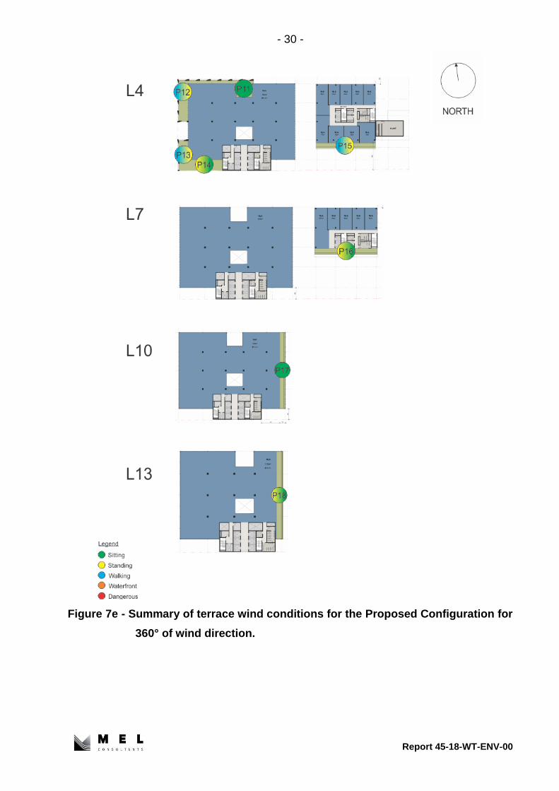
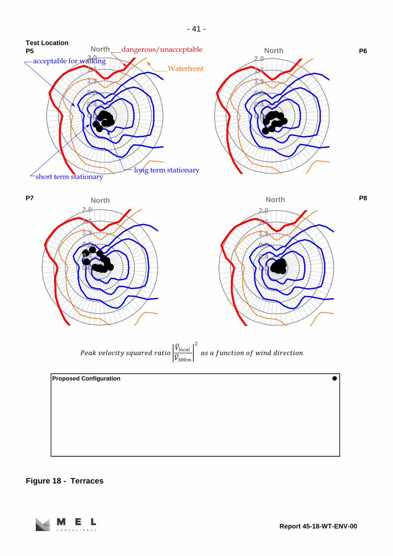
4.7 Terraces and Outdoor Areas (Figures 17 to 21)
The wind conditions have been measured on the terraces and outdoor areas (Test
Locations P1 to P18) for the Proposed Configuration with standard height balustrades. The
wind conditions on the terraces depend on the location of the terrace and their exposure
to the strong and prevailing wind directions, with terraces located in the middle of the faces
have better wind conditions compared to terraces located near building corners. The wind
conditions have been shown to be either on or within the walking criterion for all wind
directions, with wind conditions for wind directions where the building shields the terraces
achieving the standing and sitting criterion.
The wind conditions for the Proposed Configuration in the outdoor playspace of the
childcare (Test Location P1) have been shown to achieve the walking criterion for the
southwest and west-southwest wind directions and the standing and sitting criteria for the
remaining wind directions. The wind conditions were measured in this space without any
landscape features (trees, canopies) and these data will inform the design team so
appropriate wind mitigation strategies can be developed in the playspace.

- 17 -
Report 45-18-WT-ENV-00
5 CONCLUSIONS
Wind tunnel tests have been conducted on a 1/400 scale model of the proposed 459-471
Church Street Development. The model of the Development within surrounding buildings
was tested in a simulated upstream boundary layer of the natural wind to determine likely
environmental wind conditions. These wind conditions have been related to the freestream
mean wind speed at a reference height of 300m and compared with criteria developed for
the Melbourne region as a function of wind direction.
For the Proposed Configuration with wind mitigation strategies at the northwest corner of
the development site (wind break screens and a canopy), the pedestrian level wind
conditions in the streetscapes surrounding the proposed Development have been shown
to be either within or on the criterion for walking comfort for all wind directions, with many
wind directions achieving the stationary activities criteria. The wind effects of the proposed
development have been shown to decrease with increasing distance from the proposed
development site.
The wind conditions outside the Church Street building entrance, East access, and
childcare entry achieve the standing criterion as a minimum, with many wind directions
achieving the sitting criterion.
The wind conditions for the Proposed Configuration in the Private Yard on the south side
of the development site have been shown to be within the standing criterion, with most
wind directions achieving the sitting criterion.
The wind conditions for the Proposed Configuration in the Plaza have been shown to be
within the sitting criterion for all wind directions.
The wind conditions for the Proposed Configuration on the terraces achieve the walking
criterion as a minimum, with many wind directions achieving the standing and sitting criteria
depending on exposure to the prevailing wind directions and location on the building.
The wind conditions at all Test Locations in the surrounding streetscapes satisfy the safety
criterion.

- 18 -
Report 45-18-WT-ENV-00
The Existing Configuration wind conditions at all Test Locations around the Development
have been provided for comparison.
M. Eaddy
June 2018

- 19 -
Report 45-18-WT-ENV-00
REFERENCES
1. W. H. Melbourne, Criteria for environmental wind conditions, Journal of Industrial
Aerodynamics, Volume 3, 1978, pp. 241-249
2. W. H. Melbourne, Wind environment studies in Australia, Journal of Industrial
Aerodynamics, Volume 3, 1978, pp. 201-214

- 20 -
Report 45-18-WT-ENV-00
FIGURES
Figure 2 - 1/400 scale TC3 boundary layer turbulence intensity and mean velocity
profiles in the MEL Consultants Boundary Layer Wind Tunnel 4.8m x
2.2m working section, scaled to full scale dimensions.
0
100
200
300
400
500
600
0 0.1 0.2 0.3 0.4
HE
IGH
T z
(m
)
0
100
200
300
400
500
600
0 0.2 0.4 0.6 0.8 1
HE
IGH
T z
(m
)
600
500
400
300
200
100
0
TERRAIN GRADIENT EXPONENT LENGTH SCALE LZ AT
CATEGORY HEIGHT Zg(m) a Z=10m 50m 200m
1. SEA DESERT 300 0.10 to 0.12 1800 2100 2500
2. OPEN COUNTRY 400 0.13 to 0.17 1200 1500 1900RURAL AIRPORT
3. SUBURBAN 500 0.18 to 0.25 900 1200 1600TREES HILLS
4. URBAN 600 0.26 to 0.40 600 1000 1500
TERRAIN CATEGORY
1 2 3 4
a=0.3 0.2 0.1
5 0.1
TURBULENCE INTENSITY PROFILE MEAN VELOCITY PROFILE
α
gg
z
z
z
V
V÷÷
ø
ö
çç
è
æ=
g
z
VV
z
v
V
σ

- 21 -
Report 45-18-WT-ENV-00
Figure 3 – View from the north of the 1/400 scale Basic Configuration model of the
459-471 Church Street Development in the wind tunnel.
Figure 4 – View from the north of the 1/400 scale Basic Configuration model of the
459-471 Church Street Development with 510 Church Street in the wind
tunnel.

- 22 -
Report 45-18-WT-ENV-00
Figure 5a – Ground level Test Locations around the proposed 459-471 Church Street Development.
- 23 -
Report 45-18-WT-ENV-00
Figure 5b – Terrace and Outdoor Area Test Locations around the proposed 459-471
Church Street Development.

- 24 -
Report 45-18-WT-ENV-00
Figure 5c – Terrace Test Locations on the terraces of the proposed 459-471 Church
Street Development.

- 25 -
Report 45-18-WT-ENV-00
Figure 6 – Details of Wind Mitigation Strategies at the northwest corner.

- 26 -
Report 45-18-WT-ENV-00
Figure 7a - Summary of ground level wind conditions for the Existing Configuration for 360° of wind direction.

- 27 -
Report 45-18-WT-ENV-00
Figure 7b - Summary of ground level wind conditions for the Proposed Configuration for 360° of wind direction.

- 28 -
Report 45-18-WT-ENV-00
Figure 7c - Summary of ground level wind conditions for the Proposed Configuration with wind mitigation strategies for 360° of
wind direction.

- 29 -
Report 45-18-WT-ENV-00
Figure 7d - Summary of terrace wind conditions for the Proposed Configuration for
360° of wind direction.
- 30 -
Report 45-18-WT-ENV-00
Figure 7e - Summary of terrace wind conditions for the Proposed Configuration for
360° of wind direction.

- 31 -
Test Location
1 2
3 4
Proposed Configuration
Existing Configuration
Proposed Configuration + Wind Break Screens in Corner Cutout + Canopy
Figure 8 - Church Street
Proposed Configuration + Wind Break Screens in Corner Cutout
0.0
0.4
0.8
1.2
1.6
2.0
North
0.0
0.4
0.8
1.2
1.6
2.0
North
0.0
0.4
0.8
1.2
1.6
2.0
North
0.0
0.4
0.8
1.2
1.6
2.0
North
long term stationaryshort term stationary
acceptable for walking
dangerous/unacceptable
Waterfront
𝑃𝑒𝑎𝑘 𝑣𝑒𝑙𝑜𝑐𝑖𝑡𝑦 𝑠𝑞𝑢𝑎𝑟𝑒𝑑 𝑟𝑎𝑡𝑖𝑜 𝑉 𝑙𝑜𝑐𝑎𝑙
𝑉 300𝑚
2
𝑎𝑠 𝑎 𝑓𝑢𝑛𝑐𝑡𝑖𝑜𝑛 𝑜𝑓 𝑤𝑖𝑛𝑑 𝑑𝑖𝑟𝑒𝑐𝑡𝑖𝑜𝑛
Report 45-18-WT-ENV-00

- 32 -
Test Location
4a 5
6 7
Figure 9 - Church Street
Proposed Configuration
Existing Configuration
Proposed + Wind Break Screens in Corner Cutout
Proposed Configuration + Wind Break Screens in Corner Cutout + Canopy
0.0
0.4
0.8
1.2
1.6
2.0
North
0.0
0.4
0.8
1.2
1.6
2.0
North
long term stationaryshort term stationary
acceptable for walking
dangerous/unacceptable
Waterfront
0.0
0.4
0.8
1.2
1.6
2.0
North
0.0
0.4
0.8
1.2
1.6
2.0
North
𝑃𝑒𝑎𝑘 𝑣𝑒𝑙𝑜𝑐𝑖𝑡𝑦 𝑠𝑞𝑢𝑎𝑟𝑒𝑑 𝑟𝑎𝑡𝑖𝑜 𝑉 𝑙𝑜𝑐𝑎𝑙
𝑉 300𝑚
2
𝑎𝑠 𝑎 𝑓𝑢𝑛𝑐𝑡𝑖𝑜𝑛 𝑜𝑓 𝑤𝑖𝑛𝑑 𝑑𝑖𝑟𝑒𝑐𝑡𝑖𝑜𝑛
Report 45-18-WT-ENV-00

- 33 -
Test Location
8 9
10 11
Proposed Configuration + Future 510 Church Street Development
Existing Configuration
Proposed Configuration
Figure 10 - Church Street
0.0
0.4
0.8
1.2
1.6
2.0North
0.0
0.4
0.8
1.2
1.6
2.0
North
long term stationaryshort term stationary
acceptable for walking
dangerous/unacceptable
Waterfront
0.0
0.4
0.8
1.2
1.6
2.0
North
0.0
0.4
0.8
1.2
1.6
2.0
North
𝑃𝑒𝑎𝑘 𝑣𝑒𝑙𝑜𝑐𝑖𝑡𝑦 𝑠𝑞𝑢𝑎𝑟𝑒𝑑 𝑟𝑎𝑡𝑖𝑜 𝑉 𝑙𝑜𝑐𝑎𝑙
𝑉 300𝑚
2
𝑎𝑠 𝑎 𝑓𝑢𝑛𝑐𝑡𝑖𝑜𝑛 𝑜𝑓 𝑤𝑖𝑛𝑑 𝑑𝑖𝑟𝑒𝑐𝑡𝑖𝑜𝑛
Report 45-18-WT-ENV-00

- 34 -
Test Location
12 13
14 15
Proposed Configuration + Future 510 Church Street Development
Existing Configuration
Figure 11 - Church Street & Sanders Place & Lesney Street
Proposed Configuration
0.0
0.4
0.8
1.2
1.6
2.0
North
0.0
0.4
0.8
1.2
1.6
2.0
North
long term stationaryshort term stationary
acceptable for walking
dangerous/unacceptable
Waterfront
𝑃𝑒𝑎𝑘 𝑣𝑒𝑙𝑜𝑐𝑖𝑡𝑦 𝑠𝑞𝑢𝑎𝑟𝑒𝑑 𝑟𝑎𝑡𝑖𝑜 𝑉 𝑙𝑜𝑐𝑎𝑙
𝑉 300𝑚
2
𝑎𝑠 𝑎 𝑓𝑢𝑛𝑐𝑡𝑖𝑜𝑛 𝑜𝑓 𝑤𝑖𝑛𝑑 𝑑𝑖𝑟𝑒𝑐𝑡𝑖𝑜𝑛
0.0
0.4
0.8
1.2
1.6
2.0
North
0.0
0.4
0.8
1.2
1.6
2.0
North
Report 45-18-WT-ENV-00

- 35 -
Test Location
16 17
18 19
Proposed Configuration
Existing Configuration
Proposed Configuration + Wind Break Screens in Corner Cutout + Canopy
Figure 12 - Lesney Street & Shamrock Street
Proposed + Wind Break Screens in Corner Cutout
0.0
0.4
0.8
1.2
1.6
2.0
North
0.0
0.4
0.8
1.2
1.6
2.0
North
0.0
0.4
0.8
1.2
1.6
2.0
North
0.0
0.4
0.8
1.2
1.6
2.0
North
long term stationaryshort term stationary
acceptable for walking
dangerous/unacceptable
Waterfront
𝑃𝑒𝑎𝑘 𝑣𝑒𝑙𝑜𝑐𝑖𝑡𝑦 𝑠𝑞𝑢𝑎𝑟𝑒𝑑 𝑟𝑎𝑡𝑖𝑜 𝑉 𝑙𝑜𝑐𝑎𝑙
𝑉 300𝑚
2
𝑎𝑠 𝑎 𝑓𝑢𝑛𝑐𝑡𝑖𝑜𝑛 𝑜𝑓 𝑤𝑖𝑛𝑑 𝑑𝑖𝑟𝑒𝑐𝑡𝑖𝑜𝑛
Report 45-18-WT-ENV-00

- 36 -
Test Location
20 21
22 23
Figure 13 - Shamrock Street & Brighton Street
Proposed Configuration
Existing Configuration
0.0
0.4
0.8
1.2
1.6
2.0
North
0.0
0.4
0.8
1.2
1.6
2.0
North
long term stationaryshort term stationary
acceptable for walking
dangerous/unacceptable
Waterfront
0.0
0.4
0.8
1.2
1.6
2.0
North
0.0
0.4
0.8
1.2
1.6
2.0
North
𝑃𝑒𝑎𝑘 𝑣𝑒𝑙𝑜𝑐𝑖𝑡𝑦 𝑠𝑞𝑢𝑎𝑟𝑒𝑑 𝑟𝑎𝑡𝑖𝑜 𝑉 𝑙𝑜𝑐𝑎𝑙
𝑉 300𝑚
2
𝑎𝑠 𝑎 𝑓𝑢𝑛𝑐𝑡𝑖𝑜𝑛 𝑜𝑓 𝑤𝑖𝑛𝑑 𝑑𝑖𝑟𝑒𝑐𝑡𝑖𝑜𝑛
Report 45-18-WT-ENV-00

- 37 -
Test Location
24 25
26 27
Existing Configuration
Proposed Configuration
Figure 14 - Brighton Street
0.0
0.4
0.8
1.2
1.6
2.0North
0.0
0.4
0.8
1.2
1.6
2.0
North
long term stationaryshort term stationary
acceptable for walking
dangerous/unacceptable
Waterfront
0.0
0.4
0.8
1.2
1.6
2.0
North
0.0
0.4
0.8
1.2
1.6
2.0
North
𝑃𝑒𝑎𝑘 𝑣𝑒𝑙𝑜𝑐𝑖𝑡𝑦 𝑠𝑞𝑢𝑎𝑟𝑒𝑑 𝑟𝑎𝑡𝑖𝑜 𝑉 𝑙𝑜𝑐𝑎𝑙
𝑉 300𝑚
2
𝑎𝑠 𝑎 𝑓𝑢𝑛𝑐𝑡𝑖𝑜𝑛 𝑜𝑓 𝑤𝑖𝑛𝑑 𝑑𝑖𝑟𝑒𝑐𝑡𝑖𝑜𝑛
Report 45-18-WT-ENV-00

- 38 -
Test Location
28 29
30 31
Existing Configuration
Figure 15 - Brighton Street & East Access
Proposed Configuration
0.0
0.4
0.8
1.2
1.6
2.0
North
0.0
0.4
0.8
1.2
1.6
2.0
North
long term stationaryshort term stationary
acceptable for walking
dangerous/unacceptable
Waterfront
𝑃𝑒𝑎𝑘 𝑣𝑒𝑙𝑜𝑐𝑖𝑡𝑦 𝑠𝑞𝑢𝑎𝑟𝑒𝑑 𝑟𝑎𝑡𝑖𝑜 𝑉 𝑙𝑜𝑐𝑎𝑙
𝑉 300𝑚
2
𝑎𝑠 𝑎 𝑓𝑢𝑛𝑐𝑡𝑖𝑜𝑛 𝑜𝑓 𝑤𝑖𝑛𝑑 𝑑𝑖𝑟𝑒𝑐𝑡𝑖𝑜𝑛
0.0
0.4
0.8
1.2
1.6
2.0
North
0.0
0.4
0.8
1.2
1.6
2.0
North
Report 45-18-WT-ENV-00

- 39 -
Test Location
32 33
34 35
Proposed Configuration
Existing Configuration
Figure 16 - Plaza & Private Yard
0.0
0.4
0.8
1.2
1.6
2.0
North
0.0
0.4
0.8
1.2
1.6
2.0
North
0.0
0.4
0.8
1.2
1.6
2.0
North
0.0
0.4
0.8
1.2
1.6
2.0
North
long term stationaryshort term stationary
acceptable for walking
dangerous/unacceptable
Waterfront
𝑃𝑒𝑎𝑘 𝑣𝑒𝑙𝑜𝑐𝑖𝑡𝑦 𝑠𝑞𝑢𝑎𝑟𝑒𝑑 𝑟𝑎𝑡𝑖𝑜 𝑉 𝑙𝑜𝑐𝑎𝑙
𝑉 300𝑚
2
𝑎𝑠 𝑎 𝑓𝑢𝑛𝑐𝑡𝑖𝑜𝑛 𝑜𝑓 𝑤𝑖𝑛𝑑 𝑑𝑖𝑟𝑒𝑐𝑡𝑖𝑜𝑛
Report 45-18-WT-ENV-00

- 40 -
Test Location
P1 P2
P3 P4
Figure 17 - Terraces and Outdoor Areas
Proposed Configuration
0.0
0.4
0.8
1.2
1.6
2.0
North
0.0
0.4
0.8
1.2
1.6
2.0
North
long term stationaryshort term stationary
acceptable for walking
dangerous/unacceptable
Waterfront
0.0
0.4
0.8
1.2
1.6
2.0
North
0.0
0.4
0.8
1.2
1.6
2.0
North
𝑃𝑒𝑎𝑘 𝑣𝑒𝑙𝑜𝑐𝑖𝑡𝑦 𝑠𝑞𝑢𝑎𝑟𝑒𝑑 𝑟𝑎𝑡𝑖𝑜 𝑉 𝑙𝑜𝑐𝑎𝑙
𝑉 300𝑚
2
𝑎𝑠 𝑎 𝑓𝑢𝑛𝑐𝑡𝑖𝑜𝑛 𝑜𝑓 𝑤𝑖𝑛𝑑 𝑑𝑖𝑟𝑒𝑐𝑡𝑖𝑜𝑛
Report 45-18-WT-ENV-00
- 41 -
Test Location
P5 P6
P7 P8
Proposed Configuration
Figure 18 - Terraces
0.0
0.4
0.8
1.2
1.6
2.0North
0.0
0.4
0.8
1.2
1.6
2.0
North
long term stationaryshort term stationary
acceptable for walking
dangerous/unacceptable
Waterfront
0.0
0.4
0.8
1.2
1.6
2.0
North
0.0
0.4
0.8
1.2
1.6
2.0
North
𝑃𝑒𝑎𝑘 𝑣𝑒𝑙𝑜𝑐𝑖𝑡𝑦 𝑠𝑞𝑢𝑎𝑟𝑒𝑑 𝑟𝑎𝑡𝑖𝑜 𝑉 𝑙𝑜𝑐𝑎𝑙
𝑉 300𝑚
2
𝑎𝑠 𝑎 𝑓𝑢𝑛𝑐𝑡𝑖𝑜𝑛 𝑜𝑓 𝑤𝑖𝑛𝑑 𝑑𝑖𝑟𝑒𝑐𝑡𝑖𝑜𝑛
Report 45-18-WT-ENV-00

- 42 -
Test Location
P9 P10
P11 P12
Figure 19 - Terraces
Proposed Configuration
0.0
0.4
0.8
1.2
1.6
2.0
North
0.0
0.4
0.8
1.2
1.6
2.0
North
long term stationaryshort term stationary
acceptable for walking
dangerous/unacceptable
Waterfront
𝑃𝑒𝑎𝑘 𝑣𝑒𝑙𝑜𝑐𝑖𝑡𝑦 𝑠𝑞𝑢𝑎𝑟𝑒𝑑 𝑟𝑎𝑡𝑖𝑜 𝑉 𝑙𝑜𝑐𝑎𝑙
𝑉 300𝑚
2
𝑎𝑠 𝑎 𝑓𝑢𝑛𝑐𝑡𝑖𝑜𝑛 𝑜𝑓 𝑤𝑖𝑛𝑑 𝑑𝑖𝑟𝑒𝑐𝑡𝑖𝑜𝑛
0.0
0.4
0.8
1.2
1.6
2.0
North
0.0
0.4
0.8
1.2
1.6
2.0
North
Report 45-18-WT-ENV-00

- 43 -
Test Location
P13 P14
P15 P16
Proposed Configuration
Figure 20 - Terraces
0.0
0.4
0.8
1.2
1.6
2.0
North
0.0
0.4
0.8
1.2
1.6
2.0
North
0.0
0.4
0.8
1.2
1.6
2.0
North
0.0
0.4
0.8
1.2
1.6
2.0
North
long term stationaryshort term stationary
acceptable for walking
dangerous/unacceptable
Waterfront
𝑃𝑒𝑎𝑘 𝑣𝑒𝑙𝑜𝑐𝑖𝑡𝑦 𝑠𝑞𝑢𝑎𝑟𝑒𝑑 𝑟𝑎𝑡𝑖𝑜 𝑉 𝑙𝑜𝑐𝑎𝑙
𝑉 300𝑚
2
𝑎𝑠 𝑎 𝑓𝑢𝑛𝑐𝑡𝑖𝑜𝑛 𝑜𝑓 𝑤𝑖𝑛𝑑 𝑑𝑖𝑟𝑒𝑐𝑡𝑖𝑜𝑛
Report 45-18-WT-ENV-00

- 44 -
Test Location
P17 P18
Figure 21 - Terraces
Proposed Configuration
0.0
0.4
0.8
1.2
1.6
2.0
North
0.0
0.4
0.8
1.2
1.6
2.0
North
long term stationaryshort term stationary
acceptable for walking
dangerous/unacceptable
Waterfront
0.0
0.4
0.8
1.2
1.6
2.0
North
0.0
0.4
0.8
1.2
1.6
2.0
North
𝑃𝑒𝑎𝑘 𝑣𝑒𝑙𝑜𝑐𝑖𝑡𝑦 𝑠𝑞𝑢𝑎𝑟𝑒𝑑 𝑟𝑎𝑡𝑖𝑜 𝑉 𝑙𝑜𝑐𝑎𝑙
𝑉 300𝑚
2
𝑎𝑠 𝑎 𝑓𝑢𝑛𝑐𝑡𝑖𝑜𝑛 𝑜𝑓 𝑤𝑖𝑛𝑑 𝑑𝑖𝑟𝑒𝑐𝑡𝑖𝑜𝑛
Report 45-18-WT-ENV-00