Embed Size (px)
Citation preview

Appendix H
Environmental Management Progamme

ENVIRONMENTAL RESOURCES MANAGEMENT SHELL SA MARKETING (PTY) LTD
I
ABBREVIATIONS
Fuels Abbreviation Description VP95 V-Power Unleaded 95 VPR V-Power Unleaded 93 LRP Lead Replacement Petrol VPD V-Power Diesel DX V-Power Diesel Extra
Companies and Organisations Abbreviation Company / Organisation Role Shell Shell South Africa Marketing (Pty) Ltd
Client
ERM Environmental Resources Management Southern Africa (Pty) Ltd
Environmental Consultant
PMC Project Management Company
PMC Sub-Supplier Project Management Company Sub-Supplier
Principal Contractor
PMC HSSE Specialist
Project Management Company Health, Safety, Security and Environment Specialist
HWDC Hazardous Waste Disposal Contractor
DEA&DP Department of Environmental Affairs and Development Planning
Regulator
DWA Department: Water Affairs
Regulator
General Abbreviations Abbreviation Description NERA Network Environmental Risk Assessment
EA Environmental Authorisation
EMP Environmental Management Plan
EAPSA Environmental Assessment Practitioners of South Africa
NEMA National Environmental Management Act
SANS South African National Standards
HASP Health and Safety Plan
ENVIRONMENTAL RESOURCES MANAGEMENT SHELL SA MARKETING (PTY) LTD
II
Abbreviation Description UST Underground Storage Tank
LEL
Lower Explosive Limit
VOC
Volatile Organic Compound
HSE
Health, Safety, and the Environment
PPE
Personal Protective Equipment
PID
Photoionization Detector
HDPE High-density Polyethylene
PM TDS
Project Manager Total Dissolved Solids
Scientific Abbreviations Abbreviation Description m meter
l/s litres per second
mg/l milligrams per litre

ENVIRONMENTAL RESOURCES MANAGEMENT SHELL SA MARKETING (PTY) LTD
1
CONTENTS ABBREVIATIONS I
1 INTRODUCTION 2
1.1 DETAILS OF ENVIRONMENTAL PRACTITIONER 3
2 BACKGROUND INFORMATION 4
2.1 SITE SETTING 4 2.2 PURPOSE OF THE EMP 6 2.3 STANDARDS AND GUIDELINES 6
3 ROLES AND RESPONSIBILITIES 7
3.1 PROJECT MANAGEMENT COMPANY 7 3.2 PMC HEALTH, SAFETY, SECURITY AND ENVIRONMENT SPECIALIST 7 3.3 PROJECT MANAGEMENT COMPANY SUB-SUPPLIER 7
4 COMMUNICATION PROCEDURES ON SITE 9
4.1 METHOD STATEMENTS AND EMERGENCY RESPONSE 9 4.2 RECORD KEEPING 9 4.3 PHOTOGRAPHS 9
5 POTENTIAL ENVIRONMENTAL IMPACTS 10
5.1 DESIGN AND PLANNING PHASE 10 5.2 CONSTRUCTION/ INSTALLATION PHASE 15 5.3 OPERATIONAL PHASE 21 5.4 DECOMMISSIONING PHASE 26
6 CONTACT DETAILS AND SIGNATURES 31

ENVIRONMENTAL RESOURCES MANAGEMENT SHELL SA MARKETING (PTY) LTD
2
1 INTRODUCTION
The following Environmental Management Programme (EMPr) has been prepared by ERM Southern Africa (Pty) Ltd (ERM), for Shell South Africa Marketing (Pty) Ltd (Shell). This Environmental Management Programme (EMPr) has been compiled for the installation of Underground Storage Tanks (USTs) for the storage of fuel at the proposed Shell Service Station in Parklands, Cape Town, Western Cape Province. The construction of the service station will include the following infrastructure: • 4 x 46m3 usts; • associated pipelines; • canopy; • pump islands and dispensers; • convenience store; • rest rooms; • ATMs; • fast food restaurant; • car wash; • paved forecourt; and • vehicle access points. The installation of USTs for fuel storage, triggers the following listed activity in Government Notice R544: Activity 13, GN R544 : “The construction of facilities or infrastructure for the storage or storage and handling of dangerous goods, where such storage occurs in containers with a combined capacity of 80 cubic meters but not exceeding 500 cubic meters.” This EMP is presented in draft form and will be submitted to the Western Cape Department of Environmental Affairs and Development Planning (DEA&DP). Shell remains responsible for the accuracy and relevance of the information contained in this EMP. The EMP remains a ‘live’ document and makes provision for updating during the detailed design and planning phase, and incorporation of any relevant condition in the environmental authorisation (EA). This EMP covers the installation of the USTs as well as the construction of the service station. This includes excavation activities for new below-ground infrastructure including the installation of new USTs. A description of the roles and responsibilities of the various parties involved with these activities has been provided. In addition, the potential environmental impacts and associated mitigation measures have been identified for excavation, UST installation activities as well as the general construction of the service station.

ENVIRONMENTAL RESOURCES MANAGEMENT SHELL SA MARKETING (PTY) LTD
3
The specified assets will be installed by Shell’s appointed Project Management Company Sub-Supplier, in accordance with Shell’s UST System Installation Scope of Work as well as Shell’s HSSE&SP Control Framework. The site details are as follows: Name of the site: Shell Parklands Service Station Site co-ordinates: 33° 48‘5.39“S and 18° 30‘14.25“E Date of last EMP Revision: March 2013
1.1 DETAILS OF ENVIRONMENTAL PRACTITIONER
ERM were appointed by Shell, to undertake the Basic Assessment process, which includes the preparation of an EMP. ERM has no financial ties to, nor are they a subsidiary, legally or financially, of Shell South Africa Marketing (Pty) Ltd. The ERM Partner in Charge, Brett Lawson, is a certified environmental assessment practitioner and the project has been conducted in terms of the code of ethics promulgated by the Certification Board for Environmental Assessment Practitioners of South Africa (EAPSA), which includes a requirement for independence. The project team members include Brett Lawson, and Lindsey Bungartz, see Table 1.1 below.
Table 1.1 Details of Environmental Assessment Practitioners
Name Brett Lawson Responsibility Partner in Charge Degree MSc Professional registration Certified EAPSA, Pr Sci Nat Experience in years 21+ Experience Oil and Gas, Energy
Name Lindsey Bungartz Responsibility Assistant Project Manager Degree B.Sc (Hons) (Geology); B.Sc (Hons)
(Engineering & Env Geology) Professional registration Pr Sci Nat, IAIA Experience in years 4 Experience Lindsey has over four years’ experience in
environmental consulting including Basic Assessments, Scoping/EIAs and EMPs in South Africa.

ENVIRONMENTAL RESOURCES MANAGEMENT SHELL SA MARKETING (PTY) LTD
4
2 BACKGROUND INFORMATION
2.1 SITE SETTING
The site can be accessed via Sandown Road and Wood Drive (see Figure 2.1). The surrounding land use is as follows: North: vacant East: residential West: vacant land followed by residential South: residential The site is vacant and has been heavily disturbed though activities such as clearing, dumping and infestation of invasive alien plants. The site is currently not zoned and a rezoning application is underway in terms of the Land Use Planning Ordinance( LUPO) to allow for the operation of a service station. Geology
According to the 1: 250 000 Geology Map Series, the site is underlain by sedimentary and volcanic rocks, specifically the Springfontyn formation. Hydrogeology
According to Groundwater Resources of the Republic of South Africa Map Sheet 2, 1995, borehole yields in the region are between 0.5-2.0 l/s. Total Dissolved Solid (TDS) concentrations are less than 500 mg/l. According to the Aquifer Classification of South Africa (CSIR, 1999), the regional aquifer is classified as a major aquifer which indicates that the aquifer is a high yielding aquifer system of good water quality. Furthermore, the regional aquifer is considered to have a moderate vulnerability rating which indicates the likelihood for contamination to reach a specified position in the groundwater system. Using the classification of the aquifer (major) as well as the vulnerability rating (moderate), the susceptibility rating of the aquifer can be determined using the matrix as provided in the Aquifer Classification of South Africa (CSIR, 1999). The susceptibility rating in this classification system is defined as the qualitative measure of the relative ease with which a groundwater body can be potentially contaminated by anthropogenic activities. The susceptibility rating for the site is high.

Figure 2.1 Ortho Locality Map showing the location of the proposed Service Station and UST installation

ENVIRONMENTAL RESOURCES MANAGEMENT SHELL SOUTH AFRICA MARKETING (PTY) LTD
6
2.2 PURPOSE OF THE EMP
This EMP is a delivery mechanism for environmental mitigation measures that should be implemented during the UST installation works and the construction of the Service Station. The EMP is, therefore, an environmental management tool used to ensure that undue or reasonably avoidable adverse environmental impacts are prevented and positive benefits of the project are enhanced. The overall aims of this EMP are to: • enable continuing compliance with South African environmental
legislation and Shell’s policies and procedures; • provide assurance to regulators and stakeholders that the requirements
with respect to environmental and social performance will be met; • allow employees and contractors to become familiar with the
environmental procedures to be followed and facilitate their compliance with the recommendations made within this document;
• define roles and responsibilities and facilitate understanding by employees and contractors; and
• facilitate monitoring to assess whether management actions are being implemented.
2.3 STANDARDS AND GUIDELINES
The legal and administrative requirements that are relevant to the installation of a UST at the facility are as follows: • National Environmental Management Act (NEMA) (Act No. 107 of 1998),
as amended; • NEMA EIA Regulation, 2010 (Government Notice R544- listed Activity
42); • National Water Act (Act No. 36 of 1998); • National Building Regulations and Standards Act (Act No. 103 of 1977); • Occupational Health and Safety Act (No. 85 of 1993); • Noise Control Regulations (PN 5309 of 1998); • South African National Standards (SANS): Noise, Pipework, Storage of
Dangerous Goods in USTs, Portable rechargeable fire extinguishers; and • Employment Equity Act No 55 of 1998. It is the responsibility of Shell to ensure that all relevant legal requirements are met during the installation of the USTs and construction of the service station.

ENVIRONMENTAL RESOURCES MANAGEMENT SHELL SOUTH AFRICA MARKETING (PTY) LTD
7
3 ROLES AND RESPONSIBILITIES
The following parties will be involved in the installation of the USTs. Shell has formal contracts in place with all the relevant contractors and consultants.
3.1 PROJECT MANAGEMENT COMPANY
The Project Management Company (PMC) has been appointed by Shell and is responsible for the following: • project mobilisation and implementation; • overall project management of the works and PMC Sub-Supplier
coordination; • co-ordinating the UST installation works and ensuring appointment of
the PMC Sub-Supplier; • discuss with the PMC Sub-Supplier at the pre-construction meeting the
disposal options for groundwater should it be encountered, and should dewatering be necessary;
• reviewing the Sub-supplier’s safe work practices and procedures; and • conducting random compliance audits during the UST installation
(checking permits to work etc.).
3.2 PMC HEALTH, SAFETY, SECURITY AND ENVIRONMENT SPECIALIST
The Health, Safety, Security and Environment (HSSE) Specialist will be responsible for the following: • reviewing and approving the site Health and Safety Plan (HASP); • ensuring that the contractor complies with the requirements of the
Occupational Health and Safety Act during construction; and • ensuring that the contractor complies with the requirements of the Shell
HSSE & Social Performance (SP) Control Framework.
3.3 PROJECT MANAGEMENT COMPANY SUB-SUPPLIER
The Project Management Company Sub-Supplier, hereafter referred to as the PMC Sub-Supplier is the Principal Contractor on site and is responsible for all works performed on site, including overseeing the excavation works and the installation of the new USTs and associated infrastructure. The PMC Sub-Supplier is also responsible for the following: • producing a Health and Safety Plan (HASP) and schedule for all works to
be performed on site;

ENVIRONMENTAL RESOURCES MANAGEMENT SHELL SOUTH AFRICA MARKETING (PTY) LTD
8
• complying with the Shell HSSE & SP Control Framework and conditions of the contract;
• ensuring the site is barricaded and secured to prevent public access during construction;
• coordinating the safe installation of the USTs and associated infrastructure;
• ensuring the area is safe for excavation (utility clearance and electrical lock out, barricading and signage), excavation planning, managing the excavation process and tank installation process, safe placement/storage of stockpiled soil, backfilling, permitting and health & safety oversight;
• discussing with the PMC at the pre-construction meeting the disposal options for groundwater should it be encountered, and should dewatering be necessary;
• identify and nominate a suitable disposal methodology for water pumped from excavations;
• pumping of water from excavations to a water storage tank, if required; and
• issuing original disposal certificates to Shell and copies to the Environmental Consultant.

ENVIRONMENTAL RESOURCES MANAGEMENT SHELL SOUTH AFRICA MARKETING (PTY) LTD
9
4 COMMUNICATION PROCEDURES ON SITE
4.1 METHOD STATEMENTS AND EMERGENCY RESPONSE
Any contractors employed will be required to provide method statements for specific activities on request of the PMC or Shell. A method statement describes the scope of the intended work in a step by step description to ensure that those involved understand the Contractor’s intentions. This will enable them to assist in devising any mitigation measures which would minimise environmental impact during these tasks. This includes the procedures to be followed in the event of a spill or environmental incident (ie contacting the relevant emergency response personnel and emergency services).
4.2 RECORD KEEPING
All records related to the implementation of this EMP (e.g. audit reports, incident reports, etc.) must be filed by Shell in a safe place where they can be easily retrieved. These records should be kept for two years and should, at any time, be available for scrutiny by relevant authorities.
4.3 PHOTOGRAPHS
It is recommended that photographs be taken of the site by the PMC Sub-Supplier, the PMC, and/or Environmental Consultant prior to, during and immediately after UST installation, as a visual reference. These photographs should be stored with other records related to this EMP.

ENVIRONMENTAL RESOURCES MANAGEMENT SHELL SOUTH AFRICA MARKETING (PTY) LTD
10
5 POTENTIAL ENVIRONMENTAL IMPACTS
The section below identifies the potential significant impacts associated with excavation activities for the installation, and operation of the new Shell Service Station, as well as the proposed mitigation measures and responsible parties. This EMP is presented in a tabular format section under the following headings: • Design and Planning Phase; • Installation/ Construction Phase; and • Operation Phase
5.1 DESIGN AND PLANNING PHASE
5.1.1 Site Access
To assist with the traffic flow and remain compliant with the Provincial Road Access Guidelines document, design phase mitigation measures have been recommended by the Traffic Specialist, given the current site layout plan. Shell must apply to the City of Cape Town for site access onto Sandown Rd and Wood Drive. During this application process, the recommendations made by the Traffic Specialist will be considered by the City of Cape Town and Shell. The City of Cape Town will confirm which of the recommendations must be implemented and who will be responsible for the implementation. These recommendations include: • Traffic lights must be installed at the Sandown Road/ Wood Drive
intersection; • A left-in left- out access must be constructed on Wood Drive midway
between Sandown Road and Thetford Road which can accommodate heavy vehicles (fuel delivery trucks);
• A traffic circle must be built at the Wood Drive/ Thetford Road
intersection to allow U- turns and to accommodate fuel delivery trucks; a bus/ mini- bus embayment be investigated on Sandown Road or Wood Drive in proximity to the proposed development;
• And the existing paved sidewalks should be incorporated into the design
of the roundabout and that a paved sidewalk be constructed on the eastern side of Wood Drive to link with existing sidewalks.

ENVIRONMENTAL RESOURCES MANAGEMENT SHELL SOUTH AFRICA MARKETING (PTY) LTD
11
Once Shell have obtained access permission from the City of Cape Town, the EMP and the Final Site Layout Plan must be updated to reflect any revised mitigation or changes to the Layout. In order to ensure compliance with Shell’s environmental policy as well as environmental legislation requirements, the following actions are applicable to the planning phase for installation activities.

Design and Planning Phase Activity/Aspect Objective Actions to be undertaken to Mitigate Environmental
Impact Parameters for
Monitoring Responsibility Frequency / Timing
# Description # Commitment / Actions Required / Key Controls 1. Planning Notify all registered Interested and
Affected Parties of Environmental Authorization (EA)
1.1
• Notify all registered I &APs and key stakeholders of the opportunity to appeal against the EA.
Copy of signed EMP is available on site
ERM
Prior to the start of the works
Ensure compliance with legal and other permitting requirements
1.2 • Ensure that relevant legal requirements have been met.
Relevant documentation on record
Shell Prior to the start of the works
Schedule site preparations 1.3 • Prepare a project schedule to coordinate vehicle movements, deliveries and construction activities to minimise noise emissions and minimise traffic congestion.
Project schedule sign-off
Shell Prior to construction/ installation
2. Design Minimize visual impact on the surrounding residential areas (sensitive receptors)
2.1 2.2
• Commercial buildings should ideally be clustered, possibly around an internal court, to avoid the visual scatter of isolated buildings on the site.
• The facades should be modulated to provide
Approved site plan Shell and PMC
Prior to the start of the works

Design and Planning Phase Activity/Aspect Objective Actions to be undertaken to Mitigate Environmental
Impact Parameters for
Monitoring Responsibility Frequency / Timing
# Description # Commitment / Actions Required / Key Controls 2.2 2.3 2.4 2.5 2.6 2.7 2.8 2.9 2.10 2.11 2.12
scale in sympathy with the surrounding residential development.
• Consideration should be given to introducing pitched roofs to be more congruent with the surrounding roofscape, where Shell’s design guidelines permit divations.
• There should be no access roads, parking bays, wash bays or detail bays within the 5m building line to allow adequate space for a tree-planted buffer strip on the eastern and southern boundaries of the site.
• A dense tree-planting belt should be created on the perimeter between the filling station and the adjacent residential development. The Sandown Road and Wood Drive street frontages should also be landscaped.
• A landscape plan should be prepared and form part of the building plan submission to the local authority.
• As far as possible, all yards and storage areas to be enclosed by masonry walls or screens.
• The parking bays should be paved with brick or other unit pavers to minimise expansive asphalt areas.
• External lighting should be confined to the dispensing forecourt, commercial outlets and other essential areas.
• Lights should be low-level, where possible, and fitted with reflectors to avoid light spillage.
• Lights and signage should be fixed to buildings or walls, where possible, to avoid unnecessary masts and visual clutter.
• Signage related to the enterprise should be confined to the tower, canopy and entrances. Other corporate or advertising signage and flags should be avoided or restricted.
Landscape Plan
Shell and PMC Shell and PMC
Prior to the start of the works

Design and Planning Phase Activity/Aspect Objective Actions to be undertaken to Mitigate Environmental
Impact Parameters for
Monitoring Responsibility Frequency / Timing
# Description # Commitment / Actions Required / Key Controls 3. Notification of
commencement of construction
Notify DEA&DP of the commencement date of construction activities
3.1 • Notify DEA&DP in writing, at least 10 days prior to commencement of site preparation.
Proof of communication
Shell 14-days in advance of commencement of construction/ installation
4. Method Statements Draft and approve method statements 4.1 The following method statements are required: • site layout and establishment; • storage and use of hazardous substances; • storage and release/ collection of effluent; • solid waste control system; • fire control and emergency procedures; and • oil water separator.
Method statement sign-off
Shell Prior to commencement of construction/ installation

ENVIRONMENTAL RESOURCES MANAGEMENT SHELL SOUTH AFRICA MARKETING (PTY) LTD
15
5.2 CONSTRUCTION/ INSTALLATION PHASE
In order to ensure compliance with Shell’s environmental policy as well as environmental legislation requirements, the following actions are applicable to the installation phase of the USTs as well as the general construction of the service station.

UST INSTALLATION AND SERVICE STATION CONSTRUCTION
Activity/Aspect Objective Actions to be undertaken to Mitigate Environmental Impact Parameters for Monitoring
Responsibility Frequency / Timing # Description # Commitment / Actions Required / Key Controls
1. Compliance with EMP
Confirm Shell’s and contractors’ commitment to adherence of EMP.
1.1 1.2 1.3
• Ensure that approved EMP is available on site. • Ensure that equipment is in place to meet
EMP. • Signed commitment of compliance with the
EMP, from all parties.
Copy of signed EMP is available on site.
Shell and PMC
Prior to the start of construction
2. Impacts on existing infrastructure, services and servitudes
Avoid damage or destruction of existing infrastructure on or in the vicinity of the site.
2.1 2.2
• Prior to beginning any excavation or drilling activities the person(s) conducting the task must be familiar with the location of buried utilities that may be present around the site, (including water, electricity, sewage, gas, compressed air, communication).
• Shell’s procedures for Electrical Safety must be adhered to (see Annex C).
Visual inspection Incident Report
PMC and PMC Sub-Supplier Prior to the start of construction
3. Traffic impacts associated with the asset delivery and required construction material
Manage any potential traffic congestion.
3.1 3.2 3.3 3.4 3.5
• Co-ordination of movement of vehicles on and off site to reduce risks and prevent congestion on roads in the vicinity of the site.
• No vehicles or machinery should be serviced or refuelled onsite.
• Peak traffic hours should be avoided. • Large vehicle turning must take place onsite
and not in the adjacent roads. • In cases where activities may obstruct traffic,
local traffic officials must be contacted.
Incident Report PMC and PMC Sub-Supplier Throughout construction phase
4. Noise impacts associated with construction activities
Manage any potential noise impacts. 4.1 4.2 4.3 4.4 4.5 4.6 4.6 4.7
• Work should occur during daylight hours only between sunrise and sunset, on week days only.
• Site personnel are to wear the appropriate PPE, if and when required.
• Noise levels must comply with the SANS 100103 – 0994 (recommended noise levels).
• The contractor will adhere to local authority by-laws relating to noise control.
• Mechanical equipment with lower sound power levels will be selected to ensure that the permissible occupation noise-rating limit of 85 dBA is not exceeded.
• Equipment will be fitted with silencers as far as possible to reduce noise.
• All equipment to be adequately maintained and kept in good working order to reduce
Incident Report
PMC and PMC Sub-Supplier Throughout construction phase

UST INSTALLATION AND SERVICE STATION CONSTRUCTION Activity/Aspect Objective Actions to be undertaken to Mitigate Environmental Impact Parameters for
Monitoring Responsibility Frequency / Timing
# Description # Commitment / Actions Required / Key Controls 4.8 4.9
noise. • Neighbouring landowners must be informed
prior to any very noisy activities eg high intensity drilling.
• A grievance procedure will be established whereby noise complaints can be received, recorded and responded to appropriately.
Grievance Procedure
5. Soil and Groundwater Contamination
To minimize the likelihood of soil and groundwater contamination
5.1 5.2 5.3 5.4 5.5 5.6 5.7 5.8 5.9 5.10 5.11 5.12
• All pipework will be double walled and comply with SANS 62- 1 and 2, SANS 1132 (pipework).
• All fire extinguishers must comply with SANS 1151 (Portable rechargeable fire extinguishers).
• The UST installation must comply with SANS 10089 part 1 (storage of dangerous goods in USTs).
• The USTs must have a secondary containment area to prevent subsurface leaks from seeping directly into the ground.
• An appropriate storm water management system must be included in the final site layout.
• The design must ensure that all runoff from the forecourt is directed into the storm water management system, which must include an oil/water separator.
• The buildings will comply with the National Building Regulations and Standards Act No. 103 of 1977.
• All construction vehicles will be properly maintained to prevent leaks.
• Cement mixing must be confined to a designated area and must be undertaken on an impervious surface.
• All fuel stored on site must be kept in a bunded containment area.
• Drip trays are to be utilised during daily greasing and re-fuelling of machinery and to catch incidental spills and pollutants.
• Drip trays are to be inspected on a weekly basis for leaks and effectiveness, and emptied when necessary. This is to be closely monitored during rain events to prevent
Approved site plan Visual Inspection Incedent Report
Shell, PMC and PMC Sub- Supplier
Throughout construction phase

UST INSTALLATION AND SERVICE STATION CONSTRUCTION Activity/Aspect Objective Actions to be undertaken to Mitigate Environmental Impact Parameters for
Monitoring Responsibility Frequency / Timing
# Description # Commitment / Actions Required / Key Controls overflow.
6. Dust control Limit fugitive dust emissions 6.1 6.2
• The PMC Sub-supplier will take appropriate measures to minimise the generation of dust as a result of the works. Such measures may include dampening of surfaces with water.
• Any complaints received from neighbours must be reported to Shell and measures must be taken to limit dust.
Visual inspection Grievance Report
PMC and PMC Sub-Supplier Throughout construction phase
7. Access control Minimise health and safety risks to onsite personnel and the public.
7.1
• The site must be fenced off to prevent unauthorised access during construction.
• All visitors must report to the site office.
Incident Report PMC and PMC Sub-Supplier Throughout construction phase
8. Waste generation Minimize the generation of solid and liquid waste, incl. hazardous waste, which may contaminate the receiving environment (soil, groundwater, sensitive habitats) and adjacent properties.
Limit the potential for site pollution and the accumulation of refuse materials on site.
8.1 8.2 8.3 8.4 8.5 8.6
• All hazardous material is transported to a hazardous waste site for disposal by a licensed removal contractor.
• The rubble is disposed of at a licensed municipal landfill.
• Bins/skips shall not be used for any purpose other than waste collection and shall be emptied on a regular basis.
• All off-cuts must be reused where possible or recycled.
• Soil from excavation activities must be reused as fill elsewhere on the site
• Follow Shell’s standard procedure for Waste Management (see Annex A)
Waste disposal manifest documentation from waste removal contractor. Visual inspection
PMC, PMC Sub-Supplier and Hazardous Waste Disposal Contractor
Throughout construction phase
9. Occupational Health and Safety
To ensure safe handling and installation of the UST and construction of the service station.
9.1 9.2 9.3 9.4 9.5 9.6 9.7
• All employees, contractors and sub- contractors must comply with Shell’s Health and Safety Policy.
• Follow Shell’s standard procedures for Lifting and Hoisting (see Annex A)
• Follow Shell’s standard procedures for Excavations (see Annex A)
• All contractors, consultants and labourers must ensure that the necessary personal protective equipment (PPE) is worn on site.
• The construction site must be fenced off to prohibit unauthorised access and site access must be strictly controlled.
• Open excavations must be clearly marked. • Appropriate health and safety signage must be
displayed on site.
Visual inspection
PMC and PMC Sub-Supplier Throughout construction phase

UST INSTALLATION AND SERVICE STATION CONSTRUCTION Activity/Aspect Objective Actions to be undertaken to Mitigate Environmental Impact Parameters for
Monitoring Responsibility Frequency / Timing
# Description # Commitment / Actions Required / Key Controls 10. Confined Space Work Prevent/ reduce the risk of incidences
related to working in confined spaces. 10.1 • Shell’s standard procedures for Confined
Work Space must be adhered too (see Annex C).
Incident Report PMC and PMC Sub-Supplier Throughout construction phase
11. Stakeholder Consultation
To provide surrounding residents with regular information on the progress of work and its implications; and mange disputes between stakeholders and contractors/ developer.
11.1 11.2
• Develop a grievance procedure to ensure fair and prompt resolution of problems arising from the project.
• Maintain full written records of each grievance case and the associated process of resolution and outcome for transparent, external reporting.
Grievance Procedure documentation
Shell and PMC Throughout construction phase
12. Air Quality Minimize impact on Air Quality 12.1 12.2 12.3
• Dust suppression methods, such as wetting or laying straw, should be applied where there are large tracts of exposed surfaces.
• Stock piles and spoil heaps must be covered with tarpaulins or straw to prevent fugitive dust.
• All construction vehicles must be appropriately maintained to minimise exhaust emissions
Visual inspection Shell and PMC Throughout construction phase
13. Vegetation Loss Increase vegetation on site 13.1 • Indigenous, low maintenance and water-wise landscape design must be included in the final design.
Visual inspection and approved site plan
Shell and PMC Throughout construction phase
14. Employment Creation Enhancement of employment benefits 14.1 14.2 14.3
• Appointed contractors must comply with Shell’s employment equity policy.
• As far as possible, local employment must be used to fill any vacant construction jobs.
• No employment applications may take place at the entrance to the site, formal employment channels must be used.
Shell’s Equity Policy Shell and PMC Throughout construction phase
15. Loss of Cultural or Heritage Resources
Legal Compliance and Heritage Conservation
15.1 • If an artefact of potential historical significance is uncovered during construction, Heritage Western Cape must be notified immediately.
Visual inspection Shell and PMC Throughout construction phase
16. Visual Impact Minimize visual impact associated with construction activities
16.1 16.2 16.3 16.4
• The construction site, material stores, stockpiles and lay-down area should be kept tidy.
• Measures to control wastes and litter should be included in the contract specification documents
• Wind-blown dust from stockpiles and construction activities, should be controlled.
• An environmental management plan (EMP)
Visual inspection Contract specification document Grievance Procedure documentation and Visual inspection
Shell and PMC Throughout construction phase

UST INSTALLATION AND SERVICE STATION CONSTRUCTION Activity/Aspect Objective Actions to be undertaken to Mitigate Environmental Impact Parameters for
Monitoring Responsibility Frequency / Timing
# Description # Commitment / Actions Required / Key Controls should be prepared and an environmental
control officer (ECO) employed for the duration of the construction.

ENVIRONMENTAL RESOURCES MANAGEMENT SHELL SOUTH AFRICA MARKETING (PTY) LTD
21
5.3 OPERATIONAL PHASE
In order to ensure compliance with Shell’s environmental policy as well as environmental legislation requirements, the following generic and specific requirements are applicable during the operational phase of the USTs and the service station.

OPERATIONAL PHASE Activity/Aspect Objective Actions to be undertaken to Mitigate Environmental
Impact Parameters for
Monitoring Responsibility Frequency / Timing
# Description # Commitment / Actions Required / Key Controls 1. Health and Safety Minimize occupational risk to
employees as well as surrounding land users and occupiers.
1.1 1.2 1.3 1.4 1.5 1.6 1.7 1.8 1.9 1.10 1.11
• Relevant operational staff must receive training on the correct operation of the storage tanks, as well as maintenance and repair procedures when leaks are detected.
• An emergency response plan must be available on site and employees must be familiar with the plan.
• The correct PPE should be used on the site. • Appropriate Health & Safety signage must
be placed on and around the tank. • Fire extinguishers and sand bags must be
readily available onsite and easily accessible. • Fire fighting equipment must comply with
SANS 1151 (Portable rechargeable fire extinguishers - Halogenated hydrocarbon type extinguishers), and be inspected regularly.
• No smoking may be permitted on site. • No cell phones may be used during fuel
dispensing. • Overfill and spillages during tanker
refuelling and fuel dispensing should be prevented by the installation of automatic cut off devices.
• Tanker delivery drivers must be present during delivery of fuel with the emergency cut off switch and a fire extinguisher.
• A closed coupling must be used when fuel is being transferred from the bulk delivery vehicle to the USTs to prevent fugitive emissions.
At discretion of facility SHEQ Manager.
Shell Throughout operation phase
OPERATIONAL PHASE Activity/Aspect Objective Actions to be undertaken to Mitigate Environmental
Impact Parameters for
Monitoring Responsibility Frequency / Timing
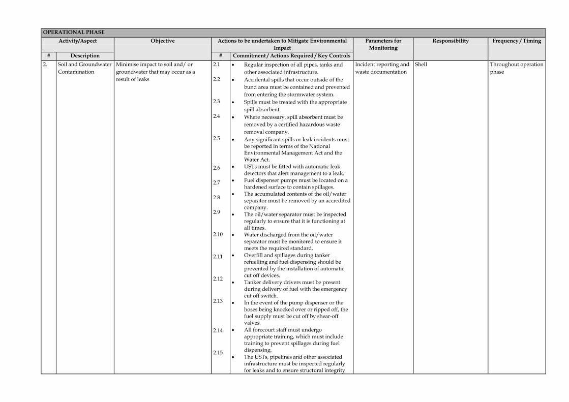
# Description # Commitment / Actions Required / Key Controls 2. Soil and Groundwater
Contamination Minimise impact to soil and/ or groundwater that may occur as a result of leaks
2.1 2.2 2.3 2.4 2.5 2.6 2.7 2.8 2.9 2.10 2.11 2.12 2.13 2.14 2.15
• Regular inspection of all pipes, tanks and other associated infrastructure.
• Accidental spills that occur outside of the bund area must be contained and prevented from entering the stormwater system.
• Spills must be treated with the appropriate spill absorbent.
• Where necessary, spill absorbent must be removed by a certified hazardous waste removal company.
• Any significant spills or leak incidents must be reported in terms of the National Environmental Management Act and the Water Act.
• USTs must be fitted with automatic leak detectors that alert management to a leak.
• Fuel dispenser pumps must be located on a hardened surface to contain spillages.
• The accumulated contents of the oil/water separator must be removed by an accredited company.
• The oil/water separator must be inspected regularly to ensure that it is functioning at all times.
• Water discharged from the oil/water separator must be monitored to ensure it meets the required standard.
• Overfill and spillages during tanker refuelling and fuel dispensing should be prevented by the installation of automatic cut off devices.
• Tanker delivery drivers must be present during delivery of fuel with the emergency cut off switch.
• In the event of the pump dispenser or the hoses being knocked over or ripped off, the fuel supply must be cut off by shear-off valves.
• All forecourt staff must undergo appropriate training, which must include training to prevent spillages during fuel dispensing.
• The USTs, pipelines and other associated infrastructure must be inspected regularly for leaks and to ensure structural integrity
Incident reporting and waste documentation
Shell Throughout operation phase

OPERATIONAL PHASE Activity/Aspect Objective Actions to be undertaken to Mitigate Environmental
Impact Parameters for
Monitoring Responsibility Frequency / Timing
# Description # Commitment / Actions Required / Key Controls 2. Soil and Groundwater
Contamination Minimise impact to soil and/ or groundwater that may occur as a result of leaks
2.16 2.17 2.18 2.19 2.20 2.21 2.22 2.23
• A closed coupling must be used when fuel is being transferred from the bulk delivery vehicle to the USTs.
• An Emergency Response Plan must be in place for the site, this must clearly describe emergency procedures and include emergency contact numbers.
• If contamination or leakage is detected, Shell’s Emergency Response Plan must be followed.
• Following a leak or accidental spill, a remediation plan must be compiled and executed.
• Accidental spills that may occur on the forecourt must be cleaned up immediately using a spill absorbent, which must then be removed by a licenced contractor.
• Fuel stock must be monitored on a daily basis and these records must be kept on site
• USTs must have corrosion protection. • Inspection wells will be installed within the
UST containment area, at all four corners of the containment area. These wells must be inspected on a monthly basis so that leaks can be detected early.
Emergency Response Plan Remediation Plan
Throughout operation phase
3. Traffic associated with the bulk delivery of diesel
Reduce any traffic congestion.
3.1 3.2
• Delivery times should be scheduled so that they do not conflict with other deliveries/ removals.
• There is to be sufficient turning space for delivery vehicles.
Incident reporting Shell Throughout operation phase
4. Air Quality Minimize impact on Air Quality 4.1 4.2 4.3
• USTs to be fitted with breather pipes. • Vent pipes to be fitted such that they face
away from the neighbouring residential areas.
• All Shell delivery vehicles will be adequately maintained to reduce exhaust emissions.
Visual inspection Shell Throughout operation phase

OPERATIONAL PHASE Activity/Aspect Objective Actions to be undertaken to Mitigate Environmental
Impact Parameters for
Monitoring Responsibility Frequency / Timing
# Description # Commitment / Actions Required / Key Controls 5. Employment Creation Maximize employment benefits 5.1
5.2 5.3 5.4
• All recruitment must be in-line with Shell’s Employment Equity Policy.
• The policy will also promote the employment of women to ensure that gender equality is attained as defined in the Employment Equity Act No 55 of 1998.
• Where possible, priority should be given to job seekers from the local area.
• Shell must build the capacity of employees through development plans, technical, health and safety training and provide them with relevant training certificates.
Shell’s Employment Equity Policy Certificates
Shell Throughout operation phase
6. Noise Minimize noise pollution 6.1 6.2 6.3 6.4 6.5
• A grievance procedure will be established whereby noise complaints can be received, recorded and responded to appropriately.
• Equipment such as mechanical equipment, extraction fans, refrigerators that are fitted with noise reduction facilities (e.g. side flaps, silencers etc) must be used as per operating instructions and maintained properly.
• Noise levels should comply with the SANS Code of Practice 100103 – 0994 (recommended noise levels).
• Local by-laws for noise levels must be adhered to.
• Noise, especially at night, should be kept to a minimum.
Grievance Procedure Shell Throughout operation phase
7. Visual Minimize visual impact associated with the day to day operations
7.1 7.2 7.3
• Litter and waste should be effectively managed to avoid visual problems in the area.
• Buildings and landscaping should receive on-going maintenance to avoid visual decay.
• Buildings and landscaping should receive on-going maintenance to avoid visual decay.
Grievance Procedure Visual inspection
Shell Throughout operation phase

ENVIRONMENTAL RESOURCES MANAGEMENT SHELL SOUTH AFRICA MARKETING (PTY) LTD
26
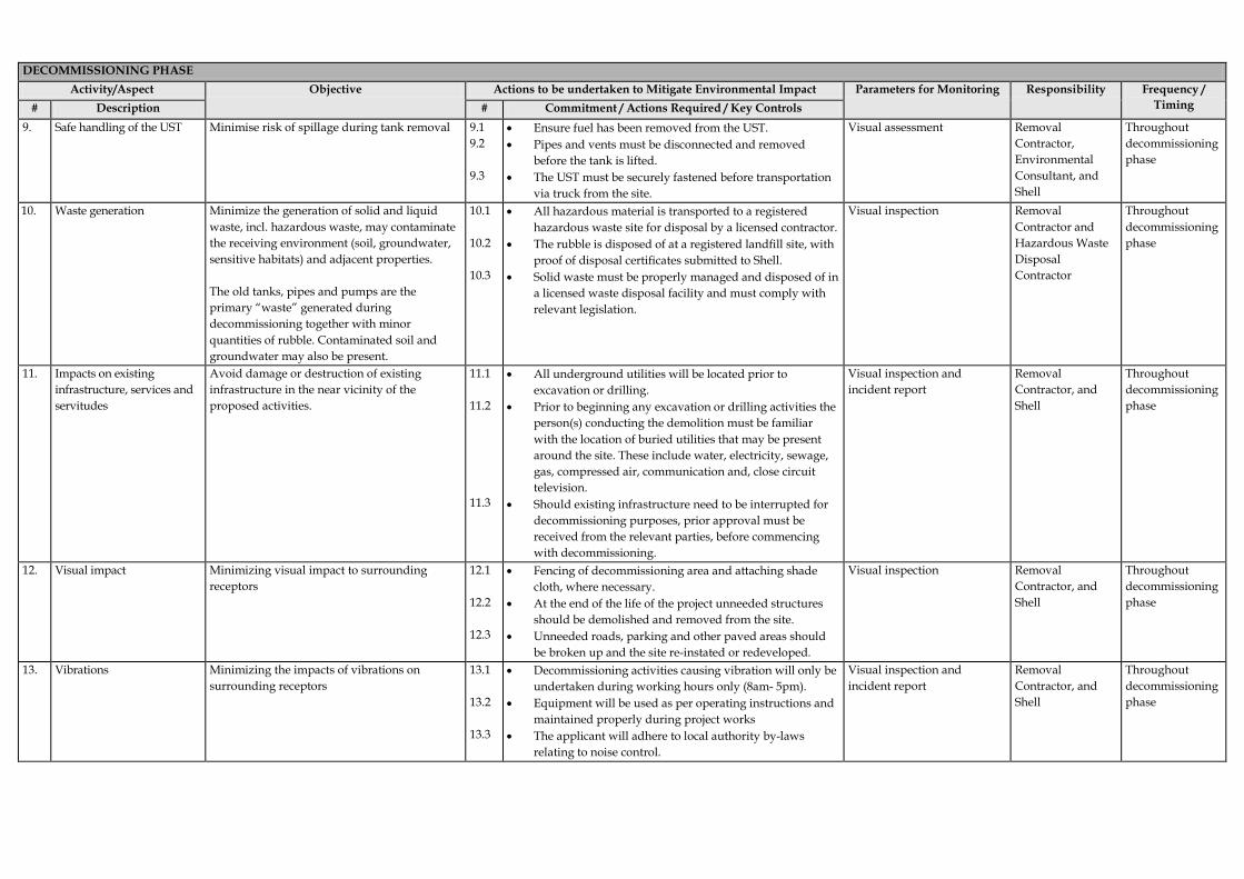
5.4 DECOMMISSIONING PHASE
A decommissioning EMPr has been included below. It must however be noted that this EMPr must be updated prior to decommissioing since a significant amount of time would have lapse by the time the service station is decommissioned. Shell must liase with DEA&DP prior to decommissioning to confirm decommissioning requirements. A detailed rehabilitation plan should also be developed prior to decommissioning of the tank area.

DECOMMISSIONING PHASE Activity/Aspect Objective Actions to be undertaken to Mitigate Environmental Impact Parameters for Monitoring Responsibility Frequency /
Timing # Description # Commitment / Actions Required / Key Controls 1. Update EMPr Ensure that the EMPr is up-to-date and
appropriate for the decommissioining task 1.1 1.2 1.3 1.4
• Ensure that the up-dated and approved EMPr is available on site.
• Ensure local environmental authorities (DEA&DP) have been informed about the decommissioning activities.
• Ensure that equipment is in place to meet EMPr and excavation plan requirements.
• Signed commitment from any sub-contractors to compliance with EMPr.
Copy of signed EMPr is available on site
Shell and Contractor
Prior to decommissioning phase
2. Traffic impacts associated with the UST removal and required machinery.
Manage any potential traffic congestion. 2.1 2.2 2.3 2.4 2.5
• Co-ordination of movement of vehicles on and off site to reduce risks and prevent congestion on roads in the vicinity of the site.
• No vehicles or machinery should be serviced or refuelled onsite.
• Peak traffic hours should be avoided. • Large vehicle turning must take place onsite and not in
the adjacent roads. • In cases where activities may obstruct traffic, local traffic
officials must be contacted.
Incident Report Contractor Throughout decommissioning phase
3. Noise impacts associated with decommissioning activities.
Manage any potential noise impacts. 3.1 3.2 3.3 3.4 3.5 3.6
• Informing surrounding businesses about the decommissioning and the expected duration thereof.
• Decommissioning activities to occur during working hours only (8am- 5pm).
• Contractors to be conscious of the noise generated during their decommissioning activities, and should limit excessive noise wherever possible.
• Where possible, decommissioning equipment should be installed with silencers.
• Ear plugs and other applicable Personal Protection Equipment must be used by workers onsite, as required.
• The applicant will adhere to local authority by-laws relating to noise control.
Incident Report Contractor and/or Shell
Throughout decommissioning phase
4. Refuse (refers to all general refuse).
Limit the potential for site pollution and the accumulation of refuse materials on site.
4.1 4.2 4.3 4.4
• Additional covered bins must be made available on site. • All refuse must be removed from site by the contractor
and disposed of at a registered facility. • Daily inspection must be undertaken of the proposed site
and immediate surrounds. • All excavation rubble must be collected into a skip and
disposed of, as and when required.
Visual inspection
Contractor and/ or Shell
Throughout decommissioning phase
DECOMMISSIONING PHASE Activity/Aspect Objective Actions to be undertaken to Mitigate Environmental Impact Parameters for Monitoring Responsibility Frequency /
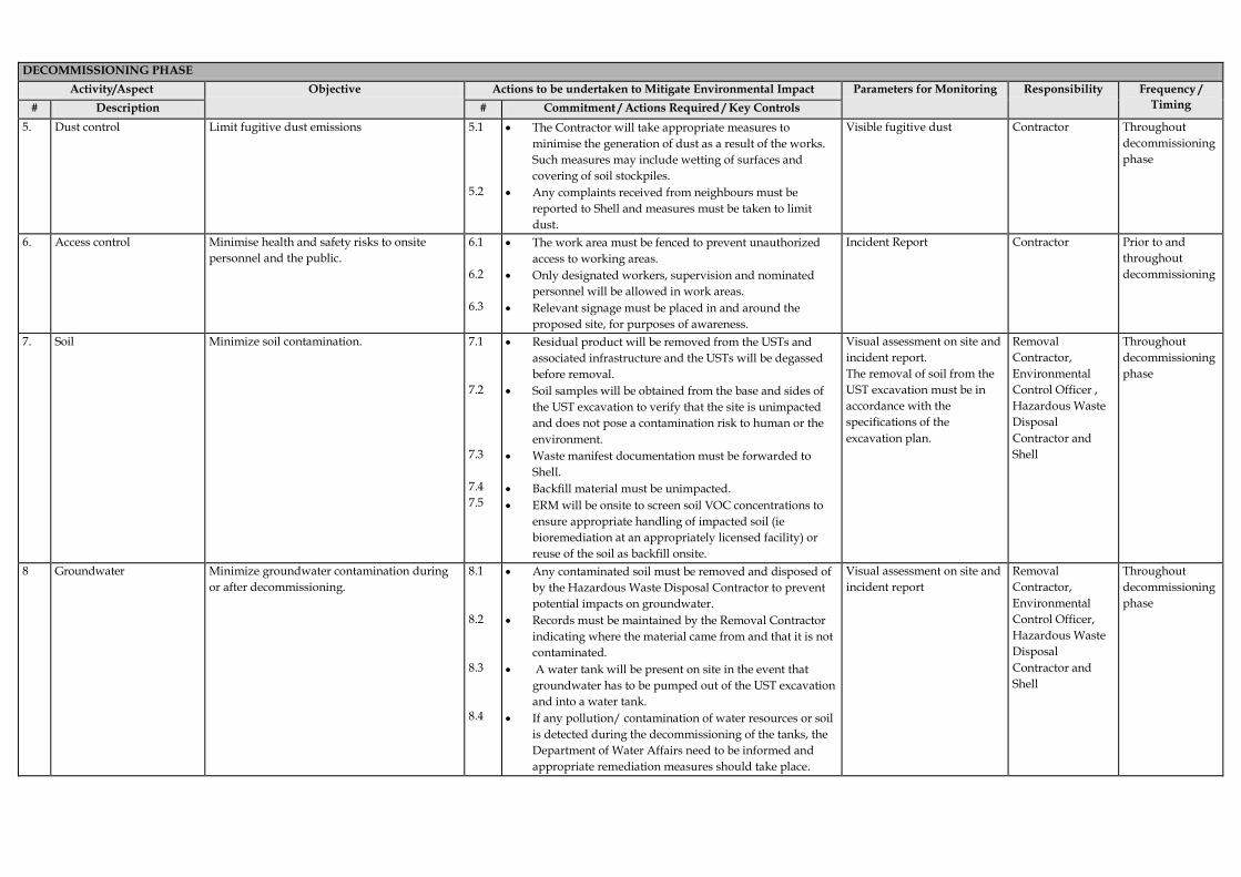
Timing # Description # Commitment / Actions Required / Key Controls 5. Dust control Limit fugitive dust emissions 5.1
5.2
• The Contractor will take appropriate measures to minimise the generation of dust as a result of the works. Such measures may include wetting of surfaces and covering of soil stockpiles.
• Any complaints received from neighbours must be reported to Shell and measures must be taken to limit dust.
Visible fugitive dust Contractor Throughout decommissioning phase
6. Access control Minimise health and safety risks to onsite personnel and the public.
6.1 6.2 6.3
• The work area must be fenced to prevent unauthorized access to working areas.
• Only designated workers, supervision and nominated personnel will be allowed in work areas.
• Relevant signage must be placed in and around the proposed site, for purposes of awareness.
Incident Report Contractor Prior to and throughout decommissioning
7. Soil Minimize soil contamination. 7.1 7.2 7.3 7.4 7.5
• Residual product will be removed from the USTs and associated infrastructure and the USTs will be degassed before removal.
• Soil samples will be obtained from the base and sides of the UST excavation to verify that the site is unimpacted and does not pose a contamination risk to human or the environment.
• Waste manifest documentation must be forwarded to Shell.
• Backfill material must be unimpacted. • ERM will be onsite to screen soil VOC concentrations to
ensure appropriate handling of impacted soil (ie bioremediation at an appropriately licensed facility) or reuse of the soil as backfill onsite.
Visual assessment on site and incident report. The removal of soil from the UST excavation must be in accordance with the specifications of the excavation plan.
Removal Contractor, Environmental Control Officer , Hazardous Waste Disposal Contractor and Shell
Throughout decommissioning phase
8 Groundwater Minimize groundwater contamination during or after decommissioning.
8.1 8.2 8.3 8.4
• Any contaminated soil must be removed and disposed of by the Hazardous Waste Disposal Contractor to prevent potential impacts on groundwater.
• Records must be maintained by the Removal Contractor indicating where the material came from and that it is not contaminated.
• A water tank will be present on site in the event that groundwater has to be pumped out of the UST excavation and into a water tank.
• If any pollution/ contamination of water resources or soil is detected during the decommissioning of the tanks, the Department of Water Affairs need to be informed and appropriate remediation measures should take place.
Visual assessment on site and incident report
Removal Contractor, Environmental Control Officer, Hazardous Waste Disposal Contractor and Shell
Throughout decommissioning phase
DECOMMISSIONING PHASE Activity/Aspect Objective Actions to be undertaken to Mitigate Environmental Impact Parameters for Monitoring Responsibility Frequency /
Timing # Description # Commitment / Actions Required / Key Controls 9. Safe handling of the UST Minimise risk of spillage during tank removal 9.1
9.2 9.3
• Ensure fuel has been removed from the UST. • Pipes and vents must be disconnected and removed
before the tank is lifted. • The UST must be securely fastened before transportation
via truck from the site.
Visual assessment Removal Contractor, Environmental Consultant, and Shell
Throughout decommissioning phase
10. Waste generation Minimize the generation of solid and liquid waste, incl. hazardous waste, may contaminate the receiving environment (soil, groundwater, sensitive habitats) and adjacent properties. The old tanks, pipes and pumps are the primary “waste” generated during decommissioning together with minor quantities of rubble. Contaminated soil and groundwater may also be present.
10.1 10.2 10.3
• All hazardous material is transported to a registered hazardous waste site for disposal by a licensed contractor.
• The rubble is disposed of at a registered landfill site, with proof of disposal certificates submitted to Shell.
• Solid waste must be properly managed and disposed of in a licensed waste disposal facility and must comply with relevant legislation.
Visual inspection
Removal Contractor and Hazardous Waste Disposal Contractor
Throughout decommissioning phase
11. Impacts on existing infrastructure, services and servitudes
Avoid damage or destruction of existing infrastructure in the near vicinity of the proposed activities.
11.1 11.2 11.3
• All underground utilities will be located prior to excavation or drilling.
• Prior to beginning any excavation or drilling activities the person(s) conducting the demolition must be familiar with the location of buried utilities that may be present around the site. These include water, electricity, sewage, gas, compressed air, communication and, close circuit television.
• Should existing infrastructure need to be interrupted for decommissioning purposes, prior approval must be received from the relevant parties, before commencing with decommissioning.
Visual inspection and incident report
Removal Contractor, and Shell
Throughout decommissioning phase
12. Visual impact Minimizing visual impact to surrounding receptors
12.1 12.2 12.3
• Fencing of decommissioning area and attaching shade cloth, where necessary.
• At the end of the life of the project unneeded structures should be demolished and removed from the site.
• Unneeded roads, parking and other paved areas should be broken up and the site re-instated or redeveloped.
Visual inspection Removal Contractor, and Shell
Throughout decommissioning phase
13. Vibrations Minimizing the impacts of vibrations on surrounding receptors
13.1 13.2 13.3
• Decommissioning activities causing vibration will only be undertaken during working hours only (8am- 5pm).
• Equipment will be used as per operating instructions and maintained properly during project works
• The applicant will adhere to local authority by-laws relating to noise control.
Visual inspection and incident report
Removal Contractor, and Shell
Throughout decommissioning phase

ENVIRONMENTAL RESOURCES MANAGEMENT SHELL SA MARKETING (PTY) LTD
Table 5.1 Emergency Contact Numbers (To be completed by the PMC)
Organisation: Contact Number: Shell:
PMC:
HWDC:
Provincial Dept. of Environmental Affairs:
Department: Water Affairs:
Name of the Municipality:
Fire Department:
Emergency Number:
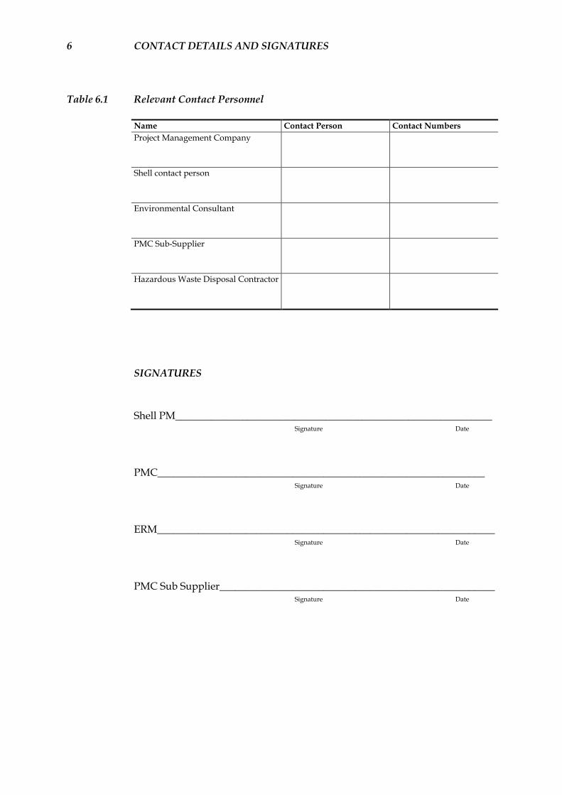
6 CONTACT DETAILS AND SIGNATURES
Table 6.1 Relevant Contact Personnel
Name Contact Person Contact Numbers Project Management Company
Shell contact person
Environmental Consultant
PMC Sub-Supplier
Hazardous Waste Disposal Contractor
SIGNATURES Shell PM_____________________________________________________________ Signature Date
PMC_______________________________________________________________ Signature Date
ERM_________________________________________________________________ Signature Date
PMC Sub Supplier_____________________________________________________ Signature Date