Embed Size (px)
Citation preview
FINAL REPORT MAY 2017
Siddhi Green Excellence Pvt. Ltd., Ankleshwar Page 1 of 220
FOR PROPOSED NEW UNITFOR MANUFACTURING OF AGROCHEMICALS &
SPECIALTY CHEMICALS
-: PROPONENT :-
GHARDA CHEMICALS LTD.
At Plot no. C-393 to 396, Sayakha Industrial Estate,Ta. Vagra, District Bharuch - 393 130 Gujarat State, India
Baseline Study Period : March 2016 to May 2016EIA Consultant Organization & Analytical Laboratory for Baseline Studies
GPCB recognizedEnv. Auditors
NABET accredited Category AEIA Consultant Organization
MoEF&CC recognized EnvironmentalLaboratory under EPA 1986
FDA Approved PublicTesting Laboratory
Regd. Off. : “Kamal Arcade – The Vertical Sunclock”, Comm. Plot No. C-3/3, Near SBI Ind. Branch, G.I.D.C.,Ankleshwar – 393 002 Dist. Bharuch, Gujarat State, India
Telefax : 02646 224805, 223805 E-Mail: [email protected] www.siddhigreen.com
FINAL REPORT OF
ENVIRONMENTAL IMPACT ASSESSMENT &EMP
WITH RISK ASSESSMENT & DMP REPORT
FINAL Environmental Impact Assessment (EIA) – EMP with Risk Assessment & DMP Report
For proposed Agrochemicals & Specialty Chemicals manufacturing unit of GHARDA CHEMICALS LTD.at Plot No. C-393 to 396, Sayakha GIDC Industrial Estate, Tal – Vagra, Dist - Bharuch, State – Gujarat, India
Contents
Siddhi Green Excellence Pvt. Ltd., Ankleshwar Page 27 of 220
4.8.3 Basis of Computer simulation using ISCST3 Air Dispersion Model.......................................1394.8.4 Process emissions.................................................................................................................1424.8.5 Dispersion Modelling for estimation of GLC of air pollutants from process emissions ..........1444.8.6 Inference for Process emissions from Dispersion modeling..................................................1454.8.7 Fugitive emissions and their control ......................................................................................1454.8.8 Prediction & Mitigation of Impacts on Ambient Noise during construction phase ..................1474.8.9 Noise prediction during construction phase within premises .................................................1484.8.10 Prediction & Mitigation of Impacts on Ambient Noise during operational phase....................149
4.9 ASSESSMENT OF WASTEWATER TREATMENT AND DISPOSAL ...............................................................1524.9.1 Process Effluent Characteristics............................................................................................1524.9.2 Treatment Concentrated Waste stream (Non-toxic, high COD, high TDS streams)..............1554.9.3 Treatment of toxic effluent stream .........................................................................................1554.9.4 Characteristics of Wastewater to be treated in ETP ..............................................................1554.9.5 Proposed Effluent Treatment Plant .......................................................................................1564.9.6 Disposal of treated effluent....................................................................................................1564.9.7 Arrangements for Performance monitoring of treatment systems .........................................157
4.10 ASSESSMENT OF IMPACTS.................................................................................................................1574.10.1 Environmental Impact Evaluation Matrices............................................................................157
5 ANALYSIS OF ALTERNATIVES..............................................................................................................1635.1 ALTERNATIVE ANALYSIS & JUSTIFICATION OF THE PROJECT ................................................................163
5.1.1 For Project selection..............................................................................................................1635.1.2 For Site selection...................................................................................................................1635.1.3 For technology / process selection ........................................................................................164
6 ENVIRONMENT MONITORING PROGRAM............................................................................................1656.1 PROPOSED ARRANGEMENTS FOR CONTINUOUS MONITORING OF EFFLUENT AND EMISSIONS ................166
7 RISK ASSESSMENT & DISASTER MANAGEMENT PLAN....................................................................1677.1 BACKGROUND ..................................................................................................................................1677.2 OBJECTIVES .....................................................................................................................................1677.3 SCOPE OF WORK..............................................................................................................................1677.4 METHODOLOGY ................................................................................................................................1677.5 HAZARD IDENTIFICATION ...................................................................................................................1687.6 STORAGE HAZARDS AND CONTROL MEASURES .................................................................................1697.7 PROCESS HAZARDS AND THEIR CONTROL MEASURES .......................................................................1727.8 OTHER HAZARDS & CONTROL ...........................................................................................................172
7.8.1 Sensitive locations around the project ...................................................................................1727.9 PROPOSED RISK REDUCTION MEASURES FOR THE PROJECT ...............................................................173
7.9.1 At design, construction & commissioning stages...................................................................1737.10 VISUALIZATION OF ACCIDENT SCENARIOS ..........................................................................................176
7.10.1 Selection of Initiating Events And Scenarios .........................................................................1767.11 CONSEQUENCE ANALYSIS .................................................................................................................179
7.11.1 Frequencies Estimation: ........................................................................................................1797.11.2 Assumptions Common for all Scenarios................................................................................1817.11.3 Summarized Table for effects of Consequences...................................................................1837.11.4 Inference of Consequence analysis ......................................................................................185
7.12 RECOMMENDATIONS .........................................................................................................................1867.12.1 Reactor area..........................................................................................................................186OPDA/PEEK Reactor runaway............................................................................................................1867.12.2 Explosive tank Storage Area .................................................................................................1877.12.3 Other Tank-farms ..................................................................................................................1877.12.4 Cylinder Storage Area ...........................................................................................................187
FINAL Environmental Impact Assessment (EIA) – EMP with Risk Assessment & DMP Report
For proposed Agrochemicals & Specialty Chemicals manufacturing unit of GHARDA CHEMICALS LTD.at Plot No. C-393 to 396, Sayakha GIDC Industrial Estate, Tal – Vagra, Dist - Bharuch, State – Gujarat, India
Contents
Siddhi Green Excellence Pvt. Ltd., Ankleshwar Page 28 of 220
7.12.5 General..................................................................................................................................1877.13 DISASTER MANAGEMENT PLAN..........................................................................................................188
7.13.1 Objectives of DMP.................................................................................................................1897.13.2 Components of DMP .............................................................................................................1897.13.3 Emergency Response ...........................................................................................................189
8 PROJECT BENEFITS...............................................................................................................................1928.1 PROJECT BENEFITS DURING CONSTRUCTION PHASE ..........................................................................1938.2 PROJECT BENEFITS DURING OPERATIONAL PHASE .............................................................................193
9 ENVIRONMENTAL COST BENEFIT ANALYSIS.....................................................................................194
10 ENVIRONMENTAL MANAGEMENT PLAN .............................................................................................19510.1 NEED FOR ENVIRONMENTAL MANAGEMENT PLANNING .......................................................................195
10.1.1 Objectives of Environmental Management Plan....................................................................19510.2 ENVIRONMENTAL MANAGEMENT SYSTEM...........................................................................................195
10.2.1 Environmental Policy .............................................................................................................19510.2.2 Environment, Health and Safety (EHS) Cell ..........................................................................195
10.3 EMP FOR CONSTRUCTION & ERECTION PHASE OF THE PROJECT......................................................19610.3.1 EMP for Impacts on Air Environment ....................................................................................19610.3.2 EMP for Impacts on Water Environment ...............................................................................19710.3.3 EMP for Impacts on Noise levels...........................................................................................19710.3.4 EMP for Impacts on Land Environment .................................................................................19710.3.5 EMP for impacts on Human (social) Environment .................................................................19710.3.6 EMP for impacts on Ecological Environment.........................................................................19710.3.7 EMP for use of fuel resources ...............................................................................................197
10.4 EMP FOR OPERATIONAL PHASE OF THE PROJECT ............................................................................19810.4.1 EMP for Stack Emissions ......................................................................................................19810.4.2 EMP for fugitive emission of chemical vapors .......................................................................19810.4.3 Odour Control ........................................................................................................................199
10.5 EMP FOR WATER ENVIRONMENT MANAGEMENT ................................................................................20010.5.1 Water consumption................................................................................................................20010.5.2 Water conservation measures...............................................................................................20010.5.3 Wastewater generation, treatment and disposal ...................................................................200
10.6 EMP FOR IMPACTS ON NOISE LEVELS ...............................................................................................20110.7 EMP FOR IMPACTS ON LAND ENVIRONMENT ......................................................................................201
10.7.1 Hazardous/Non Hazardous Waste Management ..................................................................20110.7.2 Fly ash utilization...................................................................................................................20210.7.3 EMP for impacts on Human (social) Environment .................................................................202
10.8 EMP FOR IMPACTS ON HUMAN (ECONOMICAL) ENVIRONMENT ............................................................20210.9 EMP FOR IMPACTS ON ECOLOGICAL ENVIRONMENT ...........................................................................20310.10 EMP FOR USE OF FUEL RESOURCES..................................................................................................20310.11 ENVIRONMENT MANAGEMENT THROUGH HOUSEKEEPING....................................................................20310.12 OCCUPATIONAL SAFETY AND HAZARD MANAGEMENT .........................................................................203
10.12.1 Control of Exposure levels of hazardous chemicals ..............................................................20310.12.2 Occupational Health centre (OHC)........................................................................................20410.12.3 Onsite Medical treatment.......................................................................................................20410.12.4 Medical examination practice ................................................................................................20410.12.5 Fund allocation for Occupational Health and Safety measures .............................................205
10.13 GREENBELT DEVELOPMENT ..............................................................................................................20610.13.1 Green belt development proposal .........................................................................................20610.13.2 Plantation areas.....................................................................................................................20610.13.3 Action plan for Green belt development ................................................................................20710.13.4 Road side Plantation .............................................................................................................210
FINAL Environmental Impact Assessment (EIA) – EMP with Risk Assessment & DMP Report
For proposed Agrochemicals & Specialty Chemicals manufacturing unit of GHARDA CHEMICALS LTD.at Plot No. C-393 to 396, Sayakha GIDC Industrial Estate, Tal – Vagra, Dist - Bharuch, State – Gujarat, India
Chapter 7. Risk Assessment & Disaster Management Plan
Siddhi Green Excellence Pvt. Ltd., Ankleshwar Page 167 of 220
77 RRIISSKK AASSSSEESSSSMMEENNTT && DDIISSAASSTTEERR MMAANNAAGGEEMMEENNTT PPLLAANN
7.1 BACKGROUNDRisk Assessment is a management tool for determining the hazards and risk associated with the various activities ofa project and compute the damage potential of these hazards to life and property. Risk Assessment provides basisfor determining the safety measures required to eliminate, minimize and control the risks as detailed in DisasterManagement Plan (DMP) to handle onsite and offsite emergencies.In Chemical Industry, Risk Assessment is carried out for the various hazards involved in storage and handling ofhazardous raw materials, intermediates and finished products as well as for the manufacturing processes used bythe unit.
7.2 OBJECTIVESThe given study was focused to fulfill the following objectives : Identification of safety areas Identification of process and storage hazards Visualization of maximum credible accident (MCA) scenarios Consequence analysis of scenarios Determination of quantities released, impact zones Estimation of damage distances for the accidental release scenarios with recourse to Maximum Credible
Accident (MCA) analysis Preventive and control measures required for reducing the risk factors Delineation of Disaster Management Plan
7.3 SCOPE OF WORKBased on the objectives as defined above, the scope of work for the given study has been framed as under :
1. Hazard Identification General description of project Study of manufacturing activities Study of plant facilities and layout Hazardous inventory Associated process and storage hazards Safety measures as proposed by the proponent
2. Hazard Assessment Identification of MCA and worst case scenarios using standard techniques Consequence analysis of selected scenarios using EFFECT model on ALOHA software
3. Determination of risk reduction measures4. Preparation of DMP5. Recommendations
7.4 METHODOLOGYFollowing methodology has been followed for given Risk Assessment Study as described in “Guidelines forChemical Process Quantitative Risk Assessment” by CCPS with the help of frequency data from “Purple Book”,2008.
The guidelines given by SEAC as well as Technical Guidance Manual of MoEFCC have also been followed. Collecting Input data about Process,Inventories and Site conditions Hazard Identification Defining the Potential Accident Scenarios Evaluation of Consequences and Estimation of Accident Frequencies Estimate the Impacts
FINAL Environmental Impact Assessment (EIA) – EMP with Risk Assessment & DMP Report
For proposed Agrochemicals & Specialty Chemicals manufacturing unit of GHARDA CHEMICALS LTD.at Plot No. C-393 to 396, Sayakha GIDC Industrial Estate, Tal – Vagra, Dist - Bharuch, State – Gujarat, India
Chapter 7. Risk Assessment & Disaster Management Plan
Siddhi Green Excellence Pvt. Ltd., Ankleshwar Page 168 of 220
Estimate the Risk Identify and Prioritize the Risk Reduction measures.
7.5 HAZARD IDENTIFICATIONThis is important and critical step in risk assessment. It is critical because Hazard omitted is hazard not analyzed.The tools used for identification are experience, detailed process knowledge, engineering codes, checklist, HAZOPsetc.The unit handles hazardous materials and have a defined and organized hazard control and prevention system inplace. The following statutory compliances are applicable to the unit :
1. Gujarat Factories Rules, 19632. Manufacture, Storage and Import of Hazardous Chemicals (Amended) Rules, 20003. Petroleum Act, 1934, Petroleum Rules, 20024. Gas Cylinder Rules, 2004
The hazards involved in the process are due to major two factors, Process conditions: High pressure, High temperature Material handled: Flammable, Toxic
The hazards of the materials are identified from the MSDS. The major hazards are toxic, fire and explosion.Flammable material will form pool on leakage and this pool can sustain a pool fire. In case of toxic material thevapors evaporated from pool disperse in downstream direction and may cause problem for people in process units /buildings
The inventory of hazardous material in the storage area is significantly larger than the inventory involved in theprocess, hence most of the scenarios selected for the consequences calculations are from storage vessels. Thesevessels are located near the respective plants only. The flange joints pump seals, maintenance activities arepotential sources of leak. These scenarios are identified in pumping areas and/or in reactor areas.
One scenario considered for all is ‘Catastrophic Failure’, which is the worst case (WC) and frequency of which isvery rare in the lifetime of the plant. Hence most credible accident scenarios (MCA) are also considered primarilyleaks from tanks, vessels or pipelines.
Normally all vessels or tanks have following connections
Inlet Pipe, Outlet Pipe, Level indication connections, Vent pipe, Minimum Flow line(If pump is at outlet),Pressure indication connection
Leak in the vessel or leak from the flange joints of these connections is possible. The leak through flangefailure is considered from 50% of flange perimeter and accordingly equivalent area is calculated. This areais approximated to hole of 10mm or 10% of pipe diameter. The small bore pipes less than 2” is consideredfull bore leak.
For our analysis we consider leak from pipeline which are at pump discharge, hence it shall be pressurizedand feeding to reactor or storage.
Chlorine Hazard Chlorine is toxic gas. Chlorine gas is a respiratory irritant. The distinctive odor similar to household bleach is
detectable easily at very low concentrations, It is heavier than air. This makes it difficult to disperse. Hence usually a chlorine cloud travels longer
distances. It is normally stored at atmospheric temperature as liquid equilibrium with vapors. Hence container pressure
will be vapor pressure at atmospheric pressure.
FINAL Environmental Impact Assessment (EIA) – EMP with Risk Assessment & DMP Report
For proposed Agrochemicals & Specialty Chemicals manufacturing unit of GHARDA CHEMICALS LTD.at Plot No. C-393 to 396, Sayakha GIDC Industrial Estate, Tal – Vagra, Dist - Bharuch, State – Gujarat, India
Chapter 7. Risk Assessment & Disaster Management Plan
Siddhi Green Excellence Pvt. Ltd., Ankleshwar Page 169 of 220
Thionyl Chloride Hazard Thionyl Chloride is highly toxic chemical. It vigorously reacts with water liberation SO2 and HCL. It is corrosive. The piping & vessels should be suitable to handle corrosive material.
Benzene/Toluene/ Xylene Hazard BTX are highly flammable. Benzene is known carcinogen.
SO2 Hazards Sulfur dioxide’s primary health concern is that it will attack the lungs, mucous membranes and the eyes,
and the skin leading to severe injury or death. Sulfur dioxide’s odor is strong enough that it can be detected at levels around 3-5 ppm Never use water on a leaking sulfur dioxide container; this can cause rapid corrosion of the metals making
the leak worse
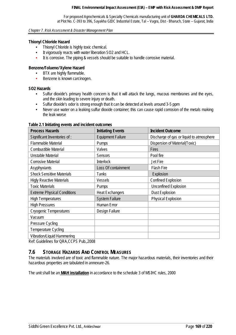
Table 2.1 Initiating events and incident outcomesProcess Hazards Initiating Events Incident OutcomeSignificant Inventories of : Equipment Failure Discharge of gas or liquid to atmosphereFlammable Material Pumps Dispersion of Material(Toxic)Combustible Material Valves FiresUnstable Material Sensors Pool fireCorrosive Material Interlock Jet FireAsyphyxiants Loss Of containment Flash FireShock Sensitive Materials Tanks ExplosionHigly Reactive Materials Vessels Confined ExplosionToxic Materials Pumps Unconfined ExplosionExtreme Physical Conditions Heat Exchangers Dust ExplosionHigh Temperatures System Failure Physical ExplosionHigh Pressures Human ErrorCryogenic Temperatures Design FailureVacuumPressure CyclingTemperature CyclingVibration/Liquid Hammering
Ref: Guidelines for QRA,CCPS Pub.,2008
7.6 STORAGE HAZARDS AND CONTROL MEASURESThe materials involved are of toxic and flammable nature. The major hazardous materials, their inventories and theirhazardous properties are tabulated in annexure-26.
The unit shall be an MAH installation in accordance to the schedule 3 of MSIHC rules, 2000
FINAL Environmental Impact Assessment (EIA) – EMP with Risk Assessment & DMP Report
For proposed Agrochemicals & Specialty Chemicals manufacturing unit of GHARDA CHEMICALS LTD.at Plot No. C-393 to 396, Sayakha GIDC Industrial Estate, Tal – Vagra, Dist - Bharuch, State – Gujarat, India
Chapter 7. Risk Assessment & Disaster Management Plan
Siddhi Green Excellence Pvt. Ltd., Ankleshwar Page 170 of 220
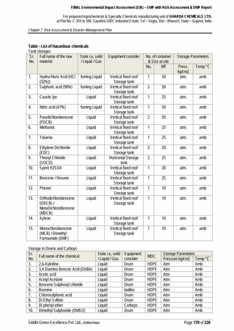
Table - List of Hazardous chemicalsTank storagesSr.No.
Full name of the rawmaterial
State i.e, solid/ Liquid / Gas
Equipment consider No. of container& Size at site
Storage Parameters
No. MT Press.kg/cm2
Temp °C
1. Hydrochloric Acid (HCl(32%))
fuming Liquid Vertical fixed roofStorage tank
1 50 atm. amb
2. Sulphuric acid (98%) fuming Liquid Vertical fixed roofStorage tank
2 50 atm. amb
3. Caustic lye Liquid Vertical fixed roofStorage tank
1 25 atm. amb
4. Nitric acid (67%) fuming Liquid Vertical fixed roofStorage tank
1 50 atm. amb
5. Paradichlorobenzene(PDCB)
Liquid Vertical fixed roofStorage tank
2 50 atm. amb
6. Methanol Liquid Vertical fixed roofStorage tank
1 25 atm. amb
7. Toluene Liquid Vertical fixed roofStorage tank
1 25 atm. amb
8. Ethylene Dichloride(EDC)
Liquid Vertical fixed roofStorage tank
2 20 atm. amb
9. Thionyl Chloride(SOCl2)
Liquid Horizontal Storagetank
2 25 atm. amb
10. Spent H2SO4 Liquid Vertical fixed roofStorage tank
1 20 atm. amb
11. Benzene / Hexane Liquid Vertical fixed roofStorage tank
1 25 atm. amb
12. Phenol Liquid Vertical fixed roofStorage tank
1 10 atm. amb
13. Orthodichlorobenzene(ODCB) /MetaDichloroBenzene(MDCB)
Liquid Vertical fixed roofStorage tank
1 10 atm. amb
14. Xylene Liquid Vertical fixed roofStorage tank
1 10 atm. amb
15. Monochlorobenzene(MCB) / DimethylFormamide (DMF)
Liquid Vertical fixed roofStorage tank
1 10 atm. amb
Storage in Drums and CarboysSr.No. Full name of the chemical State i.e, solid
/ Liquid / GasEquipmentconsider MOC Storage Parameters
Pressure kg/cm2 Temp °C1. 2,6-Xyledine Liquid Drum HDPE Atm Amb2. 3,4 Diamino Benzoic Acid (DABA) Liquid Drum HDPE Atm Amb3. Acetic acid Liquid Drum HDPE Atm Amb4. Acetyl Acetone Liquid Drum HDPE Atm Amb5. Benzene Sulphonyl chloride Liquid Drum HDPE Atm Amb6. Bromine Liquid bottles HDPE Atm Amb7. Chlorosulphonic acid Liquid Drum HDPE Atm Amb8. Di Ethyl Sulfate Liquid Drum HDPE Atm Amb9. Di phenyl ether Liquid Carboys HDPE Atm Amb10. Dimethyl Sulphoxide (DMSO) Liquid Drum HDPE Atm Amb
FINAL Environmental Impact Assessment (EIA) – EMP with Risk Assessment & DMP Report
For proposed Agrochemicals & Specialty Chemicals manufacturing unit of GHARDA CHEMICALS LTD.at Plot No. C-393 to 396, Sayakha GIDC Industrial Estate, Tal – Vagra, Dist - Bharuch, State – Gujarat, India
Chapter 7. Risk Assessment & Disaster Management Plan
Siddhi Green Excellence Pvt. Ltd., Ankleshwar Page 171 of 220
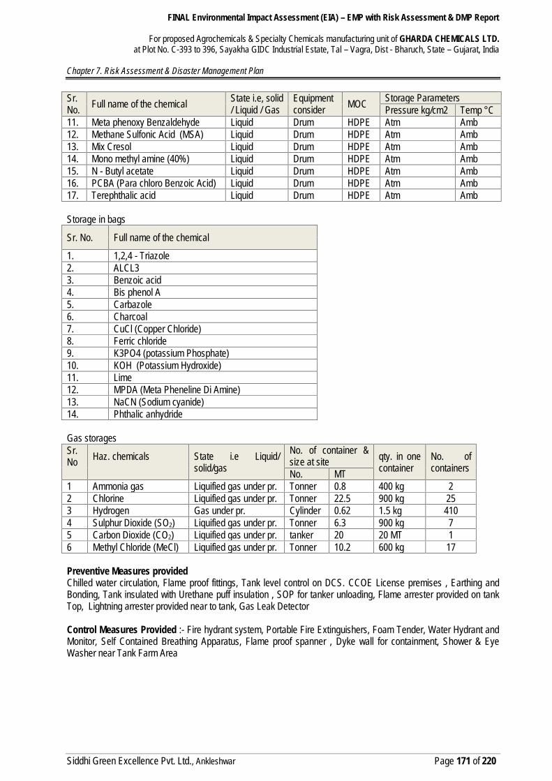
Sr.No. Full name of the chemical State i.e, solid
/ Liquid / GasEquipmentconsider MOC Storage Parameters
Pressure kg/cm2 Temp °C11. Meta phenoxy Benzaldehyde Liquid Drum HDPE Atm Amb12. Methane Sulfonic Acid (MSA) Liquid Drum HDPE Atm Amb13. Mix Cresol Liquid Drum HDPE Atm Amb14. Mono methyl amine (40%) Liquid Drum HDPE Atm Amb15. N - Butyl acetate Liquid Drum HDPE Atm Amb16. PCBA (Para chloro Benzoic Acid) Liquid Drum HDPE Atm Amb17. Terephthalic acid Liquid Drum HDPE Atm Amb
Storage in bags
Sr. No. Full name of the chemical
1. 1,2,4 - Triazole2. ALCL33. Benzoic acid4. Bis phenol A5. Carbazole6. Charcoal7. CuCl (Copper Chloride)8. Ferric chloride9. K3PO4 (potassium Phosphate)10. KOH (Potassium Hydroxide)11. Lime12. MPDA (Meta Pheneline Di Amine)13. NaCN (Sodium cyanide)14. Phthalic anhydride
Gas storagesSr.No Haz. chemicals State i.e Liquid/
solid/gas
No. of container &size at site qty. in one
containerNo. ofcontainersNo. MT
1 Ammonia gas Liquified gas under pr. Tonner 0.8 400 kg 22 Chlorine Liquified gas under pr. Tonner 22.5 900 kg 253 Hydrogen Gas under pr. Cylinder 0.62 1.5 kg 4104 Sulphur Dioxide (SO2) Liquified gas under pr. Tonner 6.3 900 kg 75 Carbon Dioxide (CO2) Liquified gas under pr. tanker 20 20 MT 16 Methyl Chloride (MeCl) Liquified gas under pr. Tonner 10.2 600 kg 17
Preventive Measures providedChilled water circulation, Flame proof fittings, Tank level control on DCS. CCOE License premises , Earthing andBonding, Tank insulated with Urethane puff insulation , SOP for tanker unloading, Flame arrester provided on tankTop, Lightning arrester provided near to tank, Gas Leak Detector
Control Measures Provided :- Fire hydrant system, Portable Fire Extinguishers, Foam Tender, Water Hydrant andMonitor, Self Contained Breathing Apparatus, Flame proof spanner , Dyke wall for containment, Shower & EyeWasher near Tank Farm Area
FINAL Environmental Impact Assessment (EIA) – EMP with Risk Assessment & DMP Report
For proposed Agrochemicals & Specialty Chemicals manufacturing unit of GHARDA CHEMICALS LTD.at Plot No. C-393 to 396, Sayakha GIDC Industrial Estate, Tal – Vagra, Dist - Bharuch, State – Gujarat, India
Chapter 7. Risk Assessment & Disaster Management Plan
Siddhi Green Excellence Pvt. Ltd., Ankleshwar Page 172 of 220
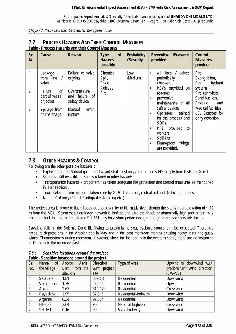
7.7 PROCESS HAZARDS AND THEIR CONTROL MEASURESTable - Process Hazards and their Control MeasuresSr.No.
Cause Reason Type ofHazardspossible
Probability/ Severity
Preventive Measuresprovided
ControlMeasuresprovided
1. Leakagefrom line /valve
Failure of valveor joints
ChemicalSpill,ToxicRelease,Fire
Low/Medium
• All lines / valvesperiodicallychecked,
• PSVs provided onreactors
• preventivemaintenance of allsafety devices
• Operators trainedfor the process andSOPs
• PPE provided toworkers
• Spill kits• Flameproof fittings
are provided.
FireExtinguisher,Fire hydrantsystemFire sprinklers,Sand buckets,First-aid andMedical facilities,LEL Sensors forearly detection.
2. Failure ofpart of vesselor jacket
Overpressureand failure ofsafety device
3. Spillage fromdrums / bags
Manual error,rupture
7.8 OTHER HAZARDS & CONTROLFollowing are the other possible hazards :
Explosion due to Natural gas – this hazard shall exist only after unit gets NG supply from GSPL or GGCL Structural failure – this hazard is related to other hazards Transportation hazards - proponent has taken adequate fire protection and control measures as mentioned
in later sections. Toxic Release from outside – taken care by GIDC fire station, mutual aid and District authorities Natural Calamity (Flood, Earthquake, lightning etc.)
The project area is prone to flash floods due to proximity to Narmada river, though the site is at an elevation of ~ 12m from the MSL. Storm water drainage network is inplace and also the floods or abnormally high precipation mayobstruct block the internal roads and SH-161 only for a short period owing to the good drainage towards the sea.
Sayakha falls in the Seismic Zone III. Owing to proximity to sea, cyclonic storms can be expected. There arepressure depressions in the Arabian sea in May and in the post monsoon months causing heavy rains and gustywinds, Thunderstorms during monsoon. However, since the location is in the western coast, there are no instancesof Tsunami in the recorded past.
7.8.1 Sensitive locations around the projectTable - Sensitive locations around the projectSr.No.
Name ofthe village
Approx. AerialDist. From thesite, km
Directionw.r.t projectsite
Type of Area Upwind or downwind w.r.tpredominant wind direction(SW-NE)
1. Saladara 1.81 359.68° Residential Downwind2. Vora samni 1.75 260.94° Residential Upwind3. Ankot 2.67 319.02° Residential Crosswind4. Dayadara 2.95 82.31° Residential-Industrial Downwind5. Argama 0.34 92.50° Residential Downwind6. NH-228 3.04 90° National highway Crosswind7. SH-161 0.16 90° State highway Downwind

FINAL Environmental Impact Assessment (EIA) – EMP with Risk Assessment & DMP Report
For proposed Agrochemicals & Specialty Chemicals manufacturing unit of GHARDA CHEMICALS LTD.at Plot No. C-393 to 396, Sayakha GIDC Industrial Estate, Tal – Vagra, Dist - Bharuch, State – Gujarat, India
Chapter 7. Risk Assessment & Disaster Management Plan
Siddhi Green Excellence Pvt. Ltd., Ankleshwar Page 173 of 220
7.9 PROPOSED RISK REDUCTION MEASURES FOR THE PROJECT7.9.1 At design, construction & commissioning stagesInbuilt safety features :-Process Safety :-The Plant shall be built as per engineering codes & standards such as ASME, applicable Indian standards (IS).Incinerator shall be provided and all hydrocarbon vents shall be directed to incinerator. This include safety valve andrupture discs discharge and normal vents.
DCS / PLC/SCADA Control System and Emergency Shutdown SystemThe plants shall be automated and controlled through DCS / PLC/SCADA system to the maximum extent possible.PLC based Emergency Shutdown system and interlocks shall be provided wherever necessary based on hazopstudies.
Defined Standard Operating Procedures Maintenance systemsStandard Operating procedures shall be followed for all critical activities like hazardous chemical tanker unloading.Every tanker unloading and loading is done in presence of operator only.
Hazardous Area ClassificationConsidering the handling of flammable and explosive materials in the process area and storage area, forminimization of fire & explosion hazard all electrical fixtures, equipments and instruments shall be classified forflammable area. The extent of hazardous area shall be as per IS 5572.
Area Segregation :- Production plant will be segregated Flame proof and Non Flame proof area . Flame prooffittings/Equipments will be provided in flame proof area.
Fire Hydrant System:- Plant premises will be covered wet fire hydrant system in addition to portable fireappliance to take any fire eventuality. Hydrant system will have hydrants, Fire Escape Hydrants & water Monitor.In addition to this mobile foam trolley will also be provided.
FINAL Environmental Impact Assessment (EIA) – EMP with Risk Assessment & DMP Report
For proposed Agrochemicals & Specialty Chemicals manufacturing unit of GHARDA CHEMICALS LTD.at Plot No. C-393 to 396, Sayakha GIDC Industrial Estate, Tal – Vagra, Dist - Bharuch, State – Gujarat, India
Chapter 7. Risk Assessment & Disaster Management Plan
Siddhi Green Excellence Pvt. Ltd., Ankleshwar Page 174 of 220
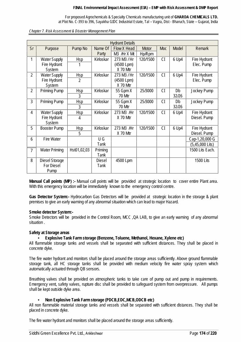
Hydrant DetailsSr Purpose Pump No Name Of
PartyFlow X Head Motor Moc Model RemarkM3 /Hr X Mt Hp/Rpm
1 Water SupplyFire Hydrant
System
Hsp Kirloskar 273 M3 / Hr(4500 Lpm)
X 70 Mtr
120/1500 CI 6 Up4 Fire HydrantElec. Pump1
2 Water SupplyFire Hydrant
System
Hsp Kirloskar 273 M3 / Hr(4500 Lpm)
X 70 Mtr
120/1500 CI 6 Up4 Fire HydrantElec. Pump2
2 Priming Pump Hsp Kirloskar 55 Gpm X70 Mtr
25/3000 CI Db32/26
Jockey Pump3
3 Priming Pump Hsp Kirloskar 55 Gpm X70 Mtr
25/3000 CI Db32/26
Jockey Pump3
4 Water SupplyFire Hydrant
System
Hsp Kirloskar 273 M3 /HrX 70 Mtr
120/1500 CI 6 Up4 Fire HydrantDiesel. Pump4
5 Booster Pump Hsp Kirloskar 273 M3 /HrX 70 Mtr
120/1500 CI 6 Up4 Fire HydrantDiesel. Pump5
6 Fire Water U GTank
Cap-1,20,000 G(5,45,000 Lits)
Water Priming Hst01,02,03 PrimingTank
1500 Lits Each.7
8 Diesel StorageFor Diesel
Pump
DieselTank
4500 Lpm 1500 Lits
Manual Call points (MP) :- Manual call points will be provided at strategic location to cover entire Plant area.With this emergency location will be immediately known to the emergency control centre.
Gas Detector System:- Hydrocarbon Gas Detectors will be provided at strategic location in the storage & plantpremises to give an early warning of any abnormal situation which can lead to major Hazard.
Smoke detector System:-Smoke Detectors will be provided in the Control Room, MCC ,QA LAB, to give an early warning of any abnormalsituation .
Safety at Storage areas Explosive Tank Farm storage (Benzene, Toluene, Methanol, Hexane, Xylene etc)
All flammable storage tanks and vessels shall be separated with sufficient distances. They shall be placed inconcrete dyke.
The fire water hydrant and monitors shall be placed around the storage areas sufficiently. Above ground flammablestorage tank, all HC storage tanks shall be provided with medium velocity fire water spray system whichautomatically actuated through QB sensors.
Breathing valves shall be provided on atmospheric tanks to take care of pump out and pump in requirements.Emergency vent, safety valves, rupture disc shall be provided to safeguard system from overpressure. All pumpsshall be kept outside dyke area.
Non Explosive Tank Farm storage (PDCB,EDC,MCB,ODCB etc)All non flammable material storage tanks and vessels shall be separated with sufficient distances. They shall beplaced in concrete dyke.
The fire water hydrant and monitors shall be placed around the storage areas sufficiently.

FINAL Environmental Impact Assessment (EIA) – EMP with Risk Assessment & DMP Report
For proposed Agrochemicals & Specialty Chemicals manufacturing unit of GHARDA CHEMICALS LTD.at Plot No. C-393 to 396, Sayakha GIDC Industrial Estate, Tal – Vagra, Dist - Bharuch, State – Gujarat, India
Chapter 7. Risk Assessment & Disaster Management Plan
Siddhi Green Excellence Pvt. Ltd., Ankleshwar Page 175 of 220
Breathing valves shall be provided on atmospheric tanks to take care of pump out and pump in requirements.Emergency vent, safety valves, rupture disc is provided to safeguard system from overpressure. All pumps are keptoutside dyke area.
Toxic/Hazardous Material Atmospheric storage (Sulfuric Acid, Nitric Acid, Thionyl Chloride, etc)All toxic/hazardous material storage tanks and vessels are separated with sufficient distances. They are placed inconcrete dike.Breathing valves are provided on atmospheric tanks to take care of pump out and pump in requirements. Emergencyvent, safety valves, rupture disc is provided to safeguard system from overpressure.All pumps are kept outside dyke area.
Common features of Storage Tanks All storage tanks shall be provided with Dyke wall to contain the chemicals in case of leakage. All tanks shall be provided with the high, very high, low, very low level alarm and interlock on DCS. All the volatile material storages will be provided with breather on the tank top to avoid pressure & vacuum
conditions. Solvent tanks will be provided with insulation as per the requirement. Continuity jumpers will be provided to
avoid static charge accumulation. Explosive and flammable tankfarms shall be constructed with full compliance with applicable rules and
regulations
8. Testing of Equipment :-All the equipments will be tested as per statutory requirement to keep them in healthy condition.
9. Lightning arrester:-Lightning arrester will be provided at tallest places on plant building and tank farm area.
10.Audit/ Inspection:-Safety inspection and audit will be carried out at fixed intervals.
General:- Total enclosed process system DCS operation plant Instrument & Plant Air System for control all parameters High level, low level, High pressure, low pressure, high temp, high flow, low flow indication and cut off
interlocking provided on storage as well as process reactors Safety valve, rupture disk provided on reactor and pressure storage tanks. Static earthling and electric earthling (Double) will be provided. Jumpers for static earthling on pipeline flanges of flammable chemical provided Flame proof light fitting installed where ever it is required. Emergency handling equipments like SCBA sets, Fire extinguishers, Gas mask, PPEs, Chlorine emergency
Kit, chlorine hood, caustic pit, Air line respirator, provided. Storage tank area is away from the process plant and Separation Distance has been maintained. Dyke wall provided to all above ground storage tanks, collection pit with valve provided. Flame arrestor with breather valve is installed on flammable material storage tank vent Lightening arrestor on all chimneys and building provided. Fencing and caution notes and hazard identification boards displayed Only authorized person are permitted in storage tank farm area. Safety permit for hazardous material loading unloading is prepared and implemented. Static earthling provision is made at all loading unloading Points of flammable chemical storage tank farm
area. TREM CARD provided to all transporters and trained for transportation Emergency of Hazardous
chemicals. Fire hydrant system and water sprinkler system installed at tank farm area.
FINAL Environmental Impact Assessment (EIA) – EMP with Risk Assessment & DMP Report
For proposed Agrochemicals & Specialty Chemicals manufacturing unit of GHARDA CHEMICALS LTD.at Plot No. C-393 to 396, Sayakha GIDC Industrial Estate, Tal – Vagra, Dist - Bharuch, State – Gujarat, India
Chapter 7. Risk Assessment & Disaster Management Plan
Siddhi Green Excellence Pvt. Ltd., Ankleshwar Page 176 of 220
Caution note, safety Posters, stickers and emergency preparedness plan will be displayed. Emergency facilities and medical emergency facilities are available at site. Occupational Health centre
facility generated at factory premises and paramedical staff is available round the clock. Wind direction indicators are provided. Tele Communication system and mobile phone will be used in case of emergency situations for
communication. Emergency siren installed at main gate as well as in all plant. Training programme are being conducted regularly and induction training shall be provided to all employees
on chemical safety and process safety.
7.10 VISUALIZATION OF ACCIDENT SCENARIOSBased on the inventory, physical and chemical properties as well as the activities associated with storage andhandling of hazardous chemicals, the largest potential hazard inventories are considered. Different releasescenarios are visualized for these inventories and short-listed for carrying out the consequence analysis.
One scenario considered for all is ‘Catastrophic Failure’, which is the worst case (WC) and frequency of which isvery rare in the lifetime of the plant. Hence most credible accident scenarios (MCA) are also considered primarilyleaks from tanks, vessels or pipelines.
Normally all vessels or tanks have following connections Inlet Pipe, Outlet Pipe, Level indication connections, Vent pipe, Minimum Flow line(If pump is at outlet),
Pressure indication connection Leak in the vessel or leak from the flange joints of these connections is possible. The leak through flange
failure is considered from 50% of flange perimeter and accordingly equivalent area is calculated. This areais approximated to hole of 10mm or 10% of pipe diameter. The small bore pipes less than 2” is consideredfull bore leak.
For our analysis we consider leak from pipeline which are at pump discharge, hence it shall be pressurizedand feeding to reactor or storage.
The atmospheric tanks catastrophic failure is considered as ‘worst case scenario’The hydrogenation reactor catastrophic failure is considered as ‘worst case scenario’ for reactor / process area
MCA (Maximum Credible Accident) analysis is considered the most appropriate consequence analysis method forrisk assessment since it does not involve quantification of the probability of occurrence of an accident and estimatesthe consequent effects of an accident scenario in terms of damage distances of heat radiation, toxic releases, vaporcloud explosion, pool fire etc. Major hazards posed by hazardous chemical storages can be assessed using MCAanalysis.
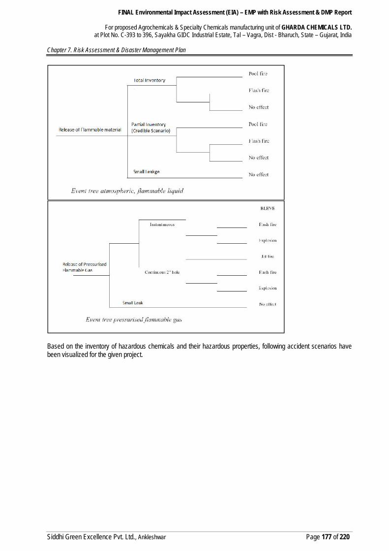
7.10.1 Selection of Initiating Events And ScenariosFollowing event tree is followed for deciding toxic and/or flammable effects:
FINAL Environmental Impact Assessment (EIA) – EMP with Risk Assessment & DMP Report
For proposed Agrochemicals & Specialty Chemicals manufacturing unit of GHARDA CHEMICALS LTD.at Plot No. C-393 to 396, Sayakha GIDC Industrial Estate, Tal – Vagra, Dist - Bharuch, State – Gujarat, India
Chapter 7. Risk Assessment & Disaster Management Plan
Siddhi Green Excellence Pvt. Ltd., Ankleshwar Page 177 of 220
Based on the inventory of hazardous chemicals and their hazardous properties, following accident scenarios havebeen visualized for the given project.
FINAL Environmental Impact Assessment (EIA) – EMP with Risk Assessment & DMP Report
For proposed Agrochemicals & Specialty Chemicals manufacturing unit of GHARDA CHEMICALS LTD.at Plot No. C-393 to 396, Sayakha GIDC Industrial Estate, Tal – Vagra, Dist - Bharuch, State – Gujarat, India
Chapter 7. Risk Assessment & Disaster Management Plan
Siddhi Green Excellence Pvt. Ltd., Ankleshwar Page 178 of 220
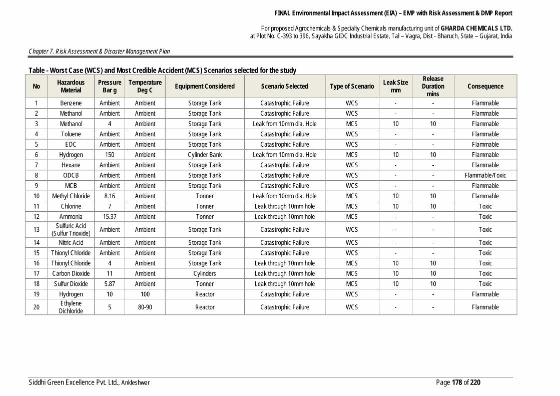
Table - Worst Case (WCS) and Most Credible Accident (MCS) Scenarios selected for the study
No HazardousMaterial
PressureBar g
TemperatureDeg C Equipment Considered Scenario Selected Type of Scenario Leak Size
mmReleaseDuration
minsConsequence
1 Benzene Ambient Ambient Storage Tank Catastrophic Failure WCS - - Flammable2 Methanol Ambient Ambient Storage Tank Catastrophic Failure WCS - - Flammable3 Methanol 4 Ambient Storage Tank Leak from 10mm dia. Hole MCS 10 10 Flammable4 Toluene Ambient Ambient Storage Tank Catastrophic Failure WCS - - Flammable5 EDC Ambient Ambient Storage Tank Catastrophic Failure WCS - - Flammable6 Hydrogen 150 Ambient Cylinder Bank Leak from 10mm dia. Hole MCS 10 10 Flammable7 Hexane Ambient Ambient Storage Tank Catastrophic Failure WCS - - Flammable8 ODCB Ambient Ambient Storage Tank Catastrophic Failure WCS - - Flammable/Toxic9 MCB Ambient Ambient Storage Tank Catastrophic Failure WCS - - Flammable
10 Methyl Chloride 8.16 Ambient Tonner Leak from 10mm dia. Hole MCS 10 10 Flammable11 Chlorine 7 Ambient Tonner Leak through 10mm hole MCS 10 10 Toxic12 Ammonia 15.37 Ambient Tonner Leak through 10mm hole MCS - - Toxic
13 Sulfuric Acid(Sulfur Trioxide) Ambient Ambient Storage Tank Catastrophic Failure WCS - - Toxic
14 Nitric Acid Ambient Ambient Storage Tank Catastrophic Failure WCS - - Toxic15 Thionyl Chloride Ambient Ambient Storage Tank Catastrophic Failure WCS - - Toxic16 Thionyl Chloride 4 Ambient Storage Tank Leak through 10mm hole MCS 10 10 Toxic17 Carbon Dioxide 11 Ambient Cylinders Leak through 10mm hole MCS 10 10 Toxic18 Sulfur Dioxide 5.87 Ambient Tonner Leak through 10mm hole MCS 10 10 Toxic19 Hydrogen 10 100 Reactor Catastrophic Failure WCS - - Flammable
20 EthyleneDichloride 5 80-90 Reactor Catastrophic Failure WCS - - Flammable

FINAL Environmental Impact Assessment (EIA) – EMP with Risk Assessment & DMP Report
For proposed Agrochemicals & Specialty Chemicals manufacturing unit of GHARDA CHEMICALS LTD.at Plot No. C-393 to 396, Sayakha GIDC Industrial Estate, Tal – Vagra, Dist - Bharuch, State – Gujarat, India
Chapter 7. Risk Assessment & Disaster Management Plan
Siddhi Green Excellence Pvt. Ltd., Ankleshwar Page 179 of 220
7.11 CONSEQUENCE ANALYSISHazardous substance on release can cause damage on a large scale in the environment. The extent of damage isdependent upon the nature of the release and the physical state of the material. It is necessary to visualize theconsequences and the damages caused by such releases. The quantification of the damage can be done by meansof various models, which can further be related in terms of injuries and damage to exposed population and buildings.
Software used for consequence analysis for proposed project :ALOHA (AREAL LOCATIONS OF HAZARDOUS ATMOSPHERES)
Is part of the CAMEO suite developed by US Environmental Protection Agency (EPA), ALOHA® is an atmosphericdispersion model used for evaluating releases of hazardous chemical vapors, including toxic gas clouds, fires, andexplosions. Using input about the release, ALOHA generates a threat zone estimate. A threat zone is the area wherea hazard (such as toxicity, flammability, thermal radiation, or damaging overpressure) is predicted to exceed a user-specified level of concern. Threat zones can also be plotted on maps with MARPLOT to display the location offacilities storing hazardous materials and vulnerable locations (such as hospitals and schools). Specific informationabout these locations can be extracted from CAMEO information modules to help make decisions about the degreeof hazard posed.
In order to assess the damage, the damage criteria have to be first defined.There are three principle types of exposures to hazardous effects
Heat radiation from a jet, pool fire, a flash fire or a BLEVE
Explosion,
Toxic effects, from toxic materials or toxic combustion productsA basis for the weather conditions (Temperature, wind speed etc.) is chosen for input in these models.
7.11.1 Frequencies Estimation:The risk is computed as product of consequence of event and frequency of occurring of the event.As part riskassessment frequency estimation is one of the activity.In literature and published guidelines the frequencies ofcatastrophic failure of various equipments are published. For this assessment the used set of frequencies is takenfrom Dutch Purple book,2008.Also for credible scenarios the frequencies for leaks from equipments or pipelines are available in the same sourceas above. For credible scenario the frequency of leak event is calculated as summation of frequencies of eachelement in the considered vessel.No Item Mode Of Failure Failure Frequency
1 Atmospheric Storage Tanks Catastrophic Failure 10E-9 /yrSignificant Leak 10E-5 /yr
2 Process Pipelines<=50mm Dia Full Bore rupture 8.8 x 10E-7 /yr
Significant Leak 8.8 x 10E-6 /yr>50mm<=150mm Dia Full Bore rupture 2.6 x 10E-7 /yr
Significant Leak 5.3 x 10E-6 /yr<150mm Dia Full Bore rupture 8.8 x 10E-7 /yr
Significant Leak 2.6 x 10E-6 /yr3 Hoses Rupture 3.5 x 10E-2 /yr4 Pressure Vessel Catastrophic Failure 3 x 10E-6 /yr
Significant Leak(6" nozzle) 7 x 10E-6 /yr5 Liquid Line Pipeline Leak 3 x 10E-7 /yr
Fittings Leak 5 x 10E-6 /yr

FINAL Environmental Impact Assessment (EIA) – EMP with Risk Assessment & DMP Report
For proposed Agrochemicals & Specialty Chemicals manufacturing unit of GHARDA CHEMICALS LTD.at Plot No. C-393 to 396, Sayakha GIDC Industrial Estate, Tal – Vagra, Dist - Bharuch, State – Gujarat, India
Chapter 7. Risk Assessment & Disaster Management Plan
Siddhi Green Excellence Pvt. Ltd., Ankleshwar Page 180 of 220
No Item Mode Of Failure Failure Frequency6 vapor line Leak 3 x 10E-6 /yr7 6" Pipe Leak (1 kg/s) 6x 10E-6 /yr8 3" Pipe Leak (1 kg/s) 6 x 10E-5 /yr9 Flange Leak (1 kg/s) 3 x 10E-4 /yr10 Pump Seal Leak (1 kg/s) 5 x 10E-3 /yr
For warehouse where the drums of chemicals are stored and handled the frequencies are as follows,No Item Mode Of Failure Failure Frequency
1storage of substances inwarehouseswith protection levels 1 and 2
Liquid Spill 1 x 10E-5 Per handling
Fire 8.8 x 10E-4 / yr
2storage of substances inwarehouseswith protection level 3
Liquid Spill 1 x 10E-5 Per handling
Fire 1.8 x 10E-4 / yr
Failure History DataTable - Failure History dataSl.No.
Item International Data Indian Data
1 Process Controller 2.4 x 10⁻⁵ hr-1 3.0 x 10⁻⁵ hr-12 Process Controller Valve 2 x 10⁻⁶ hr-1 2.4 x 10⁻⁵ hr-13 Alarm 2.3 x 10⁻⁵ hr-1 4.6 x 10⁻⁵ hr-14 Leakage at biggest storage tank 5 x 10⁻⁵ yr-1 3.0 x 10⁻⁵ yr-15 Leakage pipe line 1 x 10⁻⁷ m-1yr-1 3.0 x 10⁻⁸ m-1yr-16 Human failure 1 x 10⁻⁴ (demand)-1 1.8 x 10⁻³ (demand)-1
Assumed Failure Rate For The StudyTable - Assumed failure rate for the studySNo. Item Rupture (yr-1) Leakage (yr-1)1 Pipe lines
<3”3”-15”>15
10-610-7--
10-510-610-8
2 Vessel- pressurized- Atmospheric
5 x 10-61 x 10-5
5 x 10-51 x 10-4
Damage Due To Incident Radiation IntensityTable - Damage Due To Incident Radiation IntensityIncident RadiationIntensity (kJ/m²s)
Type of Damage
62.0 Spontaneous ignition of wood37.5 Sufficient to cause damage to process equipment25 Minimum energy required for ignite wood at infinitely long exposure (non piloted)12.5 Minimum energy required of piloted ignition of wood, melting plastic tubing etc.4.5 Sufficient to cause pain to personnel is unable to reach cover within 20 sec.; however
blistering of skin (1st degree burns) is likely1.6 Will cause no discomfort on long exposure
FINAL Environmental Impact Assessment (EIA) – EMP with Risk Assessment & DMP Report
For proposed Agrochemicals & Specialty Chemicals manufacturing unit of GHARDA CHEMICALS LTD.at Plot No. C-393 to 396, Sayakha GIDC Industrial Estate, Tal – Vagra, Dist - Bharuch, State – Gujarat, India
Chapter 7. Risk Assessment & Disaster Management Plan
Siddhi Green Excellence Pvt. Ltd., Ankleshwar Page 181 of 220
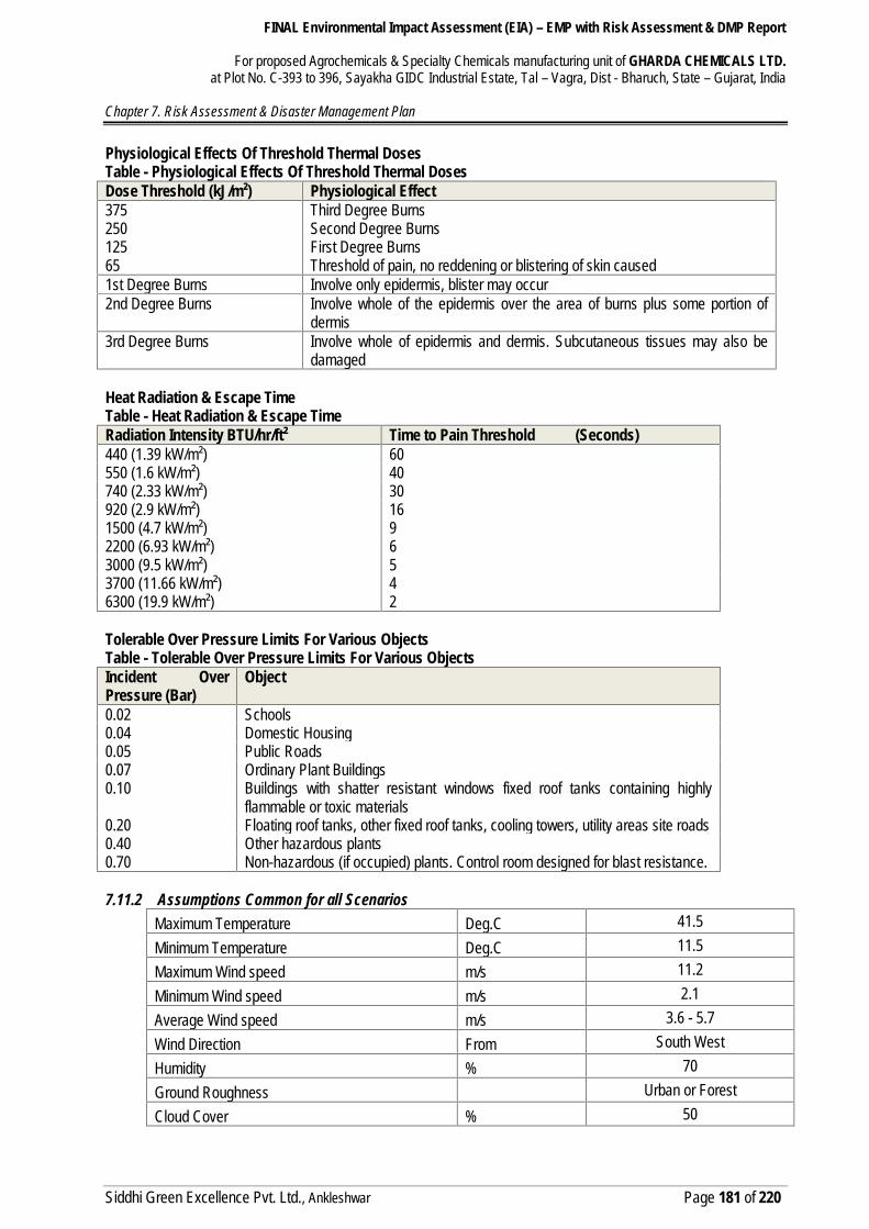
Physiological Effects Of Threshold Thermal DosesTable - Physiological Effects Of Threshold Thermal DosesDose Threshold (kJ/m²) Physiological Effect37525012565
Third Degree BurnsSecond Degree BurnsFirst Degree BurnsThreshold of pain, no reddening or blistering of skin caused
1st Degree Burns Involve only epidermis, blister may occur2nd Degree Burns Involve whole of the epidermis over the area of burns plus some portion of
dermis3rd Degree Burns Involve whole of epidermis and dermis. Subcutaneous tissues may also be
damaged
Heat Radiation & Escape TimeTable - Heat Radiation & Escape TimeRadiation Intensity BTU/hr/ft² Time to Pain Threshold (Seconds)440 (1.39 kW/m²) 60550 (1.6 kW/m²) 40740 (2.33 kW/m²) 30920 (2.9 kW/m²) 161500 (4.7 kW/m²) 92200 (6.93 kW/m²) 63000 (9.5 kW/m²) 53700 (11.66 kW/m²) 46300 (19.9 kW/m²) 2
Tolerable Over Pressure Limits For Various ObjectsTable - Tolerable Over Pressure Limits For Various ObjectsIncident OverPressure (Bar)
Object
0.02 Schools0.04 Domestic Housing0.05 Public Roads0.07 Ordinary Plant Buildings0.10 Buildings with shatter resistant windows fixed roof tanks containing highly
flammable or toxic materials0.20 Floating roof tanks, other fixed roof tanks, cooling towers, utility areas site roads0.40 Other hazardous plants0.70 Non-hazardous (if occupied) plants. Control room designed for blast resistance.
7.11.2 Assumptions Common for all ScenariosMaximum Temperature Deg.C 41.5Minimum Temperature Deg.C 11.5Maximum Wind speed m/s 11.2Minimum Wind speed m/s 2.1Average Wind speed m/s 3.6 - 5.7Wind Direction From South WestHumidity % 70Ground Roughness Urban or ForestCloud Cover % 50
FINAL Environmental Impact Assessment (EIA) – EMP with Risk Assessment & DMP Report
For proposed Agrochemicals & Specialty Chemicals manufacturing unit of GHARDA CHEMICALS LTD.at Plot No. C-393 to 396, Sayakha GIDC Industrial Estate, Tal – Vagra, Dist - Bharuch, State – Gujarat, India
Chapter 7. Risk Assessment & Disaster Management Plan
Siddhi Green Excellence Pvt. Ltd., Ankleshwar Page 182 of 220
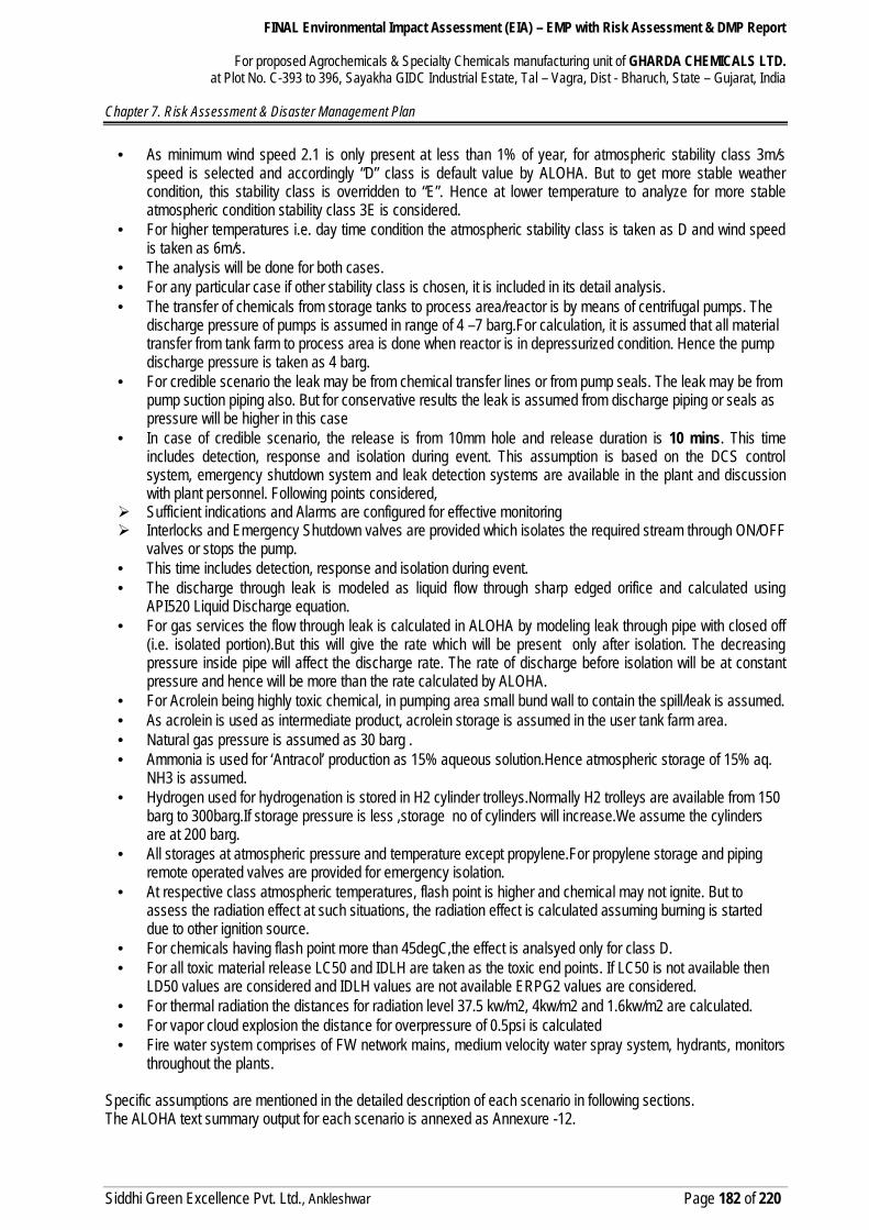
As minimum wind speed 2.1 is only present at less than 1% of year, for atmospheric stability class 3m/sspeed is selected and accordingly “D” class is default value by ALOHA. But to get more stable weathercondition, this stability class is overridden to “E”. Hence at lower temperature to analyze for more stableatmospheric condition stability class 3E is considered.
For higher temperatures i.e. day time condition the atmospheric stability class is taken as D and wind speedis taken as 6m/s.
The analysis will be done for both cases. For any particular case if other stability class is chosen, it is included in its detail analysis. The transfer of chemicals from storage tanks to process area/reactor is by means of centrifugal pumps. The
discharge pressure of pumps is assumed in range of 4 –7 barg.For calculation, it is assumed that all materialtransfer from tank farm to process area is done when reactor is in depressurized condition. Hence the pumpdischarge pressure is taken as 4 barg.
For credible scenario the leak may be from chemical transfer lines or from pump seals. The leak may be frompump suction piping also. But for conservative results the leak is assumed from discharge piping or seals aspressure will be higher in this case
In case of credible scenario, the release is from 10mm hole and release duration is 10 mins. This timeincludes detection, response and isolation during event. This assumption is based on the DCS controlsystem, emergency shutdown system and leak detection systems are available in the plant and discussionwith plant personnel. Following points considered,
Sufficient indications and Alarms are configured for effective monitoring Interlocks and Emergency Shutdown valves are provided which isolates the required stream through ON/OFF
valves or stops the pump. This time includes detection, response and isolation during event. The discharge through leak is modeled as liquid flow through sharp edged orifice and calculated using
API520 Liquid Discharge equation. For gas services the flow through leak is calculated in ALOHA by modeling leak through pipe with closed off
(i.e. isolated portion).But this will give the rate which will be present only after isolation. The decreasingpressure inside pipe will affect the discharge rate. The rate of discharge before isolation will be at constantpressure and hence will be more than the rate calculated by ALOHA.
For Acrolein being highly toxic chemical, in pumping area small bund wall to contain the spill/leak is assumed. As acrolein is used as intermediate product, acrolein storage is assumed in the user tank farm area. Natural gas pressure is assumed as 30 barg . Ammonia is used for ‘Antracol’ production as 15% aqueous solution.Hence atmospheric storage of 15% aq.
NH3 is assumed. Hydrogen used for hydrogenation is stored in H2 cylinder trolleys.Normally H2 trolleys are available from 150
barg to 300barg.If storage pressure is less ,storage no of cylinders will increase.We assume the cylindersare at 200 barg.
All storages at atmospheric pressure and temperature except propylene.For propylene storage and pipingremote operated valves are provided for emergency isolation.
At respective class atmospheric temperatures, flash point is higher and chemical may not ignite. But toassess the radiation effect at such situations, the radiation effect is calculated assuming burning is starteddue to other ignition source.
For chemicals having flash point more than 45degC,the effect is analsyed only for class D. For all toxic material release LC50 and IDLH are taken as the toxic end points. If LC50 is not available then
LD50 values are considered and IDLH values are not available ERPG2 values are considered. For thermal radiation the distances for radiation level 37.5 kw/m2, 4kw/m2 and 1.6kw/m2 are calculated. For vapor cloud explosion the distance for overpressure of 0.5psi is calculated Fire water system comprises of FW network mains, medium velocity water spray system, hydrants, monitors
throughout the plants.
Specific assumptions are mentioned in the detailed description of each scenario in following sections.The ALOHA text summary output for each scenario is annexed as Annexure -12.
FINAL Environmental Impact Assessment (EIA) – EMP with Risk Assessment & DMP Report
For proposed Agrochemicals & Specialty Chemicals manufacturing unit of GHARDA CHEMICALS LTD.at Plot No. C-393 to 396, Sayakha GIDC Industrial Estate, Tal – Vagra, Dist - Bharuch, State – Gujarat, India
Chapter 7. Risk Assessment & Disaster Management Plan
Siddhi Green Excellence Pvt. Ltd., Ankleshwar Page 183 of 220
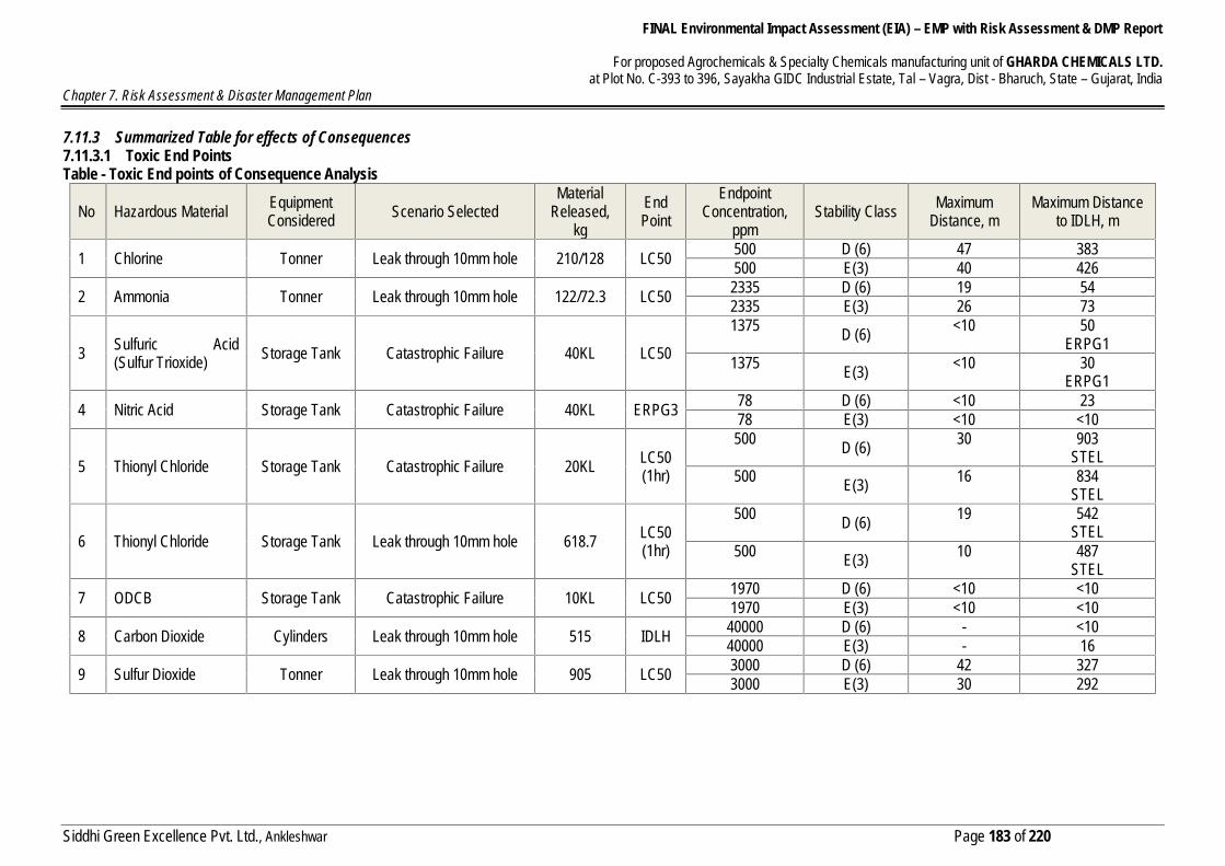
7.11.3 Summarized Table for effects of Consequences7.11.3.1 Toxic End PointsTable - Toxic End points of Consequence Analysis
No Hazardous Material EquipmentConsidered Scenario Selected
MaterialReleased,
kgEndPoint
EndpointConcentration,
ppmStability Class Maximum
Distance, mMaximum Distance
to IDLH, m
1 Chlorine Tonner Leak through 10mm hole 210/128 LC50 500 D (6) 47 383500 E(3) 40 426
2 Ammonia Tonner Leak through 10mm hole 122/72.3 LC50 2335 D (6) 19 542335 E(3) 26 73
3 Sulfuric Acid(Sulfur Trioxide) Storage Tank Catastrophic Failure 40KL LC50
1375 D (6) <10 50ERPG1
1375 E(3) <10 30ERPG1
4 Nitric Acid Storage Tank Catastrophic Failure 40KL ERPG3 78 D (6) <10 2378 E(3) <10 <10
5 Thionyl Chloride Storage Tank Catastrophic Failure 20KL LC50(1hr)
500 D (6) 30 903STEL
500 E(3) 16 834STEL
6 Thionyl Chloride Storage Tank Leak through 10mm hole 618.7 LC50(1hr)
500 D (6) 19 542STEL
500 E(3) 10 487STEL
7 ODCB Storage Tank Catastrophic Failure 10KL LC50 1970 D (6) <10 <101970 E(3) <10 <10
8 Carbon Dioxide Cylinders Leak through 10mm hole 515 IDLH 40000 D (6) - <1040000 E(3) - 16
9 Sulfur Dioxide Tonner Leak through 10mm hole 905 LC50 3000 D (6) 42 3273000 E(3) 30 292
FINAL Environmental Impact Assessment (EIA) – EMP with Risk Assessment & DMP Report
For proposed Agrochemicals & Specialty Chemicals manufacturing unit of GHARDA CHEMICALS LTD.at Plot No. C-393 to 396, Sayakha GIDC Industrial Estate, Tal – Vagra, Dist - Bharuch, State – Gujarat, India
Chapter 7. Risk Assessment & Disaster Management Plan
Siddhi Green Excellence Pvt. Ltd., Ankleshwar Page 184 of 220
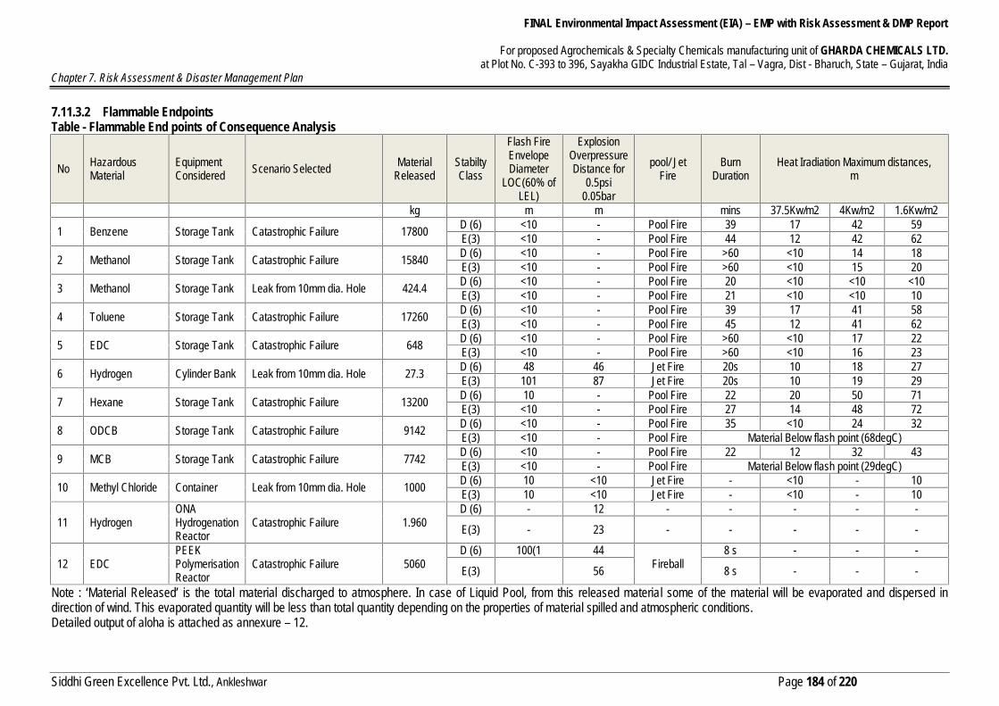
7.11.3.2 Flammable EndpointsTable - Flammable End points of Consequence Analysis
No HazardousMaterial
EquipmentConsidered Scenario Selected Material
ReleasedStabiltyClass
Flash FireEnvelopeDiameter
LOC(60% ofLEL)
ExplosionOverpressureDistance for
0.5psi0.05bar
pool/ JetFire
BurnDuration
Heat Iradiation Maximum distances,m
kg m m mins 37.5Kw/m2 4Kw/m2 1.6Kw/m2
1 Benzene Storage Tank Catastrophic Failure 17800 D (6) <10 - Pool Fire 39 17 42 59E(3) <10 - Pool Fire 44 12 42 62
2 Methanol Storage Tank Catastrophic Failure 15840 D (6) <10 - Pool Fire >60 <10 14 18E(3) <10 - Pool Fire >60 <10 15 20
3 Methanol Storage Tank Leak from 10mm dia. Hole 424.4 D (6) <10 - Pool Fire 20 <10 <10 <10E(3) <10 - Pool Fire 21 <10 <10 10
4 Toluene Storage Tank Catastrophic Failure 17260 D (6) <10 - Pool Fire 39 17 41 58E(3) <10 - Pool Fire 45 12 41 62
5 EDC Storage Tank Catastrophic Failure 648 D (6) <10 - Pool Fire >60 <10 17 22E(3) <10 - Pool Fire >60 <10 16 23
6 Hydrogen Cylinder Bank Leak from 10mm dia. Hole 27.3 D (6) 48 46 Jet Fire 20s 10 18 27E(3) 101 87 Jet Fire 20s 10 19 29
7 Hexane Storage Tank Catastrophic Failure 13200 D (6) 10 - Pool Fire 22 20 50 71E(3) <10 - Pool Fire 27 14 48 72
8 ODCB Storage Tank Catastrophic Failure 9142 D (6) <10 - Pool Fire 35 <10 24 32E(3) <10 - Pool Fire Material Below flash point (68degC)
9 MCB Storage Tank Catastrophic Failure 7742 D (6) <10 - Pool Fire 22 12 32 43E(3) <10 - Pool Fire Material Below flash point (29degC)
10 Methyl Chloride Container Leak from 10mm dia. Hole 1000 D (6) 10 <10 Jet Fire - <10 - 10E(3) 10 <10 Jet Fire - <10 - 10
11 HydrogenONAHydrogenationReactor
Catastrophic Failure 1.960D (6) - 12 - - - - -
E(3) - 23 - - - - -
12 EDCPEEKPolymerisationReactor
Catastrophic Failure 5060D (6) 100(1 44
Fireball8 s - - -
E(3) 56 8 s - - -
Note : ‘Material Released’ is the total material discharged to atmosphere. In case of Liquid Pool, from this released material some of the material will be evaporated and dispersed indirection of wind. This evaporated quantity will be less than total quantity depending on the properties of material spilled and atmospheric conditions.Detailed output of aloha is attached as annexure – 12.

FINAL Environmental Impact Assessment (EIA) – EMP with Risk Assessment & DMP Report
For proposed Agrochemicals & Specialty Chemicals manufacturing unit of GHARDA CHEMICALS LTD.at Plot No. C-393 to 396, Sayakha GIDC Industrial Estate, Tal – Vagra, Dist - Bharuch, State – Gujarat, India
Chapter 7. Risk Assessment & Disaster Management Plan
Siddhi Green Excellence Pvt. Ltd., Ankleshwar Page 185 of 220
7.11.4 Inference of Consequence analysis
7.11.4.1 Explosive Tank-farm Area (Benzene, Toluene, Hexane , Methanol) The catastrophic failure of atmospheric storage tanks of Benzene, Methanol, Toluene and Hexane is analyzed. The frequency of catastrophic failure of atmospheric tanks is 5 x 10E-6. No toxic consequence from scenarios in Explosive tank-farm. The major flammable consequence is pool fire. In case of catastrophic failure of tank the released liquid will be
contained inside the dyke and pool is formed. The maximum radiation from pool fire is estimated from Hexane, Toluene and Benzene fire. The 37.5 kw/m2 radiations from Hexane fire (20m). In case of Toluene the 37.5 kw/m2 radiation distance is 17m.
In case of Benzene the 37.5 kw/m2 radiation distance is 17m. The 4.0 kw/m2 radiations from Hexane fire (50m). In case of Toluene the 4.0 kw/m2 radiation distance is 41m. In
case of Benzene the 4.0 kw/m2 radiation distance is 42m.
7.11.4.2 Non Explosive & other Tank-farm Area (MDCB, EDC, MCB, ODCB, Thionyl Chloride, Sulfuric Acid,Nitric Acid)
The catastrophic failure of atmospheric storage tanks of ODCB, MCB, EDC, Thionyl Chloride, Sulfuric Acid &Nitric Acid is analyzed.
The frequency of catastrophic failure of atmospheric tanks is 5 x 10E-6. The major flammable consequence is pool fire. In case of catastrophic failure of tank the released liquid will be
contained inside the dyke and pool is formed. The maximum radiation from pool fire is estimated from MCB, ODCB and EDC fire. The 37.5 kw/m2 radiations from MCB fire (12m). In case of ODCB & EDC the 37.5 kw/m2 radiation distance will
be experienced at distance less than 10m. The 4.0 kw/m2 radiations from MCB fire (32m). In case of ODCB the 4.0 kw/m2 radiation distance is 24m. In case
of EDC the 4.0 kw/m2 radiation distance is 17m The severe toxic effect is from failure of Thionyl Chloride. The LC50 (500ppm) distance is 30m.The STEL
concentration (1ppm) distance is 903m.It may go beyond plant battery limit. The other toxic effects are from acid (Sulfuric Acid & Nitric Acid) storage tank failures. They do not have severe
toxic effects. In case of sulfuric acid(as SO3) ERPG1 distance is 50m.In case of nitric acid IDLH distance is 23m From most credible scenario there are leaks of highly toxic material Thionyl Chloride. The LC50 and IDLH
distances are maximum for thionyl chloride which are 19m and 542m..
7.11.4.3 Cylinder/tonner storage area (Hydrogen, Methyl Chloride,Chlorine,SO2,Ammonia,CO2) The most credible scenarios are analyzed for cylinder storage area for Hydrogen, Methyl
Chloride,Chlorine,SO2,Ammonia & CO2
Although these scenarios are taken as credible scenarios, due to high pressure the discharge rates are highenough to empty out the cylinders with in significantly short time. Hence these can be equivalent to single cylinderfailure.
The hydrogen & Methyl Chloride cylinder leaks have thermal effects. In case of hydrogen leak explosion & jet fire scenarios analyzed. The 0.5 psi overpressure distance is 87m. For
hydrogen jet fire, 37.5kw/m2 radiation distance is 10m and 4kw/m2 radiation distance is 19m. In case of MCB the thermal & explosion effects are not severe. All distances are less than 10m. The effects are Chlorine, SO2 & Ammonia scenarios. The severe toxic effect is from Chlorine & SO2 leaks. Chlorine LC50 (500ppm) distance is 47m. The IDLH
concentration (10ppm) distance is 426m. It may go beyond plant battery limit. SO2 LC50 (3000ppm) distance is 42m.The IDLH concentration (100ppm) distance is 327m.It may go beyond plant
battery limit. Ammonia LC50 (2335ppm) distance is 19m and IDLH concentration(300ppm) distance is 73m.
FINAL Environmental Impact Assessment (EIA) – EMP with Risk Assessment & DMP Report
For proposed Agrochemicals & Specialty Chemicals manufacturing unit of GHARDA CHEMICALS LTD.at Plot No. C-393 to 396, Sayakha GIDC Industrial Estate, Tal – Vagra, Dist - Bharuch, State – Gujarat, India
Chapter 7. Risk Assessment & Disaster Management Plan
Siddhi Green Excellence Pvt. Ltd., Ankleshwar Page 186 of 220
7.11.4.4 Reactors in plant process area Catastrophic failure of OPDA reactor during hydrogenation step is analysed as worst case scenario. It is resulting
in explosion and release of reactants. In case of OPDA Reactor explosion the 0.5 psig (which may cause shattering of glasses) overpressure will be
experienced up to 23m. The hydrogenation reactors are generally equipped with safety systems to take care for runaway reactions, over-
temperature and over-pressure scenarios. For this temperature, pressure indications with alarm and trip interlocksare used.
Catastrophic failure of PEEK reactor during polymerisation step is analysed as worst case scenario. In case of PEEK Reactor explosion the 0.5 psig (which may cause shattering of glasses) overpressure will be
experienced up to 56m. During explosion the flammable material in the reactor will catch fire and result in fireballwhich lasts for 8 seconds.
The frequency of reactor failure is 5 x 10E-6 and ignition is almost instantaneously due to hydrogen.
7.11.4.5 Risk to Individuals from a Major Release The risk to health to an individual at a specific point in the direction of the plume or heat radiation is dependent
on a number of factors, the most important being:o the direction of the wind when the release takes place; ando mitigating factors, such as whether the individual might be indoors or out of doors.
In the case of the wind direction, the plume width may be represented by the sector of a circle having an includedangle of 15o. In such a case, on the basis that wind direction arise, it is possible to approximate that an individualpresent in a single location for one year may be exposed for only 15/360ths of that year, or 4 x 10⁻²
In reality, it is unlikely that a person would be present at any one location in the open air for 100% of the year.Allowing for periods at work or indoors, a risk reduction factor of 3 is reasonably conservative.(three shiftoperation is considered)
Also the fatality % due to radiation is assumed at 50%.This assumption is based on the reposne time and theduration of fire in our case. We have two major fires , one is due to hydrogenation reactor failure in reactor areaand other is due to solvent (Hexane, Toluene, Benzene) tank failure. The reactor fire will last for 8 sec and forstorage tank the response time is 2 mins to evacuate persons from the area.
The overall consequence of the mitigation due to wind direction and indoor/outdoor location would be the productof these three factors, namely 1.33 x 10⁻².
The overall chance of an individual being affected at a specific location by exposure to the toxic gases would beas indicated in following table. From the table it is clear that for catastrophic failure the distances for 50% fatality ismore than MCS scenarios.
7.12 RECOMMENDATIONS7.12.1 Reactor area
OPDA/PEEK Reactor runaway The mitigation controls to avoid damage due to hydrogenation/ polymerization reactor explosion are of two
types, to avoid the runaway to happen and other measure to minimize the damage if runaway occurs. To avoid runaway normally,
o The safety systems which will detect high temperature and pressure which are providedby licensor, shall be maintained and tested with fixed maintenance schedule
o The cooling water system should be provided emergency supply and auto cut inprovision for standby cooling water pump should be provided.
o Alarms and interlock can be provided on cooling water side to detect any failure as thisis direct measurement
To minimize damage once runaway occurs,o Safety valve on the reactor should be designed to take care runaway reaction scenario or
as per licensor’s recommendation.o The steel structure and safety interlock cabling within process area should be fireproofed
Spiral wound gaskets are recommended for hydrocarbon lines. Screwed fittings should not be used exceptfor stainless steel instrumentation.

FINAL Environmental Impact Assessment (EIA) – EMP with Risk Assessment & DMP Report
For proposed Agrochemicals & Specialty Chemicals manufacturing unit of GHARDA CHEMICALS LTD.at Plot No. C-393 to 396, Sayakha GIDC Industrial Estate, Tal – Vagra, Dist - Bharuch, State – Gujarat, India
Chapter 7. Risk Assessment & Disaster Management Plan
Siddhi Green Excellence Pvt. Ltd., Ankleshwar Page 187 of 220
Fire water network providing hydrants and monitors should be around reactor building/ process area. Alsoprovision of hydrants on elevated structures and buildings to be ensured.
Fireproofing requirement of structure and equipment supports needs to be analysed and fireproofing to beprovided accordingly.
The process area should be classified area for selection of electrical equipments and instruments. The construction and fabrication should be as per standard codes and practices (ASME /ANSI / IS etc) as
the failure frequencies will be valid for such construction. If there is some deviation then the frequenciesmay increase.
7.12.2 Explosive tank Storage Area The major fire scenario is pool fire. If pool fir arises due to failure of any of the tank inside common dyke of
explosive tank-farm, it is very important to prevent failure of other tanks in the dyke. This can be achievedby keeping the other tanks cool with water spray.
It is recommended to have water spray for all the tanks inside explosive tank-farm. The actuation of thewater spray can be automatic or manual. The water spray valves should be kept 15m away from the dyke.
Fire water network providing hydrants and monitors should be around tank farm, reactor building/ processarea. Also provision of hydrants on elevated structures and buildings to be ensured.
The foam fire extinguishing system should be used for pool fire fighting. This can be semi fixed systemwith connections to all tanks and dykes and portable foam cans can be used along with fire water monitorsaround tank farm..
Fireproofing requirement of structure and equipment supports needs to be analysed and fireproofing to beprovided accordingly.
No pumps to be installed inside the dyke. The tank breather valve should have flame arrester.
7.12.3 Other Tank-farms Fire water network providing hydrants and monitors should be around tank farm. No pumps to be installed inside the dyke. Safety shower & eye washer to be placed near acid storage.
7.12.4 Cylinder Storage Area Hydrogen Gas detectors to be placed near cylinder bank area and reactor area. Hydrogen cylinder bank should be placed at distance (min 15m) from reactor area. The bank should be
covered with FW monitor and hydrants. Chlorine & SO2 gas monitors should be installed in the respective storage facility. The early detection of
any leak will help to prevent any potential big incident. It also gives enough time for evacuation of thepeople.
Chlorine & SO2 gas is heavier than air so gas monitors should be mounted approximately two feet from thefloor for quick and accurate detection.
If fire is present or imminent, chlorine & SO2 containers and equipment should be moved to a safelocation, if possible.
Non-leaking containers or equipment that cannot be moved should be kept cool by the application ofwater. This should continue until well after the fire has been extinguished and the containers are cooled
7.12.5 General The plant handles flammable materials like Hexane, Benzene, Toluene, Hydrogen etc. The handling of
these materials requires control of spark, ignition source, and open flame. This is ensured by selectingequipments as per Hazardous area classification analysis. Ensure that all electrical installations andinstruments are as per hazardous area classification(ref IS 5571 & 5572)
The atmospheric storage tanks breather valves are very important safety device to prevent tank fromfailure. Hence it is much more important to keep these valve always in line without any obstacle. They aresusceptible for choking due to plastic sheets, leaves, bird activities. These breather valves should bemonitored and visually inspected at regular frequency preferably once in a month.
FINAL Environmental Impact Assessment (EIA) – EMP with Risk Assessment & DMP Report
For proposed Agrochemicals & Specialty Chemicals manufacturing unit of GHARDA CHEMICALS LTD.at Plot No. C-393 to 396, Sayakha GIDC Industrial Estate, Tal – Vagra, Dist - Bharuch, State – Gujarat, India
Chapter 7. Risk Assessment & Disaster Management Plan
Siddhi Green Excellence Pvt. Ltd., Ankleshwar Page 188 of 220
Proper arrangement to be provided to drain rain water accumulated inside the dyke. Critical switches and alarms shall always be kept online especially in reactor area. Provide training for employees in the procedures established for their operating and maintenance
functions. Also a refresher training program at specific intervals is to be prepared to keep operatorsupdated.
Shut off and isolation valves shall be easily approachable in emergencies Some of the chemicals handled in the plant have both toxic and flammable effects. The fire fighters crew
who is responding to emergency involving such chemicals should be aware of toxic effects of thosechemicals and should use the advised PPEs for those chemicals.
A wind direction pointer shall also be installed at cavern site so that in an emergency the wind directioncan be directly seen and downwind population cautioned
Smoking shall be prohibited in designated locations. Work likely to involve flame or sparks, such as,welding or burning, shall be performed only after the area is checked for no presence of flammablematerial and other safety arrangement as required.
A proper training shall be given to the staff to handle any emergency situation and use of PPE during thework and emergency.
Self-Contained Breathing apparatus (SCBA) shall be well maintained for emergency handling. Personal protective equipments to be provided to all the employees related to the type of work and hazard
associated Mutual aid from neighboring industries to be made available whenever need arises. To check preparedness of workers for emergency control, mock drills on regular basis and disaster drills
as per factory inspectorate guidelines to be conducted.
7.13 DISASTER MANAGEMENT PLANThe proponent M/s. GCL is an established group and factory management of existing units incorporate all safetymeasures in planning the project w.r.t production, manufacturing processes, plant layout, utilities, chemical inventory,process control, safety aspects etc. and with better plant technology. The same policy shall be followed for new unit atSayakha GIDC.
There shall be inbuilt safety in the plant through DCS and PLC operations and safety interlocks. Also the technologyadopted is the most proven technology already implemented in similar units. The plant design and layout aspects alsocomply with the applicable regulations and requirements of industrial ergonomics. Thus, the risks associated with theproject are having low probability and severity.
Onsite Emergency plan are developed for existing units of GCL in compliance to the requirements of TheChemical Accidents Rules and Factories Act. The plans include emergency preparedness plan, emergencyresponse team, emergency communication, emergency responsibilities, emergency facilities, and emergencyactions.
The plans also include OFF site emergency plan for the concerned government authority giving details aboutsteps to be taken to inform related Government agencies, Medical Centers, Rescue teams and other localagencies, in an event where the emergency poses danger to surrounding area requiring evacuation.
Abstracts of onsite emergency plan of Gujarat Insecticides Ltd. Which is an associate company of GhardaGroup located at Ankleshwar GIDC and manufacturing products of the same category as proposed unit ofGCL is annexed as Annexure – 29.
GCL is committed to develop onsite emergency plan (DMP) for proposed unit at Sayakha GIDC in full compliance withthe requirements of Factories Act, Gujarat Factories Rules and The Chemical Accidents Rules.
For facilitating the DMP planning, EIA Consultant has prepared this draft DMP which the proponent has consented tofollow. The following sections discuss about the draft DMP. It is also recommended to consider the scenario-wiseemergency response and control measures discussed in Annexure – 12.
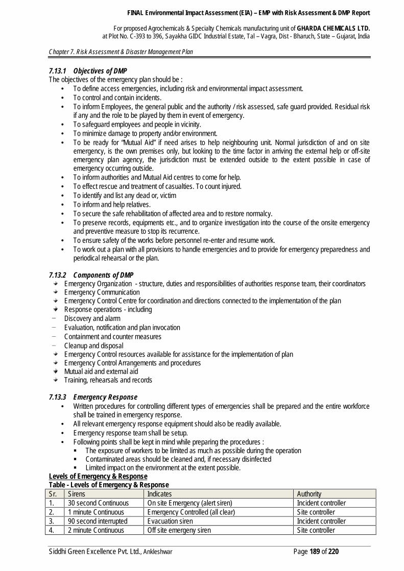
FINAL Environmental Impact Assessment (EIA) – EMP with Risk Assessment & DMP Report
For proposed Agrochemicals & Specialty Chemicals manufacturing unit of GHARDA CHEMICALS LTD.at Plot No. C-393 to 396, Sayakha GIDC Industrial Estate, Tal – Vagra, Dist - Bharuch, State – Gujarat, India
Chapter 7. Risk Assessment & Disaster Management Plan
Siddhi Green Excellence Pvt. Ltd., Ankleshwar Page 189 of 220
7.13.1 Objectives of DMPThe objectives of the emergency plan should be :
To define access emergencies, including risk and environmental impact assessment. To control and contain incidents. To inform Employees, the general public and the authority / risk assessed, safe guard provided. Residual risk
if any and the role to be played by them in event of emergency. To safeguard employees and people in vicinity. To minimize damage to property and/or environment. To be ready for “Mutual Aid” if need arises to help neighbouring unit. Normal jurisdiction of and on site
emergency, is the own premises only, but looking to the time factor in arriving the external help or off-siteemergency plan agency, the jurisdiction must be extended outside to the extent possible in case ofemergency occurring outside.
To inform authorities and Mutual Aid centres to come for help. To effect rescue and treatment of casualties. To count injured. To identify and list any dead or, victim To inform and help relatives. To secure the safe rehabilitation of affected area and to restore normalcy. To preserve records, equipments etc., and to organize investigation into the course of the onsite emergency
and preventive measure to stop its recurrence. To ensure safety of the works before personnel re-enter and resume work. To work out a plan with all provisions to handle emergencies and to provide for emergency preparedness and
periodical rehearsal or the plan.
7.13.2 Components of DMPEmergency Organization - structure, duties and responsibilities of authorities response team, their coordinatorsEmergency CommunicationEmergency Control Centre for coordination and directions connected to the implementation of the planResponse operations - including
− Discovery and alarm− Evaluation, notification and plan invocation− Containment and counter measures− Cleanup and disposal
Emergency Control resources available for assistance for the implementation of planEmergency Control Arrangements and proceduresMutual aid and external aidTraining, rehearsals and records
7.13.3 Emergency Response Written procedures for controlling different types of emergencies shall be prepared and the entire workforce
shall be trained in emergency response. All relevant emergency response equipment should also be readily available. Emergency response team shall be setup. Following points shall be kept in mind while preparing the procedures : The exposure of workers to be limited as much as possible during the operation Contaminated areas should be cleaned and, if necessary disinfected Limited impact on the environment at the extent possible.
Levels of Emergency & ResponseTable - Levels of Emergency & ResponseSr. Sirens Indicates Authority1. 30 second Continuous On site Emergency (alert siren) Incident controller2. 1 minute Continuous Emergency Controlled (all clear) Site controller3. 90 second interrupted Evacuation siren Incident controller4. 2 minute Continuous Off site emergeny siren Site controller

FINAL Environmental Impact Assessment (EIA) – EMP with Risk Assessment & DMP Report
For proposed Agrochemicals & Specialty Chemicals manufacturing unit of GHARDA CHEMICALS LTD.at Plot No. C-393 to 396, Sayakha GIDC Industrial Estate, Tal – Vagra, Dist - Bharuch, State – Gujarat, India
Chapter 7. Risk Assessment & Disaster Management Plan
Siddhi Green Excellence Pvt. Ltd., Ankleshwar Page 190 of 220
Note: 1) emergency siren to be sounded only if required2) all employees in areas other than affected to continue work unless disaster siren is blown.3) no emergency organization member will leave the emergency spot unless `all clear’ siren blown.
Emergency CommunicationThe unit shall have quick and effective communication system to make the emergency known through effectivecommunication systema) inside the factory(b) to key personnel outside normal working hours(c) to the outside emergency services and authorities and(d) to neighboring factories and public in vicinity.
The communication system beginning with raising the alarm, declaring the major emergency and procedure to make itknown to others shall include the following :
Declaring the major emergency Emergency Siren Code Information And Warning Safe Assembly Points Declaration Of Emergency
Emergency Control CentreFor the purpose of handling emergency, the following Emergency Control Centres has been identified.
During normal working hours - The Administrative Office & Main control room During other times - The Security Office.
The ECC shall be kept fully equipped with following :a) A copy of ON-SITE EMERGENCY PLAN.b) List of important telephone numbers such as Police, Fire Brigade, Hospitals, and other outside EmergencyServices, etc.c) List of key Personnel with addresses and telephone numbers.d ) List of Fire and Rescue Squad Memberse) Plant layout indicating storage of hazardous materialsf) List Fire Extinguisherg) Fire Fighting System (layout of Fire Hydrants)h) List of Personal Protective Equipmenti) First Aid box.
Assembly pointsIn case of an Emergency, the employees should assemble near the defined Assembly Points, as indicated below: -Fire Fighters - Area near Security Gate.First Aiders - Area near Security Gate.Others - Area near Security Gate.Assembly point no-1 – Near main gateAssembly point no-2 – Admin building
Wind direction to be determined by the WIND SOCKS installed on top of the Admin building, Central Workshop,Process plants.The employees should run perpendicular to the wind direction and not against / along the wind direction.
Emergency Management TeamThe management of the emergency is to be made operative by a well-structured organization (team) comprising ofresponsible group leaders. The following emergency management executive/personnel are required to play stellar rolein combating the emergency.
1. Site Main Controller
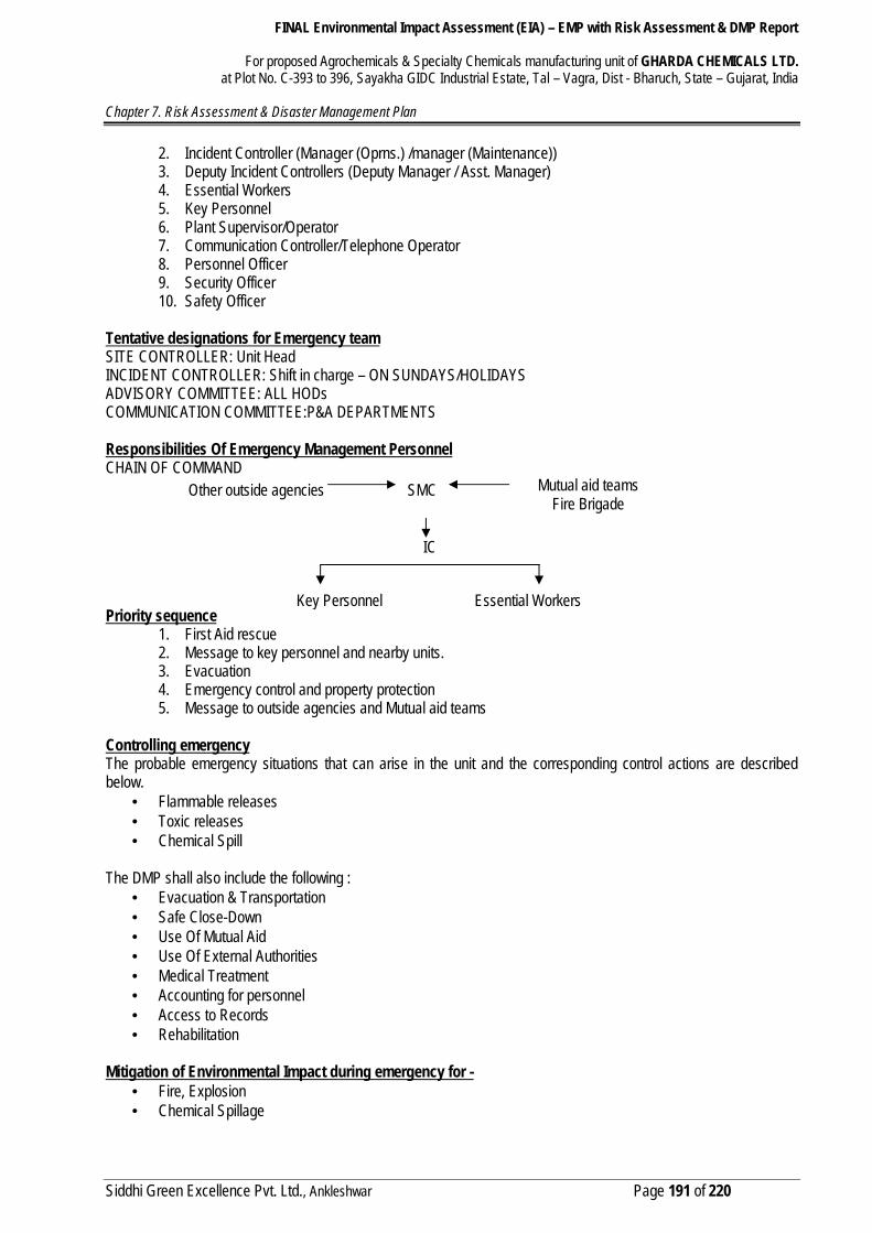
FINAL Environmental Impact Assessment (EIA) – EMP with Risk Assessment & DMP Report
For proposed Agrochemicals & Specialty Chemicals manufacturing unit of GHARDA CHEMICALS LTD.at Plot No. C-393 to 396, Sayakha GIDC Industrial Estate, Tal – Vagra, Dist - Bharuch, State – Gujarat, India
Chapter 7. Risk Assessment & Disaster Management Plan
Siddhi Green Excellence Pvt. Ltd., Ankleshwar Page 191 of 220
2. Incident Controller (Manager (Oprns.) /manager (Maintenance))3. Deputy Incident Controllers (Deputy Manager / Asst. Manager)4. Essential Workers5. Key Personnel6. Plant Supervisor/Operator7. Communication Controller/Telephone Operator8. Personnel Officer9. Security Officer10. Safety Officer
Tentative designations for Emergency teamSITE CONTROLLER: Unit HeadINCIDENT CONTROLLER: Shift in charge – ON SUNDAYS/HOLIDAYSADVISORY COMMITTEE: ALL HODsCOMMUNICATION COMMITTEE:P&A DEPARTMENTS
Responsibilities Of Emergency Management PersonnelCHAIN OF COMMAND
Priority sequence1. First Aid rescue2. Message to key personnel and nearby units.3. Evacuation4. Emergency control and property protection5. Message to outside agencies and Mutual aid teams
Controlling emergencyThe probable emergency situations that can arise in the unit and the corresponding control actions are describedbelow.
Flammable releases Toxic releases Chemical Spill
The DMP shall also include the following : Evacuation & Transportation Safe Close-Down Use Of Mutual Aid Use Of External Authorities Medical Treatment Accounting for personnel Access to Records Rehabilitation
Mitigation of Environmental Impact during emergency for - Fire, Explosion Chemical Spillage
Other outside agencies SMC Mutual aid teamsFire Brigade
IC
Key Personnel Essential Workers
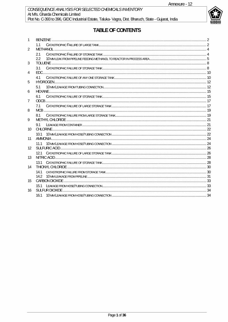
CONSEQUENCE ANALYSIS FOR SELECTED CHEMICALS INVENTORYAt M/s. Gharda Chemicals LimitedPlot No. C-393 to 396, GIDC Industrial Estate, Taluka- Vagra, Dist. Bharuch, State - Gujarat, India
Page 1 of 36
TABLE OF CONTENTS1 BENZENE ................................................................................................................................................................................. 2
1.1 CATASTROPHIC FAILURE OF LARGE TANK........................................................................................................................... 22 METHANOL .............................................................................................................................................................................. 4
2.1 CATASTROPHIC FAILURE OF STORAGE TANK ...................................................................................................................... 42.2 10 MM LEAK FROM PIPELINE FEEDING METHANOL TO REACTOR IN PROCESS AREA ................................................................. 5
3 TOLUENE ................................................................................................................................................................................. 83.1 CATASTROPHIC FAILURE OF STORAGE TANK....................................................................................................................... 8
4 EDC........................................................................................................................................................................................... 104.1 CATASTROPHIC FAILURE OF ANY ONE STORAGE TANK ......................................................................................................... 10
5 HYDROGEN.............................................................................................................................................................................. 125.1 10 MM LEAKAGE FROM TUBING CONNECTION...................................................................................................................... 12
6 HEXANE.................................................................................................................................................................................... 156.1 CATASTROPHIC FAILURE OF STORAGE TANK....................................................................................................................... 15
7 ODCB ........................................................................................................................................................................................ 177.1 CATASTROPHIC FAILURE OF LARGE STORAGE TANK ............................................................................................................ 17
8 MCB .......................................................................................................................................................................................... 198.1 CATASTROPHIC FAILURE FROM LARGE STORAGE TANK........................................................................................................ 19
9 METHYL CHLORIDE ................................................................................................................................................................ 219.1 LEAKAGE FROM CONTAINER .............................................................................................................................................. 21
10 CHLORINE................................................................................................................................................................................ 2210.1 10 MM LEAKAGE FROM HOSE/TUBING CONNECTION ............................................................................................................ 22
11 AMMONIA ................................................................................................................................................................................. 2411.1 10 MM LEAKAGE FROM HOSE/TUBING CONNECTION ............................................................................................................ 24
12 SULFURIC ACID....................................................................................................................................................................... 2612.1 CATASTROPHIC FAILURE OF LARGE STORAGE TANK ............................................................................................................ 26
13 NITRIC ACID............................................................................................................................................................................. 2813.1 CATASTROPHIC FAILURE OF STORAGE TANK....................................................................................................................... 28
14 THIONYL CHLORIDE ............................................................................................................................................................... 3014.1 CATASTROPHIC FAILURE FROM STORAGE TANK ................................................................................................................... 3014.2 10 MM LEAKAGE FROM PIPELINE ........................................................................................................................................ 31
15 CARBON DIOXIDE ................................................................................................................................................................... 3315.1 LEAKAGE FROM HOSE/TUBING CONNECTION....................................................................................................................... 33
16 SULFUR DIOXIDE .................................................................................................................................................................... 3416.1 10 MM LEAKAGE FROM HOSE/TUBING CONNECTION ............................................................................................................ 34
Annexure 12 -
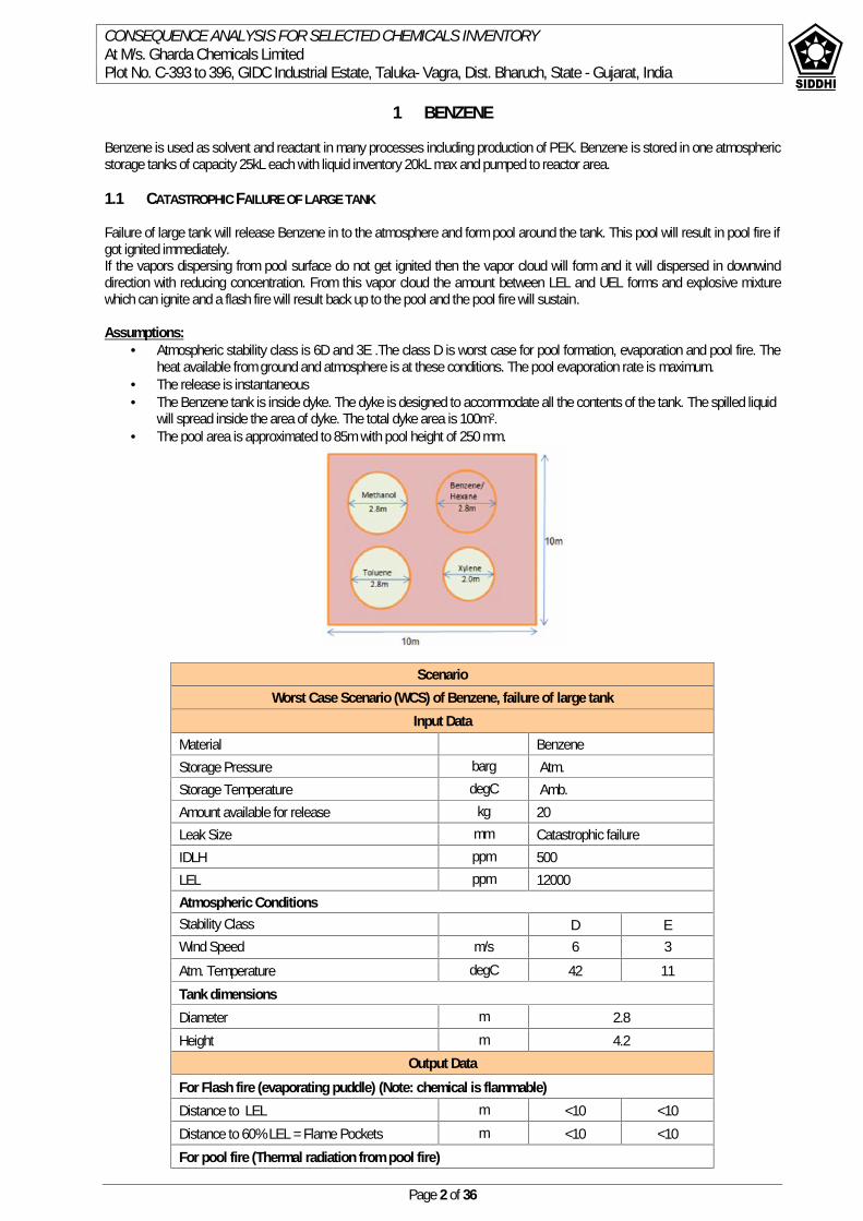
CONSEQUENCE ANALYSIS FOR SELECTED CHEMICALS INVENTORYAt M/s. Gharda Chemicals LimitedPlot No. C-393 to 396, GIDC Industrial Estate, Taluka- Vagra, Dist. Bharuch, State - Gujarat, India
Page 2 of 36
1 BENZENE
Benzene is used as solvent and reactant in many processes including production of PEK. Benzene is stored in one atmosphericstorage tanks of capacity 25kL each with liquid inventory 20kL max and pumped to reactor area.
1.1 CATASTROPHIC FAILURE OF LARGE TANK
Failure of large tank will release Benzene in to the atmosphere and form pool around the tank. This pool will result in pool fire ifgot ignited immediately.If the vapors dispersing from pool surface do not get ignited then the vapor cloud will form and it will dispersed in downwinddirection with reducing concentration. From this vapor cloud the amount between LEL and UEL forms and explosive mixturewhich can ignite and a flash fire will result back up to the pool and the pool fire will sustain.
Assumptions: Atmospheric stability class is 6D and 3E .The class D is worst case for pool formation, evaporation and pool fire. The
heat available from ground and atmosphere is at these conditions. The pool evaporation rate is maximum. The release is instantaneous The Benzene tank is inside dyke. The dyke is designed to accommodate all the contents of the tank. The spilled liquid
will spread inside the area of dyke. The total dyke area is 100m2. The pool area is approximated to 85m with pool height of 250 mm.
ScenarioWorst Case Scenario (WCS) of Benzene, failure of large tank
Input DataMaterial BenzeneStorage Pressure barg Atm.Storage Temperature degC Amb.Amount available for release kg 20Leak Size mm Catastrophic failureIDLH ppm 500LEL ppm 12000Atmospheric ConditionsStability Class D EWind Speed m/s 6 3Atm. Temperature degC 42 11Tank dimensionsDiameter m 2.8Height m 4.2
Output DataFor Flash fire (evaporating puddle) (Note: chemical is flammable)Distance to LEL m <10 <10Distance to 60% LEL = Flame Pockets m <10 <10For pool fire (Thermal radiation from pool fire)
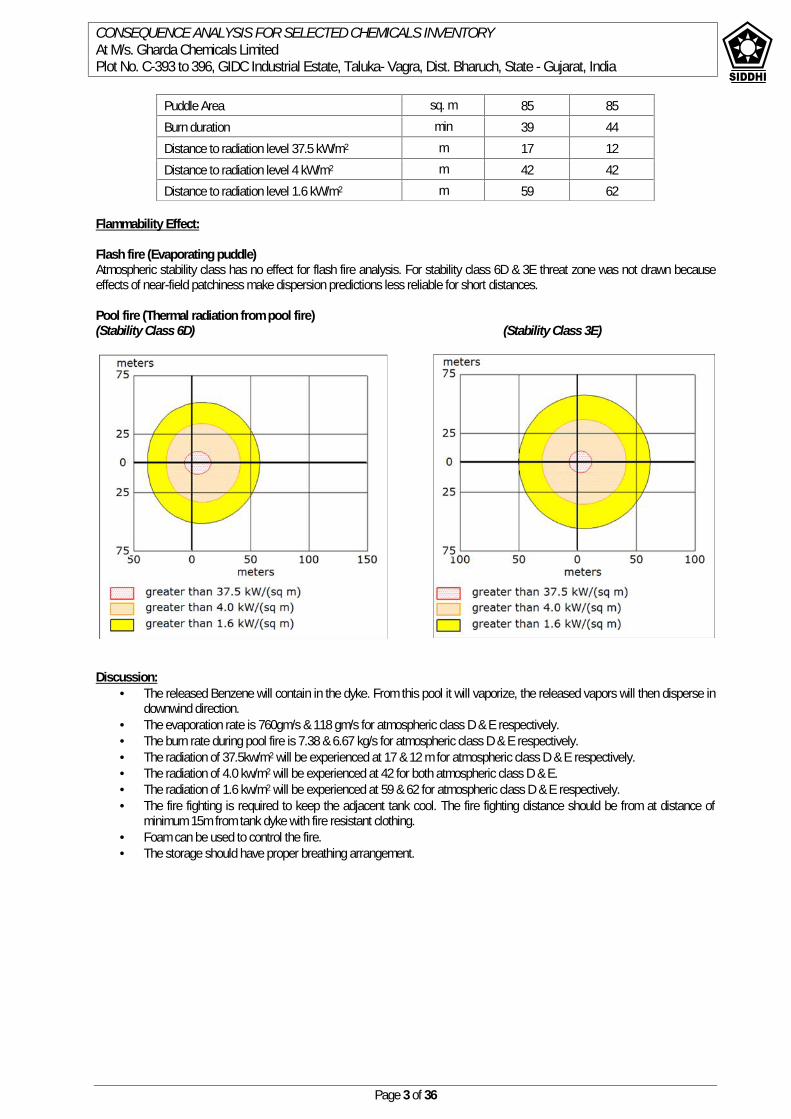
CONSEQUENCE ANALYSIS FOR SELECTED CHEMICALS INVENTORYAt M/s. Gharda Chemicals LimitedPlot No. C-393 to 396, GIDC Industrial Estate, Taluka- Vagra, Dist. Bharuch, State - Gujarat, India
Page 3 of 36
Flammability Effect:
Flash fire (Evaporating puddle)Atmospheric stability class has no effect for flash fire analysis. For stability class 6D & 3E threat zone was not drawn becauseeffects of near-field patchiness make dispersion predictions less reliable for short distances.
Pool fire (Thermal radiation from pool fire)(Stability Class 6D) (Stability Class 3E)
Discussion: The released Benzene will contain in the dyke. From this pool it will vaporize, the released vapors will then disperse in
downwind direction. The evaporation rate is 760gm/s & 118 gm/s for atmospheric class D & E respectively. The burn rate during pool fire is 7.38 & 6.67 kg/s for atmospheric class D & E respectively. The radiation of 37.5kw/m2 will be experienced at 17 & 12 m for atmospheric class D & E respectively. The radiation of 4.0 kw/m2 will be experienced at 42 for both atmospheric class D & E. The radiation of 1.6 kw/m2 will be experienced at 59 & 62 for atmospheric class D & E respectively. The fire fighting is required to keep the adjacent tank cool. The fire fighting distance should be from at distance of
minimum 15m from tank dyke with fire resistant clothing. Foam can be used to control the fire. The storage should have proper breathing arrangement.
Puddle Area sq. m 85 85Burn duration min 39 44Distance to radiation level 37.5 kW/m2 m 17 12Distance to radiation level 4 kW/m2 m 42 42Distance to radiation level 1.6 kW/m2 m 59 62
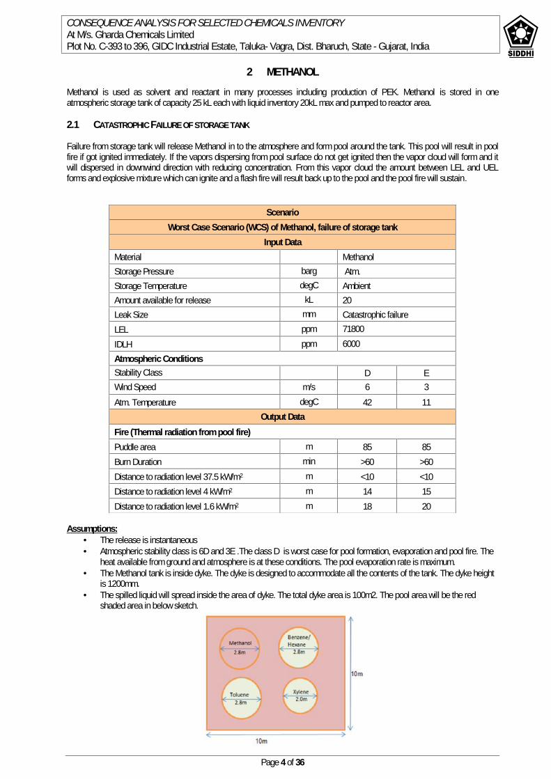
CONSEQUENCE ANALYSIS FOR SELECTED CHEMICALS INVENTORYAt M/s. Gharda Chemicals LimitedPlot No. C-393 to 396, GIDC Industrial Estate, Taluka- Vagra, Dist. Bharuch, State - Gujarat, India
Page 4 of 36
2 METHANOLMethanol is used as solvent and reactant in many processes including production of PEK. Methanol is stored in oneatmospheric storage tank of capacity 25 kL each with liquid inventory 20kL max and pumped to reactor area.
2.1 CATASTROPHIC FAILURE OF STORAGE TANK
Failure from storage tank will release Methanol in to the atmosphere and form pool around the tank. This pool will result in poolfire if got ignited immediately. If the vapors dispersing from pool surface do not get ignited then the vapor cloud will form and itwill dispersed in downwind direction with reducing concentration. From this vapor cloud the amount between LEL and UELforms and explosive mixture which can ignite and a flash fire will result back up to the pool and the pool fire will sustain.
Assumptions: The release is instantaneous Atmospheric stability class is 6D and 3E .The class D is worst case for pool formation, evaporation and pool fire. The
heat available from ground and atmosphere is at these conditions. The pool evaporation rate is maximum. The Methanol tank is inside dyke. The dyke is designed to accommodate all the contents of the tank. The dyke height
is 1200mm. The spilled liquid will spread inside the area of dyke. The total dyke area is 100m2. The pool area will be the red
shaded area in below sketch.
ScenarioWorst Case Scenario (WCS) of Methanol, failure of storage tank
Input DataMaterial MethanolStorage Pressure barg Atm.Storage Temperature degC AmbientAmount available for release kL 20Leak Size mm Catastrophic failureLEL ppm 71800IDLH ppm 6000Atmospheric ConditionsStability Class D EWind Speed m/s 6 3Atm. Temperature degC 42 11
Output DataFire (Thermal radiation from pool fire)Puddle area m 85 85Burn Duration min >60 >60Distance to radiation level 37.5 kW/m2 m <10 <10Distance to radiation level 4 kW/m2 m 14 15Distance to radiation level 1.6 kW/m2 m 18 20
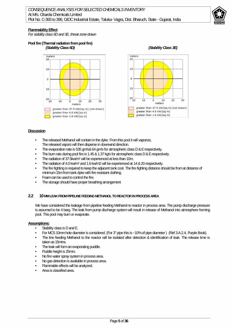
CONSEQUENCE ANALYSIS FOR SELECTED CHEMICALS INVENTORYAt M/s. Gharda Chemicals LimitedPlot No. C-393 to 396, GIDC Industrial Estate, Taluka- Vagra, Dist. Bharuch, State - Gujarat, India
Page 5 of 36
Flammability EffectFor stability class 6D and 3E, threat zone drawn
Pool fire (Thermal radiation from pool fire)(Stability Class 6D) (Stability Class 3E)
Discussion
The released Methanol will contain in the dyke. From this pool it will vaporize,The released vapors will then disperse in downwind direction.
The evaporation rate is 535 gm/s& 64 gm/s for atmospheric class D & E respectively. The burn rate during pool fire is 1.45 & 1.37 kg/s for atmospheric class D & E respectively. The radiation of 37.5kw/m2 will be experienced at less than 10m. The radiation of 4.0 kw/m2 and 1.6 kw/m2 will be experienced at 14 & 20 respectively. The fire fighting is required to keep the adjacent tank cool. The fire fighting distance should be from at distance of
minimum 15m from tank dyke with fire resistant clothing. Foam can be used to control the fire. The storage should have proper breathing arrangement
2.2 10 MM LEAK FROM PIPELINE FEEDING METHANOL TO REACTOR IN PROCESS AREA
We have considered the leakage from pipeline feeding Methanol to reactor in process area. The pump discharge pressureis assumed to be 4 barg. The leak from pump discharge system will result in release of Methanol into atmosphere formingpool. This pool may burn or evaporate.
Assumptions: Stability class is D and E. For MCS 10mm hole diameter is considered. (For 3” pipe this is ~10% of pipe diameter ) (Ref 3.A.2.4, Purple Book). The line feeding Methanol to the reactor will be isolated after detection & identification of leak. The release time is
taken as 15mins. The leak will form an evaporating puddle. Puddle height is 25mm. No fire water spray system in process area. No gas detection is available in process area. Flammable effects will be analyzed. Area is classified area.

CONSEQUENCE ANALYSIS FOR SELECTED CHEMICALS INVENTORYAt M/s. Gharda Chemicals LimitedPlot No. C-393 to 396, GIDC Industrial Estate, Taluka- Vagra, Dist. Bharuch, State - Gujarat, India
Page 6 of 36
Flammability Effect:
Evaporating puddle:Atmospheric stability class has no effect for evaporating puddle analysis. Threat zone was not drawn because effects of near-field patchiness make dispersion predictions less reliable for short distances.
Pool fire (Thermal radiation from pool fire)For stability class DNote: Threat zone was not drawn because effects of near-field patchiness make dispersion predictions less reliable for shortdistances.
(Stability class-3E)
ScenarioMost Credible Scenario (MCS) of Methanol, leakage through 10mm hole in Pipe line
Input DataMaterial MethanolStorage Pressure barg Atm.Storage Temperature degC Amb.Pump Discharge pressure barg 4Amount available for release kL 20Leak Size,diameter mm 10IDLH ppm 6000LEL ppm 71800Atmospheric ConditionsStability Class D EWind Speed m/s 6 3Atm. Temperature degC 42 11
Output DataEvaporating Puddle ( Flammable Area of Vapor Cloud)Distance to LEL concentration m <10 <10Distance to 60% LEL = Flame Pockets m <10 <10Pool Fire ( Thermal radiation from pool fire)Puddle Area sq. m 21 21Burn Duration min. 20 21Distance to radiation level 37.5 kW/m2 m <10 <10Distance to radiation level 4 kW/m2 m <10 <10Distance to radiation level 1.6 kW/m2 m <10 10
CONSEQUENCE ANALYSIS FOR SELECTED CHEMICALS INVENTORYAt M/s. Gharda Chemicals LimitedPlot No. C-393 to 396, GIDC Industrial Estate, Taluka- Vagra, Dist. Bharuch, State - Gujarat, India
Page 7 of 36
Discussion: The discharge rate through leak is 0.64kg/s. The total material released is 424.4 kg. The evaporating pool will release Methanol vapors to atmosphere which will disperse in downwind direction. The
evaporation rate is 141 & 16.5 gm/s. If the dispersed vapors got ignition then a fire will flash back to source and pool fire will sustained. The total material
will be burnt out in 21mins. In case of stability class D/E, radiation of 37.5kw/m2 will not be experienced. 4.5 & 1.6 kw/m2 distances are <10 for atmosphere condition D and <10 & 10 m for E.

CONSEQUENCE ANALYSIS FOR SELECTED CHEMICALS INVENTORYAt M/s. Gharda Chemicals LimitedPlot No. C-393 to 396, GIDC Industrial Estate, Taluka- Vagra, Dist. Bharuch, State - Gujarat, India
Page 8 of 36
3 TOLUENE
Toluene is used as solvent in production of PEK. The quantity of Toluene stored in each tank is 20 kL. The tanks to be placed incommon dyke which is designed to accommodate volume of one tank. Although it is used in reaction and present in processvessels, due to large quantity of storage the hazardous scenarios are considered in storage area.
3.1 CATASTROPHIC FAILURE OF STORAGE TANK
Failure of any one storage tank will release Toluene in to the atmosphere and form pool around the tank. This pool will result inpool fire if got ignited immediately. If the vapors dispersing from pool surface do not get ignited then the vapor cloud will formand it will dispersed in downwind direction with reducing concentration. From this vapor cloud the amount between LEL and UELforms and explosive mixture which can ignite and a flash fire will result back up to the pool and the pool fire will sustain.
Assumptions The release is instantaneous. Atmospheric stability class is 6D and 3E .The class D is worst case for pool formation, evaporation and pool fire. The
heat available from ground and atmosphere is at these conditions. The pool evaporation rate is maximum. The Toluene tank is inside dyke. The dyke is designed to accommodate all the contents of the tank. The dyke height is
1200mm. The spilled liquid will spread inside the area of dyke. The total dyke area is 100m2.
ScenarioWorst Case Scenario (WCS) of Toluene, failure of Storage Tank
Input DataMaterial TolueneStorage Pressure barg Atm.Storage Temperature degC Amb.Amount available for release kL 20 (From one tank)Leak Size mm Catastrophic failure of one tankIDLH ppm 500LEL ppm 11000Atmospheric ConditionsStability Class D EWind Speed m/s 6 3Atm. Temperature degC 42 11
Output DataFlash Fire (Evaporating puddle)Distance to LEL concentration m <10 --Distance to 60% LEL = Flame Pockets m <10 --Pool fire (Thermal radiation from Pool fire)Puddle Area sq. m 85 85Burn duration min. 39 45
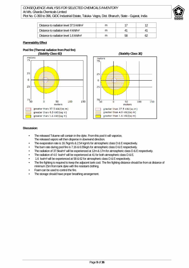
CONSEQUENCE ANALYSIS FOR SELECTED CHEMICALS INVENTORYAt M/s. Gharda Chemicals LimitedPlot No. C-393 to 396, GIDC Industrial Estate, Taluka- Vagra, Dist. Bharuch, State - Gujarat, India
Page 9 of 36
Flammability Effect
Pool fire (Thermal radiation from Pool fire)(Stability Class 6D) (Stability Class 3E)
Discussion:
The released Toluene will contain in the dyke. From this pool it will vaporize,The released vapors will then disperse in downwind direction.
The evaporation rate is 16.7kgm/s & 2.54 kgm/s for atmospheric class D & E respectively. The burn rate during pool fire is 7.16 & 6.55kg/s for atmospheric class D & E respectively. The radiation of 37.5kw/m2 will be experienced at 12m & 17m for atmospheric class D & E respectively. The radiation of 4.0 kw/m2 will be experienced at 41 for both atmospheric class D & E. 1.6 kw/m2 will be experienced at 58 & 62 for atmospheric class D & E respectively. The fire fighting is required to keep the adjacent tank cool. The fire fighting distance should be from at distance of
minimum 15m from tank dyke with fire resistant clothing. Foam can be used to control the fire. The storage should have proper breathing arrangement.
Distance to radiation level 37.5 kW/m2 m 17 12Distance to radiation level 4 kW/m2 m 41 41Distance to radiation level 1.6 kW/m2 m 58 62
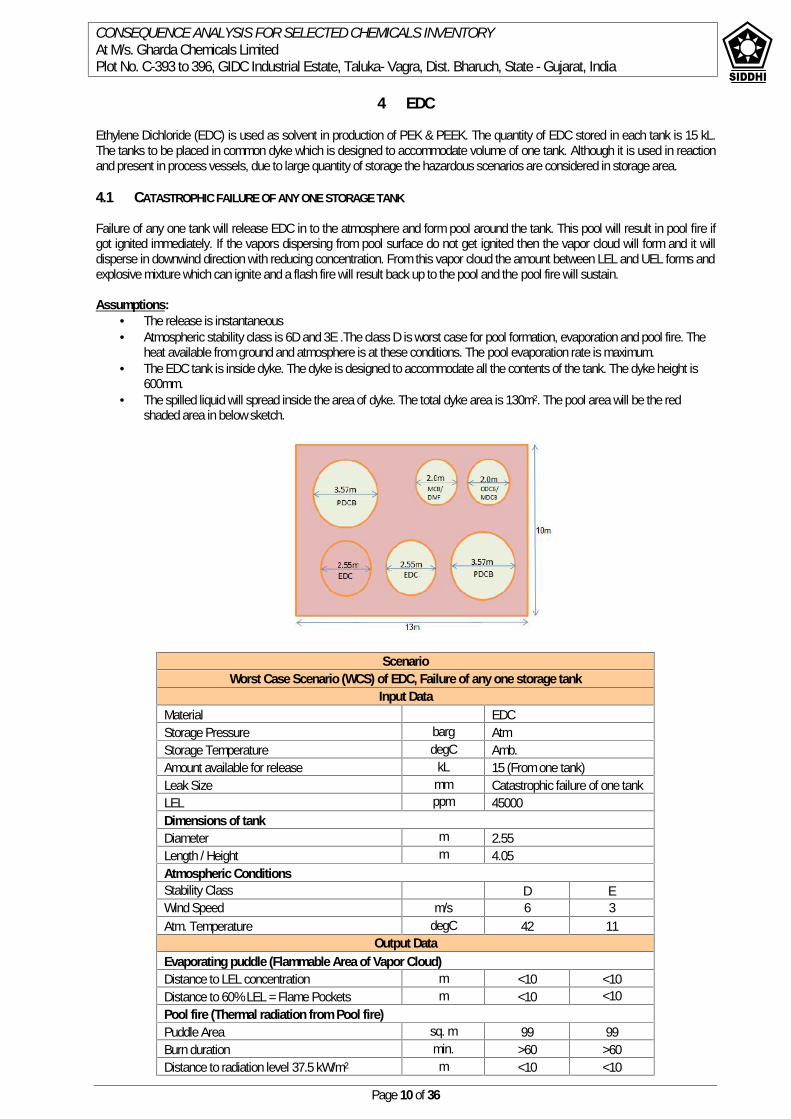
CONSEQUENCE ANALYSIS FOR SELECTED CHEMICALS INVENTORYAt M/s. Gharda Chemicals LimitedPlot No. C-393 to 396, GIDC Industrial Estate, Taluka- Vagra, Dist. Bharuch, State - Gujarat, India
Page 10 of 36
4 EDC
Ethylene Dichloride (EDC) is used as solvent in production of PEK & PEEK. The quantity of EDC stored in each tank is 15 kL.The tanks to be placed in common dyke which is designed to accommodate volume of one tank. Although it is used in reactionand present in process vessels, due to large quantity of storage the hazardous scenarios are considered in storage area.
4.1 CATASTROPHIC FAILURE OF ANY ONE STORAGE TANK
Failure of any one tank will release EDC in to the atmosphere and form pool around the tank. This pool will result in pool fire ifgot ignited immediately. If the vapors dispersing from pool surface do not get ignited then the vapor cloud will form and it willdisperse in downwind direction with reducing concentration. From this vapor cloud the amount between LEL and UEL forms andexplosive mixture which can ignite and a flash fire will result back up to the pool and the pool fire will sustain.
Assumptions: The release is instantaneous Atmospheric stability class is 6D and 3E .The class D is worst case for pool formation, evaporation and pool fire. The
heat available from ground and atmosphere is at these conditions. The pool evaporation rate is maximum. The EDC tank is inside dyke. The dyke is designed to accommodate all the contents of the tank. The dyke height is
600mm. The spilled liquid will spread inside the area of dyke. The total dyke area is 130m2. The pool area will be the red
shaded area in below sketch.
ScenarioWorst Case Scenario (WCS) of EDC, Failure of any one storage tank
Input DataMaterial EDCStorage Pressure barg AtmStorage Temperature degC Amb.Amount available for release kL 15 (From one tank)Leak Size mm Catastrophic failure of one tankLEL ppm 45000Dimensions of tankDiameter m 2.55Length / Height m 4.05Atmospheric ConditionsStability Class D EWind Speed m/s 6 3Atm. Temperature degC 42 11
Output DataEvaporating puddle (Flammable Area of Vapor Cloud)Distance to LEL concentration m <10 <10Distance to 60% LEL = Flame Pockets m <10 <10Pool fire (Thermal radiation from Pool fire)Puddle Area sq. m 99 99Burn duration min. >60 >60Distance to radiation level 37.5 kW/m2 m <10 <10
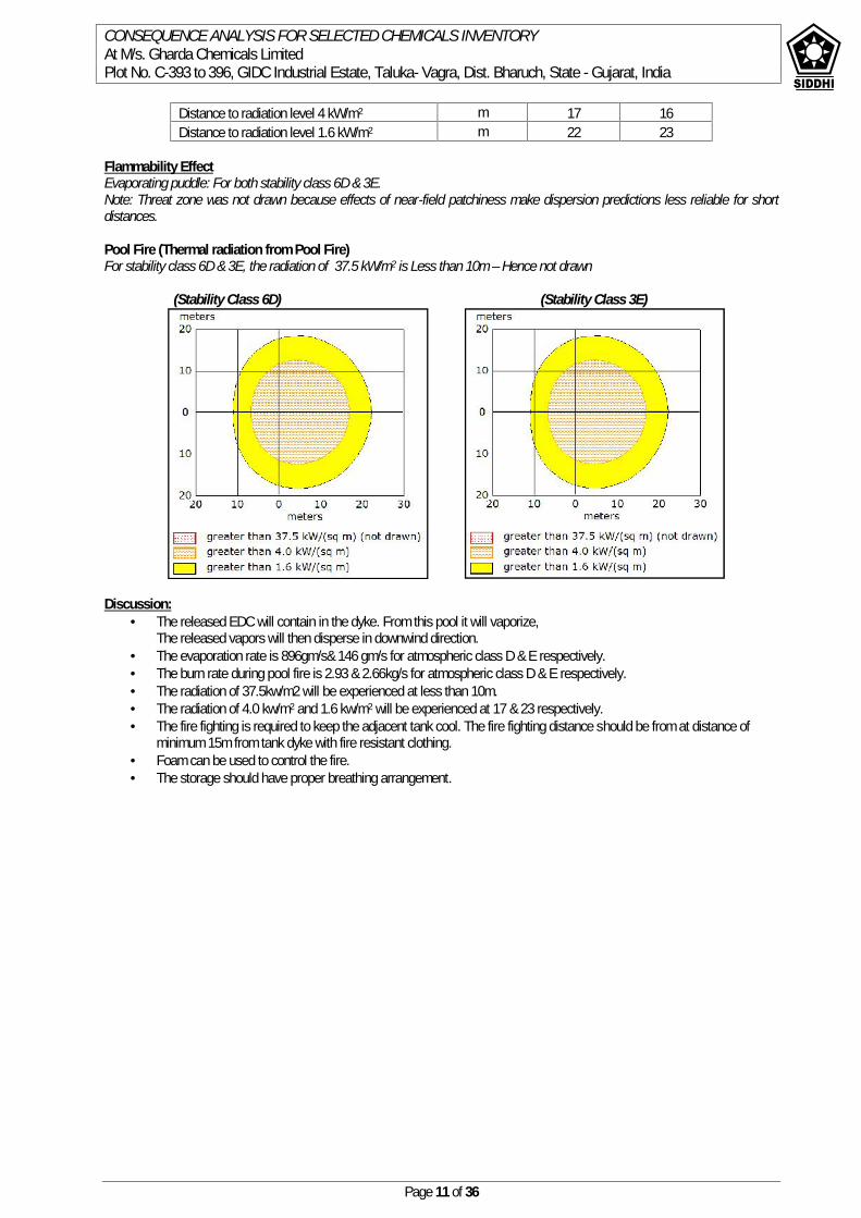
CONSEQUENCE ANALYSIS FOR SELECTED CHEMICALS INVENTORYAt M/s. Gharda Chemicals LimitedPlot No. C-393 to 396, GIDC Industrial Estate, Taluka- Vagra, Dist. Bharuch, State - Gujarat, India
Page 11 of 36
Distance to radiation level 4 kW/m2 m 17 16Distance to radiation level 1.6 kW/m2 m 22 23
Flammability EffectEvaporating puddle: For both stability class 6D & 3E.Note: Threat zone was not drawn because effects of near-field patchiness make dispersion predictions less reliable for shortdistances.
Pool Fire (Thermal radiation from Pool Fire)For stability class 6D & 3E, the radiation of 37.5 kW/m2 is Less than 10m – Hence not drawn
(Stability Class 6D) (Stability Class 3E)
Discussion: The released EDC will contain in the dyke. From this pool it will vaporize,
The released vapors will then disperse in downwind direction. The evaporation rate is 896gm/s& 146 gm/s for atmospheric class D & E respectively. The burn rate during pool fire is 2.93 & 2.66kg/s for atmospheric class D & E respectively. The radiation of 37.5kw/m2 will be experienced at less than 10m. The radiation of 4.0 kw/m2 and 1.6 kw/m2 will be experienced at 17 & 23 respectively. The fire fighting is required to keep the adjacent tank cool. The fire fighting distance should be from at distance of
minimum 15m from tank dyke with fire resistant clothing. Foam can be used to control the fire. The storage should have proper breathing arrangement.
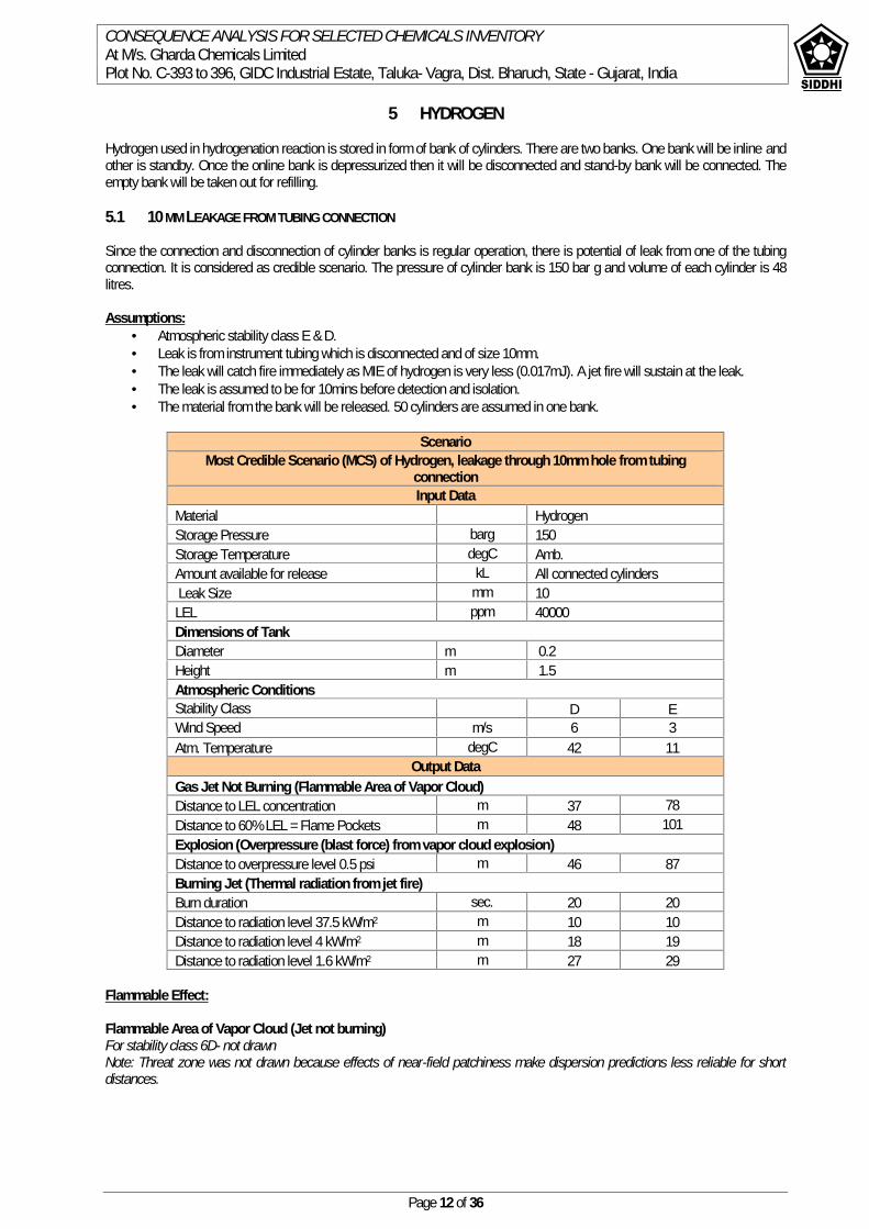
CONSEQUENCE ANALYSIS FOR SELECTED CHEMICALS INVENTORYAt M/s. Gharda Chemicals LimitedPlot No. C-393 to 396, GIDC Industrial Estate, Taluka- Vagra, Dist. Bharuch, State - Gujarat, India
Page 12 of 36
5 HYDROGEN
Hydrogen used in hydrogenation reaction is stored in form of bank of cylinders. There are two banks. One bank will be inline andother is standby. Once the online bank is depressurized then it will be disconnected and stand-by bank will be connected. Theempty bank will be taken out for refilling.
5.1 10 MM LEAKAGE FROM TUBING CONNECTION
Since the connection and disconnection of cylinder banks is regular operation, there is potential of leak from one of the tubingconnection. It is considered as credible scenario. The pressure of cylinder bank is 150 bar g and volume of each cylinder is 48litres.
Assumptions: Atmospheric stability class E & D. Leak is from instrument tubing which is disconnected and of size 10mm. The leak will catch fire immediately as MIE of hydrogen is very less (0.017mJ). A jet fire will sustain at the leak. The leak is assumed to be for 10mins before detection and isolation. The material from the bank will be released. 50 cylinders are assumed in one bank.
ScenarioMost Credible Scenario (MCS) of Hydrogen, leakage through 10mm hole from tubing
connectionInput Data
Material HydrogenStorage Pressure barg 150Storage Temperature degC Amb.Amount available for release kL All connected cylindersLeak Size mm 10
LEL ppm 40000Dimensions of TankDiameter m 0.2Height m 1.5Atmospheric ConditionsStability Class D EWind Speed m/s 6 3Atm. Temperature degC 42 11
Output DataGas Jet Not Burning (Flammable Area of Vapor Cloud)Distance to LEL concentration m 37 78Distance to 60% LEL = Flame Pockets m 48 101Explosion (Overpressure (blast force) from vapor cloud explosion)Distance to overpressure level 0.5 psi m 46 87Burning Jet (Thermal radiation from jet fire)Burn duration sec. 20 20Distance to radiation level 37.5 kW/m2 m 10 10Distance to radiation level 4 kW/m2 m 18 19Distance to radiation level 1.6 kW/m2 m 27 29
Flammable Effect:
Flammable Area of Vapor Cloud (Jet not burning)For stability class 6D- not drawnNote: Threat zone was not drawn because effects of near-field patchiness make dispersion predictions less reliable for shortdistances.
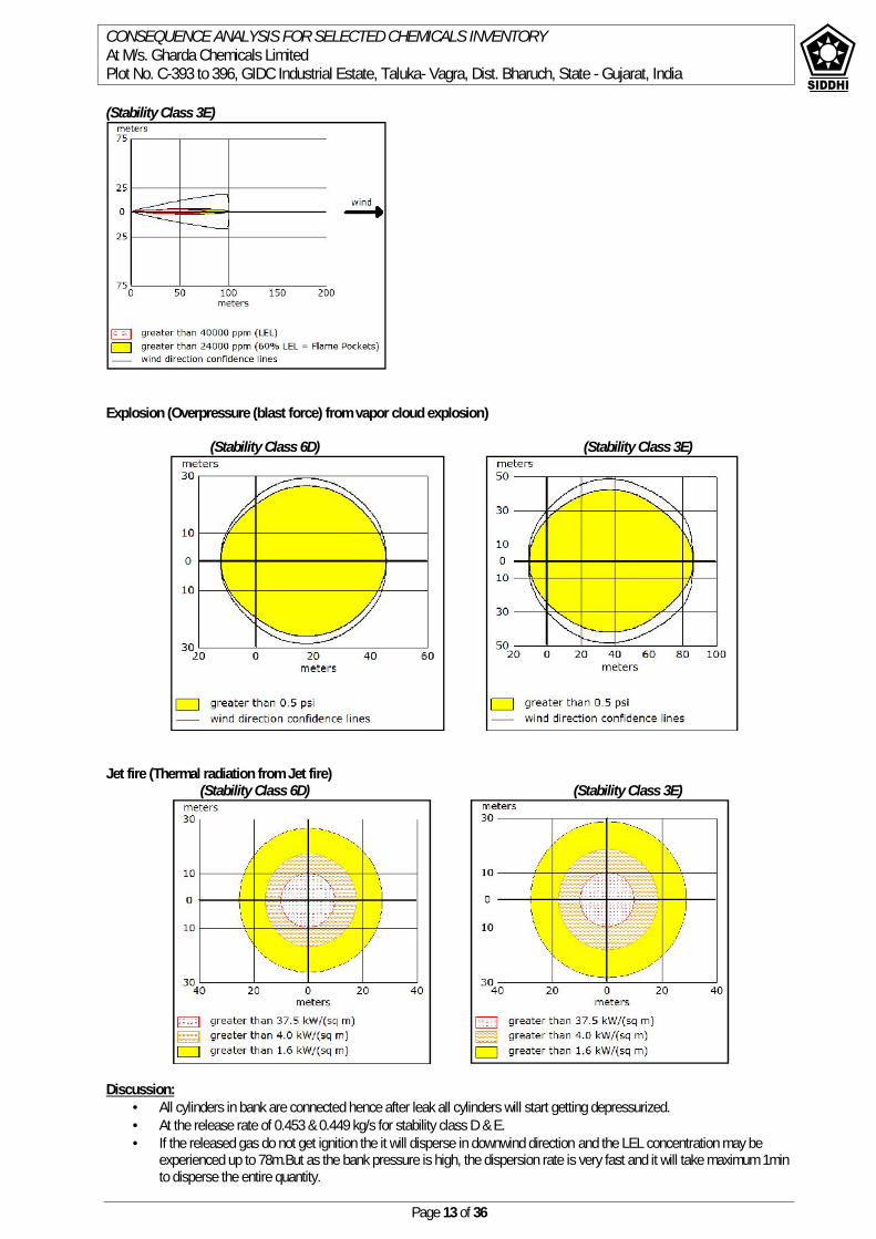
CONSEQUENCE ANALYSIS FOR SELECTED CHEMICALS INVENTORYAt M/s. Gharda Chemicals LimitedPlot No. C-393 to 396, GIDC Industrial Estate, Taluka- Vagra, Dist. Bharuch, State - Gujarat, India
Page 13 of 36
(Stability Class 3E)
Explosion (Overpressure (blast force) from vapor cloud explosion)
(Stability Class 6D) (Stability Class 3E)
Jet fire (Thermal radiation from Jet fire)(Stability Class 6D) (Stability Class 3E)
Discussion: All cylinders in bank are connected hence after leak all cylinders will start getting depressurized. At the release rate of 0.453 & 0.449 kg/s for stability class D & E. If the released gas do not get ignition the it will disperse in downwind direction and the LEL concentration may be
experienced up to 78m.But as the bank pressure is high, the dispersion rate is very fast and it will take maximum 1minto disperse the entire quantity.

CONSEQUENCE ANALYSIS FOR SELECTED CHEMICALS INVENTORYAt M/s. Gharda Chemicals LimitedPlot No. C-393 to 396, GIDC Industrial Estate, Taluka- Vagra, Dist. Bharuch, State - Gujarat, India
Page 14 of 36
Generally such high velocity hydrogen jet will get ignited immediately. The burning will occur and it will end within 20secs (completely burning 27.0 kg in Bank).
At this rate the radiation effect of Jet Fire are maximum. The radiation of 37.5 Kw/m2 will be experienced up to 10m from jet source. The radiation of 4.0 & 1.6 Kw/m2 will be experienced up to 19m & 29m from jet source respectively. The flame length is 4m at start. This is due to high pressure inside of the cylinder. Practically it will take more time but with less release rate. As pressure will reduce inside cylinder the release rate will
also reduced. In hydrogen case, there is possibility of explosion due to such release. The overpressure of 0.5 psi overpressure is experienced up to 46m & 87m for stability class D & E respectively. This
overpressure can shatter glasses.
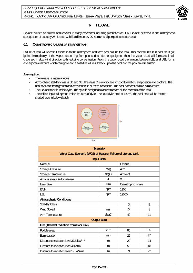
CONSEQUENCE ANALYSIS FOR SELECTED CHEMICALS INVENTORYAt M/s. Gharda Chemicals LimitedPlot No. C-393 to 396, GIDC Industrial Estate, Taluka- Vagra, Dist. Bharuch, State - Gujarat, India
Page 15 of 36
6 HEXANE
Hexane is used as solvent and reactant in many processes including production of PEK. Hexane is stored in one atmosphericstorage tank of capacity 25 kL each with liquid inventory 20 kL max and pumped to reactor area.
6.1 CATASTROPHIC FAILURE OF STORAGE TANK
Failure of tank will release Hexane in to the atmosphere and form pool around the tank. This pool will result in pool fire if gotignited immediately. If the vapors dispersing from pool surface do not get ignited then the vapor cloud will form and it willdispersed in downwind direction with reducing concentration. From this vapor cloud the amount between LEL and UEL formsand explosive mixture which can ignite and a flash fire will result back up to the pool and the pool fire will sustain.
Assumption: The release is instantaneous Atmospheric stability class is 6D and 3E .The class D is worst case for pool formation, evaporation and pool fire. The
heat available from ground and atmosphere is at these conditions. The pool evaporation rate is maximum. The Hexane tank is inside dyke. The dyke is designed to accommodate all the contents of the tank. The spilled liquid will spread inside the area of dyke. The total dyke area is 100m2. The pool area will be the red
shaded area in below sketch.
ScenarioWorst Case Scenario (WCS) of Hexane, Failure of storage tank
Input DataMaterial HexaneStorage Pressure barg AtmStorage Temperature degC AmbientAmount available for release kL 20Leak Size mm Catastrophic failureIDLH ppm 1100LEL ppm 12000Atmospheric ConditionsStability Class D EWind Speed m/s 6 3Atm. Temperature degC 42 11
Output DataFire (Thermal radiation from Pool Fire)Puddle area sq.m 85 85Burn duration min 22 27Distance to radiation level 37.5 kW/m2 m 20 14Distance to radiation level 4 kW/m2 m 50 48Distance to radiation level 1.6 kW/m2 m 71 72

CONSEQUENCE ANALYSIS FOR SELECTED CHEMICALS INVENTORYAt M/s. Gharda Chemicals LimitedPlot No. C-393 to 396, GIDC Industrial Estate, Taluka- Vagra, Dist. Bharuch, State - Gujarat, India
Page 16 of 36
Flammability Effect:
Pool Fire (Thermal radiation from Pool Fire)(Stability Class 6D) (Stability Class 3E)
Discussion: The released Hexane will contain in the dyke. From this pool it will vaporize,
The released vapors will then disperse in downwind direction. The evaporation rate is 1336 gm/s& 208 gm/s for atmospheric class D & E respectively. The burn rate during pool fire is 9.58 & 8.22 kg/s for atmospheric class D & E respectively. The radiation of 37.5kw/m2 will be experienced at 20 & 14 m for atmospheric class D & E respectively. The radiation of 4.0 kw/m2 will be experienced at 50 & 48 m for atmospheric class D & E respectively. The radiation of 1.6 kw/m2 will be experienced at 71 & 72 for atmospheric class D & E respectively. The fire fighting is required to keep the adjacent tank cool. The fire fighting distance should be from at distance of
minimum 15m from tank dyke with fire resistant clothing. Foam can be used to control the fire. The storage should have proper breathing arrangement.
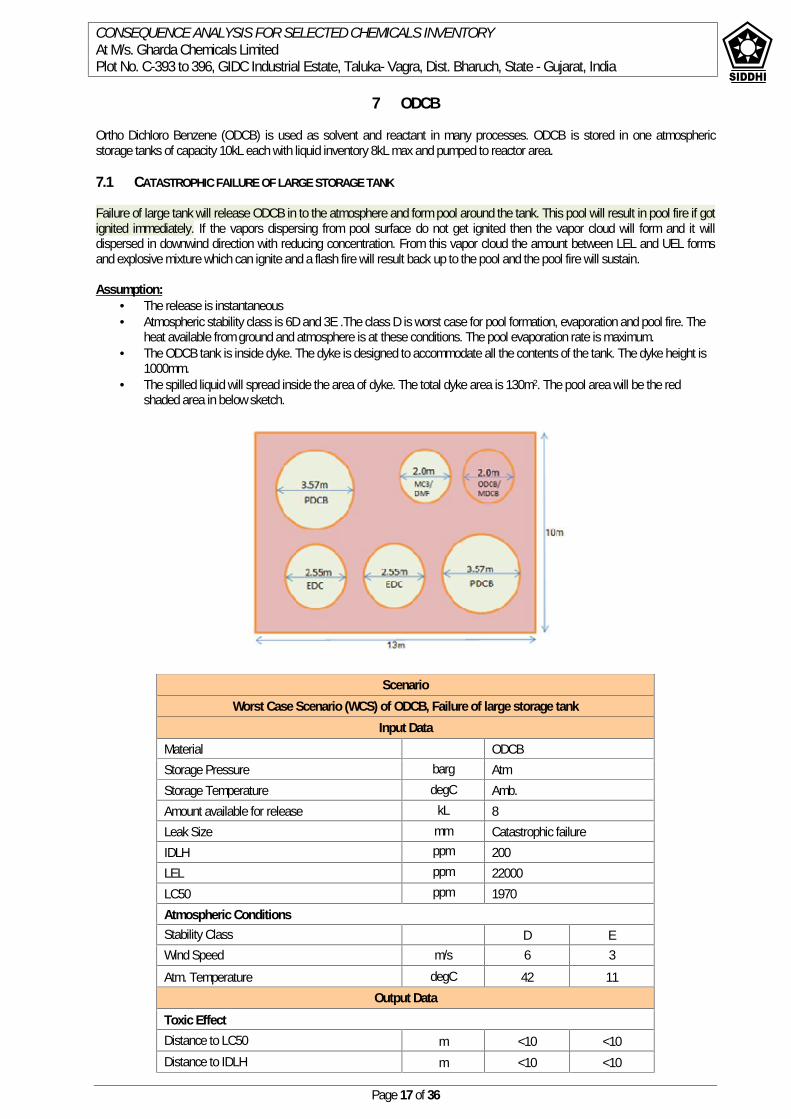
CONSEQUENCE ANALYSIS FOR SELECTED CHEMICALS INVENTORYAt M/s. Gharda Chemicals LimitedPlot No. C-393 to 396, GIDC Industrial Estate, Taluka- Vagra, Dist. Bharuch, State - Gujarat, India
Page 17 of 36
7 ODCB
Ortho Dichloro Benzene (ODCB) is used as solvent and reactant in many processes. ODCB is stored in one atmosphericstorage tanks of capacity 10kL each with liquid inventory 8kL max and pumped to reactor area.
7.1 CATASTROPHIC FAILURE OF LARGE STORAGE TANK
Failure of large tank will release ODCB in to the atmosphere and form pool around the tank. This pool will result in pool fire if gotignited immediately. If the vapors dispersing from pool surface do not get ignited then the vapor cloud will form and it willdispersed in downwind direction with reducing concentration. From this vapor cloud the amount between LEL and UEL formsand explosive mixture which can ignite and a flash fire will result back up to the pool and the pool fire will sustain.
Assumption: The release is instantaneous Atmospheric stability class is 6D and 3E .The class D is worst case for pool formation, evaporation and pool fire. The
heat available from ground and atmosphere is at these conditions. The pool evaporation rate is maximum. The ODCB tank is inside dyke. The dyke is designed to accommodate all the contents of the tank. The dyke height is
1000mm. The spilled liquid will spread inside the area of dyke. The total dyke area is 130m2. The pool area will be the red
shaded area in below sketch.
ScenarioWorst Case Scenario (WCS) of ODCB, Failure of large storage tank
Input DataMaterial ODCBStorage Pressure barg AtmStorage Temperature degC Amb.Amount available for release kL 8Leak Size mm Catastrophic failureIDLH ppm 200LEL ppm 22000LC50 ppm 1970Atmospheric ConditionsStability Class D EWind Speed m/s 6 3Atm. Temperature degC 42 11
Output DataToxic EffectDistance to LC50 m <10 <10Distance to IDLH m <10 <10
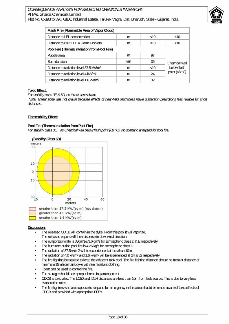
CONSEQUENCE ANALYSIS FOR SELECTED CHEMICALS INVENTORYAt M/s. Gharda Chemicals LimitedPlot No. C-393 to 396, GIDC Industrial Estate, Taluka- Vagra, Dist. Bharuch, State - Gujarat, India
Page 18 of 36
Toxic Effect:For stability class 3E & 6D, no threat zone drawnNote: Threat zone was not drawn because effects of near-field patchiness make dispersion predictions less reliable for short
distances.
Flammability Effect:
Pool Fire (Thermal radiation from Pool Fire)For stability class 3E , as Chemical well below flash point (68 °C). No scenario analyzed for pool fire.
(Stability Class 6D)
Discussion: The released ODCB will contain in the dyke. From this pool it will vaporize,
The released vapors will then disperse in downwind direction. The evaporation rate is 38gm/s& 3.6 gm/s for atmospheric class D & E respectively. The burn rate during pool fire is 4.26 kg/s for atmospheric class D. The radiation of 37.5kw/m2 will be experienced at less than 10m. The radiation of 4.0 kw/m2 and 1.6 kw/m2 will be experienced at 24 & 32 respectively. The fire fighting is required to keep the adjacent tank cool. The fire fighting distance should be from at distance of
minimum 15m from tank dyke with fire resistant clothing. Foam can be used to control the fire. The storage should have proper breathing arrangement ODCB is toxic also. The LC50 and IDLH distances are less than 10m from leak source. This is due to very less
evaporation rates. The fire fighters who are suppose to respond for emergency in this area should be made aware of toxic effects of
ODCB and provided with appropriate PPEs
Flash Fire ( Flammable Area of Vapor Cloud)Distance to LEL concentration m <10 <10Distance to 60% LEL = Flame Pockets m <10 <10Pool Fire (Thermal radiation from Pool Fire)Puddle area m 97
Chemical wellbelow flash
point (68 °C)
Burn duration min 35Distance to radiation level 37.5 kW/m2 m <10Distance to radiation level 4 kW/m2 m 24Distance to radiation level 1.6 kW/m2 m 32
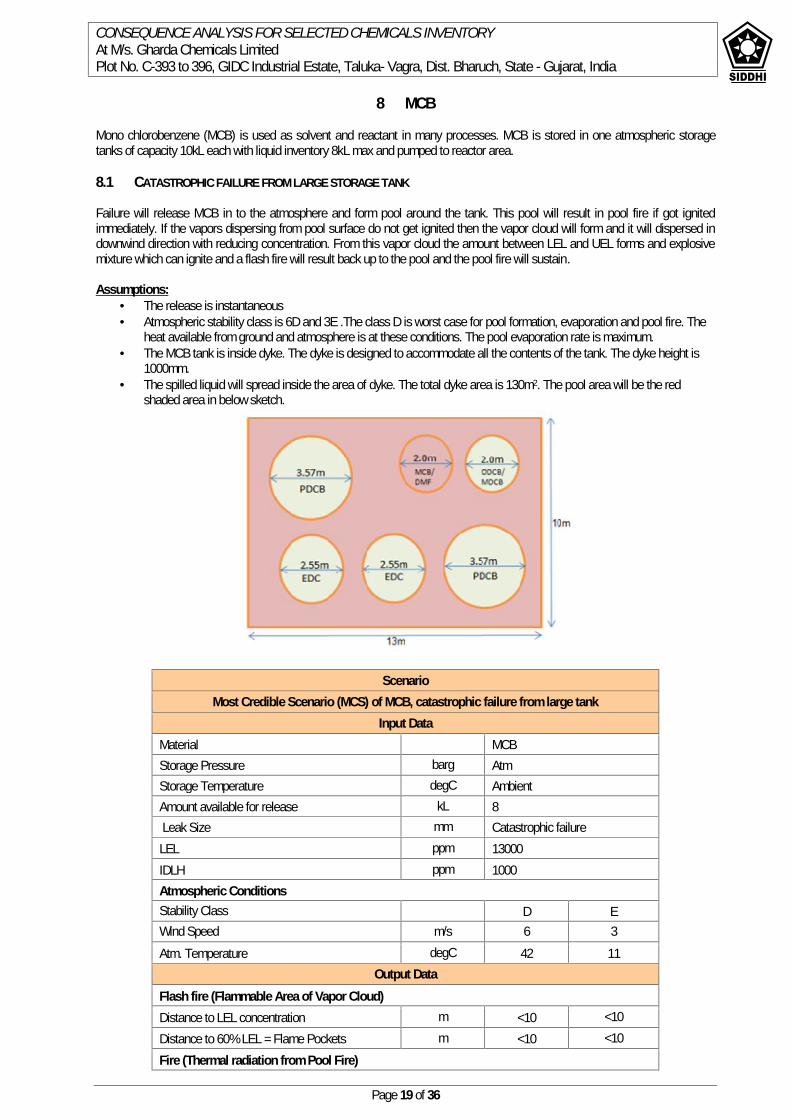
CONSEQUENCE ANALYSIS FOR SELECTED CHEMICALS INVENTORYAt M/s. Gharda Chemicals LimitedPlot No. C-393 to 396, GIDC Industrial Estate, Taluka- Vagra, Dist. Bharuch, State - Gujarat, India
Page 19 of 36
8 MCB
Mono chlorobenzene (MCB) is used as solvent and reactant in many processes. MCB is stored in one atmospheric storagetanks of capacity 10kL each with liquid inventory 8kL max and pumped to reactor area.
8.1 CATASTROPHIC FAILURE FROM LARGE STORAGE TANK
Failure will release MCB in to the atmosphere and form pool around the tank. This pool will result in pool fire if got ignitedimmediately. If the vapors dispersing from pool surface do not get ignited then the vapor cloud will form and it will dispersed indownwind direction with reducing concentration. From this vapor cloud the amount between LEL and UEL forms and explosivemixture which can ignite and a flash fire will result back up to the pool and the pool fire will sustain.
Assumptions: The release is instantaneous Atmospheric stability class is 6D and 3E .The class D is worst case for pool formation, evaporation and pool fire. The
heat available from ground and atmosphere is at these conditions. The pool evaporation rate is maximum. The MCB tank is inside dyke. The dyke is designed to accommodate all the contents of the tank. The dyke height is
1000mm. The spilled liquid will spread inside the area of dyke. The total dyke area is 130m2. The pool area will be the red
shaded area in below sketch.
ScenarioMost Credible Scenario (MCS) of MCB, catastrophic failure from large tank
Input DataMaterial MCBStorage Pressure barg AtmStorage Temperature degC AmbientAmount available for release kL 8Leak Size mm Catastrophic failure
LEL ppm 13000IDLH ppm 1000Atmospheric ConditionsStability Class D EWind Speed m/s 6 3Atm. Temperature degC 42 11
Output DataFlash fire (Flammable Area of Vapor Cloud)Distance to LEL concentration m <10 <10Distance to 60% LEL = Flame Pockets m <10 <10Fire (Thermal radiation from Pool Fire)

CONSEQUENCE ANALYSIS FOR SELECTED CHEMICALS INVENTORYAt M/s. Gharda Chemicals LimitedPlot No. C-393 to 396, GIDC Industrial Estate, Taluka- Vagra, Dist. Bharuch, State - Gujarat, India
Page 20 of 36
Puddle area sq. m 97Chemical well
below flashpoint (29degC).
Burn Duration min. 22Distance to radiation level 37.5 kW/m2 m 12Distance to radiation level 4 kW/m2 m 32Distance to radiation level 1.6 kW/m2 m 43
Flammability Effect:
Flash fire (Flammable Area of Vapor Cloud)For stability class 3E & 6D- threat zone not drawnNote: Threat zone was not drawn because effects of near-field patchiness make dispersion predictions less reliable for shortdistances.
Pool Fire (Thermal radiation from Pool Fire)For stability class 3E - Chemical well below flash point (29 °C).No scenario analyzed for pool fire.
(Stability Class 6D)
Discussion: The released MCB will contain in the dyke. From this pool it will vaporize,
The released vapors will then disperse in downwind direction. The evaporation rate is 178gm/s & 27 gm/s for atmospheric class D & E respectively. The burn rate during pool fire is 5.87 kg/s for atmospheric class D The radiation of 37.5kw/m2 will be experienced up to 12m. The radiation of 4.0 kw/m2 and 1.6 kw/m2 will be experienced at 32 & 43 respectively. The fire fighting is required to keep the adjacent tank cool. The fire fighting distance should be from at distance of
minimum 15m from tank dyke with fire resistant clothing. Foam can be used to control the fire. The storage should have proper breathing arrangement.
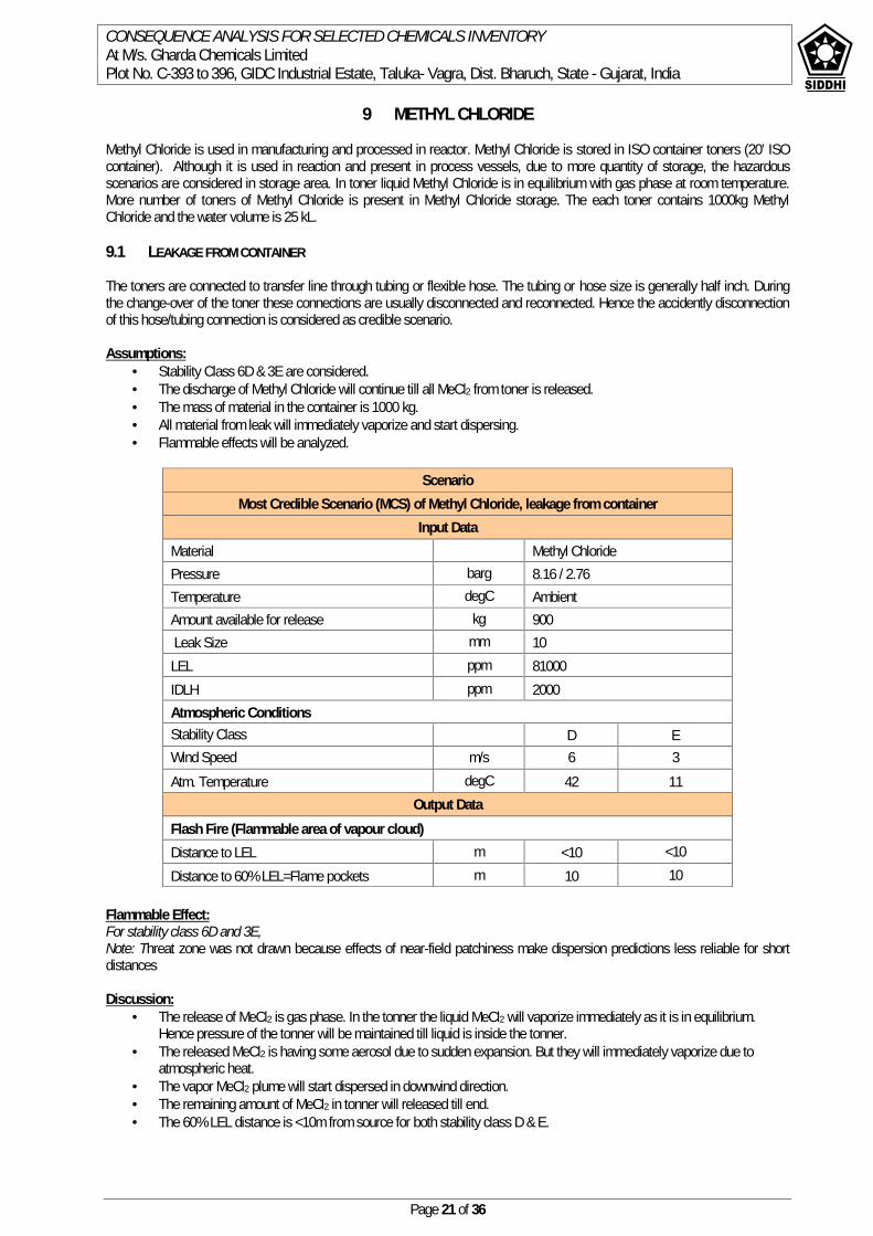
CONSEQUENCE ANALYSIS FOR SELECTED CHEMICALS INVENTORYAt M/s. Gharda Chemicals LimitedPlot No. C-393 to 396, GIDC Industrial Estate, Taluka- Vagra, Dist. Bharuch, State - Gujarat, India
Page 21 of 36
9 METHYL CHLORIDE
Methyl Chloride is used in manufacturing and processed in reactor. Methyl Chloride is stored in ISO container toners (20’ ISOcontainer). Although it is used in reaction and present in process vessels, due to more quantity of storage, the hazardousscenarios are considered in storage area. In toner liquid Methyl Chloride is in equilibrium with gas phase at room temperature.More number of toners of Methyl Chloride is present in Methyl Chloride storage. The each toner contains 1000kg MethylChloride and the water volume is 25 kL.
9.1 LEAKAGE FROM CONTAINER
The toners are connected to transfer line through tubing or flexible hose. The tubing or hose size is generally half inch. Duringthe change-over of the toner these connections are usually disconnected and reconnected. Hence the accidently disconnectionof this hose/tubing connection is considered as credible scenario.
Assumptions: Stability Class 6D & 3E are considered. The discharge of Methyl Chloride will continue till all MeCl2 from toner is released. The mass of material in the container is 1000 kg. All material from leak will immediately vaporize and start dispersing. Flammable effects will be analyzed.
Flammable Effect:For stability class 6D and 3E,Note: Threat zone was not drawn because effects of near-field patchiness make dispersion predictions less reliable for shortdistances
Discussion: The release of MeCl2 is gas phase. In the tonner the liquid MeCl2 will vaporize immediately as it is in equilibrium.
Hence pressure of the tonner will be maintained till liquid is inside the tonner. The released MeCl2 is having some aerosol due to sudden expansion. But they will immediately vaporize due to
atmospheric heat. The vapor MeCl2 plume will start dispersed in downwind direction. The remaining amount of MeCl2 in tonner will released till end. The 60% LEL distance is <10m from source for both stability class D & E.
ScenarioMost Credible Scenario (MCS) of Methyl Chloride, leakage from container
Input DataMaterial Methyl ChloridePressure barg 8.16 / 2.76Temperature degC AmbientAmount available for release kg 900Leak Size mm 10
LEL ppm 81000IDLH ppm 2000Atmospheric ConditionsStability Class D EWind Speed m/s 6 3Atm. Temperature degC 42 11
Output DataFlash Fire (Flammable area of vapour cloud)Distance to LEL m <10 <10Distance to 60% LEL=Flame pockets m 10 10
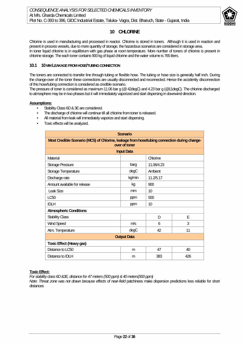
CONSEQUENCE ANALYSIS FOR SELECTED CHEMICALS INVENTORYAt M/s. Gharda Chemicals LimitedPlot No. C-393 to 396, GIDC Industrial Estate, Taluka- Vagra, Dist. Bharuch, State - Gujarat, India
Page 22 of 36
10 CHLORINE
Chlorine is used in manufacturing and processed in reactor. Chlorine is stored in toners. Although it is used in reaction andpresent in process vessels, due to more quantity of storage, the hazardous scenarios are considered in storage area.In toner liquid chlorine is in equilibrium with gas phase at room temperature. More number of toners of chlorine is present inchlorine storage. The each toner contains 900 kg of liquid chlorine and the water volume is 765 liters.
10.1 10 MM LEAKAGE FROM HOSE/TUBING CONNECTION
The toners are connected to transfer line through tubing or flexible hose. The tubing or hose size is generally half inch. Duringthe change-over of the toner these connections are usually disconnected and reconnected. Hence the accidently disconnectionof this hose/tubing connection is considered as credible scenario.The pressure of toner is considered as maximum 11.06 bar g (@ 42degC) and 4.23 bar g (@11degC). The chlorine dischargedto atmosphere may be in two phases but it will immediately vaporized and start dispersing in downwind direction.
Assumptions: Stability Class 6D & 3E are considered. The discharge of chlorine will continue till all chlorine from toner is released. All material from leak will immediately vaporize and start dispersing. Toxic effects will be analyzed.
ScenarioMost Credible Scenario (MCS) of Chlorine, leakage from hose/tubing connection during change-
over of tonerInput Data
Material ChlorineStorage Pressure barg 11.06/4.23Storage Temperature degC AmbientDischarge rate kg/min 11.2/5.17Amount available for release kg 900Leak Size mm 10
LC50 ppm 500IDLH ppm 10Atmospheric ConditionsStability Class D EWind Speed m/s 6 3Atm. Temperature degC 42 11
Output DataToxic Effect (Heavy gas)Distance to LC50 m 47 40Distance to IDLH m 383 426
Toxic Effect:For stability class 6D &3E, distance for 47 meters (500 ppm) & 40 meters(500 ppm)Note: Threat zone was not drawn because effects of near-field patchiness make dispersion predictions less reliable for shortdistances
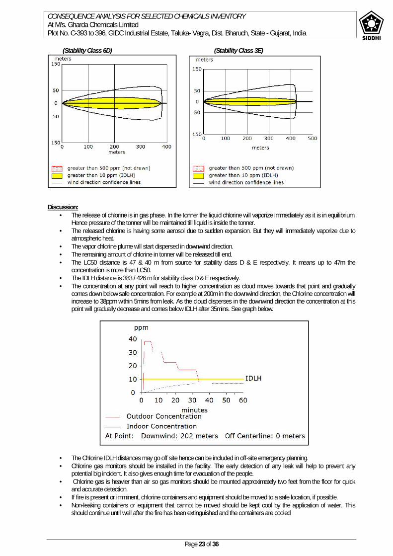
CONSEQUENCE ANALYSIS FOR SELECTED CHEMICALS INVENTORYAt M/s. Gharda Chemicals LimitedPlot No. C-393 to 396, GIDC Industrial Estate, Taluka- Vagra, Dist. Bharuch, State - Gujarat, India
Page 23 of 36
(Stability Class 6D) (Stability Class 3E)
Discussion: The release of chlorine is in gas phase. In the tonner the liquid chlorine will vaporize immediately as it is in equilibrium.
Hence pressure of the tonner will be maintained till liquid is inside the tonner. The released chlorine is having some aerosol due to sudden expansion. But they will immediately vaporize due to
atmospheric heat. The vapor chlorine plume will start dispersed in downwind direction. The remaining amount of chlorine in tonner will be released till end. The LC50 distance is 47 & 40 m from source for stability class D & E respectively. It means up to 47m the
concentration is more than LC50. The IDLH distance is 383 / 426 m for stability class D & E respectively. The concentration at any point will reach to higher concentration as cloud moves towards that point and gradually
comes down below safe concentration. For example at 200m in the downwind direction, the Chlorine concentration willincrease to 38ppm within 5mins from leak. As the cloud disperses in the downwind direction the concentration at thispoint will gradually decrease and comes below IDLH after 35mins. See graph below.
The Chlorine IDLH distances may go off site hence can be included in off-site emergency planning. Chlorine gas monitors should be installed in the facility. The early detection of any leak will help to prevent any
potential big incident. It also gives enough time for evacuation of the people. Chlorine gas is heavier than air so gas monitors should be mounted approximately two feet from the floor for quick
and accurate detection. If fire is present or imminent, chlorine containers and equipment should be moved to a safe location, if possible. Non-leaking containers or equipment that cannot be moved should be kept cool by the application of water. This
should continue until well after the fire has been extinguished and the containers are cooled
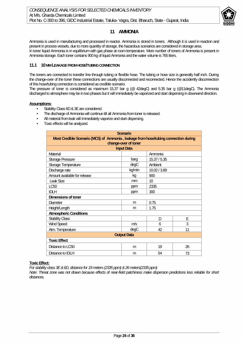
CONSEQUENCE ANALYSIS FOR SELECTED CHEMICALS INVENTORYAt M/s. Gharda Chemicals LimitedPlot No. C-393 to 396, GIDC Industrial Estate, Taluka- Vagra, Dist. Bharuch, State - Gujarat, India
Page 24 of 36
11 AMMONIA
Ammonia is used in manufacturing and processed in reactor. Ammonia is stored in toners. Although it is used in reaction andpresent in process vessels, due to more quantity of storage, the hazardous scenarios are considered in storage area.In toner liquid Ammonia is in equilibrium with gas phase at room temperature. More number of toners of Ammonia is present inAmmonia storage. Each toner contains 900 kg of liquid Ammonia and the water volume is 765 liters.
11.1 10 MM LEAKAGE FROM HOSE/TUBING CONNECTION
The toners are connected to transfer line through tubing or flexible hose. The tubing or hose size is generally half inch. Duringthe change-over of the toner these connections are usually disconnected and reconnected. Hence the accidently disconnectionof this hose/tubing connection is considered as credible scenario.The pressure of toner is considered as maximum 15.37 bar g (@ 42degC) and 5.35 bar g (@11degC). The Ammoniadischarged to atmosphere may be in two phases but it will immediately be vaporized and start dispersing in downwind direction.
Assumptions: Stability Class 6D & 3E are considered. The discharge of Ammonia will continue till all Ammonia from toner is released. All material from leak will immediately vaporize and start dispersing. Toxic effects will be analyzed.
ScenarioMost Credible Scenario (MCS) of Ammonia , leakage from hose/tubing connection during
change-over of tonerInput Data
Material AmmoniaStorage Pressure barg 15.37 / 5.35Storage Temperature degC AmbientDischarge rate kg/min 10.02 / 3.89Amount available for release kg 900Leak Size mm 10
LC50 ppm 2335IDLH ppm 300Dimensions of tonerDiameter m 0.75Height/Length m 1.75Atmospheric ConditionsStability Class D EWind Speed m/s 6 3Atm. Temperature degC 42 11
Output DataToxic EffectDistance to LC50 m 19 26Distance to IDLH m 54 73
Toxic Effect:For stability class 3E & 6D, distance for 19 meters (2335 ppm) & 26 meters(2335 ppm)Note: Threat zone was not drawn because effects of near-field patchiness make dispersion predictions less reliable for shortdistances.

CONSEQUENCE ANALYSIS FOR SELECTED CHEMICALS INVENTORYAt M/s. Gharda Chemicals LimitedPlot No. C-393 to 396, GIDC Industrial Estate, Taluka- Vagra, Dist. Bharuch, State - Gujarat, India
Page 25 of 36
(Stability Class 6D) (Stability Class 3E)
Discussion: The release of Ammonia is in gas phase. In the toner the liquid Ammonia will vaporize immediately as it is in
equilibrium. Hence pressure of the tonner will be maintained till liquid is inside the tonner. The released Ammonia is having some aerosol due to sudden expansion. But they will immediately vaporize due to
atmospheric heat. The vapor Ammonia plume will start dispersed in downwind direction. The remaining amount of Ammonia in tonner will released till end. The LC50 distance is 19 & 26 m from source for stability class D & E respectively. It means up to 26m the
concentration is more than LC50. The IDLH distance is 54 / 73 m for stability class D & E respectively

CONSEQUENCE ANALYSIS FOR SELECTED CHEMICALS INVENTORYAt M/s. Gharda Chemicals LimitedPlot No. C-393 to 396, GIDC Industrial Estate, Taluka- Vagra, Dist. Bharuch, State - Gujarat, India
Page 26 of 36
12 SULFURIC ACID
Sulfuric acid is used in manufacturing. On release to the atmosphere it will release SO3.The toxic effect of SO3 is modeled forsulfuric acid release scenarios. Sulfuric acid is stored in two 50kL atmospheric storage tanks.
12.1 CATASTROPHIC FAILURE OF LARGE STORAGE TANK
Failure of storage tank will release sulfuric acid in to the atmosphere and form pool around the tank. The vapors will startreleasing from sulfuric acid pool formed around the tanks inside the dyke. For this analysis, it was conservatively assumed thatthe sulfuric acid stored in the tank contains 4% sulfur trioxide (oleum). However, the actual amount of oleum in 96% sulfuric acidis negligible. Nevertheless, to be conservative, a 4% oleum concentration was used as input into the ALOHA model to simulatea release of sulfuric acid.
Assumptions: The release is instantaneous Atmospheric stability class is 6D and 3E .The class D is worst case for pool formation, evaporation and pool fire. The
heat available from ground and atmosphere is at these conditions. The pool evaporation rate is maximum. The Sulfuric Acid tanks are inside dyke. The dyke is designed to accommodate all the contents of a single tank. The
dyke height is 1000mm. The spilled liquid will spread inside the area of bund with pool height of 900 mm (equal to dyke height).The pool area
is 45 m2.
The total dyke area = 9.0*5.0 = 44.45m2
(Ref shaded area in sketch below)The pool area is approximated to 45m2.
ScenarioWorst Case Scenario (WCS) of Sulfuric acid, Failure of large storage tank
Input DataMaterial Sulfuric acidStorage Pressure barg 4Storage Temperature degC AmbientAmount available for release m3 38Leak Size mm Catastrophic failureLC50 ppm 1375Tank Dimensions
Diameter m 3.57Height/Length m 5.0Atmospheric ConditionsStability Class D EWind Speed m/s 6 3Atm. Temperature degC 42 11
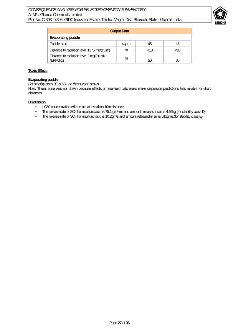
CONSEQUENCE ANALYSIS FOR SELECTED CHEMICALS INVENTORYAt M/s. Gharda Chemicals LimitedPlot No. C-393 to 396, GIDC Industrial Estate, Taluka- Vagra, Dist. Bharuch, State - Gujarat, India
Page 27 of 36
Toxic Effect:
Evaporating puddleFor stability class 3E & 6D, no threat zone drawn.Note: Threat zone was not drawn because effects of near-field patchiness make dispersion predictions less reliable for shortdistances.
Discussion: LC50 concentration will remain at less than 10m distance. The release rate of SO3 from sulfuric acid is 75.1 gm/min and amount released in air is 4.56kg.(for stability class D) The release rate of SO3 from sulfuric acid is 10.2gm/s and amount released in air is 611gms.(for stability class E)
Output DataEvaporating puddlePuddle area sq. m 45 45Distance to radiation level 1375 mg/(cu m) m <10 <10Distance to radiation level 2 mg/(cu m)(ERPG-1) m 50 30
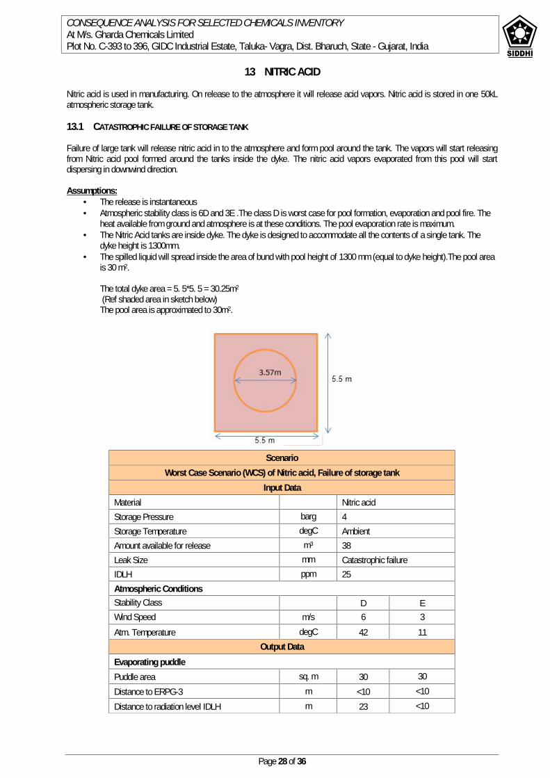
CONSEQUENCE ANALYSIS FOR SELECTED CHEMICALS INVENTORYAt M/s. Gharda Chemicals LimitedPlot No. C-393 to 396, GIDC Industrial Estate, Taluka- Vagra, Dist. Bharuch, State - Gujarat, India
Page 28 of 36
13 NITRIC ACID
Nitric acid is used in manufacturing. On release to the atmosphere it will release acid vapors. Nitric acid is stored in one 50kLatmospheric storage tank.
13.1 CATASTROPHIC FAILURE OF STORAGE TANK
Failure of large tank will release nitric acid in to the atmosphere and form pool around the tank. The vapors will start releasingfrom Nitric acid pool formed around the tanks inside the dyke. The nitric acid vapors evaporated from this pool will startdispersing in downwind direction.
Assumptions: The release is instantaneous Atmospheric stability class is 6D and 3E .The class D is worst case for pool formation, evaporation and pool fire. The
heat available from ground and atmosphere is at these conditions. The pool evaporation rate is maximum. The Nitric Acid tanks are inside dyke. The dyke is designed to accommodate all the contents of a single tank. The
dyke height is 1300mm. The spilled liquid will spread inside the area of bund with pool height of 1300 mm (equal to dyke height).The pool area
is 30 m2.
The total dyke area = 5. 5*5. 5 = 30.25m2
(Ref shaded area in sketch below)The pool area is approximated to 30m2.
ScenarioWorst Case Scenario (WCS) of Nitric acid, Failure of storage tank
Input DataMaterial Nitric acidStorage Pressure barg 4Storage Temperature degC AmbientAmount available for release m3 38Leak Size mm Catastrophic failureIDLH ppm 25Atmospheric ConditionsStability Class D EWind Speed m/s 6 3Atm. Temperature degC 42 11
Output DataEvaporating puddlePuddle area sq. m 30 30Distance to ERPG-3 m <10 <10Distance to radiation level IDLH m 23 <10
CONSEQUENCE ANALYSIS FOR SELECTED CHEMICALS INVENTORYAt M/s. Gharda Chemicals LimitedPlot No. C-393 to 396, GIDC Industrial Estate, Taluka- Vagra, Dist. Bharuch, State - Gujarat, India
Page 29 of 36
Toxic Effect:
Evaporating puddleFor stability class 3E & 6D, no threat zone drawn.Note: Threat zone was not drawn because effects of near-field patchiness make dispersion predictions less reliable for shortdistances.
Discussion: ERPG3 concentration (78ppm) will remain at less than 10m distance. The release rate of Nitric acid is 726 gm/min and amount released in air is 43.5kg.(for stability class D) The release rate of SO3 from Nitric acid is 71.2gm/s and amount released in air is 4.22kg.(for stability class E)
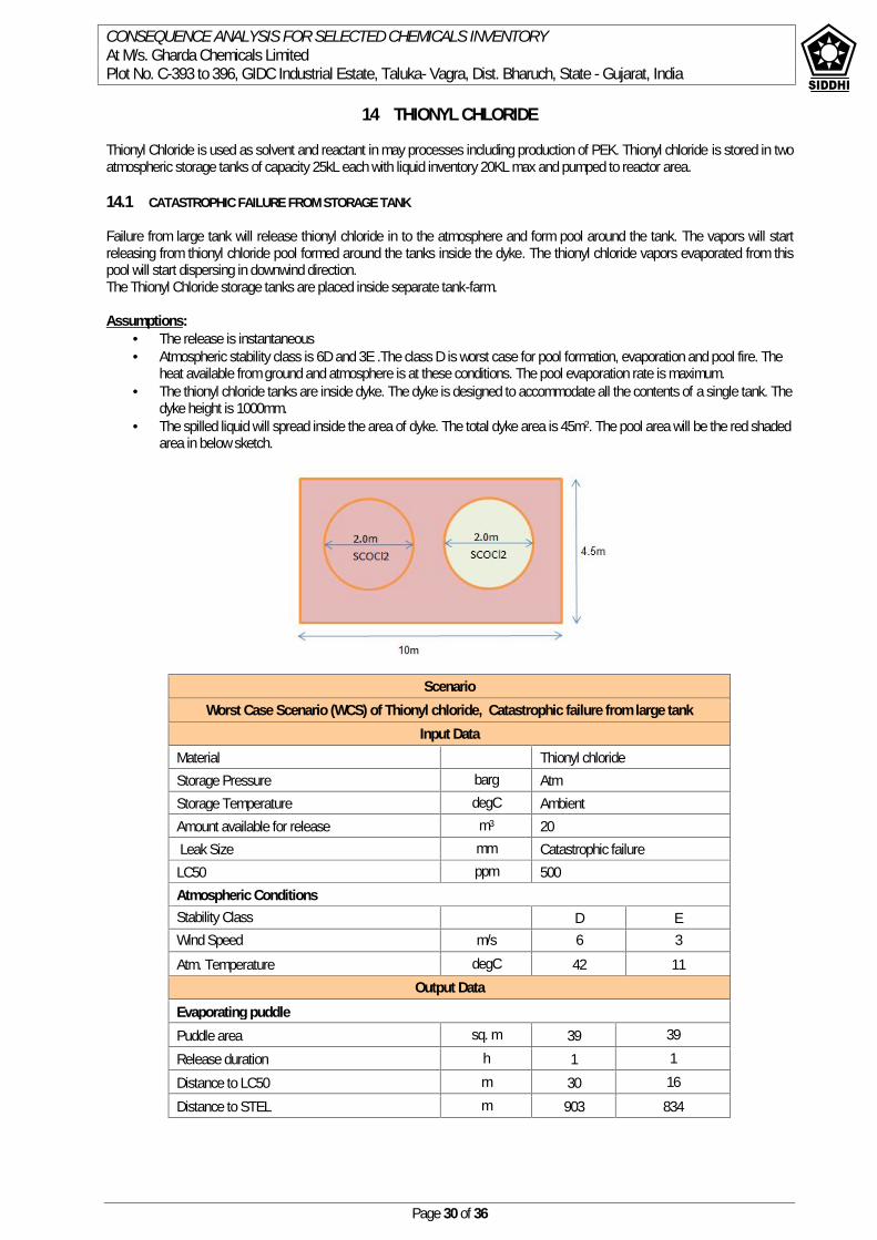
CONSEQUENCE ANALYSIS FOR SELECTED CHEMICALS INVENTORYAt M/s. Gharda Chemicals LimitedPlot No. C-393 to 396, GIDC Industrial Estate, Taluka- Vagra, Dist. Bharuch, State - Gujarat, India
Page 30 of 36
14 THIONYL CHLORIDE
Thionyl Chloride is used as solvent and reactant in may processes including production of PEK. Thionyl chloride is stored in twoatmospheric storage tanks of capacity 25kL each with liquid inventory 20KL max and pumped to reactor area.
14.1 CATASTROPHIC FAILURE FROM STORAGE TANK
Failure from large tank will release thionyl chloride in to the atmosphere and form pool around the tank. The vapors will startreleasing from thionyl chloride pool formed around the tanks inside the dyke. The thionyl chloride vapors evaporated from thispool will start dispersing in downwind direction.The Thionyl Chloride storage tanks are placed inside separate tank-farm.
Assumptions: The release is instantaneous Atmospheric stability class is 6D and 3E .The class D is worst case for pool formation, evaporation and pool fire. The
heat available from ground and atmosphere is at these conditions. The pool evaporation rate is maximum. The thionyl chloride tanks are inside dyke. The dyke is designed to accommodate all the contents of a single tank. The
dyke height is 1000mm. The spilled liquid will spread inside the area of dyke. The total dyke area is 45m2. The pool area will be the red shaded
area in below sketch.
ScenarioWorst Case Scenario (WCS) of Thionyl chloride, Catastrophic failure from large tank
Input DataMaterial Thionyl chlorideStorage Pressure barg AtmStorage Temperature degC AmbientAmount available for release m3 20Leak Size mm Catastrophic failure
LC50 ppm 500Atmospheric ConditionsStability Class D EWind Speed m/s 6 3Atm. Temperature degC 42 11
Output DataEvaporating puddlePuddle area sq. m 39 39Release duration h 1 1Distance to LC50 m 30 16Distance to STEL m 903 834
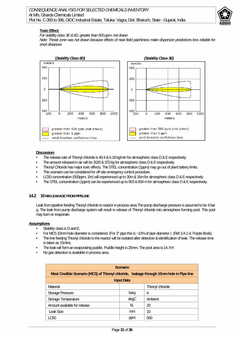
CONSEQUENCE ANALYSIS FOR SELECTED CHEMICALS INVENTORYAt M/s. Gharda Chemicals LimitedPlot No. C-393 to 396, GIDC Industrial Estate, Taluka- Vagra, Dist. Bharuch, State - Gujarat, India
Page 31 of 36
Toxic Effect:For stability class 3E & 6D, greater than 500 ppm- not drawnNote: Threat zone was not drawn because effects of near-field patchiness make dispersion predictions less reliable forshort distances
(Stability Class 6D) (Stability Class 3E)
Discussion: The release rate of Thionyl chloride is 40.4 & 6.18 kg/min for atmospheric class D & E respectively. The amount released in air will be 2020 & 370 kg for atmospheric class D & E respectively. Thionyl Chloride has major toxic effects. The STEL concentration (1ppm) may go out of plant battery limits. This scenario can be considered for off-site emergency control procedure. LC50 concentration (500ppm, 1hr) will experienced up to 30m & 16m for atmospheric class D & E respectively. The STEL concentration (1ppm) can be experienced up to 903 & 834 m for atmospheric class D & E respectively.
14.2 10 MM LEAKAGE FROM PIPELINE
Leak from pipeline feeding Thionyl chloride to reactor in process area.The pump discharge pressure is assumed to be 4 barg. The leak from pump discharge system will result in release of Thionyl chloride into atmosphere forming pool. This poolmay burn or evaporate.
Assumptions Stability class is D and E. For MCS 10mm hole diameter is considered. (For 3” pipe this is ~10% of pipe diameter ) (Ref 3.A.2.4, Purple Book). The line feeding Thionyl chloride to the reactor will be isolated after detection & identification of leak. The release time
is taken as 15mins. The leak will form an evaporating puddle. Puddle height is 25mm. The pool area is 14.7m2. No gas detection is available in process area.
ScenarioMost Credible Scenario (MCS) of Thionyl chloride, leakage through 10mm hole in Pipe line
Input DataMaterial Thionyl chlorideStorage Pressure barg 4Storage Temperature degC AmbientAmount available for release kL 20Leak Size mm 10
LC50 ppm 500

CONSEQUENCE ANALYSIS FOR SELECTED CHEMICALS INVENTORYAt M/s. Gharda Chemicals LimitedPlot No. C-393 to 396, GIDC Industrial Estate, Taluka- Vagra, Dist. Bharuch, State - Gujarat, India
Page 32 of 36
Toxic Effect:For stability class 3E & 6D, greater than 500 ppm- not drawnNote: Threat zone was not drawn because effects of near-field patchiness make dispersion predictions less reliable for shortdistances
(Stability Class 6D) (Stability Class 3E)
Discussion: The discharge rate from leak is 0.94 kg/s. The evaporation rate of Thionyl chloride from pool is 15.5 & 2.44 kg/min for atmospheric class D & E respectively. The amount evaporated in air will be 537 & 146 kg for atmospheric class D & E respectively. Thionyl Chloride has major toxic effects. The STEL concentration (1ppm) may go out of plant battery limits. This scenario can be considered for off-site emergency control procedure. LC50 concentration (500ppm, 1h) will experienced up to 19m & 10m for atmospheric class D & E respectively. The STEL concentration (1ppm) can be experienced up to 542 & 487 m for atmospheric class D & E respectively.
Atmospheric ConditionsStability Class D EWind Speed m/s 6 3Atm. Temperature degC 42 11
Output DataEvaporating puddlePuddle area sq. m 14.7 14.7Release duration h 1 1Distance to LC50 m 19 10Distance to STEL m 542 487
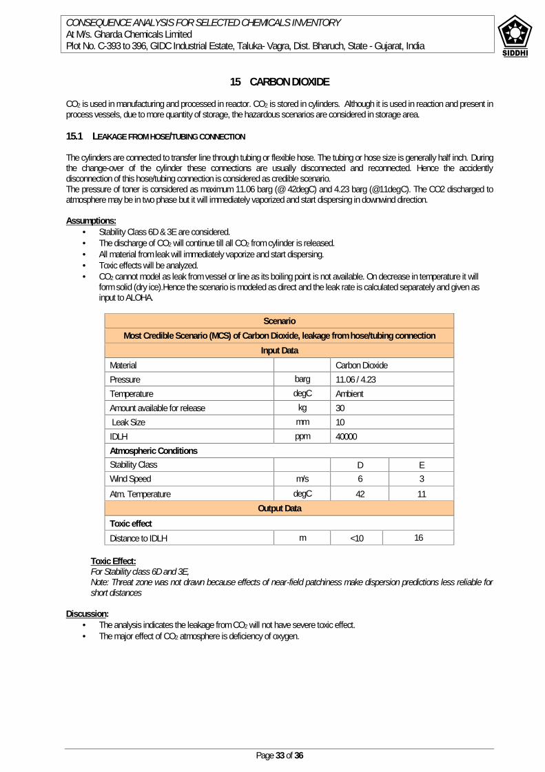
CONSEQUENCE ANALYSIS FOR SELECTED CHEMICALS INVENTORYAt M/s. Gharda Chemicals LimitedPlot No. C-393 to 396, GIDC Industrial Estate, Taluka- Vagra, Dist. Bharuch, State - Gujarat, India
Page 33 of 36
15 CARBON DIOXIDE
CO2 is used in manufacturing and processed in reactor. CO2 is stored in cylinders. Although it is used in reaction and present inprocess vessels, due to more quantity of storage, the hazardous scenarios are considered in storage area.
15.1 LEAKAGE FROM HOSE/TUBING CONNECTION
The cylinders are connected to transfer line through tubing or flexible hose. The tubing or hose size is generally half inch. Duringthe change-over of the cylinder these connections are usually disconnected and reconnected. Hence the accidentlydisconnection of this hose/tubing connection is considered as credible scenario.The pressure of toner is considered as maximum 11.06 barg (@ 42degC) and 4.23 barg (@11degC). The CO2 discharged toatmosphere may be in two phase but it will immediately vaporized and start dispersing in downwind direction.
Assumptions: Stability Class 6D & 3E are considered. The discharge of CO2 will continue till all CO2 from cylinder is released. All material from leak will immediately vaporize and start dispersing. Toxic effects will be analyzed. CO2 cannot model as leak from vessel or line as its boiling point is not available. On decrease in temperature it will
form solid (dry ice).Hence the scenario is modeled as direct and the leak rate is calculated separately and given asinput to ALOHA.
ScenarioMost Credible Scenario (MCS) of Carbon Dioxide, leakage from hose/tubing connection
Input DataMaterial Carbon DioxidePressure barg 11.06 / 4.23Temperature degC AmbientAmount available for release kg 30Leak Size mm 10
IDLH ppm 40000Atmospheric ConditionsStability Class D EWind Speed m/s 6 3Atm. Temperature degC 42 11
Output DataToxic effectDistance to IDLH m <10 16
Toxic Effect:For Stability class 6D and 3E,Note: Threat zone was not drawn because effects of near-field patchiness make dispersion predictions less reliable forshort distances
Discussion: The analysis indicates the leakage from CO2 will not have severe toxic effect. The major effect of CO2 atmosphere is deficiency of oxygen.
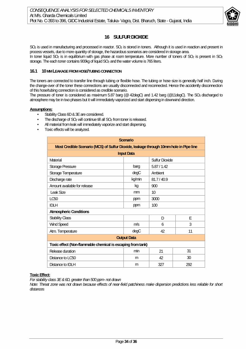
CONSEQUENCE ANALYSIS FOR SELECTED CHEMICALS INVENTORYAt M/s. Gharda Chemicals LimitedPlot No. C-393 to 396, GIDC Industrial Estate, Taluka- Vagra, Dist. Bharuch, State - Gujarat, India
Page 34 of 36
16 SULFUR DIOXIDE
SO2 is used in manufacturing and processed in reactor. SO2 is stored in toners. Although it is used in reaction and present inprocess vessels, due to more quantity of storage, the hazardous scenarios are considered in storage area.In toner liquid SO2 is in equilibrium with gas phase at room temperature. More number of toners of SO2 is present in SO2storage. The each toner contains 900kg of liquid SO2 and the water volume is 765 liters.
16.1 10 MM LEAKAGE FROM HOSE/TUBING CONNECTION
The toners are connected to transfer line through tubing or flexible hose. The tubing or hose size is generally half inch. Duringthe change-over of the toner these connections are usually disconnected and reconnected. Hence the accidently disconnectionof this hose/tubing connection is considered as credible scenario.The pressure of toner is considered as maximum 5.87 barg (@ 42degC) and 1.42 barg (@11degC). The SO2 discharged toatmosphere may be in two phases but it will immediately vaporized and start dispersing in downwind direction.
Assumptions: Stability Class 6D & 3E are considered. The discharge of SO2 will continue till all SO2 from toner is released. All material from leak will immediately vaporize and start dispersing. Toxic effects will be analyzed.
ScenarioMost Credible Scenario (MCS) of Sulfur Dioxide, leakage through 10mm hole in Pipe line
Input DataMaterial Sulfur DioxideStorage Pressure barg 5.87 / 1.42Storage Temperature degC AmbientDischarge rate kg/min 81.7 / 40.9Amount available for release kg 900Leak Size mm 10
LC50 ppm 3000IDLH ppm 100Atmospheric ConditionsStability Class D EWind Speed m/s 6 3Atm. Temperature degC 42 11
Output DataToxic effect (Non-flammable chemical is escaping from tank)Release duration min 21 31Distance to LC50 m 42 30Distance to IDLH m 327 292
Toxic Effect:For stability class 3E & 6D, greater than 500 ppm- not drawnNote: Threat zone was not drawn because effects of near-field patchiness make dispersion predictions less reliable for shortdistances

CONSEQUENCE ANALYSIS FOR SELECTED CHEMICALS INVENTORYAt M/s. Gharda Chemicals LimitedPlot No. C-393 to 396, GIDC Industrial Estate, Taluka- Vagra, Dist. Bharuch, State - Gujarat, India
Page 35 of 36
(Stability Class 6D) (Stability Class 3E)
Discussion: The release of SO2 is two phase. In the tonner the liquid SO2 will vaporize immediately as it is in equilibrium. Hence
pressure of the tonner will be maintained till liquid is inside the tonner. The released SO2 is having some aerosol due to sudden expansion. But they will immediately vaporize due to
atmospheric heat. The vapor SO2 plume will start dispersed in downwind direction. The remaining amount of SO2 in tonner will released till end. The LC50 distance is 42 & 30 m from source for stability class D & E respectively. It means up to 42m the
concentration is more than LC50. The IDLH distance is 327 / 292 m for stability class D & E respectively. The concentration at any point will reach to higher concentration as cloud moves towards that point and gradually
comes down below safe concentration. For example at 100m in the downwind direction, the SO2 concentration willincrease to 450ppm within 5mins from leak. As the cloud disperse in the downwind direction the concentration at thispoint will gradually decrease and comes below IDLH after 25mins. See graph below.
The SO2 IDLH distances may go off site hence can be included in off-site emergency planning. Sulfur dioxide gas monitors should be installed in the facility. The early detection of any leak will help to prevent any
potential big incident. . It also gives enough time for evacuation of the people. Sulfur dioxide gas is heavier than air so gas monitors should be mounted approximately two feet from the floor for
quick and accurate detection. Never use water on a leaking sulfur dioxide container; this can cause rapid corrosion of the metals making the leak
worse. Once sulfur dioxide leak is identified & concentration levels reach 50 ppm, the concentration is considered
immediately dangerous to life and health and the room should be vacated immediately The room should not be entered unless wearing proper respiratory and other personal protective equipment (PPE)
and should only be entered by appropriately trained personnel using the buddy system (a system in which two peopleare accountable for the welfare of each other).
Escape type respirators should also be available for any personnel in rooms where leaks may occur.
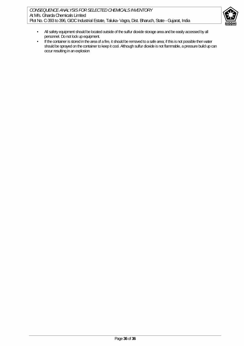
CONSEQUENCE ANALYSIS FOR SELECTED CHEMICALS INVENTORYAt M/s. Gharda Chemicals LimitedPlot No. C-393 to 396, GIDC Industrial Estate, Taluka- Vagra, Dist. Bharuch, State - Gujarat, India
Page 36 of 36
All safety equipment should be located outside of the sulfur dioxide storage area and be easily accessed by allpersonnel. Do not lock up equipment.
If the container is stored in the area of a fire, it should be removed to a safe area; if this is not possible then watershould be sprayed on the container to keep it cool. Although sulfur dioxide is not flammable, a pressure build up canoccur resulting in an explosion
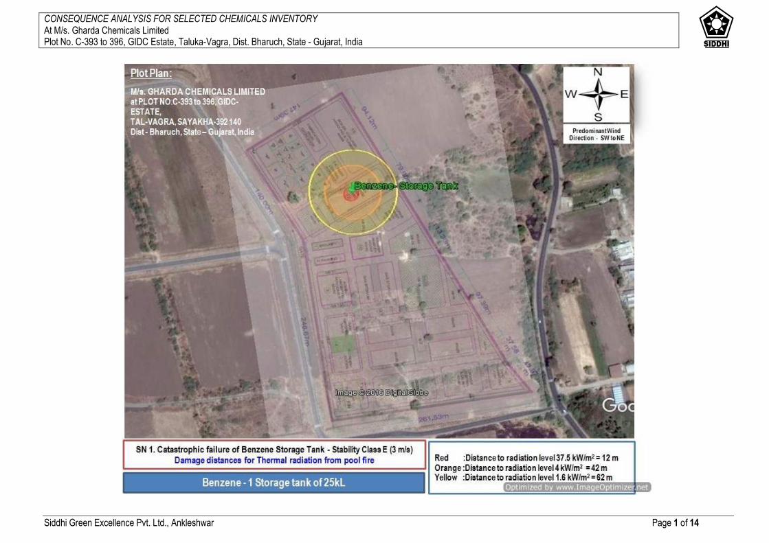
CONSEQUENCE ANALYSIS FOR SELECTED CHEMICALS INVENTORY At M/s. Gharda Chemicals Limited Plot No. C-393 to 396, GIDC Estate, Taluka-Vagra, Dist. Bharuch, State - Gujarat, India
Siddhi Green Excellence Pvt. Ltd., Ankleshwar Page 1 of 14
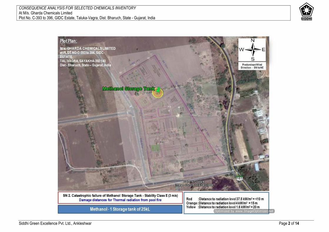
CONSEQUENCE ANALYSIS FOR SELECTED CHEMICALS INVENTORY At M/s. Gharda Chemicals Limited Plot No. C-393 to 396, GIDC Estate, Taluka-Vagra, Dist. Bharuch, State - Gujarat, India
Siddhi Green Excellence Pvt. Ltd., Ankleshwar Page 2 of 14
CONSEQUENCE ANALYSIS FOR SELECTED CHEMICALS INVENTORY At M/s. Gharda Chemicals Limited Plot No. C-393 to 396, GIDC Estate, Taluka-Vagra, Dist. Bharuch, State - Gujarat, India
Siddhi Green Excellence Pvt. Ltd., Ankleshwar Page 3 of 14
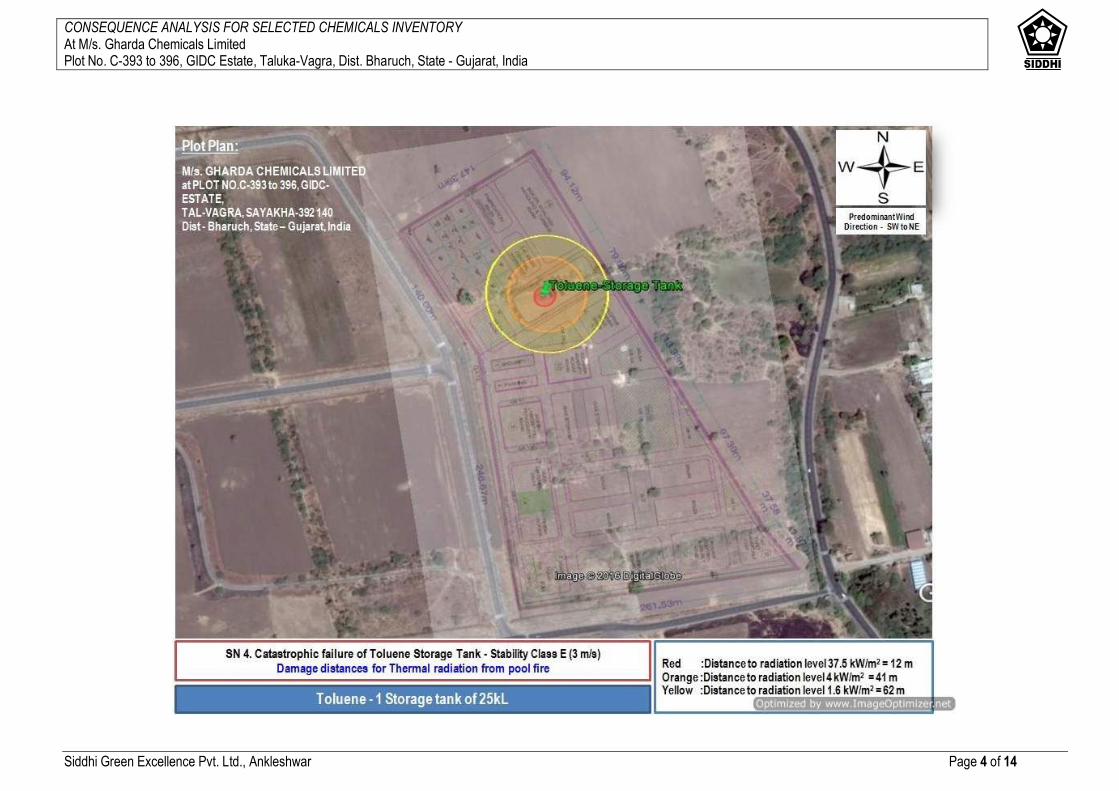
CONSEQUENCE ANALYSIS FOR SELECTED CHEMICALS INVENTORY At M/s. Gharda Chemicals Limited Plot No. C-393 to 396, GIDC Estate, Taluka-Vagra, Dist. Bharuch, State - Gujarat, India
Siddhi Green Excellence Pvt. Ltd., Ankleshwar Page 4 of 14

CONSEQUENCE ANALYSIS FOR SELECTED CHEMICALS INVENTORY At M/s. Gharda Chemicals Limited Plot No. C-393 to 396, GIDC Estate, Taluka-Vagra, Dist. Bharuch, State - Gujarat, India
Siddhi Green Excellence Pvt. Ltd., Ankleshwar Page 5 of 14
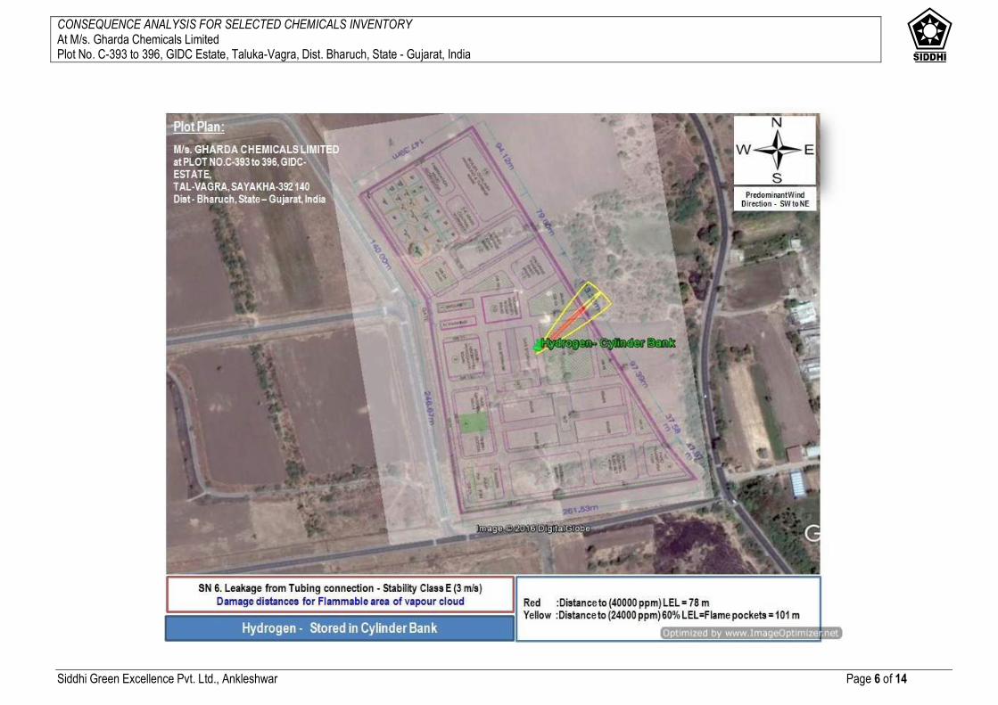
CONSEQUENCE ANALYSIS FOR SELECTED CHEMICALS INVENTORY At M/s. Gharda Chemicals Limited Plot No. C-393 to 396, GIDC Estate, Taluka-Vagra, Dist. Bharuch, State - Gujarat, India
Siddhi Green Excellence Pvt. Ltd., Ankleshwar Page 6 of 14

CONSEQUENCE ANALYSIS FOR SELECTED CHEMICALS INVENTORY At M/s. Gharda Chemicals Limited Plot No. C-393 to 396, GIDC Estate, Taluka-Vagra, Dist. Bharuch, State - Gujarat, India
Siddhi Green Excellence Pvt. Ltd., Ankleshwar Page 7 of 14
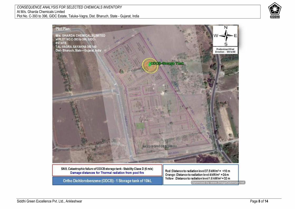
CONSEQUENCE ANALYSIS FOR SELECTED CHEMICALS INVENTORY At M/s. Gharda Chemicals Limited Plot No. C-393 to 396, GIDC Estate, Taluka-Vagra, Dist. Bharuch, State - Gujarat, India
Siddhi Green Excellence Pvt. Ltd., Ankleshwar Page 8 of 14
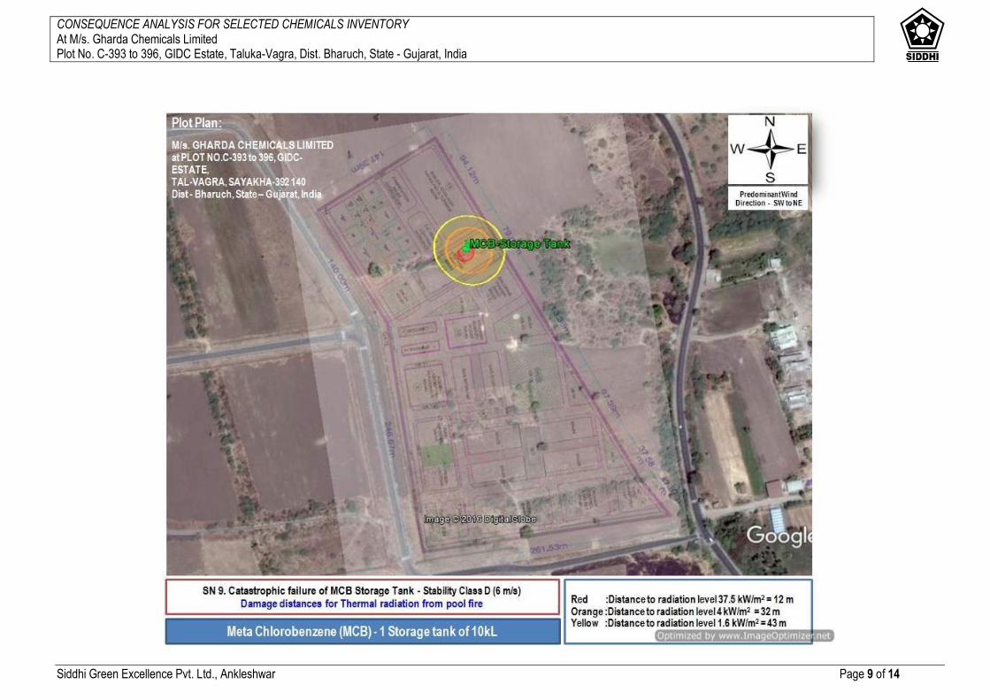
CONSEQUENCE ANALYSIS FOR SELECTED CHEMICALS INVENTORY At M/s. Gharda Chemicals Limited Plot No. C-393 to 396, GIDC Estate, Taluka-Vagra, Dist. Bharuch, State - Gujarat, India
Siddhi Green Excellence Pvt. Ltd., Ankleshwar Page 9 of 14

CONSEQUENCE ANALYSIS FOR SELECTED CHEMICALS INVENTORY At M/s. Gharda Chemicals Limited Plot No. C-393 to 396, GIDC Estate, Taluka-Vagra, Dist. Bharuch, State - Gujarat, India
Siddhi Green Excellence Pvt. Ltd., Ankleshwar Page 10 of 14

CONSEQUENCE ANALYSIS FOR SELECTED CHEMICALS INVENTORY At M/s. Gharda Chemicals Limited Plot No. C-393 to 396, GIDC Estate, Taluka-Vagra, Dist. Bharuch, State - Gujarat, India
Siddhi Green Excellence Pvt. Ltd., Ankleshwar Page 11 of 14
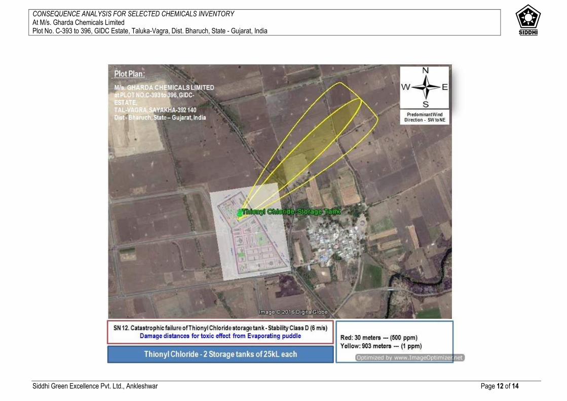
CONSEQUENCE ANALYSIS FOR SELECTED CHEMICALS INVENTORY At M/s. Gharda Chemicals Limited Plot No. C-393 to 396, GIDC Estate, Taluka-Vagra, Dist. Bharuch, State - Gujarat, India
Siddhi Green Excellence Pvt. Ltd., Ankleshwar Page 12 of 14
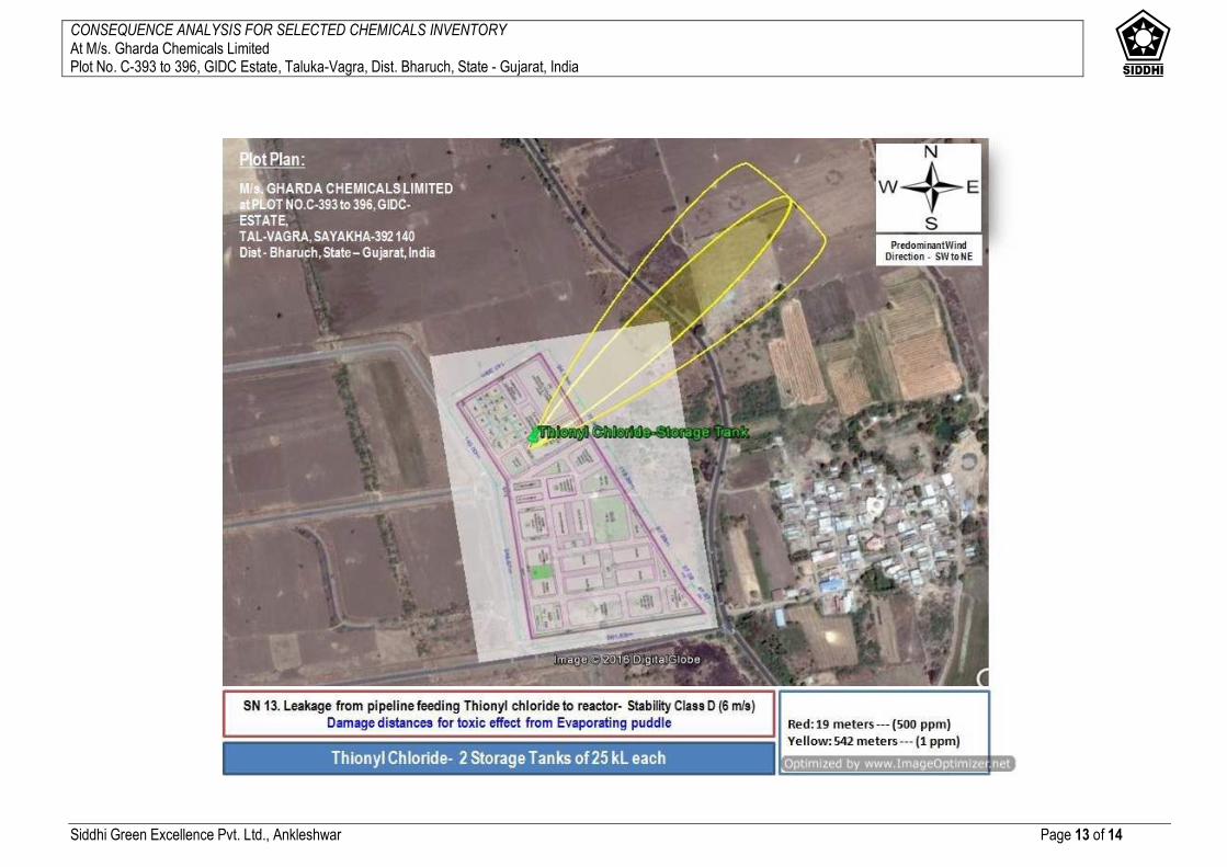
CONSEQUENCE ANALYSIS FOR SELECTED CHEMICALS INVENTORY At M/s. Gharda Chemicals Limited Plot No. C-393 to 396, GIDC Estate, Taluka-Vagra, Dist. Bharuch, State - Gujarat, India
Siddhi Green Excellence Pvt. Ltd., Ankleshwar Page 13 of 14
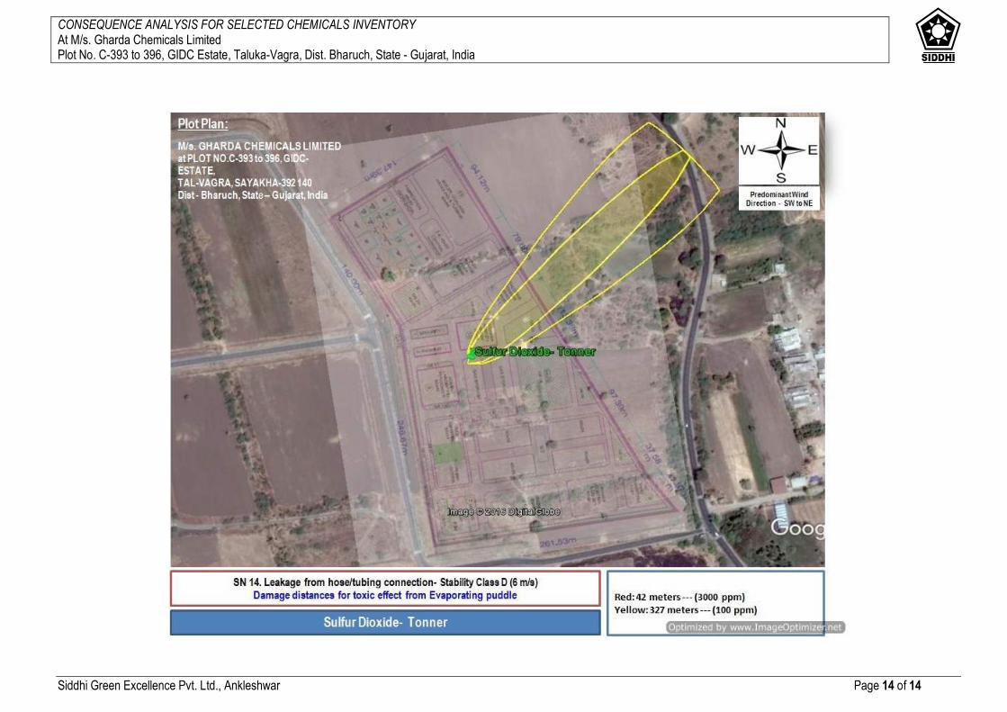
CONSEQUENCE ANALYSIS FOR SELECTED CHEMICALS INVENTORY At M/s. Gharda Chemicals Limited Plot No. C-393 to 396, GIDC Estate, Taluka-Vagra, Dist. Bharuch, State - Gujarat, India
Siddhi Green Excellence Pvt. Ltd., Ankleshwar Page 14 of 14


![EIA/EMP REPORT For Proposed Expansion of Ammonia …environmentclearance.nic.in/writereaddata/EIA/100920159QXPL126EIA... · i [Type text] EIA/EMP REPORT For Proposed Expansion of](https://img.pdfslide.us/doc/110x75/5ad8c3257f8b9a9d5c8db8f8/eiaemp-report-for-proposed-expansion-of-ammonia-type-text-eiaemp-report.jpg)