Embed Size (px)
DESCRIPTION
Tank Gauge
Citation preview

Servo gauge 854 ATG
A compact, intelligent and reliable Advanced Tank Gauge
As tank gauging has evolved, the series 854ATG servo level gauge
has become an industrial standard all over the world. Very reliable,
versatile and accurate automatic tank gauge with a minimum of
moving parts, meeting all international standards, regulations and
recommendations. A true test of its quality is the dependability and low warranty record that the
ATG has maintained for many years. The multi-functional instrument is modularly constructed.
The option slots for additional features allow connecting to a wide range of other instruments e.g.
temperature-, pressure-, interface measurement and more. Obviously the connectivity to various
fi eld busses and tank inventory or host systems can easily be accomplished. Simple confi guration
and diagnostics are possible through a hand held device or via confi guration software.
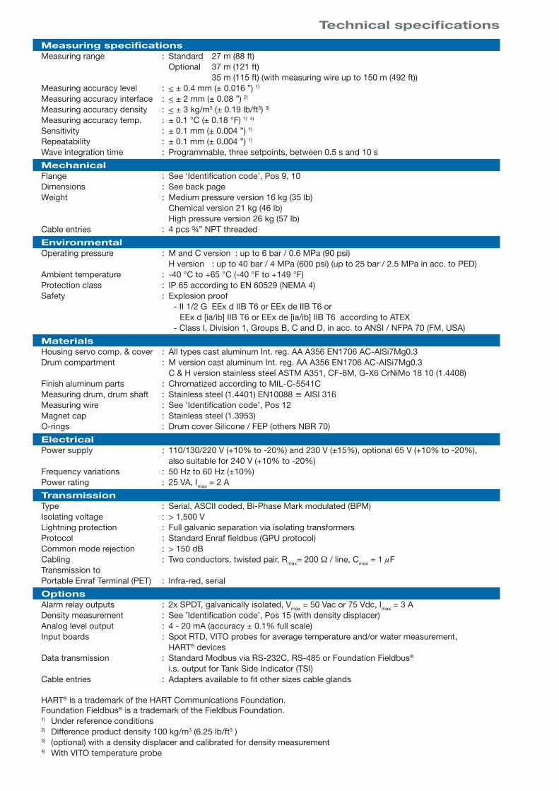
Measuring specificationsMeasuring range : Standard 27 m (88 ft) Optional 37 m (121 ft) 35 m (115 ft) (with measuring wire up to 150 m (492 ft)) Measuring accuracy level : < ± 0.4 mm (± 0.016 ”) 1)
Measuring accuracy interface : < ± 2 mm (± 0.08 ”) 2)
Measuring accuracy density : < ± 3 kg/m3 (± 0.19 lb/ft3) 3)
Measuring accuracy temp. : ± 0.1 °C (± 0.18 °F) 1) 4)
Sensitivity : ± 0.1 mm (± 0.004 ”) 1)
Repeatability : ± 0.1 mm (± 0.004 ”) 1)
Wave integration time : Programmable, three setpoints, between 0.5 s and 10 s
MechanicalFlange : See ‘Identification code’, Pos 9, 10Dimensions : See back pageWeight : Medium pressure version 16 kg (35 lb) Chemical version 21 kg (46 lb) High pressure version 26 kg (57 lb)Cable entries : 4 pcs ¾” NPT threaded
EnvironmentalOperating pressure : M and C version : up to 6 bar / 0.6 MPa (90 psi) H version : up to 40 bar / 4 MPa (600 psi) (up to 25 bar / 2.5 MPa in acc. to PED)Ambient temperature : -40 °C to +65 °C (-40 °F to +149 °F)Protection class : IP 65 according to EN 60529 (NEMA 4)Safety : Explosion proof - II 1/2 G EEx d IIB T6 or EEx de IIB T6 or EEx d [ia/ib] IIB T6 or EEx de [ia/ib] IIB T6 according to ATEX - Class I, Division 1, Groups B, C and D, in acc. to ANSI / NFPA 70 (FM, USA)
MaterialsHousing servo comp. & cover : All types cast aluminum Int. reg. AA A356 EN1706 AC-AlSi7Mg0.3Drum compartment : M version cast aluminum Int. reg. AA A356 EN1706 AC-AlSi7Mg0.3 C & H version stainless steel ASTM A351, CF-8M, G-X6 CrNiMo 18 10 (1.4408)Finish aluminum parts : Chromatized according to MIL-C-5541CMeasuring drum, drum shaft : Stainless steel (1.4401) EN10088 ≅ AISI 316Measuring wire : See ’Identification code’, Pos 12Magnet cap : Stainless steel (1.3953)O-rings : Drum cover Silicone / FEP (others NBR 70)
ElectricalPower supply : 110/130/220 V (+10% to -20%) and 230 V (±15%), optional 65 V (+10% to -20%), also suitable for 240 V (+10% to -20%)Frequency variations : 50 Hz to 60 Hz (±10%)Power rating : 25 VA, Imax = 2 A
TransmissionType : Serial, ASCII coded, Bi-Phase Mark modulated (BPM)Isolating voltage : > 1,500 VLightning protection : Full galvanic separation via isolating transformersProtocol : Standard Enraf fieldbus (GPU protocol)Common mode rejection : > 150 dBCabling : Two conductors, twisted pair, Rmax= 200 Ω / line, Cmax = 1 µF Transmission toPortable Enraf Terminal (PET) : Infra-red, serial
OptionsAlarm relay outputs : 2x SPDT, galvanically isolated, Vmax = 50 Vac or 75 Vdc, Imax = 3 ADensity measurement : See ’Identification code’, Pos 15 (with density displacer)Analog level output : 4 - 20 mA (accuracy ± 0.1% full scale)Input boards : Spot RTD, VITO probes for average temperature and/or water measurement, HART® devicesData transmission : Standard Modbus via RS-232C, RS-485 or Foundation Fieldbus®
i.s. output for Tank Side Indicator (TSI)Cable entries : Adapters available to fit other sizes cable glands
HART® is a trademark of the HART Communications Foundation.Foundation Fieldbus® is a trademark of the Fieldbus Foundation.1) Under reference conditions2) Difference product density 100 kg/m3 (6.25 lb/ft3 )3) (optional) with a density displacer and calibrated for density measurement4) With VITO temperature probe
Technical specifications

Identification code
Pos 1 ApplicationU General purpose X W&M certified
Pos 2 Data transmissionE Enraf Biphase mark protocol (standard)I i.s. Output for Tank Side Indicator (TSI) and Enraf BiPhase Mark (BPM) protocolR RS232C GPU protocol (only when Pos 4 = B, C, J, U or Z)S RS485 GPU protocol (only when Pos 4 = B, C, J, U or Z)V RS232C standard Modbus (only when Pos 4 = B, C, J, U or Z)W RS485 standard Modbus (only when Pos 4 = B, C, J, U or Z)O Foundation Fieldbus + BPM
Pos 3 DisplayA With display
Pos 4 I/O optionsB Spot temperature Pt100
WAnalog level output + VITO temperature and/or water probeC VITO temperature and/or water probe
J VITO temp. and/or water probe + HART device(s) X Analog level output + VITO temperature probeU Spot temperature Pt100 + HART device(s)
YAnalog level output + spot temperature Pt 100 + VITO temp. and/or water probe + HART device(s)V Analog level output
Z NonePos 5, 6, 7 Instrument designation8 5 4 Servo gauge ATG
Pos 8 Pressure versionC Up to 6 bar 0.6 MPa (90 psi) if Pos 9, 10 = 11, 12 or 13M Up to 6 bar 0.6 MPa (90 psi) if Pos 9, 10 = 21 or 22H Up to 40 bar 4 MPa (600 psi) if Pos 9, 10 = 51, 52, 53 or 54 (25 bar according PED)
Pos 9, 10 Drum compartment & flangemat. *) flange acc. to finish compatible with acc. to
1 1 ss 2” 150 lbs rf ANSI B16.5 turning, Ra = 3.2 12.5 μm DN50, PN20 rf ISO 70051
1 2 ss NW50 ND6 DIN 2501 turning, Rz = max. 40 μm DN50, PN6 rf ISO 70051 form D DIN 2526
1 3 ss 2” 150 lbs ff ANSI B16.5 turning, Ra = 3.2 12.5 μm DN50, PN20 ff ISO 70051
2 1 Al 2” 150 lbs ff ANSI B16.5 turning, Ra = 3.2 12.5 μm DN50, PN20 ff ISO 70051
2 2 Al NW50 ND6 DIN 2501 turning, Rz = 40 160 μm DN50, PN6 ff ISO 70051 form B DIN 2526
5 1 ss 2” 300 lbs rf ANSI B16.5 turning, Ra = 3.2 12.5 μm DN50, PN50 rf ISO 70051
5 2 ss 2” 300 lbs rf ANSI B16.5 turning, Ra = 3.2 6.3 μm DN50, PN50 rf ISO 70051
5 3 ss NW50 ND40 DIN 2501 turning, Rz = 40 160 μm DN50, PN40 rf ISO 70051 form C DIN 2526
5 4 ss NW50 ND40 DIN 2501 turning, Rz = max. 16 μm DN50, PN40 rf ISO 70051 form E DIN 2526 *) see also technical specifications
Pos 11 Safety approvalsA ATEX Europe
For other approvals please contact your nearest Enraf office
C CSA CanadaF FM USA
Pos 12 Measuring range & wire material2 27 m (88 ft) AISI 316 K 37 m (121 ft) Hasteloy C22A 27 m (88 ft) Hasteloy C22 L 37 m (121 ft) TantalumB 27 m (88 ft) Tantalum M 37 m (121 ft) InvarC 27 m (88 ft) Invar N 37 m (121 ft) Platinum / 20% IridiumD 27 m (88 ft) Platinum / 20% Iridium
935 m (115 ft) AISI 316with 150 m (492 ft) wire length3 37 m (121 ft) AISI 316
Pos 13 Purge connection* Option not used L 1/4” BSP entry
Pos 14 Mains supplyA 220 V 50/60 Hz R 130 V 50/60 HzC 110 V 50/60 Hz S 65 V 50/60 HzK 230 V 50/60 Hz
Pos 15 Density measurementD With servo density measurement * Option not used
Pos 16 AlarmsW With 2 programmable SPDT alarms Z No alarms
U E A Z 8 5 4 M 2 1 A 2 * A * Z Typical identification code
A 8 5 4 Your identification code

Honeywell Enraf
Delftechpark 39
2628 XJ Delft
The Netherlands
Tel: +31 (0)15-2701 100
E-mail: [email protected]
www.honeywellenraf.com
PS-4417876-Rev.8-ENGMarch 2008© 2008 Honeywell International Inc.
Dimensional drawing
infra-redcoupling
Position of measuring wire withdisplacer in top position.
2 cable entries 3/4" NPTfor non i.s. wiring.
2 cable entries 3/4" NPTfor i.s. wiring.
Ref. to the instr. code Pos. 9, 10for the flanges available.
1/4"
free spacefor IR
connection
233 mm (9 )3/16"82 mm (3 )
436 mm (17 )3/16"
"B"
"A"
Hoisting eye
(7 )(space needed to
remove cover)
7/8"
200 mm
(4")
100 mm
352 mm (13 )7/8"
(1 )3/4"
44 mm
184 mm (7 ) 427 mm (16 )206 mm (8 ) 449 mm (17 )
1/4" 13/16"
1/8" 11/16"
M and C versionH version
"A" "B"
Field interface
854 ATG
Entis system
Cable specifi cations Serial transmission
Number of wires : 1 twisted pair (pref. shielded)Resistance : Rmax = 200 Ω / lineCapacitance : Cmax = 1 µF
Outputs • Modbus • 4-20 mA for level • Two relay level alarms • i.s. Output for Tank Side Indictor • Digital transmission to - indicators - systems
Inputs • HART® devices • Spot temperature element • VITO probes for average temp. and/or water bottom measurement