Embed Size (px)
Citation preview

Instruction manual847 Portable Enraf Terminal


Instruction manual 847 PET Page 1
Instruction manual 847 Portable Enraf Terminal
May 2009
Part no. 4416.210
Revision 7
Honeywell Enraf B.V. P.O. Box 812 2600 AV Delft Netherlands Tel. : +31 15 2701 100 Fax : +31 15 2701 111 E-mail : [email protected] Website : http://www.honeywell.com/ps

Page 2
Copyright 2009 Enraf BV All rights reserved.
Reproduction in any form without the prior consent of Enraf BV is not allowed.
This manual is for information only. The contents, descriptions and specifications are subject to change
without notice. Enraf BV accepts no responsibility for any errors that may appear in this manual.
The warranty terms and conditions applicable in the country of purchase in respect to Enraf BV products are
available from your supplier. Please retain them with your proof of purchase.

Preface
Instruction manual 847 PET Page 3
Preface
This manual has been written for technicians involved in the installation, commissioning and service of the
Honeywell Enraf level gauges by means of the Honeywell Enraf Series 847 PET.
A description preceding the technical procedures gives the technical information necessary to understand its
functioning. It is recommended to read this description prior to performing any of the procedures.
Safety and prevention of damage
Safe execution of the procedures in this manual requires technical experience in handling tools, and
knowledge of safety regulations in handling electrical installation in hazardous environments.
"Warnings", "Cautions", and "Notes" have been used throughout this manual to bring special matters to the
immediate attention of the reader.
· A Warning concerns danger to the safety of the technician or user;
· A Caution draws attention to an action which may damage the equipment;
· A Note points out a statement deserving more emphasis than the general text, but does not deserve a
"Warning" or a "Caution".
The sequence of steps in a procedure may also be important from the point of view of personal safety and
prevention of damage; it is therefore advised not to change the sequence of procedural steps or alter a
procedure.
Legal aspects
The information in this manual is copyright property of Enraf BV, Netherlands. Enraf BV disclaims any
responsibility for personal injury or damage to equipment caused by:
· Deviation from any of the prescribed procedures;
· Execution of activities that are not prescribed;
· Negligence of the general safety precautions for handling tools, use of electricity and microwave
radiation.
EC declaration of conformity
Refer to the EC declaration of conformity, shipped with the instrument.
Additional information
Please do not hesitate to contact Honeywell Enraf or its representative if you require additional information.

Table of contents
Page 4
Table of contents
Preface.......................................................................................................................................................3
1 Introduction ................................................................................................................................................5
2 Getting started............................................................................................................................................6
2.1 Power on/off.....................................................................................................................................6
2.2 Battery charging...............................................................................................................................6
3 Set-up mode...............................................................................................................................................7
3.1 General ............................................................................................................................................7
3.2 Display contrast ...............................................................................................................................8
3.3 Mode selection.................................................................................................................................8
3.4 IR-baudrate selection.......................................................................................................................8
3.5 EN-baudrate selection .....................................................................................................................9
3.6 RS-232 baudrate selection...............................................................................................................9
3.7 EN-prefix ........................................................................................................................................10
3.8 Keyboard time-out..........................................................................................................................10
4 The IR-mode ............................................................................................................................................11
4.1 Examples IR-Mode ........................................................................................................................12
4.1.1 Example 1: Data request .......................................................................................................12
4.1.2 Example 2: Gauge operation .................................................................................................13
4.1.3 Example 3: Changing of a setting ..........................................................................................13
5 The EN-mode...........................................................................................................................................14
5.1 GPU protocol .................................................................................................................................14
5.1.1 Example: EN-mode with GPU-protocol..................................................................................15
5.2 Z record..........................................................................................................................................15
5.2.1 Example: EN-mode with Z-record, data-request....................................................................16
5.2.2 Example: EN-mode with Z-record, sending an operational command...................................16
5.2.3 Example: EN-mode with Z-record, changing a setting...........................................................16
6 Connections .............................................................................................................................................17
6.1 Connection PET to a serial computer interface (RS-232) ..............................................................17
6.2 Connection of the RS-232C PET interface (option) .......................................................................17
6.3 Configuration of the PET................................................................................................................18
6.4 The application program ................................................................................................................19
Appendix A Dimensional drawing.........................................................................................................20
Appendix B Spare parts .......................................................................................................................21
Appendix C Error messages ................................................................................................................22
Index ........................................................................................................................................................23

Introduction
Instruction manual 847 PET Page 5
1 Introduction
The PET (Portable Enraf Terminal) is a smart portable terminal, designed for service and maintenance of
Honeywell Enraf field instruments. The PET is intrinsically safe and water proof (IP55). It has a full ASCII
membrane keyboard and an LCD display. Power is supplied by two rechargeable, maintenance free lead
acid batteries and should be charged regularly.
The terminal is to be connected directly to the field instrument via the infra-red adaptor.
At present the following Honeywell Enraf instruments are provided with IR-adaptors:
· Series 854 ATG / XTG level gauges
· Series 866 HTG / HIMS hydrostatic gauges
· Series 873 SmartRadar level gauges
· Series 877 FDI field display and interface
· Series 970 / 971 / 973 SmartRadar level gauges with optional IR-adapter
With an EN-adaptor, instead of the IR-adaptor, it is possible to communicate with the field instrument via the
Enraf fieldbus.
The PET is to be used for a quick installation, commissioning, calibration, etc. of the field instrument.
Or perhaps just to check or change settings or request status data for trouble shooting purposes.

Set-up mode
Page 6
2 Getting started
2.1 Power on/off
Switch the PET on by pressing the red ON/RESET key.
Switch the PET off by pressing the CTRL and Z keys simultaneously.
Time out: If the keyboard is not being used for approx. 15 minutes, the PET will be switched off
automatically.
The PET accepts keyboard entries both in capital or small letters. The entries are standard in capital letters
(CAPSLOCK). Whenever entries are made in small letters, it is automatically converted to capital letters by
the field instrument after receiving.
Connect the IR-adaptor (refer to appendix B) to a field instrument e.g. an 854 ATG or 873 SmartRadar and
switch on the PET. The display will first show its initialization message, including the PET software version
number. After a short time the PET is operational and is ready to be used in the IR-mode.
If the field instrument is also powered, the screen may look as follows:
I > +002.7634 m INN
+019.62°C -- -- I1
U>_
I> the Instrument prompt.
This is the response display (2 rows of 16 characters), displaying information copied from the
instrument display. In this example, the 854 ATG display format is format "A" (level and temperature
display format). This will be the default display for the PET while connected to this instrument, unless
another default display format is selected by means of item PO (PET display format). For item
descriptions refer to Items descriptions in the Honeywell Enraf Instrument manuals or the Item
documentation.
U> the User prompt.
This is the input display line displaying entries from the keyboard. The displayed characters are
transmitted to the instrument after pressing the return key and the I> will display the answer from the
instrument. Pressing the return key once more returns the default display.
If the instrument is not powered or the IR-adaptor is not connected, the display is blank except for the
instrument and user prompts. In case of IR communication error, an error code or error message is
displayed (refer to Appendix C).
2.2 Battery charging
The PET is supplied with two 6V - 1,2Ah rechargeable dry lead acid batteries, sufficient for at least 8 hours of
operation. If the voltage drops too low, a warning will be displayed as follows: U L
b Low Battery.
If the user ignores this warning and does not recharge the battery the PET will be switched off after a certain
time to prevent erroneous functioning.
The batteries should be charged on a regular base. The charge time for empty batteries is about 8 hours,
however if the charging time is expended, it does not harm the batteries.
Warning
It is not allowed to use the charger in an explosion hazardous area

Set-up mode
Instruction manual 847 PET Page 7
3 Set-up mode
3.1 General
Enter the set-up mode by pressing the CTRL and ESC keys simultaneously.
Leave the set-up mode by pressing the CTRL and ESC keys simultaneously.
Enter the set-up mode and read the instructions on the screen:
*** ENRAF BV (c) ***
PORTABLE TERMINAL
**** SETUP MODE ****
*** Press _ or _ ***
By pressing the arrow _ or _ key other instructions are selected on the screen. Press the _ key.
The following instructions are displayed:
**** SETUP MODE ****
__ = parameter shift
_ / _ = next/previous
^esc = exit
Press the arrow _ key to select the first set-up menu.
Move through the set-up menu by pressing the arrow _ or _ key.
The following menus can be selected (default setting shown):
MENU Default setting
- DISPLAY CONTRAST -
- MODE (IR, EN, RS-232-C) IR
- IR BAUDRATE 1200
- EN BAUDRATE 1200
- RS232 BAUDRATE 1200
- EN PREFIX -
- KEYBOARD TIME OUT ON (approx. 15 minutes)
Changes made in the set-up becomes active after leaving the set-up (CTRL and ESC). Changes made in the
set-up are active as long as the PET is not switched off or reset. After resetting, the PET always starts up
with the default settings.

Set-up mode
Page 8
3.2 Display contrast
The “DISPLAY CONTRAST” menu is the first menu in set-up. Select this menu.
The display looks as follows:
* DISPLAY CONTRAST *
- _----------------_ +
■
The present setting of the contrast is displayed.
The contrast can now be adjusted by pressing the arrow _ or _ key.
3.3 Mode selection
The “MODE” menu is the next menu in set-up. Select this menu with the arrow _ key.
The displays looks as follows:
****** MODE *******
IR
EN
RS232
■
The ■ indicates the present setting.
The required mode can now be selected by pressing the arrow _ or _ key.
The ■ indicates the selected mode.
Note: Refer to section 6 for using the RS-232 mode.
3.4 IR-baudrate selection
Select the “IR-BAUDRATE” menu by pressing the arrow _ key.
This mode is displayed as follows:
**** IR-BAUDRATE ****
300
1200
2400
■
The ■indicates the present setting.
If required the infra red baudrate can be changed by pressing the arrow _ or _ key. The n indicates the
selected baudrate. At present, all Honeywell Enraf instruments operates with a fixed IR baudrate of 1200
baud.
Set-up mode
Instruction manual 847 PET Page 9
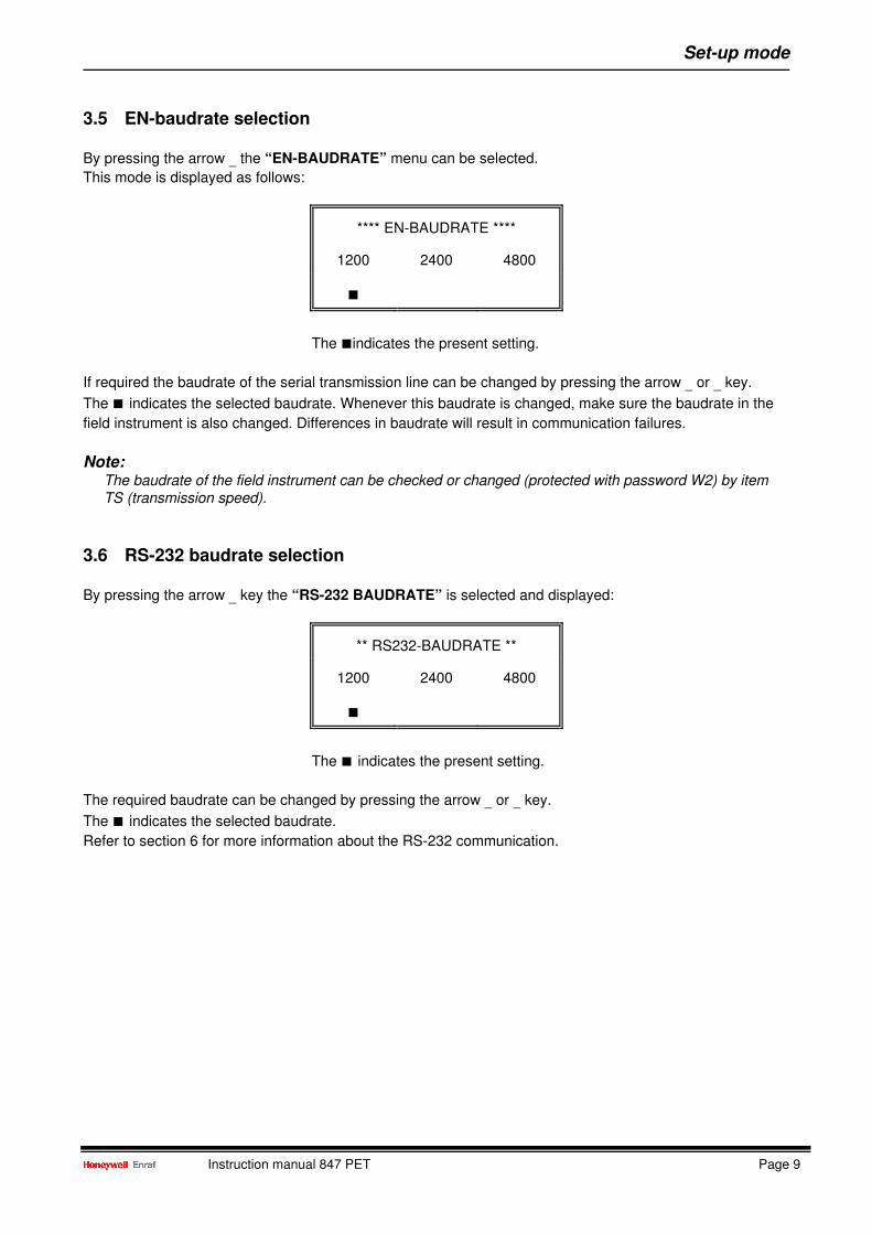
3.5 EN-baudrate selection
By pressing the arrow _ the “EN-BAUDRATE” menu can be selected.
This mode is displayed as follows:
**** EN-BAUDRATE ****
1200
2400
4800
■
The ■indicates the present setting.
If required the baudrate of the serial transmission line can be changed by pressing the arrow _ or _ key.
The ■ indicates the selected baudrate. Whenever this baudrate is changed, make sure the baudrate in the
field instrument is also changed. Differences in baudrate will result in communication failures.
Note: The baudrate of the field instrument can be checked or changed (protected with password W2) by item
TS (transmission speed).
3.6 RS-232 baudrate selection
By pressing the arrow _ key the “RS-232 BAUDRATE” is selected and displayed:
** RS232-BAUDRATE **
1200
2400
4800
■
The ■ indicates the present setting.
The required baudrate can be changed by pressing the arrow _ or _ key.
The ■ indicates the selected baudrate.
Refer to section 6 for more information about the RS-232 communication.

Set-up mode
Page 10
3.7 EN-prefix
Pressing the _ key the “EN-PREFIX” selection can be made.
The display looks like:
*** EN - PREFIX ***
>>>>>_ <<<<<
The EN-prefix is available from 847 PET software version 0.85.
This is a valuable tool in the EN-communication. To communicate in the EN-mode, the transmission address
(item TA), type of instrument (item GT), and type of record must be specified.
If a number of data is requested from one instrument, these settings must be repeated every time.
Therefore, these settings can be stored in the EN-prefix.
For instance:
· transmission address is " 24 ";
· type of instrument (gauge type) is " B ";
· type of record is " Z " (Z - protocol; to request items);
then the EN prefix would be: " 24BZ ".
To request items in the EN mode, just type the two character item name followed by a return, and the prefix
is automatically added to the record transmitted to the instrument.
For more information on the EN-mode, refer to section 5.
3.8 Keyboard time-out
By pressing the arrow _ key the “KEYBOARD TIME-OUT” menu can be selected.
This display looks as follows:
* KEYBOARD TIME OUT *
ON OFF
■
The ■ indicates the present setting.
The time out time is approx. 15 minutes. If the keyboard is not being used within this time out, the PET will
be switched off automatically. The time out can be switched OFF by pressing the arrow _ key.
The ■ indicates the selected mode.
By pressing the CTRL and ESC keys simultaneously you can leave the set-up mode and return to
operational mode. All changes made in set-up menu becomes now active.

The IR-mode
Instruction manual 847 PET Page 11
4 The IR-mode
This mode is especially suited for programming the gauges in a hazardous area.
The PET is to be connected with the IR-adaptor to any field instrument with an IR-entry.
The IPC-family of instruments are all provided with an IR-adaptor input.
Communication errors in the IR-mode are displayed on the screen as an error-code (see appendix C) or, for
later software versions of the PET, the error message itself is displayed.
After connecting and switching on, the PET will initialize communication with the connected instrument.
It will ask for data in row 1 and row 2 (items 01 and 02) of the field instruments' display and show this on the
screen as the so called default display.
I > +001.4567 m INN
+035.87°C -- -- I1
U>_
The default display for an 854 ATG.
The default display is different for different field instruments and also depends on the programmed display
format (item DF).
Data can be requested or modified, and commands can be transmitted to the field instrument. Whether data
is requested, modified or send, always do this with two characters, the so called ITEMS. Here are a few
examples of items:
Item: Description: Item: Description:
TA Transmission Address TS Transmission Speed
HA High level Alarm LD Level Dimension
TG Test Gauge W2 Password for protection level 2
The items are described in the instruction manual of the instrument and describe the procedures required at
commissioning, calibration, operation and trouble shooting. The document "Item documentation" is a
manual containing a reference list of items from all types of Honeywell Enraf instruments.

The IR-mode
Page 12
4.1 Examples IR-Mode
4.1.1 Example 1: Data request
To request data from an instrument e.g. the transmission address (item TA), proceed as follows:
· Type on the PET keyboard: 'TA'. (transmission address)
· U>TA appears on the display (correct mistyping by the backspace key).
· Press the return key. The instruments' reply is displayed e.g. I>TA35.
· I>TA35 means TA (transmission address) is 35.
Any possible data can be requested by simply typing the item plus return key. The return key will be noted
further by: <return>. Asking for data is not protected.
Try the following items and consult the instruments' manual for explanation:
Item Possible answer Item name
GT <return> I>GTB Gauge Type
HA ,, I>HA+026.0000 High level Alarm
LD ,, I>LDM Level Dimension
W1 ,, I>W1ENRAF1 *) Password for level 1
*) Refer to password protection.
Press <return> again. That returns the default display on the screen.
Press the arrow _ key. That will recall the last entry 'W1'. Press the return key again.
The item W1 is processed again and the display shows I>W1ENRAF1.
Remember: With <return>, recall the default display.
With the arrow _ key, recall the last keyboard entry.
Password protection
In the above example, the password was requested. This is only possible as long as the password is not
protected from reading. (refer to the instruments' instruction manual). Display is not possible if the password
is protected.
With jumper JA1 on the XPU board to position 1, password W1 is protected.
With jumper JA2 on the XPU board to position 1, password W2 is protected.
The jumper setting can be checked with item JS. For the default setting of the jumper setting, refer to the
instruments' instruction manual. The status is displayed from left to right for JA1 to JA7. Never change
jumper setting with power on.
Besides the password, data in a calibrated instrument may be protected by jumper JA3 set to position 1
(default JA3=0).

The IR-mode
Instruction manual 847 PET Page 13
4.1.2 Example 2: Gauge operation
If the PET is connected to an 854 ATG, the following command items can be tried:
Note: Items for gauge operations by PET are not protected by password or jumper; do not forget to press
<return> after the two character item name.
Item Display Item name
TG <return> I>TG Test Gauge (functional/repeatability test);
FR ,, I>FR Freeze (stop level measurement);
I3 ,, I>I3 Interface 3 (go to interface 3);
4.1.3 Example 3: Changing of a setting
Please keep in mind that most settings are protected by password and some settings may be protected by a
jumper (JA3). Read section 4.1.1 for some explanation on password and data protection.
Assume the high level alarm (item HA) in an 854 ATG is to be changed into e.g. 18.000 m. Item HA is under
protection level 1. If you are authorized to change this setting, use the password for level 1 (item W1).
The default password for level 1 is: "ENRAF1".
If the instrument is operating with default settings, proceed as follows:
Use <return> and the arrow _ key to ask for the default display or for the last keyboard entry.
Type in Display Description
LD I>LDM Level dimension is metres.
W1=ENRAF1 I>W1 ok Enter protection level 1.
I>1> The selected protection level is displayed.
HA I>1>HA+026.0000 The high alarm is set to 26 m. Remember, the
format "+026.0000" depends on item LD.
HA=+018.0000 I>1>HA=+018.0000 o.k. Enter the data in the right format.
EX I>1>EX busy Exit protection level 1.
With the EX command not only protection level 1 is exit, but all changes are stored in NOVRAM and become
active.
In the example given above the high level alarm initially at +026.0000 m is overwritten with +018.0000 m.

The EN-mode
Page 14
5 The EN-mode
This mode is used to communicate with the field instrument via the Enraf fieldbus, which is physically
connected to the instruments' terminals TT.
For this mode the EN-adaptor (refer to appendix B) should be used. The two leads of this adaptor can be
connected to the field bus (e.g. in control room) or direct to terminals TT of the instrument (in safe area
only!). The EN-mode must be selected as described in the "Set-up mode" section.
Communication with the field instrument is now possible in two different modes:
· via the "GPU" protocol
· via the "Z" record
5.1 GPU protocol
In this mode the data request messages and operational messages can be used as described in the
"Protocol manuals" based on the GPU protocol.
The records look as follows: (nn)(TOI)(TOR)
nn transmission address, same as item TA.
TOI type of instrument, same as item GT.
TOR type of record.
Transmission address (nn or TA).
The transmission address identifies the instrument on the Enraf fieldbus.
The transmission address consists of two ASCII digits, which allows addresses from 00 up to 99.
The transmission address (nn) is the same as item TA. The transmission address can be found or
reprogrammed with item TA using the PET and the IR-adaptor.
Type of instrument (TOI or GT).
The TOI identifies the type of instrument (communication protocol).
The 854 ATG, 854 XTG, 865 MESC, 866 SFPU, 872 RLG, 873 SmartRadar, 877 FDI or 970 / 971 / 973
SmartRadar are able to communicate in several protocols. The default setting for all the instruments is to
gauge type "B".
The TOI is the same as item GT, gauge type. The gauge type can be found or re-programmed with item GT
using the PET and the IR-adaptor.
Type of record (TOR).
Type of record (TOR) depends on the type of instrument (TOI).
For TOI=B the following records can be requested:
TOR = A: send alarm status
TOR = B: send alarm status, level status and level value
TOR = C: send alarm status, temp. status, temp. sign and temp. value.
etc...
For detailed information on the TOR, see the protocol manuals of the relevant instruments.

The EN-mode
Instruction manual 847 PET Page 15
5.1.1 Example: EN-mode with GPU-protocol
If the transmission address is known (e.g. TA=54) and type of instrument is known (e.g. GT=B), then the
data can be requested from a field instrument as follows:
(TA)(GT)(TOR)<return>
Adjust the PET to operate in EN-mode (see section 3) and type:
54BB followed by a press on the return key.
The answer of the 854 might be: 54BB--012345
54BB : echo of request
--012345 : answer from the field instrument with:
-- : alarm and level status
012345 : level value
If the asked TA, GT or TOR is wrong or if due to transmission error the message is not received, the field
instrument will not answer and the PET will display: "No Field answer".
Note: If more data must be requested from the same field instrument, the TA and GT can be stored in the
EN-prefix (refer to section 3.7).
5.2 Z record
The "Z" record allows access to nearly all items used within the instruments belonging to the IPC-family:
854 ATG, 854 XTG, 865 MESC, 866 SFPU, 872 RLG, 873 SmartRadar, 877 FDI and 970 / 971 / 973
SmartRadar. To be able to use these instruments to their full extend this record has been introduced.
The "Z" record has the following structure: (TA)(GT)(TOR)(item)<return>
for example: 54BZHA
TA (e.g. TA=54) transmission address
GT (e.g. GT=B) type of instrument
TOR (TOR=Z) type of record (must always be a Z)
item (e.g. item=HA) the two character item.
If the request is made with a wrong TA, GT or TOR, the field instrument will not answer and the PET will
display "No field answer".
If is asked for a not existing item, the instrument will answer with: !nnn (e.g. !051).
The displayed number is an error code (item EP), which is described in the instruction manual.
Note: If more data must be requested from the same field instrument, the TA and GT can be stored in the
EN-prefix (refer to section 3.7).

The EN-mode
Page 16
5.2.1 Example: EN-mode with Z-record, data-request
Request for the high level alarm setting item HA of an 854 ATG with transmission address TA=54 and gauge
type GT=B:
Type : 54BZHA
The answer might be : 54BZHA+018.0000
54BZHA : echo of the request.
+018.0000 : the answer from the instrument.
5.2.2 Example: EN-mode with Z-record, sending an operational command
Type : 54BZTG
The answer is then : 54BZTG&
54BZTG : echo of the command.
& : confirmation of successful communication and command handling.
5.2.3 Example: EN-mode with Z-record, changing a setting
Read section 4.1.1 for description of passwords and data protection.
Assume the setting of the high level alarm has to be changed to +012.0000 m.
Type:
Keyboard entry : Display I>
54BZW1=ENRAF1 : 54BZW1&
54BZHA=+012.0000 : 1>54BZHA+012.0000&
54BZEX : 1>54BZEX&
The display indicates that the entries are accepted (& sign). With the item EX at the end, the new value for
HA is stored in the instruments' NOVRAM and the high level alarm, with the new value of 12 m, becomes
operational.

Connections
Instruction manual 847 PET Page 17
6 Connections
6.1 Connection PET to a serial computer interface (RS-232)
Warning
The PET RS-232 interface may only be used in non-hazardous environments.
6.2 Connection of the RS-232C PET interface (option)
COM-port 1 or 2 of the PC can be connected to the 847 PET via an RS-232C PET Interface.
This interface, complete with cables, is an option and can be ordered from Honeywell Enraf, or its
representatives.
Connect the RS-232C PET interface to the battery charger input of the PET. The other end of the PET is
connected via the field transmission plug (see appendix B) to the 2 wires of the Enraf fieldbus to the field
instrument (refer to figure 6.1).
Figure 6.1 Connection of the RS-232C PET interface

Connections
Page 18
6.3 Configuration of the PET
The PET must be configured for the RS-232 mode.
First enter the Set-up mode and select the mode selection (refer to section 3).
****** MODE *******
IR
EN
RS232
■
Select with the _ key the RS-232 MODE.
Press the _ key for the next menu:
**** IR-BAUDRATE ****
300
1200
2400
■
When the RS-232 interface box is connected, no IR communication is used.
Press the _ key for the next menu:
**** EN-BAUDRATE ****
1200
2400
4800
■
The EN baudrate must be equal to the programmed item [TS] in the field instrument (default is 1200).
Press the _ key for the next menu:
** RS232-BAUDRATE **
1200
2400
4800
■
Select with the _ key the RS-232 BAUDRATE

Connections
Instruction manual 847 PET Page 19
Press CRTL ESC (both keys together) to leave the "SETUP MODE".
The display of the PET looks like:
I>
There is no user prompt (U>) as the PET is used as protocol converter and no keyboard input is accepted.
Note: The data is transferred via the Enraf fieldbus. The data transfer takes a considerable time. When the
instrument is connected in parallel with more instruments, which are polled by a system, there is a great
change for data transmission errors.
Therefore, the instrument under test should be isolated from other instruments, or the system should be
temporary be disconnected.
When the transmission is completed, press first the ON / RESET key and then CTRL Z to switch off the PET.
6.4 The application program
When The PC is switched on, insert the diskette / CD-ROM with the Honeywell Enraf service tool.
Follow the instructions that come with the program.
Select COM1 or COM2 and check for the correct baudrate.

Appendix
Page 20
Appendix A Dimensional drawing

Appendix
Instruction manual 847 PET Page 21
Appendix B Spare parts
The following spare parts are available for the PET:
Description Part number
IR-adaptor 0847.380
EN-adaptor 1847.812
RS-232 adaptor 1847.811
Battery charger 110 Vac 1847.801
Battery charger 220 Vac 1847.802
Battery charger 240 Vac 1847.803
PET Terminal 1847.901
Cables and accessories for 847 PET

Appendix
Page 22
Appendix C Error messages
Enter the Pet error-code menu by pressing CTRL and E simultaneously.
Use the arrow _ or _ keys to select other screens:
******* PET *******
*** ERROR CODES ***
_ or _ = menu shift
1 = No field answer
2 = No free lines
3 = No IR request
4 = No IR progress
5 = IR framing error
6 = IR parity error
7 = IR BCC error
8 = IR envelope error
9 = No EN progress
10 = EN framing error
11 = EN parity error
12 = EN BCC error
13 = EN envelope error
14 = RS parity error
15 = RS BCC error
16 = RS envelope error
17 = proc RAM error
18 = Ext RAM error
19 = EPROM error
20 = Loop back error
21 = Buffer overflow
Press CTRL and E keys simultaneously to leave this menu.
Press CTRL and Z keys simultaneously to switch off the PET.

Index
Instruction manual 847 PET Page 23
Index
Battery..............................................................5, 6
Battery charger...................................................21
Caution.................................................................3
Data request.......................................................12
Default display....................................................11
Display
contrast ...........................................................8
format ............................................................11
EN
adaptor ....................................................14, 21
baudrate ....................................................9, 18
communication ..............................................10
mode ...........................................10, 14, 15, 18
prefix .............................................................10
Enraf fieldbus .....................................5, 14, 17, 19
Error messages ..................................................22
Freeze ................................................................13
Gauge
operation .......................................................13
type .........................................................12, 14
GPU protocol......................................................14
Hazardous area....................................................3
High level alarm.............................................11-13
Infra-red adaptor...................................................5
Instrument prompt ................................................6
Interface 3 ..........................................................13
Intrinsically safe....................................................5
IR
adaptor ..................................................5, 6, 21
baudrate ....................................................8, 18
mode ...............................................................6
Item
DF .................................................................11
EP .................................................................15
EX ...........................................................13, 16
FR .................................................................13
GT ................................................10, 12, 14-16
HA ......................................................11-13, 16
I3 ...................................................................13
JS..................................................................12
LD.............................................................11-13
PO...................................................................6
TA................................................. 10-12, 14-16
TG ...........................................................11, 13
TS..............................................................9, 11
Jumper setting....................................................12
Keyboard time-out ..............................................10
Level dimension............................................11, 12
Note......................................................................3
NOVRAM............................................................13
Password
protection................................................. 11-13
W1...........................................................12, 13
W2.......................................................9, 11, 12
RS-232
adaptor ..........................................................21
baudrate ....................................................9, 18
mode .........................................................8, 18
PET interface.................................................17
Set-up mode.......................................................19
Spare parts .........................................................21
Test gauge ...................................................11, 13
Time out ...............................................................6
TOI .....................................................................14
TOR..............................................................14, 15
Transmission
address........................................ 10-12, 14, 15
errors .............................................................19
speed.............................................................11
Type of instrument..................................10, 14, 15
Type of record ........................................10, 14, 15
User prompt....................................................6, 19
Warning ................................................................3
Water proof...........................................................5
Z record ........................................................10, 15

Notes
Page 24


Honeywell Enraf
Delftechpark 39
2628 XJ Delft
The Netherlands
Tel: +31 (0)15-2701 100
Email: [email protected]
www.honeywellenraf.com
4416210 - Revision 7May 2009© 2007 Honeywell International Inc.