Embed Size (px)
Citation preview

Computer and Information Sciences College /
Computer Science Department
Enhancing
Performance with
Pipelining
Chapter 6 Enhancing Performance with Pipelining

Assuming fixed-period clock every instruction datapath uses one clock
cycle implies:
CPI = 1
cycle time determined by length of the longest instruction path (load)
but several instructions could run in a shorter clock cycle: waste of time
consider if we have more complicated instructions like floating point!
resources used more than once in the same cycle need to be duplicated
waste of hardware and chip area
Single-Cycle Design Problems
IF ID IE MEM WB A
LU
IM Reg DM Reg
Chapter 6 Enhancing Performance with Pipelining

Ex.: Fixed-period clock vs. variable-period clock in
a single-cycle implementation
Consider a machine with an additional floating point unit. Assume functional unit delays as follows
multiplexors, control unit, PC accesses, sign extension, wires: no delay
Assume instruction mix as follows
Compare the performance of (a) a single-cycle implementation using a fixed-period clock with (b) one using a variable-period clock where each instruction executes in one clock cycle that is only as long as it needs to be (not really practical but pretend it’s possible!)
Lw Sw R Beq J FP
add
FP
mul
31% 21% 27% 5% 2% 7% 7%
memory ALU FP add FP mul R
2ns 2ns 8ns 16ns 1ns

Solution
Clock period for fixed-period clock = longest instruction time = 20
ns.
Average clock period for variable-period clock = 8 31% +
7 21% + 6 27% + 5 5% + 2 2% + 20 7% + 12 7%
= 7.0 ns.
Therefore, performancevar-period /performancefixed-period = 20/7 = 2.9
Where T=Ic*CPI*t , same Ic and same CPI
Instruction Instr. Register ALU Data Register FPU FPU Total class mem. read oper. mem. write add/ mul/ time sub div ns.
Load word 2 1 2 2 1 8
Store word 2 1 2 2 7
R-format 2 1 2 0 1 6
Branch 2 1 2 5
Jump 2 2
FP mul/div 2 1 1 16 20
FP add/sub 2 1 1 8 12
Chapter 6 Enhancing Performance with Pipelining

Fixing the problem with
single-cycle designs I- One solution: a variable-period clock with different cycle times for each
instruction class
unfeasible, as implementing a variable-speed clock is technically difficult
Another solution:
use a smaller cycle time…
…have different instructions take different numbers of cycles
by breaking instructions into steps and fitting each step into one cycle
II- Multicyle approach: Break up the instructions into steps
each step takes one clock cycle. At the end of one cycle store data to be used in later cycles of the same instruction
balance the amount of work to be done in each step/cycle so that they are about equal
restrict each cycle to use at most once each major functional unit so that such units do not have to be replicated
functional units can be shared between different cycles within one instruction
Chapter 6 Enhancing Performance with Pipelining
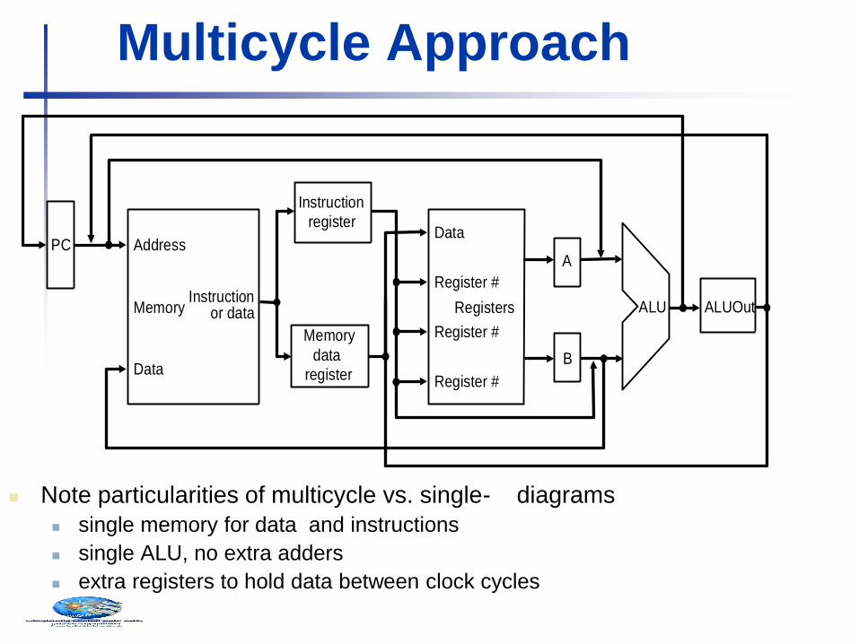
Note particularities of multicycle vs. single- diagrams
single memory for data and instructions
single ALU, no extra adders
extra registers to hold data between clock cycles
Multicycle Approach
PC
Memory
Address
Instruction or data
Data
Instruction
register
Registers
Register #
Data
Register #
Register #
ALU
Memory
data
register
A
B
ALUOut

Breaking instructions into steps
We break instructions into steps – not all instructions require all the steps – each step takes one
clock cycle and Each MIPS instruction takes from 3 – 5 cycles (steps)
1. IF: Instruction fetch and PC increment:;
2. ID : Instruction decode and register fetch:
3. EX : Execution, memory address computation, or branch completion
4. MEM : Memory access or R-type instruction completion
5. WB : Memory read completion
Steps Step nameAction for R-type
instructions
Action for memory-reference
instructions
Action for
branches
Action for
jumps
Instruction A = Reg [IR[25-21]]
decode/register fetch B = Reg [IR[20-16]]
ALUOut = PC + (sign-extend (IR[15-0]) << 2)
Execution, address ALUOut = A + sign-extend if (A ==B) then PC = PC [31-28] II
computation, branch/ (IR[15-0]) PC = ALUOut (IR[25-0]<<2)
jump completion
Memory access or R-type Reg [IR[15-11]] = Load: MDR = Memory[ALUOut]
completion ALUOut or
Store: Memory [ALUOut] = B
WR Memory read completion Load: Reg[IR[20-16]] = MDR
IF
ID
EX
MEM
Instruction fetchIR = Memory[PC]
PC = PC + 4
ALUOut = A op B
Chapter 6 Enhancing Performance with Pipelining
to keep steps balanced in length, the design restriction is to allow
each step to contain at most one ALU operation, or
one register access, or one memory access.

Pipelining
Start work ASAP!! Do not waste time!
Why is easy with MIPS?
1) all instructions are same length
1) fetch and decode stages are
similar for all instructions
2) few instruction formats
1) simplifies instruction decode and
makes it possible in one stage
3) memory operands appear only in load/stores
so memory access can be
deferred to exactly one later
stage
operands are aligned in memory
one data transfer instruction
requires one memory access stage
What about x86? (1 t0 17 bytes
instruction)
Time76 PM 8 9 10 11 12 1 2 AM
A
B
C
D
Time76 PM 8 9 10 11 12 1 2 AM
A
B
C
D
Task
order
Task
order
Assume 30 min. each task – wash, dry, fold, store
separate tasks use separate hardware
So, can be overlapped
Pipelined
Not pipelined
Chapter 6 Enhancing Performance with Pipelining
Pipelining is an implementation technique in which multiple instructions are overlapped in
execution.

Pipelined Execution Representation
To simplify pipeline, every instruction takes
same number of steps, called stages
One clock cycle per stage
Program Flow
IFtch Dcd Exec Mem WB
IFtch Dcd Exec Mem WB
IFtch Dcd Exec Mem WB
IFtch Dcd Exec Mem WB
IFtch Dcd Exec Mem WB
Time
Chapter 6 Enhancing Performance with Pipelining

Pipelined vs. Single-Cycle
Instruction Execution: the Plan
I n s t r u c t i o n
f e t c h R e g A L U
D a t a
a c c e s s R e g
8 n s I n s t r u c t i o n
f e t c h R e g A L U
D a t a
a c c e s s R e g
8 n s I n s t r u c t i o n
f e t c h
8 n s
T i m e
l w $ 1 , 1 0 0 ( $ 0 )
l w $ 2 , 2 0 0 ( $ 0 )
l w $ 3 , 3 0 0 ( $ 0 )
2 4 6 8 1 0 1 2 1 4 1 6 1 8
2 4 6 8 1 0 1 2 1 4
. . .
P r o g r a m
e x e c u t i o n
o r d e r
( i n i n s t r u c t i o n s )
I n s t r u c t i o n
f e t c h R e g A L U
D a t a
a c c e s s R e g
T i m e
l w $ 1 , 1 0 0 ( $ 0 )
l w $ 2 , 2 0 0 ( $ 0 )
l w $ 3 , 3 0 0 ( $ 0 )
2 n s I n s t r u c t i o n
f e t c h R e g A L U
D a t a
a c c e s s R e g
2 n s I n s t r u c t i o n
f e t c h R e g A L U
D a t a
a c c e s s R e g
2 n s 2 n s 2 n s 2 n s 2 n s
P r o g r a m
e x e c u t i o n
o r d e r
( i n i n s t r u c t i o n s )
Single-cycle T?
Pipelined T?
Assume 2 ns for memory access, ALU operation; 1 ns for register access:
therefore, single cycle clock 8 ns; pipelined clock cycle 2 ns.
Chapter 6 Enhancing Performance with Pipelining
assume write to
register file occurs in
first half of CLK and
read in second half..

Hazards What makes it hard?
Structural hazards: different instructions, at
different stages, in the pipeline want to use the
same hardware resource
Control hazards: Deciding on control action
depends on previous instruction
Data hazards: an instruction in the pipeline
requires data to be computed by a previous
instruction still in the pipeline
we first briefly examine these potential hazards
individually…
Chapter 6 Enhancing Performance with Pipelining
M
Load
Instr 1
Instr 2
Instr 3
Instr 4
AL
U
M Reg M Reg
AL
U
M Reg M Reg A
LU
M Reg M Reg
AL
U
Reg M Reg
AL
U
M Reg M Reg
I
n
s
t
r.
O
r
d
e
r
Time (clock cycles)
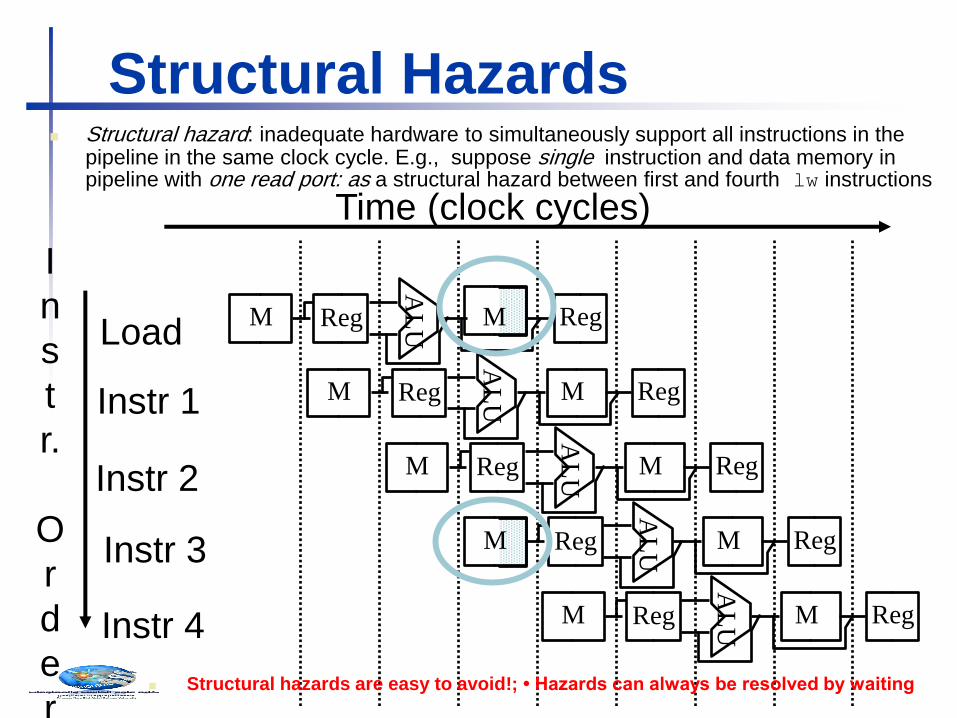
Structural Hazards Structural hazard: inadequate hardware to simultaneously support all instructions in the
pipeline in the same clock cycle. E.g., suppose single instruction and data memory in pipeline with one read port: as a structural hazard between first and fourth lw instructions
Structural hazards are easy to avoid!; • Hazards can always be resolved by waiting

Control Hazards
Control hazard: need to make a decision based on the result of a
previous instruction still executing in pipeline
Solution 1 Stall the pipeline
I n s t r u c t i o n
f e t c h R e g A L U
D a t a
a c c e s s R e g
T i m e
b e q $ 1 , $ 2 , 4 0
a d d $ 4 , $ 5 , $ 6
l w $ 3 , 3 0 0 ( $ 0 )
4 n s
I n s t r u c t i o n
f e t c h R e g A L U
D a t a
a c c e s s R e g
2 n s
I n s t r u c t i o n
f e t c h R e g A L U
D a t a
a c c e s s R e g
2 n s
2 4 6 8 1 0 1 2 1 4 1 6
P r o g r a m
e x e c u t i o n
o r d e r
( i n i n s t r u c t i o n s )
Pipeline stall
b u b b l e
Note that branch outcome is
computed in ID stage with
added hardware (later…)
Chapter 6 Enhancing Performance with Pipelining
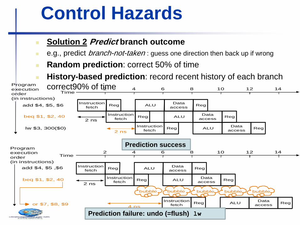
Control Hazards
Solution 2 Predict branch outcome
e.g., predict branch-not-taken : guess one direction then back up if wrong
Random prediction: correct 50% of time
History-based prediction: record recent history of each branch
correct90% of time
Instruction
fetchReg ALU
Data
accessReg
Time
beq $1, $2, 40
add $4, $5, $6
lw $3, 300($0)
Instruction
fetchReg ALU
Data
accessReg
2 ns
Instruction
fetchReg ALU
Data
accessReg
2 ns
Program
execution
order
(in instructions)
Instruction
fetchReg ALU
Data
accessReg
Time
beq $1, $2, 40
add $4, $5 ,$6
or $7, $8, $9
Instruction
fetchReg ALU
Data
accessReg
2 4 6 8 10 12 14
2 4 6 8 10 12 14
Instruction
fetchReg ALU
Data
accessReg
2 ns
4 ns
bubble bubble bubble bubble bubble
Program
execution
order
(in instructions)
Prediction success
Prediction failure: undo (=flush) lw

Control Hazards Solution 3 Delayed branch: always execute the sequentially
next statement with the branch executing after one instruction
delay – compiler’s job to find a statement that can be put in the
slot that is independent of branch outcome
MIPS does this – but it is an option in SPIM (Simulator -> Settings)
I n s t r u c t i o n
f e t c h R e g A L U
D a t a
a c c e s s R e g
T i m e
b e q $ 1 , $ 2 , 4 0
a d d $ 4 , $ 5 , $ 6
l w $ 3 , 3 0 0 ( $ 0 )
I n s t r u c t i o n
f e t c h R e g A L U
D a t a
a c c e s s R e g
2 n s I n s t r u c t i o n
f e t c h R e g A L U
D a t a
a c c e s s R e g
2 n s
2 4 6 8 1 0 1 2 1 4
2 n s
( d e l a y e d b r a n c h s l o t )
P r o g r a m e x e c u t i o n o r d e r ( i n i n s t r u c t i o n s )
Delayed branch beq is followed by add that is
independent of branch outcome
Chapter 6 Enhancing Performance with Pipelining

Data Hazards Data hazard: instruction depends on the result of a previous
instruction still executing in pipeline
Solution Forward data if possible…
Time2 4 6 8 10
add $s0, $t0, $t1
IF ID WBEX MEM
a d d $ s 0 , $ t 0 , $ t 1
s u b $ t 2 , $ s 0 , $ t 3
P r o g r a m
e x e c u t i o n
o r d e r
( i n i n s t r u c t i o n s )
I F I D W B E X
I F I D M E M E X
T i m e 2 4 6 8 1 0
M E M
W B M E M
Instruction pipeline diagram:
shade indicates use –
left=write, right=read
Without forwarding – blue
line – data has to go back in
time;
with forwarding – red line –
data is available in time

Data Hazards
Forwarding may not be enough
e.g., if an R-type instruction following a load uses the result of the
load – called load-use data hazard
T i m e 2 4 6 8 1 0 1 2 1 4
l w $ s 0 , 2 0 ( $ t 1 )
s u b $ t 2 , $ s 0 , $ t 3
P r o g r a m
e x e c u t i o n
o r d e r
( i n i n s t r u c t i o n s )
I F I D W B M E M E X
I F I D W B M E M E X
Time2 4 6 8 10 12 14
lw $s0, 20($t1)
sub $t2, $s0, $t3
Program
execution
order
(in instructions)
IF ID WBMEMEX
IF ID WBMEMEX
bubble bubble bubble bubble bubble
With a one-stage stall, forwarding can get the data to the sub
instruction in time
Without a stall it is impossible to provide input to the sub
instruction in time

Reordering Code to Avoid Pipeline Stall
(Software Solution)
Example:
lw $t0, 0($t1)
lw $t2, 4($t1)
sw $t2, 0($t1)
sw $t0, 4($t1)
Reordered code:
lw $t0, 0($t1)
lw $t2, 4($t1)
sw $t0, 4($t1)
sw $t2, 0($t1)
Data hazard
Interchanged

Pipelined Datapath - Single-Cycle Datapath “Steps”
5 5 16
RD1
RD2
RN1 RN2 WN
WD
Register File ALU
E X T N D
16 32
RD
WD
Data Memory
ADDR
5
Instruction I
32
M
U
X
<<2 RD
Instruction Memory
ADDR
PC
4
ADD
ADD
M
U
X
32
IF
Instruction Fetch
ID
Instruction Decode EX
Execute/ Address Calc.
MEM
Memory Access WB
Write Back
Zero
Chapter 6 Enhancing Performance with Pipelining

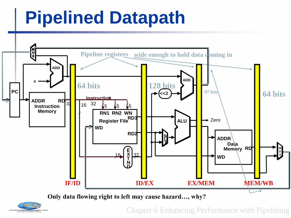
Pipelined Datapath
IF/ID
Pipeline registers
5 5 16
RD1
RD2
RN1 RN2 WN
WD
Register File ALU
E X T N D
16 32
RD
WD
Data Memory
ADDR
5
Instruction I
32
M U X
<<2
RD Instruction
Memory
ADDR
PC
4
ADD
ADD
M
U
X
32
ID/EX EX/MEM MEM/WB
Zero
64 bits 97 bits 64 bits
128 bits
wide enough to hold data coming in
Idea :What happens if we break the execution into multiple cycles, but keep the extra hardware?
Answer: We may be able to start executing a new instruction at each clock cycle - pipelining
…but we shall need extra registers to hold data between cycles – pipeline registers
Pipelined Datapath
IF/ID
Pipeline registers
5 5 16
RD1
RD2
RN1 RN2 WN
WD
Register File ALU
E X T N D
16 32
RD
WD
Data Memory
ADDR
5
Instruction I 32
M U X
<<2
RD Instruction
Memory
ADDR
PC
4
ADD
ADD
M
U
X
32
ID/EX EX/MEM MEM/WB
Zero
64 bits 97 bits 64 bits
128 bits
wide enough to hold data coming in
Only data flowing right to left may cause hazard…, why?
Chapter 6 Enhancing Performance with Pipelining

Bug in the Datapath
5 5 16
RD1
RD2
RN1 RN2 WN
WD
Register File ALU
E X T N D
16 32
RD
WD
Data Memory
ADDR
5
Instruction I 32
M U X
<<2
RD Instruction
Memory
ADDR
PC
4
ADD
ADD
M U X
32
Write register number comes from another later instruction!
IF/ID ID/EX EX/MEM MEM/WB
Chapter 6 Enhancing Performance with Pipelining
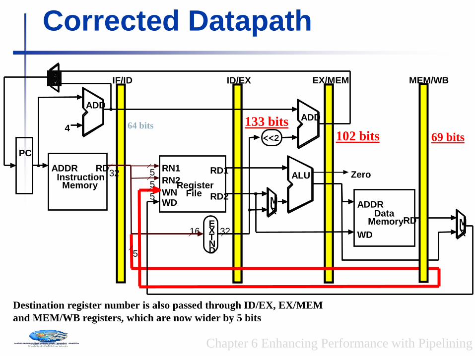
Corrected Datapath
5
RD1
RD2
RN1
RN2
WN WD
Register File
ALU
E X T N D
16 32
RD
WD
Data Memory
ADDR
32
M U X
<<2
RD Instruction
Memory
ADDR
PC
4
ADD
ADD
M U X
5
5
5
EX/MEM MEM/WB
Zero
ID/EX IF/ID
64 bits 133 bits 102 bits 69 bits
Destination register number is also passed through ID/EX, EX/MEM
and MEM/WB registers, which are now wider by 5 bits
Chapter 6 Enhancing Performance with Pipelining

Single-Clock-Cycle Diagram:
Clock Cycle 1
LW
Example
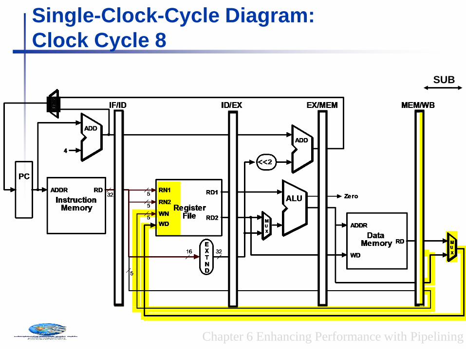
lw $t0, 10($t1); sw $t3, 20($t4)
add $t5, $t6, $t7; sub $t8, $t9, $t10
Chapter 6 Enhancing Performance with Pipelining

LW SW
Single-Clock-Cycle Diagram:
Clock Cycle 2
Chapter 6 Enhancing Performance with Pipelining
Example
lw $t0, 10($t1); sw $t3, 20($t4)
add $t5, $t6, $t7; sub $t8, $t9, $t10

Single-Clock-Cycle Diagram:
Clock Cycle 3
LW SW ADD
Chapter 6 Enhancing Performance with Pipelining

Single-Clock-Cycle Diagram:
Clock Cycle 4
LW SW ADD SUB
Chapter 6 Enhancing Performance with Pipelining

LW SW ADD SUB
Single-Clock-Cycle Diagram:
Clock Cycle 5
Chapter 6 Enhancing Performance with Pipelining

Single-Clock-Cycle Diagram:
Clock Cycle 6
SW ADD SUB
Chapter 6 Enhancing Performance with Pipelining

ADD SUB
Single-Clock-Cycle Diagram:
Clock Cycle 7
Chapter 6 Enhancing Performance with Pipelining
SUB
Single-Clock-Cycle Diagram:
Clock Cycle 8
Chapter 6 Enhancing Performance with Pipelining

Alternative View –
Multiple-Clock-Cycle Diagram
IM REG ALU DM REG lw $t0, 10($t1)
sw $t3, 20($t4)
add $t5, $t6, $t7
CC 1 CC 2 CC 3 CC 4 CC 5 CC 6 CC 7
IM REG ALU DM REG
IM REG ALU DM REG
sub $t8, $t9, $t10 IM REG ALU DM REG
CC 8
Time axis
Chapter 6 Enhancing Performance with Pipelining

Notes No write control for all pipeline registers and PC since they are updated at
every clock cycle
To specify the control for the pipeline, set the control values during each
pipeline stage
Control lines can be divided into 5 groups:
IF – NONE
ID – NONE
ALU – RegDst, ALUOp, ALUSrc
MEM – Branch, MemRead, MemWrite
WB – MemtoReg, RegWrite
Group these nine control lines into 3 subsets:
ALUControl, MEMControl, WBControl
Control signals are generated at ID stage, how to pass them to other
stages?
Chapter 6 Enhancing Performance with Pipelining
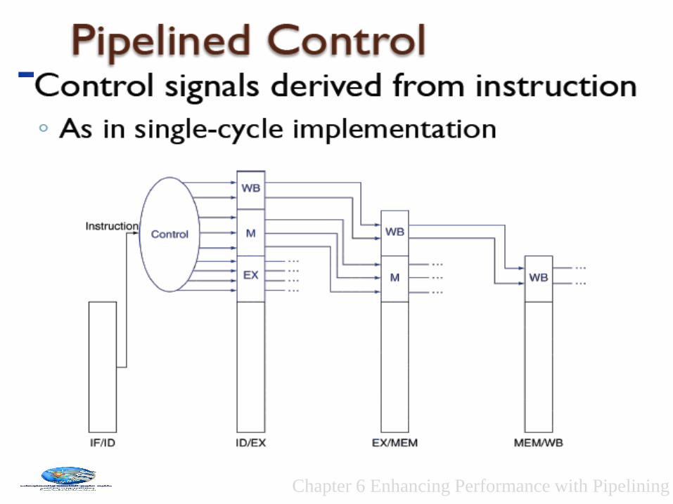
Chapter 6 Enhancing Performance with Pipelining

Pipelined Datapath with Control
PC
Instruction memory
Instr
uctio
n
Add
Instruction [20– 16]
Me
mto
Re
g
ALUOp
Branch
RegDst
ALUSrc
4
16 32Instruction [15– 0]
0
0
M u x
0
1
AddAdd
result
RegistersWrite register
Write data
Read data 1
Read data 2
Read register 1
Read register 2
Sign extend
M u x
1
ALU result
Zero
Write data
Read data
M u x
1
ALU control
Shift left 2
Re
gW
rite
MemRead
Control
ALU
Instruction [15– 11]
6
EX
M
WB
M
WB
WBIF/ID
PCSrc
ID/EX
EX/MEM
MEM/WB
M u x
0
1
Me
mW
rite
Address
Data memory
Address
Control signals
emanate from
the control
portions of the
pipeline registers
Chapter 6 Enhancing Performance with Pipelining

Instruction-Level Parallelism (ILP)
Pipelining: executing multiple instructions
in parallel. To increase ILP
Deeper pipeline
Less work per stage ⇒ shorter clock cycle
Multiple issue
Replicate pipeline stages ⇒ multiple pipelines
Start multiple instructions per clock cycle
CPI < 1, so use Instructions Per Cycle (IPC)
E.g., 4GHz 4-way multiple-issue
16 BIPS, peak CPI = 0.25, peak IPC = 4
But dependencies reduce this in practice

How ILP Works Issuing multiple instructions per cycle
would require fetching multiple instructions from memory per cycle => called Superscalar degree or Issue width
To find independent instructions, we must have a big pool of instructions to choose from, called instruction buffer (IB). As IB length increases, complexity of decoder (control) increases that increases the datapath cycle time
Prefetching instructions sequentially by an IFU that operates independently from datapath control. Fetch instruction (PC)+L, where L is the IB size or as directed by the branch predictor.
Chapter 6 Enhancing Performance with Pipelining

Compiler/Hardware Speculation
Compiler can reorder instructions
Static Multiple Issue
Compiler groups instructions into “issue packets”
Group of instructions that can be issued on a single cycle
Determined by pipeline resources required
Think of an issue packet as a very long instruction
Specifies multiple concurrent operations
⇒ Very Long Instruction Word (VLIW)
Compiler must remove some/all hazards
Reorder instructions into issue packets with No dependencies with a
packet
Varies between ISAs; compiler must know!
Pad with nop if necessary
Hardware can look ahead for instructions to execute
Buffer results until it determines they are actually needed
Flush buffers on incorrect speculation
Explicitly
Parallel
Instruction
Computer
(EPIC).

Loop Unrolling
Renaming the registers
Chapter 6 Enhancing Performance with Pipelining
Loop: lw $t0, 0($s1)
addu $t0,$t0,$s2
sw $t0, 0($s1)
addi $s1,$s1,–4
bne $s1,$zero,Loop
Replicate loop body to expose more parallelism

HW Schemes: Instruction Parallelism
Why in HW at run time?
Works when can’t know real dependence at compile time
Compiler simpler
Code for one machine runs well on another
Key idea: Allow instructions behind stall to proceed
DIVD F0,F2,F4
ADDD F10,F0,F8
SUBD F12,F8,F14
Enables out-of-order execution => out-of-order completion
ID stage checks for hazards. If no hazards, issue the instn
for execution.
Chapter 6 Enhancing Performance with Pipelining

Dynamic Multiple Issue (Superscalar)
“Superscalar” processors: An advanced pipelining
technique that enables the processor to execute more than one instruction per clock cycle
• CPU decides whether to issue 0, 1,..IPC
• Avoiding structural and data hazards(Dynamic pipeline)
• Avoids the need for compiler scheduling
• Allow the CPU to execute instructions out of order to avoid stalls
• But commit result to registers in order
Example: lw $t0, 20($s2)
addu $t1, $t0, $t2
sub $s4, $s4, $t3
slti $t5, $s4, 20 ◦ Can start sub while addu is waiting for lw
Chapter 6 Enhancing Performance with Pipelining


Speed Up Equation for Pipelining
CPIpipelined = Ideal CPI + Pipeline stall clock cycles per instn
Speedup = Ideal CPI x Pipeline depth Clock Cycleunpipelined
---------------------------------- X -------------------------
Ideal CPI + Pipeline stall CPI Clock Cyclepipelined
Speedup = Pipeline depth Clock Cycleunpipelined
------------------------ X ---------------------------
1 + Pipeline stall CPI Clock Cyclepipelined