Embed Size (px)
Citation preview
Available online at www.CivileJournal.org
Civil Engineering Journal
Vol. 6, No. 8, August, 2020
1457
Enhancement Punching Shear in Flat Slab Using Mortar
Infiltrated Fiber Concrete
Ali Sabah Imran Shwalia a*
, Nabeel Hasan Ali Al-Salim a, Haider M. Al-Baghdadi
a
b College of Engineering, University of Babylon, Hilla, Babil, Iraq.
Received 23 March 2020; Accepted 29 June 2020
Abstract
In this paper, improving the punching shear of slab column connection using mortar infiltrated fiber concrete is studied.
Eight specimens of reinforced concrete slabs identical in dimension and reinforcement were tested, six of them were
casting with hybrid concrete (normal strength concrete and mortar infiltrated fiber concrete) and two specimens were cast
with normal strength concrete as control specimens. All specimens were tested under vertical loading. The mortar
infiltrated fiber concrete was cast monolithically with the normal strength concrete at different thickness at one and a half
times of the effective depth (1.5d) at the center of the slab, once at all the thickness of cross section of the slab and the
others at half thickness either tension or compression face of the slabs all cases cast with two types of fiber. The vertical
load was applied upward through a square column with a dimension of (100 mm). In all slabs, no failure in mortar
infiltrated fiber concrete was observed. The test results showed that the use of mortar infiltrated fiber concrete improves
the punching shear strength for some cases according to the type of fibers and the location of casting mortar infiltrated
fiber concrete in slabs. The enhancement in punching shear strength due to using mortar infiltrated fiber concrete at 1.5d
square shape (265 mm) ranged from 4% to 46% compared with the control specimens.
Keywords: Improvement Punching Shear; Mortar Infiltrated Fiber Concrete; Hybrid Concrete.
1. Introduction
The flat plate slab is susceptible to punching shear failure. This type of failure is catastrophic because no visible
signs are shown before failure. There are actually specific punching shear strength formulas for slab column
connections such as those suggested by ACI 318 [1] and BS 8110 [2] codes. These formulas were developed for slab
casted using normal strength concrete; so, they might not be applicable to strengthened slab using mortar infiltrated
fiber concrete. The classical strengthening techniques using to avoiding sudden punching failure, include the use of
transverse pre-stressed reinforcement, steel plates and bolts, increase the thickness of the slab around column or use of
a larger column cross-section and use of an epoxy bonding steel plate. Further focus has been given to use advanced
composite materials to strengthen especially fibers in all different types, to prevent sudden punching shear failure. In
this study using the mortar infiltrated fiber concrete as a strengthening martial. Mortar infiltrated fiber concrete is a
comparatively modern material differentiated from Fiber Reinforced Concrete (FRC) in two aspects that is fiber
volume fraction and manufacturing process.
Mortar infiltrated fiber concrete was developed to incorporating large amounts of fibers in cement composites, to
get a very high strength property. The researchers began to use a large variety of fibers. Mortar infiltrated fiber
concrete has high strength as well as large ductility and far significant potential for structural applications [3-7]. The
* Corresponding author: [email protected]
http://dx.doi.org/10.28991/cej-2020-03091560
© 2020 by the authors. Licensee C.E.J, Tehran, Iran. This article is an open access article distributed under the terms and conditions of the Creative Commons Attribution (CC-BY) license (http://creativecommons.org/licenses/by/4.0/).
Civil Engineering Journal Vol. 6, No. 8, August, 2020
1458
matrix does not contain coarse aggregate which, of course, cannot infiltrate through the tiny spaces between dense
fibers network, but has a high cements content. However, it may contain fine or extra-fine sand and additives such as
silica fume, fly ash, and slag. The mortar fineness must be designed to properly infiltrate the dens fiber layer placed in
mold. Limited research work has been carried out on using mortar infiltrated fiber concrete to improving punching
shear, and all of this study depending on cast all the slab with mortar infiltrated fiber concrete [8-10], but this way not
economical due to the need for large quantities of fiber. Therefore, in this study, work will be done to improve the
normal strength concrete slabs by using small quantities of mortar infiltrated fiber concrete as a hybrid slabs, to
obtaining good results with great economy. The influence of the variables studied in this study covers the thickness
and position of mortar infiltrated fiber concrete and the type of fiber used.
2. Materials and Methods
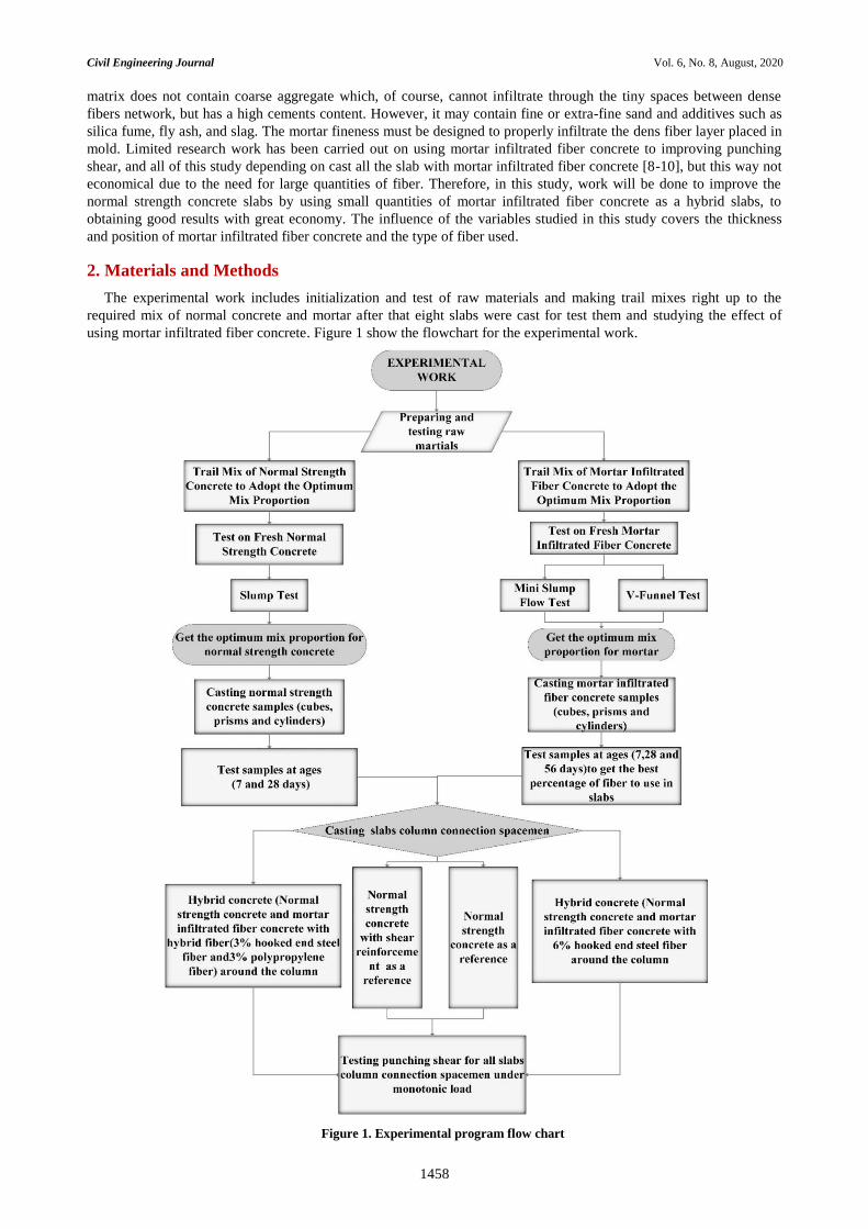
The experimental work includes initialization and test of raw materials and making trail mixes right up to the
required mix of normal concrete and mortar after that eight slabs were cast for test them and studying the effect of
using mortar infiltrated fiber concrete. Figure 1 show the flowchart for the experimental work.
Figure 1. Experimental program flow chart
Civil Engineering Journal Vol. 6, No. 8, August, 2020
1459
2.1. Materials Used for Cast Specimens
For the slab specimens, two types of concrete used normal strength concrete mixtures with compressive strengths
of 25 MPa and the other type are mortar infiltrated fiber concrete with two types of fiber (steel fiber and hybrid fiber)
with compressive strengths getting from trail mix (92 and 62 MPa) Sequentially [11].
2.1.1. Materials Used for Preparing Normal Strength Concrete
The normal strength concrete was design according to American method of mix proportions selection (ACI
Committee 211.1-91) [12]. The target concrete strength f’c was 25 MPa.
Cement
In this study the type of cement used was limestone Portland cement (CEM II/A-L- 42.5 R) mate with the (IQS No.
5/1984) limitations [13].
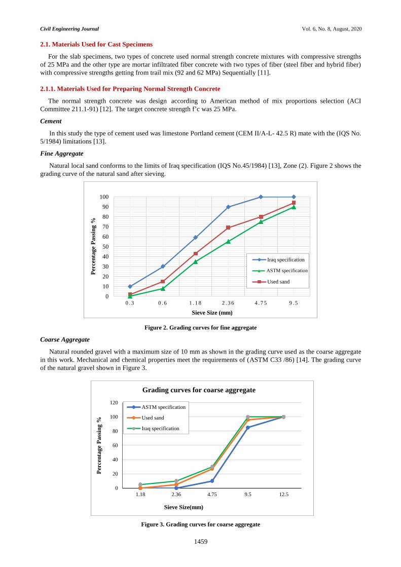
Fine Aggregate
Natural local sand conforms to the limits of Iraq specification (IQS No.45/1984) [13], Zone (2). Figure 2 shows the
grading curve of the natural sand after sieving.
Figure 2. Grading curves for fine aggregate
Coarse Aggregate
Natural rounded gravel with a maximum size of 10 mm as shown in the grading curve used as the coarse aggregate
in this work. Mechanical and chemical properties meet the requirements of (ASTM C33 /86) [14]. The grading curve
of the natural gravel shown in Figure 3.
Figure 3. Grading curves for coarse aggregate
0
10
20
30
40
50
60
70
80
90
100
0 . 3 0 . 6 1 . 1 8 2 . 3 6 4 . 7 5 9 . 5
Per
cen
tag
e P
ass
ing
%
Sieve Size (mm)
Iraq specification
Used sand
0
20
40
60
80
100
120
1.18 2.36 4.75 9.5 12.5
Per
cen
tag
e P
ass
ing
%
Sieve Size(mm)
Grading curves for coarse aggregate
ASTM specification
Used sand
Iraq specification
ASTM specification

Civil Engineering Journal Vol. 6, No. 8, August, 2020
1460
2.1.2. Materials Used for Preparing Mortar Infiltrated Fiber Concrete
In the experimental study, many trail mortar mixtures were performed to find the correct mixing proportions and
with the assistance of some previous studies [15-17].
Cement
In this study the type of cement used was limestone Portland cement (CEM II/A-L- 42.5 R) mate with the (IQS No.
5/1984) limitations [13].
Extra Fine Sand
Natural local sand was used as a fine aggregate. Only extra fine sand, which was sieve through (600 µm) to separating
the coarser particles used in preparing mortar. It conforms to the limits of Iraq specification No.45/1984 [13], Zone
(3). Figure 4 shows the grading curve after sieving process.
Figure 4. Grading curves for extra fine aggregate
Micro Silica Fume (SF)
In this work the silica fume used was commercially known as Mega Add MS (D) from the chemical company
(CONMIX), with the replacement (10%) by weight of cement.
High-Range Water Reducing Admixture (HRWRA)
The high range water reducing admixture was used in this work for the preparation of mortar, known commercially
as (Hyperplast PC200). It is factory by the company (DCP), and meets with the (ASTM C494/C494 M) requirements
[18].
Fibers
In this work two different types of fibers were used. The first type was hooked end steel fibers with a length of (30
mm), a diameter of (0.5 mm) and the tensile strength of about 1100 MPa, the hooked fiber was supplied from
JATLAS Company in Turkey. The second type was synthetic polypropylene fiber with a length of (27 mm), a
diameter of (27 mm) and with a tensile strength of 570-660 MPa, this type of fiber was manufactured by the FORTA -
FERRO Company in U.S.A. The two types of fibers following the ASTM A820/A820M-04[19]. Figure 5 shows the
two types of used fibers.
Figure 5. The fibers used: A- end hooked steel fiber, B- polypropylene fiber
0
10
20
30
40
50
60
70
80
90
100
0 . 1 5 0 . 3 0 . 6 1 . 1 8 2 . 3 6 4 . 7 5 9 . 5
Per
cen
tag
e P
ass
ing
%
Sieve Size (mm)
Iraq specification
Used sand
ASTM specification
Civil Engineering Journal Vol. 6, No. 8, August, 2020
1461
2.1.3. Reinforcing Steel
Deformed steel bars with two different diameters were used in the specimens. Uniaxial tension tests were carried
out on the (10 and 6 mm) nominal diameter bars to determine the yielding stress and the ultimate strength. Reinforced
steel bars diameter 10 mm with a yield stress of 554 MPa was used to be flexural reinforcement of the flat slab, while
6 mm in diameter bars with a yield stress of 560 was used in column stirrups. Three samples were tested for each bar
diameter and the average of the results was used. The test samples were placed in a computerized tensile test machines
and tested until ruptures, according to ASTM A615 [20].
2.2 Specimens Casting Process
Eight slabs specimens with the dimensions of (900 × 900 × 80) mm with a square column in the middle of the
slab with dimension (100 × 100 × 200) mm were cast. Before casting, the selection materials were prepared and
weighed according to the results obtained from the trail mixes as shown in Table 1. The mortar was mixed by
electrical drill mixer with a suitable pan about (0.02 m3) capacity, mixing time about (7 − 9) minutes. Before mixing
operation, the pan was cleaned off. The binder material (cement and silica fume) were mixed in the pan to disperse the
silica fume particles throughout the cement particles. Then the sand was added and the mixture was mixed to get a
uniform dry mixture. The whole amount of high-range water-reducing admixture (Hyperplast PC9200) was mixed
separately with (1/3) of mixing water, after that, (2/3) of mixing water was added to the mix, then HRWR with (1/3) of
mixing water was fed to the mixer to obtain the required fluidity [21]. At the same time, the mixing procedure of
normal strength concrete start by mixing the gravel with the dry sand in the electrical horizontal rotary drum mixer of
(0.09 m3) volume capacity and mixed for several minutes. Then added cement to the mixer, and gradual adding the
weighted water to the mix. The mixing time is total about (8 − 10 minutes).
Table 1. The optimal mixing proportions for normal strength concrete and mortar infiltrated fiber concrete for 1 𝐦𝟑
Normal strength concrete Mortar infiltrated fiber concrete
Hooked end steel fiber Hybrid fibers
Materials Proportions of mix
(kg/𝐦𝟑) Materials
Proportions of mix
(kg/𝐦𝟑) Materials
Proportions of mix
(kg/𝐦𝟑)
Cement 368 Cement 872.1 Cement 872.1
Gravel 900 Sand 969 Sand 969
Sand 850 Silica Fume 10% rep 96.9 Silica Fume 10% rep 96.9
Water 208 Hooked end Steel Fiber 471.9 Hooked end Steel Fiber 235.95
Polypropylene fiber 27.3
W/C ratio 0.57 W/b 0.32 W/b 0.32
Super Plasticizer by wt. of
Cementous (%) 2.4
Super Plasticizer by wt. of
Cementous (%) 2.4
All slabs used in this work were cast in plywood molds with clear dimensions (900 × 900 × 80 mm), and steel
mold for isolation and limit the area will be cast with mortar infiltrated fiber concrete square shape with dimension
(265 × 265 mm) have a clear height (80 mm). The reinforcing bar ratio constant with (𝜌 = 0.0158) and the concrete
cover for reinforcing bars was 15 mm for all slabs. The two types of concrete casting together to achieve the bonding
between the two types of concrete. The casting process is defined according to the following stages:
1. Before each casting, the plywood and steel molds were prepared by cleaning and lightly lubricating the internal
faces by oil to prevent adhesion with hardened concrete and placed on horizontal ground.
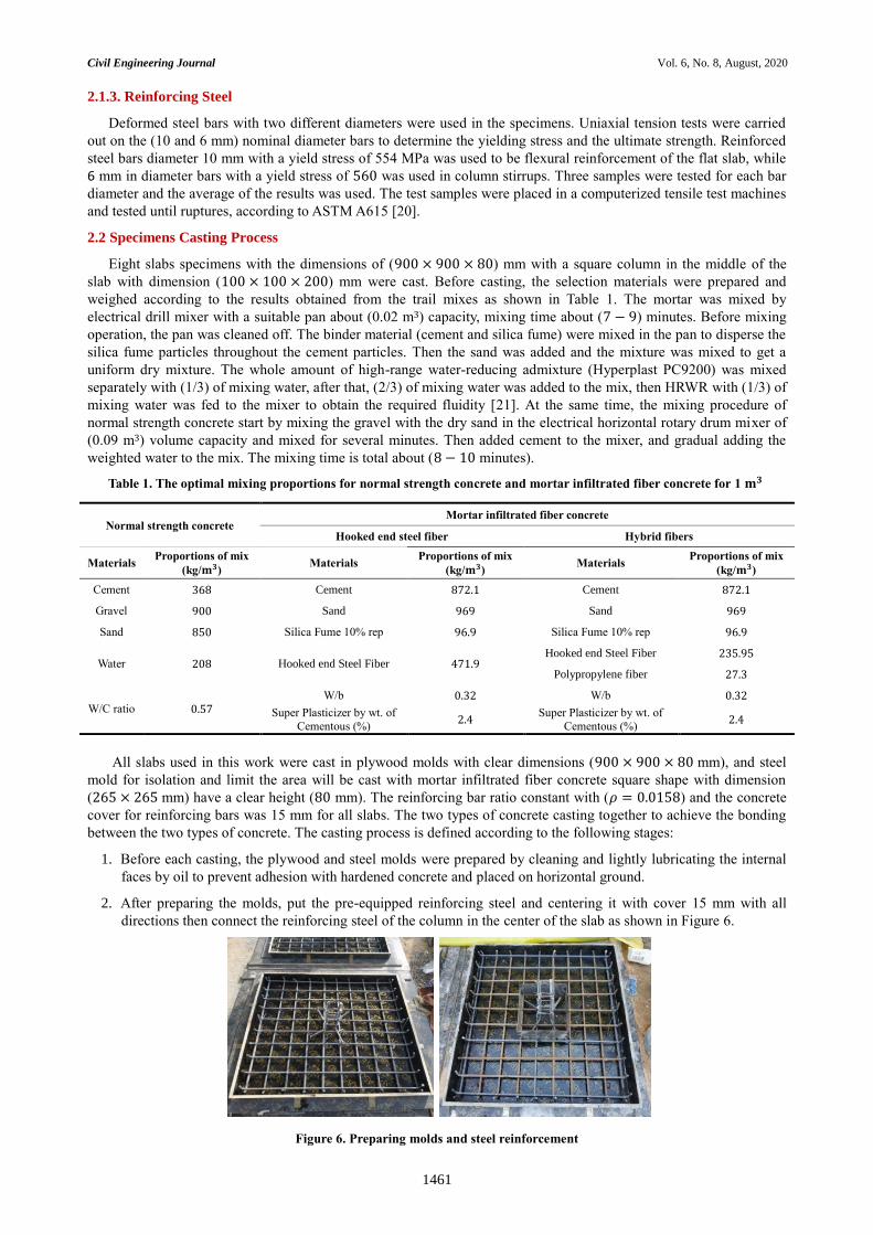
2. After preparing the molds, put the pre-equipped reinforcing steel and centering it with cover 15 mm with all
directions then connect the reinforcing steel of the column in the center of the slab as shown in Figure 6.
Figure 6. Preparing molds and steel reinforcement
Civil Engineering Journal Vol. 6, No. 8, August, 2020
1462
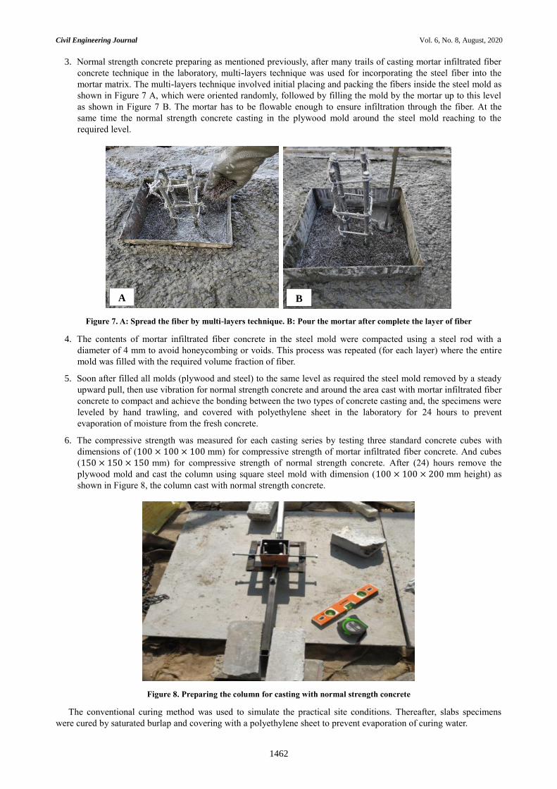
3. Normal strength concrete preparing as mentioned previously, after many trails of casting mortar infiltrated fiber
concrete technique in the laboratory, multi-layers technique was used for incorporating the steel fiber into the
mortar matrix. The multi-layers technique involved initial placing and packing the fibers inside the steel mold as
shown in Figure 7 A, which were oriented randomly, followed by filling the mold by the mortar up to this level
as shown in Figure 7 B. The mortar has to be flowable enough to ensure infiltration through the fiber. At the
same time the normal strength concrete casting in the plywood mold around the steel mold reaching to the
required level.
Figure 7. A: Spread the fiber by multi-layers technique. B: Pour the mortar after complete the layer of fiber
4. The contents of mortar infiltrated fiber concrete in the steel mold were compacted using a steel rod with a
diameter of 4 mm to avoid honeycombing or voids. This process was repeated (for each layer) where the entire
mold was filled with the required volume fraction of fiber.
5. Soon after filled all molds (plywood and steel) to the same level as required the steel mold removed by a steady
upward pull, then use vibration for normal strength concrete and around the area cast with mortar infiltrated fiber
concrete to compact and achieve the bonding between the two types of concrete casting and, the specimens were
leveled by hand trawling, and covered with polyethylene sheet in the laboratory for 24 hours to prevent
evaporation of moisture from the fresh concrete.
6. The compressive strength was measured for each casting series by testing three standard concrete cubes with
dimensions of (100 × 100 × 100 mm) for compressive strength of mortar infiltrated fiber concrete. And cubes
(150 × 150 × 150 mm) for compressive strength of normal strength concrete. After (24) hours remove the
plywood mold and cast the column using square steel mold with dimension (100 × 100 × 200 mm height) as
shown in Figure 8, the column cast with normal strength concrete.
Figure 8. Preparing the column for casting with normal strength concrete
The conventional curing method was used to simulate the practical site conditions. Thereafter, slabs specimens
were cured by saturated burlap and covering with a polyethylene sheet to prevent evaporation of curing water.
A B
Civil Engineering Journal Vol. 6, No. 8, August, 2020
1463
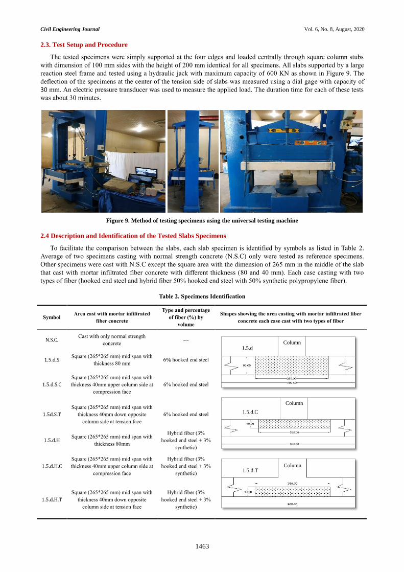
2.3. Test Setup and Procedure
The tested specimens were simply supported at the four edges and loaded centrally through square column stubs
with dimension of 100 mm sides with the height of 200 mm identical for all specimens. All slabs supported by a large
reaction steel frame and tested using a hydraulic jack with maximum capacity of 600 KN as shown in Figure 9. The
deflection of the specimens at the center of the tension side of slabs was measured using a dial gage with capacity of
30 mm. An electric pressure transducer was used to measure the applied load. The duration time for each of these tests
was about 30 minutes.
Figure 9. Method of testing specimens using the universal testing machine
2.4 Description and Identification of the Tested Slabs Specimens
To facilitate the comparison between the slabs, each slab specimen is identified by symbols as listed in Table 2.
Average of two specimens casting with normal strength concrete (N.S.C) only were tested as reference specimens.
Other specimens were cast with N.S.C except the square area with the dimension of 265 mm in the middle of the slab
that cast with mortar infiltrated fiber concrete with different thickness (80 and 40 mm). Each case casting with two
types of fiber (hooked end steel and hybrid fiber 50% hooked end steel with 50% synthetic polypropylene fiber).
Table 2. Specimens Identification
Symbol Area cast with mortar infiltrated
fiber concrete
Type and percentage
of fiber (%) by
volume
Shapes showing the area casting with mortar infiltrated fiber
concrete each case cast with two types of fiber
N.S.C. Cast with only normal strength
concrete ---
1.5.d.S Square (265*265 mm) mid span with
thickness 80 mm 6% hooked end steel
1.5.d.S.C
Square (265*265 mm) mid span with
thickness 40mm upper column side at
compression face
6% hooked end steel
1.5d.S.T
Square (265*265 mm) mid span with
thickness 40mm down opposite
column side at tension face
6% hooked end steel
1.5.d.H Square (265*265 mm) mid span with
thickness 80mm
Hybrid fiber (3%
hooked end steel + 3%
synthetic)
1.5.d.H.C
Square (265*265 mm) mid span with
thickness 40mm upper column side at
compression face
Hybrid fiber (3%
hooked end steel + 3%
synthetic)
1.5.d.H.T
Square (265*265 mm) mid span with
thickness 40mm down opposite
column side at tension face
Hybrid fiber (3%
hooked end steel + 3%
synthetic)
Column
1.5.d.C
Column
Column 1.5.d.T
1.5.d
Civil Engineering Journal Vol. 6, No. 8, August, 2020
1464
3. Results and Analysis of Tests Specimens
All eight specimens failed in punching shear with different ultimate load after relatively large deflection for some
cases as shown in Table 3.
Table 3. The results of tested slabs
specimen f’c for
N.S.C MPa
f’c for
MIFC* MPa
First crack
load KN
Ultimate
load KN
Max.
deflection mm
Type of
failure
Area of punching
shear mm2
Increase in
punching load %
N.S.C * 26.2 --- 38 114.3 5.3 Punching
Shear 231953 Reference
1.5d. S 26.2 73.59 40 119.58 5.4 Punching
Shear 304802 4.619
1.5d. H 26.2 49.39 41 149.38 7.1 Punching
Shear 352757 30.691
1.5d. S. C 26.2 73.59 43 128.77 9 Punching
Shear 355925 12.659
1.5d. H. C 26.2 49.39 42 167.04 9.45 Punching
Shear 504124 46.141
1.5d. S. T 26.2 73.59 40 114.48 5.4 Punching
Shear 210625 0.157
1.5d. H. T 26.2 49.39 39 119.56 5.4 Punching
Shear 265575 4.601
* The value of N.S.C is the average of two specimen
* (MIFC) Mortar infiltrated fiber concrete
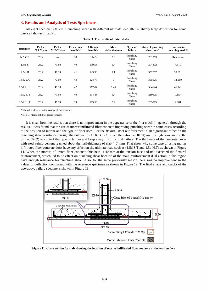
It is clear from the results that there is no improvement in the appearance of the first crack. In general, through the
results, it was found that the use of mortar infiltrated fiber concrete improving punching shear in some cases according
to the position of mortar and the type of fiber used. For the flexural steel reinforcement high significant effect on the
punching shear resistance through the dual-action E. Rizk [22], since the ratio ρ (0.0158) used is high compared to the
ρ max (0.02) to control the type of failure and keep away from flexural failure. The thickness of the concrete cover
with steel reinforcement reached about the half-thickness of slab (40) mm. That show why some case of using mortar
infiltrated fiber concrete don't have any effect on the ultimate load such as (1.5d S.T and 1.5d H.T) as shown in Figure
11. When the mortar infiltrated fiber concrete thickness is 40 mm at the tension face and not exceeded the flexural
reinforcement, which led to no effect on punching shear because of the main reinforcement dual action in this region
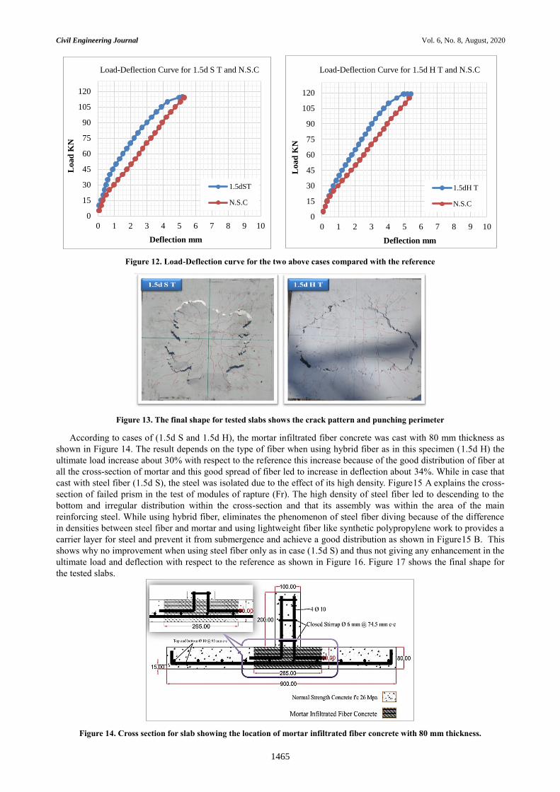
have enough resistance for punching shear. Also, for the same previously reason there was no improvement in the
values of deflection comparing with the reference specimen as shown in Figure 12. The final shape and cracks of the
two-above failure specimens shown in Figure 13.
Figure 11. Cross section for slab showing the location of mortar infiltrated fiber concrete at the tension face
Civil Engineering Journal Vol. 6, No. 8, August, 2020
1465
Figure 12. Load-Deflection curve for the two above cases compared with the reference
Figure 13. The final shape for tested slabs shows the crack pattern and punching perimeter
According to cases of (1.5d S and 1.5d H), the mortar infiltrated fiber concrete was cast with 80 mm thickness as
shown in Figure 14. The result depends on the type of fiber when using hybrid fiber as in this specimen (1.5d H) the
ultimate load increase about 30% with respect to the reference this increase because of the good distribution of fiber at
all the cross-section of mortar and this good spread of fiber led to increase in deflection about 34%. While in case that
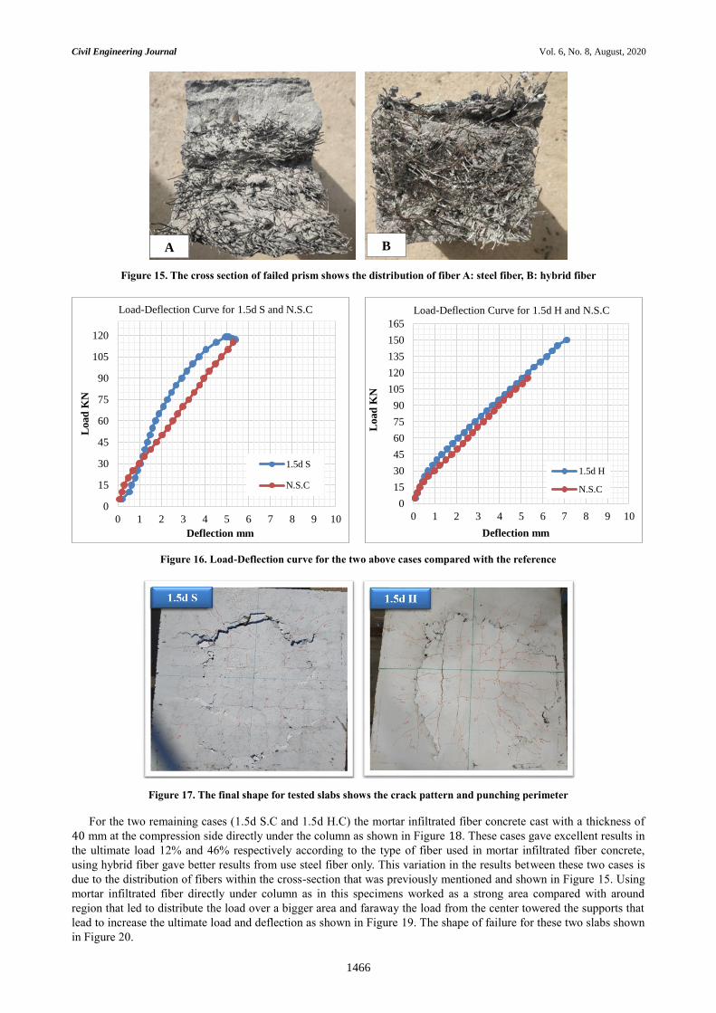
cast with steel fiber (1.5d S), the steel was isolated due to the effect of its high density. Figure15 A explains the cross-
section of failed prism in the test of modules of rapture (Fr). The high density of steel fiber led to descending to the
bottom and irregular distribution within the cross-section and that its assembly was within the area of the main
reinforcing steel. While using hybrid fiber, eliminates the phenomenon of steel fiber diving because of the difference
in densities between steel fiber and mortar and using lightweight fiber like synthetic polypropylene work to provides a
carrier layer for steel and prevent it from submergence and achieve a good distribution as shown in Figure15 B. This
shows why no improvement when using steel fiber only as in case (1.5d S) and thus not giving any enhancement in the
ultimate load and deflection with respect to the reference as shown in Figure 16. Figure 17 shows the final shape for
the tested slabs.
Figure 14. Cross section for slab showing the location of mortar infiltrated fiber concrete with 80 mm thickness.
0
15
30
45
60
75
90
105
120
0 1 2 3 4 5 6 7 8 9 10
Load
KN
Deflection mm
Load-Deflection Curve for 1.5d S T and N.S.C
1.5dST
N.S.C
0
15
30
45
60
75
90
105
120
0 1 2 3 4 5 6 7 8 9 10
Load
KN
Deflection mm
Load-Deflection Curve for 1.5d H T and N.S.C
1.5dH T
N.S.C
Civil Engineering Journal Vol. 6, No. 8, August, 2020
1466
Figure 15. The cross section of failed prism shows the distribution of fiber A: steel fiber, B: hybrid fiber
Figure 16. Load-Deflection curve for the two above cases compared with the reference
Figure 17. The final shape for tested slabs shows the crack pattern and punching perimeter
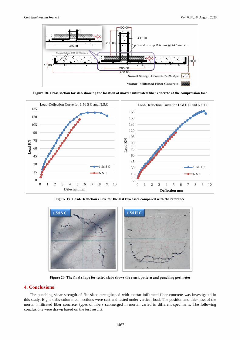
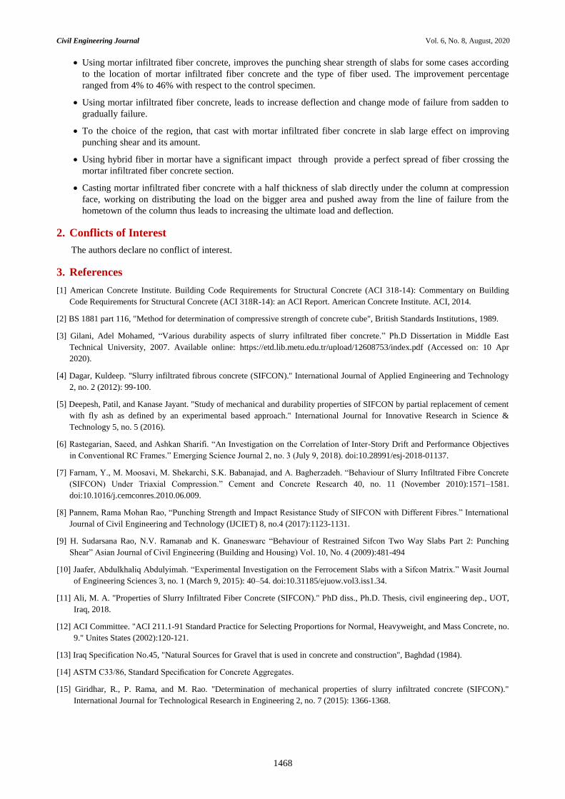
For the two remaining cases (1.5d S.C and 1.5d H.C) the mortar infiltrated fiber concrete cast with a thickness of
40 mm at the compression side directly under the column as shown in Figure 18. These cases gave excellent results in
the ultimate load 12% and 46% respectively according to the type of fiber used in mortar infiltrated fiber concrete,
using hybrid fiber gave better results from use steel fiber only. This variation in the results between these two cases is
due to the distribution of fibers within the cross-section that was previously mentioned and shown in Figure 15. Using
mortar infiltrated fiber directly under column as in this specimens worked as a strong area compared with around
region that led to distribute the load over a bigger area and faraway the load from the center towered the supports that
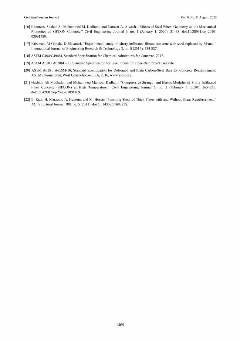
lead to increase the ultimate load and deflection as shown in Figure 19. The shape of failure for these two slabs shown
in Figure 20.
0
15
30
45
60
75
90
105
120
0 1 2 3 4 5 6 7 8 9 10
Load
KN
Deflection mm
Load-Deflection Curve for 1.5d S and N.S.C
1.5d S
N.S.C
0
15
30
45
60
75
90
105
120
135
150
165
0 1 2 3 4 5 6 7 8 9 10
Load
KN
Deflection mm
Load-Deflection Curve for 1.5d H and N.S.C
1.5d H
N.S.C
A B
Civil Engineering Journal Vol. 6, No. 8, August, 2020
1467
Figure 18. Cross section for slab showing the location of mortar infiltrated fiber concrete at the compression face
Figure 19. Load-Deflection curve for the last two cases compared with the reference
Figure 20. The final shape for tested slabs shows the crack pattern and punching perimeter
4. Conclusions
The punching shear strength of flat slabs strengthened with mortar-infiltrated fiber concrete was investigated in
this study. Eight slabs-column connections were cast and tested under vertical load. The position and thickness of the
mortar infiltrated fiber concrete, types of fibers submerged in mortar varied in different specimens. The following
conclusions were drawn based on the test results:
0
15
30
45
60
75
90
105
120
135
0 1 2 3 4 5 6 7 8 9 10
Load
KN
Delection mm
Load-Deflection Curve for 1.5d S C and N.S.C
1.5d S C
N.S.C
0
15
30
45
60
75
90
105
120
135
150
165
0 1 2 3 4 5 6 7 8 9 10
Load
KN
Deflection mm
Load-Deflection Curve for 1.5d H C and N.S.C
1.5d H C
N.S.C
Civil Engineering Journal Vol. 6, No. 8, August, 2020
1468
Using mortar infiltrated fiber concrete, improves the punching shear strength of slabs for some cases according
to the location of mortar infiltrated fiber concrete and the type of fiber used. The improvement percentage
ranged from 4% to 46% with respect to the control specimen.
Using mortar infiltrated fiber concrete, leads to increase deflection and change mode of failure from sadden to
gradually failure.
To the choice of the region, that cast with mortar infiltrated fiber concrete in slab large effect on improving
punching shear and its amount.
Using hybrid fiber in mortar have a significant impact through provide a perfect spread of fiber crossing the
mortar infiltrated fiber concrete section.
Casting mortar infiltrated fiber concrete with a half thickness of slab directly under the column at compression
face, working on distributing the load on the bigger area and pushed away from the line of failure from the
hometown of the column thus leads to increasing the ultimate load and deflection.
2. Conflicts of Interest
The authors declare no conflict of interest.
3. References
[1] American Concrete Institute. Building Code Requirements for Structural Concrete (ACI 318-14): Commentary on Building
Code Requirements for Structural Concrete (ACI 318R-14): an ACI Report. American Concrete Institute. ACI, 2014.
[2] BS 1881 part 116, "Method for determination of compressive strength of concrete cube", British Standards Institutions, 1989.
[3] Gilani, Adel Mohamed, “Various durability aspects of slurry infiltrated fiber concrete.” Ph.D Dissertation in Middle East
Technical University, 2007. Available online: https://etd.lib.metu.edu.tr/upload/12608753/index.pdf (Accessed on: 10 Apr
2020).
[4] Dagar, Kuldeep. "Slurry infiltrated fibrous concrete (SIFCON)." International Journal of Applied Engineering and Technology
2, no. 2 (2012): 99-100.
[5] Deepesh, Patil, and Kanase Jayant. "Study of mechanical and durability properties of SIFCON by partial replacement of cement
with fly ash as defined by an experimental based approach." International Journal for Innovative Research in Science &
Technology 5, no. 5 (2016).
[6] Rastegarian, Saeed, and Ashkan Sharifi. “An Investigation on the Correlation of Inter-Story Drift and Performance Objectives
in Conventional RC Frames.” Emerging Science Journal 2, no. 3 (July 9, 2018). doi:10.28991/esj-2018-01137.
[7] Farnam, Y., M. Moosavi, M. Shekarchi, S.K. Babanajad, and A. Bagherzadeh. “Behaviour of Slurry Infiltrated Fibre Concrete
(SIFCON) Under Triaxial Compression.” Cement and Concrete Research 40, no. 11 (November 2010):1571–1581.
doi:10.1016/j.cemconres.2010.06.009.
[8] Pannem, Rama Mohan Rao, “Punching Strength and Impact Resistance Study of SIFCON with Different Fibres.” International
Journal of Civil Engineering and Technology (IJCIET) 8, no.4 (2017):1123-1131.
[9] H. Sudarsana Rao, N.V. Ramanab and K. Gnaneswarc “Behaviour of Restrained Sifcon Two Way Slabs Part 2: Punching
Shear” Asian Journal of Civil Engineering (Building and Housing) Vol. 10, No. 4 (2009):481-494
[10] Jaafer, Abdulkhaliq Abdulyimah. “Experimental Investigation on the Ferrocement Slabs with a Sifcon Matrix.” Wasit Journal
of Engineering Sciences 3, no. 1 (March 9, 2015): 40–54. doi:10.31185/ejuow.vol3.iss1.34.
[11] Ali, M. A. "Properties of Slurry Infiltrated Fiber Concrete (SIFCON)." PhD diss., Ph.D. Thesis, civil engineering dep., UOT,
Iraq, 2018.
[12] ACI Committee. "ACI 211.1-91 Standard Practice for Selecting Proportions for Normal, Heavyweight, and Mass Concrete, no.
9." Unites States (2002):120-121.
[13] Iraq Specification No.45, "Natural Sources for Gravel that is used in concrete and construction", Baghdad (1984).
[14] ASTM C33/86, Standard Specification for Concrete Aggregates.
[15] Giridhar, R., P. Rama, and M. Rao. "Determination of mechanical properties of slurry infiltrated concrete (SIFCON)."
International Journal for Technological Research in Engineering 2, no. 7 (2015): 1366-1368.
Civil Engineering Journal Vol. 6, No. 8, August, 2020
1469
[16] Khamees, Shahad S., Mohammed M. Kadhum, and Nameer A. Alwash. “Effects of Steel Fibers Geometry on the Mechanical
Properties of SIFCON Concrete.” Civil Engineering Journal 6, no. 1 (January 1, 2020): 21–33. doi:10.28991/cej-2020-
03091450.
[17] Krishnan, M Gopala, D Elavarasi, “Experimental study on slurry infiltrated fibrous concrete with sand replaced by Msand.”
International Journal of Engineering Research & Technology 3, no. 5 (2014): 534-537.
[18] ASTM C494/C494M, Standard Specification for Chemical Admixtures for Concrete, 2017.
[19] ASTM A820 / A820M – 16 Standard Specification for Steel Fibers for Fiber-Reinforced Concrete.
[20] ASTM A615 / A615M-16, Standard Specification for Deformed and Plain Carbon-Steel Bars for Concrete Reinforcement,
ASTM International, West Conshohocken, PA, 2016, www.astm.org.
[21] Hashim, Ali Mudhafar, and Mohammed Mansour Kadhum. “Compressive Strength and Elastic Modulus of Slurry Infiltrated
Fiber Concrete (SIFCON) at High Temperature.” Civil Engineering Journal 6, no. 2 (February 1, 2020): 265–275.
doi:10.28991/cej-2020-03091469.
[22] E. Rizk, H. Marzouk, A. Hussein, and M. Hossin “Punching Shear of Thick Plates with and Without Shear Reinforcement.”
ACI Structural Journal 108, no. 5 (2011). doi:10.14359/51683215.


![A Neuro-Fuzzy Model for Punching Shear Prediction of Slab ...presented models to estimate the punching capacity [7,10] or to control it [9]. Nguyen and Rovnak [7] proposed a fracture](https://img.pdfslide.us/doc/110x75/600d83b08e884e4d46358f92/a-neuro-fuzzy-model-for-punching-shear-prediction-of-slab-presented-models-to.jpg)