Embed Size (px)
Citation preview

Sensors 2011, 11, 4808-4829; doi:10.3390/s110504808
sensors ISSN 1424-8220
www.mdpi.com/journal/sensors
Article
Enhancement of Optical Adaptive Sensing by Using a Dual-Stage
Seesaw-Swivel Actuator with a Tunable Vibration Absorber
Po-Chien Chou †, Yu-Cheng Lin † and Stone Cheng *
Department of Mechanical Engineering, National Chiao Tung University, No. 1001, University Road,
Hsinchu 30010, Taiwan; E-Mails: [email protected] (P.-C.C.); [email protected] (Y.-C.L.)
* Author to whom correspondence should be addressed; E-Mail: [email protected];
Tel.: +886-3-571-2121 ext. 55204; Fax: +886-3-572-0634. †
These authors contributed equally to this work.
Received: 7 April 2011; in revised form: 21 April 2011 / Accepted: 2 May 2011 /
Published: 3 May 2011
Abstract: Technological obstacles to the use of rotary-type swing arm actuators to actuate
optical pickup modules in small-form-factor (SFF) disk drives stem from a hinge’s skewed
actuation, subsequently inducing off-axis aberrations and deteriorating optical quality.
This work describes a dual-stage seesaw-swivel actuator for optical pickup actuation.
A triple-layered bimorph bender made of piezoelectric materials (PZTs) is connected to the
suspension of the pickup head, while the tunable vibration absorber (TVA) unit is mounted
on the seesaw swing arm to offer a balanced force to reduce vibrations in a focusing
direction. Both PZT and TVA are designed to satisfy stable focusing operation operational
requirements and compensate for the tilt angle or deformation of a disc. Finally, simulation
results verify the performance of the dual-stage seesaw-swivel actuator, along with
experimental procedures and parametric design optimization confirming the effectiveness
of the proposed system.
Keywords: small-form-factor; VCM; PZT; swing arm; absorber
OPEN ACCESS

Sensors 2011, 11
4809
Nomenclature
LPZT Effective length of PZT (mm) d31 Charging constant of PZT (C/N)
Larm Effective Length of arm (mm) VPZT PZT input Voltage (V)
Ddisc Distance from disk center(mm) Α The frequency ratio between system and input
Rotary angle of PZT bender (rad) Β The frequency ratio between system and TVA
θ Rotary angle of arm (rad) Μ Mass ratio between system and TVA
Rotary angle of disk (rad) msys Mass of dual-stage system (kg)
b Width of PZT bender (mm) mabs Mass of TVA (kg)
tPZT Thickness of PZT (mm) CPZT Damping constant of PZT
tcarbon Thickness of carbon (mm) Csys Damping constant of arm
PZT Density of PZT (kg/m3) Cabs Damping constant of TVA
carbon Density of carbon (kg/m3) ksys Stiffness of system (N/m)
abs Density of TVA (kg/m3) kPZT Stiffness of PZT (N-m/rad)
EPZT Young’s modulus of PZT (GPa) keq Equivalent stiffness of PZT (N/m)
Ecarbon Young’s modulus of carbon (GPa) kabs Stiffness of TVA (N/m)
IPZT Moment of inertia, PZT (m4) ζsys Damping ratio of dual-stage system
Icarbon Moment of inertia, carbon (m4) ζabs Damping ratio of TVA
1. Introduction
Swing arm actuators have been applied to small form factor (SFF) optical pickup heads or near field
hybrid recording systems. Trends in optical disk drives include developing small-form-factor (SFF) for
holographic optics and extending the applications of near-field optics. In such a high speed positioning
servo system, the head/disk spacing variation must be maintained as small as possible during disk
operations. While attempting to reduce the size of optical heads, several works have scaled down all
components of a conventional unit [1,2] and simplified the optical configuration, and micro optical
elements, such as lenses and prisms. Other approaches integrate an optical module with a seesaw
swivel actuator [3,4].
Two possible actuated mechanisms are available for active and passive head-positioning control.
For active actuation, Yeack-Scranton devised a secondary stage PZT bender with an active slider for
contact recording [5]. Following the PZT actuator and its applications, Tagawa proposed a self-loading
slider featuring a twin structure piezo-actuator to maintain constant flying height spacing [6]. Kajitani
developed an active slider associated with multilayered piezo-actuators to compensate for flying height
variation [7]. In contrast with the above track-seek operations, Jun and Takashi investigated the
feasibility of using a circular arc slider driven by a piezoelectric actuator to reduce the tilt motions of
the lens in pitching/rolling directions [8]. Liu investigated the feasibility of a dynamic motion
approach for a piezotube actuator subjected to disk deformation [9]. Moreover, in study involving a
multilayered structure, Woosung used a flexure hinge mechanism to extend the allowable stroke to
tracking and focusing motions [10]. Additionally, passive mass absorber utilizes an inertial mass and
tuned support to mitigate mechanical vibration. Chung introduced a two-dimensional vibration model
of a feeding deck system to reduce in-plane vibration [11]. According to their functional and structural

Sensors 2011, 11
4810
identification, Heo characterized the dynamic behavior of a passive damper consisting of a rubber
bobbin and plate ring [12]. Moreover, Chung established a design procedure to combine passive and
active devices with an enlarged bandwidth control. That adaptive dynamic absorber is embedded with
a voice coil motor (VCM) device [13]. However, to make use of the hollow space within the VCM,
Jiang investigated the feasibility of a tuned dual mass damping device [14]. In particular, Kuwajima
developed a novel shockproof structure by using a balanced type suspension, as well as investigated its
performance on external shock resistance during read/write operations [15].
This work describes a novel a dual-stage seesaw-swivel actuator based on optical sensing by using
a PZT bimorph component to compensate for the tilt angle variation in focusing stroke. A piezoelectric
actuated suspension for a secondary-stage actuator is also developed to implement fine head
positioning to assist the primary VCM actuator and maintain a constant flying height during the
focusing operation, as shown in Figure 1. The secondary micro actuator functions mainly for fine and
fast compensation, while a conventional VCM performs coarse positioning. A dynamic model for a
bimorph structure is also developed to optimize and verify the natural frequency of actuating behavior.
Additionally, a two dimensional vibration model of the optical sensing device with the absorber is
established to ensure system stability and robustness. Based on multi-body dynamic analysis, a
balanced mass associated with two cantilever springs provides a rotational reaction to the moving part
under seesaw actuation. Moreover, this work investigates the feasibility of implementing a passive
tunable vibration absorber (TVA) for spacing variation and head positioning control endowed with a
bimorph micro actuator. Finally performance of biaxial motion is evaluated based on numerical
simulations of optimization and experimental results.
Figure 1. Schematic illustration of the bimorph dual-stage actuator with the TVA unit
indicated.

Sensors 2011, 11
4811
2. Mechanical Design and Theoretical Analysis
The optical axis shift during the primary VCM actuation is compensated for by using the active
bimorph micro actuator. A TVA can passively absorb the residual tilt variations while actively
generating a reacting force for the moment conservation. The proposed mechanism is a seesaw type
swivel actuator using piezoelectric active control collaboratively with passive TVA design. The
following sections describe the proposed mechanism.
2.1. Angular Deviation Compensation
In actuated slider suspension, the tilt motion of the optical actuator causes the variation of focal spot
position on the photo-detector, as shown in Figure 2. The middle figure of light intensity distribution is
a well-symmetric focal spot on the PD center without tilting angle. If the focusing motion is achieved
by z seesaw-type arm which generates a ±0.1° nutating angle, the returning beam would not be
orthogonal to the optical sensor. The reflected focal spot on the PD will shift away from the center and
the light distributions will approach one side of the photo-diode. Hence, given the increasing accuracy
of head positioning, a drive capable of tilt control is necessary to reduce the tilt margin as the optical
aberration is correspondingly increased. A compensation scheme is also developed for optical axis
in-line calibration, and evaluated by driving a simply bimorph PZT bender.
Figure 2. Misalignment in the incline angle of the optical axis.
2.2. Dual-Stage Leveraged Mechanism
A common method of piezoelectric actuated suspension is driven along the opposite data (track)
tangential direction in an allowable stroke. The proposed seesaw swivel-drive actuator uses a
dual-stage leverage mechanism (Figure 3), through use of a coarse movement via VCM control and a
secondary fine positioning via PZT. As PZT compensates the tilt angle of seesaw arm in the opposite

Sensors 2011, 11
4812
way—the laser beam will be kept in orthogonal to the disk (Figure 3, left). Hence, PZT tilt control
fixes the tangential displacement of focusing, and calibrates the asymmetry of the S-curve. Complete
two-axis scanning is then performed by independently controlling the dual stage actuators.
Figure 3. Conceptual diagram of the combined bimorph piezo-VCM actuator based active
tilt compensation.
2.3. Cantilever TVA Structure
The primary structure with arbitrary distributions of mass, stiffness and damping is subjected to
vibration suppression by an absorber subsystem. Sensing variation capabilities in the optic-axis
direction are investigated to ensure the suppression of robust vibration. Consisting of two flexible
cantilever beams extended from a balanced mass, a cantilever TVA subsystem is illustrated from the
perspective of both improving bandwidth and increasing shock protection.
Figure 4. Developed tunable vibration absorber with system dynamics behavior: principles
and practices.

Sensors 2011, 11
4813
The vibration suppression of structures is based on independent design of dynamic absorbers, while
taking into account the selected tuning mass of the subsystem structure. Effective structural stiffness is
thus adjusted by adjusting the beam dimensions after a preliminary primitive design. Figure 4
illustrates the structural configuration of this work, which consists of a three-block structure called
―soundmetal‖ that is pinned by a flexible wire.
3. Numerical Analysis
DeVoe and Pisano [16] developed a model for piezoelectric multi-morph cantilevers extended from
Timoshenko’s approach to investigate the deflection of micro-actuators. To derive a simple working
equation, Weinberg [17] obtained a simple closed-form solution for the bending of piezoelectric
multi-morphs by using the Euler-Bernoulli beam theory and integrated equilibrium equations.
This theory assumes that cross sections remain plane and normal to the deformed beam axis.
Such assumptions are appropriate given the slender geometry of typical multi-morphs. Krommer
developed the constitutive equations of a multi-morph by assuming two-dimensional kinematics of the
structure [18]. Ha and Kim attempted to optimize bimorphs in order to maximize the tip stroke or
vertical displacement by using the thickness ratio between the substrate (or shim layer) and PZT
layers [19]. Pursuing a high bandwidth and a sufficient optical performance of the combined
piezo-VCM actuator and design parameters of the PZT bender (i.e., length, width and thickness) are of
priority concern. Generally, the rotary angle and deflection of the PZT bender is proportion to the
square and cube of the length of the PZT bender (by basic beam theory). Other parameters affect the
bandwidth (fundamental frequency).
3.1. Rotary Angle of PZT Bender
Figure 5 displays a ―sandwich‖-like PZT that consists of a carbon fiber chip with two d31-type PZT
ceramics. This figure also considers a small piece element in the upper PZT material, in which the
corresponding extension can be evaluated as follows:
31 PZTPZT
PZT PZT
d VL
L t
(1)
The elongation force F and momentum M generated by the small element in the Figure 4(a) are:
31 PZT PZT
PZT
d V bEM F z zdz
t (2)
Therefore, integrating Equation (2), the sum of bending moment in Figure 4 generated by the
bimorph piezoelectric material is as follows:
31 PZT PZT PZT carbonM d V E b t t (3)
Figure 5(a) shows a composed triple-layer beam that consists of both carbon fiber and piezoelectric
material. The flexural rigidity of a multilayered beam is:
eq eq PZT PZT carbon carbonE I E I E I (4)

Sensors 2011, 11
4814
where kPZT is considered the stiffness in rotation direction, and calculated from the equivalent spring
on the tip of PZT bender.
2
PZTPZT eq
Lk k (5)
where keq in Figure 5(c) is presented as equivalent spring constant.
2
2eq
PZT
EIk
L (6)
Additionally, the rotary angle of PZT is:
PZT
M
k (7)
Figure 5. Structure variables of triple-layer bimorph actuator: (a) crosswise view;
(b) cross-section view; (c) deflection skew and equivalent spring.
(a)
(b) (c)
3.2. Natural Frequency of PZT Bender
The motion of a cantilever beam can be represented as [16]:
4 22
4 2
( , ) ( , )0,
eq eqE Iw x t w x tc c
x t m (8)
By using the separation of variables method, the general solution can be expressed as
( , ) w x t X x T t (9)

Sensors 2011, 11
4815
Replacing Equation (8) with Equation (9) yields
2 2
( )
n
X x T tc
X x T t (10)
The general solution of the mode shapes in x-direction can be expressed as
2
4
1 2 3 4( ) sin cos sinh cosh , nn n n n n n
eq eq
mX x A x A x A x A x
E I
(11)
The boundary condition of Equation (10) is:
2 3
2 3
0 0, 0
0, 0 PZT
wx w
x
w wx L EI M EI V
x x
(12)
By substituting Equation (12) into Equation (11), the particular solution is
( ) cosh cos sinh sinn n n nn
PZT PZT PZT PZT
x x x xX x
L L L L
(13)
where
sinh sin
cosh cos
n PZT n PZT
n PZT n PZT
L L
L L
The natural frequency is solved from the following equation:
cos cosh 1; 1,2,3,...n nx x n (14)
For n = 1, the fundamental frequency of the bimorph PZT is:
2
1 2
1.875( )
2
eq eq
PZT
E IHz
m L
(15)
where PZT PZT carbon carbonm t t b .
3.3. Optimization
From the previous derivations of the equations, two objective functions of the optimization are
selected: lateral displacement error E(tPZT, LPZT) and fundamental frequency ω(tPZT, LPZT). Figure 6
shows the relationship between PZT arm actuator and disk, while Table 1 lists its symbols.
Figure 7 illustrates the optimization procedure, indicating that the PZT bender is optimized. Of the
two coupling optimization processes, optimization 1 determines objective functions and sets the initial
search interval and accuracy. Meanwhile, optimization 2 copes with constraint conditions for the
process. The optimization of length LPZT and thickness tPZT, which minimize objective functions to
PZT, are 14.13 mm and 0.11 mm after 64 and 59 iterations, respectively.
Figure 8 plots two parameters, rotary angle [Equation (7)] and fundamental frequency 1
[Equation (15)] as a function of effective length. The crossover point is selected to verify the
optimization results. Figure 9 illustrates the hysteresis curve of PZT displacement with maximum
point is 4 mm when input a sine wave signal is swept from −125 to 125 V. Finally, the experimental

Sensors 2011, 11
4816
results in Figure 10 demonstrate two modes frequency at 985 Hz and 5.8 kHz. Table 2 summarizes the
modal analysis results between the numerical optimization and experiments, in which the errors vary
by about 1.86% and 3.14%, respectively.
Figure 6. Geometry and coordinates for the dual stage actuator based on electromagnetism
and mechanism (t and r present tangential and radius direction respected to the disk).
Table 1. Parametric optimization investigates the design parameters.
Optimization 1 Optimization 2
Objective function
1 cos 1 cos
1 cos
arm PZT
disk
E L L
D
2
1 2
1.875/
2eq eq
PZT
E I mL
Optimization
parameter
LPZT tPZT
upper/lower bound 10 17armL
10 17PZTL
10 17PZTL
0.1 1.0PZTt
Constrain 27( )
0( )
arm PZTL L mm
rad
2 3( )PZT carbont t mm
Algorithm Medium-scale: SQP, Quasi-Newton, line-search
Iterations 64 59
Optimization value 0.271 985 Hz
FuncCount 485 603
Stepsize 0.3014 0.31
Firstorderopt 80.1485 79.3485
Constrviolation 15.0831 21.2495
result 14.13 0.11

Sensors 2011, 11
4817
Figure 7. Flowchart of the PZT optimization procedure.
Start
Optimization1.
Objective parameter:
Length of PZT
Substituted into
lateral disp. error
function: E
bk-ak<ε?
Yes
Set initial interval [a0,b0],
and accuracy ε>0
No
Start
Optimization 2.
Optimized
Length
Objective parameter:
Thickness of PZT
Set initial interval [p0,q0],
and accuracy ε>0
Substituted into
natural frequency
function: ωn
pk-qk<ε?
Optimized
Thickness
K=K+1
Yes
No
Stop
Giving constrain
equations
Coupling
K=K+1
No
Figure 8. Effective length versus optimal balance between rotary angle (rad) and natural
frequency (Hz).

Sensors 2011, 11
4818
Figure 9. Deflection curve of hysteresis loop in a bimorph bender with the applied voltage
swing from 125 V.
Figure 10. Measured frequency response of optimum PZT bender.
Sensors 2011, 11
4819
Table 2. Verification of numerical optimization.
Resonant Frequency(<10 kHz) Numerical calculation Experimental result Error
1st mode
2nd mode
967
6,065
985
5,874
1.86%
3.14%
3.4. Absorber Mass Tuning
Several attempts have been made to seek optimum absorber parameters when the main system has
significant damping. Den Hartog first tackled the optimum solution of a tuned mass damper that is
connected to a primary system with the intention of reducing its dynamic response [20]. An optimal
broadband attenuation was then achieved by a dynamic absorber design proposed by Ormondroyd and
Den Hartog [21]. Based on their fixed-point theory, Brock found the optimum tuning parameter and
defined the optimality for the optimum absorber damping [22]. By adopting a frequency locus
approach, Thompson found the optimal damper parameters that minimize the structural response [23].
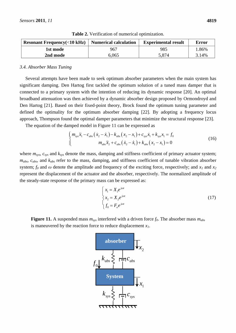
The equation of the damped model in Figure 11 can be expressed as
1 2 1 2 1 1 1 0
2 2 1 2 1 0
sys abs abs sys sys
abs abs abs
m x c x x k x x c x k x f
m x c x x k x x
(16)
where msys, csys and ksys denote the mass, damping and stiffness coefficient of primary actuator system;
mabs, cabs, and kabs refer to the mass, damping, and stiffness coefficient of tunable vibration absorber
system; f0 and ω denote the amplitude and frequency of the exciting force, respectively; and x1 and x2
represent the displacement of the actuator and the absorber, respectively. The normalized amplitude of
the steady-state response of the primary mass can be expressed as:
1 1
2 2
0
j t
j t
j t
o
x X e
x X e
f F e
(17)
Figure 11. A suspended mass msys interfered with a driven force f0. The absorber mass mabs
is maneuvered by the reaction force to reduce displacement x1.
1x
2x
absk
sysk
absc0f
sysc
absorber
System

Sensors 2011, 11
4820
The amplitudes of the system displacement, X1, are expressed as:
2
1 02 2 2
2 2 2
abs abs abs
sys sys abs abs abs abs sys abs
abs sys sys abs sys abs abs
k m j cX F
k m k m k m c c
j c k m m c k m
(18)
Taking the absolute of X1:
2 22
2
1 0 2 2
2 2 2 2 2 2
sysa a
a a sys
sys sys sys sysa a a a a a a
sys a a sys a sys a sys sys sys a
kk C
m m mX F
k C k Ck k m C C m k
m m m m m m m m m m m
(19)
Substituting the natural frequency, absabs
abs
k
m and
sys
sys
sys
k
m , into the Equation (19), the
normalized transfer function of an actuator is
2 21
1 2 2
0 0
( , ) 4 ( , , )
( , , , , ) 4 ( , , , , )
sys sys abs
sys abs sys abs
X k k A BG X
f F C D
(20)
where:
2
2( , ) 1A
, ( , , )abs absB
42
2 2
4 1( , , , , ) 1 1
sys abs
sys absC
3 3 3
2
2( , , , , )sys abs abs sysD
and the parameters are:
abs
sys
m
m ,
sys
,
2
sys
sys
sys sys
C
m k , abs
sys
,
2
absabs
abs abs
C
m k
According to Den Hartog’s theorem [17], the ratio of natural frequency between absorber and
system is:
* 1
1
(21)
Figure 12(a) displays the relationship between μ and G. Hence, the peak is reduced with enlarged μ.
According to Figure 12(b), the resonance peak frequency increases when ζabs decreases from 1 down
to 0.1. The optimal damping ratio of the absorber, ζabs*, is estimated as:
* 3
8 1abs abs
(22)

Sensors 2011, 11
4821
Figure 12. Normalized amplitudes of vibrations: (a) ζabs = 1 (fixed), μ = 0.1~1. (b) μ = 1
(fixed), ζabs = 0.1~1.
(a)
(b)
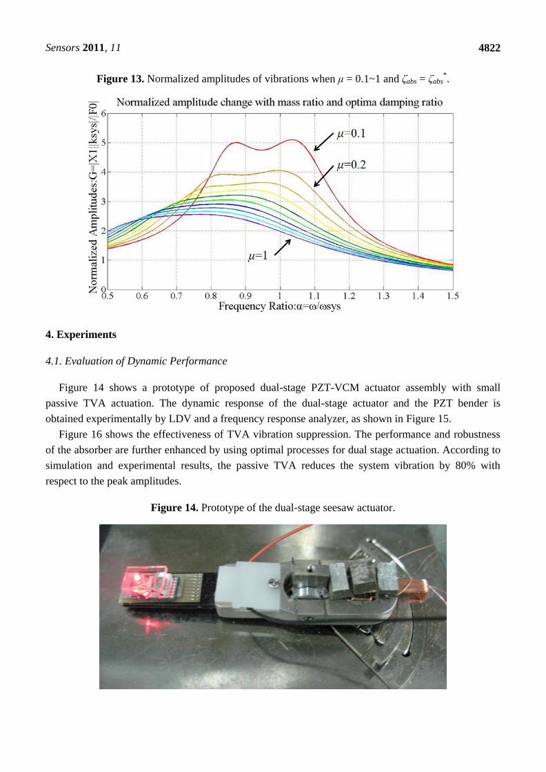
Figure 13 shows the normalized amplitude G as a function of μ. By assigning the optimal damping
ratio ζabs and mass ratio μ, the vibration magnitudes are decreased effectively. (Therefore, the actual
values of mass and stiffness of TVA are determined by selecting μ = 0.8 and ζabs* = 0.408.
Sensors 2011, 11
4822
Figure 13. Normalized amplitudes of vibrations when μ = 0.1~1 and ζabs = ζabs*.
4. Experiments
4.1. Evaluation of Dynamic Performance
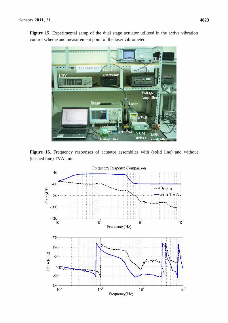
Figure 14 shows a prototype of proposed dual-stage PZT-VCM actuator assembly with small
passive TVA actuation. The dynamic response of the dual-stage actuator and the PZT bender is
obtained experimentally by LDV and a frequency response analyzer, as shown in Figure 15.
Figure 16 shows the effectiveness of TVA vibration suppression. The performance and robustness
of the absorber are further enhanced by using optimal processes for dual stage actuation. According to
simulation and experimental results, the passive TVA reduces the system vibration by 80% with
respect to the peak amplitudes.
Figure 14. Prototype of the dual-stage seesaw actuator.
Sensors 2011, 11
4823
Figure 15. Experimental setup of the dual stage actuator utilized in the active vibration
control scheme and measurement point of the laser vibrometer.
Figure 16. Frequency responses of actuator assemblies with (solid line) and without
(dashed line) TVA unit.

Sensors 2011, 11
4824
Design of the PZT loop compensator in the dual-stage actuator expands the bandwidth of the
overall system. The primary VCM continuously provides coarse positioning, while the secondary
actuator gives fine positioning, vibration and disturbances rejection. Figure 17 illustrates the open loop
frequency response of the VCM and PZT dual-stage actuator, compared with the original single-stage
VCM actuator.
Figure 17. Single- and dual-stage actuated suspension frequency response: VCM input to
head displacement (dash line); VCM and PZT combined actuation input to head
displacement (solid line).
The open loop bandwidth of the dual-stage system is approximately 3.8 kHz, with a phase margin
of 30 degrees and a gain margin of 5 dB. This represents a significant enhancement over the single-stage
VCM system, which has a 0.46 kHz bandwidth for the same stability margins. The PZT actuator can
reject high frequency disturbances. Notably, the resonant peak of the PZT actuator at 0.9 kHz is lower
than the open loop bandwidth and does not pose stability problems.
4.2. Tilt Angle Compensation
Figure 18(a) illustrates the simulated focusing error signal (S-curve) generated by the actuator
tilting from −0.5○ to 0.5
○, whereas the measured asymmetric S-curve is shown in Figure 18(b) for
comparison. The astigmatic returning laser spot deteriorates considerably due to the tilt actuation,
causing the asymmetric peak shapes of the S-curve. This unbalanced S-curve signal reduces the
accuracy of optical sensing. The optical compensation for dual stage actuator is evaluated by designing

Sensors 2011, 11
4825
the schematic layout of the reflection geometry for tilt measurement [24-26], as shown in Figure 19.
The rotary angle measurement is performed by mounting a target 45。micro-prism on the precision
VCM-Driven micro-positioning stage. The 635 nm wavelength laser, which is used to adjust tracking
angle of dual-stage actuator, produces horizontal beam (green line) and passes through the collimating
lens, the polarized beam splitter (PBS), the quarter-wave plate (QWP) to form circular polarization
beam and focusing on the side of actuator by objective lens. The returning beam is reflected by the
PBS and projected on the collimating detector. Furthermore, the LDV laser beam (red line, vertical) is
focusing on the photo-diode to measure the dynamic tilt error motions of focus operation by varying
the driving frequency in the range of 5–200 Hz. The distance of the seesaw actuator over the focus
actuation stroke is 400 µm or less.
Figure 18. Intensity profiles of the reflected beam on the photo-diode and the output
astigmatism signals (S-curve), (a) simulation; (b) measurement.
(a)
(b)

Sensors 2011, 11
4826
Figure 19. Geometrical model to detect the optical angle: optical layout for the differential
detection method and focal spot shifts along the photodiode (v-direction).
The proposed astigmatic detection method combined with differential phase detection (DPD) is
verified through simulation and experimental results. By using the quadrant photo detector array, the
astigmatic signal is generated (based on the phase difference between the sum of the diagonal
elements, as shown in Equation (22).
Focus error signal (FES), f:
( ) ( )100%
( )
A C B Df
A B C D
(23)
The DPD signal is defined versus the misalignment of the photo-detector in the plane (v, h) by
using the following calculation [27,28].
DPD signal, dh:
( ) ( )100%
( )h
A B C Dd
A B C D
(24)
DPD signal, dv:
( ) ( )100%
( )v
A D B Cd
A B C D
(25)
where dh and dv represent the misalignments along the horizontal (h) and vertical (v) the direction,
respectively.
Feasibility of the proposed secondary stage PZT-actuator to compensate for the tilt actuation
induced by the primary VCM actuator is demonstrated by conducting an experiment in which the dual
stage actuator is kept in the in-focus condition. Figure 20 summarizes the experimental results by

Sensors 2011, 11
4827
moving the prism with reflection geometry. The vertical (black) and horizontal (red) tilt angle are
obtained based on differential phase variation with 5 Hz sine-wave excitation. Although the vertical
angular displacement involves roll as well as pitch rotation, the phase variation from roll vibration is
sufficiently small to be negligible compared with the actuator nutation.
Figure 20. Comparison of two actuation directions with the DPD measurement results
from the tilt error signal (black) and lateral deviation (red).
Both results closely correspond to the numerical calculations. The measurement accuracy of the
photo-detector is validated. Figure 21 shows the tilt motions for both single and dual stage control. A
sinusoidal signal with a frequency of 5 Hz and voltage amplitude of 6 V is applied to the seesaw
actuator. As mentioned earlier, the angular displacement is within the restricted range 0.19° (peak to
peak) for the dual stage actuation than 0.45° (peak to peak) for single-stage control. The tilt signal
variance from a single-stage drive is reduced by 60% with the implementation of this dual stage
compensation. Measurement results demonstrate a high stability for the application of adjusting the
inclination angle of the optical axis with precision positioning, capable of satisfying the requirement
for small tilt angle compensation of a dual stage actuator.
Figure 21. Experimental verification of dual stage compensation: with (red line) and
without (black line) piezo-actuated stage actuator.

Sensors 2011, 11
4828
5. Conclusions
This work presents a miniaturized seesaw swivel actuator and suspension assembly with a
piezoelectric-based micro-actuator and TVA absorber. Among the unique features of the proposed
dual stage actuator include a rotary actuator for track-following and a combined piezo-VCM actuated
suspension nutation for laser focusing. By using the optimization procedure, the original design is
improved in terms of bandwidth and stability. The dynamic response of the dual-stage actuator is also
shown, in which the PZT actuator rejects a higher frequency disturbance. The difference between the
experimental frequency response of PZT bender and the numerical results is within 5.6%. Lower than
the open loop bandwidth, the resonant peak of the PZT-actuator at 0.9 kHz does not pose stability
problems. Simulation and experimental results indicate that the passive TVA reduces the system
vibration by 80% with respect to the peak amplitudes. This work also investigates the relationship
between the tilt sensor sensitivity and working distance of the dual stage actuator based on laser
auto-collimation. The tilt variance of optical axis is reduced by 60% from a single-stage drive with the
implementation of PZT compensation. Performance optimization of the combined piezo-VCM actuator
is also evaluated to demonstrate the effectiveness of the proposed optical sensing applications.
Acknowledgements
This work was supported by TDPA project 98-EC-17-A-07-S1-011, MOEA, and NSC project
NSC 96-2221-E-009-149, Taiwan. The authors would like to thank the anonymous reviewers for
useful comments and suggestions.
References
1. Shih, H.F.; Chang, C.L.; Lee, K.J.; Chang, C.S. Design of optical head with holographic optical
element for small form factor drive systems. IEEE Trans. Mag. 2006, 41, 1058-1060.
2. Shih, H.F.; Lee, Y.C.; Chiu, Y.; Chao, D.W.C.; Lin, G.D.; Lu, C.S.; Chiou, J.C. Micro Objective
Lens with NA 0.65 for The Blue-light Small-form-factor Optical Pickup Head. Optics Express
2008, 16, 13150-13157.
3. Chou, P.C.; Lin, Y.C.; Cheng, S. Optimization of Seesaw Swing Arm Actuator Design for Small
Form Factor Optical Disk Drive. Jpn. J. Appl. Phys. 2010, 49, 052502.
4. Chou, P.C.; Lin, Y.C.; Cheng, C. A Novel Seesaw Swivel Actuator Design and Fabrication. IEEE
Trans. Mag. 2010, 46, 2603-2610.
5. Yeak-Scranton, C.E. Novel Piezoelectric Transducers to Monitor Head-disk Integrations. IEEE
Trans. Mag. 1986, 22, 1011-1016.
6. Tagawa, N. State of The Art for Nanospacing Flying Head Slider Mechanisms in Magnetic
Recording Disk Storage .Wear 1993, 168, 43-47.
7. Kajitani, H.; Hashimoto, M.; Tagawa, N. Dynamic Loading Criteria for 3-1/2 Inch Inline HDD
Using Multilayer Piezoelectric Load/Unload Mechanism. IEEE Trans. Mag. 1991, 27, 5079-5081.
8. Tominaga, J.; Watabe, T.; Yoshimoto, S. A Circular Arc Slider with a High Flying Height Supported
by Parallel Flat Springs for Optical Disc Devices. Microsyst. Technol. 2007, 13, 1131-1139.
9. Chang, C.S.; Liu, T.S.; Tang, Y.C. A Tracking Motion Approach For a Piezotube Actuator in a
Disk Drive subject to Disk Deformation and Disturbance. Smart Mater. Struct. 2007, 16, 1542-1548.

Sensors 2011, 11
4829
10. Yang, W.; Lee, S.Y.; You, B.J. A Piezoelectric Actuator with A Motion-Decoupling Amplifier for
Optical Disk Drives. Smart Mater. Struct. 2010, 19, 065027.
11. Chung, J. Vibration Absorber for Reduction of the In-Plane Vibration in an Optical Disk Drive.
IEEE Trans. Consum. Electron. 2004, 50, 552-557.
12. Heo, J.W.; Chung, J. Vibration and Noise Reduction of an Optical Disk Drive by Using a
Vibration Absorber. IEEE Trans. Consum. Electron. 2002, 48, 874-878.
13. Chang, C.S.; Liu, T.S. Design of Adaptive Dynamic Absorber to Reduce Optical Disk Drive
Vibration at Multiple Rotating Speeds. Jpn. J. Appl. Phys. 2006, 45, 1120-1123.
14. Jiang, L.; Miles, R.N. A Passive Damper for the Vibration Modes of the Head Actuator in Hard
Disk Drives. J. Sound Vibra. 1999, 220, 683-694.
15. Kuwajima, H.; Kita, H.; Hashi, H.; Miyamoto, M.; Ueno, Y.; Inagaki, T.; Matsuoka, K.
Development of Balanced-type High Shock Suspension for 0.85-in Hard Disk Drive. IEEE Trans.
Mag. 2006, 42, 255-260.
16. DeVoe, D.L.; Pisano, A.P. Modeling and Optimal Design of Piezoelectric Cantilever Microactuators.
IEEE J. Microelectromech. Syst. 1997, 6, 266-270.
17. Weinberg, M.S. Working Equations for Piezoelectric Actuators and Sensors. IEEE J.
Microelectromech. Syst. 1999, 8, 529-533.
18. Krommer, M. On the Correction of the Bernoulli–Euler Beam Theory for Smart Piezoelectric
Beams. Smart Mater. Struct. 2001, 10, 668-680.
19. Ha, S.K.; Kim, Y.H. Analysis of a Piezoelectric Multimorph in Extensional and Flexural Motions.
J. Sound Vibra. 2002, 253, 1001-1014.
20. Den Hartog, J.P. Mechanical Vibrations; McGraw-Hill, Inc.: New York, NY, USA, 1956.
21. Ormondroyd, J.; Den Hartog, J.P. Theory of The Dynamic Vibration Absorber Transactions of the
Am. Soc. Mech. Eng. 1928, 50, 9-22.
22. Brock, J.E. A Note on the Damped Vibration Absorber. J. Appl. Mech. 1946, 68, A-284.
23. Thompson, A.G. Optimizing the Untuned Viscous Dynamic Vibration Absorber with Primary
System Damping. J. Sound Vibra. 1980, 73, 469-412.
24. Kim, S.H.; Kim, J.H.; Lee, Y.H.; Yang, H.; Park, J.Y.; Park, K.S.; Park, Y.P. Tilt Error
Measurement and Compensation Method for the Holographic Data Storage System Using
Disturbance Observer. IEEE Trans. Mag. 2009, 45, 2248-2251.
25. Doh, T.Y.; Ma, B.I.; Choi, B.H.; Park, I.S.; Chung, C.S.; Lee, Y.H.; Kim, S.J.; Shin, D.H. Radial
Tilt Detection Using one Beam and its Compensation in A High-density Read Only Memory. Jpn.
J. Appl. Phys. 2001, 40, 1680-1683.
26. Lin, D.; Yue, Z.; Song, N.; Meng, Y.; Yin, C. A Double Common-path Heterodyne Interferometer
for The Measurement of Flying Height Modulation. Meas. Sci. Technol. 2008, 19, 055303.
27. Shinoda, M.; Nakai, K.; Mori, K. Dependence of Differential Phase Detection Signals on
Astigmatism in A Focused Spot. Jpn. J. Appl. Phys. 2004, 43, 4870-4875.
28. Saito, Y.; Arai, Y.; Gao, W. Investigation of An Optical Sensor for Small Tilt Angle Detection of
A Precision Linear Stage. Meas. Sci. Technol. 2010, 21, 054006.
© 2011 by the authors; licensee MDPI, Basel, Switzerland. This article is an open access article
distributed under the terms and conditions of the Creative Commons Attribution license
(http://creativecommons.org/licenses/by/3.0/).


![Portable Gage for Pressure Ulcer Detection · pinning installed bimorph piezo bender is given by [8]: δ = (l 1 +l 2)l2 2 2Ewh3 fZ + 3d 31(l 1 +l 2)l 2 4h2 V (1) where δ is the deflection,](https://img.pdfslide.us/doc/110x75/601560f39ec59951254708c6/portable-gage-for-pressure-ulcer-pinning-installed-bimorph-piezo-bender-is-given.jpg)