Embed Size (px)
Citation preview

NASA Contractor Report 195405
Enhanced Capabilities and UpdatedUsers Manual for Axial-Flow
Turbine Preliminary SizingCode TURBAN
Arthur J. Glassman
University of ToledoToledo, Ohio
November 1994
Prepared forLewis Research CenterUnder Grant NAG3-1165
National Aeronautics and
Space Administration
(NASA-CR-195405) ENHANCED
CAPABILITIES AND UPDATED USERS
MANUAL FOR AXIAL-FLOW TURBINE
PRELIMINARY SIZING CODE TURBAN
Final Report (Toledo Univ.) 18 P
N95-15912
Unclas
G3/02 0031415
https://ntrs.nasa.gov/search.jsp?R=19950009497 2018-06-20T22:38:57+00:00Z


Enhanced Capabilities and Updated Users Manual for
Axial-Flow Turbine Preliminary Sizing Code TURBAN
Arthur J. Glassman
University of Toledo
Toledo, Ohio 43606
SUMMARY
This report presents the latest modifications made to the computer code TURBAN, whichdoes a preliminary sizing analysis for axial-flow turbines. The TURBAN analysis is based onmean-diameter flow characteristics. Program input includes flow, speed, and power or
pressure ratio. The output presents annulus dimensions, diagram velocities and angles, andefficiencies. Options are provided for varying stage number, mean diameter, reaction,
loading, diagram type, and/or work split.
Modifications were recently made to TURBAN to satisfy user needs and convenience.Turbine cooling-air flows and temperature now can be accounted for along with anassociated efficiency decrement. Alternative input options have been added for defining thevelocity diagram by stage reaction, for setting the mean diameter by stage loading, and for
arbitrarily specifying stage work split. The Reynolds number dependency for the loss modelwas weakened, and an internal calculation of air viscosity was added as a default. The
analytical modeling for these modifications are presented herein.
This report also serves as an updated users manual for the modified TURBAN code.Program input and output are described, and sample cases are included for illustration.
INTRODUCTION
Preliminary studies of gas turbine systems require many repetitive calculations ofgeometry and design-point performance for all the components. For this type of screeninganalysis, rapid approximate procedures, rather than time-consuming rigorous procedures,
are sufficient to yield the desired component overall geometry and performancecharacteristics. One such analysis code, named TURBAN, for axial-flow turbines was first
presented in reference 1 more than 20 years ago. An updated version of this code withnumerous modeling improvements was presented in reference 2, and blade geometry
modeling subsequently added to the code was reported in reference 3.
Recent use of TURBAN for aircraft propulsion system studies resulted in the desire for
additional capabilities that were then added to the code. Turbine cooling now can be includ-ed in the analysis. New alternative input options allow direct specification of stage reaction,
stage loading, and stage work distribution. The Reynolds number dependency was modified
to provide improved loss modeling, and an intemal calculation of air viscosity was added for

convenience. These modifications require the use of additional input information.
This report presents the analytical modeling associated with the new capabilities added tothe TURBAN code° It also serves as an updated users manual for the code. Program inputand output are described. Sample cases are included for illustration.
SYMBOLS
Cp
D
gZ_h
J
Jm
N
n
P
PR
Re
T
U
V
W
W
X
Y8
11
heat capacity, J/kg-K; Btu/Ib-°R
mean diameter, m; ft
dimensional constant, 1; 32.17 Ibm-ft/Ibf-sec 2
specific work, J/kg; Btu/lb
dimensional constant, 1; ft-lb/Btu
stage number for change in meanline slope
number of stages for meanline diameter variation
rotative speed, rad/sec; rpm
number of turbine stages
shaft power, W; hp
total pressure, N/m2; Ib/ft 2
stage reaction
Reynolds number
total temperature, K; °R
blade speed, m/sec; ft/sec
gas absolute velocity, m/sec; ft/sec
gas relative velocity, m/sec; ft/sec
mass flow rate, kg/sec; Ib/sec
ratio of stage work to turbine work
ratio of blade-row coolant flow to blade-row inlet flow
stage-efficiency specific loss
relative roughness
total efficiency, overall or stage
viscosity, N-sec/m2; Ib/sec-ft
stage work factor
Subscripts:c coolant
ex turbine exit
i index for stage numberin turbine inlet ....
n last stage
p primary (turbine inlet)
st stator
2
T1 I I]

ro rotor
rp rotor primary
u tangential component
1 first stage or stator exit
2 rotor exit
Superscript:
Y specific heat ratio* corrected for coolant
ANALYTICAL MODELING
The analytical modeling for the enhanced capabilities are presented in this section. Theadded models used for the turbine cooling, velocity diagram, and loss model calculations arediscussed.
Turbine Cooling
The model used to account for turbine cooling is based on mixing the primary flow and allthe cooling flow (assuming constant heat capacity) at the turbine inlet to obtain a correctedturbine inlet temperature.
T*ln = (wpTin + ,_,Wc,iTc)/ (Wp+ ,T-,Wc.I) (1)
Both the array of blade-row cooling flows, Wc,i,and the coolant temperature, Tc, are requiredas code input. This methodology is consistent with the turbine thermodynamic efficiencydefinition based on cooling air pressure being equal to turbine inlet pressure.
(2)11th = P / {(wpTin + ,T_,Wc,iTc)cp[1- (Pex/Pin)(_l)h']}
The turbine efficiency provided by the loss model is for an uncooled turbine. To determine
cooled turbine thermodynamic efficiency, reference 4 uses assigned values ofstage-efficiency specific loss, which is defined as
= / ( uncy) ( 3 )
for stator and rotor to determine the stage-efficiency loss due to cooling. The cooled stage
efficiency is then obtained from the uncooled stage efficiency as
Tlth/_unc= 1 - YstSst - YroSro (4)
Values for stage-efficiency specific loss, which ai'e code inputs for stator and rotor, are givenin reference 4 for various cooling configurations. These values are based on limited data and
3

20-year-old technology. Values relevant to current technology do not appear to be generallyavailable.
Cooled turbine efficiency is often alternately expressed as rotor primary efficiency, whichis defined as
_lrp= P / {(wpTin + wc,lTc)cp[1 - (Pex/Pin)('t'lY_']} (5)
Rotor primary efficiency can be obtained from thermodynamic efficiency by combining
equations (2) and (5) for the same output power.
llr p = llth(wpTtn + ,__,Wc,iTc)/ (wpTin + wc,lTc ) (6)
Velocity Diagram Options
Options have been added to the code that influence the velocity diagrams. These include
specifying the stage reaction to define the velocity diagram, specifying the stage work factorto define the mean diameter, and arbitrarily specifying the stage work split.
Stage reaction input.- The definition of stage reaction, assuming constant blade speedacross a rotor, is
R = (W22-Wl 2) /(V12-V22+W22-W12) (7)
and the definition of stage work factor is
= &Vu/ u ( 8 )
With the assumption of constant axial velocity across the stage, equations (7) and (8) can becombined with the velocity diagram equations to relate stage swirl split to stage reaction andwork factor.
Vu,1/AVu - (1 - R) / u/+ 0.5 (9)
Therefore, an input value of stage reaction, R, serves to define the velocity diagram since the
stage work factor is also known from the input.
Stage work-factor input.- A stage-average work factor can be defined based on the mean
squared blade speed.
= gJ_,hi/T-,Ui 2 (10)
By inputting this stage work factor, the stage mean blade-speed summation is computed
4

from equation (10) and the stage mean diameter summation from
T_.DI2 = (720 / _N) 2 T_.Ui2 (11)
For a single-stage turbine or a constant mean-diameter multistage turbine, the singlevalue of mean diameter, Di, can be calculated directly from equation (11). With a varyingmean diameter, the mean diameter summation is expressed
__,Di2 = D12 T_,(Di / D1) 2 (12)
Since the mean diameter variation is linear with stage number (ref. 2), the summation can be
expressed using arithmetic progression summation formulas in terms of the exit to inletdiameter ratio, Dn/D1, which must be input, and the number of stages, m, over which thediameter variation occurs.
Z(Di/D1) 2 = .f(Dn/Dl,m) = m{Dn/D1 + (Dn/D1 - 1)2(2m - 1) / [6(m - 1)]} (13)
Corresponding to the three options (ref. 2) available for stage mean-diameter variation, thediameter-ratio summation for equation (12), using the function notation defined byequation (13) becomes:
(1) Linear variation between first and last stages
:E(Di / D1)2 = .f(Dn/D1 ,n) (14)
(2) Constant from first stage to jth stage and then linear to last stage
_:(Di/D1) 2 = [j - 1 + ,f(Dn/Dl,n+l-j)] (15)
(3) Linear from first stage to jth stage and then constant to last stage
Z(Di/D1) 2 = [(n-j)(Dn/D1) 2 + .f(Dn/Dl,j)] ( 16 )
The inlet diameter, D1, can now be obtained from equation (12) using T_.D=2 computed fromequation (11) and T-,(Di/D1)2computed from equation (14), (15), or (16) as appropriate. The
exit diameter, Dn, is then found from the input diameter ratio Dn/D1.
Stage work-split input.- Previously, the basic assumption of constant stage work factor
resulted in stage work split being determined uniquely by the stage diameter variation.
Ah i / T-.3hl= Ul2 / T-,Ui2 = DI2 / T-,Di2 ( 17 )
An option is now available for the direct specification of an arbitrary work split
6hi/Z_hi = xj ( 18 )
where the xi are input. As a result, stage work factor is not constant for this option
_i = gJxiT-_hi/Ui 2 (19)
and equation (18) replaces equation (17) as required in the analysis of reference 2.
Loss Model
The dependency of loss on Reynolds number was based (ref. 2) on flow in a smooth tube.
Loss o_Re "-2 ( 20 )
Within the limited Reynolds number variation of the turbine database used for loss modelcalibration, this model appeared satisfactory. Subsequent studies of turbines with larger
variations in Reynolds number indicated that this dependency was too strong. Therefore, itwas replaced by an implicit approximation (ref. 5) of the Karman-Prandtl equation
Loss = {Iog[6.9 / Re + (_r / 7.4)1"11]} .2 (21)
A relative roughness, Er,of 0.0002 was used for equation (19).
For user convenience, an internal calculation of viscosity for air using the Sutherland
equation was added as a default option.
!1 = 7.238 x 10 .7 T 15 / (T + 199) (22)
DESCRIPTION OF INPUT AND OUTPUT
This section serves as an updated users manual by presenting a detailed description ofthe program input and normal output. The error messages are as described in reference 2.Included in the input and output sections are example cases illustrating the use of the
program with the new options.
Input
The program input, a sample of which is presented in table I, consists of a title record and
the required physical data and option indicators in NAMELIST form. The title, which is print-ed as a heading on the output listing, can contain up to 77 characters located anywhere incolumns 2 through 78 on the title record. A title, even if it is left blank, must be the first record
of the input data. Additional titles can be used to identify different cases in the same data file.This is done by placing a title in front of the data for the particular case and using the optionindicator ITIT as subsequently described.
6
:1 illii

The physical data and option indicators are input in data records having the NAMELISTname INPUT. The variables and indicators that comprise INPUT and the proper units are asfollows. These must be input for all cases except where otherwise indicated. Either SI unitsor U.S. customary units may be used.
PTIN inlet total pressure, N/cm2;Ib/in.2
TTIN inlet total temperature, K; °R
MU gas viscosity, N-sec/m2;Ib/sec-ft.<0.0 - internal computation of viscosity for air>0.0 - value of viscosity
R gas constant, J/kg-K; ft-lbf/Ibm-°R
GAM specific heat ratio
DIN inlet diameter - hub or mean or tip value as specified by IDIAM=I-3, cm; in.- relative (to exit) value if IDIAM=4
DEX exit diameter - hub or mean or tip value as specified by IDIAM=I-3, cm; in.
- relative (to inlet) value if IDIAM=4
RREX exit radius ratio; RREX may be omitted when IDIAM=2 or 4 and IALPH=0; RREXis used as a first trial when IALPH=0 and IDIAM=I or 3
RPM rotative speed, rad/sec; rpm
POW shaft power - omit when IPR=I, kW; hp
W mass flow rate, kg/sec;Ib/sec
ALPHA stator exit angle from axial direction; ALPHA is used as first trial value whenIALPH=I, deg
ALPHA0 turbine inlet flow angle from axial direction; input only when KALPH0=2, deg
VU1DVU ratio of rotor inlet swirl to total change in swirl; input only when IVD=5
REACT stage reaction; input only when IVD=6
WF stage work factor; input only when IDIAM=4
7

xl0)I=I,NMIN
KLOSS
NMIN
NMAX
NMID
E
PRTS
wcowP0)I=1 ,NMIN
TCOTP
DELS
DELR
IALPH
IDIAM
IVD
ratio of stage work to total work; XI(1)>0.0 triggers this option, which requiresthat NMIN=NMAX
turbine loss coefficient; a value of 0.3 is recommended in the absence ofadditional information
minimum number of stages for which the calculations are performed
maximum number of stages for which the calculations are performed; results areobtained for all stage numbers between NMIN and NMAX
stage number at which the meanline changes slope; input only when IMID=I
squared ratio of stage-exit to stage-average meridional velocities
turbine inlet-total to exit-static pressure ratio; input only when IPR=I
ratio of blade-row coolant flow to turbine-inlet flow; (default=NMIN*0.0)
ratio of coolant temperature to turbine inlet temperature;
stage-efficiency specific loss for stator cooling; (default=0.15)
stage-efficiency specfic loss for rotor cooling; (default=0.30)
indicates whether stator exit angle or turbine exit radius ratio is specified:
= 0 - turbine is designed for specified ALPHA
= 1 - turbine is designed for specified RREX
indicates whether input diameters are absolute hub, mean, or tip values or arelative mean value:
= 1 - input diameters are hub values
= 2 - input diameters are mean values
= 3 - input diameters are tip values
= 4 - input diameters are relative mean values
indicates type of velocity diagram used:
= 1 - symmetrical diagrams
= 2 - zero exit swirl diagrams
-- 3 - impulse diagrams
8
::11 Ii

= 4 - zero exit swirl diagrams if _ _<2.0 and impulse diagrams if _ >__2.0
= 5 - ratio of rotor-inlet swirl to total change in swirl is input as VU1DVU
= 6 - stage reaction is input as REACT
ITIT indicates use of titles in addition to that required as first line of data file:
= 0 - no title precedes next case
= 1 - title line precedes next case; must be input for each additional titlebecause ITIT is set to zero after each title is read
IEV indicates use of exit vanes:
= 0 - no exit vanes
= 1 - exit vanes are used to turn turbine exit flow to axial direction
IPR indicates whether shaft power or pressure ratio is specified:
= 0 - shaft power is input
= 1 - turbine inlet-total to exit-static pressure ratio is input
IU indicates type of units used for input and output:---1 - SI units
= 2 - U.S.customary units
KALPH0 indicates turbine-inlet flow angle option:
= 0 - turbine-inlet flow is axial (default)
= 1 - turbine-inlet flow angle equals stage-exit flow angle
= 2 - turbine-inlet flow angle is input as ALPHA0
IAR indicates blading aspect ratio:
= 1 - high aspect-ratio blading
= 2 - medium aspect-ratio blading (default)
= 3 - low aspect-ratio blading
IMID indicates meanline shape:
= 0 - meanline linear from stage 1 to stage N (default)
= 1 - meanline constant from stage 1 to stage NMID; then linear to stage N
= 2 - meanline linear from stage 1 to stage NMID; then constant to stage N
The sample input file shown in table I contains four cases, each illustrating one of the newcapabilities added to the code. Each case begins with a title card, which is indented for
demarcation purposes. The first case is a two-stage cooled turbine with the coolant flowratios, coolant temperature, and stage-efficiency specific losses included as input. The nextthree cases are a five-stage turbine. For the first of these, stage reaction (REACT) isspecified as input (option 1VD--6). The next case uses stage work factor (WF) as an input
9

(option IDIAM=4) along with exit/inlet diameter ratio to determine the stage diameters. Theseinputs were determined from the solution to the previous case and, therefore, should providethe same solution. The last case illustrates the use of stage work fraction (XI) as input. The
output corresponding to this sample input is described in the following section.
Output
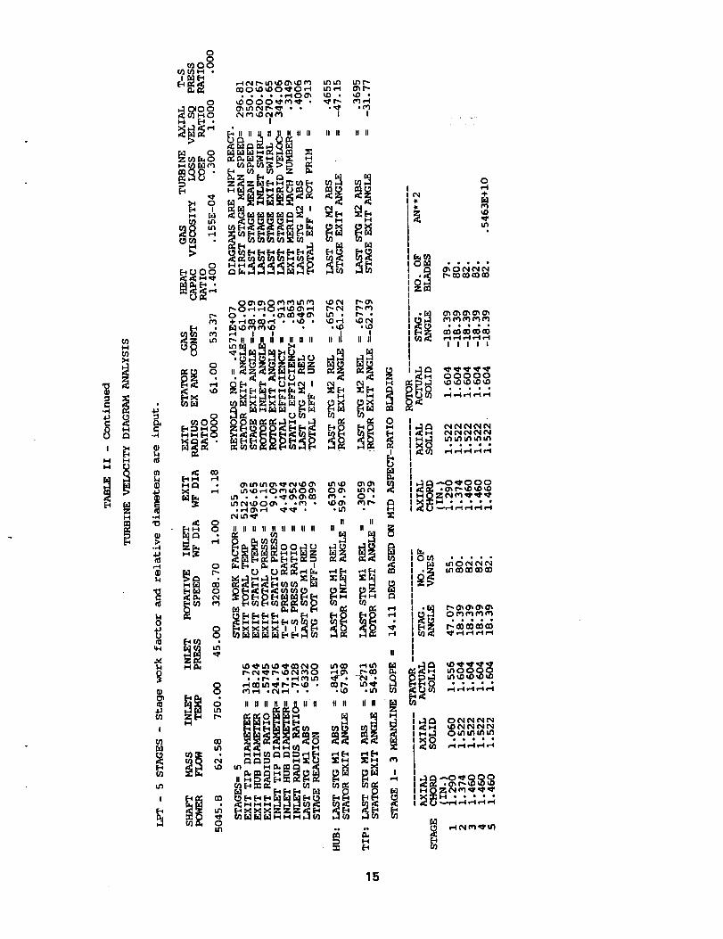
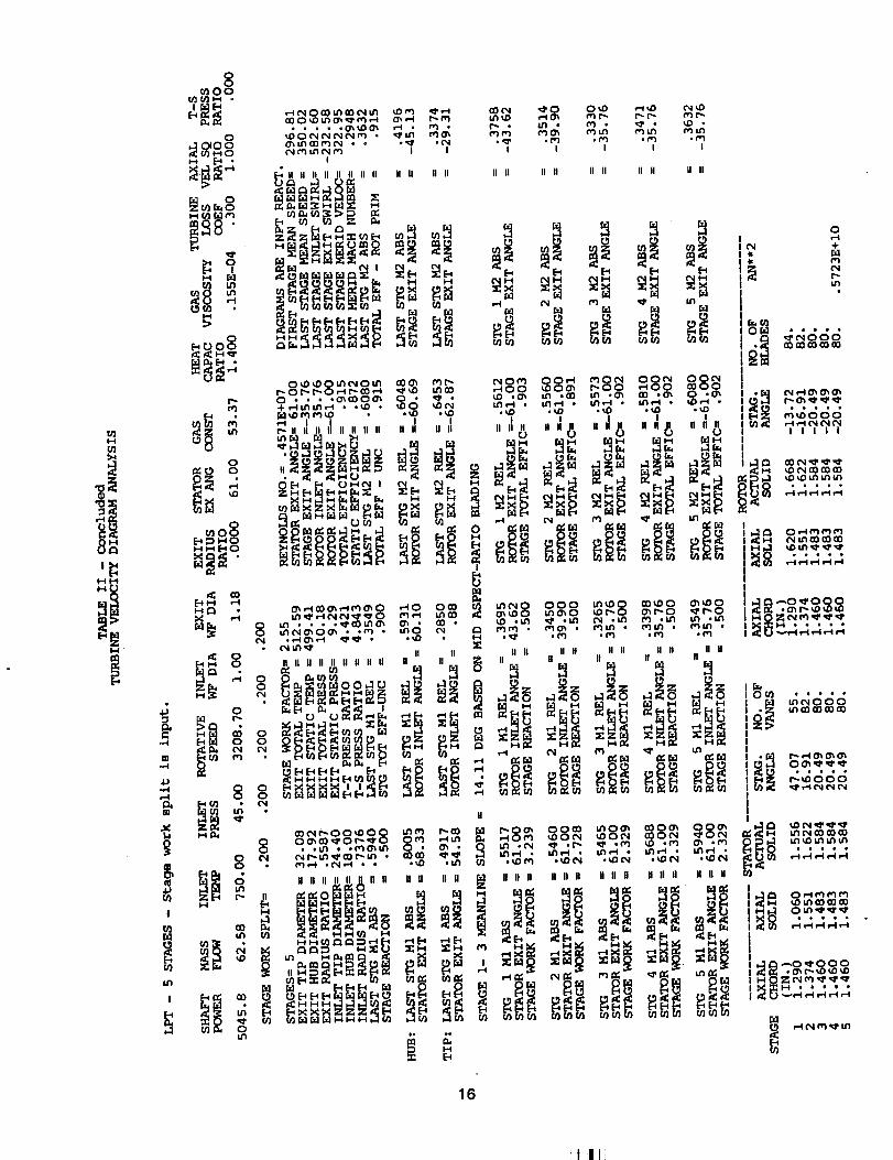
Table II presents the output that corresponds to the sample input of table I. A programidentification title is automatically printed as the top line of the page for each new case. That
is followed by the input title record message. The next four lines for each case are the inputvariables and their associated values. The input variable names are spelled out. The units
for the input variable values are as described in the "Input" section. The input diameters forthe first case are mean diameters as indicated by the MN in the variable name. Hub and tip
diameters would be indicated by HB and TP, respectively. If diameters are calculated from
an input work factor, as for the last two cases, the letters WF are used in the variable name.Note that the input diameters for the last two cases are the relative values. For a cooledturbine, such as the first case, two additional lines are printed to echo the coolant input
parameters. Where stage work split is input, as for the last case, an additional line is printedto show the stage work fractions.
The next group of nine lines is the computation results satisfying the input requirements.The output parameters are spelled out and are self-explanatory. These temperatures,
pressures, velocities and angles are meanline values, and the continuity and efficiencycalculations are based on these values. Note that identical solutions are achieved by takingthe work factor and exit/inlet diameter ratio from the second case and using them as input for
the third case to compute the absolute values for the diameters. For the cooled turbine, notethe differences between total efficiency, which is the thermodynamic efficiency (eqn. (2)),
rotor primary efficiency (eqn. (5)), and uncooled efficiency. These values are all the same forthe uncooled turbine.
The next group of four lines is the hub and tip free-vortex values of Mach number andangles for the last stage, where the radial variations are the largest. These flow parametersdo not enter into the continuity and efficiency calculations, but are shown only for information.Following this is the meanline slope for the stages where the diameter is varying.
Where the stage work split is input, the stage work factors are no longer assumed equal
and the stage velocity diagrams are not necessarily geometrically similar. For this option, thevelocity diagram parameters and efficiency for each stage are printed, as shown for the lastcase. Note the variation in stage work factor from 3.24 at the inlet diameter to 2.33 at the exit
diameter for this case of equal stage work.
The final output for each case are the blading geometries. Given for each stage are thechords, solidities, stagger angles and blade count for the stator and the rotor. Also shown forthe last stage is the rotor blade centrifugal stress parameter AN 2, where A is the exit annulus
area and N is the rotative speed.
lO
!_!11l i

SUMMARY OF RESULTS
This report presents the latest modifications made to the computer code TURBAN, whichis a preliminary sizing analysis for axial-flow turbines. The TURBAN analysis is based onmean-diameter flow characteristics. Program input includes flow, speed, and power orpressure ratio. The output presents annulus dimensions, diagram velocities and angles, andefficiencies. Options are provided for varying stage number, mean diameter, reaction,loading, diagram type, and/or work split.
Modifications were recently made to TURBAN to satisfy user needs and convenience.Turbine cooling now can be accounted for in the overall energy balance and efficiencyestimate by inputting:
(1) ratios of cooling flow to turbine-inlet flow for each blade row;
(2) ratio of coolant temperature to turbine-inlet temperature; and
(3) stage-efficiency decrements due to stator and rotor cooling.
Both thermodynamic efficiency and rotor primary efficiency are computed.
Alternative input options have been added for defining the velocity diagrams:
(1) specifying stage reaction to calculate stage swirl split;
(2) specifying stage loading to calculate mean diameter; and
(3) arbitrarily specifying stage work split.
These options can be used in any combination.
The Reynolds number dependency for the loss model was weakened, and an intemalcalculation of air viscosity was added as a default for convenience. The analytical modeling
for all these modications was presented herein.
This report also serves as an updated users manual for the modified TURBAN code.Program input and output are described, and sample cases illustrating the new capabilitiesare included.
REFERENCES
1. Glassman, A.J.: Computer Program for Preliminary Design Analysis of Axial-FlowTurbines. NASA TN D-6702, 1972.
2. Glassman, A.J.: Computer code for Preliminary Sizing Analysis of Axial-Flow Turbines.NASA CR-4430, 1992.
3. Glassman, A.J.: Blading Models for TURBAN and CSPAN Turbomachine Design Codes.NASA CR-191164, 1993.
4. Gauntner, J.W.: Algorithm for Calculating Turbine Cooling Flow and the Resulting
Decrease in Turbine Efficiency. NASA TM-81453, 1980.
5. Granger, R.A.: Fluid Mechanics. Holt, Rinehart and Winston, 1985.
11

TABLE I - SAMPLE INPUT
COOLED HPT - 2 STAGES - Cooling parameters are input.
&INPUT TTIN=I277.,PTIN=50.,MU=2.69E-5,R=53.37,GAM=I.38,DIN=27.14,DEX=27.25,RPM=8285.,POW=3630.7,W=25.7,ALPHA=71.6,NMIN=2,NMAX=2,E=I.17,
IALPH=0,IDIAM=2,IVD=2,IEV=0,IPR=0,IU=2,KLOSS=.30,ITIT=I,
WCOWP=.094,.070,.025,0.0,TCOTP=.48,DELS=.45,DELR=0.9 &END
LPT - 5 STAGES - Reaction is input (IVD=6 option)&INPUT TTIN=750.,PTIN=45.,MU=I.55E-5,R=53.37,GAM=I.4,DIN=21.2,DEX=25.0,
RPM=3208.7,POW=5045.8,W=62.58,ALPHA=61.,NMIN=5,NMAX=5,E=I.0,REACT=0.5,
IALPH=0,IDIAM=2,IVD=6,IEV=0,IPR=0,IU=2,IMID=2,NMID=3,KLOSS=.30,ITIT=I,
WCOWP=I0*0.0 &END
LPT - 5 STAGES - Stage work factor and relative diameters are input (IDIAM=4)&INPUT DIN=I.0,DEX=I.17925,IDIAM=4,WF=2.5465,ITIT=I &END
LPT - 5 STAGES - Stage work split is input.&INPUT XI=5"0.2 &END
12
!! ! I

I#'lH
I H
I,-I
lil
0
_o8
oi .[-.i
0
i_ _'
t'Nu
00000
00
m I|
_o0
_ m
_o8
_"
_ ,_ _..
0
m o_; So
!i o oO.8 "
• ,,
_0_00_ _0 _0_O_Om_ _0 _0
• . • , ,_ _ • _ •
_ _.. *
|1 n _ n ii II ii II II Ii II II
__' _ _
_l ,_ 0 i',l I_ (I} u'l eq .-I0 • • • .(I)_,-l(_l
0"_ I •
,:i'll _1111 _11 li
,,_;___ _,, 0 _ ¢',11
O_ r"., ,'-_ '_0300 u'_O
t',, M'I OOO_• _ ._0
I III II II Ii
l_lOl-'lCOl'_ . .r"l * lfi,ld' i_ll"ll• I_ u'l il'l _D . .u'l
II IIII II II II U II II II II II __ II ..
in O0 o
I
r_
II
00__ _ __0_ _ _
• ,_ , ,_ 0 • _ •
U II II H II U fl fl II H II II
!,,__
("4 ÷
r,t _,t
oli_lI I
I_ _,_p.i i-_i
r-I ,..-I
¢.-I _-i
, u'i _0_ ufl u'i
_i-I ,.4
o_ _
o_ ._._
I_ _1 •
MO_
13

ID
I
i,n
ell,,
H • • • • •
14
U}h_0_
H H
H
O
moo°U'J _1 H °
_ea_
i_ _.
0
.,q
0
_ 8
g 8
!
(,.1 m
,_ N _- u5 _D 0_ QD _ bSun u_t'-
!
ll IJ _ _ I| I; II II II II II II
_3_..,_.. _._ ,o_.__ ,,,,',,,I,,,,,,,, ,,,,',,',,
r,.)_ I
Ul * * * *"_0_0'_03 _ • 0 *
II II
1 II II II/ II II II II II II_oo_o_ _ _t
__, ,<_
II II II II II !1 II n II II Ii n
NNM_Z_Z_N
O
u_
II
.....:_i__°°°°ooo_°°____.....g
I_.o_ooo
15
t/}I-I{/]
1-11-4
I,-I
00
I/_00
0
H r_
o'1
0
0
•; o
-,-I 0
H!
!i oim
_:10_ _ _ i_ ,_ r_ ,.t_ ('_1_ l_r.i_ __'_'_'q
O_lJ'ICOn_l'_l • ° ,,,_r 0¢'_1(N n_ tft IN n'l I I
Im ,,...,,,,,,. .. ,,,,
_i_ '_,
r_ 01'- t-- 0 ,-t r'- _ ,--t _',_ u'll_(:3 • . • ,0_0)00_ 0 * _ •÷,-.l_nerl,-_ • ._,D • ,,DO _t',,l
'-_1_ II III II III II II II II II II II II!
!
0 u_l • • • ,,_I'_U'_O'_ O_ .. O0 •
o _._(_,..io_ ,,_...m.• ,_,o _, c_e,,l i.h _I' II II :I:II U Ii II II U ii II II II II _-
II
01._10 t'_I" I$_'_'(Z)r" _O_h, ,_r)(0 _I'0 r''_'O. • n')(_hi$_, _ooOn'),,_.o_'-I_'_,
• r,-l,--_°t_e4 ° • o_() oi_I f;}
;.iii!!! 0i
H H Itn II H I1H H H
,-4 _ ¢'_ _ t,tl
"°_,_oo°o8_ _go__J3 00_ I."I ,CO U'I o(PiL/'I_=4 • i_M • 1.1"I,-4 ,
• '_D ._D ._! ! !
_g8 _0,o°°°_8fq¢"_ , f"lO_ • f"_l,fl•• ,mr ,f,'1 ,_"I
II II II II II III1 II II
,-t IN I_
• C',,I _' ,,r". _ *("I
If If fl II ft II II II
0 0 (',I OOr,l
I_I,-I • _-I •
i l
(_ I",. 0 '_I' I'_ 0
.n'1 .¢'I
fill IIIIII U
I.¢I_I • l.fl_.-I ,• i,D ('_,I • _D (".I
II II II II II II
0IIt'W +I.I.
I_ l/If"ll'_ll,,...,.
I l I i I
16
!ii I I


REPORT DOCUMENTATION PAGEForm Approved
OMB No. 0704-0188
--.*h--,J_ *d _=l.4ek|a tkA t'l:dJl I_aAtlAfl _ _orr_OtlrK] &no revwwma me c_ma_n m iI1lorrr_lon. _tlrIO _n|i iU_ltUgm V ul = uufuw[i waa.llaLw in aUT]r u_lll_ eJ_la_l._ tat Urll_
collectk)n O4 informat_'._ncluding =ugge_tion= foc reducing _is .burd=en, to W_shlngton Headquarte.r= Services, Oirect_ate, for Inlor=n_,_n nC_,on.s " a_id R _e]_s, _5 JJefferson
Davis H_hway. Suite 1204, Arlington, VA 22202-1302. a.,td to tl',e _a m Management ano uuoget, _'ape_vorx Heoucuon _-role= _u_u_ u=msb wash ng_on, u_, ,_u:x_._.
1. AGENCY USE ONLY (Leave blank) 2. REPORT DATE 3. REPORTTYPE AND DATES COVERED
November 1994 Final Contractor Report
4. TITLE AND SUBTITLE 5. FUNDING NUMBERS
Enhanced Capabilities and Updated Users Manual for Axial-Flow TurbinePreliminarySizing Code TURBAN
6. AUTHOR(S)
Ar_.r L Glassman
7. PERFORMING ORGAI_IZATION NAME(S) AND ADDRESS(ES)
University of Toledo
Toledo, Ohio 43606
9. SPONSORING/MONITORING AGENCY NAME(S) AND ADDRESS(ES)
National Aeronautics and Space AdminisvadonLewis Research CenterCleveland, Ohio 44135-3191
WU-505-69-50
G-NAG3-1165
8. PERFORMING ORGANIZATIONREPORT NUMBER
E--9252
10. SPONSORING/MON_ORINGAGENCYREPORTNUMBER
NASA CR-195405
11. SUPPLEMENTARY NOTES
Project Manager, Thomas M. Lavelle, Aeropropulsion Analysis Office, NASA Lewis Research Center, organization code2410, (216) 433-7042.
1211. DISTRIBUTION/AVAILABILITY STATEMENT
Unclassified -UnlimitedSubject Category 02
12b. DI._T_i_UTION CODE
13. ABSTRACT (Maximum 200 words)
Several modifications have been made to the axial-flow turbine preliminary sizing code TURBAN. Turbine cooling has
been added to the analysis. New alternative input options allow direct specification of stage reaction, stage work factor,and stage work split. The Reynolds number loss dependency was modified and an internal calculation of air viscosity wasadded. A complete description of input and output along with sample cases are included.
14. SUBJECT TERMS
Turbine analysis; Axial-flow turbine
17. SECURITY CLASSIFICATIONOF REPORT
Unclassified
NSN 7540-01-280-5500
18. SECURITY CLASSIFICATIONOF THIS PAGE
Unclassified
19. SECURITY CLASSIFICATIONOF ABSTRACT
Unclassified
15. NUMBER OF PAGES
1816. PRICE CODE
A0320. LIMITATION OF ABSTRACT
Standard Form 298 (Rev. 2-89)Pre_d by ANSI Std. Z39-18298-102
_! !1