Embed Size (px)
Citation preview
Enhanced Arrival Procedures Enabled by GBAS - INTEROP – Consolidation
Document information
Project Title Enhanced arrival procedures enabled by GBAS
Project Number 06.08.08
Project Manager ENAV
Deliverable Name Enhanced Arrival Procedures Enabled by GBAS - INTEROP – Consolidation
Deliverable ID D05
Edition 00.01.02
Template Version 03.00.00
Task contributors
ALENIA, AIRBUS, DFS, ENAV (L), HONEYWELL,C-LVNL, THALES.
Abstract This document gathers the interoperability requirements on the GBAS services for approach procedures of: Increased Glide Slope, Adaptive Increased Glide Slope, Double Slope Approach, Multiple Runway Aiming Points and Curved RNP to GLS Precision Approach (RNP transition to GLS) concepts. Particularly it describes interoperability conditions for both GBAS ground station and GBAS avionic. It represents the final version of INTEROP.

Project Number 06.08.08 Edition 00.01.02 D05 - Enhanced Arrival Procedures Enabled by GBAS - INTEROP – Consolidation
2 of 70 ©SESAR JOINT UNDERTAKING, 2015. Created by ALENIA, AIRBUS, DFS, ENAV(L), HONEYWELL, THALES for the SESAR Joint Undertaking within the frame of the SESAR Programme co-financed by the EU and EUROCONTROL. Reprint with approval of publisher and the source properly acknowledged
Authoring & Approval Prepared By - Authors of the document. Name & Company Position & Title Date
Giovanni Riccardi / ENAV P06.08.08 member T05 – D05 Task Leader 14/11/2016
Alex Gibbs / C-LVNL on behalf of ENAV P06.08.08 T05 member 29/09/2016 Antonio Salonico / TELESPAZIO on behalf of ALENIA P06.08.08 T05 member 29/09/2016
Benjamin Tessier / AIRBUS P06.08.08 T05 member 29/09/2016 Fabien Cressend / SII on behalf of AIRBUS P06.08.08 T05 member 29/09/2016 Guillaume Cambon / AIRBUS P06.08.08 T05 member 29/09/2016 Jean-pierre Arethens / THALES P06.08.08 T05 member 29/09/2016 Jerome Bazile / AIRBUS P06.08.08 T05 member 29/09/2016 Marco Pasciuto / ENAV P06.08.08 T05 member 29/09/2016 Patrice Rouquette / AIRBUS P06.08.08 T05 member 29/09/2016 Ronald Verhoeven / C-LVNL on behalf of ENAV P06.08.08 T05 member 29/09/2016
Reviewed By - Reviewers internal to the project. Name & Company Position & Title Date Aurora Simonetti / ENAV P06.08.08 Project Manager 06/09/2016
Pavel Ptacek /Honeywell P06.08.08 member 06/09/2016
Bruno Rabiller / EUROCONTROL P06.08.08 member 19/09/2016
Anthony Inard / EUROCONTROL P06.08.08 member 19/09/2016
David De Smedt / EUROCONTROL P06.08.08 member 19/09/2016
Andre Biestmann / DFS P06.08.08 Project member 19/09/2016
Guillaume Cambon / Airbus P06.08.08 member 19/09/2016 Reviewed By - Other SESAR projects, Airspace Users, staff association, military, Industrial Support, other organisations. Name & Company Position & Title Date Ester Martin Dominguez / INECO WP 6 leader 07/09/2016
Sian Andrews /NATS SWP 5.2 15/09/2016
Didier Delibes / AIRBUS P09.49 Project Manager 28/10/2016 Andreas Linner / Novair (no comment received)
Airspace User 19/09/2016
Emre Guemues / Lufthansa (no comment received)
Airspace User 19/09/2016
Jean-Philippe RAMU / EBAA (no comment received)
Airspace User 19/09/2016
Andrew Kilner / EUROCONTROL (no comment received)
P16.06.05 Project Manager 19/09/2016
Robin Deransy / EUROCONTROL (no comment received)
P16.06.03 Project Manager 19/09/2016
John Hird / EUROCONTROL (no comment received)
P16.06.02 Project Manager 19/09/2016
Eric Perrin / EUROCONTROL (no comment received)
P16.06.01 Project Manager 19/09/2016
John Godsell / NATS (no comment received) OFA 02.01.01 Coordinator 19/09/2016

Project Number 06.08.08 Edition 00.01.02 D05 - Enhanced Arrival Procedures Enabled by GBAS - INTEROP – Consolidation
3 of 70 ©SESAR JOINT UNDERTAKING, 2015. Created by ALENIA, AIRBUS, DFS, ENAV(L), HONEYWELL, THALES for the SESAR Joint Undertaking within the frame of the SESAR Programme co-financed by the EU and EUROCONTROL. Reprint with approval of publisher and the source properly acknowledged
Frédérique Ayache / EUROCONTROL (no comment received)
OFA 01.03.01 Coordinator P06.08.01 Project Manager
19/09/2016
Vincent Treve / EUROCONTROL (no comment received)
P06.08.01 Project Member 19/09/2016
Alan Groskreutz / AENA (no comment received)
P06.02 Project Manager 19/09/2016
Richard Pugh / NATS (no comment received) WP05 Leader 19/09/2016 Lauren Reid / Met Office (no comment received)
P11.02 Member 19/09/2016
Approved for submission to the SJU By - Representatives of the company involved in the project. Name & Company Position & Title Date Aurora Simonetti / ENAV P06.08.08 Project Manager 26/09/2016 Rolf Wyss / SEAC P06.08.08 Project member 28/09/2016 Guillaume Cambon / AIRBUS P06.08.08 Project member 26/09/2016 Anthony Inard/ EUROCONTROL P06.08.08 Project member 28/09/2016 Massimo Corazza / ALENIA P06.08.08 Project member 29/09/2016 Anette Näs / NORACON P06.08.08 Project member 29/09/2016 Charles Morris / NATS P06.08.08 Project member 29/09/2016 Andre Biestmann / DFS P06.08.08 Project member 29/09/2016 Pavel Ptacek / HONEYWELL P06.08.08 Project member 29/09/2016 Stephane Mouron / THALES P06.08.08 Project member 29/09/2016
Rejected By - Representatives of the company involved in the project. Name & Company Position & Title Date <Name / Company> <Position / Title> <DD/MM/YYYY>
Rational for rejection
None.
Document History Edition Date Status Author Justification
00.00.01 09/09/2016 Draft ENAV New Document
00.00.02 14/09/2016 Draft ENAV D05 first draft: D14 updated with V2 results
00.00.03 21/09/2016 Draft ENAV D05 second draft with integration of internal reviews
00.00.04 22/09/2016 Draft ENAV D05 second draft with integration of external reviews
00.01.00 26/09/2016 Revised draft ENAV Formal Approval Request
00.01.01 29/09/2016 Final ENAV Approved for submission
00.01.02 14/11/2016 Final ENAV Integration of SJU Assessment report required actions

Project Number 06.08.08 Edition 00.01.02 D05 - Enhanced Arrival Procedures Enabled by GBAS - INTEROP – Consolidation
4 of 70 ©SESAR JOINT UNDERTAKING, 2015. Created by ALENIA, AIRBUS, DFS, ENAV(L), HONEYWELL, THALES for the SESAR Joint Undertaking within the frame of the SESAR Programme co-financed by the EU and EUROCONTROL. Reprint with approval of publisher and the source properly acknowledged
Intellectual Property Rights (foreground) This deliverable consists of SJU foreground.

Project Number 06.08.08 Edition 00.01.02 D05 - Enhanced Arrival Procedures Enabled by GBAS - INTEROP – Consolidation
5 of 70 ©SESAR JOINT UNDERTAKING, 2015. Created by ALENIA, AIRBUS, DFS, ENAV(L), HONEYWELL, THALES for the SESAR Joint Undertaking within the frame of the SESAR Programme co-financed by the EU and EUROCONTROL. Reprint with approval of publisher and the source properly acknowledged
Table of Contents EXECUTIVE SUMMARY .................................................................................................................................... 7
1 INTRODUCTION .......................................................................................................................................... 8 1.1 PURPOSE OF THE DOCUMENT ............................................................................................................... 8 1.2 INTENDED READERSHIP......................................................................................................................... 8 1.3 INPUTS FROM OTHER PROJECTS ........................................................................................................... 9 1.4 GLOSSARY OF TERMS ........................................................................................................................... 9 1.5 ACRONYMS AND TERMINOLOGY ......................................................................................................... 11
2 SYSTEM DESCRIPTION ......................................................................................................................... 15 2.1 GBAS OVERVIEW ............................................................................................................................... 15 2.2 GBAS GROUND SUBSYSTEM DESCRIPTION ...................................................................................... 16
2.2.1 Ground subsystem Functions..................................................................................................... 16 2.2.2 Ground subsystem Services....................................................................................................... 17 2.2.3 GBAS Service Volume ................................................................................................................ 18 2.2.4 GBAS Performance ..................................................................................................................... 19 2.2.5 GBAS Type 4 message - Final Approach Segment ............................................................... 20 2.2.6 Advanced GBAS concepts using GBAS Ground subsystem ................................................ 21
2.3 GBAS AVIONICS SUBSYSTEM DESCRIPTION ..................................................................................... 27 2.3.1 Operational consideration of a GLS approaches .................................................................... 28 2.3.2 Avionics implementing GLS capability ...................................................................................... 31 2.3.3 Advanced GBAS concepts using GBAS avionics ................................................................... 37
3 INTEROPERABILITY REQUIREMENTS .............................................................................................. 40 3.1 TRANSVERSAL REQUIREMENTS .......................................................................................................... 40
3.1.1 Requirements for Final approach segment definition ............................................................. 40 3.1.2 Requirements for “transition between RNP part and final approach segment” .................. 45
3.2 GBAS GROUND STATION REQUIREMENTS ......................................................................................... 49 3.2.1 Increased Glide Slope (IGS) interoperability Requirements .................................................. 49 3.2.2 Adaptive Increased Glide Slope (A-IGS) interoperability Requirements ............................. 50 3.2.3 Multiple Runway Aiming Point (MRAP) interoperability Requirements ................................ 50
3.3 AIRCRAFT AVIONICS REQUIREMENTS ................................................................................................. 52
4 REFERENCES ........................................................................................................................................... 53 4.1 APPLICABLE DOCUMENTS ................................................................................................................... 53 4.2 REFERENCE DOCUMENTS .................................................................................................................. 53
APPENDIX A SOLUTION#09 ENHANCED TERMINAL OPERATIONS WITH AUTOMATIC RNP TRANSITION TO ILS/GLS REQUIREMENTS ............................................................................................. 55
A.1 REQUIREMENTS FOR THE RNP PART OF A “CURVED RNP TRANSITION TO GLS PRECISION APPROACH” ....................................................................................................................................................... 55 A.2 ADAPTIVE INCREASED GLIDE SLOPE (A-IGS) INTEROPERABILITY REQUIREMENTS ......................... 57 A.3 DOUBLE SLOPE APPROACH (DS) INTEROPERABILITY REQUIREMENTS ............................................ 57 A.4 CURVED RNP TO GLS PRECISION APPROACH (RNP TO GLS) INTEROPERABILITY REQUIREMENTS 58 A.5 REQUIREMENTS RELATED TO RNP PART OF A “CURVED RNP TRANSITION TO GLS PRECISION APPROACH” ....................................................................................................................................................... 58
A.5.1 Navigation system performance requirements ........................................................................ 58 A.5.2 Functional requirements .............................................................................................................. 61 A.5.3 Avionics Requirements related to Final approach segment .................................................. 66

Project Number 06.08.08 Edition 00.01.02 D05 - Enhanced Arrival Procedures Enabled by GBAS - INTEROP – Consolidation
6 of 70 ©SESAR JOINT UNDERTAKING, 2015. Created by ALENIA, AIRBUS, DFS, ENAV(L), HONEYWELL, THALES for the SESAR Joint Undertaking within the frame of the SESAR Programme co-financed by the EU and EUROCONTROL. Reprint with approval of publisher and the source properly acknowledged
List of tables Table 1 GBAS performance .................................................................................................................. 19 Table 2 Lateral accuracy at greater distances ...................................................................................... 20 Table 3 Vertical accuracy at greater distances ..................................................................................... 20 Table 4 Safety classification level ......................................................................................................... 33 Table 5 channel for continuity and integrity .......................................................................................... 34 Table 6: Transversal Requirements Layout .......................................................................................... 44
List of figures Figure 1: Illustration of Increased Glide Slope concept .......................................................................... 9 Figure 2: Illustration of Adaptive Increased Glide Slope concept ......................................................... 10 Figure 3: Illustration of the Double Slope concept ................................................................................ 10 Figure 4: Illustration of the MRAP concept ........................................................................................... 11 Figure 5: Illustration of RNP to GLS concept ........................................................................................ 11 Figure 6 GBAS system overview .......................................................................................................... 15 Figure 7 Minimum GBAS service volume for Cat I operations [10] ...................................................... 19 Figure 8 FAS path definition [10] .......................................................................................................... 21 Figure 9 GBAS approach selection and verification ............................................................................. 22 Figure 10 Data required to identify uniquely a GBAS approach ........................................................... 22 Figure 11 VDB message for 2 Time Slots and 18 satellites, MT1 & MT11 [16] ................................... 23 Figure 12 Increased Glide Slope scenario example ............................................................................. 24 Figure 13 Minimum service volume to support CAT I, CAT II and APV operations (DO245A) ............ 24 Figure 14 Double Slope Approach example ......................................................................................... 26 Figure 15 Approach phases .................................................................................................................. 30 Figure 16 Frequency number ................................................................................................................ 31 Figure 17 Channel number ................................................................................................................... 31 Figure 18 functions technical decomposition ........................................................................................ 32 Figure 19 MMR/INR .............................................................................................................................. 35 Figure 20 Architecture using an Arinc 743B GNSS receiver ................................................................ 36 Figure 21 Typical avionics architecture to support LPV or GLS ........................................................... 37 Figure 22 Geometrical relationships between LTP/FTP, FPAP, TCH, GPA, GPIP [10] ....................... 42
Project Number 06.08.08 Edition 00.01.02 D05 - Enhanced Arrival Procedures Enabled by GBAS - INTEROP – Consolidation
7 of 70 ©SESAR JOINT UNDERTAKING, 2015. Created by ALENIA, AIRBUS, DFS, ENAV(L), HONEYWELL, THALES for the SESAR Joint Undertaking within the frame of the SESAR Programme co-financed by the EU and EUROCONTROL. Reprint with approval of publisher and the source properly acknowledged
Executive summary Consolidated INTEROP document gathers the interoperability requirements on the GBAS services for a single runway used during approach procedures. The GBAS services are represented by Increased Glide Slope, Adaptive Increased Glide Slope, Double Slope Approach, Multiple Runway Aiming Points and Curved RNP transition to GLS precision approach (RNP transition to GLS). It summarises the operational concept as described in the OSED [21], with a focus on the interoperability, and proposes the respective INTEROP requirements. Particularly this version describes interoperability conditions for both GBAS ground station and GBAS avionics. It represents an update of previous D14 INTERIM Version - Enhanced Arrival Procedures Enabled by GBAS - INTEROP V2 a brief description for each operational concept is provided below:
1. Increased Glide Slope - A final precision approach segment based on GLS with a glide path angle between 3° and 4.49°;
2. Adaptive Increased Glides Slope - on-board function which optimises the glide slope of existing approach, depending on aircraft performance and external conditions (e.g. wind);
3. Double Slope Approach – A final precision approach segment based on GLS split in two slope: principle is to split the final approach phase in two different successive slopes. The aircraft flies firstly an initial steeper slope and then transitions (from above) to a conventional (shallower) glide slope. The initial segment can reach up to 4.49°;
4. Multiple Runway Aiming Points - A final precision approach segment based on GLS which is offset (translated) from the conventional one, to enable landings further down on the runway;
5. Curved RNP transition to GLS precision approach - RNP curved initial / intermediate approach segments with a transition to the GLS in the final precision approach segment.

Project Number 06.08.08 Edition 00.01.02 D05 - Enhanced Arrival Procedures Enabled by GBAS - INTEROP – Consolidation
8 of 70 ©SESAR JOINT UNDERTAKING, 2015. Created by ALENIA, AIRBUS, DFS, ENAV(L), HONEYWELL, THALES for the SESAR Joint Undertaking within the frame of the SESAR Programme co-financed by the EU and EUROCONTROL. Reprint with approval of publisher and the source properly acknowledged
1 Introduction
1.1 Purpose of the document Interoperability is defined as the “capability of the ATM Systems to operate together”. It shall be decomposed into interoperability within an area / region and “global harmonization” defined as the “capacity of the ATM Systems to provide seamless operations through different regions” (definitions from SESAR Definition phase D4, deliverable Task 2.6.2 DLT-0706-262-00-06) [8]. Task T005 main purpose is to identify the interoperability requirements at both GBAS avionics and ground station level, in order to develop the concept described in the OSED:
• Increased Glide Slope (IGS: AO-0320); • Adaptive Increased Glide Slope (A-IGS: AO-0321); • Double Slope Approach (DS: AO-0322); • Multiple Runway Aiming Points (MRAP: AO-0319) • Curved RNP to GLS Precision Approach (RNP to GLS: AOM-0605)
The INTEROP is used to define the minimum technical and functional requirements that provide the basis for ensuring compatibility among identified elements of the CNS/ATM systems using a specific technology imposed as a design constraint (therefore captured as a requirement). These elements comprise the distributed CNS services and ATS applications in the aircraft systems, the CNS service providers‘ systems and the ATS provider systems. This document also identifies interface requirements between identified air / ground, ground /ground and / or air / air systems. It also defines interoperability requirements for the CNS services and for the ATS applications. It is important to highlight that in the context of P06.08.08, the INTEROP deliverable is developed by three main iterations of the documents:
1) M050 Initial INTEROP: It represents the first INTEROP Initial document. It is provided as input to the V2 Validation. This document represents an interim version and will be considered as project internal deliverable;
2) D14 INTEROP V2: It updates the Initial INTEROP with the results provided by V2 validation activities (RTS & FTS). It is an input to the V3 Validation. This document represents the formal intermediate deliverable to deliver to the SJU;
3) D05 Final INTEROP: it updates the INTEROP V2 with the results provided by V3 validation activities (RTS & Flight trial)
This document is D05 INTEROP V3.
1.2 Intended readership This document is to support any ATC, Airspace Users, ANSPs, Airport Operations and Safety Regulators willing to develop operations of IGS, A-IGS, DS, MRAP, and RNP to GLS operations, taking advantage of GBAS capabilities.
Additionally, following Primary Projects could get benefit from this OSED:
• P06.08.01: Flexible and Dynamic Use of Wake Vortex Separations
• P06.08.05: GBAS Operational Implementation
WP11.2 and B5 review can provide added value to the INTEROP in the frame of Release 5.
At a higher project level OPS 05.02 and OPS 06.02 are expected to use this document as an input into the consolidation activities and the architecture and performance modelling activities respectively.
In addition the following system projects will get input from this document:
• P09.49: Global Interoperability - Airborne Architecture and Avionics Interoperability Roadmap
• P15.03.06; GBAS Cat II/III L1 Approach

Project Number 06.08.08 Edition 00.01.02 D05 - Enhanced Arrival Procedures Enabled by GBAS - INTEROP – Consolidation
9 of 70 ©SESAR JOINT UNDERTAKING, 2015. Created by ALENIA, AIRBUS, DFS, ENAV(L), HONEYWELL, THALES for the SESAR Joint Undertaking within the frame of the SESAR Programme co-financed by the EU and EUROCONTROL. Reprint with approval of publisher and the source properly acknowledged
• P15.03.07: Multi GNSS CAT II/III GBAS
1.3 Inputs from other projects Not available because “Enhanced Arrival Procedures Enabled by GBAS” is the first project that produces the interoperability document for GBAS services:
• Increased Glide Slope (IGS: AO-0320); • Adaptive Increased Glide Slope (A-IGS: AO-0321); • Double Slope Approach (DS: AO-0322); • Multiple Runway Aiming Points (MRAP: AO-0319) • Curved RNP to GLS Precision Approach (RNP to GLS: AOM-0605).
1.4 Glossary of terms The project addresses a broad list of Operational Improvement steps (OIs). The most part of the OIs are linked to OFA01.03.01 represented by:
• AO-0319 – “Enhanced arrival procedures using multiple runway aiming points”;
• AO-0320 – “Enhanced arrival procedures using increased glide slope (IGS)”;
• AO-0321 – “Enhanced arrival procedures using adaptive increased glide slope (A-IGS)”;
• AO-0322 – “Enhanced arrival procedures using double slope approach”.
Furthermore another OI addressed by P06.08.08 and linked to OFA02.01.01 is:
AOM-0605 – “Enhanced terminal operations with RNP transition to ILS/GLS/LPV”
The following points provide an overview of the addressed concepts that in P06.08.08 are based on GBAS technology.
1. Glide slope increase [21]:
Glide slope increase concepts are based on increasing the slope of the final approach segment (IGS, A-IGS) or of the last intermediate segment (DS). The glide slope angle value can be set between the optimum approach angle (3°, as defined by ICAO PANS OPS Doc 8168) and the beginning of the “steep approach” domain (4.5°, as defined by FAA AC-25-7C).
Several procedures allow dealing with glide slope increase concept:
a. Increased Glide Slope [AO-0320]
i. final approach - steeper than the traditional with a glide path angle between the range ( –3.0°;-4,5°)
Figure 1: Illustration of Increased Glide Slope concept

Project Number 06.08.08 Edition 00.01.02 D05 - Enhanced Arrival Procedures Enabled by GBAS - INTEROP – Consolidation
10 of 70 ©SESAR JOINT UNDERTAKING, 2015. Created by ALENIA, AIRBUS, DFS, ENAV(L), HONEYWELL, THALES for the SESAR Joint Undertaking within the frame of the SESAR Programme co-financed by the EU and EUROCONTROL. Reprint with approval of publisher and the source properly acknowledged
b. Adaptive Increased Glide Slope [AO-0321]
i. final approach segment steeper than the traditional with a glide path angle on-board calculated between the range (–3.0°;-3,5°)
Figure 2: Illustration of Adaptive Increased Glide Slope concept
c. Double Slope [AO-0322]
i. final approach phase steeper than the traditional with a glide path angle between the range ] – 3.0° ; - 4,5° [ in the first phase of the final approach with a transition to the standard 3° in the last phase of the final approach
Figure 3: Illustration of the Double Slope concept
2. Multiple runway aiming points [21] [AO-0319]:
a. final approach segment anchored to shifted touch down zone
Project Number 06.08.08 Edition 00.01.02 D05 - Enhanced Arrival Procedures Enabled by GBAS - INTEROP – Consolidation
11 of 70 ©SESAR JOINT UNDERTAKING, 2015. Created by ALENIA, AIRBUS, DFS, ENAV(L), HONEYWELL, THALES for the SESAR Joint Undertaking within the frame of the SESAR Programme co-financed by the EU and EUROCONTROL. Reprint with approval of publisher and the source properly acknowledged
Figure 4: Illustration of the MRAP concept
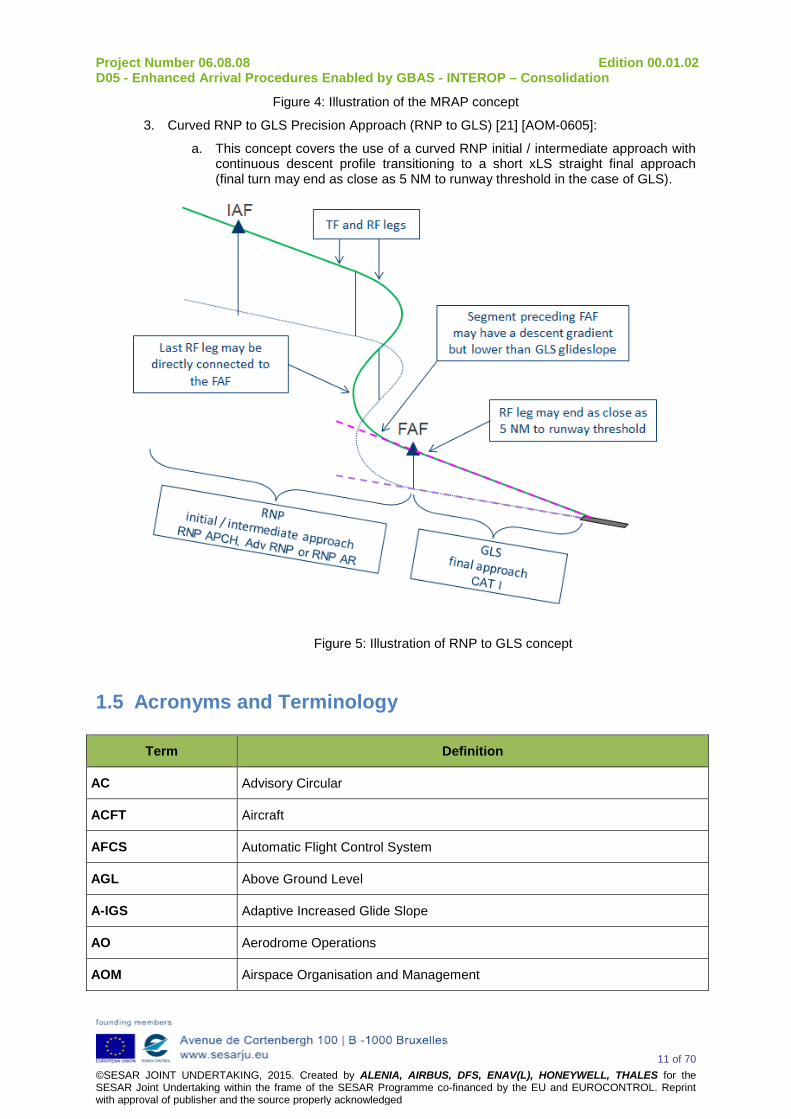
3. Curved RNP to GLS Precision Approach (RNP to GLS) [21] [AOM-0605]:
a. This concept covers the use of a curved RNP initial / intermediate approach with continuous descent profile transitioning to a short xLS straight final approach (final turn may end as close as 5 NM to runway threshold in the case of GLS).
Figure 5: Illustration of RNP to GLS concept
1.5 Acronyms and Terminology
Term Definition
AC Advisory Circular
ACFT Aircraft
AFCS Automatic Flight Control System
AGL Above Ground Level
A-IGS Adaptive Increased Glide Slope
AO Aerodrome Operations
AOM Airspace Organisation and Management

Project Number 06.08.08 Edition 00.01.02 D05 - Enhanced Arrival Procedures Enabled by GBAS - INTEROP – Consolidation
12 of 70 ©SESAR JOINT UNDERTAKING, 2015. Created by ALENIA, AIRBUS, DFS, ENAV(L), HONEYWELL, THALES for the SESAR Joint Undertaking within the frame of the SESAR Programme co-financed by the EU and EUROCONTROL. Reprint with approval of publisher and the source properly acknowledged
Term Definition
AP Auto Pilot
APV Approach Procedure with Vertical guidance
ATC Air Traffic Control
ATCO Air Traffic Controller Operator
ATFCM Air Traffic Flow and Capacity Management
ATIS Air Traffic Information Service
ATM Air Traffic Management
ATS Air Traffic Services
CDO Continuous Descent Operations
CFL Cleared Flight Level
CG Center of Gravity
CONOPS Concept of Operations
CRTG Curved RNP Transition to GLS Precision Approach
DA/H Decision Altitude/Height
DCPS Differentially Corrected Positioning Service
DOD Detailed Operational Description
DS Double Slope Approach
DT Displaced Threshold
FAF Final Approach Fix
FAP Final Approach Point
FAS Final Approach Segment
FMS Flight Management System
FPL Flight Plan
FTE Flight Technical Error
FTP Fictitious Threshold Point
G/S Glide Slope
GAST GBAS Approach Service Type
Project Number 06.08.08 Edition 00.01.02 D05 - Enhanced Arrival Procedures Enabled by GBAS - INTEROP – Consolidation
13 of 70 ©SESAR JOINT UNDERTAKING, 2015. Created by ALENIA, AIRBUS, DFS, ENAV(L), HONEYWELL, THALES for the SESAR Joint Undertaking within the frame of the SESAR Programme co-financed by the EU and EUROCONTROL. Reprint with approval of publisher and the source properly acknowledged
Term Definition
GBAS Ground Based Augmentation System
GLS GBAS Landing System
GNSS Global Navigation Satellite System
GPA Glide Path Angle
GPIP Glide Path Intercept Point
HAT Height Above Threshold
HPL Horizontal Protection Level
IAF Initial Approach Fix
ICAO International Civil Aviation Organization
ICD Interface Control Document
IGS Increased Glide Slope
ILS Instrument Landing System
INR Integrated Navigation Receiver
INTEROP Interoperability Requirements
LNAV Lateral Navigation
LOC Localizer
LPV Localizer Performance with Vertical Guidance
MASPS Minimum Aviation System Performance Standards
MMR Multi-Mode Receiver
MRAP Multiple Runway Aiming Point
NavDB Navigation Database
NM Nautical Mile
OFA Operational Focus Areas
OI Operational Improvement
OSED Operational Service and Environment Definition
PANS Procedures for Air Navigation Service
PBN Performance Based Navigation

Project Number 06.08.08 Edition 00.01.02 D05 - Enhanced Arrival Procedures Enabled by GBAS - INTEROP – Consolidation
14 of 70 ©SESAR JOINT UNDERTAKING, 2015. Created by ALENIA, AIRBUS, DFS, ENAV(L), HONEYWELL, THALES for the SESAR Joint Undertaking within the frame of the SESAR Programme co-financed by the EU and EUROCONTROL. Reprint with approval of publisher and the source properly acknowledged
Term Definition
PIRM Programme Info Reference Model
QNH Barometric pressure adjusted to sea level
RF Radius to Fix
RNAV aRea NAVigation
RNP Required Navigation Performance
RNP AR Required Navigation Performance Authorization Required
RNP to GLS Curved RNP to GLS Precision Approach
RPDS Reference Path Data Selector
RPID Reference Path Identifier
RSDS Reference Station Data Selector
RWY Runway
SESAR Single European Sky ATM Research Programme
SESAR Programme The programme which defines the Research and Development activities and Projects for the SJU.
SIS Signal-in-space
SJU SESAR Joint Undertaking (Agency of the European Commission)
SPR Safety and Performance Requirements
STAR Standard Terminal Arrival Route
TCH Threshold Crossing Height
TMA Terminal Manoeuvring Area

Project Number 06.08.08 Edition 00.01.02 D05 - Enhanced Arrival Procedures Enabled by GBAS - INTEROP – Consolidation
15 of 70 ©SESAR JOINT UNDERTAKING, 2015. Created by ALENIA, AIRBUS, DFS, ENAV(L), HONEYWELL, THALES for the SESAR Joint Undertaking within the frame of the SESAR Programme co-financed by the EU and EUROCONTROL. Reprint with approval of publisher and the source properly acknowledged
2 System Description
2.1 GBAS Overview A Ground-Based Augmentation System (GBAS) is a safety-critical system that supports local augmentation at airport level of the primary GPS constellations by providing guidance signals with different levels of service to support approach and landing up to CATIII operations (CATI already operational, CATII/III under final validation). The aim of the GBAS is the provision of Signal in Space (SIS) augmenting the Global Positioning System (GPS) performance to improve aircraft safety during airport approaches and landings. GBAS Operational concept, the definition and the performance level of the provided signals have been derived from equivalent operations using ILS system. It is expected that the GBAS end-state configuration will provide a significant improvement in service flexibility and user operating costs compared with ILS.
GBAS consists of a GBAS ground subsystem, a GBAS aircraft subsystem and a GNSS space segment (see Figure 6). One GBAS ground subsystem can support an unlimited number of aircraft subsystems within its GBAS coverage volume. The ground subsystem provides the aircraft with approach path data and, for each satellite in view, corrections and integrity information. The corrections enable the aircraft to determine its position relative to the approach path more accurately.
Figure 6 GBAS system overview
As described in [9], the GBAS ground subsystem uses at least two reference receivers, a GBAS ground facility, and a VHF Data Broadcast (VDB) transmitter.
Signals from GPS satellites are received by the GBAS / GPS Reference Receivers at the GBAS-equipped airport. Reference receivers calculate pseudo-ranges (high accuracy ranging measurements) for all GPS satellites within view. The GPS Reference Receivers and GBAS Ground Facility work together to estimate in the GPS-ranging measurements the deviation errors from the expected geometrical distances to the satellites. Then, the GBAS Ground Facility produces a GBAS ranges correction message which includes as well integrity parameters. It also produces additional messages with various static parameters and approach paths information (FAS Data-block). The
Project Number 06.08.08 Edition 00.01.02 D05 - Enhanced Arrival Procedures Enabled by GBAS - INTEROP – Consolidation
16 of 70 ©SESAR JOINT UNDERTAKING, 2015. Created by ALENIA, AIRBUS, DFS, ENAV(L), HONEYWELL, THALES for the SESAR Joint Undertaking within the frame of the SESAR Programme co-financed by the EU and EUROCONTROL. Reprint with approval of publisher and the source properly acknowledged
GBAS messages are then sent to the aircraft subsystems through a VHF Data Broadcast (VDB) transmitter in order that it uses the messages to correct their own measurements according to the differential principle. Consequently this principle requires that the ground and aircraft subsystems use exactly the same ephemeris and satellite clock corrections. Moreover, since the differential principle removes all the ranging errors that are common to ground and aircraft subsystems, absolute tropospheric or SBAS corrections are not applied by the two subsystems.
Furthermore it shall be considered that a unique GBAS ground subsystem may serve several approach paths towards the runway of a given airport. Indeed the VDB transmitter broadcasts the GBAS signal throughout the GBAS coverage area to avionics in GBAS-equipped aircraft. GBAS provides its service to a local area (approximately a 20 NM radius). The signal coverage is designed to support the aircraft's transition from en route airspace into and throughout the terminal area airspace.
As described in [9], the GBAS airborne equipment is composed of a VDB receiver and a GBAS / GPS airborne receiver. The VDB receiver gets the VHF signal transmitted by the GBAS ground subsystem in its service coverage, and demodulates the GBAS messages. The GBAS / GPS equipment processes the corrections and integrity parameter from the GBAS correction message to compute accurate positioning with high integrity. Then GBAS / GPS equipment corrects its own pseudo-range measurements for each satellite with the differential correction data received from the ground subsystem. The corrected pseudo-range measurements are then used to more accurately determine the aircraft’s position relative to the selected Final Approach Path. This position is also used to generate ILS look-alike deviation to guide the aircraft safely to the runway along a flight path whose characteristics are provided in the GBAS FAS Data-block.
The GBAS integrity concept requires the aircraft subsystem to assess the integrity risk due to:
• Satellite and/or signal errors;
• Anomalous ionospheric errors;
• Ground subsystem errors;
taking into account the geometry of the satellites used by the aircraft subsystem. In order to do that, the ground subsystem broadcasts specific integrity data to the aircraft subsystem for each pseudo-range correction. The aircraft subsystem uses specific integrity received data to limit the integrity risk. When the GBAS airborne equipment detects a degraded GNSS signal integrity, it invalidates the GBAS computed deviations. Therefore, they are no more displayed in the cockpit and the GLS approach cannot be flown.
For the cases where integrity is not a function of current satellite geometry at the aircraft subsystem, such as ranging source failures or ground subsystem faults, the integrity mechanisms are provided by the ground subsystem.
GBAS proposes different levels of services: GAST (GBAS Approach Service Type): • A GAST-C GBAS system can be used as low as 200 feet (60 m) above touchdown to support
CATI operation. • A GAST-D GBAS system is intended to support approach and landings all the way to the
runway surface to support up to CATIIIB operations.
2.2 GBAS ground Subsystem Description
2.2.1 Ground subsystem Functions The ground subsystem consists of two to four GNSS reference receivers and their respective geographically separated antennas, ground processing functions, data broadcast transmitter function and integrity monitoring functions. The ground subsystem external functions as observed from the aircraft subsystem are [9]:

Project Number 06.08.08 Edition 00.01.02 D05 - Enhanced Arrival Procedures Enabled by GBAS - INTEROP – Consolidation
17 of 70 ©SESAR JOINT UNDERTAKING, 2015. Created by ALENIA, AIRBUS, DFS, ENAV(L), HONEYWELL, THALES for the SESAR Joint Undertaking within the frame of the SESAR Programme co-financed by the EU and EUROCONTROL. Reprint with approval of publisher and the source properly acknowledged
• Broadcast of “GNSS Pseudo-range Corrections – 100 sec smoothed pseudo-ranges” – Type 1 message, which include differential correction data with error bound for individual GNSS ranging sources that are carrier smoothed with a time constant of 100 seconds.
• Broadcast of “GBAS Related Data” – Type 2 message, which identifies the exact location for which the differential corrections provided by the ground augmentation system are referenced. The ground station reference point is defined in WSG-84 co-ordinates. The message also contains configuration data and data to compute a tropospheric correction.
• Broadcast of “Final Approach Segment Data” -- Type 4 message, which includes the FAS which consist of Path Points describing approaches for each related runway end, and associated vertical/lateral alert limits.
• Broadcast of “Predicted Ranging Source Availability” (optional) – Type 5 message, which indicate to the future availability of differential corrections to the ranging measurements on an approach specific basis.
• Broadcast of “GNSS Pseudo-range Corrections – 30 sec smoothed pseudo-ranges” (Cat II/III) – Type 11 message, which include differential correction data for individual GNSS ranging sources that are carrier smoothed with a time constant of 30 seconds. The message also includes parameters that describe the distribution of errors in the 30 second smoothed corrections as well as parameters that describe the error in the corresponding 100 sec smoothed corrections (in the Type 1 message) as applicable for GAST-D.
The data broadcast uses the VHF band aeronautical radio navigation frequencies. All broadcast stations of a GBAS ground subsystem broadcast identical data with the same GBAS identification on a common frequency. The airborne receiver need not and cannot distinguish between messages received from different broadcast stations of the same GBAS ground subsystem. When within coverage of two such broadcast stations, the receiver will receive and process duplicate copies of messages in different time division multiple access (TDMA) time slots.
Furthermore, the GBAS VDB transmits with either horizontal or elliptical polarization (GBAS/H or GBAS/E). This allows service providers to tailor the broadcast to their operational requirements and user community. GBAS service providers shall publish the signal polarization (GBAS/H or GBAS/E), for each GBAS facility in the aeronautical information publication (AIP). Aircraft operators that use vertically polarized receiving antenna will have to take this information into account when managing flight operations, including flight planning and contingency procedures.
The ground subsystem internal functions are those necessary to provide the external functions with the required performance. The main internal functions are [9]:
• GNSS reference receiver function, which receives, tracks and decodes the “GNSS Satellite Signals in Space” and measures pseudo-range to, and range rates for, each GNSS satellite in view.
• Reference processing function, which calculates Pseudo-range Correction and integrity data for each valid satellite in view, by reference to the reference receiver’s antenna positions.
• VHF data broadcast transmission function, which transmits the messages to all aircraft within coverage area through the VDB antenna.
• Integrity monitoring function, which validates all messages being provided to the VHF data broadcast transmission function, and all messages actually transmitted
• GNSS ranging source monitoring function, which monitors the GNSS signals to detect conditions that will result in improper operation of differential processing.
2.2.2 Ground subsystem Services GBAS ground subsystems may provide two services: the GBAS positioning service and the approach service [10]. These services are distinct and independent. All ground stations do not necessarily support both services.

Project Number 06.08.08 Edition 00.01.02 D05 - Enhanced Arrival Procedures Enabled by GBAS - INTEROP – Consolidation
18 of 70 ©SESAR JOINT UNDERTAKING, 2015. Created by ALENIA, AIRBUS, DFS, ENAV(L), HONEYWELL, THALES for the SESAR Joint Undertaking within the frame of the SESAR Programme co-financed by the EU and EUROCONTROL. Reprint with approval of publisher and the source properly acknowledged
• The GBAS positioning service provides differentially-corrected horizontal position, velocity, and time information to support RNAV operations within the service area. It may also support other applications (e.g. surveillance).
• The approach service provides deviation guidance for approaches within the operational coverage area. The following GBAS Approach Service Types (GAST) are considered:
o GAST-A Approach with vertical guidance (APV I performance)
o GAST-B Approach with vertical guidance (APV II performance)
o GAST-C Precision Approach to lowest Category I minima
o GAST-D Precision Approach to lowest Category IIIB minima, when augmented with other airborne equipment
o GAST-E Precision Approach to lowest Category II/IIIA minima
o GAST-F Precision Approach to lowest Category IIIB minima
The two services are also distinguished by different performance requirements(see section 2.2.4). associated with the particular operations supported including different integrity requirements
A primary distinguishing feature for GBAS ground subsystem configurations is whether additional ephemeris error position bound parameters are broadcast. This feature is required for the positioning service, but is optional for approach services. If the additional ephemeris error position bound parameters are not broadcast, the ground subsystem is responsible for assuring the integrity of ranging source ephemeris data without reliance on the aircraft calculating and applying the ephemeris bound.
There are multiple configurations possible of GBAS ground subsystems conforming to the GNSS Standards, such as:
a) a configuration that supports Category I precision approach only;
b) a configuration that supports Category I precision approach and APV, and also broadcasts the additional ephemeris error position bound parameters;
c) a configuration that supports Category I precision approach, APV, and the GBAS positioning service, while also broadcasting the ephemeris error position bound parameters referred to in b), including the Reference Station Data Selector (RSDS) in Type 2 message, used in selecting the GBAS positioning service.
2.2.3 GBAS Service Volume The GBAS coverage volume is defined as the region within which the system meets the accuracy, integrity and continuity requirements.
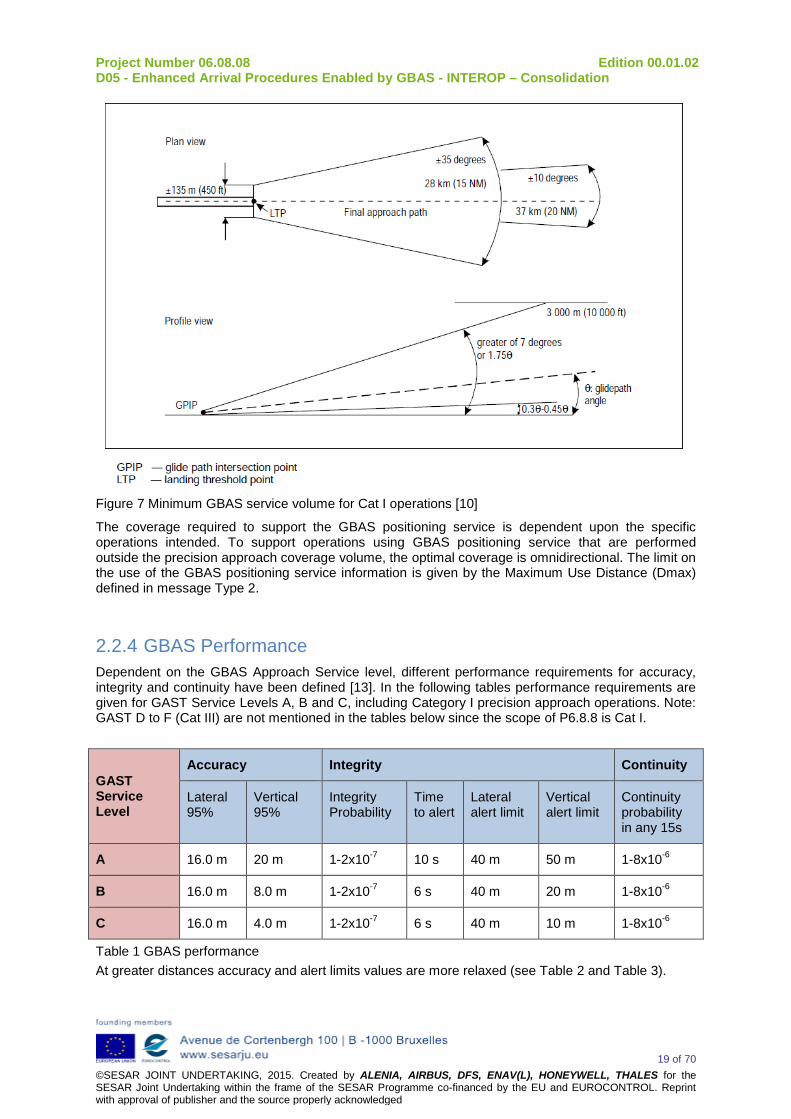
The minimum GBAS coverage volume to support each Category I precision approach is [10]:
Lateral Beginning at 450ft each side of the Landing Threshold Point (LTP) and projecting out ±35 degrees either side of the final approach path to 15 NM and ±10 degrees either side of the final approach path to 20 NM.
Vertical Within the lateral region, up to the greater of 7º or 1.75 times the promulgated glide path angle (GPA) above the horizontal with an origin at the Glide Path Intercept Point (GPIP) and 0.45 GPA above the horizontal or to such lower angle, down 0.30 GPA, as required to safeguard the promulgated glide path intercept procedure. This coverage applies between 100ft and 10000ft Height Above Threshold (HAT).
Project Number 06.08.08 Edition 00.01.02 D05 - Enhanced Arrival Procedures Enabled by GBAS - INTEROP – Consolidation
19 of 70 ©SESAR JOINT UNDERTAKING, 2015. Created by ALENIA, AIRBUS, DFS, ENAV(L), HONEYWELL, THALES for the SESAR Joint Undertaking within the frame of the SESAR Programme co-financed by the EU and EUROCONTROL. Reprint with approval of publisher and the source properly acknowledged
Figure 7 Minimum GBAS service volume for Cat I operations [10]
The coverage required to support the GBAS positioning service is dependent upon the specific operations intended. To support operations using GBAS positioning service that are performed outside the precision approach coverage volume, the optimal coverage is omnidirectional. The limit on the use of the GBAS positioning service information is given by the Maximum Use Distance (Dmax) defined in message Type 2.
2.2.4 GBAS Performance Dependent on the GBAS Approach Service level, different performance requirements for accuracy, integrity and continuity have been defined [13]. In the following tables performance requirements are given for GAST Service Levels A, B and C, including Category I precision approach operations. Note: GAST D to F (Cat III) are not mentioned in the tables below since the scope of P6.8.8 is Cat I.
GAST Service Level
Accuracy Integrity Continuity
Lateral 95%
Vertical 95%
Integrity Probability
Time to alert
Lateral alert limit
Vertical alert limit
Continuity probability in any 15s
A 16.0 m 20 m 1-2x10⁻⁷ 10 s 40 m 50 m 1-8x10⁻⁶
B 16.0 m 8.0 m 1-2x10⁻⁷ 6 s 40 m 20 m 1-8x10⁻⁶
C 16.0 m 4.0 m 1-2x10⁻⁷ 6 s 40 m 10 m 1-8x10⁻⁶
Table 1 GBAS performance At greater distances accuracy and alert limits values are more relaxed (see Table 2 and Table 3).

Project Number 06.08.08 Edition 00.01.02 D05 - Enhanced Arrival Procedures Enabled by GBAS - INTEROP – Consolidation
20 of 70 ©SESAR JOINT UNDERTAKING, 2015. Created by ALENIA, AIRBUS, DFS, ENAV(L), HONEYWELL, THALES for the SESAR Joint Undertaking within the frame of the SESAR Programme co-financed by the EU and EUROCONTROL. Reprint with approval of publisher and the source properly acknowledged
GAST Service Level Distance from LTP Accuracy Lateral 95% Lateral alert limit
A, B 16 m FASLAL
C
D ≤ 873 m 16 m FASLAL
873 m < D ≤ 7500 m from 16 m to 27.7 m linear increasing
from FASLAL to FASLAL + 29.15 m linear increasing
D > 7500 m 27.7 m FASLAL + 29.15 m Table 2 Lateral accuracy at greater distances GAST Service Level Distance from LTP Accuracy Vertical 95% Lateral alert limit
A 20 m FASVAL B 8 m FASVAL
C
H ≤ 200 ft 4 m FASVAL
200 ft < H ≤ 1340 ft from 4 m to 17.3 m linear increasing
from FASVAL to FASVAL + 33.35 m linear increasing
H > 1340 ft 17.3 m FASLAL + 33.35 m Table 3 Vertical accuracy at greater distances FASVAL and FASLAL refer to FAS Vertical Alert Limit and FAS Lateral Alert Limit. These values are broadcasted in Type 4 messages. See also next section.
2.2.5 GBAS Type 4 message - Final Approach Segment The Message Type 4 contains one or more data sets that contain Final Approach Segment (FAS) data. Each data set is transmitted with the associated vertical/lateral alert limits:
• FAS, MA Vertical Alert Limit (FASVAL) • FAS, MA Lateral Alert Limit (FASLAL)
Each Final Approach Segment (FAS) data block contains the parameters that define a single precision approach [9]. It is self-contained and includes a means to preserve integrity from the time it is generated and validated to the time that it is used in airborne equipment. All of the information necessary to describe the paths and its designation is contained within it. This primarily includes the following:
• Airport identification • Runway designation and position • Procedure type (provides flexibility for advanced procedures such as departure or curved
approach) • Procedure name • Runway surveyed points defining the FAS path
The FAS path is a line in space defined by the following parameters:
• Landing Threshold Point or Fictitious Threshold Point (LTP/FTP) • Flight Path Alignment Point (FPAP) • LTP/FTP height • Threshold Crossing Height (TCH) • Glide Path Angle (GPA).

Project Number 06.08.08 Edition 00.01.02 D05 - Enhanced Arrival Procedures Enabled by GBAS - INTEROP – Consolidation
21 of 70 ©SESAR JOINT UNDERTAKING, 2015. Created by ALENIA, AIRBUS, DFS, ENAV(L), HONEYWELL, THALES for the SESAR Joint Undertaking within the frame of the SESAR Programme co-financed by the EU and EUROCONTROL. Reprint with approval of publisher and the source properly acknowledged
By defining the appropriate FAS path, support to precision approach operations can be provided based upon one (or a combination) of the following concepts as defined in the OSED [21]:
• Increased Glide Slope • Adaptive Increased Glide Slope • Double Slope Approach • Multiple Runway Aiming Point • Curved RNP transition to GLS Precision Approach
The local level plane for the approach is a plane perpendicular to the local vertical passing through the LTP (i.e. tangent to the ellipsoid at LTP). The absolute position of the LTP/FTP is referenced to the geodetic co-ordinate system WSG-84. The FPAP position is given in Delta latitude and Delta longitude from LTP/FTP using the same co-ordinate system.
Figure 8 FAS path definition [10]
2.2.6 Advanced GBAS concepts using GBAS Ground subsystem This section provides a preliminary analysis of the potential impact of the enhanced arrival procedures concepts described in the OSED [21] on current GBAS ground subsystem and it is intended as an introduction section of the GBAS ground station Requirements reported in section 3 “Interoperability Requirements”. Changes on GBAS ground station are implicit due to the adoption of advanced arrival procedures. However the changes are mainly pertaining to be only affecting the ground station software. The GBAS technology is the best candidate to implement the new arrival procedures because a single GBAS ground station is capable of broadcasting several FAS (Final Approach Segment) using the Message Type 4 (MT4). As an example, assume one runway with possibility of GBAS use from both the ends. Also assume two RWY aiming points and two different slopes (Glide path). This leads to eight different segments to be broadcast. Flight crew can select a specific approach by tuning a channel number N. This number can be translated into the VDB frequency f and the Reference Path Data Selector (RPDS) which is a numeric

Project Number 06.08.08 Edition 00.01.02 D05 - Enhanced Arrival Procedures Enabled by GBAS - INTEROP – Consolidation
22 of 70 ©SESAR JOINT UNDERTAKING, 2015. Created by ALENIA, AIRBUS, DFS, ENAV(L), HONEYWELL, THALES for the SESAR Joint Undertaking within the frame of the SESAR Programme co-financed by the EU and EUROCONTROL. Reprint with approval of publisher and the source properly acknowledged
identifier unique to each FAS data block on a frequency in the broadcast region (21123 in the example shown in Figure 9).
Figure 9 GBAS approach selection and verification The approach identified from the FAS data-block with the matching RPDS is returned from the GBAS equipment as verification of the correct selection. Optionally, the airport identifier, runway identifier, and route indicator for the selected FAS data-block could be used for selection verification (see Figure 10).
Figure 10 Data required to identify uniquely a GBAS approach However the broadcast of GBAS messages is limited by the capacity of the VDB and thus by the number of slots assigned to a GBAS ground facility. The number of assigned slots for a GBAS ground facility should be limited as far as possible in order to use the same frequency for other GBAS ground facilities. Thus, the available capacity shall be used as effectively as possible. The use of VDB capacity is also affected by the following GBAS scenario
1) Multiple Antennas

Project Number 06.08.08 Edition 00.01.02 D05 - Enhanced Arrival Procedures Enabled by GBAS - INTEROP – Consolidation
23 of 70 ©SESAR JOINT UNDERTAKING, 2015. Created by ALENIA, AIRBUS, DFS, ENAV(L), HONEYWELL, THALES for the SESAR Joint Undertaking within the frame of the SESAR Programme co-financed by the EU and EUROCONTROL. Reprint with approval of publisher and the source properly acknowledged
As presented in [17], for the case of large complex airports, where one VDB antenna cannot serve the whole GBAS coverage area and additional transmit antennas with partly overlapping coverage areas are necessary, GAST D GBAS already would need 4 to 5 slots depending on the number of FAS data blocks to be broadcast
2) Multi-constellation & Multi-frequency GBAS evolution
It is expected that the GBAS VDB capacity will also be shared to broadcast the corrections of additional global navigation satellite systems like Galileo or BeiDou and additional aviation GNSS frequencies such as GPS L5 and Galileo E5a. In particular the Multi GNSS GBAS CAT II/III project, as part of the SESAR programme, aims at enabling CAT II/III operations based on GNSS for all CAT II/III aircraft in order to provide benefits to all low visibility users Even though the range of the Reference Path Data Selector (RPDS) allows the definition of up to 49 approach procedures their number can be limited by VDB capacity constraints. For example the number of transmittable FAS segments is limited to 19 using a transmission scheme that maximizes the GPS and Galileo L1 differential corrections while fulfilling the minimum requirements on the VDB data [16].
Figure 11 VDB message for 2 Time Slots and 18 satellites, MT1 & MT11 [16] In addition to supporting the advanced arrival procedures, the GBAS ground station is responsible for providing integrity to the users (GAST-C). This implicitly involves the use of several integrity monitors and several performances checks in real-time or near real time. In such occasions, it is empirical to consider the composite of the different procedures being supported by the ground station as the threat model perceived by different users have to be collectively considered by the GBAS station. Additional requirements are imperative on GBAS avionics to support these advanced procedures. The impact of each advanced concept on the GBAS ground station is reported hereafter.

Project Number 06.08.08 Edition 00.01.02 D05 - Enhanced Arrival Procedures Enabled by GBAS - INTEROP – Consolidation
24 of 70 ©SESAR JOINT UNDERTAKING, 2015. Created by ALENIA, AIRBUS, DFS, ENAV(L), HONEYWELL, THALES for the SESAR Joint Undertaking within the frame of the SESAR Programme co-financed by the EU and EUROCONTROL. Reprint with approval of publisher and the source properly acknowledged
2.2.6.1 Increased Glide Slope (IGS) To support IGS approach operations it is expected that the GBAS ground station will broadcast in the MT4 a corresponding FAS including a Glide Path Angle (GPA) between 3° and 4.5° to provide vertical and lateral guidance during all the IGS approach.
Figure 12 shows an example of IGS scenario where the GBAS approach service is used to start the IGS procedure at 20NM from the threshold.
Even with the steepest GPA of 4.5° the IGS approach falls within the minimum service volume to support CAT I, CAT II and APV operations shown in Figure 13.
Figure 12 Increased Glide Slope scenario example
Figure 13 Minimum service volume to support CAT I, CAT II and APV operations (DO245A) The IGS G/S interoperability requirements are reported in section 3.2.1.

Project Number 06.08.08 Edition 00.01.02 D05 - Enhanced Arrival Procedures Enabled by GBAS - INTEROP – Consolidation
25 of 70 ©SESAR JOINT UNDERTAKING, 2015. Created by ALENIA, AIRBUS, DFS, ENAV(L), HONEYWELL, THALES for the SESAR Joint Undertaking within the frame of the SESAR Programme co-financed by the EU and EUROCONTROL. Reprint with approval of publisher and the source properly acknowledged
2.2.6.2 Adaptive Increased Glide Slope (A-IGS) The A-IGS concept considers the reception of an existing GBAS FAS of a conventional procedure, i.e. with a conventional slope (GPA). Then, A-IGS on-board function optimises the glide slope of this conventional procedure. Finally, GBAS on-board receiver computes angular deviation with respect to the conventional GBAS FAS, so that the aircraft is guided along the optimized glide slope by avionics systems.
The A-IGS ground station interoperability requirements reported in section 3.2.2 consider that the GBAS ground station broadcasts a conventional FAS and that based on this latter, the A-IGS on-board function defines an increased glide slope approach path.

Project Number 06.08.08 Edition 00.01.02 D05 - Enhanced Arrival Procedures Enabled by GBAS - INTEROP – Consolidation
26 of 70 ©SESAR JOINT UNDERTAKING, 2015. Created by ALENIA, AIRBUS, DFS, ENAV(L), HONEYWELL, THALES for the SESAR Joint Undertaking within the frame of the SESAR Programme co-financed by the EU and EUROCONTROL. Reprint with approval of publisher and the source properly acknowledged
2.2.6.3 Double Slope Approach (DS) In 2012 and 2013, the flyability of a segmented approach has been tested in different full-flight training simulators of TUIfly, Condor and Lufthansa. It has been successfully flown with the following aircraft types: Airbus A320-200, Airbus A330-300, Airbus A340-600, Airbus A380-800, Boeing B737-800, Boeing B747-8, and Boeing B767-300 [19].
During these tests, BARO-VNAV and ILS navigation technologies were adopted but, in the long term, the GBAS technology is expected to support precision approaches and landings, eventually with advanced GBAS approach segments – with the goal of further reducing the impact of aircraft noise [20].
Project 06.08.08 envisages to study the use of LOC managed lateral mode coupled with VNAV managed vertical mode to fly the first steep slope and then to fly the second part with usual glide slope and LOC managed modes as shown in Figure 9. Although on some aircraft the VNAV mode might not be fully optimised to fly a final approach and therefore could lead to avionics modification, it is anticipated the use of a FPA selected vertical mode to fly the first steep would not be appropriate, as it might increase flight crew workload compared to todays’ operations, which is not wanted.
Figure 14 Double Slope Approach example
The GBAS ground station shall therefore provide a FAS with a conventional GPA.
The DS ground station interoperability requirements are reported in section 3.2.3.
Although this is completely out of P06.08.08 scope, we might also think of a more futuristic DS concept, using a GBAS ground station that would be able to send a double slope segment to the GBAS receiver or the MMR (such option is not defined in the current standard). That would allow to use a single navigation mode all along the DS, but would imply heavy avionics modifications. Indeed, the receiver algorithm to compute the deviations should be totally redefined to cope with this type of double slope FAS. Moreover, the GLS laws are today defined for a guidance along a straight segment. So they would have as well to be totally rethought. The validation & verification and certification effort and activity would be really huge.

Project Number 06.08.08 Edition 00.01.02 D05 - Enhanced Arrival Procedures Enabled by GBAS - INTEROP – Consolidation
27 of 70 ©SESAR JOINT UNDERTAKING, 2015. Created by ALENIA, AIRBUS, DFS, ENAV(L), HONEYWELL, THALES for the SESAR Joint Undertaking within the frame of the SESAR Programme co-financed by the EU and EUROCONTROL. Reprint with approval of publisher and the source properly acknowledged
2.2.6.4 Multiple Runway Aiming Point (MRAP) The use of GBAS to support displaced threshold operations is introduced in annex G.10 of the RTCA/DO245A MASPS [13].
The GBAS system is capable of providing a precision FAS to the displaced threshold. If necessary, new FAS data block with displaced LTP/FTP coordinates can be defined for each aiming point defined on the runway.
It is to be noted that decision height might increase due to the potential lack of visual aids [13].
The MRAP ground station interoperability requirements are reported in section 3.2.4.
2.2.6.5 Curved RNP to GLS precision approach (RNP to GLS) ICAO Document 9613 - Manual on Required Navigation Performance (PBN), currently establishes three types of RNP navigation specifications for approach operations: RNP approach (RNP APCH), Advanced RNP and RNP approach with Authorization Required (RNP AR APCH). These operations can offer significant operational and safety advantages compared to other RNAV procedures, since they introduce additional navigation capabilities in terms of precision, integrity and functions allowing for operations with reduced obstacle clearance allowances that permit approach and departure procedures under circumstances in which other approach and departure procedures are neither possible nor satisfactory from the operational point of view. Required Navigation Performance (RNP) defines an implementation of the PBN concept. In general, RNP is always specified according to the achievable navigation accuracy of the aircraft, i.e. RNP 0.3 means that the aircraft position is within 0.3NM of the desired track during 95% of the time. This accuracy value only applies to the cross track position of the aircraft. Vertical guidance during RNP operations is achieved using barometric vertical navigation (BARO-VNAV). RNP approaches can be classified as NPA or APV, depending on the type of minima. For example, RNP APCH down to LNAV minima is a NPA, whereas RNP APCH down to LNAV/VNAV is an APV. RNP approach procedures incorporating RF legs (curved segments) in the final approach require special operator approval and are thus called RNP AR APCH (Authorization Required APproaCH). With RNP AR APCH, the procedure can incorporate RF legs as far as down to 500ft above ground level (AGL). A newly emerging concept called advanced RNP relies on various RNAVx and RNPx PBN concepts, applies to all segments of flight and allows RF legs, except on final approach and before the final phase of a missed approach. Besides the approach service, a GBAS station can also provide a differentially corrected positioning service (DCPS) for a user in the vicinity of the airport. DCPS could serve to enhance the RNP capabilities on-board of approaching aircraft. The RTCA GBAS MASPS [13] and ICD [12] include the possibility to broadcast terminal area paths (TAPs) to provide precision guidance to aircraft manoeuvring in the terminal area but this concept has not yet been introduced by ICAO as well as P06.08.08. Moreover, it is not yet integrated into GBAS airborne system standard (DO-253C).
The RNP to GLS ground station interoperability requirements are reported in section 3.2.5.
2.3 GBAS avionics Subsystem Description On board the aircraft, the GBAS avionics enable GLS (GBAS landing system) supporting approach and landing operations. GLS has been operationally defined as an ILS look-alike operation. The principle is to operate a GLS approach or LPV approach the same way an ILS approach is operated, both from the flight crew and the controller perspective. The flight crew flies the aircraft towards the runway along a straight approach path, except for curved RNP transition to GLS precision approach,

Project Number 06.08.08 Edition 00.01.02 D05 - Enhanced Arrival Procedures Enabled by GBAS - INTEROP – Consolidation
28 of 70 ©SESAR JOINT UNDERTAKING, 2015. Created by ALENIA, AIRBUS, DFS, ENAV(L), HONEYWELL, THALES for the SESAR Joint Undertaking within the frame of the SESAR Programme co-financed by the EU and EUROCONTROL. Reprint with approval of publisher and the source properly acknowledged
with the runway with similar path angle, thanks to angular guidance signals mimicking ILS deviations along the flight path. Therefore,
• a GLS path is a straight segment simulating a fictitious ILS path with a certain flight path angle,
• the flight crew intercepts the final segment upon controller request as he does for an ILS approach,
• The cockpit information are ILS look alike, in particular angular deviations are displayed for approach monitoring and used by the AFCS (Auto Flight Control System) system for automatic guidance.
The rationale for the ILS look alike was the reuse of ILS experience and technology which has been proven along the past to be safe enough to support critical approach and landing operations under low visibility conditions.
The following sections develop the different aspects that lead to the definition of avionics supporting a GLS operation.
2.3.1 Operational consideration of a GLS approaches
2.3.1.1 Preparation/ Descent
The descent phase starts at the end of the cruise phase, following a STAR (Standard Terminal Arrival Route) which is a flight route defined and published by the air navigation service provider to cover the phase of the flight that lies between the last point of the cruise route filled in the flight plan and a point in the vicinity of the destination airport. The STAR may be linked to the approach procedure, when the last point of the STAR is linked to the first point of the approach to the airport, which normally is the IAF (Initial Approach Fix). But the STAR may not be connected to the approach procedure, which starts directly at the IF. In such case, the flight crew is generally vectored on the final approach direction so that the aircraft crosses the runway alignment with a given interception angle between IF and FAF.
During descent, the flight crew follows the successive clearance given by the ATC, and prepares the final approach phase, mainly by checking that the selected GLS capability is available. In case of unavailability, the flight crew may revert to one available XLS different approach (ILS or LPV) procedure if available, or may choose a different RNAV(GNSS) or conventional approach.
Once the GLS approach selected by the flight crew is authorized by the ATC, the GLS approach procedure can be conducted by the flight crew.
2.3.1.2 Approach
The approach phase comes after the STAR when the flight crew has joined the Initial Approach Fix (IAF) of an Instrument Approach Procedure (IAP) or when he is vectored towards the capture of the final approach segment by the terminal air traffic control.
During this approach phase, there is the transition between different navigation methods that may be flown manually or automatically.
• The "initial approach" navigation used by the flight crew during the descent phase, during which the flight crew (or autopilot) either guides the aircraft using the linear deviations from the current leg along the flight plan elaborated by the FMS (LNAV/VNAV modes), or uses conventional navigation. This “initial approach” navigation can be ended by vectoring instructions towards the “final approach” navigation.

Project Number 06.08.08 Edition 00.01.02 D05 - Enhanced Arrival Procedures Enabled by GBAS - INTEROP – Consolidation
29 of 70 ©SESAR JOINT UNDERTAKING, 2015. Created by ALENIA, AIRBUS, DFS, ENAV(L), HONEYWELL, THALES for the SESAR Joint Undertaking within the frame of the SESAR Programme co-financed by the EU and EUROCONTROL. Reprint with approval of publisher and the source properly acknowledged
• The "final approach" navigation during which the flight crew (or autopilot) guides the aircraft using the angular deviations from the selected GLS capability along the final straight flight path towards the runway end (XLS mode).
After the IAF, two transition scenarios towards the final approach path are possible according to the ATC instructions.
• The ATC clears the flight crew for a full existing IAP approach procedure (From IAF to MAP). The considered case of interest is that the flight crew operates an automatic navigation (using Autopilot or Flight Director guidance) performing the LNAV/VNAV modes of the autopilot, before starting the GLS approach operation. This scenario supports RNP to GLS curved approaches. In this case, the crew arms the automatic approach mode, enabling automatic transition from the LNAV/VNAV modes to the GLS navigation. Upon engagement of the vertical approach mode, the flight crew selects the missed approach altitude.
• The ATC clears the flight crew to reach the final approach path or to shorten the normal approach procedure, and thus steering the aircraft by radar vectoring directly to intercept the GLS approach course. Then, the flight crew disengages the LNAV mode of the autopilot, and engages a heading navigation mode intercepting the final approach according to the ATC instructions, and arm the approach mode. Upon engagement of the vertical approach mode, the flight crew selects the missed approach altitude.
The transition to the XLS mode of navigation required for the final approach guidance generally comprises two successive phases.
• A horizontal alignment on the runway axis. In this phase, the flight crew (or autopilot) uses the horizontal angular deviation to capture the direction of the GLS final course (Localizer capture) and to maintain the guidance along this axis (Localizer track).
• A vertical alignment on the desired descent plan. In this phase, the flight crew (or autopilot) uses the vertical angular deviation to capture the desired slope of the GLS descent axis towards the runway (Glide capture) and to maintain the guidance along this axis (Glide track).
When a CAT III operation is performed, an autoland is required. The AFCS performs an automatic flare, runway alignment and rollout management. Anyway P06.08.08 scope includes only CAT I operations. The following picture illustrates a typical sequence of the successive different mode engaged by an AFCS when transitioning from an en-route mode to XLS after manual engagement of an approach mode by the flight crew.

Project Number 06.08.08 Edition 00.01.02 D05 - Enhanced Arrival Procedures Enabled by GBAS - INTEROP – Consolidation
30 of 70 ©SESAR JOINT UNDERTAKING, 2015. Created by ALENIA, AIRBUS, DFS, ENAV(L), HONEYWELL, THALES for the SESAR Joint Undertaking within the frame of the SESAR Programme co-financed by the EU and EUROCONTROL. Reprint with approval of publisher and the source properly acknowledged
Figure 15 Approach phases
The initial situation of the AFCS mode presented in FMA is LNAV for horizontal navigation and ALT (maintain altitude) for the vertical navigation. After pressing the approach mode, the localizer AFCS mode (LOC*) for horizontal navigation and the glide AFCS mode (GS*) for vertical navigation are armed. When acquiring the deviation from the localizer, the Localizer capture becomes the active mode for horizontal navigation (LOC*), When the aircraft is steered on localizer for horizontal navigation, the localizer track mode is indicated (LOC). Then the aircraft gets the deviation from the glide and the glide capture mode becomes the active mode for vertical navigation (GS*). When the aircraft is steered on glide slope for vertical navigation, the glide track mode is indicated (GS). If the system is capable of an automatic landing mode (APP3 indicated), the corresponding mode of AFCS are armed (RETARD, FLARE) and become active when the condition of their activation are met. (RETARD, FLARE).
When the aircraft reaches the descent point, different possibilities exist according to avionics capabilities:
• The aircraft is already in VNAV mode, • The managed VNAV mode is manually engaged by the crew, • The managed VNAV mode is armed on the preceding segment and is automatically engaged.
During this steep segment, the flight crew is responsible for monitoring and managing the aircraft deceleration. Moreover, it is important to monitor as well that the aircraft follows accurately the vertical profile. This will ensure that the G/S capture will happen at the right point. The flight crew arms the G/S mode. Just before reaching the breaking point, the G/S mode engages. The flight crew checks the altitude/distance. The final approach segment is then flown down to the DA/H.
2.3.1.3 Tuning mechanism of a GLS approach.
The selection of the GLS approach may be done automatically when the aircraft comes in the vicinity of the destination airport, and when the GLS approach has been inserted by the flight crew as the approach procedure to be flown in the flight plan managed by the FMS. Or it may be tuned manually, through a dedicated radio management panel.

Project Number 06.08.08 Edition 00.01.02 D05 - Enhanced Arrival Procedures Enabled by GBAS - INTEROP – Consolidation
31 of 70 ©SESAR JOINT UNDERTAKING, 2015. Created by ALENIA, AIRBUS, DFS, ENAV(L), HONEYWELL, THALES for the SESAR Joint Undertaking within the frame of the SESAR Programme co-financed by the EU and EUROCONTROL. Reprint with approval of publisher and the source properly acknowledged
Tuning selection mechanism of a GLS approach has been designed so that it can be operationally similar to the selection of an ILS approach.
A unique “tuning” number is transmitted to the avionics enabling a non-ambiguous selection of a final approach path. Therefore, avionics is tuned to receive the guidance signals corresponding to the selected approach, as well as an alpha-numeric identification information. Both “tuning” and “identification” information are published on IAP charts, and used by the flight crew to select an approach, and to check correct selection by the avionics.
For ILS selection, the transmitted number is the frequency of the localizer beacon. It’s the information which is associated with the navigation aids used to guide the aircraft towards a given runway. This number is indicated on the approach chart as it is illustrated below for Newark approach on runway 4R using ILS or LOC, as well as the identifier of the navigation aids.
Figure 16 Frequency number
For GLS selection, the transmitted number is the “channel number” corresponding to the selected GLS approach. This information defines a non-ambiguous combination of the frequency of the VDB of the GBAS subsystem supporting different GLS approaches at a given airport, and of one among the different final approach segment supplied by the GBAS ground subsystem corresponding to the approach path of the GLS approach selected by the flight crew. Figure below illustrates the channel number enabling selection of a GLS approach on same runway (4R) for Newark airport.
Figure 17 Channel number
The GBAS avionics converts the GBAS channel number (N), into a VDB frequency (F) and a Reference Path Data Selector (RPDS) unique among the different FAS transmitted by the GBAS subsystem in dedicated messages using the following equations
• RPDS or RSDS = (N-20000) div 411; where: x div y = k, the integer part. • F (MHz) = 108.000 + ((N-20000) mod 411)*0.025 ; where: x mod y = x – (x div y)*y.
2.3.2 Avionics implementing GLS capability
2.3.2.1 Functional analysis Introduction of the new XLS capabilities (LPV and GLS) apart ILS had an important impact on the overall navigation and approach architecture design. GLS or LPV have been designed according to ILS look-alike concept. Whatever the source of XLS deviation is, the flight crew should experience similar operational behaviour from cockpit perspective using ILS, LPV or GLS. This implies a close integration of all the different XLS capabilities, and the use of common interface features.

Project Number 06.08.08 Edition 00.01.02 D05 - Enhanced Arrival Procedures Enabled by GBAS - INTEROP – Consolidation
32 of 70 ©SESAR JOINT UNDERTAKING, 2015. Created by ALENIA, AIRBUS, DFS, ENAV(L), HONEYWELL, THALES for the SESAR Joint Undertaking within the frame of the SESAR Programme co-financed by the EU and EUROCONTROL. Reprint with approval of publisher and the source properly acknowledged
This stands for the initiation of the approach operation either through a flight management system or tuning system, and for the delivery of the guidance signals. Important aspect for designing the architectures is the management of the several possible sources of XLS deviations, to be used by a common guidance and displays systems, implying switching capability of the angular deviations at the input of AFCS and display systems.
Following picture presents the technical decomposition of the functions implemented in the avionics supporting the different XLS capabilities.
Figure 18 functions technical decomposition
The same function provides the tuning command for ILS, LPV and GLS. It may be supported by the flight management system for auto-tuning, or by a Radio Management System for manual tuning by the flight crew (depending on avionics type).According to the generated tuning command, either ILS, or GLS or LPV can provide deviations. The diagram emphasizes that LPV or GLS have similar technical implementation: an augmented (SBAS or GBAS) position is used to compute deviation with regards to a selected final approach segment. The same function is considered for deviation computation in both LPV and GLS modes. It shall also be reminded that GNSS is not only used by the approach system of the aircraft. It may be used simultaneously and independently by others systems (navigation, surveillance).The performances of individual technical functions for provision of the deviations are defined by standards. Here below are quoted the TSO ones:
• ILS performance shall comply with TSO C34 and TSO C36 requirements
• GLS performance shall comply with TSO C161 requirements
• VDB performance shall comply with TSOC162 requirements
• LPV requirements shall comply with TSO C146 requirements
• GNSS performance shall comply with TSO C145 or TSO C196 requirements

Project Number 06.08.08 Edition 00.01.02 D05 - Enhanced Arrival Procedures Enabled by GBAS - INTEROP – Consolidation
33 of 70 ©SESAR JOINT UNDERTAKING, 2015. Created by ALENIA, AIRBUS, DFS, ENAV(L), HONEYWELL, THALES for the SESAR Joint Undertaking within the frame of the SESAR Programme co-financed by the EU and EUROCONTROL. Reprint with approval of publisher and the source properly acknowledged
The different XLS deviations are monitored1 and switched towards display or AFCS. Only one type of XLS deviation is used at a given time. It shall be noticed that LPV and GLS can provide both linear and angular deviations, which is further information that angular deviations only. If the regulations consider ILS look alike angular deviations for display during the approach, linear deviations can also be interesting information for better performance of automatic guidance law implemented in the AFCS.
Also the different XLS capabilities provide identification information and horizontal distances to runway ends or airports which are displayed and/or used by the autopilot. These different functions are implemented throughout physical components with the level of redundancy satisfying the safety requirements for the different intended operations. Two main different types of physical architectures defined by ARINC standards supporting the GLS capability can be found in the current avionics. MMR based (ARINC755, ARINC756) and standalone GPS receiver (ARINC743) architecture.
2.3.2.2 Safety considerations
The following table intends to synthetize the main safety constraints through safety classification level that can be derived from regulations (CS-AWO, AC20-138D, AC120-29A, AC120-28D) for the different approach types:
Operations Integrity Continuity Note
PA (Precision approach) down CATI
Hazardous Major Defined for LPV or GLS in AC20-138D
PA down to CATII Hazardous Major Similar safety requirements than CAT1 in AC120-29A
PA down to CATIIIA Critical Major Requires fail passive autoland system
PA down to CATIIIB Critical Hazardous Requires fail operational autoland system
Table 4 Safety classification level
To support the safety (integrity and continuity) requirements associated to the different operations, the physical architecture provides redundancy for a number of physical components.
Considering classical figures for the reliability of architecture component, the following table provides a preliminary estimation of the number of individual components or channel of component that are required to support given levels of continuity and integrity; considering a 104/h MTBF order of magnitude (the green figure within parentheses are the number of physical devices to be taken into account considering dispatch constraints).
1 It must be kept in mind that this scheme may be redunded to ensure the safety level associated to the intended operations.

Project Number 06.08.08 Edition 00.01.02 D05 - Enhanced Arrival Procedures Enabled by GBAS - INTEROP – Consolidation
34 of 70 ©SESAR JOINT UNDERTAKING, 2015. Created by ALENIA, AIRBUS, DFS, ENAV(L), HONEYWELL, THALES for the SESAR Joint Undertaking within the frame of the SESAR Programme co-financed by the EU and EUROCONTROL. Reprint with approval of publisher and the source properly acknowledged
Table 5 channel for continuity and integrity
Considering the capabilities supported by the GNSS physical components, it is assumed that a configuration with 2 GNSS receivers is sufficient to support all the GNSS based capability except GLS operation down to CATIIIB.
To support CATIIIB, a triplex or dual COM/MON architecture for the provision of XLS deviations is required. The current CATIIIB architectures (mainline aircraft only) are dual COM/MON MMR architectures. A MMR provides ILS, GLS, and LPV capability. CATIIIB supported by ILS or GLS requires dual COM/MON architecture on ILS and GLS function inside the MMR. Each MMR provides the guidance data with required level of integrity. In nominal operation, the AFCS uses the output of one single MMR. In case of failure of the MMR used by the AFCS, the AFCS reverts to the other equipment. This means that, to provide similar capability, the XLS deviations used for guidance shall be consolidated at sufficient integrity level at the output of each MMR.
If a triplex architecture with independent physical equipment is considered, the equipment shall have to provide crosstalk and consolidation capability between them.
2.3.2.3 MMR/INR avionics
The MMR/INR2 or equivalent architecture functionally defined by ARINC755 or ARINC 756 is found on nearly all mainline aircrafts: all the hardware to provide the angular deviations using the different XLS technologies is gathered in the same equipment which also provides the switching capability.
In this architecture, the GNSS component used for GLS or LPV angular deviation computation take place in the MMR equipment. But its role is also to provide GNSS positioning and timing information for the Navigation and Surveillance system of the aircraft.
Figure below indicate the functional contour of a standard MMR or INR equipment.
2 An INR is a MMR in which is added the devices to provide also VOR & Marker capability

Project Number 06.08.08 Edition 00.01.02 D05 - Enhanced Arrival Procedures Enabled by GBAS - INTEROP – Consolidation
35 of 70 ©SESAR JOINT UNDERTAKING, 2015. Created by ALENIA, AIRBUS, DFS, ENAV(L), HONEYWELL, THALES for the SESAR Joint Undertaking within the frame of the SESAR Programme co-financed by the EU and EUROCONTROL. Reprint with approval of publisher and the source properly acknowledged
Figure 19 MMR/INR
Mainline aircrafts can generally support approach and landing in the most stringent LVP CATIIIB conditions, requiring fail operational autoland and rollout systems. Mainline aircraft architecture generally implements dual COM/MON architecture.
For such architecture, the ARINC 600 MMR/INR equipment shall provide the highest level of safety for the provision of the deviation, implying COM/MON internal redundant independent architecture to ensure the integrity and continuity risks associated to the safety requirements.
First generation of A755 MMR avionics was generally ILS up to CATIII and GPS only with provision for GLS implementation. Internal HW architecture is dual COM/MON channel regarding ILS capability and generally single channel regarding GPS.
MMR755 are used on Airbus aircraft. ARINC755 MMR or ARINC756 INR can be used on Boeing aircraft. Evolution of these MMR/INR can generally support GLS and, sometimes LPV too. Certified GLS capability only considers CATI operations under GAST-C GBAS assumption (DH higher or equal to 200ft).Support of GLS GAST-D could involve a number of modifications in the MMR/INR equipment, or evolutions of the functional contour.
In the current MMR design certified for GLS CATI, VDB signal is got from the localizer antenna, enabling same VHF receiver to be used both for VDB reception and Localizer reception. Current results from SESAR 9.12 GAST-D experimentation show that the reception of VDB through VOR antenna is more favourable when the aircraft moves at the airport surface. This might imply a modification of the internal VDB reception architecture in the current MMR to acquire VHF signals from the VOR antenna. Also, future GAST-D capability shall require COM/MON architecture developed level A for GPS function, which is not required to support current GLS GAST-C or GPS navigation.
MMR INR

Project Number 06.08.08 Edition 00.01.02 D05 - Enhanced Arrival Procedures Enabled by GBAS - INTEROP – Consolidation
36 of 70 ©SESAR JOINT UNDERTAKING, 2015. Created by ALENIA, AIRBUS, DFS, ENAV(L), HONEYWELL, THALES for the SESAR Joint Undertaking within the frame of the SESAR Programme co-financed by the EU and EUROCONTROL. Reprint with approval of publisher and the source properly acknowledged
2.3.2.4 Standalone GNSS Receiver architecture
Standalone architecture is generally found on aircrafts which are not fitted with ARINC600 avionics.
Different boxes provide the XLS deviations supporting the different XLS capabilities. Particularly, GNSS based XLS can be provided by the GPS receiver according to A743 which defines the standard for a standalone receiver that may support GPS, GLS or LPV capability. Architecture with standalone receiver may be found on rotorcrafts, regional or business aircraft. The figure below indicates the functional contour of an architecture using an Arinc 743B GNSS receiver providing the guidance for GLS and LPV, with optional VDB capability included, and optional FAS DB hosted in the receiver. The receiver may also include the optional XLS switching capability. Indeed, Arinc 743B defines a solution where the switching capability is integrated in the GNSS receiver. The receiver can be considered as an MMR with an external ILS. The output of the ILS inside an architecture providing ILS capability is fed into the Arinc 743B GNSS receiver, which selects the source of deviation (ILS, LPV, and GLS) to be transmitted to the AFCS and display system according to the tuning selection.
Figure 20 Architecture using an Arinc 743B GNSS receiver
There exists equipment gathering single channel VOR/ILS/MKR capability.
A redundant system architecture regarding XLS devices, using two such equipment, and two ARINC 743 Arinc receivers providing GAST-D should support CATII / CATIII a GLS or ILS operations. Consolidation of ILS or GLS deviations is performed at AFCS level.
Typical avionics architecture that is planned by THALES to support LPV or GLS on regional aircraft is depicted below.
GNSS

Project Number 06.08.08 Edition 00.01.02 D05 - Enhanced Arrival Procedures Enabled by GBAS - INTEROP – Consolidation
37 of 70 ©SESAR JOINT UNDERTAKING, 2015. Created by ALENIA, AIRBUS, DFS, ENAV(L), HONEYWELL, THALES for the SESAR Joint Undertaking within the frame of the SESAR Programme co-financed by the EU and EUROCONTROL. Reprint with approval of publisher and the source properly acknowledged
Figure 21 Typical avionics architecture to support LPV or GLS
2.3.3 Advanced GBAS concepts using GBAS avionics This section provides a preliminary analysis of the potential impact of the studied concepts on current XLS avionics, and provides the raised issues considering current implementation. The considered advanced concepts are:
• RNP to GLS • A-IGS • MRAP • IGS • DS
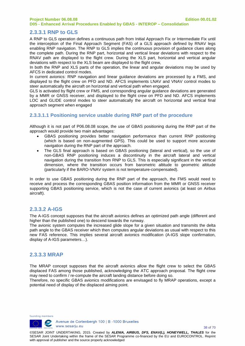
Project Number 06.08.08 Edition 00.01.02 D05 - Enhanced Arrival Procedures Enabled by GBAS - INTEROP – Consolidation
38 of 70 ©SESAR JOINT UNDERTAKING, 2015. Created by ALENIA, AIRBUS, DFS, ENAV(L), HONEYWELL, THALES for the SESAR Joint Undertaking within the frame of the SESAR Programme co-financed by the EU and EUROCONTROL. Reprint with approval of publisher and the source properly acknowledged
2.3.3.1 RNP to GLS A RNP to GLS operation defines a continuous path from Initial Approach Fix or Intermediate Fix until the interception of the Final Approach Segment (FAS) of a GLS approach defined by RNAV legs enabling RNP navigation. The RNP to GLS implies the continuous provision of guidance clues along the complete path. During the RNP part, horizontal and vertical linear deviations with respect to the RNAV path are displayed to the flight crew. During the XLS part, horizontal and vertical angular deviations with respect to the XLS beam are displayed to the flight crew, In both the RNP and XLS parts of the operation, the linear and angular deviations may be used by AFCS in dedicated control modes. In current avionics: RNP navigation and linear guidance deviations are processed by a FMS, and displayed to the flight crew on PFD and ND. AFCS implements LNAV and VNAV control modes to steer automatically the aircraft on horizontal and vertical path when engaged. GLS is activated by flight crew or FMS, and corresponding angular guidance deviations are generated by a MMR or GNSS receiver, and displayed to the flight crew on PFD and ND. AFCS implements LOC and GLIDE control modes to steer automatically the aircraft on horizontal and vertical final approach segment when engaged
2.3.3.1.1 Positioning service usable during RNP part of the procedure Although it is not part of P06.08.08 scope, the use of GBAS positioning during the RNP part of the approach would provide two main advantages:
• GBAS positioning provides better navigation performance than current RNP positioning (which is based on non-augmented GPS). This could be used to support more accurate navigation during the RNP part of the approach.
• The GLS final approach is based on GBAS positioning (lateral and vertical), so the use of non-GBAS RNP positioning induces a discontinuity in the aircraft lateral and vertical navigation during the transition from RNP to GLS. This is especially significant in the vertical dimension, where the transition occurs from barometric altitude to geometric altitude (particularly if the BARO-VNAV system is not temperature-compensated).
In order to use GBAS positioning during the RNP part of the approach, the FMS would need to receive and process the corresponding GBAS position information from the MMR or GNSS receiver supporting GBAS positioning service, which is not the case of current avionics (at least on Airbus aircraft).
2.3.3.2 A-IGS The A-IGS concept supposes that the aircraft avionics defines an optimized path angle (different and higher than the published one) to descend towards the runway. The avionic system computes the increased glide slope for a given situation and transmits the delta path angle to the GBAS receiver which then computes angular deviations as usual with respect to this new FAS reference. This implies several aircraft avionics modification (A-IGS slope confirmation, display of A-IGS parameters…).
2.3.3.3 MRAP The MRAP concept supposes that the aircraft avionics allow the flight crew to select the GBAS displaced FAS among those published, acknowledging the ATC approach proposal. The flight crew may need to confirm / re-compute the aircraft landing distance before doing so. Therefore, no specific GBAS avionics modifications are envisaged to fly MRAP operations, except a potential need of display of the displaced aiming point.

Project Number 06.08.08 Edition 00.01.02 D05 - Enhanced Arrival Procedures Enabled by GBAS - INTEROP – Consolidation
39 of 70 ©SESAR JOINT UNDERTAKING, 2015. Created by ALENIA, AIRBUS, DFS, ENAV(L), HONEYWELL, THALES for the SESAR Joint Undertaking within the frame of the SESAR Programme co-financed by the EU and EUROCONTROL. Reprint with approval of publisher and the source properly acknowledged
2.3.3.4 IGS The IGS concept is based on a published GLS approach procedure that the flight crew can select as usual. In addition, to ensure the flyability of the IGS operation during the landing phase (flare manoeuvre), two types of modifications are envisaged: - aural and visual aids to manage correctly the flare manoeuvre manually (AP off), - control laws adaptation and tuning to avoid hard landing when flown automatically (AP on, i.e. automatic landing).
2.3.3.5 DS Double Slope approaches are flown using VNAV managed vertical mode coupled with LOC managed lateral mode on the first steep segment, then G/S | LOC managed modes on the final conventional segment. This solution does not require any GBAS avionics modification, but according to aircraft types and FMS designs, might in some cases require to adapt the VNAV mode, as not being fully optimised to fly such approaches

Project Number 06.08.08 Edition 00.01.02 D05 - Enhanced Arrival Procedures Enabled by GBAS - INTEROP – Consolidation
40 of 70 ©SESAR JOINT UNDERTAKING, 2015. Created by ALENIA, AIRBUS, DFS, ENAV(L), HONEYWELL, THALES for the SESAR Joint Undertaking within the frame of the SESAR Programme co-financed by the EU and EUROCONTROL. Reprint with approval of publisher and the source properly acknowledged
3 Interoperability Requirements
3.1 Transversal Requirements This section describes the common/interoperability requirements that shall be applied to ground subsystem and airborne subsystem to support the different considered advanced operational concepts. An approach phase is generally composed of an initial approach phase where turns may occur, followed by an intermediate approach with trajectory aligned to the runway before the final approach performed along a straight in path descending towards a runway end. The approach takes place in terminal manoeuvring area and is generally controlled by the ATC of the destination airport. The foreseen concepts can be divided into three categories:
• The “curved RNP transition to GLS precision approach” relates to the initial and intermediate approach phase until the final interception of the final straight in approach segment towards the runway. The arrival phase until interception of final approach segment is supported by RNP navigation, with dedicated navigation and guidance requirements; while final approach phase is supported by XLS navigation along a straight in path with other dedicated navigation and guidance requirements. The curved RNP to GLS precision approach involves the definition of the RNP trajectory before final approach segment, and the transition between RNP and XLS navigation. The requirements for RNP navigation are further defined in ICAO Document 9613 – Performance Based Navigation Manual (PBN),
• The “Increased Glide Slope”, “Adaptive Increased Glide Slope”, “Multiple Runway Aiming
Points / Displaced Threshold” concepts relate to the final approach phase, and involve the definition of the final approach segment. The requirements for FAS definition are further defined in ICAO Annex 10.3
• “Double Slope” concept takes benefit of a first increased glide slope segment, joining a final
conventional glide slope segment down to the runway. The requirements for both RNP and GLS procedure/route design are described in ICAO Doc 8168: “Construction of Visual and Instrument Flight Procedures”.
3.1.1 Requirements for Final approach segment definition The final straight in segment of a GLS approach from which angular guidance deviations are computed is defined by a FAS data block. The FAS data block is the set of parameters identifying a single precision approach. It defines the associated approach path. The ground subsystem transmits one or several FAS in type 4 message, which contain one or more sets of FAS data. A FAS data block is organised as follow (from DO-229D “MINIMUM OPERATIONAL PERFORMANCE STANDARDS FOR GLOBAL POSITIONING SYSTEM/WIDE AREA AUGMENTATION SYSTEM AIRBORNE EQUIPMENT) [42]. 3 The latest release of DO246 document (version D), include the possibility to broadcast terminal area paths (TAPs) to provide precision guidance to aircraft maneuvering in the terminal area during initial and intermediate approach. But this possibility has not been retained by ICAO in SARPS Annex 10, and is not considered in the frame of this study.

Project Number 06.08.08 Edition 00.01.02 D05 - Enhanced Arrival Procedures Enabled by GBAS - INTEROP – Consolidation
41 of 70 ©SESAR JOINT UNDERTAKING, 2015. Created by ALENIA, AIRBUS, DFS, ENAV(L), HONEYWELL, THALES for the SESAR Joint Undertaking within the frame of the SESAR Programme co-financed by the EU and EUROCONTROL. Reprint with approval of publisher and the source properly acknowledged
Data content Bits used Range of values Resolution Operation type 4 0 to 15 1 SBAS provider ID 4 0 to 15 1 Airport ID 32 — — Runway number 6 0 to 36 1 Runway letter 2 — — Approach performance designator
3 0 to 7 1
Route indicator 5 — — Reference path data selector 8 0 to 48 1 Reference path identifier 32 — — LTP/FTP latitude 32 ±90.0° 0.0005 arcsec LTP/FTP longitude 32 ±180.0° 0.0005 arcsec LTP/FTP height 16 –512.0 to 6 041.5 m 0.1 m ΔFPAP latitude 24 ±1.0° 0.0005 arcsec ΔFPAP longitude 24 ±1.0° 0.0005 arcsec Approach TCH (Note 2) 15 0 to 1 638.35 m or
0 to 3 276.7 ft 0.05 m or 0.1 ft
Approach TCH units selector 1 — — GPA 16 0 to 90.0° 0.01° Course width (Note 1) 8 80 to 143.75 m 0.25 m Δ-Length offset 8 0 to 2 032 m 8 m Final approach segment CRC 32 — — Note 1.— When the runway number is set to 0, then the course width field is ignored and the course width is 38 metres. Note 2.— Information can be provided in either feet or metres as indicated by the approach TCH unit selector.
Table B-66. Final approach segment (FAS) data block [10] The FAS path is a line in space defined by the landing threshold point/fictitious threshold point (LTP/FTP), flight path alignment point (FPAP), threshold crossing height (TCH) and glide path angle (GPA). The local level plane for the approach is a plane perpendicular to the local vertical passing through the LTP/FTP (i.e. tangent to the ellipsoid at the LTP/FTP). Local vertical for the approach is normal to the WGS-84 ellipsoid at the LTP/FTP. The glide path intercept point (GPIP) is where the final approach path intercepts the local level plane. Geometrical relationships between LTP/FTP, FPAP, TCH, GPA, and GPIP defining the straight in approach segment in WGS84 coordinates are depicted on the figure below.

Project Number 06.08.08 Edition 00.01.02 D05 - Enhanced Arrival Procedures Enabled by GBAS - INTEROP – Consolidation
42 of 70 ©SESAR JOINT UNDERTAKING, 2015. Created by ALENIA, AIRBUS, DFS, ENAV(L), HONEYWELL, THALES for the SESAR Joint Undertaking within the frame of the SESAR Programme co-financed by the EU and EUROCONTROL. Reprint with approval of publisher and the source properly acknowledged
Figure 22 Geometrical relationships between LTP/FTP, FPAP, TCH, GPA, GPIP [10] Different FAS on the same runway shall be defined to support IGS or MRAP. DS should ideally rely on existing FAS (that describes conventional glide path), although a dedicated procedure shall be defined for each DS procedure. A-IGS fully relies on conventional published approaches and does not require any coding/publication. IGS concept is sustained by the definition of several approach segments leading to same GPIP with the same orientation but different glide path angle. This means that for the different FAS supporting these approaches segments, same LTP/FTP is used, same FPAP is used, and TCH/tan(gpa) is constant. MRAP concept may be sustained in two ways:
• by the definition of an alternate fictitious LTP/FTP, at a certain distance D of LTP/FTP. To provide similar angular lateral deviation at same height above terrain, ∆FPAP=D is considered; then, DLength (distance between FPAP and pseudo LOC station) is increased of the same D distance. Same or higher GPA, and same TCH should be considered.
• By the definition of a higher TCH over LTP/FTP, with same or higher GPA; in such case, the angular lateral deviation at same height above terrain differ depending on the chosen approach.
Following requirements shall be considered: [REQ] Identifier REQ-06.08.08-INTEROP-GENR.0005 Requirement The same GPIP shall be used when defining several FAS towards the same
runway aiming point with different path angles. Title Multiple FAS definition for IGS concept Status <In Progress> Rationale Support of IGS Category <Interoperability> Validation Method <Real Time Simulation>

Project Number 06.08.08 Edition 00.01.02 D05 - Enhanced Arrival Procedures Enabled by GBAS - INTEROP – Consolidation
43 of 70 ©SESAR JOINT UNDERTAKING, 2015. Created by ALENIA, AIRBUS, DFS, ENAV(L), HONEYWELL, THALES for the SESAR Joint Undertaking within the frame of the SESAR Programme co-financed by the EU and EUROCONTROL. Reprint with approval of publisher and the source properly acknowledged
Verification Method N/A [REQ Trace] Relationship Linked Element Type Identifier Compliance <SATISFIES> <ATMS Requirement> REQ-06.08.08-OSED-ACFT.0200 <Partial> <APPLIES_TO> <Operational Focus Area> OFA01.03.01 N/A <ALLOCATED_TO> <Functional block> Aeronautical Data Collection N/A [REQ] Identifier REQ-06.08.08-INTEROP-GENR.0006 Requirement Each FAS linked to a runway aiming point shall be published in AIP and
defined as GBAS instrument approach procedure. Title Publication of Instrument Approach Procedures for each FAS Status <In Progress> Rationale Support of GBAS enhanced arrival procedures Category <Interoperability> Validation Method <Real Time Simulation> Verification Method N/A [REQ Trace] Relationship Linked Element Type Identifier Compliance <SATISFIES> <ATMS Requirement> REQ-06.08.08-OSED-ACFT.0200 <Partial> <APPLIES_TO> <Operational Focus Area> OFA01.03.01 N/A <ALLOCATED_TO> <Functional block> Aeronautical Data Collection N/A [REQ] Identifier REQ-06.08.08-INTEROP-GENR.0007 Requirement Each PUBLISHED RAP instrument approach procedure shall have a GPIP
aligned with LTP/FTP and FPAP Title Multiple FAS definition for MRAP Status <In Progress> Rationale Support of MRAP Category <Interoperability> Validation Method <Real Time Simulation> Verification Method N/A [REQ Trace] Relationship Linked Element Type Identifier Compliance <SATISFIES> <ATMS Requirement> REQ-06.08.08-OSED-ATCO.0600 <Partial> <SATISFIES> <ATMS Requirement> REQ-06.08.08-OSED-FCRW.0240 <Partial> <APPLIES_TO> <Operational Focus Area> OFA01.03.01 N/A <ALLOCATED_TO> <Functional block> Aeronautical Data Collection N/A [REQ] Identifier REQ-06.08.08-INTEROP-GENR.0008 Requirement The Path angle of a FAS arriving to a given aiming point shall be equal to or
greater than the path angle of a FAS arriving to any aiming point closer from the starting runway end.
Title Increasing path angle for multiple FAS supporting MRAP concept Status <In Progress> Rationale Support of MRAP Category <Interoperability> Validation Method <Real Time Simulation> Verification Method N/A [REQ Trace] Relationship Linked Element Type Identifier Compliance <SATISFIES> <ATMS Requirement> REQ-06.08.08-OSED-ATCO.0600 <Partial>
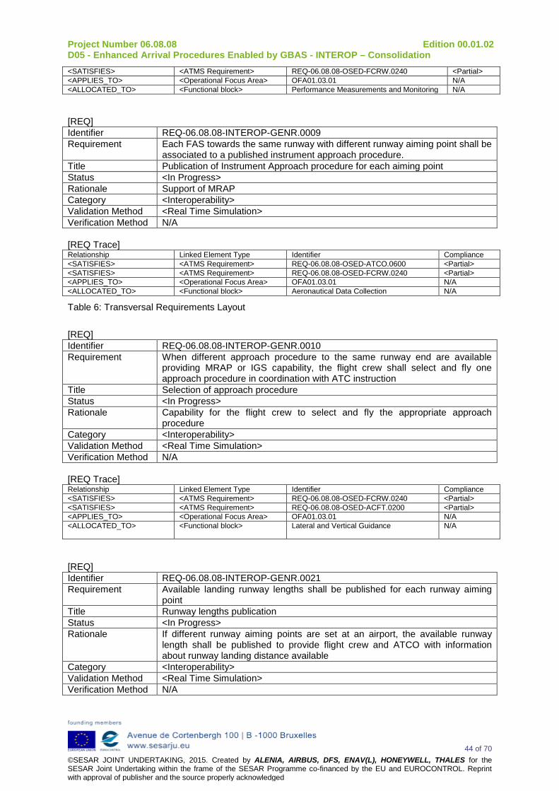
Project Number 06.08.08 Edition 00.01.02 D05 - Enhanced Arrival Procedures Enabled by GBAS - INTEROP – Consolidation
44 of 70 ©SESAR JOINT UNDERTAKING, 2015. Created by ALENIA, AIRBUS, DFS, ENAV(L), HONEYWELL, THALES for the SESAR Joint Undertaking within the frame of the SESAR Programme co-financed by the EU and EUROCONTROL. Reprint with approval of publisher and the source properly acknowledged
<SATISFIES> <ATMS Requirement> REQ-06.08.08-OSED-FCRW.0240 <Partial> <APPLIES_TO> <Operational Focus Area> OFA01.03.01 N/A <ALLOCATED_TO> <Functional block> Performance Measurements and Monitoring N/A [REQ] Identifier REQ-06.08.08-INTEROP-GENR.0009 Requirement Each FAS towards the same runway with different runway aiming point shall be
associated to a published instrument approach procedure. Title Publication of Instrument Approach procedure for each aiming point Status <In Progress> Rationale Support of MRAP Category <Interoperability> Validation Method <Real Time Simulation> Verification Method N/A [REQ Trace] Relationship Linked Element Type Identifier Compliance <SATISFIES> <ATMS Requirement> REQ-06.08.08-OSED-ATCO.0600 <Partial> <SATISFIES> <ATMS Requirement> REQ-06.08.08-OSED-FCRW.0240 <Partial> <APPLIES_TO> <Operational Focus Area> OFA01.03.01 N/A <ALLOCATED_TO> <Functional block> Aeronautical Data Collection N/A
Table 6: Transversal Requirements Layout
[REQ] Identifier REQ-06.08.08-INTEROP-GENR.0010 Requirement When different approach procedure to the same runway end are available
providing MRAP or IGS capability, the flight crew shall select and fly one approach procedure in coordination with ATC instruction
Title Selection of approach procedure Status <In Progress> Rationale Capability for the flight crew to select and fly the appropriate approach
procedure Category <Interoperability> Validation Method <Real Time Simulation> Verification Method N/A [REQ Trace] Relationship Linked Element Type Identifier Compliance <SATISFIES> <ATMS Requirement> REQ-06.08.08-OSED-FCRW.0240 <Partial> <SATISFIES> <ATMS Requirement> REQ-06.08.08-OSED-ACFT.0200 <Partial> <APPLIES_TO> <Operational Focus Area> OFA01.03.01 N/A <ALLOCATED_TO> <Functional block> Lateral and Vertical Guidance
N/A
[REQ] Identifier REQ-06.08.08-INTEROP-GENR.0021 Requirement Available landing runway lengths shall be published for each runway aiming
point Title Runway lengths publication Status <In Progress> Rationale If different runway aiming points are set at an airport, the available runway
length shall be published to provide flight crew and ATCO with information about runway landing distance available
Category <Interoperability> Validation Method <Real Time Simulation> Verification Method N/A

Project Number 06.08.08 Edition 00.01.02 D05 - Enhanced Arrival Procedures Enabled by GBAS - INTEROP – Consolidation
45 of 70 ©SESAR JOINT UNDERTAKING, 2015. Created by ALENIA, AIRBUS, DFS, ENAV(L), HONEYWELL, THALES for the SESAR Joint Undertaking within the frame of the SESAR Programme co-financed by the EU and EUROCONTROL. Reprint with approval of publisher and the source properly acknowledged
[REQ Trace] Relationship Linked Element Type Identifier Compliance <SATISFIES> <ATMS Requirement> REQ-06.08.08-OSED-ATCO.0591 <Partial> <APPLIES_TO> <Operational Focus Area> OFA01.03.01 N/A <ALLOCATED_TO> <Functional block> Aeronautical Data Collection N/A
[REQ] Identifier REQ-06.08.08-INTEROP-GENR.0022 Requirement The GBAS FAS shall only cover the final conventional segment of the DS
procedure Title GBAS landing system support for DS Status <In Progress> Rationale Current capability supports only one GBAS FAS for double slope procedures Category <Interoperability> Validation Method <Real Time Simulation> Verification Method N/A [REQ Trace] Relationship Linked Element Type Identifier Compliance <SATISFIES> <ATMS Requirement> REQ-06.08.08-OSED-ACFT.0380 <Partial> <APPLIES_TO> <Operational Focus Area> OFA01.03.01 N/A <ALLOCATED_TO> <Functional block> Lateral and Vertical Guidance
N/A
3.1.2 Requirements for “transition between RNP part and final approach segment”
RNP-GLS transitions present some technical challenges derived from the following facts:
• Current NavDB standards and FMS design do not generally support the use of FPA constraints before the FAF.
• CDA function is not yet widely supported.
• Guidance modes used for GLS approaches are not designed to follow a planned trajectory to intercept the GLS axis, so they generally make the aircraft deviate from the prescribed interception trajectory.
• The positioning means used in the RNP part of the approach (hybrid GPS/INS + barometric altitude) are different from those used in the GLS part of the approach (GBAS 3D position), potentially leading to LOC and/or G/S capture issues.
These facts lead to four main technical challenges:
1. Need to update NavDB and FMS standards to support FPA constraints before the FAF and/or CDA function.
2. Need to ensure the respect of RNP lateral and vertical performance requirements before the aircraft is established on the GLS beam. The following figures illustrate the aforementioned challenge:

Project Number 06.08.08 Edition 00.01.02 D05 - Enhanced Arrival Procedures Enabled by GBAS - INTEROP – Consolidation
46 of 70 ©SESAR JOINT UNDERTAKING, 2015. Created by ALENIA, AIRBUS, DFS, ENAV(L), HONEYWELL, THALES for the SESAR Joint Undertaking within the frame of the SESAR Programme co-financed by the EU and EUROCONTROL. Reprint with approval of publisher and the source properly acknowledged
Figure: Respect of RNP lateral requirements
Figure: Respect of BARO-VNAV vertical requirements
3. Need to ensure a timely capture of GLS LOC and G/S axes considering the expected navigation performance (including non-ISA temperature effect). The following figures illustrate the aforementioned challenge:

Project Number 06.08.08 Edition 00.01.02 D05 - Enhanced Arrival Procedures Enabled by GBAS - INTEROP – Consolidation
47 of 70 ©SESAR JOINT UNDERTAKING, 2015. Created by ALENIA, AIRBUS, DFS, ENAV(L), HONEYWELL, THALES for the SESAR Joint Undertaking within the frame of the SESAR Programme co-financed by the EU and EUROCONTROL. Reprint with approval of publisher and the source properly acknowledged
Figure: LOC capture issues
4. Advanced/improved avionics functionality to ensure that the aircraft capture GLS glideslope from bellow within localizer full scale deflection for a defined range of expected conditions (temperature, lateral navigation errors, vertical navigation errors, etc).
Figure: G/S capture issues
Note: Non-ISA temperature effect is included in the BARO-VNAV trajectory error envelope Since no change in aircraft design is expected in the short term to address challenges 2) and 3), these challenges lead to the need of defining procedure design limitations, temperature limitations and specific operational procedures for the appropriate deployment of RNP-GLS operations4. As a result, the requirements for transition between RNP part and final approach are the following, the “status” of requirements is considered Deleted due to the fact that have moved into 06 08 08 D04 Enhanced Arrival Procedures Enabled by GBAS - SPR - Consolidation (RNP to xLS) - 0.4 : [REQ] Identifier REQ-06.08.08-INTEROP-GENR.0011 Requirement RNP/GLS operations should consider either a CDO or a slope-limited segment
before FAP for before the glide capture Title Support of CDO before glide capture Status <Deleted> Rationale RNP/GLS concept should be developed considering latest ATM improvements
about vertical profile Category <Interoperability> Validation Method <Real Time Simulation>
4 Glide slope capture issues in non-standard atmosphere is theoretically also applicable to DS, at transition between the first steeper slope and the conventional slope
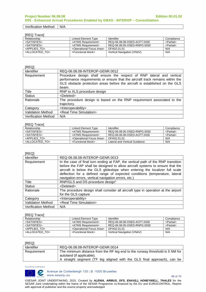
Project Number 06.08.08 Edition 00.01.02 D05 - Enhanced Arrival Procedures Enabled by GBAS - INTEROP – Consolidation
48 of 70 ©SESAR JOINT UNDERTAKING, 2015. Created by ALENIA, AIRBUS, DFS, ENAV(L), HONEYWELL, THALES for the SESAR Joint Undertaking within the frame of the SESAR Programme co-financed by the EU and EUROCONTROL. Reprint with approval of publisher and the source properly acknowledged
Verification Method N/A [REQ Trace] Relationship Linked Element Type Identifier Compliance <SATISFIES> <ATMS Requirement> REQ-06.08.08-OSED-ACFT.0430 <Partial> <SATISFIES> <ATMS Requirement> REQ-06.08.05-OSED-RNPG.0030 <Partial> <APPLIES_TO> <Operational Focus Area> OFA02.01.01 N/A <ALLOCATED_TO> <Functional block> Vertical Navigation (VNAV)
N/A
[REQ] Identifier REQ-06.08.08-INTEROP-GENR.0012 Requirement Procedure design shall ensure the respect of RNP lateral and vertical
performance requirements or ensure that the aircraft track remains within the GLS obstacle protection areas before the aircraft is established on the GLS beam.
Title RNP to XLS procedure design Status <Deleted> Rationale The procedure design is based on the RNP requirement associated to the
trajectory. Category <Interoperability> Validation Method <Real Time Simulation> Verification Method N/A [REQ Trace] Relationship Linked Element Type Identifier Compliance <SATISFIES> <ATMS Requirement> REQ-06.08.05-OSED-RNPG.0030 <Partial> <SATISFIES> <ATMS Requirement> REQ-06.08.08-OSED-ACFT.0430 <Partial> <APPLIES_TO> <Operational Focus Area> OFA02.01.01 N/A <ALLOCATED_TO> <Functional block> Lateral and Vertical Guidance N/A [REQ] Identifier REQ-06.08.08-INTEROP-GENR.0013 Requirement In the case of final turn ending at FAP, the vertical path of the RNP transition
before the FAP shall be designed to allow aircraft systems to ensure that the aircraft is below the GLS glideslope when entering the localizer full scale deflection for a defined range of expected conditions (temperature, lateral navigation errors, vertical navigation errors, etc.)
Title RNP/GLS and DS procedure design" Status <Deleted> Rationale The procedure design shall consider all aircraft type in operation at the airport
for the GLS capture Category <Interoperability> Validation Method <Real Time Simulation> Verification Method N/A [REQ Trace] Relationship Linked Element Type Identifier Compliance <SATISFIES> <ATMS Requirement> REQ-06.08.08-OSED-ACFT.0430 <Partial> <SATISFIES> <ATMS Requirement> REQ-06.08.05-OSED-RNPG.0030 <Partial> <APPLIES_TO> <Operational Focus Area> OFA02.01.01 N/A <ALLOCATED_TO> <Functional block> Vertical Navigation (VNAV)
N/A
[REQ] Identifier REQ-06.08.08-INTEROP-GENR.0014 Requirement The minimum distance from the RF leg end to the runway threshold is 5 NM for
autoland (if applicable). A straight segment (TF leg aligned with the GLS final approach), can be
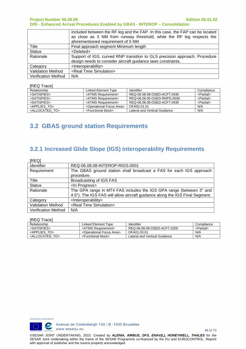
Project Number 06.08.08 Edition 00.01.02 D05 - Enhanced Arrival Procedures Enabled by GBAS - INTEROP – Consolidation
49 of 70 ©SESAR JOINT UNDERTAKING, 2015. Created by ALENIA, AIRBUS, DFS, ENAV(L), HONEYWELL, THALES for the SESAR Joint Undertaking within the frame of the SESAR Programme co-financed by the EU and EUROCONTROL. Reprint with approval of publisher and the source properly acknowledged
included between the RF leg and the FAP. In this case, the FAP can be located as close as 3 NM from runway threshold, while the RF leg respects the aforementioned requirement of 5 NM
Title Final approach segment Minimum length Status <Deleted> Rationale Support of IGS, curved RNP transition to GLS precision approach. Procedure
design needs to consider aircraft guidance laws constraints. Category <Interoperability> Validation Method <Real Time Simulation> Verification Method N/A [REQ Trace] Relationship Linked Element Type Identifier Compliance <SATISFIES> <ATMS Requirement> REQ-06.08.08-OSED-ACFT.0430 <Partial> <SATISFIES> <ATMS Requirement> REQ-06.08.05-OSED-RNPG.0030 <Partial> <SATISFIES> <ATMS Requirement> REQ-06.08.08-OSED-ACFT.0430 <Partial> <APPLIES_TO> <Operational Focus Area> OFA02.01.01 N/A <ALLOCATED_TO> <Functional block> Lateral and Vertical Guidance N/A
3.2 GBAS ground station Requirements
3.2.1 Increased Glide Slope (IGS) interoperability Requirements [REQ] Identifier REQ-06.08.08-INTEROP-RIGS.0001 Requirement The GBAS ground station shall broadcast a FAS for each IGS approach
procedure. Title Broadcasting of IGS FAS Status <In Progress> Rationale The GPA range in MT4 FAS includes the IGS GPA range (between 3° and
4.5°). The IGS FAS will allow aircraft guidance along the IGS Final Segment. Category <Interoperability> Validation Method <Real Time Simulation> Verification Method N/A [REQ Trace] Relationship Linked Element Type Identifier Compliance <SATISFIES> <ATMS Requirement> REQ-06.08.08-OSED-ACFT.0200 <Partial> <APPLIES_TO> <Operational Focus Area> OFA01.03.01 N/A <ALLOCATED_TO> <Functional block> Lateral and Vertical Guidance N/A

Project Number 06.08.08 Edition 00.01.02 D05 - Enhanced Arrival Procedures Enabled by GBAS - INTEROP – Consolidation
50 of 70 ©SESAR JOINT UNDERTAKING, 2015. Created by ALENIA, AIRBUS, DFS, ENAV(L), HONEYWELL, THALES for the SESAR Joint Undertaking within the frame of the SESAR Programme co-financed by the EU and EUROCONTROL. Reprint with approval of publisher and the source properly acknowledged
[REQ] Identifier REQ-06.08.08-INTEROP-RIGS.0003 Requirement The sub systems of GBAS ground station shall ensure that each broadcast
RPDS is associated with only one FAS for a given frequency Title GBAS Channel Assignment Status <In Progress> Rationale The RPDS assignments for GBAS installations that share the same
frequency shall be carefully coordinated to guarantee that each GBAS channel identifies one and only one approach
Category <Interoperability> Validation Method <Real Time Simulation> Verification Method N/A [REQ Trace] Relationship Linked Element Type Identifier Compliance <SATISFIES> <ATMS Requirement> REQ-06.08.08-OSED-ACFT.0200 <Partial> <APPLIES_TO> <Operational Focus Area> OFA01.03.01 N/A <ALLOCATED_TO> <Functional block> Lateral and Vertical Guidance N/A
3.2.2 Adaptive Increased Glide Slope (A-IGS) interoperability Requirements
[REQ] Identifier REQ-06.08.08-INTEROP-AIGS.0001 Requirement The GBAS ground station shall broadcast a FAS to be used as baseline for
A-IGS approaches. Title Broadcasting of A-IGS baseline FAS Status <In Progress> Rationale The A-IGS avionics will compute angular deviations based on an increased
path angle with respect to the selected baseline FAS. Category <Interoperability> Validation Method <Real Time Simulation> Verification Method N/A [REQ Trace] Relationship Linked Element Type Identifier Compliance <SATISFIES> <ATMS Requirement> REQ-06.08.08-OSED-ACFT.0270 <Partial> <APPLIES_TO> <Operational Focus Area> OFA02.01.01 N/A <APPLIES_TO> <Operational Focus Area> OFA01.03.01 N/A <ALLOCATED_TO> <Functional block> N/A N/A
3.2.3 Multiple Runway Aiming Point (MRAP) interoperability Requirements
[REQ] Identifier REQ-06.08.08-INTEROP-MRAP.0001 Requirement The GBAS ground station shall broadcast a different FAS for each runway
aiming point. Title Runway threshold displacement Status <In Progress> Rationale The GBAS system provides the capability to provide a revised precision
approach to the displaced threshold (see DO245A Appendix G10)

Project Number 06.08.08 Edition 00.01.02 D05 - Enhanced Arrival Procedures Enabled by GBAS - INTEROP – Consolidation
51 of 70 ©SESAR JOINT UNDERTAKING, 2015. Created by ALENIA, AIRBUS, DFS, ENAV(L), HONEYWELL, THALES for the SESAR Joint Undertaking within the frame of the SESAR Programme co-financed by the EU and EUROCONTROL. Reprint with approval of publisher and the source properly acknowledged
Category <Interoperability> Validation Method <Real Time Simulation> Verification Method N/A [REQ Trace] Relationship Linked Element Type Identifier Compliance <SATISFIES> <ATMS Requirement> REQ-06.08.08-OSED-FCRW.0240 <Partial> <APPLIES_TO> <Operational Focus Area> OFA01.03.01 N/A <ALLOCATED_TO> <Functional block> Lateral and Vertical Guidance N/A [REQ] Identifier REQ-06.08.08-INTEROP-MRAP.0002 Requirement GBAS ground station shall broadcast FAS parameters (a set of combination of
different glide slopes and different aiming points along the runway)allowing to combine both MRAP and IGS operations
Title Runway threshold displacement and increased glide path Status <In Progress> Rationale This requirement is intended to support the combined concept Increased glide
slope + displaced thresholds (see OSED 2.2.6.1) in order to achieve the highest efficiency.
Category <Interoperability> Validation Method <Real Time Simulation> Verification Method N/A [REQ Trace] Relationship Linked Element Type Identifier Compliance <SATISFIES> <ATMS Requirement> REQ-06.08.08-OSED-ATCO.0600 <Partial> <SATISFIES> <ATMS Requirement> REQ-06.08.08-OSED-FCRW.0240 <Partial> <APPLIES_TO> <Operational Focus Area> OFA01.03.01 N/A <ALLOCATED_TO> <Functional block> Lateral and Vertical Guidance N/A [REQ] Identifier REQ-06.08.08-INTEROP-MRAP.0003 Requirement The decision height associated to each displaced threshold should be
reassessed considering the available visual aids. Title Multiple Runway Aiming Point minima Status <In Progress> Rationale Minima might increase due to the lack of visual aids (see DO245A Appendix
G10) Category <Interoperability> Validation Method <Real Time Simulation> Verification Method N/A [REQ Trace] Relationship Linked Element Type Identifier Compliance <SATISFIES> <ATMS Requirement> REQ-06.08.08-OSED-FCRW.0240 <Partial> <APPLIES_TO> <Operational Focus Area> OFA01.03.01 N/A <ALLOCATED_TO> <Functional block> Vertical navigation N/A [REQ] Identifier REQ-06.08.08-INTEROP-MRAP.0004 Requirement The sub systems of GBAS ground station shall ensure that each broadcast
RPDS is associated with only one FAS for a given frequency Title GBAS Channel Assignment Status <In Progress> Rationale The RPDS assignments for GBAS installations that share the same frequency
shall be carefully coordinated to guarantee that each GBAS channel identifies one and only one approach
Category <Interoperability>

Project Number 06.08.08 Edition 00.01.02 D05 - Enhanced Arrival Procedures Enabled by GBAS - INTEROP – Consolidation
52 of 70 ©SESAR JOINT UNDERTAKING, 2015. Created by ALENIA, AIRBUS, DFS, ENAV(L), HONEYWELL, THALES for the SESAR Joint Undertaking within the frame of the SESAR Programme co-financed by the EU and EUROCONTROL. Reprint with approval of publisher and the source properly acknowledged
Validation Method <Real Time Simulation> Verification Method N/A [REQ Trace] Relationship Linked Element Type Identifier Compliance <SATISFIES> <ATMS Requirement> REQ-06.08.08-OSED-FCRW.0240 <Partial> <APPLIES_TO> <Operational Focus Area> OFA01.03.01 N/A <ALLOCATED_TO> <Functional block> Vertical navigation N/A
3.3 Aircraft avionics Requirements This section describes the requirements that shall be applied to airborne subsystem to support the different considered advanced operational concepts. To implement the curved RNP to GLS precision approach concept, the initial/intermediate approach where the turns occur is supported by RNP navigation application defined in the ICAO PBN manual. The final part of the approach is implemented by GBAS concept, considering some variations onto the design of FAS.

Project Number 06.08.08 Edition 00.01.02 D05 - Enhanced Arrival Procedures Enabled by GBAS - INTEROP – Consolidation
53 of 70 ©SESAR JOINT UNDERTAKING, 2015. Created by ALENIA, AIRBUS, DFS, ENAV(L), HONEYWELL, THALES for the SESAR Joint Undertaking within the frame of the SESAR Programme co-financed by the EU and EUROCONTROL. Reprint with approval of publisher and the source properly acknowledged
4 References
4.1 Applicable Documents [1] Template Toolbox 03.00.00
https://extranet.sesarju.eu/Programme%20Library/SESAR%20Template%20Toolbox.dot
[2] Requirements and V&V Guidelines 03.00.00 https://extranet.sesarju.eu/Programme%20Library/Requirements%20and%20VV%20Guidelines.doc
[3] Templates and Toolbox User Manual 03.00.00 https://extranet.sesarju.eu/Programme%20Library/Templates%20and%20Toolbox%20User%20Manual.doc
[4] EUROCONTROL ATM Lexicon https://extranet.eurocontrol.int/http://atmlexicon.eurocontrol.int/en/index.php/SESAR
4.2 Reference Documents [5] ED-78A Guidelines for Approval of the provision and use of Air Traffic Services supported by
Data Communications
[6] ICAO Document 9694
[7] WPB.01 Integrated Roadmap DS 14
[8] SESAR Definition phase D4, deliverable Task 2.6.2 DLT-0706-262-00-06
[9] EUROCAE ED-114A, Minimum Operational Performance Specification for Global Navigation Satellite Ground Based Augmentation System Ground Equipment to Support Category I Operations, March 2013
[10] ICAO SARPS, ICAO, Annex 10, Volume I, 6th Edition 2006, including Amendment 84 (GNSS SARPS)
[11] RTCA/DO-253C, Minimum Operational Performance Standards for GPS. Local Area Augmentation System Airborne Equipment
[12] RTCA/DO-246D, GNSS-Based Precision Approach Local Area Augmentation System (LAAS) Signal-In-Space Interface Control Document (ICD), December 16, 2008
[13] RTCA/DO-245A, Minimum Aviation System Performance Standards for the Local Area Augmentation System (LAAS), December 9, 2004
[14] EUROCAE ED-95, Minimum Aviation System Performance Specification for a Global Navigation Satellite System GBAS to support CAT-I
[15] EUROCAE ED-144, High-Level Performance Requirements for a Global Navigation Satellite System/Ground Based Augmentation System to Support Precision Approach Operations, October 2007
[16] M. Stanisak, M. Bitter, T. Feuerle, “Multiple Satellite Navigation Systems for the Ground Based Augmentation System” ION Technical Meeting 2014
[17] Schüttpelz, A., Lipp, A. and Birli, H., "GBAS with multiple VDB Antennas – Authentication Protocol Issues", revision 1, ICAO NSP/WGW/IP29, Revision 1, March 19-22, 2013
[18] Optimal Final Publishable Report 17/12/2008 http://www.optimal.isdefe.es/
[19] Mollwitz, V. ; Korn, B. “Steep segmented approaches for active noise abatement - A flyability study” Integrated Communications, Navigation and Surveillance Conference (ICNS), 2014
[20] http://www.lufthansagroup.com/en/press/news-releases/singleview/archive/2014/september/04/article/3168.html
[21] P06 08 08 – D07- Enhanced Arrival Procedures Enabled By GBAS - OSED Consolidation

Project Number 06.08.08 Edition 00.01.02 D05 - Enhanced Arrival Procedures Enabled by GBAS - INTEROP – Consolidation
54 of 70 ©SESAR JOINT UNDERTAKING, 2015. Created by ALENIA, AIRBUS, DFS, ENAV(L), HONEYWELL, THALES for the SESAR Joint Undertaking within the frame of the SESAR Programme co-financed by the EU and EUROCONTROL. Reprint with approval of publisher and the source properly acknowledged
[22] P06.02 – D108 Airport Validation Strategy Step 2 - 2014 Update
[23] P5.2 D51 - Validation Strategy for Concept Step 1
[24] P06.02 – D101 - Airport Detailed Operational Description - STEP 2 - 2014 Update, version 00.01.00
[25] P05.02 - D84 - DOD Report – STEP 1 - 2014 Update, version 00.01.01
[26] ICAO PBN Manual - ICAO Doc 9613
[27] EASA AMC 20-26
[28] EASA AMC 20-27
[29] FAA documents AC 20-138
[30] SESAR Release 3 Review 3 Report, 13 June 2014, Edition number 00.01.00
[31] Release 3 Close-Out Report, 17-07-2014, Edition number 01.00.00
[32] P06.08.08 D08 - Enhanced arrival procedures enabled by GBAS V2 VALP
[33] P06.08.05 D44 - GBAS Advanced Procedures Concept Validation Report for Displaced Thresholds for V2, Edition 00.01.00, December 2014
[34] P06.08.08 D09 - Enhanced arrival procedures enabled by GBAS – VALR V2
[35] P06 08 08 D15 - INTERIM Version - Enhanced Arrival Procedures Enabled by GBAS - OSED V2
[36] WP06.08.05 D55 Approach Procedures Charts and Path Terminators for RNP transition to GLS and Displaced Thresholds (Final version)
[37] WP06.08.05 D42 Concept of GBAS Advanced Operations Document (OSED- V3)
[38] WP06.08.05 D04 Operational Service and Environment Definition (OSED) Displaced Thresholds
[39] P09.49 D02 Step 1 - Consolidated functional airborne architecture
[40] P15.03.06 Ground Architecture and Airport Installation
[41] P15.03.07 D05 Ground Architecture and Airport Installation
[42] DO-229D- Minimum Operational Performance Standards for Global Positioning System/Satellite-Based Augmentation System Airborne Equipment
[43] FAA AC 90-105A, Appendix H - Approval Guidance for RNP Operations and Barometric Vertical Navigation in the U.S. National Airspace System and in Oceanic and Remote Continental Airspace
[44] P06.08.08 D11 - Enhanced arrival procedures enabled by GBAS – VALR V3 last iteration
[45] P06.08.08 D14 - INTERIM Version - Enhanced Arrival Procedures Enabled by GBAS - INTEROP Updating - V2
[46] SESAR P12.01.07 D22 Step1-3rd Iteration- Airport Technical Architecture Description
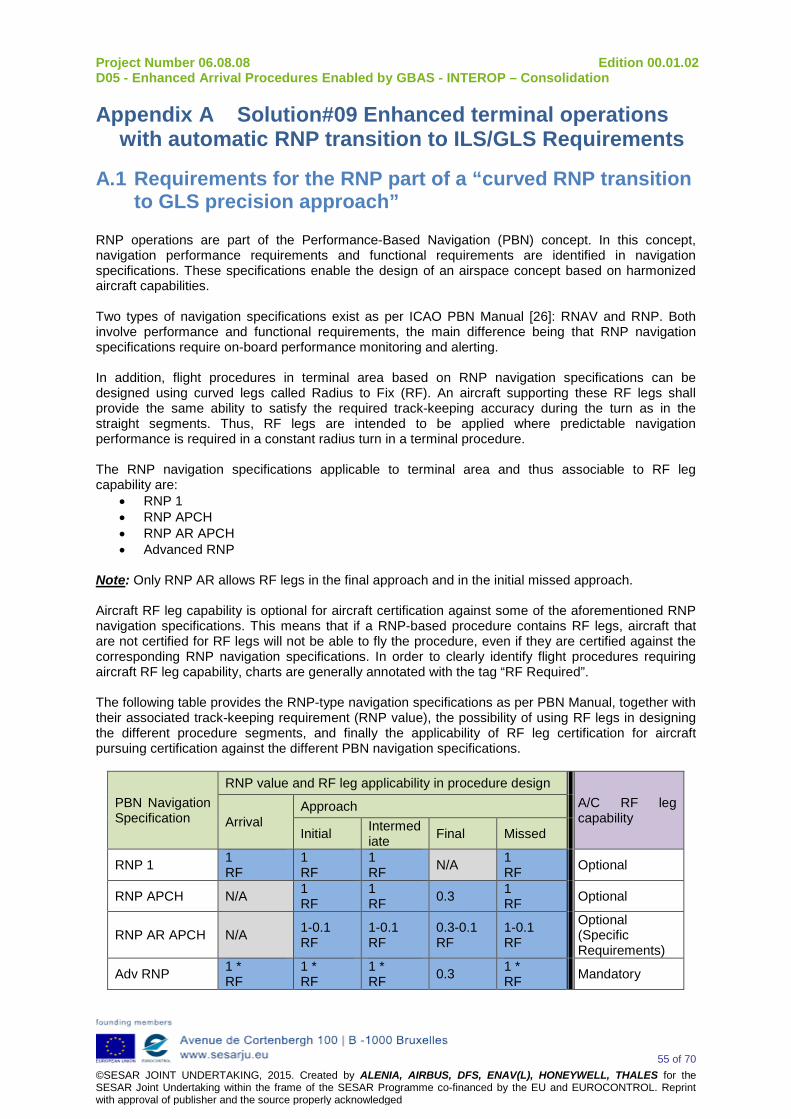
Project Number 06.08.08 Edition 00.01.02 D05 - Enhanced Arrival Procedures Enabled by GBAS - INTEROP – Consolidation
55 of 70 ©SESAR JOINT UNDERTAKING, 2015. Created by ALENIA, AIRBUS, DFS, ENAV(L), HONEYWELL, THALES for the SESAR Joint Undertaking within the frame of the SESAR Programme co-financed by the EU and EUROCONTROL. Reprint with approval of publisher and the source properly acknowledged
Appendix A Solution#09 Enhanced terminal operations with automatic RNP transition to ILS/GLS Requirements
A.1 Requirements for the RNP part of a “curved RNP transition to GLS precision approach”
RNP operations are part of the Performance-Based Navigation (PBN) concept. In this concept, navigation performance requirements and functional requirements are identified in navigation specifications. These specifications enable the design of an airspace concept based on harmonized aircraft capabilities. Two types of navigation specifications exist as per ICAO PBN Manual [26]: RNAV and RNP. Both involve performance and functional requirements, the main difference being that RNP navigation specifications require on-board performance monitoring and alerting. In addition, flight procedures in terminal area based on RNP navigation specifications can be designed using curved legs called Radius to Fix (RF). An aircraft supporting these RF legs shall provide the same ability to satisfy the required track-keeping accuracy during the turn as in the straight segments. Thus, RF legs are intended to be applied where predictable navigation performance is required in a constant radius turn in a terminal procedure. The RNP navigation specifications applicable to terminal area and thus associable to RF leg capability are:
• RNP 1 • RNP APCH • RNP AR APCH • Advanced RNP
Note: Only RNP AR allows RF legs in the final approach and in the initial missed approach. Aircraft RF leg capability is optional for aircraft certification against some of the aforementioned RNP navigation specifications. This means that if a RNP-based procedure contains RF legs, aircraft that are not certified for RF legs will not be able to fly the procedure, even if they are certified against the corresponding RNP navigation specifications. In order to clearly identify flight procedures requiring aircraft RF leg capability, charts are generally annotated with the tag “RF Required”. The following table provides the RNP-type navigation specifications as per PBN Manual, together with their associated track-keeping requirement (RNP value), the possibility of using RF legs in designing the different procedure segments, and finally the applicability of RF leg certification for aircraft pursuing certification against the different PBN navigation specifications.
PBN Navigation Specification
RNP value and RF leg applicability in procedure design A/C RF leg capability Arrival
Approach
Initial Intermediate Final Missed
RNP 1 1 RF
1 RF
1 RF N/A 1
RF Optional
RNP APCH N/A 1 RF
1 RF 0.3 1
RF Optional
RNP AR APCH N/A 1-0.1 RF
1-0.1 RF
0.3-0.1 RF
1-0.1 RF
Optional (Specific Requirements)
Adv RNP 1 * RF
1 * RF
1 * RF 0.3 1 *
RF Mandatory

Project Number 06.08.08 Edition 00.01.02 D05 - Enhanced Arrival Procedures Enabled by GBAS - INTEROP – Consolidation
56 of 70 ©SESAR JOINT UNDERTAKING, 2015. Created by ALENIA, AIRBUS, DFS, ENAV(L), HONEYWELL, THALES for the SESAR Joint Undertaking within the frame of the SESAR Programme co-financed by the EU and EUROCONTROL. Reprint with approval of publisher and the source properly acknowledged
Table: RNP value, RF leg applicability to procedure design and RF leg applicability to A/C certification [26] (*) Note: The default RNP value in TMA associated to Advanced RNP navigation specification is 1 NM. However, an optional feature called “RNP scalability” enables the use of RNP values down to 0.3 NM. In conclusion, RNP Navigation during initial and intermediate approach before connecting XLS navigation during the final approach can be designed according the RNP 1, RNP APCH, RNP AR and Advanced RNP specifications. The following requirements should be considered as transversal requirements for the implementation of the RNP part of a curved RNP transition to GLS precision approach: [REQ] Identifier REQ-06.08.08-INTEROP-GENR.0001 Requirement The RNP part of a Curved RNP to GLS Precision Approach shall be
implemented according to RNP 1 or Advanced RNP specifications (chapters 3 to 6 of section C of PBN manual Volume II), together with RF leg capability (provided in Appendix 1 to section C for RNP 1 and Advanced RNP)
Title PBN application supporting RNP part of a curved approach Status <Validated> Rationale Navigation specification able to support the RNP part of a curved RNP
transition to GLS precision approach Category <Interoperability> Validation Method <Real Time Simulation> Verification Method N/A [REQ Trace] Relationship Linked Element Type Identifier Compliance <SATISFIES> <ATMS Requirement> REQ-06.08.08-OSED-ACFT.0430 <Partial> <SATISFIES> <ATMS Requirement> REQ-06.08.05-OSED-RNPG.0030 <Partial> <SATISFIES> <ATMS Requirement> REQ-06.08.08-OSED-ACFT.0430 <Partial> <APPLIES_TO> <Operational Focus Area> OFA02.01.01 N/A <ALLOCATED_TO> <Functional block> Performance Measurements and
Monitoring N/A
[REQ] Identifier REQ-06.08.08-INTEROP-GENR.0002 Requirement AIP should clearly indicate the navigation application supporting the RNP part
of a curved RNP transition to GLS precision approach and required RF leg capability
Title Publication Status <Validated> Rationale The navigation specification and the required functionalities (e.g. RF) are
important to be known by the ATC and the flight crew to understand clearly which constraints are associated to the procedure.
Category <Interoperability> Validation Method <Real Time Simulation> Verification Method N/A [REQ Trace] Relationship Linked Element Type Identifier Compliance <SATISFIES> <ATMS Requirement> REQ-06.08.08-OSED-ACFT.0430 <Partial> <SATISFIES> <ATMS Requirement> REQ-06.08.05-OSED-RNPG.0030 <Partial> <APPLIES_TO> <Operational Focus Area> OFA02.01.01 N/A <ALLOCATED_TO> <Functional block> Aeronautical Data Collection N/A [REQ] Identifier REQ-06.08.08-INTEROP-GENR.0004

Project Number 06.08.08 Edition 00.01.02 D05 - Enhanced Arrival Procedures Enabled by GBAS - INTEROP – Consolidation
57 of 70 ©SESAR JOINT UNDERTAKING, 2015. Created by ALENIA, AIRBUS, DFS, ENAV(L), HONEYWELL, THALES for the SESAR Joint Undertaking within the frame of the SESAR Programme co-financed by the EU and EUROCONTROL. Reprint with approval of publisher and the source properly acknowledged
Requirement Navigation Service monitoring capability may be provided to ATC in order to verify and consolidate the route spacing and separation minima for traffic operating the RNP part of a curved RNP transition to GLS precision approach.
Title Navigation service monitoring capability Status <IValidated> Rationale The ATC needs to monitor route spacing and separation minima. Category <Interoperability> Validation Method <Real Time Simulation> Verification Method N/A [REQ Trace] Relationship Linked Element Type Identifier Compliance <SATISFIES> <ATMS Requirement> REQ-06.08.08-OSED-ATCO.0150 <Partial> <APPLIES_TO> <Operational Focus Area> OFA02.01.01 N/A <ALLOCATED_TO> <Functional block> Performance Measurements and
Monitoring N/A
A.2 Adaptive Increased Glide Slope (A-IGS) interoperability Requirements
[REQ] Identifier REQ-06.08.08-INTEROP-AIGS.0001 Requirement The GBAS ground station shall broadcast a FAS to be used as baseline for
A-IGS approaches. Title Broadcasting of A-IGS baseline FAS Status <Validated> Rationale The A-IGS avionics will compute angular deviations based on an increased
path angle with respect to the selected baseline FAS. Category <Interoperability> Validation Method <Real Time Simulation> Verification Method N/A [REQ Trace] Relationship Linked Element Type Identifier Compliance <SATISFIES> <ATMS Requirement> REQ-06.08.08-OSED-ACFT.0270 <Partial> <APPLIES_TO> <Operational Focus Area> OFA02.01.01 N/A <APPLIES_TO> <Operational Focus Area> OFA01.03.01 N/A <ALLOCATED_TO> <Functional block> Lateral and Vertical Guidance N/A
A.3 Double Slope Approach (DS) interoperability Requirements [REQ] Identifier REQ-06.08.08-INTEROP-GDSA.0001 Requirement The GBAS ground station shall broadcast a FAS to be used as reference
path during the DS second segment. Title Broadcasting of FAS for DS second segment Status <Validated> Rationale A FAS with conventional GPA will be intercepted by the aircraft after flying
the first DS segment. Category <Interoperability> Validation Method <Real Time Simulation> Verification Method N/A [REQ Trace] Relationship Linked Element Type Identifier Compliance
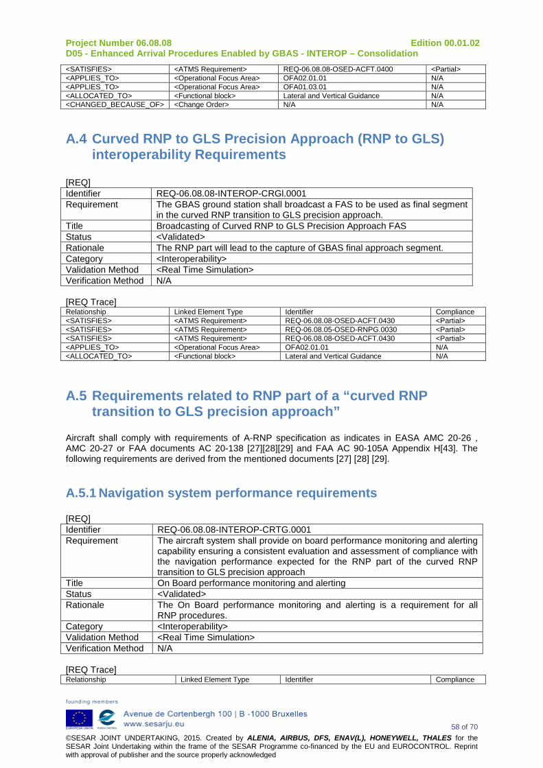
Project Number 06.08.08 Edition 00.01.02 D05 - Enhanced Arrival Procedures Enabled by GBAS - INTEROP – Consolidation
58 of 70 ©SESAR JOINT UNDERTAKING, 2015. Created by ALENIA, AIRBUS, DFS, ENAV(L), HONEYWELL, THALES for the SESAR Joint Undertaking within the frame of the SESAR Programme co-financed by the EU and EUROCONTROL. Reprint with approval of publisher and the source properly acknowledged
<SATISFIES> <ATMS Requirement> REQ-06.08.08-OSED-ACFT.0400 <Partial> <APPLIES_TO> <Operational Focus Area> OFA02.01.01 N/A <APPLIES_TO> <Operational Focus Area> OFA01.03.01 N/A <ALLOCATED_TO> <Functional block> Lateral and Vertical Guidance N/A <CHANGED_BECAUSE_OF> <Change Order> N/A N/A
A.4 Curved RNP to GLS Precision Approach (RNP to GLS) interoperability Requirements
[REQ] Identifier REQ-06.08.08-INTEROP-CRGl.0001 Requirement The GBAS ground station shall broadcast a FAS to be used as final segment
in the curved RNP transition to GLS precision approach. Title Broadcasting of Curved RNP to GLS Precision Approach FAS Status <Validated> Rationale The RNP part will lead to the capture of GBAS final approach segment. Category <Interoperability> Validation Method <Real Time Simulation> Verification Method N/A [REQ Trace] Relationship Linked Element Type Identifier Compliance <SATISFIES> <ATMS Requirement> REQ-06.08.08-OSED-ACFT.0430 <Partial> <SATISFIES> <ATMS Requirement> REQ-06.08.05-OSED-RNPG.0030 <Partial> <SATISFIES> <ATMS Requirement> REQ-06.08.08-OSED-ACFT.0430 <Partial> <APPLIES_TO> <Operational Focus Area> OFA02.01.01 N/A <ALLOCATED_TO> <Functional block> Lateral and Vertical Guidance N/A
A.5 Requirements related to RNP part of a “curved RNP transition to GLS precision approach”
Aircraft shall comply with requirements of A-RNP specification as indicates in EASA AMC 20-26 , AMC 20-27 or FAA documents AC 20-138 [27][28][29] and FAA AC 90-105A Appendix H[43]. The following requirements are derived from the mentioned documents [27] [28] [29].
A.5.1 Navigation system performance requirements [REQ] Identifier REQ-06.08.08-INTEROP-CRTG.0001 Requirement The aircraft system shall provide on board performance monitoring and alerting
capability ensuring a consistent evaluation and assessment of compliance with the navigation performance expected for the RNP part of the curved RNP transition to GLS precision approach
Title On Board performance monitoring and alerting Status <Validated> Rationale The On Board performance monitoring and alerting is a requirement for all
RNP procedures. Category <Interoperability> Validation Method <Real Time Simulation> Verification Method N/A [REQ Trace] Relationship Linked Element Type Identifier Compliance
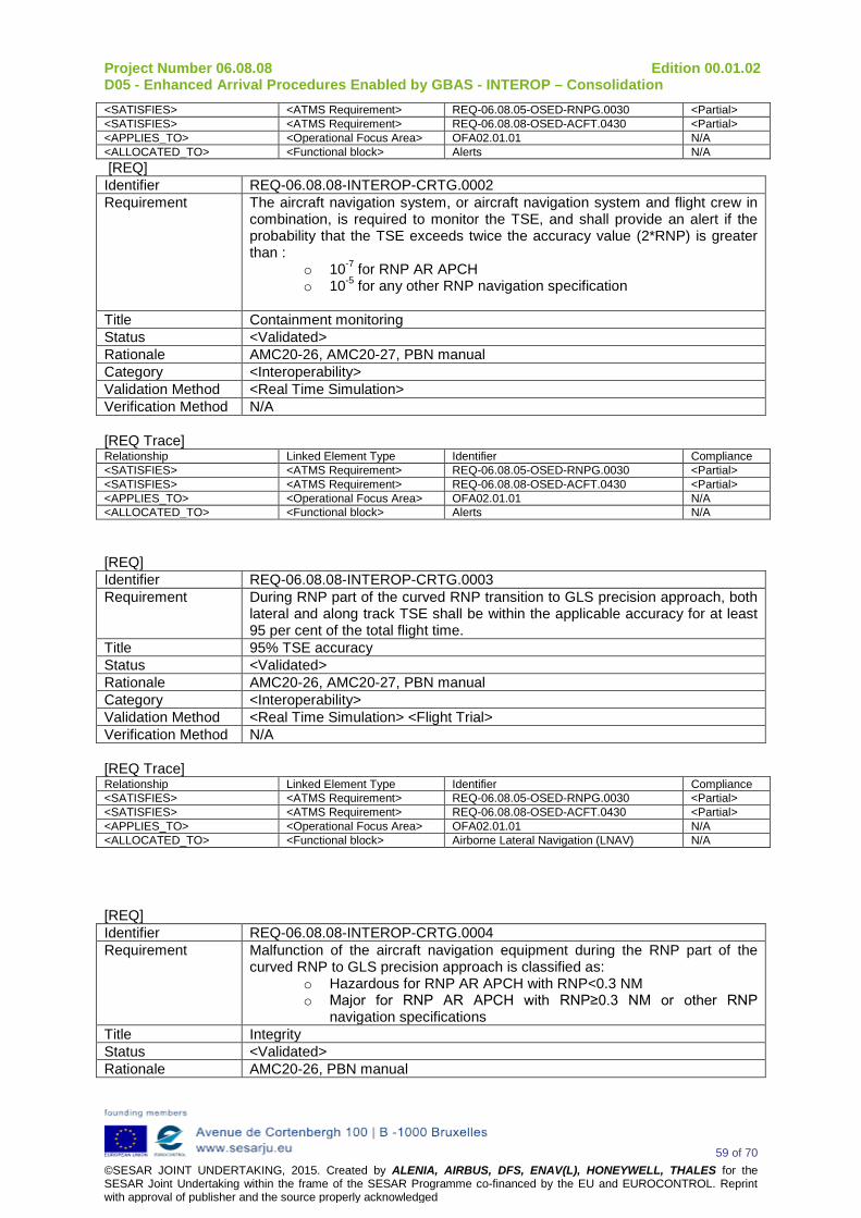
Project Number 06.08.08 Edition 00.01.02 D05 - Enhanced Arrival Procedures Enabled by GBAS - INTEROP – Consolidation
59 of 70 ©SESAR JOINT UNDERTAKING, 2015. Created by ALENIA, AIRBUS, DFS, ENAV(L), HONEYWELL, THALES for the SESAR Joint Undertaking within the frame of the SESAR Programme co-financed by the EU and EUROCONTROL. Reprint with approval of publisher and the source properly acknowledged
<SATISFIES> <ATMS Requirement> REQ-06.08.05-OSED-RNPG.0030 <Partial> <SATISFIES> <ATMS Requirement> REQ-06.08.08-OSED-ACFT.0430 <Partial> <APPLIES_TO> <Operational Focus Area> OFA02.01.01 N/A <ALLOCATED_TO> <Functional block> Alerts N/A [REQ] Identifier REQ-06.08.08-INTEROP-CRTG.0002 Requirement The aircraft navigation system, or aircraft navigation system and flight crew in
combination, is required to monitor the TSE, and shall provide an alert if the probability that the TSE exceeds twice the accuracy value (2*RNP) is greater than :
o 10-7 for RNP AR APCH o 10-5 for any other RNP navigation specification
Title Containment monitoring Status <Validated> Rationale AMC20-26, AMC20-27, PBN manual Category <Interoperability> Validation Method <Real Time Simulation> Verification Method N/A [REQ Trace] Relationship Linked Element Type Identifier Compliance <SATISFIES> <ATMS Requirement> REQ-06.08.05-OSED-RNPG.0030 <Partial> <SATISFIES> <ATMS Requirement> REQ-06.08.08-OSED-ACFT.0430 <Partial> <APPLIES_TO> <Operational Focus Area> OFA02.01.01 N/A <ALLOCATED_TO> <Functional block> Alerts N/A
[REQ] Identifier REQ-06.08.08-INTEROP-CRTG.0003 Requirement During RNP part of the curved RNP transition to GLS precision approach, both
lateral and along track TSE shall be within the applicable accuracy for at least 95 per cent of the total flight time.
Title 95% TSE accuracy Status <Validated> Rationale AMC20-26, AMC20-27, PBN manual Category <Interoperability> Validation Method <Real Time Simulation> <Flight Trial> Verification Method N/A [REQ Trace] Relationship Linked Element Type Identifier Compliance <SATISFIES> <ATMS Requirement> REQ-06.08.05-OSED-RNPG.0030 <Partial> <SATISFIES> <ATMS Requirement> REQ-06.08.08-OSED-ACFT.0430 <Partial> <APPLIES_TO> <Operational Focus Area> OFA02.01.01 N/A <ALLOCATED_TO> <Functional block> Airborne Lateral Navigation (LNAV) N/A
[REQ] Identifier REQ-06.08.08-INTEROP-CRTG.0004 Requirement Malfunction of the aircraft navigation equipment during the RNP part of the
curved RNP to GLS precision approach is classified as: o Hazardous for RNP AR APCH with RNP<0.3 NM o Major for RNP AR APCH with RNP≥0.3 NM or other RNP
navigation specifications Title Integrity Status <Validated> Rationale AMC20-26, PBN manual
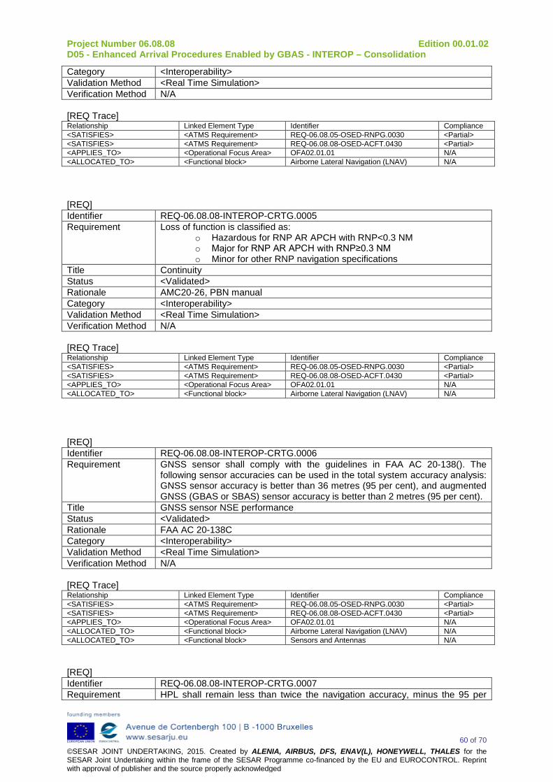
Project Number 06.08.08 Edition 00.01.02 D05 - Enhanced Arrival Procedures Enabled by GBAS - INTEROP – Consolidation
60 of 70 ©SESAR JOINT UNDERTAKING, 2015. Created by ALENIA, AIRBUS, DFS, ENAV(L), HONEYWELL, THALES for the SESAR Joint Undertaking within the frame of the SESAR Programme co-financed by the EU and EUROCONTROL. Reprint with approval of publisher and the source properly acknowledged
Category <Interoperability> Validation Method <Real Time Simulation> Verification Method N/A [REQ Trace] Relationship Linked Element Type Identifier Compliance <SATISFIES> <ATMS Requirement> REQ-06.08.05-OSED-RNPG.0030 <Partial> <SATISFIES> <ATMS Requirement> REQ-06.08.08-OSED-ACFT.0430 <Partial> <APPLIES_TO> <Operational Focus Area> OFA02.01.01 N/A <ALLOCATED_TO> <Functional block> Airborne Lateral Navigation (LNAV) N/A
[REQ] Identifier REQ-06.08.08-INTEROP-CRTG.0005 Requirement Loss of function is classified as:
o Hazardous for RNP AR APCH with RNP<0.3 NM o Major for RNP AR APCH with RNP≥0.3 NM o Minor for other RNP navigation specifications
Title Continuity Status <Validated> Rationale AMC20-26, PBN manual Category <Interoperability> Validation Method <Real Time Simulation> Verification Method N/A [REQ Trace] Relationship Linked Element Type Identifier Compliance <SATISFIES> <ATMS Requirement> REQ-06.08.05-OSED-RNPG.0030 <Partial> <SATISFIES> <ATMS Requirement> REQ-06.08.08-OSED-ACFT.0430 <Partial> <APPLIES_TO> <Operational Focus Area> OFA02.01.01 N/A <ALLOCATED_TO> <Functional block> Airborne Lateral Navigation (LNAV) N/A
[REQ] Identifier REQ-06.08.08-INTEROP-CRTG.0006 Requirement GNSS sensor shall comply with the guidelines in FAA AC 20-138(). The
following sensor accuracies can be used in the total system accuracy analysis: GNSS sensor accuracy is better than 36 metres (95 per cent), and augmented GNSS (GBAS or SBAS) sensor accuracy is better than 2 metres (95 per cent).
Title GNSS sensor NSE performance Status <Validated> Rationale FAA AC 20-138C Category <Interoperability> Validation Method <Real Time Simulation> Verification Method N/A [REQ Trace] Relationship Linked Element Type Identifier Compliance <SATISFIES> <ATMS Requirement> REQ-06.08.05-OSED-RNPG.0030 <Partial> <SATISFIES> <ATMS Requirement> REQ-06.08.08-OSED-ACFT.0430 <Partial> <APPLIES_TO> <Operational Focus Area> OFA02.01.01 N/A <ALLOCATED_TO> <Functional block> Airborne Lateral Navigation (LNAV) N/A <ALLOCATED_TO> <Functional block> Sensors and Antennas N/A
[REQ] Identifier REQ-06.08.08-INTEROP-CRTG.0007 Requirement HPL shall remain less than twice the navigation accuracy, minus the 95 per

Project Number 06.08.08 Edition 00.01.02 D05 - Enhanced Arrival Procedures Enabled by GBAS - INTEROP – Consolidation
61 of 70 ©SESAR JOINT UNDERTAKING, 2015. Created by ALENIA, AIRBUS, DFS, ENAV(L), HONEYWELL, THALES for the SESAR Joint Undertaking within the frame of the SESAR Programme co-financed by the EU and EUROCONTROL. Reprint with approval of publisher and the source properly acknowledged
cent of FTE, during the RNP operation. Title Protection against GNSS latent failure Status <In Progress> Rationale Considering a negligible PDE, TSE is composed of NSE and FTE. Category <Interoperability> Validation Method <Real Time Simulation> Verification Method N/A [REQ Trace] Relationship Linked Element Type Identifier Compliance <SATISFIES> <ATMS Requirement> REQ-06.08.05-OSED-RNPG.0030 <Partial> <SATISFIES> <ATMS Requirement> REQ-06.08.08-OSED-ACFT.0430 <Partial> <APPLIES_TO> <Operational Focus Area> OFA02.01.01 N/A <ALLOCATED_TO> <Functional block> Airborne Lateral Navigation (LNAV) N/A
A.5.2 Functional requirements [REQ] Identifier REQ-06.08.08-INTEROP-RFUN.0001 Requirement The navigation system shall provide the capability to continuously display on
the primary flight instruments for navigation of the aircraft, the lateral deviation relative to the RNP defined path with a resolution of 0.1 NM or less
Title Continuous display of deviation Status <Validated> Rationale The flight crew needs to continuously monitor the XTK during RNP operations. Category <Interoperability> Validation Method <Real Time Simulation> Verification Method N/A [REQ Trace] Relationship Linked Element Type Identifier Compliance <SATISFIES> <ATMS Requirement> REQ-06.08.05-OSED-RNPG.0030 <Partial> <SATISFIES> <ATMS Requirement> REQ-06.08.08-OSED-ACFT.0430 <Partial> <APPLIES_TO> <Operational Focus Area> OFA02.01.01 N/A <ALLOCATED_TO> <Functional block> Airborne Lateral Navigation (LNAV) N/A <ALLOCATED_TO> <Functional block> Lateral Positioning N/A [REQ] Identifier REQ-06.08.08-INTEROP-RFUN.0002 Requirement The RNP system shall be capable of automatic entry and display of navigation
accuracy requirements in tenths of NM between 0.3 and 1.0 NM corresponding to the considered accuracy for the RNP part of the curved RNP transition to GLS precision approach. The RNP system shall provide lateral deviation displays and alerting appropriate to the selected navigation accuracy and application.
Title RNP scalability Status <Validated> Rationale The RNP value is coded in the NavDB and considered for navigation
monitoring by the navigation systems. Category <Interoperability> Validation Method <Real Time Simulation> Verification Method N/A [REQ Trace] Relationship Linked Element Type Identifier Compliance <SATISFIES> <ATMS Requirement> REQ-06.08.05-OSED-RNPG.0030 <Partial> <SATISFIES> <ATMS Requirement> REQ-06.08.08-OSED-ACFT.0430 <Partial>

Project Number 06.08.08 Edition 00.01.02 D05 - Enhanced Arrival Procedures Enabled by GBAS - INTEROP – Consolidation
62 of 70 ©SESAR JOINT UNDERTAKING, 2015. Created by ALENIA, AIRBUS, DFS, ENAV(L), HONEYWELL, THALES for the SESAR Joint Undertaking within the frame of the SESAR Programme co-financed by the EU and EUROCONTROL. Reprint with approval of publisher and the source properly acknowledged
<APPLIES_TO> <Operational Focus Area> OFA02.01.01 N/A <ALLOCATED_TO> <Functional block> Airborne Lateral Navigation (LNAV) N/A <ALLOCATED_TO> <Functional block> Lateral Positioning N/A <ALLOCATED_TO> <Functional block> Alerts N/A
[REQ] Identifier REQ-06.08.08-INTEROP-RFUN.0003 Requirement The display shall allow the flight crew to readily distinguish whether the cross-
track deviation exceeds the navigation accuracy (or a smaller value). Title Display sensitivity Status <Validated> Rationale The flight crew needs to continuously monitor the XTK with regards to the RNP
value during RNP operations, with a resolution adapted to the RNP value. Category <Interoperability> Validation Method <Real Time Simulation> Verification Method N/A [REQ Trace] Relationship Linked Element Type Identifier Compliance <SATISFIES> <ATMS Requirement> REQ-06.08.05-OSED-RNPG.0030 <Partial> <SATISFIES> <ATMS Requirement> REQ-06.08.08-OSED-ACFT.0430 <Partial> <APPLIES_TO> <Operational Focus Area> OFA02.01.01 N/A <ALLOCATED_TO> <Functional block> Display and controls N/A [REQ] Identifier REQ-06.08.08-INTEROP-RFUN.0004 Requirement The navigation system shall provide a display identifying the active waypoint. Title Active waypoint Status <Validated> Rationale For the flight crew to know where the RNP value applies. Category <Interoperability> Validation Method <Real Time Simulation> Verification Method N/A [REQ Trace] Relationship Linked Element Type Identifier Compliance <SATISFIES> <ATMS Requirement> REQ-06.08.05-OSED-RNPG.0030 <Partial> <SATISFIES> <ATMS Requirement> REQ-06.08.08-OSED-ACFT.0430 <Partial> <APPLIES_TO> <Operational Focus Area> OFA02.01.01 N/A <ALLOCATED_TO> <Functional block> Display and controls N/A [REQ] Identifier REQ-06.08.08-INTEROP-RFUN.0005 Requirement The navigation system shall provide for the RNP part of the curved RNP
transition to GLS precision approach: -the display of distance and bearing to the active (To) waypoint; -the display of groundspeed and time to the active (To) waypoint; -the capability to continuously display the aircraft actual and desired track; -the ability to display distance to go to any waypoint; -the distance between procedure waypoints.
Title Navigation information display Information Status <Validated> Rationale RNP operations being closely correlated to the FPLN, it is important for the
flight crew to know precisely aircraft navigation parameters. Category <Interoperability> Validation Method <Real Time Simulation> Verification Method N/A [REQ Trace]

Project Number 06.08.08 Edition 00.01.02 D05 - Enhanced Arrival Procedures Enabled by GBAS - INTEROP – Consolidation
63 of 70 ©SESAR JOINT UNDERTAKING, 2015. Created by ALENIA, AIRBUS, DFS, ENAV(L), HONEYWELL, THALES for the SESAR Joint Undertaking within the frame of the SESAR Programme co-financed by the EU and EUROCONTROL. Reprint with approval of publisher and the source properly acknowledged
Relationship Linked Element Type Identifier Compliance <SATISFIES> <ATMS Requirement> REQ-06.08.05-OSED-RNPG.0030 <Partial> <SATISFIES> <ATMS Requirement> REQ-06.08.08-OSED-ACFT.0430 <Partial> <APPLIES_TO> <Operational Focus Area> OFA02.01.01 N/A <ALLOCATED_TO> <Functional block> Display and controls N/A [REQ] Identifier REQ-06.08.08-INTEROP-RFUN.0006 Requirement The aircraft shall provide a means to annunciate failures of any aircraft
component of the RNP system, including navigation sensors. Title Aircraft track Status <Validated> Rationale For crew awareness purpose and appropriate reaction. Category <Interoperability> Validation Method <Real Time Simulation> Verification Method N/A [REQ Trace] Relationship Linked Element Type Identifier Compliance <SATISFIES> <ATMS Requirement> REQ-06.08.08-OSED-ACFT.0430 <Partial> <SATISFIES> <ATMS Requirement> REQ-06.08.05-OSED-RNPG.0030 <Partial> <SATISFIES> <ATMS Requirement> REQ-06.08.08-OSED-ACFT.0430 <Partial> <APPLIES_TO> <Operational Focus Area> OFA02.01.01 N/A <ALLOCATED_TO> <Functional block> Alerts N/A <ALLOCATED_TO> <Functional block> Sensors and antennas N/A
[REQ] Identifier REQ-06.08.08-INTEROP-RFUN.0007 Requirement The navigation system shall provide a course selector automatically slaved to
the RNP computed path when aircraft is equipped with automatic course selector.
Title Slave course selector Status <Validated> Rationale The guidance of the aircraft navigation system needs to follow the RNP path. Category <Interoperability> Validation Method <Real Time Simulation> Verification Method N/A [REQ Trace] Relationship Linked Element Type Identifier Compliance <SATISFIES> <ATMS Requirement> REQ-06.08.05-OSED-RNPG.0030 <Partial> <SATISFIES> <ATMS Requirement> REQ-06.08.08-OSED-ACFT.0430 <Partial> <APPLIES_TO> <Operational Focus Area> OFA02.01.01 N/A <ALLOCATED_TO> <Functional block> Display and controls N/A
[REQ] Identifier REQ-06.08.08-INTEROP-RFUN.0008 Requirement The aircraft shall display the current navigation sensor(s) in use. Title Navigation sensors in use Status <Validated> Rationale For the flight crew to know whether the aircraft still complies with the
Navigation requirements of the chart Category <Interoperability> Validation Method <Real Time Simulation> Verification Method N/A [REQ Trace]

Project Number 06.08.08 Edition 00.01.02 D05 - Enhanced Arrival Procedures Enabled by GBAS - INTEROP – Consolidation
64 of 70 ©SESAR JOINT UNDERTAKING, 2015. Created by ALENIA, AIRBUS, DFS, ENAV(L), HONEYWELL, THALES for the SESAR Joint Undertaking within the frame of the SESAR Programme co-financed by the EU and EUROCONTROL. Reprint with approval of publisher and the source properly acknowledged
Relationship Linked Element Type Identifier Compliance <SATISFIES> <ATMS Requirement> REQ-06.08.05-OSED-RNPG.0030 <Partial> <SATISFIES> <ATMS Requirement> REQ-06.08.08-OSED-ACFT.0430 <Partial> <APPLIES_TO> <Operational Focus Area> OFA02.01.01 N/A <ALLOCATED_TO> <Functional block> Display and controls N/A <ALLOCATED_TO> <Functional block> Sensors and Antennas N/A
[REQ] Identifier REQ-06.08.08-INTEROP-RFUN.0009 Requirement Altitudes and/or speeds associated with published terminal procedures shall be
extracted from the navigation database Title Altitudes and/or speeds associated with published terminal procedures Status <Validated> Rationale For the flight crew to know which are the FPLN constraints to conform to them Category <Interoperability> Validation Method <Real Time Simulation> Verification Method N/A [REQ Trace] Relationship Linked Element Type Identifier Compliance <SATISFIES> <ATMS Requirement> REQ-06.08.08-OSED-FCRW.0010 <Partial> <APPLIES_TO> <Operational Focus Area> OFA02.01.01 N/A <APPLIES_TO> <Operational Focus Area> OFA01.03.01 N/A <ALLOCATED_TO> <Functional block> Databases N/A
[REQ] Identifier REQ-06.08.08-INTEROP-RFUN.0010 Requirement The navigation system shall have the capability to load the entire procedure
RNP part of the curved RNP to GLS precision approach to be flown into the RNP system from the on-board navigation database.
Title Capability to load procedures from the navigation database Status <Validated> Rationale The RNP procedure is coded in the aircraft NavDB. Category <Interoperability> Validation Method <Real Time Simulation> Verification Method N/A [REQ Trace] Relationship Linked Element Type Identifier Compliance <SATISFIES> <ATMS Requirement> REQ-06.08.05-OSED-RNPG.0030 <Partial> <SATISFIES> <ATMS Requirement> REQ-06.08.08-OSED-ACFT.0430 <Partial> <APPLIES_TO> <Operational Focus Area> OFA02.01.01 N/A <ALLOCATED_TO> <Functional block> Databases N/A
[REQ] Identifier REQ-06.08.08-INTEROP-RFUN.0011 Requirement The navigation system shall provide the ability for the flight crew to verify the
RNP part of the curved RNP to GLS precision approach procedure to be flown through review of the data stored in the on-board navigation
Title Means to retrieve and display navigation data. Status <Validated> Rationale The flight crew needs to cross check of RNP data from NavDB with those of
the chart. Category <Interoperability> Validation Method <Real Time Simulation> Verification Method N/A

Project Number 06.08.08 Edition 00.01.02 D05 - Enhanced Arrival Procedures Enabled by GBAS - INTEROP – Consolidation
65 of 70 ©SESAR JOINT UNDERTAKING, 2015. Created by ALENIA, AIRBUS, DFS, ENAV(L), HONEYWELL, THALES for the SESAR Joint Undertaking within the frame of the SESAR Programme co-financed by the EU and EUROCONTROL. Reprint with approval of publisher and the source properly acknowledged
[REQ Trace] Relationship Linked Element Type Identifier Compliance <SATISFIES> <ATMS Requirement> REQ-06.08.05-OSED-RNPG.0030 <Partial> <SATISFIES> <ATMS Requirement> REQ-06.08.08-OSED-ACFT.0430 <Partial> <APPLIES_TO> <Operational Focus Area> OFA02.01.01 N/A <ALLOCATED_TO> <Functional block> Databases N/A
[REQ] Identifier REQ-06.08.08-INTEROP-RFUN.0012 Requirement The RNP system should automatically retrieve and set the navigation accuracy
for each leg segment of a route or procedure from the on-board navigation database with a timing of change that considers any latency in alerting from the RNP system.
Title Changes in navigation accuracy Status <Validated> Rationale When a change occurs to a smaller navigation accuracy, e.g. from RNP 1.0 to
RNP 0.3, the change shall be completed by the first fix defining the leg with the smaller navigation accuracy requirement. When the RNP system cannot automatically set the navigation accuracy for each leg segment, any operational procedures necessary to accomplish this shall be identified. The aim is to always have RNP monitoring compliant with published/coded RNP value.
Category <Interoperability> Validation Method <Real Time Simulation> Verification Method N/A [REQ Trace] Relationship Linked Element Type Identifier Compliance <SATISFIES> <ATMS Requirement> REQ-06.08.05-OSED-RNPG.0030 <Partial> <SATISFIES> <ATMS Requirement> REQ-06.08.08-OSED-ACFT.0430 <Partial> <APPLIES_TO> <Operational Focus Area> OFA02.01.01 N/A <ALLOCATED_TO> <Functional block> Databases N/A
[REQ] Identifier REQ-06.08.08-INTEROP-RFUN.0013 Requirement The navigation system shall provide the capability to automatically sequence
the different legs of the RNP part of a curved RNP to GLS precision approach and display the sequencing to the flight crew in a readily visible manner.
Title Automatic leg sequencing of RNP part of a curved RNP transition to GLS precision approach
Status <Validated> Rationale The flight crew needs to monitor the aircraft conformance to the RNP path. Category <Interoperability> Validation Method <Real Time Simulation> Verification Method N/A [REQ Trace] Relationship Linked Element Type Identifier Compliance <SATISFIES> <ATMS Requirement> REQ-06.08.05-OSED-RNPG.0030 <Partial> <SATISFIES> <ATMS Requirement> REQ-06.08.08-OSED-ACFT.0430 <Partial> <APPLIES_TO> <Operational Focus Area> OFA02.01.01 N/A <ALLOCATED_TO> <Functional block> Display and Controls N/A
[REQ] Identifier REQ-06.08.08-INTEROP-RFUN.0014 Requirement The aircraft navigation system shall use an on-board navigation database,

Project Number 06.08.08 Edition 00.01.02 D05 - Enhanced Arrival Procedures Enabled by GBAS - INTEROP – Consolidation
66 of 70 ©SESAR JOINT UNDERTAKING, 2015. Created by ALENIA, AIRBUS, DFS, ENAV(L), HONEYWELL, THALES for the SESAR Joint Undertaking within the frame of the SESAR Programme co-financed by the EU and EUROCONTROL. Reprint with approval of publisher and the source properly acknowledged
containing current navigation data officially promulgated for civil aviation, which can be updated in accordance with the AIRAC cycle; and allow retrieval and loading RNP part of the curved approach procedures into the RNP system. The stored resolution of the data shall be sufficient to achieve negligible PDE.
Title Automatic leg sequencing Status <Validated> Rationale The RNP path is coded in the navigation database to be used by a navigation
system. If the PDE is negligible, the TSE is only composed of NSE and FTE. Category <Interoperability> Validation Method <Real Time Simulation> Verification Method N/A [REQ Trace] Relationship Linked Element Type Identifier Compliance <SATISFIES> <ATMS Requirement> REQ-06.08.05-OSED-RNPG.0030 <Partial> <SATISFIES> <ATMS Requirement> REQ-06.08.08-OSED-ACFT.0430 <Partial> <APPLIES_TO> <Operational Focus Area> OFA02.01.01 N/A <ALLOCATED_TO> <Functional block> Databases N/A
A.5.3 Avionics Requirements related to Final approach segment
Avionics shall comply with AC20-138D requirements regarding Category 1 precision approach supported by GBAS.
Avionics supports the GLS straight in final approach operations along selected FAS. The GPS/GBAS supports also optionally, a GPS/GBAS Differentially Corrected Positioning Service (DCPS). When the GPS/GBAS avionics supports both levels of service, whether or not the DCPS is available is determined by the GPS/GBAS ground station. All GPS/GBAS ground stations provide precision approach service, but not all ground stations are expected to provide DCPS. Following requirements are considered: [REQ] Identifier REQ-06.08.08-INTEROP-ACFT.0001 Requirement GPS/GBAS antenna shall comply with TSO-C190 that references RTCA/DO-
301. Title GPS antenna for GBAS Status <Validated> Rationale To be compliant with GBAS standards. Category <Interoperability> Validation Method <Real Time Simulation> Verification Method N/A [REQ Trace] Relationship Linked Element Type Identifier Compliance <SATISFIES> <ATMS Requirement> REQ-06.08.08-OSED-FCRW.0010 <Partial> <APPLIES_TO> <Operational Focus Area> OFA02.01.01 N/A <APPLIES_TO> <Operational Focus Area> OFA01.03.01 N/A <ALLOCATED_TO> <Functional block> Sensors and Antennas N/A
[REQ] Identifier REQ-06.08.08-INTEROP-ACFT.0002 Requirement VDB datalink shall comply with DO253C modified by TSO C162a. Title GBAS VDB datalink Status <Validated> Rationale To be compliant with GBAS standards.

Project Number 06.08.08 Edition 00.01.02 D05 - Enhanced Arrival Procedures Enabled by GBAS - INTEROP – Consolidation
67 of 70 ©SESAR JOINT UNDERTAKING, 2015. Created by ALENIA, AIRBUS, DFS, ENAV(L), HONEYWELL, THALES for the SESAR Joint Undertaking within the frame of the SESAR Programme co-financed by the EU and EUROCONTROL. Reprint with approval of publisher and the source properly acknowledged
Category <Interoperability> Validation Method <Real Time Simulation> Verification Method N/A [REQ Trace] Relationship Linked Element Type Identifier Compliance <SATISFIES> <ATMS Requirement> REQ-06.08.08-OSED-FCRW.0010 <Partial> <APPLIES_TO> <Operational Focus Area> OFA02.01.01 N/A <APPLIES_TO> <Operational Focus Area> OFA01.03.01 N/A <ALLOCATED_TO> <Functional block> A/G Datalink N/A
[REQ] Identifier REQ-06.08.08-INTEROP-ACFT.0003 Requirement VDB datalink shall be connected to a VHF LOC or VOR antenna for which
installation shall satisfy following requirement: the VDB antenna should be installed so that the maximum received power from any on-board transmitter does not exceed the desensitization levels of the VDB receiver specified in RTCA/DO-253C.
Title GBAS VDB datalink Status <Validated> Rationale To be compliant with GBAS standards. Category <Interoperability> Validation Method <Real Time Simulation> Verification Method N/A [REQ Trace] Relationship Linked Element Type Identifier Compliance <SATISFIES> <ATMS Requirement> REQ-06.08.08-OSED-FCRW.0010 <Partial> <APPLIES_TO> <Operational Focus Area> OFA02.01.01 N/A <APPLIES_TO> <Operational Focus Area> OFA01.03.01 N/A <ALLOCATED_TO> <Functional block> A/G Datalink N/A <ALLOCATED_TO> <Functional block> Sensors and Antennas N/A
[REQ] Identifier REQ-06.08.08-INTEROP-ACFT.0004 Requirement The GLS equipment shall comply with the RTCA/DO-253C, section 2
requirements as modified by TSO-C161a. Title GLS performance Status <Validated> Rationale To be compliant with GBAS standards. Category <Interoperability> Validation Method <Real Time Simulation> Verification Method N/A [REQ Trace] Relationship Linked Element Type Identifier Compliance <SATISFIES> <ATMS Requirement> REQ-06.08.08-OSED-FCRW.0010 <Partial> <APPLIES_TO> <Operational Focus Area> OFA02.01.01 N/A <APPLIES_TO> <Operational Focus Area> OFA01.03.01 N/A <ALLOCATED_TO> <Functional block> Lateral and Vertical Guidance N/A
[REQ] Identifier REQ-06.08.08-INTEROP-ACFT.0005 Requirement The on-board equipment shall output lateral and vertical angular deviations
relative to the selected final approach path transmitted from a GBAS ground subsystem through the VHF data broadcast.
Title GLS performance
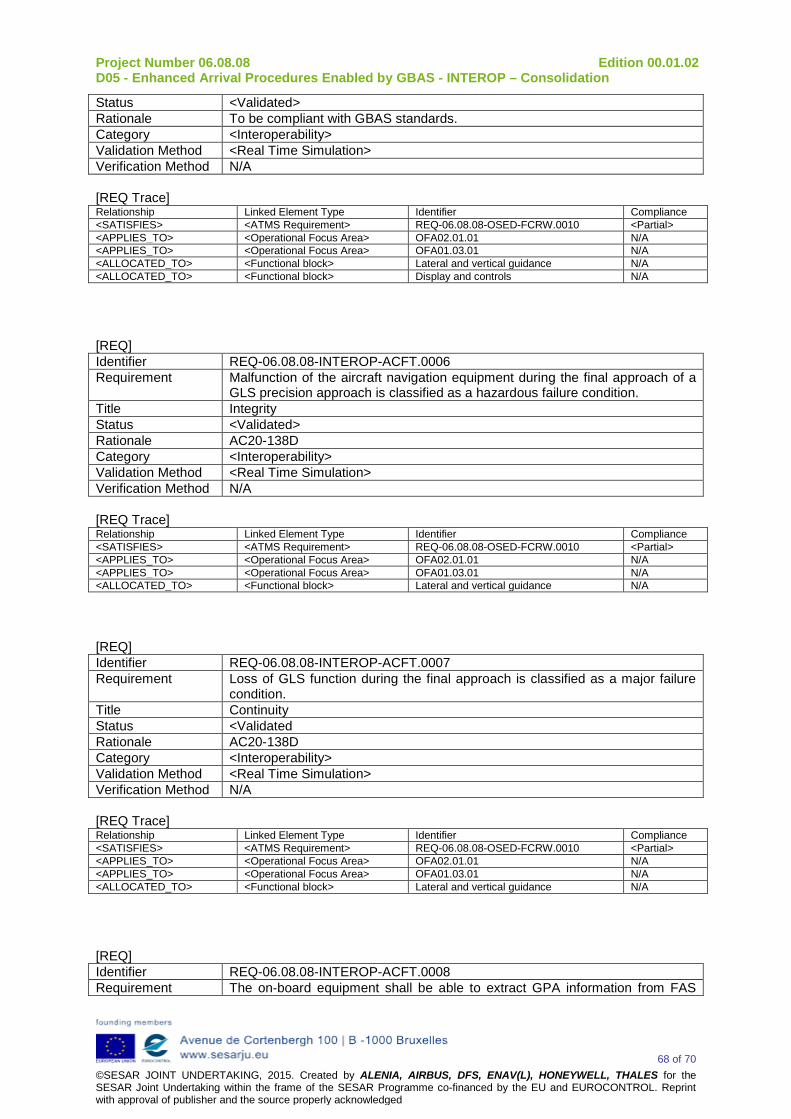
Project Number 06.08.08 Edition 00.01.02 D05 - Enhanced Arrival Procedures Enabled by GBAS - INTEROP – Consolidation
68 of 70 ©SESAR JOINT UNDERTAKING, 2015. Created by ALENIA, AIRBUS, DFS, ENAV(L), HONEYWELL, THALES for the SESAR Joint Undertaking within the frame of the SESAR Programme co-financed by the EU and EUROCONTROL. Reprint with approval of publisher and the source properly acknowledged
Status <Validated> Rationale To be compliant with GBAS standards. Category <Interoperability> Validation Method <Real Time Simulation> Verification Method N/A [REQ Trace] Relationship Linked Element Type Identifier Compliance <SATISFIES> <ATMS Requirement> REQ-06.08.08-OSED-FCRW.0010 <Partial> <APPLIES_TO> <Operational Focus Area> OFA02.01.01 N/A <APPLIES_TO> <Operational Focus Area> OFA01.03.01 N/A <ALLOCATED_TO> <Functional block> Lateral and vertical guidance N/A <ALLOCATED_TO> <Functional block> Display and controls N/A
[REQ] Identifier REQ-06.08.08-INTEROP-ACFT.0006 Requirement Malfunction of the aircraft navigation equipment during the final approach of a
GLS precision approach is classified as a hazardous failure condition. Title Integrity Status <Validated> Rationale AC20-138D Category <Interoperability> Validation Method <Real Time Simulation> Verification Method N/A [REQ Trace] Relationship Linked Element Type Identifier Compliance <SATISFIES> <ATMS Requirement> REQ-06.08.08-OSED-FCRW.0010 <Partial> <APPLIES_TO> <Operational Focus Area> OFA02.01.01 N/A <APPLIES_TO> <Operational Focus Area> OFA01.03.01 N/A <ALLOCATED_TO> <Functional block> Lateral and vertical guidance N/A
[REQ] Identifier REQ-06.08.08-INTEROP-ACFT.0007 Requirement Loss of GLS function during the final approach is classified as a major failure
condition. Title Continuity Status <Validated Rationale AC20-138D Category <Interoperability> Validation Method <Real Time Simulation> Verification Method N/A [REQ Trace] Relationship Linked Element Type Identifier Compliance <SATISFIES> <ATMS Requirement> REQ-06.08.08-OSED-FCRW.0010 <Partial> <APPLIES_TO> <Operational Focus Area> OFA02.01.01 N/A <APPLIES_TO> <Operational Focus Area> OFA01.03.01 N/A <ALLOCATED_TO> <Functional block> Lateral and vertical guidance N/A
[REQ] Identifier REQ-06.08.08-INTEROP-ACFT.0008 Requirement The on-board equipment shall be able to extract GPA information from FAS

Project Number 06.08.08 Edition 00.01.02 D05 - Enhanced Arrival Procedures Enabled by GBAS - INTEROP – Consolidation
69 of 70 ©SESAR JOINT UNDERTAKING, 2015. Created by ALENIA, AIRBUS, DFS, ENAV(L), HONEYWELL, THALES for the SESAR Joint Undertaking within the frame of the SESAR Programme co-financed by the EU and EUROCONTROL. Reprint with approval of publisher and the source properly acknowledged
transmitted from a GBAS ground subsystem to compute the optimal A-IGS slope value
Title Computation of A-IGS guidance deviation Status <Validated> Rationale Capability to compute A-IGS slope Category <Interoperability> Validation Method <Real Time Simulation> Verification Method N/A [REQ Trace] Relationship Linked Element Type Identifier Compliance <SATISFIES> <ATMS Requirement> REQ-06.08.08-OSED-FCRW.0010 <Partial> <APPLIES_TO> <Operational Focus Area> OFA02.01.01 N/A <APPLIES_TO> <Operational Focus Area> OFA01.03.01 N/A <ALLOCATED_TO> <Functional block> Information Domain N/A
Project Number 06.08.08 Edition 00.01.02 D05 - Enhanced Arrival Procedures Enabled by GBAS - INTEROP – Consolidation
70 of 70 ©SESAR JOINT UNDERTAKING, 2015. Created by ALENIA, AIRBUS, DFS, ENAV(L), HONEYWELL, THALES for the SESAR Joint Undertaking within the frame of the SESAR Programme co-financed by the EU and EUROCONTROL. Reprint with approval of publisher and the source properly acknowledged
-END OF DOCUMENT-


![The GBAS Landing SystemThe GBAS Landing SystemTitle: Microsoft PowerPoint - Boeing GBAS Presentation, Beijing, October 29, 2009.ppt [兼容模式] Author: Shile Created Date: 11/10/2009](https://img.pdfslide.us/doc/110x75/5a727f467f8b9ac0538da536/the-gbas-landing-systemthe-gbas-landing-systemtitle-microsoft-powerpoint-boeing.jpg)