Embed Size (px)
Citation preview
ENGLISH INSTRUCTION MANUAL
NON-MYDRIATIC RETINAL CAMERA
TRC-NW6SF/TRC-NW6S

Copyrights and trademarks
Non-Mydriatic Retinal Camera TRC-NW6SF/ TRC-NW6S is atrademark of the TOPCON Corporation.
© TOPCON 2000

INTRODUCTION
Thank you for purchasing the TOPCONNon-Mydriatic Retinal CameraTRC-NW6SF/ TRC-NW6S.
This manual contains instructions for theTOPCON Non-Mydriatic Retinal Camera.This includes the main features, basicoperation, troubleshooting, and themaintenance and cleaning of thisinstrument.
Please read the section Warning labels onpage 5 and the section Safety precautions onpage 6 carefully, before operating theinstrument.
To ensure the best performance of thisinstrument, read all instructions carefully andplace this manual in a convenient location forfuture reference.

Non-Mydriatic Retinal Camera TRC-NW6SF/ TRC-NW6S
This machine offers the following innovativefeatures
� Observe the fundus of the eye and take images without usingmydriatics.
� Improved picture quality and ease of use.
� Allows images of the periphery, using the alignment point and theexternal fixation target for peripheral photography.
� Allows Fluoro-photography by changing the photography mode(TRC-NW6SF only).
� Allows Fluoro-observation by using the built-in color video monitor(TRC-NW6SF only).
Precautions
� This machine is a precision instrument. Be sure to install and use itin a controlled environment under normal temperature, humidityand atmospheric pressure conditions (10~40°C, 30-85%,70~106kPa) and avoid direct exposure to sunlight.
� Never install the machine on a slope or an unstable surface.
� Before using the machine, ensure that all cables are correctlyconnected.
� Use a power supply within the range of ±10% of the rated voltage(50/60Hz).
� Ensure the surrounding area is always clean. When the instrumentis not in use, turn off the Power switch, cap the objective lens, andinstall the dust cover.
� To ensure the best imaging results, handle the objective lens withparticular care and keep it free of dust, fingerprints, or other stains.
4
Selecting externally connected equipment
The TOPCON TRC-NW6SF/ TRC-NW6S complies with the CEstandard.
Before connecting a personal computer, image recorder, image printer,TV camera, or monitor to the TOPCON product, ensure that suchexternal equipment is in compliance with the CE marking.
Note: The illustrations in this manual pertain to the model TRC-NW6SF only.Please note that the TRC-NW6S differs from the SF model.
Warning labels
Important warnings are placed on the products and inserted in theinstruction manuals, in order to encourage the safe use of products andprevent any danger to the operator and others or damage to existingfacilities.
We recommend that the following information about labels and icons beread before going on to read "Safety precautions" and the rest of themanual.
Meaning of labels
Label Meaning
WARNING
Ignoring or disregarding this label may lead to death or serious injury.
PRECAUTIONS
Ignoring or disregarding this label may result in personal injury orsevere damage to the instrument or other facilities.
� Possible injuries include wounds, burns, electric shocks, etc.
� Damage to other facilities means extensive damage to buildings,equipment and furniture.
INSTRUCTION MANUAL 5
Non-Mydriatic Retinal Camera TRC-NW6SF/ TRC-NW6S
Meaning of icons
Safety precautions
This instruction manual details the safety precautions that need to beobserved to prevent accidents.
Always observe these precautions and use the instrument correctly.
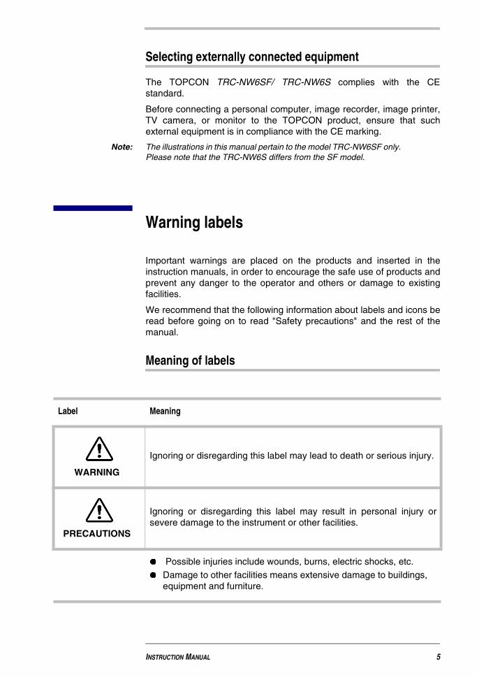
Icons Meaning
This icon indicates Caution.
A further explanation or picture is placed close to the icon.
This icon indicates Prohibition (DO NOT!).
A further explanation or picture is placed close to the icon.
This indicates Mandatory Action (DO!).
A further explanation or picture is placed close to the icon.
WARNING
Icons Precautions Page
� To avoid the risk of electric shock, disconnect thecable from the power supply before assembling theinstrument. Always ensure the power supply isdisconnected before assembly.
29
� Ensure the power supply is equipped with a 3-plug ACreceptacle to safeguard against power leakage.Power leakage could cause fire or electric shock.
36
� To avoid the risk of electric shock, do not attemptdisassembling, rebuilding and/or repairs. Alwaysconsult your dealer in case of repairs.
95
6

� To avoid the risk of electric shock do not remove anyinstrument components, TV relay lens covers,chinrest or power supply components, other than thelamp house cover.
95
� To avoid the risk of electric shock, always disconnectthe power cable from the instrument before removingthe fuse cover.
Always replace the fuse cover before reconnecting theinstrument to the power supply.
89
� Install the instrument in a clean, dry area.-
� To avoid the risk of fire or electric shock, do not placeany liquids near the instrument. -
� To avoid the risk of electric shock, do not insert metalitems into any vents and/or slots. -
� To avoid the risk of fire, always use the correctly ratedfuse as specified on the fuse holder. -
� To avoid the risk of fire, always use the correctly ratedfuse as specified on the fuse holder. 89
WARNING
Icons Precautions Page
INSTRUCTION MANUAL 7

Non-Mydriatic Retinal Camera TRC-NW6SF/ TRC-NW6S
CAUTION
Icons Precautions Page
� Ensure that the monitor lamp is no brighter thannecessary, to avoid any discomfort or injury to thepatient.
-
� Ensure that the photography light is no brighter thannecessary, to avoid any discomfort or injury to thepatient.
65, 66
� Do not continue visible fluoro-observation any longerthan necessary (TRC-NW6SF only), to avoid anydiscomfort or injury to the patient.
77
� Always install the instrument on a fixed, stablesurface, to prevent damage or injury. 29, 34,
85
� To avoid potential injury, do not place your hand orfingers into the area between the instrument body andthe power supply unit.
68
� To avoid potential burns, do not touch the lamp during,or immediately after use. 86
� To avoid the risk of electric shock, never handle a plugwith wet hands. 36
� To avoid the risk of electric shock, never touch thexenon lamp immediately after a flash or burn out. 87
� To avoid potential injury to the patient, always watchthe patient carefully while adjusting the chinrest. 61
8
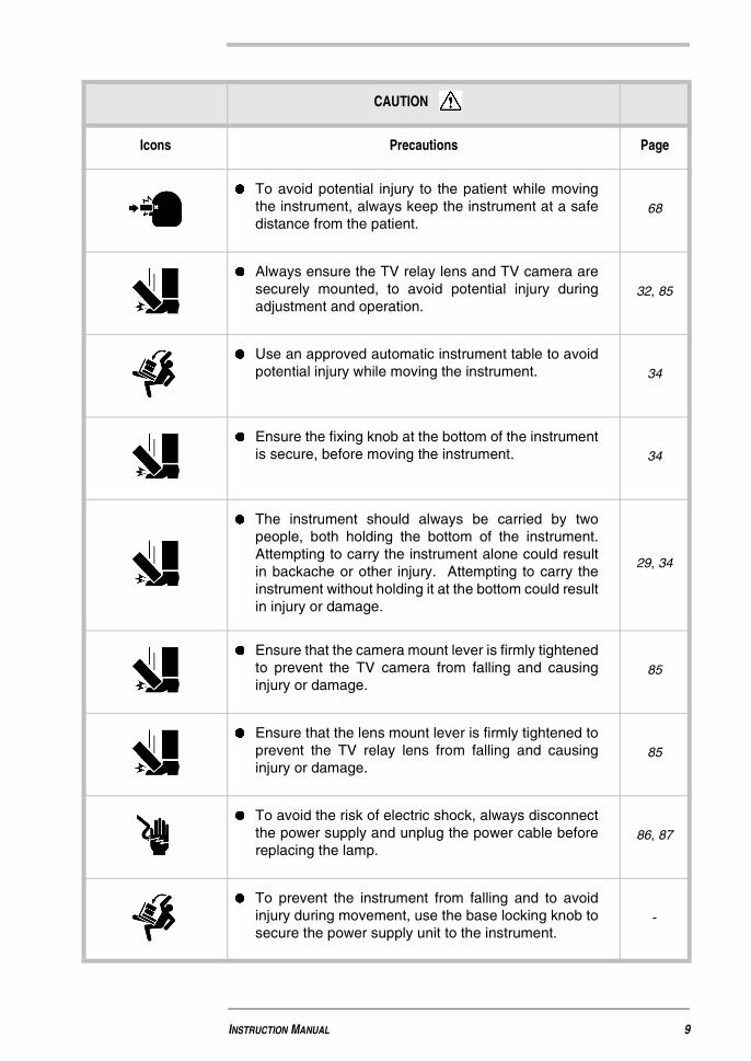
� To avoid potential injury to the patient while movingthe instrument, always keep the instrument at a safedistance from the patient.
68
� Always ensure the TV relay lens and TV camera aresecurely mounted, to avoid potential injury duringadjustment and operation.
32, 85
� Use an approved automatic instrument table to avoidpotential injury while moving the instrument. 34
� Ensure the fixing knob at the bottom of the instrumentis secure, before moving the instrument. 34
� The instrument should always be carried by twopeople, both holding the bottom of the instrument.Attempting to carry the instrument alone could resultin backache or other injury. Attempting to carry theinstrument without holding it at the bottom could resultin injury or damage.
29, 34
� Ensure that the camera mount lever is firmly tightenedto prevent the TV camera from falling and causinginjury or damage.
85
� Ensure that the lens mount lever is firmly tightened toprevent the TV relay lens from falling and causinginjury or damage.
85
� To avoid the risk of electric shock, always disconnectthe power supply and unplug the power cable beforereplacing the lamp.
86, 87
� To prevent the instrument from falling and to avoidinjury during movement, use the base locking knob tosecure the power supply unit to the instrument.
-
CAUTION
Icons Precautions Page
INSTRUCTION MANUAL 9
Non-Mydriatic Retinal Camera TRC-NW6SF/ TRC-NW6S
Operation and maintenance
Purpose
This Non-Mydriatic Retinal Camera is a precision electronic medicalinstrument, and should only be used under the direction of a medicaldoctor.
User maintenance
To ensure the safe and proper operation of the instrument, unlessotherwise specified in this manual, all maintenance should be carried outby a trained service technician. The following maintenance tasks,however, can be performed by the user. Please refer to the relevant textin this manual for the maintenance method.
Replacing lamps The illumination lamp and xenon lamp may be replaced by the user. Fordetails, see Replacing the illumination lamp on page 86 and Replacingthe xenon lamp on page 87.
Replacing fuses Fuses used with the instrument may be replaced by the user. For details,see Changing the fuses on page 89.
Cleaning theobjective lens
The objective lens may be cleaned by the user. For details, see Cleaningthe objective lens on page 91.
10

TOPCON Instruments general statements
� TOPCON shall not bear any responsibility for damage due to fire,earthquakes, actions by third persons and other accidents, or thenegligence and misuse by the user and use under unusualconditions.
� TOPCON shall not bear any responsibility for damage resultingfrom the inability to use this equipment, such as a loss of businessprofit and suspension of business.
� TOPCON shall not bear any responsibility for damage caused byoperations other than those described in this Instruction Manual.
� The diagnoses that are made are the responsibility of relevantdoctors, and TOPCON shall not take any responsibility for theresults of such diagnoses.
Warning labels and positions
To ensure safe operation of this equipment, warning labels are provided.
Please adhere to the following warning instructions.
INSTRUCTION MANUAL 11

Non-Mydriatic Retinal Camera TRC-NW6SF/ TRC-NW6S
CAUTION
• To avoid the risk of electric shock, alwaysdisconnect the power supply and unplug thepower cable before replacing the lamp.
• To avoid potential burns, do not touch thelamp during, or immediately after use.
WARNING
• To avoid the risk of electric shock, do notattempt to remove the instrument cover.
No user serviceable parts inside, referservicing to qualified personnel.
WARNING
• Electrical shock may cause burns or fire.Turn the main power switch OFF andUNPLUG the power cable before replacingfuses. Only replace with fuses of the correctrating.
CAUTION
• To avoid potential injury to the patient,always watch the patient carefully whileadjusting the chinrest.
CAUTION
• Never touch the patient's eyes or nose withthe instrument during operation as this mayresult in personal injury.
WARNING
• Electrical shock may cause burns or fire.Turn the main power switch OFF andUNPLUG the power cable before replacingfuses. Only replace with fuses of the correctrating.
12
Contents
INTRODUCTION
This machine offers the following innovative features 4
Precautions 4
Warning labels 5
Meaning of labels . . . . . . . . . . . . . . . . . . . . . . . . . . . . . . . . . . . . . . . . . . . . . . . 5Meaning of icons . . . . . . . . . . . . . . . . . . . . . . . . . . . . . . . . . . . . . . . . . . . . . . . . 6
Safety precautions 6
Operation and maintenance 10
Purpose . . . . . . . . . . . . . . . . . . . . . . . . . . . . . . . . . . . . . . . . . . . . . . . . . . . . . 10User maintenance . . . . . . . . . . . . . . . . . . . . . . . . . . . . . . . . . . . . . . . . . . . . . . 10
TOPCON Instruments general statements 11
Warning labels and positions 11
1 COMPONENTS
1.1 Component names 17
1.2 Control panel components 21
1.3 Monitor screen 22
1.4 Standard accessories 24
1.5 Assembly components 26
Non-Mydriatic Retinal Camera TRC-NW6SF/TRC-NW6S
2 ASSEMBLY PROCEDURE
2.1 Assembling the instrument body 29
2.2 Connecting the tv relay lens with the instrument body 32
2.3 Confirmation after assembly 33
2.4 Installing the instrument 34
2.5 Connecting the power cable 36
2.6 Connecting the external device 36
2.6.1 Connecting the TV camera . . . . . . . . . . . . . . . . . . . . . . . . . . . . . . . . . . . . . . . . 36
2.6.2 Connecting the external recording device . . . . . . . . . . . . . . . . . . . . . . . . . . . . . 37
2.6.3 Outputting images to an external monitor . . . . . . . . . . . . . . . . . . . . . . . . . . . . . 38
2.6.4 VIDEO OUT terminal . . . . . . . . . . . . . . . . . . . . . . . . . . . . . . . . . . . . . . . . . . . . . 39
2.7 Menu setting 39
2.7.1 Preparation for menu setting . . . . . . . . . . . . . . . . . . . . . . . . . . . . . . . . . . . . . . . 39
2.7.2 Displaying the Menu screen . . . . . . . . . . . . . . . . . . . . . . . . . . . . . . . . . . . . . . . . 39
2.7.3 Returning to the Monitor screen . . . . . . . . . . . . . . . . . . . . . . . . . . . . . . . . . . . . . 40
2.7.4 Setting the Record/Playback mode . . . . . . . . . . . . . . . . . . . . . . . . . . . . . . . . . . 40
2.7.5 Switching of fixation target on/flicker . . . . . . . . . . . . . . . . . . . . . . . . . . . . . . . . . 40
2.7.6 Switching of internal/external fixation targets . . . . . . . . . . . . . . . . . . . . . . . . . . . 41
2.7.7 Fixation target pattern . . . . . . . . . . . . . . . . . . . . . . . . . . . . . . . . . . . . . . . . . . . . 41
2.7.8 Flash level . . . . . . . . . . . . . . . . . . . . . . . . . . . . . . . . . . . . . . . . . . . . . . . . . . . . . 42
2.8 Reset from power save state 43
3 INITIAL SETTING
3.1 Preparation for initial set-up 45
3.2 Setting the record/playback mode 46
3.3 Setting the fixation target 47
3.3.1 Switching the fixation target on/flicker . . . . . . . . . . . . . . . . . . . . . . . . . . . . . . . . 47
3.3.2 Switching of internal/external fixation targets . . . . . . . . . . . . . . . . . . . . . . . . . . . 48
3.4 Setting peripheral photography 48
3.4.1 Fixation target pattern . . . . . . . . . . . . . . . . . . . . . . . . . . . . . . . . . . . . . . . . . . . . 49
3.4.2 R/L reset . . . . . . . . . . . . . . . . . . . . . . . . . . . . . . . . . . . . . . . . . . . . . . . . . . . . . . 50
3.4.3 Display mode . . . . . . . . . . . . . . . . . . . . . . . . . . . . . . . . . . . . . . . . . . . . . . . . . . . 50
3.5 Setting the screen display 51
3.5.1 Flash level compensation display . . . . . . . . . . . . . . . . . . . . . . . . . . . . . . . . . . . 51
3.5.2 Flash level display . . . . . . . . . . . . . . . . . . . . . . . . . . . . . . . . . . . . . . . . . . . . . . . 52
3.5.3 Illumination level display . . . . . . . . . . . . . . . . . . . . . . . . . . . . . . . . . . . . . . . . . . 52
3.5.4 Picture angle display . . . . . . . . . . . . . . . . . . . . . . . . . . . . . . . . . . . . . . . . . . . . . 53
xiv
3.5.5 Illumination aperture display . . . . . . . . . . . . . . . . . . . . . . . . . . . . . . . . . . . . . . . 53
3.5.6 Peripheral fixation position display . . . . . . . . . . . . . . . . . . . . . . . . . . . . . . . . . . 54
3.6 System setting 55
3.7 Setting the initial state 55
3.7.1 Flash level . . . . . . . . . . . . . . . . . . . . . . . . . . . . . . . . . . . . . . . . . . . . . . . . . . . . . 56
3.7.2 Commercial power supply frequency . . . . . . . . . . . . . . . . . . . . . . . . . . . . . . . . . 57
3.7.3 LED display . . . . . . . . . . . . . . . . . . . . . . . . . . . . . . . . . . . . . . . . . . . . . . . . . . . . 57
3.7.4 Timer sound . . . . . . . . . . . . . . . . . . . . . . . . . . . . . . . . . . . . . . . . . . . . . . . . . . . 58
3.7.5 Operation sound . . . . . . . . . . . . . . . . . . . . . . . . . . . . . . . . . . . . . . . . . . . . . . . . 58
3.7.6 Power save time . . . . . . . . . . . . . . . . . . . . . . . . . . . . . . . . . . . . . . . . . . . . . . . . 59
3.7.7 Quick mirror up . . . . . . . . . . . . . . . . . . . . . . . . . . . . . . . . . . . . . . . . . . . . . . . . . 59
3.8 Setting the language 60
4 BASIC OPERATION
4.1 Preparation for photography 61
4.1.1 Connecting to the power supply . . . . . . . . . . . . . . . . . . . . . . . . . . . . . . . . . . . . 61
4.1.2 Positioning the patient . . . . . . . . . . . . . . . . . . . . . . . . . . . . . . . . . . . . . . . . . . . . 61
4.2 Color photography (center) 64
4.2.1 Setting the photography mode . . . . . . . . . . . . . . . . . . . . . . . . . . . . . . . . . . . . . . 64
4.2.2 Setting the picture position . . . . . . . . . . . . . . . . . . . . . . . . . . . . . . . . . . . . . . . . 64
4.2.3 Setting the picture angle . . . . . . . . . . . . . . . . . . . . . . . . . . . . . . . . . . . . . . . . . . 65
4.2.4 Setting illumination level . . . . . . . . . . . . . . . . . . . . . . . . . . . . . . . . . . . . . . . . . . 65
4.2.5 Setting the flash level . . . . . . . . . . . . . . . . . . . . . . . . . . . . . . . . . . . . . . . . . . . . . 66
4.2.6 Changing the diopter compensation lens . . . . . . . . . . . . . . . . . . . . . . . . . . . . . 67
4.2.7 Collimation and photography . . . . . . . . . . . . . . . . . . . . . . . . . . . . . . . . . . . . . . . 68
4.3 Fluoro-photography (center) 75
4.3.1 Setting the photography mode . . . . . . . . . . . . . . . . . . . . . . . . . . . . . . . . . . . . . . 75
4.3.2 Setting the picture position . . . . . . . . . . . . . . . . . . . . . . . . . . . . . . . . . . . . . . . . 75
4.3.3 Setting the picture angle . . . . . . . . . . . . . . . . . . . . . . . . . . . . . . . . . . . . . . . . . . 75
4.3.4 Setting illumination level . . . . . . . . . . . . . . . . . . . . . . . . . . . . . . . . . . . . . . . . . . 76
4.3.5 Setting the flash level . . . . . . . . . . . . . . . . . . . . . . . . . . . . . . . . . . . . . . . . . . . . . 76
4.3.6 Changing the diopter compensation lens . . . . . . . . . . . . . . . . . . . . . . . . . . . . . 76
4.3.7 Preparing the patient . . . . . . . . . . . . . . . . . . . . . . . . . . . . . . . . . . . . . . . . . . . . . 76
4.3.8 Collimation and photography . . . . . . . . . . . . . . . . . . . . . . . . . . . . . . . . . . . . . . . 76
4.3.9 Fluoro-observation . . . . . . . . . . . . . . . . . . . . . . . . . . . . . . . . . . . . . . . . . . . . . . . 77
4.4 Peripheral photography 79
4.4.1 Setting the picture position . . . . . . . . . . . . . . . . . . . . . . . . . . . . . . . . . . . . . . . . 79
4.4.2 Other settings . . . . . . . . . . . . . . . . . . . . . . . . . . . . . . . . . . . . . . . . . . . . . . . . . . 80
4.4.3 Collimation and photography . . . . . . . . . . . . . . . . . . . . . . . . . . . . . . . . . . . . . . . 80
INSTRUCTION MANUAL xv

Non-Mydriatic Retinal Camera TRC-NW6SF/TRC-NW6S
4.5 Anterior segment photography 82
4.5.1 Setting the photography mode . . . . . . . . . . . . . . . . . . . . . . . . . . . . . . . . . . . . . . 82
4.5.2 Setting the picture position . . . . . . . . . . . . . . . . . . . . . . . . . . . . . . . . . . . . . . . . . 83
4.5.3 Setting the picture angle . . . . . . . . . . . . . . . . . . . . . . . . . . . . . . . . . . . . . . . . . . 83
4.5.4 Setting the illumination level . . . . . . . . . . . . . . . . . . . . . . . . . . . . . . . . . . . . . . . 83
4.5.5 Changing the diopter compensation lens . . . . . . . . . . . . . . . . . . . . . . . . . . . . . . 83
4.5.6 Collimation and photography . . . . . . . . . . . . . . . . . . . . . . . . . . . . . . . . . . . . . . . 83
4.6 Finishing 84
5 MAINTENANCE AND CHECKS
5.1 Daily care 85
5.2 Changing the lamp 86
5.2.1 Replacing the illumination lamp . . . . . . . . . . . . . . . . . . . . . . . . . . . . . . . . . . . . . 86
5.2.2 Replacing the xenon lamp . . . . . . . . . . . . . . . . . . . . . . . . . . . . . . . . . . . . . . . . . 87
5.3 Changing the fuses 89
5.4 Supplying the chinrest tissue 90
5.5 Adjusting the color video monitor 90
5.6 Cleaning the instrument 91
5.6.1 Cleaning the dust cover, control panel and monitor screen . . . . . . . . . . . . . . . . 91
5.6.2 Cleaning the objective lens . . . . . . . . . . . . . . . . . . . . . . . . . . . . . . . . . . . . . . . . 91
5.7 List of expendables and spare parts 92
5.8 Optional accessories 93
5.8.1 Adjustable instrument table AIT-11 . . . . . . . . . . . . . . . . . . . . . . . . . . . . . . . . . . 93
5.9 Contacting TOPCON 94
6 TROUBLESHOOTING
6.1 Before requesting service 95
6.2 Troubleshooting table 96
6.3 Error code list 99
6.4 Emergency chinrest operation 99
7 SPECIFICATIONS
xvi
1 COMPONENTS
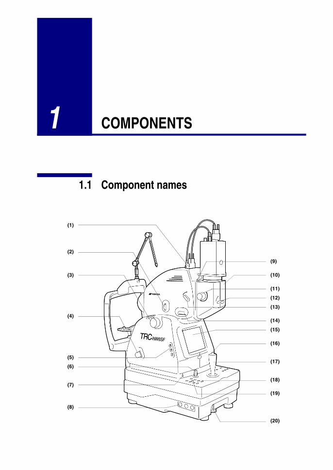
1.1 Component names
(1)
(2)
(3)
(4)
(5)
(6)
(7)
(8)
(9)
(10)
(11)
(12)
(13)
(14)
(15)
(16)
(17)
(18)
(20)
(19)

Non-Mydriatic Retinal Camera TRC-NW6SF/ TRC-NW6S
(1) TV camera connection terminal
(2) Diopter compensation lens selector
(3) Focusing knob
(4) IR filter selector
(5) Image quality adjustment knob
(6) Base brake knob
(7) Vertical position mark
(8) Fuse holder
(9) TV relay lens attaching lever
(10) TV relay lens
(11) Angle selector
(12) Mode selector *
(13) Fluoro-observation knob *
(14) Name plate slot
(15) Color video monitor
(16) Photography switch
(17) Omni-directional joystick
(18) Power lamp
(19) Control panel
(20) Fixing knob (for use when carrying the instrument)
* TRC-NW6SF only
18
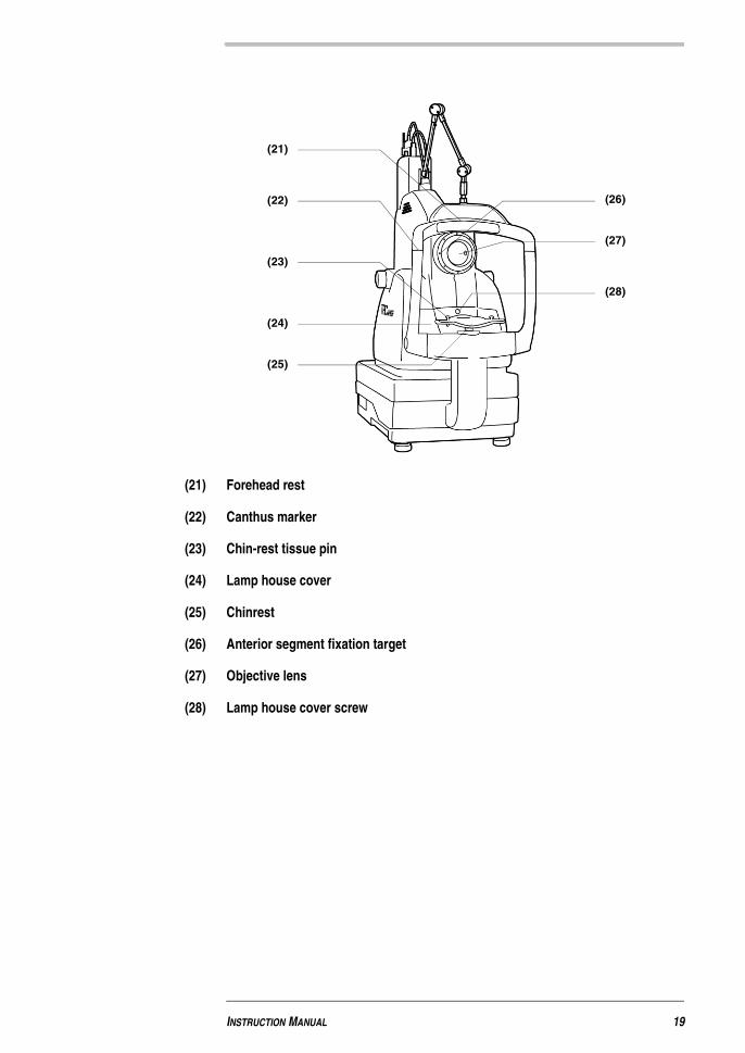
(21) Forehead rest
(22) Canthus marker
(23) Chin-rest tissue pin
(24) Lamp house cover
(25) Chinrest
(26) Anterior segment fixation target
(27) Objective lens
(28) Lamp house cover screw
(21)
(26)(22)
(23)
(24)
(25)
(27)
(28)
INSTRUCTION MANUAL 19
Non-Mydriatic Retinal Camera TRC-NW6SF/ TRC-NW6S
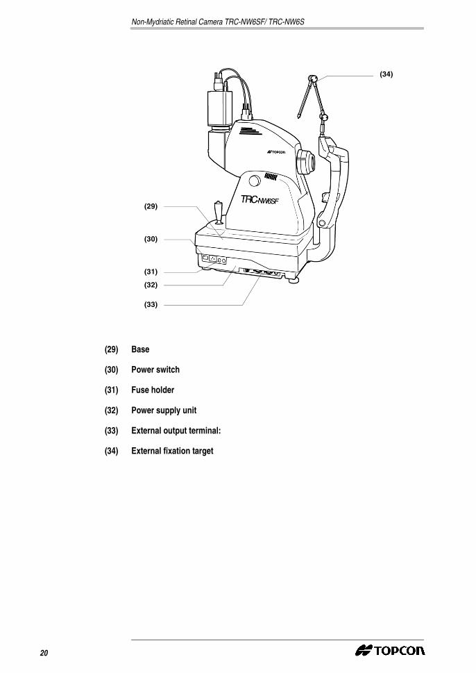
(29) Base
(30) Power switch
(31) Fuse holder
(32) Power supply unit
(33) External output terminal:
(34) External fixation target
(29)
(34)
(30)
(31)
(32)
(33)
20
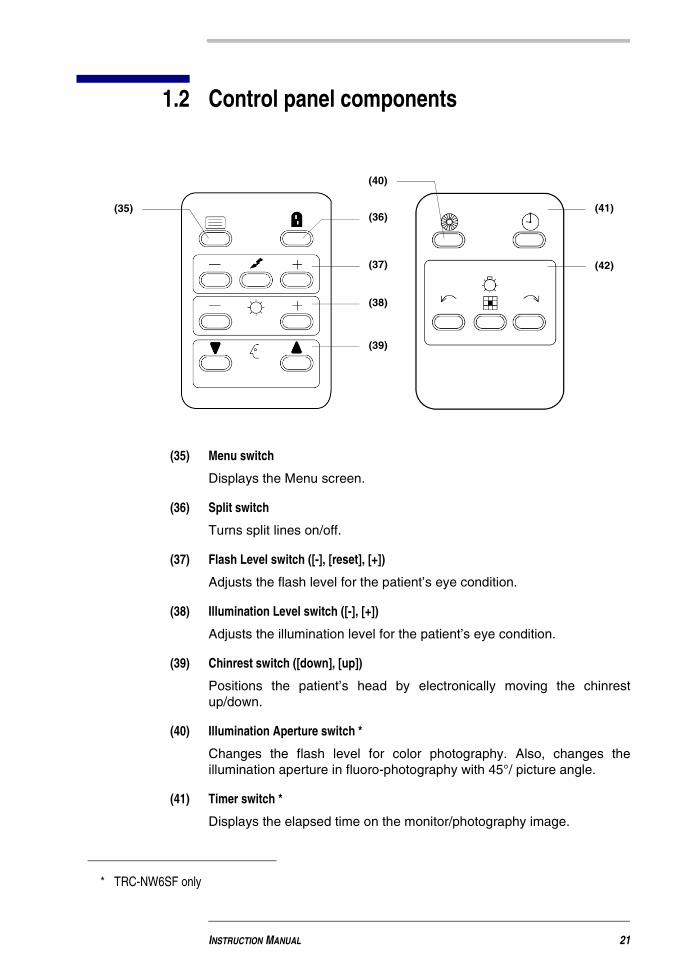
1.2 Control panel components
(35) Menu switch
Displays the Menu screen.
(36) Split switch
Turns split lines on/off.
(37) Flash Level switch ([-], [reset], [+])
Adjusts the flash level for the patient’s eye condition.
(38) Illumination Level switch ([-], [+])
Adjusts the illumination level for the patient’s eye condition.
(39) Chinrest switch ([down], [up])
Positions the patient’s head by electronically moving the chinrestup/down.
(40) Illumination Aperture switch *
Changes the flash level for color photography. Also, changes theillumination aperture in fluoro-photography with 45°/ picture angle.
(41) Timer switch *
Displays the elapsed time on the monitor/photography image.
(41)(35)(36)
(37)
(38)
(39)
(40)
(42)
* TRC-NW6SF only
INSTRUCTION MANUAL 21
Non-Mydriatic Retinal Camera TRC-NW6SF/ TRC-NW6S
(42) Periphery Fixation switch ([left turn], [reset], [right turn])
Switches the position of the internal fixation target, therefore guiding thepatient’s eye to the periphery fixation point.
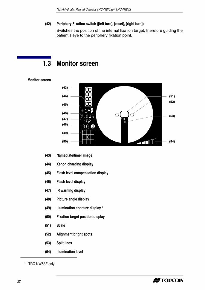
1.3 Monitor screen
Monitor screen
(43) Nameplate/timer image
(44) Xenon charging display
(45) Flash level compensation display
(46) Flash level display
(47) IR warning display
(48) Picture angle display
(49) Illumination aperture display *
(50) Fixation target position display
(51) Scale
(52) Alignment bright spots
(53) Split lines
(54) Illumination level
(43)
(44)
(45)
(46)
(47)
(48)
(49)
(50)
(51)
(52)
(53)
(54)
* TRC-NW6SF only
22
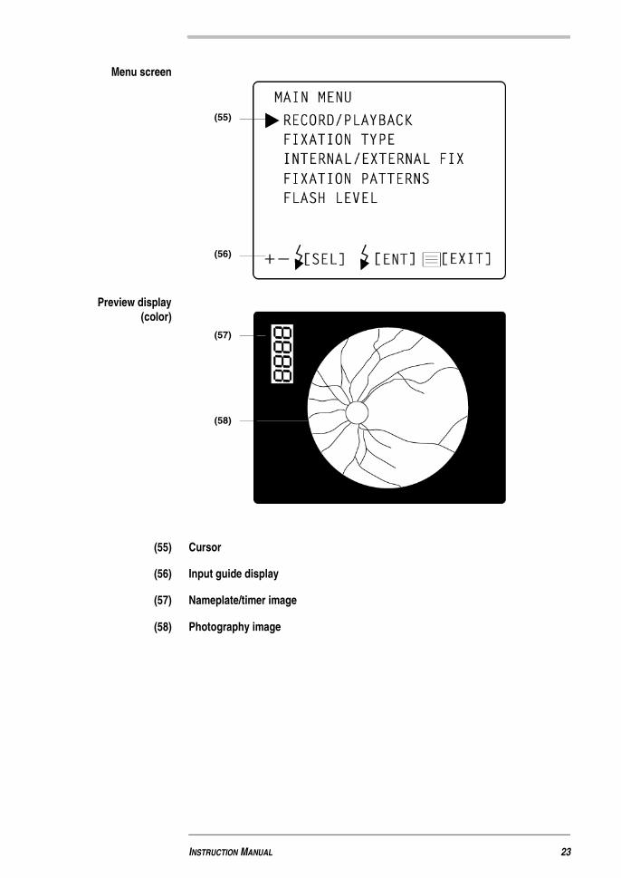
Menu screen
Preview display(color)
(55) Cursor
(56) Input guide display
(57) Nameplate/timer image
(58) Photography image
(55)
(56)
(57)
(58)
INSTRUCTION MANUAL 23

Non-Mydriatic Retinal Camera TRC-NW6SF/ TRC-NW6S
1.4 Standard accessories
Upon unpacking, make sure that all the following standard accessoriesare delivered. Figures in parentheses, ( ), indicate the quantity.
(59) (60)
(61) (62)
(63) (64)
(65)(66)
24

(59) Power cable (1)
(60) Nameplate (10)
(61) Illumination lamp (1)
(62) Fuse (9)
(63) Chinrest tissue (1)
(64) Chinrest tissue pin (2)
(65) Emergency chinrest knob (1)
(66) Spare parts case (1)
(67) Instruction Manual
(68) Warranty (1)
(69) Dust cover (1)
(70) External fixation target (1)
(67) (68)
(69) (70)
(71) (72)
INSTRUCTION MANUAL 25

Non-Mydriatic Retinal Camera TRC-NW6SF/ TRC-NW6S
(71) Power cable (1)
(72) TV camera signal cable (1)
1.5 Assembly components
(1) + (2)
(3)
(6)
(7)
(8)
(4)
(5)
(13)(12)(11)(10)
(9)
(14)
(15) (16) (17)
(20)
(19)(18)
26
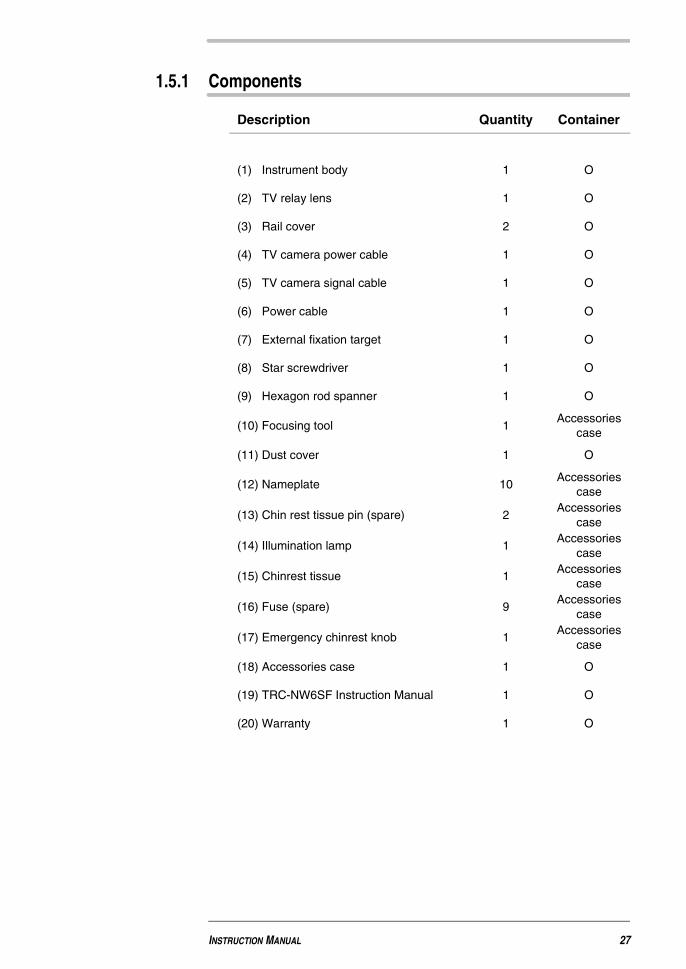
1.5.1 Components
Description Quantity Container
(1) Instrument body 1 O
(2) TV relay lens 1 O
(3) Rail cover 2 O
(4) TV camera power cable 1 O
(5) TV camera signal cable 1 O
(6) Power cable 1 O
(7) External fixation target 1 O
(8) Star screwdriver 1 O
(9) Hexagon rod spanner 1 O
(10) Focusing tool 1Accessories
case
(11) Dust cover 1 O
(12) Nameplate 10Accessories
case
(13) Chin rest tissue pin (spare) 2Accessories
case
(14) Illumination lamp 1Accessories
case
(15) Chinrest tissue 1Accessories
case
(16) Fuse (spare) 9Accessories
case
(17) Emergency chinrest knob 1Accessories
case
(18) Accessories case 1 O
(19) TRC-NW6SF Instruction Manual 1 O
(20) Warranty 1 O
INSTRUCTION MANUAL 27

Non-Mydriatic Retinal Camera TRC-NW6SF/ TRC-NW6S
28
2 ASSEMBLY PROCEDURE
2.1 Assembling the instrument body
Note: Since the upper part and lower part of the instrument are connectedonly by the power cable, take them out together so they do notseparate from each other.
WARNING
� To avoid the risk of electric shock, disconnect the cable from thepower supply before assembling the instrument. Never plug in thepower cable before assembly.
CAUTION
� Always install the instrument on a fixed, stable surface, to preventdamage or injury.
CAUTION
� The instrument should always be carried by two people, bothholding the bottom of the instrument. Attempting to carry theinstrument alone could result in backache or other injury.Attempting to carry the instrument without holding it at the bottomcould result in injury or damage.
Non-Mydriatic Retinal Camera TRC-NW6SF/ TRC-NW6S
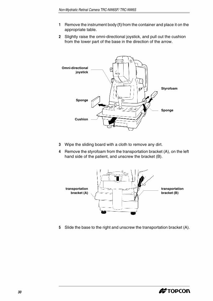
1 Remove the instrument body (1) from the container and place it on theappropriate table.
2 Slightly raise the omni-directional joystick, and pull out the cushionfrom the lower part of the base in the direction of the arrow.
3 Wipe the sliding board with a cloth to remove any dirt.
4 Remove the styrofoam from the transportation bracket (A), on the lefthand side of the patient, and unscrew the bracket (B).
5 Slide the base to the right and unscrew the transportation bracket (A).
Styrofoam
Sponge
Cushion
Sponge
Omni-directionaljoystick
transportationbracket (A)
transportationbracket (B)
30
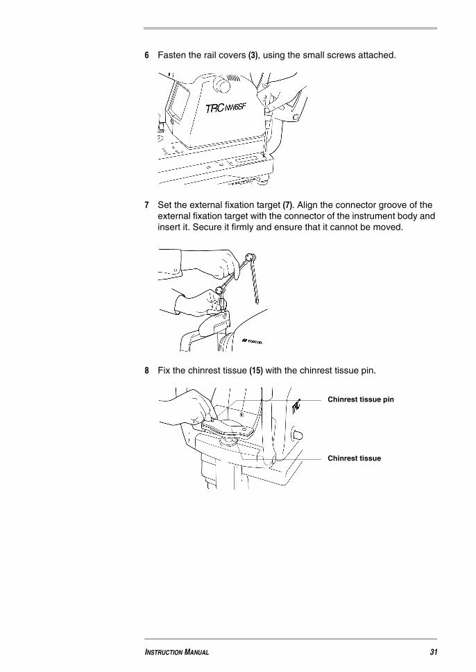
6 Fasten the rail covers (3), using the small screws attached.
7 Set the external fixation target (7). Align the connector groove of theexternal fixation target with the connector of the instrument body andinsert it. Secure it firmly and ensure that it cannot be moved.
8 Fix the chinrest tissue (15) with the chinrest tissue pin.
Chinrest tissue pin
Chinrest tissue
INSTRUCTION MANUAL 31
Non-Mydriatic Retinal Camera TRC-NW6SF/ TRC-NW6S
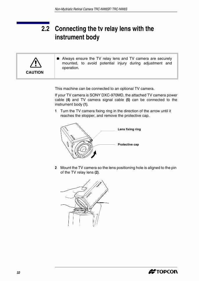
2.2 Connecting the tv relay lens with theinstrument body
This machine can be connected to an optional TV camera.
If your TV camera is SONY DXC-970MD, the attached TV camera powercable (4) and TV camera signal cable (5) can be connected to theinstrument body (1).
1 Turn the TV camera fixing ring in the direction of the arrow until itreaches the stopper, and remove the protective cap.
2 Mount the TV camera so the lens positioning hole is aligned to the pinof the TV relay lens (2).
CAUTION
� Always ensure the TV relay lens and TV camera are securelymounted, to avoid potential injury during adjustment andoperation.
Lens fixing ring
Protective cap
32
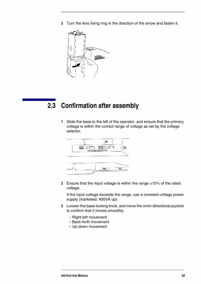
3 Turn the lens fixing ring in the direction of the arrow and fasten it.
2.3 Confirmation after assembly
1 Slide the base to the left of the operator, and ensure that the primaryvoltage is within the correct range of voltage as set by the voltageselector.
2 Ensure that the input voltage is within the range ±10% of the ratedvoltage.
If the input voltage exceeds the range, use a constant-voltage powersupply (marketed: 400VA up).
3 Loosen the base locking knob, and move the omni-directional joystickto confirm that it moves smoothly.
- Right-left movement- Back-forth movement- Up-down movement
INSTRUCTION MANUAL 33
Non-Mydriatic Retinal Camera TRC-NW6SF/ TRC-NW6S
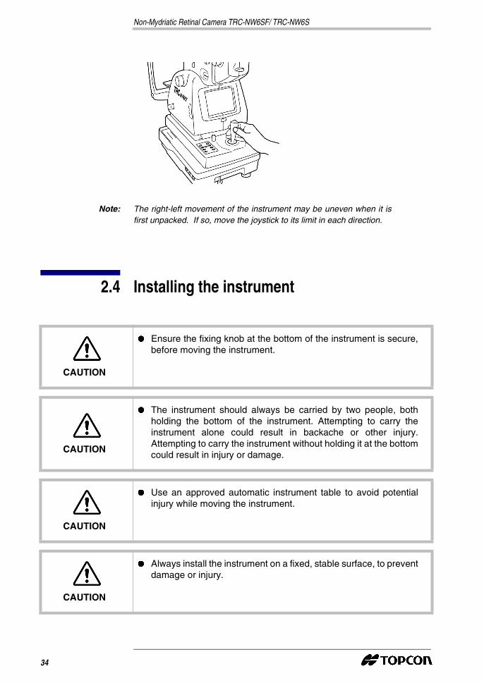
Note: The right-left movement of the instrument may be uneven when it isfirst unpacked. If so, move the joystick to its limit in each direction.
2.4 Installing the instrument
CAUTION
� Ensure the fixing knob at the bottom of the instrument is secure,before moving the instrument.
CAUTION
� The instrument should always be carried by two people, bothholding the bottom of the instrument. Attempting to carry theinstrument alone could result in backache or other injury.Attempting to carry the instrument without holding it at the bottomcould result in injury or damage.
CAUTION
� Use an approved automatic instrument table to avoid potentialinjury while moving the instrument.
CAUTION
� Always install the instrument on a fixed, stable surface, to preventdamage or injury.
34
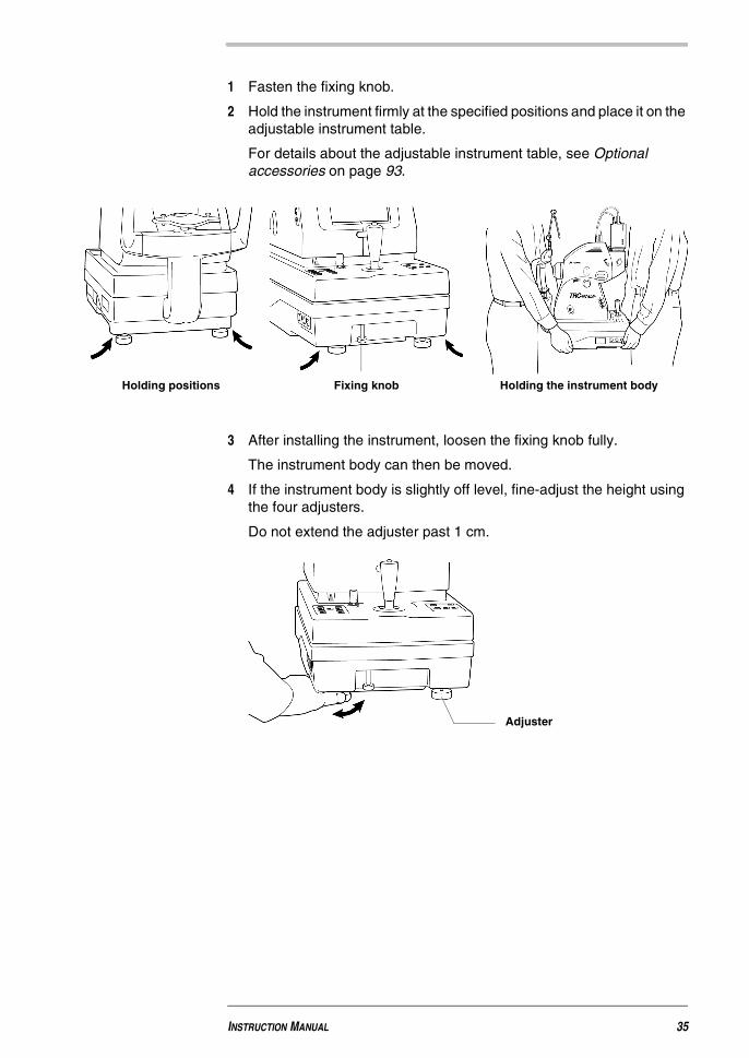
1 Fasten the fixing knob.
2 Hold the instrument firmly at the specified positions and place it on theadjustable instrument table.
For details about the adjustable instrument table, see Optionalaccessories on page 93.
3 After installing the instrument, loosen the fixing knob fully.
The instrument body can then be moved.
4 If the instrument body is slightly off level, fine-adjust the height usingthe four adjusters.
Do not extend the adjuster past 1 cm.
Holding the instrument bodyFixing knobHolding positions
Adjuster
INSTRUCTION MANUAL 35
Non-Mydriatic Retinal Camera TRC-NW6SF/ TRC-NW6S
2.5 Connecting the power cable
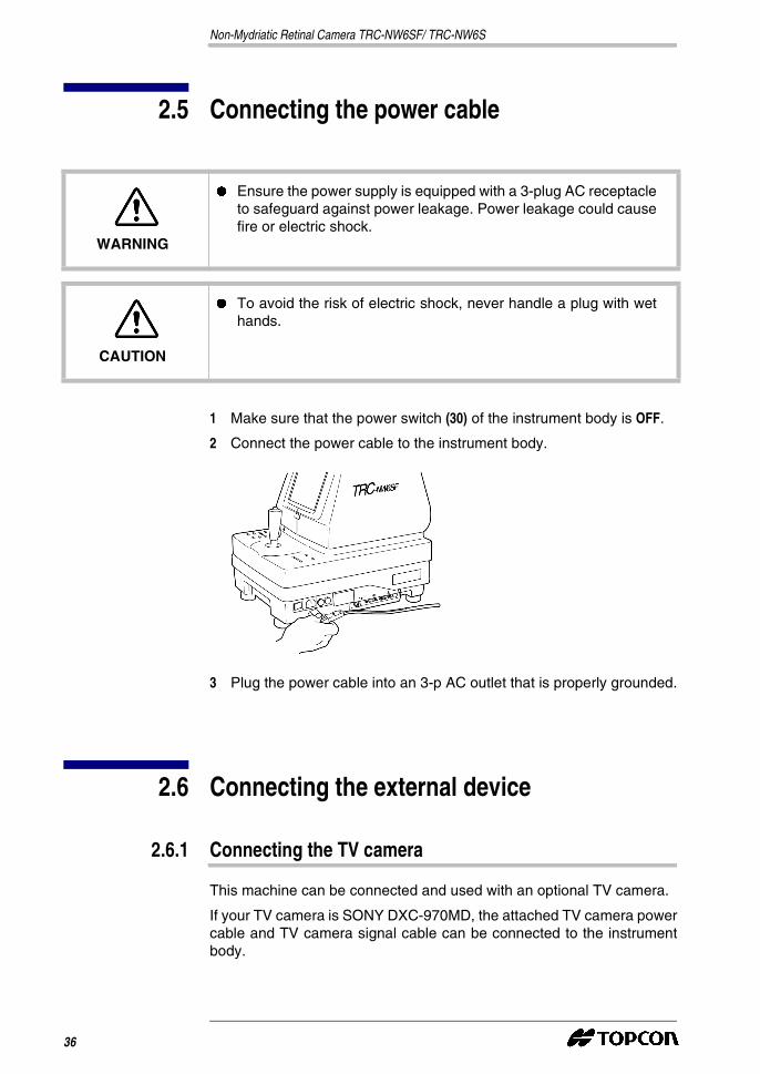
1 Make sure that the power switch (30) of the instrument body is OFF.
2 Connect the power cable to the instrument body.
3 Plug the power cable into an 3-p AC outlet that is properly grounded.
2.6 Connecting the external device
2.6.1 Connecting the TV camera
This machine can be connected and used with an optional TV camera.
If your TV camera is SONY DXC-970MD, the attached TV camera powercable and TV camera signal cable can be connected to the instrumentbody.
WARNING
� Ensure the power supply is equipped with a 3-plug AC receptacleto safeguard against power leakage. Power leakage could causefire or electric shock.
CAUTION
� To avoid the risk of electric shock, never handle a plug with wethands.
36
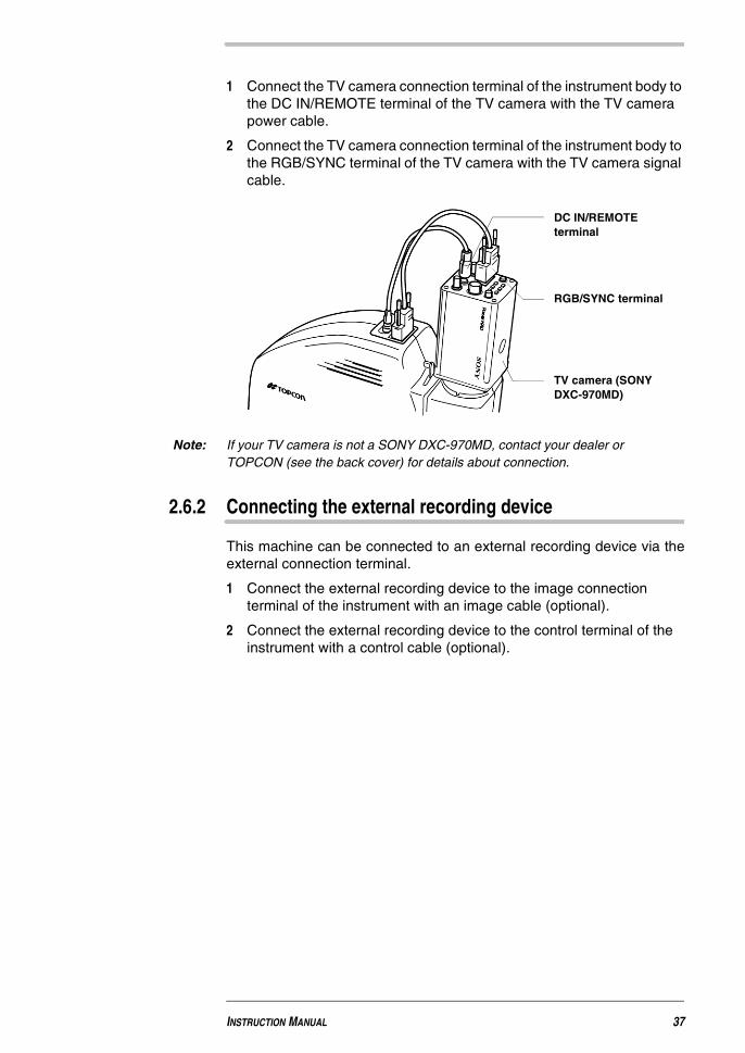
1 Connect the TV camera connection terminal of the instrument body tothe DC IN/REMOTE terminal of the TV camera with the TV camerapower cable.
2 Connect the TV camera connection terminal of the instrument body tothe RGB/SYNC terminal of the TV camera with the TV camera signalcable.
Note: If your TV camera is not a SONY DXC-970MD, contact your dealer orTOPCON (see the back cover) for details about connection.
2.6.2 Connecting the external recording device
This machine can be connected to an external recording device via theexternal connection terminal.
1 Connect the external recording device to the image connectionterminal of the instrument with an image cable (optional).
2 Connect the external recording device to the control terminal of theinstrument with a control cable (optional).
DC IN/REMOTEterminal
RGB/SYNC terminal
TV camera (SONYDXC-970MD)
INSTRUCTION MANUAL 37
Non-Mydriatic Retinal Camera TRC-NW6SF/ TRC-NW6S
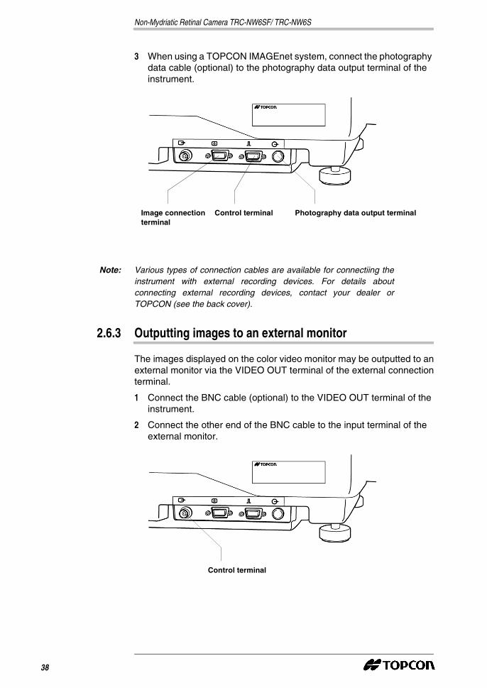
3 When using a TOPCON IMAGEnet system, connect the photographydata cable (optional) to the photography data output terminal of theinstrument.
Note: Various types of connection cables are available for connectiing theinstrument with external recording devices. For details aboutconnecting external recording devices, contact your dealer orTOPCON (see the back cover).
2.6.3 Outputting images to an external monitor
The images displayed on the color video monitor may be outputted to anexternal monitor via the VIDEO OUT terminal of the external connectionterminal.
1 Connect the BNC cable (optional) to the VIDEO OUT terminal of theinstrument.
2 Connect the other end of the BNC cable to the input terminal of theexternal monitor.
Photography data output terminalControl terminalImage connectionterminal
Control terminal
38
2.6.4 VIDEO OUT terminal
Note: For details about video output to external recording devices, contactyour dealer or TOPCON (see the back cover).
2.7 Menu setting
The following items can be set within Menu setting: record/playback,fixation target on/flicker, internal/ external fixation targets, fixation targetpatterns and flash level.
2.7.1 Preparation for menu setting
1 Check the power cable connection.
For details about the connection, see Connecting the power cable onpage 36.
2 Turn the power switch (30) on.
2.7.2 Displaying the Menu screen
1 Check the monitor screen.
2 Press the Menu switch (35) on the control panel.
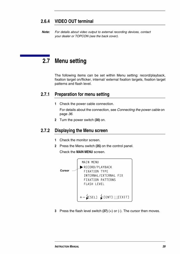
Check the MAIN MENU screen.
3 Press the flash level switch (37) (+) or (-). The cursor then moves.
Cursor
INSTRUCTION MANUAL 39
Non-Mydriatic Retinal Camera TRC-NW6SF/ TRC-NW6S
2.7.3 Returning to the Monitor screen
1 Press the menu switch (35).
2.7.4 Setting the Record/Playback mode
It is possible to alternate between Record and Playback modes.
In the Record mode, ordinary photography is available.
Use the Playback mode to display the recorded images of the recordingdevice to the color video monitor.
The record mode RECORD is set automatically once the power supply isturned on.
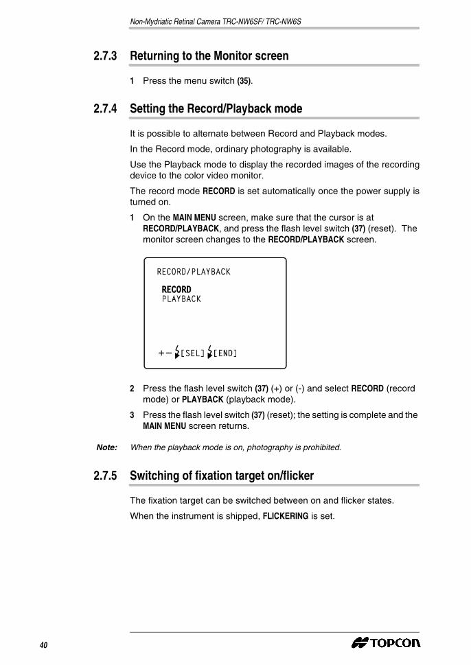
1 On the MAIN MENU screen, make sure that the cursor is atRECORD/PLAYBACK, and press the flash level switch (37) (reset). Themonitor screen changes to the RECORD/PLAYBACK screen.
2 Press the flash level switch (37) (+) or (-) and select RECORD (recordmode) or PLAYBACK (playback mode).
3 Press the flash level switch (37) (reset); the setting is complete and theMAIN MENU screen returns.
Note: When the playback mode is on, photography is prohibited.
2.7.5 Switching of fixation target on/flicker
The fixation target can be switched between on and flicker states.
When the instrument is shipped, FLICKERING is set.
40
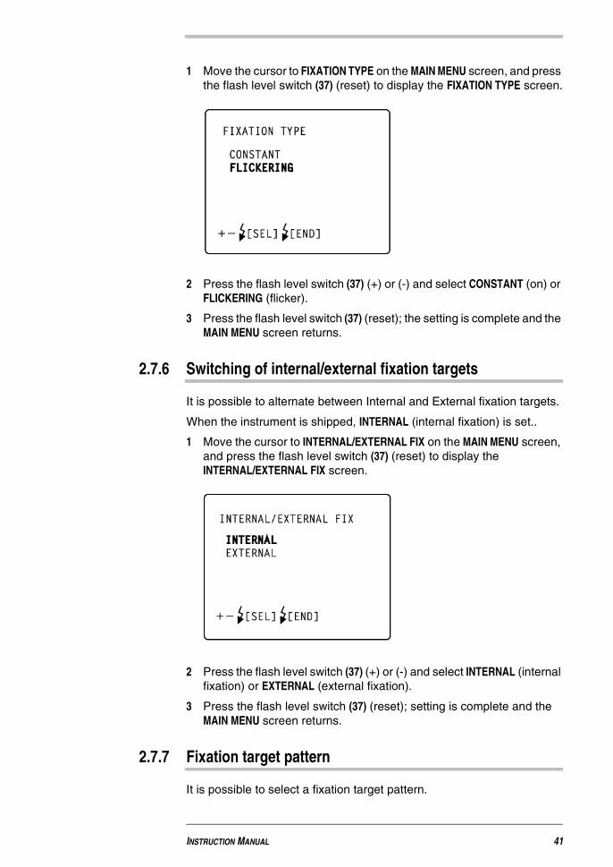
1 Move the cursor to FIXATION TYPE on the MAIN MENU screen, and pressthe flash level switch (37) (reset) to display the FIXATION TYPE screen.
2 Press the flash level switch (37) (+) or (-) and select CONSTANT (on) orFLICKERING (flicker).
3 Press the flash level switch (37) (reset); the setting is complete and theMAIN MENU screen returns.
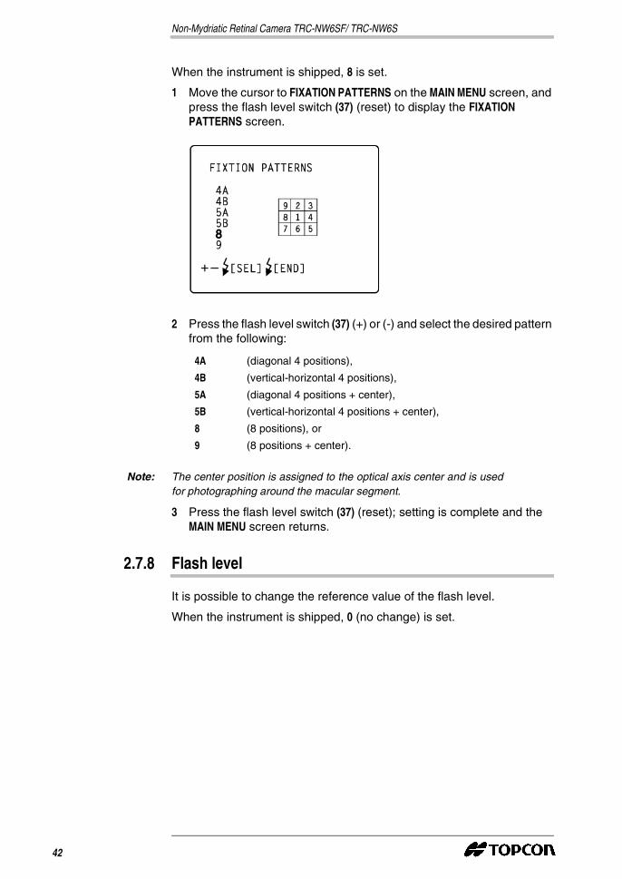
2.7.6 Switching of internal/external fixation targets
It is possible to alternate between Internal and External fixation targets.
When the instrument is shipped, INTERNAL (internal fixation) is set..
1 Move the cursor to INTERNAL/EXTERNAL FIX on the MAIN MENU screen,and press the flash level switch (37) (reset) to display theINTERNAL/EXTERNAL FIX screen.
2 Press the flash level switch (37) (+) or (-) and select INTERNAL (internalfixation) or EXTERNAL (external fixation).
3 Press the flash level switch (37) (reset); setting is complete and theMAIN MENU screen returns.
2.7.7 Fixation target pattern
It is possible to select a fixation target pattern.
INSTRUCTION MANUAL 41
Non-Mydriatic Retinal Camera TRC-NW6SF/ TRC-NW6S
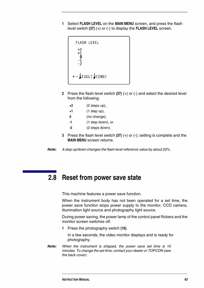
When the instrument is shipped, 8 is set.
1 Move the cursor to FIXATION PATTERNS on the MAIN MENU screen, andpress the flash level switch (37) (reset) to display the FIXATIONPATTERNS screen.
2 Press the flash level switch (37) (+) or (-) and select the desired patternfrom the following:
Note: The center position is assigned to the optical axis center and is usedfor photographing around the macular segment.
3 Press the flash level switch (37) (reset); setting is complete and theMAIN MENU screen returns.
2.7.8 Flash level
It is possible to change the reference value of the flash level.
When the instrument is shipped, 0 (no change) is set.
4A (diagonal 4 positions),
4B (vertical-horizontal 4 positions),
5A (diagonal 4 positions + center),
5B (vertical-horizontal 4 positions + center),
8 (8 positions), or
9 (8 positions + center).
42
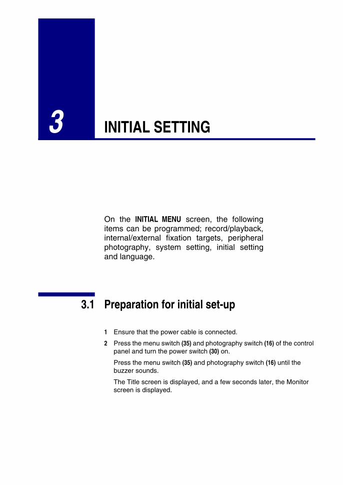
1 Select FLASH LEVEL on the MAIN MENU screen, and press the flashlevel switch (37) (+) or (-) to display the FLASH LEVEL screen.
2 Press the flash level switch (37) (+) or (-) and select the desired levelfrom the following:
3 Press the flash level switch (37) (+) or (-); setting is complete and theMAIN MENU screen returns.
Note: A step up/down changes the flash level reference value by about 20%.
2.8 Reset from power save state
This machine features a power save function.
When the instrument body has not been operated for a set time, thepower save function stops power supply to the monitor, CCD camera,illumination light source and photography light source.
During power saving, the power lamp of the control panel flickers and themonitor screen switches off.
1 Press the photography switch (16).
In a few seconds, the video monitor displays and is ready forphotography.
Note: When the instrument is shipped, the power save set time is 10minutes. To change the set time, contact your dealer or TOPCON (seethe back cover).
+2 (2 steps up),
+1 (1 step up),
0 (no change),
-1 (1 step down), or
-2 (2 steps down).
INSTRUCTION MANUAL 43

Non-Mydriatic Retinal Camera TRC-NW6SF/ TRC-NW6S
44
3 INITIAL SETTING
On the INITIAL MENU screen, the followingitems can be programmed; record/playback,internal/external fixation targets, peripheralphotography, system setting, initial settingand language.
3.1 Preparation for initial set-up
1 Ensure that the power cable is connected.
2 Press the menu switch (35) and photography switch (16) of the controlpanel and turn the power switch (30) on.
Press the menu switch (35) and photography switch (16) until thebuzzer sounds.
The Title screen is displayed, and a few seconds later, the Monitorscreen is displayed.
Non-Mydriatic Retinal Camera TRC-NW6SF/ TRC-NW6S
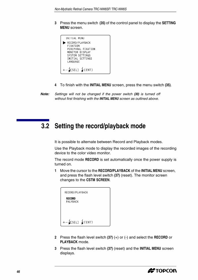
3 Press the menu switch (35) of the control panel to display the SETTINGMENU screen.
4 To finish with the INITIAL MENU screen, press the menu switch (35).
Note: Settings will not be changed if the power switch (30) is turned offwithout first finishing with the INITIAL MENU screen as outlined above.
3.2 Setting the record/playback mode
It is possible to alternate between Record and Playback modes.
Use the Playback mode to display the recorded images of the recordingdevice to the color video monitor.
The record mode RECORD is set automatically once the power supply isturned on.
1 Move the cursor to the RECORD/PLAYBACK of the INITIAL MENU screen,and press the flash level switch (37) (reset). The monitor screenchanges to the CSTM SCREEN.
2 Press the flash level switch (37) (+) or (-) and select the RECORD orPLAYBACK mode.
3 Press the flash level switch (37) (reset) and the INITIAL MENU screendisplays.
46

Note: Settings will not be changed if the power switch (30) is turned offwithout first finishing with the INITIAL MENU screen as outlined above.
3.3 Setting the fixation target
It is possible to set the fixation target on/flicker and internal/externalfixation target switching on the FIXATION screen.
1 On the INITIAL MENU screen, move the cursor to FIXATION and pressthe flash level switch (37) (reset). The monitor screen changes to theFIXATION screen.
2 To finish with the FIXATION screen, press the menu switch (35).
Note: Settings will not be changed if the power switch (30) is turned offwithout first finishing with the INITIAL MENU screen as outlined above.
3.3.1 Switching the fixation target on/flicker
The fixation target can be switched between on and flicker states. Whenthe instrument is shipped, FLICKERING (flicker) is set.
1 Select FIXATION TYPE on the FIXATION screen to display the FIXATIONTYPE screen.
INSTRUCTION MANUAL 47
Non-Mydriatic Retinal Camera TRC-NW6SF/ TRC-NW6S
2 Press the flash level switch (37) (+) or (-) and select CONSTANT (on) orFLICKERING (flicker).
3 Press the flash level switch (37) (reset); setting is complete and theFIXATION screen returns.
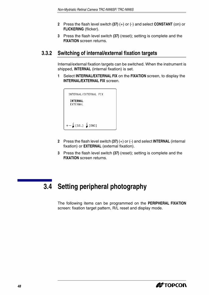
3.3.2 Switching of internal/external fixation targets
Internal/external fixation targets can be switched. When the instrument isshipped, INTERNAL (internal fixation) is set.
1 Select INTERNAL/EXTERNAL FIX on the FIXATION screen, to display theINTERNAL/EXTERNAL FIX screen.
2 Press the flash level switch (37) (+) or (-) and select INTERNAL (internalfixation) or EXTERNAL (external fixation).
3 Press the flash level switch (37) (reset); setting is complete and theFIXATION screen returns.
3.4 Setting peripheral photography
The following items can be programmed on the PERIPHERAL FIXATIONscreen: fixation target pattern, R/L reset and display mode.
48

1 Move the cursor to the PERIPHERAL FIXATION of the INITIAL MENUscreen, and press the flash level switch (37) (reset). The monitorscreen changes to the PERIPHERAL FIXATION screen.
2 To finish with the PERIPHERAL FIXATION screen, press the menu switch(35).
Note: Settings will not be changed if the power switch (30) is turned offwithout first finishing with the INITIAL MENU screen as outlined above.
3.4.1 Fixation target pattern
It is possible to select a fixation target pattern. When the instrument isshipped, 8 is set.
1 Move the cursor to FIXATION PATTERNS on the PERIPHERAL FIXATIONscreen, to display the FIXATION PATTERNS screen.
2 Press the flash level switch (37) (+) or (-) and select the desired patternfrom the following:
3 Press the flash level switch (37) (reset); the setting is complete and thePERIPHERAL FIXATION screen returns.
4A (diagonal 4 positions),
4B (vertical-horizontal 4 positions),
5A (diagonal 4 positions + center),
5B (vertical-horizontal 4 positions + center),
8 (8 positions), or
9 (8 positions + center).
INSTRUCTION MANUAL 49
Non-Mydriatic Retinal Camera TRC-NW6SF/ TRC-NW6S
Note: The center position is assigned to the optical axis center and is usedfor photographing around the macular segment.
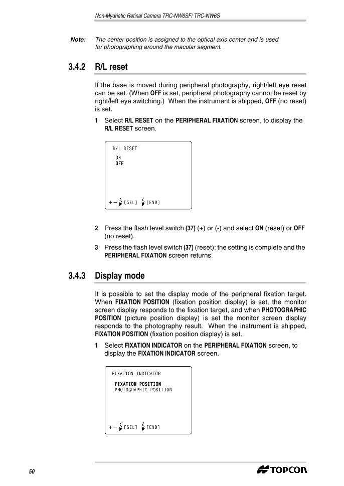
3.4.2 R/L reset
If the base is moved during peripheral photography, right/left eye resetcan be set. (When OFF is set, peripheral photography cannot be reset byright/left eye switching.) When the instrument is shipped, OFF (no reset)is set.
1 Select R/L RESET on the PERIPHERAL FIXATION screen, to display theR/L RESET screen.
2 Press the flash level switch (37) (+) or (-) and select ON (reset) or OFF(no reset).
3 Press the flash level switch (37) (reset); the setting is complete and thePERIPHERAL FIXATION screen returns.
3.4.3 Display mode
It is possible to set the display mode of the peripheral fixation target.When FIXATION POSITION (fixation position display) is set, the monitorscreen display responds to the fixation target, and when PHOTOGRAPHICPOSITION (picture position display) is set the monitor screen displayresponds to the photography result. When the instrument is shipped,FIXATION POSITION (fixation position display) is set.
1 Select FIXATION INDICATOR on the PERIPHERAL FIXATION screen, todisplay the FIXATION INDICATOR screen.
50

2 Press the flash level switch (37) (+) or (-) and select FIXATION POSITION(fixation position display) or PHOTOGRAPHIC POSITION (picture positiondisplay).
3 Press the flash level switch (37) (reset); the setting is complete and thePERIPHERAL FIXATION screen returns.
3.5 Setting the screen display
On the MONITOR DISPLAY screen, the following display settings can beset: flash level compensation, flash level, illumination level, picture angle,illumination aperture* and fixation position.
1 Ensure that the cursor is on the MONITOR DISPLAY of the INITIAL MENUscreen, and press the flash level switch (37) (reset). The monitorscreen changes to the MONITOR DISPLAY screen.
2 To finish with the MONITOR DISPLAY screen, press the menu switch(35).
Note: Settings will not be changed if the power switch (30) is turned offwithout first finishing with the INITIAL MENU screen as outlined above.
3.5.1 Flash level compensation display
The flash level compensation display can be set. When the instrument isshipped, ON (display) is set.
* TRC-NW6SF only
TRC-NW6SF TRC-NW6S
INSTRUCTION MANUAL 51

Non-Mydriatic Retinal Camera TRC-NW6SF/ TRC-NW6S
1 Select FLASH LEVEL IN 5STEPS on the MONITOR DISPLAY screen, todisplay the FLASH LEVEL IN 5STEPS screen.
2 Press the flash level switch (37) (+) or (-) and select ON (display) or OFF(no display).
3 Press the flash level switch (37) (reset); the setting is complete and theMONITOR DISPLAY screen returns.
3.5.2 Flash level display
The flash level display can be set. When the instrument is shipped, OFF(no display) is set.
1 Select FLASH LEVELS IN WS on the MONITOR DISPLAY screen, to displaythe FLASH LEVELS IN WS screen.
2 Press the flash level switch (37) (+) or (-) and select ON (display) or OFF(no display).
3 Press the flash level switch (37) (reset); the setting is complete and theMONITOR DISPLAY screen returns.
3.5.3 Illumination level display
The illumination level display can be set. When the instrument isshipped, ON (display) is set.
52
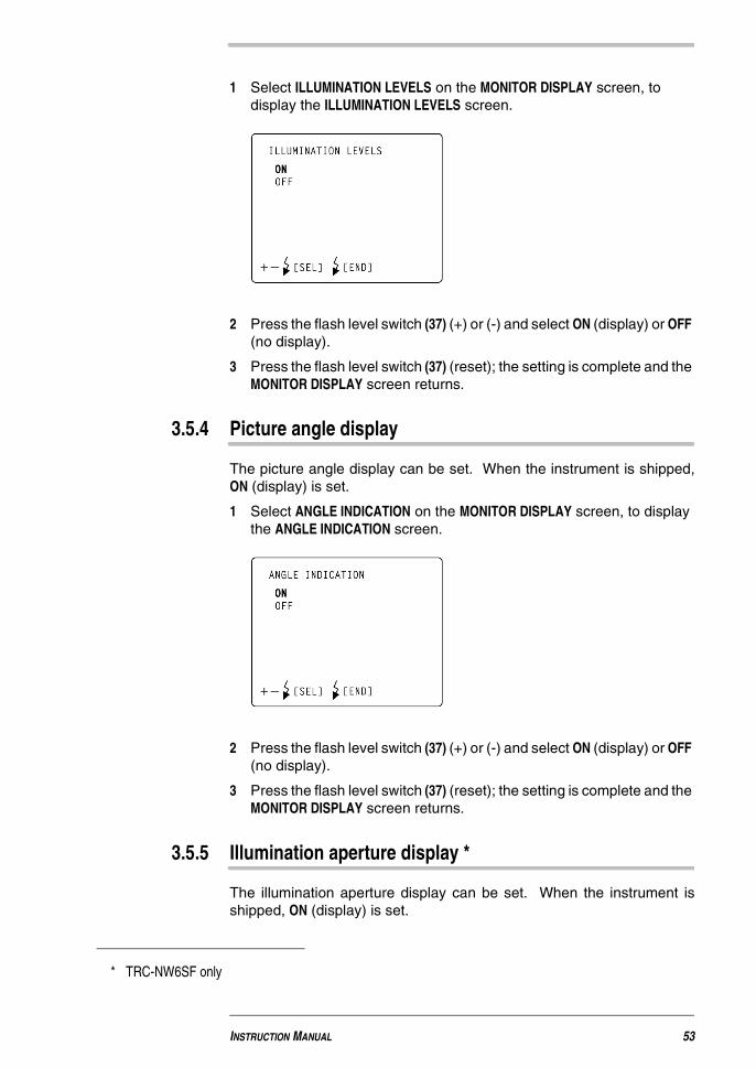
1 Select ILLUMINATION LEVELS on the MONITOR DISPLAY screen, todisplay the ILLUMINATION LEVELS screen.
2 Press the flash level switch (37) (+) or (-) and select ON (display) or OFF(no display).
3 Press the flash level switch (37) (reset); the setting is complete and theMONITOR DISPLAY screen returns.
3.5.4 Picture angle display
The picture angle display can be set. When the instrument is shipped,ON (display) is set.
1 Select ANGLE INDICATION on the MONITOR DISPLAY screen, to displaythe ANGLE INDICATION screen.
2 Press the flash level switch (37) (+) or (-) and select ON (display) or OFF(no display).
3 Press the flash level switch (37) (reset); the setting is complete and theMONITOR DISPLAY screen returns.
3.5.5 Illumination aperture display *
The illumination aperture display can be set. When the instrument isshipped, ON (display) is set.
* TRC-NW6SF only
INSTRUCTION MANUAL 53
Non-Mydriatic Retinal Camera TRC-NW6SF/ TRC-NW6S
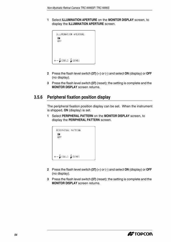
1 Select ILLUMINATION APERTURE on the MONITOR DISPLAY screen, todisplay the ILLUMINATION APERTURE screen.
2 Press the flash level switch (37) (+) or (-) and select ON (display) or OFF(no display).
3 Press the flash level switch (37) (reset); the setting is complete and theMONITOR DISPLAY screen returns.
3.5.6 Peripheral fixation position display
The peripheral fixation position display can be set. When the instrumentis shipped, ON (display) is set.
1 Select PERIPHERAL PATTERN on the MONITOR DISPLAY screen, todisplay the PERIPHERAL PATTERN screen.
2 Press the flash level switch (37) (+) or (-) and select ON (display) or OFF(no display).
3 Press the flash level switch (37) (reset); the setting is complete and theMONITOR DISPLAY screen returns.
54

3.6 System setting
Settings of the connected external recording device can be programmedon the SYSTEM SETTINGS screen.
When the instrument is shipped, IMAGENET MODE (image modeconnection) is set.
1 Ensure that the cursor is on the SYSTEM SETTINGS of the INITIAL MENUscreen, and press the flash level switch (37) (reset). The monitorscreen changes to the SYSTEM SETTINGS screen.
2 Press the flash level switch (37) (+) or (-) and select:
3 Press the flash level switch (37) (reset) and the INITIAL MENU screendisplays.
Note: For details about single/double-action, refer to the instruction manualof the external recording device.
Note: Settings will not be changed if the power switch (30) is turned offwithout first finishing with the INITIAL MENU screen as outlined above.
3.7 Setting the initial state
On the INITIAL SETTINGS screen, the following items can be set: flashlevel, commercial power supply frequency, LED display, timer sound*,operation sound and quick mirror-up of power save time.
IMAGE MODE (IMAGEnet connection);
TYPE1 MODE (single-action external device connection); or
TYPE2 MODE (double-action external device connection).
* TRC-NW6SF only
INSTRUCTION MANUAL 55
Non-Mydriatic Retinal Camera TRC-NW6SF/ TRC-NW6S
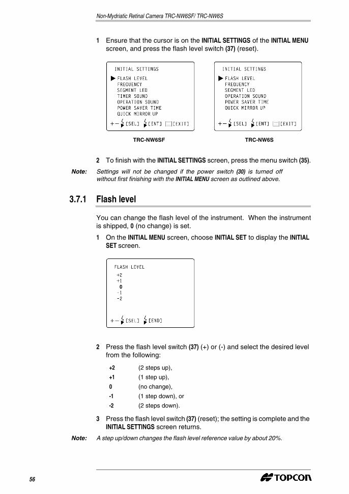
1 Ensure that the cursor is on the INITIAL SETTINGS of the INITIAL MENUscreen, and press the flash level switch (37) (reset).
2 To finish with the INITIAL SETTINGS screen, press the menu switch (35).
Note: Settings will not be changed if the power switch (30) is turned offwithout first finishing with the INITIAL MENU screen as outlined above.
3.7.1 Flash level
You can change the flash level of the instrument. When the instrumentis shipped, 0 (no change) is set.
1 On the INITIAL MENU screen, choose INITIAL SET to display the INITIALSET screen.
2 Press the flash level switch (37) (+) or (-) and select the desired levelfrom the following:
3 Press the flash level switch (37) (reset); the setting is complete and theINITIAL SETTINGS screen returns.
Note: A step up/down changes the flash level reference value by about 20%.
TRC-NW6SF TRC-NW6S
+2 (2 steps up),
+1 (1 step up),
0 (no change),
-1 (1 step down), or
-2 (2 steps down).
56
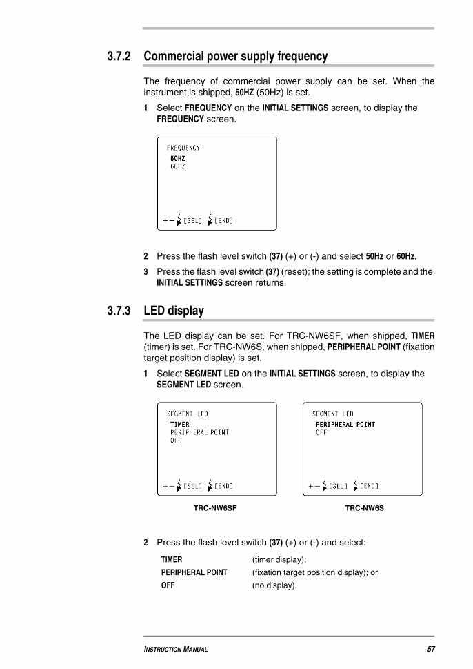
3.7.2 Commercial power supply frequency
The frequency of commercial power supply can be set. When theinstrument is shipped, 50HZ (50Hz) is set.
1 Select FREQUENCY on the INITIAL SETTINGS screen, to display theFREQUENCY screen.
2 Press the flash level switch (37) (+) or (-) and select 50Hz or 60Hz.
3 Press the flash level switch (37) (reset); the setting is complete and theINITIAL SETTINGS screen returns.
3.7.3 LED display
The LED display can be set. For TRC-NW6SF, when shipped, TIMER(timer) is set. For TRC-NW6S, when shipped, PERIPHERAL POINT (fixationtarget position display) is set.
1 Select SEGMENT LED on the INITIAL SETTINGS screen, to display theSEGMENT LED screen.
2 Press the flash level switch (37) (+) or (-) and select:
TIMER (timer display);
PERIPHERAL POINT (fixation target position display); or
OFF (no display).
TRC-NW6SF TRC-NW6S
INSTRUCTION MANUAL 57
Non-Mydriatic Retinal Camera TRC-NW6SF/ TRC-NW6S
3 Press the flash level switch (37) (reset); the setting is complete and theINITIAL SETTINGS screen returns.
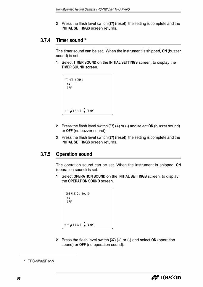
3.7.4 Timer sound *
The timer sound can be set. When the instrument is shipped, ON (buzzersound) is set.
1 Select TIMER SOUND on the INITIAL SETTINGS screen, to display theTIMER SOUND screen.
2 Press the flash level switch (37) (+) or (-) and select ON (buzzer sound)or OFF (no buzzer sound).
3 Press the flash level switch (37) (reset); the setting is complete and theINITIAL SETTINGS screen returns.
3.7.5 Operation sound
The operation sound can be set. When the instrument is shipped, ON(operation sound) is set.
1 Select OPERATION SOUND on the INITIAL SETTINGS screen, to displaythe OPERATION SOUND screen.
2 Press the flash level switch (37) (+) or (-) and select ON (operationsound) or OFF (no operation sound).
* TRC-NW6SF only
58
3 Press the flash level switch (37) (reset); the setting is complete and theINITIAL SETTINGS screen returns.
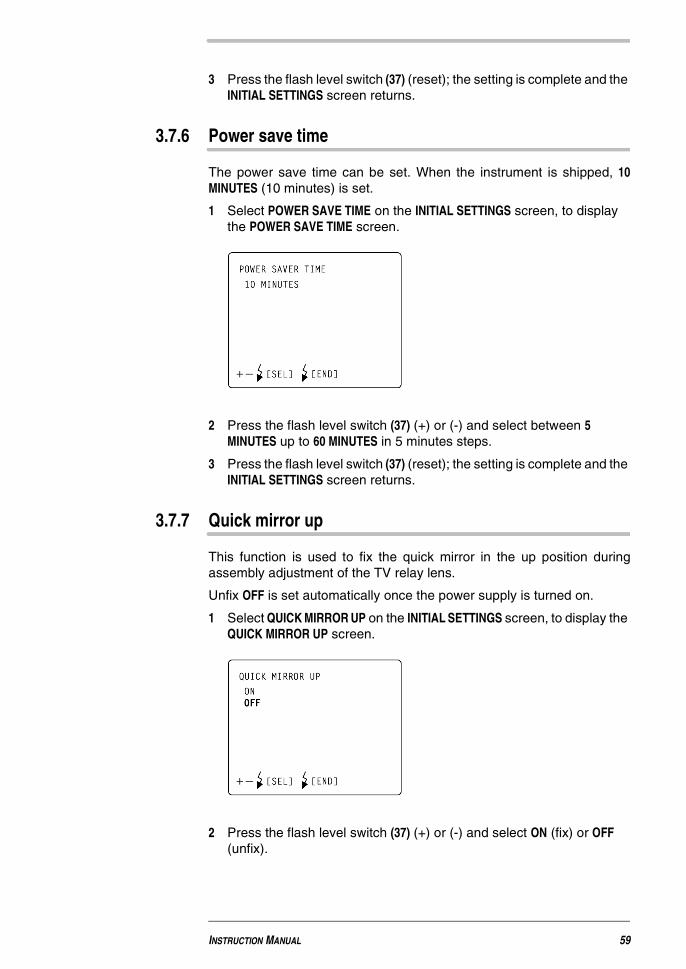
3.7.6 Power save time
The power save time can be set. When the instrument is shipped, 10MINUTES (10 minutes) is set.
1 Select POWER SAVE TIME on the INITIAL SETTINGS screen, to displaythe POWER SAVE TIME screen.
2 Press the flash level switch (37) (+) or (-) and select between 5MINUTES up to 60 MINUTES in 5 minutes steps.
3 Press the flash level switch (37) (reset); the setting is complete and theINITIAL SETTINGS screen returns.
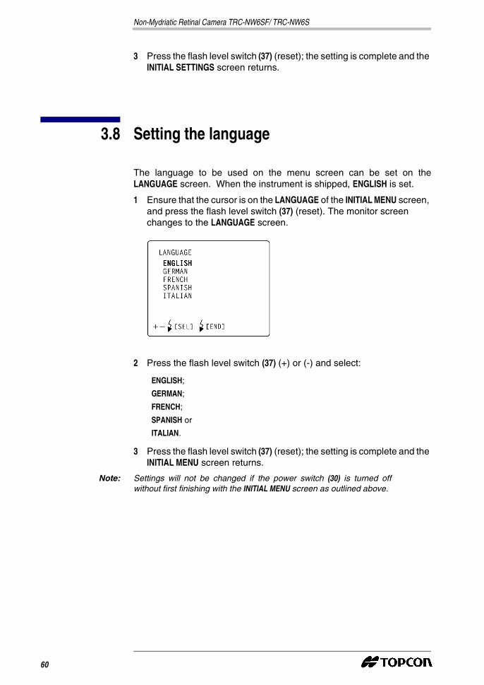
3.7.7 Quick mirror up
This function is used to fix the quick mirror in the up position duringassembly adjustment of the TV relay lens.
Unfix OFF is set automatically once the power supply is turned on.
1 Select QUICK MIRROR UP on the INITIAL SETTINGS screen, to display theQUICK MIRROR UP screen.
2 Press the flash level switch (37) (+) or (-) and select ON (fix) or OFF(unfix).
INSTRUCTION MANUAL 59
Non-Mydriatic Retinal Camera TRC-NW6SF/ TRC-NW6S
3 Press the flash level switch (37) (reset); the setting is complete and theINITIAL SETTINGS screen returns.
3.8 Setting the language
The language to be used on the menu screen can be set on theLANGUAGE screen. When the instrument is shipped, ENGLISH is set.
1 Ensure that the cursor is on the LANGUAGE of the INITIAL MENU screen,and press the flash level switch (37) (reset). The monitor screenchanges to the LANGUAGE screen.
2 Press the flash level switch (37) (+) or (-) and select:
3 Press the flash level switch (37) (reset); the setting is complete and theINITIAL MENU screen returns.
Note: Settings will not be changed if the power switch (30) is turned offwithout first finishing with the INITIAL MENU screen as outlined above.
ENGLISH;
GERMAN;
FRENCH;
SPANISH or
ITALIAN.
60
4 BASIC OPERATION
4.1 Preparation for photography
4.1.1 Connecting to the power supply
1 Check the power cable connection.
For details about connection, see Connecting the power cable onpage 36.
2 Turn on the power switch (30) of both the instrument and the externalrecording device.
3 Confirm that the title screen is displayed first, followed by the Monitorscreen.
4.1.2 Positioning the patient
Note: If the patient wears glasses or contact lens, remove them beforehand.
CAUTION
� To avoid potential injury to the patient, always watch the patientcarefully while adjusting the chinrest.

Non-Mydriatic Retinal Camera TRC-NW6SF/ TRC-NW6S
1 Ensure the main monitor screen is displayed.
2 When imaging the patient’s data, write the date on the nameplate andinsert it into the nameplate slot.
Note: Use a felt-tip marker to write the patient's name on the nameplate. Donot use an oil felt-tip as this can appear unclear on the monitor screen.
3 Press in the IR filter selector.
Nameplate insert
Monitor screen
Pressing the IR filter selector
62

Note: If the IR filter selector has not been pressed, the IR warning display(IR) flickers on the color video monitor, to indicate that the filter isinactive.
4 Seat the patient comfortably in the examination chair.
5 Adjust the table or chair height, so that the patient is comfortablewhen placing his/her chin on the chin rest (14).
6 Let the patient rest his/her chin on the chinrest, with the foreheadagainst the forehead rest.
7 Use the chinrest switch to adjust the height of the chinrest (39) so thetail of the eye comes level with the Canthus marker of the chinrestpost.
Note: The chinrest can be moved up or down as required when the chinrestswitch (39) is pressed.If you are unable to move the chinrest even when the chinrest switch(39) is pressed, discontinue the examination. Turn the power switch(30) off and remove the power cable, and contact your dealer orTOPCON (see the back cover).
Canthus marker
INSTRUCTION MANUAL 63
Non-Mydriatic Retinal Camera TRC-NW6SF/ TRC-NW6S
In the case of an emergency, you can manually operate the chinrest.For details about the manual operation, see Troubleshooting table onpage 96.
4.2 Color photography (center)
Note: To ensure correct imaging, adjust the table height so the patient canrest his/her chin comfortably on the chinrest.
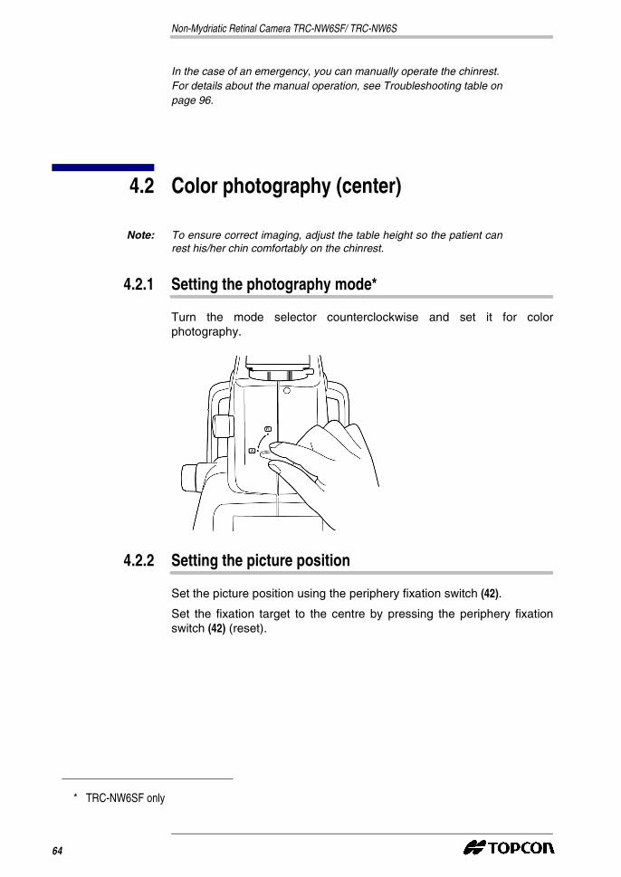
4.2.1 Setting the photography mode*
Turn the mode selector counterclockwise and set it for colorphotography.
4.2.2 Setting the picture position
Set the picture position using the periphery fixation switch (42).
Set the fixation target to the centre by pressing the periphery fixationswitch (42) (reset).
* TRC-NW6SF only
64
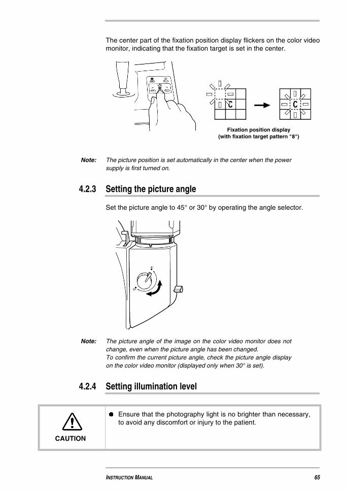
The center part of the fixation position display flickers on the color videomonitor, indicating that the fixation target is set in the center.
Note: The picture position is set automatically in the center when the powersupply is first turned on.
4.2.3 Setting the picture angle
Set the picture angle to 45° or 30° by operating the angle selector.
Note: The picture angle of the image on the color video monitor does notchange, even when the picture angle has been changed.To confirm the current picture angle, check the picture angle displayon the color video monitor (displayed only when 30° is set).
4.2.4 Setting illumination level
Fixation position display(with fixation target pattern "8")
CAUTION
� Ensure that the photography light is no brighter than necessary,to avoid any discomfort or injury to the patient.
INSTRUCTION MANUAL 65
Non-Mydriatic Retinal Camera TRC-NW6SF/ TRC-NW6S
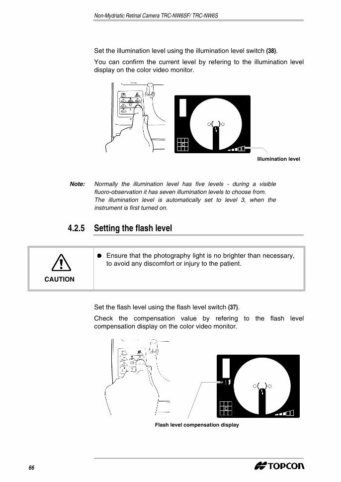
Set the illumination level using the illumination level switch (38).
You can confirm the current level by refering to the illumination leveldisplay on the color video monitor.
Note: Normally the illumination level has five levels - during a visiblefluoro-observation it has seven illumination levels to choose from.The illumination level is automatically set to level 3, when theinstrument is first turned on.
4.2.5 Setting the flash level
Set the flash level using the flash level switch (37).
Check the compensation value by refering to the flash levelcompensation display on the color video monitor.
Illumination level
CAUTION
� Ensure that the photography light is no brighter than necessary,to avoid any discomfort or injury to the patient.
Flash level compensation display
66

Note: You can compensate for the flash level in either direction, (+) and (-),to a maximum of two steps from the currently set position.When the flash level is identical to the reference value, nocompensation value is displayed.The flash level is automatically set to the reference value, when theinstrument is first turned on.The illumination level is automatically set to the reference value, whenthe power supply is turned on.
Note: You can adjust the reference value of the flash level in either direction,(+) or (-), to a maximum of two steps. See the Flash level on page 56.
Note: The flash level display can also display the light intensity level (unit:WS), as well as the the compensation value.For details about the flash level setting, contact your dealer orTOPCON (see the back cover).
4.2.6 Changing the diopter compensation lens
Pull out the diopter compensation lens selector and change the dioptercompensation lens for the patient’s eye.
Note: If the patient has strong myopia, pull out the diopter compensationlens selector one step and set it to (-) myopia.If the patient has strong hyperopia, pull out the diopter compensationlens selector two steps and set it to (+) hyperopia.
Compensation range: 0 :-13~+12D
- :-12~-33D
+ :+9~+40D
INSTRUCTION MANUAL 67
Non-Mydriatic Retinal Camera TRC-NW6SF/ TRC-NW6S
4.2.7 Collimation and photography
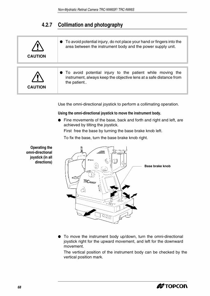
Use the omni-directional joystick to perform a collimating operation.
Using the omni-directional joystick to move the instrument body.
� Fine movements of the base, back and forth and right and left, areachieved by tilting the joystick.
First free the base by turning the base brake knob left.
To fix the base, turn the base brake knob right.
Operating theomni-directional
joystick (in alldirections)
� To move the instrument body up/down, turn the omni-directionaljoystick right for the upward movement, and left for the downwardmovement.
The vertical position of the instrument body can be checked by thevertical position mark.
CAUTION
� To avoid potential injury, do not place your hand or fingers into thearea between the instrument body and the power supply unit.
CAUTION
� To avoid potential injury to the patient while moving theinstrument, always keep the objective lens at a safe distance fromthe patient..
Base brake knob
68

Operating theomni-directional
joystick (in verticaldirections)
1 Hold the omni-directional joystick and pull the instrument backtowards the operator. When the internal fixation target has turned on,instruct the patient to look at the fixation target in the center.
Observe the anterior segment image on the color video monitor.
2 Move the instrument body as required until the patient’s eye can beseen in the center of the color video monitor.
Vertical position mark
INSTRUCTION MANUAL 69
Non-Mydriatic Retinal Camera TRC-NW6SF/ TRC-NW6S
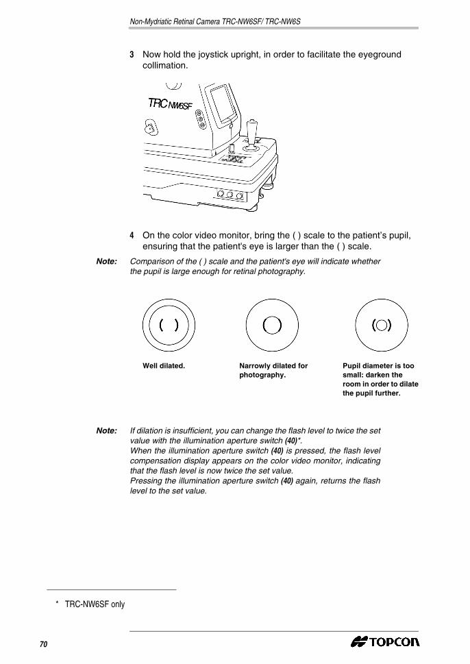
3 Now hold the joystick upright, in order to facilitate the eyegroundcollimation.
4 On the color video monitor, bring the ( ) scale to the patient’s pupil,ensuring that the patient's eye is larger than the ( ) scale.
Note: Comparison of the ( ) scale and the patient's eye will indicate whetherthe pupil is large enough for retinal photography.
Note: If dilation is insufficient, you can change the flash level to twice the setvalue with the illumination aperture switch (40)*.When the illumination aperture switch (40) is pressed, the flash levelcompensation display appears on the color video monitor, indicatingthat the flash level is now twice the set value.Pressing the illumination aperture switch (40) again, returns the flashlevel to the set value.
Well dilated. Narrowly dilated forphotography.
Pupil diameter is toosmall: darken theroom in order to dilatethe pupil further.
* TRC-NW6SF only
70
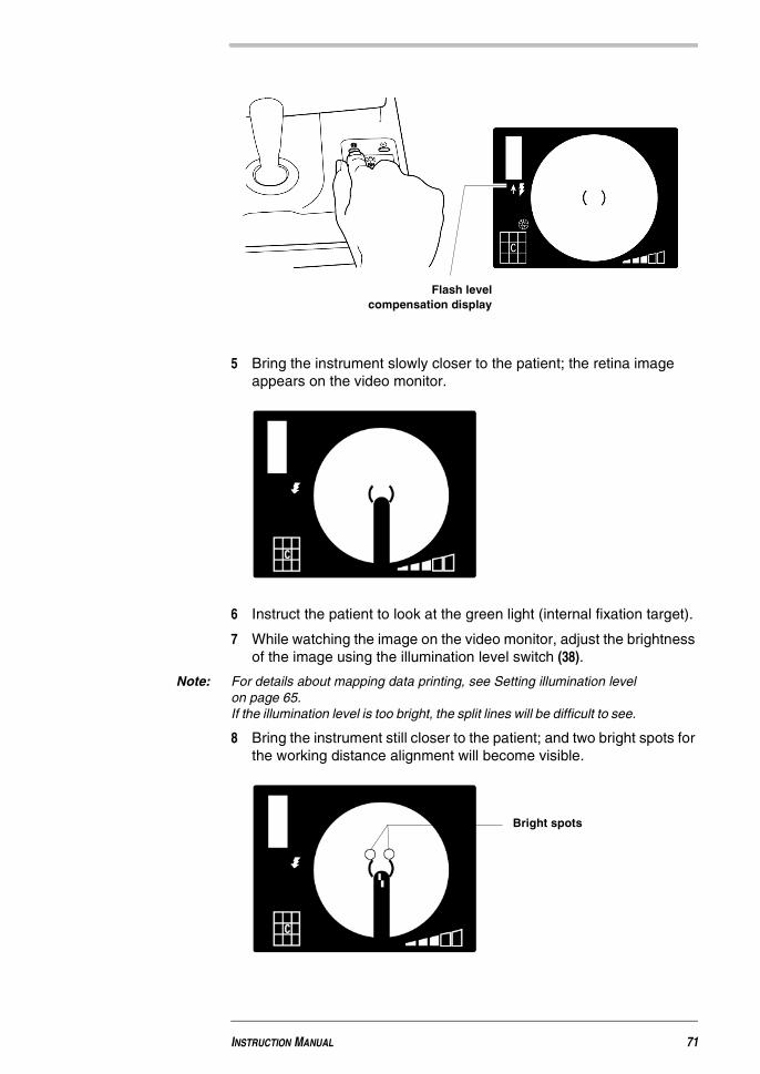
5 Bring the instrument slowly closer to the patient; the retina imageappears on the video monitor.
6 Instruct the patient to look at the green light (internal fixation target).
7 While watching the image on the video monitor, adjust the brightnessof the image using the illumination level switch (38).
Note: For details about mapping data printing, see Setting illumination levelon page 65.If the illumination level is too bright, the split lines will be difficult to see.
8 Bring the instrument still closer to the patient; and two bright spots forthe working distance alignment will become visible.
Flash levelcompensation display
Bright spots
INSTRUCTION MANUAL 71
Non-Mydriatic Retinal Camera TRC-NW6SF/ TRC-NW6S
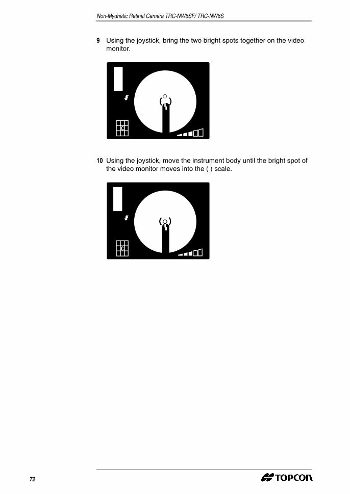
9 Using the joystick, bring the two bright spots together on the videomonitor.
10 Using the joystick, move the instrument body until the bright spot ofthe video monitor moves into the ( ) scale.
72
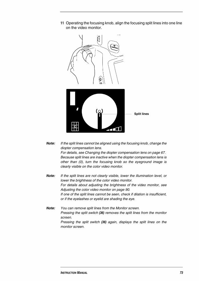
11 Operating the focusing knob, align the focusing split lines into one lineon the video monitor.
Note: If the split lines cannot be aligned using the focusing knob, change thediopter compensation lens.For details, see Changing the diopter compensation lens on page 67.Because split lines are inactive when the diopter compensation lens isother than (0), turn the focusing knob so the eyeground image isclearly visible on the color video monitor.
Note: If the split lines are not clearly visible, lower the illumination level, orlower the brightness of the color video monitor.For details about adjusting the brightness of the video monitor, seeAdjusting the color video monitor on page 90.If one of the split lines cannot be seen, check if dilation is insufficient,or if the eyelashes or eyelid are shading the eye.
Note: You can remove split lines from the Monitor screen.Pressing the split switch (36) removes the split lines from the monitorscreen.Pressing the split switch (36) again, displays the split lines on themonitor screen.
Split lines
INSTRUCTION MANUAL 73
Non-Mydriatic Retinal Camera TRC-NW6SF/ TRC-NW6S
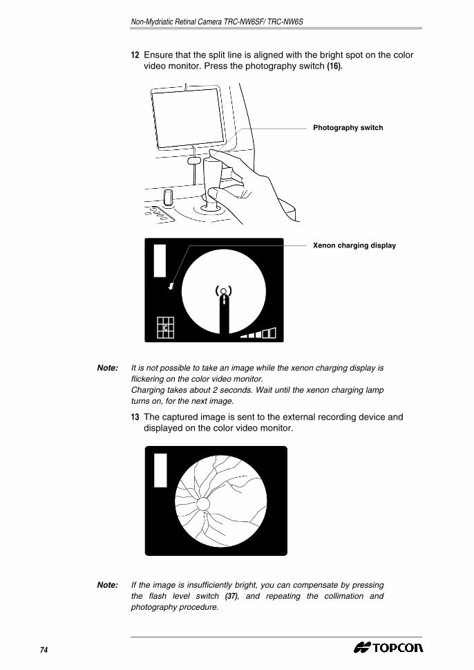
12 Ensure that the split line is aligned with the bright spot on the colorvideo monitor. Press the photography switch (16).
Note: It is not possible to take an image while the xenon charging display isflickering on the color video monitor.Charging takes about 2 seconds. Wait until the xenon charging lampturns on, for the next image.
13 The captured image is sent to the external recording device anddisplayed on the color video monitor.
Note: If the image is insufficiently bright, you can compensate by pressingthe flash level switch (37), and repeating the collimation andphotography procedure.
Photography switch
Xenon charging display
74
Note: The display of images on the color video monitor depends on thesettings of the external recording device as well as those of theinstrument.
14 To return to the capture screen on the color video monitor, press thephotography switch (16).
4.3 Fluoro-photography (center)*
Note: To ensure correct photography, adjust the table height so the patientcan rest his/her chin comfortably on the chinrest.
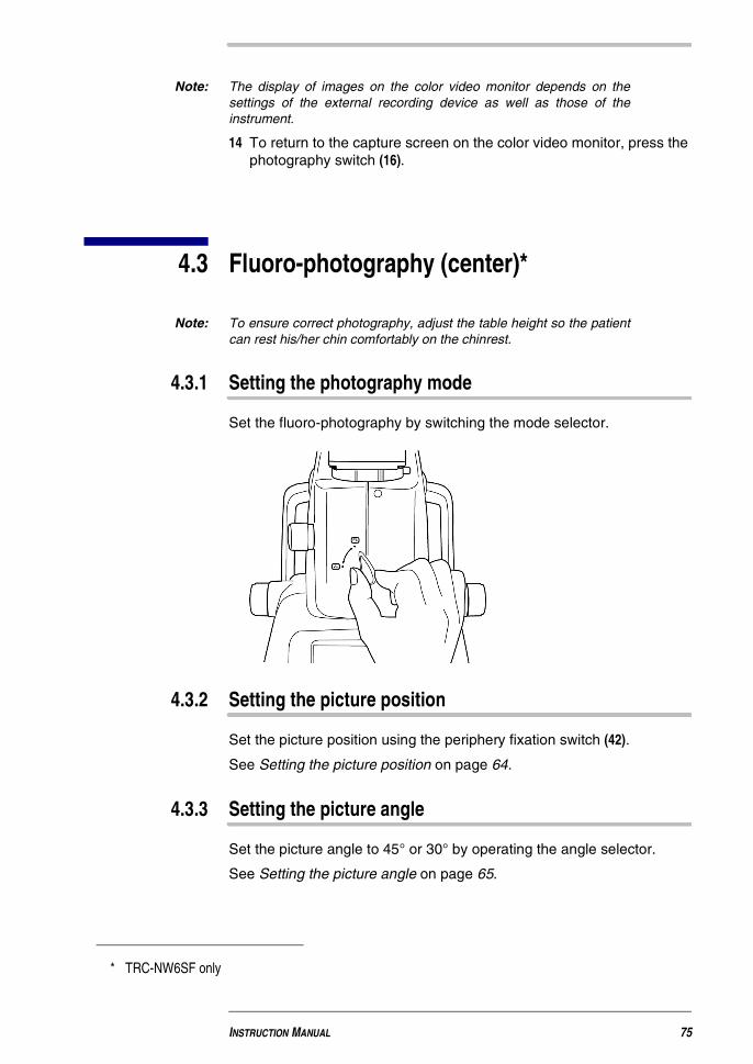
4.3.1 Setting the photography mode
Set the fluoro-photography by switching the mode selector.
4.3.2 Setting the picture position
Set the picture position using the periphery fixation switch (42).
See Setting the picture position on page 64.
4.3.3 Setting the picture angle
Set the picture angle to 45° or 30° by operating the angle selector.
See Setting the picture angle on page 65.
* TRC-NW6SF only
INSTRUCTION MANUAL 75
Non-Mydriatic Retinal Camera TRC-NW6SF/ TRC-NW6S
4.3.4 Setting illumination level
Set the illumination level using the illumination level switch (38).
See Setting illumination level on page 65.
4.3.5 Setting the flash level
Set the flash level using the flash level switch (37).
See Setting the flash level on page 66.
4.3.6 Changing the diopter compensation lens
Pull out the diopter compensation lens selector and change the dioptercompensation lens for the patient’s eye.
See Changing the diopter compensation lens on page 67.
4.3.7 Preparing the patient
1 Apply mydriatics to the patient’s eyes, wait for thorough dilation, andthen guide the patient to the photography room.
Note: If picturing at a 45° picture angle or if there is insufficient dilation,photography is possible up to ø 3.7 mm pupil diameter by changingthe stop using the illumination aperture switch (40).
The illumination aperture display appears on the color video monitor.
2 Seat the patient comfortably in the examination chair.
See Positioning the patient on page 61.
3 Prepare for an intravenous injection of fluorescent contrast medium.
4.3.8 Collimation and photography
Use the omni-directional joystick to perform a collimating operation.
For details about movement or adjustment of the instrument body usingthe omni-directional joystick, see Collimation and photography on page68.
1 As all operations are identical to color photography up to the point offocusing, please refer to collimation of color photography.
2 Upon injecting fluorescent contrast medium, press the timer switch(41).
Note: When the timer switch (41) is pressed, the timer begins to operate, andthe buzzer sounds every 1 second for the first 20 seconds.Pressing the timer switch (41) again, will turn off the timer.
Note: The result of fluoro-photography depends on the injection time and thequantity of the fluorescent contrast medium used.
76

3 For details about visible fluoro-observation, see Fluoro-observationon page 77.
4 Ensure that the aligned bright spot is in the ( ) scale and the split linesare aligned to a straight line on the color video monitor, and thenpress the photography switch (16).
5 The photography image is sent to the external recording device anddisplayed on the color video monitor.
6 To return to the capture screen on the color video monitor, press thephotography switch (16).
4.3.9 Fluoro-observation
Normally, observation is performed using infrared rays, butfluoro-observation of dynamic images can be performed using a colorvideo monitor at the instant the fluorescent contrast medium begins toflow through the fundus artery.
CAUTION
� Do not continue visible fluoro-observation any longer thannecessary to avoid any discomfort or injury to the patient.
INSTRUCTION MANUAL 77
Non-Mydriatic Retinal Camera TRC-NW6SF/ TRC-NW6S
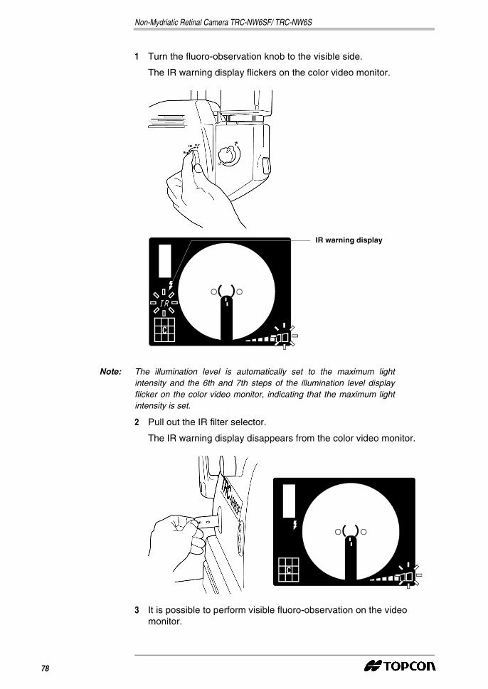
1 Turn the fluoro-observation knob to the visible side.
The IR warning display flickers on the color video monitor.
Note: The illumination level is automatically set to the maximum lightintensity and the 6th and 7th steps of the illumination level displayflicker on the color video monitor, indicating that the maximum lightintensity is set.
2 Pull out the IR filter selector.
The IR warning display disappears from the color video monitor.
3 It is possible to perform visible fluoro-observation on the videomonitor.
IR warning display
78
Note: Because the internal fixation target cannot be used when thefluoro-observation knob is on the visible side, instead use the externalfixation target to guide the patient's eye.
Note: You can remove split lines from the Monitor screen.Pressing the split switch (36) removes the split lines from the Monitorscreen.Pressing the split switch (36) again displays the split lines on theMonitor screen.
Note: During the visible fluoro-observation, observation TV camera settingsare changed for visible fluoro-observation. In this case, as the TVcamera gain is increased, images may become grainy.
4.4 Peripheral photography
4.4.1 Setting the picture position
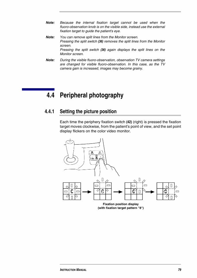
Each time the periphery fixation switch (42) (right) is pressed the fixationtarget moves clockwise, from the patient's point of view, and the set pointdisplay flickers on the color video monitor.
Fixation position display(with fixation target pattern "8")
INSTRUCTION MANUAL 79
Non-Mydriatic Retinal Camera TRC-NW6SF/ TRC-NW6S
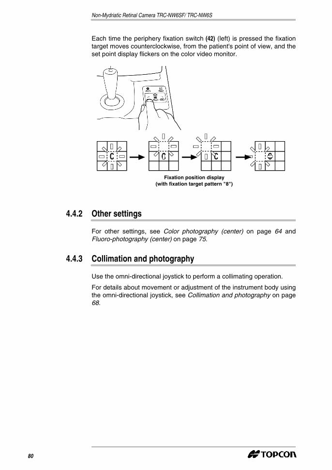
Each time the periphery fixation switch (42) (left) is pressed the fixationtarget moves counterclockwise, from the patient's point of view, and theset point display flickers on the color video monitor.
4.4.2 Other settings
For other settings, see Color photography (center) on page 64 andFluoro-photography (center) on page 75.
4.4.3 Collimation and photography
Use the omni-directional joystick to perform a collimating operation.
For details about movement or adjustment of the instrument body usingthe omni-directional joystick, see Collimation and photography on page68.
Fixation position display(with fixation target pattern "8")
80
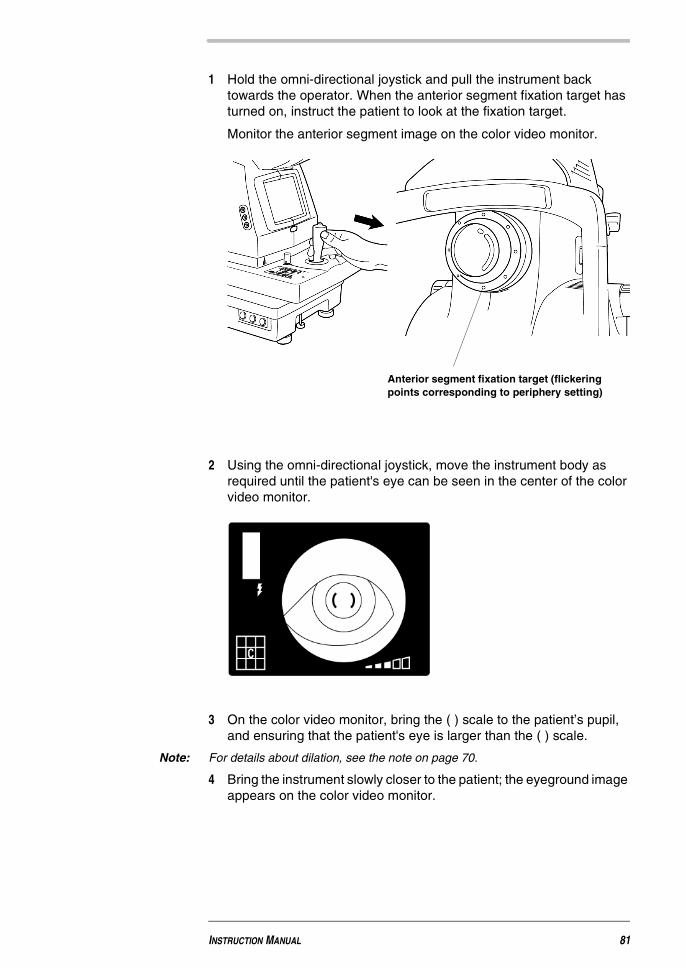
1 Hold the omni-directional joystick and pull the instrument backtowards the operator. When the anterior segment fixation target hasturned on, instruct the patient to look at the fixation target.
Monitor the anterior segment image on the color video monitor.
2 Using the omni-directional joystick, move the instrument body asrequired until the patient's eye can be seen in the center of the colorvideo monitor.
3 On the color video monitor, bring the ( ) scale to the patient’s pupil,and ensuring that the patient's eye is larger than the ( ) scale.
Note: For details about dilation, see the note on page 70.
4 Bring the instrument slowly closer to the patient; the eyeground imageappears on the color video monitor.
Anterior segment fixation target (flickeringpoints corresponding to periphery setting)
INSTRUCTION MANUAL 81
Non-Mydriatic Retinal Camera TRC-NW6SF/ TRC-NW6S
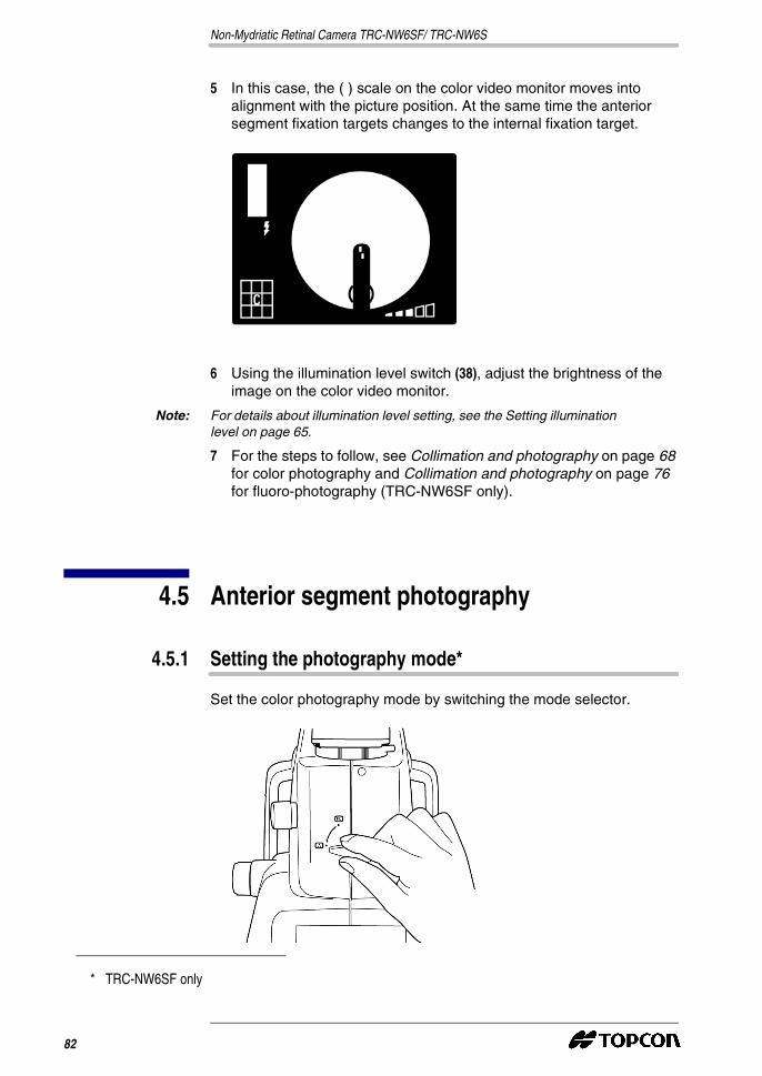
5 In this case, the ( ) scale on the color video monitor moves intoalignment with the picture position. At the same time the anteriorsegment fixation targets changes to the internal fixation target.
6 Using the illumination level switch (38), adjust the brightness of theimage on the color video monitor.
Note: For details about illumination level setting, see the Setting illuminationlevel on page 65.
7 For the steps to follow, see Collimation and photography on page 68for color photography and Collimation and photography on page 76for fluoro-photography (TRC-NW6SF only).
4.5 Anterior segment photography
4.5.1 Setting the photography mode*
Set the color photography mode by switching the mode selector.
* TRC-NW6SF only
82
4.5.2 Setting the picture position
Set the fixation target to the center using the periphery fixation switch(42).
See Setting the picture position on page 64.
4.5.3 Setting the picture angle
Set the picture angle by operating the angle selector.
See Setting the picture angle on page 65.
4.5.4 Setting the illumination level
Set the flash level using the illumination level switch (38).
See Setting the flash level on page 66.
4.5.5 Changing the diopter compensation lens
Press in the diopter compensation lens selector and change the dioptercompensation lens (0).
See Changing the diopter compensation lens on page 67.
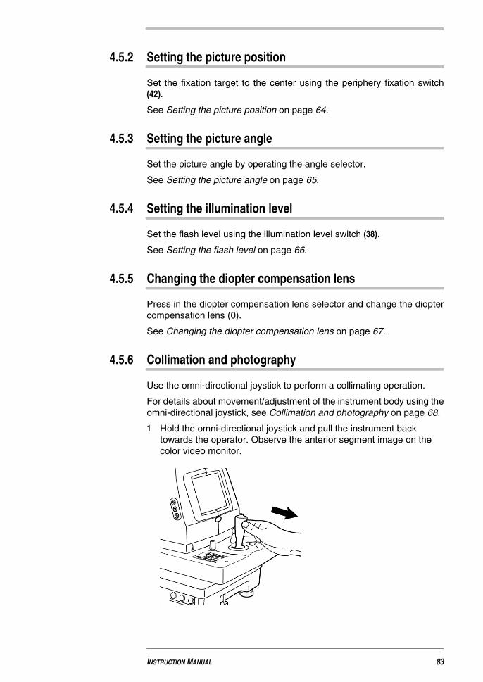
4.5.6 Collimation and photography
Use the omni-directional joystick to perform a collimating operation.
For details about movement/adjustment of the instrument body using theomni-directional joystick, see Collimation and photography on page 68.
1 Hold the omni-directional joystick and pull the instrument backtowards the operator. Observe the anterior segment image on thecolor video monitor.
INSTRUCTION MANUAL 83

Non-Mydriatic Retinal Camera TRC-NW6SF/ TRC-NW6S
2 Move the instrument body as required until the patient's eye can beseen in the center of the color video monitor.
3 Turn the focusing knob so the anterior segment image is clearlyvisible on the color video monitor, and press the photography switch(16).
Note: In the anterior segment photography, the flash level is changedautomatically to an optimal set value.
4.6 Finishing
1 Turn off the power switch (30) of the instrument body and of theexternal recording device.
2 Use the omni-directional joystick to move the instrument body so thatit comes to just above the base.
3 Turn the base brake knob to the right to brake the base and preventit from moving suddenly.
Note: To prepare the instrument body for the next imaging session, turn theomni-directional joystick and move the body into the center position.The vertical center position of the instrument body is indicated by thevertical posi-tion mark.
Note: If the instrument will not be in use for a long period, remove the powercables of the instrument body and external recording device from thepower outlets, and remove all cables connecting the instrument to theexternal capture device to avoid accidental cable damage.
84

5 MAINTENANCE AND CHECKS
5.1 Daily care
� Keep the instrument protected from dust at all times.
Keep the objective lens protected from fingerprints and dirt to ensurethe best possible images.
CAUTION
� Always install the instrument on a fixed, stable surface, to preventdamage or injury.
CAUTION
� Ensure that the camera mount lever is firmly tightened to preventthe TV camera from falling and causing injury or damage.
CAUTION
� Ensure that the lens mount lever is firmly tightened to prevent theTV relay lens from falling and causing injury or damage.
Non-Mydriatic Retinal Camera TRC-NW6SF/ TRC-NW6S
When not in use, be sure to cap the objective lens and cover theinstrument with the dust cover.
If the objective lens becomes stained, follow the instructions inCleaning the objective lens on page 91.
� When not in use, always turn the power switch (30) off.
5.2 Changing the lamp
5.2.1 Replacing the illumination lamp
Note: Do not touch the lamp with bare fingers: fingerprints can damage(whiten) the lamp.
Note: The lamp can be easily damaged: handle it with particular care.
� The service life of illumination lamp is approx. 2,000 hours.
� Replacing the illumination lamp if it is burned or becomes whitened.
1 Turn the power switch (30) off and unplug the power cable.
2 Turn the omni-directional joystick to raise the instrument bodycompletely.
3 Unscrew the lamp house cover.
CAUTION
� To avoid the risk of electric shock, always disconnect the powersupply and unplug the power cable before replacing the lamp.
CAUTION
� To avoid potential burns, do not touch the lamp during, orimmediately after use.
86
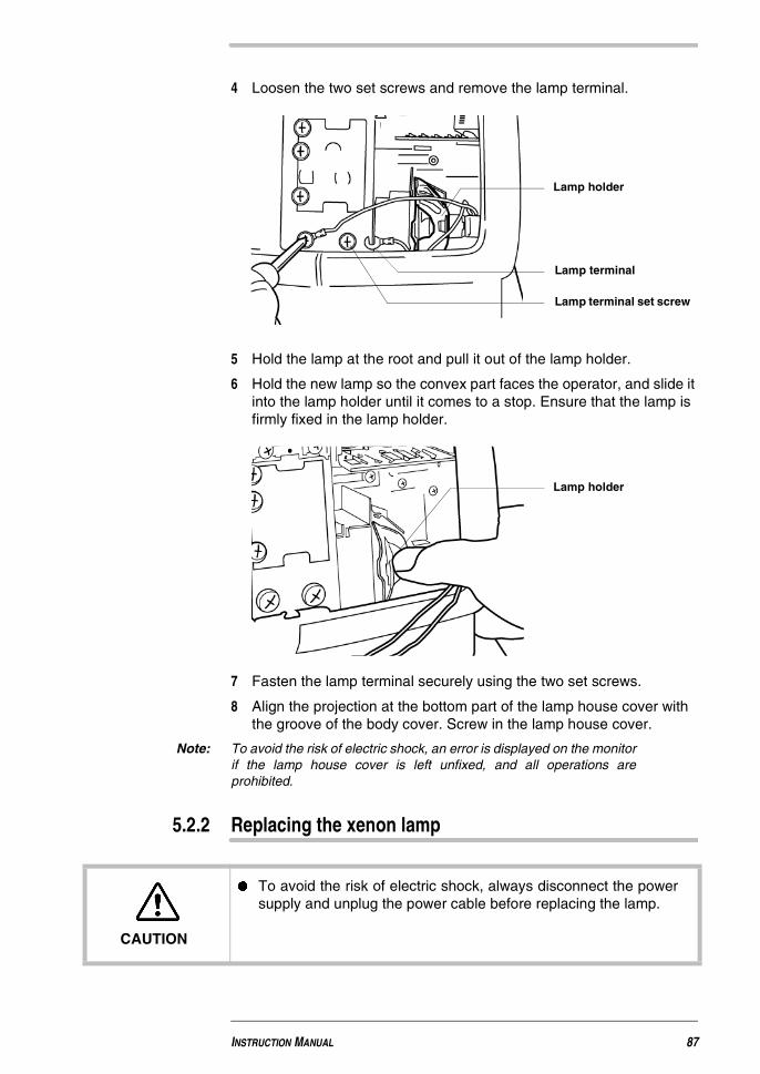
4 Loosen the two set screws and remove the lamp terminal.
5 Hold the lamp at the root and pull it out of the lamp holder.
6 Hold the new lamp so the convex part faces the operator, and slide itinto the lamp holder until it comes to a stop. Ensure that the lamp isfirmly fixed in the lamp holder.
7 Fasten the lamp terminal securely using the two set screws.
8 Align the projection at the bottom part of the lamp house cover withthe groove of the body cover. Screw in the lamp house cover.
Note: To avoid the risk of electric shock, an error is displayed on the monitorif the lamp house cover is left unfixed, and all operations areprohibited.
5.2.2 Replacing the xenon lamp
Lamp holder
Lamp terminal
Lamp terminal set screw
Lamp holder
CAUTION
� To avoid the risk of electric shock, always disconnect the powersupply and unplug the power cable before replacing the lamp.
INSTRUCTION MANUAL 87
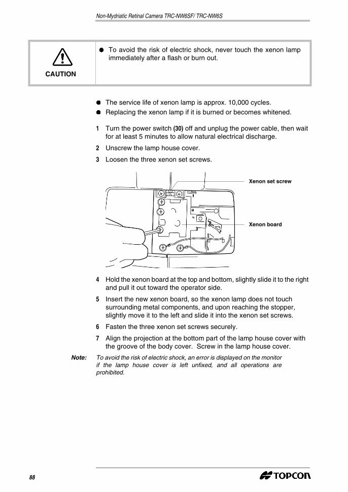
Non-Mydriatic Retinal Camera TRC-NW6SF/ TRC-NW6S
� The service life of xenon lamp is approx. 10,000 cycles.
� Replacing the xenon lamp if it is burned or becomes whitened.
1 Turn the power switch (30) off and unplug the power cable, then waitfor at least 5 minutes to allow natural electrical discharge.
2 Unscrew the lamp house cover.
3 Loosen the three xenon set screws.
4 Hold the xenon board at the top and bottom, slightly slide it to the rightand pull it out toward the operator side.
5 Insert the new xenon board, so the xenon lamp does not touchsurrounding metal components, and upon reaching the stopper,slightly move it to the left and slide it into the xenon set screws.
6 Fasten the three xenon set screws securely.
7 Align the projection at the bottom part of the lamp house cover withthe groove of the body cover. Screw in the lamp house cover.
Note: To avoid the risk of electric shock, an error is displayed on the monitorif the lamp house cover is left unfixed, and all operations areprohibited.
CAUTION
� To avoid the risk of electric shock, never touch the xenon lampimmediately after a flash or burn out.
Xenon set screw
Xenon board
88
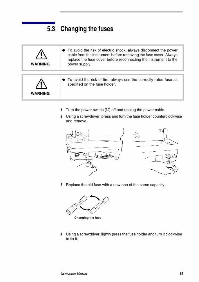
5.3 Changing the fuses
1 Turn the power switch (30) off and unplug the power cable.
2 Using a screwdriver, press and turn the fuse holder counterclockwiseand remove.
3 Replace the old fuse with a new one of the same capacity.
4 Using a screwdriver, lightly press the fuse holder and turn it clockwiseto fix it.
WARNING
� To avoid the risk of electric shock, always disconnect the powercable from the instrument before removing the fuse cover. Alwaysreplace the fuse cover before reconnecting the instrument to thepower supply.
WARNING
� To avoid the risk of fire, always use the correctly rated fuse asspecified on the fuse holder.
Changing the fuse
INSTRUCTION MANUAL 89

Non-Mydriatic Retinal Camera TRC-NW6SF/ TRC-NW6S
The usage of each fuse and the result after it has burned are shownbelow:
5.4 Supplying the chinrest tissue
� To change the chinrest tissue, remove the chinrest tissue pin andreplace the tissue.
5.5 Adjusting the color video monitor
� This machine is adjusted for the best image quality beforeshipment, however, readjustment may be required aftertransportation.
� The image quality adjustment knob is located on the left hand sideof the color video monitor.
Fuse No. Use When the fuse blows
F1, F2 (5A) Power input Instrument will not work.
F3 (6A) Illumination lightIllumination lamp will notwork.
F4 (0.5A) Xenon lampERR3: Xenon lamp has notbeen charged.
F5 (5A) Control circuit Instrument will not work.
Chinrest tissue pin
90

� Please note that the ideal monitor settings for fundus viewing maybe different than those for anterior segment viewing.
� Adjust the brightness, contrast and hue adjustment knobs to attainthe desired image quality.
5.6 Cleaning the instrument
5.6.1 Cleaning the dust cover, control panel and monitor screen
Note: To protect the instrument body from discoloration and deterioration, donot use volatile solvents to clean the instrument, including benzine,thinner, ether, gasoline, etc.
1 If the dust cover, control panel and monitor screen become stained,clean them with dry cloth.
2 If the dust cover is badly stained, prepare a tepid solution of neutraldetergent, suitable for kitchenware. Moisten the cloth with thesolution and rinse it thoroughly.
5.6.2 Cleaning the objective lens
� To check the objective lens, turn the illumination lamp on.
Darken the room, pull out the IR filter selector and set it to visiblefluoro-observation.
Press the illumination level switch (38) (+) four times and maximise thelevel of light.
Examine the objective lens from the front and at a angle. The lenscondition can be seen clearly.
� Dust and dirt adhered to the surface
Brightness adjustmentknob
Contrast adjustment knob
Hue adjustment knob
INSTRUCTION MANUAL 91

Non-Mydriatic Retinal Camera TRC-NW6SF/ TRC-NW6S
Blow off dust with a blower.
� Fingerprints and oil spots on the surface:
1 Blow off any large particles.
2 Prepare a mix of ethanol (2) and ether (8).
3 Moisten a clean, dried gauze with the mix, and lightly wipe the lensspirally from the center outward. Continue until the stains have beencompletely removed.
To prevent the objective lens from being scratched, always use cleangauze and wipe the surface of the lens gently.
Note: If the stains are persistent and difficult to remove, contact your dealeror TOPCON (see the back cover).Use the ethanol-ether mix at temperatures (10~40°C) and moisture(30~85%) under normal conditions.
5.7 List of expendables and spare parts
When ordering expendables and spare parts, please specify the codenumber and the quantity required, in addition to the description.
Description Code Number
Expendables
Xenon lamp 40531 1810
Illumination lamp 40531 1880
Chin rest paper 40310 4082
Data plate 40547 1132
Dust cover 40488 1007
Spare parts
Fuses (F1)(F2)5A/125V
44691 5006
Fuse (F3) 6A/125V T2400 0001A
Fuse (F4) 0.5A/250V 40547 5302
Fuse (F5) 5A/125V 44691 5006
92
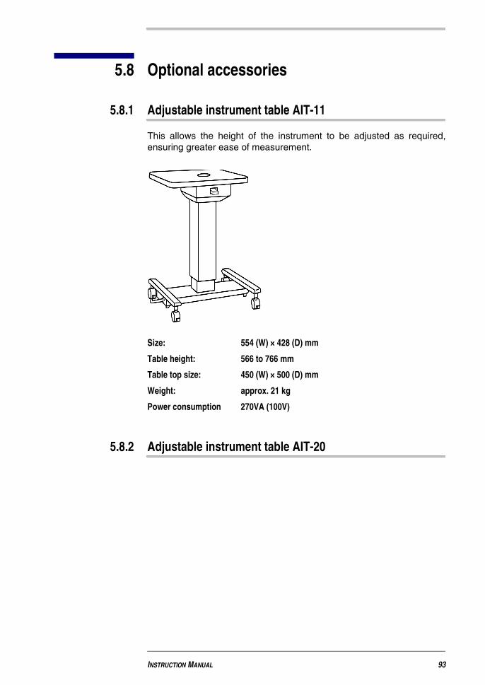
5.8 Optional accessories
5.8.1 Adjustable instrument table AIT-11
This allows the height of the instrument to be adjusted as required,ensuring greater ease of measurement.
Size: 554 (W) × 428 (D) mm
Table height: 566 to 766 mm
Table top size: 450 (W) × 500 (D) mm
Weight: approx. 21 kg
Power consumption 270VA (100V)
5.8.2 Adjustable instrument table AIT-20
INSTRUCTION MANUAL 93

Non-Mydriatic Retinal Camera TRC-NW6SF/ TRC-NW6S
5.9 Contacting TOPCON
When you contact us, please mention the following:
Model name: TRC-NW6SF/TRC-NW6S
Serial number: This is located on the rating nameplate on the right sideof the base.
Period of use: Please inform us of the purchase date of this instrument.
Type of problem: Please give us a brief description of the problem.
94
6 TROUBLESHOOTING
6.1 Before requesting service
If a problem should occur, first consult thefollowing troubleshooting table, and follow theinstructions suggested. If you cannot solvethe problem, or the instrument is defective,contact your authorized dealer or TOPCON.
Be sure to disconnect the power input plugfrom the outlet before replacing a lamp orfuse.
Non-Mydriatic Retinal Camera TRC-NW6SF/ TRC-NW6S
6.2 Troubleshooting table
Trouble Check points
Color video monitordoes not work.
� Power cable is not connected
Connect power cable.
� Fuse has burned.
Change fuse.
� Power save function is on (flickering power lamp).
Cancel power save function (Photography switch).
Color video monitordoes not display
clearly.
� Image contrast is needs adjustment.
Adjust contrast (contrast control).
� Image is dark.
Adjust brightness (brightness control).
Adjust light intensity (Illumination Level switch).
Darken room and thoroughly dilate patient’s pupil.
� Image color is abnormal.
Adjust hue (hue control).
Periphery ofphotography image is
dark.
� Collimation is incorrect.
Adjust collimation.
WARNING
� To avoid the risk of electric shock, do not attempt disassembling,rebuilding or repairs. Consult your dealer for repairs.
WARNING
� To avoid the risk of electric shock, do not remove any bodycomponents, covers of the TV relay lens, the chinrest or powersupply. - other than the lamp house cover.
96

� Focusing is incorrect.
Adjust focus.
� Patient’s pupil is not large enough.
Darken room and thoroughly dilate patient’s pupil.
Press illumination aperture switch (40).*
Photography image iscompletely flared.
� Collimation is incorrect.
Adjust collimation
� Focusing is incorrect.
Adjust focus.
� Opacity in patient’s eye.
Flare cannot be removed.
Photography image iswhitened.
� Patient blinked during photography.
Take another picture.
Photography imagecontains a dim white
spot.
� Objective lens is stained.
Clean lens.
� Eyelashes obscured patient’s eye during photography. (Dim light atthe bottom of the screen during alignment.)
Instruct the patient to open the eye wider and retake the picture. Ifwide enough, open eyelid (i.e., Take the picture while holding theeyelid open).
Photography image iscompletely dark.
� Flash level is insufficient.
Adjust flash level (Flash level switch).
� Xenon set screws are loose.
Refasten screws to terminal.
� Xenon lamp has exceeded the recommended service life.
Change xenon lamp.
Illumination lampcannot be turned on.
� Power save function is on (flickering power lamp).
Press Photography switch and cancel power save function.
� Lamp terminal is loose.
Refasten lamp terminal.
� Fuse is burnt.
Change fuse.
� The lamp is burnt.
Change lamp.
* TRC-NW6SF only
INSTRUCTION MANUAL 97
Non-Mydriatic Retinal Camera TRC-NW6SF/ TRC-NW6S
Internal fixation targetcannot be seen.
� Collimation is incorrect.
Adjust collimation.
� Instrument is set to external fixation target.
Reset to internal fixation target.
� Fluoro-observation knob is set to visible.*
Change to infrared-observation (fluoro-observation knob (13)).*
� Fuse is burnt.
Change fuse.
( ) scale is off centreof the monitor.
� Internal fixation target is set to periphery.
Change fixation position to center (periphery fixation switch (42)(reset)).
Split lines cannot beseen.
� Split line is set to off.
Turn split line on (split switch (36)).
� Diopter compensation lens selector is other than (0).
Return diopter compensation lens selector to (0).
� Patient’s pupil is not large enough.
Darken room and thoroughly dilate patient’s eye.
Xenon lamp cannotbe turned on.
� Power save function is on (flickering power lamp).
Cancel power save function (photography switch (16)).
� Xenon lamp has exceeded the recommended service life.
Change xenon lamp.
� Anomaly in external recording device.
Check power supply, settings, ink ribbon, paper, etc.
� Incorrect cable connection.
Check and correct cable connection.
Cannot see patient’spupil center.
� Position of patient’s face (incl. chin, forehead) is incorrect.
Allow patient to correct position of face.
� Patient’s face height is incorrect.
Adjust face height (chinrest switch).
Nothing is recordedin external recording
device.
� Anomaly in external recording device.
Check power supply, settings, ink ribbon, paper, etc.
� Cable connection is incorrect.
Check and correct cable connections.
* TRC-NW6SF only
98

6.3 Error code list
In the event that "Err#" (# indicates an error number) is beingintermittently displayed on the data display unit, together with a beepingsound, caused by an operational error or a malfunction of the instrument,correct the error as instructed in the table below:
6.4 Emergency chinrest operation
If the chinrest cannot be moved with the elevation switch, you canoperate it manually using the attached emergency chinrest knob.
Note that the manual chinrest operation should be used only in anemergency situation.
Also, contact your dealer or TOPCON immediately (see the back cover).
No. Name
1 Lamp cover is off.
3 Overcharge, undercharge; or Fuse (F4) is burnt.
4 Quick mirror mechanism malfunctions.
5 Alignment mechanism malfunctions.
6 Diaphragm selector position is halfway.
7 Mode selector position is halfway (TRC-NW6SF only).
8 TV relay lens is off.
INSTRUCTION MANUAL 99

Non-Mydriatic Retinal Camera TRC-NW6SF/ TRC-NW6S
1 Turn the power switch (30) off and unplug the power cable.
2 Using a screwdriver, remove the cover to the left side of the operator.
3 Turning the emergency chinrest knob, insert it into the hole. Ensurethat the emergency chinrest knob drops securely into the hole.
4 Turn the emergency chinrest knob to move the chinrest up/down.
100
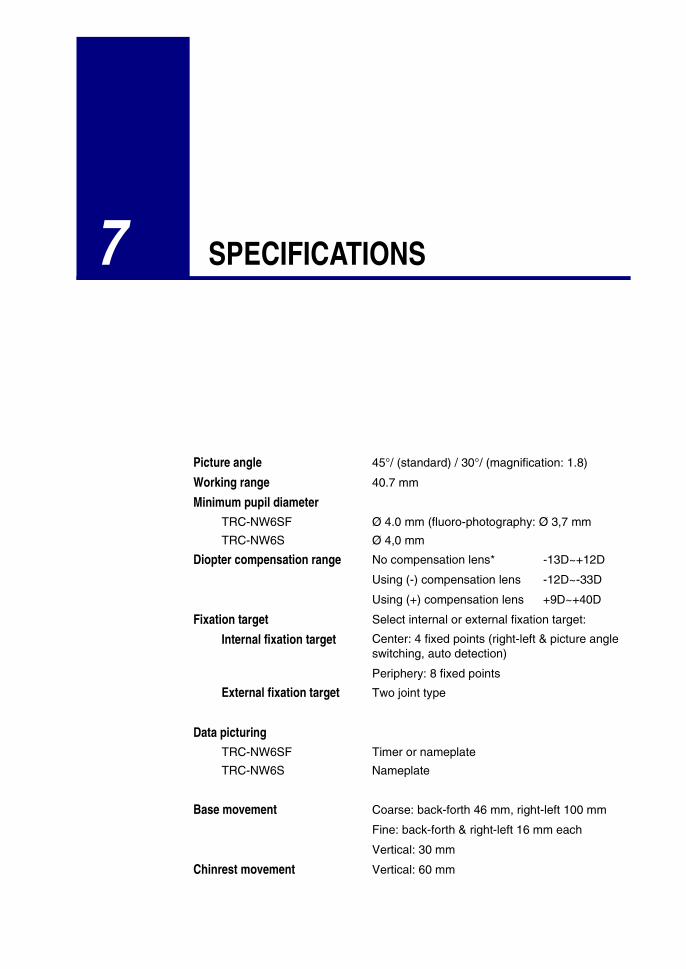
7 SPECIFICATIONS
Picture angle 45°/ (standard) / 30°/ (magnification: 1.8)
Working range 40.7 mm
Minimum pupil diameterTRC-NW6SF Ø 4.0 mm (fluoro-photography: Ø 3,7 mm
TRC-NW6S Ø 4,0 mm
Diopter compensation range No compensation lens* -13D~+12D
Using (-) compensation lens -12D~-33D
Using (+) compensation lens +9D~+40D
Fixation target Select internal or external fixation target:
Internal fixation target Center: 4 fixed points (right-left & picture angleswitching, auto detection)
Periphery: 8 fixed points
External fixation target Two joint type
Data picturingTRC-NW6SF Timer or nameplate
TRC-NW6S Nameplate
Base movement Coarse: back-forth 46 mm, right-left 100 mm
Fine: back-forth & right-left 16 mm each
Vertical: 30 mm
Chinrest movement Vertical: 60 mm

Non-Mydriatic Retinal Camera TRC-NW6SF/ TRC-NW6S
Subject to changes in design and/or specifications, without notice in advance.
Power consumption
Power voltage General type AC110, 120, 230, 240V ±10%
European type AC100, 120, 220, 240V ±10%
Switch over by selector switch
Power frequency 50/60Hz
Power consumption 100VA (normal), 400VA (max.)
Leak current
Ground Normal 0.5 mA max., Single failure 1 mA max.
Exterior Normal 0.1 mA max., Single failure 0.5 mA max.
Patient Normal 0.1 mA max., Single failure 0.5 mA max.
Dimensions 272 mm x 505 mm x 530-560 mm (W x D x H)(instrument body)
WeightTRC-NW6SF 26 kg (instrument body)
TRC-NW6S 25.5 kg (instrument body)
* Split line working range
102


TOPCON CORPORATION75-1 Hasunuma-cho, Itabashi-ku, Tokyo, 174 JapanPhone: 3-3558-2520 Fax: 3-3960-4214
TOPCON EUROPE B.V.Esse Baan 11, 2908 LJ Capelle a/d IJssel,THE NETHERLANDS.Phone: 10-4585077Fax: 10-4585045TOPCON S.A.R.L.
HEAD OFFICE104/106, Rue Rivay 92300 Levallois-Perret,FRANCE.Phone: 01-41069494Fax: 01-47390251LYON OFFICE138, Avenue du 8 Mai 1945, 69100Villeurbanne, FrancePhone: 78688237Fax: 78681902
TOPCON DEUTSCHLAND G.M.B.H.Halskestr. 7, 47877 WillichGERMANY.Phone: 02154-9290Fax: 02154-929-111C-Point Baden-WürtembergGutenbergstaße 10, 73274 NotzingenGERMANYPhone: 07021-974411Fax: 07021-974421C-Point BayernKarl-Benz-Straße 15, 85221 DachauGERMANYPhone: 08131-321790Fax: 08131- 321787
TOPCON GREAT BRITAINTopcon HouseKennet SideBone Lane / NewburryBerks RG14 5PXUNITED KINGDOMPhone: 01-635551120Fax: 01-635551170
TOPCON ESPAÑA S.A.HEAD OFFICEFrederic Mompou, 5 Edificio Euro 308960, Sant Just Desvern BarcelonaSPAINPhone: 3-4734057Fax: 3-4733932MADRID OFFICEAvenida Ciudad de Barcelona 81,28007, MadridSPAINPhone: 1-552-4160Fax: 1-552-4161
TOPCON SCANDINAVIA A. B.Industrivägen 4 / P. O. Box 214043302 SävedalenSWEDENPhone: 031-261250Fax: 031-268607TOPCON TÖNSBERGRamdalsveien 6 / PO Box 448 Sentrum3101 TönsbergNORGEPhone: 00747-33323500Fax: 00747-33323501TOPCON DANMARKRingstedvej 1254000 RoskildeDANMARKPhone: +45 46327500Fax: +45 46327555
Printed in The Netherlands May 12, 2000
TOPCON-Tom05c-UK-0500-02