Embed Size (px)
Citation preview
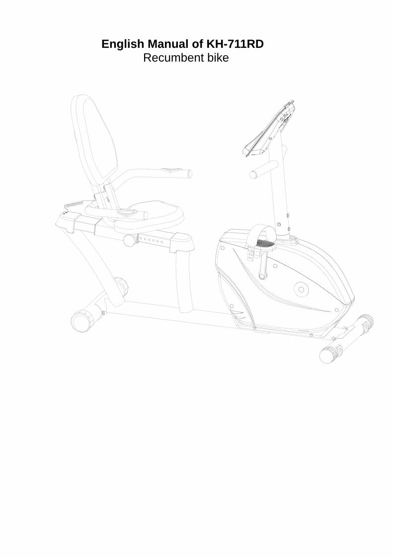
English Manual of KH-711RD Recumbent bike
Safety Instructions
• To ensure the best safety of the exerciser, regularly check it on damages and worn parts. • If you pass on this exerciser to another person or if
you allow another person to use it, make sure that that person is familiar with the content and instructions in these instructions.
• Only one person should use the exerciser at a time. • Before the first use and regularly make sure that all
screws, bolts and other joints are properly tightened and firmly seated.
• Before you start your work-out, remove all
sharp-edged objects around the exerciser. • Only use the exercise for your work-out if it works
flawlessly. • Any broken, worn or defective part must immediately
be replaced and/or the exerciser must no longer be used until it has been properly maintained and repaired.
• Parents and other supervisory persons should be
aware of their responsibility, due to situations which may arise for which the exerciser has not been designed and which may occur due to children’s natural play instinct and interest in experimenting.
• If you do allow children to use this exerciser, be sure
to take into consideration and assess their mental and physical condition and development, and above all their temperament. Children should use the exerciser only under adult supervision and be instructed on the correct and proper use of the exerciser. The exerciser is not a toy.
• Make sure there is sufficient free space around the
exerciser when you set it up. • To avoid possible accidents, do not allow children
to approach the exerciser without supervision, since they may use it in a way for which it is not intended due to their natural play instinct and interest in experimenting.
• Please note that an improper and excessive
work-out may be harmful to your health. • Please note that levers amd other adjustment
mechanisms are not projecting into the area of movement during the work-out.
• When setting up the exerciser, please make
sure that the exerciser is standing in a stable way and that any possible unevenness of the floor is evened out.
• Always wear appropriate clothing and shoes
which are suitable for your work-out on the exerciser. The clothes must be designed in a way so that they will not get caught in any part of the exerciser during the work-out due to their form (for example, length). Be sure to wear appropriate shoes which are suitable for the work-out, firmly support the feet and which are provided with a non-slip sole.
• Be sure to consult a physician before you start
any exercise program. He may give you proper hints and advice with respect to the individual intensity of stress for you as well as to your work-out and sensible eating habits.
Important Notes
• Assemble the exerciser as per assembly instructions
and be sure to only use the structural parts provided
with the exerciser and designed for it. Prior to the
assembly, make sure the content of the delivery is
complete by referring to the parts list of the assembly
and operating instructions.
• Be sure to set up the exerciser in a dry and even place
and always protect it from humidity. If you wish to
protect the place particularly against pressure points,
contamination, etc., it is recommended to put a suitable,
non-slip mat under the exerciser.
• The general rule is that exercisers and training devices
are no toys. Therefore, they must only be used by
properly informed or instructed persons.
• Stop your work-out immediately in case of dizziness,
nausea, chest pain or any other physical symptoms. In
case of doubt, consult your physician immediately.
• Children, disabled and handicapped persons should
use the exercise only under supervision and in
presence of another person who may give support and
useful instructions.
• Be sure that your body parts and those of other persons
are never close to any moving parts of the exerciser
during its use.
• When adjusting the adjustable parts, make sure they
are adjusted properly and note the marked, maximum
adjusting position, for example of the saddle support,
respectively.
• Do not work out immediately after meals!
4
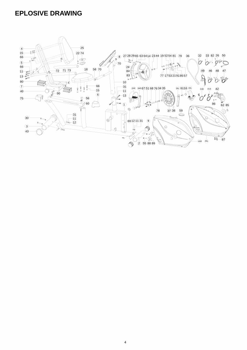
EPLOSIVE DRAWING
84
14 23
24
83
6327 6428 29 65
9177 17 53 21
7919 54 3652
57
81
39R
37 38
51 6867 3420R 39L 20L611635
69 9
45L
12 11 31
2 55
8
45R
70
13
11
31
1
15
66
25
74
80
75
7
40
4
15
66
66
11
5
18
13
71
22
78
4649 48
10
42
47
41A
3332 26
5872 73
59
62
76
82
86
70
50
41B
56
311112
30
43
3
60
8788 89
90
85
6
44
85
5
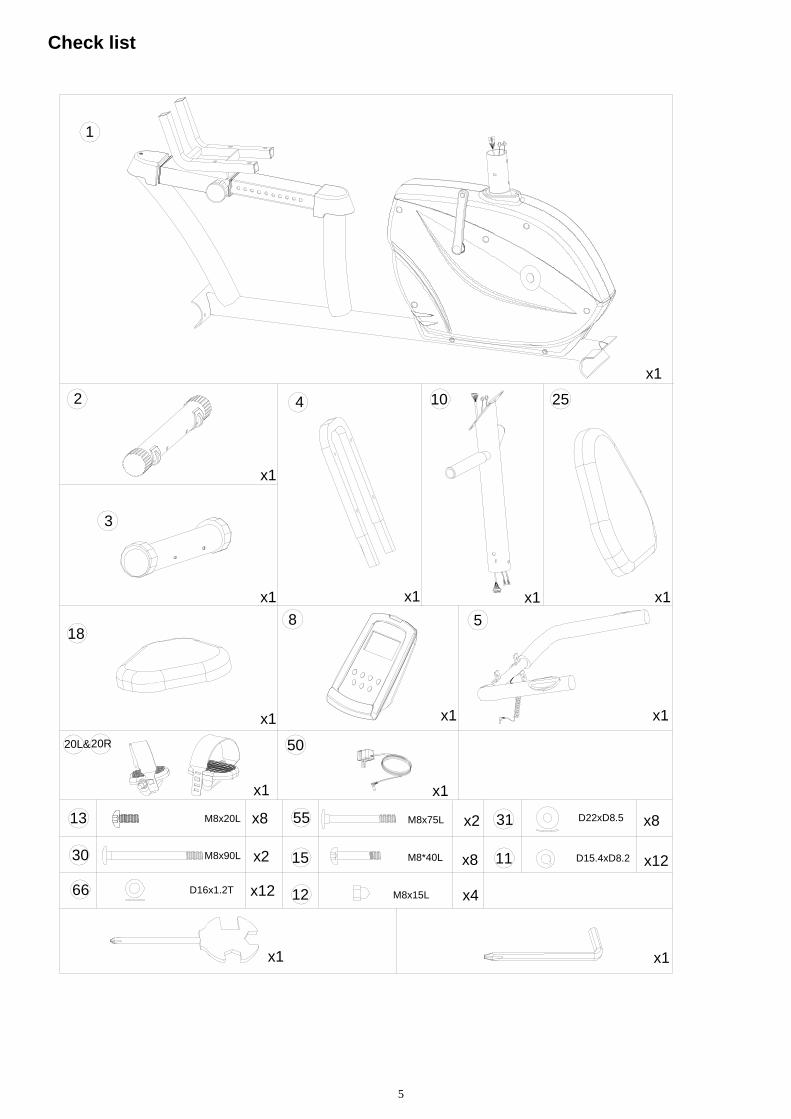
Check list
D22xD8.5
D15.4xD8.2
M8x20L13
11
31
M8x90L
M8x75L
M8x15LD16x1.2T
M8*40L
x8
x2
x2
x8
x12 x4
x12
x8
30
55
15
1266
1
x1x1
20L&20R
5
10 254
x1
x1x1
x1 x1
x1x1
3
2
188
50
x1
x1
x1
x1
6
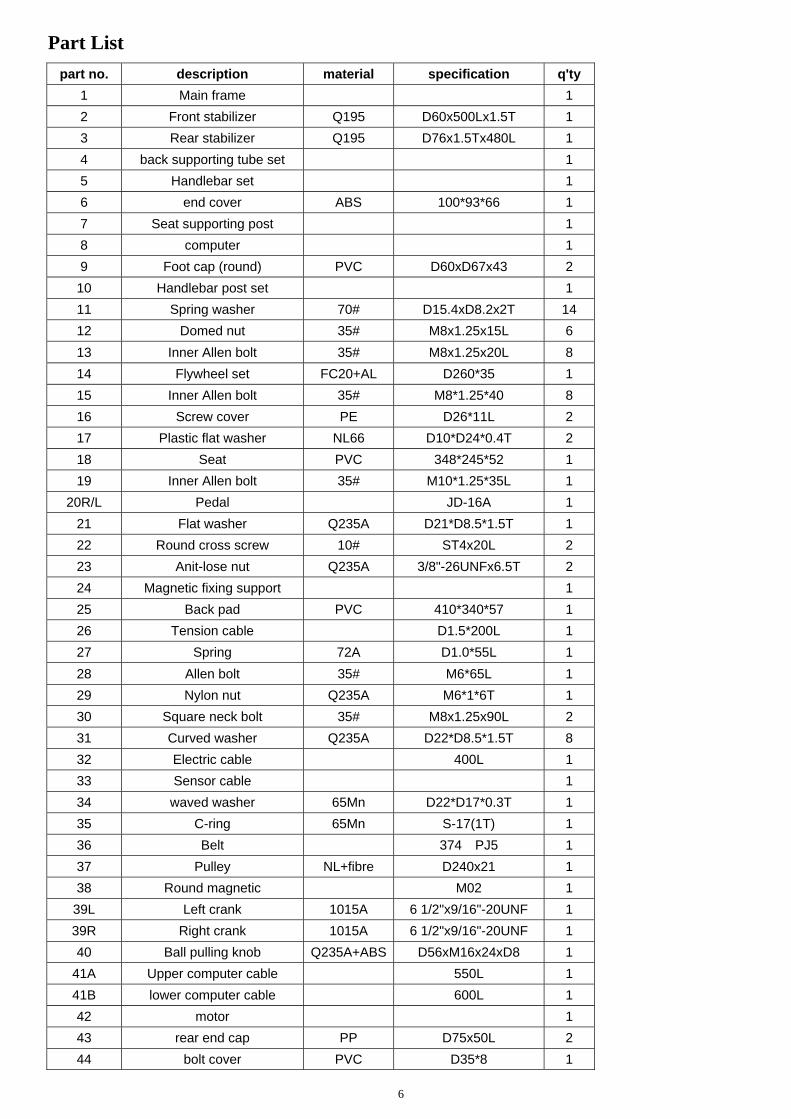
Part List
part no. description material specification q'ty
1 Main frame 1
2 Front stabilizer Q195 D60x500Lx1.5T 1
3 Rear stabilizer Q195 D76x1.5Tx480L 1
4 back supporting tube set 1
5 Handlebar set 1
6 end cover ABS 100*93*66 1
7 Seat supporting post 1
8 computer 1
9 Foot cap (round) PVC D60xD67x43 2
10 Handlebar post set 1
11 Spring washer 70# D15.4xD8.2x2T 14
12 Domed nut 35# M8x1.25x15L 6
13 Inner Allen bolt 35# M8x1.25x20L 8
14 Flywheel set FC20+AL D260*35 1
15 Inner Allen bolt 35# M8*1.25*40 8
16 Screw cover PE D26*11L 2
17 Plastic flat washer NL66 D10*D24*0.4T 2
18 Seat PVC 348*245*52 1
19 Inner Allen bolt 35# M10*1.25*35L 1
20R/L Pedal JD-16A 1
21 Flat washer Q235A D21*D8.5*1.5T 1
22 Round cross screw 10# ST4x20L 2
23 Anit-lose nut Q235A 3/8"-26UNFx6.5T 2
24 Magnetic fixing support 1
25 Back pad PVC 410*340*57 1
26 Tension cable D1.5*200L 1
27 Spring 72A D1.0*55L 1
28 Allen bolt 35# M6*65L 1
29 Nylon nut Q235A M6*1*6T 1
30 Square neck bolt 35# M8x1.25x90L 2
31 Curved washer Q235A D22*D8.5*1.5T 8
32 Electric cable 400L 1
33 Sensor cable 1
34 waved washer 65Mn D22*D17*0.3T 1
35 C-ring 65Mn S-17(1T) 1
36 Belt 374 PJ5 1
37 Pulley NL+fibre D240x21 1
38 Round magnetic M02 1
39L Left crank 1015A 6 1/2"x9/16"-20UNF 1
39R Right crank 1015A 6 1/2"x9/16"-20UNF 1
40 Ball pulling knob Q235A+ABS D56xM16x24xD8 1
41A Upper computer cable 550L 1
41B lower computer cable 600L 1
42 motor 1
43 rear end cap PP D75x50L 2
44 bolt cover PVC D35*8 1
7
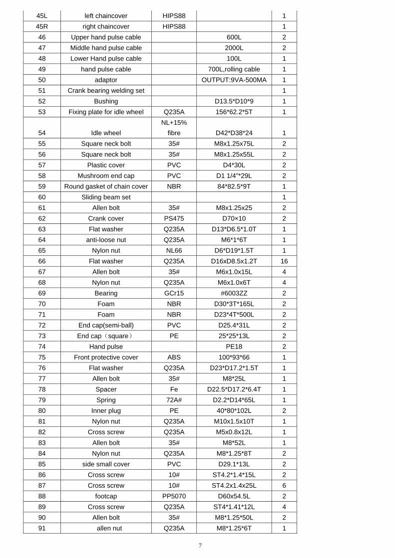
45L left chaincover HIPS88 1
45R right chaincover HIPS88 1
46 Upper hand pulse cable 600L 2
47 Middle hand pulse cable 2000L 2
48 Lower Hand pulse cable 100L 1
49 hand pulse cable 700L,rolling cable 1
50 adaptor OUTPUT:9VA-500MA 1
51 Crank bearing welding set 1
52 Bushing D13.5*D10*9 1
53 Fixing plate for idle wheel Q235A 156*62.2*5T 1
54 Idle wheel
NL+15%
fibre D42*D38*24 1
55 Square neck bolt 35# M8x1.25x75L 2
56 Square neck bolt 35# M8x1.25x55L 2
57 Plastic cover PVC D4*30L 2
58 Mushroom end cap PVC D1 1/4"*29L 2
59 Round gasket of chain cover NBR 84*82.5*9T 1
60 Sliding beam set 1
61 Allen bolt 35# M8x1.25x25 2
62 Crank cover PS475 D70×10 2
63 Flat washer Q235A D13*D6.5*1.0T 1
64 anti-loose nut Q235A M6*1*6T 1
65 Nylon nut NL66 D6*D19*1.5T 1
66 Flat washer Q235A D16xD8.5x1.2T 16
67 Allen bolt 35# M6x1.0x15L 4
68 Nylon nut Q235A M6x1.0x6T 4
69 Bearing GCr15 #6003ZZ 2
70 Foam NBR D30*3T*165L 2
71 Foam NBR D23*4T*500L 2
72 End cap(semi-ball) PVC D25.4*31L 2
73 End cap(square) PE 25*25*13L 2
74 Hand pulse PE18 2
75 Front protective cover ABS 100*93*66 1
76 Flat washer Q235A D23*D17.2*1.5T 1
77 Allen bolt 35# M8*25L 1
78 Spacer Fe D22.5*D17.2*6.4T 1
79 Spring 72A# D2.2*D14*65L 1
80 Inner plug PE 40*80*102L 2
81 Nylon nut Q235A M10x1.5x10T 1
82 Cross screw Q235A M5x0.8x12L 1
83 Allen bolt 35# M8*52L 1
84 Nylon nut Q235A M8*1.25*8T 2
85 side small cover PVC D29.1*13L 2
86 Cross screw 10# ST4.2*1.4*15L 2
87 Cross screw 10# ST4.2x1.4x25L 6
88 footcap PP5070 D60x54.5L 2
89 Cross screw Q235A ST4*1.41*12L 4
90 Allen bolt 35# M8*1.25*50L 2
91 allen nut Q235A M8*1.25*6T 1
8
inner allen spanner 35# M6 1
wrench Q235A 121*D6 1
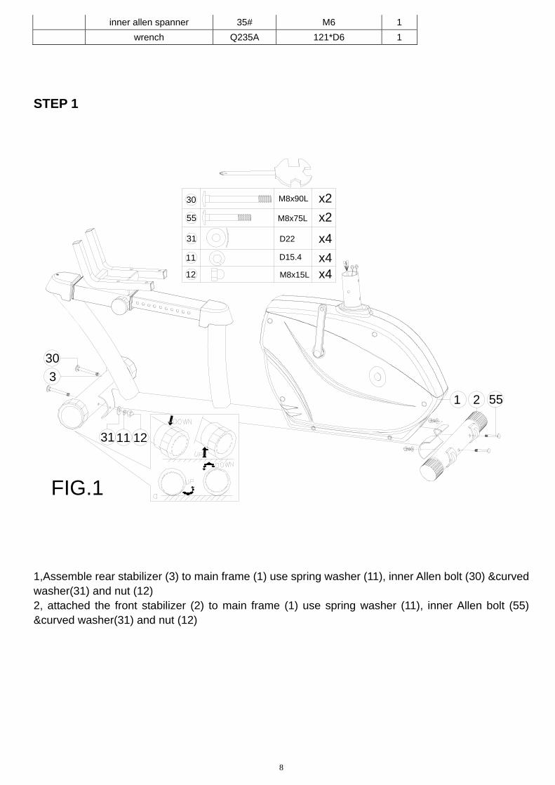
STEP 1
FIG.1
M8x90L30
M8x75L55
D2231
11
12 M8x15L
D15.4
x2
x2
x4
x4x4
30
31 11 12
55
3
21
1,Assemble rear stabilizer (3) to main frame (1) use spring washer (11), inner Allen bolt (30) &curved washer(31) and nut (12) 2, attached the front stabilizer (2) to main frame (1) use spring washer (11), inner Allen bolt (55) &curved washer(31) and nut (12)
9
STEP 2
FIG.2
661113
7
4
5
M8x20L
D15.4
D16
13
66
11
x4
x4
x4
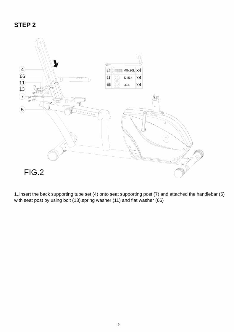
1,,insert the back supporting tube set (4) onto seat supporting post (7) and attached the handlebar (5) with seat post by using bolt (13),spring washer (11) and flat washer (66)
10
STEP 3
FIG.3
6615
25
6615
C
49
M8*40L
D16
15
66
x8
x8184
7
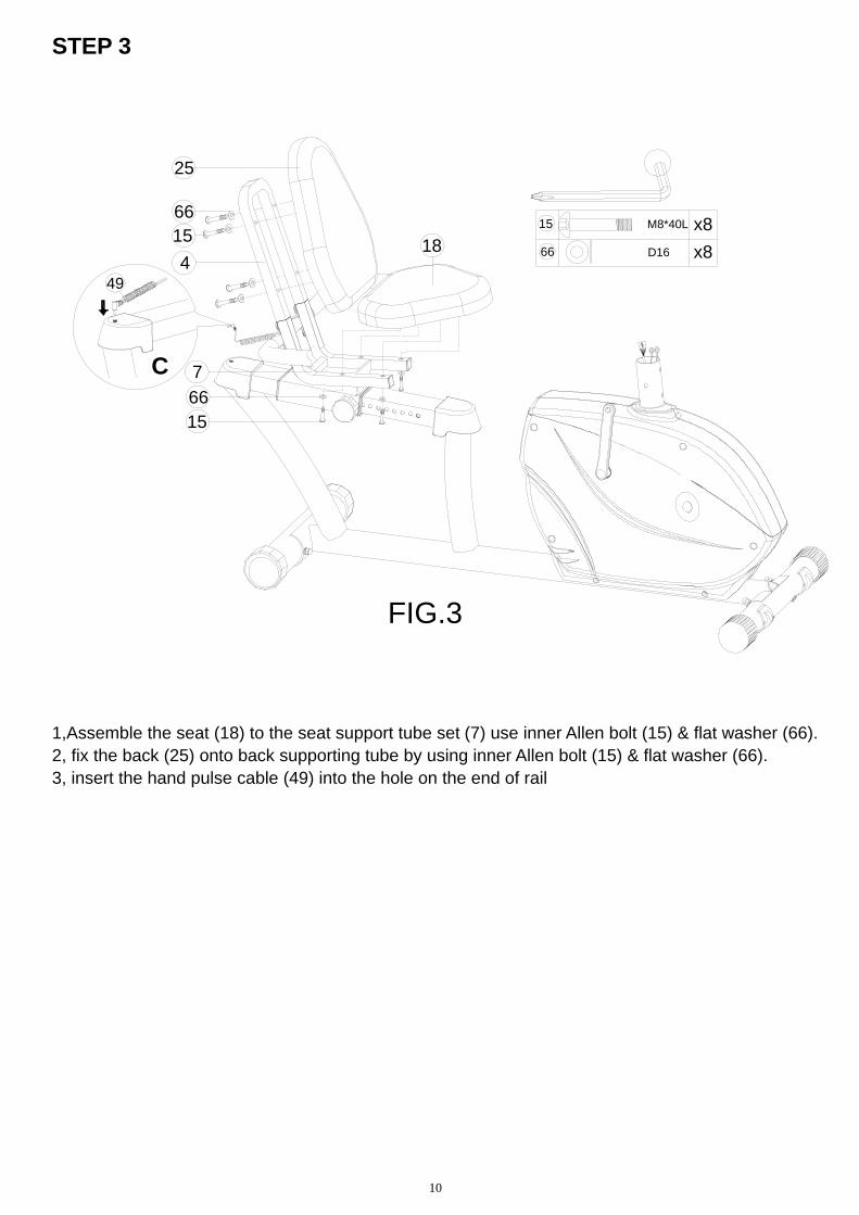
1,Assemble the seat (18) to the seat support tube set (7) use inner Allen bolt (15) & flat washer (66). 2, fix the back (25) onto back supporting tube by using inner Allen bolt (15) & flat washer (66). 3, insert the hand pulse cable (49) into the hole on the end of rail
11
STEP 4
FIG.4
41A
41B
46
47
13113110
M8x20L
D15.4
D22
13
11
31
x4
x4
x4
1
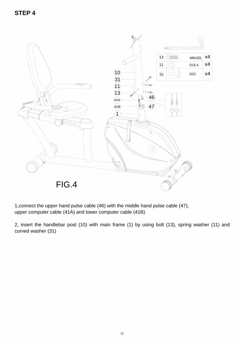
1,connect the upper hand pulse cable (46) with the middle hand pulse cable (47), upper computer cable (41A) and lower computer cable (41B) 2, insert the handlebar post (10) with main frame (1) by using bolt (13), spring washer (11) and curved washer (31)
12
STEP 5
20R
LFIG.5
50
8
20L 39L
46
8
41A
10
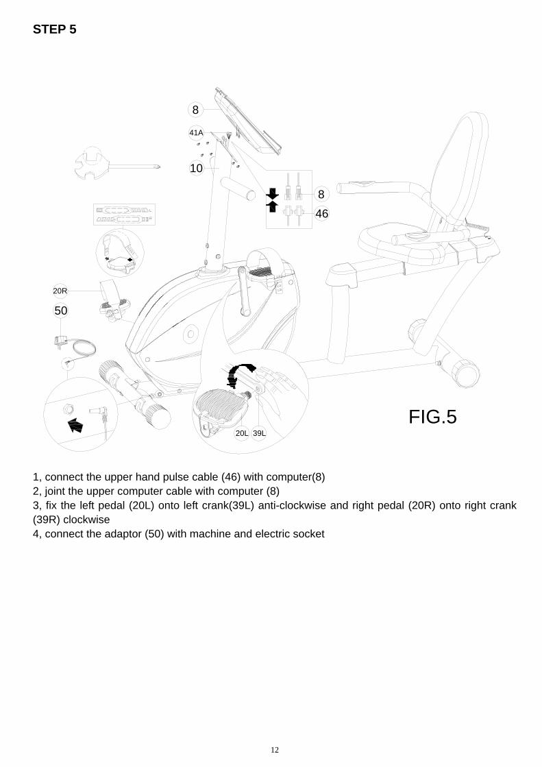
1, connect the upper hand pulse cable (46) with computer(8) 2, joint the upper computer cable with computer (8) 3, fix the left pedal (20L) onto left crank(39L) anti-clockwise and right pedal (20R) onto right crank (39R) clockwise 4, connect the adaptor (50) with machine and electric socket
13
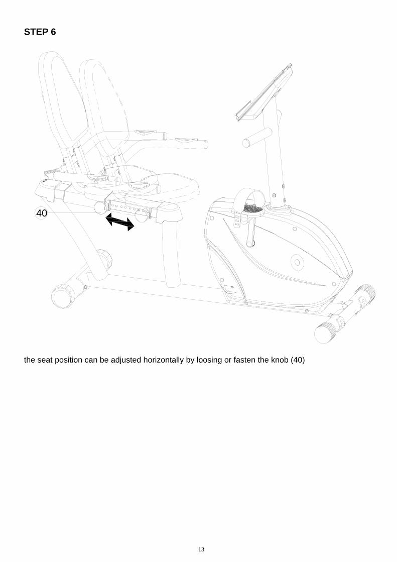
STEP 6
40
the seat position can be adjusted horizontally by loosing or fasten the knob (40)
14
SM3770 INSTRUCTION MANUAL
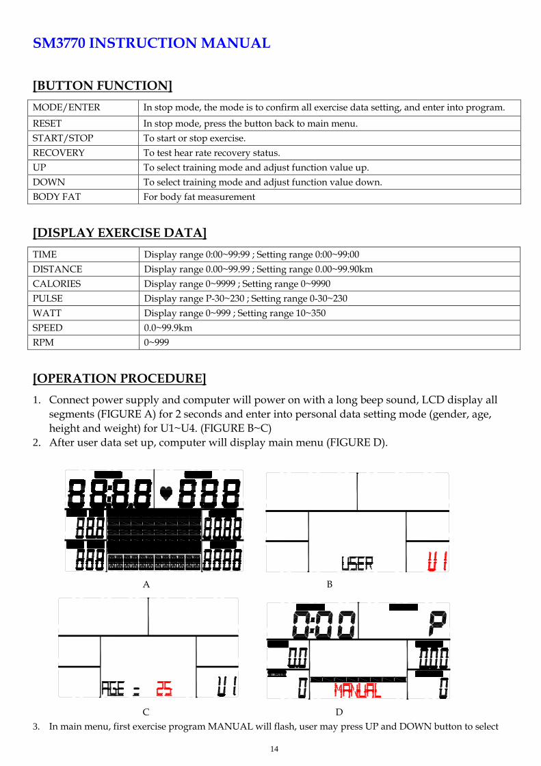
[BUTTON FUNCTION]
MODE/ENTER In stop mode, the mode is to confirm all exercise data setting, and enter into program.
RESET In stop mode, press the button back to main menu.
START/STOP To start or stop exercise.
RECOVERY To test hear rate recovery status.
UP To select training mode and adjust function value up.
DOWN To select training mode and adjust function value down.
BODY FAT For body fat measurement
[DISPLAY EXERCISE DATA]
TIME Display range 0:00~99:99 ; Setting range 0:00~99:00
DISTANCE Display range 0.00~99.99 ; Setting range 0.00~99.90km
CALORIES Display range 0~9999 ; Setting range 0~9990
PULSE Display range P-30~230 ; Setting range 0-30~230
WATT Display range 0~999 ; Setting range 10~350
SPEED 0.0~99.9km
RPM 0~999
[OPERATION PROCEDURE]
1. Connect power supply and computer will power on with a long beep sound, LCD display all segments (FIGURE A) for 2 seconds and enter into personal data setting mode (gender, age, height and weight) for U1~U4. (FIGURE B~C)
2. After user data set up, computer will display main menu (FIGURE D).
A B
C D
3. In main menu, first exercise program MANUAL will flash, user may press UP and DOWN button to select
15
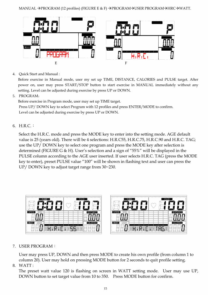
MANUAL PROGRAM (12 profiles) (FIGURE E & F) PROGRAMUSER PROGRAMHRCWATT.
E F 4. Quick Start and Manual : Before exercise in Manual mode, user my set up TIME, DISTANCE, CALORIES and PULSE target. After
power on, user may press START/STOP button to start exercise in MANUAL immediately without any setting. Level can be adjusted during exercise by press UP or DOWN.
5. PROGRAM: Before exercise in Program mode, user may set up TIME target.
Press UP/ DOWN key to select Program with 12 profiles and press ENTER/MODE to confirm. Level can be adjusted during exercise by press UP or DOWN.
6. H.R.C.:
Select the H.R.C. mode and press the MODE key to enter into the setting mode. AGE default value is 25 (years old). There will be 4 selections: H.R.C55, H.R.C.75, H.R.C.90 and H.R.C. TAG; use the UP/ DOWN key to select one program and press the MODE key after selection is determined (FIGURE G & H). User’s selection and a sign of “55%” will be displayed in the PULSE column according to the AGE user inserted. If user selects H.R.C. TAG (press the MODE key to enter), preset PULSE value “100” will be shown in flashing text and user can press the UP/ DOWN key to adjust target range from 30~230.
G H
7. USER PROGRAM:
User may press UP, DOWN and then press MODE to create his own profile (from column 1 to column 20). User may hold on pressing MODE button for 2 seconds to quit profile setting.
8. WATT : The preset watt value 120 is flashing on screen in WATT setting mode. User may use UP, DOWN button to set target value from 10 to 350. Press MODE button for confirm.
16
9. BODY FAT:
9-1 In STOP mode, press the BODY FAT button to start body fat measurement.
9-2 Then selected user (U1~U4) will blinking for 2 seconds. Then start measuring.
9-3 During measuring, users have to hold both hands on the handgrip. And the LCD will display “--” “--“for 8 seconds until computer finish measuring.
9-4 LCD will display BODY FAT advice symbol, BODY FAT percentage, BMI for 30 seconds.
10. RECOVERY: After exercising for a period of time, keep holding on handgrips and press “RECOVERY” button. All function display will stop except “TIME” starts counting down from 00:60 to 00:00.
Screen will display your heart rate recovery status with the F1, F2….to F6. F1 is the best, F6 F6 is the worst. User may keep exercising to improve the heart rate recovery status. (Press the RECOVERY button again to return the main display.)
NOTE: 1. This computer requires 9V, 500mA adaptor. 2. When user stop pedaling for 4 minutes, computer will enter into power save mode, all setting
and exercise data will stored until user start exercise again. 3. When computer act abnormal, please plug out the adaptor and plug in again.