Embed Size (px)
Citation preview

RFAL-DIMR-EN (REV. B)
ENGLISH IN U.S.A.: Cooper Wiring Devices, 203 Cooper Circle, Peachtree City, GA 30269 • 866-853-4293
RF SMART DIMMER – RF9540-N For dimmable LED/ CFL/ incandecent/ MLV/ ELV/ Halogen/ dimmable Fluorescent RF9536-N For incandescent/MLV RF9537-N for ELV Lighting Fixtures / RF9542-Z RF Accessory for multi-location
INSTALLATION INSTRUCTIONSWARNING: • Turn OFF circuit breaker or remove fuse(s) and test that power is off before wiring. • Never wire any electrical device with power turned on. Wiring dimmer with power on may cause permanent damage to dimmer and void warranty.• If you are not sure about any part of these instructions, please contact a licensed electrician.
IMPORTANT:RF Smart dimmer will not work or will become damaged if wired incorrectly, and warranty will be voided. Refer to wiring instructions provided on reverse side.
OPERATION INSTRUCTIONS• Press once to turn lights ON at previously selected level. • Press again to turn lights OFF.• When lights are OFF, press and hold for 2 seconds for full brightness.• When lights are ON, press and hold for 2 seconds until the blue LED blinks. After the preset
delay, the lights will begin fading to OFF (up to 4 minutes).• Amber ON/OFF LED indicates that dimmer is turned on.
DIMMING LEVEL ADJUSTMENT (RF9540-N only)For maximum compatibility with different loads types, RF9540-N allows the user to set the minimum level. Also to save on power consumption RF9540-N allows the user to set the maximum level.1. After installing the dimmer and restoring power, press on/off button to turn on the light.2. Press and hold on/off button for five seconds until the blue dimmer LEDs begin to cycle rapidly (NOTICE- after two seconds blue dimmer LEDs will start to flash indicating activation of the delay off feature. Continue holding the ON/OFF button for three additional seconds until the blue dimmer LEDs begin to cycle rapidly.) 3. Release the button. Dimmer will set the light to the previously saved minimum level (that may cause the light to flicker or turn off). During initial setup, the light will set to the factory minimum default.4. Press either the dim or bright buttons to change the minimum level until the light output is acceptable.5. Press ON/OFF button. Blue dimmer LEDs will start to cycle rapidly again and the dimmer light will go to previously saved maximum level.6. Press either the dim or bright buttons to change the maximum level until the light output is acceptable.7. Press ON/OFF button, LED will flash indicating completion of programming• NOTE – To restore the default min/max, repeat the steps above and adjust light levels to full
min/max settings by pressing dim/bright buttons until the light output no longer changes.• NOTE - User could ignore setting max or min by pressing on/off button without changing the
dimmer level.
Rapid start feature (RF9540-N only) This feature ensures that LED/CFL lights turn on when the dimmer preset level is low. With this setting enabled, the lights may momentarily be brighter than the preset level (less than one sec-ond) and then dim down to the preset level. Depending on the type of light used, this feature may not be needed.To enable/disable the feature, turn lights on. Press and hold the on/off button for 10 seconds until the blue dimmer LEDs flash for the third time, then release the button.
CAUTION:1. Use only with 120V AC 60 Hz.2. Do not exceed maximum rating of the dimmer as indicated on the device.3. Must be installed and used in accordance with electrical codes.4. If a bare copper or green ground connection is not available in the wallbox, contact a licensed electrician for installation. 5. Use only #14 or #12 copper wire rated for at least 75°C with these devices. Do not
use with Aluminum wire.
NOTES:1. The RF Master Dimmer is wired directly to the light fixture. 2. The RF Smart Dimmer is not compatible with standard 3-way switches.3. For Multi-location applications (3-Way or 4-Way) the RF Smart Accessory Dimmer(s) is used along with one RF Master Dimmer.4. The RF Accessory Dimmer communicates via RF signals to control the light from more than one location.5. For multi-location control use RF Smart Dimmer Master direct wired to the light along with RF Accessory (RF9542-Z). The RF Accessory does not require direct connection to the light (use Association function).6. When installing more than one dimmer in a wall box the total lamp wattage may need to
be reduced. See Ganging chart.
GANGING When ganging multiple Smart Dimmer Masters in one wall box, derating is required as follows
Catalog # Loads Single Gang Double Gang Tripple Gang
RF9536-N INC/MLV 1000W/VA 800W/VA 800W/VA
RF9537-N ELV 1000W 800W 800W
RF9540-NINC/ ELV/ FLR/ Halogen/ MLV
600W/VA 600W/VA 600W/VA
CFL/ LED 300W 300W 300W
Troubleshooting GuideSymptom Possible Cause Solution
No Function. All LEDs are OFF A) Light bulb(s) burned outB) Circuit breaker is off or
trippedC) Disconnect switch on the
dimmer is pulled out to the OFF position
D) Improper wiringE) Defective dimmer
A) Replace light bulbB) Turn on the circuit breaker
C) Push in the disconnect switch on the dimmer
D) Check and correct wiringE) Replace dimmer
Erratic operation or flickering LEDs
A) Loose wiring connectionsB) Low dim setting
(RF9540-N)
A) Check and correct wiringB) Set minimum brightness to
a higher level (RF9540-N)
Lights turns on after long delay
A) Rapid start feature is disabled (RF9540-N)
B) Low dim setting (RF9540-N)
A) Enable rapid start feature (RF9540-N)
B) Set minimum brightness to a higher level (RF9540-N)
Functions normally using the dimmer push buttons but not from Z-Wave controller and one of the blue LEDs blinks ON and OFF about once per second
Dimmer is not included in Z-Wave network
Include dimmer in a Z-Wave network using a Z-Wave controller. Refer to Z-Wave controller user manual for details
Z-Wave Device Network Installation Instructions1. This product may be added to a new or existing Z-Wave network. A Cooper Wiring Devices
Z-Wave device has a blue LED, which will blink when the device is not included in a Z-Wave network. The LED stops blinking when the device is in a network.
2. To include this device in a Z-Wave network, select the command on your Z Wave controller for inclusion (Install, Add Device, Add Node, Include Device, etc.). Then press the device switch one time to include it in the network. The LED will stop blinking.
3.To exclude this device from a Z-Wave network, select the command on your Z-Wave controller for exclusion (Uninstall, Remove Device, Remove Node, Exclude Device, etc.). Then press the device switch one time to exclude it from the network. The LED will start blinking.
4. This product works with other Z-Wave products from different vendors and product categories as part of the same network.
5. This product is a listening node and it will act as a repeater in the Z-Wave network. It will perform the repeater function with Z-Wave products from Cooper and from other Z-Wave vendors.
READ BEFORE INSTALLATION!Switch Identification
ACCESSORY
ACCESSORYACCESSORY
WhiteWhite
Master Control Accessory
Disconnect Switch
Red
Black Black
Green Green
Functions normally using the Master dimmer control but not from Z-Wave controller and no LEDs are blinking
Problem with RF communica-tion on dimmer
Replace dimmer
Functions normally both locally and from a Z-Wave controller but can’t be controlled from a dimmer accessory switch (RF9542-Z) or other Z-Wave device
The dimmer accessory or other Z-Wave device is not associated with the dimmer you wish to control
Create an association between the dimmer acces-sory or other device and the dimmer. Refer to your Z-Wave controller user manual for details
Dimmer is warm to touch after a period of time
This is normal No action required
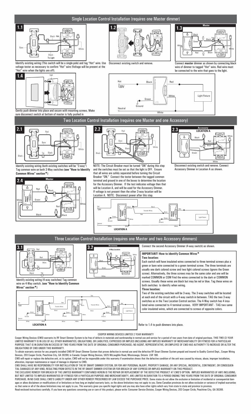
Single Location Control Installation (requires one Master dimmer)
Identify existing wiring (This switch will be a single-pole) and tag “Hot” wire. Use voltage tester as necessary to confirm “Hot” wire (Voltage will be present at the “Hot” wire when the lights are off).
Disconnect existing switch and remove. Connect master dimmer as shown by connecting black wire of dimmer to tagged “Hot” wire. Red wire must be connected to the wire that goes to the light.
Gently push dimmer into place and secure with mounting screws. Make sure disconnect switch at bottom of master is fully pushed in
Black RedHot
Neutral
120V
Light FixtureGreen
Ground
MA
STER
DIM
MER
White
White
Two Location Control Installation (requires one Master and one Accessory)
Identify existing wiring (both existing switches will be “3-way”) Tag common wire on both 3-Way switches (see “How to Identify Common Wires” section*)
NOTE: The Circuit Breaker must be turned “ON” during this step and the switches must be set so that the light is OFF. Ensure that all wires are safely separated before turning the Circuit Breaker “ON.” Connect the tester between the tagged common terminal and ground in one of the boxes to determine the location for the Accessory Dimmer. If the test indicates voltage then that will be Location A, and will be used for the Accessory Dimmer. If voltage is not present then the other 3-way location will be Location A. NOTE: Disconnect power after this step.
Disconnect existing switch and remove. Connect Accessory Dimmer in Location A as shown.
RedBlackHot
Neutral
120V
Light FixtureGreen
Ground
Green
Ground
White White White
Red
White
BlackTraveler Wires
Black
ACC
ESSO
RYD
IMM
ER
MA
STER
DIM
MER
LOCATION A
Three Location Control Installation (requires one Master and two Accessory dimmers)
Identify existing wiring (4-way switches) Tag common wire on 4-Way switch. (see “How to Identify Common Wires” section*)
Connect the second Accessory Dimmer (4-way switch) as shown.
IMPORTANT! How to identify Common Wires*Two location:Each switch will have insulated wires connected to three terminal screws plus a green or bare wire connected to a green terminal screw. The three terminals are usually one dark colored screw and two light colored screws (ignore the Green screw). Alternatively, the three screws may be the same color and one will be marked COMMON or COM Find the wires connected to the dark or COMMON screws. Usually these wires are black but may be red or blue. Tag these wires on both switches to identify when wiring.Three location:Two of the existing switches will be 3-way. The 3-way switches will be located at each end of the circuit with a 4-way switch in between. TAG the two 3-way switches as in the Two Location Control section. The 4-Way switch has 4 insu-lated wires connected to 4 terminal screws. VERY IMPORTANT - TAG two same color insulated wires, which are connected to screws of opposite colors.
Refer to 1.4 to push dimmers into place.
COOPER WIRING DEVICES LIMITED 2 YEAR WARRANTYCooper Wiring Devices (CWD) warrants its RF Smart Dimmer System to be free of defects in materials and workmanship in normal use and service for a period of two years from date of original purchase. THIS TWO (2) YEAR LIMITED WARRANTY IS IN LIEU OF ALL OTHER WARRANTIES, OBLIGATIONS, OR LIABILITIES, EXPRESSED OR IMPLIED (INCLUDING ANY IMPLIED WARRANTY OF MERCHANTABILITY OR FITNESS FOR A PARTICULAR PURPOSE THAT IS IN DURATION IN EXCESS OF TWO YEARS FROM THE DATE OF ORIGINAL CONSUMER PURCHASE). NO AGENT, REPRESENTATIVE, OR EMPLOYEE OF CWD HAS AUTHORITY TO INCREASE OR ALTER THE OBLIGATIONS OF CWD UNDER THIS WARRANTY.To obtain warranty service for any properly installed CWD RF Smart Dimmer System that proves defective in normal use send the defective RF Smart Dimmer System prepaid and insured to Quality Control Dept., Cooper Wiring Devices, 203 Cooper Circle, Peachtree City, GA 30269; in Canada: Cooper Wiring Devices, 5925 McLaughlin Road, Mississauga, Ontario L5R 1B8.CWD will repair or replace the defective unit, at its option. CWD will not be responsible under this warranty if examination shows that the defective condition of the unit was caused by misuse, abuse, improper installation, alteration, improper maintenance or repair of damage in shipment to CWD.CWD SHALL HAVE NO RESPONSIBILITY FOR INSTALLATION OF THE RF SMART DIMMER SYSTEM, OR FOR ANY PERSONAL INJURY, PROPERTY DAMAGE, OR ANY SPECIAL, INCIDENTAL, CONTINGENT, OR CONSEQUEN-TIAL DAMAGES OF ANY KIND, RESULTING FROM DEFECTS IN THE RF SMART DIMMER SYSTEM OR FOR BREACH OF ANY EXPRESS OR IMPLIED WARRANTY ON THIS PRODUCT.THE EXCLUSIVE REMEDY FOR BREACH OF THE LIMITED WARRANTY CONTAINED HEREIN IS THE REPAIR OR REPLACEMENT OF THE DEFECTIVE PRODUCT AT CWD’S OPTION. IMPLIED WARRANTIES (IF ANY) INCLUDING, BUT NOT LIMITED TO IMPLIED WARRANTIES OF FITNESS FOR A PARTICULAR PURPOSE AND MERCHANTABIITY, ARE LIMITED IN DURATION TO A PERIOD ENDING TWO YEARS FROM THE DATE OF ORIGINAL CONSUMER PURCHASE. IN NO CASE SHALL CWD’S LIABILITY UNDER ANY OTHER REMEDY PRESCRIBED BY LAW EXCEED THE PURCHASE PRICE. Some states do not allow the exclusion or limitation of incidental or consequential dam-ages or allow disclaimers or modifications of or limitations on how long an implied warranty lasts, so the above limitations may not apply to you. Some Canadian provinces do not allow exclusion or variance of implied warranties so that some or all of the above limitations may not apply to you. This warranty gives you specific legal rights and you may also have other rights which vary from state to state and province to province.Read enclosed instructions carefully. If you have any questions concerning use or care of this product, please write: Consumer Service Division, Cooper Wiring Devices, 203 Cooper Circle, Peachtree City, GA 30269.
Black
1.3
White
Black
Bare
1.1 1.41.2 1.5 Master
Black
Black
Green
Red
Black
White
White
1.3
1.6 TOP1.4
2.1
Black
Bare
Black
Red
Tag
White
2.1 2.2
Black
Bare
Black
Red
Tag
White
2.2
Green
Red
Tag Black
2.4 Accessory
ACCESSORY
White
Black
LOCATION A
ACCESSORY
White
2.3
2.5 Master
Red
Green
White
Black
Black
Tag
Black
Red
MA
STER
DIM
MER
White
2.4
3.1
White
Black
Red
Red
Bare
TagBlack
Tag
3.1 3.2 Accessory
White
Red
Black
Black
GreenACCESSORY
White
Tag
4-Way Location3.2
Tag
-To Light
Tag- Hot
Red
Black
Hot
Neutral
120V
Light FixtureGreen
Ground
Green
Ground
White White White
ACC
ESSO
RYD
IMM
ER
Red
White
BlackTraveler Wires
Green
GroundWhite
White White
Black
Red
Black Traveler Wires
LOCATION A
ACC
ESSO
RYD
IMM
ER
MA
STER
DIM
MER