Embed Size (px)
Citation preview
T34A2A1 2313
2414
+ -Ub
T22T21
F1
K1
T11
E-Stop
Reset
T12 51
52
33
44
T33
Monitoring logic
K3 K4K2
K2
K1
K3
K4
43
34
T35T10
Due
lco
a/s
acce
pts
no re
spon
sibi
lity
for p
ossi
ble
erro
rs a
nd d
efici
enci
es in
bro
chur
es, c
atal
ogue
s an
d ot
her p
rinte
d m
ater
ial.
Due
lco
a/s
rese
rves
th
e rig
ht to
alte
r its
pro
duct
s w
ithou
t prio
r not
ice.
Thi
s al
so a
pplie
s to
pro
duct
s al
read
y on
ord
er
prov
ided
that
suc
h al
tera
tions
can
be
mad
e w
ithou
t sub
sequ
entia
l cha
nges
bei
ng n
eces
sary
in s
peci
ficat
ions
alre
ady
agre
ed. D
uelc
o a/
s gu
aran
-te
es c
orre
ct fu
nctio
n as
wel
l as
fulfi
lmen
t of t
he s
afet
yreq
uire
men
ts o
nly
whe
n co
nnec
tions
are
mad
e in
acc
orda
nce
with
inst
ruct
ions
.04
/13
NS
T-20
09 m
anua
l / D
ocum
ent:N
ST-
2009
man
ual 2
edi
tion.
indd
Safety control circuits must fulfill the requirements of the Machine Directive 2006/42/EC. The safety relay NST-2009 fulfils these require-ments and further it is designed according to specific standard requirements on doubl ing and monitoring of safety control circuits cf. European stan dard on safety requirements for electrical equipment on machines, EN 60 204-1. APPROBATIONSUL & cULCE-marked according to MD, EMC and LVD
GB
Sicherheitssteuerkreise müssen die Bestim mungen in der Maschinenrichtlinie 2006/42/EG erfüllen. Das Sicherheitsschaltgerät Typ NST-2009 erfüllt diese Bestimmungen und ist außerdem nach spe-zifischen Normenforderungen nach Verdopp lung und Überwachung von Sicherheitssteuerkreisen konstruiert worden, vergleiche die Europäische Norm über Sicherheitsanfor derungen an die elek-trische Ausrüstung von Maschinen, EN 60 204-1.ZULASSUNGEN UL & cULCE-Zeichen in Übereinstimmung mit MD, EMV und LVD
D
Sikkerhedsstyrekredse skal over holde bestemmelserne i Maskindirektivet 2006/42/EF.Sikkerhedsrelæet type NST-2009 opfylder disse bestemmelser og er endvidere konstrueret efter specifikke normkrav om dublering og overvågning af sikkerhedsstyrekredse jf. europæisk norm om sikkerhedskrav til elektrisk materiel på maskiner, EN 60 204-1 (stærkstrømsbekendtgørelsen afsnit 204-1).APPROBATIONERUL & cULCE-mærket i overensstemmelse med MD, EMC og LVD
DK
DK FUNKTIONSBESKRIVELSE Driftsspændingen tilsluttes terminalerne A1(+) og A2(-) og lysdioden tilknyttet strømforsyn-ingen Ub lyser grønt. I uaktiveret tilstand (hvile) er relæets sluttekontakter 13-14, 23-24, 33-34 og 43-44 åbne og brydekontakten 51-52 er lukket. Såfremt nødstop er uaktiveret, og overvågning-skredsløbet konstaterer fejlfri funktion af relæet (dioder blinker), kan dette startes ved aktivering af en sluttekontakt (se RESET-TYPES). Herved sluttes kontakterne 13-14, 23-24, 33-34, 43-44 og brydekontakten 51- 52 åbnes. LED K1, K2, K3 og K4 lyser derved.Betjenes nødstoppet, vil relæerne K1 og K2 deak-tiveres. K3 og K4 deaktiveres ligeledes efter den indstillede forsinkelse er udløbet. Derved åbnes strømvejene 13-14, 23-24 og 51-52 lukkes. 33-34 og 43-44 åbnes efter udløb af tidsforsinkelsen.Efter tilbagestilling af nødstop vil NST-2009 påny være klar til aktivering, såfremt overvågnings-kredsløbet konstaterer fejlfri funktion af relæet. En kortslutning mellem de 2 nødstopkontakter vil deaktivere NST-2009 via en intern overvågning (det vil sige at nødstoprelæet kan resettes igen når kortslutningen/fejlen er rettet og forsyningsspænd-ing har været fjernet).I visse industrielle miljøer kan korrosion/oxida-tion forekomme. NST-2009 bør i sådanne miljøer aktiveres/deaktiveres med jævne mellemrum for at sikre relæernes optimale kontaktfunktion.BEMÆRK! Potentiometerne Delay 1 og Delay 2 skal være identisk indstillet for at opnå korrekt funktion (se tidsskema). Efter ændring af tidsind-stillingen skal forsyningsspændingen kortvarigt afbrydes for at ændringen træder i kraft. Før forsyn-ingsspændingen genindkobles, skal det påses, at NST-2009’s kapsling er intakt og korrekt monteret.ADVARSEL! Forsyningsspændingen skal afbrydes før arbejdsoperationer udføres på nødstoprelæet.
INSTRUCTION SHEET DUELCO Emergency Stop Relay NST-2009Relay version 1.00
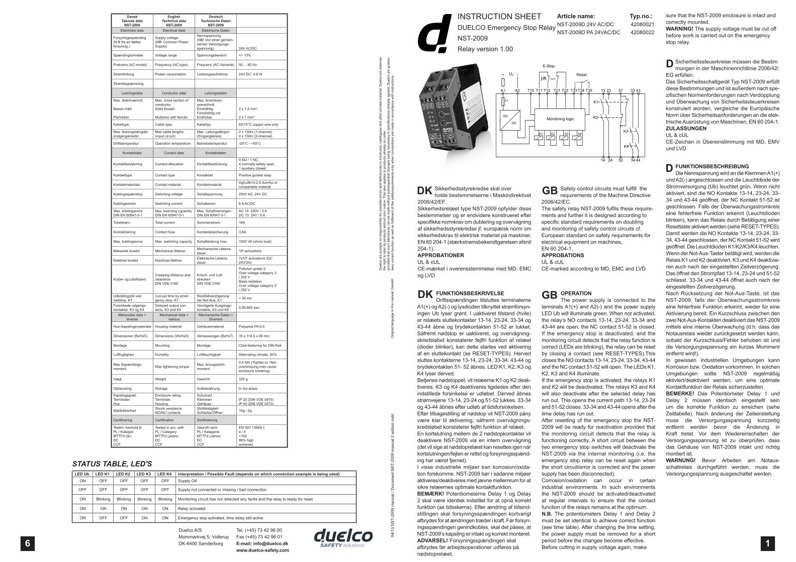
OPERATION The power supply is connected to the terminals A1(+) and A2(-) and the power supply LED Ub will illuminate green. When not ac tivated, the relay’s NO contacts 13-14, 23-24, 33-34 and 43-44 are open, the NC contact 51-52 is closed. If the emergency stop is deactivated, and the monitoring circuit detects that the relay func tion is correct (LEDs are blinking), the relay can be reset by closing a contact (see RESET-TYPES).This closes the NO contacts 13-14, 23-24, 33-34, 43-44 and the NC contact 51-52 will open. The LEDs K1, K2, K3 and K4 illuminate.If the emergency stop is activated, the relays K1 and K2 will be deactivated. The relays K3 and K4 will also deactivate after the selected delay has run out. This opens the current path 13-14, 23-24 and 51-52 closes. 33-34 and 43-44 opens after the time delay has run out.After resetting of the emergency stop the NST-2009 will be ready for reactivation provided that the monitoring circuit detects that the relay is functioning correctly. A short circuit between the two emergency stop switches will deactivate the NST-2009 via the internal monitoring (i.e. the emergency stop relay can be reset again when the short circuit/error is corrected and the power supply has been disconnected).Corrosion/oxidation can occur in certain industrial environments. In such environments the NST-2009 should be activated/deactivated at regular intervals to ensure that the contact function of the relays remains at the optimum.N.B. The potentiometers Delay 1 and Delay 2 must be set identical to achieve correct function (see time table). After changing the time setting, the power supply must be removed for a short period before the changes become effective.Before cutting in supply voltage again, make
GB
FUNKTIONSBESCHREIBUNG Die Nennspannung wird an die Klemmen A1(+) und A2(-) angeschlossen und die Leuchtdiode der Stromversorgung (Ub) leuchtet grün. Wenn nicht aktiviert, sind die NO Kontakte 13-14, 23-24, 33-34 und 43-44 geöffnet, der NC Kontakt 51-52 ist geschlossen. Falls der Überwachungsstromkreis eine fehlerfreie Funktion erkennt (Leuchtdioden blinken), kann das Relais durch Betätigung einer Resettaste aktiviert werden (sehe RESET-TYPES). Damit werden die NO Kontakte 13-14, 23-24, 33-34, 43-44 geschlossen, der NC Kontakt 51-52 wird geöffnet. Die Leuchtdioden K1/K2/K3/K4 leuchten.Wenn der Not-Aus-Taster betätigt wird, werden die Relais K1 und K2 deaktiviert. K3 und K4 deaktivie-ren auch nach der eingestellten Zeitverzögerung. Das öffnet den Strompfad 13-14, 23-24 und 51-52 schliesst. 33-34 und 43-44 öffnet auch nach der eingestellten Zeitverzögerung.Nach Rücksetzung der Not-Aus-Taste, ist das NST-2009, falls der Überwachungsstromkreis eine fehlerfreie Funktion erkennt, wieder für eine Aktivierung bereit. Ein Kurzschluss zwischen den zwei Not-Aus-Kontakten deaktiviert das NST-2009 mittels eine interne Überwachung (d.h. dass das Notausrelais wieder zurückgesetzt werden kann, sobald der Kurzschluss/Fehler behoben ist und die Versorgungsspannung ein kurzes Momment entfernt wird!).In gewissen industriellen Umgebungen kann Korrosion bzw. Oxidation vorkommen. In solchen Umgebungen sollte NST-2009 regelmäßig aktiviert/deaktiviert werden, um eine optimale Kontaktfunktion der Relais sicherzustellen.BEMERKE! Das Potentiometer Delay 1 und Delay 2 müssen identisch eingestellt sein um die korrekte Funktion zu erreichen (sehe Zeittabelle). Nach änderung der Zeiteinstellung muss die Versorgungsspannung kurzzeitig entfernt werden bevor die Änderung in Kraft tretet. Vor dem Wiedereinschalten der Versorgungsspannung ist zu überprüfen, dass das Gehäuse von NST-2009 intakt und richtig montiert ist.WARNUNG! Bevor Arbeiten am Notaus-schaltrelais durchgeführt werden, muss die Versorgungsspannung ausgeschaltet werden.
D
Article name: Typ.no.: NST-2009D 24V AC/DC 42080021NST-2009D PA 24VAC/DC 42080022
16Duelco A/SMommarkvej 5, VollerupDK-6400 Sønderborg
DanskTeknisk data
NST-2009
EnglishTechnical data
NST-2009
DeutschTechnische Daten
NST-2009Elektriske data Electrical data Elektrische Daten
Forsyningsspænding(N.B fra en fællesforsyning.)
Supply voltage(NB! Common Power Supply)
Nennspannung (NB! Von einer gemein-samen Versorgungs-spannung) 24V AC/DC
Spændingsområde Voltage range Spannungsbereich +/- 10%
Frekvens (AC-model) Frequency (AC-type) Frequenz (AC-Variante) 50 ... 60 Hz
Strømforbrug Power consumption Leistungsaufnahme 24V DC: 4,8 W
Strømbegrænsning
Ledningsdata Conductor data Leitungsdaten
Max. ledertværsnit,
Massiv tråd:
Flertrådet:
Max. cross section of conductor,Solid thread:
Multiwire with ferrule:
Max. Anschluss-querschnitt,Eindrähtig:Feindrähtig mit Endhülse:
2 x 1,5 mm2
2 x 1 mm2
Kabeltype Cable type Kabeltyp 60/75°C copper wire only
Max. ledningslængder (indgangskreds)
Max cable lengths (input circuit)
Max. Leitungslängen (Eingangskreis)
2 x 150m (1-channel)4 x 150m (2-channel)
Driftstemperatur Operation temperature Betriebstemperatur -20°C - +50°C
Kontaktdata Contact data Kontaktdaten
Kontaktbestykning Contact-allocation Kontaktbestückung4 NO / 1 NC4 normally safety open1 auxiliary closed
Kontakttype Contact type Kontaktart Positive guided relay
Kontaktmateriale Contact material Kontaktmaterial AgCuNi+0,2-0,4umAu or comparable material
Koblingsspænding Switching voltage Schaltspannung 250V AC, 24V DC
Koblingsstrøm Switching current Schaltstrom 6 A AC/DC
Max. koblingsevneDIN EN 60947-5-1
Max. switching capabilityDIN EN 60947-5-1
Max. SchaltvermögenDIN EN 60947-5-1
AC 15 230V / 3 ADC 13 24V / 5 A
Totalstrøm Total current Summenstrom 16A
Kontaktsikring Contact fuse Kontaktabsicherung 3,6A
Max. koblingsevne Max. switching capacity Schaltleistung max. 1500 VA (ohms load)
Mekanisk levetid Mechanical lifetime Mechanische Lebens-dauer 106 activations
Elektrisk levetid Electrical lifetime Elektrische Lebens-dauer
7x10⁵ activations (DC 24V/2A)
Krybe- og luftafstandCreeping distance and clearanceDIN VDE 0160
Kriech- und Luft-streckenDIN VDE 0160
Pollution grade 2: Over voltage category 3 / 250 VBasis isolation:Over voltage category 3/ 250 V
Udkoblingstid ved nødstop, K1
Cut-out time by emer-gency stop, K1
Rückfallverzögerung bei Not-Aus, K1 < 30 ms
Forsinkede udgangs-kontakter, K3 og K4
Delayed output con-tacts, K3 and K4
Verzögerte Ausgangs-kontakte, K3 und K4 0,05-600 sec.
Mekaniske data + diverse
Mechanical data + various
Mechanische Daten + Diverses
Hus-/kapslingsmateriale Housing material Gehäusematerial Polyamid PA 6.6
Dimensioner (BxHxD) Dimensions (WxHxD) Abmessungen (BxHxT) 35 x 114,5 x 99 mm
Montage Mounting Montage Click-fastening for DIN-Rail
Luftfugtighed Humidity Luftfeuchtigkeit Alternating climate, 85%
Max tilspændings-moment Max tightening torque Max. Anzugsdreh-
moment
0,4 Nm (Tighten to 1Nm overtorquing may cause enclosure breaking)
Vægt Weight Gewicht 325 g
Opbevaring Storage Aufbewahrung In dry areas
Kapslingsgrad,TerminalerHus
Enclosure rating,TerminalsHousing
Schutzart,KlemmenGehäuse
IP 20 (DIN VDE 0470)IP 40 (DIN VDE 0470)
Stødsikkerhed Shock resistance NO/NC contacts
Stoßfestigkeit Schließer/Öffner 10g / 2g
Certificering Certification Zertifizierung
Testet i henhold tilPL / KategoriMTTFd (år)DCCCF
Tested in acc. withPL / CategoryMTTFd (years)DCCCF
Geprüft nachPL / KategorieMTTFd (Jahre)DCCCF
EN ISO 13849-1e / 4>10099% highachieved
STATUS TABLE, LED'SLED Ub LED K1 LED K2 LED K3 LED K4 Interpretation / Possible Fault (depends on which connection example is being used)
ON OFF OFF OFF OFF Supply OK
OFF OFF OFF OFF OFF Supply not connected or missing / bad connection
ON Blinking Blinking Blinking Blinking Monitoring circuit has not detected any faults and the relay is ready for reset
ON ON ON ON ON Relay activated
ON OFF OFF ON ON Emergency stop activated, time delay still active
Tel. (+45) 73 42 96 00Fax (+45) 73 42 96 01E-mail: [email protected]
Orig
inal
lang
uage
in th
is m
anua
l: D
anis
h!
sure that the NST-2009 enclosure is intact and correctly mounted.WARNING! The supply voltage must be cut off before work is carried out on the emergency stop relay.

1
DK
EKS. 2: 2-KANALS DRIFT (MED KORT-SLUTNINGSSIKRING)
CATEGORY 4; SIL3; PL e
Ved anvendelse af 2-kanals drift med kort-slutningssikring skal terminalfortrådningen T11-T12, T21-T22 benyttes. Ved tryk på RESET-tasten sluttes T33-T34 (se reset-diagram) og enheden aktiveres. Ved tryk på nødstoptasten deaktiveres relæet (de forsinkede udgangskontakter falder først fra efter den indstillede tid er udløbet).
EKSEMPEL. 1: 1-KANALS DRIFT
CATEGORY 2; PL d
Ved tryk på RESET-tasten sluttes T33-T34 (se reset-diagram) og enheden aktiveres. Ved tryk på nødstoptasten deaktiveres relæet (de forsinkede udgangskontakter falder først fra efter den indstillede tid er udløbet).
2
4
CONNECTION EXAMPLESPlease see terminal description on page 3 for correct terminal location!
SCHALTBEISPIELESiehe Terminalbeschreibung auf Seite 3 für korrekten Anschluss!
D
5
EKS. 4: 2-KANALS DRIFT MED MAG-NETKONTAKTER (MAX. STRØM: 20 mA)
CATEGORY 3; PL e
Ved anvendelse af 2-kanals drift med kortslutningssikring og magnetkontakter skal terminalfortrådningen T11-T12, T21-T22 benyttes. Ved tryk på RESET-tasten sluttes T33-T34 (se reset-diagram) og enheden aktiveres. Ved tryk på nødstop-tasten deaktiveres relæet (de forsinkede udgangskontakter falder først fra efter den indstillede tid er udløbet).
GBTILSLUTNINGSEKSEMPLERSe terminalbeskrivelse på side 3 for korrekt terminallokation!
EXAMPLE 1: 1-CHANNEL OPERATION
CATEGORY 2; PL d
Pressing the RESET-button, the contacts T33-T34 are closed (see reset diagram) and the unit will be activated. Pressing the emergency stop will deactivate the relay (the delayed output contacts cut out after the selected time delay).
EXAMPLE 2: 2-CHANNEL OPERATION (WITH SHORT CIRCUIT PROTECTION)
CATEGORY 4; SIL3; PL e
For this application the terminal wiring T11-T12, T21-T22 must be used. When pushing the RESET-button the contacts T33-T34 are closed (see reset diagram) and the device will be activated. Pressing the emergency stop will deactivate the relay (the delayed output contacts cut out after the selected time delay).
EXAMPLE 3: 2-CHANNEL OPERATION WITH EXTERNAL CONTACTS, CONTACT MONITORING AND SHORT CIRCUIT PROTECTION
CATEGORY 4; SIL3; PL e
For this application the terminal wiring T11-T12, T21-T22 must be used. When pushing the RESET-button the contacts T33-T34 are closed (see reset diagram) and the device will be activated. Pressing the emergency stop will deactivate the relay (the delayed output contacts cut out after the selected time delay). As the NC contacts are connected to the reset loop, the relay can only reset when the external contacts are in their initial position (forced contacts must be used).
BEISPIEL 1: 1-KANAL BETRIEB
CATEGORY 2; PL d
Mit dem RESET-taster wird das Gerät aktiviert. Die Kontakte T33-T34 schlies-sen (sehe Reset-Diagramm). Über den Not-Halt-Schalter fallen die Kontakte in ihre Grundstellung zurück (die verzögerten Ausgangskontakte fallen erst nach auslauf der eingestellten Periode in ihre Grundstel-lung zurück).
BEISPIEL 2: 2-KANAL-BETRIEB (MIT QUERSCHLUSS-SICHERHEIT)
CATEGORY 4; SIL3; PL e
Bei der zweikanaligen Not-Halt-Schaltung mit Querschlußsicherheit wird der Klemmen-anschluß T11-T12, T21-T22 verwendet. Mit dem RESET-taster wird das Gerät aktiviert. Die Kontakte T33-T34 schliessen (sehe Re-set-Diagramm). Über den Not-Halt-Schalter fallen die Kontakte in ihre Grundstellung zurück (die verzögerten Ausgangskontakte fallen erst nach auslauf der eingestellten Periode in ihre Grundstellung zurück).
BEISPIEL 3: ZWEIKANALIGE NOT-HALT-SCHALTUNG MIT EXTERNER KONTAKTERWEITERUNG (2SCHÜTZE), K O N TA K T Ü B E RWA C H U N G U N D QUERSCHLUSSSICHERHEIT
CATEGORY 4; SIL3; PL e
Bei der zweikanaligen Not-Halt-Schaltung mit Querschlußsicherheit wird der Klemmen-anschluß T11-T12, T21-T22 verwendet. Mit dem RESET-taster wird das Gerät aktiviert. Die Kontakte T33-T34 schliessen (sehe Re-set-Diagramm). Über den Not-Halt-Schalter fallen die Kontakte in ihre Grundstellung zurück (die verzögerten Ausgangskontakte fallen erst nach auslauf der eingestellten Periode in ihre Grundstellung zurück). Weil die Öffnerkontakte an den Reset-Loop ange-schlossen ist, kann das Relais nur geresettet werden, wenn die externen Kontakte in ihrer Ausgangsposition sind (zwangsgeführte Kontakte müssen benuzt werden).
BEISPIEL 4: ZWEIKANAL-BETRIEB MIT MAGNETKONTAKTE (MAX. STROM: 20 mA)
CATEGORY 3; PL e
Bei Anwendung von Magnetkontakte und Querschlusssicherheit wird der Klemmenanschluß T11-T12, T21-T22 verwendet. Mit dem RESET-taster wird das Gerät aktiviert. Die Kontakte T33-T34 schliessen (sehe Reset-Diagramm). Über den Not-Halt-Schalter fallen die Kontakte in ihre Grundstellung zurück (die verzögerten Ausgangskontakte fallen erst nach auslauf der eingestellten Periode in ihre Grundstellung zurück.
EKS. 3 : 2 -KANALS DRIFT MED EKSTERNE KONTAKTORER, KON-TAKTOVERVÅGNING OG KORTSLUT-NINGSSIKRING
CATEGORY 4; SIL3; PL e
Ved anvendelse af 2-kanals drift med kort-slutningssikring skal terminalfortrådningen T11-T12, T21-T22 benyttes. Ved tryk på RESET-tasten sluttes T33-T34 (se reset-diagram) og enheden aktiveres. Ved tryk på nødstoptasten deaktiveres relæet (de forsinkede udgangskontakter falder først fra efter den indstillede tid er udløbet). Da NC-kontakterne er ført ind i reset-sløjfen, kan relæet først resette når kontaktorerne er i udgangsposition (kontaktorer skal være med tvangsførte kontakter).
3
EXAMPLE 4: 2-CHANNEL OPERATION WITH MAGNETIC CONTACTS (MAX. CURRENT: 20 mA)
CATEGORY 3; PL e
By use of magnetic contacts and short circuit protection the terminal wiring T11-T12, T21-T22 must be used. When pushing the RESET-button the contacts T33-T34 are closed (see reset diagram) and the relay is activated. Pressing the emergency stop will deactivate the relay (the delayed output contacts cut out after the selected time delay).
SIKKERHEDSFORANSTALTNINGERRelæet må kun installeres og ibrugtages af hertil instrueret eller uddannet personel, der er bekendt med indholdet i denne manual og respektive forskrifter vedr. arbejdssikkerhed.
BESTEMMELSERSikkerhedsrelæet er konstrueret for anvendelse i - Nødstopindretninger og applikationer som anført i denne manual- Sikkerhedsstrømkredse jf. EN 60 204-1- Maskinsikkerhed jf. EN ISO 12100-1- Sikkerhedsrelaterede dele af styresystemer jf. EN ISO 13849-1
!BELASTNING AF UDGANGSKONTAKTERNEVed kapacitiv og induktiv belastning af udgangskontakterne, bør der træffes de nødvendige forholdsregler mod overbelastning i form af støj- / transientbeskyttelse ell. lignende.
BEMÆRK!- Udgangskontakterne MÅ IKKE bypasses eller afbrydes ved eventuel defekt.- Enheden må ikke anvendes, før defekten er blevet rettet. - Uautoriseret ændring eller reparation af apparatet MÅ IKKE foretages, da det kan påvirke relæets sikkerheds funktioner. Endvidere annullerer det enhver garanti.
FEJLSØGNING1. Kontroller at forsyningsspændingen er korrekt tilsluttet. Kontroller at forsyningsspændingen overholder de fore- skrevne tolerancer. 2. Kontroller at relæet er forbundet korrekt. Se tilslutningseksempler. 3. Kontroller at indkoblingsproceduren er blevet fulgt.
SERVICEIf the relay fails, return it to the manufacturers representative for failureinvestigation and possible repair.
NOTE!- Any of the output-contacts which are defective MUST NOT be linked or disconnected.- The unit must be taken out of service until the defect has beenrectified.- UnauthorizedmodificationsorrepairstotheunitMUST NOT be carried out because it can affect the safety functions.Furthermoreitnullifiesanyguarantee.SERVICE
Ved fejl på relæet kan dette returneres til producentens dis-tributør / forhandler for fejlsøgning og evt. reparation.
SAFETY ARRANGEMENTSThe relay must only be connected and used by instructed or trained personnel and who are familiar with the contents of this manual and the respective regulations regarding work-ing security.
REGULATIONThe safety relay is constructed for use in - Emergency stop devices and applications as stated in this manual- Safety circuits referring to EN 60 204-1- Machine safety referring to EN ISO 12100-1 - Safetyrelated parts of the controlsystem acc. to EN ISO 13849-1
GB
!LOAD AT THE OUTPUTCONTACTSWith capacitive and inductive load on the outputcontacts, take precautions against overloads, such as noise- / transient or the like.FAULT LOCATION1. Check that the supply voltage is correctly connected. Check that the supply voltage is within the prescribed tolerances. 2. Check that the relay is correctly connected (see connection examples).3. Check that the coupling procedure instructions have been followed.
SICHERHEITSMASSNAHMENDas Relais darf nur von Personen installiert und in Betrieb genom-men werden, welche dafür instruiert oder ausgebildet sind, und mit dem Inhalt dieses Manuals resp. den Vorschriften betreffend Arbeitssicherheit vertraut sind.
D
BESTIMMUNGENDas Sicherheitsrelais ist für Anwendung in - Not-Auseinrichtungen und Applikationen wie in diesem Manual angegeben- Sicherheitsstromkreise vgl. EN 60 204-1- Maschinensicherheit vgl. EN ISO 12100-1- Sicherhei tsbezogene Tei le des Steuersystems, vgl . EN ISO 13849-1
BEMERKUNG!- Bei einem Defekt DÜRFEN die Ausgangskontakte weder überbrükt noch unterbrochen werden.- Das Gerät darf nicht mehr verwendet werden, bevor der Defekt behoben ist.- Unautorisierte Personen DÜRFEN weder Änderungen noch Reparaturen vornehmen, da dies die Sicherheit bee influssen kann.Ausserdemverfällt dadurchdieGarantie- verpflichtung.
!BELASTUNG DER AUSGANGSKONTAKTEBei kapazitiven und induktiven Lasten, müssen Kontakt–schutzmassnahmen getroffen werden z.b. durch RC-Glied, Freilaufdiode oder Varistor.
FEHLERSUCHE1. Kontrollieren ob die Versorgungsspannung richtig angeschlossen ist. Kontrollieren, ob die Versorgungs– spannung die vorgeschriebene Toleranzen einhält. 2. Kontrollieren, ob das Relais richtig angeschlossen ist (siehe Anschlußbeispiele).3. Kontrollieren, ob das in der Anleitung beschriebene Einschaltverfahren befolgt worden ist.
SERVICEBei Fehlern im Relais senden Sie bitte das defekte Gerät an die Werksvertretung retour zur Untersuchung und eventuel-len Reparatur.
DK
DK GB DTERMINALBESKRIVELSE TERMINAL DESCRIPTION TERMINALBESCHREIBUNG
A1(+): Strømforsyning (+)A2(-): Strømforsyning (-)T10: En-kanals konfigurationT11-T12: Indgangsterminal nødstopT21-T22: Indgangsterminaler nødstopT33-T34-T35: Reset indgang13-14: NO sikkerhedsudgang23-24: NO sikkerhedsudgang51-52: NC signaludgang33-34: Tidsforsinket NO signaludgang43-44: Tidsforsinket NO signaludgang
A1(+): Power supply (+)A2(-): Power supply (-)T10: 1-channel configurationT11-T12: Input terminal emergency stopT21-T22: Input terminal emergency stopT33-T34-T35: Reset input13-14: NO safety output23-24: NO safety output51-52: NC signal output33-34: Time delayed NO signal output43-44: Time delayed NO signal output
A1(+): Stromversorgung (+)A2(-): Stromversorgung (-)T10: 1-Kanals KonfigurationT11-T12: Eingangsterminal Not-AusT21-T22: Eingangsterminal Not-AusT33-T34-T35: Reset Eingang13-14: S Sicherheitsausgang23-24: S Sicherheitsausgang51-52: S Sicherheitsausgang33-34: Zeitverzögerte NO Signalausgang43-44: Zeitverzögerte NO Signalausgang
2 3
INSTALLATIONSikkerhedsrelæet skal monteres på en 35 mm DIN-Skinne i en tavle på en lodret montageflade, således at sikkerhedsrelæet opererer i vandret position!
INSTALLATIONThe safety relay must be panel mounted on a 35 mm DIN-rail on a vertical mounting area, so that the safety relay operates in horizontal position!
INSTALLATIONDas Sicherheitsrelais muss an eine 35 mm DIN-Schiene in einen Schaltschrank oder Gehäuse auf eine Senkrechte Montagefläche montiert werden, so dass das Relais in horizontaler Position operiert!
A2A1
E-Stop Reset
NST-2009
+ -Ub
T33T21 T34T11 T35T10 T12 T22 13 23 51 33 43
14 24 52 34 44
A2A1
E-Stop Reset
NST-2009
+ -Ub
T33T21 T34T11 T35T10 T12 T22 13 23 51 33 43
14 24 52 34 44
A2A1
E-StopReset
NST-2009
+ -Ub
T33T21 T34T11 T35T10 T12 T22 13 23 51 33
K3
K4
L(+)
K3 K4
43
14 24 52 34 44
N(-)
K3
K4
A2A1
Magnetic switch Reset
NST-2009
+ -Ub
T33T21 T34T11 T35T10 T12 T22 13 23 51 33 43
14 24 52 34 44
A2A1
Reset
NST-2009
+ -Ub
T33T21 T34T11 T35T10 T12 T22 13 23 51 33 43
14 24 52 34 44
RXTX
OSSD 1
OSSD 2
EKS. 5: 2-KANALS DRIFT MED OSSD
CATEGORY 3; PL e
OSSD fra lygitteret tilsluttes indgangene T12 og T22. Hvis lysgitteret er aktivt (+24V DC på OSSD udgangene), kan relæet aktiveres. Ved tryk på RESET-tasten sluttes T33-T34 (se reset-diagram) og enheden aktiveres. Når lysgitteret brydes, deaktiveres relæet (de forsinkede udgangskontakter falder først fra efter den indstillede tid er udløbet).
BEISPIEL 5: ZWEIKANAL-BETRIEB MIT OSSD
CATEGORY 3; PL e
Die OSSD des Lichtgitters soll an die Eingänge T12 und T22 angeschlossen werden. Wenn das Lichtgitter aktiv ist (+24VDC an die OSSD-Ausgänge), kann das Relais aktiviert werden. Mit dem RESET-taster wird das Gerät aktiviert. Die Kontakte T33-T34 schliessen (sehe Reset-Diagramm). Bei Unterbrechung des Lichtgitterstrahls fallen die Kontakte in ihre Grundstellung zurück (die verzögerten Ausgangskontakte fallen erst nach auslauf der eingestellten Periode in ihre Grundstellung zurück.
EXAMPLE 5: 2-CHANNEL OPERATION WITH OSSD
CATEGORY 3; PL e
The OSSD from the light curtain must be connected to the inputs T12 and T22. If the light curtain is active (+24VDC on the OSSD outputs), the relay can be activated. When pushing the RESET-button the contacts T33-T34 are closed (see reset diagram) and the relay is activated. Interrupting the light curtain beam will deactivate the relay (the delayed output contacts cut out after the selected time delay).
T33
Reset
T34 T35T33 T34 T35T33 T34 T35
Reset
Automatic reset Manual reset Monitored reset
RESET TYPES
TIME DELAY TABLE - 0 - 600 SEC.
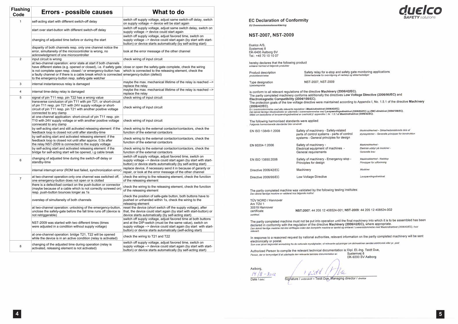
Flashing Code Errors - possible causes What to do
1 self-acting start with different switch-off delay switch off supply voltage, adjust same switch-off delay, switch on supply voltage -> device will be start again
start over start-button with different switch-off delay switch off supply voltage, adjust same switch delay, switch on supply voltage -> device could start again
changing of adjusted time before or during the start switch off supply voltage, adjust favored time, switch on supply voltage --> device could start again (by start with start-button) or device starts automatically (by self-acting start)
disparity of both channels resp. only one channel notice the error, simultaneity of the microcontroller is wrong, no acknowledgment of one microcontroller
look at the error message of the other channel
2 input circuit is wrong check wiring of input circuit at two-channel operation: error state at start if both channels have different states (e.g. opened or closed), i.e. if safety gate is not complete open resp. closed / or emergency-button has a faulty channel or if there is a cable break which is connected to the emergency-button resp. safety-gate watcher
close or open the safety-gate complete, check the wiring which is connected to the releasing element, check the emergency-button (defect)
3 internal instantaneous relay is damaged maybe the max. mechanical lifetime of the relay is reached --> replace the relay
4 internal time-delay relay is damaged maybe the max. mechanical lifetime of the relay is reached --> replace the relay
5 signal of pin T11 resp. pin T22 has a wrong value check wiring of input circuit transverse conclusion of pin T11 with pin T21, or short-circuit of pin T11 resp. pin T21 with 24V supply voltage or short-circuit of pin T11 resp. pin T21 with another positive voltage connected to any clamp
check wiring of input circuit
at one-channel application: short-circuit of pin T11 resp. pin T10 with 24V supply voltage or with another positive voltage connecetd to any clamp
check wiring of input circuit
by self-acting start and still activated releasing element: if the feedback loop is closed not until after standby-time
check wiring to the external contactor/contactors, check the function of the external contactors
by self-acting start and activated releasing element: if the feedback loop is closed not until after approx. 0.5s after the relay NST-2009 is connected to the supply voltage
check wiring to the external contactor/contactors, check the function of the external contactors
by self-acting start and activated releasing element: if the bridge for self-acting start will be opened, i.g cable break
check wiring to the external contactor/contactors, check the function of the external contactors
6 changing of adjusted time during the switch-off delay or standby-time
switch off supply voltage, adjust favored time, switch on supply voltage --> device could start again (by start with start-button) or device starts automatically (by self-acting start)
internal interrupt error (ROM test failed, synchronization error) replace device, if necessary send it in because of garanty or repair, or look at the error message of the other channel
7 at two-channel operation:only one channel was switched off, one emergency-button does not open or is clotted
check the wiring to the releasing element, check the function of the releasing element
there is a defect/bad contact on the push-button or connector (maybe because of a cable which is not correctly screwed on) resp. push-button bounces longer as 1s
check the wiring to the releasing element, check the function of the releasing element
overstep of simultaneity of both channels check the position of safe-gate button, both buttons have to pushed or unhanded within 1s, check the wiring to the releasing element
at two-channel operation: unlocking of the emergency-button, unclose the safety-gate before the fall time runs off (device is not retriggerable)
reset the device (short switch off the supply voltage), after that, the device could start again (by start with start-button) or device starts automatically (by self-acting start)
NST-2009 was started with two different times (times were adjusted in a condition without supply voltage)
switch off supply voltage, adjust favored time at both buttons and at the DIP-switch (must be the same value), switch on supply voltage --> device could start again (by start with start-button) or device starts automatically (self-acting start)
at one-channel operation: bridge T21, T22 will be opened while the device is in an active condition (relay is activated) check the wiring to T21 and T22
8 changing of the adjusted time during operation (relay is activated, releasing element is not activated)
switch off supply voltage, adjust favored time, switch on supply voltage --> device could start again (by start with start-button) or device starts automatically (by self-acting start)
4 5


![[Czech] NST 13.14 JDs](https://img.pdfslide.us/doc/110x75/55380be44a79599a678b468f/czech-nst-1314-jds.jpg)