Embed Size (px)
Citation preview
engineering thermoplastic elastomerHytrel
Design Guide—Module V
®
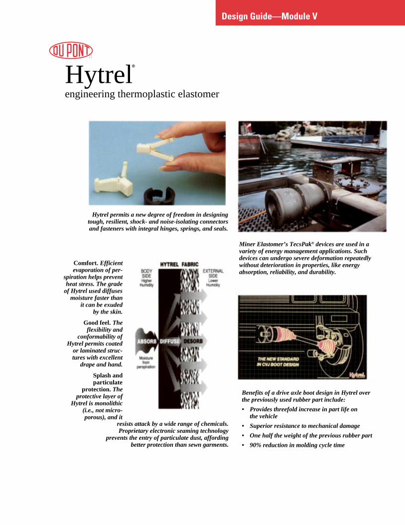
Miner Elastomer’s TecsPak® devices are used in avariety of energy management applications. Suchdevices can undergo severe deformation repeatedlywithout deterioration in properties, like energyabsorption, reliability, and durability.
Benefits of a drive axle boot design in Hytrel overthe previously used rubber part include:
• Provides threefold increase in part life onthe vehicle
• Superior resistance to mechanical damage
• One half the weight of the previous rubber part
• 90% reduction in molding cycle time
Hytrel permits a new degree of freedom in designingtough, resilient, shock- and noise-isolating connectorsand fasteners with integral hinges, springs, and seals.
Comfort. Efficientevaporation of per-
spiration helps preventheat stress. The grade
of Hytrel used diffusesmoisture faster than
it can be exudedby the skin.
Good feel. Theflexibility and
conformability ofHytrel permits coated
or laminated struc-tures with excellent
drape and hand.
Splash andparticulate
protection. Theprotective layer of
Hytrel is monolithic(i.e., not micro-porous), and it
resists attack by a wide range of chemicals.Proprietary electronic seaming technology
prevents the entry of particulate dust, affordingbetter protection than sewn garments.

Table of Contents
Chapter 1
General Information . . . . . . . . . . . . . . . . . . . . . . . . . . . . . . . . . . 1Description . . . . . . . . . . . . . . . . . . . . . . . . . . . . . . . . . . . . . . . . 2Properties and Characteristics . . . . . . . . . . . . . . . . . . . . . . . . 2Processing . . . . . . . . . . . . . . . . . . . . . . . . . . . . . . . . . . . . . . . . 2Applications . . . . . . . . . . . . . . . . . . . . . . . . . . . . . . . . . . . . . . . 2Compositions . . . . . . . . . . . . . . . . . . . . . . . . . . . . . . . . . . . . . . 3Typical Properties . . . . . . . . . . . . . . . . . . . . . . . . . . . . . . . . . . 6
Chapter 2
Mechanical Properties . . . . . . . . . . . . . . . . . . . . . . . . . . . . . . . 10Tensile Properties . . . . . . . . . . . . . . . . . . . . . . . . . . . . . . . . . 11Tensile Stress-Strain . . . . . . . . . . . . . . . . . . . . . . . . . . . . . . . 11Tensile Strength . . . . . . . . . . . . . . . . . . . . . . . . . . . . . . . . . . 11Yield Strength . . . . . . . . . . . . . . . . . . . . . . . . . . . . . . . . . . . . 11Elastic Modulus in Tension . . . . . . . . . . . . . . . . . . . . . . . . . 14Tensile Set . . . . . . . . . . . . . . . . . . . . . . . . . . . . . . . . . . . . . . . 14Poissons’ Ratio . . . . . . . . . . . . . . . . . . . . . . . . . . . . . . . . . . . 14Compressive Properties . . . . . . . . . . . . . . . . . . . . . . . . . . . . 15Elastic Modulus in Compression . . . . . . . . . . . . . . . . . . . . . 16Flexural Properties . . . . . . . . . . . . . . . . . . . . . . . . . . . . . . . . 17Flexural Modulus . . . . . . . . . . . . . . . . . . . . . . . . . . . . . . . . . . 17Creep Modulus . . . . . . . . . . . . . . . . . . . . . . . . . . . . . . . . . . . 17Compressive Creep . . . . . . . . . . . . . . . . . . . . . . . . . . . . . . . . 20Fatigue Resistance . . . . . . . . . . . . . . . . . . . . . . . . . . . . . . . . 21Flexural Fatigue . . . . . . . . . . . . . . . . . . . . . . . . . . . . . . . . . . . 21Heat Generation and Flexural Fatigue in Compression . . . 21Resistance to Flex Cut Growth . . . . . . . . . . . . . . . . . . . . . . . 21Ross Flex . . . . . . . . . . . . . . . . . . . . . . . . . . . . . . . . . . . . . . . . 22DeMattia Flex . . . . . . . . . . . . . . . . . . . . . . . . . . . . . . . . . . . . . 22Impact Resistance . . . . . . . . . . . . . . . . . . . . . . . . . . . . . . . . . 23Notched Izod Impact . . . . . . . . . . . . . . . . . . . . . . . . . . . . . . . 23Instrumented Impact . . . . . . . . . . . . . . . . . . . . . . . . . . . . . . . 23Brittleness Temperature . . . . . . . . . . . . . . . . . . . . . . . . . . . . 25
Chapter 3
Thermal Properties . . . . . . . . . . . . . . . . . . . . . . . . . . . . . . . . . . 26Thermal Conductivity and Specific Heat . . . . . . . . . . . . . . . 27Dynamic Properties . . . . . . . . . . . . . . . . . . . . . . . . . . . . . . . . 27
Chapter 4
Electrical Properties . . . . . . . . . . . . . . . . . . . . . . . . . . . . . . . . . 29Electrical Properties . . . . . . . . . . . . . . . . . . . . . . . . . . . . . . . 30
(continued)

Table of Contents (continued)
Chapter 5
Abrasion and Wear . . . . . . . . . . . . . . . . . . . . . . . . . . . . . . . . . . 31Friction . . . . . . . . . . . . . . . . . . . . . . . . . . . . . . . . . . . . . . . . . . 32Wear . . . . . . . . . . . . . . . . . . . . . . . . . . . . . . . . . . . . . . . . . . . . 32
Chapter 6
Effect of Environment . . . . . . . . . . . . . . . . . . . . . . . . . . . . . . . 33Moisture Pickup and Drying . . . . . . . . . . . . . . . . . . . . . . . . . 34Shrinkage and Post-Molding Shrinkage . . . . . . . . . . . . . . . 35Annealing . . . . . . . . . . . . . . . . . . . . . . . . . . . . . . . . . . . . . . . . 36Dimensional Tolerances . . . . . . . . . . . . . . . . . . . . . . . . . . . . 37The Molding Operation . . . . . . . . . . . . . . . . . . . . . . . . . . . . . 37Concentrates . . . . . . . . . . . . . . . . . . . . . . . . . . . . . . . . . . . . . 38Fluid Resistance . . . . . . . . . . . . . . . . . . . . . . . . . . . . . . . . . . . 43Gas Permeability . . . . . . . . . . . . . . . . . . . . . . . . . . . . . . . . . . 44Radiation Resistance . . . . . . . . . . . . . . . . . . . . . . . . . . . . . . . 45Resistance to Mildew and Fungus . . . . . . . . . . . . . . . . . . . . 46
Chapter 7
Agency Approvals . . . . . . . . . . . . . . . . . . . . . . . . . . . . . . . . . . 47Food and Drug Administration . . . . . . . . . . . . . . . . . . . . . . 48National Science Foundation . . . . . . . . . . . . . . . . . . . . . . . . 48Underwriters Laboratories Recognition . . . . . . . . . . . . . . . 48
Chapter 8
Applications . . . . . . . . . . . . . . . . . . . . . . . . . . . . . . . . . . . . . . . 51General Considerations . . . . . . . . . . . . . . . . . . . . . . . . . . . . 52Design Methods . . . . . . . . . . . . . . . . . . . . . . . . . . . . . . . . . . 54Undercuts . . . . . . . . . . . . . . . . . . . . . . . . . . . . . . . . . . . . . . . . 55Realistic Tolerances . . . . . . . . . . . . . . . . . . . . . . . . . . . . . . . 55Assembly . . . . . . . . . . . . . . . . . . . . . . . . . . . . . . . . . . . . . . . . 55Assembly Techniques . . . . . . . . . . . . . . . . . . . . . . . . . . . . . . 56Overmolding . . . . . . . . . . . . . . . . . . . . . . . . . . . . . . . . . . . . . 62Bearings and Seals . . . . . . . . . . . . . . . . . . . . . . . . . . . . . . . . 62Gears . . . . . . . . . . . . . . . . . . . . . . . . . . . . . . . . . . . . . . . . . . . 63Boots and Bellows . . . . . . . . . . . . . . . . . . . . . . . . . . . . . . . . . 63Rolling Diaphragms . . . . . . . . . . . . . . . . . . . . . . . . . . . . . . . 64Belts . . . . . . . . . . . . . . . . . . . . . . . . . . . . . . . . . . . . . . . . . . . . 64Coiled Tubing and Cables . . . . . . . . . . . . . . . . . . . . . . . . . . . 65Reinforced Hose . . . . . . . . . . . . . . . . . . . . . . . . . . . . . . . . . . 65
Index . . . . . . . . . . . . . . . . . . . . . . . . . . . . . . . . . . . . . . . . . . . . . . . 67

1
Chapter 1
General Information
Contents
DescriptionProperties and CharacteristicsProcessingApplicationsCompositionsTypical Properties

e
-
nd
e
.
ve
i-
e
General Information
DescriptionHytrel is the DuPont registered trademark forits engineering thermoplastic elastomers. Thepolyether-ester block copolymers combine manyof the most desirable characteristics of high-performance elastomers and flexible plastics.Hytrel offers a unique combination of mechanical,physical, and chemical properties that qualifies itfor demanding applications. The various grades oHytrel exhibit a wide range of flexibility/stiffnessand processing capabilities.
This brochure is intended to assist design enginein the successful and efficient design of parts ofHytrel engineering thermoplastic elastomers. Manof the same design considerations that apply tometals and other engineering materials of constrution apply to Hytrel. It is common practice to usestandard engineering equations for designing withHytrel. However, because all engineering materiaare affected to some extent by temperature, moisture, and other environmental service conditions,it is necessary to determine the extreme operatingconditions and to design a part so that it will per-form satisfactorily under all these conditions.
The selection of the best material for any applica-tion requires a knowledge of the properties ofall candidate materials and how they satisfy therequirements of the application. Hytrel may bechosen for a job because of one, or a combinationof its properties.
Much of the engineering data needed to design wHytrel is given in the following pages and shouldbe helpful to the designer. However, it is alwaysimportant to test prototypes of a proposed designand material under realistic conditions beforemaking production commitments.
2
f
rs
y
c-
ls
,
ith
Properties and CharacteristicsHytrel is an engineering thermoplastic elastomerthat combines many of the most desirable charac-teristics of high-performance elastomers andflexible plastics. It features exceptional toughnessand resilience; high resistance to creep, impact, aflex fatigue; flexibility at low temperatures; andgood retention of properties at elevated tempera-tures. In addition, it resists deterioration from manyindustrial chemicals, oils, and solvents.
ProcessingHytrel can be readily formed into high-performancproducts by a variety of thermoplastic processingtechniques, including injection molding, extrusion,blow molding, rotational molding, and melt castingHytrel is processed at temperatures between 177and 260°C (350 and 500°F), depending on theprocess and polymer type. All standard grades haa sharp melting point and very good melt stability.
ApplicationsThe excellent properties of Hytrel qualify it for anumber of demanding applications where mechancal strength and durability are required in a flexiblecomponent. Examples include seals, belts, bush-ings, pump diaphragms, gears, protective boots,hose and tubing, springs, and impact-absorbingdevices. In many of these applications, Hytrelallows a multipiece rubber, plastic, or even metalcomposite assembly to be replaced with a singlepart. For outdoor applications, Hytrel should beprotected from ultraviolet (UV) attack.
Some of the industries where Hytrel can already bfound include: automotive, fluid power, electrical/electronic, appliance and power tool, sportinggoods, footwear, wire and cable (including fiberoptics), furniture, and off-road transportationequipment. The potential for using Hytrel in otherindustries is limited only by one’s imagination.

3
Typical Uses
Applications requiring flex lifecoupled with good flexibility atlow temperatures. Thin,flexible membranes. Good forhigh original color retention.
TubingHose jacketsWire and cable jacketsFilm sheetingMolded products
Applications requiring highoriginal color retention.Molded and extrudedproducts for consumer use.
TubingHose jacketsWire and cable jacketsProfilesMolded products
TubingMolded and extrudedproducts for consumer use.
Same as Hytrel G4774.
Characteristics*
Very flexible grade of Hytrel.Excellent flex resistance,especially at low temperatures.Moldable even in thin sections.Can be used in light-coloredproducts.
Excellent heat-aging resistanceand resistance to oils at hightemperatures. Best low modulusmolding and extrusion grade.
Like Hytrel G4074, except thatheat-aging resistance isreduced. Can be used in light-colored products.
Excellent heat-aging resistanceand resistance to oils at hightemperatures. Good resistanceto oils, fuels, and solvents.
Good balance of low and hightemperature properties.
Excellent heat-aging resistanceand resistance to oils at hightemperatures.
Hytrel G3548W
Hytrel G4074
Hytrel G4078W
Hytrel G4774
Hytrel G4778
Hytrel G5544
Description
Low modulus molding andextrusion grade. Containsimproved color-stableantioxidants.
Low modulus molding andextrusion grade. Contains adiscoloring antioxidant.
Low modulus molding andextrusion grade. Containsimproved color-stableantioxidants.
Medium-low modulus moldingand extrusion grade. Containsa discoloring antioxidant.
Medium-low modulus moldingand extrusion grade. Containscolor-stable antioxidants.
Medium modulus molding andextrusion grade. Contains adiscoloring antioxidant.
(continued)* The characteristics shown are those of the unmodified standard composition. Special stabilizers and additives can be mixed with Hytrel to improve its
resistance to UV light, heat aging, and moisture.
Grade
Table 1Compositions of Hytrel
High-Productivity Hytrel ResinsThese grades offer the best balance of properties and cost.
4
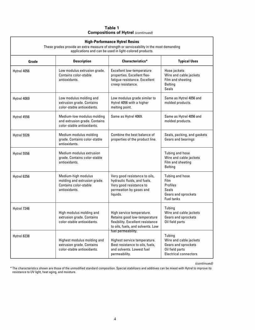
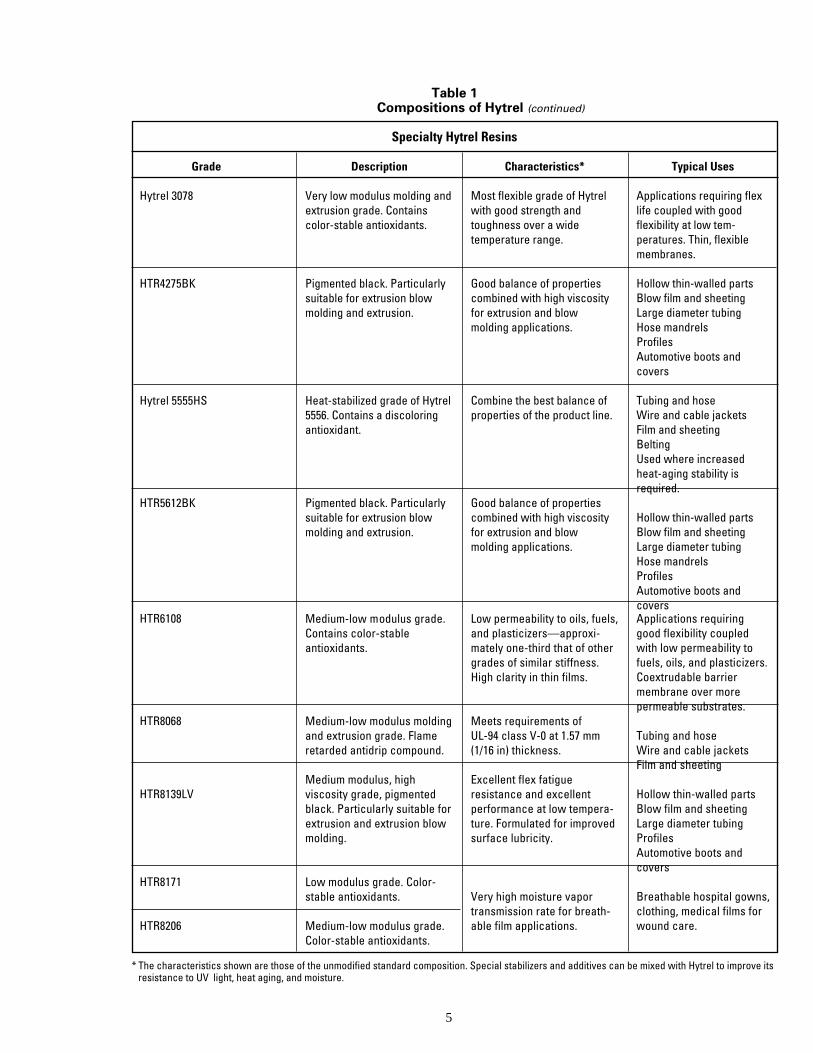
Table 1Compositions of Hytrel (continued)
High-Performance Hytrel ResinsThese grades provide an extra measure of strength or serviceability in the most demanding
applications and can be used in light-colored products.
Description
Low modulus extrusion grade.Contains color-stableantioxidants.
Low modulus molding andextrusion grade. Containscolor-stable antioxidants.
Medium-low modulus moldingand extrusion grade. Containscolor-stable antioxidants.
Medium modulus moldinggrade. Contains color-stableantioxidants.
Medium modulus extrusiongrade. Contains color-stableantioxidants.
Medium-high modulusmolding and extrusion grade.Contains color-stableantioxidants.
High modulus molding andextrusion grade. Containscolor-stable antioxidants.
Highest modulus molding andextrusion grade. Containscolor-stable antioxidants.
Hytrel 4056
Hytrel 4069
Hytrel 4556
Hytrel 5526
Hytrel 5556
Hytrel 6356
Hytrel 7246
Hytrel 8238
Characteristics*
Excellent low-temperatureproperties. Excellent flex-fatigue resistance. Excellentcreep resistance.
Low modulus grade similar toHytrel 4056 with a highermelting point.
Same as Hytrel 4069.
Combine the best balance ofproperties of the product line.
Very good resistance to oils,hydraulic fluids, and fuels.Very good resistance topermeation by gases andliquids.
High service temperature.Retains good low-temperatureflexibility. Excellent resistanceto oils, fuels, and solvents. Lowfuel permeability.
Highest service temperature.Best resistance to oils, fuels,and solvents. Lowest fuelpermeability.
(continued)* The characteristics shown are those of the unmodified standard composition. Special stabilizers and additives can be mixed with Hytrel to improve its
resistance to UV light, heat aging, and moisture.
Grade Typical Uses
Hose jacketsWire and cable jacketsFilm and sheetingBeltingSeals
Same as Hytrel 4056 andmolded products.
Same as Hytrel 4056 andmolded products.
Seals, packing, and gasketsGears and bearings
Tubing and hoseWire and cable jacketsFilm and sheetingBelting
Tubing and hoseFilmProfilesSealsGears and sprocketsFuel tanks
TubingWire and cable jacketsGears and sprocketsOil field parts
TubingWire and cable jacketsGears and sprocketsOil field partsElectrical connectors
5
Description
Very low modulus molding andextrusion grade. Containscolor-stable antioxidants.
Pigmented black. Particularlysuitable for extrusion blowmolding and extrusion.
Heat-stabilized grade of Hytrel5556. Contains a discoloringantioxidant.
Pigmented black. Particularlysuitable for extrusion blowmolding and extrusion.
Characteristics*
Most flexible grade of Hytrelwith good strength andtoughness over a widetemperature range.
Good balance of propertiescombined with high viscosityfor extrusion and blowmolding applications.
Combine the best balance ofproperties of the product line.
Good balance of propertiescombined with high viscosityfor extrusion and blowmolding applications.
Typical Uses
Applications requiring flexlife coupled with goodflexibility at low tem-peratures. Thin, flexiblemembranes.
Hollow thin-walled partsBlow film and sheetingLarge diameter tubingHose mandrelsProfilesAutomotive boots andcovers
Tubing and hoseWire and cable jacketsFilm and sheetingBeltingUsed where increasedheat-aging stability isrequired.
Hollow thin-walled partsBlow film and sheetingLarge diameter tubingHose mandrelsProfilesAutomotive boots andcovers
Table 1Compositions of Hytrel (continued)
Specialty Hytrel Resins
Grade
Hytrel 3078
HTR4275BK
Hytrel 5555HS
HTR5612BK
Medium-low modulus grade.Contains color-stableantioxidants.
Medium-low modulus moldingand extrusion grade. Flameretarded antidrip compound.
Medium modulus, highviscosity grade, pigmentedblack. Particularly suitable forextrusion and extrusion blowmolding.
Low modulus grade. Color-stable antioxidants.
Medium-low modulus grade.Color-stable antioxidants.
Low permeability to oils, fuels,and plasticizers—approxi-mately one-third that of othergrades of similar stiffness.High clarity in thin films.
Meets requirements ofUL-94 class V-0 at 1.57 mm(1/16 in) thickness.
Excellent flex fatigueresistance and excellentperformance at low tempera-ture. Formulated for improvedsurface lubricity.
Very high moisture vaportransmission rate for breath-able film applications.
Applications requiringgood flexibility coupledwith low permeability tofuels, oils, and plasticizers.Coextrudable barriermembrane over morepermeable substrates.
Tubing and hoseWire and cable jacketsFilm and sheeting
Hollow thin-walled partsBlow film and sheetingLarge diameter tubingProfilesAutomotive boots andcovers
Breathable hospital gowns,clothing, medical films forwound care.
HTR6108
HTR8068
HTR8139LV
HTR8171
HTR8206
* The characteristics shown are those of the unmodified standard composition. Special stabilizers and additives can be mixed with Hytrel to improve itsresistance to UV light, heat aging, and moisture.
6
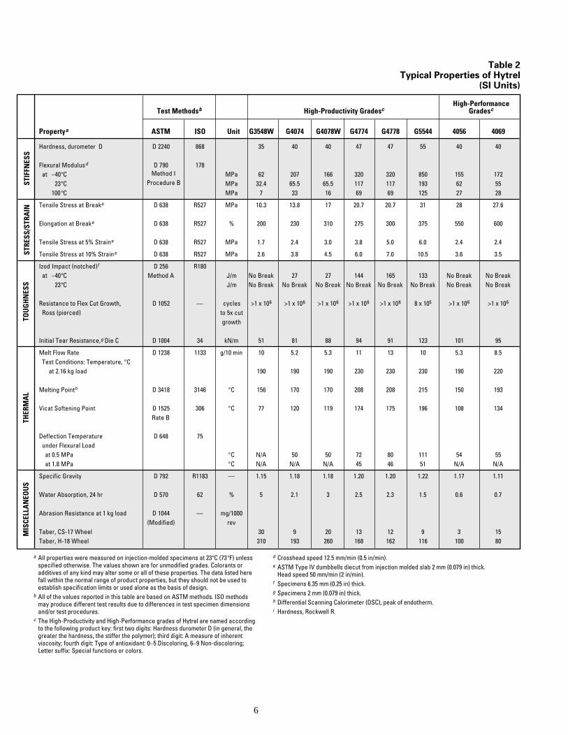
Propertya ASTM ISO Unit G3548W G4074 G4078W G4774 G4778 G5544 4056 4069
Hardness, durometer D D 2240 868 35 40 40 47 47 55 40 40
Flexural Modulusd D 790 178at –40°C MPa 62 207 166 320 320 850 155 172
23°C MPa 32.4 65.5 65.5 117 117 193 62 55100°C MPa 7 33 16 69 69 125 27 28
Tensile Stress at Breake D 638 R527 MPa 10.3 13.8 17 20.7 20.7 31 28 27.6
Elongation at Breake D 638 R527 % 200 230 310 275 300 375 550 600
Tensile Stress at 5% Straine D 638 R527 MPa 1.7 2.4 3.0 3.8 5.0 6.0 2.4 2.4
Tensile Stress at 10% Straine D 638 R527 MPa 2.6 3.8 4.5 6.0 7.0 10.5 3.6 3.5
Izod Impact (notched)f D 256 R180at –40°C Method A J/m No Break 27 27 144 165 133 No Break No Break
23°C J/m No Break No Break No Break No Break No Break No Break No Break No Break
Resistance to Flex Cut Growth, D 1052 — cycles >1 x 10⁶ >1 x 10⁶ >1 x 10⁶ >1 x 10⁶ >1 x 10⁶ 8 x 10⁵ >1 x 10⁶ >1 x 10⁶
Ross (pierced) to 5x cutgrowth
Initial Tear Resistance,g Die C D 1004 34 kN/m 51 81 88 94 91 123 101 95
Melt Flow Rate D 1238 1133 g/10 min 10 5.2 5.3 11 13 10 5.3 8.5Test Conditions: Temperature, °C
at 2.16 kg load 190 190 190 230 230 230 190 220
Melting Pointh D 3418 3146 °C 156 170 170 208 208 215 150 193
Vicat Softening Point D 1525 306 °C 77 120 119 174 175 196 108 134Rate B
Deflection Temperature D 648 75under Flexural Load
at 0.5 MPa °C N/A 50 50 72 80 111 54 55at 1.8 MPa °C N/A N/A N/A 45 46 51 N/A N/A
Specific Gravity D 792 R1183 — 1.15 1.18 1.18 1.20 1.20 1.22 1.17 1.11
Water Absorption, 24 hr D 570 62 % 5 2.1 3 2.5 2.3 1.5 0.6 0.7
Abrasion Resistance at 1 kg load D 1044 — mg/1000(Modified) rev
Taber, CS-17 Wheel 30 9 20 13 12 9 3 15Taber, H-18 Wheel 310 193 260 168 162 116 100 80
Method IProcedure BST
IFFN
ESS
THER
MA
L
High-PerformanceGradescHigh-Productivity GradescTest Methodsb
TOU
GH
NES
SST
RESS
/STR
AIN
MIS
CELL
AN
EOU
S
a All properties were measured on injection-molded specimens at 23°C (73°F) unlessspecified otherwise. The values shown are for unmodified grades. Colorants oradditives of any kind may alter some or all of these properties. The data listed herefall within the normal range of product properties, but they should not be used toestablish specification limits or used alone as the basis of design.
b All of the values reported in this table are based on ASTM methods. ISO methodsmay produce different test results due to differences in test specimen dimensionsand/or test procedures.
c The High-Productivity and High-Performance grades of Hytrel are named accordingto the following product key: first two digits: Hardness durometer D (in general, thegreater the hardness, the stiffer the polymer); third digit: A measure of inherentviscosity; fourth digit: Type of antioxidant: 0–5 Discoloring, 6–9 Non-discoloring;Letter suffix: Special functions or colors.
d Crosshead speed 12.5 mm/min (0.5 in/min).e ASTM Type IV dumbbells diecut from injection molded slab 2 mm (0.079 in) thick.
Head speed 50 mm/min (2 in/min).f Specimens 6.35 mm (0.25 in) thick.g Specimens 2 mm (0.079 in) thick.h Differential Scanning Calorimeter (DSC), peak of endotherm.i Hardness, Rockwell R.
Table 2Typical Properties of Hytrel
(SI Units)
7
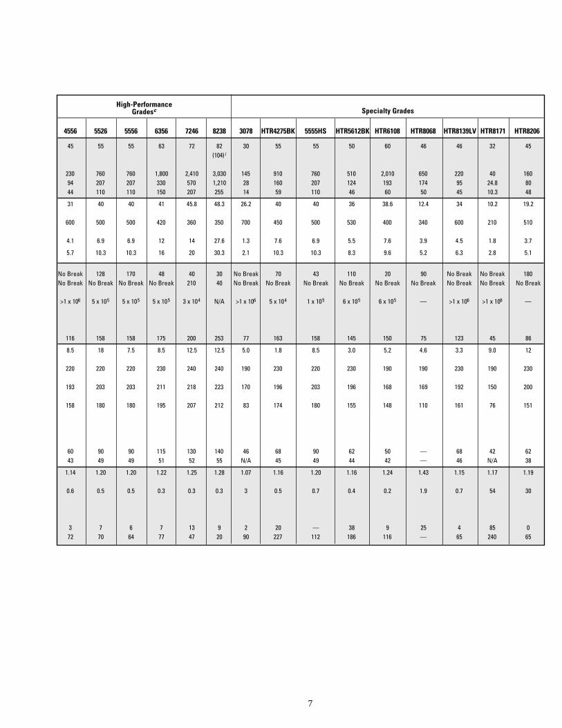
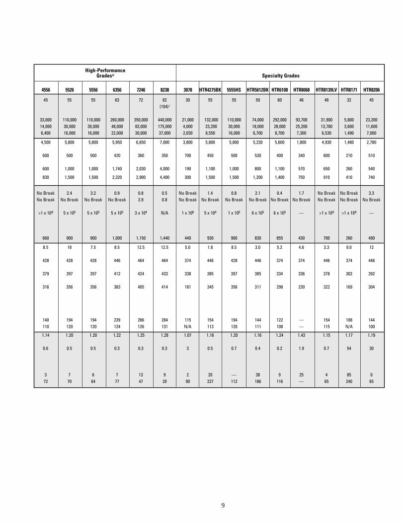
4556 5526 5556 6356 7246 8238 3078 HTR4275BK 5555HS HTR5612BK HTR6108 HTR8068 HTR8139LV HTR8171 HTR8206
45 55 55 63 72 82 30 55 55 50 60 46 46 32 45(104)i
230 760 760 1,800 2,410 3,030 145 910 760 510 2,010 650 220 40 16094 207 207 330 570 1,210 28 160 207 124 193 174 95 24.8 8044 110 110 150 207 255 14 59 110 46 60 50 45 10.3 48
31 40 40 41 45.8 48.3 26.2 40 40 36 38.6 12.4 34 10.2 19.2
600 500 500 420 360 350 700 450 500 530 400 340 600 210 510
4.1 6.9 6.9 12 14 27.6 1.3 7.6 6.9 5.5 7.6 3.9 4.5 1.8 3.7
5.7 10.3 10.3 16 20 30.3 2.1 10.3 10.3 8.3 9.6 5.2 6.3 2.8 5.1
No Break 128 170 48 40 30 No Break 70 43 110 20 90 No Break No Break 180No Break No Break No Break No Break 210 40 No Break No Break No Break No Break No Break No Break No Break No Break No Break
>1 x 10⁶ 5 x 10⁵ 5 x 10⁵ 5 x 10⁵ 3 x 10⁴ N/A >1 x 10⁶ 5 x 10⁴ 1 x 10⁵ 6 x 10⁵ 6 x 10⁵ — >1 x 10⁶ >1 x 10⁶ —
116 158 158 175 200 253 77 163 158 145 150 75 123 45 86
8.5 18 7.5 8.5 12.5 12.5 5.0 1.8 8.5 3.0 5.2 4.6 3.3 9.0 12
220 220 220 230 240 240 190 230 220 230 190 190 230 190 230
193 203 203 211 218 223 170 196 203 196 168 169 192 150 200
158 180 180 195 207 212 83 174 180 155 148 110 161 76 151
60 90 90 115 130 140 46 68 90 62 50 — 68 42 6243 49 49 51 52 55 N/A 45 49 44 42 — 46 N/A 38
1.14 1.20 1.20 1.22 1.25 1.28 1.07 1.16 1.20 1.16 1.24 1.43 1.15 1.17 1.19
0.6 0.5 0.5 0.3 0.3 0.3 3 0.5 0.7 0.4 0.2 1.9 0.7 54 30
3 7 6 7 13 9 2 20 — 38 9 25 4 85 072 70 64 77 47 20 90 227 112 186 116 — 65 240 65
Specialty GradesHigh-Performance
Gradesc
8
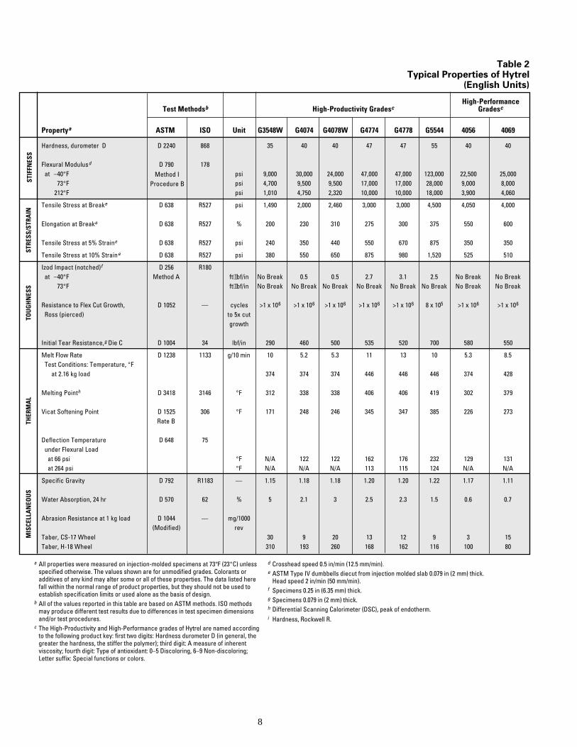
Propertya ASTM ISO Unit G3548W G4074 G4078W G4774 G4778 G5544 4056 4069
Hardness, durometer D D 2240 868 35 40 40 47 47 55 40 40
Flexural Modulusd D 790 178at –40°F psi 9,000 30,000 24,000 47,000 47,000 123,000 22,500 25,000
73°F psi 4,700 9,500 9,500 17,000 17,000 28,000 9,000 8,000212°F psi 1,010 4,750 2,320 10,000 10,000 18,000 3,900 4,060
Tensile Stress at Breake D 638 R527 psi 1,490 2,000 2,460 3,000 3,000 4,500 4,050 4,000
Elongation at Breake D 638 R527 % 200 230 310 275 300 375 550 600
Tensile Stress at 5% Straine D 638 R527 psi 240 350 440 550 670 875 350 350
Tensile Stress at 10% Straine D 638 R527 psi 380 550 650 875 980 1,520 525 510
Izod Impact (notched)f D 256 R180at –40°F Method A ft⋅lbf/in No Break 0.5 0.5 2.7 3.1 2.5 No Break No Break
73°F ft⋅lbf/in No Break No Break No Break No Break No Break No Break No Break No Break
Resistance to Flex Cut Growth, D 1052 — cycles >1 x 10⁶ >1 x 10⁶ >1 x 10⁶ >1 x 10⁶ >1 x 10⁶ 8 x 10⁵ >1 x 10⁶ >1 x 10⁶
Ross (pierced) to 5x cutgrowth
Initial Tear Resistance,g Die C D 1004 34 lbf/in 290 460 500 535 520 700 580 550
Melt Flow Rate D 1238 1133 g/10 min 10 5.2 5.3 11 13 10 5.3 8.5Test Conditions: Temperature, °F
at 2.16 kg load 374 374 374 446 446 446 374 428
Melting Pointh D 3418 3146 °F 312 338 338 406 406 419 302 379
Vicat Softening Point D 1525 306 °F 171 248 246 345 347 385 226 273Rate B
Deflection Temperature D 648 75under Flexural Load
at 66 psi °F N/A 122 122 162 176 232 129 131at 264 psi °F N/A N/A N/A 113 115 124 N/A N/A
Specific Gravity D 792 R1183 — 1.15 1.18 1.18 1.20 1.20 1.22 1.17 1.11
Water Absorption, 24 hr D 570 62 % 5 2.1 3 2.5 2.3 1.5 0.6 0.7
Abrasion Resistance at 1 kg load D 1044 — mg/1000(Modified) rev
Taber, CS-17 Wheel 30 9 20 13 12 9 3 15Taber, H-18 Wheel 310 193 260 168 162 116 100 80
STIF
FNES
STH
ERM
AL
High-PerformanceGradescHigh-Productivity GradescTest Methodsb
TOU
GH
NES
SST
RESS
/STR
AIN
MIS
CELL
AN
EOU
S
Method IProcedure B
d Crosshead speed 0.5 in/min (12.5 mm/min).e ASTM Type IV dumbbells diecut from injection molded slab 0.079 in (2 mm) thick.
Head speed 2 in/min (50 mm/min).f Specimens 0.25 in (6.35 mm) thick.g Specimens 0.079 in (2 mm) thick.h Differential Scanning Calorimeter (DSC), peak of endotherm.i Hardness, Rockwell R.
a All properties were measured on injection-molded specimens at 73°F (23°C) unlessspecified otherwise. The values shown are for unmodified grades. Colorants oradditives of any kind may alter some or all of these properties. The data listed herefall within the normal range of product properties, but they should not be used toestablish specification limits or used alone as the basis of design.
b All of the values reported in this table are based on ASTM methods. ISO methodsmay produce different test results due to differences in test specimen dimensionsand/or test procedures.
c The High-Productivity and High-Performance grades of Hytrel are named accordingto the following product key: first two digits: Hardness durometer D (in general, thegreater the hardness, the stiffer the polymer); third digit: A measure of inherentviscosity; fourth digit: Type of antioxidant: 0–5 Discoloring, 6–9 Non-discoloring;Letter suffix: Special functions or colors.
Table 2Typical Properties of Hytrel
(English Units)
9
4556 5526 5556 6356 7246 8238 3078 HTR4275BK 5555HS HTR5612BK HTR6108 HTR8068 HTR8139LV HTR8171 HTR8206
45 55 55 63 72 82 30 55 55 50 60 46 46 32 45(104) i
33,000 110,000 110,000 260,000 350,000 440,000 21,000 132,000 110,000 74,000 292,000 93,700 31,900 5,800 23,20014,000 30,000 30,000 48,000 83,000 175,000 4,000 23,200 30,000 18,000 28,000 25,200 13,780 3,600 11,6006,400 16,000 16,000 22,000 30,000 37,000 2,030 8,550 16,000 6,700 8,700 7,300 6,530 1,490 7,000
4,500 5,800 5,800 5,950 6,650 7,000 3,800 5,800 5,800 5,230 5,600 1,800 4,930 1,480 2,780
600 500 500 420 360 350 700 450 500 530 400 340 600 210 510
600 1,000 1,000 1,740 2,030 4,000 190 1,100 1,000 800 1,100 570 650 260 540
830 1,500 1,500 2,320 2,900 4,400 300 1,500 1,500 1,200 1,400 750 910 410 740
No Break 2.4 3.2 0.9 0.8 0.5 No Break 1.4 0.8 2.1 0.4 1.7 No Break No Break 3.3No Break No Break No Break No Break 3.9 0.8 No Break No Break No Break No Break No Break No Break No Break No Break No Break
>1 x 10⁶ 5 x 10⁵ 5 x 10⁵ 5 x 10⁵ 3 x 10⁴ N/A 1 x 10⁶ 5 x 10⁴ 1 x 10⁵ 6 x 10⁵ 6 x 10⁵ — >1 x 10⁶ >1 x 10⁶ —
660 900 900 1,000 1,150 1,440 440 930 900 830 855 430 700 260 490
8.5 18 7.5 8.5 12.5 12.5 5.0 1.8 8.5 3.0 5.2 4.6 3.3 9.0 12
428 428 428 446 464 464 374 446 428 446 374 374 446 374 446
379 397 397 412 424 433 338 385 397 385 334 336 378 302 392
316 356 356 383 405 414 181 345 356 311 298 230 322 169 304
140 194 194 239 266 284 115 154 194 144 122 — 154 108 144110 120 120 124 126 131 N/A 113 120 111 108 — 115 N/A 100
1.14 1.20 1.20 1.22 1.25 1.28 1.07 1.16 1.20 1.16 1.24 1.43 1.15 1.17 1.19
0.6 0.5 0.5 0.3 0.3 0.3 3 0.5 0.7 0.4 0.2 1.9 0.7 54 30
3 7 6 7 13 9 2 20 — 38 9 25 4 85 072 70 64 77 47 20 90 227 112 186 116 — 65 240 65
Specialty GradesHigh-Performance
Gradesc

10
Chapter 2
Mechanical Properties
Compressive CreepFatigue ResistanceFlexural FatigueHeat Generation and Flexural Fatigue
in CompressionResistance to Flex Cut GrowthRoss FlexDeMattia FlexImpact ResistanceNotched Izod ImpactInstrumented ImpactBrittleness Temperature
Contents
Tensile PropertiesTensile Stress-StrainTensile StrengthYield StrengthElastic Modulus in TensionTensile SetPoissons’ RatioCompressive PropertiesElastic Modulus in CompressionFlexural PropertiesFlexural ModulusCreep Modulus
r
Mechanical Properties
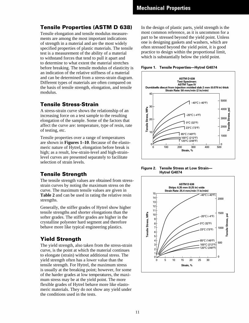
Tensile Properties (ASTM D 638)Tensile elongation and tensile modulus measurements are among the most important indicationsof strength in a material and are the most widelyspecified properties of plastic materials. The tenstest is a measurement of the ability of a materialto withstand forces that tend to pull it apart andto determine to what extent the material stretchesbefore breaking. The tensile modulus of elasticityan indication of the relative stiffness of a materialand can be determined from a stress-strain diagrDifferent types of materials are often compared othe basis of tensile strength, elongation, and tensmodulus.
Tensile Stress-StrainA stress-strain curve shows the relationship of anincreasing force on a test sample to the resultingelongation of the sample. Some of the factors thaaffect the curve are: temperature, type of resin, raof testing, etc.
Tensile properties over a range of temperaturesare shown in Figures 1–10. Because of the elasto-meric nature of Hytrel, elongation before break ishigh; as a result, low-strain-level and high-strain-level curves are presented separately to facilitateselection of strain levels.
Tensile StrengthThe tensile strength values are obtained from strstrain curves by noting the maximum stress on thcurve. The maximum tensile values are given inTable 2 and can be used in rating the relative resstrengths.
Generally, the stiffer grades of Hytrel show highetensile strengths and shorter elongations than thesofter grades. The stiffer grades are higher in thecrystalline polyester hard segment and thereforebehave more like typical engineering plastics.
Yield StrengthThe yield strength, also taken from the stress-stracurve, is the point at which the material continuesto elongate (strain) without additional stress. Theyield strength often has a lower value than thetensile strength. For Hytrel, the maximum stressis usually at the breaking point; however, for somof the harder grades at low temperatures, the maxmum stress may be at the yield point. The moreflexible grades of Hytrel behave more like elasto-meric materials. They do not show any yield undethe conditions used in the tests.
1
-
ile
is
am.nile
tte
ess-e
in
r
in
ei-
In the design of plastic parts, yield strength is themost common reference, as it is uncommon for apart to be stressed beyond the yield point. Unlessone is designing gaskets and washers, which areoften stressed beyond the yield point, it is goodpractice to design within the proportional limit,which is substantially below the yield point.
Figure 1. Tensile Properties—Hytrel G4074
Figure 2. Tensile Stress at Low Strain—Hytrel G4074
100 200 300 400 50000 0
10
20
30
40
ASTM D 638 Test Specimen: ASTM Type IV
Dumbbells diecut from injection molded slab 2 mm (0.079 in) thick Strain Rate: 50 mm/min (2 in/min)
Strain, %
1000100°C (212°F)120°C (248°F)
65°C (149°F)
23°C (73°F)
0°C (32°F)
–20°C (–4°F)
–40°C (–40°F)
2000
3000
4000
5000
Tens
ile S
tres
s, p
si
Tens
ile S
tres
s, M
Pa
302520151050012
34
56
78
9
1011
1213
14
15
ASTM D 638 Strips: 6.35 mm (0.25 in) wide
Strain Rate: 25.4 mm/min (1 in/min)
Strain, %
500
1000
1500
2000
0
Tens
ile S
tres
s, p
si
Tens
ile S
tres
s, M
Pa
100°C (212°F)120°C (248°F)
65°C (149°F)
23°C (73°F)
0°C (32°F)
–20°C (–4°F)
–40°C (–40°F)
1
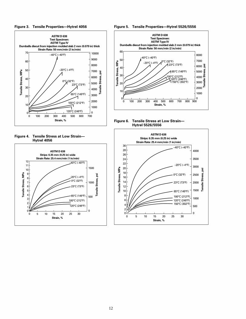
Figure 3. Tensile Properties—Hytrel 4056
Figure 4. Tensile Stress at Low Strain—Hytrel 4056
100°C (212°F)
120°C (248°F)
65°C (149°F)
23°C (73°F)
0°C (32°F)–20°C (–4°F)
–40°C (–40°F)
302520151050012
34
5
67
8
910
1112
Strain, %
500
1000
1500
0
Tens
ile S
tres
s, M
Pa
Tens
ile S
tres
s, p
si
ASTM D 638 Strips: 6.35 mm (0.25 in) wide
Strain Rate: 25.4 mm/min (1 in/min)
100°C (212°F)
120°C (248°F)
65°C (149°F)
23°C (73°F)0°C (32°F)
–20°C (–4°F)
–40°C (–40°F)
600 70050040030020010000
10
20
30
40
50
60
70
ASTM D 638 Test Specimen: ASTM Type IV
Dumbells diecut from injection molded slab 2 mm (0.079 in) thick Strain Rate: 50 mm/min (2 in/min)
Strain, %
1000
2000
3000
4000
5000
6000
7000
8000
9000
10000
0
Tens
ile S
tres
s, M
Pa
Tens
ile S
tres
s, p
si
1
Figure 5. Tensile Properties—Hytrel 5526/5556
Figure 6. Tensile Stress at Low Strain—Hytrel 5526/5556
100°C (212°F)120°C (248°F)
150°C (302°F)
65°C (149°F)
23°C (73°F)0°C (32°F)–20°C (–4°F)
–40°C (–40°F)
800 90070060050040030020010000
10
20
30
40
50
60
Strain, %
1000
2000
3000
4000
5000
6000
7000
8000
0
Tens
ile S
tres
s, M
Pa
Tens
ile S
tres
s, p
si
ASTM D 638 Test Specimen: ASTM Type IV
Dumbells diecut from injection molded slab 2 mm (0.079 in) thick Strain Rate: 50 mm/min (2 in/min)
100°C (212°F)120°C (248°F)150°C (302°F)
65°C (149°F)
23°C (73°F)
0°C (32°F)
–20°C (–4°F)
–40°C (–40°F)
30252015105002
4
6
8
10
12
14
16
18
20
22
24
26
28
30
Strain, %
500
1000
1500
2000
2500
3000
3500
4000
0
Tens
ile S
tres
s, M
Pa
Tens
ile S
tres
s, p
si
ASTM D 638 Strips: 6.35 mm (0.25 in) wide
Strain Rate: 25.4 mm/min (1 in/min)
2
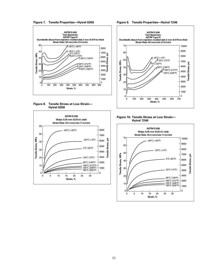
Figure 7. Tensile Properties—Hytrel 6356
Figure 8. Tensile Stress at Low Strain—Hytrel 6356
100°C (212°F)120°C (248°F)
150°C (302°F)
65°C (149°F)23°C (73°F)
0°C (32°F)–20°C (–4°F)
–40°C (–40°F)
800 90070060050040030020010000
10
20
30
40
50
60
ASTM D 638 Test Specimen: ASTM Type IV
Dumbbells diecut from injection molded slab 2 mm (0.079 in) thick Strain Rate: 50 mm/min (2 in/min)
Strain, %
1000
2000
3000
4000
5000
6000
7000
8000
0
Tens
ile S
tres
s, M
Pa
Tens
ile S
tres
s, p
si
ASTM D 638 Strips: 6.35 mm (0.25 in) wide
Strain Rate: 25.4 mm/min (1 in/min)
100°C (212°F)120°C (248°F)150°C (302°F)
65°C (149°F)
23°C (73°F)
0°C (32°F)
–20°C (–4°F)
–40°C (–40°F)
3025201510500
10
20
30
40
50
60
Strain, %
1000
2000
3000
4000
5000
6000
7000
8000
0
Tens
ile S
tres
s, M
Pa
Tens
ile S
tres
s, p
si
13
Figure 9. Tensile Properties—Hytrel 7246
Figure 10. Tensile Stress at Low Strain—Hytrel 7246
100°C (212°F)120°C (248°F)
65°C (149°F)
23°C (73°F)0°C (32°F)
–20°C (–4°F)
600 70050040030020010000
10
20
30
40
50
60
70
Strain, %
1000
0
2000
3000
4000
5000
6000
7000
8000
9000
10000
Tens
ile S
tres
s, M
Pa
Tens
ile S
tres
s, p
si
ASTM D 638 Test Specimen: ASTM Type IV
Dumbbells diecut from injection molded slab 2 mm (0.079 in) thick Strain Rate: 50 mm/min (2 in/min)
100°C (212°F)120°C (248°F)150°C (302°F)
65°C (149°F)
23°C (73°F)
0°C (32°F)
–20°C (–4°F)
–40°C (–40°F)
3025201510500
10
20
30
40
50
60
70
Strain, %
1000
2000
3000
4000
5000
6000
7000
8000
9000
10000
0
Tens
ile S
tres
s, M
Pa
Tens
ile S
tres
s, p
si
ASTM D 638 Strips: 6.35 mm (0.25 in) wide
Strain Rate: 25.4 mm/min (1 in/min)
h
’
le .
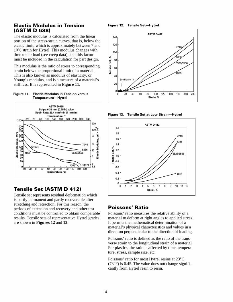
Elastic Modulus in Tension(ASTM D 638)The elastic modulus is calculated from the linearportion of the stress-strain curves, that is, below telastic limit, which is approximately between 7 an10% strain for Hytrel. This modulus changes withtime under load (see creep data), and this factormust be included in the calculation for part design
This modulus is the ratio of stress to correspondinstrain below the proportional limit of a material.This is also known as modulus of elasticity, orYoung’s modulus, and is a measure of a materialstiffness. It is represented in Figure 11.
ASTM D 638 Strips: 6.35 mm (0.25 in) wide
Strain Rate: 25.4 mm/min (1 in/min)Temperature, °F
Temperature, °C
G4074
G40746356
5526/5556
4056
4056
7246
160140120100806040200–20–4010
2030406080
100
200300400600800
1000
2000
1.52
5
10
20
50
100
200
300 3402602201801401006020–20
Elas
tic
Mod
ulus
, MPa
Elas
tic
Mod
ulus
, psi
× 1
03Figure 11. Elastic Modulus in Tension versus
Temperature—Hytrel
Tensile Set (ASTM D 412)Tensile set represents residual deformation whichis partly permanent and partly recoverable afterstretching and retraction. For this reason, theperiods of extension and recovery and other testconditions must be controlled to obtain comparabresults. Tensile sets of representative Hytrel gradare shown in Figures 12 and 13.
1
ed
.
g
s
es
18016014012010080604020 200
4056
6356
5526/5556
See Figure 13
7246
00
20
40
60
80
100
120
140ASTM D 412
Strain, %
Ten
sile
Set
, %
Figure 12. Tensile Set—Hytrel
ASTM D 412
11 12109
4056
6356
7246
5526/5556
8765432100
0.2
0.4
0.6
0.8
1.0
1.2
1.4
1.6
1.8
2.0
Strain, %
Tens
ile S
et, %
Figure 13. Tensile Set at Low Strain—Hytrel
Poissons’ RatioPoissons’ ratio measures the relative ability of amaterial to deform at right angles to applied stressIt permits the mathematical determination of amaterial’s physical characteristics and values in adirection perpendicular to the direction of loading.
Poissons’ ratio is defined as the ratio of the trans-verse strain to the longitudinal strain of a material.For plastics, the ratio is affected by time, tempera-ture, stress, sample size, etc.
Poissons’ ratio for most Hytrel resins at 23°C(73°F) is 0.45. The value does not change signifi-cantly from Hytrel resin to resin.
4
a
nt
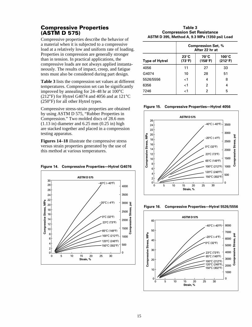
Compressive Properties(ASTM D 575)Compressive properties describe the behavior ofa material when it is subjected to a compressiveload at a relatively low and uniform rate of loadingProperties in compression are generally strongerthan in tension. In practical applications, thecompressive loads are not always applied instantneously. The results of impact, creep, and fatiguetests must also be considered during part design.
Table 3 lists the compression set values at differetemperatures. Compression set can be significanimproved by annealing for 24–48 hr at 100°C(212°F) for Hytrel G4074 and 4056 and at 121°C(250°F) for all other Hytrel types.
Compressive stress-strain properties are obtainedby using ASTM D 575, “Rubber Properties inCompression.” Two molded discs of 28.6 mm(1.13 in) diameter and 6.25 mm (0.25 in) highare stacked together and placed in a compressiontesting apparatus.
Figures 14–18 illustrate the compressive stressversus strain properties generated by the use ofthis method at various temperatures.
Figure 14. Compressive Properties—Hytrel G4076
ASTM D 575
100°C (212°F)
120°C (248°F)
150°C (302°F)
65°C (149°F)
23°C (73°F)
0°C (32°F)
–20°C (–4°F)
–40°C (–40°F)
30252015105002
4
6
8
10
12
14
16
18
20
22
24
26
2830
Strain, %
500
1000
1500
2000
2500
3000
3500
4000
0
Com
pres
sive
Str
ess,
MPa
Com
pres
sive
Str
ess,
psi
15
.
-
tly
Table 3Compression Set Resistance
ASTM D 395, Method A, 9.3 MPa (1350 psi) Load
Compression Set, %After 22 hr at
23°C 70°C 100°CType of Hytrel (73°F) (158°F) (212°F)
4056 11 27 33
G4074 10 28 51
5526/5556 <1 4 8
6356 <1 2 4
7246 <1 2 5
ASTM D 575
100°C (212°F)
120°C (248°F)
150°C (302°F)
65°C (149°F)
23°C (73°F)
0°C (32°F)
–20°C (–4°F)
–40°C (–40°F)
30252015105002
4
6
8
10
12
14
16
18
20
22
24
26
Strain, %
500
1000
1500
2000
2500
3000
3500
0
Com
pres
sive
Str
ess,
MPa
Com
pres
sive
Str
ess,
psi
Figure 15. Compressive Properties—Hytrel 4056
Figure 16. Compressive Properties—Hytrel 5526/5556
ASTM D 575
100°C (212°F)120°C (248°F)150°C (302°F)
65°C (149°F)23°C (73°F)
0°C (32°F)
–20°C (–4°F)
–40°C (–40°F)
3025201510500
10
20
30
40
50
60
Strain, %
1000
2000
3000
4000
5000
6000
7000
8000
0
Com
pres
sive
Str
ess,
MPa
Com
pres
sive
Str
ess,
psi
ASTM D 575
100°C (212°F)
120°C (248°F)150°C (302°F)
65°C (149°F)
23°C (73°F)
0°C (32°F)
–20°C (–4°F)
–40°C (–40°F)
3025201510500
10
20
30
40
50
60
70
80
90
Strain, %
1000
2000
3000
4000
5000
6000
7000
8000
9000
10000
11000
12000
13000
0
Com
pres
sive
Str
ess,
MPa
Com
pres
sive
Str
ess,
psi
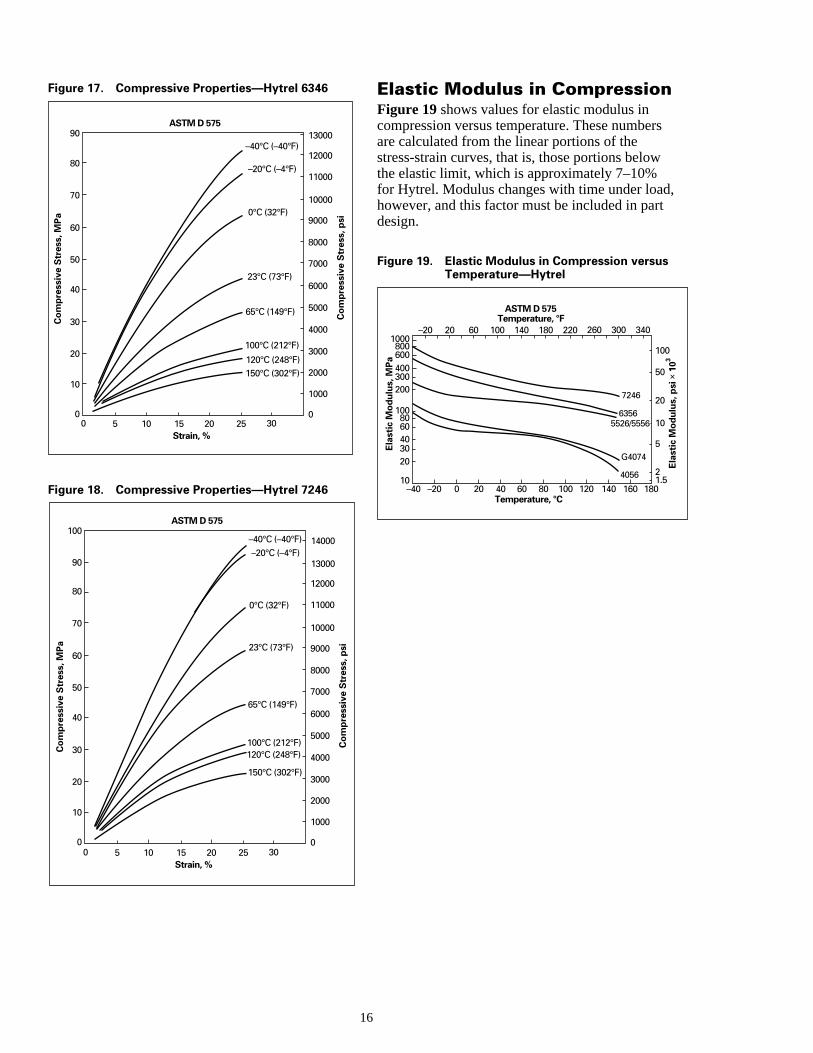
Figure 17. Compressive Properties—Hytrel 6346
ASTM D 575
100°C (212°F)120°C (248°F)
150°C (302°F)
65°C (149°F)
23°C (73°F)
0°C (32°F)
–20°C (–4°F)–40°C (–40°F)
3025201510500
10
20
30
40
50
60
70
80
90
100
Strain, %
1000
2000
3000
4000
5000
6000
7000
8000
9000
10000
11000
12000
14000
13000
0
Com
pres
sive
Str
ess,
MPa
Com
pres
sive
Str
ess,
psi
Figure 18. Compressive Properties—Hytrel 7246
1
Elastic Modulus in CompressionFigure 19 shows values for elastic modulus incompression versus temperature. These numbersare calculated from the linear portions of thestress-strain curves, that is, those portions belowthe elastic limit, which is approximately 7–10%for Hytrel. Modulus changes with time under load,however, and this factor must be included in partdesign.
ASTM D 575Temperature, °F
Temperature, °C
G4074
63565526/5556
4056
7246
160 180140120100806040200–20–4010
2030406080
100
200300400600800
1000
1.52
5
10
20
50
100
300 3402602201801401006020–20
Elas
tic
Mod
ulus
, MPa
Elas
tic
Mod
ulus
, psi
× 1
03
Figure 19. Elastic Modulus in Compression versusTemperature—Hytrel
6
ngal
ctoriss,
rt.
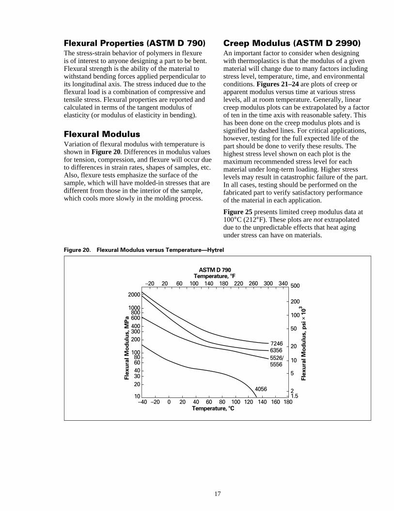
Flexural Properties (ASTM D 790)The stress-strain behavior of polymers in flexureis of interest to anyone designing a part to be benFlexural strength is the ability of the material towithstand bending forces applied perpendicular toits longitudinal axis. The stress induced due to theflexural load is a combination of compressive andtensile stress. Flexural properties are reported ancalculated in terms of the tangent modulus ofelasticity (or modulus of elasticity in bending).
Flexural ModulusVariation of flexural modulus with temperature isshown in Figure 20. Differences in modulus valuesfor tension, compression, and flexure will occur duto differences in strain rates, shapes of samples, Also, flexure tests emphasize the surface of thesample, which will have molded-in stresses that adifferent from those in the interior of the sample,which cools more slowly in the molding process.
1
t
Figure 20. Flexural Modulus versus Temperature—Hy
ASTMTempera
Tempera6040200–20–40
10
2030406080
100
200300400600800
1000
2000
1401006020–20
Flex
ura
l Mo
du
lus,
MP
a
t.
d
eetc.
re
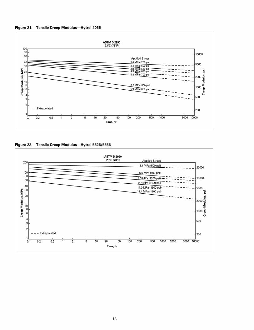
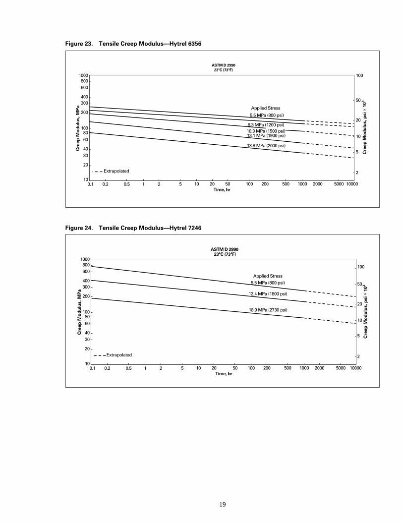
Creep Modulus (ASTM D 2990)An important factor to consider when designingwith thermoplastics is that the modulus of a givematerial will change due to many factors includinstress level, temperature, time, and environmentconditions. Figures 21–24 are plots of creep orapparent modulus versus time at various stresslevels, all at room temperature. Generally, linearcreep modulus plots can be extrapolated by a faof ten in the time axis with reasonable safety. Thhas been done on the creep modulus plots and isignified by dashed lines. For critical applicationshowever, testing for the full expected life of thepart should be done to verify these results. Thehighest stress level shown on each plot is themaximum recommended stress level for eachmaterial under long-term loading. Higher stresslevels may result in catastrophic failure of the paIn all cases, testing should be performed on thefabricated part to verify satisfactory performanceof the material in each application.
Figure 25 presents limited creep modulus data a100°C (212°F). These plots are not extrapolateddue to the unpredictable effects that heat agingunder stress can have on materials.
7
trel
D 790ture, °F
ture, °C
63565526/ 5556
4056
7246
160 180140120100801.52
5
10
20
50
100
200
500300 340260220180
Flex
ura
l Mo
du
lus,
psi
× 1
03
18
Figure 21. Tensile Creep Modulus—Hytrel 4056
ASTM D 299023°C (73°F)
Time, hr10000500010005002001005020105210.50.20.1
1
2
34
68
10
20
3040
6080
100
200
500
1000
2000
5000
10000Applied Stress
1.4 MPa (200 psi)3.4 MPa (500 psi)3.8 MPa (550 psi)4.3 MPa (625 psi)4.8 MPa (700 psi)
5.5 MPa (800 psi)5.9 MPa (850 psi)
Cre
ep M
od
ulu
s, M
Pa
Cre
ep M
od
ulu
s, p
si
Extrapolated
Figure 22. Tensile Creep Modulus—Hytrel 5526/5556
ASTM D 299023°C (73°F)
Time, hr
100005000200010005002001005020105210.5
Extrapolated
0.20.11
2
34
68
10
20
3040
6080
100
200
200
500
1000
2000
5000
10000
20000
Applied Stress
3.4 MPa (500 psi)
5.5 MPa (800 psi)
8.3 MPa (1200 psi)
9.7 MPa (1400 psi)
11.0 MPa (1600 psi)12.4 MPa (1800 psi)
Cre
ep M
od
ulu
s, M
Pa
Cre
ep M
od
ulu
s, p
si
19
Figure 23. Tensile Creep Modulus—Hytrel 6356
ASTM D 299023°C (73°F)
Time, hr1000050001000 20005002001005020105210.50.20.1
10
20
3040
6080
100
200
300400
600800
1000
2
5
10
20
50
100
Applied Stress
5.5 MPa (800 psi)
8.3 MPa (1200 psi)10.3 MPa (1500 psi)13.1 MPa (1900 psi)
13.8 MPa (2000 psi)
Cre
ep M
od
ulu
s, M
Pa
Extrapolated
Cre
ep M
od
ulu
s, p
si ×
103
Figure 24. Tensile Creep Modulus—Hytrel 7246
ASTM D 299023°C (73°F)
Time, hr1000050001000 20005002001005020105210.50.20.1
10
20
3040
6080
100
200
300400
600800
1000
2
5
10
20
50
100
Applied Stress5.5 MPa (800 psi)
12.4 MPa (1800 psi)
18.9 MPa (2730 psi)
Cre
ep M
od
ulu
s, M
Pa
Cre
ep M
od
ulu
s, p
si ×
103
Extrapolated
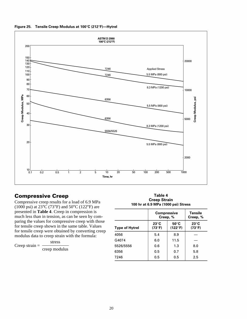
Figure 25. Tensile Creep Modulus at 100°C (212°F)—Hytrel
ASTM D 2990100°C (212°F)
Time, hr
10005002001005020105210.50.20.110
20
30
40
50
60
70
80
90
100110120130140150
200
2000
5000
7246
7246
6356
6356
5556/5526
5.5 MPa (800 psi)
5.5 MPa (800 psi)
5.5 MPa (800 psi)
Applied Stress
8.3 MPa (1200 psi)
8.3 MPa (1200 psi)
20000
10000
Cre
ep M
od
ulu
s, M
Pa
Cre
ep M
od
ulu
s, p
si
s
e
Compressive CreepCompressive creep results for a load of 6.9 MPa(1000 psi) at 23°C (73°F) and 50°C (122°F) arepresented in Table 4. Creep in compression ismuch less than in tension, as can be seen by comparing the values for compressive creep with thofor tensile creep shown in the same table. Valuesfor tensile creep were obtained by converting cremodulus data to creep strain with the formula:
Creep strain =stress
creep modulus
2
-e
p
Table 4Creep Strain
100 hr at 6.9 MPa (1000 psi) Stress
Compressive TensileCreep, % Creep, %
23°C 50°C 23°CType of Hytrel (73°F) (122°F) (73°F)
4056 5.4 8.9 —
G4074 6.0 11.5 —
5526/5556 0.6 1.3 8.0
6356 0.5 0.7 5.8
7246 0.5 0.5 2.5
0
e
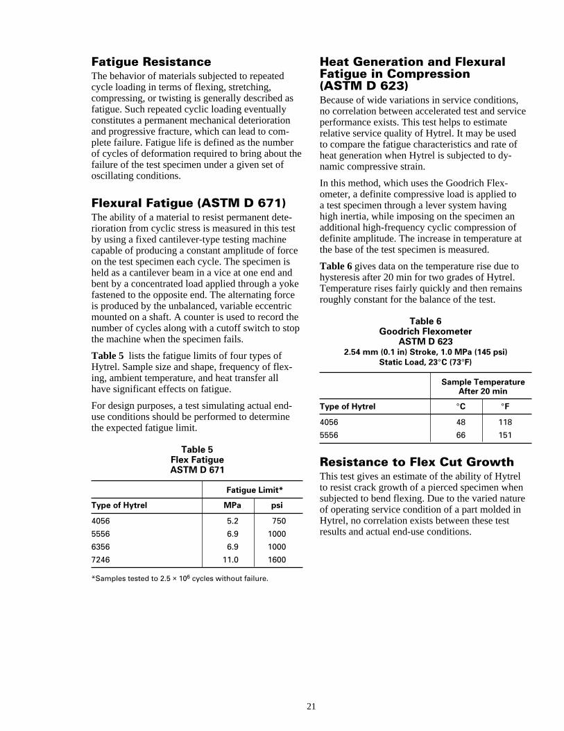
Fatigue ResistanceThe behavior of materials subjected to repeatedcycle loading in terms of flexing, stretching,compressing, or twisting is generally described afatigue. Such repeated cyclic loading eventuallyconstitutes a permanent mechanical deteriorationand progressive fracture, which can lead to com-plete failure. Fatigue life is defined as the numbeof cycles of deformation required to bring about tfailure of the test specimen under a given set ofoscillating conditions.
Flexural Fatigue (ASTM D 671)The ability of a material to resist permanent dete-rioration from cyclic stress is measured in this tesby using a fixed cantilever-type testing machinecapable of producing a constant amplitude of forcon the test specimen each cycle. The specimen iheld as a cantilever beam in a vice at one end anbent by a concentrated load applied through a yofastened to the opposite end. The alternating forcis produced by the unbalanced, variable eccentrimounted on a shaft. A counter is used to record tnumber of cycles along with a cutoff switch to stothe machine when the specimen fails.
Table 5 lists the fatigue limits of four types ofHytrel. Sample size and shape, frequency of flexing, ambient temperature, and heat transfer allhave significant effects on fatigue.
For design purposes, a test simulating actual enduse conditions should be performed to determinethe expected fatigue limit.
Table 5Flex FatigueASTM D 671
Fatigue Limit*
Type of Hytrel MPa psi
4056 5.2 750
5556 6.9 1000
6356 6.9 1000
7246 11.0 1600
*Samples tested to 2.5 × 10⁶ cycles without failure.
2
s
rhe
t
esdkee
chep
-
-
Heat Generation and FlexuralFatigue in Compression(ASTM D 623)Because of wide variations in service conditions,no correlation between accelerated test and servicperformance exists. This test helps to estimaterelative service quality of Hytrel. It may be usedto compare the fatigue characteristics and rate ofheat generation when Hytrel is subjected to dy-namic compressive strain.
In this method, which uses the Goodrich Flex-ometer, a definite compressive load is applied toa test specimen through a lever system havinghigh inertia, while imposing on the specimen anadditional high-frequency cyclic compression ofdefinite amplitude. The increase in temperature atthe base of the test specimen is measured.
Table 6 gives data on the temperature rise due tohysteresis after 20 min for two grades of Hytrel.Temperature rises fairly quickly and then remainsroughly constant for the balance of the test.
Table 6Goodrich Flexometer
ASTM D 6232.54 mm (0.1 in) Stroke, 1.0 MPa (145 psi)
Static Load, 23°C (73°F)
Sample TemperatureAfter 20 min
Type of Hytrel °C °F
4056 48 118
5556 66 151
Resistance to Flex Cut GrowthThis test gives an estimate of the ability of Hytrelto resist crack growth of a pierced specimen whensubjected to bend flexing. Due to the varied natureof operating service condition of a part molded inHytrel, no correlation exists between these testresults and actual end-use conditions.
1
e
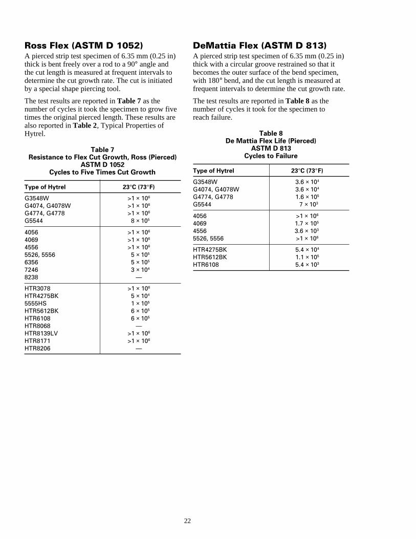
Ross Flex (ASTM D 1052)A pierced strip test specimen of 6.35 mm (0.25 in)thick is bent freely over a rod to a 90° angle andthe cut length is measured at frequent intervals todetermine the cut growth rate. The cut is initiatedby a special shape piercing tool.
The test results are reported in Table 7 as thenumber of cycles it took the specimen to grow fivetimes the original pierced length. These results aralso reported in Table 2, Typical Properties ofHytrel.
Table 7Resistance to Flex Cut Growth, Ross (Pierced)
ASTM D 1052Cycles to Five Times Cut Growth
Type of Hytrel 23°C (73°F)
G3548W >1 × 10⁶
G4074, G4078W >1 × 10⁶
G4774, G4778 >1 × 10⁶
G5544 8 × 10⁵
4056 >1 × 10⁶
4069 >1 × 10⁶
4556 >1 × 10⁶
5526, 5556 5 × 10⁵
6356 5 × 10⁵
7246 3 × 10⁴
8238 —
HTR3078 >1 × 10⁶
HTR4275BK 5 × 10⁴
5555HS 1 × 10⁵
HTR5612BK 6 × 10⁵
HTR6108 6 × 10⁵
HTR8068 —HTR8139LV >1 × 10⁶
HTR8171 >1 × 10⁶
HTR8206 —
22
DeMattia Flex (ASTM D 813)A pierced strip test specimen of 6.35 mm (0.25 in)thick with a circular groove restrained so that itbecomes the outer surface of the bend specimen,with 180° bend, and the cut length is measured atfrequent intervals to determine the cut growth rate.
The test results are reported in Table 8 as thenumber of cycles it took for the specimen toreach failure.
Table 8De Mattia Flex Life (Pierced)
ASTM D 813Cycles to Failure
Type of Hytrel 23°C (73°F)
G3548W 3.6 × 10⁴
G4074, G4078W 3.6 × 10⁴
G4774, G4778 1.6 × 10⁵
G5544 7 × 10³
4056 >1 × 10⁶
4069 1.7 × 10⁵
4556 3.6 × 10³
5526, 5556 >1 × 10⁶
HTR4275BK 5.4 × 10⁴
HTR5612BK 1.1 × 10⁵
HTR6108 5.4 × 10³
re
s
k
s
h
-
e
ge
te
e
we
Impact ResistanceThe impact properties of polymeric materials aredirectly related to their overall toughness, whichis defined as the ability of the polymer to absorbapplied energy. Impact resistance is the ability ofmaterial to resist breaking under shock loading othe ability to resist the fracture under stress appliat high speed.
Most polymers, when subjected to impact loadingseem to fracture in a characteristic fashion. Thecrack is initiated on the polymer surface by theimpact loading. The energy to initiate such a cracis called the crack-initiation energy. If the loadexceeds the crack-initiation energy, the crackcontinues to propagate. A complete failure occurwhen the load exceeds the crack-propagationenergy. Thus, both crack initiation and crackpropagation contribute to the measured impactstrength.
The speed at which the specimen or part is strucwith an object has a significant effect on the be-havior of the polymer under impact loading. Atlow rates of impact, relatively stiff material canstill have good impact strength; while at high rateof impact, even highly elastomeric material likeHytrel may exhibit brittle failure at low tempera-tures. All materials have a critical velocity in whicthey behave as glassy, brittle materials.
Impact properties are highly dependent on tempeture. Generally, plastics are tougher and exhibitductile modes of failure at temperatures above thglass transition temperature (Tg), and are brittlewell below their Tg.
A notch in a test specimen, which creates a localized stress concentration, or a sharp corner in amolded part drastically lowers impact strength.
Notched Izod Impact (ASTM D 256)The objective of the Izod impact test is to measurthe behavior of a standard notched test specimento a pendulum-type impact load. The specimen isclamped vertically and the swinging pendulum isreleased with the notch on the opposite side. Theresults are expressed in terms of kinetic energyconsumed by the pendulum in order to break thespecimen. The energy required to break a standaspecimen is actually the sum of energies neededdeform it, to initiate its fracture, and to propagatethe fracture across it, and the energy needed tothrow the broken ends of the specimen. Thesetest results are reported in Table 2, pages 6–9, atroom temperature and at –40°C (–40°F).
2
a
d
,
k
ra-
eir
e
rdto
Instrumented Impact(ASTM D 3763)One of the drawbacks of the conventional impacttest method is that it provides only one value, thetotal impact energy; it does not provide data on thtype of fracture (ductile, brittle), dynamic tough-ness, fracture, yield loads or fracture behaviorbased on the geometry of the specimen.
The falling weight instrumented impact testerprovides a complete load and energy history ofspecimen fracture mechanism. Such a systemmonitors and precisely records the entire impactevent, starting from the rest position to initialimpact, plastic bending to fracture initiation,and propagations to complete failure.
Measurement is done by mounting the strain gauinto the striking tup, and an optical device triggersthe microprocessor just before striking the speci-men. The output of the strain gauge records theapplied load variations to the specimen throughouthe entire fracturing process. A complete load-timhistory (fracturing) of the entire specimen is ob-tained. The apparent total energy absorbed by thspecimen is calculated and plotted against time.
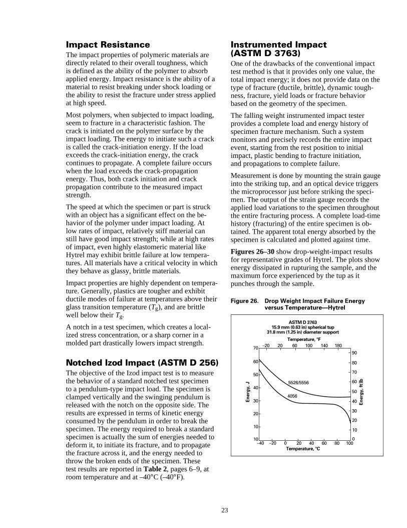
Figures 26–30 show drop-weight-impact resultsfor representative grades of Hytrel. The plots shoenergy dissipated in rupturing the sample, and thmaximum force experienced by the tup as itpunches through the sample.
Figure 26. Drop Weight Impact Failure Energyversus Temperature—Hytrel
ASTM D 3763 15.9 mm (0.63 in) spherical tup
31.8 mm (1.25 in) diameter support
Temperature, °F
Temperature, °C100806040200–20–40
10
10
20
30
40
50
5526/5556
4056
60
70
0
10
20
30
40
50
60
70
80
90
1801401006020–20
Ener
gy, J
Ener
gy, f
t⋅lb
3
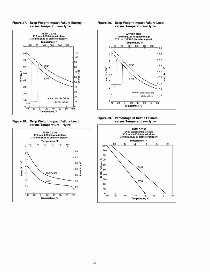
Figure 27. Drop Weight Impact Failure Energyversus Temperature—Hytrel
Figure 28. Drop Weight Impact Failure Loadversus Temperature—Hytrel
ASTM D 3763 15.9 mm (0.63 in) spherical tup
31.8 mm (1.25 in) diameter supportTemperature, °F
Temperature, °C100806040200–20–40
0
10
20
30
40
50
7246
6356
60
90
70
0
10
20
30
40
50
60
70
80
90
100
110
ductile failurebrittle failure
1801401006020–20
Ener
gy, J
80
Ener
gy, f
t⋅lb
ASTM D 3763 15.9 mm (0.63 in) spherical tup
31.8 mm (1.25 in) diameter supportTemperature, °F
Temperature, °C100806040200–20–40
0
1
2
3
4
5
5526/5556
4056
6
7
0
0.2
0.4
0.6
0.8
1.0
1.2
1.4
1801401006020–20
Load
, N ×
103
Load
, lb
× 10
3
2
Figure 29. Drop Weight Impact Failure Loadversus Temperature—Hytrel
Figure 30. Percentage of Brittle Failuresversus Temperature—Hytrel
ASTM D 3763 15.9 mm (0.63 in) spherical tup
31.8 mm (1.25 in) diameter supportTemperature, °F
Temperature, °C100806040200–20–40
0
1
2
3
4
57246
6356
6
8
7
0
0.2ductile failurebrittle failure
0.4
0.6
0.8
1.0
1.2
1.4
1.6
1.81801401006020–20
Load
, N ×
103
Load
, lb
× 10
3
ASTM D 3763 Drop Weight Impact Tests
15.9 mm (0.63 in) spherical tup 31.8 mm (1.25 in) diameter support
Temperature, °F
Temperature, °C100–10–40 –30 –20–50–60
0
10
20
30
40
50
60
70
80
90
100
6356
7246
0 20 40–20–40–60
Bri
ttle
Fai
lure
s, %
4
e-
o
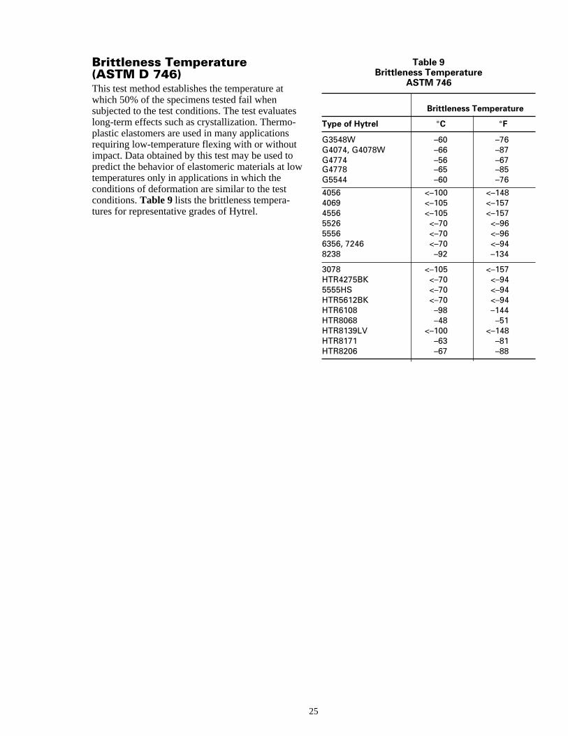
Brittleness Temperature(ASTM D 746)This test method establishes the temperature atwhich 50% of the specimens tested fail whensubjected to the test conditions. The test evaluatlong-term effects such as crystallization. Thermoplastic elastomers are used in many applicationsrequiring low-temperature flexing with or withoutimpact. Data obtained by this test may be used tpredict the behavior of elastomeric materials at lotemperatures only in applications in which theconditions of deformation are similar to the testconditions. Table 9 lists the brittleness tempera-tures for representative grades of Hytrel.
2
s
w
Table 9Brittleness Temperature
ASTM 746
Brittleness Temperature
Type of Hytrel °C °F
G3548W –60 –76G4074, G4078W –66 –87G4774 –56 –67G4778 –65 –85G5544 –60 –76
4056 <–100 <–1484069 <–105 <–1574556 <–105 <–1575526 <–70 <–965556 <–70 <–966356, 7246 <–70 <–948238 –92 –134
3078 <–105 <–157HTR4275BK <–70 <–945555HS <–70 <–94HTR5612BK <–70 <–94HTR6108 –98 –144HTR8068 –48 –51HTR8139LV <–100 <–148HTR8171 –63 –81HTR8206 –67 –88
5

26
Chapter 3
Thermal Properties
Contents
Thermal Conductivity and Specific HeatDynamic Properties
r
icnts
Thermal Properties
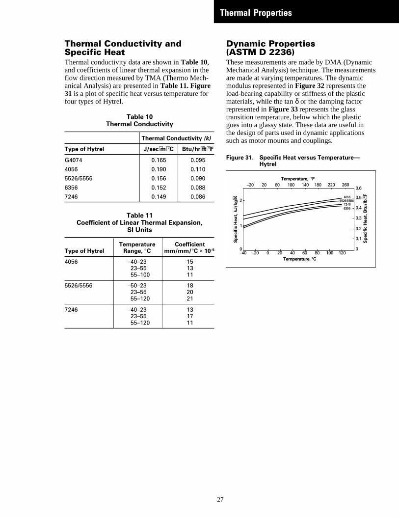
Thermal Conductivity andSpecific HeatThermal conductivity data are shown in Table 10,and coefficients of linear thermal expansion in theflow direction measured by TMA (Thermo Mech-anical Analysis) are presented in Table 11. Figure31 is a plot of specific heat versus temperature fofour types of Hytrel.
Table 10Thermal Conductivity
Thermal Conductivity (k)
Type of Hytrel J/sec⋅m⋅°C Btu/hr⋅ft⋅°F
G4074 0.165 0.095
4056 0.190 0.110
5526/5556 0.156 0.090
6356 0.152 0.088
7246 0.149 0.086
Table 11Coefficient of Linear Thermal Expansion,
SI Units
Temperature CoefficientType of Hytrel Range, °C mm/mm/°C × 10–5
4056 –40–23 1523–55 1355–100 11
5526/5556 –50–23 1823–55 2055–120 21
7246 –40–23 1323–55 1755–120 11
27
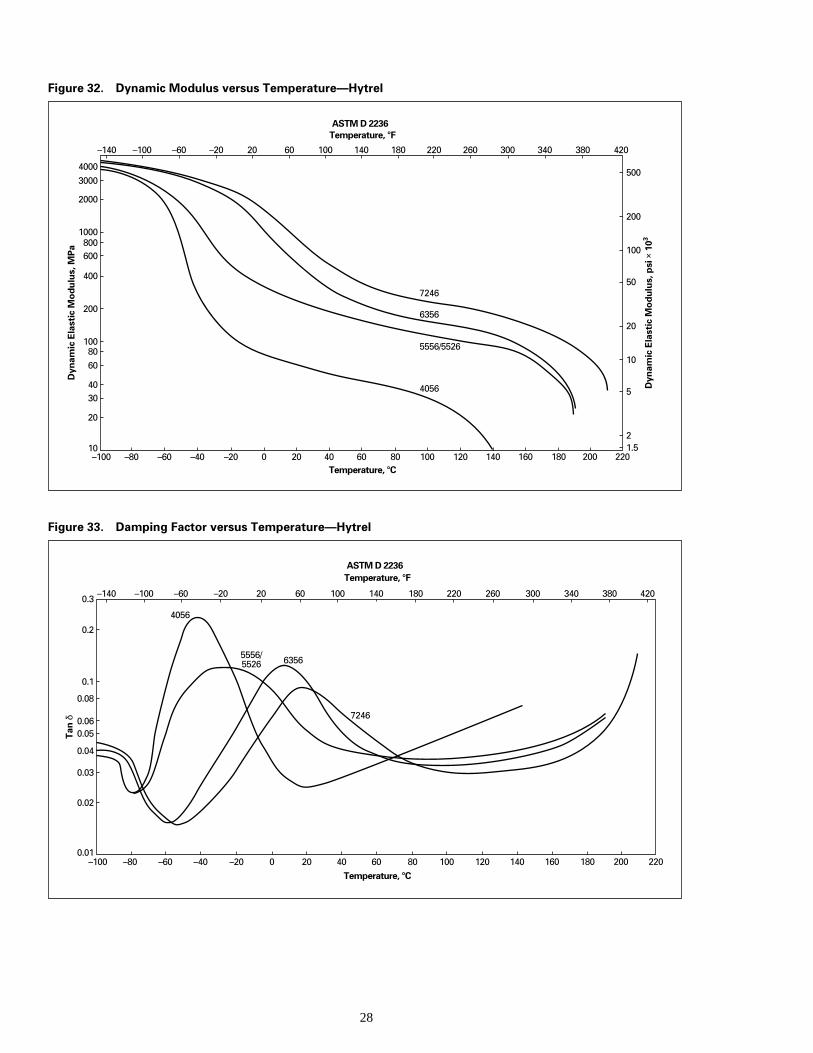
Dynamic Properties(ASTM D 2236)These measurements are made by DMA (DynamMechanical Analysis) technique. The measuremeare made at varying temperatures. The dynamicmodulus represented in Figure 32 represents theload-bearing capability or stiffness of the plasticmaterials, while the tan δ or the damping factorrepresented in Figure 33 represents the glasstransition temperature, below which the plasticgoes into a glassy state. These data are useful inthe design of parts used in dynamic applicationssuch as motor mounts and couplings.
Figure 31. Specific Heat versus Temperature—Hytrel
Temperature, °F
Temperature, °C–40 –20 0 20 40 60 80 100 120
0
0.1
0
1
2
63567246
5526/55564056
100 140 180 220 2606020–20
Spe
cific
Hea
t, k
J/kg
⋅K
Spe
cific
Hea
t, B
tu/l
b ⋅°F
0.2
0.3
0.4
0.5
0.6
28
Figure 32. Dynamic Modulus versus Temperature—Hytrel
ASTM D 2236Temperature, °F
Temperature, °C200 220
1.510
20
3040
6080
100
200
400
600800
1000
2000
30004000
6356
4056
5556/5526
7246
–140 –100 –60 –20 20 60 100 140 180 220 260 300 340 380 420
Dyn
amic
Ela
stic
Mod
ulus
, MPa
Dyn
amic
Ela
stic
Mod
ulus
, psi
× 1
03
180160140120100806040200–20–40–60–80–100
2
5
10
20
50
100
200
500
Figure 33. Damping Factor versus Temperature—Hytrel
ASTM D 2236Temperature, °F
Temperature, °C200 220
0.01
0.02
0.03
0.04
0.050.06
0.08
0.1
0.2
0.3
6356
4056
5556/ 5526
7246
–140 –100 –60 –20 20 60 100 140 180 220 260 300 340 380 420
Tan
δ
180160140120100806040200–20–40–60–80–100

29
Chapter 4
Electrical Properties
Contents
Electrical Properties
Electrical Properties
e
,n
e
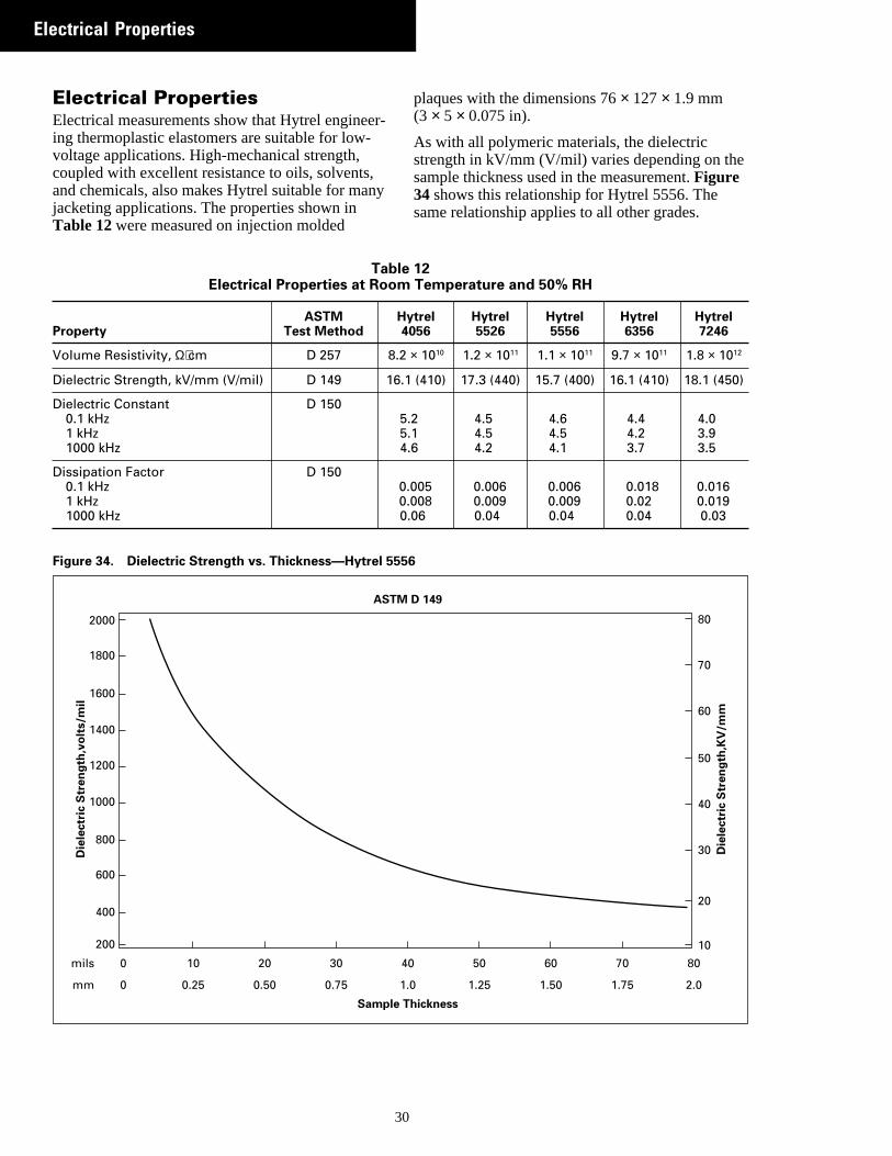
Electrical PropertiesElectrical measurements show that Hytrel engineing thermoplastic elastomers are suitable for low-voltage applications. High-mechanical strength,coupled with excellent resistance to oils, solventsand chemicals, also makes Hytrel suitable for majacketing applications. The properties shown inTable 12 were measured on injection molded
30
TableElectrical Properties at Room
ASTM HProperty Test Method 4
Volume Resistivity, Ω⋅cm D 257 8.2
Dielectric Strength, kV/mm (V/mil) D 149 16.1
Dielectric Constant D 1500.1 kHz 51 kHz 51000 kHz 4
Dissipation Factor D 1500.1 kHz 01 kHz 01000 kHz 0
Figure 34. Dielectric Strength vs. Thickness—Hytrel 555
2000
1800
1600
1400
1200
1000
800
600
400
200
0 10 20 30 4
0
mils
mm 0.25 0.50 0.75 1
Sample T
Die
lect
ric
Str
eng
th,v
olt
s/m
il
ASTM
r-
y
plaques with the dimensions 76 × 127 × 1.9 mm(3 × 5 × 0.075 in).
As with all polymeric materials, the dielectricstrength in kV/mm (V/mil) varies depending on thsample thickness used in the measurement. Figure34 shows this relationship for Hytrel 5556. Thesame relationship applies to all other grades.
12 Temperature and 50% RH
ytrel Hytrel Hytrel Hytrel Hytrel056 5526 5556 6356 7246
× 1010 1.2 × 10¹¹ 1.1 × 10¹¹ 9.7 × 10¹¹ 1.8 × 10¹²
(410) 17.3 (440) 15.7 (400) 16.1 (410) 18.1 (450)
.2 4.5 4.6 4.4 4.0
.1 4.5 4.5 4.2 3.9
.6 4.2 4.1 3.7 3.5
.005 0.006 0.006 0.018 0.016
.008 0.009 0.009 0.02 0.019
.06 0.04 0.04 0.04 0.03
6
0 50 60 70 80
.0
hickness
Die
lect
ric
Str
eng
th,K
V/m
m
1.25 1.50 1.75 2.0
10
20
30
40
50
60
70
80
D 149

31
Chapter 5
Abrasion and Wear
Contents
FrictionWear
d
o
n
-
t
on
n
Abrasion and Wear
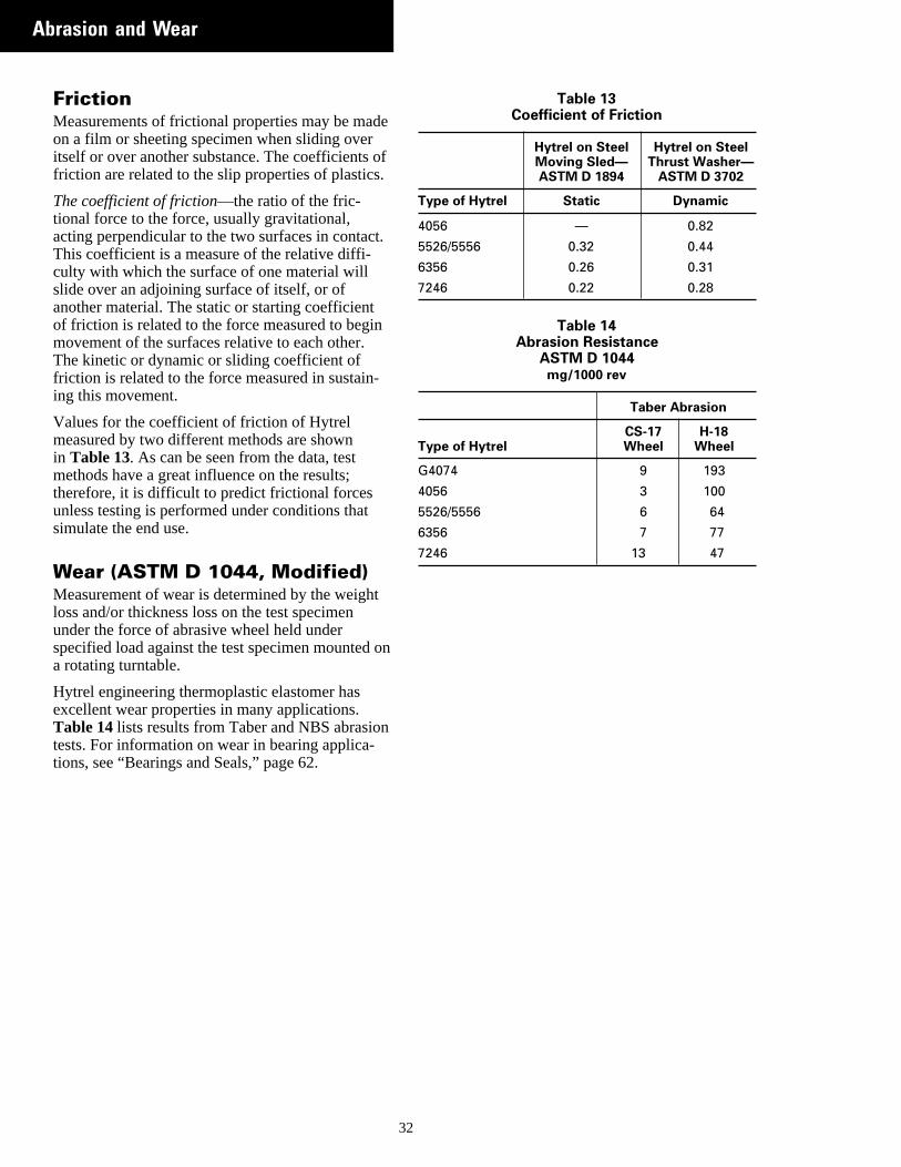
FrictionMeasurements of frictional properties may be maon a film or sheeting specimen when sliding overitself or over another substance. The coefficients friction are related to the slip properties of plastics
The coefficient of friction—the ratio of the fric-tional force to the force, usually gravitational,acting perpendicular to the two surfaces in contacThis coefficient is a measure of the relative diffi-culty with which the surface of one material willslide over an adjoining surface of itself, or ofanother material. The static or starting coefficientof friction is related to the force measured to begimovement of the surfaces relative to each other.The kinetic or dynamic or sliding coefficient offriction is related to the force measured in sustaining this movement.
Values for the coefficient of friction of Hytrelmeasured by two different methods are shownin Table 13. As can be seen from the data, testmethods have a great influence on the results;therefore, it is difficult to predict frictional forcesunless testing is performed under conditions thatsimulate the end use.
Wear (ASTM D 1044, Modified)Measurement of wear is determined by the weighloss and/or thickness loss on the test specimenunder the force of abrasive wheel held underspecified load against the test specimen mounteda rotating turntable.
Hytrel engineering thermoplastic elastomer hasexcellent wear properties in many applications.Table 14 lists results from Taber and NBS abrasiotests. For information on wear in bearing applica-tions, see “Bearings and Seals,” page 62.
3
e
f.
t.
Table 13Coefficient of Friction
Hytrel on Steel Hytrel on SteelMoving Sled— Thrust Washer—ASTM D 1894 ASTM D 3702
Type of Hytrel Static Dynamic
4056 — 0.82
5526/5556 0.32 0.44
6356 0.26 0.31
7246 0.22 0.28
Table 14Abrasion Resistance
ASTM D 1044mg/1000 rev
Taber Abrasion
CS-17 H-18Type of Hytrel Wheel Wheel
G4074 9 193
4056 3 100
5526/5556 6 64
6356 7 77
7246 13 47
2

33
Chapter 6
Effect of Environment
Contents
Moisture Pickup and DryingShrinkage and Post-Molding ShrinkageAnnealingDimensional TolerancesThe Molding OperationConcentratesFluid ResistanceGas PermeabilityRadiation ResistanceResistance to Mildew and Fungus
n
r
Effect of Environment
Moisture Pickup and DryingHytrel granules are supplied in moisture-resistantpackaging. However, when exposed to air, thegranules pick up moisture. Moisture levels above0.10% may seriously impair the processing, causihighly variable melt pressure, varying extruderoutput, degradation of the resin, and, possibly,bubbles in the melt as it exits the die.
At temperatures above the melting point, excessivmoisture causes hydrolytic degradation of the polymer. Such degradation results in poor physicalproperties and brittleness, particularly at lowtemperatures.
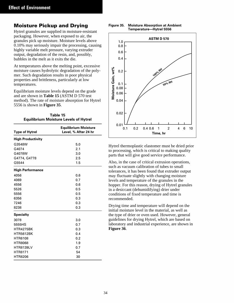
Equilibrium moisture levels depend on the gradeand are shown in Table 15 (ASTM D 570 testmethod). The rate of moisture absorption for Hytre5556 is shown inFigure 35.
Table 15Equilibrium Moisture Levels of Hytrel
Equilibrium MoistureType of Hytrel Level, % After 24 hr
High Productivity
G3548W 5.0G4074 2.1G4078W 3.0G4774, G4778 2.5G5544 1.5
High Performance
4056 0.64069 0.74556 0.65526 0.55556 0.56356 0.37246 0.38238 0.3
Specialty
3078 3.05555HS 0.7HTR4275BK 0.3HTR5612BK 0.4HTR6108 0.2HTR8068 1.9HTR8139LV 0.7HTR8171 54HTR8206 30
34
g
e-
l
Figure 35. Moisture Absorption at AmbientTemperature—Hytrel 5556
Hytrel thermoplastic elastomer must be dried prioto processing, which is critical to making qualityparts that will give good service performance.
Also, in the case of critical extrusion operations,such as vacuum calibration of tubes to smalltolerances, it has been found that extruder outputmay fluctuate slightly with changing moisturelevels and temperature of the granules in thehopper. For this reason, drying of Hytrel granulesin a desiccant (dehumidifying) drier underconditions of fixed temperature and time isrecommended.
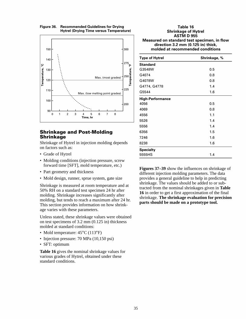
Drying time and temperature will depend on theinitial moisture level in the material, as well asthe type of drier or oven used. However, generalguidelines for drying Hytrel, which are based onlaboratory and industrial experience, are shown inFigure 36.
1.00.8
0.6
0.4
0.2
0.10.080.06
0.04
0.02
0.010.1 0.2 0.4 0.6 1 2 4 6 10
100%RH
50% RH
Time, hr
Mo
istu
re G
ain
, wt%
ASTM D 570
ned
Figure 36. Recommended Guidelines for DryingHytrel (Drying Time versus Temperature)
0
150
140
130
120
110
100
90
Tem
per
atu
re, °
C
Time, hr1 32 4 5 6 7 8
Max. (low melting point grades)
Max. (most grades)
300
275
250
225
200
Tem
per
atu
re, °
FShrinkage and Post-MoldingShrinkageShrinkage of Hytrel in injection molding dependson factors such as:
• Grade of Hytrel
• Molding conditions (injection pressure, screwforward time [SFT], mold temperature, etc.)
• Part geometry and thickness
• Mold design, runner, sprue system, gate size
Shrinkage is measured at room temperature and 50% RH on a standard test specimen 24 hr aftermolding. Shrinkage increases significantly aftermolding, but tends to reach a maximum after 24 hThis section provides information on how shrink-age varies with these parameters.
Unless stated, these shrinkage values were obtaion test specimens of 3.2 mm (0.125 in) thicknessmolded at standard conditions:• Mold temperature: 45°C (113°F)• Injection pressure: 70 MPa (10,150 psi)• SFT: optimum
Table 16 gives the nominal shrinkage values forvarious grades of Hytrel, obtained under thesestandard conditions.
3
at
r.
Table 16Shrinkage of Hytrel
ASTM D 955Measured on standard test specimen, in flow
direction 3.2 mm (0.125 in) thick,molded at recommended conditions
Type of Hytrel Shrinkage, %
StandardG3548W 0.5
G4074 0.8
G4078W 0.8
G4774, G4778 1.4
G5544 1.6
High-Performance4056 0.5
4069 0.8
4556 1.1
5526 1.4
5556 1.4
6356 1.5
7246 1.6
8238 1.6
Specialty5555HS 1.4
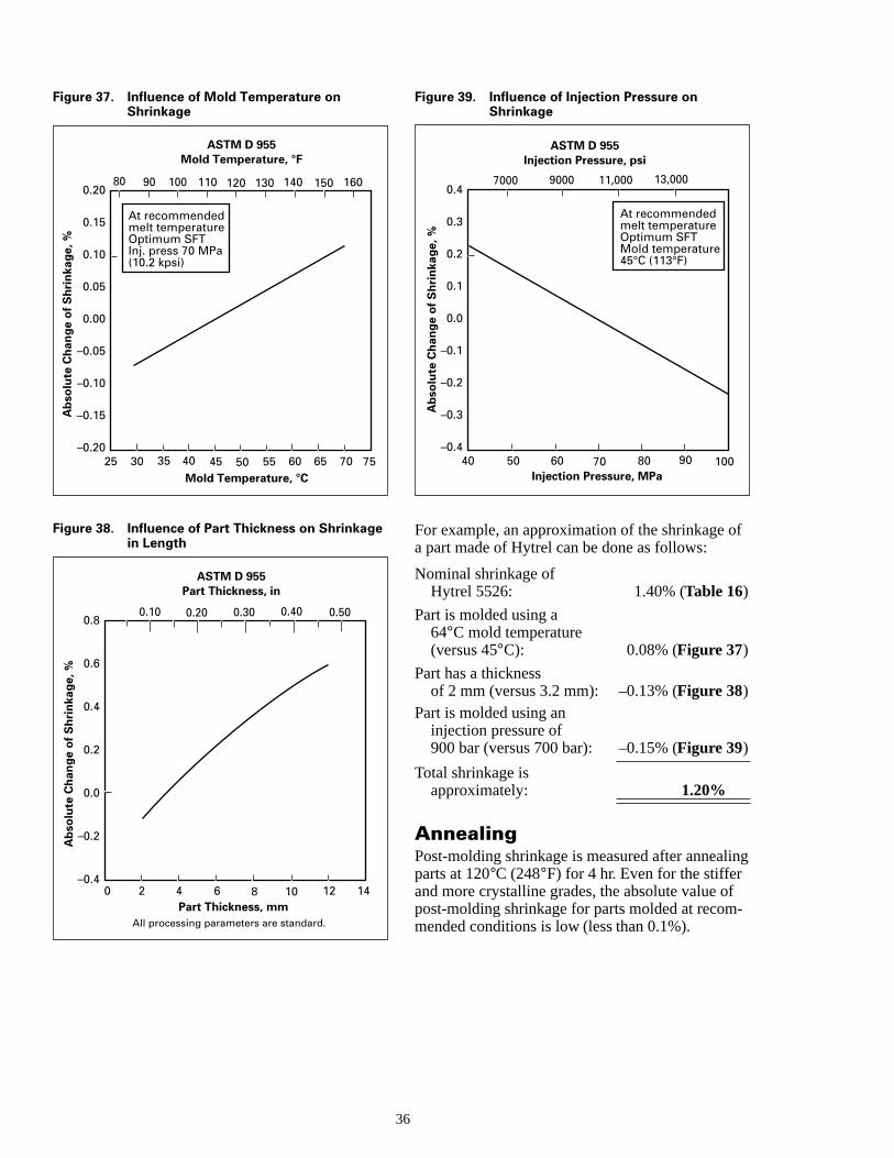
Figures 37–39 show the influences on shrinkage ofdifferent injection molding parameters. The dataprovides a general guideline to help in predictingshrinkage. The values should be added to or sub-tracted from the nominal shrinkages given in Table16 in order to get a first approximation of the finalshrinkage. The shrinkage evaluation for precisionparts should be made on a prototype tool.
5
f
ng
-
Figure 37. Influence of Mold Temperature onShrinkage
Figure 38. Influence of Part Thickness on Shrinkagein Length
0.20
0.15
0.10
0.05
0.00
–0.05
–0.10
–0.15
–0.20
25 5030 60 70Mold Temperature, °C
ASTM D 955 Mold Temperature, °F
Ab
solu
te C
han
ge
of
Sh
rin
kag
e, %
9080 100
65
At recommended melt temperature Optimum SFT Inj. press 70 MPa (10.2 kpsi)
35 40 45 55 75
110 120 130 140 150 160
0.8
0.6
0.4
0.2
0.0
–0.2
–0.40 2 4 6 8 10
Part Thickness, mm
ASTM D 955 Part Thickness, in
Ab
solu
te C
han
ge
of
Sh
rin
kag
e, %
All processing parameters are standard.
0.500.300.200.10 0.40
12 14
3
Figure 39. Influence of Injection Pressure onShrinkage
For example, an approximation of the shrinkage oa part made of Hytrel can be done as follows:
Nominal shrinkage ofHytrel 5526: 1.40% (Table 16)
Part is molded using a64°C mold temperature(versus 45°C): 0.08% (Figure 37)
Part has a thicknessof 2 mm (versus 3.2 mm): –0.13% (Figure 38)
Part is molded using aninjection pressure of900 bar (versus 700 bar): –0.15% (Figure 39)
Total shrinkage isapproximately: 1.20%
AnnealingPost-molding shrinkage is measured after annealiparts at 120°C (248°F) for 4 hr. Even for the stifferand more crystalline grades, the absolute value ofpost-molding shrinkage for parts molded at recommended conditions is low (less than 0.1%).
0.4
0.3
0.2
0.1
0.0
–0.1
–0.2
–0.3
–0.4
40 50 7060 80 100Injection Pressure, MPa
ASTM D 955 Injection Pressure, psi
Ab
solu
te C
han
ge
of
Sh
rin
kag
e, %
11,00090007000 13,000
90
At recommended melt temperature Optimum SFT Mold temperature 45°C (113°F)
6
h
g
-
e
.
ety
til
c-
rt
y
e
es
ned
Dimensional TolerancesAllowable variations in the dimensions of aninjection molded part are called the tolerances ofthe part and greatly affect the cost of manufactureA realistic view of the purchased cost of toleranceoften helps avoid high manufacturing charges witno detriment to the performance of the part.
Regardless of the economics, it may be unreasonable to specify close production tolerances on a pwhen it is designed to operate within a wide rangeof environmental conditions. Dimensional changedue to temperature variations alone can be three four times as great as the specified tolerances. Alin many applications such as bearings and gears,close tolerances with plastics are not as vital aswith metals, because of the resiliency of plastics.
Some general suggestions are:• The design for a part should indicate conditions
under which the dimensions shown must be hel(temperature, humidity, etc.).
• On a drawing, overall tolerances for a part shoube shown in mm/mm (in/in), not in fixed values.A title block should read, “All decimal dimen-sions ±0.00X mm/mm (±0.00X in/in), not±0.00Xmm (±0.00X in), unless otherwise specified.”
• The number of critical dimensions per part shoube as low as possible. A part with several criticadimensions will naturally be more difficult tomold than a part with few critical dimensions.
• Tight tolerances should not be put on dimensionacross a parting line or on sections formed bymovable cores or sliding cams.
• Where compromises in tolerances could beacceptable from a performance standpoint, thetolerances in question should be discussed withthe molder in view of possible economics.
Factors that must be considered when establishintolerances for injection-molded parts are:• Thermal expansion and contraction• Nature of the surroundings• Processing conditions and part molding shrinka• Molding tolerances
Multicavity molds will result in a cost savingsbut can increase tolerance limits from 1–5% percavity. Therefore, a tolerance that would be specified for a single-cavity mold would have to beincreased to allow for production variables.Whether or not the part can withstand this varianc
37
.s
-art
toso,
d
ld
ldl
s
g
e
will depend on the function of the part and shouldalways be considered.
The ability to maintain minimum tolerances isdependent on part design, the number of cavities,mold design, the injection molding system used,molding conditions, and the ability of the molder.Only through an optimization of all of these vari-ables can the tightest of tolerances be maintained
The Molding OperationIn the injection molding of thermoplastics, parts armade by injecting molten resin into a shaped cavithat has been built into an appropriate mold. In thecavity, the molten resin is held under pressure unit solidifies. Simultaneously, it is shrinking due tothe change from liquid to solid and thermal contration. The solid part thus formed reproduces thecavity shape in detail and is removed from themold. Ejector pins or rings in the mold free the pafrom it. Molten resin is produced by melting rawmaterial in the cylinder of the molding machinewhile the part just formed is cooling in the mold.
This overall procedure is repeated on a rigidlymaintained cycle until the required number ofparts is produced. Cycle time is determined largelby the rate at which heat can be removed from thecooling part. This rate is approximately propor-tional to the wall thickness of the part and is slowbecause of low thermal conductivity. For thisreason, parts should be designed with walls asthin as is consistent with design requirementsand ease of fabrication.
The configuration and dimensions of the moldingtool depend on the size and shape of the part to bproduced as well as the number of cavities to beemployed in production. At the same time, molddimensions must be governed by the dimensionsof standard molding machines. Mold costs oftencan be reduced by the use of standard mold framinto which the part-forming cavities are fitted.
The molding process and the injection mold offerthe designer an opportunity to add both value andfunction to the design. A close relationship betweethe functional designer and the molder is suggestto optimize these opportunities.
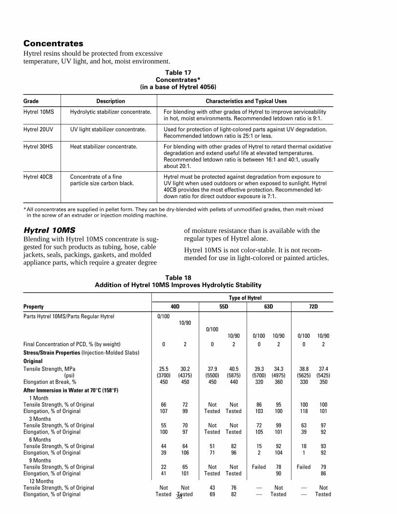
nt.
ConcentratesHytrel resins should be protected from excessivetemperature, UV light, and hot, moist environme
Table 17Concentrates*
(in a base of Hytrel 4056)
Grade Description Characteristics and Typical Uses
Hytrel 10MS Hydrolytic stabilizer concentrate. For blending with other grades of Hytrel to improve serviceabilityin hot, moist environments. Recommended letdown ratio is 9:1.
Hytrel 20UV UV light stabilizer concentrate. Used for protection of light-colored parts against UV degradation.Recommended letdown ratio is 25:1 or less.
Hytrel 30HS Heat stabilizer concentrate. For blending with other grades of Hytrel to retard thermal oxidativedegradation and extend useful life at elevated temperatures.Recommended letdown ratio is between 16:1 and 40:1, usuallyabout 20:1.
Hytrel 40CB Concentrate of a fine Hytrel must be protected against degradation from exposure toparticle size carbon black. UV light when used outdoors or when exposed to sunlight. Hytrel
40CB provides the most effective protection. Recommended let-down ratio for direct outdoor exposure is 7:1.
*All concentrates are supplied in pellet form. They can be dry-blended with pellets of unmodified grades, then melt-mixedin the screw of an extruder or injection molding machine.
-le
dee
es.
Hytrel 10MSBlending with Hytrel 10MS concentrate is suggested for such products as tubing, hose, cabjackets, seals, packings, gaskets, and moldeappliance parts, which require a greater degr
3
TabAddition of Hytrel 10MS Im
Property 40D
Parts Hytrel 10MS/Parts Regular Hytrel 0/100
Final Concentration of PCD, % (by weight) 0Stress/Strain Properties (Injection-Molded Slabs)OriginalTensile Strength, MPa 25.5
(psi) (3700)Elongation at Break, % 450After Immersion in Water at 70°C (158°F)
1 MonthTensile Strength, % of Original 66Elongation, % of Original 107
3 MonthsTensile Strength, % of Original 55Elongation, % of Original 100
6 MonthsTensile Strength, % of Original 44Elongation, % of Original 39
9 MonthsTensile Strength, % of Original 22Elongation, % of Original 41
12 MonthsTensile Strength, % of Original NotElongation, % of Original Tested
of moisture resistance than is available with theregular types of Hytrel alone.
Hytrel 10MS is not color-stable. It is not recom-mended for use in light-colored or painted articl
8
le 18proves Hydrolytic Stability
Type of Hytrel
55D 63D 72D
10/900/100
10/90 0/100 10/90 0/100 10/902 0 2 0 2 0 2
30.2 37.9 40.5 39.3 34.3 38.8 37.4(4375) (5500) (5875) (5700) (4975) (5625) (5425)
450 450 440 320 360 330 350
72 Not Not 86 95 100 10099 Tested Tested 103 100 118 101
70 Not Not 72 99 63 9797 Tested Tested 105 101 39 92
64 51 82 15 92 18 93106 71 96 2 104 1 92
65 Not Not Failed 78 Failed 79101 Tested Tested 90 86
Not 43 76 — Not — NotTested 69 82 — Tested — Tested
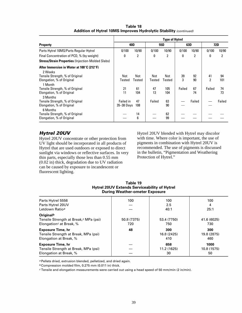
Table 18Addition of Hytrel 10MS Improves Hydrolytic Stability (continued)
Type of Hytrel
Property 40D 55D 63D 72D
Parts Hytrel 10MS/Parts Regular Hytrel 0/100 10/90 0/100 10/90 0/100 10/90 0/100 10/90Final Concentration of PCD, % (by weight) 0 2 0 2 0 2 0 2Stress/Strain Properties (Injection-Molded Slabs)
After Immersion in Water at 100°C (212°F)2 Weeks
Tensile Strength, % of Original Not Not Not Not 39 92 41 94Elongation, % of Original Tested Tested Tested Tested 3 90 2 101
1 MonthTensile Strength, % of Original 21 61 47 105 Failed 67 Failed 74Elongation, % of Original 11 104 13 104 74 73
3 MonthsTensile Strength, % of Original Failed in 47 Failed 63 — Failed — FailedElongation, % of Original 35–38 Days 108 90 — —
6 MonthsTensile Strength, % of Original — 14 — 62 — — — —Elongation, % of Original — 6 — 99 — — — —
red
Hytrel 20UVHytrel 20UV concentrate or other protection fromUV light should be incorporated in all products ofHytrel that are used outdoors or exposed to direcsunlight via windows or reflective surfaces. In vethin parts, especially those less than 0.55 mm(0.02 in) thick, degradation due to UV radiationcan be caused by exposure to incandescent orfluorescent lighting.
3
TablHytrel 20UV Extends S
During Weather-o
Parts Hytrel 5556 100Parts Hytrel 20UV —Letdown Ratioa —
OriginalbTensile Strength at Break,c MPa (psi) 50.8 (73Elongationc at Break, % 720
Exposure Time, hr 48Tensile Strength at Break, MPa (psi)Elongation at Break, %
Exposure Time, hr —Tensile Strength at Break, MPa (psi) —Elongation at Break, % —
a Pellets dried, extrusion blended, pelletized, and dried again.b Compression molded film, 0.275 mm (0.011 in) thick.c Tensile and elongation measurements were carried out using
ty
Hytrel 20UV blended with Hytrel may discolorwith time. Where color is important, the use ofpigments in combination with Hytrel 20UV isrecommended. The use of pigments is discussin the bulletin, “Pigmentation and WeatheringProtection of Hytrel.”
9
e 19erviceability of Hytrelmeter Exposure
100 1002.5 4
40:1 25:1
75) 53.4 (7750) 41.6 (6025)750 730
300 30016.8 (2425) 19.8 (2875)
410 460
658 100011.2 (1625) 10.8 (1575)
30 50
a head speed of 50 mm/min (2 in/min).
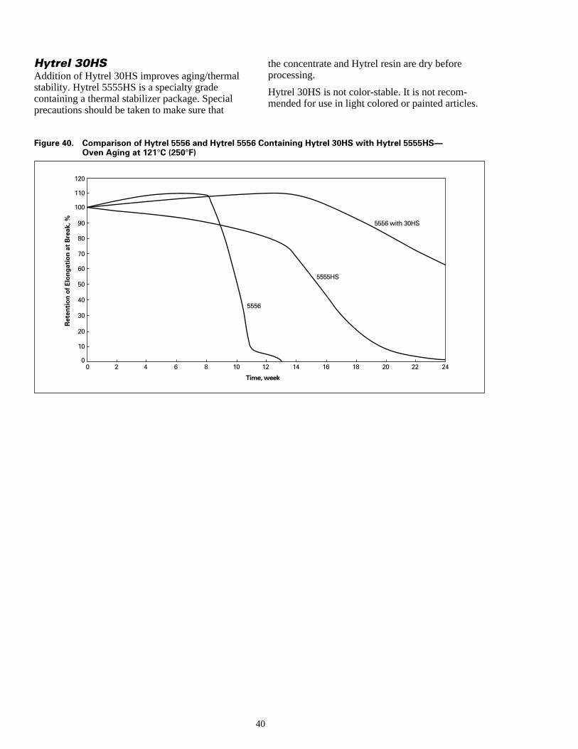
l
l .
Hytrel 30HSAddition of Hytrel 30HS improves aging/thermastability. Hytrel 5555HS is a specialty gradecontaining a thermal stabilizer package. Speciaprecautions should be taken to make sure that
Tim
0
10
20
40
60
80
100
30
50
70
90
110
120
Ret
enti
on o
f Elo
ngat
ion
at B
reak
, %
0 2 4 6 8 10
555
Figure 40. Comparison of Hytrel 5556 and Hytrel 5556Oven Aging at 121°C (250°F)
the concentrate and Hytrel resin are dry beforeprocessing.
Hytrel 30HS is not color-stable. It is not recom-mended for use in light colored or painted articles
40
e, week
5555HS
12 14 16 18 20 22 24
6
5556 with 30HS
Containing Hytrel 30HS with Hytrel 5555HS—
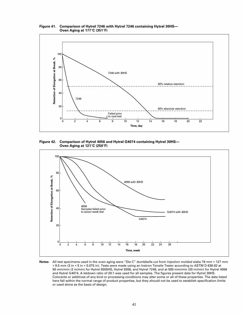
41
Figure 41. Comparison of Hytrel 7246 with Hytrel 7246 containing Hytrel 30HS—Oven Aging at 177°C (351°F)
Time, day
0
20
40
60
80
100
7246 with 30HS
50% relative retention
50% absolute retention
Ret
enti
on o
f Elo
ngat
ion
at B
reak
, %
0 2 4 6 8 10 12 14 16 18 20 22
7246
Failed prior to next test
Figure 42. Comparison of Hytrel 4056 and Hytrel G4074 containing Hytrel 30HS—Oven Aging at 121°C (250°F)
Time, week
0
20
40
60
80
100
4056 with 30HS
G4074
G4074 with 30HS
Ret
enti
on o
f Elo
ngat
ion
at B
reak
, %
0 2 6 10 14 18 22 262420161284
4056 Samples failed prior to seven-week test
Notes: All test specimens used in the oven aging were “Die C” dumbbells cut from injection molded slabs 76 mm × 127 mm× 9.5 mm (3 in × 5 in × 0.075 in). Tests were made using an Instron Tensile Tester according to ASTM D 638-82 at50 mm/min (2 in/min) for Hytrel 5555HS, Hytrel 5556, and Hytrel 7246, and at 500 mm/min (20 in/min) for Hytrel 4056and Hytrel G4074. A letdown ratio of 20:1 was used for all samples. The figures present data for Hytrel 30HS.Colorants or additives of any kind or processing conditions may alter some or all of these properties. The data listedhere fall within the normal range of product properties, but they should not be used to establish specification limitsor used alone as the basis of design.
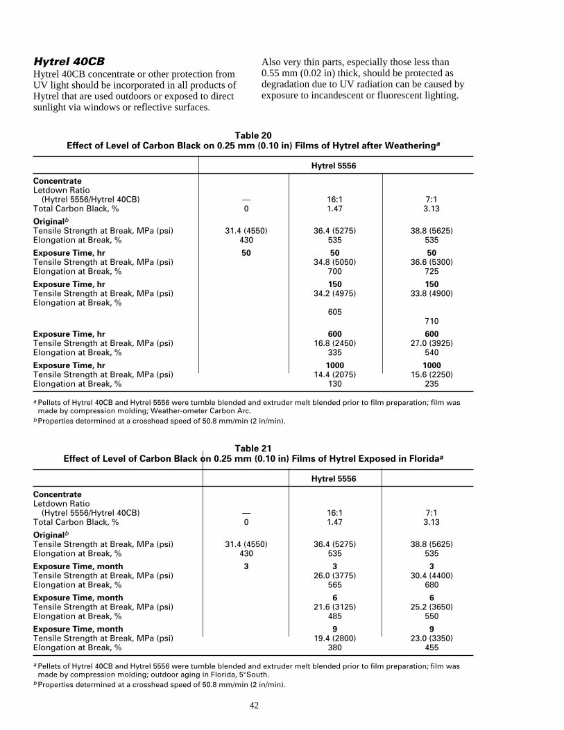
mofc
by.
Hytrel 40CBHytrel 40CB concentrate or other protection froUV light should be incorporated in all products Hytrel that are used outdoors or exposed to diresunlight via windows or reflective surfaces.
4
TablEffect of Level of Carbon Black on 0.25 mm
ConcentrateLetdown Ratio
(Hytrel 5556/Hytrel 40CB) —Total Carbon Black, % 0
OriginalbTensile Strength at Break, MPa (psi) 31.4 (45Elongation at Break, % 430
Exposure Time, hr 50Tensile Strength at Break, MPa (psi)Elongation at Break, %
Exposure Time, hrTensile Strength at Break, MPa (psi)Elongation at Break, %
Exposure Time, hrTensile Strength at Break, MPa (psi)Elongation at Break, %
Exposure Time, hrTensile Strength at Break, MPa (psi)Elongation at Break, %
a Pellets of Hytrel 40CB and Hytrel 5556 were tumble blended anmade by compression molding; Weather-ometer Carbon Arc.
b Properties determined at a crosshead speed of 50.8 mm/min (2
TablEffect of Level of Carbon Black on 0.25 mm
ConcentrateLetdown Ratio
(Hytrel 5556/Hytrel 40CB) —Total Carbon Black, % 0
OriginalbTensile Strength at Break, MPa (psi) 31.4 (45Elongation at Break, % 430
Exposure Time, month 3Tensile Strength at Break, MPa (psi)Elongation at Break, %
Exposure Time, monthTensile Strength at Break, MPa (psi)Elongation at Break, %
Exposure Time, monthTensile Strength at Break, MPa (psi)Elongation at Break, %
a Pellets of Hytrel 40CB and Hytrel 5556 were tumble blended anmade by compression molding; outdoor aging in Florida, 5°So
b Properties determined at a crosshead speed of 50.8 mm/min (2
t
Also very thin parts, especially those less than0.55 mm (0.02 in) thick, should be protected asdegradation due to UV radiation can be causedexposure to incandescent or fluorescent lighting
2
e 20 (0.10 in) Films of Hytrel after Weatheringa
Hytrel 5556
16:1 7:11.47 3.13
50) 36.4 (5275) 38.8 (5625)535 535
50 5034.8 (5050) 36.6 (5300)
700 725
150 15034.2 (4975) 33.8 (4900)
605710
600 60016.8 (2450) 27.0 (3925)
335 540
1000 100014.4 (2075) 15.6 (2250)
130 235
d extruder melt blended prior to film preparation; film was
in/min).
e 21(0.10 in) Films of Hytrel Exposed in Floridaa
Hytrel 5556
16:1 7:11.47 3.13
50) 36.4 (5275) 38.8 (5625)535 535
3 326.0 (3775) 30.4 (4400)
565 680
6 621.6 (3125) 25.2 (3650)
485 550
9 919.4 (2800) 23.0 (3350)
380 455
d extruder melt blended prior to film preparation; film wasuth. in/min).
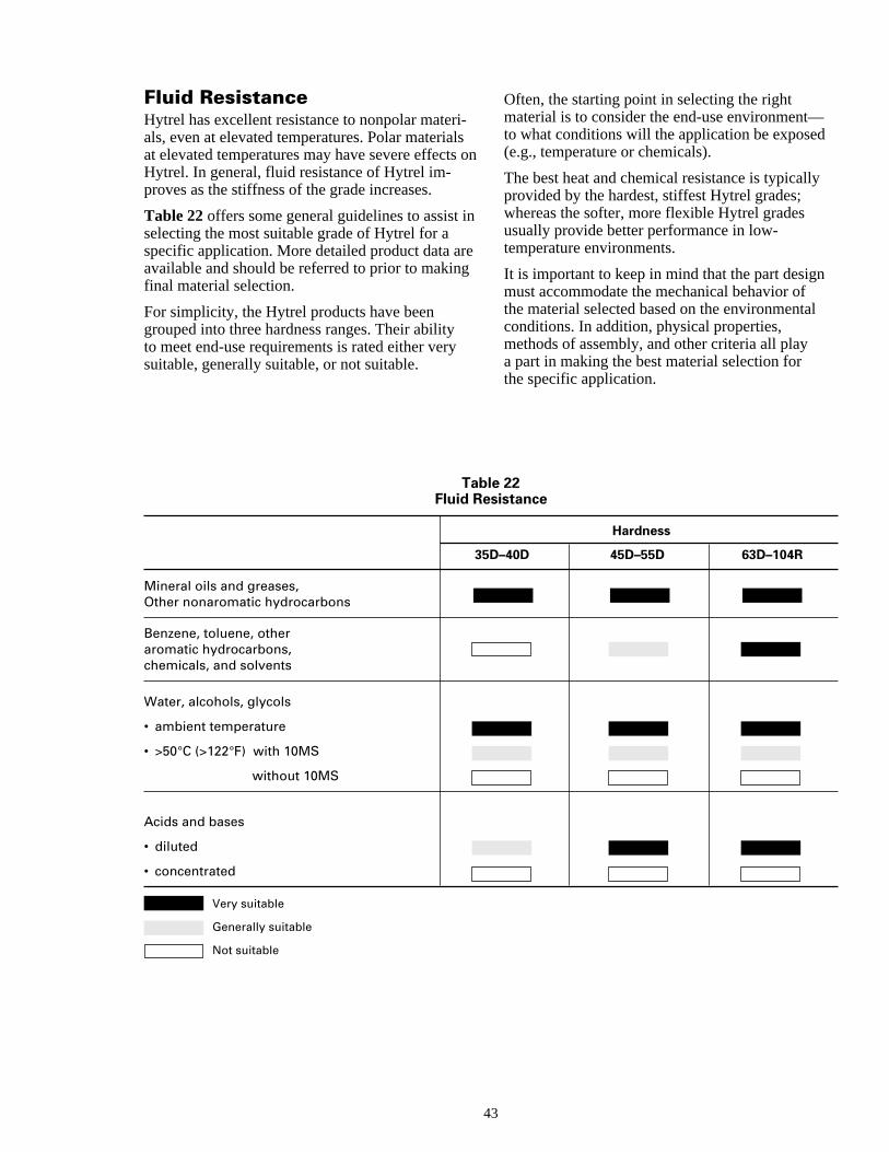
i
s
i
rg
—d
ly
n
l
Fluid ResistanceHytrel has excellent resistance to nonpolar materals, even at elevated temperatures. Polar materiaat elevated temperatures may have severe effectHytrel. In general, fluid resistance of Hytrel im-proves as the stiffness of the grade increases.
Table 22 offers some general guidelines to assist selecting the most suitable grade of Hytrel for aspecific application. More detailed product data aavailable and should be referred to prior to makinfinal material selection.
For simplicity, the Hytrel products have beengrouped into three hardness ranges. Their abilityto meet end-use requirements is rated either verysuitable, generally suitable, or not suitable.
43
TableFluid Res
35D
Mineral oils and greases,Other nonaromatic hydrocarbons
Benzene, toluene, otheraromatic hydrocarbons,chemicals, and solvents
Water, alcohols, glycols
• ambient temperature
• >50°C (>122°F) with 10MS
without 10MS
Acids and bases
• diluted
• concentrated
Very suitable
Generally suitable
Not suitable
-ls on
n
e
Often, the starting point in selecting the rightmaterial is to consider the end-use environmentto what conditions will the application be expose(e.g., temperature or chemicals).
The best heat and chemical resistance is typicalprovided by the hardest, stiffest Hytrel grades;whereas the softer, more flexible Hytrel gradesusually provide better performance in low-temperature environments.
It is important to keep in mind that the part desigmust accommodate the mechanical behavior ofthe material selected based on the environmentaconditions. In addition, physical properties,methods of assembly, and other criteria all playa part in making the best material selection forthe specific application.
22istance
Hardness
–40D 45D–55D 63D–104R
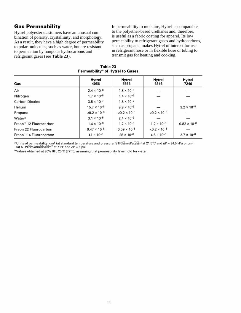
-
in
s,
Gas PermeabilityHytrel polyester elastomers have an unusual combination of polarity, crystallinity, and morphology.As a result, they have a high degree of permeabilto polar molecules, such as water, but are resistato permeation by nonpolar hydrocarbons andrefrigerant gases (see Table 23).
44
TablePermeabilitya of H
HytrelGas 4056
Air 2.4 × 10⁻⁸
Nitrogen 1.7 × 10⁻⁸
Carbon Dioxide 3.5 × 10⁻⁷
Helium 15.7 × 10⁻⁸
Propane <0.2 × 10⁻⁸
Waterb 3.1 × 10⁻⁵
Freon 12 Fluorocarbon 1.4 × 10⁻⁸
Freon 22 Fluorocarbon 0.47 × 10⁻⁸
Freon 114 Fluorocarbon 41 × 10–8
a Units of permeability: cm3 (at standard temperature and pressu(at STP)⋅cm/atm⋅sec⋅cm2 at 71°F and ∆P = 5 psi
b Values obtained at 90% RH, 25°C (77°F), assuming that permeab
tyt
In permeability to moisture, Hytrel is comparableto the polyether-based urethanes and, therefore,is useful as a fabric coating for apparel. Its lowpermeability to refrigerant gases and hydrocarbonsuch as propane, makes Hytrel of interest for usein refrigerant hose or in flexible hose or tubing totransmit gas for heating and cooking.
23ytrel to Gases
Hytrel Hytrel Hytrel5556 6346 7246
1.8 × 10⁻⁸ — —
1.4 × 10⁻⁸ — —
1.8 × 10⁻⁷ — —
9.9 × 10⁻⁸ — 3.2 × 10⁻⁸
<0.2 × 10⁻⁸ <0.2 × 10⁻⁸ —
2.4 × 10⁻⁵ — —
1.2 × 10⁻⁸ 1.2 × 10⁻⁸ 0.82 × 10⁻⁸
0.59 × 10⁻⁸ <0.2 × 10⁻⁸ —
28 × 10–8 4.6 × 10⁻⁸ 2.7 × 10⁻⁸
re, STP)⋅mm/Pa⋅s⋅m2 at 21.5°C and ∆P = 34.5 kPa or cm3
ility laws hold for water.
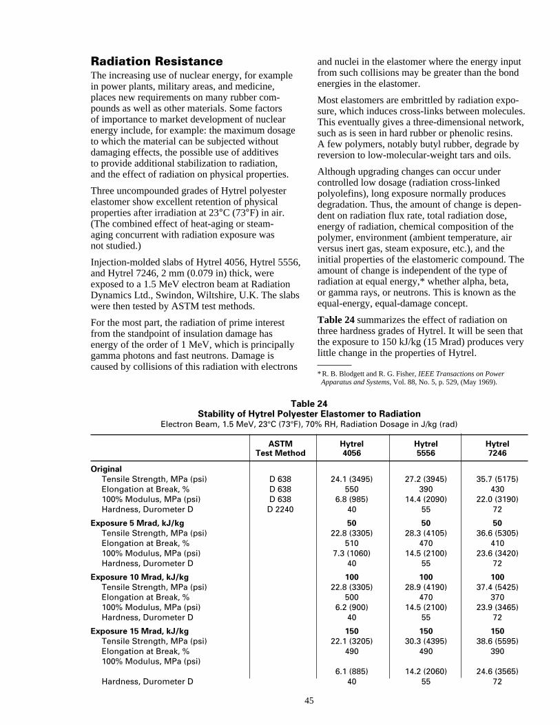
e
s
utd
-es.k,.
n-
e
atry
Radiation ResistanceThe increasing use of nuclear energy, for examplin power plants, military areas, and medicine,places new requirements on many rubber com-pounds as well as other materials. Some factorsof importance to market development of nuclearenergy include, for example: the maximum dosagto which the material can be subjected withoutdamaging effects, the possible use of additivesto provide additional stabilization to radiation,and the effect of radiation on physical properties.
Three uncompounded grades of Hytrel polyesterelastomer show excellent retention of physicalproperties after irradiation at 23°C (73°F) in air.(The combined effect of heat-aging or steam-aging concurrent with radiation exposure wasnot studied.)
Injection-molded slabs of Hytrel 4056, Hytrel 5556and Hytrel 7246, 2 mm (0.079 in) thick, wereexposed to a 1.5 MeV electron beam at RadiationDynamics Ltd., Swindon, Wiltshire, U.K. The slabwere then tested by ASTM test methods.
For the most part, the radiation of prime interestfrom the standpoint of insulation damage hasenergy of the order of 1 MeV, which is principallygamma photons and fast neutrons. Damage iscaused by collisions of this radiation with electron
45
TableStability of Hytrel Polyeste
Electron Beam, 1.5 MeV, 23°C (73°F), 70
ASTMTest Method
OriginalTensile Strength, MPa (psi) D 638Elongation at Break, % D 638100% Modulus, MPa (psi) D 638Hardness, Durometer D D 2240
Exposure 5 Mrad, kJ/kgTensile Strength, MPa (psi)Elongation at Break, %100% Modulus, MPa (psi)Hardness, Durometer D
Exposure 10 Mrad, kJ/kgTensile Strength, MPa (psi)Elongation at Break, %100% Modulus, MPa (psi)Hardness, Durometer D
Exposure 15 Mrad, kJ/kgTensile Strength, MPa (psi)Elongation at Break, %100% Modulus, MPa (psi)
Hardness, Durometer D
e
,
s
and nuclei in the elastomer where the energy inpfrom such collisions may be greater than the bonenergies in the elastomer.
Most elastomers are embrittled by radiation exposure, which induces cross-links between moleculThis eventually gives a three-dimensional networsuch as is seen in hard rubber or phenolic resinsA few polymers, notably butyl rubber, degrade byreversion to low-molecular-weight tars and oils.
Although upgrading changes can occur undercontrolled low dosage (radiation cross-linkedpolyolefins), long exposure normally producesdegradation. Thus, the amount of change is depedent on radiation flux rate, total radiation dose,energy of radiation, chemical composition of thepolymer, environment (ambient temperature, airversus inert gas, steam exposure, etc.), and theinitial properties of the elastomeric compound. Thamount of change is independent of the type ofradiation at equal energy,* whether alpha, beta,or gamma rays, or neutrons. This is known as theequal-energy, equal-damage concept.
Table 24 summarizes the effect of radiation onthree hardness grades of Hytrel. It will be seen ththe exposure to 150 kJ/kg (15 Mrad) produces velittle change in the properties of Hytrel.
*R. B. Blodgett and R. G. Fisher, IEEE Transactions on PowerApparatus and Systems, Vol. 88, No. 5, p. 529, (May 1969).
24r Elastomer to Radiation% RH, Radiation Dosage in J/kg (rad)
Hytrel Hytrel Hytrel4056 5556 7246
24.1 (3495) 27.2 (3945) 35.7 (5175)550 390 430
6.8 (985) 14.4 (2090) 22.0 (3190)40 55 72
50 50 5022.8 (3305) 28.3 (4105) 36.6 (5305)
510 470 4107.3 (1060) 14.5 (2100) 23.6 (3420)
40 55 72
100 100 10022.8 (3305) 28.9 (4190) 37.4 (5425)
500 470 3706.2 (900) 14.5 (2100) 23.9 (3465)
40 55 72
150 150 15022.1 (3205) 30.3 (4395) 38.6 (5595)
490 490 390
6.1 (885) 14.2 (2060) 24.6 (3565)40 55 72

o
ied as
Resistance to Mildew andFungusThe resistance of a high-performance 40 duromeD hardness grade of Hytrel polyester elastomer tcertain fungi was determined according to ASTMD 1924-63, using the following cultures.
Culture Observed GrowthAspergillus niger NoneAspergillus flavus NoneAspergillus versicolor Very slight, sparsePenicillin funiculosum NonePullularia pullulans None
4
t
ter
Trichloderma sp. None
Samples of the same grade Hytrel were also burfor one year in Panama. Instron test results werefollows.
OriginalDurometer D Hardness 40Tensile Strength, MPa (psi) 25.5 (3700)Elongation at Break, % 450100% Modulus, MPa (psi) 6.9 (1000)300% Modulus, MPa (psi) 8.8 (1275)
Retention after 1 yr Soil Burial in Panama, %Durometer Hardness 98Tensile Strength 82Elongation at Break 82100% Modulus 99300% Modulus 98
The harder grades of Hytrel were not includedin these tests but should show at least equivalen
6

47
Chapter 7
Agency Approvals
Contents
Food and Drug AdministrationNational Science FoundationUnderwriters Laboratories Recognition

n
e
t,etyal
ld
ge
Agency Approvals
resistance, because they are based on the sameraw materials.
Food and Drug AdministrationThe following grades of Hytrel meet Food andDrug Administration (FDA) guidelines for foodcontact use in the U.S. The stabilizer system usedin these grades is in full compliance with FDAregulations.
The following grades of Hytrel may be used incompliance with the Federal Food, Drug, andCosmetic Act, specifically:
Contact with Dry Repeated Use ContactBulk Food with Fatty or Wet Food
(Regulation (RegulationHytrel 21CFR177.1590) 21CFR177.2600)
4069 √ √4556 √ √5526 √ √5556 √ √6356 √ √7246 √ √8238 √ √3078 √ √4056 √HTR6108 √
Essentially all High Performance grades meetFDA guideline for bulk dry food contact use inthe U.S. If the customer uses compliant additivesand follows the temperature and alcohol contentrequirements of the application, then the applica-tion should be in compliance with the repeateduse regulation.
This information, based upon our experience, is offered without charas part of our service to customers. It is intended for use by personshaving technical skill, at their own discretion and risk. We do not
4
guarantee favorable results, and we assume no liability in connectiowith its use. The information is not intended as a license to operateunder, or a recommendation to infringe, any patent of DuPont orothers.
None of the High Productivity grades have FDAapproval in the U.S.—not because of the presencof toxic extractable material, but rather becausethey have not been tested due to the enormousexpense of extraction and animal feeding testsrequired by the FDA.
National Science FoundationThe following grades of Hytrel have NationalScience Foundation (NSF) approval: 4056, 5526,5556, and 7246, under standards 14 and 61.
Underwriters LaboratoriesRecognitionUnderwriters Laboratories (UL) is an independennonprofit testing laboratory that evaluates the safof equipment offered for sale. Many state and locgovernments require that electrical appliances inthe U.S. carry UL approval before they can be sowithin their jurisdiction.
8
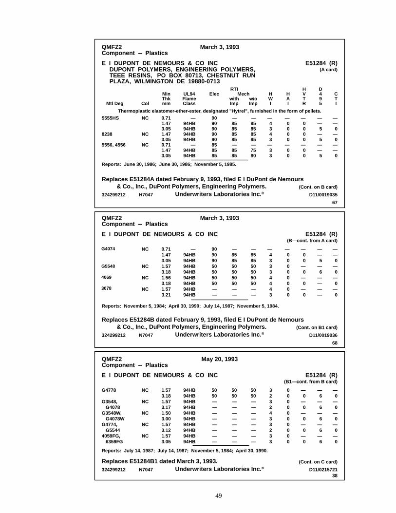
49
QMFZ2Component -- Plastics
May 20, 1993
E I DUPONT DE NEMOURS & CO INC E51284 (R)(B1—cont. from B card)
—0
—0
—0
—0
—0
—6
—6
—6
—6
—6
—0
—0
—0
—0
—0
0000000000
3232433233
5050————————
5050————————
5050————————
94HB94HB94HB94HB94HB94HB94HB94HB94HB94HB
1.573.181.573.171.503.001.573.121.573.05
NC
NC
NC
NC
NC
G4778 G3548, G4078G3548W, G4078WG4774, G55444059FG, 6359FG
Replaces E51284B1 dated March 3, 1993.Underwriters Laboratories Inc. ®
Reports: July 14, 1987; July 14, 1987; November 5, 1984; April 30, 1990.
324299212 N7047 D11/0215721
(Cont. on C card)
38
QMFZ2Component -- Plastics
March 3, 1993
E I DUPONT DE NEMOURS & CO INC E51284 (R)(B—cont. from A card)
——0
—0
—0
—0
——5
—6
————
—00
—0
—0
—0
—00000000
—43334443
—858550505050——
—858550505050——
90909050505050——
—94HB94HB94HB94HB94HB94HB94HB94HB
0.711.473.051.573.181.563.181.573.21
NC
NC
NC
NC
G-4074 G-5548 4069 8122
Replaces E51284B dated February 9, 1993, filed E I DuPont de Nemours & Co., Inc., DuPont Polymers, Engineering Polymers.
Underwriters Laboratories Inc. ®
Reports: November 5, 1984; April 30, 1990; July 14, 1987; November 5, 1984.
324299212 N7047 D11/0019036
(Cont. on B1 card)
68
Mech
QMFZ2Component -- Plastics
March 3, 1993
E I DUPONT DE NEMOURS & CO INCDUPONT POLYMERS, ENGINEERING POLYMERS,TEEE RESINS, PO BOX 80713, CHESTNUT RUNPLAZA, WILMINGTON DE 19880-0713
E51284 (R)(A card)
——0
—0
——0
——5
—5
——5
—0000
—00
—0000
—00
—4343
—33
—85858585—7580
—85858585—8585
9090909090858585
—94HB94HB94HB94HB
—94HB94HB
0.711.473.051.473.050.711.473.05
NC
NC
NC
5555HS 8238 5556, 4556
Thermoplastic elastomer-ether-ester, designated "Hytrel", furnished in the form of pellets.
CTI
D495
HVTR
HAI
HWI
w/oImp
withImp
ElecUL94FlameClass
MinThkmmColMtl Deg
RTI
Replaces E51284A dated February 9, 1993, filed E I DuPont de Nemours & Co., Inc., DuPont Polymers, Engineering Polymers.
Underwriters Laboratories Inc. ®
Reports: June 30, 1986; June 30, 1986; November 5, 1985.
324299212 H7047 D11/0019035
(Cont. on B card)
67
G4074
G5548
4069
3078
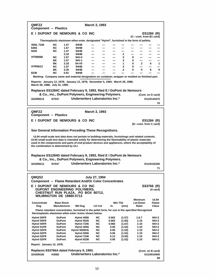
50
QMFZ2Component -- Plastics
March 3, 1993
E I DUPONT DE NEMOURS & CO INC E51284 (R)(D—cont. from C card)
Replaces E51284D dated February 9, 1993, filed E I DuPont de Nemours & Co., Inc., DuPont Polymers, Engineering Polymers.
Underwriters Laboratories Inc. ®
UL94 small-scale test data does not pertain to building materials, furnishings and related contents.UL94 small-scale test data is intended solely for determining the flammability of plastic materialsused in the components and parts of end-product devices and appliances, where the acceptability ofthe combination is determined by ULI.
324299212 N7047 D11/0152205
71
See General Information Preceding These Recognitions.
QMFZ2Component -- Plastics
March 3, 1993
E I DUPONT DE NEMOURS & CO INC E51284 (R)(C—cont. from B1 card)
——————1
—0
—
——————6
—6
—
——————2
—0
—
————00000
—
———233142
—
——————————
——————————
——————————
94HB94HB94HB94HB94V-094V-194-V094HB94HB94HB
1.471.571.473.181.571.573.181.573.300.91
NCNCNC
NCBKBKNCBKNC
4056, 724663565526 HTR-8068 HTR-5612
8238
Replaces E51284C dated February 9, 1993, filed E I DuPont de Nemours & Co., Inc., DuPont Polymers, Engineering Polymers.
Underwriters Laboratories Inc. ®
Reports: January 12, 1978; January 12, 1978; November 5, 1984; March 28, 1988; March 28, 1988; July 31, 1990.
324299212 N7047 D11/0144472
(Cont. on D card)
70
Thermoplastic elastomer-ether-ester, designated "Hytrel", furnished in the form of pellets.
Marking: Company name and material designation on container, wrapper or molded on finished part.
Concentrate Dsg
QMQS2Component -- Flame Retardant And/Or Color Concentrates
July 27, 1994
E I DUPONT DE NEMOURS & CO INC E63766 (R)(A card)
Report: January 12, 1978.
DUPONT ENGINEERING POLYMERS,CHESTNUT RUN PLAZA, PO BOX 80713, WILMINGTON DE 19880-0713
Hytrel 50FRHytrel 50FRHytrel 50FRHytrel 51FRHytrel 52FRHytrel 52FRHytrel 52FRHytrel 52FR
Flame retardant concentrates, furnished in the pellet form, for use in the specified Recognizedthermoplastic elastomer-ether-ester resins shown below.
DuPontDuPontDuPontDuPontDuPontDuPontDuPontDuPont
Hytrel 4056Hytrel 5526Hytrel 7246Hytrel 4056
Hytrel 5555HSHytrel 5556Hytrel 7246Hytrel 8238
NCNCNCNCNCNCNCNC
0.0620.0630.066
0.060.060.060.120.06
(1.57)(1.60)(1.67)(1.52)(1.52)(1.52)(3.00)(1.52)
1:6.71:101:101:101:101:101:101:10
94V-294V-294V-294V-294V-294V-294V-294V-2
Base ResinManufacturer Mtl Dsg LD Col In. (mm)
MinimumLet-Down
Ratio
UL94FlameClass
Min Thk
Underwriters Laboratories Inc. ®324299182 H3082 D11/0010940(Cont. on B card)
58
Replaces E63766A dated February 9, 1993.
HTR8068
HTR5612

51
Chapter 8
Applications
Contents
General ConsiderationsDesign MethodsUndercutsRealistic TolerancesAssemblyAssembly TechniquesOvermoldingBearings and SealsGearsBoots and BellowsRolling DiaphragmsBeltsCoiled Tubing and CablesReinforced Hose
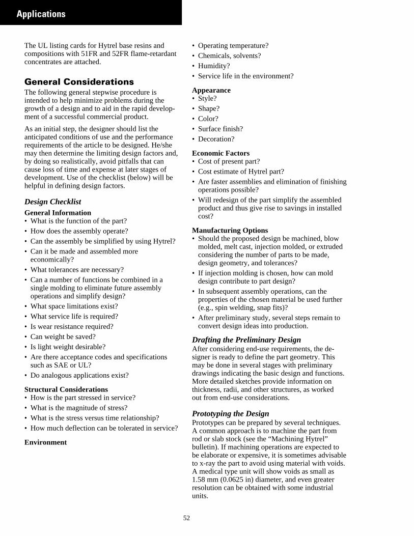
d
Applications
r
.
.
The UL listing cards for Hytrel base resins andcompositions with 51FR and 52FR flame-retardanconcentrates are attached.
General ConsiderationsThe following general stepwise procedure isintended to help minimize problems during thegrowth of a design and to aid in the rapid development of a successful commercial product.
As an initial step, the designer should list theanticipated conditions of use and the performancerequirements of the article to be designed. He/shemay then determine the limiting design factors anby doing so realistically, avoid pitfalls that cancause loss of time and expense at later stages ofdevelopment. Use of the checklist (below) will behelpful in defining design factors.
Design ChecklistGeneral Information• What is the function of the part?• How does the assembly operate?• Can the assembly be simplified by using Hytrel?• Can it be made and assembled more
economically?• What tolerances are necessary?• Can a number of functions be combined in a
single molding to eliminate future assemblyoperations and simplify design?
• What space limitations exist?• What service life is required?• Is wear resistance required?• Can weight be saved?• Is light weight desirable?• Are there acceptance codes and specifications
such as SAE or UL?• Do analogous applications exist?
Structural Considerations• How is the part stressed in service?• What is the magnitude of stress?• What is the stress versus time relationship?• How much deflection can be tolerated in service
Environment
5
le.
t
-
,
?
• Operating temperature?• Chemicals, solvents?• Humidity?• Service life in the environment?
Appearance• Style?• Shape?• Color?• Surface finish?• Decoration?
Economic Factors• Cost of present part?• Cost estimate of Hytrel part?• Are faster assemblies and elimination of finishing
operations possible?• Will redesign of the part simplify the assembled
product and thus give rise to savings in installedcost?
Manufacturing Options• Should the proposed design be machined, blow
molded, melt cast, injection molded, or extrudedconsidering the number of parts to be made,design geometry, and tolerances?
• If injection molding is chosen, how can molddesign contribute to part design?
• In subsequent assembly operations, can theproperties of the chosen material be used furthe(e.g., spin welding, snap fits)?
• After preliminary study, several steps remain toconvert design ideas into production.
Drafting the Preliminary DesignAfter considering end-use requirements, the de-signer is ready to define the part geometry. Thismay be done in several stages with preliminarydrawings indicating the basic design and functionsMore detailed sketches provide information onthickness, radii, and other structures, as workedout from end-use considerations.
Prototyping the DesignPrototypes can be prepared by several techniquesA common approach is to machine the part fromrod or slab stock (see the “Machining Hytrel”bulletin). If machining operations are expected tobe elaborate or expensive, it is sometimes advisabto x-ray the part to avoid using material with voidsA medical type unit will show voids as small as1.58 mm (0.0625 in) diameter, and even greaterresolution can be obtained with some industrialunits.
2
i
r
e
yn
,
n
h
g
s
e
t
ticw
and
ld
tnd,e,
lt
The melt stability of Hytrel permits production ofprototypes by melt casting, which is a process usan extruder to fill an inexpensive aluminum mold.This method can also be advantageous for shortproduction runs because setup costs are low. Fofurther information, see the “Melt Casting” bulletin
In any large and important development, thepreparation of prototypes, using the fabricationmethod intended for production, can provide addassurance against failure in use. For injection-molded parts, the use of an inexpensive alumi-num, brass, or copper beryllium mold is frequentlconsidered an important step between conceptioand production. In addition, molded prototypesprovide information on gate location and on moldshrinkage.
Additional reasons why the molded prototype ispreferred to the machined prototype are:• Machine marks may result in variable behavior.• Orientation effects in the molded parts resulting
from gate location or knockout pins may influ-ence toughness.
Testing the DesignEvery design should be subjected to some form otesting while in the prototype stage to check theaccuracy of calculations and basic assumptions.• Actual end-use testing of a part in service is the
most meaningful kind of prototype testing. Hereall of the performance requirements are encountered, and a complete assessment of the desigcan be made.
• Simulated service tests are often conducted witprototype parts. The value of this type of testingdepends on how closely the end-use conditionsare duplicated. For example, an automobileengine part might be given temperature, vibra-tion, and hydrocarbon resistance tests; a luggafixture could be subjected to impact and abrasiotests; and a radio component might undergo tefor electrical and thermal insulation.
• Standard test procedures, such as those develoby the ASTM, generally are useful as a designguide but normally cannot be drawn upon topredict accurately the performance of a part inservice. Again, representative field testing maybe indispensable.
53
t
le
ng
.
d
f
-
ents
ped
Long-term performance must sometimes be pre-dicted on the basis of “severe” short-term tests.This form of accelerated testing is widely usedbut should be used with discretion, because therelationship between the long-term service and thaccelerated condition is not always known.
Taking a Second LookA second look at the design helps to answer thebasic question: “Will the product do the right job athe right price?” Even at this point, most productscan be improved by redesigning for productioneconomies or for important functional and aesthechanges. Weak sections can be strengthened, nefeatures added, and colors changed. Substantialvital changes in design may necessitate completeevaluation of the new design. If the design has heup under this close scrutiny, specifications thendetails of production can be established.
Writing Meaningful SpecificationsThe purpose of a specification is to eliminate anyvariations in the product that would prevent it fromsatisfying the functional, aesthetic, or economicrequirements. The specification is a complete setof written requirements that the part must meet. Ishould include such things as: generic name, braand grade of material, finish, parting line locationflash, gating, locations where voids are intolerablwarpage, color, and decorating and performancespecifications.
Setting Up ProductionOnce the specifications have been carefully andrealistically written, molds can be designed andbuilt to fit the processing equipment. Tool designfor injection molding should be left to a specialistor able consultant in the field, because inefficientand unnecessarily expensive production can resufrom improper design of tools or selection ofmanufacturing equipment.
Controlling the QualityIt is good inspection practice to schedule regularchecking of production parts against a givenstandard. An inspection checklist should includeall the items that are pertinent to satisfactoryperformance of the part in actual service at itsassembled cost. The end user and molder shouldjointly establish the quality control procedures thawill facilitate production of parts within specifica-tions. (See DuPont Engineering Polymers, ModuI, for general design principles.)
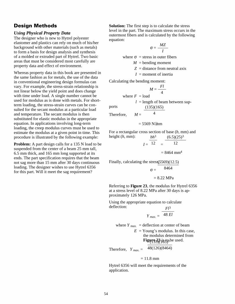
Design MethodsUsing Physical Property DataThe designer who is new to Hytrel polyesterelastomer and plastics can rely on much of his/hebackground with other materials (such as metals)to form a basis for design analysis and synthesisof a molded or extruded part of Hytrel. Two basicareas that must be considered most carefully areproperty data and effect of environment.
Whereas property data in this book are presentedthe same fashion as for metals, the use of the datin conventional engineering design formulas canvary. For example, the stress-strain relationship isnot linear below the yield point and does changewith time under load. A single number cannot beused for modulus as is done with metals. For shoterm loading, the stress-strain curves can be con-sulted for the secant modulus at a particular loadand temperature. The secant modulus is thensubstituted for elastic modulus in the appropriateequation. In applications involving long-termloading, the creep modulus curves must be used estimate the modulus at a given point in time. Thiprocedure is illustrated by the following example:
Problem: A part design calls for a 135 N load to bsuspended from the center of a beam 25 mm tall,6.5 mm thick, and 165 mm long supported at itsends. The part specification requires that the beanot sag more than 15 mm after 30 days continuouloading. The designer wishes to use Hytrel 6356for this part. Will it meet the sag requirement?
5
r
ina
rt-
tos
e
ms
Solution: The first step is to calculate the stresslevel in the part. The maximum stress occurs in theoutermost fibers and is calculated by the followingequation:
σ =
where σ = stress in outer fibersM = bending momentZ = distance from neutral axisI = moment of inertia
Calculating the bending moment:
M =
where F = loadl = length of beam between sup-
ports
Therefore, M =
= 5569 N⋅mm
For a rectangular cross section of base (b, mm) andheight (h, mm):
I = =
= 8464 mm4
Finally, calculating the stress,
σ =
= 8.22 MPa
Referring to Figure 23, the modulus for Hytrel 6356at a stress level of 8.22 MPa after 30 days is ap-proximately 126 MPa.
Using the appropriate equation to calculatedeflection:
Y max. =
where Y max. = deflection at center of beamE = Young’s modulus. In this case,
the modulus determined fromFigure 23 is to be used.
Therefore, Y max. =
= 11.8 mm
Hytrel 6356 will meet the requirements of theapplication.
MZ
I
Fl
4
(135)(165)
4
bh3
12
(6.5)(25)3
12
(5569)(12.5)
8464
Fl3
48 El
(135)(165)3
48(126)(8464)
4
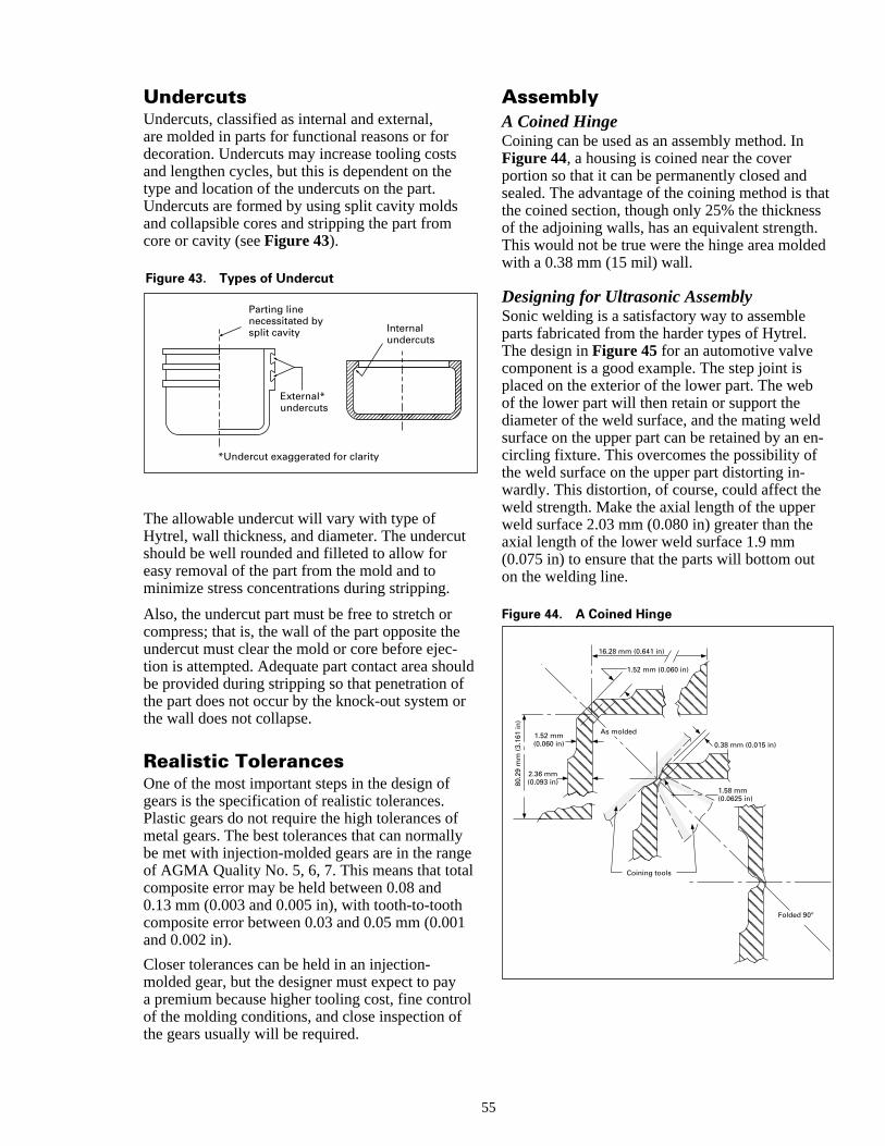
ats
d
n-
f
fl
ol
External* undercuts
Parting line necessitated by split cavity Internal
undercuts
*Undercut exaggerated for clarity
Figure 43. Types of Undercut
UndercutsUndercuts, classified as internal and external,are molded in parts for functional reasons or fordecoration. Undercuts may increase tooling costsand lengthen cycles, but this is dependent on thetype and location of the undercuts on the part.Undercuts are formed by using split cavity moldsand collapsible cores and stripping the part fromcore or cavity (see Figure 43).
The allowable undercut will vary with type ofHytrel, wall thickness, and diameter. The undercushould be well rounded and filleted to allow foreasy removal of the part from the mold and tominimize stress concentrations during stripping.
Also, the undercut part must be free to stretch orcompress; that is, the wall of the part opposite theundercut must clear the mold or core before ejec-tion is attempted. Adequate part contact area shobe provided during stripping so that penetration othe part does not occur by the knock-out system othe wall does not collapse.
Realistic TolerancesOne of the most important steps in the design ofgears is the specification of realistic tolerances.Plastic gears do not require the high tolerances ometal gears. The best tolerances that can normalbe met with injection-molded gears are in the rangof AGMA Quality No. 5, 6, 7. This means that totacomposite error may be held between 0.08 and0.13 mm (0.003 and 0.005 in), with tooth-to-toothcomposite error between 0.03 and 0.05 mm (0.00and 0.002 in).
Closer tolerances can be held in an injection-molded gear, but the designer must expect to paya premium because higher tooling cost, fine controf the molding conditions, and close inspection ofthe gears usually will be required.
55
AssemblyA Coined HingeCoining can be used as an assembly method. InFigure 44, a housing is coined near the coverportion so that it can be permanently closed andsealed. The advantage of the coining method is ththe coined section, though only 25% the thicknesof the adjoining walls, has an equivalent strength.This would not be true were the hinge area moldewith a 0.38 mm (15 mil) wall.
Designing for Ultrasonic AssemblySonic welding is a satisfactory way to assembleparts fabricated from the harder types of Hytrel.The design in Figure 45 for an automotive valvecomponent is a good example. The step joint isplaced on the exterior of the lower part. The webof the lower part will then retain or support thediameter of the weld surface, and the mating weldsurface on the upper part can be retained by an ecircling fixture. This overcomes the possibility ofthe weld surface on the upper part distorting in-wardly. This distortion, of course, could affect theweld strength. Make the axial length of the upperweld surface 2.03 mm (0.080 in) greater than theaxial length of the lower weld surface 1.9 mm(0.075 in) to ensure that the parts will bottom outon the welding line.
Figure 44. A Coined Hinge
0.38 mm (0.015 in)
Folded 90°
As molded
Coining tools
1.52 mm (0.060 in)
16.28 mm (0.641 in)
80.2
9 m
m (
3.16
1 in
)
1.52 mm (0.060 in)
2.36 mm (0.093 in)
1.58 mm (0.0625 in)
t
uld
r
yel
1
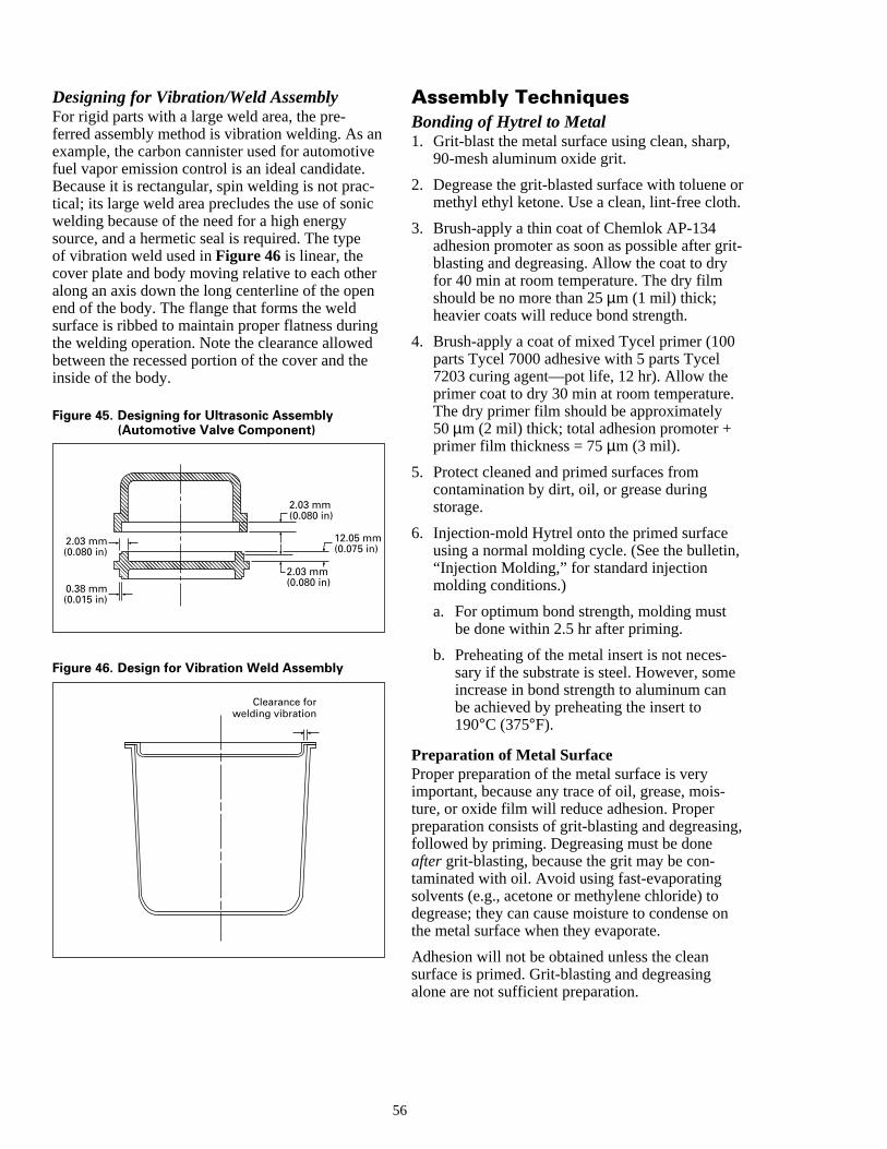
n
e
,
or.
rit-
,
e
g,
n
Designing for Vibration/Weld AssemblyFor rigid parts with a large weld area, the pre-ferred assembly method is vibration welding. As aexample, the carbon cannister used for automotivfuel vapor emission control is an ideal candidate.Because it is rectangular, spin welding is not practical; its large weld area precludes the use of soniwelding because of the need for a high energysource, and a hermetic seal is required. The typeof vibration weld used in Figure 46 is linear, thecover plate and body moving relative to each othealong an axis down the long centerline of the opeend of the body. The flange that forms the weldsurface is ribbed to maintain proper flatness durinthe welding operation. Note the clearance allowedbetween the recessed portion of the cover and thinside of the body.
Figure 45. Designing for Ultrasonic Assembly(Automotive Valve Component)
Clearance for welding vibration
2.03 mm (0.080 in)
2.03 mm (0.080 in)
2.03 mm (0.080 in)
0.38 mm (0.015 in)
12.05 mm (0.075 in)
Figure 46. Design for Vibration Weld Assembly
5
ne
-c
r
g
Assembly TechniquesBonding of Hytrel to Metal1. Grit-blast the metal surface using clean, sharp
90-mesh aluminum oxide grit.
2. Degrease the grit-blasted surface with toluenemethyl ethyl ketone. Use a clean, lint-free cloth
3. Brush-apply a thin coat of Chemlok AP-134adhesion promoter as soon as possible after gblasting and degreasing. Allow the coat to dryfor 40 min at room temperature. The dry filmshould be no more than 25 µm (1 mil) thick;heavier coats will reduce bond strength.
4. Brush-apply a coat of mixed Tycel primer (100parts Tycel 7000 adhesive with 5 parts Tycel7203 curing agent—pot life, 12 hr). Allow theprimer coat to dry 30 min at room temperature.The dry primer film should be approximately50µm (2 mil) thick; total adhesion promoter +primer film thickness = 75 µm (3 mil).
5. Protect cleaned and primed surfaces fromcontamination by dirt, oil, or grease duringstorage.
6. Injection-mold Hytrel onto the primed surfaceusing a normal molding cycle. (See the bulletin“Injection Molding,” for standard injectionmolding conditions.)
a. For optimum bond strength, molding mustbe done within 2.5 hr after priming.
b. Preheating of the metal insert is not neces-sary if the substrate is steel. However, somincrease in bond strength to aluminum canbe achieved by preheating the insert to190°C (375°F).
Preparation of Metal SurfaceProper preparation of the metal surface is veryimportant, because any trace of oil, grease, mois-ture, or oxide film will reduce adhesion. Properpreparation consists of grit-blasting and degreasinfollowed by priming. Degreasing must be doneafter grit-blasting, because the grit may be con-taminated with oil. Avoid using fast-evaporatingsolvents (e.g., acetone or methylene chloride) todegrease; they can cause moisture to condense othe metal surface when they evaporate.
Adhesion will not be obtained unless the cleansurface is primed. Grit-blasting and degreasingalone are not sufficient preparation.
6
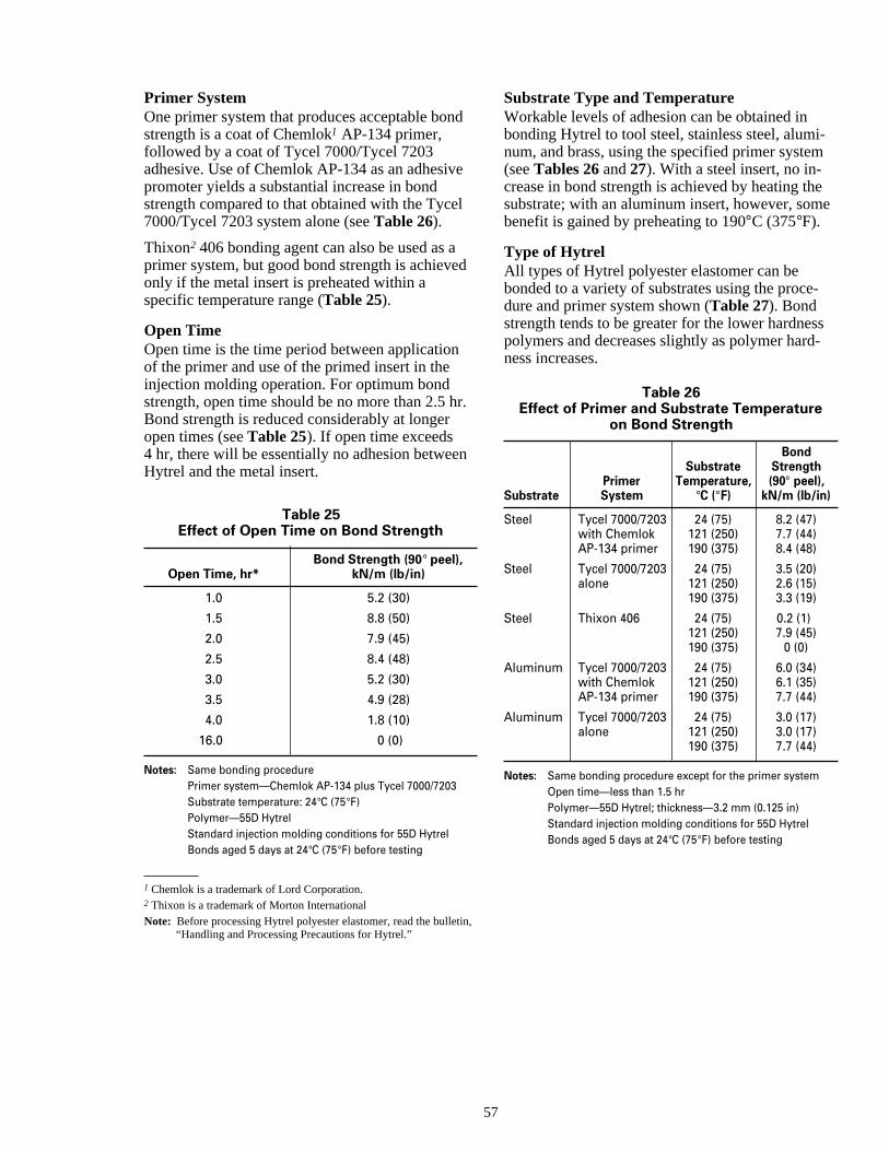
e
l
n
n,
e
s
Primer SystemOne primer system that produces acceptable bonstrength is a coat of Chemlok1 AP-134 primer,followed by a coat of Tycel 7000/Tycel 7203adhesive. Use of Chemlok AP-134 as an adhesivpromoter yields a substantial increase in bondstrength compared to that obtained with the Tyce7000/Tycel 7203 system alone (see Table 26).
Thixon2 406 bonding agent can also be used as aprimer system, but good bond strength is achieveonly if the metal insert is preheated within aspecific temperature range (Table 25).
Open TimeOpen time is the time period between applicationof the primer and use of the primed insert in theinjection molding operation. For optimum bondstrength, open time should be no more than 2.5 hBond strength is reduced considerably at longeropen times (see Table 25). If open time exceeds4 hr, there will be essentially no adhesion betweeHytrel and the metal insert.
Table 25Effect of Open Time on Bond Strength
Bond Strength (90° peel),Open Time, hr* kN/m (lb/in)
1.0 5.2 (30)
1.5 8.8 (50)
2.0 7.9 (45)
2.5 8.4 (48)
3.0 5.2 (30)
3.5 4.9 (28)
4.0 1.8 (10)
16.0 0 (0)
Notes: Same bonding procedurePrimer system—Chemlok AP-134 plus Tycel 7000/7203Substrate temperature: 24°C (75°F)Polymer—55D HytrelStandard injection molding conditions for 55D HytrelBonds aged 5 days at 24°C (75°F) before testing
1 Chemlok is a trademark of Lord Corporation.2 Thixon is a trademark of Morton InternationalNote: Before processing Hytrel polyester elastomer, read the bulleti
“Handling and Processing Precautions for Hytrel.”
57
d
d
r.
Substrate Type and TemperatureWorkable levels of adhesion can be obtained inbonding Hytrel to tool steel, stainless steel, alumi-num, and brass, using the specified primer system(see Tables 26 and 27). With a steel insert, no in-crease in bond strength is achieved by heating thesubstrate; with an aluminum insert, however, sombenefit is gained by preheating to 190°C (375°F).
Type of HytrelAll types of Hytrel polyester elastomer can bebonded to a variety of substrates using the proce-dure and primer system shown (Table 27). Bondstrength tends to be greater for the lower hardnespolymers and decreases slightly as polymer hard-ness increases.
Table 26Effect of Primer and Substrate Temperature
on Bond Strength
BondSubstrate Strength
Primer Temperature, (90° peel),Substrate System °C (°F) kN/m (lb/in)
Steel Tycel 7000/7203 24 (75) 8.2 (47)with Chemlok 121 (250) 7.7 (44)AP-134 primer 190 (375) 8.4 (48)
Steel Tycel 7000/7203 24 (75) 3.5 (20)alone 121 (250) 2.6 (15)
190 (375) 3.3 (19)
Steel Thixon 406 24 (75) 0.2 (1)121 (250) 7.9 (45)190 (375) 0 (0)
Aluminum Tycel 7000/7203 24 (75) 6.0 (34)with Chemlok 121 (250) 6.1 (35)AP-134 primer 190 (375) 7.7 (44)
Aluminum Tycel 7000/7203 24 (75) 3.0 (17)alone 121 (250) 3.0 (17)
190 (375) 7.7 (44)
Notes: Same bonding procedure except for the primer systemOpen time—less than 1.5 hrPolymer—55D Hytrel; thickness—3.2 mm (0.125 in)Standard injection molding conditions for 55D HytrelBonds aged 5 days at 24°C (75°F) before testing
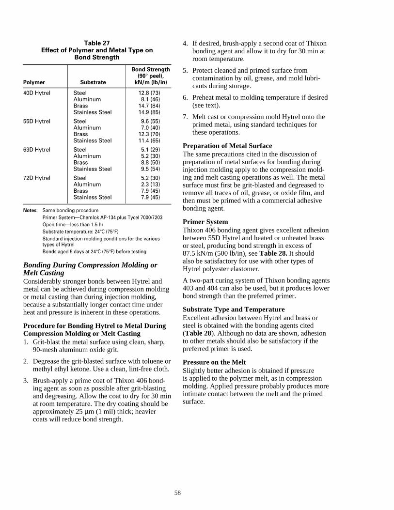
n
.
,
gine
n
d
lo
ons
tswer
re
Table 27Effect of Polymer and Metal Type on
Bond Strength
Bond Strength(90° peel),
Polymer Substrate kN/m (lb/in)
40D Hytrel Steel 12.8 (73)Aluminum 8.1 (46)Brass 14.7 (84)Stainless Steel 14.9 (85)
55D Hytrel Steel 9.6 (55)Aluminum 7.0 (40)Brass 12.3 (70)Stainless Steel 11.4 (65)
63D Hytrel Steel 5.1 (29)Aluminum 5.2 (30)Brass 8.8 (50)Stainless Steel 9.5 (54)
72D Hytrel Steel 5.2 (30)Aluminum 2.3 (13)Brass 7.9 (45)Stainless Steel 7.9 (45)
Notes: Same bonding procedurePrimer System—Chemlok AP-134 plus Tycel 7000/7203Open time—less than 1.5 hrSubstrate temperature: 24°C (75°F)Standard injection molding conditions for the varioustypes of HytrelBonds aged 5 days at 24°C (75°F) before testing
Bonding During Compression Molding orMelt CastingConsiderably stronger bonds between Hytrel andmetal can be achieved during compression moldior metal casting than during injection molding,because a substantially longer contact time underheat and pressure is inherent in these operations
Procedure for Bonding Hytrel to Metal DuringCompression Molding or Melt Casting1. Grit-blast the metal surface using clean, sharp
90-mesh aluminum oxide grit.
2. Degrease the grit-blasted surface with toluenemethyl ethyl ketone. Use a clean, lint-free cloth
3. Brush-apply a prime coat of Thixon 406 bond-ing agent as soon as possible after grit-blastinand degreasing. Allow the coat to dry for 30 mat room temperature. The dry coating should bapproximately 25 µm (1 mil) thick; heaviercoats will reduce bond strength.
58
g
or.
4. If desired, brush-apply a second coat of Thixobonding agent and allow it to dry for 30 min atroom temperature.
5. Protect cleaned and primed surface fromcontamination by oil, grease, and mold lubri-cants during storage.
6. Preheat metal to molding temperature if desire(see text).
7. Melt cast or compression mold Hytrel onto theprimed metal, using standard techniques forthese operations.
Preparation of Metal SurfaceThe same precautions cited in the discussion ofpreparation of metal surfaces for bonding duringinjection molding apply to the compression mold-ing and melt casting operations as well. The metasurface must first be grit-blasted and degreased tremove all traces of oil, grease, or oxide film, andthen must be primed with a commercial adhesivebonding agent.
Primer SystemThixon 406 bonding agent gives excellent adhesibetween 55D Hytrel and heated or unheated brasor steel, producing bond strength in excess of87.5 kN/m (500 lb/in), see Table 28. It shouldalso be satisfactory for use with other types ofHytrel polyester elastomer.
A two-part curing system of Thixon bonding agen403 and 404 can also be used, but it produces lobond strength than the preferred primer.
Substrate Type and TemperatureExcellent adhesion between Hytrel and brass orsteel is obtained with the bonding agents cited(Table 28). Although no data are shown, adhesionto other metals should also be satisfactory if thepreferred primer is used.
Pressure on the MeltSlightly better adhesion is obtained if pressureis applied to the polymer melt, as in compressionmolding. Applied pressure probably produces mointimate contact between the melt and the primedsurface.
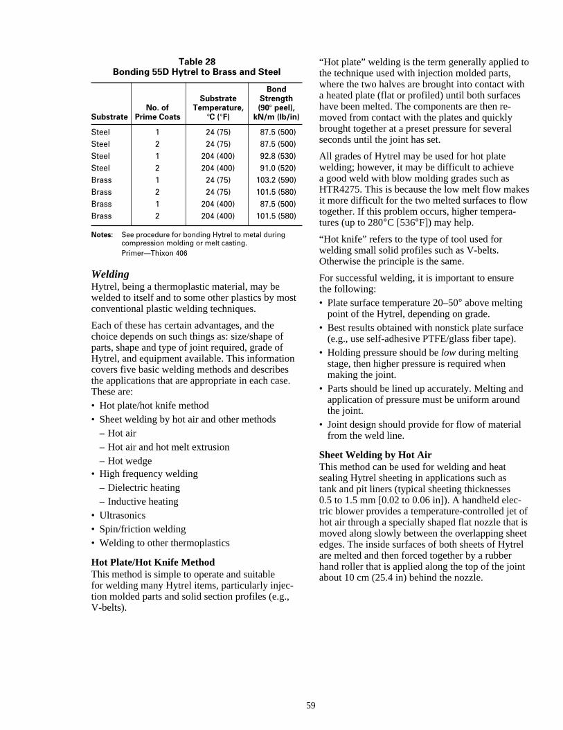
o
h
es
e
d
of isetel
t
Table 28Bonding 55D Hytrel to Brass and Steel
BondSubstrate Strength
No. of Temperature, (90° peel),Substrate Prime Coats °C (°F) kN/m (lb/in)
Steel 1 24 (75) 87.5 (500)Steel 2 24 (75) 87.5 (500)Steel 1 204 (400) 92.8 (530)Steel 2 204 (400) 91.0 (520)Brass 1 24 (75) 103.2 (590)Brass 2 24 (75) 101.5 (580)Brass 1 204 (400) 87.5 (500)Brass 2 204 (400) 101.5 (580)
Notes: See procedure for bonding Hytrel to metal duringcompression molding or melt casting.Primer—Thixon 406
WeldingHytrel, being a thermoplastic material, may bewelded to itself and to some other plastics by mosconventional plastic welding techniques.
Each of these has certain advantages, and thechoice depends on such things as: size/shape ofparts, shape and type of joint required, grade ofHytrel, and equipment available. This informationcovers five basic welding methods and describesthe applications that are appropriate in each caseThese are:• Hot plate/hot knife method• Sheet welding by hot air and other methods
– Hot air– Hot air and hot melt extrusion– Hot wedge
• High frequency welding– Dielectric heating– Inductive heating
• Ultrasonics• Spin/friction welding• Welding to other thermoplastics
Hot Plate/Hot Knife MethodThis method is simple to operate and suitablefor welding many Hytrel items, particularly injec-tion molded parts and solid section profiles (e.g.,V-belts).
59
t
.
“Hot plate” welding is the term generally applied tthe technique used with injection molded parts,where the two halves are brought into contact wita heated plate (flat or profiled) until both surfaceshave been melted. The components are then re-moved from contact with the plates and quicklybrought together at a preset pressure for severalseconds until the joint has set.
All grades of Hytrel may be used for hot platewelding; however, it may be difficult to achievea good weld with blow molding grades such asHTR4275. This is because the low melt flow makit more difficult for the two melted surfaces to flowtogether. If this problem occurs, higher tempera-tures (up to 280°C [536°F]) may help.
“Hot knife” refers to the type of tool used forwelding small solid profiles such as V-belts.Otherwise the principle is the same.
For successful welding, it is important to ensurethe following:• Plate surface temperature 20–50° above melting
point of the Hytrel, depending on grade.• Best results obtained with nonstick plate surfac
(e.g., use self-adhesive PTFE/glass fiber tape).• Holding pressure should be low during melting
stage, then higher pressure is required whenmaking the joint.
• Parts should be lined up accurately. Melting anapplication of pressure must be uniform aroundthe joint.
• Joint design should provide for flow of materialfrom the weld line.
Sheet Welding by Hot AirThis method can be used for welding and heatsealing Hytrel sheeting in applications such astank and pit liners (typical sheeting thicknesses0.5 to 1.5 mm [0.02 to 0.06 in]). A handheld elec-tric blower provides a temperature-controlled jet hot air through a specially shaped flat nozzle thatmoved along slowly between the overlapping sheedges. The inside surfaces of both sheets of Hytrare melted and then forced together by a rubberhand roller that is applied along the top of the joinabout 10 cm (25.4 in) behind the nozzle.
e
t
.
-
e
c
c
en
es
-
.ed
amis).
ffc.
de.m
AdvantageEquipment is relatively inexpensive and light-weight. It is convenient to use for field (i.e., on-siteweld-ing inside tanks and other places wherefactory prefabrication of all joints is not possible.
Disadvantages• Difficult to achieve consistent, reliable results.
Success depends on the skill of the operator.• Sensitive to temperature changes—insufficient
heat will not melt the surfaces, while too muchheat may cause blow holes, etc.
• Only suitable for certain grades of Hytrel, such a4056, G4075, 5556. Very high or very low meltflow grades (e.g., 5526 and HTR4275), as wellas those with additives such as 10MS, have beefound to be difficult to weld by this method.
Welding with Hot Air Combined with HotMelt ExtrusionA modification of the above method is to applya molten bead of Hytrel to the joint area, com-bined with hot air preheating of the sheet surfacesfollowed by hand roller pressure. Good welds havbeen produced using this equipment with severalgrades of Hytrel sheeting, including those con-taining 10MS.
Hot WedgeThis technique uses a seam welding machine thacontains an electrically heated wedge, which ispassed between the two sheet edges to be joinedThe handheld machine is moved along by twopowered rollers, which also press the sheetingtogether behind the wedge. A device of this typehas been successfully used for factory prefabrication of Hytrel sheeting for tank liners.
High Frequency (HF) WeldingDielectric HeatingThis method can generally only be applied to shewelding (up to 1.5 mm [0.06 in]) but is very suit-able for factory (i.e., prefabrication) welding ofnozzles and similar areas for tank linings. Theprinciple of this method is that the material to bewelded becomes the dielectric between two capator plates (formed by the steel work table and themetal electrode), which are part of a high-frequenAC circuit. The frequency used is allocated by lawand in most cases is 27.12 MHz. When the circuitis energized, heat is generated in the dielectricmaterial; the amount of heat is dependent on:• Frequency used (usually fixed by law and by
machine manufacturers).
60
)
s
n
,
t
i-
y
• Voltage applied—this is the normal means ofcontrolling the power available for heat genera-tion in the weld, after other parameters have beestablished. However, excessive voltage cancause dielectric breakdown of the material,resulting in “burn holes.”
• Electrode area—the bigger the area, the morepower is required from the machine, all otherconditions being equal. The electrode, andhence the weld area, is therefore limited bythe capacity of the machine. For Hytrel, whichhas a lower dielectric loss than other plastics, thoptimum electrode area for a 1.5 kW machine iabout 150 mm × 12 mm (5.9 in × 0.5 in) (i.e.,1800 mm2 [2.95 in2]).
• Thickness of material to be welded—the maxi-mum sheet thickness that can be easily weldedwith a 1.5 kW machine is approximately 1.5 mm(0.06 in).
• Type of material—materials with low dielectricloss factors, such as Hytrel, require higher volt-age or smaller electrodes than other materialssuch as PVC.
• Loss—the loss of heat from the joint by conduction through the metal electrodes. It is advanta-geous (see below) to cover the work table andelectrode with heat-insulating material (whichmay itself act as a dielectric and generate heat)Another technique is to use an electrically-heatelectrode.
• Time—the temperature reached in the weld arewill rise over several seconds until an equilibriuis reached where heat energy being generated equal to heat losses (conduction, radiation, etc.If the power applied by the machine is not suf-ficient, then this equilibrium temperature will bebelow the melting point of the material, and noweld is possible. Provided sufficient power isavailable, the operator then determines whenwelding has occurred (by visual indication ofthe joint area and power meter) and switches othe power. This time varies between 3 and 8 sedepending on the grade of Hytrel, thickness, etc
For successful welding of Hytrel by this method,the following points are also important:• A heated (temperature-controlled) electrode is
best for consistent results, because the powersetting required for a particular material type anthickness depends on the electrode temperaturA heated electrode reduces heat conduction frothe joint and eliminates variability caused by acold electrode, which warms as it is used.
as-
.
d,
elt
nttoust
aryse
tn
i
s
s
,
t
so
d
,
ld
• Heat generation at the joint can be assisted byuse of a thin paper/Mylar® laminate—known as“elephant hide”—on top of the work table. Anadditional layer of varnished cloth under theelephant hide has been used to further increasethe heat. Also, a self-adhesive PTFE tape overelectrode surface can be used for similar reasoalthough this should not be necessary with aheated electrode.
• Where possible, the joint line should fall approxmately midway between the electrode and thework table, i.e., use two sheets of equal thickneThis way the surfaces to be welded are at thepoint where maximum heat is generated.
The 40D and 55D grades have been very succesfully welded by this method. Harder grades ofHytrel sheet up to 1 mm (0.04 in) may be weldedbut longer times may be required.
Inductive (Electromagnetic) WeldingThis technique is based on the principle that heacan be induced in certain materials by alternatingelectromagnetic fields. The most effective result iobtained when a magnetic material is subjected ta high-frequency field produced by an inductiongenerator via water-cooled work coils. Thefrequency is normally determined by legallyestablished values in the range of 4–40 MHz.
For welding applications, the magnetic materialtakes the form of fine metal, graphite, or ferriteparticles that are dispersed in a tape or rod of thematerial to be welded. This tape is then positionein the joint area, and by action of the appliedelectromagnetic field and external pressure, thetape material fuses with the two surfaces to forma welded joint.
This method can be applied to sheeting applica-tions as well as to injection molded or other partsas long as the geometry of the weld line will allowcoils to be placed so as to provide a magnetic fieof sufficient intensity to melt the weld material.
Ultrasonic WeldingUltrasonic energy is transmitted to thermoplasticsin the form of high-frequency mechanical vibra-tions that cause the areas in contact to melt byfrictional heat and to fuse together, producing ahigh-strength joint.
A power supply converts a line voltage of50–60 Hz to an ultrasonic frequency, generally20 kHz. A transducer then converts the 20 kHzelectrical energy to mechanical energy of the samfrequency. The horn (metal tool that contacts thework) transmits the mechanical vibrations of the
61
transducer to the parts being assembled. Hytrel hbeen successfully welded using ultrasonics; however, the rate of welding is slower than for othermethods because the contact area of the horn isrelatively small.
The following considerations are important indetermining the applicability of this method toHytrel.• The more rigid plastics are easier to weld.
Hytrel requires high-power input because ofits flexibility.
• The higher the modulus, coefficient of friction,and thermal conductivity, the easier it is to weld
• The lower the melt temperature, density, andspecific heat, the easier it is to weld.
• Mold release agents and lubricants can reducefrictional heating and must be removed.
• If different grades of Hytrel are being assemblethe melting points of these grades should differby no more than 10–15°C (18–27°F).
Spin/Friction WeldingFriction welding is generally considered to meanrotary or spin welding, where one part is rotatedat high speed against the other while a steadypressure is applied. Frictional heat develops atthe surface, and when a prescribed amount of mis developed, rotation is stopped while pressureis maintained on the joint until the bond hassolidified.
Basic variables of spin welding are rotationalspeed, joint pressure, and spin time. If two differeHytrel grades having differing melting points are be assembled by this process, these variables mbe adjusted such that both polymer surfaces aremelted.
A limitation of the spin welding technique is thedifficulty in using it for very flexible polymersor thin cross sections. Spinning parts of theseflexible materials under pressure will cause dis-tortion of the bonded area.
Welding Hytrel to Other ThermoplasticsA limited amount of work has been done onwelding Hytrel to other thermoplastics, usingthe hot plate method.
It should be noted that in some cases it is necessto use plate temperatures that are higher than thonormally recommended for Hytrel-to-Hytrelwelding. This may cause stringing of the moltenHytrel. It is sometimes necessary to use differentplate contact times and pressures for the twomaterials.
hes,
-
s.
-
,
e
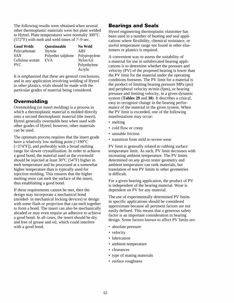
e
n
e
a
e
e
n
h
:
The following results were obtained when severalother thermoplastic materials were hot plate weldto Hytrel. Plate temperatures were normally 300°C(572°F) with melt and weld times of 7–9 sec.
Good Welds Questionable No WeldPolycarbonate Styrene ABSSAN Polyether sulphone PolypropyleneCellulose acetate EVA Nylon 6,6PVC Polyethylene
Acrylic
It is emphasized that these are general conclusioand in any application involving welding of Hytrelto other plastics, trials should be made with theparticular grades of material being considered.
OvermoldingOvermolding (or insert molding) is a process inwhich a thermoplastic material is molded directlyonto a second thermoplastic material (the insert).Hytrel generally overmolds best when used withother grades of Hytrel; however, other materialscan be used.
The optimum process requires that the insert gradhave a relatively low melting point (<190°C[<374°F]), and preferably with a broad meltingrange for slower crystallization. In order to achieva good bond, the material used as the overmoldshould be injected at least 30°C (54°F) higher inmelt temperature and be processed at a somewhhigher temperature than is typically used forinjection molding. This ensures that the highermelting resin can melt the surface of the insert,thus establishing a good bond.
If these requirements cannot be met, then thedesign may incorporate a mechanical bond(molded- in mechanical locking devices) or designwith some flash or projection that can melt togethto form a bond. The insert can also be mechanicaabraded or may even require an adhesive to achia good bond. In all cases, the insert should be dryand free of grease and oil, which could interferewith a good bond.
6
d
s,
e
t
rllyve
Bearings and SealsHytrel engineering thermoplastic elastomer hasbeen used in a number of bearing and seal appli-cations where flexibility, chemical resistance, oruseful temperature range not found in other elas-tomers or plastics is required.
A convenient way to assess the suitability ofa material for use in unlubricated bearing appli-cations is to determine whether the pressure andvelocity (PV) of the proposed bearing is lower thathe PV limit for the material under the operatingconditions foreseen. The PV limit for a material isthe product of limiting bearing pressure MPa (psi)and peripheral velocity m/min (fpm), or bearingpressure and limiting velocity, in a given dynamicsystem (Tables 29 and 30). It describes a critical,easy to recognize change in the bearing perfor-mance of the material in the given system. Whenthe PV limit is exceeded, one of the followingmanifestations may occur:• melting• cold flow or creep• unstable friction• transition from mild to severe wear
PV limit is generally related to rubbing surfacetemperature limit. As such, PV limit decreases witincreasing ambient temperature. The PV limitsdetermined on any given tester geometry andambient temperature can rank materials, buttranslation of test PV limits to other geometriesis difficult.
For a given bearing application, the product of PVis independent of the bearing material. Wear isdependent on PV for any material.
The use of experimentally determined PV limitsin specific applications should be consideredapproximate because all pertinent factors are noteasily defined. This means that a generous safetyfactor is an important consideration in bearingdesign. Some factors known to affect PV limits are
• absolute pressure• velocity• lubrication• ambient temperature• clearances• type of mating materials• surface roughness
2
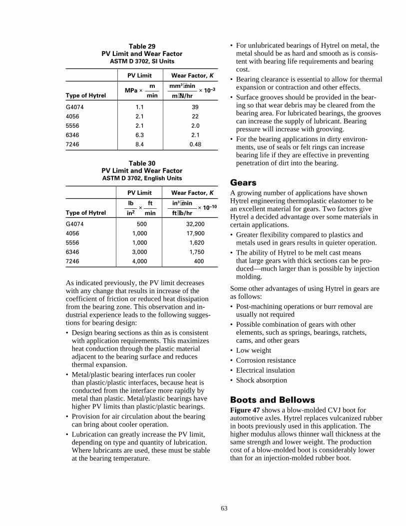
s-
al
-
es
n
.
re
er
e
Table 29PV Limit and Wear Factor
ASTM D 3702, SI Units
PV Limit Wear Factor, K
MPa × × 10–3
G4074 1.1 39
4056 2.1 22
5556 2.1 2.0
6346 6.3 2.1
7246 8.4 0.48
Table 30PV Limit and Wear FactorASTM D 3702, English Units
PV Limit Wear Factor, K
× × 10–10
G4074 500 32,200
4056 1,000 17,900
5556 1,000 1,620
6346 3,000 1,750
7246 4,000 400
As indicated previously, the PV limit decreaseswith any change that results in increase of thecoefficient of friction or reduced heat dissipationfrom the bearing zone. This observation and in-dustrial experience leads to the following sugges-tions for bearing design:• Design bearing sections as thin as is consistent
with application requirements. This maximizesheat conduction through the plastic materialadjacent to the bearing surface and reducesthermal expansion.
• Metal/plastic bearing interfaces run coolerthan plastic/plastic interfaces, because heat isconducted from the interface more rapidly bymetal than plastic. Metal/plastic bearings havehigher PV limits than plastic/plastic bearings.
• Provision for air circulation about the bearingcan bring about cooler operation.
• Lubrication can greatly increase the PV limit,depending on type and quantity of lubrication.Where lubricants are used, these must be stableat the bearing temperature.
m
min
lb
in2
ft
min
in3⋅min
ft⋅lb/hr
mm3⋅min
m⋅N/hrType of Hytrel
Type of Hytrel
63
• For unlubricated bearings of Hytrel on metal, themetal should be as hard and smooth as is consitent with bearing life requirements and bearingcost.
• Bearing clearance is essential to allow for thermexpansion or contraction and other effects.
• Surface grooves should be provided in the bearing so that wear debris may be cleared from thebearing area. For lubricated bearings, the groovcan increase the supply of lubricant. Bearingpressure will increase with grooving.
• For the bearing applications in dirty environ-ments, use of seals or felt rings can increasebearing life if they are effective in preventingpenetration of dirt into the bearing.
GearsA growing number of applications have shownHytrel engineering thermoplastic elastomer to bean excellent material for gears. Two factors giveHytrel a decided advantage over some materials icertain applications.• Greater flexibility compared to plastics and
metals used in gears results in quieter operation• The ability of Hytrel to be melt cast means
that large gears with thick sections can be pro-duced—much larger than is possible by injectionmolding.
Some other advantages of using Hytrel in gears aas follows:• Post-machining operations or burr removal are
usually not required• Possible combination of gears with other
elements, such as springs, bearings, ratchets,cams, and other gears
• Low weight• Corrosion resistance• Electrical insulation• Shock absorption
Boots and BellowsFigure 47 shows a blow-molded CVJ boot forautomotive axles. Hytrel replaces vulcanized rubbin boots previously used in this application. Thehigher modulus allows thinner wall thickness at thsame strength and lower weight. The productioncost of a blow-molded boot is considerably lowerthan for an injection-molded rubber boot.
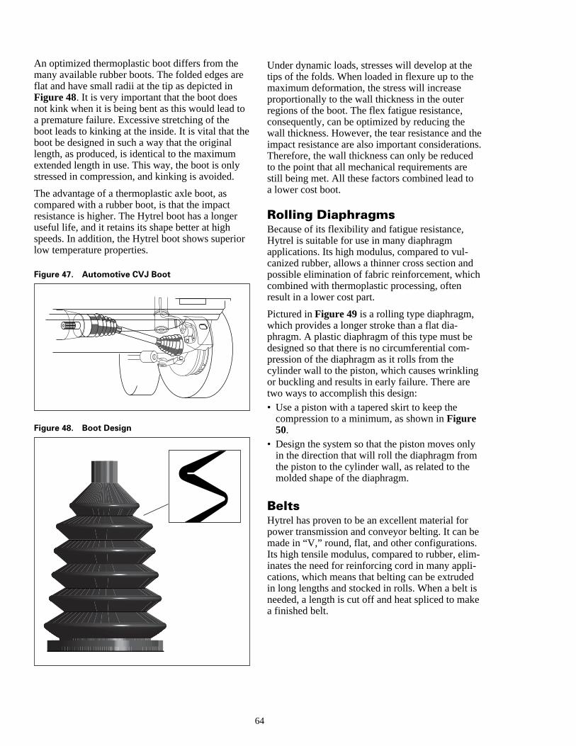
hes.
y
e
-
ke
An optimized thermoplastic boot differs from themany available rubber boots. The folded edges arflat and have small radii at the tip as depicted inFigure 48. It is very important that the boot doesnot kink when it is being bent as this would lead toa premature failure. Excessive stretching of theboot leads to kinking at the inside. It is vital that thboot be designed in such a way that the originallength, as produced, is identical to the maximumextended length in use. This way, the boot is onlystressed in compression, and kinking is avoided.
The advantage of a thermoplastic axle boot, ascompared with a rubber boot, is that the impactresistance is higher. The Hytrel boot has a longeruseful life, and it retains its shape better at highspeeds. In addition, the Hytrel boot shows superiolow temperature properties.
Figure 47. Automotive CVJ Boot
Figure 48. Boot Design
64
e
e
r
Under dynamic loads, stresses will develop at thetips of the folds. When loaded in flexure up to themaximum deformation, the stress will increaseproportionally to the wall thickness in the outerregions of the boot. The flex fatigue resistance,consequently, can be optimized by reducing thewall thickness. However, the tear resistance and timpact resistance are also important considerationTherefore, the wall thickness can only be reducedto the point that all mechanical requirements arestill being met. All these factors combined lead toa lower cost boot.
Rolling DiaphragmsBecause of its flexibility and fatigue resistance,Hytrel is suitable for use in many diaphragmapplications. Its high modulus, compared to vul-canized rubber, allows a thinner cross section andpossible elimination of fabric reinforcement, whichcombined with thermoplastic processing, oftenresult in a lower cost part.
Pictured in Figure 49 is a rolling type diaphragm,which provides a longer stroke than a flat dia-phragm. A plastic diaphragm of this type must bedesigned so that there is no circumferential com-pression of the diaphragm as it rolls from thecylinder wall to the piston, which causes wrinklingor buckling and results in early failure. There aretwo ways to accomplish this design:• Use a piston with a tapered skirt to keep the
compression to a minimum, as shown in Figure50.
• Design the system so that the piston moves onlin the direction that will roll the diaphragm fromthe piston to the cylinder wall, as related to themolded shape of the diaphragm.
BeltsHytrel has proven to be an excellent material forpower transmission and conveyor belting. It can bmade in “V,” round, flat, and other configurations.Its high tensile modulus, compared to rubber, eliminates the need for reinforcing cord in many appli-cations, which means that belting can be extrudedin long lengths and stocked in rolls. When a belt isneeded, a length is cut off and heat spliced to maa finished belt.
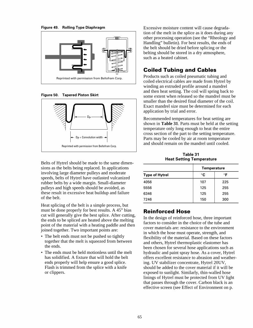
d
be
g
e.
t
sler-
n
t
Reprinted with permission from Bellofram Corp.
Figure 49. Rolling Type Diaphragm
Figure 50. Tapered Piston Skirt
DP
DP + Convolution width
Reprinted with permission from Bellofram Corp.
Belts of Hytrel should be made to the same dimensions as the belts being replaced. In applicationsinvolving large diameter pulleys and moderatespeeds, belts of Hytrel have outlasted vulcanizedrubber belts by a wide margin. Small-diameterpulleys and high speeds should be avoided, asthese result in excessive heat buildup and failureof the belt.
Heat splicing of the belt is a simple process, butmust be done properly for best results. A 45° biascut will generally give the best splice. After cuttingthe ends to be spliced are heated above the meltipoint of the material with a heating paddle and thejoined together. Two important points are:• The belt ends must not be pushed so tightly
together that the melt is squeezed from betweethe ends.
• The ends must be held motionless until the melhas solidified. A fixture that will hold the beltends properly will help ensure a good splice.Flash is trimmed from the splice with a knifeor clippers.
65
Excessive moisture content will cause degrada-tion of the melt in the splice as it does during anyother processing operation (see the “Rheology anHandling” bulletin). For best results, the ends ofthe belt should be dried before splicing or thebelting should be stored in a dry atmosphere,such as a heated cabinet.
Coiled Tubing and CablesProducts such as coiled pneumatic tubing andcoiled electrical cables are made from Hytrel bywinding an extruded profile around a mandreland then heat setting. The coil will spring back tosome extent when released so the mandrel must smaller than the desired final diameter of the coil.Exact mandrel size must be determined for eachapplication by trial and error.
Recommended temperatures for heat setting areshown in Table 31. Parts must be held at the settintemperature only long enough to heat the entirecross section of the part to the setting temperaturParts may be cooled by air at room temperatureand should remain on the mandrel until cooled.
Table 31Heat Setting Temperature
Temperature
Type of Hytrel °C °F
4056 107 225
5556 125 255
6346 125 255
7246 150 300
Reinforced HoseIn the design of reinforced hose, three importantfactors to consider in the choice of the tube andcover materials are: resistance to the environmenin which the hose must operate, strength, andflexibility of the material. Based on these factorsand others, Hytrel thermoplastic elastomer hasbeen chosen for several hose applications such ahydraulic and paint spray hose. As a cover, Hytreoffers excellent resistance to abrasion and weathing. UV stabilizer concentrate, Hytrel 20UV,should be added to the cover material if it will beexposed to sunlight. Similarly, thin-walled hoselinings of Hytrel must be protected from UV lightthat passes through the cover. Carbon black is aneffective screen (see Effect of Environment on p.
-
,ngn

-
7rr
t
al
42).
In fire hose and other lay-flat hoses, it is possible use a tube of Hytrel, which is thinner than a vulcanized rubber tube, making the hoses lighter andeasier to handle. Hytrel can be used in SAE100Rand R8 thermoplastic hydraulic hoses, which offethe advantages of lighter weight and a wider coloselection than steel-reinforced rubber hose.
In the design of thin-walled tubing of Hytrel, caremust be taken that the expansion of the liningagainst the cover does not exceed the elastic limi
6
to
of Hytrel.
If the finished hose is to be coupled, creep, thermexpansion, and cut or notch sensitivity must beconsidered in the fitting design. Creep data forHytrel may be calculated from the creep modulusplots (see pages 18 and 19). Sharp edges andburrs should be avoided when designing fittingsfor hoses based on Hytrel. In all cases, the finalfitting design should be tested under actual orclosely simulated service conditions to ensuresatisfactory performance.
6
Index
AAnnealing 36Applications 2Assembly 55Assembly Techniques 56
BBearings and Seals 62Belts 64Bonding of Hytrel to Metal 56Boots and Bellows 63Brittleness Temperature 25
CCoiled Tubing and Cables 65Compositions 3Compressive Creep 20Compressive Properties 14Concentrates 38Creep Modulus 17Cut Growth Using Ross Flexing Machine 21
DDescription 2Design Methods 54Dimensional Tolerances 37Dynamic Properties 27
EEffect of Environment 33Elastic Modulus 16, 17Electrical Properties 30
FFatigue Resistance 21Flexural Fatigue 21Flexural Modulus 17Flexural Properties 17Fluid Resistance 43Food and Drug Administration 48Friction 32
GGas Permeability 44Gears 63General Considerations 52General Information 1Government and Agency Approvals 47
HHeat Generation and Flexural Fatigue in
Compression 21
6
IImpact Resistance 23Instrumented Impact 23Izod Impact 23
MMoisture Pickup and Drying 34Molding Operation 37
NNational Science Foundation 48
OOvermolding 62
PPoissons’ Ratio 14Processing 2Properties and Characteristics 2
RRadiation Resistance 45Realistic Tolerances 55Reinforced Hose 65Resistance to Mildew and Fungus 46Rolling Diaphragms 64
SShrinkage and Post-Molding Shrinkage 35
TTensile Properties 11Tensile Strength 11Tensile Stress-Strain 11Thermal Properties 26Typical Properties 6
UUndercuts 55Underwriters Laboratories Recognition 48
WWear 32Welding 59
YYield Strength 11
7

HytrelOnly by DuPont
201714C Printed in U.S.A.[Replaces: E-52083-1]Reorder No.: H-57474 (95.1)
®
For more informationon Engineering Polymers:
For Automotive Inquiries:
U.S.A.EASTDuPont Engineering Polymers1007 Market StreetSuite D-12064Wilmington, DE 19898(302) 773-0640
CanadaDuPont Canada, Inc.DuPont Engineering PolymersP.O. Box 2200Streetsville, MississaugaOntario, Canada L5M 2H3(905) 821-5953
WESTDuPont Engineering Polymers18500 Von Karman AvenueSuite 750, P.O. Box 19732Irvine, CA 92715(714) 263-6233
MIDWESTDuPont Engineering Polymers100 Corporate NorthSuite 200Bannockburn, IL 60015(708) 831-6420
DuPont Engineering PolymersAutomotive Products950 Stephenson HighwayTroy, MI 48007-7013(313) 583-8000
EuropeDuPont de Nemours Int’l SA2, chemin du PavillonCH-1218 Le Grand-SaconnexGeneva, Switzerland(022) 717-51-11Telex: 415 777
Asia PacificDuPont Asia Pacific Ltd.P.O. Box TST 98851Tsim Sha TsuiKowloon, Hong Kong852-3-734-5345
The data listed here fall within the normal range of properties but they should not be used to establish specification limits nor used alone as the basis ofdesign. The DuPont Company assumes no obligation or liability for any advice furnished or for any results obtained with respect to this information. Allsuch advice is given and accepted at the buyer’s risk. The disclosure of information herein is not a license to operate under, or a recommendation to infringe,any patent of DuPont or others. DuPont warrants that the use or sale of any material which is described herein and is offered for sale by DuPont doesnot infringe any patent covering the material itself, but does not warrant against infringement by reason of the use thereof in combination with othermaterials or in the operation of any process.
CAUTION: Do not use in medical applications involving permanent implantation in the human body. For other medical applications, see “DuPontMedical Caution Statement,” H-50102.
Latin AmericaDuPont S.A. de C.V.Homero 206Col. Chapultepec Morales11570 Mexico D.F.(011 525) 250-8000
JapanDuPont Kabushiki KaishaArco Tower8-1, Shimomeguro 1-chomeMeguro-ku, Tokyo 153Japan(011) 81-3-5434-6100
StartwithDuPont
(302) 999-4592
(800) 533-1313