Embed Size (px)
Citation preview
ENGINEERING PHOTOGRAPHY 41
cameras, in this case mostly K-22 aerial cameras, are set up to give a remotely actuated, precision record of the manometer board. These photographs and their time records provide the accurate data needed to analyze the behavior of the wind tunnel (fig. 26) .
As an example of a recording of dynamic events by a data camera, figure 27 shows a fairing nose-cone deployment test photographed with a 70-mm, 30-frame-per-second, externally triggered data camera. The test was recorded at Goddard Space
Flight Center. Similar tests are made at Lewis Research Center. At Langley Research Center one analysis involved studying the
dynamic action of a helicopter rotor blade by mounting a motionpicture camera on the rotor shaft facing in the direction of the blade. The power and controls of the camera were arranged through slipring commutators, so the camera recorded the dynamic motion of the blade independent of the background, which became smeared as the camera rotated with the blade.
Some excellent stroboscopic photography, which we have rigidly defined as using motion pictures to obtain a static or
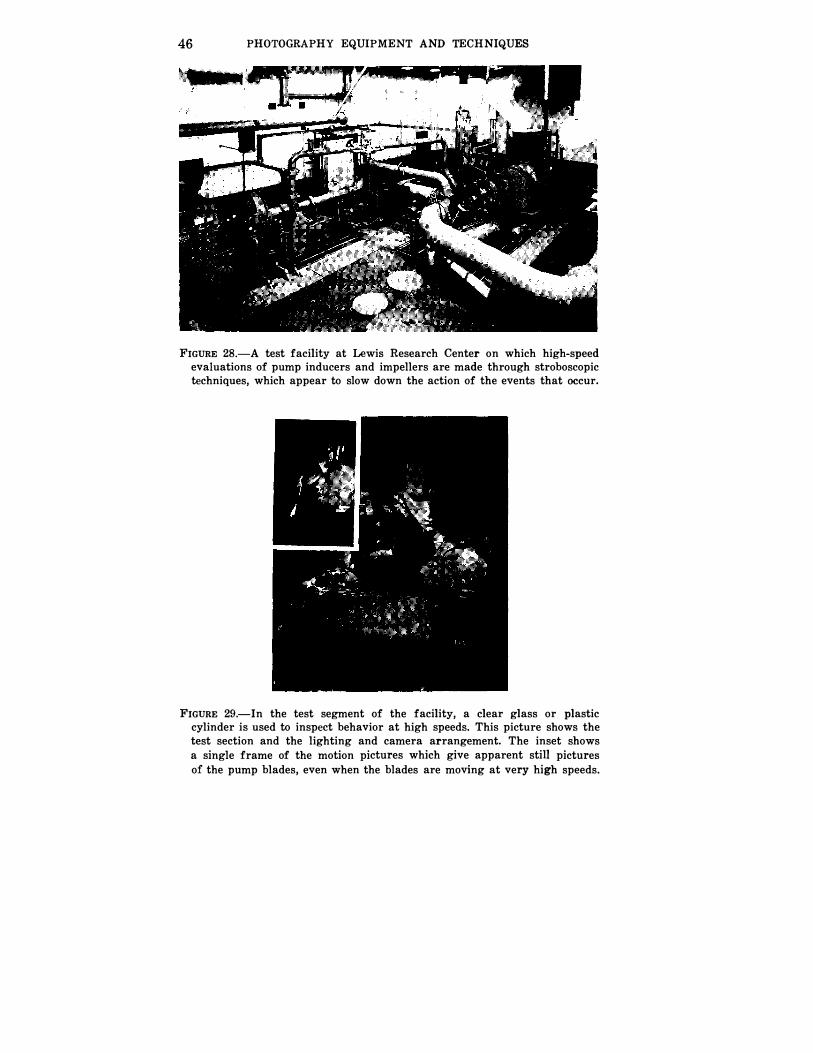
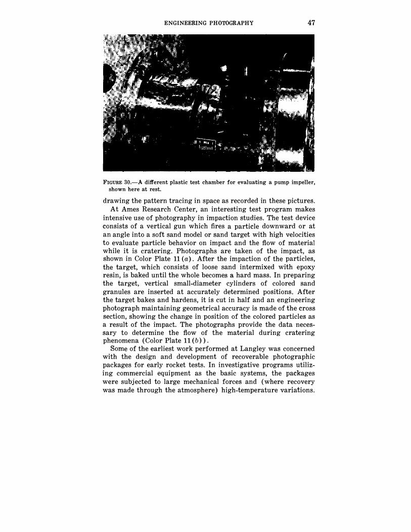
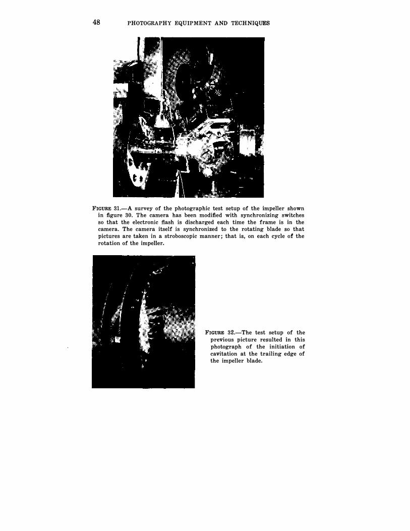
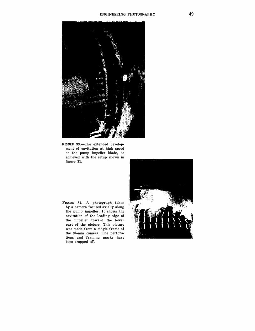
very slow moving reproduction of a cyclic event, has resulted from efforts of the staff at Lewis Research Center. Work on pump inducers and impellers is conducted in the test facility shown in figure 28. In this facility, high-speed stroboscopic photography is used to study the behavior of fluid flow around the pump blades and pump impellers. Studies are made of cavitation with the development of turbulence-generated foaming or bubbling. The close range from which a pump blade is typically photographed for a cavitation study is indicated by figure 29. The insert in the figure is an enlargement from a single frame. Figure 30, which shows a pump inducer at rest before fluid motion is imparted, demonstrates further the type of test assembly which must be photographed. Figure 31 is the arrangement of the 16-mm motion-picture camera which was specially modified to synchronize the illuminating electronic discharge lamp with the camera shutter A photograph recovered from the 16-mm individual frames in figure 32 shows the initiation of the cavitation at the impeller edge with increase in speed. Figure 33 shows the more extended development of turbulence at higher speed.
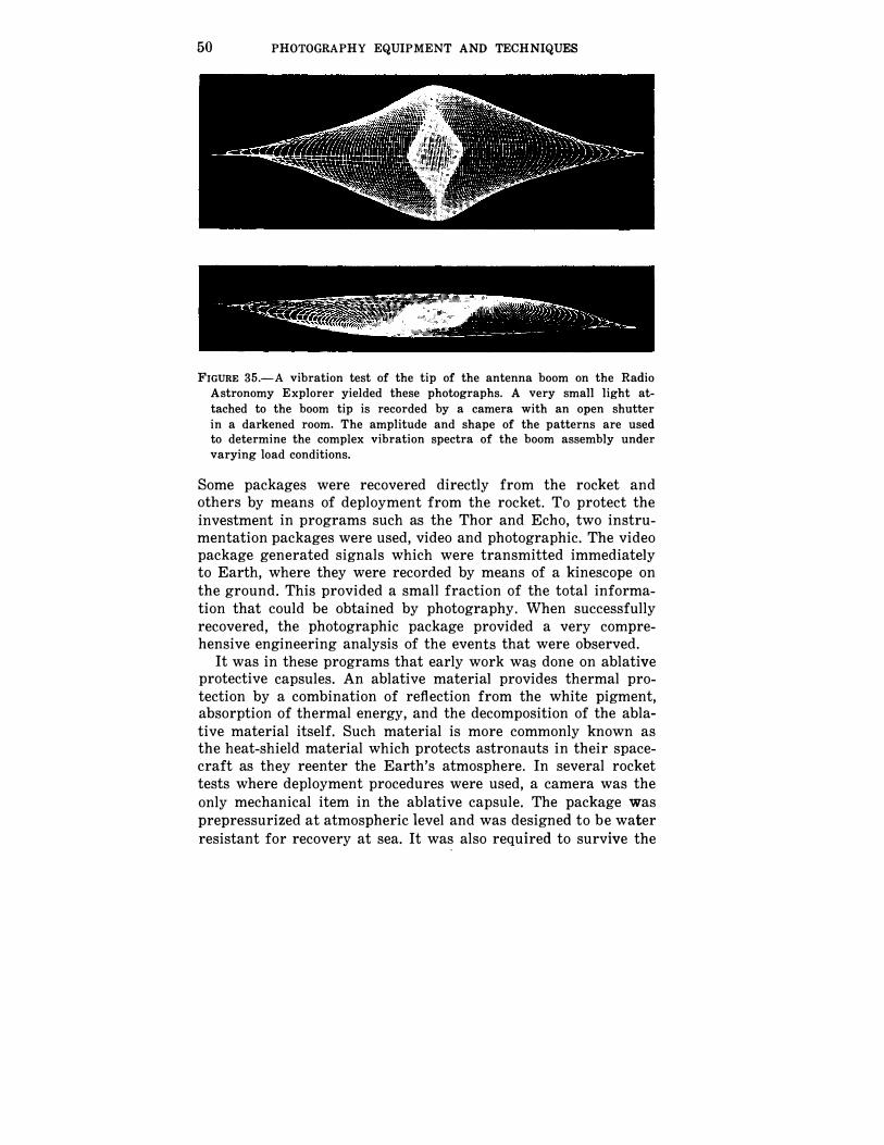
Figure 34 is a high-speed photograph taken axially and showing the travel of the developed cavitation from the pump rotor. The numbers observable in figures 32 and 33 are records of the frame number generated while the photographs were taken for subsequent engineering analysis. This technique is one of many that
42 PHOTOGRAPHY EQUIPMENT AND TECHNIQUES
a
II
b
ENGINEERING PHOTOGRAPHY 43
c
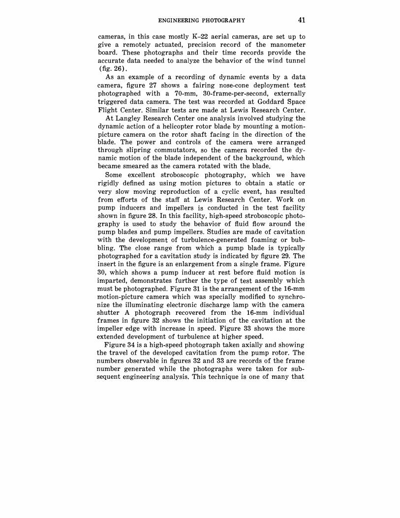
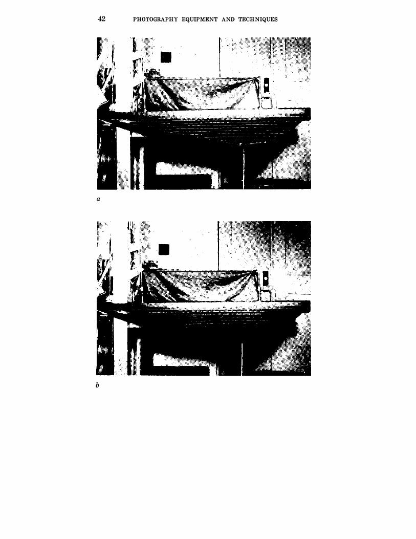
FIGURE 24.-The mode-shape analysis technique shown in these photographs is based on work done by Robert W. Herr of the Vibration and Flutter Section, Langley Research Center. It utilizes the photographic double-image and time-exposure methods to record amplitudes of oscillating subjects such as vibrations, mode shapes, static deflections, etc.
The subject is prepared by first painting it black, then scribing it with white lines, as in (a) .
To obtain a negative of a vibrating subject, a time exposure is made which produces a "smear" image with the lines registering most heavily while at rest at the extremes of the stroke (b).
To record a study of static deflections a double exposure is made as shown in (c). The first exposure registers the white lines at the beginning of the deflection stroke (zero position) and the second exposure registers the lines when the subject is fully deflected. Each line on the subject then appears as two lines on the negative from which the measurements are taken.
The negatives are then placed in a reader and measurements taken at the points of interest. This information appears in typewritten and punched-card form. If desired, the punched cards can be further processed to furnish the information in tabular or graph form.
can be used for incorporating engineering data directly into the photographic frame with a record of the event.
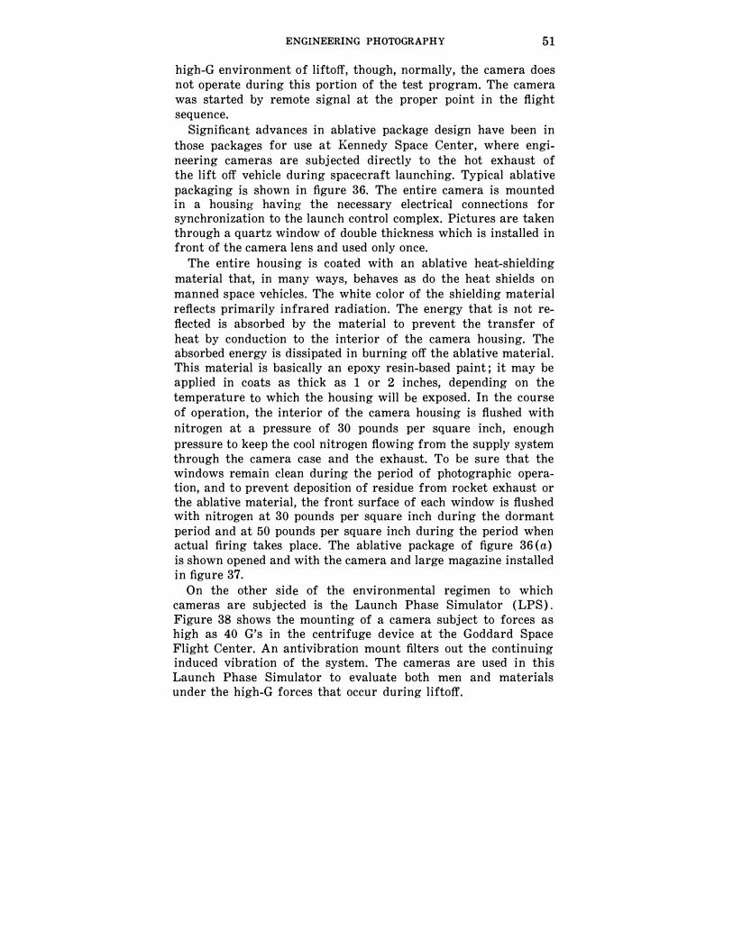
Another technique used for engineering analysis is shown in figure 35, used for evaluation of the vibration pattern of the antenna boom of the Radio Astronomy Explorer satellite. This technique is very effective and, from an engineering measurement viewpoint, is one of the simplest. Very small light bulbs were placed at the end of the boom and a simple open shutter on the camera. As soon as the vibration of this boom was started, the camera shutter was opened and the light acted like a pencil,
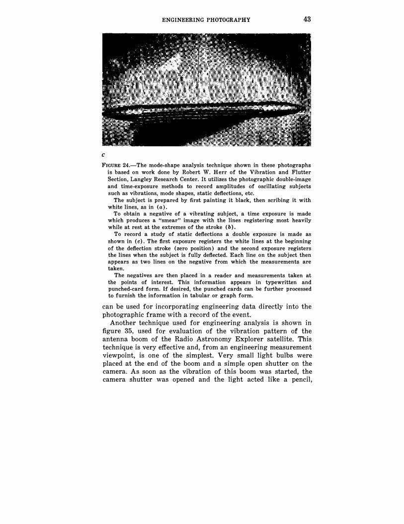
FIGURE 25.-The line of demarcation in the photographic tone between the area of apparent matte finish and glossy finish represents a contour of constant temperature. The model is in a wind tunnel, and the variation of the line with time provides an engineering analysis of the rate at which thermal effects occur across the surface of the model.
FIGURE 26.-These photographs of a manometer assembly demonstrate how photography may be used for instantaneous reading of a large number of recordings from devices of the direct, physical indication type. The manometers, individual U-tubes, are filled with liquid, the nature of which varies with the level of pressure to be measured. The manometers shown here indicate pressure levels at various points in a wind-tunnel test system. The camera assembly using a K-24 5-inch aerial camera with automatic advance is seen in (a) and (b) is a typical record made with this test arrangement.
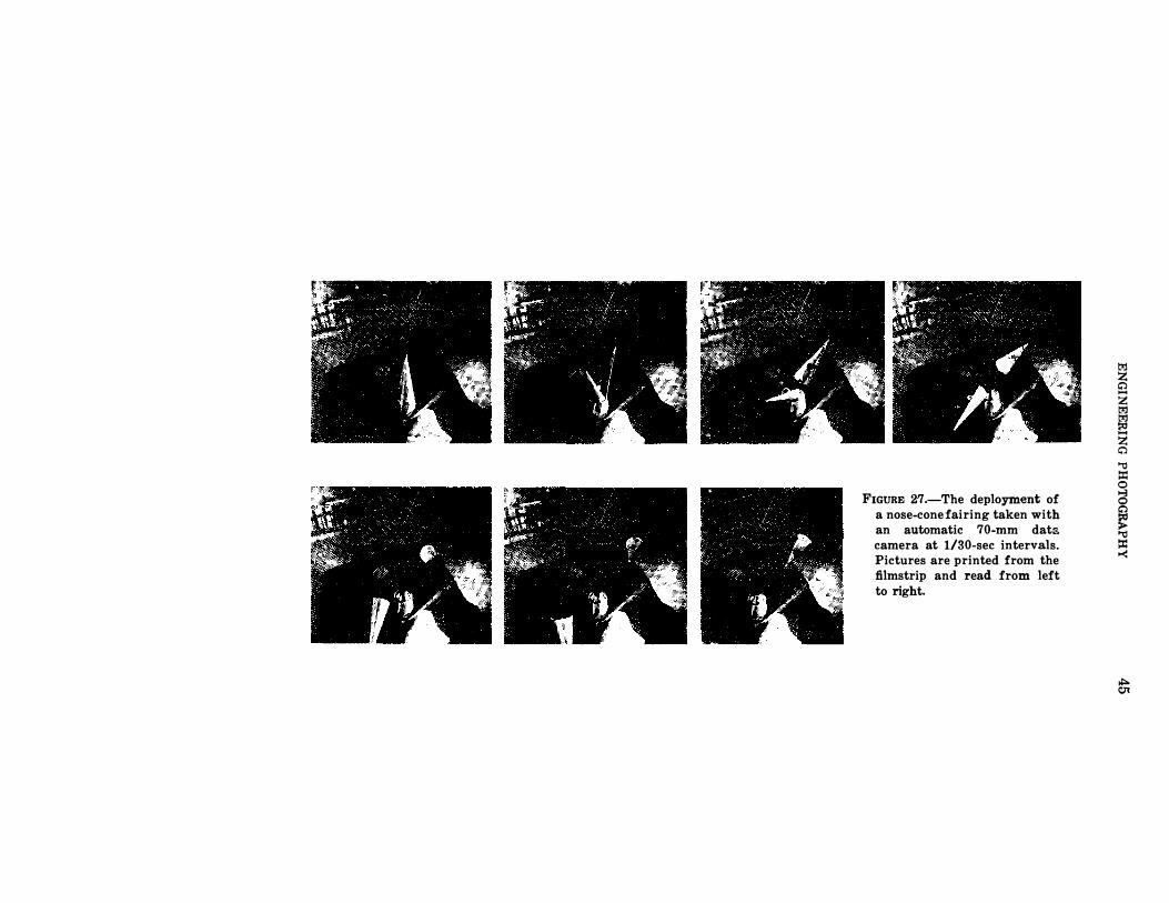
FIGURE 27.-The deployment of a nose-cone fairing taken with an automatic 70-mm dats camera at 1/30-sec intervals. Pictures are printed from the filmstrip and read from left to right.
l'=:l z c;"} -
z l'=:l l'=:l �
z c;"}
"'0 ::= 0
C5
� "'0 ::= -<
.;:. Ol
46 PHOTOGRAPHY EQUIPMENT AND TECHNIQUES
FIGURE 28.-A test facility at Lewis Research Center on which high-speed evaluations of pump inducers and impellers are made through stroboscopic techniques, which appear to slow down the action of the events that occur.
FIGURE 29.-In the test segment of the facility, a clear glass or plastic cylinder is used to inspect behavior at high speeds. This picture shows the test section and the lighting and camera arrangement. The inset shows a single frame of the motion pictures which give apparent still pictures of the pump blades, even when the blades are moving at very high speeds.
ENGINEERING PHOTOGRAPHY 47
FIGURE 30.-A different plastic test chamber for evaluating a pump impeller, shown here at rest.
drawing the pattern tracing in space as recorded in these pictures. At Ames Research Center, an interesting test program makes
intensive use of photography in impaction studies. The test device consists of a vertical gun which fires a particle downward or at an angle into a soft sand model or sand target with high velocities to evaluate particle behavior on impact and the flow of material while it is cratering. Photographs are taken of the impact, as shown in Color Plate 11 (a). After the impaction of the particles,
the target, which consists of loose sand intermixed with epoxy resin, is baked until the whole becomes a hard mass. In preparing the target, vertical small-diameter cylinders of colored sand granules are inserted at accurately determined positions. After the target bakes and hardens, it is cut in half and an engineering photograph maintaining geometrical accuracy is made of the cross section, showing the change in position of the colored particles as a result of the impact. The photographs provide the data necessary to determine the flow of the material during cratering phenomena (Color Plate 11 (b) ) .
Some of the earliest work performed at Langley was concerned with the design and development of recoverable photographic packages for early rocket tests. In investigative programs utilizing commercial equipment as the basic systems, the packages were subjected to large mechanical forces and (where recovery was made through the atmosphere) high-temperature variations.
48 PHOTOGRAPHY EQUIPMENT AND TECHNIQUES
FIGURE 31.-A survey of the photographic test setup of the impeller shown in figure 30. The camera has been modified with synchronizing switches so that the electronic flash is discharged each time the frame is in the camera. The camera itself is synchronized to the rotating blade so that pictures are taken in a stroboscopic manner; that is, on each cycle of the rotation of the impeller.
FIGURE 32.-The test setup of the previous picture resulted in this photograph of the initiation of cavitation at the trailing edge of the impeller blade.
ENGINEERING PHOTOGRAPHY
FIGURE 33.-The extended development of cavitation at high speed on the pump impeller blade, as achieved with the setup shown in figure 31.
FIGURE 34.-A photograph taken by a camera focused axially along the pump impeller. It shows the cavitation of the leading edge of the impeller toward the lower part of the picture. This picture was made from a single frame of the 35-mm camera. The perforations and framing marks have been cropped off.
49
50 PHOTOGRAPHY EQUIPMENT AND TECHNIQUES
FIGURE 35.-A vibration test of the tip of the antenna boom on the Radio Astronomy Explorer yielded these photographs. A very small light attached to the boom tip is recorded by a camera with an open shutter in a darkened room. The amplitude and shape of the patterns are used to determine the complex vibration spectra of the boom assembly under varying load conditions.
Some packages were recovered directly from the rocket and others by means of deployment from the rocket. To protect the investment in programs such as the Thor and Echo, two instrumentation packages were used, video and photographic. The video package generated signals which were transmitted immediately to Earth, where they were recorded by means of a kinescope on the ground. This provided a small fraction of the total information that could be obtained by photography. When successfully recovered, the photographic package provided a very comprehensive engineering analysis of the events that were observed.
It was in these programs that early work was done on ablative protective capsules. An ablative material provides thermal protection by a combination of reflection from the white pigment, absorption of thermal energy, and the decomposition of the ablative material itself. Such material is more commonly known as the heat-shield material which protects astronauts in their spacecraft as they reenter the Earth's atmosphere. In several rocket tests where deployment procedures were used, a camera was the
only mechanical item in the ablative capsule. The package was prepressurized at atmospheric level and was designed to be water
resistant for recovery at sea. It was also required to survive the
ENGINEERING PHOTOGRAPHY 51
high-G environment of liftoff, though, normally, the camera does not operate during this portion of the test program. The camera was started by remote signal at the proper point in the flight sequence.
Significant advances in ablative package design have been in
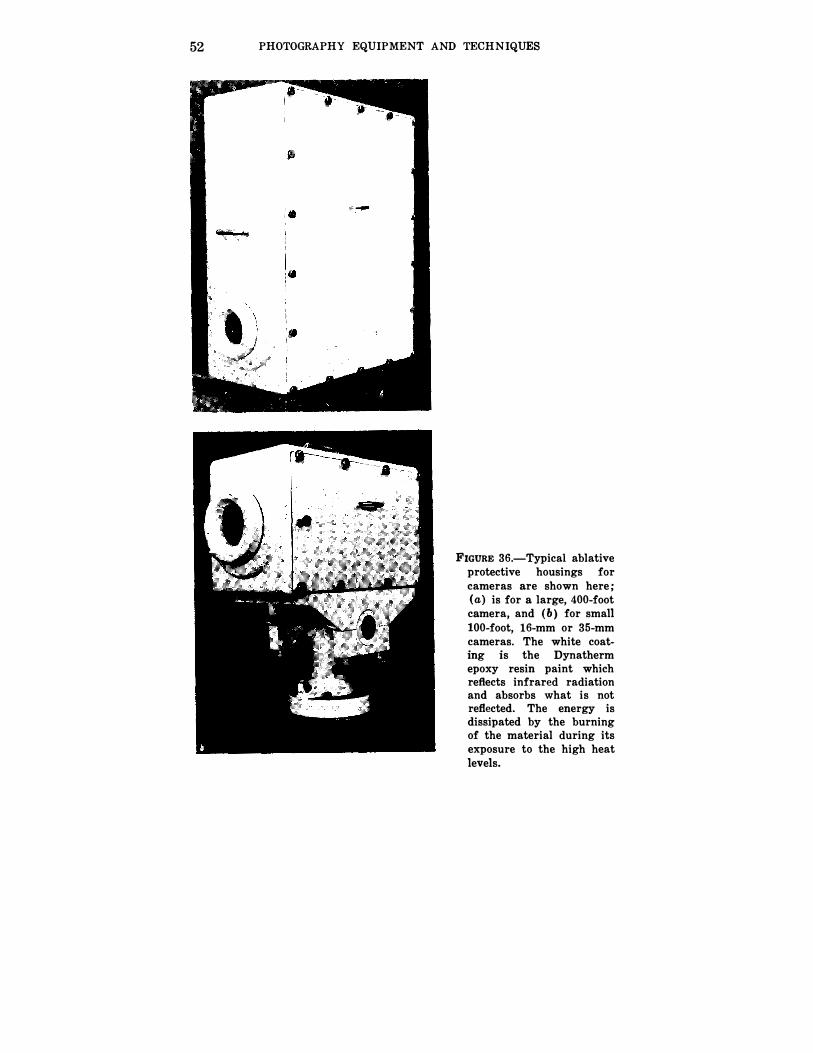
those packages for use at Kennedy Space Center, where engineering cameras are subjected directly to the hot exhaust of the lift off vehicle during spacecraft launching. Typical ablative packaging is shown in figure 36. The entire camera is mounted in a housing having the necessary electrical connections for synchronization to the launch control complex. Pictures are taken through a quartz window of double thickness which is installed in front of the camera lens and used only once.
The entire housing is coated with an ablative heat-shielding
material that, in many ways, behaves as do the heat shields on manned space vehicles. The white color of the shielding material reflects primarily infrared radiation. The energy that is not reflected is absorbed by the material to prevent the transfer of heat by conduction to the interior of the camera housing. The absorbed energy is dissipated in burning off the ablative material. This material is basically an epoxy resin-based paint; it may be applied in coats as thick as 1 or 2 inches, depending on the temperature to which the housing will be exposed. In the course of operation, the interior of the camera housing is flushed with
nitrogen at a pressure of 30 pounds per square inch, enough
pressure to keep the cool nitrogen flowing from the supply system through the camera case and the exhaust. To be sure that the windows remain clean during the period of photographic operation, and to prevent deposition of residue from rocket exhaust or the ablative material, the front surface of each window is flushed with nitrogen at 30 pounds per square inch during the dormant period and at 50 pounds per square inch during the period when actual firing takes place. The ablative package of figure 36 (a) is shown opened and with the camera and large magazine installed in figure 37.
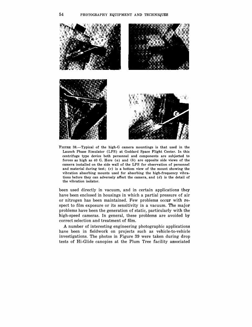
On the other side of the environmental regimen to which cameras are subjected is the Launch Phase Simulator (LPS) . Figure 38 shows the mounting of a camera subject to forces as high as 40 G's in the centrifuge device at the Goddard Space Flight Center. An antivibration mount filters out the continuing induced vibration of the system. The cameras are used in this Launch Phase Simulator to evaluate both men and materials under the high-G forces that occur during liftoff.
52 PHOTOGRAPHY EQUIPMENT AND TECHNIQUES
FIGURE 36.-Typical ablative protective housings for cameras are shown here; (a) is for a large, 400-foot camera, and (b) for small
100-foot, 16-mm or 35-mm cameras. The white coating is the Dynatherm epoxy resin paint which reflects infrared radiation and absorbs what is not reflected. The energy is dissipated by the burning of the material during its exposure to the high heat levels.
ENGINEERING PHOTOGRAPHY 53
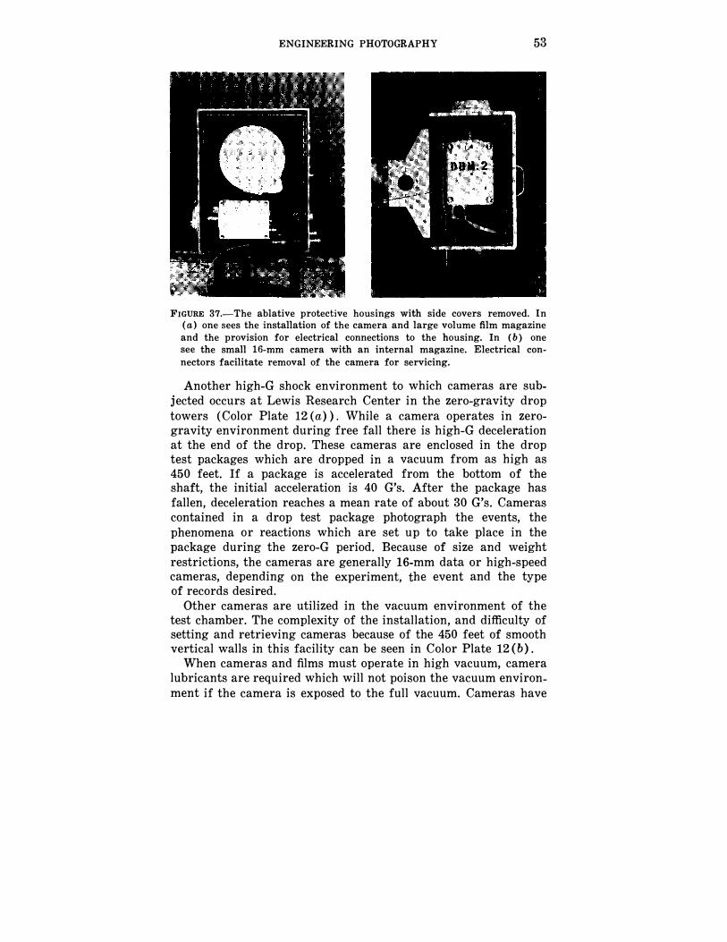
FIGURE 37.-The ablative protective housings with side covers removed. In (a) one sees the installation of the camera and large volume film magazine and the provision for electrical connections to the housing. In (b) one see the small 16-mm camera with an internal magazine. Electrical connectors facilitate removal of the camera for servicing.
Another high-G shock environment to which cameras are subjected occurs at Lewis Research Center in the zero-gravity drop
towers (Color Plate 12 (a) ) . While a camera operates in zerogravity environment during free fall there is high-G deceleration at the end of the drop. These cameras are enclosed in the drop test packages which are dropped in a vacuum from as high as 450 feet. If a package is accelerated from the bottom of the shaft, the initial acceleration is 40 G's. After the package has fallen, deceleration reaches a mean rate of about 30 G's. Cameras contained in a drop test package photograph the events, the
phenomena or reactions which are set up to take place in the package during the zero-G period. Because of size and weight restrictions, the cameras are generally 16-mm data or high-speed cameras, depending on the experiment, the event and the type of records desired.
Other cameras are utilized in the vacuum environment of the test chamber. The complexity of the installation, and difficulty of setting and retrieving cameras because of the 450 feet of smooth vertical walls in this facility can be seen in Color Plate 12 (b).
When cameras and films must operate in high vacuum, camera lubricants are required which will not poison the vacuum environment if the camera is exposed to the full vacuum. Cameras have
54 PHOTOGRAPHY EQUIPMENT AND TECHNIQUES
FIGURE 38.-Typical of the high-G camera mountings is that used in the Launch Phase Simulator (LPS) at Goddard Space Flight Center. In this centrifuge type device both personnel and components are subjected to forces as high as 40 G. Here (a) and (b) are opposite side views of the camera installed on the side wall of the LPS for observation of personnel and material during test; (c) is a bottom view of the mount showing the vibration absorbing mounts used for absorbing the high-frequency vibrations before they can adversely affect the camera, and (d) is the detail of the vibration isolator.
been used directly in vacuum, and in certain applications they have been enclosed in housings in which a partial pressure of air or nitrogen has been maintained. Few problems occur with respect to film exposure or its sensitivity in a vacuum. The major problems have been the generation of static, particularly with the high-speed cameras. In general, these problems are avoided by correct selection and treatment of film.
A number of interesting engineering photographic applications have been in fieldwork on projects such as vehicle-to-vehicle investigations. The photos in Figure 39 were taken during drop tests of Hi-Glide canopies at the Plum Tree facility associated
ENGINEERING PHOTOGRAPHY 55
with the Langley Research Center. These devices have glide ratios of 2% to 1. They drop a foot for each 21;2 feet of forward motion at fairly rapid speeds. They must be chased by an aircraft or helicopter. Generally, the cameras are tracked manually.
Reference 14 describes an electronic shutter control system developed under NASA management that can record automatically the times at which the exposures are made. Though primarily intended for planetary photography, it represents an operational achievement that might be used elsewhere. Other controls, such as a pulse-train generator and low power timing devices for use in space vehicles or other limited power environments, are described in references 15 and 16.
Extensive use of engineering photography has been made by the Kennedy Space Center. Typical is the photographic coverage of the entire launch area and vehicle operations, primarily for engineering analysis. The pictures obtained also provide historical records and public information. This Center's photography requirements are met by a rather large-scale photographic system
which uses manually or sequentially operated data cameras and
vehicle tracking cameras. In Launch Complex 39, the entire
photographic complex is controlled remotely from the Launch Control Center. The equipment and its various modes of operation enable the engineers to obtain complete photographic coverage of a Saturn 5 operation including prelaunch functions, the actual liftoff, and events of the first 1300 feet of flight. Beyond this point in flight, events are photographed by tracking theodolite cameras of the Air Force Eastern Test Range.
As many as 130 cameras are specified for a typical launch. Of these, 90 are designated as engineering cameras. They range
from data cameras that make still photographs as slow as two frames per second to high-speed motion-picture cameras with framing rates up to 1000 frames per second. The 16-, 35- or 70-mm films used for the cameras are either black-and-white, or color, depending on the type of information to be gathered.
A remote Photographic Control Console permits operation of all cameras associated with a given launch sequence at Launch Complex 39. These cameras are integrated with the launch sequence timing equipment and can be operated automatically from the launch sequence time signal. The operator may start and stop certain cameras in the course of activities that can be viewed through video monitors. A significant feature is that this installation is also interlocked with the master Launch Control Console; in event of any deviation from the normal launch pattern
56 PHOTOGRAPHY EQUIPMENT AND TECHNIQUES
that would result in destruction, an abort, or similar emergency situation, the Launch Controller, rather than the Photographic Controller, can activate all cameras to produce as quickly as possible a record of events as documentary evidence of the trouble.
The cameras associated with the Launch Control Complex can thus be operated in a start-stop sequence in conjunction with
ENGINEERING PHOTOGRAPHY 57
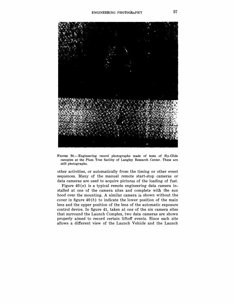
FIGURE 39.-Engineering record photographs made of tests of Hy-Glide canopies at the Plum Tree facility of Langley Research Center. These are still photographs.
other activities, or automatically from the timing or other event sequences. Many of the manual remote start-stop cameras or data cameras are used to acquire pictures of the loading of fuel.
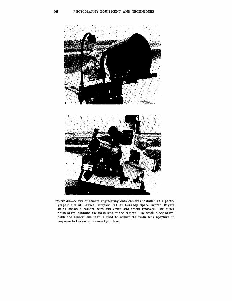
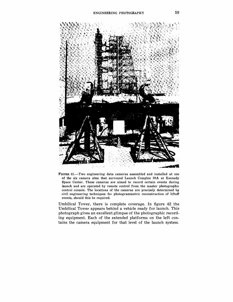
Figure 40 (a) is a typical remote engineering data camera installed at one of the camera sites and complete with the sun hood over the mounting. A similar camera is shown without the cover in figure 40 (b) to indicate the lower position of the main lens and the upper position of the lens of the automatic exposure control device. In figure 41, taken at one of the six camera sites that surround the Launch Complex, two data cameras are shown properly aimed to record certain liftoff events. Since each site allows a different view of the Launch Vehicle and the Launch
58 PHOTOGRAPHY EQUIPMENT AND TECHNIQUES
FIGURE 40.-Views of remote engineering data cameras installed at a photographic site at Launch Complex 39A at Kennedy Space Center. Figure 40 (b) shows a camera with sun cover and shield removed. The silver finish barrel contains the main lens of the camera. The small black barrel holds the sensor lens that is used to adjust the main lens aperture in response to the instantaneous light level.
ENGINEERING PHOTOGRAPHY 59
FIGURE 41.-Two engineering data cameras assembled and installed at one of the six camera sites that surround Launch Complex 39A at Kennedy Space Center. These cameras are aimed to record certain events during launch and are operated by remote control from the master photographic control console. The locations of the cameras are precisely determined by civil engineering techniques for photogrammetric reconstruction of liftoff events, should this be required.
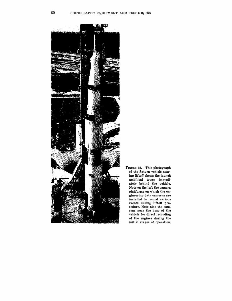
Umbilical Tower, there is complete coverage. In figure 42 the Umbilical Tower appears behind a vehicle ready for launch. This photograph gives an excellent glimpse of the photographic recording equipment. Each of the extended platforms on the left contains the camera equipment for that level of the launch system.
60 PHOTOGRAPHY EQUIPMENT AND TECHNIQUES
FIGURE 42.-This photograph of the Saturn vehicle nearing liftoff shows the launch umbilical tower immediately behind the vehicle. Note on the left the camera platforms on which the engineering data cameras are installed to record various events during liftoff procedure. Note also the cameras near the base of the vehicle for direct recording of the engines during the initial stages of operation.


![An Overview of Tissue Engineering as an Alternative for ...researchprofiles.herts.ac.uk/.../26014_69276_1_PB.pdf · systems are required for tissue engineering[41], transplantation[41],](https://img.pdfslide.us/doc/110x75/603b240130b173752e24d723/an-overview-of-tissue-engineering-as-an-alternative-for-systems-are-required.jpg)