Embed Size (px)
Citation preview

8/11/2019 Engineering Materials & Metal
http://slidepdf.com/reader/full/engineering-materials-metal 1/159
ENGINEERING MATERIALS AND
METALLURGYAUTONOMOUS
For fourth SEMESTER(II YEAR)
PREPARED BYS.ARAVINDHA BALAJI
ASSISTANT PROFESSORDEPARTMENT OF MECHANICAL
ENGINEERING SONA COLLEGE OF TECHNOLOGYSALEM:636005
8/11/2019 Engineering Materials & Metal
http://slidepdf.com/reader/full/engineering-materials-metal 2/159
ENGINEERING MATERIALS ANDMETALLURGY
Application of EMAM(In Industry):Steel industry( e.g. steel plants, (SAIL) Essarsteels, jindal steel ltd.(JSW))
Pipe maufacturing industry, Plasticindustry. Some jewelry industry(Grades of the gold) Manufacturing industry.
1 / 5 / 2 0 1
3
2
S A B -A P
/ M
E C H
S ONA
C T
8/11/2019 Engineering Materials & Metal
http://slidepdf.com/reader/full/engineering-materials-metal 3/159
ENGINEERING MATERIALS ANDMETALLURGY
OBJECTIVE
Knowledge on the structure
Properties of the materials Treatment Testing and applications of metals and non-metallic
materials Suitable materials for various engineering application
1 / 5 / 2 0 1
3
3
S A B -A P
/ M
E C H
S ONA
C T

8/11/2019 Engineering Materials & Metal
http://slidepdf.com/reader/full/engineering-materials-metal 4/159
ENGINEERING MATERIALS ANDMETALLURGY
Review (Not for Exam)
Crystal structure
BCC, (Body cubic centre) structure
FCC, (Face cubic centre) structure and
HCP, (Hexagonal close packing)structure Unit cell
Crystallographic planes and directions
Miller indices
Crystal imperfections for point, line, planar and
volume defects.
8/11/2019 Engineering Materials & Metal
http://slidepdf.com/reader/full/engineering-materials-metal 5/159
8/11/2019 Engineering Materials & Metal
http://slidepdf.com/reader/full/engineering-materials-metal 6/159
ENGINEERING MATERIALS ANDMETALLURGY
UNIT:I CONSTITUTION OF ALLOYS ANDPHASE DIAGRAMS
Constitution of alloys-Solid solution,substitutional and interstitial-Phasediagrams, Isomorphous, eutectic,peritectic, and peritectroid reactions,Iron-Iron carbon equilibrium diagram.
Classification of steel and cast Iron,Microstructure, Properties andapplications.
1 / 5 / 2 0 1
3
6
S A B -A P
/ M
E C H
S ONA
C T
8/11/2019 Engineering Materials & Metal
http://slidepdf.com/reader/full/engineering-materials-metal 7/159
ENGINEERING MATERIALS ANDMETALLURGY
UNIT:II HEAT TREATMENTDefinition- Full annealing, stress relief,
recrystallisation and spheroidizing-normalising, hardening and tempering ofsteel. Isothermal transformationdiagrams-cooling curves superimposed onI.T.diagram, CCR-Hardenability, Jominyand quench test- Austempering,Martempering-case hardening-carburising, nitriding, cyaniding,carbonitriding, flame and inductionhardening .
1 / 5 / 2 0 1
3
7
S A B -A P
/ M
E C H
S ONA
C T
8/11/2019 Engineering Materials & Metal
http://slidepdf.com/reader/full/engineering-materials-metal 8/159
ENGINEERING MATERIALS ANDMETALLURGY
UNIT:IIIMECHANICAL PROPERTIES AND TESTING
Mechanism of plastic deformation, slip and
twinning-types of fracture-testing of materialsunder tension, compression and shear loads-Hardness tests (Brinell, Vickers and Rockwell),Impact test-Izod and charpy, Fatigue and creeptests, fracture toughness tests.
1 / 5 / 2 0 1
3
8
S A B -A P
/ M
E C H
S ONA
C T
8/11/2019 Engineering Materials & Metal
http://slidepdf.com/reader/full/engineering-materials-metal 9/159
ENGINEERING MATERIALS ANDMETALLURGY
UNIT:IVFERROUS AND NON FERROUS METALS
Effect of alloying elements on steel(Mn, Si,
Cr, Mo, V, Ti & W) – Stainless and tool steels – HSLA-maraging steels-Cast irons-Grey,White malleable, spheroidal-Graphite, Alloycast irons,
Copper and copper alloys-Brass, Bronze andCupronickel-Aluminum and Al-Cu alloy-Precipitation hardening-Bearing alloys.
1 / 5 / 2 0 1
3
9
S A B -A P
/ M
E C H
S ONA
C T

8/11/2019 Engineering Materials & Metal
http://slidepdf.com/reader/full/engineering-materials-metal 10/159
ENGINEERING MATERIALS ANDMETALLURGY
UNIT VNON-METALLIC MATERIALS
Polymers-Types of polymer, commodity and
Engineering polymers-properties andapplications of PE, PP, PS, PVC, PMMA, PET,PC, PA, ABS, PI, PAI, PPO, PPS, PEEK, PTFE
Polymer-Urea and Phenol formaldehydes-
Engineering ceramics-Introduction to fiberreinforced plastics.
1 / 5 / 2 0 1
3
10
S A B -A P
/ M
E C H
S ONA
C T
8/11/2019 Engineering Materials & Metal
http://slidepdf.com/reader/full/engineering-materials-metal 11/159
ENGINEERING MATERIALS ANDMETALLURGY
1 / 5 / 2 0 1
3
11
S A B -A P
/ M
E C H
S ONA
C T
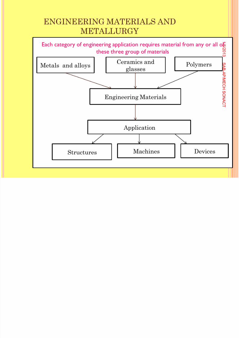
Metals and alloys Ceramics andglasses
Polymers
Engineering Materials
Application
Structures Machines Devices
Each category of engineering application requires material from any or all ofthese three group of materials
8/11/2019 Engineering Materials & Metal
http://slidepdf.com/reader/full/engineering-materials-metal 12/159
ENGINEERING MATERIALS ANDMETALLURGY
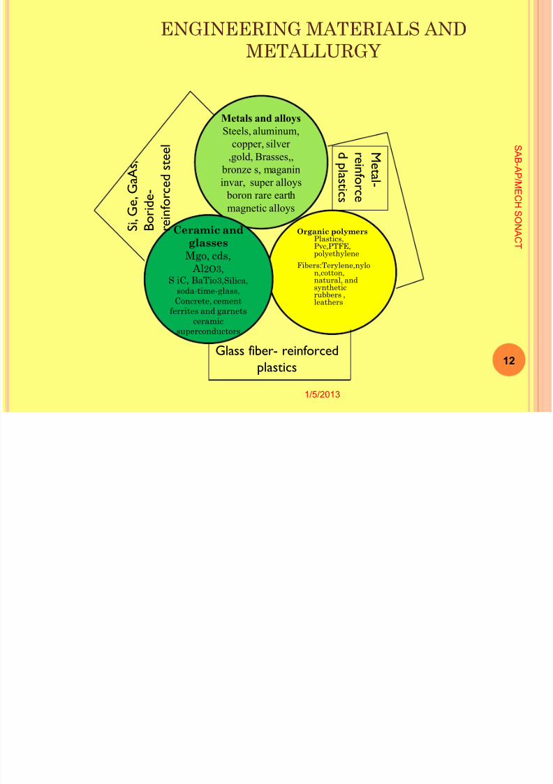
Organic polymers Plastics,Pvc,PTFE,polyethylene
Fibers:Terylene,nylon,cotton,natural, and
syntheticrubbers ,leathers
1/5/2013
12
S A B -A P
/ M
E C H
S ONA
C T
Metals and alloysSteels, aluminum,
copper, silver,gold, Brasses,,
bronze s, maganininvar, super alloys boron rare earthmagnetic alloys
Ceramic andglasses
Mgo, cds, Al 2O3,
S iC, BaTio 3,Silica,
soda-time-glass,Concrete, cement
ferrites and garnetsceramic
superconductors
Glass fiber- reinforcedplastics
S i , G e ,
G a A s ,
B o r i d e -
r e i n f o r c e
d s t e e
l
M e t a l -
r ei nf o
r c e
d pl a s t i c s
8/11/2019 Engineering Materials & Metal
http://slidepdf.com/reader/full/engineering-materials-metal 13/159
ENGINEERING MATERIALS ANDMETALLURGY
Structure:The internal structure of a material,
simply called the structure.
1 / 5 / 2 0 1
3
13
S A B -A P
/ M
E C H
S ONA
C T
8/11/2019 Engineering Materials & Metal
http://slidepdf.com/reader/full/engineering-materials-metal 14/159
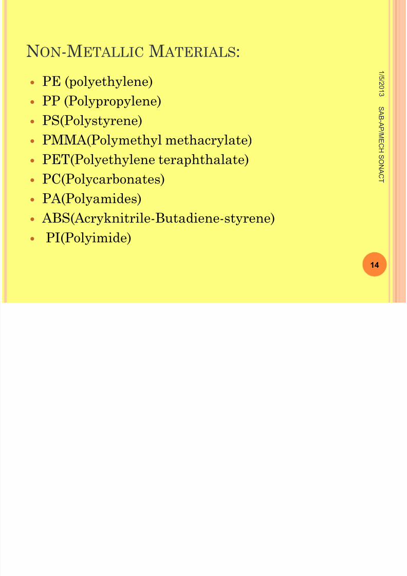
N ON -M ETALLIC M ATERIALS :
PE (polyethylene)PP (Polypropylene)PS(Polystyrene)
PMMA(Polymethyl methacrylate)PET(Polyethylene teraphthalate)PC(Polycarbonates)PA(Polyamides)
ABS(Acryknitrile-Butadiene-styrene) PI(Polyimide)
1 / 5 / 2 0 1
3
14
S A B -A P
/ M
E C H
S ONA
C T
8/11/2019 Engineering Materials & Metal
http://slidepdf.com/reader/full/engineering-materials-metal 15/159
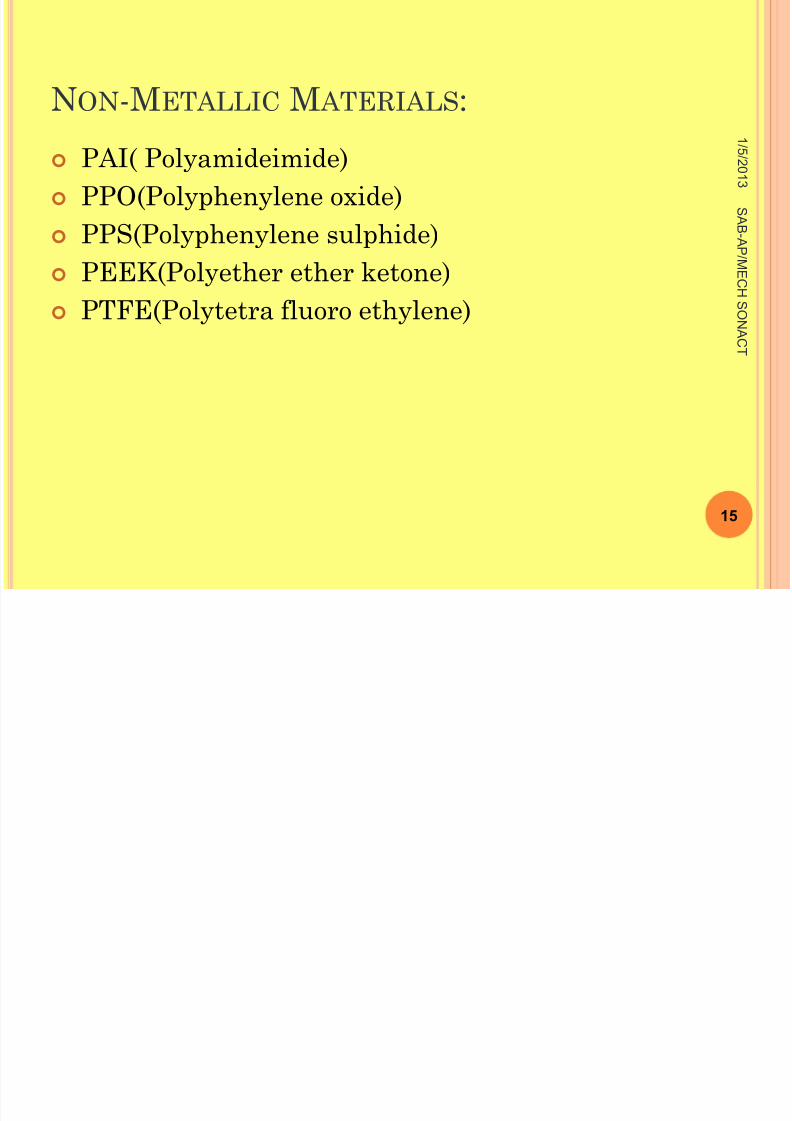
N ON -M ETALLIC M ATERIALS :
PAI( Polyamideimide) PPO(Polyphenylene oxide) PPS(Polyphenylene sulphide)
PEEK(Polyether ether ketone) PTFE(Polytetra fluoro ethylene)
1 / 5 / 2 0 1
3
15
S A B -A P
/ M
E C H
S ONA
C T
8/11/2019 Engineering Materials & Metal
http://slidepdf.com/reader/full/engineering-materials-metal 16/159
ENGINEERING MATERIALS ANDMETALLURGY
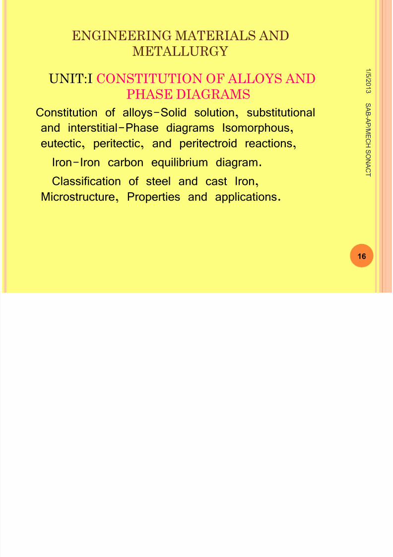
UNIT:I CONSTITUTION OF ALLOYS ANDPHASE DIAGRAMS
Constitution of alloys-Solid solution, substitutionaland interstitial-Phase diagrams Isomorphous,eutectic, peritectic, and peritectroid reactions,
Iron-Iron carbon equilibrium diagram.
Classification of steel and cast Iron,Microstructure, Properties and applications.
1 / 5 / 2 0 1
3
16
S A B -A P
/ M
E C H
S ONA
C T
8/11/2019 Engineering Materials & Metal
http://slidepdf.com/reader/full/engineering-materials-metal 17/159
UNIT:ICONSTITUTION OF ALLOYS
AND PHASE DIAGRAMS CONSTITUTION - establishment, foundation,
creation, formation, structure, organization,
charter, bill.
1 / 5 / 2 0 1
3
17
S A B -A P
/ M
E C H
S ONA
C T
8/11/2019 Engineering Materials & Metal
http://slidepdf.com/reader/full/engineering-materials-metal 18/159
UNIT:ICONSTITUTION OF ALLOYS
AND PHASE DIAGRAMS SOME TECHNICAL TERMS AND
DEFINITIONS:
1.SYSTEM: It is a combination of phases of one ormore components.
2.PHASE: It is a Physically and chemically
homogenous part of a system under study, one
phase is different from the other in structure or
composition
1 / 5 / 2 0 1
3
18
S A B -A P
/ M
E C H
S ONA
C T
8/11/2019 Engineering Materials & Metal
http://slidepdf.com/reader/full/engineering-materials-metal 19/159
UNIT:ICONSTITUTION OF ALLOYS AND
PHASE DIAGRAMS 3.COMPONENTS:
The elements present in the
system are called component. A system may
consist of two or more components.
1 / 5 / 2 0 1
3
19
S A B -A P
/ M
E C H
S ONA
C T
8/11/2019 Engineering Materials & Metal
http://slidepdf.com/reader/full/engineering-materials-metal 20/159
CONSTITUTION OF ALLOYS AND PHASE DIAGRAMS
CONSTITUTION OF ALLOYS:4.ALLOY:
An alloy is defined as a combination of two or
more elements, of which one of the element should be
a metal in major proportion.
The others could be metals or non-metals, for eg:
Brass (CU-Zn), Steel (Fe-C)
1 / 5 / 2 0 1
3
20
S A B -A P
/ M
E C H
S ONA
C T
8/11/2019 Engineering Materials & Metal
http://slidepdf.com/reader/full/engineering-materials-metal 21/159
CONSTITUTION OF ALLOYS AND
PHASE DIAGRAMS
Alloy find very wide application in the industry than pure metals.
Uses of pure metals
1. High electrical conductivity
2. High ductility
3. Corrosion resistance are required.
These properties are generally at a maximum value in pure metals.
1 / 5 / 2 0 1
3
21
S A B -A P
/ M
E C H
S ONA
C T
8/11/2019 Engineering Materials & Metal
http://slidepdf.com/reader/full/engineering-materials-metal 22/159
UNIT:ICONSTITUTION OF ALLOYS AND
PHASE DIAGRAMS
Mechanical properties
1. Tensile strength
2. Yield point
3. Hardness are
improved by alloying.
1 / 5 / 2 0 1
3
22
S A B -A P
/ M
E C H
S ONA
C T
8/11/2019 Engineering Materials & Metal
http://slidepdf.com/reader/full/engineering-materials-metal 23/159
UNIT:ICONSTITUTION OF ALLOYS AND PHASE
DIAGRAMS
CLASSIFICATION OF ALLOYS1 / 5
/ 2 0 1
3
23
S A B -A P
/ M
E C H
S ONA
C T
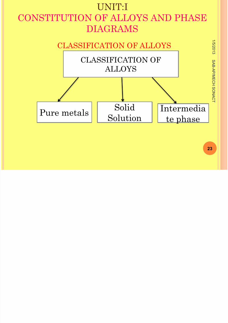
CLASSIFICATION OF ALLOYS
Pure metals Solid
Solution
Intermedia
te phase
8/11/2019 Engineering Materials & Metal
http://slidepdf.com/reader/full/engineering-materials-metal 24/159
UNIT:ICONSTITUTION OF ALLOYS AND
PHASE DIAGRAMS
Alloy can be either a single phase or a mixture
of phases.
A phases is anything which is homogeneous and
physically distinct.
In solid state alloys of three are three possible
phase.
1 / 5 / 2 0 1
3
24
S A B -A P
/ M
E C H
S ONA
C T
8/11/2019 Engineering Materials & Metal
http://slidepdf.com/reader/full/engineering-materials-metal 25/159
UNIT:ICONSTITUTION OF ALLOYS AND
PHASE DIAGRAMS
If an alloy has a single phase, it could be either
a solid solution or an intermediate phase.
If the alloy is a mixture it could be composed ofany combination of the above three phases.
1 / 5 / 2 0 1
3
25
S A B -A P
/ M
E C H
S ONA
C T
UNIT I
8/11/2019 Engineering Materials & Metal
http://slidepdf.com/reader/full/engineering-materials-metal 26/159
UNIT:ICONSTITUTION OF ALLOYS AND
PHASE DIAGRAMS
The major element which is large inamount is called base metal or parentmetal or solvent.
The other element that is lesser inamount is called the alloying element orsolute, it is the minor part (such as salt orsugar which is less in amount, beingmixed in water- solvent).
1 / 5 / 2 0 1
3
26
S A B -A P
/ ME
C H
S ONA
C T
UNIT I
8/11/2019 Engineering Materials & Metal
http://slidepdf.com/reader/full/engineering-materials-metal 27/159
UNIT:ICONSTITUTION OF ALLOYS AND
PHASE DIAGRAMS
5. MIXTURE:It is a material more than one phase.
1 / 5 / 2 0 1
3
27
S A B -A P
/ ME
C H
S ONA
C T
UNIT:I
8/11/2019 Engineering Materials & Metal
http://slidepdf.com/reader/full/engineering-materials-metal 28/159
UNIT:ICONSTITUTION OF ALLOYS AND
PHASE DIAGRAMS 1 / 5
/ 2 0 1
3
28
S A B -A P
/ ME
C H
S ONA
C T
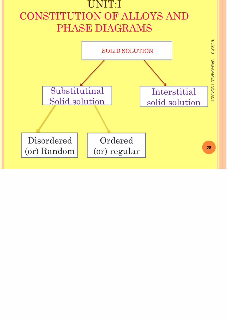
SOLID SOLUTION
SubstitutinalSolid solution
Interstitialsolid solution
Disordered(or) Random
Ordered(or) regular
UNIT I
8/11/2019 Engineering Materials & Metal
http://slidepdf.com/reader/full/engineering-materials-metal 29/159
UNIT:ICONSTITUTION OF ALLOYS AND
PHASE DIAGRAMS
Solid solutions: A solid solution is the simplest type of alloys.
A Solution can be defined as a homogeneous mixture
in which the atoms or molecules of one substance are
dispersed at random into another substance.
1 / 5 / 2 0 1
3
29
S A B -A P
/ ME
C H
S ONA
C T
UNIT I
8/11/2019 Engineering Materials & Metal
http://slidepdf.com/reader/full/engineering-materials-metal 30/159
UNIT:ICONSTITUTION OF ALLOYS AND
PHASE DIAGRAMS
A solid solution may be defined as a solidthat consist of two or more elementsatomically dispersed in a single-phase
structure. A solid solution is composed of two parts.
1 . Solute: A solute is the minor part ofthe solution or the material which isdissolved.
1 / 5 / 2 0 1
3
30
S A B -A P
/ ME
C H
S ONA
C T
UNIT I
8/11/2019 Engineering Materials & Metal
http://slidepdf.com/reader/full/engineering-materials-metal 31/159
UNIT:ICONSTITUTION OF ALLOYS AND
PHASE DIAGRAMS
2. Solvent: Solvent constitutes the major portion of
the solution.
Both the solute and the solvent can be solid,
liquid or gas.
1 / 5 / 2 0 1
3
31
S A B -A P
/ ME
C H
S ONA
C T
UNIT I

8/11/2019 Engineering Materials & Metal
http://slidepdf.com/reader/full/engineering-materials-metal 32/159
UNIT:ICONSTITUTION OF ALLOYS AND
PHASE DIAGRAMS
Solid solution:
Simply a solution in the solid state.
Solid solution may be defined as a
solution In the solid state which consists of two
kinds of atoms combined in one type of space
lattice.
1 / 5 / 2 0 1
3
32
S A B -A P
/ ME
C H
S ONA
C T
UNIT I
8/11/2019 Engineering Materials & Metal
http://slidepdf.com/reader/full/engineering-materials-metal 33/159
UNIT:ICONSTITUTION OF ALLOYS AND
PHASE DIAGRAMS
space lattice:
Space lattice is defined as an array of
points in three dimensions in which every point
has surroundings identical to that every other
point in the array.
1 / 5 / 2 0 1
3
33
S A B -A P
/ ME
C H
S ONA
C T
8/11/2019 Engineering Materials & Metal
http://slidepdf.com/reader/full/engineering-materials-metal 34/159
S OLID SOLUTION
Case: In certain cases, the solidification of analloy results in the formation of one kind ofcrystal. In which both metals are present, but theycannot be detected by the microscope Although properties of the crystals areprofoundly( deeply,strongly ) changed.
1 / 5 / 2 0 1
3
34
S A B -A P
/ ME
C H
S ONA
C T
8/11/2019 Engineering Materials & Metal
http://slidepdf.com/reader/full/engineering-materials-metal 35/159
S OLID SOLUTION
In such a case we have a solid metal in which the
interatomic state which existed in the liquid solution
has been persevered after solidification , and it is
known as a solid solution.
In a solid solution the atom occur in a definite
geometrical pattern, which is usually a slightly
distorted form of one of the constituent metals.
1 / 5 / 2 0 1
3
35
S A B -A P
/ ME
C H S ONA
C T
8/11/2019 Engineering Materials & Metal
http://slidepdf.com/reader/full/engineering-materials-metal 36/159
S OLID SOLUTION
Soildsolution are conductors, but not so good asthe pure metals on which they are based.
Some examples of solid solutions are: Cu-Zn alloys (Brasses) Ni-Cu alloys (Monel metal) Au-Ag alloys(Sterling silver) Fe-Cr-Ni alloys (Certain stainless steels)
Fe-C alloys (Steels)
1 / 5 / 2 0 1
3
36
S A B -A P
/ ME
C H S ONA
C T
8/11/2019 Engineering Materials & Metal
http://slidepdf.com/reader/full/engineering-materials-metal 37/159
S UBSTITUTIONAL SOLID SOLUTION 1 / 5
/ 2 0 1
3
37
S A B -A P
/ ME
C H S ONA
C T
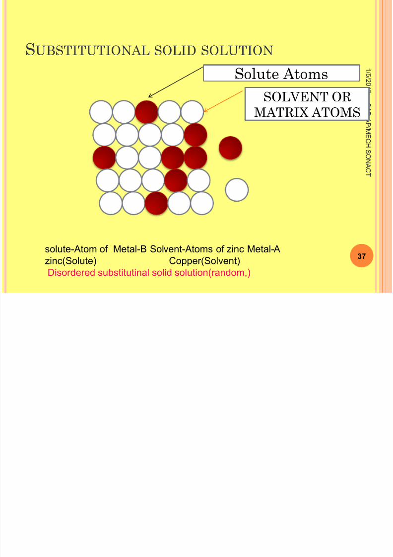
Solute AtomsSOLVENT OR
MATRIX ATOMS
solute-Atom of Metal-B Solvent-Atoms of zinc Metal-Azinc(Solute) Copper(Solvent)
Disordered substitutinal solid solution(random,)
8/11/2019 Engineering Materials & Metal
http://slidepdf.com/reader/full/engineering-materials-metal 38/159
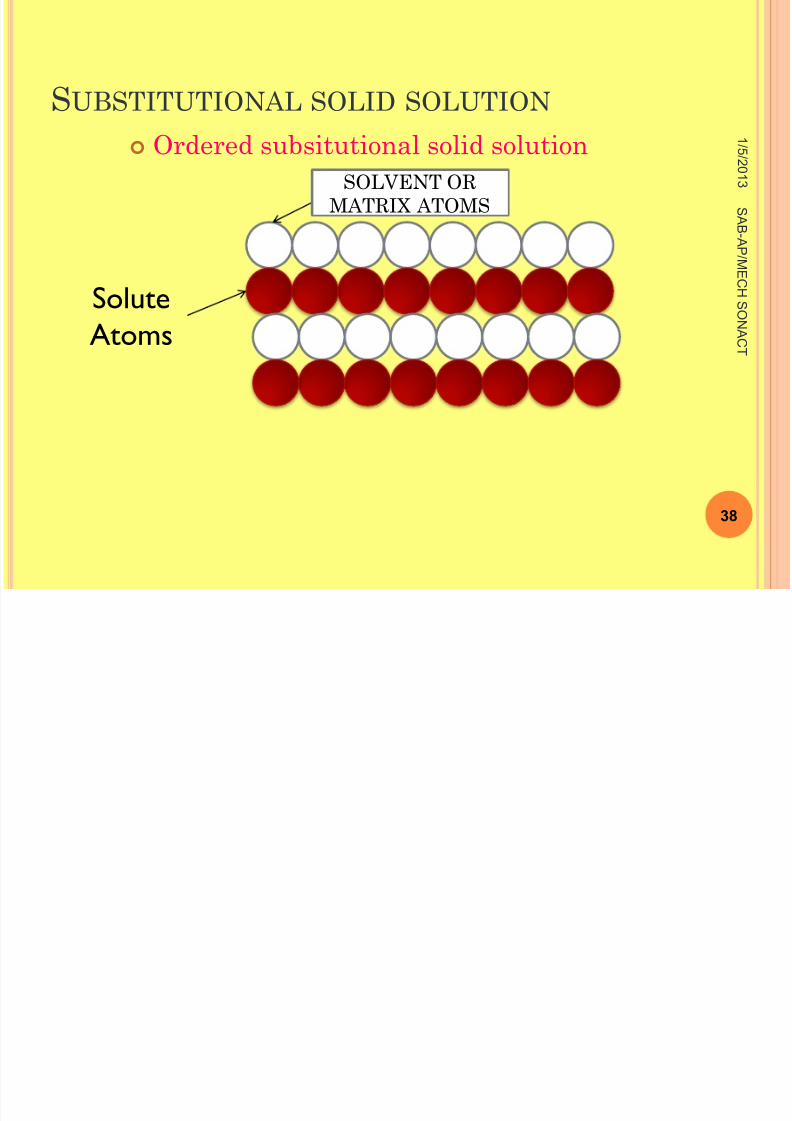
S UBSTITUTIONAL SOLID SOLUTION
Ordered subsitutional solid solution 1 / 5 / 2 0 1
3
38
S A B -A P
/ ME
C H S ONA
C T
SoluteAtoms
SOLVENT ORMATRIX ATOMS
8/11/2019 Engineering Materials & Metal
http://slidepdf.com/reader/full/engineering-materials-metal 39/159
S UBSTITUTIONAL SOLID SOLUTION
In substitutional solid solution, there is a direct
substitution of one type of atom for another.
so that solute atoms(cu) enter the crystal to take
positions normally occupied by solvent atoms (e.g.,
Nickel atoms);
1 / 5 / 2 0 1
3
39
S A B -A P
/ ME
C H S ONA
C T
8/11/2019 Engineering Materials & Metal
http://slidepdf.com/reader/full/engineering-materials-metal 40/159
S UBSTITUTIONAL SOLID SOLUTION
The alloy is said to be in a disordered condition if
in the formation of a substitutional solid
solution, the solute atoms do not occupy any
specific position but are distributed at random in
the lattice structure of the solvent.
1 / 5 / 2 0 1
3
40
S A B -A P
/ ME
C H S ONA
C T
8/11/2019 Engineering Materials & Metal
http://slidepdf.com/reader/full/engineering-materials-metal 41/159
S UBSTITUTIONAL SOLID SOLUTION
An ordered subsititutional solid solution is shown
fig Cu-Zn, Al-Cu, α -Brass are some examples of
ordered structures.
1 / 5 / 2 0 1
3
41
S A B -A P
/ ME
C H S ONA
C T
8/11/2019 Engineering Materials & Metal
http://slidepdf.com/reader/full/engineering-materials-metal 42/159
INTERSTITIAL SOLID SOLUTION
The four elements hydrogen, carbon, nitrogen,
and boron have such small diameters that they
can occupy the empty spaces (Interstices) in the
crystal lattices of many metals.
1 / 5 / 2 0 1
3
42
S A B -A P
/ ME
C H S ONA
C T
8/11/2019 Engineering Materials & Metal
http://slidepdf.com/reader/full/engineering-materials-metal 43/159
INTERSTITIAL SOLID SOLUTION 1 / 5
/ 2 0 1
3
43
S A B -A P
/ ME
C H S ONA
C T
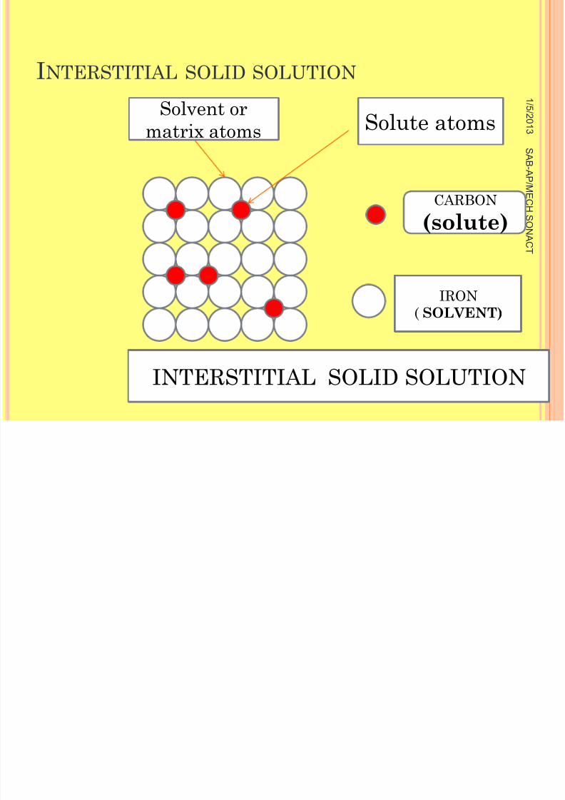
Solvent ormatrix atoms Solute atoms
INTERSTITIAL SOLID SOLUTION
CARBON(solute)
IRON( SOLVENT)
8/11/2019 Engineering Materials & Metal
http://slidepdf.com/reader/full/engineering-materials-metal 44/159
INTERSTITIAL SOLID SOLUTION
Interstitial solid solution usually have a limited
composition range and are generally considered
of secondary importance, but there are a few
instances worthy of special attention.
1 / 5 / 2 0 1
3
44
S A B -A P
/ ME
C H S ONA
C T
8/11/2019 Engineering Materials & Metal
http://slidepdf.com/reader/full/engineering-materials-metal 45/159
INTERSTITIAL SOLID SOLUTION
The interstitial solution of carbon in iron
constitutes the basis of steel hardening.
Very small amount of hydrogen introduced into
steels during acid pickling(cleaning), plating, or
welding operations causes a Sharpe decrease in
ductility, known as hydrogen embrittlement.
1 / 5 / 2 0 1
3
45
S A B -A P
/ ME
C H S ONA
C T
8/11/2019 Engineering Materials & Metal
http://slidepdf.com/reader/full/engineering-materials-metal 46/159
INTERSTITIAL SOLID SOLUTION
Interstitial nitrogen is useful not only in
nirtriding process but also as an important factor
in maintaining 18Cr-8Ni
Stainless steel in the austenitic condition.
1 / 5 / 2 0 1
3
46
S A B -A P
/ ME
C H S ONA
C T
8/11/2019 Engineering Materials & Metal
http://slidepdf.com/reader/full/engineering-materials-metal 47/159
HUME - ROTHERY’S RULES OF SOLIDSOLUBILITY
1 / 5 / 2 0 1
3
47
S A B -A P
/ ME
C H S ONA
C T
Hume - Rothery’s Rules of solid solubility
8/11/2019 Engineering Materials & Metal
http://slidepdf.com/reader/full/engineering-materials-metal 48/159
H UME - R OTHERY ’S R ULES OF SOLID SOLUBILITY
1 / 5 / 2 0 1
3
48
S A B -A P
/ ME
C H S ONA
C T
Hume - Rothery’s Rules of solid solubility
8/11/2019 Engineering Materials & Metal
http://slidepdf.com/reader/full/engineering-materials-metal 49/159
INTERSTITIAL SOLID SOLUTION
HUME –ROTHERY’S RULES OF SOLID SOLUBILITY
The solubility limit of solute in solvents depends on
various factors. These were stated by Hume-rothery
and are as follows:
1. Critical structure factor (or) Crystal structure:
Metals that have the same crystal stucture (Lattice
structure) have a greater solubility.
1 / 5 / 2 0 1
3
49
S A B -A P
/ ME
C H S ONA
C T
8/11/2019 Engineering Materials & Metal
http://slidepdf.com/reader/full/engineering-materials-metal 50/159
8/11/2019 Engineering Materials & Metal
http://slidepdf.com/reader/full/engineering-materials-metal 51/159
INTERSTITIAL SOLID SOLUTION
3. Chemical affinity factor (or) Electronegativity:
Formulation of solid solution is
favoured for metals that have less chemical affinity
is more, then a compound is formed instead of a solid
solution.
The metal which are separated in widely in theperiodic table are not suitable for making alloys
because of their high affinity.
1 / 5 / 2 0 1
3
51
S A B -A P
/ ME
C H S ONA
C T
8/11/2019 Engineering Materials & Metal
http://slidepdf.com/reader/full/engineering-materials-metal 52/159
INTERSTITIAL SOLID SOLUTION
4. Relative valency factor(or)valence:
A metal that has a higher valency will
disslove only a small amount of a lower valency
metal, where as the metal with low valency
will have good solubility for the higher valency
metal.
1 / 5 / 2 0 1
3
52
S A B -A P
/ ME
C H S ONA
C T
8/11/2019 Engineering Materials & Metal
http://slidepdf.com/reader/full/engineering-materials-metal 53/159
INTERSTITIAL SOLID SOLUTION
In some alloys both interstitial and
substitutional solid solution are formed to an
appreciable extent.
For Eg: A Cr-Ni steel contains interstitially
dissolved carbon and substitution ally dissolved
chromium, nickel, and minor elements.
1 / 5 / 2 0 1
3
53
S A B -A P
/ ME
C H S ONA
C T
8/11/2019 Engineering Materials & Metal
http://slidepdf.com/reader/full/engineering-materials-metal 54/159
P OSSIBILITIES OF SOLID SOLUTIONS
• There are three possible solid solutions based on
the amount of their elements. They are:
1.Unsaturated solid solution: In the solvent is
dissolving small amount of solute as well as at a
given temperature and pressure, it is called
unsaturated solid solution.
1 / 5 / 2 0 1
3
54
S A B -A P
/ ME
C H S ONA
C T
8/11/2019 Engineering Materials & Metal
http://slidepdf.com/reader/full/engineering-materials-metal 55/159
P OSSIBILITIES OF SOLID SOLUTIONS
2. Saturated solid solution:
If the solvent is dissolving
limiting amount of solute, it is called saturated
solid solution.
1 / 5 / 2 0 1
3
55
S A B -A P
/ ME
C H S ONA
C T
8/11/2019 Engineering Materials & Metal
http://slidepdf.com/reader/full/engineering-materials-metal 56/159
P OSSIBILITIES OF SOLID SOLUTIONS
3. Supersaturated solid solution:
If the solvent is dissolving more of solute that it
should, under equilibrium, it is called
supersaturated solid solution.
1 / 5 / 2 0 1
3
56
S A B -A P
/ ME
C H S ONA
C T
8/11/2019 Engineering Materials & Metal
http://slidepdf.com/reader/full/engineering-materials-metal 57/159
PHASE DIAGRAM
Types of phase diagram
1. Isomorphous
2. Eutectoid system
3. Eutectic system
4.Peritectic system
5. Peritectroid reactions
1 / 5 / 2 0 1
3
57
S A B -A P
/ ME
C H S ONA
C T
8/11/2019 Engineering Materials & Metal
http://slidepdf.com/reader/full/engineering-materials-metal 58/159
PHASE DIAGRAM
Phase Diagrams
Phase diagrams are graphical
representation of what phases are present in an
alloy system at various
Temperatures, pressures, and compositions.
1 / 5 / 2 0 1
3
58
S A B -A P
/ ME
C H S ONA
C T
8/11/2019 Engineering Materials & Metal
http://slidepdf.com/reader/full/engineering-materials-metal 59/159
PHASE DIAGRAM
(or)
A phase diagram is a map showing thestructure or phase present as thetemperature and overall composition ofthe material are varied.
Phase diagrams are also known as equilibrium
diagrams or constitutional diagrams .
1 / 5 / 2 0 1
3
59
S A B -A P
/ ME
C H S ONA
C T
8/11/2019 Engineering Materials & Metal
http://slidepdf.com/reader/full/engineering-materials-metal 60/159
WHY SHOULD PHASE DIAGRAMS BE STUDIED ?
The phase diagrams can answer the following
important questions:
What condition is the material in?
Is the composition uniform throughout ?
If not, how much of each component is present?
1 / 5 / 2 0 1
3
60
S A B -A P
/ ME
C H S ONA
C T
8/11/2019 Engineering Materials & Metal
http://slidepdf.com/reader/full/engineering-materials-metal 61/159
WHY SHOULD PHASE DIAGRAMS BE STUDIED ?
Is something present that may give undesired
properties?
What will happen if temperature is increased or
decreased; pressure is changed or composition is
varied?
1 / 5 / 2 0 1
3
61
S A B -A P
/ ME
C H S ONA
C T
8/11/2019 Engineering Materials & Metal
http://slidepdf.com/reader/full/engineering-materials-metal 62/159
WHY SHOULD PHASE DIAGRAMS BE STUDIED ?
Phase diagrams are used by engineers and
scientists to understand and to predict many
aspects of the behavior of materials.
1 / 5 / 2 0 1
3
62
S A B -A P
/ ME
C H S ONA
C T
8/11/2019 Engineering Materials & Metal
http://slidepdf.com/reader/full/engineering-materials-metal 63/159
TERMINOLOGY USED IN PHASE DIAGRAMS
1. Components
2. System
3. Alloy
4. Solid solution
5. Solute Solution
1 / 5 / 2 0 1
3
63
S A B -A P
/ ME
C H S ONA
C T
8/11/2019 Engineering Materials & Metal
http://slidepdf.com/reader/full/engineering-materials-metal 64/159
TERMINOLOGY USED IN PHASE DIAGRAMS
6. Solvent
7. Phase
8. Equilibrium
9. Solubility limit
10.Degrees of freedom
1 / 5 / 2 0 1
3
64
S A B -A P
/ ME
C H S ONA
C T
8/11/2019 Engineering Materials & Metal
http://slidepdf.com/reader/full/engineering-materials-metal 65/159
TERMINOLOGY USED IN PHASE DIAGRAMS
The various terms used in the study of phase
diagrams have been explained below:
1. COMPONENT: Component are pure metals
and or compounds of which an alloy is composed.
Eg: In a copper-zinc brass, the components are
CU and Zn.
1 / 5 / 2 0 1
3
65
S A B -A P
/ ME
C H S ONA
C T
8/11/2019 Engineering Materials & Metal
http://slidepdf.com/reader/full/engineering-materials-metal 66/159
TERMINOLOGY USED IN PHASE DIAGRAMS
2. SYSTEM: The system has two meanings in this
context
i. System: May refer to a specific body of
material under consideration. For Eg: A
ladle of molten steel is referred as a system.
1 / 5 / 2 0 1
3
66
S A B -A P
/ ME
C H S ONA
C T
8/11/2019 Engineering Materials & Metal
http://slidepdf.com/reader/full/engineering-materials-metal 67/159
TERMINOLOGY USED IN PHASE DIAGRAMS
(ii)system: May also refer to the series of possible
alloys consisting of the same components. For
example, the Iron-Carbon system.
1 / 5 / 2 0 1
3
67
S A B -A P
/ ME
C H S ONA
C T
8/11/2019 Engineering Materials & Metal
http://slidepdf.com/reader/full/engineering-materials-metal 68/159
TERMINOLOGY USED IN PHASE DIAGRAMS
A system having one components is called a
Unary system, and the system having two, three
and four components are known as Binary,
ternary and quaternary systems, respectively.
1 / 5 / 2 0 1
3
68
S A B -A P
/ ME
C H S ONA
C T
8/11/2019 Engineering Materials & Metal
http://slidepdf.com/reader/full/engineering-materials-metal 69/159
TERMINOLOGY USED IN PHASE DIAGRAMS
3. ALLOY:
An alloy is a mixture of two or more metals
or a metal (metals) and a non-metal (non-metals).
1 / 5 / 2 0 1
3
69
S A B -A P
/ ME
C H S ONA
C T
8/11/2019 Engineering Materials & Metal
http://slidepdf.com/reader/full/engineering-materials-metal 70/159
TERMINOLOGY USED IN PHASE DIAGRAMS
4.SOLID SOLUTION:
It is a solid that consist of two or
more elements atomically dispersed in a single-
phase structure.
1 / 5 / 2 0 1
3
70
S A B -A P
/ ME
C H S ONA
C T
8/11/2019 Engineering Materials & Metal
http://slidepdf.com/reader/full/engineering-materials-metal 71/159
TERMINOLOGY USED IN PHASE DIAGRAMS
5. SOLUTE SOLUTION:
It is the minor part of the
solution or the material which is dissolved.
1 / 5 / 2 0 1
3
71
S A B -A P
/ ME
C H S ONA
C T
8/11/2019 Engineering Materials & Metal
http://slidepdf.com/reader/full/engineering-materials-metal 72/159
TERMINOLOGY USED IN PHASE DIAGRAMS
6. SOLVENT:
The material which contributes the
major portion of the solution.
1 / 5 / 2 0 1
3
72
S A B -A P
/ ME
C H S ONA
C T
8/11/2019 Engineering Materials & Metal
http://slidepdf.com/reader/full/engineering-materials-metal 73/159
TERMINOLOGY USED IN PHASE DIAGRAMS
7. PHASE:
A phase may be defined as a homogenous
portion of a system that has uniform physical
and chemical characteristics.
1 / 5 / 2 0 1
3
73
S A B -A P
/ ME
C H S ONA
C T

8/11/2019 Engineering Materials & Metal
http://slidepdf.com/reader/full/engineering-materials-metal 74/159
TERMINOLOGY USED IN PHASE DIAGRAMS
8. EQUILIBRIUM:
Equilibrium is said to exit when
enough time is allowed for all possible reactions
to be completed.
1 / 5 / 2 0 1
3
74
S A B -A P
/ ME
C H S ONA
C T

8/11/2019 Engineering Materials & Metal
http://slidepdf.com/reader/full/engineering-materials-metal 75/159
TERMINOLOGY USED IN PHASE DIAGRAMS
The equilibrium state refers to the
characteristics of the system that remain
constant indefinitely. Equilibrium occurs when
the free energy of the system is at its minimum
value.
1 / 5 / 2 0 1
3
75
S A B -A P
/ ME
C H S ONA
C T
8/11/2019 Engineering Materials & Metal
http://slidepdf.com/reader/full/engineering-materials-metal 76/159
TERMINOLOGY USED IN PHASE DIAGRAMS
The term phase equilibrium refers to
equilibrium as it applies to systems in which
more than one phase may exist.
1 / 5 / 2 0 1
3
76
S A B -A P
/ ME
C H
S ONA
C T
8/11/2019 Engineering Materials & Metal
http://slidepdf.com/reader/full/engineering-materials-metal 77/159
TERMINOLOGY USED IN PHASE DIAGRAMS
9. SOLUBILITY LIMIT:
It is the maximum concentration of
solute that may be added without forming a new
phase.
1 / 5 / 2 0 1
3
77
S A B -A P
/ ME
C H
S ONA
C T
8/11/2019 Engineering Materials & Metal
http://slidepdf.com/reader/full/engineering-materials-metal 78/159
TERMINOLOGY USED IN PHASE DIAGRAMS
NOTE: The addition of solution in excess
of the solubility limit results in the formation of
another solid solution or compound.
1 / 5 / 2 0 1
3
78
S A B -A P
/ ME
C H
S ONA
C T
8/11/2019 Engineering Materials & Metal
http://slidepdf.com/reader/full/engineering-materials-metal 79/159
TERMINOLOGY USED IN PHASE DIAGRAMS
10. DEGREES OF FREEDOM:
It is the number of
independent variables ( such as temperature,
pressure, and composition).
That can be changed independently without
changing the phase or phases of the system.
1 / 5 / 2 0 1
3
79
S A B -A P
/ ME
C H
S ONA
C T
WHAT IS MEANT BY THE TERM PHASE ?
8/11/2019 Engineering Materials & Metal
http://slidepdf.com/reader/full/engineering-materials-metal 80/159
WHAT IS MEANT BY THE TERM PHASE ?
A phase may be a portion of matter which is
homogenous
A phase may be defined as any physical distinct
homogenous and mechanically separable portion
of a substance.
1 / 5 / 2 0 1
3
80
S A B -A P
/ ME
C H
S ONA
C T
8/11/2019 Engineering Materials & Metal
http://slidepdf.com/reader/full/engineering-materials-metal 81/159
WHAT IS MEANT BY THE TERM PHASE ?
In Layman’s term, a phase requires a unique
structure, uniform composition, and well-defined
boundaries or interfaces
Examples: A pure substance such as water is a
single phase.
1 / 5 / 2 0 1
3
81
S A B -A P
/ ME
C H
S ONA
C T
8/11/2019 Engineering Materials & Metal
http://slidepdf.com/reader/full/engineering-materials-metal 82/159
WHAT IS MEANT BY THE TERM PHASE ?
The pure substance water can exist in solid,
liquid and vapour, each of these states being a
single phase, as shown in fig (a)
Now consider the effect of adding salt(Nacl) to
water. Salt will dissolve in water to give a
homogeneous solution.
1 / 5 / 2 0 1
3
82
S A B -A P
/ ME
C H
S ONA
C T
8/11/2019 Engineering Materials & Metal
http://slidepdf.com/reader/full/engineering-materials-metal 83/159
WHAT IS MEANT BY THE TERM PHASE ?
Thus the salt- water solution forms a single
phase as shown if fig(b)
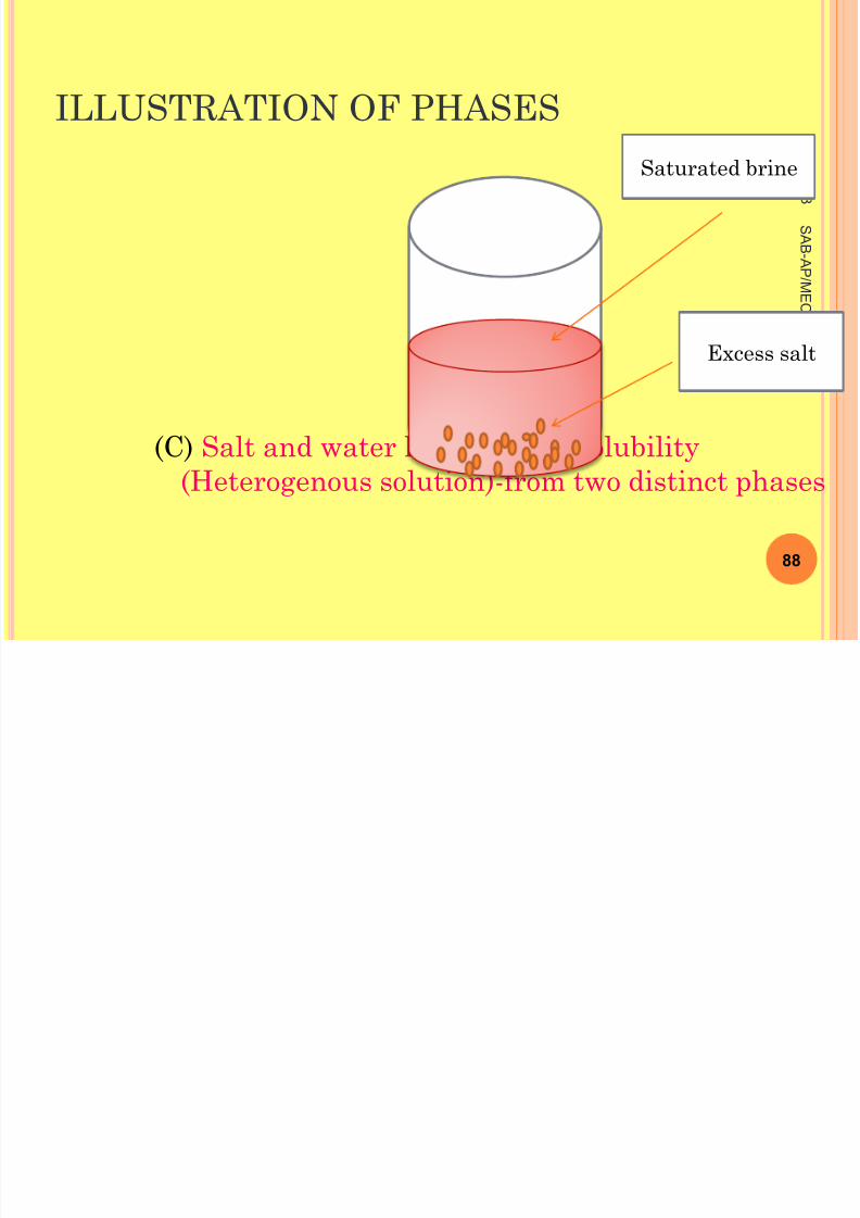
If more salt is added into water, then we have
two different phases as shown if fig(c)
1 / 5 / 2 0 1
3
83
S A B -A P
/ ME
C H
S ONA
C T
8/11/2019 Engineering Materials & Metal
http://slidepdf.com/reader/full/engineering-materials-metal 84/159
WHAT IS MEANT BY THE TERM PHASE ?
A Single phase system is also termed as
“homogeneous system”
1 / 5 / 2 0 1
3
84
S A B -A P
/ ME
C H
S ONA
C T
8/11/2019 Engineering Materials & Metal
http://slidepdf.com/reader/full/engineering-materials-metal 85/159
WHAT IS MEANT BY THE TERM PHASE ?
System composed of two or more phases are
termed as mixtures or heterogeneous systems’.
Fig (d)
Most metallic alloys, ceramic, polymers, and
composite are heterogenous.
1 / 5 / 2 0 1
3
85
S A B -A P
/ ME
C H
S ONA
C T
8/11/2019 Engineering Materials & Metal
http://slidepdf.com/reader/full/engineering-materials-metal 86/159
ILLUSTRATION OF PHASES
WATER(2)
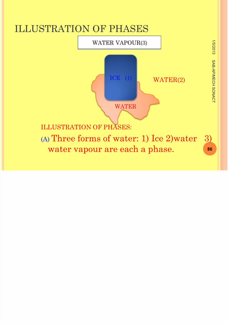
ILLUSTRATION OF PHASES:
(A) Three forms of water: 1) Ice 2)water 3)water vapour are each a phase.
1 / 5 / 2 0 1
3
86
S A B -A P
/ ME
C H
S ONA
C T
WATER
ICE (1)
WATER VAPOUR(3)
8/11/2019 Engineering Materials & Metal
http://slidepdf.com/reader/full/engineering-materials-metal 87/159
ILLUSTRATION OF PHASES
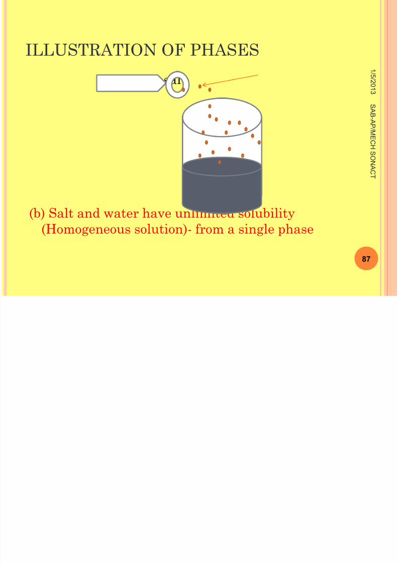
salt
(b) Salt and water have unlimited solubility(Homogeneous solution)- from a single phase
1 / 5 / 2 0 1
3
87
S A B -A P
/ ME
C H
S ONA
C T
•
8/11/2019 Engineering Materials & Metal
http://slidepdf.com/reader/full/engineering-materials-metal 88/159
ILLUSTRATION OF PHASES
(C) Salt and water have limited solubility(Heterogenous solution)-from two distinct phases
1 / 5 / 2 0 1
3
88
S A B -A P
/ ME
C H
S ONA
C T
Saturated brine
Excess salt
ILLUSTRATION OF PHASES
8/11/2019 Engineering Materials & Metal
http://slidepdf.com/reader/full/engineering-materials-metal 89/159
ILLUSTRATION OF PHASES
1 / 5 / 2 0 1
3
89
S A B -A P
/ ME
C H
S ONA
C T
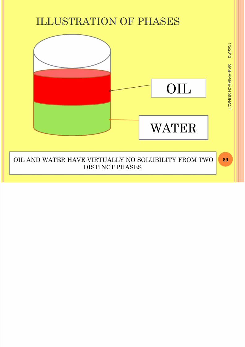
OIL
WATER
OIL AND WATER HAVE VIRTUALLY NO SOLUBILITY FROM TWODISTINCT PHASES
PHASE DIAGRAM OF PURE
8/11/2019 Engineering Materials & Metal
http://slidepdf.com/reader/full/engineering-materials-metal 90/159
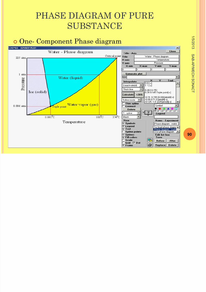
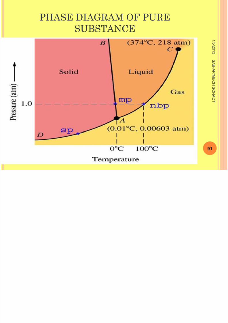
PHASE DIAGRAM OF PURESUBSTANCE
One- Component Phase diagram1
/ 5 / 2 0 1
3
90
S A B -A P
/ ME
C H
S ONA
C T
PHASE DIAGRAM OF PURE
8/11/2019 Engineering Materials & Metal
http://slidepdf.com/reader/full/engineering-materials-metal 91/159
PHASE DIAGRAM OF PURESUBSTANCE
1
/ 5 / 2 0 1
3
91
S A B -A P
/ ME
C H
S ONA
C T
PHASE DIAGRAM OF PURE
8/11/2019 Engineering Materials & Metal
http://slidepdf.com/reader/full/engineering-materials-metal 92/159
PHASE DIAGRAM OF PURESUBSTANCE
A pure substance such as water can exist in
solid, liquid, or vapour phases, depending on the
condition of temperature and pressure
1
/ 5 / 2 0 1
3
92
S A B -A P
/ ME
C H
S ONA
C T
PHASE DIAGRAM OF PURE
8/11/2019 Engineering Materials & Metal
http://slidepdf.com/reader/full/engineering-materials-metal 93/159
PHASE DIAGRAM OF PURESUBSTANCE
The phase relationships may be represented on
a pressure- temperature (PT) diagram, known as
a one-component (or unary) phase diagram, for
the H 2O System.
1
/ 5 / 2 0 1
3
93
S A B -A P
/ ME
C H
S ONA
C T
PHASE DIAGRAM OF PURE
8/11/2019 Engineering Materials & Metal
http://slidepdf.com/reader/full/engineering-materials-metal 94/159
PHASE DIAGRAM OF PURESUBSTANCE
The phase diagram is composed of regions of
pressure and temperature where only a single
phase is stable.
The line OA indicates the vapourisation line
and the line OB indicates the freezing line.
1
/ 5 / 2 0 1
3
94
S A B -A P
/ ME
C H
S ONA
C T
PHASE DIAGRAM OF PURE
8/11/2019 Engineering Materials & Metal
http://slidepdf.com/reader/full/engineering-materials-metal 95/159
PHASE DIAGRAM OF PURESUBSTANCE
Liquid and vapour phase exist along the
vapourisation line and liquid and solid phases
along the freezing line, shows in figure. These
lines are also known as Two phase equilibrium
lines.
1
/ 5 / 2 0 1
3
95
S A B -A P
/ ME
C H
S ONA
C T
PHASE DIAGRAM OF PURE
8/11/2019 Engineering Materials & Metal
http://slidepdf.com/reader/full/engineering-materials-metal 96/159
PHASE DIAGRAM OF PURESUBSTANCE
The point “O” is know as Triple point.
Triple point is the point at which three phases
(Solid, liquid, and vapour phases(gas)).
of a single material coexit. This triple point of
water exists at temperature 0.00980C
and at pressure 4.58 mm of Hg.
1
/ 5 / 2 0 1
3
96
S A B -A P
/ ME
C H
S ONA
C T
PHASE DIAGRAMS
8/11/2019 Engineering Materials & Metal
http://slidepdf.com/reader/full/engineering-materials-metal 97/159
PHASE DIAGRAMS
The properties of an alloy depend on nature,
amount, size, distribution and orientation of the
phases.
A phase is the chemically and structurally
homogeneous portion of the microstructure.
1 / 5 / 2 0 1
3
97
S A B -A P
/ ME
C H
S ONA
C T
8/11/2019 Engineering Materials & Metal
http://slidepdf.com/reader/full/engineering-materials-metal 98/159
PHASE DIAGRAMS
It has the following characteristics
1. Same structure throughout.
2. Roughly the same composition and
properties throughout.
3. Definite interface between the phase
and surrounding.
1 / 5 / 2 0 1
3
98
S A B -A P
/ ME
C H
S ONA
C T

8/11/2019 Engineering Materials & Metal
http://slidepdf.com/reader/full/engineering-materials-metal 99/159
J.W. GIBBS( J OSIAH W ILLARD G IBBS ) 1
/ 5 / 2 0 1
3
99
S A B -A P
/ ME
C H
S ONA
C T
J.W. GIBBS( J OSIAH W ILLARD

8/11/2019 Engineering Materials & Metal
http://slidepdf.com/reader/full/engineering-materials-metal 100/159
(G IBBS )
JOSIAH WILLARD GIBBS PROPOSAL(OR)
J.W. GIBBS LAW
(OR) GIBB’S PHASE RULE
(or)
PHASE RULE
1 / 5 / 2 0 1
3
100
S A B -A P
/ ME
C H
S ONA
C T
8/11/2019 Engineering Materials & Metal
http://slidepdf.com/reader/full/engineering-materials-metal 101/159
GIBBS PHASE RULE
J.W. Gibbs, American physicist derived an
equation which established relationship in a
system between the number of phases,
The number of degree of freedom and the
number of components.
1 / 5 / 2 0 1
3
101
S A B -A P
/ ME
C H
S ONA
C T
8/11/2019 Engineering Materials & Metal
http://slidepdf.com/reader/full/engineering-materials-metal 102/159
GIBB’S PHASE RULE
The phase rule indicates the phases that exists
at equilibrium.
The Gibb’s phase rule satisfies the following
relation:
P+F=C+n
1 / 5 / 2 0 1
3
102
S A B -A P
/ ME
C H
S ONA
C T
8/11/2019 Engineering Materials & Metal
http://slidepdf.com/reader/full/engineering-materials-metal 103/159
GIBB’S PHASE RULE
P- Number of phases that exist in a
system under certain conditions.
C-Number of components in the system.
n- It represents the number of variables,
examples: Temperature, pressure and
concentration.
1 / 5 / 2 0 1
3
103
S A B -A P
/ ME
C H
S ONA
C T
8/11/2019 Engineering Materials & Metal
http://slidepdf.com/reader/full/engineering-materials-metal 104/159
GIBB’S PHASE RULE
F- Degree of freedom. It is the number of
variables such as temperature or
pressure or concentration which can
be change independently without
changing the number of phases that
are present in the system.
1 / 5 / 2 0 1
3
104
S A B -A P
/ ME
C H
S ONA
C T
8/11/2019 Engineering Materials & Metal
http://slidepdf.com/reader/full/engineering-materials-metal 105/159
GIBB’S PHASE RULE
In most studies the pressure is constant
i.e., 1 atmospheric pressure and hence pressureis not considered a variable.
Usually the only variable under consideration istemperature and hence the Gibb’s phase rulebecomes;
P+F=C+1
1 / 5 / 2 0 1
3
105
S A B -A P
/ ME
C H
S ONA
C T
8/11/2019 Engineering Materials & Metal
http://slidepdf.com/reader/full/engineering-materials-metal 106/159
USES OF PHASE RULE
The phase rule predicts maximum number of
phases present in the alloy under equilibrium
conditions at any point of diagram.
If the number of phases are known, one can
determine the degree of freedom using phase
rule.
1 / 5 / 2 0 1
3
106
S A B -A P
/ ME
C H
S ONA
C T
8/11/2019 Engineering Materials & Metal
http://slidepdf.com/reader/full/engineering-materials-metal 107/159
USES OF PHASE RULE
Thus the phase rule is useful to know whether
the temperature or pressure or both variables
can be changed without changing the structure of
the alloy.
1 / 5 / 2 0 1
3
107
S A B -A P
/ ME
C H
S ONA
C T
ILLUSTRATION OF THE USE OF THE
8/11/2019 Engineering Materials & Metal
http://slidepdf.com/reader/full/engineering-materials-metal 108/159
PHASE RULE
Let us consider the application of gibbs phase rule
to the phase diagram of water system
Case 1 : Consider a triple point in the diagram. At the triple point, three phases coexist inequilibrium .
P=3. Since there is one component (water) in thesystem C= 1
1 / 5 / 2 0 1
3
108
S A B -A P
/ ME
C H
S ONA
C T
8/11/2019 Engineering Materials & Metal
http://slidepdf.com/reader/full/engineering-materials-metal 109/159
THE USE OF THE PHASE RULE
The number of degree of freedom can be
calculated using the Gibbs phase rule as,
F =1- 3+2F=0 (Zero degree of freedom)
This means that one of the variables
(Temperature or pressure) can be changed
at the triple point.
1 / 5 / 2 0 1
3
109
S A B -A P
/ ME
C H S
ONA
C T
8/11/2019 Engineering Materials & Metal
http://slidepdf.com/reader/full/engineering-materials-metal 110/159
THE USE OF THE PHASE RULE
Note: Since the variables temperature or
pressure cannot be changed and still keep the
three phases of coexistence.
The triple point is called an invariant point.
1 / 5 / 2 0 1
3
110
S A B -A P
/ ME
C H S
ONA
C T
8/11/2019 Engineering Materials & Metal
http://slidepdf.com/reader/full/engineering-materials-metal 111/159
THE USE OF THE PHASE RULE
Case 2: Next consider a point along liquid-solid freezing curve
P=2Then for water system
C=1 Applying the phase rule, we get:
F=1- 2+ 2F=1 (one degree of freedom)
1 / 5 / 2 0 1
3
111
S A B -A P
/ ME
C H S
ONA
C T

8/11/2019 Engineering Materials & Metal
http://slidepdf.com/reader/full/engineering-materials-metal 112/159
THE USE OF THE PHASE RULE
This means that one variable
( Temperature or pressure) can be changed
independently and still maintain a system
with two coexisting phases.
1 / 5 / 2 0 1
3
112
S A B -A P
/ ME
C
H S ONA
C T
8/11/2019 Engineering Materials & Metal
http://slidepdf.com/reader/full/engineering-materials-metal 113/159
THE USE OF THE PHASE RULE
Case:3Now consider a point on the phase
diagram of water inside a single phase in thiscase there will be only one phase present.
P=1 ,Then for water system, C=1Now the phase rule gives
1 / 5 / 2 0 1
3
113
S A B -A P
/ ME
C
H S ONA
C T
8/11/2019 Engineering Materials & Metal
http://slidepdf.com/reader/full/engineering-materials-metal 114/159
THE USE OF THE PHASE RULE
F=1-1+2
F=2 ( two degree of freedom)
This means that two variables ( Temperature
and pressure) can be varied independently and
the system will still remain in a single phase.
1 / 5 / 2 0 1
3
114
S A B -A P
/ ME
C
H S ONA
C T
8/11/2019 Engineering Materials & Metal
http://slidepdf.com/reader/full/engineering-materials-metal 115/159
THE USE OF THE PHASE RULE
Note: In many application (especially for most
binary alloy) the pressure is kept constant at 1
atmosphere.
In this case Gibbs phase rule is modified as
F=C-P+1
1 / 5 / 2 0 1
3
115
S A B -A P
/ ME
C
H S ONA
C T
8/11/2019 Engineering Materials & Metal
http://slidepdf.com/reader/full/engineering-materials-metal 116/159
THE USE OF THE PHASE RULE
The above equation is known as condensed phase
rule.
This equation can be applied to most of
the binary phase diagram.
1 / 5 / 2 0 1
3
116
S A B -A P
/ ME
C
H S ONA
C T
8/11/2019 Engineering Materials & Metal
http://slidepdf.com/reader/full/engineering-materials-metal 117/159
OBJECTIVE TYPE QUESTIONS
1. -----------May be visualized as forming from a
centre of freezing, or nucleus, which is composed
of a small group of atoms oriented into one of the
common crystal patterns.
Crystal
1 / 5 / 2 0 1
3
117
S A B -A P
/ ME
C
H S ONA
C T
8/11/2019 Engineering Materials & Metal
http://slidepdf.com/reader/full/engineering-materials-metal 118/159
OBJECTIVE TYPE QUESTIONS
2.Perfect crystal of proper external shape can be
obtained only if crystallisation develops under
conditions
when degree of ----------------is very slight and the
metal has a very high purity.
1 / 5 / 2 0 1
3
118
S A B -A P
/ ME
C
H S ONA
C T
8/11/2019 Engineering Materials & Metal
http://slidepdf.com/reader/full/engineering-materials-metal 119/159
V ARIOUS M ICRO -C ONSTITUENTS OF I RON -
8/11/2019 Engineering Materials & Metal
http://slidepdf.com/reader/full/engineering-materials-metal 120/159
C ARBON A LLOYS ARE :
1.Ferrite
2.Austenite
3.Cementite
4.Pearlite
5.Ledeburite
6.Martensite
1 / 5 / 2 0 1
3
120
S A B -A P
/ ME
C
H S ONA
C T
V ARIOUS M ICRO -C ONSTITUENTS OF I RON -

8/11/2019 Engineering Materials & Metal
http://slidepdf.com/reader/full/engineering-materials-metal 121/159
C ARBON A LLOYS ARE :
7. Troosite
8. Sorbite, and
9.Bainite
1 / 5 / 2 0 1
3
121
S A B -A P
/ ME
C
H S ONA
C T
V ARIOUS M ICRO -C ONSTITUENTS OF I RON -
8/11/2019 Engineering Materials & Metal
http://slidepdf.com/reader/full/engineering-materials-metal 122/159
C ARBON A LLOYS ARE :
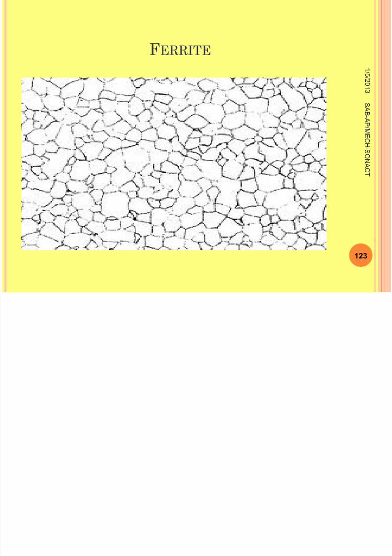
1. Ferrite (or α -Iron)
Ferrite is a primary solid solution based on α iron
having BCC structure.
It is Nothing but the interstitial solid solution of
carbon in iron.
1 / 5 / 2 0 1
3
122
S A B -A P
/ ME
C
H S ONA
C T
8/11/2019 Engineering Materials & Metal
http://slidepdf.com/reader/full/engineering-materials-metal 123/159
F ERRITE 1
/ 5 / 2 0 1
3
123
S A B -A P
/ ME
C
H S ONA
C T
V ARIOUS M ICRO -C ONSTITUENTS OF I RON -
8/11/2019 Engineering Materials & Metal
http://slidepdf.com/reader/full/engineering-materials-metal 124/159
C ARBON A LLOYS ARE :
Maximum solubility of carbon in iron is 0.025% carbon
at 723 °C, While its solubility at room temperature is
only 0.008%.
Ferrite is soft, ductile, and highly
Magnetic.
It can undergo extensive cold working
1 / 5 / 2 0 1
3
124
S A B -A P
/ ME
C
H S ONA
C T
V ARIOUS M ICRO -C ONSTITUENTS OF I RON -
8/11/2019 Engineering Materials & Metal
http://slidepdf.com/reader/full/engineering-materials-metal 125/159
C ARBON A LLOYS ARE :
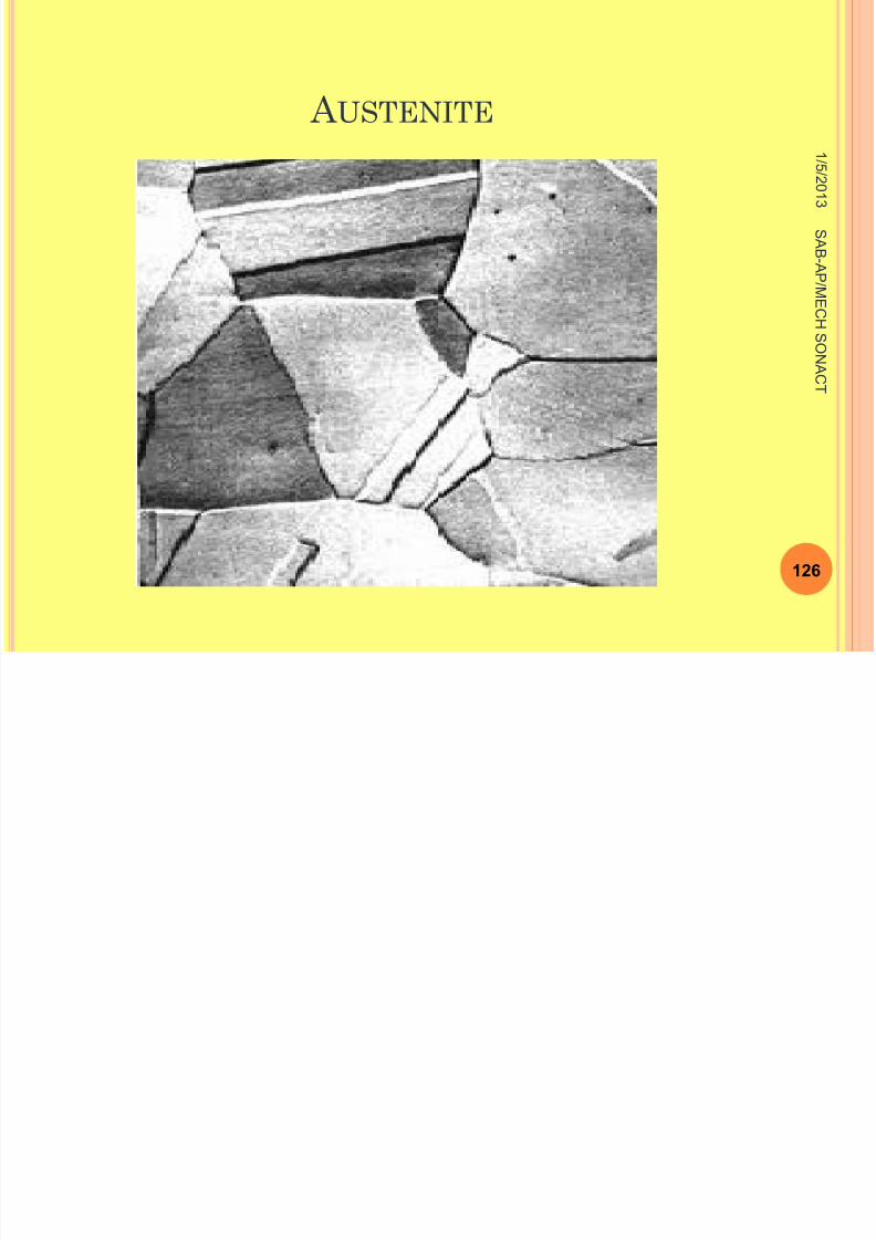
2. Austenite (or γ -Iron)
Austenite is a primary solid solution based on γ
iron having FCC structure.
This is also an interstitial solid solution of
carbon in iron
1 / 5 / 2 0 1
3
125
S A B -A P
/ ME
C
H S ONA
C T
8/11/2019 Engineering Materials & Metal
http://slidepdf.com/reader/full/engineering-materials-metal 126/159
A USTENITE 1
/ 5 / 2 0 1
3
126
S A B -A P
/ ME
C
H S ONA
C T
A
8/11/2019 Engineering Materials & Metal
http://slidepdf.com/reader/full/engineering-materials-metal 127/159
A USTENITE
It is also a non-magnetic (paramagnetic)
Austentite has a greater electrical resistance
and coefficient of expansion than ferrite.
1 / 5 / 2 0 1
3
127
S A B -A P
/ ME
C
H S ONA
C T
C
8/11/2019 Engineering Materials & Metal
http://slidepdf.com/reader/full/engineering-materials-metal 128/159
C EMENTITE
Cementite is the name given to the carbide of
iron(Fe 3c).
It is the hard, brittle, intermetallic compound of
iron with 6.69% of carbon.
1 / 5 / 2 0 1
3
128
S A B -A P
/ ME
C
H S ONA
C T
C
8/11/2019 Engineering Materials & Metal
http://slidepdf.com/reader/full/engineering-materials-metal 129/159
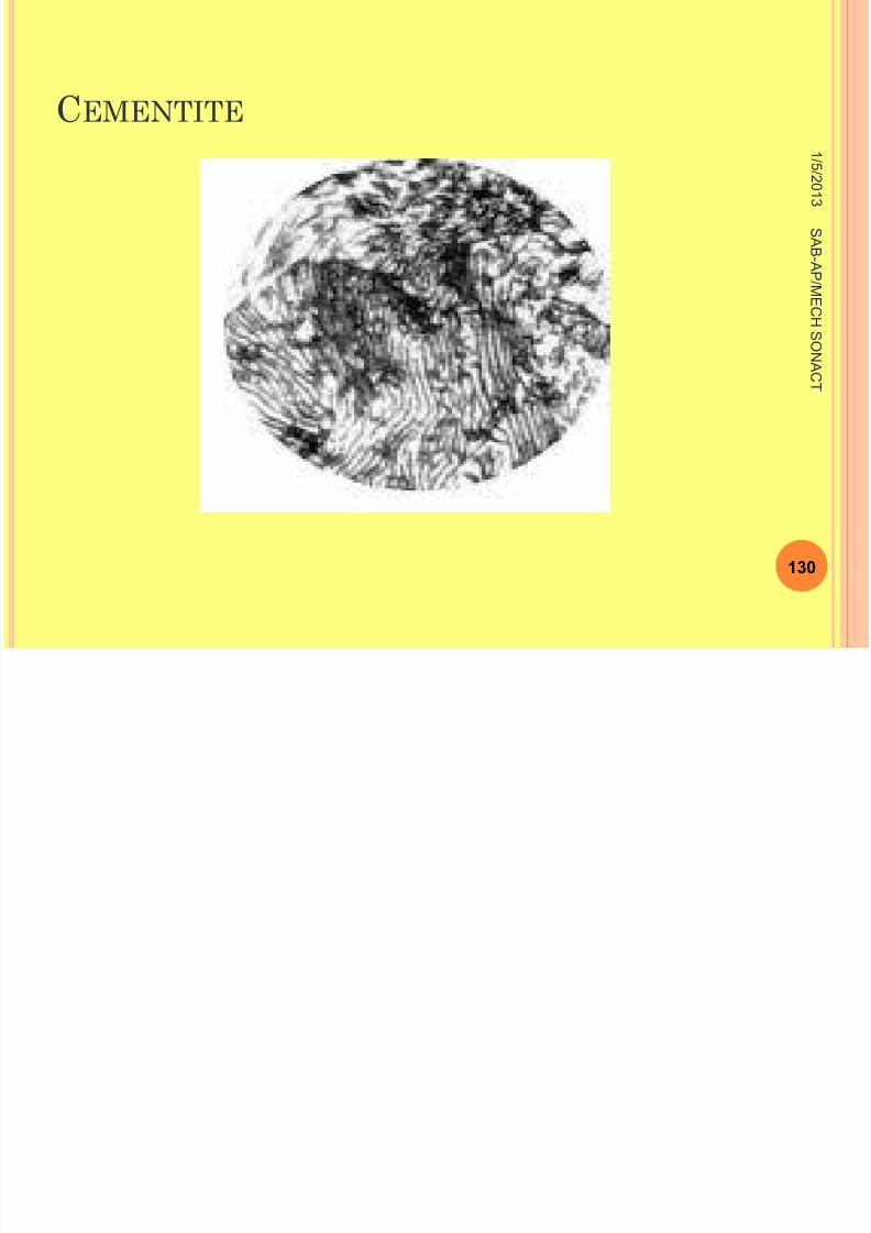
CEMENTITE
The hardness and brittleness of cast iron is
believed to be due to the presence of the
cementite.
It is Magnetic below 250°c
1 / 5 / 2 0 1
3
129
S A B -A P
/ ME
C
H S ONA
C T
C
8/11/2019 Engineering Materials & Metal
http://slidepdf.com/reader/full/engineering-materials-metal 130/159
CEMENTITE 1
/ 5 / 2 0 1
3
130
S A B -A P
/ ME
C H
S ONA
C T
P

8/11/2019 Engineering Materials & Metal
http://slidepdf.com/reader/full/engineering-materials-metal 131/159
P EARLITE
Pearlite is the eutectoid mixture of ferrite
(87.5%) and cementite (12.5%).
It is formed when austenite decomposes
during cooling. It contains 0.8% of carbon
1 / 5 / 2 0 1
3
131
S A B -A P
/ ME
C H
S ONA
C T
P EARLITE

8/11/2019 Engineering Materials & Metal
http://slidepdf.com/reader/full/engineering-materials-metal 132/159
P EARLITE 1
/ 5 / 2 0 1
3
132
S A B -A P
/ ME
C H
S ONA
C T
P

8/11/2019 Engineering Materials & Metal
http://slidepdf.com/reader/full/engineering-materials-metal 133/159
P EARLITE L AMELLAR -P EARLITE BEADED BAG 1
/ 5 / 2 0 1
3
133
S A B -A P
/ ME
C H
S ONA
C T
8/11/2019 Engineering Materials & Metal
http://slidepdf.com/reader/full/engineering-materials-metal 134/159
P EARLITE
8/11/2019 Engineering Materials & Metal
http://slidepdf.com/reader/full/engineering-materials-metal 135/159
P EARLITE
The properties of pearlite is midway between
ferrite and cementite. It is relatively strong, hard
and ductile.
1 / 5 / 2 0 1
3
135
S A B -A P
/ ME
C H
S ONA
C T
LEDEBURITE
8/11/2019 Engineering Materials & Metal
http://slidepdf.com/reader/full/engineering-materials-metal 136/159
LEDEBURITE
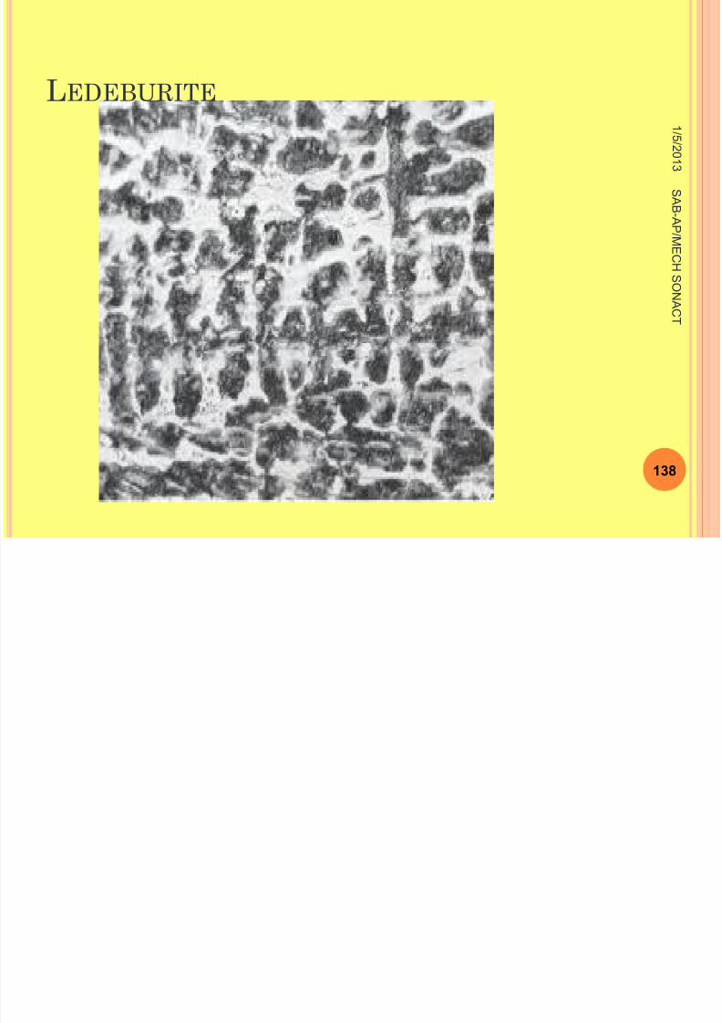
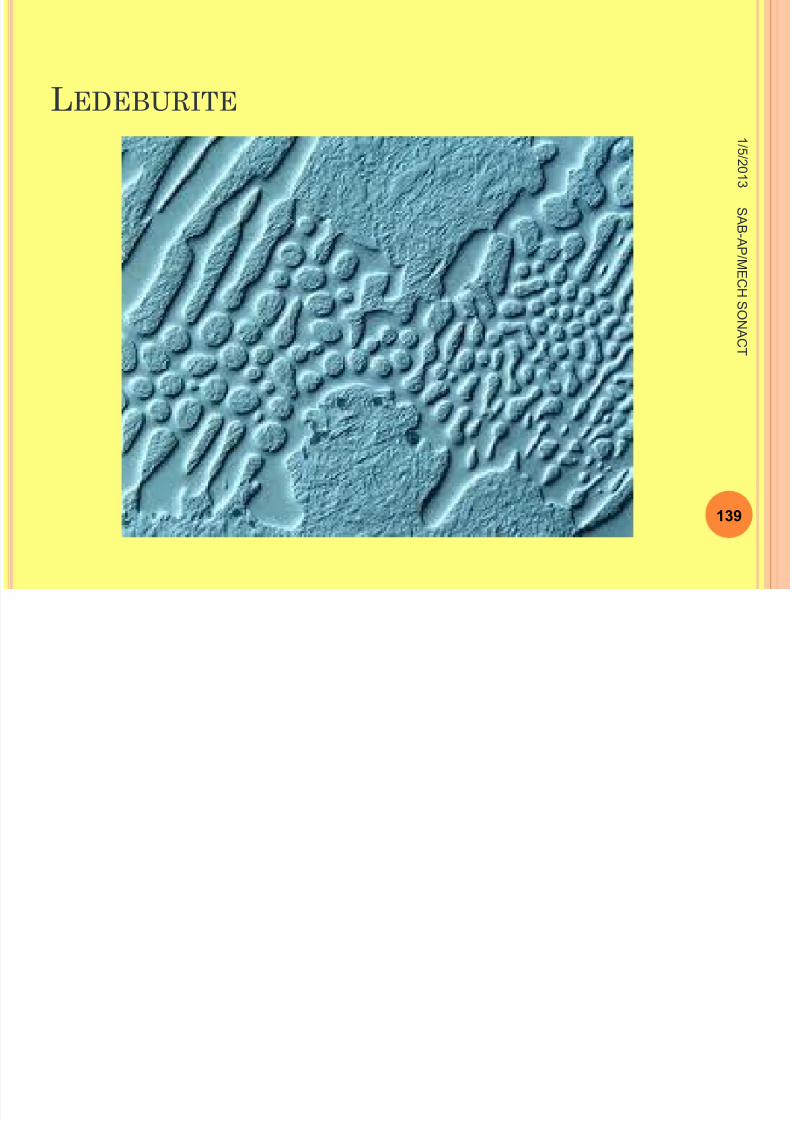
Ledeburite is the eutectic mixture of austenite( γ -Iron) and
cementite (Fe 3C) Containing 4.3% carbon.
In pure iron-carbon alloy, it forms at 1140 °C.
Most of the engineering alloy materials belong to
this range of alloy.
1 / 5 / 2 0 1
3
136
S A B -A P
/ ME
C H
S ONA
C T

8/11/2019 Engineering Materials & Metal
http://slidepdf.com/reader/full/engineering-materials-metal 137/159
LEDEBURITE
8/11/2019 Engineering Materials & Metal
http://slidepdf.com/reader/full/engineering-materials-metal 138/159
LEDEBURITE 1
/ 5 / 2 0 1
3
138
S A B -A P
/ ME
C H
S ONA
C T
LEDEBURITE
8/11/2019 Engineering Materials & Metal
http://slidepdf.com/reader/full/engineering-materials-metal 139/159
LEDEBURITE 1
/ 5 / 2 0 1
3
139
S A B -A P
/ ME
C H
S ONA
C T
MARTENSITE
8/11/2019 Engineering Materials & Metal
http://slidepdf.com/reader/full/engineering-materials-metal 140/159
M ARTENSITE
Martensite is the super saturated solid solution
of carbon in α -Iron.
It is formed when steel is very rapidly cooled from the
austenitic state.
It exhibits a characteristic acicular or needle like
structure.
1 / 5 / 2 0 1
3
140
S A B -A P
/ ME
C H
S ONA
C T
MARTENSITE

8/11/2019 Engineering Materials & Metal
http://slidepdf.com/reader/full/engineering-materials-metal 141/159
M ARTENSITE
It is very hard more brittle and low ductility
properties.
There is an increase in specific volume during
formation of martensite from austenite.
1 / 5 / 2 0 1
3
141
S A B -A P
/ ME
C H
S ONA
C T
MARTENSITE
8/11/2019 Engineering Materials & Metal
http://slidepdf.com/reader/full/engineering-materials-metal 142/159
M ARTENSITE
As a result internal stresses are set up in the
materials leading to the formation of minute
cracks.
1 / 5 / 2 0 1
3
142
S A B -A P
/ ME
C H
S ONA
C T
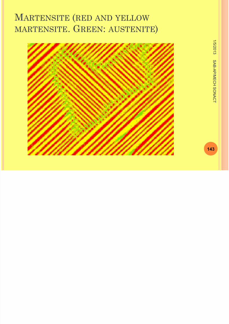
M ARTENSITE (RED AND YELLOW MARTENSITE G REEN : AUSTENITE )
8/11/2019 Engineering Materials & Metal
http://slidepdf.com/reader/full/engineering-materials-metal 143/159
MARTENSITE . G REEN : AUSTENITE )1
/ 5 / 2 0 1
3
143
S A B -A P
/ ME
C H
S ONA
C T
TROOSTITE
8/11/2019 Engineering Materials & Metal
http://slidepdf.com/reader/full/engineering-materials-metal 144/159
TROOSTITE
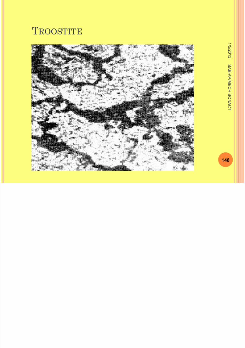
Troosite is the mixture of radial lamella of
ferrite and cementite. In fact, it differs from
pearlite only in the degree of fitness.
This constituents is also known as troostite
pearlite.
1 / 5 / 2 0 1
3
144
S A B -A P
/ ME
C H
S ONA
C T
TROOSTITE
8/11/2019 Engineering Materials & Metal
http://slidepdf.com/reader/full/engineering-materials-metal 145/159
TROOSTITE
It is the microstructure consisting ferrite and
finely divided cementite, produced on tempering
martensite below 450 °C
1 / 5 / 2 0 1
3
145
S A B -A P
/ ME
C H
S ONA
C T
TROOSTITE
8/11/2019 Engineering Materials & Metal
http://slidepdf.com/reader/full/engineering-materials-metal 146/159
TROOSTITE
It is formed by the decomposition of austenite
when cooled at a rate slower than that which
will yield a martensitic structure and faster than
that which will produce a sorbitic structure.
1 / 5 / 2 0 1
3
146
S A B -A P
/ ME
C H
S ONA
C T
TROOSTITE
8/11/2019 Engineering Materials & Metal
http://slidepdf.com/reader/full/engineering-materials-metal 147/159
TROOSTITE
It has hardness intermediate between
martensite and sorbite.
1 / 5 / 2 0 1
3
147
S A B -A P
/ ME
C H
S ONA
C T
TROOSTITE
8/11/2019 Engineering Materials & Metal
http://slidepdf.com/reader/full/engineering-materials-metal 148/159
TROOSTITE 1
/ 5 / 2 0 1
3
148
S A B -A P
/ ME
C H
S ONA
C T
S ORBITE
8/11/2019 Engineering Materials & Metal
http://slidepdf.com/reader/full/engineering-materials-metal 149/159
S ORBITE
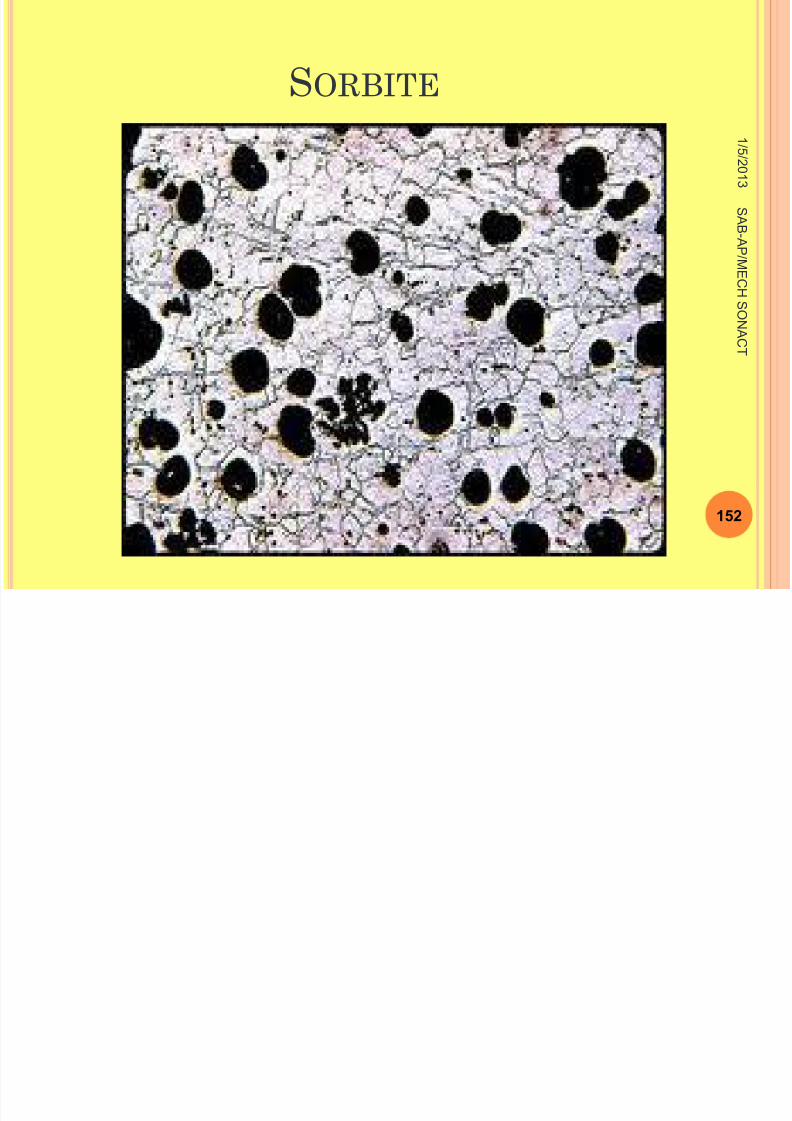
Sorbite is the microstructure consisting ferrite,
and finely divided cementite, produced on
tempering martensite above 450°C
1 / 5 / 2 0 1
3
149
S A B -A P
/ ME
C H
S ONA
C T
8/11/2019 Engineering Materials & Metal
http://slidepdf.com/reader/full/engineering-materials-metal 150/159
8/11/2019 Engineering Materials & Metal
http://slidepdf.com/reader/full/engineering-materials-metal 151/159
S ORBITE
8/11/2019 Engineering Materials & Metal
http://slidepdf.com/reader/full/engineering-materials-metal 152/159
1 / 5 / 2 0 1
3
152
S A B -A P
/ ME
C H
S ONA
C T
S ORBITE
8/11/2019 Engineering Materials & Metal
http://slidepdf.com/reader/full/engineering-materials-metal 153/159
S O
Note:
All the pearlite, troosite and sorbite are ferrite-
cementite mixtures having lamellar structure.
However they are distinguished by their degree of
dispersion.
Pearlite has corase pearlite.
1 / 5 / 2 0 1
3
153
S A B -A P
/ ME
C H
S ONA
C T
S ORBITE
8/11/2019 Engineering Materials & Metal
http://slidepdf.com/reader/full/engineering-materials-metal 154/159
Troosite has fine pearlite
And sorbite has medium pearlite
1 / 5
/ 2 0 1
3
154
S A B -A P
/ ME
C H
S ONA
C T
B AINITE
8/11/2019 Engineering Materials & Metal
http://slidepdf.com/reader/full/engineering-materials-metal 155/159
Bainite is a decomposition product of austenite,
consisting of an aggregate of ferrite and carbide.
Bainite is obtained by transformation of pearlite
higher temperature ( has a feathery structure) is
called upper bainite.
1 / 5
/ 2 0 1
3
155
S A B -A P
/ ME
C H
S ONA
C T
B AINITE
8/11/2019 Engineering Materials & Metal
http://slidepdf.com/reader/full/engineering-materials-metal 156/159
Lower bainite provides high mechanical
properties and that is why it is extensively
used for components of machine and structures.
Bainite has hardness in between the hardness
of pearlite and martensite.
1 / 5
/ 2 0 1
3
156
S A B -A P
/ ME
C H
S ONA
C T
B AINITE

8/11/2019 Engineering Materials & Metal
http://slidepdf.com/reader/full/engineering-materials-metal 157/159
1 / 5
/ 2 0 1
3
157
S A B -A P
/ ME
C H
S ONA
C T
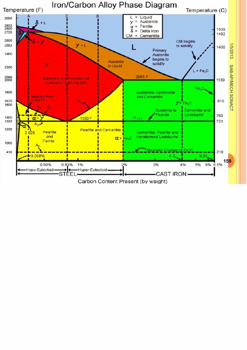
IRON /C ARBON ALLOY P HASE D IAGRAM

8/11/2019 Engineering Materials & Metal
http://slidepdf.com/reader/full/engineering-materials-metal 158/159
1 / 5
/ 2 0 1
3
158
S A B -A P
/ ME
C H
S ONA
C T
8/11/2019 Engineering Materials & Metal
http://slidepdf.com/reader/full/engineering-materials-metal 159/159
1 / 5
/ 2 0 1
3
S A B -A P
/ ME
C H
S ONA
C T