Embed Size (px)
DESCRIPTION
Basics of Engineering Graphics and Projection of Line
Citation preview

1
Projections of Points andStraight Lines – I
PRINCIPLES OF PROJECTIONS
Projecting the image of an object to the plane of projection is known as projection. Theobject may be a point, line, plane, solid, machine component or a building. Consider thefollowing illustration to project the image of an object on to a plane.
Figure 1.1 Projection of an object
In engineering drawing practice two principal planes are used to get the projectionof an object as shown in Fig.1.2.
They are,(i) Vertical plane (VP) which is assumed to be placed vertically. The front view of the
object is projected onto this plane.

16 Lesson Plan for Engineering Graphics
(ii) Horizontal plane (HP) which is assumed to be placed horizontally. The top view ofthe object is projected onto this plane.
These principal planes are also known as reference planes or co-ordinate planes. Theplanes considered are imaginary, transparent and dimensionless. The reference planesVP and HP are placed in such a way that they intersect each other at right angles. As aresult of intersection, an intersecting line is obtained which is known as the referenceline or XY line.
Observe in Fig. 1.2 the reference planes (VP & HP) forming four quadrants namely,(i) First quadrant (iii) Third quadrant(ii) Second quadrant (iv) Fourth quadrantIt is assumed that the observer always stands at the right side of the reference planes.
Figure 1.2
When an object is assumed to be placed in first quadrant, the projection methodfollowed is called first angle projection. In this method, the object is placed between theobserver and the plane of projection.
The image of the object is projected and obtained on HP by observing it from top ofthe object and is called topview or plan of the object. The image is projected and obtainedon VP by seeing the object from front and is called front view or elevation. As per thegeneral rule of drawing, the HP is rotated clockwise through 90°. After rotation, the imagesare drawn on HP and VP.

Projections of Points and Straight Lines – I 17
Figure 1.3
When the object is assumed to be placed in third quadrant, the projection methodfollowed is called third angle projection. In this method, the plane of projection lies betweenthe object and the observer.
As per BIS code IS: SP 46-1988, first angle projection method is tobe followed in engineering drawing practices
NAMING VIEWS
In drawing practice, capital letters A,B,C, etc. are used to represent objects inspace.Their top views are represented by small letters a,b,c, etc.The front views are represented by small letters with dashes a′, b′, c′, etc.These letters are used to represent a point, ends of a straight line, corners of asolid, etc.Actual projections in top and front views are drawn in thick lines. Constructionlines and projectors are drawn using thin lines.

18 Lesson Plan for Engineering Graphics
PROJECTIONS OF A POINT IN FIRST QUADRANT
Consider a point A placed in the first quadrant. This is at a height h mm above HP,at a distance d mm in front of VP. Its front view a′ is projected onto VP and the top viewa is projected onto HP.
(i) (ii)
Figure 1.4
Now the HP is rotated in the clockwise direction through 90° and is obtained in verticalposition. The projections will be seen as given in Fig. 1.4 (ii).
It is drawn with reference to XY line. Mark a point a′ at a height h mm above XY,and a at a distance d mm below XY. The projector joining a′ and a is always perpendicularto XY.
PROJECTIONS OF A POINT IN SECOND QUADRANT
Consider a point B placed in the second quadrant. This is at a height h mm aboveHP and at a distance d mm behind VP. Its front view b′ is projected onto VP and topview b is projected on to HP.
Now the HP is rotated in the clockwise direction through 90° and is obtained in verticalposition. The projections will be seen as given in Fig. 1.5 (ii). It is drawn with referenceto XY line. Mark a point b′ at a height h mm above XY and b at a distance d mm aboveXY.

Projections of Points and Straight Lines – I 19
(i) (ii)
Figure 1.5
PROJECTIONS OF A POINT IN THIRD QUADRANT
Consider a point C placed in the third quadrant. The point is at a height h mm belowHP and at a distance d mm behind VP. Its front view c′ is projected onto VP and the topview c is projected onto HP.
(i) (ii)
Figure 1.6

20 Lesson Plan for Engineering Graphics
Now the HP is rotated in the clockwise direction through 90° and is obtained in verticalposition. The projections will be seen as given in Fig. 1.6 (ii). It is drawn with referenceto XY line. Mark a point c′ at a height h mm below XY and c at a distance d mm aboveXY.
PROJECTIONS OF A POINT IN FOURTH QUADRANT
Consider a point D placed in the fourth quadrant. This is at a height h mm below HPand at a distance d mm in front of VP. Its front view d′ is projected onto VP and the topview d is projected onto HP.
Now the HP is rotated in the clockwise direction through 90° and is obtained in verticalposition. The projections will be seen as given in Fig. 1.7 (ii). It is drawn with referenceto XY line Mark a point d′ at a height h mm below XY and d at a distance d mm belowXY.
(i) (ii)
Figure 1.7
Example 1.1 A point A is 20 mm above HP and 30 mm in front of VP. Draw itsprojections.
SolutionTo draw the projections Draw the reference line XY. Mark a point a′ at a distance of20 mm above XY. Through this point draw a perpendicular line to XY and mark the topview a at a distance of 30 mm below XY.

Projections of Points and Straight Lines – I 21
(i) (ii)
Figure 1.8
Example 1.2 A point B is 20 mm above HP and 30 mm behind VP. Draw its projections.
(i) (ii)
Figure 1.9
To draw the projections Draw the reference line XY. Mark a point b′ at a distance of20 mm above XY. Through this point draw a perpendicular line to XY and mark the topview b at a distance of 30 mm above XY.

22 Lesson Plan for Engineering Graphics
Example 1.3 A point C is 20 mm below HP and 30 mm behind VP. Draw its projections.
(i) (ii)
Figure 1.10
To draw the projections Draw the reference line XY. Mark a point c′ at a distance of20 mm below XY. Through this point draw a perpendicular line to XY and mark the topview c at a distance of 30 mm above XY.
Example 1.4 A point D is 20 mm below HP and 30 mm in front of VP. Draw itsprojections.
(i) (ii)
Figure 1.11

Projections of Points and Straight Lines – I 23
To draw the projections Draw the reference line XY. Mark a point d′ at a distance of20 mm below XY. Through this point draw a perpendicular line to XY and mark the topview d at a distance of 30 mm below XY.
BASICS OF STRAIGHT LINE
A straight line is the shortest route to join any two given points. It is a one-dimensionalobject having only length (l).
Figure 1.12
The projections of a straight line are obtained by joining the top and front views ofthe respective end points of the line. The actual length of the straight line is known astrue length (TL).
PROJECTIONS OF STRAIGHT LINE
A straight line is placed witlh reference to the planes of projections in the followingpositions.
1. Line perpendicular to HP and parallel to VP2. Line perpendicular to VP and parallel to HP3. Line parallel to both HP and VP4. Line inclined to HP and parallel to VP5. Line inclined to VP and parallel to HP6. Line inclined to both HP and VP
In first angle projection method, the line is assumed to be placed in the first quadrant.The projections of the line in the above mentioned positions are discussed below.
Projections of a Line kept Perpendicular to HP and Parallel to VP
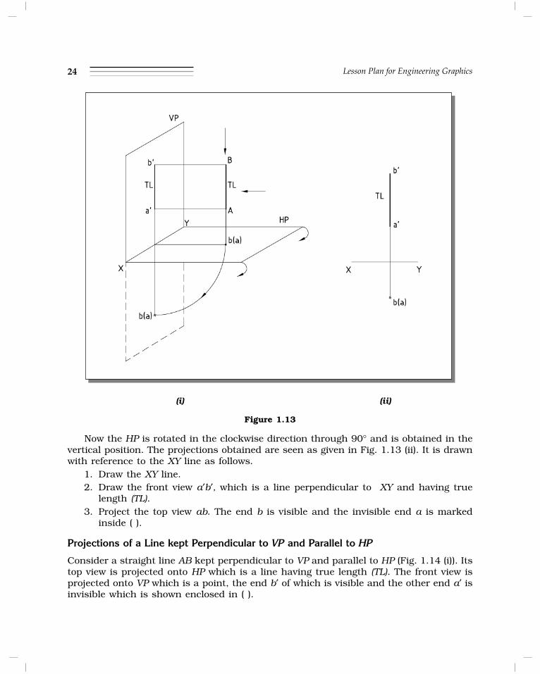
Consider a straight line AB kept perpendicular to HP and parallel to VP (Fig. 1.13(i)). Itsfront view is projected onto VP which is a line having true length. The top view is projectedonto HP which is a point, one end b of which is visible while the other end a is invisibleand is enclosed within ( ).
24 Lesson Plan for Engineering Graphics
(i) (ii)
Figure 1.13
Now the HP is rotated in the clockwise direction through 90° and is obtained in thevertical position. The projections obtained are seen as given in Fig. 1.13 (ii). It is drawnwith reference to the XY line as follows.
1. Draw the XY line.2. Draw the front view a′b′, which is a line perpendicular to XY and having true
length (TL).3. Project the top view ab. The end b is visible and the invisible end a is marked
inside ( ).
Projections of a Line kept Perpendicular to VP and Parallel to HP
Consider a straight line AB kept perpendicular to VP and parallel to HP (Fig. 1.14 (i)). Itstop view is projected onto HP which is a line having true length (TL). The front view isprojected onto VP which is a point, the end b′ of which is visible and the other end a′ isinvisible which is shown enclosed in ( ).

Projections of Points and Straight Lines – I 25
Now the HP is rotated in the clockwise direction through 90° and is obtained in thevertical position. The projections obtained are seen as given in Fig. 1.14 (ii). It is drawnwith reference to the XY line as follows.
1. Draw the XY line.2. Draw the top view ab, a line perpendicular to XY and having true length (TL).3. Project the front view a′b′. The end b′ is visible and the invisible end a′ is marked
inside ( ).
(i) (ii)
Figure 1.14
Projections of a Line kept Parallel to Both HP and VP
Consider a straight line AB kept parallel to both HP and VP (Fig. 1.15 (i)). Its front viewis projected onto VP which is a line having true length (TL). The top view is projectedonto HP which is also a line having true length.
Now the HP is rotated in the clockwise direction through an angle of 90° andis obtained in the vertical position. The projections obtained are seen as given inFig. 1.15 (ii). It is drawn with references to the XY line as follows.

26 Lesson Plan for Engineering Graphics
1. Draw the XY line.2. Draw the front view a′b′, a line parallel to XY and having true length (TL).3. Project the top view ab which is also a line parallel to XY having true length (TL).
(i) (ii)
Figure 1.15
Projections of a Line kept Inclined to HP and Parallel to VP
Consider a straight line AB kept inclined to HP and parallel to VP (Fig. 1.16(i)).
(i) (ii)Figure 1.16
Projections of Points and Straight Lines – I 27
Its front view is projected onto VP which is an inclined line at an angle θ to XY andhaving true length (TL). The top view is projected onto HP which is also a line but smallerthan the true length and parallel to XY. The inclination of the line with HP is alwaysrepresented by the symbol θ.
Now the HP is rotated in the clockwise direction through 90° and is obtained in thevertical position. The projections obtained are seen as given in Fig. 1.16 (ii). It is drawnwith reference to the XY line as follows.
1. Draw the XY line.2. Draw the front view a′b′, a line inclined at an angle θ to XY and having true length
(TL)3. Project the top view ab which is also a line parallel to XY and smaller than true
length.
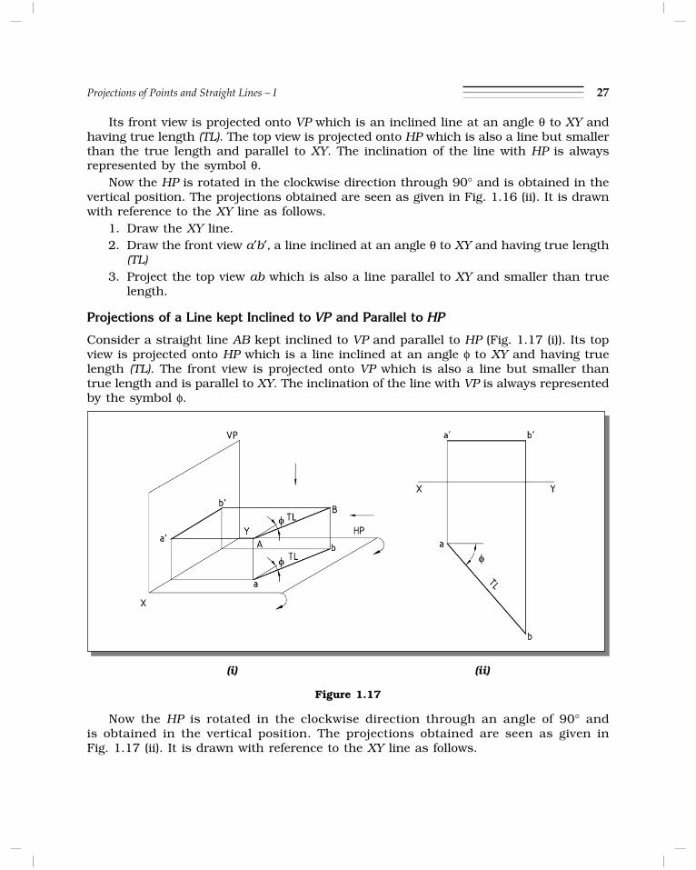
Projections of a Line kept Inclined to VP and Parallel to HP
Consider a straight line AB kept inclined to VP and parallel to HP (Fig. 1.17 (i)). Its topview is projected onto HP which is a line inclined at an angle φ to XY and having truelength (TL). The front view is projected onto VP which is also a line but smaller thantrue length and is parallel to XY. The inclination of the line with VP is always representedby the symbol f.
(i) (ii)
Figure 1.17
Now the HP is rotated in the clockwise direction through an angle of 90° andis obtained in the vertical position. The projections obtained are seen as given inFig. 1.17 (ii). It is drawn with reference to the XY line as follows.
28 Lesson Plan for Engineering Graphics
1. Draw the XY line.2. Draw the top view ab, a line inclined at an angle φ to XY and having true length
(TL).3. Project the front view a′b′, which is also a line parallel to XY but smaller than
true length.
TRACE OF A LINE
The point of intersection or meeting of a line with the reference plane, extended ifnecessary, is known as the trace of a line. The point of intersection of a line with the HPis known as the horizontal trace, represented by HT and that with the VP is known asthe vertical trace, represented by VT. No trace is obtained when a line is kept parallel toa reference plane. Note that HT always lies on plan or extanded plan, VT always lies onelevation or extended elevation.
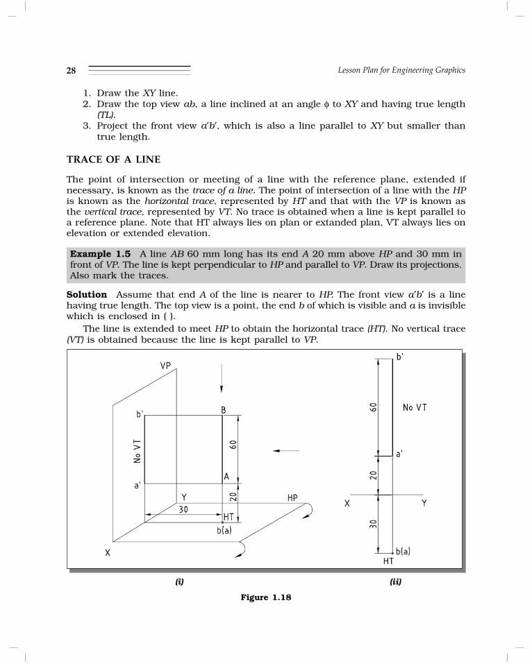
Example 1.5 A line AB 60 mm long has its end A 20 mm above HP and 30 mm infront of VP. The line is kept perpendicular to HP and parallel to VP. Draw its projections.Also mark the traces.
Solution Assume that end A of the line is nearer to HP. The front view a′b′ is a linehaving true length. The top view is a point, the end b of which is visible and a is invisiblewhich is enclosed in ( ).
The line is extended to meet HP to obtain the horizontal trace (HT). No vertical trace(VT) is obtained because the line is kept parallel to VP.
(i) (ii)
Figure 1.18
Projections of Points and Straight Lines – I 29
The projections obtained are drawn with reference to XY line as shown in Fig. 1.18 (ii).
1. Mark the projections of the end A by considering it as a point. Its front view ′ais 20 mm above XY and the top view a is 30 mm below XY.
2. The front view of the line a′b′ is obtained by drawing a line perpendicular to XYfrom a′ and having a length of 60 mm.
3. Top view of the line is obtained by projecting the other end b which coincideswith a. The invisible end a is enclosed in ( ).
4. The horizontal trace (HT) is marked coinciding with the top view of the line. Novertical trace (VT) is obtained.
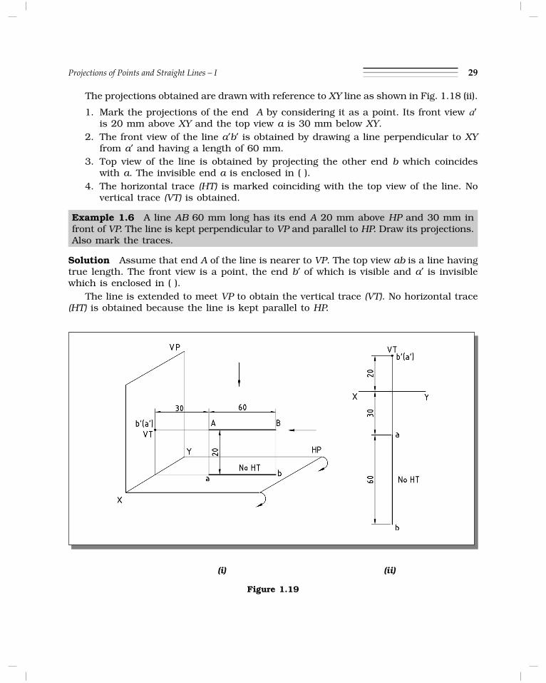
Example 1.6 A line AB 60 mm long has its end A 20 mm above HP and 30 mm infront of VP. The line is kept perpendicular to VP and parallel to HP. Draw its projections.Also mark the traces.
Solution Assume that end A of the line is nearer to VP. The top view ab is a line havingtrue length. The front view is a point, the end b′ of which is visible and a′ is invisiblewhich is enclosed in ( ).
The line is extended to meet VP to obtain the vertical trace (VT). No horizontal trace(HT) is obtained because the line is kept parallel to HP.
(i) (ii)
Figure 1.19

30 Lesson Plan for Engineering Graphics
The projections obtained are drawn with reference to the XY line as shown inFig. 1.19 (ii).
1. Mark the projections of the end A by considering it as a point. Its front view a′ is20 mm above XY and top view a is 30 mm below XY.
2. Top view of the line ab is obtained by drawing a line of length 60 mm perpendicularto XY from a.
3. Front view of the line is obtained by projecting the other end b′ which concideswith a′. The invisible end a′ is enclosed in ( ).
4. The vertical trace (VT) is marked coinciding with the front view of the line. Nohorizontal trace (HT) is obtained.
Example 1.7 A line AB 60 mm long has its end A 20 mm above HP and 30 mm infront of VP. The line is kept parallel to both HP and VP. Draw its projections.
Solution The front view a′b′ and top view ab are lines having true lengths. No horizontaland vertical traces are obtained because the line is kept parallel to both HP and VP.
The projections obtained are drawn with reference to the XY line as shown inFig. 1.20 (ii).
1. Mark the projections of end A by considering it as a point. Its front view a′ is20 mm above XY and top view a is 30 mm below XY.
2. The front view of the line a′b′ is obtained by drawing a line parallel to XY from a′having a length of 60 mm.
3. The top view of the line ab is obtained by drawing another line parallel to XY froma, also of length 60 mm.
4. No traces are marked because the line is kept parallel to both HP and VP.
(i) (ii)
Figure 1.20
Projections of Points and Straight Lines – I 31
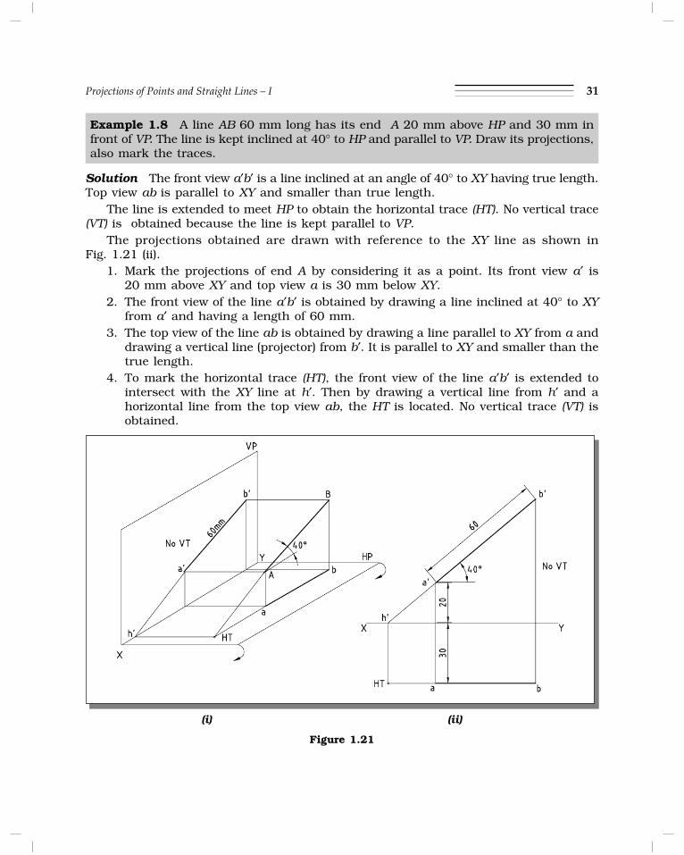
Example 1.8 A line AB 60 mm long has its end A 20 mm above HP and 30 mm infront of VP. The line is kept inclined at 40° to HP and parallel to VP. Draw its projections,also mark the traces.
Solution The front view a′b′ is a line inclined at an angle of 40° to XY having true length.Top view ab is parallel to XY and smaller than true length.
The line is extended to meet HP to obtain the horizontal trace (HT). No vertical trace(VT) is obtained because the line is kept parallel to VP.
The projections obtained are drawn with reference to the XY line as shown inFig. 1.21 (ii).
1. Mark the projections of end A by considering it as a point. Its front view a′ is20 mm above XY and top view a is 30 mm below XY.
2. The front view of the line a′b′ is obtained by drawing a line inclined at 40° to XYfrom a′ and having a length of 60 mm.
3. The top view of the line ab is obtained by drawing a line parallel to XY from a anddrawing a vertical line (projector) from b′. It is parallel to XY and smaller than thetrue length.
4. To mark the horizontal trace (HT), the front view of the line a′b′ is extended tointersect with the XY line at h′. Then by drawing a vertical line from h′ and ahorizontal line from the top view ab, the HT is located. No vertical trace (VT) isobtained.
(i) (ii)
Figure 1.21

32 Lesson Plan for Engineering Graphics
Example 1.9 A line AB 60 mm long has its end A 20 mm above HP and 30 mm infront of VP. The line is inclined at 40° to VP and parallel to HP. Draw its projections.Also mark the traces.
Solution The top view ab is a line inclined at an angle of 40° to XY and having truelength. Its front view a′b′ is parallel to XY and smaller than true length.
The line is extended to meet VP to obtain the vertical trace (VT). No horizontal trace(HT) is obtained because the line is kept parallel to HP.
The projections obtained are drawn with reference to XY line as shown in Fig. 1.22(ii).1. Mark the projections of end A by considering it as a point. Its front view a′ is
20 mm above XY and top view a is 30 mm below XY.2. The top view of the line ab is obtained by drawing a line inclined at an angle 40°
to XY from a and having a length of 60 mm.3. The front view of the line a′b′ is obtained by drawing a line parallel to XY from a′
and drawing a vertical line (projector) from b. It is parallel to XY and smaller thanthe true length.
4. To mark the vertical trace (VT) the top view of the line ab is extended to intersectwith XY line at v. Then by drawing a vertical line from v and a horizontal linefrom a′b′, the VT is located. No horizontal trace (HT) is obtained.
(i) (ii)
Figure 1.22

Projections of Points and Straight Lines – I 33
Tips to solve problems
When a line is inclined to one plane and parallel to the other plane.
(a) When a line is inclined to HP and parallel to VP: The projections are usuallyobtained as follows:
There are three variables namely TL, θ and TV marked in the drawing. In a problemusually any two variable values will be given and the third variable value can be obtainedgraphically by completing the drawing as mentioned below. Draw the projections a′ anda of the given end A.
(i) When TL and θ are given. Draw the front view a′b′ from a′ using TL and θ. Topview (TV) ab is projected and obtained by drawing a line parallel to the XY lineand a vertical line (projector) from b′.
(ii) When TL and TV are given. Draw the top view ab using TV parallel to XY line.Draw the vertical line (projector) from b. Using TL as radius and a′ as centre, marka point in the vertical line to get b′. Join a′ and b′ to complete the front view a′b′of the line. The inclination of a′b′ with XY is measured to get θ.
(iii) When TV and θ are given. Draw the top view using the length of TV parallel to theXY line. Draw the vertical line (projector) from b. Using the angle θ, draw a linewhich intersects the projector at b′. Join a′ and b′ to complete the front view a′b′of the line. The length of a′b′ is measured to get TL.
Figure 1.23
34 Lesson Plan for Engineering Graphics
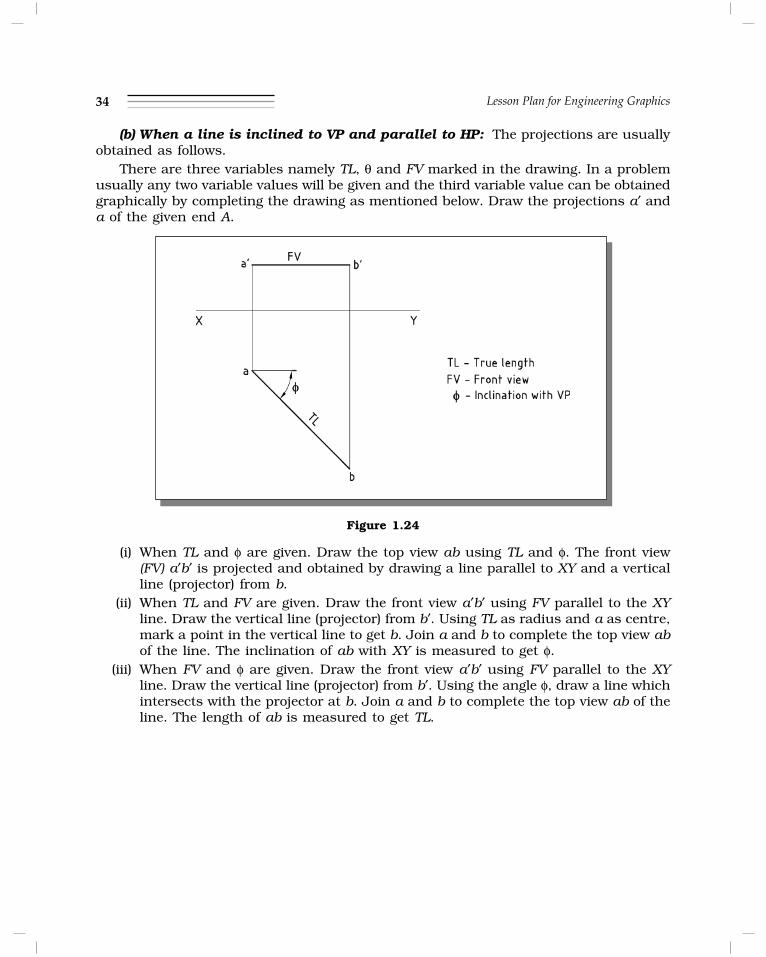
(b) When a line is inclined to VP and parallel to HP: The projections are usuallyobtained as follows.
There are three variables namely TL, θ and FV marked in the drawing. In a problemusually any two variable values will be given and the third variable value can be obtainedgraphically by completing the drawing as mentioned below. Draw the projections a′ anda of the given end A.
Figure 1.24
(i) When TL and φ are given. Draw the top view ab using TL and φ. The front view(FV) a′b′ is projected and obtained by drawing a line parallel to XY and a verticalline (projector) from b.
(ii) When TL and FV are given. Draw the front view a′b′ using FV parallel to the XYline. Draw the vertical line (projector) from b′. Using TL as radius and a as centre,mark a point in the vertical line to get b. Join a and b to complete the top view abof the line. The inclination of ab with XY is measured to get φ.
(iii) When FV and φ are given. Draw the front view a′b′ using FV parallel to the XYline. Draw the vertical line (projector) from b′. Using the angle φ, draw a line whichintersects with the projector at b. Join a and b to complete the top view ab of theline. The length of ab is measured to get TL.

Projections of Points and Straight Lines – I 35
Space for Rough Work
36 Lesson Plan for Engineering Graphics

Projections of Points and Straight Lines – I 37
PRACTICE PROBLEMS
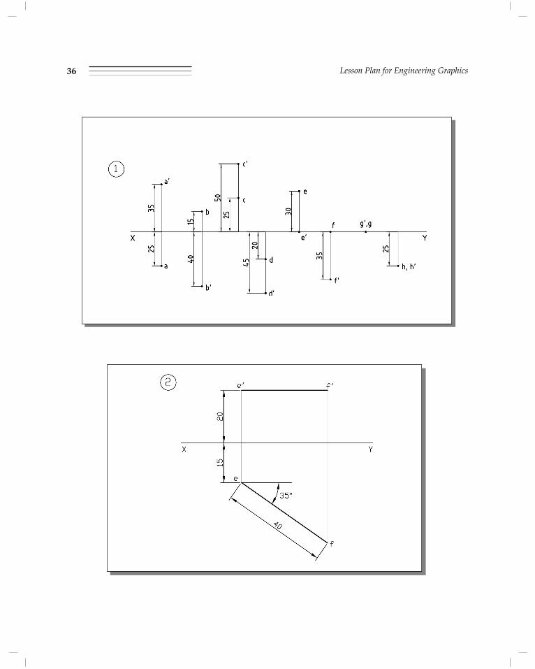
Problem 1. Draw the projections of the following points on a common reference line.Take 30 mm distance between the projectors.
A, 35 mm above HP and 25 mm in front of VP.
B, 40 mm below HP and 15 mm behind VP.
C, 50 mm above HP and 25 mm behind VP.
D, 45 mm below HP and 20 mm in front of VP.
E, 30 mm behind VP and on HP.
F, 35 mm below HP and on VP.
G, on both HP and VP.
H, 25 mm below HP and 25 mm in front of VP.
Problem 2 A line EF 40 mm long has its end E 20 mm above HP and 15 mm in frontof VP. The line is inclined at 35° to VP and parallel to HP. Draw its projections.
Solution
The top view ef is a line inclined at an angle of 35° to XY and having true length. Itsfront view e¢f ¢ is parallel to XY and smaller than true length.
The projections obtained are drawn with reference to XY line as follows.
1. Mark the projections of end E by considering it as a point. Its front view e¢ is 20mm above XY and top view e is 15 mm below XY.
2. The top view of the line ef is obtained by drawing a line inclined at an angle 35°to XY from a and having a length of 40 mm.
3. The front view of the line e¢f ¢ is obtained by drawing a line parallel to XY from e¢and drawing a vertical line (projector) from f. It is parallel to XY and smaller thanthe true length.

38 Lesson Plan for Engineering Graphics
Projections of Points and Straight Lines – I 39
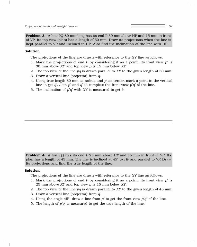
Problem 3 A line PQ 80 mm long has its end P 30 mm above HP and 15 mm in frontof VP. Its top view (plan) has a length of 50 mm. Draw its projections when the line iskept parallel to VP and inclined to HP. Also find the inclination of the line with HP.
Solution
The projections of the line are drawn with reference to the XY line as follows.1. Mark the projections of end P by considering it as a point. Its front view p¢ is
30 mm above XY and top view p is 15 mm below XY.2. The top view of the line pq is drawn parallel to XY to the given length of 50 mm.3. Draw a vertical line (projector) from q.4. Using true length 80 mm as radius and p¢ as center, mark a point in the vertical
line to get q¢. Join p¢ and q¢ to complete the front view p¢q¢ of the line.5. The inclination of p¢q¢ with XY is measured to get θ.
Problem 4 A line PQ has its end P 25 mm above HP and 15 mm in front of VP. Itsplan has a length of 45 mm. The line is inclined at 45° to HP and parallel to VP. Drawits projections and find the true length of the line.
SolutionThe projections of the line are drawn with reference to the XY line as follows.1. Mark the projections of end P by considering it as a point. Its front view p¢ is
25 mm above XY and top view p is 15 mm below XY.2. The top view of the line pq is drawn parallel to XY to the given length of 45 mm.3. Draw a vertical line (projector) from q.4. Using the angle 45°, draw a line from p¢ to get the front view p¢q¢ of the line.5. The length of p¢q¢ is measured to get the true length of the line.

40 Lesson Plan for Engineering Graphics
Projections of Points and Straight Lines – I 41
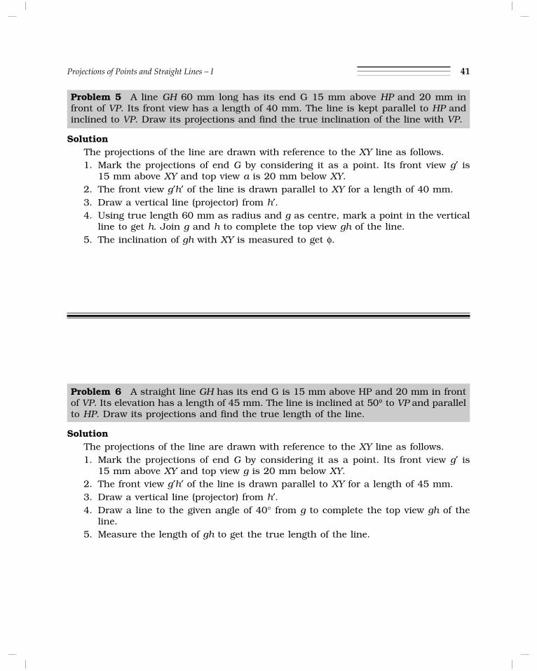
Problem 5 A line GH 60 mm long has its end G 15 mm above HP and 20 mm infront of VP. Its front view has a length of 40 mm. The line is kept parallel to HP andinclined to VP. Draw its projections and find the true inclination of the line with VP.
SolutionThe projections of the line are drawn with reference to the XY line as follows.1. Mark the projections of end G by considering it as a point. Its front view g¢ is
15 mm above XY and top view a is 20 mm below XY.2. The front view g¢h¢ of the line is drawn parallel to XY for a length of 40 mm.3. Draw a vertical line (projector) from h¢.4. Using true length 60 mm as radius and g as centre, mark a point in the vertical
line to get h. Join g and h to complete the top view gh of the line.5. The inclination of gh with XY is measured to get φ.
Problem 6 A straight line GH has its end G is 15 mm above HP and 20 mm in frontof VP. Its elevation has a length of 45 mm. The line is inclined at 50º to VP and parallelto HP. Draw its projections and find the true length of the line.
SolutionThe projections of the line are drawn with reference to the XY line as follows.1. Mark the projections of end G by considering it as a point. Its front view g¢ is
15 mm above XY and top view g is 20 mm below XY.2. The front view g¢h¢ of the line is drawn parallel to XY for a length of 45 mm.3. Draw a vertical line (projector) from h¢.4. Draw a line to the given angle of 40° from g to complete the top view gh of the
line.5. Measure the length of gh to get the true length of the line.

42 Lesson Plan for Engineering Graphics
q = 50°

Projections of Points and Straight Lines – I 43
Problem 7 A line RS 70 mm long has its end R 20 mm above HP and 25 mm in frontof VP. The line is inclined to HP and parallel to VP. Draw its projections when thedistance between the projectors is 45 mm. Also mark the traces of the line.
SolutionThe projections of the line are drawn with reference to the XY line as follows.1. Mark the projections of end R by considering it as a point. Its front view r¢ is
15 mm above XY and top view r is 25 mm below XY.2. The top view of the line rs is drawn parallel to XY to the given length of 45 mm.
Note that the distance between end projectors is equal to the length of top view.3. Draw a vertical line (projector) from s.4. Using true length 70 mm as radius and r¢ as centre, mark a point in the vertical
line to get s¢. Join r ¢ and s¢ to complete the front view r ¢s¢ of the line.5. The inclination of r ¢s¢ with XY line is measured to get q.
Problem 8 A line EF 50 mm long is in VP and inclined to HP. The top view measures30 mm. The end E is 10 mm above HP. Draw the projections of the line.
SolutionThe projections obtained are drawn with reference to the XY line as follows.1. Mark the projections of end E by considering it as a point. Its front view e¢ is
10 mm above XY and top view e is on the XY line.2. The top view of the line ef is obtained by drawing a line on XY from e to the given
length of 30 mm.3. Draw a vertical line (projector) from f.4. Using true length 50 mm as radius end e as centre, mark a point in the vertical
line to get f ¢. Join e¢ and f ¢ to complete the front view e¢f ¢ of the line.5. The inclination of e¢f ¢ with XY line is measured to get θ.

44 Lesson Plan for Engineering Graphics
Space for Rough Work