Embed Size (px)
Citation preview

Subject: Engineering
GraphicsSubject code: 2110013

PRESENTATION ON:
Presented by:Shah Juhi
Om institute of technology
2
Om institute of technology
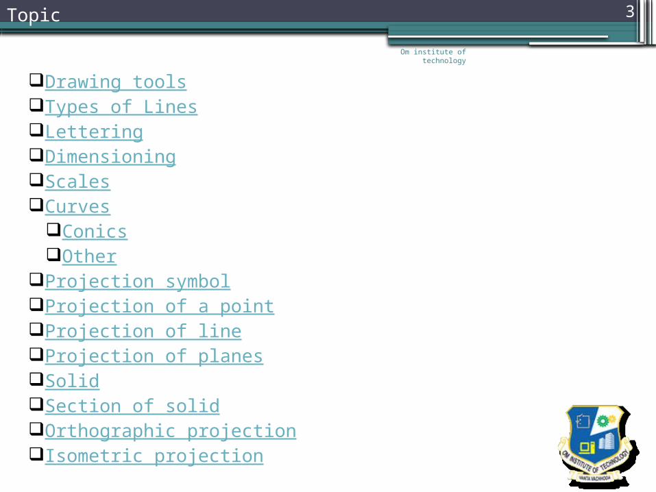
3Topic
Drawing toolsTypes of LinesLetteringDimensioningScalesCurves
ConicsOther
Projection symbolProjection of a pointProjection of lineProjection of planesSolidSection of solidOrthographic projectionIsometric projection

Om institute of technology
4Objectives in Drawing
Typical Drawing Equipment
Objectives in Drawing
1. Accuracy2. Speed3. Legibility4. Neatness

12 3 4
5
6
78
9
10
14
13
12 11
Viewing-plane lineExtension line
Dimension Line
Center LineHidden Line
Break Line
Cutting-plane LineVisible Line
Center Line (of motion)Leader
VIEW B-BSECTION A-A
Section Line
Phantom Line
Om institute of technology
5Types of Lines

GOOD
Not uniform in style.
Not uniform in height.
Not uniformly vertical or inclined.
Not uniform in thickness of stroke.Area between letters not uniform.Area between words not uniform.
Example : Good and Poor LetteringOm institute of
technology
6
Om institute of technology
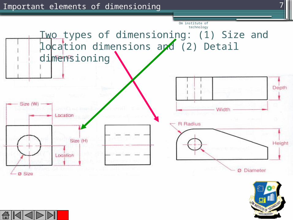
7Important elements of dimensioning
Two types of dimensioning: (1) Size and location dimensions and (2) Detail dimensioning
Om institute of technology
8
Om institute of technology
9
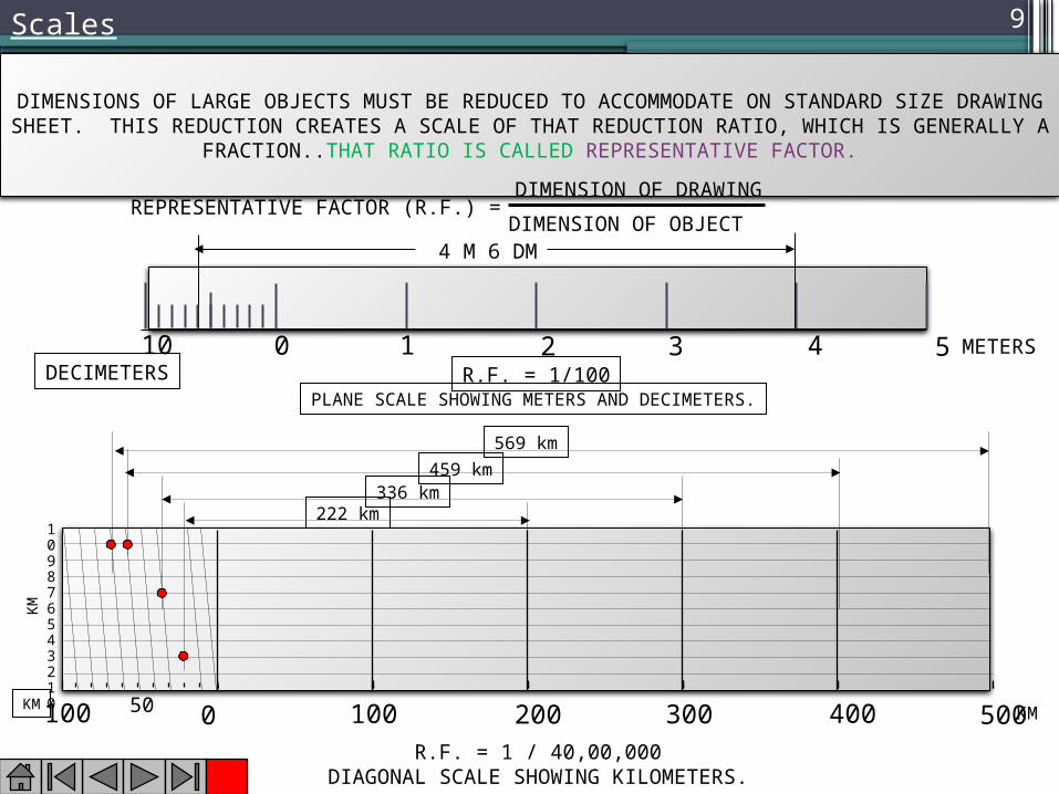
DIMENSIONS OF LARGE OBJECTS MUST BE REDUCED TO ACCOMMODATE ON STANDARD SIZE DRAWING SHEET. THIS REDUCTION CREATES A SCALE OF THAT REDUCTION RATIO,
WHICH IS GENERALLY A FRACTION..THAT RATIO IS CALLED REPRESENTATIVE FACTOR.
REPRESENTATIVE FACTOR (R.F.) =DIMENSION OF DRAWINGDIMENSION OF OBJECT
0 1 2 3 4 510 METERSDECIMETERS R.F. = 1/100
4 M 6 DM
PLANE SCALE SHOWING METERS AND DECIMETERS.
R.F. = 1 / 40,00,000DIAGONAL SCALE SHOWING KILOMETERS.
0 100 200 300 400 500100 50
109876543210 KMKM
KM
569 km459 km
336 km222 km
Scales
Om institute of technology
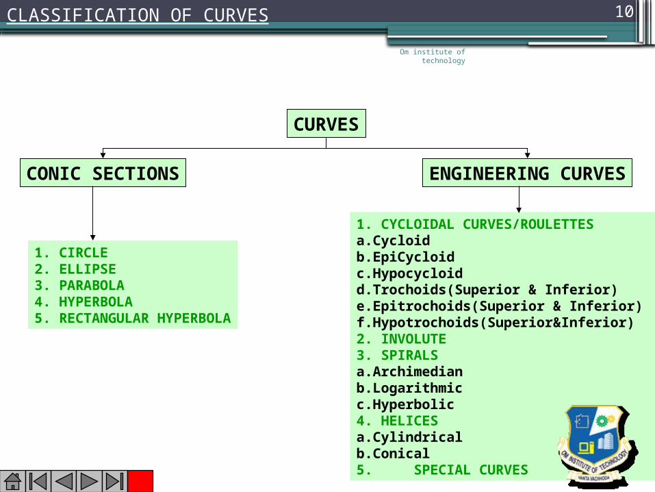
10CLASSIFICATION OF CURVES
CURVES
CONIC SECTIONS ENGINEERING CURVES
1. CIRCLE2. ELLIPSE3. PARABOLA4. HYPERBOLA5. RECTANGULAR HYPERBOLA
1. CYCLOIDAL CURVES/ROULETTESa.Cycloidb.EpiCycloidc.Hypocycloidd.Trochoids(Superior & Inferior)e.Epitrochoids(Superior & Inferior)f.Hypotrochoids(Superior&Inferior)2. INVOLUTE3. SPIRALSa.Archimedianb.Logarithmicc.Hyperbolic4. HELICESa.Cylindricalb.Conical5. SPECIAL CURVES
Om institute of technology
11
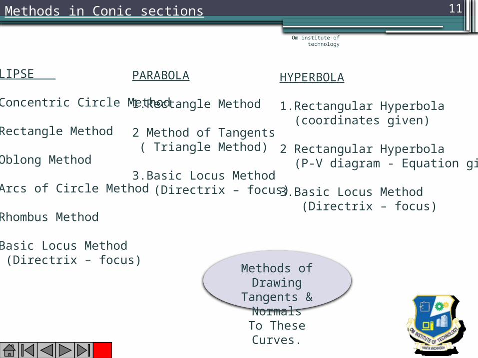
ELLIPSE
1.Concentric Circle Method
2.Rectangle Method
3.Oblong Method
4.Arcs of Circle Method
5.Rhombus Method
6.Basic Locus Method (Directrix – focus)
HYPERBOLA
1.Rectangular Hyperbola (coordinates given)
2 Rectangular Hyperbola (P-V diagram - Equation given)
3.Basic Locus Method (Directrix – focus)
PARABOLA
1.Rectangle Method
2 Method of Tangents ( Triangle Method)
3.Basic Locus Method (Directrix – focus)
Methods of Drawing
Tangents & Normals
To These Curves.
Methods in Conic sections

Om institute of technology
12
Om institute of technology
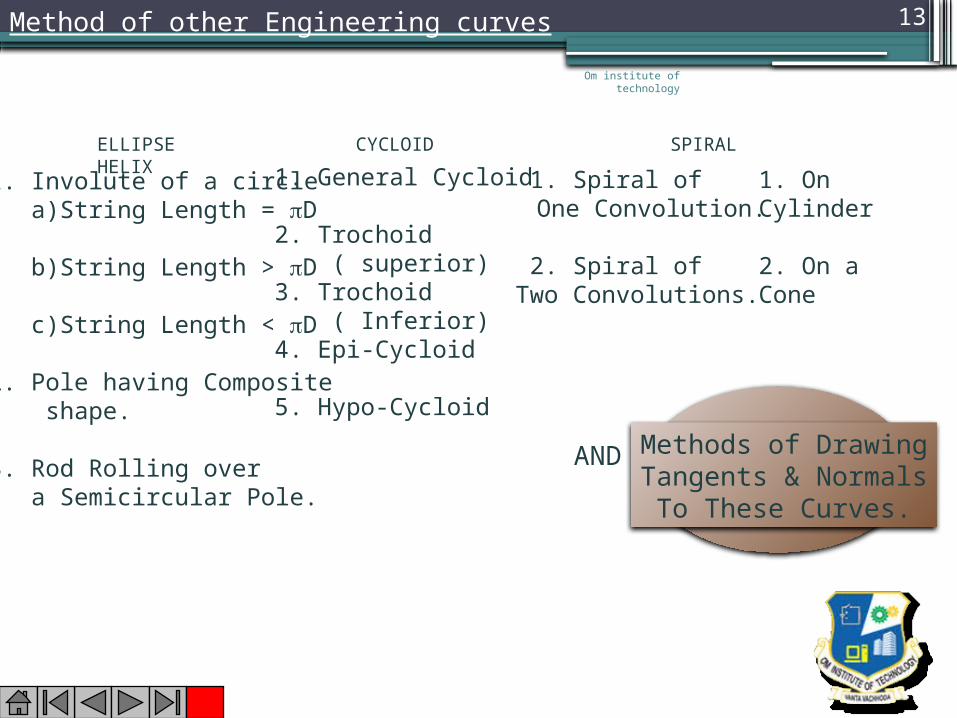
13
ELLIPSE CYCLOID SPIRAL HELIX
1. Involute of a circle a)String Length = D
b)String Length > D
c)String Length < D
2. Pole having Composite shape.
3. Rod Rolling over a Semicircular Pole.
1. General Cycloid
2. Trochoid ( superior) 3. Trochoid ( Inferior) 4. Epi-Cycloid
5. Hypo-Cycloid
1. Spiral of One Convolution.
2. Spiral of Two Convolutions.
1. On Cylinder
2. On a Cone
Methods of DrawingTangents & Normals
To These Curves.
AND
Method of other Engineering curves
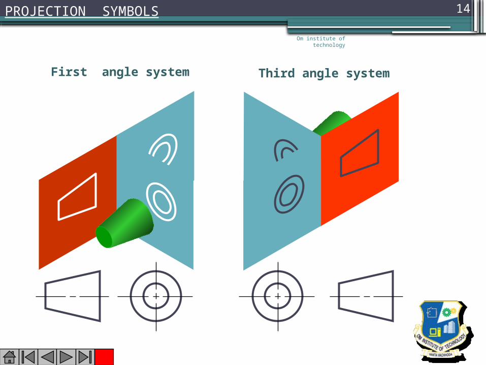
First angle system Third angle system
PROJECTION SYMBOLSOm institute of
technology
14

A
a
a’ A
a
a’
Aa
a’
X
Y
X
Y
X
YFor Fv
For Tv
For Fv
For Tv
For Tv
For Fv
POINT A ABOVE HP& INFRONT OF VP
POINT A IN HP& INFRONT OF VP
POINT A ABOVE HP& IN VP
PROJECTIONS OF A POINT
PICTORIAL PRESENTATION
PICTORIAL PRESENTATION
ORTHOGRAPHIC PRESENTATIONS OF ALL ABOVE CASES.
X Y
a
a’
VP
HP
X Y
a’
VP
HP
a X Y
a
VP
HP
a’
Fv above xy,Tv below xy.
Fv above xy,Tv on xy.
Fv on xy,Tv below xy.
Om institute of technology
15

X
Y
V.P.
X
Y
V.P. b’
a’
b
a
F.V.
T.V.
a b
a’
b’
B
A
TV
FV
A
B
X Y
H.P.
V.P. a’
b’
a b
Fv
Tv
X Y
H.P.
V.P.
a b
a’ b’Fv
Tv
For Fv
For Tv
For Tv
For Fv
Note:Fv is a vertical line
Showing True Length&
Tv is a point.
Note:Fv & Tv both are
// to xy &
both show T. L.
1.
2.
A Line perpendicular
to Hp &
// to Vp
A Line // to Hp
& // to Vp
Orthographic Pattern
(Pictorial Presentation)
(Pictorial Presentation)
Om institute of technology
16PROJECTIONS OF LINES

HPa 1
b 1
c 1
d 1
VPVP
a’
d’c’
b’
VP
a’ d’c’b’
For Fv
For T
v
For F.V.
For
T.V.
For
T.V.
For F.V.
HP
a
b c
d
a1’
d1’ c1’
b1’
HP
a1
b1 c1
d1
SURFACE PARALLEL TO HPPICTORIAL PRESENTATION
SURFACE INCLINED TO HPPICTORIAL PRESENTATION
ONE SMALL SIDE INCLINED TO VPPICTORIAL PRESENTATION
ORTHOGRAPHICTV-True Shape
FV- Line // to xy
ORTHOGRAPHICFV- Inclined to XY
TV- Reduced Shape
ORTHOGRAPHICFV- Apparent ShapeTV-Previous Shape
A B C
Om institute of technology
17PROJECTIONS OF PLANES
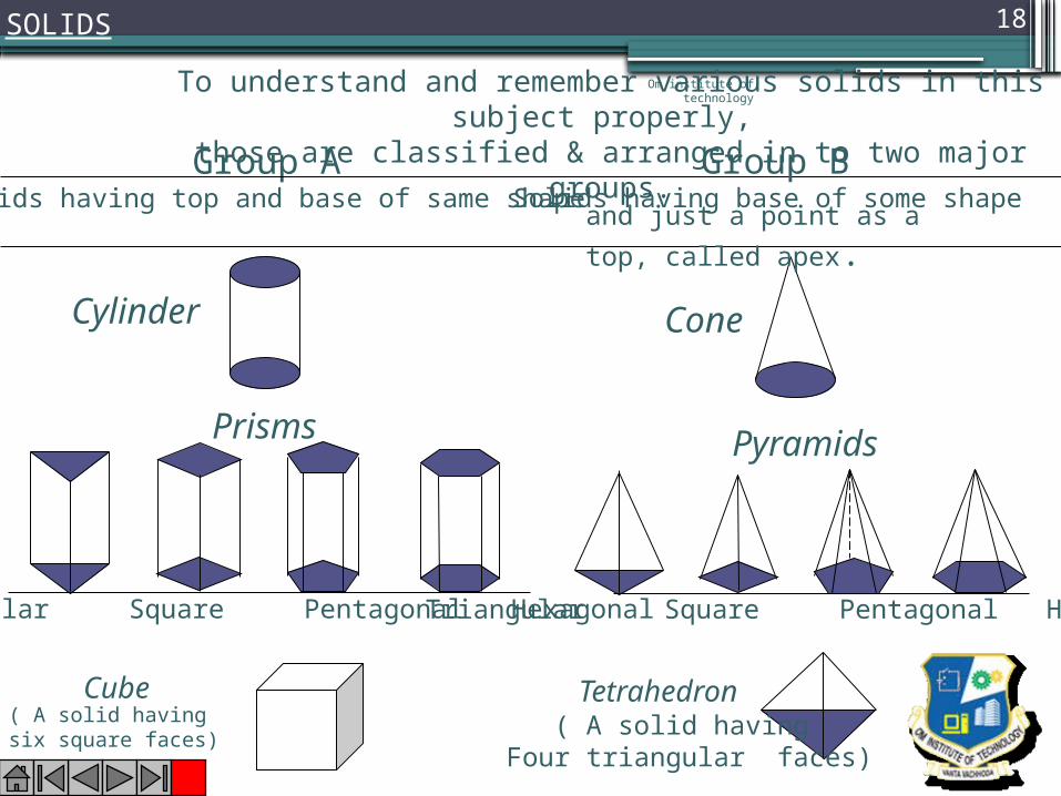
SOLIDSTo understand and remember various solids in this subject
properly, those are classified & arranged in to two major groups.Group A
Solids having top and base of same shape
Cylinder
Prisms
Triangular Square Pentagonal Hexagonal
Cube
Triangular Square Pentagonal Hexagonal
Cone
Tetrahedron
Pyramids
( A solid having six square faces) ( A solid having
Four triangular faces)
Group BSolids having base of some shape
and just a point as a top, called apex.
Om institute of technology
18
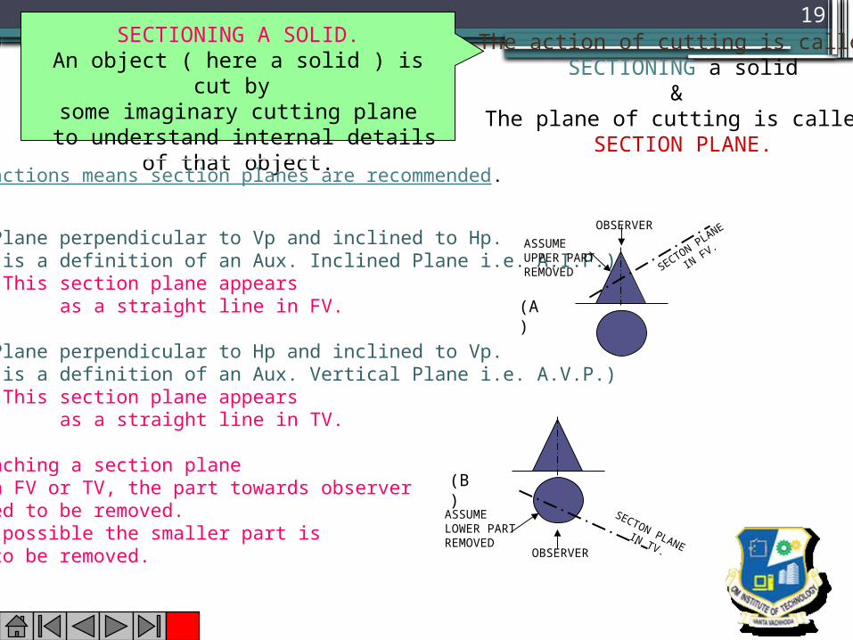
SECTIONING A SOLID.An object ( here a solid ) is cut by
some imaginary cutting plane to understand internal details of that object.
The action of cutting is called SECTIONING a solid
&The plane of cutting is called
SECTION PLANE.Two cutting actions means section planes are recommended.
A) Section Plane perpendicular to Vp and inclined to Hp. ( This is a definition of an Aux. Inclined Plane i.e. A.I.P.) NOTE:- This section plane appears as a straight line in FV. B) Section Plane perpendicular to Hp and inclined to Vp. ( This is a definition of an Aux. Vertical Plane i.e. A.V.P.) NOTE:- This section plane appears as a straight line in TV.Remember:-1. After launching a section plane either in FV or TV, the part towards observer is assumed to be removed.2. As far as possible the smaller part is assumed to be removed.
OBSERVERASSUME UPPER PARTREMOVED SECTON PLANE
IN FV.
OBSERVER
ASSUME LOWER PARTREMOVED
SECTON PLANE IN TV.
(A)
(B)
19

TOP VIEW
R22
204010
FRONT VIEWRIGHT SIDE
VIEW
1402080
SCALE: 1:1
303066
26
30
Om institute of technology
20
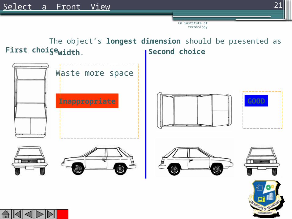
Select a Front View
The object’s longest dimension should be presented as a width.
Inappropriate
First choice
GOOD
Second choice
Waste more space
Om institute of technology
21
Om institute of technology
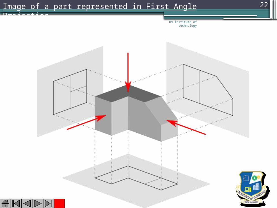
22Image of a part represented in First Angle Projection
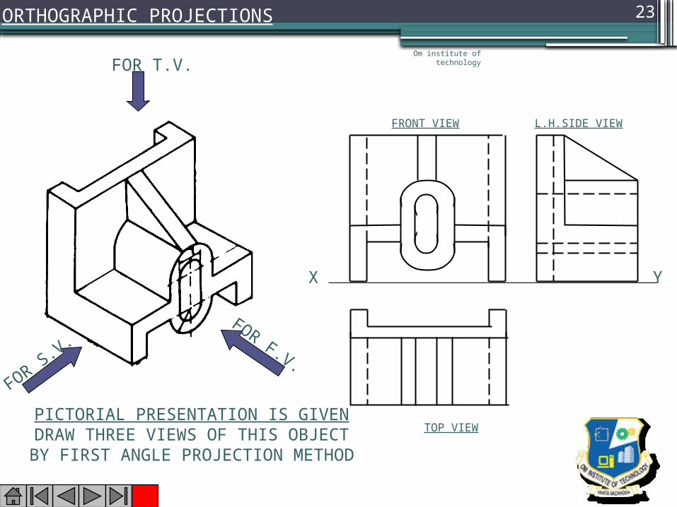
FOR T.V.
FOR F.V.FOR S.V.
PICTORIAL PRESENTATION IS GIVENDRAW THREE VIEWS OF THIS OBJECT
BY FIRST ANGLE PROJECTION METHOD
ORTHOGRAPHIC PROJECTIONS
FRONT VIEW
TOP VIEW
L.H.SIDE VIEW
X Y
Om institute of technology
23

H
3-D DRAWINGS CAN BE DRAWN IN NUMEROUS WAYS AS SHOWN BELOW.ALL THESE DRAWINGS MAY BE CALLED
3-DIMENSIONAL DRAWINGS, OR PHOTOGRAPHIC
OR PICTORIAL DRAWINGS.HERE NO SPECIFIC RELATION
AMONG H, L & D AXES IS MENTAINED.
H
NOW OBSERVE BELOW GIVEN DRAWINGS.ONE CAN NOTE SPECIFIC INCLINATION
AMONG H, L & D AXES.ISO MEANS SAME, SIMILAR OR EQUAL.
HERE ONE CAN FIND EDUAL INCLINATION AMONG H, L & D AXES. EACH IS 1200 INCLINED WITH OTHER TWO. HENCE IT IS CALLED ISOMETRIC DRAWING
H
L
IT IS A TYPE OF PICTORIAL PROJECTIONIN WHICH ALL THREE DIMENSIONS OF
AN OBJECT ARE SHOWN IN ONE VIEW AND IF REQUIRED, THEIR ACTUAL SIZES CAN BE
MEASURED DIRECTLY FROM IT.
IN THIS 3-D DRAWING OF AN OBJECT, ALL THREE DIMENSIONAL AXES ARE MENTAINED AT EQUAL INCLINATIONS
WITH EACH OTHER.( 1200)
PURPOSE OF ISOMETRIC DRAWING IS TO UNDERSTAND OVERALL SHAPE, SIZE & APPEARANCE OF AN OBJECT PRIOR TO IT’S PRODUCTION.
ISOMETRIC DRAWING TYPICAL CONDITION.Om institute of
technology
24
Om institute of technology
25