Embed Size (px)
Citation preview
ENGINEERING GEOLOGY 15CV35
1
Dept of Civil Engg, ACE
SYLLABUS
Module -1
Introduction:
Application of Earth Science in Civil Engineering Practices, Understanding the earth,
internal structure and composition.
Mineralogy:
Mineral properties, composition and their use in the manufacture of construction materials
– Quartz Group (Glass); Feldspar Group (Ceramic wares and Flooring tiles); Kaolin (Paper,
paint and textile); Asbestos (AC sheets); Carbonate Group ( Cement) ; Gypsum (POP,
gypsum sheets, cement); Mica Group (Electrical industries); Ore minerals - Iron ores
(Steel); Chromite (Alloy); Bauxite (aluminum); Chalcopyrite (copper),
Module -2
Petrology:
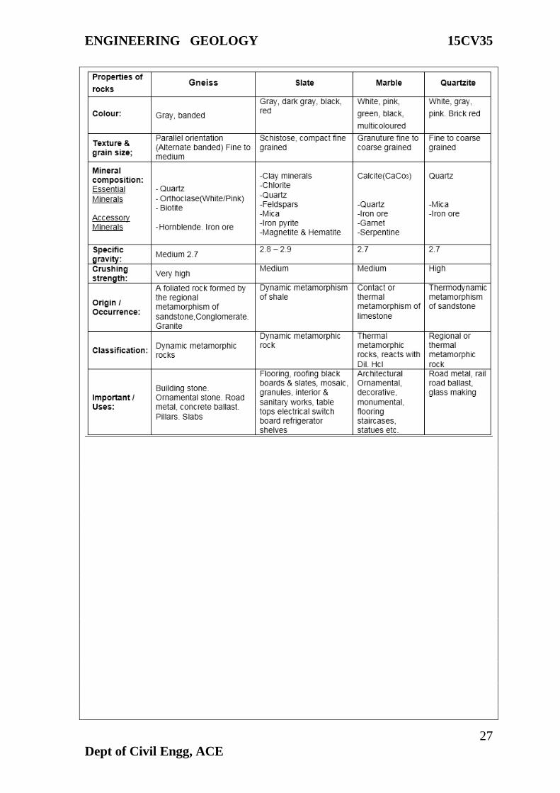
Formation, Classification and Engineering Properties. Rock as construction material,
concrete aggregate, railway ballast, roofing, flooring, cladding and foundation.
Deformation of rocks, Development of Joints, Folds, Faults and Unconformities. Their
impact in the selection of sites for Dams, Reservoirs, Tunnels, Highways and Bridges, Rock
Quality Determination (RQD), Rock Structure Rating (RSR),: Igneous Rocks - Granite,
Gabbro, Dolerite, Basalt; Sedimentary rocks - Sandstone, Shale, Limestone, Laterite;
Metamorphic rocks - Gneiss, Quartzite, Slate, Charnockite: Decorative stones - Porphyries,
Marble and Quartzite.
Module -3
Geomorphology and Seismology:
Landforms – Classification, Rock weathering, types and its effects on Civil Engineering
Projects. Study of Geo-morphological aspects in the selection of sites for Dams, Reservoirs,
Tunnels, Highways and Bridges. Watershed management, Floods and their control, River
valley, Drainage pattern – parameters and development; Coastlines and their engineering\
considerations. Earthquake - Causes and Effects, Seismic waves, engineering problems
related to Earthquakes, Earthquake intensity, Richter scale, Seismograph, Seismic zones-
World and India, Tsunami – causes and effects. Early warning system. Reservoir Induced
Seismicity; Landslides – causes and their control.
Module -4
Hydrogeology:
Hydrological cycle, Occurrence of Groundwater in different terrains -Weathered, Hard and
Stratified rocks; Determination of Quality aspects - SAR, RSC and TH of Groundwater.
Groundwater Pollution, Groundwater Exploration- Electrical Resistivity and Seismic
methods, Resistivity curves, Water Bearing Formations, Aquifer types and parameters –
ENGINEERING GEOLOGY 15CV35
2
Dept of Civil Engg, ACE
Porosity, Specific yield and retention, Permeability, Transmissibility and Storage
Coefficient. Springs and Artesian Wells, Artificial Recharging of Groundwater, Sea water
intrusion and remedies.
Module -5:
Geodesy:
Study of Topographic maps and Contour maps; Remote Sensing – Concept, Application
and its Limitations; Geographic Information System (GIS) and Global Positioning System
(GPS) – Concept and their use resource mapping. LANDSAT Imagery – Definition and its
use. Impact of Mining, Quarrying and Reservoirs on Environment. Natural Disasters and
their mitigation.
Text Books:
1. P.K. Mukerjee, “A Text Book of Geology”, World Press Pvt., Ltd. Kolkatta.
2. Parbin Singh, “Text Book of Engineering and General Geology”, Published by S.K.
Kataria and Sons, New Dehli.
Reference Books:
1. Earthquake Tips - Learning Earthquake Design and Construction - C V R Murthy
Published by National Information Centre of Earthquake Engineering, Indian Institute of
Technology, Kanpur.
2. Dimitri P Krynine and William R Judd, “Principles of Engineering Geology and
Geotechnics”, CBS Publishers and Distributors, New Delhi.
3. K V G K Gokhale, “Principles of Engineering Geology”, BS Publications, Hyderabad.
4. M Anji Reddy, “Text book of Remote Sensing and Geographical Information System”,
BS Publications, Hyderabad.
5. Ground water Assessment, development and Management by K.R. Karanth, Tata Mc
Graw Hills
6. K. Todd, “Groundwater Hydrology”, Tata Mac Grow Hill, New Delhi.
7. D. Venkata Reddy, “Engineering Geology”, New Age International Publications, New
Delhi.
8. S.K Duggal, H.K Pandey and N Rawal, “Engineering Geology”, McGraw Hill Education
(India) Pvt, Ltd. New Delhi.
9. M.P Billings, “Structural Geology”, CBS Publishers and Distributors, New Delhi.

ENGINEERING GEOLOGY 15CV35
3
Dept of Civil Engg, ACE
Module -1
Introduction:
Geology is a Branch of Natural science deals with the study of the Earth, It is also known
as Earth science. For studying the Earth in detail the subject of geology has been divided
into various branches, which are as follows:
Application of Earth Science in Civil Engineering Practices
1. Mapping: The engineering geologist has to prepare a geological map of the area based
on aerial photo and satellite imagery interpretation and field observation. Subsurface
geological features are also mapped.
2. Exploration: In this stage the engineering geologist explore the area based on
exploration techniques. The engineering geologist works from the planning stage.
Supervise the exploration works and records the data for further interpretation.
3. Project Planning: Project planning is the most important aspect in civil engineering.
The civil engineer plans the various stages. The engineering geologists plans and prepares
geologic feasibility and developmental parameters reports, which are useful to the civil
engineer for planning the project schedule.
4. Surface water: The engineering geologist and the civil engineer together prepare surface
–water mapping. Both study the volume of total runoff, drainage basin characteristics and
sedimentary process in the basin. Weathered areas, silting potential and erosion potential
are also estimated before planning any hydraulic structure in the basin.
5. Groundwater: Groundwater is the major problem in the majority of civil engineering
works. The engineering geologist studies in detail the occurrence, movement, structural
controls and hydro geological properties of the rocks. Hydro geological maps are prepared
for civil engineering purposes.
6. Slope Stability: Geological parameters of possible slide regions are studies
7. Geological Structures: Field investigation is carried out for selection of a suitable area.
Detailed surface-subsurface studies are conducted and surface and subsurface maps are
ENGINEERING GEOLOGY 15CV35
4
Dept of Civil Engg, ACE
prepared. The engineering geologist and the civil engineer conduct in-situ tests for
foundation materials, supervise the construction methods and monitor the structure after
completion of the work.
8. Tunneling: The tunnel site selected is based on a detailed study of the region. The civil
engineer and the geologist have to conduct in-situ tests for estimation of weathered zone
thickness, depth of hard rock, structural features etc.
9. Earthquake: The engineering geologist studies the seismic nature of the project site. He
examines the seismic zoning map of the country, evaluates active and inactive faults and
keeps the historical record of the earthquake of the region in which the civil engineer will
prepare a seismic design of structure.
Geological features of the civil engineering have to be studied a detail before execution of
the work. The engineering geologist must work from the exploration stage to the end of the
project.
INTERNAL STRUCTURE OF EARTH
Our Earth is a cosmic body. It is one of the nine members of he Solar system of which
Sun is the central star. The nine planets constituting the Solar system has been named as
Mercury, Venus, Earth, Mars, Jupiter, Saturn, Uranus, Neptune and Pluto. In its shape, he
Earth is commonly described as a spheroid, it has an equatorial diameter of 12,757.776km
and a polar diameter of 12,713.824km and thus has an equatorial bulge.
At present the Earth is the only planet believed to be sustaining life other planets have
shown no signs of life on them. For systematic scientific investigations, the earth is
commonly differentiated into three parts; they are atmosphere, lithosphere and
hydrosphere. Each forms an extensive field of study, volumes of information have been
collected about each of these parts during last hundred years or so but findings of last
three decades have made our understanding about these parts very clear. Only most
important characteristics of these parts have been summarized below.
ATMOSPHERE
The outer gaseous part of earth starting from the surface and extending as far as 700km and
beyond is termed atmosphere. Although extending for such great distances, the atmosphere
makes only one-millionth part of the mass of earth; this is because of its gaseous
composition. It is now fairly established that the atmosphere possesses a layered structure.
Their well-defined layers or zones of the atmosphere are surface upward, troposphere,
stratosphere and ionosphere.
LITHOSPHERE
It is the solid part of the earth and in a broader sense includes all the solid materials
composing the earth from surface downwards, although sometimes-specific terms are used
for deeper earth
zones. Recent detailed seismic studies of the body of the earth have shown that it is
composed of three well-defined shells, Crust, Mantle, Core.

ENGINEERING GEOLOGY 15CV35
5
Dept of Civil Engg, ACE
The Crust: - Is the topmost shell of the earth, which has a thickness of 30-40 km in the
continents and 5-6 km in the oceans. There is a striking variation in the materials or rocks,
as they are called, composing the crust over the continents and ocean floors. The oceanic
crust is made up of heavier and darker rocks called basalts compared to lightcolored and
light-density, granitic rocks of the continental crust. When considered as a part of the total
structure of the earth, crust makes only an insignificant part represented by a thin layer,
similar to the skin of an apple. As regards he chemical composition of the crust, analyses
made by Clarke and Gold Schmith, using rocks from different geographic regions of the
crust have all shown that when expressed in terms of oxides, the crust has Silica as the most
dominant component, its value lying above 50% by volume in the oceanic crust and above
62% in the continental crust. Alumina is the next important oxide, varying between 13-
16% followed by Iron Oxides (8%), Lime (6%), Sodium (4%), Magnesium (4%),
Potassium (2.5%) & Titanium (2%). The crust itself shows a complicated structure both in
make-up and compositional variations.
Figure 1.0 INTERNAL STRUCTURE OF EARTH
The Mantle: - At the base of the crust materials of the earth become greatly different in
many properties from those overlying them in the crust. These materials appear to form a
nearly
homogeneous zone till a depth of 2900 km is reached. This zone of materials lying between
crust and a depth of 2900 km is known a MANTLE. It is made up of extremely basic
materials, called ultra-basic rocks, which are believed to be very rich in iron and magnesium

ENGINEERING GEOLOGY 15CV35
6
Dept of Civil Engg, ACE
but quite poor in silica. Such rock names as Periodotites, Dunite. This One is characterized
with a high density, increasing steadily with depth further; the mantle material is believed
to be highly plastic in nature. Many of the most important geological process such as
earthquakes and formation of mountains are believed to have their origin in this zone.
The Core: - It is the third and the innermost structure shell of the earth, which is clearly
marked by the seismic evidence. It starts at a depth of 2900 km below the surface and
extends right up to the center of the earth at 6370 km. The material making g the core is
found to be from seismic studies only strikingly different from that making the other two
shells in one major aspect, in elastic properties. The material has no shear resistance, which
makes it nearer to liquid than to a solid body. It has a very high density, above 10gms/cubic
centimeter, at the mantle –core boundary. Nothing can be said about the composition of the
core. According to one, widely favored view, the core is made up of Iron and Nickel alloy
material.
MINERALOGY
Minerals have been defined as naturally occurring substances, mostly inorganic, that are
characterized by a definite chemical composition and a definite atomic structure. Since
rocks which make up the earth are simply natural aggregates of minerals, a study of
minerals is of fundamental importance understands the elements of science of geology. The
branch of geology dealing with the study of minerals is designated as Mineralogy. Each
mineral is generally characterized with a set of qualities some of which are always
distinctive and differentiate it from other minerals. Some of these qualities or properties
may be studied from the body of the minerals, its shape, color, shine, hardness etc.; these
are termed physical properties. Some other qualities like the behavior towards light require
extremely thin sheets or sections of the minerals and are best studied with the help of a
microscope. These are termed optical or microscopic properties. A third group of properties
involving. These are the physical properties most useful for mineral identification:
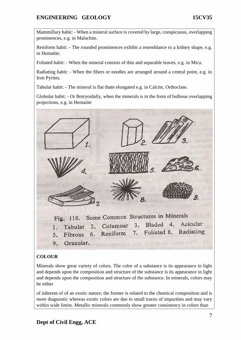
HABIT
A mineral may sometimes show a definite and characteristic arrangement in its outer
appearance or physical shape. This shape is expressed by the term Habit and is typical in
the case of many minerals. A few common habits with examples are given below. Fibrous
habit: -When the mineral is made up of fibers, generally separable, e.g. in Asbestos.
Columnar habit: - When the mineral is composed of thin or thick columns, sometimes
flattened, e.g. in Hornblende.
Bladed habit: - The minerals appears as if composed of thin, blade like structure, e.g. in
Kyanite.
Lamellar habit: - The plates or leaves are separable, e.g. Vermiculite.
Granular habit: - The mineral shows numerous grains packed together, e.g. in Chromite.
Acicular habit: - When a mineral surface is covered by large, conspicuous, overlapping
prominences, e.g. in Malachite.
ENGINEERING GEOLOGY 15CV35
7
Dept of Civil Engg, ACE
Mammillary habit: - When a mineral surface is covered by large, conspicuous, overlapping
prominences, e.g. in Malachite.
Reniform habit: - The rounded prominences exhibit a resemblance to a kidney shape, e.g.
in Hematite.
Foliated habit: - When the mineral consists of thin and separable leaves, e.g. in Mica.
Radiating habit: - When the fibers or needles are arranged around a central point, e.g. in
Iron Pyrites.
Tabular habit: - The mineral is flat thatn elongated e.g. in Calcite, Orthoclase.
Globular habit: - Or Botryoidally, when the minerals is in the form of bulbous overlapping
projections, e.g. in Hematite
COLOUR
Minerals show great variety of colors. The color of a substance is its appearance in light
and depends upon the composition and structure of the substance is its appearance in light
and depends upon the composition and structure of the substance. In minerals, colors may
be either
of inherent of of an exotic nature; the former is related to the chemical composition and is
more diagnostic whereas exotic colors are due to small traces of impurities and may vary
within wide limits. Metallic minerals commonly show greater consistency in colors than
ENGINEERING GEOLOGY 15CV35
8
Dept of Civil Engg, ACE
the non-metallic minerals. Some minerals show peculiar phenomena connected with color.
Of these, the following are interesting and important.
Play of Colors: - It is the development of a series of prismatic colours shown by some
minerals on turning about in light. The colors change in rapid succession on rotation,
example: Diamond.
Change of Colors: - It is similar to play of colors except that rate of change of colors on
rotation is rather slow; each color continues over a larger space in the mineral, ex: -
Labradorite.
Iridescence: - Some minerals show rainbow colors either in their interior or on their surface.
This termed iridescence.
Tarnish: - Sometimes the surface color is different, rather dull, than the color of the mineral
as seen on freshly fractured surface; ex: Chalcopyrite, an ore of copper. Although color is
never taken as a conclusive property in the identification of minerals, it is invariably studied
first and is generally helpful.
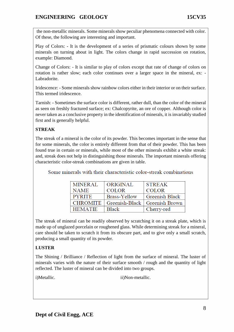
STREAK
The streak of a mineral is the color of its powder. This becomes important in the sense that
for some minerals, the color is entirely different from that of their powder. This has been
found true in certain or minerals, while most of the other minerals exhibit a white streak:
and, streak does not help in distinguishing those minerals. The important minerals offering
characteristic color-streak combinations are given in table.
The streak of mineral can be readily observed by scratching it on a streak plate, which is
made up of unglazed porcelain or roughened glass. While determining streak for a mineral,
care should be taken to scratch it from its obscure part, and to give only a small scratch,
producing a small quantity of its powder.
LUSTER
The Shining / Brilliance / Reflection of light from the surface of mineral. The luster of
minerals varies with the nature of their surface smooth / rough and the quantity of light
reflected. The luster of mineral can be divided into two groups.
i)Metallic. ii)Non-metallic.
ENGINEERING GEOLOGY 15CV35
9
Dept of Civil Engg, ACE
DIAPHENEITY:
Diaphaneity is the ability of the mineral to transmit light through it. The following
terms are used to describe the varying degree of transmission of light.
Descriptive Terminology:
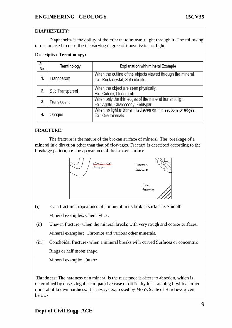
FRACTURE:
The fracture is the nature of the broken surface of mineral. The breakage of a
mineral in a direction other than that of cleavages. Fracture is described according to the
breakage pattern, i.e. the appearance of the broken surface.
(i) Even fracture-Appearance of a mineral in its broken surface is Smooth.
Mineral examples: Chert, Mica.
(ii) Uneven fracture- when the mineral breaks with very rough and coarse surfaces.
Mineral examples: Chromite and various other minerals.
(iii) Conchoidal fracture- when a mineral breaks with curved Surfaces or concentric
Rings or half moon shape.
Mineral example: Quartz
Hardness: The hardness of a mineral is the resistance it offers to abrasion, which is
determined by observing the comparative ease or difficulty in scratching it with another
mineral of known hardness. It is always expressed by Moh's Scale of Hardness given
below-
ENGINEERING GEOLOGY 15CV35
10
Dept of Civil Engg, ACE
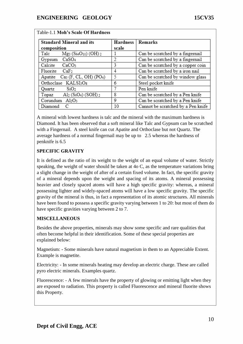
Table-1.1 Moh’s Scale Of Hardness
A mineral with lowest hardness is talc and the mineral with the maximum hardness is
Diamond. It has been observed that a soft mineral like Talc and Gypsum can be scratched
with a Fingernail. A steel knife can cut Apatite and Orthoclase but not Quartz. The
average hardness of a normal fingernail may be up to 2.5 whereas the hardness of
penknife is 6.5
SPECIFIC GRAVITY
It is defined as the ratio of its weight to the weight of an equal volume of water. Strictly
speaking, the weight of water should be taken at 4o C, as the temperature variations bring
a slight change in the weight of after of a certain fixed volume. In fact, the specific gravity
of a mineral depends upon the weight and spacing of its atoms. A mineral possessing
heavier and closely spaced atoms will have a high specific gravity: whereas, a mineral
possessing lighter and widely-spaced atoms will have a low specific gravity. The specific
gravity of the mineral is thus, in fact a representation of its atomic structures. All minerals
have been found to possess a specific gravity varying between 1 to 20: but most of them do
have specific gravities varying between 2 to 7.
MISCELLANEOUS
Besides the above properties, minerals may show some specific and rare qualities that
often become helpful in their identification. Some of these special properties are
explained below:
Magnetism: - Some minerals have natural magnetism in them to an Appreciable Extent.
Example is magnetite.
Electricity: - In some minerals heating may develop an electric charge. These are called
pyro electric minerals. Examples quartz.
Fluorescence: - A few minerals have the property of glowing or emitting light when they
are exposed to radiation. This property is called Fluorescence and mineral fluorite shows
this Property.
ENGINEERING GEOLOGY 15CV35
11
Dept of Civil Engg, ACE
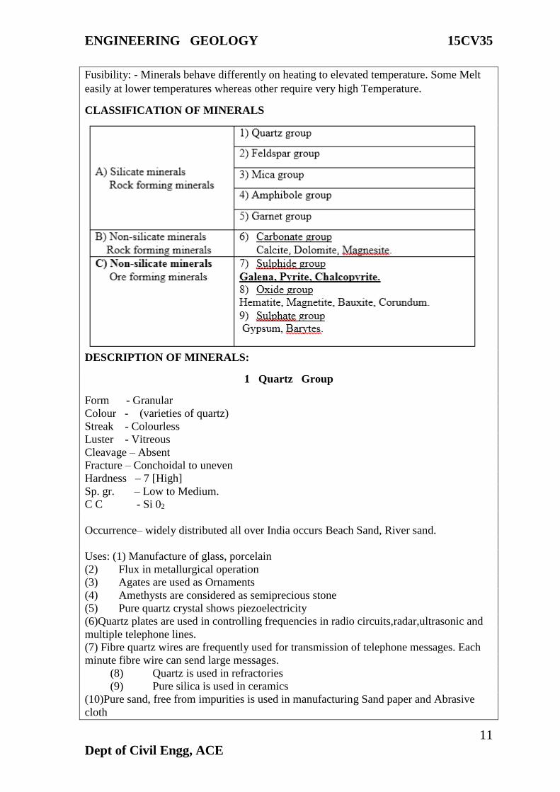
Fusibility: - Minerals behave differently on heating to elevated temperature. Some Melt
easily at lower temperatures whereas other require very high Temperature.
CLASSIFICATION OF MINERALS
DESCRIPTION OF MINERALS:
1 Quartz Group
Form - Granular
Colour - (varieties of quartz)
Streak - Colourless
Luster - Vitreous
Cleavage – Absent
Fracture – Conchoidal to uneven
Hardness – 7 [High]
Sp. gr. – Low to Medium.
C C - Si 02
Occurrence– widely distributed all over India occurs Beach Sand, River sand.
Uses: (1) Manufacture of glass, porcelain
(2) Flux in metallurgical operation
(3) Agates are used as Ornaments
(4) Amethysts are considered as semiprecious stone
(5) Pure quartz crystal shows piezoelectricity
(6)Quartz plates are used in controlling frequencies in radio circuits,radar,ultrasonic and
multiple telephone lines.
(7) Fibre quartz wires are frequently used for transmission of telephone messages. Each
minute fibre wire can send large messages.
(8) Quartz is used in refractories
(9) Pure silica is used in ceramics
(10)Pure sand, free from impurities is used in manufacturing Sand paper and Abrasive
cloth
ENGINEERING GEOLOGY 15CV35
12
Dept of Civil Engg, ACE
ENGINEERING GEOLOGY 15CV35
13
Dept of Civil Engg, ACE
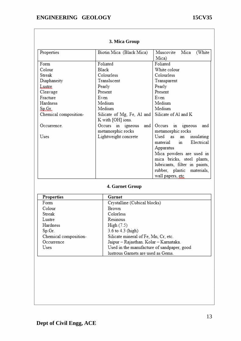
3. Mica Group
4. Garnet Group

ENGINEERING GEOLOGY 15CV35
14
Dept of Civil Engg, ACE
5. Amphibole Group
ENGINEERING GEOLOGY 15CV35
15
Dept of Civil Engg, ACE
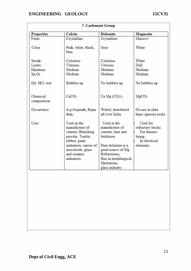
7. Carbonate Group
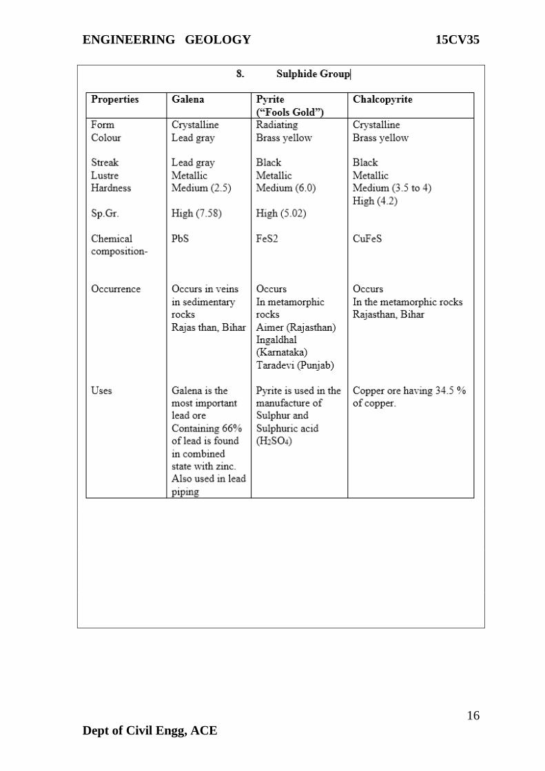
ENGINEERING GEOLOGY 15CV35
16
Dept of Civil Engg, ACE
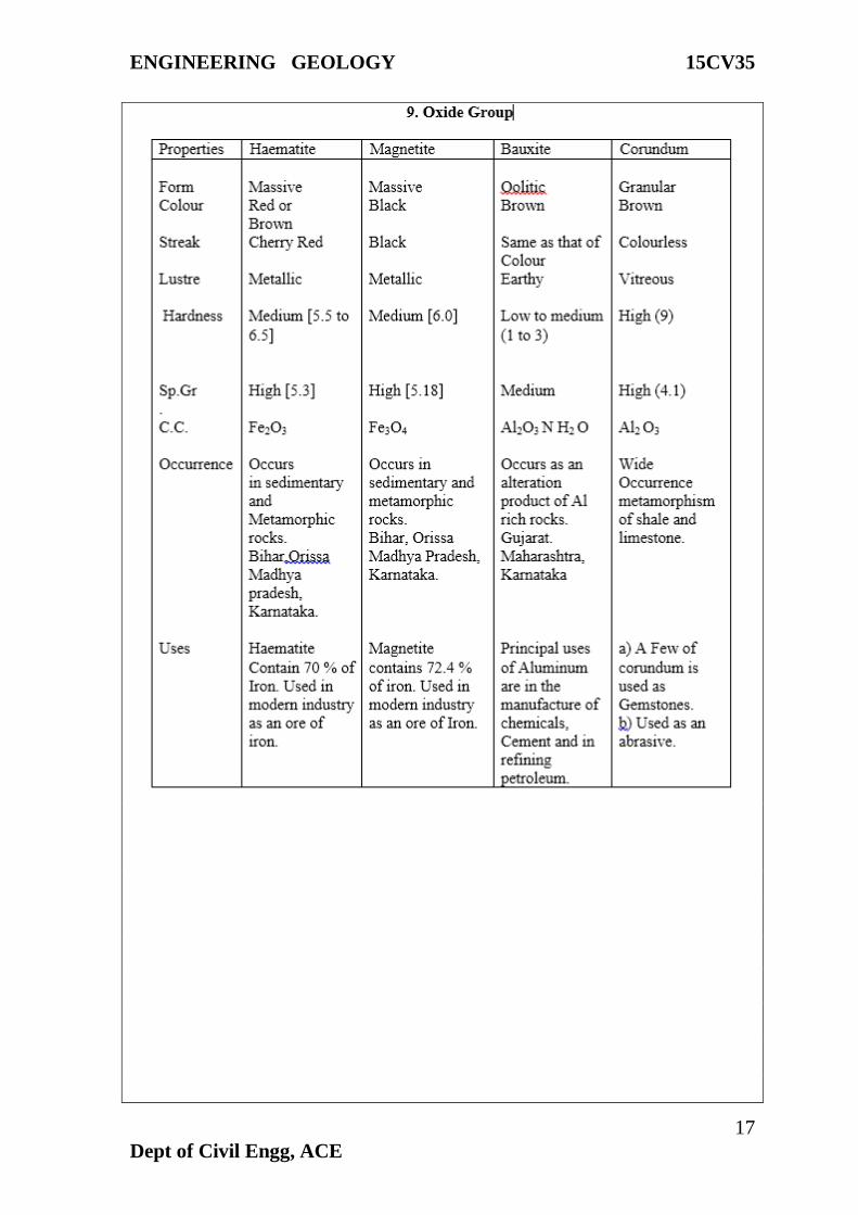
ENGINEERING GEOLOGY 15CV35
17
Dept of Civil Engg, ACE
ENGINEERING GEOLOGY 15CV35
18
Dept of Civil Engg, ACE
Module -2
Petrology:
Petrology is that branch of geology which deals with the study of rocks, with their
mode of formation, composition and the uses for all types of engineering works.
Rock:
Definition:- Rocks are naturally occurring aggregates of mineral grains.
Rocks composed of grains of only one mineral are called Monomineralic rocks.
Ex: Marble:- Composed of calcite
S.St:- Composed of quartz
Dunite:- Composed of olivine
Rocks composed of grains of two / more minerals are called Polymineralic rocks.
Ex: Granite:- Composed of quartz, Orthoclase, Plagioclase, Biotite mica.
Basalt:- Composed of plagioclase, Augite.
Classification of Rocks:
Rocks are the building blocks of the earth’s crust and they are classified on the
basis of their mode of formation into three major groups as following.
1. Igneous rocks
2. Sedimentary rocks and
3. Metamorphic rocks.
Igneous rocks:-
Igneous rocks are formed by cooling and solidification of magma or lava. There
are first formed at very high temperature at a very great depth. The igneous rocks which
are formed upon the earth’s surface are known as extrusive rocks (lava). The rocks which
are formed at a great or moderate depth below the earth surface is known as intrusive
rocks (magma).
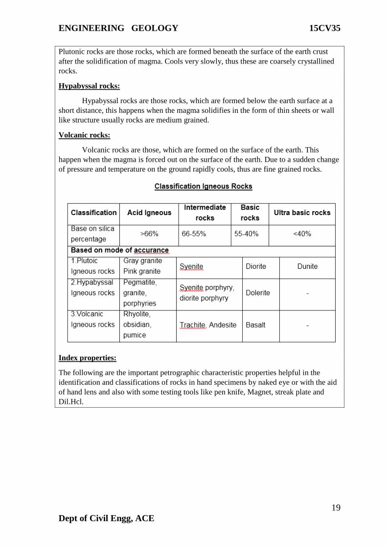
Classification of igneous rocks:
Igneous rocks may be classified by different scientist by different basis, but on the
basis of mode of solidification of magma into the following three types.
1. Plutonic rocks:
2. Hypabyssal rocks:
3. Volcanic rocks:
Plutonic rocks:
ENGINEERING GEOLOGY 15CV35
19
Dept of Civil Engg, ACE
Plutonic rocks are those rocks, which are formed beneath the surface of the earth crust
after the solidification of magma. Cools very slowly, thus these are coarsely crystallined
rocks.
Hypabyssal rocks:
Hypabyssal rocks are those rocks, which are formed below the earth surface at a
short distance, this happens when the magma solidifies in the form of thin sheets or wall
like structure usually rocks are medium grained.
Volcanic rocks:
Volcanic rocks are those, which are formed on the surface of the earth. This
happen when the magma is forced out on the surface of the earth. Due to a sudden change
of pressure and temperature on the ground rapidly cools, thus are fine grained rocks.
Index properties:
The following are the important petrographic characteristic properties helpful in the
identification and classifications of rocks in hand specimens by naked eye or with the aid
of hand lens and also with some testing tools like pen knife, Magnet, streak plate and
Dil.Hcl.
ENGINEERING GEOLOGY 15CV35
20
Dept of Civil Engg, ACE
1. Colour: - The colour of rocks depends upon the colour of their aggregated minerals or
cementing materials and is generalized according to the overall shade.
2. a) Texture:- The texture is defined as the mutual relationship of the constituent
mineral grains their size, shape and etc.
2. (b) Grain Size:-
This is the diameter of the component mineral grains, expressed as follows.
Fine grained – grain diameter 1 mm to less.
Medium grained – grain diameter 1 mm to 5 mm.
Coarse grained – grain diameter 5 mm and above.
Mineral Composition:
The combination and proportion of the component minerals.
a) Essential minerals – easily identified by necked eye.
b) Accessory minerals – finer particles of deleterious component.

ENGINEERING GEOLOGY 15CV35
21
Dept of Civil Engg, ACE
ENGINEERING GEOLOGY 15CV35
22
Dept of Civil Engg, ACE
Sedimentary Rocks:
Rocks which are formed under water in different situations. There rocks are
derived from the consolidation of sediments of the preexisting rock. The distinguished
products of pre-existing rocks are transferred by the influence of geological agents like,
wind, water and glacier etc. through, the process of erosion, transportation, deposition as
a sediment. This sediment deposit into the depressions of the earth, and gets consolidated
and cemented to from sedimentary rocks.
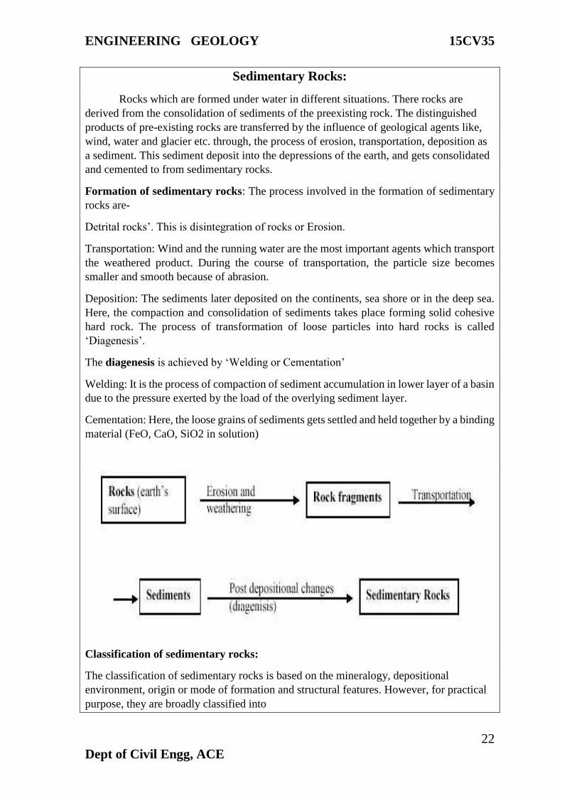
Formation of sedimentary rocks: The process involved in the formation of sedimentary
rocks are-
Detrital rocks’. This is disintegration of rocks or Erosion.
Transportation: Wind and the running water are the most important agents which transport
the weathered product. During the course of transportation, the particle size becomes
smaller and smooth because of abrasion.
Deposition: The sediments later deposited on the continents, sea shore or in the deep sea.
Here, the compaction and consolidation of sediments takes place forming solid cohesive
hard rock. The process of transformation of loose particles into hard rocks is called
‘Diagenesis’.
The diagenesis is achieved by ‘Welding or Cementation’
Welding: It is the process of compaction of sediment accumulation in lower layer of a basin
due to the pressure exerted by the load of the overlying sediment layer.
Cementation: Here, the loose grains of sediments gets settled and held together by a binding
material (FeO, CaO, SiO2 in solution)
Classification of sedimentary rocks:
The classification of sedimentary rocks is based on the mineralogy, depositional
environment, origin or mode of formation and structural features. However, for practical
purpose, they are broadly classified into

ENGINEERING GEOLOGY 15CV35
23
Dept of Civil Engg, ACE
1) Clastic and 2) Non-clastic rocks
1. Clastic rocks: They are mechanically formed rocks. These are formed due to the
process of weathering, erosion, transportation and deposition and diagenesis of
preexisting rocks. Based on grain size, they are further classified into
a) Rudaceous
b) Arenaceous
c) Argillaceous
a) Rudaceous rocks: If the grain size of sediment / particle are more than 2 mm in dia,
they are called ‘Rudites’ and the rocks are called Rudaceous rocks. They are further
classified into
Gravel (2-10 mm in dia)
Pebbles (10-50 mm)
Cobble (50-200 mm)
Boulder (>200 mm)
The grains may be rounded or angular / sharp which depends on the rate of transportation.
Rounded – Example: Conglomerate
Angular/sharp - Example: Breccia
b) Arenaceous rocks: If the size of the particle is in between 1 and 2 mm, then such
sedimentary rocks are called arenaceous rocks. Here, the main constituent is sand (quartz
and feldspar) and the cementing material is may be argillaceous, calcareous, ferruginous
or siliceous material.
Example: Sandstone, Grit
c) Argillaceous rocks: If the size of the particle is < 1mm in dia, they are described as
‘dust’ and rocks are called argillaceous rocks. Argillaceous rocks are formed by the
accumulation and compaction of dust particles. If the particles are loose and dry, the
deposits are called ‘dust’, if it compact and semi wet it is mud and if it is wet, it is
described as clay.
Example: Shale, Mudstone
2. Non-clastic rocks: They are formed either by chemical processes or organic process.
Accordingly, they are grouped into
a) Chemically formed rocks
b) Organically formed rocks
a) Chemically formed rocks; They are formed by precipitation, evaporation or
crystallization from natural aqueous solution. They are further classified into
i) Sileceous deposits – formed by precipitation of silica solution

ENGINEERING GEOLOGY 15CV35
24
Dept of Civil Engg, ACE
Ex: Flint, Chert, Jasper
ii) Carbonate deposits - formed by precipitation of carbonate rich water
Ex: Limestone, Dolomite, Magnesite
iii) Ferrugeneous rocks- formed by precipitate of oxides and hydroxides of iron
Ex: Bog iron ores
iv) Phosphatic deposits- formed by sea water rich in phosphoric acid
Ex: Phosphate compound
v) Evapories – formed by evaporation of sea water (bays and esturies).
Ex: Rock salt, Anhydrites, Gypsum, Borates
b) Organically formed rocks: Sedimentary rocks which are formed exclusively from
remains of organisms (plant / animals).
Ex: Carbonaceous deposits – Coal and petroleum fossiliferous limestone
ENGINEERING GEOLOGY 15CV35
25
Dept of Civil Engg, ACE
METAMORPHIC ROCKS
Introduction:
The word "Metamorphism" comes from the Greek: Meta = change, Morph = form, so
metamorphism means to change form. Metamorphic rocks are those rocks that are formed
as a result of transformation that takes place in the pre-existing rock (Igneous/sedimentary
rocks). When the pre-existing rocks are subjected to higher temperature, pressure and
chemically active liquids and gases, the minerals present in the original rocks changes to
new environmental condition. This adjustment processes continues until the minerals attain
stability or equilibrium. By this, original minerals get recrystallized and the original
structure and texture also changes. The process by which the metamorphic rocks are formed
is known as metamorphism.
Agents or factors of metamorphism: Temperature, Pressure and Fluid are main agents
responsible for metamorphism.
1. Temperature: It is responsible in bringing the recrystallization or reconstitution of the
original minerals into newer ones. Here, there is no addition or subtraction of minerals from
the rocks. The metamorphic reaction taking place between temperature of 300-800°C and
even more upto 1000°C.
2. Pressure: Pressure is one of the important dominant factors in metamorphic rocks and
in majority of rocks it is associated with temperature. It is of two types.
a) Load pressure – Here the pressure acts generally in a vertical direction due over burden
resulting change in structure of the rocks.
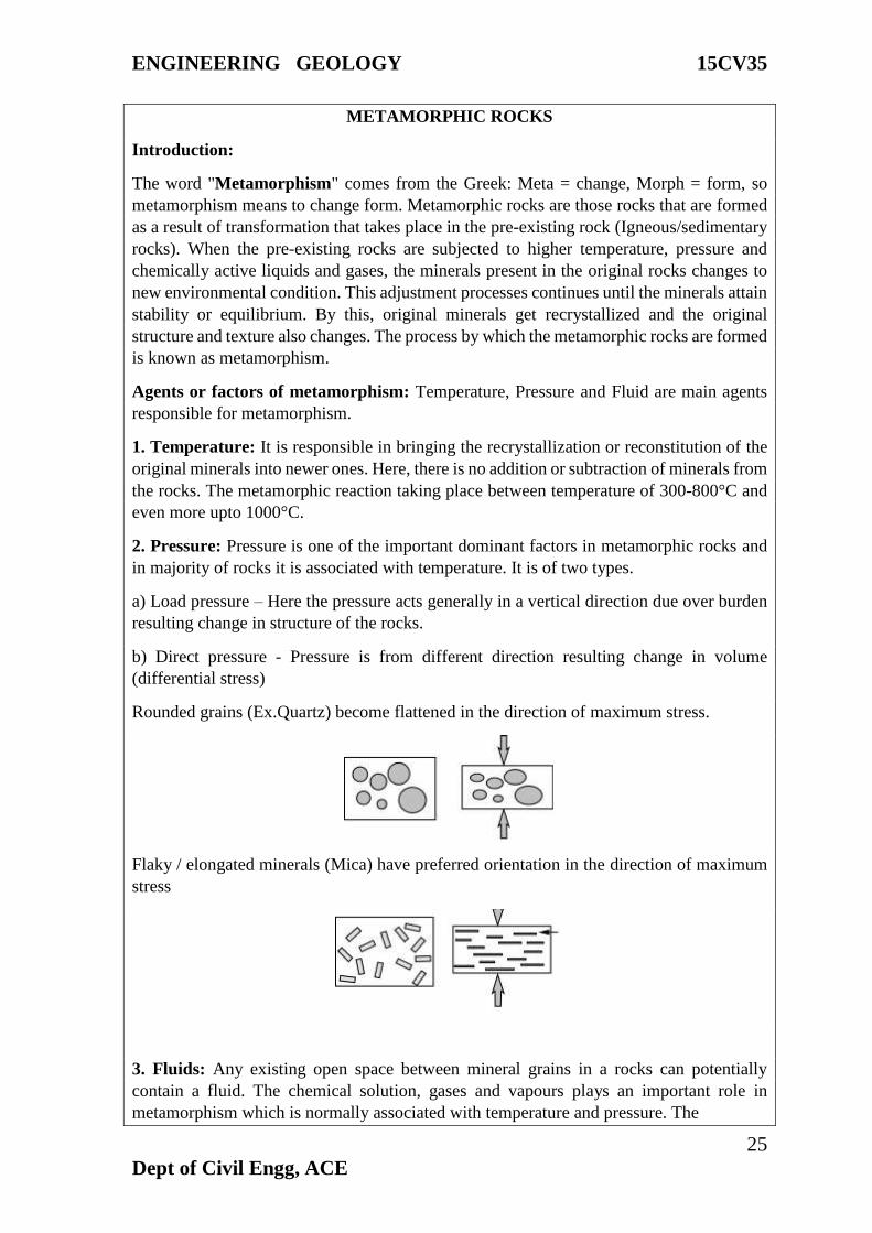
b) Direct pressure - Pressure is from different direction resulting change in volume
(differential stress)
Rounded grains (Ex.Quartz) become flattened in the direction of maximum stress.
Flaky / elongated minerals (Mica) have preferred orientation in the direction of maximum
stress
3. Fluids: Any existing open space between mineral grains in a rocks can potentially
contain a fluid. The chemical solution, gases and vapours plays an important role in
metamorphism which is normally associated with temperature and pressure. The
ENGINEERING GEOLOGY 15CV35
26
Dept of Civil Engg, ACE
chemically active fluids facilitates recrystallization of original minerals. Due to rise in
pressure and temperature. Water is the most important chemically active fluid.
Metasomatism: Sometimes fluids present around the rock comes in contact with the
minerals at high temperature producing many changes in composition, and structure. This
process of rock/mineral alteration by the agency of solution is called metasomatism.
Kinds of metamorphism: Depending upon the factors responsible for metamorphism,
different kinds of metamorphism are noticed and they are
1. Thermal metamorphism
2. Dynamic metamorphism
3. Dynamo -thermal metamorphism
1. Thermal metamorphism: Here, temperature is the dominant factor and pressure and fluid
are the sub-ordinate factors. When the thermal metamorphism occurs in the immediate
contact of igneous intrusions, it is called contact metamorphism and when it occurs on a
regional scale at depth it is called Plutonic metamorphism. As a result of thermal
metamorphism, recrystallization of original minerals takes place.
Ex: Limestone → Marble, Sandstone → Quartzite
2. Dynamic metamorphism: This type of metamorphism takes place in the rock by means
of direct pressure / stress which is a dominant which leads to new structures. It is also called
Cataclastic / kinetic metamorphism and the rock undergo mechanical breaking down and
they may be crushed into smaller ones by pressure.
Ex. Shale → Slate
3. Dynamothermal metamorphism: It is a kind of metamorphism where temperature and
pressure are the dominant factors which operates upon pre-existing rocks. The
metamorphism may be regional / local scale and it is called Regional metamorphism. Here,
temperature promotes recrystallization as in the case of thermal metamorphism and the
original mineral grains re-arrange into new minerals. Direct pressure / stress leads into the
formation of new structures. Thus, the minerals developed under direct pressure are usually
flat, tabular, and flaky in nature.
Ex. Granite → Gneiss
ENGINEERING GEOLOGY 15CV35
27
Dept of Civil Engg, ACE
ENGINEERING GEOLOGY 15CV35
28
Dept of Civil Engg, ACE
Module -3
Geomorphology and Seismology:
Landforms
Landforms are natural features of the landscape, natural physical features of the earth’s
surface, for example, valleys, plateaus, mountains, plains, hills, glaciers.
Types of landforms
There are many different types of landforms on the Earth. Some of them were formed over
millions of years and others were formed in a matter of hours. The formation of a mountain
range, for example, would usually take a few million years. Events like earthquakes and
volcanic eruptions can 'wipe off' landforms, or form new ones in a matter of hours.
Examples of some natural landforms are mountains, oceans, rivers, hills, volcanoes,
valleys, desserts, waterfalls, caves and cliffs. This chapter looks at the formation of some
major types of landforms
Mountains
A mountain is a raised part of the Earth's surface. Mountains can be formed in different
ways that involve internal (inside) or external (outside) natural forces. The movement of
tectonic plates is called plate tectonics. Plate tectonics is an internal natural force because
it happens inside the Earth. When tectonic plates collide, they raise the Earth's crust. As
mentioned before, tectonic plates move very slowly, so it takes many millions of years to
build a mountain. Mountains can also be formed by external natural forces like rain, wind
and frost in the process of erosion.
Mountains with shapes that are sharp and jagged are called young mountains. Mountains
that have a smoother, more rounded look are called old mountains. The South American
mountain range, the Andes, is a young mountain range. Old mountains look smoother
because they have been shaped by natural weathering over a longer period of time. The
Himalayan Mountains, which are an older type of mountain, are still 'growing' due to plate
tectonics.
Valleys
A flat area of land between hills or mountains is called a valley. Valleys are usually formed
by river water. The speed at which a river deepens its valley depends on the speed of the
flow of the river water and the type of materials from which the river bed (the bottom of
the river) is made. Softer and lighter materials are moved by water faster than hard and
heavy ones. That means that a river bed made from soft sediments can be changed or
deepened faster than a hard and rocky one.
Oceans
An ocean is a large body of salty water that surrounds a large land mass. After studying
different rock, scientists have established that the first ocean on the Earth was formed about
4000 million years ago. Even though early Earth did not have any water, it had the chemical
elements that make up a water molecule. Some scientists believe that the Earth's first rain
was just cooled-down volcanic steam. Rainwater started to collect in low-lying areas of the
ENGINEERING GEOLOGY 15CV35
29
Dept of Civil Engg, ACE
Earth's crust, forming the first ocean. Another group of scientists believes that first water
was 'delivered' on the Earth by massive ice-bearing comets.
Deserts
A desert is an area that receives very little or no rain through the year. Deserts usually form
as a result of climate change. Deserts have very dry air and lots of wind. Deserts can be hot
or cold. During the daytime the temperature in hot deserts is very high and at night it drops
to a few degrees. A cold desert is a desert that has snow in the winter. An example of a hot
desert is the Sahara desert. Sometimes people call Antarctica a frozen \desert. It has not
rained or snowed in some places there for over 100 years. A cold desert never becomes
warm enough for plants to grow in it. Deserts cover about a fifth of the Earth's land surface.
Rock Weathering:
It is a process that cause the breakdown of rocks, either to form new minerals that are stable
on the surface of the Earth, or to break the rocks down into smaller particles. Weathering
is the result of the interactions of air, water, and temperature on exposed rock surfaces and
prepares the rock for erosion. Erosion is the movement of the particles by ice, wind, or
water. The particles are then transported by that agent until they are deposited to form
sedimentary deposits, which can be later eroded again or transformed into sedimentary
rocks. Weathering is generally a long, slow process that is continuously active at the earth's
surface.
There are three kinds of weathering: Mechanical, Chemical and Biological Weathering.
Mechanical weathering: It is the process by which rocks are broken down into smaller
pieces by external conditions.
Processes of Mechanical Weathering
A single block is broken gradually into numerous small irregular fragments and then into
smaller fragments. Further it is classified into Block disintegration and Granular
disintegration.
Block disintegration: - This is because of regular arrangement of atoms in a rock, due to
this individual blocks are obtain.
Granular disintegration: - This is because of irregular arrangement of atoms in a rock,
due to this small grains are obtain.
Thermal or heat effect: The effect of change of temperature on rocks is of considerable
importance in arid and semiarid regions where difference between day- time and nighttime
temperature is very high. Expansion on heating followed by contraction on cooling,
repeated expansion and of the same rock body gradually breaks into smaller pieces due to
stress developing by this process.
Frost action: It results due to freezing of water which are trapped in the cracks of the rocks
widens and deepens the cracks, breaking off pieces and slabs.
ENGINEERING GEOLOGY 15CV35
30
Dept of Civil Engg, ACE
Exfoliation - Concentrated shells of weathering may form on the outside of a rock and may
become separated from the rock. These thin shells of weathered rock are separated by
stresses that result from changes in volume of the minerals that occur as a result of the
formation of new minerals.
Spheroidal Weathering - If joints and fractures in rock beneath the surface form a 3-
dimensional network, the rock will be broken into cube like pieces separated by the
fractures. Water can penetrate more easily along these fractures, and each of the cube like
pieces will begin to weather inward. The rate of weathering will be greatest along the
corners of each cube, followed by the edges, and finally the faces of the cubes. As a result
the cube will weather into a spherical shape, with unweathered rock in the center and
weathered rock toward the outside. Such progression of weathering is referred to as
spheroidal weathering.
Chemical weathering: It is a process where chemical alteration or decomposition of rocks
and minerals takes due to rain, water, and other atmospheric agents. Chemical weathering
weakens the bonds in rocks and makes them more vulnerable to decomposition and erosion.
Processes of Chemical Weathering
The main agent responsible for chemical weathering reactions is water, oxygen and weak
acids. These react with surface rocks to form new minerals that are stable in, or in
equilibrium with, the physical and chemical conditions present at the earth's surface. Any
excess ions left over from the chemical reactions are carried away in the acidic water. For
example, feldspar minerals (which a silicate of potassium, sodium, calcium and aluminum)
will weather to clay minerals, releasing silica, potassium, hydrogen, sodium, and calcium.
These elements remain in solution and are commonly found in surface water and
groundwater. Newly deposited sediments are often cemented by calcite or quartz that is
precipitated between the sediment grains from calcium- and silica bearing water,
respectively.
Water: Chemical weathering is most intense in areas that have abundant water. Different
minerals weather at different rates that are climate dependent. Ferromagnesian minerals
break down quickly, whereas quartz is very resistant to weathering.
Oxygen: Oxygen is present in air and water and is an important part of many chemical
reactions. One of the more common and visible chemical weathering reactions is the
combination of iron and oxygen to form iron oxide (rust).
Acids. Acids are chemical compounds that decompose in water to release hydrogen atoms.
Hydrogen atoms frequently substitute for other elements in mineral structures, breaking
them down to form new minerals that contain the hydrogen atoms. The most abundant
natural acid is carbonic acid, a weak acid that consists of dissolved carbon dioxide in water.
Other acids that can affect the formation of minerals in the near surface weathering
environment are organic acids derived from plant and humus material.
Leaching - ions are removed by dissolution into water. In the example above, K+ ion was
leached.
Oxidation - Since free oxygen (O2) is more common near the Earth's surface, it may react
with minerals to change the oxidation state of an ion. This is more common in Fe (iron)
ENGINEERING GEOLOGY 15CV35
31
Dept of Civil Engg, ACE
bearing minerals, since Fe can have several oxidation states, Fe, Fe+2, Fe+3. Deep in the
Earth the most common oxidation state of Fe.
Biological Weathering: Plant roots can extend into fractures and grow, causing expansion
of the fracture and eventually can break rock. Animals burrowing or moving through cracks
can break rock. Plants can penetrates into the ground just a few meters whereas
microorganisms can penetrate to a greater than of 10-25 mts.
EARTHQUAKE
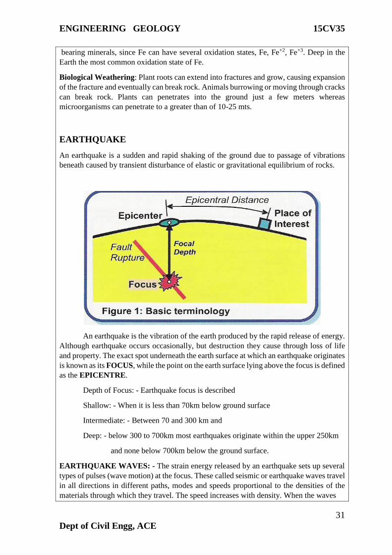
An earthquake is a sudden and rapid shaking of the ground due to passage of vibrations
beneath caused by transient disturbance of elastic or gravitational equilibrium of rocks.
An earthquake is the vibration of the earth produced by the rapid release of energy.
Although earthquake occurs occasionally, but destruction they cause through loss of life
and property. The exact spot underneath the earth surface at which an earthquake originates
is known as its FOCUS, while the point on the earth surface lying above the focus is defined
as the EPICENTRE.
Depth of Focus: - Earthquake focus is described
Shallow: - When it is less than 70km below ground surface
Intermediate: - Between 70 and 300 km and
Deep: - below 300 to 700km most earthquakes originate within the upper 250km
and none below 700km below the ground surface.
EARTHQUAKE WAVES: - The strain energy released by an earthquake sets up several
types of pulses (wave motion) at the focus. These called seismic or earthquake waves travel
in all directions in different paths, modes and speeds proportional to the densities of the
materials through which they travel. The speed increases with density. When the waves
ENGINEERING GEOLOGY 15CV35
32
Dept of Civil Engg, ACE
reach the ground surface they spread out in ever widening circles around the epicenter like
water waves from a point of impact in a pond and cause that span of the ground to shake.
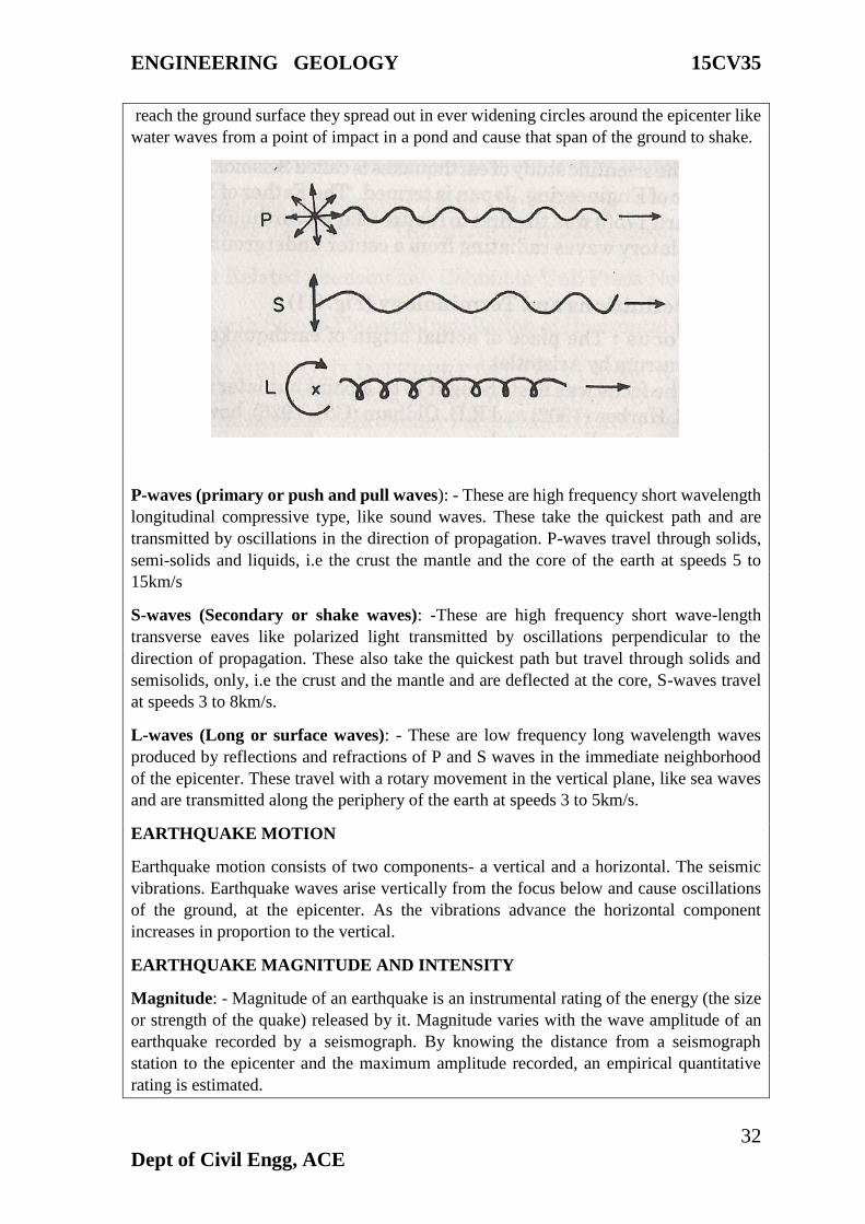
P-waves (primary or push and pull waves): - These are high frequency short wavelength
longitudinal compressive type, like sound waves. These take the quickest path and are
transmitted by oscillations in the direction of propagation. P-waves travel through solids,
semi-solids and liquids, i.e the crust the mantle and the core of the earth at speeds 5 to
15km/s
S-waves (Secondary or shake waves): -These are high frequency short wave-length
transverse eaves like polarized light transmitted by oscillations perpendicular to the
direction of propagation. These also take the quickest path but travel through solids and
semisolids, only, i.e the crust and the mantle and are deflected at the core, S-waves travel
at speeds 3 to 8km/s.
L-waves (Long or surface waves): - These are low frequency long wavelength waves
produced by reflections and refractions of P and S waves in the immediate neighborhood
of the epicenter. These travel with a rotary movement in the vertical plane, like sea waves
and are transmitted along the periphery of the earth at speeds 3 to 5km/s.
EARTHQUAKE MOTION
Earthquake motion consists of two components- a vertical and a horizontal. The seismic
vibrations. Earthquake waves arise vertically from the focus below and cause oscillations
of the ground, at the epicenter. As the vibrations advance the horizontal component
increases in proportion to the vertical.
EARTHQUAKE MAGNITUDE AND INTENSITY
Magnitude: - Magnitude of an earthquake is an instrumental rating of the energy (the size
or strength of the quake) released by it. Magnitude varies with the wave amplitude of an
earthquake recorded by a seismograph. By knowing the distance from a seismograph
station to the epicenter and the maximum amplitude recorded, an empirical quantitative
rating is estimated.
ENGINEERING GEOLOGY 15CV35
33
Dept of Civil Engg, ACE
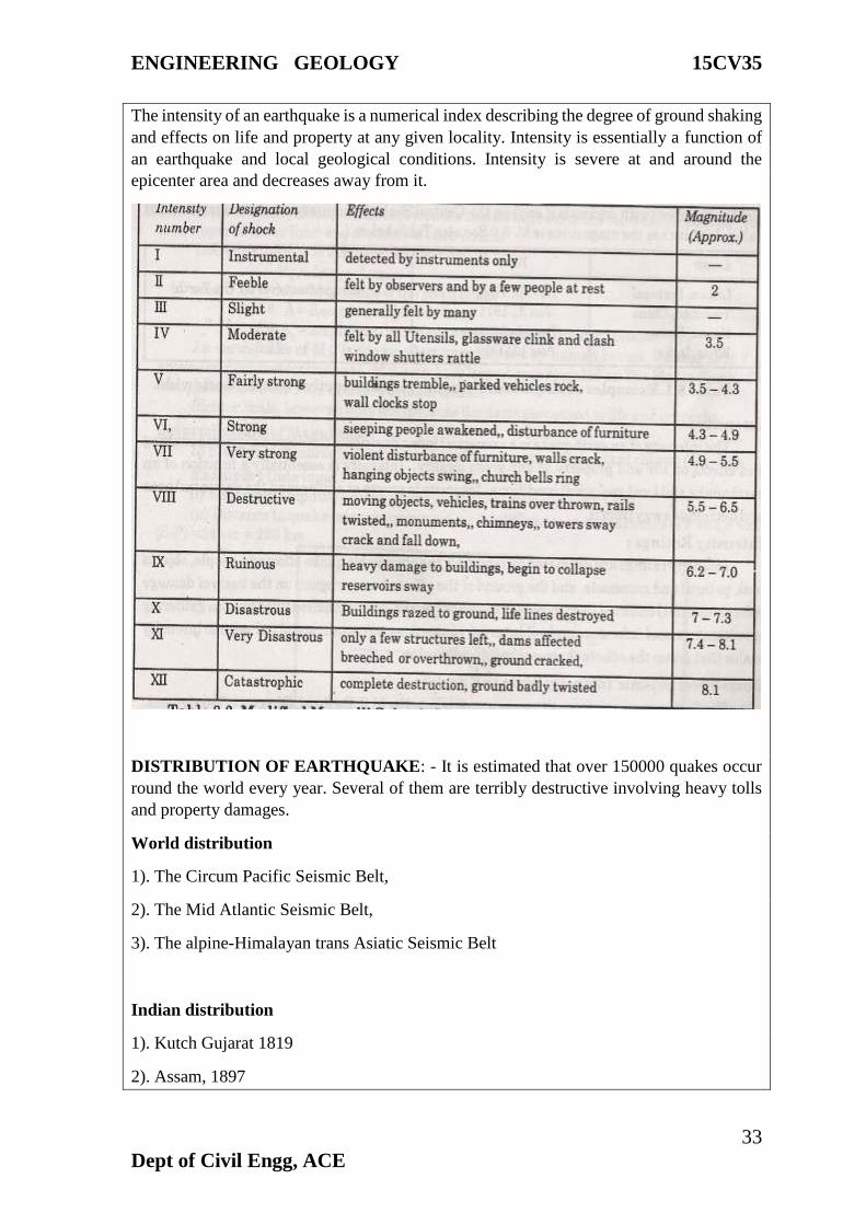
The intensity of an earthquake is a numerical index describing the degree of ground shaking
and effects on life and property at any given locality. Intensity is essentially a function of
an earthquake and local geological conditions. Intensity is severe at and around the
epicenter area and decreases away from it.
DISTRIBUTION OF EARTHQUAKE: - It is estimated that over 150000 quakes occur
round the world every year. Several of them are terribly destructive involving heavy tolls
and property damages.
World distribution
1). The Circum Pacific Seismic Belt,
2). The Mid Atlantic Seismic Belt,
3). The alpine-Himalayan trans Asiatic Seismic Belt
Indian distribution
1). Kutch Gujarat 1819
2). Assam, 1897
ENGINEERING GEOLOGY 15CV35
34
Dept of Civil Engg, ACE
3). Bihar1934
4). Anjar-Gujarath,
5). Peninsular India (South India)
Indian continent is divided into (based on earthquakes)
Zone of Maximum Intensity: - Which comprises the Northeastern regions, especially the
folded chains of Himalayas, geographically this area covers Assam, Himachal Pradesh,
Kashmir, U.P, Nagaland.
Zone of Intermediate Intensity:- Which covers the regions of indo-Gangetic basin. This
zone of moderate Intensity comprises the remaining areas of Punjab, West Bengal and
Bihar.
Zone of Minimum Intensity: - No land mass is free from earthquake, all the regions are
highly affected by this activity.
EARTHQUAKE HAZARDS
The energy released by an earthquake travel along the earth’s surface, it causes the ground
to vibrate in a complex manner by moving up and down as well as from side to side. The
amount of structural damage attributable to the vibrations depends on several factors
including
# The intensity and duration of the vibration
# The nature of the material upon which the structure arrest
# The design of the structure
Earthquake effects are remarkable and directly proportional to the intensity of then
tremblers and geologic setting of the affected area. Earthquake effects comprise of changes
super induced upon land and sea levels, topography and surface and groundwater regimes
as a result of readjustments of certain, components of the crust in order to restore
equilibrium. The hazards are due to two important seismic events are Ground shaking and
Tsunami generation.
Violent ground shaking induces topographic changes and ground failure by landslides,
fissuring surface faulting and soil liquefaction. Ground shaking is maximum in epicenter
regions. Generally topography of the affected areas is transformed partly or totally. Hill
ranges rise or fall or rented. The ground is thrown into terraces or wave like a choppy sea
and extensional cracks.
FIRE HAZARDS
The loss of life and property that accompany great quakes often is mainly due to secondary
cause especially fire. If a quake strikes a modern town or city today it may cause
uncontrollable fire due to electric short circuit severance of gas and water mains and
flooding with attendant serious damages.
STRANGE BEHAVIOR OF ANIMALS
ENGINEERING GEOLOGY 15CV35
35
Dept of Civil Engg, ACE
There are reports of fanciful behavior of animals sometimes before and during an
earthquake. Tigers and chimpanzees scream. Domestic animals horses and cows become
restless and run abut madly stampeding or seek highlands. Dogs and cats howl and huge
closer to people. Rats disappear, pigs rush out in swarms. Rabbits try to climb walls and
fences. Zoo animals refuse to get into their cages and shelters.
EARTHQUAKE SOUNDS
Earthquake records frequently refer to strange sounds that accompany ground shaking. It
is reported that earthquake sounds are due to the shaking ground beating upon the air above
like the membrane of a drum. The near vertical incident of P-waves is supposed to be
responsible for the sounds with the ground behaving like an enormous loud speaker driven
by them. It is observed that earthquakes occurring in areas of crystalline rocks like granite
or gneiss produce strong high frequency sounds and those in thick sedimentary terrines
produce softer low frequency sounds.
TYPES OF EARTHQUAKE PROOF STRUCTURES
Quake proof models: - TO bear the strain due to earthquake shocks and prevent or
minimize damages and death two opposite methods of anti-earthquake construction in
earthquake regions are recommended, they are Light and elastic constructions and Heavy
and rigid constructions
Light and elastic constructions: - In India and elsewhere in earthquake countries most
people in countryside live in non-engineered mud huts or timber structures. The mud
habitats usually are constructed with mud walls and sloping thatched roof, in some cases
bamboo walls with plaster or crude brick or rubble masonry. These fail in earthquakes with
disastrous effects. Mud structures are very popular in India, especially in Kashmir, Kutch,
Maharashtra, Bihar and Assam regions. Timber frame structures and Brick Masonry
Heavy and rigid constructions: - These are well built structures of brick and stone
masonry, RCC frames with filler brick walls, and single or multistoried buildings. The main
object of these is to construct stronger than ordinary building in order to prevent their
collapse and loss of life and property, especially those of large selling’s, schools, office
building, hospitals, business complexes community halls etc. Where commonly good
number of people assembles at a time and also certain vital or critical installations like
powerhouses nuclear facilities.
Safety measures to be adopted for buildings to be construction in seismic areas. As
stated earlier, an earthquake resultant building must be strong and sturdy. Hence, besides
incorporating these additional safety factors in the design of such buildings the following
other points must be given due attention to
1. Good quality materials, strictly according to the specifications, should be used.
2. The foundation should not be on soft ground and rather it should preferably be on the
solid rocks. The depth of foundation should also be uniform.
3. The walls should be continuous in nature. The long walls and cross wall be erected
simultaneously without any joints.
ENGINEERING GEOLOGY 15CV35
36
Dept of Civil Engg, ACE
4. Doors and windows should be minimized.
5. Height of the building should be kept uniform.
6. All parts of the buildings, particularly its edges and corners should be well tied, so that
it moves as a single unit during an earthquake vibration.
7. Construction of cantilevers, Chimneys, Arches and other extra projections should be
avoided.
EARTHQUAKE AND CIVIL ENGINEERING
An earthquake is a vibratory motion having components in all directions. The vertical
components are more dominant near the epicentral tracts and the horizontal components
away from these tracts. Hence strong structures have to withstand bigger forces near the
epicenter and soft and flexible structures are safer, away from the epicenter flexi bile
structure suffer severe damage while hard structures as safer. Extensive research has been
carried out in the last 50 years to develop new methods to minimize losses.
Buildings: - Steel – framed tall buildings in which the frame supports all wall and floor
loads usually behave well during earthquake. Reinforced concrete buildings may develop
cracks in walls and piers houses with roofs; wall and foundations tied into one strong unit
behave safely during earthquake. Houses built with wood and flexible materials of
construction absorb earthquake shocks. In our country modern methods are increasingly
being adopted and reinforced brick buildings are built against earthquake forces. This
method increases the construction cost 2-5%, but simultaneously saves buildings and lives.
Even more recently by a new direction in research and developed insulators for absorbing
energy transmitted by ground motion to reduce damage to structure. Some of these methods
are useful for rigid structures.
Foundations: - The amount of damage caused by ground shaking depends on the type of
foundation below the building or structure. These are built in low-strength roc materials
such as sand and silt tend to absorb much of the shaking motion, hence buildings have not
been designed to cope with strong shaking but rather to accommodate large foundation
movements. Such buildings have to provide competent footings, adequate drainage and
flexible power, water and sewage connections. Unconsolidated sandstone may saturate as
a result of earthquake vibrations, sometimes the entire structure is destroyed.
Slopes and embankments: -Settlement of embankments can be minimized by careful
compaction control during construction but even then settlement can occur. Landslides due
to earthquakes have resulted in loss of lives and property. So embankment has to be
designed with extra care. Highways and railway cuttings and avoidance of steep slopes for
residential development re necessary in high seismic areas.
Dams: -Rock fill dams usually stand up well to earthquake shocks. A river valley project
may consist of a dam or barrage, tunnel, powerhouses, buildings and bridges of various
types, which may fail during strong earthquake.
ENGINEERING GEOLOGY 15CV35
37
Dept of Civil Engg, ACE
Tunnels: - Tunnels, which intersect at geological fault, are often seriously affected by
earthquake movement. Special tunnel deigns are necessary in seismically active zones.
Generally rupture of the lining may cause flooding of partial dislocations. Earth tunnels are
less affected by earthquake movements but the chances of liquefaction of the surrounding
materials are real.
Impacts of reservoir-induced seismicity (RIS): The weight of the reservoir, by itself or
in conjunction with other reservoirs in the region, can create the sorts of pressures that
could result in an earthquake. The weight of the reservoir can also force water down cracks
and faults till it catalyses an earthquake. The occurrence of reservoir-induced seismicity is
now a well-accepted fact. RIS has occurred in various dams across the world. 17 of the 75
cases of RIS reported worldwide have been reported from India.
LANDSLIDE
A landslide is a slow or sudden downhill movement of slope forming rock and soil material
under the force of gravity. Landslides or slopes failures are natural Erosional process. They
occur in hillsides valley slopes, seacoasts, riverbanks and bends, on the slopes of volcanic
cones and in earthquake prone areas. They also occur underneath as on lake or sea floor.
Man in his urban and regional development activities also trigger landslides. Such as
excavations, fills quarries, cuttings of roads, railway and canals etc. Landslides as natural
erosional process not only modify the existing topography and landscape, they also cause
immense damages to manmade structures and heavy loss of life.
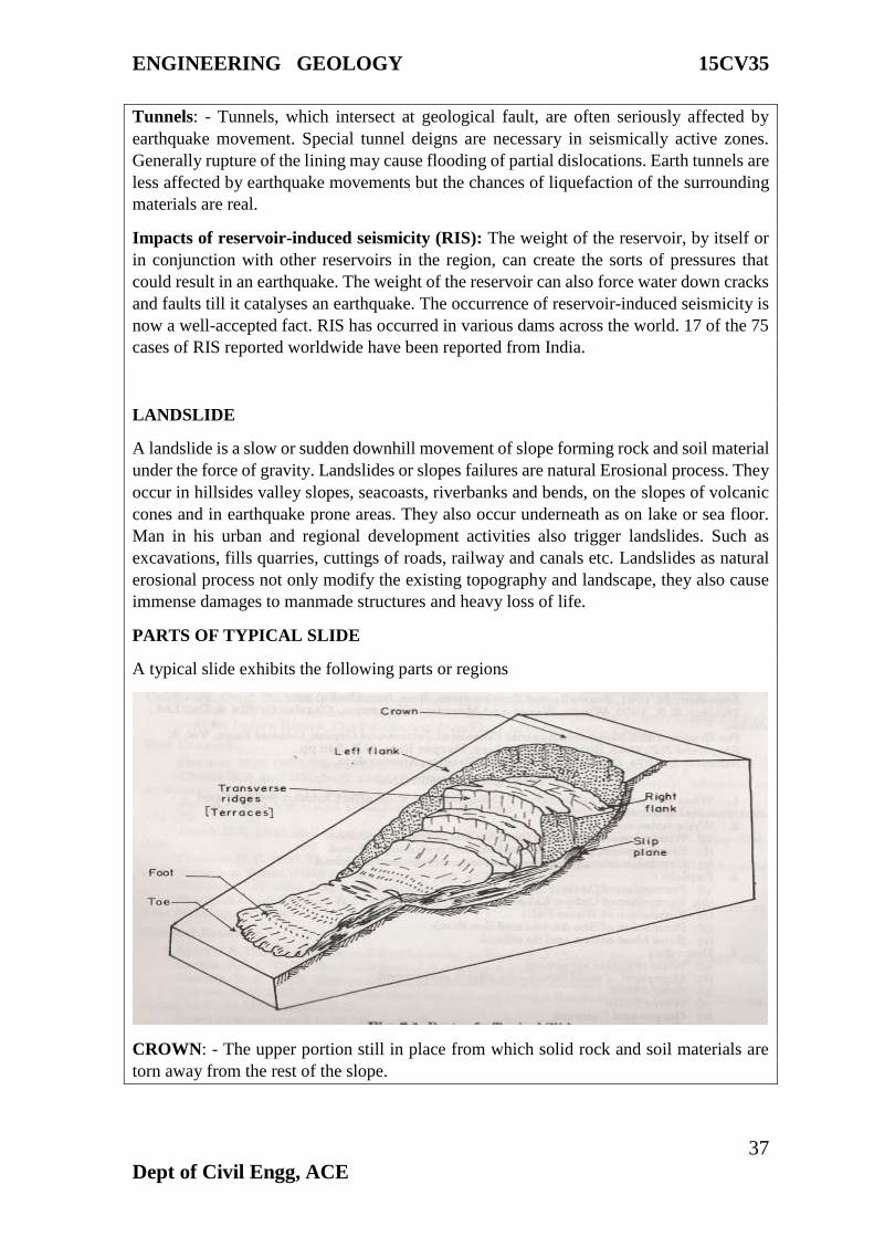
PARTS OF TYPICAL SLIDE
A typical slide exhibits the following parts or regions
CROWN: - The upper portion still in place from which solid rock and soil materials are
torn away from the rest of the slope.
ENGINEERING GEOLOGY 15CV35
38
Dept of Civil Engg, ACE
SCARP: - The steep wall of the undisturbed material below crown around the periphery of
the slide material
HEAD: - The upper part f the slide material
SLIP PLANE: - The shear surface – the surface of movement downhill of the slide material
FLANKS: - Sides of a slide, left flank and Right Flank
TRANSVERSE RIDGES: - Terrace or step like pressure or compression ridges
FOOT: - The line of intersection of the lower part of the slip plane and the original ground
surface
TOE: - The lower portion in which the rock or soil material is heaped up
LENGTH: - Horizontal distance from crown to toe.
WIDTH: - Horizontal distance form flank to flank
HEIGHT: - Vertical distance, crown to toe
DEPTH: - Thickness of the slide mass between crown and foot.
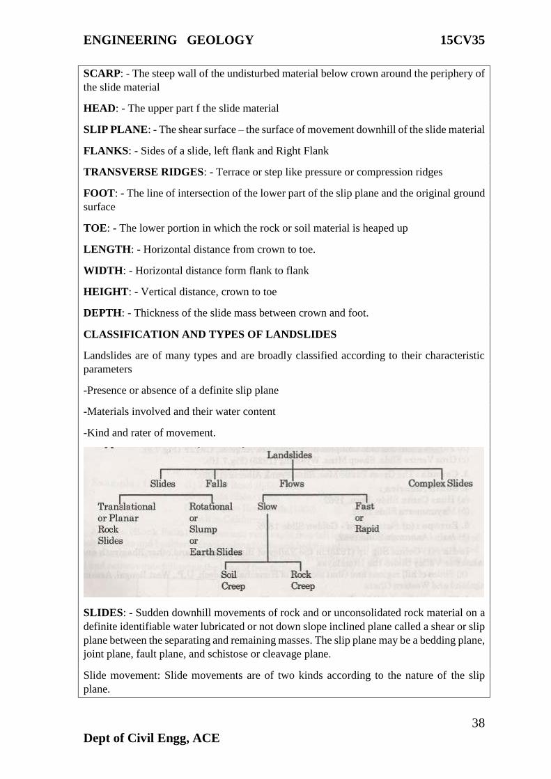
CLASSIFICATION AND TYPES OF LANDSLIDES
Landslides are of many types and are broadly classified according to their characteristic
parameters
-Presence or absence of a definite slip plane
-Materials involved and their water content
-Kind and rater of movement.
SLIDES: - Sudden downhill movements of rock and or unconsolidated rock material on a
definite identifiable water lubricated or not down slope inclined plane called a shear or slip
plane between the separating and remaining masses. The slip plane may be a bedding plane,
joint plane, fault plane, and schistose or cleavage plane.
Slide movement: Slide movements are of two kinds according to the nature of the slip
plane.
ENGINEERING GEOLOGY 15CV35
39
Dept of Civil Engg, ACE
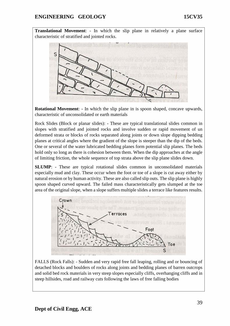
Translational Movement: - In which the slip plane in relatively a plane surface
characteristic of stratified and jointed rocks.
Rotational Movement: - In which the slip plane in is spoon shaped, concave upwards,
characteristic of unconsolidated or earth materials
Rock Slides (Block or planar slides): - These are typical translational slides common in
slopes with stratified and jointed rocks and involve sudden or rapid movement of un
deformed strata or blocks of rocks separated along joints or down slope dipping bedding
planes at critical angles where the gradient of the slope is steeper than the dip of the beds.
One or several of the water lubricated bedding planes form potential slip planes. The beds
hold only so long as there is cohesion between them. When the dip approaches at the angle
of limiting friction, the whole sequence of top strata above the slip plane slides down.
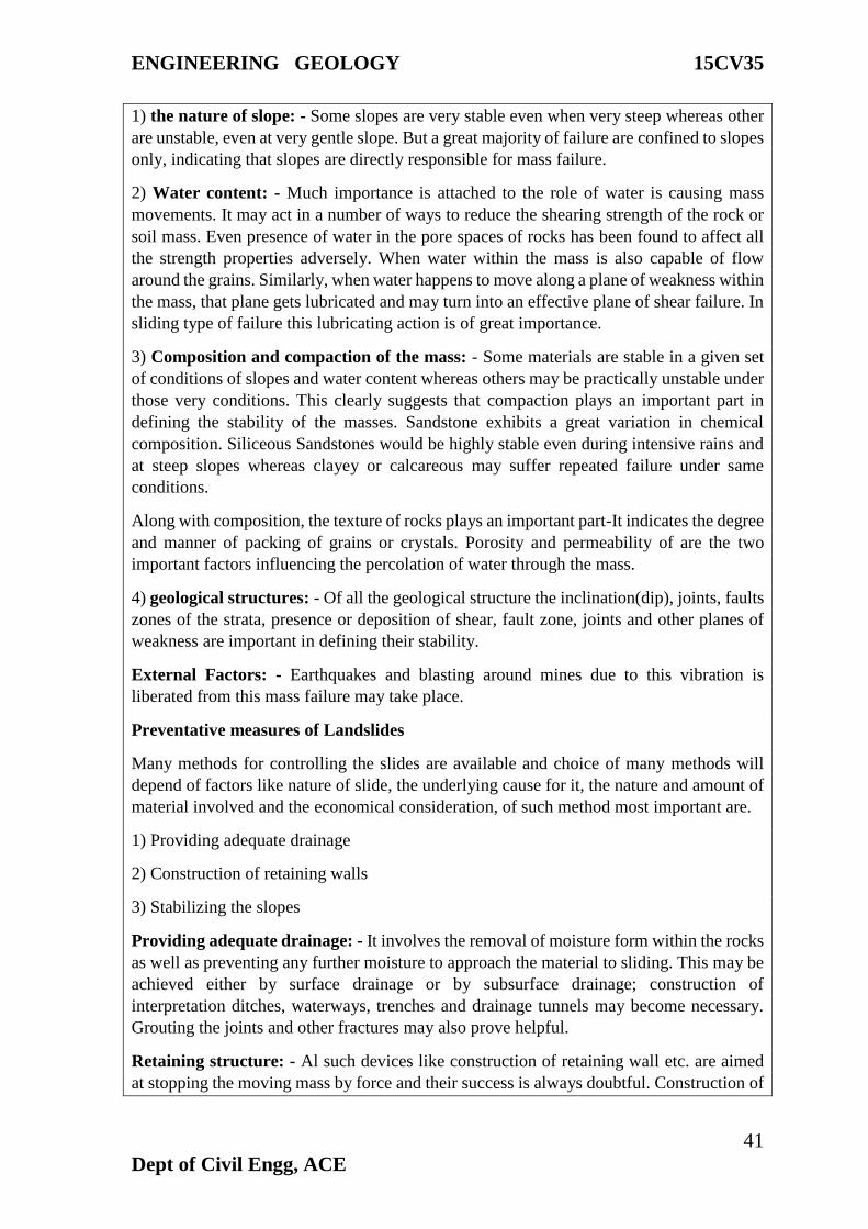
SLUMP: - These are typical rotational slides common in unconsolidated materials
especially mud and clay. These occur when the foot or toe of a slope is cut away either by
natural erosion or by human activity. These are also called slip outs. The slip plane is highly
spoon shaped curved upward. The failed mass characteristically gets slumped at the toe
area of the original slope, when a slope suffers multiple slides a terrace like features results.
FALLS (Rock Falls): - Sudden and very rapid free fall leaping, rolling and or bouncing of
detached blocks and boulders of rocks along joints and bedding planes of barren outcrops
and solid bed rock materials in very steep slopes especially cliffs, overhanging cliffs and in
steep hillsides, road and railway cuts following the laws of free falling bodies

ENGINEERING GEOLOGY 15CV35
40
Dept of Civil Engg, ACE
FLOWS: - Slow to fast downhill movement of unconsolidated materials, earth sand and
rock debris, dry or wet with water or ice and snow and in some cases bedrock itself. Flows
are characterized by the absence of a recognizable slip plane. The movement resembles
those of viscous fluids. Flows are of two types according to the materials and rate of
movement slow or fast.
Slow Flows: - These are of two types
(a). Soil Creep: - A very slow almost imperceptible down slope plastic movement of wet
or dry surface materials following the laws of viscous flows of fluids and semi fluids.
Curved tree trunks recognize soil creep, tilted lampposts telegraph as well as displacement
or destruction of foundations, buildings, and retaining walls, fences etc on sloping grounds
If water saturated materials are involved soil creep is called solifluxion and when it it’s a
wet mud without vegetation mud flow. Mudflows are common in areas effected by wild
forest fires and on slopes of volcanic cones.
Fast Flows (Rapids Flows): -
Fast flows are sudden and very fast-to-fast downhill slide of soil, rock debris and boulders
with large masses of ice and snow on steep slopes of Snow Mountains. It includes
disruption of highways, railroads, recreation facilities heavy damage to buildings and loss
of life.
CAUSES OF LANDSLIDES
Many factors are causing a mass of material to slide or flow. Some of them play a direct
role and are easily understand whereas others are indirectly responsible for the instability
of the landmass. All such factors that facilities land sliding is one way or another is
generally grouped in tow headings.
1) Internal Factors
2) External Factors
Internal Factors: - These include such causes, which tend to reduce the shearing of the
rock, further it is classified into, 1) the nature of slope, 2) water content, 3) composition
and compaction of the mass, 4) geological structures
ENGINEERING GEOLOGY 15CV35
41
Dept of Civil Engg, ACE
1) the nature of slope: - Some slopes are very stable even when very steep whereas other
are unstable, even at very gentle slope. But a great majority of failure are confined to slopes
only, indicating that slopes are directly responsible for mass failure.
2) Water content: - Much importance is attached to the role of water is causing mass
movements. It may act in a number of ways to reduce the shearing strength of the rock or
soil mass. Even presence of water in the pore spaces of rocks has been found to affect all
the strength properties adversely. When water within the mass is also capable of flow
around the grains. Similarly, when water happens to move along a plane of weakness within
the mass, that plane gets lubricated and may turn into an effective plane of shear failure. In
sliding type of failure this lubricating action is of great importance.
3) Composition and compaction of the mass: - Some materials are stable in a given set
of conditions of slopes and water content whereas others may be practically unstable under
those very conditions. This clearly suggests that compaction plays an important part in
defining the stability of the masses. Sandstone exhibits a great variation in chemical
composition. Siliceous Sandstones would be highly stable even during intensive rains and
at steep slopes whereas clayey or calcareous may suffer repeated failure under same
conditions.
Along with composition, the texture of rocks plays an important part-It indicates the degree
and manner of packing of grains or crystals. Porosity and permeability of are the two
important factors influencing the percolation of water through the mass.
4) geological structures: - Of all the geological structure the inclination(dip), joints, faults
zones of the strata, presence or deposition of shear, fault zone, joints and other planes of
weakness are important in defining their stability.
External Factors: - Earthquakes and blasting around mines due to this vibration is
liberated from this mass failure may take place.
Preventative measures of Landslides
Many methods for controlling the slides are available and choice of many methods will
depend of factors like nature of slide, the underlying cause for it, the nature and amount of
material involved and the economical consideration, of such method most important are.
1) Providing adequate drainage
2) Construction of retaining walls
3) Stabilizing the slopes
Providing adequate drainage: - It involves the removal of moisture form within the rocks
as well as preventing any further moisture to approach the material to sliding. This may be
achieved either by surface drainage or by subsurface drainage; construction of
interpretation ditches, waterways, trenches and drainage tunnels may become necessary.
Grouting the joints and other fractures may also prove helpful.
Retaining structure: - Al such devices like construction of retaining wall etc. are aimed
at stopping the moving mass by force and their success is always doubtful. Construction of
ENGINEERING GEOLOGY 15CV35
42
Dept of Civil Engg, ACE
retaining wall requires an accurate assessment of the forces, which the wall has to
withstand. Retaining walls may prove exceptionally, successful where,
A) The ground is neither too fine nor too plastic
B) The sliding mass is likely t remain dry
C) The movement is of shallow nature
Slope treatment: - When the material is soil and situation is a slope the failure is attributed
to a loss of stability. In such cases the treatment involves stability for the particular type of
soil and slope and if such computation indicate that a given slope of soil will not be stable
then the solution lies in either,
A) Flattening the slope
B) Decreasing the load
C) Increasing the shearing resistant of the soil by decreasing its water content with help of
drains and evaporation
D) A forestation that is growth of vegetation cover with intricate and interwoven root
system has also been found useful in stabilizing the barren slopes.
Effects on Hillside Homes and Structures, Landslide Damages:
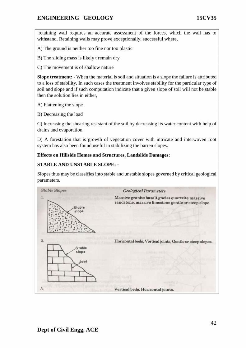
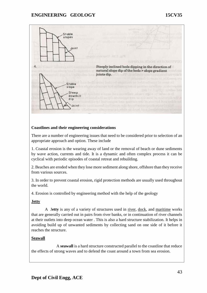
STABLE AND UNSTABLE SLOPE: -
Slopes thus may be classifies into stable and unstable slopes governed by critical geological
parameters.
ENGINEERING GEOLOGY 15CV35
43
Dept of Civil Engg, ACE
Coastlines and their engineering considerations
There are a number of engineering issues that need to be considered prior to selection of an
appropriate approach and option. These include
1. Coastal erosion is the wearing away of land or the removal of beach or dune sediments
by wave action, currents and tide. It is a dynamic and often complex process it can be
cyclical with periodic episodes of coastal retreat and rebuilding.
2. Beaches are eroded when they lose more sediment along shore, offshore than they receive
from various sources.
3. In order to prevent coastal erosion, rigid protection methods are usually used throughout
the world.
4. Erosion is controlled by engineering method with the help of the geology
Jetty
A Jetty is any of a variety of structures used in river, dock, and maritime works
that are generally carried out in pairs from river banks, or in continuation of river channels
at their outlets into deep ocean water . This is also a hard structure stabilization. It helps in
avoiding build up of unwanted sediments by collecting sand on one side of it before it
reaches the structure.
Seawall
A seawall is a hard structure constructed parallel to the coastline that reduce
the effects of strong waves and to defend the coast around a town from sea erosion.
ENGINEERING GEOLOGY 15CV35
44
Dept of Civil Engg, ACE
Groins
Groins are impermeable structures that fingerlike, perpendicularly to the shore
which extend from backshore into the littoral zone. This type of structure is easy to
construct from a variety of materials such as wood, rock or concrete, steel, bamboo
(Timber) and normally used on sandy coasts.
Revetments
Revetments are another type of hard structure of stone, concrete built parallel to the sea
or at the front of a beach to protect the slope against wave or current–induced erosion.
Beach Nourishment
Beach nourishment is one of the most popular soft engineering techniques of
coastal defense management schemes. Mainly, Beach Nourishment is the addition of sand
and sediment to a beach to replace sand and sediment that has been eroded away. It involves
the transport of the “nourishment material” from one area to the affected areas. The
replacement sand is usually dredged up offshore and transported to the beach. Offshore
sand is almost always much finer grained and muddier, therefore it erodes very quickly
Sand dune Stabilization
Mainly, coastal sand dune are of vital importance in providing natural protection
to beaches and backshore areas from infrequent severe storms. Another way is Vegetation:
it can be used to encourage dune growth by trapping and stabilizing blown sand.
WATERSHED MANAGEMENT
The maintaining (land use practice-includes both soil and water conservation (also
controlling anthropogenic pollution activities)) of water draining through a common point
and ultimately recharged in a basin (check dam, reservoir, ponds, underground) is termed
as watershed management. Watershed management has been thus proposed to meet the
needs of water of our society.
A watershed, also called a drainage basin or catchment area, is defined as an area in which
all water flowing into it goes to a common outlet.
A Topographically Delineated Area that is drained by a Stream System.
Types of watershed
Watersheds is classified depending upon the size, drainage, shape and land use pattern.
1) Macro watershed (>50,000Hect)
2)Sub-watershed (10,000to50,000Hect)
3)Milli-watershed (1000to10000Hect)
4)Micro watershed (100to1000Hect)
5) Mini watershed (1-100 Hect)
ENGINEERING GEOLOGY 15CV35
45
Dept of Civil Engg, ACE
Importance of watershed management
Watershed management helps to control pollution of the water and other natural resources
in the watershed by identifying the different kinds of pollution present in the watershed and
how those pollutants are transported, and recommending ways to reduce or eliminate those
pollution sources.
Watershed management planning comprehensively identifies those activities that affect the
health of the watershed and makes recommendations to properly address them so that
adverse impacts from pollution are reduced.
It is to protect and improve the water quality and other natural resources in a watershed.
Components of watershed management
Entry point activity (EPA) - introducing development program to the community is the
foremost activity done after the site selection
Land and water conservation practices- soil and water conservation practices are the
primary step of watershed management program. Conservation practices can be divided
into two main categories:
1) in-situ and 2) ex-situ management.
Contour bunds, graded bunds, field bunds, terraces building, broad bed and furrow practice
and other soil-moisture conservation practices, are known as in-situ management.
Construction of check dam, farm pond, gully control structures, pits excavation across the
stream channel is known as ex-situ management.
Floods and their control
Different measures have been adopted to reduce the flood losses and protect the flood
plains. Depending upon the nature work, Flood protection and flood management measures
may be broadly classified as under:
(a) Engineering / Structural Measures
(b) Administrative / Non-Structural Measures
Engineering /Structural Measures
The engineering measures for flood control which bring relief to the flood prone areas by
reducing flood flows and thereby the flood levels are –
(a) An artificially created reservoir behind a dam across a river
(b) A natural depression suitably improved and regulated, if necessary or
(c) By diversion of a part of the peak flow to another river or basin, where such diversion
would not cause appreciable damage.
(d) By constructing a parallel channel bye passing a particular town/reach of the river prone
to flooding.
ENGINEERING GEOLOGY 15CV35
46
Dept of Civil Engg, ACE
The engineering methods of flood protection, which do not reduce the flood flow but reduce
spilling, are:
(i) Embankments which artificially raise the effective river bank and thereby prevent
spilling and
(ii) Channel and drainage improvement works, which artificially reduce the flood water
level so as to keep the same, confined within the river banks and thus prevent spilling.
Different aspects of some of the important measures for flood management are enumerated
below
Reservoirs
Reservoirs can moderate the intensity and timing of the incoming flood. They store the
water during periods of high discharges in the river and release it after the critical high flow
condition is over, so as to be ready to receive the next wave. Their effectiveness in
moderating floods would depend on the reservoir capacity available at that time for
absorbing the flood runoff and their proximity to the likely damage center.
Embankments
Embankments (including ring bunds and town protection works) confine the flood flows
and prevent spilling, thereby reducing the damage. These are generally cheap, quick and
most popular method of flood protection and have been constructed extensively in the past.
Channel Improvement
The method of improving the channel by improving the hydraulic conditions of the river
channels by desilting, dredging, lining etc., to enable the river to carry its discharges at
lower levels or within its banks has been often advocated but adopted on a very limited
extent because of its high cost and other problems.
Drainage Improvement
Surface water drainage congestion due to inadequacy of natural or artificial drainage
channels to carry the storm water discharge within a reasonable period causes damages. It
is often difficult to distinguish between flood and drainage congestion situations. This
problem is rather acute in Andhra Pradesh, Bihar, Haryana, Punjab, Orissa, Uttar Pradesh,
Assam and West Bengal, J&K, Gujarat and Tamilnadu. Therefore, improvement of
drainage by construction of new channels or improvement in the discharge capacity of the
existing drainage system is recommended as an integral part of the flood management
programme in the country.
Diversion of Flood Waters
Diversion of flood waters takes a part of the flood discharge to another basin or to the same
basin downstream of the problem area or to a depression where it could be stored for
subsequent release.
ENGINEERING GEOLOGY 15CV35
47
Dept of Civil Engg, ACE
Watershed Management
The watershed management measures include developing and conserving the vegetative
and soil covers and also to undertake structural works like check-dams, detention basins,
and diversion channels, etc. In the watershed management of upper catchment, land
treatment through afforestation and grass land development practices should be
supplemented by structural works for retarding the water velocity and arresting silt.
The administrative methods endeavor to mitigate the flood damages by;
(a) Facilitating timely evacuation of the people and shifting of their movable property to
safer grounds by having advance warning of incoming flood i.e. flood forecasting, flood
warning in case of threatened inundation
(b) Discouraging creation of valuable assets/settlement of the people in the areas subject to
frequent flooding i.e. enforcing flood plain zoning regulation.
Providing absolute protection to all flood prone areas against all magnitude of floods is
neither practically possible nor economically viable. Such an attempt would involve
stupendously high cost for construction and for maintenance. Hence a pragmatic approach
in flood management is to provide a reasonable degree of protection against flood damages
at economic cost through a combination of structural and non-structural measures.
Drainage Patterns -Parameters and Development
Drainage systems, also known as river systems, are the patterns formed by the streams,
rivers, and lakes in a particular drainage basin. They are governed by the topography of
the land, whether a particular region is dominated by hard or soft rocks, and the gradient of
the land.
Drainage pattern to its network of stream channels and tributaries as determined by local
geologic factors. Drainage patterns or nets are classified on the basis of their form and
texture. Their shape or pattern develops in response to the local topography and subsurface
geology. Drainage channels develop where surface runoff is enhanced and earth materials
provide the least resistance to erosion. The texture is governed by soil infiltration, and the
volume of water available in a given period of time to enter the surface.
Types of Drainage patterns
Dendritic drainage pattern
A dendritic drainage pattern is the most common form and looks like the branching
pattern of tree roots. It develops in regions underlain by homogeneous material. That is, the
subsurface geology has a similar resistance to weathering so there is no apparent control
over the direction the tributaries take. Tributaries joining larger streams at acute angle (less
than 90 degrees).
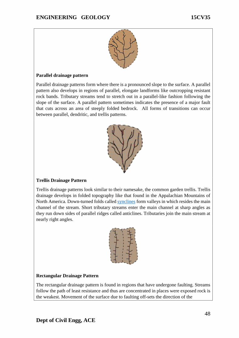
ENGINEERING GEOLOGY 15CV35
48
Dept of Civil Engg, ACE
Parallel drainage pattern
Parallel drainage patterns form where there is a pronounced slope to the surface. A parallel
pattern also develops in regions of parallel, elongate landforms like outcropping resistant
rock bands. Tributary streams tend to stretch out in a parallel-like fashion following the
slope of the surface. A parallel pattern sometimes indicates the presence of a major fault
that cuts across an area of steeply folded bedrock. All forms of transitions can occur
between parallel, dendritic, and trellis patterns.
Trellis Drainage Pattern
Trellis drainage patterns look similar to their namesake, the common garden trellis. Trellis
drainage develops in folded topography like that found in the Appalachian Mountains of
North America. Down-turned folds called synclines form valleys in which resides the main
channel of the stream. Short tributary streams enter the main channel at sharp angles as
they run down sides of parallel ridges called anticlines. Tributaries join the main stream at
nearly right angles.
Rectangular Drainage Pattern
The rectangular drainage pattern is found in regions that have undergone faulting. Streams
follow the path of least resistance and thus are concentrated in places were exposed rock is
the weakest. Movement of the surface due to faulting off-sets the direction of the
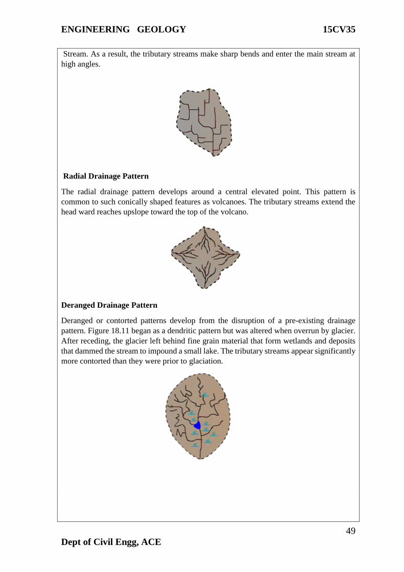
ENGINEERING GEOLOGY 15CV35
49
Dept of Civil Engg, ACE
Stream. As a result, the tributary streams make sharp bends and enter the main stream at
high angles.
Radial Drainage Pattern
The radial drainage pattern develops around a central elevated point. This pattern is
common to such conically shaped features as volcanoes. The tributary streams extend the
head ward reaches upslope toward the top of the volcano.
Deranged Drainage Pattern
Deranged or contorted patterns develop from the disruption of a pre-existing drainage
pattern. Figure 18.11 began as a dendritic pattern but was altered when overrun by glacier.
After receding, the glacier left behind fine grain material that form wetlands and deposits
that dammed the stream to impound a small lake. The tributary streams appear significantly
more contorted than they were prior to glaciation.
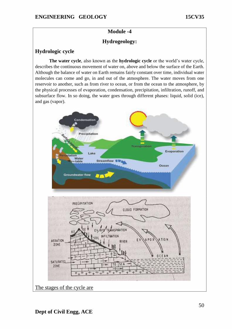
ENGINEERING GEOLOGY 15CV35
50
Dept of Civil Engg, ACE
Module -4
Hydrogeology:
Hydrologic cycle
The water cycle, also known as the hydrologic cycle or the world’s water cycle,
describes the continuous movement of water on, above and below the surface of the Earth.
Although the balance of water on Earth remains fairly constant over time, individual water
molecules can come and go, in and out of the atmosphere. The water moves from one
reservoir to another, such as from river to ocean, or from the ocean to the atmosphere, by
the physical processes of evaporation, condensation, precipitation, infiltration, runoff, and
subsurface flow. In so doing, the water goes through different phases: liquid, solid (ice),
and gas (vapor).
The stages of the cycle are
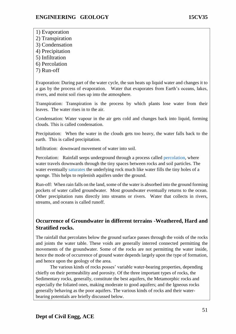
ENGINEERING GEOLOGY 15CV35
51
Dept of Civil Engg, ACE
1) Evaporation
2) Transpiration
3) Condensation
4) Precipitation
5) Infiltration
6) Percolation
7) Run-off
Evaporation: During part of the water cycle, the sun heats up liquid water and changes it to
a gas by the process of evaporation. Water that evaporates from Earth’s oceans, lakes,
rivers, and moist soil rises up into the atmosphere.
Transpiration: Transpiration is the process by which plants lose water from their
leaves. The water rises in to the air.
Condensation: Water vapour in the air gets cold and changes back into liquid, forming
clouds. This is called condensation.
Precipitation: When the water in the clouds gets too heavy, the water falls back to the
earth. This is called precipitation.
Infiltration: downward movement of water into soil.
Percolation: Rainfall seeps underground through a process called percolation, where
water travels downwards through the tiny spaces between rocks and soil particles. The
water eventually saturates the underlying rock much like water fills the tiny holes of a
sponge. This helps to replenish aquifers under the ground.
Run-off: When rain falls on the land, some of the water is absorbed into the ground forming
pockets of water called groundwater. Most groundwater eventually returns to the ocean.
Other precipitation runs directly into streams or rivers. Water that collects in rivers,
streams, and oceans is called runoff.
Occurrence of Groundwater in different terrains -Weathered, Hard and
Stratified rocks.
The rainfall that percolates below the ground surface passes through the voids of the rocks
and joints the water table. These voids are generally interred connected permitting the
movements of the groundwater. Some of the rocks are not permitting the water inside,
hence the mode of occurrence of ground water depends largely upon the type of formation,
and hence upon the geology of the area.
The various kinds of rocks posses’ variable water-bearing properties, depending
chiefly on their permeability and porosity. Of the three important types of rocks, the
Sedimentary rocks, generally, constitute the best aquifers, the Metamorphic rocks and
especially the foliated ones, making moderate to good aquifers; and the Igneous rocks
generally behaving as the poor aquifers. The various kinds of rocks and their water-
bearing potentials are briefly discussed below.
ENGINEERING GEOLOGY 15CV35
52
Dept of Civil Engg, ACE
SEDIMENTARY ROCKS AS AQUIFERS: - Among the Sedimentary rocks, Gravels
possess the highest water retaining as well as water yielding capacities. This is truer in case
of loose and weakly cemented coarse gravels. In general, next to Gravel, the other
Sedimentary rocks in their successive order of decreasing water bearing capacity are;
loose sand, sandstone, limestone etc. Shale (Clay) is the poorest in absorbing water, being
impermeable although porous, and hence classified as aquicludes.
Among sandstones, the water-bearing capacity depends much upon their texture
and nature of cementing material. Coarse-grained sandstone may be good aquifers.
Whereas fine grained sandstone may prove to be the poorest aquifers.
The water-bearing capacity of limestone depends much upon the presence of
solution channels, crevices, fissures and other such opening in the rock. Hence, fissured
and cracks limestones may prove to be excellent aquifers and other compacted limestones
may prove to be totally unproductive.
IGNEOUS ROCKS AS AQUIFERS: - The intrusive igneous rocks like granites, syenites
etc., are generally very compact and dense and hence are non-porous. They are barren
groundwater under normal conditions. However when they are traversed by fissures or
cracks, they may be capable of holding some groundwater quantities. Even these cracks
and fissures die out with depth, and as such, there is absolutely no possibility of getting any
groundwater in these rocks at depths greater than 80-100mts.
The extrusive igneous rocks also exhibit great variations in their water-bearing properties.
Basic igneous rocks like basalts are generally rich in cavities and contraction cracks; and
as such may become permeable and sources of groundwater. Acidic igneous rocks like
rhyolites may or may not contain groundwater, because such rocks although generally
possess interstices, but may be filled up with ash and other material, and hence the
uncertainty.
METAMORPHIC ROCKS AS AQUIFERS: - Non-foliated metamorphic rocks like
Marble and Quartzite are generally impermeable, except along the original bedding, if the
same is not completely destroyed during metamorphism. Foliated metamorphic rocks like
Slates, Schist, Phyllites and sometimes even Gneiss may contain some good amount of
Groundwater due to their being highly fractured.
Groundwater Contamination
Groundwater contamination occurs when man-made products such as gasoline, oil, road
salts and chemicals get into the groundwater and cause it to become unsafe and unfit for
human use.
Materials from the land's surface can move through the soil and end up in the
groundwater. For example, pesticides and fertilizers can find their way into groundwater
supplies over time. Road salt, toxic substances from mining sites, and used motor oil also
may seep into groundwater. In addition, it is possible for untreated waste from septic
tanks and toxic chemicals from underground storage tanks and leaky landfills to
contaminate groundwater.
ENGINEERING GEOLOGY 15CV35
53
Dept of Civil Engg, ACE
Potential Sources of Groundwater Contamination
Storage Tanks: May contain gasoline, oil, chemicals, or other types of liquids and they
can either be above or below ground. There are estimated to be over 10 million storage
tanks buried in the United States and over time the tanks can corrode, crack and develop
leaks. If the contaminants leak out and get into the groundwater, serious contamination
can occur.
Septic Systems:
Onsite wastewater disposal systems used by homes, offices or other buildings that are not
connected to a city sewer system. Septic systems are designed to slowly drain away
human waste underground at a slow, harmless rate. An improperly designed, located,
constructed, or maintained septic system can leak bacteria, viruses, household chemicals,
and other contaminants into the groundwater causing serious problems.
Uncontrolled Hazardous Waste:
In the U.S. today, there are thought to be over 20,000 known abandoned and uncontrolled
hazardous waste sites and the numbers grow every year. Hazardous waste sites can lead
to groundwater contamination if there are barrels or other containers laying around that
are full of hazardous materials. If there is a leak, these contaminants can eventually make
their way down through the soil and into the groundwater.
Landfills:
Landfills are the places that our garbage is taken to be buried. Landfills are supposed to
have a protective bottom layer to prevent contaminants from getting into the water.
However, if there is no layer or it is cracked, contaminants from the landfill (car battery
acid, paint, household cleaners, etc.) can make their way down into the groundwater.
Chemicals and Road Salts:
The widespread use of chemicals and road salts is another source of potential
groundwater contamination. Chemicals include products used on lawns and farm fields to
kill weeds and insects and to fertilize plants, and other products used in homes and
businesses. When it rains, these chemicals can seep into the ground and eventually into
the water. Road salts are used in the wintertime to put melt ice on roads to keep cars from
sliding around. When the ice melts, the salt gets washed off the roads and eventually ends
up in the water.
Atmospheric Contaminants:
Since groundwater is part of the hydrologic cycle, contaminants in other parts of the
cycle, such as the atmosphere or bodies of surface water, can eventually be transferred
into our groundwater supplies.
GROUNDWATER PROSPECTING
The term groundwater prospecting means searching for the ground water. It not only
includes to find out the places where ground water is available, but also to find out its
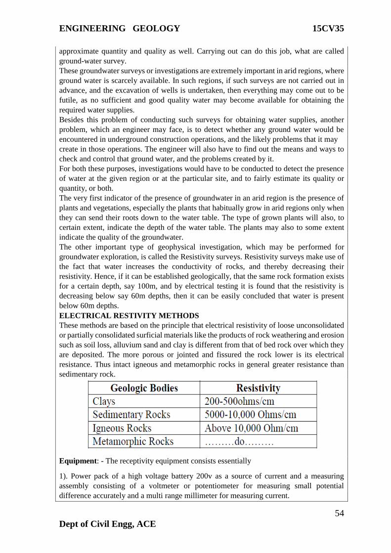
ENGINEERING GEOLOGY 15CV35
54
Dept of Civil Engg, ACE
approximate quantity and quality as well. Carrying out can do this job, what are called
ground-water survey.
These groundwater surveys or investigations are extremely important in arid regions, where
ground water is scarcely available. In such regions, if such surveys are not carried out in
advance, and the excavation of wells is undertaken, then everything may come out to be
futile, as no sufficient and good quality water may become available for obtaining the
required water supplies.
Besides this problem of conducting such surveys for obtaining water supplies, another
problem, which an engineer may face, is to detect whether any ground water would be
encountered in underground construction operations, and the likely problems that it may
create in those operations. The engineer will also have to find out the means and ways to
check and control that ground water, and the problems created by it.
For both these purposes, investigations would have to be conducted to detect the presence
of water at the given region or at the particular site, and to fairly estimate its quality or
quantity, or both.
The very first indicator of the presence of groundwater in an arid region is the presence of
plants and vegetations, especially the plants that habitually grow in arid regions only when
they can send their roots down to the water table. The type of grown plants will also, to
certain extent, indicate the depth of the water table. The plants may also to some extent
indicate the quality of the groundwater.
The other important type of geophysical investigation, which may be performed for
groundwater exploration, is called the Resistivity surveys. Resistivity surveys make use of
the fact that water increases the conductivity of rocks, and thereby decreasing their
resistivity. Hence, if it can be established geologically, that the same rock formation exists
for a certain depth, say 100m, and by electrical testing it is found that the resistivity is
decreasing below say 60m depths, then it can be easily concluded that water is present
below 60m depths.
ELECTRICAL RESTIVITY METHODS
These methods are based on the principle that electrical resistivity of loose unconsolidated
or partially consolidated surficial materials like the products of rock weathering and erosion
such as soil loss, alluvium sand and clay is different from that of bed rock over which they
are deposited. The more porous or jointed and fissured the rock lower is its electrical
resistance. Thus intact igneous and metamorphic rocks in general greater resistance than
sedimentary rock.
Equipment: - The receptivity equipment consists essentially
1). Power pack of a high voltage battery 200v as a source of current and a measuring
assembly consisting of a voltmeter or potentiometer for measuring small potential
difference accurately and a multi range millimeter for measuring current.
ENGINEERING GEOLOGY 15CV35
55
Dept of Civil Engg, ACE
2). Four Stainless Steel metallic spikes (electrodes) about 800mm long 20m dia prod vided
with heads for easy driving into the ground and clamps for cable connection.
3). Abundant stranded insulated single conductor cable of 0.5m2 conducting area. The
cable is wound on portable reels.
FIELD PROCEDURE AND INTERPRETATION
In this method, four electrodes are driven into the ground in a straight line at equal distances
and electric current is intruded through, two outer spikes called current electrodes, which
are connected by insulated wire through a mill ammeter to a power pack. The current flows
through the ground. Theoretically the current flow extends to indefinite depths but the
intensity diminishes with dept. For practical purposes the current is considered to be
confined within a depth approxcipamately equal to one-third the distance between the
current electrodes. The current impressed into the ground is recorded by the millimeter. In
homogeneous ground the lines of current flow have a definite shape independent of the
medium of the distance between electrodes. As such the current penetration can be varied
by varying the electrode spacing. Next, the voltage drop due to potential difference between
two inner electrodes called potential electrodes is measured from the potentiometer.
Restivity is then obtained by the expression
R=2P/I
R=Resistivity, P= Potential difference, I= Current applied between electrodes
The value of R so measured is only apparent resistivity of the ground as the ground is rarely
homogeneous. The underground configuration of rocks is deduced by variations in the
apparent resistivity obtained as a function of depth. The electrode system as a whole. The
depth determined would be over the central point of electrode determined would be over
the central point of electrode system. This forms the station sounded. Thus principally there
are two distinct methods of resistivity determinations
a). Expanding electrodes separation techniques or Vertical Profiling
b). Lateral traversing techniques or Horizontal Profiling.
a). Expanding electrodes separation techniques or Vertical Profiling: - In this method
electrode spacing is increased about a fixed central point thereby depth of current
penetration is increased. If the ground is homogeneous resistivity is constant for all
electrode spacing and equal to actual resistance of the geological formation. Therefore the
graph of resistivity against electrode spacing would be a constant. The resistivity curve is
then compared with a series of master curves, computed for various values of depth and
resistivity ratio like those of master curves and depth is obtained.

ENGINEERING GEOLOGY 15CV35
56
Dept of Civil Engg, ACE
Test value curve for electrical resistivity analysis
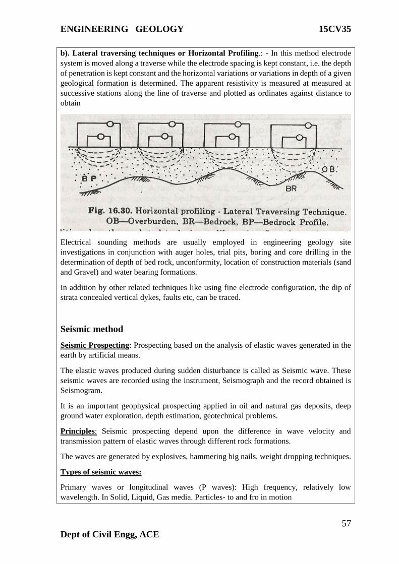
ENGINEERING GEOLOGY 15CV35
57
Dept of Civil Engg, ACE
b). Lateral traversing techniques or Horizontal Profiling.: - In this method electrode
system is moved along a traverse while the electrode spacing is kept constant, i.e. the depth
of penetration is kept constant and the horizontal variations or variations in depth of a given
geological formation is determined. The apparent resistivity is measured at measured at
successive stations along the line of traverse and plotted as ordinates against distance to
obtain
Electrical sounding methods are usually employed in engineering geology site
investigations in conjunction with auger holes, trial pits, boring and core drilling in the
determination of depth of bed rock, unconformity, location of construction materials (sand
and Gravel) and water bearing formations.
In addition by other related techniques like using fine electrode configuration, the dip of
strata concealed vertical dykes, faults etc, can be traced.
Seismic method
Seismic Prospecting: Prospecting based on the analysis of elastic waves generated in the
earth by artificial means.
The elastic waves produced during sudden disturbance is called as Seismic wave. These
seismic waves are recorded using the instrument, Seismograph and the record obtained is
Seismogram.
It is an important geophysical prospecting applied in oil and natural gas deposits, deep
ground water exploration, depth estimation, geotechnical problems.
Principles: Seismic prospecting depend upon the difference in wave velocity and
transmission pattern of elastic waves through different rock formations.
The waves are generated by explosives, hammering big nails, weight dropping techniques.
Types of seismic waves:
Primary waves or longitudinal waves (P waves): High frequency, relatively low
wavelength. In Solid, Liquid, Gas media. Particles- to and fro in motion
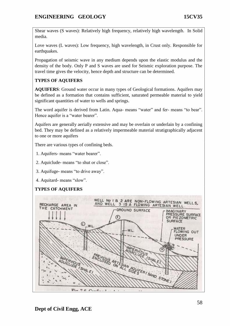
ENGINEERING GEOLOGY 15CV35
58
Dept of Civil Engg, ACE
Shear waves (S waves): Relatively high frequency, relatively high wavelength. In Solid
media.
Love waves (L waves): Low frequency, high wavelength, in Crust only. Responsible for
earthquakes.
Propagation of seismic wave in any medium depends upon the elastic modulus and the
density of the body. Only P and S waves are used for Seismic exploration purpose. The
travel time gives the velocity, hence depth and structure can be determined.
TYPES OF AQUIFERS
AQUIFERS: Ground water occur in many types of Geological formations. Aquifers may
be defined as a formation that contains sufficient, saturated permeable material to yield
significant quantities of water to wells and springs.
The word aquifer is derived from Latin. Aqua- means “water” and fer- means “to bear”.
Hence aquifer is a “water bearer”.
Aquifers are generally aerially extensive and may be overlain or underlain by a confining
bed. They may be defined as a relatively impermeable material stratigraphically adjacent
to one or more aquifers
There are various types of confining beds.
1. Aquifers- means “water bearer”.
2. Aquiclude- means “to shut or close”.
3. Aquifuge- means “to drive away”.
4. Aquitard- means “slow”.
TYPES OF AQUIFERS

ENGINEERING GEOLOGY 15CV35
59
Dept of Civil Engg, ACE
There are four types, they are
1. Unconfined aquifers (Water table aquifers):-
An unconfined aquifers is one in which a water table varies in undulating form and in
slope, depending on the area of recharge and discharge, pump age from wells and
permeability, rises and falls in the water table corresponds to changes in volume of water
in storage within an aquifer.
2. Confined aquifers (Artesian or pressure aquifers):-
This type of aquifers occurs where ground water is confined under pressure (hydrostatic)
greater than atmospheric by overlying impermeable strata. Water in wells stand above the
top of the aquifer rather than storage changes. It exhibit only minor changes in storage and
act as conducts from zones of recharge to those of discharge. The imaginary surface to
which water rises in wells tapping an artesian aquifer is known as “PIEZOMETRIC
SURFACE”. A well be “free flowing” when this Piezometric levels rises above the ground
surfaces. Such wells are called “Artesian wells”.
3. Semi confined (Leaky) aquifers:-
It is completely saturated aquifer bounded above by a semi pervious and below by an
impervious layer. A semi pervious layer is defined as a layer which has low permeability.
Lowering of piezometric levels in leaky aquifer for examples by pumping will generate a
vertical flow of water semi pervious layer into the pumped aquifer. Horizontal flow
component in the semi pervious layer is negligible since it is very low permeability.
4. Semi unconfined aquifer:- If the hydraulic conductivity of the semi pervious layer of the
above case is very high an aquifer intermediate between semi-confined and unconfined
aquifers may exit, and it is called as semi unconfined.
Aquifer parameters
Porosity
Porosity is nothing but the ratio between the total Voids or Pores to the total volume of the
rock or material.
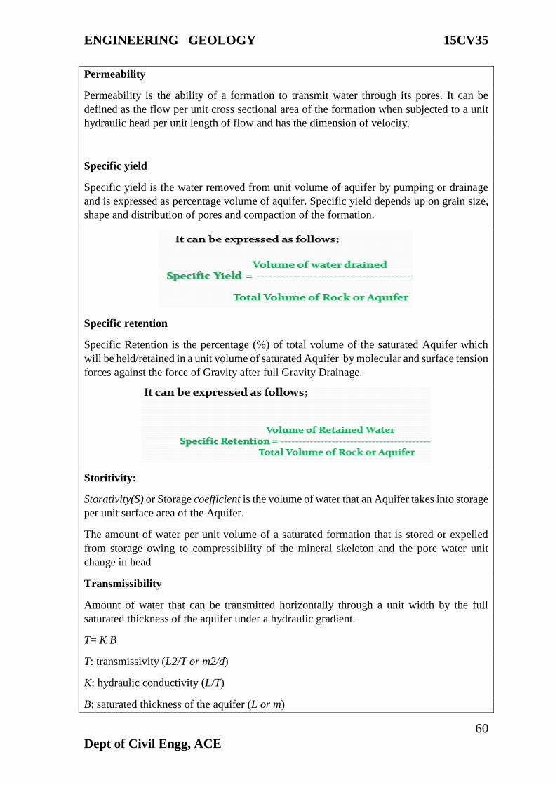
ENGINEERING GEOLOGY 15CV35
60
Dept of Civil Engg, ACE
Permeability
Permeability is the ability of a formation to transmit water through its pores. It can be
defined as the flow per unit cross sectional area of the formation when subjected to a unit
hydraulic head per unit length of flow and has the dimension of velocity.
Specific yield
Specific yield is the water removed from unit volume of aquifer by pumping or drainage
and is expressed as percentage volume of aquifer. Specific yield depends up on grain size,
shape and distribution of pores and compaction of the formation.
Specific retention
Specific Retention is the percentage (%) of total volume of the saturated Aquifer which
will be held/retained in a unit volume of saturated Aquifer by molecular and surface tension
forces against the force of Gravity after full Gravity Drainage.
Storitivity:
Storativity(S) or Storage coefficient is the volume of water that an Aquifer takes into storage
per unit surface area of the Aquifer.
The amount of water per unit volume of a saturated formation that is stored or expelled
from storage owing to compressibility of the mineral skeleton and the pore water unit
change in head
Transmissibility
Amount of water that can be transmitted horizontally through a unit width by the full
saturated thickness of the aquifer under a hydraulic gradient.
T= K B
T: transmissivity (L2/T or m2/d)
K: hydraulic conductivity (L/T)
B: saturated thickness of the aquifer (L or m)
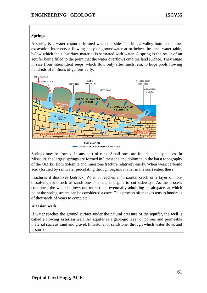
ENGINEERING GEOLOGY 15CV35
61
Dept of Civil Engg, ACE
Springs
A spring is a water resource formed when the side of a hill, a valley bottom or other
excavation intersects a flowing body of groundwater at or below the local water table,
below which the subsurface material is saturated with water. A spring is the result of an
aquifer being filled to the point that the water overflows onto the land surface. They range
in size from intermittent seeps, which flow only after much rain, to huge pools flowing
hundreds of millions of gallons daily.
Springs may be formed in any sort of rock. Small ones are found in many places. In
Missouri, the largest springs are formed in limestone and dolomite in the karst topography
of the Ozarks. Both dolomite and limestone fracture relatively easily. When weak carbonic
acid (formed by rainwater percolating through organic matter in the soil) enters these
fractures it dissolves bedrock. When it reaches a horizontal crack or a layer of non-
dissolving rock such as sandstone or shale, it begins to cut sideways. As the process
continues, the water hollows out more rock, eventually admitting an airspace, at which
point the spring stream can be considered a cave. This process often takes tens to hundreds
of thousands of years to complete.
Artesian wells
If water reaches the ground surface under the natural pressure of the aquifer, the well is
called a flowing artesian well. An aquifer is a geologic layer of porous and permeable
material such as sand and gravel, limestone, or sandstone, through which water flows and
is stored.
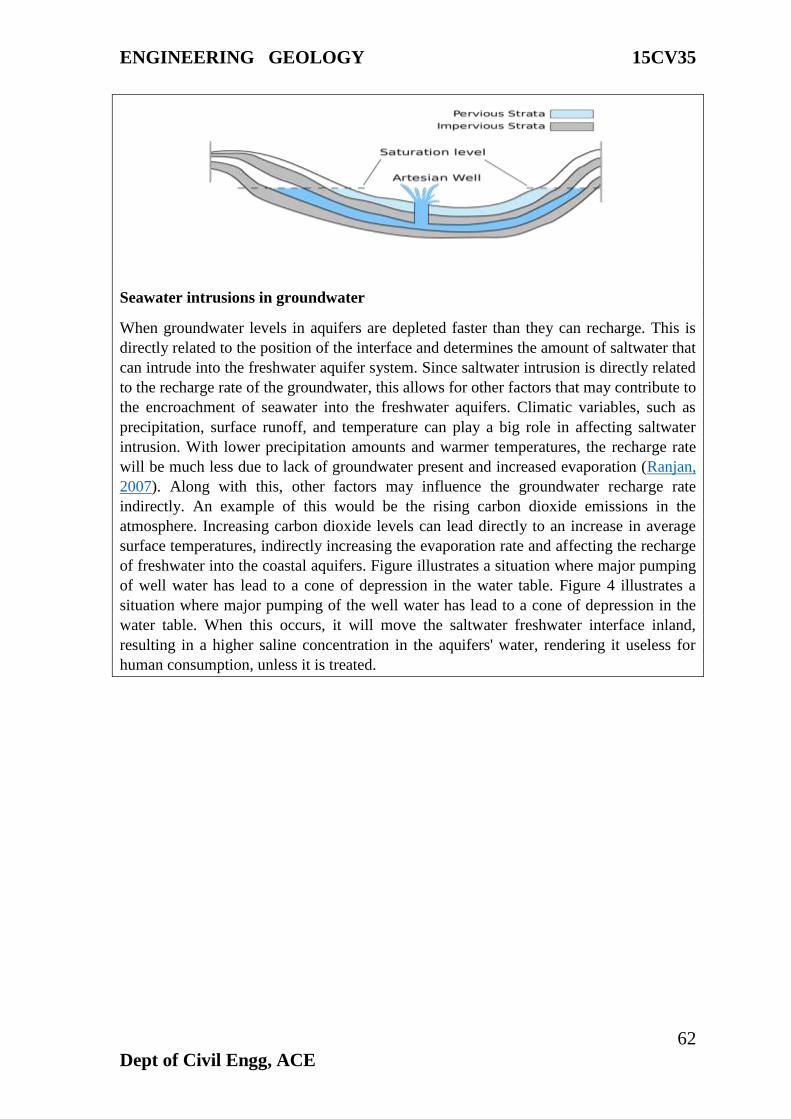
ENGINEERING GEOLOGY 15CV35
62
Dept of Civil Engg, ACE
Seawater intrusions in groundwater
When groundwater levels in aquifers are depleted faster than they can recharge. This is
directly related to the position of the interface and determines the amount of saltwater that
can intrude into the freshwater aquifer system. Since saltwater intrusion is directly related
to the recharge rate of the groundwater, this allows for other factors that may contribute to
the encroachment of seawater into the freshwater aquifers. Climatic variables, such as
precipitation, surface runoff, and temperature can play a big role in affecting saltwater
intrusion. With lower precipitation amounts and warmer temperatures, the recharge rate
will be much less due to lack of groundwater present and increased evaporation (Ranjan,
2007). Along with this, other factors may influence the groundwater recharge rate
indirectly. An example of this would be the rising carbon dioxide emissions in the
atmosphere. Increasing carbon dioxide levels can lead directly to an increase in average
surface temperatures, indirectly increasing the evaporation rate and affecting the recharge
of freshwater into the coastal aquifers. Figure illustrates a situation where major pumping
of well water has lead to a cone of depression in the water table. Figure 4 illustrates a
situation where major pumping of the well water has lead to a cone of depression in the
water table. When this occurs, it will move the saltwater freshwater interface inland,
resulting in a higher saline concentration in the aquifers' water, rendering it useless for
human consumption, unless it is treated.
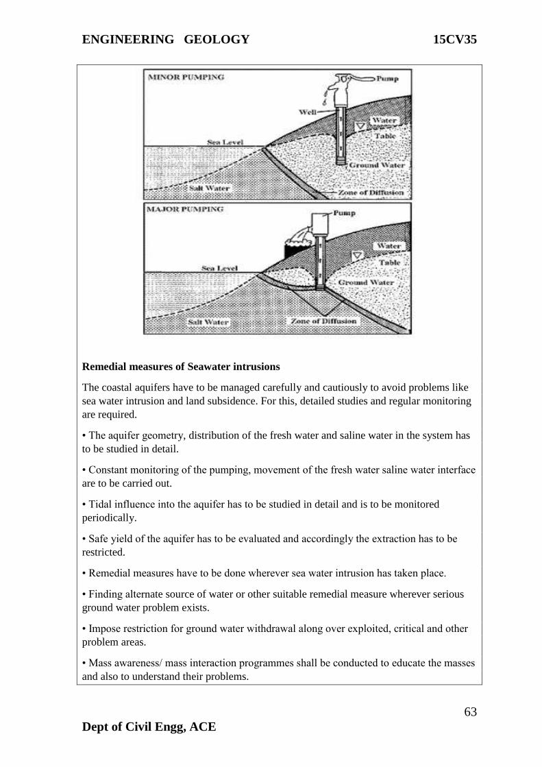
ENGINEERING GEOLOGY 15CV35
63
Dept of Civil Engg, ACE
Remedial measures of Seawater intrusions
The coastal aquifers have to be managed carefully and cautiously to avoid problems like
sea water intrusion and land subsidence. For this, detailed studies and regular monitoring
are required.
• The aquifer geometry, distribution of the fresh water and saline water in the system has
to be studied in detail.
• Constant monitoring of the pumping, movement of the fresh water saline water interface
are to be carried out.
• Tidal influence into the aquifer has to be studied in detail and is to be monitored
periodically.
• Safe yield of the aquifer has to be evaluated and accordingly the extraction has to be
restricted.
• Remedial measures have to be done wherever sea water intrusion has taken place.
• Finding alternate source of water or other suitable remedial measure wherever serious
ground water problem exists.
• Impose restriction for ground water withdrawal along over exploited, critical and other
problem areas.
• Mass awareness/ mass interaction programmes shall be conducted to educate the masses
and also to understand their problems.
ENGINEERING GEOLOGY 15CV35
64
Dept of Civil Engg, ACE
• Preparing a policy document for the judicial and equitable distribution of the resource.
Artificial Recharge of Ground Water
The artificial recharge to ground water aims at augmentation of ground water reservoir by
modifying the natural movement of surface water utilizing suitable civil construction
techniques. Artificial recharge techniques normally address to following issues -
(i) To enhance the sustainable yield in areas where over-development has depleted the
aquifer.
(ii) Conservation and storage of excess surface water for future requirements, since these
requirements often changes within a season or a period.
(iii) To improve the quality of existing ground water through dilution.
(iv) To remove bacteriological and other impurities from sewage and waste water so that
water is suitable for re-use.
The basic purpose of artificial recharge of ground water is to restore supplies from aquifers
depleted due to excessive ground water development.
Artificial Recharge Techniques and Designs
A wide spectrum of techniques are in vogue to recharge ground water reservoir.
Similar to the variations in hydrogeological framework, the artificial recharge techniques
too vary widely. The artificial recharge techniques can be broadly categorized as
follows:-
a. Direct surface techniques
• Flooding
• Basins or percolation tanks
• Stream augmentation
• Ditch and furrow system
• Over irrigation
b. Direct sub surface techniques
• Injection wells or recharge wells
• Recharge pits and shafts
• Dug well recharge
• Bore hole flooding
• Natural openings, cavity fillings.
ENGINEERING GEOLOGY 15CV35
65
Dept of Civil Engg, ACE
c. Combination surface – sub-surface techniques
• Basin or percolation tanks with pit shaft or wells.
d. Indirect Techniques
• Induced recharge from surface water source.
• Aquifer modification.
ENGINEERING GEOLOGY 15CV35
66
Dept of Civil Engg, ACE
Module -5:
Geodesy
Topographical Maps
A map of a small area drawn on a large scale depicting detailed surface features
both natural and man-made. Relief in this map is shown by contours.
You know that the map is an important geographic tool. You also know that maps
are classified on the basis of scale and functions. They serve the purpose of base maps and
are used to draw all the other maps. Topographical maps, also known as general purpose
maps, are drawn at relatively large scales. These maps show important natural and cultural
features such as relief, vegetation, water bodies, cultivated land, settlements, and
transportation networks, etc.
These maps are prepared and published by the National Mapping Organization of
each country. For example, the Survey of India prepares the topographical maps in India
for the entire country. The topographical maps are drawn in the form of series of maps at
different scales. Hence, in the given series, all maps employ the same reference point, scale,
projection, conventional signs, symbols and colors.
The topographical maps of India are prepared on 1 : 10,00,000, 1 : 250,000, 1 :
1,25,000, 1 : 50,000 and 1: 25,000 scale providing a latitudinal and longitudinal coverage
of 4° x 4°, 1° x 1°, 30' x 30', 15' x 15' and 5' x 7' 30", respectively.
Reading of Topographical Maps: The study of topographical maps is simple. It
requires the reader to get acquainted with the legend, conventional sign and the colors
shown on the sheets. The conventional sign and symbols depicted on the topographical
sheets are shown below
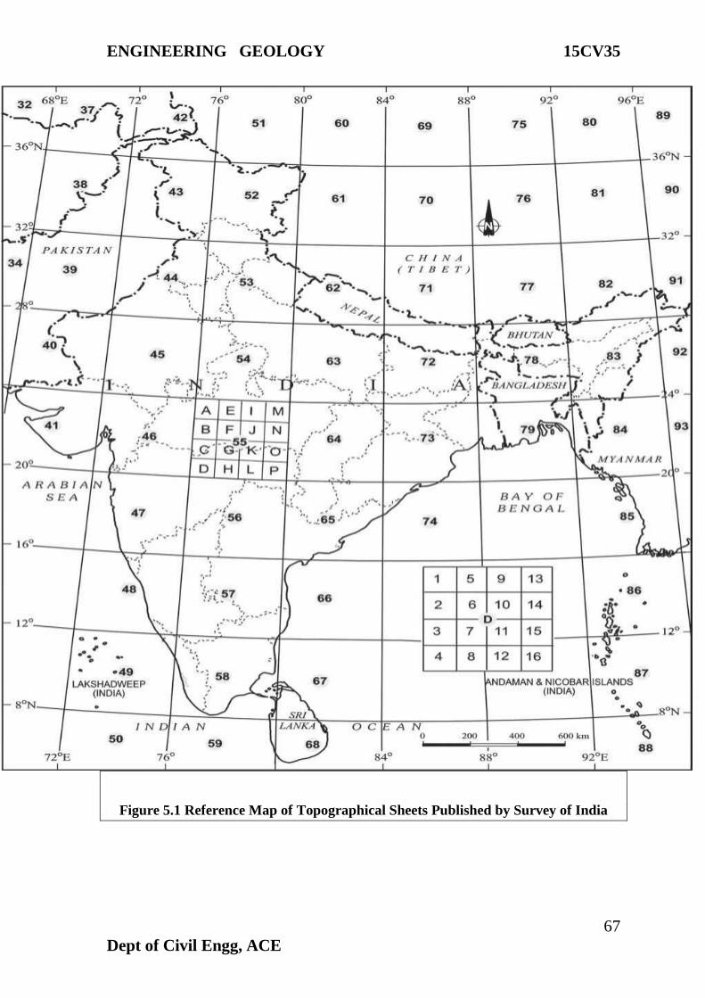
ENGINEERING GEOLOGY 15CV35
67
Dept of Civil Engg, ACE
Figure 5.1 Reference Map of Topographical Sheets Published by Survey of India
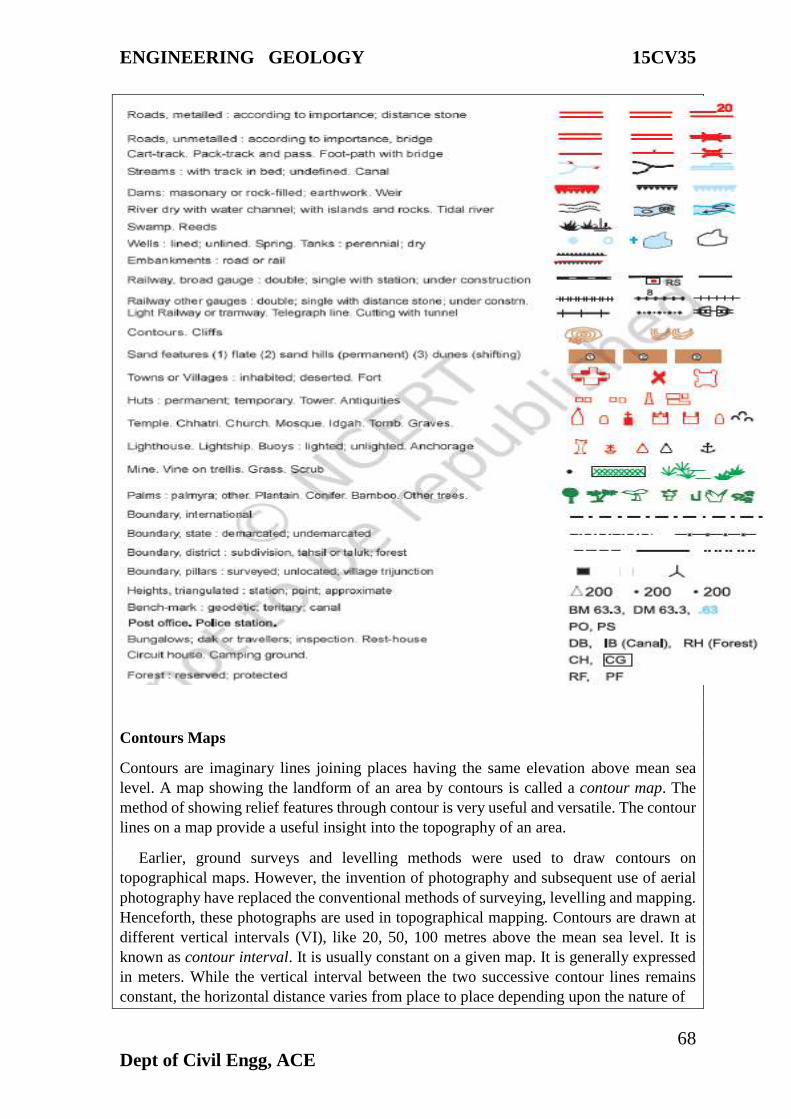
ENGINEERING GEOLOGY 15CV35
68
Dept of Civil Engg, ACE
Contours Maps
Contours are imaginary lines joining places having the same elevation above mean sea
level. A map showing the landform of an area by contours is called a contour map. The
method of showing relief features through contour is very useful and versatile. The contour
lines on a map provide a useful insight into the topography of an area.
Earlier, ground surveys and levelling methods were used to draw contours on
topographical maps. However, the invention of photography and subsequent use of aerial
photography have replaced the conventional methods of surveying, levelling and mapping.
Henceforth, these photographs are used in topographical mapping. Contours are drawn at
different vertical intervals (VI), like 20, 50, 100 metres above the mean sea level. It is
known as contour interval. It is usually constant on a given map. It is generally expressed
in meters. While the vertical interval between the two successive contour lines remains
constant, the horizontal distance varies from place to place depending upon the nature of

ENGINEERING GEOLOGY 15CV35
69
Dept of Civil Engg, ACE
slope. The horizontal distance, also known as the horizontal equivalent (HE), is large when
the slope is gentler and decreases with increasing slope gradient.
Some basic features of contour lines are
° A contour line is drawn to show places of equal heights.
° Contour lines and their shapes represent the height and slope or gradient of the landform.
° Closely spaced contours represent steep slopes while widely spaced contours represent
gentle slope.
° When two or more contour lines merge with each other, they represent features of vertical
slopes such as cliffs or waterfalls.
° Two contours of different elevation usually do not cross each other.
REMOTE SENSING
“The art, science, and technology of obtaining reliable information about physical
objects and the environment, through the process of recording, measuring and interpreting
imagery and digital representations of energy patterns derived from non-contact sensor
systems”.
According to India’s National Remote Sensing Agency- “Remote Sensing is the
technique of acquiring information about objects on the earth’s surface without physically
coming into contact with them”.
Principles of remote sensing
1. Detection and discrimination of objects or surface features means detecting and
recording of radiant energy reflected or emitted by objects or surface.
2. Different objects return different amount of energy in different bands of the
electromagnetic spectrum, incident upon it.
3. Depend upon the property of material (physical, structural, and chemical), surface
roughness, angle of incidence, intensity, and wavelength of radiant energy.
Stages in remote sensing
1. Energy Source or Illumination (A)
2. Radiation and the Atmosphere (B)
3. Interaction with the Target (C)
4. Recording of Energy by the Sensor (D)
5. Transmission, Reception, and Processing (E)
6. Interpretation and Analysis (F)
7. Application (G)
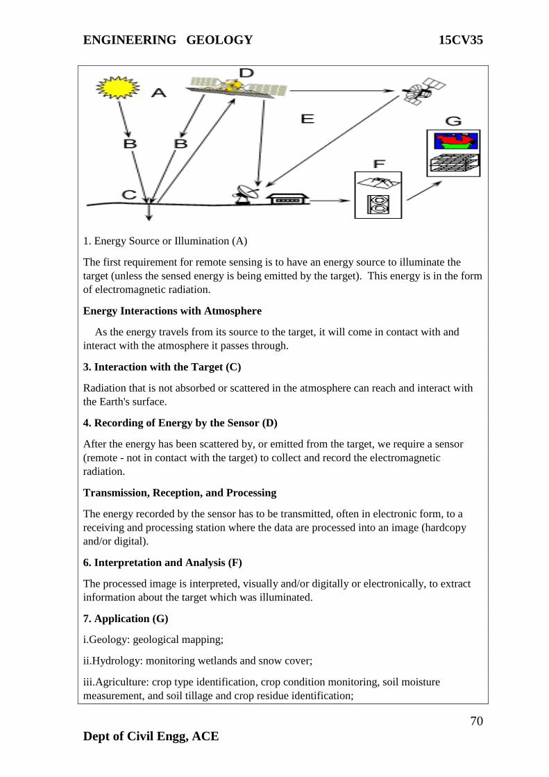
ENGINEERING GEOLOGY 15CV35
70
Dept of Civil Engg, ACE
1. Energy Source or Illumination (A)
The first requirement for remote sensing is to have an energy source to illuminate the
target (unless the sensed energy is being emitted by the target). This energy is in the form
of electromagnetic radiation.
Energy Interactions with Atmosphere
As the energy travels from its source to the target, it will come in contact with and
interact with the atmosphere it passes through.
3. Interaction with the Target (C)
Radiation that is not absorbed or scattered in the atmosphere can reach and interact with
the Earth's surface.
4. Recording of Energy by the Sensor (D)
After the energy has been scattered by, or emitted from the target, we require a sensor
(remote - not in contact with the target) to collect and record the electromagnetic
radiation.
Transmission, Reception, and Processing
The energy recorded by the sensor has to be transmitted, often in electronic form, to a
receiving and processing station where the data are processed into an image (hardcopy
and/or digital).
6. Interpretation and Analysis (F)
The processed image is interpreted, visually and/or digitally or electronically, to extract
information about the target which was illuminated.
7. Application (G)
i.Geology: geological mapping;
ii.Hydrology: monitoring wetlands and snow cover;
iii.Agriculture: crop type identification, crop condition monitoring, soil moisture
measurement, and soil tillage and crop residue identification;
ENGINEERING GEOLOGY 15CV35
71
Dept of Civil Engg, ACE
iv.Forestry: clear-cuts and linear features mapping, biomass estimation, species
identification and fire scar mapping;
v.Oceanography: sea ice identification, coastal wind field measurement, and wave slope
measurement.
vi.Shipping: for ship detection and classification.
Coastal Zone: for shoreline detection, substrate mapping, slick detection and general
vegetation mapping.
vii.Military/Security Applications: detecting or locating metal objects.
Limitations of Remote Sensing
i.Perhaps the greatest limitation is that its utility is often oversold.
ii.It is not a panacea that will provide all the information needed for conducting physical,
biological, or a science.
iii.It simply provides some spatial, spectral, and temporal information.
Geographic Information System (GIS)
GIS stands for Geographical Information System. It is defined as an integrated tool,
capable of mapping, analyzing, manipulating and storing geographical data in order to
provide solutions to real world problems and help in planning for the future.
A “geographic information system” (GIS) is a computer-based tool that allows you to
create, manipulate, analyze, store and display information based on its location. GIS
makes it possible to integrate different kinds of geographic information, such as digital
maps, aerial photographs, satellite images and global positioning system data (GPS),
along with associated tabular database information (e.g., ‘attributes' or characteristics
about geographic features).
Components of a GIS
Hardware: It consists of the equipments and support devices that are required to capture,
store process and visualize the geographic information. These include computer with hard
disk, digitizers, scanners, printers and plotters etc.
Software: Software is at the heart of a GIS system. The GIS software must have the basic
capabilities of data input, storage, transformation, analysis and providing desired outputs.
The interfaces could be different for different software’s. The GIS software’s being used
today belong to either of the category –proprietary or open source. ArcGIS by ESRI is the
widely used proprietary GIS software. Others in the same category are MapInfo,
Microstation, Geomedia etc. The development of open source GIS has provided us with
freely available desktop GIS such as Quantum, uDIG, GRASS, MapWindow GIS etc.,
GIS softwares.
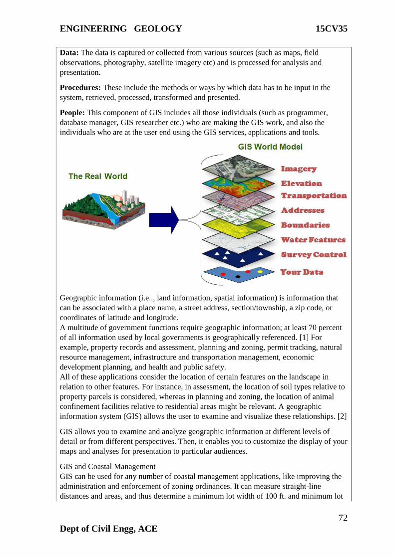
ENGINEERING GEOLOGY 15CV35
72
Dept of Civil Engg, ACE
Data: The data is captured or collected from various sources (such as maps, field
observations, photography, satellite imagery etc) and is processed for analysis and
presentation.
Procedures: These include the methods or ways by which data has to be input in the
system, retrieved, processed, transformed and presented.
People: This component of GIS includes all those individuals (such as programmer,
database manager, GIS researcher etc.) who are making the GIS work, and also the
individuals who are at the user end using the GIS services, applications and tools.
Geographic information (i.e.., land information, spatial information) is information that
can be associated with a place name, a street address, section/township, a zip code, or
coordinates of latitude and longitude.
A multitude of government functions require geographic information; at least 70 percent
of all information used by local governments is geographically referenced. [1] For
example, property records and assessment, planning and zoning, permit tracking, natural
resource management, infrastructure and transportation management, economic
development planning, and health and public safety.
All of these applications consider the location of certain features on the landscape in
relation to other features. For instance, in assessment, the location of soil types relative to
property parcels is considered, whereas in planning and zoning, the location of animal
confinement facilities relative to residential areas might be relevant. A geographic
information system (GIS) allows the user to examine and visualize these relationships. [2]
GIS allows you to examine and analyze geographic information at different levels of
detail or from different perspectives. Then, it enables you to customize the display of your
maps and analyses for presentation to particular audiences.
GIS and Coastal Management
GIS can be used for any number of coastal management applications, like improving the
administration and enforcement of zoning ordinances. It can measure straight-line
distances and areas, and thus determine a minimum lot width of 100 ft. and minimum lot

ENGINEERING GEOLOGY 15CV35
73
Dept of Civil Engg, ACE
size of 20,000 sq. ft. as often mandated in subdivision regulations. Or, GIS can also be
used to generate buffers around lines or designated areas.
The benefits of taking a GIS approach to coastal management, might include: (1) the
ability to model, test, and compare alternative scenarios - before the proposed strategy is
imposed on the real world; (2) the ability to handle much larger data bases and to
integrate and synthesize data -- leading to a more holistic and coordinated management
strategies; and (3) enhanced capacity for data exchange. [3]
GIS and Decision-Making
Local government units make countless land-related decisions. As a whole, these
decisions shape the way in which land is used and the built environment is managed. GIS
has tremendous potential for facilitating this decision-making process and for revealing
the combined effect of incremental decisions. Indeed, many have praised GIS for its
ability to provide “better information” – information that is faster, cheaper, more reliable,
more readily available, and more understandable – which, in turn, might lead to “better
decision-making”.
Global Positioning System (GPS)
The GPS is a satellite based navigation and surveying system for determination of precise
position and time in post processing mode. It was developed by U.S Department of Defence
(DOD) which revolutionized the field of modern surveying, navigation and mapping. GPS
was considered as a ranging system from known positions on land, sea, air and space and
an essential input for GIS. It is having a 24 hr service in all weather conditions. It can
analyse upto 24 satellite orbiting at an altitude of 20,200 km. The system was replaced by
NAVSTAR GPS (Navigation satellite timing and ranging GPS), launched in 1972 by US
defense mapping agency.
GPS, which stands for Global Positioning System, is the only system today able to show
the exact location on the Earth’s surface anytime, in any weather and anywhere.
The three parts of GPS are:
1. Satellites
2. Receivers
3. Software
THREE SEGMENTS OF THE GPS
1. Space Segment
Space Segment has 24 GPS space vehicles (SVs).Satellites orbit the earth in 12 hrs. 6 orbital
planes inclined at 55 degrees with the equator. This constellation provides 5 to 8 SVs from
any point on the earth.
2. Control Segment
It has 3 components
ENGINEERING GEOLOGY 15CV35
74
Dept of Civil Engg, ACE
Monitor station: it accumulates ranging data from navigation segment, which transports
shelters with receiver and computer and it is located in USA.
Master Control station: the accumulated data by MS’s is transferred to MC’s for
processing in computer to provide and clock drift related to system time generating
information like gravity field influencing the satellite motion.
Up-load Station: From MC’s navigation messages are generated, is loaded into satellite
memory and a day via ULS consists of parabolic antenna a transmitter and a computer.
They measure the distances of the overhead satellites every 1.5 seconds and send the
corrected data to Master control.
3. User Segment
The user equipment consists of an antenna, a receiver, a data processor with software and
control or display unit.
GPS and their use resource mapping
The surveying and mapping community was one of the first to take advantage of GPS
because it dramatically increased productivity and resulted in more accurate and reliable
data. Today, GPS is a vital part of surveying and mapping activities around the world.
When used by skilled professionals, GPS provides surveying and mapping data of the
highest accuracy. GPS-based data collection is much faster than conventional surveying
and mapping techniques, reducing the amount of equipment and labor required. A single
surveyor can now accomplish in one day what once took an entire team weeks to do.
GPS supports the accurate mapping and modeling of the physical world — from mountains
and rivers to streets and buildings to utility lines and other resources. Features measured
with GPS can be displayed on maps and in geographic information systems (GIS) that store,
manipulate, and display geographically referenced data.
Governments, scientific organizations, and commercial operations throughout the world
use GPS and GIS technology to facilitate timely decisions and wise use of resources. Any
organization or agency that requires accurate location information about its assets can
benefit from the efficiency and productivity provided by GPS positioning.
GPS is especially useful in surveying coasts and waterways, where there are few land-based
reference points. Survey vessels combine GPS positions with sonar depth soundings to
make the nautical charts that alert mariners to changing water depths and underwater
hazards. Bridge builders and offshore oil rigs also depend on GPS for accurate
hydrographic surveys.
Aerial studies of some of the world's most impenetrable wilderness are conducted with the
aid of GPS technology to evaluate an area’s wildlife, terrain, and human infrastructure. By
tagging imagery with GPS coordinates it is possible to evaluate conservation efforts and
assist in strategy planning.
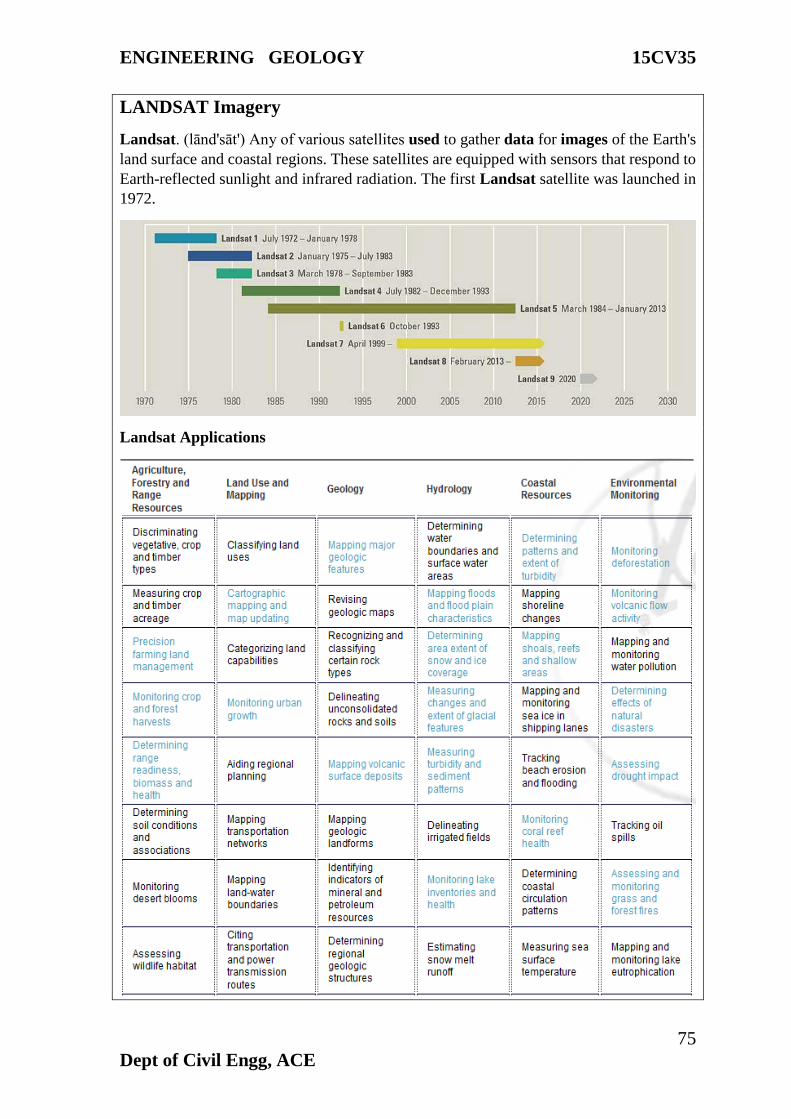
ENGINEERING GEOLOGY 15CV35
75
Dept of Civil Engg, ACE
LANDSAT Imagery
Landsat. (lānd'sāt') Any of various satellites used to gather data for images of the Earth's
land surface and coastal regions. These satellites are equipped with sensors that respond to
Earth-reflected sunlight and infrared radiation. The first Landsat satellite was launched in
1972.
Landsat Applications
ENGINEERING GEOLOGY 15CV35
76
Dept of Civil Engg, ACE
Impact of Mining and Quarrying On Environment
For example the essential raw material for cement manufacture being Limestone, it has to
be exploited from where it occurs. In India, only opencast mines are winning Limestone, a
low cost material. To produce a tons of cement 1.5-1.6 tons of Limestone is required over
21,400 sq.m will come under mining operation every year depending upon the thickness of
limestone to be exploited. Such huge operation will no doubt, leave its impact on relief and
topography, hydrology, air forestry/agriculture wild life etc.
However the environmental impacts of operating the limestone mines may not be very
serious as in the case of other such as chemical, fertilizer and metallurgical industries.
RELIEF AND LANDSCAPE ALTERATIONS: Mining operation and installation of
various allied units will change the existing topography and will cause creation of huge pits
or leveling of hills or creation of wastes heaps etc.
IMPACT ON HYDROLOGY: Mining activities in some cases may disturb the aquifer,
the ground water flow and recharge capacity of the surrounding areas are affected due to
change in topography.
CONTAMINATION OF WATER: Limestone mining by and large does not adversely
contaminate the rain waters and ground water flowing through the exposed mine cuts but
may carry fine particle of Limestone dust, which may cause silting problems, but they are
non-toxic. Surface runoff from mine cuts may however be turbid during monsoons due to
seepage of overburden soil etc.
AIR POLLUTION OR DUST POLLUTION: In mining air pollution is mainly caused
by dust generation. Blasting is one of the pollutants as it creates fumes, dust, vibrations, air
blaster, noise and fly rock fragments. The other activities such as drilling excavation, waste
dumping will also cause dust nuisance. Crushing plant, conveyors and transfer points will
be the other sources of dust generation.
NOISE POLLUTION: Noise may be defined as” Unwanted sound”. This implies sounds,
which interfere with human communication, comfort health etc. The noise pollution in the
Limestone blasting and movement of heavy earth moving equipment cause mine.
IMPACT ON FORESTRY /VEGETATION: The mining operation if carried out on
hills, which are usually associated with forests and vegetation causes. Impairment (spoil)
and affects climate, rainfall, soil erosion and causes in equilibrium between biotic substance
and macro/microorganisms. When carried out on plains affect agriculture and grazing
lands.
IMPACT ON WILDLIFE: Noise and habitation may probably cause migration of the
existing wild life.
IMPACT OF HUMAN ENVIRONMENT: The impact of mining on human environment
can be both beneficial and detrimental as it may provide job opportunities and overall
development of the region, can also deprive some of them of their agricultural land.
Sometimes it can help in water resources for water irrigation and domestic use.
ENGINEERING GEOLOGY 15CV35
77
Dept of Civil Engg, ACE
VIBRATION, AIR BLAST AND NOISE CONTROL: The noise in mines is caused by
blasting, movement of heavy earth moving equipment which in terms causes vibration and
air blast. The following can control these: -
a). Avoiding blasting during night and foggy weather which associated with temperature
inversion
b). Stemming of the blast hole properly
c). Avoid blasting when wind velocity is more than 25km/hr
d). Large scale plantation or shade giving trees also reduce the noise and Vibration level,
e). Using rock breaking, the secondary blasting (which usually produces a huge noise) can
be avoided
FUMES CONTROL: ensuring complete detonation with the use of proper primers and
boosters can reduce Production of blast fumes containing toxic gases. By maintaining well
the engines of mining machinery the fumes from them can be controlled well.
DUST CONTROL: During mining the dust can be controlled by the following
a). DRILLING: the using suitable dust can control Dust Collector, which is also a
stationary requirement.
b). BLASTING: If the topsoil is completely removed before blasting, dust generation
during the same can be minimized.
c). CRUSHING: Dust can be reduced by using dust Collectors or by spraying dust
suppressants including water.
d). TRANSPORTATION: Dust is generated when loaded dumpers move over
unconcerned roads. This can be overcome by concreting the roads or by sprinkling water
over the roads regularly.
Impacts of the reservoir
The creation of a reservoir provides a habitat for wetland species, especially water birds.
The reservoir can also be a source of water to animals and plants in the adjoining areas and,
where such areas have become unnaturally dry, this can be a significant environmental
benefit. These benefits were not included in the cost-benefit analysis for any of the projects
studied.
Impacts of backwater build-up: When a free flowing river meets the relatively static
reservoir, there is a build-up of back-pressure and a resultant backwater. This can destroy
the upstream ecology and cause damage to property. Backwaters can also build up due to
the deposition of sediments and silt upstream of the reservoir as ‘backwater deposits’.
Impacts on aquatic ecosystems: Construction activities, including the diversion of the
river through a tunnel, have major adverse impacts on the aquatic ecosystem. Vulnerable
species, with either limited distribution or low tolerance, could become extinct even before
the dam is completed.
ENGINEERING GEOLOGY 15CV35
78
Dept of Civil Engg, ACE
Impact on terrestrial fauna and flora: The disturbance caused by construction activities,
including noise and movement, building of roads, extraction of stone and soil, construction
of buildings, etc. also negatively impact the fauna and flora at the dam site. As
impoundment starts, the reservoir invariably submerges large tracts of forests and other
ecosystems, including grasslands and wetlands.
Submergence of forests: Data was available on forest submergence for 60 dams. On the
basis of these, the average forest area submerged per dam works out to approximately 4,879
ha. Therefore, the 1,877 dams built between 1980 and 2000 would have submerged
9,157,883 ha. (roughly 9.1 million ha.) of forests.
Impacts on cultivated biodiversity: Reservoirs also submerge productive agricultural
land in the valley. This not only has a social and economic cost but also adversely affects
cultivated biodiversity and a host of birds, insects, mammals and reptiles that have adapted
to agricultural ecosystems. In many cases, traditional crop varieties and methods of
cultivation disappear because of dams.