Embed Size (px)
Citation preview
AUTOMATION AND ROBOTICS (OPEN ELECTIVE – I)
[AS PER CHOICE BASED CREDIT SYSTEM (CBCS) SCHEME]
SEMESTER – V
Subject Code: 15ME563
Teaching Hours / Week: Lecture - 03 IA Marks 20
Exam Marks 80 Exam Hours 03
CREDITS – 03 Course Outcomes On completion of the course student will be able to
1. Classify various types of automation & manufacturing systems
2. Discuss different robot configurations, motions, drive systems and its performance parameters.
3. Describe the basic concepts of control systems, feedback components, actuators and power transmission
systems used in robots.
4. Explain the working of transducers, sensors and machine vision systems.
5. Discuss the future capabilities of sensors, mobility systems and Artificial
Intelligence in the field of robotics.
Module - 1
Automation History of Automation, Reasons for automation, Disadvantages of automation, Automation systems,
Types of automation – Fixed, Programmable and Flexible automation, Automation strategies
Automated Manufacturing Systems: Components, classification and overview of manufacturing
Systems, Flexible Manufacturing Systems (FMS), Types of FMS, Applications and benefits of FMS.
08 Hours
Module - 2 Robotics Definition of Robot, History of robotics, Robotics market and the future prospects, Robot
Anatomy, Robot configurations: Polar, Cartesian, cylindrical and Jointed-arm configuration.
Robot motions, Joints, Work volume, Robot drive systems, Precision of movement – Spatial
resolution, Accuracy, Repeatability, End effectors – Tools and grippers. 08 Hours
Module - 3
Controllers and Actuators Basic Control System concepts and Models, Transfer functions, Block diagrams, characteristic
equation, Types of Controllers: on-off, Proportional, Integral, Differential, P-I,
P-D, P-I-D controllers. Control system and analysis.
Robot actuation and feedback components Position sensors – Potentiometers, resolvers, encoders, velocity sensors. Actuators -
Pneumatic and Hydraulic Actuators, Electric Motors, Stepper motors, Servomotors, Power
Transmission systems.
09 Hours
Module - 4 Robot Sensors and Machine vision system Sensors in Robotics - Tactile sensors, Proximity and Range sensors, use of sensors in
robotics.
Machine Vision System: Introduction to Machine vision, the sensing and digitizing function
in Machine vision, Image processing and analysis, Training and Vision systems. 08 Hours
Module - 5 Robots Technology of the future: Robot Intelligence, Advanced Sensor capabilities,
Telepresence and related technologies, Mechanical design features, Mobility, locomotion and
navigation, the universal hand, system integration and networking.
Artificial Intelligence: Goals of AI research, AI techniques – Knowledge representation,
Problem representation and problem solving, LISP programming, AI and Robotics, LISP in the
factory. 09 Hours
Text Books 1. Automation, Production Systems and Computer Integrated Manufacturing M.P.
Groover, Pearson Education.5th edition, 2009
2. Industrial Robotics, Technology, Programming and Applications by M.P. Groover,
Weiss, Nagel, McGraw Hill International, 2nd edition, 2012.
Reference Books 1. Robotics, control vision and intelligence-Fu, Lee and Gonzalez. McGraw Hill
International, 2nd edition, 2007. .
2. Robotic Engineering - An Integrated approach, Klafter, Chmielewski and Negin, PHI,
1st edition, 2009.
Module – 1
Automation
Automation is the technology by which a process or procedure is accomplished without human
assistance. It is implemented using a program of instructions combined with a control system
that executes the instructions, To automate a process. Power is required, both to drive the
process itself and to operate the program and control system. Although automation can be
applied in a wide variety of areas, it is most closely associated with the manufacturing industries.
History of automation
The history of automation can be traced to the development of basic mechanical devlcea such
as the wheel (circa 3200 B.C.), lever, winch (circa 600 B.C.), cam (circa A.D. 1000), screw
(A.D. 1405). and gear in ancient and medieval times. These basic devices were refined and used
to construct the mechanisms in waterwheels, windmills (circa A.D. 650), and steam engines
(A.D. 1765).These machines generated the power to operate other machinery of various kinds,
such as flour mills (circa 85 B.c.), weaving machines (flying shuttle, 1733),machine tools
(boring mill, 1775),steamboats (1787),and railroad locomotives (1803). Power, and the capacity
to generate it and transmit it to operate a process, is one of the three basic elements of an
automated system.
After his first steam engine in 1765, James Watt and his partner, Matthew Boulton, made
several improvements in the design. One of the improvements was the flying-ball governor
(around 1785),which provided feedback to control the throttle of the engine. The governor
consisted of a ball on the end of a hinged lever attached to the rotating shaft. The lever was
connected to the throttle valve. As the speed of the rotating shaft increased, the ball was forced
to move outward by centrifugal force; this in tum caused the lever to reduce the valve opening
and slow the motor speed. As rotational speed decreased, the ball and lever relaxed, thus
allowing the valve to open. The flying-ball governor was one of the first examples in
engineering of feedback control, an important type of control/system-the second basic element
of an automated system. The third basic element of an automated system is for the actions of
the system machine to be directed by a program of instructions, One of the first examples of
machine programming.
Iron was also first smelted during the Bronze Age. Meteorites may have been one Source
of the metal, but iron ore was also mined. The temperatures required to reduce iron ore to metal
are significantly higher than for copper, which made furnace operations more difficult other
processing methods were also more difficult for the same reason. Early blacksmiths learned that
when certain irons (those containing small amounts of carbon) were sufficiently heated and then
quenched, they became very hard. This permitted the grinding of very sharp cutting edges on
knives and weapons, but it also made the metal brittle. Toughness could be in-creased by
reheating at a lower temperature, a process known as tempering. What we have de-scribed is,
of course, the heat treatment of steel. The superior properties of steel caused it to succeed bronze
in many applications (weaponry, agriculture, and mechanical devices). The pe-rtod or its use
has subsequently been named the Iron Age (starting around 1000 B.C.).lt was not until much
later, well into the nineteenth century, that the demand for steel grew significantly and more
modem steelmaking techniques were developed.
The early fabrication of implements and weapons was accomplished more as crafts and
trades than by manufacturing as we know it today. The ancient Romans had what might be
called factories to produce weapons. Scrolls, pottery, glassware, and other products of the time,
but the procedures were largely based on handicraft. It was not until the industrial Revolution
(circa 1760-1830) that major changes began to affect the systems for making things. This period
marked the beginning of the change from an economy based on agriculture and handicraft to
one based on industry and manufacturing. The change began in England, where a series of
important machines were invented, and steam power began to replace water, wind, and animal
power. Initially, these advances gave British industry significant advantages over other nations,
but eventually the revolution spread to other European countries and to the United States The
Industrial Revolution contributed to the development of manufacturing in the following ways:
(1) Watlssteam engine, a new power-generating technology; (2) development of machine tools,
starting with John Wilkinson's boring machine around 1775, which was used to bore the
cylinder on Watt's steam engine; (3) invention of the spinning jenny, power loom, and other
machinery for the textile industry, which permitted significant increases in productivity; and (4)
the factory system; a new way of organizing large numbers of production workers based on the
division of labour.
Wilkinson's boring machine is generally recognized as the beginning of machine tool
technology. It was powered by water wheel. During the period 1775-1850, other machine tools
were~ developed for most of the conventional machining processes, such as boring, turning,
drilling, milling. shaping, and planing, As steam power became more prevalent, It gradually
became the preferred power source for most of these machine tools, It is of interest to note that
many of the individual processes predate the machine tools by centuries; for example, drilling
and sawing (of wood) date from ancient times and turning (of wood) from around the time of
Christ.
AUTOMATION PRINCIPLES AND STRATEGIES
The preceding discussion leads us to conclude that automation is not always the right answer
for a given production situation. A certain caution and respect must be observed in applying
automation technologies. In this section, we offer three approaches for dealing with automation
projects:' (I) the USA Principle, (2) the Ten Strategies for Automation and Production Systems,
and (3) an Automation Migration Strategy.
1) USA Principle
The USA Principle is a common sense approach to automation projects. Similar procedures
have been suggested in the manufacturing and automation trade literature, but none has a more
captivating title than this one. USA stands for'
1. Understand the existing process
2. Simplify' the process
3. Automate the process.
A statement of the USA principle appeared in an APleS" article [41.The article was concerned
with implementation of enterprise resource planning (ERP, Section 26.6), but the USA approach
is '0 general that it is applicable to nearly any automation project. Going through each step of
the procedure for an automation project may in fact reveal that simplifying the process is
sufficient and automation is not necessary.
Understand the Existing Process. The obvious purpose of the first step in the USA
approach is to comprehend the current process in all of its details. What arc the inputs? What
are the outputs? What exactly happens to the work unit between input and output? What is the
function of the process? How does it add value to the product? What are the upstream and
downstream operations in the production sequence, and can they be combined with the process
under consideration? Some of the basic charting tools used in methods analysis are useful in
this regard, such as the operation process chart and the flow process chart [Sj.Application of
these tools to the existing process provides a model of the process that can be analyzed and
searched for weaknesses (and strengths). The number of steps in the process, the number and
placement of inspections, the number of moves and delays experienced by the work unit, and
the time spent in storage can he ascertained by these charting techniques Mathematical models
of the process may also be useful to indicate relationships between input parameters and output
variables. What are the important output variables? How are these output variables affected by
inputs to the process, such as raw material properties, process settings, operating parameters,
and environmental conditions? This information may bc valuable in identifying what output
variables need to be measured for feedback purposes and in formulating algorithms for
automatic process control.
Simplify the Process. Once the existing process is understood, then the search can begin
for ways to simplify. This often involves a checklist of Questions about the existing process.
What is the purpose of this step or this transport? Is this step necessary? Can this step be
eliminated? Is the most appropriate technology being used in this step? How can this step be
simplified? Are there. unnecessary steps in the process that might be eliminated without
detracting from function? Some of the ten strategies at automation and production systems are
applicable to try to simplify the process. Can steps be combined? Can steps be performed
simultaneously? Can steps be integrated into a manually operated production line?
Automate the Process. Once the process has been reduced to its simplest form, then
automation can be considered. The possible forms of automation include those listed in Ihe ten
strategies discussed in the following section. An automation migration strategy might be
implemented for a new product that has not yet proven itself.
Ten Strategies for Automation and Production Svstems
Following the USA Principle is a good first step in any automation project. As suggested
previously, it may turn out that automation of the process is unnecessary or cannor be cost
justified after it has been simplified. If automation seems a feasible solution to improving
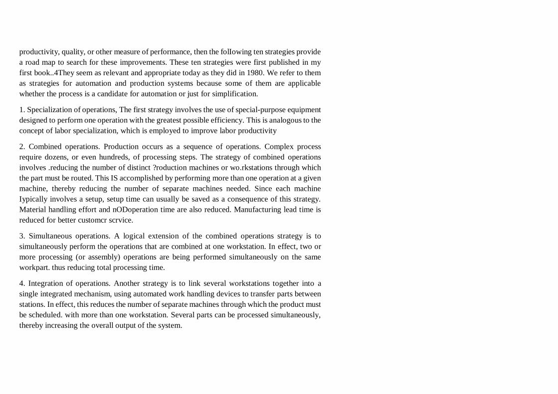
productivity, quality, or other measure of performance, then the folIowing ten strategies provide
a road map to search for these improvements. These ten strategies were first published in my
first book..4They seem as relevant and appropriate today as they did in 1980. We refer to them
as strategies for automation and production systems because some of them are applicable
whether the process is a candidate for automation or just for simplification.
1. Specialization of operations, The first strategy involves the use of special-purpose equipment
designed to perform one operation with the greatest possible efficiency. This is analogous to the
concept of labor specialization, which is employed to improve labor productivity
2. Combined operations. Production occurs as a sequence of operations. Complex process
require dozens, or even hundreds, of processing steps. The strategy of combined operations
involves .reducing the number of distinct ?roduction machines or wo.rkstations through which
the part must be routed. This IS accomplished by performing more than one operation at a given
machine, thereby reducing the number of separate machines needed. Since each machine
Iypically involves a setup, setup time can usually be saved as a consequence of this strategy.
Material handling effort and nODoperation time are also reduced. Manufacturing lead time is
reduced for better customcr scrvice.
3. Simultaneous operations. A logical extension of the combined operations strategy is to
simultaneously perform the operations that are combined at one workstation. In effect, two or
more processing (or assembly) operations are being performed simultaneously on the same
workpart. thus reducing total processing time.
4. Integration of operations. Another strategy is to link several workstations together into a
single integrated mechanism, using automated work handling devices to transfer parts between
stations. In effect, this reduces the number of separate machines through which the product must
be scheduled. with more than one workstation. Several parts can be processed simultaneously,
thereby increasing the overall output of the system.
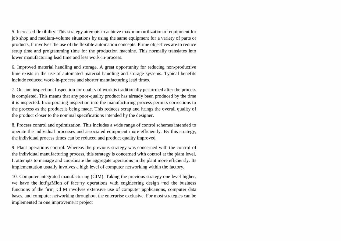
5. Increased flexibility. This strategy attempts to achieve maximum utilization of equipment for
job shop and medium-volume situations by using the same equipment for a variety of parts or
products, It involves the use of the flexible automation concepts. Prime objectives are to reduce
setup time and programming time for the production machine. This normally translates into
lower manufacturing lead time and less work-in-process.
6. Improved material handling and storage. A great opportunity for reducing non-productive
lime exists in the use of automated material handling and storage systems. Typical benefits
include reduced work-in-process and shorter manufacturing lead times.
7. On-line inspection, Inspection for quality of work is traditionally performed after the process
is completed. This means that any poor-quality product has already been produced by the time
it is inspected. Incorporating inspection into the manufacturing process permits corrections to
the process as the product is being made. This reduces scrap and hrings the overall quality of
the product closer to the nominal specifications intended hy the designer.
8, Process control and optimization. This includes a wide range of control schemes intended to
operate the individual processes and associated equipment more efficiently. By this strategy,
the individual process times can be reduced and product quality improved.
9. Plant operations control. Whereas the previous strategy was concerned with the control of
the individual manufacturing process, this strategy is concerned with control at the plant level.
It attempts to manage and coordinate the aggregate operations in the plant more efficiently. Its
implementation usually involves a high level of computer networking within the factory.
10. Computer-integrated manufacturing (CIM). Taking the previous strategy one level higher.
we have the intf'grMlon of fact~ry operations with engineering design ~nd the business
functions of the firm, Cl M involves extensive use of computer applicanons, computer data
bases, and computer networking throughout the enterprise exclusive. For most strategies can be
implemented m one improvemerit project
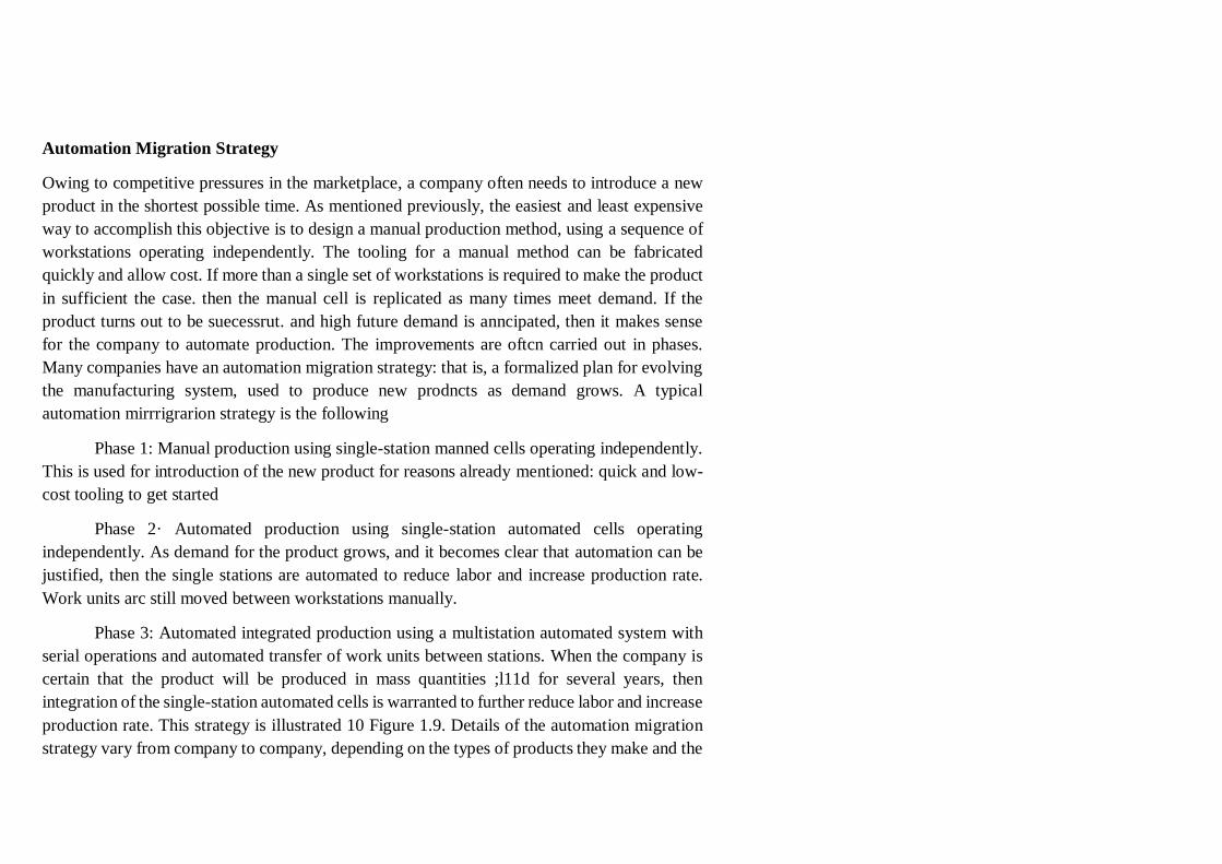
Automation Migration Strategy
Owing to competitive pressures in the marketplace, a company often needs to introduce a new
product in the shortest possible time. As mentioned previously, the easiest and least expensive
way to accomplish this objective is to design a manual production method, using a sequence of
workstations operating independently. The tooling for a manual method can be fabricated
quickly and allow cost. If more than a single set of workstations is required to make the product
in sufficient the case. then the manual cell is replicated as many times meet demand. If the
product turns out to be suecessrut. and high future demand is anncipated, then it makes sense
for the company to automate production. The improvements are oftcn carried out in phases.
Many companies have an automation migration strategy: that is, a formalized plan for evolving
the manufacturing system, used to produce new prodncts as demand grows. A typical
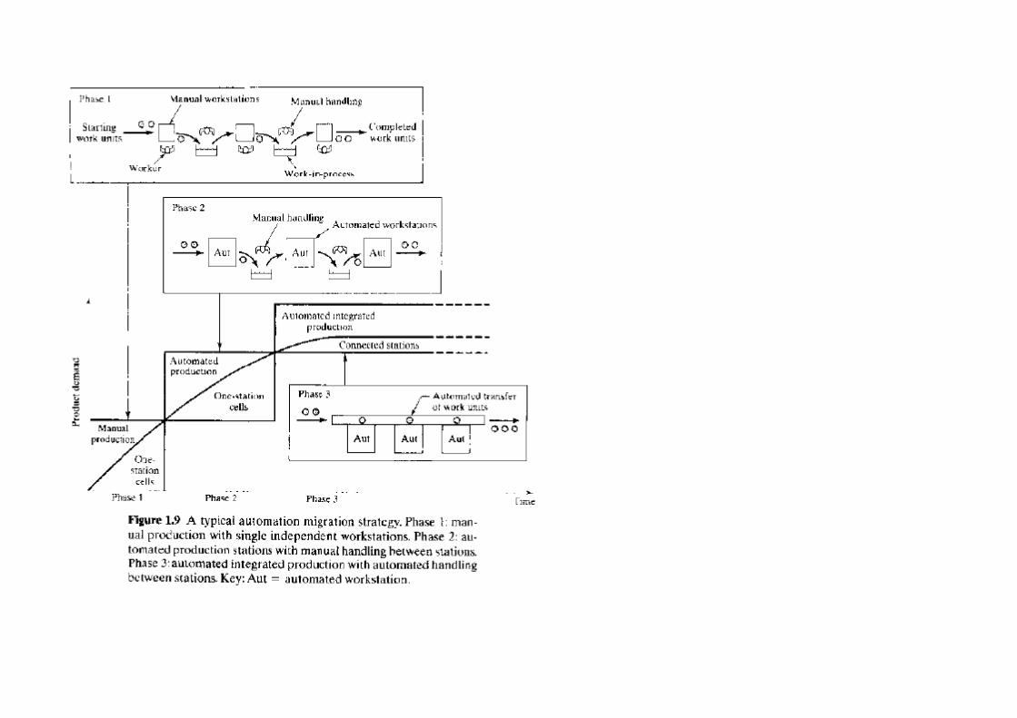
automation mirrrigrarion strategy is the following
Phase 1: Manual production using single-station manned cells operating independently.
This is used for introduction of the new product for reasons already mentioned: quick and low-
cost tooling to get started
Phase 2· Automated production using single-station automated cells operating
independently. As demand for the product grows, and it becomes clear that automation can be
justified, then the single stations are automated to reduce labor and increase production rate.
Work units arc still moved between workstations manually.
Phase 3: Automated integrated production using a multistation automated system with
serial operations and automated transfer of work units between stations. When the company is
certain that the product will be produced in mass quantities ;l11d for several years, then
integration of the single-station automated cells is warranted to further reduce labor and increase
production rate. This strategy is illustrated 10 Figure 1.9. Details of the automation migration
strategy vary from company to company, depending on the types of products they make and the
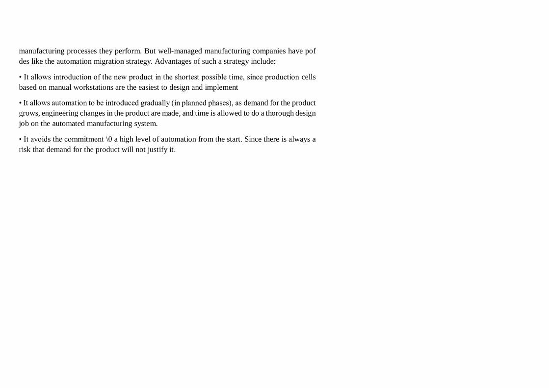
manufacturing processes they perform. But well-managed manufacturing companies have pof
des like the automation migration strategy. Advantages of such a strategy include:
• It allows introduction of the new product in the shortest possible time, since production cells
based on manual workstations are the easiest to design and implement
• It allows automation to be introduced gradually (in planned phases), as demand for the product
grows, engineering changes in the product are made, and time is allowed to do a thorough design
job on the automated manufacturing system.
• It avoids the commitment \0 a high level of automation from the start. Since there is always a
risk that demand for the product will not justify it.
Reasons for automation
1. To increase labor productivity
Automating a manufacturing operation usually increases production rate and labor productivity.
This means greater output per hour of labor input.
2. To reduce labor cost
Ever-increasing labor cost has been and continues to be the trend in the world’s industrialized
societies. Consequently, higher investment in automation has become economically justifiable
to replace manual operations.
3. To mitigate the effects of labor shortages
There is a general shortage of labor in some countries, and this has stimulated the development
of automated operations as a substitute for labor.
4. To reduce or eliminate routine manual and clerical tasks
An argument can be put forth that there is social value in automating operations that are routine,
boring, fatiguing, and possibly irksome. Automating such tasks serves a purpose of improving
the general level of working conditions.
automation (photo credit: csb.com)
5. To improve worker safety
By automating a given operation and transferring the worker from active participation in the
process to a supervisory role, the work is made safer. The safety and physical well-being of the
worker has become a national objective with the enactment of the Occupational Safety and
Health Act (OSHA) in 1970. This has provided an impetus for automation.
6. To improve product quality
Automation not only results in higher production rates than manual operations. It also performs
the manufacturing process with greater uniformity and conformity to quality
specifications. Reduction of fraction defect rate is one of the chief benefits of automation.
7. To reduce manufacturing lead time
Automation helps to reduce the elapsed time between customer order and product delivery,
providing a competitive advantage to the manufacturer for future orders. By reducing
manufacturing lead time, the manufacturer also reduces work-in-process inventory.
8. To accomplish processes that cannot be done manually
Certain operations cannot be accomplished without the aid of a machine. These processes have
requirements for precision, miniaturization, or complexity of geometry that cannot be achieved
manually.
9. To avoid the high cost of not automating
There is a significant competitive advantage gained in automating a manufacturing plant. The
advantage cannot easily be demonstrated on a company’s project authorization form
Types of Automated manufacturing systems:
it can be classified into three basic types:
a. Fixed automation. b. Programmable automation, and c. Flexible automation.
Fixed Automation: Fixed automation is a system in which the sequence of processing
(or assembly) operations is fixed by the equipment configuration. Each of the operations in
the sequence is usually simple, involving perhaps a plain linear or rotational motion or an
uncomplicated combination of the two; for example, the feeding of a rotating spindle. It is
the integration and coordination of many such operations into one piece of equipment that
makes the system complex. Typical features of fixed automation are:
• High initial investment for custom-engineered equipment
• High production rates
• Relatively inflexible in accommodating product variety
Programmable Automation: In programmable automation the production equipment is
designed with the capability to change the sequence of operations to accommodate different
product configuration. The operation sequence is controlled by a program, which is a set of
instructions coded so that they can be read and interpreted by the system. New programs
can be prepared and entered into the equipment to produce new products. Some of the
features that characterize programmable automation include:
• High investment in general purpose equipment
• Lower production rates than fixed automation
• Flexibility to deal with variations and changes in product configuration
• Most suitable for batch production.
Flexible Automation: Flexible automation is an extension of programmable automation.
A flexible automated system is capable of producing a variety of parts (or products) with
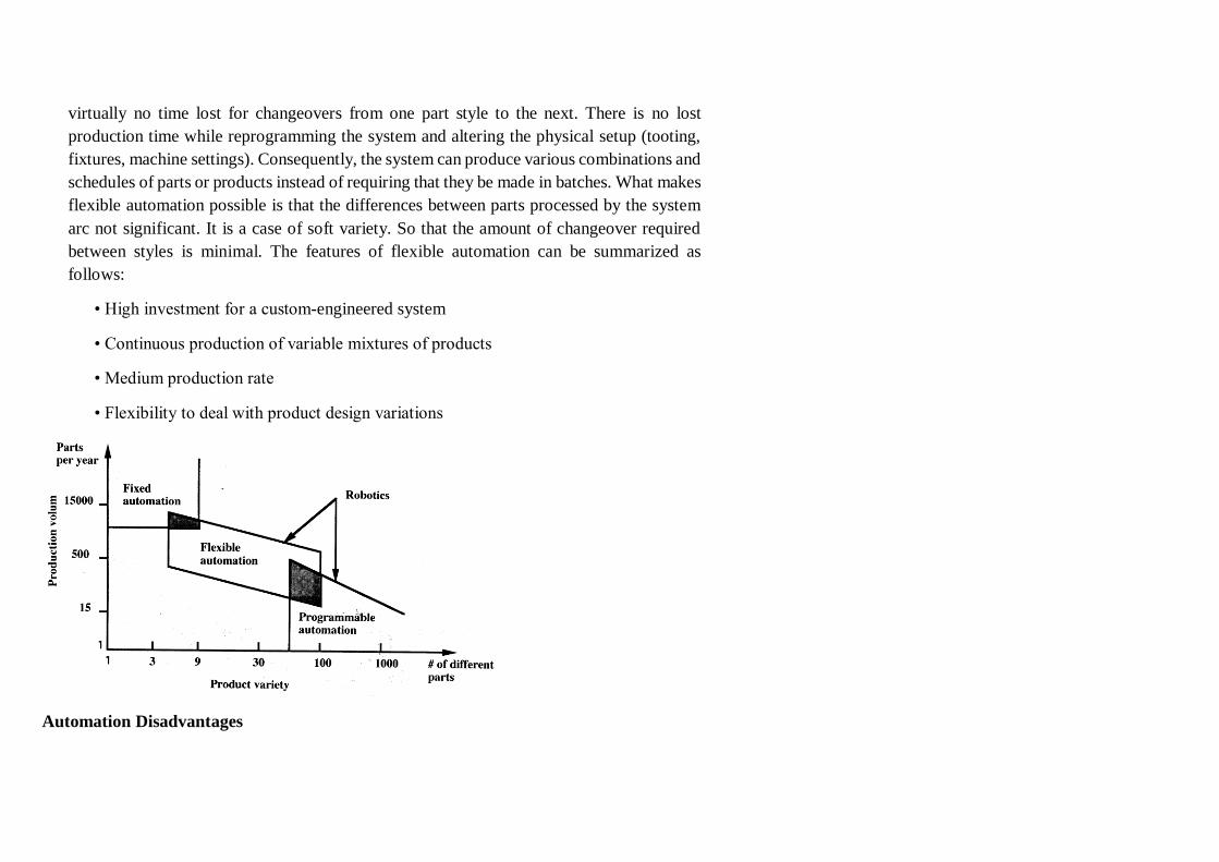
virtually no time lost for changeovers from one part style to the next. There is no lost
production time while reprogramming the system and altering the physical setup (tooting,
fixtures, machine settings). Consequently, the system can produce various combinations and
schedules of parts or products instead of requiring that they be made in batches. What makes
flexible automation possible is that the differences between parts processed by the system
arc not significant. It is a case of soft variety. So that the amount of changeover required
between styles is minimal. The features of flexible automation can be summarized as
follows:
• High investment for a custom-engineered system
• Continuous production of variable mixtures of products
• Medium production rate
• Flexibility to deal with product design variations
Automation Disadvantages
Less versatility – by having a machine that can perform a certain task limits to the
flexibility and variety of tasks that an employee could do.
More pollution – different types of machines operate using motor which may require
gases or chemicals in order to operate. This can cause an increase in pollution in the
workplace.
Large initial investment – automated machines can be one of the most costly operating
costs for a company. With automated machines running anywhere between thousands
and millions of dollars depending on the type and degree of automation.
Increase in unemployment – by increasing the amount of automation, there are less
employees required causing high unemployment rates.
Unpredictable costs – there can be several unpredictable costs that may exceed the actual
cost saved by the automation itself. Some of these costs could include research and
development costs of automating a process, preventative maintenance costs, and the cost
of training employees to operate automated machines.
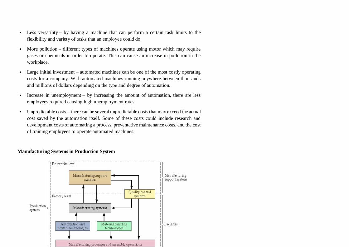
Manufacturing Systems in Production System
Manufacturing System Defined
A collection of integrated equipment and human resources, whose function is to perform
one or more processing and/or assembly operations on a starting raw material, part, or set
of parts
• Equipment includes
– Production machines and tools
– Material handling and work positioning devices Computer systems
• Human resources are required either full‐time or periodically to keep the system
running
Components of a Manufacturing System
1. Production machines
2. Material handling system
3. Computer system to coordinate and/or control the preceding
components
4. Human workers to operate and manage the system
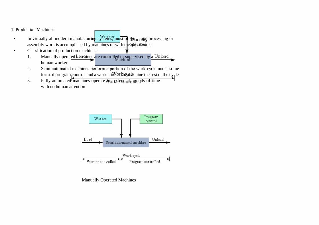
1. Production Machines
• In virtually all modern manufacturing systems, most of the actual processing or
assembly work is accomplished by machines or with the aid of tools
• Classification of production machines:
1. Manually operated machines are controlled or supervised by a
human worker
2. Semi‐automated machines perform a portion of the work cycle under some
form of program control, and a worker tends the machine the rest of the cycle
3. Fully automated machines operate for extended periods of time
with no human attention
Manually Operated Machines
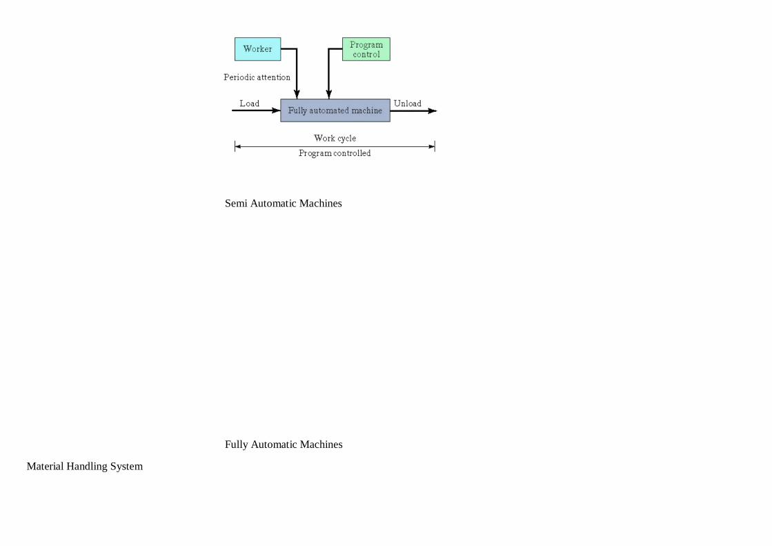
Semi Automatic Machines
Fully Automatic Machines
Material Handling System
• In most manufacturing systems that process or assemble discrete parts and products,
the following material handling functions must be provided:
1. Loading work units at each station
2. Positioning work units at each station
3. Unloading work units at each station
4. Transporting work units between stations in multi‐station systems
5. Temporary storage of work units
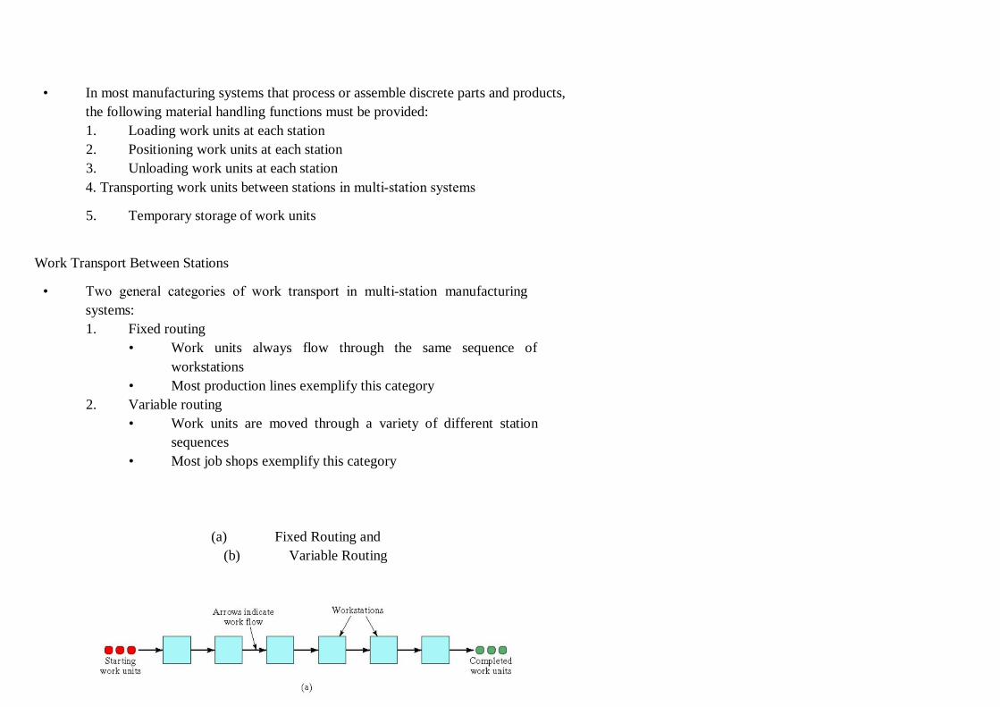
Work Transport Between Stations
• Two general categories of work transport in multi‐station manufacturing
systems:
1. Fixed routing
• Work units always flow through the same sequence of
workstations
• Most production lines exemplify this category
2. Variable routing
• Work units are moved through a variety of different station
sequences
• Most job shops exemplify this category
(a) Fixed Routing and
(b) Variable Routing
Computer Control System
• Typical computer functions in a manufacturing system:
– Communicate instructions to workers
– Download part programs to computer‐controlled machines
– Control material handling system
– Schedule production
– Failure diagnosis when malfunctions occur
– Safety monitoring
– Quality control
– Operations management
Classification of Manufacturing Systems
• Factors that define and distinguish manufacturing systems:
1. Types of operations
2. Number of workstations
3. System layout
4. Automation and manning level
5. Part or product variety
Types of Operations Performed
• Processing Vs assembly operations
• Type(s) of materials processed
• Size and weight of work units
• Part or product complexity
– For assembled products, number of components per product
– For individual parts, number of distinct operations to complete processing
• Part geometry
– For machined parts, rotational vs. non‐rotational.
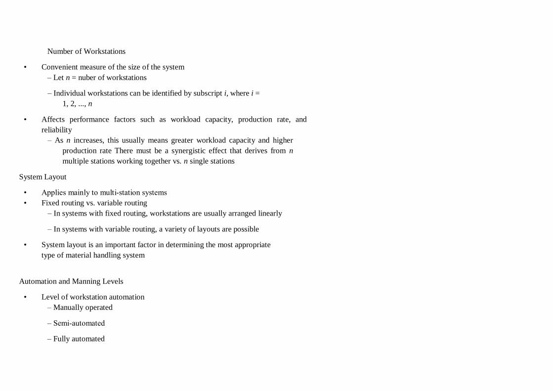
Number of Workstations
• Convenient measure of the size of the system
– Let n = nuber of workstations
– Individual workstations can be identified by subscript i, where i =
1, 2, ..., n
• Affects performance factors such as workload capacity, production rate, and
reliability
– As n increases, this usually means greater workload capacity and higher
production rate There must be a synergistic effect that derives from n
multiple stations working together vs. n single stations
System Layout
• Applies mainly to multi‐station systems
• Fixed routing vs. variable routing
– In systems with fixed routing, workstations are usually arranged linearly
– In systems with variable routing, a variety of layouts are possible
• System layout is an important factor in determining the most appropriate
type of material handling system
Automation and Manning Levels
• Level of workstation automation
– Manually operated
– Semi‐automated
– Fully automated
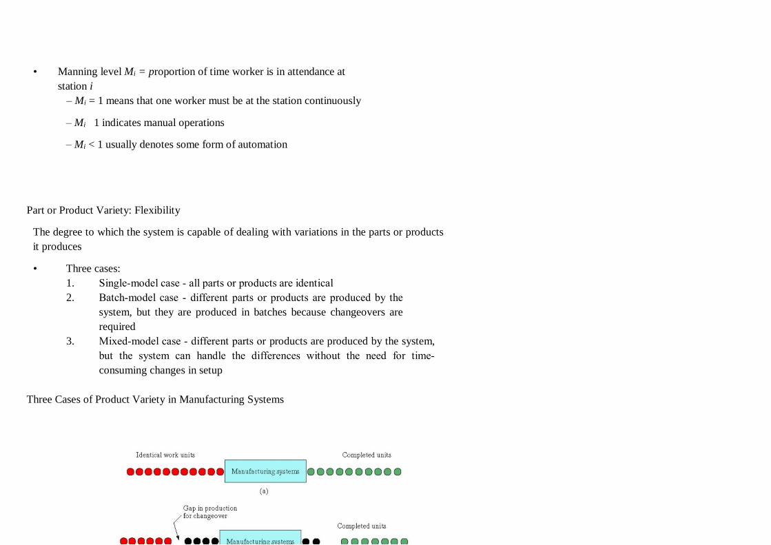
• Manning level Mi = proportion of time worker is in attendance at
station i
– Mi = 1 means that one worker must be at the station continuously
– Mi 1 indicates manual operations
– Mi < 1 usually denotes some form of automation
Part or Product Variety: Flexibility
The degree to which the system is capable of dealing with variations in the parts or products
it produces
• Three cases:
1. Single‐model case ‐ all parts or products are identical
2. Batch‐model case ‐ different parts or products are produced by the
system, but they are produced in batches because changeovers are
required
3. Mixed‐model case ‐ different parts or products are produced by the system,
but the system can handle the differences without the need for time‐
consuming changes in setup
Three Cases of Product Variety in Manufacturing Systems
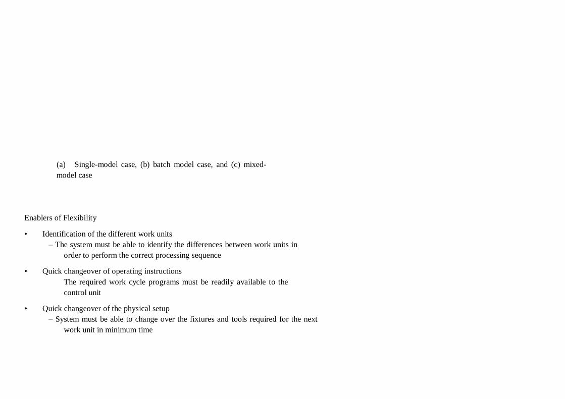
(a) Single-model case, (b) batch model case, and (c) mixed-
model case
Enablers of Flexibility
• Identification of the different work units
– The system must be able to identify the differences between work units in
order to perform the correct processing sequence
• Quick changeover of operating instructions
The required work cycle programs must be readily available to the
control unit
• Quick changeover of the physical setup
– System must be able to change over the fixtures and tools required for the next
work unit in minimum time
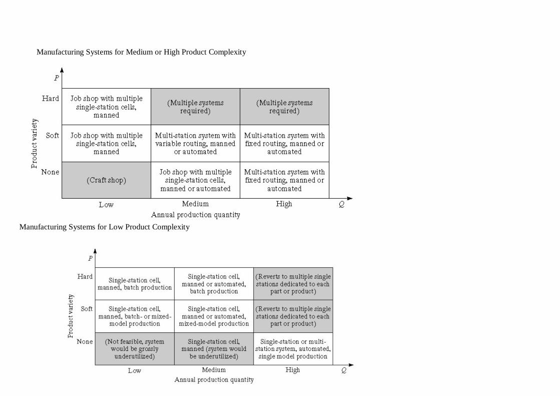
Manufacturing Systems for Medium or High Product Complexity
Manufacturing Systems for Low Product Complexity
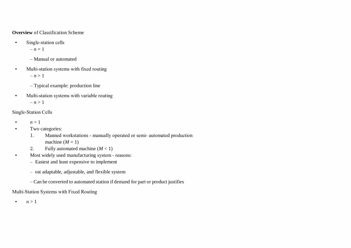
Overview of Classification Scheme
• Single‐station cells
– n = 1
– Manual or automated
• Multi‐station systems with fixed routing
– n > 1
– Typical example: production line
• Multi‐station systems with variable routing
– n > 1
Single‐Station Cells
• n = 1
• Two categories:
1. Manned workstations ‐ manually operated or semi‐ automated production
machine (M = 1)
2. Fully automated machine (M < 1)
• Most widely used manufacturing system ‐ reasons:
– Easiest and least expensive to implement
– ost adaptable, adjustable, and flexible system
– Can be converted to automated station if demand for part or product justifies
Multi‐Station Systems with Fixed Routing
• n > 1
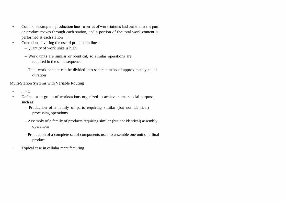
• Common example = production line ‐ a series of workstations laid out so that the part
or product moves through each station, and a portion of the total work content is
performed at each station
• Conditions favoring the use of production lines:
– Quantity of work units is high
– Work units are similar or identical, so similar operations are
required in the same sequence
– Total work content can be divided into separate tasks of approximately equal
duration
Multi‐Station Systems with Variable Routing
• n > 1
• Defined as a group of workstations organized to achieve some special purpose,
such as:
– Production of a family of parts requiring similar (but not identical)
processing operations
– Assembly of a family of products requiring similar (but not identical) assembly
operations
– Production of a complete set of components used to assemble one unit of a final
product
• Typical case in cellular manufacturing
Flexible manufacturing system (FMS
INTRODUCTION
The global competition has been increasing and enforced to various manufacturing
enterprises to adopt flexible manufacturing system (FMS) to get improved productivity and
quality of the product. flexible manufacturing system involve following items, an integrated
system of Computerized Numerically Controlled (CNC) machine tools and automated
Material Handling System (MHS), operating under the control of computer(s). Many
supporting workstations such as load/unload stations, washing stations, storage, de-burring
stations, tools and fixtures setting stations can be added to FMS (Aly and Subramaniam, 1993;
Bayazit, 2005). The fundamental building block of an FMS is data communication because
flexibility is mainly imparted by integrating the functions of various elements such as
machining cells, robots, AGVs using computers (Venkatesh and Ilyas, 1993; Ficko et al,
2010). Hence FMS is very complex and expensive in nature and requirement large amount of
planning and investment thus The flexible manufacturing system may be defined as it is a
highly automated group technology machine cell consisting of a group of processing work
stations interconnected by an automated material handling and storage system and controlled
by a distributed computer system. The Flexible manufacturing systems (FMS) is made up of
hardware and software elements. Hardware elements are visible and tangible such as CNC
machines tools. Software elements are invisible and intangible such as NC programs. Flexible
manufacturing is a concept that allows manufacturing systems to be built under high
customized production requirements. The issues such as reduction of inventories and market-
response time to meet customer demands, flexibility to adapt to changes in the market,
reducing the cost of products and services to grab more market shares, etc have made it almost
obligatory to many firms to switch over to flexible manufacturing systems (FMSs) as a viable
means to accomplish the above requirements while producing consistently good quality and
cost effective products. FMS is actually an automated set of numerically controlled machine
tools and material handling systems, capable of performing a wide range manufacturing
operations with quick tooling and instruction changeovers. In studying FMS, we need to keep
in mind what Peter Drucker said: "We must become managers of technology not merely users
of technology". Since FMS is a technology, well adjusted to the environmental needs, we have
to manage it successfully.
• FLEXIBLE MANUFACTURING AND FLEXIBILITY
Flexibility is an attribute that allows a mixed mode manufacturing system to cope up
with a certain level of variation in part or product cycle , without any interruption in production
due to change over’s between model and hence FMS is called flexible due to the reason that
it is capable of processing a variety of different part styles simultaneously at the workstation
and quantities of production can be adjusted in response to changing demand patterns. The
different type of flexibility that’s exhibited by manufacturing system are given below
2.1 Machine Flexibility
It is the capability to adapt a given machine in the system to a wide range of production
operations and part styles. The greater the range of operations and part styles the greater will
be the machine flexibility. The various factors on which machine flexibility depends are:
4. Setup or changeover time
5. Ease with which part-programs can be downloaded to machines
6. Tool storage capacity of machines
7. Skilland versatility of workers in the systems
2.2 Production Flexibility.
It is the range of part styles that can be produced on the systems. The range of part
styles that can be produced by a manufacturing system at moderate cost and time is determined
by the process envelope. It depends on following factors:
• Machine flexibility of individual stations
• Range of machine flexibilities of all stations in the system
2.3 Mix Flexibility.
It is defined as the ability to change the product mix while maintaining the same total
production quantity that is, producing the same parts only in different proportions. It is also
known as process flexibility. Mix flexibility provides protection against market variability by
accommodating changes in product mix due to the use of shared resources. However, high
mix variations may result in requirements for a greater number of tools, fixtures, and other
resources. Mixed flexibility depends on factors such as:
• Similarity of parts in the mix
• Machine flexibility
• Relative work content times of parts produced
2.4 Product Flexibility
It refers to ability to change over to a new set of products economically and quickly in
response to the changing market requirements. The change over time includes the time for
designing, planning, tooling, and fixturing of new products introduced in the manufacturing
line-up. It depends upon following factors:
5. Relatedness of new part design with the existing part family
6. Off-line part program preparation
7. Machine flexibility
2.5 Routing Flexibility.
It can define as capacity to produce parts on alternative workstation in case of
equipment breakdowns, tool failure, and other interruptions at any particular station. It helps
in increasing throughput, in the presence of external changes such as product mix, engineering
changes, or New product introductions. Following are the factors which decide routing
flexibility:
• Similarity of parts in the mix
• Similarity of workstations
• Common tooling
2.6 Volume Flexibility.
It is the ability of the system to vary the production volumes of different products to
accommodate changes in demand while remaining profitable. It can also be termed as capacity
flexibility. Factors affecting the volume flexibility are:
(a) Level of manual labor performing production
(b) Amount invested in capital equipment
(c)
2.7. Expansion Flexibility.
It is defined as the ease with which the system can be expanded to foster total production
volume.
Expansion flexibility depends on following factors:
• Cost incurred in adding new workstations and trained workers
• Easiness in expansion of layout
• Type of part handling system used
•
BASIC COMPONENT OF FMS
The basic components of FMS are:
3.1 Workstations
3.2 Automated Material Handling and Storage System
3.3 Computer Control System
3.4 .Inspection Equipments
3.5 Other Component
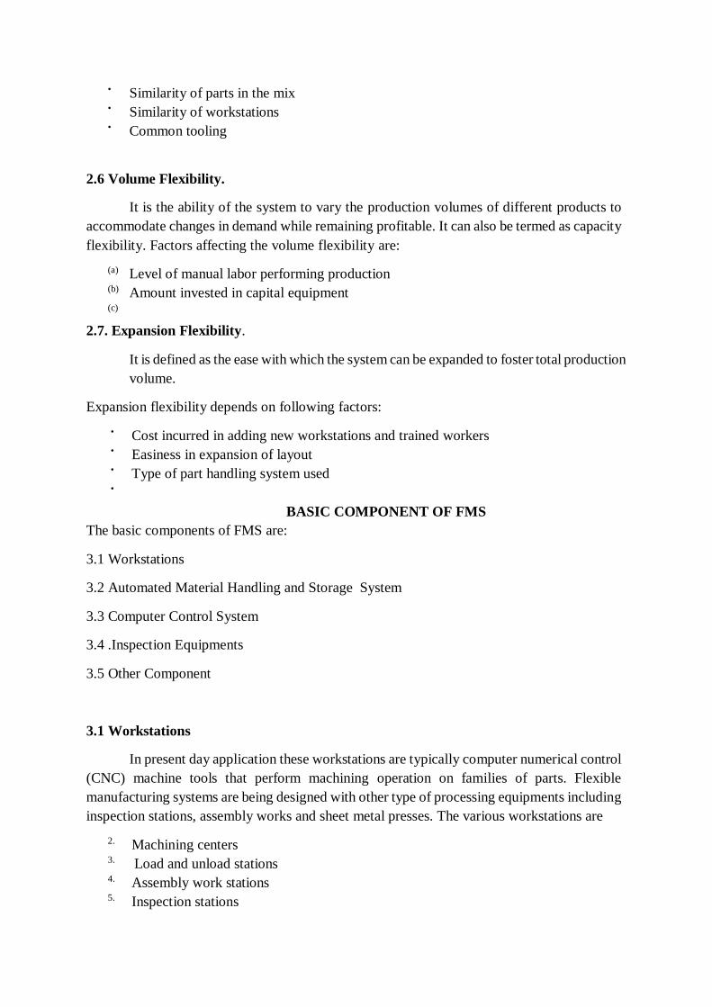
3.1 Workstations
In present day application these workstations are typically computer numerical control
(CNC) machine tools that perform machining operation on families of parts. Flexible
manufacturing systems are being designed with other type of processing equipments including
inspection stations, assembly works and sheet metal presses. The various workstations are
2. Machining centers
3. Load and unload stations
4. Assembly work stations
5. Inspection stations

6. Forging stations
7. Sheet metal processing, etc.
3.2 Automated Material Handling and Storage system
The various automated material handling systems are used to transport work parts and
subassembly parts between the processing stations, sometimes incorporating storage into
function. The various functions of automated material handling and storage system are
4. Random and independent movement of work parts between workstations
5. Handling of a variety of work part configurations
6. Temporary storage
7. Convenient access for loading and unloading of work parts
8. Compatible with computer control
Fig. 2.1 Application characteristics of FMS
3.3 Inspection equipments
It includes coordinate measuring machines (CMMs) used for offline inspection and
programmed to measure dimensions, concentricity, perpendicularity, and flatness of surfaces.
The distinguishing feature of this equipment is that it is well integrated with the machining
centers.
3.4 Other components
It includes a central coolant and efficient chip separation system. Their features are:
• The system must be capable of recovering the coolant.
• The combination of parts, fixtures, and pallets must be cleaned properly to remove dirt
and chips before operation and inspection.
3.5. Computer Control System
It is used to coordinate the activities of the processing stations and the material
handling system in the FMS. The various functions of computer control system are:
• Control of each work station
• Distribution of control instruction to work station
• Production control
• Traffic control
• Shuttle control
• Work handling system and monitoring
• System performance monitoring and reporting
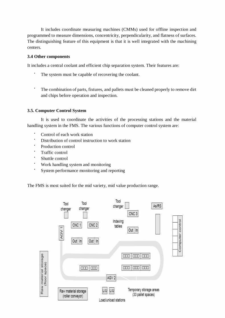
The FMS is most suited for the mid variety, mid value production range.
Fig. 2.2 Flexible Manufacturing System
DIFFERENT TYPES OF FMS
The different types of FMS are
• Sequential FMS
• Random FMS
• Dedicated FMS
• Engineered FMS
• Modular FMS
Sequential FMS: It manufactures one-piece part batch type and then planning and
preparation is carried out for the next piece part batch type to be manufactured. It
operates like a small batch flexible transfer line.
Random FMS: It manufactures any random mix of piece part types at any one time.
Dedicated FMS: It continually manufactures, for extended periods, the same but
limited mix of piece part batch types.
Engineered FMS: It manufactures the same mix of part types throughout its lifetime.
Modular FMS: A modular FMS, with a sophisticated FMS host, enables and FMS user
to expand their FMS capabilities in a stepwise fashion into any of the previous four
types of FMS.
IV. TYPES OF FMS LAYOUT
The different type of layout is:
• Progressive layout
• Loop type
• Ladder type
• Open field type
• Robot centered type
•
4.1 Progressive type or line type
The machine and handling system are arranged in a line as shown in fig.3.1 (a) . it is
most appropriate for a system in which the part progress from one work station to the next in
a well defined sequence with no back flow. The operation of this type of system is very similar
to transfer type. Work always flows in unidirectional path.
4.2 Loop type
The basic loop configuration is as shown in Fig. 3The part usually moves in one
directional around the loop, with the capability to stop and be transferred to any station. The
loading and unloading station is typically located at one end of the loop.
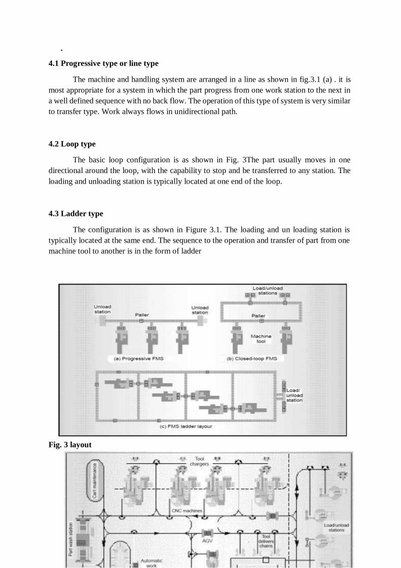
4.3 Ladder type
The configuration is as shown in Figure 3.1. The loading and un loading station is
typically located at the same end. The sequence to the operation and transfer of part from one
machine tool to another is in the form of ladder
Fig. 3 layout
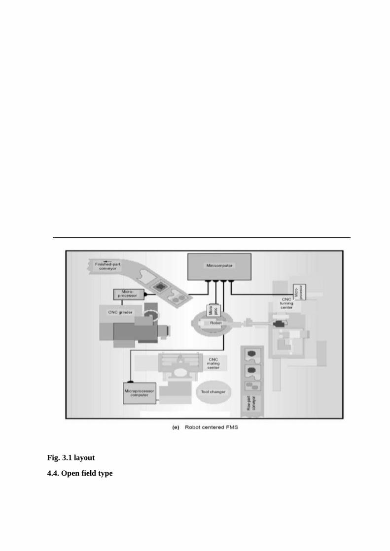
Fig. 3.1 layout
4.4. Open field type
The configuration of the open field is shown in fig. 3.1(d). The loading and unloading
station is typically located at the same end. The part will go through all the substations, such
as CNC machines , coordinate measuring and wash station by the help of AGV”S from one
substation to another.
4.5 Robot centered type
Robot centered cell is a relatively new form of flexible system in which one or more robots
are used as the material handling system as shown in fig. 3.1(e) .Industrial robots can be
equipped with grippers that make them well suited for handling of rotational par
• OBJECTIVE OF FMS
A study is carried out with West Germany manufacturing has shown the major aims of
installing an FMS to be:
• Decreased lead time
• Increase throughput
• Increased machine utilization
• Improved due date reliability
• Decreased store inventors level
• Decreased work in progress
• Increased quality
VI. Aims OF FMS
(a) To reduce cost
(b) To reduce stocks
(c) Reduction of piece part unit cost
(d) To increase technical performance
(e) Increased production level
(f) Smaller batch size
(g) Shorter or zero change over or reset times
(h) To improve order development
(i) Shorter lead time or delivery time
(j) Increase competitiveness
(k) Increased quality
(l) Improve company reputation
VII. Merits OF FMS
Following are the derived benefits of FMS
• Reduction of inventories
• Reduction of lead times
• Improved machine utilization
• Reduction of labor times
• Quick and uncompleted reaction to engineering and design changes
• Increased management control over the entire manufacturing process.
• Reduced equipment cost
• Reduced floor space
• High product quality
• Financial benefits
VIII. DEMERITS OF FMS
Following are the derived benefits of FMS
• FMS systems are quite expensive.
• It is complex than transfer lines. As every system is different and tailored made,
its commissioning And developing takes times
• Highly knowledgeable persons are required.
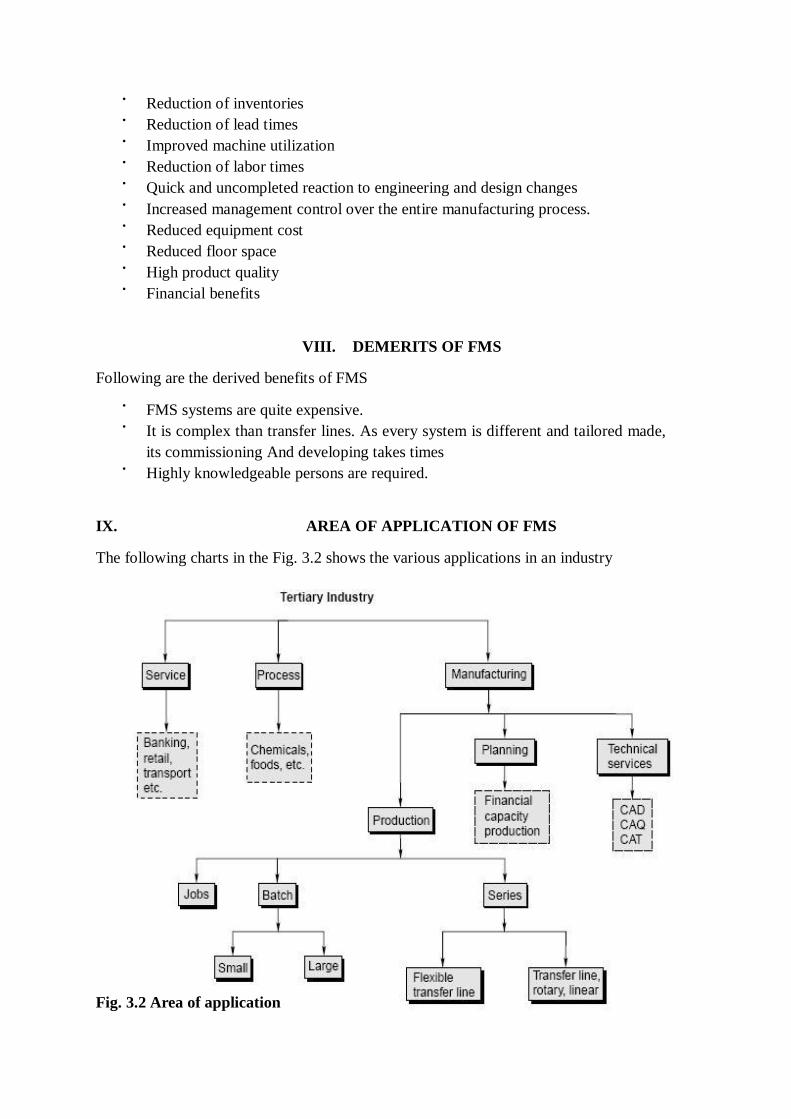
IX. AREA OF APPLICATION OF FMS
The following charts in the Fig. 3.2 shows the various applications in an industry
Fig. 3.2 Area of application