Embed Size (px)
Citation preview

Engineering Failure Analysis 40 (2014) 97–113
Contents lists available at ScienceDirect
Engineering Failure Analysis
journal homepage: www.elsevier .com/locate /engfai lanal
Tribological failure analysis of a heavily-loaded slow speedhybrid journal bearing
http://dx.doi.org/10.1016/j.engfailanal.2014.02.0161350-6307/� 2014 Elsevier Ltd. All rights reserved.
⇑ Corresponding author. Tel.: +91 98 100 24335.E-mail addresses: [email protected], [email protected] (S.M. Muzakkir).
S.M. Muzakkir ⇑, K.P. Lijesh, Harish HiraniDepartment of Mechanical Engineering, Indian Institute of Technology Delhi, India
a r t i c l e i n f o a b s t r a c t
Article history:Received 21 December 2013Received in revised form 7 February 2014Accepted 13 February 2014Available online 28 February 2014
Keywords:Journal bearingMagnetic bearingHybrid bearingRotor fracture
In the present work, the feasibility of hybridizing a magnetic arrangement in the conven-tional journal bearing system has been experimented for the operating conditions of heavyload and slow speed. A test setup has been developed to perform testing on four types ofbearing arrangements: conventional journal bearing arrangement, cylindrical magneticbearing arrangement, circular arc (180�) magnetic bearing arrangement and a hybridbearing arrangement. The magnetic levitation force was determined theoretically for thesearrangements to identify reasons for the mechanical contact between rotor and statormagnets. The results of the experimental investigations in terms of the weight loss (wear),reduction in the magnetic flux density, acceleration signals, and photographs of worn &fractured rotor are reported.
� 2014 Elsevier Ltd. All rights reserved.
1. Introduction
The operating conditions of heavy load and slow speed are encountered in many applications, like sugar mills, cement-man-ufacturing plants and steam turbines, where the support bearings operate in mixed-lubrication regime. Under these conditionsthe asperity contact occurs and excessive wear of bearing causes failure [1–3]. One way adopted by various researchers is toreduce friction and wear in the mixed-lubrication regimes using different material combinations, better lubricants & additives[4] and improving geometry (bearing clearance [5], grooving [6], texturing [7]). Other approach adopted is to hybridize the dif-ferent bearing technologies, like hydrodynamic bearing and hydrostatic bearing [8], electromagnetic bearing and permanentmagnetic bearings [9], hydrodynamic and permanent magnetic bearing [10,11], etc. It has been investigated earlier that thehybridization of magnetic bearing and hydrodynamic bearing is feasible for several applications.
In the present work, experiments have been conducted to determine the feasibility of hybridized bearing (magnetic andjournal bearings). The experiments were conducted in four phases. In the first phase experiments were conducted on con-ventional journal bearings under the operating conditions of heavy load and slow speed. The wear of the bearing was mea-sured as its weight loss after the test. In the second phase the experiments were conducted on cylindrical magnetic bearingarrangement under the similar operating conditions of heavy load and slow speed and it was observed that the arrangementis not capable of supporting the dynamic load. In the third phase the experiments were conducted on circular arc (180�)magnetic bearing arrangement under the similar operating conditions and it was observed that even though the magneticarrangement was able to separate the journal in static condition, but rotor experienced vibrations under dynamic conditionsand finally resulted into the breakage of the rotor magnets. Significant wear was also observed on the surface of stator

Nomenclature
r1 inner radius of rotor magnet, mmr2 outer radius of rotor magnet, mmr3 inner radius of stator magnet, mmr4 outer radius of stator magnet, mmBr1 magnetic remanence, TeslaBr2 magnetic remanence, Teslal0 permeability of free space, H/mFr radial force, Ne eccentricity ratioa angular variable of rotor, Radianb angular variable of stator, Radianz axial offset, mL length of cylindrical magnet, mg dynamic viscosity, Pa sN journal speed, rpmS Sommerfeld numberK specific film thickness
98 S.M. Muzakkir et al. / Engineering Failure Analysis 40 (2014) 97–113
magnet. In the fourth phase experiments were conducted on the hybrid bearing arrangement. Significant wear of both therotor and stator was observed in this arrangement with a consequent reduction in the magnetic strength.
The reasons of the bearing arrangement failures were analyzed and the conclusions drawn are reported.
2. Experimental details
The schematic diagram of the experimental setup is shown in Fig. 1a. The provisions have been made in the setup toconduct experimental studies on four types of bearing arrangements:
1. Conventional journal bearing.2. Cylindrical magnetic bearing arrangement.3. Circular sector (180�) magnetic bearing arrangement.4. Hybrid bearing arrangement.
These arrangements are shown in Figs. 1b–1e. The main experimental setup, shown in Fig. 1a, consists of a stainless steel(grade 303) shaft whose one end is free and other is connected, using a spiral coupling, to an induction motor (AC, 3 phase,1.5 kW). The motor is rigidly mounted on a base plate and is controlled by an ABB frequency drive (IP20/ll open type). Theloading arrangement consists of a horizontal loading platform supported on linear bearing mounted on vertical slide ways ofcircular cross section. A maximum of 500 N load may be applied on the bearing. A (shielded) deep groove ball bearingtransfers the load from the loading platform to the shaft. Two accelerometers (type: KS 76C-10, voltage sensitivity:
Detailed View Figure 1(b)
Detailed View Figure 1(c)
Detailed View Figure 1(d)
Detailed View Figure 1(e)
Fig. 1a. Schematic diagram of the main experimental setup.

Fig. 1b. Journal bearing test setup.
Fig. 1c. Cylindrical magnetic bearing test setup.
Fig. 1d. Circular sector (180�) magnetic bearing test setup.
S.M. Muzakkir et al. / Engineering Failure Analysis 40 (2014) 97–113 99
1.032 mV/m/s2) are connected at the top and side of the bearing housing. The data is acquired using NI USB-4432(24 bit) andstored in computer using LabVIEW interface. The detailed description of the experimental setups shown in Figs. 1b–1e aregiven in the corresponding sections.
The photographs of the experimental setup are shown in Fig. 2a and b.The description of the experimental setup, operating conditions, experimental results and corresponding discussion for
the four different bearing arrangements are given in the following sections.
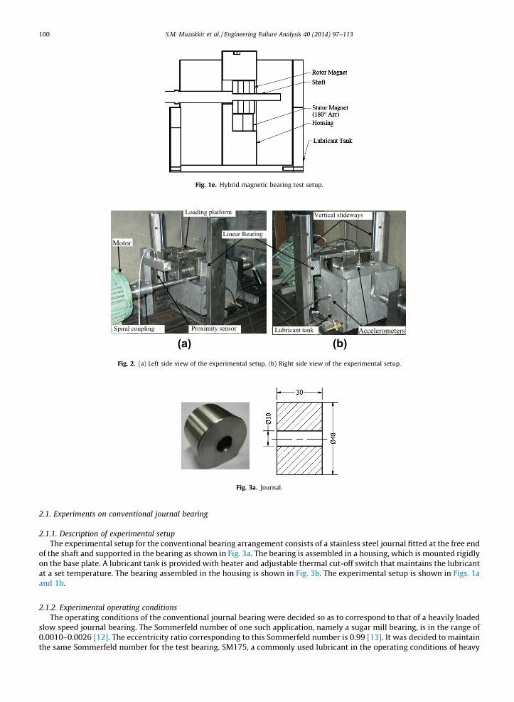
Fig. 1e. Hybrid magnetic bearing test setup.
Proximity sensorSpiral coupling
Loading platform
Motor
Vertical slideways
Accelerometers
Linear Bearing
Lubricant tank
(a) (b)Fig. 2. (a) Left side view of the experimental setup. (b) Right side view of the experimental setup.
Fig. 3a. Journal.
100 S.M. Muzakkir et al. / Engineering Failure Analysis 40 (2014) 97–113
2.1. Experiments on conventional journal bearing
2.1.1. Description of experimental setupThe experimental setup for the conventional bearing arrangement consists of a stainless steel journal fitted at the free end
of the shaft and supported in the bearing as shown in Fig. 3a. The bearing is assembled in a housing, which is mounted rigidlyon the base plate. A lubricant tank is provided with heater and adjustable thermal cut-off switch that maintains the lubricantat a set temperature. The bearing assembled in the housing is shown in Fig. 3b. The experimental setup is shown in Figs. 1aand 1b.
2.1.2. Experimental operating conditionsThe operating conditions of the conventional journal bearing were decided so as to correspond to that of a heavily loaded
slow speed journal bearing. The Sommerfeld number of one such application, namely a sugar mill bearing, is in the range of0.0010–0.0026 [12]. The eccentricity ratio corresponding to this Sommerfeld number is 0.99 [13]. It was decided to maintainthe same Sommerfeld number for the test bearing. SM175, a commonly used lubricant in the operating conditions of heavy

Fig. 3b. Bearing assembled in the housing.
S.M. Muzakkir et al. / Engineering Failure Analysis 40 (2014) 97–113 101
load and low speed, was used in the experiment. It was maintained at a temperature of 40 �C. The dynamic viscosity wasdetermined to be 0.10025 Pa s at 40 �C. A phosphor bronze bearing with inner diameter 50 mm and length 30 mm was usedfor conducting experimental investigations. In order to obtain same Sommerfeld number for the test bearing, a suitableradial clearance (for the journal bearing) is to be decided considering the dynamic viscosity of lubricant, dimensions ofthe test bearing, load and journal speed. A radial clearance of 0.25 mm (0.1% of journal radius) will require a load of2891 N at a journal speed of 5 rpm. But due to the limitation of the test setup in respect of the maximum applied load(500 N), the radial clearance was increased to 1.00 mm to obtain a reduced load of 180 N at 5 rpm. However, the shaft couldnot be rotated at 5 rpm and it became possible to rotate the journal only at 27 rpm and a load of 373 N corresponding to theSommerfeld number of 0.0068. The experiment was thus conducted under these operating conditions for 6 h [14] so as toobtain measureable wear of the bearing. The wear of the bearing was measured as its weight loss on a precision weighingbalance. The bearings were cleaned using toluene before the weight measurement, both before and after the test.
2.1.3. Results and discussionThe journal bearing (journal diameter: 50 mm, bearing inner diameter: 48 mm, radial clearance: 1 mm, length: 30 mm)
was operated at heavy load and slow speed conditions (load: 373 N, journal speed: 27 rpm, lubricant temperature: 40 �C) for6 h duration. The weight loss of the bearing after the 6 h test was measured to be 60 mg. This amount to a reduction of0.033% weight of the bearing and is considered a significant amount of wear which indicates that the journal remained incontact with the bearing under these operating conditions. The heavy load and slow speed conditions prevented the oper-ation of the journal bearing in the hydrodynamic lubrication regime. The theoretical analysis was then carried out to verifythe operative lubrication regime of the journal bearing. The lift-off speed [15] was determined to be 529 rpm, correspondingto a specific film thickness parameter, K ¼ 3, which is much higher than 27 rpm at which the experiment was conducted.This confirms that the journal bearing operated in the mixed lubrication regime.
Since the operation of the journal bearing in mixed lubrication regime results in significant wear, therefore in order toseparate the journal from the bearing, the magnetic (passive) levitation may be employed. The magnetic force (F) betweentwo magnets is inversely proportional to square of the distance (d) between them and is expressed as F / 1
d2 [16]. It may beinferred from this expression that an infinite large repulsive magnetic force may be obtained when the two magnets withsame polarity approach towards each other i.e. d ? 0. If this principle is used then the magnetic bearing may be used toseparate the journal from coming in contact with bearing. In order to explore this option and to analyze the feasibility ofthe magnetic bearing, the experiments have been conducted on the magnetic bearing arrangements, the details of whichare given in the next sections.
2.2. Experiments on cylindrical magnetic bearing arrangement
2.2.1. Description of experimental setupThe test setup for the cylindrical magnetic bearing arrangement consists of rotor made up of four neodymium magnetic
discs having inner diameter of 10 mm, outer diameter of 48 mm and thickness of 8 mm as shown in Fig. 4a. The rotor is pushfitted on the stainless steel shaft and acts as journal. The bearing stator is made of two cylindrical magnets having innerdiameter of 50 mm, outer diameter of 100 mm and thickness of 15 mm as shown in Fig. 4b. The stator magnets are assem-bled in the bearing housing as shown in Fig. 1c. The housing is rigidly mounted on the base plate.
2.2.2. Experimental operating conditionsThe operating conditions of the experimental setup employing cylindrical magnetic bearing arrangement were kept sim-
ilar to the one used for the conventional journal bearing setup so as to obtain direct comparison of their performances. Therotor was subjected to a load of 373 N and rotated at 27 rpm. The radial clearance was taken to be 1 mm.

Fig. 4a. Rotor.
Fig. 4b. Cylindrical magnet (stator) assembled in the bearing housing.
102 S.M. Muzakkir et al. / Engineering Failure Analysis 40 (2014) 97–113
2.2.3. Results and discussionThe cylindrical magnets have axial magnetization therefore a radial repulsion force is developed between the rotor and
stator. It was observed on the application of the load of 373 N that direct contact occurred between the stator and rotor mag-nets. The magnetic arrangement was thus unable to levitate the rotor at a load of 373 N. The load was then reduced so as todetermine the maximum load which this magnetic arrangement could carry without allowing contact between the statorand rotor, however it was found that even at a reduced load of 60 N the rotor and stator magnets remained in contact witheach other and the magnetic arrangement was unable to levitate the rotor as shown in Fig. 5a and b.
To understand the reasons for the contact between rotor and stator, a theoretical estimation of the magnetic levitationforce was carried out. The theoretical radial repulsive force between axially polarized stator and rotor magnets in themagnetic bearing is determined using the following equation [17].
Fr ¼ AZ 2p
0
Z 2p
0
Z r4
r3
Z r2
r1
2
j�r23j31
j�r24j31
j�r14j3
!ðeþ r3 cos a� r2 cos bÞr3dr3r2dr2dadb ð1Þ
where
r23 ¼ ðLþ zÞ2 þ ðeþ r3 cos a� r2 cos bÞ2 þ ðr3 sin a� r2 sin bÞ2h i1
2 ð2Þ
r24 ¼ z2 þ ðeþ r3 cos a� r2 cos bÞ2 þ ðr3 sin a� r2 sin bÞ2h i1
2 ð3Þ
r14 ¼ ½ðL� zÞ2 þ ðeþ r3 cos a� r2 cos bÞ2 þ ðr3 sin a� r2 sin bÞ2�12 ð4Þ
and A ¼ Br1Br2
4pl0ð5Þ
The dimensional parameters, r1 = 5 mm (d1 = 10 mm), r2 = 24 mm (d2 = 48 mm), r3 = 25 mm (d3 = 50 mm), r4 = 50 mm(d4 = 100 mm), L = 30 mm, z = 1 mm, Br1 = 1.0 T, Br2 = 1.2 T and l0 = 4p � 10�4 H/m as applicable to the present test setupare shown in Fig. 6.

(a) Cylindrical magnetic bearing arrangement under loaded condition
(b) Close up view of contact between stator and rotor
Fig. 5. (a) Cylindrical magnetic bearing arrangement under loaded condition. (b) Close up view of contact between stator and rotor.
Fig. 6. Dimensional details of cylindrical magnetic bearing arrangement.
S.M. Muzakkir et al. / Engineering Failure Analysis 40 (2014) 97–113 103
Eq. (1) is solved numerically using the Gaussian Quadrature numerical integration technique [18] and the results of repul-sive force are plotted in Fig. 7.
It is observed from Fig. 7 that the radial repulsive force increases with the increase in the eccentricity ratio. The maximumstatic load that bearing can support is 52.8 N, which is much lower than the applied load of 373 N. Therefore, this magneticbearing arrangement would not be able to sustain a load of 373 N.
However, another magnetic configuration which consists of a 180� arc magnet have been proposed and evaluated bySamanta and Hirani [19]. It was shown to be providing a larger radial force (with minimum axial force) as compared to cylin-drical magnetic bearing. The feasibility of employing this magnetic bearing arrangement was then explored and experimentswere conducted on this magnetic bearing configuration, the details of which are described in the next section.
2.3. Experiments on circular 180� arc magnetic bearing arrangement
2.3.1. Description of experimental setupThe test setup for the cylindrical magnetic bearing arrangement consists of rotor made up of four neodymium magnetic
discs having inner diameter of 10 mm, outer diameter of 48 mm and thickness of 8 mm as shown in Fig. 4a. It is supported intwo circular 180�arc magnetic bearing having inner diameter of 50 mm, outer diameter of 100 mm and thickness of 15 mm.The circular arc (180�) magnets are assembled in the bearing housing which is mounted rigidly on the base plate as shown inFig. 8. Two accelerometers were attached on the bearing housing in vertical and horizontal planes to pick the vibration sig-nals along the vertical and horizontal directions.

Fig. 7. Radial repulsive force of cylindrical bearing.
Fig. 8. Circular arc (180�) magnet in the bearing housing.
104 S.M. Muzakkir et al. / Engineering Failure Analysis 40 (2014) 97–113
2.3.2. Experimental operating conditionsThe experiment was planned to be conducted on this bearing arrangement for 6 h duration with similar operating con-
ditions as that of a conventional journal bearing (load 373 N and journal speed 27 rpm).
2.3.3. Results and discussionIt was observed that the rotor remained separated from the stator under static condition with application of 373 N load.
The radial repulsive force was therefore sufficient enough to separate the journal from the bearing under the static condition.The same was verified by the theoretical estimation of the static load carrying capacity of this bearing arrangement. The the-oretical static load carrying capacity or magnetic levitation force or radial repulsive force of this configuration is expressed byEq. (6), which is obtained by modifying Eq. (1).
Fr ¼ AZ p
2
�p2
Z 2p
0
Z r4
r3
Z r2
r1
2
j�r23j31
j�r24j31
j�r14j3
!ðeþ r3 cos a� r2 cos bÞr3dr3r2dr2dadb ð6Þ
The dimensional parameters, r1 = 5 mm (d1 = 10 mm), r2 = 24 mm (d2 = 48 mm), r3 = 25 mm (d3 = 50 mm), r4 = 50 mm(d4 = 100 mm), L = 30 mm, Br2 = 1.2 T and l0 = 4p � 10�4 H/m as applicable to the present test setup are shown in Fig. 9.
The Eq. (6) is solved numerically using the Gaussian Quadrature numerical integration technique [18]. The results ofmagnetic repulsive force vs eccentric position of rotor are plotted in Fig. 10.
It is observed from Fig. 10 that the maximum static load this bearing arrangement can support is 377.7 N at an eccentric-ity ratio almost equal to 1.0. This maximum static load is higher than the applied load of 373 N.
The test was then started and it was observed that the bearing operation was smooth in the beginning until 130 min ofthe test when suddenly high noise and vibration were observed which continued to increase and it became difficult tocontinue the test further. The test was then stopped after 140 min of its operation.
The bearing (rotor and stator) condition was examined after the test. The visible cracks appeared in the rotor magnet asshown in Fig. 11a. On the disassembly of the rotor it was found that two of the rotor magnets had been fractured into two

Fig. 9. Dimensional details of circular arc (180�) magnetic bearing arrangement.
320
330
340
350
360
370
380
390
-1 -0.8 -0.6 -0.4 -0.2 0 0.2 0.4 0.6 0.8 1
Rad
ial R
epul
sive
For
ce (
N)
Eccentricity Ratio
Fig. 10. Radial repulsive force of 180� arc magnet.
S.M. Muzakkir et al. / Engineering Failure Analysis 40 (2014) 97–113 105
pieces as shown in Fig. 11b, indicating catastrophic failure of the rotor magnets. The surface of the rotor showed significantwear indicating contact between rotor and stator as shown in Fig. 11c.
The further investigation of the bearing failure was carried out by conducting the analysis of the acceleration dataacquired using the accelerometers during the experiment. Fig. 12a depicts the acceleration vs time plot in the vertical direc-tion. It is observed from Fig. 12a that the bearing operation was relatively smoother until 130 min when a sudden increase inthe acceleration occurs. This is probably the instant of the fracture of rotor magnets. The acceleration continued to increasecyclically thereafter until the test was stopped at about 140 min of its operation.
The acceleration peaks in Fig. 12a indicates the instance of rotor hitting/striking the stator. The striking of rotor with thestator is because of the dynamic unbalance introduced due to errors and variability in manufacturing of the rotor magnets asit is difficult to manufacture a completely balanced rotor. Moreover, the 180� arc magnet has lower stiffness as compared tothe full cylindrical magnet due to the absence of the magnetic repulsive force in the top half of the bearing [20]. Therefore,

Fig. 11a. Visible cracks on the rotor magnets.
Fig. 11b. Fractured rotor magnets.
Fig. 11c. Circumferential wear marks on the rotor surface.
106 S.M. Muzakkir et al. / Engineering Failure Analysis 40 (2014) 97–113
the 180� arc magnet does not perform smoothly under dynamic loads even though it has higher static load carrying capacityas compared to cylindrical magnetic bearing. The rotor unbalance coupled with the low stiffness aggravates the problem ofrotor hitting/striking the stator. The continuous hitting/striking of the rotor with stator causes formation of cracks and finalfracture of the rotor magnets. This also introduces cracks in the stator magnets. The sudden increase in the acceleration after130 min of operation may be attributed to the fractured rotor magnets. This fracture of rotor magnets significantly reducesthe magnetic strength resulting in continuous contact between rotor and stator resulting in wear.
The FFT plot of Fig. 12a is shown in Fig. 12b. Fig. 12b shows the vibration frequency and amplitude that are induced due tothe instability of the magnetic arrangement including the hitting/striking of the rotor with stator. Fig. 12b shows the initialoperation of the bearing test setup with corresponding sub-synchronous and super-synchronous frequencies of the vibrationsignal. The vibration amplitudes are small initially.
On the examination of the stator after the test it was observed that significant wear of the bearing surface has taken placewith a crack in the axial direction as shown in Fig. 13a and b. The stator magnet also suffered fracture at the edges as shownin Figs. 14a and 14b.
Even though the load applied (373 N) was less than the theoretical estimate of the maximum permissible static load of377.7 N, the failure of both the stator and rotor indicates that the magnetic arrangement was not able to separate the rotor

122 124 126 128 130 132 134 136 138-50
0
50
100
150
Time (min)
Acc
elra
tion
(m
/sec
2 )
Fracture of rotor magnet
Fig. 12a. Acceleration vs time plot showing the instant of rotor magnet fracture.
0 1 2 3 4 50
0.05
0.1
0.15
0.2
0.25
0.3
X: 0.457Y: 0.1815
Frequency (Hz)
X: 0.6679Y: 0.1089
X: 0.3515Y: 0.08425
X: 0.2109Y: 0.3028
Am
plit
ude
(dB
)
Fig. 12b. FFT of the acceleration signal during the initial operation of the bearing.
(a) (b)
Fig. 13. (a) Circumferential wear marks on the stator surface with an axial crack. (b) Close up view of stator surface with circumferential wear marks andaxial crack.
S.M. Muzakkir et al. / Engineering Failure Analysis 40 (2014) 97–113 107
from the journal under the dynamic conditions. This failure of the 180� arc magnetic arrangement is catastrophic and needsto be avoided. The breakage of the stator magnets and significant wear of the rotor magnets suggest the need to obtain solu-tions to this problem. One possible solution is to introduce lubricant between the stator and rotor that may possibly alleviatethe problem of high wear and rotor magnet fracture by sharing the applied load.
The use of such hybridization has been proved to be feasible [10]. The next section contains the details of the experimentconducted on a hybrid bearing.

Fig. 14a. Fracture of stator magnet at the edge.
Fig. 14b. Fracture of stator magnet at the corner.
Fig. 15. Test setup for hybrid bearing arrangement.
108 S.M. Muzakkir et al. / Engineering Failure Analysis 40 (2014) 97–113
2.4. Experiments on hybrid bearing arrangement
2.4.1. Description of experimental setupA lubricant tank is provided with the test setup for the circular arc (180�) magnetic bearing arrangement and shown in
Fig. 15. The remaining arrangement, however, was similar to the one described in Section 2.1 above and shown in Figs. 1aand 1e.

Wear marks Damaged coating
(a) (b)
Fig. 16. (a) Rotor magnets before test, and (b) Rotor magnets after test.
0
0.1
0.2
0.3
0.4
0.5
0.6
0 45 90 135 180 225 270 315Mag
neti
c fl
ux d
ensi
ty (
Tes
la)
Location of measurement, θ degree
Unused rotor magnet Used rotor magnet
Fig. 17. Magnetic flux density (T) of rotor before and after test.
Table 1Magnetic flux density of rotor surface before and after test.
S. no. Measurement location (�) Magnetic flux density of rotor surface (Tesla) Percentage reduction
Before test After test
1 0 0.478 0.462 32 45 0.497 0.488 23 90 0.482 0.457 54 135 0.488 0.431 135 180 0.468 0.332 416 225 0.489 0.422 167 270 0.523 0.455 158 315 0.510 0.486 5
Wear marks
Fracture atedges
Fig. 18. Wear and fracture of stator after test.
S.M. Muzakkir et al. / Engineering Failure Analysis 40 (2014) 97–113 109

0 2 4 6 8 10 12 14 16 18 20-4
-2
0
2
4
6
Time (min)
Acc
eler
atio
n (m
/sec
2 )
Fig. 19a. Acceleration vs time plot in vertical direction during beginning of test.
0 1 2 3 4 50
0.1
0.2
0.3
0.4
Frequency (Hz)
X: 1.337Y: 0.3917
X: 0.4455Y: 0.01931
X: 0.8911Y: 0.07716
X: 1.621Y: 0.1079
X: 1.782Y: 0.09375
X: 2.673Y: 0.1537 X: 4.01
Y: 0.1292
X: 4.455Y: 0.04407
X: 3.564Y: 0.06312X: 2.541
Y: 0.03814
3rd Harmonics
2nd Harmonics
Am
plit
ude
(dB
)
Fig. 19b. FFT of the acceleration signals (vertical direction) during beginning of test.
110 S.M. Muzakkir et al. / Engineering Failure Analysis 40 (2014) 97–113
2.4.2. Experimental operating conditionsThe experiment was conducted on the hybrid bearing arrangement for 6 h duration with similar operating conditions as
that of a conventional journal bearing (load 373 N and journal speed 27 rpm). The lubricant temperature was maintained at40 �C. The acceleration data of the bearing housing in horizontal and vertical directions were acquired using twoaccelerometers.
2.4.3. Results and discussionThe experiment was conducted on hybrid bearing for 6 h duration. No significant vibrations levels were observed during
the test as were observed in the circular arc (180�) magnetic bearing arrangement without the lubricant. The rotor and statorwere examined after the completion of the test. Fig. 16a shows the rotor before the test and Fig. 16b shows the rotor after thetest of 6 h duration. It is observed from the examination of these surfaces that significant wear of the rotor surface hasoccurred during the test and the coating has been damaged. This is a cause for concern as the wear of surface indicates thatcontact occurred between stator and rotor magnets and the magnetic repulsive force was unable to levitate the rotor underthe dynamic conditions. The wear of the rotor was measured in terms of weight loss. The weight of rotor magnet was mea-sured before and after the test and the weight loss was determined to be 3.48 g which is a significant amount of wear.
The magnetic flux density of the surface of rotor magnet was measured after the test using the Gauss meter (in Tesla) andwas compared with its magnetic flux density before the test. A reduction in the magnetic flux density was observed after thetest as shown in Fig. 17 and tabulated in Table 1. The contact between the stator and rotor magnets during operation withconsequent wear and increase in surface temperature due to sliding is the cause of reduction in magnetic flux density of themagnets.
The non-uniformity in the magnetic strength introduces instability in the bearing operation [21] and causes the rotor tohit/strike the stator.
The examination of the bearing surface also indicated significant wear and fracture at the edges as shown in Fig. 18.The wear of the stator and rotor indicates that the hybrid arrangement has also not been able to maintain the separation
of the rotor from the stator under the dynamic conditions with the consequent wear of both rotor and stator. However a

340 342 344 346 348 350 352 354 356 358 360-5
0
5
10
Time (min)
Acc
eler
atio
n (m
/sec
2 )
Fig. 20b. Acceleration vs time plot in vertical direction after 340 min of the test.
0 1 2 3 4 50
1
2
3
4
5
6
X: 1.398Y: 2.753
X: 1.755Y: 0.968
Frequency (Hz)
X: 0.4251Y: 0.2602
X: 0.8774Y: 0.7333
X: 2.802Y: 1.315 X: 4.2
Y: 1.041
X: 4.387Y: 0.4579
X: 3.51Y: 0.7108
X: 2.632Y: 0.6564
Am
plit
ude
(dB
)
Fig. 20c. Amplitude vs frequency plot in vertical direction near the end of test.
0 2 4 6 8 10 12 14 16 18 20-0.02
-0.015
-0.01
-0.005
0
0.005
0.01
0.015
0.02
Time (min)
Acc
eler
atio
n (m
/sec
2 )
Fig. 20a. Acceleration vs time plot in horizontal direction during initial running.
S.M. Muzakkir et al. / Engineering Failure Analysis 40 (2014) 97–113 111

112 S.M. Muzakkir et al. / Engineering Failure Analysis 40 (2014) 97–113
hybrid bearing caused lesser wear as compared with the circular arc (180�) arrangement as described in the previous sectiondue to the presence of lubricant. The wear was also not localized as was observed in the case of conventional journal bearingtest. The analysis of the acceleration data obtained during the test indicates a much smoother operation of the hybrid bearingwith reduced level of vibrations highlighting the role of lubricant in damping the vibrations.
Fig. 19a depicts the acquired acceleration data in vertical direction during the beginning of the test. It is observed fromFig. 19a that the maximum amplitude of acceleration in vertical direction is about 6 m/s2. A FFT of the same data is given inFig. 19b to show the harmonics. It is observed from Fig. 19b that first harmonics occurs at 0.4455 Hz corresponding to a rotorspeed of 27 rpm. The peaks represent the harmonics of the rotor frequency.
Fig. 20a depicts the acceleration vs time signal in horizontal direction during the beginning of the test. As may beobserved from Fig. 20a that the maximum acceleration values are much smaller as compared to that in the vertical directiongiven in Fig. 19a.This is due to the low stiffness in the top half of the circular arc magnetic bearing arrangement
Fig. 20b depicts the acceleration vs time plot in the vertical direction after the elapse of 340 min during the test. The largevalue of the acceleration indicates the hitting/striking of the rotor on stator.
Fig. 20c depicts the FFT of the acceleration signal near the end of the test in vertical direction showing very largeamplitudes of vibration indicating impact of rotor on stator which caused the stator fracture.
It is observed from Fig. 21a that the acceleration values are significantly smaller in horizontal direction near the end of thetest. The FFT of the acceleration signal in horizontal direction near the end of the test is depicted in Fig. 21b.
Fig. 21b indicates very small magnitudes of the vibration amplitudes in the horizontal direction. This indicates that theeffect of striking of rotor on the stator in horizontal direction is not significant.
0 1 2 3 4 50
1
2
3
4
5
6
7
8x 10
-3
X: 1.475Y: 0.002619
X: 1.264Y: 0.00475
X: 0.03246Y: 0.006842
X: 1.685Y: 0.002298 X: 2.261
Y: 0.001897
X: 1.054Y: 0.0006745X: 0.8432
Y: 0.0003782X: 0.4212Y: 0.0002275
X: 2.529Y: 0.0009982
X: 4.52Y: 0.001191X: 2.95
Y: 0.0008007
Frequency (Hz)
X: 0.05966Y: 0.005155
Am
plit
ude
(dB
)
Fig. 21b. Amplitude vs frequency plot in horizontal direction near the end of test.
340 342 344 346 348 350 352 354 356 358 360-0.02
-0.015
-0.01
-0.005
0
0.005
0.01
0.015
0.02
Time (min)
Acc
eler
atio
n (m
/sec
2 )
Fig. 21a. Acceleration vs time plot in horizontal direction after 340 min of the test.

S.M. Muzakkir et al. / Engineering Failure Analysis 40 (2014) 97–113 113
3. Conclusions
Based on the experimental observations on the conventional journal bearing and different magnetic bearing arrange-ments, it is concluded that the cylindrical magnetic bearing arrangement has the minimum static load carrying capacityand it is not possible to use it for heavy load and slow speed conditions. The circular arc (180�) magnetic arrangementhas higher static load carrying capacity as compared to cylindrical magnetic bearing arrangement and is able to separatethe rotor from the stator under static conditions, however it is unable to maintain the separation under the dynamic condi-tions resulting in the contact between rotor and stator consequently resulting in significant wear and fracture of the rotorand stator. It is, therefore, concluded that the static load carrying capacity alone is not the sufficient condition for a magneticbearing to operate successfully. A complete dynamic analysis is thus required to determine the dynamic load carrying capac-ity of the bearing to determine its feasibility. The use of lubricant with the magnetic bearing arrangement (hybrid bearing) isable to contain the severity of the magnetic bearing failure. It is able to obviate rotor fracture and resulted in reduced wear ofthe rotor and stator due to the action of lubricant. Even though the hybrid bearing arrangement with the provision of lubri-cation also failed to maintain the separation between stator and rotor in dynamic conditions but resulted in less severe wearas compared to circular arc magnetic arrangement.
References
[1] Muzakkir SM, Hirani H, Thakre GD, Tyagi MR. Tribological failure analysis of journal bearings used in sugar mills. Eng Fail Anal 2011;18:2093–103.[2] Dufrane KF, Kannel JW. Wear of steam turbine journal bearings at low operating speeds. J Lubr Technol 1983;105:313–7.[3] Singhal S. Sleeve bearing design for slow speed applications in cement plant. Tech Conf Rec IEEE 2008:283–90.[4] Spikes H. The history and mechanisms of ZDDP. Tribol Lett 2004;17:469–89.[5] Loxham J. Proposals for the selection of optimum clearances in journal bearings. Tribol Int 1983;16:185–92.[6] Feng M, Kenjo T. A comparative study of turning and stationary groove journal bearings for HDD spindle motors under transient contact conditions.
IEEE Trans Magn 2007;43:3727–33.[7] Kumar CP, Menezes PL, Kailas SV. Role of surface texture on friction under boundary lubricated conditions. Tribol Online 2008;3:12–8.[8] Zhang R-Q, Chang HS. A new type of hydrostatic/hydrodynamic gas journal bearing and its optimization for maximum stability. Tribol Trans
1995;38:589–94.[9] Eryong H, Kun L. Investigation of axial carrying capacity of radial hybrid magnetic bearing. IEEE Trans Magn 2012;48:38–46.
[10] Hirani H, Samanta P. Hybrid (hydrodynamic + permanent magnetic) journal bearings. Proc Inst Mech Eng Part J J Eng Tribol 2007;221:881–91.[11] Qingchang T, Wei L, Xuejun X. Investigations on a magnetic–hydrodynamic hybrid thrust bearing. Tribol Int 2002;12:61–6.[12] Muzakkir SM, Hirani H, Thakre GD. Lubricant for heavily loaded slow-speed journal bearing. Tribol Trans 2013;56:1060–8.[13] Khonsari MM, Booser ER. Applied tribology: bearing design and lubrication. John Wiley & Sons Ltd.; 2001.[14] Begelinger A, De Gee AWJ. A study of the effect of radial clearance, contact angle and contact pressure on the wear of boundary-lubricated bearing
bronze. Wear 1982;77:45–56.[15] Lu X, Khonsari MM. On the lift-off speed in journal bearings. Tribol Lett 2005;20:299–305.[16] Noar JH, Evans RD. Rare Earth magnets in orthodontics: an overview. Br J Orthod 1999;26:29–37.[17] Tan Q, Li W, Liu B. Investigations on a permanent magnetic–hydrodynamic hybrid journal bearing. Tribol Int 2002;35:443–8.[18] Samanta P, Hirani H. A simplified optimization approach for permanent magnetic bearing. Indian J Tribol 2007;2:23–34.[19] Samanta P, Hirani H. Magnetic bearing configurations: theoretical and experimental studies. IEEE Trans Magn 2008;44:292–300.[20] Mukhopadhyay SC, Ohji T, Iwahara M. Modeling and control of a new horizontal-shaft hybrid-type magnetic bearing. IEEE Trans Magn 2000;47:100–8.[21] Ohji T, Mukhopadhyay SC, Iwahara M, Yamada S. Performance of repulsive type magnetic bearing system under nonuniform magnetization of
permanent magnet. IEEE Trans Magn 2000;36:3696–8.


![ComputationalStudyofaModelSystemof Enzyme-Mediated[4+2]Cycloaddition ...web.iitd.ac.in/~nkurur/2015-16/Isem/cml103/papers/[2015... · cycloaddition reactionstheyareinvolved in.Thecalculated](https://img.pdfslide.us/doc/110x75/5b9e72c809d3f2d7748c8647/computationalstudyofamodelsystemof-enzyme-mediated42cycloaddition-webiitdacinnkurur2015-16isemcml103papers2015.jpg)