Embed Size (px)
Citation preview
Flexible Engineering Environment Integration for(Software+) Development Teams
DIPLOMARBEIT
zur Erlangung des akademischen Grades
Diplom-Ingenieur
im Rahmen des Studiums
Software Engineering/Internet Computing
eingereicht von
Andreas PieberMatrikelnummer 0726569
an derFakultat fur Informatik der Technischen Universitat Wien
Betreuung:Betreuer: Ao. Univ.-Prof. Dr. Stefan BifflMitwirkung: Dr. Alexander Schatten
Wien, 02.01.2011
(Unterschrift Verfasser/in) (Unterschrift Betreuer/in)
Technische Universitat WienA-1040 Wien Karlsplatz 13 Tel. +43/(0)1/58801-0 http://www.tuwien.ac.at
Eidsstattliche Erklarung Andreas Pieber
Erklarung zur Verfassung der Arbeit
”Hiermit erklare ich, dass ich diese Arbeit selbstandig verfasst habe, dass ich die verwendeten
Quellen und Hilfsmittel vollstandig angegeben habe und dass ich die Stellen der Arbeit — ein-
schließlich Tabellen, Karten und Abbildungen —, die anderen Werken oder dem Internet im
Wortlaut oder dem Sinn nach entnommen sind, auf jeden Fall unter Angabe der Quelle als
Entlehnung kenntlich gemacht habe.”
Ort Datum Unterschrift
- i -
Abstract Andreas Pieber
Abstract
Modern software-intensive systems depend on distributed software to control the system be-
havior. The system behavior is supposed to be testable and predictable to meet safety and
quality standards. Software engineering, as part of systems engineering, depends in many appli-
cation domains on the specifications and designs of experts from several other disciplines, such
as mechanical and electrical engineering, and application-specific process engineering. There-
fore, system engineering teams need flexible and efficient mechanisms to exchange data between
engineering tools and models to develop a coherent product and stay aware of changes from
concurrent work on software-relevant artifacts. Project and quality managers need an environ-
ment that facilitates efficient high-quality data collection on the engineering team level in order
to track project progress and quality levels of major artifacts and production processes.
Unfortunately, currently tools only provide limited support for the flexible integration of hetero-
geneous engineering environments. While each discipline has specific tool sets that support the
major engineering tasks, there is surprisingly little work on the technical integration of tools and
models across engineering disciplines. The weak technical integration of the expert knowledge
across disciplines hinders flexible engineering process automation and quality management, lead-
ing to development delays and quality risks for the final product. To increase product quality
and reduce the risk for errors during the engineering process, an efficient, flexible and platform
independent solution approach is needed. It should be possible to integrate heterogeneous teams,
their tools and engineering processes over multiple engineering disciplines.
The concept of an open source Engineering Service Bus (OpenEngSB) platform, which extends
the Enterprise Service Bus concept from business software engineering towards bridging techni-
cal gaps between engineering systems and tools in heterogeneous engineering environments, is
introduced in this work. It provides a method for describing and developing flexible engineering
process automation and quality management across engineering disciplines. The OpenEngSB
concept is evaluated against the state-of-the-art, implementing two prototypes for real-world sce-
narios: (1) Continuous Integration & Test and (2) Signal Change Management across Tool Data
Models. The empirical evaluation reveals that implementing use cases from software-intensive
systems is feasible, efficient and effective. Additionally, compared to traditional approaches, the
OpenEngSB platform makes integration easier and much more flexible.
Keywords: Technical Integration, Software-Intensive Systems, Distributed Systems, Automa-
tion, OpenEngSB
- ii -
Kurzfassung Andreas Pieber
Kurzfassung
Moderne, Software-intensive Systeme bestehen aus einer Vielzahl von Komponenten, wobei
sowohl das Verhalten jeder einzelnen Komponente, als auch das Zusammenspiel mehrerer, durch
Software gesteuert wird. Um dabei aktuelle Sicherheits- und Qualitaetsstandards einhalten zu
konnen mussen die Systeme trotz ihrer Komplexitat test- und vorhersagbar sein. Um solche
Systeme spezifizieren, designen und entwickeln zu konnen, wird neben einer Prozesssteuerung
auch eine intensive Interaktion zwischen Softwareentwicklern und anderen Spezialisten, wie zum
Beispiel Maschinenbauern und Elektroingenieuren, notwendig. Um ein koharentes Produkt en-
twickeln zu konnen benotigt das Entwicklerteam flexible und effiziente Mechanismen um Daten
zwischen ihren heterogenen Werkzeugen auszutauschen und synchron zu halten. Außerdem
mussen sie bei der gleichzeitigen Arbeit an softwarerelevanten Artefakten uber Anderungen in-
formiert bleiben. Projekt- und Qualitatsmanager hingegeben benotigen qualitativ hochwertige
Daten uber den aktuellen Entwicklungsstand, um den Fortschritt und die Qualitat von wichtigen
Artefakten und des Produktionsprozesses jederzeit uberprufen zu konnen.
Zur Zeit gibt es allerdings kaum Toolunterstutzung fur die flexible Integration von het-
erogenen, softwareintensiven Systemen. Dies behindert flexible Prozessintegration und
Qualitatsmanagement, was letztendlich zu Entwicklungsverzogerungen und Qualitatsrisiken
fuhren kann. Zur Erhohung der Produktqualitat und Verringerung der Fehlerrate werden Sys-
teme benotigt, die einen effizienten, flexiblen und plattformunabhangigen Ansatz zur Integration
von heterogenen Teams, derer Werkzeuge und disziplinubergreifender Prozesse erlauben.
In dieser Arbeit wird ein Lsungsansatz vorgestellt, der in der quelloffenen Engineering Service
Bus(OpenEngSB) Plattform implementiert wurde. Diese Plattform erweitert das Konzept des
Enterprise Service Bus (ESB) um Lucken bei der Integration von heterogenen Werkzeugen
zu schließen. Zusatzlich wird eine Methode definiert, um disziplinubergreifende Prozesse und
Qualitatssicherung in softwareintensiven Systemen zu beschreiben und zu implementieren. Das
OpenEngSB Konzept wird anhand einer Fallstudie mit zwei praxisorientierten Szenarios mit dem
aktuellen Stand der Technik verglichen. Dabei werden folgende Szenarien herangezogen: (1)
Continuous Integration & Test und (2) Anderungsmanagement von Signalen uber Werkzeug-
domanen hinweg. Die Analyse zeigt, dass die Implementierung von Anwendungsfallen mit dem
OpenEngSB verglichen mit den heute blichen Vorgehensweisen, zu effizienteren und effektiveren
Ergebnissen fhrt. Weiters ist die Integration der Tools und Prozesse mit Hilfe der OpenEngSB
Plattform schneller durchzufuhren und flexibler anzupassen.
Schlagworter: Technische Integration, Software-Intensive Systeme, Verteilte Systeme, Automa-
tisierung, OpenEngSB
- iii -
Table of Contents Andreas Pieber
Table of Contents
1 Introduction 1
2 Business Process Models for (Software+) Engineering 8
2.1 Systematic Process Models: V-Model . . . . . . . . . . . . . . . . . . . . . . . 8
2.2 Agile Process Models: Scrum . . . . . . . . . . . . . . . . . . . . . . . . . . . . 10
2.3 Flexible Systematic Process Models: V-Modell XT . . . . . . . . . . . . . . . . . 11
3 Tool Integration in Distributed Environments 16
3.1 Integration Concepts for Distributed Environments . . . . . . . . . . . . . . . . 16
3.1.1 File Transfer . . . . . . . . . . . . . . . . . . . . . . . . . . . . . . . . . 16
3.1.2 Shared Database . . . . . . . . . . . . . . . . . . . . . . . . . . . . . . 17
3.1.3 Remote Procedure Invocation . . . . . . . . . . . . . . . . . . . . . . . . 18
3.1.4 Messaging . . . . . . . . . . . . . . . . . . . . . . . . . . . . . . . . . . 19
3.1.5 Enterprise Service Bus . . . . . . . . . . . . . . . . . . . . . . . . . . . . 19
3.2 Architectural Integration Concepts . . . . . . . . . . . . . . . . . . . . . . . . . 20
3.2.1 Service-Orientated Architecture . . . . . . . . . . . . . . . . . . . . . . . 20
3.2.2 Event-Driven Architecture . . . . . . . . . . . . . . . . . . . . . . . . . 22
3.2.3 Event-Driven Service-Oriented Architecture . . . . . . . . . . . . . . . . 23
3.3 Integration in Java . . . . . . . . . . . . . . . . . . . . . . . . . . . . . . . . . . 24
3.3.1 Mule Enterprise Service Bus . . . . . . . . . . . . . . . . . . . . . . . . 24
3.3.2 Service Component Architecture . . . . . . . . . . . . . . . . . . . . . . 25
3.3.3 Java Business Integration . . . . . . . . . . . . . . . . . . . . . . . . . . 27
4 Integration in Engineering Environments 31
4.1 Software Engineering Environments . . . . . . . . . . . . . . . . . . . . . . . . . 31
4.1.1 Script Based Integration Approaches . . . . . . . . . . . . . . . . . . . . 31
4.1.2 Integrated Development Environment Based Integration Approaches . . . 32
4.1.3 Application Lifecycle Management Based Integration Approaches . . . . . 33
4.2 (Software+) Engineering Environments . . . . . . . . . . . . . . . . . . . . . . . 36
4.2.1 Cesar . . . . . . . . . . . . . . . . . . . . . . . . . . . . . . . . . . . . . 38
4.2.2 Modale . . . . . . . . . . . . . . . . . . . . . . . . . . . . . . . . . . . . 39
4.2.3 Medeia . . . . . . . . . . . . . . . . . . . . . . . . . . . . . . . . . . . . 39
4.2.4 Comos . . . . . . . . . . . . . . . . . . . . . . . . . . . . . . . . . . . . 40
5 Research Issues and Approach 42
5.1 Research Issues . . . . . . . . . . . . . . . . . . . . . . . . . . . . . . . . . . . 43
5.1.1 Architecture for Abstract Tool Integration . . . . . . . . . . . . . . . . . 43
5.1.2 Method for Abstract (Software+) Engineering Process Definition . . . . . 45
- iv -
Table of Contents Andreas Pieber
5.2 Research Methods and Evaluation Concept . . . . . . . . . . . . . . . . . . . . . 46
5.2.1 Literature Research . . . . . . . . . . . . . . . . . . . . . . . . . . . . . 46
5.2.2 Architecture Trade-Off Analysis . . . . . . . . . . . . . . . . . . . . . . . 47
5.2.3 Feasibility Study based on Real World Use Cases . . . . . . . . . . . . . 49
6 (Software+) Engineering Processes 51
6.1 Analysis of (Software+) Engineering Processes . . . . . . . . . . . . . . . . . . . 51
6.1.1 Stakeholders . . . . . . . . . . . . . . . . . . . . . . . . . . . . . . . . . 51
6.1.2 Products . . . . . . . . . . . . . . . . . . . . . . . . . . . . . . . . . . . 52
6.1.3 Engineering Processes . . . . . . . . . . . . . . . . . . . . . . . . . . . . 53
6.2 V-Modell XT Tailoring Applied on (Software+) Engineering Processes . . . . . . 54
6.3 Scenarios within the (Software+) Engineering Process Model . . . . . . . . . . . 58
6.3.1 Continuous Integration & Test . . . . . . . . . . . . . . . . . . . . . . . 59
6.3.2 Signal Change Management Across Tool Data Models . . . . . . . . . . 63
7 OpenEngSB Architecture and Concept 70
7.1 OpenEngSB Components . . . . . . . . . . . . . . . . . . . . . . . . . . . . . . 70
7.2 OpenEngSB Infrastructure . . . . . . . . . . . . . . . . . . . . . . . . . . . . . 74
7.2.1 Message Header Extensions . . . . . . . . . . . . . . . . . . . . . . . . . 74
7.2.2 Message Body Extensions . . . . . . . . . . . . . . . . . . . . . . . . . . 75
7.3 OpenEngSB Core Components . . . . . . . . . . . . . . . . . . . . . . . . . . . 75
7.3.1 Registry . . . . . . . . . . . . . . . . . . . . . . . . . . . . . . . . . . . 75
7.3.2 Workflow . . . . . . . . . . . . . . . . . . . . . . . . . . . . . . . . . . 79
7.3.3 Log Container . . . . . . . . . . . . . . . . . . . . . . . . . . . . . . . . 80
7.4 OpenEngSB Tool Domains . . . . . . . . . . . . . . . . . . . . . . . . . . . . . 81
7.4.1 Abstraction by Tool Domains . . . . . . . . . . . . . . . . . . . . . . . . 82
7.4.2 Logical Extensions by Tool Domains . . . . . . . . . . . . . . . . . . . . 83
7.4.3 Advanced Decision Models by Tool Domains . . . . . . . . . . . . . . . . 83
7.5 OpenEngSB Tool Connectors . . . . . . . . . . . . . . . . . . . . . . . . . . . . 86
7.5.1 Connection to the OpenEngSB . . . . . . . . . . . . . . . . . . . . . . . 88
7.5.2 Integrating External Client Tools . . . . . . . . . . . . . . . . . . . . . . 89
7.5.3 Integrating External Domain Tools . . . . . . . . . . . . . . . . . . . . . 90
7.5.4 Integrating Internal Client and Domain Tools . . . . . . . . . . . . . . . 90
7.6 Process Design and Implementation with the OpenEngSB . . . . . . . . . . . . . 90
7.7 Processes Validation with the OpenEngSB . . . . . . . . . . . . . . . . . . . . . 93
8 OpenEngSB Process Implementation and Evaluation 95
8.1 Continuous Integration & Test . . . . . . . . . . . . . . . . . . . . . . . . . . . 95
8.1.1 Design and Implementation for the OpenEngSB . . . . . . . . . . . . . . 95
- v -
Table of Contents Andreas Pieber
8.1.2 Developing Extensions with the OpenEngSB . . . . . . . . . . . . . . . . 99
8.1.3 Validation and Comparison of the Implementation . . . . . . . . . . . . . 101
8.2 Signal Change Management Across Tool Data Models . . . . . . . . . . . . . . 103
8.2.1 Design and Implementation for the OpenEngSB . . . . . . . . . . . . . . 103
8.2.2 Validation and Comparison of the Implementation . . . . . . . . . . . . . 108
9 Discussion 111
9.1 Architecture for Abstract Tool Integration . . . . . . . . . . . . . . . . . . . . . 111
9.1.1 Feasibility of the OpenEngSB approach . . . . . . . . . . . . . . . . . . 111
9.1.2 Support for independent tool and process integration . . . . . . . . . . . 113
9.1.3 Support for team awareness . . . . . . . . . . . . . . . . . . . . . . . . . 114
9.1.4 More effective and efficient engineering process . . . . . . . . . . . . . . 114
9.2 Method for Abstract (Software+) Engineering Process Definition . . . . . . . . . 115
9.2.1 Support for Engineering Process Automation . . . . . . . . . . . . . . . 115
9.2.2 Support for Engineering Process Validation . . . . . . . . . . . . . . . . 116
10 Conclusion and Perspectives 117
10.1 Conclusion . . . . . . . . . . . . . . . . . . . . . . . . . . . . . . . . . . . . . . 117
10.2 Future Work . . . . . . . . . . . . . . . . . . . . . . . . . . . . . . . . . . . . . 118
- vi -
Introduction Andreas Pieber
1 Introduction
Modern automation systems, such as industrial automation plants for manufacturing, power
plants and steel mills, depend heavily on distributed software to control their system behaviour
(Lder, 2000). Because of the high costs and risks for humans and machines mostly coupled
with such software-intensive systems a wide range of safety and quality standards have to be
fulfilled during their design, development and deployment. Therefore the system behavior have
to be testable and predictable which requires quality and process management along the entire
development process. But to engineer such systems software engineering, although important,
is not enough. (Software+) engineering for automation systems requires experts from a variety
of different domains, such as electrical engineering, mechanical engineering and similar technical
disciplines, which have to interact (Biffl, Schatten, & Zoitl, 2009). But their knowledge is
embodied in domain-specific standards, peoples, tools, models and software making it hard to
integrate a comprehensive quality and process management approach often leads to errors, delays
and higher costs.
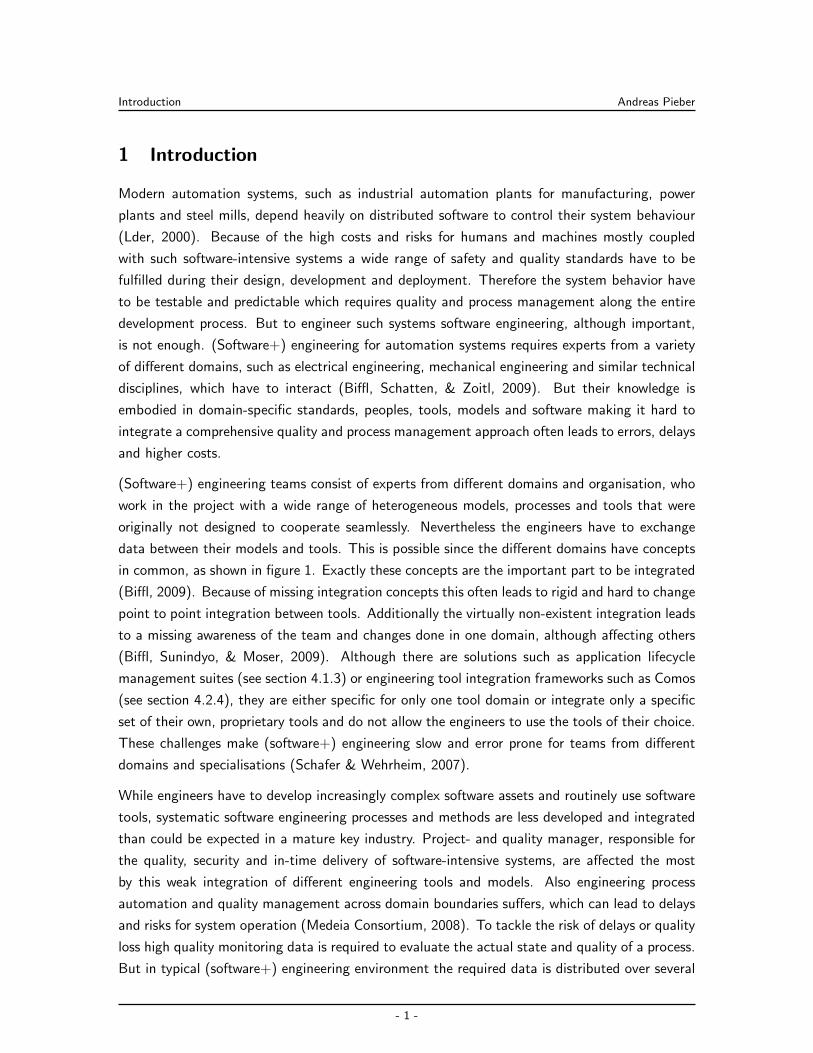
(Software+) engineering teams consist of experts from different domains and organisation, who
work in the project with a wide range of heterogeneous models, processes and tools that were
originally not designed to cooperate seamlessly. Nevertheless the engineers have to exchange
data between their models and tools. This is possible since the different domains have concepts
in common, as shown in figure 1. Exactly these concepts are the important part to be integrated
(Biffl, 2009). Because of missing integration concepts this often leads to rigid and hard to change
point to point integration between tools. Additionally the virtually non-existent integration leads
to a missing awareness of the team and changes done in one domain, although affecting others
(Biffl, Sunindyo, & Moser, 2009). Although there are solutions such as application lifecycle
management suites (see section 4.1.3) or engineering tool integration frameworks such as Comos
(see section 4.2.4), they are either specific for only one tool domain or integrate only a specific
set of their own, proprietary tools and do not allow the engineers to use the tools of their choice.
These challenges make (software+) engineering slow and error prone for teams from different
domains and specialisations (Schafer & Wehrheim, 2007).
While engineers have to develop increasingly complex software assets and routinely use software
tools, systematic software engineering processes and methods are less developed and integrated
than could be expected in a mature key industry. Project- and quality manager, responsible for
the quality, security and in-time delivery of software-intensive systems, are affected the most
by this weak integration of different engineering tools and models. Also engineering process
automation and quality management across domain boundaries suffers, which can lead to delays
and risks for system operation (Medeia Consortium, 2008). To tackle the risk of delays or quality
loss high quality monitoring data is required to evaluate the actual state and quality of a process.
But in typical (software+) engineering environment the required data is distributed over several
- 1 -
Introduction Andreas Pieber
Fig. 1: Sketch of a typical (software+) engineering team: interactions between team members and their data
models on different levels (Biffl, 2009).
tools, which even can be dislocated in different parts of the company all over the world. Available
solutions and engineering frameworks such as Jazz or ALF have considerable disadvantages as will
be shown later (see section 4.1.3). First of all these systems depend on standardized interfaces,
which are currently only available for the software engineering domain. Additionally, all data is
stored in one central database making changes, replacement of tools and other requirements at
least difficult. Other frameworks, specifically designed for (software+) engineering integration
such as Modale (see section 4.2.2) or Medeia (see section 4.2.3) provide more interfaces but do
only consider the semantical and not the technical integration. These tools are also mostly not
aware of changes in tool and data models. Additionally, project managers require high quality
data that is up to date about the project state and notifications about the development process.
Finally the project- and quality manager has to be able to change these settings on their own as
required for the situation.
For process integration there are many approaches available, such as systematic-, agile- and
flexible systematic process models (see section 2). However, all process models try to cover
the entire product lifecycle. Nevertheless, it is not advisable to change (software+) engineering
development processes, as most real-world processes, at once. First of all the engineers got
already used to the process, and are not willing to change their processes instantly. Additionally,
(software+) engineering processes are huge. This bears the risk for introducing errors unnoticed,
if the process is changed at once. This challenge is not handled well by current integration
solutions. Comos, for example, forces to change the entire tool and process environment at
once, allowing integration only between its own tools.
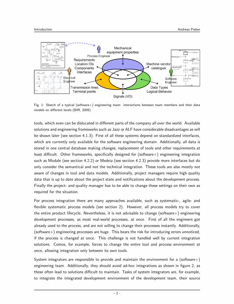
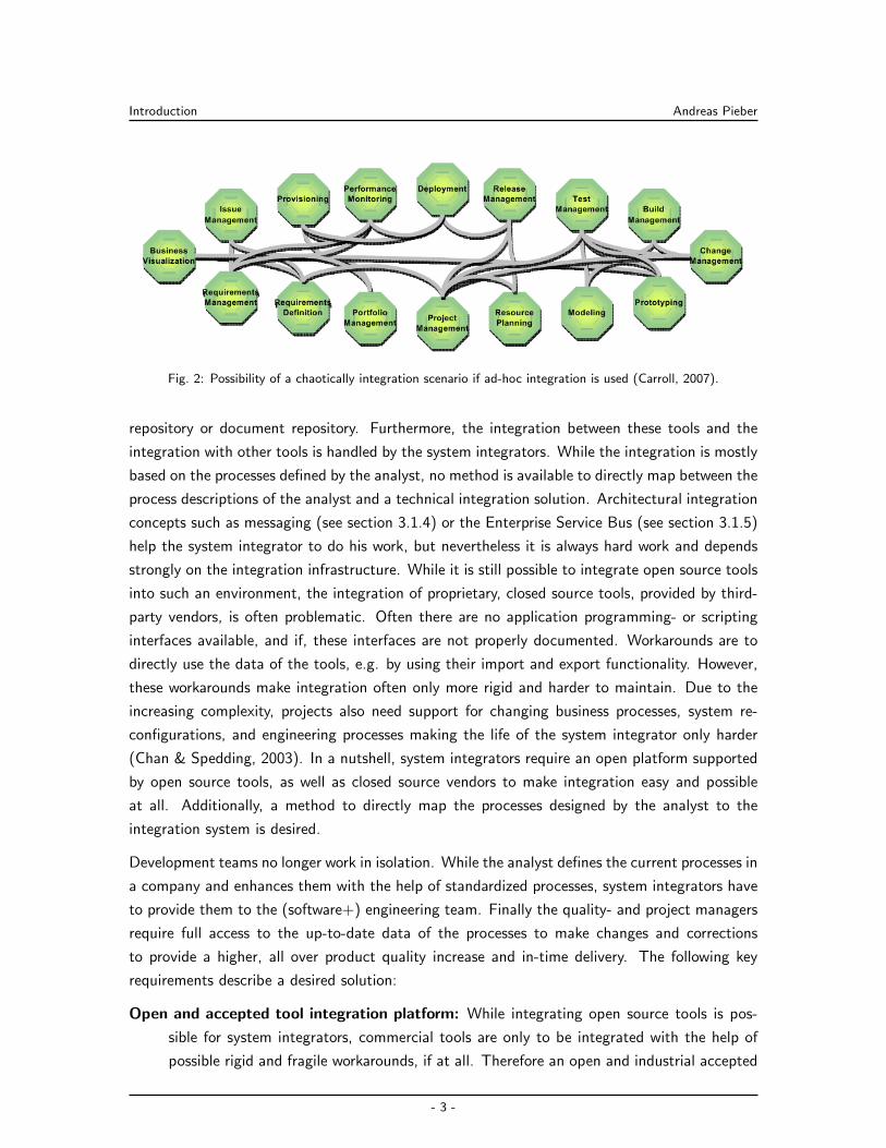
System integrators are responsible to provide and maintain the environment for a (software+)
engineering team. Additionally, they should avoid ad-hoc integrations as shown in figure 2, as
these often lead to solutions difficult to maintain. Tasks of system integrators are, for example,
to integrate the integrated development environment of the development team, their source
- 2 -
Introduction Andreas Pieber
Fig. 2: Possibility of a chaotically integration scenario if ad-hoc integration is used (Carroll, 2007).
repository or document repository. Furthermore, the integration between these tools and the
integration with other tools is handled by the system integrators. While the integration is mostly
based on the processes defined by the analyst, no method is available to directly map between the
process descriptions of the analyst and a technical integration solution. Architectural integration
concepts such as messaging (see section 3.1.4) or the Enterprise Service Bus (see section 3.1.5)
help the system integrator to do his work, but nevertheless it is always hard work and depends
strongly on the integration infrastructure. While it is still possible to integrate open source tools
into such an environment, the integration of proprietary, closed source tools, provided by third-
party vendors, is often problematic. Often there are no application programming- or scripting
interfaces available, and if, these interfaces are not properly documented. Workarounds are to
directly use the data of the tools, e.g. by using their import and export functionality. However,
these workarounds make integration often only more rigid and harder to maintain. Due to the
increasing complexity, projects also need support for changing business processes, system re-
configurations, and engineering processes making the life of the system integrator only harder
(Chan & Spedding, 2003). In a nutshell, system integrators require an open platform supported
by open source tools, as well as closed source vendors to make integration easy and possible
at all. Additionally, a method to directly map the processes designed by the analyst to the
integration system is desired.
Development teams no longer work in isolation. While the analyst defines the current processes in
a company and enhances them with the help of standardized processes, system integrators have
to provide them to the (software+) engineering team. Finally the quality- and project managers
require full access to the up-to-date data of the processes to make changes and corrections
to provide a higher, all over product quality increase and in-time delivery. The following key
requirements describe a desired solution:
Open and accepted tool integration platform: While integrating open source tools is pos-
sible for system integrators, commercial tools are only to be integrated with the help of
possible rigid and fragile workarounds, if at all. Therefore an open and industrial accepted
- 3 -
Introduction Andreas Pieber
solution is required, enabling tool vendors to integrate their tools themselves.
Easy tool and process replacement: Young startups and development teams frequently adapt
their tools and development process, till they find the best solution for them. On the other
hand, for large companies the tool landscape changes slowly. Nevertheless changes occur:
for example when a license becomes too expensive, or an internal tool is replaced by a
commercial one. Ideally, tool changes should not affect the process. On the other hand,
changes in the process should not affect tools. This requires to describe and implement
processes in a flexible and tool independent way.
Process validation: As already stated, a project- and quality manager needs up-to-date data
about the running systems and the processes in it. This requires tracing of the processes,
and collecting all relevant data to validate and evaluate the process.
Team awareness: While it is possible to integrate tools, there is currently no way to inform
members of the (software+) engineering team about changes relevant for them (particu-
larly when changes happen in tools of other domains).
Effective and efficient integration solution: While the (software+) engineering team wants
to increase their current situation, managers require to reduce the costs of the development
process. Every change to a development process costs time and money. Therefore, the
solution has to increase effectiveness and efficiency of the development process, to be
worth its introduction.
As a solution approach, the Open Engineering Service Bus (OpenEngSB) framework is developed.
The V-Modell XT is the starting point used as extensible and adaptable process model. It is used
to analyse the current processes of a company and to extract relevant use cases for the domain.
Next, a design for the OpenEngSB is created. Therefore, the required components and their
interactions are described. The OpenEngSB itself is an open source integration platform based
on an Enterprise Service Bus (ESB) concept implementation. But contrary to the ESB concept
the OpenEngSB not only provides transformers and protocol connectors but also further Core
Components. These core components are directly integrated in the bus, currently extending its
functionality with a registry-, a workflow- and a logging component. Tool Connectors connect
external tools in a protocol and platform independent approach to the OpenEngSB. Additionally,
and most importantly, the concept of Tool Domains is introduced. Tool connectors describe
the events and services of a specific class of tools in an abstract way. This helps to separate
tools and processes, thus providing more flexibility. Based on this concept it is now possible to
provide a common and reusable method to implement the processes defined by an analyst in a
tool independent way in the OpenEngSB. Additionally, it is also possible to monitor all relevant
data on the bus allowing to provide notifications for teams and project managers. Also the status
of the development process is more transparent for quality managers.
- 4 -
Introduction Andreas Pieber
To create a solution that is accepted by the industry, industrial partners were involved during
the implementation process. The model, the OpenEngSB concepts and architecture were con-
tinuously assessed and compared to their wishes and needs. Also tool vendors are included to
demonstrate the advantages of the OpenEngSB concept, particularly compared to the currently
available solutions. Additionally, because of the open source nature of the OpenEngSB imple-
mentation, the open source community has to be addressed. As the open source community
consists mostly of software engineers, an additional use case has been chosen that is relevant
for “classical” software engineering as well as for (software+) engineering. An empirical study
on the two implemented use cases will evaluate the new approach, particularly compared to
currently available “best practices”. Finally also the systems performance is analysed to show
the capabilities of the OpenEngSB concept. The two scenarios are:
Continuous Integration & Test (CI&T): CI&T is a standard practice in most software
projects. This process is easy to understand since it usually involves commonly used
software engineering tools such as: source control management systems, build tools, test
tools and deployment repositories. Nevertheless, this process is often implemented in a
rather inflexible way, allowing to follow predefined schemas. This is adequate for many
software engineering projects but usually not sufficient in an engineering environment in
which multiple teams from different engineering domains are involved.
Signal Change Management Across Tool Data Models: Large engineering companies e.g.
creating and maintaining power plants, have rather divergent requirements in their engi-
neering processes, their data models and access patterns of models of other engineering
disciplines. This use case provides a very good example for the need of a common data
model between the tools of the different experts.
In describing, designing, implementing and evaluating these two engineering use cases it is to
be shown that the OpenEngSB concept and implementation provide a straight forward method
to support analysts, project- and quality manager and the development team from the design
phase to the development of the product itself. Additionally, it will be demonstrated that the
solution provides a significantly higher flexibility than current solutions with better or only minor
reduced efficiency. The empirical evaluation outlines the independence of particular tools and
process. Notifications are provided to create team awareness for specific events. By creating
an extendible open source solution it is also more likely that other industrial partners and tool
providers will join and extend the OpenEngSB platform with their own tools.
In section 2 state-of-the-art process models are analysed, giving an overview about the relevant
frameworks for handling development processes. This section is mostly interesting for software
engineers, analysts, project- and process managers to recall the most important frameworks for
describing processes and their weaknesses.
- 5 -
Introduction Andreas Pieber
Section 3 gives a detailed description about current methods, concepts and approaches to in-
tegrate distributed environments. General integration concepts, architecture concepts for tool
integration and integration framework specifications for the Java programming language are ex-
plained. This part targets readers interested in technical challenges and solution approaches to
integrate (software+) engineering environments, such as software architects and system integra-
tors.
Additional relevant information on already existing engineering integration solutions for software
engineering, as well as for (software+) engineering, are given in section 4. This section is
especially interesting for project managers evaluating comparable solutions to the OpenEngSB
and for integrating (software+) engineering environments.
In section 5 the research issues for this work are extracted considering general (software+)
engineering integration problems. Additionally the research methods used in this work are de-
scribed. Software developers and project managers will be interesting in the current challenges
in (software+) engineering environments.
According to the engineering environment of an industrial partner, and based on the V-Modell
XT, a general method is developed for describing (software+) engineering use cases (see sec-
tion 6). Based on the described environment two integration use cases for heterogeneous systems
are extracted and described. This section might be especially interesting for analysts searching
for an approach to design (software+) engineering systems and scenarios.
The OpenEngSB architecture and concepts are described in section 7. The architecture describes
an enhanced technical integration environment, while the concept focuses on the mapping be-
tween the OpenEngSB platform and the engineering use cases, thus explaining how to implement
and validate these use cases. This section targets software engineers and architects searching
for a new approach to implement and evaluate (software+) engineering designs of analysts.
Based on the developed use cases and the OpenEngSB implementation and concept, section 8
describes the design, implementation and evaluation of the two revealed engineering use cases.
This section is especially interesting for project managers who want to evaluate the OpenEngSB
for the use in their own (software+) engineering environments. Additionally, this section should
help system integrators to use the proposed OpenEngSB method in their own environments.
The results are discussed in section 9. It is shown why, how and where the OpenEngSB platform
approach succeeds, but also outlines its limitations. Furthermore the thesis itself is discussed
in greater details trying to show missing points versus good points extracted during the work.
While the discussion on the architecture of the OpenEngSB will be most interesting for software
architects, the discussion about the process integration is more focused on analysts who plan to
use the OpenEngSB approach to describe the environments of their customers.
- 6 -
Introduction Andreas Pieber
Finally section 10 summarizes the entire thesis and gives an outlook for possible future improve-
ments. An additional semantic layer, communication and service extensions between buses and
further topics are discussed here.
- 7 -

Business Process Models for (Software+) Engineering Andreas Pieber
2 Business Process Models for (Software+) Engineering
Process models in business IT software development are used to control the lifecycle of a project
from its kickoff to its retirement (IEEE, 1998; Pfleeger, 1998). Although this chapter focuses
mostly on lifecycle and process models in business software engineering these concepts can also
be applied to automation systems (Marık et al., 2002), and therefore also for (software+) engi-
neering environments. The product lifecycle is, according to the Project Management Institute
(2004): “a sequence of steps enclose all activities, relations and resources”. Furthermore, the
use of quality enhancement arrangements are included, starting by the first idea and accompany
the lifecycle to the controlled end of the product lifetime.
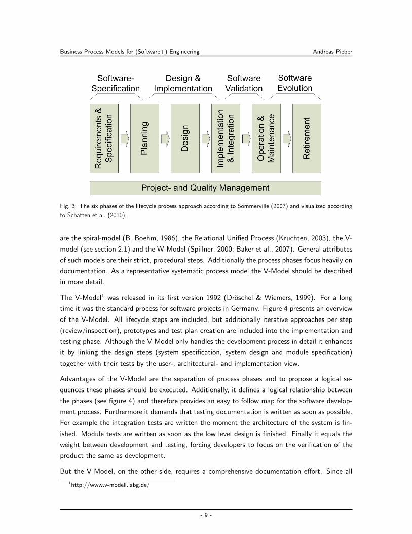
The lifecycle is the fundamental concept for business software engineering process models. Fig-
ure 3 presents the six phases of the product lifecycle according to Sommerville (2007): (1a)
Requirements handle the customer wishes regarding to the software product (user/customer
view). Requirements have to be unique, testable and unambiguous. (1b) The specification
describes the system from a technical point of view (engineering view). (2) During the planning
phase a project plan is created, in context of milestones, dates, time and costs. (3) During the
design phase technical solutions for the system requirements are developed. Component- and
package diagrams are created in this phase as well as the database design. (4) The implementa-
tion and testing phase describes the implementation, testing and assembling of the software into
a final product. (5) The operation and maintenance phase describes the time after a product had
been rolled out. Software is never finished like a traditional manufactured product, but requires
bug fixing, support and optionally extensions during its entire operational time at a customer.
(6) After the usage phase the retirement phase starts. It is the end of the product lifecycle and
describes how the product has to be turned off in a controlled manner, to avoid side-effects.
Project- and quality management companions the process during its entire lifecycle required to
deliver high quality software in time.
While these six phases of product life-cycle can be identified in all projects, their concrete
characteristics are described by concrete process models. Over time different process models for
different purposes were developed. Basically three different types of process models are actually
used to be state-of-the-art: (1) Systematic process models (see section 2.1) providing a fixed
step by step approach; (2) Agile process models (see section 2.2) describing only a most basic,
iterative approach; (3) Semi-systematic models (see section 2.3) trying to combine the best of
both other models.
2.1 Systematic Process Models: V-Model
Systematic structured process models are, for example, the waterfall-model (Royce, 1970), which
is one of the oldest (software) life-cycle process models. Newer and more iterative approaches
- 8 -
Business Process Models for (Software+) Engineering Andreas Pieber
Fig. 3: The six phases of the lifecycle process approach according to Sommerville (2007) and visualized according
to Schatten et al. (2010).
are the spiral-model (B. Boehm, 1986), the Relational Unified Process (Kruchten, 2003), the V-
model (see section 2.1) and the W-Model (Spillner, 2000; Baker et al., 2007). General attributes
of such models are their strict, procedural steps. Additionally the process phases focus heavily on
documentation. As a representative systematic process model the V-Model should be described
in more detail.
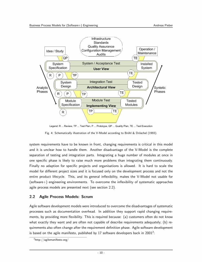
The V-Model1 was released in its first version 1992 (Droschel & Wiemers, 1999). For a long
time it was the standard process for software projects in Germany. Figure 4 presents an overview
of the V-Model. All lifecycle steps are included, but additionally iterative approaches per step
(review/inspection), prototypes and test plan creation are included into the implementation and
testing phase. Although the V-Model only handles the development process in detail it enhances
it by linking the design steps (system specification, system design and module specification)
together with their tests by the user-, architectural- and implementation view.
Advantages of the V-Model are the separation of process phases and to propose a logical se-
quences these phases should be executed. Additionally, it defines a logical relationship between
the phases (see figure 4) and therefore provides an easy to follow map for the software develop-
ment process. Furthermore it demands that testing documentation is written as soon as possible.
For example the integration tests are written the moment the architecture of the system is fin-
ished. Module tests are written as soon as the low level design is finished. Finally it equals the
weight between development and testing, forcing developers to focus on the verification of the
product the same as development.
But the V-Model, on the other side, requires a comprehensive documentation effort. Since all
1http://www.v-modell.iabg.de/
- 9 -
Business Process Models for (Software+) Engineering Andreas Pieber
Fig. 4: Schematically illustration of the V-Model according to Brohl & Droschel (1993).
system requirements have to be known in front, changing requirements is critical in this model
and it is unclear how to handle them. Another disadvantage of the V-Model is the complete
separation of testing and integration parts. Integrating a huge number of modules at once in
one specific phase is likely to raise much more problems than integrating them continuously.
Finally no adaption for specific projects and organisations is allowed. It is hard to scale the
model for different project sizes and it is focused only on the development process and not the
entire product lifecycle. This, and its general inflexibility, makes the V-Model not usable for
(software+) engineering environments. To overcome the inflexibility of systematic approaches
agile process models are presented next (see section 2.2).
2.2 Agile Process Models: Scrum
Agile software development models were introduced to overcome the disadvantages of systematic
processes such as documentation overhead. In addition they support rapid changing require-
ments, by providing more flexibility. This is required because: (a) customers often do not know
what exactly they want and are often not capable of describe requirements adequately; (b) re-
quirements also often change after the requirement definition phase. Agile software development
is based on the agile manifesto, published by 17 software developers back in 20012:
2http://agilemanifesto.org/
- 10 -
Business Process Models for (Software+) Engineering Andreas Pieber
“Individuals and interactions over processes and tools”
“Working software over comprehensive documentation”
“Customer collaboration over contract negotiation”
“Responding to change over following a plan”
This manifest covers the basic ideas for agile software development models, such as eXtreme
Programming3 (XP) and Scrum4. The base ideas behind them are tight customer interaction
and iterative software development. Through the customer cooperation a flexible requirement
management is enabled, allowing early delivery of products. Agile software development models
improve the common, mostly strictly defined software processes and still grow in their importance
(Reed et al., 2004; Hunt, 2005).
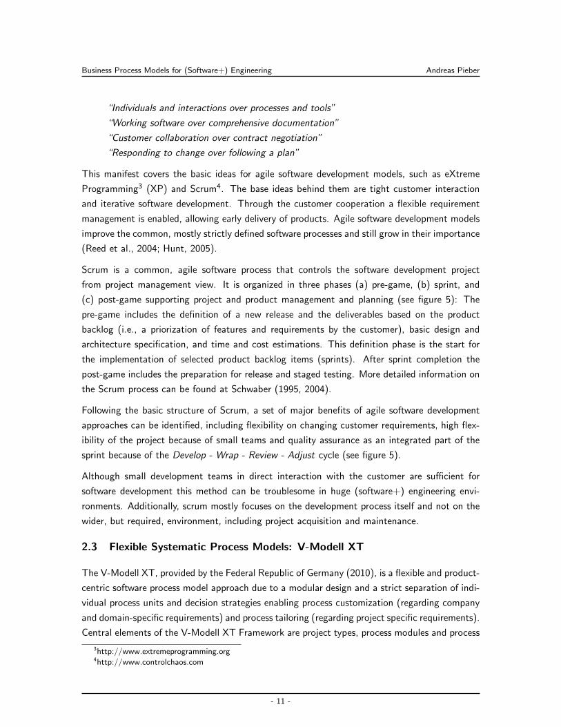
Scrum is a common, agile software process that controls the software development project
from project management view. It is organized in three phases (a) pre-game, (b) sprint, and
(c) post-game supporting project and product management and planning (see figure 5): The
pre-game includes the definition of a new release and the deliverables based on the product
backlog (i.e., a priorization of features and requirements by the customer), basic design and
architecture specification, and time and cost estimations. This definition phase is the start for
the implementation of selected product backlog items (sprints). After sprint completion the
post-game includes the preparation for release and staged testing. More detailed information on
the Scrum process can be found at Schwaber (1995, 2004).
Following the basic structure of Scrum, a set of major benefits of agile software development
approaches can be identified, including flexibility on changing customer requirements, high flex-
ibility of the project because of small teams and quality assurance as an integrated part of the
sprint because of the Develop - Wrap - Review - Adjust cycle (see figure 5).
Although small development teams in direct interaction with the customer are sufficient for
software development this method can be troublesome in huge (software+) engineering envi-
ronments. Additionally, scrum mostly focuses on the development process itself and not on the
wider, but required, environment, including project acquisition and maintenance.
2.3 Flexible Systematic Process Models: V-Modell XT
The V-Modell XT, provided by the Federal Republic of Germany (2010), is a flexible and product-
centric software process model approach due to a modular design and a strict separation of indi-
vidual process units and decision strategies enabling process customization (regarding company
and domain-specific requirements) and process tailoring (regarding project specific requirements).
Central elements of the V-Modell XT Framework are project types, process modules and process
3http://www.extremeprogramming.org4http://www.controlchaos.com
- 11 -
Business Process Models for (Software+) Engineering Andreas Pieber
Fig. 5: The three phases of scrum and the schematically illustration of a sprint according to Schwaber (2004).
The visualisation is according to Schatten et al. (2010).
execution strategies based on decision gates (comparable to milestones) (Broy & Rausch, 2005).
The selection of a project scope, for example, building software, hardware or complex systems
is the first decision for V-Modell XT application. Depending on the decision, which kind of
product should be developed within the project, the V-Modell XT applies different project types.
A project type focuses on the view on the software project, such as from customer (acquire)
perspective or from developer perspective. Strength of the V-Modell XT is the involvement of
customers and developers within a software project to enable communication between both roles.
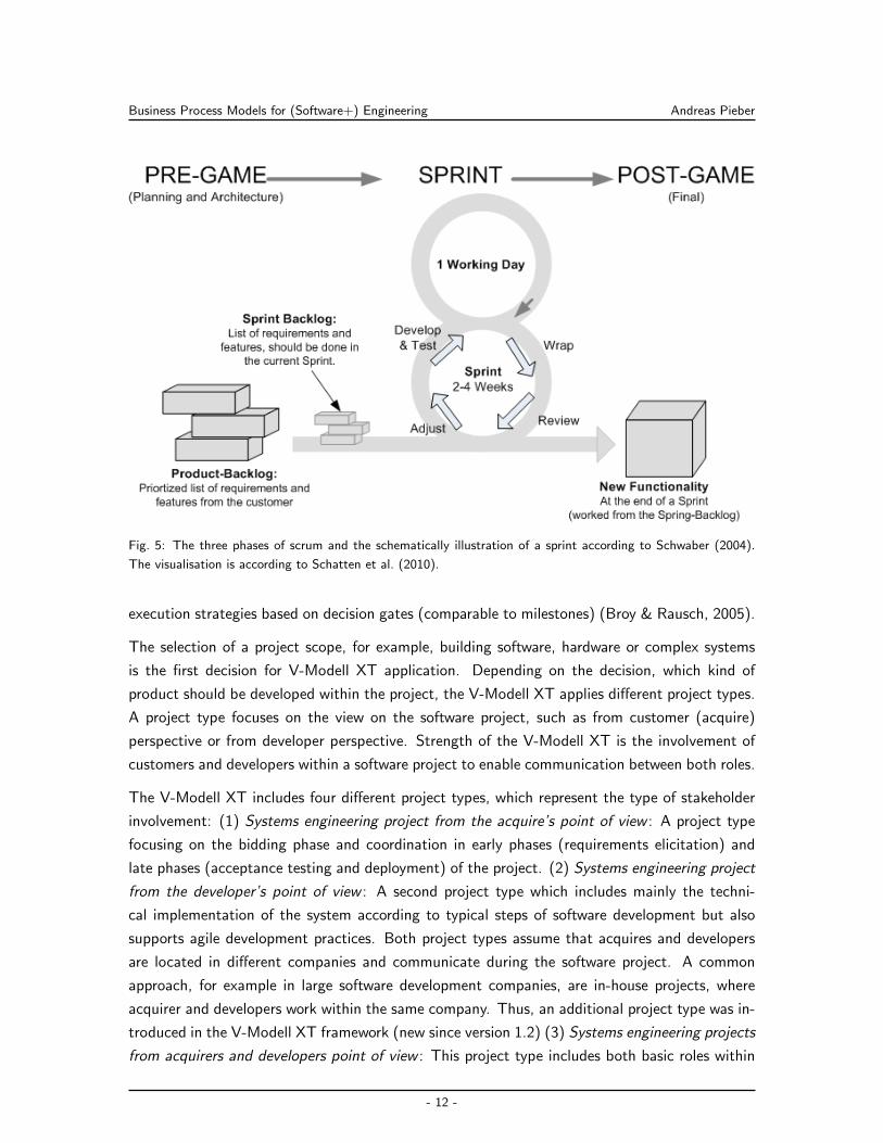
The V-Modell XT includes four different project types, which represent the type of stakeholder
involvement: (1) Systems engineering project from the acquire’s point of view : A project type
focusing on the bidding phase and coordination in early phases (requirements elicitation) and
late phases (acceptance testing and deployment) of the project. (2) Systems engineering project
from the developer’s point of view : A second project type which includes mainly the techni-
cal implementation of the system according to typical steps of software development but also
supports agile development practices. Both project types assume that acquires and developers
are located in different companies and communicate during the software project. A common
approach, for example in large software development companies, are in-house projects, where
acquirer and developers work within the same company. Thus, an additional project type was in-
troduced in the V-Modell XT framework (new since version 1.2) (3) Systems engineering projects
from acquirers and developers point of view : This project type includes both basic roles within
- 12 -
Business Process Models for (Software+) Engineering Andreas Pieber
Fig. 6: Illustrates the connection between the project type, further project characteristics and project type variant
(Federal Republic of Germany, 2010).
one company and provides a common (company related) view on the project. (4) Introduc-
tion and maintenance of a company specific software process model : Following the continuous
improvement approach, required by quality management systems, like ISO 9000, CMMI, and
SPICE, processes (e.g., software development processes) must be introduced and maintained
in a specific company setting. Thus, the V-Modell XT includes a specific project type to spot
on these requirements. Depending on the project type additional project characteristics have
to be defined, e.g. the relevant system lifecycle section for supplier and the contract structure
for acquire. Combining the project types with these additional characteristics the project type
variants as shown in figure 6.
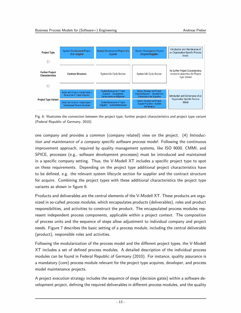
Products and deliverables are the central elements of the V-Modell XT. These products are orga-
nized in so-called process modules, which encapsulates products (deliverables), roles and product
responsibilities, and activities to construct the product. The encapsulated process modules rep-
resent independent process components, applicable within a project context. The composition
of process units and the sequence of steps allow adjustment to individual company and project
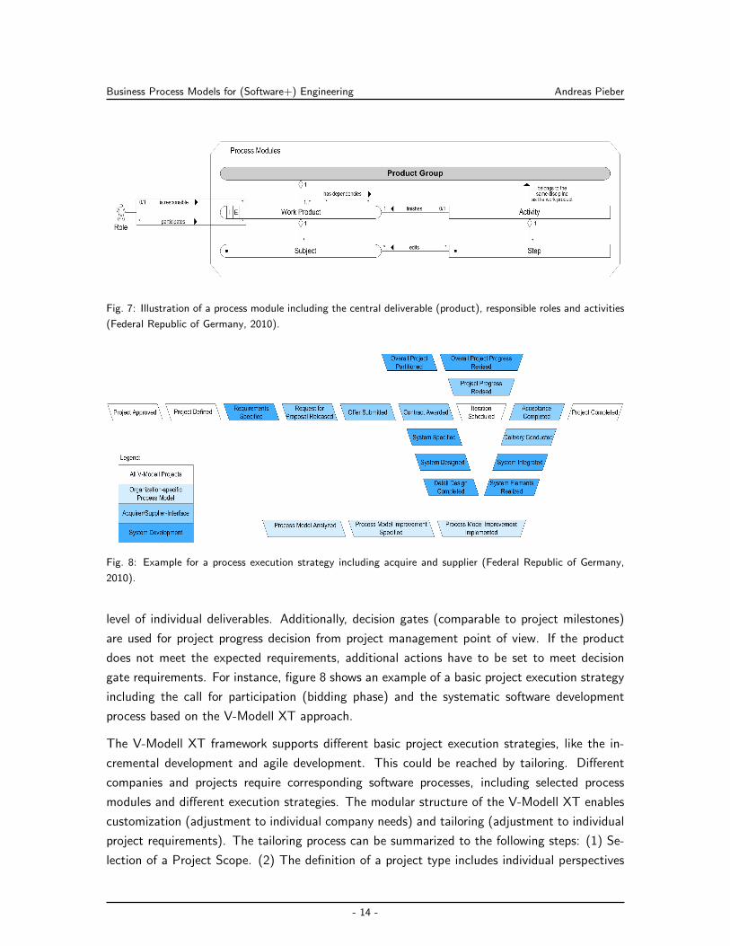
needs. Figure 7 describes the basic setting of a process module, including the central deliverable
(product), responsible roles and activities.
Following the modularization of the process model and the different project types, the V-Modell
XT includes a set of defined process modules. A detailed description of the individual process
modules can be found in Federal Republic of Germany (2010). For instance, quality assurance is
a mandatory (core) process module relevant for the project type acquires, developer, and process
model maintenance projects.
A project execution strategy includes the sequence of steps (decision gates) within a software de-
velopment project, defining the required deliverables in different process modules, and the quality
- 13 -
Business Process Models for (Software+) Engineering Andreas Pieber
Fig. 7: Illustration of a process module including the central deliverable (product), responsible roles and activities
(Federal Republic of Germany, 2010).
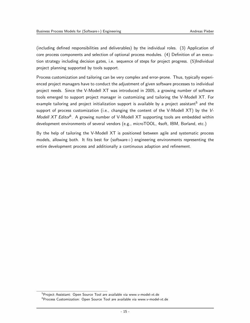
Fig. 8: Example for a process execution strategy including acquire and supplier (Federal Republic of Germany,
2010).
level of individual deliverables. Additionally, decision gates (comparable to project milestones)
are used for project progress decision from project management point of view. If the product
does not meet the expected requirements, additional actions have to be set to meet decision
gate requirements. For instance, figure 8 shows an example of a basic project execution strategy
including the call for participation (bidding phase) and the systematic software development
process based on the V-Modell XT approach.
The V-Modell XT framework supports different basic project execution strategies, like the in-
cremental development and agile development. This could be reached by tailoring. Different
companies and projects require corresponding software processes, including selected process
modules and different execution strategies. The modular structure of the V-Modell XT enables
customization (adjustment to individual company needs) and tailoring (adjustment to individual
project requirements). The tailoring process can be summarized to the following steps: (1) Se-
lection of a Project Scope. (2) The definition of a project type includes individual perspectives
- 14 -
Business Process Models for (Software+) Engineering Andreas Pieber
(including defined responsibilities and deliverables) by the individual roles. (3) Application of
core process components and selection of optional process modules. (4) Definition of an execu-
tion strategy including decision gates, i.e. sequence of steps for project progress. (5)Individual
project planning supported by tools support.
Process customization and tailoring can be very complex and error-prone. Thus, typically experi-
enced project managers have to conduct the adjustment of given software processes to individual
project needs. Since the V-Modell XT was introduced in 2005, a growing number of software
tools emerged to support project manager in customizing and tailoring the V-Modell XT. For
example tailoring and project initialization support is available by a project assistant5 and the
support of process customization (i.e., changing the content of the V-Modell XT) by the V-
Modell XT Editor6. A growing number of V-Modell XT supporting tools are embedded within
development environments of several vendors (e.g., microTOOL, 4soft, IBM, Borland, etc.)
By the help of tailoring the V-Modell XT is positioned between agile and systematic process
models, allowing both. It fits best for (software+) engineering environments representing the
entire development process and additionally a continuous adaption and refinement.
5Project Assistant: Open Source Tool are available via www.v-model-xt.de6Process Customization: Open Source Tool are available via www.v-model-xt.de
- 15 -
Tool Integration in Distributed Environments Andreas Pieber
3 Tool Integration in Distributed Environments
Nowadays, trends lead away from applications living in isolation. Distributed integration becomes
an essential part for all parts of live and business. Starting with the calendar on a mobile device to
the complex integration of different applications like customer administration and the warehouse
system. Also most complex (software+) engineering tool integration approaches depend on the
same concepts. Basically the entire concept can be summarized in the Enterprise Application
Integration (EAI) term, introduced and defined by Linthicum (2000) as:
“EAI encompasses approaches, methodologies, standards, and technologies allowing
very diverse but important systems to share information, processes, and behavior in
support of the core business.”
Typical challenges in such environments, as identified by Burg et al. (2008), are: (1) Networks
are unreliable. (2) Networks are slow. (3) Every two applications are different. (4) Change is
inevitable. To overcome these and similar challenges Trowbridge et al. (2004) and Song et al.
(2008), to name only a view, developed patterns and solutions. While section 3.1 describes and
summarizes the most common patterns in this specification, section 3.2 explains more general
architectural approaches such as service-oriented and event-driven architecture. Discovering
Java as the de-facto language for integration projects section 3.3 explains the state-of-the-art
integration concepts for this language.
3.1 Integration Concepts for Distributed Environments
Most of the integration patterns can be summarized, as by Hohpe & Woolf (2004), to the
following four patterns: File Transfer (see section 3.1.1), Shared Database (see section 3.1.2),
Remote Procedure Invocation (see section 3.1.3) and Messaging (see section 3.1.4). While the
File Transfer and the Remote Procedure Invocation work by the concept of point-to-point inte-
gration, the other patterns use a more common concept. The Messaging pattern finally results
in a huge number of middle ware frameworks available (Du et al., 2008), mostly with the Enter-
prise Service Bus (see section 3.1.5) concept, as explained by Chappell (2004). The following
chapters describe and analyse these patterns and point out their advantages and disadvantages
in a (software+) engineering context. (Barros et al., 2005)
3.1.1 File Transfer
As the universal storage mechanism, built into each operation system, the simplest approach will
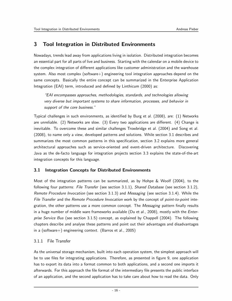
be to use files for integrating applications. Therefore, as presented in figure 9, one application
has to export its data into a format common to both applications, and a second one imports it
afterwards. For this approach the file format of the intermediary file presents the public interface
of an application, and the second application has to take care about how to read the data. Only
- 16 -
Tool Integration in Distributed Environments Andreas Pieber
Fig. 9: The File Transfer pattern sketched by Hohpe & Woolf (2004). Shows one application exporting data as
a file and shares it with another application importing the data.
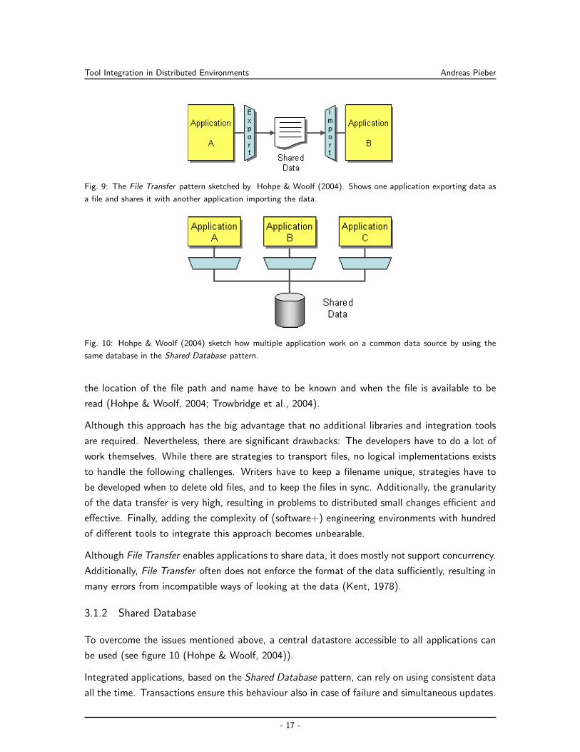
Fig. 10: Hohpe & Woolf (2004) sketch how multiple application work on a common data source by using the
same database in the Shared Database pattern.
the location of the file path and name have to be known and when the file is available to be
read (Hohpe & Woolf, 2004; Trowbridge et al., 2004).
Although this approach has the big advantage that no additional libraries and integration tools
are required. Nevertheless, there are significant drawbacks: The developers have to do a lot of
work themselves. While there are strategies to transport files, no logical implementations exists
to handle the following challenges. Writers have to keep a filename unique, strategies have to
be developed when to delete old files, and to keep the files in sync. Additionally, the granularity
of the data transfer is very high, resulting in problems to distributed small changes efficient and
effective. Finally, adding the complexity of (software+) engineering environments with hundred
of different tools to integrate this approach becomes unbearable.
Although File Transfer enables applications to share data, it does mostly not support concurrency.
Additionally, File Transfer often does not enforce the format of the data sufficiently, resulting in
many errors from incompatible ways of looking at the data (Kent, 1978).
3.1.2 Shared Database
To overcome the issues mentioned above, a central datastore accessible to all applications can
be used (see figure 10 (Hohpe & Woolf, 2004)).
Integrated applications, based on the Shared Database pattern, can rely on using consistent data
all the time. Transactions ensure this behaviour also in case of failure and simultaneous updates.
- 17 -
Tool Integration in Distributed Environments Andreas Pieber
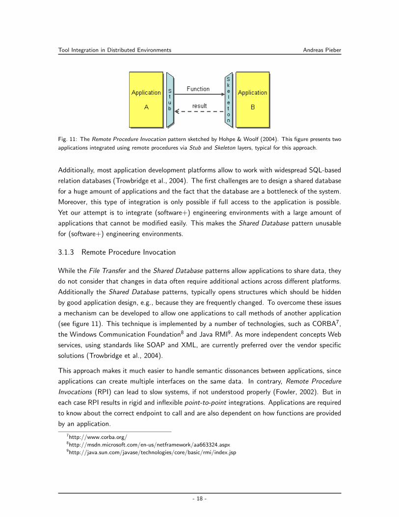
Fig. 11: The Remote Procedure Invocation pattern sketched by Hohpe & Woolf (2004). This figure presents two
applications integrated using remote procedures via Stub and Skeleton layers, typical for this approach.
Additionally, most application development platforms allow to work with widespread SQL-based
relation databases (Trowbridge et al., 2004). The first challenges are to design a shared database
for a huge amount of applications and the fact that the database are a bottleneck of the system.
Moreover, this type of integration is only possible if full access to the application is possible.
Yet our attempt is to integrate (software+) engineering environments with a large amount of
applications that cannot be modified easily. This makes the Shared Database pattern unusable
for (software+) engineering environments.
3.1.3 Remote Procedure Invocation
While the File Transfer and the Shared Database patterns allow applications to share data, they
do not consider that changes in data often require additional actions across different platforms.
Additionally the Shared Database patterns, typically opens structures which should be hidden
by good application design, e.g., because they are frequently changed. To overcome these issues
a mechanism can be developed to allow one applications to call methods of another application
(see figure 11). This technique is implemented by a number of technologies, such as CORBA7,
the Windows Communication Foundation8 and Java RMI9. As more independent concepts Web
services, using standards like SOAP and XML, are currently preferred over the vendor specific
solutions (Trowbridge et al., 2004).
This approach makes it much easier to handle semantic dissonances between applications, since
applications can create multiple interfaces on the same data. In contrary, Remote Procedure
Invocations (RPI) can lead to slow systems, if not understood properly (Fowler, 2002). But in
each case RPI results in rigid and inflexible point-to-point integrations. Applications are required
to know about the correct endpoint to call and are also dependent on how functions are provided
by an application.
7http://www.corba.org/8http://msdn.microsoft.com/en-us/netframework/aa663324.aspx9http://java.sun.com/javase/technologies/core/basic/rmi/index.jsp
- 18 -
Tool Integration in Distributed Environments Andreas Pieber
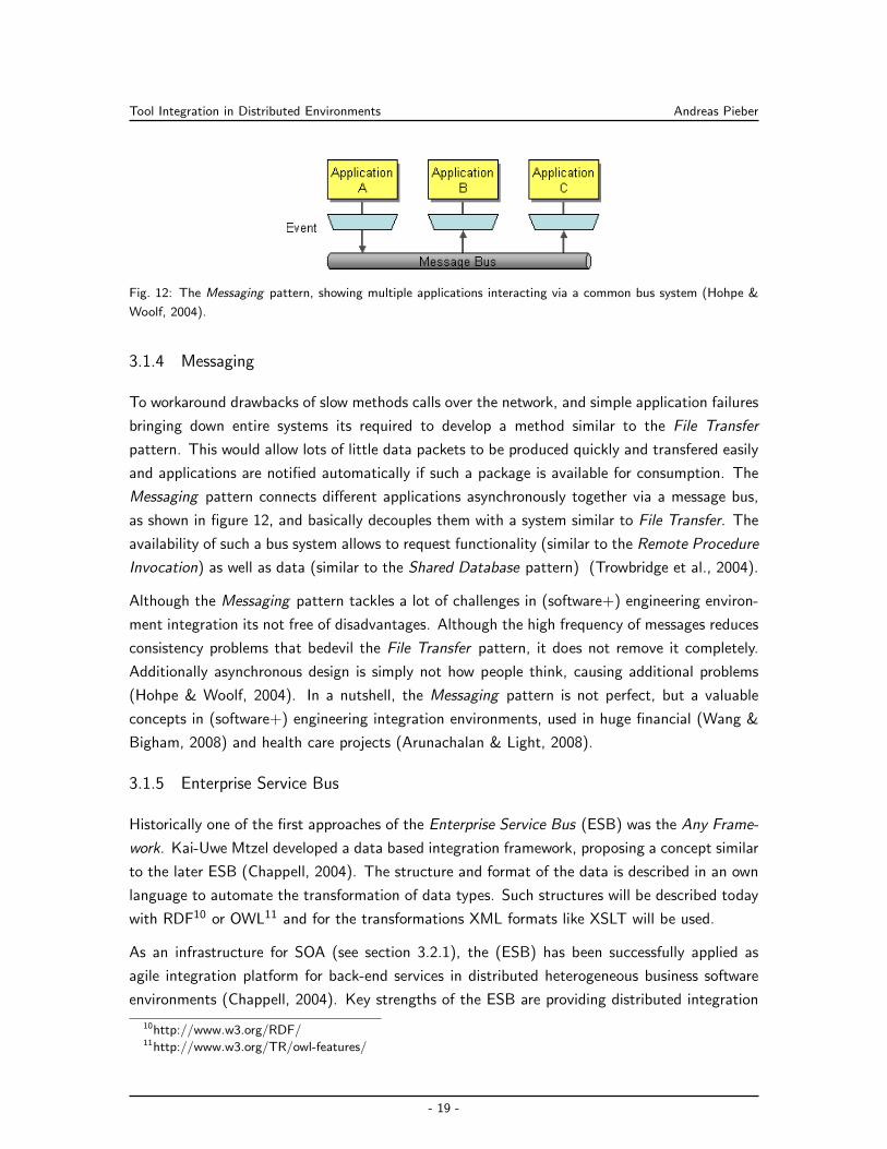
Fig. 12: The Messaging pattern, showing multiple applications interacting via a common bus system (Hohpe &
Woolf, 2004).
3.1.4 Messaging
To workaround drawbacks of slow methods calls over the network, and simple application failures
bringing down entire systems its required to develop a method similar to the File Transfer
pattern. This would allow lots of little data packets to be produced quickly and transfered easily
and applications are notified automatically if such a package is available for consumption. The
Messaging pattern connects different applications asynchronously together via a message bus,
as shown in figure 12, and basically decouples them with a system similar to File Transfer. The
availability of such a bus system allows to request functionality (similar to the Remote Procedure
Invocation) as well as data (similar to the Shared Database pattern) (Trowbridge et al., 2004).
Although the Messaging pattern tackles a lot of challenges in (software+) engineering environ-
ment integration its not free of disadvantages. Although the high frequency of messages reduces
consistency problems that bedevil the File Transfer pattern, it does not remove it completely.
Additionally asynchronous design is simply not how people think, causing additional problems
(Hohpe & Woolf, 2004). In a nutshell, the Messaging pattern is not perfect, but a valuable
concepts in (software+) engineering integration environments, used in huge financial (Wang &
Bigham, 2008) and health care projects (Arunachalan & Light, 2008).
3.1.5 Enterprise Service Bus
Historically one of the first approaches of the Enterprise Service Bus (ESB) was the Any Frame-
work. Kai-Uwe Mtzel developed a data based integration framework, proposing a concept similar
to the later ESB (Chappell, 2004). The structure and format of the data is described in an own
language to automate the transformation of data types. Such structures will be described today
with RDF10 or OWL11 and for the transformations XML formats like XSLT will be used.
As an infrastructure for SOA (see section 3.2.1), the (ESB) has been successfully applied as
agile integration platform for back-end services in distributed heterogeneous business software
environments (Chappell, 2004). Key strengths of the ESB are providing distributed integration
10http://www.w3.org/RDF/11http://www.w3.org/TR/owl-features/
- 19 -
Tool Integration in Distributed Environments Andreas Pieber
and separating the description of the business logic from the integration logic in contrast to design
patterns such as client-server architecture (Berson, 1996) or Messaging. To enable transparent
service integration, the ESB provides an infrastructure for message exchange and routing. As
part of the ESB the container model (Georgakopoulos & Papazoglou, 2008) acts as connector
between the ESB and the services. For supervising deployed services an ESB offers service
management and monitoring tools, which are the basis for evaluating assertions on the correct
function of services and for data collection on ASE processes in general such as performance
measurement.
As an extension of the Messaging pattern the ESB provides a rich integration environment
(Chappell, 2005). Nevertheless it has to be considered that the ESB is not the swiss army
knife in engineering integration (Woolf, 2007). Although the ESB can be used for almost every
integration scenario, there are also problems to be taken into consideration: Abstracting the
integration too much does not help users to integrate their environments. Although methods,
such as described by Engels et al. (2008), provide a solution approach to describe and implement
business environments with the help of ESBs the reusability of the different components is limited.
ESBs provide components which can be reused to integrate different functionality or protocols,
but only little research is done in tool and process abstraction in this part, requiring system
integrators to start again with very little for each of their projects. Anyway, by providing multiple
protocols, mostly based on the Messaging pattern, the ESB is one of the best approaches,
available at the moment, for integrating (software+) engineering teams and their heterogeneous
systems.
3.2 Architectural Integration Concepts
The technical aspects of EAI, as explained in section 3.1, only shows the perspective of the
technical integration view, but does not explain how components and technical systems have to
cooperate to provide an optimal and maintainable integration structure. In the last years two
buzz-words are always named in within this context: Service-orientated architecture (SOA) and
event-driven architecture (EDA). Additionally sometimes the term edSOA (event-driven service-
orientated architecture) is used to show that these two concepts could be combined. The state
of the art of these concepts is looked at in the next chapters and their volubility for integrating
(software+) engineering environments is assessed.
3.2.1 Service-Orientated Architecture
Service-oriented architectures (SOA) in general and web services (Alonso et al., 2004) in particu-
lar intend to support service composition and application evolution (Yin et al., 2009). In contrast
to past attempts of integration, SOA is language-independent and makes no assumption of the
underlying programming model (Alonso, 2008). Services in SOA environments in general are
- 20 -
Tool Integration in Distributed Environments Andreas Pieber
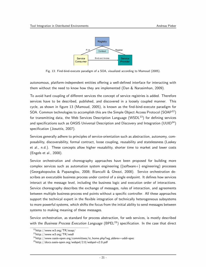
Fig. 13: Find-bind-execute paradigm of a SOA, visualized according to Mamoud (2005).
autonomous, platform-independent entities offering a well-defined interface for interacting with
them without the need to know how they are implemented (Dan & Narasimhan, 2009).
To avoid hard coupling of different services the concept of service registries is added. Therefore
services have to be described, published, and discovered in a loosely coupled manner. This
cycle, as shown in figure 13 (Mamoud, 2005), is known as the find-bind-execute paradigm for
SOA. Common technologies to accomplish this are the Simple Object Access Protocol (SOAP12)
for transmitting data, the Web Services Description Language (WSDL13) for defining services
and specifications such as OASIS Universal Description and Discovery and Integration (UUID14)
specification (Josuttis, 2007).
Services generally adhere to principles of service-orientation such as abstraction, autonomy, com-
posability, discoverability, formal contract, loose coupling, reusability and statelessness (Laskey
et al., n.d.). These concepts allow higher reusability, shorter time to market and lower costs
(Engels et al., 2008).
Service orchestration and choreography approaches have been proposed for building more
complex services such as automation system engineering ((software+) engineering) processes
(Georgakopoulos & Papazoglou, 2008; Bianculli & Ghezzi, 2008). Service orchestration de-
scribes an executable business process under control of a single endpoint. It defines how services
interact at the message level, including the business logic and execution order of interactions.
Service choreography describes the exchange of messages, rules of interaction, and agreements
between multiple business-process end points without a specific controller. All these approaches
support the technical expert in the flexible integration of technically heterogeneous subsystems
to more powerful systems, which shifts the focus from the initial ability to send messages between
systems to making meaning of these messages.
Service orchestration, as standard for process abstraction, for web services, is mostly described
with the Business Process Execution Language (BPEL15) specification. In the case that direct
12http://www.w3.org/TR/soap/13http://www.w3.org/TR/wsdl14http://www.oasis-open.org/committees/tc home.php?wg abbrev=uddi-spec15http://docs.oasis-open.org/wsbpel/2.0/wsbpel-v2.0.pdf
- 21 -
Tool Integration in Distributed Environments Andreas Pieber
human integration is required the WS-BPEL Extension for People (BPEL4People16) and Web
Services Human Task (WS-HumanTask17) specification should be used (Margolis, 2007). Nev-
ertheless the BPEL, BPEL4People and WS-HumanTask specifications are only usable for web
service integration approaches, but the architecture concepts (see section 3.2.1, as well as gen-
eral distribution integration concepts (see section 3.2) are technology and platform independent.
Therefore the more general concept of Business Process Management (BPM) is used, which is
basically a new word for orchestration, but independent from web services. Tools providing BPM
functionality are name Business Process Management Suites (BPMS) (Ko, 2009).
Although the concepts are well adapted now (Engels & Assmann, 2008), and also used within
multiple projects and disciplines (Papazoglou & Heuvel, 2007; Kirkham et al., 2008), the large
number of different standards, specifications, technologies and high requirements in analyzing
the organisation make SOA hard to understand and complex to implement. Additionally SOA
itself does not provide any concepts for business process event handling. In SOA notification
is basically implemented by defining services which directly call other services. This requires
to rewrite the service, notifying the system, for each logical change. With the help of service
orchestration the logic can be extracted from the services themselves into a meta layer, this only
moves the problem into a higher level of abstraction, because the meta layer has to be rewritten
now, each time an additional service has to be notified.
3.2.2 Event-Driven Architecture
Event-driven architecture (EDA) is an additional software architecture pattern beside SOA. Sim-
ilar to SOA EDA is a language-independent model making no assumptions about the underlying
programming model. Additionally EDA also follows the principles service-orientation, but instead
of focusing on services it focuses on events (Hohpe, 2007).
Events can be defined according to Chandy (2006) as a significant change in state. Typically,
event-driven systems consist of event emitters (agents) and event consumer (sinks) (Muhl et al.,
2006). Sinks and agents are connected via the publish-subscribe pattern (Zdun et al., 2004),
which means that sinks register for event types which are provided by agents and are transfered
by concepts like Messaging (Hohpe & Woolf, 2004; Hohpe, 2007). After receiving an event sinks
have the responsibility to react on it. This can be to execute a function, or handle it according
to one of the patterns as described by Hohpe & Woolf (2004) such as pipes and filters, message
translators or proxys.
Three styles of event processing can be distinguished: simple, stream and complex. In simple
event processing each notable event simply initiates a downstream action. This concept is used
to drive the real-time flow of work. While simple event processing only handles notable events,
16http://xml.coverpages.org/BPEL4People-V1-200706.pdf17http://docs.oasis-open.org/bpel4people/ws-humantask-1.1-spec-cd-06.pdf
- 22 -
Tool Integration in Distributed Environments Andreas Pieber
stream event processing handles notable, as well as ordinary events (orders, RFID transmissions).
While notable events are directly streamed to information subscriber, ordinary events are scanned
for notability first, to decide if they are streamed down. This method is used commonly for
driving the real-time flow of events for an enterprise. Complex event processing is finally used
to evaluate a confluence of events and then taking actions. The correlations of handled events
may be temporal, spatial or casual. The complex event processing pattern is commonly used to
detect and react to business threads, opportunities and anomalies (Michelson, 2006).
Beside event processing, a very popular model for process management in event-driven architec-
ture is the Business Rule Management (BRM). Systems providing BRM are called Business Rule
Management Systems (BRMS) (Graham, 2007). BRM is similar to simple- and stream event
processing providing a knowledge base to map incoming events according to specific rules and
take actions therefore (Halle, 2001).
EDA is important for industry by providing an loosely coupled, robust and fast EAI model (Kong
et al., 2009). But an EDA based system is designed to react on events in a asynchronous
manner (Hohpe, 2007), but not to handle direct (synchronous) service requests to endpoints.
An additional drawback with a fully event based systems is that each component has to store
all data on its own, adding the need of high storage requests.
3.2.3 Event-Driven Service-Oriented Architecture
While the SOA concept does not handle (explicitly) real time content, but rather fixed and long
running processes, the EDA pattern cares about real time content but not about fixed processes.
Therefore the idea to combine the SOA and EDA concepts was born and named event-driven
SOA (Levina & Stantchev, 2009). This new concept is sometimes also named SOA 2.0 (Krill,
2006).
By combining SOA and EDA, also the business models BPM, BRM and CEP could be wired
together. Madhava (2005) describes how the architecture for the different options can be
combined. Additionally this allows rules or complex temporal, causal or spatial events to call
events or start business processes. This tight coupling allows to describe the full business process
with all its long running transactions and short time reactions.
The event-driven SOA acts as a bridge for the interaction of business events and services per-
forming simple or complex functions or even orchestrating entire business processes. In SOA
implementations services have to know which other services are interested for an event, which
means that adding an additional services often means to change existing services to adapt the
logic. However, adding EDA to this model decouples services on this level too. Therefore, by
delivering the benefits of SOA and EDA, including modularity, loose-couplings and adaptability
event-driven SOA is ideal for distributed enterprise systems (Ghalsasi, 2009a, 2009b), as already
- 23 -
Tool Integration in Distributed Environments Andreas Pieber
proven by industry (Cameron, 2006).
3.3 Integration in Java
For implementing the discussed integration and process models a platform independent inte-
gration platform which is accepted by industry is required. As the ESB concept fulfills these
requirements, it is chosen as proper abstract and platform independent model for integrating
SOA and EDA approaches. Some of the most important ESBs for industry are GlassFish ESB18,
Tibco SOA19, Websphere ESB20, Oracle ESB21, Biztalk Server22, JBoss ESB23, Webmethods
ESB Platform24, Mule25, Tuscany26 and Apache Servicemix27. All of them, except the Microsoft
Biztalk Server, are implemented in Java. The domination of Java is due to the fact that the
ESB concept is mostly assembled of different protocols and techniques. The huge amount of
open source libraries for Java make it very easy to assemble these technologies. Additionally
Oracle ESB, Websphere ESB, Tibco SOA and Tuscany are based on the Service Component
Architecture (SCA) specification. GlassFish ESB and Apache Servicemix are based on the Java
Business Integration (JBI) specification. The others are ESBs based on proprietary models.
As an example for a popular, proprietary ESB this chapter should provide a short overview
of the Mule Enterprise Service Bus (see section 3.3.1). Also a short overview of the SCA
(see section 3.3.2) and JBI (see section 3.3.3) specifications should be provided as the two
most important specifications for Java integration, to decide how they are used in (software+)
engineering integration. A more detailed introduction about SCA and JBI is given by Pieber &
Spoerk (2008).
3.3.1 Mule Enterprise Service Bus
Mule ESB is a lightweight Enterprise Service Bus and integration framework by MuleSoft. The
framework is Java based and does not depend on any specifications or standards available for this
sector such as SCA or JBI. Services developed in Java can be deployed directly at the service
bus, whereas other protocols are attached to the bus via a wide variety of protocols such as
SOAP, REST, plain HTTP, and JMS (Rademakers & Dirksen, 2008).
The base concept of Mule ESB are inbound and outbound endpoints. Figure 14 presents this
18https://open-esb.dev.java.net/19http://www.tibco.com/20http://www-01.ibm.com/software/integration/wsesb/21http://www.oracle.com/technology/products/integration/esb/index.html22http://www.microsoft.com/germany/biztalk/default.mspx23http://jboss.org/jbossesb24http://www.softwareag.com/25http://www.mulesoft.org/display/MULE2INTRO/Home26http://tuscany.apache.org/27http://servicemix.apache.org/
- 24 -

Tool Integration in Distributed Environments Andreas Pieber
Fig. 14: Overview of integrating different components via Mule29.
concept. Services are configured with endpoints defining ingoing and outgoing message objects,
where the outgoing and ingoing protocol can differ. Technically Mule ESB centers its function-
ality around a configuration file similar to the Spring framework28. Transformers, endpoints and
transitions are defined in this file, which requires a redeployment each time a change is done
(Dossot & D’Emic, 2009).
Mule provides a stable and well supported open source framework. Nevertheless, while mule
implements many standards within connectors, the core itself does is not based on any ESB
standards or specifications, such as Java Business Integration (see section 3.3.3) or Service
Component Architecture (see section 3.3.2). It is only implemented by one tool provider and
components written for the framework are lost together with the framework. An additional
problem is that the configuration of the bus is done in mule configuration files in one place
meaning to adapt already written logic for each change. Another problem is that Mule (2.x)
does not provide hot deployment of components, i.e. it is required to restart the entire service
bus each time a new component or logic is deployed.
3.3.2 Service Component Architecture
Service Component Architecture (SCA) was first designed by a group of vendors including BEA,
IBM, Oracle, SAP and others. SCA is now owned and developed by OASIS. It provides a pro-
gramming model for building applications and solutions based on a Service Oriented Architecture
(SOA). Components of an SCA could be binded by different technologies as web services, mes-
saging systems and many others. Further more SCA allows to write different components in
different languages and techniques such as C++ or plain old Java (POJ) (Beisiegel, Blohm, et
al., 2007; Chappell, 2007).
28http://www.springsource.org/29http://www.mulesoft.org/display/MULE2INTRO/Wiring+Everything+Together
- 25 -
Tool Integration in Distributed Environments Andreas Pieber
The most basic artifact in this architecture is the composite shown in figure 15. The code
within a component could be implemented by many different technologies, including traditional
programming languages such as Java, C++ or BPEL, but also scripting languages such as PHP
or JavaScript and declarative languages such as Xquery or SQL are supported. Services are
defined by Interfaces (e.g. in Java) or via WSDL for other platforms. Also properties are set by
services.
Components can be composed in composites. Composites can be seen as components con-
taining components as seen in figure 15. References from the composite can be promoted to
many components and any number of services provided by the components could be promoted
to other composites/components. In turn, composites can be used as complete component
implementations: providing services, depending on references and with setable property values.
Such composite implementations can be used in components within other composites, allowing
a hierarchical construction of business solutions, where high-level services are implemented in-
ternally by sets of lower-level services. The content of composites can also be used to assemble
elements which are contributed by inclusion into higher-level compositions (Chappell, 2007).
The configuration defines how a component interacts with the outside world and is expressed
in the Service Component Description Language (SCDL). According to SCA assembly model
specification (Beisiegel, Blohm, et al., 2007), the current specification does not mandate the im-
plementation technologies to be supported by an SCA run-time. Therefore, vendors may choose
to support the ones that are important for them.
Composites could contain entire applications and are deployed to SCA domains. Typically these
domains represents a set of services providing an area of business functionality that is controlled
by a single organization. As an example a domain could be spread via the entire organization or
just a part of it with closed functionality as the customer service containing all administrating
services and address based functions. Although SCA does not prvide a defined way for SCA
domains provided by two different vendors to communicate with each other, communication is
yet possible via standard bindings as web services.
The record and expression of non-functional requirements is an important aspect of service
definition and has an impact on SCA throughout the lifecycle of components and composites.
SCA provides a framework to support specification of constraints, capabilities and Quality of
Service (QoS) expectations from component design through to concrete deployment (Beisiegel,
Booz, Chao, et al., 2007). It allows developers to use policies to specify their intents and let the
runtime figure out how to achive this intent.
In a nutshell SCA offers great possibility of creating SOA based applications without using
invasive techniques or let objects know about the way they are bound to other components and
services. Nevertheless, there is also the other side of the medal: The specification offers plenty
of options to implement SCA and so implementations of different vendors can be completely
- 26 -
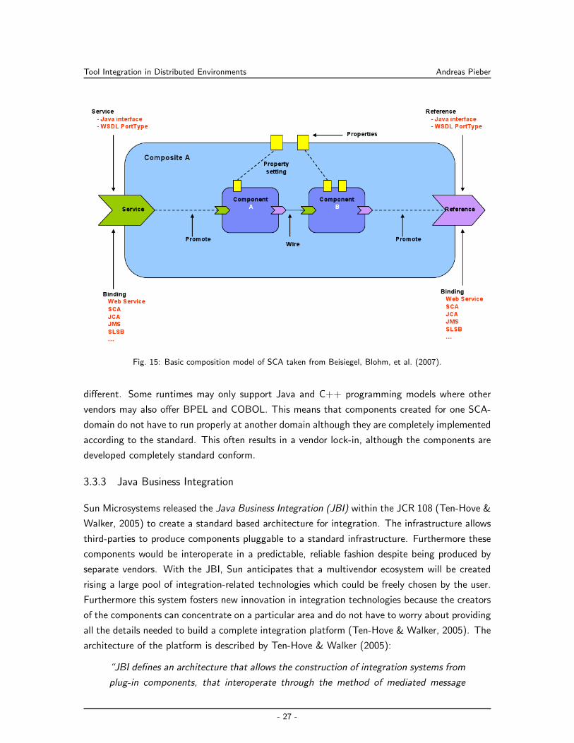
Tool Integration in Distributed Environments Andreas Pieber
Fig. 15: Basic composition model of SCA taken from Beisiegel, Blohm, et al. (2007).
different. Some runtimes may only support Java and C++ programming models where other
vendors may also offer BPEL and COBOL. This means that components created for one SCA-
domain do not have to run properly at another domain although they are completely implemented
according to the standard. This often results in a vendor lock-in, although the components are
developed completely standard conform.
3.3.3 Java Business Integration
Sun Microsystems released the Java Business Integration (JBI) within the JCR 108 (Ten-Hove &
Walker, 2005) to create a standard based architecture for integration. The infrastructure allows
third-parties to produce components pluggable to a standard infrastructure. Furthermore these
components would be interoperate in a predictable, reliable fashion despite being produced by
separate vendors. With the JBI, Sun anticipates that a multivendor ecosystem will be created
rising a large pool of integration-related technologies which could be freely chosen by the user.
Furthermore this system fosters new innovation in integration technologies because the creators
of the components can concentrate on a particular area and do not have to worry about providing
all the details needed to build a complete integration platform (Ten-Hove & Walker, 2005). The
architecture of the platform is described by Ten-Hove & Walker (2005):
“JBI defines an architecture that allows the construction of integration systems from
plug-in components, that interoperate through the method of mediated message
- 27 -
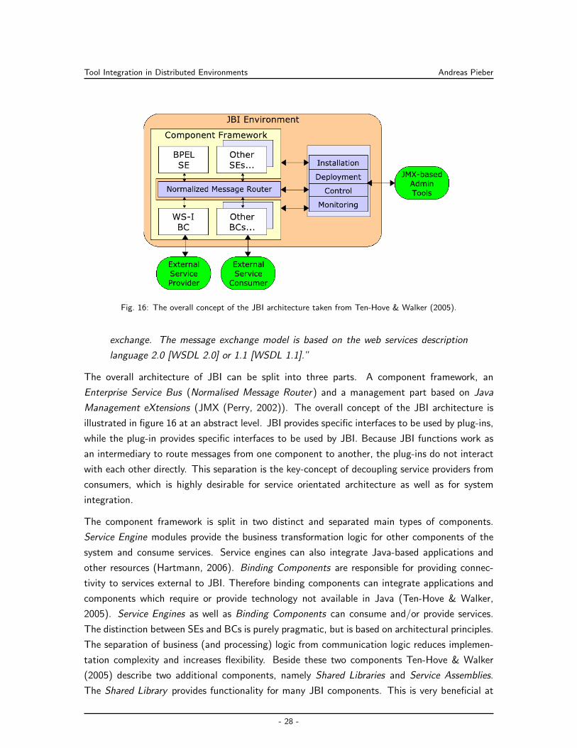
Tool Integration in Distributed Environments Andreas Pieber
Fig. 16: The overall concept of the JBI architecture taken from Ten-Hove & Walker (2005).
exchange. The message exchange model is based on the web services description
language 2.0 [WSDL 2.0] or 1.1 [WSDL 1.1].”
The overall architecture of JBI can be split into three parts. A component framework, an
Enterprise Service Bus (Normalised Message Router) and a management part based on Java
Management eXtensions (JMX (Perry, 2002)). The overall concept of the JBI architecture is
illustrated in figure 16 at an abstract level. JBI provides specific interfaces to be used by plug-ins,
while the plug-in provides specific interfaces to be used by JBI. Because JBI functions work as
an intermediary to route messages from one component to another, the plug-ins do not interact
with each other directly. This separation is the key-concept of decoupling service providers from
consumers, which is highly desirable for service orientated architecture as well as for system
integration.
The component framework is split in two distinct and separated main types of components.
Service Engine modules provide the business transformation logic for other components of the
system and consume services. Service engines can also integrate Java-based applications and
other resources (Hartmann, 2006). Binding Components are responsible for providing connec-
tivity to services external to JBI. Therefore binding components can integrate applications and
components which require or provide technology not available in Java (Ten-Hove & Walker,
2005). Service Engines as well as Binding Components can consume and/or provide services.
The distinction between SEs and BCs is purely pragmatic, but is based on architectural principles.
The separation of business (and processing) logic from communication logic reduces implemen-
tation complexity and increases flexibility. Beside these two components Ten-Hove & Walker
(2005) describe two additional components, namely Shared Libraries and Service Assemblies.
The Shared Library provides functionality for many JBI components. This is very beneficial at
- 28 -
Tool Integration in Distributed Environments Andreas Pieber
very huge components which need the same libraries for many Binding Components or Service
Engines. The Service Assembly is the aggregation of more than one Service Engine, Binding
Component or Shared Library. The packaging is not required, but often simplifies packaging a
lot (Hartmann, 2006).
The Normalized Message Router (NMR) or Enterprise Service Bus receives messages from the
JBI components and routes them to the appropriate components. This model allows the NMR
to perform additional processing during the lifetime of the message exchange. All messages of
the NMR are based on the WSDL concepts which defines how services are modeled. The WSDL
contains all information of how JBI components have to interact. It abstracts the service model
based on operations which are defined as message exchange patterns, namely One-Way (In-
Only), Reliable One-Way (Robust In-Only), Request-Response (In-Out) and Request Optional-
Response (In-Optional Out). A collection of related functions is called an interface. A service
implements such an interface. Furthermore a service has one or more endpoints which provide
access to the service over a specific binding (protocol). All these concepts are provided to allow
components acting as service producers and consumers to interoperate with one another in a
predictable fashion whereas all of the coupling done between them is described in WSDL (Ten-
Hove & Walker, 2005). Every external message protocol has to be normalized (by the binding
components) before it can be sent to another component. Each message is constructed out of
the following components:
• Payload: a XML document that conforms to an abstract WSDL message type, without
any protocol encoding or formatting.
• Message properties (Metadata): holding the extra data associated with the message,
gained during the processing of the message. Such properties can include security infor-
mation, transaction context information, and component-specific information.
• Message attachments: Certain parts of the payload which are swapped as attachments,
referenced by the payload, and contained within a data handler that is used to manipulate
the contents of the attachment itself. Such attachments can be non-XML data. The
normalized message provides interoperability between components, using abstract WSDL
message type definitions.
A JBI implementation offers the possibility to administrate its components. The specification
for the JMX component interfaces exists to manage these needs. With its help an UI can
be presented to the administrator which strongly reducing the complexity for administrating the
components. In a nutshell, the tasks of the Management Component can be summarized as: (1)
Installation of engines and bindings (components). (2) Life cycle management of components
(start/stop controls). (3) Deployment of component artifacts to engines and bindings that
support dynamic additions to their internal execution environments. (4) Monitoring and control.
- 29 -
Tool Integration in Distributed Environments Andreas Pieber
As JBI is an open standard there are a lot of implementations available. The following list
contains some of the best known and most commonly used Enterprise Service Bus systems,
namely the open source implementations Open ESB30, Apache ServiceMix31 and the commercial
Fuse ESB32.
Problems with JBI are that the core components can only be written in Java which reduces its
usability for Service Orientated Architecture (SOA) a little bit. Nevertheless JBI comes with
two considerable advantages: First of all it is designed to work asynchronously and perfectly fits
the typical architecture requirements for a SOA for EAI, respectively. On the other hand it is
defined as an open standard. This allows implementers to develop their components for every
JBI ESB the same way and not to have to lock into any vendor specific technology. Furthermore,
JBI defines a complete component and management system allowing implementors to rely on a
stable and opened definition (Vinoski, 2005). Therefore JBI seems to be a good foundation for
a (software+) engineering environment integration solution.
30https://open-esb.dev.java.net31http://servicemix.apache.org32http://open.iona.com/products/fuse-esb/
- 30 -
Integration in Engineering Environments Andreas Pieber
4 Integration in Engineering Environments
Partly based on the integration technologies described in section 3 and partly independently some
integration technologies became de-facto standard in software engineering (see section 4.1).
There are some projects specifically designed for (software+) engineering (see section 4.2).
Yet none of those received wide spread acceptance in industry. There the situation is more
fragmented in proprietary solutions. This section describes the state-of-the-art approaches and
points out their advantages and disadvantages for (software+) engineering teams.
4.1 Software Engineering Environments
Software engineering has a long tradition in integrating its own tools required for developing
software because building and testing software is a complex task integrating heterogeneous tools.
Therefore a lot of different approaches were developed over time. Actually, it seams that three
approaches were able to become de-facto standards for integration in software engineering: (a)
Script based integration approaches (see section 4.1.1), (b) integrated development environment
based integration approach (see section 4.1.2) and (c) application lifecycle management based
integration approaches (see section 4.1.3).
4.1.1 Script Based Integration Approaches
First script based approaches such as GNU Make33 only describe the build process of a soft-
ware. Because current projects become more complex and also require the integration of test-
, deployment-, announcement- and documentation-tasks more sufficient models are required
(Spinellis, 2008). There is a wide range of such tools available such as Rake34, BuildR35,
NAnt36 and Maven 237. As one of the first complete and most successful script based ap-
proaches, Maven 2 should be explained as a representative for this category (Sonatype, 2008).
In Maven 2 everything is described in a Project Object Model (POM) XML file, containing
information about the used Source Code Management (SCM) system, issue tracker, build server,
deployment location and many more. Maven 2 can be used then to fulfil the full build process
with build, test, assemble, deploy and additional features such as change and announcement
management38 (Massol & O’Brien, 2005). As a project centered approach Maven 2 is very
successful, as also described by Andersen & Amdor (2009). It is completely extendible by plug-
ins and integrates tools such as issue tracker, SCM and Email.
33http://www.gnu.org/software/make/34http://rake.rubyforge.org/35http://buildr.apache.org/36http://nant.sourceforge.net/37http://maven.apache.org/38http://maven.apache.org/plugins/maven-changes-plugin/index.html
- 31 -
Integration in Engineering Environments Andreas Pieber
Although Maven 2 is one of the most used build systems for software development in the Java
world, its reusability for other disciplines, such as (software+) engineering, is rather limited
because of two reasons: First of all the Maven 2 workflow is hard coded into its core. It can
be extended by attending plug-ins to the different lifecycle goals, but it cannot be changed
completely and adapted for other uses. The second limitation is not a Maven 2 problem in
specific, but rather generally a user-centered one. Besides that the user has to run the system in
case of changes it is also quite impossible to integrate other tools on other platforms within the
process. While so-called continuous integration platforms, such as Hudson39, provide solutions
to centralize the build process of the project, they still reimplement the static livecycle approach
for these build scripts. Therefore the script based approach is hardly capable to handle complex,
mostly event based, (software+) engineering integration.
4.1.2 Integrated Development Environment Based Integration Approaches
Another approach of tool integration is to focus anything around the developer within its Inte-
grated Development Environment (IDE), such as described by Cheng et al. (2004). Most IDEs,
such as Eclipse40, Microsoft Visual Studio41 and KDevelop42 provide integration modules. As
an example for Eclipse extensions, Mylyn43 provides a complete, task centered integration of
issues retrieved from a wide range of different issue trackers. As another example the Eclipse
team integration abstraction layer allows to use different SCM systems directly from the IDE.
These two examples only scratch the surface of what else is possible and already implemented.
On one hand the IDE based integration approach has many advantages. One is to bring the entire
environment (context aware) to the developer. Furthermore this approach is also sufficient for
(software+) engineering. On the other hand, there are also problems with direct tool integration.
Similar to software engineering, (software+) engineers work with a wide range of different tools.
As a result the logic and processes have to be implemented over and over again. Another
limitation of the IDE based integration approach is the missing automation of complex processes
spanning over multiple, different IDEs. Finally, user can reconfigure their IDEs locally for settings
such as Code Quality Checks. These local setups are hard to replicate across multiple instances
of the same IDE and even harder between multiple instances of different IDEs. Therefore the
IDE integration approach is a valuable addition to other, lesser user centered approaches, such
as the Messaging or ESB concept, but not a replacement for them.
39https://hudson.dev.java.net/40http://www.eclipse.org/41http://msdn.microsoft.com/en-us/vstudio/default.aspx42http://www.kdevelop.org/43http://www.eclipse.org/mylyn/
- 32 -
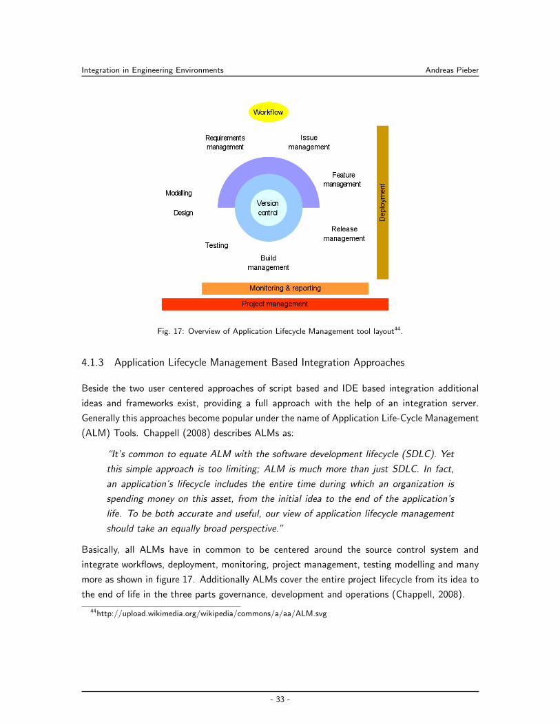
Integration in Engineering Environments Andreas Pieber
Fig. 17: Overview of Application Lifecycle Management tool layout44.
4.1.3 Application Lifecycle Management Based Integration Approaches
Beside the two user centered approaches of script based and IDE based integration additional
ideas and frameworks exist, providing a full approach with the help of an integration server.
Generally this approaches become popular under the name of Application Life-Cycle Management
(ALM) Tools. Chappell (2008) describes ALMs as:
“It’s common to equate ALM with the software development lifecycle (SDLC). Yet
this simple approach is too limiting; ALM is much more than just SDLC. In fact,
an application’s lifecycle includes the entire time during which an organization is
spending money on this asset, from the initial idea to the end of the application’s
life. To be both accurate and useful, our view of application lifecycle management
should take an equally broad perspective.”
Basically, all ALMs have in common to be centered around the source control system and
integrate workflows, deployment, monitoring, project management, testing modelling and many
more as shown in figure 17. Additionally ALMs cover the entire project lifecycle from its idea to
the end of life in the three parts governance, development and operations (Chappell, 2008).
44http://upload.wikimedia.org/wikipedia/commons/a/aa/ALM.svg
- 33 -
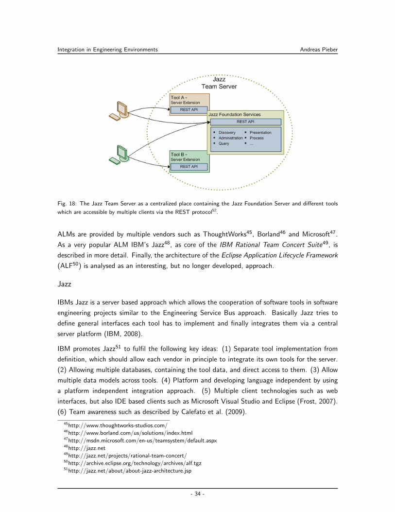
Integration in Engineering Environments Andreas Pieber
Fig. 18: The Jazz Team Server as a centralized place containing the Jazz Foundation Server and different tools
which are accessible by multiple clients via the REST protocol52.
ALMs are provided by multiple vendors such as ThoughtWorks45, Borland46 and Microsoft47.
As a very popular ALM IBM’s Jazz48, as core of the IBM Rational Team Concert Suite49, is
described in more detail. Finally, the architecture of the Eclipse Application Lifecycle Framework
(ALF50) is analysed as an interesting, but no longer developed, approach.
Jazz
IBMs Jazz is a server based approach which allows the cooperation of software tools in software
engineering projects similar to the Engineering Service Bus approach. Basically Jazz tries to
define general interfaces each tool has to implement and finally integrates them via a central
server platform (IBM, 2008).
IBM promotes Jazz51 to fulfil the following key ideas: (1) Separate tool implementation from
definition, which should allow each vendor in principle to integrate its own tools for the server.
(2) Allowing multiple databases, containing the tool data, and direct access to them. (3) Allow
multiple data models across tools. (4) Platform and developing language independent by using
a platform independent integration approach. (5) Multiple client technologies such as web
interfaces, but also IDE based clients such as Microsoft Visual Studio and Eclipse (Frost, 2007).
(6) Team awareness such as described by Calefato et al. (2009).
45http://www.thoughtworks-studios.com/46http://www.borland.com/us/solutions/index.html47http://msdn.microsoft.com/en-us/teamsystem/default.aspx48http://jazz.net49http://jazz.net/projects/rational-team-concert/50http://archive.eclipse.org/technology/archives/alf.tgz51http://jazz.net/about/about-jazz-architecture.jsp
- 34 -
Integration in Engineering Environments Andreas Pieber
IBMs Jazz Architecture is based on the Open Services for Lifecycle Collaboration53 (OSLC)
approach. The OSLC is an open platform (controlled by IBM) for defining interfaces based
on the REST concept (Representational State Transfer (Richardson & Ruby, 2007)). These
interfaces have to be provided by all tools via REST, as shown in figure 18. Clients can access
the tools directly via this REST interfaces or via the Jazz Foundation Server used as a centralized
registry, process-, query- and presentation manager.
Although IBM promotes to allow integration for IBM tools as well as for non-IBM tools, all
examples are focused on the IBM Rational suite. Because IBM wants to sell and integrate its
own products along with Jazz they are not interested in supporting other vendors and other
vendors are apparently not very motivated to support Jazz. (Software+) engineering is mostly
a closed source domain with only a minor part of open source tools. Therefore a Jazz based
approach would probably not make much sense for this domain. Additionally (although the
interfaces are opened and easy to extend) the server itself is closed. Because of its proprietary
approach, IBM makes it impossible for third parties to extend or adapt the server itself. Finally
the Jazz server is a commercial product which means an additional burden and vendor lock-in.
Particularly such a lock in should be avoided in integration efforts of (software+) engineering
environments.
Eclipse Application Lifecycle Framework
Although the Eclipse Application Lifecycle Framework (ALF) is no longer supported by the
Eclipse Foundation (Manchester, 2008), the entire material is still available as an archive file54.
Buss & Caroll (2005) and Carroll (2006) describe that ALF handles the integration challenge by
introducing a central negotiator that manages interactions between applications. This service-
oriented event manager provides uncoupling functionality, typical for event-driven architecture.
By using an intermediate communication format the event manager prevents to integrate appli-
cations several times with several other applications. It allows a single integration on the central
node, which carries out communication with other ALM applications through orchestration of
their corresponding web services. Basically ALF consists out of three main components: An ALF
Event Manager, an ALF Service Flow Engine and Event and Service Vocabularies.
An ALF Event is a web service message sent from a tool to the ALF Event Manager. While
the fundamental ALF Event is fairly generic it can be extended to encapsulate a richer event
vocabulary. Via the Event Type concept ALF allows the definition of Event Vocabularies. Event
Vocabularies allow multiple vendor tools to emit the same rich event type thus making the
operation potentially independent of the particular tool. ALF event management is based upon
52https://jazz.net/projects/content/project/plans/jia-overview/jts-1.png53http://open-services.net/54http://archive.eclipse.org/technology/archives/alf.tgz
- 35 -
Integration in Engineering Environments Andreas Pieber
a configurable dispatcher.
Tools emitting ALF events register themselves and their events with the Event Manager. An
administrator configures which ALF Service Flows will run as a result of that event. At runtime,
the Event Manager receives the event and invokes the appropriate ALF Service Flow passing it
the Event data.
A tool participating in the ALF framework needs to expose a large-grained set of web services
to query and return information or take actions. ALF provides a common service standard for
the conversations between tools. ALF specifies the overall style, organization, and constraints.
This defines the ALF base Service Vocabulary, which can be extended to define richer subject
matter specific common services. This Service Vocabulary, for example, defines the common
concepts of commits for an SCM tool only knowing the author (for centralized SCMs) and can
be extended by a commiter (for distributed SCMs).
Tools have to register their web services with the ALF framework. These services can be or-
chestrated using ALF Service Flows. ALF uses a BPEL based Engine to do this, which requires
ALF Service Flows to be defined using BPEL, an XML based programming language specifi-
cally designed to describe interactions between Web Services and facilitate the mapping of data
between them.
An example for this architecture is presented in figure 19. A user can enter an issue, by using
an Eclipse-plug-in for an issue tracking system (e.g. Mylyn). Saving the issue triggers an event
which launches an ALF Service Flow to evaluate the issue and determine if it should be added
as a new requirement or handled as a task in current projects.
ALF is interesting, because its concept is based on a vendor independent architecture allowing
to integrate different ALM tools. Since the concept can be extended for all kind of tools it is
especially interesting for (software+) engineering use cases.
4.2 (Software+) Engineering Environments
Software engineering environment integration frameworks concentrate on the integration of the
lifecycle in software development. Despite being a mature industry, automation engineering,
such as for automobiles, spacecrafts, power plants and steel-mills—due to the multitude of in-
volved disciplines also called (software+) engineering—simply ignores the trend of integrating
the development environments and data models of their engineering teams. Nevertheless it
works today, because of a large, manual effort of the engineers integrating their work. However,
increasing requirements regarding security, quality and in-time delivery for such industries the
need arise to tighten the integration of different domain experts and their knowledge. Therefore,
a lot of research- and industrial projects appear on screen. First of all some of the common
frameworks named in this area should be discussed briefly before the four most important frame-
- 36 -
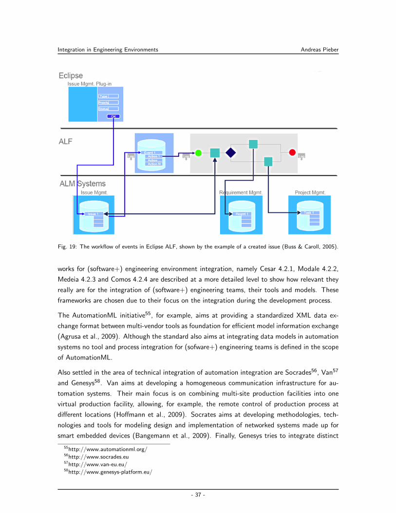
Integration in Engineering Environments Andreas Pieber
Fig. 19: The workflow of events in Eclipse ALF, shown by the example of a created issue (Buss & Caroll, 2005).
works for (software+) engineering environment integration, namely Cesar 4.2.1, Modale 4.2.2,
Medeia 4.2.3 and Comos 4.2.4 are described at a more detailed level to show how relevant they
really are for the integration of (software+) engineering teams, their tools and models. These
frameworks are chosen due to their focus on the integration during the development process.
The AutomationML initiative55, for example, aims at providing a standardized XML data ex-
change format between multi-vendor tools as foundation for efficient model information exchange
(Agrusa et al., 2009). Although the standard also aims at integrating data models in automation
systems no tool and process integration for (sofware+) engineering teams is defined in the scope
of AutomationML.
Also settled in the area of technical integration of automation integration are Socrades56, Van57
and Genesys58. Van aims at developing a homogeneous communication infrastructure for au-
tomation systems. Their main focus is on combining multi-site production facilities into one
virtual production facility, allowing, for example, the remote control of production process at
different locations (Hoffmann et al., 2009). Socrates aims at developing methodologies, tech-
nologies and tools for modeling design and implementation of networked systems made up for
smart embedded devices (Bangemann et al., 2009). Finally, Genesys tries to integrate distinct
55http://www.automationml.org/56http://www.socrades.eu57http://www.van-eu.eu/58http://www.genesys-platform.eu/
- 37 -
Integration in Engineering Environments Andreas Pieber
application domains, such as multimedia systems and automobiles, since cross-domain technolo-
gies of the Internet are being interfaced to many embedded control systems. According to the
project, there is an increasing need to link embedded subsystems from different domains, and
thus provide interoperability between the different embedded systems. The Genesys project of-
fers an architecture style to deliver a cross-domain embedded system architecture that supports
the cross-sectoral reusability of embedded system components by integrating three different in-
tegration levels: the chip-level, the device-level, and the system-level (Obermaisser et al., 2009a,
2009b; Obermaisser & Kopetz, 2009). While all three of the projects facilitate communica-
tion between embedded devices and environments, none of them aims at supporting design and
development processes of such distributed, software-intensive, embedded systems.
Boderc59 explores model-based engineering (Miller & Mukerji, 2003) as a methodology for the
design and analysis of high-tech systems. Its aim is to use multi-disciplinary models during early
product development in order to reduce product creation time (Verhoef, 2009). Nevertheless
the method only focus on the methods and models and not on the tool and process integration
required for (software+) engineering environment teams.
4.2.1 Cesar
Cesar60 is a project funded by 56 industrial partners and the European Union. The project
tries to improve system engineering disciplines by focusing on (a) requirement engineering and
(b) introducing component based engineering. This should be achieved by introducing a multi-
viewpoint based development process which should assure that (software+) engineering teams
do not only focus on functional aspects but also on other quality attributes such as costs,
robustness, timeliness and safety. By this it should be made possible to enable multi-level
design which integrates all relevant parts into the design process. Additionally, this process
should reduce the error rate closely to zero. According to the Cesar management (Affenzeller,
2009), the framework tries to become a de-factor standard as a reference technology platform
for (software+) engineering for aerospace, automotive, automation and railway.
Although Cesar targets (software+) engineering, the project does not aim at engineering teams
developing automation systems. Cesar tries to provide a complete framework integrating a
multi-view, quality assuring process for (software+) engineering but does not specify how the
process has to be executed or used by the team. They neither focus on technical nor semantical
integration itself, but rather describe and survey the problems on a higher level (Dale & Anderson,
2010). Although it is important to describe and identify the challenges and provide frameworks
and solutions how to tackle them it will not help as long no technical support for the process
exists.
59http://www.esi.nl/frames.html?/projects/boderc/home.asp60http://www.cesarproject.eu/
- 38 -
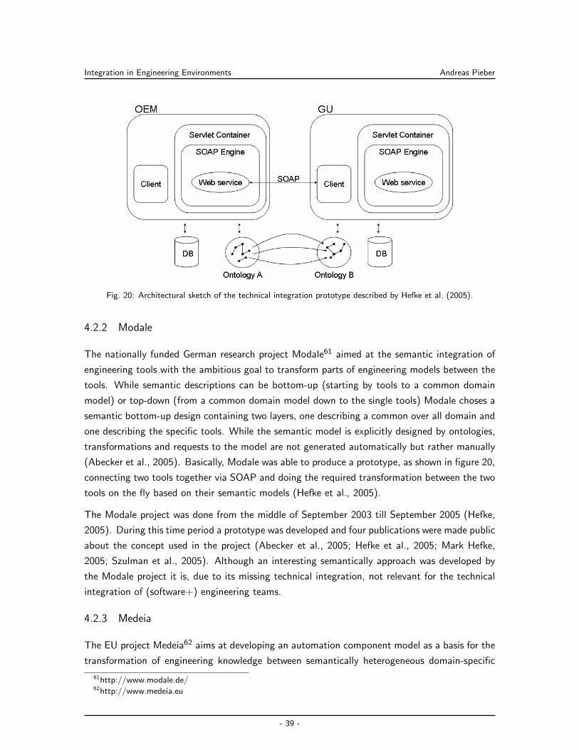
Integration in Engineering Environments Andreas Pieber
Fig. 20: Architectural sketch of the technical integration prototype described by Hefke et al. (2005).
4.2.2 Modale
The nationally funded German research project Modale61 aimed at the semantic integration of
engineering tools with the ambitious goal to transform parts of engineering models between the
tools. While semantic descriptions can be bottom-up (starting by tools to a common domain
model) or top-down (from a common domain model down to the single tools) Modale choses a
semantic bottom-up design containing two layers, one describing a common over all domain and
one describing the specific tools. While the semantic model is explicitly designed by ontologies,
transformations and requests to the model are not generated automatically but rather manually
(Abecker et al., 2005). Basically, Modale was able to produce a prototype, as shown in figure 20,
connecting two tools together via SOAP and doing the required transformation between the two
tools on the fly based on their semantic models (Hefke et al., 2005).
The Modale project was done from the middle of September 2003 till September 2005 (Hefke,
2005). During this time period a prototype was developed and four publications were made public
about the concept used in the project (Abecker et al., 2005; Hefke et al., 2005; Mark Hefke,
2005; Szulman et al., 2005). Although an interesting semantically approach was developed by
the Modale project it is, due to its missing technical integration, not relevant for the technical
integration of (software+) engineering teams.
4.2.3 Medeia
The EU project Medeia62 aims at developing an automation component model as a basis for the
transformation of engineering knowledge between semantically heterogeneous domain-specific
61http://www.modale.de/62http://www.medeia.eu
- 39 -
Integration in Engineering Environments Andreas Pieber
views, similar to Modale 4.2.2 but with focus on automation components. Medeia also explicitly
design their model, but instead of using ontologies UML-based meta models are used. The
Medeia project uses a top-down design approach for their model (from the so called automation
component to local views). They also use a layered model consisting of their meta model as
first, and a local view model as second layer. While transformations are used similar to Modale
and have to be created manually, requests to the local views can be created automatically based
on the model (Strasser et al., 2008).
It is possible to learn from the experiences of Medeia by identifying which challenges arise from
typical domain-specific views, and identify candidates for common domain concepts between
the engineering disciplines. Nevertheless, Medeia only provides a semantic integration solution
for different engineering models, doing no research in the technical integration of (software+)
engineering development systems.
4.2.4 Comos
Comos63 is an integrated engineering platform for designing and developing complex systems,
such as automation systems. It enables a comprehensive view on the engineering process, includ-
ing development phases and maintenance. Solutions for P&ID and function blocks (and others)
are integrated as in a modular systems design. Import and export functions via file-transfer
(XML structure) enable data exchange with other tools. Comos is based on a central database
including all projects. Features, advantages and limitations of Comos are:
The Comos structure enables a comprehensive view on the systems engineering project be-
cause of an integrated all-in-one solution. Important tools are integrated within the Comos
solution. Nevertheless, there is a lack in integrating tools from different vendors. Comos
uses file exchange on XML basis for interaction and data exchange between tools.
Homogeneous data of all projects are stored on a central customer specific data base.
Changes affecting the data base cannot be realized easily. Heterogeneous data, derived
from different tool vendors, require individual connectors to enable data exchange between
tools.
Change Management. Comos uses different working layers to handle changes by various en-
gineers in different disciplines. Changes can be accepted or rejected. A common problem
from field application focuses on the splitting of layers. For instance, a change request
requires the exchange of 5 valves (modeled on one layer). Three valves are available, two
are not. Thus, the change layer has to be split into a first change (3 valves modified) and
the second change (change of the remaining 2 valves) later in the project. Comos is not
able to handle this issue.
63http://www.comos.com/
- 40 -
Integration in Engineering Environments Andreas Pieber
Quality Assurance (QA). Basic checks for consistency using defined scripts and queries enable
basic quality assurance tasks. Comos do not offer any comprehensive view on QA, e.g.,
there are no additional QA activities, e.g., an end-to-end test, (nor in version 9 nor planned
in the future).
Strong interaction with Siemens Automation Designer. The Siemens Automation De-
signer is fully integrated into the Comos product. This results in a good showcase to
illustrate change management. Changes in Automation designer lead to changes in func-
tion block design and vice versa.
Cross-references and navigation within a PDF structure for documentation and navigation.
Next step is to enable PDF navigation based on the document contents. Comos supports
versioning regarding PDF export automatically.
Comos can be customized according to the individual need of customers and partners using
scripting approaches, which is most comparable to SAP customization.
- 41 -
Research Issues and Approach Andreas Pieber
5 Research Issues and Approach
Based on the typical (software+) engineering team environment described in this section, the
research issues for this thesis are derived (see section 5.1). Section 5.2 proposes the research
methods to address the identified challenges.
The left side of figure 21 presents the current interaction process in (software+) development
teams. To develop products, developers from software engineering, electrical engineering and
mechanical engineering—and often additional engineering domains—have to cooperate in com-
plex environments. Although working in teams and on similar data models, engineers spend most
time within their familiar engineering tools and data models. Additionally it has to be noted here,
that most engineers work with tools designed explicitly for their needs. The typical developer
is working for years with the same toolset. Therefore they will not likely replace these familiar
tools with other tools that promise some probably unclear benefit. Since most of the tools are
originally not designed to cooperate the integration between them is often rigid, complex and
driven by manual activities.
Using signal engineering as an example, all engineers work on signals. Signals are provided by the
mechanical components in signal engineering system. They are coupled together by electrical
engineers and provided with logic by software engineers. Since working on exactly the same signal
set, only interpreted differently be different tools, interchange of data and specific functionality
is required. The cloud on the left in figure 21 visualizes the complex and proprietary integration
of the engineering tools and their data. Additionally, processes between tools and humans may
be defined clearly or happen ad hoc. Mostly they are used to notify engineers in case that a
change done by one developer also affects them. Ideally, an engineer doing a change knows, is
aware of effects this change has on other systems in other engineering domains. In real-world
this is often not the case. In signal engineering, for example, software engineers require specific
components from mechanical engineers. Since engineers are not aware who is affected by their
changes this interaction is also hidden in the cloud on the left side in figure 21. Finally the
development process is controlled by a project manager which has to monitor the current project
state and react if anything goes wrong. Because of the complex, not automated interaction
between engineers this job is quite hard.
To support the explained problems in a technical integration environments, three parts are
relevant, as shown in figure 21. (1) First of all, an analyst has to describe the processes in
cooperation with the domain experts. (2) Afterwards the process has to be transformed into a
technical environment by an system architect, which is finally implemented by a team of system
integrators. While the configuration and adaption can be done by the engineers themselves,
the complex tool integration has to be done by experts in the domain. Finally the processes
defined by the analyst should be applied to the technical integration. Though this is not an
- 42 -
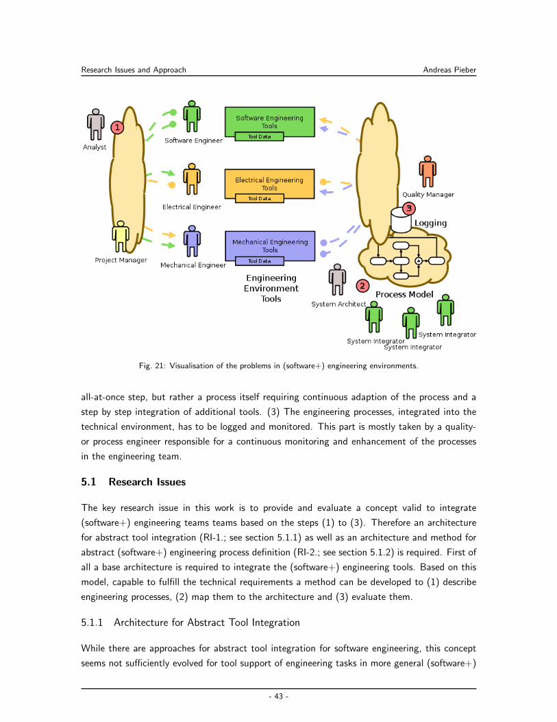
Research Issues and Approach Andreas Pieber
Fig. 21: Visualisation of the problems in (software+) engineering environments.
all-at-once step, but rather a process itself requiring continuous adaption of the process and a
step by step integration of additional tools. (3) The engineering processes, integrated into the
technical environment, has to be logged and monitored. This part is mostly taken by a quality-
or process engineer responsible for a continuous monitoring and enhancement of the processes
in the engineering team.
5.1 Research Issues
The key research issue in this work is to provide and evaluate a concept valid to integrate
(software+) engineering teams teams based on the steps (1) to (3). Therefore an architecture
for abstract tool integration (RI-1.; see section 5.1.1) as well as an architecture and method for
abstract (software+) engineering process definition (RI-2.; see section 5.1.2) is required. First of
all a base architecture is required to integrate the (software+) engineering tools. Based on this
model, capable to fulfill the technical requirements a method can be developed to (1) describe
engineering processes, (2) map them to the architecture and (3) evaluate them.
5.1.1 Architecture for Abstract Tool Integration
While there are approaches for abstract tool integration for software engineering, this concept
seems not sufficiently evolved for tool support of engineering tasks in more general (software+)
- 43 -
Research Issues and Approach Andreas Pieber
engineering teams. Therefore, an architecture is proposed for abstract tool integration for (soft-
ware+) engineering teams supporting the abstraction of data models, functionality, process logic
and team awareness. The architecture is based on the established Enterprise Service Bus con-
cept, which needs to be adapted to the needs and constraints of typical (software+) engineering
environments. The proposed architecture concepts are evaluated with use cases from software
engineering and signal engineering for hydroelectric power plants which is typical for (software+)
engineering integration scenarios.
RI-1.1. Feasibility of the (software+) engineering environment integration approach.
Investigate, whether the proposed engineering environment integration approach is capa-
ble of supporting typical (software+) engineering integration scenarios for development
teams.
RI-1.2. Support for independent tool and process integration. Because engineers are ex-
perts within their tools they are mostly not willing to replace them with other tools. This
requires step-by-step integration of tools and processes requiring an infrastructure to in-
dependently replace and extend engineering processes and tools. It has to be investigated
how well the proposed method supports such process and tools abstractions according to
feasibility, effectiveness, efficiency, usability and performance (as defined in section 5.2.3).
RI-1.3. Support for team awareness. Engineering team awareness interaction processes be-
tween tools and humans are defined or happen ad hoc. Mostly they are used to notify
engineers in case that a change, done by another developer, also affects them. However,
notification today, according to Eckhard (2007), bears the problem of information over-
load and is in most cases directly bound to tools. Current solutions contain for instance
mailing-lists where tools, such as issue trackers, send all notifications to. Taking into ac-
count that a (software+) engineering environment consists of dozens of such tools sending
notifications on changes in the project, the problem of information overload becomes un-
derstandable. Configuring a person specific notification directly in tools on the other hand
is also not viable due to the (a) number of tools involved and (b) the administration effort
for hundreds of engineers per tool. It should be evaluated if the proposed integration
approach is feasible, effective, efficient and usable to support context dependent team
awareness for (software+) engineering development teams.
RI-1.4. More effective and efficient engineering process. Investigate whether the proposed
technical integration solution provides overall a more efficient and effective engineering pro-
cess regarding typical requirements for engineering process tasks such as low delay, low
effort for achieving the information exchange between the engineering tools, and flexibil-
ity of the approach regarding the involved engineering tools and data definitions. While
RI-2 (see section 5.1.2) focuses on providing a method to describe, map, implement and
evaluate real-world engineering use cases into the technical integration environment, this
- 44 -
Research Issues and Approach Andreas Pieber
research issue covers engineering processes already implemented into the technical integra-
tion environment—independent of the method used to implement them—and evaluate if
a more effective and efficient engineering process is provided by the proposed framework.
5.1.2 Method for Abstract (Software+) Engineering Process Definition
(Software+) engineering teams need an approach for defining their engineering processes that
allows systematically and efficiently deriving technical integration solutions. There is a variety of
software engineering process models and business process description languages available. Unfor-
tunately, these approaches are not directly applicable to (software+) engineering environments,
because of gaps between the description method and the technical integration. Therefore, a
method for abstract (software+) engineering process definition is proposed, which allows the
domain experts to express their process needs. A methodology should be described to derive an
effective, efficient, flexible, and robust process design/implementation in the integration environ-
ment proposed in section 5.1.1. The proposed process method is based on the three steps of the
engineering integration process, shown in figure 21. (1) To describe engineering processes and
environments the V-Modell XT tailoring mechanism is used. Results are the description of tools,
stakeholders, processes and events for the different engineering use cases. (2) Based on the ex-
tracted engineering knowledge the 4+1 view model is used to map the mostly verbal descriptions
into an architectural model which can be implemented by system integrators or configured by
domain experts. (3) The engineering automation system automatically logs every event of the
system. Based on this run-time information the correctness and possible enhancements of pro-
cesses can be discovered and compared to the results of the first step (1). The proposed process
method concept is evaluated by describing the processes use cases for continuous integration &
test and signal change management across tool data models, implement and validate them.
RI-2.1. Support for Engineering Process Automation. Engineering processes are extracted
from the current systems used by engineering teams to develop products. This is possible by
the assumption that (software+) engineering teams already cooperate within their todays
systems. Domain experts commonly know exactly what is the relevant output of their tools
and what parts are relevant for others. Additionally, they know which events are relevant
to share in cases of change. Therefore, (software+) engineering teams cooperate already in
processes which can be observed and described. Although, there are methods to describe
processes and environments as well as frameworks and tools for technical integration the
technical implementation has to be repeated for each project (Engels et al., 2008). It is
required to describe engineering integration environments in a way that at least system
architects, but at best domain experts can transform requirements into a specification.
The specification should, again at best, be directly applied to the integration system, but
at least by system integrators. This depends on the type of process. While applying the
- 45 -
Research Issues and Approach Andreas Pieber
integration method to a completely new system with new requirements and new tools it is
clear that the integration has to be done by system integrators. Minor, continuous changes
can also be done by domain experts. Based on the typical (software+) engineering use
cases, extracted in section 6, it has to be evaluated against a prototype implementation,
if the proposed method is feasible to cover all parts of the described engineering process.
RI-2.2. Support for Engineering Process Validation. Quality- and process managers de-
velop processes according to standardized models and want to observe and validate the
process integration and the integration effects on the system from the logs gathered at
runtime. Although there are many possible processes to be evaluated within the runtime
system this work focuses on the validation of team processes. Specifically, events gath-
ered during runtime are most interesting, since they contain enough information about
the process to evaluate (a) if the sequence of events is correct; (b) if the correct data
is sent within the events; (c) the performance of the system—due to the differences of
the timestamps between two events. It is investigated how the proposed method supports
validation of team process events, according to logs gathered during runtime.
5.2 Research Methods and Evaluation Concept
In order to address the research issues RI-1 and RI-2 it is started with a literature research (see
section 5.2.1). The architecture developed for the OpenEngSB is evaluated by the Architec-
ture Trade-Off Analysis (see section 5.2.2). Finally two real world use cases are prototyped to
empirically evaluate the success of the OpenEngSB architecture and concept (see section 5.2.3).
5.2.1 Literature Research
Although (software+) engineering environments have their own requirements for technical and
data integration, their roots can be identified in classical software engineering. A literature re-
search, similar to the systematic literature review (Brereton et al., 2007), is performed on busi-
ness process models for (software+) engineering (see section 2), tool integration in distributed
environments (see section 3) and integration in engineering environments (see section 4).
A systematic literature review, as described by Brereton et al. (2007): “is primarily concerned
with the problem of aggregating empirical evidence which may have been obtained using a
variety of techniques”, and in potentially widely different contexts. Further a systematic review
is build of three main phases, namely: (1) planning the review; (2) conducting the review; (3)
documentation and reporting of the review. Figure 22 illustrates the ten activities conducted to
the three main phases and set them in context. A similar context is used in this work but with
weaker constraints on documentation of the results.
- 46 -
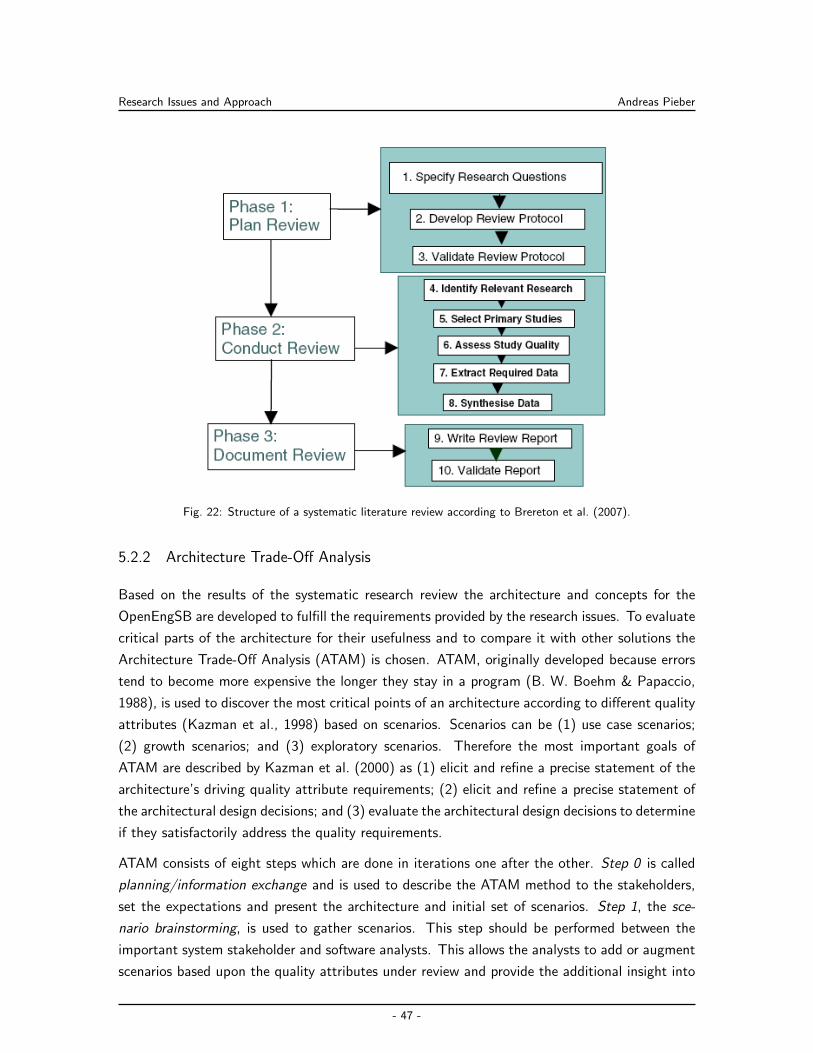
Research Issues and Approach Andreas Pieber
Fig. 22: Structure of a systematic literature review according to Brereton et al. (2007).
5.2.2 Architecture Trade-Off Analysis
Based on the results of the systematic research review the architecture and concepts for the
OpenEngSB are developed to fulfill the requirements provided by the research issues. To evaluate
critical parts of the architecture for their usefulness and to compare it with other solutions the
Architecture Trade-Off Analysis (ATAM) is chosen. ATAM, originally developed because errors
tend to become more expensive the longer they stay in a program (B. W. Boehm & Papaccio,
1988), is used to discover the most critical points of an architecture according to different quality
attributes (Kazman et al., 1998) based on scenarios. Scenarios can be (1) use case scenarios;
(2) growth scenarios; and (3) exploratory scenarios. Therefore the most important goals of
ATAM are described by Kazman et al. (2000) as (1) elicit and refine a precise statement of the
architecture’s driving quality attribute requirements; (2) elicit and refine a precise statement of
the architectural design decisions; and (3) evaluate the architectural design decisions to determine
if they satisfactorily address the quality requirements.
ATAM consists of eight steps which are done in iterations one after the other. Step 0 is called
planning/information exchange and is used to describe the ATAM method to the stakeholders,
set the expectations and present the architecture and initial set of scenarios. Step 1, the sce-
nario brainstorming, is used to gather scenarios. This step should be performed between the
important system stakeholder and software analysts. This allows the analysts to add or augment
scenarios based upon the quality attributes under review and provide the additional insight into
- 47 -
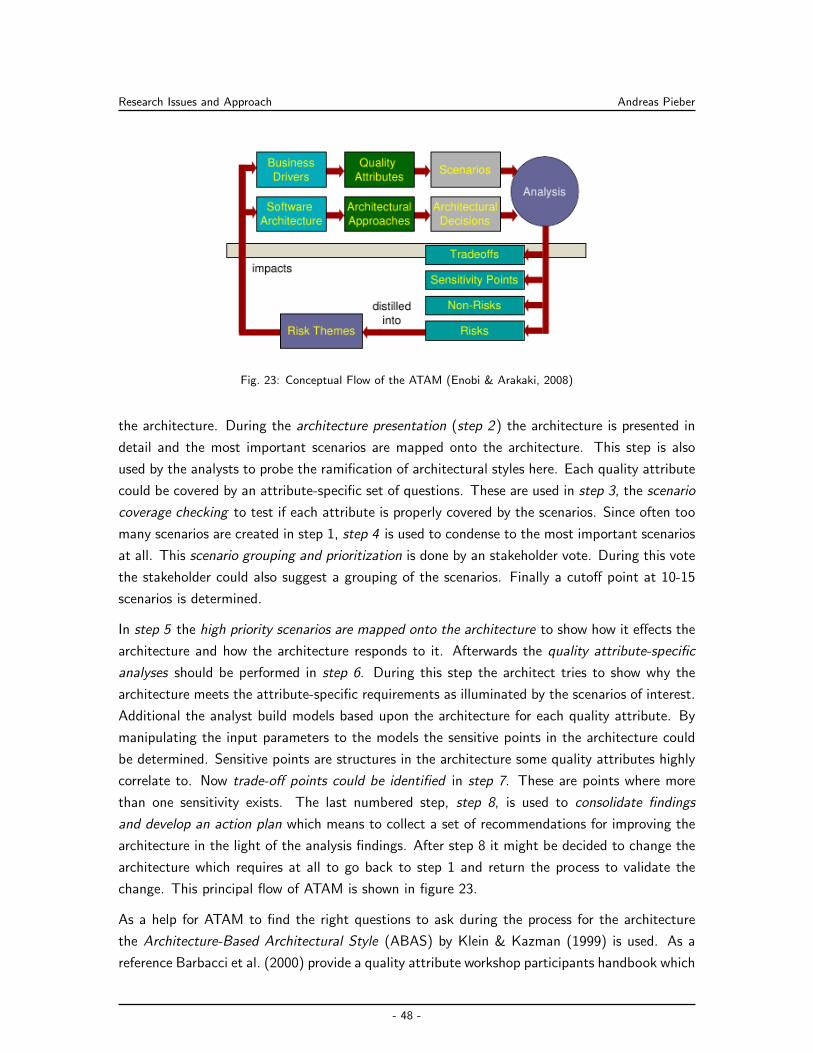
Research Issues and Approach Andreas Pieber
Fig. 23: Conceptual Flow of the ATAM (Enobi & Arakaki, 2008)
the architecture. During the architecture presentation (step 2) the architecture is presented in
detail and the most important scenarios are mapped onto the architecture. This step is also
used by the analysts to probe the ramification of architectural styles here. Each quality attribute
could be covered by an attribute-specific set of questions. These are used in step 3, the scenario
coverage checking to test if each attribute is properly covered by the scenarios. Since often too
many scenarios are created in step 1, step 4 is used to condense to the most important scenarios
at all. This scenario grouping and prioritization is done by an stakeholder vote. During this vote
the stakeholder could also suggest a grouping of the scenarios. Finally a cutoff point at 10-15
scenarios is determined.
In step 5 the high priority scenarios are mapped onto the architecture to show how it effects the
architecture and how the architecture responds to it. Afterwards the quality attribute-specific
analyses should be performed in step 6. During this step the architect tries to show why the
architecture meets the attribute-specific requirements as illuminated by the scenarios of interest.
Additional the analyst build models based upon the architecture for each quality attribute. By
manipulating the input parameters to the models the sensitive points in the architecture could
be determined. Sensitive points are structures in the architecture some quality attributes highly
correlate to. Now trade-off points could be identified in step 7. These are points where more
than one sensitivity exists. The last numbered step, step 8, is used to consolidate findings
and develop an action plan which means to collect a set of recommendations for improving the
architecture in the light of the analysis findings. After step 8 it might be decided to change the
architecture which requires at all to go back to step 1 and return the process to validate the
change. This principal flow of ATAM is shown in figure 23.
As a help for ATAM to find the right questions to ask during the process for the architecture
the Architecture-Based Architectural Style (ABAS) by Klein & Kazman (1999) is used. As a
reference Barbacci et al. (2000) provide a quality attribute workshop participants handbook which
- 48 -
Research Issues and Approach Andreas Pieber
could be used for the most common quality attributes as dependability, security, modifiability,
interoperability and performance. Each quality attributes is characterized by Kazman et al.
(2000) as stimuli, response and architectural decisions which link them. There an stimuli is an
action on the system and the response(s) are the effects on the system. For the quality attribute
security may be tested by the stimuli attack which could include the results to increased access
or disclosure of information. The architectural decision to link or solve it could be auditing
configuration management or network.
Nevertheless ATAM is not riskless (Mason, 2007). It only produces results commensurate to the
level of detail of the architectural documentation. Additionally, compared to classical analyse
methods ATAM identifies trends instead of any measurable quality attributes. It is not possible
to predict the behaviour of quality attributes at that level of detail in such an early state which
may be required to predict the behaviour of quality attributes. ATAM is more about identifying
quality attributes affected by architecture and force the design, analyses and prototyping energies
on such decisions (Kazman et al., 1999). Though ATAM was used successfully at many different
kind of projects as described for example by Nord et al. (2009) or Jalote (2005).
5.2.3 Feasibility Study based on Real World Use Cases
To investigate and evaluate the research issues two use cases are developed together with indus-
trial partners and their domain experts (see section 6) by describing their current environment
and applying it onto the V-Modell XT:
Continuous Integration & Test: While also identifying the classical Continuous Integration &
Test (CI&T) (see section 6.3.1) scenario in their (software+) engineering environment full
description and implementation of this use case in their environment will be beyond the
scope of this work. Therefore, the classical CI&T use case for software engineering, first
introduced by Fowler (2006), becomes one of the most important processes in software
engineering to validate the correctness of software (Duvall et al., 2007).
Signal Change Management Across Tool Data Models: The second use case (see sec-
tion 6.3.2) describes a typical, central (software+) engineering scenario based around
signals. Signals are the core development source for engineers developing hydro power
plants. But they are separated across different tool data models but have to be stored
and versioned central so that changes can be traced via multiple tools and their models.
Additionally team members have to be notified in case signals change.
Based on the defined requirements for the two real world use cases the OpenEngSB architecture
and concept is developed (see section 7). In section 8 the retrieved OpenEngSB concept is applied
step by step to the OpenEngSB architecture, whereas each step is described in detail. For the
empirical evaluation, done in the same section at the end of each use case implementation, the
- 49 -
Research Issues and Approach Andreas Pieber
following evaluation criteria are established:
Effectiveness: the feasibility, validity and correctness of the proposed OpenEngSB framework
regarding the original requirements, as well as the possibility to practically implement the
OpenEngSB architecture and use the OpenEngSB approach.
Efficiency: the effort needed for setting up an OpenEngSB environment, as well as the effort
needed for typical engineering tasks when supported by the OpenEngSB
Performance: the run-time performance of the OpenEngSB platform such as to build a project,
version signals or notifying developers about changes.
Robustness: the identification and handling of defects by the OpenEngSB platform, as well as
the susceptibility of the OpenEngSB regarding typical failures in engineering processes
Usability: the usability of the OpenEngSB for typical non-IT personnel, such as domain experts
from the production automation domain, as well as efforts needed for training
For feasibility evaluation a prototype is realized for each use case of this case study around the
OpenEngSB architecture implemented as an open source product. The use cases should provide
a proof-of-concept for the conceptual approaches described in this paper (Floyd, 1984). The term
prototype in connection with software development indicates a primary interest in a process rather
than in the prototype as a product. The goal of the prototyping process is the identification
of processes which involve an early practical demonstration of relevant parts of the desired
software, and which are able to be combined with other processes in system development with a
view to improving the quality of the target systems. Many software developers are motivated to
employ prototyping by important conclusions drawn from their working experience. Floyd (1984)
describes prototyping to consist of four phases: (1) functional selection; (2) construction; (3)
evaluation; and (4) further use. All of them can be located in this work throughout the sections 6
to 9.
To evaluate the performance the guidelines for empirical research in software engineering by
Kitchenham et al. (2002) are followed. The main goals of the guidelines intend that (1) the
objectives of a research are properly defined and (2) that the description and design of the
research contains enough information for other researchers and practitioners to repeat and or
evaluate the study.
- 50 -
(Software+) Engineering Processes Andreas Pieber
6 (Software+) Engineering Processes
This work is funded on the environment of an industrial partner using (software+) engineering
to develop its products. Section 6.1 describes a general purpose approach to identify relevant
requirements of a (software+) engineering environment important for supporting the environment
with a technical integration environment. The approach is applies to the environment of the
industrial partner. In section 2 a set of software process models, e.g. systematic, agile and
flexible systematic process approaches, are introduced. Process models are used to support
project managers in planning, monitoring and controlling software projects. Although they
are not explicitly designed for (software+) engineering, some are already used for automation
environments, e.g. the V-Modell XT (Broy, 2006). This is possible since process models only
set a framework for project development. Based on the process models and the identified needs
for an agile development processes, including a high adaptiveness to (software+) engineering,
the V-Modell XT is applied to the project development process of the industrial partner (see
section 6.2). It is shown that the same information can be retrieved from the V-Modell XT as
from the method described in section 6.1. Based on the process of the industrial partner two
substantial and important (software+) engineering scenarios are derived: Continuous Integration
& Test and Signal Change Management Across Tool Data Model. These scenarios are described
in section 6.3 in detail, using the method derived in section 6.1.
6.1 Analysis of (Software+) Engineering Processes
To identify processes of (software+) engineering environments an analyst has to identify basic
characteristics regarding the company and their development process definitions. This thesis
focus on mapping processes to a technical integration environment, supporting the (software+)
engineering environment. A short analyse of (software+) engineering environments reveal that
at least a description of the processes themselves, the involved stakeholders, the constructed
artifacts and the applied tools are required to support engineering processes. The following
chapters describe how to retrieve involved stakeholders (see section 6.1.1), constructed artifacts
(see section 6.1.2) and the applied tools. Finally the engineering processes itself has to be
retrieved (see section 6.1.3). In addition, each step is applied for the development process of an
industrial partner in (software+) engineering.
6.1.1 Stakeholders
Complex IT systems have a wide variety of stakeholders with different, and sometimes con-
tradicting, interests. “A stakeholder is a person or organization who influences a system’s
requirements or who is impacted by that system” (Glinz & Wieringa, 2007). To identify the
stakeholders in such a complex environment, analysts typically use classification frameworks,
such as the one described by Preiss & Wegmann (2001). Nevertheless, discussions with the
- 51 -
(Software+) Engineering Processes Andreas Pieber
industrial partner uncover that, independent of the used specification framework and specific
(software+) engineering use case, two groups of stakeholders are relevant within (software+)
engineering environments: (a) the customer group. This group contains of a management, and
individual users. Individual users can be splitted to regular users and domain experts. Compared
to regular users domain experts are also capable to support the development of scenarios and
the implementation of the process; (b) the engineering environment integration group. This
group contains the team developing or supporting the integration solution and implementing the
processes into the environment of the customers. The customer group in detail consists of the
following stakeholders:
Management: The customers management is responsible for funding the project and expects
reduced costs, errors and shorter release cycles afterwards the investment.
User: The user group consists mostly of engineers from different disciplines, e.g. software
engineers, mechanical engineers and electrical engineers. They can be split up further
into two different subtypes: (a) Simple users who only use the integrated product and
like to work with it without changing their basic workflows or tools (but hopefully more
effective and efficient) and (b) the so-called power users. These are engineers with a
deeper knowledge about the processes which are to be integrated. They want to be able
to adapt and control tool configurations, used tools and similar minor settings.
For the development team the following stakeholders are relevant:
Analyst: The analyst provided by the team developing the integration solution is responsible
for closing the gap between customers domain experts and system integrators. He should
facilitate requirements elicitation in a way that is straightforward to design and implement
on an proposed integration solution.
Architect: The architect of the technical integration solution should provide a reusable solution
which can be simply adapted to the different requirements identified by the analyst. At
best the architect can relay on an already existing integration solution and is only provided
with a method to directly map the results of the architect and the technical environment.
Developer (System Integrator): The developer finally requires straightforward models and ar-
chitecture to implement the needs discovered by the analyst and described by the architect.
6.1.2 Products
Products are the artifacts which have to be created during a (software+) engineering process.
Engineers create products in activities, with the help of their tools. The output are artifacts
such as the requirements analyses, source code, architectural models and test plans. Milestones
divides a project into different sections. Milestones are finished if a defined number of products
- 52 -
(Software+) Engineering Processes Andreas Pieber
is finished. Therefore, products are used to guide the processes. Integrated processes do not
directly affect the products, but rather the activities required to create them. For technical
integration the tools used to support the activities are relevant. Therefore, the tools used within
the industrial development process, have to be identified. Furthermore, it is important to identify
the input and output for each tool. Depending on the available integration mechanism for the
tools, relevant information can be the schema description of the data in the database or the
file export format. In addition, the common concepts between tools have to be identified, e.g.
the “signal” in signal engineering. This information is required to describe the interfaces to
be integrated. For larger tool environments UML64 provides the possibility to model the tool
interfaces and their functionality, requirements for process integration of tools. Class diagrams
can be used, for example, to describe the interfaces, the data model, and to highlight the
common concepts. Activity- and sequence diagrams can be used to describe the interaction
between tools.
The typical tool landscape at the industrial partner contains tools such as EPlan65 (for circuit
plans), OPM (part of Toolbox II66, for mapping virtual to hardware addresses), integration
development environments (function block designers for (software+) engineering environments),
and source management systems to store the code. By comparing the exported files of the
tools it can be identified that all of them focus on the common concept of signals. Signals can
be described as key-value pairs. Typical signals contain values such as project id, region, CPU
number and the address of the rack. The CPU number, for example, is on of those fields which
is used in all tools. Therefore itself, and key-value pairs with similar attributes, can be identified
as the common concept between tools. In addition, each tool contains specific data, such as the
symbolic address in EPlan, which are unimportant for the interaction between tools.
6.1.3 Engineering Processes
Project development for a product consists of many different processes, e.g. project acquisition,
deployment and assembly. Those subprocesses can be mostly be derived from a higher level
development process. In this thesis it is proposed to start the subprocess description starting at
this high level development process. Analysing the industrial partner, their development process
can be described and visualized (see figure 24). It consist of four main development phases.
Each phase ends with a milestone. The entire process is guarded by quality, project and change
management. As an additional challenge the processes of the different disciplines run in parallel
and have to be synced at the milestones again. At the industrial partner the development process
starts with a requirement phase which is finished by milestone A (Requirements Specified).
64http://www.omg.org/technology/documents/formal/uml.htm65http://www.eplanusa.com/66http://www.energy.siemens.com/hq/en/automation/power-transmission-distribution/substation-
automation/sicam-1703/toolbox-ii.htm
- 53 -
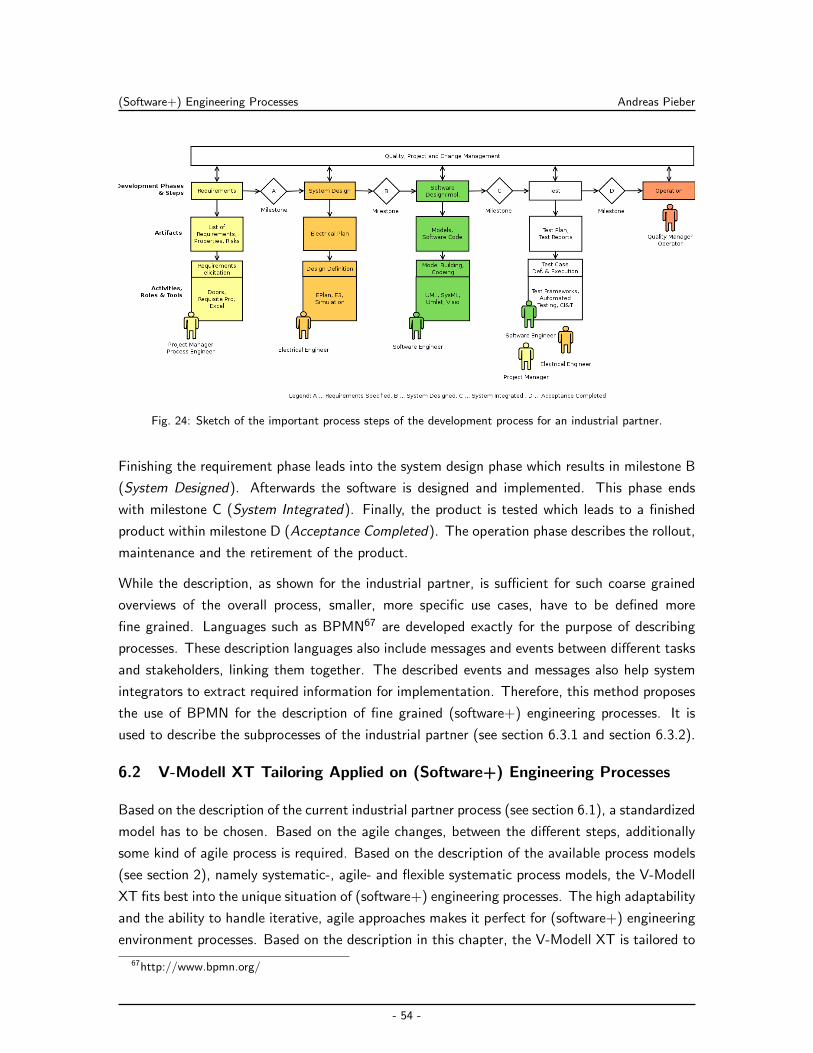
(Software+) Engineering Processes Andreas Pieber
Fig. 24: Sketch of the important process steps of the development process for an industrial partner.
Finishing the requirement phase leads into the system design phase which results in milestone B
(System Designed). Afterwards the software is designed and implemented. This phase ends
with milestone C (System Integrated). Finally, the product is tested which leads to a finished
product within milestone D (Acceptance Completed). The operation phase describes the rollout,
maintenance and the retirement of the product.
While the description, as shown for the industrial partner, is sufficient for such coarse grained
overviews of the overall process, smaller, more specific use cases, have to be defined more
fine grained. Languages such as BPMN67 are developed exactly for the purpose of describing
processes. These description languages also include messages and events between different tasks
and stakeholders, linking them together. The described events and messages also help system
integrators to extract required information for implementation. Therefore, this method proposes
the use of BPMN for the description of fine grained (software+) engineering processes. It is
used to describe the subprocesses of the industrial partner (see section 6.3.1 and section 6.3.2).
6.2 V-Modell XT Tailoring Applied on (Software+) Engineering Processes
Based on the description of the current industrial partner process (see section 6.1), a standardized
model has to be chosen. Based on the agile changes, between the different steps, additionally
some kind of agile process is required. Based on the description of the available process models
(see section 2), namely systematic-, agile- and flexible systematic process models, the V-Modell
XT fits best into the unique situation of (software+) engineering processes. The high adaptability
and the ability to handle iterative, agile approaches makes it perfect for (software+) engineering
environment processes. Based on the description in this chapter, the V-Modell XT is tailored to
67http://www.bpmn.org/
- 54 -
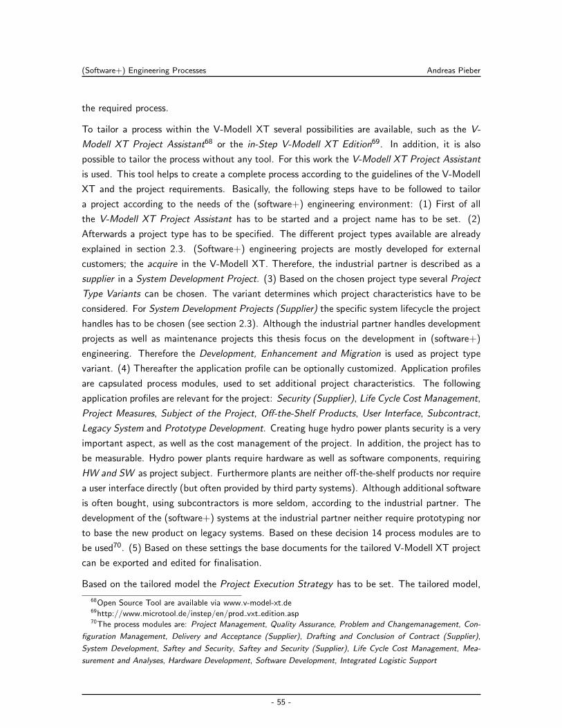
(Software+) Engineering Processes Andreas Pieber
the required process.
To tailor a process within the V-Modell XT several possibilities are available, such as the V-
Modell XT Project Assistant68 or the in-Step V-Modell XT Edition69. In addition, it is also
possible to tailor the process without any tool. For this work the V-Modell XT Project Assistant
is used. This tool helps to create a complete process according to the guidelines of the V-Modell
XT and the project requirements. Basically, the following steps have to be followed to tailor
a project according to the needs of the (software+) engineering environment: (1) First of all
the V-Modell XT Project Assistant has to be started and a project name has to be set. (2)
Afterwards a project type has to be specified. The different project types available are already
explained in section 2.3. (Software+) engineering projects are mostly developed for external
customers; the acquire in the V-Modell XT. Therefore, the industrial partner is described as a
supplier in a System Development Project. (3) Based on the chosen project type several Project
Type Variants can be chosen. The variant determines which project characteristics have to be
considered. For System Development Projects (Supplier) the specific system lifecycle the project
handles has to be chosen (see section 2.3). Although the industrial partner handles development
projects as well as maintenance projects this thesis focus on the development in (software+)
engineering. Therefore the Development, Enhancement and Migration is used as project type
variant. (4) Thereafter the application profile can be optionally customized. Application profiles
are capsulated process modules, used to set additional project characteristics. The following
application profiles are relevant for the project: Security (Supplier), Life Cycle Cost Management,
Project Measures, Subject of the Project, Off-the-Shelf Products, User Interface, Subcontract,
Legacy System and Prototype Development. Creating huge hydro power plants security is a very
important aspect, as well as the cost management of the project. In addition, the project has to
be measurable. Hydro power plants require hardware as well as software components, requiring
HW and SW as project subject. Furthermore plants are neither off-the-shelf products nor require
a user interface directly (but often provided by third party systems). Although additional software
is often bought, using subcontractors is more seldom, according to the industrial partner. The
development of the (software+) systems at the industrial partner neither require prototyping nor
to base the new product on legacy systems. Based on these decision 14 process modules are to
be used70. (5) Based on these settings the base documents for the tailored V-Modell XT project
can be exported and edited for finalisation.
Based on the tailored model the Project Execution Strategy has to be set. The tailored model,
68Open Source Tool are available via www.v-model-xt.de69http://www.microtool.de/instep/en/prod vxt edition.asp70The process modules are: Project Management, Quality Assurance, Problem and Changemanagement, Con-
figuration Management, Delivery and Acceptance (Supplier), Drafting and Conclusion of Contract (Supplier),
System Development, Saftey and Security, Saftey and Security (Supplier), Life Cycle Cost Management, Mea-
surement and Analyses, Hardware Development, Software Development, Integrated Logistic Support
- 55 -
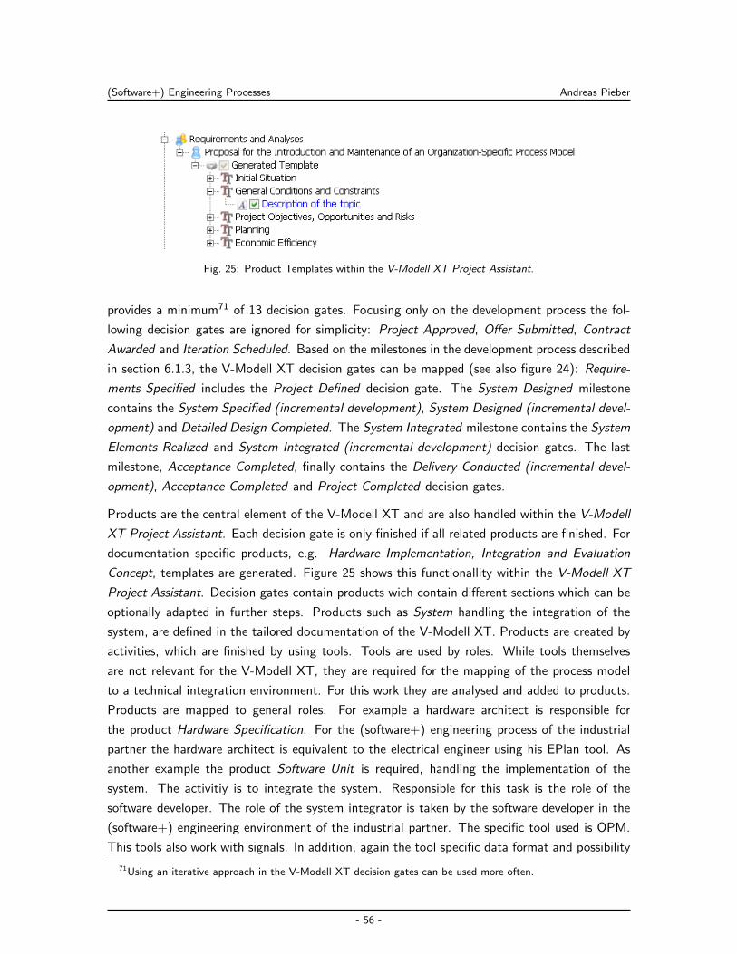
(Software+) Engineering Processes Andreas Pieber
Fig. 25: Product Templates within the V-Modell XT Project Assistant.
provides a minimum71 of 13 decision gates. Focusing only on the development process the fol-
lowing decision gates are ignored for simplicity: Project Approved, Offer Submitted, Contract
Awarded and Iteration Scheduled. Based on the milestones in the development process described
in section 6.1.3, the V-Modell XT decision gates can be mapped (see also figure 24): Require-
ments Specified includes the Project Defined decision gate. The System Designed milestone
contains the System Specified (incremental development), System Designed (incremental devel-
opment) and Detailed Design Completed. The System Integrated milestone contains the System
Elements Realized and System Integrated (incremental development) decision gates. The last
milestone, Acceptance Completed, finally contains the Delivery Conducted (incremental devel-
opment), Acceptance Completed and Project Completed decision gates.
Products are the central element of the V-Modell XT and are also handled within the V-Modell
XT Project Assistant. Each decision gate is only finished if all related products are finished. For
documentation specific products, e.g. Hardware Implementation, Integration and Evaluation
Concept, templates are generated. Figure 25 shows this functionallity within the V-Modell XT
Project Assistant. Decision gates contain products wich contain different sections which can be
optionally adapted in further steps. Products such as System handling the integration of the
system, are defined in the tailored documentation of the V-Modell XT. Products are created by
activities, which are finished by using tools. Tools are used by roles. While tools themselves
are not relevant for the V-Modell XT, they are required for the mapping of the process model
to a technical integration environment. For this work they are analysed and added to products.
Products are mapped to general roles. For example a hardware architect is responsible for
the product Hardware Specification. For the (software+) engineering process of the industrial
partner the hardware architect is equivalent to the electrical engineer using his EPlan tool. As
another example the product Software Unit is required, handling the implementation of the
system. The activitiy is to integrate the system. Responsible for this task is the role of the
software developer. The role of the system integrator is taken by the software developer in the
(software+) engineering environment of the industrial partner. The specific tool used is OPM.
This tools also work with signals. In addition, again the tool specific data format and possibility
71Using an iterative approach in the V-Modell XT decision gates can be used more often.
- 56 -
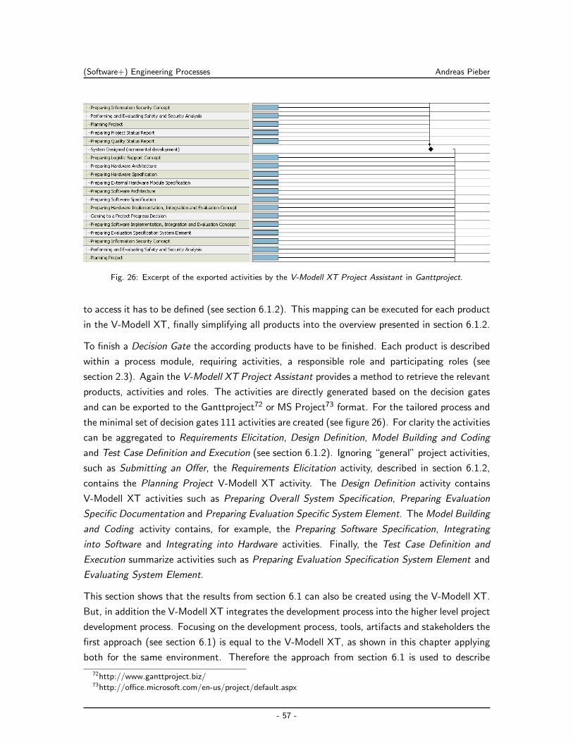
(Software+) Engineering Processes Andreas Pieber
Fig. 26: Excerpt of the exported activities by the V-Modell XT Project Assistant in Ganttproject.
to access it has to be defined (see section 6.1.2). This mapping can be executed for each product
in the V-Modell XT, finally simplifying all products into the overview presented in section 6.1.2.
To finish a Decision Gate the according products have to be finished. Each product is described
within a process module, requiring activities, a responsible role and participating roles (see
section 2.3). Again the V-Modell XT Project Assistant provides a method to retrieve the relevant
products, activities and roles. The activities are directly generated based on the decision gates
and can be exported to the Ganttproject72 or MS Project73 format. For the tailored process and
the minimal set of decision gates 111 activities are created (see figure 26). For clarity the activities
can be aggregated to Requirements Elicitation, Design Definition, Model Building and Coding
and Test Case Definition and Execution (see section 6.1.2). Ignoring “general” project activities,
such as Submitting an Offer, the Requirements Elicitation activity, described in section 6.1.2,
contains the Planning Project V-Modell XT activity. The Design Definition activity contains
V-Modell XT activities such as Preparing Overall System Specification, Preparing Evaluation
Specific Documentation and Preparing Evaluation Specific System Element. The Model Building
and Coding activity contains, for example, the Preparing Software Specification, Integrating
into Software and Integrating into Hardware activities. Finally, the Test Case Definition and
Execution summarize activities such as Preparing Evaluation Specification System Element and
Evaluating System Element.
This section shows that the results from section 6.1 can also be created using the V-Modell XT.
But, in addition the V-Modell XT integrates the development process into the higher level project
development process. Focusing on the development process, tools, artifacts and stakeholders the
first approach (see section 6.1) is equal to the V-Modell XT, as shown in this chapter applying
both for the same environment. Therefore the approach from section 6.1 is used to describe
72http://www.ganttproject.biz/73http://office.microsoft.com/en-us/project/default.aspx
- 57 -
(Software+) Engineering Processes Andreas Pieber
Fig. 27: Entire overall process of an industrial partner. Relevant sub-scenarios and the parts they affect are also
visualized and tagged.
the processes in the following chapters for simplicity. A full mapping of artifact and activity, as
provided by the V-Modell XT is beyond the scope of this thesis, but should be targeted in future
work (see section 10.2).
6.3 Scenarios within the (Software+) Engineering Process Model
According to the experiences of the industrial partner (software+) engineering environments
consist of many smaller processes, which mostly can be described as one overall process. While
section 6.1 and section 6.2 model the overall process of the industrial partner, this section
extracts and describes two specific sub-scenarios within the overall process. These use cases are
defined according to the need of the industrial partner. Both scenarios, including the areas they
effect within the overall process, are visualized and tagged within figure 27.
SC-1 Continuous Integration & Test Similar to software engineering also development teams
in (software+) engineering environments require methods to integrate their build processes.
Unfortunately, the automated validation process for (software+) engineering environments
is neither trivial nor as well established as in software engineering (Biffl & Winkler, 2009).
Beside research activities like in the test-driven automation project (D. Winkler, Biffl, &
Ostreicher, 2009; D. Winkler, Hametner, & Biffl, 2009), further research is also required to-
wards semantical validating of cross-references between heterogeneous tools (Moser, 2010)
to fully implement this use case for (software+) engineering. Both aspects are beyond the
scope of this thesis. However Continuous Integration & Test (CI&T), as described by
Fowler (2006), is a relevant scenario for software engineering. Beside being among the
most used processes within the software engineering domain typical implementations are
- 58 -
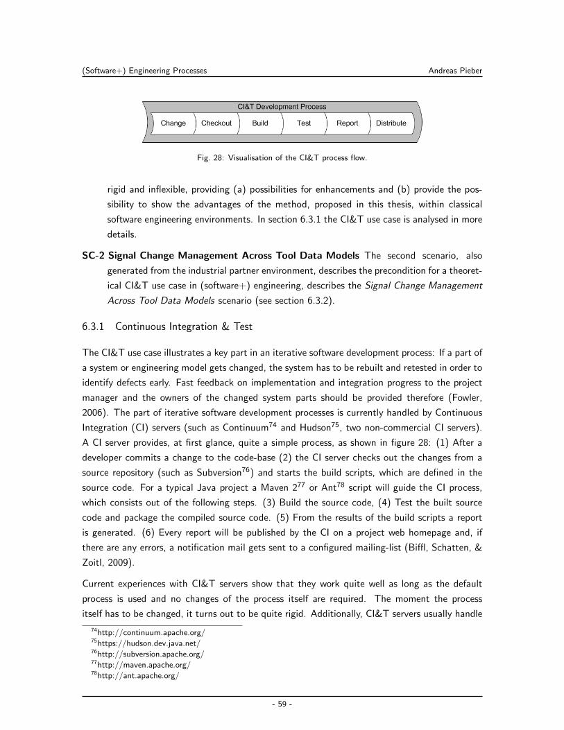
(Software+) Engineering Processes Andreas Pieber
Fig. 28: Visualisation of the CI&T process flow.
rigid and inflexible, providing (a) possibilities for enhancements and (b) provide the pos-
sibility to show the advantages of the method, proposed in this thesis, within classical
software engineering environments. In section 6.3.1 the CI&T use case is analysed in more
details.
SC-2 Signal Change Management Across Tool Data Models The second scenario, also
generated from the industrial partner environment, describes the precondition for a theoret-
ical CI&T use case in (software+) engineering, describes the Signal Change Management
Across Tool Data Models scenario (see section 6.3.2).
6.3.1 Continuous Integration & Test
The CI&T use case illustrates a key part in an iterative software development process: If a part of
a system or engineering model gets changed, the system has to be rebuilt and retested in order to
identify defects early. Fast feedback on implementation and integration progress to the project
manager and the owners of the changed system parts should be provided therefore (Fowler,
2006). The part of iterative software development processes is currently handled by Continuous
Integration (CI) servers (such as Continuum74 and Hudson75, two non-commercial CI servers).
A CI server provides, at first glance, quite a simple process, as shown in figure 28: (1) After a
developer commits a change to the code-base (2) the CI server checks out the changes from a
source repository (such as Subversion76) and starts the build scripts, which are defined in the
source code. For a typical Java project a Maven 277 or Ant78 script will guide the CI process,
which consists out of the following steps. (3) Build the source code, (4) Test the built source
code and package the compiled source code. (5) From the results of the build scripts a report
is generated. (6) Every report will be published by the CI on a project web homepage and, if
there are any errors, a notification mail gets sent to a configured mailing-list (Biffl, Schatten, &
Zoitl, 2009).
Current experiences with CI&T servers show that they work quite well as long as the default
process is used and no changes of the process itself are required. The moment the process
itself has to be changed, it turns out to be quite rigid. Additionally, CI&T servers usually handle
74http://continuum.apache.org/75https://hudson.dev.java.net/76http://subversion.apache.org/77http://maven.apache.org/78http://ant.apache.org/
- 59 -
(Software+) Engineering Processes Andreas Pieber
changes of single tools in a process pretty well, for example if the SCM system should be replaced.
Servers such as Hudson are usually also rather efficient when it comes to resource utilisation.
Based on the design method, described in section 6.1, this section adds the required stakeholders,
artifacts, data models, process flows and events, required for a full description of the engineering
process. The stakeholders for the CI&T process are only software engineers themselves. In
addition, project managers are occasionally interested in about the current state of a project.
The CI&T process integrates a wide range of different tools. As a typical tool setup for the
CI&T scenario in a Java development project (Schatten et al., 2010) the following tools are
relevant:
Subversion: This Tool Connector integrates a Subversion Source Code Management back-end
system. As shown in figure 28 required functionality for this tool is to be notified about
changes, do checkouts and notify the next system on changes. Required configurations
include the location of the Subversion repository and the credentials to access it.
Maven Build: Maven 2 is used as build tool. Maven 2 allows to build projects with different
goals (see section 4.1.1). Each instance of the build connector is responsible for only one
project. The configuration of the connector has to (a) know the project location and (b)
know the explicit build options such as clean, install or clean package. By configuring
these settings directly in the tool instance, a functionality to start a build and returning
its result seams sufficient.
Maven Test: The Maven 2 Test Tool Connector is very similar to the Maven Build Tool Con-
nector. The only difference is that no goals are required within the settings (testing is an
inherent part for the CI&T process). Settings for the location of the project to test and a
functionality to execute the tests is still required.
Reporting: For reporting no external tool is available, resulting within the development of an
own solution. For simplicity the results are concatenated from all actions done during
the CI&T process. Therefore, no configuration is required. Two methods define the
functionality of the connector for the integration solution: (1) One method to start a
reporting process. This method has to take a list of event types which should be reported
for the process. Additionally, a unique identification number is required to gather only
the events of one process for one report. (2) A second method has to finish the event
recording. It takes the unique identifier, inserted during the start of the report. This
method should create a report from the gathered events and return it.
Email Notification: The Email Notification Tool Connector requires to be configured with the
SMTP endpoint and the user credentials. With the method send, taking an address,
subject, message and attachments, everything required for email notification is defined.
- 60 -
(Software+) Engineering Processes Andreas Pieber
As proposed in section 6.1.3, in a next step the process has to be described. Figure 29, designed
with BPMN, wires the use case, tools and events together. The SCM system triggers the build
system with a commit-done event. After the build finishes the test system is triggered and finally
a report is generated from the events and distributed to a mailing-list.
Afterwards the events have to be defined containing the data- and information structure for the
CI&T use case. As shown in figure 29 the following events are required to fully define the CI&T
scenario:
Commit-Done-Event: After the Subversion Tool Connector is notified about a change in the
code base and received the change-data, this event is created. It has to contain the
change-log of the last commit (including information on the changed branch), the author
and the date of the commit.
Build-Event: This event is thrown in case the build-process has finished. The build success
flag has to be set according to the build result. Additional information required is the
build-log. Since most build tools, similar to Maven 2, produce only unstructured build
result messages, the event directly forwards this data also as unstructured text.
Test-Event: Test events are quite similar to build events. The successful flag in the event is
set according to the test results. But, independent of success or failure, the same event
type is used. The test-event contains the semi-structured log output as text. Additionally
the Surefire79 test reports, also generated by Maven 2, are attached. These can be used
directly by the development environment helping to fix errors.
To allow a standard based comparison between Hudson and a proposed integration solution
both should build a specific version80 of the OpenEngSB open source project. To avoid direct
comparisons between the command line build system and the proposed solution, Maven 2 should
be first compared to Hudson. For the measurements Maven 2 version 2.2.1 and Hudson release
1348 are used. Maven 2 is directly used from the unix command line. Hudson is started directly
using its integrated, lightweight Winstone81 web container. The time to build the OpenEngSB
with Maven 2 is extracted by the Maven 2 console log output (see listing 1). This is possible
because Hudson stores and provides access to the full Maven 2 console log output.
Listing 1: The Maven 2 build output showing the full time of the run. The memory shown can not be used since
it does not fit with the real allocated memory.
[INFO] --------------------------------------------------------------
[INFO] --------------------------------------------------------------
[INFO] BUILD SUCCESSFUL
[INFO] --------------------------------------------------------------
[INFO] Total time: 3 minutes 27 seconds
79http://maven.apache.org/plugins/maven-surefire-plugin/80http://github.com/openengsb/openengsb/commit/6caa681e661414fa50f4240e8f9d004b66ff634981http://winstone.sourceforge.net/
- 61 -
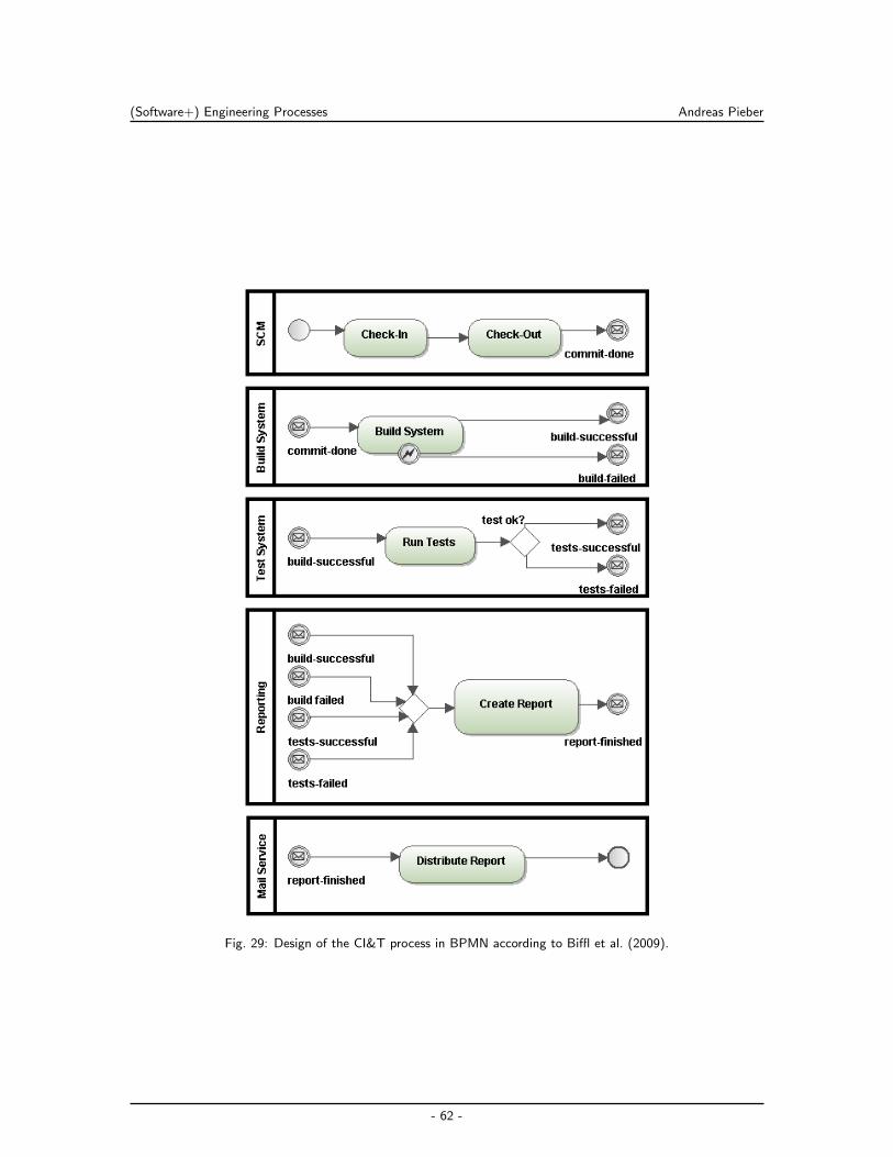
(Software+) Engineering Processes Andreas Pieber
Fig. 29: Design of the CI&T process in BPMN according to Biffl et al. (2009).
- 62 -
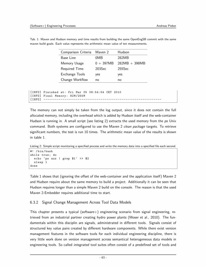
(Software+) Engineering Processes Andreas Pieber
Tab. 1: Maven and Hudson memory and time results from building the same OpenEngSB commit with the same
maven build goals. Each value represents the arithmetic mean value of ten measurements.
Comparison Criteria Maven 2 Hudson
Base Line 0MB 282MB
Memory Usage 0 + 397MB 282MB + 398MB
Required Time 203Sec 255Sec
Exchange Tools yes yes
Change Workflow no no
[INFO] Finished at: Fri Mar 05 08:54:54 CET 2010
[INFO] Final Memory: 82M/255M
[INFO] --------------------------------------------------------------
The memory can not simply be taken from the log output, since it does not contain the full
allocated memory, including the overhead which is added by Hudson itself and the web-container
Hudson is running in. A small script (see listing 2) extracts the used memory from the ps Unix
command. Both systems are configured to use the Maven 2 clean package targets. To retrieve
significant numbers, the test is run 10 times. The arithmetic mean value of the results is shown
in table 1.
Listing 2: Simple script monitoring a specified process and write the memory data into a specified file each second.
#! /bin/bash
while true; do
echo ‘ps aux | grep $1‘ >> $2
sleep 1
done
Table 1 shows that (ignoring the offset of the web-container and the application itself) Maven 2
and Hudson require about the same memory to build a project. Additionally it can be seen that
Hudson requires longer than a simple Maven 2 build on the console. The reason is that the used
Maven 2-Embedder requires additional time to start.
6.3.2 Signal Change Management Across Tool Data Models
This chapter presents a typical (software+) engineering scenario from signal engineering, re-
trieved from an industrial partner creating hydro power plants (Moser et al., 2010). The fun-
damentals within this disciplin are signals, administrated in different tools. Signals consist of
structured key value pairs created by different hardware components. While there exist version
management features in the software tools for each individual engineering discipline, there is
very little work done on version management across semantical heterogeneous data models in
engineering tools. So called integrated tool suites often consist of a predefined set of tools and
- 63 -
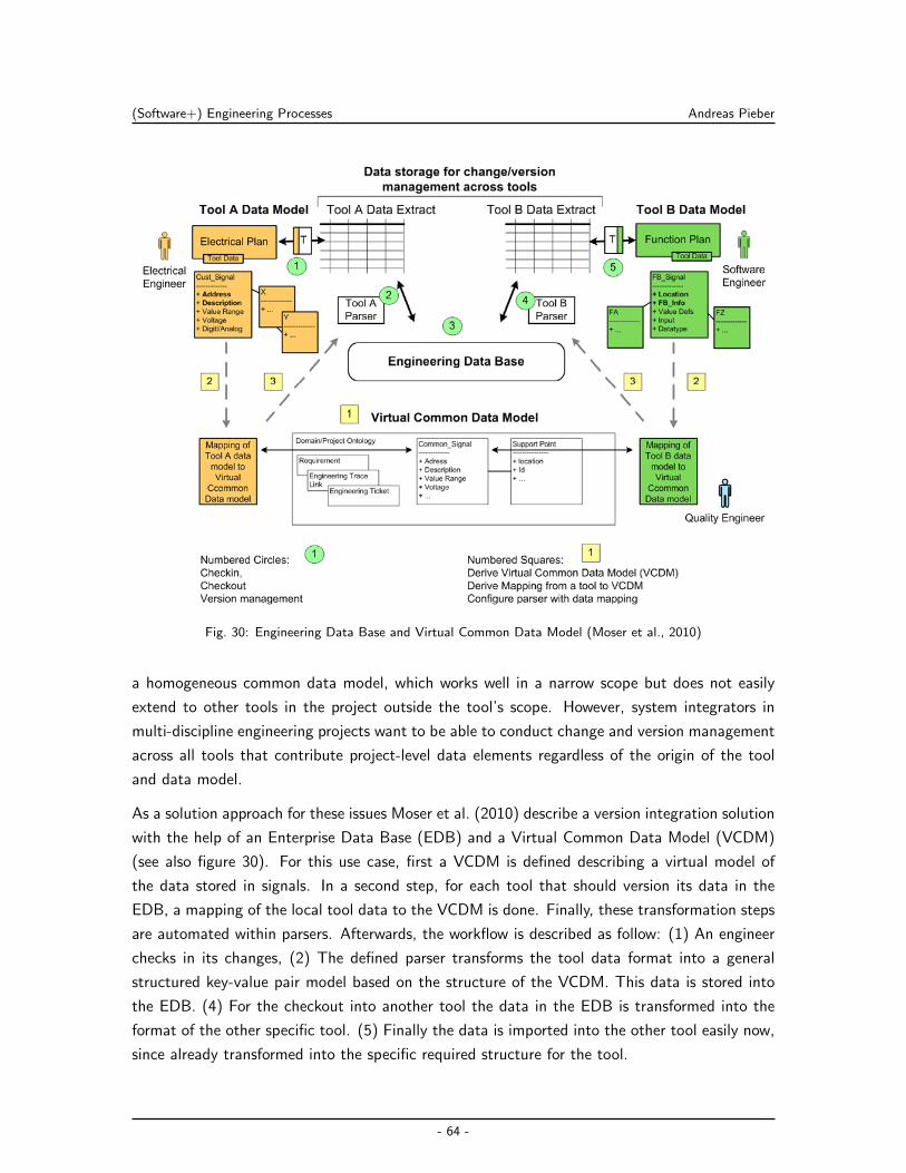
(Software+) Engineering Processes Andreas Pieber
Fig. 30: Engineering Data Base and Virtual Common Data Model (Moser et al., 2010)
a homogeneous common data model, which works well in a narrow scope but does not easily
extend to other tools in the project outside the tool’s scope. However, system integrators in
multi-discipline engineering projects want to be able to conduct change and version management
across all tools that contribute project-level data elements regardless of the origin of the tool
and data model.
As a solution approach for these issues Moser et al. (2010) describe a version integration solution
with the help of an Enterprise Data Base (EDB) and a Virtual Common Data Model (VCDM)
(see also figure 30). For this use case, first a VCDM is defined describing a virtual model of
the data stored in signals. In a second step, for each tool that should version its data in the
EDB, a mapping of the local tool data to the VCDM is done. Finally, these transformation steps
are automated within parsers. Afterwards, the workflow is described as follow: (1) An engineer
checks in its changes, (2) The defined parser transforms the tool data format into a general
structured key-value pair model based on the structure of the VCDM. This data is stored into
the EDB. (4) For the checkout into another tool the data in the EDB is transformed into the
format of the other specific tool. (5) Finally the data is imported into the other tool easily now,
since already transformed into the specific required structure for the tool.
- 64 -
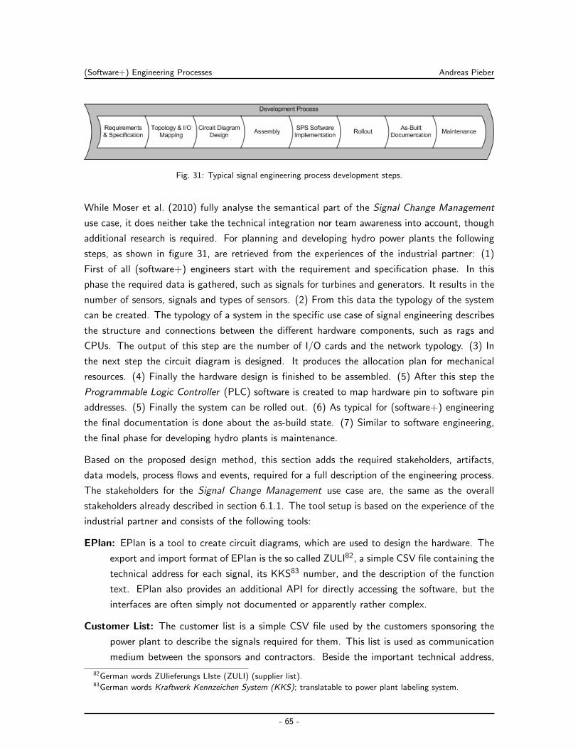
(Software+) Engineering Processes Andreas Pieber
Fig. 31: Typical signal engineering process development steps.
While Moser et al. (2010) fully analyse the semantical part of the Signal Change Management
use case, it does neither take the technical integration nor team awareness into account, though
additional research is required. For planning and developing hydro power plants the following
steps, as shown in figure 31, are retrieved from the experiences of the industrial partner: (1)
First of all (software+) engineers start with the requirement and specification phase. In this
phase the required data is gathered, such as signals for turbines and generators. It results in the
number of sensors, signals and types of sensors. (2) From this data the typology of the system
can be created. The typology of a system in the specific use case of signal engineering describes
the structure and connections between the different hardware components, such as rags and
CPUs. The output of this step are the number of I/O cards and the network typology. (3) In
the next step the circuit diagram is designed. It produces the allocation plan for mechanical
resources. (4) Finally the hardware design is finished to be assembled. (5) After this step the
Programmable Logic Controller (PLC) software is created to map hardware pin to software pin
addresses. (5) Finally the system can be rolled out. (6) As typical for (software+) engineering
the final documentation is done about the as-build state. (7) Similar to software engineering,
the final phase for developing hydro plants is maintenance.
Based on the proposed design method, this section adds the required stakeholders, artifacts,
data models, process flows and events, required for a full description of the engineering process.
The stakeholders for the Signal Change Management use case are, the same as the overall
stakeholders already described in section 6.1.1. The tool setup is based on the experience of the
industrial partner and consists of the following tools:
EPlan: EPlan is a tool to create circuit diagrams, which are used to design the hardware. The
export and import format of EPlan is the so called ZULI82, a simple CSV file containing the
technical address for each signal, its KKS83 number, and the description of the function
text. EPlan also provides an additional API for directly accessing the software, but the
interfaces are often simply not documented or apparently rather complex.
Customer List: The customer list is a simple CSV file used by the customers sponsoring the
power plant to describe the signals required for them. This list is used as communication
medium between the sponsors and contractors. Beside the important technical address,
82German words ZUlieferungs LIste (ZULI) (supplier list).83German words Kraftwerk Kennzeichen System (KKS); translatable to power plant labeling system.
- 65 -
(Software+) Engineering Processes Andreas Pieber
KKS number and the function text, also additional values are provided by the function
list. But these values are not really important for this use case as they are not reused
between different tools. Direct access to the customer list is possible via Microsoft Excel
or OpenOffice Spreadsheet macros. Nevertheless, for the sake of simplicity the CSV is
used directly for the moment.
OPM: The Siemens OPM tool is used to map the physical address of signals (from the EPlan
team) and customer list to virtual software addresses. OPM also exports its data in CSV.
Again, the technical address, KKS number and function text fields are available. Also
these values are not important for the Signal Change Management use case. There are
no officially provided APIs available for OPM. Thus, the fall back solution currently is to
use exported and imported CSV files as source for integrating this tool.
EDB: The Engineering Data Base is implemented according to Waltersdorfer (2010). The input
and output data for the EDB is defined as simple XML structure containing the key-value
pairs and the specific signal data including general data such as data, author and tool
used to create the data. Events have to be thrown for added, changed and deleted signals.
Functionality is required to commit, retrieve and query data.
Issue Tracker: For managing the tasks visible and accessible for everyone involved, the open
source issue tracker Trac84 is chosen by the industrial partners. Trac can be easily extended
using the provided XML-RPC interface.
Email Notification: The email notification is similar to the requirements described for the CI&T
use case (see section 6.3.1).
Because tools like EPlan and OPM do not allow an easy and direct integration with the proposed
integration solution, the file import and export to exchange the data between the EDB and the
tools is used. Together with the customer a solution is designed. A web application should offer
the interface to up- and download signals in the format tools export and import them. The
tools attached to the OpenEngSB are responsible to (a) store the data and (b) provide team
awareness.
The process model can be described as shown in figure 32. In some engineering tools, such as
OPM or EPlan, signal data can be changed. This data is exported and then available as a change
for further processing. In the EDB, the change is saved into the database. Afterwards, for each
signal an event (signal added, signal changed or signal removed) is generated. Thereafter the
issue tracker has to check the signal state. Dependent on the state and the values changed in
the signal, issues have to be created. A created issue throws a issue created event which finally
creates a notification for the assignee of the issue.
84http://trac.edgewall.org/
- 66 -
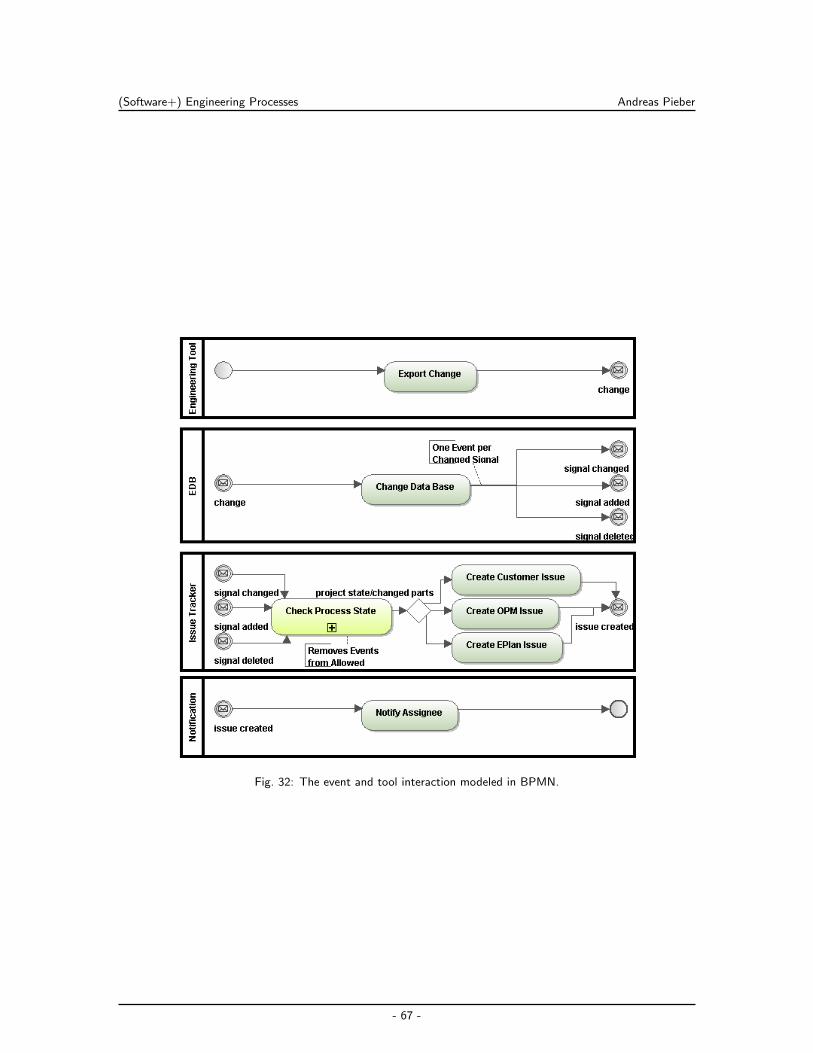
(Software+) Engineering Processes Andreas Pieber
Fig. 32: The event and tool interaction modeled in BPMN.
- 67 -
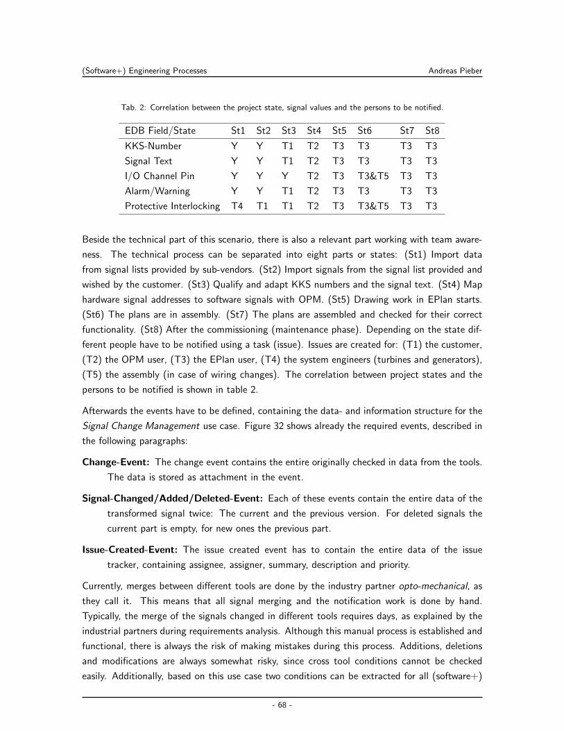
(Software+) Engineering Processes Andreas Pieber
Tab. 2: Correlation between the project state, signal values and the persons to be notified.
EDB Field/State St1 St2 St3 St4 St5 St6 St7 St8
KKS-Number Y Y T1 T2 T3 T3 T3 T3
Signal Text Y Y T1 T2 T3 T3 T3 T3
I/O Channel Pin Y Y Y T2 T3 T3&T5 T3 T3
Alarm/Warning Y Y T1 T2 T3 T3 T3 T3
Protective Interlocking T4 T1 T1 T2 T3 T3&T5 T3 T3
Beside the technical part of this scenario, there is also a relevant part working with team aware-
ness. The technical process can be separated into eight parts or states: (St1) Import data
from signal lists provided by sub-vendors. (St2) Import signals from the signal list provided and
wished by the customer. (St3) Qualify and adapt KKS numbers and the signal text. (St4) Map
hardware signal addresses to software signals with OPM. (St5) Drawing work in EPlan starts.
(St6) The plans are in assembly. (St7) The plans are assembled and checked for their correct
functionality. (St8) After the commissioning (maintenance phase). Depending on the state dif-
ferent people have to be notified using a task (issue). Issues are created for: (T1) the customer,
(T2) the OPM user, (T3) the EPlan user, (T4) the system engineers (turbines and generators),
(T5) the assembly (in case of wiring changes). The correlation between project states and the
persons to be notified is shown in table 2.
Afterwards the events have to be defined, containing the data- and information structure for the
Signal Change Management use case. Figure 32 shows already the required events, described in
the following paragraphs:
Change-Event: The change event contains the entire originally checked in data from the tools.
The data is stored as attachment in the event.
Signal-Changed/Added/Deleted-Event: Each of these events contain the entire data of the
transformed signal twice: The current and the previous version. For deleted signals the
current part is empty, for new ones the previous part.
Issue-Created-Event: The issue created event has to contain the entire data of the issue
tracker, containing assignee, assigner, summary, description and priority.
Currently, merges between different tools are done by the industry partner opto-mechanical, as
they call it. This means that all signal merging and the notification work is done by hand.
Typically, the merge of the signals changed in different tools requires days, as explained by the
industrial partners during requirements analysis. Although this manual process is established and
functional, there is always the risk of making mistakes during this process. Additions, deletions
and modifications are always somewhat risky, since cross tool conditions cannot be checked
easily. Additionally, based on this use case two conditions can be extracted for all (software+)
- 68 -
(Software+) Engineering Processes Andreas Pieber
engineering use cases: Each scenario consists of a technical and a “cooperational” part. The
technical part describes the tools, the interaction between the tools and the used data formats.
The cooperation part on the other hand describes the integration of team awareness for a process
such as notification and other interactions Waltersdorfer (2010).
- 69 -
OpenEngSB Architecture and Concept Andreas Pieber
7 OpenEngSB Architecture and Concept
This chapter gives a detailed description of the OpenEngSB architecture. First of all, the defined
research issues are mapped into the technical solution approach. Afterwards the components,
relevant for the architecture, are derived in section 7.1. The description of the components should
provide a glossary of the regularly used terms in the context of the OpenEngSB. Section 7.2
describes the infrastructural extensions to the messaging infrastructure of the used integration
framework. Similar to most integration frameworks the OpenEngSB provides Core Components
for centralized functionalities and support (section 7.3). The core integration concepts are
explained by section 7.4 and are finished by section 7.5, providing a detailed insight of how tools
are connected to the OpenEngSB.
A solution architecture approach is developed based on scenario shown in figure 21 and the
research issues outlined in section 5.1. The overview of the solution is presented in figure 33.
The solution approaches for the research issues are:
SA-1a General Integration Approach for (Software+) Engineering Teams. The
OpenEngSB integration architecture is developed based on the ESB concepts, the
solution approach for general business integration challenges. It uses an ESB implemen-
tation as message backbone and extends the concept by Tool Domains, Connectors and
Core Tools. This solution approach maps with the research issues RI-1.1 and RI-1.2.
SA-1b Team Awareness with Team Communication Tools. Team awareness is provided by
integrating tools for team communication for the OpenEngSB the same way as other tools,
but provide additional helpers for storing roles and team communication referrals. This
solution approach maps with the research issue RI-1.3.
SA-2a Workflow Component for Abstract (Software+) Engineering Process Definition.
A Core Component providing workflow integration for the OpenEngSB, combined with
the abstraction of Tool Domains allows the abstract definition of (software+) engineering
processes. This solution approach maps with the research issue RI-2.1.
SA-2b Project Monitoring Integration for (Software+) Engineering Process Validation.
Integrating a general log solution as a Core Component allows to store all relevant runtime
data in a centralized place in the OpenEngSB and their validation of them with the help
of project monitoring tools afterwards. This solution approach maps with the research
issue RI-2.2.
7.1 OpenEngSB Components
While, as presented in figure 33, there is a differentiation between Engineering Environment Tools
and Engineering Integration Tools, in a more technical perspective their differences are not valid
- 70 -
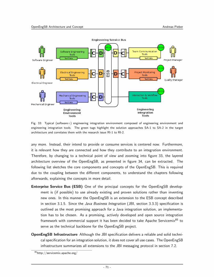
OpenEngSB Architecture and Concept Andreas Pieber
Fig. 33: Typical (software+) engineering integration environment composed of engineering environment and
engineering integration tools. The green tags highlight the solution approaches SA-1 to SA-2 in the target
architecture and correlates them with the research issue RI-1 to RI-2.
any more. Instead, their intend to provide or consume services is centered now. Furthermore,
it is relevant how they are connected and how they contribute to an integration environment.
Therefore, by changing to a technical point of view and zooming into figure 33, the layered
architecture overview of the OpenEngSB, as presented in figure 34, can be extracted. The
following list sketches the core components and concepts of the OpenEngSB. This is required
due to the coupling between the different components, to understand the chapters following
afterwards, explaining the concepts in more detail.
Enterprise Service Bus (ESB) One of the principal concepts for the OpenEngSB develop-
ment is (if possible) to use already existing and proven solutions rather than inventing
new ones. In this manner the OpenEngSB is an extension to the ESB concept described
in section 3.1.5. Since the Java Business Integration (JBI, section 3.3.3) specification is
outlined as the most promising approach for a Java integration solution, an implementa-
tion has to be chosen. As a promising, actively developed and open source integration
framework with commercial support it has been decided to take Apache Servicemix85 to
serve as the technical backbone for the OpenEngSB project.
OpenEngSB Infrastructure Although the JBI specification delivers a reliable and solid techni-
cal specification for an integration solution, it does not cover all use cases. The OpenEngSB
infrastructure summarizes all extensions to the JBI messaging protocol in section 7.2.
85http://servicemix.apache.org/
- 71 -
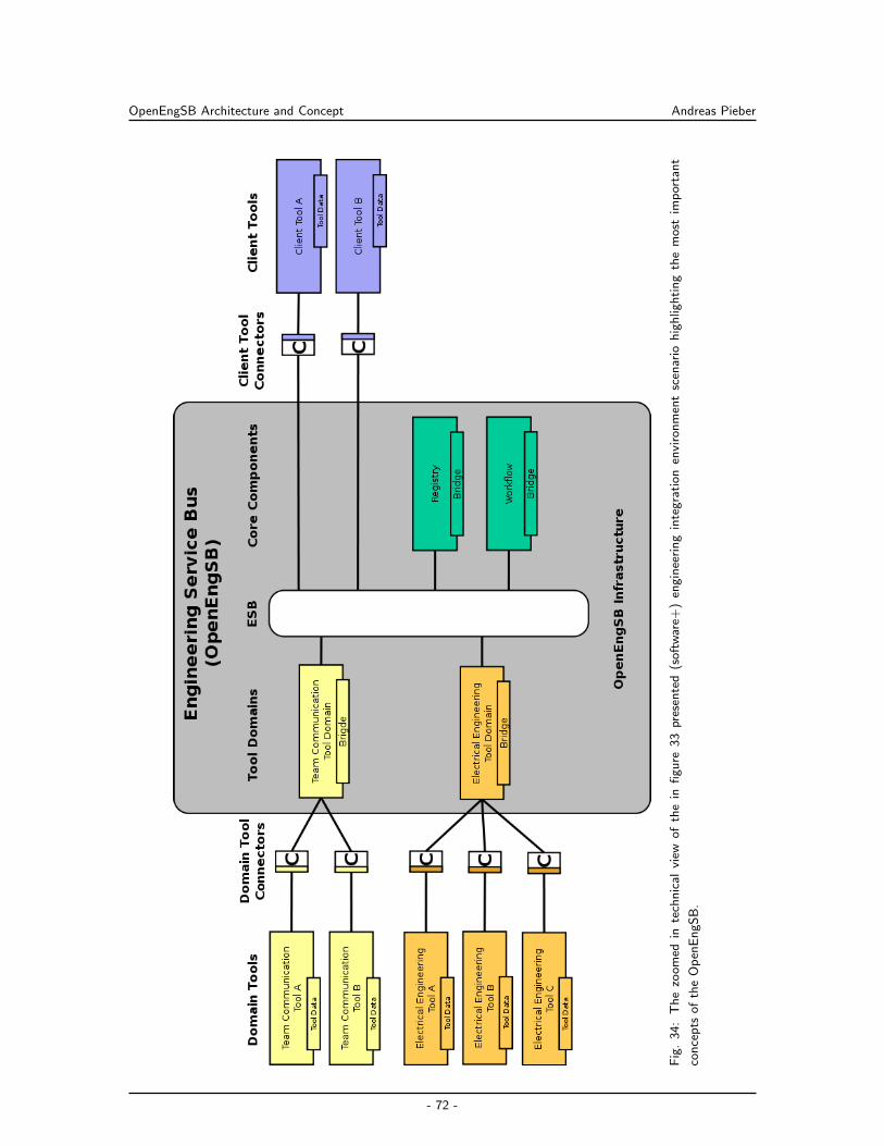
OpenEngSB Architecture and Concept Andreas Pieber
Fig
.3
4:
Th
ezo
om
edin
tech
nic
alvi
ewo
fth
ein
fig
ure
33
pres
ente
d(s
oft
war
e+)
eng
inee
rin
gin
teg
rati
on
envi
ron
men
tsc
enar
ioh
igh
ligh
tin
gth
em
ost
imp
orta
nt
con
cep
tso
fth
eO
pen
En
gS
B.
- 72 -
OpenEngSB Architecture and Concept Andreas Pieber
Core Components The concept of Core Components contains all additional developed com-
ponents providing services not available by external tools or the JBI integration infras-
tructure. These components add essential functionality to the OpenEngSB like a registry
(section 7.3.1) or workflow administration (section 7.3.2) and therefore provide a rich
framework for modeling (software+) engineering environments.
Tool Domains Although each tool provider gives a personal touch to its product their design is
driven by a specific purpose. For example, there are many different issue tracker available,
each having its own advantages and disadvantages, but all of them can create issues,
assign and delete them. Tool Domains are based on this idea and distill the common
functionality for such a group of tools into one Tool Domain interface (and component).
Tool domains could be compared best to the concept of abstract classes in in object
orientated programming languages. Similar to these, they can contain code, workflows,
additional logic and data, but they are useless without a concrete implementation. This
and further concepts are explained in greater detail in section 7.4. Together with the ESB,
the OpenEngSB infrastructure and the core components the tool domains finally result in
the OpenEngSB.
Bridge JBI does not allow components that are not deployed in the JBI infrastructure to directly
interact with services provided over the Normalized Message Router (NMR). This means
that neither tools deployed to the OpenEngSB can directly access external components nor
the other way round. To overcome this challenge the concept of the bridge is introduced
and explained in section 7.4.
Client Tools (Service Consumer) Client Tools in the OpenEngSB concept are tools which
do not provide any services, but consume services provided by Tool Domains and Core
Components instead. A classical example from software engineering for a client tool
is the Integrated Development Environment (IDE). Developer prefer to have the entire
development environment, reaching from the tickets for a project to its build results, at
hand. On the other hand they do not need to provide any services. The detailed technical
point of view on Client Tools is given in section 7.5.
Domain Tools (Service Provider) Domain Tools, compared to Client Tools, denote the other
extreme of only providing services. Classically, single purpose server tools, like issue tracker
or chat server, match the category of Domain Tools best. Most tools in (software+)
engineering environments fit of course in both categories, but since there are significant
technically differences between them (see section 7.5) they are described as two different
component types.
Domain- and Client Tool Connectors Tool Connectors wrap up tools as Domain Tool Con-
nectors to provide their services to accommodate the relevant Tool Domain with the
- 73 -
OpenEngSB Architecture and Concept Andreas Pieber
expected interface. As Client Tool Connectors they provide a Client Tool with an access
to the OpenEngSB services. Again, Domain- and Client Tool Connectors are mostly mixed
up but separated because of their technical differences (see section 7.5). Additionally it is
worth mentioning that tools can be integrated with more than one connector. This allows
one tool to act in many different domains. Maven 2 is an example for such multi-purpose
tools, relevant for build, as well as test and deploy of Java projects.
7.2 OpenEngSB Infrastructure
The message and communication infrastructure is based on the Java Business Integration (JBI)
architecture that was already explained section 3.3.3. Since messages sent via the Normalized
Message Router (NMR) are still constructed of header and payload it is possible to embed
additional functionality and information for different purposes. All these changes are summarized
in the OpenEngSB infrastructure, whereas the following chapters reason why changes are required
and how they are done.
7.2.1 Message Header Extensions
Multiple Project Support. The OpenEngSB supports multiple projects in parallel. The con-
figuration for each project has to contain information like the endpoints of the specific
tools for a project, the processes to be used, specific tool-configurations and additional
settings like user-role mappings. Additional conditions like rules affected by a project are
also important to be configured. All this information builds the context of a project. To
map the messages themselves to the relevant information in the context they require an
additional context identifier. The process of working with the context in combination with
the messages is covered in section 7.3.1.
Receiver Specification. Tool Domains (section 7.4) add an additional abstraction layer be-
tween caller and callee. The final receiver is regularly defined by the context a message is
sent to a domain, but in some situations a specific receiver wants to be called. Bypassing
the Tool Domain concept is possible, but results in loosing all their advantages. Adding
a receiver identification to each message header allows to use the advantages of the Tool
Domains but still call specific tools directly.
Logging Information. Logging of processes is required to validate them in the context described
by RI-2.2 (see section 5.1.2). Mostly every information needed to evaluate processes in
matters of feasibility, performance, reliability and similar Quality of Service (QoS) at-
tributes, can be retrieved from messages sent in the system. However, the information
required within the messages to gather these quality attributes is not available, using only
the default message header as defined in the JBI specification (see section 3.3.3). Rather
it is required to extend the message header with additional attributes, such as Process
- 74 -
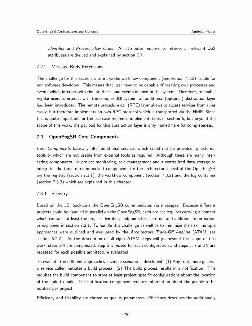
OpenEngSB Architecture and Concept Andreas Pieber
Identifier and Process Flow Order. All attributes required to retrieve all relevant QoS
attributes are derived and explained by section 7.7.
7.2.2 Message Body Extensions
The challenge for this section is to make the workflow component (see section 7.3.2) usable for
non software developer. This means that user have to be capable of creating own processes and
events which interact with the interfaces and events defined in the system. Therefore, to enable
regular users to interact with the complex JBI system, an additional (optional) abstraction layer
had been introduced. The remote procedure call (RPC) layer allows to access services from rules
easily, but therefore implements an own RPC protocol which is transported via the NMR. Since
this is quite important for the use case reference implementations in section 6, but beyond the
scope of this work, the payload for this abstraction layer is only named here for completeness.
7.3 OpenEngSB Core Components
Core Components basically offer additional services which could not be provided by external
tools or which are not usable from external tools as required. Although there are many inter-
esting components like project monitoring, role management and a centralized data storage to
integrate, the three most important components for the architectural need of the OpenEngSB
are the registry (section 7.3.1), the workflow component (section 7.3.2) and the log container
(section 7.3.3) which are explained in this chapter.
7.3.1 Registry
Based on the JBI backbone the OpenEngSB communicates via messages. Because different
projects could be handled in parallel on the OpenEngSB, each project requires carrying a context
which contains at least the project identifier, endpoints for each tool and additional information
as explained in section 7.2.1. To handle this challenge as well as to minimize the risk, multiple
approaches were outlined and evaluated by the Architecture Trade-Off Analyse (ATAM, see
section 5.2.2). As the description of all eight ATAM steps will go beyond the scope of this
work, steps 1-4 are compressed, step 6 is reused for each configuration and steps 5, 7 and 8 are
repeated for each possible architecture evaluated.
To evaluate the different approaches a simple scenario is developed: (1) Any tool, more general
a service caller, initiates a build process. (2) The build process results in a notification. This
requires the build component to store at least project specific configurations about the location
of the code to build. The notification component requires information about the people to be
notified per project.
Efficiency and Usability are chosen as quality parameters. Efficiency describes the additionally
- 75 -
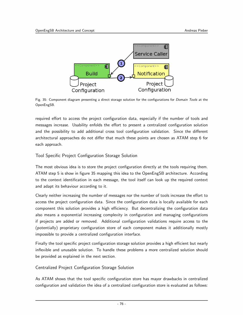
OpenEngSB Architecture and Concept Andreas Pieber
Fig. 35: Component diagram presenting a direct storage solution for the configurations for Domain Tools at the
OpenEngSB.
required effort to access the project configuration data, especially if the number of tools and
messages increase. Usability enfolds the effort to present a centralized configuration solution
and the possibility to add additional cross tool configuration validation. Since the different
architectural approaches do not differ that much these points are chosen as ATAM step 6 for
each approach.
Tool Specific Project Configuration Storage Solution
The most obvious idea is to store the project configuration directly at the tools requiring them.
ATAM step 5 is show in figure 35 mapping this idea to the OpenEngSB architecture. According
to the context identification in each message, the tool itself can look up the required context
and adapt its behaviour according to it.
Clearly neither increasing the number of messages nor the number of tools increase the effort to
access the project configuration data. Since the configuration data is locally available for each
component this solution provides a high efficiency. But decentralizing the configuration data
also means a exponential increasing complexity in configuration and managing configurations
if projects are added or removed. Additional configuration validations require access to the
(potentially) proprietary configuration store of each component makes it additionally mostly
impossible to provide a centralized configuration interface.
Finally the tool specific project configuration storage solution provides a high efficient but nearly
inflexible and unusable solution. To handle these problems a more centralized solution should
be provided as explained in the next section.
Centralized Project Configuration Storage Solution
As ATAM shows that the tool specific configuration store has mayor drawbacks in centralized
configuration and validation the idea of a centralized configuration store is evaluated as follows:
- 76 -
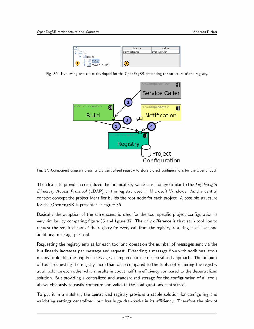
OpenEngSB Architecture and Concept Andreas Pieber
Fig. 36: Java swing test client developed for the OpenEngSB presenting the structure of the registry.
Fig. 37: Component diagram presenting a centralized registry to store project configurations for the OpenEngSB.
The idea is to provide a centralized, hierarchical key-value pair storage similar to the Lightweight
Directory Access Protocol (LDAP) or the registry used in Microsoft Windows. As the central
context concept the project identifier builds the root node for each project. A possible structure
for the OpenEngSB is presented in figure 36.
Basically the adaption of the same scenario used for the tool specific project configuration is
very similar, by comparing figure 35 and figure 37. The only difference is that each tool has to
request the required part of the registry for every call from the registry, resulting in at least one
additional message per tool.
Requesting the registry entries for each tool and operation the number of messages sent via the
bus linearly increases per message and request. Extending a message flow with additional tools
means to double the required messages, compared to the decentralized approach. The amount
of tools requesting the registry more than once compared to the tools not requiring the registry
at all balance each other which results in about half the efficiency compared to the decentralized
solution. But providing a centralized and standardized storage for the configuration of all tools
allows obviously to easily configure and validate the configurations centralized.
To put it in a nutshell, the centralized registry provides a stable solution for configuring and
validating settings centralized, but has huge drawbacks in its efficiency. Therefore the aim of
- 77 -
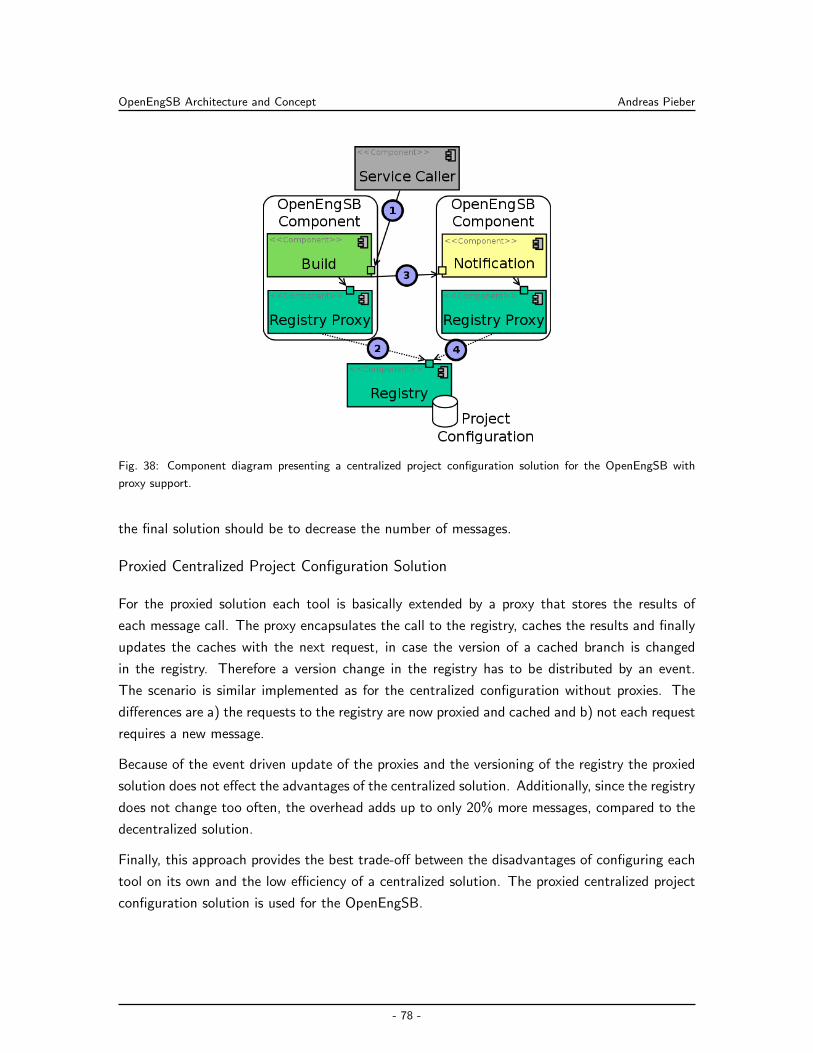
OpenEngSB Architecture and Concept Andreas Pieber
Fig. 38: Component diagram presenting a centralized project configuration solution for the OpenEngSB with
proxy support.
the final solution should be to decrease the number of messages.
Proxied Centralized Project Configuration Solution
For the proxied solution each tool is basically extended by a proxy that stores the results of
each message call. The proxy encapsulates the call to the registry, caches the results and finally
updates the caches with the next request, in case the version of a cached branch is changed
in the registry. Therefore a version change in the registry has to be distributed by an event.
The scenario is similar implemented as for the centralized configuration without proxies. The
differences are a) the requests to the registry are now proxied and cached and b) not each request
requires a new message.
Because of the event driven update of the proxies and the versioning of the registry the proxied
solution does not effect the advantages of the centralized solution. Additionally, since the registry
does not change too often, the overhead adds up to only 20% more messages, compared to the
decentralized solution.
Finally, this approach provides the best trade-off between the disadvantages of configuring each
tool on its own and the low efficiency of a centralized solution. The proxied centralized project
configuration solution is used for the OpenEngSB.
- 78 -
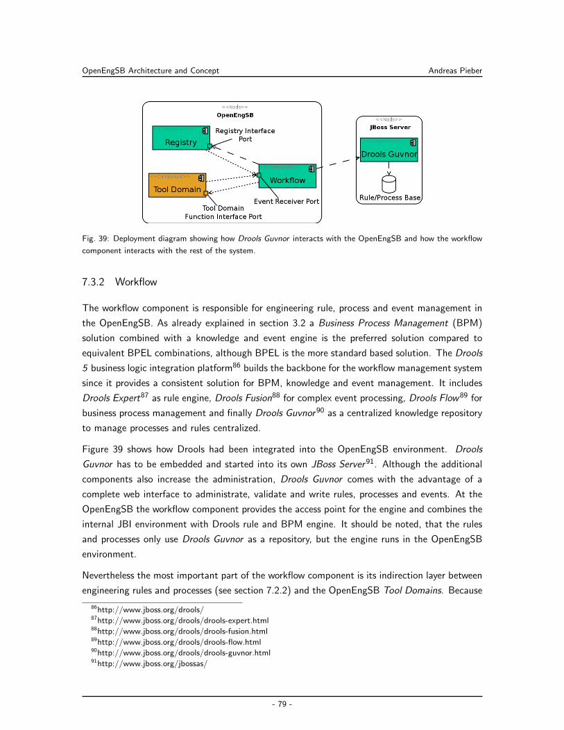
OpenEngSB Architecture and Concept Andreas Pieber
Fig. 39: Deployment diagram showing how Drools Guvnor interacts with the OpenEngSB and how the workflow
component interacts with the rest of the system.
7.3.2 Workflow
The workflow component is responsible for engineering rule, process and event management in
the OpenEngSB. As already explained in section 3.2 a Business Process Management (BPM)
solution combined with a knowledge and event engine is the preferred solution compared to
equivalent BPEL combinations, although BPEL is the more standard based solution. The Drools
5 business logic integration platform86 builds the backbone for the workflow management system
since it provides a consistent solution for BPM, knowledge and event management. It includes
Drools Expert87 as rule engine, Drools Fusion88 for complex event processing, Drools Flow89 for
business process management and finally Drools Guvnor90 as a centralized knowledge repository
to manage processes and rules centralized.
Figure 39 shows how Drools had been integrated into the OpenEngSB environment. Drools
Guvnor has to be embedded and started into its own JBoss Server91. Although the additional
components also increase the administration, Drools Guvnor comes with the advantage of a
complete web interface to administrate, validate and write rules, processes and events. At the
OpenEngSB the workflow component provides the access point for the engine and combines the
internal JBI environment with Drools rule and BPM engine. It should be noted, that the rules
and processes only use Drools Guvnor as a repository, but the engine runs in the OpenEngSB
environment.
Nevertheless the most important part of the workflow component is its indirection layer between
engineering rules and processes (see section 7.2.2) and the OpenEngSB Tool Domains. Because
86http://www.jboss.org/drools/87http://www.jboss.org/drools/drools-expert.html88http://www.jboss.org/drools/drools-fusion.html89http://www.jboss.org/drools/drools-flow.html90http://www.jboss.org/drools/drools-guvnor.html91http://www.jboss.org/jbossas/
- 79 -
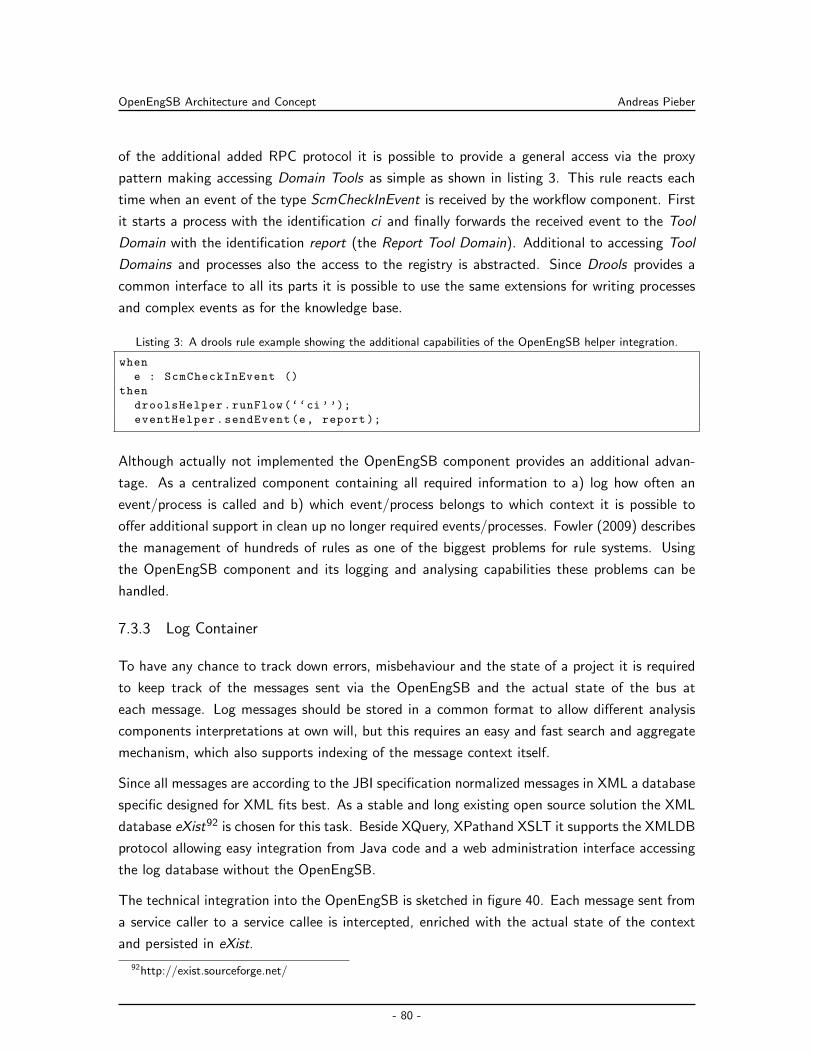
OpenEngSB Architecture and Concept Andreas Pieber
of the additional added RPC protocol it is possible to provide a general access via the proxy
pattern making accessing Domain Tools as simple as shown in listing 3. This rule reacts each
time when an event of the type ScmCheckInEvent is received by the workflow component. First
it starts a process with the identification ci and finally forwards the received event to the Tool
Domain with the identification report (the Report Tool Domain). Additional to accessing Tool
Domains and processes also the access to the registry is abstracted. Since Drools provides a
common interface to all its parts it is possible to use the same extensions for writing processes
and complex events as for the knowledge base.
Listing 3: A drools rule example showing the additional capabilities of the OpenEngSB helper integration.
when
e : ScmCheckInEvent ()
then
droolsHelper.runFlow(‘‘ci ’’);
eventHelper.sendEvent(e, report );
Although actually not implemented the OpenEngSB component provides an additional advan-
tage. As a centralized component containing all required information to a) log how often an
event/process is called and b) which event/process belongs to which context it is possible to
offer additional support in clean up no longer required events/processes. Fowler (2009) describes
the management of hundreds of rules as one of the biggest problems for rule systems. Using
the OpenEngSB component and its logging and analysing capabilities these problems can be
handled.
7.3.3 Log Container
To have any chance to track down errors, misbehaviour and the state of a project it is required
to keep track of the messages sent via the OpenEngSB and the actual state of the bus at
each message. Log messages should be stored in a common format to allow different analysis
components interpretations at own will, but this requires an easy and fast search and aggregate
mechanism, which also supports indexing of the message context itself.
Since all messages are according to the JBI specification normalized messages in XML a database
specific designed for XML fits best. As a stable and long existing open source solution the XML
database eXist92 is chosen for this task. Beside XQuery, XPathand XSLT it supports the XMLDB
protocol allowing easy integration from Java code and a web administration interface accessing
the log database without the OpenEngSB.
The technical integration into the OpenEngSB is sketched in figure 40. Each message sent from
a service caller to a service callee is intercepted, enriched with the actual state of the context
and persisted in eXist.
92http://exist.sourceforge.net/
- 80 -
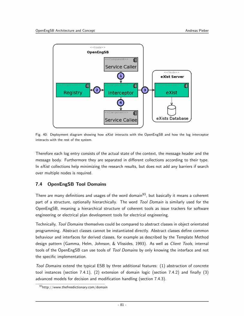
OpenEngSB Architecture and Concept Andreas Pieber
Fig. 40: Deployment diagram showing how eXist interacts with the OpenEngSB and how the log interceptor
interacts with the rest of the system.
Therefore each log entry consists of the actual state of the context, the message header and the
message body. Furthermore they are separated in different collections according to their type.
In eXist collections help minimizing the research results, but does not add any barriers if search
over multiple nodes is required.
7.4 OpenEngSB Tool Domains
There are many definitions and usages of the word domain93, but basically it means a coherent
part of a structure, optionally hierarchically. The word Tool Domain is similarly used for the
OpenEngSB, meaning a hierarchical structure of coherent tools as issue trackers for software
engineering or electrical plan development tools for electrical engineering.
Technically, Tool Domains themselves could be compared to abstract classes in object orientated
programming. Abstract classes cannot be instantiated directly. Abstract classes define common
behaviour and interfaces for derived classes, for example as described by the Template Method
design pattern (Gamma, Helm, Johnson, & Vlissides, 1993). As well as Client Tools, internal
tools of the OpenEngSB can use tools of Tool Domains by only knowing the interface and not
the specific implementation.
Tool Domains extend the typical ESB by three additional features: (1) abstraction of concrete
tool instances (section 7.4.1), (2) extension of domain logic (section 7.4.2) and finally (3)
advanced models for decision and modification handling (section 7.4.3).
93http://www.thefreedictionary.com/domain
- 81 -
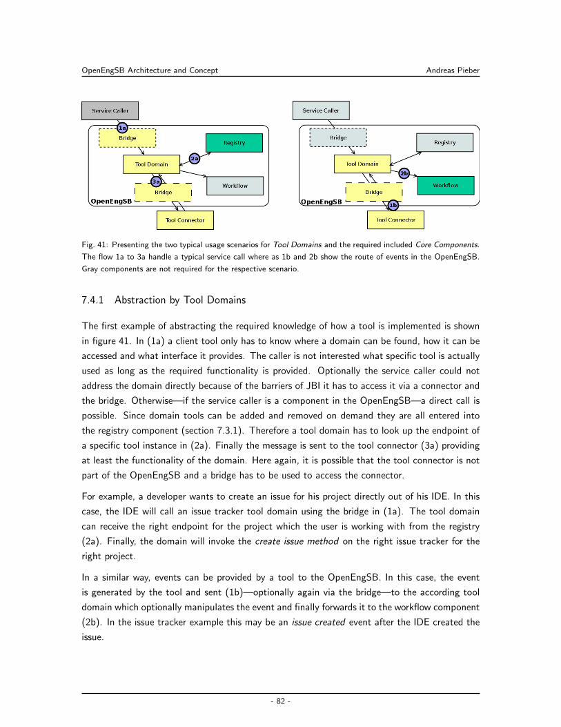
OpenEngSB Architecture and Concept Andreas Pieber
Fig. 41: Presenting the two typical usage scenarios for Tool Domains and the required included Core Components.
The flow 1a to 3a handle a typical service call where as 1b and 2b show the route of events in the OpenEngSB.
Gray components are not required for the respective scenario.
7.4.1 Abstraction by Tool Domains
The first example of abstracting the required knowledge of how a tool is implemented is shown
in figure 41. In (1a) a client tool only has to know where a domain can be found, how it can be
accessed and what interface it provides. The caller is not interested what specific tool is actually
used as long as the required functionality is provided. Optionally the service caller could not
address the domain directly because of the barriers of JBI it has to access it via a connector and
the bridge. Otherwise—if the service caller is a component in the OpenEngSB—a direct call is
possible. Since domain tools can be added and removed on demand they are all entered into
the registry component (section 7.3.1). Therefore a tool domain has to look up the endpoint of
a specific tool instance in (2a). Finally the message is sent to the tool connector (3a) providing
at least the functionality of the domain. Here again, it is possible that the tool connector is not
part of the OpenEngSB and a bridge has to be used to access the connector.
For example, a developer wants to create an issue for his project directly out of his IDE. In this
case, the IDE will call an issue tracker tool domain using the bridge in (1a). The tool domain
can receive the right endpoint for the project which the user is working with from the registry
(2a). Finally, the domain will invoke the create issue method on the right issue tracker for the
right project.
In a similar way, events can be provided by a tool to the OpenEngSB. In this case, the event
is generated by the tool and sent (1b)—optionally again via the bridge—to the according tool
domain which optionally manipulates the event and finally forwards it to the workflow component
(2b). In the issue tracker example this may be an issue created event after the IDE created the
issue.
- 82 -
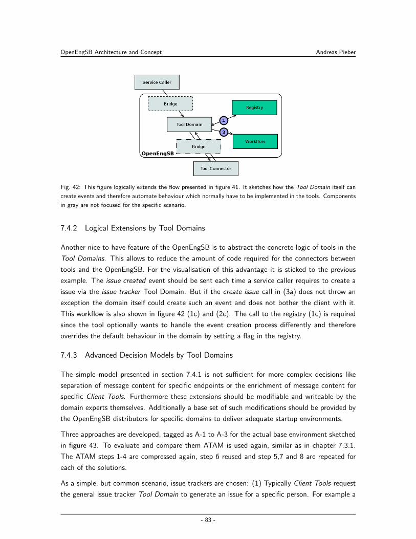
OpenEngSB Architecture and Concept Andreas Pieber
Fig. 42: This figure logically extends the flow presented in figure 41. It sketches how the Tool Domain itself can
create events and therefore automate behaviour which normally have to be implemented in the tools. Components
in gray are not focused for the specific scenario.
7.4.2 Logical Extensions by Tool Domains
Another nice-to-have feature of the OpenEngSB is to abstract the concrete logic of tools in the
Tool Domains. This allows to reduce the amount of code required for the connectors between
tools and the OpenEngSB. For the visualisation of this advantage it is sticked to the previous
example. The issue created event should be sent each time a service caller requires to create a
issue via the issue tracker Tool Domain. But if the create issue call in (3a) does not throw an
exception the domain itself could create such an event and does not bother the client with it.
This workflow is also shown in figure 42 (1c) and (2c). The call to the registry (1c) is required
since the tool optionally wants to handle the event creation process differently and therefore
overrides the default behaviour in the domain by setting a flag in the registry.
7.4.3 Advanced Decision Models by Tool Domains
The simple model presented in section 7.4.1 is not sufficient for more complex decisions like
separation of message content for specific endpoints or the enrichment of message content for
specific Client Tools. Furthermore these extensions should be modifiable and writeable by the
domain experts themselves. Additionally a base set of such modifications should be provided by
the OpenEngSB distributors for specific domains to deliver adequate startup environments.
Three approaches are developed, tagged as A-1 to A-3 for the actual base environment sketched
in figure 43. To evaluate and compare them ATAM is used again, similar as in chapter 7.3.1.
The ATAM steps 1-4 are compressed again, step 6 reused and step 5,7 and 8 are repeated for
each of the solutions.
As a simple, but common scenario, issue trackers are chosen: (1) Typically Client Tools request
the general issue tracker Tool Domain to generate an issue for a specific person. For example a
- 83 -
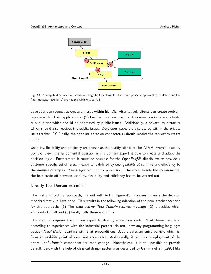
OpenEngSB Architecture and Concept Andreas Pieber
Fig. 43: A simplified service call scenario using the OpenEngSB. The three possible approaches to determine the
final message receiver(s) are tagged with A-1 to A-3.
developer can request to create an issue within his IDE. Alternatively clients can create problem
reports within their applications. (2) Furthermore, assume that two issue tracker are available.
A public one which should be addressed by public issues. Additionally, a private issue tracker
which should also receives the public issues. Developer issues are also stored within the private
issue tracker. (3) Finally, the right issue tracker connector(s) should receive the request to create
an issue.
Usability, flexibility and efficiency are chosen as the quality attributes for ATAM. From a usability
point of view, the fundamental question is if a domain expert is able to create and adapt the
decision logic. Furthermore it must be possible for the OpenEngSB distributor to provide a
customer specific set of rules. Flexibility is defined by changeability at runtime and efficiency by
the number of steps and messages required for a decision. Therefore, beside the requirements,
the best trade-off between usability, flexibility and efficiency has to be worked out.
Directly Tool Domain Extensions
The first architectural approach, marked with A-1 in figure 43, proposes to write the decision
models directly in Java code. This results in the following adaption of the issue tracker scenario
for this approach: (1) The issue tracker Tool Domain receives message, (2) it decides which
endpoints to call and (3) finally calls these endpoints.
This solution requires the domain expert to directly write Java code. Most domain experts,
according to experiences with the industrial partner, do not know any programming languages
beside Visual Basic. Starting with that preconditions, Java creates an entry barrier, which is,
from an usability point of view, not acceptable. Additionally, it requires redeployment of the
entire Tool Domain component for each change. Nonetheless, it is still possible to provide
default logic with the help of classical design patterns as described by Gamma et al. (1993) like
- 84 -
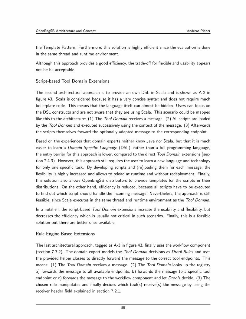
OpenEngSB Architecture and Concept Andreas Pieber
the Template Pattern. Furthermore, this solution is highly efficient since the evaluation is done
in the same thread and runtime environment.
Although this approach provides a good efficiency, the trade-off for flexible and usability appears
not be be acceptable.
Script-based Tool Domain Extensions
The second architectural approach is to provide an own DSL in Scala and is shown as A-2 in
figure 43. Scala is considered because it has a very concise syntax and does not require much
boilerplate code. This means that the language itself can almost be hidden. Users can focus on
the DSL constructs and are not aware that they are using Scala. This scenario could be mapped
like this to the architecture: (1) The Tool Domain receives a message. (2) All scripts are loaded
by the Tool Domain and executed successively using the context of the message. (3) Afterwards
the scripts themselves forward the optionally adapted message to the corresponding endpoint.
Based on the experiences that domain experts neither know Java nor Scala, but that it is much
easier to learn a Domain Specific Language (DSL), rather than a full programming language,
the entry barrier for this approach is lower, compared to the direct Tool Domain extensions (sec-
tion 7.4.3). However, this approach still requires the user to learn a new language and technology
for only one specific task. By developing scripts and (re)loading them for each message, the
flexibility is highly increased and allows to reload at runtime and without redeployment. Finally,
this solution also allows OpenEngSB distributors to provide templates for the scripts in their
distributions. On the other hand, efficiency is reduced, because all scripts have to be executed
to find out which script should handle the incoming message. Nevertheless, the approach is still
feasible, since Scala executes in the same thread and runtime environment as the Tool Domain.
In a nutshell, the script-based Tool Domain extensions increase the usability and flexibility, but
decreases the efficiency which is usually not critical in such scenarios. Finally, this is a feasible
solution but there are better ones available.
Rule Engine Based Extensions
The last architectural approach, tagged as A-3 in figure 43, finally uses the workflow component
(section 7.3.2). The domain expert models the Tool Domain decisions as Drool Rules and uses
the provided helper classes to directly forward the message to the correct tool endpoints. This
means: (1) The Tool Domain receives a message. (2) The Tool Domain looks up the registry
a) forwards the message to all available endpoints, b) forwards the message to a specific tool
endpoint or c) forwards the message to the workflow component and let Drools decide. (3) The
chosen rule manipulates and finally decides which tool(s) receive(s) the message by using the
receiver header field explained in section 7.2.1.
- 85 -
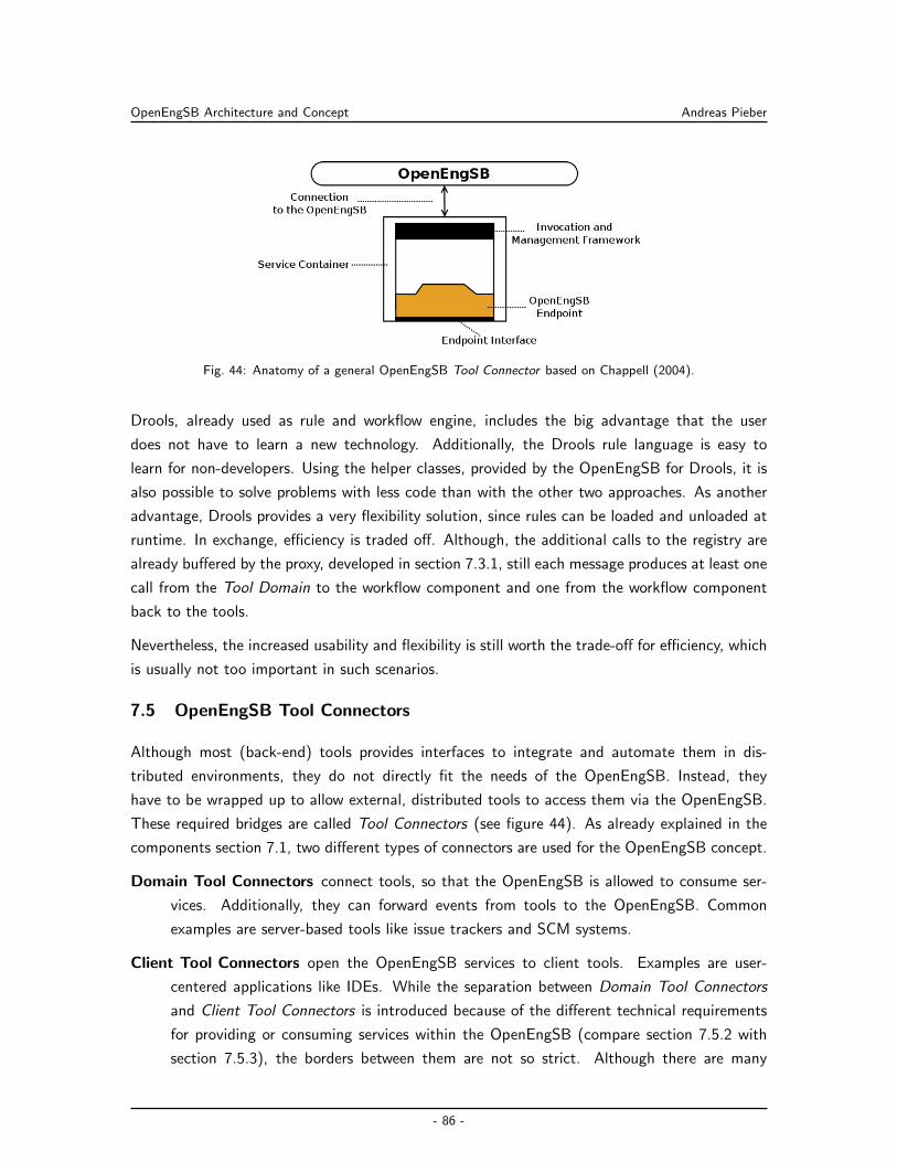
OpenEngSB Architecture and Concept Andreas Pieber
Fig. 44: Anatomy of a general OpenEngSB Tool Connector based on Chappell (2004).
Drools, already used as rule and workflow engine, includes the big advantage that the user
does not have to learn a new technology. Additionally, the Drools rule language is easy to
learn for non-developers. Using the helper classes, provided by the OpenEngSB for Drools, it is
also possible to solve problems with less code than with the other two approaches. As another
advantage, Drools provides a very flexibility solution, since rules can be loaded and unloaded at
runtime. In exchange, efficiency is traded off. Although, the additional calls to the registry are
already buffered by the proxy, developed in section 7.3.1, still each message produces at least one
call from the Tool Domain to the workflow component and one from the workflow component
back to the tools.
Nevertheless, the increased usability and flexibility is still worth the trade-off for efficiency, which
is usually not too important in such scenarios.
7.5 OpenEngSB Tool Connectors
Although most (back-end) tools provides interfaces to integrate and automate them in dis-
tributed environments, they do not directly fit the needs of the OpenEngSB. Instead, they
have to be wrapped up to allow external, distributed tools to access them via the OpenEngSB.
These required bridges are called Tool Connectors (see figure 44). As already explained in the
components section 7.1, two different types of connectors are used for the OpenEngSB concept.
Domain Tool Connectors connect tools, so that the OpenEngSB is allowed to consume ser-
vices. Additionally, they can forward events from tools to the OpenEngSB. Common
examples are server-based tools like issue trackers and SCM systems.
Client Tool Connectors open the OpenEngSB services to client tools. Examples are user-
centered applications like IDEs. While the separation between Domain Tool Connectors
and Client Tool Connectors is introduced because of the different technical requirements
for providing or consuming services within the OpenEngSB (compare section 7.5.2 with
section 7.5.3), the borders between them are not so strict. Although there are many
- 86 -
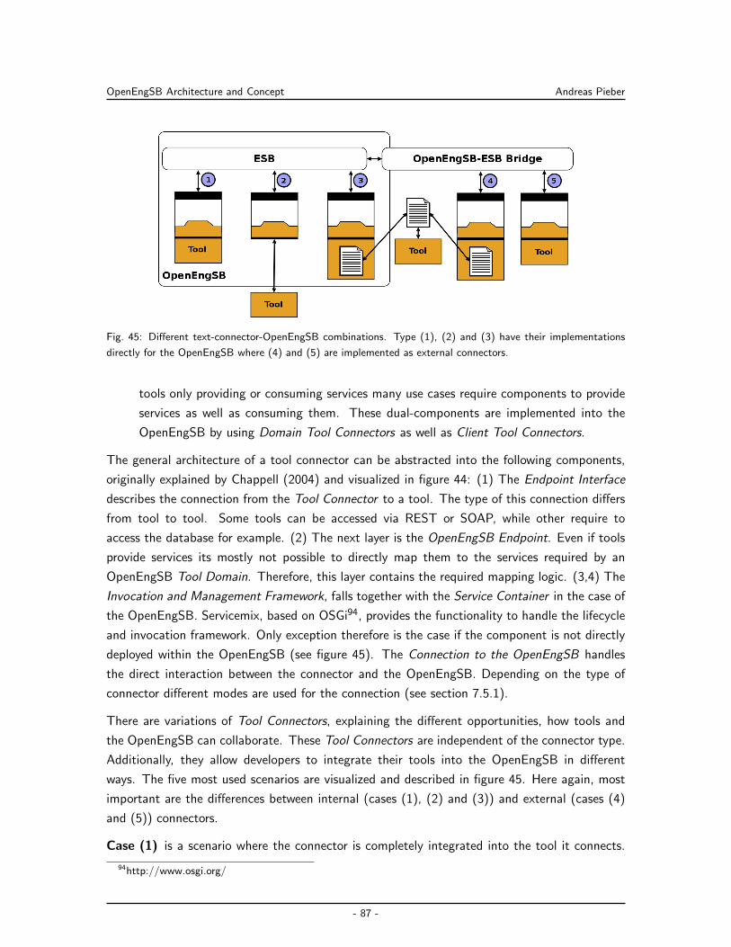
OpenEngSB Architecture and Concept Andreas Pieber
Fig. 45: Different text-connector-OpenEngSB combinations. Type (1), (2) and (3) have their implementations
directly for the OpenEngSB where (4) and (5) are implemented as external connectors.
tools only providing or consuming services many use cases require components to provide
services as well as consuming them. These dual-components are implemented into the
OpenEngSB by using Domain Tool Connectors as well as Client Tool Connectors.
The general architecture of a tool connector can be abstracted into the following components,
originally explained by Chappell (2004) and visualized in figure 44: (1) The Endpoint Interface
describes the connection from the Tool Connector to a tool. The type of this connection differs
from tool to tool. Some tools can be accessed via REST or SOAP, while other require to
access the database for example. (2) The next layer is the OpenEngSB Endpoint. Even if tools
provide services its mostly not possible to directly map them to the services required by an
OpenEngSB Tool Domain. Therefore, this layer contains the required mapping logic. (3,4) The
Invocation and Management Framework, falls together with the Service Container in the case of
the OpenEngSB. Servicemix, based on OSGi94, provides the functionality to handle the lifecycle
and invocation framework. Only exception therefore is the case if the component is not directly
deployed within the OpenEngSB (see figure 45). The Connection to the OpenEngSB handles
the direct interaction between the connector and the OpenEngSB. Depending on the type of
connector different modes are used for the connection (see section 7.5.1).
There are variations of Tool Connectors, explaining the different opportunities, how tools and
the OpenEngSB can collaborate. These Tool Connectors are independent of the connector type.
Additionally, they allow developers to integrate their tools into the OpenEngSB in different
ways. The five most used scenarios are visualized and described in figure 45. Here again, most
important are the differences between internal (cases (1), (2) and (3)) and external (cases (4)
and (5)) connectors.
Case (1) is a scenario where the connector is completely integrated into the tool it connects.
94http://www.osgi.org/
- 87 -
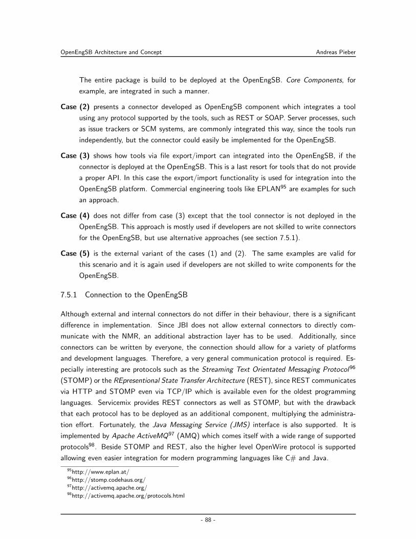
OpenEngSB Architecture and Concept Andreas Pieber
The entire package is build to be deployed at the OpenEngSB. Core Components, for
example, are integrated in such a manner.
Case (2) presents a connector developed as OpenEngSB component which integrates a tool
using any protocol supported by the tools, such as REST or SOAP. Server processes, such
as issue trackers or SCM systems, are commonly integrated this way, since the tools run
independently, but the connector could easily be implemented for the OpenEngSB.
Case (3) shows how tools via file export/import can integrated into the OpenEngSB, if the
connector is deployed at the OpenEngSB. This is a last resort for tools that do not provide
a proper API. In this case the export/import functionality is used for integration into the
OpenEngSB platform. Commercial engineering tools like EPLAN95 are examples for such
an approach.
Case (4) does not differ from case (3) except that the tool connector is not deployed in the
OpenEngSB. This approach is mostly used if developers are not skilled to write connectors
for the OpenEngSB, but use alternative approaches (see section 7.5.1).
Case (5) is the external variant of the cases (1) and (2). The same examples are valid for
this scenario and it is again used if developers are not skilled to write components for the
OpenEngSB.
7.5.1 Connection to the OpenEngSB
Although external and internal connectors do not differ in their behaviour, there is a significant
difference in implementation. Since JBI does not allow external connectors to directly com-
municate with the NMR, an additional abstraction layer has to be used. Additionally, since
connectors can be written by everyone, the connection should allow for a variety of platforms
and development languages. Therefore, a very general communication protocol is required. Es-
pecially interesting are protocols such as the Streaming Text Orientated Messaging Protocol96
(STOMP) or the REpresentional State Transfer Architecture (REST), since REST communicates
via HTTP and STOMP even via TCP/IP which is available even for the oldest programming
languages. Servicemix provides REST connectors as well as STOMP, but with the drawback
that each protocol has to be deployed as an additional component, multiplying the administra-
tion effort. Fortunately, the Java Messaging Service (JMS) interface is also supported. It is
implemented by Apache ActiveMQ97 (AMQ) which comes itself with a wide range of supported
protocols98. Beside STOMP and REST, also the higher level OpenWire protocol is supported
allowing even easier integration for modern programming languages like C# and Java.
95http://www.eplan.at/96http://stomp.codehaus.org/97http://activemq.apache.org/98http://activemq.apache.org/protocols.html
- 88 -
OpenEngSB Architecture and Concept Andreas Pieber
Fig. 46: External Client Tools calling services on the OpenEngSB.
7.5.2 Integrating External Client Tools
Client Tools simply want to use services provided by either tool domains or Core Components.
Figure 46 visualizes the scenario of a Domain Tool consuming a Tool Domain service: (1) The
communication is triggered by a domain tool which wants to call a service. Therefore the Client
Tool requests a functionality from the Client Tool Connector via the Endpoint Interface shown
in figure 44. (2) The Tool Connector creates a message from the request and sends it via Open-
Wire (JMS,NMS), REST or STOMP, depending on the development language. (3) The bridge
receives the message via the Domain Service Queue, transforms it to a normalized message and
forwards it to the addressed Tool Domain. (4) The Tool Domain handles the request as explained
in chapter 7.4 and sends response to the bridge via the NMR. (5) The bridge transforms the
message back and puts it into to a temporary response queue, which was created by the sender.
(6) The Client Tool Connector reads the response from the temporary queue and prepares a
return value for the Client Tool. (7) Finally, the return value is returned to the original caller.
For easier management, each input queue for a domain starts with the root namespace of the
OpenEngSB and appends the name of the domain. The temporary response queue additionally
adds the word response and an Universal Unique Identifier (UUID). For example, the queue for
the issue tracker Tool Domain is reached by org.openengsb.issueTracker. The response is sent to
a queue named: org.openengsb.issueTracker.response.UUID. Core services are accessed exactly
the same way, as presented in figure 46, but the naming schema uses the name of the core
component instead of a domain name (e.g.: org.openengsb.registry).
- 89 -
OpenEngSB Architecture and Concept Andreas Pieber
7.5.3 Integrating External Domain Tools
Domain Tool Connectors compared to Client Tools Connectors are different by definition, but
similar in the used architecture. Basically the same flow as explained in section 7.4 is valid. For
services provided by Client Tools Connectors, respectively by the tools they wrap, the entire flow
is the same as presented in section 7.4, but inverted. Client Tool Connectors have to register
themselves with a message queue they have created and a unique identifier at the Registry Core
Component. The Tool Domain accesses them via these queues. For events, to reduce the
administrative effort, only one queue is provided for each Tool Domain at the OpenEngSB, so
the Tool Connectors have to append their identifier to each message.
Naming event queues is similar to naming Tool Domain queues as explained for External Client
Tools, but extended by events. For the issue tracker Tool Domain this means, for example, to
have a queue with the name org.openengsb.issueTracker.events for events. To the names of
service queues the tool identifier is appended at the end of the queue name. For example, this
will result, for the issue tracker Mantis, to be org.openengsb.issueTracker.mantis and for the
temporary response queues org.openengsb.issueTracker.mantis.response.UUID.
7.5.4 Integrating Internal Client and Domain Tools
Actually, the situation (1), (2) and (3), as sketched in figure 45, are much easier to handle,
compared to external Client- and Domain Tools. Tools, directly deployed to the OpenEngSB,
are allowed to interact directly and without additional bridges with Tool Domains and Core
Components.
7.6 Process Design and Implementation with the OpenEngSB
After an analyst finished analysing the process of a (software+) engineering team (see section 6)
the question is still open on how to map the results of the analysis to a technical integration. With
the help of the OpenEngSB framework a direct mapping should be made possible. This section
identifies how system architects or system integrators can transform the analysts artifacts into
design description, from which finally executable artifacts for the OpenEngSB can be created.
As a foundation for the design of the (software+) engineering process to the OpenEngSB en-
vironment this thesis uses the 4+1 view model as defined by Kruchten (1995). Each of the
five views in the 4+1 model is designed using an architecture-centered, scenario driven, iterative
development process. The 4+1 model seams to fit best for the mapping from the scenario based
analyse model to the implementation because: (a) the model focuses to address the concerns of
various stakeholders; (b) functional and non-functional requirements are handled separated; (c)
a scenario based appraoch is provided. Figure 47 presents the overview of the 4+1 model. It
consists of the different views, namely Logical View, Development View, Process View, Physical
- 90 -
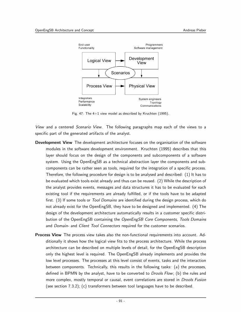
OpenEngSB Architecture and Concept Andreas Pieber
Fig. 47: The 4+1 view model as described by Kruchten (1995).
View and a centered Scenario View. The following paragraphs map each of the views to a
specific part of the generated artifacts of the analyst.
Development View The development architecture focuses on the organisation of the software
modules in the software development environment. Kruchten (1995) describes that this
layer should focus on the design of the components and subcomponents of a software
system. Using the OpenEngSB as a technical abstraction layer the components and sub-
components can be rather seen as tools, required for the integration of a specific process.
Therefore, the following procedure for design is to be analysed and described: (1) It has to
be evaluated which tools exist already and thus can be reused. (2) While the description of
the analyst provides events, messages and data structures it has to be evaluated for each
existing tool if the requirements are already fulfilled, or if the tools have to be adapted
first. (3) If some tools or Tool Domains are identified during the design process, which do
not already exist for the OpenEngSB, they have to be designed and implemented. (4) The
design of the development architecture automatically results in a customer specific distri-
bution of the OpenEngSB containing the OpenEngSB Core Components, Tools Domains
and Domain- and Client Tool Connectors required for the customer scenarios.
Process View The process view takes also the non-functional requirements into account. Ad-
ditionally it shows how the logical view fits to the process architecture. While the process
architecture can be described on multiple levels of detail, for the OpenEngSB description
only the highest level is required. The OpenEngSB already implements and provides the
low level processes. The processes at this level consist of events, tasks and the interaction
between components. Technically, this results in the following tasks: (a) the processes,
defined in BPMN by the analyst, have to be converted to Drools Flow ; (b) the rules and
more complex, mostly temporal or causal, event correlations are stored in Drools Fusion
(see section 7.3.2); (c) transformers between tool languages have to be described.
- 91 -
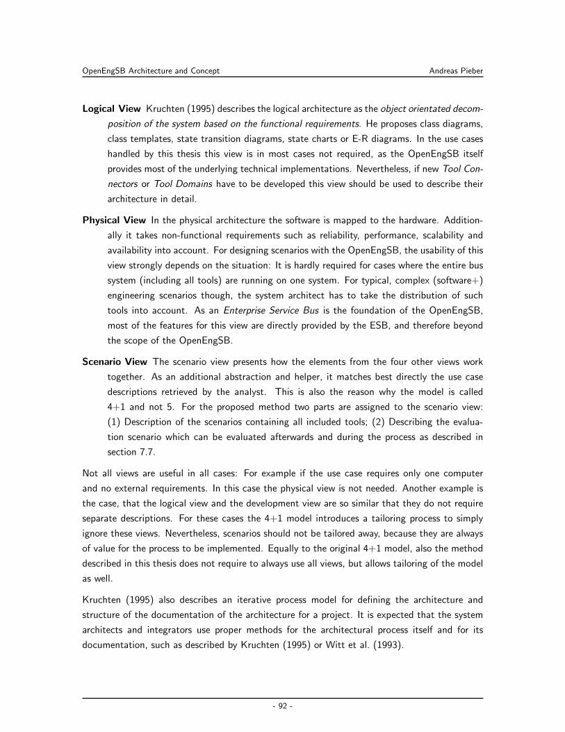
OpenEngSB Architecture and Concept Andreas Pieber
Logical View Kruchten (1995) describes the logical architecture as the object orientated decom-
position of the system based on the functional requirements. He proposes class diagrams,
class templates, state transition diagrams, state charts or E-R diagrams. In the use cases
handled by this thesis this view is in most cases not required, as the OpenEngSB itself
provides most of the underlying technical implementations. Nevertheless, if new Tool Con-
nectors or Tool Domains have to be developed this view should be used to describe their
architecture in detail.
Physical View In the physical architecture the software is mapped to the hardware. Addition-
ally it takes non-functional requirements such as reliability, performance, scalability and
availability into account. For designing scenarios with the OpenEngSB, the usability of this
view strongly depends on the situation: It is hardly required for cases where the entire bus
system (including all tools) are running on one system. For typical, complex (software+)
engineering scenarios though, the system architect has to take the distribution of such
tools into account. As an Enterprise Service Bus is the foundation of the OpenEngSB,
most of the features for this view are directly provided by the ESB, and therefore beyond
the scope of the OpenEngSB.
Scenario View The scenario view presents how the elements from the four other views work
together. As an additional abstraction and helper, it matches best directly the use case
descriptions retrieved by the analyst. This is also the reason why the model is called
4+1 and not 5. For the proposed method two parts are assigned to the scenario view:
(1) Description of the scenarios containing all included tools; (2) Describing the evalua-
tion scenario which can be evaluated afterwards and during the process as described in
section 7.7.
Not all views are useful in all cases: For example if the use case requires only one computer
and no external requirements. In this case the physical view is not needed. Another example is
the case, that the logical view and the development view are so similar that they do not require
separate descriptions. For these cases the 4+1 model introduces a tailoring process to simply
ignore these views. Nevertheless, scenarios should not be tailored away, because they are always
of value for the process to be implemented. Equally to the original 4+1 model, also the method
described in this thesis does not require to always use all views, but allows tailoring of the model
as well.
Kruchten (1995) also describes an iterative process model for defining the architecture and
structure of the documentation of the architecture for a project. It is expected that the system
architects and integrators use proper methods for the architectural process itself and for its
documentation, such as described by Kruchten (1995) or Witt et al. (1993).
- 92 -
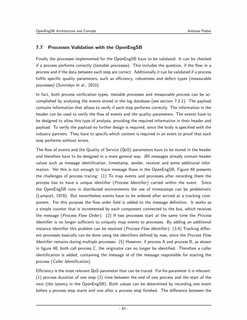
OpenEngSB Architecture and Concept Andreas Pieber
7.7 Processes Validation with the OpenEngSB
Finally the processes implemented for the OpenEngSB have to be validated. It can be checked
if a process performs correctly (testable processes). This includes the question, if the flow in a
process and if the data between each step are correct. Additionally it can be validated if a process
fulfils specific quality parameters, such as efficiency, robustness and defect types (measurable
processes) (Sunindyo et al., 2010).
In fact, both process verification types, testable processes and measurable process can be ac-
complished by analysing the events stored in the log database (see section 7.2.1). The payload
contains information that allows to verify if each step performs correctly. The information in the
header can be used to verify the flow of events and the quality parameters. The events have to
be designed to allow this type of analysis, providing the required information in their header and
payload. To verify the payload no further design is required, since the body is specified with the
industry partners. They have to specify which content is required in an event to proof that each
step performs without errors.
The flow of events and the Quality of Service (QoS) parameters have to be stored in the header
and therefore have to be designed in a more general way. JBI messages already contain header
values such as message identification, timestamp, sender, receiver and some additional infor-
mation. Yet this is not enough to trace message flows in the OpenEngSB. Figure 48 presents
the challenges of process tracing: (1) To map events and processes after recording them the
process has to have a unique identifier (Process Identifier) carried within the event. Since
the OpenEngSB runs in distributed environments the use of timestamps can be problematic
(Lamport, 1978). But nevertheless events have to be ordered after arrived at a tracking com-
ponent. For this purpose the flow order field is added to the message definition. It works as
a simple counter that is incremented by each component connected to the bus, which receives
the message (Process Flow Order). (2) If two processes start at the same time the Process
Identifier is no longer sufficient to uniquely map events to processes. By adding an additional
instance identifier this problem can be resolved (Process Flow Identifier). (3,4) Tracking differ-
ent processes basically can be done using the identifiers defined by now, since the Process Flow
Identifier remains during multiple processes. (5) However, if process A and process B, as shown
in figure 48, both call process C, the originator can no longer be identified. Therefore a caller
identification is added, containing the message id of the message responsible for starting the
process (Caller Identification).
Efficiency is the most relevant QoS parameter that can be traced. For his parameter it is relevant:
(1) process duration of one step (2) time between the end of one process and the start of the
next (the latency in the OpenEngSB). Both values can be determined by recording one event
before a process step starts and one after a process step finished. The difference between the
- 93 -
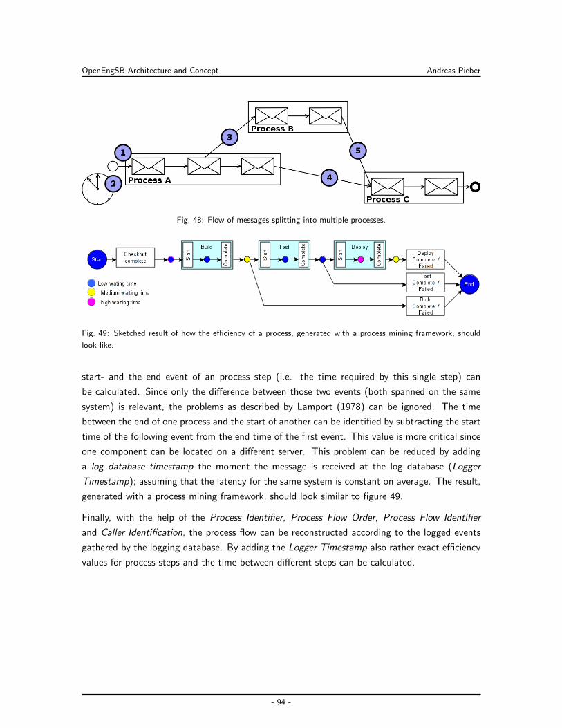
OpenEngSB Architecture and Concept Andreas Pieber
Fig. 48: Flow of messages splitting into multiple processes.
Fig. 49: Sketched result of how the efficiency of a process, generated with a process mining framework, should
look like.
start- and the end event of an process step (i.e. the time required by this single step) can
be calculated. Since only the difference between those two events (both spanned on the same
system) is relevant, the problems as described by Lamport (1978) can be ignored. The time
between the end of one process and the start of another can be identified by subtracting the start
time of the following event from the end time of the first event. This value is more critical since
one component can be located on a different server. This problem can be reduced by adding
a log database timestamp the moment the message is received at the log database (Logger
Timestamp); assuming that the latency for the same system is constant on average. The result,
generated with a process mining framework, should look similar to figure 49.
Finally, with the help of the Process Identifier, Process Flow Order, Process Flow Identifier
and Caller Identification, the process flow can be reconstructed according to the logged events
gathered by the logging database. By adding the Logger Timestamp also rather exact efficiency
values for process steps and the time between different steps can be calculated.
- 94 -
OpenEngSB Process Implementation and Evaluation Andreas Pieber
8 OpenEngSB Process Implementation and Evaluation
To evaluate the architectural concept of the OpenEngSB and the proposed method to describe
(software+) engineering processes in an abstract manner, two prototypes are implemented and
validated. Design, implementation and validation of the popular software engineering use case
Continuous Integration & Test, according to the analyses in section 6.3.1, are described in
section 8.1. The second use case (see section 8.2), shows the integration and extension of the
version management scenario for signal engineering, as analysed in section 6.3.2.
8.1 Continuous Integration & Test
The Continuous Integration & Test (CI&T) use case, as described by Fowler (2006), is one
of the most popular integration scenarios for software engineering. The use case is designed
and implemented for the OpenEngSB (see section 8.1.1), according to the method described
in section 7.6. Afterwards, it is described how the CI&T can be extended with the help of
the OpenEngSB (see section 8.1.2), tackling one of the limitations of typical CI&T server im-
plementations. Finally the use case is validated considering feasibility, efficiency, effectiveness,
performance and usability (see section 8.1.3), following the method described in section 7.7.
8.1.1 Design and Implementation for the OpenEngSB
The method developed for the OpenEngSB in section 7.6 requires to map the results of the
analyst to the architectural development, process, logical and physical view, before implementing
it. While the development, process and physical view are described in detail in this section the
logical view is not taken into account. As described in section 7.6 this section is optional and
should be used, within the proposed OpenEngSB method, to describe the detailed architecture
of Tool Domains, Tool Connectors and other components which have to be implemented. But
describing each component, implemented within this chapter, will simply go beyond the scope
of this thesis99.
Development View
Starting with the development view the first step is to analyse which Tool Connectors and Tool
Domains the connectors are assigned to, exist already and which have to be implemented first.
Starting with the first use case implemented for the OpenEngSB neither Tool Connectors nor
Tool Domains exist, resulting in a complete new implementation of all components. Since the
OpenEngSB is developed in an agile, iterative approach, and having no previous implementations,
each Tool Domain simply takes the methods as described by the analyst (see section 8.1).
99Nevertheless, the entire architectural documentation and implementation is available within the OpenEngSB
open source project at http://openengsb.org
- 95 -
OpenEngSB Process Implementation and Evaluation Andreas Pieber
Therefor, a build, test and SCM domain is added to support the basic checkout-build-test
process. To provide reports a report domain is implemented and for notifications a general
notification domain is designed according to the requirements described by the analyst. To
connect the proposed tools with the tool domains at the OpenEngSB the following connectors
have to be developed:
Subversion Connector: The subversion connector has to connect to an external subversion
repository. Additionally it has to checkout projects in the case of a change to provide
following tools with the latest version of the project. For implementing the connector the
SVNKit100 implementation is used. As a complete toolkit for Subversion, implemented in
Java, it can be used without requiring subversion to be installed on the client machine
running the OpenEngSB.
To inform other components about a new version available for a project the connector
publishes checkin-done events. To be itself notified about changes two options where con-
sidered: (1) to poll the repository and look for changes (2) to add a hook to the subversion
repository, notifying the connector directly via the OpenEngSB. Using a centralized reposi-
tory the second solution seamed more reasonable, reducing the network traffic significantly,
as the code is triggered only in case of change. The implementation of the hook is done
as a Perl101 script, sending a message to the right subversion connector via Stomp. The
ActiveMQ Stomp-JMS bridge is used to reach the Tool Connector at the OpenEngSB.
Maven Connectors: While two different Maven connectors are developed (one for build and
one for testing projects) both base on the same core code. To be able to use Maven 2
without installing it to the client machine running the OpenEngSB the Maven Embedder102
library is used. The build goals for each connector vary as defined in the analyse of the
CI&T scenario.
Reporting Connector: The reporting engine is developed specifically for OpenEngSB use cases,
since already existing solutions, such as Eclipse Birt103, only add an additional level of
complexity. More complex reporting layouts might be required in future though. The own
implementation of the reporting component, simply gathers events with unique IDs and
writes them into a file. The integration into the OpenEngSB and reporting domain is
straightforward as no additional components are required.
E-Mail Connector: To send mails, a connection to an SMTP server is required. Java already
offers a method to send mails via external servers using the javamail API104. Implementing
100http://svnkit.com/101http://www.perl.org/102http://maven.apache.org/guides/mini/guide-embedding-m2.html103http://www.eclipse.org/birt/104http://java.sun.com/products/javamail/
- 96 -
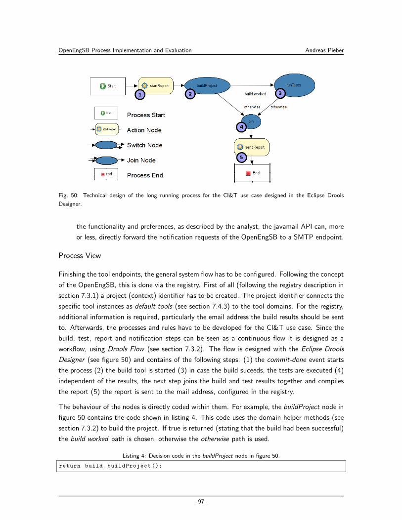
OpenEngSB Process Implementation and Evaluation Andreas Pieber
Fig. 50: Technical design of the long running process for the CI&T use case designed in the Eclipse Drools
Designer.
the functionality and preferences, as described by the analyst, the javamail API can, more
or less, directly forward the notification requests of the OpenEngSB to a SMTP endpoint.
Process View
Finishing the tool endpoints, the general system flow has to be configured. Following the concept
of the OpenEngSB, this is done via the registry. First of all (following the registry description in
section 7.3.1) a project (context) identifier has to be created. The project identifier connects the
specific tool instances as default tools (see section 7.4.3) to the tool domains. For the registry,
additional information is required, particularly the email address the build results should be sent
to. Afterwards, the processes and rules have to be developed for the CI&T use case. Since the
build, test, report and notification steps can be seen as a continuous flow it is designed as a
workflow, using Drools Flow (see section 7.3.2). The flow is designed with the Eclipse Drools
Designer (see figure 50) and contains of the following steps: (1) the commit-done event starts
the process (2) the build tool is started (3) in case the build suceeds, the tests are executed (4)
independent of the results, the next step joins the build and test results together and compiles
the report (5) the report is sent to the mail address, configured in the registry.
The behaviour of the nodes is directly coded within them. For example, the buildProject node in
figure 50 contains the code shown in listing 4. This code uses the domain helper methods (see
section 7.3.2) to build the project. If true is returned (stating that the build had been successful)
the build worked path is chosen, otherwise the otherwise path is used.
Listing 4: Decision code in the buildProject node in figure 50.
return build.buildProject ();
- 97 -
OpenEngSB Process Implementation and Evaluation Andreas Pieber
Finally, two additional challenges has to be handled: (1) The process has to be started by the
commit-done event; (2) All events, sent to the workflow component, have to be forwarded to
the report Tool Domain. Listing 5 shows the rule to fire the CI&T Drools Flow workflow. The
rule reacts on each event of the ScmCheckInEvent type, representing the commit-done event,
and starts a new instance of the CI&T process. Listing 6 presents the implementation of the
eventsToReport rule which forwards all events to the report engine. This rule reacts on each
event with the type Event—which is the base class of all events—and forwards it to the report
Tool Domain.
Listing 5: A drools rule to start the CI process on each ScmCheckInEvent.
package org.openengsb
rule ‘‘fireciworkflow ’’
when
e : ScmCheckInEvent ()
then
droolsHelper.runFlow(‘‘ci ’’);
Listing 6: Rule defining that each event retrieved at the rule engine should be forwareded to the report domain.
package org.openengsb
rule ‘‘eventsToReport ’’
when
e : Event ()
then
eventHelper.sendEventWithDefaultConfiguration(e, report );
Physical View
The physical view presents the layout of the OpenEngSB in a real system. Figure 51 presents
all Tool Domains and Tool Connectors, including core tools and the distribution logic. Using
the OpenEngSB workflow, logging and routing capabilities, also the three Core Components
Logging, Registry and Workflow are mandatory. Every component in figure 51 within the
OpenEngSB rectangle is designed to run within one OpenEngSB server instance. Tools without
the OpenEngSB can run on any machine, as long as reachable via the network. While all
Tool Domains are implemented within the OpenEngSB, because of their nature, also all Tool
Connectors are implemented within the OpenEngSB. Although the OpenEngSB architecture
also allows external Tool Connectors. Beside allowing better distribution and maintainability
of the distribution the performance is enhanced when implementing the connectors directly
as OpenEngSB components, reducing the number of bridges and transformations required to
transport the message from on connector to another. Although the Subversion, as well as
the Email Tool Connector are also implemented as OpenEngSB components, neither of them
requires the tools they work with to be on the same machine, helping the OpenEngSB to better
integrate within existing infrastructures.
- 98 -
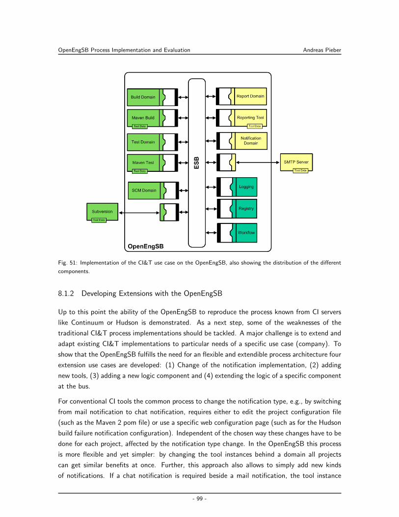
OpenEngSB Process Implementation and Evaluation Andreas Pieber
Fig. 51: Implementation of the CI&T use case on the OpenEngSB, also showing the distribution of the different
components.
8.1.2 Developing Extensions with the OpenEngSB
Up to this point the ability of the OpenEngSB to reproduce the process known from CI servers
like Continuum or Hudson is demonstrated. As a next step, some of the weaknesses of the
traditional CI&T process implementations should be tackled. A major challenge is to extend and
adapt existing CI&T implementations to particular needs of a specific use case (company). To
show that the OpenEngSB fulfills the need for an flexible and extendible process architecture four
extension use cases are developed: (1) Change of the notification implementation, (2) adding
new tools, (3) adding a new logic component and (4) extending the logic of a specific component
at the bus.
For conventional CI tools the common process to change the notification type, e.g., by switching
from mail notification to chat notification, requires either to edit the project configuration file
(such as the Maven 2 pom file) or use a specific web configuration page (such as for the Hudson
build failure notification configuration). Independent of the chosen way these changes have to be
done for each project, affected by the notification type change. In the OpenEngSB this process
is more flexible and yet simpler: by changing the tool instances behind a domain all projects
can get similar benefits at once. Further, this approach also allows to simply add new kinds
of notifications. If a chat notification is required beside a mail notification, the tool instance
- 99 -
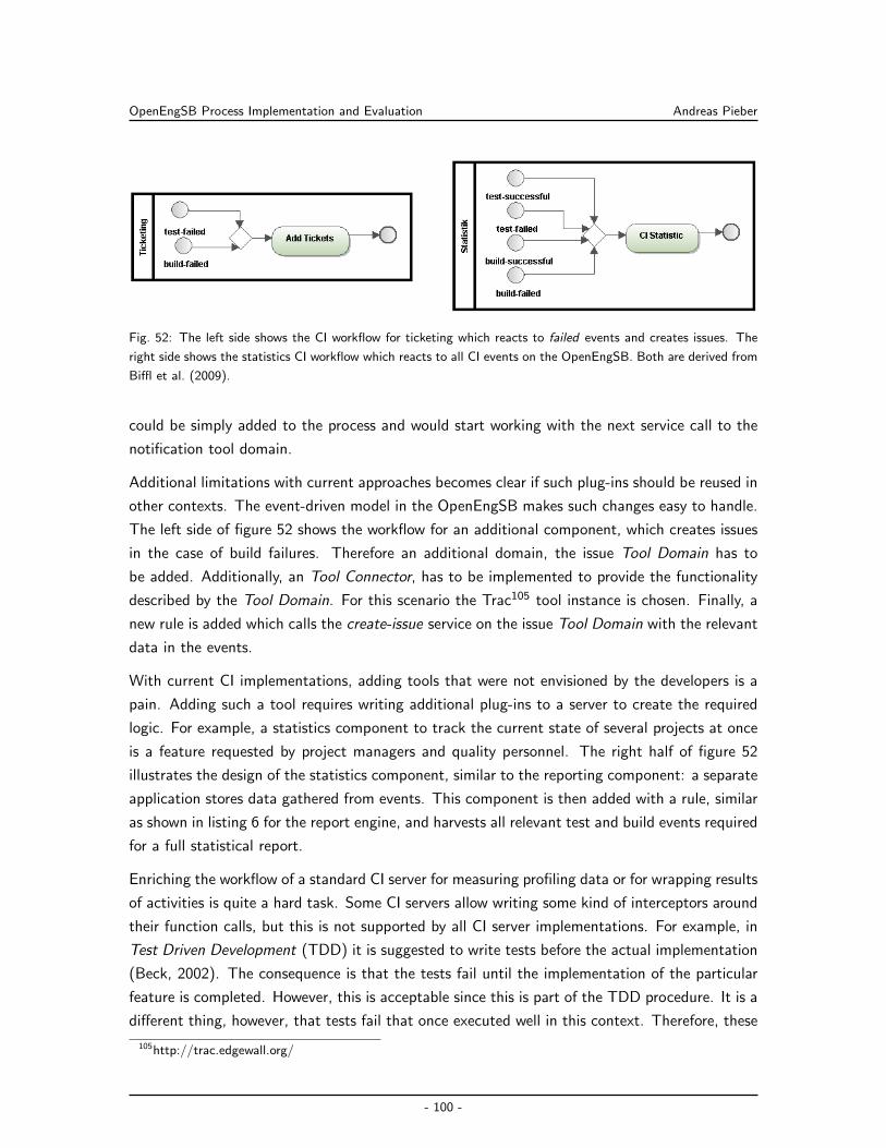
OpenEngSB Process Implementation and Evaluation Andreas Pieber
Fig. 52: The left side shows the CI workflow for ticketing which reacts to failed events and creates issues. The
right side shows the statistics CI workflow which reacts to all CI events on the OpenEngSB. Both are derived from
Biffl et al. (2009).
could be simply added to the process and would start working with the next service call to the
notification tool domain.
Additional limitations with current approaches becomes clear if such plug-ins should be reused in
other contexts. The event-driven model in the OpenEngSB makes such changes easy to handle.
The left side of figure 52 shows the workflow for an additional component, which creates issues
in the case of build failures. Therefore an additional domain, the issue Tool Domain has to
be added. Additionally, an Tool Connector, has to be implemented to provide the functionality
described by the Tool Domain. For this scenario the Trac105 tool instance is chosen. Finally, a
new rule is added which calls the create-issue service on the issue Tool Domain with the relevant
data in the events.
With current CI implementations, adding tools that were not envisioned by the developers is a
pain. Adding such a tool requires writing additional plug-ins to a server to create the required
logic. For example, a statistics component to track the current state of several projects at once
is a feature requested by project managers and quality personnel. The right half of figure 52
illustrates the design of the statistics component, similar to the reporting component: a separate
application stores data gathered from events. This component is then added with a rule, similar
as shown in listing 6 for the report engine, and harvests all relevant test and build events required
for a full statistical report.
Enriching the workflow of a standard CI server for measuring profiling data or for wrapping results
of activities is quite a hard task. Some CI servers allow writing some kind of interceptors around
their function calls, but this is not supported by all CI server implementations. For example, in
Test Driven Development (TDD) it is suggested to write tests before the actual implementation
(Beck, 2002). The consequence is that the tests fail until the implementation of the particular
feature is completed. However, this is acceptable since this is part of the TDD procedure. It is a
different thing, however, that tests fail that once executed well in this context. Therefore, these
105http://trac.edgewall.org/
- 100 -
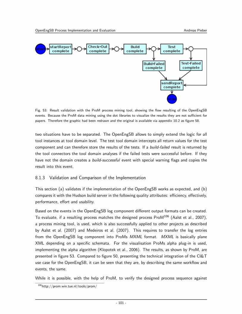
OpenEngSB Process Implementation and Evaluation Andreas Pieber
Fig. 53: Result validation with the ProM process mining tool, showing the flow resulting of the OpenEngSB
events. Because the ProM data mining using the dot libraries to visualize the results they are not sufficient for
papers. Therefore the graphic had been redrawn and the original is available via appendix 10.2 as figure 58.
two situations have to be separated. The OpenEngSB allows to simply extend the logic for all
tool instances at tool domain level. The test tool domain intercepts all return values for the test
component and can therefore store the results of the tests. If a build-failed result is returned by
the tool connectors the tool domain analyses if the failed tests were successful before. If they
have not the domain creates a build-successful event with special warning flags and copies the
result into this event.
8.1.3 Validation and Comparison of the Implementation
This section (a) validates if the implementation of the OpenEngSB works as expected, and (b)
compares it with the Hudson build server in the following quality attributes: efficiency, effectively,
performance, effort and usability.
Based on the events in the OpenEngSB log component different output formats can be created.
To evaluate, if a resulting process matches the designed process ProM106 (Aalst et al., 2007),
a process mining tool, is used, which is also successfully applied to other projects as described
by Aalst et al. (2007) and Medeiros et al. (2007). This requires to transfer the log entries
from the OpenEngSB log component into ProMs MXML format. MXML is basically plane
XML depending on a specific schemata. For the visualisation ProMs alpha plug-in is used,
implementing the alpha algorithm (Klopotek et al., 2006). The results, as shown by ProM, are
presented in figure 53. Compared to figure 50, presenting the technical integration of the CI&T
use case for the OpenEngSB, it can be seen that they are, by describing the same workflow and
events, the same.
While it is possible, with the help of ProM, to verify the designed process sequence against
106http://prom.win.tue.nl/tools/prom/
- 101 -
OpenEngSB Process Implementation and Evaluation Andreas Pieber
the technical implementation of the CI&T use case, for performance a different approach
has to be chosen. To evaluated resource- and time consumption the same methods are
used again, as for measuring Hudson and Maven 2 (see section 6.3.1). Again, the commit
6caa681e661414fa50f4240e8f9d004b66ff6349 of the OpenEngSB project is used as reference.
The output of the Maven 2 process (listing 1) is used to evaluate the time constraints. The
memory is collected with the script in listing 2. The arithmetic mean value of the values measured
during ten runs are visualized in table 3. As expected, there is a huge difference between the
Hudson and the OpenEngSB memory base line. While the only additional software Hudson uses
is the lightweight Winstone web container, the OpenEngSB requires Servicemix (ESB), Drools
Guvnor (JBoss107, Seam108 and the Guvnor web application itself) and the eXist XML database
(Jetty109 and the web application controlling the database system). But the maximum memory
for building the OpenEngSB project do not exceed what Hudson requires. The additional time
the OpenEngSB requires to build the project is created from the fact that Maven is run twice
instead of once for Hudson. This is required since the OpenEngSB completely separates the
build and test phases, but Maven requires some steps in build which always have to be done.
Additionally, the 17 percent additional required time, which is still acceptable for a long running
back-ground process, has to be compared with the advantages of completely separately handle
the test and build process.
Of course, the effort for implementing the OpenEngSB and the required connectors is much
higher than simply using the already finished Hudson server. But this is insofar irrelevant, as
Hudson also required years to get to its actual state. Therefore the time effort to implement
the infrastructure can be ignored (particularly as the OpenEngSB platform will grow over time
as well). Relevant is the effort to (a) configure a new project, (b) change connectors and (c)
change the process of the CI&T itself (see also section 8.1.2). The configuration itself is actually
much easier in Hudson, as the OpenEngSB currently does not support a graphical project setup
environment. There are already concepts for such configuration tools (see section 10.2), but
these are not yet in a production state. To change connectors is, because of its domain concept,
much simpler within the OpenEngSB (see section 8.1.2). But if the CI&T process itself has
to be adapted Hudson and the OpenEngSB use different concepts. The OpenEngSB provides
a completely free process and event model, while Hudson comes with a straight implemented
process. Of course, as Hudson is an open source project, it can also be changed. But this requires
to (a) go into implementation details and (b) maintain a personalized fork. Both options are in
most cases not an option and way more complex than changing the OpenEngSB process.
Thus, for simple CI&T use cases the OpenEngSB implementation turns out to be as efficient
and effective as the Hudson implementation. In situations where changes of the process itself
107http://www.jboss.org/108http://seamframework.org/109http://jetty.codehaus.org/jetty/
- 102 -
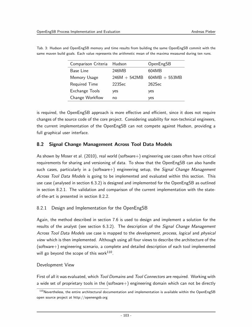
OpenEngSB Process Implementation and Evaluation Andreas Pieber
Tab. 3: Hudson and OpenEngSB memory and time results from building the same OpenEngSB commit with the
same maven build goals. Each value represents the arithmetic mean of the maxima measured during ten runs.
Comparison Criteria Hudson OpenEngSB
Base Line 246MB 604MB
Memory Usage 246M + 542MB 604MB + 553MB
Required Time 223Sec 262Sec
Exchange Tools yes yes
Change Workflow no yes
is required, the OpenEngSB approach is more effective and efficient, since it does not require
changes of the source code of the core project. Considering usability for non-technical engineers,
the current implementation of the OpenEngSB can not compete against Hudson, providing a
full graphical user interface.
8.2 Signal Change Management Across Tool Data Models
As shown by Moser et al. (2010), real world (software+) engineering use cases often have critical
requirements for sharing and versioning of data. To show that the OpenEngSB can also handle
such cases, particularly in a (software+) engineering setup, the Signal Change Management
Across Tool Data Models is going to be implemented and evaluated within this section. This
use case (analysed in section 6.3.2) is designed and implemented for the OpenEngSB as outlined
in section 8.2.1. The validation and comparison of the current implementation with the state-
of-the-art is presented in section 8.2.2.
8.2.1 Design and Implementation for the OpenEngSB
Again, the method described in section 7.6 is used to design and implement a solution for the
results of the analyst (see section 6.3.2). The description of the Signal Change Management
Across Tool Data Models use case is mapped to the development, process, logical and physical
view which is then implemented. Although using all four views to describe the architecture of the
(software+) engineering scenario, a complete and detailed description of each tool implemented
will go beyond the scope of this work110.
Development View
First of all it was evaluated, which Tool Domains and Tool Connectors are required. Working with
a wide set of proprietary tools in the (software+) engineering domain which can not be directly
110Nevertheless, the entire architectural documentation and implementation is available within the OpenEngSB
open source project at http://openengsb.org
- 103 -
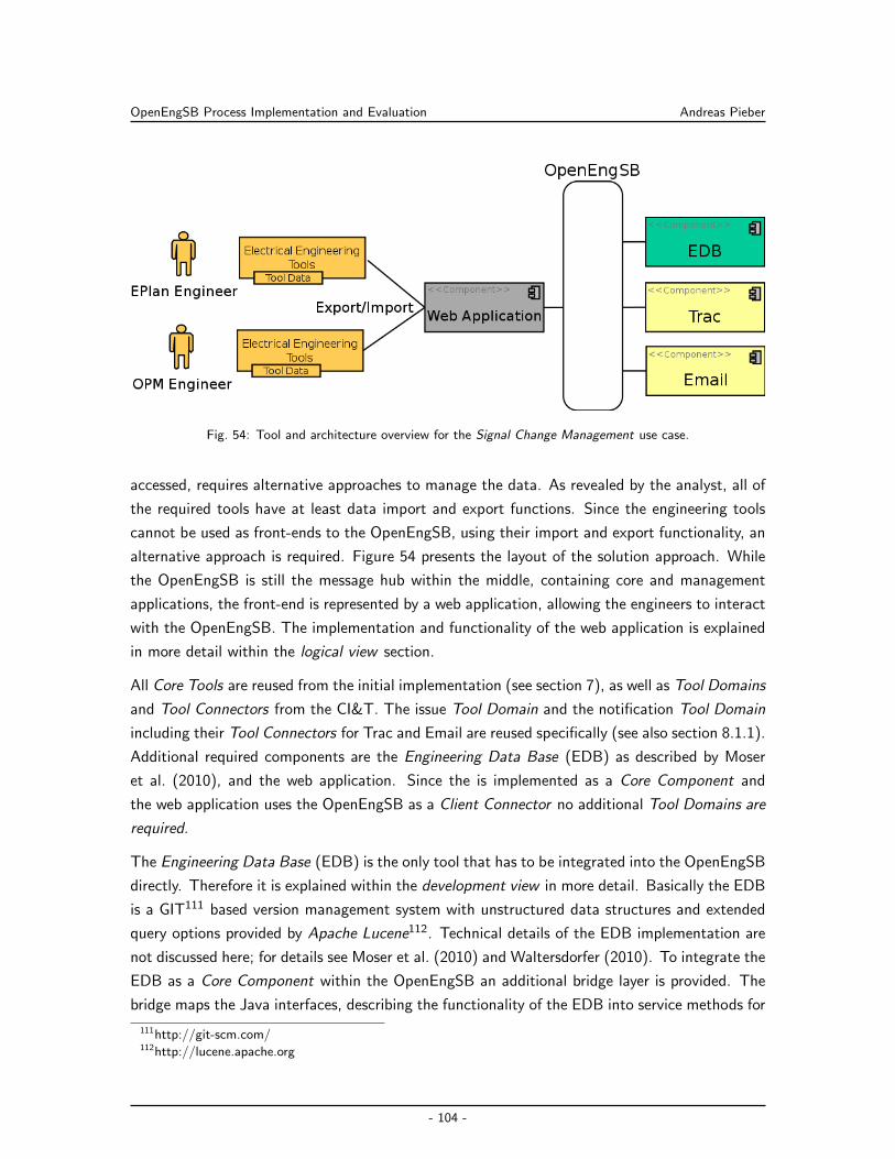
OpenEngSB Process Implementation and Evaluation Andreas Pieber
Fig. 54: Tool and architecture overview for the Signal Change Management use case.
accessed, requires alternative approaches to manage the data. As revealed by the analyst, all of
the required tools have at least data import and export functions. Since the engineering tools
cannot be used as front-ends to the OpenEngSB, using their import and export functionality, an
alternative approach is required. Figure 54 presents the layout of the solution approach. While
the OpenEngSB is still the message hub within the middle, containing core and management
applications, the front-end is represented by a web application, allowing the engineers to interact
with the OpenEngSB. The implementation and functionality of the web application is explained
in more detail within the logical view section.
All Core Tools are reused from the initial implementation (see section 7), as well as Tool Domains
and Tool Connectors from the CI&T. The issue Tool Domain and the notification Tool Domain
including their Tool Connectors for Trac and Email are reused specifically (see also section 8.1.1).
Additional required components are the Engineering Data Base (EDB) as described by Moser
et al. (2010), and the web application. Since the is implemented as a Core Component and
the web application uses the OpenEngSB as a Client Connector no additional Tool Domains are
required.
The Engineering Data Base (EDB) is the only tool that has to be integrated into the OpenEngSB
directly. Therefore it is explained within the development view in more detail. Basically the EDB
is a GIT111 based version management system with unstructured data structures and extended
query options provided by Apache Lucene112. Technical details of the EDB implementation are
not discussed here; for details see Moser et al. (2010) and Waltersdorfer (2010). To integrate the
EDB as a Core Component within the OpenEngSB an additional bridge layer is provided. The
bridge maps the Java interfaces, describing the functionality of the EDB into service methods for
111http://git-scm.com/112http://lucene.apache.org
- 104 -
OpenEngSB Process Implementation and Evaluation Andreas Pieber
the OpenEngSB. Due to the additional advantage that the EDB is embeddable, it can be provided
within the OpenEngSB distribution and does not have to be installed separated. Additionally
the EDB bridge implementation for the OpenEngSB provides an event system. Event types for
signal deleted, signal added and signal changed are added. The connector throws these events
for each successfully committed addition, deletion or change.
Process View
Compared to the CI&T use case, the Signal Change Management scenario does not require long
running processes. Therefore Drools Flow is not used in this context. Instead the following set of
rules (designed to handle the actions within the bus system and provide the required information
for team awareness) are sufficient to implement the proposed use case:
Signal Changed Event Rules: The industrial partner separates projects into eight stages and
seven important parts of a signal as presented in section 6.3.2 and visualized in table 2.
Depending on the correlation between signal part and project state specific person groups
have to be informed. The information of the engineers is done via the notification domain.
Basically each of the specific situation requires an own rule which creates an issue and
assigns it to the required group. Based on these requirements, 40 rules are required in
theory. Because of the fact that in stage one and stage two only protective interlocking
creates notifications, the number of rules can be reduced to 32. Taking additionally into
account that stage five, seven and eight follow the same requisitions one rule is sufficient
for all these cases, reducing the number to 18. Since stage six only requires two additional
rules these can also be added to the rule used for stage five, seven and eight reducing the
number to 15. Stage four can be handled within one rule reducing the required rules to
14. For stage six, signal parts three and five can also be handled within one rule making
13 rules. Stage three can be reduced to one rule excluding signal field three only requiring
12 rules. Not all correlations between signal parts and project states require notifications
(e.g. KKS-Number and St1). Since nothing has to be done in these cases they can be
ignored, finally reducing the required number of rules to 5. Table 4 presents the rules,
finally created. Parts which do not require a notification are marked with N. The other
parts are marked with the number of the rule which applies to them.
Signal Deleted Event Rule: Deleting signals always contains a risk to introduce unseen cor-
relation exceptions. The situation, considering all details, can be very complex to handle.
For the industrial partner it was already a significant improvement to just inform the soft-
ware engineering team in case of a signal deletion that they did not execute themselves.
A single rule forwarding signal deleted events to all engineers, grouped within the system
engineering group (T4 in table 2), does this job.
Issue Created Event Rule: This rule simple reacts on each issue created event and forwards
- 105 -
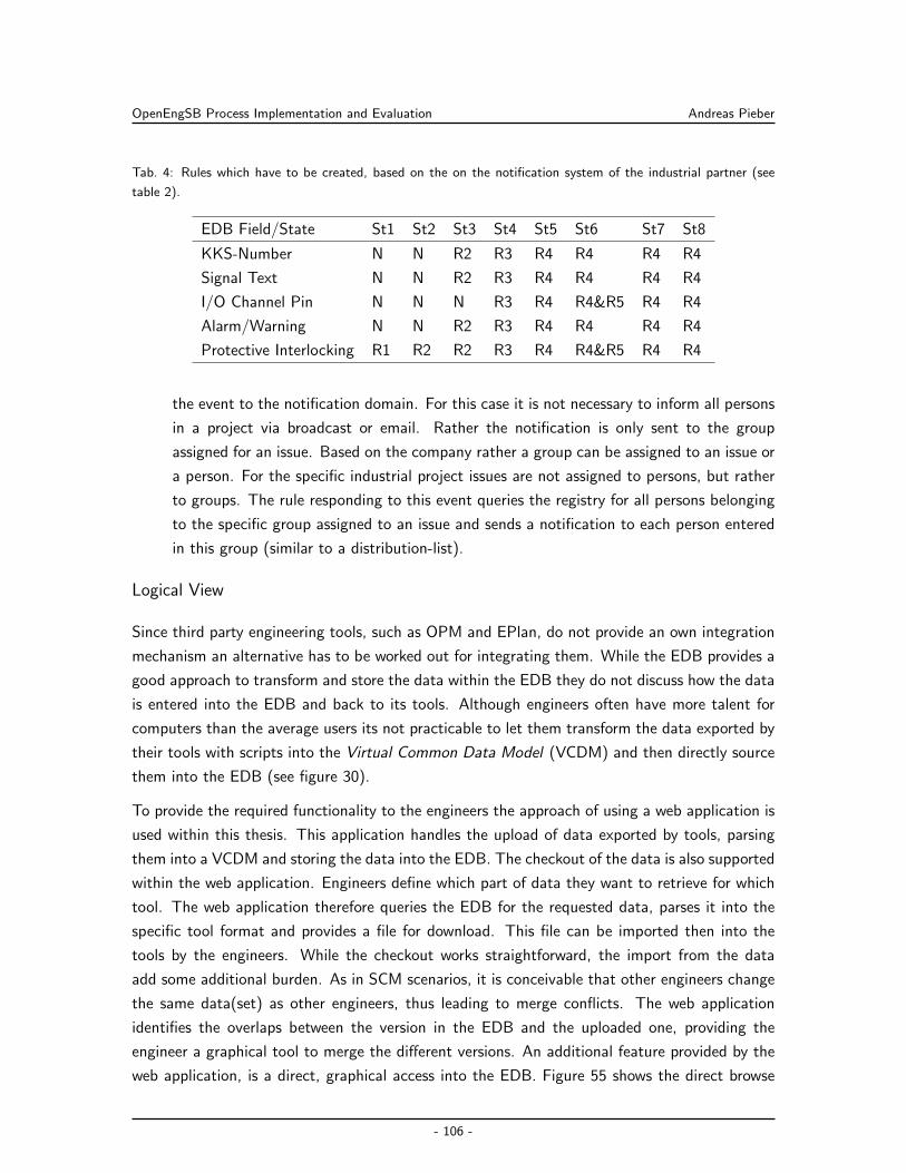
OpenEngSB Process Implementation and Evaluation Andreas Pieber
Tab. 4: Rules which have to be created, based on the on the notification system of the industrial partner (see
table 2).
EDB Field/State St1 St2 St3 St4 St5 St6 St7 St8
KKS-Number N N R2 R3 R4 R4 R4 R4
Signal Text N N R2 R3 R4 R4 R4 R4
I/O Channel Pin N N N R3 R4 R4&R5 R4 R4
Alarm/Warning N N R2 R3 R4 R4 R4 R4
Protective Interlocking R1 R2 R2 R3 R4 R4&R5 R4 R4
the event to the notification domain. For this case it is not necessary to inform all persons
in a project via broadcast or email. Rather the notification is only sent to the group
assigned for an issue. Based on the company rather a group can be assigned to an issue or
a person. For the specific industrial project issues are not assigned to persons, but rather
to groups. The rule responding to this event queries the registry for all persons belonging
to the specific group assigned to an issue and sends a notification to each person entered
in this group (similar to a distribution-list).
Logical View
Since third party engineering tools, such as OPM and EPlan, do not provide an own integration
mechanism an alternative has to be worked out for integrating them. While the EDB provides a
good approach to transform and store the data within the EDB they do not discuss how the data
is entered into the EDB and back to its tools. Although engineers often have more talent for
computers than the average users its not practicable to let them transform the data exported by
their tools with scripts into the Virtual Common Data Model (VCDM) and then directly source
them into the EDB (see figure 30).
To provide the required functionality to the engineers the approach of using a web application is
used within this thesis. This application handles the upload of data exported by tools, parsing
them into a VCDM and storing the data into the EDB. The checkout of the data is also supported
within the web application. Engineers define which part of data they want to retrieve for which
tool. The web application therefore queries the EDB for the requested data, parses it into the
specific tool format and provides a file for download. This file can be imported then into the
tools by the engineers. While the checkout works straightforward, the import from the data
add some additional burden. As in SCM scenarios, it is conceivable that other engineers change
the same data(set) as other engineers, thus leading to merge conflicts. The web application
identifies the overlaps between the version in the EDB and the uploaded one, providing the
engineer a graphical tool to merge the different versions. An additional feature provided by the
web application, is a direct, graphical access into the EDB. Figure 55 shows the direct browse
- 106 -
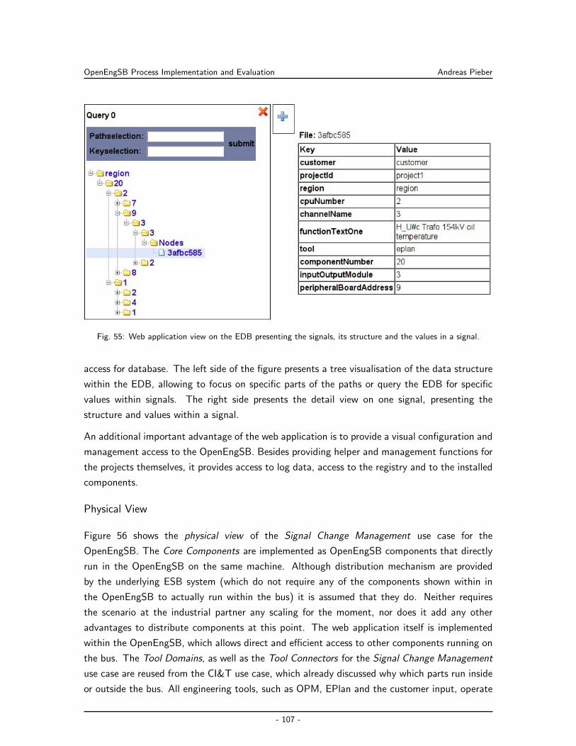
OpenEngSB Process Implementation and Evaluation Andreas Pieber
Fig. 55: Web application view on the EDB presenting the signals, its structure and the values in a signal.
access for database. The left side of the figure presents a tree visualisation of the data structure
within the EDB, allowing to focus on specific parts of the paths or query the EDB for specific
values within signals. The right side presents the detail view on one signal, presenting the
structure and values within a signal.
An additional important advantage of the web application is to provide a visual configuration and
management access to the OpenEngSB. Besides providing helper and management functions for
the projects themselves, it provides access to log data, access to the registry and to the installed
components.
Physical View
Figure 56 shows the physical view of the Signal Change Management use case for the
OpenEngSB. The Core Components are implemented as OpenEngSB components that directly
run in the OpenEngSB on the same machine. Although distribution mechanism are provided
by the underlying ESB system (which do not require any of the components shown within in
the OpenEngSB to actually run within the bus) it is assumed that they do. Neither requires
the scenario at the industrial partner any scaling for the moment, nor does it add any other
advantages to distribute components at this point. The web application itself is implemented
within the OpenEngSB, which allows direct and efficient access to other components running on
the bus. The Tool Domains, as well as the Tool Connectors for the Signal Change Management
use case are reused from the CI&T use case, which already discussed why which parts run inside
or outside the bus. All engineering tools, such as OPM, EPlan and the customer input, operate
- 107 -
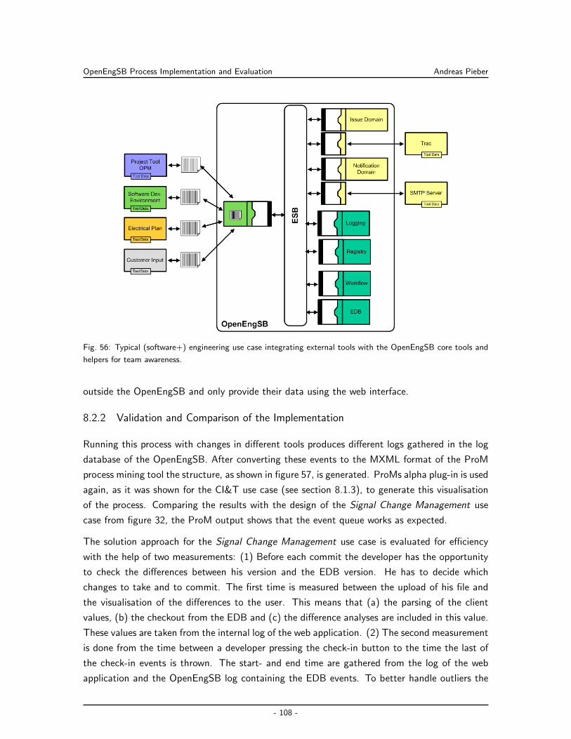
OpenEngSB Process Implementation and Evaluation Andreas Pieber
Fig. 56: Typical (software+) engineering use case integrating external tools with the OpenEngSB core tools and
helpers for team awareness.
outside the OpenEngSB and only provide their data using the web interface.
8.2.2 Validation and Comparison of the Implementation
Running this process with changes in different tools produces different logs gathered in the log
database of the OpenEngSB. After converting these events to the MXML format of the ProM
process mining tool the structure, as shown in figure 57, is generated. ProMs alpha plug-in is used
again, as it was shown for the CI&T use case (see section 8.1.3), to generate this visualisation
of the process. Comparing the results with the design of the Signal Change Management use
case from figure 32, the ProM output shows that the event queue works as expected.
The solution approach for the Signal Change Management use case is evaluated for efficiency
with the help of two measurements: (1) Before each commit the developer has the opportunity
to check the differences between his version and the EDB version. He has to decide which
changes to take and to commit. The first time is measured between the upload of his file and
the visualisation of the differences to the user. This means that (a) the parsing of the client
values, (b) the checkout from the EDB and (c) the difference analyses are included in this value.
These values are taken from the internal log of the web application. (2) The second measurement
is done from the time between a developer pressing the check-in button to the time the last of
the check-in events is thrown. The start- and end time are gathered from the log of the web
application and the OpenEngSB log containing the EDB events. To better handle outliers the
- 108 -
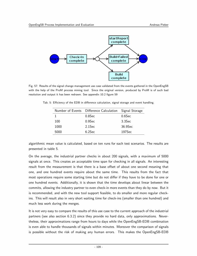
OpenEngSB Process Implementation and Evaluation Andreas Pieber
Fig. 57: Results of the signal change management use case validated from the events gathered in the OpenEngSB
with the help of the ProM process mining tool. Since the original version, produced by ProM is of such bad
resolution and output it has been redrawn. See appendix 10.2 figure 59
Tab. 5: Efficiency of the EDB in difference calculation, signal storage and event handling.
Number of Events Difference Calculation Signal Storage
1 0.8Sec 0.6Sec
100 0.9Sec 3.3Sec
1000 2.1Sec 36.9Sec
5000 6.2Sec 197Sec
algorithmic mean value is calculated, based on ten runs for each test scenarios. The results are
presented in table 5.
On the average, the industrial partner checks in about 200 signals, with a maximum of 5000
signals at once. This creates an acceptable time span for checking in all signals. An interesting
result from the measurement is that there is a base offset of about one second meaning that
one, and one hundred events require about the same time. This results from the fact that
most operations require some starting time but do not differ if they have to be done for one or
one hundred events. Additionally, it is shown that the time develops about linear between the
commits, allowing the industry partner to even check-in more events than they do by now. But it
is recommended, and with the new tool support feasible, to do smaller and more regular check-
ins. This will result also in very short waiting time for check-ins (smaller than one hundred) and
much less work during the merges.
It is not very easy to compare the results of this use case to the current approach of the industrial
partners (see also section 6.3.2) since they provide no hard data, only approximations. Never-
theless, their approximations range from hours to days while the OpenEngSB-EDB combination
is even able to handle thousands of signals within minutes. Moreover the comparison of signals
is possible without the risk of making any human errors. This makes the OpenEngSB-EDB
- 109 -
OpenEngSB Process Implementation and Evaluation Andreas Pieber
combined approach much more efficient and effective to the industrial partners compared to
their current processes.
- 110 -
Discussion Andreas Pieber
9 Discussion
In section 5 two research issues are identified which can be summarized to: (a) Design an
architecture for abstract tool integration which is able to support (software+) engineering teams
in integrating their tools, process logic and team awareness (see section 9.1); (b) Develop
a method and architecture for abstract (software+) engineering process definitions, allowing
stakeholders of (software+) engineering environments to define, implement and validate their
processes (see section 9.2). The revealed challenges are discussed in this section by comparing
the state-of-the-art solutions, presented in the related work (see sections 2, 3 and 4) with the
OpenEngSB method, concept and platform, described in sections 6 and 7. As foundation for
the scientific discussion the results from the (software+) engineering scenarios, described in
section 8, are used.
9.1 Architecture for Abstract Tool Integration
In this thesis the OpenEngSB framework is applied to two scenarios from different domains,
namely software engineering and automation engineering. The first research issue category deals
with the general functionality and feasibility of the OpenEngSB architecture. The following sec-
tions discuss and answer the research issues RI-1.1 (see section 9.1.1), RI-1.2 (see section 9.1.2),
RI-1.3 (see section 9.1.3) and RI-1.4 (see section 9.1.4).
9.1.1 Feasibility of the OpenEngSB approach
In this thesis the Open Engineering Service Bus (OpenEngSB) concept is introduced. It sup-
ports engineering environment integration for development teams in multi-disciplinary engineer-
ing projects with focus on providing an technical integration of different tools, processes and
data models. The OpenEngSB is used to support the integration of functional aspects and
data of different, heterogeneous tools. Based on two real-world use cases from software- and
automation engineering the OpenEngSB is implemented in a prototypic way. As organisation
usually have invested a lot of time and money into their own tools and processes, it is hard to
introduce new, comprehensive standards into (software+) engineering environments. Therefore,
the integration of processes and tools has to be as abstract as possible to allow (software+)
engineering teams to stay with their own tools and processes. Finally, a step-by-step integration
should be provided instead of a big bang approach.
Table 6 presents a comparison between the OpenEngSB and other discussed integration solu-
tions, such as Comos, Alf and Jazz. First of all, the OpenEngSB is the only still supported
open source solution in this domain. Compared to Comos, which only integrates its own tool-
box, the OpenEngSB supports tool replacement similar to Eclipse ALF. Jazz also supports tool
replacement, but only within the range of the tool concepts defined by the Open Services for
- 111 -
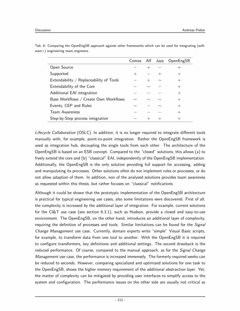
Discussion Andreas Pieber
Tab. 6: Comparing the OpenEngSB approach against other frameworks which can be used for integrating (soft-
ware+) engineering team engineers.
Comos Alf Jazz OpenEngSB
Open Source − + − +
Supported + − + +
Extendability / Replaceability of Tools − + ∼ +
Extendability of the Core − ∼ − +
Additional EAI integration − − − +
Base Workflows / Create Own Workflows ∼ ∼ ∼ +
Events, CEP and Rules ∼ − ∼ +
Team Awareness − − − +
Step-by-Step process integration − + + +
Lifecycle Collaboration (OSLC). In addition, it is no longer required to integrate different tools
manually with, for example, point-to-point integration. Rather the OpenEngSB framework is
used as integration hub, decoupling the single tools from each other. The architecture of the
OpenEngSB is based on an ESB concept. Compared to the “closed” solutions, this allows (a) to
freely extend the core and (b) “classical” EAI, independently of the OpenEngSB implementation.
Additionally, the OpenEngSB is the only solution providing full support for accessing, adding
and manipulating its processes. Other solutions often do not implement rules or processes, or do
not allow adaption of them. In addition, non of the analysed solutions provides team awareness
as requested within this thesis, but rather focuses on “classical” notifications.
Although it could be shown that the prototypic implementation of the OpenEngSB architecture
is practical for typical engineering use cases, also some limitations were discovered. First of all,
the complexity is increased by the additional layer of integration. For example, current solutions
for the CI&T use case (see section 6.3.1), such as Hudson, provide a closed and easy-to-use
environment. The OpenEngSB, on the other hand, introduces an additional layer of complexity,
requiring the definition of processes and tools. Similar limitations can be found for the Signal
Change Management use case. Currently, domain experts write “simple” Visual Basic scripts,
for example, to transform data from one tool to another. With the OpenEngSB it is required
to configure transformers, key definitions and additional settings. The second drawback is the
reduced performance. Of course, compared to the manual approach, as for the Signal Change
Management use case, the performance is increased immensely. The formerly required weeks can
be reduced to seconds. However, comparing specialized and optimized solutions for one task to
the OpenEngSB, shows the higher memory requirement of the additional abstraction layer. Yet,
the matter of complexity can be mitigated by providing user interfaces to simplify access to the
system and configuration. The performance issues on the other side are usually not critical as
- 112 -
Discussion Andreas Pieber
there are in most cases no real-time requirements for background tasks in developing (software+)
products. Additionally, it is also possible to create or use high specialized solutions for single
process steps. Of course there is always the trade-off between flexibility and performance.
9.1.2 Support for independent tool and process integration
(Software+) engineering environments are complex environments which consist of dozens of
proprietary tools. Additionally, complex processes, rules and events navigate the work of the
engineers. To implement everything at once, such as tried by Comos, creates some problems
and challenges. First of all, all engineering tools have to be accessible and provided by the
contributors themselves. This is required to get full access to integrate functionality and data
with other tools. Additionally, all processes can not be integrated at once, but rather step-by-
step for two reasons: (1) The enormous complexity of (software+) engineering environments risk
the introduction of unnoticed errors; (2) Engineers have to become familiar with the provided
integration. To handle small changes and continuous enhancements of the engineering process,
independent tool and process integration is required. The OpenEngSB, using Tool Domains,
Tool Connectors, and Core Components such as Workflow and Registry, is explicitly designed to
handle such issues.
Abstracting tools via the Tool Domains and integrating them via Tool Connectors works very
well for the CI&T use case, since most tools are back-end tools. Events, sent by front-end
tools, are also easy to integrate. A limitation comes from legacy front-end systems that do not
provide a server component and in many cases not even a sufficiently mature or accessible API
to integrate them, but rather require workarounds. This limitation is handled by using the export
and import mechanisms of the tools themselves, as shown for the Signal Change Management
use case. Alternative approaches to access closed tools are: (a) directly use the database; (b)
caching files; (c) capturing the graphical user interface (Linthicum, 2000). Because of the Tool
Domain concept, developed for the OpenEngSB, it is possible to simply replace any tool within a
domain with another tool from the same domain. For example, the mail notification is replaced
with a chat server notification instance. Other options are to replace one specific issue tracker
with another, or even use different issue trackers at the same time for different projects or aspects
of a project. Additionally, it is possible to show, that the OpenEngSB provides the ability to
easily extend and change processes without even touching tools in any way. The CI&T use case
presents the extensions of the otherwise very rigid process with additional tools, error handling
and static capabilities. The Signal Change Management use case presents the easy replacement
of tools, rules and processes with the help of the OpenEngSB. Additionally it show that change
single engineering tools does not require to touch the process using them. Moreover it shows
that also processes can be changed without affecting engineerings and their tools.
As already discussed and shown in the prototypic implementation of the use cases the
- 113 -
Discussion Andreas Pieber
OpenEngSB provides a feasible, effective and efficient method for tool integration. Processes,
rules and events are feasible, efficient and effective methods to design the workflow within an
engineering process. Though there are limitations in usability and performance, as already dis-
cussed for research issue RI-1.1 (see section 9.1.1). Finally, the platform has to be attractive for
third parties to provide integrations for their tools. It is not possible for the OpenEngSB team
to integrate all proprietary tools available and regularly used in (software+) engineering environ-
ments. Therefore, to avoid lock-in to a proprietary system, the OpenEngSB is implemented as
an open source project making it attractive for third party vendors to implement their own tools
into the environment. Finally, the abstraction between processes and tools allow even easier
implementation for third party vendors and their tools.
9.1.3 Support for team awareness
(Software+) engineering teams require to be notified about changes relevant for them. Current
solutions often either lead to information overload due to untargeted notifications, or to a lack of
important information (when these sometimes annoying systems are turned off or are ignored).
So it is required to deliver information (a) more personalized and (b) only if relevant for the
receiver. As shown in the Signal Change Management use case the OpenEngSB is feasible
to deliver information directly to relevant persons. Because of the different connectors behind
a domain its also possible to deliver events with the communication medium preferred by the
person to be notified. The OpenEngSB rule and event system is capable to produce context
specific notifications. Using complex event processing also notifications with more complex
context dependencies, such as time or order of events, are possible.
The biggest limitations of this approach is simply the number of rules. Basically, for each
notification for each person one rules has to be created. This could easily lead to hundreds of
rules. Although this process can be optimized, as shown for the Signal Change Management use
case, this does not provide an optimal solution. Technically, systems like Drools Guvnor provide
an efficient solution to handle such amounts of rules, but humans do not. A simple solution
involves to change the representation of rules to a matrix based system. While events, together
in a specific context, provide notifications to persons, their preferred way to be notified can be
simply added. Based on this matrix rules can be created, removed and maintained, providing a
possibility to remove this limitation.
9.1.4 More effective and efficient engineering process
While current software engineering processes are in many cases efficient and effective, they often
suffer from inflexibility (see section 6.3.2). (Software+) engineering processes, such as Signal
Change Management (see section 8.2.2), tend to be implemented in a rigid way; inflexible, slow
and containing a lot of manual and error-prone work. The OpenEngSB allows to automate and
- 114 -
Discussion Andreas Pieber
integrate such (software+) engineering environments in a more general and flexible way. Based
on the Signal Change Management process it is shown that the OpenEngSB reduces the required
time from weeks to minutes, or even seconds. Additionally, it is possible to completely remove
the risk of errors from typical manual merging by automating this task. By adding the ability
to stay with the well established standards and tools, adding team awareness and introduce
the possibility to simply change and enhance the existing engineering process, the OpenEngSB
provides an overall more effective and efficient solution. Nevertheless, there are also limitations,
as already discussed for the research issues RI.1.1, RI.1.2 and RI.1.3, such as an additional layer
of complexity and reduced performance. However, the discussions of the research issues also
reveals possible solutions to the problems.
9.2 Method for Abstract (Software+) Engineering Process Definition
Based on the OpenEngSB framework and the V-Modell XT, a typical process model for business
IT, a method is developed to describe real-world use cases, map them to the OpenEngSB
framework and finally validate them. This section of research issues focuses on analysing the
process and its feasibility. The following sections discuss and answer the research issues RI-2.1
(see section 9.2.1) and RI-2.2 (see section 9.2.2).
9.2.1 Support for Engineering Process Automation
(Software+) engineering teams already know a lot about the systems and processes they in-
teract with (see section 5.1.2). Nevertheless, current methods, such as the V-Modell XT, only
describe the engineering process. They do not provide solutions for mapping the descriptions
directly to technical integration solutions. Alternatives are frameworks, such as Quasar (Engels
et al., 2008), which describe the full process to implement business software. Nevertheless, those
frameworks also have disadvantages. They do not provide a method to reuse components and
implementations between use cases. Additionally, they do not provide methods to implement
processes step-by-step. A method is developed within this thesis to describe the (software+) en-
gineering process on one hand (see section 6), and map the results to the OpenEngSB framework
implementation afterwards (see section 7.6). The description of the system is mostly based on
tailoring the V-Modell XT, helping analysts to stay with their common methods. The mapping
between the description and the OpenEngSB is based on the 4+1 view method, also helping
system architects and integrators to use well known and accepted methods.
Within this theses the usability of the described approach is shown. Since it is based on already
existing and well known methods it helps the stakeholders getting in touch with the new method.
Additionally, the evaluation reveals that the method is feasible for describing engineering pro-
cesses. The mapping works straight forward without any noteworthy problems. Moreover, the
method finally closes the gaps between process models and their real implementations.
- 115 -
Discussion Andreas Pieber
A limitation of the proposed method is its current focus on system integrators and analysts. The
OpenEngSB as-is is not usable for domain experts directly. Although technically possible, on
the conditions that all required tools are already implemented for the OpenEngSB, it is currently
not possible to transform the described engineering knowledge automatically into the technical
integration environment. However, it is more a technical problem to solve, than a scientific one.
Therefore, it should not be discussed any further in this thesis, but only noticed for sake of
completeness.
9.2.2 Support for Engineering Process Validation
Quality- and process managers develop processes according to standardized models. They want
to observe and validate the final process integration and its effects on the system. This infor-
mation is retrieved from the logs gathered at runtime. Current technical integration projects do
not provide: (a) a context specific, structured log for further analyses; (b) methods to analyse
structured log files. The OpenEngSB provides, due to its architecture, a method for structured
logging as well as for analysing the logs. All events on the bus are, enhanced with the entire
context information, directly logged into a database. Based on the database entries, a full anal-
ysis of the log files is possible afterwards. For the two real-world engineering use cases described
in this thesis, it is possible to show that the content of the log database can be transformed into
another structured input format for the process mining tool ProM. Based on this input format
it is shown that the flow of events can be reproduced and made transparent. Furthermore it has
been shown, that the performance can be extracted, based on the event’s timestamps. But the
combination of the log database and ProM theoretically allows additional scenarios: A process
mining tool can extract many different types of data from the process in addition to performance
and flow visualisation. Examples are the number of events or more non-trivial analyses, such
as the linear temporal logic between processes (Ciardo & Darondeau, 2005) or fuzzy mining
(Rozinat et al., 2009).
One limitations is that currently only events are logged. Also, it can be never taken for granted
that all processes of interest are observed (based on inter-tool communication). In the first step
the OpenEngSB only logs the engineering events which are sent to the Drools engine. Defined by
the architecture these are all events generated within the OpenEngSB. This approach does not
cover the entire inter-tool communication, since tools also communicate with direct messages
(so-called service calls). To gather all messages sent on the bus, a deeper technical integration
within the underlying Enterprise Service Bus is required. Although this solution will provide more
in-depth process analyses it was beyond the scope of this thesis.
- 116 -
Conclusion and Perspectives Andreas Pieber
10 Conclusion and Perspectives
This section gives a short summary of this thesis and its results. Additionally it contains the
conclusion of using the OpenEngSB implementation and method for (software+) engineering
projects (see section 10.1). Finally, section 10.2 presents the ideas, generated during this thesis,
how the OpenEngSB platform can be extended.
10.1 Conclusion
The development of software-intensive systems in industrial automation, business IT and soft-
ware engineering usually requires the cooperation of experts from different organisations and
several engineering domains. These domain experts work with a wide range of heterogeneous
engineering tools, models, processes and standards which where not necessarily designed to
cooperate seamlessly. Therefore, the technical integration of different tools, experts and their
processes are key challenges.
A literature research of the status quo shows that current solutions, such as Jazz or Comos,
provide only partly what is required for a flexible, team aware and open solution. Additionally,
current solutions do not provide a complete model for describing engineering processes and map
them to engineering environments. Finally, many solutions do not provide methods to verify the
mapped processes in terms of feasibility and performance. To create a product, accepted by
engineering teams, it is important to support the processes and tools already in use. Moreover,
the technical integration for such environments is currently mostly achieved by rigid point to
point integrations. Therefore, maintenance and changes to the system are difficult. In addition a
generalized and open platform for integrating tools, processes and teams is required, in order to
support quality- and project managers in their work. They need data contained in the inter-tool
and process interactions, which is currently achieved using inefficient or fragile approaches.
While process lifecycle models are available for business engineering, (software+) engineering
with its multiple disciplines is not supported well. The V-Modell XT tailoring process is used
to provide a method to describe (software+) engineering use cases. Using this method on
the (software+) engineering environment of an industrial partner two relevant scenarios are
extracted. The Continuous Integration & Test and the Signal Change Management Across Data
Tool Domains use cases are described in detail to show the feasibility of the method. Finally it
is shown, that an engineering framework, as well as a method is missing to map the resulting
descriptions to the real-world engineering environment.
In this thesis the Open Engineering Service Bus (OpenEngSB) platform is presented. The
OpenEngSB is the technical backbone for integrating tools and processes. The platform provides
an abstract tool integration model based on an Enterprise Service Bus (ESB) implementation.
The abstraction is achieved by extending the basic ESB concept with Tool Domains, Core Tools
- 117 -

Conclusion and Perspectives Andreas Pieber
and the OpenEngSB Infrastructure. While Tool Domains allow an abstract tool integration,
the Core Tools and OpenEngSB Infrastructure provide support for process descriptions, process
validation and team awareness.
Finally a method is developed to map the description of the processes to the new framework.
The 4+1 architecture model is adapted to provide a method to for software architects to map
the parts of the process description to the OpenEngSB. With the help of this method the two
described engineering use cases are designed and implemented for the OpenEngSB framework.
The two implemented real-world use cases from the industry application domain are evaluated
regarding effort, feasibility, efficiency, effectiveness, performance and robustness. The evaluation
is based on prototypes for a set of specific use cases of the two industrial application domains, as
well as on feasibility studies of beneficiary roles as proof-of-concept. As a major result of this work
it is shown that the OpenEngSB architecture and concept integrates the (software+) engineering
environment in place successfully. Additionally, the process, method and tool support of the
OpenEngSB is usable and useful across engineering domains. Furthermore, better effectiveness
and efficiency is provided for (software+) engineering team integration use cases. In addition,
defects are found earlier in the engineering process, resulting in risks like errors or inconsistent
entries in data models being mitigated earlier and more efficiently. Initial evaluation results
indicate an immense effort reduction in (software+) engineering processes, reducing weeks of
error-prone manual work to minutes and the engineers involved found the method usable and
useful.
Finally, an open source solution is provided which stands out (compared to other solutions) in
providing: (a) a model for abstract tool and process integration; (b) a complete process and
event model; (b) methods to create team aware software processes; (d) a completely open and
reusable solution.
10.2 Future Work
While the OpenEngSB is a huge project, the field of engineering environment integration is even
bigger. Therefore, a lot of additional challenges and research issues are revealed during this
work. This section outlines the most important points research should focus on:
Deep semantic integration into the OpenEngSB. While this work only concentrates on the
technical part of integrating tools with each other, there is still an issue with the semantical
integration of the different parts. The moment things become more complex its not
possible any more to design all tools with a virtual data model. To handle such situations
a more abstract integration approach is required. The Engineering Knowledge Base (EKB)
concept (implemented in the OpenEngSB), as described by Moser (2010), establishes a
good foundation for semantic integration.
- 118 -
Conclusion and Perspectives Andreas Pieber
Security for the OpenEngSB. Although a sensible topic in distributed environments, security
concerns were beyond the scope of this thesis. Hence currently the OpenEngSB cannot
be used in public environments. Implementation of authorisation/authentication schemes
and more complex policies e.g. for interaction between several OpenEngSB instances are
next steps in the development roadmap.
Project management is another critical task in each company, but is currently hardly ad-
dressed. Mostly project management is done in isolation and not combined with devel-
opment tools, and sometimes not even with the people affected by it. The goal of the
OpenEngSB is to integrate existing tools where possible and, again as a principle, not to
reinvent the wheel. Nevertheless there are some tasks and applications, where using an
existing, standalone tool does not make sense. Project management, for example, requires
a lot of information from its environment to provide meaningful information about the
current project state.
First of all it has to be evaluate which data available in the OpenEngSB could improve
project management. Currently, processes are described and afterwards mapped by experts
step by step to the domain. The validation mostly happens manually by experts, as
well as the monitoring. The fast forward mapping of processes to the OpenEngSB is
missing as well as and the backward validation of the results. A semi automatic creation
and validation of processes should be used instead, helping power users to create and
administrate their processes them self. Processes should become part of the system itself,
rather than an abstract description of it. In other words, it has to be researched how to map
the process description of an company (automatically) with the environment and further
more how to (automatically) validate the results of such an environment. Additionally,
project management and processes models, as already explained in section 2, require to
manage a high number of artifacts. Milestones are completed after a specific number of
artifacts is finished. This use case of, lets call it artifact management, has to be analysed
and implemented for the OpenEngSB. While it seams quite trivial at first sight, problems,
such as integration of processes, artifacts and versioning of artifacts, have to be taken into
account.
OpenEngSB Management Application. The OpenEngSB, started as a research prototype,
grows during the time invested on this work to an open source project. To make it easier
for users to control and setup the OpenEngSB a (web based) user interface is required.
Testing freshly uploaded components before they are deployed to the bus, monitoring the
performance of the distributed environment and configuration management of components
in a distributed environments have to be taken into account, to name just a few research
issues which have to be tackled.
- 119 -
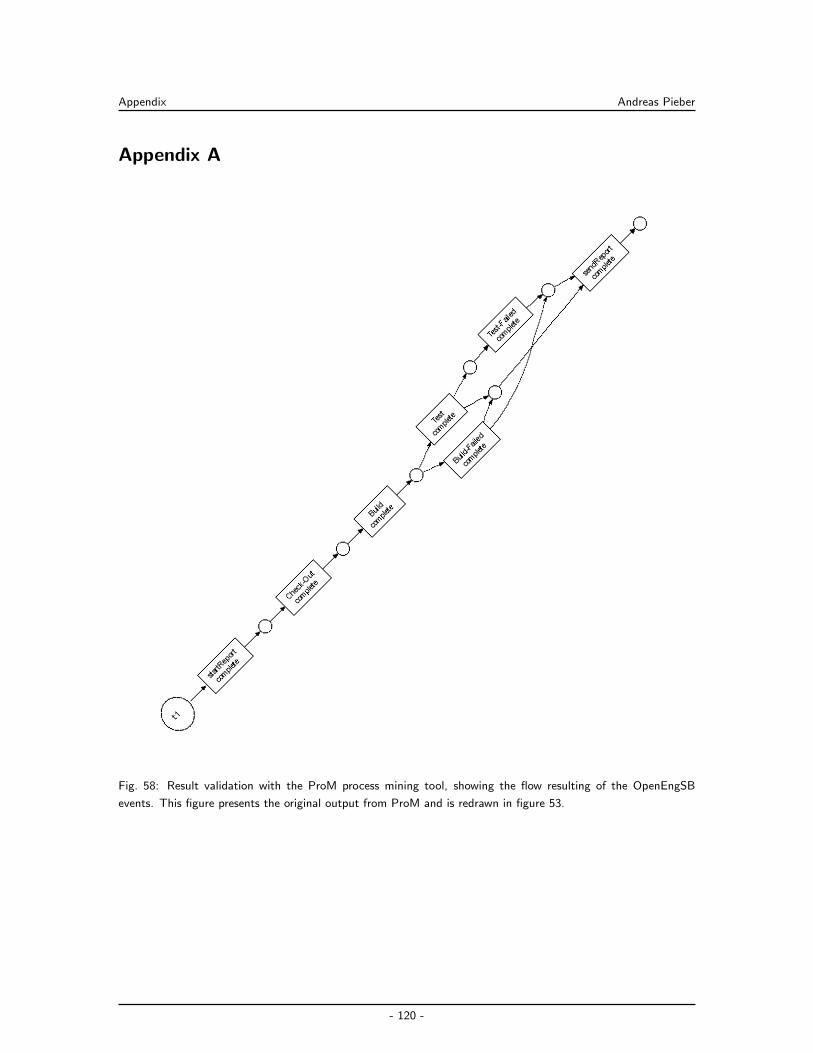
Appendix Andreas Pieber
Appendix A
Fig. 58: Result validation with the ProM process mining tool, showing the flow resulting of the OpenEngSB
events. This figure presents the original output from ProM and is redrawn in figure 53.
- 120 -
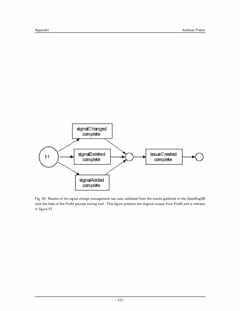
Appendix Andreas Pieber
Fig. 59: Results of the signal change management use case validated from the events gathered in the OpenEngSB
with the help of the ProM process mining tool. This figure presents the original output from ProM and is redrawn
in figure 57.
- 121 -
Bibliography Andreas Pieber
Published Papers and Books
Aalst, W. M. P. van der, Reijers, H. A., Weijters, A. J. M. M., Dongen, B. F. van, Medeiros,
A. K. Alves de, Song, M., et al. (2007). Business process mining: An industrial application.
Inf. Syst., 32(5), 713–732.
Agrusa, R., Mazza, V. G., & Penso, R. (2009). Advanced 3d visualization for manufacturing
and facility controls. In Hsi’09: Proceedings of the 2nd conference on human system
interactions (pp. 453–459). Piscataway, NJ, USA: IEEE Press.
Alonso, G. (2008). Challenges and opportunities for formal specifications in service oriented
architectures. In Petri nets ’08: Proceedings of the 29th international conference on
applications and theory of petri nets (pp. 1–6). Berlin, Heidelberg: Springer-Verlag.
Alonso, G., Casati, F., Kuno, H., & Machiraju, V. (2004). Web services: Concepts, architecture
and applications. Springer Verlag.
Andersen, T. J., & Amdor, L. E. (2009). Leveraging maven 2 for agility. In Agile ’09: Proceedings
of the 2009 agile conference (pp. 383–386). Washington, DC, USA: IEEE Computer
Society.
Arunachalan, B., & Light, J. (2008). Agent-based mobile middleware architecture (amma) for
patient-care clinical data messaging using wireless networks. In Ds-rt ’08: Proceedings of
the 2008 12th ieee/acm international symposium on distributed simulation and real-time
applications (pp. 326–329). Washington, DC, USA: IEEE Computer Society.
Baker, P., Dai, Z. R., Grabowski, J., Haugen ystein, Schieferdecker, I., & Williams, C. (2007).
Model-driven testing: Using the uml testing profile (1st ed.). Springer, Berlin. Available
from http://dx.doi.org/10.1007/978-3-540-72563-3
Beck, K. (2002). Test driven development: By example. Boston, MA, USA: Addison-Wesley
Longman Publishing Co., Inc.
Berson, A. (1996). Client/server architecture (2nd ed.). New York, NY, USA: McGraw-Hill,
Inc.
Bianculli, D., & Ghezzi, C. (2008, September). Savvy-ws at a glance: supporting verifiable dy-
namic service compositions. In Proceedings of the the 1st international workshop on auto-
mated engineering of autonomous and run-time evolving systems (aramis 2008), co-located
with ase 2008, l’aquila, italy (pp. 49–56). IEEE Computer Society Press. Available from
http://dx.doi.org/10.1109/ASEW.2008.468629310.1109/ASEW.2008.4686293
IBM. (2008). Collaborative application lifecycle management with ibm rational products. Ver-
vante.
Project Management Institute. (2004). A guide to the project management body of knowledge
(pmbok guides). Project Management Institute.
Sonatype. (2008). Maven: the definitive guide, 1st edition. Sebastopol, CA, USA: O’Reilly &
Associates, Inc.
Biffl, S., Schatten, A., & Zoitl, A. (2009). Integration of heterogeneous engineering environ-
- 122 -
Bibliography Andreas Pieber
ments for the automation systems lifecycle. In Indin 2009 7th international conference on
industrial informatics. IEEE Computer Society. (Vortrag: IEEE International Conference
on Industrial Informatics (INDIN), Cardiff, UK; 2009-06-24 – 2009-06-26)
Biffl, S., Sunindyo, W. D., & Moser, T. (2009). Bridging semantic gaps between stakehold-
ers in the production automation domain with ontology areas. In Proceedings the 21st
international conference on software engineering & knowledge engineering (seke 2009)
(pp. 233–239). USA: Knowledge Systems Institute Graduate School. Available from
http://publik.tuwien.ac.at/files/PubDat 176749.pdf (Vortrag: 21st Interna-
tional Conference on Software Engineering & Knowledege Engineering, Hyatt Harborside
Hotel, Boston, Massachusetts, USA; 2009-07-01 – 2009-07-03)
Boehm, B. (1986). A spiral model of software development and enhancement. SIGSOFT Softw.
Eng. Notes, 11(4), 14–24.
Boehm, B. W., & Papaccio, P. N. (1988). Understanding and controlling software costs. IEEE
Trans. Softw. Eng., 14(10), 1462–1477.
Brereton, P., Kitchenham, B. A., Budgen, D., Turner, M., & Khalil, M. (2007). Lessons from
applying the systematic literature review process within the software engineering domain.
J. Syst. Softw., 80(4), 571–583.
Brohl, A.-P., & Droschel, W. (1993). Das v-modell: Der stnadard fur die softwareentwicklung
mit praxisleitfaden.
Broy, M. (2006). Challenges in automotive software engineering. In Icse ’06: Proceedings of the
28th international conference on software engineering (pp. 33–42). New York, NY, USA:
ACM.
Burg, S. van der, Dolstra, E., & Jonge, M. de. (2008). Atomic upgrading of distributed systems.
In Hotswup ’08: Proceedings of the 1st international workshop on hot topics in software
upgrades (pp. 1–5). New York, NY, USA: ACM.
Calefato, F., Gendarmi, D., & Lanubile, F. (2009). Embedding social networking information
into jazz to foster group awareness within distributed teams. In Sosea ’09: Proceedings
of the 2nd international workshop on social software engineering and applications (pp.
23–28). New York, NY, USA: ACM.
Chan, K. K., & Spedding, T. A. (2003). An integrated multidimensional process improvement
methodology for manufacturing systems. Comput. Ind. Eng., 44(4), 673–693.
Chandy, M. K. (2006). Event-driven applications: Costs, benefits and design approaches. Gartner
Application Integration and Web Services Summit 2006.
Chappell, D. A. (2004). Theory in practice - enterprise service bus. O’Reilly.
Cheng, L.-T., Souza, C. R. de, Hupfer, S., Patterson, J., & Ross, S. (2004). Building collabo-
ration into ides. Queue, 1(9), 40–50.
Ciardo, G., & Darondeau, P. (Eds.). (2005). Applications and theory of petri nets 2005, 26th
international conference, icatpn 2005, miami, usa, june 20-25, 2005, proceedings (Vol.
- 123 -
Bibliography Andreas Pieber
3536). Springer.
Dale, C., & Anderson, T. (2010). Cost-efficient methods and processes for safety relevant
embedded systems (cesar) - an objective overview. In Making systems safer: Proceedings
of the eighteenth safety-critical systems symposium, bristol, uk, 9-11th february 2010 (pp.
37–50). London, UK: Springer-Verlag.
Dan, A., & Narasimhan, P. (2009). Dependable service- oriented computing. IEEE Internet
Computing , 13(2), 11–15.
Dossot, D., & D’Emic, J. (2009). Mule in action. Greenwich, CT, USA: Manning Publications
Co.
Droschel, W., & Wiemers, M. (1999). Das v-modell 97. Oldenburg.
Du, Y., Peng, W., & Zhou, L. (2008). Enterprise application integration: An overview. In
In proceedings of the 2008 international symposium on intelligent information technology
application workshops (pp. 953–957). Washington, DC, USA: IEEE Computer Society.
Duvall, P., Matyas, S. M., & Glover, A. (2007). Continuous integration: Improving software
quality and reducing risk (the addison-wesley signature series). Addison-Wesley Profes-
sional.
Engels, G., & Assmann, M. (2008). Service-oriented enterprise architectures: Evolution of
concepts and methods. In Edoc ’08: Proceedings of the 2008 12th international ieee
enterprise distributed object computing conference (pp. xxxiv–xliii). Washington, DC,
USA: IEEE Computer Society.
Engels, G., Hess, A., Humm, B., Juwig, O., Lohmann, M., Richter, J.-P., et al. (2008, March).
Anwendungslandschaften serviceorientiert gestalten. In W. H. R. Reussner (Ed.), Hand-
buch der softwarearchitektur (pp. 151–178). dpunkt-Verlag. (2. Auflage)
Floyd, C. (1984). A systematic look at prototyping. In A systematic look at prototyping. in
approaches to prototyping (pp. 1–18). Berlin: Springer-Verlag.
Fowler, M. (2002). Patterns of enterprise application architecture. Boston, MA, USA: Addison-
Wesley Longman Publishing Co., Inc.
Frost, R. (2007). Jazz and the eclipse way of collaboration. IEEE Softw., 24(6), 114–117.
Gamma, E., Helm, R., Johnson, R. E., & Vlissides, J. M. (1993). Design patterns: Abstraction
and reuse of object-oriented design. In Ecoop ’93: Proceedings of the 7th european
conference on object-oriented programming (pp. 406–431). London, UK: Springer-Verlag.
Georgakopoulos, D., & Papazoglou, M. P. (2008). Service-oriented computing. The MIT Press.
Ghalsasi, S. Y. (2009a). Critical success factors for event driven service oriented architecture.
In Icis ’09: Proceedings of the 2nd international conference on interaction sciences (pp.
1441–1446). New York, NY, USA: ACM.
Ghalsasi, S. Y. (2009b). Critical success factors for event driven service oriented architecture.
In Icis ’09: Proceedings of the 2nd international conference on interaction sciences (pp.
1441–1446). New York, NY, USA: ACM.
- 124 -
Bibliography Andreas Pieber
Glinz, M., & Wieringa, R. J. (2007). Guest editors’ introduction: Stakeholders in requirements
engineering. IEEE Software, 24 , 18-20.
Graham, I. (2007). Business rules management and service oriented architecture: A pattern
language. John Wiley & Sons.
Halle, B. V. (2001). Business rules applied: Building better systems using the business rules
approach. New York, NY, USA: John Wiley & Sons, Inc. (Foreword By-Ross, Ronald G.)
Hoffmann, M., Hundt, L., & Fuchs, T. (2009). Seamless engineering for distributed control
systems - an approach for virtual automation networks. In Icit ’09: Proceedings of the
2009 ieee international conference on industrial technology (pp. 1–6). Washington, DC,
USA: IEEE Computer Society.
Hohpe, G. (2007). Software service engineering architect’s dream or developer’s nightmare?
In Debs ’07: Proceedings of the 2007 inaugural international conference on distributed
event-based systems (pp. 188–188). New York, NY, USA: ACM.
Hohpe, G., & Woolf, B. (2004). Enterprise integration patterns : designing, building, and
deploying messaging solutions (I. Pearson Education, Ed.). Addison-Wesly.
Hunt, J. (2005). Agile software construction. Secaucus, NJ, USA: Springer-Verlag New York,
Inc.
IEEE. (1998). Ieee/eia 12207.0-1996 ieee/eia standard industry implementation of international
standard iso/iec 12207: 1995 (iso/iec 12207) standard for information technology software
life cycle processes (Tech. Rep.). Available from http://ieeexplore.ieee.org/xpls/
abs all.jsp?arnumber=707581
Josuttis, N. (2007). Soa in practice. O’Reilly.
Kazman, R., Klein, M. H., Barbacci, M., Longstaff, T. A., Lipson, H. F., & Carriere, S. J.
(1998). The architecture tradeoff analysis method. In Iceccs (p. 68-78). IEEE Computer
Society.
Kent, W. (1978). Data and reality : basic assumptions in data processing reconsidered. North-
Holland Pub. Co. ; sole distributors for the U.S.A. and Canada Elsevier/North-Holland,
Amsterdam.
Kirkham, T., Savio, D., Smit, H., Harrison, R., Monfared, R., & Phaithoonbuathong, P.
(2008). Soa middleware and automation: Services, applications and architectures. In
Services,applications and architectures in proceedings of the 6th international conference
on industrial informatics (pp. 1419–1424). Washington, DC, USA: IEEE Computer Soci-
ety.
Kitchenham, B. A., Pfleeger, S. L., Pickard, L. M., Jones, P. W., Hoaglin, D. C., Emam, K. E.,
et al. (2002). Preliminary guidelines for empirical research in software engineering. IEEE
Trans. Softw. Eng., 28(8), 721–734.
Klopotek, M. A., Wierzchon, S. T., & Trojanowski, K. (2006). Intelligent information processing
and web mining: Proceedings of the international iis: Iipwm’06 conference held in ustron,
- 125 -
Bibliography Andreas Pieber
poland, june 19-22, 2006 (advances in soft computing). Secaucus, NJ, USA: Springer-
Verlag New York, Inc.
Ko, R. K. L. (2009). A computer scientist’s introductory guide to business process management
(bpm). Crossroads, 15(4), 11–18.
Kong, J., Jung, J.-Y., & Park, J. (2009). Event-driven service coordination for business process
integration in ubiquitous enterprises. Comput. Ind. Eng., 57(1), 14–26.
Kruchten, P. (1995). The 4+1 view model of architecture. IEEE Softw., 12(6), 42–50.
Kruchten, P. (2003). The rational unified process: An introduction. Boston, MA, USA: Addison-
Wesley Longman Publishing Co., Inc.
Lamport, L. (1978). Time, clocks, and the ordering of events in a distributed system. Commun.
ACM, 21(7), 558–565.
Levina, O., & Stantchev, V. (2009). Realizing event-driven soa. In Iciw ’09: Proceedings of the
2009 fourth international conference on internet and web applications and services (pp.
37–42). Washington, DC, USA: IEEE Computer Society.
Linthicum, D. S. (2000). Enterprise application integration. Boston, Mass: Addison-Wesley.
Margolis, B. (2007). Soa for the business developer: Concepts, bpel, and sca (business developers
series). Mc Press.
Marık, V., Camarinha-Matos, L. M., & Afsarmanesh, H. (Eds.). (2002). Basys ’02: Proceedings
of the ifip tc5/wg5.3 fifth ifip/ieee international conference on information technology for
balanced automation systems in manufacturing and services. Deventer, The Netherlands,
The Netherlands: Kluwer, B.V.
Massol, V., & O’Brien, T. (2005). Maven: A developer’s notebook (developer’s notebooks).
O’Reilly Media, Inc.
Medeiros, A. K., Weijters, A. J., & Aalst, W. M. (2007). Genetic process mining: an experimental
evaluation. Data Min. Knowl. Discov., 14(2), 245–304.
Michelson, B. M. (2006, February). Event-driven architecture overview: Event-driven soa is just
part of the eda story. Patricia Seybold Group / Business-Driven Architecture SM.
Muhl, G., Fiege, L., & Pietzuch, P. (2006). Distributed event-based systems. Secaucus, NJ,
USA: Springer-Verlag New York, Inc.
Obermaisser, R., & Kopetz, H. (2009). Genesys: An artemis cross-domain reference architecture
for embedded systems. Suedwestdeutscher Verlag fuer Hochschulschriften.
Papazoglou, M. P., & Heuvel, W.-J. (2007). Service oriented architectures: approaches, tech-
nologies and research issues. The VLDB Journal , 16(3), 389–415.
Perry, J. S. (2002). Java management extensions (R. Denn, Ed.). Sebastopol, CA, USA: O’Reilly
& Associates, Inc.
Pfleeger, S. L. (1998). Software engineering: Theory and practice. Prentice Hall.
Preiss, O., & Wegmann, A. (2001). Stakeholder discovery and classification based on systems
science principles. In Apaqs ’01: Proceedings of the second asia-pacific conference on
- 126 -
Bibliography Andreas Pieber
quality software (p. 194). Washington, DC, USA: IEEE Computer Society.
Rademakers, T., & Dirksen, J. (2008). Open-source esbs in action. Greenwich, CT, USA:
Manning Publications Co.
Reed, K., Damiani, E., Gianini, G., & Colombo, A. (2004). Agile management of uncertain
requirements via generalizations: a case study. In Qute-swap ’04: Proceedings of the 2004
workshop on quantitative techniques for software agile process (pp. 40–45). New York,
NY, USA: ACM.
Richardson, L., & Ruby, S. (2007). Restful web services. O’Reilly.
Royce, W. W. (1970, August). Managing the development of large software systems: concepts
and techniques. Proc. IEEE WESTCON, Los Angeles, 1–9. Available from http://www
.cs.umd.edu/class/spring2003/cmsc838p/Process/waterfall.pdf (Reprinted in
Proceedings of the Ninth International Conference on Software Engineering, March 1987,
pp. 328–338)
Rozinat, A., De Jong, I. S. M., Gunther, C. W., & Van Der Aalst, W. M. P. (2009). Process
mining applied to the test process of wafer scanners in asml. Trans. Sys. Man Cyber Part
C , 39(4), 474–479.
Schafer, W., & Wehrheim, H. (2007). The challenges of building advanced mechatronic systems.
In Fose ’07: 2007 future of software engineering (pp. 72–84). Washington, DC, USA: IEEE
Computer Society.
Schatten, A., Biffl, S., Demolsky, M., Gostischa-Franta, E., Ostreicher, T., & Winkler, D. (2010).
Best practice software-engineering: Eine praxiserprobte zusammenstellung von komponen-
tenorientierten konzepten, methoden und werkzeugen (1. ed.). Spektrum Akademischer
Verlag Heidelberg 2010.
Schwaber, K. (2004). Agile project management with scrum. Redmond, WA, USA: Microsoft
Press.
Sommerville, I. (2007). Software engineering (8. ed.). Redwood City, CA, USA: Addison Wesley
Longman Publishing Co., Inc.
Song, X., Wang, X., & Liu, X. (2008). Research on enterprise application integration architecture
and development approach. In Iitaw ’08: Proceedings of the 2008 international symposium
on intelligent information technology application workshops (pp. 215–218). Washington,
DC, USA: IEEE Computer Society.
Spinellis, D. (2008). Software builders. IEEE Softw., 25(3), 22–23.
Strasser, T., Rooker, M. N., Ebenhofer, G., Hegny, I., Wenger, M., Sunder, C., et al. (2008).
Multi-domain model-driven design of industrial automation and control systems. In Pro-
ceedings of the 13th ieee international conference on emerging technologies and factory
automation (etfa) (p. 1067-1071). IEEE Computer Society.
Vinoski, S. (2005). Java business integration. IEEE Internet Computing , 9 , 89-91.
Wang, J., & Bigham, J. (2008). Anomaly detection in the case of message oriented middleware.
- 127 -
Bibliography Andreas Pieber
In Midsec ’08: Proceedings of the 2008 workshop on middleware security (pp. 40–42).
New York, NY, USA: ACM.
Witt, B. I., Baker, F. T., & Merritt, E. W. (1993). Software architecture and design: Principles,
models, and methods. New York, NY, USA: John Wiley & Sons, Inc.
Yin, J., Chen, H., Deng, S., Wu, Z., & Pu, C. (2009). A dependable esb framework for service
integration. IEEE Internet Computing , 13(2), 26–34.
Zdun, U., Kircher, M., & Volter, M. (2004). Remoting patterns. IEEE Internet Computing ,
8(6), 60–68.
Web Links and Technical Reports
Aalst, W. M. P. van der, Dongen, B. F. van, Gunther, C. W., Mans, R. S., Medeiros, A. K. A.
de, Rozinat, A., et al. (2007). Prom 4.0: Comprehensive support for eal process analysis.
In Icatpn (p. 484-494).
Abecker, A., Bauer, M., & Hefke, M. (2005, July). Modale - modellbasiertes anlagen-engineering,
kundenorientierte dienstleistungen fuer anlagensteuerung und -kontrolle (Tech. Rep.).
Haid-und-Neu-Str. 10-14 76131 Karlsruhe Germany: Forschungszentrum Informatik
an der Universitaet Karlsruhe. Available from http://www.modale.de/Modale/cms/
Publikationen/
Affenzeller, J. (2009, March). Cost-efficient methods and processes for safety relevant embedded
systems (No. 3). (Interview with Josef Affenzeller about the Cesar platform)
Bangemann, T., Diedrich, C., Riedl, M., Wuwer, D., Harrison, R., & Monfared, R. P. (2009).
Integration of automation devices in web service supporting systems. In Proc. of the 30th
ifac workshop on real-time programming and 4th int’l workshop on real-time software
(wrtp/rts’09).
Barbacci, M. R., Ellison, R. J., Weinstock, C. B., & Wood, W. G. (2000). Quality attribute
workshop participants handbook (Tech. Rep.). Carnegie Mellon University.
Barros, A., Dumas, M., & Hofstede, A. T. (2005). Service interaction patterns: Towards a
reference framework for service-based business process interconnection (Tech. Rep.).
Beisiegel, M., Blohm, H., Booz, D., Edwards, M., Hurley, O., Ielceanu, S., et al. (2007).
Sca service component architecture - assembly model specification. Last visited
February 26, 2010, online: http://www.osoa.org/download/attachments/35/SCA
AssemblyModel V100.pdf.
Beisiegel, M., Booz, D., Chao, C.-Y., Edwards, M., Ielceanu, S., Karmarkar, A., et al. (2007).
Sca policy framework.
Federal Republic of Germany. (2010). V-model xt, 1.3 edition. Last visited February 20, 2010,
online: http://www.v-modell-xt.de/.
Medeia Consortium. (2008). Medeia: Requirements analysis and technology review (Tech. Rep.).
Medeia Consortium. Last visited February 20, 2010, online: http://www.medeia.eu.
- 128 -
Bibliography Andreas Pieber
Biffl, S. (2009). Software engineering integration for flexible automation systems. (Presentation
at the Christian Doppler Gesellschaft Senate Meeting, Graz, 25.9.2009)
Biffl, S., Pieber, A., & Schatten, A. (2009, November). Service-oriented integration of hetero-
geneous software engineering environments (Tech. Rep.). QSE, ISIS, Vienna University of
Technology.
Biffl, S., & Winkler, D. (2009). Engineering environment integration across disciplines with the
engineering service bus: A platform for integrating (software+) engineering environments.
(Presentation at the Power Days, talk by Dietmar Winkler, Poland, 05.11.2009)
Broy, M., & Rausch, A. (2005). Das neue v-modell xt. Informatik Spektrum, 28(3), 220-229.
Buss, T., & Caroll, B. (2005). Alf architecture - draft: A platform for alm tools integration
(Tech. Rep.). Eclipse Foundation.
Cameron, D. (2006). Complex event processing and service oriented architecture
(soa). Last visited February 25, 2010, online: http://java.sun.com/developer/
technicalArticles/WebServices/soa/.
Carroll, B. (2006). Alf security technology and design: Single sign-on (draft): Technology and
design for user and message authentication by tools communicating via web services in an
alf environment (Tech. Rep.). Eclipse Foundation.
Carroll, B. (2007). Alf releases authentication and identity for development tool integration.
(Presentation at Eclipse Summit Europe 2007)
Chappell, D. (2005). Esb myth busters: 10 enterprise service bus myths debunked. Last visited
February 22, 2010, online: http://soa.sys-con.com/node/48035.
Chappell, D. (2007). Introducing sca. Last visited February 22, 2010, online: http://www
.davidchappell.com/articles/introducing sca.pdf.
Chappell, D. (2008, December). What is application lifecycle management? Last visited
February 26, 2010, online: http://www.davidchappell.com/WhatIsALM--Chappell
.pdf.
Eckhard, B. (2007). Context-aware notication in global software development. Unpublished mas-
ter’s thesis, Institut fuer Softwaretechnik und interaktive Systeme Technischen Universitaet
Wien.
Enobi, F., & Arakaki, R. (2008). Saturn 2008 architecture evaluation: Experiences in using seis
atam; atam method to evaluate a software testing automation solution. Last visited Febru-
ary 22, 2010, online: http://www.sei.cmu.edu/library/assets/ATAM in practice
.pdf.
Fowler, M. (2006). Continuous integration. Last visited February 20, 2010, online: http://
martinfowler.com/articles/continuousIntegration.html.
Fowler, M. (2009). Rule engines: Should i use a rules engine? Last visited February 20, 2010,
online: http://martinfowler.com/bliki/RulesEngine.html.
Hartmann, C. (2006). Einfuhrung in java business integration.
- 129 -
Bibliography Andreas Pieber
Hefke, M. (2005, September). Modale - abschlusspasentation. Last visited Febru-
ary 20, 2010, online: http://www.modale.de/Modale/cms/Prasentationen Flyer/
Abschlusspraesentation/MODALE-Abschlussreview.ppt. (Presentation by Mark
Hefke at the final event for the MODALE project)
Hefke, M., Szulman, P., & Trifu, A. (2005, July). An ontology-based reference model for
semantic data integration in digital production engineering (Tech. Rep.). Haid-und-Neu-
Str. 10-14 76131 Karlsruhe Germany: Forschungszentrum Informatik an der Universitaet
Karlsruhe. Available from http://www.modale.de/Modale/cms/Publikationen/
Jalote, P. (2005). Atam experiences. Last visited February 20, 2010, online: http://www.sei
.cmu.edu/library/abstracts/presentations/atamexperiencesabb.cfm.
Kai-Uwe Mtzel, W. B. (1996). The any framework; a pragmatic approach to flexibility. In 2nd
usenix conference on object-oriented technologies and systems.
Kazman, R., Barbacci, M., Klein, M., Carriere, J., & Woods, S. (1999). Experience with
performing archtiecture tradeoff analyses (Tech. Rep.). Carnegie Mellon University.
Kazman, R., Klein, M., & Clements, P. (2000). Atam: Method for architecture evaluation
(Tech. Rep.). Carnegie Mellon University.
Klein, M., & Kazman, R. (1999). Attribute-based architectural styles (Tech. Rep.). Carnegie
Mellon University.
Krill, P. (2006). Make way for soa 2.0: Oracle, gartner talk up the next-generation version of soa.
Last visited February 25, 2010, online: http://www.infoworld.com/t/architecture/
make-way-soa-20-420.
Laskey, K., Estefan, J. A., McCabe, F. G., & Thornton, D. (n.d.). Reference architecture
foundation for service oriented architecture.
Lder, A. (2000). Formaler steuerungsentwurf mit modularen diskreten verhaltensmodellen.
Unpublished doctoral dissertation, Martin-Luther-Universitt.
Madhava, P. (2005, June). Design for workflow & rule management system. Last visited
February 26, 2010, online: http://docs.codehaus.org/display/DROOLS/Design+
for+Workflow+and+Rule+Management+System.
Mamoud, Q. H. (2005). Service-oriented architecture (soa) and web services: The road to
enterprise application integration (eai). Last visited February 25, 2010, online: http://
java.sun.com/developer/technicalArticles/WebServices/soa/.
Manchester, P. (2008, November). Eclipse kills open-source soa projects. Last visited February
26, 2010, online: http://www.theregister.co.uk/2008/11/07/eclipse kills soa
projects/.
Mark Hefke, A. T., Peter Szulman. (2005, July). A methodological approach for constructing
ontology-based reference models in digital production engineering (Tech. Rep.). Haid-und-
Neu-Str. 10-14 76131 Karlsruhe Germany: Forschungszentrum Informatik an der Universi-
taet Karlsruhe. Available from http://www.modale.de/Modale/cms/Publikationen/
- 130 -
Bibliography Andreas Pieber
Mason, D. H. (2007). Common atam errors. Last visited February 22, 2010, online: http://
www.sei.cmu.edu/library/assets/Common+ATAM+Errors.pdf.
Miller, J., & Mukerji, J. (2003). Mda guide version 1.0.1. (MDA Specification Object Manage-
ment Group)
Moser, T. (2010). Semantic integration of engineering environments using an engineering
knowledge base. Phd thesis, Vienna University of Technology.
Moser, T., Waltersdorfer, F., Zoitl, A., & Biffl, S. (2010, March). Version management and
conflict detection across heterogeneous engineering data models (Tech. Rep.). QSE, ISIS,
Vienna University of Technology.
Nord, R., Bergey, J., Blanchette, S., & Klein, M., Jr. (2009). Impact of army ar-
chitecture evaluations (Tech. Rep.). Carnegie Mellon University. Available from
http://www.sei.cmu.edu/library/abstracts/reports/09sr007.cfm?DCSext
.abstractsource=SearchResults
Obermaisser, R., Salloum, C. E., Huber, B., & Kopetz, H. (2009a). From a federated to
an integrated automotive architecture. IEEE Trans. on CAD of Integrated Circuits and
Systems, 28(7), 956-965.
Obermaisser, R., Salloum, C. E., Huber, B., & Kopetz, H. (2009b). Fundamental design
principles for embedded systems: The architectural style of the cross-domain architecture
genesys. In Isorc (p. 3-11).
Pieber, A., & Spoerk, J. (2008, September). A comparative analysis of state-of-the-art compo-
nent frameworks for the java programming language (Tech. Rep.). Vienna University of
Technology.
Schwaber, K. (1995). Scrum development process. In Proceedings of the 10th annual acm
conference on object oriented programming systems, languages, and applications (oopsla)
(pp. 117–134).
Spillner, A. (2000, September). From v-model to w-model - establishing the whole test process.
In Conquest 2000, workshop on testing non-functional software-requirements (p. 222-231).
Nuremberg, Germany.
Sunindyo, W. D., Moser, T., Winkler, D., & Biffl, S. (2010, April). Foundations for event-based
process analysis in heterogeneous software engineering environments (Tech. Rep.). QSE,
ISIS, Vienna University of Technology.
Szulman, P., Hefke, M., Trifu, A., Soto, M., Assmann, D., Doerr, J., et al. (2005, July).
Using ontology-based reference models in digital production engineering integration (Tech.
Rep.). Haid-und-Neu-Str. 10-14 76131 Karlsruhe Germany: Forschungszentrum Informatik
an der Universitaet Karlsruhe. Available from http://www.modale.de/Modale/cms/
Publikationen/
Ten-Hove, R., & Walker, P. (2005). Java business integration (jbi) 1.0.
Trowbridge, D., Roxburgh, U., Hohpe, G., & Manolescu, D. (2004). Integration patterns.
- 131 -
Bibliography Andreas Pieber
Last visited February 20, 2010, online: http://msdn.microsoft.com/en-us/library/
ms978729.aspx.
Verhoef, M. H. G. (2009). Modeling and validating distributed embedded real-time control
systems. Phd thesis, Radboud Universiteit Nijmegen.
Waltersdorfer, F. (2010). Software intensive systems engineering environment integration,
lessons learned from four real world use cases. Bachelor thesis, Vienna University of
Technology.
Winkler, D., Biffl, S., & Ostreicher, T. (2009). Test-driven automation - adopting test-first
development to improve automation systems engineering processes. In Proceedings of
the 16th eurospi conference (pp. 1–13). Available from http://publik.tuwien.ac.at/
files/PubDat 180818.pdf (Vortrag: 16th EuroSPI Conference, Alcala de Henares,
Madrid, Spain; 2009-09-02 – 2009-09-04)
Winkler, D., Hametner, R., & Biffl, S. (2009). Automation component aspects for efficient unit
testing. In 2009 ieee conference on emerging technologies & factory automation. (Vortrag:
IEEE International Conference on Emerging Technologies and Factory Automation (ETFA),
Mallorca; 2009-09-22 – 2009-09-26)
Woolf, B. (2007). Esb-oriented architecture: The wrong approach to adopting soa. Last vis-
ited February 22, 2010, online: http://www.ibm.com/developerworks/webservices/
library/ws-soa-esbarch/.
- 132 -
List of Figures, Listings and Tables Andreas Pieber
List of Figures
1 Sketch of a typical (software+) engineering team: interactions between team
members and their data models on different levels (Biffl, 2009). . . . . . . . . . 2
2 Possibility of a chaotically integration scenario if ad-hoc integration is used
(Carroll, 2007). . . . . . . . . . . . . . . . . . . . . . . . . . . . . . . . . . . . 3
3 The six phases of the lifecycle process approach according to Sommerville (2007)
and visualized according to Schatten et al. (2010). . . . . . . . . . . . . . . . . 9
4 Schematically illustration of the V-Model according to Brohl & Droschel (1993). 10
5 The three phases of scrum and the schematically illustration of a sprint according
to Schwaber (2004). The visualisation is according to Schatten et al. (2010). . . 12
6 Illustrates the connection between the project type, further project characteristics
and project type variant (Federal Republic of Germany, 2010). . . . . . . . . . . 13
7 Illustration of a process module including the central deliverable (product), re-
sponsible roles and activities (Federal Republic of Germany, 2010). . . . . . . . . 14
8 Example for a process execution strategy including acquire and supplier (Federal
Republic of Germany, 2010). . . . . . . . . . . . . . . . . . . . . . . . . . . . . 14
9 The File Transfer pattern sketched by Hohpe & Woolf (2004). Shows one ap-
plication exporting data as a file and shares it with another application importing
the data. . . . . . . . . . . . . . . . . . . . . . . . . . . . . . . . . . . . . . . . 17
10 Hohpe & Woolf (2004) sketch how multiple application work on a common data
source by using the same database in the Shared Database pattern. . . . . . . . 17
11 The Remote Procedure Invocation pattern sketched by Hohpe & Woolf (2004).
This figure presents two applications integrated using remote procedures via Stub
and Skeleton layers, typical for this approach. . . . . . . . . . . . . . . . . . . . 18
12 The Messaging pattern, showing multiple applications interacting via a common
bus system (Hohpe & Woolf, 2004). . . . . . . . . . . . . . . . . . . . . . . . . 19
13 Find-bind-execute paradigm of a SOA, visualized according to Mamoud (2005). . 21
14 Overview of integrating different components via Mule. . . . . . . . . . . . . . . 25
15 Basic composition model of SCA taken from Beisiegel, Blohm, et al. (2007). . . 27
16 The overall concept of the JBI architecture taken from Ten-Hove & Walker (2005). 28
17 Overview of Application Lifecycle Management tool layout. . . . . . . . . . . . . 33
18 The Jazz Team Server as a centralized place containing the Jazz Foundation
Server and different tools which are accessible by multiple clients via the REST
protocol. . . . . . . . . . . . . . . . . . . . . . . . . . . . . . . . . . . . . . . . 34
19 The workflow of events in Eclipse ALF, shown by the example of a created issue. 37
20 Architectural sketch of the technical integration prototype described by Hefke et
al. (2005). . . . . . . . . . . . . . . . . . . . . . . . . . . . . . . . . . . . . . . 39
21 Visualisation of the problems in (software+) engineering environments. . . . . . . 43
- 133 -
List of Figures, Listings and Tables Andreas Pieber
22 Structure of a systematic literature review according to Brereton et al. (2007). . 47
23 Conceptual Flow of the ATAM (Enobi & Arakaki, 2008) . . . . . . . . . . . . . 48
24 Sketch of the important process steps of the development process for an industrial
partner. . . . . . . . . . . . . . . . . . . . . . . . . . . . . . . . . . . . . . . . 54
25 Product Templates within the V-Modell XT Project Assistant. . . . . . . . . . . 56
26 Excerpt of the exported activities by the V-Modell XT Project Assistant in
Ganttproject. . . . . . . . . . . . . . . . . . . . . . . . . . . . . . . . . . . . . . 57
27 Entire overall process of an industrial partner. Relevant sub-scenarios and the
parts they affect are also visualized and tagged. . . . . . . . . . . . . . . . . . . 58
28 Visualisation of the CI&T process flow. . . . . . . . . . . . . . . . . . . . . . . . 59
29 Design of the CI&T process in BPMN according to Biffl et al. (2009). . . . . . . 62
30 Engineering Data Base and Virtual Common Data Model (Moser et al., 2010) . . 64
31 Typical signal engineering process development steps. . . . . . . . . . . . . . . . 65
32 The event and tool interaction modeled in BPMN. . . . . . . . . . . . . . . . . 67
33 Typical (software+) engineering integration environment composed of engineer-
ing environment and engineering integration tools. The green tags highlight the
solution approaches SA-1 to SA-2 in the target architecture and correlates them
with the research issue RI-1 to RI-2. . . . . . . . . . . . . . . . . . . . . . . . . 71
34 The zoomed in technical view of the in figure 33 presented (software+) engineer-
ing integration environment scenario highlighting the most important concepts
of the OpenEngSB. . . . . . . . . . . . . . . . . . . . . . . . . . . . . . . . . . 72
35 Component diagram presenting a direct storage solution for the configurations
for Domain Tools at the OpenEngSB. . . . . . . . . . . . . . . . . . . . . . . . 76
36 Java swing test client developed for the OpenEngSB presenting the structure of
the registry. . . . . . . . . . . . . . . . . . . . . . . . . . . . . . . . . . . . . . 77
37 Component diagram presenting a centralized registry to store project configura-
tions for the OpenEngSB. . . . . . . . . . . . . . . . . . . . . . . . . . . . . . . 77
38 Component diagram presenting a centralized project configuration solution for
the OpenEngSB with proxy support. . . . . . . . . . . . . . . . . . . . . . . . . 78
39 Deployment diagram showing how Drools Guvnor interacts with the OpenEngSB
and how the workflow component interacts with the rest of the system. . . . . . 79
40 Deployment diagram showing how eXist interacts with the OpenEngSB and how
the log interceptor interacts with the rest of the system. . . . . . . . . . . . . . 81
41 Presenting the two typical usage scenarios for Tool Domains and the required
included Core Components. The flow 1a to 3a handle a typical service call where
as 1b and 2b show the route of events in the OpenEngSB. Gray components are
not required for the respective scenario. . . . . . . . . . . . . . . . . . . . . . . 82
- 134 -
List of Figures, Listings and Tables Andreas Pieber
42 This figure logically extends the flow presented in figure 41. It sketches how the
Tool Domain itself can create events and therefore automate behaviour which
normally have to be implemented in the tools. Components in gray are not
focused for the specific scenario. . . . . . . . . . . . . . . . . . . . . . . . . . . 83
43 A simplified service call scenario using the OpenEngSB. The three possible ap-
proaches to determine the final message receiver(s) are tagged with A-1 to A-3. . 84
44 Anatomy of a general OpenEngSB Tool Connector based on Chappell (2004). . . 86
45 Different text-connector-OpenEngSB combinations. Type (1), (2) and (3) have
their implementations directly for the OpenEngSB where (4) and (5) are imple-
mented as external connectors. . . . . . . . . . . . . . . . . . . . . . . . . . . . 87
46 External Client Tools calling services on the OpenEngSB. . . . . . . . . . . . . . 89
47 The 4+1 view model as described by Kruchten (1995). . . . . . . . . . . . . . . 91
48 Flow of messages splitting into multiple processes. . . . . . . . . . . . . . . . . . 94
49 Sketched result of how the efficiency of a process, generated with a process
mining framework, should look like. . . . . . . . . . . . . . . . . . . . . . . . . . 94
50 Technical design of the long running process for the CI&T use case designed in
the Eclipse Drools Designer. . . . . . . . . . . . . . . . . . . . . . . . . . . . . 97
51 Implementation of the CI&T use case on the OpenEngSB, also showing the
distribution of the different components. . . . . . . . . . . . . . . . . . . . . . . 99
52 The left side shows the CI workflow for ticketing which reacts to failed events
and creates issues. The right side shows the statistics CI workflow which reacts
to all CI events on the OpenEngSB. Both are derived from Biffl et al. (2009). . . 100
53 Result validation with the ProM process mining tool, showing the flow resulting
of the OpenEngSB events. Because the ProM data mining using the dot libraries
to visualize the results they are not sufficient for papers. Therefore the graphic
had been redrawn and the original is available via appendix 10.2 as figure 58. . . 101
54 Tool and architecture overview for the Signal Change Management use case. . . 104
55 Web application view on the EDB presenting the signals, its structure and the
values in a signal. . . . . . . . . . . . . . . . . . . . . . . . . . . . . . . . . . . 107
56 Typical (software+) engineering use case integrating external tools with the
OpenEngSB core tools and helpers for team awareness. . . . . . . . . . . . . . . 108
57 Results of the signal change management use case validated from the events
gathered in the OpenEngSB with the help of the ProM process mining tool. Since
the original version, produced by ProM is of such bad resolution and output it
has been redrawn. See appendix 10.2 figure 59 . . . . . . . . . . . . . . . . . . 109
58 Result validation with the ProM process mining tool, showing the flow resulting
of the OpenEngSB events. This figure presents the original output from ProM
and is redrawn in figure 53. . . . . . . . . . . . . . . . . . . . . . . . . . . . . . 120
- 135 -
List of Figures, Listings and Tables Andreas Pieber
59 Results of the signal change management use case validated from the events
gathered in the OpenEngSB with the help of the ProM process mining tool. This
figure presents the original output from ProM and is redrawn in figure 57. . . . . 121
Listings
1 The Maven 2 build output showing the full time of the run. The memory shown
can not be used since it does not fit with the real allocated memory. . . . . . . . 61
2 Simple script monitoring a specified process and write the memory data into a
specified file each second. . . . . . . . . . . . . . . . . . . . . . . . . . . . . . . 63
3 A drools rule example showing the additional capabilities of the OpenEngSB
helper integration. . . . . . . . . . . . . . . . . . . . . . . . . . . . . . . . . . . 80
4 Decision code in the buildProject node in figure 50. . . . . . . . . . . . . . . . . 97
5 A drools rule to start the CI process on each ScmCheckInEvent. . . . . . . . . . 98
6 Rule defining that each event retrieved at the rule engine should be forwareded
to the report domain. . . . . . . . . . . . . . . . . . . . . . . . . . . . . . . . . 98
List of Tables
1 Maven and Hudson memory and time results from building the same OpenEngSB
commit with the same maven build goals. Each value represents the arithmetic
mean value of ten measurements. . . . . . . . . . . . . . . . . . . . . . . . . . . 63
2 Correlation between the project state, signal values and the persons to be notified. 68
3 Hudson and OpenEngSB memory and time results from building the same
OpenEngSB commit with the same maven build goals. Each value represents
the arithmetic mean of the maxima measured during ten runs. . . . . . . . . . . 103
4 Rules which have to be created, based on the on the notification system of the
industrial partner (see table 2). . . . . . . . . . . . . . . . . . . . . . . . . . . . 106
5 Efficiency of the EDB in difference calculation, signal storage and event handling. 109
6 Comparing the OpenEngSB approach against other frameworks which can be
used for integrating (software+) engineering team engineers. . . . . . . . . . . . 112
- 136 -

License Andreas Pieber
This work is published using the Creative Commons Attribution-NonCommercial-NoDerivs 3.0
Unported License. The Human Readable Version could be found here, while the legal code is
accessible here.
- 137 -