Embed Size (px)
Citation preview

Planning Act 2008
Infrastructure Planning (Applications: Prescribed Forms and Procedure)
Regulations 2009
Regulation Number: Regulation 5(2)(o)
Author: Highways Agency & Jacobs
Document Reference: TR010007/APP/23.1
Revision Date Description
0 08/01/2014 Application Issue
Engineering Drawings – General Arrangements
A160/A180 Port of Immingham Improvement

A160/A180 Port of Immingham Improvement Engineering Drawings – General Arrangements
Page not used
A160/A180 Port of Immingham Improvement Engineering Drawings – General Arrangements
Rev.: 0 1 Issued: 08/01/14
Contents
• TR010007/APP/23.1(A) – Engineering Drawings Key Plan
• TR010007/APP/23.1(B) – Engineering Drawings - General Arrangements, Sheet 1 of 10
• TR010007/APP/23.1(C) – Engineering Drawings - General Arrangements, Sheet 2 of 10
• TR010007/APP/23.1(D) – Engineering Drawings - General Arrangements, Sheet 3 of 10
• TR010007/APP/23.1(E) – Engineering Drawings - General Arrangements, Sheet 4 of 10
• TR010007/APP/23.1(F) – Engineering Drawings - General Arrangements, Sheet 5 of 10
• TR010007/APP/23.1(G) – Engineering Drawings - General Arrangements, Sheet 6 of 10
• TR010007/APP/23.1(H) – Engineering Drawings - General Arrangements, Sheet 7 of 10
• TR010007/APP/23.1(I) – Engineering Drawings - General Arrangements, Sheet 8 of 10
• TR010007/APP/23.1(J) – Engineering Drawings - General Arrangements, Sheet 9 of 10
• TR010007/APP/23.1(K) – Engineering Drawings - General Arrangements, Sheet 10 of 10

A160/A180 Port of Immingham Improvement Engineering Drawings – General Arrangements
Rev.: 0 2 Issued: 08/01/14
Page not used


FO
R C
ON
TIN
UA
TIO
N S
EE
D
WG
T
R010007/A
PP
/23.1(C
)
A180
Drainage
Pond 2
(Existing)
A180
Eastbound
Off-Slip
Existing
Ryehill
Farm
Underpass
Existing
Railway
Triangle
East Bridge
A180
Westbound
On-Slip
Existing
Newsham
Culvert (pipe)
Drainage
Discharge
Point 2
RYE HILL
FARM
This drawing is not to be used in whole or part other than for the intended
purpose and project as defined on this drawing. Refer to the contract for full
terms and conditions.
Drawing status
Drawing number
Scale
Client no.
Jacobs No.
Drawing title
DO NOT SCALE
Rev
Project
Client
P:\B
1500000\B
1879500 - A
160 Im
mingham
Im
provem
ent\C
AD
\D
CO
- A
pplication\F
IN
AL P
IN
S A
pplication\E
ngineering D
raw
ings\T
R010007-A
PP
-23.1(B
) E
ngineering D
raw
ings G
eneral A
rrangem
ents.dw
g
R
Apprv'dPurpose of revision
Rev Rev. Date Drawn CheckdRev'd
A160/A180 PORT OF IMMINGHAM
IMPROVEMENT
ENGINEERING DRAWINGS
REGULATION 5(2)(o)
GENERAL ARRANGEMENTS
SHEET 1 OF 10
PRELIMINARY
1:2500 @ A3
B1879500
TR010007/APP/23.1(B) 0
0 Jan 14
DCO Submission
JY SR SH ST
1 City Walk, Leeds, LS11 9DX
Tel:+44(0)113 242 6771 Fax:+44(0)113 389 1389
www.jacobs.com
© Crown copyright and database right 2013 Ordnance Survey 100030649.
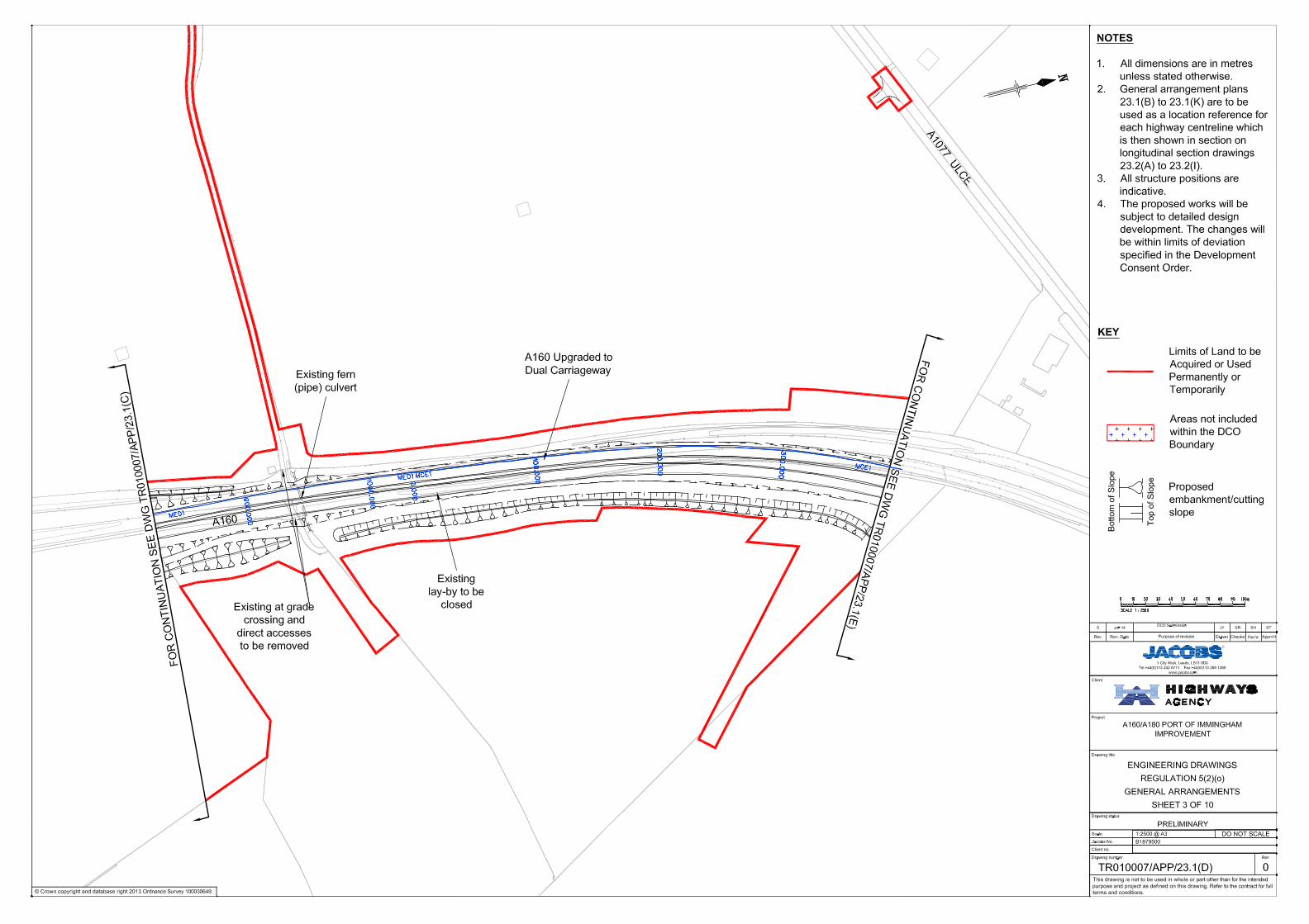
NOTES
1. All dimensions are in metres
unless stated otherwise.
2. General arrangement plans
23.1(B) to 23.1(K) are to be
used as a location reference for
each highway centreline which
is then shown in section on
longitudinal section drawings
23.2(A) to 23.2(I).
3. All structure positions are
indicative.
4. The proposed works will be
subject to detailed design
development. The changes will
be within limits of deviation
specified in the Development
Consent Order.
Limits of Land to be
Acquired or Used
Permanently or
Temporarily
KEY
Areas not included
within the DCO
Boundary
Proposed
embankment/cutting
slope

FO
R C
ON
TIN
UA
TIO
N S
EE
D
WG
T
R010007/A
PP
/23.1(B
)
FOR CO
NTINUATION SEE DW
G TR010007/APP/23.1(D)
IN
S
E
T
A
Brocklesby Interchange
Overbridge over the
A180 to be retained
BROCKLESBY
INTERCHANGE
Brocklesby Interchange New
Overbridge over A180
(DWG TR010007-APP-23.3-A)
Electricity
Pylon
Drainage
Pond 1
Existing
chapel (pipe)
culvert
Existing pylon
(pipe) culvert
A180
Westbound
Off-Slip
A180
Westbound
On-Slip
A180
Eastbound
On-Slip
A180
Eastbound
Off-Slip
Drainage
Discharge
Point 1
M
A
IN
P
L
A
N
Existing
lay-by to be
closed
Existing
lay-by to be
retained
A
1
8
0
A160/A180 PORT OF IMMINGHAM
IMPROVEMENT
ENGINEERING DRAWINGS
REGULATION 5(2)(o)
GENERAL ARRANGEMENTS
SHEET 2 OF 10
PRELIMINARY
1:2500 @ A3
B1879500
TR010007/APP/23.1(C) 0
1 City Walk, Leeds, LS11 9DX
Tel:+44(0)113 242 6771 Fax:+44(0)113 389 1389
www.jacobs.com
0 Jan 14
DCO Submission
JY SR SH ST
INSET A - 1:2500
© Crown copyright and database right 2013 Ordnance Survey 100030649.
This drawing is not to be used in whole or part other than for the intended
purpose and project as defined on this drawing. Refer to the contract for full
terms and conditions.
Drawing status
Drawing number
Scale
Client no.
Jacobs No.
Drawing title
DO NOT SCALE
Rev
Project
Client
P:\B
1500000\B
1879500 - A
160 Im
mingham
Im
provem
ent\C
AD
\D
CO
- A
pplication\F
IN
AL P
IN
S A
pplication\E
ngineering D
raw
ings\T
R010007-A
PP
-23.1(C
) E
ngineering D
raw
ings G
eneral A
rrangem
ents.dw
g
R
Apprv'dPurpose of revision
Rev Rev. Date Drawn CheckdRev'd
NOTES
1. All dimensions are in metres
unless stated otherwise.
2. General arrangement plans
23.1(B) to 23.1(K) are to be
used as a location reference for
each highway centreline which
is then shown in section on
longitudinal section drawings
23.2(A) to 23.2(I).
3. All structure positions are
indicative.
4. The proposed works will be
subject to detailed design
development. The changes will
be within limits of deviation
specified in the Development
Consent Order.
Limits of Land to be
Acquired or Used
Permanently or
Temporarily
KEY
Areas not included
within the DCO
Boundary
Proposed
embankment/cutting
slope

Drainage
Pond 4
Drainage
Pond 3
Ulceby
Truck
Stop
Proposed A1077
Ulceby Road
Link
A1077 U
LC
EB
Y R
OA
D
A160 Upgraded to
Dual Carriageway
Proposed
West Mere
Culvert
Proposed East
Mere Culvert
Drainage
Discharge
Point 3
Drainage Discharge
Point 4
A160
F
O
R
C
O
N
T
I
N
U
A
T
I
O
N
S
E
E
D
W
G
T
R
0
1
0
0
0
7
/
A
P
P
/
2
3
.
1
(
D
)
F
O
R
C
O
N
T
IN
U
A
T
IO
N
S
E
E
D
W
G
T
R
0
1
0
0
0
7
/A
P
P
/2
3
.1
(F
)
This drawing is not to be used in whole or part other than for the intended
purpose and project as defined on this drawing. Refer to the contract for full
terms and conditions.
Drawing status
Drawing number
Scale
Client no.
Jacobs No.
Drawing title
DO NOT SCALE
Rev
Project
Client
P:\B
1500000\B
1879500 - A
160 Im
mingham
Im
provem
ent\C
AD
\D
CO
- A
pplication\F
IN
AL P
IN
S A
pplication\E
ngineering D
raw
ings\T
R010007-A
PP
-23.1(E
) E
ngineering D
raw
ings G
eneral A
rrangem
ents.dw
g
R
Apprv'dPurpose of revision
Rev Rev. Date Drawn CheckdRev'd
A160/A180 PORT OF IMMINGHAM
IMPROVEMENT
ENGINEERING DRAWINGS
REGULATION 5(2)(o)
GENERAL ARRANGEMENT
SHEET 4 OF 10
PRELIMINARY
1:2500 @ A3
B1879500
TR010007/APP/23.1(E) 0
1 City Walk, Leeds, LS11 9DX
Tel:+44(0)113 242 6771 Fax:+44(0)113 389 1389
www.jacobs.com
0 Jan 14
DCO Submisson
JY SR SH ST
© Crown copyright and database right 2013 Ordnance Survey 100030649.
NOTES
1. All dimensions are in metres
unless stated otherwise.
2. General arrangement plans
23.1(B) to 23.1(K) are to be
used as a location reference for
each highway centreline which
is then shown in section on
longitudinal section drawings
23.2(A) to 23.2(I).
3. All structure positions are
indicative.
4. The proposed works will be
subject to detailed design
development. The changes will
be within limits of deviation
specified in the Development
Consent Order.
Limits of Land to be
Acquired or Used
Permanently or
Temporarily
KEY
Areas not included
within the DCO
Boundary
Proposed
embankment/cutting
slope
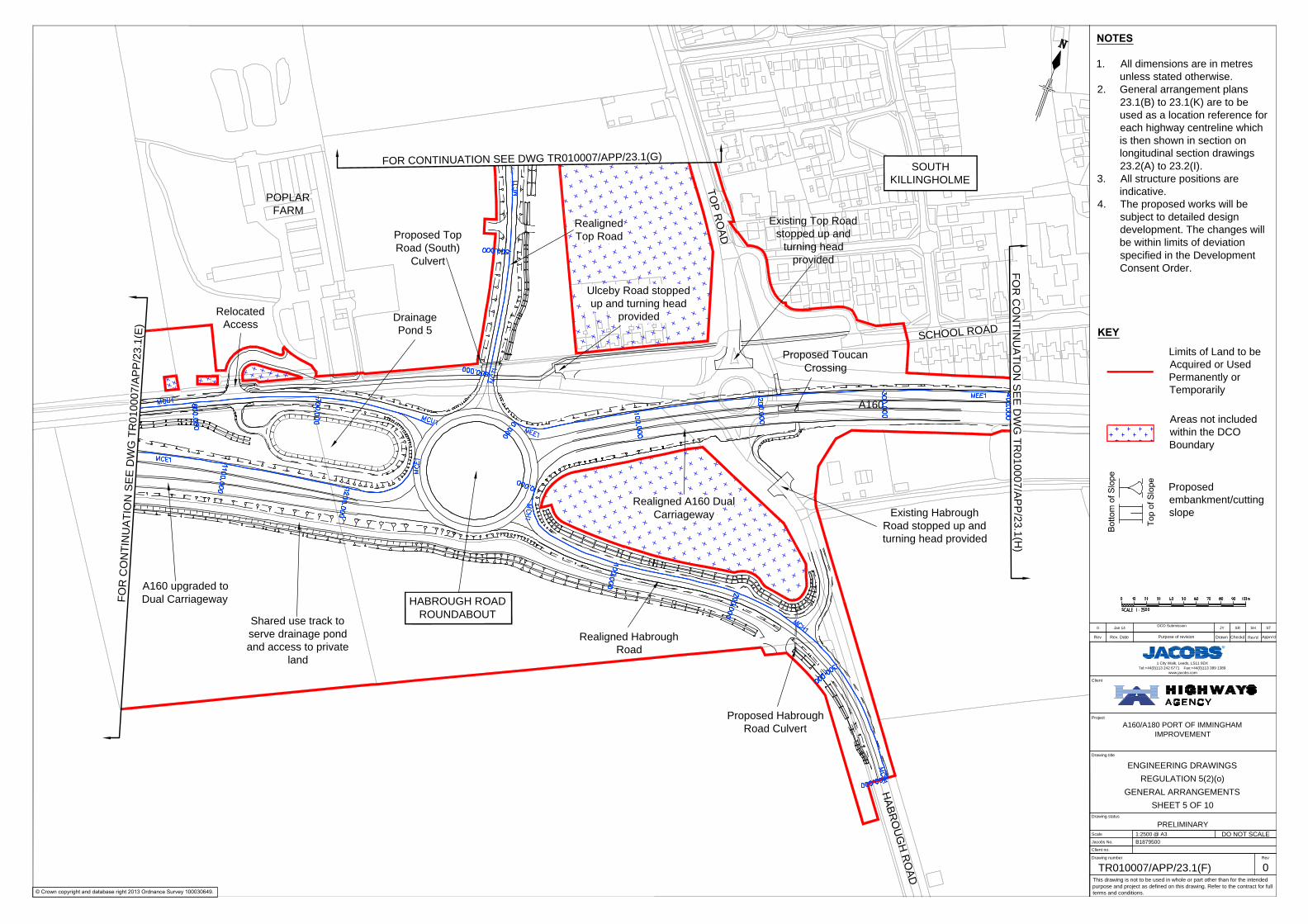
H
A
B
R
O
U
G
H
R
O
A
D
Drainage
Pond 5
Existing Top Road
stopped up and
turning head
provided
T
O
P
R
O
A
D
Realigned Habrough
Road
Existing Habrough
Road stopped up and
turning head provided
SC
HO
OL R
OA
D
HABROUGH ROAD
ROUNDABOUT
Relocated
Access
Shared use track to
serve drainage pond
and access to private
land
Proposed Toucan
Crossing
Proposed Top
Road (South)
Culvert
Proposed Habrough
Road Culvert
SOUTH
KILLINGHOLME
POPLAR
FARM
A160 upgraded to
Dual Carriageway
A160
Realigned
Top Road
Ulceby Road stopped
up and turning head
provided
Realigned A160 Dual
Carriageway
FO
R C
ON
TIN
UA
TIO
N S
EE
D
WG
T
R010007/A
PP
/23.1(E
)
FOR CONTINUATION SEE DWG TR010007/APP/23.1(G)
FO
R C
ON
TIN
UA
TIO
N S
EE
D
WG
T
R010007/A
PP
/23.1(H
)
This drawing is not to be used in whole or part other than for the intended
purpose and project as defined on this drawing. Refer to the contract for full
terms and conditions.
Drawing status
Drawing number
Scale
Client no.
Jacobs No.
Drawing title
DO NOT SCALE
Rev
Project
Client
P:\B
1500000\B
1879500 - A
160 Im
mingham
Im
provem
ent\C
AD
\D
CO
- A
pplication\F
IN
AL P
IN
S A
pplication\E
ngineering D
raw
ings\T
R010007-A
PP
-23.1(F
) E
ngineering D
raw
ings G
eneral A
rrangem
ents.dw
g
R
Apprv'dPurpose of revision
Rev Rev. Date Drawn CheckdRev'd
A160/A180 PORT OF IMMINGHAM
IMPROVEMENT
ENGINEERING DRAWINGS
REGULATION 5(2)(o)
GENERAL ARRANGEMENTS
SHEET 5 OF 10
PRELIMINARY
1:2500 @ A3
B1879500
TR010007/APP/23.1(F) 0
1 City Walk, Leeds, LS11 9DX
Tel:+44(0)113 242 6771 Fax:+44(0)113 389 1389
www.jacobs.com
0 Jan 14
DCO Submission
JY SR SH ST
© Crown copyright and database right 2013 Ordnance Survey 100030649.
NOTES
1. All dimensions are in metres
unless stated otherwise.
2. General arrangement plans
23.1(B) to 23.1(K) are to be
used as a location reference for
each highway centreline which
is then shown in section on
longitudinal section drawings
23.2(A) to 23.2(I).
3. All structure positions are
indicative.
4. The proposed works will be
subject to detailed design
development. The changes will
be within limits of deviation
specified in the Development
Consent Order.
Limits of Land to be
Acquired or Used
Permanently or
Temporarily
KEY
Areas not included
within the DCO
Boundary
Proposed
embankment/cutting
slope

T
O
P
R
O
A
D
C131 E
AS
T H
ALT
ON
R
OA
D
G
R
E
E
N
G
A
T
E
L
A
N
E
New Greengate
Lane link road
SOUTH
KILLINGHOLME
Realigned
Top Road
Existing Top Road
stopped up and
turning head provided
Proposed Top
Road (North)
Culvert
Proposed
Greengate
Culvert
FOR CONTINUATION SEE DWG TR010007/APP/23.1(F)
This drawing is not to be used in whole or part other than for the intended
purpose and project as defined on this drawing. Refer to the contract for full
terms and conditions.
Drawing status
Drawing number
Scale
Client no.
Jacobs No.
Drawing title
DO NOT SCALE
Rev
Project
Client
P:\B
1500000\B
1879500 - A
160 Im
mingham
Im
provem
ent\C
AD
\D
CO
- A
pplication\F
IN
AL P
IN
S A
pplication\E
ngineering D
raw
ings\T
R010007-A
PP
-23.1(G
) E
ngineering D
raw
ings G
eneral A
rrangem
ents.dw
g
R
Apprv'dPurpose of revision
Rev Rev. Date Drawn CheckdRev'd
1 City Walk, Leeds, LS11 9DX
Tel:+44(0)113 242 6771 Fax:+44(0)113 389 1389
www.jacobs.com
0 Jan 14
DCO Submission
JY SR SH ST
A160/A180 PORT OF IMMINGHAM
IMPROVEMENT
ENGINEERING DRAWINGS
REGULATION 5(2)(o)
GENERAL ARRANGEMENTS
SHEET 6 OF 10
PRELIMINARY
1:2500 @ A3
B1879500
TR010007/APP/23.1(G) 0
© Crown copyright and database right 2013 Ordnance Survey 100030649.
NOTES
1. All dimensions are in metres
unless stated otherwise.
2. General arrangement plans
23.1(B) to 23.1(K) are to be
used as a location reference for
each highway centreline which
is then shown in section on
longitudinal section drawings
23.2(A) to 23.2(I).
3. All structure positions are
indicative.
4. The proposed works will be
subject to detailed design
development. The changes will
be within limits of deviation
specified in the Development
Consent Order.
Limits of Land to be
Acquired or Used
Permanently or
Temporarily
KEY
Areas not included
within the DCO
Boundary
Proposed
embankment/cutting
slope
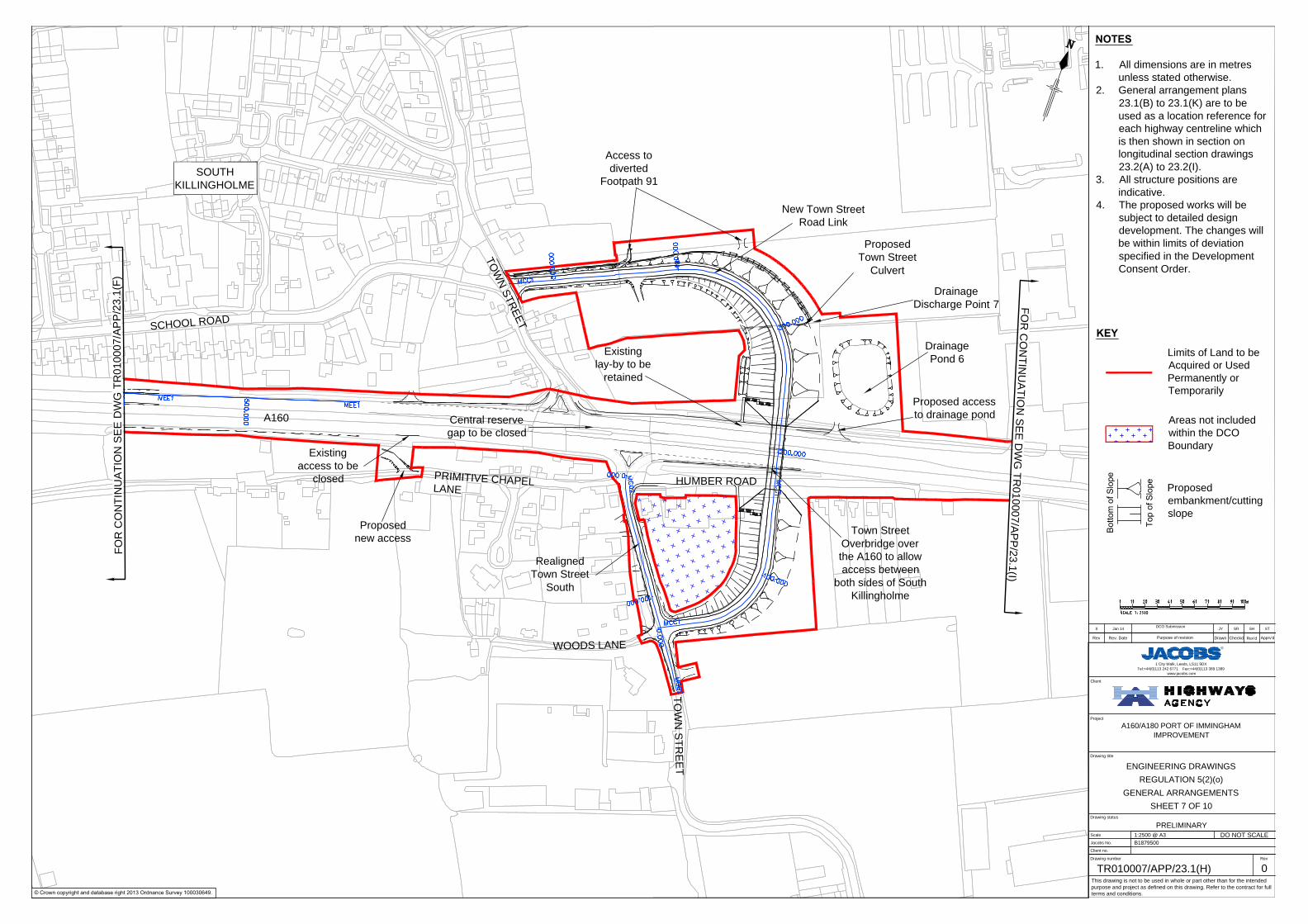
T
O
W
N
S
T
R
E
E
T
TO
WN
S
TR
EE
T
Central reserve
gap to be closed
Existing
lay-by to be
retained
Drainage
Pond 6
Town Street
Overbridge over
the A160 to allow
access between
both sides of South
Killingholme
Realigned
Town Street
South
SC
HO
OL R
OA
D
SOUTH
KILLINGHOLME
New Town Street
Road Link
PR
IMIT
IVE
CH
AP
EL
LA
NE
WOODS LANE
HUMBER ROAD
Existing
access to be
closed
Proposed
new access
Access to
diverted
Footpath 91
Proposed access
to drainage pond
Proposed
Town Street
Culvert
Drainage
Discharge Point 7
A160
FO
R C
ON
TIN
UA
TIO
N S
EE
D
WG
T
R010007/A
PP
/23.1(F
)
FO
R C
ON
TIN
UA
TIO
N S
EE
D
WG
T
R010007/A
PP
/23.1(I)
This drawing is not to be used in whole or part other than for the intended
purpose and project as defined on this drawing. Refer to the contract for full
terms and conditions.
Drawing status
Drawing number
Scale
Client no.
Jacobs No.
Drawing title
DO NOT SCALE
Rev
Project
Client
R
Apprv'dPurpose of revision
Rev Rev. Date Drawn CheckdRev'd
A160/A180 PORT OF IMMINGHAM
IMPROVEMENT
ENGINEERING DRAWINGS
REGULATION 5(2)(o)
GENERAL ARRANGEMENTS
SHEET 7 OF 10
PRELIMINARY
1:2500 @ A3
B1879500
TR010007/APP/23.1(H) 0
1 City Walk, Leeds, LS11 9DX
Tel:+44(0)113 242 6771 Fax:+44(0)113 389 1389
www.jacobs.com
0 Jan 14
DCO Submission
JY SR SH ST
© Crown copyright and database right 2013 Ordnance Survey 100030649.
NOTES
1. All dimensions are in metres
unless stated otherwise.
2. General arrangement plans
23.1(B) to 23.1(K) are to be
used as a location reference for
each highway centreline which
is then shown in section on
longitudinal section drawings
23.2(A) to 23.2(I).
3. All structure positions are
indicative.
4. The proposed works will be
subject to detailed design
development. The changes will
be within limits of deviation
specified in the Development
Consent Order.
Limits of Land to be
Acquired or Used
Permanently or
Temporarily
KEY
Areas not included
within the DCO
Boundary
Proposed
embankment/cutting
slope
FO
R C
ON
TIN
UA
TIO
N S
EE
D
WG
T
R0
10
00
7/A
PP
/2
3.1
(J)
FO
R C
ON
TIN
UA
TIO
N S
EE
D
WG
T
R010007/A
PP
/23.1(H
)
FO
R C
ON
TIN
UA
TIO
N S
EE
D
WG
T
R0
10
00
7/A
PP
/2
3.1
(J)
FO
R C
ON
TIN
UA
TIO
N S
EE
D
WG
T
R010007/A
PP
/23.1(H
)
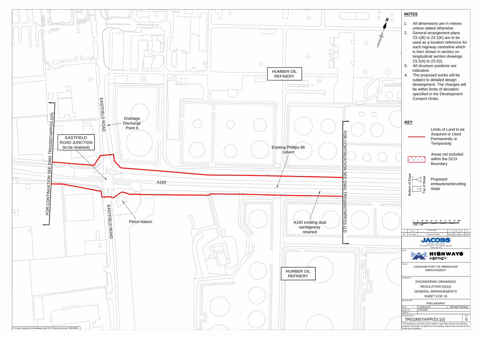
EA
ST
FIE
LD
R
OA
D
HUMBER OIL
REFINERY
A160 existing dual
carriageway
retained
Petrol station
EA
ST
FIE
LD
R
OA
D
EASTFIELD
ROAD JUNCTION
(to be retained) Existing Phillips 66
culvert
Drainage
Discharge
Point 6
HUMBER OIL
REFINERY
A160
A160/A180 PORT OF IMMINGHAM
IMPROVEMENT
ENGINEERING DRAWINGS
REGULATION 5(2)(o)
GENERAL ARRANGEMENTS
SHEET 8 OF 10
PRELIMINARY
1:2500 @ A3
B1879500
TR010007/APP/23.1(I) 0
1 City Walk, Leeds, LS11 9DX
Tel:+44(0)113 242 6771 Fax:+44(0)113 389 1389
www.jacobs.com
0 Jan 14
For Information
JY SR SH ST
© Crown copyright and database right 2013 Ordnance Survey 100030649.
This drawing is not to be used in whole or part other than for the intended
purpose and project as defined on this drawing. Refer to the contract for full
terms and conditions.
Drawing status
Drawing number
Scale
Client no.
Jacobs No.
Drawing title
DO NOT SCALE
Rev
Project
Client
P:\B
1500000\B
1879500 - A
160 Im
mingham
Im
provem
ent\C
AD
\D
CO
- A
pplication\F
IN
AL P
IN
S A
pplication\E
ngineering D
raw
ings\T
R010007-A
PP
-23.1(I) E
ngineering D
raw
ings G
eneral A
rrangem
ents.dw
g
R
Apprv'dPurpose of revision
Rev Rev. Date Drawn CheckdRev'd
NOTES
1. All dimensions are in metres
unless stated otherwise.
2. General arrangement plans
23.1(B) to 23.1(K) are to be
used as a location reference for
each highway centreline which
is then shown in section on
longitudinal section drawings
23.2(A) to 23.2(I).
3. All structure positions are
indicative.
4. The proposed works will be
subject to detailed design
development. The changes will
be within limits of deviation
specified in the Development
Consent Order.
Limits of Land to be
Acquired or Used
Permanently or
Temporarily
KEY
Areas not included
within the DCO
Boundary
Proposed
embankment/cutting
slope

Central reserve gap
to be reconfigured
A160
Existing Lindsey Oil
Refinery culvert
HUMBER OIL
REFINERY
HUMBER OIL
REFINERY
Existing Phillips 66
Culvert
FO
R C
ON
TIN
UA
TIO
N S
EE
D
WG
T
R0
10
00
7/A
PP
/2
3.1
(I)
FO
R C
ON
TIN
UA
TIO
N S
EE
D
WG
T
R0
10
00
7/A
PP
/2
3.1
(K
)
A160/A180 PORT OF IMMINGHAM
IMPROVEMENT
ENGINEERING DRAWINGS
REGULATION 5(2)(o)
GENERAL ARRANGEMENTS
SHEET 9 OF 10
PRELIMINARY
1:2500 @ A3
B1879500
TR010007/APP/23.1(J) 0
1 City Walk, Leeds, LS11 9DX
Tel:+44(0)113 242 6771 Fax:+44(0)113 389 1389
www.jacobs.com
0 Jan 14
DCO SUBMISSION
JY SR SH ST
© Crown copyright and database right 2013 Ordnance Survey 100030649.
This drawing is not to be used in whole or part other than for the intended
purpose and project as defined on this drawing. Refer to the contract for full
terms and conditions.
Drawing status
Drawing number
Scale
Client no.
Jacobs No.
Drawing title
DO NOT SCALE
Rev
Project
Client
P:\B
1500000\B
1879500 - A
160 Im
mingham
Im
provem
ent\C
AD
\D
CO
- A
pplication\F
IN
AL P
IN
S A
pplication\E
ngineering D
raw
ings\T
R010007-A
PP
-23.1(J) E
ngineering D
raw
ings G
eneral A
rrangem
ents.dw
g
R
Apprv'dPurpose of revision
Rev Rev. Date Drawn CheckdRev'd
NOTES
1. All dimensions are in metres
unless stated otherwise.
2. General arrangement plans
23.1(B) to 23.1(K) are to be
used as a location reference for
each highway centreline which
is then shown in section on
longitudinal section drawings
23.2(A) to 23.2(I).
3. All structure positions are
indicative.
4. The proposed works will be
subject to detailed design
development. The changes will
be within limits of deviation
specified in the Development
Consent Order.
Limits of Land to be
Acquired or Used
Permanently or
Temporarily
KEY
Areas not included
within the DCO
Boundary
Proposed
embankment/cutting
slope
FO
R C
ON
TIN
UA
TIO
N S
EE
D
WG
T
R0
10
00
7/A
PP
/2
3.1
(J)
R
A
I
L
W
A
Y
L
I
N
E
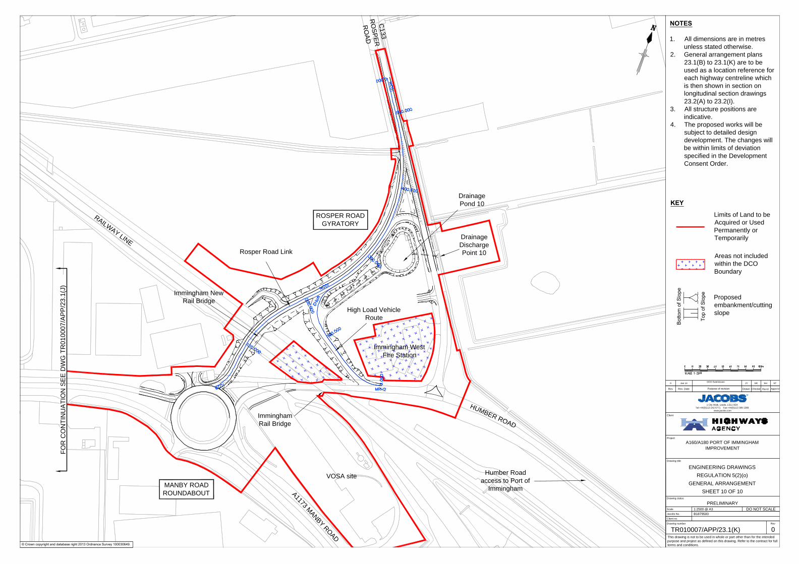
C
1
3
3
R
O
S
P
E
R
R
O
A
D
A
1
1
7
3
M
A
N
B
Y
R
O
A
D
Immingham New
Rail Bridge
High Load Vehicle
Route
Humber Road
access to Port of
Immingham
Drainage
Pond 10
MANBY ROAD
ROUNDABOUT
Immingham West
Fire Station
ROSPER ROAD
GYRATORY
VOSA site
Rosper Road Link
H
U
M
B
E
R
R
O
A
D
Drainage
Discharge
Point 10
Immingham
Rail Bridge
A160/A180 PORT OF IMMINGHAM
IMPROVEMENT
ENGINEERING DRAWINGS
REGULATION 5(2)(o)
GENERAL ARRANGEMENT
SHEET 10 OF 10
PRELIMINARY
1:2500 @ A3
B1879500
TR010007/APP/23.1(K) 0
1 City Walk, Leeds, LS11 9DX
Tel:+44(0)113 242 6771 Fax:+44(0)113 389 1389
www.jacobs.com
0 Jan 14
DCO Submission
JY SR SH ST
© Crown copyright and database right 2013 Ordnance Survey 100030649.
This drawing is not to be used in whole or part other than for the intended
purpose and project as defined on this drawing. Refer to the contract for full
terms and conditions.
Drawing status
Drawing number
Scale
Client no.
Jacobs No.
Drawing title
DO NOT SCALE
Rev
Project
Client
P:\B
1500000\B
1879500 - A
160 Im
mingham
Im
provem
ent\C
AD
\D
CO
- A
pplication\F
IN
AL P
IN
S A
pplication\E
ngineering D
raw
ings\T
R010007-A
PP
-23.1(K
) E
ngineering D
raw
ings G
eneral A
rrangem
ents.dw
g
R
Apprv'dPurpose of revision
Rev Rev. Date Drawn CheckdRev'd
NOTES
1. All dimensions are in metres
unless stated otherwise.
2. General arrangement plans
23.1(B) to 23.1(K) are to be
used as a location reference for
each highway centreline which
is then shown in section on
longitudinal section drawings
23.2(A) to 23.2(I).
3. All structure positions are
indicative.
4. The proposed works will be
subject to detailed design
development. The changes will
be within limits of deviation
specified in the Development
Consent Order.
Limits of Land to be
Acquired or Used
Permanently or
Temporarily
KEY
Areas not included
within the DCO
Boundary
Proposed
embankment/cutting
slope
![23.1(1) Accounts. EMPLOYER’SCONTRIBUTIONANDCHARGES - Iowa · IAC2/14/18 WorkforceDevelopment[871] Ch23,p.3 23.1(31)Quarterlywagedetail.Areportlistingworkersandtheirwagesbysocialsecuritynumber](https://img.pdfslide.us/doc/110x75/5aec797d7f8b9a585f8ed9fa/2311-accounts-employerscontributionandcharges-iowa-workforcedevelopment871.jpg)


![Channel List Iranian [V9]23.1](https://img.pdfslide.us/doc/110x75/55cf94f8550346f57ba5ad6d/channel-list-iranian-v9231.jpg)