Embed Size (px)
Citation preview
1
ENGINEERING DRAWING AM 09
SYLLABUS
AM Syllabus (2014): Engineering Drawing
AM SYLLABUS (2014)
2
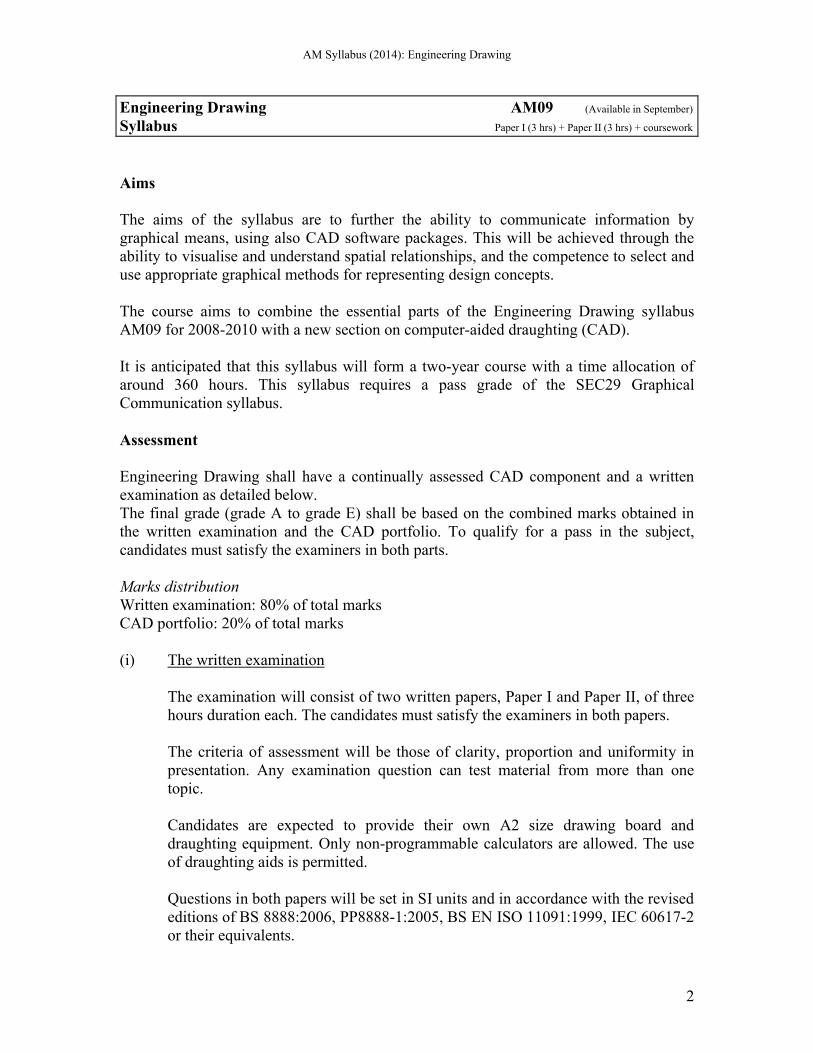
Engineering Drawing AM09 (Available in September) Syllabus Paper I (3 hrs) + Paper II (3 hrs) + coursework
Aims
The aims of the syllabus are to further the ability to communicate information by graphical means, using also CAD software packages. This will be achieved through the ability to visualise and understand spatial relationships, and the competence to select and use appropriate graphical methods for representing design concepts.
The course aims to combine the essential parts of the Engineering Drawing syllabus AM09 for 2008-2010 with a new section on computer-aided draughting (CAD).
It is anticipated that this syllabus will form a two-year course with a time allocation of around 360 hours. This syllabus requires a pass grade of the SEC29 Graphical Communication syllabus.
Assessment
Engineering Drawing shall have a continually assessed CAD component and a written examination as detailed below.The final grade (grade A to grade E) shall be based on the combined marks obtained in the written examination and the CAD portfolio. To qualify for a pass in the subject, candidates must satisfy the examiners in both parts.
Marks distributionWritten examination: 80% of total marksCAD portfolio: 20% of total marks
(i) The written examination
The examination will consist of two written papers, Paper I and Paper II, of three hours duration each. The candidates must satisfy the examiners in both papers.
The criteria of assessment will be those of clarity, proportion and uniformity in presentation. Any examination question can test material from more than one topic.
Candidates are expected to provide their own A2 size drawing board and draughting equipment. Only non-programmable calculators are allowed. The use of draughting aids is permitted.
Questions in both papers will be set in SI units and in accordance with the revised editions of BS 8888:2006, PP8888-1:2005, BS EN ISO 11091:1999, IEC 60617-2 or their equivalents.
AM Syllabus (2014): Engineering Drawing
3
(ii) The CAD portfolio
Each candidate shall present a portfolio of five hard-copy, graded CAD practical exercises previously set by MATSEC to cover the syllabus. These exercises shall be marked by the class tutor during the two-year course, according to a marking scheme, guide-lines and instructions issued by MATSEC. The portfolio shall be submitted to the MATSEC Board by a fixed date prior to the written examination.
Private candidates
Private candidates will be required to sit for the written examination as outlined above, together with a three-hour examination on Computer Aided Draughting in lieu of the continually assessed component followed by the other candidates. The CAD examination shall carry a 20% weighting of the total subject mark. Privatecandidates will not be required to present a CAD competence folio.
The syllabus
Written Examination
Paper I (100 marks)
Paper I is common to both Graphical Communication (AM15) and Engineering Drawing (AM09). It will contain six questions of which candidates are required to answer any five. All questions will carry equal marks. All five questions are to be answered on A2 size sheets, which will be provided.
1. The cone and the conic sections.
Conics regarded as sections of a right cone.Conics regarded as plane loci of a moving point.Properties common to all conics.The construction of a tangent and a normal at a point on the conics. The construction of a tangent and a normal to the ellipse and parabola from a given point outside the curve.Use of the focal sphere to find the ratio of eccentricity, the position of the directrix and the focal points of a conic.Drawing the conics using various methods.The centre of curvature at a point on the ellipse, parabola and hyperbola, the point not being a vertex.
AM Syllabus (2014): Engineering Drawing
4
2. Cycloidal curves
The construction of the cycloid, epicycloid, hypocycloid, and their derived curves.The tangent, normal, and centre of curvature at a point on the cycloid and its trochoids.
3. Spiral curves
The archimedean spiral: the drawing of one or more convolutions extending between two given radii; the tangent and normal at a point on it.
4. Helices and screw threads
The helix: right-hand and left-hand; the true length; the helix angle.Applications of the helix: one- and two-start, internal or external, vee and square threads; the helical vane; square and rectangular springs.
5. Involute Spur Gears
The involute of a circle.The construction of a spur gear tooth profile of true involute form.The analysis and drawing of gears in mesh. The number of teeth to be shown in mesh is limited to five.The rack and pinion.
6. Coplanar loci of points on moving mechanisms.
Slider-crank mechanism.Equal and unequal connected cranks.Watt’s straight-line motion.Quick-return mechanism.Geared link mechanisms.The drawing of displacement diagrams related to the above.
7. Cams
Types of motion: Dwell, Uniform velocity, Simple Harmonic Motion, Uniform Acceleration, Uniform Retardation, and Uniform Acceleration and Retardation.Types of followers: knife-edged, flat-foot, roller-ended.Line of action of followers to be in-line or offset to the axis of the cam.Types of cams: wedge, disc, cams with radial arm followers and end cams.Problems will be set to derive the cam profile from given cam data.
AM Syllabus (2014): Engineering Drawing
5
8. Projections
Isometric projection and the use of the isometric scale.First and second auxiliary projection of shapes and solids.
9. Projection of Lines
Lines inclined to the H.P. and V.P.; the determination of their true lengths, the true inclination to the horizontal and vertical planes of reference.Skew lines; the shortest distance between two straight lines.
10. Planes
Planes inclined to the H.P. and V.P.; true angles between two planes: the dihedral angle.Lines of intersection between two triangles or other plane laminae. The determination of the angle between the two planes.
Oblique planes and their traces; the conversion of an oblique plane into an inclined plane by means of auxiliary views; the true inclination to the horizontal and vertical planes.
Lines, geometrical shapes and solids resting on, or cut by oblique planes.
11. Intersection of Solids
Interpenetration of geometrical solids, covering intersections between:a. Two prismsb. Two cylindersc. Prism and cylinderd. Cone and prism/cylindere. Pyramid and prism/cylinderf. Sphere/hemisphere and prism/cylinderg. Sphere and cone
All solids are right, with the cones and pyramids standing on their bases. Prisms and cylinders may be inclined to one plane of reference.All above categories may include cases of offset middle planes.
The construction of the curve of intersection that result on:a. Palm-ended rods and eccentric cylinders;b. Rods of square section joined to cones or spheres.
12. Solids in contact
Spheres in mutual contact with each other.Spheres in contact with cones standing on their base.The projection of the points of contact.
AM Syllabus (2014): Engineering Drawing
6
13. Developments
The development of surfaces of right and oblique truncated prisms, cylinders, cones and pyramids.Development by triangulation of transition pieces; the end connections may have different cross-sections, not necessarily parallel to each other.
14. Graphical Statics
Coplanar concurrent and non-concurrent forces.The use of Bow’s notation, polar diagram and link polygon to determine graphically the resultant/equilibrant of a system of forces.
Shear Force and Bending moment diagrams for a) light cantilevers,b) light simply supported beams andc) light hinged beams - the beam is made of two parts, hinged together,when these are subjected to vertical point loads and uniformly distributed loads.
Framed structures; the use of space and force diagrams to framework problems to determine graphically the reactions and forces in members; the distinction between struts and ties. The applied external loading is limited to vertical point loads.
Paper II (100 marks)
Paper II will consist of four questions. The first is compulsory and carries 60% of the total marks. Candidates will choose two of the remaining three questions. These two questions share equally the remaining 40% of the marks.
Candidates will answer the questions on the A2 drawing sheets provided.
It is of paramount importance that the candidates be able to interpret and produce engineering drawings to relevant British and equivalent ISO standards. The candidates should be familiar with the application of these standards, regarding them as reference documents to be used when required. Knowledge of the topics covered in Paper I is assumed. Paper II will cover the following topics:
1. Layout and Presentation
Sheet layout of drawings to modern drawing office practice, including blocks for items such as title, date, drawing and job number, scales, materials and parts list, item (balloon) reference, material specification, treatment and finish and general tolerance. The sizes and types of drawing paper in use. The selection and preparation of drawing paper for subsequent reproduction.
AM Syllabus (2014): Engineering Drawing
7
The layout and presentation of drawings should be in accordance with BS 8888 or the equivalent international ISO standard.
2. Orthographic Projection
First and Third angle projections with the use of hidden detail, sectional views and auxiliary views. Conventional practice in sectional drawings. Symbols and abbreviations.
The production of assembly drawings from detail drawings of separate parts or vice versa. The drawings may feature components of engines, compressors, pumps, non-return valves, safety valves and stop valves, couplings and simple clutches, bearings and shafting details.
3. Dimensioning and tolerances
The dimensioning of drawings from centre and reference lines, machined and datum surfaces. Limits and fits and the method of indicating tolerances for selected ISO fits using hole basis – candidates should be able to read and apply Data Sheet 4500A, which will be provided if required.Types of fit: clearance, transition and interference.Geometrical tolerances covering straightness, flatness, roundness, cylindricity, profile of a line, profile of a surface, parallelism, squareness, angularity, position, concentricity, symmetry and run-out.
4. Symbols
Machine and surface texture symbols.Welding symbols (BS EN 22553: 1995) and types of welded joints: butt, fillet and lap.
5. Freehand sketches
Freehand sketching of commonly used details to extend knowledge and appreciation of the constructional and operational features of machinery and equipment.
AM Syllabus (2014): Engineering Drawing
8
Computer-Aided Draughting
1. General Guidelines
1. CAD is an obligatory component of the subjects AM09 and AM15. It shall carry 20% of the global marks for the respective subjects.
2. The CAD component is continually assessed by the class tutor responsible for the subject.
3. Computer draughting assignments based on AUTOCAD up to 2D level will be covered during the 2 years’ duration of the course.
4. A portfolio shall be set for each candidate, and will contain:
a. MATSEC Board form completed by the candidate, the class tutor, and the Head of school/college.
b. Five hard copies (A3 size) of assignments set by MATSEC and their computer generated solutions (A3 size) done by the candidate in class at fixed dates and times throughout the course.
5. The candidates’ portfolio with solutions marked by the tutor will be kept under strict confidential cover by the head of school/college and returned at the end of the course to MATSEC Board by a stipulated date.
6. The five CAD assignments set by MATSEC shall be based upon topics outlined in the examination syllabus. These assignments shall be graded examples that progress with knowledge gained both in the application of computer software and subject matter.
7. A tutor’s sample copy of a model CAD portfolio is available on request from the MATSEC Board. This copy folio contains selected examples of practical assignments and solutions indicating the standard expected in the computer aided draughting component of the course.
2. Objectives
The course is aimed at providing course participants with the fundamentals of Computer Aided Draughting (CAD) using AutoCAD software packages to draw 2D plans and/or 2D projections. This course requires the candidate to:a) demonstrate competency in using some of the standard available features of a
CAD application;b) to create and manipulate objects or elements and to modify objects or elements;c) be able to change object properties;d) be able to present a drawing in orthographic and isometric;e) undertake printing or plotting activity in colour / monochrome with specific
scales.
AM Syllabus (2014): Engineering Drawing
9
3. Contents
During the course, participants will cover the following topics and AutoCAD commands:
3.1 AutoCAD fundamentals3.1.1 Open, (and close) AutoCAD application3.1.2 Open multiple drawings and switch between them3.1.3 Create a new drawing3.1.4 Set model environment ie units, limits etc.3.1.5 Set interface settings eg snap, grid, ortho, 3.1.6 Create and save an AutoCAD drawing template
3.2 Roaming facilities 3.2.1 Use zooming tools 3.2.2 Panning a drawing 3.2.3 Create named views & recall them
3.3 Create new drawings 3.3.1 Understand & use Absolute, Relative and Polar coordinate system3.3.2 Drawing commands as line, pline, circle, arc, 3.3.3 Draw rectangle, polygon, ellipse3.3.4 Hatch a closed entity to represent sections3.3.5 Use snapping tools for accuracy
3.4 Modifying Commands 3.4.1 Erase & oops 3.4.2 Copy and Move objects3.4.3 Rotate, Scale, Stretch Extend & Offset3.4.4 Mirror and array3.4.5 Apply Chamfers and Fillets3.4.6 Edit polylines and spline, decurve, fit, thickness join & explode3.4.7 Trim, break, explode
3.5 Layers3.5.1 Create layers and assign properties as lineweights, line types, colour3.5.2 Modify status: On, Off, Freeze, Thaw, Lock, Unlock3.5.3 Set layer current3.5.4 Modify layer attributes
3.6 Text and Dimensions3.6.1 Create and set text styles with different fonts3.6.2 Understand the difference between mtext and text commands3.6.3 Understand the text alignment abbreviations eg TR, TC, TL etc.
AM Syllabus (2014): Engineering Drawing
10
3.6.4 Create & set dimension style according to ISO Standard3.6.5 Set as current style3.6.6 Create a child within a dimension style
3.7 Isometric3.7.1 Changing to isometric mode3.7.2 Switching between isoplanes (top, right & left views)3.7.3 Isometric ellipses3.7.4 Isometric fillets3.7.5 Writing in isometric mode
3.8 Plotting3.8.1 Understand between Model and Paper space3.8.2 Add a new title block 3.8.3 Create a viewports with different scales3.8.4 Select plotter/ printer3.8.5 Plot all, part of drawing to scale
Practical Exercises (school/college candidates)
Candidates will keep a record of CAD work on a CD. The five CAD assignments set by MATSEC and answered by candidates will be progressively stored on another CD which will be kept under confidential cover by the class tutor. Candidates will only have access to this CD during the fixed date and time of the CAD assignments set by MATSEC.
Reading list
Simmons & Maguire Manual of Engineering DrawingEanna O Broin Technical Draughtmanship
AM Syllabus (2014): Engineering Drawing