Embed Size (px)
Citation preview
Engineering Design Guidelines
2009 Edition
Antonio Gioiello Chief Harbor Engineer
Prepared by:
Engineering Division
2009 Engineering Design Guidelines
TABLE OF CONTENTS Page i
TABLE OF CONTENTS
01 INTRODUCTION .............................................................. 1
01.01 GENERAL INTRODUCTION ................................................................ 1 01.01.01 Background ................................................................................ 1 01.01.02 Purpose ...................................................................................... 1 01.01.03 Companion Manuals ................................................................... 1
01.02 DESIGNER'S RESPONSIBILITY ......................................................... 1 01.02.01 Overall Responsibility ................................................................. 2 01.02.02 Design Process ........................................................................... 2
01.03 FORMAT .............................................................................................. 2 01.03.01 Chapter Organization .................................................................. 2 01.03.02 Chapter Sections ........................................................................ 3 01.03.03 Chapter Subsections .................................................................. 3
01.04 REVISIONS .......................................................................................... 4 01.04.01 Revision Notification ................................................................... 4 01.04.02 Revision Completion ................................................................... 4
01.05 DISTRIBUTION .................................................................................... 4 01.05.01 Harbor Department Distribution .................................................. 4 01.05.02 Outside Distribution .................................................................... 4
02 GENERAL DESIGN ...................................................... 6 02.01 OVERVIEW .......................................................................................... 6
02.01.01 Reference Projects/Drawings/Specifications .............................. 6 02.01.02 Maintenance/Operations ............................................................. 6 02.01.03 Physical Constraints ................................................................... 6 02.01.04 Coordination ............................................................................... 7 02.01.05 Working Clearances ................................................................... 7 02.01.06 Abbreviations/Terms ................................................................... 7 02.01.07 Substructure Drawings ............................................................... 7
02.02 DESIGN CRITERIA .............................................................................. 8 02.02.01 Design Approval ......................................................................... 8 02.02.02 Compliance ................................................................................. 8 02.02.03 Design Document Preparation/Submission ................................ 8
02.03 CALCULATIONS/WORKSHEETS ...................................................... 11 02.03.01 Preparation/Submission ............................................................ 11 02.03.02 Cost Estimates .......................................................................... 11
02.04 GRAPHIC CRITERIA ......................................................................... 14 02.05 SPECIFICATIONS .............................................................................. 15
02.05.01 General ..................................................................................... 15 02.05.02 The Boiler Plate ........................................................................ 15 02.05.03 Specification Section ................................................................ 17 02.05.04 Addenda ................................................................................... 18
2009 Engineering Design Guidelines
TABLE OF CONTENTS Page ii
02.05.05 Delta Revisions ......................................................................... 18 02.05.06 Responsibilities ......................................................................... 18 02.05.07 Directions to Consultant for Preparing POLA Engineering
Specifications ............................................................................ 19 02.05.08 Reference Design Manuals/Guidelines ..................................... 21 02.05.09 List of Figures/Details ............................................................... 21
02.06 PERMITS/APPROVALS ..................................................................... 28 02.06.01 General ..................................................................................... 28 02.06.02 Application for Discretionary Permit (ADP) ............................... 28 02.06.03 Other Permits............................................................................ 29 02.06.04 List of Figures/Details ............................................................... 29 02.06.05 Port General Permit Procedures ............................................... 29
02.07 ENVIRONMENTAL CONSIDERATIONS ........................................... 30 02.08 REFERENCES ................................................................................... 31
03 BACKLAND ................................................................ 53 03.01 GENERAL .......................................................................................... 53
03.01.01 OVERVIEW .............................................................................. 53 03.01.02 DESIGN CRITERIA .................................................................. 53 03.01.03 CALCULATIONS/WORKSHEETS - Estimating ........................ 53 03.01.04 GRAPHIC CRITERIA ................................................................ 53 03.01.05 SPECIFICATIONS .................................................................... 55 03.01.06 PERMITS/APPROVALS ........................................................... 56 03.01.07 ENVIRONMENTAL CONSIDERATIONS .................................. 56 03.01.08 REFERENCE DRAWINGS ....................................................... 56
03.02 FENCING ........................................................................................... 57 03.02.01 OVERVIEW .............................................................................. 57 03.02.02 DESIGN CRITERIA – Fencing.................................................. 57 03.02.03 CALCULATIONS/WORKSHEETS ............................................ 58 03.02.04 GRAPHIC CRITERIA ................................................................ 58 03.02.05 SPECIFICATIONS .................................................................... 58 03.02.06 PERMITS/APPROVALS ........................................................... 58 03.02.07 ENVIRONMENTAL CONSIDERATIONS .................................. 58 03.02.08 REFERENCE DRAWINGS ....................................................... 59
03.03 RAIL ................................................................................................... 60 03.03.01 OVERVIEW .............................................................................. 60 03.03.02 DESIGN CRITERIA .................................................................. 60 03.03.03 CALCULATIONS/WORKSHEETS ............................................ 67 03.03.04 GRAPHIC CRITERIA ................................................................ 67 03.03.05 SPECIFICATIONS .................................................................... 67 03.03.06 PERMITS/APPROVALS ........................................................... 68 03.03.07 ENVIRONMENTAL CONSIDERATIONS .................................. 68 03.03.08 REFERENCE DRAWINGS ....................................................... 69
03.04 STRIPING........................................................................................... 70 03.04.01 OVERVIEW .............................................................................. 70 03.04.02 DESIGN CRITERIA .................................................................. 70
2009 Engineering Design Guidelines
TABLE OF CONTENTS Page iii
03.04.03 CALCULATIONS/WORKSHEETS ............................................ 71 03.04.04 GRAPHIC CRITERIA ................................................................ 71 03.04.05 SPECIFICATIONS .................................................................... 71 03.04.06 PERMITS/APPROVALS ........................................................... 71 03.04.07 ENVIRONMENTAL CONSIDERATIONS .................................. 72 03.04.08 REFERENCE DRAWINGS ....................................................... 72
03.05 REMOVALS AND EXISTING SUBSTRUCTURES ............................. 73 03.05.01 OVERVIEW .............................................................................. 73 03.05.02 DESIGN CRITERIA .................................................................. 73 03.05.03 CALCULATIONS/WORKSHEET .............................................. 76 03.05.04 GRAPHIC CRITERIA ................................................................ 76 03.05.05 SPECIFICATIONS .................................................................... 76 03.05.06 PERMITS/APPROVALS ........................................................... 76 03.05.07 ENVIRONMENTAL CONSIDERATIONS .................................. 77 03.05.08 REFERENCE DRAWINGS ....................................................... 77
03.06 GRADING AND PAVING .................................................................... 78 03.06.01 OVERVIEW .............................................................................. 78 03.06.02 DESIGN CRITERIA .................................................................. 78 03.06.03 CALCULATIONS/WORKSHEETS ............................................ 82 03.06.04 GRAPHICS CRITERIA ............................................................. 82 03.06.05 SPECIFICATIONS .................................................................... 83 03.06.06 PERMITS/APPROVALS ........................................................... 83 03.06.07 ENVIRONMENTAL CONSIDERATIONS .................................. 84 03.06.08 REFERENCE DRAWINGS ....................................................... 85
03.07 STORM DRAINS ................................................................................ 86 03.07.01 OVERVIEW .............................................................................. 86 03.07.02 DESIGN CRITERIA .................................................................. 86 03.07.03 CALCULATIONS/WORKSHEETS ............................................ 92 03.07.04 GRAPHICS CRITERIA ............................................................. 94 03.07.05 SPECIFICATIONS .................................................................... 94 03.07.06 PERMITS/APPROVALS ........................................................... 95 03.07.07 ENVIRONMENTAL CONSIDERATIONS .................................. 96 03.07.08 REFERENCE DRAWINGS ....................................................... 97
03.08 SEWERS ............................................................................................ 98 03.08.01 OVERVIEW .............................................................................. 98 03.08.02 DESIGN CRITERIA .................................................................. 98 03.08.03 CALCULATIONS/WORKSHEETS .......................................... 101 03.08.04 GRAPHIC CRITERIA .............................................................. 101 03.08.05 SPECIFICATIONS .................................................................. 101 03.08.06 PERMITS/APPROVALS ......................................................... 102 03.08.07 ENVIRONMENTAL CONSIDERATIONS ................................ 103 03.08.08 REFERENCE DRAWINGS ..................................................... 103
03.09 LANDSCAPE .................................................................................... 104 03.09.01 OVERVIEW ............................................................................ 104 03.09.02 DESIGN CRITERIA ................................................................ 104
2009 Engineering Design Guidelines
TABLE OF CONTENTS Page iv
03.09.03 CALCULATIONS/WORKSHEETS .......................................... 110 03.09.04 GRAPHIC CRITERIA .............................................................. 110 03.09.05 SPECIFICATIONS .................................................................. 111 03.09.06 PERMITS/APPROVALS ......................................................... 111 03.09.07 ENVIRONMENTAL CONSIDERATIONS ................................ 111 03.09.08 REFERENCE DRAWINGS ..................................................... 111
03.10 Structural .......................................................................................... 113 03.10.01 OVERVIEW ............................................................................ 113 03.10.02 DESIGN CRITERIA ................................................................ 113 03.10.03 CALCULATIONS/WORKSHEETS .......................................... 115 03.10.04 GRAPHIC CRITERIA .............................................................. 115 03.10.05 SPECIFICATIONS .................................................................. 115 03.10.06 ESTIMATING .......................................................................... 116 03.10.07 PERMITS/APPROVALS ......................................................... 116 03.10.08 REFERENCE DRAWINGS ..................................................... 116
03.11 MECHANICAL .................................................................................. 123 03.11.01 OVERVIEW ............................................................................ 123 03.11.02 DESIGN CRITERIA ................................................................ 123 03.11.03 CALCULATIONS/WORKSHEETS .......................................... 130 03.11.04 GRAPHIC CRITERIA .............................................................. 134 03.11.05 SPECIFICATIONS .................................................................. 134 03.11.06 PERMITS/APPROVALS ......................................................... 135 03.11.07 ENVIRONMENTAL CONSIDERATIONS ................................ 135 03.11.08 REFERENCE DRAWINGS ..................................................... 136
03.12 GAS .................................................................................................. 137 03.12.01 OVERVIEW ............................................................................ 137 03.12.02 DESIGN CRITERIA ................................................................ 137 Letter From the Gas Company .................................................................. 137 03.12.03 CALCULATIONS/WORKSHEETS .......................................... 139 03.12.04 GRAPHIC CRITERIA .............................................................. 139 03.12.05 SPECIFICATIONS .................................................................. 140 03.12.06 PERMITS/APPROVALS ......................................................... 140 03.12.07 ENVIRONMENTAL CONSIDERATIONS ................................ 140 03.12.08 REFERENCE DRAWINGS ..................................................... 140
03.13 WATER ............................................................................................ 142 03.13.01 OVERVIEW ............................................................................ 142 03.13.02 DESIGN CRITERIA ................................................................ 142 03.13.03 CALCULATIONS/WORKSHEETS .......................................... 145 03.13.04 GRAPHIC CRITERIA .............................................................. 145 03.13.05 SPECIFICATIONS .................................................................. 146 03.13.06 PERMITS/APPROVALS ......................................................... 146 03.13.07 ENVIRONMENTAL CONSIDERATIONS ................................ 147 03.13.08 REFERENCE DRAWINGS ..................................................... 147
03.14 ELECTRICAL ................................................................................... 156 03.14.01 OVERVIEW ............................................................................ 156
2009 Engineering Design Guidelines
TABLE OF CONTENTS Page v
03.14.02 DESIGN CRITERIA ................................................................ 156 03.14.03 CALCULATIONS/WORKSHEETS .......................................... 164 03.14.04 GRAPHIC CRITERIA .............................................................. 165 03.14.05 SPECIFICATIONS .................................................................. 166 03.14.06 PERMITS/APPROVALS ......................................................... 167 03.14.07 ENVIRONMENTAL CONSIDERATIONS ................................ 168 03.14.08 REFERENCE DRAWINGS ..................................................... 168
03.15 TERMINAL PLANNING .................................................................... 170 03.15.01 OVERVIEW ............................................................................ 170 03.15.02 DESIGN CRITERIA ................................................................ 171 03.15.03 CALCULATIONS/WORKSHEETS .......................................... 171 03.15.04 GRAPHIC CRITERIA .............................................................. 172 03.15.05 SPECIFICATIONS .................................................................. 172 03.15.06 PERMITS/APPROVALS ......................................................... 172 03.15.07 ENVIRONMENTAL CONSIDERATIONS ................................ 172 03.15.08 REFERENCE DRAWINGS ..................................................... 172
04 BUILDINGS .............................................................. 173 04.01 GENERAL ........................................................................................ 173
04.01.01 OVERVIEW ............................................................................ 173 04.01.02 DESIGN CRITERIA ................................................................ 173 04.01.03 CALCULATIONS/WORKSHEETS .......................................... 173 04.01.04 GRAPHIC CRITERIA .............................................................. 174 04.01.05 SPECIFICATIONS .................................................................. 175 04.01.06 PERMITS/APPROVALS ......................................................... 175 04.01.07 ENVIRONMENTAL CONSIDERATIONS ................................ 175 04.01.08 REFERENCE DRAWINGS ..................................................... 175
04.02 ARCHITECTURAL ........................................................................... 176 04.02.01 OVERVIEW ............................................................................ 176 04.02.02 DESIGN CRITERIA ................................................................ 177 04.02.03 CALCULATIONS/ WORKSHEETS ......................................... 188 04.02.04 GRAPHIC CRITERIA .............................................................. 188 04.02.05 SPECIFICATIONS .................................................................. 190 04.02.06 PERMITS/APPROVALS ......................................................... 191 04.02.07 ENVIRONMENTAL CONSIDERATIONS ................................ 193 04.02.08 REFERENCE DRAWINGS ..................................................... 193
04.03 MECHANICAL .................................................................................. 195 04.03.01 OVERVIEW ............................................................................ 195 04.03.02 DESIGN CRITERIA ................................................................ 195 04.03.03 CALCULATIONS/WORKSHEETS .......................................... 199 04.03.04 GRAPHIC CRITERIA .............................................................. 200 04.03.05 SPECIFICATIONS .................................................................. 200 04.03.06 PERMITS/APPROVALS ......................................................... 200 04.03.07 ENVIRONMENTAL CONSIDERATIONS ................................ 201 04.03.08 REFERENCE DRAWINGS ..................................................... 201 04.03.09 Building Mechanical Checklist ................................................ 202
2009 Engineering Design Guidelines
TABLE OF CONTENTS Page vi
04.04 PLUMBING ....................................................................................... 206 04.04.01 OVERVIEW ............................................................................ 206 04.04.02 DESIGN CRITERIA ................................................................ 206 04.04.03 CALCULATIONS/WORKSHEETS .......................................... 209 04.04.04 GRAPHIC CRITERIA .............................................................. 209 04.04.05 SPECIFICATIONS .................................................................. 209 04.04.06 PERMITS/APPROVALS ......................................................... 210 04.04.07 ENVIRONMENTAL CONSIDERATIONS ................................ 210 04.04.08 REFERENCE DRAWINGS ..................................................... 210 04.04.09 BUILDING PLUMBING CHECKLIST ...................................... 211
04.05 STRUCTURAL ................................................................................. 213 04.05.01 OVERVIEW ............................................................................ 213 04.05.02 DESIGN CRITERIA ................................................................ 213 04.05.03 CALCULATIONS/WORKSHEETS .......................................... 215 04.05.04 GRAPHIC CRITERIA .............................................................. 215 04.05.05 SPECIFICATIONS .................................................................. 216 04.05.06 PERMITS/APPROVALS ......................................................... 216 04.05.07 ENVIRONMENTAL CONSIDERATIONS ................................ 217 04.05.08 REFERENCE DRAWINGS (Typical structural plans) ............. 217
04.06 ELECTRICAL ................................................................................... 218 04.06.01 OVERVIEW ............................................................................ 218 04.06.02 DESIGN CRITERIA ................................................................ 218 04.06.03 CALCULATIONS/WORKSHEETS .......................................... 224 04.06.04 GRAPHIC CRITERIA .............................................................. 224 04.06.05 SPECIFICATIONS .................................................................. 225 04.06.06 PERMITS/APPROVALS ......................................................... 226 04.06.07 ENVIRONMENTAL CONSIDERATIONS ................................ 227 04.06.08 REFERENCE DRAWINGS ..................................................... 227
04.07 FIRE PROTECTION SYSTEM ......................................................... 229 04.07.01 OVERVIEW ............................................................................ 229 04.07.02 DESIGN CRITERIA ................................................................ 229 04.07.03 CALCULATIONS/WORKSHEETS .......................................... 231 04.07.04 GRAPHIC CRITERIA .............................................................. 231 04.07.05 SPECIFICATIONS .................................................................. 231 04.07.06 PERMITS/APPROVALS ......................................................... 232 04.07.07 ENVIRONMENTAL CONSIDERATIONS ................................ 233 04.07.08 REFERENCE DRAWINGS ..................................................... 233
04.08 REMOVALS AND DEMOLITION ...................................................... 234 04.08.01 OVERVIEW ............................................................................ 234 04.08.02 DESIGN CRITERIA ................................................................ 234 04.08.03 CALCULATIONS/WORKSHEET ............................................ 236 04.08.04 GRAPHIC CRITERIA .............................................................. 236 04.08.05 SPECIFICATIONS .................................................................. 237 04.08.06 PERMITS/APPROVALS ......................................................... 237 04.08.07 ENVIRONMENTAL CONSIDERATIONS ................................ 238
2009 Engineering Design Guidelines
TABLE OF CONTENTS Page vii
04.08.08 REFERENCE DRAWINGS ..................................................... 238
05 WHARF ..................................................................... 239 05.01 General ............................................................................................. 239
05.01.01 OVERVIEW ............................................................................ 239 05.01.02 DESIGN CRITERIA ................................................................ 239 05.01.03 CALCULATIONS/WORKSHEETS .......................................... 239 05.01.04 GRAPHIC CRITERIA .............................................................. 240 05.01.05 SPECIFICATIONS .................................................................. 242 05.01.06 PERMITS/APPROVALS ......................................................... 242 05.01.07 ENVIRONMENTAL CONSIDERATIONS ................................ 242 05.01.08 REFERENCE DRAWINGS ..................................................... 242
05.02 BASIC WHARF DESIGN .................................................................. 244 05.02.01 OVERVIEW ............................................................................ 244 05.02.02 DESIGN CRITERIA ................................................................ 244 05.02.03 CALCULATIONS/WORKSHEETS .......................................... 253 05.02.04 GRAPHIC CRITERIA .............................................................. 255 05.02.05 SPECIFICATIONS .................................................................. 255 05.02.06 PERMITS/APPROVALS ......................................................... 256 05.02.07 ENVIRONMENTAL CONSIDERATIONS ................................ 257 05.02.08 REFERENCE DRAWINGS ..................................................... 257
05.03 REMOVALS AND DEMOLITION ...................................................... 267 05.03.01 OVERVIEW ............................................................................ 267 05.03.02 DESIGN CRITERIA ................................................................ 267 05.03.03 CALCULATIONS/WORKSHEETS .......................................... 269 05.03.04 GRAPHIC CRITERIA .............................................................. 269 05.03.05 SPECIFICATIONS .................................................................. 269 05.03.06 PERMITS/APPROVALS ......................................................... 270 05.03.07 ENVIRONMENTAL CONSIDERATIONS ................................ 270 05.03.08 REFERENCE DRAWINGS ..................................................... 270
05.04 WHARF SECTIONS ......................................................................... 271 05.04.01 OVERVIEW ............................................................................ 271 05.04.02 DESIGN CRITERIA ................................................................ 271 05.04.03 CALCULATIONS/WORKSHEETS .......................................... 271 05.04.04 GRAPHIC CRITERIA .............................................................. 271 05.04.05 SPECIFICATIONS .................................................................. 272 05.04.06 PERMITS/APPROVALS ......................................................... 272 05.04.07 ENVIRONMENTAL CONSIDERATIONS ................................ 272 05.04.08 REFERENCE DRAWINGS ..................................................... 272
05.05 RAIL ................................................................................................. 273 05.05.01 OVERVIEW ............................................................................ 273 05.05.02 DESIGN CRITERIA ................................................................ 273 05.05.03 CALCULATIONS/WORKSHEETS .......................................... 276 05.05.04 GRAPHIC CRITERIA .............................................................. 276 05.05.05 SPECIFICATIONS .................................................................. 276 05.05.06 PERMITS/APPROVALS ......................................................... 277
2009 Engineering Design Guidelines
TABLE OF CONTENTS Page viii
05.05.07 ENVIRONMENTAL CONSIDERATIONS ................................ 277 05.05.08 REFERENCE DRAWINGS ..................................................... 277
05.06 PILES ............................................................................................... 278 05.06.01 OVERVIEW ............................................................................ 278 05.06.02 DESIGN CRITERIA ................................................................ 278 05.06.03 CALCULATIONS/WORKSHEETS .......................................... 280 05.06.04 GRAPHIC CRITERIA .............................................................. 281 05.06.05 SPECIFICATIONS .................................................................. 281 05.06.06 PERMITS/APPROVALS ......................................................... 281 05.06.07 ENVIRONMENTAL CONSIDERATIONS ................................ 281 05.06.08 REFERENCE DRAWINGS ..................................................... 281
05.07 DECK ............................................................................................... 283 05.07.01 OVERVIEW ............................................................................ 283 05.07.02 DESIGN CRITERIA ................................................................ 283 05.07.03 CALCULATIONS/WORKSHEETS .......................................... 286 05.07.04 GRAPHIC CRITERIA .............................................................. 286 05.07.05 SPECIFICATIONS .................................................................. 286 05.07.06 PERMITS/APPROVALS ......................................................... 286 05.07.07 ENVIRONMENTAL CONSIDERATIONS ................................ 286 05.07.08 REFERENCE DRAWINGS ..................................................... 286
05.08 FENDERS ........................................................................................ 288 05.08.01 OVERVIEW ............................................................................ 288 05.08.02 DESIGN CRITERIA ................................................................ 288 05.08.03 CALCULATIONS/WORKSHEETS .......................................... 288 05.08.04 GRAPHIC CRITERIA .............................................................. 288 05.08.05 SPECIFICATIONS .................................................................. 289 05.08.06 PERMITS/APPROVALS ......................................................... 289 05.08.07 ENVIRONMENTAL CONSIDERATIONS ................................ 289 05.08.08 REFERENCE DRAWINGS ..................................................... 289
05.09 WATER ............................................................................................ 290 05.09.01 OVERVIEW ............................................................................ 290 05.09.02 DESIGN CRITERIA ................................................................ 290 05.09.03 CALCULATIONS/WORKSHEETS .......................................... 292 05.09.04 GRAPHIC CRITERIA .............................................................. 294 05.09.05 .SPECIFICATIONS ................................................................. 294 05.09.06 PERMITS/APPROVALS ......................................................... 295 05.09.07 ENVIRONMENTAL CONSIDERATIONS ................................ 295 05.09.08 REFERENCE DRAWINGS ..................................................... 295
05.10 ELECTRICAL ................................................................................... 296 05.10.01 OVERVIEW ............................................................................ 296 05.10.02 DESIGN CRITERIA ................................................................ 296 05.10.03 CALCULATIONS/WORKSHEETS .......................................... 299 05.10.04 GRAPHIC CRITERIA .............................................................. 300 05.10.05 SPECIFICATIONS .................................................................. 300 05.10.06 PERMITS/APPROVALS ......................................................... 301
2009 Engineering Design Guidelines
TABLE OF CONTENTS Page ix
05.10.07 ENVIRONMENTAL CONSIDERATIONS ................................ 301 05.10.08 REFERENCE DRAWINGS ..................................................... 302
06 SPECIAL FACILITIES .............................................. 303 06.01 STREETS ......................................................................................... 303
06.01.01 OVERVIEW ............................................................................ 303 06.01.02 DESIGN CRITERIA ................................................................ 303 06.01.03 CALCULATIONS/WORKSHEETS .......................................... 308 06.01.04 GRAPHIC CRITERIA .............................................................. 308 06.01.05 SPECIFICATIONS .................................................................. 309 06.01.06 PERMITS/APPROVALS ......................................................... 309 06.01.07 REFERENCE DRAWINGS ..................................................... 310
06.02 MARINAS ......................................................................................... 311 06.02.01 OVERVIEW ............................................................................ 311 06.02.02 DESIGN CRITERIA ................................................................ 311 06.02.03 CALCULATIONS/WORKSHEETS .......................................... 317 06.02.04 GRAPHIC CRITERIA .............................................................. 317 06.02.05 SPECIFICATIONS .................................................................. 317 06.02.06 PERMITS/APPROVALS ......................................................... 317 06.02.07 ENVIRONMENTAL CONSIDERATIONS ................................ 318 06.02.08 REFERENCE DRAWINGS ..................................................... 318
06.03 PARKING LOTS ............................................................................... 320 06.03.01 OVERVIEW ............................................................................ 320 06.03.02 DESIGN CRITERIA ................................................................ 320 06.03.03 CALCULATIONS/WORKSHEETS .......................................... 322 06.03.04 GRAPHIC CRITERIA .............................................................. 323 06.03.05 SPECIFICATIONS .................................................................. 323 06.03.06 PERMITS/APPROVALS ......................................................... 324 06.03.07 ENVIRONMENTAL CONSIDERATIONS ................................ 324 06.03.08 REFERENCE DRAWINGS ..................................................... 325
06.04 RAIL YARDS (INTERMODAL) ......................................................... 327 06.04.01 OVERVIEW ............................................................................ 327 06.04.02 DESIGN CRITERIA ................................................................ 327 06.04.03 CALCULATIONS/WORKSHEETS .......................................... 329 06.04.04 GRAPHIC CRITERIA .............................................................. 330 06.04.05 SPECIFICATIONS .................................................................. 330 06.04.06 PERMITS/APPROVALS ......................................................... 330 06.04.07 ENVIRONMENTAL CONSIDERATIONS ................................ 330 06.04.08 REFERENCE DRAWINGS ..................................................... 331
06.05 CRANES .......................................................................................... 332 06.05.01 OVERVIEW ............................................................................ 332 06.05.02 DESIGN CRITERIA ................................................................ 332 06.05.03 CALCULATIONS/WORKSHEETS .......................................... 341 06.05.04 GRAPHIC CRITERIA .............................................................. 341 06.05.05 SPECIFICATIONS .................................................................. 341 06.05.06 PERMITS/APPROVALS ......................................................... 342
2009 Engineering Design Guidelines
TABLE OF CONTENTS Page x
06.05.07 ENVIRONMENTAL CONSIDERATIONS ................................ 342 06.05.08 REFERENCE DRAWINGS ..................................................... 342
07 OTHER CRITERIA.................................................... 345 07.01 SHIP CHARACTERISTICS .............................................................. 345
07.01.01 OVERVIEW ............................................................................ 345 07.01.02 DESIGN CRITERIA ................................................................ 345 07.01.03 CALCULATIONS/WORKSHEETS .......................................... 346 07.01.04 GRAPHIC CRITERIA .............................................................. 347 07.01.05 SPECIFICATIONS .................................................................. 347 07.01.06 PERMITS/APPROVALS ......................................................... 347 07.01.07 ENVIRONMENTAL CONSIDERATIONS ................................ 347 07.01.08 REFERENCE DOCUMENTS.................................................. 347
07.02 SEISMIC DESIGN ............................................................................ 354 07.02.01 OVERVIEW ............................................................................ 354 07.02.02 DESIGN CRITERIA ................................................................ 354 07.02.03 CALCULATIONS/WORKSHEETS .......................................... 359 07.02.04 GRAPHIC CRITERIA .............................................................. 359 07.02.05 SPECIFICATIONS .................................................................. 359 07.02.06 PERMITS/APPROVALS ......................................................... 359 07.02.07 ENVIRONMENTAL CONSIDERATIONS ................................ 359 07.02.08 REFERENCE DOCUMENTS.................................................. 360
07.03 NAVIGATION CHANNELS & AIDS .................................................. 361 07.03.01 OVERVIEW ............................................................................ 361 07.03.02 DESIGN CRITERIA ................................................................ 361 07.03.03 CALCULATIONS/WORKSHEETS .......................................... 363 07.03.04 GRAPHIC CRITERIA .............................................................. 363 07.03.05 SPECIFICATIONS .................................................................. 364 07.03.06 PERMITS/APPROVALS ......................................................... 364 07.03.07 ENVIRONMENTAL CONSIDERATIONS ................................ 364 07.03.08 REFERENCE DRAWINGS ..................................................... 365
07.04 SURVEY AND RIGHT-OF-WAY ....................................................... 366 07.04.01 OVERVIEW ............................................................................ 366 07.04.02 DESIGN CRITERIA ................................................................ 366 07.04.03 CALCULATIONS/WORKSHEETS .......................................... 368 07.04.04 GRAPHIC CRITERIA .............................................................. 369 07.04.05 SPECIFICATIONS .................................................................. 369 07.04.06 PERMITS/APPROVALS ......................................................... 369 07.04.07 ENVIRONMENTAL CONSIDERATION .................................. 369 07.04.08 REFERENCE DRAWINGS ..................................................... 369
07.05 SITE REMEDIATION ........................................................................ 370 07.05.01 OVERVIEW ............................................................................ 370 07.05.02 DESIGN CRITERIA ................................................................ 370 07.05.03 CALCULATIONS/WORKSHEETS .......................................... 376 07.05.04 GRAPHIC CRITERIA .............................................................. 376 07.05.05 SPECIFICATIONS .................................................................. 376
2009 Engineering Design Guidelines
TABLE OF CONTENTS Page xi
07.05.06 PERMITS/APPROVALS ......................................................... 377 07.05.07 ENVIRONMENTAL CONSIDERATIONS ................................ 377 07.05.08 REFERENCE DRAWINGS ..................................................... 377
07.06 GEOTECHNICAL ............................................................................. 378 07.06.01 OVERVIEW ............................................................................ 378 07.06.02 DESIGN CRITERIA ................................................................ 378 07.06.03 CALCULATIONS/WORKSHEETS .......................................... 381 07.06.04 GRAPHIC CRITERIA .............................................................. 381 07.06.05 SPECIFICATIONS .................................................................. 382 07.06.06 PERMITS/APPROVALS ......................................................... 385 07.06.07 ENVIRONMENTAL CONSIDERATIONS ................................ 385 07.06.08 REFERENCE DRAWINGS ..................................................... 385
07.07 GENERAL PERMIT .......................................................................... 386 07.07.01 OVERVIEW ............................................................................ 386 07.07.02 DESIGN CRITERIA ................................................................ 386 07.07.03 CALCULATIONS/WORKSHEETS .......................................... 386 07.07.04 GRAPHIC CRITERIA .............................................................. 386 07.07.05 SPECIFICATIONS .................................................................. 386 07.07.06 PERMITS/APPROVALS ......................................................... 386 07.07.07 ENVIRONMENTAL CONSIDERATIONS ................................ 388 07.07.08 REFERENCE DRAWINGS ..................................................... 388
07.08 DREDGING ...................................................................................... 389 07.08.01 OVERVIEW ............................................................................ 389 07.08.02 DESIGN CRITERIA ................................................................ 389 07.08.03 CALCULATIONS/WORKSHEETS .......................................... 390 07.08.04 GRAPHIC CRITERIA .............................................................. 391 07.08.05 SPECIFICATIONS .................................................................. 391 07.08.06 PERMITS/APPROVALS ......................................................... 391 07.08.07 ENVIRONMENTAL CONSIDERATIONS ................................ 392 07.08.08 REFERENCE DRAWINGS ..................................................... 393
08 INDEX ....................................................................... 395
2009 Engineering Design Guidelines Chapter 01 - Introduction
01 INTRODUCTION Page 1
01 INTRODUCTION 01.01
GENERAL INTRODUCTION
01.01.01 Background The Engineering Division of the Los Angeles Harbor Department (Port of Los Angeles) has completed this third revision of the design guidelines for Port facility projects. The original 1984 edition consisted of a comprehensive set of Engineering Guidelines containing summary design information for use by both Division staff and consultants in the design of Port facilities. A more detailed and comprehensive version was prepared in 1992 (two volume set), that intended to provide direction to the designers of Port facilities by documenting successful design experiences.
01.01.02 Purpose The purpose of the 2009 Engineering Design Guidelines is to provide a streamlined and user friendly reference manual for general engineering design of Port facilities. It is a supplemented, condensed, and updated version of the 1992 Engineering Design Guidelines.
01.01.03 Companion Manuals The 2-volume Policy/Procedure Manual, the POLA CADD Manual, and POLA Project Management Manual are companion volumes to the 2009 Engineering Design Guidelines. The Policy/Procedure Manual is focused on documenting Engineering Division operational/management policies and methods of implementing those policies. The POLA CADD Manual provides detailed explanations and command sequences of CADD design software. The POLA Project Management Manual is used by our Project Managers as a tool to track projects. The Draft Engineering Sustainabilty Measures contained in the Draft POLA Sustainability Guidelines for Engineering and Constructions provide requirements that ensure all POLA facilities adhere to the sustainability efforts of the City. The Engineering Division staff shall refer to these companion volumes for information on how to proceed through the design process. 01.02
DESIGNER'S RESPONSIBILITY
2009 Engineering Design Guidelines Chapter 01 - Introduction
01 INTRODUCTION Page 2
01.02.01 Overall Responsibility The designer shall be aware that the exhibits are samples only and were prepared for specific jobs/conditions prior to the development of the 2008 EDG. It is the responsibility of the designer to make professional judgments with respect to the use of the 2008 EDG and to apply his/her knowledge and experience throughout the design process. This manual does not address all situations encountered in the design of Port facilities, and their applicability to a particular situation is to be determined by the designer. The designer is also responsible for compliance with codes, standards, and permit requirements.
01.02.02 Design Process The Project Engineer shall (at the beginning of a project) review these Guidelines to determine all information that is applicable to the project design. This information shall be specifically shared with all members of the design team. All designers are responsible for meeting the applicable criteria or shall obtain Project Engineer approval for deviations from the criteria. Design reviewers shall compare the design documents against these Guidelines. The Project Engineer shall also perform a project closeout review to determine if any changes to the Guidelines are required. 01.03
FORMAT
01.03.01 Chapter Organization The Engineering Design Guidelines are organized by chapters, with chapters 2 through 6 formatted to address design issues in a manner similar to the organization of a comprehensive set of Port drawings. The six chapters are as follows:
1. Introduction -- to clarify the Guidelines' purpose/scope, format, distribution, and revision process, as well as the user's responsibility.
2. General Design Overview -- to address general design issues, or
applicable to multiple sections and included to avoid repetition.
3. Backland.
4. Buildings.
5. Wharf.
2009 Engineering Design Guidelines Chapter 01 - Introduction
01 INTRODUCTION Page 3
6. Special Facilities.
7. Other Criteria.
8. Index
01.03.02 Chapter Sections The order and format of a chapter's sections, particularly within the Backland, Building, and Wharf chapters, are directly related to a set of design drawings. Each major subset of the contract drawings which could be included in a backland facility design project, for example, is covered as a separate section in the Engineering Design Guidelines Backland chapter (e.g., storm drains, sewers, structural, etc.).
01.03.03 Chapter Subsections Generally, each section within a chapter of the Engineering Design Guidelines has seven subsections. They are listed below as arranged in these Guidelines:
• Overview
• Design Criteria
• Calculations/Worksheets
• Graphic Criteria
• Specifications
• Permits/Approvals
• Environmental Considerations
• Reference Drawings.
2009 Engineering Design Guidelines Chapter 01 - Introduction
01 INTRODUCTION Page 4
01.04
REVISIONS
01.04.01 Revision Notification It is the responsibility of each Engineering Design Guidelines user to notify the Harbor Engineer responsible for revising the Guidelines (either directly or through the appropriate Section Head) when new guidelines are advisable and/or when existing guidelines warrant updating or deletion. In keeping with the provisions of its Agreement with the City of Los Angeles, the consultant user shall notify the appropriate Engineering Division Project Manager of any recommended revisions. New sentence—take out parentheses> (the latter will forward the suggestions, if approved, to the Harbor Engineer).
01.04.02 Revision Completion The Harbor Engineer responsible for revising the Guidelines will review the proposed changes and/or additions with the Assistant Chief Harbor Engineer and Chief Harbor Engineer and obtain final approval. The distribution of revisions will follow the process outlined below under Distribution, 01.05. 01.05
DISTRIBUTION
01.05.01 Harbor Department Distribution The Guidelines (or any page updates) will be distributed by the Harbor Engineer responsible for revising the Guidelines to all Chief Harbor Engineers, Harbor Engineers, Project Managers (within the Engineering Divisions), and all Section Heads. Other distribution within the Harbor Department is at the Chief Harbor Engineer's discretion.
01.05.02 Outside Distribution One copy of the Engineering Design Guidelines will be provided at no charge to design consultant firms that have an Agreement with the Port of Los Angeles. Any other design firm wishing a copy shall be charged at a rate of $50 per copy. The Guidelines will be distributed to other organizations and agencies at the discretion of the Chief Harbor Engineer. The Port of Los Angeles will not be responsible for distributing copy updates outside of the Department. Therefore,
2009 Engineering Design Guidelines Chapter 01 - Introduction
01 INTRODUCTION Page 5
holders of these Guidelines should periodically request information about revisions (especially if starting a new project with the Port).
2009 Engineering Design Guidelines Section 02.01 – General Design
02 GENERAL DESIGN Page 6
02 GENERAL DESIGN 02.01
OVERVIEW
This chapter contains information that is standard to many of the overall design elements described in detail in the chapters which follow in these Guidelines. Additional information included as Reference Drawings (in 02.08) are:
1. Abbreviations
2. Engineering Design Glossary
3. Organizations
4. Drawing Letter Designations
02.01.01 Reference Projects/Drawings/Specifications The project design engineer shall provide reference reports, projects, drawings, and specifications on the title sheet. Reference drawing numbers on items identified for removal. Verify that referenced drawings are available for review.
02.01.02 Maintenance/Operations The designer shall determine who is responsible for maintenance and operations of project facilities and shall involve the responsible party in the design process.
02.01.03 Physical Constraints It is important when designing a project to take into account the physical constraints of the Port, such as:
1. Low lying land subject to tidal action which may affect the elevation of the groundwater table and the design of substructures.
2. Soil conditions (e.g. dealing with unconsolidated fill).
3. Project boundaries.
4. Adjacent uses and their impact on the project site.
5. Access to the site.
2009 Engineering Design Guidelines Section 02.01 – General Design
02 GENERAL DESIGN Page 7
6. Seismic characteristics of the site area.
02.01.04 Coordination All designs shall be coordinated with the appropriate disciplines, particularly those which may affect the project. The designer shall be aware of those processes which have a long lead time and should initiate them early in the start-up phase of the project. Examples of these processes are:
1. Survey 2. Geotechnical reports.
3. Site assessment/characterization.
4. Right-of-Way acquisition.
5. Permit approvals.
02.01.05 Working Clearances The designer shall make sure that there are appropriate clearances between facilities to enable proper construction. Operational clearances between adjacent structures and equipment must meet code requirements. In the absence of such code requirements, the clearances shall be determined by practical operational constraints.
02.01.06 Abbreviations/Terms Abbreviations used in these Guidelines and terminology related to Port engineering design are included as Reference Drawings Nos. 1-2 in 02.08 of these Guidelines.
02.01.07 Substructure Drawings Substructure drawings are available at the Engineering Division of the Harbor Department, 425 South Palos Verdes Street, 3rd Floor, San Pedro, California 90731.
2009 Engineering Design Guidelines Section 02.02 – Design Criteria
02 GENERAL DESIGN Page 8
02.02
DESIGN CRITERIA
02.02.01 Design Approval All designs must receive final approval from the Chief Harbor Engineer. The complete approval process is documented throughout the Harbor Department's Engineering Division Policy/ Procedure Manual.
02.02.02 Compliance All designs, plans, specifications, and calculations shall comply with the requirements of all public authorities having jurisdiction to secure approvals and permits for construction. Where a conflict exists between various codes, the most restrictive code shall have precedence. The Chief Harbor Engineer, however, will make the final determination.
02.02.03 Design Document Preparation/Submission
1. Conformance: The designer shall conform to the drafting standards, layering, symbology, and other graphic criteria as presented in the POLA CADD Manual.
2. Preparation:
Information presented in the drawings shall be organized in a logical, systematic manner. Drawings shall fully delineate the work to be done and the materials required. They shall be in sufficient detail and scope to facilitate permitting, bidding, and construction without further design, unless specifically noted.
3. Submission:
All record drawings shall be submitted by the consultant on disk and on reproducible vellum or mylar. Lines and letters shall be black and permanent (i.e. ink).
4. Design Plans
All drawings must be electronically generated on a CAD system and delivered to the Harbor Department in AutoCAD format or in a format compatible (by translation) with the AutoCAD system. If using a format other than an AutoCAD system, a translated representative sample (1 sheet minimum per discipline) may be required with each submittal. Complete translation to AutoCAD of the entire contract drawings is a requirement of the record drawing submittal. For simple projects,
2009 Engineering Design Guidelines Section 02.02 – Design Criteria
02 GENERAL DESIGN Page 9
manually produced drawings or CAD drawings in a non-AutoCAD format may be acceptable, if approved by the Chief Harbor Engineer.
5. Variety of Audiences. Overall design document preparation should take
into account the variety of audiences that will use or review them, such as:
a) Port Engineering Division staff. b) Regulatory agencies.
c) Bidders.
d) Contractors.
e) Inspectors.
f) Maintenance personnel.
g) Facility operators.
6. Other Design Documents.
All design documents (unless otherwise indicated in these Guidelines or directed by the Chief Harbor Engineer) shall be submitted in both an electronic and hard copy format. The Project Manager shall verify that the proposed method of electronic submittal is consistent with the Harbor Department's computer hardware, networking, and software systems (e.g. how information is layered and the manner of attachment of data files to drawings).
7. Reports.
a) Report contents shall be presented in a logical, clear, and organized manner.
b) Reports shall be prepared as follows, unless otherwise approved by
the Chief Harbor Engineer:
1) With a title page and table of contents including lists of exhibits, plates, and appendices.
2) In MS Word.
3) Printed (double-sided) on 8 1/2" x 11" white paper.
2009 Engineering Design Guidelines Section 02.02 – Design Criteria
02 GENERAL DESIGN Page 10
4) Bound (reports intended solely for reproduction may be unbound), with the name of the document on the binding.
5) Page numbering in the lower margin.
8. Drawings / Calculations / Worksheets / Specifications /Reports. Drawings,
calculations, worksheets, specifications, and reports shall be submitted to the Port in accordance with the following:
a) Engineering Design Guidelines b) CADD Manual
c) Specifications (02.05)
2009 Engineering Design Guidelines Section 02.03 – Calculations/Worksheets
02 GENERAL DESIGN Page 11
02.03
CALCULATIONS/WORKSHEETS
02.03.01 Preparation/Submission
1. Contents: The calculations and/or worksheets must be clear, legible, and easily followed. Assumptions, baseline information, and logic of the solution must be clearly stated.
2. Preparation:
Generally, calculations and/or work-sheets shall be presented on 8 1/2" x 11" white paper (or reduced in size to 8 1/2" x 11", where legibility can be preserved).
3. Electronic Format:
The designer shall reference Design Criteria (02.02), Design Document Preparation/Submission, for a statement of electronic requirements. Where practical, the designer should consider using the Excel format for calculations and/or work-sheets not generated from off-the-shelf software. Permission to use a manual presentation format is at the discretion of the Chief Harbor Engineer.
02.03.02 Cost Estimates Class "C" Cost Estimate (Conceptual): The Class "C" Cost Estimate is to show order of magnitude only. In most cases, cost per square footage or per acreage is used for the estimate. The scope of the project is vague, and the scope of the estimate does not take into consideration most site-specific problems and other environmental problems. The Class "C" cost estimate is generally used in opening work orders to start a project, for general alternative studies, and for the 2nd through 5th year of the 5-year Capital Improvement Program (CIP). The estimate's contingency equals 30 to 40 percent depending on the uniqueness, complexity of the project, and available information. The effort involved in preparing a Class "C" cost estimate ranges from 2 person hours to less than 2 person days, depending on the uniqueness and complexity of the project. The Project Manager/Project Engineer will be responsible for preparing the Class “C” estimate. Class "B" Cost Estimate (for Advertisement): The Class "B" cost estimate is generally the estimate prepared just prior to advertising a project when contract documents are at least 90 percent complete.
2009 Engineering Design Guidelines Section 02.03 – Calculations/Worksheets
02 GENERAL DESIGN Page 12
Many site-specific problems are identified and included in the estimate. This type of estimate can be used for the 1st year of the 5-year CIP or proposed annual budget. The estimate's contingency typically equals 15 percent, depending on the completeness of the contract documents. The estimate may require more than 20 person days to scope and estimate, depending upon the complexity of the project. The Class "B" cost estimate is converted to a range and made public by the Construction Division when they advertise the project. The Project Manager/Project Engineer will be responsible for preparing the Class “B” estimate. Class "A" Cost Estimate/Engineer's Estimate (for Bid Analysis): The Class “A” Cost Estimate (also known as the Engineer’s Estimate) is developed from an advertised or nearly completed set of construction plans and specifications. Factors affecting accuracy include the nature of the work and the quality of the completed contract documents. This type of estimate should be a reasonable expectation of what a contractor will bid for a project. This estimate should be within plus or minus 10 percent of the apparent lowest bid and requires from 1 to 40 person days of preparation, depending upon the complexity of the project. This estimate shall be prepared in the same format as the project bid proposal to aid comparison with the bidders' submittals. The design team is responsible for preparing the quantity take-off (QTO) and the Specifications/Special Projects Section is responsible for preparing the Class “A” estimate. Request for Cost Estimates Request for cost estimates from various Department divisions shall be initiated through a memorandum addressed to the Chief Harbor Engineer, Engineering Division. Records (Cost Estimates) Reference cost estimating books, records of cost estimates, and bid analyses of advertised projects are filed in the Specifications and Special Projects Section. Responsibility It is the responsibility of the Project Manager to furnish the Division estimator related cost estimates and take-offs done for the project to assist Division estimator in preparing Final Class “A” Cost Estimate or to obtain from the consultant a Final Cost “A” Estimate when the design is prepared through a consultant. (Consultant furnished estimates shall be on the proposal schedule of the specification document with backup calculations of quantity take-offs and breakdown of unit prices quantifying all cost items, including lump sum items.
2009 Engineering Design Guidelines Section 02.03 – Calculations/Worksheets
02 GENERAL DESIGN Page 13
For consultant-prepared contract documents, a Final Class “A” Cost Estimate shall be furnished to the Engineering Division at least 14 working days prior to bid opening to allow Division estimator to review and finalize the cost estimate. The Division estimator prepares the Class “A” Cost Estimate and transmits by memorandum the confidential cost estimate to Construction Division prior to bid opening date.

2009 Engineering Design Guidelines Section 02.04 – Graphic Criteria
02 GENERAL DESIGN Page 14
02.04
GRAPHIC CRITERIA
The Designer shall prepare documents that will describe the project to the contractor. Each discipline requires a particular type of document that must show specific information. This section describes these two criteria. Refer to the Port's CADD Manual to learn how these documents are presented.
2009 Engineering Design Guidelines Section 02.05 – Specifications
02 GENERAL DESIGN Page 15
02.05
SPECIFICATIONS
02.05.01 General Specifications consist of the written portion of the contract documents for Harbor Department construction projects that, in most cases, are publicly bid. Harbor Department specifications are organized in a similar fashion to the Construction Specifications Institute (CSI) Manual of Practice. The Harbor Department specifications are divided into 2 major components:
1. The first component, collectively referred to as the “boilerplate”, is “modular” in format with only specific sections to be filled in by the specification writer, such as bid items, the contract time, amount of liquidated damages, etc.. Language in these subdivisions may not be changed without City Attorney approval through the Specifications and Special Projects Section Head.
a) Bidding Requirements, which includes the Notice Inviting Bids,
Information for Bidders, and Bidding Documents that contain bid forms where prices are entered.
b) Contract forms establishing the contractual relationship between the
Department and Contractor include the contract, bonds, and insurance requirement forms.
c) General Conditions which state standardized construction
requirements common to all projects, and Supplementary Conditions which modify and expand on the General Conditions.
2. The second component consists of the specification sections (comprising
the last major subdivision), and is assembled mainly from the existing body of POLA Engineering Master Specifications. The specification writer selects sections from CSI Divisions 1 through 49 depending on the project work scope reflected principally on Drawings. The specification writer edits these generic sections to reflect project-specific conditions. Occasionally a new specification section must also be written.
Specification sections are based on the CSI divisions, which define qualitative and detailed requirements for materials and workmanship.
02.05.02 The Boiler Plate
2009 Engineering Design Guidelines Section 02.05 – Specifications
02 GENERAL DESIGN Page 16
In the Notice Inviting Bids and Information for Bidders Section, bidders can get an overview of the project scope and requirements to determine whether or not they wish to bid. The specification writer sets the advertise, pre-bid, and bid opening dates in the Notice Inviting Bids Section. After the project schedule is determined, the specification writer can work with the Project Manager and the construction manager to determine the time frame for these dates assuming a standard 4 month period from advertise to Notice to Proceed. The Bidding Documents Section provides a sequence of bid items where bidders will enter prices. The specification writer will typically create both lump sum and unit price bid items. A single lump sum bid item with a minimum number of additional unit price bid items and allowance items is the standard arrangement. Unit price bid items are included for work where there is a large quantity (e.g., tons of asphalt concrete) that is difficult to accurately determine. Contingency bid items, generally unit price, are also included for improvements that must be performed only if field conditions dictate. Allowance items are included for work that may be needed but is as yet undetermined. As opposed to other bid items, allowance items specify for the bidder the cost but not the scope-of-work or quantity. The Bidding Documents also contain additional certifications, affidavits, and programs in several subsections. In the Good Faith Effort Program, the specification writer determines the percentage of Minority Business Enterprises (MBE), Women Business Enterprises (WBE), and Other Business Enterprises (OBE) based upon a Class B Estimate of the project cost. The Contract Section establishes work to be performed and payment for that work as legally enforceable duties. The specification writer’s principal input in this Section consists of determining the contract time, in calendar days, and liquidated damages penalty if Contractor fails to complete the work in the specified contract time. Contract time should be determined in conjunction with the Project Manager and construction manager and the following criteria:
1. Site availability. 2. Long lead time materials.
3. Typical contractor production rates for the type of work.
4. Rainy season.
5. Phasing.
6. Design/build and permit lead time.
2009 Engineering Design Guidelines Section 02.05 – Specifications
02 GENERAL DESIGN Page 17
7. Work by others at or near the site. Liquidated damages must be calculated based upon the prorated rental rate for the subject property, obtained from Real Estate Division, plus salary overhead for Port employees. The General Conditions are a single standardized set of construction requirements that are included in all specifications that are going out to bid. The Engineering Division and the City Attorney’s office have specifically tailored these documents for Harbor Department projects, thus changes to these documents require Engineering Division management and City Attorney approval. Information contained in the General Conditions governs over information contained in all other sections of the specification. A faster option available to the specification writer who must change a portion of the General Conditions for the individual project is to create a Supplementary Conditions Section that supersedes or adds to the General Conditions. A typical supplementary condition is to add requirements for railroad protective insurance when the Work occurs adjacent to railroad tracks.
02.05.03 Specification Section Specification sections define the project’s individual work scopes through written qualitative descriptions. The specification writer should avoid repeating information in specifications that is more properly shown on drawings which graphically show the quantitative aspects of the project, e.g. dimensions, count, and the like.
1. CSI Format:
The existing body of Harbor Department specification sections, referred to as the Master Specifications, follows CSI’s Master Format 2004 edition for specifications divisions 1 through 49. This replaced the previous 1995 edition which used divisions 1 through 16. Individual section organization also follows CSI Section Format in arrangement of parts, articles, and paragraphs. CSI Page Format is also loosely followed in terms of fonts, indentations, margins, and the like. Refer to Master Format 2004 edition (S:\Share\Engineering Division\SPECS & SPECIAL PROJS\MasterFormat 2004\CSI Publication)
2. Reference Specifications:
The Reference Specification (RS) is the Greenbook—Standard Specifications for Public Works Construction.
3. Reference standards:
American Society for Testing and Materials (ASTM International) standards are the most commonly referenced standards in Harbor Department specifications.
2009 Engineering Design Guidelines Section 02.05 – Specifications
02 GENERAL DESIGN Page 18
4. Standard plans:
Standard plans are 8 1/2 inch by 11 inch drawings and other standards called out on the drawings but are physically included in appendices at the back of the specifications.
5. Division 1:
Division 1, General Requirements, includes sections with information applying to the entire project, such as SUMMARY OF WORK, SITE CONDITIONS, COORDINATION, and others. The specification writer will modify these sections to fit the project, and information the spec writer includes in them will govern information in the subsequent divisions 2 through 49 in the event of a discrepancy. Meetings with the Project Manager and tenant are essential to creating effective Division 1 Sections.
6. Divisions 2 through 49:
Divisions 2 through 49 each treat a specific area of construction, such as Division 2, Existing Conditions, or Division 26, Electrical.
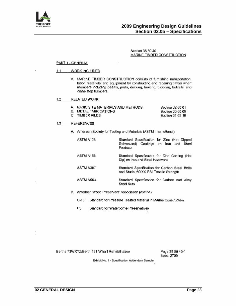
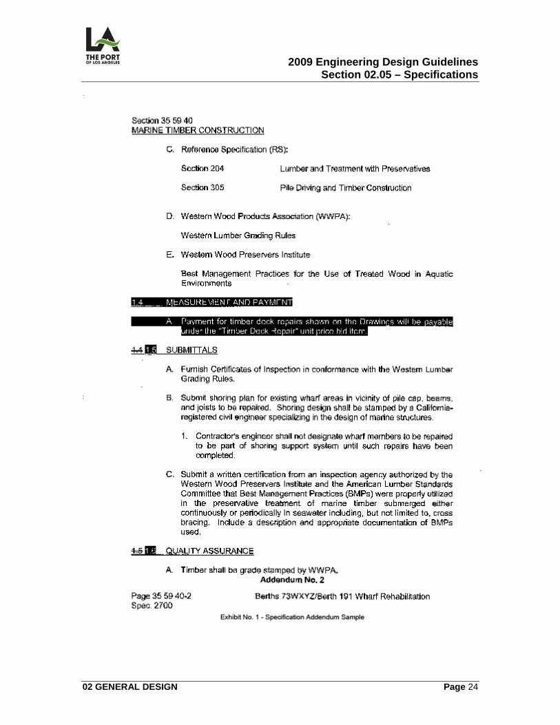
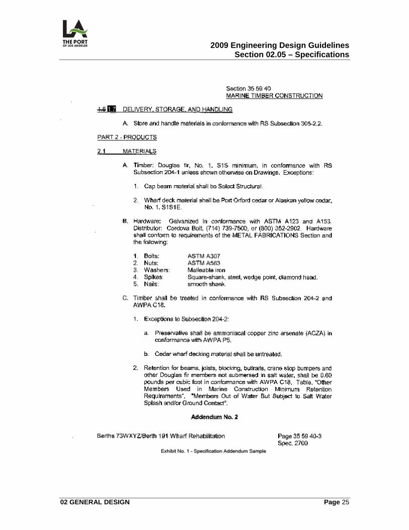
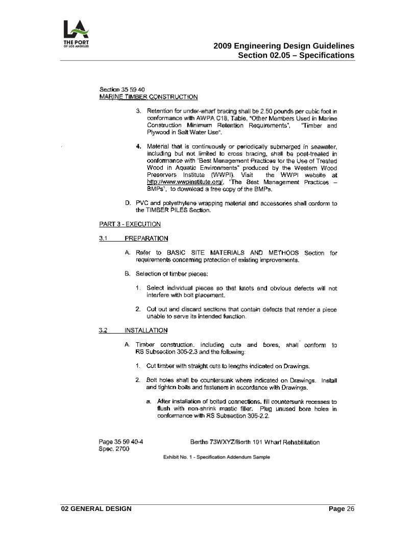
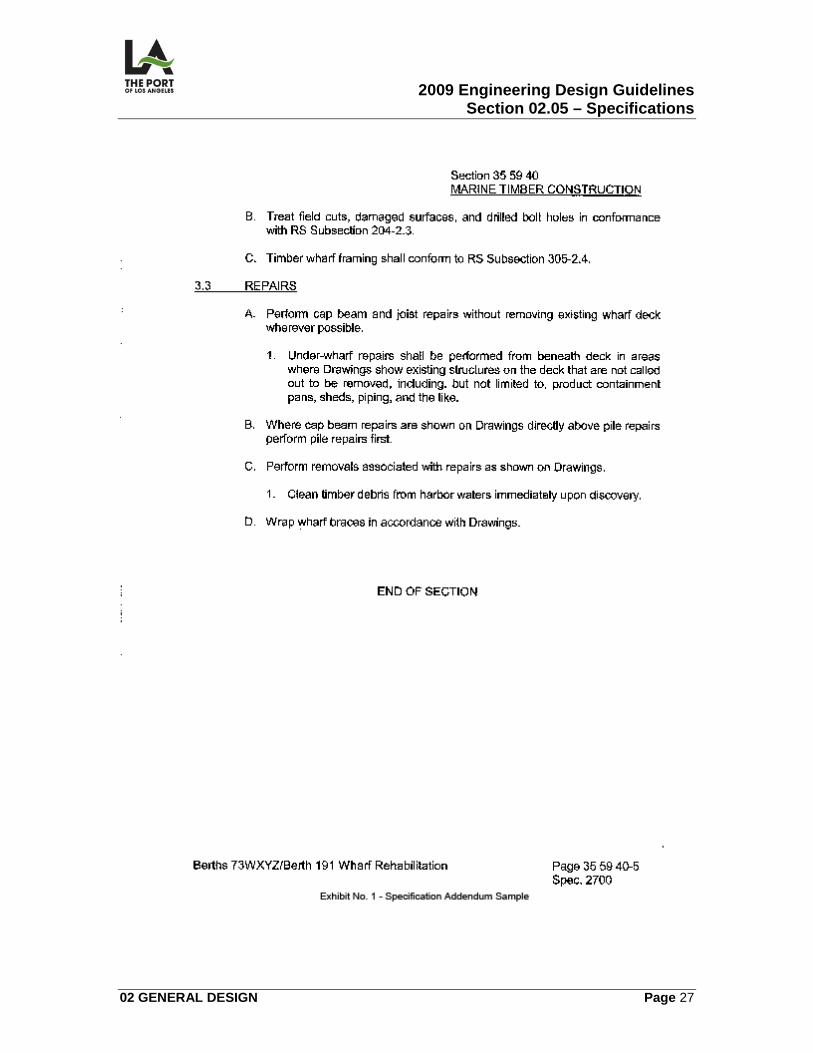
02.05.04 Addenda Addenda are changes to specifications that are transmitted to bidders prior to bid opening. Addendum format consists of striking out text to be removed from the documents and placing gray background shading on text that has been added. The words “Addendum No. __” with the number are printed on the bottom of the affected pages (Reference Specifications Addendum Sample General Exhibit No. 1.)
02.05.05 Delta Revisions Delta Revisions, while more common on drawings than specifications, sometimes occur to the specifications after bid opening. Format is the same as for addenda, except that the “Revision No. __” is printed at the bottom of the page.
02.05.06 Responsibilities
1. Project Manager shall notify Section Head of Specifications and Special Projects Section as early as possible when a new Project needs a specification.
Specifications and Special Projects Section will obtain specification number and the assigned specification writer will proceed in the preparation of the specifications.
2009 Engineering Design Guidelines Section 02.05 – Specifications
02 GENERAL DESIGN Page 19
02.05.07 Directions to Consultant for Preparing POLA Engineering Specifications
Consultants should apply these principles when drafting an original specification. Also review POLA Engineering Specifications when they are being used, for conformance to these principles.
1. Obtain specification number from S&SP Section through the Project Manager.
2. Consult with POLA specification writer regarding proper formatting and
use of most current Master Specification Sections appropriate for the project, and to determine which sections will be provided by POLA and by the consultant.
3. Create outline specifications (normally at 40 percent completion of
drawings) based on project scope. Confer with POLA specification writer.
4. Select specifications first from POLA Engineering’s list of Master Specifications. If a required spec is not available from POLA, create the original spec based on Construction Specifications Institute (CSI) Master Format. Edit specifications to fit project.
5. Create and arrange paragraphs in sections as closely as possible in CSI
Section Format (see 02.05.08 MOP, Figure SF-1). Prior to creating new articles, check Section Format to verify if a standard CSI article title could be used or modified to fit the work scope being described.
6. Organize text in CSI Page Format with the following POLA standard
exceptions:
a) Headers: Section name and number tabbed to right side of right pages, left side of left pages rather than centered. Underline Section Title.
b) Footers: State section number rather than title with spec number
directly below tabbed to right side of right pages, left side of left pages rather than centered.
c) Other Titles: Underline part and article titles.
d) Font size: Arial 12 pitch.
e) Refer to 02.05.08, MOP 5.
2009 Engineering Design Guidelines Section 02.05 – Specifications
02 GENERAL DESIGN Page 20
f) For article and paragraph addressing, use Page Format, MOP1, levels and arrangement. Avoid run-on paragraphs by adding additional levels.
g) Tables, forms, and finish schedules may either be incorporated into the
appropriate section or included as an appendix at the end of the specification.
7. Although consultant specification writers do not typically prepare POLA
Engineering’s General Conditions and General Requirements sections, avoid duplicating information in the technical specification sections that is already described in the General Conditions or General Requirements. Obtain copy of General Conditions to ensure compatibility with specification.
8. Assign contractual responsibility for each task to either the Contractor or
the Engineer. Any work by Contractor, subcontractor, or consulting engineer hired by Contractor should be referred to as Contractor work; and work by any Port division, personnel, or consultant should be referred to by the Engineer. Do not use gender specific terms.
9. Place submittal requirements in the “Submittals” article in PART 1 of each
section rather than scattering throughout the section. Review submittal requirements contained in the General Conditions to avoid conflict.
10. Specify means, methods, techniques, sequences, and procedures of
construction only when:
a) There is a compelling reason why POLA Engineering would prefer a particular method.
b) Specific means, methods, techniques, sequences, and procedures will
not unnecessarily restrict Contractor.
c) POLA Engineering is willing to accept liability for specific means, methods, techniques, sequences, and procedures.
11. Verify recent changes in listings of reference standards and reference
specifications, e.g. revised titles for ASTM standards. Verify changed section and paragraph numbers for referenced specifications.
12. Research information sources including trade and agency handbooks and
websites.
13. Research Greenbook, ASTM, and other standards.
2009 Engineering Design Guidelines Section 02.05 – Specifications
02 GENERAL DESIGN Page 21
14. Research product information to ensure products and manufacturers are
current and still available. If listing more than 1 manufacturer or product, limit list to 3 equivalent products.
02.05.08 Reference Design Manuals/Guidelines Construction Specifications Institute Manual of Practice (MOP – available at Specifications Section) and CSI Master Format,2004 edition (available at S:\Share\Engineering Division\SPECS & SPECIAL PROJS\MasterFormat 2004\CSI Publication). POLA Master Specifications are available at POLA Master Specifications. Specification Guidelines Advisor: Carmen Bognot
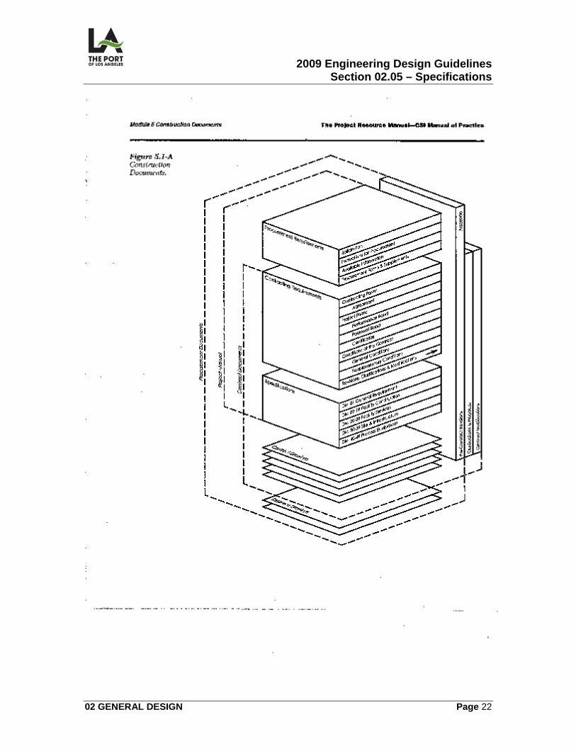
02.05.09 List of Figures/Details
• Fig. 5.1A Construction Documents (See MOP)
• Exhibit 1 Specification Addendum Sample (See S:\Share\Engineering
Division\Design Guidelines\Directives)
2009 Engineering Design Guidelines Section 02.05 – Specifications
02 GENERAL DESIGN Page 22
2009 Engineering Design Guidelines Section 02.05 – Specifications
02 GENERAL DESIGN Page 23
2009 Engineering Design Guidelines Section 02.05 – Specifications
02 GENERAL DESIGN Page 24
2009 Engineering Design Guidelines Section 02.05 – Specifications
02 GENERAL DESIGN Page 25
2009 Engineering Design Guidelines Section 02.05 – Specifications
02 GENERAL DESIGN Page 26
2009 Engineering Design Guidelines Section 02.05 – Specifications
02 GENERAL DESIGN Page 27
2009 Engineering Design Guidelines Section 02.06 – Permits/Approvals
02 GENERAL DESIGN Page 28
02.06
PERMITS/APPROVALS
02.06.01 General The Project Manager must determine project permit requirements and ensure that plan checks and permits required by local, State, and Federal agencies have been obtained. In addition, at project inception, the Project Manager must submit an Application for Discretionary Permit (ADP) which triggers the project’s environmental permits.
02.06.02 Application for Discretionary Permit (ADP) An ADP is required for all construction jobs, even for small C&M jobs, capital improvement and maintenance jobs; and independent designs added by change order to existing contracts. Jobs with safety or environmental hazards may be eligible for an exemption in the interest of timeliness. The Project Manager, at project inception, shall submit the ADP form to the Real Estate Division. Real Estate Division assigns the ADP Number to the project and forwards the ADP application to the Environmental Management Division (EMD) and the Planning and Research Division. EMD prepares the Environmental Assessment and determines if the project will be categorized as:
• Categorically Exempt
• Negative declaration
• Require an Environmental impact report
The 2 latter conditions will generate environmental requirements including local, state, and federal agency permits. Planning and Research Division determines the project’s Coastal Development Permit (CDP) status. Planning and Research advises whether project is exempt or permit is required and obtains permit when required.
2009 Engineering Design Guidelines Section 02.06 – Permits/Approvals
02 GENERAL DESIGN Page 29
02.06.03 Other Permits Additional permits required by local, state, and federal agencies are detailed in the “Project Manager’s Checklist, Part II” form in the Port of Los Angeles, Program Management Handbook.
02.06.04 List of Figures/Details Port of Los Angeles, Program Management Handbook, “Project Manager’s Checklist, Part II”
02.06.05 Port General Permit Procedures Engineering Division issues several types of General Permits and they are as follows:
1. General Permit: This permit is issued only after an Application for Discretionary Permit (ADP) is filled out. Permit section personnel are responsible for verifying the terms and conditions are complete.
2. Heavy Lift / Load Permit:
Any equipment or material with excessive weights requires an Engineering Permit. The Engineering Division must review structural capacity of Port structures relating to weight of permittee's load. Applicant obtains a short form/application from the Wharfinger Division.
3. Stockpiling Earth / Misc. Permit:
The applicant/permittee must contact Construction Division prior to applying for a General Permit to verify number of loads, acceptability of material, and stockpile availability. After the permittee has verified the above, Engineering will issue a permit for stockpiling earth material and broken concrete/asphalt and apply a fee of $70.00 per load minimum.
2009 Engineering Design Guidelines Section 02.07 – Environmental Considerations
02 GENERAL DESIGN Page 30
02.07
ENVIRONMENTAL CONSIDERATIONS
The Port's policy is to "grow, and grow green," consistent with the Port's Master Plan and General Plan. Growth is required to accommodate future increases in cargo throughput. This growth must be "green" to protect the environment and improve the quality of life. A green terminal integrates sustainable design practices and new environmental initiatives that surpass current environmental standards. It encourages a comprehensive approach to reduce impacts and increase efficiency at every stage of the shipping process. Green elements consider terminal design and construction, vessel operations, backland operations, and decommissioning. Standard POLA environmental requirements include Storm Water Pollution Prevention Plans (SWPPP), waste management, storm water control, hazardous waste management, compliance with underground storage tank (UST) requirements, spill prevention and control, and AQMD compliance. Standard green terminal design and construction will include Alternative Maritime Power (AMP) equipment on wharves, storm water controls, LEED certified buildings, low-glare lighting, energy efficiency measures, native vegetation buffers, and on-dock rail facilities. Construction will use clean construction equipment (alternative fuels), construction demolition & waste management, storm water and errosion controls, non-creosote piles, recycled materials, and asbestos and lead paint abatement. Terminal operator developed Environmental Management Systems (EMS) plan for potential impacts during terminal design, identify impacts during terminal operation, and provide monitoring and management to reduce impacts. An EMS is a continual cycle of planning, implementing, reviewing, and improving the process and actions that an organization undertakes to meet its environmental and business goals. A green terminal establishes a common standard upon which additional environmental measures are added through consultation with the Port's tenants; promotes integrated whole-terminal design practices; involves terminal operators and shipping companies; and realizes environmental, social, and economic benefits.
2009 Engineering Design Guidelines Section 02.08 – References
02 GENERAL DESIGN Page 31
02.08
REFERENCES
The following Exhibits are identified for reference:
1. Exhibit No. 1 - Abbreviations 2. Exhibit No. 2 - Engineering Design Glossary
3. Exhibit No. 3 - Organizations
4. Exhibit No. 4 - Drawing Letter Designations
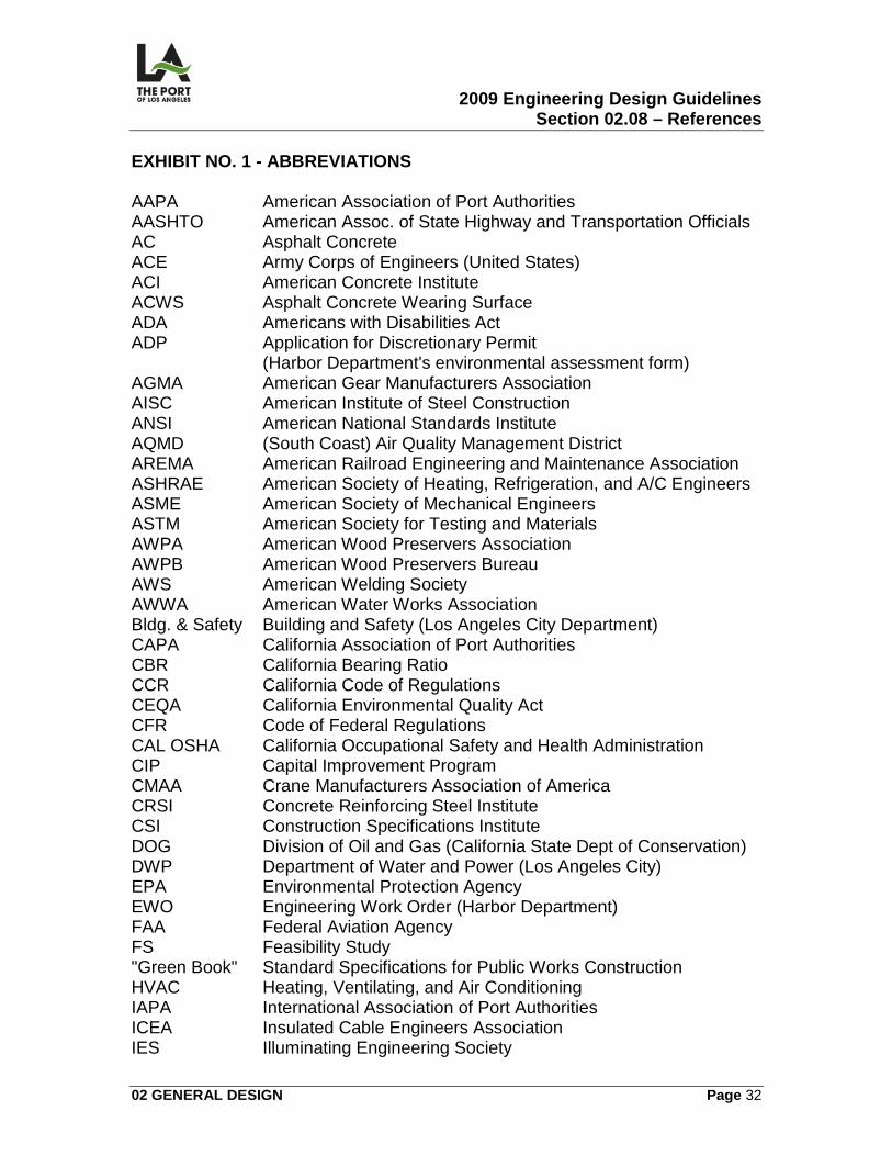
2009 Engineering Design Guidelines Section 02.08 – References
02 GENERAL DESIGN Page 32
EXHIBIT NO. 1 - ABBREVIATIONS AAPA American Association of Port Authorities AASHTO American Assoc. of State Highway and Transportation Officials AC Asphalt Concrete ACE Army Corps of Engineers (United States) ACI American Concrete Institute ACWS Asphalt Concrete Wearing Surface ADA Americans with Disabilities Act ADP Application for Discretionary Permit (Harbor Department's environmental assessment form) AGMA American Gear Manufacturers Association AISC American Institute of Steel Construction ANSI American National Standards Institute AQMD (South Coast) Air Quality Management District AREMA American Railroad Engineering and Maintenance Association ASHRAE American Society of Heating, Refrigeration, and A/C Engineers ASME American Society of Mechanical Engineers ASTM American Society for Testing and Materials AWPA American Wood Preservers Association AWPB American Wood Preservers Bureau AWS American Welding Society AWWA American Water Works Association Bldg. & Safety Building and Safety (Los Angeles City Department) CAPA California Association of Port Authorities CBR California Bearing Ratio CCR California Code of Regulations CEQA California Environmental Quality Act CFR Code of Federal Regulations CAL OSHA California Occupational Safety and Health Administration CIP Capital Improvement Program CMAA Crane Manufacturers Association of America CRSI Concrete Reinforcing Steel Institute CSI Construction Specifications Institute DOG Division of Oil and Gas (California State Dept of Conservation) DWP Department of Water and Power (Los Angeles City) EPA Environmental Protection Agency EWO Engineering Work Order (Harbor Department) FAA Federal Aviation Agency FS Feasibility Study "Green Book" Standard Specifications for Public Works Construction HVAC Heating, Ventilating, and Air Conditioning IAPA International Association of Port Authorities ICEA Insulated Cable Engineers Association IES Illuminating Engineering Society
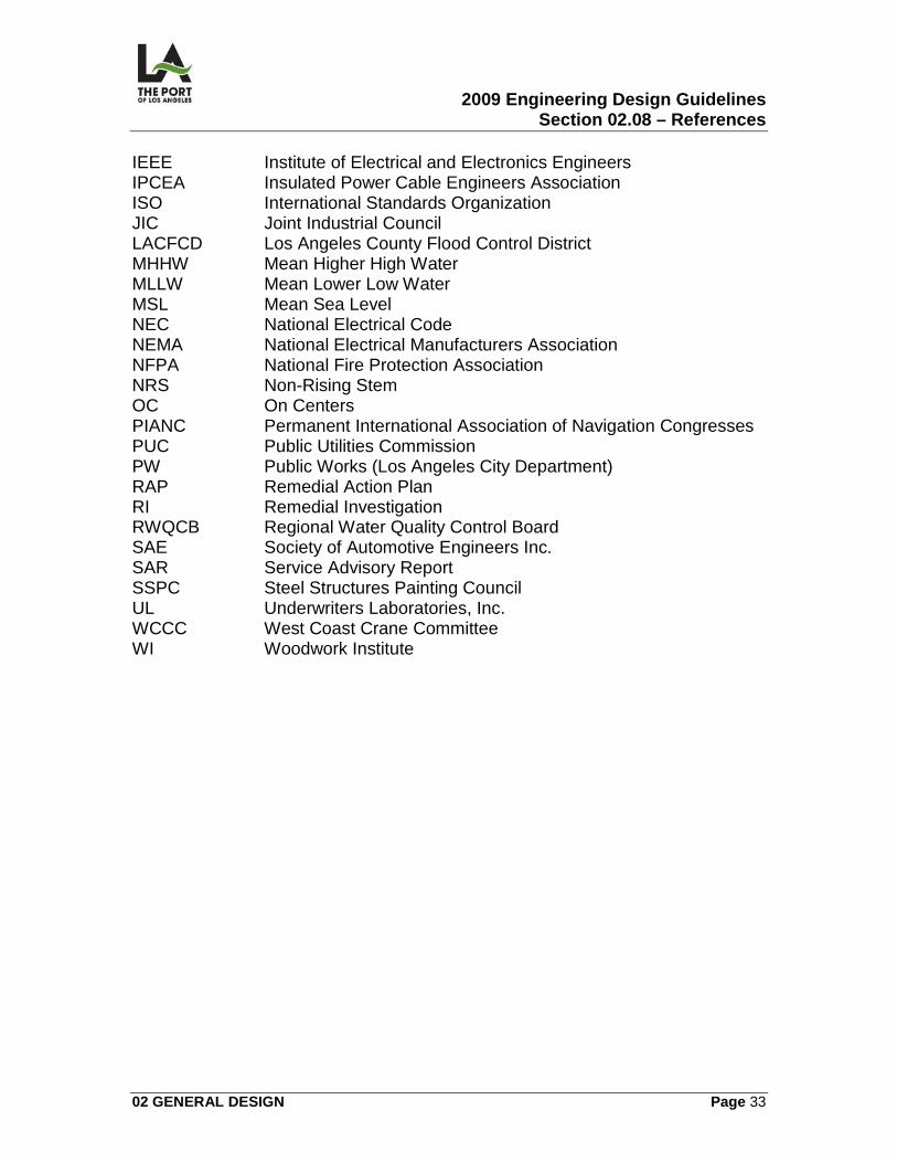
2009 Engineering Design Guidelines Section 02.08 – References
02 GENERAL DESIGN Page 33
IEEE Institute of Electrical and Electronics Engineers IPCEA Insulated Power Cable Engineers Association ISO International Standards Organization JIC Joint Industrial Council LACFCD Los Angeles County Flood Control District MHHW Mean Higher High Water MLLW Mean Lower Low Water MSL Mean Sea Level NEC National Electrical Code NEMA National Electrical Manufacturers Association NFPA National Fire Protection Association NRS Non-Rising Stem OC On Centers PIANC Permanent International Association of Navigation Congresses PUC Public Utilities Commission PW Public Works (Los Angeles City Department) RAP Remedial Action Plan RI Remedial Investigation RWQCB Regional Water Quality Control Board SAE Society of Automotive Engineers Inc. SAR Service Advisory Report SSPC Steel Structures Painting Council UL Underwriters Laboratories, Inc. WCCC West Coast Crane Committee WI Woodwork Institute
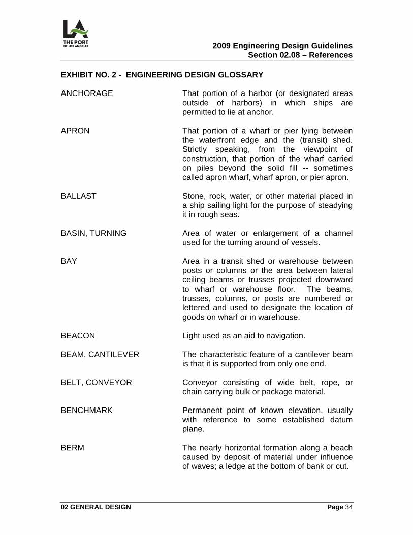
2009 Engineering Design Guidelines Section 02.08 – References
02 GENERAL DESIGN Page 34
EXHIBIT NO. 2 - ENGINEERING DESIGN GLOSSARY ANCHORAGE That portion of a harbor (or designated areas
outside of harbors) in which ships are permitted to lie at anchor.
APRON That portion of a wharf or pier lying between
the waterfront edge and the (transit) shed. Strictly speaking, from the viewpoint of construction, that portion of the wharf carried on piles beyond the solid fill -- sometimes called apron wharf, wharf apron, or pier apron.
BALLAST Stone, rock, water, or other material placed in
a ship sailing light for the purpose of steadying it in rough seas.
BASIN, TURNING Area of water or enlargement of a channel
used for the turning around of vessels. BAY Area in a transit shed or warehouse between
posts or columns or the area between lateral ceiling beams or trusses projected downward to wharf or warehouse floor. The beams, trusses, columns, or posts are numbered or lettered and used to designate the location of goods on wharf or in warehouse.
BEACON Light used as an aid to navigation. BEAM, CANTILEVER The characteristic feature of a cantilever beam
is that it is supported from only one end. BELT, CONVEYOR Conveyor consisting of wide belt, rope, or
chain carrying bulk or package material. BENCHMARK Permanent point of known elevation, usually
with reference to some established datum plane.
BERM The nearly horizontal formation along a beach
caused by deposit of material under influence of waves; a ledge at the bottom of bank or cut.
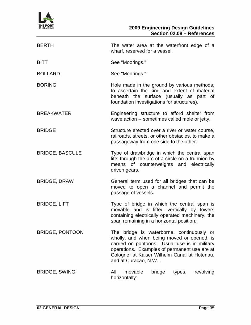
2009 Engineering Design Guidelines Section 02.08 – References
02 GENERAL DESIGN Page 35
BERTH The water area at the waterfront edge of a wharf, reserved for a vessel.
BITT See "Moorings." BOLLARD See "Moorings." BORING Hole made in the ground by various methods,
to ascertain the kind and extent of material beneath the surface (usually as part of foundation investigations for structures).
BREAKWATER Engineering structure to afford shelter from
wave action -- sometimes called mole or jetty. BRIDGE Structure erected over a river or water course,
railroads, streets, or other obstacles, to make a passageway from one side to the other.
BRIDGE, BASCULE Type of drawbridge in which the central span
lifts through the arc of a circle on a trunnion by means of counterweights and electrically driven gears.
BRIDGE, DRAW General term used for all bridges that can be
moved to open a channel and permit the passage of vessels.
BRIDGE, LIFT Type of bridge in which the central span is
movable and is lifted vertically by towers containing electrically operated machinery, the span remaining in a horizontal position.
BRIDGE, PONTOON The bridge is waterborne, continuously or
wholly, and when being moved or opened, is carried on pontoons. Usual use is in military operations. Examples of permanent use are at Cologne, at Kaiser Wilhelm Canal at Hotenau, and at Curacao, N.W.I.
BRIDGE, SWING All movable bridge types, revolving
horizontally:
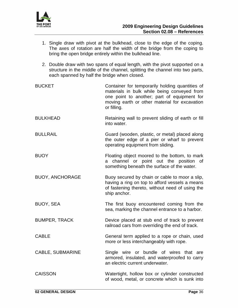
2009 Engineering Design Guidelines Section 02.08 – References
02 GENERAL DESIGN Page 36
1. Single draw with pivot at the bulkhead, close to the edge of the coping. The axes of rotation are half the width of the bridge from the coping to bring the open bridge entirely within the bulkhead line.
2. Double draw with two spans of equal length, with the pivot supported on a
structure in the middle of the channel, splitting the channel into two parts, each spanned by half the bridge when closed.
BUCKET Container for temporarily holding quantities of
materials in bulk while being conveyed from one point to another; part of equipment for moving earth or other material for excavation or filling.
BULKHEAD Retaining wall to prevent sliding of earth or fill
into water. BULLRAIL Guard (wooden, plastic, or metal) placed along
the outer edge of a pier or wharf to prevent operating equipment from sliding.
BUOY Floating object moored to the bottom, to mark
a channel or point out the position of something beneath the surface of the water.
BUOY, ANCHORAGE Buoy secured by chain or cable to moor a slip,
having a ring on top to afford vessels a means of fastening thereto, without need of using the ship anchor.
BUOY, SEA The first buoy encountered coming from the
sea, marking the channel entrance to a harbor. BUMPER, TRACK Device placed at stub end of track to prevent
railroad cars from overriding the end of track. CABLE General term applied to a rope or chain, used
more or less interchangeably with rope. CABLE, SUBMARINE Single wire or bundle of wires that are
armored, insulated, and waterproofed to carry an electric current underwater.
CAISSON Watertight, hollow box or cylinder constructed
of wood, metal, or concrete which is sunk into
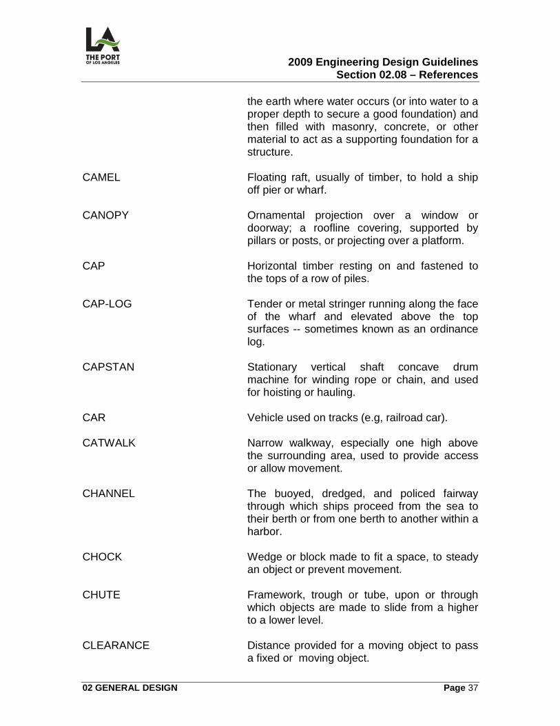
2009 Engineering Design Guidelines Section 02.08 – References
02 GENERAL DESIGN Page 37
the earth where water occurs (or into water to a proper depth to secure a good foundation) and then filled with masonry, concrete, or other material to act as a supporting foundation for a structure.
CAMEL Floating raft, usually of timber, to hold a ship
off pier or wharf. CANOPY Ornamental projection over a window or
doorway; a roofline covering, supported by pillars or posts, or projecting over a platform.
CAP Horizontal timber resting on and fastened to
the tops of a row of piles. CAP-LOG Tender or metal stringer running along the face
of the wharf and elevated above the top surfaces -- sometimes known as an ordinance log.
CAPSTAN Stationary vertical shaft concave drum
machine for winding rope or chain, and used for hoisting or hauling.
CAR Vehicle used on tracks (e.g, railroad car). CATWALK Narrow walkway, especially one high above
the surrounding area, used to provide access or allow movement.
CHANNEL The buoyed, dredged, and policed fairway
through which ships proceed from the sea to their berth or from one berth to another within a harbor.
CHOCK Wedge or block made to fit a space, to steady
an object or prevent movement. CHUTE Framework, trough or tube, upon or through
which objects are made to slide from a higher to a lower level.
CLEARANCE Distance provided for a moving object to pass
a fixed or moving object.
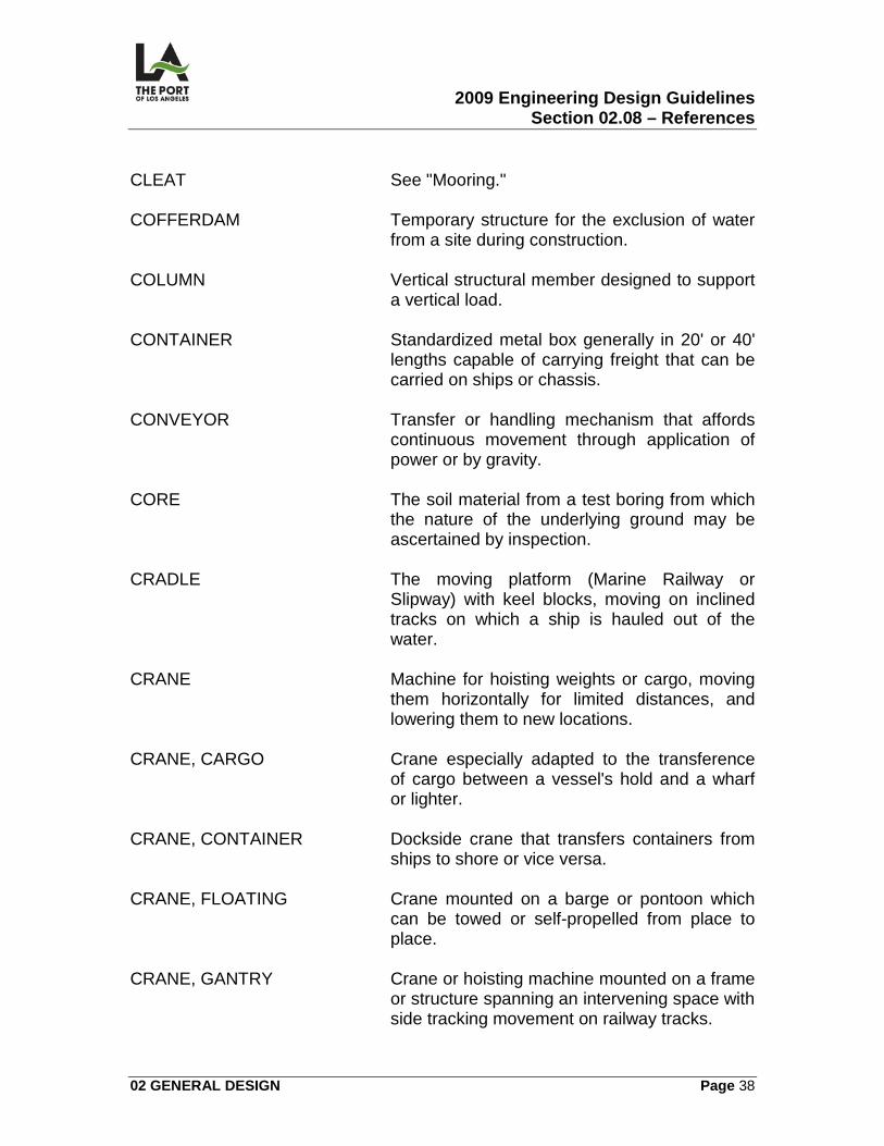
2009 Engineering Design Guidelines Section 02.08 – References
02 GENERAL DESIGN Page 38
CLEAT See "Mooring." COFFERDAM Temporary structure for the exclusion of water
from a site during construction. COLUMN Vertical structural member designed to support
a vertical load. CONTAINER Standardized metal box generally in 20' or 40'
lengths capable of carrying freight that can be carried on ships or chassis.
CONVEYOR Transfer or handling mechanism that affords
continuous movement through application of power or by gravity.
CORE The soil material from a test boring from which
the nature of the underlying ground may be ascertained by inspection.
CRADLE The moving platform (Marine Railway or
Slipway) with keel blocks, moving on inclined tracks on which a ship is hauled out of the water.
CRANE Machine for hoisting weights or cargo, moving
them horizontally for limited distances, and lowering them to new locations.
CRANE, CARGO Crane especially adapted to the transference
of cargo between a vessel's hold and a wharf or lighter.
CRANE, CONTAINER Dockside crane that transfers containers from
ships to shore or vice versa. CRANE, FLOATING Crane mounted on a barge or pontoon which
can be towed or self-propelled from place to place.
CRANE, GANTRY Crane or hoisting machine mounted on a frame
or structure spanning an intervening space with side tracking movement on railway tracks.
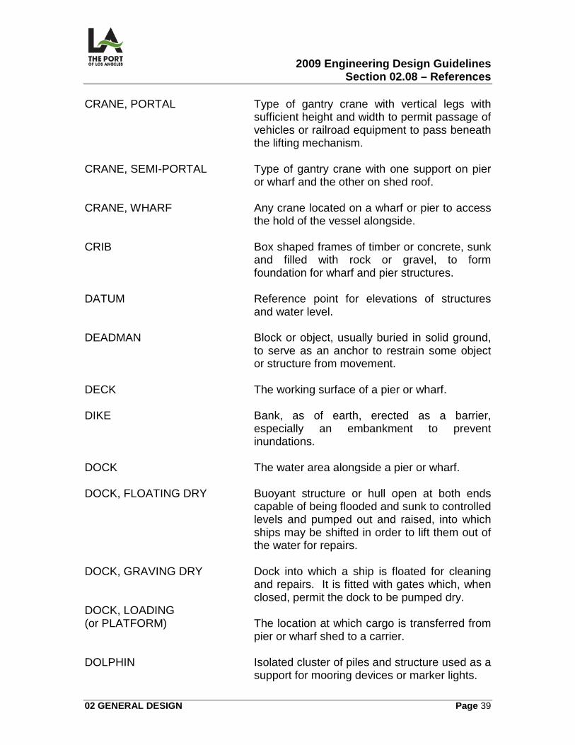
2009 Engineering Design Guidelines Section 02.08 – References
02 GENERAL DESIGN Page 39
CRANE, PORTAL Type of gantry crane with vertical legs with sufficient height and width to permit passage of vehicles or railroad equipment to pass beneath the lifting mechanism.
CRANE, SEMI-PORTAL Type of gantry crane with one support on pier
or wharf and the other on shed roof. CRANE, WHARF Any crane located on a wharf or pier to access
the hold of the vessel alongside. CRIB Box shaped frames of timber or concrete, sunk
and filled with rock or gravel, to form foundation for wharf and pier structures.
DATUM Reference point for elevations of structures
and water level. DEADMAN Block or object, usually buried in solid ground,
to serve as an anchor to restrain some object or structure from movement.
DECK The working surface of a pier or wharf. DIKE Bank, as of earth, erected as a barrier,
especially an embankment to prevent inundations.
DOCK The water area alongside a pier or wharf. DOCK, FLOATING DRY Buoyant structure or hull open at both ends
capable of being flooded and sunk to controlled levels and pumped out and raised, into which ships may be shifted in order to lift them out of the water for repairs.
DOCK, GRAVING DRY Dock into which a ship is floated for cleaning
and repairs. It is fitted with gates which, when closed, permit the dock to be pumped dry.
DOCK, LOADING (or PLATFORM) The location at which cargo is transferred from
pier or wharf shed to a carrier. DOLPHIN Isolated cluster of piles and structure used as a
support for mooring devices or marker lights.
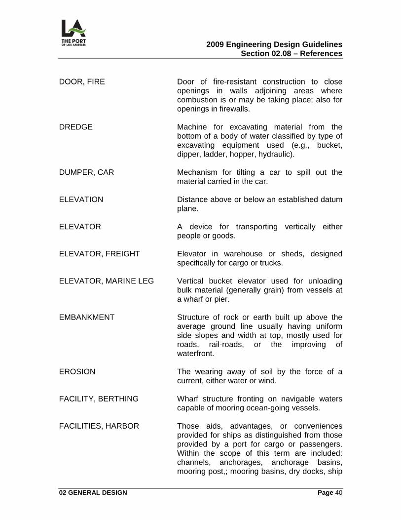
2009 Engineering Design Guidelines Section 02.08 – References
02 GENERAL DESIGN Page 40
DOOR, FIRE Door of fire-resistant construction to close
openings in walls adjoining areas where combustion is or may be taking place; also for openings in firewalls.
DREDGE Machine for excavating material from the
bottom of a body of water classified by type of excavating equipment used (e.g., bucket, dipper, ladder, hopper, hydraulic).
DUMPER, CAR Mechanism for tilting a car to spill out the
material carried in the car. ELEVATION Distance above or below an established datum
plane. ELEVATOR A device for transporting vertically either
people or goods. ELEVATOR, FREIGHT Elevator in warehouse or sheds, designed
specifically for cargo or trucks. ELEVATOR, MARINE LEG Vertical bucket elevator used for unloading
bulk material (generally grain) from vessels at a wharf or pier.
EMBANKMENT Structure of rock or earth built up above the
average ground line usually having uniform side slopes and width at top, mostly used for roads, rail-roads, or the improving of waterfront.
EROSION The wearing away of soil by the force of a
current, either water or wind. FACILITY, BERTHING Wharf structure fronting on navigable waters
capable of mooring ocean-going vessels. FACILITIES, HARBOR Those aids, advantages, or conveniences
provided for ships as distinguished from those provided by a port for cargo or passengers. Within the scope of this term are included: channels, anchorages, anchorage basins, mooring post,; mooring basins, dry docks, ship
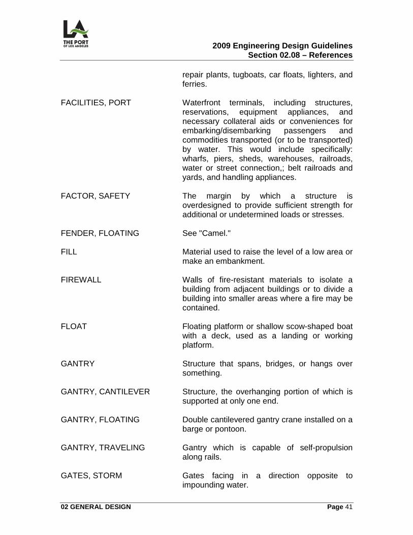
2009 Engineering Design Guidelines Section 02.08 – References
02 GENERAL DESIGN Page 41
repair plants, tugboats, car floats, lighters, and ferries.
FACILITIES, PORT Waterfront terminals, including structures,
reservations, equipment appliances, and necessary collateral aids or conveniences for embarking/disembarking passengers and commodities transported (or to be transported) by water. This would include specifically: wharfs, piers, sheds, warehouses, railroads, water or street connection,; belt railroads and yards, and handling appliances.
FACTOR, SAFETY The margin by which a structure is
overdesigned to provide sufficient strength for additional or undetermined loads or stresses.
FENDER, FLOATING See "Camel." FILL Material used to raise the level of a low area or
make an embankment. FIREWALL Walls of fire-resistant materials to isolate a
building from adjacent buildings or to divide a building into smaller areas where a fire may be contained.
FLOAT Floating platform or shallow scow-shaped boat
with a deck, used as a landing or working platform.
GANTRY Structure that spans, bridges, or hangs over
something. GANTRY, CANTILEVER Structure, the overhanging portion of which is
supported at only one end. GANTRY, FLOATING Double cantilevered gantry crane installed on a
barge or pontoon. GANTRY, TRAVELING Gantry which is capable of self-propulsion
along rails. GATES, STORM Gates facing in a direction opposite to
impounding water.
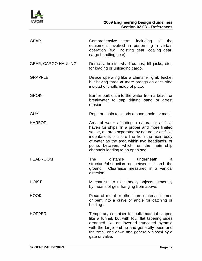
2009 Engineering Design Guidelines Section 02.08 – References
02 GENERAL DESIGN Page 42
GEAR Comprehensive term including all the
equipment involved in performing a certain operation (e.g., hoisting gear, coaling gear, cargo handling gear).
GEAR, CARGO HAULING Derricks, hoists, wharf cranes, lift jacks, etc.,
for loading or unloading cargo. GRAPPLE Device operating like a clamshell grab bucket
but having three or more prongs on each side instead of shells made of plate.
GROIN Barrier built out into the water from a beach or
breakwater to trap drifting sand or arrest erosion.
GUY Rope or chain to steady a boom, pole, or mast. HARBOR Area of water affording a natural or artificial
haven for ships. In a proper and more limited sense, an area separated by natural or artificial indentations of shore line from the main body of water as the area within two headlands, or points between, which run the main ship channels leading to an open sea.
HEADROOM The distance underneath a
structure/obstruction or between it and the ground. Clearance measured in a vertical direction.
HOIST Mechanism to raise heavy objects, generally
by means of gear hanging from above. HOOK Piece of metal or other hard material, formed
or bent into a curve or angle for catching or holding .
HOPPER Temporary container for bulk material shaped
like a funnel, but with four flat tapering sides arranged like an inverted truncated pyramid with the large end up and generally open and the small end down and generally closed by a gate or valve.
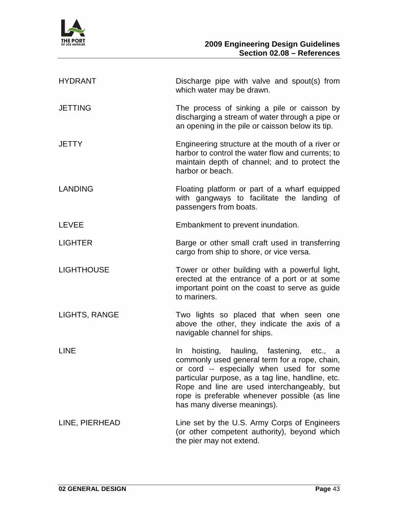
2009 Engineering Design Guidelines Section 02.08 – References
02 GENERAL DESIGN Page 43
HYDRANT Discharge pipe with valve and spout(s) from
which water may be drawn. JETTING The process of sinking a pile or caisson by
discharging a stream of water through a pipe or an opening in the pile or caisson below its tip.
JETTY Engineering structure at the mouth of a river or
harbor to control the water flow and currents; to maintain depth of channel; and to protect the harbor or beach.
LANDING Floating platform or part of a wharf equipped
with gangways to facilitate the landing of passengers from boats.
LEVEE Embankment to prevent inundation. LIGHTER Barge or other small craft used in transferring
cargo from ship to shore, or vice versa. LIGHTHOUSE Tower or other building with a powerful light,
erected at the entrance of a port or at some important point on the coast to serve as guide to mariners.
LIGHTS, RANGE Two lights so placed that when seen one
above the other, they indicate the axis of a navigable channel for ships.
LINE In hoisting, hauling, fastening, etc., a
commonly used general term for a rope, chain, or cord -- especially when used for some particular purpose, as a tag line, handline, etc. Rope and line are used interchangeably, but rope is preferable whenever possible (as line has many diverse meanings).
LINE, PIERHEAD Line set by the U.S. Army Corps of Engineers
(or other competent authority), beyond which the pier may not extend.
2009 Engineering Design Guidelines Section 02.08 – References
02 GENERAL DESIGN Page 44
LOAD Weight or force applied externally, usually stated in pounds or tons. For design purposes, generally stated per square foot.
LOAD, DEAD Load which is static or non-moving (i.e., does
not vary). The dead load of a structure is usually the weight of the structure itself.
LOAD, DECK Permissible weight to which a structure may be
subjected, per unit of area. LOAD, LIVE Load which is not static or moves in location
(i.e. varies in amount). LOW WATER, MEAN The average height of the low waters
determined from the records taken in some predetermined period.
MOLE Mound or massive work formed of masonry,
large stones, etc., laid in the sea for protection from waves.
MONORAIL Type of conveyor system run on over-head
rails in a transit shed and used for stacking, unstacking, and moving cargo on the wharf.
MOORINGS That which serves to secure a ship to a fixed
place by means of lines/cables (other than the anchor chain, generally), e.g., bitts, bollards, cleats, etc. -- of different shapes and sizes.
PAVEMENT Covering of solid materials to make a work
surface or a surface for travel. PIER Structure or platform of timber, masonry, earth,
or other material, built usually at right angles to the shoreline of the harbor and extending outwards to deep water, permitting vessels to lie at either side to discharge or receive cargo or passengers.
PILE/PILING Large stake driven in the earth to support a
building, pier, or other superstructure, or to resist lateral pressure in a bulkhead,
2009 Engineering Design Guidelines Section 02.08 – References
02 GENERAL DESIGN Page 45
cofferdam, etc. (e.g. batter piles, cluster piles, etc.). It is made of wood, metal or concrete.
PILE, FENDER Pile driven close to a structure to prevent
contact between vessel and structure. PIT, BORROW The bank from which gravel, sand, etc., is
hauled to make a fill. PORT This is defined as:
1. A harbor plus terminal facilities. 2. A harbor provided with terminal and transfer facilities that enable it to be
used in commerce.
3. Used in commerce to designate a harbor where vessels are loaded or discharged.
4. A location on a harbor or other water area equipped and in use for
embarking or disembarking passengers or commodities transported by vessels.
5. Any place from which merchandise can be shipped for exportation or at
which merchandise can be imported. Note: If there are no marked indentations of shore lines, a port may exist without a harbor(s); further, a port involves some degree of development for purposes of commerce.
QUAY The term for a wharf generally used in Europe.
A quay is usually of solid construction as distinguished from an open-pile structure. The quay system of wharf planning is a system in which a wharf, transit shed, marginal street, tracks, roadways, and warehouses are parallel to the ship at its berth (as distinguished from the pier system in which the wharf is at an angle to the other elements). A quay accommodates ships only on one side.
RAMP Artificially inclined path, road, or track along
which persons, animals, and wheeled vehicles may pass. It is primarily for the purpose of ascending or descending or changing their elevation.
2009 Engineering Design Guidelines Section 02.08 – References
02 GENERAL DESIGN Page 46
RAMP, MOVING Wood apron conveyor set at a moderate inclination and used for conveying persons, motor trucks, wheeled trucks, etc., up or down the grade. When the slope is so steep that special arrangements must be provided to prevent vehicles from running down the apron, it is usually called an apron elevator.
REVETMENTS Engineering structures to protect from erosion
and to hold in place banks of canals, rivers, and harbors.
RIGHTS, RIPARIAN The rights of a person owning land containing
or bordering a watercourse or other body of water in or to its banks, bed, or waters.
SCARP An almost perpendicular slope occurring along
the shore during periods of erosion. SEA LEVEL, MEAN The average height of the sea, determined by
averaging the hourly heights of the tide for a period of time.
SEAWALL Barrier along the shoreline to prevent
encroachment of the sea by direct wave action. SHED Structure on a wharf or pier providing
protection for cargo, stores, and passengers -- sometimes called a wharf shed or pier shed.
SHED, TRANSIT Wharf structure for the short-time storage of
merchandise in transit. SILTING The filling in of a river or harbor bottom by the
depositing of matter being carried by suspension in a stream.
SLIP Open space or tidal dock between piers. In a
restricted sense, referring to ferries or small boats only, a slip is a water space protected by racks or floats on both sides and sufficient only for the accommodation of one vessel.
2009 Engineering Design Guidelines Section 02.08 – References
02 GENERAL DESIGN Page 47
SLOPE The inclination of a line with the horizontal; the numerical value of the relationship of their vertical rise or dip to the horizontal.
SOUNDING The measured depth of water compared to
some established datum plane. SOUNDING, ECHO Determination of depth of water by electronic
equipment. SPACE, AISLE Space in cargo sheds or warehouses found
necessary by operating experience; also usually required by fire regulations.
SPRINKLER Sprinkler head (for fire protection); fitting at end
of water line with orifice stopped by plug composed of an alloy with low melting point.
STAGE, LANDING Platform entirely afloat, with one end afloat, or
with one end afloat and the other pivoted and attached to a wharf, to facilitate the discharge of ships, passengers, and cargo at places of great variance in tide.
STOP, FIRE See "Firewall." STORAGE, GROUND Storage systems where an entire supply of
bulk material is carried at ground level. The term is also used to designate a combination system in which a portion only of the material is held in elevated bins for immediate use or distribution, with the larger part resting directly on the ground.
STRIP, RUBBING Fender (horizontal or vertical) attached to face
of the pier, wharf, or other structure, against which a vessel may lie and not come into contact with the face of the structure.
SWITCH, TRACK Arrangement to permit flow of traffic from one
track to another. SYSTEM, SPRINKLER Collection throughout a building of sprinkler
heads connected by necessary pipe lines and controls.
2009 Engineering Design Guidelines Section 02.08 – References
02 GENERAL DESIGN Page 48
TERMINAL This is defined as:
1. The end of a movement in transportation. 2. The buildings, structures, or equipment at the end of a transportation
movement for the transfer, handling, delivery, and reception of passengers and freight.
TERMINAL, RAIL/WATER Terminal where freight is transferred between
railway cars and boats. TIDE The rising and falling of the water of the sea
produced by the attractions of the sun and moon.
TIE-BACK Timber of steel cable, rod, or channel iron, I-
beam, U-beam (or other form), running horizontally from a retaining wall to an anchor pile or deadman to compensate for the outward thrust of the fill.
TRACK, CROSSOVER Track connecting two parallel tracks. TRIPPER, CONVEYOR (BELT) Device for causing load on a conveyor belt to
be discharged at some predetermined point other than off the end of conveyor.
WAREHOUSE Structure in which goods may be stored at a
minimum risk from fire, theft, fraud, or deterioration for a necessary period of time prior to making further distribution. Warehouses perform this function for goods in transit or goods being merchandised, resulting in transit storage warehouses and merchandising warehouses.
WHARF Structure or platform of timber, masonry, earth,
or other material, built usually parallel to shore line of harbor or river extending outwards to deep water, permitting vessel to berth, discharge, or receive cargo/passengers.
WHARFS, RAILROAD Those wharfs, piers, sheds, and structures
thereon, owned, operated and controlled by a
2009 Engineering Design Guidelines Section 02.08 – References
02 GENERAL DESIGN Page 49
railroad; used principally for the accommodation of traffic passing over their respective lines of transportation. The term also includes such facilities as may be leased by railroad corporations.
WORKS, HARBOR The system of engineering structures, jetties,
breakwaters, basins, etc., including maintained channels, as executed for improving the navigability of a harbor and its availability and security for shipping. The term may include wharfs, docks, and all other fixed structures provided for accommodation of shipping in a harbor, but in a restricted sense, these facilities may be designated port works.
ZONE, INTERTIDAL Vertical zone between high and low tide. The
intertidal zone of a stationary structure is subject to alternate wetting and drying -- sometimes erroneously referred to as a splash zone.
2009 Engineering Design Guidelines Section 02.08 – References
02 GENERAL DESIGN Page 50
EXHIBIT NO. 3 - ORGANIZATIONS
American Association of Port Authorities (AAPA) American Association of State Highway and Transportation Officials (AASHTO) American Concrete Institute (ACI) American Gear Manufacturers Association (AGMA) American Institute of Steel Construction (AISC) American National Standards Institute (ANSI) American Railroad Engineering and Maintenance Association (AREMA) American Society of Mechanical Engineers (ASME) American Society of Testing and Materials (ASTM) American Wood Preservers Association (AWPA) American Wood Preservers Bureau (AWPB) American Welding Society (AWS) American Water Works Association (AWWA) California Association of Port Authorities (CAPA) California Occupational Safety and Health Act (CAL OSHA) Certified Federal Register (CFA) Crane Manufacturers Association of America (CMAA) Concrete Reinforcing Steel Institute (CRSI) Federal Aviation Administration (FAA) International Association of Port Authorities (IAPA) Insulated Cable Engineers Association (ICEA)
2009 Engineering Design Guidelines Section 02.08 – References
02 GENERAL DESIGN Page 51
Illumination Engineering Society (IES) Institute of Electrical and Electronics Engineers (IEEE) Insulated Power Cable Engineers Association (IPCEA) International Standards Organization (ISO) Joint Industrial Council (JIC) National Electrical Code (NEC) National Electrical Manufacturers Association (NEMA) National Fire Protection Association (NFPA) National Wire Institute (NWI) Permanent International Association of Navigation Congresses (PIANC) Society of Automotive Engineers, Inc. (SAE) Society for Protective Coatings (SSPC) Underwriters' Laboratories, Inc. (UL) West Coast Crane Committee (WCCC) West Coast Port Authorities (WCPA)
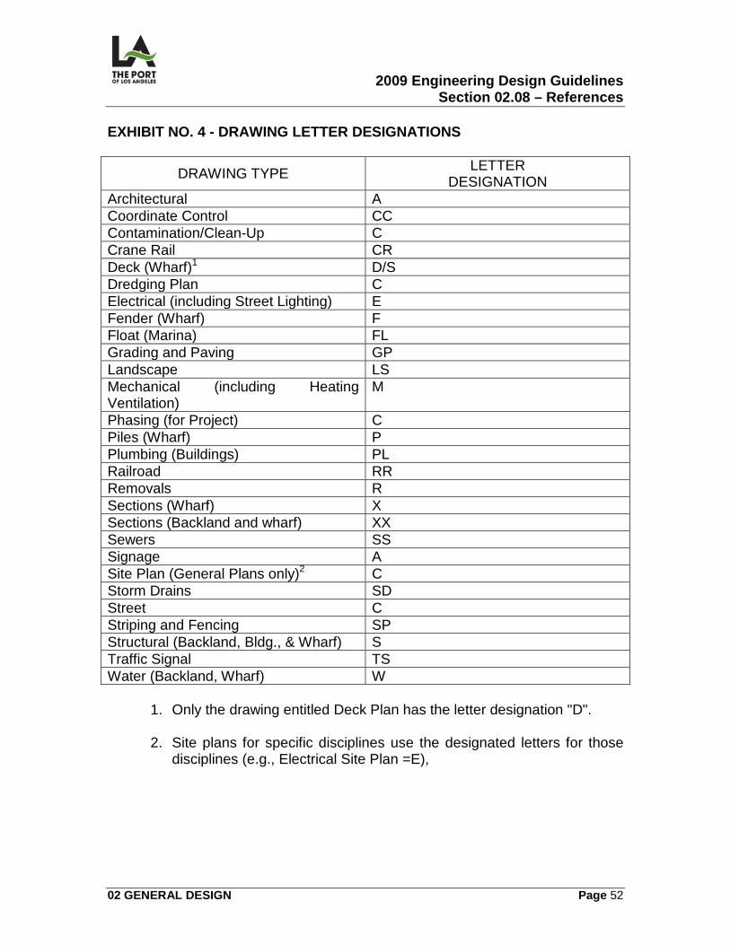
2009 Engineering Design Guidelines Section 02.08 – References
02 GENERAL DESIGN Page 52
EXHIBIT NO. 4 - DRAWING LETTER DESIGNATIONS
DRAWING TYPE LETTER DESIGNATION
Architectural A Coordinate Control CC Contamination/Clean-Up C Crane Rail CR Deck (Wharf)1 D/S Dredging Plan C Electrical (including Street Lighting) E Fender (Wharf) F Float (Marina) FL Grading and Paving GP Landscape LS Mechanical (including Heating Ventilation)
M
Phasing (for Project) C Piles (Wharf) P Plumbing (Buildings) PL Railroad RR Removals R Sections (Wharf) X Sections (Backland and wharf) XX Sewers SS Signage A Site Plan (General Plans only)2 C Storm Drains SD Street C Striping and Fencing SP Structural (Backland, Bldg., & Wharf) S Traffic Signal TS Water (Backland, Wharf) W
1. Only the drawing entitled Deck Plan has the letter designation "D".
2. Site plans for specific disciplines use the designated letters for those
disciplines (e.g., Electrical Site Plan =E),
2009 Engineering Design Guidelines Section 03.01 – General
03 BACKLAND Page 53
03 BACKLAND 03.01
GENERAL
03.01.01 OVERVIEW This section contains information related to the preparation of the following backland general contract drawings (see Exhibit Contract Drawings Nos. 1-7 in 03.01.08):
• Cover Sheet
• Title Sheet (T-1)
• Title Sheet (T-2)
• Site Plan (C)
• Coordinate Control Plan (CC)
• Phasing Plan (C)
• Contamination/Clean-Up Plan (C)
03.01.02 DESIGN CRITERIA There is no specific backland general design criteria provided for this section.
03.01.03 CALCULATIONS/WORKSHEETS - Estimating There are no estimating worksheets provided for this section. If there are any contamination/clean-up plans created under this section, an analysis and submission of cost breakdown is required. The cost impact of "phasing" a project is normally included in the unit lump sum cost of specific facility estimates.
03.01.04 GRAPHIC CRITERIA Cover Sheet
2009 Engineering Design Guidelines Section 03.01 – General
03 BACKLAND Page 54
This sheet consists of one layer and contains the title, specification number, and initial signatures and stamps. Title Sheet This sheet contains the vicinity map and index of drawings (drawing numbers/names, standard plans, and reference drawings), and general project notes (with abbreviations and general legend). It consists of the following layers:
1. Standard title sheet and text indicating index information, project notes, abbreviations, general legend, and the project site location arrow/information for the vicinity map.
2. Vicinity map of the entire harbor area.
3. Appropriate vicinity map text.
4. Water area shading.
Site Plan This sheet includes an abbreviated general summary of what exists now on the site and what the overall results of the project are going to be. It consists of the following layers:
1. Base map (site plan) -- without text.
2. Main proposed surface improvements (site plan) -- without text.
3. Project boundaries, contractor storage yard, and areafill -- with text. Coordinate Control Plan This sheet consists of the following layers, indicating distance and bearings for the site parcel:
1. Base map (site plan) -- without text.
2. Main proposed surface improvements (site plan) -- without text.
3. The project boundaries, notes (including Field Book references, zone used, and last survey date), and coordinate control information, such as:
2009 Engineering Design Guidelines Section 03.01 – General
03 BACKLAND Page 55
coordinates; metes and bounds description of each line (distance and bearing); property and lease lines; and pierhead line.
Phasing Plan This sheet consists of the following layers:
1. Base map (site plan) -- without text. 2. Main proposed surface improvements (site plan) -- without text.
3. Project boundaries, phasing boundaries, temporary fencing, contractor
storage area, and areafill -- with text. Contamination/Clean-Up Plan This sheet consists of the following layers:
1. Base map (site plan) -- without text. 2. Main proposed surface improvements (site plan) -- without text.
3. General clean-up plan indicating location (tied to a coordinate system) of
potential contamination, project boundaries, and areafill -- with text and topographic contours.
03.01.05 SPECIFICATIONS The following sections in the Harbor Department Master Specifications relate to backland general (other sections may be required, depending on the project):
SECTION TITLE Work Schedule Excavation Safety Requirements Removals Trench Excavation and Backfill
2009 Engineering Design Guidelines Section 03.01 – General
03 BACKLAND Page 56
03.01.06 PERMITS/APPROVALS There are numerous environmental permits/approvals which may be required for contamination/clean-up work. The Environmental Management Division will determine which permits are necessary for each specific case. It is the Project Manager's responsibility to determine which non-environmental permits may be required.
03.01.07 ENVIRONMENTAL CONSIDERATIONS The main environmental concern of this section is the delineation of known contaminated area, as described above.
03.01.08 REFERENCE DRAWINGS The following contract drawings are identified for reference: Contract Drawing Number and Title: 1-2209 Pier 400 Backland Phase 1- Berths 401-403
1-2209-1* Cover Sheet 1-2209 2* General Notes, vicinity Map, index to drawings
1-2324 Horizontal Coordinate Control Map
1-2210 C-1 Phasing –Project Limits and Access 1-2209 C-1 Project Limits
1-2209 C-2 Phasing Plan - Site Availability
LAHD Standard Plans * Drawing Nos. should be T-01 and T-02
2009 Engineering Design Guidelines Section 03.02 – Fencing
03 BACKLAND Page 57
03.02
FENCING
03.02.01 OVERVIEW This section contains the following information related to the preparation of the fencing contract drawings:
• Site Plan (SP)
• Fencing Plan (SP)
• Fencing Details (SP)
03.02.02 DESIGN CRITERIA – Fencing
1. Non-Corrosive - Heavy galvanizing is required to minimize fencing corrosion due to the POLA's marine environment.
2. Security Fencing - Security fencing around the perimeter of a leased area
shall be 8 feet high (5’-4” chain link fence on k-rail) with 1 foot barbed wire on top.
3. Internal Fencing - Internal fencing (within a leased area) should be 8 feet
high chain link fence, but this may vary depending on tenant need.
4. Concrete Footings
a) Terminal perimeter fencing line posts shall be designed with concrete footings.
b) Internal lease fencing line posts (on existing backland pavement) shall
be installed without concrete footings.
5. Street Fencing - Fencing at driveway exits should be set back to provide adequate site distance for exiting vehicles.
6. Fencing Only - If there is fencing but no striping to be done as part of the
project, the fencing would be included in the grading and paving drawings (see Backland - Grading and Paving, 03-06).
2009 Engineering Design Guidelines Section 03.02 – Fencing
03 BACKLAND Page 58
03.02.03 CALCULATIONS/WORKSHEETS Three are no calculations or worksheets provided in this Section.
03.02.04 GRAPHIC CRITERIA The following are required in the contract drawings when there is fencing work:
• Fencing Plan
• Fencing Details
03.02.05 SPECIFICATIONS The following sections in the POLA Department Master Specifications relate to fencing (other sections may be required, depending on the project):
SECTION TITLE Treating Damaged Galvanizing Chain Link Fences and Gates Paints and Coatings
03.02.06 PERMITS/APPROVALS The approvals listed below may be required when there is fencing work: Fire Department Approval Fire Department approval of the fencing plan may be required (to be determined by the Hydrant Unit on a case-by-case basis) whenever emergency access to a facility is impacted.
03.02.07 ENVIRONMENTAL CONSIDERATIONS Security fencing around the perimeter of a backland facility that is adjacent to a public street may require a screen as an aesthetic mitigation measure. Landscaping shall be used when possible.
2009 Engineering Design Guidelines Section 03.02 – Fencing
03 BACKLAND Page 59
03.02.08 REFERENCE DRAWINGS The following contract drawings are identified for reference: 1-2209 Pier 400 Backland Phase 1- Berths 401-403
1-2209 SP-1 Striping and Fencing Site Plan 1-2209 SP-2 Striping and Fencing Plan 1-2209 SP-41 Fencing Details
LAHD Standard Plans
2009 Engineering Design Guidelines Section 03.03 – Rail
03 BACKLAND Page 60
03.03
RAIL
03.03.01 OVERVIEW This section contains the following information related to the preparation of backland rail contract drawings:
• Railroad Track Site Plan (RR)
• Railroad Track Plan and Profile (RR)
• Railroad Details (RR)
• Cross Sections (XX)
• Compressed Air Plan (M)
• Compressed Air Details (M)
• Water System Details (W)
03.03.02 DESIGN CRITERIA General Design Requirements Railroad design for all Port-owned trackage shall meet the regulations, standards, and requirements of the following (any conflicts which arise must be resolved with the entities impacted):
1. General Orders of the California Public Utilities Commission (CPUC.) [All Port railroad facilities are under the jurisdiction of the CPUC.].
2. Harbor Department (as specified in these Guidelines or as otherwise
approved by the Chief Harbor Engineer).
3. Pacific Harbor Line (which has a maintenance responsibility).
4. American Railway Engineering and Maintenance of Way Association's (AREMA) Manual for Railway Engineering.
Main Line Track Design
2009 Engineering Design Guidelines Section 03.03 – Rail
03 BACKLAND Page 61
1. Horizontal Alignment.
a) Curvature:
1) Desirable = 7°30' (R=764‘). 2) Maximum = 8°00' (R=716‘).
b) Tangent between reversing curves:
1) Desirable = 200 feet. 2) Minimum = 100 feet.
c) Minimum center line clearance between parallel tracks = 15 feet. d) Minimum horizontal clearance to structures (and fences) from track
center line:
1) Tangent track = 10 feet. 2) Curve track = 11 feet.
2. Vertical Alignment.
a) Desirable maximum grade = 1%. b) Length of vertical curve:
1) SAG curves = rate of change of 0.1%/100 feet (V/L=.1). 2) Summit curves = rate of change of 0.2%/100 feet (V/L=.2).
3. Turnouts. No. 10 minimum.
Industry Track Design
1. Horizontal Alignment.
a) Curvature:
1) Desirable = 10°00' (R=574’). 2) Maximum = 12°30' (R=459’).
2009 Engineering Design Guidelines Section 03.03 – Rail
03 BACKLAND Page 62
b) Minimum tangent between reversing curves = 60 feet. c) Minimum center line clearance between parallel tracks = 14.5 feet.
d) Minimum horizontal clearance to structures (and fences) from track
center line:
1) Tangent track = 10 feet. 2) Curve track = 11 feet.
Railyards (Intermodal) Equipment Selection
The designer shall allow for flexibility in the equipment selected. With the exception of tenant-preferred equipment, the specifications of rail container terminal handling equipment will define the track spacing and requires the evaluation of numerous interdependent factors, such as:
1. Land availability. 2. Operating costs.
3. Development costs.
4. Volume throughput.
5. Mainline access.
Tangent vs. Curved Working Track Although tangent layouts are preferable, it is assumed that straddle cranes and rubber tire mounted transtainers (overhead cranes) can efficiently load/unload containers on tracks up to 6°00' or 7°00' of curvature.
Track Length
1. Standard Car Length: The standard car length is 305 feet. This is the overall dimension of a five platform, double-stack well car, as manufactured by Gunderson. The designer should check current manufacturer literature.
2009 Engineering Design Guidelines Section 03.03 – Rail
03 BACKLAND Page 63
2. Standard Train Length: The standard train length is twenty-two 305 foot cars (25 x 305 = 7,625 feet).
The track layout for the working or loading yard should accommodate at least one full standard unit train on 4 to 6 tracks depending on the length of the yard. Four tracks are desirable for the 25 cars six tracks are maximum.
The track layout for the storage support yard (if area is available and/or desirable by the customer) ideally should accommodate twice the capacity as the working yard. A 1:1.5 or even 1:1 ratio is acceptable. However, yard throughput and capacity will be significantly diminished.
1. Transverse Access: The track length should allow for gaps to
accommodate transverse access.
2. Run-around Track: A run-around track should be provided to allow for operational flexibility.
Yard Design
Track grade in areas where rail cars are to be spotted shall not exceed 0.4%.
1. Vertical Alignment.
a) Desirable maximum grade = 2% b) Length of vertical curve:
1) SAG curves = rate of change of 1.2%/100 feet (V/L=1.2) 2) Summit curves = rate of change of 2%/100 feet (V/L=2)
2. Turnouts.
a) Desirable = No. 10 b) Minimum = No. 8
Yard Cross Section
The designer shall submit with the other contract documents a yard cross section. A sample of cross section is included in Reference Drawings. The following information shall be included:
2009 Engineering Design Guidelines Section 03.03 – Rail
03 BACKLAND Page 64
1. Location of tracks, lightpoles, and equipment wheel path at crane pads. 2. Travel and container staging lanes.
3. Utility corridor.
4. Center storage, if available.
5. Railroad clearance lines.
6. Perimeter roads and fence.
Compressed Air
1. Car Air Reservoir: The car air reservoir requires 15 cubic feet of compressed air at 85 psig.
2. Repressurization Time: The maximum time for repressurization of the
total train system shall be 20 minutes.
3. Location of Hook-Up Outlets: Hook-up outlets shall be located at least at each break of train length.
Track Structure Components The following shall be considered Port standards for Port-owned trackage, unless otherwise authorized by the Chief Harbor Engineer:
1. Ballast Depth: minimum 8 inches from bottom of tie. Twelve inches desirable
2. Rail size 136 lb. R.E. (pounds per yard)
3. Turnout components shall be as follows:
a) Rail-bound manganese (RMG) frogs. b) 16'6" Sampson type switch points per A.R.E.M.A. Portfolio of
Trackwork Plans Plan No. 221-00, Detail 5100, with manganese tipped switch points.
c) Adjustable wedge rail braces.
2009 Engineering Design Guidelines Section 03.03 – Rail
03 BACKLAND Page 65
4. Ties
a) Timber 1) Tie size - minimum of:
(a) 7 inches x 9 inches x 8 feet -- for industry/ backland (lower tonnage) tracks.
(b) 7 inches x 9 inches x 9 feet -- for main line or intermodal (high
tonnage) tracks.
2) Tie spacing on-centers -- minimum of:
(a) 22 1/2 inches -- for industry/backland (lower tonnage) tracks (for exception, see "iv.").
(b) 19 1/2 inches -- for main line or intermodal (high tonnage) tracks
(for exception, see "iv.").
(c) 22 1/2 inches -- for rail yard tracks (for exception, see " iv.").
(d) 18 inches -- at rail joints, regardless of location (includes industry/backland, main line, and rail yard).
3) Tie plate size -- minimum of 8" x 14" double shoulder. 4) Installation of rail anchors:
(a) Switch ties -- box anchor every tie. (b) Jointed rail -- box anchor every third tie.
(c) Continuously welded rail -- box anchor every other tie.
5) Gage rods shall be installed through all curves having a curvature
greater than 10°30' and at a spacing of 5 feet on-centers.
b) Concrete
1) Tie size - 7 inches x 9 inches x 8 feet – 6 inches 2) Tie spacing on centers – 24 inches
3) Fasteners
2009 Engineering Design Guidelines Section 03.03 – Rail
03 BACKLAND Page 66
(a) Pandrol “e” clip for turnouts and other special track work. (b) Safelok clip for all other tracks
4) Rail pads and insulators shall be used for all concrete tie
applications. 5) Geotextile fabric shall be utilized for all track sections.
6) All other components shall be in accordance with AREMA
standards. Continuously Welded Rail Continuously welded rail should be used for all main line (high tonnage) tracks, tracks in paved areas, and yard tracks (intermodal or high tonnage). Highway/Street Railroad Grade Crossings - Crossing Surface Material At highway/street railroad crossings, alternative forms of crossing surface materials other than asphalt (e.g., concrete or other material types) should be considered. Factors impacting this include:
1. Cost of crossing materials. 2. Volume and makeup of vehicular traffic.
3. Recommendation of maintaining railroad.
4. Condition of track structure.
Track Drainage
1. Drainage Diversion. All drainage should be diverted away from railroad tracks by appropriate pavement grades or should be intercepted by trench or slot drains.
2. Track Drains. Track drains should be constructed at the low point of the
track grade and at all street crossings and yards unless there are no storm drains in the area (either existing or proposed) to which track drains can outlet. See "Track Drains" in Storm Drains, 03.07.02, for added detail.
2009 Engineering Design Guidelines Section 03.03 – Rail
03 BACKLAND Page 67
3. Deviations. Deviations that require drainage to run across tracks must be approved by the Chief Harbor Engineer.
Pipeline Crossings Pipelines on conduits crossing under railroad tracks shall be protected per AREMA guidelines. Jacking/Tunneling Jacking and tunneling shall be performed in accordance with the following:
1. Standard Specifications for Public Works Construction (Greenbook). 2. Cal O.S.H.A. requirements (Tunnel Safety Orders).
3. AREMA guidelines
03.03.03 CALCULATIONS/WORKSHEETS There are no calculations or worksheets provided for this section.
03.03.04 GRAPHIC CRITERIA
1. Title Sheet 2. Index of Drawings
3. Coordinate Control Plan
4. Plan & Profile Sheets
5. Cross Sections
6. Details
03.03.05 SPECIFICATIONS The following section in the Harbor Department Master Specifications relates to rail (other sections may be required, depending upon the project):
2009 Engineering Design Guidelines Section 03.03 – Rail
03 BACKLAND Page 68
SECTION TITLE Railroad Work Railroad Track and Accessories Welding of Rail
An additional section from production specification, “Running Rail” is also used for procurement.
03.03.06 PERMITS/APPROVALS The approvals listed below may be required when there is rail work: California Public Utilities Commission (CPUC) Approval Specific CPUC approval is required for new public street crossings (or for modification to existing ones). Private crossings do not require CPUC approval however it is recommended the CPUC be included in the design review process for heavy use or non-standard crossing alignments. Alameda Corridor Controlled Track Permits and approvals are obtained in conjunction with the Alameda Corridor Transportation Authority and the Port’s Property Management and Engineering Divisions. Industry/Tenant Approval This type of approval involves railroads on Port property (e.g., in backland or at a terminal) and takes the form of an Agreement. The following cases require an Agreement:
1. Private crossing (when the tenant's entrance, driveway, or aisle way crosses railroad tracks outside the terminal lease).
2. When the tenant proposes to move, load, or un-load cars on tracks which
are not within the lease area (Industrial Track Agreement used).
03.03.07 ENVIRONMENTAL CONSIDERATIONS Timber Tie Disposal – Removal and disposal of existing timber ties shall conform to Master Specification Sections REGULATORY REQUIREMENTS and RAILROAD TRACK AND ACCESSORIES.
2009 Engineering Design Guidelines Section 03.03 – Rail
03 BACKLAND Page 69
03.03.08 REFERENCE DRAWINGS The following contract drawings are identified for reference: 1-2023 New Dock Street/Henry Ford Avenue Grade Separation
1-2023-5 Key Maps (Site Plan)
1-2023 RR-1-8 Railroad Track Plan and Profile
1-2023 RR-19-22 Railroad Details 1-2208 Pier 400 ICTF
1-2208 RR-1 Railroad Site Plan
1-2208 RR-4-31 Railroad Track Plan and Profile
1-2208 RR-32-38 Railroad Details
1-2208 RR-39-40 Switch Protection
1-2208 XX-1-22 Cross Sections LAHD Standard Plans CPUC Crossing Protection Standards
No. 1-C
No. 8
No. 8A
No. 9
No. 9A Turnout Tie Spacing (See 1-2208-32 to33) Turnout Design Criteria Table – AREMA Portfolio of Trackwork Plans No. 910-02
2009 Engineering Design Guidelines Section 03.04 – Striping
03 BACKLAND Page 70
03.04
STRIPING
03.04.01 OVERVIEW This section contains the following information related to the preparation of the striping contract drawings:
• Site Plan (SP)
• Striping (SP)
• Striping Details (SP)
03.04.02 DESIGN CRITERIA Parking Lots For parking lot design information, the designer should refer to SPECIAL FACILITIES - Parking Lots (Section 06.04), in these Guidelines. Street Striping Striping on POLA streets shall meet the criteria as set forth in the CALTRANS Traffic Manual, Chapter G ("Markings") and the Los Angeles Department of Transportation design standards. Striping Details With the exception of tenant-preferred design, all details for striping dimensions, nomenclature, traffic lane widths, and truck tire stops shall be done in accordance with Striping Details as shown on the Reference Drawings.
2009 Engineering Design Guidelines Section 03.04 – Striping
03 BACKLAND Page 71
03.04.03 CALCULATIONS/WORKSHEETS Traverse calculations may be helpful in determining layout lines for striping. Calculations and worksheets shall be prepared in accordance with POLA Engineering Design Staff.
03.04.04 GRAPHIC CRITERIA The following are required in the contract drawings when there is striping work:
• Striping Plan
• Striping Details
03.04.05 SPECIFICATIONS The following sections in the POLA Department Master Specifications relate to striping (other sections may be required, depending upon the project):
SECTION TITLE Pavement Markings Chain Link Fences and Gates Paints and Coatings
03.04.06 PERMITS/APPROVALS The approvals listed below may be required when there is striping work: Fire Department Approval Fire Department approval of the striping plan may be required (to be determined by the Hydrant Unit on a case-by-case basis) whenever emergency access to a facility is impacted. Department of Transportation (DOT) Approval Los Angeles City DOT approval of the striping plan may be required if striping encroaches into a public right-of-way.
2009 Engineering Design Guidelines Section 03.04 – Striping
03 BACKLAND Page 72
03.04.07 ENVIRONMENTAL CONSIDERATIONS Removal of paint may be performed by water blasting to minimize the damage to the existing pavement. Remove and dispose all marking materials such as thermoplastic, epoxy, tape and paints. Treat or clean the debris as necessary.
03.04.08 REFERENCE DRAWINGS The following contract drawing are identified for reference: 1-2549 Berths 121-126 Terminal Re-Striping
1-2549 SP-1 Site Plan
1-2549 SP-6 Striping Plan
1-2549 SP-9 Striping Details LAHD Standard Plans
2009 Engineering Design Guidelines Section 03.05 – Removals and Existing Substructures
03 BACKLAND Page 73
03.05
REMOVALS AND EXISTING SUBSTRUCTURES
03.05.01 OVERVIEW This section contains the following information related to the preparation of backland removals and existing substructure contract drawings:
• Removals and Existing Substructures – Plan (R)
03.05.02 DESIGN CRITERIA General
1. Determine all items to be removed, salvaged, and/or relocated. 2. Verify existing conditions and substructures (using as-builts, field
investigations, survey)
3. Clearly indicate/identify limits of removal. Coordination Coordination is required with the following:
1. Engineering Division Sections: Electrical, Mechanical, and Structural. 2. Customers, agencies, other contractors, Construction & Maintenance
Division, and Construction Division.
3. Real Estate, project site tenant(s), including adjacent tenants.
4. Utility owners (DWP, Gas Co., Pacific Bell), including Wharfingers for utility disconnects.
5. Risk Management and Environmental Management for hazardous
removals (asbestos abatement, lead abatement, hydrocarbon-contaminated material).
6. Pacific Harbor Lines (PHL), when in the vicinity or within 10' of tracks.
2009 Engineering Design Guidelines Section 03.05 – Removals and Existing Substructures
03 BACKLAND Page 74
Salvage Identify salvage items; include delivery location, contact person, and phone number.
1. Request C&M (via memo) to identify items to salvage. 2. Salvaged asphalt concrete & unreinforced concrete rubble: coordinate
with the Construction Division for the disposal at the Port's stockpile site per Specifications.
Building Demolition Refer to 04 BUILDINGS, 08 Removals and Demolition. Removals: Container Backland, Wharf, Roadways, Miscellaneous Areas Clearly identify and describe items to be removed and/or salvaged within the project limits. Provide reference drawings, include:
1. Pavement: type and thickness 2. Substructures: type, material, and size of pipe; live or abandoned; contact
name and number
3. Utility: name, meter number, type and size, contact name and number (power/electricity, water, gas, sewer, telephone, oil, etc.)
4. Pile-Supported Foundations. All pile-supported foundations shall be
removed to elevation plus 5 M.L.L.W. (Mean Lower Low Water) or at least 5 feet below finished grade.
Potholing Potholing may be required to verify locations of existing substructures where they could potentially interfere with proposed work. Proper measures/precautions need to be taken in areas of known or suspected contamination when potholing.
2009 Engineering Design Guidelines Section 03.05 – Removals and Existing Substructures
03 BACKLAND Page 75
Abandoned Pipeline/Conduit Substructures When substructures are no longer needed, the following guidelines will normally apply:
1. Abandon the substructure in its place if its depth is at least 5 feet below finished grade (abandonment shall be done in accordance with the "Green Book," Standard Specifications for Public Works Construction).
2. Remove the substructure if its depth is less than 5 feet below finished
grade. 3. Hazardous Materials. The Environmental Management Division (EMD)
should be contacted regarding special requirements for removal of substructures with hazardous materials.
Historical Assessment The Project Manager shall request the EMD to perform a historical assessment on any existing facility at least 50 years old or of potential historical significance. Disposal
1. Hazardous Waste-Disposal of all hazardous waste material shall be coordinated with the Risk Management and Environmental Management Divisions. The waste material shall be disposed of at an approved disposal site off Port property. Each project is evaluated for remediation on a case by case basis.
2. Items not to be salvaged or reused shall be disposed off Port property.
Environmental/Hazardous Materials Suspected Contamination: An Environmental Site Assessment and Characterization must be done prior to demolition, if the project area has suspected contamination.
1. Asbestos Abatement 2. Lead Based Paint
3. Contaminated Soil, Hydrocarbon Impacted Soil and/or Water
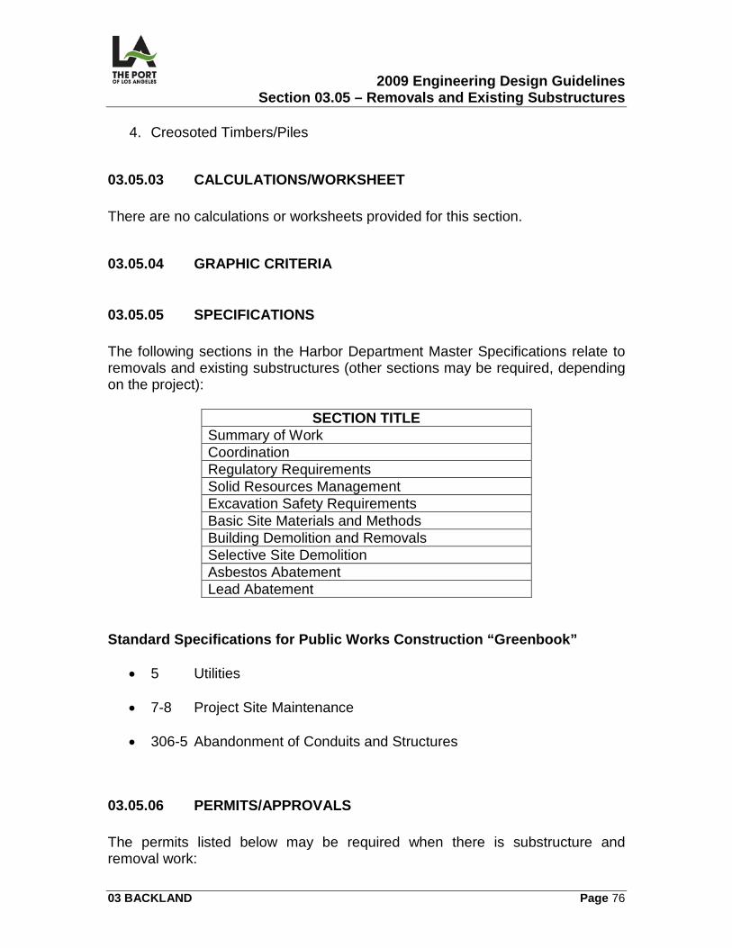
2009 Engineering Design Guidelines Section 03.05 – Removals and Existing Substructures
03 BACKLAND Page 76
4. Creosoted Timbers/Piles
03.05.03 CALCULATIONS/WORKSHEET There are no calculations or worksheets provided for this section.
03.05.04 GRAPHIC CRITERIA
03.05.05 SPECIFICATIONS The following sections in the Harbor Department Master Specifications relate to removals and existing substructures (other sections may be required, depending on the project):
SECTION TITLE Summary of Work Coordination Regulatory Requirements Solid Resources Management Excavation Safety Requirements Basic Site Materials and Methods Building Demolition and Removals Selective Site Demolition Asbestos Abatement Lead Abatement
Standard Specifications for Public Works Construction “Greenbook”
• 5 Utilities
• 7-8 Project Site Maintenance
• 306-5 Abandonment of Conduits and Structures
03.05.06 PERMITS/APPROVALS The permits listed below may be required when there is substructure and removal work:
2009 Engineering Design Guidelines Section 03.05 – Removals and Existing Substructures
03 BACKLAND Page 77
Army Corps. of Engineers Permit A Corps. Removal Permit is required when work is done in their jurisdiction (any land area in the tidal zone up to MHHW [Mean Higher High Water]). Department of Public Works (P.W.) Permit Sewer Cap Permit, the City of Los Angeles (Department of P.W, Bureau of Engineering.), must approve the sewer capping plans. Harbor Department credit will be established for the sewer facility charge. Department of Building & Safety Permit Demolition permit for structures, a plan check is required after obtaining the Sewer Cap Permit. Once approved, the Demolition Permit may be obtained. (S-21 License is required). Hazardous Materials Permits The removal and disposal of hazardous materials and wastes shall be in accordance with current regulatory requirements (e.g., AQMD, Fire Department, EPA, etc.). They vary depending on the type of hazardous materials or wastes involved.
03.05.07 ENVIRONMENTAL CONSIDERATIONS Not Applicable.
03.05.08 REFERENCE DRAWINGS The following contract drawings are identified for reference: 1-2343 Berth 142 Union Ice Building Demolition and Site Improvements.
1-2343 R-1 Substructures, Demolition and Removal – Plan LAHD Standard Plans
2009 Engineering Design Guidelines Section 03.06 – Grading and Paving
03 BACKLAND Page 78
03.06
GRADING AND PAVING
03.06.01 OVERVIEW This section contains the following information related to the preparation of grading and paving contract drawings:
• Site Plan (GP)
• Grading and Paving Plan (GP)
• Paving Details (GP)
03.06.02 DESIGN CRITERIA Fencing Only If there is fencing but no striping to be done as part of the project, the fencing should be included in the grading and paving drawings. Asphalt Concrete (AC)
1. Slope/Grade Break. AC shall adhere to the following:
a) Minimum design flowline slope = 0.5%. b) Maximum design flowline slope = 1.0% (the greatest slope within the
drainage plane shall not exceed this percentage).
c) Maximum Grade Break = 2.0%.
2. Container Terminal Pavement. Typical container terminal backland asphalt concrete pavement shall be 7 inches thick, with rock gradation per Class "Y" or Class “W” as defined in the specifications. Class “W” asphalt shall be finished with a slurry seal, due to the coarse nature of the aggregates and resulting surface finish.
3. Roadway Pavement. The typical roadway pavement shall be designed per
Section E422.1 (Flexible Pavement Design) of the City of Los Angeles Street Design Manual.
2009 Engineering Design Guidelines Section 03.06 – Grading and Paving
03 BACKLAND Page 79
a) A.C. wearing surface shall be Class C. b) A.C. base shall be Class B. A.C. mixtures shall be per subsection 203-
6.32 of the "Greenbook" (Standard Specifications for Public Works Construction).
4. Asphalt Viscosity. Asphalt viscosity grade shall be AR 16000 (PG 70-10) for container terminal pavement and AR8000 (PG 64-10) for other surfaces, per subsection 203-1 of the "Greenbook."
Concrete Surfaces Typically, POLA does not use concrete pavement for the backland. However, concrete turning pads and runways are used for transtainer runs, and concrete slabs are used to protect structures like maintenance holes and vaults in backland areas. Concrete is also used for fueling stations, sidewalks, and longitudinal gutters. Concrete pavement joints shall be keyed. Other Paved Surfaces Other paved surfaces, such as interlocking paving stones and stamped concrete, have been used. Typically, they are found in recreational areas, such as Ports o' Call and the Cabrillo Marina. Slurry Seal This is typically used to maintain existing AC surfaces and shall be as specified in Section 32 01 13 of the Harbor Department Master Specifications. AC Overlays This is typically used for maintenance of existing AC surfaces and making minor changes in existing pavement grades. If necessary, existing pavement shall be cold planed to provide a minimum 2 inch thick overlay. Where overlays join existing pavement, a minimum 3” deep sawcut join line shall be constructed. All existing asphalt surfaces shall be covered with a tack coat prior to placing overlay. Base Material
2009 Engineering Design Guidelines Section 03.06 – Grading and Paving
03 BACKLAND Page 80
Base material shall be crushed miscellaneous base per Section 32 11 01 or 32 11 23 of the Harbor Department Master Specifications. Pavement Grades
1. Grading Consistency. All pavement grades shall be designed to meet the existing grades in adjacent developed backland without creating ponding conditions.
2. Final Grade Considerations. As POLA is on low-lying land adjacent to the
ocean and subject to a high ground water table and tidal action, final grade design needs to take the following considerations into account:
a) Where possible, grades should limit the placement of substructures
within the groundwater table. b) Tidal action within substructures like storm drain systems which outlet
into the harbor.
c) Desirable elevation for final grade shall be elevation 15 M.LLW (Mean Lower Low Water). Minimum elevation shall be 10 MLLW.
Wheel and Impact Loading
1. Pavement Section Design. Design of the pavement section shall be based on wheel loading criteria (types of equipment to be utilized) and C.B.R. (California Bearing Ratio) value of the subgrade. Design methods shall be approved by the Chief Harbor Engineer (reference 03.06.03).
2. In Container Terminals.
a) For container terminals only, paving structural section and any other
structure subject to vehicular loading shall be designed to withstand 100 kip wheel plus 25% impact loading, distributed over a 5 square foot contact area, unless otherwise directed. The loading criteria are based on a single main wheel of Front End Loader or Top Pick. Where underground structures may encounter loading from both main wheels, a wheelbase of 10 feet shall be assumed.
b) For roadways outside container terminals, pavement sections shall be
designed for HS-20 loadings.
2009 Engineering Design Guidelines Section 03.06 – Grading and Paving
03 BACKLAND Page 81
Soils Report A soils report is required indicating C.B.R. and unified soils classification. This information is necessary to design the structural pavement section. Drainage All drainage should be diverted away from railroad tracks and structures. Curbs should be constructed around buildings to prevent storm water flow run-on. Where curbs cannot be constructed, pavement should slope up to the building at a grade of 4%, and the building pad elevation should be set a minimum of 4 inches above surrounding finished grade. Phased Construction Phased construction shall consider all tenant requirements (e.g., access, lighting, etc.). Longitudinal Gutters Concrete longitudinal gutter flowlines shall have a minimum slope of 0.25% (0.2% acceptable when in Public Works jurisdiction). They shall be designed in accordance with LAHD Standard Plan H-201. Concrete Curbs Concrete curbs shall be designed in accordance with City of Los Angeles DPW BOE ( http://eng.lacity.org/techdocs/stdplans/s-400/s410-2.pdf )Standard Plan S-410. Curbs shall be 6 inches high.
2009 Engineering Design Guidelines Section 03.06 – Grading and Paving
03 BACKLAND Page 82
Paving Plan The paving plan shall consist of definable planes made up of ridge lines, valleys, and grade breaks. This plan shall also show existing and proposed surface culture which will exist upon project completion (striping excluded). Fill Material When fill material is placed, a soil compaction report shall be filed with the City of Los Angeles Department of Building & Safety to certify said fill. Fill material on existing hydraulic landfill requires a variance filed with City of Los Angeles Department of Building & Safety. Poor Subgrade Conditions During construction of new pavement or in repair of existing pavement, conditions will be encountered where the subgrade cannot be compacted to the required 90 or 95%. This may be due to excessive fines or moisture in the soil. Unsuitable subgrade material should be excavated to a minimum depth of 24 inches. If the subgrade material can be compacted, select fill or CMB should be backfilled and compacted to 90% maximum density. If the newly exposed subgrade material still cannot be compacted, the use of geotextile fabric or geogrid should be considered and Crushed Miscellaneous Base (CMB) should be backfilled and compacted to 90% maximum density to the original subgrade elevation. In both cases base and paving material should be compacted per the specifications.
03.06.03 CALCULATIONS/WORKSHEETS There are no calculations or worksheets provided for this section; however, for pavement structural calculations, the designer should refer to the Pavement Design Guide prepared by Moffat and Nichol for the Port of LA.which can be found in M:\users\engineering division\civil planning\0-library\pavement design guide.
03.06.04 GRAPHICS CRITERIA Grading and paving sheets should include a site plan, individual plan sheets, and detail sheets. The site plan should show the entire project, with proposed breaklines and contours emphasized, individual sheet limits, and general grading notes. Individual grading and paving plan sheets should in general be 1” = 40’
2009 Engineering Design Guidelines Section 03.06 – Grading and Paving
03 BACKLAND Page 83
scale, or 1” = 20’ scale for detailed areas. These sheets should show proposed breaklines with a dark lineweight, proposed contours at a normal lineweight, and existing contours and elevations using a faded (gray) color. All breaks and intersections in breaklines should be labeled with coordinates and elevations. The slope of all planes should be labeled. Detail sheets should show pavement sections and any other details necessary.
03.06.05 SPECIFICATIONS The following sections in the Harbor Department Master Specifications relate to grading and paving (other sections may be required, depending on the project):
SECTION TITLE Regulatory Requirements Basic Site Materials and Methods Excavation, Stockpiling, and Disposing of Chemically-Impacted Soils Earthwork Trench Excavation and Backfill Cement Treated Base Treated Permeable Base Crushed Miscellaneous Base Crushed Miscellaneous Base – Contractor Furnished Base Course Asphalt Concrete Paving Asphalt Rubber Pavement Pavement Markings Excavation, Stockpiling, And Disposing Of Chemically-Impacted Soils Slurry Seal Cold Planing Existing Pavement
03.06.06 PERMITS/APPROVALS The permits listed below may be required when there is grading and paving work: Department of Building & Safety Grading Permit A Building & Safety grading permit is required for grading (refer to Los Angeles Building Code, Chapter 3, Section 301c, for exceptions). The designer is
2009 Engineering Design Guidelines Section 03.06 – Grading and Paving
03 BACKLAND Page 84
responsible for obtaining this permit. For grading in areas with existing uncertified fill (i.e., no prior soils compaction report was prepared), a building ordinance variance is required. Any grading permit for a project that includes an acre or more of impermeable surface, 5,000 square feet of parking lot, or a parking lot of 25 or more spaces, will be required to comply with Standard Urban Stormwater Mitigation Plan (SUSMP) requirements. Please refer to Section 03.07 Storm Drains for more information on SUSMP. Department of Public Works (P.W.) Permit Grading and/or paving within the public right-of-way will require an A- or B- Permit from the City of Los Angeles, Department of Public Works, Bureau of Engineering. The B-Permit process is extensive, and will be required for any work that affects street pavement, grades, and curb and gutter grade and alignment. Army Corps. of Engineers (ACE) Permit An ACE Permit is required (obtained by the designer) when creating a landfill.
03.06.07 ENVIRONMENTAL CONSIDERATIONS The major environmental consideration for grading is the presence of known or unknown contaminated soil and/or groundwater at the project site. If there is known or suspected contamination, specifications for its removal and/or treatment should be included, and tailored to the particular contaminant. If possible, grading should be designed to avoid “cut” areas where contamination is present. Even if there is no known contamination at a project site, the industrial history of the Port makes the presence of contamination a possibility on any project. All projects that include any earthwork, including trenching, should include specification section “Excavation, Stockpiling, And Disposing Of Chemically-Impacted Soils”. This section deals with unanticipated contaminated soil. Another environmental concern involved in grading design involves facilities handling potential pollutants. These include fueling facilities, equipment wash stations, trash storage and handling areas, and maintenance and repair facilities. All of these have the potential to contaminate storm water runoff, and should be
2009 Engineering Design Guidelines Section 03.06 – Grading and Paving
03 BACKLAND Page 85
designed to contain runoff within their own boundaries, where it can be properly treated. The surrounding area should be graded to drain away from these facilities, so that “clean” runoff is not subject to contamination. The designer should be aware of the State Water Pollution Prevention Program (SWPPP) requirements during construction of a project requiring grading and paving. For projects greater than an acre, a SWPPP plan must be developed by the contractor and submitted to the State for approval. Projects smaller than an acre that are subject to a Department of Building and Safety grading permit will be covered by the City’s Wet Weather Erosion Control regulations. Projects smaller than an acre that do not require a grading permit are still subject to basic runoff and erosion control measures. Refer to the Regulatory Requirements specifications section for more information. As noted under PERMITS/APPROVALS above, grading projects may be subject to SUSMP requirements, even if no storm drain work is planned. Regardless of whether SUSMP is required, the designer should seek to minimize paved areas, and, where possible, design grading to incorporate grassy swales or other bio-filtration/infiltration elements.
03.06.08 REFERENCE DRAWINGS The following contract drawings are identified for reference: 1-2358 Pier 400 Backland - Phase II
1-2358 GP-1 Site Plan
1-2358 GP-6-35 Grading Plans
1-2358 GP-36-38 Grading Details LAHD Standard Plans 5-7134 H-201-00 Concrete Longitudinal Gutter
2009 Engineering Design Guidelines Section 03.07 – Storm Drains
03 BACKLAND Page 86
03.07
STORM DRAINS
03.07.01 OVERVIEW This section contains information related to the preparation of the following storm drain contract drawings:
• Site Plan (SD)
• Storm Drain Plan and Profile (SD)
• Trench Drain Detail (SD)
• Catch Basin (SD)
• Non-Std. M.H. (SD)
• SUSMP
03.07.02 DESIGN CRITERIA General Design Requirements Storm drain hydraulic and hydrology design shall be performed in accordance with the Department of Public Works, Bureau of Engineering's Storm Drain Design Manual (BOE STORM DRAIN DESIGN MANUAL) and Los Angeles County Department of Public Works Hydology Manual (http://ladpw.org/wrd/publication/engineering/2006_Hydrology_Manual/2006%20Hydrology%20Manual-Divided.pdf ), unless otherwise specified in these Guidelines or approved by the Chief Harbor Engineer. Take note that in 1999 DPW Bureau of Engineering has adopted the LACDPW Hydrology Manual to replace the Hydrologic Design Section of BOE’s Storm Drain Design Manual. Substructures Substructures that closely parallel, intersect, and/or interfere with the proposed storm drain shall be shown on storm drain plans and profiles. Contamination
2009 Engineering Design Guidelines Section 03.07 – Storm Drains
03 BACKLAND Page 87
Storm drain plans and profiles shall indicate areas of suspected soil or groundwater contamination. Dewatering If tests show possible groundwater contamination at the site and/or at adjacent areas, dewatering should be avoided. Dewatering is to be considered the exception rather than the rule. If dewatering is necessary, the designer should start the process of applying for a National Pollution Discharge Elimination (NPDES) Permit as soon as possible, to avoid delaying construction. Hydrology
1. Frequency. A 10 year rainfall frequency shall be used for the design of storm drains on Port property.
2. Isohyetal. The 50 year storm isohyetal to be used for the design of storm
drains shall be:
a) 1.33 inches/hour for Port storm drains on Terminal Island, in the Wilmington area, and in the Classification Yard.
b) 1.55 inches/hour for proposed storm drains connected to existing Port
storm drains in San Pedro.
c) 1.77 inches/hour for proposed storm drains connected directly to the harbor in San Pedro.
d) According to L.A. County or City standards for non-Port storm drains.
Pipe Alignment Existing and proposed surface and sub-surface improvements shall be considered when setting horizontal and vertical pipe alignment. Possible soil and groundwater contamination areas shall be avoided whenever possible. Hydraulic Design
1. Computer Analysis. Computer analysis of pipe hydraulics may be used with prior approval from the responsible Harbor Engineer (hydraulic design
2009 Engineering Design Guidelines Section 03.07 – Storm Drains
03 BACKLAND Page 88
shall be per City of Los Angeles, Department of Public Works Storm Drain Design Manual pressure flow design [based on Manning's equation]).
2. Grade Line. The hydraulic grade line shall be no less than 12 inches
below the top (or lowest opening) of inlets, catch basins, maintenance holes, and other structures and shall be indicated on the profile plan. This criterion may be modified with prior approval from the Chief Harbor Engineer.
3. Outlet to Harbor. When the outlet is to the harbor, a water surface
elevation of 5.43 MHHW (Mean Higher High Water) above mean sea level is used as the control for the hydraulic grade line.
4. For reinforced concrete pipe (RCP) storm drains in the Port, the smallest
diameter to be used is 18 inches. Smaller diameters may be used for PVC or HDPE pipe.
Standard Urban Stormwater Mitigation Plan (SUSMP)
1. SUSMP requires that for the majority of new developments and many redevelopments, post-construction rainfall runoff be stored, infiltrated, or treated before being discharged. The requirements come from the Regional Water Quality Control Board (RWQCB), and are administered through the building or grading permit process by the City of Los Angeles Department of Building and Safety.
2. The reference manual for SUSMP at the Port is the Development Best
Management Practices Handbook – Part B Planning Activities Best Management Practice, Third Edition by the City of Los Angeles, Department of Public Works, Bureau of Sanitation, Watershed Protection Division. Presently, “treatment” is very vaguely defined, and the processes used by most proprietary (BMP) units will meet the requirements. Future regulations will require the targeting of particular pollutants and set maximum discharge levels.which may require a different set of BMP.
3. The Manual sets standards for projects that fall under SUSMP
requirements, which will include all but the smallest drainage projects at the Port. The Manual also sets out several different methods for calculating how much storm water must be treated or infiltrated, based on volume or flow rate. The method based on a 3/4” pattern storm has been used most successfully at the Port. This method is based on the Los Angeles County hydrology method and yields a minimum flow for a given tributary area which must be treated by a BMP.
2009 Engineering Design Guidelines Section 03.07 – Storm Drains
03 BACKLAND Page 89
4. The structural BMP chosen for each individual project should take into
account the type of pollutants expected for each site, volume of runoff, and maintenance issues. A great number of BMPs are available, but due to the Port’s large paved areas, proximity to receiving waters, high water table, and high land value, proprietary treatment BMPs have been the only systems installed to date. For redevelopment projects with small tributary areas drained by a few catch basins, catch basin insert filters are appropriate. For larger projects, an inline hydrodynamic system, with greater capacity, is more appropriate. The designer should keep in mind the performance of the chosen system with respect to tide levels. Many systems will not function if submerged. Infiltration, sand filters, or biofiltration should be considered for smaller new development projects with room for extensive landscaping.
5. The Bureau of Sanitation, Watershed Protection Division (WPD) has
placed an increased emphasis on infiltration and bio-filtration BMPs. Container terminals are currently being designed with a large rock-filled infiltration trench under the trench drains (see drawing set 1-2342 Berths 145-147 Wharf Improvements), and smaller parking lot projects are incorporating olanting areas that filter storm water before it is discharged. The designer should meet with WPD early in the design process to ensure that an acceptable BMP has been chosen.
Materials
1. Pipe and Joints. Reinforced concrete pipe with rubber gasketed joints shall be used unless otherwise approved. When placed below the ground water table, within the tidal influence zone, or within hydraulic fill, pipes shall have a maximum water/cement ratio of 0.40; shall be wet-cast or spun-cast; and shall have a minimum inside and outside concrete cover of 1 1/2 inches.
2. Substitutions. When substituting pipe materials, the following factors
should be considered: flow characteristics, durability, strength, type of joint, availability of pipe and/or special shapes, ease of installation, cost of material, and cost of installation.
3. Bedding. A minimum of Case 2 bedding shall be used when laying "in the
wet" (in accordance with City of L.A. Standard Plan S 251, Pipe Laying in Trenches). Higher bedding cases may be required if the pipes are close to the surface or under railroad tracks. Where unsuitable base material is encountered, the Engineer shall direct the contractor to over-excavate an additional 2 feet and place a bedding material composed of 2 inch nominal
2009 Engineering Design Guidelines Section 03.07 – Storm Drains
03 BACKLAND Page 90
gradation rock per specification section 02323 Trench Excavation and Backfill.
Structures
1. Trench Drain.
a) Slope -- minimum slope of trench drain invert shall be 0.25%. b) Trench drain detail -- trench drains shall be designed similar to the
details on sheet SD-38 of drawing set 1-2358. A number of different proprietary trench drain former or liner systems with integrated gratings can be used, such as Trench Former HD-200 by ABT, Inc.
2. Catch Basins. Gutter type catch basins, grate frames, and grates shall be
constructed per Standard Plans Exhibit No. 1 in 03.07.08. All other basins shall be per Standard Plans for Public Works Construction (American Public Works Association), as adopted by the City of Los Angeles Department of Public works.
3. Maintenance Holes.
a) Storm drain maintenance holes shall be per Standard Plans for Public
Works Construction (American Public Works Association), as adopted by the City of Los Angeles Department of Public works.
b) Frame and Cover -- Maintenance hole frames and covers shall be per
Standard Plans for Public Works Construction (American Public Works Association) 630-2, with L.A.H.D. lettering. For maintenance holes in container terminal backlands, the frame and cover shall be specified to meet the loading requirements described below.
4. Junction Structures. All junction structures shall be per Standard Plans for
Public Works Construction (American Public Works Association), as adopted by the City of Los Angeles Department of Public Works.
5. Outlets.
a) Flap gates -- flap gates are typically not used at the Port due to
maintenance considerations. They should only be considered when backflow at high tide may damage upstream property or facilities..
2009 Engineering Design Guidelines Section 03.07 – Storm Drains
03 BACKLAND Page 91
b) Monolithic -- outlets passing through rock dikes or those which are susceptible to differential settlement or alignment disturbance shall be of monolithic construction.
c) Pile supported outlets -- the designer should consider using pile-
supported outlets on rock slopes which are subject to settlement.
6. Structural Best Management Practices (BMPs) – Structural BMPs incorporated into the SUSMP for the project will in general be per the manufacturer’s specifications, with a few exceptions. First, the structure and any associated maintenance holes must be able to withstand the loading described below. Second, the unit may need to be modified to operate within the tidal zone.
7. Loads. Storm drain structures subject to loads from container handling
equipment shall be designed for 100 kip wheel loads (140 PSI) plus 25% impact loads (125 kip over a 5 square foot area).
Track Drains (Subsurface Drainage System)
1. Filter. A graded aggregate filter or filter cloth shall be provided to prevent soil grains from entering the drain.
2. Perforated Pipe. Perforated pipe (minimum diameter of 6 inches) with
closed joints shall be used as drains. Invert elevations shall be set to lower the water level to the desired elevation.
3. Non-perforated Pipe. Non-perforated pipe with closed joints shall be used
as collectors. The minimum diameter shall be 6 inches at a slope to provide minimum 2 F.P.S. velocity when flowing full. Where sufficient gradient is available, collectors shall be depressed below drains. When the pipe is half full, the pipe slope should achieve a 2 to 4 foot per second velocity.
4. Outlets. Outlets shall be designed in such a manner so as to minimize
surface water, tidal water, or groundwater from entering the drainage system.
Final Grade Considerations As the Port is on low-lying land adjacent to the ocean and subject to a high groundwater table and tidal action, final grade considerations need to take into account the following:
2009 Engineering Design Guidelines Section 03.07 – Storm Drains
03 BACKLAND Page 92
1. Avoid placing a storm drain system within the ground-water table if
possible.
2. Tidal action on storm drain systems which outlet into the harbor. Accommodating Future Extensions
1. Bulkhead. A bulkhead shall be designed at the end of the pipe to resist lateral earth loads. It shall be recessed at least 1 foot into the pipe to allow construction of future junction or transition structures. Where a bulkhead is subject to tidal action, it should be designed to resist hydraulic pressure, with no help from earth backfill. Typical materials for these bulkheads are brick and mortar.
2. Maintenance Hole or Box. A maintenance hole or box should be placed
downstream from the end of the pipe to facilitate bulkhead installation and/or removal.
3. Cutoff Wall. A simple exterior cutoff wall should be installed downstream
from the bulkhead or the outlet end of the pipe to be extended through the rock dike to facilitate dewatering. If the rock bedding is not sealed, concrete injection may be required downstream of the bulkhead.
4. Extending Existing Lines. Where existing storm drain lines are to be
extended, Nos. 1-3 above do not apply (they are for new construction only). The specifications shall require the contractor to install any required bulkheads and cutoff walls to eliminate tidal action.
Jacking/Tunneling Jacking and tunneling shall be performed in accordance with the following:
1. Standard Specifications for Public Works Construction ("Greenbook"). 2. Cal O.S.H.A. requirements (Tunnel Safety Orders).
3. Department of Public Works, Bureau of Engineering's Storm Drain Design
Manual.
03.07.03 CALCULATIONS/WORKSHEETS
2009 Engineering Design Guidelines Section 03.07 – Storm Drains
03 BACKLAND Page 93
Calculations and worksheets shall be prepared in accordance with Department of Building & Safety requirements and POLA Engineering Design Staff. The designer shall prepare all calculations on worksheets in compliance with POLA's Engineering Division's latest format. Storm Runoff Calculations A drainage area worksheet shall be prepared for the proposed system, including:
1. Outlining of the drainage area, taking into account the area's topography, drainage problems, and future development plans.
2. Plotting of all existing and proposed storm drains in and adjacent to the
drainage area.
3. Dividing the drainage area into sub-areas -- and calculating the acreage of the sub-areas.
4. Adding runoff information taken from a tabling sheet similar to the Storm
Drain Design Manual drainage area worksheet.
a) The runoff information shall include acreage, quantity of flow for design frequency, and the time of concentration above and below all junctions.
b) Computer analysis of hydrology may be used with prior approval from
the Chief Harbor Engineer.
5. Adding final pipe sizes to the drainage area worksheet. Pipe D-Loads Storm drain pipes subject to loads from container handling equipment shall be designed for 100 kip wheel loads (140 PSI) plus 25% impact loads (125 kip over a 5 square foot area). Depending on depth of the pipe, it may be necessary to consider a second wheel load (two-wheel main axle) spaced 10 feet from the first. Railroad loading shall be Cooper E-80. Pipe D-loads shall be calculated considering dead loads, including oil loads, determined by Martson's equation and live loads by Boussinesq's equation. Reference: Design and Construction of Sanitary and Storm Sewers by the American Society of Civil Engineers. In area not subject to container terminal equipment loads, Figure G-613 of the City of Los Angeles Storm Drain Design Manual can be used to determine required D loads.
2009 Engineering Design Guidelines Section 03.07 – Storm Drains
03 BACKLAND Page 94
03.07.04 GRAPHICS CRITERIA Storm drain sheets should include a site plan, individual plan sheets, profile sheets, and detail sheets. The site plan should show the entire project, with proposed storm drain lines, individual sheet limits, and general storm drain notes. Individual grading and paving plan sheets should in general be 1” = 40’ scale. These sheets should show proposed storm drain alignments in a dark lineweight, as well as proposed storm drain structures. Storm drain lines should show the outside pipe walls, and all storm drain lines should be stationed. Existing utilities should be shown in a light lineweight. All junctions, points of inflection, points of curvature, structures, and begin/end points on a storm drain line should be labeled with coordinates, station, and a description of the point (i.e. “Begin Line A”, “Construct MH Type A”, etc). Profile sheets should include a grid, and should be drawn with a 10:1 vertical scale exaggeration. Label all structures, grade breaks, and begin/end points with station, description, and invert elevation. Label all pipes with slope, diameter, and bedding type. Detail sheets should show all storm drain structures that are not represented by standard plans.
03.07.05 SPECIFICATIONS The following sections in the Harbor Department Master Specifications relate to storm drains (other sections may be required, depending upon the project):
SECTION TITLE Basic Site Methods and Materials Detection Tape Trench Excavation and Backfill Storm Drain System Excavation, Stockpiling, and Disposing of Chemically-Impacted Soils Cast-In-Place Concrete Precast Concrete
Pipe Joints All pipe joints are to be rubber gasketed, even above the water tables (per the "Green Book," Standard Specifications for Public Works Construction). Detection Tape
2009 Engineering Design Guidelines Section 03.07 – Storm Drains
03 BACKLAND Page 95
All project substructures require detection tape to be placed over them. Special Testing Requirements The specifications shall include a statement that storm drain pipe does not require testing. Pipe strength certification, however, shall be required from the manufacturer.
03.07.06 PERMITS/APPROVALS The permits/approvals listed below may be required when there is storm drain work: Department of Building & Safety Grading Permit Storm drain drawings and calculations, including SUSMP plan, must be submitted along with grading plans to obtain a Building & Safety grading permit (refer to Los Angeles Building Code, Chapter 3, Section 301c, for exceptions). The designer is responsible for obtaining this permit. The designer should coordinate with the Los Angeles Department of Public Works, Bureau of Sanitation, Watershed Protection Division regarding the proposed SUSMP system prior to submitting for plan check. California Regional Water Quality Control Board Permits A General NPDES Permit is required for discharge into the harbor as a result of construction dewatering; a Waste Discharge permit is needed for dewatering to land. Army Corps. of Engineers (A.C.E.) Permit This permit is required when constructing new storm drain outlets in harbor waters, even if the outlet is behind the pierhead line. Department of Public Works (P.W.) Permit This permit is required when connecting to or discharging into a P.W. storm drain, channel, or basin.
2009 Engineering Design Guidelines Section 03.07 – Storm Drains
03 BACKLAND Page 96
L.A. County Department of Public Works (P.W.) Permit This permit is required when connecting to or discharging into a County P.W. storm drain, channel, or basin and may require utilizing County design criteria for the drainage area in place of City criteria. Railroad Approval This approval is secured from the appropriate railroad when encroaching into their right-of-way. Other Approvals, As Appropriate Other approvals may be needed if encroachment is involved.
03.07.07 ENVIRONMENTAL CONSIDERATIONS The main environmental concern for storm drain design is the Standard Urban Stormwater Mitigation Plan, or SUSMP, as described above. The majority of Port projects requiring storm drains will be subject to SUSMP requirements. These requirements are still evolving and becoming stricter and more specific. Storm drain designers should contact the Bureau of Public Works, Department of Sanitation, Watershed Protection Division to verify the latest requirements prior to undertaking a SUSMP design. The other major environmental consideration for storm drain design and construction is the possibility of encountering contaminated soil and/or groundwater during trench excavations. If there is known or suspected contamination, specifications for its removal and/or treatment should be included, and tailored to the particular contaminant. If possible, the storm drain alignment should be designed to avoid areas where contamination is present. Even if there is no known contamination at a project site, the industrial history of the Port makes the presence of contamination a possibility on any project. All projects that include storm drains should include specifications for Excavation, Stockpiling, and Disposing Of Chemically-Impacted Soils sections. This section is specific to unanticipated contaminated soil.
2009 Engineering Design Guidelines Section 03.07 – Storm Drains
03 BACKLAND Page 97
03.07.08 REFERENCE DRAWINGS Major storm drain lines within Port property are shown on LAHD substructures maps. The following contract drawings are identified for reference: 1-2358 Pier 400 Backland Phase II.
1-2358 SD-1 Site Plan
1-2358 SD-7-32 Storm Drain Plans
1-2358 SD-35-37 Storm Drain Profiles
1-2358 SD-38 Storm Drain Details 1-2334 Berth 100 Container Wharf (SUSMP example).
1-2334 SD-1 Site Plan
1-2334 SD-2-3 Storm Drain Plans 1-2334 SD-4-5 Storm Drain Profiles 1-2334 SD-6-7 Storm Drain Details
LAHD Standard Plans
Catch Basin, Grate Frame, Grate
Standard Non-Rocking Maintenance Hole Frame and Cover
2009 Engineering Design Guidelines Section 03.08 – Sewers
03 BACKLAND Page 98
03.08
SEWERS
03.08.01 OVERVIEW This Section contains information related to the preparation of the following backland sewers contract drawings.
• Site Plan (SS)
• Sewer Plan and Profile (SS)
Jurisdiction
1. Department of Public Works (DPW) Jurisdiction: Sewers in DPW jurisdiction shall always be designed in accordance with the Department of Public Works (DPW), Bureau of Engineering's (BOE) Sewer Design Manual.
2. Los Angeles Harbor Department (LAHD) Property and Jurisdiction:
a) Sewers on LAHD property with pipe diameters 8 inches or larger shall
be in accordance with the BOE Sewer Design Manual (BOE Sewer Design Manual) unless specified otherwise in these Guidelines. Sewer designs per the Sewer Design Manual may require permit variances from Building and Safety.
b) Sewers with pipe diameters of 4 and 6 inches shall conform to the City
of Los Angeles Plumbing Code.
03.08.02 DESIGN CRITERIA
1. Gravity System Design: For gravity system design refer to the following sections of the BOE Sewer Design Manual.
a) Section F-200:
1) Projection of Flows: Projected flow in container terminals is much less than flows projected in other industries. Flow estimation should be based on the number of people using the building facilities on a regular basis. Flow projection should NOT be estimated based on building square foot.
2009 Engineering Design Guidelines Section 03.08 – Sewers
03 BACKLAND Page 99
2) Design Flows: The design of sanitary sewers must consider minimum, average, and peak flows. Normally, ADWF (Average Dry Weather Flow) is determined or selected, and a factor is applied to determine PDWF (Peak Dry Weather Flow). The PDWF is the design flow used to select the pipe size. Minimum flows are used to determine if specified velocities can be maintained to prevent deposition of solids.
3) Minimum Velocity: Gravity sewers shall be designed for a minimum
velocity of three Feet per Second (fps) using the PDWF that exists at the time the pipe is placed into service.
4) Minimum Slope: The minimum slope of a proposed slope shall
provide a minimum velocity of 3 fps at PDWF.
5) Design Depth of Flow: Sewer pipe shall be sized so depth of PDWF shall be no more than one half the pipe diameter (d/D=depth of flow/pipe diameter= 0.5).
6) Calculation of Pipe Size. Use Manning’s formula to calculate pipe
size. A Manning’s Roughness Coefficient of “n” = 0.014 shall be used, regardless of the type of pipe used.
b) Section F-300: Alignments Of Sewers c) Section F-400: Sewer Materials And Structures
2. Pumping Plant and Force Mains Design: For pumping plant and force
main design refer to the following section of the BOE Sewer Design Manual and additional recommendations.
a) Section F-700: Pumping Plant and Force Main. b) Recommendations:
1) Pump plant design in container terminal area should specify grinder
pump. Specifying grinder pump would allow the selection of small discharge pipe diameter size.
2) Provide air release valve system for pipe discharge length greater
than 1000 feet.
3) Specify same level and pump control system as existing system at the Port.
2009 Engineering Design Guidelines Section 03.08 – Sewers
03 BACKLAND Page 100
4) Involve POLA Construction and Maintenance in the review and approval of the pump equipment and system selection.
3. Design Plans: Design Plans shall be prepared using Section F 500 of
BOE Design Manual plans as a reference as well as past LAHD project plans such the Pier 400 projects
4. Miscellaneous Guidelines:
a) Substructures: Substructures that closely parallel, intersect, and/or interfere with the proposed sewer shall be shown on sewer plans and profiles.
b) Detection Tape: All project substructures require detection tape to be
placed over them.
c) Contamination: Sewer plans and profiles shall indicate areas of suspected contamination.
d) Dewatering: The sewer profile shall indicate ground-water levels.
Designs should avoid dewatering if possible. Dewatering is to be considered the exception rather than the rule.
e) Loads: Sewer structures subject to loads from container handling
equipment shall be designed for 100 kip wheel loads (140 PSI) plus 25 kip impact loads (125 kip over a 4.95 square foot area). Calculations to determine bedding requirements shall be performed in accordance with the National Clay Pipe Institute Manual (1990 edition).
f) Shallow Cover: The designer may select alternate materials (e.g.,
ductile iron pipe) in the case of sewers with shallow cover, which are subject to heavy loads.
g) Alignment: Existing and proposed surface and sub-surface
improvements shall be considered when setting horizontal and vertical pipe alignment. Possible soil and groundwater contamination areas shall be avoided whenever possible.
h) Bedding: A minimum of Case 2 bedding shall be used when laying "in
the wet" (in accordance with City of L.A. Standard Plan S-251, Pipe Laying in Trenches).
i) Jacking/Tunneling: Jacking and tunneling shall be performed in
accordance with the following:
2009 Engineering Design Guidelines Section 03.08 – Sewers
03 BACKLAND Page 101
1) Standard Specifications for Public Works Construction ("Green Book").
2) CAL OSHA requirements (Tunnel Safety Orders).
3) Department of Public Works, Bureau of Engineering's Sewer
Design Manual.
03.08.03 CALCULATIONS/WORKSHEETS Calculations and worksheets shall be prepared in accordance with the Department of Public Works, Bureau of Engineering's Sewer Design Manual. Calculations to determine bedding requirements shall be performed in accordance with the National Clay Pipe Institute Manual (1990 edition). The designer shall prepare all calculations on worksheets in compliance with POLA's Engineering Division's latest format.
03.08.04 GRAPHIC CRITERIA Bureau of Engineering's Sewer Design Manual, Section F 500 Preparation of Plans, should be used as a guide in preparing sewer plans.
03.08.05 SPECIFICATIONS
1. The following sections in the Harbor Department Master Specifications relate to sewers (other sections may be required, depending upon the project):
SECTION TITLE
Excavation Safety Requirements Detection Tape Earthwork Trench Excavation and Backfill Sanitary Sewer Sewer Pump Station and Forcemain System Basic Electrical Material and Methods
2. Design Manuals: Department of Public Works, Bureau of Engineering's Sewer Design Manual.
2009 Engineering Design Guidelines Section 03.08 – Sewers
03 BACKLAND Page 102
3. Codes: City of Los Angeles Plumbing Code.
4. Standard Specifications for Public Works Construction, “Greenbook.”
5. Department of Public Works, Bureau of Engineering's Standard Plans
03.08.06 PERMITS/APPROVALS The permits/approvals listed below may be required when there is sewer work: California Regional Water Quality Control Board Permits A standard N.P.D.E.S. permit is required for discharge into the harbor as a result of construction dewatering; a Waste Discharge Permit is needed for dewatering to land. Department of Public Works (DPW) Permit This permit is required when connecting to or discharging into a P.W. sewer or when constructing a sewer in P.W. jurisdiction. The application is for a sewerage connection permit (a sewer facilities charge fee is established and paid before applying to City of Los Angeles Department of Building & Safety). Los Angeles County Sanitation District Permit This permit is required when connecting to or discharging into a Sanitation District service area (e.g., Classification Yard). City of Los Angeles Department of Building & Safety Permit A sewer plan check is required. The permit for sewer lines (part of the Plumbing Permit) may be obtained once the plans have been approved. When a sewer is designed to P.W. standards, it may violate City of Los Angeles Department of Building & Safety codes, requiring a variance. Industrial Waste Permit When the discharge is of non-domestic waste, an Industrial Waste permit is required and is obtained from the Los Angeles City Bureau of Sanitation.
2009 Engineering Design Guidelines Section 03.08 – Sewers
03 BACKLAND Page 103
Railroad Approval This approval is secured from the appropriate railroad when encroaching into their right-of-way and/or also from the Harbor Belt Line. Other Approvals, As Appropriate Other approvals may be needed if encroachment in another jurisdiction is involved.
03.08.07 ENVIRONMENTAL CONSIDERATIONS The City’s policy of “ZERO SPILLS” shall be achieved during construction. Plans and/or specifications should contain a provision requiring the contractor to develop and submit to the Engineer for review and approval a written Spill Response Plan (SRP). The SRP shall be developed to respond to any construction related sewage spill.
03.08.08 REFERENCE DRAWINGS Major sewer lines and pump stations located within Port property are shown on LAHD substructures maps. The following contract drawings are identified for reference: 1-2209 Pier 400 Backland Phase I – Berths 401-403.
1-2209 SS-1 Site Plan 1-2209 SS-2 Sewer Plan and Profile 1-2209 SS-23-23A Pump Plant Details & Sections 1-2209 SS-29 Air Release Details & Sections
LAHD Standard Plans
2009 Engineering Design Guidelines Section 03.09 – Landscape
03 BACKLAND Page 104
03.09
LANDSCAPE
03.09.01 OVERVIEW Contents This section contains the following information related to the preparation of the following landscape contract drawings:
• Site Plan
• Planting Plan and Details
• Irrigation Plan and Details
• Hardscape Plan
• Hardscape Details
Goals The purpose of this Section is to provide landscape architects, maintenance contractors, and Harbor Department Construction and Maintenance Division personnel with landscape design/implementation criteria for all tenant and Harbor Department operated facilities to enable them to:
1. Maximize visual impact while responding to functional requirements and planting conditions, thereby promoting the highest quality of landscape in the Port and an attractive milieu.
2. Minimize service and maintenance by ensuring maximum standardization
of materials, equipment, finishes, and flora.
03.09.02 DESIGN CRITERIA Approval All landscape designs must be reviewed by the Port staff and approved by the Chief Harbor Engineer, as well as other appropriate entities. Plans must include explanations relative to the efficient use of plants and water.
2009 Engineering Design Guidelines Section 03.09 – Landscape
03 BACKLAND Page 105
Timing of Landscape Installation All approved landscape features shall be installed within 60 days of initial building occupancy or parcel use, except where weather conditions make this untenable. General Design Requirements Landscape and irrigation designs shall conform to the following:
1. City of Los Angeles Plumbing Code and the Los Angeles County Health Code.
2. City of Los Angeles Department of Public Works standard plans (these
may be modified by the Port staff).
3. City of Los Angeles Departments of Building and Safety and Planning. Cultural and Climatic Constraints Within the Port, all landscape design should reflect the Southern California heritage (i.e., Spanish/Mediterranean), culture, and lifestyle. In addition, landscaped areas shall be compatible with seaside conditions. Geological Constraints All landscape design shall reflect consideration for the geological constraints in the Port area. Results from chemical analyses generally indicate that the following constraints exist:
1. Soil is:
a) Alkaline b) Lacking in organic matter
c) Brown to brownish-yellow, fine to medium sand with some silt, traces
of shell, and dense gravel.
2. Extensive, relatively impervious, marl layers are common. 3. Groundwater and soil both contain high concentrations of chlorides and
sulphates.
2009 Engineering Design Guidelines Section 03.09 – Landscape
03 BACKLAND Page 106
4. The saline groundwater table is close to the soil surface (5 to 10 feet).
5. Large portions of the Port are built on ocean dredged fill materials.
Areas to be Landscaped All facilities shall provide landscape treatment for the following areas:
1. Areas lying between the property line and the perimeter fence/wall (especially areas which abut and extend along the public right-of-way).
2. Open areas surrounding and within buildings (i.e., adjacent to or within the
maximum building footprint). This includes areas such as courts, patios, outdoor restrooms, employee rest areas, ingress/egress areas, front internal service drives, and the like.
3. Areas within and adjacent to parking lots, especially entries, exits, and
ends of parking rows.
4. Areas not otherwise covered by paving/buildings or specifically designated for other than landscape development.
5. Any visually offensive areas such as storage, refuse, or laydown sites.
Planting Materials
1. Selection: Planting materials shall be selected from the Harbor Department approved Plant and Materials list (available from the Port staff) and be compatible with zone 24, per the current edition of Sunset's Western Garden Book (seaside conditions). In addition, all plant selection, size, and number, as well as site storage, installation, and maintenance shall conform to the sections of the drawings and specifications which govern landscape materials in public areas.
2. Planting Emphasis: Plantings shall emphasize the use of broad-leaved
evergreen trees (flowering where possible), palm trees, and shrubs. Deciduous trees may be utilized, but consideration should be given to leaf drop and structural form. Grey/green leaf plants should be de-emphasized (except where needed for contrast and/or accent purposes). High impact landscape (e.g., trees, palms, colorful accent plant materials) should be considered in areas frequented by the public.
2009 Engineering Design Guidelines Section 03.09 – Landscape
03 BACKLAND Page 107
3. In Parking Lots: Trees shall be used throughout a parking lot to break up the "sea of asphalt" effect. Canopy trees shall be used between rows, with accent or contrasting types of trees at row ends.
Use of Climbing Plants and Vines Climbing plants and vines, trained on pergolas, fences, walls, and other structures, shall assist in providing:
1. Flowering color. 2. Overhead shade.
3. Cover for unsightly objects.
4. Green leafy walls (clinging vines are not to be placed on building walls).
5. A deterrent to graffiti.
Use of Grassed Areas Grassed areas shall be considered, if practical, in:
1. Courtyards, public gathering places, and areas surrounding pedestrian walkways.
2. Front yard areas.
3. Front ingress/egress areas and medians, where appropriate.
Use of Berms Berms (earth mounds) shall be incorporated into the landscape design wherever possible, as they can:
1. Modulate flat terrain. 2. Assist in reducing noise, wind, dust, and visual pollution.
3. Assist where soil lifts are required.
4. Exaggerate and highlight landscape.
2009 Engineering Design Guidelines Section 03.09 – Landscape
03 BACKLAND Page 108
Alkaline Groundwater
1. Soil Lifts: Imported soil lifts (mounds) shall be considered to raise the rootball zones above the alkaline groundwater table.
2. Capillary Break: Intensely planted areas may need a capillary break (layer
of subgrade drainage gravel with a separator and perforated agricultural drain tiles) to divert alkaline groundwater.
3. Salt-Tolerant Plants: Salt-tolerant plants shall be considered where the
local elevation is low and close to the groundwater. Unobstructed Vision In all instances, landscape designs shall ensure that plantings do not obstruct motorists' field of vision. Shrubs should not grow above 3 feet and trees should not hang lower than 9 feet from the ground within 50 feet of intersections in conformance with City of Los Angeles Municipal Code, Chapter 6, Article 2, Section 62.200, Street Intersections -- Obstruction to Visibility [Paragraphs A and B]). Parking Lot Landscape Design
1. Shrub Spacing/Effect: Shrubs should be spaced so that they can grow to their natural size without over-lapping. They should be offset to give a natural growth effect and minimize pruning (hedging and row effects are undesirable).
2. Use of Continuous Planting Strips: These strips are not acceptable
between parking rows where they may be in conflict with natural pedestrian circulation patterns.
3. Use of Raised Medians: Where raised medians are used in lieu of wheel
stops, all designs (landscape, hardscape, and irrigation) should work together to minimize maintenance and damage from vehicle overhang/drippage.
4. Curbs and Islands: All parking lot surface landscape should be
surrounded with a six inch curb for protection; islands should be radiused to be compatible with vehicular circulation patterns.
2009 Engineering Design Guidelines Section 03.09 – Landscape
03 BACKLAND Page 109
Irrigation
1. Systems: All irrigation systems are to be below-ground, fully automated systems in compliance with the specifications for such systems.
2. Design Life Span: All irrigation systems should be designed to be
operational for a minimum of 25 years.
3. Water Conservation: Use of water-conserving systems is strongly encouraged.
4. Backflow Control Devices.: All backflow control devices are to be
screened so that they are not visible or subject to damage from parking circulation areas on the site or from public streets.
5. Utility Services: Utility services (including water/ power meters and
service connections) shall be requested, paid for, and coordinated by the contractor, with installation by the appropriate utility company.
Site Maintenance
1. Landscape Areas: Landscape areas shall be designed for maximum impact and minimum maintenance. The designer is encouraged provide the following services:
a) Use drought tolerant plants. b) Use profuse application of perennial flowers only in borders, raised
planters, and areas needing color and accent.
c) Limit the use of lawn, high maintenance ground covers, and middle height shrubs (3 to 6 feet) unless screening is desirable.
d) Plant in masses or groves, limiting the number of plant types.
e) Use trees, boulders, mounds, hardscape, and accent plantings for
parking lots.
2. Site Maintenance Plan: The site maintenance plan shall be submitted with the landscape plans to the Engineering Division for review and approval. This plan shall include methods, frequency, locations, schedule, materials, and the name of individual(s) responsible for maintenance. If the plan is
2009 Engineering Design Guidelines Section 03.09 – Landscape
03 BACKLAND Page 110
submitted by the lessee, it shall be consistent with the requirements for maintenance which are described in the Parcel Lease Agreement.
Tree Spacing To avoid visual obstructions and/or safety problems, tree locations shall be designed with great care when:
1. In the proximity of residential and other building entrances. 2. Traffic control signs may be affected.
Generally, trees should be approximately 40 to 50 feet apart. The designer should always be aware, however, of possible visual obstructions and/or safety problems (e.g., in proximity of traffic control signs, homes, and other building entrances). The chart below lists certain objects or locations which require tree placement no closer than a specified distance.
ITEM DESCRIPTION TREE'S DISTANCE FROM OBJECT
Street Light 20 feet Electrical Power Poles 20 feet Fire Hydrants 10 feet Water and Gas Meters 6 feet Driveway Aprons and Crosswalks 6 feet Alley Entrances 20 feet Intersections (point of curb line intersect)
45 feet
Railroad Tracks 100 feet
03.09.03 CALCULATIONS/WORKSHEETS The designer shall prepare all calculations on worksheets in compliance with POLA’s Engineering Division’s latest format.
03.09.04 GRAPHIC CRITERIA Landscape plans should include a site plan; planting plans that include planting notes and legend , plant materials list showing quantities, common and botanical names and plant sizes and planting details; and irrigation plans that include irrigation notes, legend and symbols, locations of point of connection, irrigation controller, valves and heads, irrigation piping calculation, etc.
2009 Engineering Design Guidelines Section 03.09 – Landscape
03 BACKLAND Page 111
03.09.05 SPECIFICATIONS The following sections in the Harbor Department Master Specifications relate to irrigation and landscaping.
SECTION TITLE Basic Site Materials and Methods Earthwork Irrigation System Planting and Landscaping Cast-In-Place Concrete
03.09.06 PERMITS/APPROVALS The permits/approvals listed below may be required when there is landscape work: Department of Building and Safety Permit A landscape irrigation plan check is required when a backflow preventer is involved. This submission by the contractor is necessary to obtain a plumbing permit. Health Department Certification The Los Angeles County Health Department requires certification that the backflow preventer is operating properly. This application is coordinated by the contractor, with the backflow preventer inspected by a County-certified inspector.
03.09.07 ENVIRONMENTAL CONSIDERATIONS When buildings are designed to achieve Leadership in Energy and Environmental Design (LEED) certification, landscaping shall be designed to achieve and comply with the requirements in achieving the certification.
03.09.08 REFERENCE DRAWINGS
2009 Engineering Design Guidelines Section 03.09 – Landscape
03 BACKLAND Page 112
The following contract drawings are identified for reference: 1-2280 Berths 302-305 Backland Expansion – Phase II.
1-2280 LS-1 Site Plan 1-2280 LS-1 Planting Plan 1-2280 LS-2-3 Irrigation Plan and Details
LAHD Standard Plans
2009 Engineering Design Guidelines Section 03.10 – Structural
03 BACKLAND Page 113
03.10
Structural
03.10.01 OVERVIEW Contents This section contains information related to the preparation of the following backland structural contract drawings.
• Light Pole
• Truck Scale
• Sign Bridge
• Chassis Rack
• Wash Down
03.10.02 DESIGN CRITERIA Design Code and Requirements The Structures below shall be designed from the latest City of Los Angeles Building Code and any other regulating agencies which have authority over any portion of the work, including the State of California Department of Industrial Relations, Division of Occupational Safety and Health (DIRDOSH), and those codes and standards listed in the Contract Documents.
1. Light Pole
a) Light Pole Foundation. The light pole foundation shall be designed for 1000 PSF soil pressure (unless a location specific soil report exists). Foundation pad fill shall be compacted to 90% relative density. See LAHD Standard Plan H-605 for detailing load criteria.
b) Protection Barricade. See LAHD Standard Plan H-601 for the design of
a light pole protection barricade.
2. Truck Scale
2009 Engineering Design Guidelines Section 03.10 – Structural
03 BACKLAND Page 114
a) Requirements. The concrete pit shall be designed by the scale manufacturer in accordance with all applicable codes and specifications. The drawings and calculations for the scale pit shall be submitted as a shop drawing to the Chief Harbor Engineer and signed by a structural or civil engineer registered in the state of California.
b) Wheel Loading. Wheel loading for the scale components and adjacent
areas of the pit wall as a surcharge live load shall be as defined by A.A.S.H.T.O. H-20-44 or as modified by the Caltrans Bridge Design Specifications, whichever governs.
c) Pit Material. If silty clay or other unsuitable material is present at the
bottom of the pit excavation, it shall be removed at the direction of the engineer and backfilled with crushed aggregate base.
3. Sign Bridge
a) In addition to the City of Los Angeles Building Code requirements the sign bridge shall be designed to the "Standard Specifications for Structural supports for Highway Signs, Luminaries and Traffic Signals". The sizes of signs for any installation are controlled by the current "Manual on Uniform Traffic Control Devices for Streets and Highways."
b) The sign bridge should be designed to support structures having light,
clean, simple lines, which will present the least hazard to motorists. The sign bridge should be functional with respect to providing adequate vertical clearance, sizing and location of structural members, and minimal maintenance.
c) The design of the sign bridge includes supporting the combined effects
of dead, live, wind, seismic and possible ice loads. Sign bridge design analysis should consider the effects of deflection, minimum material thickness, dimensional tolerances, camber, sealed joints, vibration, and fatigue.
4. Chassis Rack
a) Load Verifications. Only preliminary designs of the chassis rack shall be prepared before receiving load verifications from the chassis rack manufacturer.
b) Anchor Bolt. An anchor bolt detail shall be prepared in connection with
a chassis rack foundation. All anchor bolts are to be furnished with two nuts and one washer.
2009 Engineering Design Guidelines Section 03.10 – Structural
03 BACKLAND Page 115
c) Embedments. All structural steel embedments shall be hot-dip galvanized in accordance with A.S.T.M. A123 for structural shapes/plates and A.S.T.M. A153 for threaded products after fabrication.
d) Soils/Footings. Actual soil conditions shall be verified prior to design.
Footings are designed for 1500 PSF basic allowable soil pressure (or for the allowable soil pressure as specified by the geotechnical report).
5. Washdown Structure
a) The washdown building consists of an open framed structure with elevated concrete slab and sideramps of concrete construction. The roof canopy consists of steel framing members and metal deck construction. The base of the structure is supported on concrete continuous wall and isolated pad footings. The design of the washdown building includes supporting the combined effects of dead, live, wind, and seismic loads.
03.10.03 CALCULATIONS/WORKSHEETS The designer shall prepare all calculations on worksheets in compliance with POLA's Engineering Division's latest format.
03.10.04 GRAPHIC CRITERIA Structural plans shall show plan view with appropriate details and prepared according to the POLA CADD Manual.
03.10.05 SPECIFICATIONS The following sections in the Harbor Department Master Specifications relate to backland structures (other sections may be required, depending upon the project):
SECTION TITLE Earthwork Trench Excavation and Backfill Concrete Reinforcement Cast-In-Place Concrete Concrete Block Masonry Structural Steel
2009 Engineering Design Guidelines Section 03.10 – Structural
03 BACKLAND Page 116
Miscellaneous Metals
03.10.06 ESTIMATING Estimating worksheets shall be prepared in accordance with Exhibit No. 1 in 03.10.08.
03.10.07 PERMITS/APPROVALS The permits listed below may be required when there is backland structural work: Building and Safety Permits City of Los Angeles Department of Building & Safety permits (structural and grading) are required for all structural foundations. In order to secure the permit, soil investigations are required for structures imposing significant loads. Examples are light pole foundations, chassis racks, sign bridges, and similar structures. Where a prior compaction report has not been approved by City of Los Angeles Department of Building & Safety, a variance shall be submitted.
03.10.08 REFERENCE DRAWINGS The following contract drawings are identified for reference: 1-2211 Pier 400 Buildings and Gate Facilities Phase
1/Group 2 1-2211 TS-1 General Notes 1-2211 TS-20 Sign Support Details
1-2211-CTWR S-1 Foundation Plan (Container/Truck Wash Ramp)
1-2211-CTWR S-2 Roof Framing Plan
1-2211-CTWR S-3 Building Section 1-2211-CTWR S-4 Sections and Detail
LAHD Standard Plans Exhibit No. 1 Estimating Worksheets
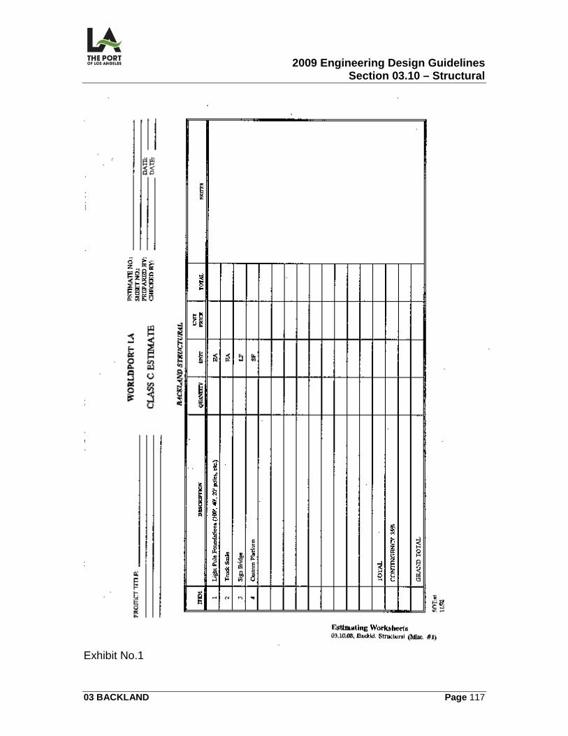
2009 Engineering Design Guidelines Section 03.10 – Structural
03 BACKLAND Page 117
Exhibit No.1
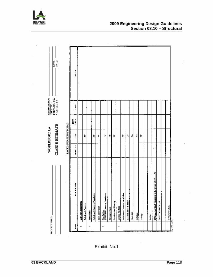
2009 Engineering Design Guidelines Section 03.10 – Structural
03 BACKLAND Page 118
Exhibit. No.1
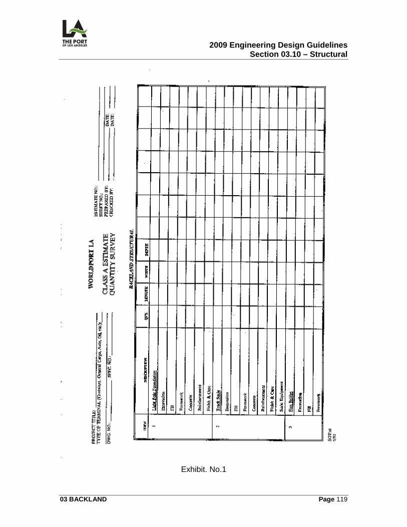
2009 Engineering Design Guidelines Section 03.10 – Structural
03 BACKLAND Page 119
Exhibit. No.1
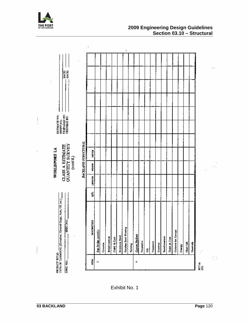
2009 Engineering Design Guidelines Section 03.10 – Structural
03 BACKLAND Page 120
Exhibit No. 1
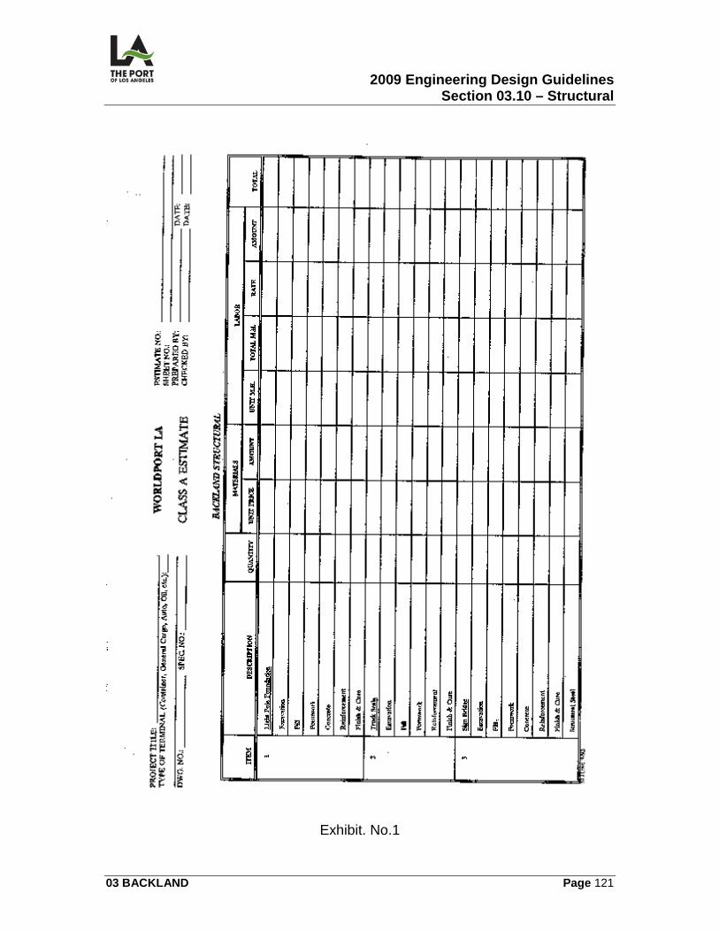
2009 Engineering Design Guidelines Section 03.10 – Structural
03 BACKLAND Page 121
Exhibit. No.1
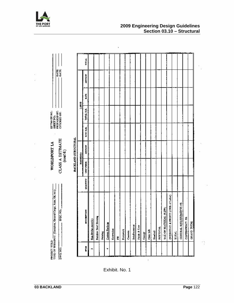
2009 Engineering Design Guidelines Section 03.10 – Structural
03 BACKLAND Page 122
Exhibit. No. 1
2009 Engineering Design Guidelines Section 03.11 – Mechanical
03 BACKLAND Page 123
03.11
MECHANICAL
03.11.01 OVERVIEW This section contains the following information related to the preparation of the mechanical contract drawings for:
• Above/Underground Storage Tank
• CNG and LNG Facilities
• Clarifiers
Drawings include but are not limited to:
• Site Plan (M)
• Storage Tank Plans, Notes, Abbreviations, and Legends (M)
• Details (M)
03.11.02 DESIGN CRITERIA Above/Underground Storage Tank Mechanical design shall be in compliance with Division 31, the latest editions of the Los Angeles City Fire Department Standard No. 68, and with the requirements of any other governmental regulatory agency having jurisdiction. Presently the design criteria in this section pertain primarily to the construction of above/underground storage tanks. Future editions of these Guidelines may contain information regarding additional backland mechanical designs. The designer should use the Mechanical Site Utilities Checklist to ensure that major areas pertaining to backland mechanical site utilities have been considered in the design.
1. Above Ground Storage Tanks
a) Construction of Tanks: Tanks shall be constructed in accordance with the provisions of Sec. 57.31.06.
2009 Engineering Design Guidelines Section 03.11 – Mechanical
03 BACKLAND Page 124
b) Tank Foundation and Supports: The foundation and supports for tanks shall comply with the provisions of Sec. 57.31.07. This section is not intended to prohibit the use of concrete, sand, or gravel pads of standard construction upon which large storage tanks are normally placed.
c) Tank Location shall be per Sec. 57.31.08.
d) Tank Spacing shall be per Sec. 57.31.09.
e) Control of Spills, Leaks and Overflows: The accidental discharge of
hazardous substances from aboveground tanks shall be diverted by means of a drainage system as provided in Section 57.31.11 or shall be contained by dikes as provided in Section 57.31.12. These provisions may be altered at the discretion of the Chief when the tanks under consideration do not constitute a hazard.
f) Tank Venting shall be per Sec. 57.31.13.
g) Grounding and Bonding: All aboveground tanks not inherently
grounded shall be electrically grounded or bonded as approved by the Chief.
h) Stairs, Walkways and Platforms: Stairs, walkways, catwalks, and
similar equipment on or adjacent to aboveground tanks or within dike walls shall be of noncombustible construction and in locations approved by the Chief.
i) Gauging Devices: Gauging devices for aboveground tanks shall be of
a type and design that will not continuously expose the vapor space above the liquid level in the tank, and will minimize liquid loss should the device be damaged mechanically or by fire.
j) Sources of Ignition: Sources of ignition shall not be within 25 feet of
any aboveground tank containing:
1) Class I liquids. 2) Class II or III liquids at temperature above their flashpoints unless
safeguarded as approved by the Chief.
k) Tanks Inside Buildings shall be per Sec. 57.31.18. l) Ventilation in Buildings which Tanks are located shall be done per Sec.
57.31.19.
2009 Engineering Design Guidelines Section 03.11 – Mechanical
03 BACKLAND Page 125
m) Reconditioning of Used Tanks: Tanks which are to be reconditioned or
abandoned by welding, cutting, or other “hot work” methods, shall be rendered gas-free before any welding or cutting operations are conducted. All operations in connection with the reconditioning of used tanks using such methods shall be executed under supervision of experienced personnel and in compliance with L.A.F.D. Standards No. 27 and 48.
n) Insulation: Atmospheric tanks containing hazardous materials may be
insulated by the application of insulating material approved by the Chief. Insulating materials shall be fire resistant and shall not decompose rapidly if exposed to fire.
o) Engine Fuel Tank shall be per Sec. 57.31.21.
p) Warning Placards and Signs shall be per Sec. 57.31.23.
q) Fire Protection for Tanks shall be per Sec. 57.31.24.
2. Underground Storage Tanks
a) New Underground Tank Requirement: Every new underground tank shall be provided with and meet the following minimum requirements:
1) Secondary containment in accordance with Section 57.31.33. 2) Construction, corrosion protection, and testing of underground
tanks in accordance with Section 57.31.34.
3) Approved release detection monitoring in accordance with Section 57.31.39.
(a) Requirements – Every underground tank shall be provided with
an automatic, continuous, electronic monitoring system designed and constructed to be capable of detecting the release of the stored hazardous substance.
(b) Approved Methods of Monitoring – Any or all of the following
methods of monitoring may be incorporated into a monitoring system:
(1) Secondary Containment Monitoring
2009 Engineering Design Guidelines Section 03.11 – Mechanical
03 BACKLAND Page 126
(2) Vadose Zone Monitoring
(3) Tank Level Monitoring
(4) Product Line Leak Detection
4) Approved spill and overfill prevention equipment in accordance with Section 57.31.42, Section 57.31.48, and Section 57.31.49.
b) Requirements for Existing: Every existing underground tank shall meet
the following minimum requirements by January 1, 1985:
1) Facility inspection evaluation in accordance with Section 57.31.36. 2) Integrity testing in accordance with Section 57.31.37. Results of
precision tests must be submitted to the Department within 90 days of the test to be considered current.
3) Soils investigation in accordance with Section 57.31.38.
(a) Site Assessment per Section 57.31.38.01.
4) Monitoring systems in accordance with Section 57.31.39. 5) Facility inspection and records in accordance with Section
57.31.40.
c) On or before December 22, 1998, the existing underground storage tank shall be replaced or upgraded to prevent unauthorized releases due to corrosion, spills, and overfills for the operating life of the underground storage tank.
d) Location of Underground Tanks shall be in accordance with Sec.
57.31.41.
e) Installation of Underground Tanks shall be in accordance with Sec. 57.31.42.
f) Venting of Underground Tanks shall be in accordance with Sec.
57.31.43.
g) Installation Inspection:
2009 Engineering Design Guidelines Section 03.11 – Mechanical
03 BACKLAND Page 127
Underground tanks, secondary containment, monitoring systems, and piping shall not be covered until the installation has been tested and approved by the Chief. Before the underground storage tank is placed in service, the underground storage systems shall be tested in operating condition using a precision test as defined in National Fire Prevention Association Pamphlet 329.
h) Suction Delivery System shall be in accordance with Sec. 57.31.45. i) Pressure Delivery System shall be in accordance with Sec. 57.31.46.
j) Unauthorized Release shall be in accordance with Sec. 57.31.47.
k) Ground Level Service Openings: All service openings at ground level
over or leading to the primary tank or secondary containment shall be so designed as to be liquid tight and not allow any drainage or contamination to enter through such opening and shall be installed a minimum of one inch above adjacent ground level.
l) Fill Box: Every fill box shall have a product identification label
attached. The fill box fixture shall have a capacity of not more than five gallons and all metallic components shall be appropriately grounded. The fill box or cap shall be capable of being locked.
m) Security of Access: Access to a facility shall be secured by fences
and/or locks or other equivalent protection approved by the Chief.
n) Temporarily Out of Service: Any underground storage tank which is temporarily out of service shall be monitored and inspected in the same manner as if it were in service.
o) Abandonment of Underground Tanks shall be in accordance with Sec.
57.31.52,
p) Repair of Underground Tanks shall be in accordance with Sec. 57.31.53.
q) Reinstallation shall be in accordance with Sec. 57.31.54.
r) Financial Responsibility shall be in accordance with Sec. 57.31.55.
s) Methanol Compatibility: At least one tank and all associated pipes and
equipment shall be compatible with methanol in accordance with
2009 Engineering Design Guidelines Section 03.11 – Mechanical
03 BACKLAND Page 128
AQMD rule 1170 when underground motor vehicle fuel storage tanks are installed or replaced.
t) Above/Underground Storage Tank Protection: Every owner or
operator in charge of any atmospheric tank which has an opening exceeding six inches in any lateral dimension or which has a depth in excess of three feet, shall secure the tank from unauthorized entry. Provisions shall be made to secure unauthorized discharge from any atmospheric tank by locking valves in a closed position or by providing and maintaining equivalent protection as approved by the Chief.
u) Above/Underground Storage Tank Heating Equipment
1) Tanks requiring application of heat may be heated by hot water, low
pressure steam coils within the tank, electrical heating units installed on the shell of the tank, or other method approved by the Chief.
2) When tanks require the heating of flammable or combustible
liquids, the provisions of Section 57.30.66 of this article shall apply.
v) Above/Underground Storage Tank Layout: The designer shall prepare a clearly detailed layout for each tank installation.
w) Above/Underground Storage Tank Checklist: The designer shall use
the Aboveground Storage Tank Checklist in Miscellaneous Exhibit No. 3 in 03.11.06 to help ensure that all the specific requirements related to tank installation have been met.
CNG and LNG Facilities Mechanical design for CNG facilities shall be in compliance with NFPA 52, NFPA 70, and NFPA 54, and as per manufacturer’s recommendations. Mechanical design for LNG facilities shall be in compliance with NFPA 220, NFPA 80, NFPA 59A, and NFPA 68, including fittings, valves, supports, and piping system, shall be per ASWE B31.3.
1. CNG Equipment: CNG equipment is available in two models: time fill and fast fill. They are manufactured by Fuel Maker Corporation located in Toronto, Canada. CNG equipment is available at 3000 psi and 3500 psi respectively, depending upon the model or the car being filled up. To avoid partial fill up of tanks during cold weather, a natural gas dryer is highly recommended.
2009 Engineering Design Guidelines Section 03.11 – Mechanical
03 BACKLAND Page 129
2. CNG Equipment Accessories: CNG equipment accessories such as
hoses, nozzle assembly, cylinders and control panel assembly, and others are available from the equipment supplier.
3. Venting of Equipment: Proper venting of equipment shall be observed,
especially when installing indoors.
4. Installation of Equipment: Equipment installation clearance on property lines and buildings is very strict and should be followed. Equipment can be installed out and indoors.
5. Natural Gas: Natural gas shall be required and be hooked to CNG
equipment with corresponding BTUs and pressures to satisfy the equipment needs. Please refer to section 3.12 for natural gas piping design.
6. Compressed Gas Tubing Materials: Compressed gas tubing material
shall be 0.035 wall 316 seamless stainless steel fittings and valves. All tubing and fitting shall be installed with proper support. Shut-off valve and relief valves shall be provided to repair the lines.
7. Electrical Work: Electrical work shall be required and design shall be
based on NFPA 70 and equipment requirement. Explosion-proof materials and emergency shut-off shall be required. It is the responsibility of the Electrical Engineer to provide what is required to operate the system.
8. Guard Posts: Guard posts shall be provided to protect the equipment and
its accessories from being hit by vehicles. Clarifiers
1. When Required: Interceptors (clarifiers), including grease, oil, and sand interceptors, etc.) shall be provided when, in the judgment of the Administrative Authority, they are necessary for the proper handling of liquid wastes containing grease, flammable wastes, sand, solids, acid or alkaline substances, or other ingredients harmful to the building drainage system, the public or private sewer, or to public or private sewage disposal.
2. Approval: The size, type, and location of each interceptor (clarifier) or
separator shall be approved by the Administrative Authority, in accordance with its standards.
2009 Engineering Design Guidelines Section 03.11 – Mechanical
03 BACKLAND Page 130
3. Design
a) Interceptors shall be constructed in accordance with the design
approved by the Administrative Authority and shall have a minimum of two compartments with fittings designed for grease retention.
b) There shall be an adequate number of manholes to provide access for
cleaning all areas of an interceptor. A minimum of one (1) per ten (10) feet (3048 mm) of interceptor length is required. Manhole covers shall be gastight in construction having a minimum opening dimension of twenty (20) inches (508 mm).
c) In areas where traffic may exist, the interceptor shall be designed to
have adequate reinforcement and cover.
4. Location: Each interceptor (clarifier) cover shall be readily accessible for servicing and maintaining the interceptor in working and operating condition. The use of ladders or the removal of bulky equipment in order to service interceptors (clarifiers) shall constitute a violation of accessibility. Location of all interceptors (clarifiers) shall be shown on the approved building plan.
5. Construction Requirements shall be per Appendix H on the California
Plumbing Code as amended by LA Plumbing Code Section H.105.0 as applicable
6. Relief Vent: Interceptors (clarifiers) shall be designed so that they will not become air bound if closed covers are used. Each interceptor (clarifier) shall be properly vented.
7. Maintenance of Interceptors: Interceptors shall be maintained in efficient
operating condition by periodic removal of accumulated grease, scum, oil, other floating substances, and solids deposited in the interceptor.
8. Discharge: The waste pipe from oil and sand interceptors shall discharge
as approved by the Administrative Authority.
03.11.03 CALCULATIONS/WORKSHEETS There are no calculations or worksheets provided for this section. The designer shall, however, prepare anchor system calculations and tank sizing calculations along with the plans for review (or submittal).
2009 Engineering Design Guidelines Section 03.11 – Mechanical
03 BACKLAND Page 131
The designer shall prepare all calculations on worksheets in compliance with POLA's Engineering Division's latest format. Check Lists Mechanical Site Utilities Checklist
1. Work to be done in project's mechanical specifications section 2. Work of other sections of the project's specifications
3. Codes and standards
4. Excavation and backfill
5. Pipe and/or conduit
6. Aboveground fuel/oil storage tanks
7. Foundation, supports, and concrete thrust blocks
8. Inspection and testing
9. Construction of manholes
10. Approval or rejection of work
11. Final inspection
12. Other
Permit/Compliance Process
1. Fire Department Permit (Division 31 and Standard No. 68 of L.A.F.D.) 2. State registration of tank
3. City of Los Angeles Department of Building & Safety Permit
4. A.Q.M.D. Rule 1170
General as applicable
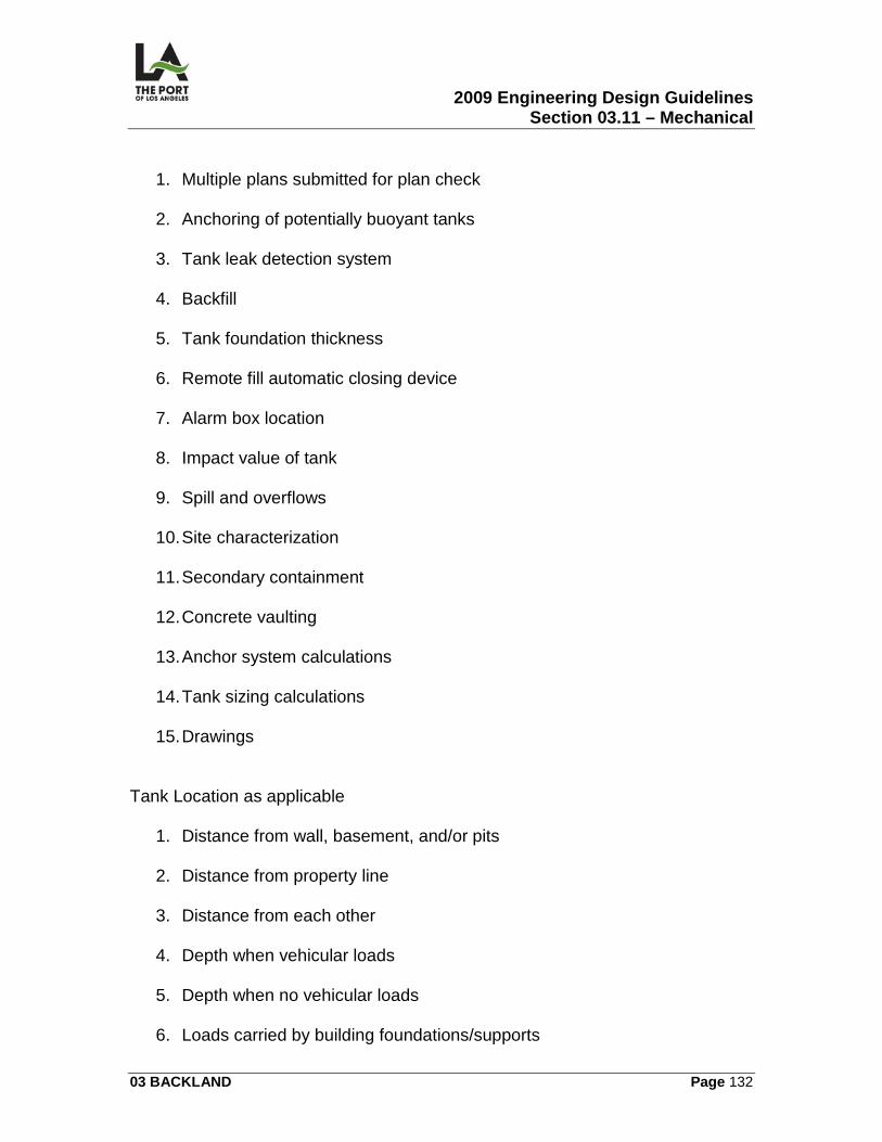
2009 Engineering Design Guidelines Section 03.11 – Mechanical
03 BACKLAND Page 132
1. Multiple plans submitted for plan check 2. Anchoring of potentially buoyant tanks
3. Tank leak detection system
4. Backfill
5. Tank foundation thickness
6. Remote fill automatic closing device
7. Alarm box location
8. Impact value of tank
9. Spill and overflows
10. Site characterization
11. Secondary containment
12. Concrete vaulting
13. Anchor system calculations
14. Tank sizing calculations
15. Drawings
Tank Location as applicable
1. Distance from wall, basement, and/or pits 2. Distance from property line
3. Distance from each other
4. Depth when vehicular loads
5. Depth when no vehicular loads
6. Loads carried by building foundations/supports
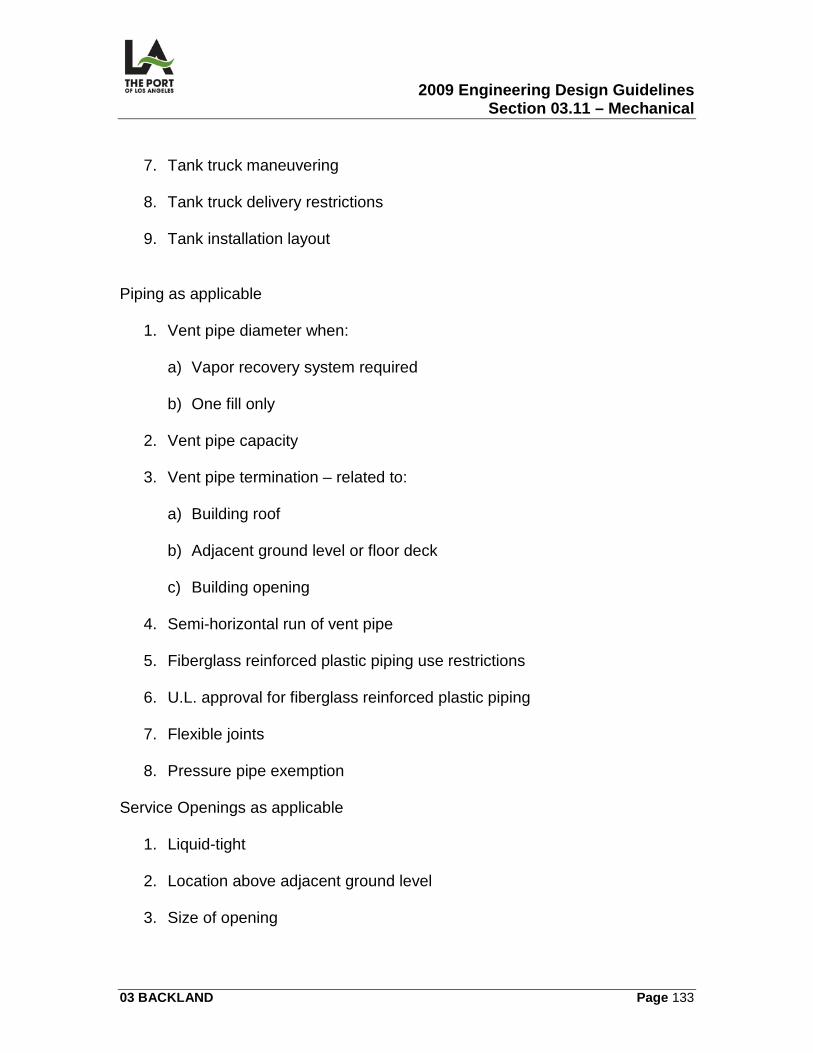
2009 Engineering Design Guidelines Section 03.11 – Mechanical
03 BACKLAND Page 133
7. Tank truck maneuvering
8. Tank truck delivery restrictions
9. Tank installation layout
Piping as applicable
1. Vent pipe diameter when:
a) Vapor recovery system required b) One fill only
2. Vent pipe capacity 3. Vent pipe termination – related to:
a) Building roof b) Adjacent ground level or floor deck
c) Building opening
4. Semi-horizontal run of vent pipe 5. Fiberglass reinforced plastic piping use restrictions
6. U.L. approval for fiberglass reinforced plastic piping
7. Flexible joints
8. Pressure pipe exemption
Service Openings as applicable
1. Liquid-tight 2. Location above adjacent ground level
3. Size of opening
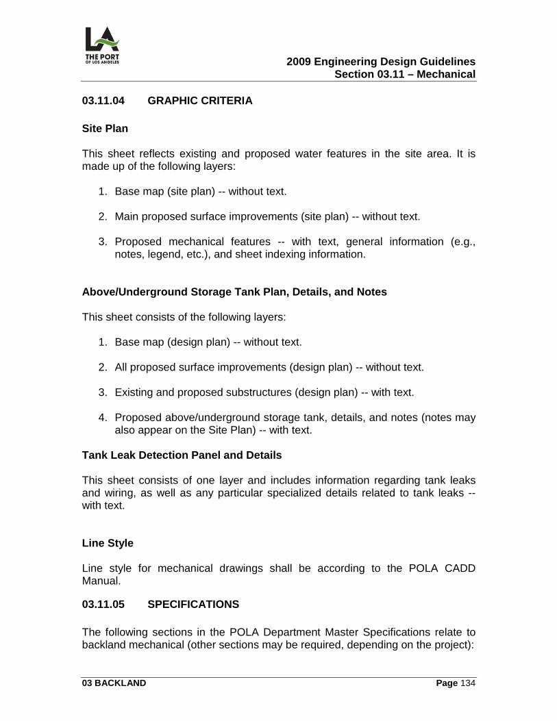
2009 Engineering Design Guidelines Section 03.11 – Mechanical
03 BACKLAND Page 134
03.11.04 GRAPHIC CRITERIA Site Plan This sheet reflects existing and proposed water features in the site area. It is made up of the following layers:
1. Base map (site plan) -- without text. 2. Main proposed surface improvements (site plan) -- without text.
3. Proposed mechanical features -- with text, general information (e.g.,
notes, legend, etc.), and sheet indexing information. Above/Underground Storage Tank Plan, Details, and Notes This sheet consists of the following layers:
1. Base map (design plan) -- without text. 2. All proposed surface improvements (design plan) -- without text.
3. Existing and proposed substructures (design plan) -- with text.
4. Proposed above/underground storage tank, details, and notes (notes may
also appear on the Site Plan) -- with text. Tank Leak Detection Panel and Details This sheet consists of one layer and includes information regarding tank leaks and wiring, as well as any particular specialized details related to tank leaks -- with text. Line Style Line style for mechanical drawings shall be according to the POLA CADD Manual.
03.11.05 SPECIFICATIONS The following sections in the POLA Department Master Specifications relate to backland mechanical (other sections may be required, depending on the project):
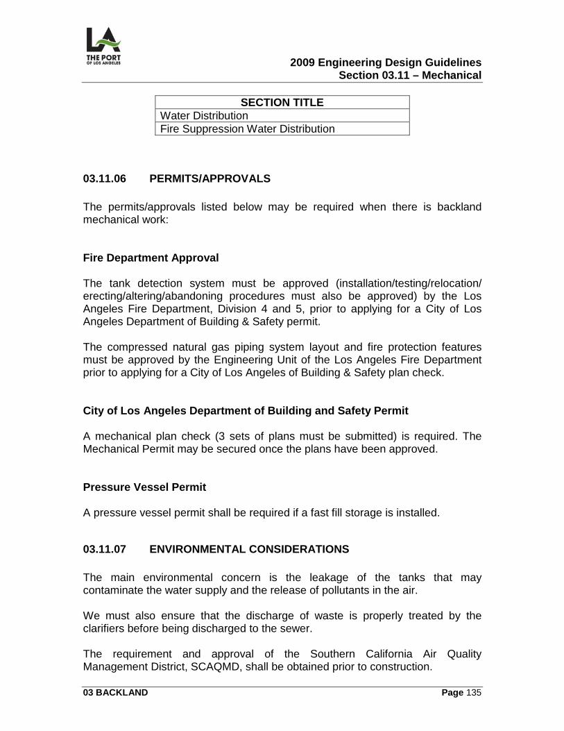
2009 Engineering Design Guidelines Section 03.11 – Mechanical
03 BACKLAND Page 135
SECTION TITLE Water Distribution Fire Suppression Water Distribution
03.11.06 PERMITS/APPROVALS The permits/approvals listed below may be required when there is backland mechanical work: Fire Department Approval The tank detection system must be approved (installation/testing/relocation/ erecting/altering/abandoning procedures must also be approved) by the Los Angeles Fire Department, Division 4 and 5, prior to applying for a City of Los Angeles Department of Building & Safety permit. The compressed natural gas piping system layout and fire protection features must be approved by the Engineering Unit of the Los Angeles Fire Department prior to applying for a City of Los Angeles of Building & Safety plan check. City of Los Angeles Department of Building and Safety Permit A mechanical plan check (3 sets of plans must be submitted) is required. The Mechanical Permit may be secured once the plans have been approved. Pressure Vessel Permit A pressure vessel permit shall be required if a fast fill storage is installed.
03.11.07 ENVIRONMENTAL CONSIDERATIONS The main environmental concern is the leakage of the tanks that may contaminate the water supply and the release of pollutants in the air. We must also ensure that the discharge of waste is properly treated by the clarifiers before being discharged to the sewer. The requirement and approval of the Southern California Air Quality Management District, SCAQMD, shall be obtained prior to construction.
2009 Engineering Design Guidelines Section 03.11 – Mechanical
03 BACKLAND Page 136
03.11.08 REFERENCE DRAWINGS The following contract drawings are identified for reference: 1-2702 UST Installation @ Berth 161
1-2702 T-1 Project Site Plan/Location Map 1-2702 M-0 Site Plan 1-2702 M-1 to 10 Mechanical plans and details
LAHD Standard Plans
2009 Engineering Design Guidelines Section 03.12 – Gas
03 BACKLAND Page 137
03.12
GAS
03.12.01 OVERVIEW This section contains the following information related to the preparation of backland gas contract drawings:
• Gas Site Plan (G)
• Gas System Plans (G)
• Gas System Details (G)
03.12.02 DESIGN CRITERIA General Design Requirements Systems design shall be in compliance with:
1. Los Angeles City Plumbing Code (latest edition). 2. Los Angeles City Fire Code (latest edition).
Depth of Cover Gas lines shall have a minimum cover of 4 feet. New Gas Services The designer shall coordinate with the Southern California Gas Company for the location of new gas meters at the onset of design. Southern California Gas Company usually provides meters and gas regulators and Harbor Department installs earthquake valves and additional gas regulators as required.
Letter From the Gas Company A letter from the Gas Company shall be obtained indicating whether or not the gas demand can be met, once the gas requirement is identified. Telephone No. (310) 605 4175.
2009 Engineering Design Guidelines Section 03.12 – Gas
03 BACKLAND Page 138
Shut-Off Valves The gas systems shall have shut-off valves installed before gas regulators and earthquake valves. Gas Regulator and Earthquake Valve Gas regulator and earthquake valve for gas service shall be approved by L.A. City Building & Safety. Gas Piping Materials Materials for the fire gas piping system shall be U.L. listed or be tested and approved by the City of Los Angeles Department of Building & Safety. It shall be the designer's responsibility during the plan check period to obtain variance for those items specified which are not approved by the City of Los Angeles Department of Building & Safety. Corrosion Protection Metal pipes (above or below ground) shall be protected against corrosion. Underground steel piping shall be coated and wrapped with PVC. Gas Flow Total gas flow demand shall be based on total flow requirement and pressure required shall be based on individual gas equipment. Piping Materials The following materials are used:
1. Steel Pipe. Black steel pipe welded or threaded schedule 40 minimum per ASTM A53B.
2. Polyethylene Yellow PE 2406-SDR11/11.5 per ASTM D 2513.
Valves for Gas Piping Systems
2009 Engineering Design Guidelines Section 03.12 – Gas
03 BACKLAND Page 139
Buried valves for gas piping systems shall be butterfly or plug, ductile iron or cast iron with position indicator.
03.12.03 CALCULATIONS/WORKSHEETS Calculations and worksheets shall be prepared in accordance with Department of Building & Safety requirements. The designer shall prepare all calculations on worksheets in compliance with POLA's Engineering Divisions latest format.
03.12.04 GRAPHIC CRITERIA Site Plan This sheet reflects existing and proposed gas features in the site area. It is made up of the following layers:
1. Base map (site plan) -- without text. 2. Main proposed surface improvements (site plan) -- without text.
3. Proposed gas features -- with text, general information (e.g., notes,
legend, etc.), and sheet indexing information. Gas Systems Plan This sheet will contain specific information necessary to construct the water system. It consists of the following layers:
1. Base map (design plan) -- without text. 2. All proposed surface improvements (design plan) -- without text.
3. Existing and proposed substructures (design plan) -- with text.
4. Proposed gas system -- with text.
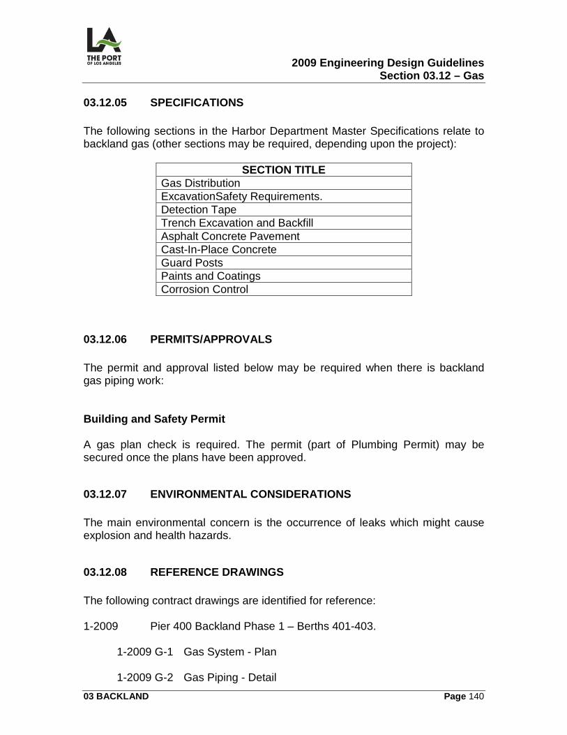
2009 Engineering Design Guidelines Section 03.12 – Gas
03 BACKLAND Page 140
03.12.05 SPECIFICATIONS The following sections in the Harbor Department Master Specifications relate to backland gas (other sections may be required, depending upon the project):
SECTION TITLE Gas Distribution ExcavationSafety Requirements. Detection Tape Trench Excavation and Backfill Asphalt Concrete Pavement Cast-In-Place Concrete Guard Posts Paints and Coatings Corrosion Control
03.12.06 PERMITS/APPROVALS The permit and approval listed below may be required when there is backland gas piping work: Building and Safety Permit A gas plan check is required. The permit (part of Plumbing Permit) may be secured once the plans have been approved.
03.12.07 ENVIRONMENTAL CONSIDERATIONS The main environmental concern is the occurrence of leaks which might cause explosion and health hazards.
03.12.08 REFERENCE DRAWINGS The following contract drawings are identified for reference: 1-2009 Pier 400 Backland Phase 1 – Berths 401-403.
1-2009 G-1 Gas System - Plan 1-2009 G-2 Gas Piping - Detail
2009 Engineering Design Guidelines Section 03.12 – Gas
03 BACKLAND Page 141
1-2206 Pier 400 Transportation Corridor South
1-2206 G-12 Gas Main Plan and Section LAHD Standard Plans
2009 Engineering Design Guidelines Section 03.13 – Water
03 BACKLAND Page 142
03.13
WATER
03.13.01 OVERVIEW This section contains information related to the preparation of the following backland water contract drawings (see Contract Drawings Exhibit Nos. 1-3 in 03.12.08):
• Site Plan (W)
• Water Systems Plan (W)
• Water Systems Details (W)
03.13.02 DESIGN CRITERIA General Design Requirements Water system design shall be in compliance with:
1. Los Angeles City Plumbing Code (latest edition). 2. Los Angeles City Fire Code (latest edition).
3. Regulations governing the control and cross connection promulgated by
D.W.P. (The water purveyor may occasionally be other than D.W.P. When this occurs, all coordination, approvals, etc., shall be done with that purveyor instead of with D.W.P.).
Depth of Cover Water lines shall have a minimum cover of 4 feet. New Water Services The designer shall coordinate with D.W.P. for the location of new water meters at the onset of design. D.W.P. usually provides and installs water meters to match the backflow preventer installed by the Harbor Department.
2009 Engineering Design Guidelines Section 03.13 – Water
03 BACKLAND Page 143
Shut-Off Valves The water system shall have shut-off valves at locations of "T's" for proposed building taps and all fire hydrants. Backflow Preventers Backflow preventers for water systems shall be approved by D.W.P. and:
1. Be the reduced pressure type. 2. Have the lowest pressure loss at rated flow for the selected size.
3. Be installed contiguous to the meter by means of valves (unless otherwise
approved by D.W.P.).
4. Be installed above grade. Fire Protection Materials Materials for the fire protection system shall be U.L. listed or tested and approved by Bldg. & Safety. It shall be the designer's responsibility during the plan check period to obtain variance for those items specified which are not approved by Bldg. & Safety. Corrosion Protection Metal pipes (above or below ground) shall be protected against corrosion. Specific requirements follow:
1. Underground piping shall be provided with corrosion protection by use of polyethylene film encasement in full accordance with A.W.W.A. (American Water Works Association) C105, "Polyethylene Encasement for Ductile Iron Piping for Water Standards."
2. Corrosion protection shall terminate no less than 12 inches above the
adjacent finished surface.
3. Copper pipes penetrating through concrete shall be provided with sleeves to prevent contact between pipe and concrete.
2009 Engineering Design Guidelines Section 03.13 – Water
03 BACKLAND Page 144
4. Underground pipes 4 inches or more in diameter shall be laid on sand bedding. This bedding depth shall be no less than the difference between the radii of the pipe and the pipe joint.
Fire Hydrant Location
1. Distance Between Hydrants. The maximum distance between hydrants shall be 400 feet when located at the ends of container rows and adjacent to light standards (or as otherwise approved by the Fire Department).
2. Location Indicator. Fire hydrants adjacent to light poles are indicated by a
3 foot wide red band painted around the pole shaft 40 feet above ground. Fire Flow Total fire flow demand and minimum residual pressure required of a fire protection system shall be obtained from the Los Angeles Fire Department. Piping Materials
1. Ductile Iron. Ductile iron, Class 52, manufactured per A.W.W.A. C151, shall be used for underground pipes at least 4 inches in diameter. The pipes shall be lined with cement mortar mechanical joints or push-on joints.
2. Steel. Steel, Schedule 40, and manufactured per A.S.T.M. 139-90 with
flanged joint, shall be used for above ground pipes at least 4 inches in diameter.
3. Copper. Pipes smaller than 4 inches shall be copper, Type K, with silver
solder joints. Valves for Fire Protection Systems Buried valves for fire protection systems shall be resilient wedge gate, N.R.S. (non-rising stem) and shall be provided with a valve box and position indicator or a post indicator, whichever is practical. Above ground valves shall be O.S.& Y. (outside stem and yoke). Fire hydrant control valves are not provided with a position indicator or post indicator.
2009 Engineering Design Guidelines Section 03.13 – Water
03 BACKLAND Page 145
Thrust Blocks Information on thrust block details can be found in Reference Drawing 1-2209 W-37.
03.13.03 CALCULATIONS/WORKSHEETS Calculations and worksheets for pipe sizes shall be prepared in accordance with Fire Flow Calculations.in 3.13.08. Estimating Estimating worksheets shall be prepared in accordance with POLA Engineering Division’s latest format. Service Advisory Report Once the location of new water meters has been determined, the Service Advisory Report (SAR) can be requested from DWP. This is necessary for executing fire flow calculations, as it includes a pressure vs. flow chart for designated locations along DWP mains.
03.13.04 GRAPHIC CRITERIA Site Plan This sheet reflects existing and proposed water features in the site area. It is made up of the following layers:
1. Base map (site plan) -- without text. 2. Main proposed surface improvements (site plan) -- without text.
3. Proposed water features -- with text, general information (e.g., notes,
legend, etc.), and sheet indexing information.
2009 Engineering Design Guidelines Section 03.13 – Water
03 BACKLAND Page 146
Water Systems Plan This sheet will contain the specific information necessary to construct the water system. It consists of the following layers:
1. Base map (design plan) -- without text. 2. All proposed surface improvements (design plan) -- without text.
3. Existing and proposed substructures (design plan) -- with text.
4. Proposed water system -- with text.
Water Systems Details This sheet consists of one layer and includes any particular specialized details (e.g., connections, fire hydrant, pipe protection, bends, and water line sections) -- with text. Line Style Line style for backland water drawings shall be as required by the POLA/CADD Manual.
03.13.05 SPECIFICATIONS The following sections in the Harbor Department Master Specifications relate to backland water (other sections may be required, depending on the project):
SECTION TITLE Fire Service System Water System
03.13.06 PERMITS/APPROVALS The permit and approval listed below may be required when there is backland water work: Fire Department Approval
2009 Engineering Design Guidelines Section 03.13 – Water
03 BACKLAND Page 147
The water system layout and fire protection features must be approved by the Hydrant Unit of the Los Angeles Fire Department prior to applying for a Bldg. & Safety Permit. Building and Safety Permit A water system plan check is required. The permit (part of Plumbing Permit) may be secured once the plans have been approved.
03.13.07 ENVIRONMENTAL CONSIDERATIONS The main concern is the disposal of contaminated water after cleaning and testing of newly installed piping. It is mandatory that this contaminated water will not spill to the storm drain system and discharge to the channel.
03.13.08 REFERENCE DRAWINGS The following exhibits are included as an example: 1-2209 Pier 400 Backland Phase 1 – Berths 401-403
1-2209 W-1 Water System Plan
1-2209 W-2 to 34 Water System Plan 1-2209 W-36 to 38 Water System Section and Details
LAHD Standard Plans Calculations/Worksheets Fire Flow Calculations
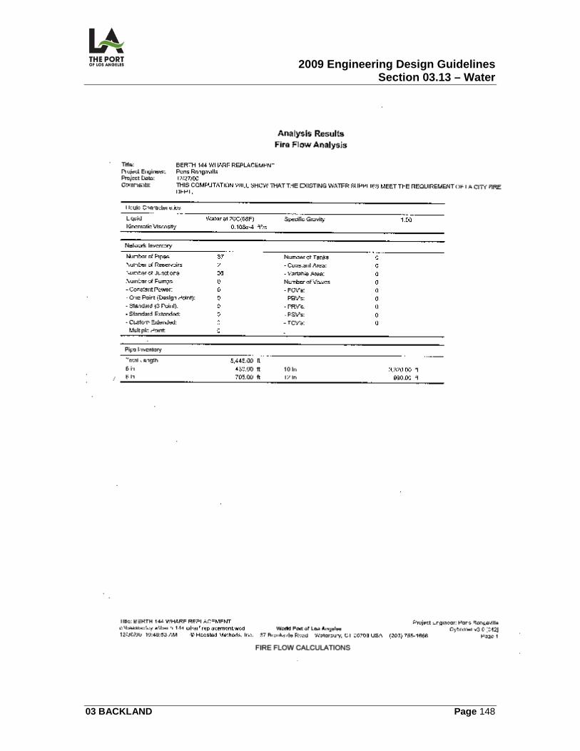
2009 Engineering Design Guidelines Section 03.13 – Water
03 BACKLAND Page 148
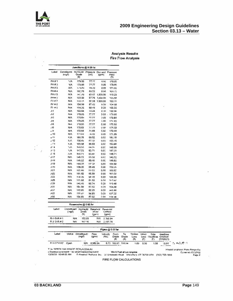
2009 Engineering Design Guidelines Section 03.13 – Water
03 BACKLAND Page 149
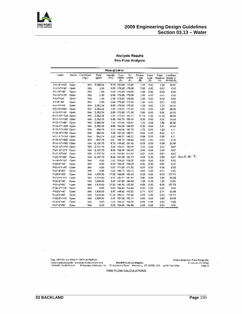
2009 Engineering Design Guidelines Section 03.13 – Water
03 BACKLAND Page 150
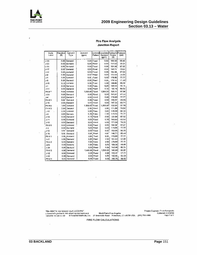
2009 Engineering Design Guidelines Section 03.13 – Water
03 BACKLAND Page 151
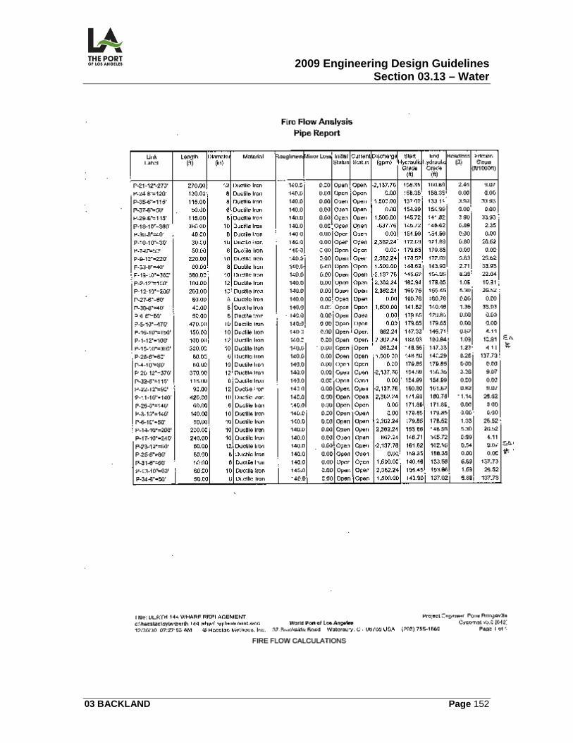
2009 Engineering Design Guidelines Section 03.13 – Water
03 BACKLAND Page 152
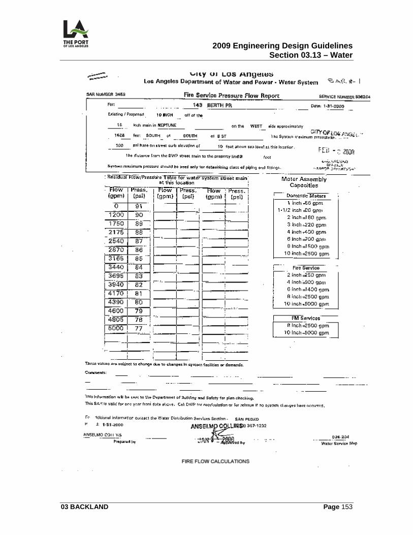
2009 Engineering Design Guidelines Section 03.13 – Water
03 BACKLAND Page 153
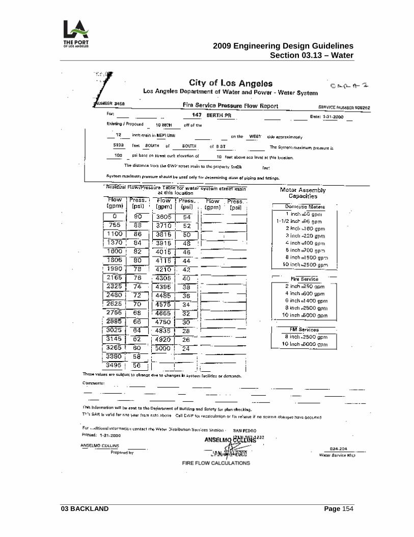
2009 Engineering Design Guidelines Section 03.13 – Water
03 BACKLAND Page 154
2009 Engineering Design Guidelines Section 03.13 – Water
03 BACKLAND Page 155
2009 Engineering Design Guidelines Section 03.14 – Electrical
03 BACKLAND Page 156
03.14
ELECTRICAL
03.14.01 OVERVIEW This section contains information related to the preparation of the following backland electrical contract drawings.
• Electrical Notes, Symbols, and Abbreviations (E)
• Electrical Site Plan (E)
• Single Line Diagrams (E)
• D.W.P. Substation Plan and Details (E)
• Pullbox and Maintenance Hole Schedules and Details (E)
• Electrical Conduit Details (E)
• Substation Equipment Foundation (E)
• Sign Bridge Plan and Details (E)
• Truck Scale Plan and Details (E)
• Automatic Equipment Identification Plan and Details (E)
• Intercom Pedestal Plan and Details (E)
• Load and Panelboard Schedules (E)
• Washdown & Pretrip Electrical Plan (E)
03.14.02 DESIGN CRITERIA Required Services The designer should check whether any of the following are required:
1. Public address service
2009 Engineering Design Guidelines Section 03.14 – Electrical
03 BACKLAND Page 157
2. Telephone system
3. Computer System
4. Electrical service and wiring for landscaping
5. High voltage >600V
6. Fiber optics
7. Security system
8. Video system
9. Underground (utility and distribution) detection system
10. Cable TV
11. Communications General Design Requirements Electrical designs shall be in compliance with the latest edition of the Los Angeles City Electrical Code. Utilities
1. Removal or Relocation – It should be determined whether existing DWP power poles or SBC telephone poles are to be removed or relocated.
2. Time and Materials Accounting – Separate accounting for time and
materials should be maintained when planning DWP pole and appurtenance relocations (to be used for shared costs).
3. Overhead Service Bracket – For overhead service, it should be verified
whether or not DWP will provide a service bracket (no cost to Harbor Department).
4. Substation Grounding – For substation grounding, counterpole grounding
shall be provided where the DWP station fence is within 18 inches of the customer substation fence. It is a DWP requirement that the customer station fence not touch their station fence, unless this grounding is provided.
2009 Engineering Design Guidelines Section 03.14 – Electrical
03 BACKLAND Page 158
5. Ground Grid System Access – Access to the ground grid system at the
substation shall be provided if future switchgear is expected to be installed.
Street Light/Traffic Signals See SPECIAL FACILITIES Section – Streets (6.01) in these Guidelines. High Mast Light When stubbing the telephone and PA system at the pole pedestal, there must be sufficient room on the pedestal; stubbing outside the pedestal should be considered. Non-Lighting Loads on Lighting Poles For non-lighting loads such as security cameras, monitoring devices, and other systems which will be mounted on light poles, the light pole power circuits shall not be used to feed nonlighting loads. A separate circuit must be installed from the nearest panel to the light pole to provide the necessary power for nonlighting loads. Nonlighting loads mounted on light poles shall not be screwed or penetrate or be welded to light poles. Mounting shall be done by strapping. Landscape Irrigation System Conduit and wire systems shall be used for wiring the controllers in the landscape sprinkler system. Direct burial type wiring is not acceptable. Single Line Diagram Short Circuit Analysis – A short circuit analysis shall be done of all electrical systems, stating all available short circuit currents on the single line diagram for all switchboards, panelboards, and any major equipment used. Arc Flash Hazard Analysis – An arc flash hazard analysis shall be done of the entire electrical system stating the arc flash ratings and boundaries for all switchboards, panelboards, and any major electrical power distribution equipment used.

2009 Engineering Design Guidelines Section 03.14 – Electrical
03 BACKLAND Page 159
2009 Engineering Design Guidelines Section 03.14 – Electrical
03 BACKLAND Page 160
DWP Service Utility Vault Requirements Utility vault requirements shall be transferred in full onto the contract drawings. Light Poles Near Wharf When setting poles near a wharf, there shall be no horizontal or vertical interferences with the back reach of the container cranes. The minimum clear space is 200 feet from the face of the wharf to the center of the light pole. Additional clearance may be required for specific crane backreach space requirements. Coordinate with Crane Specifications. Reefers
1. Grade Installation – Reefers shall not be installed below grade (to prevent infiltration of water).
2. Monitoring – Conduits shall be installed for remote monitoring of reefers
during the development of a large terminal.
3. Receptacle Assemblies – The receptacle assemblies for reefer outlets shall be manufactured as follows:
a) The enclosure shall be welded, watertight construction; 11 gauge
stainless steel front and bottom; 14 gauge stainless steel sides, back, and top.
b) All fasteners and hardware shall be stainless steel.
c) The interlocking power receptacle and circuit breaker module shall be
interchangeable and manufactured by E.S.L. Power Systems, Inc.
d) All internal wiring and connections shall be factory wired.
e) One whole side of the box shall be removable to provide access to internal parts (required by the City of Los Angeles Department of Building & Safety.)
f) A metal nameplate shall be installed on each receptacle pedestal
showing the switchboard and circuit number (e.g., DBA-1M, DBB-2, etc.).
2009 Engineering Design Guidelines Section 03.14 – Electrical
03 BACKLAND Page 161
g) Reefer outlets shall be rated for 480v, 3, 32 AMP receptacle w/30 AMP trip circuit breaker. Designer shall specify the short circuit withstand rating in accordance with specific project requirements.
Pull Boxes
1. Detail – Detail for grounding pull box covers shall be shown as required by the City of Los Angeles Department of Building & Safety.
2. Maintenance Hole Covers – Maintenance hole covers do not have to be
bonded to the ground as long as the ring is metallic and bonded. If the ring is concrete, then the cover needs to be bonded. Decision is to be made by Principal Electrical Inspector at the City of Los Angeles Department of Building & Safety.
3. Loads – Grounding pull boxes and covers shall be able to withstand 100
kip wheels plus 25% impact loading and shall be similar in shape to the City of Los Angeles standard plans or like structures.
Outdoor Lighting
1. Point by Point Calculations – Point by point calculations shall be done for outdoor lighting; as any other method does not provide satisfactory results.
2. Computer Printout – Where lighting of outdoors is involved in a design, a
computer printout of the final lighting arrangement shall be obtained from the light fixture manufacturer.
3. Control Wiring – Drawings shall include control wiring for security and
general lighting. Excess Cabling Charge An excess cabling charge for cable exceeding 150 feet shall be paid to DWP by the Harbor Department with an Interdepartmental Order. Meter Sockets Meter sockets are rated a minimum of 10,000 AIC. The specified rating of meter sockets must not be less than the available short circuit.
2009 Engineering Design Guidelines Section 03.14 – Electrical
03 BACKLAND Page 162
Main Breakers When no single main breaker exists, there shall be no more than six breakers at any panelboard. Concrete Pad The concrete pad shall be extended in front of a switchboard by a minimum of 3 feet (preferably 4 feet), especially where DWP has to install their service meter (the 3 foot dimension of the concrete pad may have to be increased as required by code). Crane Emergency Disconnect Button A glass cover shall be used over a crane emergency disconnect button at all locations. DWP Substation Plans/Details Upon request by the designer, DWP will provide substation plans and details. The designer shall modify them to conform to the Harbor Department and specific job location requirements. Crane Bus Crane bus plans and details shall include the crane bus emergency shunt trip and ground fault detection system Lighting Fixtures Lighting fixtures reference shall be complete and of itself. Following are examples of how references should be made (with an incorrect sample in parenthesis, if appropriate):
1. Fixture type "A" = 40 foot steel pole, double arm, with two 400W. H.P.S. (high pressure sodium) lamps.
2. Fixture type "B" = 40 foot steel pole, double arm, with one 400W H.P.S.
lamp (rather than "similar to 'A', except with one 400 W. H.P.S. lamp").
2009 Engineering Design Guidelines Section 03.14 – Electrical
03 BACKLAND Page 163
3. Fixture type "C" = 40 foot steel pole, double arm, with two 400W. Metal
Halide lamps (rather than "similar to 'B', except with metal Halide lamps").
4. Fixture type "D" = 30 foot steel pole, double arm, with two 400W. Metal Halide lamps (rather than "similar to 'C', except 30 foot pole and 2 Metal Halide lamps").
Panelboard Schedule A separate electrical panelboard schedule shall be shown for each and every panelboard, even if they are identical. Each panelboard shall also be identified by its own unique name (e.g., Panelboard A and Panelboard B). Wiring All circuit conductors shall be copper with type THHN/THWN insulations, 600V rating for all conductors. Equipment grounding conductors shall be sized adequately to withstand short circuits. Conduits
1. Location – No changes from the design of horizontal, vertical, or underground conduit shall be made without first obtaining permission from the Chief Harbor Engineer. The contractor's "as-built" prints must show all changes in conduit positioning and depth.
2. Materials
a) All underground conduits shall be non-metallic P.V.C. unless noted
and installed in accordance with code requirements. b) The terminating 10 feet of all non-metallic conduit (measured from the
finished surface) shall be rigid metal conduit with bonded 40 mil P.V.C. coating manufactured by KORKAP, CARLON, or an approved equal.
c) All P.V.C. conduits shall be Schedule 40, unless otherwise noted.
3. Underground Conduit Bends
a) All underground conduit bends, except at the termination of a conduit run, shall be Schedule 80.
2009 Engineering Design Guidelines Section 03.14 – Electrical
03 BACKLAND Page 164
b) In installing non-metallic P.V.C. conduits underground, all bends of 30
degrees and over shall be Schedule 80.
4. Minimum Depth - The minimum depth of direct burial conduits shall be 3 feet, 6 inches from the finished surface, unless otherwise noted.
5. Grounding – The Contractor shall ground all electrical equipment and
conduit systems to meet code requirements.
6. Buried Stub-Outs – All underground conduit buried stub-outs shall be finished with concrete monuments 6 inches x 6 inches x 15 inches deep buried flush with the finished surface over the capped ends and a 3 inch square brass plate identifying the number and sizes of conduits.
7. Detection Tape – Detection tape shall be used over all conduits.
Metal Nameplate A metal nameplate shall be provided for all electrical equipment. The nameplate shall list equipment operating parameters. Ground Fault Protection Ground fault protection shall protect circuit line wiring from line to ground short circuiting with a response time documented by calculations.
03.14.03 CALCULATIONS/WORKSHEETS Calculations and worksheets shall be prepared in accordance with City of Los Angeles Department of Building & Safety requirements and POLA Engineering Design Staff. The designer shall prepare all calculations on worksheets in compliance with POLA's Engineering Division's latest format. Panelboard
2009 Engineering Design Guidelines Section 03.14 – Electrical
03 BACKLAND Page 165
When installing a 480V panelboard, a 277/480V 3 phase/4W panelboard shall be considered as a first choice. Note that 480V 3 phase/3W panelboards are not readily available. Powerlink Panels and Circuit Breaker Panelboards controlling lighting system shall be Square D powerlink panels with powerlink circuit breakers.
03.14.04 GRAPHIC CRITERIA The Graphic criteria for Backland electrical design set shall include, but not be limited to, the following. The sheets shall be arranged with the general order as prescribed herein. Additional sheets may be inserted in the electrical design package as necessary.
• Notes, Symbols, Key Map, Abbreviations
• Overall Electrical Site Plan – show overall conduit run, switchgear
locations, light pole locations, wharf electrical box locations, AMP box
location(s), etc.
• Single Line Diagram, Load Schedules, Worst Case Voltage Drop
Calculations
• Power Plans (Show power plan for the Backland)
• Reefer power plans
• Reefer Single Line diagrams, load schedule, substation layout, equipment
schedule
• Reefer outlet design sheet
• Concrete pull box design sheet
• Lighting Plans Fixture Schedule, Lighting System Details
2009 Engineering Design Guidelines Section 03.14 – Electrical
03 BACKLAND Page 166
• Typical wharf section showing electrical conduit run and expansion joint
design
• Switchgear equipment layout, fencing, conduit layout, and grounding grid
• AMP outlet design details, box elevation, connector details
• Miscellaneous Electrical details – Switchgear pad layout, switchgear
elevation, pull box details, grounding details, guard post detail,
underground conduit section, underground conduit stub up detail,
• Panel Schedule
• DWP service entrance design and Industrial Station (IS) equipment layout
03.14.05 SPECIFICATIONS
SECTION TITLE Basic Electrical Materials and Methods Grounding System Field Tests High Voltage Testing 5 Kilovolt Rated Shielded Cable 600 Volt or Less Wiring System Crane Conductor Bus Conduit Raceways Rigid Galvanized Steel Conduit PVC Conduit Outlet, Junction, and Pull Boxes Concrete Pullboxes Reefer Pedestals and Receptacles Service Meter Transformers 4160 Volt Switchgear Low Voltage Switchboard Panelboard Electrical Backboard Lighting Interior Luminaries
2009 Engineering Design Guidelines Section 03.14 – Electrical
03 BACKLAND Page 167
Bus Bars Panelboards/switchboard bus bars shall be of 100% copper. Splices A note shall be added in the specifications that says, "All high voltage splices and terminations must be inspected by the Port of Los Angeles Inspector from the beginning of the splice work to its conclusion." High voltage cable installation shall be supervised by a cable manufacturer's representative. Luminaires
1. Effective Projected Area – A note shall be added in the specifications that "Luminaires" support system is capable of handling the wind loads designated in the specifications with luminaires' effective projected area (E.P.A.) of 3.5 square feet minimum (or use actual E.P.A. if greater than 3.5 square feet)."
2. Alloy Content – The copper content of the aluminum alloy must be less
than .50%.
03.14.06 PERMITS/APPROVALS The permit and approval listed below may be required when there is backland electrical work: Department of Water and Power Approval The designer is responsible for coordinating with and securing approval from DWP for the type of service and service location. Subsequently, the contractor shall obtain approval for the service panelboard, switchboard, meter, or any equipment installation necessary for electrical service. The DWP Design Engineer shall be notified two working days in advance of construction. Department of Building & Safety Permit
1. Plan Check –An electrical plan check is required per California Electrical Code Section. Examples of when a plan check is required are as follows:
2009 Engineering Design Guidelines Section 03.14 – Electrical
03 BACKLAND Page 168
a) A disconnecting means exceeding 600 amperes. b) The additional loads exceed 600 amperes.
2. Electrical Equipment – All electrical equipment must be approved by the
City of Los Angeles Department of Building & Safety or a variance obtained.
3. Permit – The electrical permit may be secured by a C-10 contractor once
the plans have been approved.
4. Foundation Report – A foundation report for each light pole foundation is required to obtain a City of Los Angeles Department of Building & Safety permit (a separate report should be requested from the Testing Lab for each light pole foundation).
03.14.07 ENVIRONMENTAL CONSIDERATIONS
1. Alternative Maritime Power (AMP) system shall be designed to provide shore to ship electrical connection facility.
2. AMP connection voltage shall be 6.6kv, 3, 60Hz.
3. Each AMP vault shall include two 350a amp sockets with 3 phases, two
pilot pins and provision of fiber optic connection.
4. Each amp vault shall be fed by a feeder circuit breaker located in a switchboard dedicated amp system, located behind a landside crane rail.
03.14.08 REFERENCE DRAWINGS The following contract drawings are identified for reference: 1-2209 Pier 400 Backland Phase I – Berths 401-403.
1-2209 E-1 Electrical Notes, Symbols & Abbreviations 1-2209 E-1A-34 Electrical Site Plan 1-2209 E-36-37 Single Line Diagrams 1-2209 E38-39 Equipment Elevations
2009 Engineering Design Guidelines Section 03.14 – Electrical
03 BACKLAND Page 169
1-2209 E40-41 Equipment Layout 1-2209 E42-48A Electrical Reefer Outlets 1-2209 E49-60 Single Line Diagram - Reefer Switchboard 1-2209 E61-62B Single Line Diagram - Switchboard 1-2209 E63-72C Equipment Elevation & Layout - Switchboard 1-2209 E-73 Switchgear Concrete Pad Layout 1-2209 E-74 Reefer Outlet Details 1-2209 E-75 Concrete Pull Box Details 1-2209 E-76-78 120’ High Mast Light Pole (Details) 1-2209 E-79 Electrical Details (Conduit) 1-2209 E-80 Substation No. 1 Details 1-2209 E81-84 Electrical Panel Schedules 1-2209 DWP-1-10 DWP Substation Plan and Details
LAHD Standard Plans
2009 Engineering Design Guidelines Section 03.15 – Terminal Planning
03 BACKLAND Page 170
03.15
TERMINAL PLANNING
03.15.01 OVERVIEW This section contains simplified information related to the planning of a Container Terminal, whether it is a new facility or the modification of an existing facility. This process is rather complex and requires a through and detailed study. The intent of this information is to serve as a guideline to the procedure required to complete this process. For brevity, we have omitted administrative procedures the Project Manager is required to complete during this process. Outline: 1. Real Estate and Marketing send request to Engineering to proceed with the
planning of a container terminal 2. Project Manager requests proposals from the available On-Call Terminal
Planning consulting firms. 3. Project Manager evaluates and selects consulting firm and starts preparing a
Contract Directive. 4. PM prepares contract Directive that shall include purpose, scope of work,
deliverables, schedule, personnel assigned, compensation and other conditions of agreement.
5. Consultant signs Directive; PM circulates Directive for Executive Director signature and PM issues Notice to Proceed.
6. Planning process starts; PM is required to coordinate with consultant, shipping line, terminal operator, Real Estate and Marketing.
7. Consultant prepares the terminal planning study. This is an iterative process that will require a number of working meetings with the parties involved.
8. Consultant prepares and presents final report. Shipping line and Terminal Operator sign off on the proposed project and this process transitions from the planning stage to the design stage. Please see appropriate sections for the design of the facilities.
Basic Planning of Container Terminals: Planning considerations for new and upgraded terminals are many and varied, including site evaluation, pre-existing conditions, project development issues, observance and adherence to environmental policies and the many varied elements of port planning. Detailed design of the container terminal will not be the same at any two terminals because of variations in ground conditions, and the constraints imposed by existing developments and the local environment. The main goal of this planning is an environmentally sustainable terminal with the optimization of the facilities with a high level of efficiency.
2009 Engineering Design Guidelines Section 03.15 – Terminal Planning
03 BACKLAND Page 171
This basic planning process includes, but it is not limited to the following elements: 1. Static Planning
1.1. Required Storage Capacity 1.2. Required number of ground slots 1.3. Selection of container handling systems 1.4. Required annual container handling capability
2. Dynamic Planning
2.1. Container flows in container terminals 2.2. Required size of container handling equipment fleet for yard operations 2.3. Simulation Analysis: Calibration, future scenarios, planning for higher CY
capacity and automation 3. Berth Planning
3.1. Berth Demand Modeling: Vessel arrival time, vessel call duration, dock crane demand, probability of early or late arrival and other parameters.
3.2. Berth Planning: Determine working length of berth, location of crane rails, crane stops, truck circulation under the dock cranes and conceptual vessel tie-up arrangement.
4. Gate and CFS Planning
4.1. Gate operations, process and sizing analysis 4.2. Security requirements 4.3. Traffic flow planning 4.4. Size of CFS (if required)
5. Alternative Options
03.15.02 DESIGN CRITERIA There are no design criteria relating to Terminal Planning
03.15.03 CALCULATIONS/WORKSHEETS
2009 Engineering Design Guidelines Section 03.15 – Terminal Planning
03 BACKLAND Page 172
The designer shall prepare all calculations on worksheets in compliance with POLA's Engineering Division's latest format.
03.15.04 GRAPHIC CRITERIA There are no graphic criteria relating to Terminal Planning
03.15.05 SPECIFICATIONS There are no Harbor Department Master Specifications for Terminal Planning
03.15.06 PERMITS/APPROVALS There are no permits required for this section. However, tenants will have to approve the terminal layout on the plans.
03.15.07 ENVIRONMENTAL CONSIDERATIONS Sustainable Development guidelines, the Port’s Clean Air Action Plan, current environmental regulations will have to be incorporated in the planning.
03.15.08 REFERENCE DRAWINGS There are no reference drawings for this section.
2009 Engineering Design Guidelines Section 04.01 – General
04 BUILDINGS Page 173
04 BUILDINGS
04.01
GENERAL
04.01.01 OVERVIEW This section contains the following information related to the preparation of building general contract drawings:
• Cover Sheet
• Title Sheet
• Project Notes
• Site Plan
• Coordinate Control Plan
• Phasing Plan
04.01.02 DESIGN CRITERIA Building Address The building address shall be noted prominently on the drawings (particularly on the title sheet) and the same address used for Bldg. & Safety permits. The address shall be assigned by Public Works if numbered off of a dedicated street. Otherwise the assignment is made by the Permits Section of the Port. Building Ties The building location shall be tied to the coordinate control map.
04.01.03 CALCULATIONS/WORKSHEETS The designer shall prepare all calculations on worksheets in compliance with POLA’s Engineering Division’s latest format.
2009 Engineering Design Guidelines Section 04.01 – General
04 BUILDINGS Page 174
04.01.04 GRAPHIC CRITERIA Cover Sheet This sheet contains the title, specification number, signatures, and stamps. Title Sheet This sheet contains the title information including the project name, vicinity map, index (drawing numbers/names, standard plans, and reference drawings), general project notes (with abbreviations and general legend), and the vicinity map. It consists of the following information:
1. Standard title sheet and text indicating index information, project notes, abbreviations, general legend, and project site location arrow/information for vicinity map.
2. Vicinity map of the entire harbor area.
3. Appropriate vicinity map text.
4. Water area shading.
General notes and building data (area, occupancies, building type and required parking) could be on the Title Sheet or on a subsequent sheet. Site Plan This sheet includes a general summary of the proposed project including all improvements, project boundaries, and contractor storage yard. Coordinate Control Plan (if necessary) This information may be included on the site plan. This sheet indicates distance and bearings on the site. Additional information that could be included are project boundaries, notes (including Survey Field Book references, zone used, and last survey date), coordinate control information, metes and bounds description of each line (distance and bearing), property and lease lines if applicable, and pier-head line.
2009 Engineering Design Guidelines Section 04.01 – General
04 BUILDINGS Page 175
04.01.05 SPECIFICATIONS There are no Harbor Department Master Specifications related to this section.
04.01.06 PERMITS/APPROVALS Design criteria must comply with the latest City of Los Angeles Building Code.
04.01.07 ENVIRONMENTAL CONSIDERATIONS Buildings must comply with the City’s Green Buidlding Policy and must integrate POLA’s Sustainability Guidelines. Buildings with at least 7,500 SF of floor area must be designed to achieve a rating level of silver.
04.01.08 REFERENCE DRAWINGS The following contract drawings are identified for reference: 1-2114 Evergreen Terminal Redevelopment, Marine Buildings LAHD Standard Plans
2009 Engineering Design Guidelines Section 04.03 – Mechanical
04 BUILDINGS Page 176
04.02
ARCHITECTURAL
04.02.01 OVERVIEW This section contains information related to the preparation of the following architectural contract drawings:
• Title Sheet
• Site Plan
• General or Project Notes
• Disabled Access Sheet
• Floor Plan
• Dimension Plan
• Roof Plan
• Exterior Elevations and Details
• Building Sections and Details
• Enlarged Plans
• Wall Sections
• Reflected Ceiling Plan
• Interior Elevations and Details
• Finish Schedules
• Door Schedules
• Window Schedules
• Miscellaneous Details
2009 Engineering Design Guidelines Section 04.03 – Mechanical
04 BUILDINGS Page 177
04.02.02 DESIGN CRITERIA Coordination It is the responsibility of the architect to coordinate architectural designs with mechanical, plumbing, structural, electrical, and other disciplines to ensure compatibility. General Design Requirements
1. Code - All buildings shall be designed to conform to the requirements set forth in the City of Los Angeles Building Code, Latest Edition, including requirements of the American Disability Act.(ADA)
2. LEED - Buildings shall abide to the requirements of the highest
certification levels available to the project, set forth in the Leadership in Energy and Environmental Design’s (LEED) environmental standards of the United States Green Building Council. When given the option to choose a material that is compliant to LEED standards as opposed to a non-compliant material, the LEED product will be chosen even in buildings that are not to be certified. See POLA Green Building Policy for buildings needing LEED certification (POLA Green Building Policy).
3. Parking lots or structures shall provide appropriate spaces as required by
the code relative to the building occupancy. The plan shall show access in and out. Driving lanes identified as one or two-way access. The plans shall note lights, details of space sizes, and wheel stops (if used). The plans shall have examples of spaces for handicap, vans, compact, full size, etc.
4. Site Conditions - The construction documents shall indicate all existing
physical site conditions. New construction shall be identified and fully dimensioned. Site information shall comply with industry standards.
a) Provide Title b) Provide North Arrow
c) Provide Scale
5. New Building Design - New buildings shall be designed considering
economy, quality of materials, constructability, and ease of maintenance,. They shall be constructed as stipulated in item 2 “LEED”.
2009 Engineering Design Guidelines Section 04.03 – Mechanical
04 BUILDINGS Page 178
6. Building Components - Building components shall be selected that are available without delay from manufacturers' standard catalogs, if possible. All products shall have City of Los Angeles “Research Report Numbers.”
7. Local Manufacturers - The use of manufacturers that are local to the
Southern California region is preferred whenever possible (for availability and maintenance). Note: Materials from manufacturers within a 500 mile radius is a LEED standard.
8. Construction - Construction costs (within funding available for project)
shall be maintained consistent with good design standards and construction practices, with specific consideration given to:
a) Judicious allocation of space. b) Economical circulation patterns.
c) Judicious selection of interior/exterior materials consistent with the type
and function of the structure.
d) Sprinkler systems shall be installed throughout all buildings.
e) Life expectancy of 50 years with maintenance and operational costs consistent with the use of the building. Buildings shall conform to LEED standards of life cycle cost design.
f) Conditional use requirements.
g) Energy conservation as a part of LEED standards.
9. Standard Plans and Details - Standard plans and details if available (of the
City of Los Angeles Bureau of Engineering and the Port) shall be used where applicable and approved by permitting authorities.
10. Building Drawings - Building drawings should include all construction
within 10 feet of the building perimeter.
11. All buildings shall have their adjacent exterior flat areas slope away from the building’s face, as required by code.
Roofs
2009 Engineering Design Guidelines Section 04.03 – Mechanical
04 BUILDINGS Page 179
1. Colors of exposed roof material shall comply with “cool-roofs” standards when appropriate. Provide solar reflectance index of 78 for sope equal to or greater than 2:12, 29 for slopes less that 2:12.
2. Flat roofs shall have a minimum slope of 1/4 inch to 1 foot for drainage
and provide overflow drains.
3. Parapets shall be a minimum of 18” above finished roof with cant strips.
4. Roof drains shall include overflow drains designed by Port standards.
5. All roof machinery such as HVAC equipment should be provided with appropriate crickets for drainage.
6. All roof projections such as stack vents shall be designed by industry
standards so as not to leak within the interior of the building.
7. Metal roofs are allowed but must be Energystar color for roofs greater than 2:12.
8. All large mechanical roof equipment should be covered from view by
screens.
9. All roof equipment shall be designed with vibration and sound isolators. Provide equipment pads when necessary.
10. Flat roofs shall have paths with protective padding to roof-mounted
equipment. Exterior Finishes General Care in design and construction is essential for windows and doors to prevent leakages. Stucco
1. Stucco finish shall be as required by architectural design and approved by Chief Harbor Engineer.
2. Control joints must be spaced at not more than 10 feet on center.
2009 Engineering Design Guidelines Section 04.03 – Mechanical
04 BUILDINGS Page 180
3. Stucco beads shall be used at stucco termination and corner beads shall be used.
4. Colors shall be selected by the architect and approved by the Chief
Harbor Engineer . Other
1. Metal finishes shall comply with industry standards for durability relative to Port environment.
2. Sidings shall comply with industry standards for durability relative to Port
environment. Windows General
1. Window Cleaning - Windows shall be designed so that interior and exterior glass surfaces (including those in multi-story buildings) may be economically cleaned from the ground or from an OSHA-approved platform system.
2. Operable Windows - An option for window design/layout arrangement
shall include operable windows in case of H.V.A.C. breakdown in a sealed building envelope.
3. Window Screens – Windows shall have interior window screens to offset
glare at various times of the day. Framed Windows
1. Design of the windows shall not allow leaks around the frames 2. Sealants shall be installed such that no leakage will occur.
3. Wndow finishes shall be Kinar finishes or better to resist local pollutants
Curtain Walls
1. The curtain wall frames shall be designed with Kynar finish.
2009 Engineering Design Guidelines Section 04.03 – Mechanical
04 BUILDINGS Page 181
2. Design shall clearly mandate that installed seals and sealants will not allow leakage to occur. Installers shall not stretch the insulation during construction
Doors Frames
1. Metal frames shall be galvanized and painted. 2. Metal frames shall be installed before the wall is constructed.
3. In such buildings where wood frames are allowed they shall be weather
resistant in exterior environments. Rating
1. Doors shall be rated as per code. 2. Doors in exterior environments shall be weather resistant.
Hardware
1. Standard hardware shall be lever handled to meet ADA requirements.
2. Panic hardware shall comply with code requirements.
3. Locks shall be bolt latch for exterior doors and when required for interior doors.
4. Hinges shall be 5 knuckles.
5. Hinges shall be weather resistant to be approved by the Port.
Interior Finishes Walls/Ceilings
1. Interior finishes shall contain low volatile organic compounds (VOC) and shall contain recyclable materials whenever possible. This includes gypsum board and ceiling tiles.
2. Paints shall have low VOC of not more than 50g/L for flats and 150g/L for
non-flats.
2009 Engineering Design Guidelines Section 04.03 – Mechanical
04 BUILDINGS Page 182
Ceramic Tiles Finishes
1. For Walls- Glazed, Duraglazed or other approved materials. 2. Toilets shall have a minimum of 5’-0” high wainscot of ceramic tile on the
fixtures wall and at least 4’-0” long on the perpendicular wall where the fixture is less than 3’-6” from the perpendicular wall..
3. Toilets, Kitchens, Janitor Closets, and any rooms that require the use of
water shall use waterproofing per current industry standard. Floors
1. Carpets shall comply with LEED recommendations, VOC should be not more.than 5g/L.
2. Tiles including adhesives shall comply with SCAQMD Rule No. 1168,.
3. Ceramic Tiles shall be unglazed porcelain type (with adhesive finish in wet
locations).
4. Ceramic Tile bases shall be coved unless approved by the Chief Harbor Engineer.
Casework
1. Material selected shall be low VOC emitting, such as composite wood. 2. When case work shall be made of wood, design shall conform to the
requirements of the WoodWork Institute (W.I.). Grades shall be determined per project by CHE.
3. Countertops of easement in kitchens or toilets shall have coved, 4” high
minimum backsplashes. Concealment All pipes, vents, and related equipment shall be located in the interior building walls, furred spaces, or yard wall, whenever possible. The materials identified may be exposed if allowed by code and design cosideration warrants it to be exposed. Separate Rooms
2009 Engineering Design Guidelines Section 04.03 – Mechanical
04 BUILDINGS Page 183
A building shall have separate rooms for mechanical, electrical equipment, and elevator rooms. Approval of Materials and Colors Samples of all materials and color swatches shall be submitted for approval during conceptual design and no later than design development. Roof Gutters A screen shall be placed over roof gutters. Paving Adjoining a Building For paving adjoining a building, the slope away from the building shall be as required by building codes.
• Isolation joints shall be detailed to indicate separation between paving and building footing.
Rooms All rooms within a building shall be numbered, and labeled with room titles. Door Frames New door frames in masonry or concrete shall generally be of a type that can be installed before the wall is constructed. Door Closers Door closers (surface mounted) shall be installed a minimum of 6 inches away from any wall or other obstruction to avoid the closer striking the wall. Cement Plaster
2009 Engineering Design Guidelines Section 04.03 – Mechanical
04 BUILDINGS Page 184
1. Control joints spaced at not more than 10 feet on center each way shall be used when specifying cement plaster.
2. Use medium Dashcoat or request approval from Chief Harbor Engineer for
alternative style. Summary of Port Building Types
1. Container Terminals
a) Terminal Administration Building b) Mechanic and Repair Building
c) Crane Maintenance Building
d) Driver’s Service Building
e) Marine Operational Buildings
f) Longshoremen Toilet
g) Guard Houses
h) Checker Booths
i) Roadability Inspection Buildings
2. Cruise Terminals
a) Cruise Terminal Buildings b) Guard Houses
c) Storage Buildings
3. Marina Facilities
a) Marina Operations Building b) Chandleries (Optional as an independent building)
c) Boater’s Toilets and Showers
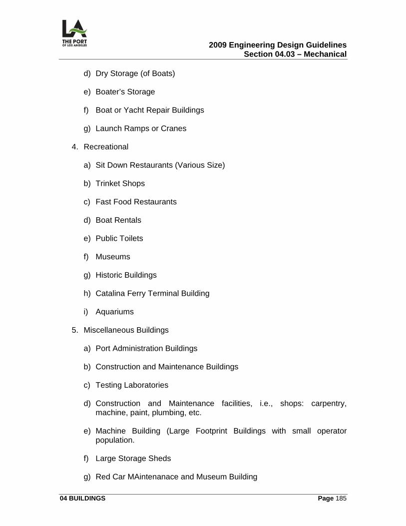
2009 Engineering Design Guidelines Section 04.03 – Mechanical
04 BUILDINGS Page 185
d) Dry Storage (of Boats)
e) Boater’s Storage
f) Boat or Yacht Repair Buildings
g) Launch Ramps or Cranes
4. Recreational
a) Sit Down Restaurants (Various Size) b) Trinket Shops
c) Fast Food Restaurants
d) Boat Rentals
e) Public Toilets
f) Museums
g) Historic Buildings
h) Catalina Ferry Terminal Building
i) Aquariums
5. Miscellaneous Buildings
a) Port Administration Buildings b) Construction and Maintenance Buildings
c) Testing Laboratories
d) Construction and Maintenance facilities, i.e., shops: carpentry,
machine, paint, plumbing, etc.
e) Machine Building (Large Footprint Buildings with small operator population.
f) Large Storage Sheds
g) Red Car MAintenanace and Museum Building
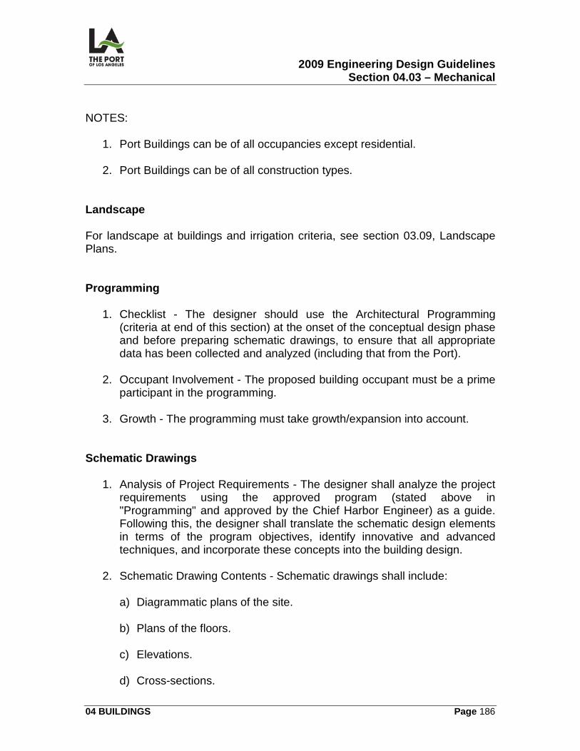
2009 Engineering Design Guidelines Section 04.03 – Mechanical
04 BUILDINGS Page 186
NOTES:
1. Port Buildings can be of all occupancies except residential. 2. Port Buildings can be of all construction types.
Landscape For landscape at buildings and irrigation criteria, see section 03.09, Landscape Plans. Programming
1. Checklist - The designer should use the Architectural Programming (criteria at end of this section) at the onset of the conceptual design phase and before preparing schematic drawings, to ensure that all appropriate data has been collected and analyzed (including that from the Port).
2. Occupant Involvement - The proposed building occupant must be a prime
participant in the programming.
3. Growth - The programming must take growth/expansion into account. Schematic Drawings
1. Analysis of Project Requirements - The designer shall analyze the project requirements using the approved program (stated above in "Programming" and approved by the Chief Harbor Engineer) as a guide. Following this, the designer shall translate the schematic design elements in terms of the program objectives, identify innovative and advanced techniques, and incorporate these concepts into the building design.
2. Schematic Drawing Contents - Schematic drawings shall include:
a) Diagrammatic plans of the site. b) Plans of the floors.
c) Elevations.
d) Cross-sections.
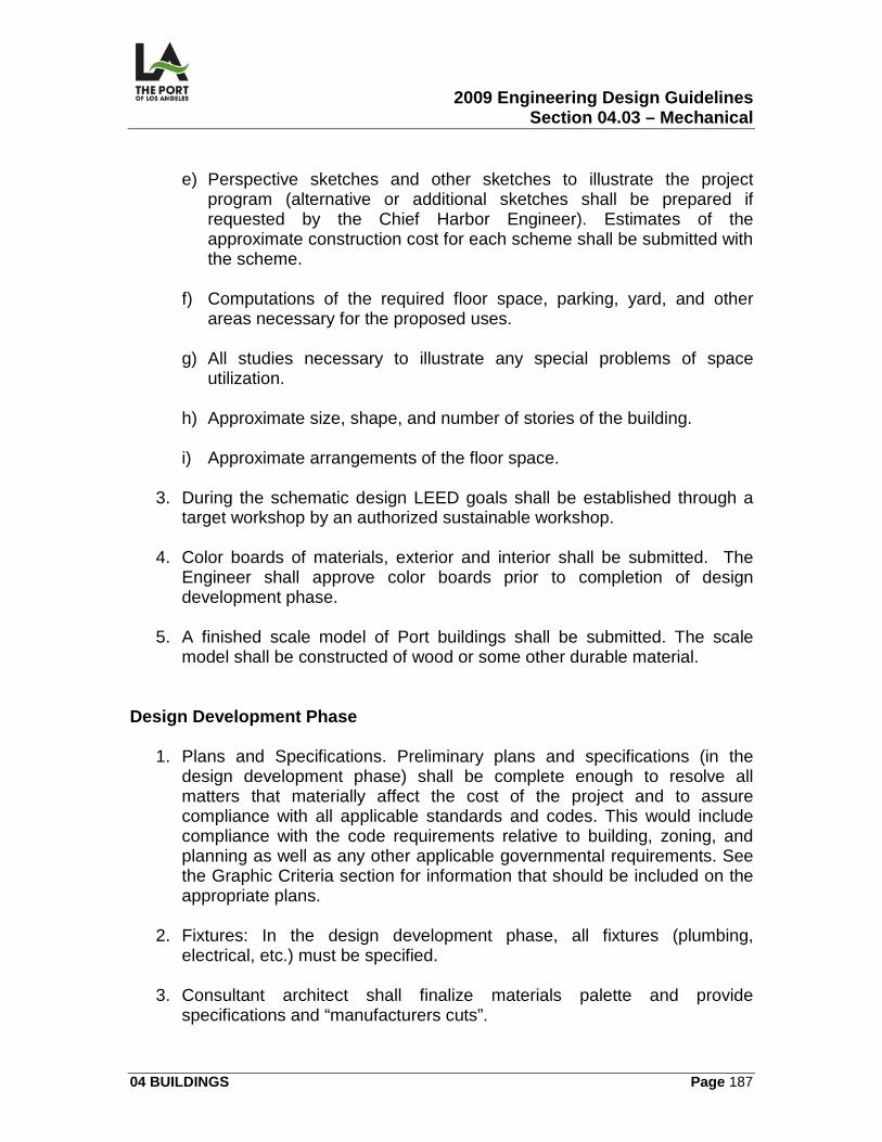
2009 Engineering Design Guidelines Section 04.03 – Mechanical
04 BUILDINGS Page 187
e) Perspective sketches and other sketches to illustrate the project
program (alternative or additional sketches shall be prepared if requested by the Chief Harbor Engineer). Estimates of the approximate construction cost for each scheme shall be submitted with the scheme.
f) Computations of the required floor space, parking, yard, and other
areas necessary for the proposed uses.
g) All studies necessary to illustrate any special problems of space utilization.
h) Approximate size, shape, and number of stories of the building.
i) Approximate arrangements of the floor space.
3. During the schematic design LEED goals shall be established through a
target workshop by an authorized sustainable workshop. 4. Color boards of materials, exterior and interior shall be submitted. The
Engineer shall approve color boards prior to completion of design development phase.
5. A finished scale model of Port buildings shall be submitted. The scale
model shall be constructed of wood or some other durable material. Design Development Phase
1. Plans and Specifications. Preliminary plans and specifications (in the design development phase) shall be complete enough to resolve all matters that materially affect the cost of the project and to assure compliance with all applicable standards and codes. This would include compliance with the code requirements relative to building, zoning, and planning as well as any other applicable governmental requirements. See the Graphic Criteria section for information that should be included on the appropriate plans.
2. Fixtures: In the design development phase, all fixtures (plumbing,
electrical, etc.) must be specified.
3. Consultant architect shall finalize materials palette and provide specifications and “manufacturers cuts”.
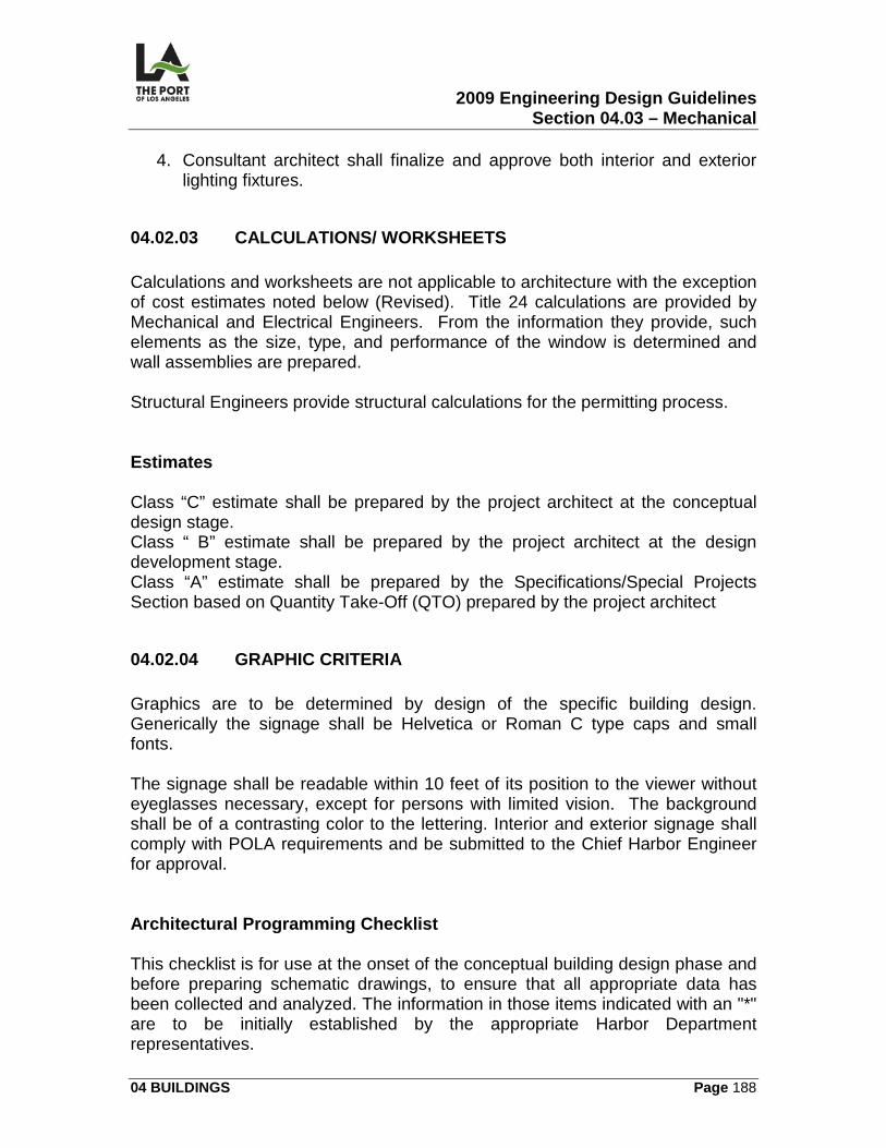
2009 Engineering Design Guidelines Section 04.03 – Mechanical
04 BUILDINGS Page 188
4. Consultant architect shall finalize and approve both interior and exterior lighting fixtures.
04.02.03 CALCULATIONS/ WORKSHEETS Calculations and worksheets are not applicable to architecture with the exception of cost estimates noted below (Revised). Title 24 calculations are provided by Mechanical and Electrical Engineers. From the information they provide, such elements as the size, type, and performance of the window is determined and wall assemblies are prepared. Structural Engineers provide structural calculations for the permitting process. Estimates Class “C” estimate shall be prepared by the project architect at the conceptual design stage. Class “ B” estimate shall be prepared by the project architect at the design development stage. Class “A” estimate shall be prepared by the Specifications/Special Projects Section based on Quantity Take-Off (QTO) prepared by the project architect
04.02.04 GRAPHIC CRITERIA Graphics are to be determined by design of the specific building design. Generically the signage shall be Helvetica or Roman C type caps and small fonts. The signage shall be readable within 10 feet of its position to the viewer without eyeglasses necessary, except for persons with limited vision. The background shall be of a contrasting color to the lettering. Interior and exterior signage shall comply with POLA requirements and be submitted to the Chief Harbor Engineer for approval. Architectural Programming Checklist This checklist is for use at the onset of the conceptual building design phase and before preparing schematic drawings, to ensure that all appropriate data has been collected and analyzed. The information in those items indicated with an "*" are to be initially established by the appropriate Harbor Department representatives.
2009 Engineering Design Guidelines Section 04.03 – Mechanical
04 BUILDINGS Page 189
1. UTILIZATION DETERMINATIONS: Determine with the Harbor
Department staff the utilization of proposed services and facilities. 2. CIRCULATION PATTERN: Establish internal and external public
circulation patterns that affect movement of staff, equipment, materials, and all related supplies.
3. SPACE ALLOCATIONS: Review program space allocations.
4. PLAN REVIEW: Review regional, local, and redevelopment agency plans,
correlating those programs with the project, if applicable.
5. LEGAL REQUIREMENTS: Consult with governing authorities concerning codes and regulations affecting the design.
6. GROSS SQUARE FOOTAGE: Determine gross square footage for the
total building in relation to net space requirements.
7. BUILDING SYSTEMS: Initiate study of applicable building systems such as structural, mechanical, electrical, plumbing, material handling, elevators, floor-to-floor relationships, and all major building components.
8. BUILDING MATERIALS: Research building materials.
9. SEISMIC REQUIREMENTS: Review and investigate seismic
requirements.
10. SYSTEMS PHILOSOPHY: Develop systems philosophy which parallels results of the engineering and architectural program study.
11. DISCIPLINE RESTRICTIONS: Investigate the restrictions applicable to
each discipline due to available utilities or conditions of the site and other components of the redevelopment area. Make recommendations to avoid interference with the program development.
12. SYSTEM REQUIREMENTS: Conduct a preliminary investigation of
building transportation, material handing, waste handling, communication, and security system requirements.
13. SUSTAINABLE REQUIREMENTS: In compliance with the standards
required by the City of Los Angeles, all buildings shall aslso comply with the POLA Green Building Policy Resolution for all LEED certification requirements.
2009 Engineering Design Guidelines Section 04.03 – Mechanical
04 BUILDINGS Page 190
a) In addition, buildings that are less than 7,500 square feet, when choosing between a LEED certified product or another, then the consultant shall choose the LEED product.
b) Specification Writers and Construction Managers shall determine the
certification goals of the project and the LEED Program.
14. COST EFFECTIVENESS: Maximize cost effectiveness by considering structural, mechanical, and electrical design -- particularly such combinations as optimum column spacing, floor-to-floor height, flooring requirements, and the like.
15. ECONOMICS TEST: Produce final test of structural, mechanical, and
electrical concept economics.
16. PERSONNEL REQUIREMENTS: Establish the personnel/staffing requirements necessary for the operation and maintenance of the project with the Harbor Department staff.
17. UTILITIES: Determine on-site and off-site utility requirements for the
project. Analyze on-site storage and energy generation requirements. Finalize utility availability with serving companies.
18. AVOIDING CONSTRUCTION DELAYS. To avoid major delays during
construction, investigate optimum method of multi-phasing construction and or preordering long lead time mechanical/electrical equipment.
04.02.05 SPECIFICATIONS The following divisions in the Harbor Department Master Specifications ( POLA Master Specs ) are related to architectural (other sections may be required, depending on the project):
DIVISION DESCRIPTION 03 Concrete 04 Masonry 05 Metals 06 Wood and Plastics 07 Therman\l and Moisture protection 08 Openings 09 Finishes 10 Specialties 12 Furnishing 13 Special Construction
2009 Engineering Design Guidelines Section 04.03 – Mechanical
04 BUILDINGS Page 191
DIVISION DESCRIPTION 32 Exterior improvements Remodeling/Demolition When remodeling or demolishing an existing building, the designer should reference the Harbor Department Master Specifications section 02.
04.02.06 PERMITS/APPROVALS The following permit and approvals may be required when there is architectural work: Fire Department Approval Building architectural designs must be approved by the Fire Department prior to submission for a City of Los Angeles Department of Building & Safety permit. Department of Building & Safety Permit Building architectural designs must be approved by City of Los Angeles Department of Building & Safety through the plan check process, including zoning where necessary (Revised). Once plans are approved, a permit may be obtained (see following two paragraphs for special fees which may be applicable). During the design phase, a variance must be obtained for any building feature that does not meet the City of Los Angeles Building Code. Sub-approvals shall also be obtained from the Disabled Access Division of City of Los Angeles Department of Building & Safety and the Fire Department (see above). As part of the City of Los Angeles Department of Building & Safety permit approval, signoffs may be required from the Bureau of Engineering, Department Of Transportation., and the Planning Department. Coastal Permits Coastal Permits are available from the Port of Los Angeles Planning Department. All projects must conform to the Harbor Department’s Master Plan. Artwork and Art Development Fee
2009 Engineering Design Guidelines Section 04.03 – Mechanical
04 BUILDINGS Page 192
In accordance with the City of Los Angeles Ordinance Nos. 166724 and 166725, the Arts Development Fee (administered by the Cultural Affairs Department and collected by City of Los Angeles Department of Building & Safety during the permitting process) requires all new building projects to provide arts and cultural amenities for the employees, owners, and users of the development. The fee shall be equal to a maximum of 1% of the building permit valuation. On applicable projects, the consultant shall be responsible for coordinating the artist selection process and the art work with the project and with the Cultural Affairs Department. School Development Fee The School Development Fee is administered by the Los Angeles Unified School District and collected by City of Los Angeles Department of Building & Safety during the permitting process. If the building is publicly owned and operated, this fee SHOULD NOT be paid, as the Harbor Department is entitled to a waiver of the fee. Cultural Affairs Commission The architectural design of a project shall be submitted to the Los Angeles City Cultural Affairs Commission a minimum of 2 times (for schematic and final review and approval of aesthetic merit) or as required by contemporaneous standards. On larger projects, 4 submittals may be required (conceptual, schematic, preliminary, and final). The 100% contract drawings shall confirm and be a part of the final submittal. The qualities considered important (and on which the project is judged) include:
1. The design style of the building (or building complex) is expressive of its function and true to the nature of the activities it contains.
2. The materials used are of the best quality available within the budget and
are appropriate to the character of the architecture.
3. The project takes into account its context and considers the buildings, streets, and the landscape that surround its boundaries.
4. Individual structures within the project relate to one another in compatible
design styles, with all details of design relating to the overall character of the architecture.
5. Landscape creates pleasant environments both for people who may work
in the project area and for those who pass by or visit.
2009 Engineering Design Guidelines Section 04.03 – Mechanical
04 BUILDINGS Page 193
04.02.07 ENVIRONMENTAL CONSIDERATIONS The environmental considerations of the Port are to exceed the standards of the Title 24 program. The LEED program is an earnest goal of the Port. The goals are to achieve the following:
1. Prepare the buildings to resist heat lakes that increase air conditioning uses.
2. Prepare the building to contain heating services during the colder periods
of the area by specifying properly sealed materials.
3. Prepare the building to maintain the health of the users by choosing healthy interior products.
4. Prepare the building to resist increased services from the Municipal
Utilities.
5. Prepare the building to not waste potable water, particularly in landscaping, and moving waste products.
6. Prepare the building to not pollute water facilities such as the channels,
inlets, and the ocean.
7. Choose materials and equipment that are recycled, sustainable and non-toxic (if practical).
8. Choose energy efficient lighting systems, mechanical systems, appliances
and machinery.
9. Prepare the building to receive optimal daylighting and views while maintaining a minimal solar heat gain.
04.02.08 REFERENCE DRAWINGS The following contract drawings are identified for reference: 1-2114Berth 225-232, Evergreen Terminal Redevelopment, Buildings Gate
Facilities
1-2114 PM A1 Site Plan 1-2114 M T,2 General or Project Notes
2009 Engineering Design Guidelines Section 04.03 – Mechanical
04 BUILDINGS Page 194
1-2114 M T-1 Title Sheets 1-2114 M T-3 Handicap Notes 1-2114 M T-3.1 Handicap Notes 1-2114 M T-3.2 Handicap Notes 1-2114 M T-4 Abbreviations 1-2114 PM A1 Floor Plan 1-2114 A-A4 to A8 Dimension Plan 1-2114 PM A2 Roof Plan 1-2114 A-3 Exterior Elevations 1-2114 A-4 Building Sections and Details 1-2114 A-A17 & 18 Wall Sections 1-2114 PM A-2 Reflected Ceiling Plan 1-2114 PM A-5 Interior Elevations and Details (Trolley
Plans are included) 1-2114 PM A-7 Door Details 1-2114 PM A-6 Finish Schedules 1-2114 PM A-6 Door Schedules 1-2114 PM A-6 Window Schedules 1-2114 PM A-8 Window Details 1-2114 PM A-10, A-13 Miscellaneous Details 1-2114 PM A-9 Roof Details 1-2114 PM A-11 Ceiling Details
LAHD Standard Plans
2009 Engineering Design Guidelines Section 04.03 – Mechanical
04 BUILDINGS Page 195
04.03
MECHANICAL
04.03.01 OVERVIEW This section contains the following information related to the preparation of building mechanical contract drawings:
• Mechanical Schedules and Legend (M)
• Floor Plan (M)
• Roof Plan (M)
• Control Diagrams and Sequence of Operations (M)
• Section Views (M)
• Mechanical Details (M)
04.03.02 DESIGN CRITERIA General Design Requirements The designer shall meet all applicable regulations, standards, and guidelines of:
1. Latest Energy Efficiency Standards for Residential and Non-Residential Buildings, California Energy Commission (current edition). Forms verifying certification of compliance to these standards shall be a part of the drawings.
2. American Society of Heating, Refrigeration, and Air Conditioning
Engineers (A.S.H.R.A.E.).
3. City of Los Angeles Mechanical Code. Concealment All pipes, conduits, vents, ducts, and related equipment shall be located inside of the building (concealed or in furred spaces) or yard wall, unless otherwise authorized by the Chief Harbor Engineer.
2009 Engineering Design Guidelines Section 04.03 – Mechanical
04 BUILDINGS Page 196
Plan Preparation The following information shall be on mechanical plans:
1. Weight of every piece of equipment in excess of 200 lbs. 2. Equipment schedule, capacities, design criteria, etc.
3. Control diagram to coordinate with the specified sequence of operation.
4. Duct and appurtenant fitting layout, sizes, hangers, insulation, and flexible
connection.
5. Type, size, and flow through of supply outlets and return inlets..
6. References to architectural drawings (wherever appropriate) such as reflected ceiling plans, roof plans, etc.
Outside Air A minimum outside air shall be provided per the latest Los Angeles Building Code and California Energy Efficiency Standards. Not all spaces within a building may require conditioned air. Building and Safety shall be contacted regarding air conditioning for questionable spaces. Design Temperatures The maximum ambient summer temperature shall be 84°F dry bulb and 69°F wet bulb, with a minimum winter temperature of 40°F. Inside temperature shall be 78°F minimum for cooling and 70°F for heating. Relative humidity shall be within the comfort zone per A.S.H.R.A.E. Face Velocity Maximum face velocity through the heating coil shall be 800 FPM. Where applicable on central systems, the maximum face velocity through the cooling coil shall be 450 FPM. Heat Pumps
2009 Engineering Design Guidelines Section 04.03 – Mechanical
04 BUILDINGS Page 197
Heat pumps shall be used for H.V.A.C. systems requiring 20 tons or lower, unless otherwise authorized by the Chief Harbor Engineer. Filter The filters shall be high efficiency/performance types designed to meet specifically installed equipment with a minimum 35% efficiency as determined by the National Bureau of Standards test. Diffusers and Registers Diffusers and registers shall match with the ceiling pattern and shall have separate or integral smudge rings (consult with the architect). Exact locations of diffusers, registers, etc. shall be as indicated on the reflected ceiling plan of the architectural drawings. Air Duct System
1. Low Velocity - A low velocity air duct system shall be employed, with the maximum main duct air velocity of 1200 FPM and the maximum pressure drop in branch ducts of 0.08 inches per 100 feet.
2. In Open Areas -Ducts in open areas shall be rectangular.
Temperature Control The building shall be divided into thermostatically controlled zones for maximum temperature control. Thermostats All thermostats shall be secured to prevent indiscriminate resetting. Solar Energy The designer shall address solar energy for feasibility and application. Energy Storage
2009 Engineering Design Guidelines Section 04.03 – Mechanical
04 BUILDINGS Page 198
Energy storage shall be considered as a means for handling heating and air conditioning peak loads without creating corresponding peak demands on the utility (also as a tool in downsizing H.V.A.C. equipment). Materials/Equipment
1. Sources - The designer shall provide a list showing three sources for all major equipment and major materials.
2. Approval - The designer shall secure Los Angeles City approval for all
materials and equipment or shall obtain a variance from the appropriate authorities in a timely manner to avoid delaying construction.
30% Design Documents At the 30% Review, the designer shall provide the following:
1. General layout of the system proposed -- including total loads, single line drawings, and schematic diagrams showing the general arrangement of mechanical piping systems and equipment.
2. Drawings -- including a large scaled plan and sections of the equipment
room showing dimensions of all the equipment, ductwork, duct insulation, space for servicing equipment (with doors of sufficient size to admit the largest piece of equipment), and other necessary items which would take up appreciable space.
3. A separately bound volume designated as Mechanical Calculations (see
Calculations Preparation).. Equipment Arrangements/Installations All equipment arrangements and installations shall be designed for safety, ease of operation, maintenance, and repair. Equipment Location & Screen/Enclosure Design Equipment location and screen/enclosure design shall be verified with the architect.
2009 Engineering Design Guidelines Section 04.03 – Mechanical
04 BUILDINGS Page 199
Mechanical Checklist The designer should use the Mechanical Checklist in 04.03.09 to ensure that the drawings and specifications have been prepared carefully and clearly articulate the scope/intent of the job and the responsibility of the contractor in producing a satisfactory mechanical system.
04.03.03 CALCULATIONS/WORKSHEETS Calculations Preparation A separately bound volume designated as Mechanical Calculations shall be prepared by the designer at the time of the 30% review (or submittal). They shall meet the requirements of the California Energy Commission (as included in Title 24) and shall include all supporting data, rationale (system and equipment selection, engineering considerations, and life cycle cost), and calculations including, but not limited to, the details specified below:
1. Heat Gain and Loss Calculations -- for the building and/or room, as appropriate.
2. Pressure Drops Calculations -- for pump and compressor selection.
3. Equipment Losses Calculations -- duct, equipment, and other losses for
fan selection.
4. Water Capacity and Pressure Calculations -- water capacity of pipe/equipment, as well as pressures used for system design and for expansion tank selection.
5. Gas and Liquid Pressure Drops Calculations -- for direct expansion
refrigeration systems, gas and liquid pressure drops shall be provided across major components and gas velocity to return oil for hot gas and suction risers.
6. Water Heater Calculations -- capacity and makeup requirements.
7. Heat Exchanger Calculations -- temperature, flow, capacity, and heat
rejection rates.
8. Single Line Schematic Diagram -- indicating load balance and/or heat balance, including the temperature, flow, and pressure gradient for all
2009 Engineering Design Guidelines Section 04.03 – Mechanical
04 BUILDINGS Page 200
mechanical system design. Diagrams shall contain the complete system component schematic to show how the system works.
9. The designer shall prepare all calculations on worksheets in compliance
with POLA's Engineering Division's latest format.
04.03.04 GRAPHIC CRITERIA
1. Site plan 2. Mechanical Floor Plan
3. Mechanical Roof Plan
4. Section plan
5. Legend
6. Control Diagrams and Sequence of Operations
7. Details
04.03.05 SPECIFICATIONS The following sections in the Harbor Department Master Specifications relate to mechanical:
SECTION TITLE Heating, Ventilation, and Air Conditioning
04.03.06 PERMITS/APPROVALS The permit listed below may be required when there is building mechanical work. Building and Safety Permit A mechanical plan check is required. The mechanical permit may be secured by the installer or contractor once the plans have been approved.
2009 Engineering Design Guidelines Section 04.03 – Mechanical
04 BUILDINGS Page 201
04.03.07 ENVIRONMENTAL CONSIDERATIONS Specify using reduced ozone depletion or zero use of CFC-based refrigerants for new building. When reusing existing HVAC systems, conduct an inventory to identify equipment that uses CFC refrigerants and adopt a replacement schedule for these refrigerants. Design an IAQ performance system to prevent the development of indoor air quality problems in building. Meet the minimum requirement of standard ASHRAE 62-1999 or local code whichever is more restrictive. Design and install a permanent carbon dioxide CO2 monitoring system. Design an effective delivery and mixing of fresh air HVAC system to support the safety, comfort, and well-being of occupants. Design the building with occupant controls for airflow, temperature, and lighting for both perimeter and non-perimeter spaces. Design separate exhaust and plumbing systems for rooms with contaminants to achieve physical isolation from the rest of the building. Develop a construction IAQ management plan for the construction phase and before occupancy. Specify Low-VOC materials in construction documents. Ensure that VOC limits are clearly stated in each section where paints, adhesives, and sealants are addressed. Provide fundamental building systems commissioning.
04.03.08 REFERENCE DRAWINGS The following contract drawings are identified for reference: 1-2325A Berths 93A&B – World Cruise Center Renovation
1-2325 M-1 Mechanical Legend, Notes & Schedules 1-2325 M-6 Mechanical Partial First Floor Plan 1-2325 M-13 Mechanical Roof Plan
2009 Engineering Design Guidelines Section 04.03 – Mechanical
04 BUILDINGS Page 202
1-2325 M-18 Mechanical Details 1-2325 M-23 Mechanical Controls 1-2325 M-24 Mechanical Controls & Sequence of Operation 1-2325 M-25 Mechanical Title 24
LAHD Standard Plans
04.03.09 Building Mechanical Checklist Requirements
1. Plan check and permits 2. Scope of work
3. Intent
4. Approvals
5. Equipment deviations
6. Codes, rules, permits, and fees
7. Surveys and measurements
8. Drawings
9. Coordination with other trades
10. Protection/safety
11. Scaffolding, rigging, and hoisting
12. Material and workmanship
13. Noise criteria
14. Accessibility
15. Waterproofing/sealing at roof penetrations
2009 Engineering Design Guidelines Section 04.03 – Mechanical
04 BUILDINGS Page 203
16. Guarantee
17. Abbreviations
18. References
19. Definitions
20. Shop Drawings
21. Equipment design and installation
22. Equipment supports, foundations, and stands
23. Pipe sleeves
24. Escutcheons and plates
25. Spare parts
26. Motors, motor controls, and electrical work
27. Concrete work
28. Testing
29. Cutting and patching
30. Painting
31. Excavation and backfill
32. Access doors
33. Operating instructions
34. Others
Heating, Ventilating, Air Conditioning, & Refrigeration
1. Scope of work 2. Design criteria
2009 Engineering Design Guidelines Section 04.03 – Mechanical
04 BUILDINGS Page 204
3. Shop drawings
4. Pipes and fittings
5. Pipe hangers and supports
6. Valves, strainers, traps, and specialties
7. Thermometers and pressure gauges
8. Expansion joints
9. Orifice plates and flowmeters
10. Boilers and burner units
11. Boiler feedwater systems
12. Pressure reducing stations
13. Refrigeration equipment
14. Cooling towers
15. Heat exchangers
16. Water-circulating pumps
17. Condensate water pump
18. Air separators
19. Expansion tanks
20. Fuel-oil transfer pump
21. Water treatment equipment and systems
22. Direction radiation
23. Air conditioning units
24. Heating and ventilating units
2009 Engineering Design Guidelines Section 04.03 – Mechanical
04 BUILDINGS Page 205
25. Heating coils
26. Air filters
27. Fans
28. Unit heaters and cabinet unit heaters
29. Fan-coil units and thermal units
30. Flexible connections
31. V-belt drivers and belt guards
32. Acoustical treatment
33. Vibration treatment
34. Ductwork
35. Dampers and access doors
36. Diffusers, registers, and grilles
37. Thermal insulation
38. Temperature control systems
39. Motors, motor controllers, and electrical work
40. Motor control center
2009 Engineering Design Guidelines Section 04.04 – Plumbing
04 BUILDINGS Page 206
04.04
PLUMBING
04.04.01 OVERVIEW This section contains the following information related to the preparation of the following plumbing contract drawings:
• Plumbing Legend, Schedules, & Notes (PL)
• Site Plan (PL)
• Plumbing Plan - Subfloor (PL)
• Plumbing Plan - Floor (PL)
• Plumbing Plan - Roof (PL)
• Riser Diagrams (PL)
• Plumbing Details (PL)
04.04.02 DESIGN CRITERIA Jurisdiction The area considered to be "building plumbing" is everything inside of or within 5 feet of the building. General Design Requirements The designer shall meet all applicable regulations, standards, and guidelines of (latest edition):
1. City of Los Angeles Plumbing Code. 2. Uniform Plumbing Code, International Association of Plumbing and
Mechanical Officials.
3. California Energy Efficiency Standards Concealment
2009 Engineering Design Guidelines Section 04.04 – Plumbing
04 BUILDINGS Page 207
All pipes, conduits, vents, ducts, and related equipment shall be located in the interior building walls, furred spaces, or yard wall, unless otherwise authorized by the Chief Harbor Engineer. Any equipment requiring servicing (e.g., clean outs, water hammer arrestors) shall be made accessible. Meters and Devices The designer shall coordinate the location of water meters and backflow prevention devices with D.W.P. (and with the Port, if the designer is a consultant). Riser Diagrams Waste, water, and gas piping riser diagrams shall indicate pipe sizes, fixtures, fixture units (GPM or CFH), and the slope at each section. Copper Pipes Penetrating Concrete Copper pipes penetrating through concrete shall be provided with sleeves to prevent contact between pipe and concrete. Sewer Clean Outs
1. Grade. No sanitary sewer clean out shall be lower than grade. 2. Spacing. The maximum straight line distance between clean outs along
straight runs is 50 feet in buildings and 100 feet in yard areas; each bend requires an additional clean out.
Toilet Rooms Toilet rooms shall have 4 air changes per hour or 50 cfm per water closet or urinal, whichever is more cfm. Automatic Trap Primer
1. Requirements - Each floor sink or floor drain trap shall be provided with automatic trap primers.
2009 Engineering Design Guidelines Section 04.04 – Plumbing
04 BUILDINGS Page 208
2. Accessible - Automatic trap primers must be accessible for service. Hot Water Recirculating Pumps When considering use of hot water recirculating pumps, the distance between fixtures needing hot water and the hot water source should be reviewed to determine the necessity for such pumps. Materials/Equipment
1. Sources - The designer shall provide a list showing three sources for all major fixtures, equipment, and materials.
2. Approval - The designer shall use City of Los Angeles Bldg. & Safety
approved materials and equipment, whenever possible, or shall obtain a variance from the appropriate authorities in a timely manner to avoid delaying construction.
3. Ductile Iron - Ductile iron, Class 52, manufactured per A.W.W.A. C151,
shall be used for underground pipes at least 4 inches in diameter. The pipes shall double cement mortar lined push-on joints, Class 52.
4. Steel - Steel, Schedule 40, and manufactured per A.S.T.M. 139-90 with
flanged joint, shall be used for above ground pipes at least 4 inches in diameter.
5. Copper - Pipes 3 inches and smaller shall be copper, Type L, with silver
solder joints. 30% Design Drawings At the 30% review, the designer shall provide the following:
1. General layout of the system proposed -- including schematic diagrams showing the general arrangement of plumbing piping systems and fixtures.
2. Drawings -- including a large scaled plan and sections of the equipment
room showing all the equipment, piping, piping insulation, space for servicing equipment (with doors of sufficient size to admit the largest piece of equipment), and other necessary items which would take up appreciable space.
2009 Engineering Design Guidelines Section 04.04 – Plumbing
04 BUILDINGS Page 209
3. Plumbing calculations (see 04.04.03 below). Equipment Arrangements/Installations All equipment arrangements and installations shall be designed for safety and ease of operation, maintenance, and repair. Plumbing Checklist The designer should use the Plumbing Checklist (in 04.04.09) to ensure that the drawings and specifications have been prepared carefully and clearly spell out the scope/intent of the job and the responsibility of the contractor in producing a satisfactory plumbing system.
04.04.03 CALCULATIONS/WORKSHEETS Calculations and worksheets for pipe sizes, flows, and pressures shall be prepared. The designer shall prepare all calculations on worksheets in compliance with POLA's Engineering Division's latest format.
04.04.04 GRAPHIC CRITERIA
1. Site plan 2. Floor piping plan
3. Section plan
4. Riser diagram
5. Plumbing Legend
6. Details
04.04.05 SPECIFICATIONS The following section in the Harbor Department Master Specifications relate to building plumbing (other sections may be required, depending upon the project):
2009 Engineering Design Guidelines Section 04.04 – Plumbing
04 BUILDINGS Page 210
SECTION TITLE Building Plumbing
The specifications for plumbing shall also conform with rules and regulations of the City of Los Angeles Plumbing Code.
04.04.06 PERMITS/APPROVALS The permit listed below may be required when there is plumbing work: Building and Safety Permit A plumbing plan check is required. The plumbing permit shall be secured by the installer or contractor once the plans have been approved.
04.04.07 ENVIRONMENTAL CONSIDERATIONS Design water system that uses 30% less water than the water use baseline calculated for the building after meeting the Energy Policy Act of 1992 fixture performance requirements. Specify high-efficiency fixtures to reduce consumption of municipal water and wastewater volumes. Specify high-efficiency irrigation technology or use captured rain or recycled site water to reduce potable water consumption for irrigation by 50% over conventional means. Specify Low-VOC materials in construction documents. Ensure that VOC limits are clearly stated in each section where paints, adhesives, and sealants are addressed.
04.04.08 REFERENCE DRAWINGS The following contract drawings are identified for reference: 1-2325A Berths 93A&B World Cruise Center Renovation
1-2325A P-1 Legend, Abbreviations, Calculation, & Notes 1-2325A P-2 Site Plan
2009 Engineering Design Guidelines Section 04.04 – Plumbing
04 BUILDINGS Page 211
1-2325A P-5 First Level Partial Plumbing Plan 1-2325A P-10 Second Level Enlarged Plumbing Plan NO ROOF PLAN FROM THIS PROJECT 1-2325A P-12 1st Level Hot & Hold Water Piping Isometric Plan 1-2325A P-17 Plumbing Details
LAHD Standard Plans
04.04.09 BUILDING PLUMBING CHECKLIST
Requirements
1. Plan check and permits 2. Scope of work
3. Intent
4. Approvals
5. Equipment deviations/variances
6. Codes, rules, permits, and fees
7. Surveys and measurements
8. Drawings
9. Coordination with other trades
10. Protection/safety
11. Scaffolding, rigging, and hoisting
12. Material and workmanship
13. Accessibility
14. Waterproofing/sealing at roof penetrations
2009 Engineering Design Guidelines Section 04.04 – Plumbing
04 BUILDINGS Page 212
15. Guarantee
16. Abbreviations
17. References
18. Definitions
19. Shop Drawings
20. Existing services
21. Pipe sleeves
22. Trap primers
23. Insulation
24. Pipe supports
25. Escutcheons and plates
26. Spare parts
27. Concrete work
28. Testing
29. Cutting and patching
30. Painting
31. Excavation and backfill
32. Access doors
33. Operating instructions
34. Others
2009 Engineering Design Guidelines Section 04.05 – Structural
04 BUILDINGS Page 213
04.05
STRUCTURAL
04.05.01 OVERVIEW Contents This section contains the following information related to the preparation of building structural contract drawings:
• Structural General Notes (S)
• Typical Details (S)
• Floor Framing Plan(s) (S)
• Roof Framing Plan (S)
• Lateral Resisting Frame Elevations (S)
• Foundation Plan (S)
• Structural Frame and Details (S)
• Sections and Details (S)
• Miscellaneous Details (S)
04.05.02 DESIGN CRITERIA Basis of Design Calculations and drawings shall include the basis of design, such as:
1. Design criteria. 2. Loading.
3. Material properties.
4. Seismic Design Requirements.
2009 Engineering Design Guidelines Section 04.05 – Structural
04 BUILDINGS Page 214
5. Applicable codes, including the latest edition of the City of Los Angeles Building Code.
6. Results of geotechnical reports (e.g., foundation requirements, spread
footings, mat foundations, and pile foundations).
7. Special Design Requirements. Seismic Design Basis A report shall be prepared stating the basis for the seismic design. This report shall be submitted to the Chief Harbor Engineer for review and conditional approval. Included in the report shall be:
1. A statement of general seismic design philosophy in narrative form. 2. All the required information as listed in Recommended Lateral Force
Requirements ("Blue Book"), Chapter 1, Section A.4, prepared by the Seismology Committee of the Structural Engineers Association of California (latest edition).
3. Sketches, as required.
Geotechnical Reporting A geotechnical report is required for all building structures in accordance with Chapter 18 of the City of Los Angeles Building Code. The extent of the geotechnical investigation is determined by the size and complexity of the project and the requirements of the City of Los Angeles Department of Building & Safety. Framing
1. Loads. Framing shall be designed to accommodate both service and construction loads.
2. Roof Slope. Roofs shall have a minimum slope of ½ inch to 1 foot. The
framing design is to achieve the minimum slope.
3. Lateral Resist Framing System. Design and detail lateral framing system to accommodate.
Structural Members
2009 Engineering Design Guidelines Section 04.05 – Structural
04 BUILDINGS Page 215
Structural members and their connections shall be shown on plans and detailed as designed. Dimensions Structural members and connections shall be dimensioned to show the system will connect properly.
04.05.03 CALCULATIONS/WORKSHEETS There are no calculations or worksheets provided for this section. The designer shall prepare all calculations on worksheets in compliance with POLA's Engineering Division's latest format. Computer Calculations All calculations shall be submitted in the format described in Recommended Lateral Force Requirements ("Blue Book"), Seismology Committee of the Structural Engineers Association of California.
04.05.04 GRAPHIC CRITERIA Structural sheets shall be prepared per POLA’s AutoCad manual and must have the following sheets:
1. Structural General Notes – should include specific design criteria and specifications regarding materials and sizing and shall have these major headings: general conditions; concret (all concrete penetrations shall be shown); reinforcing steel, structural steel and miscellaneous metals; metal deck; abbreviations; and design criteria.
2. Foundation Plan – this sheet should show building column lines and numbers, proposed foundation with all dimensions, foundation details for every different condition, size, tyoe of footing and appropriate schedules.
3. Framing Plans (Roof/Floor) – this sheet should contain building outline and interior walls; column lines and numbers; proposed framing plan showing member sizes and spacing, as well as weights, if steel, or reinforcing steel, all concrete penetrations; all dimension and materials.
4. Structural Rigid Frame Elevations – this sheet should indicate the specialized framing elevations referenced from framing plans.
5. Sections and Details – this sheet shoul show structural frame and appropriate details
2009 Engineering Design Guidelines Section 04.05 – Structural
04 BUILDINGS Page 216
6. Sections and Details – This sheet should include information regarding the manner of construction abd materials.
7. Typical Details – This sheet should include any particular specialized structural details necessary for construction clarification.
04.05.05 SPECIFICATIONS The following sections in the Harbor Department Master Specifications relate to building structural (other sections may be required, depending on the project):
SECTION TITLE Steel Pipe Piles Precast Concrete Piles Concrete Reinforcement Cast-In-Place Concrete Precast Concrete Nonshrink Concrete Mortar Lightweight Insulating Concrete Concrete Block Masonry Treating Damaged Galvanizing Structural Steel Steel Decking Metal Fabrications Metal Stairs
Building Code The specifications for the structural aspect of buildings shall conform to the rules and regulations of the latest City of Los Angeles Building Code.
04.05.06 PERMITS/APPROVALS The permit listed below may be required when there is building structural work: Department of Building & Safety Permit A City of Los Angeles Department of Building & Safety pregrading inspection report is required. Building structural designs must also be approved by City of Los Angeles Department of Building & Safety through the plan check process. Once the plans have been approved, the permit may be obtained.
2009 Engineering Design Guidelines Section 04.05 – Structural
04 BUILDINGS Page 217
04.05.07 ENVIRONMENTAL CONSIDERATIONS For new buildings, materials for protection of structural members shall be per existing codes, rules and regulations. For existing buildings, coatings of structural members that will be disturbed shall be properly identified to ensure that hazardous materials are not present. If hazardous materials are identified, the plans should indicate the removal of the materials before any structural work is undertaken.
04.05.08 REFERENCE DRAWINGS (Typical structural plans) The following contract drawings are identified for reference: 1-2211 Pier 400 Buildings and Gate Facilities Phase 1/Group 2
1-2211 TS-S1 General Notes 1-2211 TS-S4 Typical Details (Concrete) 1-2211 TS-S7 Typical Details (Masonry) 1-2211 TS-S9 Typical Details (Steel) 1-2211 TS-S13 Typical Details (Metal Deck) 1-2211 TS-S17 Typical Stair Details
1-2211 Container/Truck Wash Ramp (CTWR)
1-2211 CTWR-S1 Foundation Plan 1-2211 CTWR-S2 Roof Framing Plan 1-2211 CTWR-S3 Building Section 1-2211 CTWR-S34 Sections and Details
LAHD Standard Plans
2009 Engineering Design Guidelines Section 04.06 – Electrical
04 BUILDINGS Page 218
04.06
ELECTRICAL
04.06.01 OVERVIEW This section contains the following information related to the preparation of building electrical contract drawings:
• Electrical Notes, Symbols, and Abbreviations (E)
• Electrical Site Plan (E)
• Floor Plan - Lighting (E)
• Floor Plan - Power and Communication (E)
• Roof Plan (E)
• Single Line Diagram and Panelboard Schedules (E)
• Electrical Details (E)
04.06.02 DESIGN CRITERIA Required Services Check whether any of the following are required:
1. Public address (P.A.) service. 2. Telephone system.
3. Computer system.
4. Uninterruptable power supply system (UPS).
5. Electrical fire protection.
6. Emergency generator.
7. Electrical service and wiring for landscape.
8. Structured data wiring system.
2009 Engineering Design Guidelines Section 04.06 – Electrical
04 BUILDINGS Page 219
9. Security system.
10. Video system.
11. Cable T.V.
General Design Requirements Electrical design shall be in compliance with the latest edition of the City of Los Angeles Electrical Code. Department of Water and Power Service Utility Vault Requirements Utility vault requirements shall be transferred in full to the contract drawings. Grounding Pull Box Covers
1. Detail - Detail for grounding pull box covers shall be shown as required by Bldg. & Safety.
2. Maintenance Hole Covers - Maintenance hole covers do not have to be
bonded to the ground as long as the ring is metallic and bonded. If the ring is concrete, then the cover must be bonded (decision made by Principal Electrical Inspector at Department of Building & Safety).
Electrical Panelboard/Switchboard When specifying an electrical panelboard and/or switchboard, the designer shall ensure that the following can be fitted into the specified panelboards:
1. Each separate individual breaker. 2. The sum total of all breakers.
Panelboard Schedule A separate electrical panelboard schedule shall be shown for each and every panelboard, even if they are identical. Each panelboard shall also be identified by its own unique name.
2009 Engineering Design Guidelines Section 04.06 – Electrical
04 BUILDINGS Page 220
Fire Alarm Circuit When tapping service conductors for the fire alarm circuit, the following shall be specified: double lugs for the panelboard main, one lug for the service conductor, and another lug for the fire alarm conductor. Wiring
1. Landscape Irrigation System - The conduit and wire system shall be used for wiring controllers in the landscape sprinkler system. Direct Burial Type wiring is not acceptable.
2. Materials/Sizing - Wiring shall be copper unless otherwise directed by the
Chief Harbor Engineer. Circuit conductors shall be copper with Type THHN/THWN insulations, 600V. rating for each conductor. Equipment grounding conductors shall be sized adequately to withstand short circuits.
3. Concealment - Conduit shall be concealed unless otherwise directed by
the Chief Harbor Engineer.
4. 4-Wire Systems - Neutral wire size shall be the same as the phase wires. Outdoor Lighting
1. Type and Size - The type and size (size is typically a maximum of 30 feet) of lighting immediately adjacent to a building should be a joint decision between the Port's architect and the electrical designer. This does not apply to high mast light poles.
2. Open Spaces - If there are large open spaces between and around
buildings, consideration should be given to also using some 100 foot light poles.
3. Exterior - Exterior lighting shall be High Pressure Sodium. The most
energy efficient fixtures and lamps should be used.
4. Photocell/Timeclock - Outside lighting shall be controlled by a photocell and timeclock.
Interior Lighting
2009 Engineering Design Guidelines Section 04.06 – Electrical
04 BUILDINGS Page 221
1. Type - Interior lighting shall be fluorescent except as otherwise authorized
by the Electrical Engineer. 2. Diffusers/Lenses - Diffusers and lenses shall be 100% virgin acrylic.
3. Ceiling Fixtures - The exact location of the ceiling light fixture pattern shall
be as indicated on the reflected ceiling plan of the architectural drawings.
4. Lighting Support - Lighting support shall meet Bldg. & Safety earthquake standards.
5. Locations to Avoid - Lighting fixtures shall avoid locations of sprinklers, air
conditioners, and heaters.
6. Lamp Ballasts - Fluorescent lamp ballasts shall be High Power Factor class "P" rated. High Pressure Sodium lamp ballasts shall be High Power Factor.
7. Recessed Fixtures - Recessed fixtures over the ceiling shall permit access
to allow for relamping (this note should be added to walls on architectural drawings).
Single Line Diagram
1. Short Circuit Analysis - A short circuit analysis shall be done of all electrical systems, stating all available short circuit currents on the single line diagram for all switchboards, panelboards, and any major equipment used.
2. Inclusions - Single line diagrams shall indicate all of the items mentioned
in 03.13.04 for the Single Line Diagram and Panelboard Schedules.
3. Arc Flash Hazard Analysis – An arc flash hazard analysis shall be done of the entire electrical system stating the arc flash ratings, and boundaries for all switchboards, panelboards and any major electrical power distribution equipment used.
Distribution Centers
1. Duct System - An underfloor duct system shall be utilized (terminating in distribution centers).
2009 Engineering Design Guidelines Section 04.06 – Electrical
04 BUILDINGS Page 222
2. Location - Distribution centers shall be located to avoid door swings. Concrete Pads Switchboards and motor control centers shall be supported on raised concrete pads. Pads shall be detailed in structural drawings. Switches/Coverplates
1. Wall Switches - Wall switches should be used rather than pull chains. 2. Oversized - All switch and outlet coverplates shall be oversized.
Floor Outlets All floor outlet locations shall be dimensioned. Underground Service & Feeder Runs Underground service and feeder runs shall avoid obstructions such as tanks and footings. Meter Sockets Meter sockets are rated a minimum of 10,000 AIC. The specified rating of meter sockets must not be less than the available short circuit. Main Breakers When no single main breaker exists, there shall be no more than six breakers at any panel-board. Schedules A minimum of two schedules should be included with the building electrical plans -- a lighting fixture schedule and a panelboard schedule.
2009 Engineering Design Guidelines Section 04.06 – Electrical
04 BUILDINGS Page 223
Light Fixture Schedule Callout Sample Each drawing reference shall be complete and stand alone. The following is an example of how references should be made (with an incorrect sample in parentheses, if appropriate):
1. Fixture type "A" = indicate fixture type. H.P.S. (high pressure sodium) lamps.
2. Fixture type "B" = indicate fixture type. H.P.S. lamp (rather than "similar to
'A,' except with one 400W. H.P.S. lamp").
3. Fixture type "C" = indicate fixture type. Metal Halide lamps (rather than "similar to 'B,' except with metal Halide lamps").
4. Fixture type "D" = indicate fixture type. Metal Halide lamps (rather than
"similar to 'C,' except 30 foot pole and 2 Metal Halide lamps"). Conduits
1. Location - No changes from the design of horizontal, vertical, or underground conduit shall be made without first obtaining permission from the Chief Harbor Engineer. The contractor's "as-built" prints must show all changes in conduit positioning and depth.
2. Materials:
a) All underground conduits shall be non-metallic PVC unless noted and
installed in accordance with code requirements. b) The terminating 10 feet of all nonmetallic conduits (measured from the
finished surface) shall be rigid metal conduit with bonded 40 mil P.V.C. coating manufactured by KORKAP, CARLON, or an approved equal.
c) All PVC conduits shall be Schedule 40, unless otherwise noted.
3. Underground Conduit Bends:
a) All underground conduit bends, except at the termination of a conduit run, shall be Schedule 80.
b) In installing nonmetallic PVC conduits underground, all bends of 30
degrees and over shall be Schedule 80.
2009 Engineering Design Guidelines Section 04.06 – Electrical
04 BUILDINGS Page 224
4. Minimum Depth - The minimum depth of direct burial conduits shall be 3 feet, 6 inches from the finished surface, unless otherwise noted.
5. Grounding - The contractor shall ground all electrical equipment and
conduit systems to meet code requirements.
6. Buried Stub-Outs - All underground conduit buried stub-outs shall be furnished with concrete monuments 6 inches x 6 inches x 15 inches deep buried flush with the finished surface over the capped ends and a 3 inch square brass plate identifying the number and sizes of conduits.
7. Detection Tape - Detection tape shall be used over all conduits.
Metal Nameplate A metal nameplate shall be provided for all electrical equipment. The nameplate shall provide equipment operating parameters. Ground Fault Protection Ground fault protection shall protect circuit line wiring from line to ground short circuiting with a response time documented by calculations. 480V. Panelboard When installing a 480V service, the incoming service and the panel board voltage rating shall be 277/480V, 3 phase, 4-wire. Bus Bars Panelboard/switchboard bus bars shall be of copper.
04.06.03 CALCULATIONS/WORKSHEETS The designer shall prepare all calculations on worksheets in compliance with POLA's Engineering Division's latest format.
04.06.04 GRAPHIC CRITERIA
2009 Engineering Design Guidelines Section 04.06 – Electrical
04 BUILDINGS Page 225
1. Notes, Symbols, Key Map, Abbreviations. 2. Overall Electrical Site Plan.
3. Single Line Diagram, Load Schedules, Worst Case Voltage Drop
Calculations.
4. Power Plans (Show power plan for each floor starting from very base floor up to the roof. Show each floor’s power plan on separate sheet.)
5. Roof electrical plan.
6. Lighting Plans (Show lighting plan for each floor starting from very base
floor up to the roof. Show each floor’s lighting plan on separate sheet.)
7. Fixture Schedule, Lighting System Details.
8. Communications Plans (Show communication plan for each floor starting from very base floor up to the roof. Show each floor’s communication plan on separate sheet. Show telephone and data system design, main telephonel/data room and backboard.)
9. Communication Riser Diagram.
10. Fire Alarm System Plans (Show Fire Alarm System plan for each floor
starting from very base floor up to the roof. Show each floor’s Fire Alarm System plan on separate sheet.)
11. Fire Alarm Fire Diagram and Battery Calculations.
12. Miscellaneous Electrical Details – Switchgear elevation, pull box details,
grounding details, underground conduit section, and underground conduit stub up detail.
13. Panel Schedules.
14. Title 24 energy calculations and compliance forms.
04.06.05 SPECIFICATIONS The following is a sample list of the Harbor Department Master Specifications which relate to building electrical design. Other sections may be required, depending upon the project:
SECTION TITLE
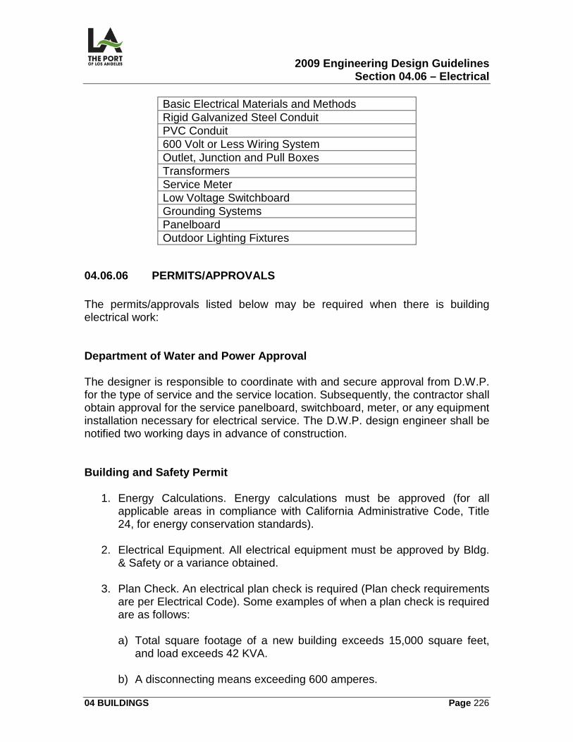
2009 Engineering Design Guidelines Section 04.06 – Electrical
04 BUILDINGS Page 226
Basic Electrical Materials and Methods Rigid Galvanized Steel Conduit PVC Conduit 600 Volt or Less Wiring System Outlet, Junction and Pull Boxes Transformers Service Meter Low Voltage Switchboard Grounding Systems Panelboard Outdoor Lighting Fixtures
04.06.06 PERMITS/APPROVALS The permits/approvals listed below may be required when there is building electrical work: Department of Water and Power Approval The designer is responsible to coordinate with and secure approval from D.W.P. for the type of service and the service location. Subsequently, the contractor shall obtain approval for the service panelboard, switchboard, meter, or any equipment installation necessary for electrical service. The D.W.P. design engineer shall be notified two working days in advance of construction. Building and Safety Permit
1. Energy Calculations. Energy calculations must be approved (for all applicable areas in compliance with California Administrative Code, Title 24, for energy conservation standards).
2. Electrical Equipment. All electrical equipment must be approved by Bldg.
& Safety or a variance obtained.
3. Plan Check. An electrical plan check is required (Plan check requirements are per Electrical Code). Some examples of when a plan check is required are as follows:
a) Total square footage of a new building exceeds 15,000 square feet,
and load exceeds 42 KVA. b) A disconnecting means exceeding 600 amperes.
2009 Engineering Design Guidelines Section 04.06 – Electrical
04 BUILDINGS Page 227
c) The additional loads exceed 600 amperes.
d) Space is conditioned over 1,000 square feet (heated/air conditioned).
e) When building occupancy requires an electrical emergency system.
f) When high voltage (greater than 600V.) is required for electrical
service.
4. Permit. The electrical permit may be secured by a C-10 contractor once the plans have been approved.
04.06.07 ENVIRONMENTAL CONSIDERATIONS
1. Use light glare control measures and equipment wherever practical to reduce light spillage.
2. Minimize use of flood light fixtures and instead utilize down light fixtures
with the total cutoff feature.
04.06.08 REFERENCE DRAWINGS The following contract drawings are identified for reference: 1-2575 Berths 90-91 Temporary Cruise Terminal Baggage Handling Building
1-2575 E-1 Electrical Notes, Symbols, and Abbreviations 1-2575 E-2 Electrical Site Plan 1-2575 E-3-5 Floor Plan - Lighting 1-2575 E-6-8 Floor Plan - Power and Communication 1-2575 E-12-13 Single Line Diagram and Panelboard Schedules
1-2107A Banning’s Landing Project 1-2107A E-11 Roof Plan 1-2107A E-12 Electrical Details
2009 Engineering Design Guidelines Section 04.06 – Electrical
04 BUILDINGS Page 228
1-2450 Berths 225-232 Evergreen Terminal Admin Office Modification 1-2450 E-6 Title 24 Calculations & Compliance Forms LAHD Standard Plans
2009 Engineering Design Guidelines Section 04.07 – Fire Protection System
04 BUILDINGS Page
04.07
FIRE PROTECTION SYSTEM
04.07.01 OVERVIEW This section contains the following information related to the preparation of fire protection system contract drawings:
• Automatic Fire Sprinkler System Site Plan (FP)
• Automatic Fire Sprinkler System Plan (FP)
• Automatic Fire Sprinkler System Section and Details (FP)
04.07.02 DESIGN CRITERIA General Design Requirements The designer shall meet all applicable regulations, standards, and guidelines of (latest edition):
1. City of Los Angeles Plumbing Code. 2. National Fire Protection Association (N.F.P.A. 13 and other standards
cross-referenced by N.F.P.A. 13) -- in hydraulic design of the system.
3. City of Los Angeles Fire Code. Materials All materials shall be U.L. listed or be tested and approved by City of Los Angeles Department of Building and Safety. It shall be the responsibility of the designer during the plan check period to obtain a variance from Bldg. & Safety for those materials specified which do not meet either of these requirements. Pipes
1. Underground. Underground pipes 4 inches and larger shall be ductile iron, Class 52, manufactured per A.W.W.A. (American Water Works Association) C151, and shall be specified to be lined with cement mortar.
2009 Engineering Design Guidelines Section 04.07 – Fire Protection System
04 BUILDINGS Page
2. Above Ground. All above ground pipes shall be steel, Schedule 40, and manufactured per A.S.T.M. (American Society for Testing and Materials) 139-90.
3. Friction Losses. Pipe friction losses shall be determined on the basis of
Hazen & Williams' formula or an approved fire sprinkler calculation method.
4. Wet-Pipe System. A wet-pipe system shall be used. The exception is in
cold storage and freezer buildings and where expensive and water sensitive electrical equipment is present, where the following is used instead:
a) In cold storage and freezer buildings -- a double interlocked,
supervised, dry system with deluge valve controlled by an electric release system and pneumatic system pressure.
b) In presence of high-value and water sensitive electrical/electronic
equipment, the most effective of the following may be considered: clean agent fire extinguishing systems, dry chemical systems, foam systems, or halogenated hydrocarbon systems.
Corrosion Protection
1. Piping Encasement. Underground piping shall be provided with corrosion protection by use of polyethylene film encasement in full accordance with A.W.W.A. (American Water Works Association) C105, "Polyethylene Encasement for Ductile Iron Piping for Water Standards."
2. Termination. Corrosion protection shall terminate no less than 12 inches
above the adjacent finished surface. Valves
1. Buried. Buried valves shall be resilient wedge gate, N.R.S. (non-rising stem), and shall be provided with a post indicator or a position indicator when it is impractical to use the former.
2. Above Ground. Above ground valves for fire protection shall be gate valve,
O.S.&Y. (outside screw and yoke) type, or butterfly valve.
2009 Engineering Design Guidelines Section 04.07 – Fire Protection System
04 BUILDINGS Page
3. Value Supervision. Valves shall be supervised open by an alarm system, which will cause the sounding of an audible signal at a constantly attended location.
Water Supply Sprinkler systems shall be supplied with water from D.W.P. mains, either directly or through existing backland mains. The designer shall request an S.A.R. (Service Advisory Report) from D.W.P. for the pertinent point of connection at their mains -- to be used in the hydraulic calculations. Plan Submission The designer shall provide two sets of plans that have been approved by Bldg. & Safety before installation starts. At least one of the sets shall bear the original stamp of approval. The rest may be copies.
04.07.03 CALCULATIONS/WORKSHEETS The designer shall prepare the hydraulic calculations at the same time as the submission of the approved plans, prepared per (and on worksheets similar in form to) N.F.P.A. 13.
04.07.04 GRAPHIC CRITERIA
1. Site plan 2. Fire Sprinkler Floor Plan
3. Roof Plan
4. Section plan
5. Legend
6. Details
04.07.05 SPECIFICATIONS
2009 Engineering Design Guidelines Section 04.07 – Fire Protection System
04 BUILDINGS Page
The following sections in the Harbor Department Master Specifications relate to buildings (other sections may be required, depending upon the project):
SECTION TITLE Fire Protection
04.07.06 PERMITS/APPROVALS The permit listed below is required when there is fire protection system work: Building and Safety Permit A plan check is required of fire protection system plans. The plumbing permit shall be secured by the installer or contractor once the plans have been approved. Fire Sprinkler System Checklist Requirements
1. Hazard classification of occupancy 2. Classification of automatic sprinkler system to be used
3. Source of water (From S.A.R.from DWP)
4. Alarm valves
5. Pressure gauges
6. Pipes, valves, fittings, and types of joints
7. Pipe hangers, braces, and fasteners
8. Sprinkler heads
9. Supervisory switches
10. Water motor and gong
11. Plan check
12. Hydraulic calculations
2009 Engineering Design Guidelines Section 04.07 – Fire Protection System
04 BUILDINGS Page
13. Backflow preventer
14. Automatic sprinkler riser
15. Fire Department connection
16. Inspector's test valve
17. Control valve and post indicator
04.07.07 ENVIRONMENTAL CONSIDERATIONS Specify fire suppression systems that use no HCFCs or Halons. Specify Low-VOC materials in construction documents. Ensure that VOC limits are clearly stated in each section where paints, adhesives, and sealants are addressed.
04.07.08 REFERENCE DRAWINGS The following contract drawings are identified for reference: 1-2325A Berths 93A&B World Cruise Center Renovation
1-2325A FP-1 Fire Protection Abbreviation, Legend, Notes, Symbol, and Site plan
1-2325A FP-10 1st Level Existing and Proposed Enlarged Fire
Protection Plan
1-2325A FP-12 Fire Protection Elevation Plan 1-2325A FP-13 Fire Protection Details
LAHD Standard Plans
2009 Engineering Design Guidelines Section 04.08 – Removals and Demolition
04 BUILDINGS Page 234
04.08
REMOVALS AND DEMOLITION
04.08.01 OVERVIEW This section contains the following information related to the preparation of removals and building demolition contract drawings:
• Building Demolitions and Removals
04.08.02 DESIGN CRITERIA General
1. Determine building(s) to be demolished. 2. Determine all items to be removed, salvaged, and/or relocated.
3. Verify existing conditions and substructures (using as-builts, field
investigations, and/or survey).
4. Clearly indicate/identify limits of removal. Coordination Coordination is required with the following:
1. Customers, utility owners, agencies, other contractors, project site tenant(s), and adjacent tenants.
2. POLA Divisions: Construction & Maintenance and Construction
Management, Real Estate, Environmental Management, Risk Management, and Wharfingers.
3. Utility owners: DWP, Gas Co., Pacific Bell, and Wharfingers for utility
disconnects.
4. Risk Management and Environmental Management for hazardous removals (asbestos abatement, hydrocarbon contaminated material)
5. Pacific Harbor Lines (PHL), when in the vicinity or within 10' of the tracks.
2009 Engineering Design Guidelines Section 04.08 – Removals and Demolition
04 BUILDINGS Page 235
Salvage Identify salvage items (requires prior coordination/request with C&M), include delivery location, contact person and phone number. Salvaged asphalt concrete & unreinforced concrete rubble: deliver to the Department stockpile site per specification section BUILDING DEMOLITION AND REMOVALS. Building Demolition Clearly identify and describe the building and all items within the building and project limits to be demolished and/or removed, including footings/foundation, if applicable. Provide:
1. Address 2. Size (square feet)
3. Type of building material
4. Number of stories
5. Reference drawing numbers
6. Method of demolition (as required by B&S)
7. Determine/indicate if protection fence and/or canopy is required (by B&S)
8. Request for asbestos and lead based paint survey/report
9. Unreinforced Masonry Building. When demolishing an unreinforced
masonry building, the designer shall prepare detailed demolition drawings (per City of Los Angeles Department of Building & Safety requirements) to a preferred scale of 1/4" = 1'0".
Removals: Container Terminal Backland, Wharf, Roadways, Miscellaneous Areas Refer to 03 BACKLAND, 05 Removals and Existing Substructures Historical Assessment
2009 Engineering Design Guidelines Section 04.08 – Removals and Demolition
04 BUILDINGS Page 236
The Project Manager shall request the E.M.D. to perform an historical assessment on any existing facility at least 50 years old or of potential historical significance. Disposal
1. Asphalt Concrete and Unreinforced Concrete. Coordinate with Construction Management for the disposal at the Port's stockpile site per Specifications.
2. Hazardous Waste-Disposal of all hazardous waste material shall be
coordinated with the Risk Management and Environmental Management Divisions. The waste material shall be disposed of at an approved disposal site off Port property. Each project is evaluated for remediation on a case by case basis.
3. Items not to be salvaged or re-used shall be disposed of off Port property.
Environmental/Hazardous Materials Suspected Contamination - An Environmental Site Assessment and Characterization must be done prior to demolition if the project area has suspected contamination.
1. Asbestos Abatement 2. Lead Based Paint
3. Contaminated Soil, Hydrocarbon Impacted Soil, and/or Water
4. Creosoted Timbers/Piles
5. Molds: Identified as those that are considered long-term health threat
04.08.03 CALCULATIONS/WORKSHEET There are no calculations or worksheets provided for this section.
04.08.04 GRAPHIC CRITERIA
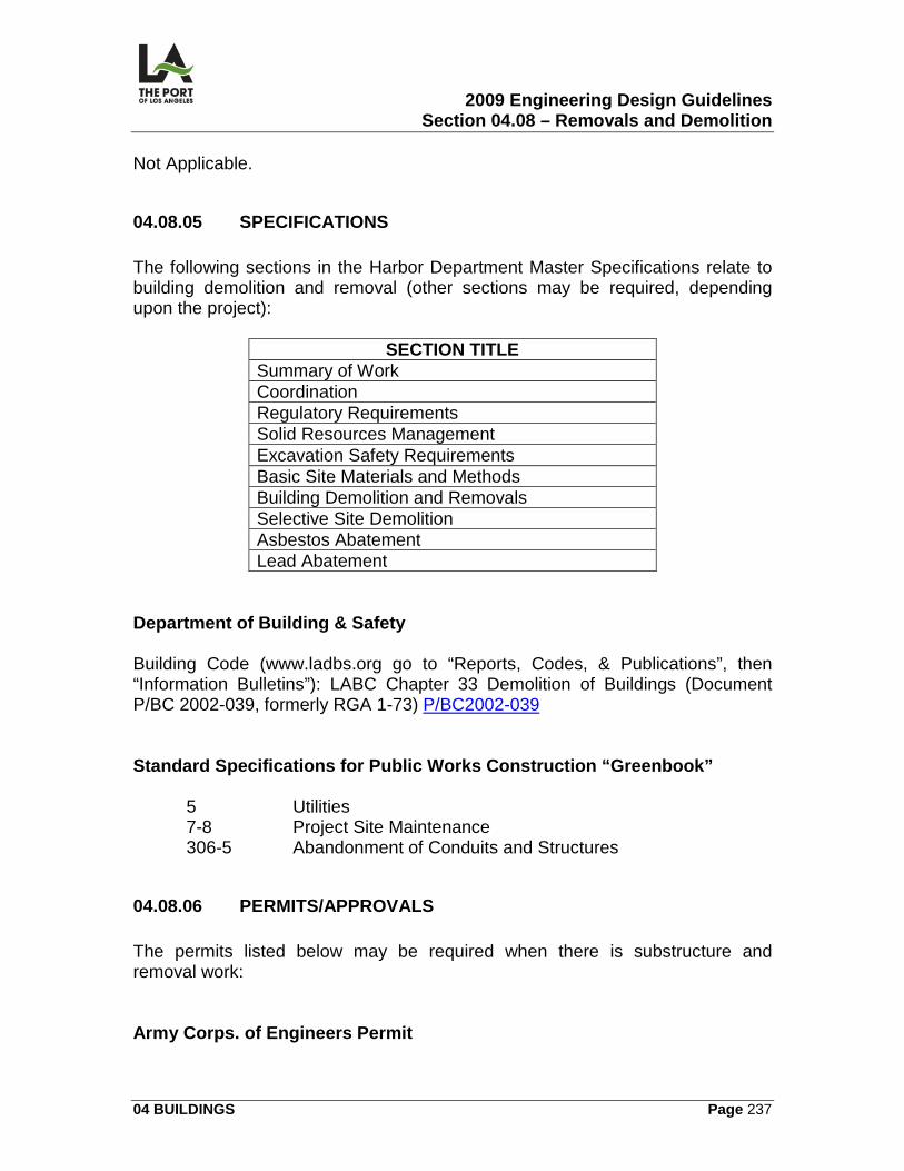
2009 Engineering Design Guidelines Section 04.08 – Removals and Demolition
04 BUILDINGS Page 237
Not Applicable.
04.08.05 SPECIFICATIONS The following sections in the Harbor Department Master Specifications relate to building demolition and removal (other sections may be required, depending upon the project):
SECTION TITLE Summary of Work Coordination Regulatory Requirements Solid Resources Management Excavation Safety Requirements Basic Site Materials and Methods Building Demolition and Removals Selective Site Demolition Asbestos Abatement Lead Abatement
Department of Building & Safety Building Code (www.ladbs.org go to “Reports, Codes, & Publications”, then “Information Bulletins”): LABC Chapter 33 Demolition of Buildings (Document P/BC 2002-039, formerly RGA 1-73) P/BC2002-039 Standard Specifications for Public Works Construction “Greenbook”
5 Utilities 7-8 Project Site Maintenance 306-5 Abandonment of Conduits and Structures
04.08.06 PERMITS/APPROVALS The permits listed below may be required when there is substructure and removal work: Army Corps. of Engineers Permit
2009 Engineering Design Guidelines Section 04.08 – Removals and Demolition
04 BUILDINGS Page 238
Army Corps - Removal Permit is required when work is done in their jurisdiction (any land area in the tidal zone up to M.H.H.W. [Mean Higher High Water]). Department of Public Works (P.W.) Permit Sewer cap permit, the City of Los Angeles [Department of P.W.Bureau of Engineering,], must approve the sewer capping plans. Harbor Department credit will be established for the sewer facility charge. Department of Building & Safety Permit A plan check is required after obtaining the Sewer Cap Permit. Once approved, the Demolition Permit may be obtained. (C-21 License is required). Hazardous Materials Permits The removal and disposal of hazardous materials and wastes shall be in accordance with current regulatory requirements (e.g., A.Q.M.D., Fire Department, E.P.A., etc.). They vary depending upon the type of hazardous materials or wastes involved.
04.08.07 ENVIRONMENTAL CONSIDERATIONS Not Applicable.
04.08.08 REFERENCE DRAWINGS The following contract drawings are identified for reference: 1-2343 Berth 142 Union Ice Building Demolition and Site Improvements.
1-2343 R-1 Substructure, Demolition and Removal Plan
2009 Engineering Design Guidelines Section 05.01 – General
05 WHARF Page 239
05 WHARF 05.01
General
05.01.01 OVERVIEW This section contains information related to the preparation of the following wharf general contract drawings: Cover Sheet (T)1
Title Sheet (T)
Coordinate Control Plan (CC) Phasing Plan (C) Dredging Plan (C) Backfill and Shoring Protection Plan (C)
05.01.02 DESIGN CRITERIA Dredging Slope Typically, the maximum dredging slope is 2 1/4 horizontal to 1 vertical. This is subject to verification by the geotechnical report. Orientation of Wharfs on Plans Generally, the wharf shall be shown on the plan in such a way that the water-side is on the top of the drawing.
05.01.03 CALCULATIONS/WORKSHEETS There are no wharf general calculations or worksheets provided for this section. The designer is, however, required to submit approximate dredge quantity calculations for the US Army Corps of Engineers application. Final dredge quantity calculations shall be prepared for the final plan/specifications review (or submittal). Estimating
1 The drawing number (with letter designations) is defined under 02.04 of these Guidelines
2009 Engineering Design Guidelines Section 05.01 – General
05 WHARF Page 240
There are no estimating worksheets provided for this section. The cost impact of "phasing" a project is normally included in the unit and lump sum cost of specific facility estimates. Dredging, backfill, and shoring estimates are included in the Basic Wharf. Design wharf section as follows:
1. Dredging -- by cubic yard (Marine Work). 2. Backfill -- by cubic yard (Earthwork).
3. Shoring -- by linear foot (Earthwork).
05.01.04 GRAPHIC CRITERIA Cover Sheet This sheet consists of one layer and contains the title, specification number, and initial signatures and stamps. Title Sheet This sheet contains the title information including the project name, vicinity map, index (drawing numbers/names, standard plans, and reference drawings), general project notes (with abbreviations and general legend), and the vicinity map. It consists of the following layers:
1. Standard title sheet and text indicating index information, project notes, abbreviations, general legend, and project site location arrow/information for the vicinity map.
2. Vicinity map of the entire harbor area.
3. Appropriate vicinity map text.
4. Water area shading.
Site Plan This sheet includes an abbreviated general summary of what exists on the site after removals and what the overall results of the project are going to be. It consists of the following layers:
2009 Engineering Design Guidelines Section 05.01 – General
05 WHARF Page 241
1. Base map (site plan) -- without text. 2. Main proposed surface improvements (site plan) -- without text.
3. Project boundaries, contractor storage yard, and areafill -- with text.
Coordinate Control Plan This sheet includes the project boundaries, and consists of the following layers, that indicate distance and bearings on the site parcel:
1. Base map (site plan) -- without text. 2. Main proposed surface improvements (site plan) -- without text.
3. The,field notes include Field Book references, zone used, and last survey
date, as well as coordinate control information, such as: coordinates; metes and bounds description of each line (distance and bearing); property and lease lines; and pierhead lines.
Phasing Plan This sheet consists of the following layers:
1. Base map (site plan) -- without text. 2. Main proposed surface improvements (site plan) -- without text.
3. Project boundaries, phasing boundaries, temporary fencing, contractor
storage area, and areafill -- with text. Dredging Plan This sheet consists of the following layers:
1. Elevations and contour lines -- without additional text. 2. Wharf outline, pierhead line, and shore facilities -- with text.
Backfill and Shoring Protection Plan
2009 Engineering Design Guidelines Section 05.01 – General
05 WHARF Page 242
This sheet consists of one layer -- with text. Line Style Refer to the Port’s CADD manual for line style for wharf general drawings.
05.01.05 SPECIFICATIONS The following sections in the Harbor Department Master Specifications relate to wharf general (other sections may be required, depending on the project):
SECTION TITLE Coordination Regulatory Requirements Excavation Safety Requirements Earthwork Dredging Rock
05.01.06 PERMITS/APPROVALS A US Army Corps of Engineers Permit is required whenever there is dredging done. This and all other permits needed for wharf work are included in the Basic Wharf Design section.
05.01.07 ENVIRONMENTAL CONSIDERATIONS Creosoted piles shall not be used.
05.01.08 REFERENCE DRAWINGS The following contract drawings are identified for reference: 1-1500 Berths 174-176 Wharf Improvements
1-1500 C-1 Cover Sheet 1-1500 C-4 Site Plan 1-1500 CC-5 Coordinate Control Plan
2009 Engineering Design Guidelines Section 05.01 – General
05 WHARF Page 243
1-1500 C-6 Dredging Plan 1-1500 C-7 Backfill and Shoring Protection
1-1190 Berth 206 Container Wharf Extension 1-1190-1 Title Sheet2
1-1466 Wharf Improvements - Berths 218 - 221
1-1466 C-3 Site and Construction Phasing Plan
2 The drawing number for the title sheet per the CADD manual should be T-2 with T-1 being the cover sheet
2009 Engineering Design Guidelines Section 05.02 – Basic Wharf Design
05 WHARF Page 244
05.02
BASIC WHARF DESIGN
05.02.01 OVERVIEW This section contains guidelines for the design of concrete wharf structures including embankment and dike construction, dredging, and ancillary features. Wharfs for services other than container traffic should follow similar guidelines as appropriate. These guidelines must be adjusted and approved by the Chief Harbor Engineer (CHE) for project specific conditions of new wharfs and wharf upgrades and repairs.
05.02.02 DESIGN CRITERIA General Guidelines for Concrete Wharfs The following general wharf design guidelines are based on the most current wharf design at the Port of Los Angeles. The only exception to the application of these guidelines is that in the event that adjustments to these criteria are required for a specific site or berth design (due to changes in the most current engineering practices, standards, and/or specific site conditions), the Chief Harbor Engineer must approve such modifications. These guidelines shall apply to:
1. All design, construction, reconstruction, rehabilitation, and/or repair of existing and future concrete wharf structures in the Port.
2. The repair of earthquake-damaged concrete wharfs, regardless of whether
batter piles or vertical piles are currently providing the lateral force resisting system to resist the effects of seismic ground motions.
Codes Wharf design shall conform to the codes, standards, and/or requirements listed below (using the most current editions). In cases of conflict between codes, the most restrictive requirement (as interpreted by the Chief Harbor Engineer) shall govern the design. The designer shall present any conflicts in codes, standards, or guidelines to the Chief Harbor Engineer for discussion and resolution. The list of requirements includes:
1. Port of Los Angeles – the latest adopted version of the POLA Code for Seismic Design, Upgrade and Repair of Container Wharfs.
2009 Engineering Design Guidelines Section 05.02 – Basic Wharf Design
05 WHARF Page 245
2. Concrete -- Building Code Requirements for Reinforced Concrete, ACI
318, American Concrete Institute, with the following additional requirements:
a) The minimum concrete cover over reinforcement shall be 3 inches for
prestressed concrete piles, wharf beams and slabs, and all concrete placed against soil.
b) The cast-in-place concrete used in wharfs shall have a minimum
ultimate strength of f'c = 5000 PSI at 28 days and a maximum water/cement ratio of 0.40.
c) The concrete used in precast piles shall have a minimum ultimate
strength of f'c = 6500 PSI at 28 days and a maximum water/ cement ratio of 0.38.
3. Structural steel -- Steel Construction Manual, American Institute of Steel
Construction (A.I.S.C.). 4. Distribution of wheel loads -- Bridge Design Specifications, A.A.S.H.T.O.
5. Welding -- Structural Welding Code - Steel (A.W.S. D1.1) and Structural
Welding Code - Reinforcing Steel (A.W.S. D1.4), American Welding Society.
6. Timber -- National Design Specifications for Wood Construction.
7. For items not covered in Nos. 1-6 above -- City of Los Angeles Building
Code. For any items not covered in this Code, design criteria and standards should be based on current accepted engineering practice related to the design of marine terminals.
Special Moment Resisting Frame The wharf shall typically be designed as a special moment resisting frame supported by vertically driven reinforced piles. The piles are connected to the wharf as an integral part of the special moment resisting frame. No batter piles shall be used unless special provisions are made to ensure ductility to the satisfaction of the Chief Harbor Engineer. This frame is specially detailed to provide ductile behavior as described in “The Port of Los Angeles Code for Seismic Design, Upgrade and Repair of Container Wharves”.
2009 Engineering Design Guidelines Section 05.02 – Basic Wharf Design
05 WHARF Page 246
Erosion Control A sufficiently deep cutoff wall (or other means) shall be provided along the back of the wharf to prevent erosion of backland materials by tidal action or other waterside disturbances under the wharf. The slope beneath the wharf shall be protected from erosion by the placement of appropriately sized riprap (or by other approved means). Dike or Cut Slope The dike or cut slope beneath the wharf shall be designed to withstand the same seismic forces as the wharf structure. It shall retain the soil behind the slope under the design earthquake loading. Flexible Connections Flexible connections shall be provided where utilities pass from the backland through the cutoff wall or other rigid structure at the back of the wharf. Project Description/Site Conditions The structural designer shall supply a short description of the new construction as part of the conceptual design, including a description of the existing site conditions and how they influence proposed construction. Ship Characteristics Information on ship characteristics is provided in 07.01 to assist in:
1. Calculating forces on the fendering system. 2. Determining bollard pull.
3. Designing berth length and width between berths.
4. Selecting cranes with adequate outreach and height.
Geotechnical Report
2009 Engineering Design Guidelines Section 05.02 – Basic Wharf Design
05 WHARF Page 247
1. Site Specific. The structural designer shall request a site specific geotechnical report (signed by a registered geotechnical engineer):
a) As the basis for the foundation and seismic design of the wharf. b) To provide information on safe and economical dike or embankment
construction, pile driving, and dredging.
2. Coordination. Coordination with the geotechnical requirements for the backland design is required.
Design Assumptions The Harbor Department has jurisdiction over the structural design of the wharfs and the geotechnical design of the dikes or embankments. The City of Los Angeles Department of Building & Safety will review and approve electrical, mechanical and grading work. This Department will also coordinate special design requirements with the Harbor Department for all wharfs that support buildings with public occupancy. The California State Lands Commission has jurisdiction for the design of liquid bulk wharfs (oil terminals).
1. Basis of Design - The Engineer of Record (designer) should prepare a “Basis of Design” document (codes, design criteria, loadings, etc.) prior to commencing the conceptual design. Any requirements not specifically called out in these guidelines will be determined by the CHE and should be incorporated in the “Basis of Design” document.
2. Project Description/Site Conditions - The structural designer should supply
a short description of the new construction as part of the conceptual design, including a description of the existing site conditions. Particular attention should be given to the construction phasing as required by the port, the tenant or by technical requirements. A site specific geotechnical report is required for the design. The Port of Los Angeles (POLA) will provide site specific seismic hazard criteria to the designer (Portwide Groundmotion and Palos Verdes Fault Study).
3. Loading - The wharf should be designed for the maximum equipment and
cargo loading as well as for the maximum berthing and mooring loads likely to be imposed on the structure over its economic life.
4. Changing Design Requirements - Port requirements for container wharfs
are constantly evolving, particularly regarding ship size, container cranes and seismic requirements. The wharf designer should take into account how new requirements may affect the design criteria.
2009 Engineering Design Guidelines Section 05.02 – Basic Wharf Design
05 WHARF Page 248
5. Wharf Foundation:
a) Erosion Control: A sufficiently deep cutoff wall (or other means) should
be provided along the back of the wharf to prevent erosion of backland materials by tidal action or other waterside disturbances under the wharf. The slope beneath the wharf should be protected from erosion by the placement of appropriately sized riprap (or by other approved means). The cutoff wall should not be part of the lateral force resisting design.
b) Dike or cut slope: The dike or cut slope beneath the wharf retains the
soil under static and seismic conditions and should have a minimum static safety factor of 1.5. For the seismic design of dikes or cut slopes see POLA Code For Seismic Design, Upgrade, And Repair Of Container Wharfs.
6. Flexible Connections - Flexible connections should be provided where
utilities pass from the backland through the cutoff wall or other rigid structures at the back of the wharf.
7. Ship Characteristics - New wharfs should be designed to accommodate
9100 TEU vessels. Ship characteristics are provided in Section 07.01 and are for information only. Ship data provided by the customer should control the design. Ship characteristics are provided to assist in:
a) Calculating the required energy and reaction for the fendering system. b) Determining bollard pull.
c) Selecting the required berth length.
d) Selecting cranes with adequate outreach and height.
Guidelines for Concrete Wharfs for Container Operations Structural Systems The structural designer shall use the following criteria when designing the wharf structural systems:
1. Wharf -- designed as a special moment resisting frame. 2. Wharf Deck -- two-way flat plate.
2009 Engineering Design Guidelines Section 05.02 – Basic Wharf Design
05 WHARF Page 249
3. Foundation -- open field piles.
4. Piling -- 24 inch octagonal precast, prestressed concrete, or equivalent
square pile.
5. Lateral resistance -- vertical piles in bending.
6. Fender system -- solid rubber buckling column systems with protector panels.
7. Crane rails -- pile supported and connected horizontally by continuous
wharf deck or other means to control the gauge of the rails.
8. Crane storage pocket spacing -- typically 162 feet apart. Vertical Loads
1. Uniform Live Load - The uniform live load should be (both inboard/outboard of waterside crane girder):
a) 1000 psf -- for the design of deck and girders. b) 800 psf -- for the design of piles.
2. Concentrated Loads - Design should provide for 100 kip wheel loads (140
PSI) + 25% impact loads = 125 kip (2 wheels located at 13 feet O.C. with a wheel print area of 4.95 square feet).
3. Gantry Crane Rail Girders - The design should provide for the following:
a) The crane girder load will be determined on a case by case basis and
should be approved by the CHE before commencing the preliminary design. The minimum crane girder load should be 50 kip/foot for 100 foot gage crane rails.
b) Side thrust at crane rails - As determined by crane manufacturer.
c) One Broken Pile Criteria - Outboard crane girder on row A should be
able to support the operating crane with one interior pile removed by damage. The intent of designing the crane girder for a one broken pile condition is to permit crane operations until the pile can be repaired at an appropriate time.
2009 Engineering Design Guidelines Section 05.02 – Basic Wharf Design
05 WHARF Page 250
d) Two Broken Piles Criteria - Outboard crane girder on row A should be able to support the crane dead load with two adjacent piles removed by damage. The intent of designing the crane girder for a two broken pile condition is to permit transfer of cranes to the other side of the damaged wharf until the pile can be repaired at an appropriate time.
e) The crane girder should be designed as a beam on elastic foundation
to take the elastic pile shortening and the pile tip movement under load into account.
4. Railroad Load - Designs should provide for AREMA Manual for Railway
Engineering Cooper E80 loads plus 15% impact load if railroad loading is required by the customer.
5. Part of the wharf deck may be designed as Heavy Lift Section: If used,
loads will be determined by the CHE.
6. Utility Vault Covers - A.A.S.H.T.O. HS 20 – 44 trucks or 1000 PSF live load.
7. Power Trench Covers - A.A.S.H.T.O. HS 20 – 44 trucks or 1000 PSF live
load. Lateral Loads
1. Mooring and Berthing Forces:
a) Mooring bitt line load - Depend upon the ship size and should be approved by the Chief Harbor Engineer.
b) Berthing and Breasting loads - Depend upon the ship size and should
be approved by the CHE. Fenders shall be designed in accordance with the “Guidelines for the design of Fender Systems:2002”, Report of Working Group 33 of the Maritime Navigation Commission by the International Navigation Association (PIANC 2002)3
. For smaller ships the approach velocity should be appropriately increased.
2. Seismic Design: Project specific seismic hazard criteria will be provided by the POLA. The seismic design is discussed in greater detail in the Seismic Design Section of these guidelines.
3 These guidelines make the reference to an approach velocity obsolete by introducing the Abnormal Berthing Condition with different adjustment factors.
2009 Engineering Design Guidelines Section 05.02 – Basic Wharf Design
05 WHARF Page 251
Load Combinations, Allowable Stresses, and Load Factors The concrete wharf components should be designed for the load factors and load combinations as stipulated in the Building Code Requirements for Reinforced Concrete, A.C.I. 318. In addition the following load factors and load combinations should be considered:
1. Load factors (L.F.) for the design of container crane girders and pile supports (not applicable for seismic loading):
a) Stowed condition - L.F. = 1.4 for crane wheel loads due to the dead
load of cranes or due to wind. b) Operating condition - L.F. = 1.45 for wheel loads due to the dead load
of cranes plus operational wind and container loading.
c) All code allowable reductions for wind should be taken into account.
d) Design of crane girders: The design of the crane girder for broken pile conditions may be based on reduced load factors as follows:
1) Acceptance criteria for the effect of a single broken pile:
(a) Load factor on crane operating load = 1.45 (b) Maximum crane girder moment = ФMn
(c) Maximum pile load = 0.75 Pn
2) Acceptance criteria for the effect of two broken piles:
(a) Load factor on crane dead load = 1.15 (b) Maximum crane girder moment = ФMn
(c) Maximum pile load = 0.85 Pn
2. Load factors for the design of piles in the soil should be as recommended
by the geotechnical report, but not less than 2.0. This load factor is not applicable for seismic loading.
3. Dead load + mooring: use the same load factor as for live loads based on
latest Navy criteria.
2009 Engineering Design Guidelines Section 05.02 – Basic Wharf Design
05 WHARF Page 252
4. Dead load + berthing: use the same load factor as for live loads. Do not use any code reduction factors for temporary loading.
5. For loads due to earth pressure, see the geotechnical report.
Materials Materials should meet the following strength, code, and other requirements.
1. Cast in Place Deck Concrete.
a) f'c = 5000 PSI b) W/C ratio: 0.40
2. Precast Concrete Piles.
a) Concrete:
1) f'c = 6500 PSI 2) W/C ratio: 0.38
b) Effective prestress: 1000 PSI to 1200 PSI
3. Precast Concrete - Cut off wall, firewalls, utility vaults -- f'c = 5000 PSI. 4. Reinforcing:
a) All reinforcing bars except listed below -- A.S.T.M. A615, Grade 60. b) Pile dowels -- A.S.T.M. A706, Grade 60.
c) Spiral pile reinforcing -- A.S.T.M. A 82.
d) Prestressing strands -- A.S.T.M. 416, Grade 270K.
5. Structural Steel:
a) Plates and shapes -- A.S.T.M. A36. b) Bolts and nuts -- A.S.T.M. A307.
c) All ferrous metal should be galvanized, except where designated
otherwise.
2009 Engineering Design Guidelines Section 05.02 – Basic Wharf Design
05 WHARF Page 253
d) Corrosion protection and coating should be per Port specifications.
e) Lumber and Timber: Douglas fir should be used in all cases.
Container Cranes The designers should refer to section 06.05, Cranes (Special Facilities chapter of the Engineering Design Guidelines) to ensure that the wharf is able to handle the necessary cranes and associated equipment. Design Checklist The designer should use the Checklist of Basic Wharf Design to ensure that the drawings and specifications have been prepared carefully.
05.02.03 CALCULATIONS/WORKSHEETS Calculations are required for the wharf structural design. The structural criteria used by the designer (design criteria, loading, structural materials specified, and the requirements for the construction as they affect the design such as phasing etc.) should be listed on the first pages of the calculations (see sample Table of Contents for structural calculations on 05.08). As a minimum, they shall include the following items:
1. Title of the project. 2. Short description of the project and the structural system to be used.
3. Applicable codes and standards, including geotechnical criteria.
4. Short description of materials (steel, concrete, reinforcing bars, timber,
and protective coating).
5. Ship criteria (length, beam and draft, size, and approach velocity).
6. Environmental conditions (tidal levels, current, wave, wind, seismic criteria, and temperature).
7. Loads (vertical/horizontal); mooring, breasting, and berthing loads shall be
called out separately.
2009 Engineering Design Guidelines Section 05.02 – Basic Wharf Design
05 WHARF Page 254
8. Load combinations, allowable stresses, and strength requirements.
Structural and geotechnical requirements shall be called out separately.
9. Other site and project specific conditions important for the design and construction of the project. If necessary, refer to other specifications or reports for a more detailed description.
10. The designer shall prepare all calculations on worksheets in compliance
with POLA's Engineering Division's latest format. Estimating Estimating worksheets for the wharfs should be prepared including careful documentation. See Estimating Worksheets in 05.02.08. Independent Review The calculations should be clear and self-contained (i.e., readable without reference to contract specifications or contract drawings). Adequate descriptive text and sketches must be provided to make an independent review possible. Clarity of Inclusions
1. Superseded Calculations. Superseded calculations may be included, but shall be clearly crossed out and marked "superseded".
2. Final Calculation Results. The final results of the calculations (e.g.,
reinforcing bar sizes and spacing, required beam dimensions, etc.) shall be underlined or marked so that they are prominent.
3. Cross References/Pagination. Cross references (with page numbers) shall
be provided when the results of one part of the calculations are used as input for other parts of the calculations.
4. Sketches. Sketches of related structures shall be included, if necessary, to
clarify calculations.
5. Unusual Formulas. References shall be provided for unusual formulas. The procedures or code paragraphs which were followed shall be clearly described.
6. Computer Program Results.
2009 Engineering Design Guidelines Section 05.02 – Basic Wharf Design
05 WHARF Page 255
a) Calculations may include the results from an electronic digital
computer program. A sketch of the complete mathematical model used to represent the structure in the computer-generated analysis shall be provided. Data provided as computer input shall be clearly distinguished from those computed in the program. The output information shall include all input data and units. The final results shall be clearly marked.
b) All calculation submittals which include a computer output shall meet
the requirements of the Recommended Lateral Force Requirements (Chapter 1, Paragraph A.5), issued by the Seismology Committee of the Structural Engineers Association of California.
c) An index cataloging computer results, pages on which the results are
found, etc., shall be included.
05.02.04 GRAPHIC CRITERIA Plans should generally follow the examples of the latest POLA wharf projects. A set of these projects will be made available to the designer by POLA.
05.02.05 SPECIFICATIONS The following sections in the Harbor Department Master Specifications relate to basic wharf design (other sections may be required, depending upon the project):
DESCRIPTION Dewatering Earthwork Dredging Ratproofing Rock Concrete Wharf Construction Rubber Fenders Cast Steel Bollard Prestressed Concrete Piles Indicator Pile Testing Welding of Crane Rails Timber Bullrails and Crane Stop Bumpers Crane Rail
2009 Engineering Design Guidelines Section 05.02 – Basic Wharf Design
05 WHARF Page 256
05.02.06 PERMITS/APPROVALS The designer shall list all agencies requiring permits (and state the person responsible for application and coordination of each permit) and present the list to the Chief Harbor Engineer for review. Permits are generally handled by the Permit Section of the Engineering Division. The Permit Section will be supported by the pertinent Sections of the Engineering Division. The permits listed below may be required. They are listed for information only. The list may not be comprehensive. US Army Corps of Engineers (ACE) Permit US Army Corps of Engineers (ACE) Permit. All new construction in the water area requires an ACE permit. This permit must be obtained prior to the Notice to Proceed being issued to the contractor. California Regional Water Quality Control Board Permit This permit is also required. California Coastal Permit This permit is required prior to advertising. Department of Building & Safety Permits The City of Los Angeles Department of Building & Safety permits (electrical, mechanical, etc.) are each required prior to construction of that element for which the permit is to be issued -- secured by the Section responsible for that element for in-house projects. No permit is required for the wharf structure, because its design is within the Port's jurisdiction. AQMD Rule 1166 Permit This permit is required prior to excavation of soil containing volatile organic compounds (preferably prior to advertising) -- secured by either the lead Section or by the Structural Section for in-house projects.
2009 Engineering Design Guidelines Section 05.02 – Basic Wharf Design
05 WHARF Page 257
05.02.07 ENVIRONMENTAL CONSIDERATIONS Creosoted piles shall not be used.
05.02.08 REFERENCE DRAWINGS The following contract drawings are identified for reference: 1-2359 Pier 400 Container Wharf Phase II Berths 404-406 LAHD Standard Plans Sample Structural Calculations Table of Contents Estimating Worksheets
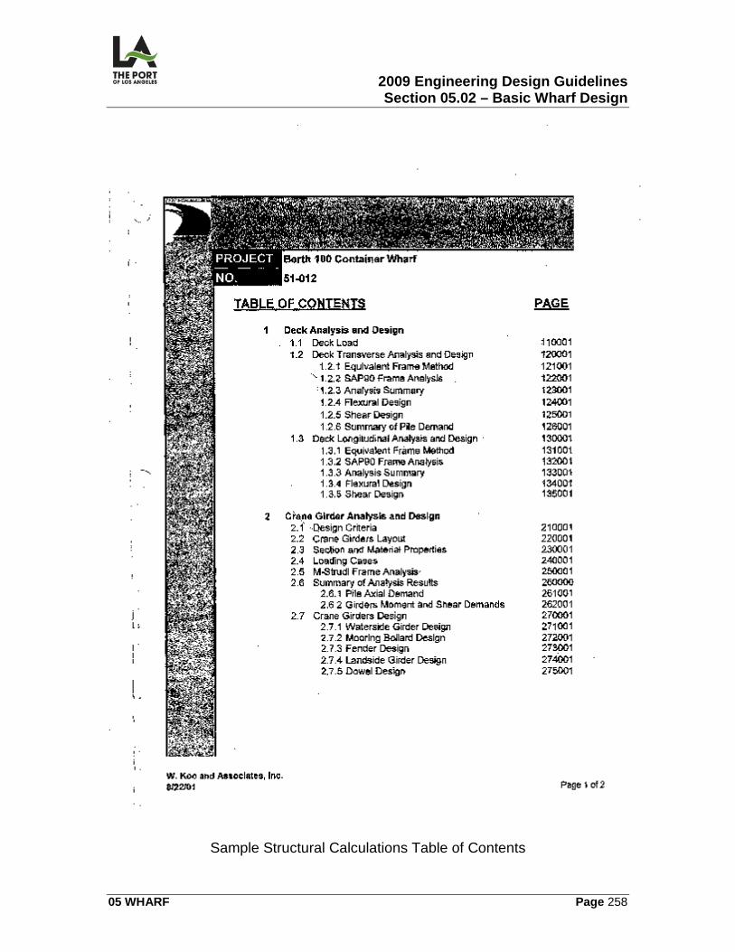
2009 Engineering Design Guidelines Section 05.02 – Basic Wharf Design
05 WHARF Page 258
Sample Structural Calculations Table of Contents
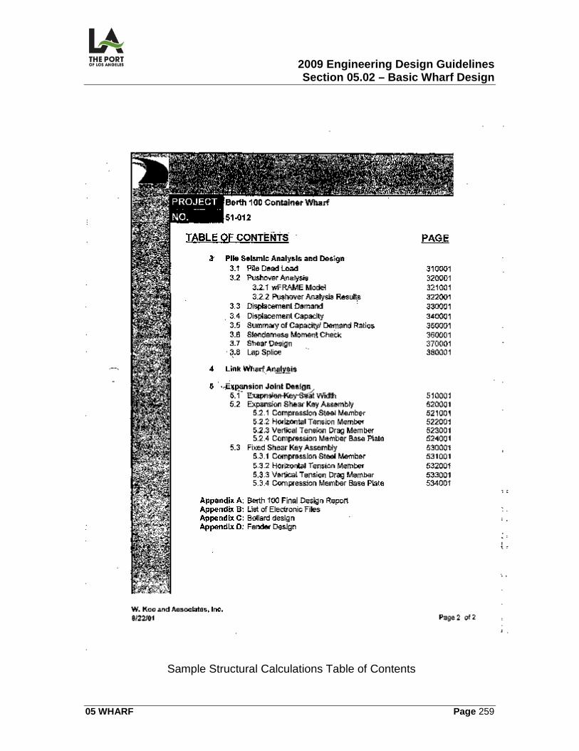
2009 Engineering Design Guidelines Section 05.02 – Basic Wharf Design
05 WHARF Page 259
Sample Structural Calculations Table of Contents
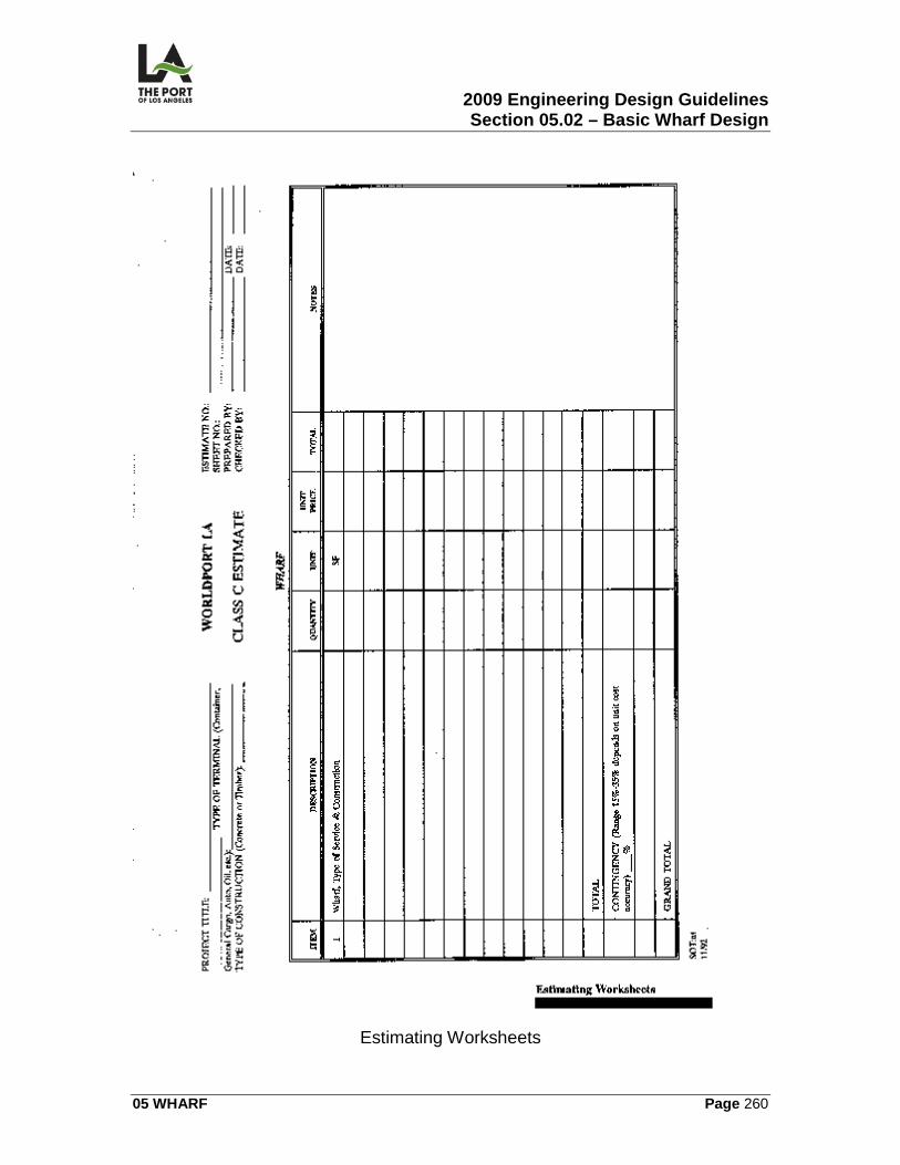
2009 Engineering Design Guidelines Section 05.02 – Basic Wharf Design
05 WHARF Page 260
Estimating Worksheets
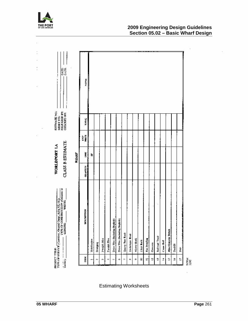
2009 Engineering Design Guidelines Section 05.02 – Basic Wharf Design
05 WHARF Page 261
Estimating Worksheets
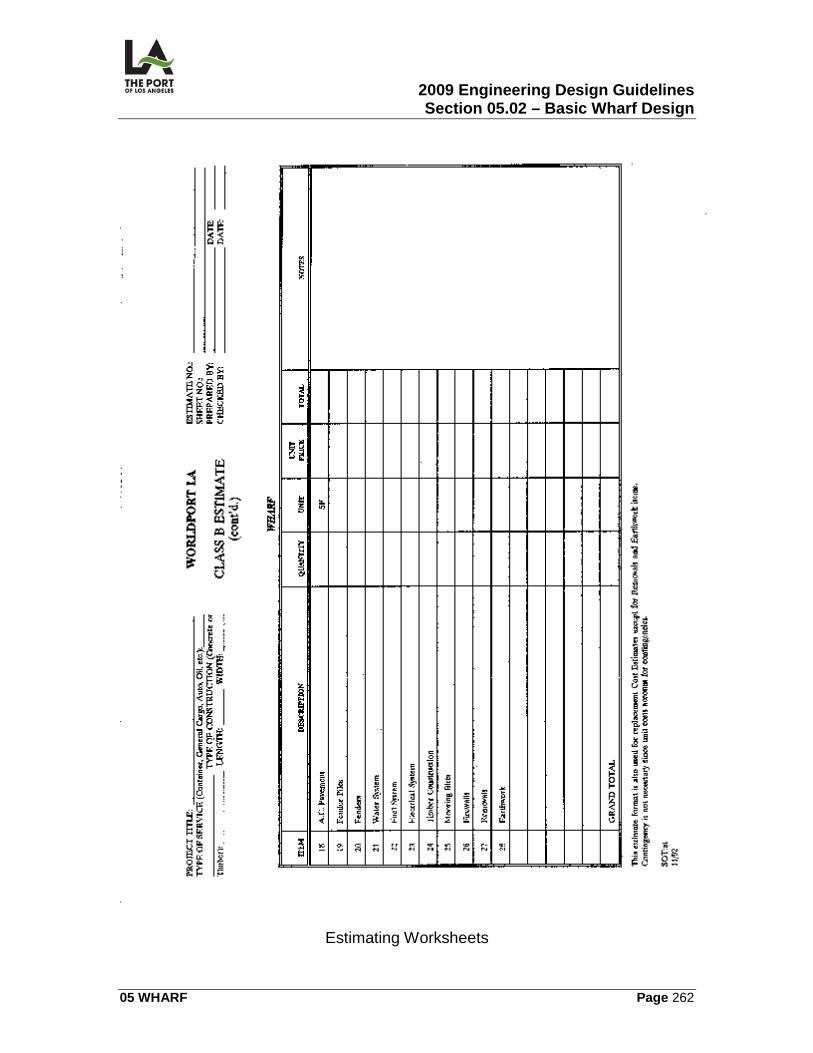
2009 Engineering Design Guidelines Section 05.02 – Basic Wharf Design
05 WHARF Page 262
Estimating Worksheets

2009 Engineering Design Guidelines Section 05.02 – Basic Wharf Design
05 WHARF Page 263
Estimating Worksheets
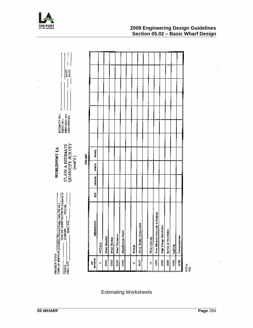
2009 Engineering Design Guidelines Section 05.02 – Basic Wharf Design
05 WHARF Page 264
Estimating Worksheets
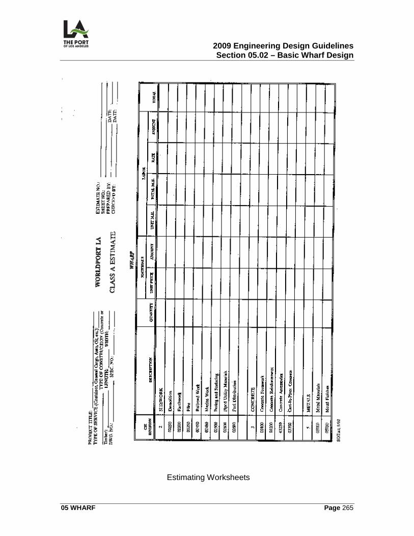
2009 Engineering Design Guidelines Section 05.02 – Basic Wharf Design
05 WHARF Page 265
Estimating Worksheets
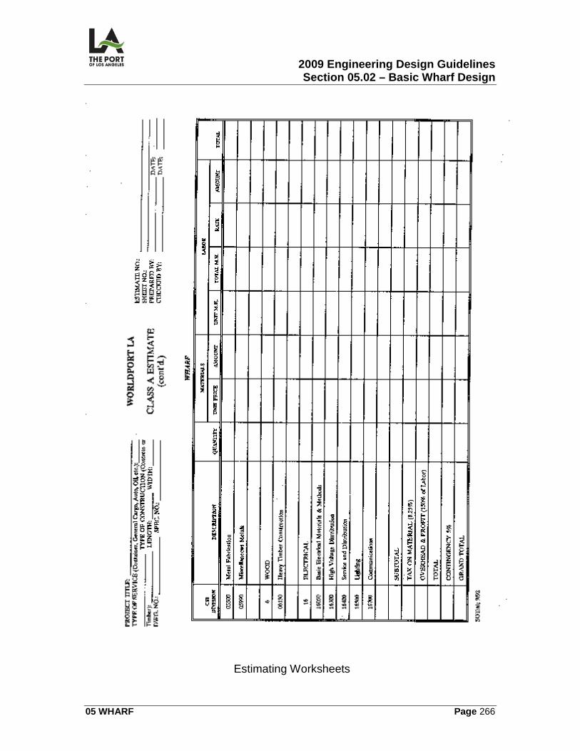
2009 Engineering Design Guidelines Section 05.02 – Basic Wharf Design
05 WHARF Page 266
Estimating Worksheets
2009 Engineering Design Guidelines Section 05.03 – Removals and Demolition
05 WHARF Page 267
05.03
REMOVALS AND DEMOLITION
05.03.01 OVERVIEW This section contains the following information related to the preparation of wharf removal and demolition contract drawings:
• Removals and Existing Substructures Plan (R)
• Wharf Demolition Sections (R)
05.03.02 DESIGN CRITERIA Historical Assessment The Designer should request the Environmental Management Division to perform an historical assessment on any existing wharf facility at least 50 years old, of potential historical significance, or where timber piles are involved. The US Army Corps.of Engineers (ACE) Permit requires historical assessments for structures more than 50 years old. Salvage The Designer should request the Construction and Maintenance Division to identify all items to be salvaged prior to bidding. All items to be salvaged must be identified in the contract documents and delivered to a location specified by that Division. Disposal
1. A/C and Concrete. Uncontaminated A/C and concrete (non-reinforced or with reinforcing removed) shall be disposed of at the Port's stockpile site.
2. Hazardous Waste. Disposal of all hazardous waste material shall be
coordinated with the Risk Management and Environmental Management Divisions; it shall be disposed of away from Port property.
2009 Engineering Design Guidelines Section 05.03 – Removals and Demolition
05 WHARF Page 268
Suspected Contamination An Environmental Site Assessment/Characterization must be coordinated with the Environmental Management Division (EMD) prior to demolition if the project area has suspected contamination. Safety/Health Issues The designer shall be aware of specific soil conditions and potential safety/health issues or problems (e.g., oil leakage) associated with the removal of piles, wharf, etc. Pile Removal
1. Clearance. The Project Manager shall obtain clearance from EMD for pile removal. For disposal of preservative-treated timber piles, a letter from EMD must go into the project file indicating disposal location and classification of the piles.
2. Pile-Supported Foundation. All pile-supported foundations shall be
removed to elevation plus 5 MLLW (Mean Lower Low Water) or at least 5 feet below finished grade.
3. Wharf Piles. Piles which cannot be removed may be broken off below the
mudline, if approved by the Chief Harbor Engineer. Coordination The designer shall coordinate wharf removals/demolition in a timely manner with following persons:
1. Project site tenant(s), as well as any impacted tenants adjacent to the project site -- for all removal work.
2. Appropriate utility (DWP, Gas Co., or Pacific Bell) and the Property
Management Division -- for all removal related water and power disconnects.
3. Risk Management and Environmental Management Divisions -- for all
hazardous removals (e.g., for asbestos, hydrocarbon contaminated soil, etc.).
2009 Engineering Design Guidelines Section 05.03 – Removals and Demolition
05 WHARF Page 269
4. Harbor Belt Line General Manager -- for removals impacting the railroads.
5. Water Quality Control Board -- whenever piles are removed, wharf deck is demolished, etc.
6. US Coast Guard -- whenever a timber wharf is involved.
Dredging The Project Manager must request an analysis of dredging material from EMD whenever an ACE permit is needed for wharf removal/demolition or for water deepening.
05.03.03 CALCULATIONS/WORKSHEETS The designer shall prepare all calculations on worksheets in compliance with POLA's Engineering Division's latest format.
05.03.04 GRAPHIC CRITERIA Removal and demolition sheets shall be prepared per POLA’s AutoCad manual and must have the following sheets:
1. Removals and existing substructures plan – this sheet should show existing surface features.
2. Wharf demolition sections.
05.03.05 SPECIFICATIONS The following sections in the Harbor Department Master Specifications relate to wharf removal and demolition (other sections may be required, depending upon the project):
SECTION TITLE Coordination Regulatory Requirements Construction and Demolition Waste Management Selective Site Demolition Building Demolition and Removals
2009 Engineering Design Guidelines Section 05.03 – Removals and Demolition
05 WHARF Page 270
05.03.06 PERMITS/APPROVALS An ACE permit is required whenever there is removal/demolition work connected with piles, deck, timber wharf, etc. All permits needed for wharf work are included in the Basic Wharf Design Section, Permits/Approvals.
05.03.07 ENVIRONMENTAL CONSIDERATIONS See 05.03.02 for historical assessment, hazardous waste disposal and contamination assessment.
05.03.08 REFERENCE DRAWINGS The following contract Drawings are identified for reference: 1-2342 Berths 145-147 Wharf Improvements
1-2342 RS-1 Removal and Demolition Berth – Site Plan 1-2342 RD-1-8 Removal Pile and Deck Plan 1-2342 RX-1-6 Removal – Berth Cross Section
LAHD Standard Plans
2009 Engineering Design Guidelines Section 05.04 – Wharf Sections
05 WHARF Page 271
05.04
05.04.01 OVERVIEW
WHARF SECTIONS
This section contains information related to the preparation of the wharf section contract drawings:
• Typical Wharf and Cross Section
05.04.02 DESIGN CRITERIA Typical Sections Typical sections shall represent typical conditions on the wharf (e.g., dike section, embankment section, etc.), with contractor details indicated (e.g., ratproofing, filter fabric, etc.). Orientation of Sections In all sections, the waterside of the structure shall be shown on the right side. Dredging Sections Dredging sections are generally drawn at intervals of 50 feet.
05.04.03 CALCULATIONS/WORKSHEETS There are no calculations or worksheets provided for this section. The designer shall prepare all calculations on worksheets in compliance with POLA's Engineering Division's latest format.
05.04.04 GRAPHIC CRITERIA Typical Wharf Cross Sections This sheet should include the following: pierhead line; distance from the face of the; locations; elevations of all breakpoints of the top wharf surface; tolerances for the dredge line and rock fills; and an asterisk where dimensions require field verifications.
2009 Engineering Design Guidelines Section 05.04 – Wharf Sections
05 WHARF Page 272
Dredging Sections This sheet should show existing surface – (dashed), wharf structure (if applicable) and dredge line Line Style - Line style for wharf section drawings shall be per the Port’s Cadd manual.
05.04.05 SPECIFICATIONS There are no Harbor Department master specifications relating to wharf cross sections.
05.04.06 PERMITS/APPROVALS There are no permits/approvals necessary for wharf cross section work.
05.04.07 ENVIRONMENTAL CONSIDERATIONS There are no environmental considerations for wharf cross section.
05.04.08 REFERENCE DRAWINGS The following contract drawings are identified for reference: 1-2359 Pier 400 Container Wharf Phase II – Berths 404-406
1-2359 X-1 Typical Wharf Cross Section – A1 LAHD Standard Plans
2009 Engineering Design Guidelines Section 05.05 – Rail
05 WHARF Page 273
05.05
RAIL
05.05.01 OVERVIEW This section contains information related to the preparation of the following wharf rail (both rail-road and crane rail) contract drawings:
1. Railroad:
a) Railroad Track Plan (RR) b) Railroad Track Profiles (RR)
c) Railroad Details (RR)
2. Crane Rail:
a) Crane Rail Details (CR) b) Crossing Frog Plan and Details (CR)
c) Crane Rail Stop Details (CR)
d) Crane Rail Expansion Joint (CR)
05.05.02 DESIGN CRITERIA General Railroad Design Requirements Railroad design shall meet the regulations, standards, and requirements of the following (any conflicts which arise must be resolved with the entities impacted):
1. General Orders of the California Public Utilities Commission (CPUC) [all Port railroad facilities must comply with CPUC General Orders].
2. Harbor Department (as specified in these Guidelines or as otherwise
approved by the Chief Harbor Engineer).
3. American Railway Engineering & Maintenance of Way Association's Manual for Railway Engineering.
Railroad -- Industry Track Design
2009 Engineering Design Guidelines Section 05.05 – Rail
05 WHARF Page 274
1. Horizontal Alignment:
a) Curvature:
1) Desirable = 12°30' (R=459 feet). 2) Maximum = 15°00' (R=383 feet).
b) Minimum tangent between reversing curves is 60 feet. c) Minimum clearance between parallel tracks = 14.25 feet.
d) Minimum horizontal clearance to structures (and fences) from track
center line:
1) Tangent track = 10 feet. 2) Curve track = 11 feet.
2. Turnouts:
a) Desirable = No. 9. b) Minimum = No. 7.
Railroad Trackage Components The following shall be considered standards, unless otherwise authorized by the Chief Harbor Engineer:
1. Ballast depth – 6 inches minimum. If the wharf design will not allow 6 inches of ballast to be constructed under the ties, then lean concrete should be placed under them.
2. Rail size -- 136 lb. R.E. (pounds per yard)
3. Turnout components shall be as follows:
a) Rail-bound manganese (RMG) frogs. b) 16'6" Sampson type switch points per A.R.E.M.A. Plan No. 221-00,
Detail 5100, with manganese-tipped switch points.
2009 Engineering Design Guidelines Section 05.05 – Rail
05 WHARF Page 275
c) Adjustable wedge rail braces.
4. Tie size -- minimum of 7 inches x 9 inches x 8 feet. 5. Tie spacing on-centers -- minimum of 22 1/2 inches (except at rail joints,
where the spacing shall be 18 inches).
6. Tie plate size -- minimum of 8" x 14" double shoulder.
7. Installation of rail anchors:
a) Switch ties -- box anchor every tie. b) Jointed rail -- box anchor every third tie.
c) Continuously welded rail -- box anchor every other tie.
8. Gage rods shall be installed through all curves having a curvature greater
than 10°30' and at a spacing of 5 feet on centers. 9. All other components shall be in accordance with AREMA standards.
Crossing Frogs When railroad tracks cross crane rails, a special crossing frog design is required. Design of the frogs shall provide travel of the crane wheel flange across the intersection point. As the crossing frog is a specialty design, the type of frog is dictated by the type of railroad track and crane rail intersection. Crane Rail Design
1. Load. The crane rail shall be designed for at most 50k/ft live load. 2. Wharf Plan. The crane rail is shown on the general wharf plan.
3. Type/Installation. The rail used shall be a 171 lb. rail and shall be installed
on crane girders designed for the wharf.
4. Extension of Existing Container Wharf. When extending an existing container wharf, the designer shall take into account the potential downslope movement of the wharf and its effect on crane rails.
2009 Engineering Design Guidelines Section 05.05 – Rail
05 WHARF Page 276
Crane Rail Detail A detail of the Gantrex System (or equivalent) shall be included with the plan submission.
1. Crane Rail Detail
a) Rail fastening system b) Rail Splicing
2. Power Systems on Wharf
a) Cable Reel System or b) Bus Bar System
05.05.03 CALCULATIONS/WORKSHEETS The designer shall prepare all calculations on worksheets in compliance with POLA's Engineering Division's latest format.
05.05.04 GRAPHIC CRITERIA Include a site plan, track plan, profiles, and cross sections to convey appropriate detail. Drawings shall be per POLA CADD manual.
05.05.05 SPECIFICATIONS The following sections in the Harbor Department Master Specifications relate to wharf railroads or crane rails (other sections may be required, depending upon the project):
SECTION TITLE Railroad Work Crane Rail Railroad Track and Accessories Welding of Rail
An additional production specification Section “Running Rail” is also used for procurement.
2009 Engineering Design Guidelines Section 05.05 – Rail
05 WHARF Page 277
05.05.06 PERMITS/APPROVALS There are no permits/approvals necessary for this section because wharf rail work is on Port property. However, all improvements must be consistent with P.U.C. General Orders.
05.05.07 ENVIRONMENTAL CONSIDERATIONS Timber Tie Disposal – Removal and disposal of existing timber ties shall conform to Master Specification Sections REGULATORY REQUIREMENTS and RAILROAD TRACK AND ACCESSORIES.
05.05.08 REFERENCE DRAWINGS The following contract drawings are identified for reference: 1-2032 Berths 302-305 Project
1-2032 RR11-21 Railroad Track Plan 1-2032 RR22-29 Railroad Track Profiles 1-2032 RR31-49 Railroad Details 1.2032 CR1-2 Crane Rail Details
1-1915 Berths 302-305 Container Wharf
1-1915 S40-41 Crossing Frog Plan and Details (No. 5) 1-1915 S26 Crane Rail Stop Details (No. 6)
Crane Rail Expansion Joint (No. 7) LAHD Standard Plans
2009 Engineering Design Guidelines Section 05.06 – Piles
05 WHARF Page 278
05.06
PILES
05.06.01 OVERVIEW This section contains the following information related to the preparation of contract drawings for the design of wharf deck piles.
05.06.02 DESIGN CRITERIA Type of Piles
1. Vertical piles are to be used. The use of batter piles is subject to limitations in paragraph 5 of this subsection.
2. Concrete, wood and steel piles are allowed. 3. Concrete Piles
a) Standard size. The standard pile is a 24” octagonal precast prestressed concrete pile. Larger size solid or hollow piles may be proposed for situations where the 24” octagonal pile is not a cost effective solution.
b) Pile Strength. Precast , prestressed concrete pile strength (f’c) shall be a minimum of 6,500 psi at the time of driving and 4,500 psi at the time of tendon stress transfer.
c) Concrete mix design. Concrete for piles shall contain a minimum of 8 sacks of cementitious material per cubic yard of concrete. The maximum allowable water to cement ratio shall be 0.38. the maximum aggregate size shall pass a ¾ inch sieve.
d) Concrete cover. The minimum concrete cover to the spiral reinforcement shall be 3 inches.
4. Clearance
An approximate minimum of 4’-0” clearance shall be used between the deck/beam soffit and top of dike to allow for adequate post earthquake inspection and repairs.
5. Batter Piles Batter piles to support the wharf or pier shall not be used without prior written approval from the Chief Harbor Engineer (see section 4.2, Basic Wharf Design). However, batter piles may be used for isolated structures with low seismic mass, such as ladside anchors, mooring and breasting dolphins.
6. Wood a) Wood piles should only be used when project criteria and site
circumstances dictate.
2009 Engineering Design Guidelines Section 05.06 – Piles
05 WHARF Page 279
b) The type and grade of wood shall be based on the published stress values in the ANSI/AF&PA National Design Specification (NDS) for Wood Construction.
c) Deterioration 1) The use of wood piles is discouraged due to the deterioration potential and associated higher maintenance cost. 2) Coating system shall be used. 3) Routine visual pile inspections shall be performed.
7. Steel Piles a) Steel piles should only be used when project criteria and site
circumstances dictate. b) Corrosion
1) The use of steel piles is discouraged due to corrosion potential and associated higher maintenance cost.
2) Corrosion barrier coating systems could be used. 3) Routine visual pile inspections shall be performed. 4) Sacrificial thickness could be added to the pile to account for
corrosion. 5) Cathodic protection systems could be used.
c) Material. Steel piles shall be according to ASTM A572 or A709
8. Connection to the Wharf Deck a) All concrete or steel piles shall use ASTM A706 dowels to connect to
the deck. b) The extension of pile prestressing strands into the deck shall not be
used for the pile deck connection. c) Dowels that are extended from piles shall not be bent outwards and all
dowels shall be confined by transverse reinforcement.. Concrete Pile Capacity
1. Vertical. The vertical ultimate pile capacity in the soil shall be established by a registered geotechnical engineer. The geotechnical analysis shall be verified by wave equation analysis and by new or existing pile tests as necessary and adjusted for site specific conditions by an indicator pile test program. Establishment of vertical pile capacity by the Engineering News formula is not acceptable.
2. Lateral. The lateral ultimate pile capacity in the soil shall be established
by a registered geotechnical engineer. The method shall take into account the increased lateral resistance by the rock dike and the potential movement of the rock dike due to settlement, soil pressure, and seismic conditions.
2009 Engineering Design Guidelines Section 05.06 – Piles
05 WHARF Page 280
3. Soil Pile Capacity. The ultimate pile capacity in the soil (vertical and
lateral) must not exceed the structural capacity of the pile and must be at least two times than pile demand load.
Load Tests A pile load test (vertical and/or lateral, depending upon the project) may be considered for very large new wharf construction. This determination is made by the designer in conjunction with the appropriate Engineering Division staff. Driving
1. Preliminary driving criteria are in the specifications. For each larger project,driving criteria are developed following a geotechnical report.
2. Piles shall not be driven through riprap with a maximum rock size larger than 500 lbs.
3. Non-displacement structural steel piles may be required if piles need to be driven close to the top of the rock embankment of an existing wharf. The specific details shall be addressed in the geotechnical report.
Additional Pile Design Criteria Additional pile design criteria can be found in the Basic Wharf Design section, Design Criteria (05.01.02), and should be reviewed.
05.06.03 CALCULATIONS/WORKSHEETS The designer shall prepare pile calculations for the final plan/specifications review. The designer shall prepare all calculations on worksheets in compliance with POLA's Engineering Division's latest format. Estimating When estimating the quantity needed, cut-off requirements should be considered. Due to driving difficulties, a certain percentage of piles are destroyed during the installation process. The number of extra piles to be ordered for each specific project should be verified with the Construction Management Division.
2009 Engineering Design Guidelines Section 05.06 – Piles
05 WHARF Page 281
Estimating worksheets for the wharf (which include line items related to piles) are found in the Basic Wharf Design Section.
05.06.04 GRAPHIC CRITERIA Pile drawings should include a Pile Plan showing grids, wharf oulline and existing and proposed piles and Precast Concrete Pile details showing sections, pick-up points, necessary fabrication data, etc.Graphic Criteria for pile drawings shall be per the Port’s CADD manual.
05.06.05 SPECIFICATIONS The following sections in the Harbor Department Master Specifications relate to precast, prestressed concrete wharf piles (other sections may be required, depending upon the project):
SECTION TITLE Rock Steel Pipe Piles Precast Concrete Piles Cast-In-Place Concrete Timber Piles
05.06.06 PERMITS/APPROVALS Necessary wharf permits/approvals are covered in the Basic Wharf Design section, Permits/Approvals.
05.06.07 ENVIRONMENTAL CONSIDERATIONS Use of wood piles with preservatives shall follow the latest guidelines of the US Army Corp of Engineers and other regulatory agencies.
05.06.08 REFERENCE DRAWINGS The following contract drawings are identified for reference: 1-2359 Pier 400 Container Wharf Phase II – Berths 404-406
2009 Engineering Design Guidelines Section 05.06 – Piles
05 WHARF Page 282
1-2359 PD-1 Prestressed Concrete Pile – Details 1-2359 PD-2 Prestressed Concrete Pile – Details 1-2359 PD-3 Prestressed Concrete Pile – Details
LAHD Standard Plans
2009 Engineering Design Guidelines Section 05.07 – Deck
05 WHARF Page 283
05.07
DECK
05.07.01 OVERVIEW This section contains the following information related to the preparation of wharf deck contract drawings:
• General Wharf Layout Plan (D)
• Deck Plan (D)
• Deck Slab Reinforcing (S)
• Crane Girder Reinforcing (S)
• Stowage Pin Anchors (S)
• Crane Power Trench Details (S)
• Utility Vaults -- Sections and Details (S)
• Mooring Bitts and Ladders (S)
• Typical Deck Expansion Joint (S)
• Cable Reel Boxes
• Bus Bar Boxes
• Crane Tie Downs
05.07.02 DESIGN CRITERIA Concrete
1. Concrete Cover. The minimum concrete cover to the reinforcing at all sides of the deck shall be 3 inches.
2. Minimum/Maximum. The concrete for the deck shall contain a minimum of
7 sacks of Portland cement (Type II) per cubic yard of concrete. The maximum allowable water to cement ratio shall be 0.40. The maximum
2009 Engineering Design Guidelines Section 05.07 – Deck
05 WHARF Page 284
aggregate size shall be able to pass a 1 1/2 inch sieve. The maximum aggregate size shall be adjusted downward in areas of congested reinforcing as required.
Special Details
1. The length of wharf units between expansion joints should generally be between 400 and 800 feet. Shorter or longer wharf units should be approved by the CHE.
2. It is recommended that the length of an anglepoint concrete wharf unit,
measured from the anglepoint to the next expansion joint, not be shorter than 250 feet on both sides. This distance is measured at the waterside concrete edge.
3. Special Details: The Port of Los Angeles (POLA) will provide guidelines for
details of wharf expansion joints. The shear key at these joints has a capacity to transfer an ultimate shear force of 3500 kips. The use of these details is recommended. Other details may be used, but must be justified by a detailed design, including calculations.
4. Pile-deck connections: These connections should be established by
dowels and must be carefully detailed as described in the POLA Code For Seismic Design, Upgrade, and Repair Of Container Wharfs.
Expansion Joints
1. Design and Detailing. Care shall be taken in the design and detailing of expansion joints to facilitate concrete placement and avoid spalling of concrete edges.
2. Spacing. Expansion joint spacing is usually every 450 feet (in multiples of
450 feet) if the deck is 900 feet or longer. Wharfs shorter than 700 feet usually do not have an expansion joint. Larger distances should be particularly analyzed.
Adjoining Wharfs Special precautions shall be taken whenever a new wharf adjoins an existing wharf. It is important to decrease the possibility of downslope movement with the new wharf. The designer shall ensure that there is a proper transition if the adjoining deck has a different slope or is at a different elevation.
2009 Engineering Design Guidelines Section 05.07 – Deck
05 WHARF Page 285
Crane Girders
1. Design. Unequal pile shortening shall be accounted for in the design of the deck. The crane girder shall be designed as a beam on an elastic foundation.
2. Construction Sequence. The construction sequence of crane girders shall
be accounted for in the design and detailing of the deck. Stowage Pins Stowage pin location, details, and spacing for container cranes must be adjusted by the designer to site specific conditions and particular crane characteristics. Work shall be coordinated with the Port. Reinforcing Bars
1. Detailing. Detailing of reinforcing bars for the stirrups shall allow for easy placement and shall be specifically shown in the drawings.
2. Crane Anchor Bolt Placement. The reinforcing bars in the top of the crane
girders shall be designed and detailed so as to allow accurate placement of the crane anchor bolts.
Additional Deck Design Criteria
1. Bollard. A standard bollard shall be designed in accordance with POLA Standard Plan H-301 (Drawing No. 5-7156).
2. Wharf Ladder. Metal wharf ladders shall be designed in accordance with
POLA Standard Plan H-302 ( Drawing No. 5-7157).
3. Strong Motion Instrumentation Box. These boxes shall be designed in accordance with POLA Standard Plan 1-1000-21.
4. Other. Additional design criteria pertinent to decks can be found in the
Basic Wharf Design section, Design Criteria (05.01.02), and should be reviewed.
2009 Engineering Design Guidelines Section 05.07 – Deck
05 WHARF Page 286
05.07.03 CALCULATIONS/WORKSHEETS The designer shall prepare all calculations on worksheets in compliance with POLA's Engineering Division's latest format.
05.07.04 GRAPHIC CRITERIA Wharf Deck plans should include Wharf Deck Layout plan, Deck Plan, Deck Slab Reinforcing Plan, Crane Girder Reinforcing plan, Stowage Pin Anchor details, Crane Power Trench details, Utility Vault sections and details, Mooring Bits and Ladders details and Typical Deck Expansion Joint details,Graphic criteria for wharf deck drawings shall be per POLA CADD manual.
05.07.05 SPECIFICATIONS The following sections in the Harbor Department Master Specifications relate to wharf decks (other sections may be required, depending upon the project):
SECTION TITLE Concrete Wharf Construction Treated Damaged Galvanizing Metal Fabrications Paints and Coatings
05.07.06 PERMITS/APPROVALS Necessary permits/approvals are covered in the Basic Wharf Design section, Permits/Approvals.
05.07.07 ENVIRONMENTAL CONSIDERATIONS Stormwater runoff shall not be allowed to discharge directly into the ocean. Runoff must comply with the SUSMP requirements of the Watershed Protection Division of the Bureau of Sanitation.
05.07.08 REFERENCE DRAWINGS The following contract drawings are identified for reference: 1-2359 Pier 400 Container Wharf Phase II – Berths 404-406.
2009 Engineering Design Guidelines Section 05.07 – Deck
05 WHARF Page 287
1-2359 D-15 to 27 Deck Plan 1-2359 S-2 to13 Deck Slab Reinforcing 1-2359 S-18 to 19 Crane Girder Reinforcing 1-2359 S-49 Stowage Pin Anchor – Plan and Details 1-2359 S-28&29 Crane Power Trench Details 1-2359 S-22 Typical Vaults – Structural Details 1-2359 S-14 to 17 Deck Expansion Joint and Details
LAHD Standard Plans
2009 Engineering Design Guidelines Section 05.08 – Fenders
05 WHARF Page 288
05.08
FENDERS
05.08.01 OVERVIEW This section contains the following information related to the preparation of fender system contract drawings:
• Fenders
05.08.02 DESIGN CRITERIA
1. Wharf Fenders. Wharf fenders should be of the buckling column type. When the wharfs have a common berthing line, attention should be paid to match fenders at adjacent berths.
2. Hull Pressure. The maximum hull pressure should be 5000 PSF, unless
specifically directed otherwise by the Chief Harbor Engineer or specific vessel requirements.
3. Fender Panel. The rubbing section of the fender panel should be UV-
stabilized UHMW polyethylene with a maximum friction factor of 0.2 or less.
4. Corrosion Protection. The steel frame of the fender panel should be
coated with an approved coating system. To provide additional corrosion protection, the minimum thickness of rolled sections should be 1/2 inch. If sealed tubular sections are used, the minimum thickness may be reduced to 3/8 inch. Units should have a coating material applied by the manufacturer and approved by the CHE.
05.08.03 CALCULATIONS/WORKSHEETS The designer shall prepare calculations on worksheets in compliance with POLA's Engineering Division's latest format.
05.08.04 GRAPHIC CRITERIA Fender drawings shall include Fender Sysytem showing elevations, sections including the face beam.and shall be prepared per the POLA CADD manual.
2009 Engineering Design Guidelines Section 05.08 – Fenders
05 WHARF Page 289
05.08.05 SPECIFICATIONS The following sections in the Harbor Department Master Specifications relate to wharf fenders (other sections may be required, depending upon the project):
SECTION TITLE Rubber Fenders Corrosion Control
05.08.06 PERMITS/APPROVALS The necessary wharf permits/approvals are covered in the Basic Wharf Design section, Permits/Approvals.
05.08.07 ENVIRONMENTAL CONSIDERATIONS There are no environmental considerations for Fenders.
05.08.08 REFERENCE DRAWINGS The following contract drawings are identified as reference: 1-2359 Pier 400 Container Wharf Phase II – Berths 404-406.
1-2359 F-1 "A" Face Fender System – Elevations and Section 1-2359 F-2 Fender System – Face Beam
LAHD Standard Plans
2009 Engineering Design Guidelines Section 05.09 – Water
05 WHARF Page 290
05.09
WATER
05.09.01 OVERVIEW This section contains the following information related to the preparation of the following wharf water contract drawings:
• Wharf Water Plan (W)
• Wharf Water Sections and Details (W)
• Wharf Water Vault Plan and Details (W)
05.09.02 DESIGN CRITERIA Coordination It is the responsibility of the designer to coordinate wharf water systems with the other wharf facilities designers. Ship Connections
1. Connections for Domestic Water. Each ship connection assembly for domestic water shall be provided with a reduced pressure type backflow preventer, strainer, meter, hose connection fitting, and valves.
2. Spacing between Assemblies. Spacing between ship connection
assemblies shall be 180 feet.
3. Connection Assembly. Ship connection assembly shall be in a vault and provided with hinged lids. Lids must be structurally designed to carry expected vehicular traffic and heavy equipment, yet reasonably light for manual opening.
4. Drain Holes. Ship connection vaults must be provided with two 4-inch
diameter drain holes.
5. Design Flow. Design flow for ship connection shall be 250 GPM at a residual pressure of no less than the total pressure losses between the connection and the ship water intake manifold.
2009 Engineering Design Guidelines Section 05.09 – Water
05 WHARF Page 291
6. Shut-Off Valve. A shut-off valve shall be provided for each branch to ship connection as it branches off of the main. Section valves on the main (perpendicular to branch valves) shall be provided to facilitate shutdown of a section during repair or maintenance without turning off the entire system.
7. Backflow Device. Use a U.L. approved backflow device which
demonstrates the lowest pressure loss at the rated flow.
8. Backflow Device. Install with a minimum clearance of 12 inches between relief valve discharge port and floor or grade.
Pipe Lines
1. Penetrating Bulkhead. Pipe line penetrating the bulkhead shall be:
a) Provided with flexible joints to allow for movement caused by earth settlement behind the bulkhead.
b) Done with a sleeve, the diameter of which shall be at least 2 inches
bigger than that of the carrier pipe.
2. Materials.
a) Underground: Ductile iron class 52 for 4” and larger, Tyton joint per A.W.W.A. C151, double cement-mortar lined class 350 mechanical joint fittings per A.W.W.A. C110.
b) Under Wharf. Ductile iron class 53 mechanical joint for A.W.W.A.
C151 double cement-mortar lined and with double cement-mortar lined class 350 mechanical joint fittings per A.W.W.A. C110.
3. Installation Restrictions. Installation of pipe lines within 130 feet from the
face of the wharf shall be avoided (except those lines going through the bulkhead).
4. Under the Wharf. Corrosion-protected pipe hangers and sway bars shall
be used for pipe sections under the wharf. Thrust Blocks/Restraints
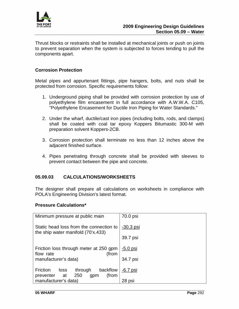
2009 Engineering Design Guidelines Section 05.09 – Water
05 WHARF Page 292
Thrust blocks or restraints shall be installed at mechanical joints or push on joints to prevent separation when the system is subjected to forces tending to pull the components apart. Corrosion Protection Metal pipes and appurtenant fittings, pipe hangers, bolts, and nuts shall be protected from corrosion. Specific requirements follow:
1. Underground piping shall be provided with corrosion protection by use of polyethylene film encasement in full accordance with A.W.W.A. C105, "Polyethylene Encasement for Ductile Iron Piping for Water Standards."
2. Under the wharf, ductile/cast iron pipes (including bolts, rods, and clamps)
shall be coated with coal tar epoxy Koppers Bitumastic 300-M with preparation solvent Koppers-2CB.
3. Corrosion protection shall terminate no less than 12 inches above the
adjacent finished surface.
4. Pipes penetrating through concrete shall be provided with sleeves to prevent contact between the pipe and concrete.
05.09.03 CALCULATIONS/WORKSHEETS The designer shall prepare all calculations on worksheets in compliance with POLA's Engineering Division's latest format. Pressure Calculations* Minimum pressure at public main Static head loss from the connection to the ship water manifold (70’x.433) Friction loss through meter at 250 gpm flow rate (from manufacturer’s data) Friction loss through backflow preventer at 250 gpm (from manufacturer’s data)
70.0 psi
-30.3 psi
39.7 psi
-5.0 psi
34.7 psi
-6.7 psi
28 psi
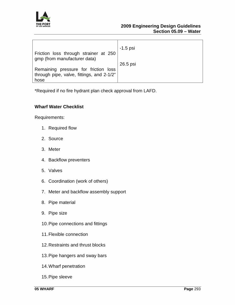
2009 Engineering Design Guidelines Section 05.09 – Water
05 WHARF Page 293
Friction loss through strainer at 250 gmp (from manufacturer data) Remaining pressure for friction loss through pipe, valve, fittings, and 2-1/2” hose
-1.5 psi 26.5 psi
*Required if no fire hydrant plan check approval from LAFD. Wharf Water Checklist Requirements:
1. Required flow 2. Source
3. Meter
4. Backflow preventers
5. Valves
6. Coordination (work of others)
7. Meter and backflow assembly support
8. Pipe material
9. Pipe size
10. Pipe connections and fittings
11. Flexible connection
12. Restraints and thrust blocks
13. Pipe hangers and sway bars
14. Wharf penetration
15. Pipe sleeve
2009 Engineering Design Guidelines Section 05.09 – Water
05 WHARF Page 294
16. Sealant for annular space between carrier pipe and sleeve
17. Ship connection assembly: meter, strainer, backflow preventer, hose
connection fitting, and valves
18. Vault drains
19. Support for ship connection assembly
20. Vault lid
21. Painting
22. Corrosion protection
23. Restraints and thrust blocks
24. Pressure calculations
25. Plumbing plan check
05.09.04 GRAPHIC CRITERIA Site Plan This sheet reflects existing and proposed water features in the site area. It should show a base map, main proposed surface improvements and water features and prepared per the POLA CADD manual. Water Systems Plan This sheet will contain specific information necessary to construct the water system including the base map, proposed surface improvements, existing and proposed substructures and the proposed water system and prepared per the POLA CADD manual
05.09.05 .SPECIFICATIONS Refer to Harbor Department Master Specifications. Specifications for plumbing shall conform with the rules and regulations of the City of Los Angeles Plumbing Code.
SECTION TITLE
2009 Engineering Design Guidelines Section 05.09 – Water
05 WHARF Page 295
Water Distribution Gas Distribution Excavated Safety Req. Detection Tape Trench Excavation and Backfill Asphalt Concrete Pavement Cast-In-Place Concrete Guard Posts Paints and Coatings Corrosion Control
05.09.06 PERMITS/APPROVALS Building and Safety Permit Necessary wharf permits/approvals are covered in the Basic Wharf Design section, Permits/Approvals (05.02). A plumbing permit is required to be obtained by the piping system installer following the designer's submission of the water plans for plan check.
05.09.07 ENVIRONMENTAL CONSIDERATIONS The main environmental concern is the disposal of contaminated water and waste (paper cups, newspapers, etc.) collected in the water vault, spilling into the channel.
05.09.08 REFERENCE DRAWINGS The following contract drawings are identified for reference: 1-2210 Pier 400 Wharf.
1-2210 W-1 Water Piping Schematic, Legend and Notes 1-2210 W-2 to 6 Wharf Water Plan 1-2210 W-7 to11 Wharf Water Sections and Details
LAHD Standard Plans
2009 Engineering Design Guidelines Section 05.10 – Electrical
05 WHARF Page 296
05.10
ELECTRICAL
05.10.01 OVERVIEW This section contains information related to the preparation of the wharf electrical contract drawings:
• Electrical Notes, Symbols, and Abbreviations (E)
• Electrical Site Plan (E)
• Wharf Electrical Plan (E)
• Wharf Power & Telephone Box Details (E)
• Crane Bus Plan (E)
• Electrical Details (E)
05.10.02 DESIGN CRITERIA General Design Requirements Electrical designs shall be in compliance with the latest edition of the City of Los Angeles Electrical Code. Utilities
1. Removal or Relocation. It should be determined whether existing DWP power poles or SBC telephone poles are to be removed or relocated.
2. Time and Materials Accounting. Separate accounting for time and
materials should be maintained when planning DWP pole and appurtenance relocations (to be used for shared costs).
Fire Protection
1. Electrical Wiring. Where required (e.g., timber wharf), electrical wiring shall be provided for the fire protection system.
2009 Engineering Design Guidelines Section 05.10 – Electrical
05 WHARF Page 297
2. Alarm System. The designer shall determine whether a sprinkler system exists (and the number of sprinkler heads). If there are at least 100 heads, a fire alarm system is required.
Lighting Poles Near Wharf When setting poles near a wharf, there shall be no horizontal or vertical interferences with the back reach of the container cranes. The minimum clear space is 200 feet from the face of the wharf to the center of the light pole. Crane Conductor Bar System
1. Bill of Materials. The following bill of materials should be specified as being provided by the contractor:
a) Hot stick, splice cover remover (Insul 8, Cat. No. 2202). b) High voltage tester (Insul 8, Cat. No. 22030).
c) Welding fixture (Insul 8, Cat. No. 26322).
2. Delivery. These should be delivered to the Construction and Maintenance
Division, with a note added under the bill of material list that says, "Contractor shall deliver these items to POLA Construction & Maintenance Division at Berth 161. Contact at Extension ."
Details Details shall be designed and included for the following:
1. Wharf Telephone Box. 2. Wharf Electrical and Telephone Outlet Box.
References Each drawing reference shall be complete in and of itself. Following is an example of how references should be made (with an incorrect sample in parentheses, if appropriate):
2009 Engineering Design Guidelines Section 05.10 – Electrical
05 WHARF Page 298
1. Fixture type "A" = 40 foot steel pole, double arm, with two 400W. H.P.S. [high pressure sodium] lamps.
2. Fixture type "B" = 40 foot steel pole, double arm, with one 400W. H.P.S.
lamp (rather than "similar to 'A,' except with one 400W. H.P.S. lamp").
3. Fixture type "C" = 40 foot steel pole, double arm, with two 400W. Metal Halide lamps (rather than "similar to 'B,' except with metal Halide lamps").
4. Fixture type "D" = 30 foot steel pole, double arm, with two 400W. Metal
Halide lamps (rather than "similar to 'C,' except 30 foot pole and 2 Metal Halide lamps").
Panelboard Schedule A separate electrical panel-board schedule shall be shown for each and every panel-board, even if they are identical. Each panelboard shall also be identified by its own unique name (e.g., Panelboard A and Panelboard B). Wiring All circuit conductors shall be copper with Type THHN/THWN insulations, 600V rating. Equipment grounding conductors shall be sized adequately to withstand short circuits. Conduits
1. Location. No changes from the design of horizontal, vertical, or underground conduit shall be made without first obtaining permission from the Chief Harbor Engineer. The contractor's "as-built" prints must show all changes in conduit positioning and depth.
2. Materials.
a) All underground conduits shall be non-metallic PVC unless noted and
installed in accordance with code requirements. b) The terminating 10 feet of all nonmetallic conduit (measured from the
finish surface) shall be rigid metal conduit with bonded 40 mil PVC coating manufactured by KORKAP, CARLON, or an approved equal, UNO on drawings.
2009 Engineering Design Guidelines Section 05.10 – Electrical
05 WHARF Page 299
c) All P.V.C. conduit shall be Schedule 40, unless otherwise noted.
3. Underground Conduit Bends.
a) All underground conduit bends, except at the termination of a conduit run, shall be Schedule 80.
b) In installing nonmetallic PVC conduits underground, all bends of 30
degrees and over shall be Schedule 80.
4. Minimum Depth. The minimum depth of direct burial conduits shall be 3 feet, 6 inches from the finished surface, unless otherwise noted.
5. Grounding. The contractor shall ground all electrical equipment and
conduit systems to meet code requirements.
6. Buried Stub-Outs. All underground conduit buried stub-outs shall be furnished with concrete monuments 6 inches x 6 inches x 15 inches deep buried flush with the finished surface over the capped ends and a 3 inch square brass plate identifying the number and sizes of conduits.
7. Detection Tape. Detection tape shall be used over all conduits.
Metal Nameplate A metal nameplate shall be provided for all electrical equipment. The nameplate shall provide equipment operating parameters. Ground Fault Protection Ground fault protection shall protect the circuit line wiring from line to ground short circuiting with a response time documented by calculations.
05.10.03 CALCULATIONS/WORKSHEETS Worksheets shall be prepared for Crane Bus System Calculations, Voltage Drop Calculations, Branch Circuit Calculations for Wharf Outlet and Short Circuit Calculations per current POLA practice.
2009 Engineering Design Guidelines Section 05.10 – Electrical
05 WHARF Page 300
05.10.04 GRAPHIC CRITERIA The Graphic Criteria for Wharf electrical design set shall include but not limited to the following list below. The sheets shall be prepared per the POLA CADD manual and arranged with the general order as prescribed herein. Additional sheets may be inserted in the electrical design package as necessary.
• Notes, Symbols, Key Map, Abbreviations.
• Overall Electrical Site Plan – Show overall conduit run, switchgear locations, light pole locations, wharf electrical box locations, AMP box location(s), etc.
• Single Line Diagram, Load Schedules, Worst Case Voltage Drop
Calculations
• Power Plans (show power plan for the wharf)
• Power Trench Plan --, show crane bus bar in the trench with clearance dimensions
• Lighting Plans Fixture Schedule, Lighting System Details
• Typical wharf section showing electrical conduit run and expansion joint
design
• Switchgear equipment layout, fencing, conduit layout, and grounding grid
• AMP outlet design details, box elevation, and connector details
• Miscellaneous Electrical Details – Switchgear pad layout, switchgear elevation, pull box details, grounding details, Power Trench detail, underground conduit section, and underground conduit stub up detail.
• Panel Schedules
05.10.05 SPECIFICATIONS The following sections in the Harbor Department Master Specifications relate to wharf electrical (other sections may be required, depending upon the project):
2009 Engineering Design Guidelines Section 05.10 – Electrical
05 WHARF Page 301
SECTION TITLE Basic Electrical Materials and Methods Wharf Receptacle Assemblies Rigid Galvanized Steel Conduit PVC Conduit 600 Volt or Less Wiring System Outlet, Junction and Pull Boxes Grounding System Crane Conductor Bus
05.10.06 PERMITS/APPROVALS The following permit may be required when there is wharf electrical work: Building and Safety Permit Necessary wharf permits/approvals are covered in the Basic Wharf Design section, Permits/Approvals. An electrical permit is required for all electrical equipment, obtained by a C-10 contractor following the designer's submission of the electrical plans (per Electrical Code Section 93.0206), for plan check and approval by City of Los Angeles Department of Building & Safety. Examples of when a plan check is required are as follows:
1. A disconnecting means exceeds 400 amperes. 2. The new loads added exceed 400 amperes.
3. High voltage (greater than 600V) is required for electrical service.
05.10.07 ENVIRONMENTAL CONSIDERATIONS
1. The wharf design shall include alternative maritime power (AMP) vault design.
2. AMP vaults shall be located strategically at the wharf, to accommodate
various vessels berthing patterns, specific to the wharf user.
3. Each AMP vault shall include 2 amp outlets, each rated 350a, 6.6kv, 30 phase, 60hz.
2009 Engineering Design Guidelines Section 05.10 – Electrical
05 WHARF Page 302
05.10.08 REFERENCE DRAWINGS The following contract drawings are identified for reference: 1-2359 Pier 400 Container Wharf Phase II – Berths 404-406.
1-2359 E-1 Electrical Notes, Symbols, and Abbreviations 1-2359 E-11 Grounding & Expansion Joint Details 1-2359 E-6-9 Wharf Electrical Plan 1-2359 E-12 Wharf Power & Telephone Box Details 1-2359 E-18-24 Crane Bus Plan 1-2359 E-15, 27-28 Electrical Details 1-2359 E-12 Switchgear Concrete Pad Layout 1-2359 E-25 High Mast Light Pole 1-2359 E-26 Pull Box & Maintenance Hole Schedule & Details 1-2359 E-16 Crane Power Pad & Interchange 1-2359 E-14,17 Transition Section Pad Details
LAHD Standard Plans
2009 Engineering Design Guidelines Section 06.01 – Streets
06 SPECIAL FACILITIES Page 303
06 SPECIAL FACILITIES 06.01
STREETS
06.01.01 OVERVIEW This section contains the following information related to the preparation of street contract drawings:
• Cover Sheet (T-1)
• Title Sheet (T-2)
• Street Plan and Profile (C)
• Street Cross Sections (XX)
• Street Lighting Plan and Details (E)
• Traffic Signal Plan (TS)
06.01.02 DESIGN CRITERIA General Design Requirements
1. Street Design. Street design (other than for backland) shall be performed in accordance with the Department of Public Works (P.W.), Bureau of Engineering's Street Design Manual, and/or CALTRANS Highway Design Manual, unless specified in these Guidelines or otherwise approved.
2. P. W. Jurisdiction. In P.W. jurisdiction:
a) All contract drawings must be prepared on P.W. supplied border
sheets (B-permit plan templates can found in Bureau of Engineering B-permit Templates and Information).
b) Elevation datum shall be in accordance with P.W. standards using
Mean Sea Level as Elev. 0.00
c) Horizontal Control must be tied to Bureau of Engineering Survey control points.
2009 Engineering Design Guidelines Section 06.01 – Streets
06 SPECIAL FACILITIES Page 304
3. Electrical Design. Electrical design shall be in compliance with the latest
edition of the City of Los Angeles Electrical Code. 4. Federal Funding. If federal funding is paying for improvements,
CALTRANS or other standards may be applicable. Port Truck Traffic The traffic index in the P.W. Street Design Manual should be adjusted to account for the concentrated truck traffic in the Port. Structural Paving Section The street structural paving section shall be designed to withstand CALTRANS H-20 loadings in accordance with Chapter 600 "Design of the Pavement Structural Section.” If the street is in the backland and container loading occurs regularly, an increased structural paving section will be required. Traffic Signals Traffic signals shall be designed to the Los Angeles Department of Transportation's criteria. Street Signage Signage on Port streets shall meet the criteria as set forth in the U.S. Department of Transportation's manual, Uniform Traffic Control Devices. Street Striping Striping on Harbor Department streets shall meet the criteria as set forth in the CALTRANS Traffic Manual, Chapter G ("Markings"), and the Los Angeles Department of Transportation design standards. Refer to Striping and Fencing, 03.02. Lane Width
2009 Engineering Design Guidelines Section 06.01 – Streets
06 SPECIAL FACILITIES Page 305
The street lane width should be consistent with the volume of truck traffic, turning movements, and Public Works standards (if applicable). Street Fencing Fencing should be set back to provide an adequate sight distance for driveway egress and to allow for placement of traffic signage (i.e., speed signs, "stop" signs). Refer to Striping and Fencing, Section 03.02. Street Design Considerations Street design shall consider many factors for inclusion in the design. Some key components are the following:
1. Selection of Design Speed 2. Geometric Design Elements. These design elements include vertical and
horizontal alignment, and sight distance
3. Other Street features such as widths of pavement and shoulders, horizontal clearances, etc.
4. Design Capacities. The design capacity is the maximum volume of traffic
for which a projected highway can provide a selected level of service (LOS)
5. Street Utilities (i.e., gas, water, power, sewer, phone, fire protection)
6. Drainage needs
7. Other street elements such as curbs, gutters, sidewalks, fencing, etc.
8. Lighting needs and levels
9. Available right-of-way
10. Bicycle lane requirements
11. Traffic requirements
12. On-street parking requirements
13. Landscaping requirements
2009 Engineering Design Guidelines Section 06.01 – Streets
06 SPECIAL FACILITIES Page 306
Cross Sections The number of street cross sections provided shall be adequate to allow for the accurate calculations of the volume of cut and fill. Curb Return Radii The minimum curb return radii at street intersections shall not be less than 25 feet. If there is extensive truck traffic, turning radii shall be designed to accommodate California semi-trailer truck turning movements as shown in the CALTRANS Highway Design Manual (Chapter 400). Future Expansion The design of the street should take into consideration future expansion into backland areas, with the design of the structural section being consistent with the proposed backland. Street Landscape The designer shall consider whether electrical service and wiring are required for street landscape. A conduit and wire system shall be used for wiring the controllers in the landscape irrigation system. Direct Burial Type wiring is not acceptable. For further information, see the Landscape section, 03.09. Electrical Utilities
1. Removal or Relocation. The designer should consider whether existing D.W.P. power poles or SBC telephone poles are to be removed or relocated.
2. Time and Materials Accounting. Separate accounting for time and
materials should be maintained when planning D.W.P. pole and appurtenance relocations (to be used for shared costs).
3. D.W.P. Notification. The D.W.P. Design Engineer should be notified two
working days in advance of construction.
2009 Engineering Design Guidelines Section 06.01 – Streets
06 SPECIAL FACILITIES Page 307
Street Lighting
1. Photocell. Street lighting shall be controlled by a photocell. 2. Computer Printout. Where street lighting is involved in a design, a lighting
distribution computer printout of the final arrangement should be obtained from the lighting fixture manufacturer (not necessary for small projects).
3. Street lighting shall be high pressure sodium, cutoff type fixture.
4. See Sec 03.14 for lighting fixture drawing reference.
Wiring All circuit conductors for lighting shall be copper with Type THHN/THWN insulation, 600V rating for all conductors. Equipment grounding conductors shall be sized adequately to withstand short circuits. Lighting Conduits
1. Location - No changes from the design of horizontal, vertical, or underground conduit shall be made without first obtaining permission from the Chief Harbor Engineer. The contractor's "as-built" prints must show all changes in conduit positioning and depth.
2. Materials:
a) All underground conduits shall be non-metallic P.V.C. unless noted
and installed in accordance with code requirements. b) The terminating 10 feet of all non-metallic conduit (measured from the
finish surface) shall be rigid metal conduit with bonded 40 mil P.V.C. coating manufactured by KORKAP, CARLON, or an approved equal.
c) All P.V.C. conduits shall be Schedule 40, unless otherwise noted.
3. Underground Conduit Bends:
a) All underground conduit bends, except at the termination of a conduit run, shall be Schedule 80.
b) When installing non-metallic P.V.C. conduits under-ground, all bends
of 30° and over shall be Schedule 80.
2009 Engineering Design Guidelines Section 06.01 – Streets
06 SPECIAL FACILITIES Page 308
4. Minimum Depth - The minimum depth of direct burial conduits shall be 3
feet, 6 inches from the finished surface, unless otherwise noted. 5. Grounding - The contractor shall ground all electrical equipment and
conduit systems to meet code requirements.
6. Buried Stub-Outs - All underground conduit buried stub-outs shall be furnished with concrete monuments 6 inches x 6 inches x 15 inches deep, buried flush with the finished surface over the capped ends and a 3 inch square brass plate identifying the number and sizes of conduits.
7. Detection Tape - Detection tape shall be used over all conduits.
Metal Nameplate A metal nameplate shall be provided for all electrical lighting equipment. The nameplate shall provide equipment operating parameters.
06.01.03 CALCULATIONS/WORKSHEETS The designer shall prepare all calculations on worksheets in compliance with POLA's Engineering Division's latest format.
06.01.04 GRAPHIC CRITERIA Street plans shall have the following sheets prepared per the POLA CADD manual:
1. Cover sheet which should show project title specification number, initial signatures and professional engineer’s stamp.
2. Title sheet which should contain project name, vicinity map, index to drawings, sitte plan, phasing/routing plan and general project notes
3. Street plan and profile. Should show profile grid, street profile, existing and proposed substructures, proposed street in plan view.
4. Street cross sections which should show profile grid, existing grade lines and proposed pavement surfaces.
5. Street lighting plan and details. Show all proposed surface improvements, existing and proposed substructures at locations of potential conflict only and proposed street lighting.
2009 Engineering Design Guidelines Section 06.01 – Streets
06 SPECIAL FACILITIES Page 309
6. Traffic signal plan showing all proposed surface improvements, exisring and proposed substructures at locations of potential conflict only and proposed traffic signal plan.
06.01.05 SPECIFICATIONS The following sections in the Harbor Department Master Specifications relate to streets (other sections may be required, depending on the project):
SECTION TITLE Earthwork Trench Excavation and Backfill Crushed Miscellaneous Base Asphalt Concrete Paving Slurry Seal Pavement Markings Cold Planing Existing Pavement Cast-In-Place Concrete Basic Electrical Materials and Methods
06.01.06 PERMITS/APPROVALS The permits/approvals listed below may be required when there is street work: Department of Water and Power Approval The designer is responsible to coordinate with and secure approval from the Department of Water and Power (DWP) for the type of service and service location. Subsequently, the contractor shall be responsible for coordinating and obtaining service from DWP. Department of Building and Safety Permit An electrical permit may be obtained following submission of plans and approval during the plan check process. A plan check is required (Plan check requirements are per Electrical Code Section 93.0206) in the following cases:
1. An overcurrent device exceeds 400 amperes. 2. The additional loads exceed 400 amperes.
2009 Engineering Design Guidelines Section 06.01 – Streets
06 SPECIAL FACILITIES Page 310
3. When high voltage (greater than 600V.) is required for electrical service. Department of Public Works (P.W.) Permit A "B" permit is also required when the street is in P.W. jurisdiction. This is a two-part permit -- a "BD" permit for plan checking/approval and a "BC" permit for construction and inspection. Fire Department Approval Approval is required from the Los Angeles Fire Department whenever fire hydrants are required or vehicular access is modified.
06.01.07 REFERENCE DRAWINGS The following contract drawings are identified for reference: 1-2206 Pier 400 Transportation Corridor.
1-2206-1 Cover Sheet 1-2206-2 Title Sheet 1-2206-3 Title Sheet 1-2206 C-8 Street Plan and Prifile 1-2206 C-29 Street Cross Sections 1-2206 E-8 Street Lighting Plan and Details
LAHD Standard Plans
2009 Engineering Design Guidelines Section 06.02 – Marinas
06 SPECIAL FACILITIES Page 311
06.02
MARINAS
06.02.01 OVERVIEW This section contains the following information related to the preparation of the following small craft marina contract drawings:
• Berth Layout (FL)
• Float Details (FL)
06.02.02 DESIGN CRITERIA Guideline References In the design of a marina, the following references shall be consulted (however, design criteria specified in 06.03.02 have precedence over these documents):
1. Layout & Design Guidelines for Small Craft Berthing Facilities, California Dept. of Boating and Waterways, 1984 (or later edition).
2. Small-Craft Harbors: Design, Construction, and Operation, U.S. Army
Corps. of Engineers, 1974 (or later edition).
3. Layout, Design and Construction Handbook for Small Craft Boat Launching Facilities, California Dept. of Boating and Waterways, 2000.
4. Planning and Design Guidelines for Small Craft Harbors, American
Society of Civil Engineers, Manual 50, 1993. Depth of Water Areas The minimum depth of water areas shall be 10 feet when the sea level is at 0.00 Mean Lower Low Water (M.L.L.W.) The depth shall be increased if required by vessel characteristics or in areas subject to shoaling. Berths
1. Single Berths. Single berths shall generally be provided, in lieu of double berths.
2009 Engineering Design Guidelines Section 06.02 – Marinas
06 SPECIAL FACILITIES Page 312
2. Berth Widths. All berths shall be wide enough to accommodate power
boats.
3. Berth Length. The length of a berth must be sufficient so that no part of the vessel extends over the main walkway and no more than 5 feet of the vessel extends into the fairway.
Parking Information regarding parking lots may be found in the following sections:
1. Landscape, 03.09. 2. Parking Lots, 06.04.
Handicap Access Handicap access requirements shall comply with the Americans with Disabilities Act (ADA) Standards for Accessible Design. Sanitary Facilities In addition to restrooms for marina tenants and guests, separate provisions must be made for the general public. Launching Ramps Special consideration must be given to salt water drainage from boats and trailers retrieved from the bay. As this drainage accelerates the deterioration of A.C. pavement, concrete wash down areas should be provided as close to the launch ramp as practical, with sealants applied to A.C. surfaces. Finger floats Finger floats with an intermediate pile shall be a minimum of five feet wide. Guide Piles
2009 Engineering Design Guidelines Section 06.02 – Marinas
06 SPECIAL FACILITIES Page 313
1. Cut-Off. Guide piles shall be cut off at +14 M.L.L.W. 2. Materials. Concrete piles are preferred (for durability and strength) over
treated timber piles.
3. Installation Tolerances. Installation tolerances for guide piles must be coordinated with the adjustability of the pile guides. It is common for piles to move slightly during driving due to soil conditions in most of the harbor.
4. Lateral Loads. Lateral loads from berthing impact are considered separate
and not additive to wind, wave, and current loads. Loadings for Floating Structures
1. Buoyancy Calculations. Buoyancy calculations must be approved prior to the fabrication of any floats.
2. Additional Buoyancy. Additional buoyancy shall be provided at finger ends
where there is a guide pile and at all locations of point loads.
3. Float Balance. Concrete float units shall be weighed with a "3 point" scale to determine if the float is balanced. Unbalanced floats can be staggered to re-store balance.
4. Freeboard. Dead load maximum freeboard shall control over live load
minimum freeboard. Thin-Wall Concrete Floats The concrete mix design curing method and the casting yard handling are critical elements in minimizing cracking of thin-wall concrete floats. Flotation Flotation shall be integral with or securely attached to the dock structure and adequately protected from damage, deterioration, and water absorption so that no buoyancy is lost as the facility ages. Future Maintenance Dredging
2009 Engineering Design Guidelines Section 06.02 – Marinas
06 SPECIAL FACILITIES Page 314
Floating structures shall be laid out to allow for future maintenance dredging near storm drain outfalls or other areas subject to shoaling. Gangways
1. Friction. To minimize friction in gangway hinges and toeplates, U.H.M.W. polyethylene or nylon bushings/rub strips may be utilized.
2. Slip Resistance. The slip resistance of the gangway deck non-skid surface
material shall be verified under both wet and dry conditions prior to approval.
3. Handrail. Incorporating a truss-type handrail as a structural element of the
gangway will minimize its weight.
4. Dimensioning. When dimensioning gangways, the run out distance over the entire tidal range should be carefully considered. The toe plate length should be included.
5. Maximum Slope. Handicap access requirements shall be considered in
selecting maximum slope.
6. Security. Unauthorized access to floating docks shall be discouraged by providing a locking gate at the upper end of each gangway. Exiting from the dock shall not require a key.
Water Service
1. Approval. The approval of the combined domestic/ fire water service for floats shall be obtained early in the project from both the Los Angeles Fire Department and City of Los Angeles Department of Building & Safety.
2. Flexible Hose Connections. Special attention shall be paid to flexible hose
connections to shore service to ensure durability, serviceability, and unrestricted movement over the tidal range. Special approval from City of Los Angeles Department of Building & Safety is required, and the Plumbing Code does not recognize flexible hose connections.
3. Hose Bibb. One hose bibb shall be provided for each berth. The Plumbing
Code requires an anti-backflow device.
4. Color of Fire Hose Cabinets. Yellow (rather than red) fire hose cabinets shall be utilized, as the yellow color is more stable under sunlight.
2009 Engineering Design Guidelines Section 06.02 – Marinas
06 SPECIAL FACILITIES Page 315
5. Isolation Valves. Isolation valves shall be installed at frequent intervals on
the float water system to minimize out-of-service time when maintenance is required.
6. Above Sea Level. All water service lines shall be installed above sea level.
Electrical
1. Grounding. The float electrical system, including transformers, shall be grounded to a landside ground rod (rather than to a ground plate immersed in sea water) to minimize the chance of stray currents affecting nearby vessels.
2. Considerations. Some considerations the designer should analyze are:
a) Whether to include a public address system and/or on-dock phones. b) Methods of placing transformers on a floating dock, so that feed from
shore may be 480V.
c) Whether metering of power to individual slips is required and/or meters should be remote reading or integrated with the marina management system.
3. Lighting. Main walkway floats shall be lighted with low mounted fixtures to
minimize the glare to approaching vessels. Lighting levels shall consider spillover from adjacent sources.
4. All electrical lines shall be installed above sea level.
Appurtenances
1. Shoreside Lockers. Rental lockers may be provided for boaters at convenient locations on shore, preferably in conjunction with restroom facilities. These lockers should be no less than 6 feet high, 2 feet wide, and 2 1/2 feet deep.
2. Dinghy Storage. An adequate storage space shall be provided for
dinghies. A minimum 6 foot width of the main float walkway is to be maintained if used for dinghy storage.
2009 Engineering Design Guidelines Section 06.02 – Marinas
06 SPECIAL FACILITIES Page 316
3. Trash. Adequate trash containers shall be provided near the head of each gangway.
4. Oil Disposal. An acid-resistant waste oil collection system shall be
provided for disposal of waste engine oil and hydraulic fluids.
5. Dock Lockers. One dock locker box constructed of durable maintenance-free materials shall be provided for each berth. Dock lockers shall not be used for supporting of utilities.
6. Signage. A signage program shall be developed to mark fairways,
gangways, and individual berths for both waterside and landside users (see Signage, 06.02).
7. Debris. The need for debris booms to trap debris carried into the marina
by storm drains or other inflows shall be considered. Materials
1. Selection Process. Materials should be selected based in part on minimizing long-term maintenance requirements. Selection of the most appropriate material for any application is a compromise of many considerations, made even more difficult by structures utilizing a composite of multiple materials.
2. Wood Products. Usage of timber, plywood, or other wood products in or
near the splash zone should be avoided or minimized because of the potential for deterioration in this wet, damp environment. Protective coatings, fasteners, and pressure treatment of wood with preservatives are not recommended as they may not perform adequately over the long term due to environmental factors.
3. Plastics. Plastics must be evaluated for the specific formulation and
application proposed. Plastics are subject to deterioration and cracking from ultra-violet radiation and other environmental factors. The chemical formulation, including color, may inhibit, but will not prevent this deterioration. Use of any plastic (glass fiber reinforced, polyethylene, poly vinyl chloride, recycled, etc.) should be based on a successful long-term similar application.
4. Concrete. Concrete performance is dependent upon application, mix
design, curing, finishing, and handling. All these factors must be addressed care-fully in specifying concrete for thin-wall floating docks.
2009 Engineering Design Guidelines Section 06.02 – Marinas
06 SPECIAL FACILITIES Page 317
5. Aluminum Alloys. Aluminum alloys, as well as the anodizing or other finishes, should be appropriate for the marine environment (e.g., the anodizing specification must consider durability and thickness). The final appearance of anodized aluminum is influenced both by the anodizing process and the base alloy.
Landscape For landscape information, the designer should consult Landscape, 03.09 in these Guidelines.
06.02.03 CALCULATIONS/WORKSHEETS The designer shall prepare all calculations on worksheets in compliance with POLA's Engineering Division's latest format. Calculations and worksheets shall be prepared for pile design, floating dock structural design, electrical design, water system design, and floating dock buoyancy/freeboard.
06.02.04 GRAPHIC CRITERIA The following are required in the contract drawings when there is marina work:
• Berth Plan
• Float and Dock Details
06.02.05 SPECIFICATIONS There are no Harbor Department Master Specifications relating specifically to marinas. However, some wharf and signage specifications sections are pertinent. Specifications for marinas shall include floating docks and appurtenances, gangways, guidepiles, electrical/plumbing systems, and signage.
06.02.06 PERMITS/APPROVALS The permits/approvals listed below may be required for marina work:
2009 Engineering Design Guidelines Section 06.02 – Marinas
06 SPECIAL FACILITIES Page 318
Army Corps. of Engineers Permit This permit is required whenever there is construction in the water. California Regional Water Quality Control Board Permit This permit is required whenever there is construction in the water and/or dredging. Fire Department Approval The water system layout and fire protection features must be approved by the Hydrant Unit of the Los Angeles Fire Department prior to applying for a City of Los Angeles Department of Building & Safety permit. Department of Building & Safety Permits
1. Electrical. An electrical plan check is required for marina construction. The electrical permit may be obtained by the contractor once the plans have been approved.
2. Plumbing. A plumbing plan check is required. The plumbing permit may
be obtained by the contractor once the plans have been approved.
06.02.07 ENVIRONMENTAL CONSIDERATIONS Use industry Best Management Practices to control pollution sources such as fuel spills, oil from oily bilges, litter, storm water runoff, used solvents and cleaners, and sewage. Evaluate all materials such as paints and coatings to ensure that they are not harmful to the marine environment.
06.02.08 REFERENCE DRAWINGS The following contract drawings are identified for reference: 1-1430 West Channel/Cabrillo Beach Recreational Complex.
1-1430 F-1-8 Berthing Layout – Site 1 through 8
2009 Engineering Design Guidelines Section 06.02 – Marinas
06 SPECIAL FACILITIES Page 319
1-1430 F11-18 Electrical Layout – Site 1 through 8 1-1430 F-21-28 Plumbing & Locker Box Layout – Site 1 through 8 1-1430 F-32 Fuel Dock Layout – Site 3 1-1430 F-33 Utility Installation / Locker Box Details 1-1430 F-34-35 Utility Installation Details 1-1430 F-36-38 Electrical One Line Diagrams 1-1430 F-39 Aluminum Gangway 1-1430 F-40 Prestressed Concrete Pile Details 1-1430 F-41 General Float Details 1-1430 F-42 Concrete Flotation Module 1-1430 F-43 Mooring Layout Plan 1-1430 F-44 Mooring Details 1-1430 F-45 Dredging Plan 1-1430 F-46 Signage Layout Plan 1-1430 F-47 Float Signage Details
LAHD Standard Plans
2009 Engineering Design Guidelines Section 06.03 – Parking Lots
06 SPECIAL FACILITIES Page 320
06.03
PARKING LOTS
06.03.01 OVERVIEW This section contains the following information related to the preparation of parking lot contract drawings:
• Striping Plans -- Parking Lot (SP)
06.03.02 DESIGN CRITERIA General Design Requirements Parking lot designs shall comply with:
1. City of Los Angeles Building Code. Building or portions of buildings shall be accessible to persons with disabilities. The design and construction of accessible building elements shall be in accordance with chapter 11A and section 1114B.1.1.
2. City of Los Angeles Planning and Zoning Code. Section 12.21 of this
Code specifies general parking lot requirements, including number of parking spaces required, driveway dimensions, enclosure wall requirements, landscaping, required bicycle parking, employee shower facilities, and requirements and limitations for signage and fencing. There is some flexibility regarding the City's requirements when parking lots are designed for Port property that is not adjacent to or adjoining a public street. The Planning and Zoning Code requirements vary for the different land use zones found on Port property. Contact the property manager for the specific project site to determine the land use zoning.
3. City of Los Angeles Department of Building & Safety (LADBS). Use the
LADBS Information Bulletin / Public - Zoning Code publication titled “Parking Design,” document number P/ZC 2002-001, as a guide to design.
4. Refer to the following sections of these Design Guidelines for additional
information: Fencing, 03.02; Striping, 03.04; Grading and Paving, 03.06; and Landscape, 03.09.
2009 Engineering Design Guidelines Section 06.03 – Parking Lots
06 SPECIAL FACILITIES Page 321
Types of Vehicles The designer shall be aware of all types of vehicles which may use or pass through the parking lot: They may include automobiles, recreational vehicles, boat trailers, trucks, and cargo handlers. Parking Lanes Design parking lanes with internal circulation (i.e., avoid dead end parking lanes). LADBS information buletin “Parking Design” specifies minimum widths for lanes serving as access to parking stalls. Stalls
1. Standard Stalls. Standard stall dimensions are 9 feet wide and 18 feet long.
2. Compact Stalls. Minimize the number of "compact only" spaces. Compact
stalls are narrower and shorter than standard stalls, with dimensions of 8 feet wide and 15 feet long. When compact stalls must be used to provide the minimum number of required parking spaces, place them at the ends of the aisles to minimize obstruction of the circulation pattern.
3. Handicapped Stalls. Handicapped stalls (number of stalls, stall
dimensions, signage, and pavement markings, etc.) shall comply with the State of California Architectural Barriers Law (Parking Requirements). Use the LADBS Information Bulletin / Public - Building Code publication titled “Accessibility Details for Parking,” document number P/BC 2002-084 as a design guide
4. Stall Wheel Stops. Minimize use of wheel stops. Wheel stops interfere
with street sweeping equipment and form ground level dead air zones where debris accumulates. Wheel stops should only be used in parking lots when necessary to avoid damage to structures. Use parking row medians where space allows.
Parking Row Medians
1. Paved. A raised median with paving or other architectural surface treatments is preferred between parking rows rather than the use of wheel stops.
2009 Engineering Design Guidelines Section 06.03 – Parking Lots
06 SPECIAL FACILITIES Page 322
2. Landscape. City of Los Angeles Zoning Code requires that a given percentage of landscaping be constructed interior to parking lots. Refer to Section 12.21 of City of Los Angeles Planning and Zoning Code for landscaping requirements. Design landscaping irrigation and drainage to contain water within medians. Do not allow irrigation water to drain across paved surfaces. Avoid median landscape treatments which obstruct parked vehicles. Include paved walk-throughs for pedestrian circulation. Consider using recessed perimeter landscaping to treat runoff by bioretention and biofiltration to reduce runoff flow rates and to reduce pollutant loadings.
3. Curb. Where parking paving abuts landscape, a 6 inch high concrete curb
shall be used to retain landscape materials, unless the landscaping is recessed to serve as initial runoff treatment. Curbs shall be Type “C” as shown in Department of Public Works Standard Plan S-410-2, Types of Curb and Gutter. Gutter width for perimeter curbs shall be 2 feet. Gutter width for median curbs shall be 1 foot.
Striping General striping shall be 4 inch wide white lines. Striping for handicapped stalls shall be 4 inch wide blue lines. Striping between stalls shall be double 4 inch wide lines 24 inches apart (from the outside of one line to the outside of the other line). Standard 9 foot wide parking stalls include 1 foot of between-stall striping on each side, so that the clear space for each 9 foot stall is 7 feet. Pavement A typical pavement section for areas not subject to heavy load vehicles shall be 3 inches A.C. on 4 inches C.M.B. Asphalt Concrete shall be Class C, AR-8000 or PG 64-10. Test existing soil to confirm the adequacy of a typical section and compact in conformance with the project specifications. Drainage Divert drainage away from structures. Maximum slope within accessible parking area shall not exceed 2%. Drain to grated drainage structures, curb inlets, or to the street. Use grates with spacings designed to allow safe bicycle traffic.
06.03.03 CALCULATIONS/WORKSHEETS
2009 Engineering Design Guidelines Section 06.03 – Parking Lots
06 SPECIAL FACILITIES Page 323
The designer shall prepare all calculations on worksheets in compliance with POLA's Engineering Division's latest format.
06.03.04 GRAPHIC CRITERIA Parking lot drawings shall be prepared per the POLA CADD manual and may consist of the following sheets: Cover Sheet This sheet contains the title, specification number, and initial signatures and stamps. Title Sheet
1. This sheet contains the title information including the project name, vicinity map, index (drawing numbers/names, standard plans, and reference drawings), general project notes (with abbreviations and general legend), and the vicinity map.
Site Plan
1. This sheet includes an abbreviated general summary of what exists on the site after removals and what the overall results of the project are going to be.
Parking Lot Plan This sheet should show coordinates, distances and bearings on the site parcel. Phasing Plan This sheet should show the main proposed surface improvements (site plan), project boundaries, phasing boundaries, temporary fencing, contractor storage area, and area fill.
06.03.05 SPECIFICATIONS The following sections in the Master Specifications have applicability for parking lots.
SECTION TITLE Earthwork Trench Excavation and Backfill
2009 Engineering Design Guidelines Section 06.03 – Parking Lots
06 SPECIAL FACILITIES Page 324
SECTION TITLE Crushed Miscellaneous Base Asphalt Concrete Paving Slurry Seal Pavement Markings Cold Planing Existing Pavement Chain Link Fences and Gates Cast-In-Place Concrete Paints and Coatings Basic Electrical Materials and Methods
06.03.06 PERMITS/APPROVALS The permits/approvals listed below may be required when there is parking lot work: Bldg. & Safety Permit Submit the parking lot plans to Bldg. & Safety for plan check and approval, and to obtain a building permit. Department of Public Works (PW) Permit Driveways entering a public street require a P.W. permit. Department of Transportation (DOT) Approval DOT approval may be required prior to issuance of the PW permit.
06.03.07 ENVIRONMENTAL CONSIDERATIONS All projects must comply with the Endangered Species Act. Check all projects for the presence of threatened or endangered species. The Historic Preservation Act requires federal agencies to consider the effects of their actions on historic site, structures, or other cultural resources. Projects must take into consideration the impacts to the environment of project related noise.
2009 Engineering Design Guidelines Section 06.03 – Parking Lots
06 SPECIAL FACILITIES Page 325
Parking lot striping shall comply with the National Ambient Air Quality Standards. Paints and solvents shall comply with requirements of the Southern California Air Quality Management District (SCAQMD) as well as stormwater regulations. Parts of NEPA and SEQR require that the Visual Environment be considered for all projects. A visual assessment would take into consideration the views "to and from " the project. Comply with California State Laws that apply whenever a project is directly undertaken, funded, or approved by local, regional, and state agencies. SEQR is more restrictive than NEPA. Projects that have been determined to have significant impacts to the environment require preparation of an Environmental Impact Statement.
06.03.08 REFERENCE DRAWINGS The following contract drawings are identified for reference: 1-2209 Pier 400 Backland Phase I – Berths 401-403
1-2209 SP-1A Master parking plan and legal description
1-2358 Pier 400 Backland Phase II – Berths 404-406
1-2358 SP-43 Striping Details City of Los Angeles Building Code – Chapter 11B Accessibility to Public Buildings, Public Accommodations, Commercial Buildings & Public Funded Housing
Table 11B-6 Spaces Required Figure 11B-18A Double Parking Stalls Figure 11B-18B Single Parking Stalls Figure 11B-18C Diagonal Parking Stalls Figure 11B-24 Access Aisle at Passenger Loading Zones
2009 Engineering Design Guidelines Section 06.03 – Parking Lots
06 SPECIAL FACILITIES Page 326
City of Los Angeles Department of Building & Safety Information Bulletin / Public - Zoning Code
P/ZC 2002-001 Parking Design P/BC 2002-084 Accessibility Details for Parking LAHD Standard Plans
2009 Engineering Design Guidelines Section 06.04 – Rail Yards (Intermodal)
06 SPECIAL FACILITIES Page 327
06.04
RAIL YARDS (INTERMODAL)
06.04.01 OVERVIEW This section contains the following information related to the preparation of intermodal rail facility contract drawings, including but not limited to:
• Site Plan (RR)
• Cross Sections (XX)
• Track Alignment Plan (RR)
• Railroad Track Plan and Profile (RR)
• Compressed Air Plan (M)
• Compressed Air Details (M)
06.04.02 DESIGN CRITERIA General Design Requirements Railroad design shall meet the regulations, standards, and requirements of the following (any conflicts which arise must be resolved with the entities impacted):
1. General Orders of the California Public Utilities Commission (CPUC) [all Port railroad facilities are under the jurisdiction of the CPUC].
2. Harbor Department (as specified in these Guidelines or as otherwise
approved by the Chief Harbor Engineer).
3. Pacific Harbor Line (which has a maintenance responsibility).
4. American Railway Engineering & Maintenance of Way Association's (AREMA) Manual for Railway Engineering.
Related Sections The designer should refer to the Backland (Section 03) and Building (Section 04) Sections of these Guidelines for information which is applicable to and required for an intermodal rail yard.
2009 Engineering Design Guidelines Section 06.04 – Rail Yards (Intermodal)
06 SPECIAL FACILITIES Page 328
Equipment Selection The designer shall allow for flexibility in the equipment selected. With the exception of tenant preferred equipment, the specifications of rail container terminal handling equipment will define the track spacing and requires the evaluation of numerous interdependent factors, such as:
1. Land availability. 2. Operating costs.
3. Development costs.
4. Volume throughput.
5. Mainline access.
Tangent vs. Curved Working Track Although tangent layouts are preferable, it is assumed that straddle cranes and rubber tire mounted transtainers (overhead cranes) can efficiently load/unload containers on tracks up to 6°00' or 7°00' of curvature. Track Length
1. Standard Car Length. The standard car length is 305 feet. This is the overall dimension of a five platform, double-stack well car, as manufactured by Gunderson. The designer should check current manufacturer literature.
2. Standard Train Length. The standard train length is twenty-five 305 foot
cars (25 x 305 = 7,625 feet). The track layout for the working or loading yard should accommodate at least one full standard unit train on 4 to 6 tracks depending upon the length of the yard. Four tracks are desirable for the 25 cars while six tracks would be the maximum needed. The track layout for the storage support yard (if area is available and/or desireable by the customer) ideally should accommodate twice the capacity as the working yard. A 1:1.5 or even 1:1 ratio is acceptable, though yard throughput and capacity will be significantly diminished.
2009 Engineering Design Guidelines Section 06.04 – Rail Yards (Intermodal)
06 SPECIAL FACILITIES Page 329
• Transverse Access. The track length should allow for gaps to
accommodate transverse access. • Run Around Track. A run around track should be provided to allow for
operational flexibility. Yard Cross Section The designer shall submit with the other contract documents a yard cross section. A sample of cross section is included in Reference Drawings. The following information shall be included:
1. Location of tracks, lightpoles, and equipment wheel path at crane pads. 2. Travel and container staging lanes.
3. Utility corridor
4. Center storage, if available.
5. Railroad clearance lines.
6. Perimeter roads and fence.
Compressed Air
1. Car Air Reservoir. The car air reservoir requires 15 cubic feet of compressed air at 85 psig.
2. Repressurization Time. The maximum time for repressurization of the
total train system shall be 20 minutes.
3. Location of Hook-Up Outlets. Hook-up outlets shall be located at least at each break of train length.
06.04.03 CALCULATIONS/WORKSHEETS The designer shall prepare all calculations on worksheets in compliance with POLA's Engineering Division's latest format.
2009 Engineering Design Guidelines Section 06.04 – Rail Yards (Intermodal)
06 SPECIAL FACILITIES Page 330
06.04.04 GRAPHIC CRITERIA Rail yard plans shall be prepared per the POLA CADD manual and may consist of the following sheets:
1. Title Sheet 2. Index of Drawings
3. Coordinate Control Plan
4. Plan & Profile Sheets
5. Cross Sections
6. Details
06.04.05 SPECIFICATIONS The following sections in the Harbor Department Master Specifications have applicability for parking rail yards (intermodal), other sections may be required, depending upon the project.
SECTION TITLE Railroad Work Welding of Rail Timber & Switch Ties Storm Drain System Compressed Air
06.04.06 PERMITS/APPROVALS Necessary permits/approvals which may be applicable to and required for an intermodal rail yard may be found in the Backland (sections 03.02.07-03.13.07) and Buildings (sections 04.02.07-04.07.07) chapters of these Guidelines.
06.04.07 ENVIRONMENTAL CONSIDERATIONS Timber Tie Disposal – Removal and disposal of existing timber ties shall conform to Master Specification Sections REGULATORY REQUIREMENTS and RAILROAD TRACK AND ACCESSORIES.
2009 Engineering Design Guidelines Section 06.04 – Rail Yards (Intermodal)
06 SPECIAL FACILITIES Page 331
06.04.08 REFERENCE DRAWINGS The following contract drawings are identified for reference:
1-2208 Pier 400 ICTF
1-2208 XX-1-22 Cross Sections 1-2208 RR-4-31 Railroad Track Plan and Profile 1-2208 CA-1, 4,13,14 Compressed Air Plan 1-2208 CA-17-24 Compressed Air Details
1-2208 DS-1-18 Storm Drain, Track Drain Plans, and System
Details
1-2208 RR-39-40 Switch Protection
2009 Engineering Design Guidelines Section 06.05 – Cranes
06 SPECIAL FACILITIES Page 332
06.05
CRANES
06.05.01 OVERVIEW This section contains information related to the purchase, relocation, and/or modification of dockside gantry cranes in the Port, in addition to related wharf design requirements. Note: The below information is for modified “A” frame ship to shore dockside container cranes. There are the low profile (shuttle boom) cranes, Inverted “L” or “Gooseneck” crane boom cranes, and Rail Mounted Gantry (RMG) Cranes.
06.05.02 DESIGN CRITERIA General Design Requirements During crane fabrication, assembly, wiring, installation, testing, and maintenance, the wharf designer and crane manufacturers shall conform to the pertinent articles and sections of the codes, standards, requirements, and current technical practices of:
1. The organizations included as Miscellaneous Exhibit No. 1 in 06.06.08 (latest version).
2. The City of Los Angeles Electrical Code.
Wharf Designs Wharf designers should perform the following functions to take into account container crane requirements:
1. The wharf crane girders shall be designed for 50 kips per linear foot (working load). Crane manufacturers design the cranes within these load restrictions.
2. Clearances at and above ground level shall be checked to ensure that
they are adequate for crane operation both laterally and tranversely along the wharf.
3. Elevation differences between seaside and landside gantry rails shall be
noted for crane move or delivery for the raising or lowering of the seaside crane legs.
2009 Engineering Design Guidelines Section 06.05 – Cranes
06 SPECIAL FACILITIES Page 333
4. Verify the power supply voltage level if it is 4.16 kv and power connection (conductor bar or cable) on the wharf for the crane.
5. Design magnetic stations (positions) at transition locations, curves, places
of obstructions, and/or at specific locations (for crane slow gantry) due to safety considerations and electric power source distribution transfers.
6. Verify limitations and conditions to wharf's loading and operations (e.g.,
wharf load distribution on loading the container crane from a barge onto the wharf).
7. Verify crane operational live load is within the wharf's loading and design
limits.
8. Verify that wharf stowage pin sockets will align with stowage pins on the crane.
9. Ensure that crane's as-built scaled drawings are provided (a reproducible
set plus 4 copies), indicating any deviations from the original design.
10. Notify the terminal operator, purchaser, or crane owner involving any changes to the wharf, as it may alter the crane design, fabrication, or relocation plans.
11. Coordinate with crane manufacturer for safe delivery and water transport
clearance under Vincent Thomas Bridge during lower low water condition. Equipment Minimum Performance To determine the minimum performance of ship to shore crane equipment, the following items shall be considered:
1. Lift capacity at all crane trolley positions and at maximum outreach:
a) Under twin 20 ft. Spreader - 65 LT b) Under Cargo Hook - 100 LT
2. Operating speeds, including those of:
a) Long travel (gantry), against 45 mph wind.- 150 fpm b) Cross travel (trolley loaded), against 45 mph wind - 800 fpm
2009 Engineering Design Guidelines Section 06.05 – Cranes
06 SPECIAL FACILITIES Page 334
c) Cross travel (trolley unloaded) - 800 fpm
d) Hoist (rated load) - 250 fpm
e) Hoist (no load) - 600 fpm
f) Lowering hoist (rated load) - 250 fpm
g) Lowering hoist (no load) - 600 fpm
h) Time to raise or lower boom - 2.5 min. to boom stowed position, and 4.5 min. to boom horizontal maintenance position.
i) Acceleration and deceleration time (gantry) with rated load, time to full
speed into a 50% wind load - 5.0 sec.
j) Acceleration and deceleration time (trolley) with rated load, time to full speed into a 50% wind load - 4.5 sec.
k) Main hoist:
1) With rated load acceleration, time to rated speed - 2.0 sec. 2) With rated load deceleration, time from rated speed to stop - 1.5
sec.
3) With empty spreader acceleration time to maximum speed - 4.0 sec.
4) With empty spreader deceleration, time from rated speed to stop -
2.5 sec.
3. Trolley: Fleet through rope towed or machine on trolley. 4. Gantry: Equalizer system articulation feature – 8 wheels per main leg.
5. Main Hoist Removal:
a) Four Fall reeving system with anti-sway (electronic) b) Trim/List/Skew with rope snag protection
c) Slack rope detection
6. Electric Drive:
2009 Engineering Design Guidelines Section 06.05 – Cranes
06 SPECIAL FACILITIES Page 335
a) TMEIC GE all AC in all motions with crane LCMS and RCMS crane
management features, Ethernet communications between crane drive controller, operator interface, and yard management with latest Microsoft Windows configuration.
b) 4160 VAC, Cable reel with fiber optic or connector bus, trolley festoon
system, headblock cable reel
7. Paint System: "No Lead" 8. Warranty:
a) Crane Structure - 10 to 20 yrs
b) Crane machinery – 5 yrs
c) Electrical components – 2 yrs d) Components that are replaced during the warranty period - 5 yrs. After
intallation
e) Paint Guarantee - 10 yrs. Degree of rust shall be no more than ISO4628/3-1982/E.
f) Galvanizing guarantee - 10 yrs.
g) Software Upgrades at no additional cost - 3 yrs.
Equipment Dimensions/Clearances To determine the appropriate dimensions and clearances for crane equipment, the following items shall be considered:
1. Span between center to center of the gantry crane rail shall be 100 ft. (Rail Gauge).
2. Crane operational outreach from the center of the seaside gantry rail shall
be 211 ft., assume 25 ft. space between seaside gantry rail and ship fender.
3. Backreach from landside gantry rail shall be 75 ft.
4. Lift above the top of the rail shall be 120 ft.
2009 Engineering Design Guidelines Section 06.05 – Cranes
06 SPECIAL FACILITIES Page 336
5. Lift below the top of the rail shall be 60 ft.
6. Total lift shall be 180 ft.
7. Clearance of 55 ft. shall be between the two seaside main legs.
8. Overall crane width (bumper to bumper) shall be 85 ft.
9. Clear height from the ground to the portal frame shall be minimum of 55 ft.
10. Height to the end of the boom in the raised stowed position shall not
exceed 300 ft., and not to exceed 366 ft. in the vertical maintenance position.
Special Features The following special features (along with any special feature requirements) for a container crane shall be considered, as follows:
1. Bridge crane capacity shall be capable of lifting the heaviest component in the machine house.
2. Trim and list and skew features (±3% from 0).
3. Quick change headblock with a twist lock connection to the lifting beam.
4. Telescopic liftbeam - shall be 20', 40', or 45'.
5. Heavy lift cargo hook - 100 LT.
6. Maximum vertical boom deflection at boom tip with rated load at outreach
should not exceed 8 inches from peak to trough.
7. Adequate gantry frame stiffness to avoid dynamic reasonance in trolley and gantry travel.
8. Operator's cab air conditioner and air filtration system with a positive
internal air pressure to prevent entry and to filter ship propulsion diesel engine exhaust.
9. Remote ground level control station booth in a locked enclosure for
maintenance use, located under the center of the landside sill beam, shall
2009 Engineering Design Guidelines Section 06.05 – Cranes
06 SPECIAL FACILITIES Page 337
include all operating controls and indicators for spreader maintenance and gantry display and crane operation with exception to boom operations.
10. Lighting -- shall be 1000 W. High Pressure Sodium, with light fixture
mounting arranged to avoid structure obstructions. Walkway lighting shall be incandescent or fluorescent.
11. Communication system -- shall be a minimum of 5 stations (cab,
machinery house, boom hoist control station, ground level, and boom tip). System shall be sound powered by Gaitronics.
12. Slack rope limiting system.
13. Electrical power pick-up on the water side of seaside crane trucks.
14. Radio communication sets -- minimum number to be determined.
15. Elevator -- shall be rack and pinion type, with a required number of landing
platforms. Minimum performance standards of the elevator cab shall be considered. For example, the elevator cab shall transport a minimum of 900 pounds, and the inside cab area shall transport 3 persons per travel. Speed control with variable frequency speed control.
16. Automatic rail set hydraulic parking brake system.
17. Gantry anti-collision system with slow down shall be an ultrasonic system.
18. Harmonic filter and power factor correction shall correct power to 95% real
power on DC electronic drive.
19. Emergency AC drives for boom, trolley, and gantry.
20. Stowage pins -- shall match dock sockets, with emphasis on stowage pin accessibility and clearance for one person to set and remove the pins. The pins, with or without a lever, shall not require more than 40 pounds of force to lift from their storage pockets. They shall be mounted at the center of sill beams.
21. Electrical power source -- shall be 4160 V., 3 Phase, 60 Hertz.
22. Kilowatt hour meter with demand indicator -- shall be installed at ground
level.
23. Headblock/spreader electrical connection -- minimum number of conductor ballony cables with the number of Pyle pin connectors to be
2009 Engineering Design Guidelines Section 06.05 – Cranes
06 SPECIAL FACILITIES Page 338
determined. Communication shall be through a G.E. Genius communication bus.
24. Control system of the crane and the lifting equipment -- shall be
interlocked to provide a "fail safe" system. In case of a power failure and/or control voltage failure, the mechanical braking systems on the crane shall lock in a "hold" position until normal power or control power has been restored.
25. Load cell -- shall be provided to prohibit release of the mechanical braking
system when load assurance circuits detect an uneven and/or overloaded cargo.
26. Electric motors -- shall be designed for solid state drives. Motors shall
have a 1.15 service factor. A factory certified test report is required for each motor.
27. Brakes -- the main hoist, boom hoist, gantry and trolley brakes shall be
disc/rotor type by Bubenzer.
28. Anemometer and alarm system -- shall be 2-stage warning type.
29. Gantry flash warning lights, with audible speakers -- shall be a minimum of 90 db.
30. Electric drive -- shall have a self-diagnostic system, data logging, and
event reporting.Encoders -- shall be provided for positioning with key interlocks for bypass.
31. Encoders – shall be provided for positioning with key interlocks for bypass
32. Maximum crane weight -- the number of tons or number of pounds.shall
be indicated
33. Crane gantry trucks -- shall be capable of negotiating a radius bend (number of degrees to be determined) of the gantry rail track. Gantry track wheel widths shall be considered.
34. Lightning arrester -- shall take into consideration:
a) Voltage rating for suitability with the system voltage. b) Power current-interrupting rating in terms of system short circuit
current.
2009 Engineering Design Guidelines Section 06.05 – Cranes
06 SPECIAL FACILITIES Page 339
c) Surge current capacity.
d) Impulse characteristics.
35. Spare parts list for the mechanical and electrical systems (e.g., fuses, lamps, ballasts, circuit breakers, control cards, etc.).
36. Enclosures for spare fuses -- shall have provisions for these, under lock,
with instructions on what type of fuses to purchase and the name/address of vender (this requirement is for large fuses not commonly kept on hand or a fuse that is critical to a load it serves).
37. Original set of system drawings, including specifications and dimensions --
shall be of a standard size that can be duplicated.
38. Ship anti-collision system -- shall be provided to prevent the crane boom from colliding with the ship's superstructure during crane gantry movement (similar to Ansaldo, Italy post-panamax cranes equipped with an infrared detection system).
39. Crane electrical requirements, dimensions, and weight -- shall be
compared to wharf for:
a) Wharf structural support. b) Stowage pin sockets.
c) Electrical power supply.
d) Gantry rail type and dimensions, including curves.
e) Forward, backreach, and side obstructions.
f) Crane power pick-up (electric power trench or cable reel).
40. Outdoor equipment, enclosures, and components -- shall be N.E.M.A.
approved for the location. 41. Electrical meters and indicators -- shall be properly scaled for the full
range of normal operations. Document Preparation
2009 Engineering Design Guidelines Section 06.05 – Cranes
06 SPECIAL FACILITIES Page 340
The following documents (and a list of the documents), one complete set for each crane unit, shall be prepared. If consultant prepared, it shall be submitted to the Port along with a form requiring an authorized Port representative's signature acknowledging their acceptance. All publications and documents shall be in the English language, with dimensions in both English and Metric:
1. As-built drawings -- system drawings, specifications, and dimensions (original drawings shall be of a standard size that can be duplicated).
2. Operations/users manual.
3. Maintenance manual.
4. Non-destructive testing procedures, including the type and frequency of
the structural test.
5. Lubrication requirements.
6. Electrical tune-up values, including system speeds with the corresponding voltage, current values, and actual start-up data.
7. Software back-up disks for reinstalling lost hard disk data, along with the
latest disk operating system with computer software manuals, guides, codes, and abbreviations.
8. Troubleshooting guidelines.
9. Electric Service Field Engineer contact name and telephone number.
10. Warranty contract.
Certified For Use The crane shall be certified by a licensed safety inspector and certified under Cal OSHA and per OSHA standards to be ready for use. Crane Manufacturers
1. References. Crane manufacturers shall provide the Port with references of current crane users (to facilitate a review of the equipment/service quality).
2. Parts & Service Availability:
2009 Engineering Design Guidelines Section 06.05 – Cranes
06 SPECIAL FACILITIES Page 341
a) Crane electric drive manufacturers shall have representation and service facilities in the Southern California area. Crane parts shall be available within the United States.
b) The same manufacturer shall be used for the following container crane
parts:
1) Electric motors. 2) Motor accessories.
3) Control components.
4) Diagnostic system.
5) Sensors.
6) Other related items.
c) The crane manufacturer shall make provisions for direct contact
between the Port and the crane drive supplier for warranty or repair service in case of emergency.
3. Field Training. The crane manufacturer shall provide a “to be determined”
number of hours of operational, maintenance, and troubleshooting field training of crane equipment.
06.05.03 CALCULATIONS/WORKSHEETS The designer shall prepare all calculations on worksheets in compliance with POLA's Engineering Division's latest format.
06.05.04 GRAPHIC CRITERIA There are no contract drawings pertaining to cranes.
06.05.05 SPECIFICATIONS There are no Harbor Department Master Specifications relating specifically to cranes, however, the following production specification sections address crane work:
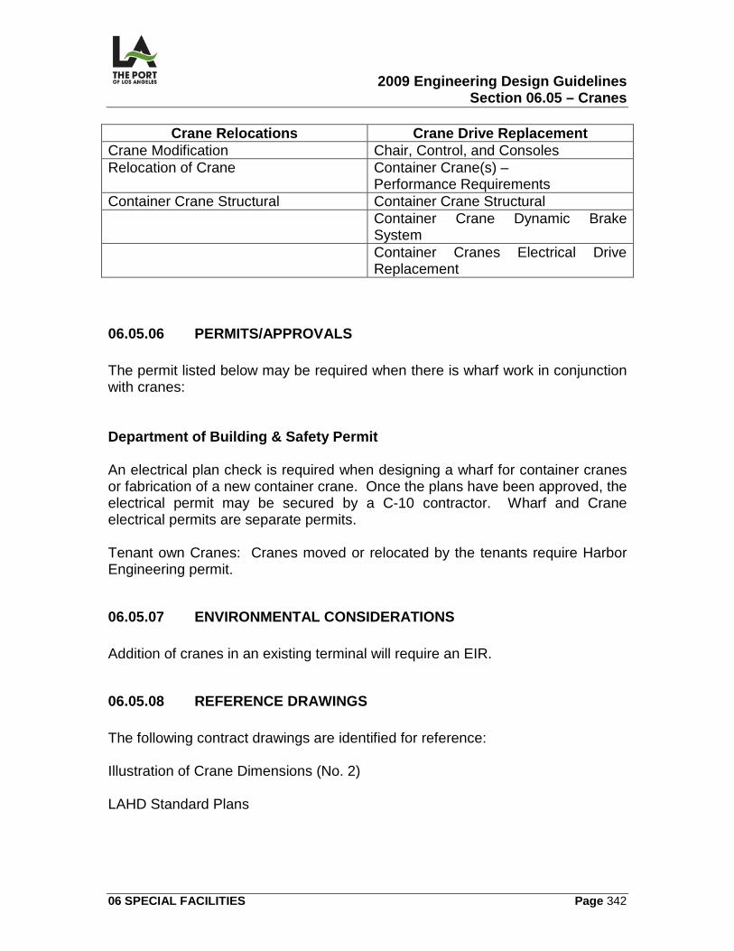
2009 Engineering Design Guidelines Section 06.05 – Cranes
06 SPECIAL FACILITIES Page 342
Crane Relocations Crane Drive Replacement Crane Modification Chair, Control, and Consoles Relocation of Crane Container Crane(s) –
Performance Requirements Container Crane Structural Container Crane Structural Container Crane Dynamic Brake
System Container Cranes Electrical Drive
Replacement
06.05.06 PERMITS/APPROVALS The permit listed below may be required when there is wharf work in conjunction with cranes: Department of Building & Safety Permit An electrical plan check is required when designing a wharf for container cranes or fabrication of a new container crane. Once the plans have been approved, the electrical permit may be secured by a C-10 contractor. Wharf and Crane electrical permits are separate permits. Tenant own Cranes: Cranes moved or relocated by the tenants require Harbor Engineering permit.
06.05.07 ENVIRONMENTAL CONSIDERATIONS Addition of cranes in an existing terminal will require an EIR.
06.05.08 REFERENCE DRAWINGS The following contract drawings are identified for reference: Illustration of Crane Dimensions (No. 2) LAHD Standard Plans
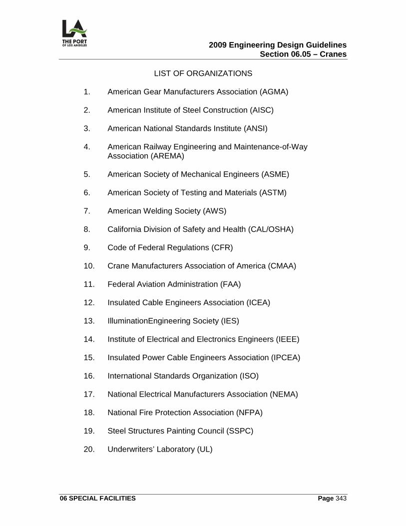
2009 Engineering Design Guidelines Section 06.05 – Cranes
06 SPECIAL FACILITIES Page 343
LIST OF ORGANIZATIONS
1. American Gear Manufacturers Association (AGMA)
2. American Institute of Steel Construction (AISC)
3. American National Standards Institute (ANSI)
4. American Railway Engineering and Maintenance-of-Way Association (AREMA)
5. American Society of Mechanical Engineers (ASME)
6. American Society of Testing and Materials (ASTM)
7. American Welding Society (AWS)
8. California Division of Safety and Health (CAL/OSHA)
9. Code of Federal Regulations (CFR)
10. Crane Manufacturers Association of America (CMAA)
11. Federal Aviation Administration (FAA)
12. Insulated Cable Engineers Association (ICEA)
13. IlluminationEngineering Society (IES)
14. Institute of Electrical and Electronics Engineers (IEEE)
15. Insulated Power Cable Engineers Association (IPCEA)
16. International Standards Organization (ISO)
17. National Electrical Manufacturers Association (NEMA)
18. National Fire Protection Association (NFPA)
19. Steel Structures Painting Council (SSPC)
20. Underwriters’ Laboratory (UL)
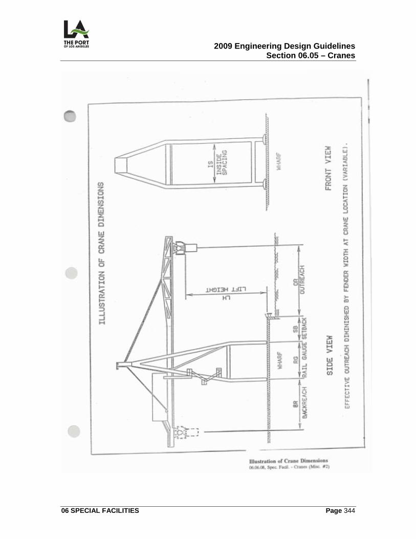
2009 Engineering Design Guidelines Section 06.05 – Cranes
06 SPECIAL FACILITIES Page 344
2009 Engineering Design Guidelines Section 07.01 – Ship Characteristics
07 OTHER CRITERIA Page 345
07 OTHER CRITERIA 07.01
SHIP CHARACTERISTICS
07.01.01 OVERVIEW This section contains information on ship characteristics pertinent to the Port of Los Angeles.
07.01.02 DESIGN CRITERIA Ship Characteristic Resources
1. Engineering Design Guidelines. Information about ship characteristics may be found in this section, with the Harbor Department's Structural Section staff as an additional resource.
2. Lloyd's Register of Ships.
a) The latest edition is available from the Port pilots. Information (e.g.,
deadweight, length, breadth, draft, and depth of vessels) is arranged according to the name of the ship.
b) Restrictions -- information is only arranged by ship name, not ship
type, and ship displacement information is not listed.
3. Clarkson Register of Tankers.
a) Although this register is not available from the Harbor Department, typical abstracts are available from the Harbor Department, Engineering Division, Structural Section.
b) Restrictions -- ship displacement information is not listed.
4. Other Resources. Other information about ship characteristics may be
obtained from the project tenant, the Port pilots, and/or from technical literature.
2009 Engineering Design Guidelines Section 07.01 – Ship Characteristics
07 OTHER CRITERIA Page 346
Typical Ship Characteristics A list of typical ship characteristics for the Port of Los Angeles is included in this section as Reference No. 1. Main Geometrical Particulars of Ships A table which includes some information on the relationship between deadweight, displacement, and other data is included in this section as Reference No. 2. It is included in the International Association of Ports and Harbors Guidelines for Port Planning and Design (2001). Comparison Tonnage Terminology Definitions of comparison tonnage terminology are included in this section as Reference No. 3. Selection of Ship Characteristics Due to the factors listed below, the ship characteristics used for a particular project shall be carefully selected and approved by the Chief Engineer:
1. Wharfs are often designed to meet specific tenant requirements. 2. Characteristics for the same type and size of ship can vary widely (e.g.,
short and wide ships can have the same deadweight tonnage as long and narrow ships).
07.01.03 CALCULATIONS/WORKSHEETS Ship Displacement Tonnage Estimate The best estimate of the displacement tonnage for ships (other than tankers or for partially laden ships) can be established by first determining the displaced volume of water which equals the overall length x breadth x draft multiplied by a block factor (which varies between 0.75 and 0.85) that accounts for hull shape. Although not exact, this estimate is adequate for berthing energy calculations required for the design of wharf fender systems.
2009 Engineering Design Guidelines Section 07.01 – Ship Characteristics
07 OTHER CRITERIA Page 347
Tanker Displacement Tonnage Estimate
1. Formula (Full). For full tankers, the displacement is closely related to the deadweight tonnage (D.W.T.) of the ship and is calculated as follows (with all units in Long Tons [i.e., 2240 lbs. per ton]): Displacement = 1.2 x D.W.T. + 3000.
2. Formula (Partially Laden). Displacement of a partially laden tanker is
calculated as follows: Displacement = (0.2 + %/100) D.W.T. + 3000 (partial loading is expressed as a percentage of the deadweight tonnage, thus if tanker is 70% loaded, replace %/100 with 0.7)
07.01.04 GRAPHIC CRITERIA There are no graphic criteria relating to ship characteristics.
07.01.05 SPECIFICATIONS There are no Harbor Department Master Specifications relating to ship characteristics.
07.01.06 PERMITS/APPROVALS There are no permits/approvals necessary for this section.
07.01.07 ENVIRONMENTAL CONSIDERATIONS See Alternative Maritime Power requirements in Section 5.10 Wharf - Electrical.
07.01.08 REFERENCE DOCUMENTS The following reference documents are identified for reference:
No. 1 Typical Ship Characteristics
No. 2 Main Geometrical Particulars of Ships
No. 3 Comparison Tonnage Terminology
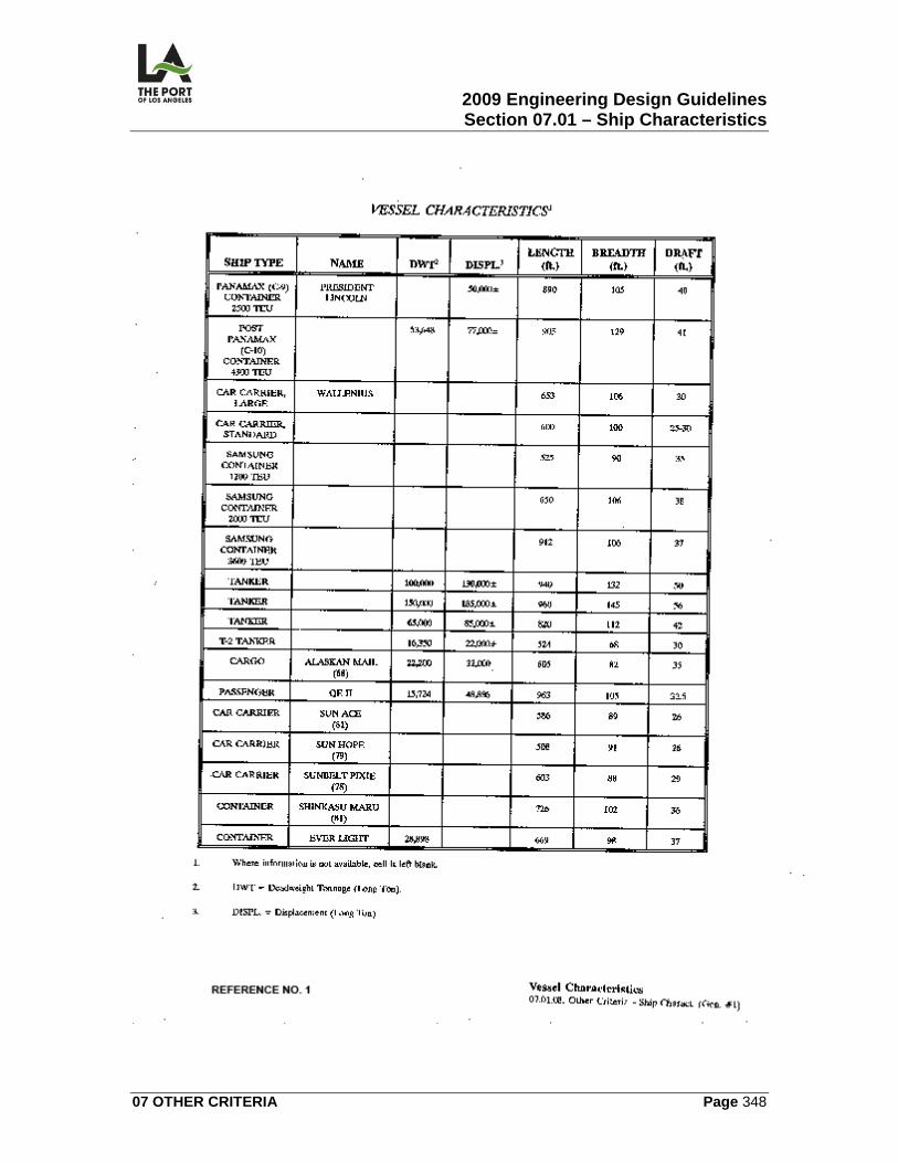
2009 Engineering Design Guidelines Section 07.01 – Ship Characteristics
07 OTHER CRITERIA Page 348
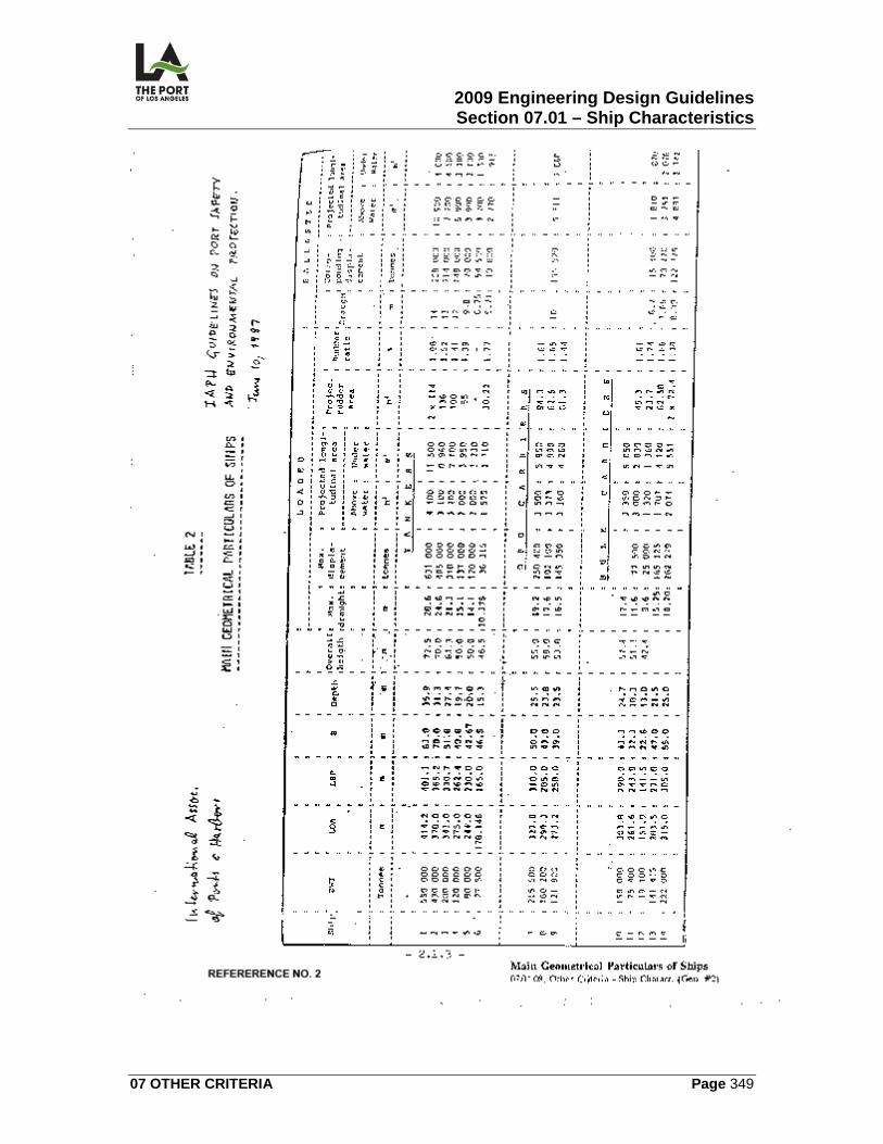
2009 Engineering Design Guidelines Section 07.01 – Ship Characteristics
07 OTHER CRITERIA Page 349
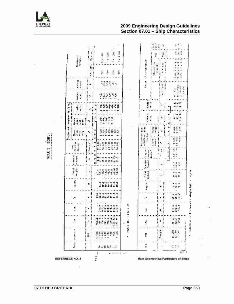
2009 Engineering Design Guidelines Section 07.01 – Ship Characteristics
07 OTHER CRITERIA Page 350
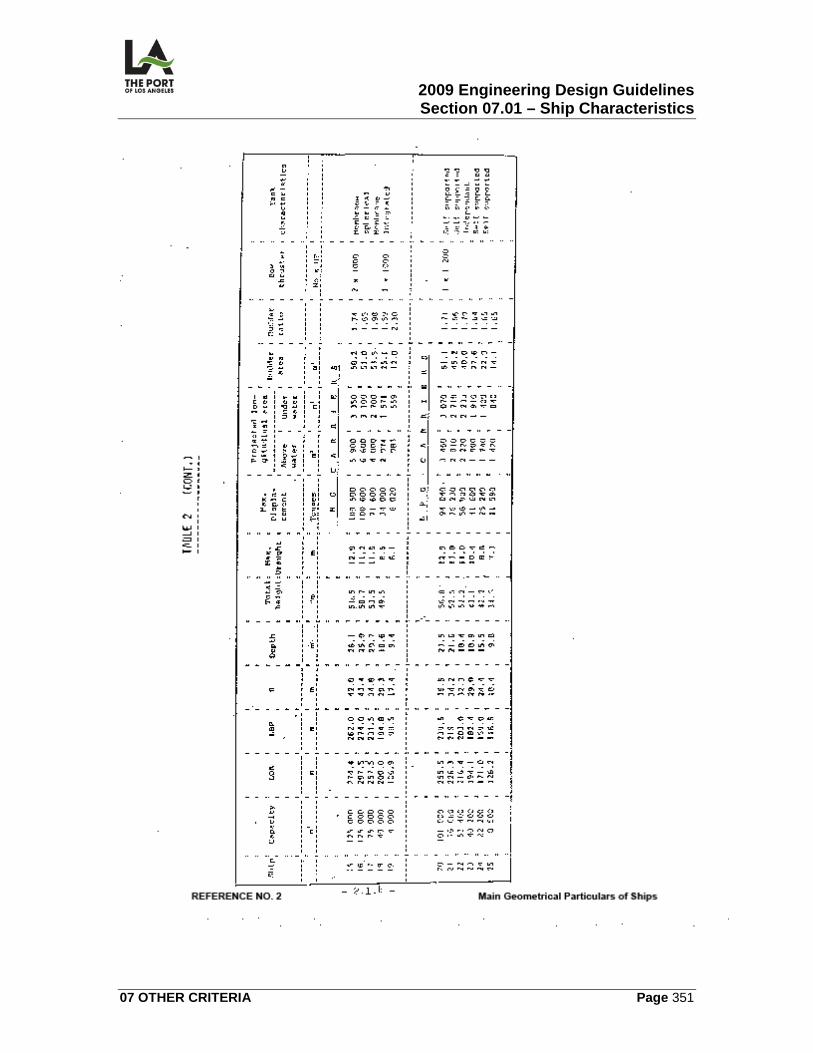
2009 Engineering Design Guidelines Section 07.01 – Ship Characteristics
07 OTHER CRITERIA Page 351
2009 Engineering Design Guidelines Section 07.01 – Ship Characteristics
07 OTHER CRITERIA Page 352
Reference No. 3: Comparison Tonnage Terminology For vessels, there are two general types of “tons.” One is weight, and used to be measured in long tons of 2,240 pounds. Sometimes tons are measured in metric tons equivalent to 2,205 pounds, a negligible difference for design purposes. The other type of ton is not a weight at all but rather a volume, equaling 100 cubic feet of enclosed space for a "vessel ton." With regard to merchant ships, gross, net, and deadweight tonnage figures are normally used. The relationship between these figures varies unless ships are of the same type. For example: Type Gross Net Deadweight Freighter 20,000 3,000 7,000 Tanker 6,700 4,000 10,000 Passenger Liner 20,000 12,000 10,000 Gross Register or Gross Tonnage (g.t.) The gross register is the total cubic capacity of all enclosed space at 100 cubic feet to the ton. It is used for general purposes and in national maritime registers. Net Register or Net Tonnage Measured in the same way as gross register, except the net register is the capacity of enclosed space less than that of the engine and boiler rooms, crew accommodations, fuel tanks, etc. (non-cargo areas). Displacement Tonnage This equals the weight of the volume of water displaced by the hull of the ship. It equals the total weight of the ship and everything on board. The volume of water displaced varies a little according to whether the water is salt, fresh, or in particular parts of the world. A given ship can have an infinite number of displacement tonnages depending on how much cargo, fuel, etc. it is carrying, thus several specific displacement tonnages have been defined. Displacement "light" is the weight of the vessel without cargo, stores, or bunker fuel. Displacement "loaded" is the weight of the vessel including a full load of cargo, stores, and bunker fuel. Displacement tonnage is needed for design (e.g. fender design), but unfortunately is not normally quoted in reference books for merchant ships, although it is for warships. Since the 1922 Washington Naval Treaty the official figure for warships has been standard displacement, which equals the full
2009 Engineering Design Guidelines Section 07.01 – Ship Characteristics
07 OTHER CRITERIA Page 353
displacement less the weight of fuel and reserve feed water for the boilers. Equations are available which allow displacement tonnage to be calculated from other types of tonnage such as deadweight tonnage. Deadweight Tonnage (dwt.) Deadweight tonnage is the number of tons that a vessel can transport of cargo stores and bunker fuel. It is the difference between the number of tons of water a vessel displaces "light" and the number of tons it displaces when submerged to its "load line" (Plimsoll line). Deadweight tonnage is used interchangeably with deadweight carrying capacity. The deadweight tonnage of a ship is a good indication of its cargo-carrying and earning capacity. Cargo Tonnage Cargo tonnage is either by "weight" or "measurement." The weight ton is taken in either long tons or metric tons. The measurement ton is usually 40 cubic feet, but in some instances a larger number of cubic feet is taken for a measurement ton. Note that a weight ton of cargo in most instances occupies less than 100 cubic feet (a vessel ton);. Hence the vessel's cargo tonnage in weight tons may exceed its net tonnage in vessel tons.
2009 Engineering Design Guidelines Section 07.03 – Navigation Channels and Aids
07 OTHER CRITERIA Page 354
07.02
SEISMIC DESIGN
07.02.01 OVERVIEW This section contains seismic design guidelines pertinent to wharf and some waterfront structures in the Port of Los Angeles. The following are not
covered by these guidelines:
1. Bridges -- shall be designed in accordance with CALTRANS standards, most current edition. Any deviation from the CALTRANS standards shall be approved by the Chief Harbor Engineer.
2. Buildings -- they shall be designed in accordance with the City of Los
Angeles Building Code, most current edition.
3. Other Structures -- the seismic design criteria for other structures such as movable bridges and access trestles, pipelines and tanks will be decided on a case-by-case basis by the appropriate Engineering Division personnel.
07.02.02 DESIGN CRITERIA Philosophy The guiding philosophy to be used for seismic design of wharfs is to provide life safety and damage control. This philosophy should be based on a two level design criteria (see the paragraph which follows). Wharf Two Level Design Criteria
1. Probabilistic Basis - A two level design criteria will be defined on a probabilistic basis. Ground and/or spectral acceleration risk levels will be expressed in probability of exceedance in an appropriate time span.
2. Determination of Risk Levels - Risk levels to be used will be determined in
joint consultation between the Engineering Division and the designer.4
3. Criteria - The criteria are:
4 More than one level of CLE events may be chosen for cost sensitivity studies at the conceptual stage.
2009 Engineering Design Guidelines Section 07.03 – Navigation Channels and Aids
07 OTHER CRITERIA Page 355
a) Moderate earthquakes (defined as operating level earthquakes [OLE]).
1) These should be resisted by wharf structures and retaining structures/dikes with only minor non-structural damage.
2) From a design standpoint, deformations of the wharf structures
should not result in significant residual cracking or spalling of the concrete or permanent elongation of the steel reinforcement. Permanent deformations of earth-retaining structures should be either less than a few inches or less than levels that will lead to structural damage, whichever is more critical.
3) The wharf structure should remain in service following the OLE.
Repairs to the structure should be minor and should be made without interruption to operations.
b) Large earthquakes (defined as contingency level earthquakes [CLE]).
1) These should be resisted by wharf structures and retaining structure/dikes in a manner which prevents collapse and major structural damage.
2) Damage to support systems shall be limited to allow operation of
container cranes after repair.
3) Structural damage that does occur to main support members should be detectable and accessible for inspection and repair.
4) Design should be such that damage to foundation elements below
ground level does not affect load capacity of the structural system. Earthquake Ground Motion Parameters The following specific ground motion parameters for horizontal and vertical earthquake components (and for both the OLE and CLE events)5
will be defined by the designer(s) based on results of existing studies and shall be compatible with the site conditions underlying the project areas:
1. Peak ground acceleration. 2. Peak ground velocity.
5 The parameters shall be consistent with the risk levels chosen.
2009 Engineering Design Guidelines Section 07.03 – Navigation Channels and Aids
07 OTHER CRITERIA Page 356
3. Elastic acceleration response spectra for 5% damping (covering the longest periods of interest).
4. If time histories are required, a minimum of seven acceleration time
histories6
for CLE events representative of source/site conditions.
5. Design for vertical accelerations is expected to be limited to such items as structural cantilever elements.
6. Soil embankment analysis shall consider only horizontal accelerations,
unless otherwise requested by Port engineers. Fault Rupture The potential magnitudes of surface ground rupture in the horizontal and vertical directions within the project area shall be provided by the Port or the design consultant7
for project design use and approved by the Chief Harbor Engineer.
Earthquake Response & Structural Deformation Analysis For purposes of analyzing the earthquake response and induced deformations of structures due to both OLE and CLE events, two- and three-dimensional idealizations should be used. For earthquake dynamic response analyses, pile-supported container wharfs or berthing structures and retaining structures/dikes may be analyzed independently, if appropriate. In considering the overall earthquake performance, however, the effects of permanent retaining structure/dike deformations on stresses induced in and the resulting performance of the individual elements of pile-supported wharf structures should be analyzed as follows:
1. Dike Retaining Structural Analysis Methods.
a) Simplified Dynamic Analysis Methods:
1) For OLE events -- these methods may be used to evaluate the permanent deformation response of the dike-retaining structures for OLE events (e.g., those based on the Newmark Approach).
2) For CLE events -- these methods (combined with nonlinear
dynamic response analysis methods) should be used to determine
6 Histories will be compatible with the elastic design spectrum over the period range of interest, 7 The magnitudes and zones shall be consistent with risk levels adopted for OLE and CLE events.
2009 Engineering Design Guidelines Section 07.03 – Navigation Channels and Aids
07 OTHER CRITERIA Page 357
the permanent deformations of the dike-retaining structures and associated foundation soils (together with any structural elements such as sheet piles).
b) Non-Linear Dynamic Response Analysis Methods -- these methods (in
combination with simplified dynamic analysis methods) should be used for CLE events:
1) Site-specific CLE input acceleration time histories should be
applied at an appropriate firm ground transmitting boundary interface at a depth to determine histories acting on the dike structure and foundation soils.
2) Deformational analyses should include the potential effects of pore
pressure buildup in the dike, back-land fill, and substructure soils.
3) Post-earthquake stability should also be assessed.
4) The potential reinforcing effects of piles installed in the embankment should also be considered.
2. Piled Berthing Structure Analysis Methods.
a) Simplified Elastic Response Spectral Analyses -- these may be used to assess the earthquake response of the wharf structures to OLE events.
b) Dynamic Response Analyses (of the wharf structure for CLE events) –
These analyses should initially use elastic methods based on appropriate response spectral accelerations. Structure components that are expected to exceed elastic behavior limits should be further analyzed using appropriate non-linear techniques to determine the effect of local plastic hinging, resulting in redistribution of internal moments, shears, and forces.
c) Two-Dimensional, Non-Linear Dynamic Response Analysis -- After the
structure is initially proportioned using the elastic approach, this analysis should be conducted for the wharf structure for CLE event(s) based on appropriate ground motion time histories. Time histories used for analyses should reflect potential modifications to site specific CLE ground motion histories, arising from results of the dynamic response analyses conducted for dike-retaining structures.
d) Ductility Requirement Analysis -- Sections of structural members that
undergo inelastic deformation should be shown to be ductile (or be
2009 Engineering Design Guidelines Section 07.03 – Navigation Channels and Aids
07 OTHER CRITERIA Page 358
made ductile, in the case of concrete piles) by confinement or by other effective means. The analysis should show that shear and bond failures in concrete structural components do not precede the formation of a flexural inelastic mechanism.
e) Alternative Innovative Structure Types:
1) For alternative innovative structure types that use "Added Damping
and Stiffness" (ADAS) elements or fused link elements, the elements should be designed and detailed to ensure ductile behavior.
2) In addition, non-ADAS elements should be proportioned to ensure
overall structure compatibility for the inelastic deformations.
3) All structural elements forced to undergo the related distortion should be evaluated to ensure adequate performance without significant damage.
3. Fault Rupture -- The conceptual design of a container wharf or berthing
structures should also reflect the potential effects of fault rupture associated with earthquake events on the Palos Verdes fault.
Landfill Performance Requirements The acceptability of the landfill performance, in terms of the results of the following analyses, will be determined by the Engineering Division in relation to the intended land use. Earthquake performance requirements for landfill, which follow, are guided by ground stability and settlement requirements in relation to the intended land use:
1. Of primary concern are potentially liquefiable fill soils. To define the earthquake performance of potentially liquefiable soils in either existing or new landfills, liquefaction analyses for OLE and CLE events should be performed using standard penetration test (SPT) data and/or cone penetrometer test (CPT) data to determine liquefaction strengths. Results of these analyses should be expressed in terms of:
a) Potential for surface manifestation of subsurface liquefaction, using a
factor of safety of 1.0 with respect to liquefaction strengths. b) Post-liquefaction settlement potential using a factor of safety of 1.0
with respect to liquefaction strengths.
2009 Engineering Design Guidelines Section 07.03 – Navigation Channels and Aids
07 OTHER CRITERIA Page 359
c) Average residual undrained strength in liquefied zones using a factor of safety of 1.0 with respect to liquefaction strengths.
2. For CLE events, site response analyses using CLE acceleration time
histories input at an appropriate "firm ground" transmitting boundary interface at depth should be used to determine earthquake-induced cyclic shear stress ratios. The liquefaction potential of landfill soils determined from such analyses may be evaluated using total stress or effective stress approaches.
3. For OLE events, the Seed Simplified Method may be used to determine
earthquake-induced cyclic shear stress ratios and the liquefaction potential of landfill soils.
4. Land use requirements in relation to critical facilities, such as the
transportation corridor and oil tanks, will require (as a minimum) no surface manifestation of subsurface liquefaction. Acceptable settlements for these facilities and questions related to the magnitude and extent of residual strengths in liquefied zones shall be evaluated based on structural and foundation requirements for these facilities.
07.02.03 CALCULATIONS/WORKSHEETS The designer shall prepare all calculations on worksheets in compliance with POLA's Engineering Division's latest format.
07.02.04 GRAPHIC CRITERIA There are no graphic criteria for this section.
07.02.05 SPECIFICATIONS There are no Master Specifications for this section.
07.02.06 PERMITS/APPROVALS See POLA's Code for Seismic Design, Upgrade & Repair on Container Wharf.
07.02.07 ENVIRONMENTAL CONSIDERATIONS
2009 Engineering Design Guidelines Section 07.03 – Navigation Channels and Aids
07 OTHER CRITERIA Page 360
There are no relevant environmental considerations for this section.
07.02.08 REFERENCE DOCUMENTS The following documents are identified for reference: POLA's Code for Seismic Design, Upgrade & Repair on Container Wharf LAHD Standard Plans
2009 Engineering Design Guidelines Section 07.03 – Navigation Channels and Aids
07 OTHER CRITERIA Page 361
07.03
NAVIGATION CHANNELS & AIDS
07.03.01 OVERVIEW This section contains information on navigation channels and aids pertinent to the Port of Los Angeles.
07.03.02 DESIGN CRITERIA Navigation Channels Resources - A designer of Port projects may find the following resources helpful in altering navigation channels.
1. “Map of California Coordinate System, Zone 5, Showing the United States Harbor Lines,” produced by the Permits & Right-of-Way Section – shows the location of US Pierhead Lines along with California State Plane Coordinates for each Pierhead Point in both Zone 7 (NAD27) and Zone 5 (NAD83).
2. “Berth Lengths,” produced by the Permits & Right-of-Way Section – shows
the ground lengths of berths. Altering Channels - If embarking on a project that will alter the width of a channel, it is necessary to:
1. Meet with the Port Pilots to review their navigational needs. 2. Coordinate any changes with the Port's Right-of-Way Section staff so that
they may update the Port Harbor Lines Map (which reflects any channel, slip, basin, or pierhead changes made after publication of the Army Corps Of Engineers Harbor Lines Map).
3. Communicate changes made to the:
a) Port's Real Estate Division b) Port Pilots
c) United States Coast Guard (USCG) (so that they may revise
navigational charts, if necessary).
4. Investigate procedures required by the Army Corps of Engineers
2009 Engineering Design Guidelines Section 07.03 – Navigation Channels and Aids
07 OTHER CRITERIA Page 362
Navigation Aids Resources - A designer of Port projects may find the following helpful in selecting navigation aids:
1. "Chart No. 1," published by the USCG (latest edition) - describes types of navigational aids.
2. "Chart No. 18751, Los Angeles and Long Beach Harbors," published by
the Coast and Geodetic Survey, National Ocean Service, National Oceanic and Atmospheric Administration (NOAA) - identifies the location/type of all charted navigational aids in the harbor.
Hazards to Navigation - The Designer shall identify any hazards to navigation (e.g., jetty, breakwater, mole, dolphin, outfall, pipeline, floating structure, or shoaling) in the project area and notify the USCG. They will publish information on the hazard (description and location) in the “Local Notice to Mariners” and will recommend the appropriate type(s) of navigation aid(s). Navigation Aids - Navigation aids, which the designer may consider, include:
1. Lights - they define a specific point or points and are typically used on a jetty, a mole, or at the end of a dock or breakwater.
2. Daymark - used when a structure is in the same location as the edge of a
navigation channel.
3. Range lights or range marks - range lights are a pair of lights which define a center line alignment of a navigation channel. The forward range is positioned lower than the back range. Range marks are identifiable unlighted targets used for the same purpose.
4. Floating marks - these may be used for hazards which are partially or
totally submerged (e.g., broken mooring dolphins). Regulatory Aids - Regulatory aids are designed for controlling the speed of watercraft, the type of watercraft, and the necessary warning information (no wake, no swimming, etc.) in the harbor. Examples of regulatory aids are:
1. Sign mounted on a floating structure. 2. Buoys painted with signage information.
2009 Engineering Design Guidelines Section 07.03 – Navigation Channels and Aids
07 OTHER CRITERIA Page 363
07.03.03 CALCULATIONS/WORKSHEETS The designer shall prepare all calculations on worksheets in compliance with POLA's Engineering Division's latest format. Navigation Channels
1. New pierhead lines must be defined in NAD83 California State Plane Coordinates, Zone 5.
2. Traverses must be run on new pierhead lines to make sure they fit within
existing pierhead lines. Navigation Aids
1. The height above water of a navigation aid is calculated depending upon whether it is on land or in the water. On land, the height is measured from mean low water (MLW). In the water, the height is measured from the water line. In addition, for those navigation aids that are located in the water, the depth of the ocean at the location of the aid must be measured from MLW.
2. There are several ways to calculate the position of a navigation aid: the
angles from two or more prominent charted landmarks, the bearing and distance to a prominent charted landmark, or its geodetic coordinates - latitude and longitude. State plane coordinates are not an acceptable method of describing the position of navigation aid.
07.03.04 GRAPHIC CRITERIA Navigation Channels A map must be prepared to show the before and after configurations of the pierhead lines when altering navigation channels. To distinguish between US pierhead lines and points (Federal) and Port of Los Angeles pierhead lines and City points, use the letters US and LA, respectively, before the pierhead point’s number. The plan must be prepared in NAD83 California State Plane Coordinates, Zone 5. Navigation Aids
2009 Engineering Design Guidelines Section 07.03 – Navigation Channels and Aids
07 OTHER CRITERIA Page 364
When installing navigation aids, a plan view is required. The plan must describe the aid, indicate its position, and show the area into which it will be installed. Include a vicinity map to narrow down the location of the installation within the Port of Los Angeles. The plan must be prepared in NAD83 California State Plane Coordinates, Zone 5.
07.03.05 SPECIFICATIONS There are no Harbor Department Master Specifications relating to navigation channels or aids. Typically, floating aids are specified by the buoy’s model number and a description relative to its purpose. The description would include any required markings on the buoy.
07.03.06 PERMITS/APPROVALS Navigation Channels In the past, any changes to the US Pierhead Line had to be approved by the U S Army Corps of Engineers (ACE). Today, we only notify them of the proposed changes. Navigation Aids There are two types of navigation aids: temporary and permanent. Temporary aids are those that will be on station for 6 months or less. A permit application is not required for a temporary aid. However, when planning to install a temporary aid, plans should be submitted to the USCG for review before it is established. The USCG publishes the location of all temporary aids in the Local Notice to Mariners. Permanent aids require a permit from the USCG and ACE. A Private Aids to Navigation Application, form CG-2554, must be submitted to the USCG, Aids to Navigation Branch, Private Aids to Navigation (PAtoN). This application includes a Nationwide Permit 1 from the ACE for Aids to Navigation.
07.03.07 ENVIRONMENTAL CONSIDERATIONS Navigation Channels
2009 Engineering Design Guidelines Section 07.03 – Navigation Channels and Aids
07 OTHER CRITERIA Page 365
The effect on water circulation within the Port of Los Angeles should be considered when altering navigation channels. A new channel configuration may affect sediment transport, trash mobility, and water quality, among other things. Navigation Aids The materials used for navigation aids should be non-toxic in nature so that they do not affect the marine environment in which they will be on station. Care should be taken when installing aids with lights or horns. Shields should be installed on lights so that they do not shine directly into near-shore residential areas.
07.03.08 REFERENCE DRAWINGS The following contract drawings are identified for reference: 1-1241-2, Map of California Coordinate System, Zone 5, Showing the United
States Harbor Lines. 1-2063-3 Berths Lengths. Chart No. 1 United States of America, Nautical Symbols, Abbreviations, and
Terms, latest edition. Chart No. 18751 Los Angeles and Long Beach Harbors. 1-2601 Watchorn Basin Obstructions.
1-2601 C-1 Buoy Installation Plan LAHD Standard Plans
2009 Engineering Design Guidelines Section 07.04 – Survey and Right-of-Way
07 OTHER CRITERIA Page 366
07.04
SURVEY AND RIGHT-OF-WAY
07.04.01 OVERVIEW This section contains survey and right-of-way information pertinent to the Port of Los Angeles.
07.04.02 DESIGN CRITERIA Establishing Stationing
1. Linear Stationing. Linear stationing is generally established parallel to the pierhead line. Stationing should be calculated using the most current existing data (assistance is available from the Port's Right-of-Way Section). Information regarding the use of linear stationing follows:
a) Linear stationing is used with sewers, storm drains, roads, and streets;
curves are handled in a circular manner. b) Linear stationing is also used with railroads; however, curves may be
spirals.
2. Grid Stationing. Grid stationing is two-directional and is used for backland, buildings, and wharfs. Wharf stationing is generally shown as parallel and perpendicular to the pierhead line. Backland and building stationing may also be positioned in a north-south, east-west manner. Establishing grid stationing (parallel and perpendicular to the pierhead line) is done as follows:
a) The first coordinate axis is perpendicular to the pierhead line (0+00 at
the pierhead line), with "plus" values extending out into the water and "minus" values (e.g., -0+50) extending onto land.
b) The second coordinate axis is parallel to the pierhead line (at right
angles), with values to be established linearly using the most current existing data.
Plane Table Coordinates One plane table coordinate is included on each coordinate control plan. Benchmark and monument information is available from the Port's Survey Section through the Project Manager. Benchmark elevations can be adjusted by
2009 Engineering Design Guidelines Section 07.04 – Survey and Right-of-Way
07 OTHER CRITERIA Page 367
using the Survey Datum Conversion Table (City of Los Angeles Standard Plan S 704 0). Legal Descriptions The designer should consult with the Port's Right-of-Way Section when preparing a legal description for a building permit application. If the legal description is to be used for a building permit application, it must be accompanied by a street address (obtained from the Permit Section). Presentation of Coordinate Control Information Coordinate control information is presented on a coordinate control plan. A plan is prepared for each project and is to identify coordinate controls, survey controls, affected tenants, and boundary conditions. Developing a Coordinate Control Plan In developing a coordinate control plan, the Project Manager shall collect current as-built information and establish stationing conventions (using the Port's Right-of-Way Section staff as a resource). Once stationing conventions are established, the Right-of-Way Section will review the stationing methods for consistency with other as-built construction and monumentation. They will also coordinate with the Survey Section of the Construction Management Division. Property and Lease Maps Property and Lease Maps (also known as Permit Maps) reflect survey information. They include boundary information with bearings and distances and may be used to verify ownership, investigate easement rights, etc. Each map has a field tie that relates to a surveyed monument in the field. The following information shall be included in this map (an example of a Permit Map is included in Reference Drawings):
1. Lessee/Permitee Name 2. Authority Number
3. Areas and Parcel Numbers
4. Curve Data
2009 Engineering Design Guidelines Section 07.04 – Survey and Right-of-Way
07 OTHER CRITERIA Page 368
5. Bearing and Distance
6. Prominent features (e.g. Vincent Thomas Bridge, channels, etc.)
Aerial Photomaps Aerial photomaps (also known as planimetric maps) are based on plane table coordinates, which are corrected for earth curvatures. They may be used by designers for design layouts. The maps are available in the Engineering Division's vault (at 1"=40') and in AutoCAD format (N:\cadd\planimetrics). Right-of-Way Map Although this map does not show stationing or a plane table coordinate, it does use a plane table coordinate as a basis for the map's preparation. The following information shall be included in this map (an example of a right-of-way map is included in Reference Drawings):
1. Areas and parcel numbers 2. Property owner's name
3. All property to be acquired (by fee title or for surface, underground, or
overhead rights)
4. Curve data
5. Bearings and distances
6. Prominent features (e.g., Vincent Thomas Bridge, channels, etc.)
07.04.03 CALCULATIONS/WORKSHEETS Traverse and area calculations shall be prepared for each parcel. The designer shall prepare all calculations on worksheets in compliance with POLA's Engineering Division's latest format.
2009 Engineering Design Guidelines Section 07.04 – Survey and Right-of-Way
07 OTHER CRITERIA Page 369
07.04.04 GRAPHIC CRITERIA The designer shall use the smallest size drawing such that all information on the map is legible. Suitable drawing sizes are 1-size, 2-size, 4-size and 5-size. The drawings shall be prepared in compliance with the latest edition of the POLA Engineering Division Right-of-Way CADD standards.
07.04.05 SPECIFICATIONS There are no Harbor Department Master Specifications relating to survey and right-of-way.
07.04.06 PERMITS/APPROVALS There are no permits/approvals necessary for this section.
07.04.07 ENVIRONMENTAL CONSIDERATION The designer shall coordinate with the Real Estate and Environmental Divisions to obtain the necessary environmental documents.
07.04.08 REFERENCE DRAWINGS The following contract drawings are identified for reference: 1-1993-2 Permit Map – Authority No. P733 Eagle Marine Services, LTD. 1-2301-1 POLA/POLB Right-of-Entry and Property Acquisition Agreements –
Revised Right-of-Entry Map LAHD Standard Plans
2009 Engineering Design Guidelines Section 07.05 – Site Remediation
07 OTHER CRITERIA Page 370
07.05
SITE REMEDIATION
07.05.01 OVERVIEW This section contains information related to the preparation of a hazardous waste site mitigation plan package.
07.05.02 DESIGN CRITERIA Initiation The Engineer files an Application for Development permit (ADP) which authorizes the Environmental Management Division (EMD) to develop an Environmental Assessment and to perform the investigative and design work described herein when required by the Environmental Assessment. Site Assessment The Site Assessment portion of a site clean-up project involves the following tasks:
1. Review of existing information. 2. Formal evaluation of the site to verify a release.
3. Identification of potential responsible parties.
4. Evaluation of the need for emergency remedial action.
5. Identification of the appropriate regulatory agencies.
6. Planning and preparation of a timetable for site mitigation activities.
7. Initiating an environmental assessment within the Harbor Department.
Remedial Investigation
1. Tasks. The Remedial Investigation (R.I.) involves the following tasks:
a) Hazardous waste investigation. b) A "site characterization" plan.
2009 Engineering Design Guidelines Section 07.05 – Site Remediation
07 OTHER CRITERIA Page 371
c) Identification of migration pathways/receptors.
d) Consideration of regulatory agency concerns.
e) Evaluation of public health/environmental concerns.
f) Investigation of:
1) Soil/groundwater contamination. 2) Land use.
3) Surface water.
g) Consideration of California Environmental Quality Act (C.E.Q.A.)
requirements. h) Development of a Community Relations Plan, if appropriate.
2. Workplan Elements. The R.I. portion of the workplan should include the
following elements:
a) Executive summary. b) Site description and background information, including:
1) Description of the general nature of the problem. 2) Information on past/present site ownership.
3) Description of past/present activities and information on types,
quantities, and concentrations of hazardous wastes/materials used, treated, stored, transferred, disposed of, or handled. A site map delineating each of these areas must be provided.
4) Groundwater data -- depth to first groundwater, maximum well
depths, flow direction and gradient of groundwater, well logs, screen intervals, and any other relevant information.
5) Surface water information including site drainage and proximity to
harbor waters.
6) Soil type, soil permeability, soil analysis, boring logs, and soil pH.
2009 Engineering Design Guidelines Section 07.05 – Site Remediation
07 OTHER CRITERIA Page 372
7) Proximity to critical habitats which may contain endangered species.
c) Site map -- the site map should show all important features (e.g.,
substructures, pipelines, etc.) in sufficient detail and accuracy to locate and report all existing and future work performed at the site.
d) Sampling and Analysis Plan -- this Plan should address all field
activities to be performed. Since the site characterization process is iterative, the results of initial sampling may indicate the need for further sampling to fully determine the extent of contamination. Provisions must, therefore, be made to accommodate a second or third phase plan, if necessary. The Plan should describe or provide:
1) Sampling objectives and protocols. 2) Sampling methods, sampling devices, quality assurance and
control protocols, chain of custody, sample packaging, transportation, and other details in conformance with E.P.A. document SW-846, unless otherwise specified.
3) Sampling locations (indicated on site map), justifications for the
choices, and chemical analyses to be performed in order to adequately define the extent (vertical and horizontal) and nature of contamination.
4) Identification of a state-certified laboratory to perform the chemical
analyses.
5) Engineering specifications for all installations including soil borings and monitoring wells.
6) Provisions for gaining access to and obtaining samples from
adjacent properties, as appropriate.
e) Health and Safety Plan -- this Plan must cover all measures taken to protect on/off site populations from exposures to hazardous wastes/materials during workplan activities. The Plan should include, but is not limited to: key personnel, responsibilities and qualifications, job hazard analysis, risk assessment summary, exposure monitoring plan, protective equipment, work zones and security measures, decontamination procedures, general safe work practices, standard operation procedures, hospital locations and maps, contingency plans, training requirements, and documentation of the medical surveillance program.
2009 Engineering Design Guidelines Section 07.05 – Site Remediation
07 OTHER CRITERIA Page 373
f) Community Relations Plan -- this Plan identifies community concerns
and provides opportunities for individuals concerned about or potentially affected by the remedial activity to be performed at the site . The Plan must outline the ongoing steps for informing local residents about activities at the site and for responding to inquiries from citizens or public entities.
g) Treatability studies -- All pilot studies, bench studies, and/or other
activities which will be performed to evaluate the treatability of contaminated materials shall be described.
h) Time schedule -- a time schedule of the proposed activities shall be
provided.
i) Regulatory agency requirements -- appropriate regulatory agencies must be notified for required permits or variances necessary to implement the workplan activities, including but not limited to:
1) California Environmental Protection Agency (CAL E.P.A.). 2) United States Environmental Protection Agency (E.P.A.).
3) South Coast Air Quality Management District.
4) Regional Water Quality Control Board.
5) Los Angeles City Fire Department.
6) Los Angeles County Fire Department.
7) State Department of Toxic Substance Control
Feasibility Study
1. Tasks. The Feasibility Study (F.S.) involves the following tasks:
a) Evaluation of remedial action alternatives. b) Recommended remedial action with justification.
c) Evaluation of public health and environmental concerns.
d) Risk assessment.
2009 Engineering Design Guidelines Section 07.05 – Site Remediation
07 OTHER CRITERIA Page 374
e) Setting clean-up levels.
2. Workplan Elements. The F.S. portion of the workplan should include the
following elements:
a) Executive summary -- briefly describing the current situation, the purpose of the remedial action, the potential or actual hazards, and exposure pathways.
b) Preliminary remedial technologies -- a master list outlining potentially
feasible technologies, along with a screening of each to ensure its feasibility.
c) Development of alternatives -- addressing the objectives of the
remedial action, as well as the development of alternatives incorporating the remedial technologies and other considerations. "No action" must also be considered to provide a basis for the other alternatives being considered. The resulting alternatives must then be screened to ensure feasibility.
d) Evaluation of alternatives -- a detailed evaluation of the alternatives
passing the screening shall be performed, addressing the following analyses:
1) Technical. 2) Environmental.
3) Public health.
4) Regulatory agency.
e) Risk assessment (clean up criteria) -- a proposed Remedial Action
Plan (R.A.P.) must consider the full range of options available: no action, complete removal, background or non-detectable levels. If a clean up is proposed where contaminants are not removed to background levels, a risk assessment must be approved and conducted (to establish and justify clean up standards specific to the site and contaminants under review).
f) Schedule -- a schedule for the Feasibility Study tasks shall be
submitted.
2009 Engineering Design Guidelines Section 07.05 – Site Remediation
07 OTHER CRITERIA Page 375
Remedial Investigation Report This Report must be submitted for review and approval in accordance with the approved workplan schedule. It shall summarize the results of the Remedial Investigation, as well as the reduction and interpretation of all information generated/compiled during the investigation process. Feasibility Study Report This Report must be submitted in accordance with the approved workplan schedule. The Report will summarize the results of the F.S., as well as the reduction and interpretation of all information generated/compiled during the study process. It shall include the recommended remedial action. Remedial Action Plan
1. Description. The Remedial Action Plan (R.A.P.) follows the R.I./F.S. and will involve a review and approval by agencies. It provides specific operational details about the approved alternative.
2. Contaminant Levels. When remediation of a site involves a small volume
of localized soil contamination (e.g., oil spillage near waste storage drums), workplan submittals may not require the amount of information outlined in this section. If contaminant levels are based on present land use, deed restrictions/notifications may be required. The Environmental Management Division should be consulted for further information.
Typical LAHD Hazardous Waste Sites Los Angeles Harbor Department contaminated sites can be classified into “Cal Sites” (California Department of Toxic Substances designation), Federal Superfund Sites, and leaking underground storage tanks, or L.U.S.T. sites, regulated by Los Angeles Regional Water Quality Control Board. An example of a Cal Site at LAHD is the San Pedro Boatyard. Examples of Superfund sites at LAHD are the Koppers site and the 22nd Street Annex site. “Dig and Haul” is the most common remediation method for soil contamination used at LAHD contaminated sites. This method involves excavating soils and stockpiling them within enclosed lined, bermed, and fenced areas at the project site. After soil samples in stockpiles are tested, they are transported to the
2009 Engineering Design Guidelines Section 07.05 – Site Remediation
07 OTHER CRITERIA Page 376
proper treatment, storage, and disposal facility (TSDF) for disposal or incineration. Personnel visiting contaminated sites should obtain information from EMD on current site conditions prior to visiting. If contaminants have been exposed that create unhealthful airborne concentrations, either use appropriate protective gear, such as respirators and goggles, or postpone visit to site until EMD verifies that concentrations have declined. The Engineer shall verify the status of the site characterization and any recommendations prior to excavating for remediation or other excavation work.
07.05.03 CALCULATIONS/WORKSHEETS There are no calculations or worksheets provided for this section.
07.05.04 GRAPHIC CRITERIA The remedial action plan should contain drawing(s) depicting, at a minimum:
1. Sampling locations 2. Identification of specific wastes to be removed or remediated and waste
volumes, if known
3. Limits of each proposed waste removal or remediation
07.05.05 SPECIFICATIONS Site remediation specifications must be specifically developed for each project in conjunction with EMD and are therefore not included in the Master Specifications. However, the following sections in the Harbor Department Master Specifications provide additional information concerning site remediation. In addition, there is a Master Specification for contingency cases of unexpected contaminated soil discovery. Specifications
SECTION TITLE Regulatory Requirements Basic Site Materials and Methods Excavating, Handling, and Disposal of
2009 Engineering Design Guidelines Section 07.05 – Site Remediation
07 OTHER CRITERIA Page 377
Chemically-Impacted Soils
07.05.06 PERMITS/APPROVALS The Environmental Management Division will determine the permits/approvals necessary for each specific site remediation.
07.05.07 ENVIRONMENTAL CONSIDERATIONS Careful monitoring of contractor site remediation activities by technical consultants and inspection staff is necessary to ensure compliance with the scope of the Remediation Action Plan and permit requirements.
07.05.08 REFERENCE DRAWINGS There are no reference drawings included in this section.
2009 Engineering Design Guidelines Section 07.06 – Geotechnical
07 OTHER CRITERIA Page 378
07.06
GEOTECHNICAL
07.06.01 OVERVIEW This section contains geotechnical guidelines required in the design of wharfs, backland, light poles, buildings, foundations, slopes, and other structures or projects that require geotechnical investigations.
07.06.02 DESIGN CRITERIA A directive to perform a geotechnical investigation needs to be issued, usually to the “on call” Geotechnical Consultant Contractor. The Consultant shall follow and abide by City of Los Angeles Building Code and all other applicable caode and requirements. Boring and Testing Program A boring and Cone Penetration Test (CPT) sounding investigation program shall be conducted. Depths, locations, and number of borings shall be determined by a Geotech Engineer based on the requirements of the project. These may be changed based upon engineering judgment on the basis of observed conditions in the field during the exploration program. The program shall include:
1. Borings to depths determined by the Geotech Engineer. 2. CPT Soundings in the backland area as determined by the Geotech
Engineer. Samples will be recovered for soil classification and laboratory testing. Alternating Standard Penetration Test Samples with either ring-lined barrel or Shelby tube samples at 5-foot intervals. Drilling mud from borings shall be transported off of Harbor Department property. Laboratory Tests A laboratory testing program shall be conducted by a City of Los Angeles Certified test lab in general accordance with the following preliminary program. The type and number of test may be changed using engineering judgement based on the results of the field exploration program.
Test ASTM
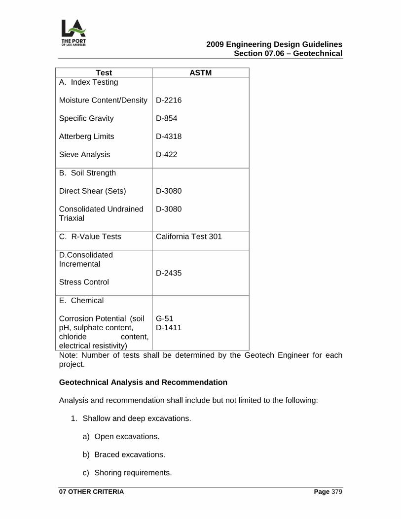
2009 Engineering Design Guidelines Section 07.06 – Geotechnical
07 OTHER CRITERIA Page 379
Test ASTM A. Index Testing Moisture Content/Density Specific Gravity Atterberg Limits Sieve Analysis
D-2216 D-854 D-4318 D-422
B. Soil Strength Direct Shear (Sets) Consolidated Undrained Triaxial
D-3080 D-3080
C. R-Value Tests
California Test 301
D.Consolidated Incremental Stress Control
D-2435
E. Chemical Corrosion Potential (soil pH, sulphate content, chloride content, electrical resistivity)
G-51 D-1411
Note: Number of tests shall be determined by the Geotech Engineer for each project. Geotechnical Analysis and Recommendation Analysis and recommendation shall include but not limited to the following:
1. Shallow and deep excavations.
a) Open excavations. b) Braced excavations.
c) Shoring requirements.
2009 Engineering Design Guidelines Section 07.06 – Geotechnical
07 OTHER CRITERIA Page 380
2. Evaluation of compacted fills and their performance. 3. Earth pressures acting on walls and retaining structures.
4. Design and evaluation of dewatering systems and operations.
5. See page analysis and control.
a) Design of drainage blanket. b) Design of lining for seepage control.
c) Erosion control.
6. Analysis of settlement and volume expansion. 7. Design and analysis for slope stability and protection.
8. Liquefaction potential, prevention, mitigation, and remediation.
9. Construction of pile supported structures.
10. Submerged and partially submerged retaining structures.
11. AC pavement design.
12. Geotechnical parameters for existing wharfs seismic upgrade.
13. Soil structure interaction evaluation under static and seismic loading
conditions.
14. Geotechnical seismic analysis and recommendations.
15. Geotechnical parameters for the design of foundations, etc.
16. Other geotechnical considerations. Deliverables After all field investigations, analyses, and recommendations are complete, a final geotechnical report shall be submitted to the Port. Upon completion of the design drawings, the geotechnical engineer will sign and stamp the Port drawings to satisfy the City of Los Angeles Department of Building and Safety
2009 Engineering Design Guidelines Section 07.06 – Geotechnical
07 OTHER CRITERIA Page 381
(LADBS) permit requirements. The geotechnical engineer will submit the geotechnical report to LADBS’ Grading Division for their conditions, comment, and acceptance. Construction Services The geotechnical engineering consultant shall provide services during the project’s construction phase.
1. Investigate unforeseen field conditions and problems, and provide consultation on an as-needed basis.
2. Observe earthwork during excavation for footings and provide certification
for compacted backfill for footings.
3. Prepare earthwork report upon completion of foundation for submittal to the LADBS.
4. Develop and monitor indicator pile program to establish pile tip elevations,
pile lengths, blow counts, pile driving, and refusal criteria.
5. Provide assistance during pile driving for unforeseen conditions and hard driving conditions. Provide recommendations during easy driving below refusal blow count.
07.06.03 CALCULATIONS/WORKSHEETS The geotechnical engineer will perform all analysis and calculations pertaining to the geotechnical information requested.
07.06.04 GRAPHIC CRITERIA The final geotechnical report shall contain the following graphs, drawings, charts, and tables:
1. AutoCAD site location. 2. Boring/CPT sounding information chart.
3. Present Borings/CPT soundings location map.
4. Soil profile along area of slope and wharf or backland.
2009 Engineering Design Guidelines Section 07.06 – Geotechnical
07 OTHER CRITERIA Page 382
5. Regional Physiographic and major active faults drawing.
6. Geologic structure map.
7. Palos Verdes Fault Map.
8. Design Acceleration Design Spectra for CLE 7 OLE.
9. Displacement estimates using CLE 7 OLE time histories.
10. Survey data boring and CPT sounding locations.
11. Idealized soil profile and strength parameters.
12. OLE and CLE Response spectra with and without fling effects.
13. Axial capacities for 24-inch octagonal precast, prestressed piles or any
other steel or concrete piles used.
14. Summary of soil corrosivity test results.
15. Logs of borings.
16. Results of CPT soundings.
17. Laboratory Results.
18. P-Y curves and spring values for lateral pile analysis.
19. Results of slope stability analysis.
20. Results of bearing, lateral earth pressures and other required geotechnical analysis.
07.06.05 SPECIFICATIONS Scope of work shall include, but not be limited to, the following geotechnical engineering tasks, activities, and services. Geotechnical planning and design and preparation of plans, specifications, estimates, calculations, studies, reports, and/or providing support for the following:
2009 Engineering Design Guidelines Section 07.06 – Geotechnical
07 OTHER CRITERIA Page 383
1. Site characterization. 2. Slope stability.
3. Excavations.
4. Geotechnical and seismic study.
5. Submerged retaining structures.
6. Retaining walls.
7. Foundations.
8. Mechanically Stabilized Earth (MSE) Walls.
9. Seismic upgrade (geotechnical) of existing structures (wharfs, etc.).
10. Pile driving and installation program.
11. Fill compaction and performance.
12. Liquefaction.
13. Settlement and soil expansion.
14. Building and Safety permit requirements.
15. Seepage – Dewatering - shoring.
16. Erosion control.
17. Other geotechnical work not mentioned.
The following subtasks may be utilized in the completion of the geotechnical planning and design work set forth above:
1. Field testing,explorations, and instrumentation.
2. Laboratory testing. 3. Soil structureinteraction evaluation analysis (static seismic conditions)
4. Earth pressure determinations and analysis.
2009 Engineering Design Guidelines Section 07.06 – Geotechnical
07 OTHER CRITERIA Page 384
5. Shoring recommendations and analysis. 6. Geotechnical analyses/parameters for existing structures (wharfs, etc.)
pursuant to sismic upgrade efforts 7. Settlement analysis. 8. Stone column analysis and recommendations. 9. Recommendations on prevention, mitigation, and remediation on potential
geotechnical issues. 10. Analysis for pile capacity and pile foundations. 11. Perform sisemic analysis and provide recommendations. 12. Perform seepage and seepage control analysis. 13. perform drainage blanket analysis and design. 14. Perform analysis and design of lining for seepage control. 15. Perform analysis for erosion control. 16. Perform tests, analysis, investigations, reports and recommendationsfor
other geotechnical issues not mentioned above.
The following support services may be utilized in the completion of the geotechnical planning and design work set forth above:
1. Sanitary sewer design support. 2. Structural design support. 3. Architectural design support.
4. Provide construction support.
5. Monitor pile indicator program and provide driving criteria.
6. Submit soil foundation report to City of Los Angeles Department of
Building and Safety.
2009 Engineering Design Guidelines Section 07.06 – Geotechnical
07 OTHER CRITERIA Page 385
07.06.06 PERMITS/APPROVALS
07.06.07 ENVIRONMENTAL CONSIDERATIONS
07.06.08 REFERENCE DRAWINGS There are no reference drawings for this section.
2009 Engineering Design Guidelines Section 07.07 – General Permit
07 OTHER CRITERIA Page 386
07.07
GENERAL PERMIT
07.07.01 OVERVIEW This section contains guidelines pertinent to obtaining a general permit from the Port of Los Angeles.
07.07.02 DESIGN CRITERIA Design shall conform to the latest edition of City of Los Angeles Building, Electrical, Mechanical and /or Plumbing Codes and with generally accepted engineering standards and practices.
07.07.03 CALCULATIONS/WORKSHEETS Calculations and worksheets shall be submitted by applicant in generally accepted engineering format.
07.07.04 GRAPHIC CRITERIA There are no graphic criteria relating to general permit.
07.07.05 SPECIFICATIONS There are no Harbor Department Master Specifications relating to general permit.
07.07.06 PERMITS/APPROVALS When the Port of Los Angeles (POLA) customer (tenant) desires to make a modification/alteration to the POLA property, they are required to submit an application. Customer approaches the Planning and Research Division (P&R) with a request to construct or modify Port property. P&R determines if the project scope, schedule, location, etc., is acceptable to the Port. If so, P&R instructs the customer to fill out an Application for Discretionary Project and /or Right to Use Harbor Department Property (ADP) application. Applicant returns the original with a wet signature along with seven (7) sets engineering plans signed and stamped by a California registered Civil/Structural Engineer. (Plans should be 24”X36” unless the project is small. such as soil boring, fence, etc., in which regular size ,
2009 Engineering Design Guidelines Section 07.07 – General Permit
07 OTHER CRITERIA Page 387
8.5X11 or 11X17, sketch will suffice). P&R receives the ADP and plans, assigns an ADP number for the proposed activity, retains the original ADP,and one copy of the project drawings. P&R may scan the ADP and the sketches and posts them on the Development Permits e-mail box. The e-mail box can be accessed by Engineering, Real Estate, and Environmental Management Divisions so they will know if any new ADP has come in so they can start processing the ADP. P&R will then transmit one copy of the ADP and the project drawings to Environmental Management and Real Estate Divisions and four copies to Engineering. PLANNING AND RESEARCH DIVISION: P&R makes a coastal assessment. If a Coastal Development Permit is necessary (typically Level I, II, or III permits), a recommendation to the Board of Harbor Commissioners (BHC) is required who will approve or dispprove the Coastal Development Permit. Otherwise, the Coastal Assessment is considered “exempt,” and an exemption assessment is made. P&R will forward the Coastal Assessments to Engineering. Once P&R receives the RED determination and the EMD assessment, they will prepare a letter to the applicant informing hime/her that the project is approved or disapproved and instructing him/her that he /she needs to get a Harbor Engineer’s permit from Engineering Division, Permit Section. P&R needs to send a copy of the letter to Engineering REAL ESTATE DIVISION (RED): RED determines if the proposed project scope, schedule, etc. are acceptable to the Port and if the applicant has an entitlement to occupy the project area and forwards their determination to P&R. ENVIRONMENTAL MANAGEMENT DIVISION (EMD): EMD makes an Environmental Assessment and forwards it, along with additional environmental conditions to P&R. ENGINEERING DIVISION (PERMITS): Permit Section will receive permit–related documents from P&R Division via e-mail or hand delivered and enters it in the Permit Tracking System.. Upon receipt of the documents PERMITS reviews the project drawings and determines if the drawings need to be circulated to other Engineering Sections for review and/or comments. If review by other Engineering Sections is required, the project drawing set is stamped with “PLAN REVIEW;” list the additional reviewing Engineering sections; and hand delivers it to the section’s head and follows up with an e-mail requesting for a return date. Once all reviews have been completed, the drawings are returned to PERMITS. If the drawings are stamped revis and resubmit, PERMITS will contact the applicant and instructs applicant to pick-up reviewed set of drawings, address the comments and return the marked up drawings and four five sets of the revised
2009 Engineering Design Guidelines Section 07.07 – General Permit
07 OTHER CRITERIA Page 388
drawings After the drawings are approved by the reviewer all four sets are signed and approved by the Permit Section head and the Chief Harbor Engineer Upon receipt of the Letter to the Applicant from P&R, the General Permit is finalized and the applicant is contacted and informed that the permit is ready for pick-up. If there is a deposit required, the deposit amount is due upon pickup. When the applicant/Permittee arrives to sign for the GEP, they are escorted to the Cashier’s office on the 4th floor, where they will pay the deposit and get a receipt. PERMITS will also keep a copy of the receipt and keep it in the office file until the work has been “signed-off” by the inspector. One copy of the permit will be retained by PERMITS, one copy of the permit and the stamped drawings will go to Construction Division Inspection Section, two copies will go to the applicant and one copy of the permit and unstamped drawing set will go to P&R. When the inspector has approved the project as complete and signed-off on the inspector copy, that copy is delivered to PERMITS. Upon receipt of the as-built drawings by PERMITS, the return of the deposit if any is initiated. A “City of Los Angeles Harbor Department Accounting Section AUTHORITY FOR EXPENDITURE” (AFE) is required. This form is filled out by PERMITS and signed by the Chief Harbor Engineer and the Executive Office and then forwarded to the Accounting Division, where the AFE number is assigned. It should take approximately 10 business days for the Permittee to receive their deposit fees. PERMITS updates the Permit data base status as closed; scans the as-built drawing; and places the hard copies in the vault at Berth 93.
07.07.07 ENVIRONMENTAL CONSIDERATIONS An environmental assessment is prepared by Environmental Management Division and any environmental documentation that may be required will have to be prepared by the applicant.
07.07.08 REFERENCE DRAWINGS There are no reference drawings for this section.
2009 Engineering Design Guidelines Section 07.08 – Dredging
07 OTHER CRITERIA Page 389
07.08
DREDGING
07.08.01 OVERVIEW This section contains information on dredging pertinent to the Port of Los Angeles. Dredging is defined as excavation performed within navigable waters as defined by Mean High Water (MHW) which is approximately at elevation +4.80 feet at the Port of Los Angeles. Dredging project can be initiated by the Engineering Division for major tenants and tenants with long term leases with the concurrence of the Real Estate Division; by the Real Estate or Marketing Divisions with a request to the Engineering Division; and by tenants with a request to the real Estate Division who will then endorse the request to the Engineering Division.
07.08.02 DESIGN CRITERIA Capital Dredging The purpose of capital dredging is to create a new berth, harbor, or waterway or to deepen existing facilities to allow access for ships with deeper draft.
1. Determine Depth a. Dredge design criteria for container terminals is determined by the
individual requirement of the terminal tenant. Dredging to a final depth of -53 feet is current practice. Shallower depths may be used for design if such requirements are specified.
b. Capital dredging for container terminals may include dredging of the existing dike for the purpose of removing material unsuitable to resist seismic loads. The new dike would then have to be rebuilt.
c. In the case of new harbor or waterway, the dredge depth may vary and will be determined by the project scope.
Maintenance Dredging The purpose for maintenance dredging is to restore the depth of water at a berth as it was originally designed for the safe berthing of vessels.
1. Monitor Water Depth
2009 Engineering Design Guidelines Section 07.08 – Dredging
07 OTHER CRITERIA Page 390
a) Periodically review the sounding maps prepared by the Survey Section to see that the water depth remains within acceptable ranges for any particular location.
b) Request from Survey Section any updated sounding maps. c) Update sounding maps for liquid bulk petroleum terminals annually,
container terminals every three years or as required by lease agreement, and all other terminals/berths every ten years or upon request by the Port Pilots, tenants, Real Estate Division, or as needed.
2. Determine the depth to be restored.
a) Determine the berth’s original design depth by reviewing the original wharf drawings or any subsequent wharf modifications.
b) Determine the berth’s previously maintenance dredged depth by
reviewing maintenance dredging records.
3. Obtain a precondition survey, when necessary, to prepare sampling plan.
a) Review the most current sounding map for the area. b) If the most current sounding map is more than three years old, a new
one must be prepared. Submit a Survey/Sounding Request to the Survey Section.
4. Identify the area to be maintenance dredged.
a) The site to be maintenance dredged is typically selected by two methods: historical interval or by request. Historical interval means the typical amount of time between maintenance dredging episodes for that area. Maintenance dredging may also be requested either from our tenants or by various Port Divisions.
b) The Limits of Dredging for a site covers a length of wharf or dike that
typically stretches from one Pierhead Point to the next. The site may also coincide with the coverage for the sounding map of the area.
07.08.03 CALCULATIONS/WORKSHEETS For both capital and maintenance dredging, Autodesk Land Desktop is used to determine the area to be dredged and the volume of material to be removed.
2009 Engineering Design Guidelines Section 07.08 – Dredging
07 OTHER CRITERIA Page 391
The general location of the site is required in geodetic coordinates for permitting purposes. These can be obtained with the help of the Permits and Right of Way Section’s spreadsheet tools.
07.08.04 GRAPHIC CRITERIA Capital and maintenance dredging projects are described graphically the same way. They include both plan views and section views. A vicinity map is provided to locate the dredging project within the Port. The area to be dredged is shown with plan views of the site’s limits of dredging stretching from left to right with the water at the top of the sheet. Typical sections are provided to show the existing seafloor profile and the dredge and overdredge depths to be achieved. The sections are usually obtained for a change in the wharf’s typical section or a change in the extents of dredging. The only other drawing required would be a plan view of the disposal area that will receive the dredged material. All plans must be prepared in NAD83 California State Plane Coordinates, Zone 5. They must reference the Pierhead Points, the local berth numbers, and stationing.
07.08.05 SPECIFICATIONS Master Specifications Section 35 20 23, Dredging, is typically used for projects involving any dredging. In addition, Sections on Selective Site Demolition (02 41 13), Earthwork (31 00 00) and Rock (35 42 37) will generally have to be included.
07.08.06 PERMITS/APPROVALS Dredging activities at the Port fall under the oversite of several regulatory agencies including various Divisions within the Port. United States Army Corps of Engineers (USACE) Dredge Application have to be submitted to the USACE. Note that USACE will require Waste Discharge Permit from the Los Angeles Regional Water Quality Control Board (LARWQCB) for disposal of dredged materials. The application can be submitted to USACE while the Waste Discharge Permit is being processed by the LARWQCB) but final approval will only be made by USACE when the Waste Discharge Permit is submitted to USACE. United States Environmental Protection Agency (USEPA)
2009 Engineering Design Guidelines Section 07.08 – Dredging
07 OTHER CRITERIA Page 392
USACE will generally ask the US Environmental Agency to review our application and the accompanying environmental documentation and provide input on the application. Note that the USACE will require Post-Dredging and Monitoring Reports. Los Angeles Regional Water Quality Control Board (LARWQCB) An NPDES Waste Discharge Permit from the LARWQCB will generally be required. The permit will have to be submitted to the USACE before USACE approves the dredge application. California Coastal Commission For maintenance dredging, a Consistency Certification will have to be secured from the Coastal Commission to find that the dredging is consistent with the Port’s Master Plan. California Department of Fish and Game (CDF&G) California Department of Fish and Game will only be involved when the dredging operations when a wetland area is affected, in which case an eel grass survey is required and a Streambed Alteration Agreement will be required. A Caulerpa Taxifolia survey will also have to be conducted not more than 90 days and not less that 30 days prior to the start of dredging operation. The report will have to be submitted to CDF&G as well as the National Marine Fisheries Service. The Port of Los Angeles An ADP will have to be prepared and submitted to Planning and Research Division. The ADP process will determine the environmental documentation required for the project.
07.08.07 ENVIRONMENTAL CONSIDERATIONS Dredging activities have two primary environmental considerations. These are the degree of sediment contamination and the monitoring of water for contamination during dredging. The degree of sediment contamination is determined prior to dredging. A three tiered process is used. Tier one involves bulk chemistry testing to determine the levels of various chemicals in the sediment. Tier two involves obtaining
2009 Engineering Design Guidelines Section 07.08 – Dredging
07 OTHER CRITERIA Page 393
bioassays. These are water column mortality tests with organisms that are typically found within the Port. Lastly, tier three involves bioaccumulation testing. The surviving organisms are sequestered within an environment that includes a portion of the sediments for a standard amount of time to determine the levels at which they absorbed the chemicals into their tissues. The results of this three tiered testing will determine where and how the dredged material may be disposed. Water quality monitoring is performed during dredging operations to determine if the chemicals within the sediments are being resuspended into the water column. If this is found to be the case, measures are taken to minimize the spread of the sediment plume by such means as silt screens. Prior to initiation of any USACE permitted dredging activities, a pre-construction Caulerpa Taxifolia survey shall be conducted to determine the presence of Caulerpa. An Eelgrass survey may also be needed for shallow areas or where eelgrass maybe present i.e., Cabrillo Beach, Cabrillo Marina or Pier 300Shallow Water Habitat. Engineering shall submit a request to Environmental Management Division (EMD) to perform these surveys which will be carried out by ED’s consultants. The survey work shall be completed not earlier than 90 days and no 30 days prior to the start of dredging activities.
07.08.08 REFERENCE DRAWINGS The following contract drawings are identified for reference: 1-2220 2001 Dredging.
1-2220 G-1 General Notes & Vicinity Map 1-2220 G-2 Anchorage Road Soil Storage Site 1-2220 C-1 Berth 226-232 Dredging Plan
1-2220 XX-1 Berth 226-232 Cross Sections Stations 100+00 & 102+00
1-2448 2004 Maintenance Dredging.
1-2448 G-01 General Notes & Vicinity Map 1-2448 G-02 Disposal Location and Haul Route 1-2448 C-1 Berth 36 - Dredging Plan
2009 Engineering Design Guidelines Section 07.08 – Dredging
07 OTHER CRITERIA Page 394
1-2448 XX-1 Berth 36 - Typical Sections LAHD Standard Plans
The Port of Los Angeles 2007 Engineering Design Guidelines Chapter 08 - Index
08 INDEX Page 395
08 INDEX
Abandoned Pipeline, 75 ACE, 32, 256 ACWS, 32 Addenda, 18 ADP, 28, 29, 32, 370, 386, 387, 392 ADWF, 99 Alternative Maritime Power, 30, 168,
347 American Society for Testing and
Materials, 17, 32 Americans with Disabilities Act, 32,
312 AMP, 30, 161, 165, 166, 168, 300,
301 Application for Discretionary Permit,
28, 29, 32 Appurtenances, 315 AREMA, 32, 50, 60, 66, 67, 250,
275, 327 Army Corps of Engineers, 32, 43,
239, 256, 364, 391 Asbestos, 75, 76 ASHRAE, 32 Asphalt Concrete Wearing Surface,
32 ASTM, 17, 20, 32, 50, 138, 379 ASTM., 20 Average Dry Weather Flow, 99 Backflow Control Devices, 109 Backland, 2, 3, 52, 57, 59, 74, 85,
97, 103, 112, 140, 165, 168, 325, 327, 330, 366
BACKLAND, 53 Ballast, 64, 274 Bedding, 89, 100 Berth, 312
berth, 77, 97, 270, 297, 317, 361, 388, 393, 394
Berth:, 311 Best Management Practice, 88 Bidding Documents, 15, 16 Bldg. & Safety, 32, 143, 147, 324 BMP, 88, 89 Boating and Waterways, 311
Building & Safety, 77, 82, 83, 93, 95, 102, 116, 131, 135, 138, 139, 160, 161, 164, 167, 168, 247, 256, 301, 314, 318, 320, 326, 342
Building and Safety, 32, 85, 88, 98, 105, 111, 116, 135, 140, 147, 295, 301, 309, 380, 383, 384
Bulkhead, 92, 291 CAISSON, 36 CAL OSHA, 32, 50, 101 CALTRANS, 70, 303, 304, 306, 354 Cargo Tonnage, 353 Catch Basins, 90 CDP, 28 CHANNEL, 37 Chief Harbor Engineer, 4, 8, 9, 11,
12, 60, 64, 67, 80, 86, 88, 93, 104, 114, 163, 244, 245, 250, 256, 268, 273, 274, 288, 298, 307, 327, 388
Class "A" Cost Estimate, 12, 13 Class "B" Cost Estimate, 11 Class "C" Cost Estimate, 11 CNG facilities, 128 Coastal Development Permit, 28,
387 COFFERDAM, 38 Companion Manuals, 1 Compressed Air, 60, 64, 327, 329,
330, 331 CONTAINER, 38 Contamination, 52, 53, 55, 56, 75,
86, 100, 268 Continuously welded rail, 65, 66, 275 contractor storage area, 55, 241, 323 crane dead load, 250, 251 Cranes, 253, 332, 342 Creosoted Timbers, 76 Cross Section, 63, 270, 271, 272,
329 CSI FormatCurbs, 81, 108, 322
, 17
cut slope, 246, 248 cutoff wall, 92, 246, 248 Cutoff Wall, 92 dead load, 44, 251
The Port of Los Angeles 2007 Engineering Design Guidelines Chapter 08 - Index
08 INDEX Page 396
Deadweight Tonnage, 353 Delta Revisions, 18 Department of Industrial Relations,
Division of Occupational Safety and Health, 113
Department of Water and Power, 32, 167, 309
dewatering, 87, 92, 95, 100, 102, 380
Dewatering, 87, 100, 255, 380, 383 dike, 92, 124, 244, 246, 247, 248,
271, 279, 356, 357, 390 DIRDOSH, 113 Displacement Tonnage, 346, 347,
352 D-loads, 93 DREDGE, 40 Dredging, 52, 239, 240, 241, 242,
243, 255, 269, 271, 313, 319, 389, 390, 391, 392, 393
DWP, 32, 73, 145, 157, 160, 161, 162, 166, 167, 169, 268, 296, 309
Environmental Considerations, 3 Environmental Protection Agency,
32, 373, 391 EPA, 32 fairway, 37, 312 Feasibility Study, 32, 373, 374, 375 Fencing, 52, 57, 58, 59, 78, 304,
305, 320 FENCING, 57 fender, 288, 335, 346, 352 Fenders, 255, 288, 289 Flap gates, 90 Float, 52, 311, 313, 317, 319 frogs, 64, 274, 275 gangway, 314, 316 GANTRY, 38, 41 Gantry Crane, 249 Gas, 32, 73, 110, 129, 137, 138,
139, 140, 268, 295 Gates, 41, 58, 324 General Conditions, 15, 17, 20 General Permit, 29 geotechnical, 115, 239, 247, 251,
252, 254, 279, 280, 378, 380, 381, 382, 383, 384
Geotechnical, 7, 246, 378, 379, 380, 382, 383
Good Faith Effort Program, 16 Grading, 52, 57, 78, 80, 82, 83, 84,
85, 95, 320, 381 Greenbook, 17, 20, 76 GROIN, 42 Gross Register. See Gross Tonnage Gross Tonnage, 352 Harbor Department Master
Specifications, 67 Harbor Engineer, 4, 87, 244 Heavy Lift / Load Permit, 29 hydraulic, 40, 82, 86, 87, 88, 89, 92,
316, 337 hydrology, 86, 88, 93 Industry Track, 61, 273 intermodal, 65, 66, 327, 330 Intermodal, 62 Jacking, 67, 92, 100 JETTY, 43 Junction Structures, 90 k-rail, 57 landscape, 104, 105, 106, 107, 108,
109, 111, 158, 306, 317, 322 Landscape, 52, 105, 108, 109, 158,
306, 312, 317, 320, 322 Lead Based Paint, 75 Leadership in Energy and
Environmental Design, 111 LEED, 30, 111 Light Pole, 113, 169, 302 LNG facilities, 128 Main Line Track, 60 Maintenance Hole, 92, 97, 156, 161,
302 maintenance holes, 79, 88, 90, 91 Manning’s Roughness Coefficient,
99 Manual of Practice, 15, 21 Markings, 70, 83, 304, 309, 324 Master Format,2004 edition, 21 Mean Higher High Water, 33, 77, 88 Mean Lower Low Water, 33, 74, 80,
268, 311 Meter sockets, 161 MHHW, 33, 77, 88 Minimum Slope, 99
The Port of Los Angeles 2007 Engineering Design Guidelines Chapter 08 - Index
08 INDEX Page 397
Minimum Velocity, 99 minority business enterprises, 16 MOP, 19, 21 National Pollution Discharge
Elimination, 87 Navigation Channels, 361, 363,
364 Net Register. See Net Tonnage Net Tonnage, 352 NPDES, 87 Pacific Harbor Line, 60, 327 parking lot, 70, 84, 107, 108, 320,
321, 324 Parking Lots, 70, 107, 312 pavement, 57, 66, 72, 78, 79, 80, 81,
82, 83, 84, 305, 312, 321, 322, 380
Paving, 52, 57, 78, 82, 83, 304, 309, 320, 324
PDWF, 99 Peak Dry Weather Flow, 99 phasing boundaries, 55, 241, 323 PIER, 44 pile driving, 247, 381 Plumbing, 52, 98, 102, 105, 130,
137, 140, 142, 147, 294, 314, 318, 319
POLA, 1, 8, 15, 19, 20, 30, 57, 58, 70, 71, 79, 80, 93, 100, 101, 110, 115, 131, 134, 139, 145, 164, 172, 244, 247, 248, 250, 254, 255, 269, 271, 276, 280, 284, 286, 288, 292, 297, 308, 317, 323, 329, 341, 359, 360, 363, 368, 369, 386
POLA CADD Manual, 1 Port, 1, 2, 4, 6, 7, 9, 10, 14, 17, 20,
29, 30, 32, 50, 51, 60, 64, 68, 74, 75, 84, 87, 88, 89, 91, 96, 97, 99, 103, 104, 105, 106, 167, 244, 247, 253, 256, 267, 273, 277, 284, 285, 304, 320, 327, 332, 340, 341, 345, 346, 354, 356, 361, 362, 363, 364, 365, 366, 367, 380, 386, 389, 390, 391, 392, 393
Port of Los Angeles, 1, 4, 29, 167, 244, 247, 284, 345, 346, 354, 361, 363, 364, 365, 366, 386, 389, 392
Potholing, 74
project boundaries, 54, 55, 241 Public Utilities Commission, 33, 60,
68, 273, 327 Public Works, 17, 32, 33, 67, 75, 76,
77, 79, 81, 84, 86, 88, 90, 92, 94, 95, 96, 98, 101, 102, 105, 303, 305, 310, 322, 324
PUC, 33 pull box, 161, 165, 166, 300 Rail, 64, 66, 68, 249, 255, 273, 274,
275, 276, 277, 330, 332, 335 Railroad, 32, 50, 52, 60, 64, 66, 69,
93, 96, 103, 110, 250, 273, 274, 276, 277, 327, 329, 330, 331
Railyards, 62 Right-of-Way, 7, 361, 366, 367, 368,
369 riprap, 246, 248, 279 Run Around Track, 63, 329 SAR, 33, 145 seismic design, 247, 248, 250, 354 Seismic Design, 244, 248, 250, 284,
359, 360 Seismology, 255 Service Advisory Report, 33, 145 Sewers, 52, 93, 98, 99 Sign Bridge, 113, 114, 156 Site Plan, 52, 53, 54, 56, 57, 59, 60,
69, 70, 72, 78, 85, 86, 97, 98, 103, 104, 112, 123, 134, 136, 137, 139, 142, 145, 147, 156, 165, 168, 240, 270, 294, 296, 300, 323, 327
Slurry Seal, 79, 83, 309, 324 Soils Report, 81 Spill Response Plan, 103 SRP, 103 Standard Car Length, 62, 328 Standard Train Length, 63, 328 State Water Pollution Prevention
Program, 85 Stockpiling Earth / Misc. Permit, 29 Storm Drains, 52, 66, 84 Stormwater Mitigation Plan, 84, 88,
96 stowage pin, 333, 337 Striping, 52, 59, 70, 71, 72, 304, 305,
320, 322, 325 Survey, 7, 362, 366, 367, 382, 390
The Port of Los Angeles 2007 Engineering Design Guidelines Chapter 08 - Index
08 INDEX Page 398
SUSMP, 84, 85, 86, 88, 91, 95, 96, 97
SWPPP, 30, 85 temporary fencing, 55, 241, 323 TERMINAL, 48, 170 Ties, 65, 330 tire stops, 70 Trench Drain, 86, 90 walkway, 37, 312, 315 Washdown, 115, 156 Waste Discharge, 95, 102 water blasting, 72
Water Conservation, 109 Wharf, 2, 3, 40, 46, 52, 74, 97, 160,
240, 241, 242, 244, 248, 253, 255, 257, 267, 268, 270, 271, 272, 275, 276, 280, 281, 283, 285, 286, 288, 289, 290, 291, 293, 295, 296, 297, 300, 301, 302, 332, 339, 342, 347, 354, 359, 360, 366
Wharfingers, 73 women business enterprises, 16 ZERO SPILLS, 103