Embed Size (px)
Citation preview

KSC-YA-5436
HUMAN FACTORS ENGINEERING GUIDELINESFOR OVERHEAD CRANES
September 28, 2001
SPACEPORT ENGINEERINGAND TECHNOLOGY DIRECTORATE
National Aeronautics andSpace Administration
John F. Kennedy Space Center
KSC FORM 16-12 (REV. 6/'95) PREVIOUS EOITIONS ARE OBSOLETE (CG 11/95)
https://ntrs.nasa.gov/search.jsp?R=20020039027 2018-05-18T17:47:21+00:00Z

OISTFIiI3UTION NUMBER
II
DOCUMENT RELEASE AUTHORIZATION DISTRIBUTION
KENNEDY SPACE CENTER, NASA
DRA NO,
E- CRO00000- I000""
PAGE 2 OF 2
QUANTITY
10P5P1P5P1P1P1P1P1P1P1PtP1P1P1P1P1P1P
1P
1P1PIP1P
1P
MAIL CODE
YA-D1TA-C1PH-P17210-C355YA-1SGS-6000SGS-5021ARC/19-11DFRC/2407FRC/6-3GSFC/540.0JPLI125-126JSC/JCWSTF/RCLaRC/429MSFC/AD42SSC/RA10PAFB/45SW/SES
CCAFS/Sverdrup
KSC/PH-JKSC/USK-353KSC/USK-127KSC/7210-350
Navy CraneCenter10 IndustrialHwy MS 82Lester,PA19113-2090
NAME
Brad LytleM. DavisM. GlennF. ChandlerL. SchultzR. TuttleF. WashburnDennis RayDean LeBretFrank DeAngeloStanley ChanJim LumsdenMike ScottTom CondonRick VogelAndy WelchRich HarrisPete Mayernik
Nell Andrew
Emery LamarSteve KocaJim MeltonRichard Bauman
Gerald Clark
QUANTITY
1P
IP
IP
IP
1P
IP
tP
MAIL CODE
ThiokolPropulsionPO Box 707MS 690BrighamCity, UT84302-0707
HQ/GS
.3"5c/,'J S
CcP, FS/LMS,.
"_FF)_4o_v
NAME
Dave Kimberling
i_. LEE
F. "DE A _ ' _°
ft. S LoA M
L. f_ lc_i4_.r_s
"v'.I(UL_/I
REPRODUCTION AND DISTRIBUTION INSTRUCTIONS
Staple upper left-hand corner. Three-hole punch for standard binder.
ipc. /PAGE 1 OF 2 \
97742 DOCUMENT RELEASE AUTHORIZATION TE
" KENNEDY SPACE CENTER, NASA REV/DA
ImR DRA NO. SIGNATURE
! N/A E-CR000000- 1000IEF_ _ . . T,TLE
Human Factors EngineeringGuideline forlEO. LOC. - Overhead Crane Cabs VENCODE
KSCL_.KSC _ N/A ;ISDL " " CONTRACT ' =
I N/A . N/A "
' ' o0CUM_.Ts; . i ..E, I OOC_._NTN_.._. ,.S_. I"Z_ .._S I .,_NO.I .S r .OOE_NO.eE. ._0 I
I
This document is new. TECHNICAL REMARKS II
Brad_L_",'le_"_-8539 I ,, APPROVALS '" |rECHNLeALaONY_CX/ . M^,L CODE DATE ' RaQ^ , MAILCODE DATE I
I'ECHN AL- /) - Af " , OTHER , I
3PACE AND WEIGHT JOINT RELEASE
KSC FORM 21-88 IREV. 111861 IC/G 101931

KSC-YA-5436
HUMAN FACTORS ENGINEERING GUIDELINESFOR OVERHEAD CRANES
Prepared by:
Approved by:
"F'_th Chandler, Technical Project ManagerThe Boeing Human Factors TeamBoeing Engineering Support Services
Bradford 16.Lytle, YA-DI"Fluids, Mechanical and StructuresBranch
Approved by:
Approved by:
Malcolm Glenn, PH
KSC Lifting Devices and Equipment Manager
q/
/
Ma_ue_ A.Davt_,QX-D/Safety, Health and Independent AssessmentProject Manager
September 28, 2001
JOHN F. KENNEDY SPACE CENTER, NASA

KSC-YA-5436
FOREWORD
This guideline provides standards for overhead crane cabs that can be applied to the design and
modification of crane cabs to reduce the potential for human error due to design. This guideline
serves as an aid during the development of a specification for purchases of cranes or for an engi-
neering support request for crane design modification. It aids human factors engineers in evalu-
ating existing cranes during accident investigations or safety reviews.
This document was prepared under Purchase Order CC 86743B by Boeing Engineering Services,
Kennedy Space Center, and funded by NASA Headquarters, Office of Safety and Mission Assur-
a/lee.
Requests for improvements to this document should be directed to NASA, Spaceport Engineer-
ing and Technology Directorate (mail code: YA, Kennedy Space Center, Florida 32899), using
the KSC form 21-610NS, Standardization Document Improvement Proposal, attached to the back
of this document. Requests for additional copies of this document should be sent to the local
KSC documentation center or Library-D, Kennedy Space Center, Florida 32899.
iii/iv

KSC-YA-5436
TABLE OFCONTENTS
Section Title
°
1.1
1.1.1
1.1.2
1.1.3
1.1.4
.
2,1
2.1.1
2.1.2
2.1.3
2.1.4
2.1.5
2.1.6
2.1.7
2.1.8
2.1.9
2.1.9.1
2.1.9.2
2.2
2.2.1
2.2.2
2.2.3
2.3
2.3.1
2.3.2
2.3.3
2.3.4
2.3.5
2.3.6
2.3.7
2.4
2.4,1
2.4.2
2.4.3
2.4.4
2.4.5
2.4.6
GENERAL .........................................................................................I-I
Scope .................................................................................................. I- IFormat ................................................................................................ I-2
Guideline Use ..................................................................................... i-2
Human Factors Specialist ................................................................... I-3Reference Documents ......................................................................... I-3
REQUIREMENTS ............................................................................. 2-1
Design Guidelines .............................................................................. 2- IIllumination ........................................................................................ 2-1
Noise ................................................................................................... 2-1
Whole Body Vibration ....................................................................... 2-2
Visability ............................................................................................ 2-2
Ingress and Egress .............................................................................. 2-2
Platforms, Passageways, and Walkways ............................................ 2-2
Ladders and Stairways ........................................................................ 2-3
Handrails ............................................................................................ 2-3
Enclosure Openings and Doorways .................................................... 2-3
Hinged-Door Dimensions (One Person) ............................................ 2-4
Emergency Doors and Exits ............................................................... 2-4
Seated Workplace ............................................................................... 2-4
Seating Dimensions ............................................................................ 2-5
Dimensions for Console Configurations ............................................ 2-6
Wraparound Consoles ........................................................................ 2-9
Controls and Displays ........................................................................ 2-10
Layout and Grouping of Controls and Displays ................................. 2-10Control Location ................................................................................ 2-10
Display Location ................................................................................ 2-11
General Display Characteristics ......................................................... 2-11
Display Response to Control .............................................................. 2-13General Control Characteristics ......................................................... 2-14
Failure Indicators ................................................................................ 2-16
Detailed Guidelines for Controls and Displays .................................. 2-16
Foot-Operated Controls and Pedals .................................................... 2-16
Rotary Controls .................................................................................. 2-17
Key-Operated Switches ...................................................................... 2-18
Single-Finger Momentary Pushbuttons .............................................. 2-18
Illuminated Legend Pushbuttons ........................................................ 2-19
Mushroom-Shaped Pushbuttons ......................................................... 2-20
P2/MSWORD/XSC _-YA-.,C43&do¢: V
KSC-YA-5436
Section
2.4.7
2.4.8
2.4.9
2.4.10
2.4.11
2.4.12
2.4.13
2.4.14
2.4.15
2.4.16
2.4.17
2.4.18
2.4.19
2.5
2.5.1
2.5.2
2.6
2.6.1
2.6.2
2.6.3
2.6.4
2.6.5
2.6.6
TABLE OF CONTENTS (cont)
Titl__.._ge
Toggle Switches .................................................................................
Rocker Switches .................................................................................
Slide Switches ....................................................................................
Joysticks .............................................................................................
Keypad and Keyboard ........................................................................
Indicator Lights ..................................................................................
Analog Displays .................................................................................CRT/LCD ...........................................................................................
Human Computer Interface Design ....................................................
Visual Warnings and Signals .............................................................
Audio Signal Displays ................................................ . .......................
Audio Warnings and Signals ..............................................................
Speech Transmission Equipment .......................................................
Labeling ..............................................................................................
General Requirements ........................................................................
Coding ................................................................................................Maintenance .......................................................................................
General Design Guidance ...................................................................
Designing Equipment for Handling ...................................................
Alignment Aids ..................................................................................
Equipment Accessibility .....................................................................
Access Openings ................................................................................
Connectors ..........................................................................................
2-20
2-21
2-22
2-23
2-24
2-24
2-25
2-27
2-27
2-29
2-30
2-30
2-32
2-32
3-32
2-36
2-38
2-38
2-40
2-42
2-42
2-43
2-43
vi
KSC-YA-5436
LISTOFKJ_,USTRATIONS
Title
2-12-22-32-42-52-6
2-7
Seated With Vision Over the Top ...................................................... 2-7
Console Dimensions ........................................................................... 2-8
Lines of Sight ..................................................................................... 2-9
Example of Horizontal Wraparound Console .................................... 2-9
Optimum Vertical and Horizontal Visual Fields ................................ 2-12
Minimum Dimensions of Openings Designed for Access by One
Hand Without Visual Access ............................................................. 2-44
Minimum Dimensions of Openings Desired for Access by TwoHands Without Visual Access ............................................................ 2-45
LIST OF TABLES
Table Title
2-1
2-2
2-3
2-4
2-5
Console Configuration Dimensions ................................................... 2-6
Color Coding of Simple Indicator Lights ........................................... 2-26
Functional Evaluation of Audio Signals ............................................ 2-31
Minimum Character Heights for Other Viewing Distances ............... 2-33Recommended Colors ........................................................................ 2-37
vii/viii

KSC-YA-5436
ABBREVIATIONSAND ACRONYMS
ANSIASMEBITcd/m_CIECMAACOTSCRT
dB
E-stop
fc
fL
fl
HFE
Hz
in
kgKSC
Ib
LCD
Ix
m
ITIIT1
mN-m
mrad
N
nm
OSHA
OZ
PSIL
$
YA
American National Standards Institute
American Society of Mechanical Engineersbuilt-in test
candela per square meter
Commission Internationale de l'EclairageCrane Manufacturer's Association of America
commercial off-the-shelf
cathode-ray tubedecibel
emergency stopfootcandle
footlambert
feet
Human Factors Engineeringhertz
inch
kilogram
John F. Kennedy Space Center
pound
liquid crystal displaylux
meter
millimeter
millinewton-meter
milliradian
newton
nanometer
Occupational Safety and Health Administration
ounce
preferred speech interference levelsecond
Spaceport Engineering and Technology Directorate
ix/x

KSC-YA-5436
SECTIONI
GENERAL
1.1 SCOPE
This Human Factors Engineering guideline for overhead crane cabs provides:
NASA John F. Kennedy Space Center (KSC) contractors and civil servants with a guideline
that can be applied to the design and modification of crane cabs to reduce the potential for
human error due to design
An aid for designers, engineers, human factors personnel, and safety personnel during the
development of a specification for purchase of commercial off-the-shelf (COTS) or custom-
built cranes and for the development of an engineering support request for a crane designmodification
• An aid for human factors engineers tasked with evaluating existing cranes during accident
investigations or safety reviews
NOTE
A customer should not use this document as a refer-
ence in a procurement specification for the devel-
opment of cab design by a crane manufacturer or
supplier. It should be considered as an internal
KSC document only and used in the development of
specifications.
KSC-YA-5436, Human Factors Engineering Guidelines for Overhead Cranes, was developed for
specialized conditions and requirements at KSC. This document should be used only by those
companies/organizations that have the same requirements stated as follows:
• A seated operator
• An open crane cab
• A view-over the-top console design
• Operations in a clean room environment
• Precise crane movements
• Detailed hook position information
• No visibility of the crane hook
1-1
KSC-YA-5436
CAUTION
This guideline specifies requirements for a seated con-
sole design that provides no visibility of the crane hook
and requires the crane operator to rely solely on the radio
communication. This is a KSC requirement and is not in
compliance with OSHA 1910.179 paragraph (c)(1)(ii),
which states: The arrangement (of the cab) shall allow
the operator a full view of the load hook in all positions.
Consequently, unless other companies/organizations
have sought a waiver from this regulation, as KSC has
done, the seated console with no-visibility of the hookshould not be used.
All crane design projects will benefit from the incorporation of human factors engineering meth-
odology and other portions of the guideline which, if applied properly, would lead to a crane de-
sign that optimizes the operator interface, minimizes human error, and improves safety in crane
operations.
1.1.1 FORMAT. This guideline is presented in a checklist format, where each subparagraph
addresses one specific item. The document can be used in its entirety or in part, as determined by
the specific crane design task or modification, Line items in the document that contain the word
"shall" are mandatory requirements from Occupational Safety and Health Administration
(OSHA) and/or other standards authorities cited in this document and must be applied if the ap-
plicable feature is incorporated into the crane design. Line items that contain the word "should"
are optional and recommended where practicable.
This document has been broken down into sections covering design guidelines, seated work-
space, controls and displays, detailed guidelines for controls and displays, labeling, and mainte-
nance. Specific requirements for seating, controls, and displays should be used to guide the pur-
chase of acceptable COTS products. Custom-built seating, controls, or display components are
not required. Standardization is a continuous process, and this guideline was developed using the
latest possible revisions of the available standards. However, this document should be updated
to reflect revisions of standards as they occur.
1.1.2 GUIDELINE USE. KSC-YA-5436 provides information about the effective design of
crane cabs to optimize human performance in crane operations and maintenance with emphasis
on operator reach, visibility and operation of controls, and visibility/legibility of displays.
For new crane designs or crane refurbishment projects, successful application of the principles in
this guideline can be achieved when used in combination with a Human Factors Engineering
(HFE) methodology. HFE should be an integral part of the design/refurbishment process to en-
sure the system functions and the operator tasks are defined so the appropriate type of human-
machine interfaces (e.g., displays, controls) is selected. Once the interfaces are selected, this
1-2
KSC-YA-5436
guidelinecanbeusedto providedetailedinformationabouttherequirementsfor thedesignandplacementof eachinterface.
For effective,safedesigns,it is recommendedthatHFEbeappliedsystematicallythroughthedesign/refurbishmentprocess,usingthisguidelineandHF methodology,includinguseabilitytestingandfeedbackfrom thecraneoperators.
1.1.3 HUMAN FACTORSSPECIALIST.Whenthisdocumentis usedasachecklistto inspectexistingcranesandto determineif thecurrentdesigncreatesasignificantpotentialfor humanerrorand/orinjury,it shouldbeusedbyaqualifiedhumanfactorsspecialist.Thehumanfactorsspecialistshouldevaluateeachfeaturethatis identifiedasdeficientanddetermineits impactonhumanperformance,thecriticalityof its impact,andthelikelihoodof thepotentialerror. If apotentialerroris critical,mayoccurfrequently,ormaycauseinjury,modificationsto thecranedesignshouldberecommendedto reducetherisk of futureaccidents.
1.1.4 REFERENCEDOCUMENTS.Thisguidelinewasdevelopedin responseto Firm FixedPricecontractMR 002072(F),whichtaskedTheBoeingCompanyto developahumanfactorsdesignconceptandrequirementsfor overheadcabsthatoptimizethehuman-machineinterface.Thecontractresultedin theproductionof thisguidelineandacontrol-consoleconceptfor KSCOperationsandCheckoutBuilding27-112-tonoverheadbridgecranes.Thisguidelinecontainsstandardsthatshallbeappliedto thedesignand/ormodificationof indooroverheadcranecabsatKSC. This guideline was developed from the following references:
a. ANSI A1264.1, Safety Requirements for Workplace Floor and Wall Openings,
Stairs, and Railing Systems
bo ANSI/HF 100-1998, American National Standard for Human Factors Engineering
of Visual Display Terminal Workstations Human Factors Society, Inc. (1998),
Human Factors Society, Inc.: Santa Monica, California
c, ASME B30.11, Monorail Systems and Underhung Cranes
d° ASME B30.17, Overhead and Gantry Cranes, Top Running Bridge, Single Girder,
Underhung Hoist
e° ASME B30.2, Overhead and Gantry Cranes, Top Running Bridge, Single or Mul-
tiple Girder, Top Running Trolley Hoist
f, 29 CFR 1910.147, Occupational Safety and Health Standards, Subsection 147, the
Control of Hazardous (Lockout/Tagout) - Inspection Procedures and Interpretive
Guidance
g°29 CFR 1910.179, Occupational Safety and Health Standards, Subsection 179,
Overhead and Gantry Cranes
1-3
KSC-YA-5436
1-4
ho
,
k.
m.
n,
o,
po
.
1".
So
t°
U°
V.
W,
X°
CMAA Standard 70, Specification for Top Running Bridge & Gantry Type Single
Girder Electric Overhead Travelling Cranes
CMAA Standard 74, Specification for Top Running Bridge & Gantry Type Multi-
ple Girder Electric Overhead Travelling Cranes
FED-STD-595, Colors Used in Government Procurement
ISO 2631-4, Mechanical vibration and shock - Evaluation of human exposure to
whole-body vibration - Part 4: Guidelines for the evaluation of the effects of vi-
bration and rotational motion on passenger and crew comfort in fixed-guideway
transport systems
ISO 3864, Safety colors and safety signs
ISO 6081, Acoustics
ISO 7096, Earth-moving machinery - Laboratory evaluation of operator seat vi-bration
ISO 7752-1, Lifting appliances- Controls -Layout and characteristics -Part 1:
General principles
ISO 7752-5, Lifting appliances - Controls -Layout and characteristics - Part 5:
Overhead travelling cranes and portal bridge cranes
ISO 8566-1, Cranes - Cabins - Part 1: General
ISO 8566-5, Cranes - Cabins - Part 5: Overhead travelling and portal bridgecranes
ISO 11660-2, Cranes - Access, guards, and restraints - Part 2: Mobile cranes
ISO 13200, Cranes - Safety signs and hazards pictorials - General principles
KSC-DE-512-SM, Facility, System and Equipment General Design Requirements
MK,-STD-681(D) 1, Identification Coding and Application of Hookup and LeadWire
MIL-STD-1472, Human Engineering Design Criteria for Systems, Equipment andFacilities
NSS/GO-1740.9, NASA Safety Standard for Lifting Devices and Equipment
KSC-YA-5436
yo
Z°
aa°
bb.
CC.
Roebuck J, Anthropometric Methods: Designing to Fit the Human Body (1995),
Human Factors & Ergonomics Society: Santa Monica, California
Salvendy, G., Handbook of Human Factors (1987), John Wiley & Sons, Inc.: New
York
Sanders, M., and McCormick, E. J., Human Factors in Engineering and Design
(1987), McGraw-Hill Book Company: New York
Shneiderman, B., Designing the User Interface: Strategies for Effective Human-
Computer Interaction (1987), Addison-Wesley: Reading, Massachusetts
Woodson, W.; Tillman, B.; and Tillman, P.; Human Factors Design Handbook,
Second Edition, McGraw-Hill Inc.: New York, New York
1-5

KSC-YA-5436
SECTIONII
REQUIREMENTS
2.1 DESIGNGUIDELINES
Thefollowing designguidelinesapplyto opencabs(in contrasttoenclosedcabins)in acleanroomenvironment.If enclosedcabinsarerequiredor preferred,seeMIL-STD-1472for guide-lines. Cabdimensionsshalltakeintoaccountthetypeof work andthelengthof continuousworkingperiodsof thecraneoperator.Thecabshouldconformto therequirementsfor mini-mumcabdimensionspresentedin ISO8566-5.Wheneverfeasible,freefloor spaceof not lessthan1220millimeters(mm) [4 feet(ft)] shouldbeprovidedin front of eachconsole.
Thecabshouldbefreefrom projectingparts that may cause injury. Where projections are neces-
sary, they shall be covered or guarded. The cab floor shall have a nonskid surface and be easily
cleaned.
2.1.1 ILLUMINATION. The cab shall be equipped with sufficient and suitable interior lighting:
f-I General lighting and supplementary lighting shall be used to ensure 540 lux (Ix) [50 footcan-
dles (fc)] at the console and at the maintainer's work area.
I--I Broad-spectrum illumination (white light) shall be used for general illumination.
121 Indirect lighting should be used where possible to provide console illumination free from
glare and unwanted reflections.
121 Direct light sources should be arranged so their angle of incidence to the visual work area is
not the same as the operator's viewing angle.
121 Polarized light, shields, hoods, lenses, diffusers, or visors shall be used over the crane con-
sole and controls (where needed) to minimize glare.
Q Cab design shall ensure (by testing) that the maximum-to-average-luminance ratio does not
exceed 5:1 across the viewing area. Six test readings should be taken in the work area to
determine the average luminance of the use area.
2.1.2 NOISE. Personnel shall be protected from noise that could cause physical impairment
(i.e., fatigue or injury). Since crane operations require direct communication, noise levels from
the crane during normal working conditions and from other nearby equipment must not interfere
with necessary voice, telephone, and radio communication. To accomplish this:
2-1
KSC-YA-5436
o The equivalent A-weighted sound pressure level, as determined in accordance with ISO 6081
shall not exceed 65 decibels (dB) at the crane operator's ear while the operator is seated at the
console.
rq To ensure that intelligible speech communication can occur, the preferred speech interference
level (PSIL) should be less than 60 dB.
2.1.3 WHOLE BODY VIBRATION. The whole body vibration (the vibration transmitted
through the chair to the crane operator) shall be measured in accordance with ISO 7096.
[] The cab shall be adequately braced to prevent swaying or vibration but not so as to interfere
with access to the cab or the vision of the operator.
O Where vibrating motions are transmitted to the human body through supporting surfaces,
equipment vibrations shall not impair required manual control or visual performance.
13 The crane-supporting surface shall not vibrate in a frequency range between 0.1 and 0.5 hertz
(Hz).
O For an operator sitting in the crane cab for 4 to 8 hours, the whole body vibration shall not
exceed 10 Hz at 0.3 meter per second squared (rrds2).
[] Vertical sinusoidal vibration between 5 and 20 Hz with accelerations exceeding 0.2 rrds 2
shall be avoided.
O System resonance below 20 Hz shall be avoided.
[] For additional guidelines on vibrations, refer to ISO 2631-4.
2.1.4 VISIBILITY. The design and arrangement of the cab shall allow the crane operator visi-
bility of the load block in all positions. When physical arrangements obscure the operator's
view, the operator shall be aided by other means such as, but not limited to, closed-circuit TV,
mirrors, radio, telephone, or a signal person.
2.1.5 INGRESS AND EGRESS. Access to and egress from the cab shall conform to the
NASA, KSC, Crane Manufacturer's Association of America (CMAA), American National Stan-
dards Institute (ANSI), American Society of Mechanical Engineers (ASME), and OSHA stan-dards.
2.1.6 PLATFORMS, PASSAGEWAYS, AND WALKWAYS. Platforms, passageways, and
walkways shall conform to the dimensions specified by OSHA and in ISO 11660-2.
O The width of any walkway shall be a minimum of 457.2 mm [18 inches (in)] but is preferred
to be 762 mm (30 in) or greater.
2-2
KSC-YA-5436
Q Thewidth of anyplatformshallbeaminimumof 609.6mm(24in) but is preferredto be762mm (30in) or greater.
Q Thewidthof anypassagewaythatwill accommodatepersonnelpassingfrom oppositedirec-tionsshallbe889mm (35in) or greater.
2.1.7 LADDERSAND STAIRWAYS. Ladderandstairwaydimensionsshallconformto ISO11660-2.This includesthefollowingrequirements:
[] For accessrequiringaladder,thepreferredangleof ascentisbetween75and85degrees,andtheangleof ascentshallnotexceed90degrees.
D For accessrequiringstairs,theangleof ascentshallbeaminimumof 20andshallnotexceed50degrees.The preferredangleof ascentfor stairsis 30to 35degrees.
Q All platforms,walkways,ladders,andstairsshallhaveanonskidor otherhigh-friction sur-face.
FI Access to the cab shall not require a step over a gap of more than 152.4 mm (6 in) whether it
is by stairs, a fixed ladder, or platform.
r'l Conductors of the open type mounted on the crane runway beams or overhead shall be so lo-
cated or so guarded that persons entering or leaving the cab or crane footwalk normally could
not come into contact with them.
2.1.8 HANDRAILS. Handrail, handhold, and toeboard dimensions shall conform to ISO
t 1660-2 and ANSI A1264.1.
Q Handrails should be 1066.8 mm (42 in) high, with vertical posts no more than 1828.8 mm
(6 ft) apart and have a 152.4 mm (6 in) toeboard at the bottom.
1"-I Handrails should have an intermediate rail halfway between the top of the toeboard and the
top rail.
2.1.9 ENCLOSURE OPENINGS AND DOORWAYS. Cab and maintenance access enclosure
openings shall conform to ISO 11660-2. These enclosures shall accommodate the entire popula-
tion and shall be equal to or exceed the 99th-percentile dimensions of that population. The pri-
mary opening shall be accessible directly from the platform, walkway, or access steps. If a door
is used, the door shall:
Q Be a hinged type.
I"1 Open outward.
2-3
KSC-YA-5436
El Be opened without infringing on the standing position of the person opening it.
13 Not require a force of more than 135 newtons (14) to open or close the door.
121 Have a latching device.
2.1.9.1 Hinged-Door Dimensions (One-Person): Hinged doors that allow the passage of one
person should have the following dimensions:
El The door should have a height between 2012 and 2103 mm (6.6 and 6.9 ft).
I_! The door should have a width between 810 and 860 mm (32 and 34 in).
O The door hinge should be between 990 and 299.7 mm (3.9 and 11.8 in) from the nearest cor-ner.
[2 The door should be at least 730 mm (2.9 in) from the nearest equipment or obstruction.
2.1.9.2 Emergency Doors and Exits: Emergency doors and exits shall:
IZl Be clearly designated.
I_ Be readily accessible.
Q Be unobstructed.
121 Be simple to locate in the dark.
O Be quick opening in 3 seconds or less.
121 Require 44 to 135 N of operating force to open.
131 Permit one-person egress in 5 seconds or less.
2.2 SEATED WORKPLACE
The cab shall be equipped with a seat suitable for operating the crane that minimizes operator
fatigue. The seat shall permit visual, reach, and communications access so the intended work
tasks can be performed efficiently and without interference. The seat shall be easily adjustable
and lockable (horizontally and vertically) in order to provide the operator with an optimal work-ing position.
Q The seat shall have cushioning that has a flat, firm shape with enough softness to deform.
2-4
KSC-YA-5436
t2 Theseatshallhaveresilientmaterialandspringsto minimizevibrationandabsorbshocks.
O Theseatshallprovideanadjustablebackrestthatinclinesandis shapedto follow theinwardcurveof the lowerbackandprovideadequatesupport.It shouldsupporttheoperator'sbodyweight,primarilyaroundthetwo bonypointsof thepelvis.
17 The seat shall provide adjustable height and adjustable elbow rests.
121 The seat shall have a swivel capability.
131 The seat shall incorporate perforated or ventilated materials to prevent hotness or sweating.
[] The seat shall be constructed and positioned to allow easy access.
2.2.1 SEATING DIMENSIONS. Use the following to select the best commercially available
seating.
I7 The seat height should provide 152.4 mm (6 in) of adjustment in increments of no more than
30 mm (1 in).
The seat pan width should be 450 mm (17.7 in) to 510 mm (20 in).
The seat pan should have a waterfall front edge.
The seat should slope backward 0 to 7 degrees.
The seat should provide a supporting backrest that reclines 100 to 115 degrees,
The backrest size should be 381 to 508 mm (15 to 20 in) high and 300 to 360 mm (!2 to 14
in) wide.
The angle between the seat and the lower leg should be 60 to 100 degrees.
The seat should have five supporting legs or should be firmly attached to the cab floor and
provide adjustable positioning toward the console. Swivel chairs that have supporting legsshould have a seat base of 457 mm (18 in).
The armrests should be undercut to allow space for the hips and thighs,
The armrests should be adjustable between 190.5 and 297 mm (7.5 and 11 in) above the
compressed seat surface.
The armrest should be at least 203 mm (8 in) in length.
O
0
0
0
[]
[]
[]
[]
0
0
2-5
KSC-YA-5436
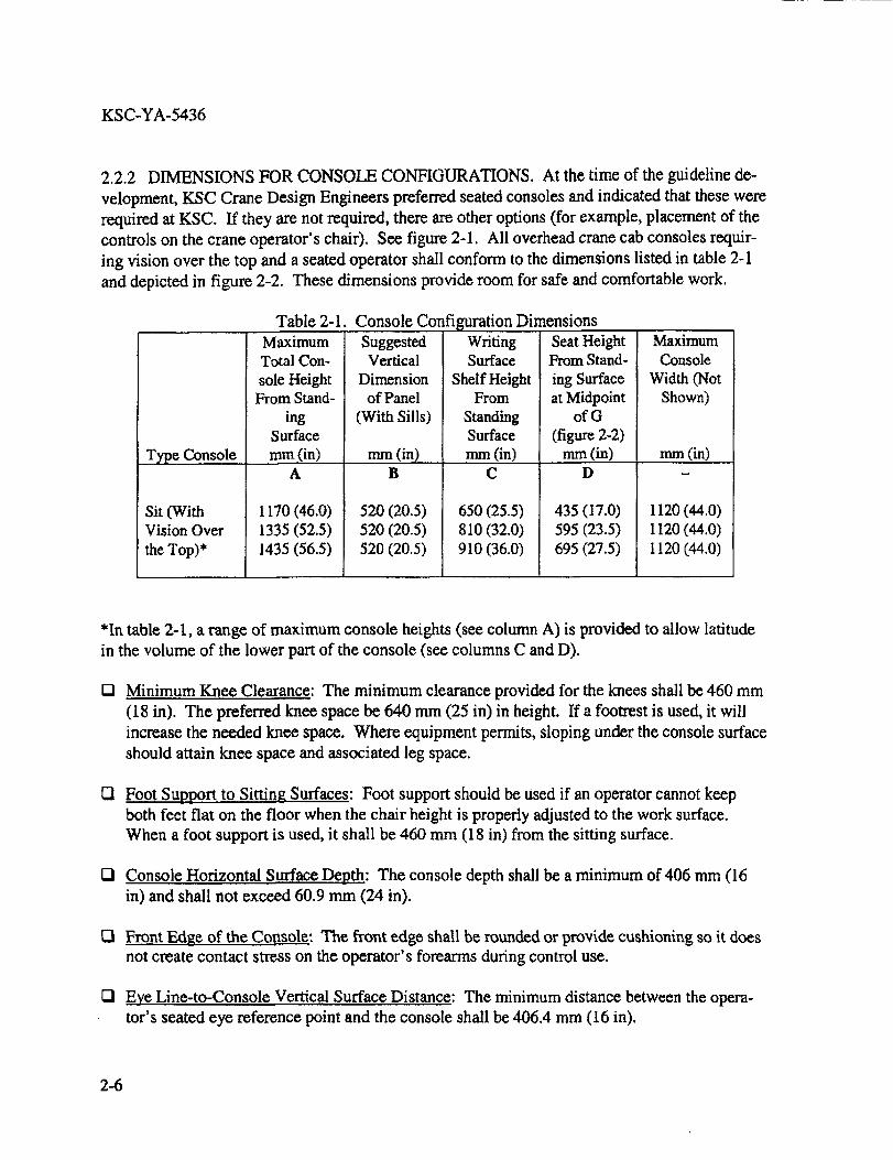
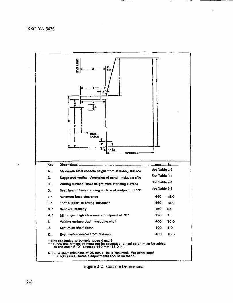
2.2.2 DIMENSIONS FOR CONSOLE CONFIGURATIONS. At the time of the guideline de-
velopment, KSC Crane Design Engineers preferred seated consoles and indicated that these were
required at KSC. If they are not required, there are other options (for example, placement of the
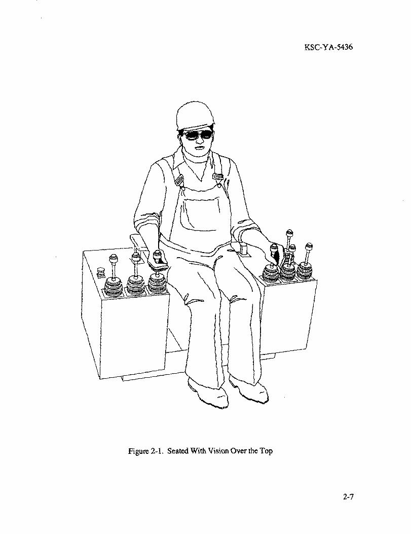
controls on the crane operator's chair). See figure 2-1. All overhead crane cab consoles requir-
ing vision over the top and a seated operator shall conform to the dimensions listed in table 2-1
and depicted in figure 2-2. These dimensions provide room for safe and comfortable work.
Table 2-1. Console Configuration Dimensions
Type Console
Sit (WithVision Over
the Top)*
Maximum
Total Con-
sole HeightFrom Stand-
ingSurface
mm (in)A
1170 (46.0)
1335 (52.5)1435 (56.5)
SuggestedVertical
Dimensionof Panel
(With Sills)
mm (in)
B
520 (20.5)520 (20.5)
520 (20.5)
WritingSurface
Shelf HeightFrom
StandingSurface
mm (in)C
650 (25.5)
810 (32.0)910 (36.0)
Seat HeightFrom Stand-
ing Surface
at Midpointof G
(figure 2-2)
mm(in)D
435 (17.0)
595 (23.5)
695 (27.5)
Maximum
Console
Width (Not
Shown)
mm (in)
1120 (44.0)
1120 (44.0)
1120 (44.0)
*In table 2-1., a range of maximum console heights (see column A) is provided to allow latitude
in the volume of the lower part of the console (see columns C and D).
Q Minimum Knee Clearance: The minimum clearance provided for the knees shall be 460 mm
(18 in). The preferred knee space be 640 mm (25 in) in height. If a footrest is used, it will
increase the needed knee space. Where equipment permits, sloping under the console surface
should attain knee space and associated leg space.
Q Foot Support to Sitting Surfaces: Foot support should be used if an operator cannot keep
both feet flat on the floor when the chair height is properly adjusted to the work surface.
When a foot support is used, it shall be 460 mm (18 in) from the sitting surface.
IZI Console Horizontal Surface Depth: The console depth shall be a minimum of 406 mm (16
in) and shall not exceed 60.9 mm (24 in).
IZI Front Edge of the Console: The front edge shall be rounded or provide cushioning so it does
not create contact stress on the operator's forearms during control use.
[Z! Eye Line-to-Console Vertical Surface Distance: The minimum distance between the opera-
tor's seated eye reference point and the console shall be 406.4 mm (16 in).
2-6
KSC-YA-5436
\
\
Figure 2-1, Seated With Vi_n Over the Top
2-7
KSC-YA-5436
c F
Key tlimmasions
HIg_LCXTCH
_L4"
"' 4_i
OPTIONAL
mm in
A. Maximum total consols height from standing surface See Table 2-1
B. Suggested vertical dimension of panel, Including sills See Table 2-1
See Table 2-1C. Writing surface: shelf height from standing surface
See Table 2-1D. Seat height from standing surface st midpoint of "G"
E." Minimum knee clearance 460 18.0
F. * Foot support to sitting surface °" 460 18.0
G." Seat adjustability 150 6.O
H,* Mimimum thigh clearance at midpoint of "G" 190 7.5
I. Writing surface depth including shelf 400 16.0
J, Mimirnurn shelf depth 100 4.0
K, Eye line-to-console front distance 400 16.0
• Not applicable to console types 4 and 5** S_rce this dimension must not be exceeded, a heel catch must be added
to the chair if "D" exceeds 460 mm (18.0 in).
Note: A shelf thickness of 25 mm (1 in) is assumed. For other shelfthicknesses, suitable adjustments should be made.
Figure 2-2. Console Dimensions
2-8
KSC-YA-5436
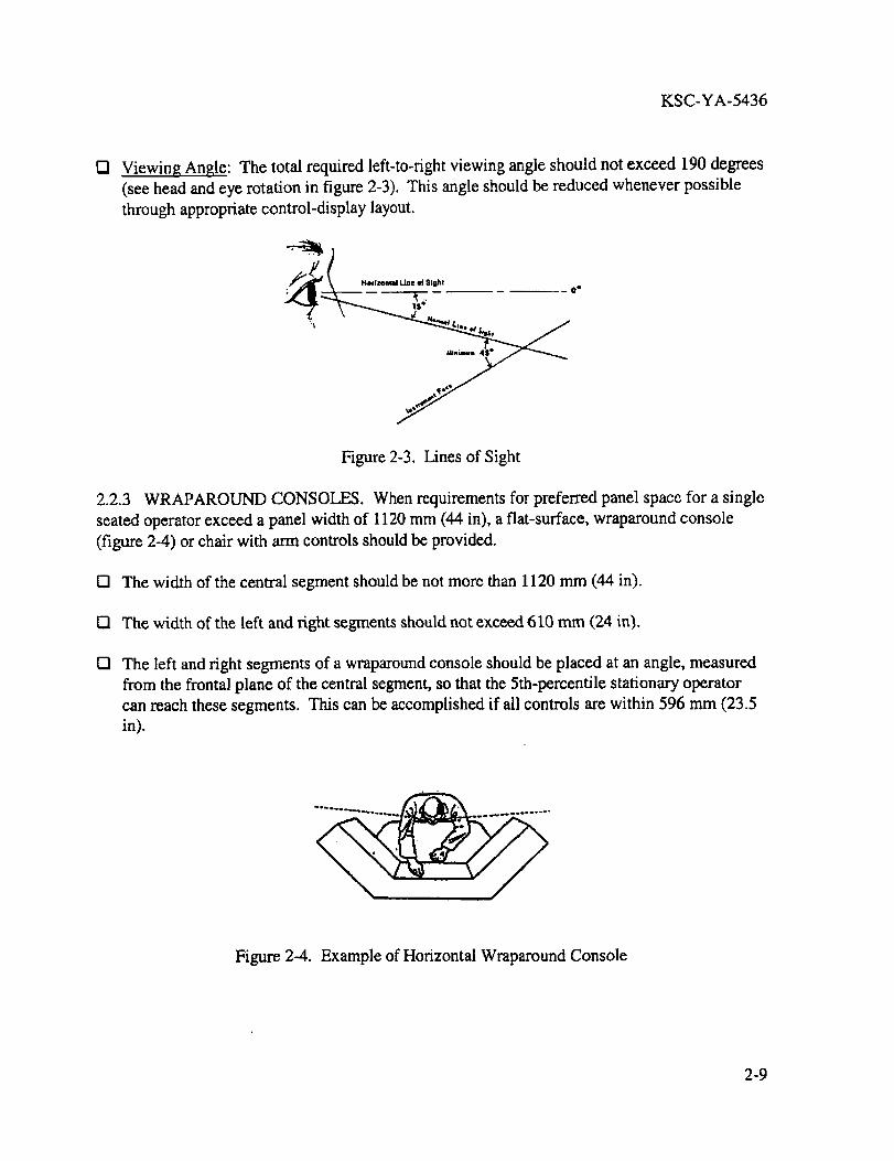
o Viewing Angle: The total required left-to-right viewing angle should not exceed 190 degrees
(see head and eye rotation in figure 2-3). This angle should be reduced whenever possible
through appropriate control-display layout.
_j. Florlzon_l line O| Sight 0 e
Figure 2-3. Lines of Sight
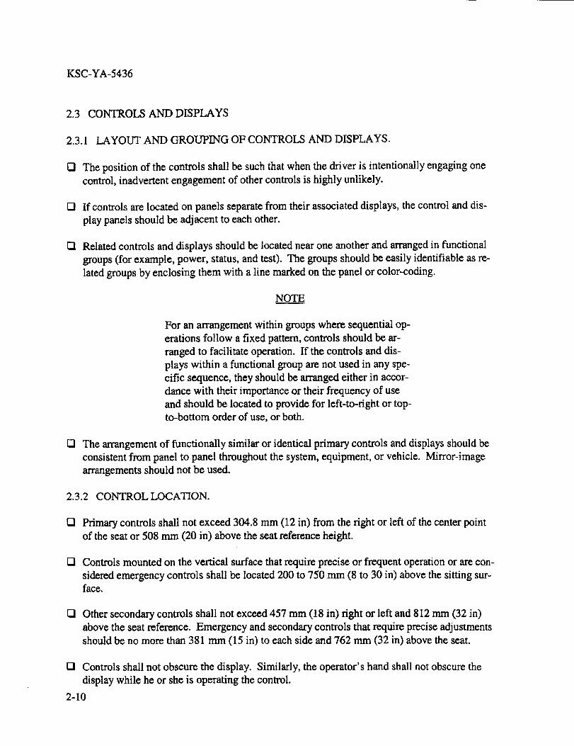
2.2.3 WRAPAROUND CONSOLES. When requirements for preferred panel space for a single
seated operator exceed a panel width of 1120 mm (44 in), a flat-surface, wraparound console
(figure 2-4) or chair with arm controls should be provided.
I"1 The width of the central segment should be not more than 1120 mm (44 in).
121 The width of the left and right segments should not exceed 610 mm (24 in).
r-I The left and right segments of a wraparound console should be placed at an angle, measured
from the frontal plane of the central segment, so that the 5th-percentile stationary operator
can reach these segments. This can be accomplished if all controls are within 596 mm (23.5
in).
Figure 2-4. Example of Horizontal Wraparound Console
2-9
KSC-YA-5436
2.3 CONTROLS AND DISPLAYS
2.3.1 LAYOUT AND GROUPING OF CONTROLS AND DISPLAYS.
O The position of the controls shall be such that when the driver is intentionally engaging one
control, inadvertent engagement of other controls is highly unlikely.
O If controls are located on panels separate from their associated displays, the centre] and dis-
play panels should be adjacent to each other.
Cl Related controls and displays should be located near one another and arranged in functional
groups (for example, power, status, and test). The groups should be easily identifiable as re-
lated groups by enclosing them with a line marked on the panel or color-coding.
NOTE
For an arrangement within groups where sequential op-
erations follow a fixed pattern, controls should be ar-
ranged to facilitate operation. If the controls and dis-
plays within a functional group are not used in any spe-
cific sequence, they should be arranged either in accor-
dance with their importance or their frequency of use
and should be located to provide for left-to-right or top-
to-bottom order of use, or both.
O The arrangement of functionally similar or identical primary controls and displays should be
consistent from panel to panel throughout the system, equipment, or vehicle. Mirror-image
arrangements should not be used.
2.3.2 CONTROL LOCATION.
O Primary controls shall not exceed 304.8 mm (12 in) from the right or left of the center point
of the seat or 508 mm (20 in) above the seat reference height.
r-I Controls mounted on the vertical surface that require precise or frequent operation or are con-
sidered emergency controls shall be located 200 to 750 mm (8 to 30 in) above the sitting sur-face.
O Other secondary controls shall not exceed 457 mm (18 in) right or left and 812 mm (32 in)
above the seat reference. Emergency and secondary controls that require precise adjustments
should be no more than 381 mm (15 in) to each side and 762 mm (32 in) above the seat.
131 Controls shall not obscure the display. Similarly, the operator's hand shall not obscure the
display while he or she is operating the control.
2-10
KSC-YA-5436
[] Thecomplexityandprecisionof controlsshouldnotexceedtheoperator'smanipulativeca-pability, includingmanualdexterity,coordination,andreactiontime, underthedynamiccon-ditionsandenvironmentin whichhisorherperformanceis expectedto occur.
2.3.3 DISPLAYLOCATION. Displayfacesshouldbeperpendicularto themaintainer'slineofsightandshallbelessthan45degreesfromthelineof sightasillustratedin figure2-3. Parallaxshouldbeminimized.
[] Displaysthatmustbereadpreciselyandfrequentlyshallbelocatedin anarea360to 810mm(4 to 32 in) abovethesittingsurfaces,andnofartherthan530mm (21in) laterallyfrom thecenterline.Displaysshallnotbelocatedanycloserthan330mm (13 in) from the operator.
O If an operator needs to manipulate a control while observing more than one display, the dis-
play should be placed as near as possible to all of the related controls and should not exceed
64 mm (25 in) from the eye reference point of a seated operator.
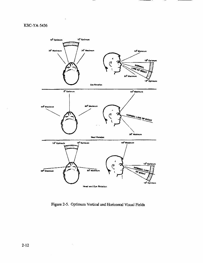
[] Important, critical, and frequently used displays should be located in the optimum visual field
as illustrated in figure 2-5. Furthermore, they should occupy a privileged position in that
field (for example, the top or left-most position) or they should be highlighted in some man-
ner.
[] Emergency display should be located where they can be seen quickly and easily (e.g., warn-
ing lights within a 30-degree cone of the operator's normal line of sight).
2.3.4 GENERAL DISPLAY CHARACTERISTICS.
[] Legibility: Displays shall be le_ble under all anticipated viewing conditions.
[] Display Information: Information should be presented in a directly usable form (i.e., opera-
tots shall not have to transpose, compute, interpolate, or mentally translate the information
displayed into other units).
O Display Font Characteristics: Where users must read quickly under adverse conditions (e.g.,
poor lighting), a sans serif style should be used.
[] Contrast: Contrast between light characters and a dark screen background should be not less
than 6: I (10: I preferred); contrast between dark characters and a light screen background
should be not less than 1:6 (I:I0 preferred).
2-11
KSC-YA-5436
16° Optimum 16° Opllmum
3_ Mild Muill_lm
Eye Ro1811on
40° Malmum
20 _ Muxlmum _
1_° Optimum
09 Optimum
80 ° Mmximum 60° Mlxlmum
6e ° MLxlmu rn
/3_ Ma"tmum
Heald Rotitlo_l
15OOptimum 1_° Optimum
96 ° M4w_m_Mm _m_ -'" _ 95° Ma]dmum
U
_o° Mutm..m
18° Optimum
Head and Eye Rotetion
Figure 2-5. Optimum Vertical and Horizontal Visual Fields
2-12
KSC-YA-5436
r'l Foreground/Background Colors on Displays: The contrast between graphics, text, or symbols
and the display background shall be sufficiently high to ensure visibility and readability. In
general, colors for symbols and text shall differ from their background by a minimum of 100
AE (CIE Lu*v*) distances. [The Commission Internationale de l'Eclairage (CIE) is an
international organization dedicated to the measurement, specification, and standardization of
color and lighting. The CIE Lu*v* (also called CIELUV) is a color relational system based
on the 1976 Uniform Color space where L represents the black-white (luminance), u' repre-
sents the red-green, and v' represented the yellow-blue coordinates of a color on a three-
dimensional color diagram called the CIE 1976 Uniform Color Scale. The _E is the distance
between colors on the diagram. Additional information and a copy of the diagram can be ob-
tained from the CIE or can be found in the book Using Computer Color Effectively (L.G.
Thorell/W.L Smith, Prentice Hall: Englewood Cliffs, New Jersey). To determine the CIE
chromaticity coordinates of each CRT color, a spectral scan can be made using a device such
as a Minolta Croma Meter CS-100]. The following color combinations shall be avoided:
• Saturated red with saturated blue
• Red with orange
• Red with purple
• Light blue with dark blue
• Dark blue with medium blue
• Kelly green with army green
• Green with gray
D Numeric Digital Displays: Numeric digital displays should be used when precision of dis-
played information is important but should not be used as the only display of information
when the pattern of variation is important for accurate perception or when rapid or slow digi-
tal display rates inhibit accurate perception.
Q Display Complexity: The complexity and precision of displays should not exceed the ability
of the operator/maintainer to discriminate detail.
2.3.5 DISPLAY RESPONSE TO CONTROL.
[] Basic Display-Control Relationships: The relationship of a control to its associated display
and a display to its associated control should be immediately apparent and unambiguous to
the operator.
2-13
KSC-YA-5436
Q Consistency of Movement: Direction of control movement should be consistent with any re-
lated movement of an associated display or equipment component. In general, depressing a
control or moving it forward, clockwise, up, or to the right should cause a quantity to increase
or cause the display or equipment component to move forward, clockwise, or up.
Moving Pointer, Circular Scale: Clockwise movement of a rotary control or movement
of a linear control forward, up, or to the right should produce a clockwise movement of
circular scale pointers and an increase in the magnitude of the reading.
@ Moving Pointer, Linear Scale: Clockwise movement of a rotary control or movement of
a linear control forward, up, or to the right should produce a movement up of a pointer on
a vertical linear scale and to the right of a pointer on a horizontal scale; in both cases, the
control movement should result in an increase in the magnitude of the reading.
I_ Display/Control Feedback: A display associated with an input control device should provide
feedback so rapidly that the operator perceives it to be instantaneous.
2.3.6 GENERAL CONTROL CHARACTERISTICS.
Control Separation: The separation between two controls shall be a minimum of 25.4 mm (1
in). Spacing should be increased as appropriate to accommodate the wearing of gloves or
other protective handwear. Some controls (e.g., foot pedals, joysticks, rotary controls, etc.)
have additional separation requirements, which can be found in the detailed control guide-lines below.
Q Feedback: All controls shall provide a positive indication of control activation by tactile
feedback (snap feel), an audible click, or an integral light.
IZl Detent Stops: If a system or unit of equipment requires operation of a control in discrete
steps, a control having detent stops should be used.
D Limit Stops: If a control does not have to be operated beyond indicated end positions or
specified limits, it shall have stops at the beginning and end of the range of control positions.
D Blind Operation: Where "blind" operation is necessary and controls are not separated by 127
mm (5 in), controls should be shape-coded. Shape-coding may be used to ensure identifica-
tion of control knobs or handles by "feel" where visual identification is not possible, where
diversion of operator visual attention to identify the proper control would detract from mis-
sion accomplishment, or where the consequences of incorrect control selection would be se-
vere. When shape-coding is used:
• The coded feature should not interfere with ease of control manipulation.
2-14
KSC-YA-5436
• Shapesshouldbeidentifiablebyhandandbyeyeregardlessof thepositionandorienta-tionof thecontrolknobor handle.
• Shape-codedknobsandhandlesshouldbepositivelyandnonmversiblyattachedtotheirshaftstoprecludeincorrectattachmentwhenreplacementis required.
• Shapesshouldbeassociatedwith orresemblethecontrolfunctionandnotalternatefunc-tions.
[] Prevent Accidental Actuation: Controls shall be designed and located so they are not suscep-
tible to being moved accidentally, particularly critical controls whose inadvertent operation
might cause damage to equipment, injury to personnel, or degradation of system functions. If
a control must be protected from accidental actuation, one or more of the following methods
shall be used:
• Locate and orient the control so the operator is not likely to strike or move it accidentally
in the normal sequence of control movements.
• Recess, shield, or otherwise surround the control by physical barriers. The control should
be entirely contained within the recess or barrier envelope.
• Cover or guard the control. Safety or lock wire should not be used.
• Interlock the control so extra movement (e.g., a side movement out of a detent position or
a pull-to-engage clutch) or the prior operation of a related or locking control is required.
• Provide the control with movement resistance (e.g., viscous or coulomb friction, spring
loading, or inertia) so definite or sustained effort is required for actuation.
• Lock the control to prevent it quickly passing through a position when strict sequential
activation is necessary (i.e., the control is moved only to the next position, then delayed).
El Dead-Man Controls: Wherever operator incapacity can produce a critical system condition,
the crane shall incorporate dead-man controls that will result in system shutdown to a non-
critical operating state when force or input is removed.
Interlocks and Alarms: Where practical, the critical position of a control that initiates haz-
ardous operation (e.g., crane movement) should activate visible and audible warning signalsin the affected work area.
I_ Consistency of Use: A control used for a critical/emergency function should be dedicated to
that function only.
2-15
KSC-YA-5436
2.3.7 FAILUREINDICATORS.
121Use of Failure Indicators: Failure indicators shall inform the user of an equipment malfunc-
tion. Indicators should be provided for:
• Equipment failures
• Equipment out-of-tolerance conditions
• Equipment overload (even if overloaded equipment remains in operation)
• Power failures
• Open circuits resulting from fuse or circuit breaker operation
• Failure of a display or display circuit
• Loss of redundancy (display should remain on until redundant unit is restored)
2.4 DETAB.E1-) GUIDELINES FOR CONTROLS AND DISPLAYS
Use the following guidelines for optimal selection and placement of commercially available con-
trois and displays. If a particular control to be used does not appear in this section, refer to MIL-
STD-1472 for specific guidelines.
2.4.1 FOOT-OPERATED CONTROLS AND PEDALS.
Q When To Use Foot-Operated Controls: Foot-operated controls should be used only if an op-
erator can be expected to have both hands occupied when activation is required. Foot-
operated controls shall be guarded to prevent accidental activation. Their use should be Iim-
ited to noncritical or infrequent operations, such as press-to-talk communication. Foot-
operated controls shall not be used when precise control actions or movements are required
or selection from many controls is required.
Q Operation of Foot Controls: Foot controls shall be located and designed so they can be oper-
ated in as natural a way as practicable. They shall be positioned for operation by the toe and
ball of the foot rather than by the heel. The following should be avoided:
• Frequent, maximum reaching.
• Requiting the leg or foot to be held in an awkward position for extended periods of time.
• Requiring frequent or prolonged application of maximum force.
2-16
KSC-YA-5436
• Requiringanoperatorto searchfor aparticularfootcontrolin orderto selecttheproperone.
• Placingafootcontrolwhereit mightbesteppedonandactuatedinadvertently.
Usingafoot pedaldesignthatcreatesconditionsin whichthefoot orclothingmightbeentrappedby aninterveningcontrolasanoperatormovesthefoot from onecontrolto an-other.
O Siz....._e:Thefootpedalshallhavearectangularshapeand be a minimum width of 88,9 mm (3.5
in) and a minimum height of 25 mm (I in). Preferably, the height of the foot pedal should be
110 mm (4.5 in) or greater.
O Resistance: The resistance of the pedal shall be a minimum of 45 N (10 lb) and shall not ex-
ceed 150 n (33.7 lb).
O Displacement: The displacement of the foot pedal should be a minimum of 13 mm (0.5 in)
and shall not exceed 63.5 mm (2.5 in).
E! Pedal Angle: The pedal angle should be less than 20 degrees. If required, the pedal angle
can exceed 20 degrees from the horizontal floor; however, a heel rest should be provided.
I_1 Pedal Return: Pedals shall return to the original null position without requiring assistance
from the operator.
O Separation Between Pedals: One switch per foot is recommended. If it is necessary that
more than one switch be operated by the same foot, those switches should be separated by at
least 75 mm (3 in) horizontally and 200 mm (8 in) vertically.
VI Nonslip Pedal Surface: Pedals shall be provided with a nonskid surface. Similar surfaces are
desirable for all pedals.
2.4.2 ROTARY CONTROLS.
O When To Use Rotary Controls: Ifa switch must have three or more detent positions, a rotary
selector switch should be used. If only two positions are needed, a rotary switch should not
be used unless prompt visual identification of the switch position is of prime importance and
if speed of control operation is not critical.
O Sh_hg__: Moving pointer knobs should be bar-shaped, with parallel sides and with the indicat-
ing end tapered to a point.
2-17
KSC-YA-5436
O Siz___&e:Thelengthof therotarycontrolknobshallbeaminimumof 25mm(1in) andshallnotexceed100mm (4 in). Thewidth shallbeaminimumof 25mm (1in). Theheightof thecontrolshallbeminimumof 16mm (0.6in) andshallnotexceed75mm(3in).
O Resistance: The turning resistance of a rotary switch shall increase between adjacent posi-
tions so the switch will not stop between the positions but rather will "snap" into one of the
positions. The resistance shall be a minimum of 115 mN-m (1 in-lb) and shall not exceed
680 mN-m (6 in-lb).
O Displacement: The displacement of a rotary control should a minimum of 15 degrees and
shall not exceed 40 degrees.
O Separation: The minimum separation between controls shall be 25 mm (1 in) for a one-hand
control operation and 75 mm (3 in) for a two-hand control operation. The preferred separa-
tion is 50 mm (2 in) for one-hand operation and 125 mm (5 in) for two-hand operation.
2.4.3 KEY-OPERATED SWITCHES.
O When To Use Key-Operated Switches: Ke.y-operated switches should be used to prevent un-
authorized operation (e.g., on and off system operation).
Size: The key-operated switch shall have a height of 13 to 75 mm (0.5 to 3 in).
[] Teeth on Both Edges: The key for the switch should have teeth on both edges and should fit
the lock with either side up or forward.
O Resistance: The key-operated switch resistance shall be a minimum of 115 mN-m (1 in-lb)
and shall not exceed of 680 mN-m (6 in-lb).
[] Displacement: The key should turn a minimum of 30 degrees and a maximum of 90 degrees.
[] Direction of Rotation: Key-operated on-off switches shall be positioned so the key is vertical
when the switch is off. The key should be turned clockwise from the vertical off position to
the on position at the 90-degree clockwise position.
rq Key Removal: Operators shall be able to remove the key from the switch only when the
switch is in the off position.
2.4.4 SINGLE-FINGER MOMENTARY PUSI-IBUTTONS,
[] When To Use Pushbuttons: Pushbuttons should be used if a control is needed for momentary
contact or to activate a locking circuit, particularly if the control will be used frequently.
Pushbuttons should not be used if the status of a function must be indicated by the position ofits control.
2-18
KSC-YA-5436
O _: All single-fingermomentarypushbuttonsshouldbesquare.
r-i Siz....._e:The single-finger momentary pushbutton shall be no smaller than 25.4 mm (1 in) and
should have a concave surface. Large hand/fist-operated mushroom-shaped pushbuttons
shall only be used as emergency stop controls.
O Resistance: The resistance shall be a minimum of 2.8 N [10 ounces (oz)] and shall not ex-
ceed 11 N (40 oz). The preferred resistance range is 2.8 N (10 oz) to 5.6 N (20 oz).
O Displacement: The displacement should be a minimum of 2 mm (0.08 in) and shall not ex-
ceed 6 mm (0.25 in), The preferred displacement is between 2 mm (0.08 in) and 3.8 mm
(0.15 in).
O Movement Direction: The pushbutton shal! be activated by pushing it down, and it should
automatically return to its original position when released. Preferably, there should be an
elastic resistance aided by slight sliding friction, starting slowly, building rapidly, and with a
final sudden drop tO indicate activation.
12] Separation: There shall be a minimum separation of 25 mm (1 in) between pushbuttons.
• Where possible, the separation between pushbuttons should be 50 mm (2 in).
O Colo._...__zr:The same color should be used for all pushbuttons. The color should provide a high
contrast with the console.
O Barriers: All pushbuttons [with the exception of the emergency stop (E-stop)] shall be sur-
rounded by a physical barrier that prevents accidental activation. The barrier shall be a mini-
mum width of 3 mm (0.125 in) and a minimum depth of 5 mm (0.2 in).
2.4.5 II2_,UMINATED LEGEND PUSI--IBU'ITONS.
O _: All illuminated legend pushbuttons should be square or rectangular and should have a
concave surface.
[] Siz_...._e:The illuminated legend pushbutton shall be no smaller than 25.4 mm (1 in). The pre-
ferred size is 38 to 50.8 mm (1.5 to 2.0 in).
(3 Resistance: The resistance shall be a minimum of 2.8 N (10 oz) and shall not exceed 11 N
(40 oz) of force. The preferred resistance range is 2.8 N (10 oz) to 5.6 N (20 oz).
[] Displacement: The displacement should be a minimum of 2 mm (0.08 in) and shall not ex-
ceed 3.8 mm (0.15 in).
r-I Movement Direction: The pushbutton shall be activated by pushing it down and it should
automatically return to its original position when released. Preferably, there should be an
2-19
KSC-YA-5436
elastic resistance aided by slight sliding friction, starting slowly, building rapidly, and with a
final sudden drop to indicate activation.
O Separation: There shall be a minimum separation of 25 mm (1 in) between illuminated leg-
end pushbuttons and other controls. Where possible, the separation should be 50 mm (2 in).
O Color: All illuminated pushbuttons that provide general system status should be white
opaque background. The color of letters on the pushbutton should be black or dark blue and
should provide a high contrast with the background.
O Barriers: All illuminated legend pushbuttons (with the exception of the E-stop) shall be sur-
rounded by a physical barrier that prevents accidental activation. The barrier shall be a
minimum width of 3 mm (0.125 in) and a minimum depth of 5 mm (0,2 in).
2.4.6 MUSHROOM-SHAPED PUSHBUTTONS.
A RED mushroom-shaped pushbutton shall provide a manual mechanism for an immediate safe
shutdown of the system, which removes all power from the crane and subsequently sets all
brakes. This pushbutton shall be manually reset by pulling up. This button shall be labeledEMERGENCY STOP.
O Siz......_e:The mushroom-shaped pushbutton shall have a diameter greater than 19 mm (1.5 in)
and shall have a slightly convex surface. This button shall be designed to be operated with
the palm of the hand or a fist.
O Resistance: The mushroom-shaped pushbutton shall provide a minimum resistance of 2.8 N
(10 oz) and shall not exceed 23 N (80 oz) of resistance. The preferred resistance for the
mushroom-shaped E-stop button is between 10 N (36 oz) and 23 N (80 oz).
IZl Displacement: The mushroom-shaped pushbutton should provide 13 mm (0.5 in) to 38 mm
(1.5 in) of displacement when pressed.
1"-! Location: The mushroom-shaped pushbutton shall be placed on the horizontal console sur-
face within 596 mm (23.5 in) of the operator's position.
O Separation: The mushroom-shaped emergency stop pushbutton should be separated from all
other controls and displays by a minimum of 152 mm (6 in).
2.4.7 TOGGLE SWlTCHE, S.
O When To Use Toggle Switches: Toggle switches should be used for functions that require
two discrete positions or where space limitations are severe.
2-20
KSC-YA-5436
[] Siz_..__e:Thearmof thetoggleswitchshallbeaminimumlengthof 13mm(0.5in) andshallnotexceeda length of 50 mm (2 in). The tip of the arm shall be a minimum of 3 mm (0.13
in) and a maximum of 25 mm (1 in).
Cl Resistance: For small toggle switches, the resistance shall be a minimum of 2.8 N (I0 oz)
and shall not exceed 4.5 N (16 oz). If a large toggle switch is used [e.g., 50-mm (2-in) arm
length] the maximum resistance is 11 N (40 oz). The resistance of a toggle switch should in-
crease as the switch is moved toward its midpoint, then decrease as the switch "snaps" into its
alternate position. The switch shall not be capable of remaining between positions without
being held.
rl Displacement: The displacement of a two-position toggle should be a minimum of 30 de-
grees and shall not exceed 80 degrees. The minimum displacement of a three-position toggle
shall be 17 degrees and shall not exceed 40 degrees. The preferred displacement is 25 de-
grees.
Ci Orientation: Toggle switches shall he vertically oriented with OFF in the down position.
Horizontal orientation and actuation of toggle switches should be used only for compatibility
with the controlled function or equipment location.
IZ! S_aration: The minimum separation between toggle switches and other controls or toggles
shall be at least 25.4 mm (1 in). The preferred separation is 50.8 mm (2 in).
O Preventing Accidental Actuation: If actuation might result in a critical or hazardous condi-
tion, the switch shall be protected. Protection should be by means of a barrier or a cover and
shall not be by lock wire. When a toggle switch cover is used, the resistance to lifting a cover
should not exceed 13 N (3 lb) and the cover should not interfere with the operation of the
switch or of adjacent controls when it is open.
2.4.8 ROCKER SWITCHES.
[] When To Use Rocker Switches: Rocker switches should be used for functions requiring two
discrete positions. They should be used rather than toggle switches if a toggle switch handle
might interfere with or be interfered with by surrounding activity (e.g., operator's clothing or
phone cord) or when the panel space is too limited for the labeling of toggle switch positions.
_2 Operation: Actuadon of the upper portion, that is, depressing it, should turn the equipment or
component ON, cause a quantity to increase, or cause movement of a unit equipment or a
component clockwise, forward, up, or to the right.
D Siz.____e:The rocker switch shall have two distinct faces, each with a width of at least 6 mm
(0.25 in) but preferably 10 mm (0.4 in). The switch should have a face length of at least 13
mm (0.5 in).
2-21
KSC-YA-5436
O Resistance: The resistance shall be a minimum force of 2.8 N (10 oz) and shall not exceed
11 N (40 oz). The preferred resistance range is between 2.8 N (10 oz) and 8 N (28.7 oz).
The resistance of a rocker switch should increase as the upper portion is pressed down or in
and then decrease so the switch "snaps" into position.
O Displacement: The displacement should be a minimum of 3 mm (1.25 in). A rocker switch
should not be capable of stopping between positions.
121 An__qgJ.q:The angle between the attemate faces of the switch should be 30 degrees.
O Labeling: The letters and numerals should be internally illuminated on an opaque switch
background. The letter/number height should be 4.8 mm (3/16 in) with a height-to-width ra-tio of 3:2 and a stroke width ratio of 10:7.
O Orientation: The rocker switch should be vertically oriented.
[] Color: Alternate color contrast on the two faces of the rocker switch should be used to pro-
vide a conspicuous cue of switch position.
O Preventing Accidental Actuation of Rocker Switches: If it is imperative that a rocker switch
not be operated inadvertently (for example, if actuation might result in a critical or hazardous
condition), the switch shall be protected (for example, with a channel guard, barrier, cover, or
an equivalent protective measure).
2.4.9 SLIDE SWITCHES.
O When To Use Slide Switches: Slide switch controls may be used for functions that require
two discrete positions or a high number of discrete positions in which the switches are ar-
ranged in a matrix to permit easy recognition of relative switch settings. Slide switches
should not be used where incorrect positioning is to be avoided. Their use should be limitedon crane consoles.
O Siz....__e:The slide switch shall have a width of at least 6 mm (0.25 in) and a maximum width of
25 mm (1.0 in). The height of the slide switch should be a minimum of 6 mm (0.25 in) for
use by a bare hand and a minimum of 13 mm (0.5 in) for use by a gloved hand.
O Resistance: For a small switch, the resistance shall be a minimum of 2.8 N (10 oz) and shall
not exceed 4.5 N (16 oz). For a large switch, the resistance shall be a minimum of 2.8 N (10
oz) and shall not exceed 11 N (40 oz).
[] Orientation: The slide switch should be vertically oriented. Movement of the switch up or
away from the operator shall turn the equipment on or cause a quantity to increase or move
clockwise, up, or to the right. Horizontally oriented slide switches should be used only for
compatibility with the control and the equipment.
2-22
KSC-YA-5436
2.4.10 JOYSTICKS.All cab-operatedcranesshallbeequippedwith displacementjoysticks.Thejoysticksshouldbeof thecontinuous-effecttypethatwill not undulytire theoperatorduringlengthyoperations.Whenadisplacementjoystickis usedfor ratecontrol,thejoystickshouldbespring-loadedsothatit returnsto centerwhenreleased.
r-i Size: All joysticks placed on one console should be shape-coded. The joysticks that are
separated by less than 12.7 mm (5 in) shall have different size shafts and/or shaped grips so
that the crane operator can differentiate between joysticks by feel.
If a round top is used, it should have a palm grip that is a minimum of 50 mm (2 in). If a
cylinder-top handgrip is used, it should have a palm grip equal to or between 25 and 32
mm (1 and 1.25 in) with 120 mm length (4.5 in).
• The grip diameter should not exceed 50 mm (2 in).
O
• The handgrip length of a hand-operated displacement joystick should be in the range of
110 to 180 mm (4.3 to 7,1 in). Clearance should be at least 100 mm (4 in) to the side and
50 mm (2 in) to the rear.
Specific Use of Buttons on Joysticks: When buttons are located on hand-operated joysticks,
they shall be operable using a normal grip without diminishing control of the joystick.
Thumb-operated buttons shall not be used. Finger-operated buttons shall be a minimum of
50 mm (2.0 in) and designed so they can be activated by two to three fingers.
Q Resistance: The joystick shall have a forward/backward resistance that is a minimum of 40 N
(145 oz) and a maximum of 80 N (290 oz). Where possible, the forward/backward resistance
should be 60 N (215 oz). The joystick shall have a lateral (left/right) resistance that is a
minimum of 20 N (72 oz) and shall not exceed 60 N (215 oz). Where possible, the lateral re-
sistance should be 40 N (145 oz).
rn Displacement: The displacement of the joystick should not exceed 45 degrees. A joystick
that moves forward/backward shall have a displacement no greater than 360 mm (14 in). A
joystick that moves from left to fight shall have a displacement no greater than 965 mm (38
in).
C] Movement Direction: The direction of joystick movement will correspond to the direction of
load movement north, south, east, and west. When the hoist joystick is pushed forward, it
should produce a corresponding downward movement of the hook. When the hoist joystick
is pulled backward, it should produce an upward movement of the hook.
Q Separation Between Joysticks: A minimum of 127 mm (5 in) shall be provided between joy-
sticks. A minimum of 50.8 mm (2 in) clearance shall be provided between the joystick and
the edge of the console.
2 -23
KSC-YA-5436
O Location: The joystick for the bridge and trolley travel should be located so the operator can
readily face the direction of travel. The arrangement of the joysticks shall be as follows:
from left to right - bridge, trolley, and hoist, conforming to CMAA specifications. The joy-
sticks should be located on the horizontal console surface within 390 mm (15.5 in) of the
seated operator.
[] Response Delay:. Delay between the joystick movement and the confirming display response
should be minimized and should not exceed 0.1 s.
O Preventing Accidental Actuation of Joysticks: Joysticks should be provided with a notch or
latch which in the "off' position prevents the handle from being inadvertently moved to the
"on" position. An "off" detent or spring return arrangement is acceptable.
2.4.11 KEYPAD AND KEYBOARD.
[] Des___ign: Where possible, a standard Qwerty design or numeric keypad should be used.
I_i Keytop Size: The minimum horizontal strike surface of each key shall be 12 mm (0.47 in).
The keys may be any shape, provided spacing requirements are not violated.
[] Key Resistance: The keys shall have a minimum resistance of 0.25 N (0.9 oz) and shall not
exceed a resistance of 1.5 N (5.4 oz).
[] Displacement: The preferred vertical displacement (key travel distance) is 2 to 4 mm (0.08 to
0.16 in). The keys should have a minimum displacement of 1.5 mm (0.06 in) and shall not
exceed a displacement of 6 mm (0.24 in).
[] Adiustable Slope: The keypad should have an adjustable slope that provides an angle from 0
to 15 degrees.
[] Key Spacing/Separation: The horizontal centerline distances between adjacent keys should
be between 18 and 19 mm (0.71 and 0.75 in). The vertical centerline distances between adja-
cent keys should be between 18 and 21 mm (0.71 and 0.82 in).
[] Key Texture: A 1.0 mm (0.04 in) texture or ridge should be placed on center key for tactile
position indication of center key.
2+4.12 INDICATOR LIGHTS.
r-I When to use: Indicator lights should be used to display qualitative information that requires
immediate attention or an immediate response. They may also be used occasionally, if ap-
propriate, to display maintenance and adjustment information. Their use, however, should be
minimized and reserved for displaying only that information necessary for effective operationand maintenance.
2-24

KSC-YA-5436
131Size: Indicatorlights shallbeaminimumof 13mm (0.5in) in diameter.Thepreferredsizeis 16mm(1 in) in diameter.
[] _: Indicatorlights shallberoundwithanextendedlensto increasetheviewingangle.
O Light Intensity: The light produced shall be twice as bright as the immediate background.
The light should be at a minimum 10 percent greater than the luminance of the cab and glare.
The luminance should not exceed 300 percent of the cab luminance.
O Time Lags: Once the system detects a malfunction, the warning light should illuminate. No
time lag should occur between the malfunction and the illumination.
0 Lamp Redundancy: Where possible, the filament/bulb of the indicator light should be redun-
dant.
0 Lamp Replacement: Lamps should be removable and replaceable through the front of the
display panel. Removal and replacement of lamps should not require the use to tools,
Q Meaning of No Illumination on Displays: The absence or removal of the illumination of a
transilluminated display shall not be used to indicate a malfunction, "no-go," or out-of-
tolerance condition. For maintenance displays, the absence of illumination should not indi-
cate a "power off" condition. In contrast, the absence of illumination is acceptable to indicate
power off for an operational display. The absence of light shall not indicate a "ready" or in-
tolerance condition unless the operator can easily test the bulb.
O Lights on Maintenance Displays: Indicator lights used solely for maintenance and adjustment
should be covered or nonvisible during normal operation of the equipment but should be
readily accessible when needed.
O Color of Indicator Lights: When an indicator light is used to represent a specific meaning
(e.g., danger, caution, go ahead), the color coding of the light shall conform with the color-
coding standards of simple indicator lights presented in table 2-2. This does not preclude the
use of additional colors to represent other meanings.
2.4.13 ANALOG DISPLAYS.
r-i Siz_.._e:The display size must allow for all numbers on a scale to be printed in 4.7-mm (0.18-
in) font or larger, without crowding. It shoul6 also be large enough to allow all graduation
marks to be printed on a display face without crowding.
[] S_.hg__: A semicircular shape is preferred over other shaped analog displays.
O Pointer: The pointer should be mounted close to the face of the dial to minimize parallax. It
should extend to but not overlap scale graduation marks. The tip should be tapered to a 20-
2-25
KSC-YA-5436
degreeangleoneachside(total40-degreeangle)equalin widthto theminor graduationmarks.
r-1 Pointer Color: The tip to the center of the dial should be the same as the color of the marks.
The tail of the pointer should be the same color as the dial face, unless the tail is used as an
indicator itself or unless the pointer is used for horizontal alignment. The luminance contrast
ratio between scale face and markings and pointer should be at least 3:1.
Size/Type
13 mm (0.5 in)
diameter/steady
25 mm (1 in)
diameter or
larger/steady
25 mm (1 in)
diameter or
larger/flashing
(3 to 5 per s)
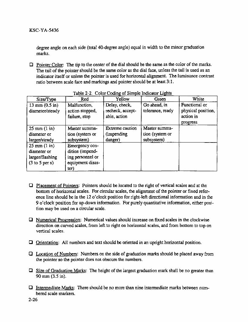
Table 2-2. Color Coding of Simple Indicator LightsRed Yellow Green
Malfunction,
action stopped,
failure, stop
Master summa-
tion (system or
subsystem)
Emergency con-
dition (impend-
ing personnel or
equipment disas-
ter)
Delay, check,
recheck, accept-
able, action
Extreme caution
(impending
danger)
Go ahead, in
tolerance, ready
Master summa-
tion (system or
subsystem)
White
Functional or
physical position,
action in
progress
D Placement of Pointers: Pointers should be located to the fight of vertical scales and at the
bottom of horizontal scales, For circular scales, the alignment of the pointer or fixed refer-
ence line should be in the 12 o'clock position for right-left directional information and in the
9 o'clock position for up-down information. For purely quantitative information, either posi-
tion may be used on a circular scale.
O Numerical Progression: Numerical values should increase on fixed scales in the clockwise
direction on curved scales, from left to fight on horizontal scales, and from bottom to top onvertical scales.
IZI Orientation: All numbers and text should be oriented in an upright horizontal position.
I_1 Location of Numbers: Numbers on the side of graduation marks should be placed away from
the pointer so the pointer does not obscure the numbers.
tZ! Size of Graduation Marks: The height of the largest graduation mark shall be no greater than
90 mm (3.5 in).
IZl Intermediate Marks:
bered scale markers.
2-26
There should be no more than nine intermediate marks between num-
KSC-YA-5436
r-i
O
Scale Starting Point: Display scales should start at zero unless this is inappropriate for the
information 'displayed.
Cgding on Display Face: Coding, for example, by pattern or color, should be used on the
faces of scale indicators to convey such information as desirable, undesirable, or inefficient
operating ranges; dangerous operating levels; warnings; and cautions.
2.4.I4 CRT/LCD
O Raster Modulation: The CRT raster modulation should be less than 20 percent.
121 Adjustable Luminance: A control should be provided to vary luminance from 10 percent of
minimum ambient luminance to full luminance. The highest luminance, either character or
background, should be 35 candela per square meter (cd/m2)[10 foot lamberts (fL)] or more.
IZi Flicker Free: The CRT refresh rate and other parameters (such as duty cycle, brightness, con-
trast, color, and motion) should be adjusted to provide a flicker-free display.
121 Installation: The face of the display should be flush with the surface of the panel in which itis installed.
2.4.1.5 HUMAN COMPUTER INTERFACE DESIGN. The software program shall be devel-
oped with the following features,
O Consistency:
• The display of data shall remain consistent from screen to screen.
• Similar parameters shall be displayed the same way.
• Similar messages shall be displayed in the same way and in the same location.
• Similar actions shall be required to produce similar results on the screen.
* Standard abbreviations and terminology shall be used. Wording of text data shall be lim-
ited to commonly understood terms.
. The character set, screen layouts, and color schemes shall be consistent from screen to
screen.
2-27
KSC-YA-5436
EffectiveFeedback:
0
0
0
0
0
0
U
0
• Response time between control inputs and displays shall be minimized.
• Graphical or alphanumeric displays shall be selected based on the type of data to be pre-sented.
The character set shall use a minimum 7:9 width-to-height ratio for tasks that require con-
tinuous reading; minimum 5:7 ratio for general numeric and uppercase text; and 4:5
minimum for superscripts, fractions, or text not directly related on the task.
• Use of color shall support task display, incorporating common color stereotypes for the
intended user community.
• Graphical displays shall be designed as monochrome to start, with color added later as re-quired for enhancement.
Cautions and warnings shall have a method for being acknowledged and turned off.
Help screens shall have a method for choosing a subsequent action.
The effect of a control input shall be displayed on the screen to give the user feedback.
The program shall have an "Undo" function that is activated by the keypad to reverse usercommands.
The program shall contain a feature to prevent data from being lost in the event a keypad
command or pushbutton is inadvertently activated. If an erroneous command is entered, the
program shall leave the system state unchanged or display a prompt on how to restore the sys-tem to its proper state.
Proficient users should have optional methods of controlling the display that eliminate func-
tional steps (e.g., going from a two-function display to the third display without having to re-
set the entire display). This may not be appropriate for all functions.
Troubleshooting or built-in-test (BIT) displays shall be selectable so users will be able to ex-
amine only what is required for the particular event.
The program shall be written to give the user the capability to control the display so required
actions can be performed easily and necessary information is readily obtained.
0 The program shall be written to reduce the number of unanticipated displays that may appear.
2-28
KSC-YA-5436
Q Theprogramshallbewrittensodatarequiredtoperformanactionis displayedatthetimeitis required.
2.4.16 VISUAL WARNINGSAND SIGNALS.
I21Failuresthatrequireimmediateoperatoractionto avertimpendinginjury, equipmentdamage,or bothshouldinitiateanemergencyalarm(visualor auditory).
Q An alertingandwarningsystemor signal should provide the operator with a greater probabil-
ity of detecting the triggering condition than his or her normal observation would provide in
the absence of the alerting or warning system or signal. An emergency alarm generated by a
visual display shall:
Use a flashing red light 3 to 5 Hz, with a 50-percent duty cycle (if the flasher fails, the
light should illuminate and bum steadily). If multiple flashers are visible, they should be
synchronized.
• Be clearly noticeable under all anticipated lighting conditions.
• Be conspicuously different from general area lighting.
• Have a specific meaning within the operational area where they are used.
• Be singular in purpose yet comprehensive in meaning (not refer to other warnings).
• Transmit all essential information in the first 5 seconds.
• Be visible from all locations, including bridge and trolley topside.
rn Alarm Parameter Selection: If applicable, the limits or set points that initiate an alarm or
warning display should be set so the alarm gives operators adequate time to respond to thecondition before it becomes more serious.
Q Text Height for Visual Warnings: Text for visual warning and caution signals shall be pre-
sented using characters between 8.7 milliradians (mrad) and 17.4 mrad (30 and 60 minutes of
subtended arc) as measured from the longest anticipated viewing distance, with the larger
size used where conditions may be adverse. For a viewing distance of 0.5 m (20 in), this
equals 4.4 mm (0.174 in) to 8.8 mm (0.349 in).
[] Automatic Clearing of Alarms: The equipment or system that triggers an alarm shall clear
the alarm automatically when the triggering condition no longer exists.
2-29
KSC-YA-5436
13 Out-of-Service Alarms: If an alarm fails, the system should provide a prompt indication ofthe failure.
O Testing of Alarms: One or more controls should be provided to permit the testing of alarms.
2.4.17 AUDIO SIGNAL DISPLAYS
O When To Use Audio Signal Displays: An audio display should be provided if any of the
following conditions apply:
• The criticality of a response to a visual signal makes supplementary or redundant alertingdesirable.
• It is desirable to warn, alert, or cue the operator for subsequent or additional responses.
• Voice communication is necessary or desirable.
O Signal Type: When an audio presentation is required, the optimum type of signal shall be
presented in accordance with table 2-3. Audio signals shall not interfere with other sound
sources, including verbal communication.
2.4.18 AUDIO WARNINGS AND SIGNALS.
O Relation to Visual Displays: If used in conjunction with a visual display, an audio warning
device should be supplementary or supportive. The audio signal should be used to alert and
direct the operator's attention to the appropriate visual displays.
O Automatic Reset: An automatic reset function for audio signals shall be provided, whether
the signals are designed to terminate automatically, manually, or both. The automatic reset
function should be controlled by a sensing mechanism that recycles the signal system to a
specified condition as a function of time or the state of the signaling system so the warning
device can sound again if the condition reappears.
E! Two-Element Signals: An alerting signal of 0.5-s duration should be provided by an identify-
ing or action signal. All essential information should be transmitted in the first 2.0 s of the
identifying or action signal.
El Frequency Range: The frequency range of a warning signal shall be between 200 and 5,000
Hz. The preferred range is between 500 and 3,000 Hz.
El Audibility: Alarms should exceed the prevailing ambient noise level by at least 10 dB or any
maximum sound level with a duration of 30 s by at least 5 dB, whichever is louder. Thealarm shall not exceed 115 dB at the ear of the listener.
2-30
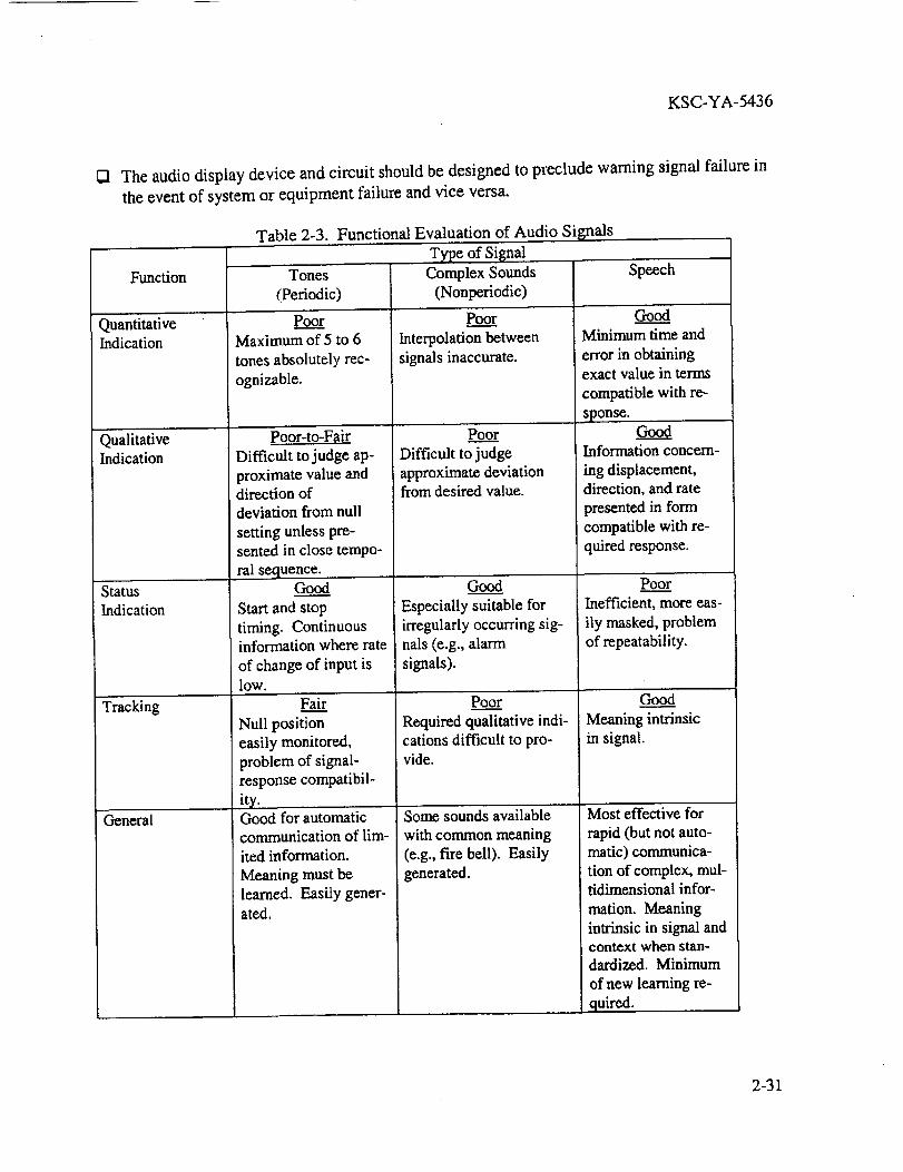
KSC-YA-5436
1_1 The audio display device and circuit should be designed to preclude warning signal failure in
the event of system or equipment failure and vice versa.
Table 2-3. Functional Evaluation of Audio Signals
Type of Signal
Complex Sounds
(Nonperiodic)
Function
QuantitativeIndication
QualitativeIndication
Status
Indication
Tracking
General
Tones
(Periodic)
Poo._____rMaximum of 5 to 6
tones absolutely rec-
ognizable.
po.or-to-Fair
Difficult to judge ap-
proximate value anddirection of
deviation from null
setting unless pre-
sented in close tempo-
ral sequence.Good
Start and stop
timing. Continuousinformation where rate
of change of input islow.
Fai.____Lr
Null position
easily monitored,
problem of signal-response compatibil-
ity,! Good for automatic
communication of lim-
ited information.
Meaning must be
learned. Easity gener-ated.
Poo....__Er
Interpolation between
signals inaccurate.
Poo......._r
Difficulttojudge
approximatedeviationfrom desiredvalue.
J,
Good
Especially suitable for
irregularly occurring sig-
nals (e.g., alarmsignals).
Poor
Required qualitative indi-
cations difficult to pro-vide.
Some sounds available
with common meaning
(e.g., fire bell). Easilygenerated.
Speech
GoodMinimum time and
error in obtainingexact value in terms
compatible with re-
sponse.Good
Information concern-
ing displacement,direction, and rate
presented in form
compatible with re-
quired response.
Poo_._.__r
Inefficient, more eas-
ily masked, problemof repeatability.
Good
Meaning intrinsicin signal.
Most effective for
rapid (but not auto-
matic) communica-
tion of complex, mul-tidimensional infor-
marion. Meaning
intrinsic in signal andcontext when stan-dardized. Minimum
of new learning re-
quired.
2-31
KSC-YA-5436
2.4.19 SPEECH TRANSMISSION EQUIPMENT.
O Frequency Range: Microphones and associated system input devices should be design_:i to
yield optimum response to the part of the speech spectrum most essential to intelligibility,
that is, between 200 and 6,100 Hz. If the system necessitates a narrower speech transmission
bandwidth, the range should be at least from 250 to 4,000 Hz.
[] Dynamic Range: The dynamic range of a microphone used with a selected amplifier should
be great enough to admit variations in signal input of at least 50 dB.
2.5 LABELING
2.5.1 GENERAL REQUIREMENT. Each unit, assembly, subassembly, and part shall be la-
beled with a clearly visible, legible, and meaningful name, number, code, mark, or symbol, as
applicable. This gross identifying label should be located externally in such a position that it is
not obscured by adjacent items, on the flattest, most uncluttered surface available, or on a main
chassis of the equipment. If appropriate, the unit should be etched or embossed into the surface
for durability, rather than stamped, stenciled, or printed. In general, labels should be provided on
equipment to:
[] Locate and identify the equipment, controls, displays, access openings, test points, etc.
[] Interpret and follow procedures.
IZl State warnings or cautions to avoid hazards.
[] Supply critical instructions for servicing or maintenance of equipment if there is no other
provision for them.
IZl Supply useful information, such as instructions, the weight of the equipment, or calibrationinformation.
[] Record or supply critical data to an operator if there is no other provision for them.
IZI Record and supply historical data, such as periodic readings or the date of servicing or re-
placement.
UI Compass Label: All overhead cranes at KSC shall have a label indicating the primary com-
pass points with the words "NORTH, .... SOUTH," "EAST," and "WEST" (or "N," "S",' "E,"
"W") aligned on the console in the proper direction and oriented so the text is read horizon-
tally by the seated operator. This shall be accompanied by a north, south, east, west (or N, S,
E, W) direction sign located beneath the crane in clear view of the persons on the floor han-
dling the load.
2-32

KSC-YA-5436
I_ Design of Labels:
@
@
@
O
Labels shall be easily identifiable and shall be designed for accurate identification of in-
formation at the distance ahd illumination level at which they are intended to be used,
Labels shall be supplemented where appropriate with other coding such as color and
shape (as in warning or danger signs).
Labels shall use boldface type to emphasize words or phrases.
Labels shall list the steps in a series of instructions, not present them in paragraph form.
Labels shall have consistent terminology.
Character Height for Viewing Distance: Unless circumstances require otherwise, labels
should be clearly legible at a viewing distance of 710 mm (28 in). The recommended height
for letters and numerals at this distance is approximately 5 mm (0.18 in). Table 2-4 gives
minimum character heights for other viewing distances.
Table 2-4. Minimum Character Heights for Other Viewing Distances
Viewing Distance Minimum Height
Less than 0,5 m (20 in) 2.3 mm (0.1 in)
0.5 to 1.0 m (20 to 40 in) 4.7 mm (0.2 in)
1.0 to 2.0 m (40 to 80 in) 9.4 mm (0.4 in)
2.0 to 4.0 m (80 to 160 in) 18 mm (0.75 in)
/21 Text on Labels: The labeling specifications for the crane shall conform to the following:
* Character height in accordance with table 2-4.
• Stroke width of 1/6 to 1/7 of the height in normal illumination and 1/7 to 1/8 of the heightin dim illumination.
Width-to-height ratio of letters and numerals should be 3:5 (with the exceptions of "M"
and "W," which should be 4:5; "4," which should be 4:5 of the height; and "I" and "1,"
which should be 1:5 of the height).
• Character Spacing: At least one stroke width.
2-33
KSC-YA-5436
• Word spacing: Between words, the space shall be one normal width character.
• Line Spacing: At least 1/_of character height.
• Case of Letters: All capitals for single words, mixed case for phrases and sentences.
• Font: San serif.
IZl Wording of Labels: The wording of labels shall:
El
CI
Q
• Be brief but explanatory.
• Be familiar to operators and maintainers.
• Use abbreviations and abstract terms only if it can be reasonably expected that all opera-tors and maintainers will know them.
• Be consistent with designations and terms in user documentation and parts catalogs.
Text and Background Combinations: Text and background combinations shall provide suffi-
cient contrast to ensure legibility. Black characters may appear on white, yellow, light gray,
matte-finished brass or aluminum, or any bright-plated backgrounds; white character may ap-
pear on dark backgrounds; other acceptable combinations are blue on white and green onwhite.
The design of graphic symbols for signs, safety messages, and labels shall conform to ISO3864 and ISO 13200.
Size Graduation Discussion: The characters identifying controls and displays should be lar-
ger than the characters identifying control positions. With the smallest characters determined
by viewing conditions, the dimensions of each character should be at least approximately 25
percent larger than those of the next smaller label.
Q Location of Labels:
2-34
• Labels shall be in a consistent location for all equipment, displays, and controls. Labels
should be placed above the control or display they describe.
• Labels shall be located so they are visible and readable with the equipment in the installedposition.
The labels shall be positioned so the operator's hand, ann, or controls will not obscurethem.

KSC-YA-5436
U!
• Thelabelsshallbelocatedsotheydonotobscureanyotherneededinformation.
• Labelsshallbeplacedsoopening or removing an access cover will not remove or ob-
scure a hazard warning.
* The labels shall be oriented so alphanumeric characters are read horizontally, not verti-
cally.
• Direction of movement shall be labeled on the display face.
• Units of measurement (e.g., volts, psi, and meters) shall be labeled on the panel.
• When a line is used to enclose a functional group, a label shall be centered at the top of
the group.
• Adjacent labels shall be sufficiently separated so they are not read as one continuous la-bel.
Control and Display Labels: Each control and display shall be labeled according to function.
The following criteria apply:
• Similar names for different controls shall be avoided.
• Instruments shall be labeled in terms of what is being measured or controlled, taking into
account the user and purpose.
Control labels shall indicate the functional result of control movement (e.g., increase,
ON, OFF) and may include calibration data where applicable. Such information should
be visible during normal operation of the control.
• All controls (e.g., joysticks) used to move the _oad shall be labeled as to function and di-rection of load movement.
• When controls and displays must be used together to make adjustments, appropriate la-
bels shall indicate their functional relationship.
O Access-Opening Labels: Each access opening shall be labeled with:
• A name, number, letter, or other symbol and referred to by that identification in mainte-
nance instructions.
• A conspicuous warning label advising the operator/maintainer of any hazard (if a hazard
exists) and stating any necessary precautions.
2-35
KSC-YA-5436
• Instructionsfor openingtheaccesscoverif it isnotobviousfrom thecoverconstruction.
• Identifiersfor maintainablecomponentsaccessiblethroughtheopening.
• Informationaboutequipmentto beusedin the maintenance tasks and procedural informa-
tion about the tasks themselves.
O Hazard Labels on Equipment: If any hazard exists in servicing or maintaining a unit of
equipment, the equipment shall have a warning label attached that describes the hazard. All
pinch hazard areas, low overhangs, and rotating equipment shall be identified and labeled.
O Labeling Heavy Units: Weight and center-of-gravity caution placards shall be placed on any
unit of equipment to be moved for maintenance if its weight exceeds 13.6 kilograms (kg) [30
pounds (lb)]. Any unit of equipment designed to be lifted or carded by more than one person
should be labeled prominently with its weight and the number of people recommended to lift
or carry it. Where mechanical or power lift is required, hoist and lift points should be clearly
labeled.
2.5.2 CODING.
O Safety colors and contrast colors shall be used to denote meaning established in ISO 3864.
O Recommended Colors for Equipme.n. t: If color coding is used, the colors shall be distinguish-
able by both color-normal and color-deficient persons. Colors meeting this criterion are
given in FED-STD-595 and are shown in table 2-5.
O Color Coding of Wire: Insulated wire, cables, and electrical connectors shall be color- and
number-coded in accordance with industry or manufacturer standards (for example, FED-
STD-595 and MIL-STD-681) acceptable to the acquisition agency. As a minimum, color
coding and wire numbers shall be provided and shown on crane wiring diagram and elemen-
tary control schematics.
O Color Selection for Displays: Unobtrusive colors should be used to display information used
infrequently. Warm colors (those with longer wavelengths, such as red or orange) should be
used to convey action or the requirement for a response. Cool colors (those with shorter
wavelengths, such as blue or green) should be used to convey status of background informa-
tion. To avoid mismatch of color and color associations that can slow recognition time and
increase errors, each color should represent only one category of displayed data. To maxi-
mize discriminability, colors having the following dominant wavelengths (or others as widely
spaced along the visible color spectrum) shall be used:
• Red [700 nanometers (nm)]
* Orange (600 nm)
2-36

KSC-YA-5436
Yellow (570nm)
Yellow-green(535nm)
• Green (500 rim)
• Blue-green (493 nm)
• Blue (470 rim)
Table 2-5. Recommended Colors
Red'
Color Specification Number*
1110
Orange 1210Yellow 1310
Blue 10B 7/6
Purple 2715
Gray 1625Buff 1745
White 1755
Black 1770
* Specifications from FED-STD-595, with
the exception of blue, which is adopted from
the Munsell Color Notation System. (Formore information contact the CIE or review
the book Using Computer Color Effectively,
L.G. Thorell/W.J. Smith, Prentice Hall:
Englewood Cliffs, New Jersey.)
Q Color-Coding for Controls: Colors may be used only to supplement other control coding
methods. Not more than five colors should be used. Controls should be black (17038,
27038, or 37038) or gray (26231 or 36231). If color coding is required, only the following
colors identified in FED-STD-595 should be selected for control coding:
• Rcd: 11105, 21105, 31105
• Green: 14187
• Orange-Yellow: 13538, 23538, 33538
2-37

KSC-YA-5436
• White: 17875,27875,37875
2.6 MAINTENANCE
This sectioncontainshumanfactorscriteriaandguidelinesintendedto makecranemaintenancesafe,fast,andeasy. It is importantto includethesehumanengineeringcriteriaearlyin thedesignphaseto ensureequipmentis designedfor maintenance.
•2.6.1 GENERALDESIGNGUIDANCE.
O Design Simplicity: Systems and equipment should be designed to be as simple as possible to
minimize the complexity and frequency of maintenance.
O Parts Standardization: Standard parts should be used whenever practicable and should meet
the human engineering criteria in MIL-STD-1472.
O Use Common Test Equipment and Tools: Whenever possible, systems and units of equip-
ment should be designed so maintenance can be accomplished with common test equipmentand tools.
r-'l Modular Design: Equipment should be designed, where possible, into modules that are inde-
pendent, interchangeable, and easily replaced.
O Noninterchangeability of Items: Units of equipment that are similar in size and shape to
other items but different from them in functional properties should be easily identifiable and
distinguishable. In addition, they should not be physically interchangeable. Equipment
should include physical features that prevent improper mounting.
0 Lubricadon:
• Equipment should be configured to permit checking of lubricant reservoir levels without
disassembly.
• Lubrication points should be accessible, clearly labeled, and where applicable, provided
with captive caps or covers.
• Access points for adding or changing lubrication should be placed so any commodity spillwill be contained.
O Separating Maintenance and Operational Displays: If a module contains both maintenance
and operational displays, the maintenance displays should be separated from the operational
displays.
2-38
KSC-YA-5436
O
O
O
O
O
O
21
O
Control Limits: Calibration or adjustment controls intended to have a limited degree of mo-
tion should have mechanical stops sufficiently strong to prevent damage by a force or torque
100 times greater than the resistance to movement within the range of adjustment.
Designing for Safety of Maintainers: Equipment shall not present hazardous conditions to
maintainers as they perform maintenance procedures. A positive means (for example, dis-
connects or lockouts, emergency shutdown devices, electrical cutout switches, warning signs,
or guards) should be designed into equipment and used to control hazardous conditions and
facilitate safety as outlined in 29 CFR 1910.147. Equipment shall be designed to eliminate
pinch hazards or provide barriers to guard personnel.
Critical or Sensitive Adjustments: Critical or sensitive adjustments shall incorporate features
such as locking devices to prevent inadvertent or accidental adjustment. If a locking device is
used, operation of the locking device should not change the adjustment setting.
Safety Switch: On cab-operated cranes a switch or circuit breaker of the enclosed type, with
provision for locking in the open position, shall be provided in the leads from the runway
conductors. A means of opening this switch or circuit breaker should be located within easy
reach of the operator.
Malfunction Identification: Use built-in testing, diagnostics, and fault localization capabili-
ties to simplify troubleshooting and to facilitate rapid and positive fault detection and isola-
tion of defective items.
Fault Detection Without Disassembly: Equipment should permit fault detection and isolation
without removing components, through the use of built-in test, integrated diagnostics, or
standard test equipment. Fault detection and isolation should identify without ambiguity
which component has failed,
Latches and Catches: Latches and catches should give a clear visual indication that they are
engaged. The spring action or snap-down force should not be so strong that it could injurethe maintainer. Latches and catches should be located and positioned to avoid inadvertent
operation.
Cable Clamps: Unless wiring ducts or conduits are used, mechanically (not adhesive)
mounted cable clamps should be provided to:
• Ensure correct routing of electrical cables within and between equipment items.
• Ensure cables do not hinder or obstruct equipment maintenance.
• Facilitate the mating of cables with their associated equipment items.
• Prevent chafing caused by contact with adjacent structure.2-39

KSC-YA-5436
• Ensureclampsarevisiblewhenequipmentis installed.
2.6.2 DESIGNINGEQUIPMENTFORHANDLING. Thepurposein designingequipmentforhandlingis to increasetheefficiencyof themaintainerandto reducethelikelihoodof injury tothemaintaineror damageto theequipment.
O Avoidance of Damage From Handling: Parts that are susceptible to damage during mainte-
nance activities should be located or shielded so they will not be damaged during these activi-
ties.
r-1 When Handles Are Needed: Units of equipment intended to be carried shall have handles or
grasp areas. Items requiring handles should be provided with not less than two handles or
one handle and one grasp area. A handle is a permanent part of a unit of equipment that is
designed to be grasped by the hand. Handles may extend out from the unit so the fingers
wrap around them, or they may be recessed areas so the fingers fit inside an opening. Ex-
tended handles may be rigid or folding. The size, number, and location of handles depend
upon the following:
• The weight and center of gravity of the unit.
• The number of people lifting or carrying the unit.
• The type of clothing worn and whether or not gloves are worn.
• The position of the unit before handling and its final position.
• The frequency with which the unit is handled.
• Any additional uses the handles may serve.
vI Units of equipment weighing less than 4.5 kg (10 lb) should have handles if they would oth-
erwise be difficult to grasp, remove, or carry.
O Units of equipment weighing between 4.5 kg (10 lb) and 18 kg (40 lb) should have one or
more handles that permit easy handling of the unit by one person. If the unit is bulky or if its
weight is unevenly distributed, the handles should permit easy handling by two people.
O Units of equipment weighing between 18 kg (40 lb) and 68 kg (150 lb) should have handles
that provide easy handling of the unit by two or more people. If the unit is very large, it shall
have a means of mechanical lifting.
O Handle Characteristics/Handle Comfort: Handles should be comfortable and easy to grasp;
they should not cut into the hand or cause undue pressure on the fingers.
2-40
KSC-YA-5436
O Handle Location: Handles should be located so their use does not expose a maintainer to
thermal or electrical hazards. The location of handles with respect to the center of gravity of
the unit of equipment determines the tendency of the unit to tip or sway when it is lifted or
carried. Placing the handles above the center of gravity and placing pairs of handles on oppo-
site sides of the unit on a line passing through the center of gravity horizontally ensure the
stability of the unit. However, other considerations may outweigh these "balance" considera-
tions. For example, if a unit is intended to be pulled out of a rack, its handles will probablybe located on the front of the unit.
• Single Handle: A single handle should be located directly above the center of gravity of a
unit of equipment.
Pairs of Handles: The two handles or a pair of handles should be located on opposite
sides of the unit of equipment on or above a line passing horizontally through the unit's
center of gravity.
121 Handle Attachment: Handles should be permanently attached to the unit of equipment.
[] Recessed, Hi.'nged, and Folding Handles: Recessed, hinged, or folding handles may be used
to conserve space or to achieve a smooth surface. When they are used, they should be acces-
sible without the use of tools, and they should remain securely folded when not in use.
O Stops for Hinged or Folding Handles: Hinged or folding handles should have a stop that
holds them perpendicular to the surface on which they are mounted when they are moved into
carrying position. It should require only one hand to move them into this position.
13 Handle Dimensions: The diameter of the handle should be 25.4 mm (1 in) or greater. The
handle should be designed to minimum handle dimensions stated in MIL STD-1472.
[] Handle Surface: The surface of handles should be sufficiently hard that grit and grime do not
become embedded during normal use.
[] Handle Conductivity: The handle material that comes into contact with a maintainer's hand
should not conduct heat or electricity.
[] Structural Clearance Around Handles: Handles should be located to provide a clearance of at
least 50 mm (2 in) between the handle and any obstruction when the equipment is in its in-
stalled position or maintenance position. The location of handles should not interfere with
installing, removing, operating, or maintaining the equipment.
2-41
KSC-YA-5436
2.6.3 ALIGNMENT AIDS.
Q Prevention of Improper Mounting: Equipment shall be designed so it is physically impossi-
ble to mount it incorrectly. To accomplish this, units of equipment should include physical
features (such as supports, guides, or alignment pins) that prevent improper mounting.
I"1 Limit Stops: Limit stops should be provided on all drawer-, slide-, or hinge-mounted equip-
ment that must be moved from its operating position to a maintenance position. Rollout
tracks and drawers should be self-locking in the retracted and extended positions.
2.6.4 EQUIPMENT ACCF_,SSIBILITY.
O Complete Visual and Physical Access: Equipment should be positioned so the maintainer
has complete visual and physical access to all parts of the equipment on which maintenance
is performed; this include maintenance displays, access openings, adjustment points, test
points, cables, connectors, labels, and mounting fasteners.
• Equipment shall be designed to eliminate or minimize the need for maintenance or repair
tasks that require technicians to be located on the bridge or trolley during crane move-ment.
• Equipment shall be designed so that all maintenance can be performed with fall preven-
tion or access to fall protection (harness tie points). This shall include access to limit
switches.
• Where there is minimal space between the facility support structure and the crane, and
when personnel are required to be on the bridge or trolley to perform maintenance activi-
ties, installation of a false ceiling should be considered to abate overhead impact and
pinch hazards.
• Access points for maintenance, inspection, calibration, and adjustment should be from
above or outside equipment where possible, as opposed to underneath or inside.
• Equipment should be arranged so items with a higher failure rate (or more frequent his-
tory of replacement) are accessible for replacement without having to move nonfailed
items.
O Visual Access for Inspection: Units of equipment that require frequent visual inspection
should be positioned so the components to be inspected (such as displays, test points, and la-
bels) can be seen easily without the removal of any other equipment.
UI Working Space for Tool Use: Units of equipment should be positioned so there is sufficient
space around them for the use of any tools and test equipment required for their maintenance.
r-! Access Room To Open Covers: Units of equipment should be positioned with sufficient
clearance from other equipment and structures to permit unhindered opening of any covers
that are opened during maintenance tasks.
2-42
KSC-YA-5436
[] Removal Path: Units of equipment intended to be replaceable by maintainers should be posi-
tioned so they can be removed along a straight or moderately curved path, not along a sharply
bent path.
2.6.5 ACCESS OPENINGS.
D Access for Near Related Displays, Controls, and Connectors: Access openings should be lo-
cated within easy view and reach of any test points, displays, controls, or connectors that re-
quire access in performing a particular maintenance task.
O Access Openings Away From Hazards: Access openings should be located at a safe distance
or shielded from any hazards, such as high voltages or dangerous moving parts to which the
maintainer might be exposed.
[] Openings To Prevent Injury or Damage: The edge of access openings should be either (1)
sufficiently rounded and smoothly finished or (2) covered or coated sufficiently to prevent in-
jury to the maintainer's person, clothing, and equipment. Exposed surfaces and comers
should be rounded to a radius not less than 0.75 mm (0.3 in). Where edges can present a per-
sonnel safety hazard, edges should be suitably protected or rounded to a radius not less than
3.3 cm (0.5 in).
D Access for Maintenance: The crane should be designed to allow effective maintenance by
providing sufficient space for maintenance personnel to access the equipment and compo-
nents. This space should permit the 95th-percentile male to have sufficient access and space
to perform the maintenance tasks and to use the tools necessary for the tasks. Reach limits
should permit the 5th-percentile female to perform the tasks with the appropriate tools.
Q Dimensions for One-Hand or -Arm Access: Dimensions for openings intended to allow ac-
cess by one hand or one arm should equal or exceed those given in figures 2-6 and 2-7.
2.6.6 CONNECTORS.
[] Safety: Connectors should be selected or designed to ensure the safety of maintainers and
equipment from pressures, contents, or voltages during the release of connectors.
[] Removal and Replacement With One Hand or Tool: Nuts and bolts that are removed and
replaced frequently or that are relatively inaccessible should be mounted so they can be re-
moved and replaced with one hand or one tool. A recess should be provided to hold eitherthe bolt or the nut.
O Distinctive Connectors: Connectors for lines serving different functions (for example, fluid
lines or electrical power lines) shall be distinctively different and physically incompatible.
2-43
KSC-YA-5436
r-i Preventing Mismatin_ and Misalilmment of Connectors: Electrical plugs and connectors
shall be selected or designed so it is physically impossible to insert them incorrectly. To pre-
vent connection to an incorrect receptacle, the connectors and receptacles for different func-
tions should have different pin configurations.
El Connector Alignment Before Contact: Each connector shall have an aligning device that
makes it physically impossible to insert it into a receptacle the wrong way. The alignment
device (connector, plug, receptacle, etc.) shall ensure correct alignment is achieved before
electrical contact is made.
O Connector Alignment Coding: The connector shall be marked or coded in a durable manner
to show the position of the alignment device. Methods for marking or coding include painted
stripes and arrows.
Q Alignment of Drawer Connectors: If a module or unit of equipment is mounted in a drawer
with a connector at the back that mates with a connector in the rack, guide pins or other
alignment devices should be provided to ensure proper mating.
2-44
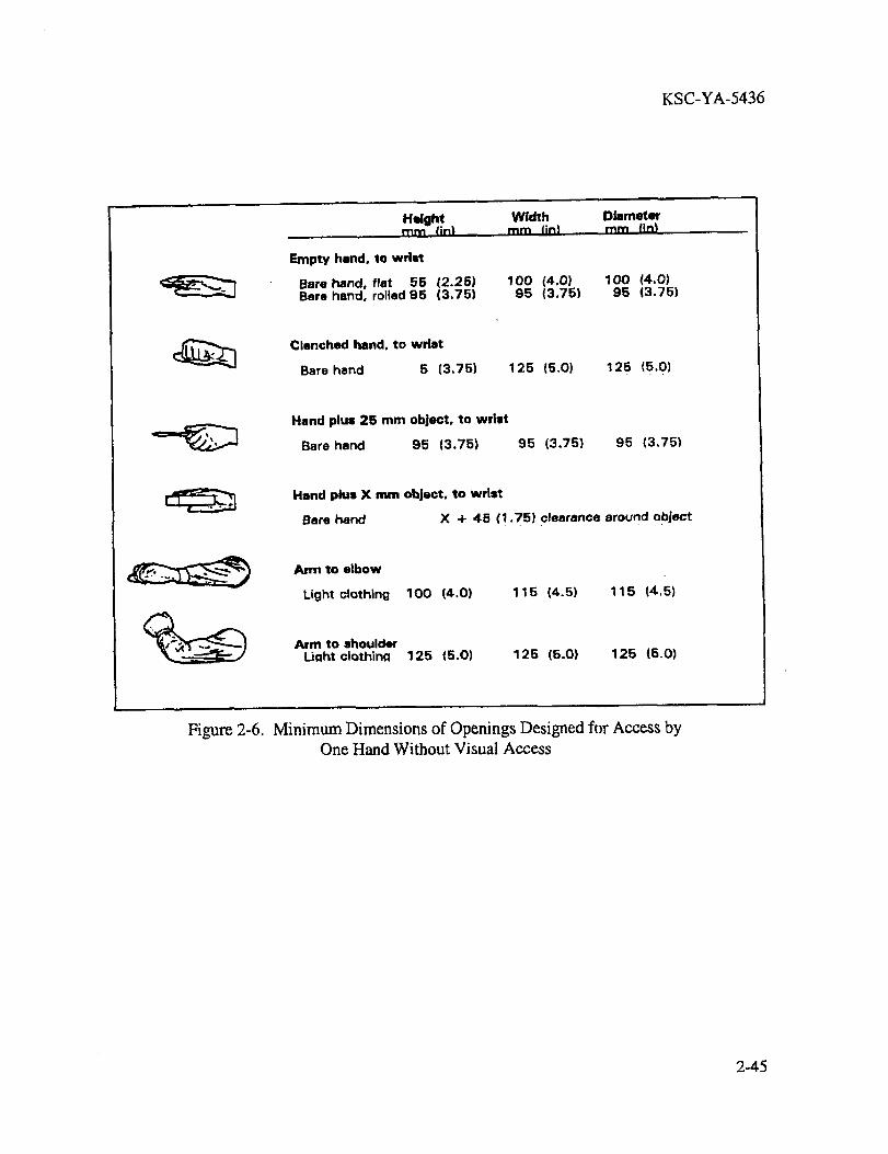
KSC-YA-5436
Height Width Dlarnetmnnm fin| mrn (in) mm lln)
Empty hand. to wdQt
Bare hand, flat 55 (2.25) 100 (4.0) 100 (4.0)Bare hand, rolled95 (3.75) 95 (3.75) 95 (3.75)
Clenched hand, to wristBare hand 5 (3.75) 125 (5,0) 125 (5.0)
Hand plus 25 mm ob]ect, to wrist
Bare hand 95 (3.75) 95 (3.75) 95 (3,75)
Hand plus X mm object, to wrist
Bare hand X + 45 (1.75) clearance around object
Arm to elbow
Light clothing 100 (4.0) 115 (4.5) 115 (4.5)
Aim to shoulderLiahtclothlng 125 (5.0) 125 (5.0) 125 (5.0)
Figure 2-6. Minimum Dimensions of Openings Designed for Access byOne Hand Without Visual Access
2-45
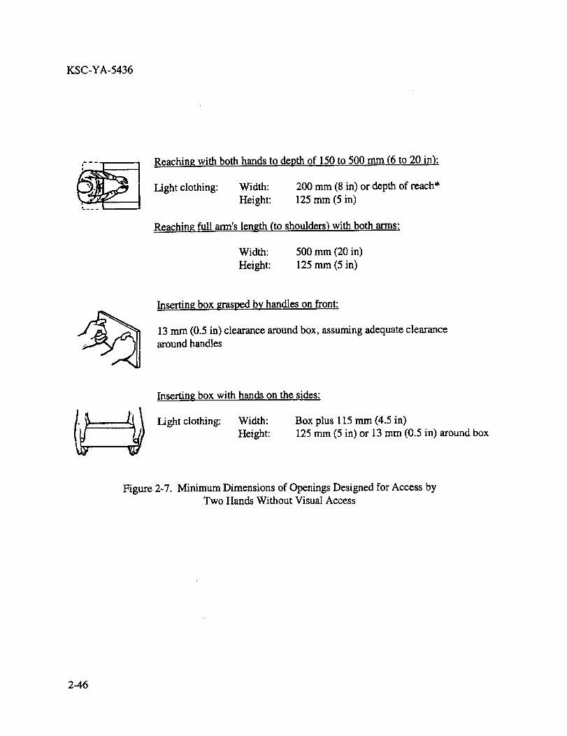
KSC-YA-5436
q--,____ | |
Re_ching with both hands to depth of 150 to 500 mm (6 m 20 in):
Light clothing: Width: 200 mm (8 in) or depth of reach*
Height: 125 mm (5 in)
Reaching full arm's length (to shoulders) with both arms:
Width: 500 mm (20 in)
Height: 125 mm (5 in)
Inserting box grasped by handles on front:
13 mm (0,5 in) clearance around box, assuming adequate clearance
around handles
Inserting box with hands on the sides:
Light clothing: Width: Box plus 115 mm (4.5 in)
Height: 125 mm (5 in) or 13 mm (0.5 in) around box
Figure 2-7. Minimum Dimensions of Openings Designed for Access byTwo Hands Without Visual Access
2-46
I I
STANDARDIZATION DOCUMENT IMPROVEMENT PROPOSAL
INSTRUCTIONS
1. The preparing activity must complete blocks 1,2, 3, and 8. In block 1, both the document number and revisionletter should be given.
2. The submitter of this form must complete blocks 4, 5, 6, and 7.3. The preparing activity must provide a reply within30 days from receipt of the form.
NOTE: This form may not be used to request copies of documents, nor to request waivers or clarification of re-quirements on current contracts. Comments submittedon this form do not constituteor imply authorization towaive any portion of the referenced document or to amend contractual requirements.
t= =i
J l. DOCUMENT NUMBER j 2. DOCUMENT OATEI RECOMMEND A CHANGE: KSC-YA-5436 September 28, 2001
3. oOCU_EN'rTm.EHuman Factors Engineering Guidelines for Overhead Cranes
4, NATURE OF CHANGE (Ide_fy paragraph nurnber and include proposed rewrite, if possible. Attach extra shears as needed.)
5. REASON FOR RECOMMENDATION
6. 8UBMITTER
a. NAME (Last, First, Middle Initial)
c. ADDRESS (include Zip Code)
8. PREPARING ACTIVITY
a. NAME
Director of Spaceport Engineering and Technology
b. ORGANIZATION
d. TELEPHONE (Include Area Code)
d. TELEPHONE (include Area Code)
(321) 867-7770
7. DATE SUBMITrED
c. ADDRESS (Include Ztp Code)
National Aeronautics and Space Administration- Mail Code: YAKennedy Space Center, FL 32899
II
FORM 21-610NS t,2/94)(C/G,2/94)