Embed Size (px)
Citation preview

Engineering Analysis and Geometric Design of Model Railroad Turnouts
NMRA Technical Note TN-12
By: Van S. Fehr Member, NMRA RP-12 Turnout Working Group Assistant Manager, NMRA Data Sheet Program
Revised: March 5, 2015
© 2015 National Model Railroad Association, Inc.

© 2015 NMRA NMRA Technical Note TN-12 Page 2 of 90
CONTENTS
ACKNOWLEDGEMENTS .............................................................................................................. 7
EXECUTIVE SUMMARY ............................................................................................................... 8
Background ..................................................................................................................................................... 8
Overview ........................................................................................................................................................ 8
Turnout Engineering and Design .................................................................................................................... 9
Geometry ..................................................................................................................................................... 9
Dimensional Consistency and Accuracy ..................................................................................................... 9
Engineering and Mathematical Validity ................................................................................................... 10
Consistency Evaluations ........................................................................................................................... 10
Analysis and Design Considerations ............................................................................................................ 10
Model Turnout Design Objective ................................................................................................................. 11
Model Turnout Design Rationale ................................................................................................................. 12
Lead ........................................................................................................................................................... 12
Frogs .......................................................................................................................................................... 12
Switch Heel Spread ................................................................................................................................... 12
Turnout Number Range ............................................................................................................................. 13
Curved Closure Rail Gauge Points............................................................................................................ 13
Guard Rails and Setting............................................................................................................................. 13
Generalized Model Turnout Design ............................................................................................................. 13
DOCUMENT ORGANIZATION .................................................................................................... 14
PART I: PROTOTYPE TURNOUTS ............................................................................................. 15
Turnout Nomenclature .................................................................................................................................. 15
Frogs ............................................................................................................................................................. 16
Frog Number and Angle ............................................................................................................................ 16
Frog Point Cutback.................................................................................................................................... 17
Frog and Toe Length ................................................................................................................................. 18
Frog Flangeway Gap ................................................................................................................................. 19
Toe and Heel Spread ................................................................................................................................. 20
Point of Tangent (PT) Location ................................................................................................................ 21
Wing Rails ................................................................................................................................................. 21
Wing Rail Flares........................................................................................................................................ 22
Wing Rail Flare – Bolted Rigid Frog ..................................................................................................... 22
Wing Rail Flare - Rail Bound Manganese Steel .................................................................................... 23
Frog Dimension Summary ........................................................................................................................ 24
Switches ........................................................................................................................................................ 24
Straight Switches ....................................................................................................................................... 25
Straight Switch Geometry ...................................................................................................................... 26
Point of Curve (PC) Location................................................................................................................ 26 AREA Straight Switch Consistency Evaluation .................................................................................... 26
Curved Switches ........................................................................................................................................ 27
Curved Switch Geometry ....................................................................................................................... 28
AREA Curved Switch Consistency Evaluation ..................................................................................... 31
Switch Heel Spread ................................................................................................................................... 31
Switch Heel Angle Relationship ............................................................................................................... 32
Turnout Lead ................................................................................................................................................ 33
© 2015 NMRA NMRA Technical Note TN-12 Page 3 of 90
Frog and Switch Locations ........................................................................................................................ 34
Curved Closure Rail .................................................................................................................................. 34
Theoretical and Actual Lead ..................................................................................................................... 35
Other Lead Equations ................................................................................................................................ 36
Closure Rails................................................................................................................................................. 36
Closure Rail Dimensions ........................................................................................................................... 36
Curved Closure Rail Gauge Points............................................................................................................ 37
Crossover Data ............................................................................................................................................. 38
AREA Turnout Consistency Evaluation....................................................................................................... 40
Tie Spacing ................................................................................................................................................... 41
Guard Rails ................................................................................................................................................... 41
Tee Rail Guard Rails ................................................................................................................................. 41
Tee Rail Guard Rail Flares ........................................................................................................................ 43
One-Piece (Cast) Guard Rails ................................................................................................................... 43
Guard Rail Setting ........................................................................................................................................ 44
Guard Rail Setting – Tee Rails .................................................................................................................. 44
Guard Rail Setting – One-Piece ................................................................................................................ 45
PART II: MODEL RAILROAD TURNOUTS ................................................................................. 47
Scaling Prototype Turnout Geometry ........................................................................................................... 47
Turnout Nomenclature .................................................................................................................................. 47
Frogs ............................................................................................................................................................. 47
Frog Flangeway Gap ................................................................................................................................. 47
Wing Rails ................................................................................................................................................. 48
Wing Rail Flares........................................................................................................................................ 48
Switches ........................................................................................................................................................ 48
Switch Heel Spread ................................................................................................................................... 49
Curved Switches ........................................................................................................................................ 49
NMRA Curved Switch Consistency Evaluation ....................................................................................... 49
Turnout Lead ................................................................................................................................................ 49
Closure Rail Lengths ................................................................................................................................. 50
Curved Closure Rail Gauge Points............................................................................................................ 50
Intersection of Centerlines ............................................................................................................................ 50
Crossover Data ............................................................................................................................................. 50
NMRA Turnout Consistency Evaluation ..................................................................................................... 50
Tie Spacing ................................................................................................................................................... 50
Guard Rails ................................................................................................................................................... 50
Guard Rail Flares ...................................................................................................................................... 51
Guard Rail Setting ..................................................................................................................................... 51
PART III: MODEL TURNOUT DESIGN ISSUES AND REQUIREMENTS ................................... 53
Primary Model Turnout Features ................................................................................................................. 53
Frog Design .................................................................................................................................................. 53
Wing Rails ................................................................................................................................................. 54
Wing Rail Flares........................................................................................................................................ 54
Switch Heel Spread ...................................................................................................................................... 54
Guard Rail Design ........................................................................................................................................ 55
Guard Rail Length Selection ..................................................................................................................... 56
Guard Rail Flares ...................................................................................................................................... 57
Guard Rail Setting ..................................................................................................................................... 57

© 2015 NMRA NMRA Technical Note TN-12 Page 4 of 90
Crossover Data ............................................................................................................................................. 57
Design Requirements – Summary ................................................................................................................ 57
PART IV: DESIGN CALCULATIONS FOR MODEL RAILROAD TURNOUTS ............................ 59
Switch Heel Spread ...................................................................................................................................... 59
Frog Angle .................................................................................................................................................... 60
Frog Design .................................................................................................................................................. 60
Guard Rail Design ........................................................................................................................................ 61
Curved Switch Turnouts ............................................................................................................................... 62
Straight Switch Turnouts .............................................................................................................................. 62
Additional Dimensional Data ....................................................................................................................... 63
Planning Template ........................................................................................................................................ 63
Tie Spacing ................................................................................................................................................... 64
Model Tie Spacing Methods......................................................................................................................... 64
Tie Spacing Method 1 ............................................................................................................................... 65
Tie Spacing Method 2 ............................................................................................................................... 66
Tie Spacing Method 3 ............................................................................................................................... 66
Tie Spacing Method 4 ............................................................................................................................... 67
Method Comparison .................................................................................................................................. 67
PART V: CHECKING FINAL DESIGN CONSISTENCY WITH CAD DRAWINGS ....................... 69
Final Design Consistency Checks ................................................................................................................ 69
Computer Aided Design Drawings............................................................................................................... 69
APPENDIX A: REVISED TURNOUT RP FORMAT AND EXAMPLES ........................................ 73
APPENDIX B: ALTERNATE CLOSURE RAIL CURVE AND LEAD LIMITS ............................... 83
Cubic Polynomial ......................................................................................................................................... 83
Lead Limits ................................................................................................................................................... 83
APPENDIX C: VARIABLE DEFINITIONS .................................................................................... 85
English Variables .......................................................................................................................................... 85
Greek Variables ............................................................................................................................................ 88
APPENDIX D: REFERENCES ..................................................................................................... 89
CHANGE RECORD ..................................................................................................................... 90

© 2015 NMRA NMRA Technical Note TN-12 Page 5 of 90
FIGURES
Figure 1: Turnout Nomenclature ................................................................................................................. 16
Figure 2: Frog nomenclature, frog number n, and frog angle ................................................................ 17
Figure 3: 1/2-inch point of frog .................................................................................................................... 18
Figure 4: Frog dimensions ........................................................................................................................... 19
Figure 5: Frog flangeway gap (No. 6 shown)............................................................................................ 20
Figure 6: Location of point PT ..................................................................................................................... 21
Figure 7: Bolted Rigid Frog End Flare (not to scale) ............................................................................... 23
Figure 8: Rail Bound Manganese Steel Frog End Flare (not to scale) ................................................. 23
Figure 9: Switch Point Rail Bend Van S. Fehr photo ............................................................................ 26
Figure 10: Straight switch rail geometry and location of point PC (no scale) ...................................... 27
Figure 11: Curved switch rail geometry and location of point PC (no scale) ....................................... 29
Figure 12: Switch Heel Spread Diagram (no scale) ................................................................................ 32
Figure 13: Turnout geometry for lead determination ............................................................................... 34
Figure 14: Curved closure rail gauge point locations .............................................................................. 38
Figure 15: Crossover Data ........................................................................................................................... 39
Figure 16: AREA No. 8 Curved Switch Turnout Tie Arrangement ........................................................ 41
Figure 17: Tee Rail Guard Rail Geometry (not to scale) ........................................................................ 42
Figure 18: Tee Rail Guard Rail End Flare (not to scale) ......................................................................... 43
Figure 19: Guard Rail Position Extremes (prototype 8’-3” Guard Rail, No. 6, drawn to scale) ........ 44
Figure 20: One-Piece Guard Rail Position (No. 4 frog shown) .............................................................. 45
Figure 21: No. 6 Frog, AREA to NMRA Comparison (wing rail flares not shown) .............................. 48
Figure 22: Guard Rail Position (HO Scale, No. 6, drawn to scale) ....................................................... 52
Figure 23: Railhead Width vs Rail Height.................................................................................................. 56
Figure 24: Turnout Template ....................................................................................................................... 64
Figure 25: Headblock Spacing .................................................................................................................... 65
Figure 26: Tie Spacing Methods 1 and 3 .................................................................................................. 66
Figure 27: Tie Spacing Methods 2 and 4 .................................................................................................. 67
Figure 28: Scale Class Comparison – No. 6 Curved Turnout ................................................................ 70
Figure 29: Scale Class Comparison – No. 6 Straight Turnout ............................................................... 71
Figure 30: Scale Class Comparison – Zoomed to Clarify Frog & Guardrail Flangeways.................. 72
Figure 31: Diagram of Turnouts - Curved or Straight Switch Rails ....................................................... 82

© 2015 NMRA NMRA Technical Note TN-12 Page 6 of 90
TABLES
Table 1: Frog Flangeway Gap ..................................................................................................................... 20
Table 2: Wing Rail Extension Lengths (in inches, for rail-bound manganese steel frogs) ................ 22
Table 3: AREA Frog Dimensions ................................................................................................................ 24
Table 4: Expanded AREA Frog Dimensions ............................................................................................. 25
Table 5: Switch Point Construction Details (AREA Plan 221-40) .......................................................... 25
Table 6: Straight Switch – Calculated Switch Angle vs. AREA Switch Angle (Plan 910-41) ............ 27
Table 7: Curved Switch Rail Radius (feet) Comparisons ....................................................................... 28
Table 8: Switch Heel Angle Relationship .................................................................................................. 33
Table 9: AREA Leads and Calculated Third-order Polynomial Lead Limits (feet) .............................. 36
Table 10: AREA Tee Rail Guard Rail Design Dimensions ..................................................................... 42
Table 11: Input Information and Sources .................................................................................................. 59

© 2015 NMRA NMRA Technical Note TN-12 Page 7 of 90
ACKNOWLEDGEMENTS
My appreciation goes to Didrik Voss, NMRA
Standards & Conformance Dept. Manger, Tim War-
ris of Fast Tracks, Andy Reichert of Proto:87 Stores,
and NMRA Trackwork Committee Manager Ed
McCamey. Their reviews and comments regarding
my work documented here were supportive, enlight-
ening and instructive.
Van S. Fehr
Member, NMRA RP-12 Turnout Working Group
Assistant Manager, NMRA Data Sheet Program
October 6, 2014

© 2015 NMRA NMRA Technical Note TN-12 Page 8 of 90
EXECUTIVE SUMMARY
Background Of the many types of turnout arrangements,
straight turnouts with rigid frogs and split switches
are the most common in the prototype. There are two
types of split switches, one with a straight switch rail
for the diverging route and the other with a curved
switch rail. The switch rail for the straight route is
always straight.
Curved switch straight turnouts are the subject of
National Model Railroad Association (NMRA) Rec-
ommended Practices (RPs) RP-12 and RP-12.1
through RP-12.7 that tabulate turnout dimensions for
O, S, HO, OO/On3, TT, HOn3 and N scales. They
are the work of E.R. Frase (original calculations),
Clarence H. Hill and Allen Hazen (original design-
ers), D.B. Seville and no doubt others whose dedi-
cated and diligent effort produced these turnout de-
signs.
The NMRA last revised RP-12.7 for N scale turn-
outs in 1979 and the others in 1961, 18 years earlier.
Recent examination of the turnout design dimensions
tabulated in these RPs shows they are not always
consistent (defined below). The inconsistencies are
perhaps due to calculation errors made at the time of
their last revision (35 and 53 years ago), and round-
ing errors introduced when converting decimal num-
bers to their nearest fractional equivalents.
While the inconsistencies are sometimes numeri-
cally excessive, they are not always visible to the
naked eye. No doubt many modelers and manufac-
turers have used the 1961 and 1979 RPs to design,
construct, and manufacture turnouts that look rea-
sonably prototypical and operate reliably, especially
when properly gauged to the appropriate NMRA
Standard.
Overview To eliminate the inconsistencies and remedy the
limited coverage of the 1961 and 1979 RPs, this
NMRA Technical Note (TN) constitutes an im-
provement and extension of the contributions of
Frase et. al. It develops an engineered set of design
requirements and design equations that produce
curved and straight switch turnout design dimen-
sions for any of the three general scale classes (scale
fidelities) of scale model railroading identified by the
NMRA. They are the Proto (and Fine), Standard,
and Deep Flange (Hi-Rail) scales defined by the
NMRA Standards S-1.1, S-1.2, and S-1.3, respec-
tively.
Importantly, the revised and expanded turnout de-
signs require no changes to any NMRA standard. In
fact, some of the design dimensions are dependent
on the NMRA standards for track gauge, frog
flangeway width and switch point rail spread. With
this dependency, the design requirements and design
equations apply to all model scales, to standard or
narrow gauge trackwork, and to any turnout num-
bered 4 through 20, inclusive.
The American Railway Engineering Association
(AREA), and its successor the American Railway
Engineering and Maintenance-of-Way Association
(AREMA), publish prototype turnout designs in its
annually updated portfolio of Trackwork Plans and
Specifications. Most of the research, engineering de-
sign analysis, and equation development contained in
this TN stems from careful examination and engi-
neering evaluation of the turnout information in that
portfolio.
The AREA does not specify designs for narrow
gauge turnouts of either switch type. Establishing
model railroad narrow gauge turnout dimensions is
impractical until a narrow gauge standard of some
kind surfaces from some definitive source, perhaps
the NMRA. Internet searches for such a prototype
standard were fruitless.
The NMRA turnout RPs do provide dimensions
for On3 and HOn3 turnouts, but the origin of the
lead and other dimensions (other than track gauge) is
unclear. When scaled up to the prototype, their lead
dimensions do not match. Nevertheless, the equa-
tions developed in this TN apply equally to narrow
gauge turnout designs for any track gauge. Once an
AREA-like set of narrow gauge trackwork plans be-
come available, preparing narrow gauge turnout di-
mensions is straightforward.
The companion MS-Excel spreadsheet NMRA
TN-12 Generalized Model Turnout Design.xls uses
the design requirements and equations developed in
this TN to generate consistent, accurate, and tabulat-
ed turnout dimensions without rounding errors. The
spreadsheet output arrangement enables bulk copy-
pasting into a revised and expanded set of new RPs.
The new RP set supports the premise that it is best
to recommend consistent and accurate turnout di-
mensions. That way, any imperfections appearing in

© 2015 NMRA NMRA Technical Note TN-12 Page 9 of 90
a finished turnout are the result of construction or
manufacturing processes, and not of a flawed design.
This TN documents five primary research activi-
ties that culminate with updated turnout designs pre-
sented in a revised turnout RP format. In particular,
this TN:
1. Documents background research regarding the
geometry of prototype turnout designs, specifi-
cally those historically specified by the AREA in
its 1946 portfolio of Trackwork Plans and Speci-
fications.
2. Develops scale-independent equations describing
turnout geometry, and shows that the calculated
turnout dimensions they produce are consistent
with the AREA tabulated dimensions, thereby
demonstrating equation validity.
3. Applies those validated equations to the tabulat-
ed dimensions in NMRA RPs RP-12.1 through
RP-12.7, and shows those dimensions are not
always consistent with the calculated dimen-
sions.
4. Develops a design approach that produces model
turnout designs with consistent dimensions, and
compares the effect of scale class on design re-
sults.
5. Presents a revised format for turnout RPs that
contain those dimensions, and presents a few ex-
amples in the Appendices.
Turnout Engineering and Design Turnout design stabilized once railroads began to
see the economic benefit of interchange and stand-
ardization. The remainder of this EXECUTIVE
SUMMARY highlights the key aspects of the re-
search activities listed above and culminates with a
brief description of generalized model turnout de-
sign.
Geometry
Throughout this TN, geometry refers to the di-
mensions of turnout rails and subassemblies normal-
ly built from rail stock, such as the switch and frog.
These are the dimensions the 1961 and 1979 RPs and
the new RP format tabulate. Geometry does not in-
clude the “nuts and bolts” of a turnout design, both
literally and figuratively, as they fall in the purview
of detailing. Additionally, geometry refers to the
gauge line of the rails making up a turnout, and does
not prescribe construction practices. Any turnout
construction comments in this TN are anecdotal and
do not constitute a recommendation.
Flangeway and railhead width do not directly af-
fect gauge-line geometry of the prototype. However,
flangeway width and switch point spread, critically
important dimensions specified by NMRA standards,
do affect the model turnout and reliable operation. In
the model, they affect frog design and switch heel
spread, and thus directly affect gauge-line geometry.
The AREA turnout geometry identified in the first
list item above was chosen simply because it is on
hand. Since then, the AREA and AREMA have no
doubt changed some of the dimensional details, but
those changes do not affect the validity of the equa-
tions described in the second list item. Those equa-
tions govern the geometric relationship between all
essential turnout dimensions.
Dimensional Consistency and Accuracy
Here and elsewhere in this TN there is reference
to dimensional consistency. Both the AREA and
NMRA summarize turnout designs using tabulated
dimensions. When enough dimensions are accepted
as given, such as the frog number, frog lengths,
switch length, heel or switch angle, and a few others,
the design equations produce calculated values for
all the remaining dimensions. For a perfectly engi-
neered, designed, computed and tabulated turnout,
there would be no difference between the tabulated
and calculated values.
Non-zero differences, if large enough, indicate er-
rors in the equations, the calculations, arithmetic
rounding, or in the tabulated values themselves.
Consistency then, is a measure of the cumulative ef-
fect of all these errors. This TN uses the following
definition of consistency:
Turnout dimensions are consistent when the per-
cent difference between a tabulated and calculat-
ed dimension is 0.5% or less.
Because of the disparate error components it in-
cludes, this is not a rigorous definition. It is simply a
judgment call based on general engineering experi-
ence and examination of calculated results. Round-
ing decimal values to fractional feet and inches, or
simply fractional inches, can sometimes cause as
much as 0.25% difference.
Accuracy is a measure of how close a calculated
number is to its actual value. Human beings can easi-

© 2015 NMRA NMRA Technical Note TN-12 Page 10 of 90
ly perform simple arithmetic, but when calculations
require precision or become tedious, errors are prone
to occur. Use of a calculator can minimize errors, but
human mistakes can still occur with complicated
equations and when transcribing results.
The consistency definition is reasonable given the
mathematically precise equations developed in this
TN and the extraordinary calculation accuracy
achievable with today’s personal computers. That
also makes the definition reasonable for evaluating
the consistency of dimensions calculated by hand or
with less accurate tools.
Prior to about 1960, when mainframe computers
first began to appear in engineering organizations,
engineers made extensive use of slide rules that are
accurate only to about three significant figures. En-
gineers used electromechanical calculators, widely
available in the second quarter of the 20th
century, to
produce results of greater accuracy. Even then, the
calculated results were likely recorded by manual
rounding and tabulation, presenting another oppor-
tunity for human error.
It is then safe to say that the 1946 AREA tabulat-
ed dimensions evaluated in this TN were not gener-
ated by a computer. Whether or not the 1961 NMRA
turnout RPs tabulate computer-generated dimensions
is unknown, but unlikely. The 1979 N scale RP tabu-
lated dimensions may have been calculated using
computers, or perhaps handheld calculators, because
they are of generally better consistency than those in
the earlier RPs.
Engineering and Mathematical Validity
Derivation of the equations developed in this TN
comes from careful review of prototype and model
turnout geometry, and application of the mathemati-
cal principles of Plane Geometry, Trigonometry, Al-
gebra and Calculus. Those equations provide a com-
plete mathematical description of turnout geometry.
To eliminate mathematical errors, deriving and
checking the equations several times, sometimes
from different directions, ultimately produced the
same set of equations. Only then were the equations
programmed in a spreadsheet for calculation and
evaluation of turnout dimensional consistency.
Consistency Evaluations
Consistency calculations, comparisons, and de-
sign calculations come from several companion MS-
Excel spreadsheets, listed with other resources in
APPENDIX D: REFERENCES. All spreadsheet cal-
culations are accomplished using Visual Basic for
Applications (imbedded in MS-Excel) and double
precision variables to ensure maximum accuracy.
Because these spreadsheets contain macros, MS-
Excel will likely issue a security warning when
opening them. The sole purpose of these macros is to
make the necessary consistency and design calcula-
tions. They present no security threat. Although writ-
ten using MS-Excel 2010, the spreadsheets are saved
in MS-Excel 97-2003 form (.xls) for compatibility
with earlier versions.
Applying the developed equations to the AREA
tabulated dimensions shows that all AREA switch
dimensions are consistent. For straight switches, the
AREA dimensions match the calculated dimensions.
For the AREA curved switches, the spreadsheet
shows the differences between calculated values and
specified values for curved switches are in the range
of -0.26% to 0.17%, well within the consistency def-
inition.
For the full AREA turnout, all dimensions, except
a few curved closure rail gauge point coordinates,
are consistent. Those few that are not appear to be
errors in the AREA calculations and are thus ig-
nored. Most importantly, the consistency of the
AREA switch and turnout designs validates the de-
veloped equations.
Applying the validated equations to the NMRA
tabulated dimensions shows that many are not con-
sistent. The differences between calculated dimen-
sions and specified dimensions for switches are in
the range of -22.4% to 26.0%, and for complete
turnouts in the range of -22.4% to 44.2%. These are
far too large to be declared consistent. Correcting
these inconsistencies is an important aspect of the
effort documented in this TN.
Analysis and Design Considerations One of the key design requirements for a proto-
type or model turnout is that it provide a smoothly
curving set of rails along the diverging (reverse)
route. This means there may be no angular disconti-
nuities (kinks) in those rails, except for the accepta-
bly small angle at the switch points. Further, there
may be no angular discontinuities where the switch
rail meets the curved closure rail and where the
curved closure rail meets the frog toe. That said, if
the key switch and closure rail dimensions are not
consistent, those angular discontinuities will occur in

© 2015 NMRA NMRA Technical Note TN-12 Page 11 of 90
either the AREA prototype tables or in the NMRA
RPs.
The equations developed in this TN satisfy the
smoothness requirement. Using them ensures con-
sistent dimensional specifications for any updated or
new turnout RPs.
Of course, this is a matter of degree. In some cas-
es, the existing discontinuities in the NMRA dimen-
sions will be unnoticeable once a turnout is con-
structed and properly gauged to NMRA Standards.
Reliable operation will likely ensue. In other cases,
rails may not line up and the discontinuities may be
more obvious. Having turnout dimensional specifica-
tions that are consistent and accurate, but rounded to
remain realistically achievable, is a worthy goal for
any NMRA (or prototype) turnout design specifica-
tion.
As noted earlier, some turnout dimensions must
be accepted as given to compute the remaining di-
mensions. The research documented in this TN does
not always discern which turnout dimensions are
given, and which are derived. For each frog number,
the AREA specifies frog toe and heel length dimen-
sions that are independent of the several frog designs
it catalogs. The frog angle is a direct consequence of
the definition of the frog number. The frog angle is
computed using its scale-independent prototype def-
inition.
Another important turnout dimension is the
switch heel spread, which the AREA standardizes at
6¼ inches for all turnout frog numbers. Similarly,
the NMRA uses a fixed switch heel spread for all
frog numbers, but it varies with model scale.
For an AREA turnout with a specified frog num-
ber, the most important dimension for the switch is
the specified switch rail length. For a straight switch
rail, the switch heel angle is a direct consequence of
the switch rail length and the switch heel spread. Be-
cause the switch is straight, the point angle is the
same as the heel angle. For a curved switch, the
point angle depends on the curved switch rail length,
a specified heel angle, and the heel spread.
Similarly, the NMRA curved switch designs spec-
ify the point and heel angles, along with the switch
rail length. While the AREA chooses switch rail
lengths based on commonly available rail-stock
lengths, the NMRA is not similarly limited, and its
specified switch rail lengths are not scaled from the
AREA lengths.
Given the frog design, the developed equations
show a relationship between the switch design and
the reverse route curvature, and thus the other turn-
out dimensions, especially the lead. In fact, once the
switch and frog design dimensions are set, there is
only one lead dimension value that is consistent with
the curved closure rail being a circular arc, as speci-
fied by both the AREA and the NMRA. For any oth-
er lead value, the curved closure rail cannot be circu-
lar, even though it may form a smooth curve. Con-
versely, for a given lead and frog design, there is on-
ly one switch length.
Thus two basic design approaches are possible.
The first approach sets the switch dimensions first
and then calculates the other dimensions, as appar-
ently done in the prototype. The second approach,
unlike the prototype, sets the lead dimension first
and then calculates the other dimensions. For either
approach, the equations ensure the designs will have
consistent dimensions.
Setting the switch dimensions first produces lead
dimensions that are excessively longer than the
scaled prototype. This is due in part to larger switch
heel spread dimensions necessary in the model. That
leaves setting the lead dimension first as the best de-
sign approach for model turnouts.
Model Turnout Design Objective In support of its mission to provide Standards and
Recommended Practices for interoperability and in-
terchangeability, the NMRA is essentially the scale
model railroading equivalent of the AREA and its
successor, AREMA, at least as it pertains to track-
work specifications.
The overall model turnout design objective is then
to produce a set of turnout NMRA Recommended
Practices that:
1. Cover all NMRA-recognized model scales, for
Proto (and Fine), Standard and Deep Flange (Hi-
Rail) scale classes.
2. Specify dimensions for both straight and curved
split switch turnout designs, for frogs No. 4
through No. 20, inclusive.
3. Meet all existing NMRA Standards for turnouts.
In the same way the AREA Trackwork Plans and
Specifications form a basis for prototype turnout de-
signs, the NMRA Recommended Practices form the
basis for turnout construction by modelers or com-

© 2015 NMRA NMRA Technical Note TN-12 Page 12 of 90
mercial model trackwork manufacturers. Prototype
railroads and turnout component manufacturers may
deviate from the AREA designs, and similarly model
builders and manufacturers may deviate from the
NMRA designs. However, in doing so model turn-
outs must still meet applicable NMRA standards to
ensure smooth and reliable operation. For turnout
manufacturers, meeting the applicable NMRA stand-
ards provides a path towards receiving an NMRA
Conformance Warrant.
Model Turnout Design Rationale To achieve the model turnout design objective re-
quires a methodical and practical design rationale.
The most visual features of a turnout design are its
overall length and its frog angle. Compare a No. 6
and No. 8 turnout side-by-side and the differences in
those features are clearly evident. The design ra-
tionale for these and other key features follow.
Lead
The primary contributor to overall length is turn-
out lead. There is no apparent documentation de-
scribing how the NMRA established lead dimensions
for the 1961 and 1979 turnout RPs. Some NMRA
lead values are shorter than the scaled AREA lead,
others are longer, but not consistently so. Using
scaled AREA lead dimensions is clearly appropriate
for scale model turnouts. As discussed earlier, setting
the lead dimension first is the best design approach.
If scaled leads are not used, a method for selecting
non-scale NMRA lead values would need to be de-
veloped, explained, quantified, and documented.
Frogs
Identifying a turnout by its frog number immedi-
ately implies its calculable frog angle. The frog angle
and the other frog dimensions are equally important.
The NMRA flangeway widths are roughly twice the
prototype flangeway width (Proto scales excepted),
making the flangeway gap between the frog throat
and the frog point roughly twice as long. This has
no effect on the frog heel length, but reduces the
available toe length necessary for the mechanical
features that attach the frog toe to the closure rails.
The NMRA frog dimensions are about 30% long-
er than the prototype, perhaps to accommodate the
longer flangeway gap, but for otherwise undocu-
mented reasons. Further, the NMRA RPs show toe
and heel lengths that are both longer than the proto-
type. However, only the toe length needs adjustment
for the longer flangeway gap of the model. Using the
scaled prototype heel length and the scaled prototype
toe length adjusted for the longer flangeway gap in
the model is a refinement to the current NMRA de-
sign. This also makes frog dimensions closer to the
scaled prototype. For Proto scales, they will be near-
ly the same as the scaled prototype.
Flare dimensions for the frog wing rail and a
guard rail (discussed below) are different. They are
dependent on frog number, and are now included in
the new RP format.
Switch Heel Spread
Although not as visually obvious as lead and frog
angle, the switch heel spread has a significant effect
on turnout dimensions. The AREA sets heel spread
to 6.25 inches for turnouts of any frog number, either
switch type (curved or straight), and for any switch
rail length. The NMRA RPs set switch heel spread as
well, but to values that are more than half again as
large as the scaled prototype.
The NMRA heel spread was perhaps set to ac-
commodate early, thicker wheel flanges that perhaps
preceded the development of NMRA RP-25 Wheel
Contour. A reasonable assumption is that the AREA
considered wheel flange thickness and some ade-
quate clearance between the back of the wheel and
the adjacent switch rail when setting its heel spread.
Using the AREA approach, with an NMRA
standard flangeway width that accommodates the
appropriate RP-25 (or Proto scale) wheel flange
thickness, is then a reasonable design approach for
setting model switch heel spread. This TN prescribes
two methods for doing this. One produces switch
heel spreads similar to those in the current RPs, and
the other produces narrower, and thus more proto-
typical, switch heel spreads.
In either method, the switch heel spread must still
meet the NMRA standards for switch point spread.
Switch point spread applies over the full length of
the switch rail, including the heel end where the heel
spread dimension occurs. Because of this, the switch
point spread standard (mechanical) sets the switch
heel spread for Proto scale. For the other scales, with
their wider flangeways, the point rail spread is satis-
fied, but is not limiting.

© 2015 NMRA NMRA Technical Note TN-12 Page 13 of 90
Turnout Number Range
The AREA does not specify dimensions for No.
4, No. 13, No. 17 and No. 19 turnouts. Skipping No.
17 and No. 19 is not surprising, especially because
these are generally high-speed mainline turnouts
where any length is readily accommodated and in-
termediate lengths are likely not needed. Some
sources say skipping No. 13 is rooted in superstition,
much like many buildings in New York City that
have no numbered 13th
floor. No. 4 turnouts have
limited application in the prototype, except for in-
dustrial applications where space limitations may
require them, and short wheelbase switchers are
more the norm. Still, skipping the No. 4 turnout is
somewhat surprising because the AREA does speci-
fy dimensions for a No. 4 frog.
Nevertheless, it is possible to infer dimensions for
the missing-number turnouts by examining the frog
dimensions and switch rail lengths of adjacent-
numbered turnouts. The AREA No. 5 and No. 6
turnouts use the same switch design for a given type
(curved or straight). Thus it is reasonable to expect
that the AREA would use that same switch design
for the more compact No. 4 turnout, including the
associated switch or heel angle. For the other miss-
ing turnout numbers, the AREA tables imply they
would have the same switch dimensions as the adja-
cent-numbered designs. Frog dimensions appear to
vary linearly with frog number, so it is reasonable to
linearly interpolated them for No. 13, 17 and 19
frogs. The validated equations then produce the re-
maining dimensions. This enables calculation of
turnout dimensions for the full range of No. 4 to No.
20 turnouts, inclusive.
Curved Closure Rail Gauge Points
The AREA specifies three gauge points along the
curved closure rail at roughly even spacing. These
gauge points aide in forming the closure rail radius
during construction in the field. The NMRA uses
one, two, or three gauge points, depending on model
scale and frog number, for the same purpose. The
number of NMRA gauge points seems to be based
on the length of the closure rails, but the choice is
not always consistent across different model scales.
Always using three gauge points, as the AREA does,
is a better choice for NMRA turnout gauge points.
Guard Rails and Setting
Guard rails and their proper setting in relation to
the frog flangeway gap are also important to reliable
operation. The AREA specifies only two guard rail
designs, one constructed from rail stock and the oth-
er made as a single casting. The rail stock design
adapts well to the model turnout, but the cast design
is too restrictive because it requires specific tie spac-
ing under the frog.
The AREA also specifies two lengths for the rail
stock design used with rigid frogs. This is adequate
for Proto scale guard rails, but the other scales, with
wider flangeway gaps needing protection, require a
set of longer guard rails. The lengths of these longer
guard rails come from the prototype practice of mak-
ing them from standard-length rail stock. For this
reason the new RP format includes guard rail length,
flare and parallel-section setback dimensions that are
dependent on frog number.
Generalized Model Turnout Design The design rationale discussed above makes it
possible to use the validated equations to produce
turnout dimensions in any prototype gauge or model
scale, standard or narrow gauge, and for any frog
number 4 to 20 inclusive. The AREA designs are the
logical starting point for standard gauge turnouts. A
narrow gauge equivalent to the AREA designs is not
currently on hand and requires further effort to un-
cover or otherwise establish.
For standard gauge turnouts, the design rationale
summary is:
1. Use AREA straight switch and curved switch
lead dimensions.
2. Set frog designs by frog number and flangeway
standards.
3. Set switch heel spread by NMRA flangeway
standards (this also accommodates appropriate
wheel flange thickness), adjusted as necessary
for NMRA switch point spread standards.
4. Specify guard rail dimensions and setback that
fully protect the wider flangeway gaps of the
model frog.
The companion spreadsheet NMRA TN-12 Gener-
alized Model Turnout Design.xls makes all design
calculations for any specified scale class and pre-
sents results in the new RP format.

© 2015 NMRA NMRA Technical Note TN-12 Page 14 of 90
DOCUMENT ORGANIZATION
In addition to the EXECUTIVE SUMMARY, this
TN is organized into five main parts and four appen-
dices:
PART I: PROTOTYPE TURNOUTS
This part describes the geometric details of proto-
type turnouts specified by the AREA. It presents a
discussion of each pertinent turnout feature and de-
velops equations describing its relevant geometry.
Except for an occasional comment in this part, a
more complete discussion of model railroad turnouts
occurs in PART II.
PART II: MODEL RAILROAD TURNOUTS
Similar to PART I, this part describes the details
of model railroad turnout geometry, and explains any
adjustments to prototype equations needed for model
turnout considerations.
PART III: MODEL TURNOUT DESIGN ISSUES AND REQUIREMENTS
This part discusses issues for model turnout de-
sign, addresses and establishes basic design require-
ments that cover both curved switch and straight
switch turnouts.
PART IV: DESIGN CALCULATIONS FOR MODEL RAILROAD TURNOUTS
This part develops design calculation algorithms
for straight and curved switch turnouts, based on the
equations developed in PART I and PART II, that
meet the design requirements set in PART III.
PART V: CHECKING FINAL DESIGN CONSISTENCY WITH CAD DRAWINGS
This part discusses the consistency evaluation of
the design examples presented in APPENDIX A. Ad-
ditionally, it includes CAD drawings that compare
the prototype and model turnouts for several model
scales and frog numbers.
APPENDIX A: REVISED TURNOUT RP FORMAT AND EXAMPLES
This appendix contains examples of recommend-
ed revisions to the turnout RPs. At best, modelers
can only measure things to about a hundredth of an
inch (two decimal places), or 1/64 of an inch using
readily available engineer’s and machinist scales.
More accurate measurement tools, such as microme-
ters, Vernier calipers, dial indicators, feeler gages,
and for trackwork, the NMRA Standards Gauge, are
typically accurate to the nearest thousandth of an
inch. Turnout manufacturers would presumably pre-
fer dimensions to the nearest thousandth of an inch
for manufacturing purposes. For these reasons, the
new turnout RPs show all dimensions rounded to the
nearest thousandth of an inch, or for angles, the
nearest thousandth of a degree.
APPENDIX B: ALTERNATE CLOSURE RAIL CURVE AND LEAD LIMITS
This appendix describes an alternate, non-circular
shape for the curved closure rail. It also describes
how a reasonable range of lead values can still de-
scribe a turnout with a smooth reverse route curve.
The developed equations apply to both the prototype
and model turnout.
APPENDIX C: VARIABLE DEFINITIONS
This appendix defines all variables used in all
equations appearing in the PART I though PART IV
and APPENDIX B.
APPENDIX D: REFERENCES
This appendix contains a numbered list of all ref-
erences and companion MS-Excel spreadsheets.
PART I through PART IV and APPENDIX B de-
velop equations that define a turnout’s geometric
features diagrammed in associated figures. The ini-
tial set up of most equations, using the principles of
Plane Geometry and Trigonometry, is straightfor-
ward. Any algebraic manipulations needed to put the
equations in final form are not detailed, with a few
exceptions where some intermediate steps clarify the
logic.
In APPENDIX B, derivation of some important
equations involving turnout closure rail curvature
and lead additionally require application of basic
Calculus, notably the use of derivatives and the prin-
ciples of maxima and minima.
Finally, all equations in this TN have a unique
identifier contained in parentheses and following on
the same line. The identifier consists of the PART
roman numeral or APPENDIX letter followed by a
dash and a sequential number staring with 1, for ex-
ample: (IV-7).

© 2015 NMRA NMRA Technical Note TN-12 Page 15 of 90
PART I: PROTOTYPE TURNOUTS
Many good sources of information about proto-
type turnouts are available. Books on railroad engi-
neering abound, historically and in the present. E.E.
Russell Tratman’s book Railway Track and Mainte-
nance, A Manual of Maintenance-of-way and Struc-
tures [1]1 provides early 20
th century insights into
railway engineering, including that of turnouts. Wil-
liam W. Hay’s highly regarded and definitive book,
Railroad Engineering [2] dating from 1982, enlight-
ens further. John A. Droege’s book, Freight Termi-
nals and Trains [3], reprinted in 2012 by the NMRA
briefly discusses turnouts. There are no doubt others.
A significant source of prototype mechanical en-
gineering information regarding turnouts is the
American Railway Engineering and Maintenance
Association (AREMA) and its predecessor, the
American Railway Engineering Association
(AREA). They annually publish a Portfolio of
Trackwork Plans and Specifications that contains a
wealth of mechanical design information about turn-
outs, crossovers, crossings and the detail parts in
their assemblies. AREMA offers the 2014 printed
version of this portfolio for sale at a cost of $1465.00
plus $45.00 for shipping and handling, but this is
cost-prohibitive for a single researcher. The CD ver-
sion at $965.00 is still cost-prohibitive.
One historical version of this portfolio, obtained
from the internet2, is the AREA Trackwork Plans
and Specifications dating from 1946 [4]. Much of the
engineering information discussed or referenced in
this TN comes from it. There is no doubt that chang-
es to these plans have occurred since then. However,
the basic mechanical and geometric characteristics of
turnouts remain the same, so the engineering princi-
ples developed from that information are equally val-
id today. There is no requirement that prototype rail-
roads use the AREA or AREMA designs exclusive-
ly, but many do, or use them as a basis for their own
turnout design specifications.
After defining pertinent turnout nomenclature in
the first section below, a following section for each
major turnout feature develops equations that de-
scribe feature geometry in terms of dimensions la-
beled in an associated figure. Collectively, the equa-
1 Numbers in square brackets identify sources listed by the
same number in APPENDIX D: References of this TN. 2 Unfortunately, as of this writing, the link to this PDF docu-
ment is broken.
tions from each section define the geometry of a
turnout.
Turnout Nomenclature A straight turnout, as the name suggests, consists
of a straight path normally aligned on a tangent
(straight) track, with a second path diverging to the
right or left of the straight path. A turnout whose di-
verging path departs to the left is a left-hand turnout
and one diverging to the right is a right-hand turn-
out. The railroad name for the straight path is the
normal route and for the diverging path the reverse
route. Figure 1 shows a left-hand turnout and identi-
fies its main features. It shows only the railheads
and, for clarity, excludes the ties and mechanical as-
sembly details.
The primary features of a turnout are the frog and
the switch, circled in the figure. The straight and
curved closure rails connect them. Opposite these
rails, at the track gauge distance, are the correspond-
ing stock rails.
The frog is a mechanical assembly that provides a
gap where the closure rails would otherwise inter-
sect, allowing passage of wheel flanges. Opposite the
frog are the guard rails that ensure wheels passing
through the frog proceed along the correct route.
The switch is the only moving part of the turn-
out3. Its purpose is to direct an approaching train to
the normal route or to the reverse route. The two ver-
tical lines between the two switch rails represent the
switch rods, which are the mechanical devices that
cause the two switch rails to move together. The
switch rails pivot at their heels, located at the heel of
switch.
An important turnout dimension is the lead, the
distance between the point of switch and the point of
frog measured parallel to the normal route. Later sec-
tions fully describe the lead and its relationship to
the frog and switch designs.
3 Spring rail frogs also move, but they are beyond the scope of
this TN.

© 2015 NMRA NMRA Technical Note TN-12 Page 16 of 90
Frogs Railroad design engineers identify turnouts by
their frog number. For example a “No. 8” turnout is
one constructed using a No. 8 frog. Figure 2 illus-
trates the pertinent features of a frog, including the
frog number and angle, but shows only the rail heads
for simplicity.
The AREA presents several types of frog designs
in its Trackwork Plans & Specifications. The types
are named for their major components and construc-
tion:
Bolted Rigid Frog
Rail-Bound Manganese Steel Frog
Spring Rail Frog
Solid Manganese Steel Frog
Self-guarding Solid Manganese Steel Frog
The first two frog types, the Bolted Rigid Frog
and the Rail-Bound Manganese Steel Frog, have the
same toe length, heel length, toe spread and heel
spread for a given frog number.
The last three types, whose designs vary even for
the same frog number and sometimes specify differ-
ent rail weights, have dimensions that are different
from the first two types. This TN covers only the
first two types of frogs, perhaps the most common.
A frog assembly is symmetric about its own cen-
terline. That way the same frog can serve either a
right- or left-hand turnout. The rails connecting to
the closure rails are the frog wing rails. The rails
converging at the frog point are the frog point rails.
The angle between the frog point rails, and the nor-
mal and diverging routes, is the frog angle.
Notice the point where the gauge sides of the frog
point rails intersect. Because it is mathematically
sharp, turnout design engineers call this point the
theoretical point of frog, in part because it is not ac-
tually fabricated. In practice, the actual frog point is
cutback to the ½-inch point where the frog point rails
diverge to one-half inch.
Frog Number and Angle
The frog number is the distance n units, measured
along the bisector of the frog point rails (the frog’s
centerline), from the theoretical point of frog to the
location where the gauge side of the frog point rails
separate by one unit. For example, if 8n feet,
measured to a point where the separation is 1 foot,
the frog is a No. 8. The separation does not have to
be one unit. For example, if the separation is 6 inch-
es at a distance of 48 inches the frog number is
86/48 . The frog number is usually a whole num-
ber, but that is not a requirement. The Pennsylvania
Railroad (PRR) used a No. 5.289 frog some special
Figure 1: Turnout Nomenclature
Switch (two types)
Frog(number)
Normal Route
Point of Switch
Heel of Switch
Point of Frog
Curved Closure Rail
Straight Closure Rail
Straight Stock Rail
Curved Stock Rail
Switch Rails
Guard Rail
Guard Rail
Lead

© 2015 NMRA NMRA Technical Note TN-12 Page 17 of 90
circumstance. The Denver & Rio Grande Western employed No 4½ and 8½ frogs in addition to No. 4
and No. 8 frogs. AREA frog numbers fall in the
whole number range from 4 to 20, skipping 13, 17
and 19, although some high-speed turnouts can have
higher frog numbers. No. 4 turnouts occasionally
occur in tight, mostly industrial, locations. Discussed
later, the AREA does not specify a No. 4 turnout.
The frog angle is a consequence of the frog
number n. The frog angle is also the angle the re-
verse route makes with the normal route. From trig-
onometry and the geometry in Figure 2:
n2
1
2tan
(I-1)
The definition of the frog angle is then:
n2
1arctan2 (I-2)
Frog Point Cutback
Again, consider the theoretical point of frog in
Figure 2. A real frog point can be extremely sharp,
but not perfectly so, making a sharp frog point im-
practical and unnecessary. Turnout design engineers
deliberately cut the frog point back towards the heel
of the frog until the separation of the gauge side of
the frog point rails reaches ½ inch. This cutback dis-
tance d, as Figure 3 illustrates, locates the half-inch point of frog. Other names for the ½-inch point of
frog are the actual or practical point of frog. From
similar triangles:
nd 2
1
4
1 (I-3)
Thus, the cutback distance, in inches, is simply
one-half the frog number:
nd2
1 (I-4)
For example, a No. 6 frog has a 3-inch cutback to
the ½-inch point. Measured along a gauge line, the
cutback distance GLd , again in inches, is slightly
longer:
2cos
ddGL (I-5)
Equation (I-5) will be useful later. Using the half -
angle formula (from trigonometry) for the tangent,
and equation (I-1), leads to other relationships be-
tween the frog angle and frog number, useful for en-
gineering analysis:
Figure 2: Frog nomenclature, frog number n, and frog angle
n units
1 unit
Frog
toe
Frog
heel
Frog
point
rails
Theoretical
point of frog
Frog centerline
Frog
angle
½-inch
point of
frog
Frog
wing
rails

© 2015 NMRA NMRA Technical Note TN-12 Page 18 of 90
14
4tan
2
n
n (I-6)
14
4sin
2
n
n (I-7)
14
14cos
2
2
n
n (I-8)
14
2
2cos
2
n
n (I-9)
Frog and Toe Length
Other features Figure 2 illustrates include the toe
of the frog, which is the end closest to the switch.
The other end is the heel of the frog. Figure 4 shows
the important frog dimensions. The toe length ToeL is
the distance from the frog toe to the ½-inch point of
frog. The heel length HeelL is the distance from the
½-inch point of frog to the frog heel. Prototype
drawings normally indicate these ½-inch point
lengths, measured along a guage line, not the frog
centerline.
What rationale the AREA uses to define frog toe
and heel length is not evident from [4]. Because
frogs are bolted assemblies of rails, various filler
blocks, risers, or manganese steel castings, the toe
and heel lengths must be long enough to accommo-
date these mechanical features. Further, there must
be enough toe and heel spread distance to allow in-
sertion of the joint bar bolts and nuts, and clearance for the wrenches required to tighten them. Because
the toe and heel spreads are rounded to the nearest
1/16th
inch, they are likely calculated after the toe
and heel lengths are established for various mechani-
cal reasons.
Nevertheless, the fact that the toe and heel spreads
are nearly the same for all frog numbers suggests
they may be set on the basis of some mechanical fea-
ture.
The toe and heel lengths can also be measured
from the theoretical frog point. The variable FTL
represents the toe length to the theoretical frog point,
and FHL the like-measured heel length. The total
frog length is always the sum of these two lengths,
regardless of the point from which they are
measured. Another important characteristic to note is
that the gauge lines along the frog length are
straight. That frogs are straight is an important factor
in establishing the curvature of the reverse route
centerline between the switch and the frog.
Substituting equation (I-4) into (I-5) gives:
2cos2
ndGL (I-10)
Then, expressing the practical toe length in inch-
es, the frog toe length to the theoretical point is:
GLToeFT dLL (I-11)
Figure 3: 1/2-inch point of frog
½ inch
Theoretical
point of frog
½-inch point
of frog
d

© 2015 NMRA NMRA Technical Note TN-12 Page 19 of 90
Similarly, the frog heel length to the theoretical
point is:
GLHeelFH dLL (I-12)
Frog Flangeway Gap
The frog flangeway gap, for any frog type, is the
distance from the throat to the ½-inch point meas-
ured along a gauge rail, as Figure 5 illustrates.
Flangeway gap should not be confused with flange-
way width measured perpendicular to the point and
wing rails.
For a flangeway width Fw , expressed in inches,
the frog flangeway gap Tg measured along a gauge
line in inches to the theoretical point is:
sin
F
T
wg (I-13)
The total frog flangeway gap Fg , in inches, is
then:
GLTF dgg (I-14)
Substituting (I-13) and (I-10) into (I-14) gives:
2cos2sin
nwg F
F (I-15)
Because equation (I-2) readily quantifies the frog
angle, there is no need to simplify equation (I-15)
further for computational purposes. Note that the
flangeway width must have units of inches for equa-
tion (I-15) to be correct.
By design intent, toe lengths are always long
enough to span the frog flangeway gap given by (I-
15). For a prototype flangeway width of 1.875 inches
[4], Table 1 shows how the flangeway gap increases
dramatically with increasing frog number. The frog
flangeway gap is almost one foot wide for a No. 5
frog, almost two feet wide for a No. 10, and almost
four feet wide for a No. 20 frog. While a wheel
flange is in this gap, the wheel on the opposite side
of the wheel set must be held against its running rail
to ensure that the wheel flange in the frog flangeway
gap stays in the proper flangeway. The guard rails
make sure that happens. The later discussion of
guard rails will make use of equation (I-15).
Figure 4: Frog dimensions
Toe length Heel length
Theo.
point of
frog
Frog length
FTL FHL
FL
HeelLToeL
½-inch
point of
frog
GLd
FHS
FTS
Toe spread
Heel spread

© 2015 NMRA NMRA Technical Note TN-12 Page 20 of 90
The first term in equation (I-15) is the distance
from the frog throat to the theoretical point, meas-
ured along a gauge line. The second term is the cut-
back distance to the ½-inch point, also along a gauge
line, given by equation (I-10). The additional dis-
tance making up the toe length is that required by the
mechanical features discussed earlier.
Using only the first term from equation (I-15), the
part of the given theoretical toe length required for
the mechanical features described above is:
sin
FFTTM
wLL (I-16)
Looking ahead, solving equation (I-16) for the
theoretical toe length is useful for model frogs hav-
ing specified flangeway widths that are wider than
the scaled prototype:
sin
FTMFT
wLL (I-17)
Similarly, the theoretical heel length must be long
enough to accommodate its required mechanical fea-
tures, but not the flangeway gap already included in
the toe length.
Toe and Heel Spread
The AREA also provides values for two other
frog parameters, the Toe Spread FTS and the Heel
Spread FHS , both measured from the theoretical
point of frog (see Figure 2).
The Toe Spread is then:
2sin2 FTFT LS (I-18)
Similarly, the Heel Spread is:
2sin2 FHFH LS (I-19)
In (I-18) and (I-19) the toe and heel lengths must
be in inches to properly express the spread in inches.
Figure 5: Frog flangeway gap (No. 6 shown)
Theo. point
½-inch point
Fg
Tg GLd
Fw
Wing rail
Table 1: Frog Flangeway Gap
Frog No.
Flangeway Gap (in.)
Frog No.
Flangeway Gap (in.)
Frog No.
Flangeway Gap (in.)
Frog No.
Flangeway Gap (in)
5 11.98 9 21.43 13 30.92 17 40.41
6 14.34 10 23.80 14 33.29 18 42.78
7 16.70 11 26.17 15 35.66 19 45.15
8 19.07 12 28.54 16 38.03 20 47.53

© 2015 NMRA NMRA Technical Note TN-12 Page 21 of 90
Point of Tangent (PT) Location
Sometimes the AREA specifies a short tangent
extension Ft in front of the frog toe, as in Figure 6.
The reasons for using this extension are not clear. In
some cases, again for unknown reasons, the exten-
sion has a negative value.
At the end of this tangent is the point PT repre-
senting the location where the curved closure rail
meets that tangent. If the tangent length is zero, PT is
at the frog toe. The location of point PT relative to
the theoretical frog point and the straight stock rail is
then:
cosFFTPT tLL (I-20)
And
sinFFTPT tLGH (I-21)
Equations (I-20) and (I-21) are correct regardless
of the algebraic sign of Ft .
Wing Rails
The AREA Plans show frog construction details
for bolted rigid frogs, spring rail frogs, rail-bound
manganese steel frogs and solid (self-guarding)
manganese steel frogs. While the AREA plans speci-fy toe length and heel length for all types, they do
not specify the distance from either the ½-inch point
or the theoretical point to the heel-end of the wing
rails, except for rail-bound manganese steel frogs.
Plan drawings for rail-bound manganese steel
frogs do not specifically dimension the wing rail ex-
tension length, but imply it as the sum of two other
given dimensions, the first from the ½-inch point.
Some frog drawings from the PRR show this dimen-
sion. By inference, other railroads may as well.
Meaningful explanations of how wing rail extension
lengths are set have been elusive.
AREA Plans 611-41 through 615-41 show details
of rail-bound manganese steel frogs for numbers 4
through 12, 14 through 16, 18 and 20 (the dash num-
ber after the AREA Plan number is the adoption or
revision year, 1941 in this case). Table 2 compares
the computed wing rail length (sum of two dimen-
sions) with other frog dimensions. The fact that the
computed values have decimal values to the nearest
¼ inch suggests they are less important and perhaps
somewhat arbitrary.
Table 2 shows the AREA wing rail extension
lengths in the fifth column as the sum of the two di-
mensions on the frog drawings. The last column
shows the ratio of the extension length to the heel
Figure 6: Location of point PT
PT
PTH
PTL
FTL
Ft
Straight Stock Rail
G
TD

© 2015 NMRA NMRA Technical Note TN-12 Page 22 of 90
length, varying from 0.449 to 0.598, and averaging
0.504.
Wing Rail Flares
Figure 7 shows a flare diagram of a Bolted Rigid
Frog, and Figure 8 shows one for a Rail-Bound
Manganese Steel Frog. Neither is drawn to scale, but
both are exaggerated to show the important details.
At the end of the flare is a 3.5-inch by 45-degree ver-
tical bevel, called the end bevel, or sometimes the
end chamfer. The total flare opening, sometimes
called the gather, is a standard 3.5 inches for all
bolted rigid and rail bound manganese steel frogs,
measured between the point rail and the wing rail
where the flare bevel intersects the end bevel.
Wing Rail Flare – Bolted Rigid Frog
A bolted rigid frog wing rail has a beveled flare in
the otherwise straight wing rail extension accom-
plished by planing the railhead. The bevel length is
the same as the flare length, measured from the heel
end of the rail. The AREA drawings indicate the
flare opening dimension as 3½“+ where the “+” may
mean it can be larger, making the 3.5 inch value a
minimum.
The flare opening is measured at a depth of 5/8
inches from the top of the railhead, the same depth
where track gauge and flangeway width measure-
ments are taken. Measurements at this depth avoid
the railhead filet radius, which varies with rail sec-
tion design. This makes the flare opening at the top
of the railhead slightly wider. The flare opening is
the sum of the flangeway width Fw and the flare
width FLw .
The rail flare is most useful, especially when
looking forward to the model, for defining the flare
geometry. In the model, the most likely construction
method would be to cut the wing rail length first,
then introduce the flare bevel (if used), and finally
cut the 45-degree end bevel. This appears to be the
opposite of prototype construction that likely cuts the
end bevel before the flare bevel, then achieving the
3.5-inch flare opening with further planing.
Consider Figure 7. The AREA plans specify the
bevel length BVL , which is the same as the flare
length FLL . Thus, from similar triangles, the flare
width is:
5.3
9375.1
FL
FLFL
L
Lw (I-22)
The 1.9375 constant in equation (I-22) comes
from examination of AREA Plan 320. The wing rail
end view geometry detail sets the flare width at
916442.1875.15.325tan625.0 o inches.
Rounding the first term in that calculation (0.291
inches) to the nearest 1/16th
inch, as the AREA does
on Plan 600, gives 5/16 or 0.3125 inches. Thus the
flare width at the top of the wing rail end bevel is
9375.1875.15.33125.0 inches.
Table 2: Wing Rail Extension Lengths (in inches, for rail-bound manganese steel frogs)
Frog No. Toe Length Heel Length Total Length Extension
Length Extension Length
/ Heel Length
4 40.00 56.00 96.00 35.50 0.598
5 42.50 65.50 108.00 37.75 0.576
6 45.00 75.00 120.00 42.00 0.560
7 56.50 87.50 144.00 46.25 0.529
8 61.00 95.00 156.00 50.50 0.532
9 76.50 115.50 192.00 54.75 0.474
10 77.00 121.00 198.00 59.00 0.488
11 84.00 140.50 224.50 63.25 0.450
12 93.50 150.50 244.00 67.50 0.449
14 103.50 179.50 283.00 82.50 0.460
15 113.00 179.50 292.50 86.75 0.483
16 113.00 199.00 312.00 96.00 0.482
18 132.50 218.50 351.00 104.50 0.478
20 132.50 238.00 370.50 119.50 0.502

© 2015 NMRA NMRA Technical Note TN-12 Page 23 of 90
Wing Rail Flare - Rail Bound Manganese Steel
A wing rail for a rail-bound manganese steel frog
has a double bend in the wing rail extension and is
planed into a bevel to form the full flare when
combined with the cast manganese steel insert. This
complicates the flare geometry, as Figure 8 shows.
Again, the AREA plans specify the bevel length,
BVL . The remainder of the flare, part of the full flare
length FLL , is cast into the manganese insert.
Thus, from similar triangles:
5.3
375.09375.1375.0
BVBV
FL
LL
w (I-23)
Solving for the flare width:
375.05.3
5625.1
BV
BVFL
L
Lw (I-24)
Then, again by similar triangles:
5.3
375.09375.1
BVFL
FL
LL
w (I-25)
Substituting equation (I-24) into (I-25) and solv-
ing for the total flare length:
84.024.1 BVFL LL (I-26)
Figure 7: Bolted Rigid Frog End Flare (not to scale)
1.875 3.8125
3.5
1.9375
FRw
BVFR LL
Wing rail flare
Frog point rail gauge line
Fw
Figure 8: Rail Bound Manganese Steel Frog End Flare (not to scale)
1.875
3.5
2.25
0.375
FRL
BVL
3.8125
1.9375
FRw
Frog point rail gauge line
Wing rail flare
Fw

© 2015 NMRA NMRA Technical Note TN-12 Page 24 of 90
By similar triangles the plane width at the end of
the wing rail is:
BVFL
FLBP
LL
Lw
375.0 (I-27)
Solid manganese steel frogs (self-guarding or not)
have a cast-in flare with a single planed bevel. Di-
mensions vary widely with frog number and rail
weight. Their details are beyond the scope of this
TN.
Frog Dimension Summary
The AREA specifies dimensions for Bolted Rigid
Frogs for No. 4 through No. 12. Rail-Bound Manga-
nese Steel frogs have the same basic dimensions, but
with frog numbers that extend to No. 20.
When used in a turnout assembly, the AREA
sometimes specifies a tangent extension at the frog
toe that depends on the frog number and the type of
switch (discussed in the next section). The reasons
for using this extension are not clear. More surpris-
ingly, some values are negative, effectively decreas-
ing the toe length.
Table 3 gives the principle frog dimensions, de-
pendent on the frog number (columns 1), as specified
by the AREA plans. The AREA specifies dimen-
sions in feet and fractional inches. Table 3 converts
them to decimal inches. Measurements of the toe and
heel lengths (col. 2 and 3) are from the frog ½-inch
point. Total frog length (col. 4) is always the sum of
the toe and heel lengths, regardless the frog point
from which they are measured. The AREA plans
specify the extra tangent lengths in decimal feet. Ta-
ble 3 lists them in decimal inches.
The AREA plans specify toe and heel lengths
(col. 2 and 3 in Table 3) to the nearest ½ inch. This
suggests that they are not rigorously calculated val-
ues, and must be at least somewhat arbitrary. For that
reason, estimates of frog dimensions for the missing
frog numbers are simply averages of the adjacent
frog number values. The extra tangents are similarly
averaged, while the No. 4 extra tangents are values
extrapolated using the No. 5 and No. 6 values. Table
4 shows an expanded set of frog dimensions with the
estimated values in the cells highlighted in yellow.
Switches There are three basic types of switches, two of
which the AREA specifies. The first, and most
common, is the split switch. The second type is the
occasionally used spring switch, and the third is the
essentially obsolete stub switch. This TN addresses
only the split switch.
A split switch consists of a pair of tapered switch
rails, pivoting at their heels, connected by one or
more switch rods near the point of the switch. This
connection allows the switch rails to operate togeth-
er. When one switch rail closes against the adjacent
stock rail, the other opens, diverting the train to the
desired route. The headblocks (long ties), straddling
the first switch rod, support a manually operated
Table 3: AREA Frog Dimensions
Frog No.
Toe Length
(in)
Heel Length
(in)
Total Length
(in)
Straight Switch Extra Tangent (in)
Curved Switch Extra Tangent (in)
4 40.0000 56.0000 96.0000 Not specified Not specified
5 42.5000 65.5000 108.0000 9.3600 0.0000
6 45.0000 75.0000 120.0000 21.0000 0.0000
7 56.5000 87.5000 144.0000 0.0000 6.2400
8 61.0000 95.0000 156.0000 0.0000 0.0000
9 76.5000 115.5000 192.0000 2.0400 -8.0400
10 77.0000 121.0000 198.0000 0.0000 0.0000
11 84.0000 140.5000 224.5000 1.5600 -3.8400
12 93.5000 150.5000 244.0000 6.0000 7.3200
14 103.5000 179.5000 283.0000 0.0000 7.9200
15 113.0000 179.5000 292.5000 0.0000 -0.7200
16 113.0000 199.0000 312.0000 0.0000 -9.3600
18 132.5000 218.5000 351.0000 0.0000 11.0400
20 132.5000 238.0000 370.5000 0.0000 -3.2400

© 2015 NMRA NMRA Technical Note TN-12 Page 25 of 90
switch stand or a remotely operated actuator (me-chanical, pneumatic or motorized). The actuator,
attached to the first switch rod, moves the switch
aligning it with either the normal or the reverse
route.
Turnout fabricators cut switch rails from standard
length rail stock, historically 33 or 39 feet. To mini-
mize scrap, switch rails are typically ¼, ⅓ or ½ these
lengths, or the full length. The AREA Plans specify
common lengths of 11’-0”, 16’-6”, 22’-0”, 19’-6”,
and 39’-0”. They also specify 30’-0” switch rails,
but not 33’-0” switch rails. An early switch diagram
for the PRR shows an 8’-3” switch rail (¼ of 33
feet).
The AREA describes split switches as one of two
types, the straight rail and curved rail type, named
for the type of switch rail that diverts the train to the
reverse route. Regardless of switch type, the switch
rail that directs a train to the normal route is always
straight. AREA Plan 221-40 shows three details for
the point ends of switch and stock rails. It identifies
which detail applies to the construction of which va-
riety of switch as indicated in Table 5. Although not explicitly stated on the AREA
plans, a switch point rail has a slight bend located
about ⅓ to ½ of its length from the switch point, de-
pending on the switch point length (Figure 9). When
the railhead is planed to match the gauge lines, the
bend ensures adequate rail web thickness remains for
strength. The reinforcing bars mounted on each side
of the planed switch point rail provide additional
strength and restore much of the stiffness lost by
railhead planing.
Straight Switches
Because of their taper, the switch rails also form
an infinitely sharp point. Again, engineers cut the
switch rails back from the theoretical point, this time
to where the thickness of the switch point, Pt , is ⅛-
inch. The switch rail length SL is the distance from
the ⅛-inch point to the switch heel. Switch point
thickness is the same for all straight switch lengths.
For some straight switch turnout numbers the AREA
includes a short tangent beyond the switch heel. At
Table 4: Expanded AREA Frog Dimensions
Frog No.
Toe Length
(in)
Heel Length
(in)
Total Length
(in)
Straight Switch Extra Tangent (in)
Curved Switch Extra Tangent (in)
4 40.0000 56.0000 96.0000 -2.2800 0.0000
5 42.5000 65.5000 108.0000 9.3600 0.0000
6 45.0000 75.0000 120.0000 21.0000 0.0000
7 56.5000 87.5000 144.0000 0.0000 6.2400
8 61.0000 95.0000 156.0000 0.0000 0.0000
9 76.5000 115.5000 192.0000 2.0400 -8.0400
10 77.0000 121.0000 198.0000 0.0000 0.0000
11 84.0000 140.5000 224.5000 1.5600 -3.8400
12 93.5000 150.5000 244.0000 6.0000 7.3200
13 98.5000 165.0000 263.5000 3.0000 7.6200
14 103.5000 179.5000 283.0000 0.0000 7.9200
15 113.0000 179.5000 292.5000 0.0000 -0.7200
16 113.0000 199.0000 312.0000 0.0000 -9.3600
17 122.7500 208.7500 331.5000 0.0000 0.8400
18 132.5000 218.5000 351.0000 0.0000 11.0400
19 132.5000 228.2500 360.7500 0.0000 3.9000
20 132.5000 238.0000 370.5000 0.0000 -3.2400
Table 5: Switch Point Construction Details (AREA Plan 221-40)
Detail No: Straight Switch Curved Switch
4000 Alternate Alternate
5000 Alternate Preferred
6100 Preferred Alternate

© 2015 NMRA NMRA Technical Note TN-12 Page 26 of 90
the end of this tangent (which can be zero length) is the point PC indicating the location where the
curved closure rail begins.
Straight Switch Geometry
Straight switches are geometrically simple. Figure
10 illustrates the geometry of a straight switch rail,
exaggerated to show the switch angle more
clearly. A fundamental question about switch ge-
ometry is “Which parameters are specified (given),
and which are derived from the given parameters?”
The AREA specifies switch length because specific
lengths are readily cut from standard-length rail
stock. It also specifies the heel spread, SHS , (switch
heel gauge- line separation from adjacent straight
stock rail gauge line), standardized at 6¼ inches for
all AREA switches (the AREA also standardizes
switch throw at 4¾ inches).
The distance from the switch point to the switch
heel, aligned with the normal route, is always equal
to the switch length SL . Thus, derived from the ge-
ometry in Figure 10:
S
PSHS
L
tSarcsin (I-28)
For example, if the switch rail length SL is 16’-6”
(198 inches), then:
772690122.1198
125.025.6arcsin
S deg.
Expressed in degrees-minutes-seconds:
S 10 46’ 21.684”
Point of Curve (PC) Location
Sometimes the AREA specifies a short tangent
extension St after the switch heel. The reasons for
using this extension are not clear. At the end of this
tangent is the point PC representing the location
where the tangent meets the curved closure rail. If
the tangent length is zero, PC is at the switch heel.
The location of point PC relative to the switch point
and the straight stock rail is then:
SSSPC tLL cos (I-29)
SSSHPC tSH sin (I-30)
AREA Straight Switch Consistency Evaluation
When rounded to the nearest second of arc, the
result above agrees with the switch angle annotated
1-46-22 on AREA Plan 111-41 [4]. The same calcu-
lation agrees with switch angles for all the switch
lengths tabulated on Plan 910-41 [4], as Table 6
quantifies. Because the switch rail is straight, the
point angle is the same as the switch angle.
For either type of switch rail, the switch angle
(straight switches) or heel angle (curved switches) is
a key switch parameter affecting the geometry of the
curved closure rail (See Turnout Lead below).
While there is a shallow angular kink at the switch
point, turnout designers allow no kink where the
switch rail meets the curved closure rail.
Hay [2] states the practical switch angle is often
one-fourth (0.25) of the frog angle, or in some cases
2/7 (0.2857) of the frog angle. These ratios limit the
abrupt transition of rolling stock entering the reverse
route of the turnout. Detailed examination of the
AREA dimensions for straight switches shows this
ratio actually varies between 0.217 and 0.340, so
these ratios must only be guidelines. Given a stand-
ardized heel spread of 6.25 inches [4], AREA switch
Figure 9: Switch Point Rail Bend Van S. Fehr photo
Slight bend in switch point rail
Railhead planed on both sides
Reinforcing bars on both sides

© 2015 NMRA NMRA Technical Note TN-12 Page 27 of 90
angles are a direct consequence of switch rail length
and point thickness given by (I-28).
Curved Switches
The AREA plans define the distance between the
switch point and switch heel the same way for
curved switches. Additionally, the plans present
three different curved switch rail designs (A, B and
Alternate) tabulated on AREA Plan 920-41. Details
for Design A and Design B appear on the switch rail
plans, but not for the Alternate Design. The primary
differences seem to be in the planing of the stock
rail, the switch rail radius and the details of the taper.
However, all three design types, for a specified
switch rail length and frog number, share the same
switch heel angle. The mathematical tangent to the
switch rail radius at the switch heel equals the tan-
gent of the switch angle. Neither Hay [2] nor Droege
[3] discuss how the switch heel and point angles are
set for curved switches.
The presentation of curved switch designs in [4]
requires some interpretation. There is a set of two
plans for each switch length in the AREA Plans, one
for graduated risers4 and one for uniform risers.
There are five switch lengths, 11’-0”, 16’-6”, 19’-6”,
30’-0” and 39’-0”. There are notes on each plan that
include the following statement: For right-hand
turnouts the right-hand switch point and left-hand
stock rail are straight, and the left-hand switch point
and right-hand stock rail are curved. They also in-
clude the logical opposite statement: For left-hand
turnouts the left-hand switch point and right-hand
stock rail are straight, and the right-hand switch
point and left-hand stock rail are curved. While
4Risers are devices that lift hollow worn wheels over the stock
rails and prevent derailment or damage to the switch rails or
frog point rails. They do not affect geometry discussed in this
Technical Note.
Figure 10: Straight switch rail geometry and location of point PC (no scale)
Switch
point
Switch
heel
Straight
stock rail
Straight
switch railSwitch
angle
SHS
PC
PCH
PCL
SL
SL
S
St
Pt
Table 6: Straight Switch – Calculated Switch Angle vs. AREA Switch Angle (Plan 910-41)
Length (ft) Exact angle (deg.) Deg.-Min.-Sec. Rounded AREA
11.0 2.659565950 2-39-34.437 2-39-34 2-39-34
16.5 1.772690122 1-46-21.684 1-46-22 1-46-22
22.0 1.329424775 1-19-45.929 1-19-46 1-19-46
30.0 0.974871063 0-58-29.536 0-58-30 0-58-30

© 2015 NMRA NMRA Technical Note TN-12 Page 28 of 90
wordy, both of these statements are logical and make
physical sense.
Another note for curved switches on each plan
states: Point planing per Detail 6100, and point and
stock rail alinement [older spelling of “alignment”]
per Design B shown on this plan. One more note
states: Point planing per Detail 4000. Plan 221-40
shows details 6100, 5000, and 4000. The switch
plans themselves show drawings of Design A (detail
5000) and Design B (detail 6100), but not the Alter-
nate design (detail 4000). The primary visual differ-
ence between Designs A and B is that Design A
shows a narrowing of the stock rail railhead over the
switch planing distance while Design B does not.
The Alternate design appears to call for a point cut-
back of ¼ inch, followed by an additional chamfer
cut to 1/16 inch.
The Design A and Design B diagrams for the 11’-
0” switch length are different than the same design
diagrams for the longer length switches. For the 11’-
0” length the design diagrams show the curved
switch rail and its radius, and the adjacent straight
stock rail. For the longer switch rail lengths, the de-
sign diagrams show the straight switch rail, and the
adjacent curved stock rail and its radius. For the
longer length switches that means the radius of the
curved switch rail SR must be the radius of the
curved stock rail STKR plus the track gauge distance
G :
GRR STKS (I-31)
For the 11’-0” switches the radius of the curved
stock rail must be the radius of the curved switch rail
minus the gauge distance:
GRR SSTK (I-32)
Then, for all switch lengths the switch centerline
radius SCLR is:
2
GRR SSCL (I-33)
Table 7 compares the switch rail radii from the
AREA switch design diagrams with those specified
on AREA Plan 920-41. The boldface values in the
second and third columns are from the AREA design
diagrams on the curved switch plans for the specified
switch lengths. The other values are calculated re-
sults from the appropriate choice of equation (I-31)
or (I-32) using G = 4.70833 feet (56.5 inches).
All of the switch radius values given in AREA
Plan 920-41 match the values given in column three,
except for that of the 30’0” switch Design A, high-
lighted in yellow. Without a documented reason for
this difference, the value in Plan 920-41 must be in
error because all the other values are consistent with
the calculations. In the 1940’s, when draftsmen let-
tered engineering drawings by hand, a scribbled “8”
could be easily misread as a “3.” Whether this has
been corrected in later revisions of Plan 920 is not
known. There are no diagrams for the Alternate De-
sign.
Curved Switch Geometry
Curved switches, while visually simple, are geo-
metrically more complicated than straight switches.
They require more parameters for a complete de-
scription. Figure 11 illustrates a geometric diagram
of the curved switch rail exaggerated to show the
details and its parameters. It shows only the gauge
lines of the curved switch rail and the straight stock
rail (blue lines).
Unlike the straight switch, the AREA does not
Table 7: Curved Switch Rail Radius (feet) Comparisons
Switch Length Stock rail radius Switch rail radius Plan 920-41
11’-0” Design A 255.30 260.01 260.01
11’-0” Design B 244.50 249.21 249.21
19’-6” Design A 796.98 801.69 801.69
19’-6” Design B 763.61 768.32 768.32
30’-0” Design A 2084.63 2089.34 2039.34
30’-0” Design B 1988.48 1993.19 1993.19
39’-0” Design A 3201.43 3206.14 3206.14
39’-0” Design B 3066.85 3071.56 3071.56

© 2015 NMRA NMRA Technical Note TN-12 Page 29 of 90
specify a short tangent after the switch heel for a curved switch. Thus, the curved switch location of
point PC is simply:
SPC LL (I-34)
And
SHPC SH (I-35)
These are the same equations as the straight
switch PC location with St set to zero.
For each curved switch rail design, the AREA drawing dimensions indicate the switch rail gauge
line is a circular arc of radius SR and arc length SL ,
indicated by the curved blue line in Figure 11.
Some basic geometric equations derive from the
geometry in Figure 11. The angle (in radians)
subtended by the circular arc of the switch rail is:
S
S
R
L (I-36)
The subtended angle is also expressed:
Figure 11: Curved switch rail geometry and location of point PC (no scale)
C
SR
SR
SL
C
2
2
22
l Pt
Switch heel
Straight stock
rail gauge lineSwitch point
C
hSHS
PC
SL

© 2015 NMRA NMRA Technical Note TN-12 Page 30 of 90
C (I-37)
In equation (I-37) is the point angle. Unlike
straight switches, the point angle for curved switches
is not the same as the switch angle S (here called
the heel angle). The red line Figure 11 indicates the
chord C connecting the end points of the switch rail.
Its length is:
2sin2
SRC (I-38)
The perpendicular distance SHS from the stock
rail locates the heel spread of the curved switch rail.
The other end is the distance of the switch point
thickness Pt from the stock rail. The distance h of
the switch heel above the switch point is then:
PSH tSh (I-39)
The projection l of the switch rail chord length
along the straight stock rail is then:
22 hCl (I-40)
The angle the chord makes with the stock rail
is:
l
harctan (I-41)
From plane geometry, the chord angle is also:
C2
1 (I-42)
Like the straight switch rail, a fundamental ques-
tion about curved switch rails is which parameters
are specified (given), and which are derived from the
given parameters.
For the curved switch the AREA also specifies
the switch rail length and a standardized heel spread
(6¼ inches), so these are known quantities. The
AREA specifies the same switch heel angle for each
curved switch rail design (A, B and Alternate). This
implies, but in no way proves, that the curved switch
heel angle may be set for reasons not determined
here. Each design also specifies an associated switch
rail radius and switch rail point thickness.
The minimum information required to uniquely
define the curved switch rail geometry are its length
SL , the point angle , and the heel angle C (the
specified heel spread is the same for all turnouts).
Specified values for these three dimensions lead to a
simple expression for the curved switch rail radius:
C
SS
LR (I-43)
However, when only the curved switch rail length
and one of the two angles are given, the mathematics
for finding the unknown angle is more complicated.
Substituting (I-36) and (I-37) into (I-38) gives:
2sin
2
C
C
SLC (I-44)
From Figure 11 C is also:
2sin
C
hC (I-45)
Equating (I-44) and (I-45), then solving for SL :
2sin
2sin2
CC
CS
hL (I-46)
Noting the trigonometric identity:
2sin
2sin2
coscos
CC
C
(I-47)
Substituting (I-47) into (I-46) gives:
C
CS
hL
coscos
(I-48)
Equation (I-48) requires angles expressed in radi-
ans. When the point and heel angles are given, the
switch rail length comes directly from (I-48).

© 2015 NMRA NMRA Technical Note TN-12 Page 31 of 90
Although valid, equation (I-48) is a transcendental
equation that cannot be solved algebraically for one
of the angles when given the other and the switch
rail length. In this case the solution is found using a
numerical iteration procedure, finding the roots of (I-
48) rewritten as:
0coscos CCS hL (I-49)
Using (I-49) instead of (I-48) avoids the possibil-
ity of division by zero while searching for the roots.
AREA Curved Switch Consistency Evaluation
The equations above allow evaluation of the con-
sistency of the specified switch dimension. The di-
mensions are consistent when their specified and
computed values differ by 0.5% (See EXECUTIVE
SUMMARY for definition). In addition to the heel
spread SHS , and point thickness Pt , which are al-
ways given, taking two additional specified dimen-
sions as input, the equations above produce comput-
ed values for the others. To determine consistency,
examination of three useful options is appropriate:
1. Given C and , find SL
2. Given SL and C , find
3. Given SL and , find C
For the first option, equation (I-48) produces a
value for SL . The second and third options require a
numerical solution of equation (I-49). For each op-
tion, after determining the unknown value, finding
the corresponding switch rail radius using equations
(I-43) is straightforward.
The companion MS-Excel spreadsheet NMRA
TN-12 AREA Curved Switch Consistency Evalua-
tion.xls [28] makes the calculations for each of the
three options for the AREA curved switch plans. It
has two computational approaches, one that calcu-
lates exact values and another that rounds the exact
values in the same manner as the AREA, specifical-
ly:
Angles: 1 arc-sec.
Radii and extra tangents: 0.01 ft.
All Others: nearest feet-inches:
Lead & closure distances: ¼ in.
Gage line point (location): ¼ in.
Gage line offsets (lateral): 1/16 in.
Frog lengths: ½ in.
Frog spreads: 1/16 in.
Crossover dimensions: 1/16 in.
To be fair, the evaluation compares the rounded
exact values to the AREA tabulated values. The
spreadsheet shows the differences between the
rounded exact values and tabulated values for all
three possibilities are in the range of -0.2586% to
0.1734%. Because these percentages are so small, of
absolute value 0.5% or less, the AREA tabulated di-
mensions are consistent. Their consistency also vali-
dates the equations used to compute the exact (and
rounded) values. Note that the spreadsheet calcula-
tions use the corrected value of 2089.34 feet for the
Design A 30-foot switch rail radius reported in Table
7.
Switch Heel Spread
Switch heel spread is an important turnout param-
eter that significantly affects the calculation of other
turnout dimensions. It directly affects the switch an-
gle or switch heel angle, which in turn affects the
radius of the curved closure rail and finally the turn-
out lead.
Figure 12 shows a schematic (no scale) cross-
section of the switch through the switch heel, with a
wheel located on the stock rail (various fillet radii
are not shown). Regardless of the frog number or
switch type, the AREA specifies the switch heel
spread as 25.6SHS inches.
Examination of Figure 12 reveals some observa-
tions. The switch heel flange clearance is:
twSh HDSHF (I-50)
In equation (I-50) HDw is the railhead width and t
is the flange thickness. While equation (I-50) is ge-
ometrically correct, the AREA plans give no infor-
mation suggesting that it is used to set the heel
spread or heel rail clearance Wh .

© 2015 NMRA NMRA Technical Note TN-12 Page 32 of 90
However, there are some AREA dimensions that
can be used with equation (I-50) to compute a nomi-
nal switch heel rail clearance. AREA Plan 793 shows
1-5/32 inch and 1⅜ inch flange thicknesses for nar-
row and wide flanges, respectively. AREA Plan
1001 specifies railhead widths of no more than three
inches for 100 lb. rail or heavier, and slightly nar-
rower for lighter rail.
Conservatively using the widest railhead (3 inches
for 131 lb. rail) and the thickest wheel flange
375.1t inches, the switch heel flange clearance
becomes:
875.1375.10.325.6 Fh inches
Perhaps coincidentally, this clearance is also the
AREA standard flangeway width, 875.1Fw inch-
es, although there is no flangeway present at the
switch heel. Additionally, the wheel clearance Wh , in
terms of the flangeway width is:
375.1875.10.325.6 Wh inches
Looking ahead to the model, these observations
suggest two methods for setting switch heel spread,
both fully described in PART III.
Switch Heel Angle Relationship
Equations (I-28) and (I-48) express the relation-
ships between the switch length and switch angles
Figure 12: Switch Heel Spread Diagram (no scale)
Flange thickness
Railhead width
Switch Heel Spread
Reinforcing bar
Switch Rail Stock Rail
Reinforcing Bar Heel Block
Wheel
HDw
t
SHS
Fw Flangeway width
Ch Rail Clearance
Flange Clearance Fh
WhWheel Clearance
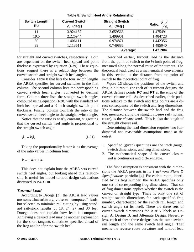
© 2015 NMRA NMRA Technical Note TN-12 Page 33 of 90
for straight and curved switches, respectively. Both
are dependent on the switch heel spread and point
thickness expressed by equation (I-39). These equa-
tions suggest there is a relationship between the
curved switch and straight switch heel angles.
Consider Table 8 that lists the four switch lengths
the AREA specifies for curved switches in the first
column. The second column lists the corresponding
curved switch heel angles, converted to decimal
form. Column three lists the straight switch angles
computed using equation (I-28) with the standard 6¼
inch heel spread and a ⅛ inch straight switch point
thickness. Finally, column four lists the ratio of the
curved switch heel angle to the straight switch angle.
Notice that the ratio is nearly constant, suggesting
that the curved switch heel angle is proportional to
the straight switch angle:
SC k (I-51)
Taking the proportionality factor k as the average
of the ratio values in column four:
471904.1k
This does not explain how the AREA sets curved
switch heel angles, but looking ahead this relation-
ship is useful for model turnout design calculations
discussed in PART III.
Turnout Lead According to Droege [3], the AREA lead values
are somewhat arbitrary, close to “computed” leads,
but selected to minimize rail cutting by using stand-
ard rail-stock lengths of 18, 24, 27 and 30 feet.
Droege does not explain how lead is computed.
Achieving a desired lead may be another explanation
for the short tangents sometimes specified ahead of
the frog and/or after the switch heel.
Described earlier, turnout lead is the distance
from the point of switch to the ½-inch point of frog,
measured along the normal route of the turnout. The
theoretical lead, used as a mathematical convenience
in this section, is the distance from the point of
switch to the theoretical point of frog.
Figure 13 shows the positions of the switch and
frog in a turnout. For each of its turnout designs, the
AREA defines points PC and PT at the ends of the
curved closure rail. As described earlier, their posi-
tions relative to the switch and frog points are a di-
rect consequence of the switch and frog dimensions.
The distance between the switch heel and the frog
toe, measured along the straight closure rail (normal
route), is the closure lead. This is also the length of
the straight closure rail.
Determining the lead dimension requires two fun-
damental and reasonable assumptions made at the
outset:
1. Specified (given) quantities are the track gauge,
switch dimensions, and frog dimensions.
2. The mathematical shape of the curved closure
rail is continuous and differentiable.
The first assumption is consistent with the dimen-
sions the AREA presents in its Trackwork Plans &
Specifications portfolio [4]. For each turnout, identi-
fied by its frog number, the AREA specifies only
one set of corresponding frog dimensions. That set
of frog dimensions applies whether the switch is the
curved or straight type. There is only one set of
straight switch dimensions for each specified frog
number, characterized by the switch rail length and
switch angle (at its heel). There are three sets of
curved switch dimensions the AREA labels as De-
sign A, Design B, and Alternate Design. Neverthe-
less, each of these three designs has the same switch
rail length and the same switch heel angle. That
means the reverse route curvature and turnout lead
Table 8: Switch Heel Angle Relationship
Switch Length (ft)
Curved Switch
C (deg.)
Straight Switch
S (deg.) Ratio,
S
C
11 3.924167 2.659566 1.475491
19.5 2.226944 1.499901 1.484728
30 1.406111 0.974871 1.442356
39 1.113611 0.749886 1.485040
Average: 1.471904

© 2015 NMRA NMRA Technical Note TN-12 Page 34 of 90
are independent of the type of curved switch design
(A, B or Alternate).
Except for the acceptably shallow switch point
angle, the second assumption ensures rolling stock
encounters no lateral or angular discontinuities (off-
sets or kinks) in the rails. This minimizes the poten-
tial for derailments and excessive wear. For straight
switches, the point angle is the same as the heel
angle. The AREA specifies a different point angle
for each curved switch design.
Frog and Switch Locations
The earlier sections on frogs and switches devel-
oped equations for the locations of point PC and PT,
repeated here for convenience. The location of point
PT, relative to the theoretical point of frog, is:
cosFFTPT tLL (I-52)
sinFFTPT tLGH (I-53)
The location of point PC, for a straight switch,
relative to the point of switch, is:
SSSPC tLL cos (I-54)
SSSHPC tSH sin (I-55)
Recall there is no short tangent specified for
curved switches. That means the equations locating
point PC for a straight switch apply to a curved
switch with 0St .
Curved Closure Rail
As another mathematical convenience, the curved
closure rail is located in a rectangular xy-coordinate
system whose origin is coincident with point PC.
The x-axis is parallel to the normal route (see Figure
13).
The y-direction distance H, which is independent
of the type of curved closure rail curve, is then:
PCPT HHH (I-56)
The distance CL , measured along the x-axis be-
tween PC and PT, depends on the shape of the
curved closure rail. This distance is not the same as
the straight closure rail length.
To be acceptable as a smooth reverse route curve
(assumption 2), any curved closure rail shape
)(xfy must pass through the point PC at the
switch (or heel) angle and pass through the point PT
at the frog angle. These requirements define four
boundary conditions expressed mathematically as:
Figure 13: Turnout geometry for lead determination
x
y
PCHPTH
PTL
SL
G
PCL
CL
)(xfy
TL
PC
PT
Hi
Switch heel
Switch point
Frog point
X
Y
Straight
stock rail
Curved
closure rail

© 2015 NMRA NMRA Technical Note TN-12 Page 35 of 90
At 0,0 yx (I-57)
At tan,0 yx (I-58)
At HyLx C , (I-59)
At tan, yLx C (I-60)
In these boundary condition equations, y indi-
cates the first derivative of y with respect to x (i.e.,
the slope). Note the absence of the subscript on the
heel angle in equation (I-58). In this case, and in
equations (I-61) through (I-64), and (I-75) through
(I-78) below, the subscript is not necessary because
the equations apply to both switch types.
In Figure 13, the shape of the curved portion of
the reverse route closure rail is labeled with the gen-
eral expression )(xfy . That the AREA specifies a
radius for the curved portion of the reverse route
centerline implies the shape of that centerline is a
circular arc. Thus, the shape of the curved closure
rail between points PC and PT is also a circular arc.
Then )(xfy becomes the equation of a circle
with a constant radius CCRR . What follows derives
that radius, but not the unneeded full equation of the
circle.
Where there is a tangent extension at the switch
heel or the frog toe, the reverse route closure rail is
circular between points PC and PT, and straight
along the tangent extensions. Where there are no
tangent extensions, the points PC and PT lie on the
switch heel and frog toe, respectively. Even though
the center of the circular arc connecting them does
not lie on the vertical axis through the y-axis, the
length CL is:
sinsin CCRC RL (I-61)
Also:
HRCCR coscos (I-62)
Because the radius of a circle is perpendicular to
the tangent of a circle at all points around the cir-
cumference, equations (I-61) and (I-62) satisfy the
four boundary conditions. Solving (I-62) for the ra-
dius CCRR :
coscos
HRCCR (I-63)
Substitute (I-63) into (I-61) to get the distance CL
:
coscos
sinsinHLC (I-64)
Equation (I-64) produces the only value of dis-
tance CL that is a result of using the radius CCRR
from equation (I-63), and satisfies the four boundary
conditions. For any other value of CL the curve can-
not be circular.
Theoretical and Actual Lead
With given switch and frog dimensions and the
distance CL from equation (I-64), the theoretical
lead is immediately:
PTCPCT LLLL (I-65)
The actual lead (in feet), from the switch point to
the frog ½-inch point is then:
2cos12
dLL TA (I-66)
While the AREA specifies a lead for each of its
turnout designs, prototype railroads sometimes spec-
ify a different lead value for their turnouts. Model
railroaders sometimes do this to match the lead of
their favorite prototype railroad’s lead values.
The APPENDIX B: ALTERNATE CLOSURE
RAIL CURVE AND LEAD LIMITS investigates turn-
out geometric properties that determine lead and lead
limitations. It examines an alternate shape for the
curved closure rail, the cubic polynomial, and shows
the following for a specified switch and frog design:
1. For a cubic polynomial, any CL greater than zero
produces a smooth closure rail curve.
2. To avoid an undesirable S-curve along the curved
closure rail, there are defined minimum and max-
imum lead values. APPENDIX B develops the
equations.

© 2015 NMRA NMRA Technical Note TN-12 Page 36 of 90
Table 9 summarizes the results of the investiga-
tion of lead values. Lead values calculated by the
equations developed above for circular arcs are with-
in 0.03% of those specified by the AREA [4]. Notice
that the lead values for turnouts using circular arcs
fall between the minimum and maximum lead values
for turnouts using a cubic polynomial.
Other Lead Equations
Tratman [1] provides three other equations for the
theoretical lead, but without derivation or further ex-
planation. The first he states in words, expressed
here as an equation:
nGLT 2 (I-67)
Equation (I-67), easily derived, expresses the lead
of a turnout having a circular arc closure rail that is
tangent to the straight stock rail at the switch point,
and has the slope of the frog angle at the theoretical
frog point. As such, it does not account for the
switch or frog geometry. A turnout with this closure
rail shape would have impossibly thin switch rails
and no straight portion guiding the approach to the
frog throat and frog point.
Tratman’s second equation, incorporating the
throw of the switch SWT , is:
SSWT LGTGnL 2 (I-68)
The third is:
FTST LLnL 6 (I-69)
All quantities (except the non-dimensional frog
number) in Tratman’s formulas must all have units
of feet. Equations (I-67), (I-68) and (I-69) produce
lead values that are considerably different from those
specified by the AREA, and by inference, the
NMRA. As such, they are only of passing interest,
and warrant no further discussion.
Closure Rails Closure rails connect the heel of the switch to the
toe of the frog. Because switches and frogs are sepa-
rate assemblies, a joint fastened with joint bars is
required at each end of each closure rail. Then, de-
pending on the frog number and the standard rail
stock lengths, the AREA specifies joints at interme-
diate locations. Plan 911-41 shows joint locations for
turnouts with straight split switches, and Plan 921-41
for curved switches.
Closure Rail Dimensions
Even though some turnouts have additional tan-
gent lengths specified at the switch heel and/or frog
toe, there are no rail joints at the ends of these tan-
gents. That means the closure rail lengths are the dis-
tances between the switch heel and frog toe.
The straight closure rail length SCRL is then the
actual (practical) lead AL minus the practical frog
toe length minus the switch rail length:
Table 9: AREA Leads and Calculated Third-order Polynomial Lead Limits (feet)
Straight Switches Curved Switches
Frog No. AREA Lead (circ. arc)
Minimum Lead
3rd-order
Maximum Lead
3rd-order AREA Lead (circ. arc)
Minimum Lead
3rd-order
Maximum Lead
3rd-order
5 42.54 37.76 49.46 40.65 36.91 45.61
6 47.50 42.53 54.55 45.29 41.51 50.15
7 62.08 54.79 73.07 62.98 56.79 71.86
8 68.00 60.28 79.38 68.38 61.79 77.58
9 72.29 64.45 83.60 73.08 66.42 82.17
10 78.75 70.67 90.14 77.52 70.88 86.34
11 91.85 81.45 107.21 81.94 75.33 90.50
12 96.67 86.12 111.98 103.79 93.70 118.23
14 107.06 95.97 122.61 113.56 103.13 127.96
15 126.38 112.25 147.36 118.38 107.81 132.71
16 131.33 116.69 152.77 123.38 112.59 137.75
18 140.96 125.99 162.28 146.00 132.83 164.13
20 151.96 136.66 173.21 156.04 142.43 174.29

© 2015 NMRA NMRA Technical Note TN-12 Page 37 of 90
StoeASCR LLLL (I-70)
Because the reverse route centerline is a circular
arc of radius CR , the radius CCRR of the curved por-
tion of the curved closure rail is:
2
GRR CCCR (I-71)
The AREA plans do not tabulate this radius, but
tabulate the centerline radius CR instead. The center-
line degree-of-curvature D (in degrees) and radius
(in feet) are related by the prototype definition:
C
DR
50arcsin2 (I-72)
The length of the curved closure rail CCRL de-
pends on the heel and frog angles and , respec-
tively, plus any tangent extensions St at the switch
heel and/or Ft at the frog toe:
FSCCRCCR ttRL (I-73)
In equation (I-73), the frog and switch heel angles
must be expressed in radians.
Curved Closure Rail Gauge Points
The AREA turnout plans 910-41 and 920-41 tabu-
late three gauge points that assist construction crews
in positioning the curved closure rail. The gauge
points fall on the gauge side of the curved closure
rail. The plans locate each gauge point in an XY-
coordinate system (see Figure 13) at a specified dis-
tance from the point of switch in the direction of the
normal route centerline, and a corresponding per-
pendicular offset from the straight stock rail gauge
line.
A cursory examination of the tabulated dimen-
sions suggests the AREA turnout designers may
have set gauge points at roughly equal intervals
along the straight closure rail length, the middle
point located at approximately ½ its length. Howev-
er, this is not uniformly true for each frog number.
For curved switches, Plan 920-41 presents gauge
points at somewhat arbitrary locations, with incre-
ments no smaller than three inches (¼ foot). Not sur-
prisingly, those locations increase with increasing
frog numbers. On the other hand, the corresponding
offsets vary only a little with changing frog number.
Plan 910-41, for straight switches, presents gauge
points whose locations appear more arbitrary. Like
those on Plan 920-41, offsets vary only a little with
changing frog number. Because the offsets do vary,
it is not likely there is some standard tool used to
check them during turnout construction.
Precise deduction of the AREA gauge point loca-
tion rationale has proved elusive. Until further re-
search or information uncovers that rationale, one
logical choice is to locate three equally-spaced gauge
points along the straight closure rail length. For this
choice the locations of the gauge points, 1X , 2X and
3X , measured from the switch point, are:
SCRS
SCRS
SCRS
LLX
LLX
LLX
75.0
50.0
25.0
3
2
1
(I-74)
Because the curved closure rail falls on a circular
arc, finding a mathematical expression for the offsets
at each of these locations is a straightforward pro-
cess. Consider Figure 14. The equations for the co-
ordinates of point PC, PCL and PCH are repeated
here as a convenience:
cosSSPC tLL (I-75)
sinSSHPC tSH (I-76)
The variable St is a short tangent following the
heel of the switch the AREA specifies for some
turnouts. From the geometry in Figure 14:
sinCCRPC RLa (I-77)
And:
cos1 CCRPC RHb (I-78)
Then for a gauge point located at iX the corre-
sponding offset iY is:

© 2015 NMRA NMRA Technical Note TN-12 Page 38 of 90
bR
aXRY
CCR
i
CCRi
2
11 (I-79)
Using the AREA gauge point X locations from the
AREA Plans, and the curved closure rail radius
computed as the AREA centerline radius plus half
the track gauge, the gauge point Y offsets computed
using equation (I-79) are very close to those speci-
fied on the AREA plans. This validates equation (I-
79) when used with any iX value, and specifically
those in equation (I-74).
Crossover Data A crossover is a pair of same-hand turnouts
whose reverse routes oppose one another, allowing a
train to cross from one track to another in a pair of
parallel tangent tracks. The AREA turnout Plans
910-41 and 920-41 provide dimensions for crossover
construction from two turnouts having the same frog
number, called equal-frog crossovers. Such cros-
Figure 14: Curved closure rail gauge point locations
Straight stock
rail gauge line
Switch
point
biY
iX
PC
PT
CCRR
Gauge
point
PCL
PCH
Curved
closure rail
gauge line
a

© 2015 NMRA NMRA Technical Note TN-12 Page 39 of 90
sovers contain an inherent S-curve, so their frog
number selection must consider the lengths of rolling
stock traversing them. Hay [2] discusses crossovers
with unequal frogs, but because they produce an un-
desirable additional S-curve, this TN does not dis-
cuss them further.
The geometry of crossovers does not depend on
switch type, so both AREA plans show the same
crossover dimensions. In particular, they show two
measurements between the two frogs. One is the dis-
tance along the straight track, and the other is the
distance along the crossover track. The presented
dimensions are for parallel tangent tracks spaced at
13 feet. Because parallel track spacing varies with
location, by state regulations, and by railroad prac-
tice, the plans provide an incremental increase in
each measurement for each one-foot change in paral-
lel track spacing.
Figure 15 illustrates a crossover with the frog an-
gle exaggerated to show the geometric details clear-
ly. As drawn, the frog points are in their theoretical
position. Adjustments to the ½-inch point appear
later in the development that follows.
From the geometry and nomenclature in Figure
15:
GpE (I-80)
The dimension F is then:
cos
GEF (I-81)
From trigonometry:
STD
Ftan (I-82)
Substituting equations (I-80) and (I-81) into (I-82)
and solving for the straight distance:
sin
cos GGpDST
(I-83)
Noting that:
Figure 15: Crossover Data
G
STD
p
EF
XTD
z
Frog theoretical
point
Frog theoretical
point

© 2015 NMRA NMRA Technical Note TN-12 Page 40 of 90
tanGz (I-84)
The crossover distance is then:
tancos
GD
D STXT (I-85)
Equations (I-83) and (I-85) represent distances be-
tween the theoretical frog points. Recall the distance
from the theoretical frog point to the ½-inch point is
along the bisector of the frog angle. That means the
distance along a gauge line, needed here, is (in feet):
2cos24
ndGL (I-86)
Because there are two frogs on a crossover, the
distance to two ½ -inch points is twice that in (I-86).
Thus, subtracting the two ½-inch point distances
along the gauge lies from equations (I-83) and (I-85),
the respective distances between the practical points
are:
GLSTSP dDD 2 (I-87)
GLXTXP dDD 2 (I-88)
Determination of the straight and crossover track
length increase for a specified increment in track
spacing p is straightforward. For the straight
track, simple trigonometry gives:
tan
pS
(I-89)
For the crossover track:
sin
pX
(I-90)
The incremental distances expressed by equations
(I-89) and (I-90), for a specified incremental increase
in track spacing, depend only on the frog angle.
AREA Turnout Consistency Evaluation Evaluation of the AREA designs requires calcula-
tions using the equations developed above. The
companion spreadsheet NMRA TN-12 AREA Turnout
Consistency Evaluation.xls [29] makes those calcula-
tions for both straight and curved switch turnouts.
Like the switch consistency evaluation, It has two
computational approaches, one that calculates exact
values and another that rounds the exact values in the
same manner as the AREA, specifically:
Angles: Nearest second of arc
Radii and extra tangents: Nearest 1/100th
foot
All Others: Nearest feet-inches:
Lead and closure distances: nearest ¼ inch
Gage line offsets (location): nearest ¼ inch
Gage line offsets (lateral): nearest 1/16 inch
Frog lengths: nearest ½ inch
Frog spreads: nearest 1/16 inch
Crossover dimensions: 1/16 inch
To be fair, the evaluation compares the exact
rounded values to the AREA tabulated values. The
spreadsheet shows the differences between rounded
calculated values and tabulated values for both
curved switch and straight switch turnouts are in the
range of -0.4831% to 1.8576%. Closer examination
of the results show these extremes are due to the
gage line offsets. Percent differences with absolute
values under 0.5% are simply small round-off errors,
which are considered in the consistency definition
(see EXECUTIVE SUMMARY for definition). The
larger percent differences, in excess of 1.0%, occur
in the gage line offsets for only a few frog numbers.
Because these few inconsistent offsets are a function
of the curved closure rail radius, which is consistent,
these differences must be due to errors in the AREA
calculations. Ignoring the percent differences ex-
ceeding 1.0%, the remaining percent differences for
gage line offsets are mostly zero, while those not are
within 0.5%. Thus, the AREA turnouts are con-
sistent.
Taken with the switch evaluations, these turnout
evaluations demonstrate that the AREA designs are
consistent, and that the equations developed in this
TN are correct. Because the equations are scale-
independent, they apply to model turnouts of any
scale.

© 2015 NMRA NMRA Technical Note TN-12 Page 41 of 90
Tie Spacing Tie spacing does not affect turnout geometry, ex-
cept for the position of the guard rails discussed
below. The discussion here serves as background for
the model guard rail position discussed in PART II.
AREA Plan 912-41 calls out “Bills of Timber for
Turnouts and Crossovers,” basically the number and
lengths of timbers (ties) required for a turnout (or
crossover) having a specified frog number. Tie
lengths come in six-inch increments. Note 7 on that
plan states “Tie spacing approximately 20 [inches]
center to center.” The word “approximately” implies
this spacing is not rigorous and likely means “unless
otherwise specified.” Examination of the frog and
switch details confirm this notion.
All the AREA frog design plans call for a tie
whose center is located back (towards the heel) four
inches from the ½-inch point of the frog, presumably
so the tie provides adequate support for the frog
point. Further, all frog plans indicate a center-to-
center tie spacing of 19½ inches, except the No. 9
spring rail frog. The No. 9 spring rail frog shows one
space of 22 inches on the toe side and two spaces of
22 inches on the heel side. The rest of the spaces are
19½ inches. Why this frog is different from all the
others is unknown.
All the switch plans show the switch heel cen-
tered between two ties spaced center-to-center at 18
inches, presumably for adequate support of the heel
blocks. They also show varying tie spaces for some
ties before and beyond the switch heels, the spacing
distances depending on whether the switch is of the
hand throw or interlocking type. With other turnout
dimensions being variable, an adjustment of tie spac-
ing becomes necessary over part of the distance be-
tween the switch and frog. The AREA plans tabulate
these adjustments.
AREA Plan 912-41 lists the total number of ties,
but does not indicate the location of “Tie No. 1.” The
tie layout drawing at the upper left is generic and
indicates two longer ties (headblocks) near the point
of switch, presumably straddling the first switch rod.
Whether the first headblock, probably 14 or 15 feet
long, is “Tie No. 1” is unclear. The tables do not list
switch timbers that long at the switch end of the
turnout. Switch timber lengths increase in six-inch
increments.
Figure 16 illustrates an AREMA No. 8 Curved
Switch turnout tie arrangement, drawn to scale at the
prescribed tie spacing. The differences in tie spacing
are difficult to see.
Guard Rails A guard rail holds a passing wheel against the ad-
jacent running rail opposite the frog. This ensures the
opposite wheel passing through the frog proceeds
along the proper route. AREA plans 910-41 and 920-
41 do not show guard rails on their turnout diagrams,
perhaps because one choice of frog design is self-
guarding and does not require them.
The AREA specifies two types of guard rails, the
tee rail guard rail with planed flares and the one
piece guard rail. While the AREA specifies five
standard guard rail lengths, none longer than 13 feet,
lengths used by various railroads can vary widely.
For example, Tratman [1] reports that the Norfolk &
Western Railway used 15-foot guard rails for turn-
outs up to No. 9, 16½-foot for No. 10 turnouts and
progressively longer for higher numbered turnouts.
Tee Rail Guard Rails
AREA Plans 503-40 and 504-40 show designs for
three tee rail guard rail lengths, 8’-3”, 11’-0” and
13’-0”. Both plans show the same guard rail designs,
Figure 16: AREA No. 8 Curved Switch Turnout Tie Arrangement
PS HS PF

© 2015 NMRA NMRA Technical Note TN-12 Page 42 of 90
the difference being that one plan specifies canted tie
plates and the other flat tie plates.
The AREA apparently selected these lengths be-
cause they can be cut from standard 33-foot or 39-
foot rails, much in the same way it selected switch
rail lengths. These guard rails are of the planed-flare
design that consists of a straight portion of length PLl
in the middle plus a planed section of length PNL
and a beveled section of length BVL on each end, as
Figure 17 illustrates.
The plans show values for the flare lengths and
parallel (straight) length such that the total tee rail
guard rail length GRL is:
BVPNPLGR LLlL 2 (I-91)
Examination of the three guard rail designs shows
the parallel length PLl and planed flare length PNL
vary linearly with guard rail length GRl . The bevel
length BVL is a constant 13 inches.
While the AREA does not specify a designs for
longer guard rails, but looking ahead to the model
guard rail suggests one or more may be useful. The
next length is likely 16’-6” (198 inches), obtained by
cutting a 33’ rail in half. Using the observed lineari-
ty, the corresponding parallel length becomes 9’-8”
(116 inches) and the inner flare length 2’-4” (28
inches). The next longest guard rail is half of a 39’
rail, or 19’-6”, with similarly extrapolated dimen-
sions. Table 10 summarizes these dimensions, the
last two rows including those for the 16’-6” and 19’-
6” designs.
The notes on Plan 502-40 specify the minimum
guard rail lengths for specific frogs, 8’-3” for frog
numbers 14 and lower, and 11’-0” for frog numbers
15 and higher, but do not prohibit longer guard rails.
These sizes apply to rigid frogs, and with the longer
13’-0” guard rail, also apply to spring frogs.
These rules are logical because the parallel length
for the 8’-3” guard rail exceeds the total flangeway
width plus the 6-inch setback for frog numbers 14
and lower. Frog numbers 15 through 20 require the
11’-0” guard rail so its parallel length exceeds the
Figure 17: Tee Rail Guard Rail Geometry (not to scale)
PNL BVLPLL
GRL
Running rail Guard railFlangeway
BVL PNL
FLL FLL
Table 10: AREA Tee Rail Guard Rail Design Dimensions
GRL (ft.-in.) GRL (in.) PLL (in.) PNL (in.) BVL (in.)
8’-3” 99 41 16 13
11’-0” 132 66 20 13
13’-0” 156 84 23 13
16’-6” 198 116 28 13
19’-6” 234 142 33 13

© 2015 NMRA NMRA Technical Note TN-12 Page 43 of 90
total flangeway width plus the 6-inch setback.
Tee Rail Guard Rail Flares
Figure 17 and Figure 18 show the geometric de-
tails of a Tee Rail Guard Rail, likely constructed as
follows.
After cutting the guard rail to its full overall
length, the manufacturer makes a 3-inch. 45-degree
end bevel. Following that is planing of the inner
flare, parallel to the vertical face of the rail head,
over the full flare length such that it reaches a depth
PNw of 0.625 inches at distance PNL from the end of
the parallel length. Then the manufacturer makes the
final bevel cut, at an angle of 25 degrees to the verti-
cal, over the distance BVL such that it reaches a flare
width of 1.625 inches where it intersects the top edge
of the end bevel cut, and a flare width of 0.625 inch-
es at the end of the inner flare. Planing and cutting of
the other end follows the same process.
Because of the inner flare cut, the flare at the end
is not affected by the depth where the gauge line is
normally measured. This makes the guard rail flare
geometry differ slightly from the wing rail flares.
From Figure 18 and similar triangles:
625.00.3
BV
BVFL
L
Lw (I-92)
Because the bevel length is 13 inches for all tee
rail guard rails, the flare is also the same. Thus,
equation (I-92) produces a constant flare value of
925.1FLw inches.
One-Piece (Cast) Guard Rails
Plan 510-40 shows the details of the one piece
cast manganese steel guard rail, specified in two
lengths, 8’-4½” for a “6-tie” guard rail and 10’-0”
for a “7-tie” guard rail. Both designs utilize a cast-in
double bend at the ends to lead approaching wheels
through the flangeway. As the name implies, the tie
plates are integral with the guard rail. Turnouts up to
and including no. 14 use the 8’-4½” one piece guard
rail and turnouts No. 15 and above use the 10’-0”
guard rail.
The plans show values for the flare lengths and
straight length such that the total one piece guard rail
length is (using the same nomenclature as the Tee
Rail type):
extBVPNPLGR lLLlL 2 (I-93)
The variable extl represents the 4¼ inch extension
on each end that is the equivalent of the end bevel on
a Tee Rail design.
Figure 18: Tee Rail Guard Rail End Flare (not to scale)
1.875
3.0
2.5
0.625
FRL
BVL
3.5
FRw
Running rail gauge line
Guard rail flare
Fw
PNL
1.625
PNw
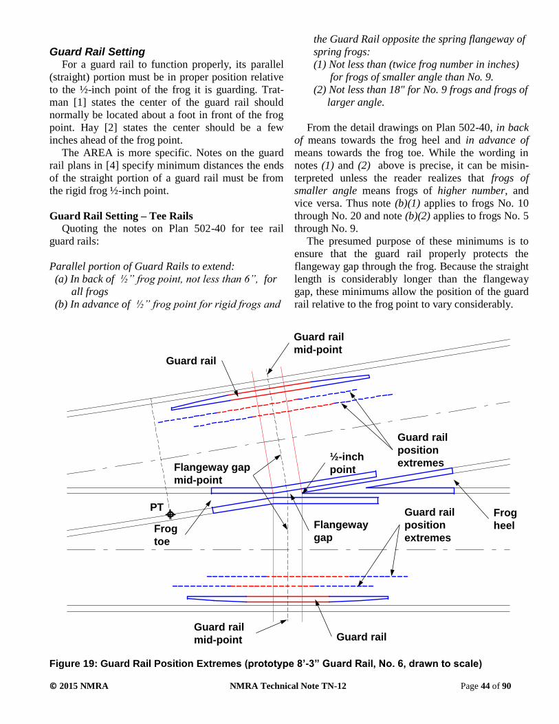
© 2015 NMRA NMRA Technical Note TN-12 Page 44 of 90
Guard Rail Setting For a guard rail to function properly, its parallel
(straight) portion must be in proper position relative
to the ½-inch point of the frog it is guarding. Trat-
man [1] states the center of the guard rail should
normally be located about a foot in front of the frog
point. Hay [2] states the center should be a few
inches ahead of the frog point.
The AREA is more specific. Notes on the guard
rail plans in [4] specify minimum distances the ends
of the straight portion of a guard rail must be from
the rigid frog ½-inch point.
Guard Rail Setting – Tee Rails
Quoting the notes on Plan 502-40 for tee rail
guard rails:
Parallel portion of Guard Rails to extend:
(a) In back of ½” frog point, not less than 6”, for
all frogs
(b) In advance of ½” frog point for rigid frogs and
the Guard Rail opposite the spring flangeway of
spring frogs:
(1) Not less than (twice frog number in inches)
for frogs of smaller angle than No. 9.
(2) Not less than 18" for No. 9 frogs and frogs of
larger angle.
From the detail drawings on Plan 502-40, in back
of means towards the frog heel and in advance of
means towards the frog toe. While the wording in
notes (1) and (2) above is precise, it can be misin-
terpreted unless the reader realizes that frogs of
smaller angle means frogs of higher number, and
vice versa. Thus note (b)(1) applies to frogs No. 10
through No. 20 and note (b)(2) applies to frogs No. 5
through No. 9.
The presumed purpose of these minimums is to
ensure that the guard rail properly protects the
flangeway gap through the frog. Because the straight
length is considerably longer than the flangeway
gap, these minimums allow the position of the guard
rail relative to the frog point to vary considerably.
Figure 19: Guard Rail Position Extremes (prototype 8’-3” Guard Rail, No. 6, drawn to scale)
Frog
toe
Frog
heelFlangeway
gap
Guard rail
Guard rail
Guard rail
position
extremes
Guard rail
position
extremes
PT
½-inch
pointFlangeway gap
mid-point
Guard rail
mid-point
Guard rail
mid-point

© 2015 NMRA NMRA Technical Note TN-12 Page 45 of 90
As an example, consider a No. 6 frog using an 8’-
3” guard rail having a straight portion length of 41
inches per Plan 502-40. If there is the minimum 18
inches of straight portion before the frog ½-inch
point there must be 23 inches behind it, far more
than the required minimum. Conversely, if there is
the minimum six inches after the frog ½-inch point
there are 35 inches before it, almost twice the speci-
fied 18” minimum. Figure 19 (drawn to scale for a
prototype No. 6 turnout) illustrates the extreme posi-
tions the guard rail can take for the specified mini-
mums. The full guard rail shapes, drawn with solid
red and blue lines, center on the flangeway gap as a
logical position for which wheels approaching from
either direction experience the same length of the
straight portion (ref lines) before reaching the
flangeway gap. The dashed red and blue lines, drawn
offset from their actual distance from the running
rail, show the extreme positions possible without vi-
olating the specified minimums.
The extremes allow substantial asymmetry in po-
sition relative to the flangeway gap in the frog.
For some larger frog numbers (smaller angles),
rule (b) above allows setting a guard rail such that its
parallel portion does not fully straddle the frog
flangeway gap. This seems counter-intuitive, but is
always avoidable by following rule (a) with a con-
stant, not minimum, 6-inch setback.
Guard Rail Setting – One-Piece
AREA settings for one-piece guard rails are even
more specific. In this case the minimum distance of
the straight portion of the guard rail behind the ½ -
inch point is 2 inches. The minimum length in front
of the frog ½-point is even more restrictive, as fol-
lows (per Plan 510-40):
Frogs 4-5 12 inches
Frogs 6-10 14 inches
Frog 11 16 inches
Frogs 12, 14 18 inches
Frog 15 24 inches
Figure 20: One-Piece Guard Rail Position (No. 4 frog shown)
Frog point tie
Straight portion
position limits (red
dashed lines)
½-inch point
location (solid
green lines)
Straight portion
(red solid lines)

© 2015 NMRA NMRA Technical Note TN-12 Page 46 of 90
Frog 16 26 inches
Frogs 18, 20 30 inches
As specific as these minimums are, the fact that
the one-piece guard rail has cast-in tie plates makes
setting its position even more restrictive. Because the
cast-in tie plates must always rest on a tie, spaced at
19½ inches, its setting must be discrete. These re-
strictions presumably account for that.
Consider Figure 20 showing the position of a one-
piece guard rail for a No. 4 frog turnout. Moving ei-
ther guard rail one tie position to the left or right
places one of the straight portion end points inside
the dashed red lines, violating the positions limits.
That means the one-piece guard rail settings are
actually more restrictive than the minimums imply.
Notice also the difficulty in positioning the tie plates
on the reverse route so they can be placed directly on
a tie. The AREA allows some flexibility in the cast-
in tie plate design so the turnout designer can ensure
proper spiking.

© 2015 NMRA NMRA Technical Note TN-12 Page 47 of 90
PART II: MODEL RAILROAD TURNOUTS
Like the AREA, and today’s AREMA, the
NMRA tabulates model railroad turnout dimensions
for the more popular model scales in a series of Rec-
ommended Practices [5-16] it has developed over the
years. The discussion in this part addresses issues
encountered in the modeling of prototype turnouts
discussed in PART I.
Scaling Prototype Turnout Geometry Defining the geometry of a model railroad turnout
is not just a simple matter of scaling the prototype.
NMRA provides Standards and Recommended Prac-
tices (S&RPs) that, when followed, enable interoper-
ability of equipment from different manufacturers.
The discussions in this part compare NMRA turnout
designs with the AREA designs. Checking a few
primary dimension in the current NMRA RPs shows
the turnouts, their switches, and their frogs are not
scaled versions of the AREA designs.
Direct scaling is not appropriate for several good
reasons. The NMRA S&RPs take wheel contours
and flangeway width into consideration. NMRA
wheel flanges are considerably thicker than the
scaled prototype, requiring a flangeway that is wider
than the prototype. NMRA Proto scale standards
prescribe more prototypical flangeway and wheel
contour dimensions. NMRA turnout lead is not
scaled either.
As PART III later discusses in detail, flangeway
width affects two primary geometric parameters of a
model turnout, the frog toe length and switch heel
spread. Another parameter affecting switch heel
spread is railhead width.
Turnout Nomenclature Model turnouts use the same nomenclature as the
prototype (Figure 1).
Frogs Because model scale does not affect angular
measurements, the prototype definition of the frog
angle applies equally to the model. That means the
related prototype equations apply as well. Some model railroaders measure the distance n
along one of the frog rails. In that case the frog angle
is:
n
1arctan (II-1)
The difference in frog angles calculated by equa-
tions (I-2) and (II-1) is negligible, especially for No.
5 frogs or higher.
Engineers often use the “small angle approxima-
tion” that states “for small angles, expressed in radi-
ans, the tangent (or sine) of the angle is approximate-
ly equal to the angle itself.” Thus:
tan (II-2)
Making this approximation in either the proto-
type’s or the modeler’s equation, and converting the
results from radians to degrees, the equation for the
frog angle, in degrees, becomes:
nn
296.57180
(II-3)
As a worst case example, consider a No. 4 frog.
From equation (I-2) the exact frog angle is 14.2500
degrees and from equation (II-3) the approximate
angle is 14.3239 degrees. The error equation (II-3)
introduces is a negligible 0.52%. As the frog number
increases, the error decreases. It becomes 0.08% for
a No. 10 frog and 0.02% for a No. 20. However, be-
cause a computer makes the necessary calculations
using equation (I-2), there is no need to make this
approximation.
Model frogs also have a theoretical point, defined
the same way as the prototype. There is no formal ½-
inch point in the model because the scaled cutback
distance is so small. For a No. 6 frog in HO scale it
is about a 0.03 inches, hardly noticeable. But a sharp
frog point in the model is also not practical, so man-
ufacturers and scratch builders dress the sharp point
slightly to a blunt edge. In the model, the location of
the frog ½-inch point is not significant. The location
of the theoretical frog point is more meaningful. All
NMRA dimensions involving the frog point are rela-
tive to its theoretical location.
Frog Flangeway Gap
The NMRA frog designs are about 30% longer
than the scaled prototype frogs. NMRA RP-12

© 2015 NMRA NMRA Technical Note TN-12 Page 48 of 90
“Turnouts General” [5] indicates NMRA frogs rep-
resent the “built-up” type, (probably “bolted rail”)
and accommodate “common slip on rail joiners.”
Because the flangeway width is wider in the model,
the throat of the frog (see Figure 5) moves forward
from the theoretical point. This shortens the effec-
tive length of the frog toe and perhaps justifies the
increased frog toe length the NMRA RPs specify in
comparison to the AREA. In turn, frog toe length
affects the location of point PT.
A wider flangeway also means a wider frog
flangeway gap as PART I equation (I-13) expresses:
sin
FT
wg (II-4)
For example, in Table 1 the prototype flangeway
gap for a No. 6 frog is 14.31 inches. Scaling directly
to HO this width is 0.164 inches. For an HO flange-
way maximum width of 0.050 (NMRA S-3.2,
“Trackwork Standard Scales” [24]), the frog flange-
way gap by PART I equation (I-17) is 0.302 inches,
almost twice as wide. This wider frog flangeway gap
in the model turnout affects the guard rail setting
(position) discussed later in this part.
Figure 21 compares the NMRA and AREA ge-
ometry for a No. 6 frog. The green lines, common to
both frogs, are the gauge lines. The red lines repre-
sent the AREA frog and the black lines the NMRA
frog. Notice the NRMA frog flangeway gap is
roughly twice that of the AREA because of the wider
flangeway width. For Proto scales, the flangeway
gap is much closer to the scaled prototype because
the flangeway width is only slightly wider than the
scaled prototype flangeway width.
Wing Rails
While the AREA does not directly specify the
length of the frog wing rail extension, the NMRA
does. NMRA RP-13.7 “Frog & Wing Rails” [15]
specifies the wing rail extension to be one-half the
heel length. This value is close to the average for the
AREA wing rail extensions, as quantified in Table 2.
This is a reasonable choice.
Wing Rail Flares
The NMRA recommends three end-flare choices
prescribed in NMRA RP-13.8 “Flangeway Flares”
[16]. RP-13.8 also states the flare lengths apply to
both wing rails and guard rails. The AREA wing rail
flare length (see PART I) increases quickly with in-
creasing frog number, becoming considerably longer
than the scaled-up RP-13.8 values. NMRA flare de-
signs are limited to frogs No. 4 through 10 and to
only a few standard class model scales.
Switches The selection of a straight or curved switch in the
model is also the modeler’s choice. In the prototype
and the model, the switch choice influences the ge-
ometry of the turnout. For a currently unknown rea-
son, the NMRA turnout RPs provide dimensions for
curved switches, but not for straight switches.
A cursory visual examination of a few commer-
cial HO scale turnouts at a local hobby shop showed
that Peco Code 83, Walthers Code 83, and Micro
Engineering Code 83 turnouts appear to be curved
switch turnouts. Atlas Code 83 turnouts appear to be
straight switch turnouts. According to their online
drawings, both Central Valley Model Works and
Fast Tracks appear to produce straight switch turn-
outs.
Figure 21: No. 6 Frog, AREA to NMRA Comparison (wing rail flares not shown)
NMRA frog gap
AREA frog gap

© 2015 NMRA NMRA Technical Note TN-12 Page 49 of 90
Switch Heel Spread
Recall the AREA specifies a standard switch heel
spread of 6.25 inches for all frog numbers and both
types of switches. Scaling this to HO scale, for ex-
ample, gives 0.072 inches. For HO scale, NMRA
RP-12.3 “Turnout Dimensions – HO Scale” [8] spec-
ifies a switch heel spread of 0.125 inches, considera-
bly wider than the prototype, and equivalent to
10.886 prototype inches. Precisely how this value
was determined is unclear, but it may be a combina-
tion of the NMRA flangeway width, an allowance
for railhead width, wheel flange width and electrical
clearance. PART III presents two methods for setting
switch heel spread for model turnouts that are based
on these parameters. For a fixed switch rail length,
again for either switch type, the wider switch heel
spread increases the switch (or heel) angle and af-
fects the location of point PC.
Curved Switches
NMRA switch rail lengths and heel angles for
curved switches are considerably different than the
AREA specifications. For frog numbers 5 and 6 the
AREA specifies 11-foot curved switch rails, which
scale to 1.516 inches in HO scale. Conversely, the
NMRA HO scale switch rail length of 2.125 inches
scales to 15.421 feet in the prototype. For frog num-
bers 7 to 10 the AREA specifies 19½-foot rails,
which scale to 2.687 inches. The NMRA switch
length of 3.1875 scales to 23.132 feet. Perhaps the
NMRA values are longer than the AREA values to
keep the switch heel angle manageable, but the
NMRA angles are still about 0.6 to 0.9 degrees larg-
er than the AREA angles. Why the NMRA uses
longer switch rails is not clear, although in part the
longer switch rails may have been selected to ac-
commodate the wider switch heel spread.
One other NMRA dimension, not specified by the
AREA, is the mid-ordinate of the curved switch rail.
Inferred from the diagram in NMRA RP-12 [5], the
mid-ordinate is the perpendicular distance between
the switch rail chord and the curved switch rail,
measured along the bisector of the subtended angle.
From Figure 11, the mid-ordinate is:
2cos1
CSMID Rh (II-5)
NMRA Curved Switch Consistency Evaluation
Like the AREA, the NMRA rounds the turnout
dimensions it tabulates in its RPs. Rounding is most-
ly uniform across scales, except N scale, to the near-
est following parts of a degree or inch:
All angles: 1 arc-minute
Switch rail length: 1/16 in.
Switch heel spread: 1/64 in.
Switch radius: 1.0 in.
Switch mid-ordinate: 0.001 in.
Lead: 1/16 in.
Straight rail: 1/16 in.
Curved rail length: 1/32 in.
Curved rail radius: 1.0 in.
Gage Y-offset 1/64 in.
Gage X-offset 1/32 in.
Frog toe and heel spread: 1/64 in.
Frog point to intersection: 1/32 in.
Crossover dimensions: 1/16 in.
Where there are different rounding values across
scales, the list above shows the most restrictive. For
N scale, all angles are to the nearest arc-minute,
switch and curved rail radii to the nearest inch, and
all other dimensions are to the nearest 0.001 inch.
Also like the AREA curved switch evaluation, the
evaluation here compares the exact rounded values
to the NMRA tabulated values.
While the curved switch discussion in PART I
shows that the AREA curved switch parameters are
consistent, the companion spreadsheet NMRA TN-12
NMRA Curved Switch Consistency Evaluation.xls
[30] shows almost all of the NMRA parameters are
not consistent (See EXECUTIVE SUMMARY for def-
inition). For the NMRA curved switch parameters,
the spreadsheet shows excessive differences between
calculated values and specified values, in the range
of -22.4138% to 26.0417%, far too large to be de-
clared consistent.
Turnout Lead Turnout lead for model turnouts has the same ge-
ometric limitations as the prototype. The equations
developed in PART I apply equally to the model and
the prototype. Recall that once the locations of
points PC and PT are set, there is only one lead val-
ue that produces a circular arc for the curved closure
rail. Further, the NMRA measures model turnout
lead to the theoretical point of frog.

© 2015 NMRA NMRA Technical Note TN-12 Page 50 of 90
While most commercial turnout manufacturers
adhere to NMRA Standards, and may receive an
NMRA Conformance Warrant when they do, they
don’t always follow Recommended Practices. Ad-
herence to Recommended Practices is not a require-
ment for a Conformance Warrant. In his article Will
turnouts fit?, Paul Dolkos [18] tabulates turnout di-
mensions for many commercial turnouts. Not one
manufacturer listed offers HO Scale No. 6 turnouts
having the NMRA recommended lead of 6¼ inches.
Although not listed in [18], the Fast Tracks No. 6
template (as one example) obtained online does
show the NMRA 6¼ inch lead.
Closure Rail Lengths
Prototype equations for the closure rail lengths
apply equally to the model. The only difference is
that the model does not require any tangent exten-
sions at the switch heel or frog toe. Although unnec-
essary, the tangent extensions may be used for Proto
scale turnouts for greater authenticity.
Curved Closure Rail Gauge Points
It is not clear how the NMRA selected gage point
locations along the curved closure rail. Nevertheless,
the principles discussed in PART I also apply to the
model turnout.
Intersection of Centerlines The normal route centerline and the straight por-
tion of the reverse route intersect at a specific dis-
tance ahead of the theoretical point of frog given by:
GnLICL (II-6)
This parameter is not specified by the AREA, but
it is useful to modelers when laying out turnouts on
track plans. It is included in the NMRA turnout RPs.
Crossover Data Prototype equations for the crossover dimensions
apply equally to the model. The only difference is
that the model uses distances to the theoretical frog
point rather than the prototype distances to the ½-
inch point.
NMRA Turnout Consistency Evaluation Spreadsheet NMRA TN-12 NMRA Turnout Con-
sistency Evaluation.xls [31] evaluates the consisten-
cy of NMRA curved switch turnouts for each major
model scale. Again, the evaluation compares round-
ed exact values to the tabulated dimensions, using
the same rounding values listed above under NMRA
Curved Switch Consistency Evaluation.
Again, unlike the AREA tabulated dimensions,
many of NMRA tabulated dimensions are not con-
sistent (See EXECUTIVE SUMMARY for definition).
Overall, the maximum differences are far too large,
in the range -22.4138% to 44.1860%. Some have
differences in the range of about 0.5%, possibly due
to rounding decimal numbers calculated in the 1961
time frame to fractional form. Other dimensions, no-
tably lead and curved closure rail length, have differ-
ences up to about 10%, with several above 10%.
One, the HOn3 curved closure rail length has a dif-
ference of 44.186%. This is the overall maximum
difference for all scales and dimensions.
Tie Spacing Turnout tie spacing in the model is a modeler’s
choice, at least for handlaid turnouts. Some model-
ers argue that the AREA’s somewhat uneven spacing
(Figure 16) is barely noticeable in the model and that
a uniform spacing is sufficient. Modelers using
commercial turnouts get whatever spacing such
turnouts provide. For example, Central Valley Model
Works turnout strips use closer tie spacing under the
frogs, as in the AREA prototype. Modelers looking
for prototypical tie spacing should examine commer-
cial turnouts carefully for this feature.
Handlaid or not, model turnouts normally have
wider spacing between the headblocks to accommo-
date the first switch rod. Model switch rods are fre-
quently much wider than the typical 2½ prototype
inches. A switch rod of scale width (e.g., 0.029 inch-
es in HO scale) would likely be too weak and subject
to breakage.
Because of the wide variation in tie spacing across
turnouts of different frog numbers and switch
lengths, it is not practical to specify tie spacing for
model turnouts in the proposed turnout RPs.
Tie spacing then becomes a construction decision
best left to the modeler or turnout manufacturer.
PART III discusses four methods for doing this.
Guard Rails NMRA RP-13.6 “Guard Rails” [14] provides a
table of guard rail dimensions for each pertinent
model scale, one length for frog numbers 4 through 7
and another for frogs 8 through 10.

© 2015 NMRA NMRA Technical Note TN-12 Page 51 of 90
In comparison, the AREA specifies 8’-3” guard
rails for turnouts up to No. 14, and 11’ guard rails for
No. 15 and beyond. The NMRA guard rail parallel
length for frogs 4-7 is about 4 scale inches longer
(on average) than that of the AREA 8’-3” guard rail.
For frogs 8-10, the parallel length is about 18 scale
inches longer. The NMRA parallel length selections
appear to account for the model flangeway gap that
is larger than the prototype. Overall lengths are simi-
larly longer. Presumably this is why the NMRA re-
quires the longer guard rail for frogs 8-10 while the
AREA does not require the longer length until frog
No. 15.
Guard Rail Flares
For end flares, the NMRA recommends using one
of three end-flare choices prescribed in NMRA RP-
13.8 “Flangeway Flares” [16]. Guard rail flare
lengths are comparable to the AREA flares, differing
perhaps due to round off error when converting to
fractional equivalents. When the scaled-up flare
lengths for the specified scales in RP-13.8 are aver-
aged, the averages are close to the AREA flare
lengths. Flare widths are considerably larger than the
prototype. NMRA guard rail flares are the same as
wing rail flares and limited to the same frog numbers
and model scales.
Guard Rail Setting
Guard rails in the model serve the same purpose
as in the prototype (see PART I). To ensure suffi-
cient parallel length guarding the frog flangeway
gap, NMRA RP-13.5 “Guard Rail & Frog Relation-
ship” [13] provides a “minimum guard rail setback
distance” for each scale. This setback is equivalent to
about 6 prototype inches, measured from the theoret-
ical point of frog. The prototype set back of 6 inches
is from the ½-point, so the model setback is actually
shorter than the prototype.
There is a semantics issue here. The minimum
setback ensures a small amount of parallel length
occurs after the frog point. The word “minimum”
implies that any greater amount is acceptable. If the
setback distance is too large, the straight portion of
the guard rail may begin after the frog throat, defeat-
ing its purpose.
The parallel portion of the guard rail must protect
the frog flangeway gap to do its job. Figure 22
shows a scale drawing of a HO scale No. 6 turnout in
the region of the frog and guard rails. The frog di-
mensions come from NMRA RP-12.3 “Turnout Di-
mensions – HO Scale” [8]. The guard rail size comes
from NMRA RP-13.6 “Guard Rails” [14] with the
“Bend and Bevel” flare design from NMRA RP-13.8
“Flangeway Flares” [16].
In Figure 22, the parallel length is PLL , the set-
back to the rear is rearL , and the remaining amount of
parallel length in front of the throat is frntL . Having a
minimum setback ensures the frog flangeway point
itself is properly guarded. For any setback rearL the
parallel length in front of the throat is:
rearTPLfrnt LgLL (II-7)
Similarly, for any parallel length in front of the
throat, the setback is:
frntTPLrear LgLL (II-8)
Guarding the frog throat is also a purpose of the
guard rail. Having some guard rail parallel length
ahead of the throat ensures that an approaching
wheel set is properly positioned before the wheel
flange enters the frog flangeway gap. That properly
positions the wheel flange to keep it from hitting
(picking) the frog point. Choosing the minimum par-
allel length in front of the throat to be the same as
the minimum length after the point gives an expres-
sion for the maximum setback after the point.
minmax LgLL TPL (II-9)

© 2015 NMRA NMRA Technical Note TN-12 Page 52 of 90
A study of guard rail positions for common model scales appears in the spreadsheet NMRA TN-12
Guard Rail Position Study.xls [32]. This study
shows that while there is variability, the maximum
setback is not too much larger than the minimum
setback. In turn, that suggests simply dropping the
word “minimum” from the description and the table
heading would eliminate the semantics problem. The
current setback specification still provides the re-
quired protection for the flangeway gap. This would
also avoid the requirement to develop and specify a
“maximum” setback.
While centering the straight portion on the flangeway gap is a logical and visually appealing
choice, the asymmetrical extreme positions of the
prototype do appear in some commercially produced
model railroad turnouts (or kits). Those by Central
Valley Model Works and Atlas are two examples.
PART III develops an improved approach that is
based on prototype practice and ensures proper
guarding of the flangeway gap.
Figure 22: Guard Rail Position (HO Scale, No. 6, drawn to scale)
Frog
toe
Frog
heel
PLLfL fL
GRL
Tgrearlfrntl

© 2015 NMRA NMRA Technical Note TN-12 Page 53 of 90
PART III: MODEL TURNOUT DESIGN ISSUES AND REQUIREMENTS
PART I develops equations that describe turnout
design geometry. Applying them to the AREA turn-
out designs shows differences between the calculated
turnout dimensions and the AREA tabulated values
are less than 0.50%, demonstrating that the equations
are correct and the AREA dimensions are consistent.
PART II shows that the turnout design dimensions
tabulated in the NMRA RPs are not consistent, some
surprisingly so.
Establishing a set of consistent dimensions for
NMRA RPs requires a recalculation of the turnout
dimensions using the equations developed in PART
I. As discussed in PART I, this requires that some
dimensions be specified as given, or accepted as-is,
and used as input to those calculations. PART III es-
tablishes model turnout design requirements, and
develops a design approach that selects those given
dimensions.
Both the AREA and the NMRA specify turnouts
as having circular arc closure rails, implying a circu-
lar arc reverse route centerline. While Appendix B
demonstrates the reverse route curve can have any
practical smooth shape, the circular arc is the sim-
plest and prototypical. PART I shows that for a spec-
ified switch design and a specified frog design, there
is only one possible value of theoretical lead. For
any other lead value, the reverse route curve simply
cannot be a circular arc. Conversely, for a specified
lead, frog design and circular arc curved closure rail,
there is only one switch design.
Primary Model Turnout Features As PART I shows, the switch design, the frog de-
sign, the theoretical lead, and the switch heel spread
are related to each other. The most visual features of
a prototype or model turnout are its lead and its frog
angle. These visual clues make the differences be-
tween any two different turnouts obvious.
The current NMRA RPs show various values for
lead, some that are less than the prototype, some that
are greater, and some that are about the same. Using
scaled AREA theoretical leads for model turnouts is
certainly appropriate for scale model railroading.
The AREA uses the same frog design in both its
curved switch and straight switch turnout designs, so
this is reasonable for the model turnout designs as
well. However, the NMRA specifies four classes of
scale fidelity (Proto, Fine, Standard and Deep
Flange) with key dimensional data required by corre-
sponding NMRA Standards. One of those standard
dimensions is flangeway width, which affects the toe
length of model frogs.
The AREA specifies three design choices for
curved switches, fundamentally differing in the
choice of switch rail point thickness. The largest
point thickness is 0.25 inches, which scales to
0.0052 inches in O scale, and 0.0016 inches in N
scale. This detail is too small to model, so using a
curved switch design of theoretically zero point
thickness for the model is a practical choice. Many
modelers and manufacturers blunt the sharp edge,
effectively producing a small, but not quantified,
point thickness. Some notch the adjacent stock rail to
protect the switch point from an approaching wheel
(like Design A for the AREA curved switch).
The AREA specifies a single value for switch heel
spread (6.25 inches) and applies it to both curved
and straight switches, and all frog numbers. A single
value is reasonable for model turnouts as well. How-
ever, because of scale class choices, the model heel
spread must be adjusted not only for flangeway
width, but for point spread standards as well.
Frog Design The NMRA frogs are overly long, with toe length,
heel length and total length each about 30% longer
than the corresponding scaled AREA values. The
NMRA flangeway widths are considerably wider
than the scaled prototype. NMRA Proto scale
flangeways are closer to the prototype width, but are
still slightly wider. In turn, this makes the flangeway
gap wider.
Making the model frog toe length longer to ac-
commodate the wider gap is certainly reasonable.
Scaling the prototype toe mechanical length and add-
ing the model flangeway gap then sets the frog toe
length. Scaling the AREA heel length is also reason-
able, unless a contrary argument surfaces.
Model railroad frogs are easily designed from the
AREA prototype by taking model flangeway stand-
ards into account. Recall equation (I-17) for the pro-
totype theoretical frog toe length:
sin
FTMFT
wLL (III-1)

© 2015 NMRA NMRA Technical Note TN-12 Page 54 of 90
To use this in the model requires scaling the pro-
totype frog toe mechanical length TML and substitut-
ing the maximum model frog flangeway width from
the NMRA Standards. Thus the model theoretical
frog toe length becomes:
sin
F
P
TMFT
w
f
LL (III-2)
The model theoretical frog heel length is:
P
FHFH
f
LL (III-3)
In the above equation the numerator of the right
hand side is understood to be the prototype theoreti-
cal frog heel length.
Wing Rails
The NMRA specifies that the wing rail extension
length is one-half the frog heel length. Because frog
heel and toe lengths are now scaled AREA values, it
is consistent to scale the AREA wing rail extension
lengths as well.
The model wing rail extension length is:
P
WR
WRf
LL (III-4)
In the above equation the numerator of the right
hand side is understood to be the prototype theoreti-
cal wing rail extension length.
Wing Rail Flares
Model wing rail flares do not require the geomet-
ric complexity of the prototype, because the com-
plexity is unnoticeable, even in the larger scales.
What is important is having adequate gather. Taking
the gather as the sum of the flangeway width and the
flare width, the simplified prototype flare width be-
comes
625.1875.15.3 FLw inches
The prototype flare width is slightly more than ½
the railhead width of 3 inches for 131 lb. rail, and
more for narrower, lighter rail.
This flare width considerably narrower that the
minimum flare the NMRA specifies in RP-13.8 (di-
mension (37) ), which varies from 2.16 inches to 3.0
inches when scaled up to the prototype.
NMRA RP-13.8 states that dimension (37) is set
to “meet the requirement of STANDARD S-3, Note
5, of 1.5 x Fmax” which does not exist in the current
standards (Standards S-3.1, S-3.2 and S-3.3 replaced
S-3 and do not contain a similar note). Were that
note to still apply, the flare width for a standard scale
HO flare would be 0.025, still less than the 0.030
RP-13.8 requires.
This suggests that the flare dimension (37) for the
model may be too conservative and should simply be
scaled from the 1.625 inch prototype value.
From PART I, the wing rail flare length for a
specified bevel length is:
84.024.1 BVFL LL (III-5)
The plane width at the end of the wing rail is:
BVFL
FLBP
LL
Lw
375.0 (III-6)
These dimension are not the same as the guard
rail flare lengths (see PART I). Making them the
same is an option for a modeler or model turnout
manufacturer.
Switch Heel Spread The switch heel spread discussion and observa-
tions in PART I suggests two methods that could be
used to set switch heel spread in model turnouts. The
key to these methods is to use the flangeway width
to set the rail clearance. Because flangeway width is
specified by NMRA standards, the two methods ap-
ply to any scale and any scale class. Each NMRA
scale and class has specified flangeway widths that
accommodate recommended wheel flange thickness-
es. It is thus appropriate to size the heel spread based
on flange width as expressed by equation (III-4).
Method 1, the simplest, applies a factor to the
flangeway width to get the rail clearance (see Figure
12):
FC wh 733333.1 (III-7)

© 2015 NMRA NMRA Technical Note TN-12 Page 55 of 90
The factor 1.733333 is the ratio of the prototype
rail clearance to the prototype flangeway width:
733333.1875.1
25.3
F
C
w
h
Because the ratio is non-dimensional, no scaling
is necessary when using equation (III-7) for the
model turnout.
Method 2 maintains the prototype wheel clearance
375.1Wh inches (again, see Figure 12) scaled by
the model proportionality factor Pf :
F
P
C wf
h 375.1
(III-8)
Regardless of the method used to calculate the rail
clearance, its value must be tested against the mini-
mum rail clearance based on the point spread maxP
specified by the NMRA Standards S-3.1, S-3.2 and
S-3.3 [23-25].
The minimum rail clearance anywhere along the
point rail, including at the switch heel, is:
maxminmin PGhC (III-9)
For the heel spread to meet the NMRA standard
for point spread maxP , the following inequality must
always be true at the switch heel:
minCC hh (III-10)
Thus, if the value of Ch calculated by either
method is less than minCh , it must be replaced by
minCh . This ensures that the rail clearance is never
less than the minimum rail clearance set by the point
spread.
Once the rail clearance is set by either method and
tested for compliance with the point spread standard,
the heel spread is:
HDCSH whS (III-11)
Determining railhead width to use in equation
(III-11) is another matter. The prototype factor de-
rives from a heel spread of 6.25 inches and a railhead
width of 3 inches, the maximum railhead width for
the heaviest AREA [4] rail designs. NMRA Recom-
mended Practice RP-15.1 “Rail” [17] specifies rail-
head widths (dimension C) for rail codes up to 297.
In principle, it is possible to select a rail code for a
particular model scale and use the corresponding
railhead width in equation (III-11). Unfortunately,
RP-15.1 does not provide rail codes for the heaviest
rail used in the larger scales, so a method for sizing
the railhead width as a function of rail height is re-
quired.
Figure 23 shows a graph of railhead widths versus
rail height where the blue diamonds represent data
from RP-15.1. The solid black line is a linear regres-
sion analysis of the data that provides a mathemati-
cal method for computing the railhead width given a
rail height. The fit is quite good. Thus:
004885.0419858.0 RHD hw (III-12)
The rail height for AREA 131 lb. rail is 7⅛ inches
[4]. Thus, for the model with proportionality factor
Pf , noting the scaled rail height is PR fh 125.7 :
004885.0991488.2
P
HDf
w (III-13)
The rationale behind doing this presumes model
rail stock cross-section design for the larger scales
will be similar to that in RP-15.1, should it be
changed to include rail sizes larger than code 297.
The purpose of equation (III-13) is to estimate a rail-
head width for setting the switch heel spread, but not
to design larger rail sizes for RP-15.1. It produces
values that are somewhat larger than the scaled pro-
totype 3.00 inches, but when setting heel spread the
larger value accommodates the sometimes wider
model railhead widths. It is unlikely that model rail
stock manufacturers would produce rail stock in cus-
tom sizes, but might produce rail stock in larger sizes
should RP-15.1 be revised to include them.
Guard Rail Design Guard rail design varies considerably among pro-
totype railroads, and those designs often differ from
the AREA designs. The AREA presents two types of
guard rails, one constructed using rail stock and one
as a casting, but in only two sizes for use with rigid
frogs of any construction type. This gives the NMRA

© 2015 NMRA NMRA Technical Note TN-12 Page 56 of 90
some leeway in guard rail design. As described in
PART I, setting the one-piece guard rail position is
most restrictive due to a precise tie spacing under the
frog. For that reason, it is better for the NMRA to
use the tee rail guard rail for the model. The tee rail
design is also more accommodating of the flangeway
gap that varies with varying flangeway width speci-
fications.
Having wider flangeway widths, the model guard
rail parallel length and setting must accommodate
the correspondingly longer flangeway gaps.
Guard Rail Length Selection
PART I examined AREA guard rails and showed
how the 6-inch setback always caused the parallel
portion to always straddle the frog flangeway gap
Fg (see Figure 5). PART I also discussed AREA
choice of standard guard rail lengths of 8’-3”, 11’-
0”, 13’-0”, and extrapolated designs using 16’-6”
and 19’-6” lengths, all cut from common rail stock
lengths of 33’ and 39’.
Noting that the flangeway gap depends on the
frog number, a given guard rail length is acceptable
as long as the following inequality is satisfied:
6
2cos2sin
nwL F
PL (III-14)
The “6” in equation (III-14) is the minimum
AREA setback of 6 inches from the frog ½-inch
point. This requires all values in (III-14) to have
units of inches. Applying this equation to the AREA
turnouts shows the 8’-3” guard rail design is suitable
for frogs up to number 14, and the 11’-0” design
suitable for frogs 15 through 20. This is also what
the AREA specifies on Plan 502-40 for rigid frogs.
The same approach works for the model as well,
again noting effect of the wider flangeway widths
required by NMRA specifications. For a model turn-
out, equation (III-14) requires selection of the next
longer guard rail design at a lower frog number.
This is the anticipated reason for the extrapolated
16’-6”, 19’-6” and 23’-0” guard rail designs from
Figure 23: Railhead Width vs Rail Height
y = 0.419858x + 0.004885R² = 0.994763
0.000
0.020
0.040
0.060
0.080
0.100
0.120
0.140
0.000 0.050 0.100 0.150 0.200 0.250 0.300 0.350
RailheadWidth(in.)
Rail Height (in.)
RP-15.1 Railhead Width

© 2015 NMRA NMRA Technical Note TN-12 Page 57 of 90
PART I included in Table 10. While the prototype
requires only two different guard rail lengths, the
model requires up to six depending on the scale class
and frog number.
Guard Rail Flares
Guard rail flares are also easily scaled from the
AREA design dimensions, but they are not the same
as the wing rail flares (see PART I).
PART I shows guard rails have a constant flare
value of:
925.1FLw inches.
Guard rail flares are not the same as the wing rail
flares (see PART I). Making them the same is an op-
tion for a modeler or model manufacturer. Using the
flares recommended in RP-13.8 is also an option, but
they are limited to only a few model scales. When
using RP-13.8 the turnout builder must ensure the
parallel length properly straddles the flangeway gap.
Guard Rail Setting
In the prototype, the minimum 6-inch setback
from the ½-inch point of the frog sets the position of
the guard rail, ensuring proper protection of the
flangeway gap. In the model, RP-13.5 sets a specific
setback distance from the theoretical point. Howev-
er, this setback is fixed for all frog numbers (in the
range 4 to 10 currently specified), but it is not suffi-
cient for higher frog numbers.
Scaling the prototype setback, measured from the
theoretical point of frog, is a better choice for the
model. For all frog numbers, including the higher
ones, the prototype setback scaled to the model is:
6
2cos2
1
n
fL
P
SB (III-15)
While the ½-inch point distance is not normally
important for other turnout dimensions, it is here. It
is included as the first term in the square brackets in
equation (III-15) to ensure that the flangeway gap is
always protected.
Crossover Data Calculation of crossover data requires a specifica-
tion for a basic parallel track spacing p and a spac-
ing increment p . With this information, calculating
crossover data using the equations in PART I is
straightforward.
The turnout RPs specify values for these parame-
ters for each model scale, but they seem to be a mix
of data from NMRA Standard S-7 “Clearances”
[26], and NMRA Standard S-8 “Track Centers” [27].
Further, these standards include only the most popu-
lar scales. To cover all NMRA scales requires a con-
sistent approach to setting track center p and track
spacing increment p in the RPs.
Turnout RPs [6-12] specify track center spacing
that seems to be the “popular” value rather than
“recommended” value. For example the HO scale
turnout track center spacing in [8], widely used by
many modelers, is two inches. Yet Standard S-8
specifies a preferred minimum track center spacing
M as twice the clearance dimension A in Standard S-
7. For “Classic” era clearances in S-7, that works out
to 2.0625 inches, not two inches as in popular prac-
tice. For “Old Time” (and narrow gauge) era clear-
ances M becomes 1.625 inches, and for “Modern”
era, 2.5 inches. None of these are values specified in
[8].
Further [8] specifies a track center spacing incre-
ment of 0.125 inches for HO scale, which is equiva-
lent to a strange value of 0.907 prototype feet. For O
scale [6], the spacing is 0.25 inches or a precise 1.0
prototype feet. Other scales sometimes have similar
inconsistencies.
With Standard S-7 providing clearances for three
different eras, it is impractical to provide crossover
data in the turnout RPs for all of them. Further, gen-
erality requires values for all NMRA scales, not just
those listed in S-7 and S-8.
Thus, regardless of scale or era, the prototype
AREA values of 13p feet and 0.1p foot seem
best for model turnout RPs, scaled by the corre-
sponding proportionality factor. The modeler may
then calculate crossover distances for any desired
track center spacing.
Design Requirements – Summary Considering the features discussed above, the
basic design requirements for a model railroad turn-
out of either switch type are:
1. Lead is the scaled AREA theoretical lead.
2. The frog angle is the same as the corresponding
AREA frog angle, computed using the specified
frog number.

© 2015 NMRA NMRA Technical Note TN-12 Page 58 of 90
3. Frog designs are scaled AREA frogs with toe
length adjusted for model flangeway gap. Curved
and straight switch turnout designs each use the
same frog design.
4. Straight switch and curved switch turnouts use
the same switch heel spread dimension for all
frog numbers, adapted from the AREA but using
model flangeway width and point spread stand-
ards.
5. The curved closure rail between the switch and
frog has the shape of a circular arc.
6. Guard rails for all scales are scaled AREA de-
signs with prototype flares, and scaled 6-inch
setback from the ½-point. Length selection ac-
counts for flangeway gap.
These requirements have a few ramifications that
make the model turnout different from a precisely
scaled prototype turnout. Because of the dependence
on flangeway width, model turnout designs for Pro-
to, Fine, Standard and Deep Flange scale classes will
differ. The differences are not visually significant
because of requirement 1 and 2, but do include
flangeway width standards. PART IV fully discusses
these differences.

© 2015 NMRA NMRA Technical Note TN-12 Page 59 of 90
PART IV: DESIGN CALCULATIONS FOR MODEL RAILROAD TURNOUTS
This part presents an algorithmic summary of the
turnout equations developed in earlier sections as
they apply to the model turnout designs. These algo-
rithmic equations form the basis for the Visual Basic
code programmed into the companion spreadsheet
NMRA TN-12 Generalized Model Turnout De-
sign.xls [34]. This spreadsheet makes the design cal-
culations for all model scales and scale classes (fi-
delities) for turnouts No. 4 through 20, inclusive, in a
format suitable for straightforward copy-paste into a
revised RP format. The turnout designs meet the re-
quirements established in PART III.
Table 11 shows the specified or given input in-
formation (and its sources) used in the equations that
follow.
Switch Heel Spread Switch heel spread is the same for all turnout
(frog) numbers. Two methods set the switch heel rail
clearance that in turn leads to the switch heel spread.
The first produces heel spreads that are close to those
specified in the current turnout RPs. The second
method produces values that are narrower, and closer
to the prototype. Both methods ensure that the
NMRA point rail spread standards are met.
The spreadsheet [34] provides both methods as an
input option, even though the second method is pre-
ferred.
Method 1 switch heel rail clearance:
FC wh 733333.1 (IV-1)
Because the ratio is non-dimensional, no scaling
is necessary to use equation (IV-1) for the model
turnout.
Method 2 switch heel rail clearance:
F
P
C wf
h 375.1
(IV-2)
Minimum rail spacing at heel:
maxmin PGhC (IV-3)
Set the rail clearance Ch to the larger of Ch calcu-
lated for the selected method or minCh .
Railhead width:
Table 11: Input Information and Sources
Variable Independent of frog number: Source:
Pf NMRA model scale proportionality factor NMRA Standard S-1.1, S-1.2, S-1.3
G NMRA minimum track gauge standard NMRA Standard S-3.1, S-3.2, S-3.3
k Curved switch heel angle factor, k = 1.471904 This TN
maxP NMRA maximum point rail spread standard NMRA Standard S-3.1, S-3.2, S-3.3
Pt AREA switch point thickness AREA Trackwork Plans & Specifications
Fw Maximum flangeway width at frog NMRA Standard S-3.1, S-3.2, S-3.3
Dependent on specified frog number n: Source:
heelL AREA frog heel length to ½-inch point AREA Trackwork Plans & Specifications
TL AREA theoretical lead AREA Trackwork Plans & Specifications
toeL AREA frog toe length to ½-inch point AREA Trackwork Plans & Specifications
BVL AREA wing or guard rail bevel length AREA Trackwork Plans & Specifications
WRL AREA wing rail length to ½-inch point AREA Trackwork Plans & Specifications
St AREA extra tangent after switch heel AREA Trackwork Plans & Specifications
Ft AREA extra tangent before/after frog toe AREA Trackwork Plans & Specifications

© 2015 NMRA NMRA Technical Note TN-12 Page 60 of 90
004885.0991488.2
P
HDf
w (IV-4)
The switch heel spread:
HDCSH whS (IV-5)
Frog Angle Frog angle:
n2
1arctan2 (IV-6)
Frog Design The following are calculations of prototype pa-
rameters which require scaling as noted later.
The distance from the theoretical point to the ½-
inch point measured along a gauge line:
2cos2
ndGL (IV-7)
Theoretical heel length:
GLheelFH dLL (IV-8)
Theoretical toe length:
GLtoeFT dLL (IV-9)
Flangeway gap to the theoretical point of frog:
sin
875.1Tg (IV-10)
Toe mechanical length:
TFTTM gLL (IV-11)
Scaled frog toe, heel and wing rail lengths (Note:
Fw is input as the model scale value, so no scaling is
required):
sin
F
P
TMFT
w
f
LL (IV-12)
P
FHFH
f
LL (IV-13)
P
WRWR
f
LL (IV-14)
Total length, toe and heel spread:
FHFTF LLL (IV-15)
2sin2 FTFT LS (IV-16)
2sin2 FHFH LS (IV-17)
The two frog types most useful to model rail-
roads, the bolted rail frog and the rail bound manga-
nese steel insert frog, have different wing rail flare
geometry. The AREA limits bolted rail frogs to
numbers 12 and smaller, and allows rail-bound man-
ganese insert frogs for all numbers 4 through 20.
When bolted frog flares are used for frog numbers up
to 12, rail bound frog flares are used for frog num-
bers 13 and larger. The spreadsheet NMRA TN-12
Generalized Model Turnout Design.xls [34] provides
both choices as an input option.
Prototype wing rail flare length and flare width
for bolted rail frogs are:
BVFL LL (IV-18)
5.3
9375.1
FL
BVFL
L
Lw (IV-19)
0.0BPw (IV-20)
5.3EBw (IV-21)
Wing rail flare length and flare width for rail
bound manganese frogs are:
375.05.3
5625.1
BV
BVFL
L
LL (IV-22)
84.024.1 BVFL Lw (IV-23)

© 2015 NMRA NMRA Technical Note TN-12 Page 61 of 90
BVFL
FLBP
LL
Lw
375.0 (IV-24)
5.3EBw (IV-25)
After the above prototype values are computed,
they are divided by Pf to convert them to the select-
ed model scale.
Guard Rail Design Guard rail designs depend on the frog number as
well.
Setback from theoretical point of frog:
61
GL
P
SB df
L (IV-26)
Total flangeway gap
SBF
FG Lw
w sin
(IV-27)
There are four possible guard rail lengths and as-
sociate flare dimensions whose choice depends on
the total flangeway gap they must protect. From Ta-
ble 10 the guard rail dimensions are:
When P
FGf
w41
use 8’-3” guard rail:
PPL
PFL
PGR
fL
fL
fL
/41
/29
/99
(IV-28)
When P
FG
P fw
f
6641 use 11’-0” guard rail:
PPL
PFL
PGR
fL
fL
fL
/66
/33
/132
(IV-29)
When P
FG
P fw
f
8466 use 13’-0” guard rail:
PPL
PFL
PGR
fL
fL
fL
/84
/36
/156
(IV-30)
When P
FG
P fw
f
11684 use 16’-6” guard rail:
PPL
PFL
PGR
fL
fL
fL
/116
/41
/198
(IV-31)
When P
FG
P fw
f
142116 use 19’-6” guard rail:
PPL
PFL
PGR
fL
fL
fL
/142
/46
/234
(IV-32)
Finally,
when P
FG
P fw
f
174142 use 23’-0” guard rail:
PPL
PFL
PGR
fL
fL
fL
/174
/51
/276
(IV-32a)
Equation (IV-32a) affects only model scales O27
and Odf for frog numbers 18 and higher. The espe-
cially wide flangeways for these scales requires the
longer length guard rails at these high frog numbers.
The bevel length is always:
PBV fL /13 (IV-33)
The plane width is:
13
625.01
FL
FL
P
BPL
L
fw (IV-34)
The flare width is the same for all guard rails:
PFL fw /925.1 (IV-35)

© 2015 NMRA NMRA Technical Note TN-12 Page 62 of 90
The end bevel (all guard rails):
PEB fw /0.3 (IV-36)
The position of point PT:
cosFFTPT tLL (IV-37)
sinFFTPT tLGH (IV-38)
Curved Switch Turnouts
Solve (IV-39) below for the switch heel angle C
using a nonlinear root finder:
0
sinsin
sin
coscos
cos
sin
coscos
C
CSSHPT
C
PTCST
C
CPSH
tSH
LtL
k
tS
(IV-39)
Similarly, solve (IV-40) below for the switch
point angle :
0sincoscos
k
C
CC
(IV-40)
Switch rail length:
C
CPSHS
tSL
coscos
(IV-41)
Switch rail radius:
C
SS
LR (IV-42)
Switch rail mid-ordinate:
2cos1
CSMID Rh (IV-43)
Location of point PC:
CSSPC tLL cos (IV-44)
CSheelPC tHH sin (IV-45)
The distance CL :
coscos
sinsin
C
CPCPTC HHL (IV-46)
Curved closure rail radius:
C
CCCR
LR
sinsin (IV-47)
Straight Switch Turnouts
Solve (IV-48) below for the switch heel angle S
using a nonlinear root finder:
0
sinsin
sin
coscos
cos
sin
coscos
S
SSSHPT
S
PTSST
S
SPSH
tSH
LtL
tS
(IV-48)
Switch rail length:
S
PSHS
tSL
sin
(IV-49)
Location of point PC:
SSSPC tLL cos (IV-50)
SSSHPC tSH sin (IV-51)
The distance CL :
coscos
sinsin
S
SPCPTC HHL (IV-52)

© 2015 NMRA NMRA Technical Note TN-12 Page 63 of 90
Additional Dimensional Data After making the calculations for a curved switch
turnout, set the generic switch heel angle to:
C (IV-53)
Also, after making the calculations for a straight
switch turnout, set the generic switch heel angle
to:
S (IV-54)
Then make the calculations for the remaining
curved or straight switch dimensional data starting
with equation (IV-55) below.
Length of the straight closure rail:
FTSTSCR LLLL (IV-55)
Length of the curved closure rail:
CCRCCR RL (IV- 56)
Curved closure rail gauge point locations:
SCRS
SCRS
SCRS
LLX
LLX
LLX
75.0
50.0
25.0
3
2
1
(IV-57)
Compute intermediate values:
sinCCRPC RLa (IV-58)
cos1 CCRPC RHb (IV-59)
For a gauge point located at iX , the correspond-
ing offset iY is:
bR
aXRY
CCR
i
CCRi
2
11 (IV-60)
Point of frog to intersection of centerlines:
GnLICL (IV-61)
For crossovers between parallel tracks at specified
spacing p , the straight dimension between the theo-
retical frog points is:
sin
cos GGpDST
(IV-62)
The crossover dimension is:
tancos
GD
D STXT (IV-63)
For a specified incremental track spacing p , the
straight incremental distance is:
tan
pS
(IV-64)
The crossover incremental distance is:
sin
pX
(IV-65)
Planning Template A turnout template for layout planning is useful.
One can be drawn to scale by hand or with a CAD
program with just the few dimensions Figure 24 il-
lustrates.
There is no official definition of turnout overall
length OAL . The overall length dimension no doubt
begins at the points, and ends at least where the
guard or frog wing rail flares end. Because guard
rails have such variable lengths, and may end on ei-
ther side of the end of the frog wing rails, neither
suggests a reliable definition.
Turnouts direct trains from one track to a second
that often runs parallel to the first. Examples are
crossovers, sidings and yard tracks. A crossover sug-
gests one possible definition of overall length that
depends of the parallel track spacing p . This defini-
tion says “The overall length is distance from the
frog point to the place where the reverse route di-
verges to one-half the track spacing.”
Figure 24 illustrates a template that uses this defi-
nition Another reason this definition is useful is be-
cause it can take advantage of the dimensions al-
ready established in the RPs (see APPENDIX A for

© 2015 NMRA NMRA Technical Note TN-12 Page 64 of 90
examples). Using the geometry developed earlier,
and the expression for the cosine of the frog angle in
terms of the frog number, the equations immediately
below define the dimensions in Figure 24. In them,
n is the frog number, the dimension GnB is the
same as (24) in the RPs, “PF to ICL,” TL is the
same as (8) “Lead,” and the parallel track spacing p
is part of the “Data for Crossovers.” Then:
BLA T (IV-66)
Bnn
pC 14
8
2 (IV-67)
14
142
2
n
nCBD (IV-68)
The overall length is then:
CLL TOA (IV-69)
The useful thing about this definition is that the
overall length of a crossover is twice the overall
length of one of its turnouts. As noted earlier, the
overall length depends on the track spacing p .
When the track spacing is different from the 13 pro-
totype feet used in the RP “Data for Crossovers,” use
one-half of the “Straight Track Incr.” values to adjust
the overall turnout length.
While implemented in [34] for convenience, the
template dimensions produced by the equations
above are not part of the turnout RPs.
Tie Spacing Tie spacing is problematical (see PART I and
PART II). Prototype turnout tie spacing is not uni-
form, but averages about 20 inches. Prototype turn-
outs locate a headblock tie, approximately centered
under the switch point. Two ties, spaced on 18 inch
centers, straddle the switch heel. Another tie, ap-
proximately centered, falls under the frog ½-inch
point. Ties in the vicinity of the frog are 19½ inches
on center. The remaining ties are nominally spaced
at 20 inches, but adjusted for available space, per-
haps to accommodate a limited set of tie plate de-
signs.
Constructing a model turnout that locates ties ac-
cordingly is possible, but it means the tie arrange-
ment for each turnout number and switch type is dif-
ferent, as it is in the prototype. There are other ap-
proaches that are more useful for turnout modeling.
Model Tie Spacing Methods This section develops methods for setting a uni-
form tie spacing for turnouts. The methods docu-
mented here are simply suggestions. Like the plan-
ning template dimensions, tie spacing dimensions are
implemented in [34], but are not part of the turnout
RPs.
Figure 24: Turnout Template
A B C
TL
OAL
2P
D
n

© 2015 NMRA NMRA Technical Note TN-12 Page 65 of 90
Whether designing a turnout for commercial
manufacturing or scratchbuilding, the first tie-
spacing design decision that must be made is head-
block centerline spacing HBS . Headblock spacing
depends on three dimensions: Headblock width
(same as tie width) Tw , switch rod width SRw , and
switch rod clearance SRc . Figure 25 illustrates these
dimensions.
Prototype ties are typically 9 inches wide and eas-
ily modeled. Prototype switch rods, made from steel,
are typically 2½ inches wide. In most model scales,
using a scaled switch rod width will likely produce a
switch rod that is not stiff enough to serve its me-
chanical purpose. Model switch rods, made from
plastic or printed circuit board material, are much
wider. Switch rod spacing, on each side, must be
wide enough so the switch rod does not rub on the
headblocks and affect the ability of the points to
close against the stock rails. Once established, these
three dimensions set the headblock centerline spac-
ing using:
SRSRTHB wcwS 2 (IV-70)
The second decision is the offset of the switch
point relative to the center of the first headblock,
OFFp . In the prototype, this dimension is 6½ inches
for interlocked switches and 3 inches for hand throw
switches. For 9 inch wide ties these dimensions place
the switch points in front of the first headblock for
interlocked switches and within it for hand throw
switches. For a model turnout, a dimension for OFFp
anywhere in this range is workable, and its value de-
pends on the fidelity desired by the manufacturer or
modeler.
Four possible methods for establishing a uniform
spacing of the remaining turnout ties follow in order
of increasing complexity.
Tie Spacing Method 1
This method assumes a tie is centered at the over-
all length (the midpoint of a crossover). There must
Figure 25: Headblock Spacing
HBS
Tw
SRw
OFFp
SRc
Headblocks
Switch
rodPS HS
(each side)
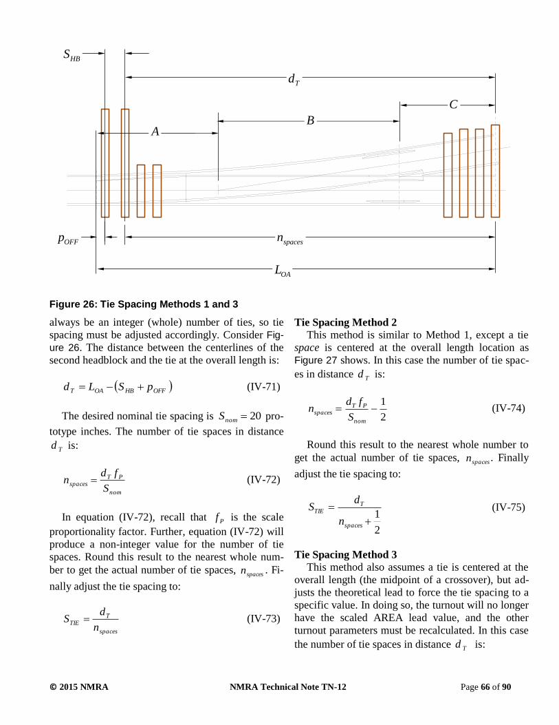
© 2015 NMRA NMRA Technical Note TN-12 Page 66 of 90
always be an integer (whole) number of ties, so tie
spacing must be adjusted accordingly. Consider Fig-
ure 26. The distance between the centerlines of the
second headblock and the tie at the overall length is:
OFFHBOAT pSLd (IV-71)
The desired nominal tie spacing is 20nomS pro-
totype inches. The number of tie spaces in distance
Td is:
nom
PTspaces
S
fdn (IV-72)
In equation (IV-72), recall that Pf is the scale
proportionality factor. Further, equation (IV-72) will
produce a non-integer value for the number of tie
spaces. Round this result to the nearest whole num-
ber to get the actual number of tie spaces, spacesn . Fi-
nally adjust the tie spacing to:
spaces
TTIE
n
dS (IV-73)
Tie Spacing Method 2
This method is similar to Method 1, except a tie
space is centered at the overall length location as
Figure 27 shows. In this case the number of tie spac-
es in distance Td is:
2
1
nom
PTspaces
S
fdn (IV-74)
Round this result to the nearest whole number to
get the actual number of tie spaces, spacesn . Finally
adjust the tie spacing to:
2
1
spaces
TTIE
n
dS (IV-75)
Tie Spacing Method 3
This method also assumes a tie is centered at the
overall length (the midpoint of a crossover), but ad-
justs the theoretical lead to force the tie spacing to a
specific value. In doing so, the turnout will no longer
have the scaled AREA lead value, and the other
turnout parameters must be recalculated. In this case
the number of tie spaces in distance Td is:
Figure 26: Tie Spacing Methods 1 and 3
OAL
spacesn
HBS
OFFp
AB
C
Td

© 2015 NMRA NMRA Technical Note TN-12 Page 67 of 90
spec
OFFHBspaces
S
CBpSAn
(IV-76)
Round this result to the nearest whole number to
get the actual number of tie spaces, spacesn . The ad-
justed distance A is:
CBpS
SnA
offHB
specspacesADJ
(IV-77)
The adjusted theoretical lead is then:
BAL ADJADJ (IV-78)
New template dimensions and other turnout di-
mensions require recalculation using the adjusted
theoretical lead.
Tie Spacing Method 4
This method is similar to Method 3, except a tie
space is centered at the overall length location. It,
too, requires an adjustment to the theoretical lead to
force tie spacing to a specified value, and a recalcu-
lation of the other turnout parameters. Here the num-
ber of tie spaces in distance Td is:
2
1
spec
OFFHBspaces
S
CBpSAn (IV-79)
Round this result to the nearest whole number to
get the actual number of tie spaces, spacesn . The ad-
justed distance A is:
CBpS
SnA
offHB
specspacesADJ
2
1
(IV-80)
The adjusted theoretical lead is again:
BAL ADJADJ (IV-81)
As in Method 3, new template dimensions and
other turnout dimensions require recalculation using
the adjusted theoretical lead.
Method Comparison
Methods 1 and 2, which retain the scaled AREA
lead, are suitable for manufactured turnouts where
tooling is different for each turnout (frog) number.
The adjusted theoretical lead values for Methods 3
and 4 differ at most by perhaps one-half the tie space
distance from the scaled AREA theoretical lead val-
Figure 27: Tie Spacing Methods 2 and 4
OAL
spacesn
HBS
OFFp
AB
C
Td
Half-space

© 2015 NMRA NMRA Technical Note TN-12 Page 68 of 90
ues, making them “close enough.” Methods 3 and 4
are useful for scratch builders who wish to use the
same turnout tie spacing fixture for all turnout num-
bers. Scratch builders will have to accept the small
deviation from the scaled AREA lead that these
methods require.
Finally, recall that template dimension C depends
on the track spacing p . That means the number of
spaces tie spacing, overall length, and the adjusted
lead values determined by all four methods all vary
slightly for different track spacing. The maximum
variation is about one-half a tie space.

© 2015 NMRA NMRA Technical Note TN-12 Page 69 of 90
PART V: CHECKING FINAL DESIGN CONSISTENCY WITH CAD DRAWINGS
Final Design Consistency Checks Reevaluating the new design dimensions using
the consistency evaluation spreadsheets determines
their consistency. The first reevaluation uses the ex-
act dimensions obtained from the design spread-
sheets. The second uses the dimensions from the de-
sign spreadsheets rounded to the nearest 0.001 inch-
es or degrees. Because using those spreadsheets will
produce the same results for all scales, only the
curved switch HO scale designs were reevaluated.
Using the exact dimensions from the design
spreadsheet, consistency reevaluation showed per-
cent differences for ALL dimensions to be identical-
ly zero. This is an expected result because the de-
sign and evaluation spreadsheets use the same vali-
dated equations.
Using the rounded (to nearest 0.001 inch) dimen-
sions from the design spreadsheets, and given in the
HO Scale RP examples, showed that percent differ-
ences for all dimensions except one were consistent
(0.5% or less). The exception was the mid-ordinate
dimension for the curved switch rail. Because this
dimension is small, on the order of a few thou-
sandths of an inch, rounding to the nearest thou-
sandth cuts off the ten thousandths part or less, pro-
ducing percent differences of several percent. The
ability to measure or construct this dimension to
more than the nearest one thousandth is not neces-
sary, so this inconsistency is ignored. This also
shows that rounding to the nearest 0.001 inch is rea-
sonable for the turnout designs presented in any new
or updated NMRA RPs.
Computer Aided Design Drawings The consistency of the new designs is demon-
strated as described above. A final visual and graph-
ical check of the turnout designs using a Computer
Aided Design (CAD) program is appropriate, in this
case DesignCAD 3D. This is also in keeping with the
earlier assertion that the most visual aspects of a
turnout design are the lead and frog angle.
Figure 28 and Figure 29 illustrate the effect of
turnout design rationale on curved and straight
switch turnout geometry for the Deep Flange, Fine,
Proto and Standard scale classes (fidelities). For ref-
erence, the scale at the bottom of each figure is in
inches. These figures compare design results for HO
No. 6 turnouts. At first glance they all look the same,
as they should, because by design intent they all
have the same lead and frog angle. Because the de-
sign rationale and equations are the same for all
scales, similar drawings of the other scales will show
the same relationships. The only exception would be
for Proto:48 and O scale having different track gaug-
es.
In Figure 28 and Figure 29, the left-most vertical
dashed line locates the point of switch. Moving to
the right, the next vertical dashed line, for reference,
locates the scaled AREA switch heel location. Final-
ly, the last vertical dashed line locates the theoretical
point of frog.
Less obvious, but noticeable, is the switch rail
length. Because the switch heel spread in the model
is larger than in the prototype, and the lead is scaled
to the AREA value, the switch rail lengths are longer
than the scaled AREA lengths. This locates the
switch heel to the right of the scaled AREA location,
as the short solid vertical line indicates. The Proto:87
switch rail length is closest to the AREA value, but
not precisely so because the switch heel spread is set
by the NMRA switch point standards. This is true for
all the Proto scales. The heel spread for all other
scales is set by the flangeway width method dis-
cussed in PART III.
Figure 28 also shows the HO scale No. 6 curved
turnout from the 1961 NMRA RP-12.3. The lead
value for that turnout is slightly longer than the
scaled AREA value, indicated by the short solid ver-
tical line at the frog point.
The more subtle differences are in the frogs and
guard rails. The most subtle difference is in the frog
toe length. Frog toe length is determined by the
flangeway width that varies with scale class in ac-
cordance with the method also discussed in PART III.
Even though the CAD drawings are highly accu-
rate, these features are more difficult to discern in
these figures because of digitization and the difficul-
ty computer screens and printers sometimes have
resolving lines at small angles from the horizontal.
Figure 30 shows a comparison of the HO No. 6
standard class and Proto:87 class frogs and guard
rails. In this zoomed-in view, the shorter frog toe
length and flangeway gap, and narrower flangeway
width of the Proto:87 frog and guard rail are clearly
visible.

© 2015 NMRA NMRA Technical Note TN-12 Page 70 of 90
Figure 28: Scale Class Comparison – No. 6 Curved Turnout
HO No. 6 Curved Turnout
Proto:87 No. 6 Curved Turnout
Fine:HO No. 6 Curved Turnout
HOdf No. 6 Curved Turnout
NMRA 1961 HO No. 6 Curved Turnout
50

© 2015 NMRA NMRA Technical Note TN-12 Page 71 of 90
Figure 29: Scale Class Comparison – No. 6 Straight Turnout
HO No. 6 Straight Turnout
Proto:87 No. 6 Straight Turnout
Fine:HO No. 6 Straight Turnout
HOdf No. 6 Straight Turnout
50

© 2015 NMRA NMRA Technical Note TN-12 Page 72 of 90
Figure 30: Scale Class Comparison – Zoomed to Clarify Frog & Guardrail Flangeways
Proto:87 No. 6 Frog & Guardrail
HO No. 6 Frog & Guardrail

© 2015 NMRA NMRA Technical Note TN-12 Page 73 of 90
APPENDIX A: REVISED TURNOUT RP FORMAT AND EXAMPLES
This appendix shows the format of the revised
turnout RP format using Proto:87 and HO scale
turnouts as examples. Because the turnouts are num-
bered 4 through 20, two pages are required for each
scale class and switch type. The first page tabulates
dimensions for frogs numbered 4 through 12 and the
second page frogs numbered 13 through 20.
Following the examples, Figure 31 shows the Di-
agram of Turnouts for turnouts with either curved
or straight switch rails, and identifies wing and guard
rail dimensions.

© 2015 NMRA NMRA Technical Note TN-12 Page 74 of 90
NMRA Recommended Practices
Proto:87 Scale Curved Switch Turnout
TURNOUT DIMENSIONS
Revised: MMM. 20YY RP-12.XXX
New Design and Calculations by Van S. Fehr
(1) FROG NUMBERS 4 5 6 7 8 9 10 11 12
PROPERTIES OF CURVED SWITCHES
(2) Switch Rail Length 1.797 1.794 1.830 3.069 3.143 3.209 3.216 3.257 4.834
(3) Switch Point Angle (deg.) 1.588 1.591 1.559 0.929 0.907 0.889 0.887 0.876 0.590
(4) Switch Heel Spread 0.094 0.094 0.094 0.094 0.094 0.094 0.094 0.094 0.094
(5) Switch Heel Angle (deg.) 4.425 4.432 4.345 2.590 2.529 2.477 2.472 2.440 1.644
(6) Switch Rail Radius 36.295 36.172 37.643 105.898 111.090 115.740 116.274 119.258 262.708
(7) Switch Mid-Ordinate 0.011 0.011 0.011 0.011 0.011 0.011 0.011 0.011 0.011
LEAD TO THEORETICAL POINT OF FROG
(8) Lead 4.937 5.572 6.206 8.638 9.376 10.019 10.625 11.227 14.233
CLOSURE DISTANCE
(9) Straight Rail Length 2.698 3.311 3.885 4.950 5.566 5.970 6.567 7.053 8.377
(10) Curved Rail Length 2.752 3.355 3.922 4.980 5.593 5.994 6.589 7.073 8.395
(11) Curved Rail Radius 16.047 27.503 43.362 51.124 69.298 88.465 116.046 146.585 153.779
GAGE LINE OFFSETS ON CURVED CLOSURE RAIL
(12) 1st Point Y1 [+] 0.161 0.171 0.179 0.165 0.170 0.171 0.177 0.180 0.169
(13) 1st Point X1 2.472 2.622 2.801 4.307 4.535 4.701 4.858 5.020 6.928
(14) Mid-Point Y2 [+] 0.256 0.273 0.286 0.266 0.273 0.274 0.283 0.287 0.272
(15) Mid-Point X2 3.146 3.450 3.773 5.544 5.926 6.194 6.500 6.783 9.022
(16) 3rd Point Y3 0.381 0.401 0.415 0.398 0.405 0.402 0.412 0.416 0.403
(17) 3rd Point X3 [+] 3.821 4.277 4.744 6.782 7.318 7.686 8.141 8.547 11.116
PROPERTIES OF FROGS
(18) Frog Angle (deg.) 14.250 11.421 9.527 8.171 7.153 6.360 5.725 5.205 4.772
(19) Overall Length 1.108 1.248 1.387 1.664 1.803 2.218 2.288 2.594 2.820
(20) Toe Length 0.442 0.467 0.491 0.619 0.666 0.840 0.841 0.918 1.022
(21) Heel Length 0.666 0.781 0.896 1.045 1.137 1.378 1.447 1.677 1.797
(22) Toe Spread 0.110 0.093 0.082 0.088 0.083 0.093 0.084 0.083 0.085
(23) Heel Spread 0.165 0.155 0.149 0.149 0.142 0.153 0.145 0.152 0.150
(35) Wing Rail Extension 0.408 0.462 0.517 0.571 0.626 0.680 0.735 0.790 0.844
(36) Wing Rail Flare Length 0.207 0.207 0.207 0.207 0.276 0.276 0.367 0.367 0.413
(37) Wing Rail Flare Width 0.028 0.028 0.028 0.028 0.026 0.026 0.025 0.025 0.025
(38) Wing Rail Bend Width 0.000 0.000 0.000 0.000 0.000 0.000 0.000 0.000 0.000
(39) Wing Rail End Chamfer 0.040 0.040 0.040 0.040 0.040 0.040 0.040 0.040 0.040
POINT OF FROG TO INTERSECTION OF CENTERLINES
(24) PF to ICL 2.596 3.245 3.894 4.543 5.192 5.841 6.490 7.139 7.788
DATA FOR CROSSOVERS: PF TO PF ON PARALLEL TRACKS
For Track Centers of: 1.791 (13 prototype feet)
(25) Straight Track Dist. 1.861 2.377 2.885 3.389 3.891 4.390 4.889 5.386 5.883
(26) Crossover Track Dist. 2.085 2.556 3.035 3.517 4.003 4.490 4.978 5.467 5.957
For Track Center Increment of: 0.138 (1 prototype foot)
(28) Straight Track Incr. 0.543 0.682 0.821 0.960 1.098 1.236 1.375 1.513 1.651
(29) Crossover Track Incr. 0.560 0.696 0.833 0.969 1.107 1.244 1.381 1.519 1.656
GUARD RAILS
(30) Parallel End Setback 0.092 0.098 0.103 0.109 0.115 0.121 0.126 0.132 0.138
(31) Bevel Length 0.149 0.149 0.149 0.149 0.149 0.149 0.149 0.149 0.149
(32) Flare Length 0.333 0.333 0.333 0.333 0.333 0.333 0.333 0.333 0.333
(33) Overall Length 1.137 1.137 1.137 1.137 1.137 1.137 1.137 1.137 1.137
(34) Parallel Length 0.471 0.471 0.471 0.471 0.471 0.471 0.471 0.471 0.471
(37) Flare Width 0.022 0.022 0.022 0.022 0.022 0.022 0.022 0.022 0.022
(38) Plane Width 0.013 0.013 0.013 0.013 0.013 0.013 0.013 0.013 0.013
(39) End Chamfer 0.034 0.034 0.034 0.034 0.034 0.034 0.034 0.034 0.034

© 2015 NMRA NMRA Technical Note TN-12 Page 75 of 90
NMRA Recommended Practices
Proto:87 Scale Curved Switch Turnout
TURNOUT DIMENSIONS
Revised: MMM. 20YY RP-12.XXX
New Design and Calculations by Van S. Fehr
(1) FROG NUMBERS 13 14 15 16 17 18 19 20
PROPERTIES OF CURVED SWITCHES
(2) Switch Rail Length 4.873 4.924 4.992 5.056 6.245 6.326 6.383 6.448
(3) Switch Point Angle (deg.) 0.585 0.579 0.571 0.564 0.457 0.451 0.447 0.442
(4) Switch Heel Spread 0.094 0.094 0.094 0.094 0.094 0.094 0.094 0.094
(5) Switch Heel Angle (deg.) 1.631 1.614 1.592 1.572 1.273 1.256 1.245 1.233
(6) Switch Rail Radius 266.980 272.600 280.175 287.437 438.513 449.981 458.106 467.467
(7) Switch Mid-Ordinate 0.011 0.011 0.011 0.011 0.011 0.011 0.011 0.011
LEAD TO THEORETICAL POINT OF FROG
(8) Lead 14.900 15.568 16.225 16.909 19.329 20.015 20.701 21.387
CLOSURE DISTANCE
(9) Straight Rail Length 8.952 9.515 10.000 10.623 11.747 12.244 12.877 13.503
(10) Curved Rail Length 8.968 9.531 10.014 10.637 11.759 12.256 12.889 13.514
(11) Curved Rail Radius 185.226 220.479 257.742 303.516 321.327 364.592 417.264 474.540
GAGE LINE OFFSETS ON CURVED CLOSURE RAIL
(12) 1st Point Y1 [+] 0.172 0.174 0.176 0.179 0.173 0.174 0.177 0.179
(13) 1st Point X1 7.111 7.303 7.492 7.712 9.182 9.387 9.603 9.824
(14) Mid-Point Y2 [+] 0.276 0.280 0.282 0.287 0.278 0.280 0.284 0.288
(15) Mid-Point X2 9.349 9.682 9.992 10.368 12.118 12.448 12.822 13.199
(16) 3rd Point Y3 0.407 0.411 0.412 0.418 0.411 0.411 0.416 0.420
(17) 3rd Point X3 [+] 11.587 12.060 12.492 13.024 15.055 15.509 16.041 16.575
PROPERTIES OF FROGS
(18) Frog Angle (deg.) 4.405 4.091 3.818 3.580 3.369 3.182 3.015 2.864
(19) Overall Length 3.045 3.270 3.381 3.606 3.832 4.057 4.170 4.284
(20) Toe Length 1.076 1.129 1.233 1.229 1.337 1.445 1.440 1.436
(21) Heel Length 1.969 2.142 2.147 2.377 2.495 2.612 2.730 2.848
(22) Toe Spread 0.083 0.081 0.082 0.077 0.079 0.080 0.076 0.072
(23) Heel Spread 0.151 0.153 0.143 0.148 0.147 0.145 0.144 0.142
(35) Wing Rail Extension 0.936 1.028 1.082 1.194 1.249 1.303 1.395 1.487
(36) Wing Rail Flare Length 0.539 0.610 0.636 0.713 0.738 0.763 0.835 0.907
(37) Wing Rail Flare Width 0.024 0.024 0.024 0.024 0.024 0.023 0.023 0.023
(38) Wing Rail Bend Width 0.024 0.024 0.024 0.024 0.024 0.023 0.023 0.023
(39) Wing Rail End Chamfer 0.040 0.040 0.040 0.040 0.040 0.040 0.040 0.040
POINT OF FROG TO INTERSECTION OF CENTERLINES
(24) PF to ICL 8.437 9.086 9.735 10.384 11.033 11.682 12.331 12.980
DATA FOR CROSSOVERS: PF TO PF ON PARALLEL TRACKS
For Track Centers of: 1.791 (13 prototype feet)
(25) Straight Track Dist. 6.379 6.875 7.370 7.865 8.360 8.855 9.350 9.844
(26) Crossover Track Dist. 6.448 6.939 7.430 7.921 8.413 8.905 9.397 9.889
For Track Center Increment of: 0.138 (1 prototype foot)
(28) Straight Track Incr. 1.789 1.927 2.065 2.203 2.340 2.478 2.616 2.754
(29) Crossover Track Incr. 1.794 1.932 2.069 2.207 2.345 2.482 2.620 2.758
GUARD RAILS
(30) Parallel End Setback 0.144 0.149 0.155 0.161 0.167 0.172 0.178 0.184
(31) Bevel Length 0.149 0.149 0.149 0.149 0.149 0.149 0.149 0.149
(32) Flare Length 0.333 0.379 0.379 0.379 0.379 0.379 0.379 0.379
(33) Overall Length 1.137 1.516 1.516 1.516 1.516 1.516 1.516 1.516
(34) Parallel Length 0.471 0.758 0.758 0.758 0.758 0.758 0.758 0.758
(37) Total Flare at End 0.022 0.022 0.022 0.022 0.022 0.022 0.022 0.022
(38) Bevel Cut at End 0.013 0.012 0.012 0.012 0.012 0.012 0.012 0.012
(39) End Chamfer 0.034 0.034 0.034 0.034 0.034 0.034 0.034 0.034

© 2015 NMRA NMRA Technical Note TN-12 Page 76 of 90
NMRA Recommended Practices
Proto:87 Scale Straight Switch Turnout
TURNOUT DIMENSIONS
Revised: MMM. 20YY RP-12.XXX
New Design and Calculations by Van S. Fehr
(1) FROG NUMBERS 4 5 6 7 8 9 10 11 12
PROPERTIES OF CURVED SWITCHES
(2) Switch Rail Length 1.790 1.745 1.745 2.669 2.747 2.737 2.872 3.621 3.638
(4) Switch Heel Spread 0.094 0.094 0.094 0.094 0.094 0.094 0.094 0.094 0.094
(5) Switch Heel Angle (deg.) 3.017 3.095 3.095 2.024 1.966 1.973 1.880 1.491 1.484
LEAD TO THEORETICAL POINT OF FROG
(8) Lead 5.156 5.833 6.511 8.514 9.324 9.910 10.794 12.594 13.251
CLOSURE DISTANCE
(9) Straight Rail Length 2.923 3.621 4.274 5.227 5.911 6.333 7.080 8.056 8.591
(10) Curved Rail Length 2.975 3.663 4.309 5.256 5.937 6.357 7.101 8.075 8.609
(11) Curved Rail Radius 15.177 25.206 38.388 48.990 65.590 83.032 105.823 124.579 150.040
GAGE LINE OFFSETS ON CURVED CLOSURE RAIL
(12) 1st Point Y1 [+] 0.150 0.160 0.167 0.158 0.162 0.164 0.167 0.163 0.165
(13) 1st Point X1 2.521 2.651 2.814 3.975 4.224 4.320 4.642 5.635 5.785
(14) Mid-Point Y2 [+] 0.242 0.258 0.270 0.257 0.263 0.264 0.270 0.264 0.267
(15) Mid-Point X2 3.252 3.556 3.882 5.282 5.702 5.903 6.412 7.648 7.933
(16) 3rd Point Y3 0.371 0.389 0.403 0.391 0.397 0.394 0.402 0.398 0.400
(17) 3rd Point X3 [+] 3.983 4.461 4.951 6.589 7.180 7.486 8.182 9.662 10.081
PROPERTIES OF FROGS
(18) Frog Angle (deg.) 14.250 11.421 9.527 8.171 7.153 6.360 5.725 5.205 4.772
(19) Overall Length 1.108 1.248 1.387 1.664 1.803 2.218 2.288 2.594 2.820
(20) Toe Length 0.442 0.467 0.491 0.619 0.666 0.840 0.841 0.918 1.022
(21) Heel Length 0.666 0.781 0.896 1.045 1.137 1.378 1.447 1.677 1.797
(22) Toe Spread 0.110 0.093 0.082 0.088 0.083 0.093 0.084 0.083 0.085
(23) Heel Spread 0.165 0.155 0.149 0.149 0.142 0.153 0.145 0.152 0.150
(35) Wing Rail Extension 0.408 0.462 0.517 0.571 0.626 0.680 0.735 0.790 0.844
(36) Wing Rail Flare Length 0.207 0.207 0.207 0.207 0.276 0.276 0.367 0.367 0.413
(37) Wing Rail Flare Width 0.028 0.028 0.028 0.028 0.026 0.026 0.025 0.025 0.025
(38) Wing Rail Bend Width 0.000 0.000 0.000 0.000 0.000 0.000 0.000 0.000 0.000
(39) Wing Rail End Chamfer 0.040 0.040 0.040 0.040 0.040 0.040 0.040 0.040 0.040
POINT OF FROG TO INTERSECTION OF CENTERLINES
(24) PF to ICL 2.596 3.245 3.894 4.543 5.192 5.841 6.490 7.139 7.788
DATA FOR CROSSOVERS: PF TO PF ON PARALLEL TRACKS
For Track Centers of: 1.791 (13 prototype feet)
(25) Straight Track Dist. 1.861 2.377 2.885 3.389 3.891 4.390 4.889 5.386 5.883
(26) Crossover Track Dist. 2.085 2.556 3.035 3.517 4.003 4.490 4.978 5.467 5.957
For Track Center Increment of: 0.138 (1 prototype foot)
(28) Straight Track Incr. 0.543 0.682 0.821 0.960 1.098 1.236 1.375 1.513 1.651
(29) Crossover Track Incr. 0.560 0.696 0.833 0.969 1.107 1.244 1.381 1.519 1.656
GUARD RAILS
(30) Parallel End Setback 0.092 0.098 0.103 0.109 0.115 0.121 0.126 0.132 0.138
(31) Bevel Length 0.149 0.149 0.149 0.149 0.149 0.149 0.149 0.149 0.149
(32) Flare Length 0.333 0.333 0.333 0.333 0.333 0.333 0.333 0.333 0.333
(33) Overall Length 1.137 1.137 1.137 1.137 1.137 1.137 1.137 1.137 1.137
(34) Parallel Length 0.471 0.471 0.471 0.471 0.471 0.471 0.471 0.471 0.471
(37) Flare Width 0.022 0.022 0.022 0.022 0.022 0.022 0.022 0.022 0.022
(38) Plane Width 0.013 0.013 0.013 0.013 0.013 0.013 0.013 0.013 0.013
(39) End Chamfer 0.034 0.034 0.034 0.034 0.034 0.034 0.034 0.034 0.034

© 2015 NMRA NMRA Technical Note TN-12 Page 77 of 90
NMRA Recommended Practices
Proto:87 Scale Straight Switch Turnout
TURNOUT DIMENSIONS
Revised: MMM. 20YY RP-12.XXX
New Design and Calculations by Van S. Fehr
(1) FROG NUMBERS 13 14 15 16 17 18 19 20
PROPERTIES OF CURVED SWITCHES
(2) Switch Rail Length 3.683 3.737 5.032 5.019 5.044 5.076 5.139 5.208
(4) Switch Heel Spread 0.094 0.094 0.094 0.094 0.094 0.094 0.094 0.094
(5) Switch Heel Angle (deg.) 1.466 1.445 1.073 1.076 1.071 1.064 1.051 1.037
LEAD TO THEORETICAL POINT OF FROG
(8) Lead 13.962 14.672 17.328 18.005 18.663 19.320 20.072 20.824
CLOSURE DISTANCE
(9) Straight Rail Length 9.204 9.807 11.063 11.757 12.282 12.800 13.493 14.181
(10) Curved Rail Length 9.220 9.822 11.077 11.770 12.294 12.811 13.504 14.191
(11) Curved Rail Radius 179.748 212.688 231.185 269.311 306.417 346.487 393.954 444.975
GAGE LINE OFFSETS ON CURVED CLOSURE RAIL
(12) 1st Point Y1 [+] 0.168 0.170 0.163 0.165 0.167 0.168 0.171 0.173
(13) 1st Point X1 5.984 6.189 7.797 7.958 8.114 8.276 8.512 8.753
(14) Mid-Point Y2 [+] 0.271 0.275 0.264 0.269 0.271 0.272 0.276 0.279
(15) Mid-Point X2 8.284 8.640 10.563 10.898 11.185 11.476 11.885 12.298
(16) 3rd Point Y3 0.404 0.407 0.399 0.404 0.405 0.406 0.410 0.414
(17) 3rd Point X3 [+] 10.585 11.092 13.329 13.837 14.255 14.676 15.259 15.843
PROPERTIES OF FROGS
(18) Frog Angle (deg.) 4.405 4.091 3.818 3.580 3.369 3.182 3.015 2.864
(19) Overall Length 3.045 3.270 3.381 3.606 3.832 4.057 4.170 4.284
(20) Toe Length 1.076 1.129 1.233 1.229 1.337 1.445 1.440 1.436
(21) Heel Length 1.969 2.142 2.147 2.377 2.495 2.612 2.730 2.848
(22) Toe Spread 0.083 0.081 0.082 0.077 0.079 0.080 0.076 0.072
(23) Heel Spread 0.151 0.153 0.143 0.148 0.147 0.145 0.144 0.142
(35) Wing Rail Extension 0.936 1.028 1.082 1.194 1.249 1.303 1.395 1.487
(36) Wing Rail Flare Length 0.539 0.610 0.636 0.713 0.738 0.763 0.835 0.907
(37) Wing Rail Flare Width 0.024 0.024 0.024 0.024 0.024 0.023 0.023 0.023
(38) Wing Rail Bend Width 0.024 0.024 0.024 0.024 0.024 0.023 0.023 0.023
(39) Wing Rail End Chamfer 0.040 0.040 0.040 0.040 0.040 0.040 0.040 0.040
POINT OF FROG TO INTERSECTION OF CENTERLINES
(24) PF to ICL 8.437 9.086 9.735 10.384 11.033 11.682 12.331 12.980
DATA FOR CROSSOVERS: PF TO PF ON PARALLEL TRACKS
For Track Centers of: 1.791 (13 prototype feet)
(25) Straight Track Dist. 6.379 6.875 7.370 7.865 8.360 8.855 9.350 9.844
(26) Crossover Track Dist. 6.448 6.939 7.430 7.921 8.413 8.905 9.397 9.889
For Track Center Increment of: 0.138 (1 prototype foot)
(28) Straight Track Incr. 1.789 1.927 2.065 2.203 2.340 2.478 2.616 2.754
(29) Crossover Track Incr. 1.794 1.932 2.069 2.207 2.345 2.482 2.620 2.758
GUARD RAILS
(30) Parallel End Setback 0.144 0.149 0.155 0.161 0.167 0.172 0.178 0.184
(31) Bevel Length 0.149 0.149 0.149 0.149 0.149 0.149 0.149 0.149
(32) Flare Length 0.333 0.379 0.379 0.379 0.379 0.379 0.379 0.379
(33) Overall Length 1.137 1.516 1.516 1.516 1.516 1.516 1.516 1.516
(34) Parallel Length 0.471 0.758 0.758 0.758 0.758 0.758 0.758 0.758
(37) Total Flare at End 0.022 0.022 0.022 0.022 0.022 0.022 0.022 0.022
(38) Bevel Cut at End 0.013 0.012 0.012 0.012 0.012 0.012 0.012 0.012
(39) End Chamfer 0.034 0.034 0.034 0.034 0.034 0.034 0.034 0.034

© 2015 NMRA NMRA Technical Note TN-12 Page 78 of 90
NMRA Recommended Practices
HO Scale Curved Switch Turnout
TURNOUT DIMENSIONS
Revised: MMM. 20YY RP-12.XXX
New Design and Calculations by Van S. Fehr
(1) FROG NUMBERS 4 5 6 7 8 9 10 11 12
PROPERTIES OF CURVED SWITCHES
(2) Switch Rail Length 1.940 1.952 2.001 3.317 3.411 3.492 3.512 3.564 5.240
(3) Switch Point Angle (deg.) 1.640 1.629 1.589 0.958 0.932 0.910 0.905 0.892 0.607
(4) Switch Heel Spread 0.105 0.105 0.105 0.105 0.105 0.105 0.105 0.105 0.105
(5) Switch Heel Angle (deg.) 4.568 4.539 4.428 2.671 2.597 2.537 2.523 2.485 1.690
(6) Switch Rail Radius 37.948 38.441 40.395 110.961 117.352 123.019 124.393 128.146 276.984
(7) Switch Mid-Ordinate 0.012 0.012 0.012 0.012 0.012 0.012 0.012 0.012 0.012
LEAD TO THEORETICAL POINT OF FROG
(8) Lead 4.937 5.572 6.206 8.638 9.376 10.019 10.625 11.227 14.233
CLOSURE DISTANCE
(9) Straight Rail Length 2.446 3.017 3.551 4.513 5.082 5.443 6.001 6.448 7.646
(10) Curved Rail Length 2.499 3.060 3.588 4.543 5.109 5.467 6.023 6.468 7.664
(11) Curved Rail Radius 14.792 25.476 40.311 47.322 64.253 81.936 107.764 136.266 142.503
GAGE LINE OFFSETS ON CURVED CLOSURE RAIL
(12) 1st Point Y1 [+] 0.167 0.176 0.184 0.171 0.175 0.177 0.182 0.185 0.174
(13) 1st Point X1 2.551 2.706 2.889 4.445 4.681 4.853 5.012 5.176 7.151
(14) Mid-Point Y2 [+] 0.254 0.270 0.282 0.264 0.271 0.271 0.279 0.283 0.269
(15) Mid-Point X2 3.163 3.461 3.777 5.573 5.952 6.214 6.512 6.788 9.063
(16) 3rd Point Y3 0.368 0.387 0.401 0.385 0.392 0.388 0.398 0.401 0.390
(17) 3rd Point X3 [+] 3.774 4.215 4.664 6.701 7.222 7.574 8.012 8.400 10.975
PROPERTIES OF FROGS
(18) Frog Angle (deg.) 14.250 11.421 9.527 8.171 7.153 6.360 5.725 5.205 4.772
(19) Overall Length 1.218 1.384 1.550 1.854 2.020 2.462 2.559 2.892 3.144
(20) Toe Length 0.552 0.603 0.654 0.809 0.883 1.084 1.112 1.215 1.347
(21) Heel Length 0.666 0.781 0.896 1.045 1.137 1.378 1.447 1.677 1.797
(22) Toe Spread 0.137 0.120 0.109 0.115 0.110 0.120 0.111 0.110 0.112
(23) Heel Spread 0.165 0.155 0.149 0.149 0.142 0.153 0.145 0.152 0.150
(35) Wing Rail Extension 0.408 0.462 0.517 0.571 0.626 0.680 0.735 0.790 0.844
(36) Wing Rail Flare Length 0.207 0.207 0.207 0.207 0.276 0.276 0.367 0.367 0.413
(37) Wing Rail Flare Width 0.028 0.028 0.028 0.028 0.026 0.026 0.025 0.025 0.025
(38) Wing Rail Bend Width 0.000 0.000 0.000 0.000 0.000 0.000 0.000 0.000 0.000
(39) Wing Rail End Chamfer 0.040 0.040 0.040 0.040 0.040 0.040 0.040 0.040 0.040
POINT OF FROG TO INTERSECTION OF CENTERLINES
(24) PF to ICL 2.596 3.245 3.894 4.543 5.192 5.841 6.490 7.139 7.788
DATA FOR CROSSOVERS: PF TO PF ON PARALLEL TRACKS
For Track Centers of: 1.791 (13 prototype feet)
(25) Straight Track Dist. 1.861 2.377 2.885 3.389 3.891 4.390 4.889 5.386 5.883
(26) Crossover Track Dist. 2.085 2.556 3.035 3.517 4.003 4.490 4.978 5.467 5.957
For Track Center Increment of: 0.138 (1 prototype foot)
(28) Straight Track Incr. 0.543 0.682 0.821 0.960 1.098 1.236 1.375 1.513 1.651
(29) Crossover Track Incr. 0.560 0.696 0.833 0.969 1.107 1.244 1.381 1.519 1.656
GUARD RAILS
(30) Parallel End Setback 0.092 0.098 0.103 0.109 0.115 0.121 0.126 0.132 0.138
(31) Bevel Length 0.149 0.149 0.149 0.149 0.149 0.149 0.149 0.149 0.149
(32) Flare Length 0.333 0.333 0.333 0.333 0.379 0.379 0.379 0.379 0.379
(33) Overall Length 1.137 1.137 1.137 1.137 1.516 1.516 1.516 1.516 1.516
(34) Parallel Length 0.471 0.471 0.471 0.471 0.758 0.758 0.758 0.758 0.758
(37) Flare Width 0.022 0.022 0.022 0.022 0.022 0.022 0.022 0.022 0.022
(38) Plane Width 0.013 0.013 0.013 0.013 0.012 0.012 0.012 0.012 0.012
(39) End Chamfer 0.034 0.034 0.034 0.034 0.034 0.034 0.034 0.034 0.034

© 2015 NMRA NMRA Technical Note TN-12 Page 79 of 90
NMRA Recommended Practices
HO Scale Curved Switch Turnout
TURNOUT DIMENSIONS
Revised: MMM. 20YY RP-12.XXX
New Design and Calculations by Van S. Fehr
(1) FROG NUMBERS 13 14 15 16 17 18 19 20
PROPERTIES OF CURVED SWITCHES
(2) Switch Rail Length 5.296 5.363 5.446 5.524 6.792 6.890 6.962 7.042
(3) Switch Point Angle (deg.) 0.600 0.593 0.584 0.575 0.468 0.461 0.456 0.451
(4) Switch Heel Spread 0.105 0.105 0.105 0.105 0.105 0.105 0.105 0.105
(5) Switch Heel Angle (deg.) 1.673 1.652 1.627 1.603 1.304 1.286 1.272 1.258
(6) Switch Rail Radius 282.923 290.101 299.153 307.866 465.379 478.889 488.960 500.210
(7) Switch Mid-Ordinate 0.012 0.012 0.012 0.012 0.012 0.012 0.012 0.012
LEAD TO THEORETICAL POINT OF FROG
(8) Lead 14.900 15.568 16.225 16.909 19.329 20.015 20.701 21.387
CLOSURE DISTANCE
(9) Straight Rail Length 8.178 8.698 9.141 9.723 10.740 11.194 11.785 12.369
(10) Curved Rail Length 8.194 8.714 9.155 9.736 10.753 11.206 11.797 12.380
(11) Curved Rail Radius 171.812 204.695 239.341 282.255 298.317 338.511 387.870 441.583
GAGE LINE OFFSETS ON CURVED CLOSURE RAIL
(12) 1st Point Y1 [+] 0.177 0.179 0.181 0.184 0.178 0.179 0.182 0.184
(13) 1st Point X1 7.340 7.537 7.731 7.955 9.477 9.688 9.908 10.134
(14) Mid-Point Y2 [+] 0.273 0.277 0.279 0.283 0.276 0.277 0.281 0.284
(15) Mid-Point X2 9.385 9.712 10.016 10.386 12.162 12.487 12.855 13.226
(16) 3rd Point Y3 0.394 0.397 0.398 0.404 0.397 0.398 0.402 0.406
(17) 3rd Point X3 [+] 11.429 11.886 12.301 12.816 14.847 15.285 15.801 16.318
PROPERTIES OF FROGS
(18) Frog Angle (deg.) 4.405 4.091 3.818 3.580 3.369 3.182 3.015 2.864
(19) Overall Length 3.396 3.649 3.786 4.039 4.291 4.543 4.684 4.824
(20) Toe Length 1.427 1.507 1.639 1.662 1.796 1.931 1.954 1.976
(21) Heel Length 1.969 2.142 2.147 2.377 2.495 2.612 2.730 2.848
(22) Toe Spread 0.110 0.108 0.109 0.104 0.106 0.107 0.103 0.099
(23) Heel Spread 0.151 0.153 0.143 0.148 0.147 0.145 0.144 0.142
(35) Wing Rail Extension 0.936 1.028 1.082 1.194 1.249 1.303 1.395 1.487
(36) Wing Rail Flare Length 0.539 0.610 0.636 0.713 0.738 0.763 0.835 0.907
(37) Wing Rail Flare Width 0.024 0.024 0.024 0.024 0.024 0.023 0.023 0.023
(38) Wing Rail Bend Width 0.024 0.024 0.024 0.024 0.024 0.023 0.023 0.023
(39) Wing Rail End Chamfer 0.040 0.040 0.040 0.040 0.040 0.040 0.040 0.040
POINT OF FROG TO INTERSECTION OF CENTERLINES
(24) PF to ICL 8.437 9.086 9.735 10.384 11.033 11.682 12.331 12.980
DATA FOR CROSSOVERS: PF TO PF ON PARALLEL TRACKS
For Track Centers of: 1.791 (13 prototype feet)
(25) Straight Track Dist. 6.379 6.875 7.370 7.865 8.360 8.855 9.350 9.844
(26) Crossover Track Dist. 6.448 6.939 7.430 7.921 8.413 8.905 9.397 9.889
For Track Center Increment of: 0.138 (1 prototype foot)
(28) Straight Track Incr. 1.789 1.927 2.065 2.203 2.340 2.478 2.616 2.754
(29) Crossover Track Incr. 1.794 1.932 2.069 2.207 2.345 2.482 2.620 2.758
GUARD RAILS
(30) Parallel End Setback 0.144 0.149 0.155 0.161 0.167 0.172 0.178 0.184
(31) Bevel Length 0.149 0.149 0.149 0.149 0.149 0.149 0.149 0.149
(32) Flare Length 0.413 0.413 0.413 0.413 0.471 0.471 0.471 0.471
(33) Overall Length 1.791 1.791 1.791 1.791 2.274 2.274 2.274 2.274
(34) Parallel Length 0.965 0.965 0.965 0.965 1.332 1.332 1.332 1.332
(37) Total Flare at End 0.022 0.022 0.022 0.022 0.022 0.022 0.022 0.022
(38) Bevel Cut at End 0.011 0.011 0.011 0.011 0.011 0.011 0.011 0.011
(39) End Chamfer 0.034 0.034 0.034 0.034 0.034 0.034 0.034 0.034

© 2015 NMRA NMRA Technical Note TN-12 Page 80 of 90
NMRA Recommended Practices
HO Scale Straight Switch Turnout
TURNOUT DIMENSIONS
Revised: MMM. 20YY RP-12.XXX
New Design and Calculations by Van S. Fehr
(1) FROG NUMBERS 4 5 6 7 8 9 10 11 12
PROPERTIES OF CURVED SWITCHES
(2) Switch Rail Length 1.945 1.918 1.932 2.922 3.021 3.025 3.182 3.989 4.021
(4) Switch Heel Spread 0.105 0.105 0.105 0.105 0.105 0.105 0.105 0.105 0.105
(5) Switch Heel Angle (deg.) 3.095 3.138 3.115 2.060 1.992 1.990 1.892 1.509 1.497
LEAD TO THEORETICAL POINT OF FROG
(8) Lead 5.156 5.833 6.511 8.514 9.324 9.910 10.794 12.594 13.251
CLOSURE DISTANCE
(9) Straight Rail Length 2.659 3.312 3.924 4.784 5.420 5.801 6.500 7.390 7.883
(10) Curved Rail Length 2.711 3.354 3.959 4.814 5.446 5.825 6.521 7.409 7.901
(11) Curved Rail Radius 13.925 23.198 35.379 45.132 60.469 76.373 97.475 114.833 138.214
GAGE LINE OFFSETS ON CURVED CLOSURE RAIL
(12) 1st Point Y1 [+] 0.157 0.165 0.172 0.164 0.167 0.169 0.172 0.169 0.171
(13) 1st Point X1 2.610 2.746 2.913 4.118 4.376 4.475 4.807 5.837 5.992
(14) Mid-Point Y2 [+] 0.241 0.255 0.267 0.255 0.260 0.261 0.267 0.262 0.264
(15) Mid-Point X2 3.274 3.574 3.895 5.314 5.731 5.925 6.432 7.684 7.963
(16) 3rd Point Y3 0.358 0.376 0.389 0.378 0.384 0.381 0.388 0.385 0.386
(17) 3rd Point X3 [+] 3.939 4.402 4.876 6.510 7.086 7.376 8.057 9.531 9.934
PROPERTIES OF FROGS
(18) Frog Angle (deg.) 14.250 11.421 9.527 8.171 7.153 6.360 5.725 5.205 4.772
(19) Overall Length 1.218 1.384 1.550 1.854 2.020 2.462 2.559 2.892 3.144
(20) Toe Length 0.552 0.603 0.654 0.809 0.883 1.084 1.112 1.215 1.347
(21) Heel Length 0.666 0.781 0.896 1.045 1.137 1.378 1.447 1.677 1.797
(22) Toe Spread 0.137 0.120 0.109 0.115 0.110 0.120 0.111 0.110 0.112
(23) Heel Spread 0.165 0.155 0.149 0.149 0.142 0.153 0.145 0.152 0.150
(35) Wing Rail Extension 0.408 0.462 0.517 0.571 0.626 0.680 0.735 0.790 0.844
(36) Wing Rail Flare Length 0.207 0.207 0.207 0.207 0.276 0.276 0.367 0.367 0.413
(37) Wing Rail Flare Width 0.028 0.028 0.028 0.028 0.026 0.026 0.025 0.025 0.025
(38) Wing Rail Bend Width 0.000 0.000 0.000 0.000 0.000 0.000 0.000 0.000 0.000
(39) Wing Rail End Chamfer 0.040 0.040 0.040 0.040 0.040 0.040 0.040 0.040 0.040
POINT OF FROG TO INTERSECTION OF CENTERLINES
(24) PF to ICL 2.596 3.245 3.894 4.543 5.192 5.841 6.490 7.139 7.788
DATA FOR CROSSOVERS: PF TO PF ON PARALLEL TRACKS
For Track Centers of: 1.791 (13 prototype feet)
(25) Straight Track Dist. 1.861 2.377 2.885 3.389 3.891 4.390 4.889 5.386 5.883
(26) Crossover Track Dist. 2.085 2.556 3.035 3.517 4.003 4.490 4.978 5.467 5.957
For Track Center Increment of: 0.138 (1 prototype foot)
(28) Straight Track Incr. 0.543 0.682 0.821 0.960 1.098 1.236 1.375 1.513 1.651
(29) Crossover Track Incr. 0.560 0.696 0.833 0.969 1.107 1.244 1.381 1.519 1.656
GUARD RAILS
(30) Parallel End Setback 0.092 0.098 0.103 0.109 0.115 0.121 0.126 0.132 0.138
(31) Bevel Length 0.149 0.149 0.149 0.149 0.149 0.149 0.149 0.149 0.149
(32) Flare Length 0.333 0.333 0.333 0.333 0.379 0.379 0.379 0.379 0.379
(33) Overall Length 1.137 1.137 1.137 1.137 1.516 1.516 1.516 1.516 1.516
(34) Parallel Length 0.471 0.471 0.471 0.471 0.758 0.758 0.758 0.758 0.758
(37) Flare Width 0.022 0.022 0.022 0.022 0.022 0.022 0.022 0.022 0.022
(38) Plane Width 0.013 0.013 0.013 0.013 0.012 0.012 0.012 0.012 0.012
(39) End Chamfer 0.034 0.034 0.034 0.034 0.034 0.034 0.034 0.034 0.034

© 2015 NMRA NMRA Technical Note TN-12 Page 81 of 90
NMRA Recommended Practices
HO Scale Straight Switch Turnout
TURNOUT DIMENSIONS
Revised: MMM. 20YY RP-12.XXX
New Design and Calculations by Van S. Fehr
(1) FROG NUMBERS 13 14 15 16 17 18 19 20
PROPERTIES OF CURVED SWITCHES
(2) Switch Rail Length 4.081 4.150 5.539 5.541 5.580 5.626 5.704 5.787
(4) Switch Heel Spread 0.105 0.105 0.105 0.105 0.105 0.105 0.105 0.105
(5) Switch Heel Angle (deg.) 1.475 1.450 1.086 1.086 1.078 1.070 1.055 1.040
LEAD TO THEORETICAL POINT OF FROG
(8) Lead 13.962 14.672 17.328 18.005 18.663 19.320 20.072 20.824
CLOSURE DISTANCE
(9) Straight Rail Length 8.454 9.015 10.149 10.803 11.286 11.763 12.415 13.061
(10) Curved Rail Length 8.470 9.031 10.163 10.816 11.298 11.775 12.426 13.071
(11) Curved Rail Radius 165.598 195.945 213.155 248.493 282.571 319.342 363.285 410.513
GAGE LINE OFFSETS ON CURVED CLOSURE RAIL
(12) 1st Point Y1 [+] 0.173 0.175 0.168 0.171 0.172 0.173 0.175 0.177
(13) 1st Point X1 6.194 6.404 8.077 8.242 8.402 8.567 8.807 9.052
(14) Mid-Point Y2 [+] 0.268 0.271 0.262 0.266 0.268 0.269 0.272 0.276
(15) Mid-Point X2 8.308 8.657 10.614 10.942 11.223 11.507 11.911 12.318
(16) 3rd Point Y3 0.390 0.393 0.386 0.391 0.391 0.392 0.396 0.400
(17) 3rd Point X3 [+] 10.421 10.911 13.151 13.643 14.045 14.448 15.015 15.583
PROPERTIES OF FROGS
(18) Frog Angle (deg.) 4.405 4.091 3.818 3.580 3.369 3.182 3.015 2.864
(19) Overall Length 3.396 3.649 3.786 4.039 4.291 4.543 4.684 4.824
(20) Toe Length 1.427 1.507 1.639 1.662 1.796 1.931 1.954 1.976
(21) Heel Length 1.969 2.142 2.147 2.377 2.495 2.612 2.730 2.848
(22) Toe Spread 0.110 0.108 0.109 0.104 0.106 0.107 0.103 0.099
(23) Heel Spread 0.151 0.153 0.143 0.148 0.147 0.145 0.144 0.142
(35) Wing Rail Extension 0.936 1.028 1.082 1.194 1.249 1.303 1.395 1.487
(36) Wing Rail Flare Length 0.539 0.610 0.636 0.713 0.738 0.763 0.835 0.907
(37) Wing Rail Flare Width 0.024 0.024 0.024 0.024 0.024 0.023 0.023 0.023
(38) Wing Rail Bend Width 0.024 0.024 0.024 0.024 0.024 0.023 0.023 0.023
(39) Wing Rail End Chamfer 0.040 0.040 0.040 0.040 0.040 0.040 0.040 0.040
POINT OF FROG TO INTERSECTION OF CENTERLINES
(24) PF to ICL 8.437 9.086 9.735 10.384 11.033 11.682 12.331 12.980
DATA FOR CROSSOVERS: PF TO PF ON PARALLEL TRACKS
For Track Centers of: 1.791 (13 prototype feet)
(25) Straight Track Dist. 6.379 6.875 7.370 7.865 8.360 8.855 9.350 9.844
(26) Crossover Track Dist. 6.448 6.939 7.430 7.921 8.413 8.905 9.397 9.889
For Track Center Increment of: 0.138 (1 prototype foot)
(28) Straight Track Incr. 1.789 1.927 2.065 2.203 2.340 2.478 2.616 2.754
(29) Crossover Track Incr. 1.794 1.932 2.069 2.207 2.345 2.482 2.620 2.758
GUARD RAILS
(30) Parallel End Setback 0.144 0.149 0.155 0.161 0.167 0.172 0.178 0.184
(31) Bevel Length 0.149 0.149 0.149 0.149 0.149 0.149 0.149 0.149
(32) Flare Length 0.413 0.413 0.413 0.413 0.471 0.471 0.471 0.471
(33) Overall Length 1.791 1.791 1.791 1.791 2.274 2.274 2.274 2.274
(34) Parallel Length 0.965 0.965 0.965 0.965 1.332 1.332 1.332 1.332
(37) Total Flare at End 0.022 0.022 0.022 0.022 0.022 0.022 0.022 0.022
(38) Bevel Cut at End 0.011 0.011 0.011 0.011 0.011 0.011 0.011 0.011
(39) End Chamfer 0.034 0.034 0.034 0.034 0.034 0.034 0.034 0.034

© 2015 NMRA NMRA Technical Note TN-12 Page 82 of 90
Figure 31: Diagram of Turnouts - Curved or Straight Switch Rails
35
39
36
39
31
30 3
43
2
33
38
37
37
9
2
13
12
14
16
15
17
8
24
25
18
35
47
6
26
23
22
20
19
21
10
11
DIA
GR
AM
of
TUR
NO
UTS
ALL
TR
AC
K G
AU
GES
CU
RV
ED O
R S
TRA
IGH
T S
WIT
CH
RA
ILS
1.
The
hea
vy li
nes
of
the
Turn
ou
t D
iagr
am r
epre
sen
t th
e ra
ilhea
d g
auge
lin
es o
nly
. Th
e W
ing
and
Gu
ard
Rai
l Dia
gram
incl
ud
es a
n e
xagg
erat
ed r
ailh
ead
wid
th t
o c
lari
fy t
he
flar
e d
imen
sio
ns.
2.
Cir
cled
nu
mb
ers
refe
r to
th
e lin
e n
um
ber
s co
nta
ined
in p
aren
thes
es in
th
e R
P-1
2.x
seri
es. C
ircl
e 3
, cir
cle
6 a
nd
cir
cle
7 a
pp
ly o
nly
to
cu
rved
sw
itch
rai
ls. F
or
stra
igh
t sw
itch
ra
ils t
he
Po
int
An
gle
is t
he
sam
e as
th
e Sw
itch
An
gle,
cir
cle
5. A
ll o
ther
cir
cle
nu
mb
ers
app
ly t
o t
urn
ou
ts w
ith
eit
her
typ
e o
f sw
itch
rai
ls.
3.
Turn
ou
ts w
ith
co
nti
nu
ou
s cu
rved
clo
sure
rai
l an
d s
wit
ch r
ail u
se R
ail L
engt
h (
circ
le 2
) fo
r th
e st
raig
ht
leg
on
ly. A
ll o
ther
dim
ensi
on
s ap
ply
wit
h t
he
swit
ch in
th
row
n p
osi
tio
n.
4.
“Hig
h S
pee
d”
turn
ou
ts w
ith
clo
sed
fro
g p
oin
ts s
ho
uld
fo
llow
th
ese
dim
ensi
on
s fo
r th
e th
row
n p
osi
tio
n.
5.
Stu
b s
wit
ches
are
co
nsi
der
ed s
pec
ial w
ork
an
d a
re n
ot
cove
red
by
thes
e sp
ecif
icat
ion
s.
6.
For
the
scal
es a
nd
fro
g n
um
ber
s it
incl
ud
es, t
he
RP
-13
.xse
ries
det
ails
alt
ern
ate
dim
ensi
on
s fo
r w
ing
rails
, gu
ard
rai
ls, a
nd
th
eir
flar
es, s
up
ple
men
tin
g th
e R
P-1
2.x
seri
es.
Trac
kC
en
ters
See
No
te 2
.
WIN
G A
ND
GU
AR
D R
AIL
DIA
GR
AM
TUR
NO
UT
DIA
GR
AM

© 2015 NMRA NMRA Technical Note TN-12 Page 83 of 90
APPENDIX B: ALTERNATE CLOSURE RAIL CURVE AND LEAD LIMITS
Cubic Polynomial While the AREA and NMRA specify circular arcs
for the curved closure rail, there is another practical
curve for its shape. That curve is a cubic polynomial,
the same mathematical curve used to approximate
spiral easements connecting tangents to circular
curves:
3
3
2
210 xaxaxaay (A-1)
In this case, equation (A-1) replaces the general
curve )(xfy defined in the xy-coordinate system
in Figure 13. Its properties are such that it can al-
ways satisfy the turnout boundary conditions as long
as the distance between the points PC and PT is
greater than zero, which it is. In principle, also for a
given frog number, switch angle (or heel angle) and
frog dimensions, that means there is a wide range of
lead dimensions that provide a theoretically smooth
reverse route curve. However, there is only a limited
range of lead dimensions that prevent the inherent
and undesirable S-curve of a cubic polynomial from
occurring between the points PC and PT.
In Figure 13 the point i indicates a possible loca-
tion of the inflection point. The inflection point is
where the cubic polynomial transitions from concave
down to concave up, or vice versa, forming an unde-
sirable S-curve in the curved closure rail. As long as
the chosen distance CL produces an inflection point
that is not between PC and PT, there is no S-curve
anywhere along the curved closure rail.
The first two derivatives of equation (A-1), re-
quired to establish expressions for the polynomial
coefficients and to locate the inflection point, are:
2
321 32 xaxaay (A-2)
xaay 32 62 (A-3)
The boundary conditions, established in PART I,
are repeated here as a convenience:
At 0,0 yx (A-4)
At tan,0 yx (A-5)
At HyLx C , (A-6)
At tan, yLx C (A-7)
These four boundary conditions force the poly-
nomial to pass through the points PC and PT, and to
match their respective slopes. Note the absence of
the subscript on the heel angle in equation (A-5). In
this case, and in subsequent equations below, it is not
necessary because the equations apply to both switch
types.
Substituting (A-4) into (A-1):
3
3
2
210 0000 aaaa (A-8)
Thus:
00 a (A-9)
Substituting (A-5) into (A-2):
2
321 0302tan aaa (A-10)
Thus:
tan1 a (A-11)
Next, using (A-6), (A-7), (A-1), (A-2) and (A-11)
produces two equations to solve simultaneously for
the remaining two unknown polynomial coefficients
2a and 3a :
2
32
3
3
2
2
32tantan
)(tan
CC
CCC
LaLa
LaLaLH
(A-12)
After algebraic manipulation of (A-12) the solu-
tion for 2a and 3a is:
tan2tan3122 C
C
LHL
a (A-13)
HLL
a C
C
2tantan133 (A-14)
Lead Limits
The value of ix that makes the second derivative
of the polynomial zero locates the inflection point:

© 2015 NMRA NMRA Technical Note TN-12 Page 84 of 90
062 32 ixaa (A-15)
Or:
3
2
3a
axi (A-16)
Substituting equations (A-13) and (A-14) into (A-
16), the location of the inflection point is:
HL
LHLx
C
CCi
2tantan
tan2tan3
3
(A-17)
To avoid the unwanted S-curve, the inflection
point must not fall between 0x and CLx (i.e.,
between points PC and PT). To ensure this requires
an expression for the value CL that causes the inflec-
tion point to lie at point PC and another that causes it
to lie at point PT.
First, substitute 0ix (the location of point PC)
into equation (A-17):
HL
LHL
C
CC
2tantan
tan2tan3
30
(A-18)
Because CL is not zero, the only non-trivial solu-
tion for CL in (A-18) occurs when:
0tan2tan3 CLH (A-19)
So, with the subscript 0 indicating the result for
0ix (point PC), solving (A-19) for CLL 0 gives:
tan2tan
30
HL (A-20)
Next, substitute Ci Lx (the location of point PT)
into equation (A-17) to get:
HL
LHLL
C
CCC
2tantan
tan2tan3
3
(A-21)
After some algebraic manipulation, with the sub-
script 1 indicating the result for Ci Lx (point PT),
solving (A-21) for CLL 1 gives:
tantan2
31
HL (A-22)
Values of 0L and 1L represent maximum and min-
imum distances CL that keep the inflection point out
of the region between PC and PT. Corresponding
lead dimensions come from (IV-10) or (V-10).
To determine the radius of curvature, consider
again the equation for the third-order polynomial and
its derivatives (plus one more), repeated and given
here:
3
3
2
210 xaxaxaay (A-23) 2
321 32 xaxaay (A-24)
xaay 32 62 (A-25)
36ay (A-26)
The radius of curvature for any function )(xfy
is:
y
yROC
23
21
(A-27)
The next step would normally require substitution
for y and its derivatives, and then solving for the
roots (x values) of equation (A-27). That process is
unwieldy and prone to error, so a numerical solution,
programmed in a spreadsheet, is a better choice.
Only those radii of curvature that lie between PC
and PT (inclusive) are of interest. That means the
numerical solution need only search between PC and
PT for the roots. If no roots exist in that interval, the
maximum radius of curvature occurs at PC and the
minimum at PT, or vice versa.
The companion spreadsheet NMRA TN-12 AREA
Turnout Reverse Curve Analysis.xls [33] makes these
calculations. Tabs located along the bottom contain
plots of the reverse route centerline for both straight
and curved switch turnout designs.

© 2015 NMRA NMRA Technical Note TN-12 Page 85 of 90
APPENDIX C: VARIABLE DEFINITIONS
English Variables
a Distance from switch point for curved closure rail gauge point determination
0a Constant term in polynomial
1a Coefficient of x in polynomial
2a Coefficient of 2x in polynomial
3a Coefficient of 3x in polynomial
A Dimension A in turnout template diagram (Figure 24)
ADJA Dimension A in turnout template diagram (Figure 24) adjusted for turnout tie spacing
b Offset from straight stock rail for curved closure rail gauge point determination
B Dimension B in turnout template diagram (Figure 24)
SRc Switch rod clearance (each side)
C Curved switch rail chord. Also dimension C in turnout template diagram (Figure 24)
d Frog point cutback (inches) along frog centerline
GLd Frog point cutback (inches) along frog gauge line
Td 2nd
headblock centerline to OAL distance
D Dimension D in turnout template diagram (Figure 24)
SPD Straight track distance between crossover frog practical points
STD Straight track distance between crossover frog theoretical points
TD Distance PC to PF with extra tangent at frog
XPD Straight track distance between crossover frog practical points
XTD Crossover track distance between crossover frog theoretical points
E Parallel track inner rail gauge side spacing
Pf Model scale proportionality factor
xf Generic curved closure rail curve, expressed as a function of x
F Distance between inner track rail and crossover track rail gauge sides at second frog point
Fg Total frog flangeway gap measured along a gauge line in inches to the ½-inch point
Tg Frog flangeway gap measured along a gauge line in inches to the theoretical point
G Minimum track gauge
h Switch heel gauge side distance above point thickness
Ch Switch heel rail clearance
minCh Minimum switch heel rail clearance
Fh Switch heel flange clearance
MIDh Curved switch mid-ordinate
Rh Railhead height

© 2015 NMRA NMRA Technical Note TN-12 Page 86 of 90
Wh Switch heel wheel clearance
H Height (lateral) distance between point PT and PC
PCH Point PC distance above normal route centerline
PTH Point PT distance above normal route centerline
k Curved switch heel angle proportionality factor
l Curved switch rail chord projection along normal route
extl Guard rail extension length
frntl Amount of straight portion of guard rail in front of throat
rearl Amount of straight portion of guard rail after frog point
AL Turnout actual (or practical) lead (to ½-inch point of frog)
ADJL Theoretical lead adjusted for turnout tie spacing
BVL Wing or guard rail bevel length
CL Length of circular portion of reverse route centerline, projected along normal route
CCRL Curved closure rail length (arc length)
DL Chord for symmetric equal-tangent parabola
FL Frog total length
FHL Frog heel length, measured from theoretical point of frog
FLL Total wing or guard rail flare length
FTL Frog toe length, measured from theoretical point of frog
GRL Guard rail length
HeelL Frog heel length, measured from ½-inch point of frog
ICLL Distance from theoretical point of frog to centerline intersection
maxL Guard rail straight portion maximum setback after frog point
minL Guard rail straight portion minimum setback after frog point
OAL Turnout overall length
PCL Point PC distance from switch point
PLL Guard rail parallel (straight) portion length
PNL Wing or guard rail planing length
PTL Point PT distance from theoretical point of frog (towards switch)
SL Switch rail length, either type
SBL Guard rail parallel length setback from theoretical point
SCRL Straight closure rail length
TL Turnout theoretical lead (to theoretical point of frog)
ToeL Frog toe length, measured from ½-inch point of frog
TL Turnout theoretical lead (to theoretical point of frog)
TML Part of frog toe length for mechanical features
WRL Wing rail length

© 2015 NMRA NMRA Technical Note TN-12 Page 87 of 90
0L Length of curved portion of reverse route centerline for inflection point at point PC
1L Length of curved portion of reverse route centerline for inflection point at point PT
n Frog number
spacesn Number of tie spaces in distance Td
p Parallel track spacing
OFFp Switch point offset from center of first headblock
maxP Maximum switch point clearance (per NMRA standard)
CR Reverse route circular arc centerline radius
CCRR Curved closure rail radius
OCR Radius of curvature for any function )(xfy
SR Curved switch rail radius
SCLR Curved switch centerline radius
STKR Curved switch curved stock rail radius
FHS Frog heel spread
FTS Frog toe spread
HBS Headblock spacing
nomS Headblock spacing
SHS Switch heel spread, either switch type
specS Specified tie spacing
TIES Calculated tie spacing
t Wheel flange thickness
Ft Additional tangent length before (or after) frog toe
St Additional tangent length after switch heel
Pt Switch rail point thickness
SWT Switch rail throw
BPw Wing or guard rail bevel or bend depth (perpendicular to rail gauge line)
EBw Wing or guard rail end bevel
Fw Flangeway width (perpendicular to rail gauge line)
FGw Total flangeway gap
FLw Total flare from side of railhead (for wing and guard rails)
HDw Railhead width
PNw Flare at end of guard rail flare planed length
SRw Switch rod width
Tw Tie or headblock width
x x-coordinate in xy-coordinate system

© 2015 NMRA NMRA Technical Note TN-12 Page 88 of 90
ix location of inflection point for 3rd
-order polynomial
1X First curved closure rail gauge point location
2X Second curved closure rail gauge point location
3X Third curved closure rail gauge point location
y y-coordinate in xy-coordinate system
y First derivative of xfy
y Second derivative of xfy
y Third derivative of xfy
1Y First curved closure rail gauge point offset
2Y Second curved closure rail gauge point offset
3Y Third curved closure rail gauge point offset
z Extra distance at dimension F along crossover track to second frog point
Greek Variables
Curved switch rail subtended angle
p Incremental change in parallel track spacing
S Incremental change in straight track distance corresponding to p
X Incremental change in crossover track distance corresponding to p
Switch angle (straight switch) or heel angle (curved switch)
C Heel angle, specifically for a curved switch
S Switch angle, specifically for a straight switch
Frog angle
D Degree-of-curvature (degrees)
Switch point angle, either switch type
Curved switch rail chord angle

© 2015 NMRA NMRA Technical Note TN-12 Page 89 of 90
APPENDIX D: REFERENCES
1. E. E. Russell Tratman, Railway Track and Maintenance, A Manual of Maintenance-of-way and Struc-
tures, A. C. Kalmbach Memorial Library, 2nd
Printing, 2012
2. William W. Hay, Railroad Engineering, John Wiley & Sons, Inc., 2nd
ed., 1982
3. John A. Droege, Freight Terminals and Trains, National Model Railroad Association, 2nd
Printing, 2012
4. Trackwork Plans and Specifications, American Railway Engineering Association, 1946
5. “Turnouts General”, NMRA Recommended Practice RP-12, January 1957
6. “Turnout Dimensions – O Scale”, NMRA Recommended Practice RP-12.1, February 1961
7. “Turnout Dimensions – S Scale”, NMRA Recommended Practice RP-12.2, February 1961
8. “Turnout Dimensions – HO Scale”, NMRA Recommended Practice RP-12.3, February 1961
9. “Turnout Dimensions – OO & On3 Scales”, NMRA Recommended Practice RP-12.4, February 1961
10. “Turnout Dimensions – TT Scale”, NMRA Recommended Practice RP-12.5, February 1961
11. “Turnout Dimensions – HOn3 Scale”, NMRA Recommended Practice RP-12.6, February 1961
12. “Turnout Dimensions – N Scale”, NMRA Recommended Practice RP-12.7, December 1979
13. “Guard Rail & Frog Relationship”, NMRA Recommended Practice RP-13.5, August 1981
14. “Guard Rails”, NMRA Recommended Practice RP-13.6, August 1981
15. “Frog & Wing Rails”, NMRA Recommended Practice RP-13.7, August 1981
16. “Flangeway Flares”, NMRA Recommended Practice RP-13.8, August 1981
17. “Rail”, NMRA Recommended Practice RP-15.1, January 1990
18. Paul J. Dolkos, “Will the turnouts fit?” Model Railroad Planning 2007, Kalmbach Publishing, January
2007, pp. 54-59
19. “General Overview”, NMRA Standard S-1, July 2004
20. “General Proto Scales”, NMRA Standard S-1.1, July 2009
21. “General Standard Scales”, NMRA Standard S-1.2, July 2009
22. “General Hi-Rail Scales”, NMRA Standard S-1.3, July 2009
23. “Trackwork Proto Scales”, NMRA Standard S-3.1, Jan 2006
24. “Trackwork Standard Scales”, NMRA Standard S-3.2, Feb 2010
25. “Trackwork Hi-Rail Scales”, NMRA Standard S-3.3, Feb 2010
26. “Clearances”, NMRA Standard S-7, February 2012
27. “Track Centers”, NMRA Standard S-8, July 2002
28. Van S. Fehr, MS-Excel spreadsheet NMRA TN-12 AREA Curved Switch Consistency Evaluation.xls
29. Van S. Fehr, MS-Excel spreadsheet NMRA TN-12 AREA Turnout Consistency Evaluation.xls
30. Van S. Fehr, MS-Excel spreadsheet NMRA TN-12 NMRA Curved Switch Consistency Evaluation.xls
31. Van S. Fehr, MS-Excel spreadsheet NMRA TN-12 NMRA Turnout Consistency Evaluation.xls
32. Van S. Fehr, MS-Excel spreadsheet NMRA TN-12 Guard Rail Position Study.xls
33. Van S. Fehr, MS-Excel spreadsheet NMRA TN-12 AREA Turnout Reverse Curve Analysis.xls
34. Van S. Fehr, MS-Excel spreadsheet NMRA TN-12 Generalized Model Turnout Design.xls

© 2015 NMRA NMRA Technical Note TN-12 Page 90 of 90
CHANGE RECORD
October 2014 Original issue (Van S. Fehr)
March 2015 Added special guard rail length needed for Odf and O27 scales ONLY.
Removed links to old Turnout RPs in References Section (Van S. Fehr)