Embed Size (px)
Citation preview
Engine Operator Student Workbook
N9018 March 2019
PREFACE The Engine Operator (ENOP) course was originally developed by the Bureau of Land Management (BLM) to meet agency training needs. The course is designed to provide students with the knowledge/skills necessary to perform the functions described in the Engine Operator BLM Position Task Book as well as address the standards, procedures, and techniques to be an engine operator on a wildland or prescribed fire. While the engine operator position and skills are interagency in nature, the course predominately refers to BLM policy, engines, references, maintenance forms, etc. Therefore, ENOP training cadres should refer to and use appropriate agency-specific references when presenting this course. Subject matter experts and course developers have transferred all distribution of the ENOP course in an electronic environment via the BLM National Fire Training and Workforce Development website (https://www.nifc.gov/training/training_main.html). Course coordinators must ensure they are using the most current course materials. This course was developed by a group of BLM subject matter experts with direction from the BLM National Fire Training and Workforce Development. The primary participants in this development effort included: Nate Kerschner High Plains District Jade Martin Carson City District Jesse Monzillo California Desert District Matthew Norden Front Range Mitch Silvester Twin Falls District Jesse Turner North Central Montana District Randy Turrill Color Country District Brent Higbee BLM National Fire Equipment Program Brian Williams BLM National Fire Equipment Program Pam McDonald BLM Fire Training and Workforce Development The National Fire Equipment Program appreciates the efforts of all contributors to the design and development of this product and the instructors who present this course. Sponsored for publication by the National Fire Equipment Program and the BLM National Fire Training and Workforce Development Program. The use of trade, firm, or corporation names in this publication is for the information and convenience of the reader and does not constitute an endorsement by the Bureau of Land Management of any product or service to the exclusion of others that may be suitable. Comments regarding the content of this publication should be directed to: National Fire Equipment Program 3833 South Development Avenue Boise, ID 83705 E-mail: [email protected]
i
TABLE OF CONTENTS INTRODUCTION .......................................................................................................................... 1
INSTRUCTOR EXPECATIONS ...................................................................................................................................... 1 COURSE OBJECTIVES ................................................................................................................................................ 1 COURSE PURPOSE ..................................................................................................................................................... 1 ROLES AND RESPONSIBILITES ................................................................................................................................... 2
Instructor ................................................................................................................................................................................... 2 Strike Team Leader/Instructor Cadre ........................................................................................................................................ 2 Student ...................................................................................................................................................................................... 2
COURSE MATERIALS ................................................................................................................................................. 2 ENOP Student Workbook ......................................................................................................................................................... 2
Course Icons ................................................................................................................................................................................................ 2 ENOP Vehicle Inspection Job Aid ............................................................................................................................................ 3
FIELD EXERCISE ........................................................................................................................................................ 3 Goals ......................................................................................................................................................................................... 3
PERFORMANCE AND EVALUATION ........................................................................................................................... 4 Unit Quizzes ............................................................................................................................................................................. 4 ENOP Training Evaluation Form.............................................................................................................................................. 4
BECOMING ENOP QUALIFIED .................................................................................................................................. 4 UNIT 1 – FIRE ENGINE MAINTENANCE ............................................................................... 5 Lesson A – Diesel Engine Operation and Maintenance .............................................................. 5
BASIC DIESEL ENGINE OPERATION .......................................................................................................................... 5 Diesel Engines vs. Gasoline Engines ........................................................................................................................................ 5 Torque and Horsepower ............................................................................................................................................................ 5
DIESEL FUEL ............................................................................................................................................................. 6 Diesel Fuel vs. Gasoline ........................................................................................................................................................... 6 Octane Number Versus Cetane Number ................................................................................................................................... 6
Octane Number ............................................................................................................................................................................................ 6 Cetane Number ............................................................................................................................................................................................ 6
On-Road Versus Off-Road Diesel Fuel .................................................................................................................................... 6 On-Road Diesel Fuel .................................................................................................................................................................................... 6 Off-Road Diesel Fuel ................................................................................................................................................................................... 6
Number 2 and Number 1 Diesel Fuels ...................................................................................................................................... 7 Number 2 (No. 2) Diesel .............................................................................................................................................................................. 7 Number 1 (No. 1) Diesel .............................................................................................................................................................................. 7 Winter Grade................................................................................................................................................................................................ 7
Diesel Fuel And Cold Weather ................................................................................................................................................. 7 Preventing Diesel Fuel from Gelling ............................................................................................................................................................ 7
DIESEL FUEL HANDLING PRACTICES ....................................................................................................................... 7 Galvanized Containers .............................................................................................................................................................. 7 Replacing Fuel Filters ............................................................................................................................................................... 8 Water ........................................................................................................................................................................................ 8
BIODIESEL ................................................................................................................................................................. 8 Using Biodiesel Fuel ................................................................................................................................................................. 8 Biodiesel Fuel Concerns ........................................................................................................................................................... 8
DIESEL FUEL SYSTEMS ............................................................................................................................................. 9 Fuel Tank and Lines ................................................................................................................................................................. 9
Fuel Tank ..................................................................................................................................................................................................... 9 High- and Low-Pressure Fuel Lines ............................................................................................................................................................. 9
Primary and Secondary Fuel Filters .......................................................................................................................................... 9 Primary Filter/Water Separator .................................................................................................................................................................... 9 Secondary Fuel Filter ................................................................................................................................................................................... 9 Filter Maintenance ..................................................................................................................................................................................... 10 Hand Primer Pump ..................................................................................................................................................................................... 10
Injection Pump ........................................................................................................................................................................ 10 Injectors .................................................................................................................................................................................. 10 High-Pressure Common Rail Systems .................................................................................................................................... 10 Glow Plugs and Heating Grids ................................................................................................................................................ 11 Electronic Control Module (ECM) ......................................................................................................................................... 11
ii
DIESEL ENGINE COMPONENTS ............................................................................................................................... 11 Turbochargers ......................................................................................................................................................................... 11
Turbocharger Basics .................................................................................................................................................................................. 11 Turbocharger Considerations ..................................................................................................................................................................... 12
Aftercooler .............................................................................................................................................................................. 12 Air Cleaner/Filter .................................................................................................................................................................... 12
Air Cleaner Maintenance ........................................................................................................................................................................... 12 Air Cleaner Restriction Gauge ................................................................................................................................................................... 13 Reasons for Black Smoke .......................................................................................................................................................................... 13
Cooling System ....................................................................................................................................................................... 13 Radiator ..................................................................................................................................................................................................... 13 Fan ............................................................................................................................................................................................................. 13 Exhaust System .......................................................................................................................................................................................... 13
POWERTRAIN COMPONENTS ................................................................................................................................... 15 Transmission ........................................................................................................................................................................... 15
Automatic Transmission ............................................................................................................................................................................ 15 Transfer Case .......................................................................................................................................................................... 15 Retarder .................................................................................................................................................................................. 15 Dynamic Engine Brakes ......................................................................................................................................................... 15
CAUSES OF LOW POWER ......................................................................................................................................... 16 Throttle Linkage ..................................................................................................................................................................... 16 Plugged Air Cleaner ................................................................................................................................................................ 16 Turbo Outlet Clamps............................................................................................................................................................... 16 Split Air Charge Boot ............................................................................................................................................................. 16 Poor Fuel Quality .................................................................................................................................................................... 16 Dirty Fuel Filter ...................................................................................................................................................................... 16 Plugged Diesel Particulate Filter ............................................................................................................................................. 16 Engine Blow-By ..................................................................................................................................................................... 16
ENGINE START UP AND SHUT DOWN ...................................................................................................................... 17 Basic Procedures ..................................................................................................................................................................... 17
UNIT 1 – FIRE ENGINE MAINTENANCE ............................................................................. 19 Lesson B – Vehicle Inspections ................................................................................................... 19
FIRE EQUIPMENT MAINTENANCE PROCEDURE AND RECORD (FEMPR) ............................................................. 19 Documentation Tool ............................................................................................................................................................... 19 Information Resource.............................................................................................................................................................. 19
FIRE ENGINE INSPECTION OVERVIEW ................................................................................................................... 19 Provide for Safety First! .......................................................................................................................................................... 19 Order of the Inspection ........................................................................................................................................................... 20 Cab and Chassis ...................................................................................................................................................................... 20
Approach and Initial Walk-Around ............................................................................................................................................................ 20 Hood .......................................................................................................................................................................................................... 20 Oil .............................................................................................................................................................................................................. 20 Power Steering Fluid .................................................................................................................................................................................. 21 Fuel Filter................................................................................................................................................................................................... 21 Fuel/Water Separator ................................................................................................................................................................................. 21 Automatic Transmission Fluid ................................................................................................................................................................... 21 Hydraulic Brake Fluid ................................................................................................................................................................................ 21 Fan and Fan Belts ....................................................................................................................................................................................... 21 Driver Side Front Tire, Rim, Hub, and Suspension .................................................................................................................................... 22 Front Bumper and Wheel Chocks .............................................................................................................................................................. 24 Coolant Level, Radiators, and Hoses ......................................................................................................................................................... 24 Radiator ..................................................................................................................................................................................................... 25 Air Filters (including air conditioner, cabin, and ember separators) ........................................................................................................... 25 Hoses ......................................................................................................................................................................................................... 25 Passenger Side Front Tire, Rim, Hub and Suspension ............................................................................................................................... 25 Fuel Tank and Brackets .............................................................................................................................................................................. 26 Passenger Side Door(s) .............................................................................................................................................................................. 26 Passenger Side General Condition ............................................................................................................................................................. 26 Passenger Side Undercarriage .................................................................................................................................................................... 26 Exhaust ...................................................................................................................................................................................................... 26 Passenger Side Rear Tire, Rim, Hub and Suspension................................................................................................................................. 26 Rear Undercarriage (Plumbing) ................................................................................................................................................................. 26 Vehicle Rear .............................................................................................................................................................................................. 27 Top Deck, Handrails, and Steps ................................................................................................................................................................. 27
iii
Driver Side General Condition ................................................................................................................................................................... 27Driver Side Rear Tire, Rim, Hub and Suspension ...................................................................................................................................... 27Driver Side Undercarriage ......................................................................................................................................................................... 27Air Tanks and Lines ................................................................................................................................................................................... 27Batteries ..................................................................................................................................................................................................... 27Driver Side Door(s) .................................................................................................................................................................................... 28Wheel Chocks ............................................................................................................................................................................................ 28
Inside Cab ............................................................................................................................................................................... 28 Start Engine................................................................................................................................................................................................ 28Lights and Signals ...................................................................................................................................................................................... 28Mirrors and Windows ................................................................................................................................................................................ 29Windshield Wipers and Washer ................................................................................................................................................................. 29Gauges ....................................................................................................................................................................................................... 29Switches ..................................................................................................................................................................................................... 29District Mobile Radio, Siren, and Public Address (PA) System ................................................................................................................. 29Horn and Backup Alarm ............................................................................................................................................................................ 30Seat Belts ................................................................................................................................................................................................... 30Heater and Air Conditioner ........................................................................................................................................................................ 30Vehicle Use (Log) Book ............................................................................................................................................................................ 30Accident Forms .......................................................................................................................................................................................... 30Fire Extinguisher ........................................................................................................................................................................................ 30First Aid Kit(s) ........................................................................................................................................................................................... 30DOT Warning Triangle Set ........................................................................................................................................................................ 30Jack and Lug Wrench ................................................................................................................................................................................. 31
Brakes ..................................................................................................................................................................................... 31 Parking Brake (both hydraulic and air brakes) ........................................................................................................................................... 31Service Brakes (both hydraulic and air brakes) .......................................................................................................................................... 31Hydraulic Brakes ....................................................................................................................................................................................... 31Air Brakes .................................................................................................................................................................................................. 32
Fire Engine Inspection Outside Exercise ................................................................................................................................ 35 POST OFF-ROAD FIRE ENGINE INSPECTION .......................................................................................................... 35 ENGINE FIRE READINESS (POST-INCIDENT) .......................................................................................................... 36
Items to Clean and Inspect ...................................................................................................................................................... 36 Normal Unit Stocking (NUS) ................................................................................................................................................. 36
Equipment/NUS Replacement Procedures.................................................................................................................................................. 36VEHICLE WATCH OUT SITUATIONS ....................................................................................................................... 37
UNIT 1 – FIRE ENGINE MAINTENANCE ............................................................................. 39 Lesson C – Pump Inspections and Maintenance ........................................................................ 39
PUMP PACKAGE INSPECTION .................................................................................................................................. 39 Pump Package ......................................................................................................................................................................... 39
Water Tank and Foam Tank ....................................................................................................................................................................... 39Valves ........................................................................................................................................................................................................ 39Coolant ....................................................................................................................................................................................................... 39Oil .............................................................................................................................................................................................................. 39Fuel Filter................................................................................................................................................................................................... 39Air Filter(s) ................................................................................................................................................................................................ 40Primer ........................................................................................................................................................................................................ 40Pump On/Off-Start Switch, Low Oil Pressure Override (Murphy) Push-to-Start Switch, Glow Plugs, and Throttle ................................. 40Gauges ....................................................................................................................................................................................................... 40Water Pressure Safety Shutdown Switch ................................................................................................................................................... 40Live Reels .................................................................................................................................................................................................. 40Foam Proportioner ..................................................................................................................................................................................... 41Water Inline Strainer .................................................................................................................................................................................. 41Pump Mounting Bolts ................................................................................................................................................................................ 41Pump Exhaust ............................................................................................................................................................................................ 41Gear Box .................................................................................................................................................................................................... 41
PUMP MAINTENANCE REQUIREMENTS .................................................................................................................. 41 Basic Service .......................................................................................................................................................................... 41 Pump Seal Maintenance .......................................................................................................................................................... 41 Annual Pump Motor Maintenance .......................................................................................................................................... 42
WINTERIZATION ...................................................................................................................................................... 42 Field or Short-Term Winterization of Fire Engine Plumbing ................................................................................................. 42
Field or Short-term Winterization Process ................................................................................................................................................. 42Full Winterization of Fire Engine Plumbing ........................................................................................................................... 43
iv
CONDUCT A PUMP PERFORMANCE TEST ............................................................................................................... 43 Pump Performance Test Guidelines ........................................................................................................................................ 43 Pump Performance Testing Equipment................................................................................................................................... 43
Commercial Certified Flow Meter ............................................................................................................................................................. 43 Non-commercial, Non-certified Flow Meter .............................................................................................................................................. 43 Homemade Pressure/Flow Tester ............................................................................................................................................................... 43
TROUBLESHOOTING ................................................................................................................................................ 44 Lights—Not Illuminated ......................................................................................................................................................... 44 Pump Engine ........................................................................................................................................................................... 44
Pump engine will not start. ......................................................................................................................................................................... 44 Pump engine starts but will not keep running............................................................................................................................................. 44 Pump engine starts and runs but no water pressure exists. ......................................................................................................................... 44
OTHER PROBLEMS .................................................................................................................................................. 44 UNIT 2 – FLEET MANAGEMENT ........................................................................................... 47
INTRODUCTION TO THE WORKING CAPITAL FUND (WCF) .................................................................................. 47 Components of the Working Capital Fund ............................................................................................................................. 47
Fixed Ownership Rates (FORs) ................................................................................................................................................................. 47 Use Rates ................................................................................................................................................................................................... 48
WCF Life Cycle ...................................................................................................................................................................... 48 Equipment Classes .................................................................................................................................................................. 48 Items WCF Does Not Cover ................................................................................................................................................... 48
FLEET CHARGE CARD ............................................................................................................................................. 51 GROSS VEHICLE WEIGHT (GVW) ......................................................................................................................... 51
Weight Ratings ....................................................................................................................................................................... 51 Gross Vehicle Weight Rating (GVWR) ..................................................................................................................................................... 51 Gross Axle Weight Rating (GAWR) .......................................................................................................................................................... 52
Determining GVW .................................................................................................................................................................. 52 RECORDKEEPING AND REPORTING........................................................................................................................ 53
Reasons For Having Records .................................................................................................................................................. 53 BLM Fire Equipment Improvement/Deficiency Reporting System (IDRS) ........................................................................... 53 Vehicle Use (Log) Book ......................................................................................................................................................... 53
Local Fleet Vehicle Documentation ........................................................................................................................................................... 53 Fleet Charge Card Receipts ........................................................................................................................................................................ 53 Proof of Insurance Form ............................................................................................................................................................................ 54 Vehicle Weight Slip ................................................................................................................................................................................... 54 Engine Use Report (EUR) .......................................................................................................................................................................... 54 Utilization Record (USDI – BLM Form 1520-042) ................................................................................................................................... 54
ACCIDENT REPORTING PROCEDURES .................................................................................................................... 59 What Every Driver Should Do When Involved in an Accident ............................................................................................... 59 What Every Driver Should Not Do When Involved in an Accident ........................................................................................ 60
FIRE ENGINE WARRANTY REPAIRS AND RECALLS ............................................................................................... 60 Warranty Repairs .................................................................................................................................................................... 60 Recalls .................................................................................................................................................................................... 60
UNIT 3 – FIRE ENGINE DRIVING ......................................................................................... 63 Lesson A – Driving Policy and Procedures................................................................................. 63
AGENCY POLICIES AND REGULATIONS .................................................................................................................. 63 Drug-Free Workplace ............................................................................................................................................................. 63 Fire Vehicle Operation Standards ........................................................................................................................................... 63
Driving Standard – Interagency Standards for Fire and Fire Aviation Operations.................................................................................... 63 General Driving Policy – Interagency Standards for Fire and Fire Aviation Operations .......................................................................... 64 Driving Limitations – Fireline Handbook .................................................................................................................................................. 64 Incident Operations Driving – Interagency Standards for Fire and Fire Aviation Operations .................................................................. 65
Driver Walk-Around (Golden Circle) ..................................................................................................................................... 66 Hazardous Materials ............................................................................................................................................................... 66
SAFETY AND THE RISK ASSESSMENT ...................................................................................................................... 67 Policy ...................................................................................................................................................................................... 67
What is a Risk Assessment? ....................................................................................................................................................................... 67 Why Complete a Risk Assessment? – Interagency Standards for Fire and Fire Aviation Operations ....................................................... 67
Tailgate Safety Sessions ......................................................................................................................................................... 67 Sample Risk Assessment ........................................................................................................................................................ 68
v
UNIT 3 – FIRE ENGINE DRIVING ......................................................................................... 71 Lesson B – Basic Driving Skills .................................................................................................. 71
PREPARING TO DRIVE A FIRE ENGINE ................................................................................................................... 71 Pre-Trip Inspection/Preventative Maintenance (PM) Check ................................................................................................... 71 Driver Walk-Around ............................................................................................................................................................... 71 The Stop Procedure ................................................................................................................................................................. 72
“S” – Seat belts on? .................................................................................................................................................................................... 72 “T” – Tools and equipment stowed? .......................................................................................................................................................... 72 “O” – Operator (driver) and crew have situational awareness? .................................................................................................................. 72 “P” – Personnel accounted for? .................................................................................................................................................................. 72
ENGINE DANGER ZONES ......................................................................................................................................... 72 Green Zones (G) ..................................................................................................................................................................... 72 Yellow Zones (Y) ................................................................................................................................................................... 73 Red Zones ............................................................................................................................................................................... 73
ENGINE SPOTTER USAGE ........................................................................................................................................ 73 When To Use A Spotter .......................................................................................................................................................... 73 Spotter Techniques ................................................................................................................................................................. 73
VEHICLE OPERATIONS AND RECOVERY................................................................................................................. 74 Vehicle Operation ................................................................................................................................................................... 74
Manual Transmission (4- or 5-speed) ......................................................................................................................................................... 74 Automatic Transmission ............................................................................................................................................................................ 74 Air Brake Use ............................................................................................................................................................................................ 75 Terrain Concerns ........................................................................................................................................................................................ 75
Vehicle Recovery .................................................................................................................................................................... 76 Winch Use ................................................................................................................................................................................................. 76 Jump Starting ............................................................................................................................................................................................. 76
Tire Changing and Jacking ..................................................................................................................................................... 76 Tire Changing Procedures .......................................................................................................................................................................... 76 Tire Changing Safety Concerns ................................................................................................................................................................. 77
Towing and Being Towed ....................................................................................................................................................... 77 DRIVING SAFETY ..................................................................................................................................................... 77
Steering Wheel Hand Positions And Turning Technique ....................................................................................................... 77 Following Other Vehicles ....................................................................................................................................................... 77
General Guidelines ..................................................................................................................................................................................... 77 Task Forces or Strike Teams ...................................................................................................................................................................... 78
Braking And Stopping/Friction ............................................................................................................................................... 78 Braking ...................................................................................................................................................................................................... 78 Stopping/Friction ....................................................................................................................................................................................... 78
Blown Tire Technique ............................................................................................................................................................ 78 Off-Road Driving .................................................................................................................................................................... 79 Night Driving .......................................................................................................................................................................... 79 Backing ................................................................................................................................................................................... 79 Engine Placement ................................................................................................................................................................... 79
Ingress and Egress ...................................................................................................................................................................................... 79 Parking ....................................................................................................................................................................................................... 79
Blind Spots.............................................................................................................................................................................. 80 Hazards ................................................................................................................................................................................... 80 Poor Weather Conditions ........................................................................................................................................................ 80
Rain ............................................................................................................................................................................................................ 80 Snow and Ice .............................................................................................................................................................................................. 80 Fog/Smoke/Dust ........................................................................................................................................................................................ 80
Wildland-Urban Interface (WUI) ............................................................................................................................................ 80 Tips for Staying Alert ............................................................................................................................................................. 81 Post Off-Road Inspection ........................................................................................................................................................ 81 Driving Reminders .................................................................................................................................................................. 81
UNIT 4 – WATER HANDLING OPERATIONS ....................................................................... 85 Lesson A – Water and Hose Hydraulics ..................................................................................... 85
TERMINOLOGY ........................................................................................................................................................ 85 Pump Discharge Pressure (PDP) ............................................................................................................................................. 85 Nozzle Pressure (NP) .............................................................................................................................................................. 85 Appliances (A) ........................................................................................................................................................................ 85
vi
Head Pressure (H) ................................................................................................................................................................... 85 Friction Loss (FL) ................................................................................................................................................................... 86
FRICTION LOSS CALCULATIONS ............................................................................................................................. 86 References and Tools for Making Calculations ...................................................................................................................... 86 Friction Loss Formula ............................................................................................................................................................. 86
FRICTION LOSS CALCULATION EXERCISES ........................................................................................................... 87 Pre-course Work ..................................................................................................................................................................... 87
Exercises 1-4 .............................................................................................................................................................................................. 87 In-Class Hydraulics Exercises Using The Friction Loss Calculator ........................................................................................ 87
Exercise 5................................................................................................................................................................................................... 88 Exercise 6................................................................................................................................................................................................... 89 Exercise 7................................................................................................................................................................................................... 90
Principles of Hydraulics – “Rule of 5s” .................................................................................................................................. 91 In-Class Hydraulics Exercises Using the Principles of Hydraulics – “Rule of 5s” (Exercises 1 – 7) ...................................... 92
Exercise 1................................................................................................................................................................................................... 92 Exercise 2................................................................................................................................................................................................... 93 Exercise 3................................................................................................................................................................................................... 94 Exercise 4................................................................................................................................................................................................... 95 Exercise 5................................................................................................................................................................................................... 96 Exercise 6................................................................................................................................................................................................... 97 Exercise 7................................................................................................................................................................................................... 98
REDUCING FRICTION LOSS ..................................................................................................................................... 99 PUMP CAVITATION ................................................................................................................................................ 100
Effects of Cavitation ............................................................................................................................................................. 100 Signs of Cavitation ................................................................................................................................................................ 100 Corrective Actions ................................................................................................................................................................ 100
DRAFTING .............................................................................................................................................................. 100 General Facts ........................................................................................................................................................................ 100 Drafting Using Engine Pump Setup ...................................................................................................................................... 101
EJECTOR USE FOR REFILL OPERATIONS ............................................................................................................. 101 General Information .............................................................................................................................................................. 101 Working Principles ............................................................................................................................................................... 102 Ejector Setup ......................................................................................................................................................................... 102
UNIT 4 – WATER HANDLING OPERATIONS ..................................................................... 103 Lesson B –Water Sources and Pumping Operations ................................................................ 103
WATER SOURCES FOR ENGINE REFILL OPERATIONS ......................................................................................... 103 Natural Water Sources .......................................................................................................................................................... 103
Types ....................................................................................................................................................................................................... 103 Considerations ......................................................................................................................................................................................... 103 Dam Building ........................................................................................................................................................................................... 103
Portable Tank Setup .............................................................................................................................................................. 104 Agricultural Sources ............................................................................................................................................................. 104
Irrigation Risers ....................................................................................................................................................................................... 104 Stock Ponds ............................................................................................................................................................................................. 104 Canals ...................................................................................................................................................................................................... 104
Stand Pipes............................................................................................................................................................................ 104 Municipal Apparatus ............................................................................................................................................................. 104 Fire Hydrants ........................................................................................................................................................................ 105
Fire Hydrant Types .................................................................................................................................................................................. 105 Proper Use and Hazards Associated with Hydrant Use ............................................................................................................................ 105 Backflow Prevention Devices .................................................................................................................................................................. 105 Air Gap Method ....................................................................................................................................................................................... 106
AQUATIC INVASIVE SPECIES (AIS) ....................................................................................................................... 106 Definitions ............................................................................................................................................................................ 106
Invasive Aquatic Plants ............................................................................................................................................................................ 106 Invasive Aquatic Animals ........................................................................................................................................................................ 106
AIS Policy Direction ............................................................................................................................................................. 106 Engine Operation and AIS .................................................................................................................................................... 107
Standard Operating Procedures (SOPs) .................................................................................................................................................... 107 Cleaning and Sanitizing Equipment ......................................................................................................................................................... 107 Common Sense Mitigation Measures for AIS Prevention ........................................................................................................................ 107
vii
SAMPLE OPERATIONAL GUIDELINES FOR AQUATIC INVASIVE SPECIES PREVENTION AND EQUIPMENT CLEANING .............................................................................................................................................................. 108
Why? ..................................................................................................................................................................................... 108 Prevention, Where Possible .................................................................................................................................................. 108 Sanitation .............................................................................................................................................................................. 108 Safety .................................................................................................................................................................................... 109 Testing Solution .................................................................................................................................................................... 109 Disposal ................................................................................................................................................................................ 109 Storage .................................................................................................................................................................................. 110 Purchase ................................................................................................................................................................................ 110
PUMPING OPERATIONS ......................................................................................................................................... 110 Water Delivery ...................................................................................................................................................................... 110
Parallel Pumping ...................................................................................................................................................................................... 110 Stage Pumping ......................................................................................................................................................................................... 110 Series Pumping ........................................................................................................................................................................................ 110
Hose Lays ............................................................................................................................................................................. 111 Simple Progressive Hose Lay .................................................................................................................................................................. 111 Progressive Hose Lay ............................................................................................................................................................................... 111
Hose Deployment Attack Methods ....................................................................................................................................... 111 Rolled Hose.............................................................................................................................................................................................. 111 Hose Packs ............................................................................................................................................................................................... 111 Mobile Attack .......................................................................................................................................................................................... 111
Engine Placement During Stationary Pumping Operations................................................................................................... 112 Engine Protection Lines ........................................................................................................................................................ 112 Communications During Pumping Operations ..................................................................................................................... 113 Fire Engine Plumbing ........................................................................................................................................................... 114
Fire Engine Plumbing System – Common Components........................................................................................................................... 114 Common Valve Configurations................................................................................................................................................................ 114
UNIT 4 – WATER HANDLING OPERATIONS ..................................................................... 117 Lesson C – Foam and Foam Proportioning Systems ............................................................... 117
FOAM ENHANCEMENTS TO WATER ...................................................................................................................... 117 FOAM SAFETY ....................................................................................................................................................... 117
Safety Concerns .................................................................................................................................................................... 117 Guidelines When Working With Foam Products .................................................................................................................. 118
FOAM PROPORTIONERS ........................................................................................................................................ 118 Manual Foam Proportioner ................................................................................................................................................... 118
Batch Mixing ........................................................................................................................................................................................... 118 Suction-side Proportioning ....................................................................................................................................................................... 119
Automatic Foam Proportioner .............................................................................................................................................. 119 FOAMPRO® 1601 / WATEROUS AQUIS 1.5 FOAM PROPORTIONING SYSTEM ...................................................... 119
Characteristics ....................................................................................................................................................................... 119 Components .......................................................................................................................................................................... 119
Operator Control Module ......................................................................................................................................................................... 119 Motor Driver Box/Module ....................................................................................................................................................................... 120 Paddlewheel Flow Meter .......................................................................................................................................................................... 120 Foam Pump and Electric Motor ............................................................................................................................................................... 120 Calibrate/Inject Valve .............................................................................................................................................................................. 120 Inline Strainer .......................................................................................................................................................................................... 121 Foam Injection Check Valve and Injection Port ....................................................................................................................................... 121
UNIT 5 – FIELD EXERCISES ................................................................................................ 125 ENGINE OPERATOR TRAINING EVALUATION ............................................................... 127

viii
NOTES
INTRODUCTION
1
INTRODUCTION
WELCOME AND HOUSEKEEPING CONCERNS
STUDENT EXPECTATION EXERCISE
INSTRUCTOR EXPECATIONS Instructors expect the following of students:
• Completion of pre-course work, exercises and assignments • Mutual cooperation within groups • Open-mindedness to processes and accomplishments • Respect for classroom procedures and timelines • On-the-job application of skills learned or refined during the course
COURSE OBJECTIVES Given Type 3, 4, and/or Type 6 engines, policy, Engine Operator Position Task Book, Interagency Standards for Fire and Fire Aviation Operations, Fire Equipment Maintenance Procedure and Record (FEMPR), fire management operations, project site conditions, and safety standards:
• Perform the correct vehicle and pump maintenance procedures on a wildland fire engine. • Document vehicle and pump maintenance and repair issues correctly in the FEMPR. • Identify tasks to be considered by ENOPs during presuppression, suppression, and post-
fire operations. • Describe pump theory and demonstrate pump operation. • Discuss the various tactical operations in which engines will be involved. • Troubleshoot various mechanical problems encountered on engines. • Conduct ongoing risk assessment to identify hazardous situations and identify corrective
actions to mitigate risk. • Identify equipment limitations and capabilities.
COURSE PURPOSE The purpose of this course is to provide the knowledge and skills necessary to operate and maintain a wildland fire engine during presuppression, suppression, and post-fire operations.
INTRODUCTION
2
ROLES AND RESPONSIBILITES
INSTRUCTOR Instructor roles include:
• Presenting information • Facilitating exercises • Asking questions • Presenting solutions • Answering questions
STRIKE TEAM LEADER/INSTRUCTOR CADRE Strike team leader roles include:
• Coaching and mentoring students during exercises • Performing student evaluations throughout the course • Answering questions • Facilitating exercises
STUDENT Student roles include:
• Actively participating in class discussions and completing all exercises and assignments • Asking questions • Helping one another to succeed • Networking with other ENOPs
COURSE MATERIALS
ENOP STUDENT WORKBOOK The ENOP Student Workbook is intended to become a reference text for students while they are in the class and long after they leave. Ample space has been provided to take notes.
Within the course materials, instructors and students may encounter difficulty with the term “engine.” In most cases, “engine” will refer to the wildland firefighting apparatus.
Course Icons
This icon alerts an instructor of action or information.
This icon alerts the instructor to show a video.
This icon indicates unit or lesson objectives.
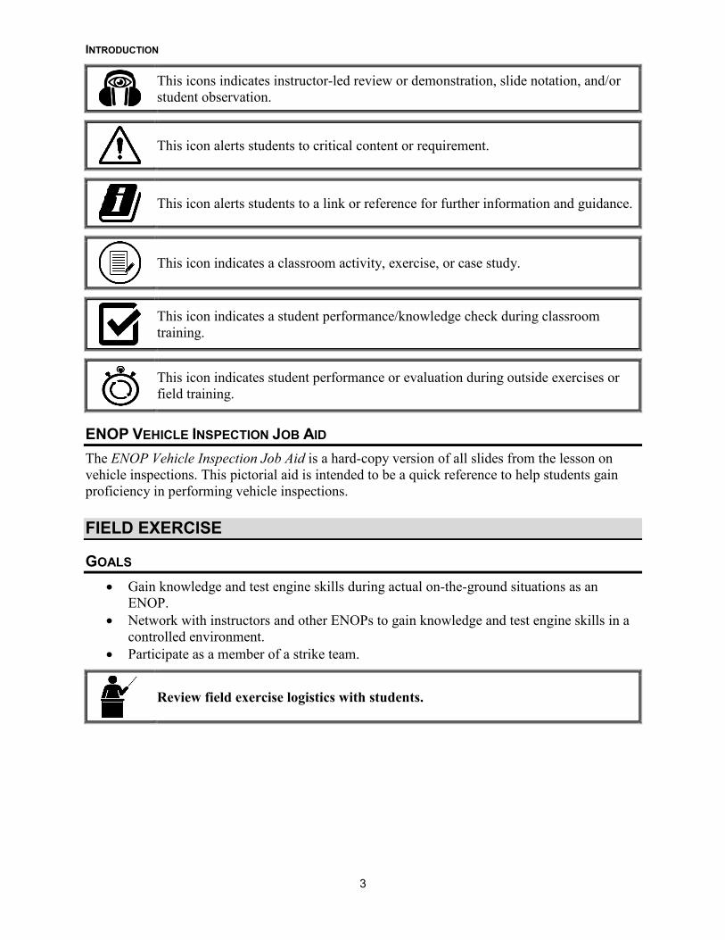
INTRODUCTION
3
This icons indicates instructor-led review or demonstration, slide notation, and/or student observation.
This icon alerts students to critical content or requirement.
This icon alerts students to a link or reference for further information and guidance.
This icon indicates a classroom activity, exercise, or case study.
This icon indicates a student performance/knowledge check during classroom training.
This icon indicates student performance or evaluation during outside exercises or field training.
ENOP VEHICLE INSPECTION JOB AID The ENOP Vehicle Inspection Job Aid is a hard-copy version of all slides from the lesson on vehicle inspections. This pictorial aid is intended to be a quick reference to help students gain proficiency in performing vehicle inspections.
FIELD EXERCISE
GOALS • Gain knowledge and test engine skills during actual on-the-ground situations as an
ENOP. • Network with instructors and other ENOPs to gain knowledge and test engine skills in a
controlled environment. • Participate as a member of a strike team.
Review field exercise logistics with students.
INTRODUCTION
4
PERFORMANCE AND EVALUATION ENOP student success is measured through quizzes and the “ENOP Training Evaluation Form” as described below. Students who pass all quizzes and the evaluation will receive their course certificate at the end of the training. Students who experience deficiency in specific areas will receive immediate feedback from their instructor(s); their course certificate and evaluations will be returned to the home unit for remediation. Supervisors will determine the proper course of action—take the course again, work with a mentor, etc. Supervisors will present the certificate when the student has mastered the knowledge, skill, or ability.
UNIT QUIZZES Students must pass each unit quiz with a 70%. Instructors may work with students as time allows or refer the student to the home unit for additional training.
ENOP TRAINING EVALUATION FORM The “ENOP Training Evaluation Form” is used to measure the student’s ability to meet course objectives. Satisfactory completion of all 25 tasks is needed to certify successful completion of this course. The form is located in this guide, the Student Workbook, and in both the facilitator and student toolkits.
BECOMING ENOP QUALIFIED Individuals desiring certification as an engine operator are required to complete the tasks found in the ENOP Position Task Book. Completion of the position task book is a function of the home unit. No tasks will be signed off while attending the ENOP course.
UNIT 1 – FIRE ENGINE MAINTENANCE LESSON A – DIESEL ENGINE OPERATION AND MAINTENANCE
5
UNIT 1 – FIRE ENGINE MAINTENANCE LESSON A – DIESEL ENGINE OPERATION AND MAINTENANCE
Given a simulated wildland fire incident scenario, case study, or exercise, students will be able to:
• Describe the differences between diesel fuel and gasoline. • Describe the major components of a diesel fuel system. • Describe correct operating procedures/parameters of starting a diesel engine. • Discuss the diesel particulate filter and its function in the regeneration
process. • Describe basic powertrain components of a fire apparatus and each
component’s operating characteristics.
BASIC DIESEL ENGINE OPERATION
DIESEL ENGINES VS. GASOLINE ENGINES Diesel engines are today’s work horses. Compared to gasoline engines, diesel engines:
• Built with stronger, heavy-duty components • Are more fuel-efficient • Produce torque at a lower revolution per minute (RPM) • Use compressed hot air to ignite their fuel mixtures, whereas gasoline engines use spark
plugs to ignite their fuel mixture • Weigh more
TORQUE AND HORSEPOWER The terms torque and horsepower are closely related. Torque is “the measurement of how much work can get done.”
• Torque = force x distance • Torque is what moves the vehicle.
In simple terms, horsepower is “how fast work gets done.” • Horsepower = torque ÷ time • Horsepower is what keeps the vehicle moving.
Typically, gas engines develop more horsepower where diesels produce more torque.
Visit the How Stuff Works website (https://auto.howstuffworks.com/diesel.htm) for more information on how diesel engines work.
UNIT 1 – FIRE ENGINE MAINTENANCE LESSON A – DIESEL ENGINE OPERATION AND MAINTENANCE
6
DIESEL FUEL DIESEL FUEL VS. GASOLINE
• Diesel fuel is heavier and oilier than gasoline. • Diesel fuel evaporates much more slowly than gasoline. • Diesel burns for a longer duration. • Diesel fuel has higher energy content (more energy per gallon) than gasoline.
OCTANE NUMBER VERSUS CETANE NUMBER Octane Number The octane number determines the fuel grade of the gasoline. In essence, the octane number is a measurement of a fuel’s ability to resist self-ignition when subjected to heat and pressure.
• The higher the octane number, the more control there is over the fuel’s ignition point. An 87 octane fuel will start to ignite at a lower temperature than a 93 octane fuel.
• Fuel should not start burning before the spark plug fires. This is an undesirable condition called fuel “knock” or “pre-ignition” which can
cause engine damage.
Cetane Number The cetane number is used to describe diesel fuel’s ignition characteristic (a measure of the ease with which the fuel is ignited in your engine).
• The higher the cetane number, the easier the fuel is to ignite. • The lower the cetane number, the harder an engine would be to start and the poorer the
ignition characteristic of the fuel. • A cetane number of 40 is common for most diesel engines.
Certain manufacturer warranties stipulate the use of 50 cetane-rated fuel for warranty purposes.
Use cetane boosters and diesel fuel additives/fuel conditioner to increase the cetane number.
ON-ROAD VERSUS OFF-ROAD DIESEL FUEL On-Road Diesel Fuel On-road diesel fuel refers to fuel used in vehicles that travel on federal, state, and local highways and roads.
• Users pay a road maintenance tax on this fuel. • Enforcement agencies distinguish between on- and off-road fuels by color. On-road fuel
is generally a yellowish to clear color.
Off-Road Diesel Fuel This fuel is used strictly for off-road use.
• Road maintenance taxes are not imposed on off-road diesel fuel. • Off-road diesel fuel can be identified by its reddish color (“red fuel”).
UNIT 1 – FIRE ENGINE MAINTENANCE LESSON A – DIESEL ENGINE OPERATION AND MAINTENANCE
7
NUMBER 2 AND NUMBER 1 DIESEL FUELS No. 2 and No. 1 diesel are two common grades of diesel fuel.
Number 2 (No. 2) Diesel No. 2 diesel is the most widely used diesel grade having more energy per gallon than No. 1 diesel.
• Provides improved power (heat energy) and better mileage than No. 1 diesel
Number 1 (No. 1) Diesel No. 1 diesel is most widely used in very cold environments.
• Considered a non-gelling fuel
Winter Grade In most areas where the weather can become cold, distributors will blend No. 1 and No. 2 diesel together for a winterized fuel.
DIESEL FUEL AND COLD WEATHER Diesel fuel is a hydrocarbon made up of paraffin (wax) that stays liquid as long as the outside air temperature stays warm. Diesel fuel has peculiarities related to low outside air temperatures including hard starting and gelled fuel.
Preventing Diesel Fuel from Gelling • Buy winter grade fuel in areas where temperatures consistently drop below 50 degrees
Fahrenheit. • Add a fuel conditioner.
Fuel conditioners break up wax crystals allowing them to flow through fuel filters. • Many diesel fuel systems employ fuel heaters to heat the fuel before it reaches the fuel
filters. This allows the fuel to flow through the filters when the temperature is at or above the
cloud point. • Keep your fuel tank full.
A full fuel tank helps reduce condensation (water) in the tank. Any amount of water in the fuel can freeze and stop all fuel flow to the engine.
DIESEL FUEL HANDLING PRACTICES Poor diesel engine performance can be the result of poor fuel handling practices. In addition to using clean diesel fuel and keeping your fuel tank full of fuel, follow the diesel fuel handling practices provided below.
GALVANIZED CONTAINERS
Never store diesel fuel in galvanized containers.
• Diesel fuel stored in a galvanized container will cause the galvanization to come off and contaminate the fuel and plug fuel filters.
UNIT 1 – FIRE ENGINE MAINTENANCE LESSON A – DIESEL ENGINE OPERATION AND MAINTENANCE
8
REPLACING FUEL FILTERS
Never pour the diesel fuel out of your old fuel filter into the new filter.
Pouring fuel out of an old fuel filter into a new filter will transfer the dirt from the old filter into the new filter and fuel system damage may occur.
WATER Water in a diesel fuel system will cause severe damage to the fuel system components and engine.
BIODIESEL Biodiesel is an alternative or additive to standard diesel fuel that is made from biological ingredients instead of petroleum (or crude oil).
• Usually made from plant oils or animal fat • Non-toxic and renewable • Safe and can be used in diesel engines with little or no modification needed.
USING BIODIESEL FUEL Biodiesel is a blended fuel—a certain percentage of biological ingredients to a certain percentage of diesel fuel.
• For example, the most common blend is B20, or 20 percent biodiesel to 80 percent diesel.
• B20 and B40 are the most common blends.
Use of blended fuel with a rating higher than B20 may void some manufacturer’s warranties.
BIODIESEL FUEL CONCERNS • In the past, biodiesel fuel were known to clog fuel filters in older diesel engines.
Biodiesel fuel should not be left in engine fuel tanks over the winter without fuel conditioners.
UNIT 1 – FIRE ENGINE MAINTENANCE LESSON A – DIESEL ENGINE OPERATION AND MAINTENANCE
9
DIESEL FUEL SYSTEMS Most diesel injection systems have common components. This section briefly addresses a few of those components as well as a few precautions and maintenance items.
FUEL TANK AND LINES
Fuel Tank • Use the correct, clean fuel. • Keep the tank full to prevent water from condensing on tank surfaces and contaminating
the fuel. • Ensure the fuel cap and the surrounding area are free of debris before refueling.
If a vacuum exists within the tank, check for a restricted fuel tank vent line.
Opening the fuel cap under vacuum may pull debris into the tank.
High- and Low-Pressure Fuel Lines Low-pressure fuel lines supply fuel to the high-pressure fuel pump and returns unused fuel back to the tank which lubricates and cools the injectors and the injector pump, and for bleeding the filters. High-pressure fuel lines carry fuel from the fuel injection pump to the injectors.
Pressure can vary between 60,000 and 90,000 PSI and may cause injury or death if not handled correctly. Do not crack fuel lines to bleed a fuel system.
PRIMARY AND SECONDARY FUEL FILTERS The fuel filter’s job is to collect water and dirt particles which cause the engine to run poorly or damage the injection equipment.
Primary Filter/Water Separator The first filter beyond the fuel tank is called the primary filter. The primary filter removes larger particles. A sensor on the primary filter determines when water is present in the fuel and illuminates the water in fuel (WIF) light on the instrument panel.
If the WIF light comes on, the ENOP should stop the vehicle and drain the water immediately by releasing the drain valve.
Secondary Fuel Filter Secondary filters are sometimes called final filters because they are the last defense before the fuel goes into the injectors. The secondary filter removes smaller particles.
UNIT 1 – FIRE ENGINE MAINTENANCE LESSON A – DIESEL ENGINE OPERATION AND MAINTENANCE
10
Filter Maintenance • At a minimum, drain the primary filter once a week. (See the owner’s manual for proper
procedures.) • Replace the primary and secondary filter when the engine oil is changed.
Hand Primer Pump Many diesel engines have a hand primer pump to bleed the fuel system when a fuel filter is changed or if the vehicle has run out of fuel. Some fuel systems do not require a hand primer pump to bleed the fuel system; these systems purge themselves automatically.
• The bleeder must be opened to allow air to escape during hand primer pump operations.
INJECTION PUMP The injection pump is the device that delivers high-pressure fuel to the injectors.
INJECTORS The injector assembly is made up of the nozzle assembly, pressure spring and spindle, nozzle holder (injector body), and a cover. Fuel passes through the injector assembly and becomes highly pressurized and is forced from the injector as an atomized spray into the combustion chamber.
• Injection pressures in diesel fuel systems can reach as high as 26,000 PSI. Many of the new diesel fuel systems can cause serious injury and/or death if mishandled.
• ENOPs should not tamper with, adjust, or attempt any repairs on diesel fuel injection systems. If problems arise, consult a technician.
“HOW AN INJECTOR WORKS”
HIGH-PRESSURE COMMON RAIL SYSTEMS • The high-pressure rail binds the pump and injectors together and supplies compressed
fuel to the injector. Allows for a smoother running engine, better fuel economy, and reduced emissions. In today’s diesel engines, fuel leaves the injector at 60,000-90,000 PSI.
For comparison, this number falls within waterjet operation pressures. Waterjets use highly pressurized water to cut through many different types of materials, including plastic, wood, steel, and aluminum.
Water at this pressure can cause severe damage to the injection pump and injectors.
• Drain the water/fuel separator weekly or as needed. If you have compromised fuel, more service may be required.
UNIT 1 – FIRE ENGINE MAINTENANCE LESSON A – DIESEL ENGINE OPERATION AND MAINTENANCE
11
GLOW PLUGS AND HEATING GRIDS Glow plugs assist with heating the combustion chamber. They are generally located in the cylinder head with the hot end protruding into the combustion chamber. Heating grids are located in the air intake system close to the intake manifold and help raise the temperature of the air entering the cylinder to help with the cold start of the engine. If ambient temperatures are lower than about 50 degrees Fahrenheit, glow plugs and heater grids may be energized.
When energized, the glow plug or heater grid temperature can reach 1,500 degrees Fahrenheit.
In some diesel engines glow plugs and heater grids may come on after the engine has run for many hours and while the engine is running. This can be seen when the vehicle’s volt meter drops and/or the headlights or other lighting systems dim momentarily. This dimming or volt meter drop is normal since glow plugs and heater grids use a significant amount of electrical energy.
If diesel engine seems to be hard starting, some glow plugs and heater grids may be inoperable.
ELECTRONIC CONTROL MODULE (ECM) With the introduction of electronics, most modern diesel fuel systems incorporate an electronic control module (ECM). The ECM is the brain for all engine controls—the fuel injectors, turbocharger, transmission, and even some of the air conditioning components.
• The ECM can also control many external options, including cruise control, power take-off (PTO) controls, and instrument panel engine indicators.
• Care is needed when cleaning the engine compartment to prevent water from getting to the electrical components and the ECM.
DIESEL ENGINE COMPONENTS TURBOCHARGERS
Turbocharger Basics Turbochargers are devices that force more air into the engine. By forcing more air into the combustion chamber, more fuel can be added, creating more horsepower for the engine.
• Turbochargers are basically a bolt-on horsepower increaser device with no mechanical connection to the engine.
• The turbine and the compressor wheel inside the turbocharger turn at the same speed because they are mounted to the same shaft.
• Hot exhaust gases leave the engine and are diverted to the turbine housing. • The housing starts out larger at the beginning and then narrows as it gets closer to the
turbine. This narrowing causes the exhaust gases to accelerate. • Accelerated gases hitting the turbine wheel at full load causes the turbine wheel to spin at
a speed of about 80,000 to 95,000 RPM. This momentum is transferred to the compressor
UNIT 1 – FIRE ENGINE MAINTENANCE LESSON A – DIESEL ENGINE OPERATION AND MAINTENANCE
12
wheel, causing it to draw considerably more air in thus pushing more air into the engine. The overage of air is called boost pressure or “turbo boost.”
Turbocharger Considerations ENOPs should be aware of several considerations related to turbochargers.
• Turbochargers are lubricated and cooled by engine oil from the engine. • Turbochargers operate under severe conditions.
The exhaust temperatures on the turbine side can exceed temperatures of over 1,300 degrees Fahrenheit.
Turbine and compressor speeds can exceed 90,000 RPM.
Never rev up the engine and then shut it off. • When the engine is turned off after revving, the turbocharger loses its
lubrication which can cause damage.
• Always let the engine idle down for at least 3-5 minutes when it is hot or has been in heavy use. This allows heat which has built up in the turbocharger and the engine to dissipate
into the atmosphere providing the turbocharger and engine a longer life.
AFTERCOOLER Aftercoolers are added to turbocharged engines to cool the compressed air that was generated by the turbocharger effectively reducing emissions. The aftercooler is located in front of the radiator and can easily become plugged with vegetative material. Therefore, keep this area free from debris and other contaminants.
• A plugged aftercooler can cause the engine to overheat or result in poor engine performance.
Periodically check aftercooler duct clamps. • Loose clamps can result in a drastic reduction in engine performance.
AIR CLEANER/FILTER The air filter prevents abrasive particulate matter from entering the engine's cylinders where it would cause mechanical wear and oil contamination. As little as two tablespoons of dirt can ruin your engine.
Air Cleaner Maintenance • Check and tap out the air cleaner filter daily, especially when you are working in severe
conditions like wildland firefighting.
• Replace a damaged air cleaner element.
Do not drive an engine with a damaged air cleaner element; wait for a replacement.
Never use compressed air to blow out an air filter.
UNIT 1 – FIRE ENGINE MAINTENANCE LESSON A – DIESEL ENGINE OPERATION AND MAINTENANCE
13
• Check intake piping for dirt; clean out as necessary. Seal any area where dirt may enter the air system beyond the air filter.
Air Cleaner Restriction Gauge Air cleaner restriction gauges are placed between the air cleaner and the engine and work on vacuum. When the air cleaner becomes dirty, it causes the gauge to read in the red, telling the operator to service the air cleaner. These gauges can be deceiving. If a leak in the piping between the air cleaner and the engine is created, the gauge may not show that the air cleaner ever gets dirty because the dirty air is bypassing the air cleaner and not getting cleaned. If you are checking your gauge every day and it is okay but other ENOPs on the fire are cleaning their air cleaners daily, you may want to check for an intake leak.
Reasons for Black Smoke Most modern diesel engines have electronic controls and will not smoke under most conditions. Occasional black smoke may appear when going up a steep grade, operating at higher altitudes, pulling a heavy load, or during heavy acceleration. If you notice black smoke while the engine is idling at low altitude or under normal driving conditions, check for a plugged air cleaner. If no blockage is found or the condition continues, consult a technician for a diagnosis.
COOLING SYSTEM
Radiator The radiator is designed to transfer heat away from the engine, keeping the engine cool.
• Always make sure the radiator is free of debris.
Fan The cooling fan is used to pull air through the radiator, intercooler, transmission cooler and the air conditioning condenser.
• Make sure the fan is operating correctly.
Exhaust System The exhaust system is in place to reduce and channel heat and combustion by-products away from the engine. Exhaust system components include the exhaust manifold, exhaust pipe, diesel particulate filter (DPF), muffler, and tailpipe. The muffler and DPF are described below. Muffler The muffler dampens sounds produced from the engine but has no filtering capabilities. Trucks with DPFs do not have mufflers.
Diesel Particulate Filter (DPF) The diesel particulate filter (DPF) was added to all post-2007 diesel engine exhaust systems to meet air quality standards. The DPF is designed to collect and incinerate diesel particulate matter or soot from the exhaust gas of a diesel engine and aids in dampening engine motor noise.
UNIT 1 – FIRE ENGINE MAINTENANCE LESSON A – DIESEL ENGINE OPERATION AND MAINTENANCE
14
DPFs must be cleaned out intermittently or continuously to avoid plugging up the filter. Excessive exhaust back pressure due to a plugged filter can damage the engine and the DPF.
• Biodiesel fuel use tends to plug DPFs more often resulting in increased regeneration rates.
DPF Regeneration The process of cleaning the filter is known as “regeneration.”
Vehicle manufacturers have different regeneration processes. Read and understand the information in the vehicle owner’s manual.
• The yellow regeneration indicator light on the instrument panel tells the operator that some process of regeneration needs to be done (passive, active, or manual).
• Regeneration is generally done automatically by passive and active systems without driver involvement. Passive systems use only the exhaust gas stream to burn out the soot. Active systems use a fuel burner that heats the filter to soot combustion temperatures.
• Regeneration can also be done manually by the driver through a process called “parked regeneration” or “manual stationary regeneration.” A flashing yellow regeneration indicator light on the instrument panel tells drivers
they should perform a parked regeneration. If the yellow regeneration indicator light is flashing and a yellow triangle light
appears on the instrument panel, the driver must perform a parked regeneration. Active and passive regeneration systems have been disabled resulting in decreased engine performance and potential severe engine damage.
If parked regeneration does not clear the yellow regeneration indicator lights and a red regeneration indicator light comes on the instrument panel, stop the truck immediately in a safe area. To avoid severe engine damage, turn off the engine and call a mechanic.
When performing parked regeneration, position the engine away from people, flammable materials, and/or structures. Exhaust temperatures are extremely hot.
Any time a parked regeneration is performed, FEMPR documentation must be completed.
Diesel Exhaust Fluid (DEF) • DEF has a shelf life. • DEF can freeze. • Running out of DEF will result in a derated motor and limited speeds. The motor may
also shut down, making the vehicle inoperable. • Use correct DEF. The use of other fluids will damage the system and make for costly
repairs.
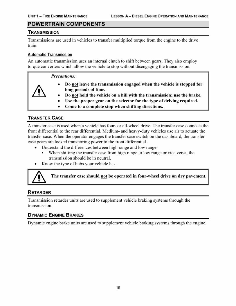
UNIT 1 – FIRE ENGINE MAINTENANCE LESSON A – DIESEL ENGINE OPERATION AND MAINTENANCE
15
POWERTRAIN COMPONENTS TRANSMISSION Transmissions are used in vehicles to transfer multiplied torque from the engine to the drive train.
Automatic Transmission An automatic transmission uses an internal clutch to shift between gears. They also employ torque converters which allow the vehicle to stop without disengaging the transmission.
Precautions:
• Do not leave the transmission engaged when the vehicle is stopped for long periods of time.
• Do not hold the vehicle on a hill with the transmission; use the brake. • Use the proper gear on the selector for the type of driving required. • Come to a complete stop when shifting directions.
TRANSFER CASE A transfer case is used when a vehicle has four- or all-wheel drive. The transfer case connects the front differential to the rear differential. Medium- and heavy-duty vehicles use air to actuate the transfer case. When the operator engages the transfer case switch on the dashboard, the transfer case gears are locked transferring power to the front differential.
• Understand the differences between high range and low range. When shifting the transfer case from high range to low range or vice versa, the
transmission should be in neutral. • Know the type of hubs your vehicle has.
The transfer case should not be operated in four-wheel drive on dry pavement.
RETARDER Transmission retarder units are used to supplement vehicle braking systems through the transmission.
DYNAMIC ENGINE BRAKES Dynamic engine brake units are used to supplement vehicle braking systems through the engine.
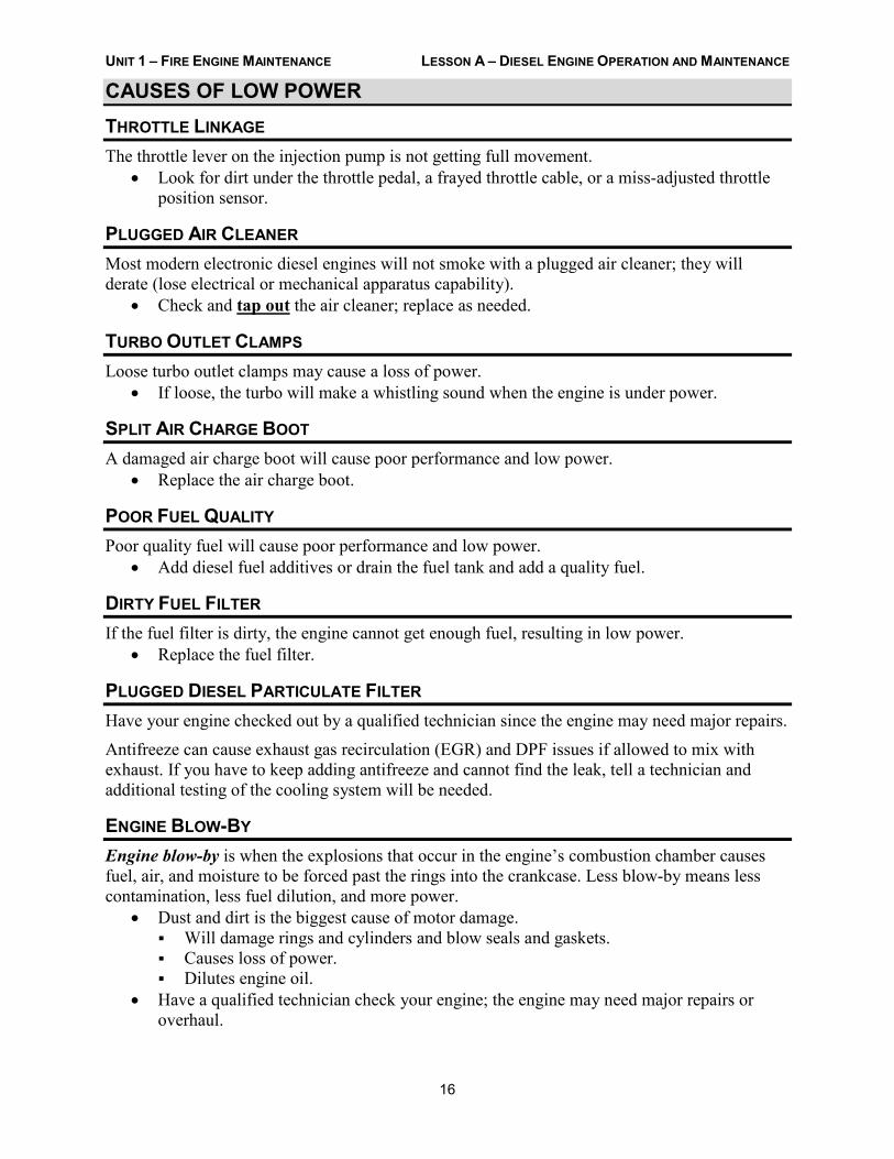
UNIT 1 – FIRE ENGINE MAINTENANCE LESSON A – DIESEL ENGINE OPERATION AND MAINTENANCE
16
CAUSES OF LOW POWER THROTTLE LINKAGE The throttle lever on the injection pump is not getting full movement.
• Look for dirt under the throttle pedal, a frayed throttle cable, or a miss-adjusted throttle position sensor.
PLUGGED AIR CLEANER Most modern electronic diesel engines will not smoke with a plugged air cleaner; they will derate (lose electrical or mechanical apparatus capability).
• Check and tap out the air cleaner; replace as needed.
TURBO OUTLET CLAMPS Loose turbo outlet clamps may cause a loss of power.
• If loose, the turbo will make a whistling sound when the engine is under power.
SPLIT AIR CHARGE BOOT A damaged air charge boot will cause poor performance and low power.
• Replace the air charge boot.
POOR FUEL QUALITY Poor quality fuel will cause poor performance and low power.
• Add diesel fuel additives or drain the fuel tank and add a quality fuel.
DIRTY FUEL FILTER If the fuel filter is dirty, the engine cannot get enough fuel, resulting in low power.
• Replace the fuel filter.
PLUGGED DIESEL PARTICULATE FILTER Have your engine checked out by a qualified technician since the engine may need major repairs. Antifreeze can cause exhaust gas recirculation (EGR) and DPF issues if allowed to mix with exhaust. If you have to keep adding antifreeze and cannot find the leak, tell a technician and additional testing of the cooling system will be needed.
ENGINE BLOW-BY Engine blow-by is when the explosions that occur in the engine’s combustion chamber causes fuel, air, and moisture to be forced past the rings into the crankcase. Less blow-by means less contamination, less fuel dilution, and more power.
• Dust and dirt is the biggest cause of motor damage. Will damage rings and cylinders and blow seals and gaskets. Causes loss of power. Dilutes engine oil.
• Have a qualified technician check your engine; the engine may need major repairs or overhaul.
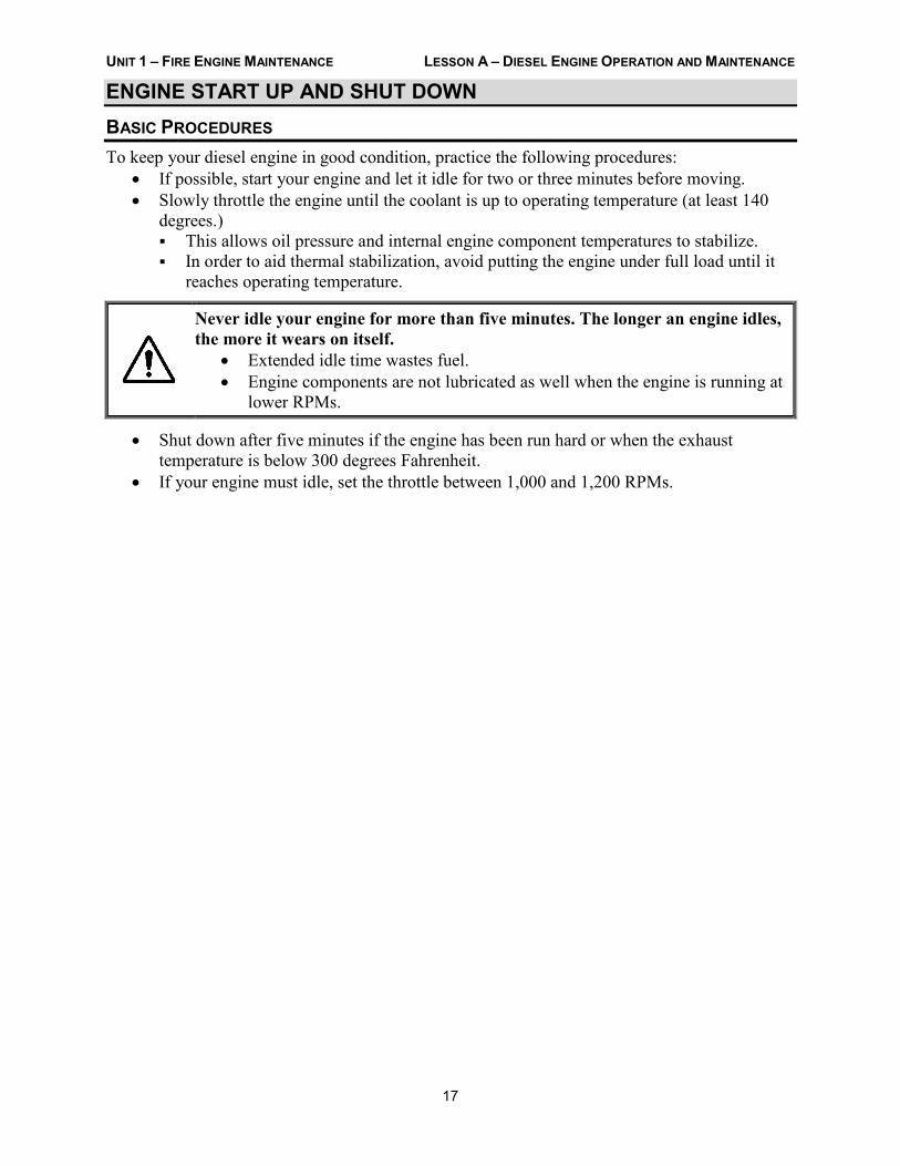
UNIT 1 – FIRE ENGINE MAINTENANCE LESSON A – DIESEL ENGINE OPERATION AND MAINTENANCE
17
ENGINE START UP AND SHUT DOWN BASIC PROCEDURES To keep your diesel engine in good condition, practice the following procedures:
• If possible, start your engine and let it idle for two or three minutes before moving. • Slowly throttle the engine until the coolant is up to operating temperature (at least 140
degrees.) This allows oil pressure and internal engine component temperatures to stabilize. In order to aid thermal stabilization, avoid putting the engine under full load until it
reaches operating temperature.
Never idle your engine for more than five minutes. The longer an engine idles, the more it wears on itself.
• Extended idle time wastes fuel. • Engine components are not lubricated as well when the engine is running at
lower RPMs.
• Shut down after five minutes if the engine has been run hard or when the exhaust temperature is below 300 degrees Fahrenheit.
• If your engine must idle, set the throttle between 1,000 and 1,200 RPMs.

UNIT 1 – FIRE ENGINE MAINTENANCE LESSON C – DIESEL ENGINE OPERATION AND MAINTENANCE
18
NOTES
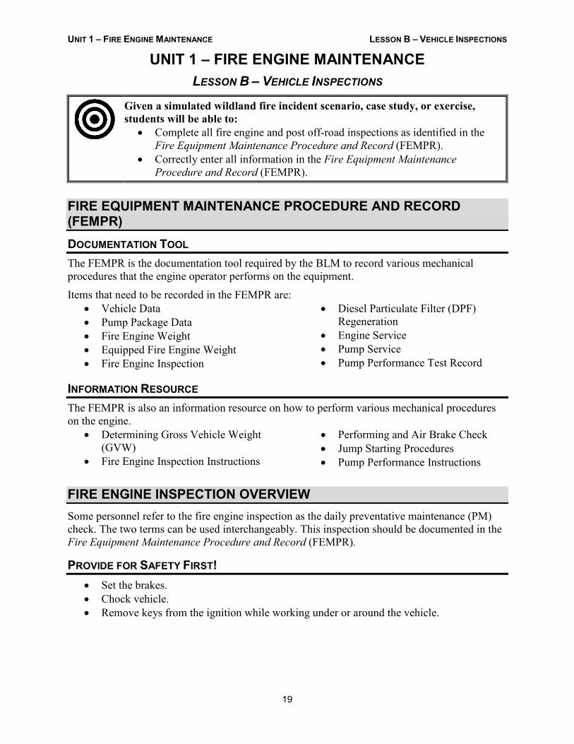
UNIT 1 – FIRE ENGINE MAINTENANCE LESSON B – VEHICLE INSPECTIONS
19
UNIT 1 – FIRE ENGINE MAINTENANCE LESSON B – VEHICLE INSPECTIONS
Given a simulated wildland fire incident scenario, case study, or exercise, students will be able to:
• Complete all fire engine and post off-road inspections as identified in the Fire Equipment Maintenance Procedure and Record (FEMPR).
• Correctly enter all information in the Fire Equipment Maintenance Procedure and Record (FEMPR).
FIRE EQUIPMENT MAINTENANCE PROCEDURE AND RECORD (FEMPR) DOCUMENTATION TOOL The FEMPR is the documentation tool required by the BLM to record various mechanical procedures that the engine operator performs on the equipment. Items that need to be recorded in the FEMPR are:
• Vehicle Data • Pump Package Data • Fire Engine Weight • Equipped Fire Engine Weight • Fire Engine Inspection
• Diesel Particulate Filter (DPF) Regeneration
• Engine Service • Pump Service • Pump Performance Test Record
INFORMATION RESOURCE The FEMPR is also an information resource on how to perform various mechanical procedures on the engine.
• Determining Gross Vehicle Weight (GVW)
• Fire Engine Inspection Instructions
• Performing and Air Brake Check • Jump Starting Procedures • Pump Performance Instructions
FIRE ENGINE INSPECTION OVERVIEW Some personnel refer to the fire engine inspection as the daily preventative maintenance (PM) check. The two terms can be used interchangeably. This inspection should be documented in the Fire Equipment Maintenance Procedure and Record (FEMPR).
PROVIDE FOR SAFETY FIRST! • Set the brakes. • Chock vehicle. • Remove keys from the ignition while working under or around the vehicle.
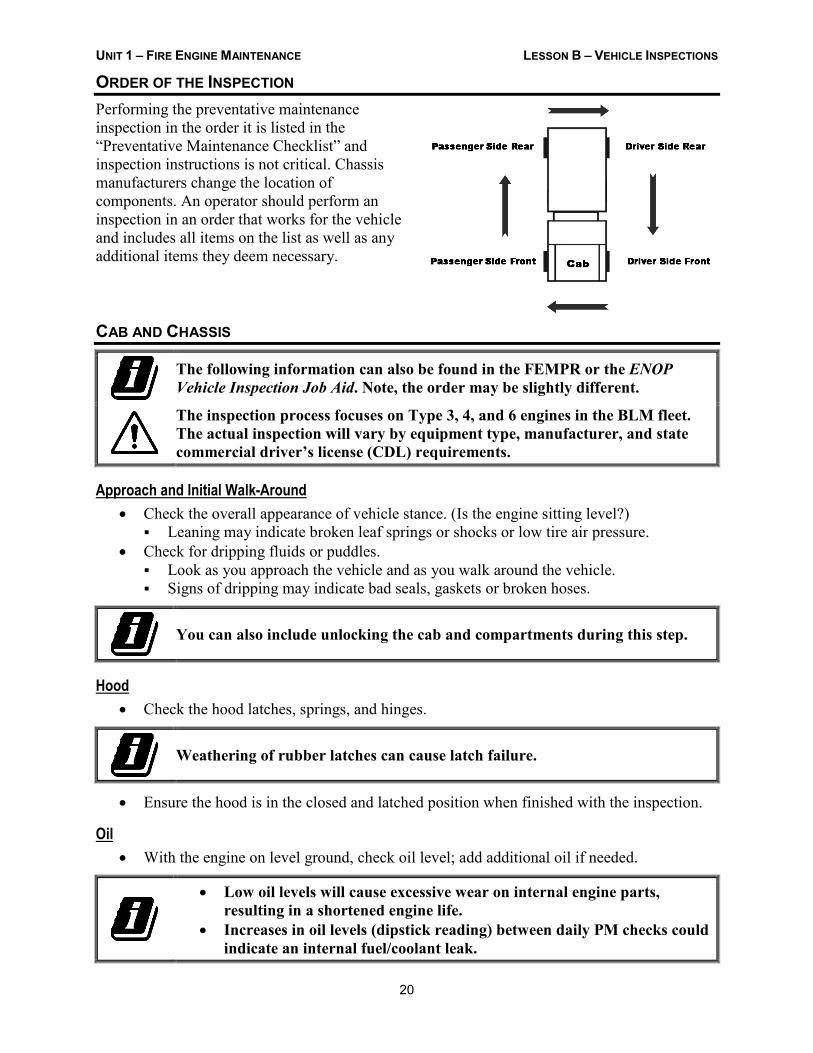
UNIT 1 – FIRE ENGINE MAINTENANCE LESSON B – VEHICLE INSPECTIONS
20
ORDER OF THE INSPECTION Performing the preventative maintenance inspection in the order it is listed in the “Preventative Maintenance Checklist” and inspection instructions is not critical. Chassis manufacturers change the location of components. An operator should perform an inspection in an order that works for the vehicle and includes all items on the list as well as any additional items they deem necessary.
CAB AND CHASSIS
The following information can also be found in the FEMPR or the ENOP Vehicle Inspection Job Aid. Note, the order may be slightly different.
The inspection process focuses on Type 3, 4, and 6 engines in the BLM fleet. The actual inspection will vary by equipment type, manufacturer, and state commercial driver’s license (CDL) requirements.
Approach and Initial Walk-Around • Check the overall appearance of vehicle stance. (Is the engine sitting level?)
Leaning may indicate broken leaf springs or shocks or low tire air pressure. • Check for dripping fluids or puddles.
Look as you approach the vehicle and as you walk around the vehicle. Signs of dripping may indicate bad seals, gaskets or broken hoses.
You can also include unlocking the cab and compartments during this step.
Hood • Check the hood latches, springs, and hinges.
Weathering of rubber latches can cause latch failure.
• Ensure the hood is in the closed and latched position when finished with the inspection.
Oil • With the engine on level ground, check oil level; add additional oil if needed.
• Low oil levels will cause excessive wear on internal engine parts, resulting in a shortened engine life.
• Increases in oil levels (dipstick reading) between daily PM checks could indicate an internal fuel/coolant leak.
UNIT 1 – FIRE ENGINE MAINTENANCE LESSON B – VEHICLE INSPECTIONS
21
Power Steering Fluid The power steering system is a closed system, meaning it should not use or lose any fluid.
• If the fluid levels are low, add fluid and thoroughly check the system for leaks.
Low levels can overheat the pump and/or cause steering failure.
Fuel Filter Engines may have more than one fuel filter. On most Type 6 engines, the fuel filter and water separator are one component (fuel/water separator).
Fuel/Water Separator Water can severely damage components within the fuel injection system.
• Ensure there are no leaks. • Drain at standard intervals or follow manufacturer’s recommendations.
Automatic Transmission Fluid • With the engine on level ground,
Ensure the transmission fluid level meets manufacturer's recommendations. Ensure fluid is the correct consistency, color and does not have a burnt smell.
There are different procedures for checking the transmission fluid depending on manufacturer.
• Some models need to be checked when the vehicle is off and the fluid is cold; some need to be running and at operating temperatures.
• Check the vehicle operator's manual for the correct procedure for your vehicle.
Hydraulic Brake Fluid • Check fluid level; add if needed.
Low levels can lead to brake failure.
Fan and Fan Belts • Ensure the fan moves freely, has no cracks, and blades are tight. • Look for chips where the fan may have contacted the shroud. • Check tension of belts.
Some motors have a tensioner gauge built into the system.
• Visually inspect belts for wear, frays, or cracks on the drive side of the belt.
UNIT 1 – FIRE ENGINE MAINTENANCE LESSON B – VEHICLE INSPECTIONS
22
• Worn fan belts can brake without warning. • A loose belt can slip, causing steering, cooling, and charging problems.
Driver Side Front Tire, Rim, Hub, and Suspension Rim and Hub
• Ensure lug nuts are present and tight.
• Look for rust stains on steel wheels and black streaks on aluminum wheels; stains indicate a loose lug nut.
• Loose lug nuts can cause stress and wear on the wheel studs, not to mention the potential for loss of control while driving.
• Inspect rims for damage and proper mounting. Ensure valve stems on “inside” duals are lined up and accessible. Look for dents and cracks.
• Check manual hubs, if equipped. Check for lubrication leaks and proper operation. Ensure hub is in the “free” position.
Tire Damage, Wear, and Inflation • Perform exterior visual inspections of tires daily and prior to release from any incident.
Look for the following deficiencies: Signs of tire deterioration related
to age Weather cracking Separation Bulges
Holes Sidewall damage Tread depth, tread condition and
uneven wear
The WCF 600-series fire fleet vehicle tires that meet any of the following criteria will be replaced using WCF or benefiting activity funds as appropriate:
• Any tire in service six calendar years from the Department of Transportation (DOT) tire identification number (TIN) date of manufacture.
• Sidewall is cut, worn, or damaged to the extent that the steel or fabric ply cord is exposed.
• Excessive tread damage including cuts, holes or excessive numbers of missing tread lugs.
• Tread depth less than 4/32 of an inch. • Visible bumps or knots related to tread or sidewall separation. • Tire service technician recommendation.
Comprehensive tire inspections of all tires (including spare tires) will be completed during required annual inspections/service and at 10,000 mile intervals. Comprehensive inspections will be completed by tire service technicians and will include interior and exterior visual inspection. All daily, post incident and comprehensive tire inspections and tire replacement will be documented in the applicable FEMPR. Replacement tires must meet vehicle specifications for size, load rating, speed rating and mission.
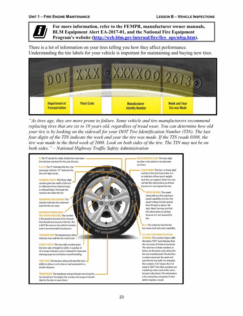
UNIT 1 – FIRE ENGINE MAINTENANCE LESSON B – VEHICLE INSPECTIONS
23
For more information, refer to the FEMPR, manufacturer owner manuals, BLM Equipment Alert EA-2017-01, and the National Fire Equipment Program’s website (http://web.blm.gov/internal/fire/fire_ops/nfep.htm).
There is a lot of information on your tires telling you how they affect performance. Understanding the tire labels for your vehicle is important for maintaining and buying new tires.
“As tires age, they are more prone to failure. Some vehicle and tire manufacturers recommend replacing tires that are six to 10 years old, regardless of tread wear. You can determine how old your tire is by looking on the sidewall for your DOT Tire Identification Number (TIN). The last four digits of the TIN indicate the week and year the tire was made. If the TIN reads 0308, the tire was made in the third week of 2008. Look on both sides of the tire. The TIN may not be on both sides.” – National Highway Traffic Safety Administration
UNIT 1 – FIRE ENGINE MAINTENANCE LESSON B – VEHICLE INSPECTIONS
24
Suspension – Leaf Springs and Mounts • Inspect the leaf springs and mounts.
Look for cracked, broken, or missing leaf springs. Inspect U-bolts and springs for proper alignment (out-of-alignment springs could be a
broken center bolt). Ensure U-bolts are tight. Check spring hangers, shackles, and bushings for wear as well as cracks or breaks. Check bump-stops for wear and damage.
Suspension – Shock Absorber • Inspect shock absorber mounting hardware for tightness. • Ensure shock absorber is free from fluid leaks and dents.
Suspension – Steering Components • Check steering column for play in the slip joint and universal joint. • Steering box should be free of leaks and cracks where the box bolts to the frame. • Ensure the Pitman arm and draglink are not cracked or bent. • Check the steering knuckle for play. • Ensure joints and sockets are not worn or loose. • Check joints and sockets for loose or missing nuts, bolts, or cotter pins.
Suspension – Tie Rods and Sway Bars Tie rods and sway bars are some of the lowest parts on the vehicle and are susceptible to damage.
• Ensure tie rods and sway bars are not bent. • Ensure bushings and joints are not worn or loose.
Front Bumper and Wheel Chocks • Ensure the brush guard, license plate, and skid plate are present, free of damage, and all
mounting hardware is tight. • Ensure both wheel chocks are present and the retention mechanisms on the wheel chock
holders function properly.
Coolant Level, Radiators, and Hoses • Check the coolant level and add if needed.
Frequently adding coolant could be a sign of an external leak or an internal motor problem.
• Check coolant color. • Check hoses for leaks, signs of wear, bulging, or cracking and hose clamps for tightness. • Check for signs of pooled or evaporated coolant around major engine components.
Chassis manufacturers have started using different coolant with very specific requirements. DO NOT mix different types of coolant! Check the chassis operator's/owner's manual to ensure you are using the correct coolant to prevent damage and voiding the warranty. Without proper coolant levels the motor may overheat causing numerous problems.
UNIT 1 – FIRE ENGINE MAINTENANCE LESSON B – VEHICLE INSPECTIONS
25
Radiator In modern vehicles, the radiator/cooling system is comprised of various components. Aside from the primary radiator, other components or groups of components include the fan, secondary radiator/intercooler, engine oil cooler, transmission cooler, and air conditioner condenser. These coolers are constructed with aluminum fins that can become plugged with sagebrush, plant seeds, dust, dirt, and other contaminants. Debris can become lodged between stacked fins.
• Periodically check the radiator/cooling system for the buildup of foreign matter, and have it removed.
You can use compressed air to clean the radiator/cooling system with a variety of tools that can be store bought (“air comb”) or homemade.
DO NOT use pressurized water to clean the radiator as the force is too great and will flatten the aluminum fins, reducing the system’s ability to cool.
The radiator in the slide was pulled off a Nevada engine that was overheating after only one and a half seasons.
Air Filters (including air conditioner, cabin, and ember separators) • Carefully inspect filters, mounting brackets, inlet hose connections, and fittings.
Dirty air filters can cause loss of power and engine damage.
• Inspect gasket and sealing surface areas. • Replace service element if needed. • Ensure ember separators are clear of particulates.
If the ember separator is plugged, the engine may fail to start.
Do not use compressed air to blow out the air filter. • Doing so will create small unseen holes that allow dust to slip through
and damage the engine components. Filter elements can be lightly tapped to dislodge the dust and/or vacuumed out to extend the service life. If in doubt, replace the filter.
• Check air filter restriction gauge. • Reset the air filter restriction gauge after a filter change.
Hoses • Check hoses for leaks, signs of wear, bulging, or cracking. • Check hose clamps for tightness. • Check for signs of pooled or evaporated coolant around major engine components.
Passenger Side Front Tire, Rim, Hub and Suspension • Refer to “Driver Side Front Tire, Rim, Hub, and Suspension.”
UNIT 1 – FIRE ENGINE MAINTENANCE LESSON B – VEHICLE INSPECTIONS
26
Fuel Tank and Brackets • Ensure the fuel tank is full and securely mounted.
Tank straps can break causing slippage.
• If accessible, look inside the tank to ensure the gauge is functioning properly. • Ensure the fuel tank is free from leaks.
Passenger Side Door(s) • Check latch, lock, handhold, mirror, hinges, and window regulator.
Passenger Side General Condition • Ensure fire engine is clean and orderly in appearance. • Ensure agency emblems, decals, and, equipment numbers are present and in good
condition. • Ensure cabinet latches, hinges, and locks are in good working condition.
Users must be able to get into the cabinets without much effort and be able to lock cabinets to secure equipment.
Passenger Side Undercarriage • Check for loose bolts, hanging wires, leaks, and broken parts. • Ensure the undercarriage is free of debris. Clean out debris if found. • Inspect steering components, drive train, body mounts, and cross members for
functionality and damage. • Check the package mounting brackets and bolts.
Exhaust • Ensure the exhaust system is leak-free and all heat protection shielding is in place. • Inspect all exhaust mounting brackets and guards.
Black carbon buildup is a sign of an exhaust leak.
Passenger Side Rear Tire, Rim, Hub and Suspension • Refer to ‘Driver Side Rear Tire, Rim, Hub, and Suspension.”
Rear Undercarriage (Plumbing) • Check for loose bolts and plumbing hanger brackets. • Check for leaking plumbing hoses and pipes. • Check for damage to rear differential and axle. • Check for loose or damaged wiring. • Inspect frame, cross members, and underbody protection for cracks, damage; ensure area
is free of vegetation and debris.
UNIT 1 – FIRE ENGINE MAINTENANCE LESSON B – VEHICLE INSPECTIONS
27
Vehicle Rear • Ensure no loose items are on the back platform. • Ensure bumper, step(s), and license plate are securely fastened. • Ensure spare tire is present and properly inflated. • Ensure mud flaps are present and in good condition. • Ensure reflective tape, decals, license plate, and lights are clean and visible.
Top Deck, Handrails, and Steps • Ensure all equipment (coolers, bladder bags, hose packs, etc.) transported on the top deck
is secured. • Ensure handrails, storage boxes, and hand reels are mounted securely and all
compartment latches are secured.
Driver Side General Condition • Refer to “Passenger Side General Condition.”
Driver Side Rear Tire, Rim, Hub and Suspension • Refer to “Passenger Side Rear Tire, Rim, Hub, and Suspension.”
Driver Side Undercarriage • Refer to “Passenger Side Undercarriage.”
Air Tanks and Lines • Open air tank drains and bleed off moisture and oil.
Excessive moisture or oil could signal a problem with the air drier or compressor.
• Inspect mounting brackets. • Ensure air lines are secure. • Ensure air lines are free of leaks, cracks, bulging, or chafing.
Batteries • Ensure batteries are secure, connections are tight, and cell caps are in place. • Ensure battery connections are not excessively corroded.
Corroded battery connections can cause starting and charging problems.
Know location(s) of fuse panels, electric junction boxes, multiplexed terminal blocks, and circuit breakers.
Common locations include behind the passenger seat, behind dashboard panels/covers, under the hood near the battery and/or on the firewall, on the frame near the driver’s side steps, hose reels, hidden panels within package compartments, and behind or below the pump panel. Some components may be hidden behind the license plate or other covers on the rear of the vehicle.
UNIT 1 – FIRE ENGINE MAINTENANCE LESSON B – VEHICLE INSPECTIONS
28
Driver Side Door(s) • Refer to “Passenger Side Door(s).”
Wheel Chocks • Ensure wheel chocks are available and easily accessible. • Ensure wheel chocks are secure when the vehicle is traveling. • Ensure latches and hinges on folding wheel chocks are functioning properly.
As a safety precaution, wheel chocks must be used whenever the vehicle is left unattended or during engine operations in a stationary mode.
INSIDE CAB
Start Engine • Allow engine to reach operating temperature and leave running for electrical checks. • Ensure the “water in fuel” light goes off after engine starts.
• If light stays on, water needs to be drained from fuel/water separator. • Water in fuel can damage engine.
• If engine fails to start, Ensure master switch is on. Ensure fuel tank has fuel. Check for and tighten loose battery connections. Check for dead battery. If the battery is dead, follow jump starting procedures.
When jump starting, ensure battery voltage systems are compatible (12-volt to 12-volt or 24-volt to 24-volt). Never jump a lower-volt battery system with a higher-volt battery system.
Refer to the FEMPR or owner’s manual for jump starting procedures.
Lights and Signals • Turn on and check the operation of all lights on the chassis and fire package which
includes, but is not limited to, headlights, off-road lights, turn signals, running lights, brake, reverse, hazard, license plate, light bar, emergency, scene or work, pump panel, compartment, step, cab, and dashboard.
• Replace burned out bulbs as necessary.
Most fire vehicles are equipped with an intelligent electrical multiplex system. This system is programmed to "shed" or turn off certain lights if the battery voltage drops to a predetermined point. It is recommended that you have the vehicle started and high idle engaged while checking the lights. If the vehicle has a light bar equipped with white or clear forward facing lights, those lights will only function if the vehicle transmission is not in neutral and the parking brakes are not engaged.
UNIT 1 – FIRE ENGINE MAINTENANCE LESSON B – VEHICLE INSPECTIONS
29
Mirrors and Windows • Ensure all mirrors and windows are clean • Inspect mirrors and windows for cracks or chips. • Inspect mirror mounts for damage or looseness. • Ensure mirrors are properly adjusted.
Clean and properly adjusted mirrors and glass can prevent accidents.
Windshield Wipers and Washer • Ensure windshield wipers work on all speeds, and rubber is free of cracks, splits, and
weathering. • Ensure the washer system functions correctly and has adequate fluid. • Replace wipers and fill reservoir as necessary.
Gauges • Ensure all gauges are operational. • Document any non-functioning gauges; ensure problem is fixed before putting the
vehicle into service.
Most manufacturers illuminate all warning lights for a few seconds after the key is turned on. Operators should check to see if any lights are not functioning. Some manufacturers “sweep” the gauges when the key is turned, this is also to assess functionality.
Switches • Ensure switches are functioning as designed.
District Mobile Radio, Siren, and Public Address (PA) System • Perform a radio check to ensure radio receives and transmits.
Faulty radio equipment is a safety hazard that should never be overlooked.
• Ensure the radio and microphone are securely mounted and speakers are functional. • Ensure siren and public address (PA) system are functioning properly.
UNIT 1 – FIRE ENGINE MAINTENANCE LESSON B – VEHICLE INSPECTIONS
30
Horn and Backup Alarm • Check the electric chassis horn and air horn. • Ensure the reverse alarm is operational.
Seat Belts • Ensure seat belts are clean, secure, accessible, and operational.
There should be no wear or fraying.
Heater and Air Conditioner • Check fan, defroster, vents, and controls.
Since the defroster helps to maintain outward visibility, its functionality is vital.
• Periodically check the cabin filter and ember screen, if equipped.
Vehicle Use (Log) Book • Ensure vehicle use book is current, neat, and accessible. • Check for vehicle credit card, receipts, proper charge codes, and weight ticket. • Ensure a signed copy of the self-insurance documentation is included in the log book.
Accident Forms • Ensure the What Every Driver Should Do in Case of Accident (DI-135) packet contains
the following forms: “Report of Accident/Incident” (DI-134) “Operator’s Report of Motor Vehicle Accident Report” (SF-91), 2 copies “Investigation Report of Motor Vehicle Accident” (SF-91A), 2 copies “Statement of Witness” (SF-94), 2 copies
Fire Extinguisher • Ensure the fire extinguisher is securely mounted, pins are in place, reflective marker is
attached, and unit is charged. • Ensure the fire extinguisher has a tag indicating the current annual service date, as well as
monthly inspections.
First Aid Kit(s) • Ensure the first aid kit(s) is maintained, updated, and clearly marked.
DOT Warning Triangle Set • Ensure the reflector warning kit is available and operational.
UNIT 1 – FIRE ENGINE MAINTENANCE LESSON B – VEHICLE INSPECTIONS
31
Jack and Lug Wrench • Ensure a properly-sized jack and lug wrench are present and compatible with the vehicle. • Ensure cribbing is strong and large enough to safely support the weight of the vehicle.
A leaning or leaking jack may fail to properly raise or support the vehicle.
BRAKES
Parking Brake (both hydraulic and air brakes) • Ensure the parking brake will hold the vehicle by gently trying to pull forward with the
parking brake engaged.
Service Brakes (both hydraulic and air brakes) • Check for proper operation.
Pull forward at approximately 5 mph. Apply service brake firmly. Check to see that brakes are working properly and to see if the vehicle pulls to one side or the other. Listen for any abnormal grinding or squeaking noises. Any unusual brake pedal “feel” or delayed stopping action can also be a signal mechanical issues.
If you find anything unsafe during the vehicle inspection, repair before operating. Federal and state laws forbid operating an unsafe vehicle.
Hydraulic Brakes • Check for proper operation.
Hydraulic Brake Check (if equipped) • Test for hydraulic brake leaks.
Pump the brake pedal three times, then apply firm pressure to the pedal and hold for five seconds.
The pedal should not move. If it does, there may be a leak or other problem. Repair before driving.
Hydraulic Brake Reserve (Backup) System, if equipped • Ensure the hydraulic brake reserve system is functioning properly.
With the key off, depress the brake pedal and listen for the sound of the reserve system electric motor.
UNIT 1 – FIRE ENGINE MAINTENANCE LESSON B – VEHICLE INSPECTIONS
32
Air Brakes • Perform an air brake check in accordance with Department of Transportation (DOT)
commercial driver’s license (CDL) standards.
“AIR BRAKES”
Slack Adjusters • Ensure the slack adjuster is securely mounted. • Check slack adjuster and pushrod for bent, broken, loose, or missing parts. • With brakes released and wheels chocked, pull the slack adjuster by hand using a large
screwdriver as leverage.
• The pushrod should not move more than approximately 1 inch. • The angle between the pushrod and the slack adjuster should not be less
than 90 degrees. • You should not be able to see the over stroked indicator.
Brake Chamber/Canister and Brake Lines • Inspect canisters for any physical damage. • Ensure the emergency release key is secured in the external mount. • Ensure the dust cap is covering the hole on top of the canister. • Check air lines and ensure there are no cracks, chafing, or bulging.
Brake Drums and Linings Brake drums are located on each end of the vehicle’s axles. The wheels are bolted to the drums. The braking mechanism is inside the drum. To stop, the brake shoes and linings are pushed against the inside of the drum. Disk brakes use a caliper to clamp two brake pads against a rotor. Both of these cause friction, which slows the vehicle (and creates heat).
• Ensure there are no cracked drums (or disks). • Ensure shoes or pads are not worn dangerously thin, missing, or broken.
Shoes should have a lining no less than ¼-inch thick.
• Ensure shoes or pads do not have oil, grease, or brake fluid on them.
Axle hub seal or hydraulic wheel cylinder leaks can result in oil or brake fluid spraying on braking surfaces. The porous friction material will absorb the oil, acting as a lubricant on the brake surfaces and causing the other brakes to work harder to compensate for the faulty brake. If this occurs, the friction material must be replaced. Oil soaked linings and pads can also catch fire due to the heat generated by friction.
Listen to the instructor as s/he reviews various methods of testing the air brake system.
UNIT 1 – FIRE ENGINE MAINTENANCE LESSON B – VEHICLE INSPECTIONS
33
Air Compressor Governor Pressure Test Pumping by the air compressor should start at about 100 PSI and stop at about 125 PSI (check manufacturer’s specifications).
• Run the engine at a fast idle.
The air governor should cut-out the air compressor at about the manufacturer’s specified pressure. The air pressure shown by your gauge(s) will stop rising.
• With the engine idling, step on and off the brake to reduce the air tank pressure.
The compressor should cut-in at about the manufacturer's specified cut-in pressure. The pressure should begin to rise.
If the air governor does not work as described above, it may need to be fixed. A governor that does not work properly may not keep enough air pressure for safe driving.
Parking Brake Leak Test • Chock the wheels. • Build up air pressure until the governor cuts out (120 – 140 PSI). • Test the leakage rate without the foot brake applied.
Ensure the Ignition is in the “OFF” position. (You need to be able to listen.) Turn the Ignition to the “ON” (not “START”) position. (Most vehicles need to
have the ignition on for the gauges to work.) Release the parking brake. (Push knob in.)
− Monitor the air pressure gauge for 1 minute. Listen for audible air leaks.
The system should lose no more than 2 PSI after the initial drop when the parking brake system is charged. If the air loss rate exceeds 2 PSI, check for air leaks and fix before driving the vehicle. Otherwise, you could experience brake failure while driving.
Service Brake Leak Test • Continuing from the parking brake leak test, perform a service brake leak test.
Ensure the Ignition is in “ON” (not “START”) position. Keep the parking brake released. (Push knob in.) Full apply the foot brake.
Never apply the service brake when the parking brake is set; the compound forces can damage components. This applies to the following checks.
Monitor the air pressure gauge for one minute.
After the initial drop when the service brake system is charged, you should lose no more than 3 PSI in one minute.
UNIT 1 – FIRE ENGINE MAINTENANCE LESSON B – VEHICLE INSPECTIONS
34
Listen for audible air leaks.
If the air loss rate is too much. Check for air leaks and fix before driving the vehicle. Brake failure could occur.
Low Pressure Warning Signal Test • Continuing from the service brake leak test, perform a low pressure warning signal test.
Ensure the Ignition is in “ON” (not “START”) position. Keep the parking brake released. (Push knob in.) Fan (pump) the foot brake to bleed off air pressure. (Never apply the service brake
when the parking brake is set; the compound forces can damage components.) Monitor the air pressure gauge. Ensure both the low air pressure warning light and audible alarm must come on when
the air pressure drops below 60 PSI.
The low air pressure warning light and audible alarm are powered independent of each other for added safety.
Parking Brake Check • Continuing from the low pressure warning signal test, perform a parking brake check.
Ensure the Ignition is in “ON” (not “START”) position. Keep the parking brake released. (Push knob in.) Continue to fan (pump) the foot brake to bleed off air pressure. Monitor the air pressure gauge as you fan the foot brake.
At approximately 20-45 PSI, the parking brake valve should close (pop out). When the parking brake is set (pulled out) it requires no air pressure. Powerful springs hold the brakes by mechanical force (because air pressure can eventually leak away). When driving, the springs are held back by air pressure. If the air pressure is removed, the springs put on the brakes.
Do not wait for the brakes to come on automatically. When the low air pressure warning light and buzzer first come on, bring the vehicle to a safe stop right away, while you can still control the brakes. The braking power of spring brakes depends on the brakes being in adjustment. If the brakes are not adjusted properly, neither the regular brakes nor the emergency/parking brakes will work correctly.
UNIT 1 – FIRE ENGINE MAINTENANCE LESSON B – VEHICLE INSPECTIONS
35
Air Pressure Buildup Rate Test • Check the air pressure buildup rate.
Start the engine. Increase engine RPMs to a “high idle.” Watch the air pressure gauge. Time how long it takes the air pressure to build from 85 to 100 PSI.
The pressure should build from 85 to 100 PSI within 45 seconds. If the vehicle has larger than minimum-sized air tanks, the buildup time can be longer and still be safe. Check the manufacturer’s specifications.
If you experience low air pressure while driving, make an emergency stop. Don't drive the engine until the problem is fixed.
FIRE ENGINE INSPECTION OUTSIDE EXERCISE
Refer to the ENOP Facilitator Guide for complete information on facilitating the “Fire Engine Inspection Outside Exercise.”
Observe the instructor and cadre members as they walk students through an in-depth inspection of the fire engine cab and chassis. Be prepared to perform when called upon. Student performance will be evaluated during fire engine inspections during days 2 through 5.
POST OFF-ROAD FIRE ENGINE INSPECTION Post off-road inspections are intended to identify any damage that may have occurred during fire suppression operations and require a more in depth look at major chassis components. These inspections should be completed immediately after traveling off-road, before returning to maintained roads, both during and after suppression operations, project work, or training. Document the inspection findings and corrective actions on the “Preventive Maintenance Checklist” in the “Notes” section. When leaving post off-road driving conditions and before driving onto a solid road surface, perform a quick visual vehicle inspection addressing the items below.
COMPONENT ITEM Steering Ensure there are no bent or broken tie rod, tie rod ends, steering stabilizer, and sway bar. Tires/Rims Ensure there is no rock(s) in the duals, no bent or broken rims, loose lug-nuts, and no
cut/gouged/bulging/underinflated tires. Brakes Ensure brake pods are not bent/dented/broken, brake lines are not broken/bulging or
dangling, and the vehicle does not pull when braking. Drive Train Ensure drivelines are not dented/bent, carrier bearings and driveline hoops are in place,
disengage 4X4 and low range, disengage locking hubs (if equipped). Suspension Ensure there are no bent/broken spring/shock mounts, no cracked or shifting springs, no
dented or leaking shock absorbers, and no bent/broken U-bolts. Noxious Weeds Ensure the undercarriage is free from debris buildup or noxious weeds.
UNIT 1 – FIRE ENGINE MAINTENANCE LESSON B – VEHICLE INSPECTIONS
36
ENGINE FIRE READINESS (POST-INCIDENT) ITEMS TO CLEAN AND INSPECT
• Engine• Undercarriage
• Tools• PPE
NORMAL UNIT STOCKING (NUS) The NUS is the official documentation of items on board the engine.
• Check for missing or damaged items; replace or repair at the appropriate site.• Ensure NUS items are documented and kept current.
BLM engine modules should follow the NUS (Normal Unit Stocking) found on the BLM Fire Operations internal website .(http://web.blm.gov/internal/fire/fire_ops/engine_policy.htm)
Equipment/NUS Replacement Procedures In-District/Local Area Process Understand the in-district/local are equipment/NUS replacement process.
• Agency-specific damage/loss forms• Local purchases, approval process, charge codes, etc.
Off-District/Out-of-Area Process Understand and become informed on off-district/out-of-area processes.
BLM engine modules should follow the Interagency Incident Business Management Handbook (NFES 2160) – property loss/damage process.
Incidents with a Supply Unit • To obtain general supply items, fill out a “General Message” form.
Line supervisor signature may be required.• For fireline replacement and damaged items:
Fill out an “Incident Replacement Requisition” (OF-315). Compare the NUS to items being replaced or are damaged. Line supervisor and/or supply approval process must be met. Supply Unit personnel approve/deny replacement and assign “S” numbers.
Many incidents require more documentation for tracking purposes. You may need to fill out a “Property Loss or Damage Report” (OF-298) and have Compensation/Claims, Ground Support, Communications, or Supply Unit approval, as well as you line supervisor’s approval (sometimes Division/Group Supervisor or above).
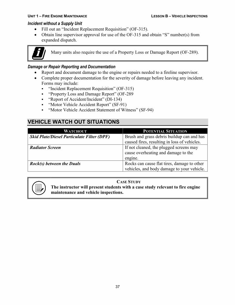
UNIT 1 – FIRE ENGINE MAINTENANCE LESSON B – VEHICLE INSPECTIONS
37
Incident without a Supply Unit • Fill out an “Incident Replacement Requisition” (OF-315). • Obtain line supervisor approval for use of the OF-315 and obtain “S” number(s) from
expanded dispatch.
Many units also require the use of a Property Loss or Damage Report (OF-289).
Damage or Repair Reporting and Documentation • Report and document damage to the engine or repairs needed to a fireline supervisor. • Complete proper documentation for the severity of damage before leaving any incident.
Forms may include: “Incident Replacement Requisition” (OF-315) “Property Loss and Damage Report” (OF-289 “Report of Accident/Incident” (DI-134) “Motor Vehicle Accident Report” (SF-91) “Motor Vehicle Accident Statement of Witness” (SF-94)
VEHICLE WATCH OUT SITUATIONS WATCHOUT POTENTIAL SITUATION
Skid Plate/Diesel Particulate Filter (DPF) Brush and grass debris buildup can and has caused fires, resulting in loss of vehicles.
Radiator Screen If not cleaned, the plugged screens may cause overheating and damage to the engine.
Rock(s) between the Duals Rocks can cause flat tires, damage to other vehicles, and body damage to your vehicle.
CASE STUDY The instructor will present students with a case study relevant to fire engine maintenance and vehicle inspections.

UNIT 1 – FIRE ENGINE MAINTENANCE LESSON B – VEHICLE INSPECTIONS
38
NOTES
UNIT 1 – FIRE ENGINE MAINTENANCE LESSON C – PUMP INSPECTIONS AND MAINTENANCE
39
UNIT 1 – FIRE ENGINE MAINTENANCE LESSON C – PUMP INSPECTIONS AND MAINTENANCE
Given a simulated wildland fire incident scenario, case study, or exercise, students will be able to:
• Inspect a pump package and describe pump maintenance procedures as outlined in the Fire Equipment Maintenance Procedure and Record.
• Correctly enter all pump information in the Fire Equipment Maintenance Procedure and Record.
• Discuss winterization procedures as outlined in the Fire Equipment Maintenance Procedure and Record.
• Conduct a pump performance test and record the results in the Fire Equipment Maintenance Procedure and Record.
• Troubleshoot and correct common problems with the pump and pump plumbing.
PUMP PACKAGE INSPECTION
The following information can also be found in the FEMPR.
The inspection process focuses on Type 3, 4, and 6 engines in the BLM fleet. The actual inspection will vary by equipment type and manufacturer.
PUMP PACKAGE
Water Tank and Foam Tank • Ensure water and foam tanks are full. • Ensure sight and water level gauges are working properly.
Valves • Ensure valves work smoothly and are not leaking. • Check valves for loose handles and bolts. • Ensure valve caps are in place to prevent dirt from damaging the valve.
Coolant • Ensure coolant is at a proper level and overflow container is in place.
Oil • Ensure crankcase oil is at a proper level; if low, fill to manufacturer’s specifications.
Fuel Filter • Inspect fuel filter for signs of fuel leakage. • Ensure the bracket is free from damage.
UNIT 1 – FIRE ENGINE MAINTENANCE LESSON C – PUMP INSPECTIONS AND MAINTENANCE
40
Air Filter(s) • Ensure the air filter(s) is in place and clean; change as needed. • If a pre-filter is being used, make sure it is clean and oiled properly. • Inspect filter housing for damage. • When reinstalling, check for proper seal between air intake and filter.
Primer • Ensure the primer functions properly and all discharge valves are closed.
Pump On/Off-Start Switch, Low Oil Pressure Override (Murphy) Push-to-Start Switch, Glow Plugs, and Throttle
• Ensure the pump on/off-start switch is secure and operational. • Ensure the low oil pressure override (Murphy) push-to-start switch is secure and
operational. • Ensure the glow plugs have cycled and the light goes off. • Ensure pump engine warms up (approximately 3-5 minutes) to operating temperature.
Gauges • Ensure all gauges are functioning properly; replace bad gauges. • Ensure panel lights are operational.
Water Pressure Safety Shutdown Switch The pumping system has a safety system designed to shut the pump engine off if no water flow or low water pressure is detected. The safety system protects the pump seal when no water is flowing through the pump. Arming the Water Pressure Safety Shutdown System Ensure the switch is in the up (safety off) position; then start the pump. Once operating pressures are obtained, arm the switch by moving it to the down (safety on) position. This will activate the safety circuit.
• When drafting, disarm the system and monitor the drafting operations.
Testing to Ensure the System is Functioning Properly To check the safety system, have the pump operating at a pressure between 100 - 150 PSI, arm the switch (down position), and then rapidly open the pump-to-tank valve. The engine should shut down when pressure falls below 20 PSI.
• Some pump engines may be able to maintain enough pressure to keep running. If this happens, the tank-to-pump valve will need to be closed.
• If the pump engine still runs with the tank-to-pump valve closed and the pump-to-tank valve open, the switch has not been set or is defective or the safety sensor located in the plumbing is defective and needs to be replaced.
Live Reels • Ensure live reels work properly and are greased. • Operate the nozzle to ensure water flows. • Check for leaks. • Ensure the hose reel rewind functions properly.
UNIT 1 – FIRE ENGINE MAINTENANCE LESSON C – PUMP INSPECTIONS AND MAINTENANCE
41
Foam Proportioner • Ensure the foam proportioner is operational. • Follow manufacturer’s guidelines for unit operation. • Refill with foam if needed.
Water Inline Strainer • Check for leaks. • Clean out strainer as needed.
Pump Mounting Bolts • Check for loose or missing bolts.
Pump Exhaust • Check for signs of leaks.
Gear Box • Ensure the gear case oil is at a proper level; if low, fill to manufacturer’s specifications.
PUMP MAINTENANCE REQUIREMENTS BASIC SERVICE (As per manufacturer’s recommendation or local policy) 1. Change oil.
• Drain and replace with correct type of oil. • Remove and replace oil filter. • Refill to full on dipstick.
2. Remove and replace air filter as needed. 3. Check the tension of drive/fan belts; tighten as needed. 4. Lubricate foam proportioning system as per manufacturer’s recommendations. 5. Change gear box oil as per manufacturer’s recommendations.
PUMP SEAL MAINTENANCE • If leaking, maintenance-free pump seals need to be replaced. • Manual pack seals will leak some water. If excessive leaking occurs, add more seal-
packing material. Refer to the pump owner’s manual for drip rates.
UNIT 1 – FIRE ENGINE MAINTENANCE LESSON C – PUMP INSPECTIONS AND MAINTENANCE
42
ANNUAL PUMP MOTOR MAINTENANCE 1. Replace fuel filter. 2. Inspect mounting hardware. 3. Check cooling system.
• Hoses • Leaks • Fluid level • Flush (change every 2 years)
Record information in the “Pump Service Record” provided in the FEMPR. Extra space has been provided for additional items.
WINTERIZATION Winterization of the fire engine and pump package is the process of preventing damage due to freezing temperatures.
FIELD OR SHORT-TERM WINTERIZATION OF FIRE ENGINE PLUMBING Perform a field or short-term winterization any time the plumbing is exposed to freezing temperatures.
The “Field or Short-term Winterization Process” can also be found in the FEMPR.
Field or Short-term Winterization Process 1. Ensure the foam system is flushed. 2. Unroll and drain all hard lines; remove as much water as possible. If your engine has the
capability, use an air hose to blow out the hard lines. • The hard lines are the first place that will freeze and the hardest to thaw.
3. Shut your tank-to-pump valve. 4. Drain strainer and pump head. If equipped with a pump drain valve, open to drain. Use
enviro-safe antifreeze and put some in the pump head until it runs into the strainer. 5. Open all discharge valves. Make sure you get as much water out of the valves as possible.
An air hose can be used if available. 6. On bladder foam proportioners, release the petcock valve on the bladder and drain out the
water; leave it open. It will usually not freeze hard enough to hurt the bladder itself even if it is loaded with foam.
Note: This is usually enough for unexpected cold weather on the line. This process is relatively simple and can be done in approximately 10 - 15 minutes. Once this process is complete, ENOPs can easily reverse the steps the following morning to make pump package functional for the next shift. Generally, direct injection proportioners are not affected by off-shift freezing temperatures.
UNIT 1 – FIRE ENGINE MAINTENANCE LESSON C – PUMP INSPECTIONS AND MAINTENANCE
43
FULL WINTERIZATION OF FIRE ENGINE PLUMBING • A full winterization should be performed:
For periods of prolonged exposure to freezing temperatures. At the end of the fire season.
• When doing a full winterization on the pump package, drain the pump, valves, plumbing, foam unit and water tank.
• Blow out the system with compressed air and add a small amount of environmentally-safe antifreeze to the pump head, foam unit and low spots in the plumbing system. (See Unit 4C.)
Review the “Full Winterization Checklist” provided in the FEMPR.
CONDUCT A PUMP PERFORMANCE TEST PUMP PERFORMANCE TEST GUIDELINES
• The pump performance test should be done according to the FEMPR or local standards. • Use the same discharge port and in the same manner every time you perform the test. • Document test results and identify trends.
Review the “Pump Performance Test Record” provided in the FEMPR.
PUMP PERFORMANCE TESTING EQUIPMENT Commercial Certified Flow Meter The BLM National Fire Equipment Program has commercial certified flow meters that can be borrowed to test flow rates.
• Loans are made on a first-come, first-served basis.
These flow meters are accurate at flows for which meter is rated but are expensive.
Refer to the FEMPR for recommended flow tester options and information.
Non-commercial, Non-certified Flow Meter • Need to procure parts and build the flow meter from scratch. • Fairly accurate for the purposes of pump testing in wildland fire. • Cost is minimal.
Homemade Pressure/Flow Tester • Need to procure parts and build the pressure/flow tester from scratch. • Easy to build from NUS items. • Accurate for the purposes of providing pump trend tests in wildland fire.
UNIT 1 – FIRE ENGINE MAINTENANCE LESSON C – PUMP INSPECTIONS AND MAINTENANCE
44
TROUBLESHOOTING
What problems have you have encountered? As a group discuss a couple of the problems presented and how to troubleshoot them if they are not covered below.
LIGHTS—NOT ILLUMINATED • Check for and replace blown fuses. • Check for and repair a bad ground.
Check for and repair loose wires.
PUMP ENGINE Pump engine will not start.
• Check electrical switches; make sure they are in the correct positions. Switches are inside the cab and back panel.
• Check for fuel in the tank. (The pump fuel pick-up line is higher than the truck fuel line.) • Determine if fuel pump is working. • Determine if glow plugs are heating.
Pump engine starts but will not keep running. • Check the override switches to ensure the low pressure override switch is in de-armed
position. • Check the valve configuration; ensure the tank-to-pump valve is open and all discharges
are closed. • Ensure the oil and coolant are at proper levels. • Check to see that fuel filter and air filter are not plugged.
Pump engine starts and runs but no water pressure exists. • Check the valve configuration. Ensure the tank-to-pump valve is open, all discharges are
closed, and tank fill port is closed. • Check the strainer for debris. • Ensure the pressure gauge is working. • Check pump shaft and/or seal. Ensure the shaft does not have any excessive play or look
damaged in any way and the seal is secure.
OTHER PROBLEMS
The operator’s manual contains additional troubleshooting procedures. Experience will also enhance your troubleshooting skills.
PUMP PACKAGE INSPECTION AND FIELD WINTERIZATION OUTSIDE EXERCISES

UNIT 1 – FIRE ENGINE MAINTENANCE QUIZ
45
UNIT 1 – QUIZ
1. List five items that need to be recorded in the FEMPR.
2. List two items you would look for when approaching a vehicle.
3. Where do you find the Field Winterization Checklist?
4. What is the function of the DPF?
5. What is the proper procedure for cleaning an air filter?

UNIT 1 – FIRE ENGINE MAINTENANCE QUIZ
46
NOTES
UNIT 2 – FLEET MANAGEMENT
47
UNIT 2 – FLEET MANAGEMENT
Given a simulated wildland fire incident scenario, case study, or exercise, students will be able to:
• Accurately identify expenditures that can be charged to the Working Capital Fund (WCF).
• Discuss the ENOP’s fleet charge card responsibilities. • Explain the concepts of gross vehicle weight rating (GVWR), gross axle
weight rating (GAWR), gross vehicle weight (GVW), and the ENOP’s role in maintaining proper GVW.
• Identify items that are included in the vehicle use (log) book. • Demonstrate the ability to complete and reconcile the “Utilization Record”
(USDI/BLM Form 1520-042). • Explain the procedure an ENOP should follow when involved in a motor
vehicle accident. • Explain fire engine warranty repairs and recall procedures.
INTRODUCTION TO THE WORKING CAPITAL FUND (WCF) Fire vehicle replacement and certain maintenance expenditures are managed through funds paid into the Working Capital Fund (WCF) over the life of the vehicle. The BLM WCF is managed by the BLM Vehicle Fleet Manager at the National Operations Center (NOC) in Denver.
Refer to the Interagency Standards for Fire and Fire Aviation Operations for more information on the WCF.
COMPONENTS OF THE WORKING CAPITAL FUND The WCF is comprised of funds collected through fixed ownership rates (FOR) and use rates.
Fixed Ownership Rates (FORs) Fixed ownership rates are monthly hours- or miles-based fees that are assessed through the Financial and Business Management System (FBMS) for each piece of fire equipment in service.
• All BLM fire engines are assessed on a per-hour basis. • These fees continue to accumulate over the life of a vehicle and are used to replace each
vehicle at the end of its life cycle. • FOR costs are charged to the benefiting activity. • The WCF Manager, who works for the BLM Vehicle Fleet Manager, adjusts FORs
annually to reflect changes in replacement costs due to inflation and/or changes in performance standards.
Present current FORs. Current FORS can be obtained from the local Fleet Manager, NFEP, or the Fire Operations website (http://web.blm.gov/internal/fire/fire_ops/nfep_policy.htm).
UNIT 2 – FLEET MANAGEMENT
48
Use Rates Use rates are fees that are charged monthly based on a per-hour or per-mile basis for vehicle operating costs.
• Use rates are independent of the FOR rates and are adjusted annually to reflect all WCF costs associated with the administration, delivery, maintenance, and repair of vehicles in each vehicle class.
• Use rates will vary from year to year, particularly those vehicle classes which have a low number of vehicles (e.g., Hummer) in the fleet.
• Use rate costs include: Fleet charge card fuel costs Repair costs for normal wear and tear on engine components Tow charges resulting from mechanical breakdowns related to normal wear and tear Preventative maintenance costs Overhead costs
WCF LIFE CYCLE The WCF life cycle is the predetermined period that vehicles of a given class are expected to be in service before they can be replaced. FORs are based on the WCF life cycle. The hourly or mileage rate charged is determined by dividing the total number of hours or miles charged in the life cycle into the expected replacement cost. Life cycles are determined through evaluation of the historical amount of use and general durability for vehicles of that class.
EQUIPMENT CLASSES All BLM equipment managed within the WCF is categorized by classes. Fire equipment is in the 600 series of classes (e.g., 662 light engine, 667 heavy engine). For a complete list of vehicle classes visit the BLM Fire Operations website (http://web.blm.gov/internal/fire/fire_ops/nfep_policy.htm).
ITEMS WCF DOES NOT COVER • Accident damage (charge to the benefitting activity) • Towing charges related to accidents or getting stuck • Locally-required vehicle modifications • Add-ons and accessories—all equipment added to a fire engine after delivery such as
light bars, tools, radios, and winches
UNIT 2 – FLEET MANAGEMENT
49
DETERMINING FUND CODE EXERCISE
Exercise Introduction Review each scenario with your instructor and determine the proper fund code (Working Capital Fund (WCF), program fund code, incident fund code) that should be used when documenting equipment problems. Common sense, agency policy, local policy, and experience should be considered when selecting the proper fund code. Some of the scenarios have a clear answer while others are open to interpretation by the Incident Commander, Finance Section Chief, Agency Administrator, line supervisor, and local supervisor (FMO). BLM fireline personnel have experienced all of the scenarios presented in this exercise. Answers should reflect honesty and good stewardship when choosing the proper fund code.
Scenario 1 You are assigned to a Type 4 engine and are traveling to an incident. While en route to the incident, the air conditioning unit in the engine goes out. You pull into a service shop and have the unit repaired.
• What fund code would you use to repair the air conditioning unit? • Who would you notify that you are having this mechanical problem repaired?
Scenario 2 Using the same scenario as above, you decide to proceed to the fire without fixing the air conditioning unit. At the end of the incident assignment, you want to obtain an S-number to repair the air conditioning unit.
• Is this the correct procedure? • What fund code would you use to repair the air conditioning unit?
Scenario 3 You are assigned to a Type 6 engine and are traveling to an incident. While en route, the transmission goes out. You are towed to a service shop and a new transmission is installed.
• What fund code would you use to fix the transmission? • What fund code would you use to pay for the towing service? • Who would you notify that you are having this mechanical problem fixed?
Scenario 4 You are assigned to a Type 3 engine and are traveling to an incident. While en route to the incident, you stop for a rest break. During the rest break, a private vehicle backs into the side of the engine and causes superficial damage (estimated cost to repair: $1,000). The engine still can perform safe fireline duties. After the sheriff writes up the accident report and you notify all parties that need to be notified of the accident, you proceed to the fire.
• What fund code would you use to get this fixed at your home unit?
Scenario 5 You are assigned to a Type 4 engine and are on the incident. While traveling to the fireline on a narrow road, another government vehicle sideswipes your engine. No one is hurt and a complete accident investigation occurs. The other driver is found to be at fault. Both vehicles are drivable.
• What fund code should be used to repair the damages to the engine?
UNIT 2 – FLEET MANAGEMENT
50
Scenario 6 You are assigned to a Type 6 engine and are on the incident. While en route to your division assignment, you blow a tire. You change the tire and proceed to your assignment.
• Should you inform your line supervisor of what happened? • What fund code should be used to purchase this new tire?
Scenario 7 You are assigned to a Type 3 engine and are on the incident. While en route to your division, a passing vehicle going the opposite way flips a rock onto the windshield. The damage to the windshield is a large star chip and crack in the lower area of the driver’s side that does not impede your view. After assessing the damage, you proceed to your assignment.
• Should you inform your line supervisor of what happened? • What fund code should be used to purchase a new windshield at your home unit?
Scenario 8 You are assigned to a Type 4 engine and are on the incident. While pumping a hose lay on a fire, the pump motor quits. All your troubleshooting tips do not get the motor running. Upon return to camp, the ground support mechanic looks it over and informs you that the pump motor is blown.
• What fund code should be used to purchase a new pump motor?
Scenario 9 You are assigned to a Type 6 engine and are on the incident. While performing a mobile attack, your engine breaks a tie rod. You are able to secure the engine in a safe area. You notify the fire overhead of your situation and ask for a towing service to get you to a service shop.
• What fund code should be used to pay for the towing? • What fund code should be used to fix or replace the tie rod?
UNIT 2 – FLEET MANAGEMENT
51
FLEET CHARGE CARD Each piece of equipment will be assigned a fleet charge card.
• Charge card purchases are restricted to the piece of equipment to which the card is assigned.
• Vehicle operators will only use charge cards for the following approved uses while performing government work: Fuel costs for unleaded, non-premium fuel or fuel alternative Emergency towing Approved preventative maintenance (e.g., oil changes) Approved repairs Tolls Parking
• Fleet cards have a single purchase limit of $3,000 and a monthly credit limit of $5,000. For repairs over $2,500, operators and their project leaders must follow the maintenance work order process in place of the fleet card.
• Abuse of the limitations on authorized purchases subjects the employee to disciplinary action.
• ENOPs should make sure a vendor will accept the fleet charge card prior to making a purchase.
• ENOPs are responsible for ensuring that each fleet charge card purchase is recorded on the Utilization Record and the proper cost code is written on each receipt.
• Fleet charge cards must be safeguarded at all times. • ENOPs are responsible for immediately notifying the local Fleet Manager of problems
with their fleet charge cards.
GROSS VEHICLE WEIGHT (GVW) The ENOP is responsible for ensuring that the gross vehicle weight (GVW) of the engine which includes the weight of the vehicle itself plus fuel, passengers, water, and Normal Unit Stocking (NUS or cargo/equipment) does not exceed the gross vehicle weight rating (GVWR). ENOPs that allow their fire engines to exceed the GVWR put passengers at risk by compromising the steering, braking, and stability of their fire engines. In addition to compromising safety, other problems may include:
• Poor handling on highways and off road • Excessive mechanical break downs
ENOPs who know the GVW of their engine will know if they can travel on weight-restricted bridges and roads.
WEIGHT RATINGS Chassis manufacturers determine each fire engine’s maximum load carrying capacity and permanently affix this information somewhere on the vehicle—generally on the driver side door. The two ratings that each ENOP should become familiar with include:
Gross Vehicle Weight Rating (GVWR) GVWR is the vehicle’s maximum load carrying capacity.
UNIT 2 – FLEET MANAGEMENT
52
Gross Axle Weight Rating (GAWR) GAWR is the maximum load carrying capacity of an axle system as measured at the tire/ground interface.
• The axle system includes, but is not limited to, the axle, tires, suspension, wheels, brakes, and applied engine torque.
• Each axle on the fire engine will have a rating.
DETERMINING GVW
Does the vehicle in the slide exceed the maximum GVWR?
Prior to fire season, ENOPs must weigh their fully-loaded engine on a certified scale to ensure the fire engine’s GVW does not exceed maximum weight ratings.
• If a crew member is unavailable during the weighing, then the NFPA 1906 standard of 250 pounds for each person and their personal gear will be used to calculate the loaded weight.
ENOPs should ensure the annually certified weight slip is kept with the vehicle at all times.
Raise your hand if your engine has been weighed for this fire season.
Refer to the “Equipment Fire Engine Weight” (GVW) table in the FEMPR. Document the engine’s GVW information any time certified scales are used.
ENOPs can utilize the following steps to assist them in determining the gross vehicle weight of their vehicle. 1. Weigh the front axle.
• Is the weight less than the manufacturer’s front axle GAWR? If the answer is “yes,” then the front axle weight is within limits. If the answer is “no,” then the front axle weight is over-grossed and weight must be
reduced (e.g., winch may need to be removed, brush guard may need to be removed, hose tray on bumper may need to be removed).
2. Weigh the rear axle. • Is the weight less than the manufacturer’s rear axle GAWR? If the answer is “yes,” then the rear axle weight is within limits. If the answer is “no,” then the rear axle weight is over-grossed and weight must be
reduced (e.g., non-vital equipment and extra fuel containers may need to be removed).
3. Add the front axle weight to the rear axle weight (this is the GVW). • Is the GVW less than the manufacturer’s GVWR? If the answer is “yes,” then the vehicle’s weight is within limits. If the answer is “no,” then the vehicle is over-grossed and weight must be reduced
(e.g. removing non-vital equipment, removing crew members, removing non-essential accessories).
UNIT 2 – FLEET MANAGEMENT
53
RECORDKEEPING AND REPORTING REASONS FOR HAVING RECORDS Records are kept for a multitude of reasons including, but not limited to:
• Helping avoid a mechanical mishap that can cause damage or injury • Discovering mechanical trends and assisting with future fire engine design • Identifying maintenance performed on incidents and during inspections (preventative
maintenance checks) • Identifying maintenance issues charged to the WCF • Documenting when certain mechanical service was performed or needs to be performed • Facilitating information sharing
Good record keeping is a great way to start newsletters, e-mail, face-to-face talk on the fireline, etc.
Safety problems on an agency-wide level can be identified and corrected, resulting in the development of newer and safer equipment.
The vehicle maintenance history is documented and follows the vehicle through the surplus process.
BLM FIRE EQUIPMENT IMPROVEMENT/DEFICIENCY REPORTING SYSTEM (IDRS) IDRS is used to collect improvement suggestions and deficiency reports for all BLM fire equipment, enabling BLM National Fire Equipment Program (NFEP) personnel to build a database to document problems, identify trends, and establish priorities for development and modification of new and existing equipment. The IDRS process is simple:
• Individuals submit reports on problems encountered or suggestions of improvement on BLM fire equipment via the NFEP website.
• NFEP personnel follow up on submissions in order to correct the deficiency or work to incorporate the improvement suggestion. Submitting reports is one way that operators can have a voice in improving and advancing the fleet.
To make improvement suggestions, file deficiency reports, view equipment alerts or recall notices, visit the BLM National Fire Equipment Program website at http://web.blm.gov/internal/fire/fire_ops/nfep.htm.
VEHICLE USE (LOG) BOOK
Local Fleet Vehicle Documentation Contact your local Fleet Manager to determine other forms or documents (vehicle maintenance and safety inspections) that need to be completed on the local unit.
Fleet Charge Card Receipts Place a pouch or envelope within the vehicle use book to hold fleet charge card receipts, pens, and other items.
• Ensure each receipt matches the “Utilization Record” and the cost code is written on each receipt.
UNIT 2 – FLEET MANAGEMENT
54
Proof of Insurance Form The “Proof of Insurance” form was created as official documentation that the government is self-insured.
• The form must be signed by the appropriate authorizing official and kept with the vehicle at all times.
“Proof of Insurance” forms for Interior-owned vehicles are available online.
Visit the BLM National Operations website (https://blmspace.blm.doi.net/oc/sites/property/operations/Documents/Fleet/Proof%20of%20Insurance.pdf) to download a copy of the “Proof of Insurance” form.
Vehicle Weight Slip The vehicle log book may be a good location to keep the annually certified vehicle weight slip.
Engine Use Report (EUR) Engine use reports are intended to be submitted monthly. EUR data is used to highlight the aspects that the engine crews bring to BLM Fire and Fire Aviation. The data is compiled and presented to the Fire Operations Group (FOG) at their fall meeting.
Utilization Record (USDI – BLM Form 1520-042)
“Utilization Record” completion procedures vary from unit to unit. Follow your local standard.
REQUIRED FOR EACH TRIP/USE (ALL VEHICLES) ITEM ACTION
Date • Record the last day of use. Meter Reading • Record the ending reading on the last day of
use. • Miles versus hours:
o Record the meter reading for support vehicles (superintendent vehicles, command vehicles, and crew carriers) in miles.
o Record the meter reading for fire engines (fuel tenders, water tenders, all classes of fire engines) in hours.
Days Used • Circle only the days used. Signature • Sign the record as the operator. If signature is
illegible, print name above signature.
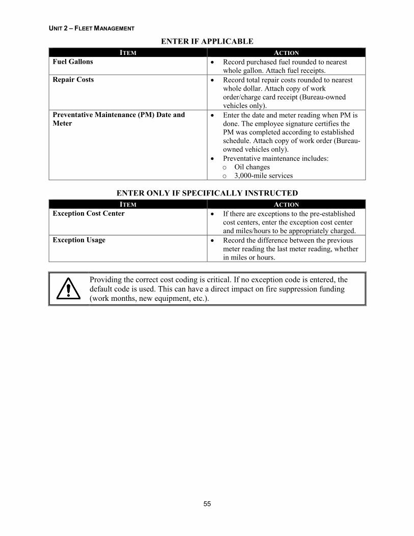
UNIT 2 – FLEET MANAGEMENT
55
ENTER IF APPLICABLE ITEM ACTION
Fuel Gallons • Record purchased fuel rounded to nearest whole gallon. Attach fuel receipts.
Repair Costs • Record total repair costs rounded to nearest whole dollar. Attach copy of work order/charge card receipt (Bureau-owned vehicles only).
Preventative Maintenance (PM) Date and Meter
• Enter the date and meter reading when PM is done. The employee signature certifies the PM was completed according to established schedule. Attach copy of work order (Bureau-owned vehicles only).
• Preventative maintenance includes: o Oil changes o 3,000-mile services
ENTER ONLY IF SPECIFICALLY INSTRUCTED ITEM ACTION
Exception Cost Center • If there are exceptions to the pre-established cost centers, enter the exception cost center and miles/hours to be appropriately charged.
Exception Usage • Record the difference between the previous meter reading the last meter reading, whether in miles or hours.
Providing the correct cost coding is critical. If no exception code is entered, the default code is used. This can have a direct impact on fire suppression funding (work months, new equipment, etc.).
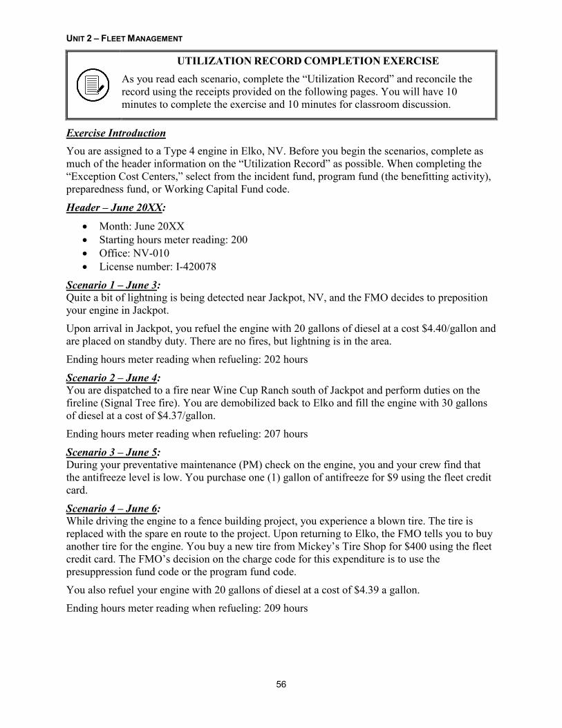
UNIT 2 – FLEET MANAGEMENT
56
UTILIZATION RECORD COMPLETION EXERCISE As you read each scenario, complete the “Utilization Record” and reconcile the record using the receipts provided on the following pages. You will have 10 minutes to complete the exercise and 10 minutes for classroom discussion.
Exercise Introduction You are assigned to a Type 4 engine in Elko, NV. Before you begin the scenarios, complete as much of the header information on the “Utilization Record” as possible. When completing the “Exception Cost Centers,” select from the incident fund, program fund (the benefitting activity), preparedness fund, or Working Capital Fund code.
Header – June 20XX:
• Month: June 20XX • Starting hours meter reading: 200 • Office: NV-010 • License number: I-420078
Scenario 1 – June 3: Quite a bit of lightning is being detected near Jackpot, NV, and the FMO decides to preposition your engine in Jackpot. Upon arrival in Jackpot, you refuel the engine with 20 gallons of diesel at a cost $4.40/gallon and are placed on standby duty. There are no fires, but lightning is in the area. Ending hours meter reading when refueling: 202 hours
Scenario 2 – June 4: You are dispatched to a fire near Wine Cup Ranch south of Jackpot and perform duties on the fireline (Signal Tree fire). You are demobilized back to Elko and fill the engine with 30 gallons of diesel at a cost of $4.37/gallon. Ending hours meter reading when refueling: 207 hours
Scenario 3 – June 5: During your preventative maintenance (PM) check on the engine, you and your crew find that the antifreeze level is low. You purchase one (1) gallon of antifreeze for $9 using the fleet credit card.
Scenario 4 – June 6: While driving the engine to a fence building project, you experience a blown tire. The tire is replaced with the spare en route to the project. Upon returning to Elko, the FMO tells you to buy another tire for the engine. You buy a new tire from Mickey’s Tire Shop for $400 using the fleet credit card. The FMO’s decision on the charge code for this expenditure is to use the presuppression fund code or the program fund code. You also refuel your engine with 20 gallons of diesel at a cost of $4.39 a gallon. Ending hours meter reading when refueling: 209 hours
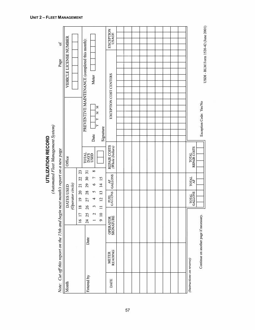
UNIT 2 – FLEET MANAGEMENT
57
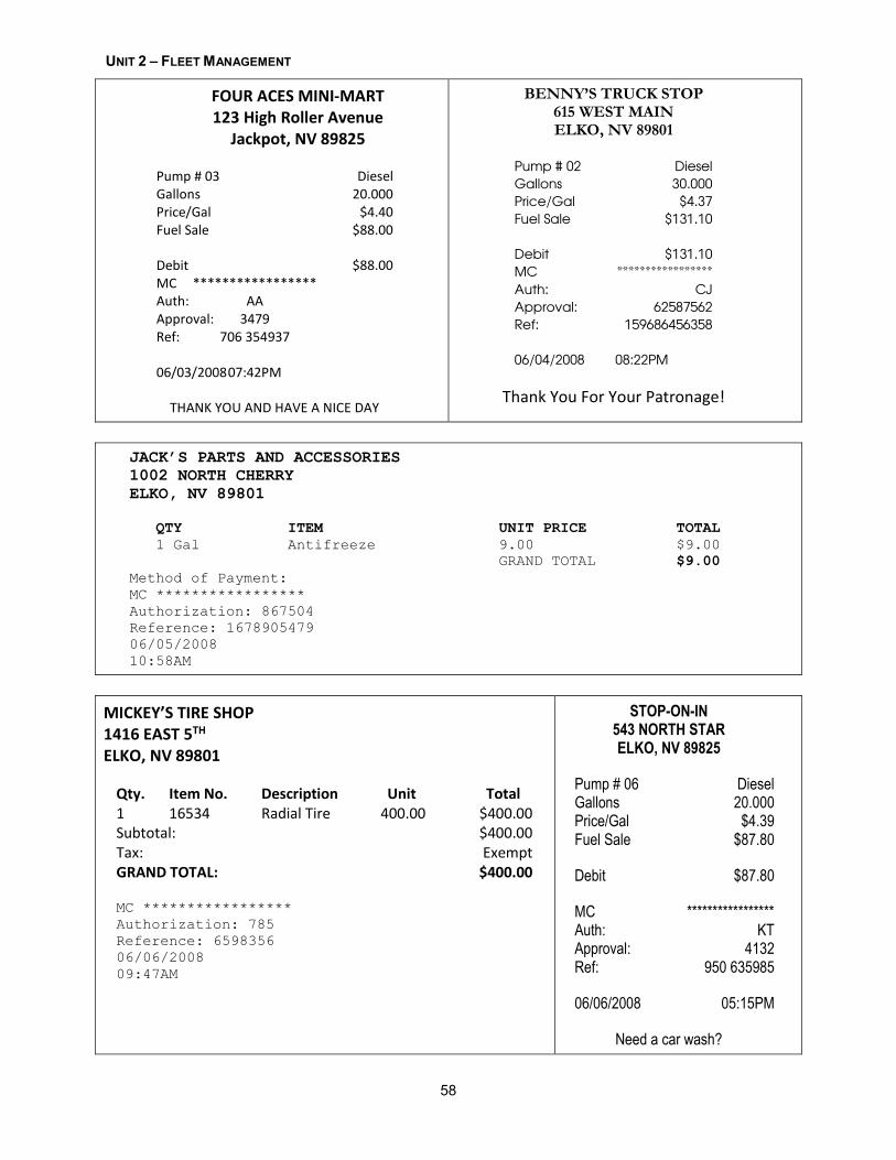
UNIT 2 – FLEET MANAGEMENT
58
FOUR ACES MINI-MART 123 High Roller Avenue
Jackpot, NV 89825
Pump # 03 Diesel Gallons 20.000 Price/Gal $4.40 Fuel Sale $88.00
Debit $88.00 MC ***************** Auth: AA Approval: 3479 Ref: 706 354937
06/03/2008 07:42PM
THANK YOU AND HAVE A NICE DAY
BENNY’S TRUCK STOP 615 WEST MAIN ELKO, NV 89801
Pump # 02 Diesel Gallons 30.000 Price/Gal $4.37 Fuel Sale $131.10 Debit $131.10 MC ***************** Auth: CJ Approval: 62587562 Ref: 159686456358
06/04/2008 08:22PM
Thank You For Your Patronage!
JACK’S PARTS AND ACCESSORIES 1002 NORTH CHERRY ELKO, NV 89801
QTY ITEM UNIT PRICE TOTAL 1 Gal Antifreeze 9.00 $9.00 GRAND TOTAL $9.00
Method of Payment: MC ***************** Authorization: 867504 Reference: 1678905479 06/05/2008 10:58AM
MICKEY’S TIRE SHOP 1416 EAST 5TH ELKO, NV 89801
Qty. Item No. Description Unit Total 1 16534 Radial Tire 400.00 $400.00 Subtotal: $400.00 Tax: Exempt GRAND TOTAL: $400.00
MC ***************** Authorization: 785 Reference: 6598356 06/06/2008 09:47AM
STOP-ON-IN 543 NORTH STAR ELKO, NV 89825
Pump # 06 Diesel Gallons 20.000 Price/Gal $4.39 Fuel Sale $87.80
Debit $87.80
MC ***************** Auth: KT Approval: 4132 Ref: 950 635985
06/06/2008 05:15PM
Need a car wash?
UNIT 2 – FLEET MANAGEMENT
59
ACCIDENT REPORTING PROCEDURES When an accident occurs, operators should follow the procedures outlined in What Every Driver Should Do in Case of Accident (DI-135) packet and obtain the necessary information to complete the “Operator’s Report of Motor Vehicle Accident” (SF-91) and the “Statement of Witness” (SF-94).
WHAT EVERY DRIVER SHOULD DO WHEN INVOLVED IN AN ACCIDENT 1. Stop and give aid to the injured.
• Notify the police and request an ambulance, if needed.• Do not move the victims until medical personnel arrive unless there are life threatening
situations involved.2. Prevent danger to oncoming vehicles but generally do not move your own vehicle until the
police arrive.3. Exchange basic information with the other driver and document on the “Operator’s Report
of Motor Vehicle Accident Report” (SF-91). Information includes:• Names• Addresses• Phone numbers• Driver’s license information Upon request, show your operator's permit.
• Vehicle registrations• Proof of insurance Show the government proof of insurance form. Since the government is self-insured, also furnish your Department, Bureau, name,
local office address, place of employment, and your supervisor’s name.4. Obtain the names and addresses of witness using the “Statement of Witnesses”
(SF-94).• Do not force the issue if they will not provide this information.
5. Notify state, county, or municipal authorities, as required by law.• Document the name, badge number and station of law enforcement officers present.
(Use SF-91, Section VII.)6. If possible, document additional information needed to complete the “Operator’s Report of
Motor Vehicle Accident Report” (SF-91). Items include: • Length of skid marks• Distances from curbs
• Weather conditions• Type of road
7. Notify your supervisor as quickly as possible.• Call him/her by phone for instruction if you are in serious trouble.
8. Notify your Fleet Manager.9. Perform other actions as required by local policy and procedures.
• Know what actions are required prior to being involved in an accident.10. Notify the proper authorities before leaving the scene of the accident.
UNIT 2 – FLEET MANAGEMENT
60
WHAT EVERY DRIVER SHOULD NOT DO WHEN INVOLVED IN AN ACCIDENT 1. Do not sign any papers or make any statement as to who was at fault except to your
supervisor or to a Federal government investigator. 2. Do not attempt to negotiate an agreement or settlement.
• Even if you think you are in the right or in the wrong, there is no point in saying so here. This is not your decision to make.
• Keep cool, be courteous, and do not argue over who is to blame.
Want more information on accident reporting procedures, contact your local Fleet Manager or refer to the G-1520-3 Fleet Management Guide (https://blmspace.blm.doi.net/oc/sites/property/GuidanceDocs/G-1525-1%20Fleet%20Managment%20Reference%20Guide%202%20%207.20.17.pdf).
FIRE ENGINE WARRANTY REPAIRS AND RECALLS
WARRANTY REPAIRS If you have a fire engine that needs repaired and you believe the work should be covered under the manufacturer’s warranty, call NFEP personnel before taking your vehicle to a repair facility. NFEP personnel may know if the manufacturer has authorized a specific repair facility to perform the warranty work.
• If you authorize repair work without first checking with NFEP personnel or the manufacturer, you may be liable for the repair bill and your vehicle may not be released until the payment is finalized.
BLM National Fire Equipment Program Telephone Numbers (208) 387-5422 (208) 387-5425 (208) 387-5445 (208) 387-5423 (208) 387-5424
RECALLS At this time, there is no standard procedure for recall notification.
To view equipment alerts or recall notices, visit the BLM National Fire Equipment Program website (http://web.blm.gov/internal/fire/fire_ops/nfep.htm).
UNIT 2 – FLEET MANAGEMENT QUIZ
61
UNIT 2 – QUIZ
1. What is the WCF?
2. What are the two components of WCF?
3. What can be charged to your fleet credit card? (circle all that apply)
Air fresheners Windshield wipers
Oil Cleaning supplies
4. What is the difference between GVWR and GVAR?
5. Identify three items that should be in the vehicle log book.
6. What should have a deficiency report filed on it? (circle all that apply)
New batteries
Motor turbo failure
Broken suspension components
Mirror damaged during fire suppression

UNIT 2 – FLEET MANAGEMENT QUIZ
62
NOTES
UNIT 3 – FIRE ENGINE DRIVING LESSON A – DRIVING POLICY AND PROCEDURES
63
UNIT 3 – FIRE ENGINE DRIVING LESSON A – DRIVING POLICY AND PROCEDURES
Given a simulated wildland fire incident scenario, case study, or exercise, students will be able to:
• Discuss agency policies and regulations related to driving fire engines. • Discuss and interpret driving duty-day limitations. • Identify the components of a risk assessment (RA).
CASE STUDY The instructor will present students with a case study relevant to driving policy and procedures.
AGENCY POLICIES AND REGULATIONS
DRUG-FREE WORKPLACE Executive Order 12564 states:
• Federal employees are required to refrain from the use of illegal drugs. • The use of illegal drugs by Federal employees, whether on duty or off duty, is contrary to the
efficiency of the service. • Persons who use illegal drugs are not suitable for Federal employment.
Therefore, anyone who is mentally or physically impaired (overly tired, on medication, intoxicated, etc.) will not be permitted to drive an engine or other vehicle.
All employees, cooperators, contractors, and volunteers who participate in wildland fire operations have the duty to treat one another with respect and to maintain a work environment free of misconduct and harassment. Misconduct includes but is not limited to: alcohol misuse, driving while intoxicated, the use of illegal drugs, hazing, insubordination, disregard for policies and procedures and the destruction or theft of government property. – Interagency Standards for Fire and Fire Aviation Operations
FIRE VEHICLE OPERATION STANDARDS
Driving Standard – Interagency Standards for Fire and Fire Aviation Operations “All employees driving motor vehicles are responsible for the proper care, operation, maintenance and protection of the vehicle. The use of government-owned, rented, or leased motor vehicles is for official business only. Unauthorized use is prohibited.”
• Operators of all vehicles must abide by state traffic regulations. Posted speed limits will not be exceeded.
UNIT 3 – FIRE ENGINE DRIVING LESSON A – DRIVING POLICY AND PROCEDURES
64
Conduct a student review of pre-course work questions regarding the maximum allowable speed limit for each engine.
Maximum allowable speed is determined by the tire speed rating which should be documented under the “Vehicle Data” section in the FEMPR. What is the tire speed rating for your vehicle’s tires?
All vehicles responding to fires will stop for traffic lights and stop signs even when using emergency warning lights, siren, and air horns. (Every state varies in Code 3 responses.)
Prior to responding to an incident, ENOPs should check with state Department of Transportation offices regarding the policy of stopping at port of entries or weigh stations.
• Headlights and tail lights will be illuminated at all times while the vehicle is in motion. • Emergency lighting will not be used except when performing suppression or prescribed fire
operations, or to mitigate serious safety hazards. • Overhead lighting and other emergency lighting must meet state code requirements, and will be
illuminated whenever visibility is reduced to less than 300 feet. Blue lights are not acceptable for wildland fire operations.
• Chock blocks will be properly utilized whenever the engine is parked or left unattended.
General Driving Policy – Interagency Standards for Fire and Fire Aviation Operations • Employees must have a valid state driver’s license for the appropriate vehicle class in their
possession before operating the vehicle. Operating a government-owned or rental vehicle without a valid state driver’s license could result in disciplinary action.
• All drivers whose job duties require the use of a motor vehicle will receive initial defensive driver training within three months of entering on duty and refresher driver training every three years, thereafter.
• The operator and all passengers are required to wear seat belts and obey all federal and state laws.
• All traffic violations or parking tickets will be the operator’s responsibility. • Cell phone use is prohibited while driving a government vehicle unless using a hands-free device
(Bluetooth). • BLM Policy – All employees operating a government motor vehicle will be required to submit
“Motor Vehicle/Special Equipment Authorization” (Form 1112-11).
Driving Limitations – Fireline Handbook • Drivers operating vehicles that require a CDL are regulated by the Federal Motor Carriers Safety
Regulations Part 393.3 and any applicable state laws. ENOPs operating vehicles in excess of 26,000 GVW must have a state-certified CDL.
• All governmental fire agencies are exempted from several requirements of CDL regulation under Department of Transportation 49 CFR but are subject to NWCG national incident operations standards.
UNIT 3 – FIRE ENGINE DRIVING LESSON A – DRIVING POLICY AND PROCEDURES
65
• BLM/FWS/NPS – “The DOI has granted wildland fire agencies a waiver to allow employees between the ages of 18 and 21 to operate agency commercial fire vehicles using a state-issued CDL under the specific conditions as stated below:” – Interagency Standards for Fire and Fire Aviation Operations Drivers with a CDL may only drive within the state that has issued the CDL and must
comply with the state’s special requirements and endorsements. These drivers must only drive vehicles that are equipped with visible and audible signals, and
are easily recognized as firefighting equipment. Supervisors must annually establish and document that these drivers have a valid license (i.e.,
that the license has not been suspended, revoked, canceled, or that the employee has not been otherwise unqualified from holding a license).
Incident Operations Driving – Interagency Standards for Fire and Fire Aviation Operations This policy addresses driving by personnel actively engaged in wildland fire suppression or all-risk activities, including driving while assigned to a specific incident (check-in to check-out) or during initial attack fire response (includes time required to control the fire and travel to a rest location).
• Agency resources assigned to an incident or engaged in initial attack fire response will adhere to the current agency work/rest policy for determining length of duty day. No driver will drive more than 10 hours (behind the wheel) within any duty day. Multiple drivers in a single vehicle may drive up to the duty-day limitation provided no
driver exceeds the individual driving (behind the wheel) time limitation of 10 hours. Driving hours are from 0500-2200 hours. To manage fatigue, every effort should be made to avoid off-unit mobilization (excluding IA
response) and demobilization travel between 2200-0500 hours. • A driver shall drive only if they have had at least eight (8) consecutive hours off duty before
beginning a shift. Exception to the minimum off-duty hour requirement is allowed when essential to: Accomplish immediate and critical suppression objectives. Address immediate and critical firefighter or public safety issues.
• As stated in the current agency work/rest policy, documentation of mitigation measures used to reduce fatigue is required for drivers who exceed 16 hours work shifts. This is required regardless of whether the driver was still compliant with the 10-hour individual (behind the wheel) driving time limitations. Work/rest guidelines should be met on all incidents. Plan for and ensure all personnel are
provided a minimum 2:1 work-to-rest ratio (for every two hours of work or travel, provide one hour of sleep and/or rest.)
UNIT 3 – FIRE ENGINE DRIVING LESSON A – DRIVING POLICY AND PROCEDURES
66
DRIVING LIMITATIONS EXERCISE
Work/Rest Scenario 1 You (the ENOP with a CDL) and a module member (non-CDL driver) are traveling to another state in a Type 4 engine. The trip length is estimated at 26 hours.
• How many days will it take to reach your destination?
Work/Rest Scenario 2 You (the ENOP with a CDL) and a module member (non-CDL driver) are traveling to another state in a Type 6 engine. The trip length is estimated at 26 hours.
• How many days will it take to reach your destination?
Work/Rest Scenario 3 While on assignment on a 200,000-acre fire and working 12-hour shifts, the division group supervisor asks your crew to work an extra 8-hour shift to monitor a line.
• Is this something your crew can do?
DRIVER WALK-AROUND (GOLDEN CIRCLE) A driver walk-around will be done every time the engine is moved.
• A more detailed explanation of this process will be covered in Lesson 3B.
HAZARDOUS MATERIALS • Wildland firefighters have the potential to be exposed to hazardous materials while performing
their jobs. • Hazardous materials or waste may be found on public lands in a variety of forms (e.g.,
clandestine drug lab waste, mining waste, illegal dumping, and transportation accidents). • Hydrogen sulfide gas (H2S) may be present in some areas • All wildland firefighters will complete a one-time, two-hour first responder awareness training
course and an annual refresher course, thereafter. • All individuals responding to wildland fire incidents should be familiar with the current
publication of the Department of Transportation’s Emergency Response Guidebook.
For more information, review the Department of Transportation’s Emergency Response Guidebook at https://www.phmsa.dot.gov/hazmat/erg/emergency-response-guidebook-erg.
UNIT 3 – FIRE ENGINE DRIVING LESSON A – DRIVING POLICY AND PROCEDURES
67
SAFETY AND THE RISK ASSESSMENT
POLICY • “The head of each agency shall furnish to each employee employment and a place of
employment which are free from recognized hazards that are causing or are likely to cause death or serious physical harm.” – 29 CFR 1960.8 (a)
• “Firefighter and public safety is the first priority. All Fire Management Plans and activities must reflect this commitment.” – Federal Wildland Fire Policy, December 1995
• “Every BLM supervisor, employee, and volunteer is responsible for following safe work practices and procedures, identifying and reporting unsafe conditions.” – Safety and Health for Field Operations; BLM Manual Handbook 1112-2
What is a Risk Assessment? A risk assessment (RA) is a technique that focuses on job tasks as a way to identify hazards before they occur. It focuses on the relationship between the worker, the task, the tools, and the work environment. Ideally, after you identify uncontrolled hazards, you will take steps to eliminate or reduce them to an acceptable risk level. RAs can be very complex or simple documents.
Review the sample risk assessment on the next few pages of your workbook.
Briefly discuss the major sections of the RA.
Why Complete a Risk Assessment? – Interagency Standards for Fire and Fire Aviation Operations A completed RA is required for:
• Jobs or work practices that have potential hazards. • New, non-routine, or hazardous tasks to be performed where potential hazards exist. • Jobs that may require the employee to use non-standard personal protective equipment (PPE). • Changes in equipment, work environment, conditions, policies, or materials.
Supervisors and appropriate line managers must ensure established RAs are reviewed and signed prior to any non-routine task or at the beginning of the fire season.
• BLM – A risk assessment must be completed for all non-suppression work practices/projects that have potential hazards.
TAILGATE SAFETY SESSIONS Before any work assignment begins, ENOPs should hold a tailgate safety session with their module to discuss the following aspects of the RA:
• Ensure module members understand their work assignments. • Identify and discuss job hazards that might occur on/at the work assignment area. • Discuss how to communicate problems and work accomplishments to the job supervisor.
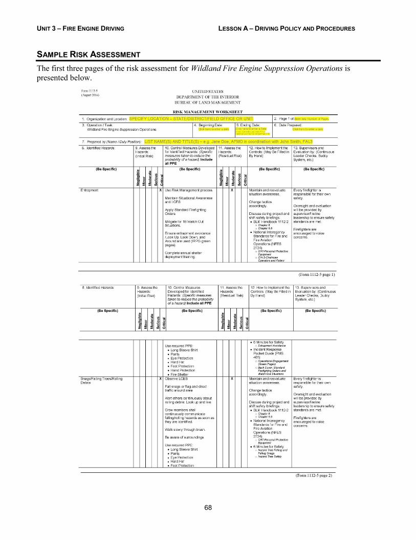
UNIT 3 – FIRE ENGINE DRIVING LESSON A – DRIVING POLICY AND PROCEDURES
68
SAMPLE RISK ASSESSMENT The first three pages of the risk assessment for Wildland Fire Engine Suppression Operations is presented below.
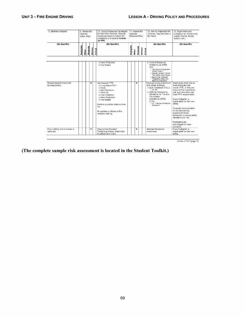
UNIT 3 – FIRE ENGINE DRIVING LESSON A – DRIVING POLICY AND PROCEDURES
69
(The complete sample risk assessment is located in the Student Toolkit.)

UNIT 3 – FIRE ENGINE DRIVING LESSON A – DRIVING POLICY AND PROCEDURES
70
NOTES
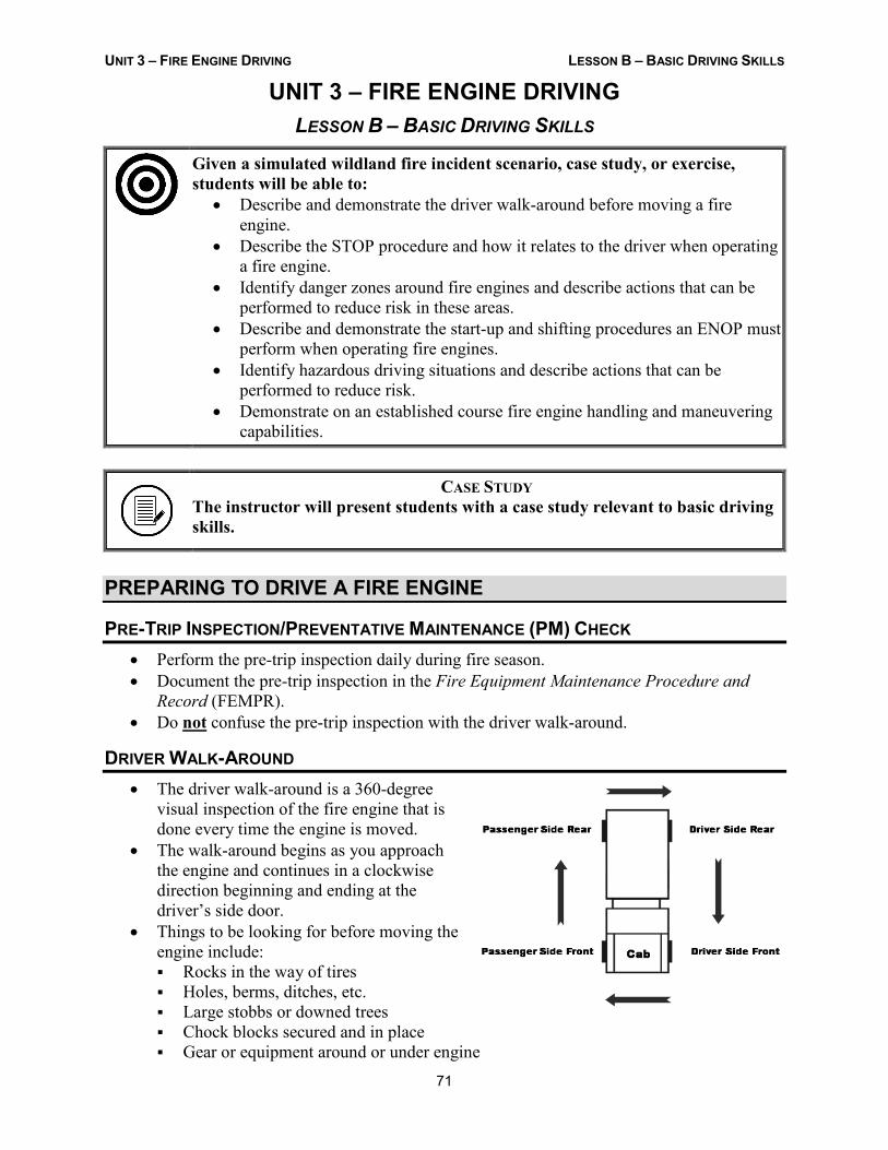
UNIT 3 – FIRE ENGINE DRIVING LESSON B – BASIC DRIVING SKILLS
71
UNIT 3 – FIRE ENGINE DRIVING LESSON B – BASIC DRIVING SKILLS
Given a simulated wildland fire incident scenario, case study, or exercise, students will be able to:
• Describe and demonstrate the driver walk-around before moving a fire engine.
• Describe the STOP procedure and how it relates to the driver when operating a fire engine.
• Identify danger zones around fire engines and describe actions that can be performed to reduce risk in these areas.
• Describe and demonstrate the start-up and shifting procedures an ENOP must perform when operating fire engines.
• Identify hazardous driving situations and describe actions that can be performed to reduce risk.
• Demonstrate on an established course fire engine handling and maneuvering capabilities.
CASE STUDY The instructor will present students with a case study relevant to basic driving skills.
PREPARING TO DRIVE A FIRE ENGINE
PRE-TRIP INSPECTION/PREVENTATIVE MAINTENANCE (PM) CHECK • Perform the pre-trip inspection daily during fire season. • Document the pre-trip inspection in the Fire Equipment Maintenance Procedure and
Record (FEMPR). • Do not confuse the pre-trip inspection with the driver walk-around.
DRIVER WALK-AROUND • The driver walk-around is a 360-degree
visual inspection of the fire engine that is done every time the engine is moved.
• The walk-around begins as you approach the engine and continues in a clockwise direction beginning and ending at the driver’s side door.
• Things to be looking for before moving the engine include: Rocks in the way of tires Holes, berms, ditches, etc. Large stobbs or downed trees Chock blocks secured and in place Gear or equipment around or under engine
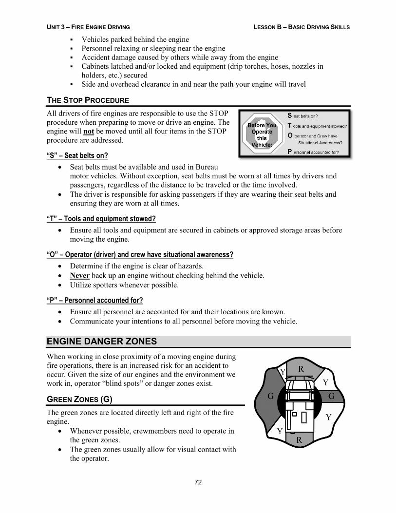
UNIT 3 – FIRE ENGINE DRIVING LESSON B – BASIC DRIVING SKILLS
72
Vehicles parked behind the engine Personnel relaxing or sleeping near the engine Accident damage caused by others while away from the engine Cabinets latched and/or locked and equipment (drip torches, hoses, nozzles in
holders, etc.) secured Side and overhead clearance in and near the path your engine will travel
THE STOP PROCEDURE All drivers of fire engines are responsible to use the STOP procedure when preparing to move or drive an engine. The engine will not be moved until all four items in the STOP procedure are addressed.
“S” – Seat belts on? • Seat belts must be available and used in Bureau
motor vehicles. Without exception, seat belts must be worn at all times by drivers and passengers, regardless of the distance to be traveled or the time involved.
• The driver is responsible for asking passengers if they are wearing their seat belts and ensuring they are worn at all times.
“T” – Tools and equipment stowed? • Ensure all tools and equipment are secured in cabinets or approved storage areas before
moving the engine.
“O” – Operator (driver) and crew have situational awareness? • Determine if the engine is clear of hazards. • Never back up an engine without checking behind the vehicle. • Utilize spotters whenever possible.
“P” – Personnel accounted for? • Ensure all personnel are accounted for and their locations are known. • Communicate your intentions to all personnel before moving the vehicle.
ENGINE DANGER ZONES When working in close proximity of a moving engine during fire operations, there is an increased risk for an accident to occur. Given the size of our engines and the environment we work in, operator “blind spots” or danger zones exist.
GREEN ZONES (G) The green zones are located directly left and right of the fire engine.
• Whenever possible, crewmembers need to operate in the green zones.
• The green zones usually allow for visual contact with the operator.
UNIT 3 – FIRE ENGINE DRIVING LESSON B – BASIC DRIVING SKILLS
73
YELLOW ZONES (Y) Yellow zones are areas of limited visibility and mirror-use areas.
• Notify the operator when you are in these areas.
RED ZONES Red zones are located directly in front and behind the fire engine.
• Never work in red areas while the engine is moving. • Notify the operator prior to entering red zones. • Stay out of red zones where the operator has no visual. • The red area in front of the engine extends 10 feet out from the front bumper. • You must have visual contact with the operator when working in front of the vehicle
beyond the 10-foot range.
ENGINE SPOTTER USAGE Engine spotters should be familiar with providing on-the-ground, visual assistance when the driver has limited vision (blind spots and danger zones) during a critical driving situation.
• When an engine crewmember is present, use a spotter. • If you are by yourself and other firefighters are available, ask for help. • If you are alone and have no help, get out of the engine and do a visual check for
yourself.
WHEN TO USE A SPOTTER Spotters should be used when:
• Backing up • Off-road pioneering • Hazardous conditions exist
• Low vehicle clearances exist • Narrow/confined driving spaces exist
SPOTTER TECHNIQUES • Spotters should have a clear line of sight to the driver. Under most situations, the
spotter’s position should be as follows: Forward movement: Outside the forward red zone on the driver side windshield Backing movement: Outside the rear red zone on the driver side mirror
• Spotters and drivers should agree upon a common set of hand signals.
Refer to the Occupational Safety and Health Administration (OSHA) website (https://www.osha.gov/doc/topics/backover/spotter.html) for a common set of spotter hand signals.
• Spotters and drivers need to communicate on the planned action. Where are we going to park? How far off the shoulder do we want to be? What areas are we going to be traveling through?
• Spotter distance from the engine will depend on various situations at the time of the maneuver; however, visual contact between spotter and driver shall not be compromised.
• If the driver loses sight of the spotter, the driver should stop immediately and determine the spotter’s location.
UNIT 3 – FIRE ENGINE DRIVING LESSON B – BASIC DRIVING SKILLS
74
VEHICLE OPERATIONS AND RECOVERY
VEHICLE OPERATION Before starting the engine for operations, make sure you have adjusted the mirrors and seat for your comfort and safety.
• Windows and mirrors are clean. • Dashboard is clear of materials.
Manual Transmission (4- or 5-speed) Starting the Vehicle 1. Put the transmission in neutral. 2. Depress the clutch. 3. Select the proper gear.
• Second gear (generally) when starting on level ground • First gear when starting on steep slopes
Up Shifting 1. Bring the tachometer to between 2,500 and 3,000 RPM. 2. Depress the clutch. 3. Shift to a higher gear.
Down Shifting 1. Bring the tachometer to 1,500 RPM (avoid lugging the engine). 2. Depress the clutch. 3. Shift to a lower gear. Off-Road Shifting 1. With the hand or air brake set, put right foot on brake; left foot on clutch. 2. Put in first gear. 3. Let clutch out slowly as you depress accelerator. 4. Feel a pull forward and release the brake. 5. Maintain RPM.
Automatic Transmission 1. Start the vehicle in neutral. 2. Select the proper gear for travel.
• First or second – low-speed crawl out • Second through fourth – city driving • Second through fifth – highway driving • If the transmission shifts constantly, go to a lower gear selection.
UNIT 3 – FIRE ENGINE DRIVING LESSON B – BASIC DRIVING SKILLS
75
Off-Road Shifting 1. With the parking brake set, move the selection lever to first or second gear. 2. With left foot on the brake, release the parking brake. 3. Apply the throttle until you feel a pull. 4. Release the brake. 5. Apply the throttle.
Air Brake Use Normal Stops
• Apply the brakes hard at first and gradually release as speed is reduced. Downhill Runs
• Use the proper gear reduction to maintain the engine at a safe speed. • Brake application can be made intermittently to keep the engine well under control.
“Fanning” • “Fanning” refers to the repeated rapid application and releasing of the air brakes during a
stop. • Fanning results in poor brake performance, lowering the reservoir, and air line pressures.
Terrain Concerns Mud and Sand Areas Even though your fire engine has 4-wheel drive, it can get stuck.
• Make sure the 4-wheel drive transfer case is engaged before entering the area. • Maintain momentum. • Keep front tires straight. • Maintain a smooth, steady speed. • Expect to slip and slide; do not oversteer.
Side Hills • Be aware of water load shifting (weight transfer).
Full versus partial tank of water
Briefly discuss a full versus partial tank of water.
• Be aware of how load structuring affects your center of gravity.
Hills • Select the proper gear before climbing a hill.
Do not force shifting while on a hill; you could miss a gear and stall. • Downshift on the crest of a hill before descending.
This prevents free-wheeling and missing a gear.
UNIT 3 – FIRE ENGINE DRIVING LESSON B – BASIC DRIVING SKILLS
76
Gullies/Ditches • Scout route for best crossing. • Use a spotter. • Cross at a diagonal.
Increases clearance and traction • Ease in and power out.
VEHICLE RECOVERY Winch Use
• Winching operations are dangerous; read and understand the owner’s manual before operating any winch.
• Always wear gloves while winching. • Inspect your cable for frays or kinks before going on your trip. • Always attach to strong anchor points (usually tow hooks) on the front and rear of the
engine. • Make sure you have a tree strap, 'D' shackles of various sizes, a short length of 3/8 chain,
and a good pulley block rated at twice the capacity of the winch. • If you are winching out another vehicle, you should anchor your vehicle to something
like another vehicle, or a tree or a special made winch anchor. • Put a heavy coat, towel or blanket over the cable while winching. • Keep people out of winch cable zone.
Jump Starting
Briefly review the jump starting procedures in the FEMPR.
TIRE CHANGING AND JACKING
Tire Changing Procedures 1. Follow local protocol. 2. Read and understand the owner’s manual before changing a tire on the vehicle. 3. Ensure you have the proper tools and equipment to perform the task.
• Proper tonnage weight hydraulic jack • Cribbing material • Tire iron and wrench sockets • Air impact wrench • Spare tire
4. Ensure the gear selector is in “Park” (automatic transmission) or “Reverse” (manual transmission).
5. Ensure the ignition is in the “OFF” position and the emergency brake has been set. 6. Properly chock the vehicle. 7. Make sure cribbing material and jack are located on flat, firm, and level ground. 8. Loosen lug nuts before truck is raised.
UNIT 3 – FIRE ENGINE DRIVING LESSON B – BASIC DRIVING SKILLS
77
9. Jack up vehicle at proper jack points. 10. Spin off all lug nuts and remove flat tire.
• For inside dual tire flat follow the manufacturer’s recommendations for removing tire and realigning the spare.
11. Place spare tire on studs and hand tighten lug nuts with wrench while tire is off the ground. • This sets the tire properly on the studs.
12. Lower vehicle and tighten lug nuts using a crisscross pattern. 13. Properly stow all tools and equipment. 14. After driving approximately 20 miles, recheck the lug nuts for tightness.
Tire Changing Safety Concerns • Tires are heavy and need to be lifted correctly. • Cribbing material and jack can slip. • Uneven ground can cause jack to tip. • Never work under a vehicle when the tire is off.
TOWING AND BEING TOWED • Follow local protocol.
DRIVING SAFETY The lives and welfare of your crew depend upon you. Practicing safe driving procedures is the least you can do to provide for their safety as well as your own. The following safe driving practices can help keep you and your crew safe during vehicle driving.
STEERING WHEEL HAND POSITIONS AND TURNING TECHNIQUE • Place both hands on the steering wheel with thumbs on the outside of the wheel. Maintain
a comfortable yet responsive hand position for all driving conditions. The National Highway Traffic Safety Administration takes a neutral stance on hand
position. • Use the shuffle steering technique when turning.
This entails your left hand staying on the left side of the wheel, and the right hand on the right side.
FOLLOWING OTHER VEHICLES
General Guidelines • Follow the three-second rule when following another vehicle.
Pick a fixed object ahead of the vehicle you are following. As a vehicle ahead reaches that object, start counting off seconds (one one thousand,
two one thousand, three one thousand). • In heavy traffic, at night, or when weather conditions (e.g., light rain, light fog, light
snow) are not ideal, double the three-second rule to six seconds for added safety.
UNIT 3 – FIRE ENGINE DRIVING LESSON B – BASIC DRIVING SKILLS
78
• If the weather conditions (e.g., heavy rain, heavy fog, or heavy snow) are very poor, start by tripling the three-second rule to nine seconds to determine a safe following distance.
When following a vehicle and it signals or brakes, pull slightly to the right to let any vehicle behind you see the action ahead. Leaving a cushion of space in front of the engine allows the operator to read the road for road debris and other obstacles.
Task Forces or Strike Teams • Each vehicle is responsible for the vehicle behind it. • Remember, your vehicle is slow going uphill; therefore, longer distances are needed for
passing. • If one vehicle stops, then all vehicles need to stop. • Keep distance between vehicles in a convoy so that passing can occur. • Do not drive directly behind or alongside large trucks.
BRAKING AND STOPPING/FRICTION
Braking • Be aware of the effect speed has on perception, reaction time, brake lag, and effective
braking distances. • National average for perception/reaction (thinking) time to apply brakes is .75 seconds. • Brake lag = distance traveled in .4 seconds (in feet). • Braking distance = number of feet traveled after the brakes are applied.
At 60 mph an engine is traveling 88 feet per second. At this speed, the perception/reaction distance is 132 feet; the brake lag, 35 feet; and the effective braking distance, 180 feet. The total stopping distance is 347 feet which is just over a football field from end zone to end zone.
Stopping/Friction • Do not lock up the wheels. • Rolling friction is reduced—beads of rubber come off the locked, skidding tires acting as
ball bearings for the vehicle to slide on. Friction between tires and the road keeps the vehicle controllable.
• Other factors affecting friction between tires and road are tire size, type, and inflation.
BLOWN TIRE TECHNIQUE The goal in any rapid loss of tire pressure or “blowout” is to keep the vehicle balanced and controllable. Do not panic. Any over-reaction by the driver—including slamming on the brakes or abruptly removing your foot from the accelerator—can result in a loss of vehicle control.
• What you should not do: Do not step on the brake. Do not abruptly release your foot from the accelerator pedal.
UNIT 3 – FIRE ENGINE DRIVING LESSON B – BASIC DRIVING SKILLS
79
• What you should do: Accelerate slightly or keep steady pressure on the accelerator pedal. Gently correct the steering as necessary to stabilize your vehicle and regain control.
Look where you want the vehicle to go and steer in that direction. Once your vehicle has stabilized, slowly remove your foot from the accelerator pedal
allowing the vehicle to slow on its own.
OFF-ROAD DRIVING • Know the limitations of your engine and your skills. • Read the terrain ahead of you. • Choose the proper line of travel over the terrain and obstacles. • Choose the proper range and gear selections.
NIGHT DRIVING • Night driving is three times as dangerous as day driving.
Intoxication and fatigue are major contributors. • Do not overdrive headlights. • Use low beams for freeway driving. • Avoid looking directly into oncoming lights; look to the side of the road at the white line. • Use spotters during off-road driving or when hazards (blind hills, rocks, etc.) dictate.
BACKING • Use a spotter whenever possible. • Know what is located behind the
vehicle.
• Honk your horn before you move. • Make sure your backup alarm is
sounding.
ENGINE PLACEMENT
Ingress and Egress • Never put an engine in a place where
you cannot exit easily. • Secure an engine in a safety zone
when leaving for extended periods.
• Do not block traffic or other vehicles.
Parking • Face the engine towards an exit
(escape route). • Park in a low gear for manual
transmission; park for an automatic transmission.
• Set the parking brake. • Place chocks in front and rear of
back tire. • Leave keys in an unattended engine
during fire operations.
• When parking in the black, watch for: Hot spots under the tires Venting fuel tanks
• Be aware of hazards (snags, rolling debris, unburned fuel, etc.)
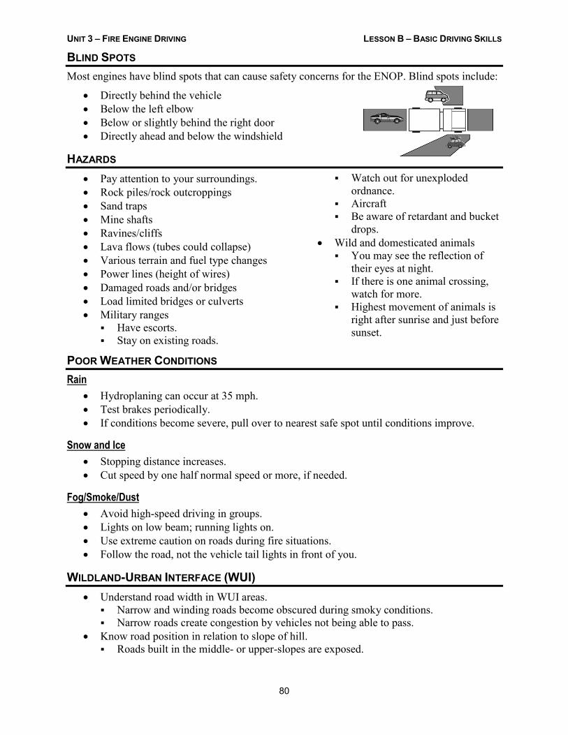
UNIT 3 – FIRE ENGINE DRIVING LESSON B – BASIC DRIVING SKILLS
80
BLIND SPOTS Most engines have blind spots that can cause safety concerns for the ENOP. Blind spots include:
• Directly behind the vehicle • Below the left elbow • Below or slightly behind the right door • Directly ahead and below the windshield
HAZARDS • Pay attention to your surroundings. • Rock piles/rock outcroppings • Sand traps • Mine shafts • Ravines/cliffs • Lava flows (tubes could collapse) • Various terrain and fuel type changes • Power lines (height of wires) • Damaged roads and/or bridges • Load limited bridges or culverts • Military ranges
Have escorts. Stay on existing roads.
Watch out for unexploded ordnance.
Aircraft Be aware of retardant and bucket
drops. • Wild and domesticated animals
You may see the reflection of their eyes at night.
If there is one animal crossing, watch for more.
Highest movement of animals is right after sunrise and just before sunset.
POOR WEATHER CONDITIONS Rain
• Hydroplaning can occur at 35 mph. • Test brakes periodically. • If conditions become severe, pull over to nearest safe spot until conditions improve.
Snow and Ice • Stopping distance increases. • Cut speed by one half normal speed or more, if needed.
Fog/Smoke/Dust • Avoid high-speed driving in groups. • Lights on low beam; running lights on. • Use extreme caution on roads during fire situations. • Follow the road, not the vehicle tail lights in front of you.
WILDLAND-URBAN INTERFACE (WUI) • Understand road width in WUI areas.
Narrow and winding roads become obscured during smoky conditions. Narrow roads create congestion by vehicles not being able to pass.
• Know road position in relation to slope of hill. Roads built in the middle- or upper-slopes are exposed.
UNIT 3 – FIRE ENGINE DRIVING LESSON B – BASIC DRIVING SKILLS
81
• Understand how the fuel canopy can affect your driving (e.g., ladder fuel across the road). Visibility can be impaired.
• Consider the following when performing fire operations in the WUI: Human safety is the first priority. Evacuees have the right of way. Roads might not be on maps. Roads may be private roads, dead ends, or cul-de-sacs. Driveways might not be accessible to fire vehicles.
TIPS FOR STAYING ALERT • Have windows opened or air condition on, if available. • When returning from a fire at night, have an alert person sitting up front with you. • Take periodic breaks. • If fatigue becomes a problem, get rest. • Make sure work/rest guidelines are followed. • Be aware that motor drone causes fatigue.
POST OFF-ROAD INSPECTION After performing off-road driving and prior to transitioning to paved road surfaces, perform a post off-road fire engine inspection as well as disengaging the four-wheel drive and low-range. The post off-road inspection is a quick, visual safety inspection of the following components:
• Tie rod and tie rod ends • Steering stabilizers • Rocks stuck in duals • Noxious weeds caught in under
carriage
• Tire condition and pressure • Air brake canisters • Drivelines and linkage • Shock mounts
DRIVING REMINDERS • Never let driving distractions (e.g., radio and crew chatter, reaching for items, reading
maps) interfere with your main job—driving the engine safely. • More time can be gained by exiting the station quickly than by speeding en route. • Keep your engine in top condition. Inspect your engine regularly. • Good drivers drive smoothly and with control—not recklessly or erratically! • A heavier piece of equipment will not stop as easily as a passenger car. • Accidents do not just happen; they are caused.
CONE COURSE OUTSIDE EXERCISE

UNIT 3 – FIRE ENGINE DRIVING LESSON B – BASIC DRIVING SKILLS
82
NOTES
UNIT 3 – FIRE ENGINE DRIVING OPERATIONS QUIZ
83
UNIT 3 – QUIZ
1. When must a vehicle operator have a CDL?
2. Where can you find BLM driver duty limitations?
3. What does S.T.O.P. stand for?
4. What should you use when backing up a piece of equipment? (circle all that apply)
A spotter Stop and get out
Mirrors Best judgment
5. List five items to check on a post off-road inspection.

UNIT 3 – FIRE ENGINE DRIVING OPERATIONS QUIZ
84
NOTES
UNIT 4 – WATER HANDLING OPERATIONS LESSON A – WATER AND HOSE HYDRAULICS
85
UNIT 4 – WATER HANDLING OPERATIONS LESSON A – WATER AND HOSE HYDRAULICS
Given a simulated wildland fire incident scenario, case study, or exercise, students will be able to:
• Identify the elements that should be considered when calculating pump discharge pressure.
• Perform friction loss calculations using friction loss calculators and Principles of Hydraulics – “Rule of 5s.”
• Identify ways to reduce friction loss. • Describe the causes and effects of pump cavitation and the corrective actions
the ENOP must take if cavitation occurs. • Discuss how hydraulics affect drafting procedures used to refill an engine. • Describe the effects of ejector use during pump operations.
TERMINOLOGY
PUMP DISCHARGE PRESSURE (PDP) Pump discharge pressure is the amount of pressure in pounds per square inch (PSI) as measured at the pump discharge.
NOZZLE PRESSURE (NP) Nozzle pressure is pressure delivered to the nozzle. Optimum operating pressures include:
• Straight stream nozzles with tips and Forester nozzles, 50 PSI • Variable pattern or fog nozzle, 100 PSI
NFES 1089, 1” combination barrel nozzle dual gallon flow rates, 10-25 GPM at 100 PSI
NFES 0138, 1” plastic combination barrel nozzle, 35 GPM at 100 PSI NFES 0137, 1½” plastic combination barrel nozzle, 60 GPM at 100 PSI
APPLIANCES (A) Appliances are items (gated wyes, inline tees, and check valves) that connect or interconnect the hose and pump together to form a hose lay. Appliances have a negligible effect on friction loss calculations at flows used in wildland suppression and have been omitted from calculations in this lesson.
HEAD PRESSURE (H) “Head pressure” is the weight of a given height (depth) of water column at its base.
• Head pressure is also known as lift, back pressure, gravity loss or gain as is measured in terms of feet of water. One foot of water exerts a pressure of .5 PSI at the base of a column of water.
OR Two feet of water exerts a pressure of 1 PSI at the base of a column of water.
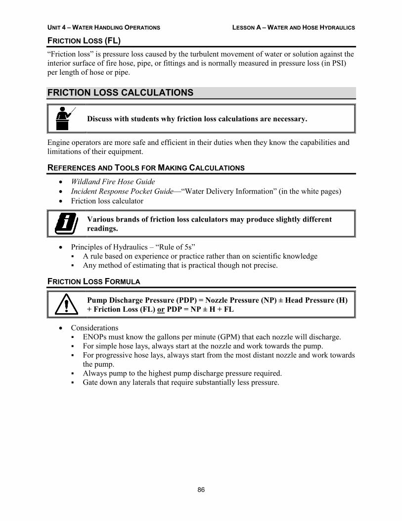
UNIT 4 – WATER HANDLING OPERATIONS LESSON A – WATER AND HOSE HYDRAULICS
86
FRICTION LOSS (FL) “Friction loss” is pressure loss caused by the turbulent movement of water or solution against the interior surface of fire hose, pipe, or fittings and is normally measured in pressure loss (in PSI) per length of hose or pipe.
FRICTION LOSS CALCULATIONS
Discuss with students why friction loss calculations are necessary.
Engine operators are more safe and efficient in their duties when they know the capabilities and limitations of their equipment.
REFERENCES AND TOOLS FOR MAKING CALCULATIONS • Wildland Fire Hose Guide • Incident Response Pocket Guide—“Water Delivery Information” (in the white pages) • Friction loss calculator
Various brands of friction loss calculators may produce slightly different readings.
• Principles of Hydraulics – “Rule of 5s” A rule based on experience or practice rather than on scientific knowledge Any method of estimating that is practical though not precise.
FRICTION LOSS FORMULA
Pump Discharge Pressure (PDP) = Nozzle Pressure (NP) ± Head Pressure (H) + Friction Loss (FL) or PDP = NP ± H + FL
• Considerations ENOPs must know the gallons per minute (GPM) that each nozzle will discharge. For simple hose lays, always start at the nozzle and work towards the pump. For progressive hose lays, always start from the most distant nozzle and work towards
the pump. Always pump to the highest pump discharge pressure required. Gate down any laterals that require substantially less pressure.
UNIT 4 – WATER HANDLING OPERATIONS LESSON A – WATER AND HOSE HYDRAULICS
87
FRICTION LOSS CALCULATION EXERCISES
PRE-COURSE WORK
Exercises 1-4
Return the students’ pre-course work. After students have had time to review their work, provide a step-by-step review or overview of Exercises 1-4 to address student difficulties and questions.
Review the friction loss calculations you submitted as pre-course work.
IN-CLASS HYDRAULICS EXERCISES USING THE FRICTION LOSS CALCULATOR
Guide students through Exercises #5 and #6 in a step-by-step manner.
Using the friction loss calculator, complete Exercises 5 and 6 with the instructor. Ask questions if your solution is different from the instructor’s. Complete Exercise 7 individually. You will have 5 minutes to complete this exercise.
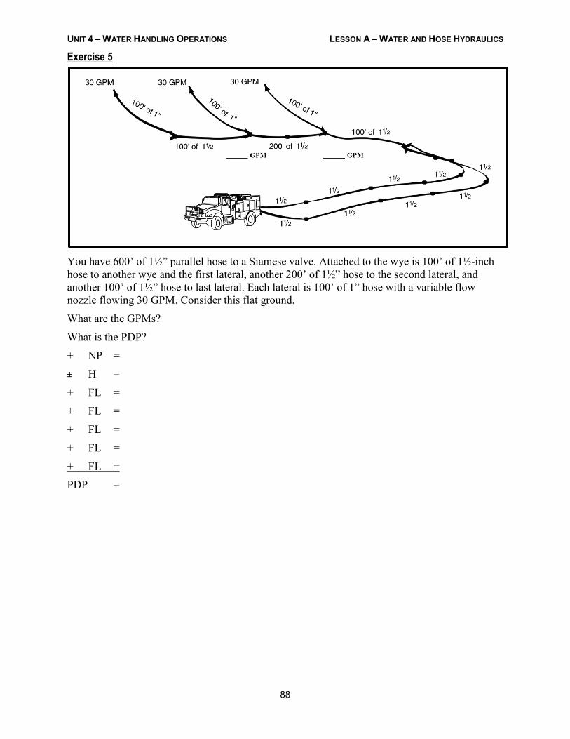
UNIT 4 – WATER HANDLING OPERATIONS LESSON A – WATER AND HOSE HYDRAULICS
88
Exercise 5
You have 600’ of 1½” parallel hose to a Siamese valve. Attached to the wye is 100’ of 1½-inch hose to another wye and the first lateral, another 200’ of 1½” hose to the second lateral, and another 100’ of 1½” hose to last lateral. Each lateral is 100’ of 1” hose with a variable flow nozzle flowing 30 GPM. Consider this flat ground. What are the GPMs? What is the PDP? + NP = ± H = + FL = + FL = + FL = + FL = + FL = PDP =
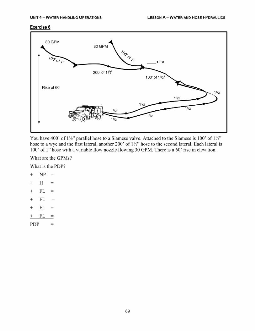
UNIT 4 – WATER HANDLING OPERATIONS LESSON A – WATER AND HOSE HYDRAULICS
89
Exercise 6
You have 400’ of 1½” parallel hose to a Siamese valve. Attached to the Siamese is 100’ of 1½” hose to a wye and the first lateral, another 200’ of 1½” hose to the second lateral. Each lateral is 100’ of 1” hose with a variable flow nozzle flowing 30 GPM. There is a 60’ rise in elevation. What are the GPMs? What is the PDP? + NP = ± H = + FL = + FL = + FL = + FL = PDP =
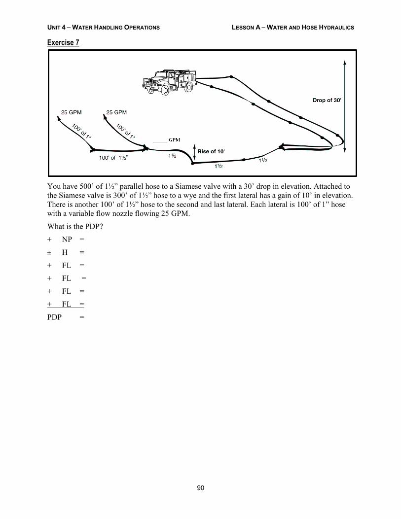
UNIT 4 – WATER HANDLING OPERATIONS LESSON A – WATER AND HOSE HYDRAULICS
90
Exercise 7
You have 500’ of 1½” parallel hose to a Siamese valve with a 30’ drop in elevation. Attached to the Siamese valve is 300’ of 1½” hose to a wye and the first lateral has a gain of 10’ in elevation. There is another 100’ of 1½” hose to the second and last lateral. Each lateral is 100’ of 1” hose with a variable flow nozzle flowing 25 GPM. What is the PDP? + NP = ± H = + FL = + FL = + FL = + FL = PDP =
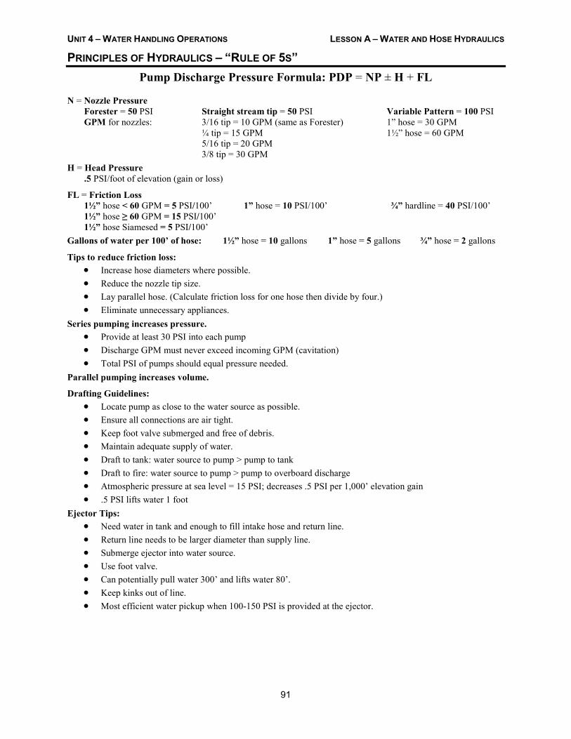
UNIT 4 – WATER HANDLING OPERATIONS LESSON A – WATER AND HOSE HYDRAULICS
91
PRINCIPLES OF HYDRAULICS – “RULE OF 5S” Pump Discharge Pressure Formula: PDP = NP ± H + FL
N = Nozzle Pressure Forester = 50 PSI Straight stream tip = 50 PSI Variable Pattern = 100 PSI GPM for nozzles: 3/16 tip = 10 GPM (same as Forester) 1” hose = 30 GPM ¼ tip = 15 GPM 1½” hose = 60 GPM 5/16 tip = 20 GPM 3/8 tip = 30 GPM
H = Head Pressure .5 PSI/foot of elevation (gain or loss)
FL = Friction Loss 1½” hose < 60 GPM = 5 PSI/100’ 1” hose = 10 PSI/100’ ¾” hardline = 40 PSI/100’ 1½” hose ≥ 60 GPM = 15 PSI/100’ 1½” hose Siamesed = 5 PSI/100’
Gallons of water per 100’ of hose: 1½” hose = 10 gallons 1” hose = 5 gallons ¾” hose = 2 gallons
Tips to reduce friction loss: • Increase hose diameters where possible. • Reduce the nozzle tip size. • Lay parallel hose. (Calculate friction loss for one hose then divide by four.) • Eliminate unnecessary appliances.
Series pumping increases pressure. • Provide at least 30 PSI into each pump • Discharge GPM must never exceed incoming GPM (cavitation) • Total PSI of pumps should equal pressure needed.
Parallel pumping increases volume.
Drafting Guidelines: • Locate pump as close to the water source as possible. • Ensure all connections are air tight. • Keep foot valve submerged and free of debris. • Maintain adequate supply of water. • Draft to tank: water source to pump > pump to tank • Draft to fire: water source to pump > pump to overboard discharge • Atmospheric pressure at sea level = 15 PSI; decreases .5 PSI per 1,000’ elevation gain • .5 PSI lifts water 1 foot
Ejector Tips: • Need water in tank and enough to fill intake hose and return line. • Return line needs to be larger diameter than supply line. • Submerge ejector into water source. • Use foot valve. • Can potentially pull water 300’ and lifts water 80’. • Keep kinks out of line. • Most efficient water pickup when 100-150 PSI is provided at the ejector.
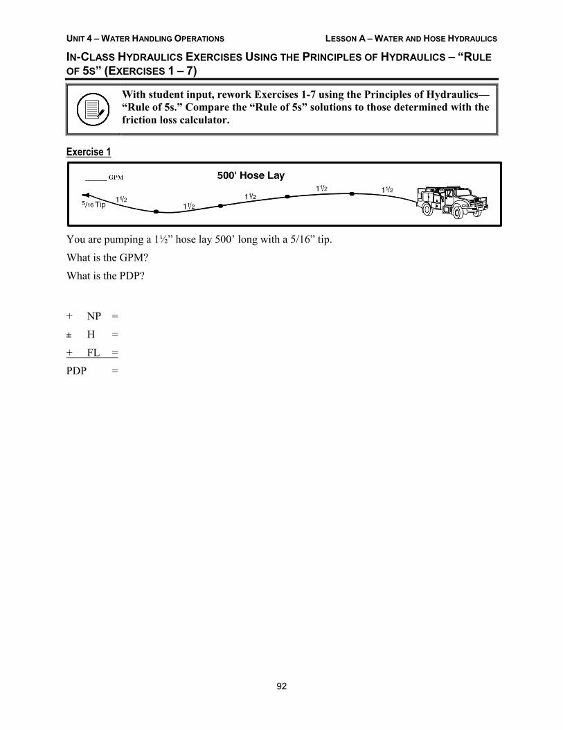
UNIT 4 – WATER HANDLING OPERATIONS LESSON A – WATER AND HOSE HYDRAULICS
92
IN-CLASS HYDRAULICS EXERCISES USING THE PRINCIPLES OF HYDRAULICS – “RULE OF 5S” (EXERCISES 1 – 7)
With student input, rework Exercises 1-7 using the Principles of Hydraulics—“Rule of 5s.” Compare the “Rule of 5s” solutions to those determined with the friction loss calculator.
Exercise 1
You are pumping a 1½” hose lay 500’ long with a 5/16” tip. What is the GPM? What is the PDP?
+ NP = ± H = + FL = PDP =
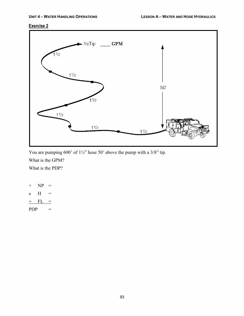
UNIT 4 – WATER HANDLING OPERATIONS LESSON A – WATER AND HOSE HYDRAULICS
93
Exercise 2
You are pumping 600’ of 1½” hose 50’ above the pump with a 3/8” tip. What is the GPM? What is the PDP?
+ NP = ± H = + FL = PDP =
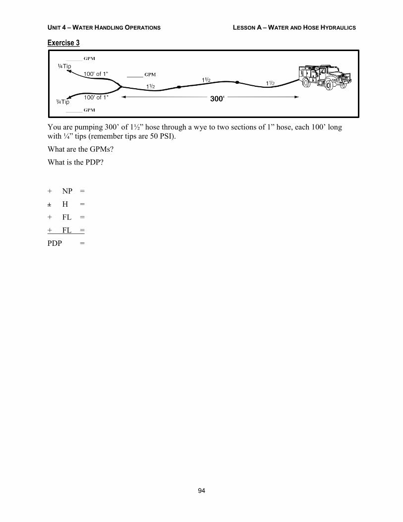
UNIT 4 – WATER HANDLING OPERATIONS LESSON A – WATER AND HOSE HYDRAULICS
94
Exercise 3
You are pumping 300’ of 1½” hose through a wye to two sections of 1” hose, each 100’ long with ¼” tips (remember tips are 50 PSI). What are the GPMs? What is the PDP?
+ NP = ± H = + FL = + FL = PDP =
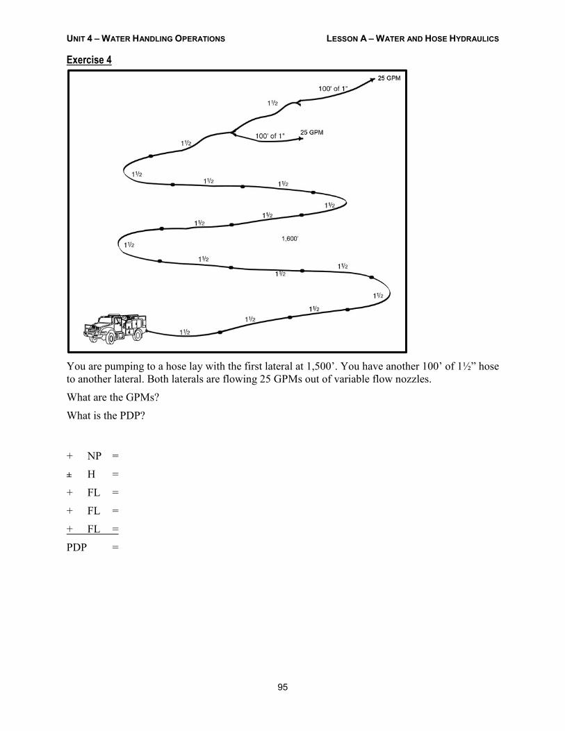
UNIT 4 – WATER HANDLING OPERATIONS LESSON A – WATER AND HOSE HYDRAULICS
95
Exercise 4
You are pumping to a hose lay with the first lateral at 1,500’. You have another 100’ of 1½” hose to another lateral. Both laterals are flowing 25 GPMs out of variable flow nozzles. What are the GPMs? What is the PDP?
+ NP = ± H = + FL = + FL = + FL = PDP =
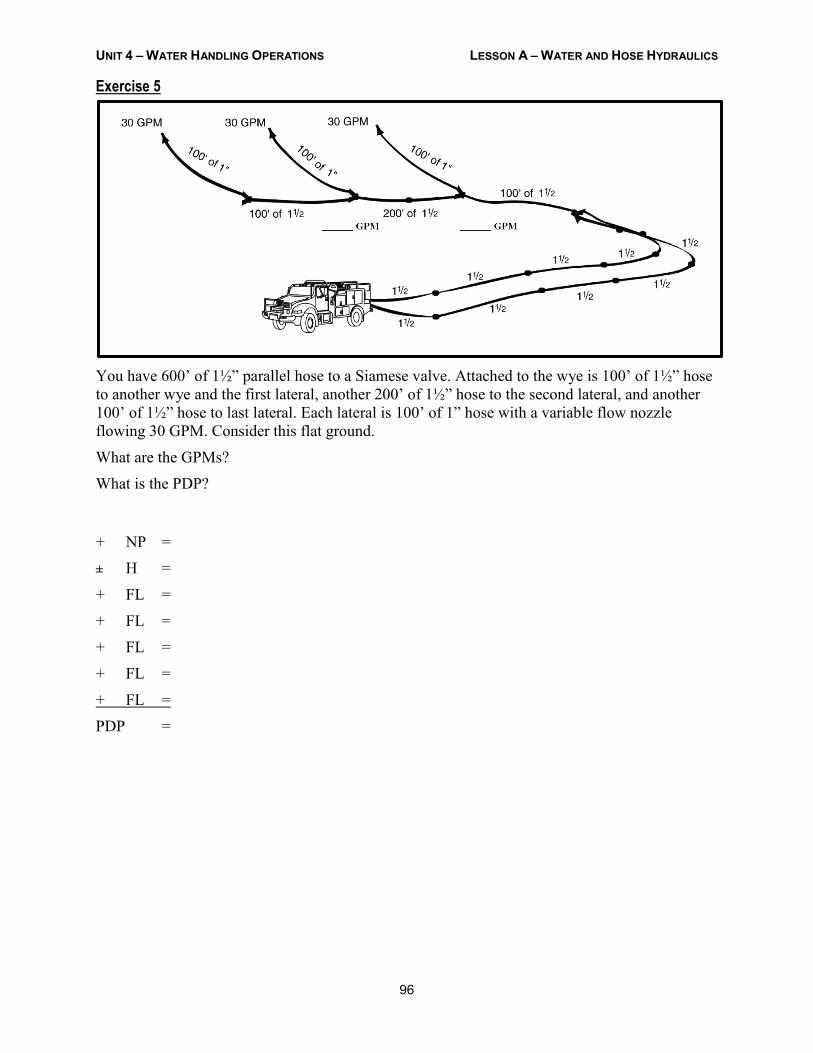
UNIT 4 – WATER HANDLING OPERATIONS LESSON A – WATER AND HOSE HYDRAULICS
96
Exercise 5
You have 600’ of 1½” parallel hose to a Siamese valve. Attached to the wye is 100’ of 1½” hose to another wye and the first lateral, another 200’ of 1½” hose to the second lateral, and another 100’ of 1½” hose to last lateral. Each lateral is 100’ of 1” hose with a variable flow nozzle flowing 30 GPM. Consider this flat ground. What are the GPMs? What is the PDP?
+ NP = ± H = + FL = + FL = + FL = + FL = + FL = PDP =
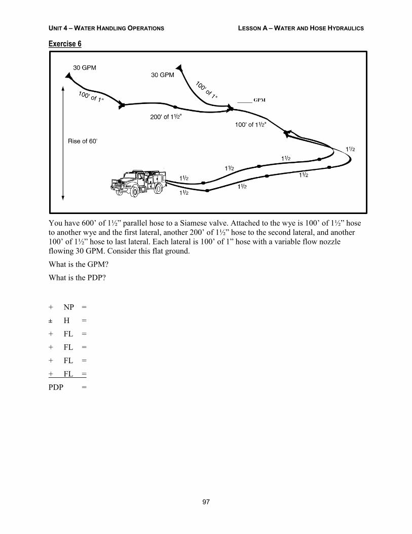
UNIT 4 – WATER HANDLING OPERATIONS LESSON A – WATER AND HOSE HYDRAULICS
97
Exercise 6
You have 600’ of 1½” parallel hose to a Siamese valve. Attached to the wye is 100’ of 1½” hose to another wye and the first lateral, another 200’ of 1½” hose to the second lateral, and another 100’ of 1½” hose to last lateral. Each lateral is 100’ of 1” hose with a variable flow nozzle flowing 30 GPM. Consider this flat ground. What is the GPM? What is the PDP?
+ NP = ± H = + FL = + FL = + FL = + FL = PDP =
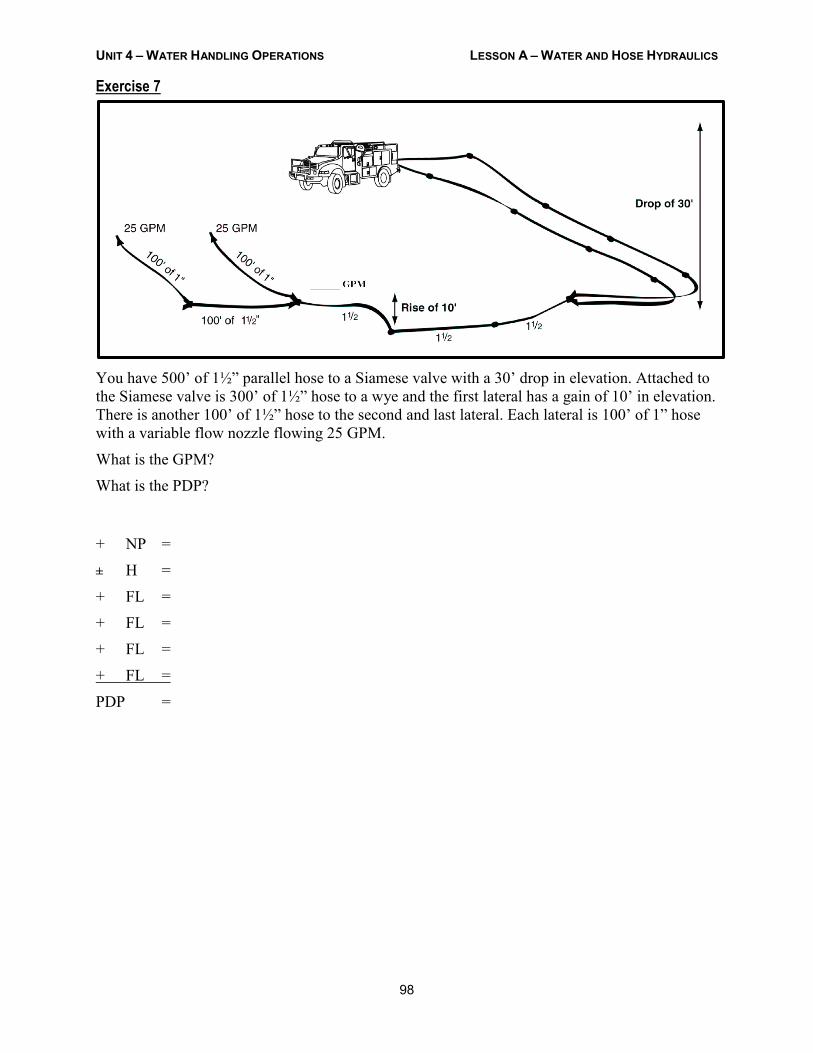
UNIT 4 – WATER HANDLING OPERATIONS LESSON A – WATER AND HOSE HYDRAULICS
98
Exercise 7
You have 500’ of 1½” parallel hose to a Siamese valve with a 30’ drop in elevation. Attached to the Siamese valve is 300’ of 1½” hose to a wye and the first lateral has a gain of 10’ in elevation. There is another 100’ of 1½” hose to the second and last lateral. Each lateral is 100’ of 1” hose with a variable flow nozzle flowing 25 GPM. What is the GPM? What is the PDP?
+ NP = ± H = + FL = + FL = + FL = + FL = PDP =
UNIT 4 – WATER HANDLING OPERATIONS LESSON A – WATER AND HOSE HYDRAULICS
99
• Why are there differences between the friction loss calculator and “Rule of 5s” solutions?
• Are the differences in the answers significant enough to cause problems in building hose lays?
• Why are we using the friction loss calculator and the Principles of Hydraulics – “Rule of 5s”?
THE PRINCIPLES OF HYDRAULICS – “RULE OF 5s” “Rule of 5s” have been developed to provide quick solutions for fire situations based on the theories already learned. Both methods show the ENOP capabilities and limitations of the water handling equipment involved. Practical experience and the “Rule of 5s” will allow the ENOP to make fast and practical decisions during hose lay construction.
REDUCING FRICTION LOSS • Increase hose diameters where possible. • Lay parallel hose.
With all other factors remaining constant, two parallel lines of hose will have 1/4 the friction loss of a single line of the same diameter and length, and carrying the same quantity of water.
Three lines will be 1/9 the friction loss of a single line. Four lines will have 1/16 the friction loss.
• Reduce the pump discharge pressure. If the nozzle pressure is reduced, the discharge will be less; therefore, the friction loss
will be less. But, this may prevent the fire stream from doing the required task. • Reduce the nozzle tip size.
Reducing the tip size and maintaining the same nozzle pressure reduces the discharge. However, the quantity of water being discharged may not be sufficient to effectively extinguish the fire or provide for firefighter safety.
• Eliminate unnecessary plumbing parts.
Water additives such as foam concentrate or wet water may reduce friction loss to a small degree.
UNIT 4 – WATER HANDLING OPERATIONS LESSON A – WATER AND HOSE HYDRAULICS
100
PUMP CAVITATION Pump cavitation occurs when more water is being discharged from the pump than is being supplied creating a low-pressure area within the center (or eye) of the pump.
CAVITATION IN A WATER PUMP
EFFECTS OF CAVITATION • When water enters the low-pressure area at the eye of the impeller, water vaporizes or
boils more easily. • When vapor bubbles reach the pressure or discharge side of the pump, they implode or
forcefully collapse, resulting in an intense shock wave which creates dings and pits on the pump wall and impeller. Damage is cumulative and progressive.
• A centrifugal pump that is allowed to cavitate too long will eventually suffer impeller failure.
SIGNS OF CAVITATION • Pump RPMs suddenly increase due to the lack of water resistance on the impeller. • Cavitation may cause a rattling or a sound like gravel flowing through the pump. • A reliable indicator that cavitation is occurring is an increase in pump RPMs without an
increase in pump discharge pressure (PDP). If this occurs, reduce the throttle immediately. Any further increase in RPMs will
result in additional damage.
CORRECTIVE ACTIONS • Increase the supply of water coming into the pump and/or decrease the discharge volume
from the pump. • If the pump is not staffed, the low-pressure shutoff switch must be in the down position.
The purpose of this safety device is to protect the pump from damage due to cavitation and/or overheating.
• Clean out the suction strainer; it could be clogged. • Do not deadhead the pump for prolonged periods.
Ensure water is circulating through the plumbing.
DRAFTING GENERAL FACTS
• Atmospheric pressure is approximately 15 PSI at sea level. A good pump can pull water 24 feet at sea level.
• Atmospheric pressure decreases .5 PSI for each 1,000 foot increase in elevation. • Each 1,000 foot increase in elevation results in a loss of 1 foot of draft power. • Locating a pump as close to the water source as possible and reducing the vertical
distance a pump must draft will increase its pumping ability.
UNIT 4 – WATER HANDLING OPERATIONS LESSON A – WATER AND HOSE HYDRAULICS
101
DRAFTING USING ENGINE PUMP SETUP 1. Locate a water source with adequate water supply. 2. Always obtain permission from the land owner before using a private water source. 3. Source site should allow for good ingress and egress. 4. Source site should be free of floating debris. 5. All fittings and hoses on the suction side of the pump should be free of air leaks.
• Air leaks prevent the pump from creating a vacuum, which affects the pump’s ability to draft.
6. The foot valve should be completely submerged, free from debris, and properly functioning. • This is a common problem when unable to achieve a draft. Check for debris in the foot
valve or a damaged seal of the valve. 7. Obtain a prime by using the hand/electric primer on the engine.
• Fill the draft hose with water manually before using a primer pump. 8. Set the water pressure shutdown switch to the up (override) position.
• Leave the switch in this position for the entire drafting process.
What will happen if the water pressure safety shutdown switch is in the down (on) position and the operator opens the draft-to-tank valve?
1. Set correct valve configuration. Draft-to-tank: 1) Slowly open the suction valve (#8). 2) Open the pump-to-tank valve (#2). Draft-to-fire: 1) Slowly open the suction valve (#8). 2) Open the overboard valve (#3) or the hose reels valve (#4) after a draft has been
achieved. 2. Confirm pump is drafting water into the tank or pump is forcing water to the nozzle.
EJECTOR USE FOR REFILL OPERATIONS
GENERAL INFORMATION • Ejectors increase water flow between 50-150%. • Ejectors can lift water 80 feet or more vertically. • Ejectors can move water 300 feet or more horizontally. • Ensure you have enough water in the tank to fill the intake hose and return line.
UNIT 4 – WATER HANDLING OPERATIONS LESSON A – WATER AND HOSE HYDRAULICS
102
WORKING PRINCIPLES • Water from the pump is directed to the pressure inlet on the ejector. • Water is then directed through a tapered throat to increase velocity. • The high velocity stream enters the Venturi tube section of the ejector. • This high velocity stream creates a low-pressure area in the suction chamber. • Atmospheric pressure forces water into the chamber where it is picked up by the high-
velocity stream and directed out the discharge.
EJECTOR SETUP 1. Connect a section of 1-inch hose to overboard discharge and run it out to the ejector (inlet
side). 2. Attach a strainer foot valve to the suction port of the ejector. 3. Attach a 1½-inch hose to the discharge side of the ejector. 4. Submerge ejector in the water source. 5. Start pump and throttle up to desired output (generally 100-150 PSI at the ejector). 6. Keep all kinks out of supply and return lines.
• Kinks will inhibit ejector performance.
7. If the site is going to be used multiple times, then leave hardware in place for refill operations.
UNIT 4 – WATER HANDLING OPERATIONS LESSON B – WATER SOURCES AND PUMPING OPERATIONS
103
UNIT 4 – WATER HANDLING OPERATIONS LESSON B –WATER SOURCES AND PUMPING OPERATIONS
Given a simulated wildland fire incident scenario, case study, or exercise, students will be able to:
• Identify water sources used in engine refill operations. • Define aquatic invasive species. • Discuss actions an ENOP can perform to help reduce/eliminate the spread of
aquatic invasive species. • Identify potential problems that occur when interfacing with a municipal
apparatus. • Demonstrate the use and hazards of hydrants during refill operations. • Describe the differences between parallel, stage, and series pumping. • Describe the differences between a simple and progressive hose lay. • List the advantages and disadvantages of hose deployment methods. • Locate and describe the function of valves in the fire engine plumbing
system.
CASE STUDY The instructor will present students with a case study relevant to water handling operations.
WATER SOURCES FOR ENGINE REFILL OPERATIONS NATURAL WATER SOURCES Types
• Streams • Ponds • Lakes
• Springs • Other
Considerations • Limit environmental impact. • Locate a water source with adequate water supply (flow). • Source site should allow for good ingress and egress. • Obtain owner permission from the land owner before using a private water source. • Communicate location to others. • Always flush the tank and plumbing after using natural water sources.
Dam Building • Construct dams in areas narrow enough to dam easily. • Use rocks, logs, or plastic to build a dam. • Tear down the dam after use.
UNIT 4 – WATER HANDLING OPERATIONS LESSON B – WATER SOURCES AND PUMPING OPERATIONS
104
PORTABLE TANK SETUP • Provide for the following when setting up portable tanks:
Locate in an area where the water can drain on the downhill side without causing access problems.
Locate on relatively smooth, flat ground—free of sharp objects, rocks, tree limbs, etc. Communicate location to others.
AGRICULTURAL SOURCES Irrigation Risers
• Obtain owner permission before use. • Consult with owner to ensure the line is operational and pump is on. • Obtain and use a riser adapter and fill hose. • Open with caution due to unknown fill rates. • Communicate location to others.
Stock Ponds • Limit environmental impact. • Obtain owner permission before use. • Ensure there is adequate recharge of water (flow). • Allow for good ingress and egress. • Communicate location to others. • Refill the pond after use, if required.
Canals • Obtain owner permission before use. • Inspect site for safe access (cut banks and soft or loose banks can cause engine rollovers). • Communicate location to others.
STAND PIPES • Obtain owner permission before use. • Ensure the fill hose is long enough to be placed inside tank. Use an air gap as backflow
prevention. • Employ a two-person operation when necessary. • Open the stand pipe with caution due to unknown fill rates. • Communicate location to others.
MUNICIPAL APPARATUS • Consider the following when interfacing with municipal apparatus:
Municipal apparatus deal with large volume pumps. Thread types vary from department to department. Carefully inspect all connections
before using. When filling through the direct fill (Dri-Fill) valve, do not exceed 50 PSI.
Why should you not exceed 50 PSI?
UNIT 4 – WATER HANDLING OPERATIONS LESSON B – WATER SOURCES AND PUMPING OPERATIONS
105
FIRE HYDRANTS • Identify the type of hydrant you are going to use.
Fire Hydrant Types Dry Barrel
• Most common—used in areas subject to freezing. • Drain when not in use to prevent freeze damage. The bonnet-top cover of hydrant houses
the turning stem nut. • Single on/off system must be shut down to add/remove hose attachments. • Stem nut has to be opened all the way.
Wet Barrel • Mostly seen in Southern states and coastal Southern California. • Never used in areas subject to freezing temperatures. • Always charged. • Individual hookup; disconnect while in use.
Proper Use and Hazards Associated with Hydrant Use • The five-sided hydrant wrench is the only wrench that should be used on hydrants. • Always use the correct thread adapters and reducers. • While the hydrant is in the off position, install appropriate fittings (e.g., gated wye,
automatic check and bleeder valve) to control hydrant flow. • Open and close hydrant and valves slowly to avoid water hammer (pressure surge
resulting when a fluid in motion is forced to stop or change direction suddenly). Bleed off any air, rust or debris before attaching hose.
• Open hydrant completely. Never attempt to control water flow with hydrant stem nut!
• Improper use of a hydrant can result in: Contamination of drinking water supply. Damage to underground water supply lines. Injury to the engine operator. Damage to the engine, fill controls, backflow prevention devices, or hose.
Backflow Prevention Devices Why Use a Backflow Prevention Device?
• Most areas require the use of backflow prevention devices. These devices protect the water supply by preventing the backflow of tainted water or chemicals.
• A simple backflow prevention device is the automatic check and bleeder valve.
Backflow Prevention Device Components • Two check valves • Differential pressure relief valve
• Four properly located test cocks • Two isolation valves
Use of the Back Flow Prevention Device • Place between the hydrant and the engine tank. • Know the local protocol regarding hydrant use. • Certify and test the device annually. • Use the air gap method to refill if you do not have a backflow prevention device.
UNIT 4 – WATER HANDLING OPERATIONS LESSON B – WATER SOURCES AND PUMPING OPERATIONS
106
Air Gap Method An air gap assembly is a permanently attached pipe with a hose connection. Air Gap Requirements The air gap distance is required to be two times the inside diameter of the pipe. If you are in a location that requires either a backflow prevention device or the permanently attached air gap assembly and have neither, you can refill during emergency operations by providing an air gap manually. Manual Air Gap Method
• In most cases, a person holds the fill hose. Some appliances have been set up to hold the hose that is attached to the fill tower.
• Never insert the fill hose below the tank water level. • Always maintain the air gap.
AQUATIC INVASIVE SPECIES (AIS)
DEFINITIONS “Aquatic invasive species” are alien (non-native) aquatic plants and animals whose introduction into an ecosystem causes, or is likely to cause, economic or environmental harm or harm to human health.
Invasive Aquatic Plants Invasive aquatic plants are non-native plants that have adapted to living in, on, or next to water, and that can grow either submerged or partially submerged in water. Examples common to the Great Basin include:
• Eurasian Milfoil • Chytrid Fungus
• Didymo (Rock Snot)
Invasive Aquatic Animals Invasive aquatic animals are non-native animals that require a watery habitat but do not necessarily have to live entirely in water. Examples common to the Great Basin include:
• New Zealand Mudsnails • Zebra Mussels
• Quagga Mussels • Whirling Disease Parasite
AIS POLICY DIRECTION AIS is an emerging issue with no clear national policy direction for fire operations. Engine operators should educate themselves as best as possible regarding aquatic invasive species by asking questions of their geographic area specialists and conducting personal research. Websites relating to this topic include: https://www.wildlife.ca.gov/Conservation/Invasives https://www.fs.fed.us/invasivespecies/index.shtml http://www.fs.fed.us/invasivespecies/relatedlinks.shtml https://www.invasivespeciesinfo.gov/aquatics/main.shtml
UNIT 4 – WATER HANDLING OPERATIONS LESSON B – WATER SOURCES AND PUMPING OPERATIONS
107
ENGINE OPERATION AND AIS • Fire equipment including engines, other fire vehicles, helicopter water buckets, water
tanks, and hoses can spread AIS. • Engine operators are responsible for understanding how their actions regarding engine
operations can reduce/eliminate the spread of AIS.
Standard Operating Procedures (SOPs) • Understand and follow the SOPs for AIS in your area.
Do not transfer the problem from a dirty area to a clean area. Treat every body of water as if an aquatic invasive species is present.
• Brief out-of-area engine crews working with you about AIS problems in your area. • When working outside your local area, learn and understand the SOPs for AIS in that
area. Do not transfer AIS from out of area to your local area.
Cleaning and Sanitizing Equipment • As an ENOP, understand how to clean equipment that may have been exposed to AIS.
Screening Methods • Screening may be impractical since most AIS are microscopic.
Chemical Use • Mix ratio of chemicals to treatment area • Cleaning solution disposal
When? Where? How?
Refer to the chemical’s “Safety Data Sheet” (SDS) when using chemicals in cleaning operations.
Common Sense Mitigation Measures for AIS Prevention • Always assume that AIS could be present in any body of water. • When possible, avoid driving through bodies of water. • Avoid dumping water directly from one waterway into another. • Avoid drafting water from multiple sources during a single operational period unless
equipment is sanitized between sources. • Avoid sucking organic and bottom material when drafting. • Clean out and sanitize the plumbing strainers.
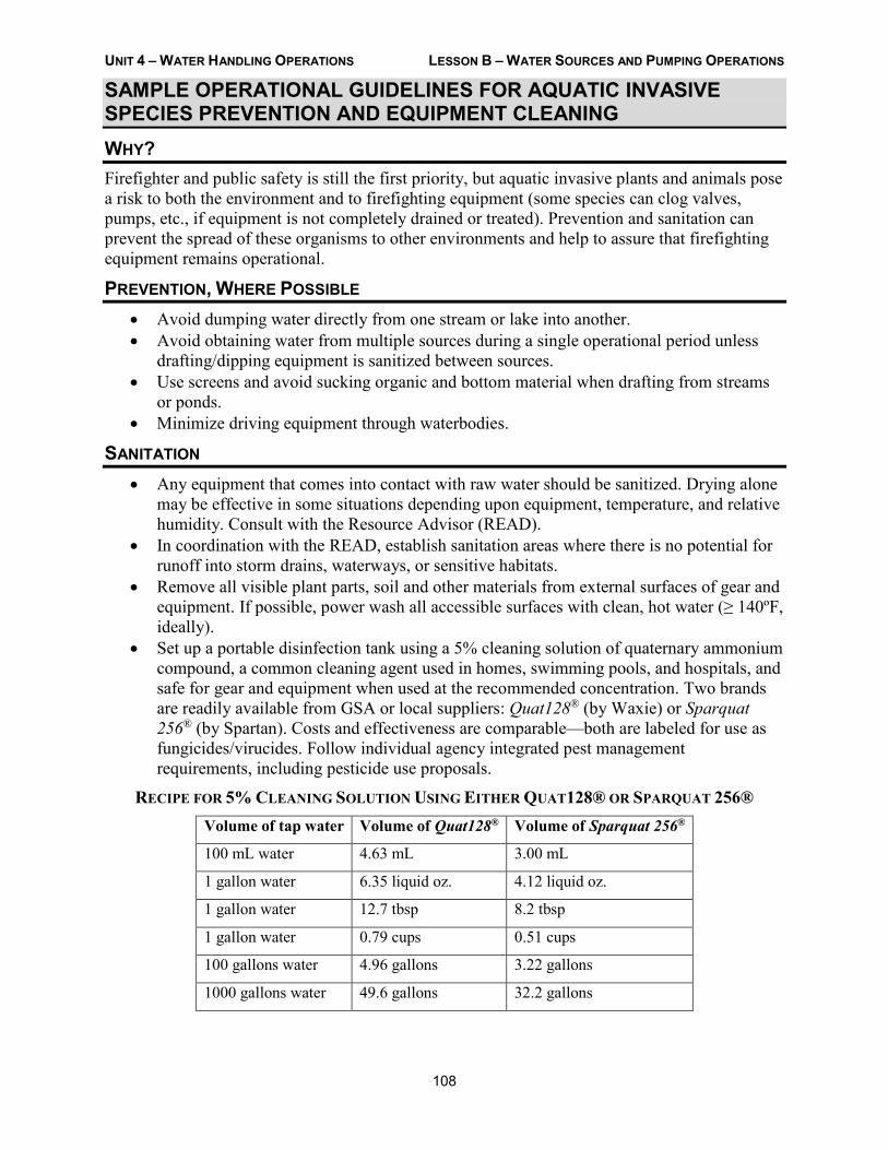
UNIT 4 – WATER HANDLING OPERATIONS LESSON B – WATER SOURCES AND PUMPING OPERATIONS
108
SAMPLE OPERATIONAL GUIDELINES FOR AQUATIC INVASIVE SPECIES PREVENTION AND EQUIPMENT CLEANING WHY? Firefighter and public safety is still the first priority, but aquatic invasive plants and animals pose a risk to both the environment and to firefighting equipment (some species can clog valves, pumps, etc., if equipment is not completely drained or treated). Prevention and sanitation can prevent the spread of these organisms to other environments and help to assure that firefighting equipment remains operational.
PREVENTION, WHERE POSSIBLE • Avoid dumping water directly from one stream or lake into another. • Avoid obtaining water from multiple sources during a single operational period unless
drafting/dipping equipment is sanitized between sources. • Use screens and avoid sucking organic and bottom material when drafting from streams
or ponds. • Minimize driving equipment through waterbodies.
SANITATION • Any equipment that comes into contact with raw water should be sanitized. Drying alone
may be effective in some situations depending upon equipment, temperature, and relative humidity. Consult with the Resource Advisor (READ).
• In coordination with the READ, establish sanitation areas where there is no potential for runoff into storm drains, waterways, or sensitive habitats.
• Remove all visible plant parts, soil and other materials from external surfaces of gear and equipment. If possible, power wash all accessible surfaces with clean, hot water (≥ 140ºF, ideally).
• Set up a portable disinfection tank using a 5% cleaning solution of quaternary ammonium compound, a common cleaning agent used in homes, swimming pools, and hospitals, and safe for gear and equipment when used at the recommended concentration. Two brands are readily available from GSA or local suppliers: Quat128® (by Waxie) or Sparquat 256® (by Spartan). Costs and effectiveness are comparable—both are labeled for use as fungicides/virucides. Follow individual agency integrated pest management requirements, including pesticide use proposals.
RECIPE FOR 5% CLEANING SOLUTION USING EITHER QUAT128® OR SPARQUAT 256® Volume of tap water Volume of Quat128® Volume of Sparquat 256®
100 mL water 4.63 mL 3.00 mL
1 gallon water 6.35 liquid oz. 4.12 liquid oz.
1 gallon water 12.7 tbsp 8.2 tbsp
1 gallon water 0.79 cups 0.51 cups
100 gallons water 4.96 gallons 3.22 gallons
1000 gallons water 49.6 gallons 32.2 gallons
UNIT 4 – WATER HANDLING OPERATIONS LESSON B – WATER SOURCES AND PUMPING OPERATIONS
109
• For engines and tenders, empty the tank then circulate the 5% cleaning solution for 10 minutes. Float portable pumps in the disinfection tank and pump cleaning solution through for 10 minutes. Pump cleaning solution through hose then rinse with water. Discharge cleaning solution back into the disinfection tank for reuse.
• Where feasible, dip gear or equipment (e.g., helicopter buckets) into the cleaning solution. Alternatively, put the 5% cleaning solution in backpack spray pumps to clean portable tanks, helicopter buckets, and other equipment. The solution must be in contact with the surface being sanitized for at least 10 minutes and then rinsed with water.
• Under the direction of the READ, test cleaning solution daily according to the directions below. The cleaning solution can be used repeatedly for up to a week unless heavily muddied or diluted. If the concentration is too weak, dispose of the used solution properly and make a new solution.
SAFETY • Use protective, unlined rubber gloves and splash goggles or face shield when handling
the cleaning solution and take extra precautions when handling undiluted chemicals. Have eye wash and clean water available onsite to treat accidental exposure.
• Consult the product label and “Safety Data Sheet” for additional information.
TESTING SOLUTION • To determine if the solution is below the 5% strength, use “Quat Chek 1000” test papers.
(Purchase these from the supplier of the cleaning compound.) The used cleaning solution needs to be diluted to about 600 ppm of ammonium compounds before it can be tested with these papers. Take one cup of used Sparquat 256® cleaning solution, pour into a bucket. Add five
cups of water. Mix. OR Take one cup of used Quat128® cleaning solution, pour into a bucket. Add four cups
of water. Mix. • Test the diluted solution with “Quat Chek” test papers. Match up the color of the paper
with the ppms on the color chart. For optimal disinfection, the diluted solution should have a concentration between 600 and 800 ppm. If it is too diluted, dispose of properly and make a new cleaning solution.
DISPOSAL • Use caution when disposing of used cleaning solution; follow all federal, state, and local
regulations. • Do not dump cleaning solution into any stream or lake, or on areas where it can migrate
into any storm drain, water body, or sensitive habitat. Small quantities may be disposed of down sanitary drains into a municipal sewer system. Larger quantities may need to be transported to a municipal wastewater treatment facility. Consult the facility operator/manager prior to disposal.
• Used cleaning solution may or may not be suitable for disposal in onsite septic systems. Consult the local agency’s utilities supervisor or facilities manager prior to disposal.
• It may be possible to dispose of used cleaning solution over open land or on roadways where there is no potential for runoff into storm drains, waterways, or sensitive habitats. Consult the READ for appropriate locations before using this method and check with the appropriate state or county authority as state or local permits may be required.
UNIT 4 – WATER HANDLING OPERATIONS LESSON B – WATER SOURCES AND PUMPING OPERATIONS
110
STORAGE
Sparquat 256® and Quat128® can be stored up to two years in an unopened container without losing its effectiveness. Both should be stored in a cool, dry place, out of direct sunlight. Temperatures can range from 32º to 110º Fahrenheit.
PURCHASE
Both products are available from GSA (https://www.gsaadvantage.gov) and are commonly available through local janitorial and swimming pool chemical suppliers.
• Quat 128® by Waxie’s Enterprises Inc.; GSA (NSN No. 170304), $36/case (4 gal); EPA registration #1839-166-14994. Additional information can be found at http://www.waxie.com
• Sparquat 256® by Spartan Chemical Company; GSA (NSN No. 1025-04), $54/case (4 gal); EPA registration #5741-9. Additional information can be found at http://www.spartanchemical.com
Remember to buy “Quat Chek 1000” test papers when you purchase the chemicals.
PUMPING OPERATIONS
PUMP OPERATION WATCH OUTS • Ensure the use of proper PPE. • Use caution when working around high-pressure hose lines. • Ensure proper water circulation to mitigate the pump from
overheating. • Utilize a check valve to reduce the head pressure on the pump. • Ensure all pressure hose is tested annually.
WATER DELIVERY Parallel Pumping
• Two engines with similar pump capacities are parked in a side-by-side formation. • A Siamese fitting is used to connect the two water supplies. • Water is pumped independently from each engine into a single hose lay coming off the
Siamese fitting. The hydraulic effect is increased volume.
Stage Pumping • Two engines are operated independently of one another. • Water is pumped from one engine to the holding tank of another engine.
The hydraulic effect is equal to the ability of each pump.
Series Pumping • Two or more pumps are directly connected in a series. • Place the pump with the highest output closest to the water source.
The hydraulic effect is increased pressure. • Series pumping is generally only done with portable pumps.
UNIT 4 – WATER HANDLING OPERATIONS LESSON B – WATER SOURCES AND PUMPING OPERATIONS
111
HOSE LAYS
What is a hose lay?
Simple Progressive Hose Lay • A simple progressive hose lay comes straight off the pump and goes directly to the nozzle
with no appliances in between hose connections.
Progressive Hose Lay • A progressive hose lay comes from a pump source to the fire via a series of laterals
coming off different appliances. • A greater number of firefighters can use the water being pumped.
HOSE DEPLOYMENT ATTACK METHODS Rolled Hose Rolled hose is the most common type of hose deployment.
• Advantages: Easy to store and transport Comes from the supply cache
single-rolled
• Disadvantages: Hard to deploy uphill Hard to deploy through brush or
slash Takes both hands to unroll
Hose Packs Hose packs are used for quick deployment of predetermined lengths of hose.
• Geographic hose pack types: Forester hose packsack Gasner and modified Gasner
• Advantages: Easy to deploy Fittings attached Easy to store and transport
• Disadvantages: Takes skill and time to package Requires extra training time
You will be performing hose lays as described during the simple progressive and progressive hose lay field exercises. Prepare yourself for this exercise by developing or building hose packs.
Mobile Attack Live Reel Use/Pre-connect Use
• Placement of hoses for mobile attack: The lead hose usually knocks down the fire; the trail hose catches any remaining
threat to the line. • Speed of line construction:
Line construction speed is dependent upon the number of resources and fuel type.
UNIT 4 – WATER HANDLING OPERATIONS LESSON B – WATER SOURCES AND PUMPING OPERATIONS
112
Attack from the Black Attacking from the black entails positioning the engine and personnel in the black and directing the water stream towards the green.
• Used when terrain, obstacles, and fuel type allow Hazards include:
• Residual heat from the flaming fire front • Burning debris under the engine
Attack from the Green Attacking from the green entails positioning the engine and personnel in the unburned fuel on the fire perimeter and directing the water stream towards the black. Hazards include:
• Unburned fuel between you and the fire • Rocks or holes hidden by fuels
ENGINE PLACEMENT DURING STATIONARY PUMPING OPERATIONS • Adhere to LCES (Lookouts, Communication, Escape Routes, Safety Zones) during all
fire operations. • Keep in mind ingress and egress during pumping operations.
Back in vehicle for quick egress. Chock vehicle.
• Look Up, Look Down, Look Around
What are potential hazards (e.g., snags) that may be encountered during stationary pumping operations?
ENGINE PROTECTION LINES • Know the location of engine protection lines. • Leave a quick connect hose in place to protect the engine at all times. • Engine protection line should be 1½” hose with same sized nozzle. • Leave a supply of water in tank for engine protection. • Line needs to be able be deployed quickly and cover all sides of the engine.
Refer to the Interagency Standards for Fire and Fire Aviation Operations for the standard.
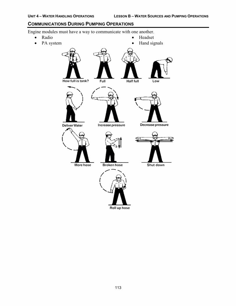
UNIT 4 – WATER HANDLING OPERATIONS LESSON B – WATER SOURCES AND PUMPING OPERATIONS
113
COMMUNICATIONS DURING PUMPING OPERATIONS Engine modules must have a way to communicate with one another.
• Radio • PA system
• Headset • Hand signals
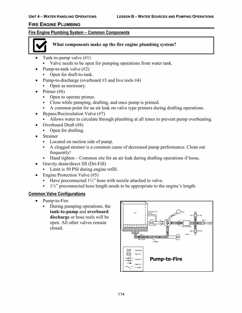
UNIT 4 – WATER HANDLING OPERATIONS LESSON B – WATER SOURCES AND PUMPING OPERATIONS
114
FIRE ENGINE PLUMBING Fire Engine Plumbing System – Common Components
What components make up the fire engine plumbing system?
• Tank-to-pump valve (#1) Valve needs to be open for pumping operations from water tank.
• Pump-to-tank valve (#2) Open for draft-to-tank.
• Pump-to-discharge (overboard #3 and live reels #4) Open as necessary.
• Primer (#6) Open to operate primer. Close while pumping, drafting, and once pump is primed. A common point for an air leak on valve type primers during drafting operations.
• Bypass/Recirculation Valve (#7) Allows water to circulate through plumbing at all times to prevent pump overheating.
• Overboard Draft (#8) Open for drafting.
• Strainer Located on suction side of pump. A clogged strainer is a common cause of decreased pump performance. Clean out
frequently! Hand tighten – Common site for an air leak during drafting operations if loose.
• Gravity drain/direct fill (Dri-Fill) Limit is 50 PSI during engine refill.
• Engine Protection Valve (#5) Have preconnected 1½” hose with nozzle attached to valve. 1½” preconnected hose length needs to be appropriate to the engine’s length.
Common Valve Configurations • Pump-to-Fire
During pumping operations, the tank-to-pump and overboard discharge or hose reels will be open. All other valves remain closed.
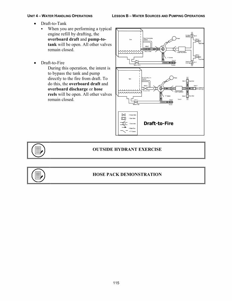
UNIT 4 – WATER HANDLING OPERATIONS LESSON B – WATER SOURCES AND PUMPING OPERATIONS
115
• Draft-to-Tank When you are performing a typical
engine refill by drafting, the overboard draft and pump-to-tank will be open. All other valves remain closed.
• Draft-to-Fire
During this operation, the intent is to bypass the tank and pump directly to the fire from draft. To do this, the overboard draft and overboard discharge or hose reels will be open. All other valves remain closed.
OUTSIDE HYDRANT EXERCISE
HOSE PACK DEMONSTRATION

UNIT 4 – WATER HANDLING OPERATIONS LESSON B – WATER SOURCES AND PUMPING OPERATIONS
116
NOTES
UNIT 4 – WATER HANDLING OPERATIONS LESSON C – FOAM AND FOAM PROPORTIONING SYSTEMS
117
UNIT 4 – WATER HANDLING OPERATIONS LESSON C – FOAM AND FOAM PROPORTIONING SYSTEMS
Given a simulated wildland fire incident scenario, case study, or exercise, students will be able to:
• Discuss why foam is more effective than plain water when performing wildland fire suppression operations.
• Discuss foam safety, including guidelines for handling foam products. • Identify and discuss the advantages and disadvantages of two manual foam
proportioning methods used when performing wildland fire suppression operations.
• Identify various operational components of the FoamPro® 1600/1601 and Waterous Aquis™ 1.5.
• Demonstrate the ability to set up, run, have foam solution pumped to a nozzle person, and shut down a foam proportioner.
FOAM ENHANCEMENTS TO WATER • Foam makes water more effective than plain water during wildland fire suppression
operations. • Foam more easily absorbs heat than plain water (greater surface-to-mass ratio). • Foam controls the release of water at a rate commensurable to the fuel's ability to absorb
water. • Foam reduces evaporation.
As long as bubbles remain over the coated fuel, moisture will not be lost. • Foam’s opaque surface reflects heat. • Foam provides heat insulation to fuels with which it makes contact. • Foam adheres to most surfaces. Water by itself does not hang onto fuels the same way as
it does with foam. • Foam is highly visible.
FOAM SAFETY
SAFETY CONCERNS Class A foam concentrates are similar to common household detergents and shampoos. You can expect cleansing, drying, slipperiness, and other properties similar to those of household soaps. Safety concerns resulting from contact with foam concentrate and solution include:
• Skin and eye irritation • Degradation of clothing such as leather boots and gloves
UNIT 4 – WATER HANDLING OPERATIONS LESSON C – FOAM AND FOAM PROPORTIONING SYSTEMS
118
GUIDELINES WHEN WORKING WITH FOAM PRODUCTS • When working with foam or foam concentrates, wear proper PPE to protect your hands,
eyes, and clothing. Use hand lotion/skin cream as necessary.
• Label containers, including backpack pumps, which contain foaming agents. • Clean up concentrate spills with absorbents. Do not rinse. • Avoid application of foam and spillage of foam concentrate into bodies of water.
What is going on in this slide? What are the potential impacts of what you see? What prevention techniques are available?
• Due to foam’s slippery nature, use caution when using foam-covered hand tools. • Maintain good housekeeping practices with concentrates and equipment by rinsing tools
and flushing proportioners, nozzles, and anything else that is regularly exposed to solution.
FOAM PROPORTIONERS A proportioner adds a specific amount of foam concentrate to water that will be used in firefighting efforts. There are two types of foam proportioners—manual and automatic—used to add foam concentrate to water.
MANUAL FOAM PROPORTIONER • With a manual foam proportioner, operators manually adjust the device to maintain a
constant mix ratio when water flow and pressure changes. • In wildland firefighting, water flow rates and pressures are constantly changing; there is
no way to keep the mix ratio constant. • Common wildland fire manual foam proportioning methods of adding foam concentrate
to water include batch mixing and suction-side proportioning.
Batch Mixing • When using the batch mixing method, foam concentrate is added to a water tank,
resulting in a known percentage rate. • Batch mixing is proportional the first time. After that it is difficult to know the exact
amount of water and solution in the tank. • Batch mixing is accurate at any water flow for a single-mix ratio for the first tank of
water. • Batch mixing is a labor-intensive process. • Operators must have knowledge of mix ratios. • Foam solution running through pump results in wear of the pump seal over time. • Batch mixing is less expensive—no upfront equipment cost—than other methods.
UNIT 4 – WATER HANDLING OPERATIONS LESSON C – FOAM AND FOAM PROPORTIONING SYSTEMS
119
Suction-side Proportioning • Suction-side proportioning is a proportional but not automatic process. • Suction-side proportioning utilizes the suction side of the pump. • Suction-side proportioning is dependent on the pump pulling a draft. There must be
suction on the suction-side of the pump. Whether this happens or not depends on the water source, the pump, and the output of
the pump. • Foam solution running through pump results in wear of the pump seal over time. • Suction-side proportioning is accurate at a single water flow and single-mix ratio.
AUTOMATIC FOAM PROPORTIONER An automatic foam proportioner makes an adjustment on its own to maintain a constant mix ratio when water flow and/or pressure changes. We will discuss two foam proportioning systems—FoamPro® 1601 and the Waterous Aquis 1.5.
FOAMPRO® 1601 / WATEROUS AQUIS™ 1.5 FOAM PROPORTIONING SYSTEM
CHARACTERISTICS Characteristics of the FoamPro® 1601 and Waterous Aquis™ 1.5 foam proportioning system include:
• A direct injection foam proportioning system • Proportional and automatic • Works on the discharge side of the pump • Uses only Class A foam concentrate • Requires water flow and electrical current to operate • An unlimited number of hose lengths/elevation and nozzles can be used • Use results in no loss in pressure or flow due to the device • Accurate at a wide range of water flows for any mix ratio • Can refill foam concentrate while in operation
COMPONENTS The FoamPro® 1601and Waterous Aquis™ 1.5 systems are made up of several components.
Operator Control Module The operator control module:
• Allows the operator to turn the foam proportioner on/off. • Provides simple instructions on running the foam proportioner. • Allows the operator to select foam concentration percent. • Warns the operator when foam concentrate is running low. • Automatically shuts down foam pump after two minutes if foam tank runs empty.
UNIT 4 – WATER HANDLING OPERATIONS LESSON C – FOAM AND FOAM PROPORTIONING SYSTEMS
120
Motor Driver Box/Module The motor drive box/module allows the operator to calibrate the proportioner, purge air from the proportioners foam lines, and select the foam proportioner operational mode. Operators need to fully understand the toggle switch settings. Normal Operation The “Circuit Breaker” toggle switch should be in the “Up” position for normal operation. The “Simulated Flow” toggle switch should be in “Down” position for normal operation.
Simulated Flow The simulated flow setting is used to purge air from the system, calibrate the system, and to prime the foam pump. The “Circuit Breaker” switch should be in the “Up” position for simulated flow operation. The “Simulated Flow” switch should be in “Up” position for simulated flow operation.
Paddlewheel Flow Meter The paddlewheel flow meter senses the water flow output from the pump and relays water flow information to the motor driver box/module.
Foam Pump and Electric Motor The foam pump and electric motor pumps foam concentrate into the water stream at the set percentage rate.
Calibrate/Inject Valve • The “Calibrate/Inject” valve is attached to the foam pump and electrical motor. • The operator manually sets the “Calibrate/Inject” valve to either the “Inject” or
“Cal/Flush” position. In the “Inject” position, the system is set up to flow foam concentrate to the water
stream. In the “Cal/Flush” position, the system is set up to flow foam concentrate into a
container supplied by the operator. • The operator uses the “Calibrate/Inject” valve to purge air trapped in the foam
proportioner. If the foam pump is running and foam concentrate is not being injected, the operator
must move the “Calibrate/Inject” valve to the “Cal/Flush” position until a steady flow of foam concentrate comes out of the line.
The operator must move the lever back to the “Inject” position for normal operations.
• The operator uses the “Calibrate/Inject” valve to prime the system when the foam pump is not primed or has been sitting dry for extended periods of time. In the “Cal/Flush” position, the operator can prime the foam pump.
Ensure you have a container available to catch the flow of foam concentrate.
UNIT 4 – WATER HANDLING OPERATIONS LESSON C – FOAM AND FOAM PROPORTIONING SYSTEMS
121
Inline Strainer • Inline strainers filter out debris that may be in the foam tank and should be cleaned out on
a regular basis. A clogged strainer can cause priming problems and restricts foam concentrate to flow
into foam pump. • To clean the inline strainer:
Close the valve that feeds the strainer. Remove the element and wash with fresh water.
Foam Injection Check Valve and Injection Port The foam injection check valve prevents foam solution from entering the water pump. The injection port provides a port where foam concentrate can be injected into the main water stream.
FOAM PROPORTIONING SYSTEM EXERCISE
Steps to Prime the Foam Proportioner 1. Make sure that the motor driver box toggle switches are set correctly.
• “Simulated Flow” switch is in the “Up” position. • “Circuit Breaker” switch is in the “Up” position.
2. Set the Foam Percentage” switch to “1%.” 3. Place a container to collect the output that will be coming from the foam pump through the
outflow foam concentrate line. 4. Turn the “Calibrate/Inject” valve to the “Cal/Flush” position. 5. Turn the “Controller Module” switch to the “On” position
• Foam concentrate should start flowing into the container. When it is flowing at a steady rate (about 20 seconds), the foam pump is primed and ready for operation.
6. Turn the “Controller Module” switch to the “Off” position.
Steps to Run the Foam Proportioner (Normal Operations) The water pump package must be running before operating the foam proportioner to produce foam solution. 1. Make sure that the motor driver box toggle switches are set correctly.
• “Simulated Flow” switch is in the “Down” position. • “Circuit Breaker” switch is in the “Up” position.
2. Set the “Foam Percentage” switch to a setting that produces the foam structure the operator wants. (Usually around 0.5%.)
3. Turn the “Calibrate/Inject” valve to the “Inject” position.
UNIT 4 – WATER HANDLING OPERATIONS LESSON C – FOAM AND FOAM PROPORTIONING SYSTEMS
122
4. Turn the “Controller Module” switch to the “On” position. • Foam concentrate will start being injected into the water stream as the nozzle is opened
up. The nozzle operator should see some foam production within 30 seconds. 5. Turn the “Controller Module” switch to the “Off” position.
Steps to Shut Down the Foam Proportioner The water pump package must be running for this operation to be accomplished. 1. Turn the “Controller Module” switch to the “Off” position. 2. Set the “Foam Percentage” switch to “0%.” 3. Leave the motor driver box toggle switches in the normal operations position. 4. Leave the “Calibrate/Inject” valve in the “Inject” position. 5. Flow water through the hose and nozzle for one minute. This provides a flush of the
plumbing system.
Steps to Winterize the Foam Proportioner 1. Make sure that the motor driver box toggle switches are set correctly.
• “Simulated Flow” switch is in the “Up” position • “Circuit Breaker” switch is in the “Up” position.
2. Set the “Foam Percentage” switch to “1%.” 3. Place a container to collect the output that will be coming from the foam pump through the
outflow foam concentrate line. • Container(s) must be large enough to collect all the foam concentrate in the foam tank.
4. Turn the “Calibrate/Inject” valve to the “Cal/Flush” position. 5. Turn the “Controller Module” switch to the “On” position.
• Foam concentrate should start flowing into the container. Completely empty the foam tank.
6. Turn the “Controller Module” switch to the “Off” position. 7. Remove the screen in the inline strainer, remove slime and debris, and rinse with fresh
water. Place clean screen back in strainer. 8. Place a half of a gallon of environmentally-safe antifreeze that contains a rust inhibitor into
the foam tank. 9. Keep all settings the same and turn the “Controller Module” switch to the “On” position.
• This will force the antifreeze into the foam pump motor to prevent rusting parts and lubricate the pump parts.
• Do not run the pump dry. 10. Turn the “Controller Module” switch to the “Off” position. 11. Set the “Foam Percentage” switch to 0%. 12. Leave the motor driver box toggle switches in the normal operations position. 13. Leave the “Calibrate/Inject valve in the “Inject” position.
UNIT 4 – WATER HANDLING OPERATIONS QUIZ
123
UNIT 4 – QUIZ
1. List the three factors that must be considered in calculating pump discharge pressure during hydraulic calculations.
2. What is the nozzle pressure needed for a Forester nozzle?
3. What is the nozzle pressure needed for a combination nozzle?
4. List two ways to reduce friction loss.
5. How high will one PSI lift water?
6. Define the following:
Parallel pumping
Staged pumping
Series pumping
7. List two benefits of using foam.

UNIT 4 – WATER HANDLING OPERATIONS QUIZ
124
NOTES
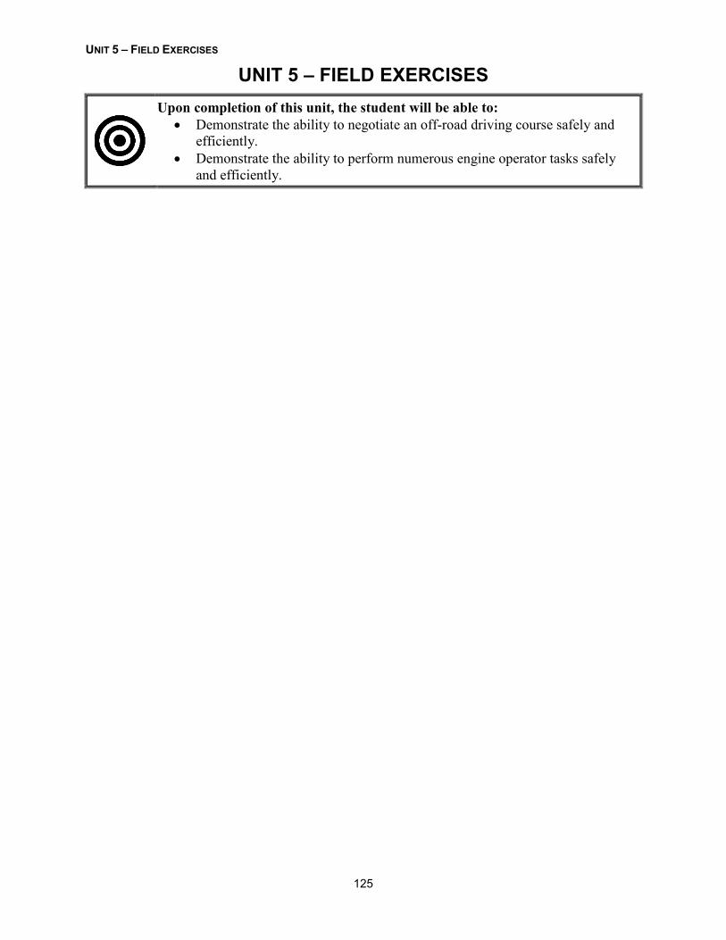
UNIT 5 – FIELD EXERCISES
125
UNIT 5 – FIELD EXERCISES
Upon completion of this unit, the student will be able to: • Demonstrate the ability to negotiate an off-road driving course safely and
efficiently. • Demonstrate the ability to perform numerous engine operator tasks safely
and efficiently.

UNIT 5 – FIELD EXERCISES
126
NOTES
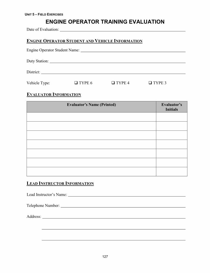
UNIT 5 – FIELD EXERCISES
127
ENGINE OPERATOR TRAINING EVALUATION Date of Evaluation:
ENGINE OPERATOR STUDENT AND VEHICLE INFORMATION
Engine Operator Student Name:
Duty Station:
District:
Vehicle Type: TYPE 6 TYPE 4 TYPE 3
EVALUATOR INFORMATION
Evaluator’s Name (Printed) Evaluator’s Initials
LEAD INSTRUCTOR INFORMATION
Lead Instructor’s Name:
Telephone Number:
Address:
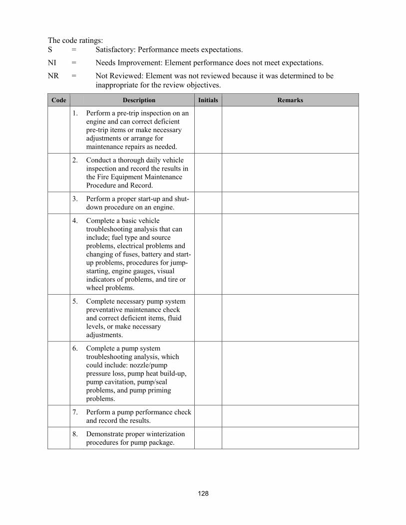
128
The code ratings: S = Satisfactory: Performance meets expectations. NI = Needs Improvement: Element performance does not meet expectations. NR = Not Reviewed: Element was not reviewed because it was determined to be
inappropriate for the review objectives.
Code Description Initials Remarks
1. Perform a pre-trip inspection on an engine and can correct deficient pre-trip items or make necessary adjustments or arrange for maintenance repairs as needed.
2. Conduct a thorough daily vehicle inspection and record the results in the Fire Equipment Maintenance Procedure and Record.
3. Perform a proper start-up and shut-down procedure on an engine.
4. Complete a basic vehicle troubleshooting analysis that can include; fuel type and source problems, electrical problems and changing of fuses, battery and start-up problems, procedures for jump-starting, engine gauges, visual indicators of problems, and tire or wheel problems.
5. Complete necessary pump system preventative maintenance check and correct deficient items, fluid levels, or make necessary adjustments.
6. Complete a pump system troubleshooting analysis, which could include: nozzle/pump pressure loss, pump heat build-up, pump cavitation, pump/seal problems, and pump priming problems.
7. Perform a pump performance check and record the results.
8. Demonstrate proper winterization procedures for pump package.
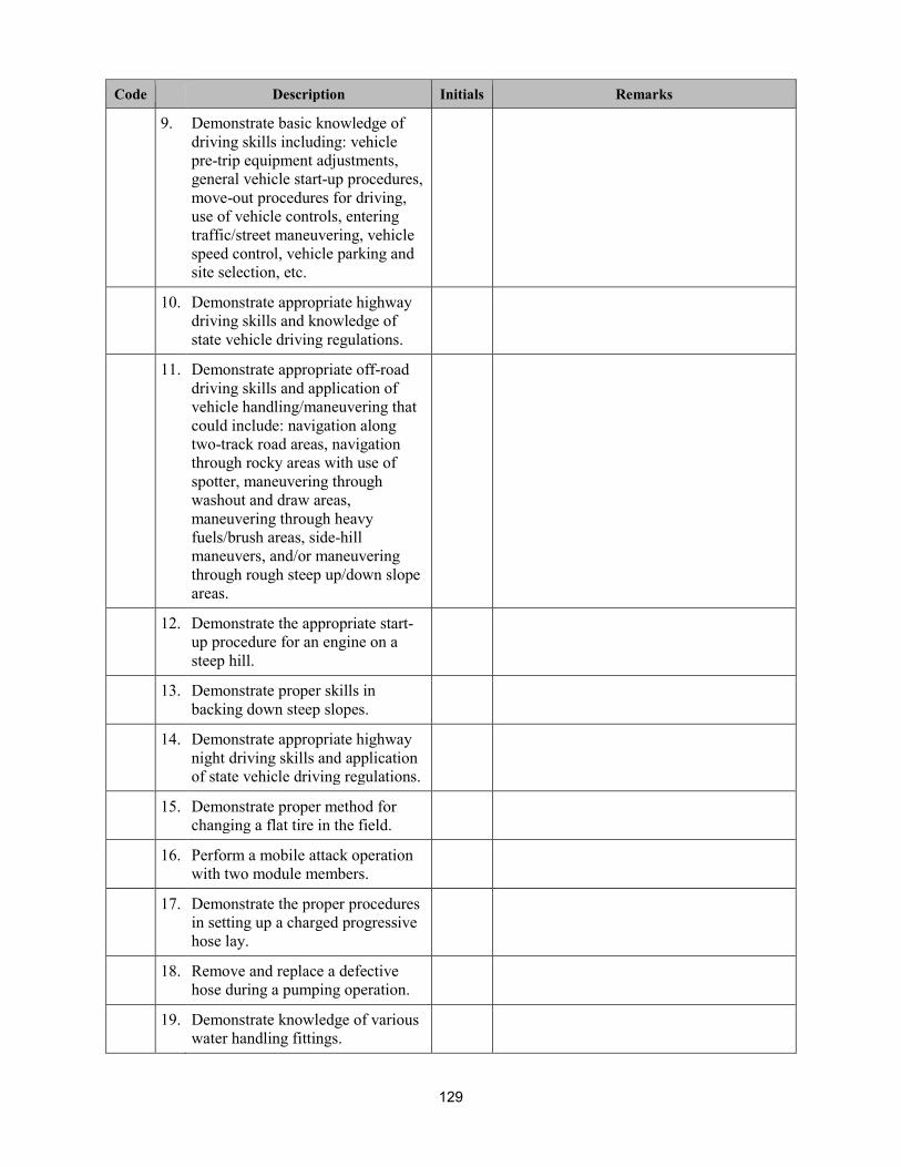
129
Code Description Initials Remarks
9. Demonstrate basic knowledge of driving skills including: vehicle pre-trip equipment adjustments, general vehicle start-up procedures, move-out procedures for driving, use of vehicle controls, entering traffic/street maneuvering, vehicle speed control, vehicle parking and site selection, etc.
10. Demonstrate appropriate highway driving skills and knowledge of state vehicle driving regulations.
11. Demonstrate appropriate off-road driving skills and application of vehicle handling/maneuvering that could include: navigation along two-track road areas, navigation through rocky areas with use of spotter, maneuvering through washout and draw areas, maneuvering through heavy fuels/brush areas, side-hill maneuvers, and/or maneuvering through rough steep up/down slope areas.
12. Demonstrate the appropriate start-up procedure for an engine on a steep hill.
13. Demonstrate proper skills in backing down steep slopes.
14. Demonstrate appropriate highway night driving skills and application of state vehicle driving regulations.
15. Demonstrate proper method for changing a flat tire in the field.
16. Perform a mobile attack operation with two module members.
17. Demonstrate the proper procedures in setting up a charged progressive hose lay.
18. Remove and replace a defective hose during a pumping operation.
19. Demonstrate knowledge of various water handling fittings.
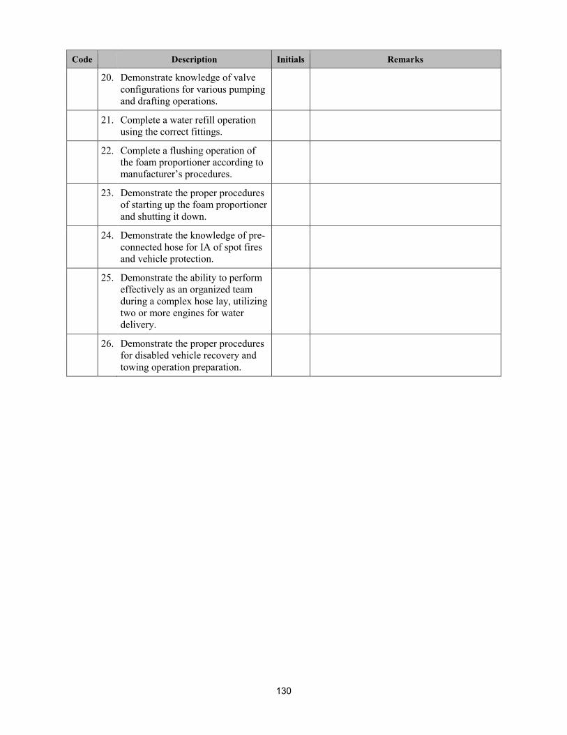
130
Code Description Initials Remarks
20. Demonstrate knowledge of valve configurations for various pumping and drafting operations.
21. Complete a water refill operation using the correct fittings.
22. Complete a flushing operation of the foam proportioner according to manufacturer’s procedures.
23. Demonstrate the proper procedures of starting up the foam proportioner and shutting it down.
24. Demonstrate the knowledge of pre-connected hose for IA of spot fires and vehicle protection.
25. Demonstrate the ability to perform effectively as an organized team during a complex hose lay, utilizing two or more engines for water delivery.
26. Demonstrate the proper procedures for disabled vehicle recovery and towing operation preparation.


![DATED [ ] 2000 [Operator] and [Vodafone AirTouch Plc ...ec.europa.eu/competition/mergers/cases/decisions/...("VFAT Operator"). The Operator and the VFAT Operator are jointly referred](https://img.pdfslide.us/doc/110x75/5f957bfbb358510723214249/dated-2000-operator-and-vodafone-airtouch-plc-ec-vfat-operator.jpg)