Embed Size (px)
Citation preview

Introduction of engine OM 471 andexhaust aftertreatmentIntroduction into Service Manual
Daimler AG, GSP/OI, HPC R 822, D-70546 StuttgartBestell-Nr. 6517 1260 02 - HLI 000 000 02 82 – Printed in Germany – 09/11 In
trodu
ctio
n of
engi
ne O
M 4
71 a
nd e
xhau
st a
fter
trea
tmen
t
– This printout will not be recorded by the update service. Status: 09 / 2011 –

Mercedes>Benz Service
Introduction of engine OM 471 andexhaust aftertreatment
Technical status 01.09.2011
Daimler AG . Technical Information and Workshop Equipment(GSP/OI)D$70546 Stuttgart
– This printout will not be recorded by the update service. Status: 09 / 2011 –

Information and copyright
Product portfolio
You can also find comprehensive information about our complete product portfolio on our Internet portal:Link: http://aftersales.mercedes>benz.com
Questions and suggestions
If you have any questions or suggestions concerning this product, please writeto us.
E>Mail: [email protected]: +49>(0)18 05/0 10>79 78
or alternativelyAddress: Daimler AG
GSP/OIS, HPC R822, W002D>70546 Stuttgart(Germany)
©2011 by Daimler AG
This document, including all its parts, is protected by copyright.Any further processing or use requires the previous written consent of Daimler AG, Department GSP/OIS, HPC R822, W002, D>70546 Stuttgart.This applies in particular to reproduction, distribution, alteration, translation,microfilming and storage and/or processing in electronic systems, includingdatabases and online services.
Image no. of title image: W00.01>1015>00
Order no. of this publication: 6517 1260 02 > HLI 000 000 02 82
09/11
– This printout will not be recorded by the update service. Status: 09 / 2011 –

Preface
SN00.00>W>0001>01HD Preface
The intention behind this brochure is to introduce you to the new
6>cylinder inline diesel engine OM 471 along with the new
exhaust aftertreatment system (EATS).
This brochure is intended for the technical personnel entrusted
with the maintenance and repair of Mercedes>Benz trucks.
The content of this brochure is split up into:
• as>built configuration descriptions
• function descriptions
• component descriptions
All the data listed in this brochure correspond with the technical
status as per September 2011.
Any changes or supplements hereto will be published in the
Workshop Information System (WIS) only.
Additional documents for the OM 471 engine and the EATS, such
as maintenance and repair instructions or wiring diagrams are
also available in the Workshop Information System (WIS).
Mercedes>Benz
W‘rth plant, GSP/TTM
September 2011
i Introduction of engine OM 471 and exhaust aftertreatment > 09/2011 > 1
– This printout will not be recorded by the update service. Status: 09 / 2011 –

Contents
2
SN00.00>W>0110HA Overview of as>built configuration and function descriptions 2.8.11
ENGINES 471.9
Overview of new features
Engine OM!471 Page 10
Technical data of diesel engine OM 471 Page 11
As>built configurationdescriptions
Cylinder head cover, as>built configuration Page 12
Cylinder head, as>built configuration Page 13
Cylinder head gasket, as>built configuration Page 18
Crankcase as>built configuration Page 19
Connecting rod, as>built configuration Page 21
Piston, as>built configuration Page 22
Crankshaft, as>built configuration Page 23
Valve control; as>built configuration Page 24
Gear drive, as>built configuration Page 29
Camshaft, as>built configuration Page 31
Belt drive, as>built configuration Page 32
Function descriptions
Crankcase ventilation system function Page 34
Charging, function Page 35
Engine management, function Page 37
Engine management, overall network Page 39
Engine management, behavior in the event
of malfunctions
Page 40
Start procedure, function Page 42
Idle speed control, function Page 44
Working speed control, function Page 46
Driving, function Page 48
Engine shutoff procedure, function Page 50
Determination of the engine speed and
crankshaft angle, function
Page 53
Determination of the compression stroke at
cylinder 1, function
Page 54
– This printout will not be recorded by the update service. Status: 09 / 2011 –

Contents
i Introduction of engine OM 471 and exhaust aftertreatment > 09/2011 > 3
Determination of coolant temperature,
function
Page 55
Determination of air mass, function Page 56
Determination of the fuel temperature,
function
Page 57
Function of the specified engine torque
calculation
Page 58
Engine brake, function Page 60
Exhaust gas recirculation, function Page 66
Exhaust aftertreatment, function Vehicles with code (M5R) Engine version
EEV and vehicles with code (M5Y) Engine
version Euro V
Page 68
Vehicles with code (M5Z) Engine version
Euro VI
Page 73
Exhaust aftertreatment, overall network Page 79
Engine oil circuit, function Page 80
Engine oil circuit, diagram Page 82
Coolant circuit, function Page 83
Coolant circuit, diagram Page 86
Engine cooling thermal management,
function
i Only in vehicles with code (M7T)
Coolant pump, controlled.
Page 87
Engine cooling thermal management,
overall network
Page 90
Fuel supply, function Page 91
Fuel low pressure circuit function Vehicles with code (M5R) Engine version
EEV and vehicles with code (M5Y) Engine
version Euro V
Page 93
Vehicles with code (M5Z) Engine version
Euro VI
Page 96
Fuel high pressure circuit function Page 100
Component descriptions
Central gateway control unit (CGW),
component description
A2 Page 101
– This printout will not be recorded by the update service. Status: 09 / 2011 –

Contents
4
Component description drive control (CPC)
control unit
A3 Page 102
Component description for engine
management (MCM) control unit
A4 Page 103
Electronic Brake Control control unit (EBS),
component description
A10b, A10c Page 105
Parameterizable special module (PSM)
control unit component description
A22 Page 106
Battery disconnect switch control unit,
component description
A33
i Only in vehicles with one of the
following codes:
• Code (E5T) ADR model class EX/II,
including AT
• Code (E5U) ADR model class EX/III,
including EX/II and AT
• Code (E5V) ADR model class FL,
including EX/II, EX/III and AT
• Code (E5X) ADR model class AT
• Code (E5Z) Accessories, ADR
• Code (E9D) Preinstallation, for bipolar
battery disconnect switch
• Code (E9E) ADR preinstallation, without
chassis shielding
Page 107
Radiator shutters, component description A54, A55
i Only in vehicles with code (M7K)
Radiator shutters.
Page 109
EATU output NOx sensor, component
description
A57, A57 b1
Vehicles with code (M5R) Engine version
EEV and vehicles with code (M5Y) Engine
version Euro V
Page 110
Vehicles with code (M5Z) Engine version
Euro VI
Page 112
Pump module, component description A58, M25 Page 115
Exhaust aftertreatment (ACM) control unit,
component description
A60
Vehicles with code (M5R) Engine version
EEV and vehicles with code (M5Y) Engine
version Euro V
Page 117
Vehicles with code (M5Z) Engine version
Euro VI
Page 119
AdBlue metering device, component
description
A67 Page 121
EATU input NOx sensor, component
description
A70, A70 b1
Vehicles with code (M5R) Engine version
EEV and vehicles with code (M5Y) Engine
version Euro V
Page 123
– This printout will not be recorded by the update service. Status: 09 / 2011 –

Contents
i Introduction of engine OM 471 and exhaust aftertreatment > 09/2011 > 5
Vehicles with code (M5Z) Engine version
Euro VI
Page 125
Auxiliary heater heating unit, component
description
A901
i Only in vehicles with code (D6M)
Auxiliary water heater, cab or code (D6N)
Auxiliary water heater, cab and electric
motor.
Page 128
Auxiliary heater coolant circulation pump,
component description
A901 M2
i Only in vehicles with code (D6M)
Auxiliary water heater, cab or code (D6N)
Auxiliary water heater, cab and electric
motor.
Page 130
Travel and speed sensor, component
description
B18 Page 131
Exhaust pressure sensor upstream of diesel
oxidation catalytic converter, component
description
B37
i Only for vehicles with code (M5Z)
Engine version Euro VI.
Page 132
Exhaust pressure sensor downstream of
diesel particulate filter, component
description
B38
i Only for vehicles with code (M5Z)
Engine version Euro VI.
Page 133
Component description for accelerator
pedal sensor
B44 Page 134
Exhaust temperature sensor upstream of
diesel oxidation catalytic converter,
component description
B67
i Only for vehicles with code (M5Z)
Engine version Euro VI.
Page 135
Exhaust temperature sensor downstream of
diesel oxidation catalytic converter, top,
component description
B68
i Only for vehicles with code (M5Z)
Engine version Euro VI.
Page 136
Exhaust temperature sensor downstream of
diesel oxidation catalytic converter, bottom,
component description
B69
i Only for vehicles with code (M5Z)
Engine version Euro VI.
Page 137
Exhaust temperature sensor downstream of
diesel particulate filter, component
description
B70
i Only for vehicles with code (M5Z)
Engine version Euro VI.
Page 138
Exhaust temperature sensor upstream of
SCR catalytic converter, component
description
B72
i Only in vehicles with code (M5R) Engine
version EEV and in vehicles with code
(M5Y) Engine version Euro V.
Page 139
Exhaust temperature sensor downstream of
SCR catalytic converter, component
description
B73
Vehicles with code (M5R) Engine version
EEV and vehicles with code (M5Y) Engine
version Euro V
Page 140
– This printout will not be recorded by the update service. Status: 09 / 2011 –

Contents
6
Vehicles with code (M5Z) Engine version
Euro VI
Page 141
AdBlue fill level sensor/temperature sensor,
component description
B74 Page 142
Coolant pressure control sensor, component
description
B87
i Only in vehicles with code (B3H)
Secondary water retarder.
Page 144
Component description for crankshaft
position sensor
B600 Page 145
Component description for camshaft
position sensor
B601 Page 146
Component description for fuel
temperature sensor
B602 Page 147
Oil pressure sensor, description of
components
B604 Page 148
Component description for engine oil fill
level sensor
B605 Page 149
Component description for exhaust coolant
temperature sensor
B606 Page 150
Component description for intake coolant
temperature sensor
B607 Page 151
Charge air pressure and temperature sensor
in charge air pipe, component description
B608 Page 152
Turbine wheel rpm sensor, component
description
B610
i Only for vehicles with code (M5Z)
Engine version Euro VI.
Page 153
Component description for temperature
sensor downstream of air filter
B611
i Only for vehicles with code (M5Z)
Engine version Euro VI.
Page 154
Charge air temperature sensor in charge air
housing, component description
B617 Page 155
Exhaust gas recirculation differential
pressure sensor, component description
B621 Page 156
Component description for rail pressure
sensor
B622 Page 157
Diesel fuel metering device, component
description
B625, B626, Y628, Y629
i Only for vehicles with code (M5Z)
Engine version Euro VI.
Page 158
Fuel filter module pressure sensor,
component description
B638 Page 159
– This printout will not be recorded by the update service. Status: 09 / 2011 –

Contents
i Introduction of engine OM 471 and exhaust aftertreatment > 09/2011 > 7
Component description for coolant pump B640, Y631
i Only in vehicles with code (M7T)
Coolant pump, controlled.
No component description was created for
vehicles with a rigid coolant pump.
Page 160
Residual heat pump, component description M20
i Only in vehicles with code (D6I)
Residual heat utilization.
Page 162
Tachograph (TCO) component description P1 Page 163
Electronic ignition lock (EIS), component
description
S1 Page 164
EMERGENCY OFF switch, component
description
S30
i Only in vehicles with one of the
following codes:
• Code (E5T) ADR model class EX/II,
including AT
• Code (E5U) ADR model class EX/III,
including EX/II and AT
• Code (E5V) ADR model class FL,
including EX/II, EX/III and AT
• Code (E5X) ADR model class AT
• Code (E5Z) Accessories, ADR
• Code (E9D) Preinstallation, for bipolar
battery disconnect switch
• Code (E9E) ADR preinstallation, without
chassis shielding
Page 165
EMERGENCY OFF switch frame, component
description
S31
i Only in vehicles with one of the
following codes:
• Code (E5T) ADR model class EX/II,
including AT
• Code (E5U) ADR model class EX/III,
including EX/II and AT
• Code (E5V) ADR model class FL,
including EX/II, EX/III and AT
• Code (E5X) ADR model class AT
• Code (E5Z) Accessories, ADR
• Code (E9D) Preinstallation, for bipolar
battery disconnect switch
• Code (E9E) ADR preinstallation, without
chassis shielding
Page 166
Engine start and engine stop button,
component description
S600 Page 167
Heating shutoff valve, component
description
Y49 Page 168
Coolant pressure control solenoid valve,
component description
Y53
i Only in vehicles with code (B3H)
Secondary water retarder.
Page 169
– This printout will not be recorded by the update service. Status: 09 / 2011 –

Contents
8
Component description for fuel injectors Y608. to Y613 Page 170
Component description for the
electromagnetic viscous coupling
Y616, Y616 b1 Page 174
Component description for exhaust gas
recirculation controller
Y621 Page 176
Component description for engine brake
solenoid valve
Y624, Y625 Page 178
AdBlue“ heater coolant solenoid valve,
component description
Y627 Page 180
Component description for boost pressure
regulator
Y636 Page 181
Component description for quantity control
valve
Y642 Page 182
Oil separator component description Page 183
Component description for fuel system high
pressure pump
Page 184
Pressure limiting valve, component
description
Page 185
Component description for turbocharger Page 186
Component description for exhaust gas
recirculation cooler
Page 187
Component description for AdBlue tank Page 188
Component description for oil pump Page 189
Oil/coolant module, component description Page 191
Oil thermostat, component description Page 193
Component description for oil/water heat
exchanger
Page 194
Component description for coolant
thermostat
Page 195
Retarder, component description i Only in vehicles with code (B3H)
Secondary water retarder.
Page 197
Component description for fuel pump Page 203
Component description for fuel cooler Page 204
Component description for fuel filter
module
Page 205
Diesel oxidation catalytic converter,
component description
i Only for vehicles with code (M5Z)
Engine version Euro VI.
Page 208
Component description for SCR catalytic
converter
Vehicles with code (M5R) Engine version
EEV and vehicles with code (M5Y) Engine
version Euro V
Page 209
Vehicles with code (M5Z) Engine version
Euro VI
Page 211
Exhaust aftertreatment unit, component
description
Vehicles with code (M5R) Engine version
EEV and vehicles with code (M5Y) Engine
version Euro V
Page 213
– This printout will not be recorded by the update service. Status: 09 / 2011 –

Contents
i Introduction of engine OM 471 and exhaust aftertreatment > 09/2011 > 9
Vehicles with code (M5Z) Engine version
Euro VI
Page 215
Diesel particulate filter of exhaust
aftertreatment unit, component description
i Only for vehicles with code (M5Z)
Engine version Euro VI.
Page 218
Nozzle unit for DPF regeneration,
component description
i Only for vehicles with code (M5Z)
Engine version Euro VI.
Page 220
Heating system heat exchanger, component
description
Page 221
– This printout will not be recorded by the update service. Status: 09 / 2011 –

Engine
SN00.00>W>0002>04H Engine OM!471
W01.10>1090>09
1 Amplified Pressure Common>Rail
System (APCRS)
2 Diesel fuel>metering device (for
regeneration of diesel particulate
filter (DPF))
3 Oil/coolant module
9 Cooled and regulated exhaust gas
recirculation (AGR)
G2 Generator
4 Fuel filter module
5 Compressor
6 Power steering pump
7 Oil separator for crankcase
ventilation system
8 Turbocharger
The engine OM 471 is the first 6>cylinder inline engine with two
overhead camshafts to be used in a Mercedes>Benz commercial
vehicle.
Both camshafts are driven by a gear drive which is located at the
output side of the engine. The position of this drive gear makes a
major contribution to reducing noise emission.
The extremely compact design of the engine is based on the
optimized cylinder liner concept in which the overhead seat is
located at the bottom in the crankcase > this design measure
allows the gap between the cylinders to be reduced considerably. >>>>>>>>>>>>>>>>>>>>>>>>>>>>>>>>>>>>>>>>>>>>>>>>>>>>>>>>>>>>>>>>>>>>>>>>>>>>>>>>>>>>>>>>>
The OM 471 engine is available in four output stages between 310
and 375 kW.
Advantages of new 6>cylinder inline engine:
• Lower fuel consumption in relation to high output
• Smooth running characteristics, whereby only four
counterweights are required on the crankshaft
• Excellent application capability for the various emissions
standards
• Implementation of particularly high combustion pressures of
up to 230 bar
>>>>>>>>>>>>>>>>>>>>>>>>>>>>>>>>>>>>>>>>>>>>>>>>>>>>>>>>>>>>>>>>>>>>>>>>>>>>>>>>>>>>>>>>>
The positive properties of the new engine have been made
possible by a variety of new technical developments:
• The new injection system, the amplified pressure common
rail system (APCRS) (1), is the first common rail system to be
used in Mercedes>Benz commercial vehicles that minimizes
the quantity of fuel required for combustion. The advantage
of this system lies in the fact that the rail and high>pressure
lines have a relatively low pressure of 900 bar, and the fuel
pressure required for injecting into the injector is generated,
which has a particularly positive effect on material loads and
therefore on component longevity. >>>>>>>>>>>>>>>>>>>>>>>>>>>>>>>>>>>>>>>>>>>>>>>>>>>>>>>>>>>>>>>>>>>>>>>>>>>>>>>>>>>>>>>>>
• The completely redesigned engine brake system has an even
higher braking power.
• The cooled and regulated exhaust gas recirculation (EGR) (9)
and the diesel particulate filter (DPF) as well as the modified
oil separator of the crankcase ventilation system (7) ensure
that tomorrow's emissions regulations can also be met.
• The regulated coolant pump installed in the oil/coolant
module (3), which has already been installed in Actros
vehicles, also contributes to fuel economy. >>>>>>>>>>>>>>>>>>>>>>>>>>>>>>>>>>>>>>>>>>>>>>>>>>>>>>>>>>>>>>>>>>>>>>>>>>>>>>>>>>>>>>>>>
i With each maintenance and repair work to the engine as well
as to the ancillary assemblies and detachable parts comes the
danger of property damage caused by soiling and foreign bodies.
The high pressure diesel injection system, the intake system and
the oil circuit, in particular, are at risk here.
To avoid any damage, when conducting repair work not only the
specified special tools must be used along with observance of the
WIS repair instructions, but in addition to this special care must be
given to cleanliness at the workbay.
Additional information is available in the document
AH00.00>N>5000>01H.
10
– This printout will not be recorded by the update service. Status: 09 / 2011 –

Technical data
SN00.00>W>0002>05H Technical data of diesel engine OM 471
General information
OM 471
Displacement (l) 12,8
No. of cylinders 6 (in line)
Valve control DOHC
Valve number for each cylinder(intake/exhaust)
2/2
Idle speed (rpm) 560
Compression ratio (f) 17,3
Stroke (mm) 156
Stroke:bore ratio 1,18
Weight (kg) approx. 1200
Power categories
OM 471 with
code M3A
OM 471 with
code M3B
OM 471 with
code M3C
OM 471 with
code M3D
Output (kW) 310 330 350 375
Output (horsepower) 421 449 476 510
Torque (Nm) 2100 2200 2300 2500
Piston
OM 471
Diameter (mm) 132
Overall height (mm) 113
Compression height (mm) 75
Shank length 71,65
Piston pin
OM 471
Inside diameter (mm) 23.5
Outside diameter (mm) 58
Length (mm) 88
Fuel system
OM 471
Rail pressure, max. (bar) 900
Crankshaft bearing
OM 471
Diameter (mm) 114
Width (mm) 36
Connecting rod
OM 471
Length (mm) 268
Connecting rod bearing
OM 471
Diameter (mm) 95
Width (mm) 36,4
Crankcase, cylinder liner (wet)
OM 471
Cylinder diameter (mm) 132
Cylinder distance (mm) 165
i Introduction of engine OM 471 and exhaust aftertreatment > 09/2011 > 11
– This printout will not be recorded by the update service. Status: 09 / 2011 –

As>built configurations
GF01.20>W>0801H Cylinder head cover, as>built configuration 1.7.11
ENGINES 471.9
W01.20>1046>76
1 Cylinder head cover
2 Prefilter
3 Elastomer element
4 Elastomer seal
x Direction of travel
The cylinder head cover (1) consists of plastic and, on the one
hand, prevents ingress of water and foreign objects into the valve
assembly. On the other hand it seals the camshaft case to the
outside using an elastomer seal (4) and prevents escape of the
engine oil used to lubricate the valve assembly.
A prefilter (2) is integrated in the cylinder head cover (1). The
prefilter (2) ensures that the engine oil which is swirled by the
valve assembly and mixes with the blow>by gases is roughly
separated before the blow>by gases are passed on to the oil
separator for the crankcase ventilation system.
For acoustic decoupling of the cylinder head cover (1) an
elastomer element (3) is inserted in all through holes which serve
to attach the cylinder head cover (1) to the camshaft case. The
elastomer elements (3) reduce noise emissions and possible
damage which can occur due to vibrations.
12
– This printout will not be recorded by the update service. Status: 09 / 2011 –

As>built configurations
GF01.30>W>0800H Cylinder head, as>built configuration 1.7.11
ENGINES 471.9
The engine OM 471 has a one>piece cylinder head.
There are two intake valves and two exhaust valves for each
cylinder in the cylinder head. The narrow engine design means
that overall a symmetrical location of the valves can ensue. This
symmetrical valve pattern is optimum for the combustion.
W01.30>1105>78
Tightening procedure for cylinder head
bolts
1 > 38 Cylinder head bolt (M15¥2) 40 Bolt (M10)39 Bolt (M10)
Cylinder head bolts
In order to ensure that the correct bolts are used when installing
the cylinder head, on each bolt head there is an embossing which
provides information on the thread strength of the respective
cylinder head bolt.
The cylinder head bolts have the M15 2 thread and therefore have
the embossing "15".
All the cylinder head bolts must be tightened in four stages as per
a set tightening pattern. The tightening torques and the
tightening angle can be obtained from the repair instructions.
As the cylinder head bolts elongate due to assembly, the shank
length for each bolt which has already been used once must be
measured before it is reassembled.
The relevant bolt must be replaced when the permissible shank
length is exceeded.
i The cylinder head bolts are no longer assembled when the
valve assembly is mounted. The valve assembly must be removed
before dismantling the cylinder head.
i Introduction of engine OM 471 and exhaust aftertreatment > 09/2011 > 13
– This printout will not be recorded by the update service. Status: 09 / 2011 –

As>built configurations
W01.30>1122>76
41 Intake ports
42 Threaded holes for the charge air
manifold attachment
x Direction of travel
W01.30>1123>76
43 Exhaust ducts
44 Threaded holes for the charge air
manifold attachment
x Direction of travel
14
– This printout will not be recorded by the update service. Status: 09 / 2011 –

As>built configurations
W01.30>1124>76
45 Connectors for coolant collector block
x Direction of travel
W01.30>1125>76
46 Inlet valves
47 Exhaust valves
48 Bores for the fuel injectors
x Direction of travel
i Introduction of engine OM 471 and exhaust aftertreatment > 09/2011 > 15
– This printout will not be recorded by the update service. Status: 09 / 2011 –

As>built configurations
W01.30>1126>76
49 OiI overflow holes from cylinder
crankcase to cylinder head
50 Oil return flow openings or oil return
flow holes from cylinder head to
cylinder crankcase
x Direction of travel
W01.30>1127>76
51 Coolant short>circuit channel from
cylinder head to cylinder crankcase
52 Coolant overflow holes from cylinder
crankcase to cylinder head
x Direction of travel
16
– This printout will not be recorded by the update service. Status: 09 / 2011 –

As>built configurations
W01.30>1128>76
Cooling levers
53 Lower cooling level
54 Upper cooling level
Cooling
The cylinder head has a divided coolant jacket. This means that
the coolant, after it has flushed around the cylinders, flows into
the cylinder head on the inlet side and on the exhaust side. The
advantage is that the coolant first flushes around the fuel
injectors and valve seat rings in the lower cooling level (53) of the
cylinder head.
After this the coolant flows into the upper cooling level (54) of the
cylinder head and cools the valve guides. The coolant is collected
there and directed outwards.
i Introduction of engine OM 471 and exhaust aftertreatment > 09/2011 > 17
– This printout will not be recorded by the update service. Status: 09 / 2011 –

As>built configurations
GF01.30>W>0801H Cylinder head gasket, as>built configuration 1.7.11
ENGINES 471.9
W01.30>1120>06
Upper side of the cylinder head seal
OD Engine oil feed openings
OR Engine oil return opening
WR Coolant bypass duct opening
WZ Coolant feed opening
KG Opening for the blow>by duct to the
crankcase ventilation system
x Direction of travel
The cylinder head gasket consists of a number of layers of stainless
steel.
The cylinder head gasket at the engine oil feed openings (OD) and
at the coolant feed opening (WZ) is fitted with raised elastomer
elements through which the seal between the cylinder head and
the cylinder crankcase is improved.
18
– This printout will not be recorded by the update service. Status: 09 / 2011 –

As>built configurations
GF01.40>W>0802H Crankcase as>built configuration 1.7.11
ENGINES 471.9
W01.40>1144>76
Crankcase from above, shown with coolant
ducts
1 Coolant bypass duct
2 Recess for oil>water heat exchanger
3 Coolant connection for fuel cooler
4 Coolant connection for compressor
5 Coolant connection for exhaust gas
recirculation positioner
6 Coolant overflow holes to the cylinder
head
7 Coolant return from the cylinder head
x Direction of travel
W01.40>1145>76
Crankcase from above, shown with oil
ducts
8 Oil hole closed longitudinally
9 Connection for the oil pressure sensor
10 Oil return duct from oil filter (for
changing the oil filter)
11 Oil feed from oil/coolant module
(from oil filter) to crankcase
12 Oil feed from crankcase (from the oil
pump) to
oil/coolant module
13 Oil hole closed off laterally
14 Bores for oil supply to the gear drive
15 Connection for oil supply of the
centrifuge on the oil separator to the
crankcase ventilation system
16 Oil return duct from oil separator for
crankcase ventilation system
20 OiI overflow holes to the cylinder
head
21 Oil return ducts from cylinder head
x Direction of travel
17 Oil return duct from turbocharger
18 Connection for oil supply to the
turbocharger
19 Oil hole closed off laterally
i Introduction of engine OM 471 and exhaust aftertreatment > 09/2011 > 19
– This printout will not be recorded by the update service. Status: 09 / 2011 –

As>built configurations
W01.40>1146>76
Crankcase from below, shown with oil
ducts
22 Oil return duct to oil/coolant module
23 Oil return ducts to oil pan
x Direction of travel
W01.40>1147>76
Crankcase from below, shown with oil
ducts
24 Bores for oil supply to the oil spray
nozzles
25 Bores for oil supply to the main
bearing, crankshaft and connecting
rod bearing
x Direction of travel
The crankcase consists of cast iron and is characterized by the
following features:
f a high rigidity and low noise emissions due to the vertical
and horizontal reinforcements, as well as due to the design
form of the oil return ducts
f a compact design due to the low distance from the cylinder
The crankcase also has 1.5 mm recesses at the sealing surface to
the cylinder head for all coolant overflow holes to the cylinder
head (6) and for all oil overflow holes to the cylinder head (20).
These serve to receive the respective elastomer elements in the
cylinder head gasket.
The following major assemblies and components are located on
the crankcase:
Right>hand side
f Turbocharger
f Starter
f Oil separator for crankcase ventilation system
Left>hand side
f Oil/coolant module
f Engine management (MCM) control unit
f Fuel filter module
f Fuel high pressure pump
f Compressor, power steering pump
20
– This printout will not be recorded by the update service. Status: 09 / 2011 –

As>built configurations
GF03.10>W>0800H Connecting rod, as>built configuration 1.7.11
ENGINES 471.9
W03.10>1119>76
1 Connecting rod
2 Connecting rod small end (small)
3 Connecting rod bushing
4 Connecting>rod shank
5 Connecting rod big end
6 Connecting rod bearing shells
7 Connecting rod bearing cap
8 Stretch bolt
The connecting rods are forged in steel and are characterized by
their high strength.
The connecting point between the connecting rod (1) and the
connecting rod bearing cap (7) is cracked. This has the advantages,
amongst other things, that one has no offset after screwing
together both parts and the connecting rod bearing cap (7)
cannot slip.
A connecting rod bushing (3) is pressed into a small connecting
rod small end (2).
i Introduction of engine OM 471 and exhaust aftertreatment > 09/2011 > 21
– This printout will not be recorded by the update service. Status: 09 / 2011 –
As>built configurations
GF03.10>W>0801H Piston, as>built configuration 2.8.11
ENGINE 471.9
W03.10>1124>76
1 Piston
2 Combustion recess
3 Piston crown
4 Top land
5 Piston ring zone
6 1st piston ring
7 2nd piston ring
8 Oil scraper ring
9 Bolt eye
10 Piston skirt
11 Piston bolt circlip
12 Piston pin
13 Cooling duct
Feature
OM 471
Version Two piece
Material Steel
Weight (with spring steel sheet) 3,339 KG
Piston diameter 132 mm
Bolt diameter 58 mm
Surface friction optimized
Piston (1)
The piston (1) consists of a forged upper section and a forged
lower section, which are connected to each other by means of a
friction weld.
Piston crown (3)
The piston crown (3) is fitted with a combustion recess (2).
Through the combustion recess (2) the clearance volume is
partially transferred into the piston (1).
Top land (4)
The top land (4) protects the 1st piston ring (6) against excessively
heating during the combustion process.>>>>>>>>>>>>>>>>>>>>>>>>>>>>>>>>>>>>>>>>>>>>>>>>>>>>>>>>>>>>>>>>>>>>>>>>>>>>>>>>>>>>>>>>>
Piston ring zone (5)
The 1st piston ring (6), the 2nd piston ring (7) and the oil scraper
ring (8) are located in the piston ring zone (5).
The 1st piston ring (6), the 2nd piston ring (7) take on the task of
fine sealing to the crankcase.
The oil scraper ring (8) wipes off excess oil on the cylinder wall and
leads the oil back into the oil pan.
Piston skirt (10)
The piston skirt (10) serves to guide the piston (1) into the cylinder
liner. It transfers the lateral forces to the cylinder wall.
Located in the piston skirt (10) is the bolt eye (9) which supports
the piston pin (12).>>>>>>>>>>>>>>>>>>>>>>>>>>>>>>>>>>>>>>>>>>>>>>>>>>>>>>>>>>>>>>>>>>>>>>>>>>>>>>>>>>>>>>>>>
22
– This printout will not be recorded by the update service. Status: 09 / 2011 –

As>built configurations
Cooling
The piston (1) is cooled via an oil spray nozzle for each cylinder
located in the crankcase.
The oil spray nozzle continuously sprays engine oil into an
injection opening in the cooling duct (13). Due to the coaxial spray
direction of the oil spray nozzle the greatest possible throughput
of engine oil is achieved in the cooling duct (13) and thus cooling
of the piston is improved significantly.
One further opening which is located on the opposite side serves
as a drain.
Additional bores in the cooling duct (13) serve to achieve better
lubrication of the piston pin (12) and the connecting rod bearing
bushing.
Protecting the contact surfaces
In order to protect the contact surfaces the friction, above all in
the startup phase of the engine, is reduced by the applied
protective coatings. This allows a longer working life and engine
damage is avoided by the emergency running characteristics
which result from the coating if the lubrication is faulty.
GF03.20>W>0800H Crankshaft, as>built configuration 2.8.11
ENGINE 471.9
W03.20>1216>06
1 Crankshaft bearing journals
2 Connecting rod bearing journals
3 Counterweight
Arrows Oil holes
The crankshaft is mounted in the crankcase with 7 crankshaft
bearing journals (1).
Counterweights (3) are forged onto the webs to avoid vibrations
arising.
The crankshaft bearing journals (1) and the connecting rod
journals (2) are inductively hardened and ground in the surface
layer.
There are oil holes (arrows) on the crankshaft bearing journals (1)
and on the connecting rod journal (2) over which the crankshaft
bearing and connecting rod bearing are lubricated.
i Introduction of engine OM 471 and exhaust aftertreatment > 09/2011 > 23
– This printout will not be recorded by the update service. Status: 09 / 2011 –

As>built configurations
GF05.00>W>0800H Valve control; as>built configuration 1.7.11
ENGINES 471.9
W05.00>1033>06
Valve control overall
1 Exhaust rocker arm
2 Exhaust rocker arm with
hydroelement
3 Brake rocker arm
4 Exhaust rocker arm spindle
5 Drive gear for exhaust camshaft
6 Exhaust camshaft
7 Outlet valve
8 Valve spring
9 Intake rocker arm
10 Intake rocker arm spindle
11 Drive gear for intake camshaft
12 Intake camshaft
13 Inlet valve
14 Camshaft frame
The gas exchange system in the combustion chambers is
controlled via the valve control.
Components of the valve control include:
• Two upper recumbent camshafts > the intake camshaft (12)
and the exhaust camshaft (6), which are driven by the gear
drive via the pinion gear drive for the intake camshaft (11) or
via the pinion gear drive for the exhaust camshaft (5)
• Two rocker arm spindles > the intake rocker arm spindle (10)
and the exhaust rocker arm spindle (4) on which the intake
rocker arm (9) or exhaust rocker arm (1), the exhaust rocker
arm with hydroelement (2) as well as the brake rocker arm
(3) are mounted
• Two exhaust valves (7) and two intake valves (13) per
cylinder which are located symmetrically and pressed onto
their seat via the valve springs (8) if they are not actuated by
the corresponding rocker arm.
24
– This printout will not be recorded by the update service. Status: 09 / 2011 –

As>built configurations
W05.00>1034>82
Valve control on the exhaust side
1 Exhaust rocker arm
2 Exhaust rocker arm with hydroelement
3 Brake rocker arm
4 Exhaust rocker arm spindle
6 Exhaust camshaft
7 Exhaust valves
8 Valve springs
19 Adjusting elements for adjusting the valve clearance
23 Adjusting element for engine brake
W05.00>1035>75
Design of the exhaust rocker arm spindle
(4)
4 Exhaust rocker arm spindle
15 Lubricating oil duct
16 Oil duct for cylinders 1 and 3
17 Oil duct for cylinders 4 and 6
i Introduction of engine OM 471 and exhaust aftertreatment > 09/2011 > 25
– This printout will not be recorded by the update service. Status: 09 / 2011 –

As>built configurations
W05.00>1036>01 W05.00>1037>01 W05.00>1038>01
Design of the rocker arm
1 Exhaust rocker arm
18 Rocker arm roller
19 Adjusting element for adjusting the
valve clearance
20 Oil inlet hole
3 Brake rocker arm
18 Rocker arm roller
23 Adjusting element for engine brake
2 Exhaust rocker arm with
hydroelement
18 Rocker arm roller
19 Adjusting element for adjusting the
valve clearance
20 Oil inlet hole
21 Piston
The valve control of the exhaust side is characterized by the fact
that every cylinder has three rocker arms > one exhaust rocker arm
(1), one exhaust rocker arm with hydroelement (2) and one brake
rocker arm (3).
All rocker arms are fitted with a rocker arm roller (18). Use of
rocker arm rollers (18) means that wear between the respective
actuation cams of the exhaust camshaft (6) and the corresponding
rocker arm is reduced. The noise emission of the valve assembly is
also reduced.
The exhaust rocker arm (1) and exhaust rocker arm with
hydroelement (2) are each equipped with an adjusting element
for adjusting the valve clearance (19). The clearance between the
brake rocker arm (3) and exhaust rocker arm with hydroelement
(2) is set using the adjusting element for the engine brake (23).
The exhaust rocker arm (1), exhaust rocker arm with
hydroelement (2) and brake rocker arm (3) are mounted rotatable
on the exhaust rocker arm spindle (4).
The exhaust rocker arm spindle (4) is made out of solid material
due to the higher loads in the engine brake system and is fitted
with oil ducts > a lubricating oil duct (15) and two oil ducts for
operation of the engine brake.
Exhaust valve control for a deactivated engine brake
2 Exhaust rocker arm with hydroelement
3 Brake rocker arm
4 Exhaust rocker arm spindle
6 Exhaust camshaft
7 Outlet valve
21 Piston
22 Check valve
Rotational movement of the camshaft is converted into linear travel by the exhaust cam on
the exhaust camshaft (6) and transferred to the associated exhaust rocker arm on the
exhaust rocker arm spindle (4). The exhaust rocker arms steer the linear travel in turn onto
the respective exhaust valves (7) which are opened and then closed again by the valve
springs.
Because the pistons (21) are pressed by a spring to their lower limit stop when the engine
brake is deactivated, no contact takes place between the brake rocker arms (3) and the
exhaust rocker arms with hydroelement (2) and the brake rocker arms (3) run in idle. This
serves to prevent any unnecessary piston (21) motion and therefore any unnecessary wear.
W05.00>1024>73
26
– This printout will not be recorded by the update service. Status: 09 / 2011 –
As>built configurations
Exhaust valve control for an activated engine brake
2 Exhaust rocker arm with hydroelement
3 Brake rocker arm
4 Exhaust rocker arm spindle
6 Exhaust camshaft
7 Outlet valve
21 Piston
22 Check valve
When in engine brake operation up to six exhaust valves (7), one per cylinder are opened as
follows, according to the engine brake stage, by the brake cam of the exhaust camshaft (6):
The corresponding exhaust rocker arms with hydroelement (2) have oil pressure applied to
them in engine brake operation via the oil inlet hole (20). If the corresponding brake rocker
arm (3) now presses on the piston (21), the check valve (22) is closed by the increased oil
pressure. Depressurization is prevented and the downward movement of the respective
brake rocker arm (3) is transmitted by the piston (21) onto the associated exhaust rocker arm
with hydroelement (2) which opens the respective exhaust valve (7).
W05.00>1025>73
W05.00>1039>82
Valve control on the inlet side
8 Valve springs
9 Intake rocker arm
10 Intake rocker arm spindle
12 Intake camshaft
13 Inlet valves
19 Adjusting elements for adjusting the valve clearance
i Introduction of engine OM 471 and exhaust aftertreatment > 09/2011 > 27
– This printout will not be recorded by the update service. Status: 09 / 2011 –

As>built configurations
W05.00>1040>75
Design of the intake rocker arm spindle (10)
10 Intake rocker arm spindle
15 Lubricating oil duct
W05.00>1041>01
Design of the intake rocker arm (9)
9 Intake rocker arm
18 Rocker arm roller
19 Adjusting elements for adjusting the valve clearance
Every cylinder is assigned to an intake rocker arm (9) for valve timing for the inlet side over
which the two intake valves (13) are actuated respectively.
All intake rocker arm (9) are fitted with a rocker arm roller (18). Use of rocker arm rollers (18)
means that wear between the respective actuation cams of the intake camshaft (12) and the
corresponding intake rocker arm (9) is reduced. The noise emission of the valve assembly is
also reduced.
The intake rocker arms (9) are mounted rotatable on the intake rocker arm spindle (10).
The intake rocker arm spindle (10) is made out of pipe material for weight reduction and is
fitted with a lubrication oil duct (15).
Each intake rocker arm (9) is fitted with two adjusters for adjusting the valve clearance (19).
W05.00>1039>82
Exhaust valve control
8 Valve springs
9 Intake rocker arm
10 Intake rocker arm spindle
12 Intake camshaft
13 Inlet valves
19 Adjusting elements for adjusting the valve clearance
Rotational movement of the camshaft is converted into linear
travel over the cam on the intake camshaft (12) and on the
associated exhaust rocker arm (9) on the exhaust rocker arm
spindle (10). The intake rocker arms (9) in turn steer the linear
travel onto the respective intake valves (13) which are opened and
then closed again by the valve springs (8).
28
– This printout will not be recorded by the update service. Status: 09 / 2011 –

As>built configurations
GF05.10>W>0801H Gear drive, as>built configuration 1.7.11
ENGINES 471.9 in MODEL 963
W01.40>1132>76
1 Crankshaft
2 Oil pump
3 Double intermediate wheel
4 Compressor
5 Intermediate gear
6 Power steering pump
7 Fuel high pressure pump
8 Double intermediate wheel
9 Intermediate gear
10 Exhaust camshaft
11 Intake camshaft
A Level 1
B Level 2
C Level 3
x Direction of travel
W01.40>1133>76
1 Crankshaft
2 Oil pump
3 Double intermediate wheel
4 Compressor
5 Intermediate gear
6 Power steering pump
7 Fuel high pressure pump
8 Double intermediate wheel
9 Intermediate gear
10 Exhaust camshaft
11 Intake camshaft
A Level 1
B Level 2
C Level 3
x Direction of travel
i Introduction of engine OM 471 and exhaust aftertreatment > 09/2011 > 29
– This printout will not be recorded by the update service. Status: 09 / 2011 –

As>built configurations
General
The gear drive is located on the output side of the engine. This
design allows the majority of major assemblies to be placed on the
engine side.
The following components and major assemblies are driven by the
crankshaft (1) via the gear drive:
f Oil pump (2)
f Double intermediate gear (3)
f Compressor (4)
f Intermediate gear (5)
f Power steering pump (6)
f Fuel high pressure pump (7)
f Double intermediate gear (8)
f Intermediate gear (9)
f Exhaust camshaft (10)
f Intake camshaft (11)
The driving power for the individual major assemblies and
components is spatially transferred to the following levels:
f Level 1 (A)
f Level 2 (B)
f Level 3 (C)>>>>>>>>>>>>>>>>>>>>>>>>>>>>>>>>>>>>>>>>>>>>>>>>>>>>>>>>>>>>>>>>>>>>>>>>>>>>>>>>>>>>>>>>>
Level 1 (A)
Level 1 (C) includes the drive gear for the crankshaft (1), the drive
gear for the oil pump (2) and the double intermediate wheel (3).
The gears for level 1 (A) are helically geared.
Level 2 (B)
Level 2 (B) includes the intermediate gear (5), the double
intermediate gear (8) as well as the drive gear for the fuel high>
pressure pump (7) and the compressor (4).
The gears for level 2 (A) are straight geared.
Level 3 (C)
Level 3 (C) includes the intermediate gear (9), the drive gear for
the exhaust camshaft (10) and the drive gear for the intake
camshaft (11).
The gears for level 3 (A) are straight geared.
>>>>>>>>>>>>>>>>>>>>>>>>>>>>>>>>>>>>>>>>>>>>>>>>>>>>>>>>>>>>>>>>>>>>>>>>>>>>>>>>>>>>>>>>>
Torque curve
The drive for the gear drive takes place over the crankshaft (1):
The drive gear for the crankshaft (1) drives the gears of Level 1 (A),
that is the drive gear for the oil pump (2) and the double
intermediate wheel (3).
The gears for
Level 2 (B), that is the drive gear for the compressor (4) and the
intermediate gear (5) are driven over the double intermediate
gear (3), and the double intermediate gear (8) and the drive gear
for the fuel high>pressure pump (7) are driven over the
intermediate gear (5).
The double intermediate gear (8) drives the gears for level 3 (C),
that is the intermediate gear (9), and via the intermediate gear
(9), the drive gear of the exhaust camshaft (10) and the drive gear
of the intake camshafts (11).
The power steering pump (6) is driven over a driver by the fuel
high>pressure pump (7).
i The gear drive can be adjusted using a suitable special tool.
30
– This printout will not be recorded by the update service. Status: 09 / 2011 –

As>built configurations
GF05.20>W>0800H Camshaft, as>built configuration 1.7.11
ENGINES 471.9
W05.20>1039>06
1 Exhaust camshaft
2 Intake camshaft
3 Drive gear for exhaust camshaft
4 Drive gear for intake camshaft
5 Exhaust cams
6 Brake cam
7 Intake cams
The engine OM 471 is the first 6>cylinder inline engine with two
overhead camshafts to be used in a Mercedes>Benz commercial
vehicle.
The exhaust camshaft (1) and the intake camshaft (2) are driven by
the gear drive for the exhaust camshaft (3) and the gear drive for
the intake camshaft (4) via the pinion gear drive.
There is an intake cam (7) on the intake camshaft (2) for each
cylinder. The corresponding intake valves are opened via the
intake cams (7) and the associated intake rocker arms on the
intake rocker arm spindle.
There are two exhaust cams (5) and a brake cam (6) on the exhaust
camshaft (1) per cylinder.
The corresponding exhaust valves are opened via the exhaust
cams (5) and the associated exhaust rocker arms on the exhaust
rocker arm spindle.
For an activated engine brake, an exhaust valve is opened per
cylinder via the brake cam (6), shortly after beginning and before
the end of the respective compression cycle.
i Introduction of engine OM 471 and exhaust aftertreatment > 09/2011 > 31
– This printout will not be recorded by the update service. Status: 09 / 2011 –
As>built configurations
GF13.21>W>0800H Belt drive, as>built configuration 2.8.11
ENGINES 471.9 in MODEL 963, 964
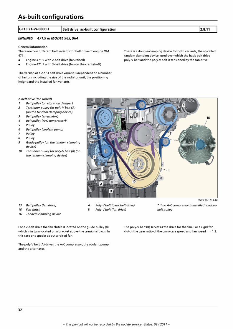
General information
There are two different belt variants for belt drive of engine OM
471:
f Engine 471.9 with 2>belt drive (fan raised)
f Engine 471.9 with 3>belt drive (fan on the crankshaft)
The version as a 2 or 3 belt drive variant is dependent on a number
of factors including the size of the radiator unit, the positioning
height and the installed fan variants.
There is a double>clamping device for both variants, the so>called
tandem clamping device, used over which the basic belt drive
poly>V belt and the poly>V belt is tensioned by the fan drive.
W13.21>1015>76
2>belt drive (fan raised)
1 Belt pulley (on vibration damper)
2 Tensioner pulley for poly>V belt (A)
(on the tandem clamping device)
3 Belt pulley (alternator)
4 Belt pulley (A/C compressor)*
5 Pulley
6 Belt pulley (coolant pump)
7 Pulley
8 Pulley
9 Guide pulley (on the tandem clamping
device)
10 Tensioner pulley for poly>V belt (B) (on
the tandem clamping device)
13 Belt pulley (fan drive)
15 Fan clutch
16 Tandem clamping device
* if no A/C compressor is installed: backup
belt pulley
A Poly>V belt (basic belt drive)
B Poly>V belt (fan drive)
For a 2>belt drive the fan clutch is located on the guide pulley (8)
which is in turn located on a bracket above the crankshaft axis. In
this case one speaks about a raised fan.
The poly>V belt (A) drives the A/C compressor, the coolant pump
and the alternator.
The poly>V belt (B) serves as the drive for the fan. For a rigid fan
clutch the gear ratio of the crankcase speed and fan speed i = 1.2.
32
– This printout will not be recorded by the update service. Status: 09 / 2011 –

As>built configurations
W13.21>1016>76
3>belt drive (fan on crankshaft)
1 Belt pulley (on vibration damper)
2 Tensioner pulley for poly>V belt (A)
(on the tandem clamping device)
3 Belt pulley (alternator)
4 Belt pulley (A/C compressor)*
5 Pulley
6 Belt pulley (coolant pump)
7 Pulley
8 Pulley
9 Guide pulley (on the tandem clamping
device)
10 Tensioner pulley for poly>V belt (B) (on
the tandem clamping device)
11 Drive plate (fan drive)
12 Tensioning device for fan drive C (fan
drive)
13 Belt pulley (fan drive)
14 Drive plate (fan drive)
15 Fan clutch
16 Tandem clamping device
* if no A/C compressor is installed: backup
belt pulley
A Poly>V belt (basic belt drive)
B Poly>V belt (fan drive)
C Poly>V belt (fan drive)
For a 3>belt drive the fan clutch (15) is mounted on a drive plate
(14) which is mounted rotatable on the belt pulley (1). The fan is
therefore located on the crankshaft axis.
The poly>V belt (A) drives the A/C compressor, the coolant pump
and the alternator.
The poly>V belt (B) and (C) together drive the fan.
The poly>V belt (B) drives the guide pulley (8) which sits on an axle
with the drive plate (11). The poly>V belt (C) is driven over the
drive plate (11) which in turn drives the drive plate (14) lying on
the crankshaft axis.
For a rigid fan clutch the gear ratio of the crankcase speed and fan
speed i, also here = 1.2.
i Introduction of engine OM 471 and exhaust aftertreatment > 09/2011 > 33
– This printout will not be recorded by the update service. Status: 09 / 2011 –
Functions
GF01.20>W>0001H Crankcase ventilation system function 1.7.11
ENGINES 471.9 in MODEL 963
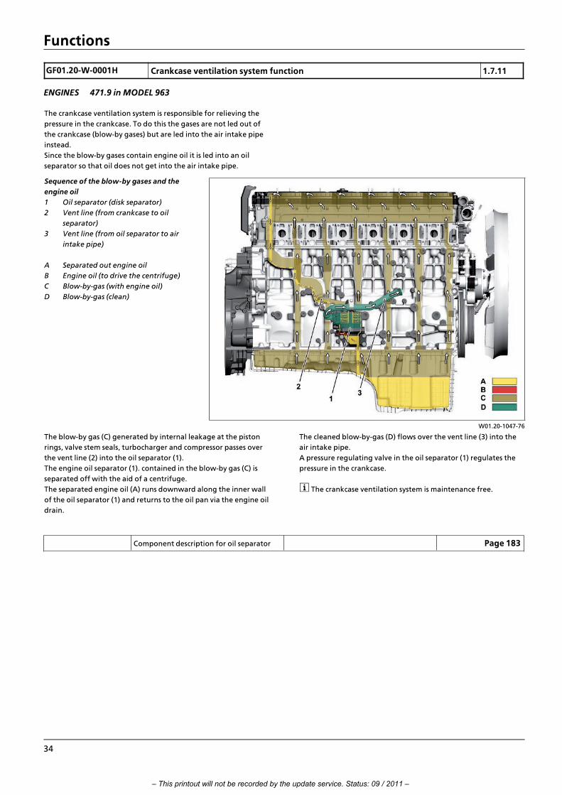
The crankcase ventilation system is responsible for relieving the
pressure in the crankcase. To do this the gases are not led out of
the crankcase (blow>by gases) but are led into the air intake pipe
instead.
Since the blow>by gases contain engine oil it is led into an oil
separator so that oil does not get into the air intake pipe.
W01.20>1047>76
Sequence of the blow>by gases and the
engine oil
1 Oil separator (disk separator)
2 Vent line (from crankcase to oil
separator)
3 Vent line (from oil separator to air
intake pipe)
A Separated out engine oil
B Engine oil (to drive the centrifuge)
C Blow>by>gas (with engine oil)
D Blow>by>gas (clean)
The blow>by gas (C) generated by internal leakage at the piston
rings, valve stem seals, turbocharger and compressor passes over
the vent line (2) into the oil separator (1).
The engine oil separator (1). contained in the blow>by gas (C) is
separated off with the aid of a centrifuge.
The separated engine oil (A) runs downward along the inner wall
of the oil separator (1) and returns to the oil pan via the engine oil
drain.
The cleaned blow>by>gas (D) flows over the vent line (3) into the
air intake pipe.
A pressure regulating valve in the oil separator (1) regulates the
pressure in the crankcase.
i The crankcase ventilation system is maintenance free.
Component description for oil separator Page 183
34
– This printout will not be recorded by the update service. Status: 09 / 2011 –

Functions
GF09.00>W>2000H Forced induction, function 20.7.11
ENGINES 471.9 in MODEL 963
W09.40>1213>79
Shown code (M5Z) Engine version Euro VI
1 Turbocharger
2 Charge air manifold
3 Turbine wheel
4 Vacuum cell
5 Compressor impeller
6 Shaft
Y636 Charge pressure positioner
A Intake air from air filter
B Charge air to charge air cooler
C Charge air from charge air cooler
D Exhaust
7 Valve
8 Bypass opening
B610 Rpm sensor for turbine wheel
(only for code (M5Z) Engine version
Euro VI)
General
Charging to the engines of model series OM 471 takes place
through a turbocharger (1).
Through compression of the suctioned in air in the turbocharger
(1) a larger air mass is brought into the combustion chamber.
The following advantages result through this:
• An increase in the engine power and the torque
• Reduction of fuel consumption in comparison to not
supercharged diesel engines of the same power output
• Reduction of the pollutant emission
Function
The turbocharger (1) consists of a turbine and a compressor which
are fitted to a joint shaft (6).
The exhaust (D) flows over the turbine wheel (3) and causes this to
rotate. This rotational movement is transferred to the compressor
impeller (5) over the shaft (6).
Through the compressor impeller (5) the intake air is compacted
by the air filter (A) and passes over a charge air pipe to the charge
air cooler.
In the charge air cooler the compacted air is cooled whereby the
air density of the fresh gas filling and thus the output of the
engine is increased.
The charge air then passes from the charge air cooler (C) via the
charge air manifold (2) into the individual cylinders.
i Introduction of engine OM 471 and exhaust aftertreatment > 09/2011 > 35
– This printout will not be recorded by the update service. Status: 09 / 2011 –

Functions
W09.40>1228>76
Boost pressure control and turbocharger
protection function, shown code (M5Z)
Engine version Euro VI
A4 Engine management control unit
(MCM)
B608 Charge air pressure and
temperature sensor in charge air
pipe
B610 Rpm sensor for turbine wheel
(only for code (M5Z) Engine version
Euro VI)
B611 Temperature sensor downstream of
air filter (only for code (M5Z) Engine
version Euro VI)
Y636 Charge pressure positioner
Boost pressure control (via wastegate)
The engine management (MCM) control unit (A4) determines the
current boost pressure via the charge air pressure and
temperature sensor in the charge air pipe (B608).
If the engine management (MCM) control unit (A4) recognizes
that the current boost pressure is too high, it limits the boost
pressure in that it actuates the boost pressure regulator (Y636)
with an appropriate pulse width modulated signal. The engine
management (MCM) control unit (A4) can use the duty cycle of
this signal to influence the pressure (up to 2.8 bar) which should
be applied to the vacuum cell (4). The valve (7) is opened over a
linkage according to this pressure, so that more or less exhaust (D)
is passed over the bypass opening (8) on the turbine wheel (3)
depending on how far it is opened.
Since only part of the exhaust (D) hits the turbine wheel (3) the
acceleration is not so strong anymore and the boost pressure
drops.
Turbocharger protection function
For vehicles with code (M5Z) Engine version Euro VI the rotor
speed of the turbocharger (1) as well as the temperature of the
intake air are monitored by the air filter (A) on the compressor
inlet to protect the turbocharger.
This occurs with the aid of the turbine wheel rpm sensor (B610)
and the temperature sensor downstream of air filter (B611).
Since these sensors for vehicles with code (M5R) Engine version
EEV and vehicles with code (M5Y) Engine version Euro VI are not
installed, the engine management (MCM) control unit (A4)
orients itself on the ambient temperature and on the altitude the
vehicle is at. The latter is determined using the installed
atmospheric pressure sensor.
Dependent on the determined values and values stored in the
characteristics maps for the turbocharger protection function the
engine management (MCM) control unit (A4) adapts the injection
which leads to a lowering of the combustion temperature.
One indirect effect of actuation of the boost pressure regulator
(Y636) can be reduction of the rotor speed of the turbocharger.
Component description for engine
management (MCM) control unit
A4 Page 103
Charge air pressure and temperature
sensor in charge air pipe, component
description
B608 Page 152
Turbine wheel rpm sensor, component
description
B610
i Only for vehicles with code (M5Z)
Engine version Euro VI.
Page 153
Component description for temperature
sensor downstream of air filter
B611
i Only for vehicles with code (M5Z)
Engine version Euro VI.
Page 154
Component description for boost pressure
regulator
Y636 Page 181
Component description for turbocharger Page 186
36
– This printout will not be recorded by the update service. Status: 09 / 2011 –

Functions
GF07.16>W>0003H Engine management, function 2.8.11
ENGINE 471.9 in MODEL 963
The central control and regulator unit for engine management,
which together with the EATS ensures that the engine runs under
all operating conditions in as economical a manner as possible,
with low pollutant and low>noise, is the engine management
(MCM) control unit (A4).
It calculates the optimal beginning of injection as well as the
injection quantity required for combustion according to the
operating condition of the engine and the torque specification of
the drive control (CPC) control unit (A3).
The engine management (MCM) control unit (A4) also ensures
that the fuel is injected at exactly the right point in time and in
the correct amount into the cylinders through exact, electrical
actuation of fuel injectors for cylinder 1 to 6 (Y608 to Y613).
W07.16>1056>79
Input signals, shown with code (M5Z) Euro
VI engine version
A4 Engine management control unit
(MCM)
B600 Crankshaft position sensor
B601 Camshaft position sensor
B602 Fuel temperature sensor
B604 Oil pressure sensor
B606 Exhaust coolant temperature sensor
B621 Exhaust gas recirculation (AGR)
differential pressure sensor
B622 Rail pressure sensor
B638 Fuel filter module pressure sensor
CAN 4 Drive train CAN
S600 Engine start and engine stop
button
Y621 Exhaust gas recirculation positioner
B607 Intake coolant temperature sensor
B608 Charge air pressure and
temperature sensor in charge air
pipe
B611 Temperature sensor downstream of
air filter (only for code (M5Z)
Engine version Euro VI)
B617 Charge air temperature sensor in
charge air housing
The operating condition of the engine is determined based on
input values from the following sensors:
• Crankshaft position sensor (B600)
• Camshaft position sensor (B601)
• Fuel temperature sensor (B602)
• Exhaust coolant temperature sensor (B606)
• Intake coolant temperature sensor (B607)
• Charge air pressure and temperature sensor in charge air
pipe (B608)
• Temperature sensor downstream of air filter (B611)
(only with code (M5Z) Euro VI engine version)
• Charge air temperature sensor in charge air housing (B617)
• Exhaust gas recirculation (AGR) differential pressure sensor
(B621)
• Rail pressure sensor (B622)
• Fuel filter module pressure sensor (B638)
The specified torque, which is calculated by the drive control (CPC)
control unit (A3) from (among other things) the position of the
accelerator pedal, is routed over the drive train CAN (CAN 4) to
the engine management (MCM) control unit (A4), which in turn
sends the current engine torque and the maximum torque
possible to the drive control (CPC) control unit (A3).
The drive train CAN (CAN 4) and the drive control (CPC) control
unit (A3) can also be used to exchange information with other
electronic systems or control units.
i Introduction of engine OM 471 and exhaust aftertreatment > 09/2011 > 37
– This printout will not be recorded by the update service. Status: 09 / 2011 –

Functions
W07.16>1115>79
Output signals, shown with code (M5Z)
Euro VI engine version
A4 Engine management control unit
(MCM)
CAN 4 Drive train CAN
Y608 Cylinder 1 fuel injector
Y609 Cylinder 2 fuel injector
Y621 Exhaust gas recirculation positioner
Y624 Engine brake solenoid valve, stage 1
Y625 Engine brake solenoid valve, stage 2
Y642 Quantity control valve
Y610 Cylinder 3 fuel injector
Y611 Cylinder 4 fuel injector
Y612 Cylinder 5 fuel injector
Y613 Cylinder 6 fuel injector
After evaluation of the input signals the engine management
(MCM) control unit (A4) actuates the following actuators
depending on the engine operating conditions and the torque
specification from the drive control (CPC) control unit (A3):
• Cylinder 1 fuel injector (Y608)
• Cylinder 2 fuel injector (Y609)
• Cylinder 3 fuel injector (Y610)
• Cylinder 4 fuel injector (Y611)
• Cylinder 5 fuel injector (Y612)
• Cylinder 6 fuel injector (Y613)
• Exhaust gas recirculation positioner (Y621)
• Quantity control valve (Y642)
If a fault occurs on the drive train CAN (CAN 4) or on a system
component for the engine management, the engine
management (MCM) control unit (A4) proceeds according to a
clearly defined pattern depending on the severity of the fault.
Thus it will fall back on replacement values for less severe faults
such as the failure of a sensor while it will go into emergency
mode for severe faults such as failure of the drive train CAN (CAN
4).
The driver is able to at least drive to the nearest workshop if there
is a fault in the system.
i The engine management (MCM) control unit (A4) is part of
the DAS, to which also the electronic ignition lock (EIS) (S1) and
the transmission control unit (TCM) (A5) belong. If one of these
control units or the electronic ignition lock (EIS) (S1) is replaced,
then it must undergo teach>in using the Star Diagnosis in the DAS.
Engine management, overall network Page 39
Engine management behavior for
malfunctions
Page 40
Start procedure, function Page 42
Idle speed control, function Page 44
Working speed control, function Page 46
Driving, function Page 48
Engine shutoff procedure, function Page 50
38
– This printout will not be recorded by the update service. Status: 09 / 2011 –

Functions
GF07.16>W>0003>01H Engine management, overall network
W07.16>1108>79
A1 Instrument cluster (ICUC) control unit
A2 Central gateway control unit (CGW)
A3 Drive control (CPC) control unit
A4 Engine management control unit
(MCM)
A5 Transmission control (TCM) control
unit
A7 Cab signal acquisition and actuation
module control unit (SCA)
A8 Frame signal acquisition and actuation
module control unit (SCH)
A10 Antilock brake system (ABS) control
unit, 4>channel
A10b Electronic Brake Control (EBS) control
unit (Wabco)
A10c Electronic Brake Control (EBS) control
unit (Knorr)
A11 Retarder control (RCM) control unit
A15 Front radar sensor (RDF) control unit
A18 Electronic Air Processing Unit (EAPU)
control unit
A22 Parameterizable special module (PSM)
control unit
A25 Electronic Stability Program (ESP“)
control unit (Wabco)
A25a Electronic Stability Program (ESP“)
control unit (Knorr)
A30 FleetBoard control unit
A33 Battery disconnect switch control unit
(BESO)
S1 Electronic ignition lock (EIS)
S23 Right multifunction control lever
S110 Left multifunction steering wheel
button group
S111 Right multifunction steering
wheel button group
X100.16 Diagnostic socket
X102.15 Trailer socket , 15>pin
X167.12 Electrical connector (telematics
platform (TP))
X910 Electrical connector for body
manufacturers
XR>E1H CAN>H exterior cable weld point 1
XR>E1L CAN>L exterior cable weld point 1
XR>E1M CAN>ground exterior cable weld
point 1
Z1 Cab instrument panel CAN bus star
point
Z3 Frame CAN bus star point
Z4 Drive CAN bus star point
ASIC ASIC data bus (Application System
Integrated Circuit)
A43 Modular switch panel (MSF)
control unit
A53 Driver assistance system (VRDU)
control unit
A57 EATU output NOx sensor control
unit
A58 SCR control unit
A60 Exhaust aftertreatment (ACM)
control unit
A70 EATU input NOx sensor control
unit
CAN 1 Exterior>CAN
CAN 2 Interior CAN
CAN 3 Frame CAN
CAN 4 Drive train CAN
CAN 6d ESP“ brakes CAN
CAN 7 Trailer CAN (PSM)
CAN 8 Body manufacturer CAN (PSM)
CAN 9 Telematics CAN
CAN 10 Diagnostic CAN
CAN 12 Radar CAN
CAN 13 NOx>CAN
LIN 3 Right multifunction control lever>
LIN
LIN 6 LIN SCA/SCH redundancy
LIN 7 Button group LIN
LIN 10 EAPU>LIN
i Introduction of engine OM 471 and exhaust aftertreatment > 09/2011 > 39
– This printout will not be recorded by the update service. Status: 09 / 2011 –

Functions
GF07.16>W>0003>02H Engine management behavior for
malfunctions
i If the engine management (MCM) control unit (A4) detects a
malfunction or a fault in the system or on a system component, it
proceeds in accordance with a precisely specified method
depending on the severity of the actual fault.
1 Response in the event of drive train CAN (CAN 4)
malfunction
In order to achieve the greatest possible security against
breakdowns, the signal line of the drive train CAN (CAN 4) is a
double line. The individual lines are designated as CAN Low and
CAN High and are fed with reverse poled signals. Thus faults
which effect both lines simultaneously cancel each other out.
Faults which only occur on one CAN line also do not create
confusion for data transmission since the message can be
reconstructed on the basis of the signal of the undisturbed line,
i.e. the drive train CAN (CAN 4) is capable of operating over one
wire.
The drive train CAN (CAN 4) only fails when both lines are
interrupted or there is a short>circuit with the battery voltage or
to ground.>>>>>>>>>>>>>>>>>>>>>>>>>>>>>>>>>>>>>>>>>>>>>>>>>>>>>>>>>>>>>>>>>>>>>>>>>>>>>>>>>>>>>>>>>
A failure of the drive train CAN (CAN 4) is detected by the engine
management (MCM) control unit (A4), and it switches to limp>
home mode. If the engine speed at this stage is below the limp>
home mode speed, the engine speed is then maintained. In all
other cases, including after restarting the engine, the engine
management (MCM) control unit (A4) adjusts the limp>home
mode speed, irrespective of the load.
It is thus possible for the driver to at least bring the vehicle to the
nearest workshop.
i The limp>home mode is notified to the other systems and
displayed in the instrument cluster control unit (ICUC) (A1).
There is also entry of the condition in the fault memory.
>>>>>>>>>>>>>>>>>>>>>>>>>>>>>>>>>>>>>>>>>>>>>>>>>>>>>>>>>>>>>>>>>>>>>>>>>>>>>>>>>>>>>>>>>
2 Response when camshaft position sensor (B601) fails
If the camshaft position sensor (B601) fails when driving, then the
engine continues to run. Nevertheless, the maximum torque of
the engine will be limited to protect the engine from damage.
The engine management (MCM) control unit (A4) can also
regulate the limp>home speed.
If the camshaft position sensor (B601) fails to return any pulses
during the startup phase, then in each case a portion of the
double firing, with which the engine is started, is cutoff, until the
dip in speed, which then occurs, when a piston is not in ignition
TDC, enables ignition TDC to be recognized. Once ignition TDC is
recognized, the engine continues to run in unchanged state.
Nevertheless, the maximum torque of the engine will be limited
to protect the engine from damage. The engine management
(MCM) control unit (A4) can also regulate the limp>home speed.>>>>>>>>>>>>>>>>>>>>>>>>>>>>>>>>>>>>>>>>>>>>>>>>>>>>>>>>>>>>>>>>>>>>>>>>>>>>>>>>>>>>>>>>>
3 Response when crankshaft position sensor (B600) fails
If the crankshaft position sensor (B600) fails, then the engine
management (MCM) control unit (A4) still receives the rpm signals
from the crankshaft position sensor (B601).
Its pulses do not come so closely together as those from the
crankshaft position sensor (B600) but they are still adequate for
calculating control time of the respective fuel injector. The time
determination will be somewhat less exact so optimum fuel
consumption or pollutant emission levels will not be achievable.
Furthermore, for engine protection reasons, the maximum torque
of the engine is limited to about a half. The engine management
(MCM) control unit (A4) can also regulate the limp>home speed.
>>>>>>>>>>>>>>>>>>>>>>>>>>>>>>>>>>>>>>>>>>>>>>>>>>>>>>>>>>>>>>>>>>>>>>>>>>>>>>>>>>>>>>>>>
40
– This printout will not be recorded by the update service. Status: 09 / 2011 –

Functions
4 Response when a temperature sensor fails
If the values from a temperature sensor are implausible, or if a
temperature sensor has an open circuit or a short circuit, the
engine management (MCM) control unit (A4) continues to
operate with substitute values.
Own replacement values are stored for each temperature sensor
since the measurement values of the individual temperature
sensors can deviate from each other. It is not feasible for these to
be suitable for all operating conditions, however, which is why a
mild reduction in the maximum possible torque available takes
place.
>>>>>>>>>>>>>>>>>>>>>>>>>>>>>>>>>>>>>>>>>>>>>>>>>>>>>>>>>>>>>>>>>>>>>>>>>>>>>>>>>>>>>>>>>
5 Response when an exhaust gas recirculation (EGR)
component fails
If the values of the charge air pressure and temperature sensor in
the charge air pipe (B608), the charge air temperature sensor in
the charge air housing (B617), the exhaust gas recirculation (EGR)
differential pressure sensor (B621) or the exhaust gas recirculation
positioner (Y621) are implausible, or if one of them suffers an
open circuit or a short circuit, the engine management (MCM)
control unit (A4) adjusts the limp>home mode speed and the
engine's maximum torque is limited.
i The fact that the limp>home strategy is alterable by the
manufacturer means that it is possible that the engine speed
remains unchanged and only the maximum torque of the engine
is limited.>>>>>>>>>>>>>>>>>>>>>>>>>>>>>>>>>>>>>>>>>>>>>>>>>>>>>>>>>>>>>>>>>>>>>>>>>>>>>>>>>>>>>>>>>
6 Response when atmospheric pressure sensor in engine
management (MCM) control unit (A4) fails
If the atmospheric pressure sensor in the engine management
(MCM) control unit (A4) has a malfunction or a fault, then >
depending on the particular situation > it uses substitute values:
• If the pressure sensor in the charge air pressure and
temperature sensor in the charge air pipe (B608) is intact,
the engine management (MCM) control unit (A4) uses the
air pressure in the charge air housing during the start
procedure and the values stored in a substitute characteristic
when the engine is running.
The reason why the engine management (MCM) control unit
(A4) falls back on values in a substitute characteristic while
the engine is running is because the charge pressure in the
charge air housing can differ according to the engine
loading and cannot therefore be used as the atmospheric
pressure.>>>>>>>>>>>>>>>>>>>>>>>>>>>>>>>>>>>>>>>>>>>>>>>>>>>>>>>>>>>>>>>>>>>>>>>>>>>>>>>>>>>>>>>>>
• If the pressure sensor in the charge air pressure and
temperature sensor in the charge air pipe (B608) is also
defective, the engine management (MCM) control unit (A4)
then uses the values of the previously>mentioned substitute
characteristic for all operating conditions.
>>>>>>>>>>>>>>>>>>>>>>>>>>>>>>>>>>>>>>>>>>>>>>>>>>>>>>>>>>>>>>>>>>>>>>>>>>>>>>>>>>>>>>>>>
7 Response when engine management (MCM) control unit
(A4) fails
The engine management (MCM) control unit (A4) has only one
host CPU, and no limp>home mode CPU.
If the host CPU fails the engine stops and cannot be started
anymore.
The drive control (CPC) control unit (A3) however is capable of
diagnosing the failure of the engine management (MCM) control
unit (A4) by reading out the fault memory, so that diagnosis is still
possible.
i While the engine management (MCM) control unit (A4)
switches to the limp>home mode when a severe fault occurs or if a
less serious fault occurs it operates using substitute values, it saves
every fault that occurs and notifies the driver of them by means of
an appropriate display in the instrument cluster (ICUC) control
unit (A1).
In addition to information about the type of fault and possibly
also a measurement value, the engine control (MR) also stores
information about whether the fault is current or just transient or
occurs sporadically. The fault memory can also be automatically
deleted again, of course, for less serious faults if the stored fault
does not occur again within the next 50 hours. In order to avoid
coming to wrong conclusions when troubleshooting, please
observe that certain operating conditions can lead to limitation of
the maximum torque of the engine.
e. example, a radiator contaminated with dirt and dust will have a
reduced cooling output. The engine management (MCM) control
unit (A4) determines an increase in coolant temperature and
limits the engine's maximum torque so that the coolant
temperature limit is not exceeded.
i Introduction of engine OM 471 and exhaust aftertreatment > 09/2011 > 41
– This printout will not be recorded by the update service. Status: 09 / 2011 –

Functions
GF07.00>W>2001H Start procedure, function 2.8.11
ENGINE 471.9 in MODEL 963
W07.16>1058>79
Shown code (M5Z) Engine version Euro VI
A4 Engine management control unit
(MCM)
B600 Crankshaft position sensor
B601 Camshaft position sensor
B602 Fuel temperature sensor
B606 Exhaust coolant temperature
sensor
B608 Charge air pressure and
temperature sensor in charge air
pipe
CAN 4 Drive train CAN
M1 Starter
S600 'Engine start and engine stop
button
Y608 Cylinder 1 fuel injector
Y609 Cylinder 2 fuel injector
Y610 Cylinder 3 fuel injector
Y611 Cylinder 4 fuel injector
Y612 Cylinder 5 fuel injector
Y613 Cylinder 6 fuel injector
Y642 Quantity control valve
B611 Temperature sensor downstream
of air filter (only for code (M5Z)
Engine version Euro VI)
B617 Charge air temperature sensor in
charge air housing
B621 Exhaust gas recirculation (EGR)
differential pressure sensor
B622 Rail pressure sensor
B638 Fuel filter module pressure sensor
General information
The engine start procedure is initiated when a corresponding start
request through the drive train CAN (CAN 4) is present, e.g. when
starting the engine using the electronic ignition lock (EIS) (S1) or
through the parameterizable special module (PSM) control unit
(A22), or through corresponding operation of the engine start
and engine stop button (S600).
>>>>>>>>>>>>>>>>>>>>>>>>>>>>>>>>>>>>>>>>>>>>>>>>>>>>>>>>>>>>>>>>>>>>>>>>>>>>>>>>>>>>>>>>>
Requirements
• Voltage supply (terminal 30 and terminal 15) on the engine
management (MCM) control unit (A4) (ignition switched on)
• Electronic immobilizer deactivated by DAS and start enable
issued by electronic ignition lock (EIS) (S1), i.e. the inserted
transmitter key is authorized
• Starter lockout canceled, i.e.:
> Transmission in neutral (only for start request using
engine start and engine stop button (S600))
> Power take>off, where present, switched off
> Engine stopped or engine speed is <50 rpm>>>>>>>>>>>>>>>>>>>>>>>>>>>>>>>>>>>>>>>>>>>>>>>>>>>>>>>>>>>>>>>>>>>>>>>>>>>>>>>>>>>>>>>>>
42
– This printout will not be recorded by the update service. Status: 09 / 2011 –

Functions
Function
If all requirements are met and if the engine start and engine stop
button (S600) is pressed or a corresponding message with the start
request is received over the drive train CAN (CAN 4), e.g. when the
start>stop button on the electronic ignition lock (EIS) (S1) is
pushed to the start position (Stage 2) and held there or the
parameterizable special module (PSM) control unit (A22) sends a
corresponding message with the start request, the engine
management (MCM) control unit (A4) actuates the starter's
starter solenoid (M1) through a series relay.
The starter (M1) sets the engine in motion and the engine
management (MCM) control unit (A4) checks whether the starter
(M1) is turning the engine at the specified minimum speed.
It also waits until it can recognize from crankshaft position sensor
signals (B600) when cylinders 1 and 6 are at top dead center (TDC).>>>>>>>>>>>>>>>>>>>>>>>>>>>>>>>>>>>>>>>>>>>>>>>>>>>>>>>>>>>>>>>>>>>>>>>>>>>>>>>>>>>>>>>>>
Only then can the actuation begin for the fuel injectors for
cylinder 1 and 6 (Y608 and Y613), calculated while taking account
of the current operating condition of the engine.
At the same time, the engine management (MCM) control unit
(A4) calculates the required injection quantity for combustion and
initiates the injection of this at the correct point in time into the
combustion chambers of cylinders 1 and 6 through appropriate
actuation of the quantity control valves (Y642) and fuel injectors
for cylinder 1 and 6 (Y608 and Y613).
This so>called double ignition serves to accelerate the starting
procedure. It is continued (afterwards follow cylinders 5 and 2, 3
and 4, then further with 1 and 6, etc.), until the ignition TDC of
cylinder 1 is recognized with the aid of the camshaft position
sensor (B601).>>>>>>>>>>>>>>>>>>>>>>>>>>>>>>>>>>>>>>>>>>>>>>>>>>>>>>>>>>>>>>>>>>>>>>>>>>>>>>>>>>>>>>>>>
i If the camshaft position sensor (B601) fails to return any
pulses, then in each case a portion of the double firing is cutoff,
until the dip in speed, which then occurs, when a piston is not in
ignition TDC, enables ignition TDC to be recognized. Once
ignition TDC is recognized, the engine continues to run in
unchanged state. Nevertheless, the maximum torque of the
engine will be limited to protect the engine from damage. The
engine management (MCM) control unit (A4) can also regulate
the limp>home speed.
Determining the injection quantity:
Determination of the injection volume independently of the
accelerator pedal position in order to achieve a secure engine
start with the lowest possible emission of pollutants. >>>>>>>>>>>>>>>>>>>>>>>>>>>>>>>>>>>>>>>>>>>>>>>>>>>>>>>>>>>>>>>>>>>>>>>>>>>>>>>>>>>>>>>>>
The injection quantity selected for the starting procedure is
primarily geared to the coolant temperature, which is determined
by the engine management (MCM) control unit (A4) via the
exhaust coolant temperature sensor (B606).
Further influencing factors for the injection quantity during the
starting procedure are the current engine speed as well as the
geographical altitude at which the vehicle or engine is located.
i There is an atmospheric pressure sensor in the engine
management (MCM) control unit (A4) over which the air pressure
of the ambient air is determined for determination of the altitude
and the current altitude of the vehicle or engine can be deduced.
>>>>>>>>>>>>>>>>>>>>>>>>>>>>>>>>>>>>>>>>>>>>>>>>>>>>>>>>>>>>>>>>>>>>>>>>>>>>>>>>>>>>>>>>>
The engine starts with this initial, primarily temperature>
dependent, start injection quantity.
If the engine does not start with the start injection amount, then
the injection quantity will be continuously increased until the
engine starts or the limit value for the max. start injection
quantity is reached. This is then maintained until the starter (M1)
actuation is interrupted either by itself or after a specific time by
the engine management (MCM) control unit (A4), to protect the
starter (M1) against mechanical or thermal overload (start time
limit).
If the engine starts, while the start>stop button on the electronic
ignition lock (EIS) (S1) or the engine start and engine stop button
(S600) are still being pressed, and if it reaches a specific speed then
the actuation of the starter (M1) is interrupted (starter dump
speed).
The pinion is pulled back out of the ring gear on the flywheel,
while start actuation of the injection quantity changes over to the
idle speed control. This changeover is known as starter
disengagement which exclusively results in a change of the
calculation method. Because the cold start ability of diesel engines
at low outside temperatures is restricted by the engine's
increasing resistance to rotation, lower combustion chamber
temperatures and unfavorable fuel atomization conditions, under
certain conditions a pilot injection is conducted.
This contributes significantly to shorter starting times, to faster
smooth engine operation, to improved throttle response, to lower
white smoke emission, to less pollutant emissions and lower noise
emissions.
Determination of the engine speed and
crankshaft angle, function
Page 53
Determination of the compression stroke
at cylinder 1, function
Page 54
Determination of coolant temperature,
function
Page 55
Determination of air mass, function Page 56
Determination of the fuel temperature,
function
Page 57
Fuel supply, function Page 91
i Introduction of engine OM 471 and exhaust aftertreatment > 09/2011 > 43
– This printout will not be recorded by the update service. Status: 09 / 2011 –

Functions
GF07.16>W>2021H Idle speed control, function 2.8.11
ENGINE 471.9 in MODEL 963
W07.16>1059>79
Shown code (M5Z) Engine version Euro VI
A4 Engine management control unit
(MCM)
B600 Crankshaft position sensor
B601 Camshaft position sensor
B602 Fuel temperature sensor
B606 Exhaust coolant temperature
sensor
B608 Charge air pressure and
temperature sensor in charge air
pipe
CAN 4 Drive train CAN
Y608 Cylinder 1 fuel injector
Y609 Cylinder 2 fuel injector
Y610 Cylinder 3 fuel injector
Y611 Cylinder 4 fuel injector
Y612 Cylinder 5 fuel injector
Y613 Cylinder 6 fuel injector
Y621 Exhaust gas recirculation
positioner
Y642 Quantity control valve
B611 Temperature sensor downstream
of air filter (only for code (M5Z)
Engine version Euro VI)
B617 Charge air temperature sensor in
charge air housing
B621 Exhaust gas recirculation (AGR)
differential pressure sensor
B622 Rail pressure sensor
B638 Fuel filter module pressure sensor
i The idle speed is parameterized in the engine management
(MCM) control unit (A4). The drive control (CPC) control unit (A3)
can, however, send its own request via the drive train CAN (CAN
4), for example if the idle speed should be higher in order to
operate ancillary assemblies at their working speed.
The higher rotational speed is basically always regulated. In other
words, if the idle speed required by the drive control (CPC) control
unit (A3) is higher than the idle speed parameterized in the
engine management (MCM) control unit (A4), then the speed
required by the drive control (CPC) control unit (A3) is regulated
and vice versa.
>>>>>>>>>>>>>>>>>>>>>>>>>>>>>>>>>>>>>>>>>>>>>>>>>>>>>>>>>>>>>>>>>>>>>>>>>>>>>>>>>>>>>>>>>
The idle speed is regulated immediately after the starting
procedure or if the drive control (CPC) control unit (A3) recognizes
that the accelerator pedal is not being actuated.
While taking account of the idle speed specification from the
drive control (CPC) control unit (A3) and the current operating
condition of the engine, the engine management (MCM) control
unit (A4) calculates the optimal start of actuation for the fuel
injectors as well as the optimum actuation period (injection
quantity) while also ensuring that the fuel is injected at the
correct point in time, and in the correct quantities into the
respective combustion chamber through appropriate actuation of
the quantity control valve (Y642) and the fuel injectors for
cylinder 1 to 6 (Y608 to Y613).>>>>>>>>>>>>>>>>>>>>>>>>>>>>>>>>>>>>>>>>>>>>>>>>>>>>>>>>>>>>>>>>>>>>>>>>>>>>>>>>>>>>>>>>>
44
– This printout will not be recorded by the update service. Status: 09 / 2011 –

Functions
The injection quantity is constantly adjusted to the operating
condition of the engine during the whole idling operation > e.g. if
the load condition of the engine changes or a higher fuel
requirement exists (due to a low outside temperature).
To calculate the injection quantity, the engine management
(MCM) control unit (A4) mainly takes account of the following
input factors:
f Engine speed
f Coolant temperature
f Fuel temperature
f Load request (specified torque)
Smoke limitation, smooth running control and altitude correction
in the engine management (MCM) control unit (A4) can also
influence the injection quantity (period of actuation) as well as
the start of actuation for the fuel injectors.
>>>>>>>>>>>>>>>>>>>>>>>>>>>>>>>>>>>>>>>>>>>>>>>>>>>>>>>>>>>>>>>>>>>>>>>>>>>>>>>>>>>>>>>>>
Smoke limitation
The fuel quantity is limited via the smoke limitation characteristics
so that virtually no output of smoke occurs.
Smooth running control
The smooth running control evens out injection amount
differences of the individual fuel injectors.
Development of torque on the various cylinders can differ due to
tolerances and wear on the individual fuel injectors. This leads to
irregular running of the engine, that is the rotational speed of the
crankshaft is slightly faster and slower. One particularly feels this
when idling. The smooth running control can respond to rough
running because it actuates every injection nozzle individually. It
balances out the rotational speed fluctuations through slightly
different injection quantities for the individual cylinder until all
cylinders develop the same torque.>>>>>>>>>>>>>>>>>>>>>>>>>>>>>>>>>>>>>>>>>>>>>>>>>>>>>>>>>>>>>>>>>>>>>>>>>>>>>>>>>>>>>>>>>
Altitude correction
Altitude correction is primarily designed in such a way that the
rotor speed, the compressor outlet temperature and the turbine
inlet temperature of the turbocharger, as well as the air/fuel ratio
n (lambda), does not exceed or drop below established limits. To
do this, the exhaust gas recirculation rate (AGR rate), the
actuation begin as well as the actuation period (injection
quantity) for fuel injectors for cylinder 1 to 6 (Y608 to Y613) are
adapted.
In order to reduce nitrous oxide emissions, the exhaust gas
recirculation (AGR) is active for a certain period of time during
idling mode (the AGR is switched off for longer periods in idling
mode so that the exhaust gas recirculation cooler is not sooted
up).
In the case of the exhaust gas recirculation (AGR), the suctioned
out or supercharged fresh air is mixed with exhaust gas. This leads
to the situation where the oxygen content of the suctioned out or
supercharged air drops and its specific heat increases.
One can therefore achieve a lower combustion temperature and
thus reduced output of nitrogen oxides (NOx), whose proportion
increases with increasing combustion temperatures. The amount
of exhaust gases produced is also reduced.
Determination of the engine speed and
crankshaft angle, function
Page 53
Determination of the compression stroke
at cylinder 1, function
Page 54
Determination of coolant temperature,
function
Page 55
Determination of air mass, function Page 56
Determination of the fuel temperature,
function
Page 57
Function of the specified engine torque
calculation
Page 58
Fuel supply, function Page 91
Exhaust gas recirculation, function Page 66
Exhaust aftertreatment, function Vehicles with code (M5R) EEV engine
version and vehicles with code (M5Y) Euro
V engine version
Page 68
Vehicles with code (M5Z) Euro VI engine
version
Page 73
i Introduction of engine OM 471 and exhaust aftertreatment > 09/2011 > 45
– This printout will not be recorded by the update service. Status: 09 / 2011 –

Functions
GF07.16>W>2022H Working speed control, function 2.8.11
ENGINES 471.9 in MODEL 963
W07.16>1059>79
Shown code (M5Z) Engine version Euro VI
A4 Engine management control unit
(MCM)
B600 Crankshaft position sensor
B601 Camshaft position sensor
B602 Fuel temperature sensor
B606 Exhaust coolant temperature
sensor
B608 Charge air pressure and
temperature sensor in charge air
pipe
CAN 4 Drive train CAN
Y608 Cylinder 1 fuel injector
Y609 Cylinder 2 fuel injector
Y610 Cylinder 3 fuel injector
Y611 Cylinder 4 fuel injector
Y612 Cylinder 5 fuel injector
Y613 Cylinder 6 fuel injector
Y621 Exhaust gas recirculation
positioner
Y642 Quantity control valve
B611 Temperature sensor downstream
of air filter (only for code (M5Z)
Engine version Euro VI)
B617 Charge temperature sensor in
charge air housing
B621 Exhaust gas recirculation (AGR)
differential pressure sensor
B622 Rail pressure sensor
B638 Fuel filter module pressure sensor
General information
The electronic working speed control takes place as soon as a
power take>off is switched in. To do this up to three power take>
offs can be parameterized differently according to the vehicle
equipment. This means that for every power take>off difference
control specifications can be established according to the area of
use of the vehicle and according to how the parameters for the
power take>off functions are set in the SCA (SCA) control unit (A7)
or in the parameterizable special module (PSM) control unit (A22).
Along with a range of other parameters it is possible, for example,
to set the entry requirements such as "parking brake tightened"
or "transmission in neutral", or the engine speed range (min.
engine speed, max. engine speed) as well as a torque limitation.
It is furthermore possible to set the working speed during
operation of a power take>off over the accelerator pedal or the
keys on the multifunction steering wheel individually to a
rotational speed between 550 rpm and 750 rpm or to raise it over
the idle speed switch (S900) to a parameterizable value.>>>>>>>>>>>>>>>>>>>>>>>>>>>>>>>>>>>>>>>>>>>>>>>>>>>>>>>>>>>>>>>>>>>>>>>>>>>>>>>>>>>>>>>>>
Regulation of the working speed
Upon switching on of a power take>off its parameters for working
speed control are transmitted by the SCA (SCA) control unit (A7)
and the parameterizable special module (PSM) control unit (A22)
via the CAN data bus system to the drive control (CPC) control unit
(A3).
The drive control (CPC) control unit (A3) passes on the parameter
via the drive train CAN (CAN 4) to the engine management (MCM)
control unit (A4) whereby it initially takes account of the
parameters set in the parameterizable special module (PSM)
control unit (A22) since these are super>imposed over the
parameters set in the SCA (SCA) control unit (A7).
This means: for vehicles with code (E3Y) PSM, body and trailer
CAN ISO 11992 and for vehicles with code (E3Z) PSM, body CAN
ISO 11898 instead of 11992 only the parameters in the
parameterizable special module (PSM) control unit (A22) are
taken into account, independently of which parameters are set in
the SCA (SCA) control unit (A7).>>>>>>>>>>>>>>>>>>>>>>>>>>>>>>>>>>>>>>>>>>>>>>>>>>>>>>>>>>>>>>>>>>>>>>>>>>>>>>>>>>>>>>>>>
46
– This printout will not be recorded by the update service. Status: 09 / 2011 –
Functions
Upon receipt of the appropriate information and while taking
account of the current operating condition of the engine, the
parameterizable special module (PSM) control unit (A4) computes
the now required actuation begin of the fuel injectors as well as
the necessary period of actuation (injection quantity) and ensures
that the fuel is injected at the correct point in time and in the
correct quantities into the respective combustion chamber
through appropriate actuation of the quantity control valve
(Y642) and the fuel injectors for
cylinders 1 to 6 (Y608 to Y613).
i The working speed is only regulated if the appropriate power
take>off is fully engaged.>>>>>>>>>>>>>>>>>>>>>>>>>>>>>>>>>>>>>>>>>>>>>>>>>>>>>>>>>>>>>>>>>>>>>>>>>>>>>>>>>>>>>>>>>
Changing the working speed
It is possible, dependent on the vehicle equipment and
parameterization of the power take>off functions, to set the
working speed during operation of a power take>off over the
accelerator pedal or the keys on the multifunction steering wheel
individually to a rotational speed between 550 rpm and 750 rpm
or to raise it over the idle speed switch (S900) to a
parameterizable value in as far as the max. working speed is not
exceeded and the min. working speed is always reached.
>>>>>>>>>>>>>>>>>>>>>>>>>>>>>>>>>>>>>>>>>>>>>>>>>>>>>>>>>>>>>>>>>>>>>>>>>>>>>>>>>>>>>>>>>
f Changing the working speed with the
accelerator pedal
If the accelerator pedal is actuated and thus the position of the
accelerator pedal sensor (B44) alters then the drive control (CPC)
control unit (A3) alters the control specification for the working
speed and transmits this via the drive train CAN (CAN 4) to the
engine management (MCM) control unit (A4). It takes account at
the same time of the parameters prescribed by the SCA (SCA)
control unit (A7) or by the parameterizable special module (PSM)
control unit (A22), according to the vehicle equipment as well as
the current actual rotational speed.
The engine management (MCM) control unit (A4) increases the
working speed through appropriate actuation of the injection
quantity to the desired value and holds this constant.
>>>>>>>>>>>>>>>>>>>>>>>>>>>>>>>>>>>>>>>>>>>>>>>>>>>>>>>>>>>>>>>>>>>>>>>>>>>>>>>>>>>>>>>>>
f Changing the working speed over the multifunction steering
wheel
The working speed can be altered step by step in steps of 20 with
the aid of keys on the multifunction steering wheel. The keys on
the multifunction steering wheel are connected via a LIN data bus
with the modular switch panel (MSF) control unit (A43) which
transmits the entries via the interior CAN (CAN 2) to the central
gateway (CGW) control unit (A2) which, in turn, passes this on via
the frame>CAN (CAN 3) to the drive control (CPC) control unit
(A3). The drive control (CPC) control unit (A3) compares the
desired working speed with the current one, the max. permissible
as well as the min. permissible working speed (if these were
parameterized), adapts the control specification and transmits
this to the engine management (MCM) control unit (A4).
The engine management (MCM) control unit (A4) alters the
working speed through appropriate actuation of the injection
quantity to the desired value and holds this constant.>>>>>>>>>>>>>>>>>>>>>>>>>>>>>>>>>>>>>>>>>>>>>>>>>>>>>>>>>>>>>>>>>>>>>>>>>>>>>>>>>>>>>>>>>
f Changing the working speed using the idle speed switch (S900)
One special task for regulation of the working speed is taken on
by the idle speed switch (S900).
This allows one to switch in the constant engine speed facility
which means that the engine management (MCM) control unit
(A4) sets a single engine speed which has been parameterized and
maintains this constant, quite independently of the loading
conditions.
Determination of the engine speed and
crankshaft angle, function
Page 53
Determination of the compression stroke
at cylinder 1, function
Page 54
Determination of the coolant temperature,
function
Page 55
Determination of air mass, function Page 56
Determination of the fuel temperature,
function
Page 57
Fuel supply, function Page 91
Exhaust gas recirculation, function Page 66
Exhaust aftertreatment, function Vehicles with code (M5R) Engine version
EEV and vehicles with code (M5Y) Engine
version Euro V
Page 68
Vehicles with code (M5Z) Engine version
Euro VI
Page 73
i Introduction of engine OM 471 and exhaust aftertreatment > 09/2011 > 47
– This printout will not be recorded by the update service. Status: 09 / 2011 –

Functions
GF07.16>W>2023H Driving, function 2.8.11
ENGINES 471.9 in MODEL 963
W07.16>1060>79
Shown code (M5Z) Engine version Euro VI
A4 Engine management control unit
(MCM)
B600 Crankshaft position sensor
B601 Camshaft position sensor
B602 Fuel temperature sensor
B606 Exhaust coolant temperature
sensor
B608 Charge air pressure and
temperature sensor in charge air
pipe
B611 Temperature sensor downstream of
air filter (only for code (M5Z)
Engine version Euro VI)
Y611 Cylinder 4 fuel injector
Y612 Cylinder 5 fuel injector
Y613 Cylinder 6 fuel injector
Y621 Exhaust gas recirculation
positioner
Y624 Engine brake solenoid valve, stage
1
Y625 Engine brake solenoid valve, stage
2
Y642 Quantity control valve
B617 Charge temperature sensor in
charge air housing
B621 Exhaust gas recirculation (AGR)
differential pressure sensor
B622 Rail pressure sensor
B638 Fuel filter module pressure sensor
CAN 4 Drive train CAN
Y608 Cylinder 1 fuel injector
Y609 Cylinder 2 fuel injector
Y610 Cylinder 3 fuel injector
If the drive control (CPC) control unit (A3) does not demand any
idle or working speed control then this is normal driving mode. In
driving mode the injection quantity is primarily adjusted
according to requests from the driver. This means that the torque
specification of the engine is primarily dependent on the position
of the accelerator pedal. It is only in certain situations that it can
happen that the engine speed is adapted independently of the
accelerator pedal position or of the specified torque request, for
example for downshifting for rotational speed comparison
between the main shaft and the countershaft.
In normal driving mode the engine management (MCM) control
unit (A4) therefore first compares the engine specified torque
coming in from the drive control (CPC) control unit (A3), which is
derived from the position of the accelerator pedal and made
available via the drive train CAN (CAN 4), with the current actual
engine torque which represents the real operating conditions of
the engine.>>>>>>>>>>>>>>>>>>>>>>>>>>>>>>>>>>>>>>>>>>>>>>>>>>>>>>>>>>>>>>>>>>>>>>>>>>>>>>>>>>>>>>>>>
If the required engine torque is less than the current actual engine
torque, the engine management (MCM) control unit (A4) reduces
the injection quantity, and if the required engine torque is
greater than the current actual engine torque then it increases
the injection quantity.
i The engine management (MCM) control unit (A4) can limit the
required engine torque sent by the drive control (CPC) control
unit (A3) for engine protection reasons, e.g. if the coolant
temperature exceeds a certain value or the engine has reached its
final or maximum governed rpm, to observe the legally prescribed
maximum speed or to limit it due to a control intervention
function of the ABS (ABS) or the acceleration skid control (ASR).
Limitation of the required engine torque always leads to
limitation of the injection quantity.
>>>>>>>>>>>>>>>>>>>>>>>>>>>>>>>>>>>>>>>>>>>>>>>>>>>>>>>>>>>>>>>>>>>>>>>>>>>>>>>>>>>>>>>>>
48
– This printout will not be recorded by the update service. Status: 09 / 2011 –

Functions
The injection quantity is also dependent on the following input
parameters:
f Engine speed
f Air mass
f Coolant temperature
f Fuel temperature
The altitude correction and smoke emission limitation can also
influence the injection quantity (actuation period) as well as the
start of actuation of the fuel injectors.
>>>>>>>>>>>>>>>>>>>>>>>>>>>>>>>>>>>>>>>>>>>>>>>>>>>>>>>>>>>>>>>>>>>>>>>>>>>>>>>>>>>>>>>>>
Altitude correction
The altitude correction is primarily designed in such a way that the
turbine speed, the compressor outlet temperature and the
turbine inlet temperature of the turbocharger, as well as the
air/fuel ratio n (Lambda) does not exceed or drop below
established limits. To do this, the exhaust gas recirculation rate
(AGR rate), the actuation begin as well as the actuation period
(injection quantity) for fuel injectors for cylinder 1 to 6 (Y608 to
Y613) are adapted.
Smoke limitation
The fuel quantity is limited via the smoke limitation characteristics
so that virtually no output of smoke occurs.>>>>>>>>>>>>>>>>>>>>>>>>>>>>>>>>>>>>>>>>>>>>>>>>>>>>>>>>>>>>>>>>>>>>>>>>>>>>>>>>>>>>>>>>>
If the specified engine torque is negative, e.g. in deceleration
mode, and if the motor speed lies above 950 rpm, the engine
management (MCM) control unit (A4) interrupts actuation of the
fuel injectors for cylinders 1 to 6 ( Y608 to Y613) and lowers the
fuel pressure in the rail via the rail quantity control valve (Y642).
In this way the braking effect of the engine is used and the fuel
consumption lowered.
The engine brake can be activated to reinforce the braking effect.
The driver can select between 3 brake stages.
If the motor speed drops below 950 rpm, the engine management
(MCM) control unit (A4) increases the fuel pressure in the rail over
the rail quantity control valve (Y642) and actuates the fuel
injectors for cylinders 1 to 6 (Y608 to Y613).
The exhaust gas recirculation (AGR) is active throughout the
whole driving mode to reduce the nitrous oxide emissions.
In the case of the exhaust gas recirculation (AGR), the suctioned
out or supercharged fresh air is mixed with exhaust gas. This leads
to the situation where the oxygen content of the suctioned out or
supercharged air drops and its specific heat increases.
One can therefore achieve a lower combustion temperature and
thus reduced output of nitrogen oxides (NOx), whose proportion
increases with increasing combustion temperatures. The amount
of exhaust gases produced is also reduced.
Determination of the engine speed and
crankshaft angle, function
Page 53
Determination of the compression stroke
at cylinder 1, function
Page 54
Determination of the coolant temperature,
function
Page 55
Determination of air mass, function Page 56
Determination of the fuel temperature,
function
Page 57
Function of the specified engine torque
calculation
Page 58
Fuel supply, function Page 91
Exhaust gas recirculation, function Page 66
Forced induction, function Page 35
Engine brake, function Page 60
Exhaust aftertreatment, function Vehicles with code (M5R) Engine version
EEV and vehicles with code (M5Y) Engine
version Euro V
Page 68
Vehicles with code (M5Z) Engine version
Euro VI
Page 73
i Introduction of engine OM 471 and exhaust aftertreatment > 09/2011 > 49
– This printout will not be recorded by the update service. Status: 09 / 2011 –

Functions
GF07.00>W>2002H Engine shutoff procedure, function 2.8.11
ENGINE 471.9 in MODEL 963
W07.16>1116>79
A2 Central gateway control unit
(CGW)
A3 Drive control (CPC) control unit
A4 Engine management control unit
(MCM)
A22 Parameterizable special module
(PSM) control unit
A33 Battery disconnect switch control
unit (BESO)*
CAN 1 Exterior>CAN
* (Only for vehicles with
code (E5T) ADR model class EX/II,
including AT,
code (E5U) ADR model class EX/III,
including EX/II and AT,
code (E5V) ADR model class FL,
including EX/II, EX/III and AT,
code (E5X) ADR model class AT,
code (E5Z) accessories, ADR,
code (E9D) preinstallation, bipolar
battery circuit breaker,
code (E9E) ADR preinstallation,
without chassis cover)
CAN 2 Interior CAN
CAN 3 Frame CAN
CAN 4 Drive train CAN
S30 EMERGENCY STOP switch*
S31 Chassis EMERGENCY OFF switch*
Z1 Cab instrument panel CAN bus star
point
Z3 Frame CAN bus star point
Z4 Drive CAN bus star point
50
– This printout will not be recorded by the update service. Status: 09 / 2011 –

Functions
i Introduction of engine OM 471 and exhaust aftertreatment > 09/2011 > 51
W07.16>1073>76
Code (M5Z) Euro VI engine version shown
A4 Engine management control unit
(MCM)
CAN 4 Drive train CAN
Y608 Cylinder 1 fuel injector
Y609 Cylinder 2 fuel injector
Y610 Cylinder 3 fuel injector
Y611 Cylinder 4 fuel injector
Y612 Cylinder 5 fuel injector
Y613 Cylinder 6 fuel injector
S600 Engine start and engine stop
button
General
The engine's shutdown is initiated, when a corresponding
shutdown message over the drive train CAN
(CAN 4) is pending, e.g. when switching off the engine through
the electronic ignition lock (EIS) (S1), through the battery
disconnect switch (BESO) control unit (A33) or through the
parameterizable special module (PSM) control unit (A22), or
through a corresponding operation of the engine start and
engine stop button (S600).
Function
As soon as the engine management (MCM) control unit (A4)
receives a corresponding shutdown request over the drive train
CAN
(CAN 4) or if the engine start and engine stop button (S600) is
operated with the engine running, it interrupts actuation of the
fuel injectors for cylinder 1 to 6 (Y608 to Y613). The fact that no
further injection occurs means that the engine comes to a
standstill and stops.
At engine oil temperatures of less than 70 ∞C the engine brake is
also activated to ensure that the engine can "coast down" when
shutting down. At engine oil temperatures higher than 70 ∞C it
can therefore happen that the engine "vibrates" when shutting
down.
Central gateway control unit (CGW),
component description
A2 Page 101
Component description drive control (CPC)
control unit
A3 Page 102
Component description for engine
management (MCM) control unit
A4 Page 103
Parameterizable special module (PSM)
control unit component description
A22 Page 106
– This printout will not be recorded by the update service. Status: 09 / 2011 –

Functions
52
Battery disconnect switch control unit,
component description
A33
i Only in vehicles with one of the
following codes:
• Code (E5T) ADR model class EX/II,
including AT
• Code (E5U) ADR model class EX/III,
including EX/II and AT
• Code (E5V) ADR model class FL,
including EX/II, EX/III and AT
• Code (E5X) ADR model class AT
• Code (E5Z) Accessories, ADR
• Code (E9D) Preinstallation, for bipolar
battery circuit breaker
• Code (E9E) ADR preinstallation, without
chassis shielding
Page 107
Electronic ignition lock (EIS), component
description
S1 Page 164
EMERGENCY OFF switch, component
description
S30
i Only in vehicles with one of the
following codes:
• Code (E5T) ADR model class EX/II,
including AT
• Code (E5U) ADR model class EX/III,
including EX/II and AT
• Code (E5V) ADR model class FL,
including EX/II, EX/III and AT
• Code (E5X) ADR model class AT
• Code (E5Z) Accessories, ADR
• Code (E9D) Preinstallation, for bipolar
battery circuit breaker
• Code (E9E) ADR preinstallation, without
chassis shielding
Page 165
Chassis EMERGENCY OFF switch,
component description
S31
i Only in vehicles with one of the
following codes:
• Code (E5T) ADR model class EX/II,
including AT
• Code (E5U) ADR model class EX/III,
including EX/II and AT
• Code (E5V) ADR model class FL,
including EX/II, EX/III and AT
• Code (E5X) ADR model class AT
• Code (E5Z) Accessories, ADR
• Code (E9D) Preinstallation, for bipolar
battery circuit breaker
• Code (E9E) ADR preinstallation, without
chassis shielding
Page 166
Engine start and engine stop button,
component description
S600 Page 167
Component description for fuel injectors Y608. to Y613 Page 170
– This printout will not be recorded by the update service. Status: 09 / 2011 –

Functions
GF07.00>W>3001H Determination of the engine speed and crankshaft angle, function 2.8.11
ENGINE 471.9 in MODEL 963
W07.16>1065>82
1 Flywheel
2 Groove
A4 Engine management control unit (MCM)
B600 Crankshaft position sensor
The engine speed and the crankshaft angle are taken at the
flywheel (1). To do this there are 58 grooves (2) around the
circumference of the flywheel (1) located 6∞ apart around the
circumference, except for a gap of 18∞.
i With the aid of the 18∞ gap which is located between the
groove 63∞ before top dead center (TDC) and the groove 45∞
before top dead center (TDC) for cylinders 1 and 6, the top dead
center of cylinders 1 and 6 or the angular position of the
crankshaft can be recognized.
Each groove (2) triggers an impulse in the crankshaft position
sensor (B600). As soon as the engine management (MCM) control
unit (A4) receives an impulse from the crankshaft position sensor
(B600) its starts an internal counter (trigger). Calculations yield the
crankshaft position and the engine speed.
Calculation of intermediate values makes it possible for the
engine management (MCM) control unit (A4) to accurately
determine the start of injection and the period of injection to
within a fraction of a degree.
Component description for engine
management (MCM) control unit
A4 Page 103
Component description for crankshaft
position sensor
B600 Page 145
i Introduction of engine OM 471 and exhaust aftertreatment > 09/2011 > 53
– This printout will not be recorded by the update service. Status: 09 / 2011 –

Functions
GF07.00>W>3002H Determination of the compression stroke at cylinder 1, function 2.8.11
ENGINE 471.9 in MODEL 963
W07.16>1064>82
1 Flywheel
2 Camshaft sprocket
3 Groove (to detect the crankshaft angle for failure of the
crankshaft position sensor)
4 Additional groove (for detecting the compression cycle at
cylinder 1)
A4 Engine management control unit (MCM)
B600 Crankshaft position sensor
B601 Camshaft position sensor
General information
Detection of the compression cycle at cylinder 1 takes place as
soon as the engine has started. Because the position of the
crankshaft alone is not enough, the engine management (MCM)
control unit (A4) also uses the signals from the camshaft position
sensor (B601).
If the compression cycle at cylinder 1 is, however, just known the
one time then all further compression cycles are just calculated
based on signals from the crankshaft position sensor (B600).
Signals from the camshaft position sensor (B601) are exclusively
used to determine the rotational speed or the compression cycle
at cylinder 1 if the crankshaft position sensor (B600) fails.
The reason for this is that the crankshaft position sensor (B600)
delivers more precise values about the position of the crankshaft
than does the camshaft position sensor (B601); thus start of
actuation of the fuel injectors can be determined that more
exactly.
Function
The camshaft sprocket (2) on the intake camshaft has 12 grooves
(3) which are respectively distributed at a distance of 30∞ from
each other over the whole circumference of the camshaft sprocket
(2), as well as an additional groove (4) before top dead center
(TDC) of cylinder 1.
As soon as the intake camshaft turns, the grooves in the camshaft
position sensor (B601) generate changes in the magnetic field
which are converted by an electronic analysis system into
switching signals and passed on to the engine management
(MCM) control unit (A4).
If the engine is then started, the engine management (MR)
control unit uses the additional groove (4) (A4) to check when
cylinder 1 is in its compression cycle.
The fact that the engine management (MCM) control unit (A4)
determines the position of the crankshaft at the same time via the
crankshaft position sensor (B600) means that it can compare the
position of the additional groove (4) to the position of the gap on
the flywheel, so that signals from the crankshaft position sensor
(B600) are sufficient to determine the compression cycle of
cylinder 1 and thus actuation begin of the fuel injectors.
Component description for engine
management (MCM) control unit
A4 Page 103
Component description for crankshaft
position sensor
B600 Page 145
Component description for camshaft
position sensor
B601 Page 146
54
– This printout will not be recorded by the update service. Status: 09 / 2011 –

Functions
GF07.16>W>4012H Determination of the coolant temperature, function 2.8.11
ENGINES 471.9 in MODEL 963
W07.16-1061-81
Shown code (M5Z) Engine version Euro VI
A4 Engine management control unit (MCM)
B606 Exhaust coolant temperature sensor
B607 Intake coolant temperature sensor
CAN 4 Drive train CAN
General
The coolant temperature which is required for a number of
factors, including fan regulation or computation of the actuation
begin of fuel injectors, is determined by the engine management
(MCM) control unit (A4).
For fan regulation the engine management (MCM) control unit
(A4) uses measurements made by the coolant intake temperature
sensor (B607) and the coolant outlet temperature sensor (B606).
In order to determine the actuation begin as well as the actuation
period (=injection quantity) of the fuel injectors, the engine
management (MCM) control unit (A4) exclusively uses
measurements from the coolant outlet temperature sensor
(B606).
Function
Both sensors, the intake coolant temperature sensor (B607) and
the exhaust temperature sensor in the charge air temperature and
boost pressure combination sensor (B606), are fitted with a
temperature>dependent resistance with a negative temperature
coefficient (NTC) > that is an electrical resistance which reduces as
the temperature increases.
The voltage applied to the engine management (MCM) control
unit changes (A4) according to the temperature of the coolant at
the inlet coolant temperature sensor (B607) or outlet sensor
(B606) the inlet or outlet coolant temperature can be determined
based on its level.
If one of the sensors fails the engine management (MCM) control
unit (A4) continues to operate with substitute values.
This allows the engine to be started even under unfavorable
conditions and for the vehicle to continue to be driven.
i The engine management (MCM) control unit (A4) will limit the
specified engine torque to protect the engine from overheating if
the coolant temperature reaches an impermissibly high value.
Component description for engine
management (MCM) control unit
A4 Page 103
Component description for exhaust
coolant temperature sensor
B606 Page 150
Component description for intake coolant
temperature sensor
B607 Page 151
i Introduction of engine OM 471 and exhaust aftertreatment > 09/2011 > 55
– This printout will not be recorded by the update service. Status: 09 / 2011 –

Functions
GF07.07>W>3001H Determination of air mass, function 2.8.11
ENGINE 471.9 in MODEL 963
W07.16>1062>81
Input signals,
shown with code (M5Z) Euro VI engine version
A4 Engine management control unit (MCM)
B608 Charge air pressure and temperature sensor in charge air
pipe
B611 Temperature sensor downstream of air filter (only for
code (M5Z) Engine version Euro VI)
B617 Charge air temperature sensor in charge air housing
B621 Exhaust gas recirculation (AGR) differential pressure
sensor
CAN 4 Drive train CAN
General information
The air mass, along with the coolant temperature, engine speed
or fuel temperature, is one of the most important factors required
by the engine management to regulate the injection quantity.
The injection quantity can only be exactly calculated with the aid
of the air mass.
Function
Determination of the air mass occurs over the engine
management (MCM) control unit (A4). This uses the following
information, which is determined by the charge air pressure and
temperature sensor in charge air pipe (B608), the temperature
sensor downstream of the air filter (B611) > only with code (M5Z)
Euro VI engine version, the exhaust gas recirculation (EGR)
differential pressure sensor (B621) and the charge air temperature
sensor in the charge air housing (B617):
f Mass of the actual suctioned in or supercharged fresh air
f Mass of the actual returned exhaust gases
The engine management (MCM) control unit (A4) can derive the
air mass which is routed to the engine for combustion from these
values.
Component description for engine
management (MCM) control unit
A4 Page 103
Charge air pressure and temperature
sensor in charge air pipe, component
description
B608 Page 152
Component description for temperature
sensor downstream of air filter
B611
i Only for vehicles with code (M5Z)
Engine version Euro VI.
Page 154
Charge air temperature sensor in charge air
housing, component description
B617 Page 155
EGR differential pressure sensor,
component description
B621 Page 156
56
– This printout will not be recorded by the update service. Status: 09 / 2011 –

Functions
GF07.04>W>3001H Determination of the fuel temperature, function 2.8.11
ENGINE 471.9 in MODEL 963
W07.16-1063-81
Shown code (M5Z) Engine version Euro VI
A4 Engine management control unit (MCM)
B602 Fuel temperature sensor
CAN 4 Drive train CAN
General
The properties of the fuel (volume, viscosity) change significantly
with increases or decreases in temperature so it is essential to
determine the fuel temperature, particularly for calculating the
injection period.
Function
The fuel temperature is determined by the engine management
(MCM) control unit (A4) using measurement values provided by
the fuel temperature sensor (B602).
There is a temperature>dependent resistance with a negative
temperature coefficient (NTC) in the fuel temperature sensor
(B602), an electrical resistance which reduces as the temperature
increases. The voltage applied to the engine management (MCM)
control unit (A4) changes according to the temperature of the
fuel; the level of this voltage is what determines the fuel
temperature.
i If the fuel temperature sensor (B602) malfunctions, the engine
management continues to operate with substitute values.
Component description for engine
management (MCM) control unit
A4 Page 103
Component description for fuel
temperature sensor
B602 Page 147
i Introduction of engine OM 471 and exhaust aftertreatment > 09/2011 > 57
– This printout will not be recorded by the update service. Status: 09 / 2011 –

Functions
GF30.35>W>3002H Function of the specified engine torque calculation 20.7.11
MODEL 963
W30.35>1235>79
1 Anti>lock braking system (ABS), status
2 Acceleration Skid Control (ASR),
status
3 Electronic Stability Program (ESP“),
status
4 Transmission output speed, signal
5 Vehicle speed, signal
6 Accelerator pedal sensor, signal
7 Exhaust aftertreatment, status
8 Maximum available engine torque,
status
9 Engine target torque, request
A60 Exhaust aftertreatment (ACM)
control unit
B18 Travel and speed sensor
B44 Accelerator pedal sensor
CAN 3 Frame CAN
CAN 4 Drive train CAN
P1 Tachograph (TCO)
Z3 Frame CAN bus star point
Z4 Drive CAN bus star point
A3 Drive control (CPC) control unit
A4 Engine management control unit
(MCM)
A10 Antilock brake system (ABS) control
unit, 4>channel
A10b Electronic brake control control
unit (EBS) (Wabco)
A10c Electronic brake control control
unit (EBS) (Knorr)
58
– This printout will not be recorded by the update service. Status: 09 / 2011 –

Functions
General information
The target engine torque is a value that is calculated by the drive
control control unit (CPC) (A3).
This value represents the driver request (e.g. accelerate) taking
the current driving status into consideration.
The drive control control unit (CPC) (A3) provides the engine
management control unit (MCM) (A4) with the current target
engine torque for calculating the relevant variables for the engine
timing.
>>>>>>>>>>>>>>>>>>>>>>>>>>>>>>>>>>>>>>>>>>>>>>>>>>>>>>>>>>>>>>>>>>>>>>>>>>>>>>>>>>>>>>>>>
Function
The drive control control unit (CPC) (A3) determines the current
position of the accelerator pedal from the PWM (Pulse Width
Modulated) signal of the accelerator pedal sensor (B44). As well as
the accelerator pedal position, the drive control control unit (CPC)
(A3) evaluates additional information, which can limit the target
engine torque depending on the situation:
f Anti>lock braking system (ABS)
(braking torque) status
f Acceleration skid control (ASR)
(engine torque) status
f Electronic Stability Program (ESP“) (braking torque) status
f Vehicle speed
f Status of driver assist systems (e.g. Proximity Control Assist,
with code (S1l) Proximity Control Assist)
f Exhaust aftertreatment status >>>>>>>>>>>>>>>>>>>>>>>>>>>>>>>>>>>>>>>>>>>>>>>>>>>>>>>>>>>>>>>>>>>>>>>>>>>>>>>>>>>>>>>>>
The maximum available engine torque is evaluated in addition to
this information. The information concerning the maximum
available engine torque is provided by the engine management
control unit (MCM) (A4).
The engine management control unit (MCM) (A4) evaluates the
current coolant temperature, the fuel temperature and the
engine rpm to do this.
The engine management control unit (MCM) (A4) then sends the
maximum available engine torque to the drive control control
unit (CPC) (A3).
The drive control control unit (CPC) (A3) uses the sum total of the
listed information to calculate the relevant target engine torque.
The drive control control unit (CPC) (A3) transmits this request to
the engine management control unit (MCM) (A4), which then
calculates the variables for the injection quantity.
i The calculated target engine torque is output as a positive
value. If the accelerator pedal is not operated, the target engine
torque is specified as "0", and in deceleration mode the target
engine torque is shown as a negative value.
Drive control (CPC) control unit,
component description
A3 Page 102
Engine management control unit (MCM),
component description
A4 Page 103
Electronic Brake Control control unit (EBS),
component description
A10b, A10c Page 105
Exhaust aftertreatment (ACM) control unit,
component description
A60
Vehicles with code (M5R) Engine version
EEV and vehicles with code (M5Y) Engine
version Euro V
Page 117
Vehicles with code (M5Z) Engine version
Euro VI
Page 119
Travel and speed sensor, component
description
B18 Page 131
Accelerator pedal sensor, component
description
B44 Page 134
Tachograph (TCO) component description P1 Page 163
i Introduction of engine OM 471 and exhaust aftertreatment > 09/2011 > 59
– This printout will not be recorded by the update service. Status: 09 / 2011 –
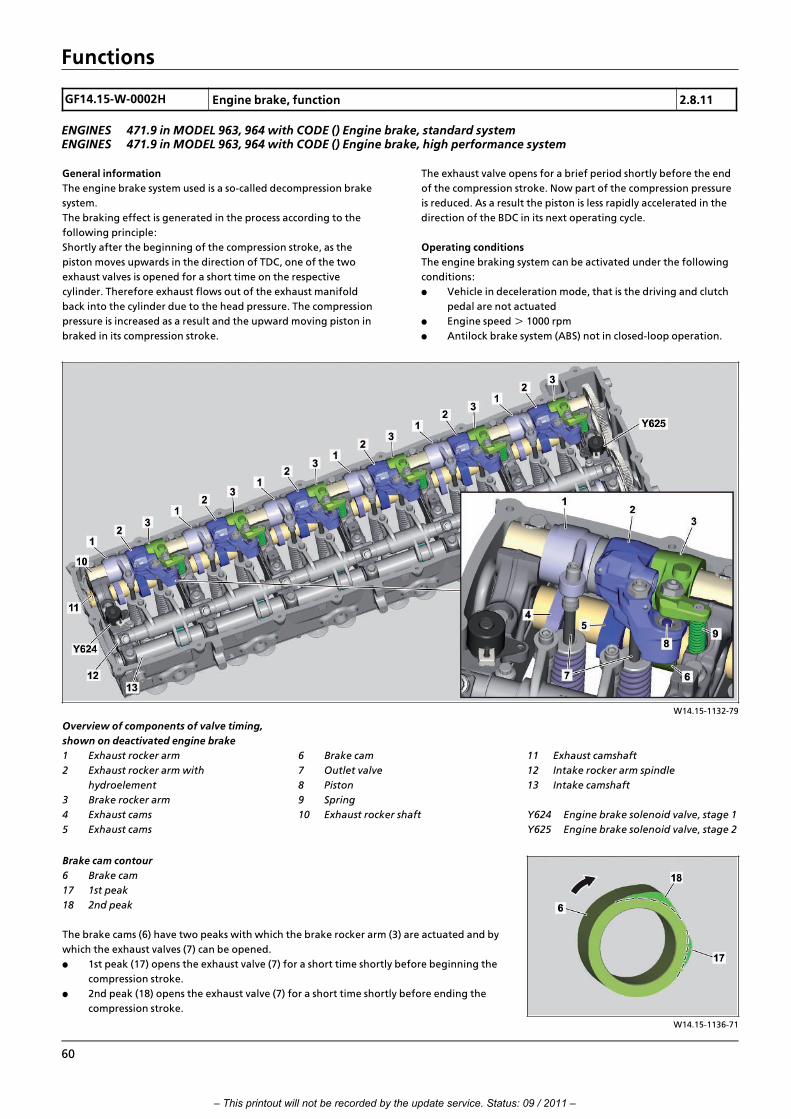
Functions
GF14.15>W>0002H Engine brake, function 2.8.11
ENGINES 471.9 in MODEL 963, 964 with CODE () Engine brake, standard systemENGINES 471.9 in MODEL 963, 964 with CODE () Engine brake, high performance system
General information
The engine brake system used is a so>called decompression brake
system.
The braking effect is generated in the process according to the
following principle:
Shortly after the beginning of the compression stroke, as the
piston moves upwards in the direction of TDC, one of the two
exhaust valves is opened for a short time on the respective
cylinder. Therefore exhaust flows out of the exhaust manifold
back into the cylinder due to the head pressure. The compression
pressure is increased as a result and the upward moving piston in
braked in its compression stroke.
The exhaust valve opens for a brief period shortly before the end
of the compression stroke. Now part of the compression pressure
is reduced. As a result the piston is less rapidly accelerated in the
direction of the BDC in its next operating cycle.
Operating conditions
The engine braking system can be activated under the following
conditions:
f Vehicle in deceleration mode, that is the driving and clutch
pedal are not actuated
f Engine speed >!1000 rpm
f Antilock brake system (ABS) not in closed>loop operation.
W14.15>1132>79
Overview of components of valve timing,
shown on deactivated engine brake
1 Exhaust rocker arm
2 Exhaust rocker arm with
hydroelement
3 Brake rocker arm
4 Exhaust cams
5 Exhaust cams
11 Exhaust camshaft
12 Intake rocker arm spindle
13 Intake camshaft
Y624 Engine brake solenoid valve, stage 1
Y625 Engine brake solenoid valve, stage 2
6 Brake cam
7 Outlet valve
8 Piston
9 Spring
10 Exhaust rocker shaft
W14.15>1136>71
Brake cam contour
6 Brake cam
17 1st peak
18 2nd peak
The brake cams (6) have two peaks with which the brake rocker arm (3) are actuated and by
which the exhaust valves (7) can be opened.
f 1st peak (17) opens the exhaust valve (7) for a short time shortly before beginning the
compression stroke.
f 2nd peak (18) opens the exhaust valve (7) for a short time shortly before ending the
compression stroke.
60
– This printout will not be recorded by the update service. Status: 09 / 2011 –

Functions
W14.15>1140>81
Engine brake solenoid valve, shown on engine brake solenoid
valve, stage 1
10 Exhaust rocker shaft
14 Cylinder 1...3 oil duct
19 Coil
20 Valve body
Y624 Engine brake solenoid valve, stage 1
W14.15>1133>79
Engine brake deactivated
1 Exhaust rocker arm
2 Exhaust rocker arm with
hydroelement
3 Brake rocker arm
4 Exhaust cams
5 Exhaust cams
15 Cylinder 4...6 oil duct
16 Check valve
Y624 Engine brake solenoid valve, stage 1
Y625 Engine brake solenoid valve, stage 2
6 Brake cam
7 Outlet valve
8 Piston
9 Spring
14 Cylinder 1...3 oil duct
In normal driving mode, if the engine brake is not activated, the
engine brake solenoid valve, stage 1 (Y624) and the engine brake
solenoid valve, stage 2 (Y625) are not actuated.
In this way no oil pressure can find its way out of the engine oil
circuit over the oil ducts for the exhaust rocker shaft (10) to the
exhaust rocker arms with hydroelement (2). The oil pressure
present causes the piston (8) contained therein to be pressed by
the spring (9) onto its downstop.
The respective brake rocker arm (3) does shift on the respective
brake cams (6) but comes to nothing due to the missing frictional
connection to piston (8).
Both exhaust valves (7) are therefore opened or closed as normal
according to the cycles of the working cycle.
i Introduction of engine OM 471 and exhaust aftertreatment > 09/2011 > 61
– This printout will not be recorded by the update service. Status: 09 / 2011 –
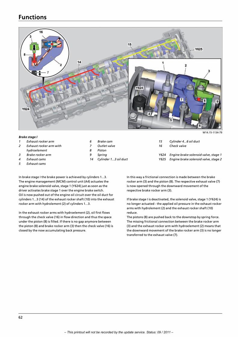
Functions
W14.15>1134>79
Brake stage I
1 Exhaust rocker arm
2 Exhaust rocker arm with
hydroelement
3 Brake rocker arm
4 Exhaust cams
5 Exhaust cams
15 Cylinder 4...6 oil duct
16 Check valve
Y624 Engine brake solenoid valve, stage 1
Y625 Engine brake solenoid valve, stage 2
6 Brake cam
7 Outlet valve
8 Piston
9 Spring
14 Cylinder 1...3 oil duct
In brake stage I the brake power is achieved by cylinders 1...3.
The engine management (MCM) control unit (A4) actuates the
engine brake solenoid valve, stage 1 (Y624) just as soon as the
driver activates brake stage 1 over the engine brake switch.
Oil is now pushed out of the engine oil circuit over the oil duct for
cylinders 1...3 (14) of the exhaust rocker shaft (10) into the exhaust
rocker arm with hydrolement (2) of cylinders 1...3.
In the exhaust rocker arms with hydroelement (2), oil first flows
through the check valve (16) in flow direction and thus the space
under the piston (8) is filled. If there is no gap anymore between
the piston (8) and brake rocker arm (3) then the check valve (16) is
closed by the now accumulating back pressure.
In this way a frictional connection is made between the brake
rocker arm (3) and the piston (8). The respective exhaust valve (7)
is now opened through the downward movement of the
respective brake rocker arm (3).
If brake stage I is deactivated, the solenoid valve, stage 1 (Y624) is
no longer actuated > the applied oil pressure in the exhaust rocker
arms with hydrolement (2) and the exhaust rocker shaft (10)
reduce.
The pistons (8) are pushed back to the downstop by spring force.
The missing frictional connection between the brake rocker arm
(3) and the exhaust rocker arm with hydroelement (2) means that
the downward movement of the brake rocker arm (3) is no longer
transferred to the exhaust valve (7).
62
– This printout will not be recorded by the update service. Status: 09 / 2011 –

Functions
W14.15>1135>79
Brake stage II
1 Exhaust rocker arm
2 Exhaust rocker arm with
hydroelement
3 Brake rocker arm
4 Exhaust cams
5 Exhaust cams
15 Cylinder 4...6 oil duct
16 Check valve
Y624 Engine brake solenoid valve, stage 1
Y625 Engine brake solenoid valve, stage 2
6 Brake cam
7 Outlet valve
8 Piston
9 Spring
14 Cylinder 1...3 oil duct
In brake stage II the brake power is provided by all cylinders.
As soon as the driver activates brake stage 2 over the engine brake
switch the engine management (MCM) control unit (A4) not only
actuates the engine brake solenoid valve, stage 1 (Y624), but also
the engine brake solenoid valve, stage 2 (Y625).
Oil is now pushed out of the engine oil circuit over the oil duct for
cylinders 1...3 (14) and oil duct for cylinders 4...6 (15) of the
exhaust rocker shaft (10) into all exhaust rocker arms with
hydrolement (2).
In the exhaust rocker arms with hydroelement (2) oil first flows
through the check valve (16) in flow direction and thus the space
under the piston (8) is filled. If there is no gap anymore between
the piston (8) and brake rocker arm (3) then the check valve (16) is
closed by the now accumulating back pressure.
In this way a frictional connection is made between the brake
rocker arm (3) and the piston (8). The respective exhaust valve is
now opened through the downward movement of the respective
brake rocker arm (3).
If the brake stage 2 is deactivated the engine brake solenoid
valve, stage 1 (Y624) and the engine brake solenoid valve, stage 2
(Y625) are no longer actuated > the oil pressure applied in the
exhaust rocker arms with hydrolement (2) and the exhaust rocker
shaft (10) drops.
The pistons (8) are pushed back to the downstop by spring force.
The missing frictional connection between the brake rocker arm
(3) and the exhaust rocker arm with hydroelement (2) means that
the downward movement of the brake rocker arm (3) is no longer
transferred to the exhaust valve (7).
i Introduction of engine OM 471 and exhaust aftertreatment > 09/2011 > 63
– This printout will not be recorded by the update service. Status: 09 / 2011 –

Functions
W14.15>1137>79
Brake stage III
14 Cylinder 1...3 oil duct
15 Cylinder 4...6 oil duct
Y624 Engine brake solenoid valve, stage 1
Y625 Engine brake solenoid valve, stage 2
17 Turbocharger
Y621 Exhaust gas recirculation positioner
In brake stage III the brake power is reached by all cylinders and
through an additional increase in the internal pressure of the
cylinder.
As soon as the brake stage III is activated by the driver over the
engine brake switch the initial reaction is for the same processes
as for brake stage II to be triggered. In addition to the now fully
switched>in decompression brake also the wastegate valve on the
turbocharger (17) as well as the exhaust gas recirculation
positioner (Y621) are actuated. >>>>>>>>>>>>>>>>>>>>>>>>>>>>>>>>>>>>>>>>>>>>>>>>>>>>>>>>>>>>>>>>>>>>>>>>>>>>>>>>>>>>>>>>>
In this way a situation is achieved whereby the internal pressure of
the cylinder is increased during the compression stroke > which
results in a higher braking torque.
The engine management (MCM) control unit (A4) uses the boost
pressure and the turborcharger speed as controlled variables.
>>>>>>>>>>>>>>>>>>>>>>>>>>>>>>>>>>>>>>>>>>>>>>>>>>>>>>>>>>>>>>>>>>>>>>>>>>>>>>>>>>>>>>>>>
Additional functions of the engine brake system
Providing support during shift operations
The engine brake is automatically activated for all normal shift
operations without the driver having to do anything. Activation
of the engine brake significantly lowers the rotational speed
between the individual shift operations whereby more rapid
synchronization is achieved, which in turn leads to a more rapid
acceleration of the vehicle.
The engine management (MCM) control unit (A4) uses the
following parameters as a controlled variable:
f Oil temperature
f Differential speed
f Boost pressure
The brake stages I...III are activated based on these. >>>>>>>>>>>>>>>>>>>>>>>>>>>>>>>>>>>>>>>>>>>>>>>>>>>>>>>>>>>>>>>>>>>>>>>>>>>>>>>>>>>>>>>>>
Supporting stopping the engine
If the ignition is switched off and the injected fuel quantity = 0,
the engine brake is automatically activated without any action on
the part of the driver. The compression is strongly reduced
through opening the exhaust valve so the engine can "slowly
come to a halt" and not be shifted between two ignition TDCs by
the compression.
This function is only effective for oil temperatures below about
70∞C. In the case of a warm engine it is, therefore, possible that
the engine tangibly "shakes" when stopping.
>>>>>>>>>>>>>>>>>>>>>>>>>>>>>>>>>>>>>>>>>>>>>>>>>>>>>>>>>>>>>>>>>>>>>>>>>>>>>>>>>>>>>>>>>
64
– This printout will not be recorded by the update service. Status: 09 / 2011 –

Functions
Performance feature of a standard and high performance system
The engine brake system is offered in two different power
categories. The hardware of the two systems is identical.
The differences lie in the software > both systems are fitted with a
different code>controlled data record.
Code (M5U) Engine brake, standard system
f 100 kW at 1300 rpm
f 300 kW at 2300 rpm
Code (M5V) Engine brake, high performance system
f 150 kW at 1300 rpm
f 400 kW at 2300 rpm
The high performance system functions according to the same
mechanical/thermodynamic principle as the standard system.
There are, however, parameters in the engine management
(MCM) control unit (A4) which ensure that the internal pressure is
increased in all cylinders in all engine brake stages over actuation
of the wastegate on the turbocharger.
The exhaust gas recirculation positioner (Y621) is also actuated if
necessary whereby the fill level of the cylinder is increased again.
The result of this is: the piston must do more work to compress
the air > the braking torque increases.
Component description for engine
management (MCM) control unit
A4 Page 103
Component description for engine brake
solenoid valve
Y624, Y625 Page 178
i Introduction of engine OM 471 and exhaust aftertreatment > 09/2011 > 65
– This printout will not be recorded by the update service. Status: 09 / 2011 –

Functions
GF14.20>W>3000H Exhaust gas recirculation, function 2.8.11
ENGINES 471.9 in MODEL 963, 964
General information
The exhaust recycling (AGR) primarily serves to reduce the amount
of nitrogen oxides to comply with the emission limits even before
aftertreatment of the exhaust.
The suctioned in or supercharged fresh air is mixed with exhaust
so that the concentration of oxygen in the combustion mixture
reduces.
If the concentration of oxygen reduces the combustion
temperature drops which leads to reduced output of nitrogen
oxides (NOx).
The ratio of the recycled quantity of exhaust and suctioned in or
supercharged fresh air must be exactly regulated at all points in
time since the EGR (EGR) is active over the whole range of
rotational speeds. For a combustion mixture with an excessively
high proportion of exhaust deteriorates the combustion and the
emission of soot particles, carbon monoxide (CO) and
hydrocarbon (HC) increases. On the other hand the emission of
nitrogen oxides (NOx) increases if the ratio of fresh or
supercharged air is too high.
W14.20>1028>76
System components
1 Exhaust gas recirculation cooler
2 Turbocharger
3 Exhaust manifold center part
4 Control lever
5 Throttle valve
6 EGR line (cold)
7 Charge air pipe (mixer housing)
8 Charge air housing
9 EGR line (hot)
10 Exhaust pipe
Y621 Exhaust gas recirculation positioner
A Intake air from air filter
B Charge air to charge air cooler (hot)
C Charge air to charge air cooler (cold)
W14.20>1027>81
Networking of the electrical components
A4 Engine management (MCM) control unit
B608 Charge air pressure and temperature sensor in charge air
pipe
B617 Charge temperature sensor in charge air housing
B621 Exhaust gas recirculation (AGR) differential pressure sensor
Y621 Exhaust gas recirculation positioner
66
– This printout will not be recorded by the update service. Status: 09 / 2011 –

Functions
Function
The EGR rate describes the relationship of recycled quantity of
exhaust to the quantity of fresh air. It is determined over the
engine management (MCM) control unit (A4) that the mass of
actually suctioned in or supercharged fresh air and the mass of
actually recycled exhaust are correlated with one another.
Regulation of the EGR rate takes place over the exhaust gas
recirculation positioner (Y621) which opens or closes the throttle
valve (5) in the EGR line (6) over the adjustment lever (4) and
therefore regulates which quantity of exhaust is added.
The branched off exhaust initially flows through the exhaust gas
recirculation cooler (1) attached to the coolant circuit. Here
cooling takes place from a temperature of about 650∞C down to
about 170∞C.
The AGR rate can be increased by the cooling since the density
and therefore the mass of the recycled exhaust is increased.
Furthermore the added quantity of cooled exhaust causes a
reduction in the NOx emissions by the lowering of the combustion
temperature.
Once the exhaust has passed through the exhaust gas
recirculation cooler (1), it passes through the EGR line (6) into the
charge air pipe (7). It is mixed here with the fresh air coming out
of the charge air cooler and then led to the individual cylinders for
combustion.
Component description for engine
management (MCM) control unit
A4 Page 103
Component description for charge air
pressure and temperature sensor in charge
air pipe
B608 Page 152
Component description for charge
temperature sensor in charge air housing
B617 Page 155
Component description for EGR
differential pressure sensor
B621 Page 156
Component description for exhaust gas
recirculation controller
Y621 Page 176
Component description for exhaust gas
recirculation cooler
Page 187
i Introduction of engine OM 471 and exhaust aftertreatment > 09/2011 > 67
– This printout will not be recorded by the update service. Status: 09 / 2011 –

Functions
GF14.40>W>0002HA Exhaust aftertreatment, function 2.8.11
ENGINES 471.9 in MODEL 963 with CODE (M5Y) Engine version Euro VENGINES 471.9 in MODEL 963 with CODE (M5R) Engine version EEV
General information
The EATS to comply with the emissions standards Euro V or EEV
based on new engine technology in combination with a range of
measures to reduce the emissions in exhaust.
The emissions standard Euro V, EEV
Emissions standard are legal guidelines which serve to subdivide
vehicles into certain emissions classes. These emissions classes are
assigned to certain emission>code>numbers
which serve, amongst other things, to compute the vehicle tax
and classification in emission groups for environmental zones. >>>>>>>>>>>>>>>>>>>>>>>>>>>>>>>>>>>>>>>>>>>>>>>>>>>>>>>>>>>>>>>>>>>>>>>>>>>>>>>>>>>>>>>>>
The emissions standards Euro V and EEV for commercial vehicles
establish very strict limits for output of carbon monoxide (CO),
nitrogen oxide (NOx), hydrocarbons (HC) and particles (PM).
As a vehicle manufacturer Mercedes>Benz must guarantee
compliance with these limits for an established time period and
mileage. Therefore the EATS is a component of engine/vehicle
homologation subject to compulsory certification.
>>>>>>>>>>>>>>>>>>>>>>>>>>>>>>>>>>>>>>>>>>>>>>>>>>>>>>>>>>>>>>>>>>>>>>>>>>>>>>>>>>>>>>>>>
EATS for Euro V, EEV
New diesel engine generation
The new engine generation is fitted with a common rail diesel
injection system, EGR and boost pressure control. The engines
themselves are set to maximum efficiency and low particulate
emissions.
Exhaust aftertreatment by means of:
f Selective Catalytic Reduction (SCR) with an ammonia locking
CAT
W14.40>1589>76
Networking of control units
A3 Drive control (CPC) control unit
A4 Engine management control unit
(MCM)
A57 NOx sensor control unit outlet of
EATU
A58 SCR control unit (in pump module)
A60 Exhaust aftertreatment (ACM)
control unit
A70 NOx sensor control unit inlet of EATU
68
– This printout will not be recorded by the update service. Status: 09 / 2011 –

Functions
W14.40>1590>79
1 Pump module
2 Exhaust aftertreatment unit
3 Ammonia locking CAT
4 SCR catalytic converter
5 AdBlue“ tank
A4 Engine management control unit
(MCM)
A57 NOx sensor control unit outlet of
EATU
B72 Exhaust temperature sensor
upstream of SCR catalytic converter
B73 Exhaust temperature sensor
downstream of SCR catalytic
converter
B74 AdBlue“ fill level
sensor/temperature sensor
M25 SCR delivery pump
Y627 AdBlue“ heater coolant solenoid
valve
A57 b1 NOx sensor outlet of EATUA58 SCR control unit
A60 Exhaust aftertreatment (ACM)
control unit
A67 AdBlue“ metering device
A70 NOx sensor control unit inlet of
EATU
A70 b1 NOx sensor inlet of EATU
i Introduction of engine OM 471 and exhaust aftertreatment > 09/2011 > 69
– This printout will not be recorded by the update service. Status: 09 / 2011 –

Functions
W14.40>1598>79
A4 Engine management control unit
(MCM)
A57 NOx sensor control unit outlet of
EATU
A57 b1 NOx sensor outlet of EATUA58 SCR control unit
A60 Exhaust aftertreatment (ACM)
control unit
B73 Exhaust temperature sensor
downstream of SCR catalytic
converter
B74 AdBlue“ fill level
sensor/temperature sensor
CAN 4 Drive train CAN
CAN 13 NOx>CAN
M25 SCR delivery pump
A67 AdBlue“ metering device
A70 b1 NOx sensor control unit inlet ofEATU
A70 NOx sensor inlet of EATU
B72 Exhaust temperature sensor
upstream of SCR catalytic
converter
Function of the EATS (overall system)
The basic functionalities of the whole EATS are monitored and
regulated over the engine management (MCM) control unit (A4)
and the exhaust aftertreatment (ACM) control unit (A60).
After an engine start the engine management (MCM) control unit
(A4) starts an automatic test routine automatically in the
background which checks the operational readiness of the EATS.
The SCR control unit (A58) integrated in the pump module (1) is
actuated after successful release of the system. This switches on
the SCR delivery pump (M25) contained in the pump module (1)
which now suctions up AdBlue“ out of the AdBlue“ container (5)
and delivers it over the AdBlue“ feed line to the AdBlue“
metering device (A67). >>>>>>>>>>>>>>>>>>>>>>>>>>>>>>>>>>>>>>>>>>>>>>>>>>>>>>>>>>>>>>>>>>>>>>>>>>>>>>>>>>>>>>>>>
Since the AdBlue“ injection does take place continuously in the
exhaust flow the AdBlue“ flows back again over the AdBlue“
return line into the AdBlue“ container. This circulation
continuously takes place independently of whether AdBlue“ is
injected or not. So recirculation cooling is achieved which protects
the AdBlue“ metering device (A67) directly attached to the EATU
(2) against damage due to overheating.
>>>>>>>>>>>>>>>>>>>>>>>>>>>>>>>>>>>>>>>>>>>>>>>>>>>>>>>>>>>>>>>>>>>>>>>>>>>>>>>>>>>>>>>>>
Reduction of NOx in the SCR catalytic converter
The AdBlue“ injection into the exhaust flow is calculated by the
engine management (MCM) control unit (A4). If AdBlue“ should
be injected this first of all sends a signal to the exhaust
aftertreatment (ACM) control unit (A60) which processes the data
and afterwards actuates the SCR control unit (A58) integrated on
the pump module.
The injection timing point and the injection quantity are now
calculated there and the AdBlue“ metering device (A67) is
appropriately actuated.
The following occurs if AdBlue“ is injected:
the AdBlue“ metering device (A67) injects AdBlue“ into the so>
called hydrolysis segment in the EATU (2) directly into the exhaust
flow.
The AdBlue“ mixes here with the already precleaned exhaust and
breaks down in a first process step into ammonia (NH3). Along
with the nitrogen oxide molecules (NOx) generated during
combustion the ammonia (NH3) so created flows on in the exhaust
flow to the SCR catalytic converter (4). Its honeycomb structure
has a special coating which allows conversion of NH3 and NOx into
harmless nitrogen (N2) and water vapor (H2O).
70
– This printout will not be recorded by the update service. Status: 09 / 2011 –

Functions
W14.40>1592>79
AdBlue“/coolant line system
1 Pump module
6 Coolant feed line
7 Coolant return line
R7 AdBlue“ intake duct heating
element
R8 AdBlue“ pressure line heating
element
Y627 AdBlue“ heater coolant solenoid
valve
A67 AdBlue“ metering device
B74 AdBlue“ fill level
sensor/temperature sensor
R6 AdBlue“ return line heating element
AdBlue“ line system
The AdBlue“ line system lies between the AdBlue“ container (5),
pump module (1) and AdBlue“ metering device (A67).
The fact that the AdBlue“ metering device (A67) is directly
attached to the EATU and is therefore subjected to high
temperatures, AdBlue“ is circulated continuously from engine
start and in a certain run>on time after engine stop for
recirculation cooling.
AdBlue“ heater
AdBlue“ freezes below a temperature of about >13∞C. The
AdBlue“ heater ensures that any AdBlue“ that has frozen during
periods of non>operation is heated and reliquified and prevents
AdBlue from freezing while driving in cold outside temperatures.
The AdBlue“ lines from the AdBlue“ container (5) to the pump
module (1) are bundled with the coolant lines and routed
insulated.
The AdBlue“ lines between the pump module (1) and the AdBlue“
metering device (A67) are not heated by coolant but instead over
in electrically heated heating elements integrated in the line
sections.
Function of AdBlue“ heating by coolant
The AdBlue“ heater consists of the AdBlue“ coolant solenoid
valve heater (Y627) which is located on the rear side of the engine
and a coolant line system. The AdBlue“ coolant solenoid valve
heater (Y627) is actuated by the engine management (MCM)
control unit (A4). Over the AdBlue“ fill level sensor/temperature
sensor (B74) integrated in the AdBlue“ container (5), it detects
when the temperature of the tank contents is approaching the
defined limit value of approx. 8∞C. If this is the case and if the
coolant temperature has already reached a temperature of 65∞C,
the AdBlue“ heater coolant solenoid valve (Y627) is opened so the
coolant flows through the line system.
Function of AdBlue“ heating by an electrical heater
The heating coil of the heating elements integrated in the
AdBlue“ lines is switched on and off by the exhaust
aftertreatment (ACM) control unit (A60). Very pertinent here are
also the values which are delivered by the AdBlue“ fill level
sensor/temperature sensor (B74).
i Introduction of engine OM 471 and exhaust aftertreatment > 09/2011 > 71
– This printout will not be recorded by the update service. Status: 09 / 2011 –

Functions
Overall network for exhaust
aftertreatment
Page 79
Component description for engine
management (MCM) control unit
A4 Page 103
Component description for NOx sensor
outlet of EATU
A57, A57 b1 Page 110
Component description for pump module A58, M25 Page 115
Component description for exhaust
aftertreatment (ACM) control unit
A60 Page 117
Component description for AdBlue
metering device
A67 Page 121
Component description for NOx sensor
control unit inlet of EATU
A70, A70 b1 Page 123
Component description for exhaust
temperature sensor upstream of SCR
catalytic converter
B72 Page 139
Component description for exhaust
temperature sensor downstream of SCR
catalytic converter
B73 Page 140
Component description for AdBlue“ fill
level sensor/temperature sensor
B74 Page 142
Component description for AdBlue“ heater
coolant solenoid valve
Y627 Page 180
Component description for AdBlue tank Page 188
Component description for SCR catalytic
converter
Page 209
Component description for EATU Page 213
72
– This printout will not be recorded by the update service. Status: 09 / 2011 –

Functions
GF14.40>W>0002H Exhaust aftertreatment, function 20.7.11
ENGINE 471.9 in MODEL 963 with CODE (M5Z) Engine version Euro VI
General information
The EATS for fulfilling the Euro VI emissions standard is based on
new engine technology in combination with a series of measures
aimed at reducing exhaust emissions.
Euro VI emissions standard
Emissions standards are statutory directives used to classify
vehicles in specific pollutant classes. These pollutant classes are
assigned specific emission code numbers,
that are also used to calculate the automobile tax and the
categorization into pollutant classes for environmental zones.
The Euro VI emissions standard for commercial vehicles defines
strict limits for the emission of carbon monoxide (CO), nitrogen
oxides (NOx), hydrocarbons (HC) and particles (PM).
As the vehicle manufacturer Mercedes>Benz must guarantee
compliance with these limits for a determined period of time and
mileage. For this reason, the exhaust aftertreatment system
(EATS) is a part of the engine/vehicle homologation process that
requires certification.
Brief information on EATS for Euro VI
New diesel engine generation
The new engine generation is equipped with a common rail diesel
injection system, EGR and boost pressure control. The engines are
configured for maximum efficiency and low particulate emissions.
Exhaust aftertreatment through:
f Selective catalytic reduction (SCR) with ammonia blocking
CAT
f Diesel oxidation catalytic converter (DOC)
f Diesel particulate filter (DPF)
i Introduction of engine OM 471 and exhaust aftertreatment > 09/2011 > 73
– This printout will not be recorded by the update service. Status: 09 / 2011 –

Functions
W14.40>1557>79
System overview
1 Nozzle unit for DPF regeneration
2 Pump module
3 AdBlue“ tank
4 Exhaust aftertreatment unit
5 Ammonia blocking CAT
6 SCR catalytic converter
7 Diesel oxidation catalytic
converter (DOC)
8 Diesel particulate filter (DPF)
9 Diesel fuel metering device (for
DPF regeneration)
A4 Engine management control unit
(MCM)
A57 NOx sensor control unit output for
exhaust aftertreatment unit
A57 b1 NOx sensor output for exhaust
aftertreatment unit
B69 Exhaust temperature sensor
downstream of lower diesel
oxidation catalytic converter
B70 Exhaust temperature sensor
downstream of diesel particulate
filter
B73 Exhaust temperature sensor
downstream of SCR catalytic
converter
B74 AdBlue“ fill level
sensor/temperature sensor
B625 Fuel pressure sensor (inlet)
B626 Fuel pressure sensor (outlet)
M25 SCR delivery pump
Y627 AdBlue“ heater coolant solenoid
valve
Y628 Fuel metering valve
Y629 Fuel shutoff valve
A58 SCR control unit
A60 Exhaust aftertreatment (ACM)
control unit
A67 AdBlue“ metering device
A70 NOx sensor control unit input for
exhaust aftertreatment unit
A70 b1 NOx sensor input for exhaust
aftertreatment unit
B37 Exhaust pressure sensor upstream
of diesel oxidation catalytic
converter
B38 Exhaust pressure sensor
downstream of diesel particulate
filter
B67 Exhaust temperature sensor
upstream of diesel oxidation
catalytic converter
B68 Exhaust temperature sensor
downstream of upper diesel
oxidation catalytic converter
74
– This printout will not be recorded by the update service. Status: 09 / 2011 –

Functions
W14.40>1599>79
Electronic networking
A4 Engine management control unit
(MCM)
A57 NOx sensor control unit output for
exhaust aftertreatment unit
A57 b1 NOx sensor output for exhaust
aftertreatment unit
A58 SCR control unit
A60 Exhaust aftertreatment (ACM)
control unit
A67 AdBlue“ metering device
A70 NOx sensor control unit input for
exhaust aftertreatment unit
A70 b1 NOx sensor input for exhaust
aftertreatment unit
B73 Exhaust temperature sensor
downstream of SCR catalytic
converter
B74 AdBlue“ fill level sensor/
temperature sensor
CAN 4 Drive train CAN
CAN 13 NOx>CAN
B625 Fuel pressure sensor (inlet)
B626 Fuel pressure sensor (outlet)
M25 SCR delivery pump
Y628 Fuel metering valve
Y629 Fuel shutoff valve
B37 Exhaust pressure sensor upstream
of diesel oxidation catalytic
converter
B38 Exhaust pressure sensor
downstream of diesel particulate
filter
B67 Exhaust temperature sensor
upstream of diesel oxidation
catalytic converter
B68 Exhaust temperature sensor
downstream of upper diesel
oxidation catalytic converter
B69 Exhaust temperature sensor
downstream of lower diesel
oxidation catalytic converter
B70 Exhaust temperature sensor
downstream of diesel particulate
filter
i Introduction of engine OM 471 and exhaust aftertreatment > 09/2011 > 75
– This printout will not be recorded by the update service. Status: 09 / 2011 –

Functions
W14.40>1589>76
Networking of control units
A3 Drive control (CPC) control unit
A4 Engine management control unit
(MCM)
A57 NOx sensor control unit output for
exhaust aftertreatment unit
A58 SCR control unit (in pump module)
A60 Exhaust aftertreatment (ACM)
control unit
A70 NOx sensor control unit input for
exhaust aftertreatment unit
Function of exhaust aftertreatment system (overall system)
The basic functionalities of the overall EATS are monitored and
controlled by the engine management (MCM) control unit (A4)
and the exhaust aftertreatment (ACM) control unit (A60).
After the engine is started, the engine management (MCM)
control unit (A4) automatically starts an automatic test routine in
the background, which checks the operational readiness of the
EATS. Once the system has been enabled, the SCR control unit
(A58) integrated into the pump module (2) is actuated. This
switches on the SCR delivery pump (M25) in the pump module (2),
which then sucks in AdBlue“ from the AdBlue“ container (3) and
pumps it over the AdBlue“ feed line to the AdBlue“ metering
device (A67). >>>>>>>>>>>>>>>>>>>>>>>>>>>>>>>>>>>>>>>>>>>>>>>>>>>>>>>>>>>>>>>>>>>>>>>>>>>>>>>>>>>>>>>>>
Because the AdBlue“ injection into the exhaust flow is not
continuous, the AdBlue“ flows over the AdBlue“ return line back
into the AdBlue“ container (3). This circulation is continuous, and
irrespective of whether AdBlue“ is injected or not. This enables
recirculation cooling to be achieved, which prevents the AdBlue“
metering device (A67), which is installed on the EATU (4) itself
against damage due to overheating.
>>>>>>>>>>>>>>>>>>>>>>>>>>>>>>>>>>>>>>>>>>>>>>>>>>>>>>>>>>>>>>>>>>>>>>>>>>>>>>>>>>>>>>>>>
Phase 1: Conversion of CO and HC in the diesel oxidation catalytic
converter
The exhaust gas coming from the exhaust manifold initially flows
through the EATU (4) into the diesel oxidation catalytic converter
(7). In it, the given hydrocarbons (HC) and the carbon monoxide
(CO) are converted to carbon dioxide (CO2) and water (H2O).
Apart from this, a part of the nitric oxide (NO) is oxidized to form
nitrogen dioxide (NO2).
Phase 2: Reduction of particulate mass in the diesel particulate
filter
The diesel particulate filter (8) is connected in series after the
diesel oxidation catalytic converter (7). In its porous filter structure
the particles are separated through adhesion and then collected.
Phase 3: Reduction of NOx in SCR catalytic converter
The AdBlue“ injection into the exhaust flow is calculated by the
engine management (MCM) control unit (A4). If AdBlue“ is to be
injected, then this initially sends a signal to the exhaust
aftertreatment (ACM) control unit (A60), which processes the data
and then actuates the SCR control unit (A58) integrated into the
pump module.
The injection timing point and the injection quantity are now
calculated here and the AdBlue“ metering device (A67) actuated
accordingly.
If AdBlue“ is injected, the following happens:
The AdBlue“ metering device (A67) located in the exhaust path
downstream of the diesel oxidation catalytic converter (7) and
diesel particulate filter (8) injects AdBlue“ straight into the
exhaust flow.
The AdBlue“ is mixed here with the previously precleaned exhaust
and decomposes in an initial process step to form ammonia (NH3).
Along with the nitrogen oxide molecules generated during
combustion (NOx), the resulting ammonia (NH3) flows through
the exhaust flow towards the SCR catalytic converter (6). Its
honeycomb core has a special coating, which enables a conversion
of NH3 and NOx into harmless nitrogen (N2) and water vapor
(H2O).
76
– This printout will not be recorded by the update service. Status: 09 / 2011 –

Functions
i Introduction of engine OM 471 and exhaust aftertreatment > 09/2011 > 77
W14.40>1561>79
AdBlue“/coolant line system
2 Pump module
11 Coolant feed line
12 Coolant return line
R7 AdBlue“ intake duct heating
element
R8 AdBlue“ pressure line heating
element
Y627 AdBlue“ heater coolant solenoid
valve
A67 AdBlue“ metering device
B74 AdBlue“ fill level
sensor/temperature sensor
R6 AdBlue“ return line heating element
AdBlue“ line system
The AdBlue“ line system extends from the AdBlue“ container (3),
the pump module (2) and the AdBlue“ metering device (A67).
Because the AdBlue“ metering device (A67) is installed onto the
EATU itself, and therefore exposed to high temperatures,
AdBlue“ is constantly circulated when the engine starts and in a
specific run>on time after the engine is stopped for recirculation
cooling.
AdBlue“ heater
AdBlue“ freezes from a temperature of approx. >13 ∞C. The
AdBlue “ heater ensures that any AdBlue“ that has frozen during
periods of non>operation is heated and reliquified and prevents it
from freezing while driving in cold outside temperatures.
The AdBlue“ lines from the AdBlue“ container (3) to the pump
module (2) are routed and insulated together with coolant lines.
The AdBlue“ lines between the pump module (2) and AdBlue“
metering device (A67) are not electrically heated by the coolant,
but by the heating elements integrated into the line sections.
Function of AdBlue“ heating through coolant
The AdBlue“ heater consists of the AdBlue“ heater coolant
solenoid valve (Y627), which is located on the rear end of the
engine and a coolant line system. The AdBlue“ heater coolant
solenoid valve (Y627) is actuated by the engine management
(MCM) control unit (A4). The AdBlue“ fill
level sensor/temperature sensor (B74) integrated in the AdBlue“
container (3) enables it to detect when the temperature of the
container's contents is approaching the limit of approx. 8 ∞C. If this
is the case and if the coolant temperature has already reached
+65 ∞C, the AdBlue“ heater coolant solenoid valve (Y627) is
opened is that the coolant can flow through the line system.
Function of AdBlue“ heating through electrical heater
The heating coils of the heater elements integrated into the
AdBlue“ lines are switched on and off by the exhaust
aftertreatment (ACM) control unit (A60). Decisive here are the
values supplied by the AdBlue“ fill level sensor/temperature
sensor (B74).
Exhaust aftertreatment overall network Page 79
NOx sensor output for exhaust
aftertreatment unit, component
description
A57, A57 b1 Page 112
Pump module, component description A58, M25 Page 115
Exhaust aftertreatment (ACM) control unit,
component description
A60 Page 119
– This printout will not be recorded by the update service. Status: 09 / 2011 –

Functions
78
AdBlue metering device, component
description
A67 Page 121
NOx sensor input for exhaust
aftertreatment unit, component
description
A70, A70 b1 Page 125
Exhaust pressure sensor upstream of diesel
oxidation catalytic converter, component
description
B37 Page 132
Exhaust pressure sensor downstream of
diesel particulate filter, component
description
B38 Page 133
Exhaust temperature sensor upstream of
diesel oxidation catalytic converter,
component description
B67 Page 135
Exhaust temperature sensor downstream
of upper diesel oxidation catalytic
converter, component description
B68 Page 136
Exhaust temperature sensor downstream
of lower diesel oxidation catalytic
converter, component description
B69 Page 137
Exhaust temperature sensor downstream
of diesel particulate filter, component
description
B70 Page 138
Exhaust temperature sensor downstream
of SCR catalytic converter, component
description
B73 Page 141
AdBlue“ fill level sensor/temperature
sensor, component description
B74 Page 142
Diesel fuel metering device, component
description
B625, B626, Y628, Y629 Page 158
AdBlue“ heater coolant solenoid valve,
component description
Y627 Page 180
Component description for AdBlue tank Page 188
Diesel oxidation catalytic converter,
component description
Page 208
Component description for SCR catalytic
converter
Page 211
EATU, component description Page 215
Diesel particulate filter of EATU,
component description
Page 218
Nozzle unit for DPF regeneration,
component description
Page 220
– This printout will not be recorded by the update service. Status: 09 / 2011 –

Functions
GF14.40>W>0003>03H Exhaust aftertreatment overall network
W14.40>1558>79
A3 Drive control (CPC) control unit
A4 Engine management control unit
(MCM)
A57 NOx sensor control unit output for
exhaust aftertreatment unit
CAN 4 Drive train CAN
CAN 13 NOx>CAN
Z4 Drive CAN bus star point
A58 SCR control unit
A60 Exhaust aftertreatment (ACM)
control unit
A70 NOx sensor control unit input for
exhaust aftertreatment unit
i Introduction of engine OM 471 and exhaust aftertreatment > 09/2011 > 79
– This printout will not be recorded by the update service. Status: 09 / 2011 –
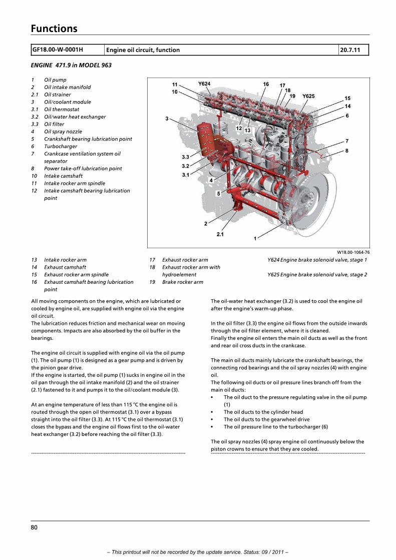
Functions
GF18.00>W>0001H Engine oil circuit, function 20.7.11
ENGINE 471.9 in MODEL 963
W18.00>1064>76
1 Oil pump
2 Oil intake manifold
2.1 Oil strainer
3 Oil/coolant module
3.1 Oil thermostat
3.2 Oil/water heat exchanger
3.3 Oil filter
4 Oil spray nozzle
5 Crankshaft bearing lubrication point
6 Turbocharger
7 Crankcase ventilation system oil
separator
8 Power take>off lubrication point
10 Intake camshaft
11 Intake rocker arm spindle
12 Intake camshaft bearing lubrication
point
13 Intake rocker arm
14 Exhaust camshaft
15 Exhaust rocker arm spindle
16 Exhaust camshaft bearing lubrication
point
Y624 Engine brake solenoid valve, stage 1
Y625 Engine brake solenoid valve, stage 2
17 Exhaust rocker arm
18 Exhaust rocker arm with
hydroelement
19 Brake rocker arm
All moving components on the engine, which are lubricated or
cooled by engine oil, are supplied with engine oil via the engine
oil circuit.
The lubrication reduces friction and mechanical wear on moving
components. Impacts are also absorbed by the oil buffer in the
bearings.
The engine oil circuit is supplied with engine oil via the oil pump
(1). The oil pump (1) is designed as a gear pump and is driven by
the pinion gear drive.
If the engine is started, the oil pump (1) sucks in engine oil in the
oil pan through the oil intake manifold (2) and the oil strainer
(2.1) fastened to it and pumps it to the oil/coolant module (3).
At an engine temperature of less than 115 ∞C the engine oil is
routed through the open oil thermostat (3.1) over a bypass
straight into the oil filter (3.3). At 115 ∞C the oil thermostat (3.1)
closes the bypass and the engine oil flows first to the oil>water
heat exchanger (3.2) before reaching the oil filter (3.3).
>>>>>>>>>>>>>>>>>>>>>>>>>>>>>>>>>>>>>>>>>>>>>>>>>>>>>>>>>>>>>>>>>>>>>>>>>>>>>>>>>>>>>>>>>
The oil>water heat exchanger (3.2) is used to cool the engine oil
after the engine's warm>up phase.
In the oil filter (3.3) the engine oil flows from the outside inwards
through the oil filter element, where it is cleaned.
Finally the engine oil enters the main oil ducts as well as the front
and rear oil cross ducts in the crankcase.
The main oil ducts mainly lubricate the crankshaft bearings, the
connecting rod bearings and the oil spray nozzles (4) with engine
oil.
The following oil ducts or oil pressure lines branch off from the
main oil ducts:
• The oil duct to the pressure regulating valve in the oil pump
(1)
• The oil ducts to the cylinder head
• The oil ducts to the gearwheel drive
• The oil pressure line to the turbocharger (6)
The oil spray nozzles (4) spray engine oil continuously below the
piston crowns to ensure that they are cooled.>>>>>>>>>>>>>>>>>>>>>>>>>>>>>>>>>>>>>>>>>>>>>>>>>>>>>>>>>>>>>>>>>>>>>>>>>>>>>>>>>>>>>>>>>
80
– This printout will not be recorded by the update service. Status: 09 / 2011 –

Functions
The lubricating oil duct for the exhaust rocker arm spindle (15),
lubricating oil duct for the intake rocker arm spindle (11) and oil
ducts for operation of the engine brake all branch off from the oil
ducts to the cylinder head.
Engine oil is supplied through the lubricating oil duct for the
exhaust rocker arm spindle (15) to the exhaust rocker arm's rocker
arm bearings (17), the exhaust rocker arm with hydro element (18)
and the brake rocker arm (19) as well as the bearings and cams of
the exhaust camshaft (14). The rocker arm bearings for the intake
rocker arms (13) and the bearings and cams on the intake
camshaft (10) are supplied with engine oil via the lubricating oil
duct for the intake rocker arm spindle (11).
>>>>>>>>>>>>>>>>>>>>>>>>>>>>>>>>>>>>>>>>>>>>>>>>>>>>>>>>>>>>>>>>>>>>>>>>>>>>>>>>>>>>>>>>>
The oil ducts for operation of the engine brake are used solely to
supply engine oil to the exhaust rocker arm with hydro element
(18). Both oil ducts are separated by two solenoid valves from oil
ducts to the cylinder head and are only filled with oil under
pressure for an activated engine brake.
The oil ducts to the gearwheel drive supply engine oil to the
individual bearings of the gearwheels on the gearwheel drive as
well as the engine>mounted power take>off, insofar as one is
installed.
The turbocharger (6) is supplied with engine oil through the
external oil pressure line.
The engine oil is returned by way of return ducts and return holes
in the camshaft housing, cylinder head and in the crankcase.>>>>>>>>>>>>>>>>>>>>>>>>>>>>>>>>>>>>>>>>>>>>>>>>>>>>>>>>>>>>>>>>>>>>>>>>>>>>>>>>>>>>>>>>>
i The engine oil fill level sensor (B605) is used for monitoring
the engine oil level and engine oil temperature in the oil pan.
The engine oil pressure is recorded through the oil pressure sensor
(B604).
The engine oil fill level sensor (B605) and the oil pressure sensor
(B604) are connected to the engine management (MCM) control
unit (A4).
Where there is insufficient engine oil pressure, the oil level is too
low or the engine oil temperature too high, a corresponding
warning is shown in the instrument cluster control unit (A1).
If the engine oil pressure is too low the engine power is reduced.
Engine management control unit (MCM),
component description
A4 Page 103
Oil pressure sensor, description of
components
B604 Page 148
Component description for engine oil fill
level sensor
B605 Page 149
Oil separator component description Page 183
Component description for turbocharger Page 186
Engine oil circuit schematic Page 82
Component description for oil pump Page 189
Oil/coolant module, component
description
Page 191
Oil thermostat, component description Page 193
Component description for oil/water heat
exchanger
Page 194
i Introduction of engine OM 471 and exhaust aftertreatment > 09/2011 > 81
– This printout will not be recorded by the update service. Status: 09 / 2011 –
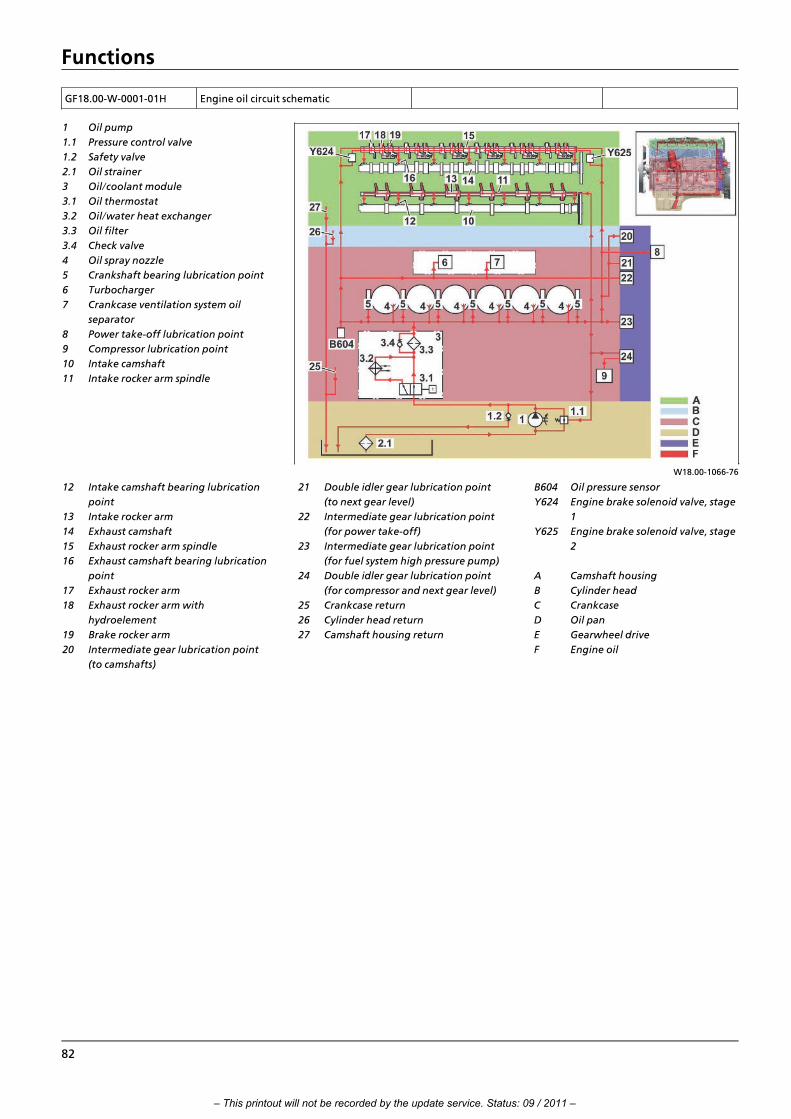
Functions
GF18.00>W>0001>01H Engine oil circuit schematic
W18.00>1066>76
1 Oil pump
1.1 Pressure control valve
1.2 Safety valve
2.1 Oil strainer
3 Oil/coolant module
3.1 Oil thermostat
3.2 Oil/water heat exchanger
3.3 Oil filter
3.4 Check valve
4 Oil spray nozzle
5 Crankshaft bearing lubrication point
6 Turbocharger
7 Crankcase ventilation system oil
separator
8 Power take>off lubrication point
9 Compressor lubrication point
10 Intake camshaft
11 Intake rocker arm spindle
12 Intake camshaft bearing lubrication
point
13 Intake rocker arm
14 Exhaust camshaft
15 Exhaust rocker arm spindle
16 Exhaust camshaft bearing lubrication
point
17 Exhaust rocker arm
18 Exhaust rocker arm with
hydroelement
19 Brake rocker arm
20 Intermediate gear lubrication point
(to camshafts)
B604 Oil pressure sensor
Y624 Engine brake solenoid valve, stage
1
Y625 Engine brake solenoid valve, stage
2
A Camshaft housing
B Cylinder head
C Crankcase
D Oil pan
E Gearwheel drive
F Engine oil
21 Double idler gear lubrication point
(to next gear level)
22 Intermediate gear lubrication point
(for power take>off)
23 Intermediate gear lubrication point
(for fuel system high pressure pump)
24 Double idler gear lubrication point
(for compressor and next gear level)
25 Crankcase return
26 Cylinder head return
27 Camshaft housing return
82
– This printout will not be recorded by the update service. Status: 09 / 2011 –

Functions
GF20.00>W>0001H Coolant circuit, function 20.7.11
ENGINE 471.9 in MODEL 963
W20.00>1073>76
Shown with code (M5Z) Euro VI engine
version
1 Oil/coolant module
1.1 Coolant thermostat
1.2 Coolant pump
2 Cylinder liner
3 Cylinder head
4 Coolant manifold
5 Injection nozzle for regeneration of
diesel particulate filter
(only with code (M5Z) Euro VI engine
version)
6 Exhaust gas recirculation cooler
8 Fuel cooler
9 Compressor
12 Fan
14 Coolant feed to AdBlue“ heater
KA Coolant outlet to cooler KE Coolant inlet from cooler
General
The engines in model series OM 471 have a closed cooling system
(pressurized system). This means that coolant in the cooling
system, which is circulated by the coolant pump (1.2), absorbs the
heat from the hot engine components and > once the engine has
reached its operating temperature > it dissipates this through a
cooler to the outside air.
Engine cooling circuit
The coolant pump (1.2) is belt driven. If the engine is running, and
if it has not yet reached its operating temperature, then the
coolant pump (1.2) circulates the coolant inside the engine. In
vehicles with code (M7T) Coolant pump, control of the speed of
the coolant pump (1.2) is permanently monitored by the engine
management (MCM) control unit (A4) with the aid of the coolant
pump rpm sensor (B640), and adapted as needed through
activation of the coolant pump solenoid valve (Y631).>>>>>>>>>>>>>>>>>>>>>>>>>>>>>>>>>>>>>>>>>>>>>>>>>>>>>>>>>>>>>>>>>>>>>>>>>>>>>>>>>>>>>>>>>
Because the coolant thermostat (1.1) is closed when the engine is
cold, the coolant flows over the coolant bypass duct into the
oil/coolant module (1) and is routed there past the closed coolant
thermostat (1.1) through the coolant pump (1.2) to the oil>water
heat exchanger.
The oil>water heat exchanger cools the engine oil if its
temperature is more than 115 ∞C (opening temperature of oil
thermostat), so that a temperature of 120 ∞C is not exceeded. The
oil>water heat exchanger is fastened to the oil/coolant module
(1), and it protrudes into the crankcase.
The coolant is routed in this way into the crankcase and therefore
to the cylinder liners (2). At the same time a portion of the coolant
is routed to the fuel cooler (8) and the compressor (9), as well as
over separate feed lines to the exhaust gas recirculation cooler (6)
and the exhaust gas recirculation positioner (Y621).
>>>>>>>>>>>>>>>>>>>>>>>>>>>>>>>>>>>>>>>>>>>>>>>>>>>>>>>>>>>>>>>>>>>>>>>>>>>>>>>>>>>>>>>>>
i Introduction of engine OM 471 and exhaust aftertreatment > 09/2011 > 83
– This printout will not be recorded by the update service. Status: 09 / 2011 –

Functions
84
The coolant then flows from the fuel cooler (8) and the
compressor (9) straight back to the coolant pump (1.2).
The coolant pumped to the cylinder liners (2) then flows back to
the cylinder head (3).
The cylinder head (3) contains a partitioned coolant jacket. This
means that once the coolant has flushed the cylinders, both on
the inlet and the outlet sides, it then flows to the cylinder head
(3). In the cylinder head (3) the coolant flows first to the lower
cooling level where it flushes the fuel injectors and the valve seat
rings.
Finally, the coolant flows to the upper cooling level and cools the
valve guides located there.
After this the coolant is routed outwards into the coolant
manifold (4), into which the coolant from the exhaust gas
recirculation cooler (6) and the coolant from the exhaust gas
recirculation positioner (Y621) is routed.
The coolant flows from the coolant manifold (4) back over the
coolant bypass duct and the still closed coolant thermostat (1.1)
into the oil/coolant module (1) and to the coolant pump (1.2),
until the engine's operating temperature is reached. >>>>>>>>>>>>>>>>>>>>>>>>>>>>>>>>>>>>>>>>>>>>>>>>>>>>>>>>>>>>>>>>>>>>>>>>>>>>>>>>>>>>>>>>>
When the engine operating temperature is reached, the cooler
circuit is activated when the coolant thermostat (1.1) is opened.
Depending on the position of the coolant thermostat (1.1), more
or less coolant flows through the vehicle cooler or directly over
the coolant bypass line to the coolant pump (1.2). The
temperature of the coolant in the coolant circuit is regulated in
this way.
The fan (12) is used to increase the vehicle cooler's cooling output.
The coolant temperature is continuously monitored by the
coolant outlet temperature sensor (B606) and coolant inlet
temperature sensor (B607), both of which are connected to the
engine management (MCM) control unit (A4).
The various pressures in the cooling system, which are created by
the temperature fluctuations, are compensated for through the
coolant expansion reservoir, which > depending on the vehicle
equipment > is located either at the front behind the maintenance
flap or at the rear on the cab mounting crossmember.
>>>>>>>>>>>>>>>>>>>>>>>>>>>>>>>>>>>>>>>>>>>>>>>>>>>>>>>>>>>>>>>>>>>>>>>>>>>>>>>>>>>>>>>>>
Heating circuit
The coolant for the heater circuit is taken from the coolant
manifold (4).
A shutoff valve is installed in front of the heater heat exchanger,
through which the coolant flow through the heater circuit or the
heater heat exchanger can be regulated.
In vehicles with code (D6I) Residual heat utilization, the additional
residual heat pump (M20) upstream of the heater shutoff valve
(Y49) ensures that the coolant is circulated in the heater circuit
when the engine is switched off. This in turn means that the
engine's residual heat can be used for up to two hours. >>>>>>>>>>>>>>>>>>>>>>>>>>>>>>>>>>>>>>>>>>>>>>>>>>>>>>>>>>>>>>>>>>>>>>>>>>>>>>>>>>>>>>>>>
The auxiliary heater installed in vehicles with code (D6M) Cab
auxiliary water heater or with code (D6N) Cab and engine
auxiliary water heater, is integrated with an additional bypass line
into the heater circuit in such a way that the coolant is circulated
through the auxiliary circulation pump in the heater circuit only
and therefore does not have to be routed through the entire
engine.
>>>>>>>>>>>>>>>>>>>>>>>>>>>>>>>>>>>>>>>>>>>>>>>>>>>>>>>>>>>>>>>>>>>>>>>>>>>>>>>>>>>>>>>>>
Connection of secondary water retarder > in vehicles with code
(B3H) Secondary water retarder
The coolant for the secondary water retarder is also taken from
the coolant manifold (4). Due to the fact that when the secondary
water retarder is activated, a large volume of coolant is taken
from the coolant circuit thereby causing the pressure in the
cooling system to be greatly reduced, this is regulated by targeted
injection of compressed air from the consumer circuit.
To do so, the drive control (CPC) control unit (A3) uses the coolant
pressure control sensor (B87) to permanently monitor the pressure
in the coolant expansion reservoir. Under a certain pressure and
depending on the coolant temperature, it actuates the coolant
pressure solenoid valve control (Y53), which accordingly allows
compressed air to pass through the consumer circuit in the coolant
expansion reservoir.
Cooling of injection nozzle for regeneration of diesel particulate
filter (DPF) > for vehicles with code (M5Z) Euro VI engine version
The coolant used for cooling the injection nozzle is taken from the
exhaust gas recirculation cooler (6), routed through the nozzle
unit for diesel particulate filter regeneration, in which the
injection nozzle is located, and routed back to the coolant
manifold (4).
AdBlue“ heater
The coolant for the AdBlue“ heater is also taken from the coolant
manifold (4). When the AdBlue“ heater coolant solenoid valve
(Y627) is actuated, the coolant is routed through the hose
package to the AdBlue“ container and from there back to the
oil/coolant module (1).
Coolant circuit schematic Page 86
Engine management control unit (MCM),
component description
A4 Page 103
Auxiliary heating heater, component
description
A901
i Only in vehicles with code (D6M) Cab
auxiliary water heater or code (D6N) Cab
and engine auxiliary water heater.
Page 128
– This printout will not be recorded by the update service. Status: 09 / 2011 –

Functions
i Introduction of engine OM 471 and exhaust aftertreatment > 09/2011 > 85
Auxiliary heater coolant circulation pump,
component description
A901 M2
i Only in vehicles with code (D6M) Cab
auxiliary water heater or code (D6N) Cab
and engine auxiliary water heater.
Page 130
Coolant pressure control sensor,
component description
B87
i Only in vehicles with code (B3H)
Secondary water retarder.
Page 144
Component description for exhaust
coolant temperature sensor
B606 Page 150
Component description for intake coolant
temperature sensor
B607 Page 151
Residual heat pump, component
description
M20
i Only in vehicles with code (D6I)
Residual heat utilization .
Page 162
Heating shutoff valve, component
description
Y49 Page 168
Coolant pressure control solenoid valve,
component description
Y53
i Only in vehicles with code (B3H)
Secondary water retarder.
Page 169
Component description for exhaust gas
recirculation controller
Y621 Page 176
AdBlue“ heater coolant solenoid valve,
component description
Y627 Page 180
Component description for exhaust gas
recirculation cooler
Page 187
Oil/coolant module, component
description
Page 191
Component description for coolant pump i Only in vehicles with code (M7T)
Coolant pump, controlled.
A component description was not created
for vehicles with a rigid coolant pump.
Page 160
Component description for oil/water heat
exchanger
Page 194
Component description for coolant
thermostat
Page 195
Retarder, component description i Only in vehicles with code (B3H)
Secondary water retarder.
Page 197
Nozzle unit for DPF regeneration,
component description
i Only in vehicles with code (M5Z) Euro
VI engine version.
Page 220
Heating system heat exchanger,
component description
Page 221
– This printout will not be recorded by the update service. Status: 09 / 2011 –

Functions
GF20.00>W>0001>01H Coolant circuit schematic
W20.00>1068>79
1 Oil/coolant module
1.1 Coolant thermostat
1.2 Coolant pump
1.3 Oil/water heat exchanger
2 Cylinder liners
3.1 Lower coolant level
3.2 Upper coolant level
4 Coolant manifold
5 Nozzle unit for regeneration of
diesel particulate filter (only
with code (M5Z) Euro VI engine
version)
16 Coolant feed to retarder (only
with code (B3H) Secondary>
water retarder)
17 Coolant return from retarder
(only with code (B3H)
Secondary>water retarder)
18 Coolant return to retarder
ventilation (only with code
(B3H) Secondary>water
retarder)
6 Exhaust gas recirculation
cooler
7 Throttle
8 Fuel cooler
9 Compressor
10 Coolant expansion reservoir
11 Radiator
12 Fan
13 Heating system heat exchanger
14 Coolant feed to AdBlue“
heater
15 Coolant return from AdBlue“
heater
A901 Heater for auxiliary water
heater (only with code (D6M)
Cab auxiliary water heater or
code (D6N) Cab and engine
auxiliary water heater)
A901 M2 Circulation pump (only with
code (D6M) Cab auxiliary water
heater or code (D6N) Cab and
engine auxiliary water heater)
B47 Coolant level switch
Y53 Solenoid valve for coolant
pressure regulation (only with
code (B3H) Secondary water
retarder)
Y621 Exhaust gas recirculation
positioner
Y627 AdBlue“ heater coolant
solenoid valve
Y631 Solenoid valve for coolant
pump (only with code (M7T)
Coolant pump, controlled)
B Cylinder head
C Crankcase
NV Compressed air supply
electrical accessory
B87 Sensor for coolant pressure
regulation (only with code
(B3H) Secondary water
retarder)
B606 Exhaust coolant temperature
sensor
B607 Intake coolant temperature
sensor
B640 Coolant pump rpm sensor (only
with code (M7T) Coolant
pump, controlled)
M20 Residual heat pump (only with
code (D6I) Residual>heat
utilization)
Y49 Heater shutoff valve
86
– This printout will not be recorded by the update service. Status: 09 / 2011 –

Functions
GF20.00>W>0003H Engine cooling thermal management, function 20.7.11
MODEL 963 with CODE (M7T) Coolant pump, controlled
W20.00>1072>76
A3 Drive control (CPC) control unit
A4 Engine management control unit
(MCM)
A54 Lower radiator shutters controller
unit
A55 Upper radiator shutters controller
unit
B640 Coolant pump rpm sensor
CAN 4 Drive train CAN
LIN 5 Radiator shutters LIN
Y616 Fan clutch solenoid valve
Y616b1 Fan rpm sensor
Y631 Coolant pump solenoid valve
Z4 Drive CAN bus star point
a Coolant pump rpm, signal
b Coolant pump, actuation
c Fan clutch rpm, signal
d Fan clutch, actuation
e Coolant temperature, signal
f Charge air temperature, signal
g Engine speed, signal
k Upper radiator shutters controller
unit (A55), status *
l Secondary water retarder, status
* With code (M7K) Radiator shutters
h Lower radiator shutters controller
unit (A54), actuation *
i Upper radiator shutters controller
unit (A55), actuation *
j Lower radiator shutters controller
unit (A54), status *
General information
The engine cooling thermal management optimizes the engine's
efficiency while also reducing fuel consumption. This is achieved
by the targeted and demand>controlled actuation of the
following components:
f Circulation pump
f Fan clutch
Regulation of the coolant pump enables the coolant flow rate
through the engine to be reduced to the amount required for
each operating condition. The engine radiator's cooling air flow
rate is also regulated by the fan clutch as a function of the
operating condition. Apart from this, the engine cooling thermal
management in vehicles with code (M7K) Radiator shutters has a
cooling air control, which governs the vehicle's aerodynamics
depending on the coolant temperature.
The cooling air control is implemented by actuating the following
components:
f Lower radiator shutters controller unit (A54)
f Upper radiator shutters controller unit (A55) >>>>>>>>>>>>>>>>>>>>>>>>>>>>>>>>>>>>>>>>>>>>>>>>>>>>>>>>>>>>>>>>>>>>>>>>>>>>>>>>>>>>>>>>>
Electromagnetic coolant pump control
The electromagnetic coolant pump delivery rate can be
continuously varied through the integrated electromagnetic
viscous coupling. The electromagnetic viscous coupling is actuated
by the engine management (MCM) control unit (A4) through a
pulse width modulated signal (PWM signal). The engine
management (MCM) control unit (A4) evaluates the following
information for this:
f Coolant temperature
f Engine speed
f Engine load status
f Compressor operating condition (active/idle)
f Secondary water retarder operating condition
(with code (B3H) Secondary water retarder)
Depending on the listed information, the engine management
(MCM) control unit (A4) calculates the corresponding set value for
actuation of the viscous coupling.
>>>>>>>>>>>>>>>>>>>>>>>>>>>>>>>>>>>>>>>>>>>>>>>>>>>>>>>>>>>>>>>>>>>>>>>>>>>>>>>>>>>>>>>>>
i Introduction of engine OM 471 and exhaust aftertreatment > 09/2011 > 87
– This printout will not be recorded by the update service. Status: 09 / 2011 –

Functions
88
i In vehicles with code (B3H) Secondary water retarder, during
the secondary water retarder's braking operation, the coolant
pump is actuated at full power to achieve a maximum braking
effect of the secondary water retarder.
Electromagnetic fan clutch control, function
The electromagnetic fan clutch delivery rate can be continuously
varied through the integrated electromagnetic viscous coupling.
The electromagnetic fan clutch is actuated by the engine
management (MCM) control unit (A4) using a PWM signal.
>>>>>>>>>>>>>>>>>>>>>>>>>>>>>>>>>>>>>>>>>>>>>>>>>>>>>>>>>>>>>>>>>>>>>>>>>>>>>>>>>>>>>>>>>
The engine management (MCM) control unit (A4) evaluates the
following information for this:
f Coolant temperature
f Engine oil temperature
f Boost air temperature
f Engine speed
f Fan speed
f Secondary water retarder operating condition
(with code (B3H) Secondary water retarder)
Depending on the listed information, the engine management
(MCM) control unit (A4) calculates the set value for actuation of
the electromagnetic fan clutch. >>>>>>>>>>>>>>>>>>>>>>>>>>>>>>>>>>>>>>>>>>>>>>>>>>>>>>>>>>>>>>>>>>>>>>>>>>>>>>>>>>>>>>>>>
Cooling air control, function (with code (M7K) Radiator shutters)
The lower radiator shutters control unit (A54) and the upper
radiator shutters control unit (A55) is actuated steplessly by the
drive control (CPC) control unit (A3) over the radiator shutters LIN
(LIN 5). The radiator shutters are opened and closed as a function
of the following factors:
f Secondary water retarder operating condition
(with code (B3H) Secondary water retarder)
f Engine brake operating condition
f A/C operating condition
f Heat output requirement
f Vehicle speed
f Outside air temperature
f Coolant temperature
f Boost air temperature
f Engine speed
Depending on the listed information, the drive control (CPC)
control unit (A3) uses a characteristics map to calculate the set
values for actuation of the radiator shutters.
i To prevent any repeated radiator shutter switching, there is a
hysteresis between the opening and closing points.
This means that the opening time of the radiator shutters is
30 s, even when the vehicle's operating condition would result in
the corresponding radiator shutters being closed.
The lower radiator shutters control unit (A54) and the upper
radiator shutters control unit (A55) closes or opens the slats as
described in the following table:
Vehicle operating condition Upper radiator shutters Lower radiator shutters
Ignition OFF,
Parking brake closed
Open Closed (step protection)
Engine running,
Parking brake open
Open Open
Vehicle accelerates,
Vehicle speed 55 km/h
Open Open
Speed 55 km/h,
No cooling request pending
Closed Closed
Speed drops below 55 km/h,
Cooling request pending
Is opened and remains open Is opened and remains open
Vehicle speed 20 km/h Open Open
Air conditioning switched on Open Open
Secondary water retarder in braking
operation
(With code (B3H) Secondary water retarder);
Coolant temperature < 94 ∞C and brake
power < 150 kW
Opens 5 s after braking of secondary water
retarder starts
Opens 5 s after braking of secondary water
retarder starts
Secondary water retarder in braking
operation
(With code (B3H) Secondary water retarder);
Coolant temperature < 94 ∞C and brake
power > 150 kW
Opens immediately Opens immediately
– This printout will not be recorded by the update service. Status: 09 / 2011 –

Functions
i Introduction of engine OM 471 and exhaust aftertreatment > 09/2011 > 89
Vehicle operating condition Upper radiator shutters Lower radiator shutters
Coolant temperature > 97∞C OPENS Opens immediately
Coolant temperature > 98∞C Open Open
Charge air temperature > 8 ∞C over ambient
temperature
OPENS OPENS
Charge air temperature > 10 ∞C over ambient
temperature
Open Open
Engine cooling thermal management
overall network
Page 90
Drive control (CPC) control unit,
component description
A3 Page 102
Engine management control unit (MCM),
component description
A4 Page 103
Radiator shutters, component description A54, A55
i Only in vehicles with code (M7K)
Radiator shutters.
Page 109
Component description for coolant pump B640, Y631 Page 160
Component description for the
electromagnetic viscous coupling
Y616, Y616 b1 Page 174
– This printout will not be recorded by the update service. Status: 09 / 2011 –

Functions
GF20.00>W>0003>01H Engine cooling thermal management
overall network
W20.00>1070>79
A3 Drive control (CPC) control unit
A4 Engine management control unit
(MCM)
LIN 5 Radiator shutters LIN
Z4 Drive CAN bus star point
A54 Lower radiator shutters controller
unit
A55 Upper radiator shutters controller
unit
CAN 4 Drive train CAN
90
– This printout will not be recorded by the update service. Status: 09 / 2011 –

Functions
GF47.00>W>0002H Fuel supply, function 20.7.11
ENGINES 471.9 in MODEL 963
W07.16>1066>76
Code (M5Z) Engine version Euro VI shown
1 Water separator
2 Fuel prefilter
3 Fuel filter
4 Fuel system high pressure pump
5 Fuel high>pressure lines from fuel
system high pressure pump to rail
6 Rail
7 Fuel high>pressure line from rail to
respective fuel injector
8 Pressure limiting valve
9 Fuel return lines of fuel injectors
10 Fuel return line from pressure limiting
valve
B602 Fuel temperature sensor
B622 Rail pressure sensor
B625 Fuel pressure sensor (input) (only
with code (M5Z) Engine version
Euro VI)
B626 Fuel pressure sensor (output) (only
with code (M5Z) Engine version
Euro VI)
B638 Fuel filter module pressure sensor
Y608 Cylinder 1 fuel injector
Y609 Cylinder 2 fuel injector
A Fuel feed lines, intake side
B Fuel feed lines, thrust side
C Fuel high>pressure lines
D Fuel return lines
Y610 Cylinder 3 fuel injector
Y611 Cylinder 4 fuel injector
Y612 Cylinder 5 fuel injector
Y613 Cylinder 6 fuel injector
Y628 Fuel metering valve
(only with code (M5Z) Engine
version Euro VI)
Y629 Fuel shutoff valve
(only with code (M5Z) Engine
version Euro VI)
Y642 Quantity control valve
General information
The emission regulations, which are becoming increasingly strict,
and increasing customer demand with regard to fuel
consumption, overall profitability, and also environmental
protection, require a completely new injection system.
The "Amplified Pressure Common Rail System (APCRS)", is the first
common rail system to be used in a Mercedes>Benz commercial
vehicle that minimizes the quantity of fuel required for
combustion. >>>>>>>>>>>>>>>>>>>>>>>>>>>>>>>>>>>>>>>>>>>>>>>>>>>>>>>>>>>>>>>>>>>>>>>>>>>>>>>>>>>>>>>>>
On the one hand, this is taken care of by a fuel low>pressure
circuit, which ensures that the fuel is cleaned and available to the
fuel high>pressure circuit of the APCRS in sufficient quantities, and
on the other hand the fuel high>pressure circuit, via which the fuel
supplied by the fuel low>pressure circuit is injected into the
cylinder at the right time, with the required pressure and in
sufficient quantities.
>>>>>>>>>>>>>>>>>>>>>>>>>>>>>>>>>>>>>>>>>>>>>>>>>>>>>>>>>>>>>>>>>>>>>>>>>>>>>>>>>>>>>>>>>
i Introduction of engine OM 471 and exhaust aftertreatment > 09/2011 > 91
– This printout will not be recorded by the update service. Status: 09 / 2011 –

Functions
Fuel low pressure circuit
The fuel low>pressure circuit essentially consists of the following
components:
• Fuel tank
• Fuel filter module with water separator (1), fuel prefilter (2)
and fuel filter (3), in which the fuel is cleaned in several
stages
• Fuel pump which is located at the fuel high pressure pump
(4)
• Fuel feed lines, intake side (A)
• Fuel feed lines, thrust side (B)
• Fuel return lines (D), via which the diverted quantity of the
solenoid valves at the nozzle needles and the diverted
quantity of the solenoid valves at the pressure boosters is
returned to the fuel low>pressure circuit
• Fuel temperature sensor (B602)
• Fuel filter module pressure sensor (B638) >>>>>>>>>>>>>>>>>>>>>>>>>>>>>>>>>>>>>>>>>>>>>>>>>>>>>>>>>>>>>>>>>>>>>>>>>>>>>>>>>>>>>>>>>
With code (M5Z) Engine version Euro VI, the following
components are also present:
• Fuel pressure sensor (inlet) (B625)
• Fuel pressure sensor (outlet) (B626)
• Fuel metering valve (Y628)
• Fuel shutoff valve (Y629)
>>>>>>>>>>>>>>>>>>>>>>>>>>>>>>>>>>>>>>>>>>>>>>>>>>>>>>>>>>>>>>>>>>>>>>>>>>>>>>>>>>>>>>>>>
Fuel high>pressure circuit
The fuel high>pressure circuit of the APCRS consists of the
following components:
• Fuel system high pressure pump (4), which delivers the fuel
into the rail (6) and compresses it to about 900 bar
• Rail (6)
• Pressure limiting valve (8), which is closed during normal
operation and only opens if the maximum rail pressure of
1100 bar is exceeded (limp home mode)
• Rail pressure sensor (B622)
• Cylinder 1 fuel injector (Y608)
• Cylinder 2 fuel injector (Y609)
• Cylinder 3 fuel injector (Y610)
• Cylinder 4 fuel injector (Y611)
• Cylinder 5 fuel injector (Y612)
• Cylinder 6 fuel injector (Y613)
• Quantity control valve (Y642)
• Fuel high>pressure lines (C)
Fuel low pressure circuit function Vehicles with code (M5R) Engine version
EEV and vehicles with code (M5Y) Engine
version Euro V
Page 93
Vehicles with code (M5Z) Engine version
Euro VI
Page 96
Fuel high pressure circuit function Page 100
92
– This printout will not be recorded by the update service. Status: 09 / 2011 –

Functions
GF47.00>W>3011HA Fuel low pressure circuit function 20.7.11
ENGINES 471.9 in MODEL 963 with CODE (M5R) Engine version EEVENGINES 471.9 in MODEL 963 with CODE (M5Y) Engine version Euro V
W47.00>1043>79
1 Fuel tank
2 Fuel filter module
3 Fuel pump
3.1 Pressure limiting valve
3.2 Bypass valve
5 Fuel system high pressure pump
6 Rail
7 Fuel prefilter
7.1 Wastegate
8 Water separator
9 Fuel filter
10 Fuel cooler
11 Throttle
12 Check valve
13 Fuel accumulator
14 Hand>operated delivery pump
15 Shutoff valve in the fuel feed (locked
in open position)
16 Shutoff valve in the fuel return
(locked in open position)
17 Shutoff valve (in the form of an
elastomer ball, which prevents
draining of the intake duct for
standstill of the engine)
18 Evaporation volume of the diesel fuel
metering device (for regeneration of
the diesel particulate filter (DPF) > for
engine version Euro VI)
B602 Fuel temperature sensor
B622 Rail pressure sensor
B638 Fuel filter module pressure sensor
Y608 Cylinder 1 fuel injector
Y609 Cylinder 2 fuel injector
Y610 Cylinder 3 fuel injector
Y611 Cylinder 4 fuel injector
Y612 Cylinder 5 fuel injector
Y613 Cylinder 6 fuel injector
Y642 Quantity control valve
A Fuel feed/suction side
B Fuel feed (thrust side)
C Fuel high pressure
D Fuel return
E Bleeding
19 2>stage valve
20 Pressure limiting valve
22 Filling valve
23 Pressure preparation flange for the
fuel supply of the diesel fuel metering
device
(for engine version Euro VI)
30 Fuel return line from fuel cooler to
fuel filter module
31 Fuel feed line from fuel filter module
to fuel pump
32 Fuel feed line from fuel pump to fuel
filter module
33 Fuel feed line from fuel filter module
to fuel system high pressure pump
35 Fuel return line from 2>stage valve
36 Fuel return line of pressure booster
37 Fuel return line of nozzle needle
valves
38 Fuel return line from pressure limiting
valve
39 Vent line (from water separator)
40 Vent line (from fuel filter)
41 Fuel return line from pressure
preparation flange for fuel supply of
diesel fuel metering device
(with engine version Euro VI)
42 Fuel return bypass
i Introduction of engine OM 471 and exhaust aftertreatment > 09/2011 > 93
– This printout will not be recorded by the update service. Status: 09 / 2011 –

Functions
The fuel pump (3), which has been designed as a gear pump,
supplies fuel to the fuel low pressure circuit.
When the engine is started, the fuel pump (3) draws in the fuel in
the fuel tank (1) and delivers it into the fuel filter module (2) via
the shutoff valve in the fuel feed (15).
The shutoff valve in the fuel feed (15) prevents fuel from escaping
when the fuel line between the fuel tank (1) and the fuel filter
module (2) is disconnected.
The fuel in the fuel filter module (2) first passes into the fuel
prefilter (7), in which large dirt particles (> 100 om) are filtered
out of the fuel that is flowing through it.
A shutoff valve (17) which is located at the fuel inlet of the fuel
prefilter (7) prevents the suction line in the fuel tank (1) from
emptying during long vehicle stop times.
>>>>>>>>>>>>>>>>>>>>>>>>>>>>>>>>>>>>>>>>>>>>>>>>>>>>>>>>>>>>>>>>>>>>>>>>>>>>>>>>>>>>>>>>>
i If the fuel prefilter (7) is contaminated and the flow of fuel is
therefore inhibited, the fuel is drawn in via the bypass valve (7.1).
The fuel which has been cleaned by the fuel prefilter (7) is led out
of the fuel filter module (2) and enters the fuel pump (3) which
delivers it back into the fuel filter module (2) and into the water
separator (8) that it contains.
i The system pressure in the fuel feed thrust side (B) which can
already be achieved at idle speed is determined by the opening
pressure of the pressure limiting valve (3.1).
The bypass valve (3.2) is installed for the case of external filling of
the fuel system.
The water inside the fuel is separated out in the water separator
(8) and led to the water accumulator. Small dirt particles are also
filtered out due to the construction.>>>>>>>>>>>>>>>>>>>>>>>>>>>>>>>>>>>>>>>>>>>>>>>>>>>>>>>>>>>>>>>>>>>>>>>>>>>>>>>>>>>>>>>>>
The water from the water collector can be drained by means of a
mechanical drain valve.
After leaving the water separator (8), the fuel flows through the
fuel filter (9).
Extremely small contamination (> 2 om) is filtered out in the fuel
filter (9), similarly to the water separator (8).
If air has gathered in the water separator (8) housing or the fuel
filter (9) due to replacement of a filter insert, for example, this is
led into the fuel collection chamber (13) via one ventilation bore
each with vent lines (39, 40). The air is then dissipated from there
into the fuel tank (1).
The fuel system must be bled occasionally after changing an air
filter element with the aid of the hand>operated delivery pump
(14). In the case of extensive repair work one can also use the
filling valve (22).
Once the contamination has been filtered out by the fuel filter (9),
the fuel is pumped out of the fuel filter module (2) to the fuel
system high pressure pump (5). >>>>>>>>>>>>>>>>>>>>>>>>>>>>>>>>>>>>>>>>>>>>>>>>>>>>>>>>>>>>>>>>>>>>>>>>>>>>>>>>>>>>>>>>>
The fuel is compressed in the fuel system high pressure pump (5)
and then led to the rail (6).
When this occurs, the quantity control valve (Y642) restricts the
amount of fuel to be delivered by the fuel system high pressure
pump (5) to exactly the right quantity.
The remaining fuel is led away via the 2>stage valve (19). The first
stage of the 2>stage valve (19) opens at around 2 bar and provides
the lubrication of the camshaft plain bearings in the fuel system
high pressure pump (5).
The second stage opens at around 4.5 bar and regulates the
system pressure in the thrust side fuel feed (B) to a range between
4.5 and 6.5 bar by leading excess fuel from the 2>stage valve (35)
to the fuel collection chamber (13) via the fuel return line.
If the maximum rail pressure is exceeded, the pressure limiting
valve (20) opens and the excess fuel is led from the pressure
limiting valve (38) to the fuel collection chamber (13) via the fuel
return line.
>>>>>>>>>>>>>>>>>>>>>>>>>>>>>>>>>>>>>>>>>>>>>>>>>>>>>>>>>>>>>>>>>>>>>>>>>>>>>>>>>>>>>>>>>
94
– This printout will not be recorded by the update service. Status: 09 / 2011 –

Functions
The fuel that is required for hydraulic pressure boosting is
collected in a bore in the cylinder head and led to the fuel cooler
(10) via the fuel return line of the pressure booster (36), from
where it is led back to the fuel pump (3).
The fuel cooler (10) serves to cool down the fuel, which is at a
temperature of about
120 ∞C.
The excess fuel from the injector needle valves is also collected in a
bore in the cylinder head and led into the fuel collection chamber
(13) via the fuel return of the nozzle needle valves (37) and the
check valve (12).
The check valve (12) in the fuel return of the nozzle needle valves
(37) has the task of achieving the required back pressure of about
2 bar while the engine is running, therefore ensuring that the fuel
injectors work perfectly.
Part of the returned fuel is taken from the fuel collection chamber
(13) and returned to the fuel low pressure circuit via the fuel
return bypass (42), just upstream of the fuel prefilter (7).
The fuel quantity is determined by the throttle (11) and the check
valve (12) in the fuel return bypass (42), which reduces the fuel
pump (3) suction load.
The remaining fuel from the fuel collection chamber (13) is led
back to the fuel tank (1).
The shutoff valve in the fuel return line (16) prevents fuel leaking
out when the fuel line between the fuel tank (1) and the fuel filter
module (2) is disconnected.
Component description for fuel
temperature sensor
B602 Page 147
Fuel filter module pressure sensor,
component description
B638 Page 159
Component description for quantity
control valve
Y642 Page 182
Pressure limiting valve, component
description
Page 185
Component description for fuel pump Page 203
Component description for fuel cooler Page 204
Component description for fuel filter
module
Page 205
i Introduction of engine OM 471 and exhaust aftertreatment > 09/2011 > 95
– This printout will not be recorded by the update service. Status: 09 / 2011 –

Functions
GF47.00>W>3011HB Fuel low pressure circuit function 20.7.11
ENGINES 471.9 in MODEL 963 with CODE (M5Z) Engine version Euro VI
W47.00>1038>79
1 Fuel tank
2 Fuel filter module
3 Fuel pump
3.1 Pressure limiting valve
3.2 Bypass valve
4 Diesel fuel metering device (for
regeneration of diesel particulate
filter (DPF))
5 Fuel system high pressure pump
6 Rail
7 Fuel prefilter
7.1 Wastegate
8 Water separator
9 Fuel filter
10 Fuel cooler
11 Throttle
12 Check valve
13 Fuel accumulator
14 Hand>operated delivery pump
15 Shutoff valve in the fuel feed (locked
in open position)
16 Shutoff valve in the fuel return
(locked in open position)
17 Shutoff valve (in the form of an
elastomer ball, which prevents
draining of the intake duct for
standstill of the engine)
18 Evaporation volume of diesel fuel
metering device (for regeneration of
the diesel particulate filter (DPF))
42 Fuel return bypass
43 Fuel feed line from diesel fuel
metering device to injection nozzle
in the nozzle unit for DPF
regeneration
B602 Fuel temperature sensor
B622 Rail pressure sensor
B625 Fuel pressure sensor (inlet)
B626 Fuel pressure sensor (outlet)
B638 Fuel filter module pressure sensor
Y608 Cylinder 1 fuel injector
Y609 Cylinder 2 fuel injector
Y610 Cylinder 3 fuel injector
Y611 Cylinder 4 fuel injector
Y612 Cylinder 5 fuel injector
Y613 Cylinder 6 fuel injector
Y628 Fuel metering valve
Y629 Fuel shutoff valve
Y642 Quantity control valve
A Fuel feed/suction side
B Fuel feed (thrust side)
C Fuel high pressure
D Fuel return
E Bleeding
19 2>stage valve
20 Pressure limiting valve
21 Injection nozzle (for regeneration
of the diesel particulate filter (DPF))
22 Filling valve
23 Pressure preparation flange for the
fuel supply of the diesel fuel metering
device
30 Fuel return line from fuel cooler to
fuel filter module
31 Fuel feed line from fuel filter module
to fuel pump
32 Fuel feed line from fuel pump to fuel
filter module
33 Fuel feed line from fuel filter module
to fuel system high pressure pump
34 Fuel feed line from fuel system high
pressure pump to diesel fuel metering
device
35 Fuel return line from 2>stage valve
36 Fuel return line of pressure booster
37 Fuel return line of nozzle needle
valves
38 Fuel return line from pressure limiting
valve
39 Vent line (from water separator)
40 Vent line (from fuel filter)
41 Fuel return line from pressure
preparation flange for the fuel supply
of the diesel fuel metering device
96
– This printout will not be recorded by the update service. Status: 09 / 2011 –

Functions
W47.00>1039>76
3 Fuel pump
4 Diesel fuel metering device (for
regeneration of diesel particulate
filter (DPF))
5 Fuel system high pressure pump
6 Rail
7 Fuel prefilter
8 Water separator
9 Fuel filter
14 Hand>operated delivery pump
15 Shutoff valve in the fuel feed (locked
in open position)
16 Shutoff valve in the fuel return (locked
in open position)
20 Pressure limiting valve
21 Injection nozzle (for regeneration of
the diesel particulate filter (DPF))
22 Filling valve
30 Fuel return line from fuel cooler to
fuel filter module
31 Fuel feed line from fuel filter module
to fuel pump
32 Fuel feed line from fuel pump to fuel
filter module
33 Fuel feed line from fuel filter module
to fuel system high pressure pump
34 Fuel feed line from fuel system high
pressure pump to diesel fuel metering
device
35 Fuel return line from 2>stage valve
36 Fuel return line of pressure booster
37 Fuel return line of nozzle needle
38 Fuel return line from pressure limiting
valve
41 Fuel return line from pressure
preparation flange for the fuel supply
of the diesel fuel metering device
43 Fuel feed line from diesel fuel
metering device to injection nozzle in
the nozzle unit for DPF regeneration
Y613 Cylinder 6 fuel injector
Y628 Fuel metering valve
Y629 Fuel shutoff valve
A Fuel feed/suction side
B Fuel feed (thrust side)
C Fuel high pressure
D Fuel return
B622 Rail pressure sensor
B625 Fuel pressure sensor (inlet)
B626 Fuel pressure sensor (outlet)
Y608 Cylinder 1 fuel injector
Y609 Cylinder 2 fuel injector
Y610 Cylinder 3 fuel injector
Y611 Cylinder 4 fuel injector
Y612 Cylinder 5 fuel injector
i Introduction of engine OM 471 and exhaust aftertreatment > 09/2011 > 97
– This printout will not be recorded by the update service. Status: 09 / 2011 –

Functions
The fuel pump (3), which has been designed as a gear pump,
supplies fuel to the fuel low pressure circuit.
When the engine is started, the fuel pump (3) draws in the fuel in
the fuel tank (1) and delivers it into the fuel filter module (2) via
the shutoff valve in the fuel feed (15).
The shutoff valve in the fuel feed (15) prevents fuel escaping
when the fuel line between the fuel tank (1) and the fuel filter
module (2) is disconnected.
The fuel in the fuel filter module (2) first passes into the fuel
prefilter (7), in which large dirt particles (> 100 om) are filtered
out of the fuel flowing through it.
A shutoff valve (17) which is located at the fuel inlet of the fuel
prefilter (7) prevents the suction line in the fuel tank (1) from
being emptied during long vehicle stop times.
>>>>>>>>>>>>>>>>>>>>>>>>>>>>>>>>>>>>>>>>>>>>>>>>>>>>>>>>>>>>>>>>>>>>>>>>>>>>>>>>>>>>>>>>>
i If the fuel prefilter (7) is contaminated and the fuel flow rate is
therefore being inhibited, the fuel is drawn in via the bypass valve
(7.1).
The fuel which has been cleaned by the fuel prefilter (7) is led out
of the fuel filter module (2) and enters the fuel pump (3), which
delivers it back into the fuel filter module (2) and into the water
separator (8) that it contains.
i The system pressure in the fuel feed thrust side (B) which can
already be achieved at idle speed is determined by the opening
pressure of the pressure limiting valve (3.1).
The bypass valve (3.2) is installed for the case of external filling of
the fuel system.
The water inside the fuel is separated out in the water separator
(8) and led to the water accumulator. Small dirt particles are also
filtered out due to the construction.>>>>>>>>>>>>>>>>>>>>>>>>>>>>>>>>>>>>>>>>>>>>>>>>>>>>>>>>>>>>>>>>>>>>>>>>>>>>>>>>>>>>>>>>>
The water from the water collector can be drained by means of a
mechanical drain valve.
After leaving the water separator (8) the fuel flows through the
fuel filter (9).
Extremely fine contamination (> 2 om) is filtered out in the fuel
filter (9), as it is in the water separator (8).
If air has gathered in the water separator (8) housing or the fuel
filter (9) due to replacement of a filter insert, for example, this is
led into the fuel collection chamber (13) via one ventilation bore
each with vent lines (39, 40). The air is then dissipated from there
into the fuel tank (1).
The fuel system must be bled occasionally after changing an air
filter element with the aid of the hand>operated delivery pump
(14). In the case of extensive repair work one can also use the
filling valve (22).
Once the contamination has been filtered out by the fuel filter (9)
the fuel is pumped out of the fuel filter module (2) to the fuel
system high pressure pump (5). >>>>>>>>>>>>>>>>>>>>>>>>>>>>>>>>>>>>>>>>>>>>>>>>>>>>>>>>>>>>>>>>>>>>>>>>>>>>>>>>>>>>>>>>>
Part of the fuel is compressed in the fuel system high pressure
pump (5) and then led to the rail (6).
When this occurs, the quantity control valve (Y642) restricts the
amount of fuel to be delivered by the fuel system high pressure
pump (5) to exactly the right quantity.
Part of the fuel is prepared for supplying the diesel fuel metering
device (23) with fuel upstream of the quantity control valve (Y642)
in the pressure preparation flange, and then led out of the fuel
system high pressure pump (5) to the diesel fuel metering device
(4).
The diesel fuel metering device (4) ensures that the metered
quantity of fuel is led via a line to the injection nozzle (21) in the
nozzle unit for DPF regeneration, which is at the exhaust pipe
upstream of the diesel particulate filter (DPF).
The fuel is then injected in a targeted manner into the hot
exhaust flow from the injection nozzle (21), whereby the exhaust
temperature increases and the diesel particulate filter (DPF) is
regenerated. >>>>>>>>>>>>>>>>>>>>>>>>>>>>>>>>>>>>>>>>>>>>>>>>>>>>>>>>>>>>>>>>>>>>>>>>>>>>>>>>>>>>>>>>>
98
– This printout will not be recorded by the update service. Status: 09 / 2011 –

Functions
The remaining fuel is led away via the 2>stage valve (19). The first
stage of the 2>stage valve (19) opens at around 2 bar and provides
the lubrication of the camshaft plain bearings in the fuel system
high pressure pump (5).
The second stage opens at around 4.5 bar and regulates the
system pressure in the thrust side fuel feed (B) to a range between
4.5 and 6.5 bar by leading excess fuel from the 2>stage valve (35)
to the fuel collection chamber (13) via the fuel return line.
If the maximum rail pressure is exceeded, the pressure limiting
valve (20) opens and the excess fuel is led from the pressure
limiting valve (38) to the fuel collection chamber (13) via the fuel
return line.
The fuel that is required for hydraulic pressure boosting is
collected in a bore in the cylinder head and led to the fuel cooler
(10) via the fuel return line of the pressure booster (36), from
where it is delivered to the fuel pump (3).
The fuel cooler (10) serves to cool down the fuel, which is at a
temperature of about
120 ∞C.
The excess fuel from the nozzle needle valves is also gathered in a
bore in the cylinder head and led into the fuel collection chamber
(13) via the fuel return for the nozzle needle valves (37) and the
check valve (12).
The check valve (12) in the fuel return of the nozzle needle valves
(37) has the task of achieving the required back pressure of about
2 bar while the engine is running and therefore ensuring that the
fuel injectors work perfectly.
Part of the returned fuel is taken from the fuel collection chamber
(13) and led back into the fuel low pressure circuit via the fuel
return bypass (42) just upstream of the fuel prefilter (7).
The fuel quantity is determined by the throttle (11) and the check
valve (12) in the fuel return bypass (42), which reduces the suction
load on the fuel pump (3). The remaining fuel from the fuel
collection chamber (13) is led back to the fuel tank (1).
The shutoff valve in the fuel return line (16) prevents fuel from
escaping when the fuel line between the fuel tank (1) and the fuel
filter module (2) is disconnected.
Component description for fuel
temperature sensor
B602 Page 147
Diesel fuel metering device, component
description
B625, B626, Y628, Y629 Page 158
Fuel filter module pressure sensor,
component description
B638 Page 159
Component description for quantity
control valve
Y642 Page 182
Pressure limiting valve, component
description
Page 185
Component description for fuel pump Page 203
Component description for fuel cooler Page 204
Component description for fuel filter
module
Page 205
Nozzle unit for DPF regeneration,
component description
Page 220
i Introduction of engine OM 471 and exhaust aftertreatment > 09/2011 > 99
– This printout will not be recorded by the update service. Status: 09 / 2011 –

Functions
GF47.00>W>3013H Fuel high pressure circuit function 20.7.11
ENGINES 471.9 in MODEL 963
W07.16>1067>76
Code (M5Z) Engine version Euro VI shown
1 Fuel system high pressure pump
2 Fuel high>pressure lines
(from fuel system high pressure
pump to rail)
3 Rail
4 Fuel high>pressure lines
(from rail to respective fuel injector)
5 Pressure limiting valve
6 Fuel return lines of fuel injectors
7 Fuel return line from pressure
limiting valve
A4 Engine management control unit
(MCM)
B622 Rail pressure sensor
Y608 Cylinder 1 fuel injector
Y609 Cylinder 2 fuel injector
Y610 Cylinder 3 fuel injector
Y611 Cylinder 4 fuel injector
Y612 Cylinder 5 fuel injector
Y613 Cylinder 6 fuel injector
Y642 Quantity control valve
C Fuel high pressure lines
D Fuel return lines
The fuel delivered by the fuel pump and cleaned by the fuel filter
module flows via the quantity control valve (Y642) to the fuel
high pressure pump (1).
Depending on the operating status of the engine, the engine
management control unit (MCM) (A4) uses the quantity control
valve (Y642) to determine the amount of fuel that is led into the
fuel system high pressure pump (1).
The fuel is compressed by the fuel high pressure pump (1) and
delivered to the rail via the two fuel high pressure lines (2). The
fuel pressure of about 900 bar that is generated in this way is
detected via the rail pressure sensor (B622) and passed on to the
engine management (MCM) control unit (A4).
If the maximum permissible rail pressure has been exceeded, the
mechanical pressure limiting valve (5) opens and the excess fuel
flows back from the pressure limiting valve (7) to the fuel filter
module in the low>pressure fuel circuit via the fuel return line.
The highly compressed fuel passes from the rail (3) to the fuel
injectors for cylinder 1 to 6 (Y608 to Y613) via the fuel high
pressure lines (4).
From fuel injectors for cylinders 1 to 6 (Y608 to Y613) the fuel is
injected, according to the injection variant, with or without
additional pressure amplification into the respective cylinder. The
injection pressure can be up to 2100 bar.
The injection quantity, the injection timing point and the relevant
injection variants are determined by the engine management
(MCM) control unit (A4) depending on the operating condition of
the engine.
The diverted quantity of the solenoid valves at the nozzle needles
and the diverted quantity of the solenoid valves at the pressure
boosters pass via the two fuel return lines of the fuel injectors (6)
back to the fuel filter module and therefore back into the low>
pressure fuel circuit.
Engine management control unit (MCM),
component description
A4 Page 103
Component description for rail pressure
sensor
B622 Page 157
Component description for fuel injectors Y608. to Y613 Page 170
Component description for quantity
control valve
Y642 Page 182
Component description for fuel system
high pressure pump
Page 184
Pressure limiting valve, component
description
Page 185
100
– This printout will not be recorded by the update service. Status: 09 / 2011 –

System components
GF54.21>W>0009H Central gateway control unit (CGW), component description 29.6.11
MODEL 963, 964
W54.21>1422>11
Location
A2 Central gateway control unit (CGW)
The central gateway control unit (CGW) (A2) is located
in the electronics compartment on the passenger side.
Task
The central gateway control unit (CGW) (A2) forms the central
interface of the vehicle networking and is directly connected to
the following 5 high>speed bus systems:
• Vehicle CAN (CAN 1)
• Interior CAN (CAN 2)
• Frame CAN (CAN 3)
• Telematics CAN (CAN 9)
• Diagnostic CAN (CAN 10)
Routing data
The main task of the central gateway control unit (CGW) (A2) is to
route individual CAN messages between the connected CAN data
bus systems. In other words, e.g. it issues messages from the
interior CAN (CAN 2) to the frame CAN (CAN 3).
The central gateway control unit (CGW) (A2) only knows which
messages are being routed to which CAN system, and not which
control unit must receive the individual messages. >>>>>>>>>>>>>>>>>>>>>>>>>>>>>>>>>>>>>>>>>>>>>>>>>>>>>>>>>>>>>>>>>>>>>>>>>>>>>>>>>>>>>>>>>
Control unit monitoring
The central gateway control unit (CGW) (A2) monitors all control
units for failure except itself and the components of the Electronic
Brake Control control unit (EBS).
In the process, it checks whether a control unit actively
participates in the bus traffic. If a control unit does not send a
message after a long period, it assumes failure and issues a
corresponding fault code. In addition, the failure is displayed on
the instrument cluster control unit (ICUC) (A1).
Network management
The central gateway control unit (CGW) (A2) is responsible for
selectively waking up and putting asleep the connected control
units. All control units are awakened if a message is sent to a bus
system.
Sleep is initiated only when all control units have signaled sleep
readiness. As a result, synchronization occurs at sleep time.
>>>>>>>>>>>>>>>>>>>>>>>>>>>>>>>>>>>>>>>>>>>>>>>>>>>>>>>>>>>>>>>>>>>>>>>>>>>>>>>>>>>>>>>>>
Bus termination resistors
Bus termination resistors are used to avoid reflections that would
lead to the falsification of actual information. The characteristic
impedance of the electrical line is important for the bus
termination resistor.
Bus termination resistors are installed for the following data bus
systems in the central gateway control unit (CGW) (A2):
• Frame CAN (CAN 3)
• Telematics CAN (CAN 9)
• Diagnostic CAN (CAN 10)
Virtual control units
Virtual control units are not equipped with their own housing.
They are integrated into the hardware and software of other
control units. However, they do appear as individual control units
in the Star Diagnosis.
The following control units are realized as virtual control units in
the central gateway control unit (CGW) (A2):
• The central data memory (CDS) (A2 a1)
• The communications interface control unit (COM) (A2 a2)
• The maintenance system control unit (MS) (A2 a3)
i Introduction of engine OM 471 and exhaust aftertreatment > 09/2011 > 101
– This printout will not be recorded by the update service. Status: 09 / 2011 –
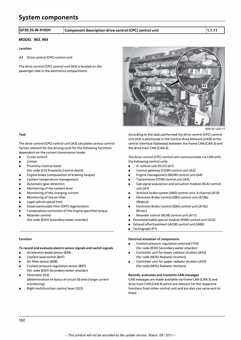
System components
GF30.35>W>4105H Component description drive control (CPC) control unit 1.7.11
MODEL 963, 964
W30.35>1237>11
Location
A3 Drive control (CPC) control unit
The drive control (CPC) control unit (A3) is located on the
passenger>side in the electronics compartment.
Task
The drive control (CPC) control unit (A3) calculates various control
factors relevant for the driving cycle for the following functions
dependent on the current transmission mode:
f Cruise control
f Limiter
f Proximity Control Assist
(for code (S1l) Proximity Control Assist)
f Engine brake (computation of braking torque)
f Coolant temperature management
f Automatic gear detection
f Monitoring of the coolant level
f Monitoring of the charging current
f Monitoring of the air filter
f Legal vehicle speed limit
f Diesel particulate filter (DPF) regeneration
f Computation/correction of the engine specified torque
f Retarder control
(for code (B3H) Secondary water retarder)
>>>>>>>>>>>>>>>>>>>>>>>>>>>>>>>>>>>>>>>>>>>>>>>>>>>>>>>>>>>>>>>>>>>>>>>>>>>>>>>>>>>>>>>>>
According to the tasks performed the drive control (CPC) control
unit (A3) is positioned in the Control Area Network (CAN) as the
central interface (Gateway) between the frame CAN (CAN 3) and
the drive train CAN (CAN 4).
The drive control (CPC) control unit communicates via CAN with
the following control units:
f IC control unit (ICUC) (A1)
f Central gateway (CGW) control unit (A2)
f Engine management (MCM) control unit (A4)
f Transmission (TCM) control unit (A5)
f Cab signal acquisition and actuation module (SCA) control
unit (A7)
f Antilock brake system (ABS) control unit, 4>channel (A10)
f Electronic Brake Control (EBS) control unit (A10b)
(Wabco)
f Electronic Brake Control (EBS) control unit (A10c)
(Knorr)
f Retarder control (RCM) control unit (A11)
f Parameterizable special module (PSM) control unit (A22)
f Exhaust aftertreatment (ACM) control unit (A60)
f Tachograph (P1) >>>>>>>>>>>>>>>>>>>>>>>>>>>>>>>>>>>>>>>>>>>>>>>>>>>>>>>>>>>>>>>>>>>>>>>>>>>>>>>>>>>>>>>>>
Function
To record and evaluate electric sensor signals and switch signals
f Accelerator pedal sensor (B44)
f Coolant level switch (B47)
f Air filter sensor (B48)
f Coolant pressure regulation sensor (B87)
(for code (B3H) Secondary water retarder)
f Alternator (G2)
(determination of status of circuit 50 and charge current
monitoring)
f Right multifunction control lever (S23)
Electrical actuation of components
f Coolant pressure regulation solenoid (Y53)
(for code (B3H) Secondary water retarder)
f Controller unit for lower radiator shutters (A54)
(for code (M7K) Radiator shutters)
f Controller unit for upper radiator shutters (A55)
(for code (M7K) Radiator shutters)
Records, evaluates and transmits CAN messages
CAN messages are made available via frame CAN (CAN 3) and
drive train CAN (CAN 4) which are relevant for the respective
functions from other control unit and are also vise versa sent to
these.
102
– This printout will not be recorded by the update service. Status: 09 / 2011 –

System components
GF07.08>W>4110H Component description for engine management (MCM) control unit 2.8.11
ENGINE 471.9 in MODEL 963
Location
A4 Engine management control unit (MCM)
The engine management (MCM) control unit (A4) is located on the left side of crankcase.
W07.08>1006>03
Task
The engine management (MCM) control unit (A4) services
primarily as an interface between the electrical or electronic
components located on the engine side and drive control (CPC)
control unit (A3) on the vehicle side.
Both control units are networked together via the drive train CAN
(CAN 4) and the CAN bus drive neutral point (Z4).
The engine management (MCM) control unit (A4) takes on a
number of tasks.>>>>>>>>>>>>>>>>>>>>>>>>>>>>>>>>>>>>>>>>>>>>>>>>>>>>>>>>>>>>>>>>>>>>>>>>>>>>>>>>>>>>>>>>>
On the one hand it takes on the controlling and regulating
processes, e.g. for systems such as the engine management or the
exhaust gas recirculation (AGR) while, on the other hand, it serves
in turn just to pass on information such as the oil level in the
engine.
The following is an overview of the tasks of the engine
management (MCM) control unit (A4):>>>>>>>>>>>>>>>>>>>>>>>>>>>>>>>>>>>>>>>>>>>>>>>>>>>>>>>>>>>>>>>>>>>>>>>>>>>>>>>>>>>>>>>>>
i Introduction of engine OM 471 and exhaust aftertreatment > 09/2011 > 103
– This printout will not be recorded by the update service. Status: 09 / 2011 –

System components
Engine management for the Amplified Pressure Common Rail
System (APCRS)
The main task of the engine management (MCM) control unit (A4)
is to regulate injection of the Amplified Pressure Common Rail
System (APCRS).
All required data such as the output, diverse performance maps or
data which serves to protect the engine is stored in the engine
management (MCM) control unit (A4).
In order to regulate the injection which takes place through
appropriate actuation of the fuel injectors for cylinder 1 to 6
(Y608 to Y613) and the quantity control valve (Y642), the engine
management (MCM) control unit (A4) reads in signals from
virtually all sensors connected to it. This means: all information
except that from the engine oil fill level sensor (B605) is used in
the computations.>>>>>>>>>>>>>>>>>>>>>>>>>>>>>>>>>>>>>>>>>>>>>>>>>>>>>>>>>>>>>>>>>>>>>>>>>>>>>>>>>>>>>>>>>
Exhaust gas recirculation (EGR)
The fact that exhaust gas recirculation is active over the whole
rotational speed range means that the ratio between recycled
exhaust gas masses and suctioned in or supercharged fresh air
mass must be matched exactly and thus exactly regulated.
This relationship, the so>called exhaust gas recirculation rate, is
regulated by the engine management (MCM) control unit (A4)
through appropriate actuation of the exhaust gas recirculation
positioner (Y621).
The EGR rate value here is determined by the information from
the charge air pressure and temperature sensor in the charge air
pipe (B608), by the exhaust gas recirculation (EGR) differential
pressure sensor (B621) and by the charge air temperature sensor
in the charge air housing (B617), taking the data stored in a
corresponding characteristics map into account.>>>>>>>>>>>>>>>>>>>>>>>>>>>>>>>>>>>>>>>>>>>>>>>>>>>>>>>>>>>>>>>>>>>>>>>>>>>>>>>>>>>>>>>>>
Diesel particulate filter (DPF) > only for code (M5Z) Engine version
Euro VI
During the regeneration phase of the diesel particulate filter
(DPF) the engine management (MCM) control unit (A4) actuates
the fuel shutoff valve (Y629) and (in intervals) the fuel metering
valve (Y628).
The fuel shutoff valve (Y629) and the fuel metering valve (Y628)
are located together with the fuel pressure sensor (inlet) (B625)
and the fuel pressure sensor (outlet) (B626), in one metering
device. This ensures that diesel fuel is metered over a line to the
injection nozzle in the nozzle unit for DPF regeneration which is
located on the exhaust pipe upstream of the diesel particulate
filter (DPF).
The injection nozzle injects specific fuel amounts into the hot
exhaust flow. During the resulting reaction in the exhaust
aftertreatment unit, a great deal of heat is generated, in which
the soot deposited in the diesel particulate filter (DPF) is burnt to
form ash.>>>>>>>>>>>>>>>>>>>>>>>>>>>>>>>>>>>>>>>>>>>>>>>>>>>>>>>>>>>>>>>>>>>>>>>>>>>>>>>>>>>>>>>>>
IC control unit (ICUC) (A1)
To display this in the instrument cluster control unit (ICUC) (A1)
the engine management (MCM) control unit (A4) records the
engine oil level, the engine oil temperature, the engine oil
pressure, the coolant temperature and the engine rpm.
It also uses values from the following sensors:
f Engine oil fill level sensor (B605)
f Oil pressure sensor (B604)
f Intake coolant temperature sensor (B607) or exhaust (B606)
f Crankshaft position sensor (B600)
Fan control
For fan regulation purposes the engine management (MCM)
control unit (A4) uses information from the coolant inlet
temperature sensor (B607) and the coolant outlet temperature
sensor (B606).
>>>>>>>>>>>>>>>>>>>>>>>>>>>>>>>>>>>>>>>>>>>>>>>>>>>>>>>>>>>>>>>>>>>>>>>>>>>>>>>>>>>>>>>>>
Engine brake
According to a request from the drive control (CPC) control unit
(A3), the engine management (MCM) control unit (A4) actuates
the engine brake solenoid valve, stage 1 (Y624), the engine brake
solenoid valve, stage 2 (Y625) or both solenoid valves together.
Actuation of solenoid valves causes the engine oil to be fed to the
respective rocker arms with hydroelement. This means that the
respective brake rocker arms operate via the respective rocker arm
with hydroelement on an exhaust valve, whereby the engine
brake is active.
Tasks covering a number of systems
These tasks include engine or system diagnosis, since almost all
electrical or electronic components which are attached to the
engine management (MCM) control unit (A4) can be diagnosed.
104
– This printout will not be recorded by the update service. Status: 09 / 2011 –

System components
GF42.25>W>3135H Electronic Brake Control control unit (EBS), component description 20.7.11
MODEL 963
W42.25>1270>81
Location
Shown on model 963.4, Knorr version
A10c Electronic brake system (EBS) control unit
The Electronic Brake Control control unit (EBS) (A10c) is installed in
the electronics compartment on the front passenger side.
Task
The Electronic Brake Control control unit (EBS) (A10b or A10c) is
the central component of the electronic brake system (EBS) and
has the following tasks:
f Record the driver's brake command via the electrical signals
of the brake value sensor (B17 or B17a).
f Calculate the specified brake pressures of the individual
axles or the semi>trailer/trailer depending on the sensor data
and taking into account the brake force distribution and
wear harmonization.
f Actuation of the front axle axle modulator (A20 or A20a),
the rear axle axle modulator (A21 or A21a), the ABS solenoid
valves (Y1, Y2) and the trailer control valve (Y6 or Y6a) with
the corresponding electrical signals to apply the specified
brake pressures.
f Evaluate the feedback from the brake components during
the entire brake application and readjust the brake pressure
if necessary.
f Control the ABS or ASR interventions.
f Communication with other systems/control units in the
vehicle via the frame CAN (CAN 3).
f Actuation of electronically braked trailers via the ISO 11992
interface (X103.7).
f Actuation of the air admission 3/2>way valve (Y5) or the ASR
solenoid valve 2 (Y5a) for ASR suppression on the leading
axle/trailing axle on vehicles with 3 axles.
f Control the function of the hill holder.
f Performing system diagnosis.
f Storage of system errors for diagnosis.
f Report major faults via the display field in the instrument
cluster control unit (ICUC) (A1).
i Introduction of engine OM 471 and exhaust aftertreatment > 09/2011 > 105
– This printout will not be recorded by the update service. Status: 09 / 2011 –
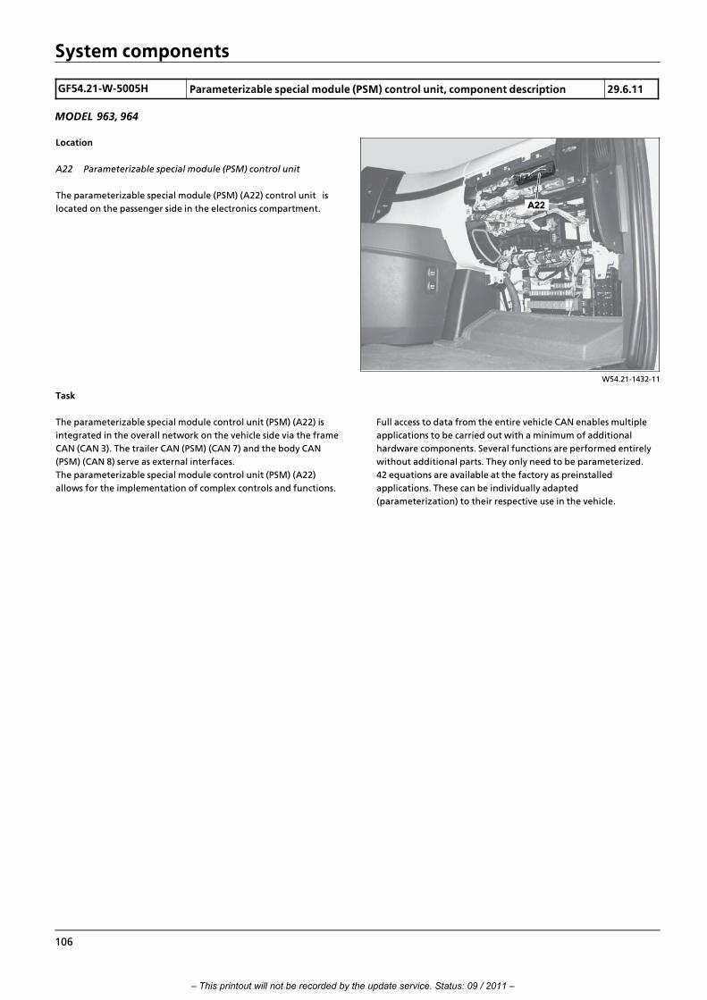
System components
GF54.21>W>5005H Parameterizable special module (PSM) control unit, component description 29.6.11
MODEL 963, 964
W54.21>1432>11
Location
A22 Parameterizable special module (PSM) control unit
The parameterizable special module (PSM) (A22) control unit is
located on the passenger side in the electronics compartment.
Task
The parameterizable special module control unit (PSM) (A22) is
integrated in the overall network on the vehicle side via the frame
CAN (CAN 3). The trailer CAN (PSM) (CAN 7) and the body CAN
(PSM) (CAN 8) serve as external interfaces.
The parameterizable special module control unit (PSM) (A22)
allows for the implementation of complex controls and functions.
Full access to data from the entire vehicle CAN enables multiple
applications to be carried out with a minimum of additional
hardware components. Several functions are performed entirely
without additional parts. They only need to be parameterized.
42 equations are available at the factory as preinstalled
applications. These can be individually adapted
(parameterization) to their respective use in the vehicle.
106
– This printout will not be recorded by the update service. Status: 09 / 2011 –

System components
GF54.25>W>6000H Battery disconnect switch control unit, component description 2.8.11
MODEL 963 with CODE (E5T) ADR model class EX/II, including ATMODEL 963 with CODE (E5U) ADR model class EX/III, including EX/II and ATMODEL 963 with CODE (E5V) ADR model class FL including EX/II, EX/III and ATMODEL 963 with CODE (E5X) ADR model class ATMODEL 963 with CODE (E5Z) Accessories, ADRMODEL 963 with CODE (E9D) Preinstallation, double>pole battery disconnect switchMODEL 963 with CODE (E9E)
Location
In vehicles without code (C7T) Integral rear end
A33 Battery disconnect switch control unit (BESO)
In vehicles with standard rear end, the battery disconnect switch (BESO) control unit (A33) is
installed below the vehicle battery in the direction of travel in front of the compressed air
reservoirs of the brake system.
W54.21>1431>03
W54.21>1430>04
In vehicles with code (C7T) Integral rear end
A33 Battery disconnect switch control
unit (BESO)
In vehicles with integral rear end, the
battery disconnect switch (BESO) control
unit (A33) is installed on the inside of the
left longitudinal frame member above the
rear axle.
i Introduction of engine OM 471 and exhaust aftertreatment > 09/2011 > 107
– This printout will not be recorded by the update service. Status: 09 / 2011 –

System components
Tasks
f Evaluating the positions of the EMERGENCY OFF switch (S30)
and the frame EMERGENCY OFF frame (S31)
f Disconnecting the on>board electrical system from the
battery, when the EMERGENCY OFF switch (S30) or the
frame EMERGENCY OFF switch (S31) is pressed
Design
f Control electronics
f Bistable relay for disconnecting the on>board electrical
system from the battery
Function
The battery disconnect switch (BESO) control unit (A33) evaluates
the positions of the EMERGENCY OFF switch (S30) and the frame
EMERGENCY OFF switch (S31) via the input signal. >>>>>>>>>>>>>>>>>>>>>>>>>>>>>>>>>>>>>>>>>>>>>>>>>>>>>>>>>>>>>>>>>>>>>>>>>>>>>>>>>>>>>>>>>
When the EMERGENCY OFF switch (S30) or the frame
EMERGENCY OFF switch (S31) are pressed, the battery disconnect
switch (BESO) control unit (A33) disconnects the on>board
electrical system from the battery. Even before the on>board
electrical system is disconnected from the battery, it sends a
message to the exterior CAN (CAN 1) for further processing,
announcing that the on>board electrical system will be
disconnected from the battery. Among other things, the engine
management (MCM) control unit (A4) initiates the switching>off
of the engine due to this message. The on>board electrical system
is disconnected by a bistable relay integrated into the battery
disconnect switch (BESO) control unit (A33). The bistable relay is
actuated 800 ms after the battery disconnect switch (BESO)
control unit (A33) has recognized that the EMERGENCY OFF
switch (S30) or the frame EMERGENCY OFF switch (S31) was
pressed. The tachograph (TCO) (P1) continues to be supplied with
voltage by the battery disconnect switch (BESO) control unit (A33)
via a separate pin.
>>>>>>>>>>>>>>>>>>>>>>>>>>>>>>>>>>>>>>>>>>>>>>>>>>>>>>>>>>>>>>>>>>>>>>>>>>>>>>>>>>>>>>>>>
i As a redundant message on the exterior CAN (CAN 1), the
battery disconnect switch (BESO) control unit (A33) also transmits
a pulse width modulated signal (PWM signal) via a direct line to
the sensor and actuator module, cab (SCA) control unit (A7). If the
battery disconnect switch (BESO) control unit (A33) recognizes
that the EMERGENCY OFF switch (S30) or the frame EMERGENCY
OFF switch (S31) was pressed, it changes the duty cycle of the
PWM signal from 50% to 75%, whereupon the sensor and
actuator module, cab (SCA) control unit (A7) recognizes that the
on>board electrical system starts being disconnected.
108
– This printout will not be recorded by the update service. Status: 09 / 2011 –

System components
GF20.40>W>5010H Radiator shutters, component description 20.7.11
MODEL 963, 964 with CODE (M7K) Radiator shutters
W20.00>1062>79
Shown on model 963 with code (S1l)
Proximity Control Assist
1 Slats
A54 Lower radiator shutters controller unit
A55 m1 Upper radiator shutters actuatormotor
A55 t1 Voltage converter 24 V/14 V
A54 m1 Lower radiator shutters actuatormotor
A54 t1 Voltage converter 24 V/14 V
A55 Upper radiator shutters controller
unit
Location
The radiator shutters, consisting of the lower radiator shutters
controller unit (A54) and the upper radiator shutters controller
unit (A55) are located behind the respective radiator grille.
Task
The lower radiator shutters controller unit (A54) and the upper
radiator shutters controller unit (A55) control the throughflow of
air in the engine compartment via the position of the slats (1). The
drag coefficient of the vehicle is optimized by controlled slat (1)
opening and closing, since the air flow is led around the vehicle.
The warm>up phase of the engine can also be influenced via the
position of the slats (1).
Design
The lower radiator shutters controller unit (A54) consists of the
following components:
f Lower radiator shutters actuator motor (A54 m1)
f Voltage converter 24 V/ 14 V (A54 t1)
The upper radiator shutters controller unit (A55) consists of the
following components:
f Upper radiator shutters controller unit (A55 m1)
f Voltage converter 24 V/ 14 V (A55 t1)
Function
The lower radiator shutters controller unit (A54) and the upper
radiator shutters controller unit (A55) are actuated by the drive
control control unit (CPC) (A3) using digital switching signals via
the radiator shutters LIN (LIN 5). The digital switching signals are
forwarded by the voltage converter 24 V/ 14 V (A54 t1) and the
voltage converter 24 V/ 14 V (A55 t1) in the form of direction of
rotation commands (voltage reversal) to the lower radiator
shutters actuator motor (A54 m1) and the upper radiator shutters
actuator motor (A55 m1). The slats (1) of the lower radiator
shutters controller unit (A54) and the slats (1) of the upper
radiator shutters controller unit (A55) are opened or closed in
accordance with the request from the drive control control unit
(CPC) (A3).
i The operating voltage of the lower radiator shutters actuator
motor (A54 m1) and the upper radiator shutters actuator motor
(A55 m1) is designed to be U = 12 V. The on>board electrical
system voltage (U = 24 V) is reduced accordingly by the voltage
converter 24 V/ 14 V (A54 t1) and the voltage converter 24 V/ 14 V
(A55 t1).
Variants
The design of the lower radiator shutters controller unit (A54) and
the upper radiator shutters controller unit (A55) varies according
to the model and the equipment:
f Vehicles with ground clearance of 600
f Vehicles with ground clearance of 765
f Vehicles with Proximity Control Assist
(with code (S1l) Proximity Control Assist)
i Introduction of engine OM 471 and exhaust aftertreatment > 09/2011 > 109
– This printout will not be recorded by the update service. Status: 09 / 2011 –

System components
GF49.20>W>3009HA EATU output NOx sensor, component description 2.8.11
ENGINES 471.9 in MODEL 963, 964 with CODE (M5Y) Engine version Euro VENGINES 471.9 in MODEL 963, 964 with CODE (M5R) Engine version EEV
W14.40>1595>76
Location
1 Exhaust aftertreatment unit
A57 EATU output NOx sensor control
unit
A57 b1 EATU output NOx sensor
The EATU output NOx sensor (A57 b1) is
screwed into the inlet tube of the exhaust
aftertreatment unit (1) from the outside
and forms one unit together with the EATU
output NOx sensor control unit (A57).
Task
The EATU output NOx sensor (A57 b1)
represents the actual measurement sensor,
whereas the EATU output NOx sensor
electronic control unit (A57) is used to
compute the NOx raw concentration in the
exhaust before exhaust aftertreatment by
the SCR catalytic converter and ammonia
slip catalytic converter.
W14.40>1586>12
Design
2 Electrical connection
A57 EATU output NOx sensor control unit
A57 b1 EATU output NOx sensor
The EATU output NOx sensor control unit (A57) and the EATU
output NOx sensor (A57 b1) are connected to each other via a non>
separable electrical line and form one unit.
The EATU output NOx sensor (A57 b1) is similar in design to a
wide>band oxygen sensor. It is fitted with its basic elements such as
the so>called Nernst cell and the oxygen pump cell.
Its front part in the measuring probe which projects out into the
exhaust consists of a metal housing with openings and a gas>
permeable ceramic body inside made out of zirconium dioxide.
The surfaces of the ceramic body are fitted on both sides with
electrodes made out of a thin platinum layer. The measuring
probe is in contact with outside air via a reference air duct.
The metal housing protects the ceramic body inside against
mechanical stress and sudden increases in temperature.
The EATU output NOx sensor (A57 b1) is fitted with an integral
heating element which serves to rapidly achieve the required
operating temperature of about 800 ∞C for the chemical processes
taking place therein.
The electrical line between the EATU output NOx sensor (A57 b1)
and the EATU output NOx sensor control unit (A57) has a defined
length of approx. 60 mm.
110
– This printout will not be recorded by the update service. Status: 09 / 2011 –

System components
W14.40>1350>76
Function
3 Measuring probe (ceramic body)
5 Chamber
6 Heating element
7 Reference air duct
8 Chamber
Ip0 Pump current (main pump electrode)
Ip1 Pump current (auxiliary pump
electrode)
Ip2 Pump current (measuring electrode)
The EATU output NOx sensor (A57 b1) functions according to the
principle of the so>called oxygen ions line according to which the
wide>band oxygen sensor also functions.
Part of the exhaust flowing past the measuring probe (3) passes
through a diffusion barrier into the first chamber (8).
In this case, the O2 concentration is regulated at a defined value
by means of the so>called pump voltage applied to an electrode
until the oxygen content differs on either side of the ceramic
body.
The special properties of the ceramic body create the signal
voltage (Nernst voltage) at its friction planes. This is the measure
for the residual oxygen content in the exhaust.
The traces of HC, CO and H2 in the exhaust oxygenate at the
electrode made out of platinum. The gas then passes over a
further diffusion barrier and arrives in the second chamber (5)
where it is broken down with the aid of a second NOx electrode
into NO and O2.
The O2 concentration is also regulated to close to zero at the same
time with the aid of a further electrode. The nitrous oxide
concentration is deduced from the size of the pump current (Ip2)
required.
The EATU output NOx sensor control unit (A57) is used to
compute the required pump voltages, to regulate the complex
system and to compute the NOx raw values. It receives the analog
signals from the EATU output NOx sensor (A57 b1) and digitizes
them. It then forwards them as digital CAN messages to the
exhaust aftertreatment (ACM) control unit (A60) at a defined
transfer rate, which then evaluates them.
i Introduction of engine OM 471 and exhaust aftertreatment > 09/2011 > 111
– This printout will not be recorded by the update service. Status: 09 / 2011 –
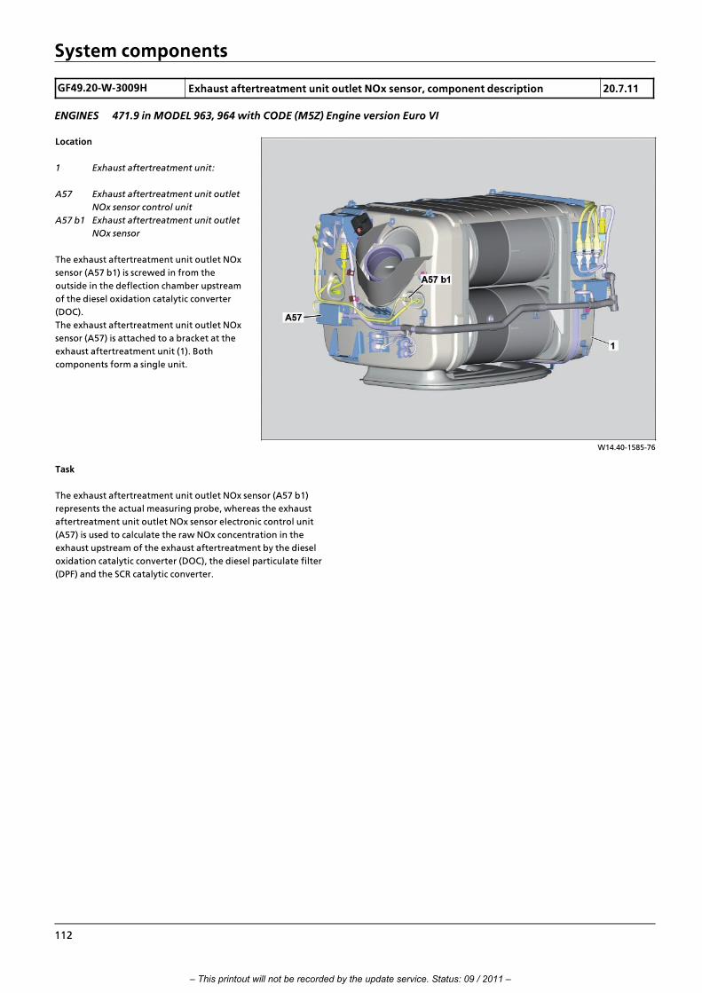
System components
GF49.20>W>3009H Exhaust aftertreatment unit outlet NOx sensor, component description 20.7.11
ENGINES 471.9 in MODEL 963, 964 with CODE (M5Z) Engine version Euro VI
W14.40>1585>76
Location
1 Exhaust aftertreatment unit:
A57 Exhaust aftertreatment unit outlet
NOx sensor control unit
A57 b1 Exhaust aftertreatment unit outlet
NOx sensor
The exhaust aftertreatment unit outlet NOx
sensor (A57 b1) is screwed in from the
outside in the deflection chamber upstream
of the diesel oxidation catalytic converter
(DOC).
The exhaust aftertreatment unit outlet NOx
sensor (A57) is attached to a bracket at the
exhaust aftertreatment unit (1). Both
components form a single unit.
Task
The exhaust aftertreatment unit outlet NOx sensor (A57 b1)
represents the actual measuring probe, whereas the exhaust
aftertreatment unit outlet NOx sensor electronic control unit
(A57) is used to calculate the raw NOx concentration in the
exhaust upstream of the exhaust aftertreatment by the diesel
oxidation catalytic converter (DOC), the diesel particulate filter
(DPF) and the SCR catalytic converter.
112
– This printout will not be recorded by the update service. Status: 09 / 2011 –

System components
W14.40>1586>12
Design
2 Electrical connection
A57 Exhaust aftertreatment unit outlet NOx sensor control
unit
A57 b1 Exhaust aftertreatment unit outlet NOx sensor
The exhaust aftertreatment unit outlet NOx sensor control unit
(A57) and the exhaust aftertreatment unit outlet NOx sensor (A57
b1) are interconnected via an electrical line that cannot be
disconnected, and form a single unit.
The exhaust aftertreatment unit outlet NOx sensor
(A57 b1) has a similar design to a wide>band oxygen sensor. It is
fitted with its basic elements such as the so>called Nernst cell and
the oxygen pump cell.
Its front part in the measuring probe which projects out into the
exhaust consists of a metal housing with openings and a gas>
permeable ceramic body inside made out of zirconium dioxide.
The surfaces of the ceramic body are fitted on both sides with
electrodes made out of a thin platinum layer. The measuring
probe is in contact with outside air via a reference air duct.
The metal housing protects the ceramic body inside against
mechanical stress and sudden increases in temperature.
The exhaust aftertreatment unit outlet NOx sensor (A57 b1) is
fitted with an integral heating element which serves to rapidly
achieve the operating temperature of about 800 ∞C that is
required for the chemical processes taking place therein.
The electrical line between the exhaust aftertreatment unit outlet
NOx sensor (A57 b1) and the exhaust aftertreatment unit outlet
NOx sensor control unit (A57) has a defined length of approx.
60 mm.
i Introduction of engine OM 471 and exhaust aftertreatment > 09/2011 > 113
– This printout will not be recorded by the update service. Status: 09 / 2011 –

System components
W14.40>1350>76
Function
3 Measuring probe (ceramic body)
5 Chamber
6 Heating element
7 Reference air duct
8 Chamber
Ip0 Pump current (main pump electrode)
Ip1 Pump current (auxiliary pump
electrode)
Ip2 Pump current (measuring electrode)
The exhaust aftertreatment unit outlet NOx sensor (A57 b1)
functions according to the principle of the so>called oxygen ions
line, according to which the wideband oxygen sensor also
functions.
Part of the exhaust flowing past the measuring probe (3) passes
through a diffusion barrier into the first chamber (8).
In this case the O2 concentration is regulated at a defined value by
means of the so>called pump voltage applied to an electrode until
the oxygen content differs at both sides of the ceramic body.
The special properties of the ceramic body create the signal
voltage (Nernst voltage) at its boundary surfaces. This is the
measure for the residual oxygen content in the exhaust.
The traces of HC, CO and H2 in the exhaust oxygenate at the
electrode made out of platinum.
The gas then passes over a further diffusion barrier and arrives in
the second chamber (5) where it is broken down with the aid of a
second NOx electrode into NO and O2. The O2 concentration is
also regulated to close to zero at the same time with the aid of a
further electrode. The nitrous oxide concentration is deduced
from the size of the pump current (Ip2) required.
The exhaust aftertreatment unit outlet NOx sensor (A57) serves to
compute the required pump voltages, to regulate the complex
system and to compute the NOx raw values.It receives the analog
signal from the exhaust aftertreatment unit outlet NOx sensor
(A57 b1) and digitalizes it. It forwards these as digital CAN signals
at a defined transfer rate to the exhaust aftertreatment control
unit (ACM) (A60), which then evaluates them.
114
– This printout will not be recorded by the update service. Status: 09 / 2011 –

System components
GF14.40>W>3003H Pump module, component description 20.7.11
ENGINE 471.9 in MODEL 963, 964
W14.40>1562>76
Location
Shown on model 963 with code (M5Z)
Engine version Euro VI
1 Pump module
2 EATU
16 AdBlue“ tank
The pump module (1) which contains the
SCR control unit (A58) and SCR delivery
pump (M25) is fastened to a bracket on the
inside of the right longitudinal frame
member behind the EATU (2).
Task
The pump module (1) sucks in AdBlue“ from the AdBlue“
container (16), filters it and pumps it to the AdBlue“ metering
device (A67). The SCR control unit (A58) calculates the injection
period and the injection quantity.
W14.40>1570>76
Design
3 Electronics housing
4 Connecting body
5 Filter housing
6 Electrical connection
(communication to AdBlue“
metering device)
7 Electrical connection
(communication to exhaust
aftertreatment (ACM) control unit)
8 AdBlue“ inlet
9 Intake filter
(mesh size 190 om)
10 AdBlue outlet
11 Vent valves
12 Coolant inlet
13 Coolant outlet
14 Pressure limiting valve
15 Main filter
(mesh size 20 to 30 om)
A58 SCR control unit
M25 SCR delivery pump
i Introduction of engine OM 471 and exhaust aftertreatment > 09/2011 > 115
– This printout will not be recorded by the update service. Status: 09 / 2011 –

System components
Function
8 AdBlue“ inlet
9 Intake filter
10 AdBlue“ outlet
12 Coolant inlet
13 Coolant outlet
14 Pressure limiting valve
15 Main filter
M25 SCR delivery pump
W14.40>1560>03
After the engine starts, the exhaust aftertreatment (ACM) control
unit (A60) actuates the pump module (1) or more accurately, the
SCR control unit (A58) integrated into it. This switches the SCR
delivery pump (M25), so that AdBlue“ is sucked in from the
AdBlue“ container and pumped at an operating pressure of
approx. 10 bar towards the AdBlue“ metering device (A67).
Because the AdBlue“ metering device (A67) is cooled be
circulation through circulating AdBlue“, AdBlue“ is pumped
continuously, irrespective of whether injection is necessary or not.
The AdBlue“ that is not required or not injected flows back
through the return line to the AdBlue“ container.
Heating
A duct inside the connecting body (4) enables the pump module
(1) to have engine coolant flow through it for heating or
defrosting. The coolant inflow is regulated by an engine mounted
solenoid valve as a function of the temperature by the engine
management (MCM) control unit (A60).
Delayed>off running
To avoid any damage through overheating on the AdBlue“
metering device (A67), the pump module (1) continues to pump
AdBlue“ for some time after the engine stops so that the cooling
can be maintained for a longer period.
116
– This printout will not be recorded by the update service. Status: 09 / 2011 –

System components
GF14.40>W>3020HA Exhaust aftertreatment (ACM) control unit, component description 20.7.11
ENGINE 471.9 in MODEL 963, 964 with CODE (M5Y) Engine version Euro VENGINE 471.9 in MODEL 963, 964 with CODE (M5R) Engine version EEV
W14.40>1568>76
Location
1 Exhaust aftertreatment unit
A60 Exhaust aftertreatment (ACM)
control unit
The exhaust aftertreatment (ACM) control
unit (A60) is fastened to a bracket on the
inside of the EATU (1).
W14.40>1598>79
A4 Engine management control unit
(MCM)
A57 NOx sensor control unit output for
exhaust aftertreatment unit
A57 b1 NOx sensor output for exhaust
aftertreatment unit
A58 SCR control unit (in pump module)
B73 Exhaust temperature sensor
downstream of SCR catalytic
converter
B74 AdBlue“ fill level sensor/
temperature sensor
CAN 4 Drive train CAN
CAN 13 NOx>CAN
M25 SCR delivery pump (in pump
module)
A60 Exhaust aftertreatment (ACM)
control unit
A67 AdBlue“ metering device
A70 NOx sensor control unit input for
exhaust aftertreatment unit
A70 b1 NOx sensor input for exhaust
aftertreatment unit
B72 Exhaust temperature sensor
upstream of SCR catalytic converter
i Introduction of engine OM 471 and exhaust aftertreatment > 09/2011 > 117
– This printout will not be recorded by the update service. Status: 09 / 2011 –

System components
Task
The exhaust aftertreatment (ACM) control unit (A60) regulates
and controls practically all the exhaust aftertreatment system
functions.
The exhaust aftertreatment (ACM) control unit (A60) receives the
analog signals from the directly connected sensors. It receives the
NOx sensor signals over CAN connections and communicates with
the SCR control unit (A58) and the engine management (MCM)
control unit (A4).
AdBlue“ injection
It uses the data supplied by the SCR control unit (A58) and the
engine management (MCM) control unit (A4) to calculate the
required AdBlue“ quantity, which is then sent over the SCR
control unit (A58) to the AdBlue“ metering device (A67).
118
– This printout will not be recorded by the update service. Status: 09 / 2011 –

System components
GF14.40>W>3020H Exhaust aftertreatment (ACM) control unit, component description 20.7.11
ENGINE 471.9 in MODEL 963 with CODE (M5Z) Engine version Euro VI
W14.40>1568>76
Location
1 Exhaust aftertreatment unit
A60 Exhaust aftertreatment (ACM)
control unit
The exhaust aftertreatment (ACM) control
unit (A60) is fastened to a bracket on the
inside of the EATU (1).
Task
The exhaust aftertreatment (ACM) control unit (A60) regulates
and controls practically all the exhaust aftertreatment system
functions.
It also processes the incoming digital and analog signals of the
connected sensor system and communicates over CAN
connections with the connected control units.
i Introduction of engine OM 471 and exhaust aftertreatment > 09/2011 > 119
– This printout will not be recorded by the update service. Status: 09 / 2011 –

System components
W14.40>1597>79
A4 Engine management control unit
(MCM)
A57 NOx sensor control unit output for
exhaust aftertreatment unit
A57 b1 NOx sensor output for exhaust
aftertreatment unit
A58 SCR control unit
A60 Exhaust aftertreatment unit
(ACM) control unit
A67 AdBlue“ metering device
A70 NOx sensor control unit input for
exhaust aftertreatment unit
B70 Exhaust temperature sensor
downstream of diesel particulate
filter
B73 Exhaust temperature sensor
downstream of SCR catalytic
converter
B74 AdBlue“ fill level
sensor/temperature sensor
CAN 4 Drive train CAN
CAN 13 NOx>CAN
M25 SCR delivery pump
A70 b1 NOx sensor input for exhaust
aftertreatment unit
B37 Exhaust pressure sensor upstream
of diesel oxidation catalytic
converter
B38 Exhaust pressure sensor
downstream of diesel particulate
filter
B67 Exhaust temperature sensor
upstream of diesel oxidation
catalytic converter
B68 Exhaust temperature sensor
downstream of upper diesel
oxidation catalytic converter
B69 Exhaust temperature sensor
downstream of lower diesel
oxidation catalytic converter
The exhaust aftertreatment (ACM) control unit (A60) receives the
analog signals from the directly connected sensors. It receives the
NOx sensor signals over CAN connections and communicates with
the SCR control unit (A58) and the engine management (MCM)
control unit (A4).
AdBlue“ injection
It uses the data supplied by the SCR control unit (A58) and the
engine management (MCM) control unit (A4) to calculate the
required AdBlue“ quantity, which is then forwarded over the SCR
control unit (A58) to the AdBlue“ metering device (A67).
Diesel particulate filter regeneration
The diesel particulate filter load status is monitored by the
temperature and pressure sensors. If active regeneration is
required, it is requested by the engine management (MCM)
control unit (A4).
120
– This printout will not be recorded by the update service. Status: 09 / 2011 –

System components
GF14.40>W>3013H AdBlue metering device, component description 20.7.11
ENGINE 471.9 in MODEL 963, 964
W14.40>1565>76
Location
Shown on model 963 with code (M5Z)
Engine version Euro VI
1 Exhaust aftertreatment unit
16 AdBlue“ return line
17 AdBlue“ pressure line
18 Electrical line
A67 AdBlue“ metering device
The AdBlue“ metering device (A67) is
directly screwed onto the EATU at the right
front in the direction of travel. The injection
nozzle of the AdBlue“ metering device
(A67) protrudes here into the hydrolysis
segment of the EATU (1).
Task
The AdBlue“ metering device (A67) injects the AdBlue“ quantity,
as calculated by the control units, for the corresponding period
into the exhaust flow.
W14.40>1566>76
Design
3 Housing (plastic)
4 Basic body (stainless steel)
5 AdBlue“ inlet
6 AdBlue“ outlet (return)
7 Injection nozzle
8 Gasket
9 Vent valve
10 Electrical connection
i Introduction of engine OM 471 and exhaust aftertreatment > 09/2011 > 121
– This printout will not be recorded by the update service. Status: 09 / 2011 –

System components
W14.40>1567>10
Function
5 AdBlue“ inlet
7 Injection nozzle
11 Temperature sensor
12 Pressure sensor
13 Heating element
14 Injector
15 Filter
When the engine is started and at an operating pressure of
approx. 10 bar, the AdBlue“ metering device (A67) has AdBlue“
pumped constantly through it by the pump module.
This happens irrespective of whether AdBlue“ is injected or not,
because the AdBlue“ metering device (A67) is protected against
overheating at the installation location on the EATU (1) and the
prevailing high temperatures by this recirculation cooling. >>>>>>>>>>>>>>>>>>>>>>>>>>>>>>>>>>>>>>>>>>>>>>>>>>>>>>>>>>>>>>>>>>>>>>>>>>>>>>>>>>>>>>>>>
The AdBlue“ that is not required or not injected flows back
through the return line to the AdBlue“ container. This cooling is
absolutely necessary, and it continues for a specific period in a
run>on phase, even when the engine is switched off.
>>>>>>>>>>>>>>>>>>>>>>>>>>>>>>>>>>>>>>>>>>>>>>>>>>>>>>>>>>>>>>>>>>>>>>>>>>>>>>>>>>>>>>>>>
Injection
The AdBlue“ metering device (A67) receives the signals from the
SCR control unit (A58) for the currently delivered AdBlue“
quantity. The pressure sensor (12) and temperature sensor (11)
integrated into the AdBlue“ metering device (A67) supply the
values for the basis on which the opening duration and opening
period of the injection valve (14) are calculated.
The AdBlue“ metering device (A67) is actuated by the SCR control
unit (A58) > the computation however takes place in the exhaust
aftertreatment (ACM) control unit (A60).
The injection valve (14) opens in pulsed intervals and injects > due
to the atomized effect produced by the injection nozzle (7) >
AdBlue“ as a superfine spray straight into the exhaust flow, or put
more accurately into the hydrolysis path of the EATU (1)
Heating
At low ambient temperatures the AdBlue“ metering device (A67)
is heated by the integrated heating element (13).
122
– This printout will not be recorded by the update service. Status: 09 / 2011 –

System components
GF49.20>W>3008HA EATU input NOx sensor, component description 2.8.11
ENGINES 471.9 in MODEL 963, 964 with CODE (M5Y) Engine version Euro VENGINES 471.9 in MODEL 963, 964 with CODE (M5R) Engine version EEV
W14.40>1596>76
Location
1 Exhaust aftertreatment unit
A70 EATU input NOx sensor control unit
A70 b1 EATU input NOx sensor
The EATU input NOx sensor (A70 b1) is
screwed into the chamber downstream of
the SCR catalytic converter and ammonia
slip catalytic converter from the outside and
forms one unit together with the EATU
input NOx sensor control unit (A70).
Task
The EATU input NOx sensor (A70 b1) represents the actual
measurement sensor, whereas the EATU input NOx sensor
electronic control unit (A70) is used to compute the NOx
concentration in the exhaust after exhaust aftertreatment by the
SCR catalytic converter and ammonia slip catalytic converter.
W14.40>1587>12
Design
2 Electrical connection
A70 EATU input NOx sensor control unit
A70 b1 EATU input NOx sensor
The EATU input NOx sensor control unit (A70) and the EATU input
NOx sensor (A70 b1) are connected to each other via a non>
separable electrical line and form one unit.
The EATU input NOx sensor (A70 b1) is similar in design to a wide>
band oxygen sensor. It is fitted with its basic elements such as the
so>called Nernst cell and the oxygen pump cell.
Its front part in the measuring probe which projects out into the
exhaust consists of a metal housing with openings and a gas>
permeable ceramic body inside made out of zirconium dioxide.
i Introduction of engine OM 471 and exhaust aftertreatment > 09/2011 > 123
– This printout will not be recorded by the update service. Status: 09 / 2011 –

System components
The surfaces of the ceramic body are fitted on both sides with
electrodes made out of a thin platinum layer. The measuring
probe is in contact with outside air via a reference air duct.
The metal housing protects the ceramic body inside against
mechanical stress and sudden increases in temperature.
The EATU input NOx sensor (A70 b1) is fitted with an integral
heating element which serves to rapidly achieve the required
operating temperature of about 800 ∞C for the chemical processes
taking place therein.
The electrical line between the EATU input NOx sensor (A70 b1)
and the EATU input NOx sensor control unit (A70) has a defined
length of approx. 60 mm.
W14.40>1350>76
Function
3 Measuring probe (ceramic body)
5 Chamber
6 Heating element
7 Reference air duct
8 Chamber
Ip0 Pump current (main pump electrode)
Ip1 Pump current (auxiliary pump
electrode)
Ip2 Pump current (measuring electrode)
The EATU input NOx sensor (A70 b1) functions according to the
principle of the so>called oxygen ions line according to which the
wide>band oxygen sensor also functions.
Part of the exhaust flowing past the measuring probe (3) passes
through a diffusion barrier into the first chamber (8).
In this case, the O2 concentration is regulated at a defined value
by means of the so>called pump voltage applied to an electrode
until the oxygen content differs on either side of the ceramic
body.
The special properties of the ceramic body create the signal
voltage (Nernst voltage) at its friction planes. This is the measure
for the residual oxygen content in the exhaust.
The traces of HC, CO and H2 in the exhaust oxygenate at the
electrode made out of platinum.
The gas then passes over a further diffusion barrier and arrives in
the second chamber (5) where it is broken down with the aid of a
second NOx electrode into NO and O2. The O2 concentration is
also regulated to close to zero at the same time with the aid of a
further electrode. The nitrous oxide concentration is deduced
from the size of the pump current (Ip2) required. The EATU input
NOx sensor control unit (A70) is used to compute the required
pump voltages, to regulate the complex system and to compute
the NOx raw values. It receives the analog signals from the EATU
input NOx sensor (A70 b1) and digitizes them. It then forwards
them as digital CAN signals to the exhaust aftertreatment (ACM)
control unit (A60) at a defined transfer rate, which then evaluates
them.
124
– This printout will not be recorded by the update service. Status: 09 / 2011 –

System components
GF49.20>W>3008H Exhaust aftertreatment unit inlet NOx sensor, component description 20.7.11
ENGINES 471.9 in MODEL 963, 964 with CODE (M5Z) Engine version Euro VI
W14.40>1582>76
Location
1 Exhaust aftertreatment unit:
A70 Exhaust aftertreatment unit inlet
NOx sensor control unit
A70 b1 Exhaust aftertreatment unit inlet
NOx sensor
The exhaust aftertreatment unit inlet NOx
sensor (A70 b1) is screwed in from the
outside in the chamber downstream of the
SCR catalytic converter and the ammonia
blocking catalytic converter.
The exhaust aftertreatment unit inlet NOx
sensor (A70) is attached to a bracket at the
exhaust aftertreatment unit (1). Both
components form a single unit.
Task
The exhaust aftertreatment unit inlet NOx sensor (A70 b1)
represents the actual measuring probe, whereas the exhaust
aftertreatment unit inlet NOx sensor control unit (A70) is used to
calculate the NOx concentration in the exhaust downstream of
the exhaust aftertreatment by the diesel oxidation catalytic
converter (DOC), the diesel particulate filter (DPF) and the SCR
catalytic converter.
i Introduction of engine OM 471 and exhaust aftertreatment > 09/2011 > 125
– This printout will not be recorded by the update service. Status: 09 / 2011 –

System components
W14.40>1587>12
Design
2 Electrical connection
A70 Exhaust aftertreatment unit inlet NOx sensor control unit
A70 b1 Exhaust aftertreatment unit inlet NOx sensor
The exhaust aftertreatment unit inlet NOx sensor control unit
(A70) and the exhaust aftertreatment unit inlet NOx sensor (A70
b1) are interconnected via an electrical line that cannot be
disconnected, and form a single unit.
The exhaust aftertreatment unit inlet NOx sensor
(A70 b1) has a similar design to a wide>band oxygen sensor. It is
fitted with its basic elements such as the so>called Nernst cell and
the oxygen pump cell.
Its front part in the measuring probe which projects out into the
exhaust consists of a metal housing with openings and a gas>
permeable ceramic body inside made out of zirconium dioxide.
The surfaces of the ceramic body are fitted on both sides with
electrodes made out of a thin platinum layer. The measuring
probe is in contact with outside air via a reference air duct.
The metal housing protects the ceramic body inside against
mechanical stress and sudden increases in temperature.
The exhaust aftertreatment unit inlet NOx sensor (A70 b1) is fitted
with an integral heating element which serves to rapidly achieve
the operating temperature of about 800 ∞C that is required for the
chemical processes taking place therein.
The electrical line between the exhaust aftertreatment unit inlet
NOx sensor (A70 b1) and the exhaust aftertreatment unit inlet
NOx sensor control unit (A70) has a defined length of approx.
60 mm.
126
– This printout will not be recorded by the update service. Status: 09 / 2011 –

System components
W14.40>1350>76
Function
3 Measuring probe (ceramic body)
5 Chamber
6 Heating element
7 Reference air duct
8 Chamber
Ip0 Pump current (main pump electrode)
Ip1 Pump current (auxiliary pump
electrode)
Ip2 Pump current (measuring electrode)
The exhaust aftertreatment unit inlet NOx sensor (A70 b1)
functions according to the principle of the so>called oxygen ions
line according to which the wideband oxygen sensor also
functions.
Part of the exhaust flowing past the measuring probe (3) passes
through a diffusion barrier into the first chamber (8).
In this case the O2 concentration is regulated at a defined value by
means of the so>called pump voltage applied to an electrode until
the oxygen content differs at both sides of the ceramic body.
The special properties of the ceramic body create the signal
voltage (Nernst voltage) at its boundary surfaces. This is the
measure for the residual oxygen content in the exhaust.
The traces of HC, CO and H2 in the exhaust oxygenate at the
electrode made out of platinum.
The gas then passes over a further diffusion barrier and arrives in
the second chamber (5) where it is broken down with the aid of a
second NOx electrode into NO and O2. The O2 concentration is
also regulated to close to zero at the same time with the aid of a
further electrode. The nitrous oxide concentration is deduced
from the size of the pump current (Ip2) required.
The exhaust aftertreatment unit inlet NOx sensor control unit
(A70) serves to compute the required pump voltages, to regulate
the complex system and to compute the NOx raw values.It receives
the analogue sensor signals and digitizes them. It forwards these
as digital CAN signals at a defined transfer rate to the exhaust
aftertreatment control unit (ACM) (A60), which then evaluates
them.
i Introduction of engine OM 471 and exhaust aftertreatment > 09/2011 > 127
– This printout will not be recorded by the update service. Status: 09 / 2011 –
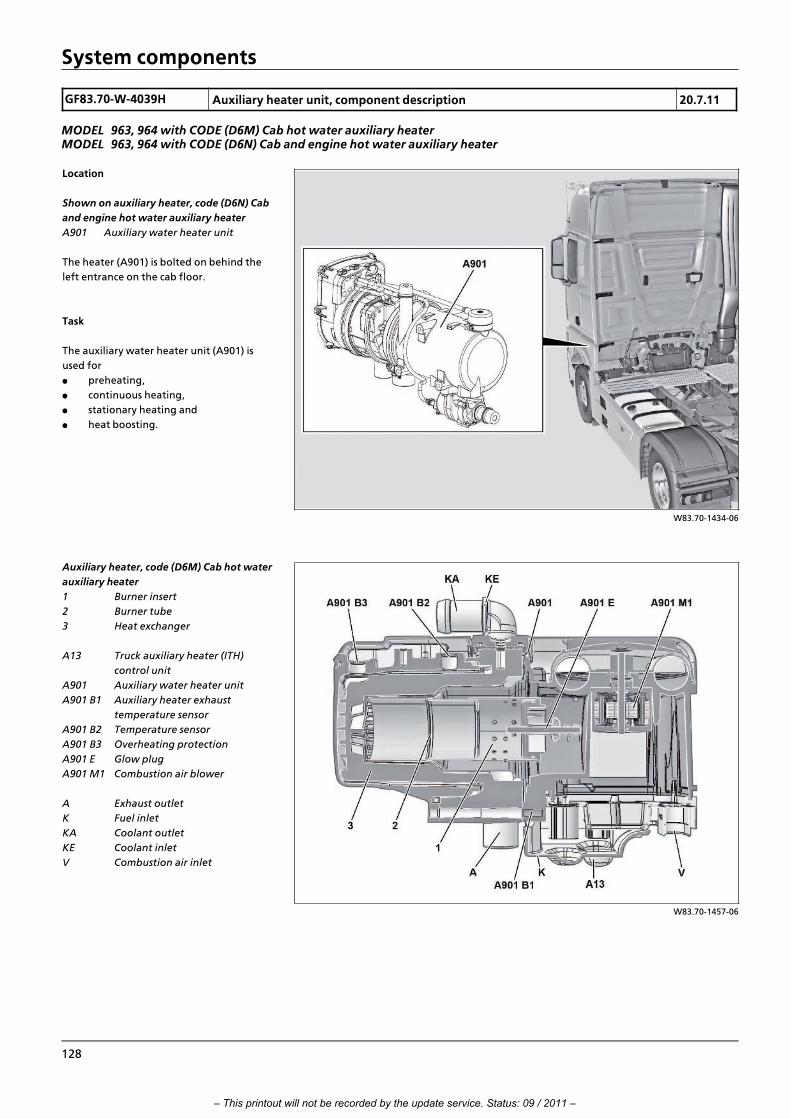
System components
GF83.70>W>4039H Auxiliary heater unit, component description 20.7.11
MODEL 963, 964 with CODE (D6M) Cab hot water auxiliary heaterMODEL 963, 964 with CODE (D6N) Cab and engine hot water auxiliary heater
W83.70>1434>06
Location
Shown on auxiliary heater, code (D6N) Cab
and engine hot water auxiliary heater
A901 Auxiliary water heater unit
The heater (A901) is bolted on behind the
left entrance on the cab floor.
Task
The auxiliary water heater unit (A901) is
used for
f preheating,
f continuous heating,
f stationary heating and
f heat boosting.
W83.70>1457>06
Auxiliary heater, code (D6M) Cab hot water
auxiliary heater
1 Burner insert
2 Burner tube
3 Heat exchanger
A13 Truck auxiliary heater (ITH)
control unit
A901 Auxiliary water heater unit
A901 B1 Auxiliary heater exhaust
temperature sensor
A901 B2 Temperature sensor
A901 B3 Overheating protection
A901 E Glow plug
A901 M1 Combustion air blower
A Exhaust outlet
K Fuel inlet
KA Coolant outlet
KE Coolant inlet
V Combustion air inlet
128
– This printout will not be recorded by the update service. Status: 09 / 2011 –

System components
W83.70>1458>06
Auxiliary heater, code (D6N) Cab and
engine hot water auxiliary heater
3 Heat exchanger
A13 Truck auxiliary heater (ITH)
control unit
A901 Auxiliary water heater unit
A901 B1 Auxiliary heater exhaust
temperature sensor
A901 B2 Temperature sensor
A901 B3 Overheating protection
A901 M1 Combustion air blower
A Exhaust outlet
K Fuel inlet
KA Coolant outlet
KE Coolant inlet
V Combustion air inlet
W83.70>1459>05
Auxiliary heater, code (D6N) Cab and
engine hot water auxiliary heater
1 Burner insert
2 Burner tube
3 Heat exchanger
A901 B1 Auxiliary heater exhaust
temperature sensor
A901 M1 Combustion air blower
A901 E Glow plug
i Introduction of engine OM 471 and exhaust aftertreatment > 09/2011 > 129
– This printout will not be recorded by the update service. Status: 09 / 2011 –

System components
GF83.70>W>4032H Auxiliary heater coolant circulation pump, component description 20.7.11
MODEL 963, 964 with CODE (D6M) Cab hot water auxiliary heaterMODEL 963, 964 with CODE (D6N) Cab and engine hot water auxiliary heater
W83.70>1436>11
Location
A901 M2 Circulation pump
KA Coolant outlet
KE Coolant inlet
The circulation pump (A901 M2) is connected on the outside to the
heater.
Task
The circulation pump (A901 M2) pumps coolant out of the
engine's cooling circuit, through the heater unit's heat exchanger
to the heater heat exchanger.
Design
Located in the circulation pump (A901 M2) is a DC motor, which
drives an impeller in an external housing. Located on the front
side of the circulation pump (A901 M2) is the coolant inlet (KE).
130
– This printout will not be recorded by the update service. Status: 09 / 2011 –
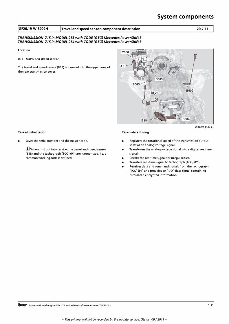
System components
GF26.19>W>3002H Travel and speed sensor, component description 20.7.11
TRANSMISSION 715 in MODEL 963 with CODE (G5G) Mercedes PowerShift 3TRANSMISSION 715 in MODEL 964 with CODE (G5G) Mercedes PowerShift 3
W26.19>1127>81
Location
B18 Travel and speed sensor
The travel and speed sensor (B18) is screwed into the upper area of
the rear transmission cover.
Task at initialization
f Saves the serial number and the master code.
i When first put into service, the travel and speed sensor
(B18) and the tachograph (TCO) (P1) are harmonized, i.e. a
common working code is defined.
Tasks while driving
f Registers the rotational speed of the transmission output
shaft as an analog voltage signal.
f Transforms the analog voltage signal into a digital realtime
signal.
f Checks the realtime signal for irregularities.
f Transfers real>time signal to tachograph (TCO) (P1).
f Receives data and command signals from the tachograph
(TCO) (P1) and provides an "I/O" data signal containing
cumulated encrypted information.
i Introduction of engine OM 471 and exhaust aftertreatment > 09/2011 > 131
– This printout will not be recorded by the update service. Status: 09 / 2011 –

System components
GF49.20>W>3001H Exhaust pressure sensor upstream of diesel oxidation catalytic converter,component description
20.7.11
ENGINES 471.9 in MODEL 963, 964 with CODE (M5Z) Engine version Euro VI
W14.40>1577>76
Location
1 Exhaust aftertreatment unit:
2 Pressure line
B37 Exhaust pressure sensor, upstream of
diesel oxidation catalytic converter
The exhaust pressure sensor upstream of
the diesel oxidation catalytic converter
(B37) is screwed into the deflection
chamber from the outside, upstream of the
diesel oxidation catalytic converter (DOC).
Task
The exhaust pressure sensor upstream of
the diesel oxidation catalytic converter
(B37) records the pressure at the defined
measuring point in the deflection chamber.
Design
Inside the stainless steel sensor housing there is a basic unit to
which two electrodes are attached.
The inner electrode is the measuring electrode, and the outer
electrode is the reference electrode. Above this, exposed to the
exhaust pressure, there is a pressure>sensitive ceramic membrane >
the shared counter>electrode.
Together, this configuration constitutes a plate capacitor. Since
the measuring principle is based on the capacity change, which is
extremely small, the sensor has processing electronics that are
extremely sensitive.
Function
The exhaust flowing past the probe deforms the membrane
because of its pressure. The deformation changes the distance
between the capacitor plates and therefore the capacity of the
capacitor. The integrated circuit converts the capacity change
signal into a defined voltage, from which the exhaust
aftertreatment control unit (ACM) (A60) calculates the exhaust
pressure level.
132
– This printout will not be recorded by the update service. Status: 09 / 2011 –

System components
GF49.20>W>3002H Exhaust pressure sensor downstream of diesel particulate filter, componentdescription
20.7.11
ENGINES 471.9 in MODEL 963, 964 with CODE (M5Z) Engine version Euro VI
W14.40>1578>76
Location
1 Exhaust aftertreatment unit:
2 Pressure line
B38 Exhaust pressure sensor
downstream of diesel particulate
filter
The exhaust pressure sensor downstream of
the diesel particulate filter (B38) is screwed
into the deflection chamber from the
outside, downstream of the diesel
particulate filter (DPF).
Task
The exhaust aftertreatment control unit
(ACM) (A60) records the pressure at the
defined measuring point in the deflection
chamber via the exhaust pressure sensor
downstream of the diesel particulate filter
(B38).
Design
Inside the stainless steel sensor housing there is a basic unit to
which two electrodes are attached.
The inner electrode is the measuring electrode, and the outer
electrode is the reference electrode. Above this, exposed to the
exhaust pressure, there is a pressure>sensitive ceramic membrane,
the shared counter>electrode.
Together, this configuration constitutes a plate capacitor. Since
the measuring principle is based on the capacity change, which is
extremely small, the sensor has processing electronics that are
extremely sensitive.
Function
The exhaust flowing past the probe deforms the membrane
because of its pressure. The deformation changes the distance
between the capacitor plates and therefore the capacity of the
capacitor. The integrated circuit converts the capacity change
signal into a defined voltage, from which the exhaust
aftertreatment control unit (ACM) (A60) calculates the exhaust
pressure level.
i Introduction of engine OM 471 and exhaust aftertreatment > 09/2011 > 133
– This printout will not be recorded by the update service. Status: 09 / 2011 –

System components
GF30.20>W>2012H Component description for accelerator pedal sensor 1.7.11
MODEL 963, 964
W30.20>1005>06
Location
B44 Accelerator pedal sensor
The accelerator pedal sensor (B44) is located
on the accelerator pedal in the driver
footwell at the front right.
Task
The accelerator pedal sensor (B44) detects the accelerator pedal
position.
Design
The accelerator pedal sensor (B44) consists of two Hall sensors.
Function
The Hall sensors integrated in the accelerator pedal sensor (B44)
transmit a respectively anticyclical signal. In this way perfect
position recognition of the accelerator pedal is achieved at any
time. This information is read in and appropriately processed by
the drive control (CPC) control unit (A3) by means of direct lines as
a pulse width modulation signal.
134
– This printout will not be recorded by the update service. Status: 09 / 2011 –

System components
GF49.20>W>3003H Exhaust temperature sensor upstream of diesel oxidation catalytic converter,component description
20.7.11
ENGINES 471.9 in MODEL 963, 964 with CODE (M5Z) Engine version Euro VI
W14.40>1579>76
Location
1 Exhaust aftertreatment unit:
B67 Exhaust temperature sensor
upstream of diesel oxidation
catalytic converter
Task
Via the exhaust temperature sensor
upstream of the diesel oxidation catalytic
converter (B67), the exhaust aftertreatment
control unit (ACM) (A60) records the
temperature of the exhaust flow in the
deflection chamber upstream of the diesel
oxidation catalytic converter (DOC).
Design
The sensor consists of a stainless steel housing. The housing
contains a measuring element, a PTC resistor.PTC stands for
"Positive Temperature Coefficient" and means that the electrical
resistance increases as the temperature increases.
Function
Depending on its temperature, the gas flowing past the probe
influences the measuring element inside, and makes its electrical
resistance change.
Since the sensor has a constant measuring current flowing
through it, the resistance change causes a voltage drop, via which
the exhaust aftertreatment control unit (ACM) (A60) can work out
the associated temperature value.
i Introduction of engine OM 471 and exhaust aftertreatment > 09/2011 > 135
– This printout will not be recorded by the update service. Status: 09 / 2011 –

System components
GF49.20>W>3004H Exhaust temperature sensor downstream of upper diesel oxidation catalyticconverter, component description
20.7.11
ENGINES 471.9 in MODEL 963, 964 with CODE (M5Z) Engine version Euro VI
W14.40>1580>76
Location
1 Exhaust aftertreatment unit:
B68 Exhaust temperature sensor
downstream of upper diesel
oxidation catalytic converter
Task
The exhaust aftertreatment control unit
(ACM) (A60) records the temperature of the
exhaust flow downstream of the upper
diesel oxidation catalytic converter (DOC)
via the exhaust temperature sensor
upstream of the upper diesel oxidation
catalytic converter (B68).
Design
The sensor consists of a stainless steel housing. The housing
contains a measuring element, a PTC resistor.PTC stands for
"Positive Temperature Coefficient" and means that the electrical
resistance increases as the temperature increases.
Function
Depending on its temperature, the gas flowing past the probe
influences the measuring element inside, and makes its electrical
resistance change.
Since the sensor has a constant measuring current flowing
through it, the resistance change causes a voltage drop, via which
the exhaust aftertreatment control unit (ACM) (A60) can work out
the associated temperature value.
136
– This printout will not be recorded by the update service. Status: 09 / 2011 –

System components
GF49.20>W>3005H Exhaust temperature sensor downstream of lower diesel oxidation catalyticconverter, component description
20.7.11
ENGINES 471.9 in MODEL 963, 964
W14.40>1581>76
Location
1 Exhaust aftertreatment unit:
B69 Exhaust temperature sensor
downstream of lower diesel
oxidation catalytic converter
Task
The exhaust aftertreatment control unit
(ACM) (A60) records the temperature of the
exhaust flow downstream of the lower
diesel oxidation catalytic converter (DOC)
via the exhaust temperature sensor
upstream of the lower diesel oxidation
catalytic converter (B69).
Design
The sensor consists of a stainless steel housing. The housing
contains a measuring element, a PTC resistor.PTC stands for
"Positive Temperature Coefficient" and means that the electrical
resistance increases as the temperature increases.
Function
Depending on its temperature, the gas flowing past the probe
influences the measuring element inside, and makes its electrical
resistance change.
Since the sensor has a constant measuring current flowing
through it, the resistance change causes a voltage drop, via which
the exhaust aftertreatment control unit (ACM) (A60) can work out
the associated temperature value.
i Introduction of engine OM 471 and exhaust aftertreatment > 09/2011 > 137
– This printout will not be recorded by the update service. Status: 09 / 2011 –

System components
GF49.20>W>3006H Exhaust temperature sensor downstream of diesel particulate filter, componentdescription
20.7.11
ENGINES 471.9 in MODEL 963, 964 with CODE (M5Z) Engine version Euro VI
W14.40>1583>76
Location
1 Exhaust aftertreatment unit:
B70 Exhaust temperature sensor
downstream of diesel particulate
filter
Task
The exhaust aftertreatment control unit
(ACM) (A60) records the temperature of the
exhaust flow downstream in the deflection
chamber downstream of the diesel
particulate filter (DPF) via the exhaust
temperature sensor downstream of the
diesel particulate filter (B70).
Design
The sensor consists of a stainless steel housing. The housing
contains a measuring element, a PTC resistor.PTC stands for
"Positive Temperature Coefficient" and means that the electrical
resistance increases as the temperature increases.
Function
Depending on its temperature, the gas flowing past the probe
influences the measuring element inside, and makes its electrical
resistance change.
Since the sensor has a constant measuring current flowing
through it, the resistance change causes a voltage drop, via which
the exhaust aftertreatment control unit (ACM) (A60) can work out
the associated temperature value.
138
– This printout will not be recorded by the update service. Status: 09 / 2011 –

System components
GF49.20>W>3013HA Exhaust temperature sensor upstream of SCR catalytic converter, componentdescription
2.8.11
ENGINES 471.9 in MODEL 963, 964 with CODE (M5Z) Engine version Euro VIENGINES 471.9 in MODEL 963, 964 with CODE (M5R) Engine version EEV
W14.40>1593>76
Location
1 Exhaust aftertreatment unit
B72 Exhaust temperature sensor
upstream of SCR catalytic converter
Task
The exhaust aftertreatment (ACM) control
unit (A60) registers the temperature of the
exhaust flow in the inlet tube of the
exhaust aftertreatment unit (1) via the
temperature sensor exhaust upstream of
the SCR catalytic converter (B72).
Design
The exhaust temperature sensor upstream of SCR catalytic
converter (B72) consists of a stainless steel housing. The inside
contains a measuring element, a PTC resistor. PTC stands for
"Positive Temperature Coefficient" and means that the electrical
resistance increases as the temperature increases.
Function
The exhaust blowing by the sensor influences the measuring
element on the inside depending on its temperature and leads to
a change in its electric resistance.
Since a constant measurement current flows through the exhaust
temperature sensor upstream of SCR catalytic converter (B72),
there is a voltage drop due to the change in resistance, which the
exhaust aftertreatment (ACM) control unit (A60) can use to derive
the associated temperature value.
i Introduction of engine OM 471 and exhaust aftertreatment > 09/2011 > 139
– This printout will not be recorded by the update service. Status: 09 / 2011 –

System components
GF49.20>W>3007HA Exhaust temperature sensor downstream of SCR catalytic converter, componentdescription
2.8.11
ENGINES 471.9 in MODEL 963, 964 with CODE (M5Y) Engine version Euro VENGINES 471.9 in MODEL 963, 964 with CODE (M5R) Engine version EEV
W14.40>1594>76
Location
1 Exhaust aftertreatment unit
B73 Exhaust temperature sensor
downstream of SCR catalytic
converter
Task
The exhaust aftertreatment (ACM) control
unit (A60) registers the temperature of the
exhaust flow in the chamber downstream
of the SCR catalytic converter via the
exhaust temperature sensor downstream of
SCR catalytic converter (B73).
Design
The exhaust temperature sensor downstream of SCR catalytic
converter (B73) consists of a stainless steel housing. The inside
contains a measuring element, a PTC resistor. PTC stands for
"Positive Temperature Coefficient" and means that the electrical
resistance increases as the temperature increases.
Function
The exhaust blowing by the sensor influences the measuring
element on the inside depending on its temperature and leads to
a change in its electric resistance.
Since a constant measurement current flows through the exhaust
temperature sensor downstream of SCR catalytic converter (B73),
there is a voltage drop due to the change in resistance, which the
exhaust aftertreatment (ACM) control unit (A60) can use to derive
the associated temperature value.
140
– This printout will not be recorded by the update service. Status: 09 / 2011 –

System components
GF49.20>W>3007H Exhaust temperature sensor downstream of SCR catalytic converter, componentdescription
20.7.11
ENGINES 471.9 in MODEL 963, 964 with CODE (M5Z) Engine version Euro VI
W14.40>1584>76
Location
1 Exhaust aftertreatment unit:
B73 Exhaust temperature sensor
downstream of SCR catalytic
converter
Task
The exhaust aftertreatment control unit
(ACM) (A60) records the temperature of the
exhaust flow in the chamber downstream
of the SCR catalytic converter via the
exhaust temperature sensor downstream of
the SCR catalytic converter (B73).
Design
The sensor consists of a stainless steel housing. The housing
contains a measuring element, a PTC resistor.PTC stands for
"Positive Temperature Coefficient" and means that the electrical
resistance increases as the temperature increases.
Function
Depending on its temperature, the gas flowing past the probe
influences the measuring element inside, and makes its electrical
resistance change.
Since the sensor has a constant measuring current flowing
through it, the resistance change causes a voltage drop, via which
the exhaust aftertreatment control unit (ACM) (A60) can work out
the associated temperature value.
i Introduction of engine OM 471 and exhaust aftertreatment > 09/2011 > 141
– This printout will not be recorded by the update service. Status: 09 / 2011 –
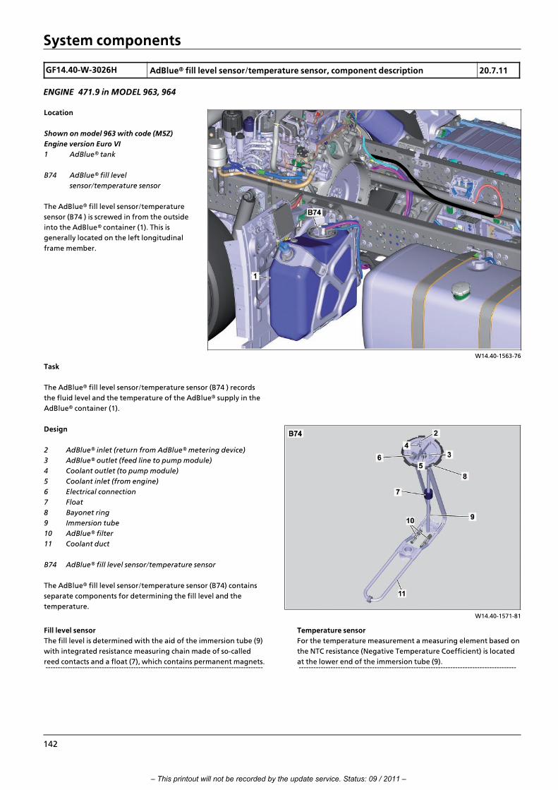
System components
GF14.40>W>3026H AdBlue“ fill level sensor/temperature sensor, component description 20.7.11
ENGINE 471.9 in MODEL 963, 964
W14.40>1563>76
Location
Shown on model 963 with code (M5Z)
Engine version Euro VI
1 AdBlue“ tank
B74 AdBlue“ fill level
sensor/temperature sensor
The AdBlue“ fill level sensor/temperature
sensor (B74 ) is screwed in from the outside
into the AdBlue“ container (1). This is
generally located on the left longitudinal
frame member.
Task
The AdBlue“ fill level sensor/temperature sensor (B74 ) records
the fluid level and the temperature of the AdBlue“ supply in the
AdBlue“ container (1).
W14.40>1571>81
Design
2 AdBlue“ inlet (return from AdBlue“ metering device)
3 AdBlue“ outlet (feed line to pump module)
4 Coolant outlet (to pump module)
5 Coolant inlet (from engine)
6 Electrical connection
7 Float
8 Bayonet ring
9 Immersion tube
10 AdBlue“ filter
11 Coolant duct
B74 AdBlue“ fill level sensor/temperature sensor
The AdBlue“ fill level sensor/temperature sensor (B74) contains
separate components for determining the fill level and the
temperature.
Fill level sensor
The fill level is determined with the aid of the immersion tube (9)
with integrated resistance measuring chain made of so>called
reed contacts and a float (7), which contains permanent magnets. >>>>>>>>>>>>>>>>>>>>>>>>>>>>>>>>>>>>>>>>>>>>>>>>>>>>>>>>>>>>>>>>>>>>>>>>>>>>>>>>>>>>>>>>>
Temperature sensor
For the temperature measurement a measuring element based on
the NTC resistance (Negative Temperature Coefficient) is located
at the lower end of the immersion tube (9). >>>>>>>>>>>>>>>>>>>>>>>>>>>>>>>>>>>>>>>>>>>>>>>>>>>>>>>>>>>>>>>>>>>>>>>>>>>>>>>>>>>>>>>>>
142
– This printout will not be recorded by the update service. Status: 09 / 2011 –

System components
Function
Determination of the fill level
The sensor to determine the fill level functions according to the
float principle with magnetic transfer. A ring magnet fitted in the
float (7) actuates tiny reed contacts via its magnetic field through
the wall of the immersion tube (9). These reed contacts pick up an
uninterrupted measured voltage at a resistor data channel
(voltage divider principle), which is proportional to the height of
the fill level.
The values of the electrical resistance that changes along with the
position of the float (7) are transmitted in defined intervals as an
analog signal over the exhaust aftertreatment (ACM) control unit
(A60) to the engine management (MCM) control unit (A4). Using
the resistance value, this calculates the associated fill level.
Determination of temperature
The AdBlue surrounding the AdBlue“ fill level sensor/temperature
sensor (B74) influences the inside of the measuring element
according to its temperature and therefore the size of the
electrical resistance.
The values of the electrical resistance that changes are
transmitted in defined intervals as an analog signal over the
exhaust aftertreatment (ACM) control unit (A60) to the engine
management (MCM) control unit (A4). Based on the resistance
value, the MR control unit calculates the associated temperature.
i Introduction of engine OM 471 and exhaust aftertreatment > 09/2011 > 143
– This printout will not be recorded by the update service. Status: 09 / 2011 –

System components
GF20.30>W>1002H Coolant pressure control sensor, component description 20.7.11
MODEL 963, 964 with CODE (B3H) Secondary water retarder
W20.30>1027>76
Location
Shown on model 963, front coolant
expansion reservoir
B87 Coolant pressure control sensor
The coolant pressure control sensor (B87) is
located on the coolant expansion reservoir.
Task
The coolant pressure control sensor (B87) monitors the pressure in
the coolant circuit. The signals from the coolant pressure control
sensor (B87) are read in directly by the drive control (CPC) control
unit (A3). The drive control (CPC) control unit (A3) uses them to
calculate the set values for the coolant pressure control solenoid
valve (Y57).
144
– This printout will not be recorded by the update service. Status: 09 / 2011 –

System components
GF03.20>W>4100H Component description for crankshaft position sensor 20.7.11
ENGINES 471.9 in MODEL 963
W07.04>1073>12
Location
B600 Crankshaft position sensor
The crankshaft position sensor (B600) is located on the left on the
timing case.
Task
The crankshaft position sensor (B600) makes electrical voltage
signals available to the engine management (MCM) control unit
(A4) for a rotating engine from which the rotational speed as well
as the position of the crankshaft can be determined.
Design
The crankshaft position sensor (B600) is an inductive sensor and is
fitted with a sensor coil as well as a permanent magnet.
Function
The permanent magnet on the camshaft position sensor (B600)
generates a magnetic field. Once the flywheel is rotated,
magnetic field fluctuations occur due to grooves in the flywheel
which are located, up to a gap of 18∞, 6∞ apart around the flywheel
circumference. Inductive voltage signals are generated in this way
in the crankshaft position sensor coil (B600) with the aid of which
the engine management (MCM) control unit (A4) can determine
the engine speed and, by using the gap of 18∞, the angular
position of the crankshaft.
i Introduction of engine OM 471 and exhaust aftertreatment > 09/2011 > 145
– This printout will not be recorded by the update service. Status: 09 / 2011 –

System components
GF05.20>W>4105H Component description for camshaft position sensor 20.7.11
ENGINES 471.9 in MODEL 963
W05.20>1035>06
Location
B601 Camshaft position sensor
The camshaft position sensor (B601) is
located on the camshaft frame at the height
of cylinder 6 next to the rail.
Task
The camshaft position sensor (B601) makes a switching signal
available to the engine management (MCM) control unit (A4) for
rotating engine from which the compression cycle of cylinder 1
and, as required (in limp>home mode, in case of failure of the
crankshaft position sensor), the engine speed or crankshaft
position can be determined.
Design
The camshaft position sensor (B601) is a Hall sensor and is fitted
with a permanent magnet as well as an electronic analysis system.
Function
The permanent magnet on the camshaft position sensor (B601)
generates a magnetic field. When the camshaft rotates,
fluctuations in the magnetic field occur due to the grooves in the
camshaft sprocket. These changes in the magnetic field are
converted by the electronic analysis system in the camshaft
position sensor (B601) into shift signals and passed on to the
engine management (MCM) control unit (A4).
146
– This printout will not be recorded by the update service. Status: 09 / 2011 –

System components
GF47.50>W>4100H Component description for fuel temperature sensor 20.7.11
ENGINES 471.9 in MODEL 963
W47.50>1010>12
Location
B602 Fuel temperature sensor
The fuel temperature sensor (B602) is on the left>hand side of the
crankcase, next to the fuel filter module.
Task
The engine management control unit (MCM) (A4) records the fuel
temperature via the fuel temperature sensor (B602).
Design
There is an NTC resistor inside the fuel temperature sensor (B602).
NTC stands for "Negative Temperature Coefficient", which means
that electrical resistance falls as temperature rises.
Function
The fuel at the fuel temperature sensor (B602) influences the
temperature measuring element inside the sensor depending on
its temperature and thus the size of the electrical resistance. The
engine management control unit (MCM) (A4) derives the
associated temperature from the electrical resistance.
i Introduction of engine OM 471 and exhaust aftertreatment > 09/2011 > 147
– This printout will not be recorded by the update service. Status: 09 / 2011 –

System components
GF18.40>W>2010H Oil pressure sensor, description of components 20.7.11
ENGINE 471.9 in MODEL 963
W18.40>1034>06
Location
B604 Oil pressure sensor
The oil pressure sensor (B604) is screwed on
below the coolant pump into the crankcase.
Task
The oil pressure sensor (B604) enables the
engine management (MCM) control unit
(A4) to determine the current engine oil
pressure.
W18.40>1029>01
Design
1 Sensor element
2 Sensor membrane
3 Hybrid element
B604 Oil pressure sensor
Function
The engine oil pressure operates on the sensor element (1) of the
hybrid element (3) and distorts the sensor membrane (2).
There are four pressure>dependent resistances (strain measuring
resistors) on the sensor membrane (2). Its bridge circuit is supplied
with voltage by an electronic analysis system which also serves for
signal amplification and signal correction. The electronic analysis
system is powered by the engine management (MCM) control unit
(A4) with 5 V direct voltage.
The resistors in the sensor membrane (2) are arranged in such a
way that on deforming the sensor membrane (2) two resistors are
clinched and two resistors elongated.
Contraction and elongation changes the electrical resistance of
the resistors which in turn has effects upon the measurement
voltage, which is being applied to the electronic analysis system.
The electronic analysis system amplifies the measurement voltage,
compensating for possible temperature fluctuations or balancing
out possible manufacturing tolerances on the resistances and
passes on the cleared out measurement voltage to the engine
management (MCM) control unit (A4) which uses it to derive the
current engine oil pressure.
148
– This printout will not be recorded by the update service. Status: 09 / 2011 –

System components
GF18.40>W>4117H Component description for engine oil fill level sensor 20.7.11
ENGINE 471.9 in MODEL 963
W18.40>1033>12
Location
B605 Engine oil fill level sensor
The engine oil fill level sensor (B605) is located onto the right side
of the engine and screwed into the oil pan from above.
Task
The engine oil fill level sensor (B605) enables the engine
management (MCM) control unit (A4) to determine the
instantaneous fill level as well as the engine oil temperature in the
oil pan.
Design
Located inside the engine oil fill level sensor (B605) is a series
resistor and resistance wire, which are connected in parallel to
each other, as well as an NTC resistor, which is connected before
them in series. NTC stands for "Negative Temperature
Coefficient", which means that electrical resistance falls as
temperature rises. >>>>>>>>>>>>>>>>>>>>>>>>>>>>>>>>>>>>>>>>>>>>>>>>>>>>>>>>>>>>>>>>>>>>>>>>>>>>>>>>>>>>>>>>>
The resistance wire is located in the measuring probe.
The engine oil fill level sensor (B605) is installed in such a way that
the measuring probe dips fully into the engine oil when the
engine oil level is correct.
The NTC resistor is located at the tip of the sensor.
>>>>>>>>>>>>>>>>>>>>>>>>>>>>>>>>>>>>>>>>>>>>>>>>>>>>>>>>>>>>>>>>>>>>>>>>>>>>>>>>>>>>>>>>>
Function
Determine engine oil level
Engine oil passes via a feed hole into the measuring probe of the
engine oil fill level sensor (B605) and thus directly to the resistance
wire.
Depending on how far the resistance wire dips into the engine oil
the overall resistance at the engine oil fill level sensor (B605)
changes and drops with a reducing engine oil level.
After switching on of the ignition, the engine management
(MCM) control unit (A4) applies a measurement voltage every 6 s
to the engine oil fill level sensor (B605). It checks the electrical
overall resistance of the engine oil fill level sensor (B605) and uses
it to deduce the current engine oil level in the oil pan.
Measurement of engine oil temperature
The engine oil at the engine oil fill level sensor (B605) influences
the temperature measuring element inside the sensor depending
on its temperature and therefore the electrical resistance value.
The engine management (MCM) control unit (A4) deduces the
associated temperature from the electrical resistance.
i Introduction of engine OM 471 and exhaust aftertreatment > 09/2011 > 149
– This printout will not be recorded by the update service. Status: 09 / 2011 –

System components
GF20.00>W>4100H Component description for exhaust coolant temperature sensor 20.7.11
ENGINE 471.9 in MODEL 963
W07.04>1078>06
Location
B606 Exhaust coolant temperature
sensor
The exhaust coolant temperature sensor
(B606) is located on the front side of the
coolant manifold which is on the right side
of engine between the cylinder head and
the exhaust gas recirculation cooler.
Task
The coolant outlet temperature sensor (B606) enables the engine
management (MCM) control unit (A4) to determine the current
coolant temperature at the engine outlet.
Design
There is an NTC resistor inside the exhaust coolant temperature
sensor (B606). NTC stands for "Negative Temperature
Coefficient", which means that electrical resistance falls as
temperature rises.
Function
The coolant at the exhaust coolant temperature sensor (B606)
influences the temperature measuring element inside the sensor
depending on its temperature and thus the size of the electrical
resistance. The engine management (MCM) control unit (A4)
deduces the associated temperature from the electrical resistance.
150
– This printout will not be recorded by the update service. Status: 09 / 2011 –

System components
GF20.00>W>4110H Component description for intake coolant temperature sensor 20.7.11
ENGINE 471.9 in MODEL 963
W20.00>1052>06
Location
Shown with code (M5Z) Euro VI engine
version
B607 Intake coolant temperature sensor
The intake coolant temperature sensor
(B607) is located under the coolant pump
on the oil/coolant module.
Task
The coolant inlet temperature sensor (B607) enables the engine
management (MCM) control unit (A4) to determine the current
coolant temperature downstream of the coolant pump.
Design
There is an NTC resistor inside the intake coolant temperature
sensor (B607). NTC stands for "Negative Temperature
Coefficient", which means that electrical resistance falls as
temperature rises.
Function
The coolant at the intake coolant temperature sensor (B607)
influences the temperature measuring element inside the sensor
depending on its temperature and thus the size of the electrical
resistance. The engine management (MCM) control unit (A4)
deduces the associated temperature from the electrical resistance.
i Introduction of engine OM 471 and exhaust aftertreatment > 09/2011 > 151
– This printout will not be recorded by the update service. Status: 09 / 2011 –

System components
GF09.41>W>4130H Charge air pressure and temperature sensor in charge air pipe, componentdescription
20.7.11
ENGINE 471.9 in MODEL 963
W07.04>1072>12
Location
B608 Charge air pressure and temperature sensor in charge air
pipe
The charge air pressure and temperature sensor in the charge air
pipe (B608) is located on the charge air pipe on the left side of the
engine.
Task
The charge air pressure and temperature sensor in the charge air
pipe (B608) enables the engine management (MCM) control unit
(A4) to determine the air pressure and the air temperature of the
aspirated or supercharged combustion air.
These two values and the values of the differential pressure sensor
exhaust gas recirculation (EGR) (B621), the charge air temperature
sensor in the charge air housing (B617), as well as the values of the
temperature sensor downstream of the air filter (B611) with code
(M5Z) Euro VI engine version, are used to deduce the air mass that
is routed to the engine for combustion.
Design
The charge air pressure and temperature sensor (B608) consists of
two electrically separate components for measuring the boost
pressure and the charge air temperature.
Pressure sensor for determining the charge air temperature
The pressure sensor is a so>called semiconductor pressure sensor
which detects the air pressure in the charge air pipe by means of
the piezoelectric principle. This consists of four pressure>
dependent resistors (strain measuring resistors) which are
arranged in a silicon membrane as well as an electronic analysis
system which is supplied with a 5 V DC voltage via the engine
management (MCM) control unit (A4).
Temperature sensor for measurement of the charge air
temperature
There is an NTC resistor at the cone point of the charge air
pressure and temperature sensor in the charge air pipe (B608).
NTC stands for "Negative Temperature Coefficient", which means
that electrical resistance falls as temperature rises.
Function
Determining the boost pressure
The intake air or supercharged combustion air in the charge air
housing passes over a bore in the silicon diaphragm with the four
pressure>dependent resistors and distorts it.
The resistors in the silicon membrane are arranged in such a way
that, on deformation of the membrane, the transverse stress of
the resistance bridge is altered.
The electronic analysis system amplifies this transverse stress and
compensates in this way for possible temperature fluctuations or
compensates for any manufacturing tolerances of the resistors. It
subsequently routes the filtered measurement voltage to the
engine management (MCM) control unit (A4) which then deduces
the air pressure in the charge air housing.
Measuring the charge air temperature
Depending on its temperature, the air flowing by influences the
temperature of the measuring element on the tip of the sensor
and therefore the electrical resistance value. The engine
management (MCM) control unit (A4) deduces the associated
temperature from the electrical resistance.
152
– This printout will not be recorded by the update service. Status: 09 / 2011 –

System components
GF09.40>W>4050H Component description for turbine wheel rpm sensor 1.7.11
ENGINES 471.9 in MODEL 963 with CODE (M5Z) Engine version Euro VI
W09.40>1229>06
Location
B610 Turbine wheel rpm sensor
The turbine wheel rpm sensor (B610) is
located in the center of the turbocharger.
Task
The engine management (MCM) control unit (A4) detects the
rotor speed of the turbocharger over the turbine wheel rpm
sensor (B610).
The rotor speed is used to protect the turbocharger from running
at excessively high rotational speeds.
Design
The turbine wheel rpm sensor (B610) is an inductive sensor and
possesses a permanent magnet as well as a sensor coil.
Function
The permanent magnet on the turbine wheel rpm sensor (B610)
generates a magnetic field. Magnetic field changes occur due to a
groove in the turbocharger shaft when the shaft turns. A voltage
is induced in the coil of the turbine wheel rpm sensor (B610) or
inductive voltage signals are generated. With the aid of these
signals the engine management (MCM) control unit (A4) can
determine the rotor speed.
i Introduction of engine OM 471 and exhaust aftertreatment > 09/2011 > 153
– This printout will not be recorded by the update service. Status: 09 / 2011 –
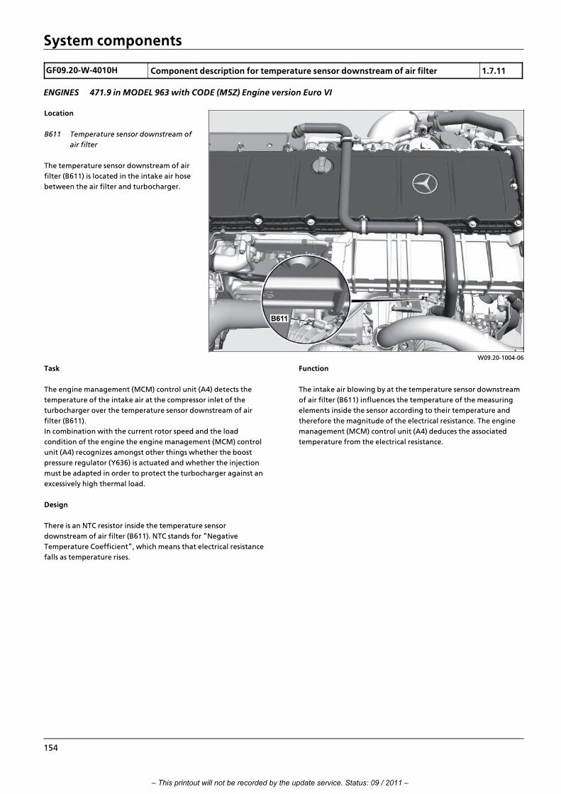
System components
GF09.20>W>4010H Component description for temperature sensor downstream of air filter 1.7.11
ENGINES 471.9 in MODEL 963 with CODE (M5Z) Engine version Euro VI
W09.20>1004>06
Location
B611 Temperature sensor downstream of
air filter
The temperature sensor downstream of air
filter (B611) is located in the intake air hose
between the air filter and turbocharger.
Task
The engine management (MCM) control unit (A4) detects the
temperature of the intake air at the compressor inlet of the
turbocharger over the temperature sensor downstream of air
filter (B611).
In combination with the current rotor speed and the load
condition of the engine the engine management (MCM) control
unit (A4) recognizes amongst other things whether the boost
pressure regulator (Y636) is actuated and whether the injection
must be adapted in order to protect the turbocharger against an
excessively high thermal load.
Design
There is an NTC resistor inside the temperature sensor
downstream of air filter (B611). NTC stands for "Negative
Temperature Coefficient", which means that electrical resistance
falls as temperature rises.
Function
The intake air blowing by at the temperature sensor downstream
of air filter (B611) influences the temperature of the measuring
elements inside the sensor according to their temperature and
therefore the magnitude of the electrical resistance. The engine
management (MCM) control unit (A4) deduces the associated
temperature from the electrical resistance.
154
– This printout will not be recorded by the update service. Status: 09 / 2011 –

System components
GF09.41>W>4125H Component description for charge temperature sensor in charge air housing 2.8.11
ENGINES 471.9 in MODEL 963
W09.41>1059>06
Location
B617 Charge temperature sensor in
charge air housing
The charge air temperature sensor in the
charge air housing (B617) is located on the
charge air housing.
Task
Over the charge air temperature sensor downstream in the charge
air housing (B617), the engine management (MCM) control unit
(A4) detects the temperature of the charge air shortly before it
enters the combustion chamber.
The engine management (MCM) control unit (A4) determines the
effective recycled exhaust mass using the charge air temperature
and values from the exhaust recirculation (AGR) differential
pressure sensor (B621) which plays a significant role in calculating
the exhaust recirculation rate.
Design
There is an NTC resistor located inside the charge air temperature
sensor in the charge air housing (B617). NTC stands for "Negative
Temperature Coefficient", which means that electrical resistance
falls as temperature rises.
Function
The charge air prevailing at the charge air temperature sensor in
the charge air housing (B617), depending on its temperature,
influences the temperature of the measuring element inside the
sensor and thus the magnitude of the electrical resistance. The
engine management (MCM) control unit (A4) deduces the
associated temperature from the electrical resistance.
i Introduction of engine OM 471 and exhaust aftertreatment > 09/2011 > 155
– This printout will not be recorded by the update service. Status: 09 / 2011 –

System components
GF14.20>W>1004H Component description for EGR differential pressure sensor 2.8.11
ENGINES 471.9 in MODEL 963, 964
W14.20>1023>76
Location
1 Exhaust gas recirculation cooler
2 Exhaust gas recirculation pipe
B621 Exhaust gas recirculation (AGR)
differential pressure sensor
The EGR (AGR) differential pressure sensor
(B621) is located on the front side of the
engine, where it is screwed in from the
outside into the exhaust gas recirculation
pipe (2).
Task
The EGR (AGR) differential pressure sensor
(B621) supplies the engine management
(MCM) control unit (A4) with information in
order to calculate the EGR volumetric flow
rate.
W14.20>1024>81
Design
3 Electrical connection
4 High pressure connection
5 Low>pressure connection
6 Seals
7 Bolts
The EGR (AGR) differential pressure sensor (B621) consists of a
plastic housing which it fitted inside with two chambers which is
separated from a thin membrane which functions as a mechanical
intermediate stage. Four strain gauge resistances (DMS) are
located on the membrane in the bridge circuit.
The membrane is exposed on one side to the exhaust and thus the
pressure.
The EGR (AGR) differential pressure sensor (B621) is fitted with an
electronic analysis system and for signal transmission to the engine
management (MCM) control unit (A4) and a power supply due to
the bridge circuit it contains
Function
If the exhaust recycling pipe (2) has exhaust flowing through it
there is a respective pressure applied at the part of the membrane
in the EGR (AGR) differential pressure sensor (B621) exposed to
the exhaust. This is therefore distorted and the strain gauge
resistances (DMS) are elongated or squashed. The strain gauge
resistances (DMS) reacts to the change in length with a change in
its ohmic resistance. These values are prepared by the electronic
analysis system and transmitted as analog signals to the engine
management (MCM) control unit (A4).
Since the EGR (AGR) differential pressure sensor (B621) has a
constant measuring current flowing through it there is a voltage
drop due to the change in resistance over which the engine
management (MCM) control unit (A4) can deduce the associated
pressure value.
156
– This printout will not be recorded by the update service. Status: 09 / 2011 –

System components
GF07.04>W>6253H Component description for rail pressure sensor 20.7.11
ENGINES 471.9 in MODEL 963
W07.04>1080>05
Location
B622 Rail pressure sensor
The rail pressure sensor (B622) is located at
the front on the rail.
Task
The engine management (MCM) control
unit (A4) determines the current rail
pressure via the rail pressure sensor (B622).
W07.04>1071>01
Design
1 Sensor element
2 Sensor membrane
3 Hybrid element
B622 Rail pressure sensor
Function
The rail pressure operates on the sensor element (1) of the hybrid
element (3) and distorts the sensor membrane (2).
There are four pressure>dependent resistances (strain measuring
resistors) on the sensor membrane (2). Its bridge circuit is supplied
with voltage by an electronic analysis system which also serves for
signal amplification and signal correction. The electronics analysis
system itself is provided with a 5 V DC voltage by the engine
management (MCM) control unit (A4).
The resistors in the sensor membrane (2) are arranged in such a
way that on deforming the sensor membrane (2) two resistors are
clinched and two resistors elongated.
Contraction and elongation changes the electrical resistance of
the resistors which in turn has effects upon the measurement
voltage, which is being applied to the electronic analysis system.
The electronic analysis system amplifies the measurement voltage,
compensating for possible temperature fluctuations or balancing
out possible manufacturing tolerances on the resistances and
passes on the cleared out measurement voltage to the engine
management (MCM) control unit (A4) which uses it to derive the
current rail pressure.
i Introduction of engine OM 471 and exhaust aftertreatment > 09/2011 > 157
– This printout will not be recorded by the update service. Status: 09 / 2011 –

System components
GF49.20>W>3011H Diesel fuel metering device, component description 20.7.11
ENGINES 471.9 in MODEL 963, 964 with CODE (M5Z) Engine version Euro VI
W49.20>1017>76
Location
1 Diesel fuel metering device
2 Nozzle unit for DPF regeneration
3 Fuel line
4 Exhaust pipe
5 Coolant line
6 Coolant line
7 Leakage line
The diesel fuel metering device (1) is on the
left>hand side of the engine behind the fuel
system high pressure pump.
Task
The diesel fuel metering device (1) is used to
provide the required quantity of diesel fuel
for injecting into the exhaust pipe (4)
during active diesel particulate filter (DPF)
regeneration.
W49.20>1018>76
Design
1 Diesel fuel metering device
2 Nozzle unit for DPF regeneration
3 Fuel line
4 Exhaust pipe
5 Coolant line
B625 Fuel pressure sensor (inlet)
B626 Fuel pressure sensor (outlet)
Y628 Fuel metering valve
Y629 Fuel shutoff valve
The diesel fuel metering device (1) is a
component that is permeated with fuel
channels and has an aluminum body. The
sensors that are placed on it have their
measuring probes inserted into the fuel
channels.
It is connected to the nozzle unit (2) via the
fuel line (3).
Function
When the exhaust aftertreatment control unit (ACM) (A60)
decides that active regeneration of the diesel particulate filter
(DPF) is required on the basis of the values provided by the sensor
system, it sends a request to the engine management control unit
(MCM) (A4). This actuates the fuel shutoff valve (Y629), so that
diesel fuel from the low>pressure circuit enters the component.
The fuel metering valve (Y628) is also opened at defined intervals.
The calculated quantity of diesel fuel therefore flows into the
feed line to the nozzle unit for DPF regeneration (2).
The two pressure sensors deliver values that are used in the valve
opening time calculation.
158
– This printout will not be recorded by the update service. Status: 09 / 2011 –

System components
GF47.50>W>4110H Fuel filter module pressure sensor, component description 20.7.11
ENGINES 471.9 in MODEL 963
W47.50>1009>06
Location
B638 Fuel filter module pressure sensor
The fuel filter module pressure sensor
(B638) is on the left>hand side of the
crankcase at the fuel filter module.
Task
With the aid of the fuel filter module pressure sensor (B638) the
engine management control unit (MCM) (A4) can detect whether
the fuel filter element needs to be changed. The fuel filter module
pressure sensor (B638) is also used for diagnostic purposes.
Design
The fuel filter module pressure sensor (B638) is a so>called
semiconductor pressure sensor which detects the fuel pressure in
the fuel filter module using the piezo>electric principle. This
consists of 4 pressure>dependent resistors (strain measuring
resistors) which are arranged in a silicon membrane, and an
electronic analysis system which is supplied with a 5 V DC voltage
via the engine management control unit (MCM).
Function
The fuel pressure acts upon the silicon membrane with the four
pressure>dependent resistors and deforms it. The resistors in the
silicon membrane are arranged in such a way that 2 resistors are
contracted and 2 resistors are elongated when the sensor
membrane is deformed.
Contraction and elongation changes the electrical resistance of
the resistors which in turn has effects upon the measurement
voltage, which is being applied to the electronic analysis system.
The electronic analysis system amplifies the measuring voltage,
compensating for possible temperature fluctuations and
manufacturing tolerances in the resistors. The measuring voltage
which has been "cleaned" in this way is forwarded to the engine
management control unit (MCM) (A4), which uses it to derive the
current fuel pressure in the fuel filter module and the load
condition of the fuel filter element.
i Introduction of engine OM 471 and exhaust aftertreatment > 09/2011 > 159
– This printout will not be recorded by the update service. Status: 09 / 2011 –

System components
GF20.00>W>4000H Component description for coolant pump 20.7.11
MODEL 963, 964 with CODE (M7T) Coolant pump, controlled
W20.10>1071>05
Location
1 Coolant pump
The coolant pump (1) is located at the left
front on the engine.
Task
The coolant pump (1) is used to recirculate the coolant in the
engine's cooling circuit. The coolant is recirculated in a demand>
oriented manner as a function of the operating condition. In
other words, the engine management (MCM) control unit (A4)
continuously regulates the coolant pump's (1) delivery rate
through an electromagnetic viscous coupling.
This means that the delivery rate is reduced, in particular, in the
partial load range. The reduced delivery rate cuts the required
drive energy, whereupon the fuel consumption is reduced
accordingly.
Design
Sectional view
2 Base body
3 Cover
4 Working chamber (filled with silicone oil)
5 Viscous disk
6 Intermediate disk
7 Armature (with valve lever)
8 O>ring (sealing ring)
9 Belt pulley
10 Two>collar bearing (with drive shaft)
11 Slide ring seal
12 Seal (to engine)
13 Pump impeller
14 Signal ring for coolant pump rpm sensor (B640)
15 Pump housing
16 Solenoid
B640 Coolant pump rpm sensor
Y631 Coolant pump solenoid valve
W20.10>1072>73
160
– This printout will not be recorded by the update service. Status: 09 / 2011 –

System components
Function
The frictional connection between the belt pulley (9) and the
drive shaft is made by an electromagnetic viscous coupling, which
is actuated by the engine management (MCM) control unit (A4).
i The power is transmitted between the belt pulley (9) and the
drive shaft through the silicone oil shearing in the working
chamber (4). Shearing is understood to mean the displacement of
silicone oil between the basic body's (2) drive slats and the drive
slats of the viscous coupling (5).
The engine management (MCM) control unit (A4) requires the
speed of the coupling drive (rotational speed of pump impeller
(13)) and the drive speed of the belt pulley (9) to regulate the
electromagnetic viscous coupling.
The belt pulley (9) drive speed is determined using the engine rpm
and the diameter of the belt pulley (9).
>>>>>>>>>>>>>>>>>>>>>>>>>>>>>>>>>>>>>>>>>>>>>>>>>>>>>>>>>>>>>>>>>>>>>>>>>>>>>>>>>>>>>>>>>
The step>up ratio through the poly>V belt is also taken into
consideration.
This information is filed in the engine management (MCM)
control unit (A4).
The speed of the coupling output shaft is recorded by the coolant
pump rpm sensor (B640) and evaluated by the engine
management (MCM) control unit (A4).
This information is used by the engine management (MCM)
control unit (A4) to determine the current speed and therefore
the coolant pump's delivery rate (1).
For design reasons the coolant pump (1) always supplies the full
delivery rate when it is not actuated. In other words, the belt
pulley (9) and the pump impeller (13) are 95% nonpositive. If the
coolant pump (1) delivery rate is to be reduced, the engine
management (MCM) control unit (A4) actuates the coolant pump
solenoid valve (Y631) through a pulse width modulated signal
(PWM signal). >>>>>>>>>>>>>>>>>>>>>>>>>>>>>>>>>>>>>>>>>>>>>>>>>>>>>>>>>>>>>>>>>>>>>>>>>>>>>>>>>>>>>>>>>
The armature (7) is closed through actuating the coolant pump
solenoid valve (Y631). The silicone oil is then pumped by the
centrifugal force out of the working chamber (4) between the lid
(3) and viscous disk (5), thereby reducing the pump impeller's (13)
mechanical power.
The constant balancing between drive and output speed enables
the engine management (MCM) control unit (A4) to detect the
current delivery rate at any given time. The engine management
(MCM) control unit (A4) raises or lowers the delivery rate of the
coolant pump (1) depending on the respective cooling
requirement. >>>>>>>>>>>>>>>>>>>>>>>>>>>>>>>>>>>>>>>>>>>>>>>>>>>>>>>>>>>>>>>>>>>>>>>>>>>>>>>>>>>>>>>>>
i The coolant pump (1) is configured as a fail>safe component.
This means that the working chamber (4) of the electromagnetic
viscous coupling is filled with silicone oil when in an idle condition.
If the electronic actuation of the electromagnetic viscous coupling
is missing because of a defect, then 100 % of the cooling output
available is always used. This means however, that the working
principle of the viscous coupling may be extremely restricted at
very low temperatures or when the engine is cold started. The
extremely sluggish and cold silicone oil (particularly at low speeds)
cannot be pumped out of the working chamber (4) and therefore it
results in full activation of the coolant pump (1). >>>>>>>>>>>>>>>>>>>>>>>>>>>>>>>>>>>>>>>>>>>>>>>>>>>>>>>>>>>>>>>>>>>>>>>>>>>>>>>>>>>>>>>>>
The coolant pump (1) is equipped with the following emergency
running characteristics:
f In the event of electrical faults (e.g. cable breakage, sensor
system malfunction) the coolant pump (1) automatically
supplies the maximum delivery rate for design reasons.
f Mechanical defects (e.g. rpm drop because of an oil loss at
the viscous coupling or a cracked poly>V belt) are detected
by the coolant pump rpm sensor (B640) and they result in
engine output limitation.
f A mechanical defect in the coolant pump (1) with
simultaneous failure of the coolant pump rpm sensor (B640)
can be detected through the coolant temperature trend,
and it also results in an engine output limitation.
i In the event of a fault, the driver is notified by means of a
corresponding warning message shown on the multifunction
display (A1 p1).
i Introduction of engine OM 471 and exhaust aftertreatment > 09/2011 > 161
– This printout will not be recorded by the update service. Status: 09 / 2011 –

System components
GF83.75>W>0002H Residual heat pump, component description 6.7.11
MODEL 963, 964 with CODE (D6I) Residual heat utilization
W83.20>1102>05
Location
M20 Residual heat pump
The residual heat pump (M20) is located at
the left under the cab.
Task
The residual heat pump (M20) ensures coolant circulation with the
engine switched off. The heater core is thus constantly supplied
with coolant still warm from the operation of the engine.
162
– This printout will not be recorded by the update service. Status: 09 / 2011 –

System components
GF54.61>W>4105H Tachograph (TCO) component description 1.7.11
MODEL 963, 964
W54.61>1089>06
Location
P1 Tachograph (TCO)
The tachograph (TCO) (P1) is installed in the
headliner.
Task
The tachograph (TCO) (P1):
f Records the real>time signal of the travel and speed sensor
(B18).
f Sends data and command signals to the travel and speed
sensor (B18).
f Calculates the vehicle speed, route and trip mileage covered.
f Transmits the calculated data over the frame>CAN (CAN 3) to
the instrument cluster control unit (ICUC) (A1).
f Serves for registration, storage, display, printout and output
of driver and vehicle>specific data. Storage on the digital
tachograph is in the device memory, as well as on the
inserted tachograph cards or > for the modular tachograph >
on the tachograph disk.
i Introduction of engine OM 471 and exhaust aftertreatment > 09/2011 > 163
– This printout will not be recorded by the update service. Status: 09 / 2011 –

System components
GF80.57>W>6004H Electronic ignition lock (EIS), component description 1.7.11
MODEL 963, 964
W80.57>1020>11
Location
S1 Electronic ignition lock (EIS)
The electronic ignition lock (EIS) (S1) is located at the right next to
the steering column in the instrument panel.
General information
The electronic ignition lock (EIS) (S1) in combination with the
transmitter key (S953) is the central controller unit for the DAS.
The electronic ignition lock (EIS) (S1) > when the transmitter key
(S953) is not inserted > also serves as a communications interface
between the transmitter key (S953) and the vehicle network.
W80.57>1009>12
Design
1 Start>stop button
S1 Electronic ignition lock (EIS)
S1 X1 Connector
S1 X2 Connector
S953 Transmitter key
Task
The electronic ignition lock (EIS) (S1) is responsible for the
following tasks:
f Reading in input factors
Input factors are red in over the interior CAN (CAN 2).
f Output of signals
Signal output is over the interior CAN (CAN 2) and over a direct
line to the sensor and actuator module, cab (SCA) control unit
(A7).
f Transmitter key voltage supply (S953)
When the transmitter key (S953) is inserted into the electronic
ignition lock (EIS) (S1) this activates the inductive power
transmission for the transmitter key (S953) power supply.
Function
Sending and receiving infrared signals with the transmitter key
(S953) inserted
Data exchange between the electronic ignition lock (EIS) (S1) and
the transmitter key (S953) with regard to the DAS over an infrared
interface.
Sending and receiving high>frequency signals when the
transmitter key (S953) is not inserted
Depending on the transmitter key (S953) version, the electronic
ignition lock (EIS) (S1) reads in the high frequency signals of the
transmitter key (S953) or it sends them to it.
164
– This printout will not be recorded by the update service. Status: 09 / 2011 –

System components
GF54.25>W>4130H EMERGENCY OFF switch, component description 2.8.11
MODEL 963 with CODE (E5T) ADR model class EX/II, including ATMODEL 963 with CODE (E5U) ADR model class EX/III, including EX/II and ATMODEL 963 with CODE (E5V) ADR model class FL including EX/II, EX/III and ATMODEL 963 with CODE (E5X) ADR model class ATMODEL 963 with CODE (E5Z) Accessories, ADRMODEL 963 with CODE (E9D) Preinstallation, double>pole battery disconnect switchMODEL 963 with CODE (E9E)
W54.25>1190>11
Location
Shown on left>hand drive vehicle
S30 EMERGENCY STOP switch
The EMERGENCY OFF switch (S30) is located in the instrument
panel to the right next to the steering wheel in instrument panel
switch module 3 (A46).
Task
The switching positions of the EMERGENCY OFF switch (S30) are
evaluated by the battery disconnect switch (BESO) control unit
(A33). When the EMERGENCY OFF switch (S30) is pressed, the
battery disconnect switch (BESO) control unit (A33) ensures that
the engine is switched off and all electrical consumers are
disconnected from the on>board electrical system.
Design
Double>throw contact switch with protective cap designed as a
flap in order to rule out inadvertent actuation.
i Introduction of engine OM 471 and exhaust aftertreatment > 09/2011 > 165
– This printout will not be recorded by the update service. Status: 09 / 2011 –

System components
GF54.25>W>4131H Frame EMERGENCY OFF switch, component description 2.8.11
MODEL 963 with CODE (E5T) ADR model class EX/II, including ATMODEL 963 with CODE (E5U) ADR model class EX/III, including EX/II and ATMODEL 963 with CODE (E5V) ADR model class FL including EX/II, EX/III and ATMODEL 963 with CODE (E5X) ADR model class ATMODEL 963 with CODE (E5Z) Accessories, ADRMODEL 963 with CODE (E9D) Preinstallation, double>pole battery disconnect switchMODEL 963 with CODE (E9E)
W54.25>1189>11
Location
Shown on left>hand drive vehicle
S31 Frame EMERGENCY OFF switch
The frame EMERGENCY OFF switch (S31) is located on the driver
side behind the cab at the level of the wheel arch.
Task
The switching positions of the frame EMERGENCY OFF switch
(S31) are evaluated by the battery disconnect switch (BESO)
control unit (A33). When the frame EMERGENCY OFF switch (S31)
is pressed, the battery disconnect switch (BESO) control unit (A33)
ensures that the engine is switched off and all electrical
consumers are disconnected from the on>board electrical system.
Design
Double>throw contact switch with protective cap designed as a
flap in order to rule out inadvertent actuation.
166
– This printout will not be recorded by the update service. Status: 09 / 2011 –

System components
GF07.00>W>4010H Engine start and engine stop button, component description 2.8.11
ENGINE 471.9 in MODEL 963
W07.16>1070>82
Location
Code (M5Z) Euro VI engine version shown
S600 Engine start and engine stop button
The engine start and engine stop button (S600) is located in the
left direction of travel position, next to the fuel filter on the
charge air housing.
Task
The engine start and engine stop button (S600) has different
tasks, depending on whether the engine is at a standstill or
running, and if the actuation of the fuel injectors via Star
Diagnosis was switched off or not:
• If the engine is at a standstill and actuation of the fuel
injectors is not switched off, a brief press of the engine start
and engine stop button (S600) can start the engine again.
The engine continues to run at idle speed after releasing the
button.
• If the engine start and engine stop button (S600) is pressed
and held with the engine at a standstill, the engine rpm
starts increasing after 3 s until the engine reaches the
maximum governed rpm or until the engine start and engine
stop button (S600) is released again. After releasing the
engine start and engine stop button (S600) the engine will
continue to run at the rpm it had reached before the button
was released.
• If the engine has stopped and actuation of the fuel injectors
has been switched off, then pressing the engine start and
engine stop button (S600) rotates the engine until the
button is released again.
• If the engine start and engine stop button (S600) is pressed
with the engine running, the engine management (MCM)
control unit (A4) interrupts actuation of the fuel injectors
and the engine is switched off.
i A safety function in the software for the engine management
(MCM) control unit (A4) and the drive control (CPC) control unit
(A3) prevents the engine from starting when a gear is engaged
(starter lockout), or it prevents starter actuation when the engine
is already running (start>quantity locking device).
i Introduction of engine OM 471 and exhaust aftertreatment > 09/2011 > 167
– This printout will not be recorded by the update service. Status: 09 / 2011 –

System components
GF83.20>W>3126H Heating shutoff valve, component description 20.7.11
MODEL 963, 964
W83.20>1104>05
Location
Y49 Heater shutoff valve
The heater shutoff valve (Y49) is located on
the left next to the fresh air intake on the
heater blower unit.
Task
The heater shutoff valve (Y49) blocks the
coolant supply to the heater heat
exchanger if heat output is not required
(temperature control flaps set to cold).
Function in vehicles with code (D6M) Hot water auxiliary heater,
cab or code (D6N) Hot water auxiliary heater, cab and engine
The auxiliary heater only heats the coolant in the cooling circuit of
the heater heat exchanger when the heating shutoff valve is
closed (Y49). To avoid frequent switching on and off of the
auxiliary heater, the heater shutoff valve (Y49) is intermittently
opened so that coolant continues to flow from the engine cooling
circuit.
168
– This printout will not be recorded by the update service. Status: 09 / 2011 –

System components
GF20.30>W>1001H Coolant pressure control solenoid valve, component description 20.7.11
MODEL 963, 964 with CODE (B3H) Secondary water retarder
W20.30>1026>76
Location
Shown on model 963, front coolant
expansion reservoir
Y57 Coolant pressure control solenoid
valve
The coolant pressure control solenoid valve
(Y57) is located on the coolant expansion
reservoir.
Task
The coolant pressure control solenoid valve
(Y57) enables the pressure in the cooling
system to be raised or lowered.
Design
The coolant pressure control solenoid valve (Y57) consists of the
following components:
f Intake valve (reservoir pressure)
f Exhaust valve (atmosphere)
Function
The coolant pressure control solenoid valve (Y57) is actuated by
the drive control (CPC) control unit (A3). The pressure level is
taken from a characteristic filed in the drive control (CPC) control
unit (A3). The characteristic, and therefore the pressure level,
increases along with the coolant temperature. If the pressure
drops below the stored value, the compressed air is routed out of
the consumer circuit into the expansion reservoir until the
required pressure level is reached. If the pressure increases beyond
the stored value, the pressure is released from the expansion
reservoir. When in an operating temperature condition, a
pressure of between p = 480 mbar and max. 1480 mbar is
regulated, depending on the coolant temperature level.
This regulation is necessary to ensure that a high pressure level is
achieved at all operating conditions. A higher pressure level is
required, in particular, when activating the secondary water
retarder.
i Coolant is taken from the cooling circuit when the secondary
water retarder is activated. This in turn results in a drop in
pressure in the cooling system.
The increased pressure serves to prevent pressure dropping below
a critical threshold. This helps to avoid any cavitation damage in
the cooling circuit, while also preventing the coolant in the
exhaust gas recirculation cooler from boiling.
i Cavitation damage is caused by blistering (hollow spaces) in
the cooling circuit. If, for example, a turbine wheel moves in such
a hollow space and impacts then with the coolant flow, extremely
high mechanical forces will be generated on the surface of the
turbine wheel. In the long term these will destroy the turbine
wheel.
i Introduction of engine OM 471 and exhaust aftertreatment > 09/2011 > 169
– This printout will not be recorded by the update service. Status: 09 / 2011 –

System components
GF07.03>W>6120H Component description for fuel injectors 3.8.11
ENGINES 471.9 in MODEL 963
W07.03>1056>12
Location
Y608 Cylinder 1 fuel injector
Y609 Cylinder 2 fuel injector
Y610 Cylinder 3 fuel injector
Y611 Cylinder 4 fuel injector
Y612 Cylinder 5 fuel injector
Y613 Cylinder 6 fuel injector
The fuel injectors for cylinder 1 to 6 (Y608 to Y613) are fastened by
means of clamping pieces at the cylinder head and positioned
centrally between the valves of the respective cylinder.
Task
The purpose of the fuel injectors is to inject fuel at high pressure
into the respective cylinders.
The injection timing point, injection period and the injection
variants (e.g. with or without pressure boosting) are established by
the engine management (MCM) control unit (A4).
W07.03>1057>76
Design
Shown on cylinder 1 fuel injector (Y608)
1 Electrical connection
2 Coil
3 High pressure feed
4 Pressure booster
5 Coil
6 Spring
7 Nozzle needle
8 Check valve
9 Return spring
Y608 Cylinder 1 fuel injectorY608 y1 Cylinder 1 pressure booster
solenoid valve
Y608 y2 Cylinder 1 nozzle needlesolenoid valve
170
– This printout will not be recorded by the update service. Status: 09 / 2011 –

System components
W07.03>1062>11
Location of the injector quantity compensation code, shown on
injection nozzle for cylinder 6 (Y613)
Y613 Cylinder 6 fuel injector
Arrow Injector quantity compensation code
All fuel injectors have a 6>digit code, the so>called injector quantity
compensation code (arrow) which is applied above the high
pressure feed point.
The code describes the quantity characteristics of the respective
fuel injector. If a fuel injector is replaced this must be reported to
the engine management (MCM) control unit (A4) over Star
Diagnosis.
Function
The fuel injectors are fitted with a pressure booster (4). This gives
rise to 2 injection variants:
f Injection without a pressure booster (4)
f Injection with a pressure booster (4)
In the case of injection without pressure booster (4) the injection
pressure is determined by the rail pressure (about 900 bar).
In the case of injection with pressure booster (4) the injection
pressure of up to 2100 bar is generated in the fuel injector.
Use of the pressure booster (4) offers the following advantages:
f The leak oil losses in the high pressure area are reduced.
f The pressure load of the high pressure pump, the rail, the
high pressure lines as well as components in the fuel
injectors are countersunk since only few components have
the highest pressure applied to them.>>>>>>>>>>>>>>>>>>>>>>>>>>>>>>>>>>>>>>>>>>>>>>>>>>>>>>>>>>>>>>>>>>>>>>>>>>>>>>>>>>>>>>>>>
Therefore each injection nozzle is fitted with a second solenoid
valve. Taking the example of the cylinder 1 fuel injector (Y608),
this would be the solenoid valve for the pressure booster for
cylinder 1 (Y608 y1), over that for the pressure booster (4),
depending on the operating condition of the engine, which can
be actuated by the engine management (MCM) control unit (A4),
independently of actuation of the cylinder 1 nozzle needle
solenoid valve (Y608 y2).
>>>>>>>>>>>>>>>>>>>>>>>>>>>>>>>>>>>>>>>>>>>>>>>>>>>>>>>>>>>>>>>>>>>>>>>>>>>>>>>>>>>>>>>>>
Injection without a pressure booster (4)
i The following description of the function of injection without
a pressure booster (4) is described using the cylinder 1 fuel injector
(Y608) as an example and can be applied to all other fuel injectors.
W07.03>1058>72
Schematic diagram of injection without a pressure booster (4),
shown on cylinder 1 fuel injector (Y608)
3 High pressure feed
4 Pressure booster
6 Spring
7 Nozzle needle
8 Check valve
9 Return spring
10 Fuel return for pressure booster
11 Fuel return for nozzle needle
Y608 Cylinder 1 fuel injectorY608 y1 Cylinder 1 pressure booster solenoid valveY608 y2 Cylinder 1 nozzle needle solenoid valve
i Introduction of engine OM 471 and exhaust aftertreatment > 09/2011 > 171
– This printout will not be recorded by the update service. Status: 09 / 2011 –

System components
The cylinder 1 pressure booster solenoid valve (Y608 y1) is not
actuated.
The fuel lies at rail pressure above and below the pressure booster
(4). The compressed fuel passes out of the rail to the nozzle needle
(7) via the check valve (8) in the pressure booster (4).
If the engine management (MCM) control unit (A4) actuates the
cylinder 1 nozzle needle solenoid valve (Y608 y2) then the fuel
pressure in the control space is built up above the nozzle needle
(7) via the fuel return nozzle needle (11).>>>>>>>>>>>>>>>>>>>>>>>>>>>>>>>>>>>>>>>>>>>>>>>>>>>>>>>>>>>>>>>>>>>>>>>>>>>>>>>>>>>>>>>>>
The nozzle needle (7) is lifted with the aid of the adjacent rail
pressure. The fuel is injected at the specified rail pressure into
cylinder 1.
If the engine management (MCM) control unit (A4) interrupts
actuation of the cylinder 1 nozzle needle solenoid valve
(Y608 y1) the pressure in the control space above the nozzle
needle (7) builds up again. The nozzle needle (7) is pressed onto
its seat again with the aid of the spring (6) and the injection
process stops.>>>>>>>>>>>>>>>>>>>>>>>>>>>>>>>>>>>>>>>>>>>>>>>>>>>>>>>>>>>>>>>>>>>>>>>>>>>>>>>>>>>>>>>>>
Injection with a pressure booster (4)
i The following descriptions of the variants for injection with a
pressure booster (4) is described using the cylinder 1 fuel injector
(Y608) as an example and can be applied to all other fuel injectors.
W07.03>1059>72
Schematic diagram of injection with a pressure booster (4),
shown on cylinder 1 fuel injector (Y608)
3 High pressure feed
4 Pressure booster
6 Spring
7 Nozzle needle
8 Check valve
9 Return spring
10 Fuel return for pressure booster
11 Fuel return for nozzle needle
Y608 Cylinder 1 fuel injectorY608 y1 Cylinder 1 pressure booster solenoid valveY608 y2 Cylinder 1 nozzle needle solenoid valve
W07.16>1009>01
Graphic presentation of the injection process
A Actuation of the solenoid valve for the pressure booster before actuation of the nozzle
needle solenoid valve
B Actuation of the solenoid valve for the pressure booster parallel to actuation of the
nozzle needle solenoid valve
C Actuation of the solenoid valve for the pressure booster after actuation of the nozzle
needle solenoid valve
p Injection pressure
t Time
During injection with a pressure booster (4), the injection process
is determined by temporally offset or simultaneous actuation of
the nozzle needle solenoid valve and the solenoid valve for the
pressure booster for the injection process. The following options
for the injection process are possible:
f Actuation of the solenoid valve for the pressure booster
before actuation of the nozzle needle solenoid valve (A)
f Actuation of the solenoid valve for the pressure booster
parallel to actuation of the nozzle needle solenoid valve (B)
f Actuation of the solenoid valve for the pressure booster
after actuation of the nozzle needle solenoid valve (C)
172
– This printout will not be recorded by the update service. Status: 09 / 2011 –

System components
Actuation of the solenoid valve for the pressure booster before
actuation of the nozzle needle solenoid valve (A)
The cylinder 1 pressure intensifier solenoid valve (Y608 y1) is
actuated before the cylinder 1 nozzle needle solenoid valve (Y608
y2) by the engine management (MCM) control unit (A4). The rail
pressure applied below the pressure booster (4) is reduced via the
fuel return pressure booster (10).
The pre>compressed fuel from the rail which is also pressing
against the nozzle needle (7) is compressed by the pressure
booster (4) up to a high fuel pressure level (red).
If the engine management (MCM) control unit (A4) actuates the
cylinder 1 nozzle needle solenoid valve (Y608 y2) then the fuel
pressure in the control space is built up above the nozzle needle
(7) via the fuel return nozzle needle (11). The nozzle needle (7) is
lifted with the aid of the fuel pressure.
The fuel is injected with a fuel pressure increased by the pressure
booster (4) into cylinder 1.>>>>>>>>>>>>>>>>>>>>>>>>>>>>>>>>>>>>>>>>>>>>>>>>>>>>>>>>>>>>>>>>>>>>>>>>>>>>>>>>>>>>>>>>>
The level of the fuel pressure is dependent on the point in time of
the initial actuation of the cylinder 1 pressure booster solenoid
valve (Y608 y1).
If the engine management (MCM) control unit (A4) interrupts
actuation of the cylinder 1 pressure booster solenoid valve
(Y608 y1), the pressure below the pressure booster (4) builds up
again. The pressure booster (4) goes back into its starting position.
If the engine management (MCM) control unit (A4) interrupts
actuation of the cylinder 1 nozzle needle solenoid valve
(Y608 y2) the pressure in the control space above the nozzle
needle (7) builds up again. The nozzle needle (7) is pressed onto
its seat again with the aid of the spring (6) and the injection
process stops.
>>>>>>>>>>>>>>>>>>>>>>>>>>>>>>>>>>>>>>>>>>>>>>>>>>>>>>>>>>>>>>>>>>>>>>>>>>>>>>>>>>>>>>>>>
Actuation of the solenoid valve for the pressure booster parallel
to actuation of the nozzle needle solenoid valve (B)
The cylinder 1 pressure intensifier solenoid valve (Y608 y1) and the
cylinder 1 nozzle needle solenoid valve (Y608 y2) are actuated
simultaneously by the engine management (MCM) control unit
(A4).
The rail pressure applied below the pressure booster (4) is reduced
via the fuel return pressure booster (10).
The fuel pressure in the control space above the injector needle
(7) is reduced via the fuel return injector needle (11).
The nozzle needle (7) is lifted at first with the aid of the adjacent
rail pressure.
During injection the pre>compressed fuel from the rail is
compressed by the pressure booster (4) to a high fuel pressure
level (red).
The fuel pressure increases during injection.>>>>>>>>>>>>>>>>>>>>>>>>>>>>>>>>>>>>>>>>>>>>>>>>>>>>>>>>>>>>>>>>>>>>>>>>>>>>>>>>>>>>>>>>>
If the engine management (MCM) control unit (A4) interrupts
actuation of the cylinder 1 pressure booster solenoid valve
(Y608 y1), the pressure below the pressure booster (4) builds up
again. The pressure booster (4) goes back into its starting position.
If the engine management (MCM) control unit (A4) interrupts
actuation of the cylinder 1 nozzle needle solenoid valve
(Y608 y1) the pressure in the control space above the nozzle
needle (7) builds up again. The nozzle needle (7) is pressed onto
its seat again with the aid of the spring (6) and the injection
process stops.
>>>>>>>>>>>>>>>>>>>>>>>>>>>>>>>>>>>>>>>>>>>>>>>>>>>>>>>>>>>>>>>>>>>>>>>>>>>>>>>>>>>>>>>>>
Actuation of the solenoid valve for the pressure booster after
actuation of the nozzle needle solenoid valve (C)
The fuel pressure in the control compartment above the nozzle
needle (7) is initially reduced. This occurs in that the engine
management (MCM) control unit (A4) actuates the cylinder 1
nozzle needle solenoid valve (Y608 y2). The nozzle needle (7) is
lifted with the aid of the adjacent rail pressure. The fuel is injected
at the prescribed rail pressure.
After beginning the injection the cylinder 1 pressure booster
solenoid valve (Y608 y1) is actuated and the rail pressure applied
under the pressure booster (4) reduces over the fuel return
pressure booster (10).
On then is the pre>compressed fuel from the rail compressed by
the pressure booster (4) to a high fuel pressure level (red).
This means that the fuel pressure only increases some time after
beginning injection.
If the engine management (MCM) control unit (A4) interrupts
actuation of the cylinder 1 pressure booster solenoid valve
(Y608 y1), the pressure below the pressure booster (4) builds up
again. The pressure booster (4) goes back into its starting position.
If the engine management (MCM) control unit (A4) interrupts
actuation of the cylinder 1 nozzle needle solenoid valve
(Y608 y1) the pressure in the control space above the nozzle
needle (7) builds up again. The nozzle needle (7) is pressed onto
its seat again with the aid of the spring (6) and the injection
process stops.
i Introduction of engine OM 471 and exhaust aftertreatment > 09/2011 > 173
– This printout will not be recorded by the update service. Status: 09 / 2011 –
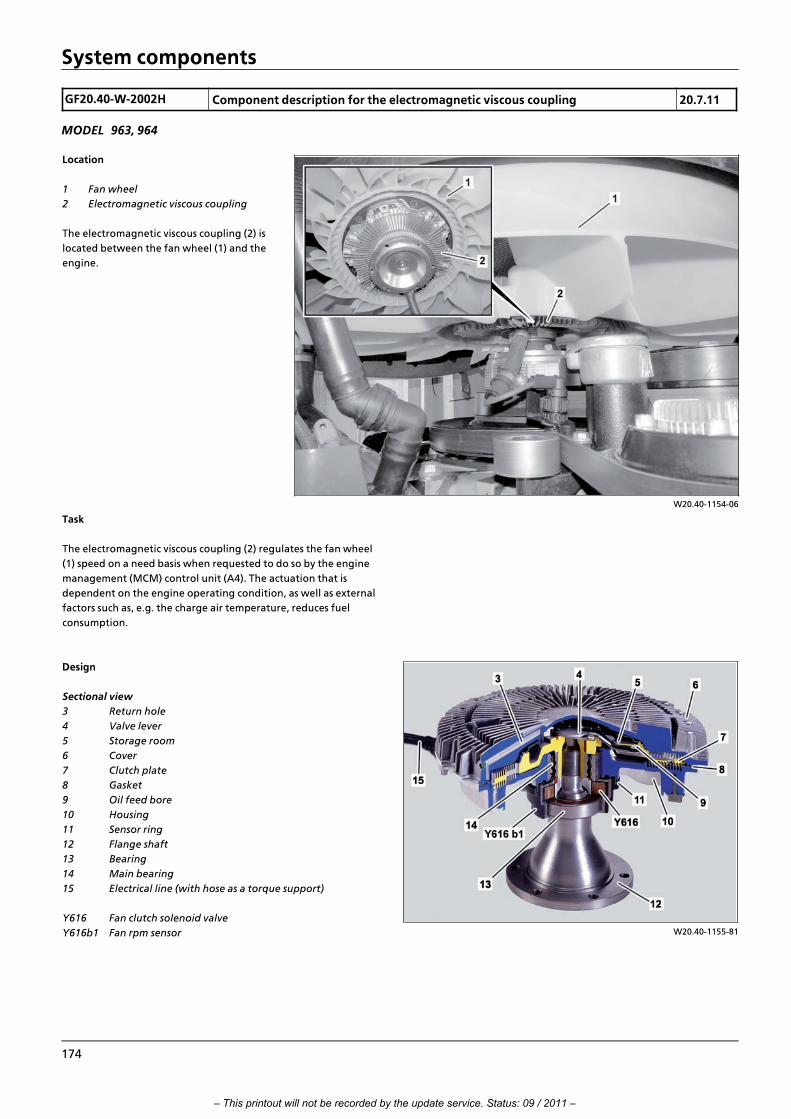
System components
GF20.40>W>2002H Component description for the electromagnetic viscous coupling 20.7.11
MODEL 963, 964
W20.40>1154>06
Location
1 Fan wheel
2 Electromagnetic viscous coupling
The electromagnetic viscous coupling (2) is
located between the fan wheel (1) and the
engine.
Task
The electromagnetic viscous coupling (2) regulates the fan wheel
(1) speed on a need basis when requested to do so by the engine
management (MCM) control unit (A4). The actuation that is
dependent on the engine operating condition, as well as external
factors such as, e.g. the charge air temperature, reduces fuel
consumption.
W20.40>1155>81
Design
Sectional view
3 Return hole
4 Valve lever
5 Storage room
6 Cover
7 Clutch plate
8 Gasket
9 Oil feed bore
10 Housing
11 Sensor ring
12 Flange shaft
13 Bearing
14 Main bearing
15 Electrical line (with hose as a torque support)
Y616 Fan clutch solenoid valve
Y616b1 Fan rpm sensor
174
– This printout will not be recorded by the update service. Status: 09 / 2011 –

System components
i The fan clutch solenoid valve (Y616) is swivel mounted along
with the fan rpm sensor (Y616 b1) on the stub shaft (12). The hose
fitted to the electrical line (15) is used as a torque support. This
prevents the assembly from also turning.
Function
Power is transmitted between the primary side (clutch plate (7))
and the secondary side, consisting of the lid (6) and the housing
(10), through silicone oil shearing in the working chamber.
i Shearing is understood to refer to the displacement of silicone
oil between the drive slats of the clutch plate (7) and the power
take>off slats of the housing (10) and the lid (6).
The rotational speed of the primary side on vehicles without a
high>speed fan drive matches the current engine speed. >>>>>>>>>>>>>>>>>>>>>>>>>>>>>>>>>>>>>>>>>>>>>>>>>>>>>>>>>>>>>>>>>>>>>>>>>>>>>>>>>>>>>>>>>
On vehicles equipped with a high>speed fan drive, the rotational
speed of the primary side is higher by the respective step>up ratio.
i Information on the respective step>up ratio for the belt drive is
stored in the engine management (MCM) control unit (A4).
The secondary side is connected to the fan wheel (1). The main
bearing (14) separates it from the primary side.
The rotational speed of the secondary side is sensed by the engine
management (MCM) control unit (A4) through the fan rpm sensor
(Y616 b1).
The rotation of the primary side generates a centrifugal pressure.
The centrifugal force induces the silicone oil to flow from the
reservoir chamber (5) through the oil feed bore (9) and into the
working chamber. The inflow of silicone oil is regulated by the
valve lever (4). It opens and closes the oil feed bore (9).
The valve lever (4) is actuated by the engine management (MCM)
control unit (A4) through the fan clutch solenoid valve (Y616). >>>>>>>>>>>>>>>>>>>>>>>>>>>>>>>>>>>>>>>>>>>>>>>>>>>>>>>>>>>>>>>>>>>>>>>>>>>>>>>>>>>>>>>>>
If the fan clutch solenoid valve (Y616) is not actuated, the oil feed
bore (9) is open and the clutch plate (7) is flushed with the
maximum possible volume of silicone oil.
In other words, the fan wheel (1) rotates at the current engine
speed or the rotational speed that matches the belt drive's step>
up ratio.
The engine management (MCM) control unit (A4) energizes the
fan clutch solenoid valve (Y616) using a pulse width modulated
signal (PWM signal) corresponding to the current cooling
requirement. A magnetic field is generated at the valve lever (4)
which then closes the valve lever (4).
The silicone oil then flows partly or completely through the return
hole (3) back into the working chamber, which then results in the
fan speed being reduced. If the rotational speed of the fan wheel
(1) is to be increased, the PWM signal for actuating the fan clutch
solenoid valve (Y616) is changed accordingly. The magnetic field is
then reduced and the valve lever (4) opens the inflow into the
working chamber.
This then increases the volume of silicone oil that flows in. The fan
rotational speed and the cooling output are increased. Due to this
operating principle, the electromagnetic viscous coupling (2)
operates in fail>safe mode. In other words, in the event of an
electronic defect, e.g. line break, the electromagnetic viscous
coupling (2) is activated at full output (max. cooling output).
Thermal protection function
To prevent any thermal overloading of the silicone oil in the
electromagnetic viscous coupling (2), from an engine speed of
n = approx. 2200 rpm (vehicles without high>speed fan drive) or
n = 1850 rpm (vehicles with high>speed fan drive), a limited
activation of the viscous coupling is then necessary. Depending on
the engine's operating condition, the electromagnetic viscous
coupling (2) is either fully activated or not at all. This is necessary
to prevent any critical temperature in the electromagnetic viscous
coupling (2). Cooling output remains available.
i Introduction of engine OM 471 and exhaust aftertreatment > 09/2011 > 175
– This printout will not be recorded by the update service. Status: 09 / 2011 –

System components
GF14.20>W>4007H Component description for exhaust gas recirculation controller 20.7.11
ENGINE 471.9 in MODEL 963, 964
W14.20>1025>76
Location
1 Exhaust gas recirculation cooler
2 Exhaust manifold center section
3 Exhaust gas recirculation pipe
4 Throttle valve
Y621 Exhaust gas recirculation positioner
Task
The exhaust gas recirculation positioner
(Y621) regulates the volume of recirculated
exhaust gas through deflection of the
throttle valve (4).
W14.20>1026>76
Design
1 Exhaust gas recirculation cooler
4 Throttle valve
5 Coolant line
6 Coolant line
7 Actuator rod
8 Lever
9 Electrical line
10 Control lever
Y621 Exhaust gas recirculation positioner
The exhaust gas recirculation positioner
(Y621) consists of a housing, which has a coil
inside and a mechanism for moving the
adjusting lever (10) for the throttle valve
(4).
The component is supplied with coolant
from the engine's coolant circuit through a
duct.
176
– This printout will not be recorded by the update service. Status: 09 / 2011 –

System components
Function
Exhaust gas recirculation rate control
The exhaust gas recirculation positioner (Y621) is actuated by a
PWM signal from the engine management (MCM) control unit
(A4).
During actuation a magnetic field is generated inside the coil
through which the mechanism is then actuated to deflect the
adjusting lever (10).
The adjusting lever (10) is connected to the throttle valve (4) in the
exhaust gas recirculation pipe (3) and it gradually rotates this
depending on the control signal from the engine management
(MCM) control unit (A4) so that more or less exhaust is branched
off towards the exhaust gas recirculation cooler.
Influence on the engine braking system
The exhaust gas recirculation positioner (Y621) is actuated in
certain circumstances by the engine management (MCM) control
unit (A4) to support the engine braking system. In interplay with
the waste gate valve of the turbocharger, this should help to
achieve an increase in the cylinder's internal pressure, which in
turn means that the upstroke piston is braked more powerfully,
and therefore the braking torque is increased.
i Introduction of engine OM 471 and exhaust aftertreatment > 09/2011 > 177
– This printout will not be recorded by the update service. Status: 09 / 2011 –

System components
GF14.15>W>3000H Component description for engine brake solenoid valve 2.8.11
ENGINES 471.9 in MODEL 963, 964 with CODE () Engine brake, standard systemENGINES 471.9 in MODEL 963, 964 with CODE () Engine brake, high performance system
W14.15>1138>79
Location
Y624 Engine brake solenoid valve, stage 1
Y625 Engine brake solenoid valve, stage 2
The engine brake solenoid valve, stage 1 (Y624) is installed in the
front rocker arm bracket, the Engine brake solenoid valve, stage 2
(Y625) in the rear rocker arm bracket in the camshaft case.
Task
The task of the engine brake solenoid valve, stage 1 (Y624) is to
supply oil pressure to the hydroelements in the exhaust rocker
arms of cylinders 1 and 3.
The engine brake solenoid valve, stage 2 (Y625) on the other hand
applies oil pressure to cylinders 4...6 for actuation.
178
– This printout will not be recorded by the update service. Status: 09 / 2011 –

System components
W14.15>1139>81
Design
Shown on engine brake valve, stage 1 (Y624)
1 Coil
2 Valve body
3 Outlet rocker shaft
4 Oil ducts for cylinders 1...3
Y624 Engine brake solenoid valve, stage 1
Function
For a stopped engine the valve body (2) lies under the force of
gravity on its downstop. The control oil passage to the exhaust
rocker arm spindle (3) is open. Since there is no oil pressure
applied at this point in time, no control oil flows in the direction
of the outlet rocker shaft (3). >>>>>>>>>>>>>>>>>>>>>>>>>>>>>>>>>>>>>>>>>>>>>>>>>>>>>>>>>>>>>>>>>>>>>>>>>>>>>>>>>>>>>>>>>
If the engine is started oil pressure is applied to the valve body (2)
and pushes this against the upper stop. In this way the control oil
passage to the exhaust rocker arm spindle (3) is closed off.
>>>>>>>>>>>>>>>>>>>>>>>>>>>>>>>>>>>>>>>>>>>>>>>>>>>>>>>>>>>>>>>>>>>>>>>>>>>>>>>>>>>>>>>>>
Activation of the engine brake
The engine management (MCM) control unit (A4) actuates the
engine brake solenoid valve, stage 1 (Y624) just as soon as the
driver activates the engine brake over the engine brake switch.
The energization of the coil (1) the valve body (2) is presses into
the downstop.
The pressure oil now flows through the again opened pressure oil
passage over the oil duct for cylinders 1...3 (4) contained in the
outlet rocker shaft (3) to the exhaust rocker arms with
hydroelement. The engine brake is activated in this way.
Deactivation of the engine brake
If the driver sets the engine brake switch back into position 0 or
the engine brake is deactivated, the coil (1) is no longer energized
> the valve body (2) is pushed upwards. No more oil flows over the
control oil passage in the outlet rocker shaft (3). The oil remaining
in the outlet rocker shaft (3) escapes in the ventilation.
i For brake stages 2 and 3 engine brake valve, stage 2 is
actuated.
i Introduction of engine OM 471 and exhaust aftertreatment > 09/2011 > 179
– This printout will not be recorded by the update service. Status: 09 / 2011 –

System components
GF14.40>W>3025H AdBlue“ heater coolant solenoid valve, component description 20.7.11
ENGINE 471.9 in MODEL 963, 964
W14.40>1600>76
Location
Shown on engine 471.9 with code (M5Z)
Engine version Euro VI
Y627 AdBlue“ heater coolant solenoid
valve
The AdBlue“ heater coolant solenoid valve
(Y627) is located at the right rear on the
engine's crankcase.
Task
The AdBlue“ heater coolant solenoid valve
(Y627) branches off coolant from the
engine's coolant circuit to heat the AdBlue“
line circuit, the AdBlue“ container and the
pump module.
W14.40>1573>71
Design
1 Electrical connector
2 Coolant inlet
3 Coolant outlet
Y627 AdBlue“ heater coolant solenoid valve
The AdBlue“ heater coolant solenoid valve (Y627) is A 2/2 directional control valve.
Inside the valve, the valve body is designed as a solenoid armature.
Function
The AdBlue“ heater coolant solenoid valve (Y627)) is actuated by
the engine management (MCM) control unit (A4). The AdBlue“ fill
level sensor/temperature sensor (B74) enables the engine
management (MCM) control unit (A4) to recognize whether the
temperature of the AdBlue“ is approaching the limit of 8 ∞C.
If the coolant has reached a temperature of f 65 ∞C, and the
temperature of the AdBlue has reached the limit value, then the
AdBlue“ heater solenoid valve (Y627) is actuated by the engine
management (MCM) control unit (A4). The valve then opens and
coolant is branched off from the engine's coolant circuit.
If the AdBlue“ heater coolant solenoid valve (Y627) is open, the
coolant is available at the closed valve body inside the
component.
This valve body keeps the passage between the coolant supply
line and the coolant working line closed via the force of a push
spring.
When current is applied the valve body slides and opens the
passage so that coolant can flow through.
When the current is interrupted, the spring pushes it back into its
starting position. Thus means that the passage is blocked off
again.
180
– This printout will not be recorded by the update service. Status: 09 / 2011 –

System components
GF09.40>W>4020H Component description for boost pressure regulator 1.7.11
ENGINES 471.9 in MODEL 963
W09.40>1212>06
Location
Shown code (M5Z) Engine version Euro VI
1 Turbocharger
2 Vacuum cell
Y636 Charge pressure positioner
The boost pressure regulator (Y636) is
located on the right side of the engine next
to the turbocharger (1).
Task
The vacuum cell (2) on the turbocharger (1) has compressed air
applied to it over the boost pressure regulator (Y636).
If the engine management (MCM) control unit (A4) recognizes
that the current boost pressure or the rotor speed is too high it
limits the boost pressure or the rotor speed in that it actuates the
boost pressure regulator (Y636) with an appropriate pulse width
modulated signal. The engine management (MCM) control unit
(A4) can use the duty cycle of this signal to influence the pressure
(up to 2.8 bar) which should be applied to the vacuum cell (2).
A valve is opened on the bypass opening over a linkage according
to this pressure which allows more or less exhaust to be led past
the turbine wheel dependent on how wide it is opened.
Since only part of the exhaust (D) hits the turbine wheel the
acceleration is not so strong anymore and the boost pressure or
the rotor speed drop.
i Introduction of engine OM 471 and exhaust aftertreatment > 09/2011 > 181
– This printout will not be recorded by the update service. Status: 09 / 2011 –

System components
GF07.05>W>6010H Component description for quantity control valve 20.7.11
ENGINES 471.9 in MODEL 963
W07.16>1068>11
Location
Y642 Quantity control valve
The quantity control valve (Y642) is located on the fuel high
pressure pump.
Task
The quantity control valve (Y642) has the following tasks to fulfill:
f Regulation of the fuel feed to the pump elements of the
high>pressure pump
f Regulation of the rail pressure
f Discontinuity of fuel supply to pump elements of the fuel
high pressure pump for "Engine stop"
W07.05>1003>81
Design
1 Fuel high pressure pump housing
2 Coil
3 Float needle
4 Valve spring
Y642 Quantity control valve
Function
The engine management (MCM) control unit (A4) actuates the
coil (2) of the quantity control valve (Y642) using a pulse width
modulated signal. The magnetic field of the coil (2) produced in
this way influences the position of the float needle (3) and thus
the flow cross>section in the quantity control valve (Y642) and
flow rate of the fuel.
At "Engine stop" the float needle (3) is pushed back by the valve
spring (4) and the fuel flow is interrupted.
182
– This printout will not be recorded by the update service. Status: 09 / 2011 –
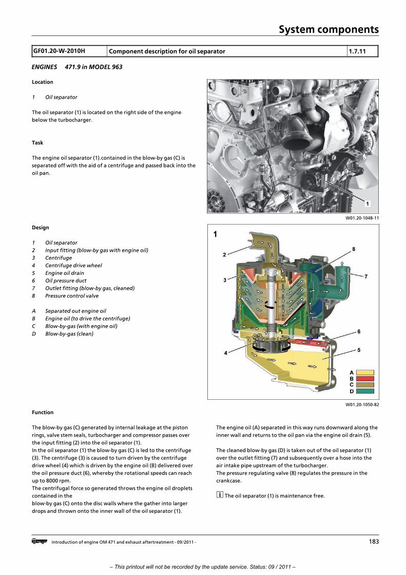
System components
GF01.20>W>2010H Component description for oil separator 1.7.11
ENGINES 471.9 in MODEL 963
W01.20>1048>11
Location
1 Oil separator
The oil separator (1) is located on the right side of the engine
below the turbocharger.
Task
The engine oil separator (1).contained in the blow>by gas (C) is
separated off with the aid of a centrifuge and passed back into the
oil pan.
W01.20>1050>82
Design
1 Oil separator
2 Input fitting (blow>by gas with engine oil)
3 Centrifuge
4 Centrifuge drive wheel
5 Engine oil drain
6 Oil pressure duct
7 Outlet fitting (blow>by gas, cleaned)
8 Pressure control valve
A Separated out engine oil
B Engine oil (to drive the centrifuge)
C Blow>by>gas (with engine oil)
D Blow>by>gas (clean)
Function
The blow>by gas (C) generated by internal leakage at the piston
rings, valve stem seals, turbocharger and compressor passes over
the input fitting (2) into the oil separator (1).
In the oil separator (1) the blow>by gas (C) is led to the centrifuge
(3). The centrifuge (3) is caused to turn driven by the centrifuge
drive wheel (4) which is driven by the engine oil (B) delivered over
the oil pressure duct (6), whereby the rotational speeds can reach
up to 8000 rpm.
The centrifugal force so generated throws the engine oil droplets
contained in the
blow>by gas (C) onto the disc walls where the gather into larger
drops and thrown onto the inner wall of the oil separator (1).
The engine oil (A) separated in this way runs downward along the
inner wall and returns to the oil pan via the engine oil drain (5).
The cleaned blow>by gas (D) is taken out of the oil separator (1)
over the outlet fitting (7) and subsequently over a hose into the
air intake pipe upstream of the turbocharger.
The pressure regulating valve (8) regulates the pressure in the
crankcase.
i The oil separator (1) is maintenance free.
i Introduction of engine OM 471 and exhaust aftertreatment > 09/2011 > 183
– This printout will not be recorded by the update service. Status: 09 / 2011 –

System components
GF07.02>W>3012H Component description for fuel system high pressure pump 20.7.11
ENGINES 471.9 in MODEL 963
W47.20>1084>76
Location
1 Fuel system high pressure pump
B Fuel feed (thrust side)
C Fuel high pressure
D Fuel return
The fuel high pressure pump (1) is located at
the rear on the left side of the crankcase
and is driven via the pinion gear drive.
Task
The fuel high>pressure pump (1) supplies
the fuel high>pressure circuit with fuel and
ensures that the fuel required for
combustion is available in sufficient
quantity and at the required pressure at the
fuel injectors, under all operating
conditions.
W07.20>1000>81
Design
1 Fuel system high pressure pump
2 Fuel high pressure pump housing
3 Suction valves
4 High pressure piston
5 Compression springs
6 Roller tappet
7 Camshaft
8 High pressure valve
9 High pressure connection
Function
The camshaft (7) for the fuel high pressure pump (1) is driven by
the pinion gear drive.
The fuel is compressed by two high>pressure pistons (4) and led via
the respective high>pressure connection (9) and corresponding
high>pressure lines to the rail.
Both roller tappets (6) on the double cams of the camshaft (7) are
pressed together by the two push springs (5) which are offset by
90∞. Thus two power strokes occur for one camshaft revolution per
high>pressure piston (4).
If the high pressure piston (4) is in a downward movement, the
fuel can flow over the corresponding intake valve (3) into the
clearance volume via the high pressure piston (4).
If the high pressure piston (4) now changes to an upward
movement, the corresponding intake valve (3) is closed by the
compression pressure arising and the fuel in compressed until the
high pressure valve (8) opens a transfer duct between the high
pressure compartment and the corresponding high pressure
connection (9). The highly compressed fuel can now flow into the
rail.
If the high pressure piston (4) again changes to a downward
movement, the transfer duct is closed by the spring>loaded high
pressure valve (8) and new fuel can flow through the now opened
intake valve (3) into the clearance volume.
184
– This printout will not be recorded by the update service. Status: 09 / 2011 –

System components
GF07.05>W>6011H Component description for pressure limiting valve 20.7.11
ENGINES 471.9 in MODEL 963
W07.16>1069>11
Location
1 Pressure limiting valve
The pressure limiting valve (1) is located at the rear end of the rail.
Task
The pressure limiting valve (1) is a safety element which limits the
maximum rail pressure in the injection system to about 1100 bar. If
the engine management (MCM) control unit (A4) recognizes that
the pressure limiting valve (1) is open it activates the limp>home
mode.
W07.04>1052>01
Design
2 Compression spring
3 Cutoff bore
4 Pressure plate
5 Cutoff throttle
Function
If the current rail pressure exceeds the maximum rail pressure of
about 1100 bar, the push spring (2) is pressed together by the
pressure plate (4). A connection is opened at the same time to the
cutoff bore (3) and the excess fuel flows into the return.
i Introduction of engine OM 471 and exhaust aftertreatment > 09/2011 > 185
– This printout will not be recorded by the update service. Status: 09 / 2011 –

System components
GF09.40>W>4010H Component description for turbocharger 20.7.11
ENGINES 471.9 in MODEL 963
W09.40>1214>06
Location
Shown code (M5Z) Engine version Euro VI
1 Turbocharger
The turbocharger (1) is located on the right
side of the engine below the exhaust gas
recirculation cooler.
Task
The turbocharger (1) converts the thermal
energy of the exhaust flow into mechanical
energy and compacts the suctioned air.
W09.40>1230>76
Body
Shown code (M5Z) Engine version Euro VI
1 Turbocharger
2 Turbine wheel
3 Vacuum cell
4 Shaft
5 Compressor impeller
6 Compressor housing
7 Oil supply connection
8 Turbine housing
9 Valve
B610 Rpm sensor for turbine wheel
(only for code (M5Z) Engine version
Euro VI)
i Engine oil passes to the bearings on the shaft (4) via the oil
supply connection (7) which is lubricated and cooled in this way.
Via a return line, the engine oil flows back again into the
crankcase and from there into the oil pan.
186
– This printout will not be recorded by the update service. Status: 09 / 2011 –

System components
GF14.20>W>2020H Component description for exhaust gas recirculation cooler 20.7.11
ENGINE 471.9 in MODEL 963, 964
W14.20>1021>76
Location
1 Charge air housing
2 Charge air pipe (mixer housing)
3 Exhaust gas recirculation cooler
Y621 Exhaust gas recirculation positioner
The exhaust gas recirculation cooler (3) is
located on the right side of the engine over
the exhaust manifold and the turbocharger.
Task
The exhaust gas recirculation cooler (3)
cools the branched off exhaust from a
temperature of approx. 650 ∞C to a
temperature of approx. 170 ∞C.
W14.20>1022>76
Design
3 Exhaust gas recirculation cooler
4 Exhaust chamber
5 Coolant strip
6 Coolant output (feed line to nozzle unit
for diesel particulate filter
regeneration)
7 Coolant line (return line from nozzle
unit for diesel particulate filter
regeneration)
8 Coolant outlet
9 Exhaust outlet (to charge air pipe)
10 Coolant output (to coolant pump)
11 Exhaust inlet (from exhaust manifold)
12 Front end cover
13 Rear end cover
14 Coolant outlet
The exhaust gas recirculation cooler (3)
consists of an oblong box>shaped housing,
with two disconnected chambers > the
exhaust chamber (4) and the coolant strip (5).
Function
The branched off exhaust flows through the exhaust inlet (11)
into the exhaust chamber (4) and flows through it and on to the
exhaust outlet (9) towards the charge air pipe (2), where it is then
fed together with the fresh air or the charged air to the
combustion process.
Coolant from the engine's coolant circuit permanently flows
through the coolant strip (5) of the exhaust gas recirculation
cooler.
The exhaust gas that flows in the exhaust chamber (4) is cooled by
the heat transfer.
i Introduction of engine OM 471 and exhaust aftertreatment > 09/2011 > 187
– This printout will not be recorded by the update service. Status: 09 / 2011 –

System components
GF14.40>W>3001H Component description for AdBlue tank 20.7.11
ENGINE 471.9 in MODEL 963, 964
W14.40>1563>76
Location
1 AdBlue“ tank
B74 AdBlue“ fill level sensor/temperature
sensor
W14.40>1564>81
Design
1 AdBlue“ tank
2 AdBlue“ filter
3 Coolant duct
4 Filler neck
5 Bleeding
6 Coolant inlet (from engine)
7 Coolant outlet (to pump module)
8 AdBlue“ inlet (return from AdBlue“ metering device)
9 AdBlue“ outlet (feed line to pump module)
10 Electrical connection
B74 AdBlue“ fill level sensor/temperature sensor
Function
AdBlue“ refueling
The filler neck (4) with its special diameter and integrated
magnetic adapter should prevent incorrect fueling, e.g. with
diesel fuel.
During refueling, the magnetic field of the magnetic adapter
actuates a solenoid switch located in the outlet pipe of the nozzle,
thereby enabling the tank to be refueled.
This system also prevents incorrect fueling of the diesel fuel tank
with AdBlue“, as its filler neck is not fitted with a magnetic
adapter and the solenoid switch in the nozzle only permits
refueling when a defined magnetic field is present.
AdBlue“ heating
The coolant coming from the engine or the AdBlue“ heater
coolant solenoid valve flows through the coolant inlet (6) into the
coolant duct (3), flows through this and then through the coolant
outlet (7) and on to the pump module.
The heat transfer of the coolant duct (3) means that any frozen
AdBlue“ is defrosted and it also prevents liquid AdBlue“ from
freezing at low temperatures.
188
– This printout will not be recorded by the update service. Status: 09 / 2011 –

System components
GF18.10>W>4000H Component description for oil pump 20.7.11
ENGINE 471.9 in MODEL 963
W18.10>1044>11
Location
1 Oil pump
2 Oil pan
3 Oil strainer
4 Oil drain screw
5 Oil intake manifold
6 Suction pipe
7 Return flow check valve
8 Pressure line
B605 Engine oil fill level sensor
The oil pump (1) is located in the oil pan (2) at the output side of
the engine.
Task
The oil pump (1) supplies the oil circuit of the engine with engine
oil. It ensures that engine oil is available under all operating
conditions in adequate quantities and at the required pressure at
the respective locations.
W18.10>1045>11
Body
Rear
1 Oil pump
9 Drive gear
10 Pressure control valve
11 Oil inlet
12 Safety valve
13 Oil outlet
14 Oil duct > to pressure regulator valve (10)
i Introduction of engine OM 471 and exhaust aftertreatment > 09/2011 > 189
– This printout will not be recorded by the update service. Status: 09 / 2011 –

System components
W18.10>1046>75
Front side, without drive gear (9)
1 Oil pump
3 Oil strainer
5 Oil intake manifold
6 Suction pipe
8 Pressure line
12 Safety valve
14 Oil duct (to pressure regulator valve
(10))
15 Impeller
Function
The drive gear (9) for the oil pump (1) which is driven by the
crankshaft gear drives the two impellers (15).
The rotational movement of the impellers (15) and the design of
the pump chamber cause the engine oil to be suctioned up and
delivered to the oil outlet (13) along the inner wall of the pump.
When sucked in, the engine oil in the oil pan (2) flows first to the
oil strainer (3) and the suction line (6), before passing through the
oil inlet (11) into the oil pump (1).
The engine oil flows first through the oil outlet (13) into the
pressure line (8) before then flowing through the return flow
check valve (7) and the main oil duct's feed line into the engine oil
circuit.
Regulation of the engine oil pressure takes place via the pressure
regulator valve (10).
The pressure regulator valve (10) has the oil pressure applied to it
via the engine oil in the oil duct (14) which is connected with the
main oil duct. A certain amount of engine oil is fed via the
pressure regulator valve (10) on the suction line according to the
oil pressure in the oil duct (14). This regulates the engine oil
pressure on the one hand and reduces the operating energy input
of the oil pump (1) on the other.
Impermissibly high pressures in the oil circuit are avoided via the
safety valve (12) which can occur in the cold start phase of the
engine if the engine oil is not yet viscous.
The safety valve (12) opens at a pressure >10 bar and routes some
of the engine oil back into oil pan (2).
190
– This printout will not be recorded by the update service. Status: 09 / 2011 –

System components
GF18.20>W>4100H Oil/coolant module, component description 20.7.11
ENGINE 471.9 in MODEL 963
W18.20>1032>06
Location
1 Oil/coolant module
The oil/coolant module (1) is located on the
left side of the engine.
Task
The oil/coolant module (1) is used to:
• Filter the engine oil
• Regulate the engine oil temperature
• Regulate the coolant temperature
• Support the coolant pump
W18.20>1037>82
Body
1 Oil/coolant module
2 Oil thermostat
3 Oil filter
4 Oil filter cover
5 Oil/water heat exchanger
6 Coolant pump
7 Coolant thermostat
i Introduction of engine OM 471 and exhaust aftertreatment > 09/2011 > 191
– This printout will not be recorded by the update service. Status: 09 / 2011 –

System components
W18.20>1038>75
Function
1 Oil/coolant module
3 Oil filter
5 Oil/water heat exchanger
6 Coolant pump
7 Coolant thermostat
8 Initial filling valve
9 Engine oil inlet (from oil pump)
10 Engine oil outlet (to main oil ducts in
crankcase)
11 Engine oil drain from oil filter (for oil
filter change)
12 Coolant outlet (to crankcase)
13 Coolant inlet (from coolant bypass
duct)
14 Coolant outlet (to exhaust gas
recirculation cooler)
15 Coolant inlet (from coolant expansion
reservoir, when the coolant
expansion reservoir is at the front or
the heater return, when the coolant
expansion reservoir is at the rear)
17 Coolant inlet (return from compressor
and fuel cooler)
18 Coolant inlet (from cooler)
A Coolant
B Engine oil
16 Coolant inlet (from coolant expansion
reservoir, when the coolant
expansion reservoir is at the rear or
the heater return, when the coolant
expansion reservoir is at the front)
Filter the engine oil
The engine oil flows, depending on the position of the oil
thermostat (2), either straight into the oil filter housing (3) or
after it has passed through the oil>water heat exchanger (5).
In the oil filter housing the engine oil flows from the outside
inwards through the oil filter (3) and on to the support dome,
where it is filtered The worm>shaped characteristic of the support
dome routes the filtered engine oil upwards to the tip of the
support dome, where it flows in through several holes in the
support dome. Within the support dome the engine oil is initially
routed downwards and then to the rear of the oil/coolant module
(1), where the engine oil outlet (10) is located. The filtered engine
oil then flows through the engine oil outlet (10) into the
crankcase and the main oil ducts located there, and therefore
back into the oil circuit. >>>>>>>>>>>>>>>>>>>>>>>>>>>>>>>>>>>>>>>>>>>>>>>>>>>>>>>>>>>>>>>>>>>>>>>>>>>>>>>>>>>>>>>>>
Regulate the engine oil temperature
To regulate the engine oil temperature an oil thermostat (2) is
located immediately downstream of the engine oil inlet.
At an engine temperature of less than 115 ∞C the engine oil is
routed through the open oil thermostat (2) over a bypass straight
into the oil filter (3). At 115 ∞C the oil thermostat (2) closes the
bypass and the engine oil flows first to the oil>water heat
exchanger (5) before reaching the oil filter (3).
>>>>>>>>>>>>>>>>>>>>>>>>>>>>>>>>>>>>>>>>>>>>>>>>>>>>>>>>>>>>>>>>>>>>>>>>>>>>>>>>>>>>>>>>>
Regulating the coolant temperature
The coolant temperature is regulated through the coolant
thermostat (7). When the engine is cold, the coolant pump (6)
makes the coolant circulate inside the engine. The coolant from
the coolant short>circuit duct flows over the coolant inlet (13) into
the oil/coolant module (1) where it is routed at the closed coolant
thermostat (7) past the coolant pump (6) to the coolant outlet
(12). When the engine operating temperature is reached, the
cooler circuit is activated when the coolant thermostat (7) is
opened.
The coolant from the cooler flows over the coolant inlet (18) and
the open coolant thermostat (7) into the oil/coolant module (1).
Depending on the position of the coolant thermostat (7), more or
less coolant flows through the cooler or directly over the coolant
bypass line to the coolant pump (6). The temperature of the
coolant in the coolant circuit is regulated in this way.
192
– This printout will not be recorded by the update service. Status: 09 / 2011 –

System components
GF18.30>W>2020H Oil thermostat, component description 20.7.11
ENGINE 471.9 in MODEL 963
W18.30>1015>06
Location
1 Oil/coolant module
2 Oil thermostat
3 O>ring
4 Cover
The oil thermostat (2) is built into the
oil/coolant module (1), which is located on
the left side of the engine.
Task
The oil thermostat (2) is used to regulate
the engine oil temperature.
W18.30>1016>74
Design
2.1 Housing
2.2 Sliding ring valve
2.3 Spring
2.4 Operating piston
2.5 Expansion element
3 O>ring
A Oil thermostat open
B Oil thermostat closed
W18.30>1017>74
Function
2 Oil thermostat
5 Oil/water heat exchanger
A Oil thermostat open
B Oil thermostat closed
At an engine temperature of less than 115 ∞C the engine oil is
routed through the open oil thermostat (2) over a bypass straight
into the oil filter. At 115 ∞C the oil thermostat (2) closes the bypass
and the engine oil flows first to the oil>water heat exchanger (5)
before reaching the oil filter.
i Introduction of engine OM 471 and exhaust aftertreatment > 09/2011 > 193
– This printout will not be recorded by the update service. Status: 09 / 2011 –

System components
GF20.00>W>4003H Component description for oil/water heat exchanger 20.7.11
ENGINE 471.9 in MODEL 963
W20.00>1044>06
Location
1 Oil/coolant module
2 Oil/water heat exchanger
The oil>water heat exchanger (2) is located
on the left side of the engine in the
oil/coolant module (1).
Task
The oil>water heat exchanger (2) is used to
cool the engine oil.
W20.00>1045>11
Design
2 Oil/water heat exchanger
P Plates
The oil/water heat exchanger (2) consists of a number of plates (P)
in which engine oil circulates.
Function
From an engine oil temperature of 115 ∞C, when the oil thermostat
closes the bypass to the oil filter, the engine oil is routed through
the oil>water heat exchanger (2). The oil>water heat exchanger (2)
has coolant flowing around it and as a consequence it cools the
engine oil.
194
– This printout will not be recorded by the update service. Status: 09 / 2011 –

System components
GF20.10>W>3162H Component description for coolant thermostat 20.7.11
ENGINE 471.9 in MODEL 963
W20.10>1066>06
Location
1 Oil/coolant module
2 Coolant thermostat
The coolant thermostat (2) is located on the
left side of the engine on the oil/coolant
module (1).
Task
The coolant thermostat (2) regulates the
coolant inlet temperature in the engine in a
range between roughly 87 ∞C to 95 ∞C.
Design
The coolant thermostat (2) consists of a housing with integral
sliding ring valve thermostat.
Function
The coolant thermostat (2) regulates the flow of coolant through
the engine radiator and thereby the temperature of the coolant
in the coolant circuit.
The following benefits result from regulating the coolant inlet
temperature in the engine:
f Operating temperature is reached faster
f Emissions reduced
The 3 following different operating conditions can arise
depending on the coolant inlet temperature:
f Bypass mode
f Mixed mode
f Cooler mode
i Introduction of engine OM 471 and exhaust aftertreatment > 09/2011 > 195
– This printout will not be recorded by the update service. Status: 09 / 2011 –

System components
W20.10>1073>81
Bypass mode
1 Oil/coolant module
2 Coolant thermostat
3 Coolant pump
KA Coolant outlet (to engine)
KE1 Coolant inlet (from bypass line)
KE2 Coolant inlet (from cooler)
The coolant thermostat (2) is closed for a coolant inlet
temperature < 87∞C. The coolant only circulates in the engine.
The vehicle heating heat exchanger can, however, be flowed
through.
W20.10>1074>81
Mixed mode
1 Oil/coolant module
2 Coolant thermostat
3 Coolant pump
KA Coolant outlet (to engine)
KE1 Coolant inlet (from bypass line)
KE2 Coolant inlet (from cooler)
For a coolant inlet temperature > 87∞C and < 95∞C the coolant
thermostat (2) opens partially and the coolant flows at the same
time through the engine radiator and the short circuit line to the
coolant thermostat (2).
W20.10>1075>81
Cooler mode
1 Oil/coolant module
2 Coolant thermostat
3 Coolant pump
KA Coolant outlet (to engine)
KE1 Coolant inlet (from bypass line)
KE2 Coolant inlet (from cooler)
The coolant thermostat (2) is completely open for a coolant inlet
temperature > 95∞C. The coolant is fully fed to the engine
radiator.
196
– This printout will not be recorded by the update service. Status: 09 / 2011 –

System components
GF43.30>W>3300H Retarder, component description 20.7.11
MODEL 963, 964 with CODE (B3H) Secondary water retarder
W43.30>1320>06
Location
Illustrated on model 963
1 Secondary water retarder
The secondary water retarder (1) is located
on the left in the direction of travel next to
the transmission output flange.
Task
The task of the secondary water retarder (1)
is to convert the flow energy of the engine
coolant into mechanical braking energy
when requested by the driver or a driving
assistance system.
W43.30>1298>05
Design
The secondary water retarder (1) is
designed on the principle of hydrodynamic
torque conversion.
External view of secondary water retarder
2 Coolant manifold, feed
3 Coolant manifold, return
4 Relief valve
A11 Retarder control (RCM) control unit
B933 Coolant temperature sensor
i Introduction of engine OM 471 and exhaust aftertreatment > 09/2011 > 197
– This printout will not be recorded by the update service. Status: 09 / 2011 –

System components
W43.30>1296>76
Sectional view of secondary water retarder
in idle mode
5 Valve block
6 Actuator
7 Switching valve
8 Switching valve compression spring
9 Control valve compression spring
10 Control valve
11 Side channel pump
12 Compression spring for sliding rotor
13 Twisted teeth
14 Slide ring seal
15 Retarder shaft
17 Rotor
18 Stator
20 Shutoff pressure line, return
A11 Retarder control (RCM) control unit
W43.30>1322>11
Function
i The individual components shown under Design perform the
functions described below.
Relief valve (4)
The relief valve (4) actuates the side channel pump (11) when
requested by the retarder control unit (RCM) (A11).
W43.30>1324>11
Valve block (5)
The valve block (5) consists of an actuator (6), a switching valve (7),
a control valve (10), the switching valve compression spring (8) and
the control valve compression spring (9).
If a braking torque is requested, the switching valve (7) directs the
engine coolant into the working chamber. If no braking torque is
requested, the switching valve (7) separates the working chamber
from the coolant circuit. Depending on the pneumatic pressure
applied, the control valve (10) controls the coolant feed into the
working chamber and thus the intensity of the braking effect. In
idle mode, the control valve (10) acts as a check valve and seals the
bypass to the working chamber.
198
– This printout will not be recorded by the update service. Status: 09 / 2011 –
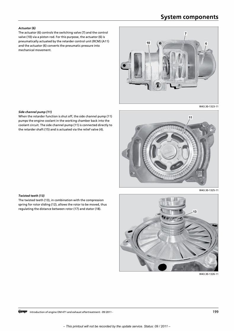
System components
W43.30>1323>11
Actuator (6)
The actuator (6) controls the switching valve (7) and the control
valve (10) via a piston rod. For this purpose, the actuator (6) is
pneumatically actuated by the retarder control unit (RCM) (A11)
and the actuator (6) converts the pneumatic pressure into
mechanical movement.
W43.30>1325>11
Side channel pump (11)
When the retarder function is shut off, the side channel pump (11)
pumps the engine coolant in the working chamber back into the
coolant circuit. The side channel pump (11) is connected directly to
the retarder shaft (15) and is actuated via the relief valve (4).
W43.30>1326>11
Twisted teeth (13)
The twisted teeth (13), in combination with the compression
spring for rotor sliding (12), allows the rotor to be moved, thus
regulating the distance between rotor (17) and stator (18).
i Introduction of engine OM 471 and exhaust aftertreatment > 09/2011 > 199
– This printout will not be recorded by the update service. Status: 09 / 2011 –
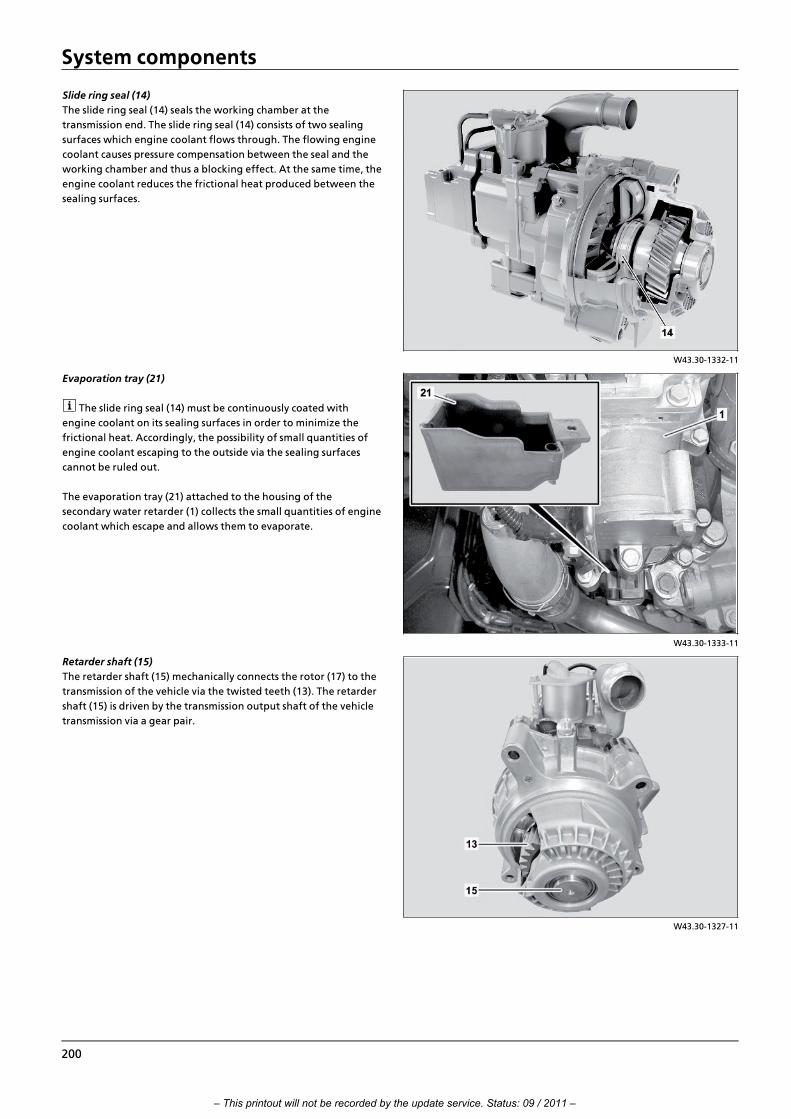
System components
W43.30>1332>11
Slide ring seal (14)
The slide ring seal (14) seals the working chamber at the
transmission end. The slide ring seal (14) consists of two sealing
surfaces which engine coolant flows through. The flowing engine
coolant causes pressure compensation between the seal and the
working chamber and thus a blocking effect. At the same time, the
engine coolant reduces the frictional heat produced between the
sealing surfaces.
W43.30>1333>11
Evaporation tray (21)
i The slide ring seal (14) must be continuously coated with
engine coolant on its sealing surfaces in order to minimize the
frictional heat. Accordingly, the possibility of small quantities of
engine coolant escaping to the outside via the sealing surfaces
cannot be ruled out.
The evaporation tray (21) attached to the housing of the
secondary water retarder (1) collects the small quantities of engine
coolant which escape and allows them to evaporate.
W43.30>1327>11
Retarder shaft (15)
The retarder shaft (15) mechanically connects the rotor (17) to the
transmission of the vehicle via the twisted teeth (13). The retarder
shaft (15) is driven by the transmission output shaft of the vehicle
transmission via a gear pair.
200
– This printout will not be recorded by the update service. Status: 09 / 2011 –

System components
W43.30>1331>11
Shutoff pressure line, feed (16)
The shutoff pressure line, feed (16) continuously supplies the slide
ring seal (14) with engine coolant. The engine coolant is fed back
to the cooling circuit of the engine via the connection to the
shutoff pressure line, return (20).
W43.30>1328>11
Rotor (17)
The rotor (17) is driven by the retarder shaft (15) via the twisted
teeth (13) and feeds the engine coolant to the stator (18) through
the rotational movement of its blades.
W43.30>1329>11
Stator (18)
The stator (18), which is fixed to the retarder housing, takes in the
rotating engine coolant with its blades through the filling slot (19)
and directs it back to the rotor (17). The resulting frictional forces
brake the rotor (17).
i Introduction of engine OM 471 and exhaust aftertreatment > 09/2011 > 201
– This printout will not be recorded by the update service. Status: 09 / 2011 –

System components
W43.30>1330>11
Coolant temperature sensor (B933)
The coolant temperature sensor (B933) records the coolant
temperature of the coolant which is fed back to the cooling circuit
of the engine. The signals from the coolant temperature sensor
(B933) are read in directly by the retarder control unit (RCM) (A11).
202
– This printout will not be recorded by the update service. Status: 09 / 2011 –

System components
GF47.20>W>2000H Component description for fuel pump 20.7.11
ENGINES 471.9 in MODEL 963
W47.20>1083>76
Location
1 Fuel pump
A Fuel feed/suction side
B Fuel feed (thrust side)
The fuel pump (1) is located at the fuel high
pressure pump.
Task
The fuel pump (1) draws the fuel out of the
fuel tank via the fuel filter module, and
supplies the fuel system high pressure pump
with the required quantity in all engine
operating conditions.
W47.20>1061>81
Design
2 Fuel inlet
3 Bypass valve
4 Fuel outlet
5 Pressure limiting valve
A Fuel feed/suction side
B Fuel feed (thrust side)
Function
The fuel pump (1) is designed as a gear pump and is driven via the
fuel high pressure pump. As soon as the engine starts and runs,
the right gearwheel in the fuel pump (1) is driven via a drive plate
on the camshaft of the fuel high pressure pump. Since the teeth
on the right gearwheel engages in the teeth on the left
gearwheel, it turns simultaneously in the opposite direction. The
rotating movement of both gearwheels and the design of the
pump chamber cause the fuel to be drawn in via the fuel inlet (2)
and delivered to the fuel outlet (4) along the inner wall of the
pump. During this operation fuel is compressed until the fuel
pressure or system pressure required is reached.
The max. permissible system pressure that can already be reached
at idle speed is determined by the opening pressure of the
pressure limiting valve (5).
If the system and/or the opening pressure is reached and
therefore the pressure limiting valve (5), that is designed as an
overflow valve, is opened, thrust side fuel feed (B) is connected to
the suction side fuel feed (A) via a duct to prevent a further build>
up of pressure.
If the fuel system is being filled externally, the bypass valve (3) is
installed through which fuel can flow past the stationary
gearwheels to the thrust side fuel feed (B).
i Introduction of engine OM 471 and exhaust aftertreatment > 09/2011 > 203
– This printout will not be recorded by the update service. Status: 09 / 2011 –

System components
GF47.20>W>2103H Component description for fuel cooler 20.7.11
ENGINES 471.9 in MODEL 963
W47.00>1037>82
Location
1 Fuel filter module
2 Fuel cooler
3 Coolant outlet for fuel filter module
4 Coolant inlet
B Coolant
The fuel cooler (2) is located behind the fuel filter module (1).
Task
The fuel cooler (2) cools the warmed fuel which is led from the fuel
injector pressure boosters into the fuel filter module (1) via a
return line.
W47.00>1027>71
Body
2 Fuel cooler
4 Coolant inlet
5 Coolant outlet
6 Fuel inlet
7 Fuel outlet
8 Fuel cooling ducts
9 Coolant duct
A Fuel
B Coolant
The fuel cooler (2) is designed as a shell cooler.
Function
The warmed fuel from the fuel injector pressure boosters flows
through the fuel cooling ducts (8) to the fuel outlet (7) via the fuel
inlet (6). From there, the cooled fuel then runs through the fuel
feed line of the fuel filter module to the fuel pump via a line.
The fuel cooler (2) is supplied with coolant from the crankcase via
the coolant inlet (4).The coolant flowing through the coolant duct
(9) cools the fuel, it passes via the coolant outlet (5) to the fuel
filter module (1) and flows via the fuel filter module coolant
outlet (3) directly to the coolant pump.
204
– This printout will not be recorded by the update service. Status: 09 / 2011 –
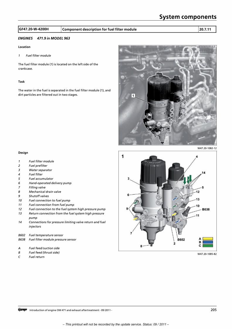
System components
GF47.20>W>4200H Component description for fuel filter module 20.7.11
ENGINES 471.9 in MODEL 963
W47.20>1082>12
Location
1 Fuel filter module
The fuel filter module (1) is located on the left side of the
crankcase.
Task
The water in the fuel is separated in the fuel filter module (1), and
dirt particles are filtered out in two stages.
W47.20>1085>82
Design
1 Fuel filter module
2 Fuel prefilter
3 Water separator
4 Fuel filter
5 Fuel accumulator
6 Hand>operated delivery pump
7 Filling valve
8 Mechanical drain valve
9 Shutoff valves
10 Fuel connection to fuel pump
11 Fuel connection from fuel pump
12 Fuel connection to the fuel system high pressure pump
13 Return connection from the fuel system high pressure
pump
14 Connections for pressure limiting valve return and fuel
injectors
B602 Fuel temperature sensor
B638 Fuel filter module pressure sensor
A Fuel feed/suction side
B Fuel feed (thrust side)
C Fuel return
i Introduction of engine OM 471 and exhaust aftertreatment > 09/2011 > 205
– This printout will not be recorded by the update service. Status: 09 / 2011 –

System components
The fuel filter module (1) consists of the following components:
f Fuel prefilter (2) through which large dirt particles are
removed from the fuel.
f Water separator (3) with water collector through which the
water in the fuel is separated.
f Fuel filter (4) through which small dirt particles are removed
from the fuel.
f The fuel collection chamber (5) via which the fuel is collected
from all fuel return lines and led into either the fuel prefilter
(2) via a bypass or directly into the fuel tank.
f The hand>operated delivery pump (6) with the aid of which
the fuel system can be vented, for example after replacing a
fuel filter insert.
f The filling valve (7) with the aid of which the fuel system can
also be vented, for example after replacing a fuel filter
insert.
f Shutoff valves (9) which prevent fuel escaping when
disassembling the fuel lines between the fuel tank and the
fuel filter module (1).
W47.20>1078>72
Function
Fuel prefilter
2 Fuel prefilter
16 Fuel inlet
17 Filter element
18 Elastomer ball
19 Wastegate
20 Fuel outlet
D Not cleaned fuel
E Precleaned fuel
Not cleaned fuel (D) passes over the fuel inlet (16) into the fuel
prefilter (2).
The suctioned up fuel presses the elastomer ball (18) off its seat
and flows through the filter insert (17) from inside to out. The
larger dirt particles remain in the filter insert (17) and the
precleaned fuel (E) flows via the fuel outlet (20) to the fuel pump.
The elastomer ball (18) has the task of preventing the intake duct
from running dry with the fuel prefilter (2) open.
If the fuel prefilter (2) is fouled and the fuel flow rate is blocked in
the process then the fuel is suctioned over the wastegate (19).
When removing the filter insert clipped on the cover (17) a drain
bore to the fuel collector (5) is released so the fuel can flow out of
the fuel prefilter housing.
206
– This printout will not be recorded by the update service. Status: 09 / 2011 –

System components
W47.20>1081>81
Water separator and
fuel filter
3 Water separator
4 Fuel filter
8 Mechanical drain valve
21 Water separator insert
22 Water collector
23 Ventilation bore
24 Fine filter insert
25 Inner dome
B602 Fuel temperature sensor
E Precleaned fuel
F Cleaned fuel
Water separator (3)
The water separator insert (21) in the water separator (3) consists
of many layers and has the task of separating out the water
contained in the fuel.
The water separator insert (21) has fuel flowing from inside
outwards. The special construction ensures that small water
droplets either remain in the water separator insert (21) or bind
themselves to already retained water droplets. Small dirt particles
are also filtered out due to the construction.
In order to ensure that the water droplets can sink downwards
into the water collector (22), it is essential that the flow rate of the
fuel is reduced.
This is achieved using the special forming of the housing.
The flow rate of the fuel is increased again by the shape of the
housing and the fuel passes into the fine filter insert (24).>>>>>>>>>>>>>>>>>>>>>>>>>>>>>>>>>>>>>>>>>>>>>>>>>>>>>>>>>>>>>>>>>>>>>>>>>>>>>>>>>>>>>>>>>
The ventilation bore (23) above the water separator insert (21)
diverts the air that is trapped in the water separator (3) when the
water separator insert (21) is changed, for example, into the fuel
collection chamber (5), from where it can be returned to the fuel
tank via the fuel return line.
The ventilation bore (23) also guarantees full use of area in the
water separator insert (21).
When removing the water separator insert (21) clipped on the
cover a drain bore to the fuel collector (5) is released so that fuel
can flow out of the water separator housing.
>>>>>>>>>>>>>>>>>>>>>>>>>>>>>>>>>>>>>>>>>>>>>>>>>>>>>>>>>>>>>>>>>>>>>>>>>>>>>>>>>>>>>>>>>
Fuel filter (4)
The fine filter insert (24) of the fuel filter (4) also consists of many
layers but has fuel flowing from outside inwards.
The smallest dirt particles are filtered out at a very high separation
rate by the fine filter insert (24).
Also the fuel filter (4) has a ventilation bore (23). Just as for the
water separator insert (21), full use of area in the water separator
insert (24) is achieved and venting of the fuel filter housing
guaranteed.
When removing the fine filter insert clipped on the cover (24) a
drain bore to the fuel collector (5) is released so the fuel can flow
out of the fuel filter housing.
The cleaned fuel (F) is led to the fuel high pressure pump through
an overflow bore in the inner dome (25).
The high position of the overflow bore in the inner dome (25)
ensures that no uncleaned fuel can reach the fuel high pressure
pump, even if the fuel does not run out of the fuel filter housing.
The engine management control unit (MCM) (A4) determines the
current fuel temperature via the fuel temperature sensor
(B602).With the aid of the fuel filter module pressure sensor
(B638) the engine management control unit (MCM) (A4) can
detect whether the fuel filter element needs to be changed. The
fuel filter module pressure sensor (B638) is also used for diagnostic
purposes.
i Introduction of engine OM 471 and exhaust aftertreatment > 09/2011 > 207
– This printout will not be recorded by the update service. Status: 09 / 2011 –

System components
GF49.10>W>3006H Diesel oxidation catalytic converter, component description 20.7.11
ENGINES 471.9 in MODEL 963, 964 with CODE (M5Z) Engine version Euro VI
W14.40>1576>76
Location
4 Diesel oxidation catalytic converter
(DOC)
5 Diesel particulate filter (DPF)
A70 Exhaust aftertreatment unit inlet
NOx sensor control unit
A70 b1 Exhaust aftertreatment unit inlet
NOx sensor
B37 Exhaust pressure sensor upstream
of diesel oxidation catalytic
converter
B38 Exhaust pressure sensor
downstream of diesel particulate
filter
B67 Exhaust temperature sensor
upstream of diesel oxidation
catalytic converter
B68 Exhaust temperature sensor
downstream of upper diesel
oxidation catalytic converter
B70 Exhaust temperature sensor
downstream of diesel particulate
filter
B69 Exhaust temperature sensor
downstream of lower diesel
oxidation catalytic converter
The diesel oxidation catalytic converter (DOC) (4) is integrated in
the exhaust aftertreatment unit. It is the first location upstream of
the diesel particulate filter (DPF) (5) to be reached by the exhaust
downstream of the engine.
Task
The diesel oxidation catalytic converter (DOC) (4) is used to
convert the carbon monoxide (CO) and hydrocarbon (HC) in the
exhaust into less harmful carbon dioxide (CO2) and water (H2O). >>>>>>>>>>>>>>>>>>>>>>>>>>>>>>>>>>>>>>>>>>>>>>>>>>>>>>>>>>>>>>>>>>>>>>>>>>>>>>>>>>>>>>>>>
Design
The diesel oxidation catalytic converter (DOC) (4) consists of two
cylindrical inserts with a metal sleeve. Inside this is the actual
catalytic converter element, which consists of a porous monolithic
block made from a special ceramic material.
In order to make it possible for the required chemical reactions to
take place and assist with passive regeneration of the diesel
particulate filter (DPF) (5), the catalytic converter element is
covered with a series of rare metals > the so>called oxidization
layer (wash coat). >>>>>>>>>>>>>>>>>>>>>>>>>>>>>>>>>>>>>>>>>>>>>>>>>>>>>>>>>>>>>>>>>>>>>>>>>>>>>>>>>>>>>>>>>
Function
The exhaust coming from the engine flows through the diesel
oxidation catalytic converter (DOC) (4). Part of the nitrous oxides
(NOx) that is present is reduced by the chemical reaction with the
rare metals in the coating, meaning that oxygen is released. The
released oxygen then allows the CH and CO parts of the exhaust
to oxidize, resulting in CO2 and water.
Since a significant amount of pollutant conversion only occurs
from a temperature of about 250 ∞C, the exhaust aftertreatment
unit with the diesel oxidation catalytic converter (DOC) (4) is
located as close to the engine as possible on the right>hand side of
the vehicle.
208
– This printout will not be recorded by the update service. Status: 09 / 2011 –

System components
GF49.10>W>3008HA Component description for SCR catalytic converter 2.8.11
ENGINES 471.9 in MODEL 963, 964 with CODE (M5Y) Engine version Euro VENGINES 471.9 in MODEL 963, 964 with CODE (M5R) Engine version EEV
W14.40>1602>76
Location
2 Ammonia slip catalytic converter
3 SCR catalytic converter
A57 EATU output NOx sensor control
unit
A57 b1 EATU output NOx sensor
A67 AdBlue“ metering device
A70 EATU input NOx sensor control unit
A70 b1 EATU input NOx sensor
B72 Exhaust temperature sensor
upstream of SCR catalytic converter
B73 Exhaust temperature sensor
downstream of SCR catalytic
converter
The SCR catalytic converter (3) is located in
the exhaust aftertreatment unit and forms
one unit together with the ammonia slip
catalytic converter (2).
Task
The poisonous nitrogen oxides (NOx) generated during
combustion are reduced into non>toxic nitrogen (N2) and water
(H2O) in the SCR catalytic converter (3). The ammonia slip catalytic
converter (2) is primarily used to the convert ammonia particles
(NH3) that have not reacted, which would otherwise be easy to
detect in the vehicle environment due to the low odor threshold
of ammonia.
Design
The SCR catalytic converter (3) and the ammonia slip catalytic
converter (2) consist of two cylindrical catalytic converter
elements connected in series in a sheet metal envelope. To permit
the chemical reaction, this ceramics block is fitted with a special
coating made from a series of rare metals such as titanium,
tungsten, platinum and vanadium.
i Introduction of engine OM 471 and exhaust aftertreatment > 09/2011 > 209
– This printout will not be recorded by the update service. Status: 09 / 2011 –

System components
W14.40>1588>05
Function
2 Ammonia slip catalytic converter
3 SCR catalytic converter
A Exhaust (from electric motor)
B Hydrolysis segment
C AdBlue“
D Exhaust gas (end product)
The exhaust (A) flows through the inlet
tube of the exhaust aftertreatment unit
into the mixing tube, the so>called
hydrolysis segment (B).
Here, the amount of AdBlue“ computed by
the exhaust aftertreatment (ACM) control
unit (A60) based on the sensor information
is injected.
The AdBlue“ is converted here in a first process step into ammonia
(NH3) and then continues to flow in the direction of the SCR
catalytic converter (3).
In the honeycomb bodies contained in it, the second stage of the
reduction process takes place: The nitrogen oxide molecules meet
the ammonia molecules (NH3) - energy in the form of heat is
released. Only nitrogen (N2) and water vapor (H2O) are left over
as products of this chemical reaction, which are not harmful to the
environment
For this procedure, which is known as selective catalytic reduction,
a certain operating temperature is necessary for the SCR catalytic
converter (3). This is 250 ∞C for this purpose.
The exhaust that has already been cleaned from NOx by the SCR
catalytic converter (3) for the most part also flows through the
ammonia slip catalytic converter (2) before it is emitted into the
environment.
Here, the NH3 molecules that have not been used up are oxidized
by the platinum on the surface of the ammonia slip catalytic
converter (2) together with the O2 molecules.
Some of the few NOx molecules that haven not been reduced
during the previous processing step are also reduced to NO and
H2O.
210
– This printout will not be recorded by the update service. Status: 09 / 2011 –

System components
GF49.10>W>3008H Component description for SCR catalytic converter 20.7.11
ENGINES 471.9 in MODEL 963, 964 with CODE (M5Z) Engine version Euro VI
W14.40>1575>76
Location
2 Ammonia blocking catalytic
converter
3 SCR catalytic converter
A57 Exhaust aftertreatment unit outlet
NOx sensor control unit
A57 b1 Exhaust aftertreatment unit outlet
NOx sensor
A67 AdBlue“ metering device
A70 Exhaust aftertreatment unit inlet
NOx sensor control unit
B38 Exhaust pressure sensor
downstream of diesel particulate
filter
B70 Exhaust temperature sensor
downstream of diesel particulate
filter
B73 Exhaust temperature sensor
downstream of SCR catalytic
converter
The SCR catalytic converter (3) is in the exhaust aftertreatment
unit, and forms a single unit together with the ammonia blocking
catalytic converter (2).
Task
The SCR catalytic converter (6) reduces the toxic nitrous oxides
(NOx) generated by fuel combustion into non>toxic nitrogen (N2)
and water (H2O).The ammonia blocking catalytic converter (2) is
primarily used to convert non>reactive ammonia particles (NH3),
which would otherwise be easily perceptible in the vehicle
environment because of the low odor threshold of ammonia.
Design
The SCR catalytic converter (3) and the ammonia blocking catalytic
converter (2) consist of two cylindrical catalytic converter
elements in a metal sleeve that are connected in series. In order to
make the chemical reactions take place, this ceramic block has a
special coating made from a series of rare metals such as titanium,
tungsten, platinum and vanadium.
i Introduction of engine OM 471 and exhaust aftertreatment > 09/2011 > 211
– This printout will not be recorded by the update service. Status: 09 / 2011 –

System components
W14.40>1588>05
Function
2 Ammonia blocking catalytic converter
3 SCR catalytic converter
A Exhaust (from DPF)
B Hydrolysis segment
C AdBlue“
D Exhaust gas (end product)
The exhaust (A), which has been pre>cleaned by the diesel
oxidation catalytic converter (DOC) and the diesel particulate
filter (DPF), continues flowing through the mixing tube, the so>
called hydrolysis segment (B). This is where the quantity of
AdBlue“ that has been calculated by the exhaust aftertreatment
control unit (ACM) (A60) on the basis of the sensor information is
injected in.
The AdBlue“ first converts itself into ammonia (NH3) here, and
then continues flowing in the direction of the SCR catalytic
converter (3).
The second stage of the reduction process takes place in the
honeycomb structure that it contains. The nitrous oxide molecules
collide with the ammonia molecules (NH3), and energy is releasedin the form of heat. Only nitrogen (N2) and water vapor (H2O) are
left over as products of this chemical reaction, which are not
harmful to the environment
The SCR catalytic converter (3) must be at a certain operating
temperature for this process to take place (known as selective
catalytic reduction). This is 250 ∞C for this purpose.
The exhaust, which has had most of the NOx removed by the SCR
catalytic converter (3) passes the ammonia blocking catalytic
converter (2) before it enters the atmosphere.
Here, the platinum on the surface of the ammonia blocking
catalytic converter makes the unused NH3 molecules oxidize with
the O2 molecules.
Some of the few NOx molecules that were not reduced in the
previous stage of the process are also reduced to NO and H2O.
212
– This printout will not be recorded by the update service. Status: 09 / 2011 –

System components
GF49.10>W>3010HA Exhaust aftertreatment unit, component description 2.8.11
ENGINES 471.9 in MODEL 963, 964 with CODE (M5Y) Engine version Euro VENGINES 471.9 in MODEL 963, 964 with CODE (M5R) Engine version EEV
W49.20>1027>76
Location
1 Exhaust aftertreatment unit
The exhaust aftertreatment unit (1) is
mounted on the side on the frame.
Task
The exhaust aftertreatment unit (1) is the
major component in the vehicle for limiting
emissions. Furthermore, it also keeps noise
emission as low as possible in its function as
a muffler.
W14.40>1602>76
Design
2 Ammonia slip catalytic converter
3 SCR catalytic converter
A57 EATU output NOx sensor control
unit
A57 b1 EATU output NOx sensor
A67 AdBlue“ metering device
A70 EATU input NOx sensor control unit
A70 b1 EATU input NOx sensor
B72 Exhaust temperature sensor
upstream of SCR catalytic converter
B73 Exhaust temperature sensor
downstream of SCR catalytic
converter
i Introduction of engine OM 471 and exhaust aftertreatment > 09/2011 > 213
– This printout will not be recorded by the update service. Status: 09 / 2011 –

System components
W49.20>1023>75
Location of sensors
1 Exhaust aftertreatment unit
2 Ammonia slip catalytic converter
3 SCR catalytic converter
4 Mixing tube (hydrolysis segment)
A57 b1 EATU output NOx sensor
A67 AdBlue“ metering device
A70 b1 EATU input NOx sensor
B72 Exhaust temperature sensor
upstream of SCR catalytic converter
B73 Exhaust temperature sensor
downstream of SCR catalytic
converter
A Exhaust from the engine
B Exhaust cleaned (to atmosphere)
W49.20>1024>79
Function
1 Exhaust aftertreatment unit
2 Ammonia slip catalytic converter
3 SCR catalytic converter
4 Mixing tube (hydrolysis segment)
b Exhaust in SCR catalytic converter and
ammonia slip catalytic converter
c Exhaust cleaned (to atmosphere)
F Direction of travel
5 Inlet pipe
6 Outlet pipe
a Exhaust from the engine
The exhaust from the engine (a) flows through the inlet tube (5)
into the mixing tube (4). In the mixing tube (4), the so>called
hydrolysis segment, AdBlue“ is injected via the AdBlue“ metering
device (A67). The exhaust is redirected in the rear section of the
exhaust aftertreatment unit (1), so that it flows through the SCR
catalytic converter (3) and the ammonia slip catalytic converter (2)
from the rear.
The exhaust is redirected again at the front side of the exhaust
aftertreatment unit (1) and passes the muffler housing. The
cleaned exhaust is finally emitted into the environment via the
outlet tube (6).
214
– This printout will not be recorded by the update service. Status: 09 / 2011 –

System components
GF49.10>W>3010H Exhaust aftertreatment unit, component description 20.7.11
ENGINES 471.9 in MODEL 963, 964
W14.40>1574>76
Location
1 Exhaust aftertreatment unit:
The exhaust aftertreatment unit (1) is
attached to the frame on the right>hand
side.
Task
The exhaust aftertreatment unit (1) is the
main component that restricts emissions in
the vehicle. It also keeps noise emissions to
a minimum because of its function as a
muffler.
W14.40>1575>76
Design
2 Ammonia blocking catalytic
converter
3 SCR catalytic converter
A57 Exhaust aftertreatment unit outlet
NOx sensor control unit
A57 b1 Exhaust aftertreatment unit outlet
NOx sensor
A67 AdBlue“ metering device
A70 Exhaust aftertreatment unit inlet
NOx sensor control unit
B38 Exhaust pressure sensor
downstream of diesel particulate
filter
B70 Exhaust temperature sensor
downstream of diesel particulate
filter
B73 Temperature sensor downstream
of SCR catalytic converter
i Introduction of engine OM 471 and exhaust aftertreatment > 09/2011 > 215
– This printout will not be recorded by the update service. Status: 09 / 2011 –

System components
W14.40>1576>76
4 Diesel oxidation catalytic converter
(DOC)
5 Diesel particulate filter (DPF)
A70 Exhaust aftertreatment unit inlet
NOx sensor control unit
A70 b1 Exhaust aftertreatment unit inlet
NOx sensor
B37 Exhaust pressure sensor
downstream of diesel oxidation
catalytic converter
B38 Exhaust pressure sensor
downstream of diesel particulate
filter
B67 Exhaust temperature sensor
upstream of diesel oxidation
catalytic converter
B68 Exhaust temperature sensor
downstream of upper diesel
oxidation catalytic converter
B69 Exhaust temperature sensor
downstream of lower diesel
oxidation catalytic converter
B70 Exhaust temperature sensor
downstream of diesel particulate
filter
W49.20>1022>75
Location of sensors
1 Exhaust aftertreatment unit:
2 Ammonia blocking catalytic
converter
3 SCR catalytic converter
4 Diesel oxidation catalytic converter
(DOC)
5 Diesel particulate filter (DPF)
A57 b1 Exhaust aftertreatment unit outlet
NOx sensor
A67 AdBlue“ metering device
A70 b1 Exhaust aftertreatment unit inlet
NOx sensor control unit
B37 Exhaust pressure sensor
downstream of diesel oxidation
catalytic converter
B38 Exhaust pressure sensor
downstream of diesel particulate
filter
B67 Exhaust temperature sensor
upstream of diesel oxidation
catalytic converter
B70 Exhaust temperature sensor
downstream of diesel particulate
filter
B73 Temperature sensor downstream
of SCR catalytic converter
B68 Exhaust temperature sensor
downstream of upper diesel
oxidation catalytic converter
B69 Exhaust temperature sensor
downstream of lower diesel
oxidation catalytic converter
216
– This printout will not be recorded by the update service. Status: 09 / 2011 –

System components
W49.20>1021>79
Function
2 Ammonia blocking catalytic converter
3 SCR catalytic converter
4 Diesel oxidation catalytic converter
5 Diesel particulate filter
6 Inlet pipe
7 Mixing tube (hydrolysis segment)
c Exhaust downstream of diesel
oxidation catalytic converter, diesel
particulate filter, SCR catalytic
converter and ammonia blocking
catalytic converter
F Direction of travel
10 Outlet pipe
a Exhaust from engine
b Exhaust downstream of diesel
oxidation catalytic converter and
diesel particulate filter
The exhaust from the engine (a) first flows through the exhaust
aftertreatment unit (1) via a pipe. Then it is deflected and flows
through the diesel oxidation catalytic converter (4) from the rear,
and then flows through the diesel particulate filter (5).
At the front of the exhaust aftertreatment unit (1) the exhaust is
then deflected again and flows back to the rear part of the
exhaust aftertreatment unit (1) via the mixing tube (7).
In the mixing tube (7), the so>called hydrolysis segment, AdBlue“
is injected by the AdBlue“ metering device (A67). In the rear part
of the exhaust aftertreatment unit (1) the exhaust is deflected so
that it flows through the SCR catalytic converter (3) and the
ammonia blocking catalytic converter (2) from the rear. The
cleaned exhaust is given off into the atmosphere via the outlet
pipe (10).
i Introduction of engine OM 471 and exhaust aftertreatment > 09/2011 > 217
– This printout will not be recorded by the update service. Status: 09 / 2011 –

System components
GF49.20>W>3010H Diesel particulate filter of the exhaust aftertreatment unit, componentdescription
20.7.11
ENGINES 471.9 in MODEL 963, 964 with CODE (M5Z) Engine version Euro VI
W14.40>1601>76
Location
4 Diesel oxidation catalytic converter
(DOC)
5 Diesel particulate filter (DPF)
B37 Pressure sensor, exhaust upstream
of oxidation catalytic converter
B38 Exhaust pressure sensor
downstream of diesel particulate
filter
B67 Exhaust temperature sensor
upstream of diesel oxidation
catalytic converter
B68 Exhaust temperature sensor
downstream of upper diesel
oxidation catalytic converter
B69 Exhaust temperature sensor
downstream of lower diesel
oxidation catalytic converter
B70 Exhaust temperature sensor
downstream of diesel particulate
filter
The diesel particulate filter (DPF) (5) is integrated in the exhaust
aftertreatment unit. It is the second location downstream of the
diesel oxidation catalytic converter (DOC) (4) to be reached by the
exhaust downstream of the engine.
Task
The diesel particulate filter (DPF) (5) is used for filtering and
storing the soot particles in the exhaust, which occur during the
combustion process in the engine. >>>>>>>>>>>>>>>>>>>>>>>>>>>>>>>>>>>>>>>>>>>>>>>>>>>>>>>>>>>>>>>>>>>>>>>>>>>>>>>>>>>>>>>>>
Design
The diesel particulate filter (DPF) (4) consists of two cylindrical
inserts with a metal sleeve. Inside the filter is the actual filter
element, which consists of a porous monolithic block made from
silicon carbide (SiC).
In order to assist with passive regeneration and counteract rapid
filter clogging, the filter element is covered with a series of rare
metals > the so>called oxidization layer (wash coat).
>>>>>>>>>>>>>>>>>>>>>>>>>>>>>>>>>>>>>>>>>>>>>>>>>>>>>>>>>>>>>>>>>>>>>>>>>>>>>>>>>>>>>>>>>
218
– This printout will not be recorded by the update service. Status: 09 / 2011 –

System components
Function
The exhaust, which has been pre>cleaned by the diesel oxidation
catalytic converter (DOC) (4), flows through the filter element in
the diesel particulate filter (DPF) (5). The soot particles are
retained in its porous honeycomb structure.
The effectiveness of the diesel particulate filter (DPF) (5) is so high
that about 90 % of the particulate mass and approx. 95 % of the
number of particles can be retained.
The exhaust aftertreatment control unit (ACM) (A60) can calculate
the current load condition of the diesel particulate filter (DPF) (5)
via the signal evaluations of the pressure and temperature sensors
attached to the inlet and the outlet of the exhaust aftertreatment
unit, and initiate regeneration measures via the engine
management control unit (MCM (A4).
In spite of passive and active regeneration, the diesel particulate
filter (DPF) (5) does not have an unlimited service life and
therefore requires regular maintenance. >>>>>>>>>>>>>>>>>>>>>>>>>>>>>>>>>>>>>>>>>>>>>>>>>>>>>>>>>>>>>>>>>>>>>>>>>>>>>>>>>>>>>>>>>
Regeneration
The diesel particulate filter (DPF) (5) regenerates itself more or less
independently. This is achieved using a passive self>cleaning
mechanism. This passive regeneration is based on CRT technology
(Continuously Regenerating Trap).
If a certain condition is reached in which passive regeneration is
not longer sufficient, active regeneration is initiated.
Passive regeneration
Passive regeneration takes place imperceptibly to the driver while
the vehicle is being driven. Because of the diesel oxidation
catalytic converter (DOC) (4) upstream of the diesel particulate
filter (DPF) (5) the exhaust contains carbon dioxide (CO2) instead
of carbon monoxide (CO). This reacts with the soot particles on
the oxidization layer of the filter element. This exothermic
reaction releases heat, meaning that some of the deposited soot
particles combust when a temperature of approx. 250 ∞C is
reached. >>>>>>>>>>>>>>>>>>>>>>>>>>>>>>>>>>>>>>>>>>>>>>>>>>>>>>>>>>>>>>>>>>>>>>>>>>>>>>>>>>>>>>>>>
Active regeneration
For active regeneration, diesel fuel is added to the exhaust flow
via the diesel fuel metering device. Extremely high temperatures
occur in the exhaust aftertreatment unit during the ensuing
reaction.The deposited soot is burned and turns into ash.
Whereas passive regeneration takes place unnoticed in the
background, when active regeneration occurs an indication is
given, and in some cases the driver is requested to initiate active
regeneration at the next opportunity. Regeneration can be
interrupted, but this must be avoided if possible.
Basically, the regeneration duration is variable and is calculated
on the basis of sensor signals, recorded values, the distance driven
since the previous regeneration and the different operating
ranges of the engine.
When the diesel particulate filter (DPF) (5) has reached its filling
limit and active regeneration is no longer possible, it must be
cleaned or replaced by a specialist workshop.
i Introduction of engine OM 471 and exhaust aftertreatment > 09/2011 > 219
– This printout will not be recorded by the update service. Status: 09 / 2011 –

System components
GF49.20>W>3012H Nozzle unit for DPF regeneration, component description 20.7.11
ENGINES 471.9 in MODEL 963, 964 with CODE (M5Z) Engine version Euro VI
W49.20>1017>76
Location
1 Metering device for DPF regeneration
2 Nozzle unit for DPF regeneration
3 Fuel line
4 Exhaust pipe
5 Coolant line
6 Coolant line
7 Leakage line
The nozzle unit for DPF regeneration (2) is
on the right>hand side of the engine next to
the exhaust pipe (4) downstream of the
turbocharger.
Task
The nozzle unit for DPF regeneration (2) is
used for injecting the correct quantity of
diesel fuel provided by the metering device
for DPF regeneration (1) into the exhaust
flow during active diesel particulate filter
(DPF) regeneration.
W49.20>1019>11
Design
8 Cooling adapter
9 Housing lower section
10 Sealing ring
11 Injection nozzle
12 Shielding pot
13 Gasket
Function
The nozzle unit for DPF regeneration (2) injects the diesel fuel
that is present at the injection nozzle into the exhaust flow in a
fine spray (atomized). Backflow is prevented by the integrated
check valve.
Because of the temperature present at the exhaust pipe, it is
cooled using the coolant from the engine's coolant circuit.
220
– This printout will not be recorded by the update service. Status: 09 / 2011 –

System components
GF83.20>W>3123H Heating system heat exchanger, component description 20.7.11
MODEL 963, 964
W83.20>1103>05
Location
1 Heater blower unit
2 Heating system heat exchanger
The heater heat exchanger (2) is in the
heater blower unit (1).
Task
The heater heat exchanger (2) gives off the
heat of the coolant into the air that flows
through it.
The temperature of the vehicle interior is
therefore controlled
i Introduction of engine OM 471 and exhaust aftertreatment > 09/2011 > 221
– This printout will not be recorded by the update service. Status: 09 / 2011 –

Introduction of engine OM 471 andexhaust aftertreatmentIntroduction into Service Manual
Daimler AG, GSP/OI, HPC R 822, D-70546 StuttgartBestell-Nr. 6517 1260 02 - HLI 000 000 02 82 – Printed in Germany – 09/11 Intro
duct
ion
of en
gine
OM
471
and
exh
aust
aft
ertr
eatm
ent
– This printout will not be recorded by the update service. Status: 09 / 2011 –