Embed Size (px)
Citation preview

ENGINE
C
D
E
SECTION ECA
EC
ENGINE CONTROL SYSTEM
F
G
H
I
J
K
L
M
N
O
P
CONTENTS
VQ37VHR
BASIC INSPECTION .................................... 9
DIAGNOSIS AND REPAIR WORKFLOW .......... 9Work Flow .................................................................9Diagnostic Work Sheet ............................................12
INSPECTION AND ADJUSTMENT ....................13
BASIC INSPECTION .................................................13BASIC INSPECTION : Special Repair Require-ment ........................................................................13
ADDITIONAL SERVICE WHEN REPLACING CONTROL UNIT (ECM) .............................................16
ADDITIONAL SERVICE WHEN REPLACING CONTROL UNIT (ECM) : Description .....................16ADDITIONAL SERVICE WHEN REPLACING CONTROL UNIT (ECM) : Special Repair Require-ment ........................................................................16
ADDITIONAL SERVICE WHEN REPLACING CONTROL UNIT (VVEL CONTROL MODULE) ........17
ADDITIONAL SERVICE WHEN REPLACING CONTROL UNIT (VVEL CONTROL MODULE) : Description ..............................................................17ADDITIONAL SERVICE WHEN REPLACING CONTROL UNIT (VVEL CONTROL MODULE) : Special Repair Requirement ...................................17
IDLE SPEED ..............................................................17IDLE SPEED : Description ......................................17IDLE SPEED : Special Repair Requirement ...........17
IGNITION TIMING ......................................................17IGNITION TIMING : Description ..............................17IGNITION TIMING : Special Repair Requirement ....17
VIN REGISTRATION .................................................18VIN REGISTRATION : Description .........................18VIN REGISTRATION : Special Repair Require-ment ........................................................................18
ACCELERATOR PEDAL RELEASED POSITION LEARNING .................................................................18
ACCELERATOR PEDAL RELEASED POSITION LEARNING : Description .........................................18ACCELERATOR PEDAL RELEASED POSITION LEARNING : Special Repair Requirement ..............18
THROTTLE VALVE CLOSED POSITION LEARN-ING .............................................................................18
THROTTLE VALVE CLOSED POSITION LEARNING : Description .........................................18THROTTLE VALVE CLOSED POSITION LEARNING : Special Repair Requirement ..............18
IDLE AIR VOLUME LEARNING ................................19IDLE AIR VOLUME LEARNING : Description .........19IDLE AIR VOLUME LEARNING : Special Repair Requirement ............................................................19
VVEL CONTROL SHAFT POSITION SENSOR AD-JUSTMENT ................................................................20
VVEL CONTROL SHAFT POSITION SENSOR ADJUSTMENT : Description ...................................21VVEL CONTROL SHAFT POSITION SENSOR ADJUSTMENT : Special Repair Requirement ........21
MIXTURE RATIO SELF-LEARNING VALUE CLEAR .......................................................................22
MIXTURE RATIO SELF-LEARNING VALUE CLEAR : Description ................................................22MIXTURE RATIO SELF-LEARNING VALUE CLEAR : Special Repair Requirement .....................22
FUNCTION DIAGNOSIS ..............................24
ENGINE CONTROL SYSTEM ..........................24System Diagram .....................................................24System Description ..................................................25Component Parts Location ......................................25Component Description ...........................................32
MULTIPORT FUEL INJECTION SYSTEM .......34
EC-1Revision: 2007 June G37 Coupe

System Diagram .................................................... 34System Description ................................................. 34Component Parts Location ..................................... 37Component Description .......................................... 43
ELECTRIC IGNITION SYSTEM ......................... 45System Diagram .................................................... 45System Description ................................................. 45Component Parts Location ..................................... 46Component Description .......................................... 52
AIR CONDITIONING CUT CONTROL .............. 54System Diagram ..................................................... 54System Description ................................................. 54Component Parts Location ..................................... 55Component Description .......................................... 61
AUTOMATIC SPEED CONTROL DEVICE (ASCD) ............................................................... 62
System Diagram ..................................................... 62System Description ................................................. 62Component Parts Location ..................................... 64Component Description ......................................... 70
CAN COMMUNICATION ................................... 71System Description ................................................. 71
COOLING FAN CONTROL ............................... 72System Diagram ..................................................... 72System Description ................................................. 72Component Parts Location ..................................... 73Component Description .......................................... 79
EVAPORATIVE EMISSION SYSTEM ............... 80System Diagram ..................................................... 80System Description ................................................. 81Component Parts Location ..................................... 83Component Description ......................................... 89
INTAKE VALVE TIMING CONTROL ................. 91System Diagram ..................................................... 91System Description ................................................. 91Component Parts Location ..................................... 92Component Description .......................................... 98
VVEL SYSTEM .................................................. 99System Diagram .................................................... 99System Description ................................................. 99Component Parts Location ....................................100Component Description .........................................106
ON BOARD DIAGNOSTIC (OBD) SYSTEM ... 107Diagnosis Description ............................................107CONSULT-III Function ..........................................120Diagnosis Tool Function ......................................129
COMPONENT DIAGNOSIS .......................132
TROUBLE DIAGNOSIS - SPECIFICATION VALUE ............................................................. 132
Description .............................................................132
Component Function Check ................................. 132Diagnosis Procedure ............................................. 133
POWER SUPPLY AND GROUND CIRCUIT ....140Diagnosis Procedure ............................................. 140
U0113, U1003 CAN COMM CIRCUIT ..............144Description ............................................................ 144DTC Logic ............................................................. 144Diagnosis Procedure ............................................. 144
U1000, U1001 CAN COMM CIRCUIT ..............146Description ............................................................ 146DTC Logic ............................................................. 146Diagnosis Procedure ............................................. 146
U1010 CONTROL UNIT (CAN) ........................147Description ............................................................ 147DTC Logic ............................................................. 147Diagnosis Procedure ............................................. 147
U1011 CONTROL UNIT (CAN) ........................148Description ............................................................ 148DTC Logic ............................................................. 148Diagnosis Procedure ............................................. 148
U1024 CAN COMM CIRCUIT ...........................149Description ............................................................ 149DTC Logic ............................................................. 149Diagnosis Procedure ............................................. 149
P0011, P0021 IVT CONTROL ..........................151DTC Logic ............................................................. 151Diagnosis Procedure ............................................. 152Component Inspection .......................................... 153
P0031, P0032, P0051, P0052 A/F SENSOR 1 HEATER ...........................................................155
Description ............................................................ 155DTC Logic ............................................................. 155Diagnosis Procedure ............................................. 156Component Inspection .......................................... 157
P0037, P0038, P0057, P0058 HO2S2 HEAT-ER .....................................................................158
Description ............................................................ 158DTC Logic ............................................................. 158Diagnosis Procedure ............................................. 159Component Inspection .......................................... 160
P0075, P0081 IVT CONTROL SOLENOID VALVE ..............................................................162
Description ............................................................ 162DTC Logic ............................................................. 162Diagnosis Procedure ............................................. 162Component Inspection .......................................... 163
P0101, P010B MAF SENSOR ..........................165Description ............................................................ 165DTC Logic ............................................................. 165Component Function Check ................................. 167
EC-2Revision: 2007 June G37 Coupe

C
D
E
F
G
H
I
J
K
L
M
C
A
N
O
P
E
Diagnosis Procedure ............................................. 167Component Inspection .......................................... 169
P0102, P0103, P010C, P010D MAF SENSOR ..172Description ............................................................ 172DTC Logic ............................................................. 172Diagnosis Procedure ............................................. 173Component Inspection .......................................... 174
P010A MANIFOLD ABSOLUTE PRESSURE SENSOR ........................................................... 177
Description ............................................................ 177DTC Logic ............................................................. 177Diagnosis Procedure ............................................. 177Component Inspection .......................................... 178
P0112, P0113 IAT SENSOR ............................ 181Description ............................................................ 181DTC Logic ............................................................. 181Diagnosis Procedure ............................................. 182Component Inspection .......................................... 182
P0117, P0118 ECT SENSOR ........................... 184Description ............................................................ 184DTC Logic ............................................................. 184Diagnosis Procedure ............................................. 185Component Inspection .......................................... 186
P0122, P0123, P0227, P0228 TP SENSOR ..... 187Description ............................................................ 187DTC Logic ............................................................. 187Diagnosis Procedure ............................................. 188Component Inspection .......................................... 189Special Repair Requirement ................................. 189
P0125 ECT SENSOR ....................................... 190Description ............................................................ 190DTC Logic ............................................................. 190Diagnosis Procedure ............................................. 191Component Inspection .......................................... 191
P0127 IAT SENSOR ......................................... 193Description ............................................................ 193DTC Logic ............................................................. 193Diagnosis Procedure ............................................. 194Component Inspection .......................................... 194
P0128 THERMOSTAT FUNCTION .................. 195DTC Logic ............................................................. 195Diagnosis Procedure ............................................. 195Component Inspection .......................................... 196
P0130, P0150 A/F SENSOR 1 ......................... 197Description ............................................................ 197DTC Logic ............................................................. 197Component Function Check .................................. 199Diagnosis Procedure ............................................. 199
P0131, P0151 A/F SENSOR 1 ......................... 201Description ............................................................ 201DTC Logic ............................................................. 201
Diagnosis Procedure .............................................202
P0132, P0152 A/F SENSOR 1 ........................ 204Description .............................................................204DTC Logic ..............................................................204Diagnosis Procedure .............................................205
P0133, P0153 A/F SENSOR 1 ........................ 207Description .............................................................207DTC Logic ..............................................................207Diagnosis Procedure .............................................209
P0137, P0157 HO2S2 ..................................... 212Description .............................................................212DTC Logic ..............................................................212Component Function Check ..................................213Diagnosis Procedure .............................................214Component Inspection ...........................................215
P0138, P0158 HO2S2 ..................................... 218Description .............................................................218DTC Logic ..............................................................218Component Function Check ..................................220Diagnosis Procedure .............................................221Component Inspection ...........................................223
P0139, P0159 HO2S2 ..................................... 226Description .............................................................226DTC Logic ..............................................................226Component Function Check ..................................227Diagnosis Procedure .............................................228Component Inspection ...........................................229
P0171, P0174 FUEL INJECTION SYSTEM FUNCTION ...................................................... 232
DTC Logic ..............................................................232Diagnosis Procedure .............................................233
P0172, P0175 FUEL INJECTION SYSTEM FUNCTION ...................................................... 236
DTC Logic ..............................................................236Diagnosis Procedure .............................................237
P0181 FTT SENSOR ....................................... 240Description .............................................................240DTC Logic ..............................................................240Diagnosis Procedure .............................................241Component Inspection ...........................................242
P0182, P0183 FTT SENSOR .......................... 243Description .............................................................243DTC Logic ..............................................................243Diagnosis Procedure .............................................243Component Inspection ...........................................245
P0196 EOT SENSOR ...................................... 246Description .............................................................246DTC Logic ..............................................................246Diagnosis Procedure .............................................247Component Inspection ...........................................248
EC-3Revision: 2007 June G37 Coupe

P0197, P0198 EOT SENSOR .......................... 249Description .............................................................249DTC Logic ..............................................................249Diagnosis Procedure .............................................250Component Inspection ...........................................250
P0222, P0223, P2132, P2133 TP SENSOR .... 252Description .............................................................252DTC Logic ..............................................................252Diagnosis Procedure .............................................253Component Inspection ...........................................254Special Repair Requirement ..................................254
P0300, P0301, P0302, P0303, P0304, P0305, P0306 MISFIRE ............................................... 255
DTC Logic ..............................................................255Diagnosis Procedure .............................................256
P0327, P0328, P0332, P0333 KS .................... 261Description .............................................................261DTC Logic ..............................................................261Diagnosis Procedure .............................................261Component Inspection ...........................................262
P0335 CKP SENSOR (POS) ........................... 264Description .............................................................264DTC Logic ..............................................................264Diagnosis Procedure .............................................265Component Inspection ...........................................267
P0340, P0345 CMP SENSOR (PHASE) .......... 268Description .............................................................268DTC Logic ..............................................................268Diagnosis Procedure .............................................269Component Inspection ...........................................271
P0420, P0430 THREE WAY CATALYST FUNCTION ....................................................... 272
DTC Logic ..............................................................272Component Function Check ..................................273Diagnosis Procedure .............................................274
P0441 EVAP CONTROL SYSTEM .................. 277DTC Logic ..............................................................277Component Function Check ..................................278Diagnosis Procedure .............................................279
P0442 EVAP CONTROL SYSTEM .................. 282DTC Logic ..............................................................282Diagnosis Procedure .............................................283Component Inspection ...........................................287
P0443 EVAP CANISTER PURGE VOLUME CONTROL SOLENOID VALVE ....................... 288
Description .............................................................288DTC Logic ..............................................................288Diagnosis Procedure .............................................289Component Inspection ...........................................291
P0444, P0445 EVAP CANISTER PURGE VOLUME CONTROL SOLENOID VALVE ...... 293
Description ............................................................ 293DTC Logic ............................................................. 293Diagnosis Procedure ............................................. 293Component Inspection .......................................... 295
P0447 EVAP CANISTER VENT CONTROL VALVE ..............................................................296
Description ............................................................ 296DTC Logic ............................................................. 296Diagnosis Procedure ............................................. 296Component Inspection .......................................... 298
P0448 EVAP CANISTER VENT CONTROL VALVE ..............................................................300
Description ............................................................ 300DTC Logic ............................................................. 300Diagnosis Procedure ............................................. 301Component Inspection .......................................... 302
P0451 EVAP CONTROL SYSTEM PRES-SURE SENSOR ................................................304
Description ............................................................ 304DTC Logic ............................................................. 304Diagnosis Procedure ............................................. 304Component Inspection .......................................... 306
P0452 EVAP CONTROL SYSTEM PRES-SURE SENSOR ................................................307
Description ............................................................ 307DTC Logic ............................................................. 307Diagnosis Procedure ............................................. 308Component Inspection .......................................... 310
P0453 EVAP CONTROL SYSTEM PRES-SURE SENSOR ................................................312
Description ............................................................ 312DTC Logic ............................................................. 312Diagnosis Procedure ............................................. 313Component Inspection .......................................... 316
P0455 EVAP CONTROL SYSTEM ..................318DTC Logic ............................................................. 318Diagnosis Procedure ............................................. 320Component Inspection .......................................... 322
P0456 EVAP CONTROL SYSTEM ..................324DTC Logic ............................................................. 324Component Function Check ................................. 326Diagnosis Procedure ............................................. 326Component Inspection .......................................... 330
P0460 FUEL LEVEL SENSOR .........................331Description ............................................................ 331DTC Logic ............................................................. 331Diagnosis Procedure ............................................. 331
P0461 FUEL LEVEL SENSOR .........................333Description ............................................................ 333DTC Logic ............................................................. 333Component Function Check ................................. 333Diagnosis Procedure ............................................. 334
EC-4Revision: 2007 June G37 Coupe

C
D
E
F
G
H
I
J
K
L
M
C
A
N
O
P
E
P0462, P0463 FUEL LEVEL SENSOR ............ 335Description ............................................................ 335DTC Logic ............................................................. 335Diagnosis Procedure ............................................. 335
P0500 VSS ....................................................... 337Description ............................................................ 337DTC Logic ............................................................. 337Component Function Check .................................. 338Diagnosis Procedure ............................................. 338
P0506 ISC SYSTEM ......................................... 339Description ............................................................ 339DTC Logic ............................................................. 339Diagnosis Procedure ............................................. 339
P0507 ISC SYSTEM ......................................... 341Description ............................................................ 341DTC Logic ............................................................. 341Diagnosis Procedure ............................................. 341
P0524 ENGINE OIL PRESSURE ..................... 343DTC Logic ............................................................. 343Diagnosis Procedure ............................................. 344Component Inspection .......................................... 345
P0550 PSP SENSOR ....................................... 346Description ............................................................ 346DTC Logic ............................................................. 346Diagnosis Procedure ............................................. 346Component Inspection .......................................... 347
P0555 BRAKE BOOSTER PRESSURE SEN-SOR .................................................................. 349
Description ............................................................ 349DTC Logic ............................................................. 349Diagnosis Procedure ............................................. 349Component Inspection .......................................... 352
P0603 ECM POWER SUPPLY ......................... 354Description ............................................................ 354DTC Logic ............................................................. 354Diagnosis Procedure ............................................. 354
P0605 ECM ....................................................... 356Description ............................................................ 356DTC Logic ............................................................. 356Diagnosis Procedure ............................................. 357
P0643 SENSOR POWER SUPPLY ................. 358DTC Logic ............................................................. 358Diagnosis Procedure ............................................. 358
P0850 PNP SWITCH ........................................ 361Description ............................................................ 361DTC Logic ............................................................. 361Component Function Check .................................. 362Diagnosis Procedure ............................................. 362
P100A, P100B VVEL SYSTEM ........................ 365DTC Logic ............................................................. 365
Diagnosis Procedure .............................................365Component Inspection (VVEL ACTUATOR MO-TOR) ......................................................................367Component Inspection (VVEL ACTUATOR SUB ASSEMBLY) ..........................................................368Special Repair Requirement ..................................368
P1087, P1088 VVEL SYSTEM ........................ 369DTC Logic ..............................................................369
P1089, P1092 VVEL CONTROL SHAFT PO-SITION SENSOR ............................................. 370
Description .............................................................370DTC Logic ..............................................................370Diagnosis Procedure .............................................370Special Repair Requirement ..................................373
P1090, P1093 VVEL ACTUATOR MOTOR .... 374Description .............................................................374DTC Logic ..............................................................374Diagnosis Procedure .............................................374Component Inspection (VVEL ACTUATOR MO-TOR) ......................................................................376Component Inspection (VVEL ACTUATOR SUB ASSEMBLY) ..........................................................377Special Repair Requirement ..................................377
P1091 VVEL ACTUATOR MOTOR RELAY ... 378Description .............................................................378DTC Logic ..............................................................378Diagnosis Procedure .............................................378Component Inspection ...........................................380
P1148, P1168 CLOSED LOOP CONTROL .... 381DTC Logic ..............................................................381
P1211 TCS CONTROL UNIT .......................... 382Description .............................................................382DTC Logic ..............................................................382Diagnosis Procedure .............................................382
P1212 TCS COMMUNICATION LINE ............. 383Description .............................................................383DTC Logic ..............................................................383Diagnosis Procedure .............................................383
P1217 ENGINE OVER TEMPERATURE ........ 384DTC Logic ..............................................................384Component Function Check ..................................384Diagnosis Procedure .............................................385
P1225, P1234 TP SENSOR ............................ 388Description .............................................................388DTC Logic ..............................................................388Diagnosis Procedure .............................................388Special Repair Requirement ..................................389
P1226, P1235 TP SENSOR ............................ 390Description .............................................................390DTC Logic ..............................................................390Diagnosis Procedure .............................................390
EC-5Revision: 2007 June G37 Coupe

Special Repair Requirement ..................................391
P1233, P2101 ELECTRIC THROTTLE CON-TROL FUNCTION ............................................ 392
Description .............................................................392DTC Logic ..............................................................392Diagnosis Procedure .............................................392Component Inspection ...........................................395Special Repair Requirement ..................................395
P1236, P2118 THROTTLE CONTROL MO-TOR .................................................................. 396
Description .............................................................396DTC Logic ..............................................................396Diagnosis Procedure .............................................396Component Inspection ...........................................397Special Repair Requirement ..................................398
P1238, P2119 ELECTRIC THROTTLE CON-TROL ACTUATOR .......................................... 399
Description .............................................................399DTC Logic ..............................................................399Diagnosis Procedure .............................................400Special Repair Requirement ..................................400
P1239, P2135 TP SENSOR ............................. 401Description .............................................................401DTC Logic ..............................................................401Diagnosis Procedure .............................................401Component Inspection ...........................................403Special Repair Requirement ..................................403
P1290, P2100, P2103 THROTTLE CONTROL MOTOR RELAY ............................................... 404
Description .............................................................404DTC Logic ..............................................................404Diagnosis Procedure .............................................404
P1421 COLD START CONTROL .................... 406Description .............................................................406DTC Logic ..............................................................406Diagnosis Procedure .............................................406
P1550 BATTERY CURRENT SENSOR .......... 408Description .............................................................408DTC Logic ..............................................................408Diagnosis Procedure .............................................408Component Inspection ...........................................410
P1551, P1552 BATTERY CURRENT SEN-SOR .................................................................. 411
Description .............................................................411DTC Logic ..............................................................411Diagnosis Procedure .............................................411Component Inspection ...........................................413
P1553 BATTERY CURRENT SENSOR .......... 414Description .............................................................414DTC Logic ..............................................................414Diagnosis Procedure .............................................414Component Inspection ...........................................416
P1554 BATTERY CURRENT SENSOR ...........417Description ............................................................ 417DTC Logic ............................................................. 417Component Function Check ................................. 417Diagnosis Procedure ............................................. 418Component Inspection .......................................... 419
P1564 ASCD STEERING SWITCH ..................421Description ............................................................ 421DTC Logic ............................................................. 421Diagnosis Procedure ............................................. 421Component Inspection .......................................... 423
P1564 ICC STEERING SWITCH ......................424Description ............................................................ 424DTC Logic ............................................................. 424Diagnosis Procedure ............................................. 424Component Inspection .......................................... 426
P1568 ICC FUNCTION .....................................427DTC Logic ............................................................. 427Diagnosis Procedure ............................................. 427
P1572 ASCD BRAKE SWITCH ........................428Description ............................................................ 428DTC Logic ............................................................. 428Diagnosis Procedure ............................................. 429Component Inspection (ASCD Brake Switch) ....... 433Component Inspection (ASCD Clutch Switch) ...... 434Component Inspection (Stop Lamp Switch) .......... 434
P1572 ICC BRAKE SWITCH ............................435Description ............................................................ 435DTC Logic ............................................................. 435Diagnosis Procedure ............................................. 436Component Inspection (ICC Brake Switch) .......... 441Component Inspection (ICC Clutch Switch) .......... 441Component Inspection (Stop Lamp Switch) .......... 442Component Inspection (ICC Brake Hold Relay) ... 442
P1574 ASCD VEHICLE SPEED SENSOR .......443Description ............................................................ 443DTC Logic ............................................................. 443Diagnosis Procedure ............................................. 443
P1574 ICC VEHICLE SPEED SENSOR ...........445Description ............................................................ 445DTC Logic ............................................................. 445Diagnosis Procedure ............................................. 445
P1606 VVEL CONTROL MODULE ..................447Description ............................................................ 447DTC Logic ............................................................. 447Diagnosis Procedure ............................................. 447
P1607 VVEL CONTROL MODULE ..................449Description ............................................................ 449DTC Logic ............................................................. 449Diagnosis Procedure ............................................. 449
P1608 VVEL SENSOR POWER SUPPLY .......451
EC-6Revision: 2007 June G37 Coupe

C
D
E
F
G
H
I
J
K
L
M
C
A
N
O
P
E
DTC Logic ............................................................. 451Diagnosis Procedure ............................................. 451Special Repair Requirement ................................. 452
P1715 INPUT SPEED SENSOR (TURBINE REVOLUTION SENSOR) ................................. 454
Description ............................................................ 454DTC Logic ............................................................. 454Diagnosis Procedure ............................................. 454
P1805 BRAKE SWITCH ................................... 455Description ............................................................ 455DTC Logic ............................................................. 455Diagnosis Procedure ............................................. 455Component Inspection (Stop Lamp Switch) .......... 456
P2122, P2123 APP SENSOR ........................... 458Description ............................................................ 458DTC Logic ............................................................. 458Diagnosis Procedure ............................................. 458Component Inspection .......................................... 460Special Repair Requirement ................................. 460
P2127, P2128 APP SENSOR ........................... 462Description ............................................................ 462DTC Logic ............................................................. 462Diagnosis Procedure ............................................. 463Component Inspection .......................................... 465Special Repair Requirement ................................. 465
P2138 APP SENSOR ....................................... 466Description ............................................................ 466DTC Logic ............................................................. 466Diagnosis Procedure ............................................. 467Component Inspection .......................................... 469Special Repair Requirement ................................. 470
P2A00, P2A03 A/F SENSOR 1 ........................ 471Description ............................................................ 471DTC Logic ............................................................. 471Diagnosis Procedure ............................................. 472
ASCD BRAKE SWITCH ................................... 475Description ............................................................ 475Component Function Check .................................. 475Diagnosis Procedure ............................................. 475Component Inspection (ASCD Brake Switch) ....... 478Component Inspection (ASCD Clutch Switch) ...... 478
ASCD INDICATOR ........................................... 480Description ............................................................ 480Component Function Check .................................. 480Diagnosis Procedure ............................................. 480
COOLING FAN ................................................. 481Description ............................................................ 481Component Function Check .................................. 481Diagnosis Procedure ............................................. 481Component Inspection (Cooling Fan Motor) ......... 483Component Inspection (Cooling Fan Relay) ......... 484
ELECTRICAL LOAD SIGNAL ........................ 485Description .............................................................485Component Function Check ..................................485Diagnosis Procedure .............................................485
FUEL INJECTOR ............................................ 487Description .............................................................487Component Function Check ..................................487Diagnosis Procedure .............................................487Component Inspection ...........................................489
FUEL PUMP .................................................... 490Description .............................................................490Component Function Check ..................................490Diagnosis Procedure .............................................490Component Inspection ...........................................492
ICC BRAKE SWITCH ...................................... 493Description .............................................................493Component Function Check ..................................493Diagnosis Procedure .............................................493Component Inspection (ICC Brake Switch) ...........496Component Inspection (ICC Clutch Switch) ..........496
IGNITION SIGNAL .......................................... 498Description .............................................................498Component Function Check ..................................498Diagnosis Procedure .............................................498Component Inspection (Ignition Coil with Power Transistor) .............................................................501Component Inspection (Condenser) ......................502
MALFUNCTION INDICATOR LAMP .............. 503Description .............................................................503Component Function Check ..................................503Diagnosis Procedure .............................................503
ON BOARD REFUELING VAPOR RECOV-ERY (ORVR) .................................................... 504
Description .............................................................504Component Function Check ..................................504Diagnosis Procedure .............................................504Component Inspection ...........................................507
POSITIVE CRANKCASE VENTILATION ....... 509Description .............................................................509Component Inspection ...........................................509
REFRIGERANT PRESSURE SENSOR .......... 511Description .............................................................511Component Function Check ..................................511Diagnosis Procedure .............................................511
ECU DIAGNOSIS ....................................... 513
ECM ................................................................. 513Reference Value ....................................................513Wiring Diagram - ENGINE CONTROL SYSTEM - ..529Fail Safe ................................................................548DTC Inspection Priority Chart .............................550DTC Index .............................................................552
EC-7Revision: 2007 June G37 Coupe

How to Set SRT Code ........................................557Test Value and Test Limit ...................................560
VVEL CONTROL MODULE ............................. 565Reference Value ....................................................565Wiring Diagram - ENGINE CONTROL SYSTEM - ..569
SYMPTOM DIAGNOSIS ............................589
ENGINE CONTROL SYSTEM SYMPTOMS ... 589Symptom Table .....................................................589
NORMAL OPERATING CONDITION .............. 593Description .............................................................593
PRECAUTION ............................................594
PRECAUTIONS ............................................... 594Precaution for Supplemental Restraint System (SRS) "AIR BAG" and "SEAT BELT PRE-TEN-SIONER" ................................................................594Precaution for Procedure without Cowl Top Cover ..594Precautions For Xenon Headlamp Service ...........594On Board Diagnostic (OBD) System of Engine and A/T ..................................................................595General Precautions ..............................................595
PREPARATION ..........................................599
PREPARATION ................................................599Special Service Tools ........................................... 599Commercial Service Tools .................................... 599
ON-VEHICLE MAINTENANCE .................601
FUEL PRESSURE ............................................601Inspection .............................................................. 601
EVAP LEAK CHECK ........................................602Inspection .............................................................. 602
ON-VEHICLE REPAIR ..............................604
EVAP CANISTER .............................................604Exploded View ...................................................... 604Removal and Installation ....................................... 604Inspection .............................................................. 605
SERVICE DATA AND SPECIFICATIONS (SDS) .........................................................606
SERVICE DATA AND SPECIFICATIONS (SDS) ................................................................606
Idle Speed ............................................................. 606Ignition Timing ....................................................... 606Calculated Load Value .......................................... 606Mass Air Flow Sensor ........................................... 606
EC-8Revision: 2007 June G37 Coupe

DIAGNOSIS AND REPAIR WORKFLOW[VQ37VHR]
C
D
E
F
G
H
I
J
K
L
M
A
C
N
P
O
< BASIC INSPECTION >
E
BASIC INSPECTIONDIAGNOSIS AND REPAIR WORKFLOW
Work Flow INFOID:0000000001733906
OVERALL SEQUENCE
DETAILED FLOW
JMBIA0078GB
EC-9Revision: 2007 June G37 Coupe

[VQ37VHR]DIAGNOSIS AND REPAIR WORKFLOW
< BASIC INSPECTION >
1.GET INFORMATION FOR SYMPTOM
Get the detailed information from the customer about the symptom (the condition and the environment whenthe incident/malfunction occurred) using the “Diagnostic Work Sheet”. (Refer to EC-12, "Diagnostic WorkSheet".)
>> GO TO 2.
2.CHECK DTC
1. Check DTC.2. Perform the following procedure if DTC is displayed.- Record DTC and freeze frame data. (Print them out with CONSULT-III or GST.)- Erase DTC. (Refer to EC-107, "Diagnosis Description".)- Study the relationship between the cause detected by DTC and the symptom described by the customer.
(Symptom Matrix Chart is useful. Refer to EC-589, "Symptom Table".)3. Check related service bulletins for information.Is any symptom described and is any DTC detected?Symptom is described, DTC is detected>>GO TO 3.Symptom is described, DTC is not detected>>GO TO 4.Symptom is not described, DTC is detected>>GO TO 5.
3.CONFIRM THE SYMPTOM
Try to confirm the symptom described by the customer (except MIL ON).Also study the normal operation and fail safe related to the symptom. Refer to EC-593, "Description" and EC-548, "Fail Safe".Diagnosis Work Sheet is useful to verify the incident.Verify relation between the symptom and the condition when the symptom is detected.
>> GO TO 5.
4.CONFIRM THE SYMPTOM
Try to confirm the symptom described by the customer.Also study the normal operation and fail safe related to the symptom. Refer to EC-593, "Description" and EC-548, "Fail Safe".Diagnosis Work Sheet is useful to verify the incident.Verify relation between the symptom and the condition when the symptom is detected.
>> GO TO 6.
5.PERFORM DTC CONFIRMATION PROCEDURE
Perform DTC CONFIRMATION PROCEDURE for the displayed DTC, and then make sure that DTC isdetected again.If two or more DTCs are detected, refer to EC-550, "DTC Inspection Priority Chart" and determine troublediagnosis order.NOTE:• Freeze frame data is useful if the DTC is not detected.• Perform Component Function Check if DTC CONFIRMATION PROCEDURE is not included on Service
Manual. This simplified check procedure is an effective alternative though DTC cannot be detected duringthis check.If the result of Component Function Check is NG, it is the same as the detection of DTC by DTC CONFIR-MATION PROCEDURE.
Is DTC detected?YES >> GO TO 10.NO >> Check according to GI-38, "Intermittent Incident".
6.PERFORM BASIC INSPECTION
Perform EC-13, "BASIC INSPECTION : Special Repair Requirement".Do you have CONSULT-III?
EC-10Revision: 2007 June G37 Coupe

DIAGNOSIS AND REPAIR WORKFLOW[VQ37VHR]
C
D
E
F
G
H
I
J
K
L
M
A
C
N
P
O
< BASIC INSPECTION >
E
YES >> GO TO 7.NO >> GO TO 9.
7.PERFORM SPEC IN DATA MONITOR MODE
With CONSULT-IIIMake sure that “MAS A/F SE-B1”, “MAS A/F SE-B2”, “B/FUEL SCHDL”, and “A/F ALPHA-B1”, “A/F ALPHA-B2” are within the SP value using CONSULT-III “SPEC” in “DATA MONITOR” mode. Refer to EC-132, "Com-ponent Function Check".Is the measurement value within the SP value?YES >> GO TO 9.NO >> GO TO 8.
8.DETECT MALFUNCTIONING PART BY TROUBLE DIAGNOSIS - SPECIFICATION VALUE
Detect malfunctioning part according to EC-133, "Diagnosis Procedure".Is malfunctioning part detected?YES >> GO TO 11.NO >> GO TO 9.
9.DETECT MALFUNCTIONING SYSTEM BY SYMPTOM TABLE
Detect malfunctioning system according to EC-589, "Symptom Table" based on the confirmed symptom instep 4, and determine the trouble diagnosis order based on possible causes and symptom.
>> GO TO 10.
10.DETECT MALFUNCTIONING PART BY DIAGNOSIS PROCEDURE
Inspect according to Diagnosis Procedure of the system.NOTE:The Diagnosis Procedure in EC section described based on open circuit inspection. A short circuit inspectionis also required for the circuit check in the Diagnosis Procedure. For details, refer to GI-41, "Circuit Inspec-tion".Is malfunctioning part detected?YES >> GO TO 11.NO >> Monitor input data from related sensors or check voltage of related ECM terminals using CON-
SULT-III. Refer to EC-513, "Reference Value".
11.REPAIR OR REPLACE THE MALFUNCTIONING PART
1. Repair or replace the malfunctioning part.2. Reconnect parts or connectors disconnected during Diagnosis Procedure again after repair and replace-
ment.3. Check DTC. If DTC is displayed, erase it. Refer to EC-107, "Diagnosis Description".
>> GO TO 12.
12.FINAL CHECK
When DTC was detected in step 2, perform DTC CONFIRMATION PROCEDURE or Component FunctionCheck again, and then make sure that the malfunction have been repaired securely.When symptom was described from the customer, refer to confirmed symptom in step 3 or 4, and make surethat the symptom is not detected.Is DTC detected and does symptom remain?YES-1 >> DTC is detected: GO TO 10.YES-2 >> Symptom remains: GO TO 6.NO >> Before returning the vehicle to the customer, make sure to erase unnecessary DTC in ECM and
TCM (Transmission Control Module). (Refer to EC-107, "Diagnosis Description".) If the comple-tion of SRT is needed, drive vehicle under the specific driving pattern. Refer to EC-557,"How to Set SRT Code".
EC-11Revision: 2007 June G37 Coupe
[VQ37VHR]DIAGNOSIS AND REPAIR WORKFLOW
< BASIC INSPECTION >
Diagnostic Work Sheet INFOID:0000000001733907
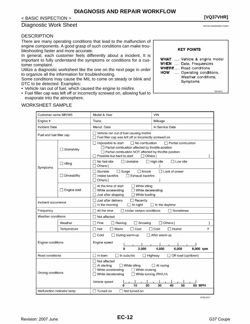
DESCRIPTIONThere are many operating conditions that lead to the malfunction ofengine components. A good grasp of such conditions can make trou-bleshooting faster and more accurate.In general, each customer feels differently about a incident. It isimportant to fully understand the symptoms or conditions for a cus-tomer complaint.Utilize a diagnostic worksheet like the one on the next page in orderto organize all the information for troubleshooting.Some conditions may cause the MIL to come on steady or blink andDTC to be detected. Examples:• Vehicle ran out of fuel, which caused the engine to misfire.• Fuel filler cap was left off or incorrectly screwed on, allowing fuel to
evaporate into the atmosphere.
WORKSHEET SAMPLE
SEF907L
MTBL0017
EC-12Revision: 2007 June G37 Coupe

INSPECTION AND ADJUSTMENT[VQ37VHR]
C
D
E
F
G
H
I
J
K
L
M
A
C
N
P
O
< BASIC INSPECTION >
E
INSPECTION AND ADJUSTMENTBASIC INSPECTION
BASIC INSPECTION : Special Repair Requirement INFOID:0000000001733908
1.INSPECTION START
1. Check service records for any recent repairs that may indicate a related malfunction, or a current need forscheduled maintenance.
2. Open engine hood and check the following:- Harness connectors for improper connections- Wiring harness for improper connections, pinches and cut- Vacuum hoses for splits, kinks and improper connections- Hoses and ducts for leaks- Air cleaner clogging- Gasket3. Confirm that electrical or mechanical loads are not applied.- Headlamp switch is OFF.- Air conditioner switch is OFF.- Rear window defogger switch is OFF.- Steering wheel is in the straight-ahead position, etc.4. Start engine and warm it up until engine coolant temperature
indicator points the middle of gauge.Ensure engine stays below 1,000 rpm.
5. Run engine at about 2,000 rpm for about 2 minutes under noload.
6. Make sure that no DTC is displayed with CONSULT-III or GST.Is any DTC detected?YES >> GO TO 2.NO >> GO TO 3.
2.REPAIR OR REPLACE
Repair or replace components as necessary according to corresponding Diagnosis Procedure.
>> GO TO 3
3.CHECK TARGET IDLE SPEED
1. Run engine at about 2,000 rpm for about 2 minutes under no load.
SEF983U
SEF976U
SEF977U
EC-13Revision: 2007 June G37 Coupe

[VQ37VHR]INSPECTION AND ADJUSTMENT
< BASIC INSPECTION >2. Rev engine (2,000 to 3,000 rpm) two or three times under no
load, then run engine at idle speed for about 1 minute.3. Check idle speed.
For procedure, refer to EC-17, "IDLE SPEED : Special RepairRequirement".For specification, refer to EC-606, "Idle Speed".
Is the inspection result normal?YES >> GO TO 10.NO >> GO TO 4.
4.PERFORM ACCELERATOR PEDAL RELEASED POSITION LEARNING
1. Stop engine.2. Perform EC-18, "ACCELERATOR PEDAL RELEASED POSITION LEARNING : Special Repair Require-
ment".
>> GO TO 5.
5.PERFORM THROTTLE VALVE CLOSED POSITION LEARNING
Perform EC-18, "THROTTLE VALVE CLOSED POSITION LEARNING : Special Repair Requirement".
>> GO TO 6.
6.PERFORM IDLE AIR VOLUME LEARNING
Perform EC-19, "IDLE AIR VOLUME LEARNING : Special Repair Requirement".Is Idle Air Volume Learning carried out successfully?YES >> GO TO 7.NO >> Follow the instruction of Idle Air Volume Learning. Then GO TO 4.
7.CHECK TARGET IDLE SPEED AGAIN
1. Start engine and warm it up to normal operating temperature.2. Check idle speed.
For procedure, refer to EC-17, "IDLE SPEED : Special Repair Requirement".For specification, refer to EC-606, "Idle Speed".
Is the inspection result normal?YES >> GO TO 10.NO >> GO TO 8.
8.DETECT MALFUNCTIONING PART
Check the Following.• Check camshaft position sensor (PHASE) and circuit. Refer to EC-271, "Component Inspection".• Check crankshaft position sensor (POS) and circuit. Refer to EC-267, "Component Inspection".Is the inspection result normal?YES >> GO TO 9.NO >> Repair or replace. Then GO TO 4.
9.CHECK ECM FUNCTION
1. Substitute another known-good ECM to check ECM function. (ECM may be the cause of an incident, butthis is a rare case.)
2. Perform initialization of IVIS (NATS) system and registration of all IVIS (NATS) ignition key IDs. Refer toSEC-8, "ECM RE-COMMUNICATING FUNCTION : Special Repair Requirement".
>> GO TO 4.
10.CHECK IGNITION TIMING
1. Run engine at idle.
PBIA8513J
EC-14Revision: 2007 June G37 Coupe

INSPECTION AND ADJUSTMENT[VQ37VHR]
C
D
E
F
G
H
I
J
K
L
M
A
C
N
P
O
< BASIC INSPECTION >
E
2. Check ignition timing with a timing light.
For procedure, refer to EC-17, "IGNITION TIMING : SpecialRepair Requirement".For specification, refer to EC-606, "Ignition Timing".
Is the inspection result normal?YES >> GO TO 19.NO >> GO TO 11.
11.PERFORM ACCELERATOR PEDAL RELEASED POSITION LEARNING
1. Stop engine.2. Perform EC-18, "ACCELERATOR PEDAL RELEASED POSITION LEARNING : Special Repair Require-
ment".
>> GO TO 12.
12.PERFORM THROTTLE VALVE CLOSED POSITION LEARNING
Perform EC-18, "THROTTLE VALVE CLOSED POSITION LEARNING : Special Repair Requirement".
>> GO TO 13.
13.PERFORM IDLE AIR VOLUME LEARNING
Perform EC-19, "IDLE AIR VOLUME LEARNING : Special Repair Requirement".Is Idle Air Volume Learning carried out successfully?YES >> GO TO 14.NO >> Follow the instruction of Idle Air Volume Learning. Then GO TO 4.
14.CHECK TARGET IDLE SPEED AGAIN
1. Start engine and warm it up to normal operating temperature.2. Check idle speed.
For procedure, refer to EC-17, "IDLE SPEED : Special Repair Requirement".For specification, refer to EC-606, "Idle Speed".
Is the inspection result normal?YES >> GO TO 15.NO >> GO TO 17.
15.CHECK IGNITION TIMING AGAIN
1. Run engine at idle.2. Check ignition timing with a timing light.
For procedure, refer to EC-17, "IGNITION TIMING : SpecialRepair Requirement".For specification, refer to EC-606, "Ignition Timing".
Is the inspection result normal?YES >> GO TO 19.NO >> GO TO 16.
16.CHECK TIMING CHAIN INSTALLATION
Check timing chain installation. Refer to EM-49, "Removal and Installation".Is the inspection result normal?YES >> GO TO 17.NO >> Repair the timing chain installation. Then GO TO 4.
A :Timing indicator
JMBIA0054ZZ
A :Timing indicator
JMBIA0054ZZ
EC-15Revision: 2007 June G37 Coupe

[VQ37VHR]INSPECTION AND ADJUSTMENT
< BASIC INSPECTION >
17.DETECT MALFUNCTIONING PART
Check the following.• Check camshaft position sensor (PHASE) and circuit. Refer to EC-271, "Component Inspection".• Check crankshaft position sensor (POS) and circuit. Refer to EC-267, "Component Inspection".Is the inspection result normal?YES >> GO TO 18.NO >> Repair or replace. Then GO TO 4.
18.CHECK ECM FUNCTION
1. Substitute another known-good ECM to check ECM function. (ECM may be the cause of an incident, butthis is a rare case.)
2. Perform initialization of IVIS (NATS) system and registration of all IVIS (NATS) ignition key IDs. Refer toSEC-8, "ECM RE-COMMUNICATING FUNCTION : Special Repair Requirement".
>> GO TO 4.
19.INSPECTION END
If ECM is replaced during this BASIC INSPECTION procedure, go to EC-16, "ADDITIONAL SERVICE WHENREPLACING CONTROL UNIT (ECM) : Special Repair Requirement".
>> INSPECTION ENDADDITIONAL SERVICE WHEN REPLACING CONTROL UNIT (ECM)
ADDITIONAL SERVICE WHEN REPLACING CONTROL UNIT (ECM) : DescriptionINFOID:0000000001733909
When replacing ECM, this procedure must be performed.
ADDITIONAL SERVICE WHEN REPLACING CONTROL UNIT (ECM) : Special Repair Requirement INFOID:0000000001733910
1.PERFORM INITIALIZATION OF NATS SYSTEM AND REGISTRATION OF ALL NATS IGNITION KEY IDS
Refer to SEC-8, "ECM RE-COMMUNICATING FUNCTION : Special Repair Requirement".
>> GO TO 2.
2.PERFORM VIN REGISTRATION
Refer to EC-18, "VIN REGISTRATION : Special Repair Requirement".
>> GO TO 3.
3.PERFORM ACCELERATOR PEDAL RELEASED POSITION LEARNING
Refer to EC-18, "ACCELERATOR PEDAL RELEASED POSITION LEARNING : Special Repair Requirement".
>> GO TO 4.
4.PERFORM THROTTLE VALVE CLOSED POSITION LEARNING
Refer to EC-18, "THROTTLE VALVE CLOSED POSITION LEARNING : Special Repair Requirement".
>> GO TO 5.
5.PERFORM IDLE AIR VOLUME LEARNING
Refer to EC-19, "IDLE AIR VOLUME LEARNING : Special Repair Requirement".
>> END
EC-16Revision: 2007 June G37 Coupe

INSPECTION AND ADJUSTMENT[VQ37VHR]
C
D
E
F
G
H
I
J
K
L
M
A
C
N
P
O
< BASIC INSPECTION >
E
ADDITIONAL SERVICE WHEN REPLACING CONTROL UNIT (VVEL CONTROLMODULE)
ADDITIONAL SERVICE WHEN REPLACING CONTROL UNIT (VVEL CONTROL MODULE) : Description INFOID:0000000001830660
When replacing VVEL control module, this procedure must be performed.
ADDITIONAL SERVICE WHEN REPLACING CONTROL UNIT (VVEL CONTROL MODULE) : Special Repair Requirement INFOID:0000000001830661
1.PERFORM IDLE AIR VOLUME LEARNING
Refer to EC-19, "IDLE AIR VOLUME LEARNING : Special Repair Requirement".
>> ENDIDLE SPEED
IDLE SPEED : Description INFOID:0000000001733911
This describes how to check the idle speed. For the actual procedure, follow the instructions in “BASICINSPECTION”.
IDLE SPEED : Special Repair Requirement INFOID:0000000001733912
1.CHECK IDLE SPEED
With CONSULT-IIICheck idle speed in “DATA MONITOR” mode with CONSULT-III.
With GSTCheck idle speed with Service $01 of GST.
>> INSPECTION ENDIGNITION TIMING
IGNITION TIMING : Description INFOID:0000000001733913
This describes how to check the ignition timing. For the actual procedure, follow the instructions in “BASICINSPECTION”.
IGNITION TIMING : Special Repair Requirement INFOID:0000000001733914
1.CHECK IGNITION TIMING
1. Attach timing light to loop wire as shown.
1. Loop wire
A. Timing light B. Timing indicator
JMBIA0846ZZ
EC-17Revision: 2007 June G37 Coupe

[VQ37VHR]INSPECTION AND ADJUSTMENT
< BASIC INSPECTION >2. Check ignition timing.
>> INSPECTION ENDVIN REGISTRATION
VIN REGISTRATION : Description INFOID:0000000001733915
VIN Registration is an operation to registering VIN in ECM. It must be performed each time ECM is replaced.NOTE:Accurate VIN which is registered in ECM may be required for Inspection & Maintenance (I/M).
VIN REGISTRATION : Special Repair Requirement INFOID:0000000001733916
1.CHECK VIN
Check the VIN of the vehicle and note it. Refer to GI-20, "Information About Identification or Model Code".
>> GO TO 2.
2.PERFORM VIN REGISTRATION
With CONSULT-III1. Turn ignition switch ON and engine stopped.2. Select “VIN REGISTRATION” in “WORK SUPPORT” mode.3. Follow the instruction of CONSULT-III display.
>> ENDACCELERATOR PEDAL RELEASED POSITION LEARNING
ACCELERATOR PEDAL RELEASED POSITION LEARNING : Description INFOID:0000000001733917
Accelerator Pedal Released Position Learning is a function of ECM to learn the fully released position of theaccelerator pedal by monitoring the accelerator pedal position sensor output signal. It must be performed eachtime harness connector of accelerator pedal position sensor or ECM is disconnected.
ACCELERATOR PEDAL RELEASED POSITION LEARNING : Special Repair Re-quirement INFOID:0000000001733918
1.START
1. Make sure that accelerator pedal is fully released.2. Turn ignition switch ON and wait at least 2 seconds.3. Turn ignition switch OFF and wait at least 10 seconds.4. Turn ignition switch ON and wait at least 2 seconds.5. Turn ignition switch OFF and wait at least 10 seconds.
>> ENDTHROTTLE VALVE CLOSED POSITION LEARNING
THROTTLE VALVE CLOSED POSITION LEARNING : Description INFOID:0000000001733919
Throttle Valve Closed Position Learning is a function of ECM to learn the fully closed position of the throttlevalve by monitoring the throttle position sensor output signal. It must be performed each time harness connec-tor of electric throttle control actuator or ECM is disconnected.
THROTTLE VALVE CLOSED POSITION LEARNING : Special Repair RequirementINFOID:0000000001733920
1.START
1. Make sure that accelerator pedal is fully released.
EC-18Revision: 2007 June G37 Coupe

INSPECTION AND ADJUSTMENT[VQ37VHR]
C
D
E
F
G
H
I
J
K
L
M
A
C
N
P
O
< BASIC INSPECTION >
E
2. Turn ignition switch ON.3. Turn ignition switch OFF and wait at least 10 seconds.
Make sure that throttle valve moves during above 10 seconds by confirming the operating sound.
>> ENDIDLE AIR VOLUME LEARNING
IDLE AIR VOLUME LEARNING : Description INFOID:0000000001733921
Idle Air Volume Learning is a function of ECM to learn the idle air volume that keeps engine idle speed withinthe specific range. It must be performed under any of the following conditions:• Each time electric throttle control actuator or ECM is replaced.• Each time VVEL actuator sub assembly or VVEL control module is replaced.• Idle speed or ignition timing is out of specification.
IDLE AIR VOLUME LEARNING : Special Repair Requirement INFOID:0000000001733922
1.PRECONDITIONING
Make sure that all of the following conditions are satisfied.Learning will be cancelled if any of the following conditions are missed for even a moment.• Battery voltage: More than 12.9V (At idle)• Engine coolant temperature: 70 - 105°C (158 - 221°F)• PNP switch: ON• Electric load switch: OFF
(Air conditioner, headlamp, rear window defogger)On vehicles equipped with daytime light systems, if the parking brake is applied before the engine isstarted the headlamp will not be illuminated.
• Steering wheel: Neutral (Straight-ahead position)• Vehicle speed: Stopped• Transmission: Warmed-up- A/T models• With CONSULT-III: Drive vehicle until “ATF TEMP SE 1” in “DATA MONITOR” mode of “A/T” system indi-
cates less than 0.9V.• Without CONSULT-III: Drive vehicle for 10 minutes.- M/T models• Drive vehicle for 10 minutes.Do you have CONSULT-III?YES >> GO TO 2.NO >> GO TO 3.
2.PERFORM IDLE AIR VOLUME LEARNING
With CONSULT-III1. Perform Accelerator Pedal Released Position Learning. Refer to EC-18, "ACCELERATOR PEDAL
RELEASED POSITION LEARNING : Special Repair Requirement".2. Perform Throttle Valve Closed Position Learning. EC-18, "THROTTLE VALVE CLOSED POSITION
LEARNING : Special Repair Requirement".3. Start engine and warm it up to normal operating temperature.4. Select “IDLE AIR VOL LEARN” in “WORK SUPPORT” mode.5. Touch “START” and wait 20 seconds.Is “CMPLT” displayed on CONSULT-III screen?YES >> GO TO 4.NO >> GO TO 5.
3.PERFORM IDLE AIR VOLUME LEARNING
Without CONSULT-IIINOTE:• It is better to count the time accurately with a clock.• It is impossible to switch the diagnostic mode when an accelerator pedal position sensor circuit has
a malfunction.
EC-19Revision: 2007 June G37 Coupe

[VQ37VHR]INSPECTION AND ADJUSTMENT
< BASIC INSPECTION >1. Perform Accelerator Pedal Released Position Learning. Refer to EC-18, "ACCELERATOR PEDAL
RELEASED POSITION LEARNING : Special Repair Requirement".2. Perform Throttle Valve Closed Position Learning. EC-18, "THROTTLE VALVE CLOSED POSITION
LEARNING : Special Repair Requirement".3. Start engine and warm it up to normal operating temperature.4. Turn ignition switch OFF and wait at least 10 seconds.5. Confirm that accelerator pedal is fully released, turn ignition switch ON and wait 3 seconds.6. Repeat the following procedure quickly five times within 5 seconds.- Fully depress the accelerator pedal.- Fully release the accelerator pedal.7. Wait 7 seconds, fully depress the accelerator pedal and keep it for approx. 20 seconds until the MIL stops
blinking and turned ON.8. Fully release the accelerator pedal within 3 seconds after the MIL turned ON.9. Start engine and let it idle.10. Wait 20 seconds.
>> GO TO 4.
4.CHECK IDLE SPEED AND IGNITION TIMING
1. Start engine and warm it up to normal operating temperature.2. Let it idle for 20 seconds.3. Rev up the engine two or three times and make sure that idle speed and ignition timing are within the
specifications. Refer to EC-606, "Idle Speed" and EC-606, "Ignition Timing".Is the inspection result normal?YES >> INSPECTION ENDNO >> GO TO 5.
5.DETECT MALFUNCTIONING PART-I
Check the following• Check that throttle valve is fully closed.• Check PCV valve operation.• Check that downstream of throttle valve is free from air leakage.Is the inspection result normal?YES >> GO TO 6.NO >> Repair or replace malfunctioning part.
6.DETECT MALFUNCTIONING PART-II
Engine component parts and their installation condition are questionable. Check and eliminate the cause ofthe incident.It is useful to perform “TROUBLE DIAGNOSIS - SPECIFICATION VALUE”. Refer to EC-132, "Description".If any of the following conditions occur after the engine has started, eliminate the cause of the incident andperform Idle Air Volume Learning all over again:• Engine stalls.• Erroneous idle.
>> INSPECTION ENDVVEL CONTROL SHAFT POSITION SENSOR ADJUSTMENT
SEC897C
EC-20Revision: 2007 June G37 Coupe

INSPECTION AND ADJUSTMENT[VQ37VHR]
C
D
E
F
G
H
I
J
K
L
M
A
C
N
P
O
< BASIC INSPECTION >
E
VVEL CONTROL SHAFT POSITION SENSOR ADJUSTMENT : DescriptionINFOID:0000000001736789
VVEL control shaft position sensor adjustment is an operation to adjust the initial position angle that is thebasis for the VVEL control shaft position sensor.It must be performed each time VVEL actuator sub assembly is replaced.CAUTION:• It must be performed only on the replaced bank side.• It must not be performed except when VVEL actuator sub assembly is replaced. If by any chance the
adjustment is performed, replace VVEL actuator sub assembly.
VVEL CONTROL SHAFT POSITION SENSOR ADJUSTMENT : Special Repair Re-quirement INFOID:0000000001736790
1.START
Do you have CONSULT-III?Do you have CONSULT-III?YES >> GO TO 2.NO >> GO TO 3.
2.PERFORM VVEL CONTROL SHAFT POSITION SENSOR ADJUSTMENT
With CONSULT-III1. Turn ignition switch ON.2. Select “VVEL POS SEN ADJ PREP” in “WORK SUPPORT” mode with CONSULT-III.3. Touch “Start” and wait a few seconds.4. Make sure the “CMPLT” is displayed on CONSULT-III screen.5. Select “VVEL POSITION SEN- B1” or “VVEL POSITION SEN- B2” in “DATA MONITOR” mode with CON-
SULT-III.6. Loosen the VVEL control shaft position sensor mounting bolt (1).7. Turn the VVEL control shaft position sensor (2) right and left
while monitoring the output voltage of “VVEL POSITION SEN-B1” or “VVEL POSITION SEN-B2” and adjust the output voltageto be within the standard value.
8. Tighten the VVEL control shaft position sensor mounting bolt.
9. Reconfirm that the output voltage of “VVEL POSITION SEN- B1”or “VVEL POSITION SEN- B2” is within the standard value.
NOTE:If it varies from the standard value after the bolt is tightened, perform steps 6 to 8 again.
10. Turn ignition switch OFF and wait at least 10 seconds.11. Start engine and warm it up to normal operating temperature.12. Turn ignition switch OFF and wait at least 10 seconds.13. Perform idle air volume learning. Refer to EC-19, "IDLE AIR VOLUME LEARNING : Special Repair
Requirement".
>> INSPECTION END
3.PERFORM VVEL CONTROL SHAFT POSITION SENSOR ADJUSTMENT
Without CONSULT-III1. Disconnect VVEL control shaft position sensor harness connector.2. Remove VVEL actuator motor relay.3. Turn ignition switch ON, wait at least 5 seconds and then turn OFF.
Voltage : 500±48mV
: 7.0 N•m (0.71kg-m, 62in-lb)
Voltage : 500±48mV
JMBIA0740ZZ
EC-21Revision: 2007 June G37 Coupe

[VQ37VHR]INSPECTION AND ADJUSTMENT
< BASIC INSPECTION >4. Reconnect all harness connectors disconnected.5. Install VVEL actuator motor relay.6. Turn ignition switch ON and wait at least 5 seconds.7. Loosen the VVEL control shaft position sensor mounting bolt (1).8. Turn the VVEL control shaft position sensor (2) right and left
while monitoring the output voltage between the VVEL controlmodule terminals with a tester and adjust the output voltage tobe within the standard value.
9. Tighten the VVEL control shaft position sensor mounting bolt.
10. Reconfirm that the output voltage of VVEL control shaft position sensor is within the standard value.
NOTE:If it varies from the standard value after the bolt is tightened, perform steps 7 to 9 again.
11. Turn ignition switch OFF and wait at least 10 seconds.12. Start engine and warm it up to normal operating temperature.13. Turn ignition switch OFF and wait at least 10 seconds.14. Perform idle air volume learning. Refer to EC-19, "IDLE AIR VOLUME LEARNING : Special Repair
Requirement".
>> INSPECTION ENDMIXTURE RATIO SELF-LEARNING VALUE CLEAR
MIXTURE RATIO SELF-LEARNING VALUE CLEAR : Description INFOID:0000000001733925
This describes how to erase the mixture ratio self-learning value. For the actual procedure, follow the instruc-tions in “Diagnosis Procedure”.
MIXTURE RATIO SELF-LEARNING VALUE CLEAR : Special Repair RequirementINFOID:0000000001733926
1.START
With CONSULT-III1. Start engine and warm it up to normal operating temperature.2. Select “SELF-LEARNING CONT” in “WORK SUPPORT” mode with CONSULT-III.
JMBIA0740ZZ
VVEL control module
VoltageBank Connector
+ –
Terminal Terminal
1E15
3 4500±48mV
2 5 6
: 7.0 N•m (0.71kg-m, 62in-lb)
VVEL control module
VoltageBank Connector
+ –
Terminal Terminal
1E15
3 4500±48mV
2 5 6
EC-22Revision: 2007 June G37 Coupe

INSPECTION AND ADJUSTMENT[VQ37VHR]
C
D
E
F
G
H
I
J
K
L
M
A
C
N
P
O
< BASIC INSPECTION >
E
3. Clear mixture ratio self-learning value by touching “CLEAR”.With GST
1. Start engine and warm it up to normal operating temperature.2. Turn ignition switch OFF.3. Disconnect mass air flow sensor (bank 1) harness connector.4. Restart engine and let it idle for at least 5 seconds.5. Stop engine and reconnect mass air flow sensor (bank 1) harness connector.6. Select Service $03 with GST. Make sure DTC P0102 is detected.7. Select Service $04 with GST to erase the DTC P0102.
>> END
EC-23Revision: 2007 June G37 Coupe

[VQ37VHR]ENGINE CONTROL SYSTEM
< FUNCTION DIAGNOSIS >
FUNCTION DIAGNOSISENGINE CONTROL SYSTEM
System Diagram INFOID:0000000001733927
1. ECM 2. Can communication 3. VVEL control module
4. EVAP canister purge volume control solenoid valve
5. EVAP service port 6. EVAP canister vent control valve
7. EVAP control system pressure sen-sor
8. EVAP canister 9. Battery current sensor
10. Battery 11. Fuel tank temperature sensor 12. Fuel level sensor
13. Fuel tank 14. Fuel pressure regulator 15. Fuel pump
16. Three way catalyst 2 17. Heated oxygen sensor 2 18. Three way catalyst 1
19. Engine oil temperature sensor 20. A/F sensor 1 21. Spark plug
22. PCV valve 23. Ignition coil (with power transistor) 24. VVEL actuator motor
JMBIA0856ZZ
EC-24Revision: 2007 June G37 Coupe

ENGINE CONTROL SYSTEM[VQ37VHR]
C
D
E
F
G
H
I
J
K
L
M
A
C
N
P
O
< FUNCTION DIAGNOSIS >
E
System Description INFOID:0000000001733928
ECM performs various controls such as fuel injection control and ignition timing control.
Component Parts Location INFOID:0000000001733929
25. VVEL control shaft position sensor 26. Intake valve timing control solenoid valve
27. Camshaft position sensor (PHASE)
28. Fuel damper 29. Engine coolant temperature sensor 30. Knock sensor
31. Crankshaft position sensor (POS) 32. Muffler 33. Cooling fan control module
34. Cooling fan 35. PNP switch 36. Air cleaner
37. Mass air flow sensor (with intake air temperature sensor)
38. Electric throttle control actuator 39. Throttle position sensor
40. Manifold absolute pressure (MAP) sensor
41. Brake booster pressure sensor 42. MIL
43. Ignition switch 44. Accelerator pedal position sensor 45. Power steering pressure sensor
46. Refrigerant pressure sensor
1. Battery current sensor 2. IPDM E/R 3. VVEL control module
4. Cooling fan relay 5. VVEL actuator motor relay 6. Mass air flow sensor (with intake air temperature sensor) (bank 1)
JMBIA0837ZZ
EC-25Revision: 2007 June G37 Coupe

[VQ37VHR]ENGINE CONTROL SYSTEM
< FUNCTION DIAGNOSIS >
7. Refrigerant pressure sensor 8. Camshaft position sensor (PHASE) (bank 1)
9. Cooling fan motor-2
10. Intake valve timing control solenoid valve (bank 1)
11. Cooling fan control module 12. Cooling fan motor-1
13. Intake valve timing control solenoid valve (bank 2)
14. Camshaft position sensor (PHASE) (bank 2)
15. Mass air flow sensor (with intake air temperature sensor) (bank 2)
16. ICC brake hold relay (ICC models) 17. Brake booster pressure sensor 18. Ignition coil (with power transistor) and spark plug (bank 2)
19. Electric throttle control actuator (bank 2)
20. A/F sensor 1 (bank 2) 21. Fuel injector (bank 2)
22. VVEL control shaft position sensor (bank 2)
23. VVEL actuator motor (bank 2) 24. Manifold absolute pressure (MAP) sensor
25. Engine coolant temperature sensor 26. Knock sensor 27. Fuel injector (bank 1)
28. VVEL actuator motor (bank 1) 29. EVAP canister purge volume control solenoid valve
30. VVEL control shaft position sensor (bank 1)
31. Ignition coil (with power transistor) and spark plug (bank 1)
32. EVAP service port 33. A/F sensor 1 (bank 1)
34. Crankshaft position sensor (POS) 35. Electric throttle control actuator (bank 1)
1. Mass air flow sensor (with intake air temperature sensor) (bank 1)
2. Mass air flow sensor (with intake air temperature sensor) (bank 2)
1. Electric throttle control actuator (bank 1)
2. Electric throttle control actuator (bank 2)
JMBIA0838ZZ
JMBIA0839ZZ
JMBIA0840ZZ
EC-26Revision: 2007 June G37 Coupe

ENGINE CONTROL SYSTEM[VQ37VHR]
C
D
E
F
G
H
I
J
K
L
M
A
C
N
P
O
< FUNCTION DIAGNOSIS >
E
: Vehicle front
1. Cooling fan motor-2 2. Cooling fan control module 3. Cooling fan motor-1
4. Cooling fan relay
PBIB1907E
: Vehicle front
1. A/F sensor 1 (bank 1) 2. A/F sensor 1 (bank 2)
: Vehicle front
1. A/F sensor 1 (bank 1) harness con-nector
2. A/F sensor 1 (bank 2) harness con-nector
JMBIA0007ZZ
JMBIA0841ZZ
EC-27Revision: 2007 June G37 Coupe
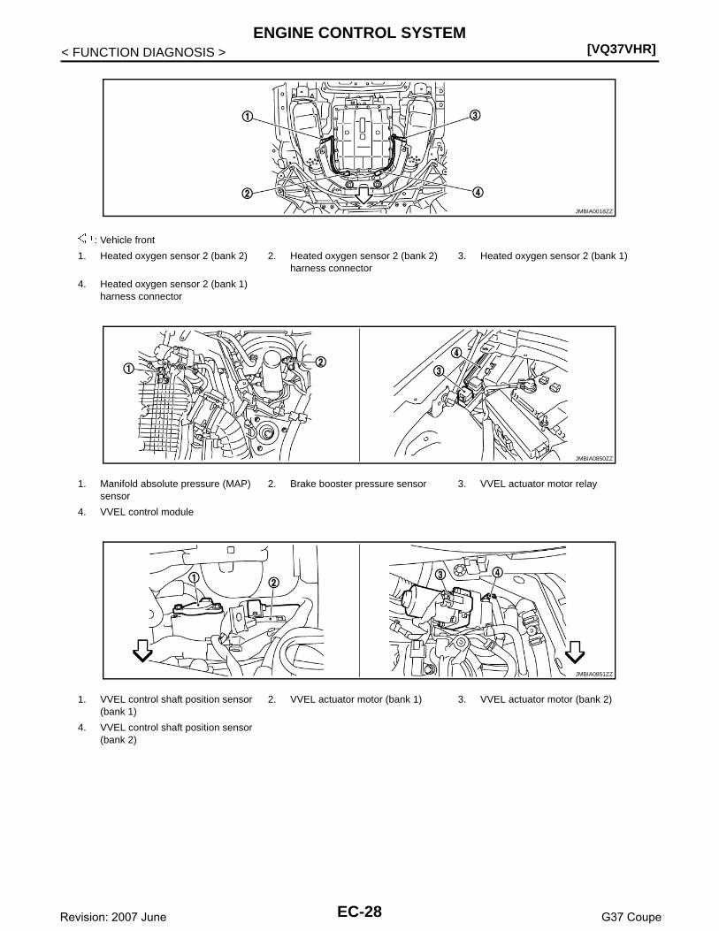
[VQ37VHR]ENGINE CONTROL SYSTEM
< FUNCTION DIAGNOSIS >
: Vehicle front
1. Heated oxygen sensor 2 (bank 2) 2. Heated oxygen sensor 2 (bank 2) harness connector
3. Heated oxygen sensor 2 (bank 1)
4. Heated oxygen sensor 2 (bank 1) harness connector
1. Manifold absolute pressure (MAP) sensor
2. Brake booster pressure sensor 3. VVEL actuator motor relay
4. VVEL control module
1. VVEL control shaft position sensor (bank 1)
2. VVEL actuator motor (bank 1) 3. VVEL actuator motor (bank 2)
4. VVEL control shaft position sensor (bank 2)
JMBIA0018ZZ
JMBIA0850ZZ
JMBIA0851ZZ
EC-28Revision: 2007 June G37 Coupe

ENGINE CONTROL SYSTEM[VQ37VHR]
C
D
E
F
G
H
I
J
K
L
M
A
C
N
P
O
< FUNCTION DIAGNOSIS >
E
1. Camshaft position sensor (PHASE) (bank 1)
2. Intake valve timing control solenoid valve (bank 1) harness connector
3. Intake valve timing control solenoid valve (bank 2) harness connector
4. Camshaft position sensor (PHASE) (bank 2)
1. Ignition coil No.5 (with power transis-tor)
2. Ignition coil No.3 (with power transis-tor)
3. Ignition coil No.1 (with power transis-tor)
4. Fuel injector No.3 5. Fuel injector No.1 6. Fuel injector No.2
7. Fuel injector No.4 8. Ignition coil No.2 (with power transis-tor)
9. Ignition coil No.4 (with power transis-tor)
10. Ignition coil No.6 (with power transis-tor)
11. Fuel injector No.6 12. Fuel injector No.5
13. Knock sensor (bank 1) 14. Knock sensor (bank 2)
: Vehicle front
1. Engine coolant temperature sensor 2. A/F sensor 1 (bank 1) 3. Crankshaft position sensor (POS)
JMBIA0842ZZ
JMBIA0843ZZ
JMBIA0844ZZ
EC-29Revision: 2007 June G37 Coupe

[VQ37VHR]ENGINE CONTROL SYSTEM
< FUNCTION DIAGNOSIS >
1. IPDM E/R 2. Battery current sensor 3. Refrigerant pressure sensor
: Vehicle front
1. Power steering pressure sensor 2. Alternator 3. Engine oil temperature sensor
: Vehicle front
1. EVAP service port 2. EVAP canister purge volume control solenoid valve
3. EVAP canister
4. EVAP canister vent control valve 5. EVAP control system pressure sen-sor
JMBIA0013ZZ
JMBIA0014ZZ
JMBIA0845ZZ
JMBIA0019ZZ
EC-30Revision: 2007 June G37 Coupe

ENGINE CONTROL SYSTEM[VQ37VHR]
C
D
E
F
G
H
I
J
K
L
M
A
C
N
P
O
< FUNCTION DIAGNOSIS >
E
: Vehicle front
1. Fuel level sensor unit and fuel pump harness connector
2. Fuel level sensor unit and fuel pump 3. Fuel pressure regulator
4. Fuel tank temperature sensor
1. Accelerator pedal position sensor 2. ECM
1. ICC steering switch 2. CANCEL switch 3. RESUME/ACCELERATE switch
4. SET/COAST switch 5. DISTANCE switch 6. MAIN switch
1. ASCD steering switch 2. CANCEL switch 3. RESUME/ACCELERATE switch
4. SET/COAST switch 5. MAIN switch
JMBIA0015ZZ
JMBIA0016ZZ
JMBIA0017ZZ
JMBIA0051ZZ
EC-31Revision: 2007 June G37 Coupe

[VQ37VHR]ENGINE CONTROL SYSTEM
< FUNCTION DIAGNOSIS >
Component Description INFOID:0000000001733930
1. Stop lamp switch 2. ASCD brake switch (ASCD models)ICC brake switch (ICC models)
3. Brake pedal
4. ASCD clutch switch (ASCD models)ICC clutch switch (ICC models)
5. Clutch pedal
Component Reference
A/F sensor 1 EC-197, "Description"
A/F sensor 1 heater EC-155, "Description"
Accelerator pedal position sensor EC-458, "Description"
ASCD brake switch EC-428, "Description"
ASCD steering switch EC-421, "Description"
ASCD vehicle speed sensor EC-443, "Description"
Battery current sensor EC-408, "Description"
Brake booster pressure sensor EC-346, "Description"
Camshaft position sensor (PHASE) EC-268, "Description"
Crankshaft position sensor (POS) EC-264, "Description"
Cooling fan control module EC-481, "Description"
Cooling fan motor EC-481, "Description"
Electric throttle control actuator EC-399, "Description"
Engine coolant temperature sensor EC-184, "Description"
Engine oil temperature sensor EC-246, "Description"
EVAP canister purge volume control solenoid valve EC-288, "Description"
EVAP canister vent control valve EC-296, "Description"
EVAP control system pressure sensor EC-304, "Description"
Fuel injector EC-487, "Description"
Fuel level sensor EC-331, "Description"
Fuel pump EC-490, "Description"
Fuel tank temperature sensor EC-240, "Description"
Heated oxygen sensor 2 EC-212, "Description"
Heated oxygen sensor 2 heater EC-158, "Description"
ICC brake switch EC-435, "Description"
ICC steering switch EC-424, "Description"
ICC vehicle speed sensor EC-445, "Description"
Ignition signal EC-498, "Description"
Intake air temperature sensor EC-181, "Description"
Intake valve timing control solenoid valve EC-162, "Description"
Knock sensor EC-261, "Description"
Manifold absolute pressure (MAP) sensor EC-177, "Description"
Mass air flow sensor EC-165, "Description"
Park/neutral position switch EC-361, "Description"
PCV valve EC-509, "Description"
Power steering pressure sensor EC-346, "Description"
Refrigerant pressure sensor EC-511, "Description"
Stop lamp switch EC-455, "Description"
EC-32Revision: 2007 June G37 Coupe

ENGINE CONTROL SYSTEM[VQ37VHR]
C
D
E
F
G
H
I
J
K
L
M
A
C
N
P
O
< FUNCTION DIAGNOSIS >
E
Throttle control motor EC-396, "Description"
Throttle control motor relay EC-404, "Description"
Throttle position sensor EC-187, "Description"
Vehicle speed sensor EC-337, "Description"
VVEL actuator motor EC-374, "Description"
VVEL actuator motor relay EC-378, "Description"
VVEL control module EC-447, "Description"
VVEL control shaft position sensor EC-370, "Description"
Component Reference
EC-33Revision: 2007 June G37 Coupe
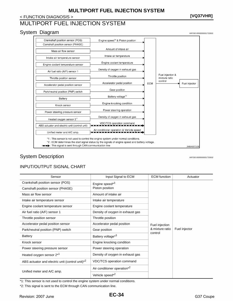
[VQ37VHR]MULTIPORT FUEL INJECTION SYSTEM
< FUNCTION DIAGNOSIS >
MULTIPORT FUEL INJECTION SYSTEM
System Diagram INFOID:0000000001733931
System Description INFOID:0000000001733932
INPUT/OUTPUT SIGNAL CHART
*1: This sensor is not used to control the engine system under normal conditions.
*2: This signal is sent to the ECM through CAN communication line.
JMBIA0071GB
Sensor Input Signal to ECM ECM function Actuator
Crankshaft position sensor (POS) Engine speed*3
Piston position
Fuel injection & mixture ratio control
Fuel injector
Camshaft position sensor (PHASE)
Mass air flow sensor Amount of intake air
Intake air temperature sensor Intake air temperature
Engine coolant temperature sensor Engine coolant temperature
Air fuel ratio (A/F) sensor 1 Density of oxygen in exhaust gas
Throttle position sensor Throttle position
Accelerator pedal position sensor Accelerator pedal position
Park/neutral position (PNP) switch Gear position
Battery Battery voltage*3
Knock sensor Engine knocking condition
Power steering pressure sensor Power steering operation
Heated oxygen sensor 2*1 Density of oxygen in exhaust gas
ABS actuator and electric unit (control unit)*2 VDC/TCS operation command
Unified meter and A/C amp.Air conditioner operation*2
Vehicle speed*2
EC-34Revision: 2007 June G37 Coupe

MULTIPORT FUEL INJECTION SYSTEM[VQ37VHR]
C
D
E
F
G
H
I
J
K
L
M
A
C
N
P
O
< FUNCTION DIAGNOSIS >
E
*3: ECM determines the start signal status by the signals of engine speed and battery voltage.
SYSTEM DESCRIPTIONThe amount of fuel injected from the fuel injector is determined by the ECM. The ECM controls the length oftime the valve remains open (injection pulse duration). The amount of fuel injected is a program value in theECM memory. The program value is preset by engine operating conditions. These conditions are determinedby input signals (for engine speed and intake air) from the crankshaft position sensor (POS), camshaft positionsensor (PHASE) and the mass air flow sensor.
VARIOUS FUEL INJECTION INCREASE/DECREASE COMPENSATIONIn addition, the amount of fuel injected is compensated to improve engine performance under various operat-ing conditions as listed below.
<Fuel increase>• During warm-up• When starting the engine• During acceleration• Hot-engine operation• When selector lever is changed from N to D (A/T models)• High-load, high-speed operation
<Fuel decrease>• During deceleration• During high engine speed operation
MIXTURE RATIO FEEDBACK CONTROL (CLOSED LOOP CONTROL)
The mixture ratio feedback system provides the best air-fuel mixture ratio for driveability and emission control.The three way catalyst 1 can then better reduce CO, HC and NOx emissions. This system uses A/F sensor 1in the exhaust manifold to monitor whether the engine operation is rich or lean. The ECM adjusts the injectionpulse width according to the sensor voltage signal. For more information about A/F sensor 1, refer to EC-197,"Description". This maintains the mixture ratio within the range of stoichiometric (ideal air-fuel mixture).This stage is referred to as the closed loop control condition.Heated oxygen sensor 2 is located downstream of the three way catalyst 1. Even if the switching characteris-tics of A/F sensor 1 shift, the air-fuel ratio is controlled to stoichiometric by the signal from heated oxygen sen-sor 2.• Open Loop Control
The open loop system condition refers to when the ECM detects any of the following conditions. Feedbackcontrol stops in order to maintain stabilized fuel combustion.
- Deceleration and acceleration- High-load, high-speed operation- Malfunction of A/F sensor 1 or its circuit- Insufficient activation of A/F sensor 1 at low engine coolant temperature- High engine coolant temperature- During warm-up- After shifting from N to D (A/T models)- When starting the engine
MIXTURE RATIO SELF-LEARNING CONTROLThe mixture ratio feedback control system monitors the mixture ratio signal transmitted from A/F sensor 1.This feedback signal is then sent to the ECM. The ECM controls the basic mixture ratio as close to the theoret-ical mixture ratio as possible. However, the basic mixture ratio is not necessarily controlled as originallydesigned. Both manufacturing differences (i.e., mass air flow sensor hot wire) and characteristic changes dur-ing operation (i.e., fuel injector clogging) directly affect mixture ratio.
PBIB2793E
EC-35Revision: 2007 June G37 Coupe
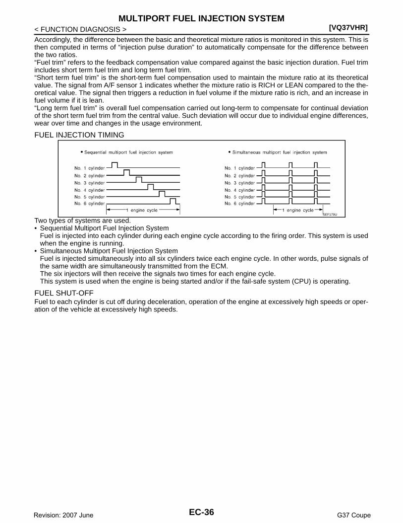
[VQ37VHR]MULTIPORT FUEL INJECTION SYSTEM
< FUNCTION DIAGNOSIS >Accordingly, the difference between the basic and theoretical mixture ratios is monitored in this system. This isthen computed in terms of “injection pulse duration” to automatically compensate for the difference betweenthe two ratios.“Fuel trim” refers to the feedback compensation value compared against the basic injection duration. Fuel trimincludes short term fuel trim and long term fuel trim.“Short term fuel trim” is the short-term fuel compensation used to maintain the mixture ratio at its theoreticalvalue. The signal from A/F sensor 1 indicates whether the mixture ratio is RICH or LEAN compared to the the-oretical value. The signal then triggers a reduction in fuel volume if the mixture ratio is rich, and an increase infuel volume if it is lean.“Long term fuel trim” is overall fuel compensation carried out long-term to compensate for continual deviationof the short term fuel trim from the central value. Such deviation will occur due to individual engine differences,wear over time and changes in the usage environment.
FUEL INJECTION TIMING
Two types of systems are used.• Sequential Multiport Fuel Injection System
Fuel is injected into each cylinder during each engine cycle according to the firing order. This system is usedwhen the engine is running.
• Simultaneous Multiport Fuel Injection SystemFuel is injected simultaneously into all six cylinders twice each engine cycle. In other words, pulse signals ofthe same width are simultaneously transmitted from the ECM.The six injectors will then receive the signals two times for each engine cycle.This system is used when the engine is being started and/or if the fail-safe system (CPU) is operating.
FUEL SHUT-OFFFuel to each cylinder is cut off during deceleration, operation of the engine at excessively high speeds or oper-ation of the vehicle at excessively high speeds.
SEF179U
EC-36Revision: 2007 June G37 Coupe

MULTIPORT FUEL INJECTION SYSTEM[VQ37VHR]
C
D
E
F
G
H
I
J
K
L
M
A
C
N
P
O
< FUNCTION DIAGNOSIS >
E
Component Parts Location INFOID:0000000001910704
1. Battery current sensor 2. IPDM E/R 3. VVEL control module
4. Cooling fan relay 5. VVEL actuator motor relay 6. Mass air flow sensor (with intake air temperature sensor) (bank 1)
7. Refrigerant pressure sensor 8. Camshaft position sensor (PHASE) (bank 1)
9. Cooling fan motor-2
10. Intake valve timing control solenoid valve (bank 1)
11. Cooling fan control module 12. Cooling fan motor-1
13. Intake valve timing control solenoid valve (bank 2)
14. Camshaft position sensor (PHASE) (bank 2)
15. Mass air flow sensor (with intake air temperature sensor) (bank 2)
16. ICC brake hold relay (ICC models) 17. Brake booster pressure sensor 18. Ignition coil (with power transistor) and spark plug (bank 2)
19. Electric throttle control actuator (bank 2)
20. A/F sensor 1 (bank 2) 21. Fuel injector (bank 2)
22. VVEL control shaft position sensor (bank 2)
23. VVEL actuator motor (bank 2) 24. Manifold absolute pressure (MAP) sensor
25. Engine coolant temperature sensor 26. Knock sensor 27. Fuel injector (bank 1)
28. VVEL actuator motor (bank 1) 29. EVAP canister purge volume control solenoid valve
30. VVEL control shaft position sensor (bank 1)
JMBIA0837ZZ
EC-37Revision: 2007 June G37 Coupe
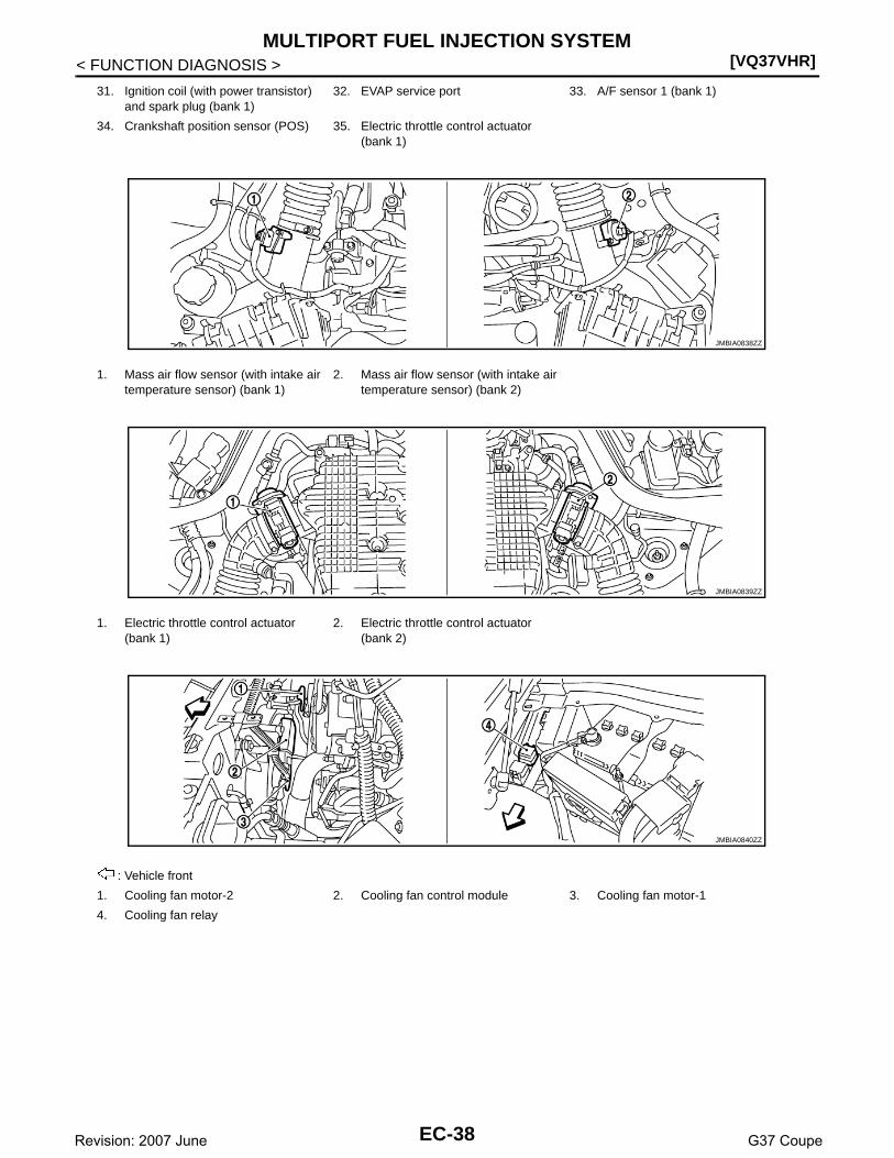
[VQ37VHR]MULTIPORT FUEL INJECTION SYSTEM
< FUNCTION DIAGNOSIS >
31. Ignition coil (with power transistor) and spark plug (bank 1)
32. EVAP service port 33. A/F sensor 1 (bank 1)
34. Crankshaft position sensor (POS) 35. Electric throttle control actuator (bank 1)
1. Mass air flow sensor (with intake air temperature sensor) (bank 1)
2. Mass air flow sensor (with intake air temperature sensor) (bank 2)
1. Electric throttle control actuator (bank 1)
2. Electric throttle control actuator (bank 2)
: Vehicle front
1. Cooling fan motor-2 2. Cooling fan control module 3. Cooling fan motor-1
4. Cooling fan relay
JMBIA0838ZZ
JMBIA0839ZZ
JMBIA0840ZZ
EC-38Revision: 2007 June G37 Coupe

MULTIPORT FUEL INJECTION SYSTEM[VQ37VHR]
C
D
E
F
G
H
I
J
K
L
M
A
C
N
P
O
< FUNCTION DIAGNOSIS >
E
PBIB1907E
: Vehicle front
1. A/F sensor 1 (bank 1) 2. A/F sensor 1 (bank 2)
: Vehicle front
1. A/F sensor 1 (bank 1) harness con-nector
2. A/F sensor 1 (bank 2) harness con-nector
JMBIA0007ZZ
JMBIA0841ZZ
JMBIA0018ZZ
EC-39Revision: 2007 June G37 Coupe
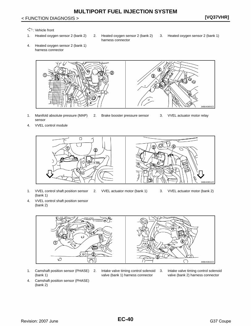
[VQ37VHR]MULTIPORT FUEL INJECTION SYSTEM
< FUNCTION DIAGNOSIS >
: Vehicle front
1. Heated oxygen sensor 2 (bank 2) 2. Heated oxygen sensor 2 (bank 2) harness connector
3. Heated oxygen sensor 2 (bank 1)
4. Heated oxygen sensor 2 (bank 1) harness connector
1. Manifold absolute pressure (MAP) sensor
2. Brake booster pressure sensor 3. VVEL actuator motor relay
4. VVEL control module
1. VVEL control shaft position sensor (bank 1)
2. VVEL actuator motor (bank 1) 3. VVEL actuator motor (bank 2)
4. VVEL control shaft position sensor (bank 2)
1. Camshaft position sensor (PHASE) (bank 1)
2. Intake valve timing control solenoid valve (bank 1) harness connector
3. Intake valve timing control solenoid valve (bank 2) harness connector
4. Camshaft position sensor (PHASE) (bank 2)
JMBIA0850ZZ
JMBIA0851ZZ
JMBIA0842ZZ
EC-40Revision: 2007 June G37 Coupe

MULTIPORT FUEL INJECTION SYSTEM[VQ37VHR]
C
D
E
F
G
H
I
J
K
L
M
A
C
N
P
O
< FUNCTION DIAGNOSIS >
E
1. Ignition coil No.5 (with power transis-tor)
2. Ignition coil No.3 (with power transis-tor)
3. Ignition coil No.1 (with power transis-tor)
4. Fuel injector No.3 5. Fuel injector No.1 6. Fuel injector No.2
7. Fuel injector No.4 8. Ignition coil No.2 (with power transis-tor)
9. Ignition coil No.4 (with power transis-tor)
10. Ignition coil No.6 (with power transis-tor)
11. Fuel injector No.6 12. Fuel injector No.5
13. Knock sensor (bank 1) 14. Knock sensor (bank 2)
: Vehicle front
1. Engine coolant temperature sensor 2. A/F sensor 1 (bank 1) 3. Crankshaft position sensor (POS)
1. IPDM E/R 2. Battery current sensor 3. Refrigerant pressure sensor
JMBIA0843ZZ
JMBIA0844ZZ
JMBIA0013ZZ
JMBIA0014ZZ
EC-41Revision: 2007 June G37 Coupe

[VQ37VHR]MULTIPORT FUEL INJECTION SYSTEM
< FUNCTION DIAGNOSIS >
: Vehicle front
1. Power steering pressure sensor 2. Alternator 3. Engine oil temperature sensor
: Vehicle front
1. EVAP service port 2. EVAP canister purge volume control solenoid valve
3. EVAP canister
4. EVAP canister vent control valve 5. EVAP control system pressure sen-sor
: Vehicle front
1. Fuel level sensor unit and fuel pump harness connector
2. Fuel level sensor unit and fuel pump 3. Fuel pressure regulator
4. Fuel tank temperature sensor
1. Accelerator pedal position sensor 2. ECM
JMBIA0845ZZ
JMBIA0019ZZ
JMBIA0015ZZ
EC-42Revision: 2007 June G37 Coupe

MULTIPORT FUEL INJECTION SYSTEM[VQ37VHR]
C
D
E
F
G
H
I
J
K
L
M
A
C
N
P
O
< FUNCTION DIAGNOSIS >
E
Component Description INFOID:0000000001733934
1. ICC steering switch 2. CANCEL switch 3. RESUME/ACCELERATE switch
4. SET/COAST switch 5. DISTANCE switch 6. MAIN switch
1. ASCD steering switch 2. CANCEL switch 3. RESUME/ACCELERATE switch
4. SET/COAST switch 5. MAIN switch
1. Stop lamp switch 2. ASCD brake switch (ASCD models)ICC brake switch (ICC models)
3. Brake pedal
4. ASCD clutch switch (ASCD models)ICC clutch switch (ICC models)
5. Clutch pedal
JMBIA0016ZZ
JMBIA0017ZZ
JMBIA0051ZZ
Component Reference
A/F sensor 1 EC-197, "Description"
Accelerator pedal position sensor EC-458, "Description"
Camshaft position sensor (PHASE) EC-268, "Description"
Crankshaft position sensor (POS) EC-264, "Description"
Engine coolant temperature sensor EC-184, "Description"
Fuel injector EC-487, "Description"
Heated oxygen sensor 2 EC-212, "Description"
EC-43Revision: 2007 June G37 Coupe

[VQ37VHR]MULTIPORT FUEL INJECTION SYSTEM
< FUNCTION DIAGNOSIS >
Intake air temperature sensor EC-181, "Description"
Knock sensor EC-261, "Description"
Mass air flow sensor EC-165, "Description"
Park/neutral position switch EC-361, "Description"
Power steering pressure sensor EC-346, "Description"
Throttle position sensor EC-187, "Description"
Vehicle speed sensor EC-337, "Description"
Component Reference
EC-44Revision: 2007 June G37 Coupe
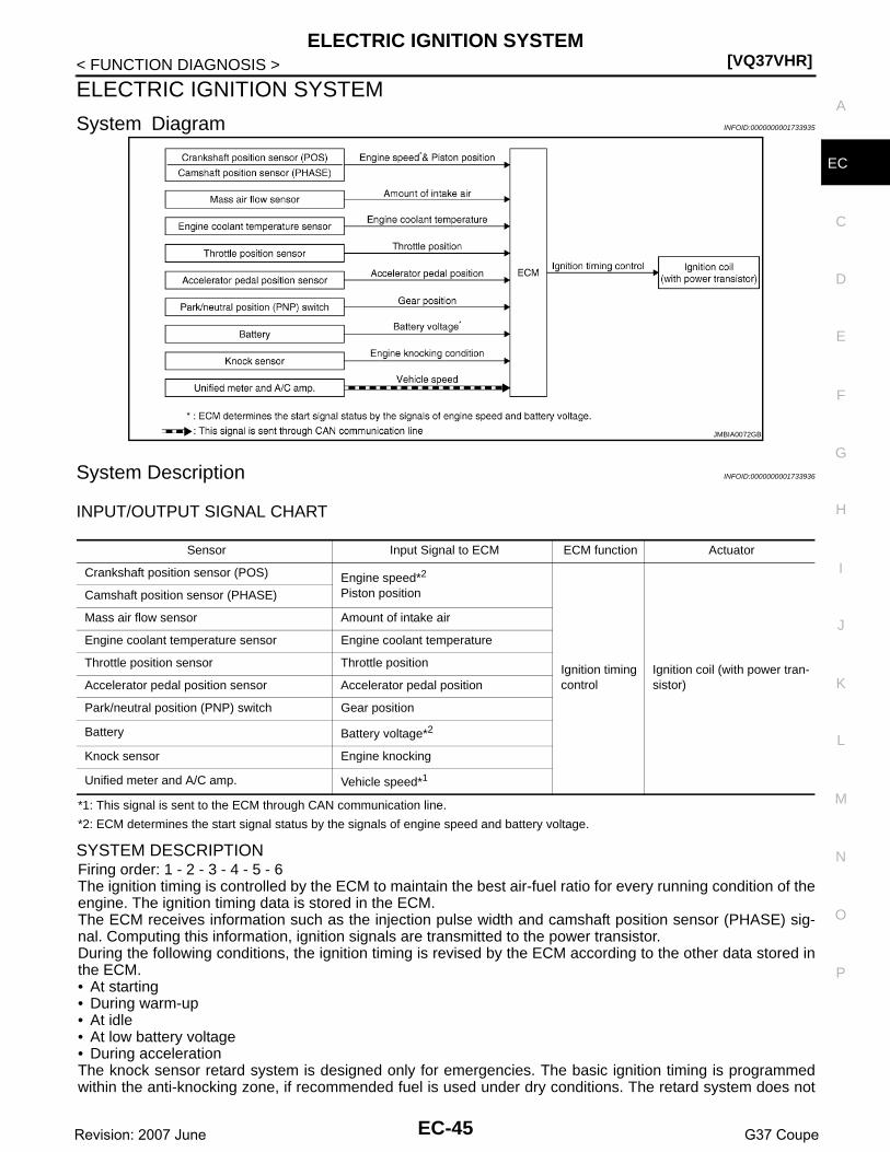
ELECTRIC IGNITION SYSTEM[VQ37VHR]
C
D
E
F
G
H
I
J
K
L
M
A
C
N
P
O
< FUNCTION DIAGNOSIS >
E
ELECTRIC IGNITION SYSTEM
System Diagram INFOID:0000000001733935
System Description INFOID:0000000001733936
INPUT/OUTPUT SIGNAL CHART
*1: This signal is sent to the ECM through CAN communication line.
*2: ECM determines the start signal status by the signals of engine speed and battery voltage.
SYSTEM DESCRIPTIONFiring order: 1 - 2 - 3 - 4 - 5 - 6The ignition timing is controlled by the ECM to maintain the best air-fuel ratio for every running condition of theengine. The ignition timing data is stored in the ECM.The ECM receives information such as the injection pulse width and camshaft position sensor (PHASE) sig-nal. Computing this information, ignition signals are transmitted to the power transistor.During the following conditions, the ignition timing is revised by the ECM according to the other data stored inthe ECM.• At starting• During warm-up• At idle• At low battery voltage• During accelerationThe knock sensor retard system is designed only for emergencies. The basic ignition timing is programmedwithin the anti-knocking zone, if recommended fuel is used under dry conditions. The retard system does not
JMBIA0072GB
Sensor Input Signal to ECM ECM function Actuator
Crankshaft position sensor (POS) Engine speed*2
Piston position
Ignition timing control
Ignition coil (with power tran-sistor)
Camshaft position sensor (PHASE)
Mass air flow sensor Amount of intake air
Engine coolant temperature sensor Engine coolant temperature
Throttle position sensor Throttle position
Accelerator pedal position sensor Accelerator pedal position
Park/neutral position (PNP) switch Gear position
Battery Battery voltage*2
Knock sensor Engine knocking
Unified meter and A/C amp. Vehicle speed*1
EC-45Revision: 2007 June G37 Coupe

[VQ37VHR]ELECTRIC IGNITION SYSTEM
< FUNCTION DIAGNOSIS >operate under normal driving conditions. If engine knocking occurs, the knock sensor monitors the condition.The signal is transmitted to the ECM. The ECM retards the ignition timing to eliminate the knocking condition.
Component Parts Location INFOID:0000000001910703
1. Battery current sensor 2. IPDM E/R 3. VVEL control module
4. Cooling fan relay 5. VVEL actuator motor relay 6. Mass air flow sensor (with intake air temperature sensor) (bank 1)
7. Refrigerant pressure sensor 8. Camshaft position sensor (PHASE) (bank 1)
9. Cooling fan motor-2
10. Intake valve timing control solenoid valve (bank 1)
11. Cooling fan control module 12. Cooling fan motor-1
13. Intake valve timing control solenoid valve (bank 2)
14. Camshaft position sensor (PHASE) (bank 2)
15. Mass air flow sensor (with intake air temperature sensor) (bank 2)
16. ICC brake hold relay (ICC models) 17. Brake booster pressure sensor 18. Ignition coil (with power transistor) and spark plug (bank 2)
19. Electric throttle control actuator (bank 2)
20. A/F sensor 1 (bank 2) 21. Fuel injector (bank 2)
22. VVEL control shaft position sensor (bank 2)
23. VVEL actuator motor (bank 2) 24. Manifold absolute pressure (MAP) sensor
25. Engine coolant temperature sensor 26. Knock sensor 27. Fuel injector (bank 1)
28. VVEL actuator motor (bank 1) 29. EVAP canister purge volume control solenoid valve
30. VVEL control shaft position sensor (bank 1)
JMBIA0837ZZ
EC-46Revision: 2007 June G37 Coupe

ELECTRIC IGNITION SYSTEM[VQ37VHR]
C
D
E
F
G
H
I
J
K
L
M
A
C
N
P
O
< FUNCTION DIAGNOSIS >
E
31. Ignition coil (with power transistor) and spark plug (bank 1)
32. EVAP service port 33. A/F sensor 1 (bank 1)
34. Crankshaft position sensor (POS) 35. Electric throttle control actuator (bank 1)
1. Mass air flow sensor (with intake air temperature sensor) (bank 1)
2. Mass air flow sensor (with intake air temperature sensor) (bank 2)
1. Electric throttle control actuator (bank 1)
2. Electric throttle control actuator (bank 2)
: Vehicle front
1. Cooling fan motor-2 2. Cooling fan control module 3. Cooling fan motor-1
4. Cooling fan relay
JMBIA0838ZZ
JMBIA0839ZZ
JMBIA0840ZZ
EC-47Revision: 2007 June G37 Coupe

[VQ37VHR]ELECTRIC IGNITION SYSTEM
< FUNCTION DIAGNOSIS >
PBIB1907E
: Vehicle front
1. A/F sensor 1 (bank 1) 2. A/F sensor 1 (bank 2)
: Vehicle front
1. A/F sensor 1 (bank 1) harness con-nector
2. A/F sensor 1 (bank 2) harness con-nector
JMBIA0007ZZ
JMBIA0841ZZ
JMBIA0018ZZ
EC-48Revision: 2007 June G37 Coupe

ELECTRIC IGNITION SYSTEM[VQ37VHR]
C
D
E
F
G
H
I
J
K
L
M
A
C
N
P
O
< FUNCTION DIAGNOSIS >
E
: Vehicle front
1. Heated oxygen sensor 2 (bank 2) 2. Heated oxygen sensor 2 (bank 2) harness connector
3. Heated oxygen sensor 2 (bank 1)
4. Heated oxygen sensor 2 (bank 1) harness connector
1. Manifold absolute pressure (MAP) sensor
2. Brake booster pressure sensor 3. VVEL actuator motor relay
4. VVEL control module
1. VVEL control shaft position sensor (bank 1)
2. VVEL actuator motor (bank 1) 3. VVEL actuator motor (bank 2)
4. VVEL control shaft position sensor (bank 2)
1. Camshaft position sensor (PHASE) (bank 1)
2. Intake valve timing control solenoid valve (bank 1) harness connector
3. Intake valve timing control solenoid valve (bank 2) harness connector
4. Camshaft position sensor (PHASE) (bank 2)
JMBIA0850ZZ
JMBIA0851ZZ
JMBIA0842ZZ
EC-49Revision: 2007 June G37 Coupe

[VQ37VHR]ELECTRIC IGNITION SYSTEM
< FUNCTION DIAGNOSIS >
1. Ignition coil No.5 (with power transis-tor)
2. Ignition coil No.3 (with power transis-tor)
3. Ignition coil No.1 (with power transis-tor)
4. Fuel injector No.3 5. Fuel injector No.1 6. Fuel injector No.2
7. Fuel injector No.4 8. Ignition coil No.2 (with power transis-tor)
9. Ignition coil No.4 (with power transis-tor)
10. Ignition coil No.6 (with power transis-tor)
11. Fuel injector No.6 12. Fuel injector No.5
13. Knock sensor (bank 1) 14. Knock sensor (bank 2)
: Vehicle front
1. Engine coolant temperature sensor 2. A/F sensor 1 (bank 1) 3. Crankshaft position sensor (POS)
1. IPDM E/R 2. Battery current sensor 3. Refrigerant pressure sensor
JMBIA0843ZZ
JMBIA0844ZZ
JMBIA0013ZZ
JMBIA0014ZZ
EC-50Revision: 2007 June G37 Coupe

ELECTRIC IGNITION SYSTEM[VQ37VHR]
C
D
E
F
G
H
I
J
K
L
M
A
C
N
P
O
< FUNCTION DIAGNOSIS >
E
: Vehicle front
1. Power steering pressure sensor 2. Alternator 3. Engine oil temperature sensor
: Vehicle front
1. EVAP service port 2. EVAP canister purge volume control solenoid valve
3. EVAP canister
4. EVAP canister vent control valve 5. EVAP control system pressure sen-sor
: Vehicle front
1. Fuel level sensor unit and fuel pump harness connector
2. Fuel level sensor unit and fuel pump 3. Fuel pressure regulator
4. Fuel tank temperature sensor
1. Accelerator pedal position sensor 2. ECM
JMBIA0845ZZ
JMBIA0019ZZ
JMBIA0015ZZ
EC-51Revision: 2007 June G37 Coupe

[VQ37VHR]ELECTRIC IGNITION SYSTEM
< FUNCTION DIAGNOSIS >
Component Description INFOID:0000000001733938
1. ICC steering switch 2. CANCEL switch 3. RESUME/ACCELERATE switch
4. SET/COAST switch 5. DISTANCE switch 6. MAIN switch
1. ASCD steering switch 2. CANCEL switch 3. RESUME/ACCELERATE switch
4. SET/COAST switch 5. MAIN switch
1. Stop lamp switch 2. ASCD brake switch (ASCD models)ICC brake switch (ICC models)
3. Brake pedal
4. ASCD clutch switch (ASCD models)ICC clutch switch (ICC models)
5. Clutch pedal
JMBIA0016ZZ
JMBIA0017ZZ
JMBIA0051ZZ
Component Reference
Accelerator pedal position sensor EC-458, "Description"
Camshaft position sensor (PHASE) EC-268, "Description"
Crankshaft position sensor (POS) EC-264, "Description"
Engine coolant temperature sensor EC-184, "Description"
Ignition signal EC-498, "Description"
Knock sensor EC-261, "Description"
Mass air flow sensor EC-165, "Description"
EC-52Revision: 2007 June G37 Coupe

ELECTRIC IGNITION SYSTEM[VQ37VHR]
C
D
E
F
G
H
I
J
K
L
M
A
C
N
P
O
< FUNCTION DIAGNOSIS >
E
Park/neutral position switch EC-361, "Description"
Throttle position sensor EC-187, "Description"
Vehicle speed sensor EC-337, "Description"
Component Reference
EC-53Revision: 2007 June G37 Coupe

[VQ37VHR]AIR CONDITIONING CUT CONTROL
< FUNCTION DIAGNOSIS >
AIR CONDITIONING CUT CONTROL
System Diagram INFOID:0000000001733939
System Description INFOID:0000000001733940
INPUT/OUTPUT SIGNAL CHART
*1: This signal is sent to the ECM through CAN communication line.
*2: ECM determines the start signal status by the signals of engine speed and battery voltage.
SYSTEM DESCRIPTIONThis system improves engine operation when the air conditioner is used.Under the following conditions, the air conditioner is turned off.• When the accelerator pedal is fully depressed.• When cranking the engine.• At high engine speeds.• When the engine coolant temperature becomes excessively high.• When operating power steering during low engine speed or low vehicle speed.• When engine speed is excessively low.• When refrigerant pressure is excessively low or high.
JMBIA0073GB
Sensor Input Signal to ECM ECM function Actuator
Crankshaft position sensor (POS)Camshaft position sensor (PHASE) Engine speed*2
Air conditioner cut control
IPDM E/R↓A/C relay↓Compressor
Engine coolant temperature sensor Engine coolant temperature
Accelerator pedal position sensor Accelerator pedal position
Battery Battery voltage*2
Refrigerant pressure sensor Refrigerant pressure
Power steering pressure sensor Power steering operation
Unified meter and A/C amp.Air conditioner ON signal*1
Vehicle speed*1
EC-54Revision: 2007 June G37 Coupe

AIR CONDITIONING CUT CONTROL[VQ37VHR]
C
D
E
F
G
H
I
J
K
L
M
A
C
N
P
O
< FUNCTION DIAGNOSIS >
E
Component Parts Location INFOID:0000000001910706
1. Battery current sensor 2. IPDM E/R 3. VVEL control module
4. Cooling fan relay 5. VVEL actuator motor relay 6. Mass air flow sensor (with intake air temperature sensor) (bank 1)
7. Refrigerant pressure sensor 8. Camshaft position sensor (PHASE) (bank 1)
9. Cooling fan motor-2
10. Intake valve timing control solenoid valve (bank 1)
11. Cooling fan control module 12. Cooling fan motor-1
13. Intake valve timing control solenoid valve (bank 2)
14. Camshaft position sensor (PHASE) (bank 2)
15. Mass air flow sensor (with intake air temperature sensor) (bank 2)
16. ICC brake hold relay (ICC models) 17. Brake booster pressure sensor 18. Ignition coil (with power transistor) and spark plug (bank 2)
19. Electric throttle control actuator (bank 2)
20. A/F sensor 1 (bank 2) 21. Fuel injector (bank 2)
22. VVEL control shaft position sensor (bank 2)
23. VVEL actuator motor (bank 2) 24. Manifold absolute pressure (MAP) sensor
25. Engine coolant temperature sensor 26. Knock sensor 27. Fuel injector (bank 1)
28. VVEL actuator motor (bank 1) 29. EVAP canister purge volume control solenoid valve
30. VVEL control shaft position sensor (bank 1)
JMBIA0837ZZ
EC-55Revision: 2007 June G37 Coupe

[VQ37VHR]AIR CONDITIONING CUT CONTROL
< FUNCTION DIAGNOSIS >
31. Ignition coil (with power transistor) and spark plug (bank 1)
32. EVAP service port 33. A/F sensor 1 (bank 1)
34. Crankshaft position sensor (POS) 35. Electric throttle control actuator (bank 1)
1. Mass air flow sensor (with intake air temperature sensor) (bank 1)
2. Mass air flow sensor (with intake air temperature sensor) (bank 2)
1. Electric throttle control actuator (bank 1)
2. Electric throttle control actuator (bank 2)
: Vehicle front
1. Cooling fan motor-2 2. Cooling fan control module 3. Cooling fan motor-1
4. Cooling fan relay
JMBIA0838ZZ
JMBIA0839ZZ
JMBIA0840ZZ
EC-56Revision: 2007 June G37 Coupe

AIR CONDITIONING CUT CONTROL[VQ37VHR]
C
D
E
F
G
H
I
J
K
L
M
A
C
N
P
O
< FUNCTION DIAGNOSIS >
E
PBIB1907E
: Vehicle front
1. A/F sensor 1 (bank 1) 2. A/F sensor 1 (bank 2)
: Vehicle front
1. A/F sensor 1 (bank 1) harness con-nector
2. A/F sensor 1 (bank 2) harness con-nector
JMBIA0007ZZ
JMBIA0841ZZ
JMBIA0018ZZ
EC-57Revision: 2007 June G37 Coupe

[VQ37VHR]AIR CONDITIONING CUT CONTROL
< FUNCTION DIAGNOSIS >
: Vehicle front
1. Heated oxygen sensor 2 (bank 2) 2. Heated oxygen sensor 2 (bank 2) harness connector
3. Heated oxygen sensor 2 (bank 1)
4. Heated oxygen sensor 2 (bank 1) harness connector
1. Manifold absolute pressure (MAP) sensor
2. Brake booster pressure sensor 3. VVEL actuator motor relay
4. VVEL control module
1. VVEL control shaft position sensor (bank 1)
2. VVEL actuator motor (bank 1) 3. VVEL actuator motor (bank 2)
4. VVEL control shaft position sensor (bank 2)
1. Camshaft position sensor (PHASE) (bank 1)
2. Intake valve timing control solenoid valve (bank 1) harness connector
3. Intake valve timing control solenoid valve (bank 2) harness connector
4. Camshaft position sensor (PHASE) (bank 2)
JMBIA0850ZZ
JMBIA0851ZZ
JMBIA0842ZZ
EC-58Revision: 2007 June G37 Coupe

AIR CONDITIONING CUT CONTROL[VQ37VHR]
C
D
E
F
G
H
I
J
K
L
M
A
C
N
P
O
< FUNCTION DIAGNOSIS >
E
1. Ignition coil No.5 (with power transis-tor)
2. Ignition coil No.3 (with power transis-tor)
3. Ignition coil No.1 (with power transis-tor)
4. Fuel injector No.3 5. Fuel injector No.1 6. Fuel injector No.2
7. Fuel injector No.4 8. Ignition coil No.2 (with power transis-tor)
9. Ignition coil No.4 (with power transis-tor)
10. Ignition coil No.6 (with power transis-tor)
11. Fuel injector No.6 12. Fuel injector No.5
13. Knock sensor (bank 1) 14. Knock sensor (bank 2)
: Vehicle front
1. Engine coolant temperature sensor 2. A/F sensor 1 (bank 1) 3. Crankshaft position sensor (POS)
1. IPDM E/R 2. Battery current sensor 3. Refrigerant pressure sensor
JMBIA0843ZZ
JMBIA0844ZZ
JMBIA0013ZZ
JMBIA0014ZZ
EC-59Revision: 2007 June G37 Coupe

[VQ37VHR]AIR CONDITIONING CUT CONTROL
< FUNCTION DIAGNOSIS >
: Vehicle front
1. Power steering pressure sensor 2. Alternator 3. Engine oil temperature sensor
: Vehicle front
1. EVAP service port 2. EVAP canister purge volume control solenoid valve
3. EVAP canister
4. EVAP canister vent control valve 5. EVAP control system pressure sen-sor
: Vehicle front
1. Fuel level sensor unit and fuel pump harness connector
2. Fuel level sensor unit and fuel pump 3. Fuel pressure regulator
4. Fuel tank temperature sensor
1. Accelerator pedal position sensor 2. ECM
JMBIA0845ZZ
JMBIA0019ZZ
JMBIA0015ZZ
EC-60Revision: 2007 June G37 Coupe

AIR CONDITIONING CUT CONTROL[VQ37VHR]
C
D
E
F
G
H
I
J
K
L
M
A
C
N
P
O
< FUNCTION DIAGNOSIS >
E
Component Description INFOID:0000000001733942
1. ICC steering switch 2. CANCEL switch 3. RESUME/ACCELERATE switch
4. SET/COAST switch 5. DISTANCE switch 6. MAIN switch
1. ASCD steering switch 2. CANCEL switch 3. RESUME/ACCELERATE switch
4. SET/COAST switch 5. MAIN switch
1. Stop lamp switch 2. ASCD brake switch (ASCD models)ICC brake switch (ICC models)
3. Brake pedal
4. ASCD clutch switch (ASCD models)ICC clutch switch (ICC models)
5. Clutch pedal
JMBIA0016ZZ
JMBIA0017ZZ
JMBIA0051ZZ
Component Reference
Accelerator pedal position sensor EC-458, "Description"
Camshaft position sensor (PHASE) EC-268, "Description"
Crankshaft position sensor (POS) EC-264, "Description"
Engine coolant temperature sensor EC-184, "Description"
Power steering pressure sensor EC-346, "Description"
Refrigerant pressure sensor EC-511, "Description"
Vehicle speed sensor EC-337, "Description"
EC-61Revision: 2007 June G37 Coupe

[VQ37VHR]AUTOMATIC SPEED CONTROL DEVICE (ASCD)
< FUNCTION DIAGNOSIS >
AUTOMATIC SPEED CONTROL DEVICE (ASCD)
System Diagram INFOID:0000000001733943
System Description INFOID:0000000001733944
INPUT/OUTPUT SIGNAL CHART
*: This signal is sent to the ECM through CAN communication line
BASIC ASCD SYSTEMRefer to Owner's Manual for ASCD operating instructions.Automatic Speed Control Device (ASCD) allows a driver to keep vehicle at predetermined constant speedwithout depressing accelerator pedal. Driver can set vehicle speed in advance between approximately 40 km/h (25 MPH) and 144 km/h (89 MPH).ECM controls throttle angle of electric throttle control actuator to regulate engine speed.Operation status of ASCD is indicated by CRUISE lamp and SET lamp in combination meter. If any malfunc-tion occurs in ASCD system, it automatically deactivates control.NOTE:Always drive vehicle in safe manner according to traffic conditions and obey all traffic laws.
SET OPERATIONPress MAIN switch. (The CRUISE lamp in combination meter illuminates.)When vehicle speed reaches a desired speed between approximately 40 km/h (25 MPH) and 144 km/h (89MPH), press SET/COAST switch. (Then SET lamp in combination meter illuminates.)
ACCELERATE OPERATIONIf the RESUME/ACCELERATE switch is pressed during cruise control driving, increase the vehicle speed untilthe switch is released or vehicle speed reaches maximum speed controlled by the system.And then ASCD will keep the new set speed.
CANCEL OPERATION
JMBIA0074GB
Sensor Input signal to ECM ECM function Actuator
ASCD brake switch Brake pedal operation
ASCD vehicle speed controlElectric throttle control actuator
Stop lamp switch Brake pedal operation
ASCD clutch switch (M/T models) Clutch pedal operation
ASCD steering switch ASCD steering switch operation
Park/neutral position (PNP) switch Gear position
Unified meter and A/C amp. Vehicle speed*
TCM (A/T models) Powertrain revolution*
EC-62Revision: 2007 June G37 Coupe

AUTOMATIC SPEED CONTROL DEVICE (ASCD)[VQ37VHR]
C
D
E
F
G
H
I
J
K
L
M
A
C
N
P
O
< FUNCTION DIAGNOSIS >
E
When any of following conditions exist, cruise operation will be canceled.• CANCEL switch is pressed• More than 2 switches at ASCD steering switch are pressed at the same time (Set speed will be cleared)• Brake pedal is depressed• Clutch pedal is depressed or gear position is changed to neutral position. (M/T models)• Selector lever is changed to N, P, R position (A/T models)• Vehicle speed decreased to 13 km/h (8 MPH) lower than the set speed• TCS system is operatedWhen the ECM detects any of the following conditions, the ECM will cancel the cruise operation and informthe driver by blinking indicator lamp.• Engine coolant temperature is slightly higher than the normal operating temperature, CRUISE lamp may
blink slowly.When the engine coolant temperature decreases to the normal operating temperature, CRUISE lamp willstop blinking and the cruise operation will be able to work by pressing SET/COAST switch or RESUME/ACCELERATE switch.
• Malfunction for some self-diagnoses regarding ASCD control: SET lamp will blink quickly.If MAIN switch is turned to OFF during ASCD is activated, all of ASCD operations will be canceled and vehiclespeed memory will be erased.
COAST OPERATIONWhen the SET/COAST switch is pressed during cruise control driving, decrease vehicle set speed until theswitch is released. And then ASCD will keep the new set speed.
RESUME OPERATIONWhen the RESUME/ACCELERATE switch is pressed after cancel operation other than pressing MAIN switchis performed, vehicle speed will return to last set speed. To resume vehicle set speed, vehicle condition mustmeet following conditions.• Brake pedal is released• Clutch pedal is released (M/T models)• A/T selector lever is in other than P and N positions (A/T models)• Vehicle speed is greater than 40 km/h (25 MPH) and less than 144 km/h (89 MPH)
EC-63Revision: 2007 June G37 Coupe

[VQ37VHR]AUTOMATIC SPEED CONTROL DEVICE (ASCD)
< FUNCTION DIAGNOSIS >
Component Parts Location INFOID:0000000001910705
1. Battery current sensor 2. IPDM E/R 3. VVEL control module
4. Cooling fan relay 5. VVEL actuator motor relay 6. Mass air flow sensor (with intake air temperature sensor) (bank 1)
7. Refrigerant pressure sensor 8. Camshaft position sensor (PHASE) (bank 1)
9. Cooling fan motor-2
10. Intake valve timing control solenoid valve (bank 1)
11. Cooling fan control module 12. Cooling fan motor-1
13. Intake valve timing control solenoid valve (bank 2)
14. Camshaft position sensor (PHASE) (bank 2)
15. Mass air flow sensor (with intake air temperature sensor) (bank 2)
16. ICC brake hold relay (ICC models) 17. Brake booster pressure sensor 18. Ignition coil (with power transistor) and spark plug (bank 2)
19. Electric throttle control actuator (bank 2)
20. A/F sensor 1 (bank 2) 21. Fuel injector (bank 2)
22. VVEL control shaft position sensor (bank 2)
23. VVEL actuator motor (bank 2) 24. Manifold absolute pressure (MAP) sensor
25. Engine coolant temperature sensor 26. Knock sensor 27. Fuel injector (bank 1)
28. VVEL actuator motor (bank 1) 29. EVAP canister purge volume control solenoid valve
30. VVEL control shaft position sensor (bank 1)
JMBIA0837ZZ
EC-64Revision: 2007 June G37 Coupe
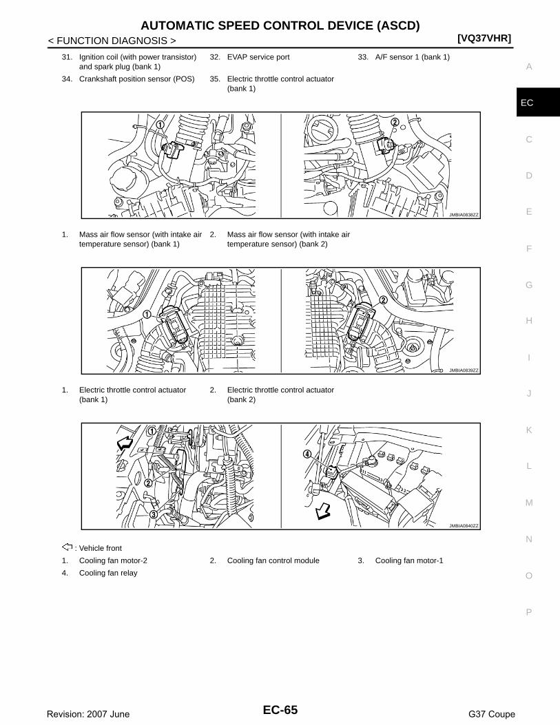
AUTOMATIC SPEED CONTROL DEVICE (ASCD)[VQ37VHR]
C
D
E
F
G
H
I
J
K
L
M
A
C
N
P
O
< FUNCTION DIAGNOSIS >
E
31. Ignition coil (with power transistor) and spark plug (bank 1)
32. EVAP service port 33. A/F sensor 1 (bank 1)
34. Crankshaft position sensor (POS) 35. Electric throttle control actuator (bank 1)
1. Mass air flow sensor (with intake air temperature sensor) (bank 1)
2. Mass air flow sensor (with intake air temperature sensor) (bank 2)
1. Electric throttle control actuator (bank 1)
2. Electric throttle control actuator (bank 2)
: Vehicle front
1. Cooling fan motor-2 2. Cooling fan control module 3. Cooling fan motor-1
4. Cooling fan relay
JMBIA0838ZZ
JMBIA0839ZZ
JMBIA0840ZZ
EC-65Revision: 2007 June G37 Coupe

[VQ37VHR]AUTOMATIC SPEED CONTROL DEVICE (ASCD)
< FUNCTION DIAGNOSIS >
PBIB1907E
: Vehicle front
1. A/F sensor 1 (bank 1) 2. A/F sensor 1 (bank 2)
: Vehicle front
1. A/F sensor 1 (bank 1) harness con-nector
2. A/F sensor 1 (bank 2) harness con-nector
JMBIA0007ZZ
JMBIA0841ZZ
JMBIA0018ZZ
EC-66Revision: 2007 June G37 Coupe

AUTOMATIC SPEED CONTROL DEVICE (ASCD)[VQ37VHR]
C
D
E
F
G
H
I
J
K
L
M
A
C
N
P
O
< FUNCTION DIAGNOSIS >
E
: Vehicle front
1. Heated oxygen sensor 2 (bank 2) 2. Heated oxygen sensor 2 (bank 2) harness connector
3. Heated oxygen sensor 2 (bank 1)
4. Heated oxygen sensor 2 (bank 1) harness connector
1. Manifold absolute pressure (MAP) sensor
2. Brake booster pressure sensor 3. VVEL actuator motor relay
4. VVEL control module
1. VVEL control shaft position sensor (bank 1)
2. VVEL actuator motor (bank 1) 3. VVEL actuator motor (bank 2)
4. VVEL control shaft position sensor (bank 2)
1. Camshaft position sensor (PHASE) (bank 1)
2. Intake valve timing control solenoid valve (bank 1) harness connector
3. Intake valve timing control solenoid valve (bank 2) harness connector
4. Camshaft position sensor (PHASE) (bank 2)
JMBIA0850ZZ
JMBIA0851ZZ
JMBIA0842ZZ
EC-67Revision: 2007 June G37 Coupe

[VQ37VHR]AUTOMATIC SPEED CONTROL DEVICE (ASCD)
< FUNCTION DIAGNOSIS >
1. Ignition coil No.5 (with power transis-tor)
2. Ignition coil No.3 (with power transis-tor)
3. Ignition coil No.1 (with power transis-tor)
4. Fuel injector No.3 5. Fuel injector No.1 6. Fuel injector No.2
7. Fuel injector No.4 8. Ignition coil No.2 (with power transis-tor)
9. Ignition coil No.4 (with power transis-tor)
10. Ignition coil No.6 (with power transis-tor)
11. Fuel injector No.6 12. Fuel injector No.5
13. Knock sensor (bank 1) 14. Knock sensor (bank 2)
: Vehicle front
1. Engine coolant temperature sensor 2. A/F sensor 1 (bank 1) 3. Crankshaft position sensor (POS)
1. IPDM E/R 2. Battery current sensor 3. Refrigerant pressure sensor
JMBIA0843ZZ
JMBIA0844ZZ
JMBIA0013ZZ
JMBIA0014ZZ
EC-68Revision: 2007 June G37 Coupe

AUTOMATIC SPEED CONTROL DEVICE (ASCD)[VQ37VHR]
C
D
E
F
G
H
I
J
K
L
M
A
C
N
P
O
< FUNCTION DIAGNOSIS >
E
: Vehicle front
1. Power steering pressure sensor 2. Alternator 3. Engine oil temperature sensor
: Vehicle front
1. EVAP service port 2. EVAP canister purge volume control solenoid valve
3. EVAP canister
4. EVAP canister vent control valve 5. EVAP control system pressure sen-sor
: Vehicle front
1. Fuel level sensor unit and fuel pump harness connector
2. Fuel level sensor unit and fuel pump 3. Fuel pressure regulator
4. Fuel tank temperature sensor
1. Accelerator pedal position sensor 2. ECM
JMBIA0845ZZ
JMBIA0019ZZ
JMBIA0015ZZ
EC-69Revision: 2007 June G37 Coupe

[VQ37VHR]AUTOMATIC SPEED CONTROL DEVICE (ASCD)
< FUNCTION DIAGNOSIS >
Component Description INFOID:0000000001733946
1. ICC steering switch 2. CANCEL switch 3. RESUME/ACCELERATE switch
4. SET/COAST switch 5. DISTANCE switch 6. MAIN switch
1. ASCD steering switch 2. CANCEL switch 3. RESUME/ACCELERATE switch
4. SET/COAST switch 5. MAIN switch
1. Stop lamp switch 2. ASCD brake switch (ASCD models)ICC brake switch (ICC models)
3. Brake pedal
4. ASCD clutch switch (ASCD models)ICC clutch switch (ICC models)
5. Clutch pedal
JMBIA0016ZZ
JMBIA0017ZZ
JMBIA0051ZZ
Component Reference
ASCD steering switch EC-421, "Description"
ASCD brake switch EC-428, "Description"
Stop lamp switch EC-428, "Description"
Electric throttle control actuator EC-404, "Description"
ASCD indicator EC-480, "Description"
EC-70Revision: 2007 June G37 Coupe

CAN COMMUNICATION[VQ37VHR]
C
D
E
F
G
H
I
J
K
L
M
A
C
N
P
O
< FUNCTION DIAGNOSIS >
E
CAN COMMUNICATION
System Description INFOID:0000000001733947
CAN (Controller Area Network) is a serial communication line for real time application. It is an on-vehicle mul-tiplex communication line with high data communication speed and excellent error detection ability. Many elec-tronic control units are equipped onto a vehicle, and each control unit shares information and links with othercontrol units during operation (not independent). In CAN communication, control units are connected with 2communication lines (CAN H line, CAN L line) allowing a high rate of information transmission with less wiring.Each control unit transmits/receives data but selectively reads required data only.Refer to LAN-8, "CAN Communication Control Circuit", about CAN communication for detail..
EC-71Revision: 2007 June G37 Coupe

[VQ37VHR]COOLING FAN CONTROL
< FUNCTION DIAGNOSIS >
COOLING FAN CONTROL
System Diagram INFOID:0000000001733948
System Description INFOID:0000000001733949
INPUT/OUTPUT SIGNAL CHART
*1: The ECM determines the start signal status by the signals of engine speed and battery voltage.
*2: This signal is sent to ECM through CAN communication line.
SYSTEM DESCRIPTIONECM controls cooling fan speed corresponding to vehicle speed, engine coolant temperature, air conditionerON signal, refrigerant pressure, target A/C evaporator temperature and A/C evaporator temperature.Cooling fan control signal is sent to IPDM E/R from ECM by CAN communication line. Then, IPDM E/R sendsON/OFF pulse duty signal to cooling fan control module. Corresponding to this ON/OFF pulse duty signal,cooling fan control module gives cooling fan motor operating voltage to cooling fan motors. Cooling fan speedis controlled by duty cycle of cooling fan motor operating voltage sent from cooling fan control module.
JMBIA0075GB
Sensor Input signal to ECM ECM function Actuator
Crankshaft position sensor (POS)Camshaft position sensor (PHASE) Engine speed*1
Cooling fan control
IPDM E/R↓Cooling fan control module↓Cooling fan motor
Engine coolant temperature sensor Engine coolant temperature
Refrigerant pressure sensor Refrigerant pressure
Battery Battery voltage*1
Unified meter and A/C amp.
Vehicle speed*2
Air conditioner ON signal*2
A/C evaporator temperature*2
Target A/C evaporator temperature*2
EC-72Revision: 2007 June G37 Coupe

COOLING FAN CONTROL[VQ37VHR]
C
D
E
F
G
H
I
J
K
L
M
A
C
N
P
O
< FUNCTION DIAGNOSIS >
E
Component Parts Location INFOID:0000000001910707
1. Battery current sensor 2. IPDM E/R 3. VVEL control module
4. Cooling fan relay 5. VVEL actuator motor relay 6. Mass air flow sensor (with intake air temperature sensor) (bank 1)
7. Refrigerant pressure sensor 8. Camshaft position sensor (PHASE) (bank 1)
9. Cooling fan motor-2
10. Intake valve timing control solenoid valve (bank 1)
11. Cooling fan control module 12. Cooling fan motor-1
13. Intake valve timing control solenoid valve (bank 2)
14. Camshaft position sensor (PHASE) (bank 2)
15. Mass air flow sensor (with intake air temperature sensor) (bank 2)
16. ICC brake hold relay (ICC models) 17. Brake booster pressure sensor 18. Ignition coil (with power transistor) and spark plug (bank 2)
19. Electric throttle control actuator (bank 2)
20. A/F sensor 1 (bank 2) 21. Fuel injector (bank 2)
22. VVEL control shaft position sensor (bank 2)
23. VVEL actuator motor (bank 2) 24. Manifold absolute pressure (MAP) sensor
25. Engine coolant temperature sensor 26. Knock sensor 27. Fuel injector (bank 1)
28. VVEL actuator motor (bank 1) 29. EVAP canister purge volume control solenoid valve
30. VVEL control shaft position sensor (bank 1)
JMBIA0837ZZ
EC-73Revision: 2007 June G37 Coupe

[VQ37VHR]COOLING FAN CONTROL
< FUNCTION DIAGNOSIS >
31. Ignition coil (with power transistor) and spark plug (bank 1)
32. EVAP service port 33. A/F sensor 1 (bank 1)
34. Crankshaft position sensor (POS) 35. Electric throttle control actuator (bank 1)
1. Mass air flow sensor (with intake air temperature sensor) (bank 1)
2. Mass air flow sensor (with intake air temperature sensor) (bank 2)
1. Electric throttle control actuator (bank 1)
2. Electric throttle control actuator (bank 2)
: Vehicle front
1. Cooling fan motor-2 2. Cooling fan control module 3. Cooling fan motor-1
4. Cooling fan relay
JMBIA0838ZZ
JMBIA0839ZZ
JMBIA0840ZZ
EC-74Revision: 2007 June G37 Coupe

COOLING FAN CONTROL[VQ37VHR]
C
D
E
F
G
H
I
J
K
L
M
A
C
N
P
O
< FUNCTION DIAGNOSIS >
E
PBIB1907E
: Vehicle front
1. A/F sensor 1 (bank 1) 2. A/F sensor 1 (bank 2)
: Vehicle front
1. A/F sensor 1 (bank 1) harness con-nector
2. A/F sensor 1 (bank 2) harness con-nector
JMBIA0007ZZ
JMBIA0841ZZ
JMBIA0018ZZ
EC-75Revision: 2007 June G37 Coupe

[VQ37VHR]COOLING FAN CONTROL
< FUNCTION DIAGNOSIS >
: Vehicle front
1. Heated oxygen sensor 2 (bank 2) 2. Heated oxygen sensor 2 (bank 2) harness connector
3. Heated oxygen sensor 2 (bank 1)
4. Heated oxygen sensor 2 (bank 1) harness connector
1. Manifold absolute pressure (MAP) sensor
2. Brake booster pressure sensor 3. VVEL actuator motor relay
4. VVEL control module
1. VVEL control shaft position sensor (bank 1)
2. VVEL actuator motor (bank 1) 3. VVEL actuator motor (bank 2)
4. VVEL control shaft position sensor (bank 2)
1. Camshaft position sensor (PHASE) (bank 1)
2. Intake valve timing control solenoid valve (bank 1) harness connector
3. Intake valve timing control solenoid valve (bank 2) harness connector
4. Camshaft position sensor (PHASE) (bank 2)
JMBIA0850ZZ
JMBIA0851ZZ
JMBIA0842ZZ
EC-76Revision: 2007 June G37 Coupe

COOLING FAN CONTROL[VQ37VHR]
C
D
E
F
G
H
I
J
K
L
M
A
C
N
P
O
< FUNCTION DIAGNOSIS >
E
1. Ignition coil No.5 (with power transis-tor)
2. Ignition coil No.3 (with power transis-tor)
3. Ignition coil No.1 (with power transis-tor)
4. Fuel injector No.3 5. Fuel injector No.1 6. Fuel injector No.2
7. Fuel injector No.4 8. Ignition coil No.2 (with power transis-tor)
9. Ignition coil No.4 (with power transis-tor)
10. Ignition coil No.6 (with power transis-tor)
11. Fuel injector No.6 12. Fuel injector No.5
13. Knock sensor (bank 1) 14. Knock sensor (bank 2)
: Vehicle front
1. Engine coolant temperature sensor 2. A/F sensor 1 (bank 1) 3. Crankshaft position sensor (POS)
1. IPDM E/R 2. Battery current sensor 3. Refrigerant pressure sensor
JMBIA0843ZZ
JMBIA0844ZZ
JMBIA0013ZZ
JMBIA0014ZZ
EC-77Revision: 2007 June G37 Coupe

[VQ37VHR]COOLING FAN CONTROL
< FUNCTION DIAGNOSIS >
: Vehicle front
1. Power steering pressure sensor 2. Alternator 3. Engine oil temperature sensor
: Vehicle front
1. EVAP service port 2. EVAP canister purge volume control solenoid valve
3. EVAP canister
4. EVAP canister vent control valve 5. EVAP control system pressure sen-sor
: Vehicle front
1. Fuel level sensor unit and fuel pump harness connector
2. Fuel level sensor unit and fuel pump 3. Fuel pressure regulator
4. Fuel tank temperature sensor
1. Accelerator pedal position sensor 2. ECM
JMBIA0845ZZ
JMBIA0019ZZ
JMBIA0015ZZ
EC-78Revision: 2007 June G37 Coupe

COOLING FAN CONTROL[VQ37VHR]
C
D
E
F
G
H
I
J
K
L
M
A
C
N
P
O
< FUNCTION DIAGNOSIS >
E
Component Description INFOID:0000000001733951
1. ICC steering switch 2. CANCEL switch 3. RESUME/ACCELERATE switch
4. SET/COAST switch 5. DISTANCE switch 6. MAIN switch
1. ASCD steering switch 2. CANCEL switch 3. RESUME/ACCELERATE switch
4. SET/COAST switch 5. MAIN switch
1. Stop lamp switch 2. ASCD brake switch (ASCD models)ICC brake switch (ICC models)
3. Brake pedal
4. ASCD clutch switch (ASCD models)ICC clutch switch (ICC models)
5. Clutch pedal
JMBIA0016ZZ
JMBIA0017ZZ
JMBIA0051ZZ
Component Reference
Camshaft position sensor (PHASE) EC-268, "Description"
Crankshaft position sensor (POS) EC-264, "Description"
Cooling fan control module EC-481, "Description"
Cooling fan motor EC-481, "Description"
Engine coolant temperature sensor EC-184, "Description"
Refrigerant pressure sensor EC-511, "Description"
EC-79Revision: 2007 June G37 Coupe

[VQ37VHR]EVAPORATIVE EMISSION SYSTEM
< FUNCTION DIAGNOSIS >
EVAPORATIVE EMISSION SYSTEM
System Diagram INFOID:0000000001733952
EVAPORATIVE EMISSION LINE DRAWING
PBIB1631E
1. Intake manifold collector 2. EVAP canister purge volume control solenoid valve
3. EVAP service port
: From next figure
JMBIA0859ZZ
EC-80Revision: 2007 June G37 Coupe

EVAPORATIVE EMISSION SYSTEM[VQ37VHR]
C
D
E
F
G
H
I
J
K
L
M
A
C
N
P
O
< FUNCTION DIAGNOSIS >
E
NOTE:Do not use soapy water or any type of solvent while installing vacuum hose or purge hoses.
System Description INFOID:0000000001733953
INPUT/OUTPUT SIGNAL CHART
: Vehicle front
1. EVAP canister 2. EVAP canister vent control valve 3. EVAP control system pressure sen-sor
: To previous figure
JMBIA0847ZZ
EC-81Revision: 2007 June G37 Coupe

[VQ37VHR]EVAPORATIVE EMISSION SYSTEM
< FUNCTION DIAGNOSIS >
*1: ECM determines the start signal status by the signals of engine speed and battery voltage.
*2: This signal is sent to the ECM through CAN communication line.
SYSTEM DESCRIPTIONThe evaporative emission system is used to reduce hydrocarbons emitted into the atmosphere from the fuelsystem. This reduction of hydrocarbons is accomplished by activated charcoals in the EVAP canister.The fuel vapor in the sealed fuel tank is led into the EVAP canister which contains activated carbon and thevapor is stored there when the engine is not operating or when refueling to the fuel tank.The vapor in the EVAP canister is purged by the air through the purge line to the intake manifold when theengine is operating. EVAP canister purge volume control solenoid valve is controlled by ECM. When theengine operates, the flow rate of vapor controlled by EVAP canister purge volume control solenoid valve isproportionally regulated as the air flow increases.EVAP canister purge volume control solenoid valve also shuts off the vapor purge line during decelerating andidling.
Sensor Input signal to ECM ECM function Actuator
Crankshaft position sensor (POS)Camshaft position sensor (PHASE) Engine speed*1
EVAP canister purge flow control
EVAP canister purge vol-ume control solenoid valve
Mass air flow sensor Amount of intake air
Engine coolant temperature sensor Engine coolant temperature
Battery Battery voltage*1
Throttle position sensor Throttle position
Accelerator pedal position sensor Accelerator pedal position
Air fuel ratio (A/F) sensor 1Density of oxygen in exhaust gas(Mixture ratio feedback signal)
Fuel tank temperature sensor Fuel temperature in fuel tank
EVAP control system pressure sensor Pressure in purge line
Unified meter and A/C amp. Vehicle speed*2
EC-82Revision: 2007 June G37 Coupe

EVAPORATIVE EMISSION SYSTEM[VQ37VHR]
C
D
E
F
G
H
I
J
K
L
M
A
C
N
P
O
< FUNCTION DIAGNOSIS >
E
Component Parts Location INFOID:0000000001910708
1. Battery current sensor 2. IPDM E/R 3. VVEL control module
4. Cooling fan relay 5. VVEL actuator motor relay 6. Mass air flow sensor (with intake air temperature sensor) (bank 1)
7. Refrigerant pressure sensor 8. Camshaft position sensor (PHASE) (bank 1)
9. Cooling fan motor-2
10. Intake valve timing control solenoid valve (bank 1)
11. Cooling fan control module 12. Cooling fan motor-1
13. Intake valve timing control solenoid valve (bank 2)
14. Camshaft position sensor (PHASE) (bank 2)
15. Mass air flow sensor (with intake air temperature sensor) (bank 2)
16. ICC brake hold relay (ICC models) 17. Brake booster pressure sensor 18. Ignition coil (with power transistor) and spark plug (bank 2)
19. Electric throttle control actuator (bank 2)
20. A/F sensor 1 (bank 2) 21. Fuel injector (bank 2)
22. VVEL control shaft position sensor (bank 2)
23. VVEL actuator motor (bank 2) 24. Manifold absolute pressure (MAP) sensor
25. Engine coolant temperature sensor 26. Knock sensor 27. Fuel injector (bank 1)
28. VVEL actuator motor (bank 1) 29. EVAP canister purge volume control solenoid valve
30. VVEL control shaft position sensor (bank 1)
JMBIA0837ZZ
EC-83Revision: 2007 June G37 Coupe

[VQ37VHR]EVAPORATIVE EMISSION SYSTEM
< FUNCTION DIAGNOSIS >
31. Ignition coil (with power transistor) and spark plug (bank 1)
32. EVAP service port 33. A/F sensor 1 (bank 1)
34. Crankshaft position sensor (POS) 35. Electric throttle control actuator (bank 1)
1. Mass air flow sensor (with intake air temperature sensor) (bank 1)
2. Mass air flow sensor (with intake air temperature sensor) (bank 2)
1. Electric throttle control actuator (bank 1)
2. Electric throttle control actuator (bank 2)
: Vehicle front
1. Cooling fan motor-2 2. Cooling fan control module 3. Cooling fan motor-1
4. Cooling fan relay
JMBIA0838ZZ
JMBIA0839ZZ
JMBIA0840ZZ
EC-84Revision: 2007 June G37 Coupe

EVAPORATIVE EMISSION SYSTEM[VQ37VHR]
C
D
E
F
G
H
I
J
K
L
M
A
C
N
P
O
< FUNCTION DIAGNOSIS >
E
PBIB1907E
: Vehicle front
1. A/F sensor 1 (bank 1) 2. A/F sensor 1 (bank 2)
: Vehicle front
1. A/F sensor 1 (bank 1) harness con-nector
2. A/F sensor 1 (bank 2) harness con-nector
JMBIA0007ZZ
JMBIA0841ZZ
JMBIA0018ZZ
EC-85Revision: 2007 June G37 Coupe

[VQ37VHR]EVAPORATIVE EMISSION SYSTEM
< FUNCTION DIAGNOSIS >
: Vehicle front
1. Heated oxygen sensor 2 (bank 2) 2. Heated oxygen sensor 2 (bank 2) harness connector
3. Heated oxygen sensor 2 (bank 1)
4. Heated oxygen sensor 2 (bank 1) harness connector
1. Manifold absolute pressure (MAP) sensor
2. Brake booster pressure sensor 3. VVEL actuator motor relay
4. VVEL control module
1. VVEL control shaft position sensor (bank 1)
2. VVEL actuator motor (bank 1) 3. VVEL actuator motor (bank 2)
4. VVEL control shaft position sensor (bank 2)
1. Camshaft position sensor (PHASE) (bank 1)
2. Intake valve timing control solenoid valve (bank 1) harness connector
3. Intake valve timing control solenoid valve (bank 2) harness connector
4. Camshaft position sensor (PHASE) (bank 2)
JMBIA0850ZZ
JMBIA0851ZZ
JMBIA0842ZZ
EC-86Revision: 2007 June G37 Coupe

EVAPORATIVE EMISSION SYSTEM[VQ37VHR]
C
D
E
F
G
H
I
J
K
L
M
A
C
N
P
O
< FUNCTION DIAGNOSIS >
E
1. Ignition coil No.5 (with power transis-tor)
2. Ignition coil No.3 (with power transis-tor)
3. Ignition coil No.1 (with power transis-tor)
4. Fuel injector No.3 5. Fuel injector No.1 6. Fuel injector No.2
7. Fuel injector No.4 8. Ignition coil No.2 (with power transis-tor)
9. Ignition coil No.4 (with power transis-tor)
10. Ignition coil No.6 (with power transis-tor)
11. Fuel injector No.6 12. Fuel injector No.5
13. Knock sensor (bank 1) 14. Knock sensor (bank 2)
: Vehicle front
1. Engine coolant temperature sensor 2. A/F sensor 1 (bank 1) 3. Crankshaft position sensor (POS)
1. IPDM E/R 2. Battery current sensor 3. Refrigerant pressure sensor
JMBIA0843ZZ
JMBIA0844ZZ
JMBIA0013ZZ
JMBIA0014ZZ
EC-87Revision: 2007 June G37 Coupe

[VQ37VHR]EVAPORATIVE EMISSION SYSTEM
< FUNCTION DIAGNOSIS >
: Vehicle front
1. Power steering pressure sensor 2. Alternator 3. Engine oil temperature sensor
: Vehicle front
1. EVAP service port 2. EVAP canister purge volume control solenoid valve
3. EVAP canister
4. EVAP canister vent control valve 5. EVAP control system pressure sen-sor
: Vehicle front
1. Fuel level sensor unit and fuel pump harness connector
2. Fuel level sensor unit and fuel pump 3. Fuel pressure regulator
4. Fuel tank temperature sensor
1. Accelerator pedal position sensor 2. ECM
JMBIA0845ZZ
JMBIA0019ZZ
JMBIA0015ZZ
EC-88Revision: 2007 June G37 Coupe

EVAPORATIVE EMISSION SYSTEM[VQ37VHR]
C
D
E
F
G
H
I
J
K
L
M
A
C
N
P
O
< FUNCTION DIAGNOSIS >
E
Component Description INFOID:0000000001733955
1. ICC steering switch 2. CANCEL switch 3. RESUME/ACCELERATE switch
4. SET/COAST switch 5. DISTANCE switch 6. MAIN switch
1. ASCD steering switch 2. CANCEL switch 3. RESUME/ACCELERATE switch
4. SET/COAST switch 5. MAIN switch
1. Stop lamp switch 2. ASCD brake switch (ASCD models)ICC brake switch (ICC models)
3. Brake pedal
4. ASCD clutch switch (ASCD models)ICC clutch switch (ICC models)
5. Clutch pedal
JMBIA0016ZZ
JMBIA0017ZZ
JMBIA0051ZZ
Component Reference
A/F sensor 1 EC-197, "Description"
Accelerator pedal position sensor EC-458, "Description"
Camshaft position sensor (PHASE) EC-268, "Description"
Crankshaft position sensor (POS) EC-264, "Description"
Engine coolant temperature sensor EC-184, "Description"
EVAP canister purge volume control solenoid valve EC-288, "Description"
EVAP control system pressure sensor EC-304, "Description"
EC-89Revision: 2007 June G37 Coupe
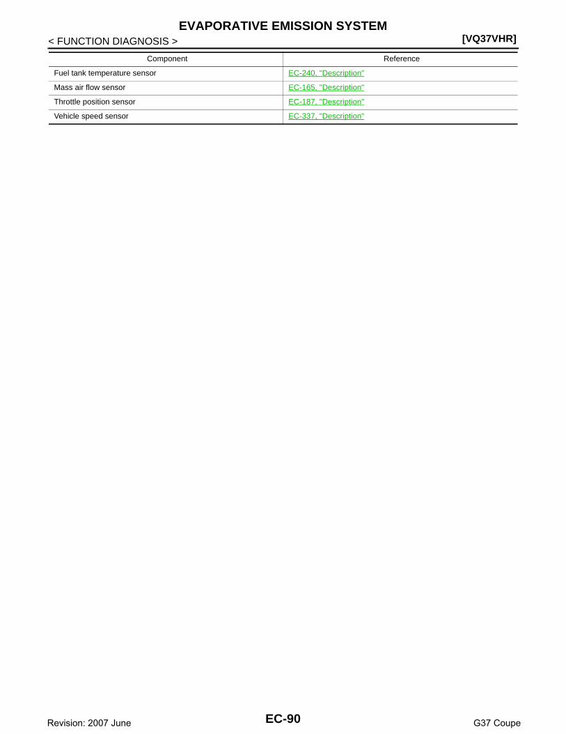
[VQ37VHR]EVAPORATIVE EMISSION SYSTEM
< FUNCTION DIAGNOSIS >
Fuel tank temperature sensor EC-240, "Description"
Mass air flow sensor EC-165, "Description"
Throttle position sensor EC-187, "Description"
Vehicle speed sensor EC-337, "Description"
Component Reference
EC-90Revision: 2007 June G37 Coupe

INTAKE VALVE TIMING CONTROL[VQ37VHR]
C
D
E
F
G
H
I
J
K
L
M
A
C
N
P
O
< FUNCTION DIAGNOSIS >
E
INTAKE VALVE TIMING CONTROL
System Diagram INFOID:0000000001733960
System Description INFOID:0000000001733961
INPUT/OUTPUT SIGNAL CHART
*: This signal is sent to the ECM through CAN communication line
SYSTEM DESCRIPTIONThis mechanism hydraulically controls cam phases continuously with the fixed operating angle of the intakevalve.The ECM receives signals such as crankshaft position, camshaft position, engine speed, and engine coolanttemperature. Then, the ECM sends ON/OFF pulse duty signals to the intake valve timing (IVT) control sole-noid valve depending on driving status. This makes it possible to control the shut/open timing of the intakevalve to increase engine torque in low/mid speed range and output in high-speed range.
JMBIA0060GB
Sensor Input signal to ECM ECM function Actuator
Crankshaft position sensor (POS)Engine speed and piston position
Intake valve timing control
Intake valve timing control solenoid valve
Camshaft position sensor (PHASE)
Engine coolant temperature sensor Engine coolant temperature
Unified meter and A/C amp. Vehicle speed*
EC-91Revision: 2007 June G37 Coupe

[VQ37VHR]INTAKE VALVE TIMING CONTROL
< FUNCTION DIAGNOSIS >
Component Parts Location INFOID:0000000001910709
1. Battery current sensor 2. IPDM E/R 3. VVEL control module
4. Cooling fan relay 5. VVEL actuator motor relay 6. Mass air flow sensor (with intake air temperature sensor) (bank 1)
7. Refrigerant pressure sensor 8. Camshaft position sensor (PHASE) (bank 1)
9. Cooling fan motor-2
10. Intake valve timing control solenoid valve (bank 1)
11. Cooling fan control module 12. Cooling fan motor-1
13. Intake valve timing control solenoid valve (bank 2)
14. Camshaft position sensor (PHASE) (bank 2)
15. Mass air flow sensor (with intake air temperature sensor) (bank 2)
16. ICC brake hold relay (ICC models) 17. Brake booster pressure sensor 18. Ignition coil (with power transistor) and spark plug (bank 2)
19. Electric throttle control actuator (bank 2)
20. A/F sensor 1 (bank 2) 21. Fuel injector (bank 2)
22. VVEL control shaft position sensor (bank 2)
23. VVEL actuator motor (bank 2) 24. Manifold absolute pressure (MAP) sensor
25. Engine coolant temperature sensor 26. Knock sensor 27. Fuel injector (bank 1)
28. VVEL actuator motor (bank 1) 29. EVAP canister purge volume control solenoid valve
30. VVEL control shaft position sensor (bank 1)
JMBIA0837ZZ
EC-92Revision: 2007 June G37 Coupe

INTAKE VALVE TIMING CONTROL[VQ37VHR]
C
D
E
F
G
H
I
J
K
L
M
A
C
N
P
O
< FUNCTION DIAGNOSIS >
E
31. Ignition coil (with power transistor) and spark plug (bank 1)
32. EVAP service port 33. A/F sensor 1 (bank 1)
34. Crankshaft position sensor (POS) 35. Electric throttle control actuator (bank 1)
1. Mass air flow sensor (with intake air temperature sensor) (bank 1)
2. Mass air flow sensor (with intake air temperature sensor) (bank 2)
1. Electric throttle control actuator (bank 1)
2. Electric throttle control actuator (bank 2)
: Vehicle front
1. Cooling fan motor-2 2. Cooling fan control module 3. Cooling fan motor-1
4. Cooling fan relay
JMBIA0838ZZ
JMBIA0839ZZ
JMBIA0840ZZ
EC-93Revision: 2007 June G37 Coupe
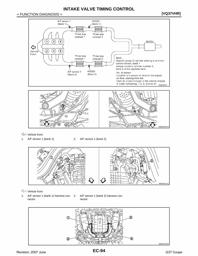
[VQ37VHR]INTAKE VALVE TIMING CONTROL
< FUNCTION DIAGNOSIS >
PBIB1907E
: Vehicle front
1. A/F sensor 1 (bank 1) 2. A/F sensor 1 (bank 2)
: Vehicle front
1. A/F sensor 1 (bank 1) harness con-nector
2. A/F sensor 1 (bank 2) harness con-nector
JMBIA0007ZZ
JMBIA0841ZZ
JMBIA0018ZZ
EC-94Revision: 2007 June G37 Coupe

INTAKE VALVE TIMING CONTROL[VQ37VHR]
C
D
E
F
G
H
I
J
K
L
M
A
C
N
P
O
< FUNCTION DIAGNOSIS >
E
: Vehicle front
1. Heated oxygen sensor 2 (bank 2) 2. Heated oxygen sensor 2 (bank 2) harness connector
3. Heated oxygen sensor 2 (bank 1)
4. Heated oxygen sensor 2 (bank 1) harness connector
1. Manifold absolute pressure (MAP) sensor
2. Brake booster pressure sensor 3. VVEL actuator motor relay
4. VVEL control module
1. VVEL control shaft position sensor (bank 1)
2. VVEL actuator motor (bank 1) 3. VVEL actuator motor (bank 2)
4. VVEL control shaft position sensor (bank 2)
1. Camshaft position sensor (PHASE) (bank 1)
2. Intake valve timing control solenoid valve (bank 1) harness connector
3. Intake valve timing control solenoid valve (bank 2) harness connector
4. Camshaft position sensor (PHASE) (bank 2)
JMBIA0850ZZ
JMBIA0851ZZ
JMBIA0842ZZ
EC-95Revision: 2007 June G37 Coupe

[VQ37VHR]INTAKE VALVE TIMING CONTROL
< FUNCTION DIAGNOSIS >
1. Ignition coil No.5 (with power transis-tor)
2. Ignition coil No.3 (with power transis-tor)
3. Ignition coil No.1 (with power transis-tor)
4. Fuel injector No.3 5. Fuel injector No.1 6. Fuel injector No.2
7. Fuel injector No.4 8. Ignition coil No.2 (with power transis-tor)
9. Ignition coil No.4 (with power transis-tor)
10. Ignition coil No.6 (with power transis-tor)
11. Fuel injector No.6 12. Fuel injector No.5
13. Knock sensor (bank 1) 14. Knock sensor (bank 2)
: Vehicle front
1. Engine coolant temperature sensor 2. A/F sensor 1 (bank 1) 3. Crankshaft position sensor (POS)
1. IPDM E/R 2. Battery current sensor 3. Refrigerant pressure sensor
JMBIA0843ZZ
JMBIA0844ZZ
JMBIA0013ZZ
JMBIA0014ZZ
EC-96Revision: 2007 June G37 Coupe

INTAKE VALVE TIMING CONTROL[VQ37VHR]
C
D
E
F
G
H
I
J
K
L
M
A
C
N
P
O
< FUNCTION DIAGNOSIS >
E
: Vehicle front
1. Power steering pressure sensor 2. Alternator 3. Engine oil temperature sensor
: Vehicle front
1. EVAP service port 2. EVAP canister purge volume control solenoid valve
3. EVAP canister
4. EVAP canister vent control valve 5. EVAP control system pressure sen-sor
: Vehicle front
1. Fuel level sensor unit and fuel pump harness connector
2. Fuel level sensor unit and fuel pump 3. Fuel pressure regulator
4. Fuel tank temperature sensor
1. Accelerator pedal position sensor 2. ECM
JMBIA0845ZZ
JMBIA0019ZZ
JMBIA0015ZZ
EC-97Revision: 2007 June G37 Coupe
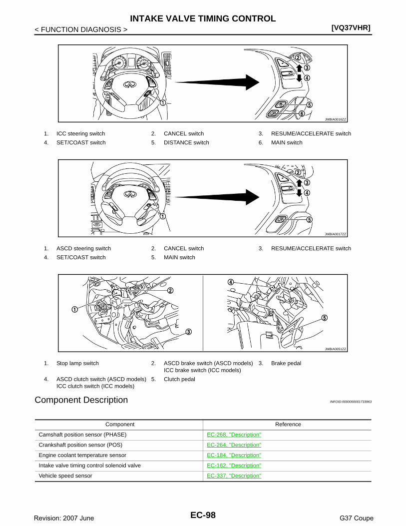
[VQ37VHR]INTAKE VALVE TIMING CONTROL
< FUNCTION DIAGNOSIS >
Component Description INFOID:0000000001733963
1. ICC steering switch 2. CANCEL switch 3. RESUME/ACCELERATE switch
4. SET/COAST switch 5. DISTANCE switch 6. MAIN switch
1. ASCD steering switch 2. CANCEL switch 3. RESUME/ACCELERATE switch
4. SET/COAST switch 5. MAIN switch
1. Stop lamp switch 2. ASCD brake switch (ASCD models)ICC brake switch (ICC models)
3. Brake pedal
4. ASCD clutch switch (ASCD models)ICC clutch switch (ICC models)
5. Clutch pedal
JMBIA0016ZZ
JMBIA0017ZZ
JMBIA0051ZZ
Component Reference
Camshaft position sensor (PHASE) EC-268, "Description"
Crankshaft position sensor (POS) EC-264, "Description"
Engine coolant temperature sensor EC-184, "Description"
Intake valve timing control solenoid valve EC-162, "Description"
Vehicle speed sensor EC-337, "Description"
EC-98Revision: 2007 June G37 Coupe

VVEL SYSTEM[VQ37VHR]
C
D
E
F
G
H
I
J
K
L
M
A
C
N
P
O
< FUNCTION DIAGNOSIS >
E
VVEL SYSTEM
System Diagram INFOID:0000000001841366
System Description INFOID:0000000001841367
INPUT/OUTPUT SIGNAL CHART
*: This signal is sent to the ECM through CAN communication line
SYSTEM DESCRIPTIONVVEL (Variable Valve Event & Lift) is a system that controls valve event and valve lift continuously. Rotationalmovement of the drive shaft equipped with eccentric cam is transmitted to output cam via the rocker arm andtwo kinds of links to depress the intake valve. ECM decides the target valve lift according to the driving condi-tion and sends the command signal to the VVEL control module. The VVEL control module controls the rota-tion of the control shaft using the VVEL actuator motor and changes the movement of the output cam byshifting the link supporting point. As a result, valve lift changes continuously to improve engine output andresponse.
1. VVEL actuator motor 2. VVEL control shaft position sensor 3. Ball screw nut
4. Ball screw shaft 5. Rocker arm 6. Link A
7. Control shaft 8. Eccentric cam 9. Drive shaft
10. Valve lifter 11. Intake valve 12. Link B
13. Output cam
JMBIA0739GB
Sensor Input signal to ECM ECM function Actuator
Crankshaft position sensor (POS) Engine speed and piston position
VVEL controlVVEL control module↓VVEL actuator sub assembly
Accelerator pedal position sensor Accelerator pedal position
VVEL control shaft position sensor Control shaft actual angle*
EC-99Revision: 2007 June G37 Coupe

[VQ37VHR]VVEL SYSTEM
< FUNCTION DIAGNOSIS >
Component Parts Location INFOID:0000000001910710
1. Battery current sensor 2. IPDM E/R 3. VVEL control module
4. Cooling fan relay 5. VVEL actuator motor relay 6. Mass air flow sensor (with intake air temperature sensor) (bank 1)
7. Refrigerant pressure sensor 8. Camshaft position sensor (PHASE) (bank 1)
9. Cooling fan motor-2
10. Intake valve timing control solenoid valve (bank 1)
11. Cooling fan control module 12. Cooling fan motor-1
13. Intake valve timing control solenoid valve (bank 2)
14. Camshaft position sensor (PHASE) (bank 2)
15. Mass air flow sensor (with intake air temperature sensor) (bank 2)
16. ICC brake hold relay (ICC models) 17. Brake booster pressure sensor 18. Ignition coil (with power transistor) and spark plug (bank 2)
19. Electric throttle control actuator (bank 2)
20. A/F sensor 1 (bank 2) 21. Fuel injector (bank 2)
22. VVEL control shaft position sensor (bank 2)
23. VVEL actuator motor (bank 2) 24. Manifold absolute pressure (MAP) sensor
25. Engine coolant temperature sensor 26. Knock sensor 27. Fuel injector (bank 1)
28. VVEL actuator motor (bank 1) 29. EVAP canister purge volume control solenoid valve
30. VVEL control shaft position sensor (bank 1)
JMBIA0837ZZ
EC-100Revision: 2007 June G37 Coupe

VVEL SYSTEM[VQ37VHR]
C
D
E
F
G
H
I
J
K
L
M
A
C
N
P
O
< FUNCTION DIAGNOSIS >
E
31. Ignition coil (with power transistor) and spark plug (bank 1)
32. EVAP service port 33. A/F sensor 1 (bank 1)
34. Crankshaft position sensor (POS) 35. Electric throttle control actuator (bank 1)
1. Mass air flow sensor (with intake air temperature sensor) (bank 1)
2. Mass air flow sensor (with intake air temperature sensor) (bank 2)
1. Electric throttle control actuator (bank 1)
2. Electric throttle control actuator (bank 2)
: Vehicle front
1. Cooling fan motor-2 2. Cooling fan control module 3. Cooling fan motor-1
4. Cooling fan relay
JMBIA0838ZZ
JMBIA0839ZZ
JMBIA0840ZZ
EC-101Revision: 2007 June G37 Coupe

[VQ37VHR]VVEL SYSTEM
< FUNCTION DIAGNOSIS >
PBIB1907E
: Vehicle front
1. A/F sensor 1 (bank 1) 2. A/F sensor 1 (bank 2)
: Vehicle front
1. A/F sensor 1 (bank 1) harness con-nector
2. A/F sensor 1 (bank 2) harness con-nector
JMBIA0007ZZ
JMBIA0841ZZ
JMBIA0018ZZ
EC-102Revision: 2007 June G37 Coupe
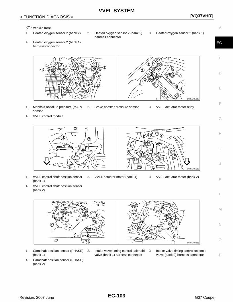
VVEL SYSTEM[VQ37VHR]
C
D
E
F
G
H
I
J
K
L
M
A
C
N
P
O
< FUNCTION DIAGNOSIS >
E
: Vehicle front
1. Heated oxygen sensor 2 (bank 2) 2. Heated oxygen sensor 2 (bank 2) harness connector
3. Heated oxygen sensor 2 (bank 1)
4. Heated oxygen sensor 2 (bank 1) harness connector
1. Manifold absolute pressure (MAP) sensor
2. Brake booster pressure sensor 3. VVEL actuator motor relay
4. VVEL control module
1. VVEL control shaft position sensor (bank 1)
2. VVEL actuator motor (bank 1) 3. VVEL actuator motor (bank 2)
4. VVEL control shaft position sensor (bank 2)
1. Camshaft position sensor (PHASE) (bank 1)
2. Intake valve timing control solenoid valve (bank 1) harness connector
3. Intake valve timing control solenoid valve (bank 2) harness connector
4. Camshaft position sensor (PHASE) (bank 2)
JMBIA0850ZZ
JMBIA0851ZZ
JMBIA0842ZZ
EC-103Revision: 2007 June G37 Coupe

[VQ37VHR]VVEL SYSTEM
< FUNCTION DIAGNOSIS >
1. Ignition coil No.5 (with power transis-tor)
2. Ignition coil No.3 (with power transis-tor)
3. Ignition coil No.1 (with power transis-tor)
4. Fuel injector No.3 5. Fuel injector No.1 6. Fuel injector No.2
7. Fuel injector No.4 8. Ignition coil No.2 (with power transis-tor)
9. Ignition coil No.4 (with power transis-tor)
10. Ignition coil No.6 (with power transis-tor)
11. Fuel injector No.6 12. Fuel injector No.5
13. Knock sensor (bank 1) 14. Knock sensor (bank 2)
: Vehicle front
1. Engine coolant temperature sensor 2. A/F sensor 1 (bank 1) 3. Crankshaft position sensor (POS)
1. IPDM E/R 2. Battery current sensor 3. Refrigerant pressure sensor
JMBIA0843ZZ
JMBIA0844ZZ
JMBIA0013ZZ
JMBIA0014ZZ
EC-104Revision: 2007 June G37 Coupe

VVEL SYSTEM[VQ37VHR]
C
D
E
F
G
H
I
J
K
L
M
A
C
N
P
O
< FUNCTION DIAGNOSIS >
E
: Vehicle front
1. Power steering pressure sensor 2. Alternator 3. Engine oil temperature sensor
: Vehicle front
1. EVAP service port 2. EVAP canister purge volume control solenoid valve
3. EVAP canister
4. EVAP canister vent control valve 5. EVAP control system pressure sen-sor
: Vehicle front
1. Fuel level sensor unit and fuel pump harness connector
2. Fuel level sensor unit and fuel pump 3. Fuel pressure regulator
4. Fuel tank temperature sensor
1. Accelerator pedal position sensor 2. ECM
JMBIA0845ZZ
JMBIA0019ZZ
JMBIA0015ZZ
EC-105Revision: 2007 June G37 Coupe

[VQ37VHR]VVEL SYSTEM
< FUNCTION DIAGNOSIS >
Component Description INFOID:0000000001841369
1. ICC steering switch 2. CANCEL switch 3. RESUME/ACCELERATE switch
4. SET/COAST switch 5. DISTANCE switch 6. MAIN switch
1. ASCD steering switch 2. CANCEL switch 3. RESUME/ACCELERATE switch
4. SET/COAST switch 5. MAIN switch
1. Stop lamp switch 2. ASCD brake switch (ASCD models)ICC brake switch (ICC models)
3. Brake pedal
4. ASCD clutch switch (ASCD models)ICC clutch switch (ICC models)
5. Clutch pedal
JMBIA0016ZZ
JMBIA0017ZZ
JMBIA0051ZZ
Component Reference
Accelerator pedal position sensor EC-458, "Description"
Crankshaft position sensor (POS) EC-264, "Description"
VVEL actuator motor EC-374, "Description"
VVEL actuator motor relay EC-378, "Description"
VVEL control module EC-447, "Description"
VVEL control shaft position sensor EC-370, "Description"
EC-106Revision: 2007 June G37 Coupe
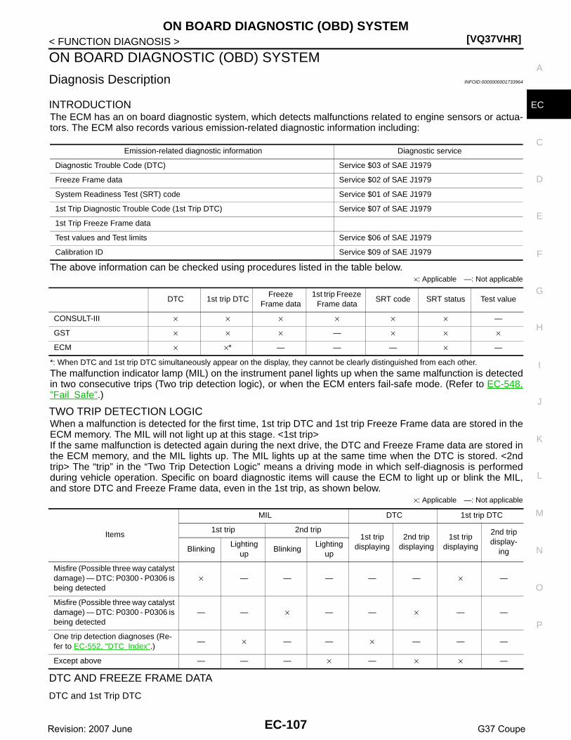
ON BOARD DIAGNOSTIC (OBD) SYSTEM[VQ37VHR]
C
D
E
F
G
H
I
J
K
L
M
A
C
N
P
O
< FUNCTION DIAGNOSIS >
E
ON BOARD DIAGNOSTIC (OBD) SYSTEM
Diagnosis Description INFOID:0000000001733964
INTRODUCTIONThe ECM has an on board diagnostic system, which detects malfunctions related to engine sensors or actua-tors. The ECM also records various emission-related diagnostic information including:
The above information can be checked using procedures listed in the table below.×: Applicable —: Not applicable
*: When DTC and 1st trip DTC simultaneously appear on the display, they cannot be clearly distinguished from each other.
The malfunction indicator lamp (MIL) on the instrument panel lights up when the same malfunction is detectedin two consecutive trips (Two trip detection logic), or when the ECM enters fail-safe mode. (Refer to EC-548,"Fail Safe".)
TWO TRIP DETECTION LOGICWhen a malfunction is detected for the first time, 1st trip DTC and 1st trip Freeze Frame data are stored in theECM memory. The MIL will not light up at this stage. <1st trip>If the same malfunction is detected again during the next drive, the DTC and Freeze Frame data are stored inthe ECM memory, and the MIL lights up. The MIL lights up at the same time when the DTC is stored. <2ndtrip> The “trip” in the “Two Trip Detection Logic” means a driving mode in which self-diagnosis is performedduring vehicle operation. Specific on board diagnostic items will cause the ECM to light up or blink the MIL,and store DTC and Freeze Frame data, even in the 1st trip, as shown below.
×: Applicable —: Not applicable
DTC AND FREEZE FRAME DATA
DTC and 1st Trip DTC
Emission-related diagnostic information Diagnostic service
Diagnostic Trouble Code (DTC) Service $03 of SAE J1979
Freeze Frame data Service $02 of SAE J1979
System Readiness Test (SRT) code Service $01 of SAE J1979
1st Trip Diagnostic Trouble Code (1st Trip DTC) Service $07 of SAE J1979
1st Trip Freeze Frame data
Test values and Test limits Service $06 of SAE J1979
Calibration ID Service $09 of SAE J1979
DTC 1st trip DTCFreeze
Frame data1st trip Freeze
Frame dataSRT code SRT status Test value
CONSULT-III × × × × × × —
GST × × × — × × ×
ECM × ×* — — — × —
Items
MIL DTC 1st trip DTC
1st trip 2nd trip 1st trip
displaying2nd trip
displaying1st trip
displaying
2nd trip display-
ingBlinkingLighting
upBlinking
Lighting up
Misfire (Possible three way catalyst damage) — DTC: P0300 - P0306 is being detected
× — — — — — × —
Misfire (Possible three way catalyst damage) — DTC: P0300 - P0306 is being detected
— — × — — × — —
One trip detection diagnoses (Re-fer to EC-552, "DTC Index".)
— × — — × — — —
Except above — — — × — × × —
EC-107Revision: 2007 June G37 Coupe

[VQ37VHR]ON BOARD DIAGNOSTIC (OBD) SYSTEM
< FUNCTION DIAGNOSIS >The 1st trip DTC (whose number is the same as the DTC number) is displayed for the latest self-diagnosticresult obtained. If the ECM memory was cleared previously, and the 1st trip DTC did not reoccur, the 1st tripDTC will not be displayed.If a malfunction is detected during the 1st trip, the 1st trip DTC is stored in the ECM memory. The MIL will notlight up (two trip detection logic). If the same malfunction is not detected in the 2nd trip (meeting the requireddriving pattern), the 1st trip DTC is cleared from the ECM memory. If the same malfunction is detected in the2nd trip, both the 1st trip DTC and DTC are stored in the ECM memory and the MIL lights up. In other words,the DTC is stored in the ECM memory and the MIL lights up when the same malfunction occurs in two consec-utive trips. If a 1st trip DTC is stored and a non-diagnostic operation is performed between the 1st and 2ndtrips, only the 1st trip DTC will continue to be stored. For malfunctions that blink or light up the MIL during the1st trip, the DTC and 1st trip DTC are stored in the ECM memory.Procedures for clearing the DTC and the 1st trip DTC from the ECM memory are described in “HOW TOERASE EMISSION-RELATED DIAGNOSTIC INFORMATION”.For malfunctions in which 1st trip DTCs are displayed, refer to “EMISSION-RELATED DIAGNOSTIC INFOR-MATION ITEMS”. These items are required by legal regulations to continuously monitor the system/compo-nent. In addition, the items monitored non-continuously are also displayed on CONSULT-III.1st trip DTC is specified in Service $07 of SAE J1979. 1st trip DTC detection occurs without lighting up the MILand therefore does not warn the driver of a malfunction. However, 1st trip DTC detection will not prevent thevehicle from being tested, for example during Inspection/Maintenance (I/M) tests.When a 1st trip DTC is detected, check, print out or write down and erase (1st trip) DTC and Freeze Framedata as specified in Work Flow procedure Step 2, refer to EC-9, "Work Flow". Then perform DTC ConfirmationProcedure or Component Function Check to try to duplicate the malfunction. If the malfunction is duplicated,the item requires repair.
Freeze Frame Data and 1st Trip Freeze Frame DataThe ECM records the driving conditions such as fuel system status, calculated load value, engine coolant tem-perature, short term fuel trim, long term fuel trim, engine speed, vehicle speed, absolute throttle position, basefuel schedule and intake air temperature at the moment a malfunction is detected.Data which are stored in the ECM memory, along with the 1st trip DTC, are called 1st trip freeze frame data.The data, stored together with the DTC data, are called freeze frame data and displayed on CONSULT-III orGST. The 1st trip freeze frame data can only be displayed on the CONSULT-III screen, not on the GST.Only one set of freeze frame data (either 1st trip freeze frame data or freeze frame data) can be stored in theECM. 1st trip freeze frame data is stored in the ECM memory along with the 1st trip DTC. There is no priorityfor 1st trip freeze frame data and it is updated each time a different 1st trip DTC is detected. However, oncefreeze frame data (2nd trip detection/MIL on) is stored in the ECM memory, 1st trip freeze frame data is nolonger stored. Remember, only one set of freeze frame data can be stored in the ECM. The ECM has the fol-lowing priorities to update the data.
For example, the EGR malfunction (Priority: 2) was detected and the freeze frame data was stored in the 2ndtrip. After that when the misfire (Priority: 1) is detected in another trip, the freeze frame data will be updatedfrom the EGR malfunction to the misfire. The 1st trip freeze frame data is updated each time a different mal-function is detected. There is no priority for 1st trip freeze frame data. However, once freeze frame data isstored in the ECM memory, 1st trip freeze data is no longer stored (because only one freeze frame data or 1sttrip freeze frame data can be stored in the ECM). If freeze frame data is stored in the ECM memory and freezeframe data with the same priority occurs later, the first (original) freeze frame data remains unchanged in theECM memory.Both 1st trip freeze frame data and freeze frame data (along with the DTCs) are cleared when the ECM mem-ory is erased. Procedures for clearing the ECM memory are described in “HOW TO ERASE EMISSION-RELATED DIAGNOSTIC INFORMATION”.
How to Read DTC and 1st Trip DTCWith CONSULT-IIIWith GST
CONSULT-III or GST (Generic Scan Tool) Examples: P0340, P0850, P1148, etc.These DTCs are prescribed by SAE J2012.
Priority Items
1Freeze frame data Misfire — DTC: P0300 - P0306
Fuel Injection System Function — DTC: P0171, P0172, P0174, P0175
2 Except the above items (Includes A/T related items)
3 1st trip freeze frame data
EC-108Revision: 2007 June G37 Coupe

ON BOARD DIAGNOSTIC (OBD) SYSTEM[VQ37VHR]
C
D
E
F
G
H
I
J
K
L
M
A
C
N
P
O
< FUNCTION DIAGNOSIS >
E
(CONSULT-III also displays the malfunctioning component or system.)No Tools
The number of blinks of the MIL in the Diagnostic Test Mode II (Self-Diagnostic Results) indicates the DTC.Example: 0340, 0850, 1148, etc.These DTCs are controlled by NISSAN.• 1st trip DTC No. is the same as DTC No.• Output of a DTC indicates a malfunction. However, GST or the Diagnostic Test Mode II do not indi-
cate whether the malfunction is still occurring or has occurred in the past and has returned to nor-mal. CONSULT-III can identify malfunction status as shown below. Therefore, using CONSULT-III (ifavailable) is recommended.
DTC or 1st trip DTC of a malfunction is displayed in SELF-DIAGNOSTIC RESULTS mode of CONSULT-III.Time data indicates how many times the vehicle was driven after the last detection of a DTC.If the DTC is being detected currently, the time data will be [0].If a 1st trip DTC is stored in the ECM, the time data will be [1t].
How to Erase DTC and 1st Trip DTC With CONSULT-III
1. If the ignition switch stays ON after repair work, be sure to turn ignition switch OFF once. Wait at least 10seconds and then turn it ON (engine stopped) again.
2. The emission related diagnostic information in the ECM can be erased by selecting “All Erase” in theDescription” of “FINAL CHECK” mode with CONSULT-III.
With GSTThe emission related diagnostic information in the ECM can be erased by selecting Service $04 with GST.NOTE:If the DTC is not for A/T related items (see EC-552, "DTC Index"), skip step 2.1. If the ignition switch stays ON after repair work, be sure to turn ignition switch OFF once. Wait at least 10
seconds and then turn it ON (engine stopped) again.2. Perform TM-108, "Diagnosis Description". (The DTC in TCM will be erased)3. Select Service $04 with GST (Generic Scan Tool).
No ToolsNOTE:If the DTC is not for A/T related items (see EC-552, "DTC Index"), skip step 2.1. If the ignition switch stays ON after repair work, be sure to turn ignition switch OFF once.
Wait at least 10 seconds and then turn it ON (engine stopped) again.2. Perform TM-108, "Diagnosis Description". (The DTC in the TCM will be erased.)3. Change the diagnostic test mode from Mode II to Mode I by depressing the accelerator pedal.• If the battery is disconnected, the emission-related diagnostic information will be lost within 24
hours.• The following data are cleared when the ECM memory is erased.- Diagnostic trouble codes- 1st trip diagnostic trouble codes- Freeze frame data- 1st trip freeze frame data- System readiness test (SRT) codes- Test valuesActual work procedures are explained using a DTC as an example. Be careful so that not only the DTC, but allof the data listed above, are cleared from the ECM memory during work procedures.
SYSTEM READINESS TEST (SRT) CODESystem Readiness Test (SRT) code is specified in Service $01 of SAE J1979.As part of an enhanced emissions test for Inspection & Maintenance (I/M), certain states require the status ofSRT be used to indicate whether the ECM has completed self-diagnosis of major emission systems and com-ponents. Completion must be verified in order for the emissions inspection to proceed.If a vehicle is rejected for a State emissions inspection due to one or more SRT items indicating “INCMP”, usethe information in this Service Manual to set the SRT to “CMPLT”.In most cases the ECM will automatically complete its self-diagnosis cycle during normal usage, and the SRTstatus will indicate “CMPLT” for each application system. Once set as “CMPLT”, the SRT status remains“CMPLT” until the self-diagnosis memory is erased.Occasionally, certain portions of the self-diagnostic test may not be completed as a result of the customer'snormal driving pattern; the SRT will indicate “INCMP” for these items.NOTE:
EC-109Revision: 2007 June G37 Coupe

[VQ37VHR]ON BOARD DIAGNOSTIC (OBD) SYSTEM
< FUNCTION DIAGNOSIS >The SRT will also indicate “INCMP” if the self-diagnosis memory is erased for any reason or if the ECM mem-ory power supply is interrupted for several hours.If, during the state emissions inspection, the SRT indicates “CMPLT” for all test items, the inspector will con-tinue with the emissions test. However, if the SRT indicates “INCMP” for one or more of the SRT items thevehicle is returned to the customer untested.NOTE:If MIL is ON during the state emissions inspection, the vehicle is also returned to the customer untested eventhough the SRT indicates “CMPLT” for all test items. Therefore, it is important to check SRT (“CMPLT”) andDTC (No DTCs) before the inspection.
SRT ItemThe table below shows required self-diagnostic items to set the SRT to “CMPLT”.
*: If completion of several SRTs is required, perform driving patterns (DTC confirmation procedure), one by one based on the priority formodels with CONSULT-III.
SRT Set TimingSRT is set as “CMPLT” after self-diagnosis has been performed one or more times. Completion of SRT isdone regardless of whether the result is OK or NG. The set timing is different between OK and NG results andis shown in the table below.
OK: Self-diagnosis is carried out and the result is OK.
NG: Self-diagnosis is carried out and the result is NG.
—: Self-diagnosis is not carried out.
SRT item(CONSULT-III indication)
Performance Priority*
Required self-diagnostic items to set the SRT to “CMPLT”Corresponding
DTC No.
CATALYST 2 Three way catalyst function P0420, P0430
EVAP SYSTEM 2 EVAP control system purge flow monitoring P0441
1 EVAP control system P0442
2 EVAP control system P0456
HO2S 2 Air fuel ratio (A/F) sensor 1 P0133, P0153
Heated oxygen sensor 2 P0137, P0157
Heated oxygen sensor 2 P0138, P0158
Heated oxygen sensor 2 P0139, P0159
Self-diagnosis result
Example
DiagnosisIgnition cycle
← ON → OFF ← ON → OFF ← ON → OFF ← ON →
All OK Case 1 P0400 OK (1) — (1) OK (2) — (2)
P0402 OK (1) — (1) — (1) OK (2)
P1402 OK (1) OK (2) — (2) — (2)
SRT of EGR “CMPLT” “CMPLT” “CMPLT” “CMPLT”
Case 2 P0400 OK (1) — (1) — (1) — (1)
P0402 — (0) — (0) OK (1) — (1)
P1402 OK (1) OK (2) — (2) — (2)
SRT of EGR “INCMP” “INCMP” “CMPLT” “CMPLT”
NG exists Case 3 P0400 OK OK — —
P0402 — — — —
P1402 NG — NGNG
(Consecutive NG)
(1st trip)DTC
1st trip DTC — 1st trip DTCDTC
(= MIL ON)
SRT of EGR “INCMP” “INCMP” “INCMP” “CMPLT”
EC-110Revision: 2007 June G37 Coupe

ON BOARD DIAGNOSTIC (OBD) SYSTEM[VQ37VHR]
C
D
E
F
G
H
I
J
K
L
M
A
C
N
P
O
< FUNCTION DIAGNOSIS >
E
When all SRT related self-diagnoses showed OK results in a single cycle (Ignition OFF-ON-OFF), the SRT willindicate “CMPLT”. → Case 1 aboveWhen all SRT related self-diagnoses showed OK results through several different cycles, the SRT will indicate“CMPLT” at the time the respective self-diagnoses have at least one OK result. → Case 2 aboveIf one or more SRT related self-diagnoses showed NG results in 2 consecutive cycles, the SRT will also indi-cate “CMPLT”. → Case 3 aboveThe table above shows that the minimum number of cycles for setting SRT as “INCMP” is one (1) for eachself-diagnosis (Case 1 & 2) or two (2) for one of self-diagnoses (Case 3). However, in preparation for the stateemissions inspection, it is unnecessary for each self-diagnosis to be executed twice (Case 3) for the followingreasons:• The SRT will indicate “CMPLT” at the time the respective self-diagnoses have one (1) OK result.• The emissions inspection requires “CMPLT” of the SRT only with OK self-diagnosis results.• When, during SRT driving pattern, 1st trip DTC (NG) is detected prior to “CMPLT” of SRT, the self-diagnosis
memory must be erased from ECM after repair.• If the 1st trip DTC is erased, all the SRT will indicate “INCMP”.
NOTE:SRT can be set as “CMPLT” together with the DTC(s). Therefore, DTC check must always be carried outprior to the state emission inspection even though the SRT indicates “CMPLT”.
SRT Service ProcedureIf a vehicle has failed the state emissions inspection due to one or more SRT items indicating “INCMP”, reviewthe flowchart diagnostic sequence on the next page.
EC-111Revision: 2007 June G37 Coupe

[VQ37VHR]ON BOARD DIAGNOSTIC (OBD) SYSTEM
< FUNCTION DIAGNOSIS >
How to Display SRT StatusWITH CONSULT-III
Selecting “SRT STATUS” in “DTC CONFIRMATION” mode with CONSULT-III.For items whose SRT codes are set, a “CMPLT” is displayed on the CONSULT-III screen; for items whoseSRT codes are not set, “INCMP” is displayed.NOTE:Though displayed on the CONSULT-III screen, “HO2S HTR” is not SRT item.
WITH GSTSelecting Service $01 with GST (Generic Scan Tool)
NO TOOLSA SRT code itself can not be displayed while only SRT status can be.1. Turn ignition switch ON and wait 20 seconds.2. SRT status is indicated as shown below.
• When all SRT codes are set, MIL lights up continuously.
*1 “How to Read DTC and 1st Trip DTC” *2 “How to Display SRT Status” *3 “How to Set SRT Code”
PBIB2320E
EC-112Revision: 2007 June G37 Coupe

ON BOARD DIAGNOSTIC (OBD) SYSTEM[VQ37VHR]
C
D
E
F
G
H
I
J
K
L
M
A
C
N
P
O
< FUNCTION DIAGNOSIS >
E
• When any SRT codes are not set, MIL will flash periodically for 10 seconds.
MALFUNCTION INDICATOR LAMP (MIL)
DescriptionThe MIL is located on the combination meter.1. The MIL will light up when the ignition switch is turned ON with-
out the engine running. This is a bulb check.If the MIL does not light up, refer to EC-503, "Component Func-tion Check".
2. When the engine is started, the MIL should go off.If the MIL remains on, the on board diagnostic system hasdetected an engine system malfunction.
On Board Diagnostic System FunctionThe on board diagnostic system has the following three functions.
PBIB2317E
SEF217U
EC-113Revision: 2007 June G37 Coupe

[VQ37VHR]ON BOARD DIAGNOSTIC (OBD) SYSTEM
< FUNCTION DIAGNOSIS >
Diagnostic Test Mode I — Bulb CheckIn this mode, the MIL on the instrument panel should stay ON. If it remains OFF, check the bulb. Refer to EC-503, "Component Function Check".
Diagnostic Test Mode I — Malfunction Warning
This DTC number is clarified in Diagnostic Test Mode II (SELF-DIAGNOSTIC RESULTS)
Diagnostic Test Mode II — Self-diagnostic ResultsIn this mode, the DTC and 1st trip DTC are indicated by the number of blinks of the MIL as shown below.The DTC and 1st trip DTC are displayed at the same time. If the MIL does not illuminate in diagnostic testmode I (Malfunction warning), all displayed items are 1st trip DTCs. If only one code is displayed when the MILilluminates in diagnostic test mode II (SELF-DIAGNOSTIC RESULTS), it is a DTC; if two or more codes aredisplayed, they may be either DTCs or 1st trip DTCs. DTC No. is same as that of 1st trip DTC. These uniden-
Diagnostic Test Mode
KEY and ENG. Status
Function Explanation of Function
Mode I Ignition switch in ON position
Engine stopped
BULB CHECK This function checks the MIL bulb for damage (blown, open circuit, etc.).If the MIL does not come on, check MIL circuit.
Engine running MALFUNCTIONWARNING
This is a usual driving condition. When a malfunction is de-tected twice in two consecutive driving cycles (two trip de-tection logic), the MIL will light up to inform the driver that a malfunction has been detected.The following malfunctions will light up or blink the MIL in the 1st trip.• Misfire (Possible three way catalyst damage)• One trip detection diagnoses
Mode II Ignition switch in ON position
Engine stopped
SELF-DIAGNOSTICRESULTS
This function allows DTCs and 1st trip DTCs to be read.
MIL Condition
ON When the malfunction is detected.
OFF No malfunction.
EC-114Revision: 2007 June G37 Coupe

ON BOARD DIAGNOSTIC (OBD) SYSTEM[VQ37VHR]
C
D
E
F
G
H
I
J
K
L
M
A
C
N
P
O
< FUNCTION DIAGNOSIS >
E
tified codes can be identified by using the CONSULT-III or GST. A DTC will be used as an example for how toread a code.
A particular trouble code can be identified by the number of four-digit numeral flashes as follows.
The length of time the 1,000th-digit numeral flashes on and off is 1.2 seconds consisting of an ON (0.6-sec-ond) - OFF (0.6-second) cycle.The 100th-digit numeral and lower digit numerals consist of a 0.3-second ON and 0.3-second OFF cycle.A change from one digit numeral to another occurs at an interval of 1.0-second OFF. In other words, the laternumeral appears on the display 1.3 seconds after the former numeral has disappeared.A change from one trouble code to another occurs at an interval of 1.8-second OFF.In this way, all the detected malfunctions are classified by their DTC numbers. The DTC 0000 refers to no mal-function. (See EC-552, "DTC Index")
How to Switch Diagnostic Test ModeNOTE:• It is better to count the time accurately with a clock.• It is impossible to switch the diagnostic mode when an accelerator pedal position sensor circuit has
a malfunction.• Always ECM returns to Diagnostic Test Mode I after ignition switch is turned OFF.HOW TO SET DIAGNOSTIC TEST MODE II (SELF-DIAGNOSTIC RESULTS)1. Confirm that accelerator pedal is fully released, turn ignition switch ON and wait 3 seconds.2. Repeat the following procedure quickly five times within 5 seconds.- Fully depress the accelerator pedal.- Fully release the accelerator pedal.3. Wait 7 seconds, fully depress the accelerator pedal and keep it for approx. 10 seconds until the MIL starts
blinking.NOTE:Do not release the accelerator pedal for 10 seconds if MIL may start blinking on the halfway of this10 seconds. This blinking is displaying SRT status and is continued for another 10 seconds.
PBIB3005E
Number 0 1 2 3 4 5 6 7 8 9 A B C D E F
Flashes 10 1 2 3 4 5 6 7 8 9 11 12 13 14 15 16
EC-115Revision: 2007 June G37 Coupe

[VQ37VHR]ON BOARD DIAGNOSTIC (OBD) SYSTEM
< FUNCTION DIAGNOSIS >4. Fully release the accelerator pedal.
ECM has entered to Diagnostic Test Mode II (Self-diagnostic results).NOTE:Wait until the same DTC (or 1st trip DTC) appears to confirm all DTCs certainly.
HOW TO ERASE DIAGNOSTIC TEST MODE II (SELF-DIAGNOSTIC RESULTS)1. Set ECM in Diagnostic Test Mode II (Self-diagnostic results). Refer to “How to Set Diagnostic Test Mode II
(Self-diagnostic Results)”.2. Fully depress the accelerator pedal and keep it for more than 10 seconds.
The emission-related diagnostic information has been erased from the backup memory in the ECM.3. Fully release the accelerator pedal, and confirm the DTC 0000 is displayed.
How to Erase Diagnostic Test Mode II (Self-diagnostic Results)The DTC can be erased from the back up memory in the ECM by depressing accelerator pedal. Refer to “Howto Erase Diagnostic Test Mode II (Self-diagnostic Results)”.• If the battery is disconnected, the DTC will be lost from the backup memory within 24 hours.• Be careful not to erase the stored memory before starting trouble diagnoses.
OBD System Operation Chart
Relationship Between MIL, 1st Trip DTC, DTC, and Detectable Items• When a malfunction is detected for the first time, the 1st trip DTC and the 1st trip freeze frame data are
stored in the ECM memory.• When the same malfunction is detected in two consecutive trips, the DTC and the freeze frame data are
stored in the ECM memory, and the MIL will come on.• The MIL will go off after the vehicle is driven 3 times (driving pattern B) with no malfunction. The drive is
counted only when the recorded driving pattern is met (as stored in the ECM). If another malfunction occurswhile counting, the counter will reset.
• The DTC and the freeze frame data will be stored until the vehicle is driven 40 times (driving pattern A) with-out the same malfunction recurring (except for Misfire and Fuel Injection System). For Misfire and Fuel Injec-tion System, the DTC and freeze frame data will be stored until the vehicle is driven 80 times (driving patternC) without the same malfunction recurring. The “TIME” in “SELF-DIAGNOSTIC RESULTS” mode of CON-SULT-III will count the number of times the vehicle is driven.
• The 1st trip DTC is not displayed when the self-diagnosis results in OK for the 2nd trip.
Summary Chart
For details about patterns B and C under “Fuel Injection System” and “Misfire”, see “EXPLANATION FOR DRIVING PATTERNS FOR“MISFIRE <EXHAUST QUALITY DETERIORATION>”, “FUEL INJECTION SYSTEM”.
For details about patterns A and B under Other, see “EXPLANATION FOR DRIVING PATTERNS FOR “MISFIRE <EXHAUST QUALITYDETERIORATION>”, “FUEL INJECTION SYSTEM”.
*1: Clear timing is at the moment OK is detected.
*2: Clear timing is when the same malfunction is detected in the 2nd trip.
Relationship Between MIL, DTC, 1st Trip DTC and Driving Patterns for “Misfire <Exhaust Quality Deterioration>”,
PBIB0092E
Items Fuel Injection System Misfire Other
MIL (goes off) 3 (pattern B) 3 (pattern B) 3 (pattern B)
DTC, Freeze Frame Data (no display)
80 (pattern C) 80 (pattern C) 40 (pattern A)
1st Trip DTC (clear) 1 (pattern C), *1 1 (pattern C), *1 1 (pattern B)
1st Trip Freeze Frame Data (clear)
*1, *2 *1, *2 1 (pattern B)
EC-116Revision: 2007 June G37 Coupe

ON BOARD DIAGNOSTIC (OBD) SYSTEM[VQ37VHR]
C
D
E
F
G
H
I
J
K
L
M
A
C
N
P
O
< FUNCTION DIAGNOSIS >
E
“Fuel Injection System”
Explanation for Driving Patterns for “Misfire <Exhaust Quality Deterioration>”, “Fuel Injection System”<Driving Pattern B>Driving pattern B means the vehicle operation as follows:
*1: When the same malfunction is de-tected in two consecutive trips, MIL will light up.
*2: MIL will go off after vehicle is driven 3 times (pattern B) without any mal-functions.
*3: When the same malfunction is de-tected in two consecutive trips, the DTC and the freeze frame data will be stored in ECM.
*4: The DTC and the freeze frame data will not be displayed any longer after vehicle is driven 80 times (pattern C) without the same malfunction. (The DTC and the freeze frame data still remain in ECM.)
*5: When a malfunction is detected for the first time, the 1st trip DTC and the 1st trip freeze frame data will be stored in ECM.
*6: The 1st trip DTC and the 1st trip freeze frame data will be cleared at the moment OK is detected.
*7: When the same malfunction is de-tected in the 2nd trip, the 1st trip freeze frame data will be cleared.
*8: 1st trip DTC will be cleared when ve-hicle is driven once (pattern C) with-out the same malfunction after DTC is stored in ECM.
SEF392S
EC-117Revision: 2007 June G37 Coupe

[VQ37VHR]ON BOARD DIAGNOSTIC (OBD) SYSTEM
< FUNCTION DIAGNOSIS >All components and systems should be monitored at least once by the OBD system.• The B counter will be cleared when the malfunction is detected once regardless of the driving pattern.• The B counter will be counted up when driving pattern B is satisfied without any malfunction.• The MIL will go off when the B counter reaches 3. (*2 in “OBD SYSTEM OPERATION CHART”)<Driving Pattern C>Driving pattern C means the vehicle operation as follows:The following conditions should be satisfied at the same time:Engine speed: (Engine speed in the freeze frame data) ±375 rpmCalculated load value: (Calculated load value in the freeze frame data) x (1±0.1) [%]Engine coolant temperature (T) condition:• When the freeze frame data shows lower than 70°C (158°F), T should be lower than 70°C (158°F).• When the freeze frame data shows higher than or equal to 70°C (158°F), T should be higher than or equal to
70°C (158°F).Example:If the stored freeze frame data is as follows:Engine speed: 850 rpm, Calculated load value: 30%, Engine coolant temperature: 80°C (176°F)To be satisfied with driving pattern C, the vehicle should run under the following conditions:Engine speed: 475 - 1,225 rpm, Calculated load value: 27 - 33%, Engine coolant temperature: more than 70°C(158°F)• The C counter will be cleared when the malfunction is detected regardless of vehicle conditions above.• The C counter will be counted up when vehicle conditions above is satisfied without the same malfunction.• The DTC will not be displayed after C counter reaches 80.• The 1st trip DTC will be cleared when C counter is counted once without the same malfunction after DTC is
stored in ECM.
Relationship Between MIL, DTC, 1st Trip DTC and Driving Patterns Except For “Misfire <Exhaust Quality Deteriora-tion>”, “Fuel Injection System”
EC-118Revision: 2007 June G37 Coupe

ON BOARD DIAGNOSTIC (OBD) SYSTEM[VQ37VHR]
C
D
E
F
G
H
I
J
K
L
M
A
C
N
P
O
< FUNCTION DIAGNOSIS >
E
Explanation for Driving Patterns Except for “Misfire <Exhaust Quality Deterioration>”, “Fuel Injection System”
*1: When the same malfunction is de-tected in two consecutive trips, MIL will light up.
*2: MIL will go off after vehicle is driven 3 times (pattern B) without any mal-functions.
*3: When the same malfunction is de-tected in two consecutive trips, the DTC and the freeze frame data will be stored in ECM.
*4: The DTC and the freeze frame data will not be displayed any longer after vehicle is driven 40 times (pattern A) without the same malfunction.(The DTC and the freeze frame data still remain in ECM.)
*5: When a malfunction is detected for the first time, the 1st trip DTC and the 1st trip freeze frame data will be stored in ECM.
*6: 1st trip DTC will be cleared after vehi-cle is driven once (pattern B) without the same malfunction.
*7: When the same malfunction is de-tected in the 2nd trip, the 1st trip freeze frame data will be cleared.
SEF393SD
EC-119Revision: 2007 June G37 Coupe

[VQ37VHR]ON BOARD DIAGNOSTIC (OBD) SYSTEM
< FUNCTION DIAGNOSIS ><Driving Pattern A>
• The A counter will be cleared when the malfunction is detected regardless of (1) - (4).• The A counter will be counted up when (1) - (4) are satisfied without the same malfunction.• The DTC will not be displayed after the A counter reaches 40.<Driving Pattern B>Driving pattern B means the vehicle operation as follows:All components and systems should be monitored at least once by the OBD system.• The B counter will be cleared when the malfunction is detected once regardless of the driving pattern.• The B counter will be counted up when driving pattern B is satisfied without any malfunctions.• The MIL will go off when the B counter reaches 3 (*2 in OBD SYSTEM OPERATION CHART).
CONSULT-III Function INFOID:0000000001733965
FUNCTION
*: The following emission-related diagnostic information is cleared when the ECM memory is erased.
• Diagnostic trouble codes
• 1st trip diagnostic trouble codes
• Freeze frame data
• 1st trip freeze frame data
• System readiness test (SRT) codes
• Test values
ENGINE CONTROL COMPONENT PARTS/CONTROL SYSTEMS APPLICATION
AEC574
Diagnostic test mode Function
Work supportThis mode enables a technician to adjust some devices faster and more accurately by following the in-dications on the CONSULT-III unit.
Self-diagnostic resultsSelf-diagnostic results such as 1st trip DTC, DTCs and 1st trip freeze frame data or freeze frame data can be read and erased quickly.*
Data monitor Input/Output data in the ECM can be read.
CAN diagnostic support mon-itor
The results of transmit/receive diagnosis of CAN communication can be read.
Active testDiagnostic Test Mode in which CONSULT-III drives some actuators apart from the ECMs and also shifts some parameters in a specified range.
DTC & SRT confirmation The status of system monitoring tests and the self-diagnosis status/result can be confirmed.
Function test This mode is used to inform customers when their vehicle condition requires periodic maintenance.
ECU part number ECM part number can be read.
EC-120Revision: 2007 June G37 Coupe

ON BOARD DIAGNOSTIC (OBD) SYSTEM[VQ37VHR]
C
D
E
F
G
H
I
J
K
L
M
A
C
N
P
O
< FUNCTION DIAGNOSIS >
EItem
DIAGNOSTIC TEST MODE
WORK SUPPORT
SELF-DIAGNOSTIC RESULTS
DATA MONI-TOR
ACTIVE TEST
DTC & SRTCONFIRMATION
DTC*1FREEZE FRAME DATA*2
SRT STA-TUS
DTC WORK SUP-PORT
EN
GIN
E C
ON
TR
OL
CO
MP
ON
EN
T P
AR
TS
INP
UT
Crankshaft position sensor (POS) × × ×
Camshaft position sensor (PHASE) × × ×
Mass air flow sensor × ×
Engine coolant temperature sensor × × × ×
Engine oil temperature sensor × ×
Air fuel ratio (A/F) sensor 1 × × × ×
Heated oxygen sensor 2 × × × ×
Wheel sensor × × ×
Accelerator pedal position sensor × ×
Throttle position sensor × × ×
Fuel tank temperature sensor × × ×
EVAP control system pressure sensor × ×
Intake air temperature sensor × × ×
Knock sensor ×
Refrigerant pressure sensor ×
Closed throttle position switch (accel-erator pedal position sensor signal)
×
Air conditioner switch ×
Park/neutral position (PNP) switch × ×
Stop lamp switch × ×
Power steering pressure sensor × ×
Battery voltage ×
Load signal ×
Fuel level sensor × ×
Battery current sensor × ×
ICC steering switch × ×
ASCD steering switch × ×
ICC brake switch × ×
ASCD brake switch × ×
VVEL control shaft position sensor × ×
Manifold absolute pressure (MAP) sensor
×
Brake booster pressure sensor ×
EC-121Revision: 2007 June G37 Coupe

[VQ37VHR]ON BOARD DIAGNOSTIC (OBD) SYSTEM
< FUNCTION DIAGNOSIS >
×: Applicable
*1: This item includes 1st trip DTCs.
*2: This mode includes 1st trip freeze frame data or freeze frame data. The items appear on CONSULT-III screen in freeze frame datamode only if a 1st trip DTC or DTC is detected. For details, refer to EC-107, "Diagnosis Description".
*3: Always “CMPLT” is displayed.
WORK SUPPORT MODE
Work Item
EN
GIN
E C
ON
TR
OL
CO
MP
ON
EN
T P
AR
TS
OU
TP
UT
Fuel injector × ×
Power transistor (Ignition timing) × ×
Throttle control motor relay × ×
Throttle control motor ×
EVAP canister purge volume control solenoid valve
× × × ×
Air conditioner relay ×
Fuel pump relay × × ×
Cooling fan relay × × ×
Air fuel ratio (A/F) sensor 1 heater × × ×*3
Heated oxygen sensor 2 heater × × ×*3
EVAP canister vent control valve × × × ×
Intake valve timing control solenoid valve
× × ×
VVEL actuator motor relay ×
VVEL actuator motor × ×
Alternator × ×
Calculated load value × ×
Item
DIAGNOSTIC TEST MODE
WORK SUPPORT
SELF-DIAGNOSTIC RESULTS
DATA MONI-TOR
ACTIVE TEST
DTC & SRTCONFIRMATION
DTC*1FREEZE FRAME DATA*2
SRT STA-TUS
DTC WORK SUP-PORT
EC-122Revision: 2007 June G37 Coupe

ON BOARD DIAGNOSTIC (OBD) SYSTEM[VQ37VHR]
C
D
E
F
G
H
I
J
K
L
M
A
C
N
P
O
< FUNCTION DIAGNOSIS >
E
*: This function is not necessary in the usual service procedure.
SELF-DIAG RESULTS MODE
Self Diagnostic ItemRegarding items of DTC and 1st trip DTC, refer to EC-552, "DTC Index".)
Freeze Frame Data and 1st Trip Freeze Frame Data
WORK ITEM CONDITION USAGE
IDLE AIR VOL LEARN• THE IDLE AIR VOLUME THAT KEEPS THE ENGINE
WITHIN THE SPECIFIED RANGE IS MEMORIZED IN ECM.
When learning the idle air volume
EVAP SYSTEM CLOSE
CLOSE THE EVAP CANISTER VENT CONTROL VALVE IN ORDER TO MAKE EVAP SYSTEM CLOSE UNDER THE FOLLOWING CONDITIONS.• IGN SW ON• ENGINE NOT RUNNING• AMBIENT TEMPERATURE IS ABOVE 0°C (32°F).• NO VACUUM AND NO HIGH PRESSURE IN EVAP SYS-
TEM• FUEL TANK TEMP. IS MORE THAN 0°C (32°F).• WITHIN 10 MINUTES AFTER STARTING “EVAP SYS-
TEM CLOSE”• WHEN TRYING TO EXECUTE “EVAP SYSTEM CLOSE”
UNDER THE CONDITION EXCEPT ABOVE, CONSULT-III WILL DISCONTINUE IT AND DISPLAY APPROPRI-ATE INSTRUCTION.NOTE:WHEN STARTING ENGINE, CONSULT-III MAY DIS-PLAY “BATTERY VOLTAGE IS LOW. CHARGE BAT-TERY”, EVEN IN USING CHARGED BATTERY.
When detecting EVAP vapor leak point of EVAP system
FUEL PRESSURE RELEASE• FUEL PUMP WILL STOP BY TOUCHING “START” DUR-
ING IDLING.CRANK A FEW TIMES AFTER ENGINE STALLS.
When releasing fuel pressure from fuel line
SELF-LEARNING CONT• THE COEFFICIENT OF SELF-LEARNING CONTROL
MIXTURE RATIO RETURNS TO THE ORIGINAL COEF-FICIENT.
When clearing mixture ratio self-learning value
TARGET IDLE RPM ADJ* • IDLE CONDITION When setting target idle speed
TARGET IGN TIM ADJ* • IDLE CONDITIONWhen adjusting target ignition tim-ing
VIN REGISTRATION • IN THIS MODE, VIN IS REGISTERED IN ECM. When registering VIN in ECM
VVEL POS SEN ADJ PREP• USE THIS ITEM ONLY WHEN REPLACING VVEL ACTU-
ATOR SUB ASSEMBLY.• IGNITION ON AND ENGINE STOPPED.
When adjusting VVEL control shaft position sensor
Freeze frame data item*
Description
DIAG TROUBLE CODE[PXXXX]
• The engine control component part/control system has a trouble code, it is displayed as PXXXX. (Refer to EC-552, "DTC Index".)
CAL/LD VALUE [%] • The calculated load value at the moment a malfunction is detected is displayed.
COOLANT TEMP [°C] or [°F]
• The engine coolant temperature at the moment a malfunction is detected is displayed.
L-FUEL TRM-B1 [%] • “Long-term fuel trim” at the moment a malfunction is detected is displayed.• The long-term fuel trim indicates much more gradual feedback compensation to the base fuel schedule than
short-term fuel trim.L-FUEL TRM-B2 [%]
S-FUEL TRM-B1 [%] • “Short-term fuel trim” at the moment a malfunction is detected is displayed.• The short-term fuel trim indicates dynamic or instantaneous feedback compensation to the base fuel sched-
ule.S-FUEL TRM-B2 [%]
EC-123Revision: 2007 June G37 Coupe

[VQ37VHR]ON BOARD DIAGNOSTIC (OBD) SYSTEM
< FUNCTION DIAGNOSIS >
*: The items are the same as those of 1st trip freeze frame data.
DATA MONITOR MODE
Monitored Item×: Applicable
ENGINE SPEED [rpm] • The engine speed at the moment a malfunction is detected is displayed
VEHICL SPEED[km/h] or [mph]
• The vehicle speed at the moment a malfunction is detected is displayed
ABSOL TH·P/S [%] • The throttle valve opening angle at the moment a malfunction is detected is displayed
B/FUEL SCHDL [msec]
• The base fuel schedule at the moment a malfunction is detected is displayed
INT/A TEMP SE [°C] or [°F]
• The intake air temperature at the moment a malfunction is detected is displayed
FUEL SYS-B1 • “Fuel injection system status” at the moment a malfunction is detected is displayed.• One mode in the following is displayed.
Mode2: Open loop due to detected system malfunctionMode3: Open loop due to driving conditions (power enrichment, deceleration enleanment)Mode4: Closed loop - using oxygen sensor(s) as feedback for fuel controlMode5: Open loop - has not yet satisfied condition to go to closed loop
FUEL SYS-B2
Freeze frame data item*
Description
Monitored item Unit Description Remarks
ENG SPEED rpm• Indicates the engine speed computed from the
signal of the crankshaft position sensor (POS) and camshaft position sensor (PHASE).
• Accuracy becomes poor if engine speed drops below the idle rpm.
• If the signal is interrupted while the engine is running, an abnormal value may be indicated.
MAS A/F SE-B1
V• The signal voltage of the mass air flow sensor is
displayed.
• When the engine is stopped, a certain value is indicated.
• When engine is running specification range is indicated in “SPEC”.
MAS A/F SE-B2
B/FUEL SCHDL msec• “Base fuel schedule” indicates the fuel injection
pulse width programmed into ECM, prior to any learned on board correction.
• When engine is running specification range is indicated in “SPEC”.
A/F ALPHA-B1
%• The mean value of the air-fuel ratio feedback cor-
rection factor per cycle is indicated.
• When the engine is stopped, a certain value is indicated.
• This data also includes the data for the air-fuel ratio learning control.
• When engine is running specification range is indicated in “SPEC”.
A/F ALPHA-B2
COOLAN TEMP/S °C or °F• The engine coolant temperature (determined by
the signal voltage of the engine coolant tempera-ture sensor) is displayed.
• When the engine coolant temperature sensor is open or short-circuited, ECM enters fail-safe mode. The en-gine coolant temperature determined by the ECM is displayed.
A/F SEN1 (B1)V
• The A/F signal computed from the input signal of the air fuel ratio (A/F) sensor 1 is displayed.A/F SEN1 (B2)
HO2S2 (B1)V
• The signal voltage of the heated oxygen sensor 2 is displayed.HO2S2 (B2)
HO2S2 MNTR (B1)
RICH/LEAN
• Display of heated oxygen sensor 2 signal:RICH: means the amount of oxygen after three way catalyst is relatively small.LEAN: means the amount of oxygen after three way catalyst is relatively large.
• When the engine is stopped, a certain value is indicated.HO2S2 MNTR (B2)
VHCL SPEED SE km/h or mph• The vehicle speed computed from the vehicle
speed signal sent from combination meter is dis-played.
E C - 1 2 4Revision: 2007 June G37 Coupe

ON BOARD DIAGNOSTIC (OBD) SYSTEM[VQ37VHR]
C
D
E
F
G
H
I
J
K
L
M
A
C
N
P
O
< FUNCTION DIAGNOSIS >
E
BATTERY VOLT V • The power supply voltage of ECM is displayed.
ACCEL SEN 1V
• The accelerator pedal position sensor signal volt-age is displayed.
• ACCEL SEN 2 signal is converted by ECM internally. Thus, they differs from ECM terminal voltage signal.ACCEL SEN 2
TP SEN 1-B1V
• The throttle position sensor signal voltage is dis-played.
• TP SEN 2-B1 signal is converted by ECM internally. Thus, they differs from ECM terminal voltage signal.TP SEN 2-B1
FUEL T/TMP SE °C or °F• The fuel temperature (determined by the signal
voltage of the fuel tank temperature sensor) is displayed.
INT/A TEMP SE °C or °F• The intake air temperature (determined by the
signal voltage of the intake air temperature sen-sor) is indicated.
EVAP SYS PRES V• The signal voltage of EVAP control system pres-
sure sensor is displayed.
FUEL LEVEL SE V• The signal voltage of the fuel level sensor is dis-
played.
START SIGNAL ON/OFF• Indicates start signal status [ON/OFF] computed
by the ECM according to the signals of engine speed and battery voltage.
• After starting the engine, [OFF] is dis-played regardless of the starter sig-nal.
CLSD THL POS ON/OFF• Indicates idle position [ON/OFF] computed by
ECM according to the accelerator pedal position sensor signal.
AIR COND SIG ON/OFF• Indicates [ON/OFF] condition of the air condition-
er switch as determined by the air conditioner sig-nal.
P/N POSI SW ON/OFF• Indicates [ON/OFF] condition from the park/neu-
tral position (PNP) switch signal.
PW/ST SIGNAL ON/OFF• [ON/OFF] condition of the power steering system
(determined by the signal voltage of the power steering pressure sensor signal) is indicated.
LOAD SIGNAL ON/OFF
• Indicates [ON/OFF] condition from the electrical load signal.ON: Rear window defogger switch is ON and/or lighting switch is in 2nd position.OFF: Both rear window defogger switch and light-ing switch are OFF.
IGNITION SW ON/OFF• Indicates [ON/OFF] condition from ignition switch
signal.
HEATER FAN SW ON/OFF• Indicates [ON/OFF] condition from the heater fan
switch signal.
BOOST VCUM SW ON/OFF• Always a certain value is displayed.• This item is not efficient for CV36 models.
BRAKE SW ON/OFF• Indicates [ON/OFF] condition from the stop lamp
switch signal.
INJ PULSE-B1msec
• Indicates the actual fuel injection pulse width compensated by ECM according to the input sig-nals.
• When the engine is stopped, a certain computed value is indicated.INJ PULSE-B2
IGN TIMING BTDC• Indicates the ignition timing computed by ECM
according to the input signals.• When the engine is stopped, a certain
value is indicated.
CAL/LD VALUE %• “Calculated load value” indicates the value of the
current air flow divided by peak air flow.
MASS AIRFLOW g·m/s• Indicates the mass air flow computed by ECM ac-
cording to the signal voltage of the mass air flow sensor.
Monitored item Unit Description Remarks
EC-125Revision: 2007 June G37 Coupe

[VQ37VHR]ON BOARD DIAGNOSTIC (OBD) SYSTEM
< FUNCTION DIAGNOSIS >
PURG VOL C/V %
• Indicates the EVAP canister purge volume con-trol solenoid valve control value computed by the ECM according to the input signals.
• The opening becomes larger as the value in-creases.
INT/V SOL (B1)
%
• The control value of the intake valve timing con-trol solenoid valve (determined by ECM accord-ing to the input signals) is indicated.
• The advance angle becomes larger as the value increases.
INT/V SOL (B2)
TP SEN 1-B2V
• The throttle position sensor signal voltage is dis-played.
• TP SEN 2-B2 signal is converted by ECM internally. Thus, they differs from ECM terminal voltage signal.TP SEN 2-B2
AIR COND RLY ON/OFF• The air conditioner relay control condition (deter-
mined by ECM according to the input signals) is indicated.
FUEL PUMP RLY ON/OFF• Indicates the fuel pump relay control condition
determined by ECM according to the input sig-nals.
VENT CONT/V ON/OFF
• The control condition of the EVAP canister vent control valve (determined by ECM according to the input signals) is indicated.ON: ClosedOFF: Open
THRTL RELAY ON/OFF• Indicates the throttle control motor relay control
condition determined by the ECM according to the input signals.
HO2S2 HTR (B1)ON/OFF
• Indicates [ON/OFF] condition of heated oxygen sensor 2 heater determined by ECM according to the input signals.HO2S2 HTR (B2)
I/P PULLY SPD rpm• Indicates the engine speed computed from the
turbine revolution sensor signal.
VEHICLE SPEED km/h or mph• The vehicle speed computed from the vehicle
speed signal sent from TCM is displayed.
IDL A/V LEARN YET/CMPLT
• Display the condition of Idle Air Volume LearningYET: Idle air volume learning has not been per-formed yet.CMPLT: Idle air volume learning has already been performed successfully.
ENG OIL TEMP °C or °F• The engine oil temperature (determined by the
signal voltage of the engine oil temperature sen-sor) is displayed.
TRVL AFTER MIL km or mile • Distance traveled while MIL is activated.
A/F S1 HTR (B1)
%
• Air fuel ratio (A/F) sensor 1 heater control value computed by ECM according to the input signals.
• The current flow to the heater becomes larger as the value increases.
A/F S1 HTR (B2)
AC PRESS SEN V• The signal voltage from the refrigerant pressure
sensor is displayed.
VHCL SPEED SE km/h or mph• The vehicle speed computed from the vehicle
speed signal sent from combination meter is dis-played.
SET VHCL SPD km/h or mph • The preset vehicle speed is displayed.
MAIN SW ON/OFF• Indicates [ON/OFF] condition from MAIN switch
signal.
CANCEL SW ON/OFF• Indicates [ON/OFF] condition from CANCEL
switch signal.
Monitored item Unit Description Remarks
EC-126Revision: 2007 June G37 Coupe

ON BOARD DIAGNOSTIC (OBD) SYSTEM[VQ37VHR]
C
D
E
F
G
H
I
J
K
L
M
A
C
N
P
O
< FUNCTION DIAGNOSIS >
E
RESUME/ACC SW ON/OFF• Indicates [ON/OFF] condition from RESUME/AC-
CELERATE switch signal.
SET SW ON/OFF• Indicates [ON/OFF] condition from SET/COAST
switch signal.
BRAKE SW1 ON/OFF• Indicates [ON/OFF] condition from ASCD brake
switch signal.
BRAKE SW2 ON/OFF• Indicates [ON/OFF] condition of stop lamp switch
signal.
DIST SW ON/OFF• Indicates [ON/OFF] condition from DISTANCE
switch signal.
VHCL SPD CUT NON/CUT
• Indicates the vehicle cruise condition.NON: Vehicle speed is maintained at the ASCD set speed.CUT: Vehicle speed decreased to excessively low compared with the ASCD set speed, and ASCD operation is cut off.
LO SPEED CUT NON/CUT
• Indicates the vehicle cruise condition.NON: Vehicle speed is maintained at the ASCD set speed.CUT: Vehicle speed decreased to excessively low, and ASCD operation is cut off.
AT OD MONITOR ON/OFF• Indicates [ON/OFF] condition of A/T O/D accord-
ing to the input signal from the TCM.• For M/T models, always “OFF” is dis-
played.
AT OD CANCEL ON/OFF• Indicates [ON/OFF] condition of A/T O/D cancel
request signal.• For M/T models, always “OFF” is dis-
played.
CRUISE LAMP ON/OFF• Indicates [ON/OFF] condition of CRUISE lamp
determined by the ECM according to the input signals.
SET LAMP ON/OFF• Indicates [ON/OFF] condition of SET lamp deter-
mined by the ECM according to the input signals.
BAT CUR SEN mV• The signal voltage of battery current sensor is
displayed.
ALT DUTY SIG ON/OFF
• The control condition of the power generation voltage variable control (determined by ECM ac-cording to the input signals) is indicated.ON: Power generation voltage variable control is active.OFF: Power generation voltage variable control is inactive.
A/F ADJ-B1
—
• Indicates the correction of factor stored in ECM. The factor is calculated from the difference be-tween the target air-fuel ratio stored in ECM and the air-fuel ratio calculated from A/F sensor 1 sig-nal.
A/F ADJ-B2
FAN DUTY %• Indicates a command value for cooling fan. The
value is calculated by ECM based on input sig-nals.
AC EVA TEMP °C or °F • Indicates A/C evaporator temperature sent from “unified meter and A/C amp.”.
AC EVA TARGET °C or °F • Indicates target A/C evaporator temperature sent from “unified meter and A/C amp.”.
ALTDUTY %• Indicates the duty ratio of the power generation
command value. The ratio is calculated by ECM based on the battery current sensor signal.
Monitored item Unit Description Remarks
EC-127Revision: 2007 June G37 Coupe

[VQ37VHR]ON BOARD DIAGNOSTIC (OBD) SYSTEM
< FUNCTION DIAGNOSIS >
NOTE:
Any monitored item that does not match the vehicle being diagnosed is deleted from the display automatically.
ACTIVE TEST MODE
Test Item
VVEL SEN LEARN-B1
V • Indicates the VVEL learning value.VVEL SEN LEARN-B2
VVEL POSITION SEN-B1
V• The VVEL control shaft position sensor signal
voltage is displayed.VVEL POSITION SEN-B2
VVEL TIM-B1deg • Indicates [deg] of VVEL control shaft angle.
VVEL TIM-B2
VVEL LEARN YET/DONE
• Display the condition of VVEL learningYET: VVEL learning has not been performed yet.CMPLT: VVEL learning has already been per-formed successfully.
Monitored item Unit Description Remarks
TEST ITEM CONDITION JUDGEMENT CHECK ITEM (REMEDY)
VENT CON-TROL/V
• Ignition switch: ON (Engine stopped)
• Turn solenoid valve ON and OFF with the CONSULT-III and listen to operating sound.
Solenoid valve makes an operating sound.
• Harness and connectors• Solenoid valve
ENG COOLANT TEMP
• Engine: Return to the original trouble condition
• Change the engine coolant tem-perature using CONSULT-III.
If trouble symptom disappears, see CHECK ITEM.
• Harness and connectors• Engine coolant temperature sen-
sor• Fuel injector
FUEL INJEC-TION
• Engine: Return to the original trouble condition
• Change the amount of fuel injec-tion using CONSULT-III.
If trouble symptom disappears, see CHECK ITEM.
• Harness and connectors• Fuel injector• Air fuel ratio (A/F) sensor 1
FUEL/T TEMP SEN
• Change the fuel tank temperature using CONSULT-III.
PURG VOL CONT/V
• Engine: After warming up, run en-gine at 1,500 rpm.
• Change the EVAP canister purge volume control solenoid valve opening percent using CON-SULT-III.
Engine speed changes according to the opening percent.
• Harness and connectors• Solenoid valve
FUEL PUMP RE-LAY
• Ignition switch: ON (Engine stopped)
• Turn the fuel pump relay ON and OFF using CONSULT-III and lis-ten to operating sound.
Fuel pump relay makes the operat-ing sound.
• Harness and connectors• Fuel pump relay
IGNITION TIM-ING
• Engine: Return to the original trouble condition
• Timing light: Set• Retard the ignition timing using
CONSULT-III.
If trouble symptom disappears, see CHECK ITEM.
• Perform Idle Air Volume Learning.
FAN DUTY CON-TROL*
• Ignition switch: ON• Change duty ratio using CON-
SULT-III.Cooling fan speed changes.
• Harness and connectors• Cooling fan motor• Cooling fan relay• Cooling fan control module• IPDM E/R
EC-128Revision: 2007 June G37 Coupe

ON BOARD DIAGNOSTIC (OBD) SYSTEM[VQ37VHR]
C
D
E
F
G
H
I
J
K
L
M
A
C
N
P
O
< FUNCTION DIAGNOSIS >
E
*: Leaving cooling fan OFF with CONSULT-III while engine is running may cause the engine to overheat.
DTC & SRT CONFIRMATION MODE
SRT STATUS ModeFor details, refer to EC-107, "Diagnosis Description".
SRT WORK SUPPORT ModeThis mode enables a technician to drive a vehicle to set the SRT while monitoring the SRT status.
DTC WORK SUPPORT Mode
*: DTC P1442 and P1456 does not apply to CV36 models but appears in DTC Work Support Mode screens.
Diagnosis Tool Function INFOID:0000000001733966
DESCRIPTIONGeneric Scan Tool (OBDII scan tool) complying with SAE J1978 has8 different functions explained below.ISO15765-4 is used as the protocol.The name GST or Generic Scan Tool is used in this service manual.
ALTERNATOR DUTY
• Engine: Idle• Change duty ratio using CON-
SULT-III.Battery voltage changes.
• Harness and connectors• IPDM E/R• Alternator
POWER BAL-ANCE
• Engine: After warming up, idle the engine.
• A/C switch OFF• Selector lever: P or N (A/T), Neu-
tral (M/T)• Cut off each injector signal one at
a time using CONSULT-III.
Engine runs rough or dies.
• Harness and connectors• Compression• Fuel injector• Power transistor• Spark plug• Ignition coil
TEST ITEM CONDITION JUDGEMENT CHECK ITEM (REMEDY)
Test mode Test item Corresponding DTC No. Reference page
EVAPORATIVE SYSTEM
EVP SML LEAK P0442/P1442*P0442 EC-282
P0455 EC-318
EVP V/S LEAK P0456/P1456* P0456 EC-324
PURG VOL CN/V P1444 P0443 EC-288
PURG FLOW P0441 P0441 EC-277
A/F SEN1
A/F SEN1 (B1) P1278/P1279 P0133 EC-207
A/F SEN1 (B1) P1276 P0130 EC-197
A/F SEN1 (B2) P1288/P1289 P0153 EC-207
A/F SEN1 (B2) P1286 P0150 EC-197
HO2S2
HO2S2 (B1) P1146 P0138 EC-218
HO2S2 (B1) P1147 P0137 EC-212
HO2S2 (B1) P0139 P0139 EC-226
HO2S2 (B2) P1166 P0158 EC-218
HO2S2 (B2) P1167 P0157 EC-212
HO2S2 (B2) P0159 P0159 EC-226
SEF139P
EC-129Revision: 2007 June G37 Coupe

[VQ37VHR]ON BOARD DIAGNOSTIC (OBD) SYSTEM
< FUNCTION DIAGNOSIS >
FUNCTION
INSPECTION PROCEDURE1. Turn ignition switch OFF.2. Connect “GST” to data link connector (1), which is located under
LH dash panel near the hood opener handle.
Diagnostic Service Function
Service $01 READINESS TESTSThis diagnostic service gains access to current emission-related data values, including an-alog inputs and outputs, digital inputs and outputs, and system status information.
Service $02 (FREEZE DATA)This diagnostic service gains access to emission-related data value which were stored by ECM during the freeze frame. For details, refer to EC-552, "DTC Index".
Service $03 DTCsThis diagnostic service gains access to emission-related power train trouble codes which were stored by ECM.
Service $04 CLEAR DIAG INFO
This diagnostic service can clear all emission-related diagnostic information. This in-cludes:• Clear number of diagnostic trouble codes (Service $01)• Clear diagnostic trouble codes (Service $03)• Clear trouble code for freeze frame data (Service $01)• Clear freeze frame data (Service $02)• Reset status of system monitoring test (Service $01)• Clear on board monitoring test results (Service $06 and $07)
Service $06 (ON BOARD TESTS)This diagnostic service accesses the results of on board diagnostic monitoring tests of specific components/systems that are not continuously monitored.
Service $07 (ON BOARD TESTS)This diagnostic service enables the off board test drive to obtain test results for emission-related powertrain components/systems that are continuously monitored during normal driving conditions.
Service $08 —
This diagnostic service can close EVAP system in ignition switch ON position (Engine stopped). When this diagnostic service is performed, EVAP canister vent control valve can be closed.In the following conditions, this diagnostic service cannot function.• Low ambient temperature• Low battery voltage• Engine running• Ignition switch OFF• Low fuel temperature• Too much pressure is applied to EVAP system
Service $09 (CALIBRATION ID)This diagnostic service enables the off-board test device to request specific vehicle infor-mation such as Vehicle Identification Number (VIN) and Calibration IDs.
JMBIA0055ZZ
EC-130Revision: 2007 June G37 Coupe

ON BOARD DIAGNOSTIC (OBD) SYSTEM[VQ37VHR]
C
D
E
F
G
H
I
J
K
L
M
A
C
N
P
O
< FUNCTION DIAGNOSIS >
E
3. Turn ignition switch ON.4. Enter the program according to instruction on the screen or in
the operation manual.(*: Regarding GST screens in this section, sample screens areshown.)
5. Perform each diagnostic mode according to each service proce-dure.For further information, see the GST Operation Manual ofthe tool maker.
SEF398S
SEF416S
EC-131Revision: 2007 June G37 Coupe

[VQ37VHR]TROUBLE DIAGNOSIS - SPECIFICATION VALUE
< COMPONENT DIAGNOSIS >
COMPONENT DIAGNOSISTROUBLE DIAGNOSIS - SPECIFICATION VALUE
Description INFOID:0000000001733967
The specification (SP) value indicates the tolerance of the value that is displayed in “SPEC” in “DATA MONI-TOR” mode of CONSULT-III during normal operation of the Engine Control System. When the value in “SPEC”in “DATA MONITOR” mode is within the SP value, the Engine Control System is confirmed OK. When thevalue in “SPEC” in “DATA MONITOR” mode is NOT within the SP value, the Engine Control System may haveone or more malfunctions.The SP value is used to detect malfunctions that may affect the Engine Control System, but will not light theMIL.The SP value will be displayed for the following three items:• B/FUEL SCHDL (The fuel injection pulse width programmed into ECM prior to any learned on board correc-
tion)• A/F ALPHA-B1/B2 (The mean value of air-fuel ratio feedback correction factor per cycle)• MAS A/F SE-B1/B2 (The signal voltage of the mass air flow sensor)
Component Function Check INFOID:0000000001733968
1.PRECONDITIONING
Make sure that all of the following conditions are satisfied.TESTING CONDITION• Vehicle driven distance: More than 5,000 km (3,107 miles)• Barometric pressure: 98.3 - 104.3 kPa (1.003 - 1.064 kg/cm2, 14.25 - 15.12 psi)• Atmospheric temperature: 20 - 30°C (68 - 86°F)• Engine coolant temperature: 75 - 95°C (167 - 203°F)• Transmission: Warmed-up- For A/T models: After the engine is warmed up to normal operating temperature, drive vehicle until “ATF
TEMP SE 1” (A/T fluid temperature sensor signal) indicates more than 60°C (140°F).- For M/T models: After the engine is warmed up to normal operating temperature, drive for 5 minutes.• Electrical load: Not applied- Rear window defogger switch, air conditioner switch, lighting switch are OFF. Steering wheel is straight
ahead.• Engine speed: Idle
>> GO TO 2.
2.PERFORM SPEC IN DATA MONITOR MODE
With CONSULT-IIINOTE:Perform “SPEC” in “DATA MONITOR” mode in maximum scale display.1. Perform EC-13, "BASIC INSPECTION : Special Repair Requirement".2. Select “B/FUEL SCHDL”, “A/F ALPHA-B1”, “A/F ALPHA-B2”, “MAS A/F SE-B1” and “MAS A/F SE-B2” in
“SPEC” of “DATA MONITOR” mode with CONSULT-III.3. Make sure that monitor items are within the SP value.Is the measurement value within the SP value?YES >> INSPECTION ENDNO >> Go to EC-133, "Diagnosis Procedure".
EC-132Revision: 2007 June G37 Coupe

TROUBLE DIAGNOSIS - SPECIFICATION VALUE[VQ37VHR]
C
D
E
F
G
H
I
J
K
L
M
A
C
N
P
O
< COMPONENT DIAGNOSIS >
E
Diagnosis Procedure INFOID:0000000001733969
OVERALL SEQUENCE
PBIB2268E
EC-133Revision: 2007 June G37 Coupe

[VQ37VHR]TROUBLE DIAGNOSIS - SPECIFICATION VALUE
< COMPONENT DIAGNOSIS >
DETAILED PROCEDURE
1.CHECK “A/F ALPHA-B1”, “A/F ALPHA-B2”
With CONSULT-III1. Start engine.2. Confirm that the testing conditions are met. Refer to EC-132, "Component Function Check".3. Select “A/F ALPHA-B1”, “A/F ALPHA-B2” in “SPEC” of “DATA MONITOR” mode, and make sure that the
each indication is within the SP value.
JMBIA0056GB
EC-134Revision: 2007 June G37 Coupe

TROUBLE DIAGNOSIS - SPECIFICATION VALUE[VQ37VHR]
C
D
E
F
G
H
I
J
K
L
M
A
C
N
P
O
< COMPONENT DIAGNOSIS >
E
NOTE:Check “A/F ALPHA-B1”, “A/F ALPHA-B2” for approximately 1 minute because they may fluctuate. It is NGif the indication is out of the SP value even a little.
Is the measurement value within the SP value?YES >> GO TO 17.NO-1 >> Less than the SP value: GO TO 2.NO-2 >> More than the SP value: GO TO 3.
2.CHECK “B/FUEL SCHDL”
Select “B/FUEL SCHDL” in “SPEC” of “DATA MONITOR” mode, and make sure that the indication is within theSP value.Is the measurement value within the SP value?YES >> GO TO 4.NO >> More than the SP value: GO TO 19.
3.CHECK “B/FUEL SCHDL”
Select “B/FUEL SCHDL” in “SPEC” of “DATA MONITOR” mode, and make sure that the indication is within theSP value.Is the measurement value within the SP value?YES >> GO TO 6.NO-1 >> More than the SP value: GO TO 6.NO-2 >> Less than the SP value: GO TO 25.
4.CHECK “A/F ALPHA-B1”, “A/F ALPHA-B2”
1. Stop the engine.2. Disconnect PCV hose, and then plug it.3. Start engine.4. Select “A/F ALPHA-B1”, “A/F ALPHA-B2” in “SPEC” of “DATA MONITOR” mode, and make sure that the
each indication is within the SP value.Is the measurement value within the SP value?YES >> GO TO 5.NO >> GO TO 6.
5.CHANGE ENGINE OIL
1. Stop the engine.2. Change engine oil.
NOTE:This symptom may occur when a large amount of gasoline is mixed with engine oil because of drivingconditions (such as when engine oil temperature does not rise enough since a journey distance is tooshort during winter). The symptom will not be detected after changing engine oil or changing driving con-dition.
>> INSPECTION END
6.CHECK FUEL PRESSURE
Check fuel pressure. (Refer to EC-601, "Inspection".)Is the inspection result normal?YES >> GO TO 9.NO-1 >> Fuel pressure is too high: Replace “fuel filter and fuel pump assembly” and then GO TO 8.NO-2 >> Fuel pressure is too low: GO TO 7.
7.DETECT MALFUNCTIONING PART
Check fuel hoses and fuel tubes for clogging.Is the inspection result normal?YES >> Replace “fuel filter and fuel pump assembly” and then GO TO 8.NO >> Repair or replace and then GO TO 8.
8.CHECK “A/F ALPHA-B1”, “A/F ALPHA-B2”
EC-135Revision: 2007 June G37 Coupe

[VQ37VHR]TROUBLE DIAGNOSIS - SPECIFICATION VALUE
< COMPONENT DIAGNOSIS >1. Start engine.2. Select “A/F ALPHA-B1”, “A/F ALPHA-B2” in “SPEC” of “DATA MONITOR” mode, and make sure that the
each indication is within the SP value.Is the measurement value within the SP value?YES >> INSPECTION ENDNO >> GO TO 9.
9.PERFORM POWER BALANCE TEST
1. Perform “POWER BALANCE” in “ACTIVE TEST” mode.2. Make sure that the each cylinder produces a momentary engine speed drop.Is the inspection result normal?YES >> GO TO 12.NO >> GO TO 10.
10.DETECT MALFUNCTIONING PART
Check the following.• Ignition coil and its circuit (Refer to EC-498, "Component Function Check".)• Fuel injector and its circuit (Refer to EC-487, "Component Function Check".)• Intake air leakage• Low compression pressure (Refer to EM-22, "Inspection".)Is the inspection result normal?YES >> Replace fuel injector and then GO TO 11.NO >> Repair or replace malfunctioning part and then GO TO 11.
11.CHECK “A/F ALPHA-B1”, “A/F ALPHA-B2”
1. Start engine.2. Select “A/F ALPHA-B1”, “A/F ALPHA-B2” in “SPEC” of “DATA MONITOR” mode, and make sure that the
each indication is within the SP value.Is the measurement value within the SP value?YES >> INSPECTION ENDNO >> GO TO 12.
12.CHECK A/F SENSOR 1 FUNCTION
Perform all DTC CONFIRMATION PROCEDURE related with A/F sensor 1.• For DTC P0130, P0150, refer to EC-197, "DTC Logic".• For DTC P0131, P0151, refer to EC-201, "DTC Logic".• For DTC P0132, P0152, refer to EC-204, "DTC Logic".• For DTC P0133, P0153, refer to EC-207, "DTC Logic".• For DTC P2A00, P2A03, refer to EC-471, "DTC Logic".Is any DTC detected?YES >> GO TO 13.NO >> GO TO 15.
13.CHECK A/F SENSOR 1 CIRCUIT
Perform Diagnosis Procedure according to corresponding DTC.
>> GO TO 14.
14.CHECK “A/F ALPHA-B1”, “A/F ALPHA-B2”
1. Start engine.2. Select “A/F ALPHA-B1”, “A/F ALPHA-B2” in “SPEC” of “DATA MONITOR” mode, and make sure that the
each indication is within the SP value.Is the measurement value within the SP value?YES >> INSPECTION ENDNO >> GO TO 15.
15.DISCONNECT AND RECONNECT ECM HARNESS CONNECTOR
1. Stop the engine.
EC-136Revision: 2007 June G37 Coupe

TROUBLE DIAGNOSIS - SPECIFICATION VALUE[VQ37VHR]
C
D
E
F
G
H
I
J
K
L
M
A
C
N
P
O
< COMPONENT DIAGNOSIS >
E
2. Disconnect ECM harness connector. Check pin terminal and connector for damage, and then reconnect it.
>> GO TO 16.
16.CHECK “A/F ALPHA-B1”, “A/F ALPHA-B2”
1. Start engine.2. Select “A/F ALPHA-B1”, “A/F ALPHA-B2” in “SPEC” of “DATA MONITOR” mode, and make sure that the
each indication is within the SP value.Is the measurement value within the SP value?YES >> INSPECTION ENDNO >> Detect malfunctioning part according to EC-589, "Symptom Table".
17.CHECK “B/FUEL SCHDL”
Select “B/FUEL SCHDL” in “SPEC” of “DATA MONITOR” mode, and make sure that the indication is within theSP value.Is the measurement value within the SP value?YES >> INSPECTION ENDNO-1 >> More than the SP value: GO TO 18.NO-2 >> Less than the SP value: GO TO 25.
18.DETECT MALFUNCTIONING PART
1. Check for the cause of large engine friction. Refer to the following.- Engine oil level is too high- Engine oil viscosity- Belt tension of power steering, alternator, A/C compressor, etc. is excessive- Noise from engine- Noise from transmission, etc.2. Check for the cause of insufficient combustion. Refer to the following.- Valve clearance malfunction- Intake valve timing control function malfunction- Camshaft sprocket installation malfunction, etc.
>> Repair or replace malfunctioning part, and then GO TO 30.
19.CHECK INTAKE SYSTEM
Check for the cause of uneven air flow through mass air flow sensor. Refer to the following.• Crushed air ducts• Malfunctioning seal of air cleaner element• Uneven dirt of air cleaner element• Improper specification of intake air systemIs the inspection result normal?YES >> GO TO 21.NO >> Repair or replace malfunctioning part, and then GO TO 20.
20.CHECK “A/F ALPHA-B1”, “A/F ALPHA-B2”, AND “B/FUEL SCHDL”
Select “A/F ALPHA-B1”, “A/F ALPHA-B2”, and “B/FUEL SCHDL” in “SPEC” of “DATA MONITOR” mode, andmake sure that the each indication is within the SP value.Is the measurement value within the SP value?YES >> INSPECTION ENDNO >> “B/FUEL SCHDL” is more, “A/F ALPHA-B1”, “A/F ALPHA-B2” are less than the SP value: GO TO
21.
21.DISCONNECT AND RECONNECT MASS AIR FLOW SENSOR HARNESS CONNECTOR
1. Stop the engine.2. Disconnect mass air flow sensor harness connector. Check pin terminal and connector for damage and
then reconnect it again.
>> GO TO 22.
EC-137Revision: 2007 June G37 Coupe

[VQ37VHR]TROUBLE DIAGNOSIS - SPECIFICATION VALUE
< COMPONENT DIAGNOSIS >
22.CHECK “A/F ALPHA-B1”, “A/F ALPHA-B2”
1. Start engine.2. Select “A/F ALPHA-B1”, “A/F ALPHA-B2” in “SPEC” of “DATA MONITOR” mode, and make sure that the
each indication is within the SP value.Is the measurement value within the SP value?YES >> Detect malfunctioning part of mass air flow sensor circuit and repair it. Refer to EC-173, "Diagno-
sis Procedure". Then GO TO 29.NO >> GO TO 23.
23.CHECK “MAS A/F SE-B1”, “MAS A/F SE-B2”
Select “MAS A/F SE-B1”, “MAS A/F SE-B2” in “SPEC” of “DATA MONITOR” mode, and make sure that theindication is within the SP value.Is the measurement value within the SP value?YES >> GO TO 24.NO >> More than the SP value: Replace malfunctioning mass air flow sensor, and then GO TO 29.
24.REPLACE ECM
1. Replace ECM.2. Go to EC-16, "ADDITIONAL SERVICE WHEN REPLACING CONTROL UNIT (ECM) : Special Repair
Requirement".
>> GO TO 29.
25.CHECK INTAKE SYSTEM
Check for the cause of uneven air flow through mass air flow sensor. Refer to the following.• Crushed air ducts• Malfunctioning seal of air cleaner element• Uneven dirt of air cleaner element• Improper specification of intake air systemIs the inspection result normal?YES >> GO TO 27.NO >> Repair or replace malfunctioning part, and then GO TO 26.
26.CHECK “B/FUEL SCHDL”
Select “B/FUEL SCHDL” in “SPEC” of “DATA MONITOR” mode, and make sure that the indication is within theSP value.Is the measurement value within the SP value?YES >> INSPECTION ENDNO >> Less than the SP value: GO TO 27.
27.CHECK “MAS A/F SE-B1”, “MAS A/F SE-B2”
Select “MAS A/F SE-B1”, “MAS A/F SE-B2” in “SPEC” of “DATA MONITOR” mode, and make sure that theindication is within the SP value.Is the measurement value within the SP value?YES >> GO TO 28.NO >> Less than the SP value: Replace malfunctioning mass air flow sensor, and then GO TO 30.
28.CHECK INTAKE SYSTEM
Check for the cause of air leak after the mass air flow sensor. Refer to the following.• Disconnection, looseness, and cracks in air duct• Looseness of oil filler cap• Disconnection of oil level gauge• Open stuck, breakage, hose disconnection, or cracks of PCV valve• Disconnection or cracks of EVAP purge hose, open stuck of EVAP canister purge volume control solenoid
valve• Malfunctioning seal of rocker cover gasket• Disconnection, looseness, or cracks of hoses, such as vacuum hose, connecting to intake air system parts
EC-138Revision: 2007 June G37 Coupe

TROUBLE DIAGNOSIS - SPECIFICATION VALUE[VQ37VHR]
C
D
E
F
G
H
I
J
K
L
M
A
C
N
P
O
< COMPONENT DIAGNOSIS >
E
• Malfunctioning seal of intake air system, etc.
>> GO TO 30.
29.CHECK “A/F ALPHA-B1”, “A/F ALPHA-B2”, AND “B/FUEL SCHDL”
Select “A/F ALPHA-B1”, “A/F ALPHA-B2”, and “B/FUEL SCHDL” in “SPEC” of “DATA MONITOR” mode, andmake sure that the each indication is within the SP value. Is the measurement value within the SP value?YES >> INSPECTION ENDNO >> Detect malfunctioning part according to EC-589, "Symptom Table".
30.CHECK “B/FUEL SCHDL”
Select “B/FUEL SCHDL” in “SPEC” of “DATA MONITOR” mode, and then make sure that the indication iswithin the SP value.Is the measurement value within the SP value?YES >> INSPECTION ENDNO >> Detect malfunctioning part according to EC-589, "Symptom Table".
EC-139Revision: 2007 June G37 Coupe

[VQ37VHR]POWER SUPPLY AND GROUND CIRCUIT
< COMPONENT DIAGNOSIS >
POWER SUPPLY AND GROUND CIRCUIT
Diagnosis Procedure INFOID:0000000001733970
1.INSPECTION START
Start engine.Is engine running?YES >> GO TO 8.NO >> GO TO 2.
2.CHECK ECM POWER SUPPLY CIRCUIT-I
1. Turn ignition switch OFF and then ON.2. Check the voltage between ECM harness connector and ground.
Is the inspection result normal?YES >> GO TO 4.NO >> GO TO 3.
3.DETECT MALFUNCTIONING PART
Check the following.• Harness connectors E3, F1• IPDM E/R harness connector E7• 10A fuse (No. 44)• Harness for open or short between ECM and fuse
>> Repair open circuit or short to ground or short to power in harness or connectors.
4.CHECK GROUND CONNECTION-I
1. Turn ignition switch OFF.2. Check ground connection M95. Refer to Ground Inspection in GI-41, "Circuit Inspection".Is the inspection result normal?YES >> GO TO 5.NO >> Repair or replace ground connection.
5.CHECK ECM GROUND CIRCUIT FOR OPEN AND SHORT-I
1. Disconnect ECM harness connector.2. Check the continuity between ECM harness connector and ground.
3. Also check harness for short to power.Is the inspection result normal?YES >> GO TO 7.NO >> GO TO 6.
ECMGround Voltage
Connector Terminal
F102 53 Ground Battery voltage
ECMGround Continuity
Connector Terminal
F101 8
Ground ExistedM107
123
124
127
128
EC-140Revision: 2007 June G37 Coupe

POWER SUPPLY AND GROUND CIRCUIT[VQ37VHR]
C
D
E
F
G
H
I
J
K
L
M
A
C
N
P
O
< COMPONENT DIAGNOSIS >
E
6.DETECT MALFUNCTIONING PART
Check the following.• Harness connectors F103, M116• Harness for open or short between ECM and ground
>> Repair open circuit or short to power in harness or connectors.
7.CHECK ECM POWER SUPPLY CIRCUIT-II
1. Reconnect ECM harness connector.2. Turn ignition switch ON.3. Check the voltage between IPDM E/R harness connector and ground.
Is the inspection result normal?YES >> Go to EC-498, "Diagnosis Procedure".NO >> GO TO 8.
8.CHECK ECM POWER SUPPLY CIRCUIT-III
1. Turn ignition switch OFF and wait at least 10 seconds.2. Check the voltage between ECM harness connector and ground.
Is the inspection result normal?YES >> GO TO 15.NO-1 >> Battery voltage does not exist: GO TO 9.NO-2 >> Battery voltage exists for more than a few seconds: GO TO 12.
9.CHECK ECM POWER SUPPLY CIRCUIT-IV
1. Turn ignition switch OFF and wait at least 10 seconds.2. Check the voltage between ECM harness connector and ground.
Is the inspection result normal?YES >> GO TO 10.NO >> GO TO 12.
10.CHECK ECM POWER SUPPLY CIRCUIT-V
1. Disconnect ECM harness connector.2. Disconnect IPDM E/R harness connector E7.3. Check the continuity between ECM harness connector and IPDM E/R harness connector.
4. Also check harness for short to ground and short to power.
IPDM E/RGround Voltage
Connector Terminal
E7 53 Ground Battery voltage
ECMGround Voltage
Connector Terminal
M107 125 GroundAfter turning ignition switch OFF, battery volt-age will exist for a few seconds, then drop ap-proximately 0V.
ECMGround Voltage
Connector Terminal
F101 24 Ground Battery voltage
ECM IPDM E/RContinuity
Connector Terminal Connector Terminal
M107 125 E7 49 Existed
EC-141Revision: 2007 June G37 Coupe

[VQ37VHR]POWER SUPPLY AND GROUND CIRCUIT
< COMPONENT DIAGNOSIS >Is the inspection result normal?YES >> GO TO 18.NO >> GO TO 11.
11.DETECT MALFUNCTIONING PART
Check the following.• Harness or connectors E106, M6• Harness for open or short between ECM and IPDM E/R
>> Repair open circuit or short to ground or short to power in harness or connectors.
12.CHECK ECM POWER SUPPLY CIRCUIT-VI
1. Disconnect ECM harness connector.2. Disconnect IPDM E/R harness connector E7.3. Check the continuity between ECM harness connector and IPDM E/R harness connector.
4. Also check harness for short to ground and short to power.Is the inspection result normal?YES >> GO TO 14.NO >> GO TO 13.
13.DETECT MALFUNCTIONING PART
Check the following.• Harness or connectors E3, F1• Harness connectors F104, F105• Harness for open or short between ECM and IPDM E/R
>> Repair open circuit or short to ground or short to power in harness or connectors.
14.CHECK 15A FUSE
1. Disconnect 15A fuse (No. 50) from IPDM E/R.2. Check 15A fuse.Is the inspection result normal?YES >> GO TO 18.NO >> Replace 15A fuse.
15.CHECK GROUND CONNECTION-II
Check ground connection M95. Refer to Ground Inspection in GI-41, "Circuit Inspection".Is the inspection result normal?YES >> GO TO 16.NO >> Repair or replace ground connection.
16.CHECK ECM GROUND CIRCUIT FOR OPEN AND SHORT-II
1. Disconnect ECM harness connector.2. Check the continuity between ECM harness connector and ground.
ECM IPDM E/RContinuity
Connector Terminal Connector Terminal
F101 24 E7 69 Existed
EC-142Revision: 2007 June G37 Coupe
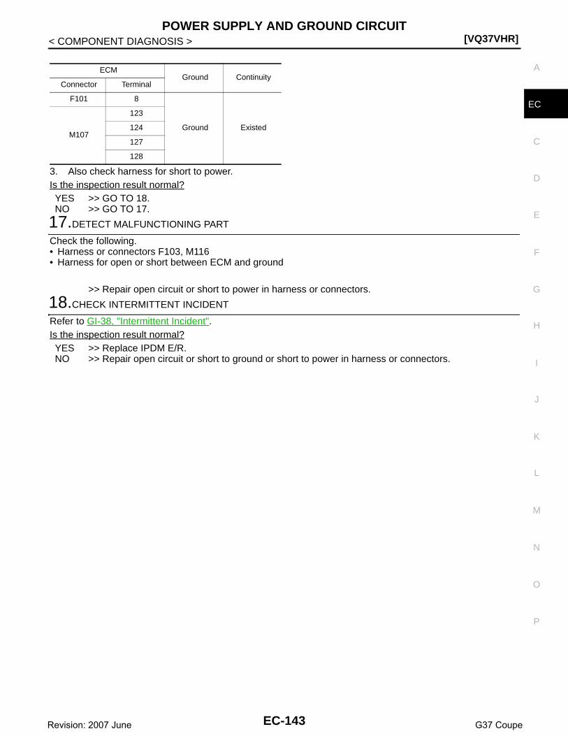
POWER SUPPLY AND GROUND CIRCUIT[VQ37VHR]
C
D
E
F
G
H
I
J
K
L
M
A
C
N
P
O
< COMPONENT DIAGNOSIS >
E
3. Also check harness for short to power.Is the inspection result normal?YES >> GO TO 18.NO >> GO TO 17.
17.DETECT MALFUNCTIONING PART
Check the following.• Harness or connectors F103, M116• Harness for open or short between ECM and ground
>> Repair open circuit or short to power in harness or connectors.
18.CHECK INTERMITTENT INCIDENT
Refer to GI-38, "Intermittent Incident".Is the inspection result normal?YES >> Replace IPDM E/R.NO >> Repair open circuit or short to ground or short to power in harness or connectors.
ECMGround Continuity
Connector Terminal
F101 8
Ground ExistedM107
123
124
127
128
EC-143Revision: 2007 June G37 Coupe

[VQ37VHR]U0113, U1003 CAN COMM CIRCUIT
< COMPONENT DIAGNOSIS >
U0113, U1003 CAN COMM CIRCUIT
Description INFOID:0000000001736729
CAN (Controller Area Network) is a serial communication line for real time application. It is an on-vehicle mul-tiplex communication line with high data communication speed and excellent error detection ability. ECM andVVEL control module are connected with two communication lines (CAN H line and CAN L line) and transmit/receive data. ECM shares information and links with the VVEL control module during operation.
DTC Logic INFOID:0000000001736730
DTC DETECTION LOGICNOTE:If DTC U0113 or U1003 is displayed with DTC U1011, first perform the trouble diagnosis for DTC U1011.Refer to EC-148, "DTC Logic".
DTC CONFIRMATION PROCEDURE
1.PRECONDITIONING
TESTING CONDITION:Before performing the following procedure, confirm that battery voltage is more than 10V at idle.
>> GO TO 2.
2.PERFORM DTC CONFIRMATION PROCEDURE
1. Turn ignition switch ON and wait at least 3 seconds.2. Check DTC.Is DTC detected?YES >> Go to EC-144, "Diagnosis Procedure".NO >> INSPECTION END
Diagnosis Procedure INFOID:0000000001736732
1.CHECK VVEL CAN COMMUNICATION CIRCUIT
1. Turn ignition switch OFF.2. Disconnect ECM harness connector.3. Disconnect VVEL control module harness connector.4. Check the continuity between ECM harness connector and VVEL control module harness connector.
5. Also check harness for short to ground and power.Is the inspection result normal?YES >> GO TO 2.
DTC No. Trouble diagnosis name DTC detecting condition Possible cause
U0113
Lost communication with VVEL control module
CAN communication signal of OBD (emission related diagnosis) is not re-ceived VVEL control module and ECM for 2 seconds or more .
• Harness or connectors(VVEL CAN communication line is open or shorted)
• ECM• VVEL control moduleU1003
CAN communication signal other than OBD (emission related diagnosis) is not received between VVEL control module and ECM for 2 seconds or more .
ECM VVEL control moduleContinuity
Connector Terminal Connector Terminal
F10254
E1524
Existed55 11
EC-144Revision: 2007 June G37 Coupe
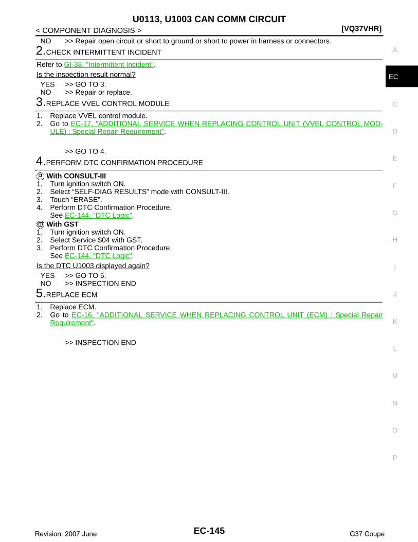
U0113, U1003 CAN COMM CIRCUIT[VQ37VHR]
C
D
E
F
G
H
I
J
K
L
M
A
C
N
P
O
< COMPONENT DIAGNOSIS >
E
NO >> Repair open circuit or short to ground or short to power in harness or connectors.
2.CHECK INTERMITTENT INCIDENT
Refer to GI-38, "Intermittent Incident".Is the inspection result normal?YES >> GO TO 3.NO >> Repair or replace.
3.REPLACE VVEL CONTROL MODULE
1. Replace VVEL control module.2. Go to EC-17, "ADDITIONAL SERVICE WHEN REPLACING CONTROL UNIT (VVEL CONTROL MOD-
ULE) : Special Repair Requirement".
>> GO TO 4.
4.PERFORM DTC CONFIRMATION PROCEDURE
With CONSULT-III1. Turn ignition switch ON.2. Select “SELF-DIAG RESULTS” mode with CONSULT-III.3. Touch “ERASE”.4. Perform DTC Confirmation Procedure.
See EC-144, "DTC Logic". With GST
1. Turn ignition switch ON.2. Select Service $04 with GST.3. Perform DTC Confirmation Procedure.
See EC-144, "DTC Logic".Is the DTC U1003 displayed again?YES >> GO TO 5.NO >> INSPECTION END
5.REPLACE ECM
1. Replace ECM.2. Go to EC-16, "ADDITIONAL SERVICE WHEN REPLACING CONTROL UNIT (ECM) : Special Repair
Requirement".
>> INSPECTION END
EC-145Revision: 2007 June G37 Coupe

[VQ37VHR]U1000, U1001 CAN COMM CIRCUIT
< COMPONENT DIAGNOSIS >
U1000, U1001 CAN COMM CIRCUIT
Description INFOID:0000000001733971
CAN (Controller Area Network) is a serial communication line for real time application. It is an on-vehicle mul-tiplex communication line with high data communication speed and excellent error detection ability. Many elec-tronic control units are equipped onto a vehicle, and each control unit shares information and links with othercontrol units during operation (not independent). In CAN communication, control units are connected with 2communication lines (CAN H line, CAN L line) allowing a high rate of information transmission with less wiring.Each control unit transmits/receives data but selectively reads required data only.
DTC Logic INFOID:0000000001733972
DTC DETECTION LOGIC
DTC CONFIRMATION PROCEDURE
1.PERFORM DTC CONFIRMATION PROCEDURE
1. Turn ignition switch ON and wait at least 3 seconds.2. Check DTC.Is DTC detected?YES >> EC-146, "Diagnosis Procedure".NO >> INSPECTION END
Diagnosis Procedure INFOID:0000000001733973
Go to LAN-16, "Trouble Diagnosis Flow Chart".
DTC No.Trouble diagnosis
nameDTC detecting condition Possible cause
U1000
CAN communication line
When ECM is not transmitting or receiving CAN com-munication signal of OBD (emission related diagno-sis) for 2 seconds or more. • Harness or connectors
(CAN communication line is open or shorted)
U1001When ECM is not transmitting or receiving CAN com-munication signal other than OBD (emission related diagnosis) for 2 seconds or more.
EC-146Revision: 2007 June G37 Coupe

U1010 CONTROL UNIT (CAN)[VQ37VHR]
C
D
E
F
G
H
I
J
K
L
M
A
C
N
P
O
< COMPONENT DIAGNOSIS >
E
U1010 CONTROL UNIT (CAN)
Description INFOID:0000000001910713
CAN (Controller Area Network) is a serial communication line for real time application. It is an on-vehicle mul-tiplex communication line with high data communication speed and excellent error detection ability. Many elec-tronic control units are equipped onto a vehicle, and each control unit shares information and links with othercontrol units during operation (not independent). In CAN communication, control units are connected with 2communication lines (CAN H line, CAN L line) allowing a high rate of information transmission with less wiring.Each control unit transmits/receives data but selectively reads required data only.
DTC Logic INFOID:0000000001733975
DTC DETECTION LOGIC
DTC CONFIRMATION PROCEDURE
1.PERFORM DTC CONFIRMATION PROCEDURE
1. Turn ignition switch ON.2. Check DTC.Is DTC detected?YES >> Go to EC-147, "Diagnosis Procedure".NO >> INSPECTION END
Diagnosis Procedure INFOID:0000000001733976
1.INSPECTION START
With CONSULT-III1. Turn ignition switch ON.2. Select “SELF-DIAG RESULTS” mode with CONSULT-III.3. Touch “ERASE”.4. Perform DTC Confirmation Procedure.
See EC-147, "DTC Logic".5. Check DTC.
With GST1. Turn ignition switch ON.2. Select “Service $04” with GST.3. Perform DTC Confirmation Procedure.
See EC-147, "DTC Logic".4. Check DTC.Is the DTC U1010 displayed again?YES >> GO TO 2.NO >> INSPECTION END
2.REPLACE ECM
1. Replace ECM.2. Go to EC-16, "ADDITIONAL SERVICE WHEN REPLACING CONTROL UNIT (ECM) : Special Repair
Requirement".
>> INSPECTION END
DTC No. Trouble diagnosis name DTC detecting condition Possible cause
U1010 CAN communication busWhen detecting error during the initial diagno-sis of CAN controller of ECM.
• ECM
EC-147Revision: 2007 June G37 Coupe

[VQ37VHR]U1011 CONTROL UNIT (CAN)
< COMPONENT DIAGNOSIS >
U1011 CONTROL UNIT (CAN)
Description INFOID:0000000001910711
CAN (Controller Area Network) is a serial communication line for real time application. It is an on-vehicle mul-tiplex communication line with high data communication speed and excellent error detection ability. ECM andVVEL control module are connected with two communication lines (CAN H line and CAN L line) and transmit/receive data. ECM shares information and links with the VVEL control module during operation.
DTC Logic INFOID:0000000001736735
DTC DETECTION LOGIC
DTC CONFIRMATION PROCEDURE
1.PRECONDITIONING
TESTING CONDITION:Before performing the following procedure, confirm that battery voltage is more than 10V at idle.
>> GO TO 2.
2.PERFORM DTC CONFIRMATION PROCEDURE
1. Turn ignition switch ON and wait at least 3 seconds.2. Check DTC.Is DTC detected?YES >> Go to EC-148, "Diagnosis Procedure".NO >> INSPECTION END
Diagnosis Procedure INFOID:0000000001736741
1.PERFORM DTC CONFIRMATION PROCEDURE
With CONSULT-III1. Turn ignition switch ON.2. Select “SELF-DIAG RESULTS” mode with CONSULT-III.3. Touch “ERASE”.4. Perform DTC Confirmation Procedure.
See EC-148, "DTC Logic". With GST
1. Turn ignition switch ON.2. Select Service $04 with GST.3. Perform DTC Confirmation Procedure.
See EC-148, "DTC Logic".Is the DTC U1011 displayed again?YES >> GO TO 2.NO >> INSPECTION END
2.REPLACE ECM
1. Replace ECM.2. Go to EC-16, "ADDITIONAL SERVICE WHEN REPLACING CONTROL UNIT (ECM) : Special Repair
Requirement".
>> INSPECTION END
DTC No. Trouble diagnosis name DTC detecting condition Possible cause
U1011 VVEL CAN controllerWhen detecting error during the ini-tial diagnosis of VVEL CAN controller of ECM.
• ECM
EC-148Revision: 2007 June G37 Coupe

U1024 CAN COMM CIRCUIT[VQ37VHR]
C
D
E
F
G
H
I
J
K
L
M
A
C
N
P
O
< COMPONENT DIAGNOSIS >
E
U1024 CAN COMM CIRCUIT
Description INFOID:0000000001910712
CAN (Controller Area Network) is a serial communication line for real time application. It is an on-vehicle mul-tiplex communication line with high data communication speed and excellent error detection ability. ECM andVVEL control module are connected with two communication lines (CAN H line and CAN L line) and transmit/receive data. ECM shares information and links with the VVEL control module during operation.
DTC Logic INFOID:0000000001736736
DTC DETECTION LOGICNOTE:If DTC U1024 is displayed with DTC U1011, first perform the trouble diagnosis for DTC U1011. Refer to EC-148, "DTC Logic".
DTC CONFIRMATION PROCEDURE
1.PRECONDITIONING
TESTING CONDITION:Before performing the following procedure, confirm that battery voltage is more than 10V at idle.
>> GO TO 2.
2.PERFORM DTC CONFIRMATION PROCEDURE
1. Turn ignition switch ON and wait at least 3 seconds.2. Check DTC.Is DTC detected?YES >> Go to EC-149, "Diagnosis Procedure".NO >> INSPECTION END
Diagnosis Procedure INFOID:0000000001736743
1.CHECK VVEL CAN COMMUNICATION CIRCUIT
1. Turn ignition switch OFF.2. Disconnect ECM harness connector.3. Disconnect VVEL control module harness connector.4. Check the continuity between ECM harness connector and VVEL control module harness connector.
5. Also check harness for short to ground and power.Is the inspection result normal?YES >> GO TO 2.NO >> Repair open circuit or short to ground or short to power in harness or connectors.
2.CHECK INTERMITTENT INCIDENT
DTC No. Trouble diagnosis name DTC detecting condition Possible cause
U1024 VVEL CAN communication
• When VVEL control module cannot transmit/receive can communication signal from ECM.
• When detecting error during the ini-tial diagnosis of CAN controller of VVEL control module.
• Harness or connectors(CAN communication line is open or shorted)
• ECM• VVEL control module
ECM VVEL control moduleContinuity
Connector Terminal Connector Terminal
F10254
E1524
Existed55 11
EC-149Revision: 2007 June G37 Coupe

[VQ37VHR]U1024 CAN COMM CIRCUIT
< COMPONENT DIAGNOSIS >Refer to GI-38, "Intermittent Incident".Is the inspection result normal?YES >> GO TO 3.NO >> Repair or replace.
3.REPLACE VVEL CONTROL MODULE
1. Replace VVEL control module.2. Go to EC-17, "ADDITIONAL SERVICE WHEN REPLACING CONTROL UNIT (VVEL CONTROL MOD-
ULE) : Special Repair Requirement".
>> GO TO 4.
4.PERFORM DTC CONFIRMATION PROCEDURE
With CONSULT-III1. Turn ignition switch ON.2. Select “SELF-DIAG RESULTS” mode with CONSULT-III.3. Touch “ERASE”.4. Perform DTC Confirmation Procedure.
See EC-149, "DTC Logic".
With GST1. Turn ignition switch ON.2. Select Service $04 with GST.3. Perform DTC Confirmation Procedure.
See EC-149, "DTC Logic".Is the DTC U1024 displayed again?YES >> GO TO 5.NO >> INSPECTION END
5.REPLACE ECM
1. Replace ECM.2. Go to EC-16, "ADDITIONAL SERVICE WHEN REPLACING CONTROL UNIT (ECM) : Special Repair
Requirement".
>> INSPECTION END
EC-150Revision: 2007 June G37 Coupe

P0011, P0021 IVT CONTROL[VQ37VHR]
C
D
E
F
G
H
I
J
K
L
M
A
C
N
P
O
< COMPONENT DIAGNOSIS >
E
P0011, P0021 IVT CONTROL
DTC Logic INFOID:0000000001733977
DTC DETECTION LOGICNOTE:• If DTC P0011 or P0021 is displayed with DTC P0075 or P0081, first perform the trouble diagnosis for
DTC P0075, P0081. Refer to EC-162, "DTC Logic".• If DTC P0011 or P0021 is displayed with DTC P0524, first perform the trouble diagnosis for DTC
P0524. Refer to EC-343, "DTC Logic".
DTC CONFIRMATION PROCEDURE
1.PRECONDITIONING
If DTC Confirmation Procedure has been previously conducted, always perform the following before conduct-ing the next test. 1. Turn ignition switch OFF and wait at least 10 seconds.2. Turn ignition switch ON.3. Turn ignition switch OFF and wait at least 10 seconds.TESTING CONDITION:Before performing the following procedure, confirm that battery voltage is between 10V and 16V atidle.
>> GO TO 2.
2.PERFORM DTC CONFIRMATION PROCEDURE-I
With CONSULT-III1. Turn ignition switch ON and select “DATA MONITOR” mode with CONSULT-III.2. Start engine and warm it up to the normal operating temperature.3. Maintain the following conditions for at least 6 consecutive seconds. Hold the accelerator pedal as steady
as possible.
CAUTION:Always drive at a safe speed.
4. Stop vehicle with engine running and let engine idle for 10 seconds.5. Check 1st trip DTC.
With GSTFollow the procedure “With CONSULT-III” above.Is 1st trip DTC detected?YES >> Go to EC-152, "Diagnosis Procedure"
DTC No.Trouble diagnosis
nameDetecting condition Possible cause
P0011Intake valve timing control performance (bank 1)
There is a gap between angle of target and phase-control angle degree.
• Crankshaft position sensor (POS)• Camshaft position sensor (PHASE)• Intake valve control solenoid valve• Accumulation of debris to the signal pick-up
portion of the camshaft• Timing chain installation• Foreign matter caught in the oil groove for in-
take valve timing control
P0021Intake valve timing control performance (bank 2)
VHCL SPEED SE 100 - 120 km/h (63 - 75 mph)
ENG SPEED 1,200 - 2,000 rpm
COOLAN TEMP/S More than 60°C (140°F)
B/FUEL SCHDL More than 7.3 msec
Selector leverD position (A/T)5th position (M/T)
EC-151Revision: 2007 June G37 Coupe

[VQ37VHR]P0011, P0021 IVT CONTROL
< COMPONENT DIAGNOSIS >NO >> GO TO 3.
3.PERFORM DTC CONFIRMATION PROCEDURE-II
With CONSULT-III1. Select “DATA MONITOR” mode with CONSULT-III.2. Maintain the following conditions for at least 20 consecutive seconds.
CAUTION:Always drive at a safe speed.
3. Check 1st trip DTC.With GST
Follow the procedure “With CONSULT-III” above.Is 1st trip DTC detected?YES >> Go to EC-152, "Diagnosis Procedure"NO >> INSPECTION END
Diagnosis Procedure INFOID:0000000001733978
1.CHECK OIL PRESSURE WARNING LAMP
1. Start engine.2. Check oil pressure warning lamp and confirm it is not illumi-
nated.Is oil pressure warning lamp illuminated?YES >> Go to LU-6, "Inspection".NO >> GO TO 2.
2.CHECK INTAKE VALVE TIMING CONTROL SOLENOID VALVE
Refer to EC-153, "Component Inspection".Is the inspection result normal?YES >> GO TO 3.NO >> Replace malfunctioning intake valve timing control solenoid valve.
3.CHECK CRANKSHAFT POSITION SENSOR (POS)
Refer to EC-267, "Component Inspection".Is the inspection result normal?YES >> GO TO 4.NO >> Replace crankshaft position sensor (POS).
4.CHECK CAMSHAFT POSITION SENSOR (PHASE)
Refer to EC-271, "Component Inspection".Is the inspection result normal?YES >> GO TO 5.NO >> Replace malfunctioning camshaft position sensor (PHASE).
ENG SPEED 1,700 - 3,175 rpm (A constant rotation is maintained.)
COOLAN TEMP/S More than 70°C (158°F)
Selector lever 1st or 2nd position
Driving location uphillDriving vehicle uphill(Increased engine load will help maintain the driving conditions required for this test.)
PBIA8559J
EC-152Revision: 2007 June G37 Coupe

P0011, P0021 IVT CONTROL[VQ37VHR]
C
D
E
F
G
H
I
J
K
L
M
A
C
N
P
O
< COMPONENT DIAGNOSIS >
E
5.CHECK CAMSHAFT (INTAKE)
Check the following.• Accumulation of debris to the signal plate of camshaft front end• Chipping signal plate of camshaft front endIs the inspection result normal?YES >> GO TO 6.NO >> Remove debris and clean the signal plate of camshaft
front end or replace camshaft.
6.CHECK TIMING CHAIN INSTALLATION
Check service records for any recent repairs that may cause timing chain misaligned.Are there any service records that may cause timing chain misaligned?YES >> Check timing chain installation. Refer to EM-49, "Removal and Installation".NO >> GO TO 7.
7.CHECK LUBRICATION CIRCUIT
Perform “Inspection of Camshaft Sprocket (INT) Oil Groove”. Refer to EM-93, "Inspection".Is the inspection result normal?YES >> GO TO 8.NO >> Clean lubrication line.
8.CHECK INTERMITTENT INCIDENT
Refer to GI-38, "Intermittent Incident".
>> INSPECTION END
Component Inspection INFOID:0000000001733979
1.CHECK INTAKE VALVE TIMING CONTROL SOLENOID VALVE-I
1. Turn ignition switch OFF.2. Disconnect intake valve timing control solenoid valve harness connector.3. Check resistance between intake valve timing control solenoid valve terminals as follows.
Is the inspection result normal?YES >> GO TO 2.NO >> Replace malfunctioning intake valve timing control solenoid valve.
2.CHECK INTAKE VALVE TIMING CONTROL SOLENOID VALVE-II
1. Remove intake valve timing control solenoid valve.
JMBIA0962ZZ
Terminals Resistance
1 and 2 7.0 - 7.7 Ω [at 20°C (68°F)]
1 or 2 and ground∞Ω
(Continuity should not exist)
EC-153Revision: 2007 June G37 Coupe

[VQ37VHR]P0011, P0021 IVT CONTROL
< COMPONENT DIAGNOSIS >2. Provide 12V DC between intake valve timing control solenoid
valve terminals 1 and 2, and then interrupt it. Make sure that theplunger moves as shown in the figure.CAUTION:Do not apply 12V DC continuously for 5 seconds or more.Doing so may result in damage to the coil in intake valvetiming control solenoid valve.NOTE:Always replace O-ring when intake valve timing controlsolenoid valve is removed.
Is the inspection result normal?YES >> INSPECTION ENDNO >> Replace malfunctioning intake valve timing control solenoid valve.
JMBIA0079ZZ
EC-154Revision: 2007 June G37 Coupe

P0031, P0032, P0051, P0052 A/F SENSOR 1 HEATER[VQ37VHR]
C
D
E
F
G
H
I
J
K
L
M
A
C
N
P
O
< COMPONENT DIAGNOSIS >
E
P0031, P0032, P0051, P0052 A/F SENSOR 1 HEATER
Description INFOID:0000000001733983
SYSTEM DESCRIPTION
The ECM performs ON/OFF duty control of the A/F sensor 1 heater corresponding to the engine operatingcondition to keep the temperature of A/F sensor 1 element at the specified range.
DTC Logic INFOID:0000000001733984
DTC DETECTION LOGIC
DTC CONFIRMATION PROCEDURE
1.PRECONDITIONING
If DTC Confirmation Procedure has been previously conducted, always perform the following before conduct-ing the next test.1. Turn ignition switch OFF and wait at least 10 seconds.2. Turn ignition switch ON.3. Turn ignition switch OFF and wait at least 10 seconds.TESTING CONDITION:Before performing the following procedure, confirm that battery voltage is between 10.5V and 16V atidle.
>> GO TO 2.
2.PERFORM DTC CONFIRMATION PROCEDURE
1. Start engine and let it idle for at least 10 seconds.2. Check 1st trip DTC.Is 1st trip DTC detected?YES >> Go to EC-156, "Diagnosis Procedure".NG >> INSPECTION END
Sensor Input Signal to ECM ECM function Actuator
Camshaft position sensor (PHASE)Crankshaft position sensor (POS)
Engine speed Air fuel ratio (A/F) sensor 1 heater control
Air fuel ratio (A/F) sensor 1 heater
Mass air flow sensor Amount of intake air
DTC No. Trouble diagnosis name DTC detecting condition Possible cause
P0031Air fuel ratio (A/F) sensor 1 heater (bank 1) control circuit low
The current amperage in the A/F sensor 1 heater circuit is out of the normal range.(An excessively low voltage signal is sent to ECM through the A/F sensor 1 heater.)
• Harness or connectors(The A/F sensor 1 heater circuit is open or shorted.)
• A/F sensor 1 heater
P0032Air fuel ratio (A/F) sensor 1 heater (bank 1) control circuit high
The current amperage in the A/F sensor 1 heater circuit is out of the normal range.(An excessively high voltage signal is sent to ECM through the A/F sensor 1 heater.)
• Harness or connectors(The A/F sensor 1 heater circuit is shorted.)
• A/F sensor 1 heater
P0051Air fuel ratio (A/F) sensor 1 heater (bank 2) control circuit low
The current amperage in the A/F sensor 1 heater circuit is out of the normal range.(An excessively low voltage signal is sent to ECM through the A/F sensor 1 heater.)
• Harness or connectors(The A/F sensor 1 heater circuit is open or shorted.)
• A/F sensor 1 heater
P0052Air fuel ratio (A/F) sensor 1 heater (bank 2) control circuit high
The current amperage in the A/F sensor 1 heater circuit is out of the normal range.(An excessively high voltage signal is sent to ECM through the A/F sensor 1 heater.)
• Harness or connectors(The A/F sensor 1 heater circuit is shorted.)
• A/F sensor 1 heater
EC-155Revision: 2007 June G37 Coupe

[VQ37VHR]P0031, P0032, P0051, P0052 A/F SENSOR 1 HEATER
< COMPONENT DIAGNOSIS >
Diagnosis Procedure INFOID:0000000001733985
1.CHECK GROUND CONNECTION
1. Turn ignition switch OFF.2. Check ground connection M95. Refer to Ground Inspection in GI-41, "Circuit Inspection".Is the inspection result normal?YES >> GO TO 2.NO >> Repair or replace ground connection.
2.CHECK AIR FUEL RATIO (A/F) SENSOR 1 POWER SUPPLY CIRCUIT
1. Disconnect air fuel ratio (A/F) sensor 1 harness connector.2. Turn ignition switch ON.3. Check the voltage between A/F sensor 1 harness connector and ground.
Is the inspection result normal?YES >> GO TO 4.NO >> GO TO 3.
3.DETECT MALFUNCTIONING PART
Check the following.• Harness connectors E3, F1• IPDM E/R harness connector E7• 15A fuse (No. 46)• Harness for open or short between A/F sensor 1 and fuse
>> Repair or replace harness or connectors.
4.CHECK A/F SENSOR 1 HEATER OUTPUT SIGNAL CIRCUIT
1. Turn ignition switch OFF.2. Disconnect ECM harness connector.3. Check the continuity between A/F sensor 1 harness connector and ECM harness connector.
4. Also check harness for short to ground and short to power.Is the inspection result normal?YES >> GO TO 5.NO >> Repair open circuit or short to ground or short to power in harness or connectors.
5.CHECK A/F SENSOR 1 HEATER
Refer to EC-157, "Component Inspection".Is the inspection result normal?YES >> GO TO 7.NO >> GO TO 6.
6.REPLACE AIR FUEL RATIO (A/F) SENSOR 1
Replace malfunctioning air fuel ratio (A/F) sensor 1.CAUTION:
DTCA/F sensor 1
Ground VoltageBank Connector Terminal
P0031, P0032 1 F3 4Ground Battery voltage
P0051, P0052 2 F20 4
DTCA/F sensor 1 ECM
ContinuityBank Connector Terminal Connector Terminal
P0031, P0032 1 F3 3F101
1Existed
P0051, P0052 2 F20 3 5
EC-156Revision: 2007 June G37 Coupe

P0031, P0032, P0051, P0052 A/F SENSOR 1 HEATER[VQ37VHR]
C
D
E
F
G
H
I
J
K
L
M
A
C
N
P
O
< COMPONENT DIAGNOSIS >
E
• Discard any A/F sensor which has been dropped from a height of more than 0.5 m (19.7 in) onto ahard surface such as a concrete floor; use a new one.
• Before installing new A/F sensor, clean exhaust system threads using Oxygen Sensor ThreadCleaner tool J-43897-18 or J-43897-12 and approved anti-seize lubricant.
>> INSPECTION END
7.CHECK INTERMITTENT INCIDENT
Perform GI-38, "Intermittent Incident".
>> Repair or replace.
Component Inspection INFOID:0000000001733986
1.CHECK AIR FUEL RATIO (A/F) SENSOR 1
1. Turn ignition switch OFF.2. Disconnect A/F sensor 1 harness connector.3. Check resistance between A/F sensor 1 terminals as follows.
Is the inspection result normal?YES >> INSPECTION ENDNO >> GO TO 2.
2.REPLACE AIR FUEL RATIO (A/F) SENSOR 1
Replace malfunctioning air fuel ratio (A/F) sensor 1.CAUTION:• Discard any air fuel ratio (A/F) sensor which has been dropped from a height of more than 0.5 m
(19.7 in) onto a hard surface such as a concrete floor; use a new one.• Before installing new air fuel ratio (A/F) sensor, clean exhaust system threads using Heated Oxygen
Sensor Thread Cleaner tool J-43897-18 or J-43897-12 and approved anti-seize lubricant.
>> INSPECTION END
Terminal Resistance
3 and 4 1.8 - 2.44 Ω [at 25°C (77°F)]
3 and 1, 2 ∞Ω(Continuity should not exist)4 and 1, 2
EC-157Revision: 2007 June G37 Coupe
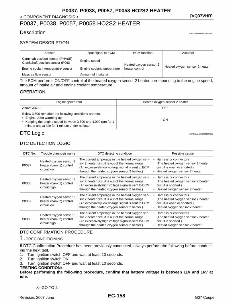
[VQ37VHR]P0037, P0038, P0057, P0058 HO2S2 HEATER
< COMPONENT DIAGNOSIS >
P0037, P0038, P0057, P0058 HO2S2 HEATER
Description INFOID:0000000001733987
SYSTEM DESCRIPTION
The ECM performs ON/OFF control of the heated oxygen sensor 2 heater corresponding to the engine speed,amount of intake air and engine coolant temperature.
OPERATION
DTC Logic INFOID:0000000001733988
DTC DETECTION LOGIC
DTC CONFIRMATION PROCEDURE
1.PRECONDITIONING
If DTC Confirmation Procedure has been previously conducted, always perform the following before conduct-ing the next test.1. Turn ignition switch OFF and wait at least 10 seconds.2. Turn ignition switch ON.3. Turn ignition switch OFF and wait at least 10 seconds.TESTING CONDITION:Before performing the following procedure, confirm that battery voltage is between 11V and 16V atidle.
>> GO TO 2.
Sensor Input signal to ECM ECM function Actuator
Camshaft position sensor (PHASE)Crankshaft position sensor (POS)
Engine speedHeated oxygen sensor 2 heater control
Heated oxygen sensor 2 heaterEngine coolant temperature sensor Engine coolant temperature
Mass air flow sensor Amount of intake air
Engine speed rpm Heated oxygen sensor 2 heater
Above 3,600 OFF
Below 3,600 rpm after the following conditions are met.• Engine: After warming up• Keeping the engine speed between 3,500 and 4,000 rpm for 1
minute and at idle for 1 minute under no load
ON
DTC No. Trouble diagnosis name DTC detecting condition Possible cause
P0037Heated oxygen sensor 2 heater (bank 1) control circuit low
The current amperage in the heated oxygen sen-sor 2 heater circuit is out of the normal range.(An excessively low voltage signal is sent to ECM through the heated oxygen sensor 2 heater.)
• Harness or connectors(The heated oxygen sensor 2 heater circuit is open or shorted.)
• Heated oxygen sensor 2 heater
P0038Heated oxygen sensor 2 heater (bank 1) control circuit high
The current amperage in the heated oxygen sen-sor 2 heater circuit is out of the normal range.(An excessively high voltage signal is sent to ECM through the heated oxygen sensor 2 heater.)
• Harness or connectors(The heated oxygen sensor 2 heater circuit is shorted.)
• Heated oxygen sensor 2 heater
P0057Heated oxygen sensor 2 heater (bank 2) control circuit low
The current amperage in the heated oxygen sen-sor 2 heater circuit is out of the normal range.(An excessively low voltage signal is sent to ECM through the heated oxygen sensor 2 heater.)
• Harness or connectors(The heated oxygen sensor 2 heater circuit is open or shorted.)
• Heated oxygen sensor 2 heater
P0058Heated oxygen sensor 2 heater (bank 2) control circuit high
The current amperage in the heated oxygen sen-sor 2 heater circuit is out of the normal range.(An excessively high voltage signal is sent to ECM through the heated oxygen sensor 2 heater.)
• Harness or connectors(The heated oxygen sensor 2 heater circuit is shorted.)
• Heated oxygen sensor 2 heater
EC-158Revision: 2007 June G37 Coupe

P0037, P0038, P0057, P0058 HO2S2 HEATER[VQ37VHR]
C
D
E
F
G
H
I
J
K
L
M
A
C
N
P
O
< COMPONENT DIAGNOSIS >
E
2.PERFORM DTC CONFIRMATION PROCEDURE
With CONSULT-III1. Turn ignition switch ON and select “DATA MONITOR” mode with CONSULT-III.2. Start engine and warm it up to the normal operating temperature.3. Turn ignition switch OFF and wait at least 10 seconds.4. Turn ignition switch ON.5. Turn ignition switch OFF and wait at least 10 seconds.6. Start engine and keep the engine speed between 3,500 and 4,000 rpm for at least 1 minute under no load.7. Let engine idle for 1 minute.8. Check 1st trip DTC.
With GSTFollow the procedure “With CONSULT-III” above.Is 1st tip DTC detected?YES >> Go to EC-159, "Diagnosis Procedure".NO >> INSPECTION END
Diagnosis Procedure INFOID:0000000001733989
1.CHECK GROUND CONNECTION
1. Turn ignition switch OFF.2. Check ground connection M95. Refer to Ground Inspection in GI-41, "Circuit Inspection".Is the inspection result normal?YES >> GO TO 2.NO >> Repair or replace ground connection.
2.CHECK HO2S2 POWER SUPPLY CIRCUIT
1. Disconnect heated oxygen sensor 2 harness connector.2. Turn ignition switch ON.3. Check the voltage between HO2S2 harness connector and ground.
Is the inspection result normal?YES >> GO TO 4.NO >> GO TO 3.
3.DETECT MALFUNCTIONING PART
Check the following.• Harness connectors E3, F1• IPDM E/R harness connector E7• 15A fuse (No. 46)• Harness for open or short between heated oxygen sensor 2 and fuse
>> Repair open circuit or short to ground or short to power in harness or connectors.
4.CHECK HO2S2 OUTPUT SIGNAL CIRCUIT FOR OPEN AND SHORT
1. Turn ignition switch OFF.2. Disconnect ECM harness connector.3. Check the continuity between HO2S2 harness connector and ECM harness connector.
DTCHO2S2
Ground VoltageBank Connector Terminal
P0037, P0038 1 F54 2Ground Battery voltage
P0057, P0058 2 F53 2
EC-159Revision: 2007 June G37 Coupe

[VQ37VHR]P0037, P0038, P0057, P0058 HO2S2 HEATER
< COMPONENT DIAGNOSIS >
4. Also check harness for short to ground and short to power.Is the inspection result normal?YES >> GO TO 5.NO >> Repair open circuit or short to ground or short to power in harness or connectors.
5.CHECK HEATED OXYGEN SENSOR 2 HEATER
Refer to EC-160, "Component Inspection".Is the inspection result normal?YES >> GO TO 7.NO >> GO TO 6.
6.REPLACE HEATED OXYGEN SENSOR 2
Replace malfunctioning heated oxygen sensor 2.CAUTION:• Discard any heated oxygen sensor which has been dropped from a height of more than 0.5 m (19.7
in) onto a hard surface such as a concrete floor; use a new one.• Before installing new oxygen sensor, clean exhaust system threads using Oxygen Sensor Thread
Cleaner tool J-43897-18 or J-43897-12 and approved anti-seize lubricant.
>> INSPECTION END
7.CHECK INTERMITTENT INCIDENT
Refer to GI-38, "Intermittent Incident".
>> INSPECTION END
Component Inspection INFOID:0000000001733990
1.CHECK HEATED OXYGEN SENSOR 2 HEATER
1. Turn ignition switch OFF.2. Disconnect heated oxygen sensor 2 harness connector.3. Check resistance between HO2S2 terminals as follows.
Is the inspection result normal?YES >> INSPECTION ENDNO >> GO TO 2.
2.REPLACE HEATED OXYGEN SENSOR 2
Replace malfunctioning heated oxygen sensor 2.CAUTION:• Discard any heated oxygen sensor which has been dropped from a height of more than 0.5 m (19.7
in) onto a hard surface such as a concrete floor; use a new one.• Before installing new oxygen sensor, clean exhaust system threads using Oxygen Sensor Thread
Cleaner tool J-43897-18 or J-43897-12 and approved anti-seize lubricant.
DTCHO2S2 ECM
ContinuityBank Connector Terminal Connector Terminal
P0037, P0038 1 F54 3F101
17Existed
P0057, P0058 2 F53 3 33
Terminal Resistance
2 and 3 3.4 - 4.4 Ω [at 25°C (77°F)]
1 and 2, 3, 4 ∞Ω(Continuity should not exist)4 and 1, 2, 3
EC-160Revision: 2007 June G37 Coupe
P0037, P0038, P0057, P0058 HO2S2 HEATER[VQ37VHR]
C
D
E
F
G
H
I
J
K
L
M
A
C
N
P
O
< COMPONENT DIAGNOSIS >
E
>> INSPECTION END
EC-161Revision: 2007 June G37 Coupe

[VQ37VHR]P0075, P0081 IVT CONTROL SOLENOID VALVE
< COMPONENT DIAGNOSIS >
P0075, P0081 IVT CONTROL SOLENOID VALVE
Description INFOID:0000000001733991
Intake valve timing control solenoid valve is activated by ON/OFFpulse duty (ratio) signals from the ECM.The intake valve timing control solenoid valve changes the oilamount and direction of flow through intake valve timing control unitor stops oil flow.The longer pulse width advances valve angle.The shorter pulse width retards valve angle.When ON and OFF pulse widths become equal, the solenoid valvestops oil pressure flow to fix the intake valve angle at the controlposition.
DTC Logic INFOID:0000000001733992
DTC DETECTION LOGIC
DTC CONFIRMATION PROCEDURE
1.PRECONDITIONING
If DTC Confirmation Procedure has been previously conducted, always perform the following before conduct-ing the next test.1. Turn ignition switch OFF and wait at least 10 seconds.2. Turn ignition switch ON.3. Turn ignition switch OFF and wait at least 10 seconds.
>> GO TO 2.
2.PERFORM DTC CONFIRMATION PROCEDURE
1. Start engine and let it idle for 5 seconds.2. Check 1st trip DTC.Is 1st trip DTC detected?YES >> Go to EC-162, "Diagnosis Procedure".NO >> INSPECTION END
Diagnosis Procedure INFOID:0000000001733993
1.CHECK INTAKE VALVE TIMING CONTROL SOLENOID VALVE POWER SUPPLY CIRCUIT
1. Turn ignition switch OFF.2. Disconnect intake valve timing control solenoid valve harness connector.3. Turn ignition switch ON.4. Check the voltage between intake valve timing control solenoid valve harness connector and ground.
PBIB1842E
DTC No. Trouble diagnosis name DTC detecting condition Possible cause
P0075Intake valve timing control so-lenoid valve (bank 1) circuit An improper voltage is sent to the ECM
through intake valve timing control solenoid valve.
• Harness or connectors(Intake valve timing control solenoid valve circuit is open or shorted.)
• Intake valve timing control solenoid valve
P0081Intake valve timing control so-lenoid valve (bank 2) circuit
DTCIVT control solenoid valve
Ground VoltageBank Connector Terminal
P0075 1 F28 2Ground Battery voltage
P0081 2 F29 2
EC-162Revision: 2007 June G37 Coupe

P0075, P0081 IVT CONTROL SOLENOID VALVE[VQ37VHR]
C
D
E
F
G
H
I
J
K
L
M
A
C
N
P
O
< COMPONENT DIAGNOSIS >
E
Is the inspection result normal?YES >> GO TO 3.NO >> GO TO 2.
2.DETECT MALFUNCTIONING PART
Check the following.• Harness connectors E3, F1• Harness for open or short between intake valve timing control solenoid valve and IPDM E/R
>> Repair open circuit or short to ground or short to power in harness or connectors.
3.CHECK INTAKE VALVE TIMING CONTROL SOLENOID VALVE OUTPUT SIGNAL CIRCUIT FOR OPENAND SHORT
1. Turn ignition switch OFF.2. Disconnect ECM harness connector.3. Check the continuity between intake valve timing control solenoid valve harness connector and ECM har-
ness connector.
4. Also check harness for short to ground and short to power. Is the inspection result normal?YES >> GO TO 4.NO >> Repair open circuit or short to ground or short to power in harness or connectors.
4.CHECK INTAKE VALVE TIMING CONTROL SOLENOID VALVE
Refer to EC-163, "Component Inspection".Is the inspection result normal?YES >> GO TO 5.NO >> Replace malfunctioning intake valve timing control solenoid valve.
5.CHECK INTERMITTENT INCIDENT
Refer to GI-38, "Intermittent Incident".
>> INSPECTION END
Component Inspection INFOID:0000000001910714
1.CHECK INTAKE VALVE TIMING CONTROL SOLENOID VALVE-I
1. Turn ignition switch OFF.2. Disconnect intake valve timing control solenoid valve harness connector.3. Check resistance between intake valve timing control solenoid valve terminals as follows.
Is the inspection result normal?YES >> GO TO 2.NO >> Replace malfunctioning intake valve timing control solenoid valve.
2.CHECK INTAKE VALVE TIMING CONTROL SOLENOID VALVE-II
1. Remove intake valve timing control solenoid valve.
DTCIVT control solenoid valve ECM
ContinuityBank Connector Terminal Connector Terminal
P0075 1 F28 1F101
18Existed
P0081 2 F29 1 29
Terminals Resistance
1 and 2 7.0 - 7.7 Ω [at 20°C (68°F)]
1 or 2 and ground∞Ω
(Continuity should not exist)
EC-163Revision: 2007 June G37 Coupe

[VQ37VHR]P0075, P0081 IVT CONTROL SOLENOID VALVE
< COMPONENT DIAGNOSIS >2. Provide 12V DC between intake valve timing control solenoid
valve terminals 1 and 2, and then interrupt it. Make sure that theplunger moves as shown in the figure.CAUTION:Do not apply 12V DC continuously for 5 seconds or more.Doing so may result in damage to the coil in intake valvetiming control solenoid valve.NOTE:Always replace O-ring when intake valve timing controlsolenoid valve is removed.
Is the inspection result normal?YES >> INSPECTION ENDNO >> Replace malfunctioning intake valve timing control solenoid valve.
JMBIA0079ZZ
EC-164Revision: 2007 June G37 Coupe
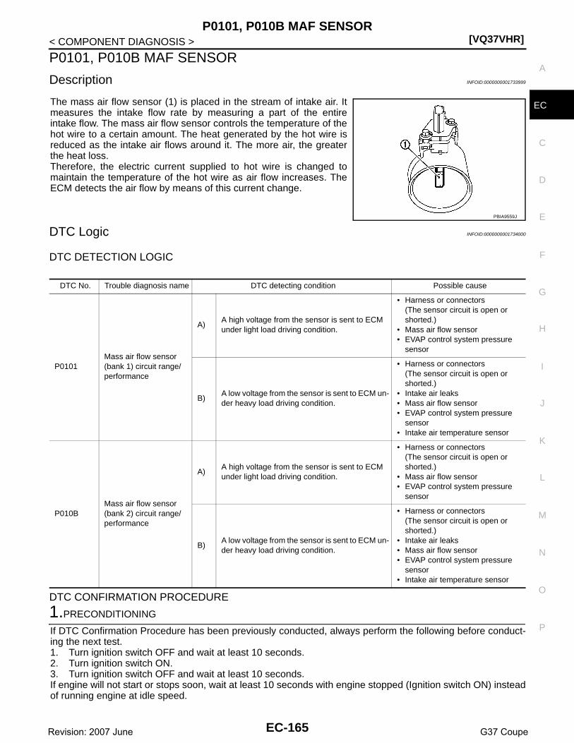
P0101, P010B MAF SENSOR[VQ37VHR]
C
D
E
F
G
H
I
J
K
L
M
A
C
N
P
O
< COMPONENT DIAGNOSIS >
E
P0101, P010B MAF SENSOR
Description INFOID:0000000001733999
The mass air flow sensor (1) is placed in the stream of intake air. Itmeasures the intake flow rate by measuring a part of the entireintake flow. The mass air flow sensor controls the temperature of thehot wire to a certain amount. The heat generated by the hot wire isreduced as the intake air flows around it. The more air, the greaterthe heat loss. Therefore, the electric current supplied to hot wire is changed tomaintain the temperature of the hot wire as air flow increases. TheECM detects the air flow by means of this current change.
DTC Logic INFOID:0000000001734000
DTC DETECTION LOGIC
DTC CONFIRMATION PROCEDURE
1.PRECONDITIONING
If DTC Confirmation Procedure has been previously conducted, always perform the following before conduct-ing the next test.1. Turn ignition switch OFF and wait at least 10 seconds.2. Turn ignition switch ON.3. Turn ignition switch OFF and wait at least 10 seconds.If engine will not start or stops soon, wait at least 10 seconds with engine stopped (Ignition switch ON) insteadof running engine at idle speed.
PBIA9559J
DTC No. Trouble diagnosis name DTC detecting condition Possible cause
P0101Mass air flow sensor (bank 1) circuit range/performance
A)A high voltage from the sensor is sent to ECM under light load driving condition.
• Harness or connectors(The sensor circuit is open or shorted.)
• Mass air flow sensor• EVAP control system pressure
sensor
B)A low voltage from the sensor is sent to ECM un-der heavy load driving condition.
• Harness or connectors(The sensor circuit is open or shorted.)
• Intake air leaks• Mass air flow sensor• EVAP control system pressure
sensor• Intake air temperature sensor
P010BMass air flow sensor (bank 2) circuit range/performance
A)A high voltage from the sensor is sent to ECM under light load driving condition.
• Harness or connectors(The sensor circuit is open or shorted.)
• Mass air flow sensor• EVAP control system pressure
sensor
B)A low voltage from the sensor is sent to ECM un-der heavy load driving condition.
• Harness or connectors(The sensor circuit is open or shorted.)
• Intake air leaks• Mass air flow sensor• EVAP control system pressure
sensor• Intake air temperature sensor
EC-165Revision: 2007 June G37 Coupe

[VQ37VHR]P0101, P010B MAF SENSOR
< COMPONENT DIAGNOSIS >>> GO TO 2.
2.PERFORM DTC CONFIRMATION PROCEDURE FOR MALFUNCTION A
1. Start engine and warm it up to normal operating temperature.2. Run engine for at least 10 seconds at idle speed.3. Check 1st trip DTC.Is 1st trip DTC detected?YES >> Go to EC-167, "Diagnosis Procedure".NO-1 >> With CONSULT-III: GO TO 3.NO-2 >> Without CONSULT-III: GO TO 5.
3.CHECK MASS AIR FLOW SENSOR FUNCTION
1. Turn ignition switch ON.2. Start engine and warm it up to normal operating temperature.
If engine cannot be started, go to EC-167, "Diagnosis Procedure".3. Select “DATA MONITOR” mode with CONSULT-III.4. Check the voltage of “MAS A/F SE-B1/B2” with “DATA MONI-
TOR”.5. Increases engine speed to about 4,000 rpm.6. Monitor the linear voltage rise in response to engine speed
increases.Is the inspection result normal?YES >> GO TO 4.NO >> Go to EC-167, "Diagnosis Procedure".
4.PERFORM DTC CONFIRMATION PROCEDURE FOR MALFUNCTION B
1. Maintain the following conditions for at least 10 consecutive seconds.
CAUTION:Always drive vehicle at a safe speed.
2. Check 1st rip DTC.Is 1st trip DTC detected?YES >> Go to EC-167, "Diagnosis Procedure".NO >> INSPECTION END
PBIB3457E
ENG SPEED More than 2,000 rpm
TP SEN 1-B1 More than 3V
TP SEN 2-B1 More than 3V
TP SEN 1-B2 More than 3V
TP SEN 2-B2 More than 3V
Selector lever Suitable position
Driving locationDriving vehicle uphill (Increased engine load) will help maintain the driving conditions required for this test.
EC-166Revision: 2007 June G37 Coupe

P0101, P010B MAF SENSOR[VQ37VHR]
C
D
E
F
G
H
I
J
K
L
M
A
C
N
P
O
< COMPONENT DIAGNOSIS >
E
5.PERFORM COMPONENT FUNCTION CHECK FOR MALFUNCTION B
Perform component function check. Refer to EC-167, "Component Function Check".NOTE:Use component function check to check the overall function of the mass air flow sensor circuit. During thischeck, a 1st trip DTC might not be confirmed.Is the inspection result normal?YES >> INSPECTION ENDNO >> Go to EC-167, "Diagnosis Procedure".
Component Function Check INFOID:0000000001734001
1.PERFORM COMPONENT FUNCTION CHECK FOR MALFUNCTION B
With GST1. Start engine and warm it up to normal operating temperature.2. Select Service $01 with GST.3. Check the mass air flow sensor signal with Service $01.4. Check for linear mass air flow sensor signal value rise in
response to increases to about 4,000 rpm in engine speed.Is the inspection result normal?YES >> INSPECTION ENDNO >> Go to EC-167, "Diagnosis Procedure".
Diagnosis Procedure INFOID:0000000001734002
1.INSPECTION START
Confirm the detected malfunction (A or B). Refer to EC-165, "DTC Logic".Which malfunction is detected?A >> GO TO 3.B >> GO TO 2.
2.CHECK INTAKE SYSTEM
Check the following for connection.• Air duct• Vacuum hoses• Intake air passage between air duct and intake manifoldIs the inspection result normal?YES >> GO TO 3.NO >> Reconnect the parts.
3.CHECK GROUND CONNECTION
1. Turn ignition switch OFF.2. Check ground connection M95. Refer to Ground Inspection in GI-41, "Circuit Inspection".Is the inspection result normal?YES >> GO TO 4.NO >> Repair or replace ground connection.
4.CHECK MAF SENSOR POWER SUPPLY CIRCUIT
1. Disconnect mass air flow (MAF) sensor harness connector.2. Turn ignition switch ON.3. Check the voltage between MAF sensor harness connector and ground.
SEF534P
EC-167Revision: 2007 June G37 Coupe

[VQ37VHR]P0101, P010B MAF SENSOR
< COMPONENT DIAGNOSIS >
Is the inspection result normal?YES >> GO TO 6.NO >> GO TO 5.
5.DETECT MALFUNCTIONING PART
Check the following.• Harness connectors E106, M6• Harness connectors M116, F103• Harness for open or short between mass air flow sensor and ECM• Harness for open or short between mass air flow sensor and IPDM E/R
>> Repair open circuit or short to ground or short to power in harness or connectors.
6.CHECK MAF SENSOR GROUND CIRCUIT FOR OPEN AND SHORT
1. Turn ignition switch OFF.2. Disconnect ECM harness connector.3. Check the continuity between MAF sensor harness connector and ECM harness connector.
4. Also check harness for short to ground and short to power.Is the inspection result normal?YES >> GO TO 7.NO >> Repair open circuit or short to ground or short to power in harness or connectors.
7.CHECK MAF SENSOR INPUT SIGNAL CIRCUIT FOR OPEN AND SHORT
1. Check the continuity between MAF sensor harness connector and ECM harness connector.
2. Also check harness for short to ground and short to power.Is the inspection result normal?YES >> GO TO 8.NO >> Repair open circuit or short to ground or short to power in harness or connectors.
8.CHECK INTAKE AIR TEMPERATURE SENSOR
Check intake air temperature sensor (bank 1).Refer to EC-182, "Component Inspection".Is the inspection result normal?YES >> GO TO 9.NO >> Replace mass air flow sensor (bank 1) (with intake air temperature sensor).
9.CHECK EVAP CONTROL SYSTEM PRESSURE SENSOR
Refer to EC-306, "Component Inspection".
DTCMAF sensor
Ground VoltageBank Connector Terminal
P0101 1 F31 5Ground Battery voltage
P010B 2 F42 5
DTCMAF sensor ECM
ContinuityBank Connector Terminal Connector Terminal
P0101 1 F31 4F102
68Existed
P010B 2 F42 4 94
DTCMAF sensor ECM
ContinuityBank Connector Terminal Connector Terminal
P0101 1 F31 3F102
77Existed
P010B 2 F42 3 79
EC-168Revision: 2007 June G37 Coupe

P0101, P010B MAF SENSOR[VQ37VHR]
C
D
E
F
G
H
I
J
K
L
M
A
C
N
P
O
< COMPONENT DIAGNOSIS >
E
Is the inspection result normal?YES >> GO TO 10.NO >> Replace EVAP control system pressure sensor.
10.CHECK MASS AIR FLOW SENSOR
Refer to EC-169, "Component Inspection".Is the inspection result normal?YES >> GO TO 11.NO >> Replace malfunctioning mass air flow sensor.
11.CHECK INTERMITTENT INCIDENT
Refer to GI-38, "Intermittent Incident".
>> INSPECTION END
Component Inspection INFOID:0000000001734003
1.CHECK MASS AIR FLOW SENSOR-I
With CONSULT-III1. Turn ignition switch OFF.2. Reconnect all harness connectors disconnected.3. Start engine and warm it up to normal operating temperature.4. Connect CONSULT-III and select “DATA MONITOR” mode.5. Select “MAS A/F SE-B1” and “MAS A/F SE-B2”, and check the indication.
*: Check for linear voltage rise in response to engine being increased to about 4,000 rpm.
Without CONSULT-III1. Turn ignition switch OFF.2. Reconnect all harness connectors disconnected.3. Start engine and warm it up to normal operating temperature.4. Check the voltage between ECM harness connector and ground.
*: Check for linear voltage rise in response to engine being increased to about 4,000 rpm.
Is the inspection result normal?YES >> GO TO 4.NO >> GO TO 2.
2.CHECK FOR THE CAUSE OF UNEVEN AIR FLOW THROUGH MASS AIR FLOW SENSOR
1. Turn ignition switch OFF.2. Check for the cause of uneven air flow through mass air flow sensor. Refer to following.- Crushed air ducts
Monitor item Condition Indication
MAS A/F SE-B1MAS A/F SE-B2
Ignition switch ON (Engine stopped.) Approx. 0.4V
Idle (Engine is warmed-up to normal operating temperature.) 0.7 - 1.2V
2,500 rpm (Engine is warmed-up to normal operating temperature.) 1.3 - 1.7V
Idle to about 4,000 rpm 0.7 - 1.2V to Approx. 2.4V*
ECMGround Condition Voltage
Connector Terminal
F10277 [MAF sensor (bank 1) signal]79 [MAF sensor (bank 2) signal]
Ground
Ignition switch ON (Engine stopped.) Approx. 0.4V
Idle (Engine is warmed-up to normal operat-ing temperature.)
0.7 - 1.2V
2,500 rpm (Engine is warmed-up to normal operating temperature.)
1.3 - 1.7V
Idle to about 4,000 rpm 0.7 - 1.2V to Approx. 2.4V*
EC-169Revision: 2007 June G37 Coupe
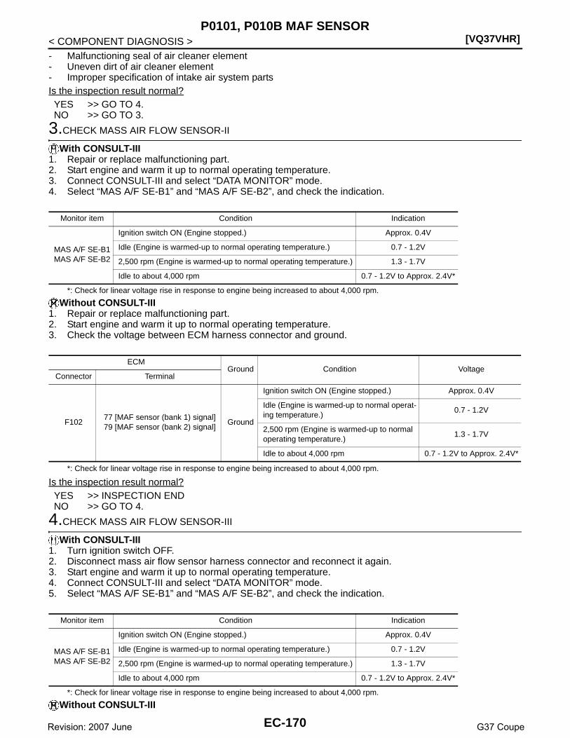
[VQ37VHR]P0101, P010B MAF SENSOR
< COMPONENT DIAGNOSIS >- Malfunctioning seal of air cleaner element- Uneven dirt of air cleaner element- Improper specification of intake air system partsIs the inspection result normal?YES >> GO TO 4.NO >> GO TO 3.
3.CHECK MASS AIR FLOW SENSOR-II
With CONSULT-III1. Repair or replace malfunctioning part.2. Start engine and warm it up to normal operating temperature.3. Connect CONSULT-III and select “DATA MONITOR” mode.4. Select “MAS A/F SE-B1” and “MAS A/F SE-B2”, and check the indication.
*: Check for linear voltage rise in response to engine being increased to about 4,000 rpm.
Without CONSULT-III1. Repair or replace malfunctioning part.2. Start engine and warm it up to normal operating temperature.3. Check the voltage between ECM harness connector and ground.
*: Check for linear voltage rise in response to engine being increased to about 4,000 rpm.
Is the inspection result normal?YES >> INSPECTION ENDNO >> GO TO 4.
4.CHECK MASS AIR FLOW SENSOR-III
With CONSULT-III1. Turn ignition switch OFF.2. Disconnect mass air flow sensor harness connector and reconnect it again.3. Start engine and warm it up to normal operating temperature.4. Connect CONSULT-III and select “DATA MONITOR” mode.5. Select “MAS A/F SE-B1” and “MAS A/F SE-B2”, and check the indication.
*: Check for linear voltage rise in response to engine being increased to about 4,000 rpm.
Without CONSULT-III
Monitor item Condition Indication
MAS A/F SE-B1MAS A/F SE-B2
Ignition switch ON (Engine stopped.) Approx. 0.4V
Idle (Engine is warmed-up to normal operating temperature.) 0.7 - 1.2V
2,500 rpm (Engine is warmed-up to normal operating temperature.) 1.3 - 1.7V
Idle to about 4,000 rpm 0.7 - 1.2V to Approx. 2.4V*
ECMGround Condition Voltage
Connector Terminal
F10277 [MAF sensor (bank 1) signal]79 [MAF sensor (bank 2) signal]
Ground
Ignition switch ON (Engine stopped.) Approx. 0.4V
Idle (Engine is warmed-up to normal operat-ing temperature.)
0.7 - 1.2V
2,500 rpm (Engine is warmed-up to normal operating temperature.)
1.3 - 1.7V
Idle to about 4,000 rpm 0.7 - 1.2V to Approx. 2.4V*
Monitor item Condition Indication
MAS A/F SE-B1MAS A/F SE-B2
Ignition switch ON (Engine stopped.) Approx. 0.4V
Idle (Engine is warmed-up to normal operating temperature.) 0.7 - 1.2V
2,500 rpm (Engine is warmed-up to normal operating temperature.) 1.3 - 1.7V
Idle to about 4,000 rpm 0.7 - 1.2V to Approx. 2.4V*
EC-170Revision: 2007 June G37 Coupe

P0101, P010B MAF SENSOR[VQ37VHR]
C
D
E
F
G
H
I
J
K
L
M
A
C
N
P
O
< COMPONENT DIAGNOSIS >
E
1. Turn ignition switch OFF.2. Disconnect mass air flow sensor harness connector and reconnect it again.3. Start engine and warm it up to normal operating temperature.4. Check the voltage between ECM harness connector and ground.
*: Check for linear voltage rise in response to engine being increased to about 4,000 rpm.
Is the inspection result normal?YES >> INSPECTION ENDNO >> Clean or replace malfunctioning mass air flow sensor.
ECMGround Condition Voltage
Connector Terminal
F10277 [MAF sensor (bank 1) signal]79 [MAF sensor (bank 2) signal]
Ground
Ignition switch ON (Engine stopped.) Approx. 0.4V
Idle (Engine is warmed-up to normal operat-ing temperature.)
0.7 - 1.2V
2,500 rpm (Engine is warmed-up to normal operating temperature.)
1.3 - 1.7V
Idle to about 4,000 rpm 0.7 - 1.2V to Approx. 2.4V*
EC-171Revision: 2007 June G37 Coupe

[VQ37VHR]P0102, P0103, P010C, P010D MAF SENSOR
< COMPONENT DIAGNOSIS >
P0102, P0103, P010C, P010D MAF SENSOR
Description INFOID:0000000001910824
The mass air flow sensor (1) is placed in the stream of intake air. Itmeasures the intake flow rate by measuring a part of the entireintake flow. The mass air flow sensor controls the temperature of thehot wire to a certain amount. The heat generated by the hot wire isreduced as the intake air flows around it. The more air, the greaterthe heat loss. Therefore, the electric current supplied to hot wire is changed tomaintain the temperature of the hot wire as air flow increases. TheECM detects the air flow by means of this current change.
DTC Logic INFOID:0000000001734005
DTC DETECTION LOGIC
DTC CONFIRMATION PROCEDURE
1.PRECONDITIONING
If DTC Confirmation Procedure has been previously conducted, always perform the following before conduct-ing the next test.1. Turn ignition switch OFF and wait at least 10 seconds.2. Turn ignition switch ON.3. Turn ignition switch OFF and wait at least 10 seconds.Which DTC is detected?P0102, P010C>>GO TO 2.P0103, P010D>>GO TO 3.
2.PERFORM DTC CONFIRMATION PROCEDURE FOR DTC P0102 AND P010C
1. Start engine and wait at least 5 seconds.2. Check DTC.Is DTC detected?YES >> Go to EC-173, "Diagnosis Procedure".NO >> INSPECTION END
3.PERFORM DTC CONFIRMATION PROCEDURE FOR DTC P0103 AND P010D-I
1. Turn ignition switch ON and wait at least 5 seconds.2. Check DTC.
PBIA9559J
DTC No.Trouble diagnosis
nameDTC detecting condition Possible cause
P0102Mass air flow sensor (bank 1) circuit low input
An excessively low voltage from the sensor is sent to ECM.
• Harness or connectors(The sensor circuit is open or shorted.)
• Intake air leaks• Mass air flow sensor
P0103Mass air flow sensor (bank 1) circuit high input
An excessively high voltage from the sensor is sent to ECM.
• Harness or connectors(The sensor circuit is open or shorted.)
• Mass air flow sensor
P010CMass air flow sensor (bank 2) circuit low input
An excessively low voltage from the sensor is sent to ECM.
• Harness or connectors(The sensor circuit is open or shorted.)
• Intake air leaks• Mass air flow sensor
P010DMass air flow sensor (bank 2) circuit high input
An excessively high voltage from the sensor is sent to ECM.
• Harness or connectors(The sensor circuit is open or shorted.)
• Mass air flow sensor
EC-172Revision: 2007 June G37 Coupe

P0102, P0103, P010C, P010D MAF SENSOR[VQ37VHR]
C
D
E
F
G
H
I
J
K
L
M
A
C
N
P
O
< COMPONENT DIAGNOSIS >
E
Is DTC detected?YES >> Go to EC-173, "Diagnosis Procedure".NO >> GO TO 4.
4.PERFORM DTC CONFIRMATION PROCEDURE FOR DTC P0103 AND P010D-II
1. Start engine and wait at least 5 seconds.2. Check DTC.Is DTC detected?YES >> Go to EC-173, "Diagnosis Procedure".NO >> INSPECTION END
Diagnosis Procedure INFOID:0000000001734006
1.INSPECTION START
Confirm the detected DTC.Which DTC is detected?P0102, P010C>>GO TO 2.P0103, P010D>>GO TO 3.
2.CHECK INTAKE SYSTEM
Check the following for connection.• Air duct• Vacuum hoses• Intake air passage between air duct to intake manifoldIs the inspection result normal?YES >> GO TO 3.NO >> Reconnect the parts.
3.CHECK GROUND CONNECTION
1. Turn ignition switch OFF.2. Check ground connection M95. Refer to Ground Inspection in GI-41, "Circuit Inspection".Is the inspection result normal?YES >> GO TO 4.NO >> Repair or replace ground connection.
4.CHECK MAF SENSOR POWER SUPPLY CIRCUIT
1. Disconnect mass air flow (MAF) sensor harness connector.2. Turn ignition switch ON.3. Check the voltage between MAF sensor harness connector and ground.
Is the inspection result normal?YES >> GO TO 6.NO >> GO TO 5.
5.DETECT MALFUNCTIONING PART
Check the following.• Harness connectors E106, M6• Harness connectors M116, F103• Harness for open or short between mass air flow sensor and ECM• Harness for open or short between mass air flow sensor and IPDM E/R
>> Repair open circuit or short to ground or short to power in harness or connectors.
DTCMAF sensor
Ground VoltageBank Connector Terminal
P0102, P0103 1 F31 5Ground Battery voltage
P010C, P010D 2 F42 5
EC-173Revision: 2007 June G37 Coupe

[VQ37VHR]P0102, P0103, P010C, P010D MAF SENSOR
< COMPONENT DIAGNOSIS >
6.CHECK MAF SENSOR GROUND CIRCUIT FOR OPEN AND SHORT
1. Turn ignition switch OFF.2. Disconnect ECM harness connector.3. Check the continuity between MAF sensor harness connector and ECM harness connector.
4. Also check harness for short to ground and short to power.Is the inspection result normal?YES >> GO TO 7.NO >> Repair open circuit or short to ground or short to power in harness or connectors.
7.CHECK MAF SENSOR INPUT SIGNAL CIRCUIT FOR OPEN AND SHORT
1. Check the continuity between MAF sensor harness connector and ECM harness connector.
2. Also check harness for short to ground and short to power.Is the inspection result normal?YES >> GO TO 8.NO >> Repair open circuit or short to ground or short to power in harness or connectors.
8.CHECK MASS AIR FLOW SENSOR
Refer to EC-169, "Component Inspection".Is the inspection result normal?YES >> GO TO 9.NO >> Replace malfunctioning mass air flow sensor.
9.CHECK INTERMITTENT INCIDENT
Refer to GI-38, "Intermittent Incident".
>> INSPECTION END
Component Inspection INFOID:0000000001910825
1.CHECK MASS AIR FLOW SENSOR-I
With CONSULT-III1. Turn ignition switch OFF.2. Reconnect all harness connectors disconnected.3. Start engine and warm it up to normal operating temperature.4. Connect CONSULT-III and select “DATA MONITOR” mode.5. Select “MAS A/F SE-B1” and “MAS A/F SE-B2”, and check the indication.
DTCMAF sensor ECM
ContinuityBank Connector Terminal Connector Terminal
P0102, P0103 1 F31 4F102
68Existed
P010C, P010D 2 F42 4 94
DTCMAF sensor ECM
ContinuityBank Connector Terminal Connector Terminal
P0102, P0103 1 F31 3F102
77Existed
P010C, P010D 2 F42 3 79
Monitor item Condition Indication
MAS A/F SE-B1MAS A/F SE-B2
Ignition switch ON (Engine stopped.) Approx. 0.4V
Idle (Engine is warmed-up to normal operating temperature.) 0.7 - 1.2V
2,500 rpm (Engine is warmed-up to normal operating temperature.) 1.3 - 1.7V
Idle to about 4,000 rpm 0.7 - 1.2V to Approx. 2.4V*
EC-174Revision: 2007 June G37 Coupe

P0102, P0103, P010C, P010D MAF SENSOR[VQ37VHR]
C
D
E
F
G
H
I
J
K
L
M
A
C
N
P
O
< COMPONENT DIAGNOSIS >
E
*: Check for linear voltage rise in response to engine being increased to about 4,000 rpm.
Without CONSULT-III1. Turn ignition switch OFF.2. Reconnect all harness connectors disconnected.3. Start engine and warm it up to normal operating temperature.4. Check the voltage between ECM harness connector and ground.
*: Check for linear voltage rise in response to engine being increased to about 4,000 rpm.
Is the inspection result normal?YES >> GO TO 4.NO >> GO TO 2.
2.CHECK FOR THE CAUSE OF UNEVEN AIR FLOW THROUGH MASS AIR FLOW SENSOR
1. Turn ignition switch OFF.2. Check for the cause of uneven air flow through mass air flow sensor. Refer to following.- Crushed air ducts- Malfunctioning seal of air cleaner element- Uneven dirt of air cleaner element- Improper specification of intake air system partsIs the inspection result normal?YES >> GO TO 4.NO >> GO TO 3.
3.CHECK MASS AIR FLOW SENSOR-II
With CONSULT-III1. Repair or replace malfunctioning part.2. Start engine and warm it up to normal operating temperature.3. Connect CONSULT-III and select “DATA MONITOR” mode.4. Select “MAS A/F SE-B1” and “MAS A/F SE-B2”, and check the indication.
*: Check for linear voltage rise in response to engine being increased to about 4,000 rpm.
Without CONSULT-III1. Repair or replace malfunctioning part.2. Start engine and warm it up to normal operating temperature.3. Check the voltage between ECM harness connector and ground.
ECMGround Condition Voltage
Connector Terminal
F10277 [MAF sensor (bank 1) signal]79 [MAF sensor (bank 2) signal]
Ground
Ignition switch ON (Engine stopped.) Approx. 0.4V
Idle (Engine is warmed-up to normal operat-ing temperature.)
0.7 - 1.2V
2,500 rpm (Engine is warmed-up to normal operating temperature.)
1.3 - 1.7V
Idle to about 4,000 rpm 0.7 - 1.2V to Approx. 2.4V*
Monitor item Condition Indication
MAS A/F SE-B1MAS A/F SE-B2
Ignition switch ON (Engine stopped.) Approx. 0.4V
Idle (Engine is warmed-up to normal operating temperature.) 0.7 - 1.2V
2,500 rpm (Engine is warmed-up to normal operating temperature.) 1.3 - 1.7V
Idle to about 4,000 rpm 0.7 - 1.2V to Approx. 2.4V*
EC-175Revision: 2007 June G37 Coupe

[VQ37VHR]P0102, P0103, P010C, P010D MAF SENSOR
< COMPONENT DIAGNOSIS >
*: Check for linear voltage rise in response to engine being increased to about 4,000 rpm.
Is the inspection result normal?YES >> INSPECTION ENDNO >> GO TO 4.
4.CHECK MASS AIR FLOW SENSOR-III
With CONSULT-III1. Turn ignition switch OFF.2. Disconnect mass air flow sensor harness connector and reconnect it again.3. Start engine and warm it up to normal operating temperature.4. Connect CONSULT-III and select “DATA MONITOR” mode.5. Select “MAS A/F SE-B1” and “MAS A/F SE-B2”, and check the indication.
*: Check for linear voltage rise in response to engine being increased to about 4,000 rpm.
Without CONSULT-III1. Turn ignition switch OFF.2. Disconnect mass air flow sensor harness connector and reconnect it again.3. Start engine and warm it up to normal operating temperature.4. Check the voltage between ECM harness connector and ground.
*: Check for linear voltage rise in response to engine being increased to about 4,000 rpm.
Is the inspection result normal?YES >> INSPECTION ENDNO >> Clean or replace malfunctioning mass air flow sensor.
ECMGround Condition Voltage
Connector Terminal
F10277 [MAF sensor (bank 1) signal]79 [MAF sensor (bank 2) signal]
Ground
Ignition switch ON (Engine stopped.) Approx. 0.4V
Idle (Engine is warmed-up to normal operat-ing temperature.)
0.7 - 1.2V
2,500 rpm (Engine is warmed-up to normal operating temperature.)
1.3 - 1.7V
Idle to about 4,000 rpm 0.7 - 1.2V to Approx. 2.4V*
Monitor item Condition Indication
MAS A/F SE-B1MAS A/F SE-B2
Ignition switch ON (Engine stopped.) Approx. 0.4V
Idle (Engine is warmed-up to normal operating temperature.) 0.7 - 1.2V
2,500 rpm (Engine is warmed-up to normal operating temperature.) 1.3 - 1.7V
Idle to about 4,000 rpm 0.7 - 1.2V to Approx. 2.4V*
ECMGround Condition Voltage
Connector Terminal
F10277 [MAF sensor (bank 1) signal]79 [MAF sensor (bank 2) signal]
Ground
Ignition switch ON (Engine stopped.) Approx. 0.4V
Idle (Engine is warmed-up to normal operat-ing temperature.)
0.7 - 1.2V
2,500 rpm (Engine is warmed-up to normal operating temperature.)
1.3 - 1.7V
Idle to about 4,000 rpm 0.7 - 1.2V to Approx. 2.4V*
EC-176Revision: 2007 June G37 Coupe

P010A MANIFOLD ABSOLUTE PRESSURE SENSOR[VQ37VHR]
C
D
E
F
G
H
I
J
K
L
M
A
C
N
P
O
< COMPONENT DIAGNOSIS >
E
P010A MANIFOLD ABSOLUTE PRESSURE SENSOR
Description INFOID:0000000001736745
The manifold absolute pressure (MAP) sensor is placed at intakemanifold collector. It detects intake manifold pressure and sends thevoltage signal to the ECM.The sensor uses a silicon diaphragm which is sensitive to thechange in pressure. As the pressure increases, the voltage rises.
DTC Logic INFOID:0000000001736746
DTC DETECTION LOGICNOTE:If DTC P010A is displayed with DTC P0643, first perform the trouble diagnosis for DTC P0643. Refer to EC-358, "DTC Logic".
DTC CONFIRMATION PROCEDURE
1.PRECONDITIONING
If DTC Confirmation Procedure has been previously conducted, always perform the following before conduct-ing the next test.1. Turn ignition switch OFF and wait at least 10 seconds.2. Turn ignition switch ON.3. Turn ignition switch OFF and wait at least 10 seconds.
>> GO TO 2.
2.PERFORM DTC CONFIRMATION PROCEDURE
1. Start engine and let it idle for 10 seconds.2. Check DTC.Is DTC detected?YES >> Go to EC-177, "Diagnosis Procedure".NO >> INSPECTION END
Diagnosis Procedure INFOID:0000000001736747
1.CHECK GROUND CONNECTION
1. Turn ignition switch OFF.2. Check ground connection M95. Refer to Ground Inspection in GI-41, "Circuit Inspection".Is the inspection result normal?YES >> GO TO 2.NO >> Repair or replace ground connection.
2.CHECK MAP SENSOR POWER SUPPLY CIRCUIT
1. Disconnect MAP sensor harness connector.
JMBIA0877ZZ
DTC No. Trouble diagnosis name DTC detecting condition Possible cause
P010AManifold absolute pressure sensor circuit
• An excessively low voltage from the sensor is sent to ECM.
• An excessively high voltage from the sensor is sent to ECM.
• Harness or connectors(The sensor circuit is open or shorted.)
• Manifold absolute pressure (MAP) sensor
EC-177Revision: 2007 June G37 Coupe

[VQ37VHR]P010A MANIFOLD ABSOLUTE PRESSURE SENSOR
< COMPONENT DIAGNOSIS >2. Turn ignition switch ON.3. Check the voltage between MAP sensor harness connector and ground.
Is the inspection result normal?YES >> GO TO 3.NO >> Repair open circuit or short to ground or short to power in harness or connectors.
3.CHECK MAP SENSOR GROUND CIRCUIT FOR OPEN AND SHORT
1. Turn ignition switch OFF.2. Disconnect ECM harness connector.3. Check the continuity between MAP sensor harness connector and ECM harness connector.
4. Also check harness for short to ground and power.Is the inspection result normal?YES >> GO TO 4.NO >> Repair open circuit or short to ground or short to power in harness or connectors.
4.CHECK MAP SENSOR INTPUT SIGNAL CIRCUIT FOR OPEN AND SHORT
1. Check the continuity between MAP sensor harness connector and ECM harness connector.
2. Also check harness for short to ground and power.Is the inspection result normal?YES >> GO TO 5.NO >> Repair open circuit or short to ground or short to power in harness or connectors.
5.CHECK MAP SENSOR
Refer to EC-178, "Component Inspection".Is the inspection result normal?YES >> GO TO 6.NO >> Replace MAP sensor.
6.CHECK INTERMITTENT INCIDENT
Refer to GI-38, "Intermittent Incident".
>> INSPECTION END
Component Inspection INFOID:0000000001736748
1.CHECK MAP SENSOR-I
1. Turn ignition switch OFF.2. Start engine and warm it up to normal operating temperature.3. Turn ignition switch OFF, wait at least 5 seconds and then turn ON.4. Check the voltage between ECM harness connector terminals as follows.
MAP sensorGround Voltage
Connector Terminal
F50 1 Ground Approx. 5V
MAP sensor ECMContinuity
Connector Terminal Connector Terminal
F50 3 F102 96 Existed
MAP sensor ECMContinuity
Connector Terminal Connector Terminal
F50 2 F101 38 Existed
EC-178Revision: 2007 June G37 Coupe

P010A MANIFOLD ABSOLUTE PRESSURE SENSOR[VQ37VHR]
C
D
E
F
G
H
I
J
K
L
M
A
C
N
P
O
< COMPONENT DIAGNOSIS >
E
NOTE:• To avoid the influence of intake manifold vacuum, check the voltage 1 or more minutes past after engine
is stopped.• Because the sensor is absolute pressure sensor, output value may differ depending on atmospheric
pressure and altitude.5. Measure the atmospheric pressure.
NOTE:As the atmospheric pressure described on the synoptic chart is the value at sea level, compensate thepressure with the following chart.
6. Check the manifold absolute pressure sensor value corresponding to the atmospheric pressure.
Is the inspection result normal?YES >> GO TO 2.NO >> Replace MAP sensor.
2.CHECK MAP SENSOR-II
1. Start engine and let it idle.2. Check intake manifold vacuum.3. Check the voltage between ECM harness connector terminals as follows.
4. Confirm the difference of the voltage when engine is stopped and at idling is within the values shown inthe following chart.
ECM
+ –
Connector Terminal Connector Terminal
F101 38 F102 96
Altitude Compensated pressure
0m 0hPa
200m -24hPa
400m -47hPa
600m -70hPa
800m -92hPa
1000m -114hPa
1500m -168hPa
2000m -218hPa
Atmospheric pressure Voltage
800hPa 3.1 – 3.7V
850hPa 3.3 – 3.9V
900hPa 3.5 – 4.1V
950hPa 3.8 – 4.3V
1000hPa 4.0 – 4.6V
1050hPa 4.2 – 4.8V
JMBIA0870GB
ECM
+ –
Connector Terminal Connector Terminal
F101 38 F102 96
EC-179Revision: 2007 June G37 Coupe

[VQ37VHR]P010A MANIFOLD ABSOLUTE PRESSURE SENSOR
< COMPONENT DIAGNOSIS >
Is the inspection result normal?YES >> INSPECTION ENDNO >> Replace MAP sensor.
Intake manifold vacuum Voltage difference
-40kPa(-300mmHg) 1.5 – 2.0V
-53.3kPa(-400mmHg) 2.0 – 2.6V
-66.7kPa(-500mmHg) 2.6 – 3.2V
-80kPa(-600mmHg) 3.2 – 3.8V
EC-180Revision: 2007 June G37 Coupe

P0112, P0113 IAT SENSOR[VQ37VHR]
C
D
E
F
G
H
I
J
K
L
M
A
C
N
P
O
< COMPONENT DIAGNOSIS >
E
P0112, P0113 IAT SENSOR
Description INFOID:0000000001734008
The intake air temperature sensor is built-into mass air flow sensor(1). The sensor detects intake air temperature and transmits a signalto the ECM.The temperature sensing unit uses a thermistor which is sensitive tothe change in temperature. Electrical resistance of the thermistordecreases in response to the temperature rise.NOTE:ECM uses only the intake air temperature sensor (bank 1) for enginecontrol and self-diagnosis. It does not use the intake air temperaturesensor (bank 2).
<Reference data>
*: These data are reference values and are measured between ECM terminal 67(Intake air temperature sensor) and ground.
CAUTION:
Do not use ECM ground terminals when measuring input/output voltage. Doingso may result in damage to the ECM’s transistor. Use a ground other than ECMterminals, such as the ground.
DTC Logic INFOID:0000000001734009
DTC DETECTION LOGIC
DTC CONFIRMATION PROCEDURE
1.PRECONDITIONING
If DTC Confirmation Procedure has been previously conducted, always perform the following before conduct-ing the next test.1. Turn ignition switch OFF and wait at least 10 seconds.2. Turn ignition switch ON.3. Turn ignition switch OFF and wait at least 10 seconds.
>> GO TO 2.
2.PERFORM DTC CONFIRMATION PROCEDURE
1. Turn ignition switch ON and wait at least 5 seconds.2. Check 1st trip DTC.Is 1st trip DTC detected?YES >> Go to EC-182, "Diagnosis Procedure".NO >> INSPECTION END
PBIA9559J
Intake air temperature°C (°F)
Voltage* V Resistance kΩ
25 (77) 3.3 1.800 - 2.200
80 (176) 1.2 0.283 - 0.359
SEF012P
DTC No. Trouble diagnosis name DTC detecting condition Possible cause
P0112Intake air temperature sensor (bank 1) circuit low input
An excessively low voltage from the sensor is sent to ECM.
• Harness or connectors(The sensor circuit is open or short-ed.)
• Intake air temperature sensorP0113Intake air temperature sensor (bank 1) circuit high input
An excessively high voltage from the sensor is sent to ECM.
EC-181Revision: 2007 June G37 Coupe

[VQ37VHR]P0112, P0113 IAT SENSOR
< COMPONENT DIAGNOSIS >
Diagnosis Procedure INFOID:0000000001734010
1.CHECK GROUND CONNECTION
1. Turn ignition switch OFF.2. Check ground connection M95. Refer to Ground Inspection in GI-41, "Circuit Inspection".Is the inspection result normal?YES >> GO TO 2.NO >> Repair or replace ground connection.
2.CHECK INTAKE AIR TEMPERATURE SENSOR POWER SUPPLY CIRCUIT
1. Disconnect mass air flow sensor (intake air temperature sensor is built-into) (bank 1) harness connector.2. Turn ignition switch ON.3. Check the voltage between mass air flow sensor (bank 1) harness connector and ground.
Is the inspection result normal?YES >> GO TO 3.NO >> Repair open circuit or short to ground or short to power in harness or connectors.
3.CHECK INTAKE AIR TEMPERATURE SENSOR GROUND CIRCUIT FOR OPEN AND SHORT
1. Turn ignition switch OFF.2. Disconnect ECM harness connector.3. Check the continuity between mass air flow sensor (bank 1) harness connector and ECM harness con-
nector.
4. Also check harness for short to ground and short to power.Is the inspection result normal?YES >> GO TO 4.NO >> Repair open circuit or short to ground or short to power in harness or connectors.
4.CHECK INTAKE AIR TEMPERATURE SENSOR
Refer to EC-182, "Component Inspection".Is the inspection result normal?YES >> GO TO 5.NO >> Replace mass air flow sensor (with intake air temperature sensor) (bank 1).
5.CHECK INTERMITTENT INCIDENT
Refer to GI-38, "Intermittent Incident".
>> INSPECTION END
Component Inspection INFOID:0000000001734011
1.CHECK INTAKE AIR TEMPERATURE SENSOR
1. Turn ignition switch OFF.2. Disconnect mass air flow sensor (bank 1) harness connector.3. Check resistance between mass air flow sensor (bank 1) terminals as follows.
MAF sensor (bank 1)Ground Voltage
Connector Terminal
F31 2 Ground Approx. 5
MAF sensor (bank 1) ECMContinuity
Connector Terminal Connector Terminal
F31 1 F102 68 Existed
EC-182Revision: 2007 June G37 Coupe

P0112, P0113 IAT SENSOR[VQ37VHR]
C
D
E
F
G
H
I
J
K
L
M
A
C
N
P
O
< COMPONENT DIAGNOSIS >
EIs the inspection result normal?YES >> INSPECTION ENDNO >> Replace mass air flow sensor (with intake air temperature sensor) (bank 1).
Terminals Condition Resistance
1 and 2 Temperature °C (°F) 25 (77) 1.800 - 2.200 kΩ
EC-183Revision: 2007 June G37 Coupe

[VQ37VHR]P0117, P0118 ECT SENSOR
< COMPONENT DIAGNOSIS >
P0117, P0118 ECT SENSOR
Description INFOID:0000000001734012
The engine coolant temperature sensor is used to detect the enginecoolant temperature. The sensor modifies a voltage signal from theECM. The modified signal returns to the ECM as the engine coolanttemperature input. The sensor uses a thermistor which is sensitive tothe change in temperature. The electrical resistance of the ther-mistor decreases as temperature increases.
<Reference data>
*: These data are reference values and are measured between ECM terminal 71(Engine coolant temperature sensor) and ground.
CAUTION:
Do not use ECM ground terminals when measuring input/output voltage. Doing so may result in damage to the ECM’s transis-tor. Use a ground other than ECM terminals, such as the ground.
DTC Logic INFOID:0000000001734013
DTC DETECTION LOGIC
DTC CONFIRMATION PROCEDURE
1.PRECONDITIONING
If DTC Confirmation Procedure has been previously conducted, always perform the following before conduct-ing the next test.1. Turn ignition switch OFF and wait at least 10 seconds.2. Turn ignition switch ON.3. Turn ignition switch OFF and wait at least 10 seconds.
>> GO TO 2.
2.PERFORM DTC CONFIRMATION PROCEDURE
1. Turn ignition switch ON and wait at least 5 seconds.2. Check DTC.
SEF594K
Engine coolant temperature°C (°F)
Voltage* V Resistance kΩ
–10 (14) 4.4 7.0 - 11.4
20 (68) 3.5 2.37 - 2.63
50 (122) 2.2 0.68 - 1.00
90 (194) 0.9 0.236 - 0.260
SEF012P
DTC No.Trouble Diagnosis
NameDTC Detecting Condition Possible Cause
P0117Engine coolant tem-perature sensor cir-cuit low input
An excessively low voltage from the sensor is sent to ECM. • Harness or connectors
(The sensor circuit is open or shorted.)• Engine coolant temperature sensor
P0118Engine coolant tem-perature sensor cir-cuit high input
An excessively high voltage from the sensor is sent to ECM.
EC-184Revision: 2007 June G37 Coupe

P0117, P0118 ECT SENSOR[VQ37VHR]
C
D
E
F
G
H
I
J
K
L
M
A
C
N
P
O
< COMPONENT DIAGNOSIS >
E
Is DTC detected?YES >> Go to EC-185, "Diagnosis Procedure".NO >> INSPECTION END
Diagnosis Procedure INFOID:0000000001734014
1.CHECK GROUND CONNECTION
1. Turn ignition switch OFF.2. Check ground connection M95. Refer to Ground Inspection in GI-41, "Circuit Inspection".Is the inspection result normal?YES >> GO TO 2.NO >> Repair or replace ground connection.
2.CHECK ECT SENSOR POWER SUPPLY CIRCUIT
1. Disconnect engine coolant temperature (ECT) sensor harness connector.2. Turn ignition switch ON.3. Check the voltage between ECT sensor harness connector and ground.
Is the inspection result normal?YES >> GO TO 4.NO >> GO TO 3.
3.DETECT MALFUNCTIONING PART
Check the following.• Harness connectors F106, F107• Harness for open or short between engine coolant temperature sensor and ECM
>> Repair open circuit or short to ground or short to power in harness or connectors.
4.CHECK ECT SENSOR GROUND CIRCUIT FOR OPEN AND SHORT
1. Turn ignition switch OFF.2. Disconnect ECM harness connector.3. Check the continuity between ECT sensor harness connector and ECM harness connector.
4. Also check harness for short to ground and short to power.Is the inspection result normal?YES >> GO TO 5.NO >> Repair open circuit or short to ground or short to power in harness or connectors.
5.CHECK ENGINE COOLANT TEMPERATURE SENSOR
Refer to EC-186, "Component Inspection".Is the inspection result normal?YES >> GO TO 6.NO >> Replace engine coolant temperature sensor.
6.CHECK INTERMITTENT INCIDENT
Refer to GI-38, "Intermittent Incident".
>> INSPECTION END
ECT sensorGround Voltage
Connector Terminal
F17 1 Ground Approx. 5V
ECT sensor ECMContinuity
Connector Terminal Connector Terminal
F17 2 F102 84 Existed
EC-185Revision: 2007 June G37 Coupe

[VQ37VHR]P0117, P0118 ECT SENSOR
< COMPONENT DIAGNOSIS >
Component Inspection INFOID:0000000001734015
1.CHECK ENGINE COOLANT TEMPERATURE SENSOR
1. Turn ignition switch OFF.2. Disconnect engine coolant temperature sensor harness connector.3. Remove engine coolant temperature sensor.4. Check resistance between engine coolant temperature sensor
terminals by heating with hot water as shown in the figure.
Is the inspection result normal?YES >> INSPECTION ENDNO >> Replace engine coolant temperature sensor.
Terminals Condition Resistance
1 and 2 Temperature °C (°F)
20 (68) 2.37 - 2.63 kΩ
50 (122) 0.68 - 1.00 kΩ
90 (194) 0.236 - 0.260 kΩ
JMBIA0080ZZ
EC-186Revision: 2007 June G37 Coupe

P0122, P0123, P0227, P0228 TP SENSOR[VQ37VHR]
C
D
E
F
G
H
I
J
K
L
M
A
C
N
P
O
< COMPONENT DIAGNOSIS >
E
P0122, P0123, P0227, P0228 TP SENSOR
Description INFOID:0000000001734016
Electric throttle control actuator consists of throttle control motor,throttle position sensor, etc. The throttle position sensor responds tothe throttle valve movement. The throttle position sensor has two sensors. These sensors are akind of potentiometers which transform the throttle valve position intooutput voltage, and emit the voltage signal to the ECM. In addition,these sensors detect the opening and closing speed of the throttlevalve and feed the voltage signals to the ECM. The ECM judges thecurrent opening angle of the throttle valve from these signals and theECM controls the throttle control motor to make the throttle valveopening angle properly in response to driving condition.
DTC Logic INFOID:0000000001734017
DTC DETECTION LOGICNOTE:If DTC P0122, P0123, P0227 or P0228 is displayed with DTC P0643, first perform the trouble diagnosisfor DTC P0643. Refer to EC-358, "DTC Logic".
DTC CONFIRMATION PROCEDURE
1.PRECONDITIONING
If DTC Confirmation Procedure has been previously conducted, always perform the following before conduct-ing the next test.1. Turn ignition switch OFF and wait at least 10 seconds.2. Turn ignition switch ON.3. Turn ignition switch OFF and wait at least 10 seconds.TESTING CONDITION:Before performing the following procedure, confirm that battery voltage is more than 10V at idle.
>> GO TO 2.
2.PERFORM DTC CONFIRMATION PROCEDURE
1. Start engine and let it idle for 1 second.2. Check DTC.Is DTC detected?YES >> Go to EC-188, "Diagnosis Procedure".NO >> INSPECTION END
PBIB0145E
DTC No. Trouble diagnosis name DTC detecting condition Possible cause
P0122Throttle position sensor 2 (bank 1) circuit low in-put
An excessively low voltage from the TP sensor 2 is sent to ECM.
• Harness or connectors(TP sensor 2 circuit is open or shorted.)
• Electric throttle control actuator(TP sensor 2)
P0123Throttle position sensor 2 (bank 1) circuit high in-put
An excessively high voltage from the TP sensor 2 is sent to ECM.
P0227Throttle position sensor 2 (bank 2) circuit low in-put
An excessively low voltage from the TP sensor 2 is sent to ECM.
P0228Throttle position sensor 2 (bank 2) circuit high in-put
An excessively high voltage from the TP sensor 2 is sent to ECM.
EC-187Revision: 2007 June G37 Coupe

[VQ37VHR]P0122, P0123, P0227, P0228 TP SENSOR
< COMPONENT DIAGNOSIS >
Diagnosis Procedure INFOID:0000000001734018
1.CHECK GROUND CONNECTION
1. Turn ignition switch OFF.2. Check ground connection M95. Refer to Ground Inspection in GI-41, "Circuit Inspection".Is the inspection result normal?YES >> GO TO 2.NO >> Repair or replace ground connection.
2.CHECK THROTTLE POSITION SENSOR 2 POWER SUPPLY CIRCUIT
1. Disconnect electric throttle control actuator harness connector.2. Turn ignition switch ON.3. Check the voltage between electric throttle control actuator harness connector and ground.
Is the inspection result normal?YES >> GO TO 3.NO >> Repair open circuit or short to ground or short to power in harness or connectors.
3.CHECK THROTTLE POSITION SENSOR 2 GROUND CIRCUIT FOR OPEN AND SHORT
1. Turn ignition switch OFF.2. Disconnect ECM harness connector.3. Check the continuity between electric throttle control actuator harness connector and ECM harness con-
nector.
4. Also check harness for short to ground and short to power.Is the inspection result normal?YES >> GO TO 4.NO >> Repair open circuit or short to ground or short to power in harness or connectors.
4.CHECK THROTTLE POSITION SENSOR 2 INPUT SIGNAL CIRCUIT FOR OPEN AND SHORT
1. Check the continuity between electric throttle control actuator harness connector and ECM harness con-nector.
2. Also check harness for short to ground and short to power.Is the inspection result normal?YES >> GO TO 5.NO >> Repair open circuit or short to ground or short to power in harness or connectors.
5.CHECK THROTTLE POSITION SENSOR
Refer to EC-189, "Component Inspection".
DTCElectric throttle control actuator
Ground VoltageBank Connector Terminal
P0122, P0123 1 F6 6Ground Approx. 5V
P0227, P0228 2 F27 1
DTCElectric throttle control actuator ECM
ContinuityBank Connector Terminal Connector Terminal
P0122, P0123 1 F6 3F101
40Existed
P0227, P0228 2 F27 4 48
DTCElectric throttle control actuator ECM
ContinuityBank Connector Terminal Connector Terminal
P0122, P0123 1 F6 5F101
34Existed
P0227, P0228 2 F27 3 35
EC-188Revision: 2007 June G37 Coupe

P0122, P0123, P0227, P0228 TP SENSOR[VQ37VHR]
C
D
E
F
G
H
I
J
K
L
M
A
C
N
P
O
< COMPONENT DIAGNOSIS >
E
Is the inspection result normal?YES >> GO TO 7.NO >> GO TO 6.
6.REPLACE ELECTRIC THROTTLE CONTROL ACTUATOR
1. Replace malfunctioning electric throttle control actuator.2. Go to EC-189, "Special Repair Requirement".
>> INSPECTION END
7.CHECK INTERMITTENT INCIDENT
Refer to GI-38, "Intermittent Incident".
>> INSPECTION END
Component Inspection INFOID:0000000001734019
1.CHECK THROTTLE POSITION SENSOR
1. Turn ignition switch OFF.2. Reconnect all harness connectors disconnected.3. Perform EC-18, "THROTTLE VALVE CLOSED POSITION LEARNING : Special Repair Requirement".4. Turn ignition switch ON.5. Set selector lever to D (A/T) or 1st (M/T) position. 6. Check the voltage between ECM harness connector and ground.
Is the inspection result normal?YES >> INSPECTION ENDNO >> GO TO 2.
2.REPLACE ELECTRIC THROTTLE CONTROL ACTUATOR
1. Replace malfunctioning electric throttle control actuator.2. Go to EC-189, "Special Repair Requirement".
>> INSPECTION END
Special Repair Requirement INFOID:0000000001734020
1.PERFORM THROTTLE VALVE CLOSED POSITION LEARNING
Refer to EC-18, "THROTTLE VALVE CLOSED POSITION LEARNING : Special Repair Requirement"
>> GO TO 2.
2.PERFORM IDLE AIR VOLUME LEARNING
Refer to EC-19, "IDLE AIR VOLUME LEARNING : Special Repair Requirement"
>> END
ECMGround Condition Voltage
Connector Terminal
F101
30 [TP sensor 1 (bank 1)]31 [TP sensor 1 (bank 2)]
Ground Accelerator pedal
Fully released More than 0.36V
Fully depressed Less than 4.75V
34 [TP sensor 2 (bank 1)]35 [TP sensor 2 (bank 2)]
Fully released Less than 4.75V
Fully depressed More than 0.36V
EC-189Revision: 2007 June G37 Coupe
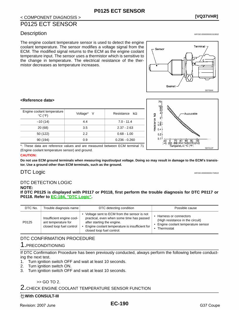
[VQ37VHR]P0125 ECT SENSOR
< COMPONENT DIAGNOSIS >
P0125 ECT SENSOR
Description INFOID:0000000001910832
The engine coolant temperature sensor is used to detect the enginecoolant temperature. The sensor modifies a voltage signal from theECM. The modified signal returns to the ECM as the engine coolanttemperature input. The sensor uses a thermistor which is sensitive tothe change in temperature. The electrical resistance of the ther-mistor decreases as temperature increases.
<Reference data>
*: These data are reference values and are measured between ECM terminal 71(Engine coolant temperature sensor) and ground.
CAUTION:
Do not use ECM ground terminals when measuring input/output voltage. Doing so may result in damage to the ECM’s transis-tor. Use a ground other than ECM terminals, such as the ground.
DTC Logic INFOID:0000000001734022
DTC DETECTION LOGICNOTE:If DTC P0125 is displayed with P0117 or P0118, first perform the trouble diagnosis for DTC P0117 orP0118. Refer to EC-184, "DTC Logic".
DTC CONFIRMATION PROCEDURE
1.PRECONDITIONING
If DTC Confirmation Procedure has been previously conducted, always perform the following before conduct-ing the next test.1. Turn ignition switch OFF and wait at least 10 seconds.2. Turn ignition switch ON.3. Turn ignition switch OFF and wait at least 10 seconds.
>> GO TO 2.
2.CHECK ENGINE COOLANT TEMPERATURE SENSOR FUNCTION
With CONSULT-III
SEF594K
Engine coolant temperature°C (°F)
Voltage* V Resistance kΩ
–10 (14) 4.4 7.0 - 11.4
20 (68) 3.5 2.37 - 2.63
50 (122) 2.2 0.68 - 1.00
90 (194) 0.9 0.236 - 0.260
SEF012P
DTC No. Trouble diagnosis name DTC detecting condition Possible cause
P0125Insufficient engine cool-ant temperature for closed loop fuel control
• Voltage sent to ECM from the sensor is not practical, even when some time has passed after starting the engine.
• Engine coolant temperature is insufficient for closed loop fuel control.
• Harness or connectors(High resistance in the circuit)
• Engine coolant temperature sensor• Thermostat
EC-190Revision: 2007 June G37 Coupe

P0125 ECT SENSOR[VQ37VHR]
C
D
E
F
G
H
I
J
K
L
M
A
C
N
P
O
< COMPONENT DIAGNOSIS >
E
1. Turn ignition switch ON.2. Select “DATA MONITOR” mode with CONSULT-III.3. Check that “COOLAN TEMP/S” is above 10°C (50°F).
With GSTFollow the procedure “With CONSULT-III” above.Is it above 10°C (50°F)?YES >> INSPECTION ENDNO >> GO TO 3.
3.PERFORM DTC CONFIRMATION PROCEDURE
With CONSULT-III1. Start engine and run it for 65 minutes at idle speed.
If “COOLAN TEMP/S” increases to more than 10°C (50°F) within 65 minutes, stop engine becausethe test result will be OK.CAUTION:Be careful not to overheat engine.
2. Check 1st trip DTC.With GST
Follow the procedure “With CONSULT-III” above.Is 1st trip DTC detected?YES >> EC-191, "Diagnosis Procedure"NO >> INSPECTION END
Diagnosis Procedure INFOID:0000000001734023
1.CHECK GROUND CONNECTION
1. Turn ignition switch OFF.2. Check ground connection M95. Refer to Ground Inspection in GI-41, "Circuit Inspection".Is the inspection result normal?YES >> GO TO 2.NO >> Repair or replace ground connection.
2.CHECK ENGINE COOLANT TEMPERATURE SENSOR
Refer to EC-191, "Component Inspection".Is the inspection result normal?YES >> GO TO 3.NO >> Replace engine coolant temperature sensor.
3.CHECK THERMOSTAT OPERATION
When the engine is cold [lower than 70°C (158°F)] condition, grasp lower radiator hose and confirm the enginecoolant does not flow.Is the inspection result normal?YES >> GO TO 4.NO >> Repair or replace thermostat. Refer to CO-22, "Removal and Installation".
4.CHECK INTERMITTENT INCIDENT
Refer to GI-38, "Intermittent Incident".
>> INSPECTION END
Component Inspection INFOID:0000000001910833
1.CHECK ENGINE COOLANT TEMPERATURE SENSOR
1. Turn ignition switch OFF.2. Disconnect engine coolant temperature sensor harness connector.3. Remove engine coolant temperature sensor.
EC-191Revision: 2007 June G37 Coupe

[VQ37VHR]P0125 ECT SENSOR
< COMPONENT DIAGNOSIS >4. Check resistance between engine coolant temperature sensor
terminals by heating with hot water as shown in the figure.
Is the inspection result normal?YES >> INSPECTION ENDNO >> Replace engine coolant temperature sensor.
Terminals Condition Resistance
1 and 2 Temperature °C (°F)
20 (68) 2.37 - 2.63 kΩ
50 (122) 0.68 - 1.00 kΩ
90 (194) 0.236 - 0.260 kΩ
JMBIA0080ZZ
EC-192Revision: 2007 June G37 Coupe

P0127 IAT SENSOR[VQ37VHR]
C
D
E
F
G
H
I
J
K
L
M
A
C
N
P
O
< COMPONENT DIAGNOSIS >
E
P0127 IAT SENSOR
Description INFOID:0000000001910830
The intake air temperature sensor is built-into mass air flow sensor(1). The sensor detects intake air temperature and transmits a signalto the ECM.The temperature sensing unit uses a thermistor which is sensitive tothe change in temperature. Electrical resistance of the thermistordecreases in response to the temperature rise.NOTE:ECM uses only the intake air temperature sensor (bank 1) for enginecontrol and self-diagnosis. It does not use the intake air temperaturesensor (bank 2).
<Reference data>
*: These data are reference values and are measured between ECM terminal 67(Intake air temperature sensor) and ground.
CAUTION:
Do not use ECM ground terminals when measuring input/output voltage. Doingso may result in damage to the ECM’s transistor. Use a ground other than ECMterminals, such as the ground.
DTC Logic INFOID:0000000001734026
DTC DETECTION LOGIC
DTC CONFIRMATION PROCEDURE
1.PRECONDITIONING
If DTC Confirmation Procedure has been previously conducted, always perform the following before conduct-ing the next test.1. Turn ignition switch OFF and wait at least 10 seconds.2. Turn ignition switch ON.3. Turn ignition switch OFF and wait at least 10 seconds.TESTING CONDITION:This test may be conducted with the drive wheels lifted in the shop or by driving the vehicle. If a roadtest is expected to be easier, it is unnecessary to lift the vehicle.
>> GO TO 2.
2.PERFORM DTC CONFIRMATION PROCEDURE
With CONSULT-III1. Wait until engine coolant temperature is less than 90°C (194°F)- Turn ignition switch ON.- Select “DATA MONITOR” mode with CONSULT-III.
PBIA9559J
Intake air temperature°C (°F)
Voltage* V Resistance kΩ
25 (77) 3.3 1.800 - 2.200
80 (176) 1.2 0.283 - 0.359
SEF012P
DTC No. Trouble diagnosis name DTC detecting condition Possible cause
P0127Intake air temperature too high
Rationally incorrect voltage from the sensor is sent to ECM, compared with the voltage signal from engine coolant temperature sensor.
• Harness or connectors(The sensor circuit is open or shorted)
• Intake air temperature sensor
EC-193Revision: 2007 June G37 Coupe

[VQ37VHR]P0127 IAT SENSOR
< COMPONENT DIAGNOSIS >- Check the engine coolant temperature.- If the engine coolant temperature is not less than 90°C (194°F), turn ignition switch OFF and cool down
engine.NOTE:Perform the following steps before engine coolant temperature is above 90°C (194°F).
2. Turn ignition switch ON.3. Select “DATA MONITOR” mode with CONSULT-III.4. Start engine.5. Hold vehicle speed at more than 70 km/h (43 MPH) for 100 consecutive seconds.
CAUTION:Always drive vehicle at a safe speed.
6. Check 1st trip DTC.With GST
Follow the procedure “With CONSULT-III” above.Is 1st trip DTC detected?YES >> Go to EC-194, "Diagnosis Procedure".NO >> INSPECTION END
Diagnosis Procedure INFOID:0000000001734027
1.CHECK GROUND CONNECTION
1. Turn ignition switch OFF.2. Check ground connection M95. Refer to Ground Inspection in GI-41, "Circuit Inspection".Is the inspection result normal?YES >> GO TO 2.NO >> Repair or replace ground connection.
2.CHECK INTAKE AIR TEMPERATURE SENSOR
Refer to EC-194, "Component Inspection".Is the inspection result normal?YES >> GO TO 3.NO >> Replace mass air flow sensor (bank 1) (with intake air temperature sensor).
3.CHECK INTERMITTENT INCIDENT
Refer to GI-38, "Intermittent Incident".
>> INSPECTION END
Component Inspection INFOID:0000000001910831
1.CHECK INTAKE AIR TEMPERATURE SENSOR
1. Turn ignition switch OFF.2. Disconnect mass air flow sensor (bank 1) harness connector.3. Check resistance between mass air flow sensor (bank 1) terminals as follows.
Is the inspection result normal?YES >> INSPECTION ENDNO >> Replace mass air flow sensor (with intake air temperature sensor) (bank 1).
Terminals Condition Resistance
1 and 2 Temperature °C (°F) 25 (77) 1.800 - 2.200 kΩ
EC-194Revision: 2007 June G37 Coupe

P0128 THERMOSTAT FUNCTION[VQ37VHR]
C
D
E
F
G
H
I
J
K
L
M
A
C
N
P
O
< COMPONENT DIAGNOSIS >
E
P0128 THERMOSTAT FUNCTION
DTC Logic INFOID:0000000001734029
DTC DETECTION LOGICEngine coolant temperature has not risen enough to open the thermostat even though the engine has run longenough.This is due to a leak in the seal or the thermostat stuck open.
DTC CONFIRMATION PROCEDURE
1.PRECONDITIONING
If DTC Confirmation Procedure has been previously conducted, always perform the following before conduct-ing the next test.1. Turn ignition switch OFF and wait at least 10 seconds.2. Turn ignition switch ON.3. Turn ignition switch OFF and wait at least 10 seconds.TESTING CONDITION:• For best results, perform at ambient temperature of –10°C (14°F) or higher.• For best results, perform at engine coolant temperature of –10°C (14°F) to 60°C (140°F).
>> GO TO 2.
2.PERFORM DTC CONFIRMATION PROCEDURE
With CONSULT-III1. Replace thermostat with new one. Refer to CO-22, "Removal and Installation". Use only a genuine NIS-
SAN thermostat as a replacement. If an incorrect thermostat is used, the MIL may come on.2. Turn ignition switch ON.3. Select “COOLAN TEMP/S” in “DATA MONITOR” mode with CONSULT-III.4. Check the indication of “COOLAN TEMP/S”.
If it is below 60°C (140°F), go to the following steps.If it is above 60°C (140°F), cool engine down to less than 60°C (140°F). Then go to next step.
5. Drive vehicle for 10 consecutive minutes under the following conditions.
CAUTION:Always drive vehicle at a safe speed.
6. Check 1st trip DTC.With GST
Follow the procedure “With CONSULT-III” above.Is 1st trip DTC detected?YES >> Go to EC-195, "Diagnosis Procedure".NO >> INSPECTION END
Diagnosis Procedure INFOID:0000000001734030
1.CHECK ENGINE COOLANT TEMPERATURE SENSOR
Refer to EC-196, "Component Inspection".Is the inspection result normal?YES >> INSPECTION ENDNO >> Replace engine coolant temperature sensor.
DTC No. Trouble diagnosis name DTC detecting condition Possible cause
P0128 Thermostat functionThe engine coolant temperature does not reach to specified temperature even though the en-gine has run long enough.
• Thermostat• Leakage from sealing portion of thermo-
stat• Engine coolant temperature sensor
VHCL SPEED SE 80 - 120 km/h (50 - 75 mph)
EC-195Revision: 2007 June G37 Coupe
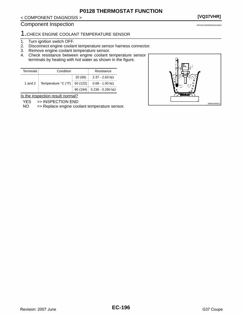
[VQ37VHR]P0128 THERMOSTAT FUNCTION
< COMPONENT DIAGNOSIS >
Component Inspection INFOID:0000000001910834
1.CHECK ENGINE COOLANT TEMPERATURE SENSOR
1. Turn ignition switch OFF.2. Disconnect engine coolant temperature sensor harness connector.3. Remove engine coolant temperature sensor.4. Check resistance between engine coolant temperature sensor
terminals by heating with hot water as shown in the figure.
Is the inspection result normal?YES >> INSPECTION ENDNO >> Replace engine coolant temperature sensor.
Terminals Condition Resistance
1 and 2 Temperature °C (°F)
20 (68) 2.37 - 2.63 kΩ
50 (122) 0.68 - 1.00 kΩ
90 (194) 0.236 - 0.260 kΩ
JMBIA0080ZZ
EC-196Revision: 2007 June G37 Coupe

P0130, P0150 A/F SENSOR 1[VQ37VHR]
C
D
E
F
G
H
I
J
K
L
M
A
C
N
P
O
< COMPONENT DIAGNOSIS >
E
P0130, P0150 A/F SENSOR 1
Description INFOID:0000000001734032
The air fuel ratio (A/F) sensor 1 is a planar one-cell limit current sen-sor. The sensor element of the A/F sensor 1 is composed an elec-trode layer, which transports ions. It has a heater in the element.The sensor is capable of precise measurement = 1, but also in thelean and rich range. Together with its control electronics, the sensoroutputs a clear, continuous signal throughout a wide range.The exhaust gas components diffuse through the diffusion layer atthe sensor cell. An electrode layer is applied voltage, and this currentrelative oxygen density in lean. Also this current relative hydrocar-bon density in rich.
Therefore, the A/F sensor 1 is able to indicate air fuel ratio by thiselectrode layer of current. In addition, a heater is integrated in thesensor to ensure the required operating temperature of about 800°C(1,472°F).
DTC Logic INFOID:0000000001734033
DTC DETECTION LOGICTo judge the malfunction, the diagnosis checks that the A/F signal computed by ECM from the A/F sensor 1signal fluctuates according to fuel feedback control.
DTC CONFIRMATION PROCEDURE
1.PRECONDITIONING
If DTC Confirmation Procedure has been previously conducted, always perform the following before conduct-ing the next test.1. Turn ignition switch OFF and wait at least 10 seconds.2. Turn ignition switch ON.3. Turn ignition switch OFF and wait at least 10 seconds.TESTING CONDITION:Before performing the following procedure, confirm that battery voltage is more than 11V at idle.
>> GO TO 2.
JMBIA0112GB
PBIB3354E
DTC No. Trouble diagnosis name DTC detecting condition Possible Cause
P0130Air fuel ratio (A/F) sensor 1 (bank 1) circuit
A)The A/F signal computed by ECM from the A/F sensor 1 signal is constantly in the range other than approx. 2.2V.
• Harness or connectors(The A/F sensor 1 circuit is open or shorted.)
• A/F sensor 1
B)The A/F signal computed by ECM from the A/F sensor 1 signal is constantly approx. 2.2V.
P0150Air fuel ratio (A/F) sensor 1 (bank 2) circuit
A)The A/F signal computed by ECM from the A/F sensor 1 signal is constantly in the range other than approx. 2.2V.
B)The A/F signal computed by ECM from the A/F sensor 1 signal is constantly approx. 2.2V.
EC-197Revision: 2007 June G37 Coupe

[VQ37VHR]P0130, P0150 A/F SENSOR 1
< COMPONENT DIAGNOSIS >
2.PERFORM DTC CONFIRMATION PROCEDURE FOR MALFUNCTION A
1. Start engine and warm it up to normal operating temperature.2. Let it idle for 2 minutes.3. Check 1st trip DTC.Is 1st trip DTC detected?YES >> Go to EC-199, "Diagnosis Procedure".NO-1 >> With CONSULT-III: GO TO 3.NO-2 >> Without CONSULT-III: GO TO 7.
3.CHECK AIR FUEL RATIO (A/F) SENSOR 1 FUNCTION
1. Start engine and warm it up to normal operating temperature.2. Select “A/F SEN1 (B1)” or “A/F SEN1 (B2)” in “DATA MONITOR” mode with CONSULT-III.3. Check “A/F SEN1 (B1)” or “A/F SEN1 (B2)” indication.Does the indication fluctuates around 2.2V?YES >> GO TO 4.NO >> Go to EC-199, "Diagnosis Procedure".
4.PERFORM DTC CONFIRMATION PROCEDURE FOR MALFUNCTION B-I
1. Select “A/F SEN1 (B1) P1276” (for DTC P0130) or “A/F SEN1 (B2) P1286” (for DTC P0150) of “A/FSEN1” in “DTC WORK SUPPORT” mode with CONSULT-III.
2. Touch “START”.3. When the following conditions are met, “TESTING” will be displayed on the CONSULT-III screen.
If “TESTING” is not displayed after 20 seconds, retry from step 2.CAUTION:Always drive vehicle at a safe speed.
Is “TESTING” displayed on CONSULT-III screen?YES >> GO TO 5.NO >> Check A/F sensor 1 function again. GO TO 3.
5.PERFORM DTC CONFIRMATION PROCEDURE FOR MALFUNCTION B-II
Release accelerator pedal fully.NOTE:Never apply brake during releasing the accelerator pedal.Which does “TESTING” change to?COMPLETED>>GO TO 6.OUT OF CONDITION>>Retry DTC CONFIRMATION PROCEDURE. GO TO 4.
6.PERFORM DTC CONFIRMATION PROCEDURE FOR MALFUNCTION B-III
Touch “SELF-DIAG RESULT”.Which is displayed on CONSULT-III screen?OK >> INSPECTION ENDNG >> Go to EC-199, "Diagnosis Procedure".
7.PERFORM COMPONENT FUNCTION CHECK FOR MALFUNCTION B
Perform component function check. Refer to EC-199, "Component Function Check".NOTE:Use component function check to check the overall function of the A/F sensor 1 circuit. During this check, a1st trip DTC might not be confirmed.Is the inspection result normal?
ENG SPEED 1,100 - 3,200 rpm
VHCL SPEED SE More than 64 km/h (40 mph)
B/FUEL SCHDL 1.0 - 8.0 msec
Selector leverD position (A/T)5th position (M/T)
EC-198Revision: 2007 June G37 Coupe

P0130, P0150 A/F SENSOR 1[VQ37VHR]
C
D
E
F
G
H
I
J
K
L
M
A
C
N
P
O
< COMPONENT DIAGNOSIS >
E
YES >> INSPECTION ENDNO >> Go to EC-199, "Diagnosis Procedure".
Component Function Check INFOID:0000000001734034
1.PERFORM COMPONENT FUNCTION CHECK
With GST1. Start engine and warm it up to normal operating temperature.2. Drive the vehicle at a speed of 80 km/h (50 MPH) for a few minutes in the suitable gear position.3. Shift the selector lever to D position (A/T) or 5th position (M/T), then release the accelerator pedal fully
until the vehicle speed decreases to 50 km/h (30 MPH).CAUTION:Always drive vehicle at a safe speed.NOTE:Never apply brake during releasing the accelerator pedal.
4. Repeat steps 2 to 3 for five times.5. Stop the vehicle and turn ignition switch OFF.6. Turn ignition switch ON.7. Turn ignition switch OFF and wait at least 10 seconds.8. Restart engine.9. Repeat steps 2 to 3 for five times.10. Stop the vehicle and connect GST to the vehicle.11. Check 1st trip DTC.Is 1st trip DTC detected?YES >> Go to EC-199, "Diagnosis Procedure".NO >> INSPECTION END
Diagnosis Procedure INFOID:0000000001734035
1.CHECK GROUND CONNECTION
1. Turn ignition switch OFF.2. Check ground connection M95. Refer to Ground Inspection in GI-41, "Circuit Inspection".Is the inspection result normal?YES >> GO TO 2.NO >> Repair or replace ground connection.
2.CHECK AIR FUEL RATIO (A/F) SENSOR 1 POWER SUPPLY CIRCUIT
1. Disconnect A/F sensor 1 harness connector.2. Turn ignition switch ON.3. Check the voltage between A/F sensor 1 harness connector and ground.
Is the inspection result normal?YES >> GO TO 4.NO >> GO TO 3.
3.DETECT MALFUNCTIONING PART
Check the following.• Harness connectors E3, F1• IPDM E/R harness connector E7• 15A fuse (No. 46)• Harness for open or short between A/F sensor 1 and fuse
>> Repair or replace harness or connectors.
DTCA/F sensor 1
Ground VoltageBank Connector Terminal
P0130 1 F3 4Ground Battery voltage
P0150 2 F20 4
EC-199Revision: 2007 June G37 Coupe
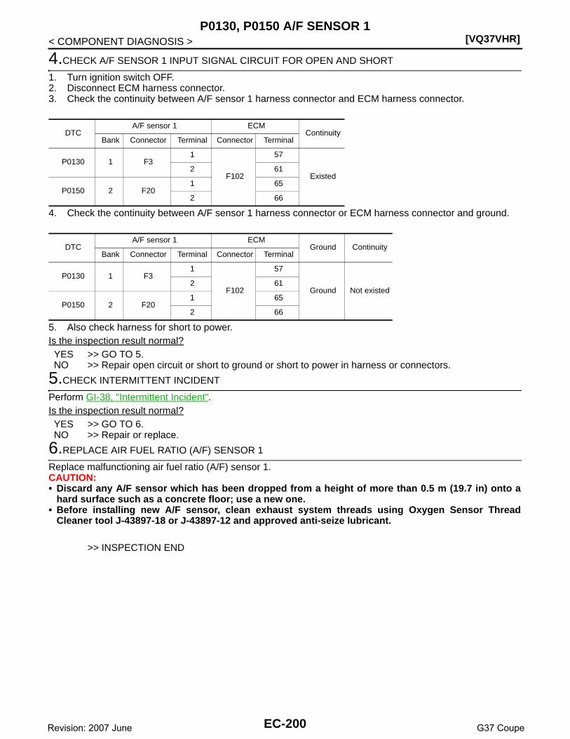
[VQ37VHR]P0130, P0150 A/F SENSOR 1
< COMPONENT DIAGNOSIS >
4.CHECK A/F SENSOR 1 INPUT SIGNAL CIRCUIT FOR OPEN AND SHORT
1. Turn ignition switch OFF.2. Disconnect ECM harness connector.3. Check the continuity between A/F sensor 1 harness connector and ECM harness connector.
4. Check the continuity between A/F sensor 1 harness connector or ECM harness connector and ground.
5. Also check harness for short to power.Is the inspection result normal?YES >> GO TO 5.NO >> Repair open circuit or short to ground or short to power in harness or connectors.
5.CHECK INTERMITTENT INCIDENT
Perform GI-38, "Intermittent Incident".Is the inspection result normal?YES >> GO TO 6.NO >> Repair or replace.
6.REPLACE AIR FUEL RATIO (A/F) SENSOR 1
Replace malfunctioning air fuel ratio (A/F) sensor 1.CAUTION:• Discard any A/F sensor which has been dropped from a height of more than 0.5 m (19.7 in) onto a
hard surface such as a concrete floor; use a new one.• Before installing new A/F sensor, clean exhaust system threads using Oxygen Sensor Thread
Cleaner tool J-43897-18 or J-43897-12 and approved anti-seize lubricant.
>> INSPECTION END
DTCA/F sensor 1 ECM
ContinuityBank Connector Terminal Connector Terminal
P0130 1 F31
F102
57
Existed2 61
P0150 2 F201 65
2 66
DTCA/F sensor 1 ECM
Ground ContinuityBank Connector Terminal Connector Terminal
P0130 1 F31
F102
57
Ground Not existed2 61
P0150 2 F201 65
2 66
EC-200Revision: 2007 June G37 Coupe
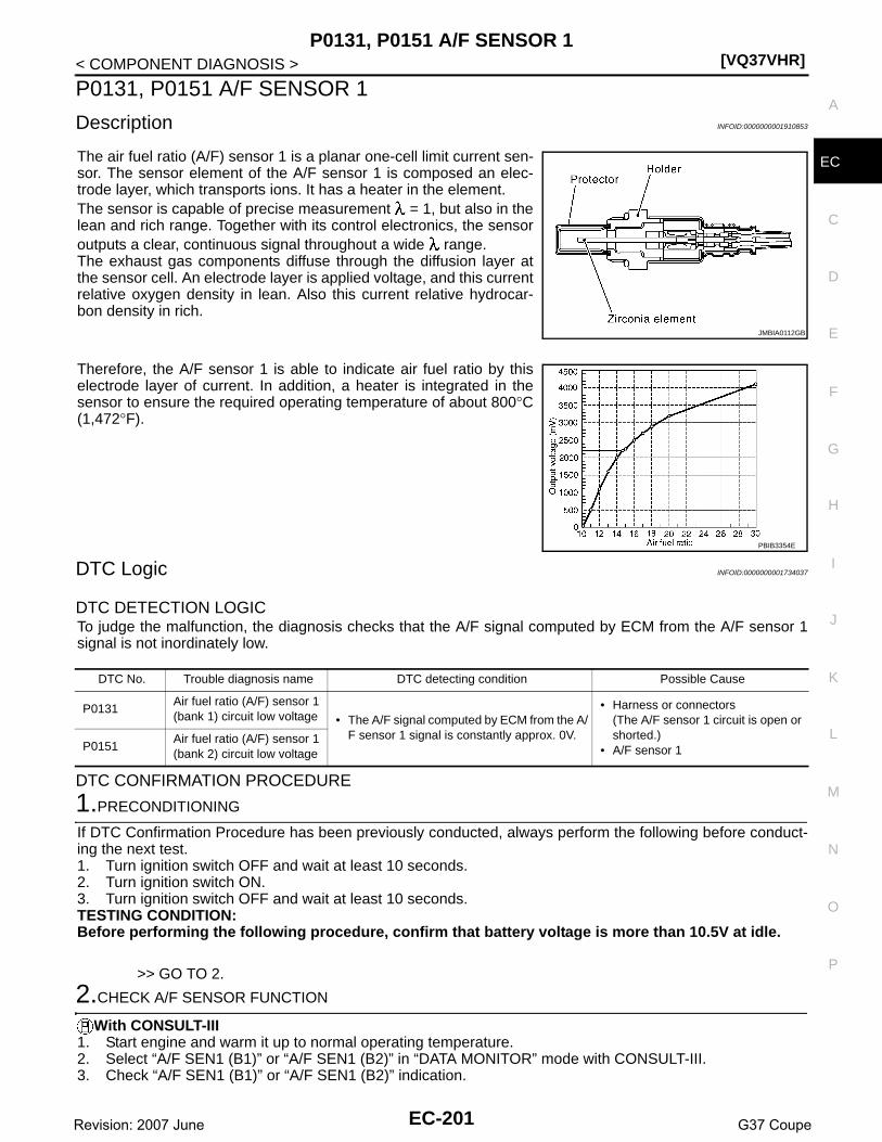
P0131, P0151 A/F SENSOR 1[VQ37VHR]
C
D
E
F
G
H
I
J
K
L
M
A
C
N
P
O
< COMPONENT DIAGNOSIS >
E
P0131, P0151 A/F SENSOR 1
Description INFOID:0000000001910853
The air fuel ratio (A/F) sensor 1 is a planar one-cell limit current sen-sor. The sensor element of the A/F sensor 1 is composed an elec-trode layer, which transports ions. It has a heater in the element.The sensor is capable of precise measurement = 1, but also in thelean and rich range. Together with its control electronics, the sensoroutputs a clear, continuous signal throughout a wide range.The exhaust gas components diffuse through the diffusion layer atthe sensor cell. An electrode layer is applied voltage, and this currentrelative oxygen density in lean. Also this current relative hydrocar-bon density in rich.
Therefore, the A/F sensor 1 is able to indicate air fuel ratio by thiselectrode layer of current. In addition, a heater is integrated in thesensor to ensure the required operating temperature of about 800°C(1,472°F).
DTC Logic INFOID:0000000001734037
DTC DETECTION LOGICTo judge the malfunction, the diagnosis checks that the A/F signal computed by ECM from the A/F sensor 1signal is not inordinately low.
DTC CONFIRMATION PROCEDURE
1.PRECONDITIONING
If DTC Confirmation Procedure has been previously conducted, always perform the following before conduct-ing the next test.1. Turn ignition switch OFF and wait at least 10 seconds.2. Turn ignition switch ON.3. Turn ignition switch OFF and wait at least 10 seconds.TESTING CONDITION:Before performing the following procedure, confirm that battery voltage is more than 10.5V at idle.
>> GO TO 2.
2.CHECK A/F SENSOR FUNCTION
With CONSULT-III1. Start engine and warm it up to normal operating temperature.2. Select “A/F SEN1 (B1)” or “A/F SEN1 (B2)” in “DATA MONITOR” mode with CONSULT-III.3. Check “A/F SEN1 (B1)” or “A/F SEN1 (B2)” indication.
JMBIA0112GB
PBIB3354E
DTC No. Trouble diagnosis name DTC detecting condition Possible Cause
P0131Air fuel ratio (A/F) sensor 1 (bank 1) circuit low voltage • The A/F signal computed by ECM from the A/
F sensor 1 signal is constantly approx. 0V.
• Harness or connectors(The A/F sensor 1 circuit is open or shorted.)
• A/F sensor 1P0151Air fuel ratio (A/F) sensor 1 (bank 2) circuit low voltage
EC-201Revision: 2007 June G37 Coupe

[VQ37VHR]P0131, P0151 A/F SENSOR 1
< COMPONENT DIAGNOSIS >
With GSTFollow the procedure “With CONSULT-III” above.Is the indication constantly approx. 0V?YES >> Go to EC-202, "Diagnosis Procedure".NO >> GO TO 3.
3.PERFORM DTC CONFIRMATION PROCEDURE
With CONSULT-III1. Turn ignition switch OFF and wait at least 10 seconds.2. Turn ignition switch ON.3. Turn ignition switch OFF and wait at least 10 seconds.4. Restart engine.5. Drive and accelerate vehicle to more than 40 km/h (25 MPH) within 20 seconds after restarting engine.
CAUTION:Always drive vehicle at a safe speed.
6. Maintain the following conditions for about 20 consecutive seconds.
NOTE:• Keep the accelerator pedal as steady as possible during the cruising.• If this procedure is not completed within 1 minute after restarting engine at step 1, return to step
1.7. Check 1st trip DTC.
With GSTFollow the procedure “With CONSULT-III” above.Is 1st trip DTC detected?YES >> Go to EC-202, "Diagnosis Procedure".NO >> INSPECTION END
Diagnosis Procedure INFOID:0000000001734038
1.CHECK GROUND CONNECTION
1. Turn ignition switch OFF.2. Check ground connection M95. Refer to Ground Inspection in GI-41, "Circuit Inspection".Is the inspection result normal?YES >> GO TO 2.NO >> Repair or replace ground connection.
2.CHECK AIR FUEL RATIO (A/F) SENSOR 1 POWER SUPPLY CIRCUIT
1. Disconnect A/F sensor 1 harness connector.2. Turn ignition switch ON.3. Check the voltage between A/F sensor 1 harness connector and ground.
Is the inspection result normal?YES >> GO TO 4.NO >> GO TO 3.
3.DETECT MALFUNCTIONING PART
ENG SPEED 1,000 - 3,200 rpm
VHCL SPEED SE More than 40 km/h (25 mph)
B/FUEL SCHDL 1.5 - 9.0 msec
Selector lever Suitable position
DTCA/F sensor 1
Ground VoltageBank Connector Terminal
P0131 1 F3 4Ground Battery voltage
P0151 2 F20 4
EC-202Revision: 2007 June G37 Coupe

P0131, P0151 A/F SENSOR 1[VQ37VHR]
C
D
E
F
G
H
I
J
K
L
M
A
C
N
P
O
< COMPONENT DIAGNOSIS >
E
Check the following.• Harness connectors E3, F1• IPDM E/R harness connector E7• 15A fuse (No. 46)• Harness for open or short between A/F sensor 1 and fuse
>> Repair or replace harness or connectors.
4.CHECK A/F SENSOR 1 INPUT SIGNAL CIRCUIT FOR OPEN AND SHORT
1. Turn ignition switch OFF.2. Disconnect ECM harness connector.3. Check the continuity between A/F sensor 1 harness connector and ECM harness connector.
4. Check the continuity between A/F sensor 1 harness connector or ECM harness connector and ground.
5. Also check harness for short to power.Is the inspection result normal?YES >> GO TO 5.NO >> Repair open circuit or short to ground or short to power in harness or connectors.
5.CHECK INTERMITTENT INCIDENT
Perform GI-38, "Intermittent Incident".Is the inspection result normal?YES >> GO TO 6.NO >> Repair or replace.
6.REPLACE AIR FUEL RATIO (A/F) SENSOR 1
Replace malfunctioning air fuel ratio (A/F) sensor 1.CAUTION:• Discard any A/F sensor which has been dropped from a height of more than 0.5 m (19.7 in) onto a
hard surface such as a concrete floor; use a new one.• Before installing new A/F sensor, clean exhaust system threads using Oxygen Sensor Thread
Cleaner tool J-43897-18 or J-43897-12 and approved anti-seize lubricant.
>> INSPECTION END
DTCA/F sensor 1 ECM
ContinuityBank Connector Terminal Connector Terminal
P0131 1 F31
F102
57
Existed2 61
P0151 2 F201 65
2 66
DTCA/F sensor 1 ECM
Ground ContinuityBank Connector Terminal Connector Terminal
P0131 1 F31
F102
57
Ground Not existed2 61
P0151 2 F201 65
2 66
EC-203Revision: 2007 June G37 Coupe

[VQ37VHR]P0132, P0152 A/F SENSOR 1
< COMPONENT DIAGNOSIS >
P0132, P0152 A/F SENSOR 1
Description INFOID:0000000001910854
The air fuel ratio (A/F) sensor 1 is a planar one-cell limit current sen-sor. The sensor element of the A/F sensor 1 is composed an elec-trode layer, which transports ions. It has a heater in the element.The sensor is capable of precise measurement = 1, but also in thelean and rich range. Together with its control electronics, the sensoroutputs a clear, continuous signal throughout a wide range.The exhaust gas components diffuse through the diffusion layer atthe sensor cell. An electrode layer is applied voltage, and this currentrelative oxygen density in lean. Also this current relative hydrocar-bon density in rich.
Therefore, the A/F sensor 1 is able to indicate air fuel ratio by thiselectrode layer of current. In addition, a heater is integrated in thesensor to ensure the required operating temperature of about 800°C(1,472°F).
DTC Logic INFOID:0000000001734040
DTC DETECTION LOGICTo judge the malfunction, the diagnosis checks that the A/F signal computed by ECM from the A/F sensor 1signal is not inordinately high.
DTC CONFIRMATION PROCEDURE
1.PRECONDITIONING
If DTC Confirmation Procedure has been previously conducted, always perform the following before conduct-ing the next test.1. Turn ignition switch OFF and wait at least 10 seconds.2. Turn ignition switch ON.3. Turn ignition switch OFF and wait at least 10 seconds.TESTING CONDITION:Before performing the following procedure, confirm that battery voltage is more than 10.5V at idle.
>> GO TO 2.
2.CHECK A/F SENSOR FUNCTION
With CONSULT-III1. Start engine and warm it up to normal operating temperature.2. Select “A/F SEN1 (B1)” or “A/F SEN1 (B2)” in “DATA MONITOR” mode with CONSULT-III.3. Check “A/F SEN1 (B1)” or “A/F SEN1 (B2)” indication.
JMBIA0112GB
PBIB3354E
DTC No. Trouble diagnosis name DTC detecting condition Possible Cause
P0132Air fuel ratio (A/F) sensor 1 (bank 1) circuit high voltage • The A/F signal computed by ECM from the A/F
sensor 1 signal is constantly approx. 5V.
• Harness or connectors(The A/F sensor 1 circuit is open or shorted.)
• A/F sensor 1P0152Air fuel ratio (A/F) sensor 1 (bank 2) circuit high voltage
EC-204Revision: 2007 June G37 Coupe
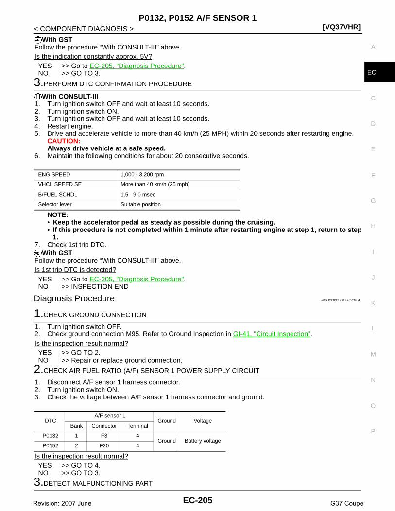
P0132, P0152 A/F SENSOR 1[VQ37VHR]
C
D
E
F
G
H
I
J
K
L
M
A
C
N
P
O
< COMPONENT DIAGNOSIS >
E
With GSTFollow the procedure “With CONSULT-III” above.Is the indication constantly approx. 5V?YES >> Go to EC-205, "Diagnosis Procedure".NO >> GO TO 3.
3.PERFORM DTC CONFIRMATION PROCEDURE
With CONSULT-III1. Turn ignition switch OFF and wait at least 10 seconds.2. Turn ignition switch ON.3. Turn ignition switch OFF and wait at least 10 seconds.4. Restart engine.5. Drive and accelerate vehicle to more than 40 km/h (25 MPH) within 20 seconds after restarting engine.
CAUTION:Always drive vehicle at a safe speed.
6. Maintain the following conditions for about 20 consecutive seconds.
NOTE:• Keep the accelerator pedal as steady as possible during the cruising.• If this procedure is not completed within 1 minute after restarting engine at step 1, return to step
1.7. Check 1st trip DTC.
With GSTFollow the procedure “With CONSULT-III” above.Is 1st trip DTC is detected?YES >> Go to EC-205, "Diagnosis Procedure".NO >> INSPECTION END
Diagnosis Procedure INFOID:0000000001734041
1.CHECK GROUND CONNECTION
1. Turn ignition switch OFF.2. Check ground connection M95. Refer to Ground Inspection in GI-41, "Circuit Inspection".Is the inspection result normal?YES >> GO TO 2.NO >> Repair or replace ground connection.
2.CHECK AIR FUEL RATIO (A/F) SENSOR 1 POWER SUPPLY CIRCUIT
1. Disconnect A/F sensor 1 harness connector.2. Turn ignition switch ON.3. Check the voltage between A/F sensor 1 harness connector and ground.
Is the inspection result normal?YES >> GO TO 4.NO >> GO TO 3.
3.DETECT MALFUNCTIONING PART
ENG SPEED 1,000 - 3,200 rpm
VHCL SPEED SE More than 40 km/h (25 mph)
B/FUEL SCHDL 1.5 - 9.0 msec
Selector lever Suitable position
DTCA/F sensor 1
Ground VoltageBank Connector Terminal
P0132 1 F3 4Ground Battery voltage
P0152 2 F20 4
EC-205Revision: 2007 June G37 Coupe

[VQ37VHR]P0132, P0152 A/F SENSOR 1
< COMPONENT DIAGNOSIS >Check the following.• Harness connectors E3, F1• IPDM E/R harness connector E7• 15A fuse (No. 46)• Harness for open or short between A/F sensor 1 and fuse
>> Repair or replace harness or connectors.
4.CHECK A/F SENSOR 1 INPUT SIGNAL CIRCUIT FOR OPEN AND SHORT
1. Turn ignition switch OFF.2. Disconnect ECM harness connector.3. Check the continuity between A/F sensor 1 harness connector and ECM harness connector.
4. Check the continuity between A/F sensor 1 harness connector or ECM harness connector and ground.
5. Also check harness for short to power.Is the inspection result normal?YES >> GO TO 5.NO >> Repair open circuit or short to ground or short to power in harness or connectors.
5.CHECK INTERMITTENT INCIDENT
Perform GI-38, "Intermittent Incident".Is the inspection result normal?YES >> GO TO 6.NO >> Repair or replace.
6.REPLACE AIR FUEL RATIO (A/F) SENSOR 1
Replace malfunctioning air fuel ratio (A/F) sensor 1.CAUTION:• Discard any A/F sensor which has been dropped from a height of more than 0.5 m (19.7 in) onto a
hard surface such as a concrete floor; use a new one.• Before installing new A/F sensor, clean exhaust system threads using Oxygen Sensor Thread
Cleaner tool J-43897-18 or J-43897-12 and approved anti-seize lubricant.
>> INSPECTION END
DTCA/F sensor 1 ECM
ContinuityBank Connector Terminal Connector Terminal
P0132 1 F31
F102
57
Existed2 61
P0152 2 F201 65
2 66
DTCA/F sensor 1 ECM
Ground ContinuityBank Connector Terminal Connector Terminal
P0132 1 F31
F102
57
Ground Not existed2 61
P0152 2 F201 65
2 66
EC-206Revision: 2007 June G37 Coupe

P0133, P0153 A/F SENSOR 1[VQ37VHR]
C
D
E
F
G
H
I
J
K
L
M
A
C
N
P
O
< COMPONENT DIAGNOSIS >
E
P0133, P0153 A/F SENSOR 1
Description INFOID:0000000001910855
The air fuel ratio (A/F) sensor 1 is a planar one-cell limit current sen-sor. The sensor element of the A/F sensor 1 is composed an elec-trode layer, which transports ions. It has a heater in the element.The sensor is capable of precise measurement = 1, but also in thelean and rich range. Together with its control electronics, the sensoroutputs a clear, continuous signal throughout a wide range.The exhaust gas components diffuse through the diffusion layer atthe sensor cell. An electrode layer is applied voltage, and this currentrelative oxygen density in lean. Also this current relative hydrocar-bon density in rich.
Therefore, the A/F sensor 1 is able to indicate air fuel ratio by thiselectrode layer of current. In addition, a heater is integrated in thesensor to ensure the required operating temperature of about 800°C(1,472°F).
DTC Logic INFOID:0000000001734043
DTC DETECTION LOGICTo judge the malfunction of A/F sensor 1, this diagnosis measures response time of the A/F signal computedby ECM from the A/F sensor 1 signal. The time is compensated by engine operating (speed and load), fuelfeedback control constant, and the A/F sensor 1 temperature index. Judgment is based on whether the com-pensated time (the A/F signal cycling time index) is inordinately long or not.
DTC CONFIRMATION PROCEDURE
1.PRECONDITIONING
If DTC Confirmation Procedure has been previously conducted, always perform the following before conduct-ing the next test.1. Turn ignition switch OFF and wait at least 10 seconds.2. Turn ignition switch ON.3. Turn ignition switch OFF and wait at least 10 seconds.TESTING CONDITION:Before performing the following procedure, confirm that battery voltage is more than 11V at idle.Do you have CONSULT-III?
JMBIA0112GB
PBIB3354E
DTC No. Trouble diagnosis name DTC detecting condition Possible Cause
P0133Air fuel ratio (A/F) sensor 1 (bank 1) circuit slow re-sponse
• The response of the A/F signal computed by ECM from A/F sensor 1 signal takes more than the specified time.
• Harness or connectors(The A/F sensor 1 circuit is open or shorted.)
• A/F sensor 1• A/F sensor 1 heater• Fuel pressure• Fuel injector• Intake air leaks• Exhaust gas leaks• PCV• Mass air flow sensor
P0153Air fuel ratio (A/F) sensor 1 (bank 2) circuit slow re-sponse
EC-207Revision: 2007 June G37 Coupe

[VQ37VHR]P0133, P0153 A/F SENSOR 1
< COMPONENT DIAGNOSIS >YES >> GO TO 2.NO >> GO TO 5.
2.PERFORM DTC CONFIRMATION PROCEDURE-I
With CONSULT-III1. Start engine and warm it up to normal operating temperature.2. Turn ignition switch OFF and wait at least 10 seconds.3. Turn ignition switch ON.4. Turn ignition switch OFF and wait at least 10 seconds.5. Start engine and keep the engine speed between 3,500 and 4,000 rpm for at least 1minute under no load.6. Let engine idle for 1 minute.7. Select “A/F SEN1(B1) P1278/P1279” (for DTC P0133) or “A/F SEN1(B2) P1288/P1289” (for DTC P0153)
of “A/F SEN1” in “DTC WORK SUPPORT” mode with CONSULT-III.8. Touch “START”.Is “COMPLETED” displayed on CONSULT-III screen?YES >> GO TO 3NO >> GO TO 4.
3.PERFORM DTC CONFIRMATION PROCEDURE-II
Touch “SELF-DIAG RESULT”.Which is displayed on CONSULT-III screen?OK >> INSPECTION ENDNG >> Go to EC-209, "Diagnosis Procedure".
4.PERFORM DTC CONFIRMATION PROCEDURE-II
1. After perform the following procedure, “TESTING” will be displayed on the CONSULT-III screen.- Increase the engine speed up to about 3,600 rpm and keep it for 10 seconds.- Fully release accelerator pedal and then let engine idle for about 10 seconds.
If “TESTING” is not displayed after 10 seconds, refer to EC-132, "Component Function Check".2. Wait for about 20 seconds at idle at under the condition that “TESTING” is displayed on the CONSULT-III
screen.3. Make sure that “TESTING” changes to “COMPLETED”.
If “TESTING” changed to “OUT OF CONDITION”, refer to EC-132, "Component Function Check". 4. Touch “SELF-DIAG RESULT”.Which is displayed on CONSULT-III screen?OK >> INSPECTION ENDNG >> Go to EC-209, "Diagnosis Procedure".
5.CHECK AIR-FUEL RATIO SELF-LEARNING VALUE
With GST1. Start engine and warm it up to normal operating temperature.2. Select Service $01 with GST.3. Calculate the total value of “Short term fuel trim” and “Long term fuel trim” indications.Is the total percentage within ±15%?YES >> GO TO 7.NO >> GO TO 6.
6.DETECT MALFUNCTIONING PART
Check the following.• Intake air leaks• Exhaust gas leaks• Incorrect fuel pressure• Lack of fuel• Fuel injector• Incorrect PCV hose connection• PCV valve• Mass air flow sensor
EC-208Revision: 2007 June G37 Coupe

P0133, P0153 A/F SENSOR 1[VQ37VHR]
C
D
E
F
G
H
I
J
K
L
M
A
C
N
P
O
< COMPONENT DIAGNOSIS >
E
>> Repair or replace malfunctioning part.
7.PERFORM DTC CONFIRMATION PROCEDURE
1. Turn ignition switch OFF and wait at least 10 seconds.2. Turn ignition switch ON.3. Turn ignition switch OFF and wait at least 10 seconds.4. Start engine and keep the engine speed between 3,500 and 4,000 rpm for at least 1minute under no load.5. Let engine idle for 1 minute.6. Increase the engine speed up to about 3,600 rpm and keep it for 10 seconds.7. Fully release accelerator pedal and then let engine idle for about 1 minute.8. Check 1st trip DTC.Is 1st trip DTC detected?YES >> Go to EC-209, "Diagnosis Procedure".NO >> INSPECTION END
Diagnosis Procedure INFOID:0000000001734044
1.CHECK GROUND CONNECTION
1. Turn ignition switch OFF.2. Check ground connection M95. Refer to Ground Inspection in GI-41, "Circuit Inspection".Is the inspection result normal?YES >> GO TO 2.NO >> Repair or replace ground connection.
2.RETIGHTEN A/F SENSOR 1
Loosen and retighten the A/F sensor 1. Refer to EM-33, "Removal and Installation".
>> GO TO 3.
3.CHECK EXHAUST GAS LEAK
1. Start engine and run it at idle.2. Listen for an exhaust gas leak before three way catalyst 1.
Is exhaust gas leak detected?YES >> Repair or replace.NO >> GO TO 4.
4.CHECK FOR INTAKE AIR LEAK
Listen for an intake air leak after the mass air flow sensor.Is intake air leak detected?YES >> Repair or replace.NO >> GO TO 5.
5.CLEAR THE MIXTURE RATIO SELF-LEARNING VALUE
1. Clear the mixture ratio self-learning value. Refer to EC-22, "MIXTURE RATIO SELF-LEARNING VALUECLEAR : Special Repair Requirement".
2. Run engine for at least 10 minutes at idle speed.Is the 1st trip DTC P0171, P172, P0174 or P0175 detected? Is it difficult to start engine?
PBIB1922E
EC-209Revision: 2007 June G37 Coupe

[VQ37VHR]P0133, P0153 A/F SENSOR 1
< COMPONENT DIAGNOSIS >YES >> Perform trouble diagnosis for DTC P0171, P0174 or P0172, P0175. Refer to EC-232, "DTC Logic"
or EC-236, "DTC Logic".NO >> GO TO 6.
6.CHECK AIR FUEL RATIO (A/F) SENSOR 1 POWER SUPPLY CIRCUIT
1. Disconnect A/F sensor 1 harness connector.2. Turn ignition switch ON.3. Check the voltage between A/F sensor 1 harness connector and ground.
Is the inspection result normal?YES >> GO TO 8.NO >> GO TO 7.
7.DETECT MALFUNCTIONING PART
Check the following.• Harness connectors E3, F1• IPDM E/R harness connector E7• 15A fuse (No. 46)• Harness for open or short between A/F sensor 1 and fuse
>> Repair or replace harness or connectors.
8.CHECK A/F SENSOR 1 INPUT SIGNAL CIRCUIT FOR OPEN AND SHORT
1. Turn ignition switch OFF.2. Disconnect ECM harness connector.3. Check the continuity between A/F sensor 1 harness connector and ECM harness connector.
4. Check the continuity between A/F sensor 1 harness connector or ECM harness connector and ground.
5. Also check harness for short to power.Is the inspection result normal?YES >> GO TO 9.NO >> Repair open circuit or short to ground or short to power in harness or connectors.
9.CHECK AIR FUEL RATIO (A/F) SENSOR 1 HEATER
Refer to EC-157, "Component Inspection".
DTCA/F sensor 1
Ground VoltageBank Connector Terminal
P0133 1 F3 4Ground Battery voltage
P0153 2 F20 4
DTCA/F sensor 1 ECM
ContinuityBank Connector Terminal Connector Terminal
P0133 1 F31
F102
57
Existed2 61
P0153 2 F201 65
2 66
DTCA/F sensor 1 ECM
Ground ContinuityBank Connector Terminal Connector Terminal
P0133 1 F31
F102
57
Ground Not existed2 61
P0153 2 F201 65
2 66
EC-210Revision: 2007 June G37 Coupe

P0133, P0153 A/F SENSOR 1[VQ37VHR]
C
D
E
F
G
H
I
J
K
L
M
A
C
N
P
O
< COMPONENT DIAGNOSIS >
E
Is the inspection result normal?YES >> GO TO 10.NO >> GO TO 13.
10.CHECK MASS AIR FLOW SENSOR
Check both mass air flow sensor (bank 1 and bank 2).Refer to EC-169, "Component Inspection".Is the inspection result normal?YES >> GO TO 11. NO >> Replace malfunctioning mass air flow sensor.
11.CHECK PCV VALVE
Refer to EC-509, "Component Inspection".Is the inspection result normal?YES >> GO TO 12.NO >> Repair or replace PCV valve.
12.CHECK INTERMITTENT INCIDENT
Perform GI-38, "Intermittent Incident".Is the inspection result normal?YES >> GO TO 13.NO >> Repair or replace.
13.REPLACE AIR FUEL RATIO (A/F) SENSOR 1
Replace malfunctioning air fuel ratio (A/F) sensor 1.CAUTION:• Discard any A/F sensor which has been dropped from a height of more than 0.5 m (19.7 in) onto a
hard surface such as a concrete floor; use a new one.• Before installing new A/F sensor, clean exhaust system threads using Oxygen Sensor Thread
Cleaner tool J-43897-18 or J-43897-12 and approved anti-seize lubricant.
>> INSPECTION END
EC-211Revision: 2007 June G37 Coupe

[VQ37VHR]P0137, P0157 HO2S2
< COMPONENT DIAGNOSIS >
P0137, P0157 HO2S2
Description INFOID:0000000001734045
The heated oxygen sensor 2, after three way catalyst 1, monitors theoxygen level in the exhaust gas on each bank.Even if switching characteristics of the air fuel ratio (A/F) sensor 1are shifted, the air-fuel ratio is controlled to stoichiometric, by the sig-nal from the heated oxygen sensor 2.This sensor is made of ceramic zirconia. The zirconia generates volt-age from approximately 1V in richer conditions to 0V in leaner condi-tions.Under normal conditions the heated oxygen sensor 2 is not used forengine control operation.
DTC Logic INFOID:0000000001734046
DTC DETECTION LOGICThe heated oxygen sensor 2 has a much longer switching timebetween rich and lean than the air fuel ratio (A/F) sensor 1. The oxy-gen storage capacity of the three way catalyst 1 causes the longerswitching time. To judge the malfunctions of heated oxygen sensor2, ECM monitors whether the maximum voltage of the sensor is suf-ficiently high during the various driving condition such as fuel-cut.
DTC CONFIRMATION PROCEDURE
1.INSPECTION START
Do you have CONSULT-III?Do you have CONSULT-III?YES >> GO TO 2.NO >> GO TO 5.
2.PRECONDITIONING
If DTC confirmation Procedure has been previously conducted, always perform the following before conduct-ing the next test.1. Turn ignition switch OFF and wait at least 10 seconds.2. Turn ignition switch ON.3. Turn ignition switch OFF and wait at least 10 seconds.TESTING CONDITION:For better results, perform “DTC WORK SUPPORT” at a temperature of 0 to 30 °C (32 to 86 °F).
>> GO TO 3.
SEF327R
SEF259VA
DTC No. Trouble diagnosis name DTC detecting condition Possible cause
P0137Heated oxygen sensor 2 (bank 1) circuit low volt-age The maximum voltage from the sensor is not
reached to the specified voltage.
• Harness or connectors(The sensor circuit is open or shorted)
• Heated oxygen sensor 2• Fuel pressure• Fuel injector• Intake air leaks
P0157Heated oxygen sensor 2 (bank 2) circuit low volt-age
EC-212Revision: 2007 June G37 Coupe

P0137, P0157 HO2S2[VQ37VHR]
C
D
E
F
G
H
I
J
K
L
M
A
C
N
P
O
< COMPONENT DIAGNOSIS >
E
3.PERFORM DTC CONFIRMATION PROCEDURE
With CONSULT-III1. Turn ignition switch ON and select “DATA MONITOR” mode with CONSULT-III.2. Start engine and warm it up to the normal operating temperature.3. Turn ignition switch OFF and wait at least 10 seconds.4. Turn ignition switch ON.5. Turn ignition switch OFF and wait at least 10 seconds.6. Start engine and keep the engine speed between 3,500 and 4,000 rpm for at least 1 minute under no load.7. Let engine idle for 1 minute.8. Make sure that “COOLAN TEMP/S” indicates more than 70°C (158°F).
If not, warm up engine and go to next step when “COOLAN TEMP/S” indication reaches to 70°C (158°F).9. Open engine hood.10. Select “HO2S2 (B1) P1147” (for DTC P0137) or “HO2S2 (B2) P1167” (for DTC P0157) of “HO2S2” in
“DTC WORK SUPPORT” mode with CONSULT-III.11. Start engine and following the instruction of CONSULT-III.
NOTE:It will take at most 10 minutes until “COMPLETED” is displayed.
12. Touch “SELF-DIAG RESULTS”.Which is displayed on CONSULT-III screen?OK >> INSPECTION ENDNG >> Go to EC-214, "Diagnosis Procedure".CAN NOT BE DIAGNOSED>>GO TO 4.
4.PERFORM DTC CONFIRMATION PROCEDURE AGAIN
1. Turn ignition switch OFF and leave the vehicle in a cool place (soak the vehicle).2. Perform DTC confirmation procedure again.
>> GO TO 3.
5.PERFORM COMPONENT FUNCTION CHECK
Perform component function check. Refer to EC-213, "Component Function Check".NOTE:Use component function check to check the overall function of the heated oxygen sensor 2 circuit. During thischeck, a 1st trip DTC might not be confirmed.Is the inspection result normal?YES >> INSPECTION ENDNO >> Go to EC-214, "Diagnosis Procedure".
Component Function Check INFOID:0000000001734047
1.PERFORM COMPONENT FUNCTION CHECK-I
Without CONSULT-III1. Start engine and warm it up to the normal operating temperature.2. Turn ignition switch OFF and wait at least 10 seconds.3. Turn ignition switch ON.4. Turn ignition switch OFF and wait at least 10 seconds.5. Start engine and keep the engine speed between 3,500 and 4,000 rpm for at least 1 minute under no load.6. Let engine idle for 1 minute.7. Check the voltage between ECM harness connector and ground under the following condition.
Is the inspection result normal?YES >> INSPECTION END
DTCECM
Ground Condition VoltageConnector Terminal
P0137F102
76Ground
Revving up to 4,000 rpm under no load at least 10 times
The voltage should be above 0.68V at least once during this procedure.P0157 80
EC-213Revision: 2007 June G37 Coupe

[VQ37VHR]P0137, P0157 HO2S2
< COMPONENT DIAGNOSIS >NO >> GO TO 2.
2.PERFORM COMPONENT FUNCTION CHECK-II
Check the voltage between ECM harness connector and ground under the following condition.
Is the inspection result normal?YES >> INSPECTION ENDNO >> GO TO 3.
3.PERFORM COMPONENT FUNCTION CHECK-III
Check the voltage between ECM harness connector and ground under the following condition.
Is the inspection result normal?YES >> INSPECTION ENDNO >> Go to EC-214, "Diagnosis Procedure".
Diagnosis Procedure INFOID:0000000001734048
1.CHECK GROUND CONNECTION
1. Turn ignition switch OFF.2. Check ground connection M95. Refer to Ground Inspection in GI-41, "Circuit Inspection".Is the inspection result normal?YES >> GO TO 2.NO >> Repair or replace ground connection.
2.CLEAR THE MIXTURE RATIO SELF-LEARNING VALUE
1. Clear the mixture ratio self-learning value. Refer to EC-22, "MIXTURE RATIO SELF-LEARNING VALUECLEAR : Special Repair Requirement".
2. Run engine for at least 10 minutes at idle speed.Is the 1st trip DTC P0171 or P0174 detected? Is it difficult to start engine?YES >> Perform trouble diagnosis for DTC P0171 or P0174. Refer to EC-232, "DTC Logic".NO >> GO TO 3.
3.CHECK HO2S2 GROUND CIRCUIT FOR OPEN AND SHORT
1. Turn ignition switch OFF.2. Disconnect heated oxygen sensor 2 harness connector.3. Disconnect ECM harness connector.4. Check the continuity between HO2S2 harness connector and ECM harness connector.
5. Also check harness for short to ground and short to power.Is the inspection result normal?
DTCECM
Ground Condition VoltageConnector Terminal
P0137F102
76Ground Keeping engine at idle for 10 minutes
The voltage should be above 0.68V at least once during this procedure.P0157 80
DTCECM
Ground Condition VoltageConnector Terminal
P0137F102
76Ground
Coasting from 80 km/h (50 MPH) in D po-sition (A/T), 4th gear position (M/T)
The voltage should be above 0.68V at least once during this procedure.P0157 80
DTCHO2S2 ECM
ContinuityBank Connector Terminal Connector Terminal
P0137 1 F54 1F102 84 Existed
P0157 2 F53 1
EC-214Revision: 2007 June G37 Coupe

P0137, P0157 HO2S2[VQ37VHR]
C
D
E
F
G
H
I
J
K
L
M
A
C
N
P
O
< COMPONENT DIAGNOSIS >
E
YES >> GO TO 4.NO >> Repair open circuit or short to ground or short to power in harness or connectors.
4.CHECK HO2S2 INPUT SIGNAL CIRCUIT FOR OPEN AND SHORT
1. Check the continuity between HO2S2 harness connector and ECM harness connector.
2. Check the continuity between HO2S2 harness connector or ECM harness connector and ground.
3. Also check harness for short to power.Is the inspection result normal?YES >> GO TO 5.NO >> Repair open circuit or short to ground or short to power in harness or connectors.
5.CHECK HEATED OXYGEN SENSOR 2
Refer to EC-215, "Component Inspection".Is the inspection result normal?YES >> GO TO 7.NO >> GO TO 6.
6.REPLACE HEATED OXYGEN SENSOR 2
Replace malfunctioning heated oxygen sensor 2.CAUTION:• Discard any heated oxygen sensor which has been dropped from a height of more than 0.5 m (19.7
in) onto a hard surface such as a concrete floor; use a new one.• Before installing new oxygen sensor, clean exhaust system threads using Oxygen Sensor Thread
Cleaner tool J-43897-18 or J-43897-12 and approved anti-seize lubricant.
>> INSPECTION END
7.CHECK INTERMITTENT INCIDENT
Refer to GI-38, "Intermittent Incident".
>> INSPECTION END
Component Inspection INFOID:0000000001734049
1.INSPECTION START
Do you have CONSULT-III?Do you have CONSULT-III?YES >> GO TO 2.NO >> GO TO 3.
2.CHECK HEATED OXYGEN SENSOR 2
With CONSULT-III1. Turn ignition switch ON and select “DATA MONITOR” mode with CONSULT-III.2. Start engine and warm it up to the normal operating temperature.
DTCHO2S2 ECM
ContinuityBank Connector Terminal Connector Terminal
P0137 1 F54 4F102
76Existed
P0157 2 F53 4 80
DTCHO2S2 ECM
Ground ContinuityBank Connector Terminal Connector Terminal
P0137 1 F54 4F102
76Ground Not existed
P0157 2 F53 4 80
EC-215Revision: 2007 June G37 Coupe

[VQ37VHR]P0137, P0157 HO2S2
< COMPONENT DIAGNOSIS >3. Turn ignition switch OFF and wait at least 10 seconds.4. Start engine and keep the engine speed between 3,500 and 4,000 rpm for at least 1 minute under no load.5. Let engine idle for 1 minute.6. Select “FUEL INJECTION” in “ACTIVE TEST” mode, and select “HO2S2 (B1)/(B2)” as the monitor item
with CONSULT-III.7. Check “HO2S2 (B1)/(B2)” at idle speed when adjusting “FUEL INJECTION” to ±25%.
“HO2S2 (B1)/(B2)” should be above 0.68V at least once when the “FUEL INJECTION” is +25%.“HO2S2 (B1)/(B2)” should be below 0.18V at least once when the “FUEL INJECTION” is −25%.
Is the inspection result normal?YES >> INSPECTION ENDNO >> GO TO 6.
3.CHECK HEATED OXYGEN SENSOR 2-I
Without CONSULT-III1. Start engine and warm it up to the normal operating temperature.2. Turn ignition switch OFF and wait at least 10 seconds.3. Start engine and keep the engine speed between 3,500 and 4,000 rpm for at least 1 minute under no load.4. Let engine idle for 1 minute.5. Check the voltage between ECM harness connector and ground under the following condition.
Is the inspection result normal?YES >> INSPECTION ENDNO >> GO TO 4.
4.CHECK HEATED OXYGEN SENSOR 2-II
Check the voltage between ECM harness connector and ground under the following condition.
Is the inspection result normal?YES >> INSPECTION ENDNO >> GO TO 5.
5.CHECK HEATED OXYGEN SENSOR 2-III
Check the voltage between ECM harness connector and ground under the following condition.
PBIB3458E
ECMGround Condition Voltage
Connector Terminal
F102
76[HO2S2 (bank 1)]
GroundRevving up to 4,000 rpm under no load at least 10 times
The voltage should be above 0.68V at least once during this procedure.The voltage should be below 0.18V at least once during this procedure.
80[HO2S2 (bank 2)]
ECMGround Condition Voltage
Connector Terminal
F102
76[HO2S2 (bank 1)]
Ground Keeping engine at idle for 10 minutes
The voltage should be above 0.68V at least once during this procedure.The voltage should be below 0.18V at least once during this procedure.
80[HO2S2 (bank 2)]
EC-216Revision: 2007 June G37 Coupe
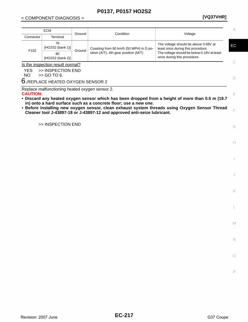
P0137, P0157 HO2S2[VQ37VHR]
C
D
E
F
G
H
I
J
K
L
M
A
C
N
P
O
< COMPONENT DIAGNOSIS >
E
Is the inspection result normal?YES >> INSPECTION ENDNO >> GO TO 6.
6.REPLACE HEATED OXYGEN SENSOR 2
Replace malfunctioning heated oxygen sensor 2.CAUTION:• Discard any heated oxygen sensor which has been dropped from a height of more than 0.5 m (19.7
in) onto a hard surface such as a concrete floor; use a new one.• Before installing new oxygen sensor, clean exhaust system threads using Oxygen Sensor Thread
Cleaner tool J-43897-18 or J-43897-12 and approved anti-seize lubricant.
>> INSPECTION END
ECMGround Condition Voltage
Connector Terminal
F102
76[HO2S2 (bank 1)]
GroundCoasting from 80 km/h (50 MPH) in D po-sition (A/T), 4th gear position (M/T)
The voltage should be above 0.68V at least once during this procedure.The voltage should be below 0.18V at least once during this procedure.
80[HO2S2 (bank 2)]
EC-217Revision: 2007 June G37 Coupe

[VQ37VHR]P0138, P0158 HO2S2
< COMPONENT DIAGNOSIS >
P0138, P0158 HO2S2
Description INFOID:0000000001910856
The heated oxygen sensor 2, after three way catalyst 1, monitors theoxygen level in the exhaust gas on each bank.Even if switching characteristics of the air fuel ratio (A/F) sensor 1are shifted, the air-fuel ratio is controlled to stoichiometric, by the sig-nal from the heated oxygen sensor 2.This sensor is made of ceramic zirconia. The zirconia generates volt-age from approximately 1V in richer conditions to 0V in leaner condi-tions.Under normal conditions the heated oxygen sensor 2 is not used forengine control operation.
DTC Logic INFOID:0000000001734051
DTC DETECTION LOGICThe heated oxygen sensor 2 has a much longer switching time between rich and lean than the air fuel ratio (A/F) sensor 1. The oxygen storage capacity of the three way catalyst 1 causes the longer switching time.MALFUNCTION ATo judge the malfunctions of heated oxygen sensor 2, ECM monitorswhether the voltage is unusually high during the various driving con-dition such as fuel-cut.
MALFUNCTION BTo judge the malfunctions of heated oxygen sensor 2, ECM monitorswhether the minimum voltage of sensor is sufficiently low during thevarious driving condition such as fuel-cut.
SEF327R
PBIB1848E
PBIB2376E
DTC No. Trouble diagnosis name DTC detecting condition Possible cause
P0138Heated oxygen sensor 2 (bank 1) circuit high volt-age
A)An excessively high voltage from the sen-sor is sent to ECM.
• Harness or connectors(The sensor circuit is open or shorted)
• Heated oxygen sensor 2
B)The minimum voltage from the sensor is not reached to the specified voltage.
• Harness or connectors(The sensor circuit is open or shorted)
• Heated oxygen sensor 2• Fuel pressure• Fuel injector
EC-218Revision: 2007 June G37 Coupe
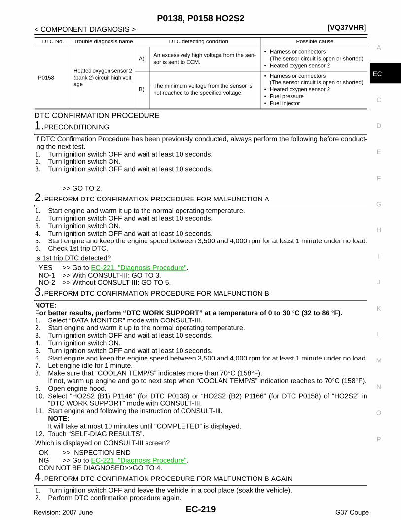
P0138, P0158 HO2S2[VQ37VHR]
C
D
E
F
G
H
I
J
K
L
M
A
C
N
P
O
< COMPONENT DIAGNOSIS >
E
DTC CONFIRMATION PROCEDURE
1.PRECONDITIONING
If DTC Confirmation Procedure has been previously conducted, always perform the following before conduct-ing the next test.1. Turn ignition switch OFF and wait at least 10 seconds.2. Turn ignition switch ON.3. Turn ignition switch OFF and wait at least 10 seconds.
>> GO TO 2.
2.PERFORM DTC CONFIRMATION PROCEDURE FOR MALFUNCTION A
1. Start engine and warm it up to the normal operating temperature.2. Turn ignition switch OFF and wait at least 10 seconds.3. Turn ignition switch ON.4. Turn ignition switch OFF and wait at least 10 seconds.5. Start engine and keep the engine speed between 3,500 and 4,000 rpm for at least 1 minute under no load.6. Check 1st trip DTC.Is 1st trip DTC detected?YES >> Go to EC-221, "Diagnosis Procedure".NO-1 >> With CONSULT-III: GO TO 3.NO-2 >> Without CONSULT-III: GO TO 5.
3.PERFORM DTC CONFIRMATION PROCEDURE FOR MALFUNCTION B
NOTE:For better results, perform “DTC WORK SUPPORT” at a temperature of 0 to 30 °C (32 to 86 °F).1. Select “DATA MONITOR” mode with CONSULT-III.2. Start engine and warm it up to the normal operating temperature.3. Turn ignition switch OFF and wait at least 10 seconds.4. Turn ignition switch ON.5. Turn ignition switch OFF and wait at least 10 seconds.6. Start engine and keep the engine speed between 3,500 and 4,000 rpm for at least 1 minute under no load.7. Let engine idle for 1 minute.8. Make sure that “COOLAN TEMP/S” indicates more than 70°C (158°F).
If not, warm up engine and go to next step when “COOLAN TEMP/S” indication reaches to 70°C (158°F).9. Open engine hood.10. Select “HO2S2 (B1) P1146” (for DTC P0138) or “HO2S2 (B2) P1166” (for DTC P0158) of “HO2S2” in
“DTC WORK SUPPORT” mode with CONSULT-III.11. Start engine and following the instruction of CONSULT-III.
NOTE:It will take at most 10 minutes until “COMPLETED” is displayed.
12. Touch “SELF-DIAG RESULTS”.Which is displayed on CONSULT-III screen?OK >> INSPECTION ENDNG >> Go to EC-221, "Diagnosis Procedure".CON NOT BE DIAGNOSED>>GO TO 4.
4.PERFORM DTC CONFIRMATION PROCEDURE FOR MALFUNCTION B AGAIN
1. Turn ignition switch OFF and leave the vehicle in a cool place (soak the vehicle).2. Perform DTC confirmation procedure again.
P0158Heated oxygen sensor 2 (bank 2) circuit high volt-age
A)An excessively high voltage from the sen-sor is sent to ECM.
• Harness or connectors(The sensor circuit is open or shorted)
• Heated oxygen sensor 2
B)The minimum voltage from the sensor is not reached to the specified voltage.
• Harness or connectors(The sensor circuit is open or shorted)
• Heated oxygen sensor 2• Fuel pressure• Fuel injector
DTC No. Trouble diagnosis name DTC detecting condition Possible cause
EC-219Revision: 2007 June G37 Coupe

[VQ37VHR]P0138, P0158 HO2S2
< COMPONENT DIAGNOSIS >
>> GO TO 3.
5.PERFORM COMPONENT FUNCTION CHECK FOR MALFUNCTION B
Perform component function check. Refer to EC-220, "Component Function Check".NOTE:Use component function check to check the overall function of the heated oxygen sensor 2 circuit. During thischeck, a 1st trip DTC might not be confirmed.Is the inspection result normal?YES >> INSPECTION ENDNO >> Go to EC-221, "Diagnosis Procedure".
Component Function Check INFOID:0000000001734052
1.PERFORM COMPONENT FUNCTION CHECK-I
Without CONSULT-III1. Start engine and warm it up to the normal operating temperature.2. Turn ignition switch OFF and wait at least 10 seconds.3. Turn ignition switch ON.4. Turn ignition switch OFF and wait at least 10 seconds.5. Start engine and keep the engine speed between 3,500 and 4,000 rpm for at least 1 minute under no load.6. Let engine idle for 1 minute.7. Check the voltage between ECM harness connector and ground under the following condition.
Is the inspection result normal?YES >> INSPECTION ENDNO >> GO TO 2.
2.PERFORM COMPONENT FUNCTION CHECK-II
Check the voltage between ECM harness connector and ground under the following condition.
Is the inspection result normal?YES >> INSPECTION ENDNO >> GO TO 3.
3.PERFORM COMPONENT FUNCTION CHECK-III
Check the voltage between ECM harness connector and ground under the following condition.
Is the inspection result normal?YES >> INSPECTION ENDNO >> Go to EC-221, "Diagnosis Procedure".
DTCECM
Ground Condition VoltageConnector Terminal
P0138F102
76Ground
Revving up to 4,000 rpm under no load at least 10 times
The voltage should be below 0.18V at least once during this procedure.P0158 80
DTCECM
Ground Condition VoltageConnector Terminal
P0138F102
76Ground Keeping engine at idle for 10 minutes
The voltage should be below 0.18V at least once during this procedure.P0158 80
DTCECM
Ground Condition VoltageConnector Terminal
P0138F102
76Ground
Coasting from 80 km/h (50 MPH) in D po-sition (A/T), 4th gear position (M/T)
The voltage should be below 0.18V at least once during this procedure.P0158 80
EC-220Revision: 2007 June G37 Coupe

P0138, P0158 HO2S2[VQ37VHR]
C
D
E
F
G
H
I
J
K
L
M
A
C
N
P
O
< COMPONENT DIAGNOSIS >
E
Diagnosis Procedure INFOID:0000000001734053
1.INSPECTION START
Confirm the detected malfunction (A or B). Refer to EC-218, "DTC Logic".Which malfunction is detected?A >> GO TO 2B >> GO TO 9.
2.CHECK GROUND CONNECTION
1. Turn ignition switch OFF.2. Check ground connection M95. Refer to Ground Inspection in GI-41, "Circuit Inspection".Is the inspection result normal?YES >> GO TO 3.NO >> Repair or replace ground connection.
3.CHECK HO2S2 GROUND CIRCUIT FOR OPEN AND SHORT
1. Disconnect heated oxygen sensor 2 harness connector.2. Disconnect ECM harness connector.3. Check the continuity between HO2S2 harness connector and ECM harness connector.
4. Also check harness for short to ground and short to power.Is the inspection result normal?YES >> GO TO 4.NO >> Repair open circuit or short to ground or short to power in harness or connectors.
4.CHECK HO2S2 INPUT SIGNAL CIRCUIT FOR OPEN AND SHORT
1. Check the continuity between HO2S2 harness connector and ECM harness connector.
2. Check the continuity between HO2S2 harness connector or ECM harness connector and ground.
3. Also check harness for short to power.Is the inspection result normal?YES >> GO TO 5.NO >> Repair open circuit or short to ground or short to power in harness or connectors.
5.CHECK HO2S2 CONNECTOR FOR WATER
Check connectors for water.
Is the inspection result normal?
DTCHO2S2 ECM
ContinuityBank Connector Terminal Connector Terminal
P0138 1 F54 1F102 84 Existed
P0158 2 F53 1
DTCHO2S2 ECM
ContinuityBank Connector Terminal Connector Terminal
P0138 1 F54 4F102
76Existed
P0158 2 F53 4 80
DTCHO2S2 ECM
Ground ContinuityBank Connector Terminal Connector Terminal
P0138 1 F54 4F102
76Ground Not existed
P0158 2 F53 4 80
Water should not exist.
EC-221Revision: 2007 June G37 Coupe

[VQ37VHR]P0138, P0158 HO2S2
< COMPONENT DIAGNOSIS >YES >> GO TO 6.NO >> Repair or replace harness or connectors.
6.CHECK HEATED OXYGEN SENSOR 2
Refer to EC-223, "Component Inspection".Is the inspection result normal?YES >> GO TO 8.NO >> GO TO 7.
7.REPLACE HEATED OXYGEN SENSOR 2
Replace malfunctioning heated oxygen sensor 2.CAUTION:• Discard any heated oxygen sensor which has been dropped from a height of more than 0.5 m (19.7
in) onto a hard surface such as a concrete floor; use a new one.• Before installing new oxygen sensor, clean exhaust system threads using Oxygen Sensor Thread
Cleaner tool J-43897-18 or J-43897-12 and approved anti-seize lubricant.
>> INSPECTION END
8.CHECK INTERMITTENT INCIDENT
Refer to GI-38, "Intermittent Incident".
>> INSPECTION END
9.CHECK GROUND CONNECTION
1. Turn ignition switch OFF.2. Check ground connection M95. Refer to Ground Inspection in GI-41, "Circuit Inspection".Is the inspection result normal?YES >> GO TO 10.NO >> Repair or replace ground connection.
10.CLEAR THE MIXTURE RATIO SELF-LEARNING VALUE
1. Clear the mixture ratio self-learning value. Refer to EC-22, "MIXTURE RATIO SELF-LEARNING VALUECLEAR : Special Repair Requirement".
2. Run engine for at least 10 minutes at idle speed.Is the 1st trip DTC P0172 or P0175 detected? Is it difficult to start engine?YES >> Perform trouble diagnosis for DTC P0172, P0175. Refer to EC-236, "DTC Logic".NO >> GO TO 11.
11.CHECK HO2S2 GROUND CIRCUIT FOR OPEN AND SHORT
1. Turn ignition switch OFF.2. Disconnect heated oxygen sensor 2 harness connector.3. Disconnect ECM harness connector.4. Check the continuity between HO2S2 harness connector and ECM harness connector.
5. Also check harness for short to ground and short to power.Is the inspection result normal?YES >> GO TO 12.NO >> Repair open circuit or short to ground or short to power in harness or connectors.
12.CHECK HO2S2 INPUT SIGNAL CIRCUIT FOR OPEN AND SHORT
1. Check the continuity between HO2S2 harness connector and ECM harness connector.
DTCHO2S2 ECM
ContinuityBank Connector Terminal Connector Terminal
P0138 1 F54 1F102 84 Existed
P0158 2 F53 1
EC-222Revision: 2007 June G37 Coupe

P0138, P0158 HO2S2[VQ37VHR]
C
D
E
F
G
H
I
J
K
L
M
A
C
N
P
O
< COMPONENT DIAGNOSIS >
E
2. Check the continuity between HO2S2 harness connector or ECM harness connector and ground.
3. Also check harness for short to power.Is the inspection result normal?YES >> GO TO 13.NO >> Repair open circuit or short to ground or short to power in harness or connectors.
13.CHECK HEATED OXYGEN SENSOR 2
Refer to EC-223, "Component Inspection".Is the inspection result normal?YES >> GO TO 15.NO >> GO TO 14.
14.REPLACE HEATED OXYGEN SENSOR 2
Replace malfunctioning heated oxygen sensor 2.CAUTION:• Discard any heated oxygen sensor which has been dropped from a height of more than 0.5 m (19.7
in) onto a hard surface such as a concrete floor; use a new one.• Before installing new oxygen sensor, clean exhaust system threads using Oxygen Sensor Thread
Cleaner tool J-43897-18 or J-43897-12 and approved anti-seize lubricant.
>> INSPECTION END
15.CHECK INTERMITTENT INCIDENT
Refer to GI-38, "Intermittent Incident".
>> INSPECTION END
Component Inspection INFOID:0000000001910858
1.INSPECTION START
Do you have CONSULT-III?Do you have CONSULT-III?YES >> GO TO 2.NO >> GO TO 3.
2.CHECK HEATED OXYGEN SENSOR 2
With CONSULT-III1. Turn ignition switch ON and select “DATA MONITOR” mode with CONSULT-III.2. Start engine and warm it up to the normal operating temperature.3. Turn ignition switch OFF and wait at least 10 seconds.4. Start engine and keep the engine speed between 3,500 and 4,000 rpm for at least 1 minute under no load.5. Let engine idle for 1 minute.6. Select “FUEL INJECTION” in “ACTIVE TEST” mode, and select “HO2S2 (B1)/(B2)” as the monitor item
with CONSULT-III.
DTCHO2S2 ECM
ContinuityBank Connector Terminal Connector Terminal
P0138 1 F54 4F102
76Existed
P0158 2 F53 4 80
DTCHO2S2 ECM
Ground ContinuityBank Connector Terminal Connector Terminal
P0138 1 F54 4F102
76Ground Not existed
P0158 2 F53 4 80
EC-223Revision: 2007 June G37 Coupe

[VQ37VHR]P0138, P0158 HO2S2
< COMPONENT DIAGNOSIS >7. Check “HO2S2 (B1)/(B2)” at idle speed when adjusting “FUEL INJECTION” to ±25%.
“HO2S2 (B1)/(B2)” should be above 0.68V at least once when the “FUEL INJECTION” is +25%.“HO2S2 (B1)/(B2)” should be below 0.18V at least once when the “FUEL INJECTION” is −25%.
Is the inspection result normal?YES >> INSPECTION ENDNO >> GO TO 6.
3.CHECK HEATED OXYGEN SENSOR 2-I
Without CONSULT-III1. Start engine and warm it up to the normal operating temperature.2. Turn ignition switch OFF and wait at least 10 seconds.3. Start engine and keep the engine speed between 3,500 and 4,000 rpm for at least 1 minute under no load.4. Let engine idle for 1 minute.5. Check the voltage between ECM harness connector and ground under the following condition.
Is the inspection result normal?YES >> INSPECTION ENDNO >> GO TO 4.
4.CHECK HEATED OXYGEN SENSOR 2-II
Check the voltage between ECM harness connector and ground under the following condition.
Is the inspection result normal?YES >> INSPECTION ENDNO >> GO TO 5.
5.CHECK HEATED OXYGEN SENSOR 2-III
Check the voltage between ECM harness connector and ground under the following condition.
PBIB3458E
ECMGround Condition Voltage
Connector Terminal
F102
76[HO2S2 (bank 1)]
GroundRevving up to 4,000 rpm under no load at least 10 times
The voltage should be above 0.68V at least once during this procedure.The voltage should be below 0.18V at least once during this procedure.
80[HO2S2 (bank 2)]
ECMGround Condition Voltage
Connector Terminal
F102
76[HO2S2 (bank 1)]
Ground Keeping engine at idle for 10 minutes
The voltage should be above 0.68V at least once during this procedure.The voltage should be below 0.18V at least once during this procedure.
80[HO2S2 (bank 2)]
EC-224Revision: 2007 June G37 Coupe

P0138, P0158 HO2S2[VQ37VHR]
C
D
E
F
G
H
I
J
K
L
M
A
C
N
P
O
< COMPONENT DIAGNOSIS >
E
Is the inspection result normal?YES >> INSPECTION ENDNO >> GO TO 6.
6.REPLACE HEATED OXYGEN SENSOR 2
Replace malfunctioning heated oxygen sensor 2.CAUTION:• Discard any heated oxygen sensor which has been dropped from a height of more than 0.5 m (19.7
in) onto a hard surface such as a concrete floor; use a new one.• Before installing new oxygen sensor, clean exhaust system threads using Oxygen Sensor Thread
Cleaner tool J-43897-18 or J-43897-12 and approved anti-seize lubricant.
>> INSPECTION END
ECMGround Condition Voltage
Connector Terminal
F102
76[HO2S2 (bank 1)]
GroundCoasting from 80 km/h (50 MPH) in D po-sition (A/T), 4th gear position (M/T)
The voltage should be above 0.68V at least once during this procedure.The voltage should be below 0.18V at least once during this procedure.
80[HO2S2 (bank 2)]
EC-225Revision: 2007 June G37 Coupe

[VQ37VHR]P0139, P0159 HO2S2
< COMPONENT DIAGNOSIS >
P0139, P0159 HO2S2
Description INFOID:0000000001910857
The heated oxygen sensor 2, after three way catalyst 1, monitors theoxygen level in the exhaust gas on each bank.Even if switching characteristics of the air fuel ratio (A/F) sensor 1are shifted, the air-fuel ratio is controlled to stoichiometric, by the sig-nal from the heated oxygen sensor 2.This sensor is made of ceramic zirconia. The zirconia generates volt-age from approximately 1V in richer conditions to 0V in leaner condi-tions.Under normal conditions the heated oxygen sensor 2 is not used forengine control operation.
DTC Logic INFOID:0000000001734056
DTC DETECTION LOGICThe heated oxygen sensor 2 has a much longer switching timebetween rich and lean than the air fuel ratio (A/F) sensor 1. The oxy-gen storage capacity of the three way catalyst 1 causes the longerswitching time. To judge the malfunctions of heated oxygen sensor2, ECM monitors whether the switching response of the sensor'svoltage is faster than specified during the various driving conditionsuch as fuel-cut.
DTC CONFIRMATION PROCEDURE
1.INSPECTION START
Do you have CONSULT-III?Do you have CONSULT-III?YES >> GO TO 2.NO >> GO TO 5.
2.PRECONDITIONING
If DTC Confirmation Procedure has been previously conducted, always perform the following before conduct-ing the next test.1. Turn ignition switch OFF and wait at least 10 seconds.2. Turn ignition switch ON.3. Turn ignition switch OFF and wait at least 10 seconds.TESTING CONDITION:For better results, perform “DTC WORK SUPPORT” at a temperature of 0 to 30 °C (32 to 86 °F).
>> GO TO 3.
SEF327R
SEF302U
DTC No. Trouble diagnosis name DTC detecting condition Possible cause
P0139Heated oxygen sensor 2 (bank 1) circuit slow re-sponse It takes more time for the sensor to respond be-
tween rich and lean than the specified time.
• Harness or connectors(The sensor circuit is open or shorted)
• Heated oxygen sensor 2• Fuel pressure• Fuel injector• Intake air leaks
P0159Heated oxygen sensor 2 (bank 2) circuit slow re-sponse
EC-226Revision: 2007 June G37 Coupe

P0139, P0159 HO2S2[VQ37VHR]
C
D
E
F
G
H
I
J
K
L
M
A
C
N
P
O
< COMPONENT DIAGNOSIS >
E
3.PERFORM DTC CONFIRMATION PROCEDURE
With CONSULT-III1. Turn ignition switch ON and select “DATA MONITOR” mode with CONSULT-III.2. Start engine and warm it up to the normal operating temperature.3. Turn ignition switch OFF and wait at least 10 seconds.4. Turn ignition switch ON.5. Turn ignition switch OFF and wait at least 10 seconds.6. Start engine and keep the engine speed between 3,500 and 4,000 rpm for at least 1 minute under no load.7. Let engine idle for 1 minute.8. Make sure that “COOLAN TEMP/S” indicates more than 70°C (158°F).
If not, warm up engine and go to next step when “COOLAN TEMP/S” indication reaches to 70°C (158°F).9. Open engine hood.10. Select “HO2S2 (B1) P0139” or “HO2S2 (B2) P0159” of “HO2S2” in “DTC WORK SUPPORT” mode with
CONSULT-III.11. Start engine and following the instruction of CONSULT-III.
NOTE:It will take at most 10 minutes until “COMPLETED” is displayed.
12. Touch “SELF-DIAG RESULTS”.Which is displayed on CONSULT-III screen?OK >> INSPECTION ENDNG >> Go to EC-228, "Diagnosis Procedure".CAN NOT BE DIAGNOSED>>GO TO 4.
4.PERFORM DTC CONFIRMATION PROCEDURE AGAIN
1. Turn ignition switch OFF and leave the vehicle in a cool place (soak the vehicle).2. Perform DTC confirmation procedure again.
>> GO TO 3.
5.PERFORM COMPONENT FUNCTION CHECK
Perform component function check. Refer to EC-227, "Component Function Check".NOTE:Use component function check to check the overall function of the heated oxygen sensor 2 circuit. During thischeck, a 1st trip DTC might not be confirmed.Is the inspection result normal?YES >> INSPECTION ENDNO >> Go to EC-228, "Diagnosis Procedure".
Component Function Check INFOID:0000000001734057
1.PERFORM COMPONENT FUNCTION CHECK-I
Without CONSULT-III1. Start engine and warm it up to the normal operating temperature.2. Turn ignition switch OFF and wait at least 10 seconds.3. Turn ignition switch ON.4. Turn ignition switch OFF and wait at least 10 seconds.5. Start engine and keep the engine speed between 3,500 and 4,000 rpm for at least 1 minute under no load.6. Let engine idle for 1 minute.7. Check the voltage between ECM harness connector and ground under the following condition.
Is the inspection result normal?YES >> INSPECTION END
DTCECM
Ground Condition VoltageConnector Terminal
P0139F102
76Ground
Revving up to 4,000 rpm under no load at least 10 times
A change of voltage should be more than 0.24V for 1 second during this procedure.P0159 80
EC-227Revision: 2007 June G37 Coupe

[VQ37VHR]P0139, P0159 HO2S2
< COMPONENT DIAGNOSIS >NO >> GO TO 2.
2.PERFORM COMPONENT FUNCTION CHECK-II
Check the voltage between ECM harness connector and ground under the following condition.
Is the inspection result normal?YES >> INSPECTION ENDNO >> GO TO 3.
3.PERFORM COMPONENT FUNCTION CHECK-III
Check the voltage between ECM harness connector and ground under the following condition.
Is the inspection result normal?YES >> INSPECTION ENDNO >> Go to EC-228, "Diagnosis Procedure".
Diagnosis Procedure INFOID:0000000001734058
1.CHECK GROUND CONNECTION
1. Turn ignition switch OFF.2. Check ground connection M95. Refer to Ground Inspection in GI-41, "Circuit Inspection".Is the inspection result normal?YES >> GO TO 2.NO >> Repair or replace ground connection.
2.CLEAR THE MIXTURE RATIO SELF-LEARNING VALUE
1. Clear the mixture ratio self-learning value. Refer to EC-22, "MIXTURE RATIO SELF-LEARNING VALUECLEAR : Special Repair Requirement".
2. Run engine for at least 10 minutes at idle speed.Is the 1st trip DTC P0171, P0172, P0174 or P0175 detected? Is it difficult to start engine?YES >> Perform trouble diagnosis for DTC P0171, P0174 or P0172, P0175. Refer to EC-232, "DTC Logic"
or EC-236, "DTC Logic".NO >> GO TO 3.
3.CHECK HO2S2 GROUND CIRCUIT FOR OPEN AND SHORT
1. Turn ignition switch OFF.2. Disconnect heated oxygen sensor 2 harness connector.3. Disconnect ECM harness connector.4. Check the continuity between HO2S2 harness connector and ECM harness connector.
5. Also check harness for short to ground and short to power.
DTCECM
Ground Condition VoltageConnector Terminal
P0139F102
76Ground Keeping engine at idle for 10 minutes
A change of voltage should be more than 0.24V for 1 second during this procedure.P0159 80
DTCECM
Ground Condition VoltageConnector Terminal
P0139F102
76Ground
Coasting from 80 km/h (50 MPH) in D po-sition (A/T), 4th gear position (M/T)
A change of voltage should be more than 0.24V for 1 second during this procedure.P0159 80
DTCHO2S2 ECM
ContinuityBank Connector Terminal Connector Terminal
P0139 1 F54 1F102 84 Existed
P0159 2 F53 1
EC-228Revision: 2007 June G37 Coupe

P0139, P0159 HO2S2[VQ37VHR]
C
D
E
F
G
H
I
J
K
L
M
A
C
N
P
O
< COMPONENT DIAGNOSIS >
E
Is the inspection result normal?YES >> GO TO 4.NO >> Repair open circuit or short to ground or short to power in harness or connectors.
4.CHECK HO2S2 INPUT SIGNAL CIRCUIT FOR OPEN AND SHORT
1. Check the continuity between HO2S2 harness connector and ECM harness connector.
2. Check the continuity between HO2S2 harness connector or ECM harness connector and ground.
3. Also check harness for short to power.Is the inspection result normal?YES >> GO TO 5.NO >> Repair open circuit or short to ground or short to power in harness or connectors.
5.CHECK HEATED OXYGEN SENSOR 2
Refer to EC-229, "Component Inspection".Is the inspection result normal?YES >> GO TO 7.NO >> GO TO 6.
6.REPLACE HEATED OXYGEN SENSOR 2
Replace malfunctioning heated oxygen sensor 2.CAUTION:• Discard any heated oxygen sensor which has been dropped from a height of more than 0.5 m (19.7
in) onto a hard surface such as a concrete floor; use a new one.• Before installing new oxygen sensor, clean exhaust system threads using Oxygen Sensor Thread
Cleaner tool J-43897-18 or J-43897-12 and approved anti-seize lubricant.
>> INSPECTION END
7.CHECK INTERMITTENT INCIDENT
Refer to GI-38, "Intermittent Incident".
>> INSPECTION END
Component Inspection INFOID:0000000001910859
1.INSPECTION START
Do you have CONSULT-III?Do you have CONSULT-III?YES >> GO TO 2.NO >> GO TO 3.
2.CHECK HEATED OXYGEN SENSOR 2
With CONSULT-III1. Turn ignition switch ON and select “DATA MONITOR” mode with CONSULT-III.
DTCHO2S2 ECM
ContinuityBank Connector Terminal Connector Terminal
P0139 1 F54 4F102
76Existed
P0159 2 F53 4 80
DTCHO2S2 ECM
Ground ContinuityBank Connector Terminal Connector Terminal
P0139 1 F54 4F102
76Ground Not existed
P0159 2 F53 4 80
EC-229Revision: 2007 June G37 Coupe

[VQ37VHR]P0139, P0159 HO2S2
< COMPONENT DIAGNOSIS >2. Start engine and warm it up to the normal operating temperature.3. Turn ignition switch OFF and wait at least 10 seconds.4. Start engine and keep the engine speed between 3,500 and 4,000 rpm for at least 1 minute under no load.5. Let engine idle for 1 minute.6. Select “FUEL INJECTION” in “ACTIVE TEST” mode, and select “HO2S2 (B1)/(B2)” as the monitor item
with CONSULT-III.7. Check “HO2S2 (B1)/(B2)” at idle speed when adjusting “FUEL INJECTION” to ±25%.
“HO2S2 (B1)/(B2)” should be above 0.68V at least once when the “FUEL INJECTION” is +25%.“HO2S2 (B1)/(B2)” should be below 0.18V at least once when the “FUEL INJECTION” is −25%.
Is the inspection result normal?YES >> INSPECTION ENDNO >> GO TO 6.
3.CHECK HEATED OXYGEN SENSOR 2-I
Without CONSULT-III1. Start engine and warm it up to the normal operating temperature.2. Turn ignition switch OFF and wait at least 10 seconds.3. Start engine and keep the engine speed between 3,500 and 4,000 rpm for at least 1 minute under no load.4. Let engine idle for 1 minute.5. Check the voltage between ECM harness connector and ground under the following condition.
Is the inspection result normal?YES >> INSPECTION ENDNO >> GO TO 4.
4.CHECK HEATED OXYGEN SENSOR 2-II
Check the voltage between ECM harness connector and ground under the following condition.
Is the inspection result normal?YES >> INSPECTION ENDNO >> GO TO 5.
5.CHECK HEATED OXYGEN SENSOR 2-III
Check the voltage between ECM harness connector and ground under the following condition.
PBIB3458E
ECMGround Condition Voltage
Connector Terminal
F102
76[HO2S2 (bank 1)]
GroundRevving up to 4,000 rpm under no load at least 10 times
The voltage should be above 0.68V at least once during this procedure.The voltage should be below 0.18V at least once during this procedure.
80[HO2S2 (bank 2)]
ECMGround Condition Voltage
Connector Terminal
F102
76[HO2S2 (bank 1)]
Ground Keeping engine at idle for 10 minutes
The voltage should be above 0.68V at least once during this procedure.The voltage should be below 0.18V at least once during this procedure.
80[HO2S2 (bank 2)]
EC-230Revision: 2007 June G37 Coupe

P0139, P0159 HO2S2[VQ37VHR]
C
D
E
F
G
H
I
J
K
L
M
A
C
N
P
O
< COMPONENT DIAGNOSIS >
E
Is the inspection result normal?YES >> INSPECTION ENDNO >> GO TO 6.
6.REPLACE HEATED OXYGEN SENSOR 2
Replace malfunctioning heated oxygen sensor 2.CAUTION:• Discard any heated oxygen sensor which has been dropped from a height of more than 0.5 m (19.7
in) onto a hard surface such as a concrete floor; use a new one.• Before installing new oxygen sensor, clean exhaust system threads using Oxygen Sensor Thread
Cleaner tool J-43897-18 or J-43897-12 and approved anti-seize lubricant.
>> INSPECTION END
ECMGround Condition Voltage
Connector Terminal
F102
76[HO2S2 (bank 1)]
GroundCoasting from 80 km/h (50 MPH) in D po-sition (A/T), 4th gear position (M/T)
The voltage should be above 0.68V at least once during this procedure.The voltage should be below 0.18V at least once during this procedure.
80[HO2S2 (bank 2)]
EC-231Revision: 2007 June G37 Coupe

[VQ37VHR]P0171, P0174 FUEL INJECTION SYSTEM FUNCTION
< COMPONENT DIAGNOSIS >
P0171, P0174 FUEL INJECTION SYSTEM FUNCTION
DTC Logic INFOID:0000000001734060
DTC DETECTION LOGICWith the Air/Fuel Mixture Ratio Self-Learning Control, the actual mixture ratio can be brought closely to thetheoretical mixture ratio based on the mixture ratio feedback signal from the A/F sensors 1. The ECM calcu-lates the necessary compensation to correct the offset between the actual and the theoretical ratios.In case the amount of the compensation value is extremely large (The actual mixture ratio is too lean.), theECM judges the condition as the fuel injection system malfunction and lights up the MIL (2 trip detection logic).
DTC CONFIRMATION PROCEDURE
1.PRECONDITIONING
If DTC Confirmation Procedure has been previously conducted, always perform the following before conduct-ing the next test.1. Turn ignition switch OFF and wait at least 10 seconds.2. Turn ignition switch ON.3. Turn ignition switch OFF and wait at least 10 seconds.
>> GO TO 2.
2.PERFORM DTC CONFIRMATION PROCEDURE-I
1. Clear the mixture ratio self-learning value. Refer to EC-22, "MIXTURE RATIO SELF-LEARNING VALUECLEAR : Special Repair Requirement".
2. Start engine.Is it difficult to start engine?YES >> GO TO 3.NO >> GO TO 4.
3.RESTART ENGINE
If it is difficult to start engine, the fuel injection system has a malfunction, too.Crank engine while depressing accelerator pedal.Does engine start?YES >> Go to EC-233, "Diagnosis Procedure".NO >> Check exhaust and intake air leak visually.
4.PERFORM DTC CONFIRMATION PROCEDURE-II
1. Keep engine idle for at least 10 minutes.2. Check 1st trip DTC.Is 1st trip DTC detected?YES >> Go to EC-233, "Diagnosis Procedure".NO >> GO TO 5.
Sensor Input signal to ECM ECM function Actuator
A/F sensor 1Density of oxygen in exhaust gas(Mixture ratio feedback signal)
Fuel injection control Fuel injector
DTC No. Trouble diagnosis name DTC detecting condition Possible cause
P0171Fuel injection system too lean (bank 1)
• Fuel injection system does not operate properly.• The amount of mixture ratio compensation is too
large. (The mixture ratio is too lean.)
• Intake air leaks• A/F sensor 1• Fuel injector• Exhaust gas leaks• Incorrect fuel pressure• Lack of fuel• Mass air flow sensor• Incorrect PCV hose connection
P0174Fuel injection system too lean (bank 2)
EC-232Revision: 2007 June G37 Coupe

P0171, P0174 FUEL INJECTION SYSTEM FUNCTION[VQ37VHR]
C
D
E
F
G
H
I
J
K
L
M
A
C
N
P
O
< COMPONENT DIAGNOSIS >
E
5.PERFORM DTC CONFIRMATION PROCEDURE-III
1. Turn ignition switch OFF and wait at least 10 seconds.2. Turn ignition switch ON.3. Turn ignition switch OFF and wait at least 10 seconds.4. Start engine and drive the vehicle under the similar conditions to (1st trip) Freeze Frame Data for 10 min-
utes. Refer to the table below.Hold the accelerator pedal as steady as possible.The similar conditions to (1st trip) Freeze Frame Data means the vehicle operation that the following con-ditions should be satisfied at the same time.
5. Check 1st trip DTC.Is 1st trip DTC detected?YES >> Go to EC-233, "Diagnosis Procedure".NO >> INSPECTION END
Diagnosis Procedure INFOID:0000000001734061
1.CHECK EXHAUST GAS LEAK
1. Start engine and run it at idle.2. Listen for an exhaust gas leak before three way catalyst 1.
Is exhaust gas leak detected?YES >> Repair or replace.NO >> GO TO 2.
2.CHECK FOR INTAKE AIR LEAK
1. Listen for an intake air leak after the mass air flow sensor.2. Check PCV hose connection.Is intake air leak detected?YES >> Repair or replace.NO >> GO TO 3.
3.CHECK A/F SENSOR 1 INPUT SIGNAL CIRCUIT
1. Turn ignition switch OFF.2. Disconnect corresponding A/F sensor 1 harness connector.3. Disconnect ECM harness connector.4. Check the continuity between A/F sensor 1 harness connector and ECM harness connector.
Engine speed Engine speed in the freeze frame data ± 400 rpm
Vehicle speed Vehicle speed in the freeze frame data ± 10 km/h (6 MPH)
Engine coolant temperature (T) condition
When the freeze frame data shows lower than 70 °C (158 °F),T should be lower than 70 °C (158 °F).
When the freeze frame data shows higher than or equal to 70 °C (158 °F),T should be higher than or equal to 70 °C (158 °F).
PBIB1922E
EC-233Revision: 2007 June G37 Coupe

[VQ37VHR]P0171, P0174 FUEL INJECTION SYSTEM FUNCTION
< COMPONENT DIAGNOSIS >
5. Check the continuity between A/F sensor 1 harness connector or ECM harness connector and ground.
6. Also check harness for short to power.Is the inspection result normal?YES >> GO TO 4.NO >> Repair open circuit or short to ground or short to power in harness or connectors.
4.CHECK FUEL PRESSURE
1. Release fuel pressure to zero. Refer to EC-601, "Inspection".2. Install fuel pressure gauge and check fuel pressure. Refer to EC-601, "Inspection".
Is the inspection result normal?YES >> GO TO 6.NO >> GO TO 5.
5. DETECT MALFUNCTIONING PART
Check fuel hoses and fuel tubes for clogging.Is the inspection result normal?YES >> Replace “fuel filter and fuel pump assembly”.NO >> Repair or replace.
6.CHECK MASS AIR FLOW SENSOR
With CONSULT-III1. Install all removed parts.2. Check “MASS AIR FLOW” in “DATA MONITOR” mode with CONSULT-III.
For specification, refer to EC-606, "Mass Air Flow Sensor".With GST
1. Install all removed parts.2. Check mass air flow sensor signal in Service $01 with GST.
For specification, refer to EC-606, "Mass Air Flow Sensor".Is the measurement value within the specification?YES >> GO TO 7.NO >> Check connectors for rusted terminals or loose connections in the mass air flow sensor circuit or
grounds. Refer to EC-173, "Diagnosis Procedure".
7.CHECK FUNCTION OF FUEL INJECTOR
With CONSULT-III1. Start engine.2. Perform “POWER BALANCE” in “ACTIVE TEST” mode with CONSULT-III.
DTCA/F sensor 1 ECM
ContinuityBank Connector Terminal Connector Terminal
P0171 1 F31
F102
57
Existed2 61
P0174 2 F201 65
2 66
DTCA/F sensor 1 ECM
Ground ContinuityBank Connector Terminal Connector Terminal
P0171 1 F31
F102
57
Ground Not existed2 61
P0174 2 F201 65
2 66
At idling: Approximately 350 kPa (3.57 kg/cm2, 51 psi)
EC-234Revision: 2007 June G37 Coupe

P0171, P0174 FUEL INJECTION SYSTEM FUNCTION[VQ37VHR]
C
D
E
F
G
H
I
J
K
L
M
A
C
N
P
O
< COMPONENT DIAGNOSIS >
E
3. Make sure that each circuit produces a momentary engine speed drop.Without CONSULT-III
1. Start engine and let it idle.2. Listen to each fuel injector operating sound.
Is the inspection result normal?YES >> GO TO 8.NO >> Perform trouble diagnosis for FUEL INJECTOR, refer to
EC-487, "Diagnosis Procedure".
8.CHECK FUEL INJECTOR
1. Turn ignition switch OFF.2. Confirm that the engine is cooled down and there are no fire hazards near the vehicle.3. Disconnect all fuel injector harness connectors.4. Remove fuel tube assembly. Refer to EM-36, "Removal and Installation".
Keep fuel hose and all fuel injectors connected to fuel tube.5. For DTC P0171, reconnect fuel injector harness connectors on bank 1.
For DTC P0174, reconnect fuel injector harness connectors on bank 2.6. Disconnect all ignition coil harness connectors.7. Prepare pans or saucers under each fuel injector.8. Crank engine for about 3 seconds.
For DTC P0171, make sure that fuel sprays out from fuel injec-tors on bank 1.For DTC P0174, make sure that fuel sprays out from fuel injec-tors on bank 2.
Is the inspection result normal?YES >> GO TO 9.NO >> Replace fuel injectors from which fuel does not spray
out. Always replace O-ring with new ones.
9.CHECK INTERMITTENT INCIDENT
Refer to GI-38, "Intermittent Incident".
>> INSPECTION END
Clicking sound should be heard.
PBIB3332E
Fuel should be sprayed evenly for each fuel injector.
PBIB1726E
EC-235Revision: 2007 June G37 Coupe

[VQ37VHR]P0172, P0175 FUEL INJECTION SYSTEM FUNCTION
< COMPONENT DIAGNOSIS >
P0172, P0175 FUEL INJECTION SYSTEM FUNCTION
DTC Logic INFOID:0000000001734062
DTC DETECTION LOGICWith the Air/Fuel Mixture Ratio Self-Learning Control, the actual mixture ratio can be brought closely to thetheoretical mixture ratio based on the mixture ratio feedback signal from the A/F sensors 1. The ECM calcu-lates the necessary compensation to correct the offset between the actual and the theoretical ratios.In case the amount of the compensation value is extremely large (The actual mixture ratio is too rich.), theECM judges the condition as the fuel injection system malfunction and lights up the MIL (2 trip detection logic).
DTC CONFIRMATION PROCEDURE
1.PRECONDITIONING
If DTC Confirmation Procedure has been previously conducted, always perform the following before conduct-ing the next test.1. Turn ignition switch OFF and wait at least 10 seconds.2. Turn ignition switch ON.3. Turn ignition switch OFF and wait at least 10 seconds.
>> GO TO 2.
2.PERFORM DTC CONFIRMATION PROCEDURE-I
1. Clear the mixture ratio self-learning value. Refer to EC-22, "MIXTURE RATIO SELF-LEARNING VALUECLEAR : Special Repair Requirement".
2. Start engine.Is it difficult to start engine?YES >> GO TO 3.NO >> GO TO 4.
3.RESTART ENGINE
If it is difficult to start engine, the fuel injection system has a malfunction, too.Crank engine while depressing accelerator pedal.Does engine start?YES >> Go to EC-237, "Diagnosis Procedure".NO >> Remove spark plugs and check for fouling, etc.
4.PERFORM DTC CONFIRMATION PROCEDURE-II
1. Keep engine idle for at least 10 minutes.2. Check 1st trip DTC.Is 1st trip DTC detected?YES >> Go to EC-237, "Diagnosis Procedure".NO >> GO TO 5.
5.PERFORM DTC CONFIRMATION PROCEDURE-III
1. Turn ignition switch OFF and wait at least 10 seconds.2. Turn ignition switch ON.
Sensor Input signal to ECM ECM function Actuator
A/F sensor 1Density of oxygen in exhaust gas(Mixture ratio feedback signal)
Fuel injection control Fuel injector
DTC No. Trouble diagnosis name DTC detecting condition Possible cause
P0172Fuel injection system too rich (bank 1) • Fuel injection system does not operate properly.
• The amount of mixture ratio compensation is too large. (The mixture ratio is too rich.)
• A/F sensor 1• Fuel injector• Exhaust gas leaks• Incorrect fuel pressure• Mass air flow sensor
P0175Fuel injection system too rich (bank 2)
EC-236Revision: 2007 June G37 Coupe

P0172, P0175 FUEL INJECTION SYSTEM FUNCTION[VQ37VHR]
C
D
E
F
G
H
I
J
K
L
M
A
C
N
P
O
< COMPONENT DIAGNOSIS >
E
3. Turn ignition switch OFF and wait at least 10 seconds.4. Start engine and drive the vehicle under the similar conditions to (1st trip) Freeze Frame Data for 10 min-
utes. Refer to the table below.Hold the accelerator pedal as steady as possible.The similar conditions to (1st trip) Freeze Frame Data means the vehicle operation that the following con-ditions should be satisfied at the same time.
5. Check 1st trip DTC.Is 1st trip DTC detected?YES >> Go to EC-237, "Diagnosis Procedure".NO >> INSPECTION END
Diagnosis Procedure INFOID:0000000001734063
1.CHECK EXHAUST GAS LEAK
1. Start engine and run it at idle.2. Listen for an exhaust gas leak before three way catalyst 1.
Is exhaust gas leak detected?YES >> Repair or replace.NO >> GO TO 2.
2.CHECK FOR INTAKE AIR LEAK
Listen for an intake air leak after the mass air flow sensor.Is intake air leak detected?YES >> Repair or replace.NO >> GO TO 3.
3.CHECK A/F SENSOR 1 INPUT SIGNAL CIRCUIT
1. Turn ignition switch OFF.2. Disconnect corresponding A/F sensor 1 harness connector.3. Disconnect ECM harness connector.4. Check the continuity between A/F sensor 1 harness connector and ECM harness connector.
Engine speed Engine speed in the freeze frame data ± 400 rpm
Vehicle speed Vehicle speed in the freeze frame data ± 10 km/h (6 MPH)
Engine coolant temperature (T) condition
When the freeze frame data shows lower than 70 °C (158 °F),T should be lower than 70 °C (158 °F).
When the freeze frame data shows higher than or equal to 70 °C (158 °F),T should be higher than or equal to 70 °C (158 °F).
PBIB1922E
DTCA/F sensor 1 ECM
ContinuityBank Connector Terminal Connector Terminal
P0172 1 F31
F102
57
Existed2 61
P0175 2 F201 65
2 66
EC-237Revision: 2007 June G37 Coupe

[VQ37VHR]P0172, P0175 FUEL INJECTION SYSTEM FUNCTION
< COMPONENT DIAGNOSIS >5. Check the continuity between A/F sensor 1 harness connector or ECM harness connector and ground.
6. Also check harness for short to power.Is the inspection result normal?YES >> GO TO 4.NO >> Repair open circuit or short to ground or short to power in harness or connectors.
4.CHECK FUEL PRESSURE
1. Release fuel pressure to zero. Refer to EC-601, "Inspection".2. Install fuel pressure gauge and check fuel pressure. Refer to EC-601, "Inspection".
Is the inspection result normal?YES >> GO TO 5.NO >> Replace “fuel filter and fuel pump assembly”.
5.CHECK MASS AIR FLOW SENSOR
With CONSULT-III1. Install all removed parts.2. Check “MASS AIR FLOW” in “DATA MONITOR” mode with CONSULT-III.
For specification, refer to EC-606, "Mass Air Flow Sensor".With GST
1. Install all removed parts.2. Check mass air flow sensor signal in “Service $01” with GST.
For specification, refer to EC-606, "Mass Air Flow Sensor".Is the measurement value within the specification?YES >> GO TO 6.NO >> Check connectors for rusted terminals or loose connections in the mass air flow sensor circuit or
grounds. Refer to EC-173, "Diagnosis Procedure".
6.CHECK FUNCTION OF FUEL INJECTOR
With CONSULT-III1. Start engine.2. Perform “POWER BALANCE” in “ACTIVE TEST” mode with CONSULT-III.3. Make sure that each circuit produces a momentary engine speed drop.
Without CONSULT-III1. Start engine and let it idle.2. Listen to each fuel injector operating sound.
Is the inspection result normal?YES >> GO TO 7.NO >> Perform trouble diagnosis for FUEL INJECTOR, refer to
EC-487, "Diagnosis Procedure".
7.CHECK FUELINJECTOR
DTCA/F sensor 1 ECM
Ground ContinuityBank Connector Terminal Connector Terminal
P0172 1 F31
F102
57
Ground Not existed2 61
P0175 2 F201 65
2 66
At idling: Approximately 350 kPa (3.57 kg/cm2, 51 psi)
Clicking sound should be heard.
PBIB3332E
EC-238Revision: 2007 June G37 Coupe

P0172, P0175 FUEL INJECTION SYSTEM FUNCTION[VQ37VHR]
C
D
E
F
G
H
I
J
K
L
M
A
C
N
P
O
< COMPONENT DIAGNOSIS >
E
1. Remove fuel injector assembly. Refer to EM-36, "Removal and Installation".Keep fuel hose and all fuel injectors connected to fuel tube.
2. Confirm that the engine is cooled down and there are no fire hazards near the vehicle.3. Disconnect all fuel injector harness connectors.4. Disconnect all ignition coil harness connectors.5. Prepare pans or saucers under each fuel injectors.6. Crank engine for about 3 seconds.
Make sure fuel does not drip from fuel injector.Is the inspection result normal?YES >> GO TO 8.NO >> Replace the fuel injectors from which fuel is dripping. Always replace O-ring with new one.
8.CHECK INTERMITTENT INCIDENT
Refer to GI-38, "Intermittent Incident".
>> INSPECTION END
EC-239Revision: 2007 June G37 Coupe

[VQ37VHR]P0181 FTT SENSOR
< COMPONENT DIAGNOSIS >
P0181 FTT SENSOR
Description INFOID:0000000001734064
The fuel tank temperature sensor is used to detect the fuel tempera-ture inside the fuel tank. The sensor modifies a voltage signal fromthe ECM. The modified signal returns to the ECM as the fuel temper-ature input. The sensor uses a thermistor which is sensitive to thechange in temperature. The electrical resistance of the thermistordecreases as temperature increases.<Reference data>
*: These data are reference values and are measured between ECM terminal 106 (Fuel tank temperature sensor) and ground.
CAUTION:
Do not use ECM ground terminals when measuring input/output voltage. Doing so may result in damage to the ECM’s transis-tor. Use a ground other than ECM terminals, such as the ground.
DTC Logic INFOID:0000000001734065
DTC DETECTION LOGIC
DTC CONFIRMATION PROCEDURE
1.PRECONDITIONING
If DTC Confirmation Procedure has been previously conducted, always perform the following before conduct-ing the next test.1. Turn ignition switch OFF and wait at least 10 seconds.2. Turn ignition switch ON.3. Turn ignition switch OFF and wait at least 10 seconds.
>> GO TO 2.
2.PERFORM DTC CONFIRMATION PROCEDURE-I
1. Turn ignition switch ON and wait at least 10 seconds.2. Check 1st trip DTC.Is 1st trip DTC detected?YES >> Go to EC-241, "Diagnosis Procedure".NO >> GO TO 3.
3.CHECK ENGINE COOLANT TEMPERATURE
With CONSULT-III1. Select “COOLAN TEMP/S” in “DATA MONITOR” with CONSULT-III.2. Check “COOLAN TEMP/S” value.
With GSTFollow the procedure “With CONSULT-III” above.“COOLAN TEMP/S” less than 60°C (140°F)?YES >> INSPECTION ENDNO >> GO TO 4.
Fluid temperature °C (°F) Voltage* V Resistance kΩ
20 (68) 3.5 2.3 - 2.7
50 (122) 2.2 0.79 - 0.90SEF012P
DTC No. Trouble diagnosis name DTC detecting condition Possible cause
P0181Fuel tank temperature sensor circuit range/per-formance
Rationally incorrect voltage from the sensor is sent to ECM, compared with the voltage signals from engine coolant temperature sensor and in-take air temperature sensor.
• Harness or connectors(The sensor circuit is open or shorted)
• Fuel tank temperature sensor
EC-240Revision: 2007 June G37 Coupe

P0181 FTT SENSOR[VQ37VHR]
C
D
E
F
G
H
I
J
K
L
M
A
C
N
P
O
< COMPONENT DIAGNOSIS >
E
4.PERFORM DTC CONFIRMATION PROCEDURE-II
With CONSULT-III1. Cool engine down until “COOLAN TEMP/S” is less than 60°C (140°F).2. Wait at least 10 seconds.3. Check 1st trip DTC.
With GSTFollow the procedure “With CONSULT-III” above.Is 1st trip DTC detected?YES >> Go to EC-241, "Diagnosis Procedure".NO >> INSPECTION END
Diagnosis Procedure INFOID:0000000001734066
1.CHECK GROUND CONNECTION
1. Turn ignition switch OFF.2. Check ground connection M95. Refer to Ground Inspection in GI-41, "Circuit Inspection".Is the inspection result normal?YES >> GO TO 2.NO >> Repair or replace ground connection.
2.CHECK DTC WITH “UNIFIED METER AND A/C AMP.”
Refer to MWI-37, "CONSULT-III Function (METER/M&A)".Is the inspection result normal?YES >> GO TO 3.NO >> Go to MWI-54, "Component Function Check".
3.CHECK FUEL TANK TEMPERATURE SENSOR POWER SUPPLY CIRCUIT
1. Turn ignition switch OFF.2. Disconnect “fuel level sensor unit and fuel pump” harness connector.3. Turn ignition switch ON.4. Check the voltage between “fuel level sensor unit and fuel pump” harness connector and ground.
Is the inspection result normal?YES >> GO TO 5.NO >> GO TO 4.
4.DETECT MALFUNCTIONING PART
Check the following.• Harness connectors M7, B1• Harness for open or short between ECM and “fuel level sensor unit and fuel pump”
>> Repair open circuit or short to ground or short to power in harness or connector.
5.CHECK FUEL TANK TEMPERATURE SENSOR GROUND CIRCUIT FOR OPEN AND SHORT
1. Turn ignition switch OFF.2. Disconnect “unified meter and A/C amp.” harness connector.3. Check the continuity between “fuel level sensor unit and fuel pump” harness connector and “unified meter
and A/C amp.” harness connector.
Fuel level sensor unit and fuel pump Ground Voltage
Connector Terminal
B22 4 Ground Approx. 5V
EC-241Revision: 2007 June G37 Coupe

[VQ37VHR]P0181 FTT SENSOR
< COMPONENT DIAGNOSIS >
4. Also check harness for short to ground and short to power.Is the inspection result normal?YES >> GO TO 7.NO >> GO TO 6.
6.DETECT MALFUNCTIONING PART
Check the following.• Harness connectors M7, B1• Harness for open or short between “fuel level sensor unit and fuel pump” and “unified meter and A/C amp.”
>> Repair open circuit or short to ground or short to power in harness or connector.
7.CHECK FUEL TANK TEMPERATURE SENSOR
Refer to EC-242, "Component Inspection".Is the inspection result normal?YES >> GO TO 8.NO >> Replace “fuel level sensor unit and fuel pump”.
8.CHECK INTERMITTENT INCIDENT
Refer to GI-38, "Intermittent Incident".
>> INSPECTION END
Component Inspection INFOID:0000000001734067
1.CHECK FUEL TANK TEMPERATURE SENSOR
1. Turn ignition switch OFF.2. Disconnect “fuel level sensor unit and fuel pump” harness connector.3. Remove fuel level sensor unit.4. Check resistance between “fuel level sensor unit and fuel pump”
terminals by heating with hot water as shown in the figure.
Is the inspection result normal?YES >> INSPECTION ENDNO >> Replace “fuel level sensor unit and fuel pump”.
Fuel level sensor unit and fuel pump
Unified meter and A/C amp. Continuity
Connector Terminal Connector Terminal
B22 5 M67 58 Existed
Terminals Condition Resistance
4 and 5 Temperature °C (°F)20 (68) 2.3 - 2.7 kΩ
50 (122) 0.79 - 0.90 kΩ
JMBIA0167ZZ
EC-242Revision: 2007 June G37 Coupe
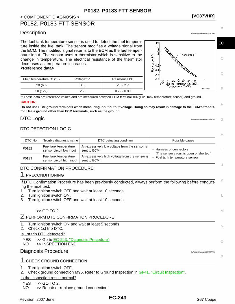
P0182, P0183 FTT SENSOR[VQ37VHR]
C
D
E
F
G
H
I
J
K
L
M
A
C
N
P
O
< COMPONENT DIAGNOSIS >
E
P0182, P0183 FTT SENSOR
Description INFOID:0000000001910860
The fuel tank temperature sensor is used to detect the fuel tempera-ture inside the fuel tank. The sensor modifies a voltage signal fromthe ECM. The modified signal returns to the ECM as the fuel temper-ature input. The sensor uses a thermistor which is sensitive to thechange in temperature. The electrical resistance of the thermistordecreases as temperature increases.<Reference data>
*: These data are reference values and are measured between ECM terminal 106 (Fuel tank temperature sensor) and ground.
CAUTION:
Do not use ECM ground terminals when measuring input/output voltage. Doing so may result in damage to the ECM’s transis-tor. Use a ground other than ECM terminals, such as the ground.
DTC Logic INFOID:0000000001734069
DTC DETECTION LOGIC
DTC CONFIRMATION PROCEDURE
1.PRECONDITIONING
If DTC Confirmation Procedure has been previously conducted, always perform the following before conduct-ing the next test.1. Turn ignition switch OFF and wait at least 10 seconds.2. Turn ignition switch ON.3. Turn ignition switch OFF and wait at least 10 seconds.
>> GO TO 2.
2.PERFORM DTC CONFIRMATION PROCEDURE
1. Turn ignition switch ON and wait at least 5 seconds.2. Check 1st trip DTC.Is 1st trip DTC detected?YES >> Go to EC-243, "Diagnosis Procedure".NO >> INSPECTION END
Diagnosis Procedure INFOID:0000000001910861
1.CHECK GROUND CONNECTION
1. Turn ignition switch OFF.2. Check ground connection M95. Refer to Ground Inspection in GI-41, "Circuit Inspection".Is the inspection result normal?YES >> GO TO 2.NO >> Repair or replace ground connection.
Fluid temperature °C (°F) Voltage* V Resistance kΩ
20 (68) 3.5 2.3 - 2.7
50 (122) 2.2 0.79 - 0.90SEF012P
DTC No. Trouble diagnosis name DTC detecting condition Possible cause
P0182Fuel tank temperature sensor circuit low input
An excessively low voltage from the sensor is sent to ECM. • Harness or connectors
(The sensor circuit is open or shorted.)• Fuel tank temperature sensorP0183
Fuel tank temperature sensor circuit high input
An excessively high voltage from the sensor is sent to ECM.
EC-243Revision: 2007 June G37 Coupe

[VQ37VHR]P0182, P0183 FTT SENSOR
< COMPONENT DIAGNOSIS >
2.CHECK DTC WITH “UNIFIED METER AND A/C AMP.”
Refer to MWI-37, "CONSULT-III Function (METER/M&A)".Is the inspection result normal?YES >> GO TO 3.NO >> Go to MWI-54, "Component Function Check".
3.CHECK FUEL TANK TEMPERATURE SENSOR POWER SUPPLY CIRCUIT
1. Turn ignition switch OFF.2. Disconnect “fuel level sensor unit and fuel pump” harness connector.3. Turn ignition switch ON.4. Check the voltage between “fuel level sensor unit and fuel pump” harness connector and ground.
Is the inspection result normal?YES >> GO TO 5.NO >> GO TO 4.
4.DETECT MALFUNCTIONING PART
Check the following.• Harness connectors M7, B1• Harness for open or short between ECM and “fuel level sensor unit and fuel pump”
>> Repair open circuit or short to ground or short to power in harness or connector.
5.CHECK FUEL TANK TEMPERATURE SENSOR GROUND CIRCUIT FOR OPEN AND SHORT
1. Turn ignition switch OFF.2. Disconnect “unified meter and A/C amp.” harness connector.3. Check the continuity between “fuel level sensor unit and fuel pump” harness connector and “unified meter
and A/C amp.” harness connector.
4. Also check harness for short to ground and short to power.Is the inspection result normal?YES >> GO TO 7.NO >> GO TO 6.
6.DETECT MALFUNCTIONING PART
Check the following.• Harness connectors M7, B1• Harness for open or short between “fuel level sensor unit and fuel pump” and “unified meter and A/C amp.”
>> Repair open circuit or short to ground or short to power in harness or connector.
7.CHECK FUEL TANK TEMPERATURE SENSOR
Refer to EC-245, "Component Inspection".Is the inspection result normal?YES >> GO TO 8.NO >> Replace “fuel level sensor unit and fuel pump”.
Fuel level sensor unit and fuel pump Ground Voltage
Connector Terminal
B22 4 Ground Approx. 5V
Fuel level sensor unit and fuel pump
Unified meter and A/C amp. Continuity
Connector Terminal Connector Terminal
B22 5 M67 58 Existed
EC-244Revision: 2007 June G37 Coupe

P0182, P0183 FTT SENSOR[VQ37VHR]
C
D
E
F
G
H
I
J
K
L
M
A
C
N
P
O
< COMPONENT DIAGNOSIS >
E
8.CHECK INTERMITTENT INCIDENT
Refer to GI-38, "Intermittent Incident".
>> INSPECTION END
Component Inspection INFOID:0000000001910862
1.CHECK FUEL TANK TEMPERATURE SENSOR
1. Turn ignition switch OFF.2. Disconnect “fuel level sensor unit and fuel pump” harness connector.3. Remove fuel level sensor unit.4. Check resistance between “fuel level sensor unit and fuel pump”
terminals by heating with hot water as shown in the figure.
Is the inspection result normal?YES >> INSPECTION ENDNO >> Replace “fuel level sensor unit and fuel pump”.
Terminals Condition Resistance
4 and 5 Temperature °C (°F)20 (68) 2.3 - 2.7 kΩ
50 (122) 0.79 - 0.90 kΩ
JMBIA0167ZZ
EC-245Revision: 2007 June G37 Coupe

[VQ37VHR]P0196 EOT SENSOR
< COMPONENT DIAGNOSIS >
P0196 EOT SENSOR
Description INFOID:0000000001734072
The engine oil temperature sensor is used to detect the engine oiltemperature. The sensor modifies a voltage signal from the ECM.The modified signal returns to the ECM as the engine oil tempera-ture input. The sensor uses a thermistor which is sensitive to thechange in temperature. The electrical resistance of the thermistordecreases as temperature increases.
<Reference data>
*: These data are reference values and are measured between ECM terminal 78(Engine oil temperature sensor) and ground.
CAUTION:
Do not use ECM ground terminals when measuring input/output voltage. Doing so may result in damage to the ECM’s transis-tor. Use a ground other than ECM terminals, such as the ground.
DTC Logic INFOID:0000000001734073
DTC DETECTION LOGICNOTE:If DTC P0196 is displayed with P0197 or P0198, first perform the trouble diagnosis for DTC P0197 orP0198. Refer to EC-249, "DTC Logic".
DTC CONFIRMATION PROCEDURE
1.PRECONDITIONING
If DTC Confirmation Procedure has been previously conducted, always perform the following before conduct-ing the next test.1. Turn ignition switch OFF and wait at least 10 seconds.2. Turn ignition switch ON.3. Turn ignition switch OFF and wait at least 10 seconds.TESTING CONDITION:Before performing the following procedure, confirm that battery voltage is more than 11V at idle.
>> GO TO 2.
SEF594K
Engine oil temperature°C (°F)
Voltage* V Resistance kΩ
–10 (14) 4.4 7.0 - 11.4
20 (68) 3.5 2.1 - 2.9
50 (122) 2.2 0.68 - 1.00
90 (194) 0.9 0.236 - 0.260
110 (230) 0.6 0.143 - 0.153SEF012P
DTC No. Trouble diagnosis name DTC detecting condition Possible cause
P0196Engine oil temperature sensor range/perfor-mance
Rationally incorrect voltage from the sensor is sent to ECM, compared with the voltage signals from engine coolant temperature sensor and in-take air temperature sensor.
• Harness or connectors(The sensor circuit is open or shorted)
• Engine oil temperature sensor
EC-246Revision: 2007 June G37 Coupe

P0196 EOT SENSOR[VQ37VHR]
C
D
E
F
G
H
I
J
K
L
M
A
C
N
P
O
< COMPONENT DIAGNOSIS >
E
2.PERFORM DTC CONFIRMATION PROCEDURE-I
1. Start engine and warm it up to normal operating temperature.2. Turn ignition switch OFF and wait at least 10 seconds.3. Turn ignition switch ON.4. Turn ignition switch OFF and wait at least 10 seconds.5. Start engine and let it idle for 5 minutes and 10 seconds.6. Check 1st trip DTC.Is 1st trip DTC detected?YES >> EC-247, "Diagnosis Procedure".NO >> GO TO 3.
3.PERFORM DTC CONFIRMATION PROCEDURE-II
With CONSULT-III1. Select “DATA MONITOR” mode with CONSULT-III.2. Check that “COOLAN TEMP/S” indicates above 80°C (176°F).
If it is above 80°C (176°F), go to the following steps.If it is below 80°C (176°F), warm engine up until “COOLAN TEMP/S” indicates more than 80°C (176°F).Then go to the following steps.
3. Turn ignition switch OFF and soak the vehicle at cool place.4. Turn ignition switch ON.5. Turn ignition switch OFF and wait at least 10 seconds.6. Turn ignition switch ON.
NOTE:Do not turn ignition switch OFF until step 10.
7. Select “DATA MONITOR” mode with CONSULT-III.8. Check the following.
If they are within the specified range, go to following steps.If they are out of the specified range, soak the vehicle to meet the above conditions. Then go to followingsteps.NOTE:• Do not turn ignition switch OFF.• If it is supposed to need a long period of time, do not deplete the battery.
9. Start engine and let it idle for 5 minutes.10. Check 1st trip DTC.
With GSTFollow the procedure “With CONSULT-III” above.Is 1st trip DTC detected?YES >> EC-247, "Diagnosis Procedure".NO >> INSPECTION END
Diagnosis Procedure INFOID:0000000001734074
1.CHECK GROUND CONNECTION
1. Turn ignition switch OFF.2. Check ground connection M95. Refer to Ground Inspection in GI-41, "Circuit Inspection".Is the inspection result normal?YES >> GO TO 2.NO >> Repair or replace ground connection.
2.CHECK ENGINE OIL TEMPERATURE SENSOR
Refer to EC-248, "Component Inspection".Is the inspection result normal?
COOLAN TEMP/S Below 40°C (104°F)
INT/A TEMP SE Below 40°C (104°F)
Difference between “COOLAN TEMP/S” and “INT/A TEMP SE” Within 6°C (11°F)
EC-247Revision: 2007 June G37 Coupe

[VQ37VHR]P0196 EOT SENSOR
< COMPONENT DIAGNOSIS >YES >> GO TO 3.NO >> Replace engine oil temperature sensor.
3.CHECK INTERMITTENT INCIDENT
Refer to GI-38, "Intermittent Incident".
>> INSPECTION END
Component Inspection INFOID:0000000001734075
1.CHECK ENGINE OIL TEMPERATURE SENSOR
1. Turn ignition switch OFF.2. Disconnect engine oil temperature sensor harness connector.3. Remove engine oil temperature sensor.4. Check resistance between engine oil temperature sensor termi-
nals by heating with hot water as shown in the figure.
Is the inspection result normal?YES >> INSPECTION ENDNO >> Replace engine oil temperature sensor.
Terminals Condition Resistance
1 and 2 Temperature °C (°F)
20 (68) 2.1 - 2.9 kΩ
50 (122) 0.68 - 1.00 kΩ
90 (194) 0.236 - 0.260 kΩ
JMBIA0080ZZ
EC-248Revision: 2007 June G37 Coupe

P0197, P0198 EOT SENSOR[VQ37VHR]
C
D
E
F
G
H
I
J
K
L
M
A
C
N
P
O
< COMPONENT DIAGNOSIS >
E
P0197, P0198 EOT SENSOR
Description INFOID:0000000001910867
The engine oil temperature sensor is used to detect the engine oiltemperature. The sensor modifies a voltage signal from the ECM.The modified signal returns to the ECM as the engine oil tempera-ture input. The sensor uses a thermistor which is sensitive to thechange in temperature. The electrical resistance of the thermistordecreases as temperature increases.
<Reference data>
*: These data are reference values and are measured between ECM terminal 78(Engine oil temperature sensor) and ground.
CAUTION:
Do not use ECM ground terminals when measuring input/output voltage. Doing so may result in damage to the ECM’s transis-tor. Use a ground other than ECM terminals, such as the ground.
DTC Logic INFOID:0000000001734077
DTC DETECTION LOGIC
DTC CONFIRMATION PROCEDURE
1.PRECONDITIONING
If DTC Confirmation Procedure has been previously conducted, always perform the following before conduct-ing the next test.1. Turn ignition switch OFF and wait at least 10 seconds.2. Turn ignition switch ON.3. Turn ignition switch OFF and wait at least 10 seconds.
>> GO TO 2.
2.PERFORM DTC CONFIRMATION PROCEDURE
1. Start engine and wait at least 5 seconds.
SEF594K
Engine oil temperature°C (°F)
Voltage* V Resistance kΩ
–10 (14) 4.4 7.0 - 11.4
20 (68) 3.5 2.1 - 2.9
50 (122) 2.2 0.68 - 1.00
90 (194) 0.9 0.236 - 0.260
110 (230) 0.6 0.143 - 0.153SEF012P
DTC No.Trouble Diagnosis
NameDTC Detecting Condition Possible Cause
P0197Engine oil tempera-ture sensor circuit low input
An excessively low voltage from the sensor is sent to ECM. • Harness or connectors
(The sensor circuit is open or shorted.)• Engine oil temperature sensor
P0198Engine oil tempera-ture sensor circuit high input
An excessively high voltage from the sensor is sent to ECM.
EC-249Revision: 2007 June G37 Coupe

[VQ37VHR]P0197, P0198 EOT SENSOR
< COMPONENT DIAGNOSIS >2. Check 1st trip DTC.Is 1st trip DTC detected?YES >> Go to EC-250, "Diagnosis Procedure".NO >> INSPECTION END
Diagnosis Procedure INFOID:0000000001734078
1.CHECK GROUND CONNECTION
1. Turn ignition switch OFF.2. Check ground connection M95. Refer to Ground Inspection in GI-41, "Circuit Inspection".Is the inspection result normal?YES >> GO TO 2.NO >> Repair or replace ground connection.
2.CHECK EOT SENSOR POWER SUPPLY CIRCUIT
1. Disconnect engine oil temperature (EOT) sensor harness connector.2. Turn ignition switch ON.3. Check the voltage between EOT sensor harness connector and ground.
Is the inspection result normal?YES >> GO TO 3.NO >> Repair open circuit or short to ground or short to power in harness or connectors.
3.CHECK EOT SENSOR GROUND CIRCUIT FOR OPEN AND SHORT
1. Turn ignition switch OFF.2. Disconnect ECM harness connector.3. Check the continuity between EOT sensor harness connector and ECM harness connector.
4. Also check harness for short to ground and short to power.Is the inspection result normal?YES >> GO TO 4.NO >> Repair open circuit or short to ground or short to power in harness or connectors.
4.CHECK ENGINE OIL TEMPERATURE SENSOR
Refer to EC-250, "Component Inspection".Is the inspection result normal?YES >> GO TO 5.NO >> Replace engine oil temperature sensor.
5.CHECK INTERMITTENT INCIDENT
Refer to GI-38, "Intermittent Incident".
>> INSPECTION END
Component Inspection INFOID:0000000001910868
1.CHECK ENGINE OIL TEMPERATURE SENSOR
1. Turn ignition switch OFF.
EOT sensorGround Voltage
Connector Terminal
F38 1 Ground Approx. 5V
EOT sensor ECMContinuity
Connector Terminal Connector Terminal
F38 2 F102 84 Existed
EC-250Revision: 2007 June G37 Coupe
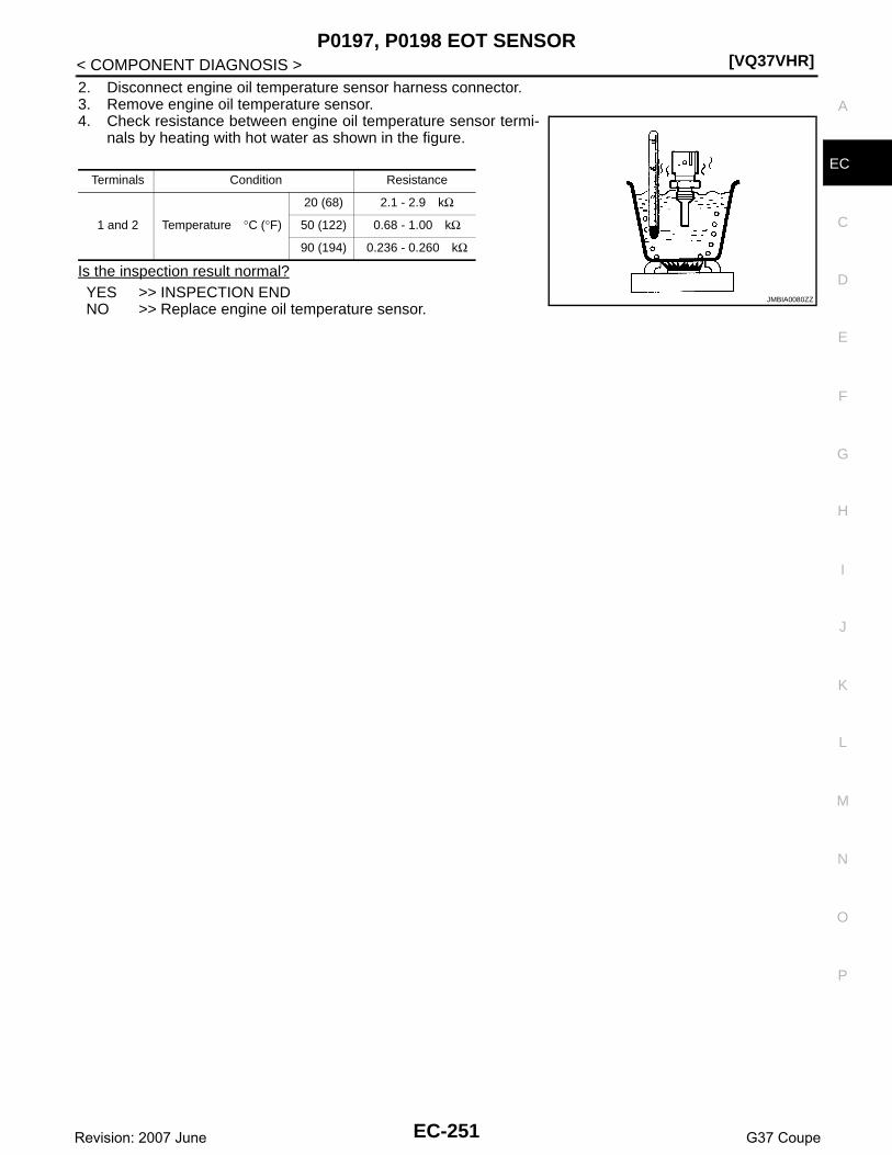
P0197, P0198 EOT SENSOR[VQ37VHR]
C
D
E
F
G
H
I
J
K
L
M
A
C
N
P
O
< COMPONENT DIAGNOSIS >
E
2. Disconnect engine oil temperature sensor harness connector.3. Remove engine oil temperature sensor.4. Check resistance between engine oil temperature sensor termi-
nals by heating with hot water as shown in the figure.
Is the inspection result normal?YES >> INSPECTION ENDNO >> Replace engine oil temperature sensor.
Terminals Condition Resistance
1 and 2 Temperature °C (°F)
20 (68) 2.1 - 2.9 kΩ
50 (122) 0.68 - 1.00 kΩ
90 (194) 0.236 - 0.260 kΩ
JMBIA0080ZZ
EC-251Revision: 2007 June G37 Coupe
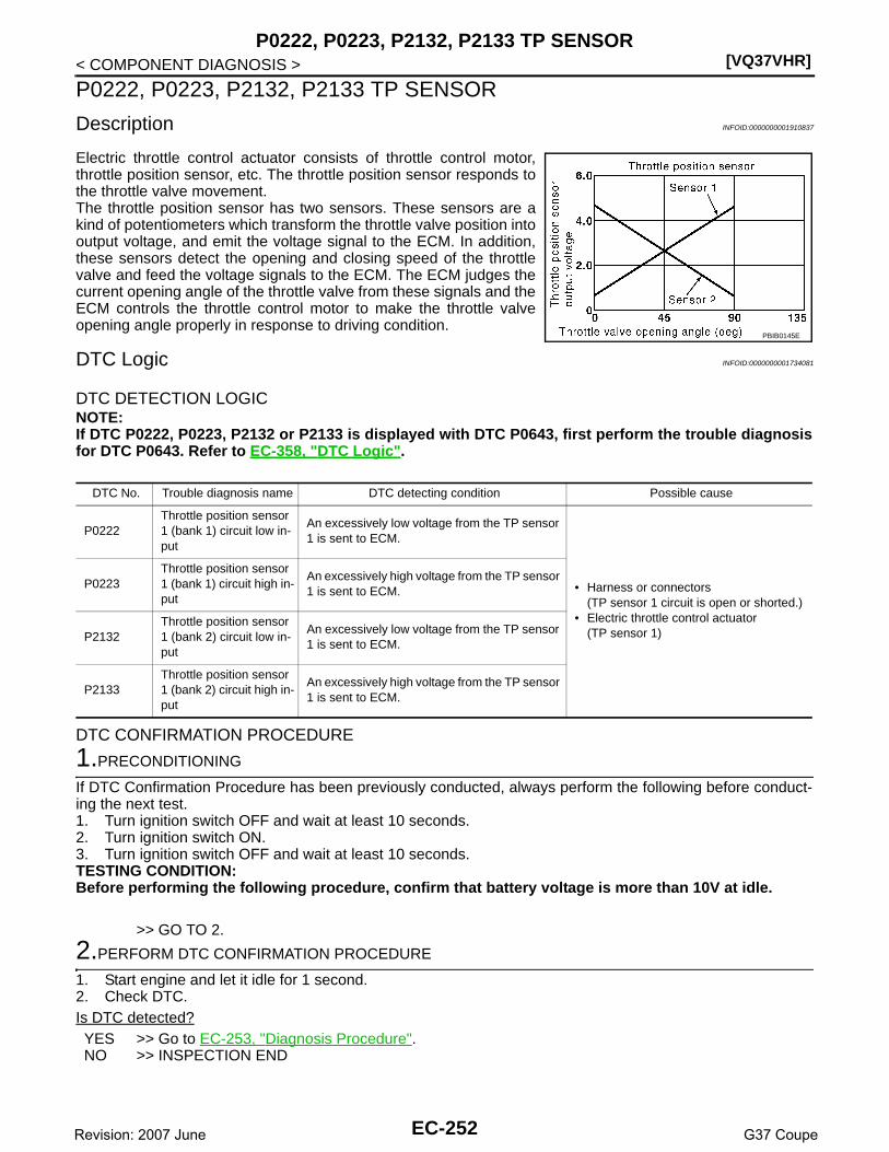
[VQ37VHR]P0222, P0223, P2132, P2133 TP SENSOR
< COMPONENT DIAGNOSIS >
P0222, P0223, P2132, P2133 TP SENSOR
Description INFOID:0000000001910837
Electric throttle control actuator consists of throttle control motor,throttle position sensor, etc. The throttle position sensor responds tothe throttle valve movement. The throttle position sensor has two sensors. These sensors are akind of potentiometers which transform the throttle valve position intooutput voltage, and emit the voltage signal to the ECM. In addition,these sensors detect the opening and closing speed of the throttlevalve and feed the voltage signals to the ECM. The ECM judges thecurrent opening angle of the throttle valve from these signals and theECM controls the throttle control motor to make the throttle valveopening angle properly in response to driving condition.
DTC Logic INFOID:0000000001734081
DTC DETECTION LOGICNOTE:If DTC P0222, P0223, P2132 or P2133 is displayed with DTC P0643, first perform the trouble diagnosisfor DTC P0643. Refer to EC-358, "DTC Logic".
DTC CONFIRMATION PROCEDURE
1.PRECONDITIONING
If DTC Confirmation Procedure has been previously conducted, always perform the following before conduct-ing the next test.1. Turn ignition switch OFF and wait at least 10 seconds.2. Turn ignition switch ON.3. Turn ignition switch OFF and wait at least 10 seconds.TESTING CONDITION:Before performing the following procedure, confirm that battery voltage is more than 10V at idle.
>> GO TO 2.
2.PERFORM DTC CONFIRMATION PROCEDURE
1. Start engine and let it idle for 1 second.2. Check DTC.Is DTC detected?YES >> Go to EC-253, "Diagnosis Procedure".NO >> INSPECTION END
PBIB0145E
DTC No. Trouble diagnosis name DTC detecting condition Possible cause
P0222Throttle position sensor 1 (bank 1) circuit low in-put
An excessively low voltage from the TP sensor 1 is sent to ECM.
• Harness or connectors(TP sensor 1 circuit is open or shorted.)
• Electric throttle control actuator(TP sensor 1)
P0223Throttle position sensor 1 (bank 1) circuit high in-put
An excessively high voltage from the TP sensor 1 is sent to ECM.
P2132Throttle position sensor 1 (bank 2) circuit low in-put
An excessively low voltage from the TP sensor 1 is sent to ECM.
P2133Throttle position sensor 1 (bank 2) circuit high in-put
An excessively high voltage from the TP sensor 1 is sent to ECM.
EC-252Revision: 2007 June G37 Coupe

P0222, P0223, P2132, P2133 TP SENSOR[VQ37VHR]
C
D
E
F
G
H
I
J
K
L
M
A
C
N
P
O
< COMPONENT DIAGNOSIS >
E
Diagnosis Procedure INFOID:0000000001734082
1.CHECK GROUND CONNECTION
1. Turn ignition switch OFF.2. Check ground connection M95. Refer to Ground Inspection in GI-41, "Circuit Inspection".Is the inspection result normal?YES >> GO TO 2.NO >> Repair or replace ground connection.
2.CHECK THROTTLE POSITION SENSOR 1 POWER SUPPLY CIRCUIT-I
1. Disconnect electric throttle control actuator harness connector.2. Turn ignition switch ON.3. Check the voltage between electric throttle control actuator harness connector and ground.
Is the inspection result normal?YES >> GO TO 3.NO >> Repair open circuit or short to ground or short to power in harness or connectors.
3.CHECK THROTTLE POSITION SENSOR 1 GROUND CIRCUIT FOR OPEN AND SHORT
1. Turn ignition switch OFF.2. Disconnect ECM harness connector.3. Check the continuity between electric throttle control actuator harness connector and ECM harness con-
nector.
4. Also check harness for short to ground and short to power.Is the inspection result normal?YES >> GO TO 4.NO >> Repair open circuit or short to ground or short to power in harness or connectors.
4.CHECK THROTTLE POSITION SENSOR 1 INPUT SIGNAL CIRCUIT FOR OPEN AND SHORT
1. Check the continuity between electric throttle control actuator harness connector and ECM harness con-nector.
2. Also check harness for short to ground and short to power.Is the inspection result normal?YES >> GO TO 5.NO >> Repair open circuit or short to ground or short to power in harness or connectors.
5.CHECK THROTTLE POSITION SENSOR
Refer to EC-254, "Component Inspection".
DTCElectric throttle control actuator
Ground VoltageBank Connector Terminal
P0222, P0223 1 F6 6Ground Approx. 5V
P2132, P2133 2 F27 1
DTCElectric throttle control actuator ECM
ContinuityBank Connector Terminal Connector Terminal
P0222, P0223 1 F6 3F101
40Existed
P2132, P2133 2 F27 4 48
DTCElectric throttle control actuator ECM
ContinuityBank Connector Terminal Connector Terminal
P0222, P0223 1 F6 4F101
30Existed
P2132, P2133 2 F27 2 31
EC-253Revision: 2007 June G37 Coupe

[VQ37VHR]P0222, P0223, P2132, P2133 TP SENSOR
< COMPONENT DIAGNOSIS >Is the inspection result normal?YES >> GO TO 7.NO >> GO TO 6.
6.REPLACE ELECTRIC THROTTLE CONTROL ACTUATOR
1. Replace malfunctioning electric throttle control actuator.2. Go to EC-254, "Special Repair Requirement".
>> INSPECTION END
7.CHECK INTERMITTENT INCIDENT
Refer to GI-38, "Intermittent Incident".
>> INSPECTION END
Component Inspection INFOID:0000000001910838
1.CHECK THROTTLE POSITION SENSOR
1. Turn ignition switch OFF.2. Reconnect all harness connectors disconnected.3. Perform EC-18, "THROTTLE VALVE CLOSED POSITION LEARNING : Special Repair Requirement".4. Turn ignition switch ON.5. Set selector lever to D (A/T) or 1st (M/T) position. 6. Check the voltage between ECM harness connector and ground.
Is the inspection result normal?YES >> INSPECTION ENDNO >> GO TO 2.
2.REPLACE ELECTRIC THROTTLE CONTROL ACTUATOR
1. Replace malfunctioning electric throttle control actuator.2. Go to EC-254, "Special Repair Requirement".
>> INSPECTION END
Special Repair Requirement INFOID:0000000001910839
1.PERFORM THROTTLE VALVE CLOSED POSITION LEARNING
Refer to EC-18, "THROTTLE VALVE CLOSED POSITION LEARNING : Special Repair Requirement"
>> GO TO 2.
2.PERFORM IDLE AIR VOLUME LEARNING
Refer to EC-19, "IDLE AIR VOLUME LEARNING : Special Repair Requirement"
>> END
ECMGround Condition Voltage
Connector Terminal
F101
30 [TP sensor 1 (bank 1)]31 [TP sensor 1 (bank 2)]
Ground Accelerator pedal
Fully released More than 0.36V
Fully depressed Less than 4.75V
34 [TP sensor 2 (bank 1)]35 [TP sensor 2 (bank 2)]
Fully released Less than 4.75V
Fully depressed More than 0.36V
EC-254Revision: 2007 June G37 Coupe
P0300, P0301, P0302, P0303, P0304, P0305, P0306 MISFIRE[VQ37VHR]
C
D
E
F
G
H
I
J
K
L
M
A
C
N
P
O
< COMPONENT DIAGNOSIS >
E
P0300, P0301, P0302, P0303, P0304, P0305, P0306 MISFIRE
DTC Logic INFOID:0000000001734085
DTC DETECTION LOGICWhen a misfire occurs, engine speed will fluctuate. If the engine speed fluctuates enough to cause the crank-shaft position (CKP) sensor (POS) signal to vary, ECM can determine that a misfire is occurring.
The misfire detection logic consists of the following two conditions.1. One Trip Detection Logic (Three Way Catalyst Damage)
On the 1st trip that a misfire condition occurs that can damage the three way catalyst (TWC) due to over-heating, the MIL will blink.When a misfire condition occurs, the ECM monitors the CKP sensor signal every 200 engine revolutionsfor a change.When the misfire condition decreases to a level that will not damage the TWC, the MIL will turn off.If another misfire condition occurs that can damage the TWC on a second trip, the MIL will blink.When the misfire condition decreases to a level that will not damage the TWC, the MIL will remain on.If another misfire condition occurs that can damage the TWC, the MIL will begin to blink again.
2. Two Trip Detection Logic (Exhaust quality deterioration)For misfire conditions that will not damage the TWC (but will affect vehicle emissions), the MIL will onlylight when the misfire is detected on a second trip. During this condition, the ECM monitors the CKP sen-sor signal every 1,000 engine revolutions.A misfire malfunction can be detected on any one cylinder or on multiple cylinders.
DTC CONFIRMATION PROCEDURE
1.PRECONDITIONING
If DTC Confirmation Procedure has been previously conducted, always perform the following before conduct-ing the next test.1. Turn ignition switch OFF and wait at least 10 seconds.2. Turn ignition switch ON.3. Turn ignition switch OFF and wait at least 10 seconds.
>> GO TO 2.
2.PERFORM DTC CONFIRMATION PROCEDURE-I
1. Start engine and warm it up to normal operating temperature.2. Turn ignition switch OFF and wait at least 10 seconds.3. Turn ignition switch ON.4. Turn ignition switch OFF and wait at least 10 seconds.5. Restart engine and let it idle for about 15 minutes.6. Check 1st trip DTC.
Sensor Input signal to ECM ECM function
Crankshaft position sensor (POS) Engine speed On board diagnosis of misfire
DTC No. Trouble diagnosis name DTC detecting condition Possible cause
P0300 Multiple cylinder misfire detected Multiple cylinder misfire. • Improper spark plug• Insufficient compression• Incorrect fuel pressure• The fuel injector circuit is open or shorted• Fuel injector• Intake air leak• The ignition signal circuit is open or short-
ed• Lack of fuel• Signal plate• A/F sensor 1• Incorrect PCV hose connection
P0301 No.1 cylinder misfire detected No. 1 cylinder misfires.
P0302 No. 2 cylinder misfire detected No. 2 cylinder misfires.
P0303 No. 3 cylinder misfire detected No. 3 cylinder misfires.
P0304 No. 4 cylinder misfire detected No. 4 cylinder misfires.
P0305 No. 5 cylinder misfire detected No. 5 cylinder misfires.
P0306 No. 6 cylinder misfire detected No. 6 cylinder misfires.
EC-255Revision: 2007 June G37 Coupe

[VQ37VHR]P0300, P0301, P0302, P0303, P0304, P0305, P0306 MISFIRE
< COMPONENT DIAGNOSIS >Is 1st trip DTC detected?YES >> Go to EC-256, "Diagnosis Procedure".NO >> GO TO 3.
3.PERFORM DTC CONFIRMATION PROCEDURE-II
1. Turn ignition switch OFF and wait at least 10 seconds.2. Turn ignition switch ON.3. Turn ignition switch OFF and wait at least 10 seconds.4. Start engine and drive the vehicle under the similar conditions to (1st trip) Freeze Frame Data for a certain
time. Refer to the table below.Hold the accelerator pedal as steady as possible.The similar conditions to (1st trip) Freeze Frame Data means the vehicle operation that the following con-ditions should be satisfied at the same time.CAUTION:Always drive vehicle in safe manner according to traffic conditions and obey all traffic laws whendriving.
The time to driving varies according to the engine speed in the freeze frame data.
5. Check 1st trip DTC.Is 1st trip DTC detected?YES >> Go to EC-256, "Diagnosis Procedure".NO >> INSPECTION END
Diagnosis Procedure INFOID:0000000001734086
1.CHECK FOR INTAKE AIR LEAK AND PCV HOSE
1. Start engine and run it at idle speed.2. Listen for the sound of the intake air leak.3. Check PCV hose connection.Is intake air leak detected?YES >> Discover air leak location and repair.NO >> GO TO 2.
2.CHECK FOR EXHAUST SYSTEM CLOGGING
Stop engine and visually check exhaust tube, three way catalyst and muffler for dents.Is the inspection result normal?YES-1 >> With CONSULT-III: GO TO 3.YES-2 >> Without CONSULT-III: GO TO 4.NO >> Repair or replace it.
3.PERFORM POWER BALANCE TEST
With CONSULT-III1. Start engine.2. Perform “POWER BALANCE” in “ACTIVE TEST” mode with CONSULT-III.
Engine speed Engine speed in the freeze frame data ± 400 rpm
Vehicle speed Vehicle speed in the freeze frame data ± 10 km/h (6 MPH)
Engine coolant temperature (T) condition
When the freeze frame data shows lower than 70 °C (158 °F),T should be lower than 70 °C (158 °F).
When the freeze frame data shows higher than or equal to 70 °C (158 °F),T should be higher than or equal to 70 °C (158 °F).
Engine speed Time
Around 1,000 rpm Approximately 10 minutes
Around 2,000 rpm Approximately 5 minutes
More than 3,000 rpm Approximately 3.5 minutes
EC-256Revision: 2007 June G37 Coupe

P0300, P0301, P0302, P0303, P0304, P0305, P0306 MISFIRE[VQ37VHR]
C
D
E
F
G
H
I
J
K
L
M
A
C
N
P
O
< COMPONENT DIAGNOSIS >
E
3. Make sure that each circuit produces a momentary engine speed drop.Is the inspection result normal?YES >> GO TO 9.NO >> GO TO 4.
4.CHECK FUNCTION OF FUEL INJECTOR-I
1. Start engine and let it idle.2. Listen to each fuel injector operating sound.
Is the inspection result normal?YES >> GO TO 5.NO >> Perform trouble diagnosis for FUEL INJECTOR, refer to
EC-487, "Diagnosis Procedure".
5.CHECK FUNCTION OF IGNITION COIL-I
CAUTION:Do the following procedure in the place where ventilation is good without the combustible.1. Turn ignition switch OFF.2. Remove fuel pump fuse (1) in IPDM E/R (2) to release fuel pres-
sure.NOTE:Do not use CONSULT-III to release fuel pressure, or fuel pres-sure applies again during the following procedure.
3. Start engine.4. After engine stalls, crank it two or three times to release all fuel
pressure.5. Turn ignition switch OFF.6. Remove all ignition coil harness connectors to avoid the electri-
cal discharge from the ignition coils.7. Remove ignition coil and spark plug of the cylinder to be
checked.8. Crank engine for 5 seconds or more to remove combustion gas in the cylinder.9. Connect spark plug and harness connector to ignition coil.10. Fix ignition coil using a rope etc. with gap of 13 - 17 mm (0.52 -
0.66 in) between the edge of the spark plug and grounded metalportion as shown in the figure.
11. Crank engine for about 3 seconds, and check whether spark isgenerated between the spark plug and the grounded metal por-tion.
CAUTION:• Do not approach to the spark plug and the ignition coil
within 50 cm (19.7 in). Be careful not to get an electricalshock while checking, because the electrical dischargevoltage becomes 20kV or more.
• It might cause to damage the ignition coil if the gap of more than 17 mm (0.66 in) is taken.NOTE:When the gap is less than 13 mm (0.52 in), the spark might be generated even if the coil is mal-functioning.
Is the inspection result normal?YES >> GO TO 9.NO >> GO TO 6.
Clicking sound should be heard.
PBIB3332E
Spark should be generated.
JMBIA0021ZZ
JMBIA0066GB
EC-257Revision: 2007 June G37 Coupe

[VQ37VHR]P0300, P0301, P0302, P0303, P0304, P0305, P0306 MISFIRE
< COMPONENT DIAGNOSIS >
6.CHECK FUNCTION OF IGNITION COIL-II
1. Turn ignition switch OFF.2. Disconnect spark plug and connect a known-good spark plug.3. Crank engine for about 3 seconds, and recheck whether spark is generated between the spark plug and
the grounded metal portion.
Is the inspection result normal?YES >> GO TO 7.NO >> Check ignition coil, power transistor and their circuits. Refer to EC-498, "Diagnosis Procedure".
7.CHECK SPARK PLUG
Check the initial spark plug for fouling, etc.Is the inspection result normal?YES >> Replace spark plug(s) with standard type one(s). For
spark plug type, refer to EM-16, "Inspection".NO >> Repair or clean spark plug. Then GO TO 8.
8.CHECK FUNCTION OF IGNITION COIL-III
1. Reconnect the initial spark plugs.2. Crank engine for about 3 seconds, and recheck whether spark is generated between the spark plug and
the grounded portion.
Is the inspection result normal?YES >> INSPECTION ENDNO >> Replace spark plug(s) with standard type one(s). For spark plug type, refer to EM-15, "Removal
and Installation".
9.CHECK COMPRESSION PRESSURE
Check compression pressure. Refer to EM-16, "Inspection".Is the inspection result normal?YES >> GO TO 10.NO >> Check pistons, piston rings, valves, valve seats and cylinder head gaskets.
10.CHECK FUEL PRESSURE
1. Install all removed parts.2. Release fuel pressure to zero. Refer to EC-601, "Inspection".3. Install fuel pressure gauge and check fuel pressure. Refer to EC-601, "Inspection".
Is the inspection result normal?YES >> GO TO 12.NO >> GO TO 11.
11.DETECT MALFUNCTIONING PART
Check fuel hoses and fuel tubes for clogging.Is the inspection result normal?YES >> Replace “fuel filter and fuel pump assembly”.NO >> Repair or replace.
Spark should be generated.
SEF156I
Spark should be generated.
At idle: Approximately 350 kPa (3.57 kg/cm2, 51 psi)
EC-258Revision: 2007 June G37 Coupe

P0300, P0301, P0302, P0303, P0304, P0305, P0306 MISFIRE[VQ37VHR]
C
D
E
F
G
H
I
J
K
L
M
A
C
N
P
O
< COMPONENT DIAGNOSIS >
E
12.CHECK IDLE SPEED AND IGNITION TIMING
For procedure, refer to EC-13, "BASIC INSPECTION : Special Repair Requirement".For specification, refer to EC-606, "Idle Speed" and EC-606, "Ignition Timing".Is the inspection result normal?YES >> GO TO 13.NO >> Follow the EC-13, "BASIC INSPECTION : Special Repair Requirement".
13.CHECK A/F SENSOR 1 INPUT SIGNAL CIRCUIT
1. Turn ignition switch OFF.2. Disconnect corresponding A/F sensor 1 harness connector.3. Disconnect ECM harness connector.4. Check the continuity between A/F sensor 1 harness connector and ECM harness connector.
5. Check the continuity between A/F sensor 1 harness connector or ECM harness connector and ground.
6. Also check harness for short to power.Is the inspection result normal?YES >> GO TO 14.NO >> Repair open circuit or short to ground or short to power in harness or connectors.
14.CHECK A/F SENSOR 1 HEATER
Refer to EC-157, "Component Inspection".Is the inspection result normal?YES >> GO TO 15.NO >> Replace (malfunctioning) A/F sensor 1.
15.CHECK MASS AIR FLOW SENSOR
With CONSULT-IIICheck mass air flow sensor signal in “DATA MONITOR” mode with CONSULT-III.For specification, refer to EC-606, "Mass Air Flow Sensor".
With GSTCheck mass air flow sensor signal in Service $01 with GST.For specification, refer to EC-606, "Mass Air Flow Sensor".Is the measurement value within the specification?YES >> GO TO 16.NO >> Check connectors for rusted terminals or loose connections in the mass air flow sensor circuit or
ground. Refer to EC-173, "Diagnosis Procedure".
16.CHECK SYMPTOM MATRIX CHART
Check items on the rough idle symptom in EC-589, "Symptom Table".
A/F sensor 1 ECMContinuity
Bank Connector Terminal Connector Terminal
1 F31
F102
57
Existed2 61
2 F201 65
2 66
A/F sensor 1 ECMGround Continuity
Bank Connector Terminal Connector Terminal
1 F31
F102
57
Ground Not existed2 61
2 F201 65
2 66
EC-259Revision: 2007 June G37 Coupe

[VQ37VHR]P0300, P0301, P0302, P0303, P0304, P0305, P0306 MISFIRE
< COMPONENT DIAGNOSIS >Is the inspection result normal?YES >> GO TO 17.NO >> Repair or replace.
17.ERASE THE 1ST TRIP DTC
Some tests may cause a 1st trip DTC to be set.Erase the 1st trip DTC from the ECM memory after performing the tests. Refer to EC-107, "Diagnosis Descrip-tion".
>> GO TO 18.
18.CHECK INTERMITTENT INCIDENT
Refer to GI-38, "Intermittent Incident".
>> INSPECTION END
EC-260Revision: 2007 June G37 Coupe

P0327, P0328, P0332, P0333 KS[VQ37VHR]
C
D
E
F
G
H
I
J
K
L
M
A
C
N
P
O
< COMPONENT DIAGNOSIS >
E
P0327, P0328, P0332, P0333 KS
Description INFOID:0000000001734087
The knock sensor is attached to the cylinder block. It senses engine knocking using a piezoelectric element. Aknocking vibration from the cylinder block is sensed as vibrational pressure. This pressure is converted into avoltage signal and sent to the ECM.
DTC Logic INFOID:0000000001734088
DTC DETECTION LOGIC
DTC CONFIRMATION PROCEDURE
1.PRECONDITIONING
If DTC Confirmation Procedure has been previously conducted, always perform the following before conduct-ing the next test.1. Turn ignition switch OFF and wait at least 10 seconds.2. Turn ignition switch ON.3. Turn ignition switch OFF and wait at least 10 seconds.TESTING CONDITION:Before performing the following procedure, confirm that battery voltage is more than 10V at idle.
>> GO TO 2.
2.PERFORM DTC CONFIRMATION PROCEDURE
1. Start engine and run it for at least 5 seconds at idle speed.2. Check 1st trip DTC.Is 1st trip DTC detected?YES >> Go to EC-261, "Diagnosis Procedure".NO >> INSPECTION END
Diagnosis Procedure INFOID:0000000001734089
1.CHECK GROUND CONNECTION
1. Turn ignition switch OFF.2. Check ground connection M95. Refer to Ground Inspection in GI-41, "Circuit Inspection".Is the inspection result normal?YES >> GO TO 2.NO >> Repair or replace ground connection.
2.CHECK KNOCK SENSOR GROUND CIRCUIT FOR OPEN AND SHORT
1. Disconnect knock sensor harness connector and ECM harness connector.2. Check the continuity between knock sensor harness connector and ECM harness connector.
DTC No.Trouble diagnosis
nameDTC detected condition Possible cause
P0327Knock sensor (bank 1) circuit low input
An excessively low voltage from the sensor is sent to ECM.
• Harness or connectors(The sensor circuit is open or shorted.)
• Knock sensor
P0328Knock sensor (bank 1) circuit high input
An excessively high voltage from the sensor is sent to ECM.
P0332Knock sensor (bank 2) circuit low input
An excessively low voltage from the sensor is sent to ECM.
P0333Knock sensor (bank 2) circuit high input
An excessively high voltage from the sensor is sent to ECM.
EC-261Revision: 2007 June G37 Coupe

[VQ37VHR]P0327, P0328, P0332, P0333 KS
< COMPONENT DIAGNOSIS >
3. Also check harness for short to ground and short to power.Is the inspection result normal?YES >> GO TO 4.NO >> GO TO 3.
3.DETECT MALFUNCTIONING PART
Check the following.• Harness connectors F9, F201• Harness for open or short between knock sensor and ECM
>> Repair open circuit or short to power in harness or connectors.
4.CHECK KNOCK SENSOR INPUT SIGNAL CIRCUIT FOR OPEN AND SHORT
1. Check the continuity between knock sensor harness connector and ECM harness connector.
2. Also check harness for short to ground and short to power.Is the inspection result normal?YES >> GO TO 6.NO >> GO TO 5.
5.DETECT MALFUNCTIONING PART
Check the following.• Harness connectors F9, F201• Harness for open or short between ECM and knock sensor
>> Repair open circuit or short to ground or short to power in harness or connectors.
6.CHECK KNOCK SENSOR
Refer to EC-262, "Component Inspection".Is the inspection result normal?YES >> GO TO 7.NO >> Replace malfunctioning knock sensor.
7.CHECK INTERMITTENT INCIDENT
Refer to GI-38, "Intermittent Incident".
>> INSPECTION END
Component Inspection INFOID:0000000001734090
1.CHECK KNOCK SENSOR
1. Turn ignition switch OFF.2. Disconnect knock sensor harness connector.3. Check resistance between knock sensor terminals as follows.
NOTE:
DTCKnock sensor ECM
ContinuityBank Connector Terminal Connector Terminal
P0327, P0328 1 F203 2F102 72 Existed
P0332, P0333 2 F202 2
DTCKnock sensor ECM
ContinuityBank Connector Terminal Connector Terminal
P0327, P0328 1 F203 1F102
73Existed
P0332, P0333 2 F202 1 69
EC-262Revision: 2007 June G37 Coupe

P0327, P0328, P0332, P0333 KS[VQ37VHR]
C
D
E
F
G
H
I
J
K
L
M
A
C
N
P
O
< COMPONENT DIAGNOSIS >
E
It is necessary to use an ohmmeter which can measure more than 10 MΩ.
CAUTION:Do not use any knock sensors that have been dropped or physically damaged. Use only new ones.Is the inspection result normal?YES >> INSPECTION ENDNO >> Replace malfunctioning knock sensor.
Terminals Resistance
1 and 2 Approx. 532 - 588 kΩ [at 20°C (68°F)]
EC-263Revision: 2007 June G37 Coupe

[VQ37VHR]P0335 CKP SENSOR (POS)
< COMPONENT DIAGNOSIS >
P0335 CKP SENSOR (POS)
Description INFOID:0000000001734091
The crankshaft position sensor (POS) is located on the cylinderblock facing the gear teeth (cogs) of the signal plate. It detects thefluctuation of the engine revolution.The sensor consists of a permanent magnet and Hall IC.When the engine is running, the high and low parts of the teethcause the gap with the sensor to change.The changing gap causes the magnetic field near the sensor tochange.Due to the changing magnetic field, the voltage from the sensorchanges.The ECM receives the voltage signal and detects the fluctuation ofthe engine revolution.ECM receives the signals as shown in the figure.
DTC Logic INFOID:0000000001734092
DTC DETECTION LOGIC
DTC CONFIRMATION PROCEDURE
1.PRECONDITIONING
If DTC Confirmation Procedure has been previously conducted, always perform the following before conduct-ing the next test.1. Turn ignition switch OFF and wait at least 10 seconds.2. Turn ignition switch ON.3. Turn ignition switch OFF and wait at least 10 seconds.TESTING CONDITION:Before performing the following procedure, confirm that battery voltage is more than 10.5V with igni-tion switch ON.
JMBIA0062ZZ
JMBIA0001GB
DTC No. Trouble diagnosis name DTC detecting condition Possible cause
P0335Crankshaft position sen-sor (POS) circuit
• The crankshaft position sensor (POS) signal is not detected by the ECM during the first few seconds of engine cranking.
• The proper pulse signal from the crankshaft position sensor (POS) is not sent to ECM while the engine is running.
• The crankshaft position sensor (POS) signal is not in the normal pattern during engine run-ning.
• Harness or connectors[CKP sensor (POS) circuit is open or shorted.](APP sensor 2 circuit is shorted.)(EVAP control system pressure sensor circuit is shorted.)(Refrigerant pressure sensor circuit is shorted.)(Brake booster pressure sensor circuit is shorted)
• Crankshaft position sensor (POS)• Accelerator pedal position sensor• EVAP control system pressure sensor• Refrigerant pressure sensor• Brake booster pressure snsor.• Signal plate
EC-264Revision: 2007 June G37 Coupe

P0335 CKP SENSOR (POS)[VQ37VHR]
C
D
E
F
G
H
I
J
K
L
M
A
C
N
P
O
< COMPONENT DIAGNOSIS >
E
>> GO TO 2.
2.PERFORM DTC CONFIRMATION PROCEDURE
1. Start engine and let it idle for at least 5 seconds.If engine does not start, crank engine for at least 2 seconds.
2. Check 1st trip DTC.Is 1st trip DTC detected?YES >> Go to EC-265, "Diagnosis Procedure".NO >> INSPECTION END
Diagnosis Procedure INFOID:0000000001734093
1.CHECK GROUND CONNECTION
1. Turn ignition switch OFF.2. Check ground connection M95. Refer to Ground Inspection in GI-41, "Circuit Inspection".Is the inspection result normal?YES >> GO TO 2.NO >> Repair or replace ground connection.
2.CHECK CRANKSHAFT POSITION (CKP) SENSOR (POS) POWER SUPPLY CIRCUIT-I
1. Disconnect crankshaft position (CKP) sensor (POS) harness connector.2. Turn ignition switch ON.3. Check the voltage between CKP sensor (POS) harness connector and ground.
Is the inspection result normal?YES >> GO TO 8.NO >> GO TO 3.
3.CHECK CRANKSHAFT POSITION (CKP) SENSOR (POS) POWER SUPPLY CIRCUIT-II
1. Turn ignition switch ON.2. Disconnect ECM harness connector.3. Check the continuity between CKP sensor (POS) harness connector and ECM harness connector.
Is the inspection result normal?YES >> GO TO 4.NO >> Repair open circuit.
4.CHECK CRANKSHAFT POSITION (CKP) SENSOR (POS) POWER SUPPLY CIRCUIT-III
Check harness for short to power and short to ground, between the following terminals.
CKP sensor (POS)Ground Voltage
Connector Terminal
F2 1 Ground Approx. 5V
CKP sensor (POS) ECMContinuity
Connector Terminal Connector Terminal
F2 1 F101 46 Existed
ECM Sensor
Connector Terminal Name Connector Terminal
F10145 Brake booster pressure sensor E48
146 CKP sensor (POS) F2
EC-265Revision: 2007 June G37 Coupe

[VQ37VHR]P0335 CKP SENSOR (POS)
< COMPONENT DIAGNOSIS >
Is the inspection result normal?YES >> GO TO 5.NO >> Repair short to ground or short to power in harness or connectors.
5.CHECK COMPONENTS
Check the following.• Brake booster pressure sensor (Refer to EC-352, "Component Inspection".)• EVAP control system pressure sensor (Refer to EC-306, "Component Inspection".)• Refrigerant pressure sensor (Refer to HAC-85, "Diagnosis Procedure".)Is the inspection result normal?YES >> GO TO 6.NO >> Replace malfunctioning component.
6.CHECK APP SENSOR
Refer to EC-460, "Component Inspection".Is the inspection result normal?YES >> GO TO 12.NO >> GO TO 7.
7.REPLACE ACCELERATOR PEDAL ASSEMBLY
1. Replace accelerator pedal assembly.2. Go to EC-460, "Special Repair Requirement".
>> INSPECTION END
8.CHECK CKP SENSOR (POS) GROUND CIRCUIT FOR OPEN AND SHORT
1. Turn ignition switch OFF.2. Disconnect ECM harness connector.3. Check the continuity between CKP sensor (POS) harness connector and ECM harness connector.
4. Also check harness for short to ground and short to power.Is the inspection result normal?YES >> GO TO 9.NO >> Repair open circuit or short to ground or short to power in harness or connectors.
9.CHECK CKP SENSOR (POS) INPUT SIGNAL CIRCUIT FOR OPEN AND SHORT
1. Check the continuity between CKP sensor (POS) harness connector and ECM harness connector.
2. Also check harness for short to ground and short to power.Is the inspection result normal?YES >> GO TO 10.NO >> Repair open circuit or short to ground or short to power in harness or connectors.
M107
103 APP sensor E112 6
107 EVAP control system pressure sensor B30 3
111 Refrigerant pressure sensor E77 3
ECM Sensor
Connector Terminal Name Connector Terminal
CKP sensor (POS) ECMContinuity
Connector Terminal Connector Terminal
F2 2 F101 47 Existed
CKP sensor (POS) ECMContinuity
Connector Terminal Connector Terminal
F2 3 F101 37 Existed
EC-266Revision: 2007 June G37 Coupe

P0335 CKP SENSOR (POS)[VQ37VHR]
C
D
E
F
G
H
I
J
K
L
M
A
C
N
P
O
< COMPONENT DIAGNOSIS >
E
10.CHECK CRANKSHAFT POSITION SENSOR (POS)
Refer to EC-267, "Component Inspection".Is the inspection result normal?YES >> GO TO 11.NO >> Replace crankshaft position sensor (POS).
11.CHECK GEAR TOOTH
Visually check for chipping signal plate gear tooth.Is the inspection result normal?YES >> GO TO 12.NO >> Replace the signal plate.
12.CHECK INTERMITTENT INCIDENT
Refer to GI-38, "Intermittent Incident".
>> INSPECTION END
Component Inspection INFOID:0000000001734094
1.CHECK CRANKSHAFT POSITION SENSOR (POS)-I
1. Turn ignition switch OFF.2. Loosen the fixing bolt of the sensor.3. Disconnect crankshaft position sensor (POS) harness connector.4. Remove the sensor.5. Visually check the sensor for chipping.Is the inspection result normal?YES >> GO TO 2.NO >> Replace crankshaft position sensor (POS).
2.CHECK CRANKSHAFT POSITION SENSOR (POS)-II
Check resistance between crankshaft position sensor (POS) terminals as follows.
Is the inspection result normal?YES >> INSPECTION ENDNO >> Replace crankshaft position sensor (POS).
JMBIA0063ZZ
Terminals (Polarity) Resistance
1 (+) - 2 (-)
Except 0 or ∞Ω [at 25°C (77°F)]1 (+) - 3 (-)
2 (+) - 3 (-)
EC-267Revision: 2007 June G37 Coupe

[VQ37VHR]P0340, P0345 CMP SENSOR (PHASE)
< COMPONENT DIAGNOSIS >
P0340, P0345 CMP SENSOR (PHASE)
Description INFOID:0000000001734095
The camshaft position sensor (PHASE) senses the retraction ofcamshaft (INT) to identify a particular cylinder. The camshaft positionsensor (PHASE) senses the piston position.When the crankshaft position sensor (POS) system becomes inoper-ative, the camshaft position sensor (PHASE) provides various con-trols of engine parts instead, utilizing timing of cylinder identificationsignals.The sensor consists of a permanent magnet and Hall IC.When engine is running, the high and low parts of the teeth causethe gap with the sensor to change.The changing gap causes the magnetic field near the sensor tochange.Due to the changing magnetic field, the voltage from the sensor changes. ECM receives the signals as shown in the figure.
DTC Logic INFOID:0000000001734096
DTC DETECTION LOGICNOTE:If DTC P0340 or P0345 is displayed with DTC P0643, first perform the trouble diagnosis for DTC P0643.Refer to EC-358, "DTC Logic".
DTC CONFIRMATION PROCEDURE
1.PRECONDITIONING
If DTC Confirmation Procedure has been previously conducted, always perform the following before conduct-ing the next test.
JMBIA0064ZZ
JMBIA0001GB
DTC No. Trouble diagnosis name DTC detecting condition Possible cause
P0340Camshaft position sen-sor (PHASE) (bank 1) circuit
• The cylinder No. signal is not sent to ECM for the first few seconds during engine cranking.
• The cylinder No. signal is not sent to ECM during engine running.
• The cylinder No. signal is not in the normal pattern during engine running.
• Harness or connectors[CMP sensor (PHASE) (bank 1) circuit is open or shorted.]
• Camshaft position sensor (PHASE) (bank 1)
• Camshaft (INT)• Starter motor• Starting system circuit• Dead (Weak) battery
P0345Camshaft position sen-sor (PHASE) (bank 2) circuit
• Harness or connectors[CMP sensor (PHASE) (bank 2) circuit is open or shorted.]
• Camshaft position sensor (PHASE) (bank 2)
• Camshaft (INT)• Starter motor• Starting system circuit• Dead (Weak) battery
EC-268Revision: 2007 June G37 Coupe

P0340, P0345 CMP SENSOR (PHASE)[VQ37VHR]
C
D
E
F
G
H
I
J
K
L
M
A
C
N
P
O
< COMPONENT DIAGNOSIS >
E
1. Turn ignition switch OFF and wait at least 10 seconds.2. Turn ignition switch ON.3. Turn ignition switch OFF and wait at least 10 seconds.TESTING CONDITION:Before performing the following procedure, confirm that battery voltage is more than 10.5V with igni-tion switch ON.
>> GO TO 2.
2.PERFORM DTC CONFIRMATION PROCEDURE-I
1. Start engine and let it idle for at least 5 seconds.If engine does not start, crank engine for at least 2 seconds.
2. Check 1st trip DTC.Is 1st trip DTC detected?YES >> Go to EC-269, "Diagnosis Procedure".NO >> GO TO 3.
3.PERFORM DTC CONFIRMATION PROCEDURE-I
1. Maintaining engine speed at more than 800 rpm for at least 5 seconds.2. Check 1st trip DTC.Is 1st trip DTC detected?YES >> Go to EC-269, "Diagnosis Procedure".NO >> INSPECTION END
Diagnosis Procedure INFOID:0000000001734097
1.CHECK STARTING SYSTEM
Turn ignition switch to START position.Does the engine turn over? Does the starter motor operate?YES >> GO TO 2.NO >> Check starting system. (Refer to EC-9, "Work Flow".)
2.CHECK GROUND CONNECTION
1. Turn ignition switch OFF.2. Check ground connection M95. Refer to Ground Inspection in GI-41, "Circuit Inspection".Is the inspection result normal?YES >> GO TO 3.NO >> Repair or replace ground connection.
3.CHECK CAMSHAFT POSITION (CMP) SENSOR (PHASE) POWER SUPPLY CIRCUIT-I
1. Disconnect camshaft position (CMP) sensor (PHASE) harness connector.2. Turn ignition switch ON.3. Check the voltage between CMP sensor (PHASE) harness connector and ground.
Is the inspection result normal?YES >> GO TO 4.NO >> Repair open circuit or short to ground or short to power in harness or connectors.
4.CHECK CMP SENSOR (PHASE) GROUND CIRCUIT FOR OPEN AND SHORT
1. Turn ignition switch OFF.2. Disconnect ECM harness connector.3. Check the continuity between CMP sensor (PHASE) harness connector and ECM harness connector.
DTCCMP sensor (PHASE)
Ground VoltageBank Connector Terminal
P0340 1 F5 1Ground Approx. 5V
P0345 2 F18 1
EC-269Revision: 2007 June G37 Coupe

[VQ37VHR]P0340, P0345 CMP SENSOR (PHASE)
< COMPONENT DIAGNOSIS >
4. Also check harness for short to ground and short to power.Is the inspection result normal?YES >> GO TO 6.NO >> GO TO 5.
5.DETECT MALFUNCTIONING PART
Check the following.• Harness connectors F107, F106• Harness for open or short between CMP sensor (PHASE) and ECM
>> Repair open circuit or short to ground or short to power in harness or connectors.
6.CHECK CMP SENSOR (PHASE) INPUT SIGNAL CIRCUIT FOR OPEN AND SHORT
1. Check the continuity between CMP sensor (PHASE) harness connector and ECM harness connector.
2. Also check harness for short to ground and short to power.Is the inspection result normal?YES >> GO TO 8.NO >> GO TO 7.
7.DETECT MALFUNCTIONING PART
Check the following.• Harness connectors F107, F106• Harness for open or short between CMP sensor (PHASE) and ECM
>> Repair open circuit or short to ground or short to power in harness or connectors.
8.CHECK CAMSHAFT POSITION SENSOR (PHASE)
Refer to EC-271, "Component Inspection".Is the inspection result normal?YES >> GO TO 9.NO >> Replace malfunctioning camshaft position sensor (PHASE).
9.CHECK CAMSHAFT (INTAKE)
Check the following.• Accumulation of debris to the signal plate of camshaft front end• Chipping signal plate of camshaft front endIs the inspection result normal?YES >> GO TO 10.NO >> Remove debris and clean the signal plate of camshaft
front end or replace camshaft.
DTCCMP sensor (PHASE) ECM
ContinuityBank Connector Terminal Connector Terminal
P0340 1 F5 2F102
92Existed
P0345 2 F18 2 96
DTCCMP sensor (PHASE) ECM
ContinuityBank Connector Terminal Connector Terminal
P0340 1 F5 3F102
59Existed
P0345 2 F18 3 63
JMBIA0962ZZ
EC-270Revision: 2007 June G37 Coupe

P0340, P0345 CMP SENSOR (PHASE)[VQ37VHR]
C
D
E
F
G
H
I
J
K
L
M
A
C
N
P
O
< COMPONENT DIAGNOSIS >
E
10.CHECK INTERMITTENT INCIDENT
Refer to GI-38, "Intermittent Incident".
>> INSPECTION END
Component Inspection INFOID:0000000001734098
1.CHECK CAMSHAFT POSITION SENSOR (PHASE)-I
1. Turn ignition switch OFF.2. Loosen the fixing bolt of the sensor.3. Disconnect camshaft position sensor (PHASE) harness connector.4. Remove the sensor.5. Visually check the sensor for chipping.Is the inspection result normal?YES >> GO TO 2.NO >> Replace malfunctioning camshaft position sensor
(PHASE).
2.CHECK CAMSHAFT POSITION SENSOR (PHASE)-II
Check resistance camshaft position sensor (PHASE) terminals as follows.
Is the inspection result normal?YES >> INSPECTION ENDNO >> Replace malfunctioning camshaft position sensor (PHASE).
JMBIA0065ZZ
Terminals (Polarity) Resistance
1 (+) - 2 (-)
Except 0 or ∞Ω [at 25°C (77°F)]1 (+) - 3 (-)
2 (+) - 3 (-)
EC-271Revision: 2007 June G37 Coupe

[VQ37VHR]P0420, P0430 THREE WAY CATALYST FUNCTION
< COMPONENT DIAGNOSIS >
P0420, P0430 THREE WAY CATALYST FUNCTION
DTC Logic INFOID:0000000001734099
DTC DETECTION LOGICThe ECM monitors the switching frequency ratio of air fuel ratio (A/F) sensor 1 and heated oxygen sensor 2.A three way catalyst 1 with high oxygen storage capacity will indicate a low switching frequency of heated oxy-gen sensor 2. As oxygen storage capacity decreases, the heated oxygen sensor 2 switching frequency willincrease.When the frequency ratio of A/F sensor 1 and heated oxygen sensor 2 approaches a specified limit value, thethree way catalyst 1 malfunction is diagnosed.
DTC CONFIRMATION PROCEDURE
1.INSPECTION START
Do you have CONSULT-III?Do you have CONSULT-III?YES >> GO TO 2.NO >> GO TO 7.
2.PRECONDITIONING
If DTC Confirmation Procedure has been previously conducted, always perform the following before conduct-ing the next test.1. Turn ignition switch OFF and wait at least 10 seconds.2. Turn ignition switch ON.3. Turn ignition switch OFF and wait at least 10 seconds.TESTING CONDITION:Do not hold engine speed for more than the specified minutes below.
>> GO TO 3.
3.PERFORM DTC CONFIRMATION PROCEDURE-I
With CONSULT-III1. Turn ignition switch ON and select “DATA MONITOR” mode with CONSULT-III.2. Start engine and warm it up to the normal operating temperature.3. Turn ignition switch OFF and wait at least 10 seconds.4. Turn ignition switch ON.5. Turn ignition switch OFF and wait at least 10 seconds.6. Start engine and keep the engine speed between 3,500 and 4,000 rpm for at least 1 minute under no load.7. Let engine idle for 1 minute.
DTC No. Trouble diagnosis name DTC detecting condition Possible cause
P0420Catalyst system efficiency below threshold (bank 1)
• Three way catalyst (manifold) does not op-erate properly.
• Three way catalyst (manifold) does not have enough oxygen storage capacity.
• Three way catalyst (manifold)• Exhaust tube• Intake air leaks• Fuel injector• Fuel injector leaks• Spark plug• Improper ignition timing
P0430Catalyst system efficiency below threshold (bank 2)
PBIB1923E
EC-272Revision: 2007 June G37 Coupe

P0420, P0430 THREE WAY CATALYST FUNCTION[VQ37VHR]
C
D
E
F
G
H
I
J
K
L
M
A
C
N
P
O
< COMPONENT DIAGNOSIS >
E
8. Make sure that “COOLAN TEMP/S” indicates more than 70°C (158°F).If not, warm up engine and go to next step when “COOLAN TEMP/S” indication reaches to 70°C (158°F).
9. Open engine hood.10. Select “DTC & SRT CONFIRMATION” then “SRT WORK SUPPORT” mode with CONSULT-III.11. Rev engine up to about 2,000 rpm and hold it for 3 consecutive minutes then release the accelerator
pedal completely.12. Check the indication of “CATALYST”.Which is displayed on CONSULT-III screen?CMPLT>> GO TO 6.INCMP >> GO TO 4.
4.PERFORM DTC CONFIRMATION PROCEDURE-II
1. Wait 5 seconds at idle.2. Rev engine up to about 2,000 rpm and maintain it until “INCMP” of “CATALYST” changes to “CMPLT” (It
will take approximately 5 minutes).Does the indication change to “CMPLT”?YES >> GO TO 6.NO >> GO TO 5.
5.PERFORM DTC CONFIRMATION PROCEDURE AGAIN
1. Stop engine and cool it down to less than 70°C (158°F).2. Perform DTC CONFIRMATION PROCEDURE again.
>> GO TO 3.
6.PERFORM DTC CONFIRMATION PROCEDURE-III
Check 1st trip DTC.Is 1st trip DTC detected?YES >> Go to EC-274, "Diagnosis Procedure".NO >> INSPECTION END
7.PERFORM COMPONENT FUNCTION CHECK
Perform component function check. Refer to EC-273, "Component Function Check".NOTE:Use component function check to check the overall function of the three way catalyst (manifold). During thischeck, a 1st trip DTC might not be confirmed.Is the inspection result normal?YES >> INSPECTION ENDNO >> Go to EC-274, "Diagnosis Procedure".
Component Function Check INFOID:0000000001734100
1.PERFORM COMPONENT FUNCTION CHECK
Without CONSULT-III1. Start engine and warm it up to the normal operating temperature.2. Turn ignition switch OFF and wait at least 10 seconds.3. Turn ignition switch ON.4. Turn ignition switch OFF and wait at least 10 seconds.5. Start engine and keep the engine speed between 3,500 and 4,000 rpm for at least 1 minute under no load.6. Let engine idle for 1 minute.7. Open engine hood.8. Check the voltage between ECM harness connector and ground under the following condition.
EC-273Revision: 2007 June G37 Coupe
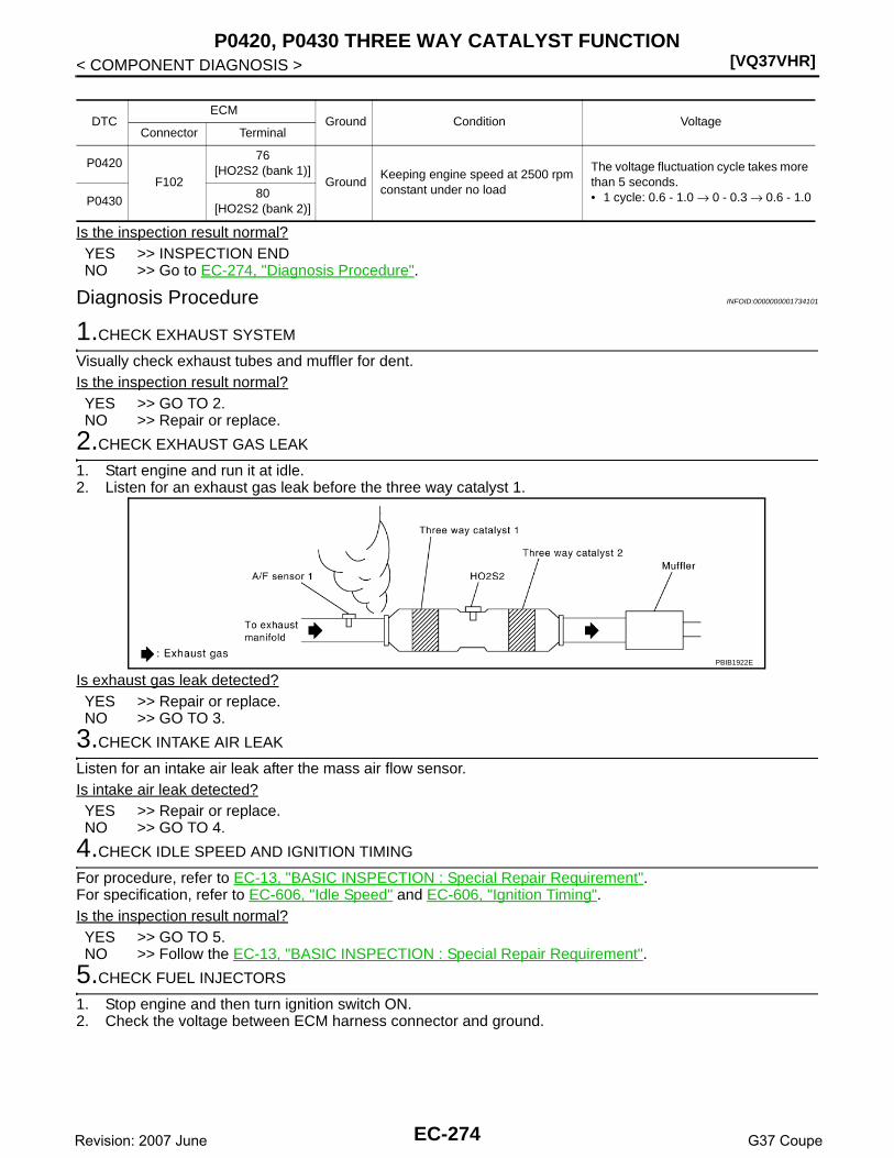
[VQ37VHR]P0420, P0430 THREE WAY CATALYST FUNCTION
< COMPONENT DIAGNOSIS >
Is the inspection result normal?YES >> INSPECTION ENDNO >> Go to EC-274, "Diagnosis Procedure".
Diagnosis Procedure INFOID:0000000001734101
1.CHECK EXHAUST SYSTEM
Visually check exhaust tubes and muffler for dent.Is the inspection result normal?YES >> GO TO 2.NO >> Repair or replace.
2.CHECK EXHAUST GAS LEAK
1. Start engine and run it at idle.2. Listen for an exhaust gas leak before the three way catalyst 1.
Is exhaust gas leak detected?YES >> Repair or replace.NO >> GO TO 3.
3.CHECK INTAKE AIR LEAK
Listen for an intake air leak after the mass air flow sensor.Is intake air leak detected?YES >> Repair or replace.NO >> GO TO 4.
4.CHECK IDLE SPEED AND IGNITION TIMING
For procedure, refer to EC-13, "BASIC INSPECTION : Special Repair Requirement".For specification, refer to EC-606, "Idle Speed" and EC-606, "Ignition Timing".Is the inspection result normal?YES >> GO TO 5.NO >> Follow the EC-13, "BASIC INSPECTION : Special Repair Requirement".
5.CHECK FUEL INJECTORS
1. Stop engine and then turn ignition switch ON.2. Check the voltage between ECM harness connector and ground.
DTCECM
Ground Condition VoltageConnector Terminal
P0420
F102
76[HO2S2 (bank 1)]
GroundKeeping engine speed at 2500 rpm constant under no load
The voltage fluctuation cycle takes more than 5 seconds.• 1 cycle: 0.6 - 1.0 → 0 - 0.3 → 0.6 - 1.0P0430
80[HO2S2 (bank 2)]
PBIB1922E
EC-274Revision: 2007 June G37 Coupe
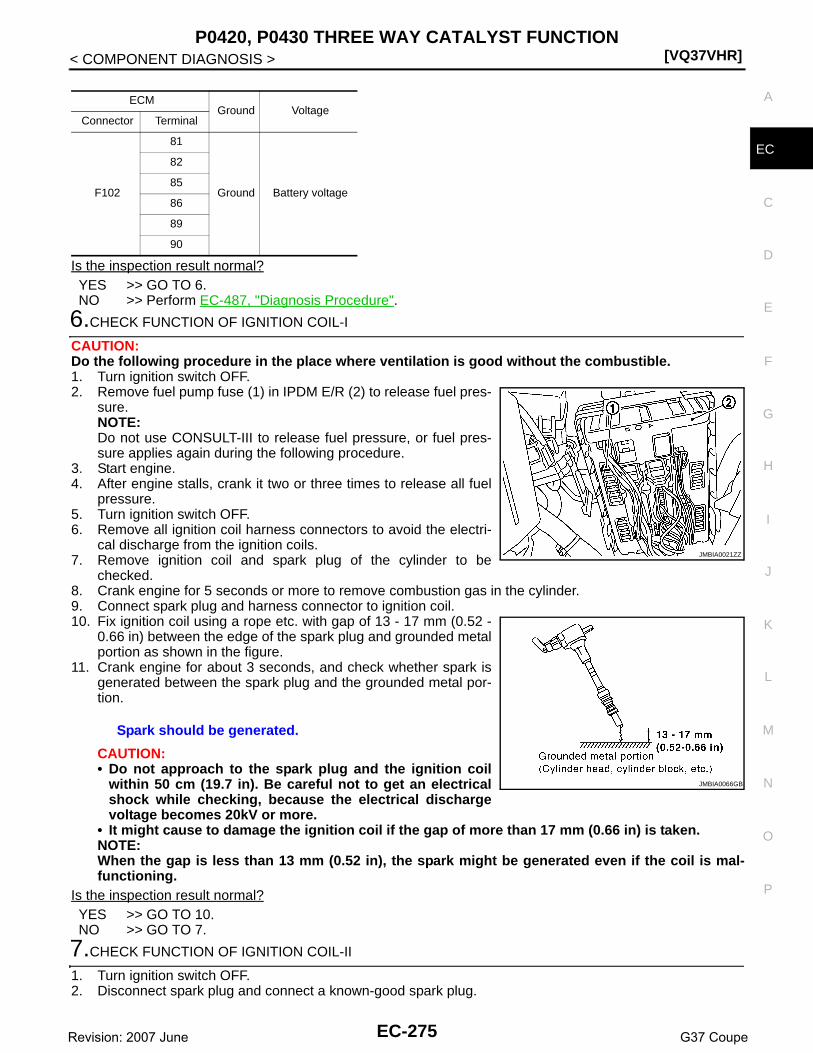
P0420, P0430 THREE WAY CATALYST FUNCTION[VQ37VHR]
C
D
E
F
G
H
I
J
K
L
M
A
C
N
P
O
< COMPONENT DIAGNOSIS >
E
Is the inspection result normal?YES >> GO TO 6.NO >> Perform EC-487, "Diagnosis Procedure".
6.CHECK FUNCTION OF IGNITION COIL-I
CAUTION:Do the following procedure in the place where ventilation is good without the combustible.1. Turn ignition switch OFF.2. Remove fuel pump fuse (1) in IPDM E/R (2) to release fuel pres-
sure.NOTE:Do not use CONSULT-III to release fuel pressure, or fuel pres-sure applies again during the following procedure.
3. Start engine.4. After engine stalls, crank it two or three times to release all fuel
pressure.5. Turn ignition switch OFF.6. Remove all ignition coil harness connectors to avoid the electri-
cal discharge from the ignition coils.7. Remove ignition coil and spark plug of the cylinder to be
checked.8. Crank engine for 5 seconds or more to remove combustion gas in the cylinder.9. Connect spark plug and harness connector to ignition coil.10. Fix ignition coil using a rope etc. with gap of 13 - 17 mm (0.52 -
0.66 in) between the edge of the spark plug and grounded metalportion as shown in the figure.
11. Crank engine for about 3 seconds, and check whether spark isgenerated between the spark plug and the grounded metal por-tion.
CAUTION:• Do not approach to the spark plug and the ignition coil
within 50 cm (19.7 in). Be careful not to get an electricalshock while checking, because the electrical dischargevoltage becomes 20kV or more.
• It might cause to damage the ignition coil if the gap of more than 17 mm (0.66 in) is taken.NOTE:When the gap is less than 13 mm (0.52 in), the spark might be generated even if the coil is mal-functioning.
Is the inspection result normal?YES >> GO TO 10.NO >> GO TO 7.
7.CHECK FUNCTION OF IGNITION COIL-II
1. Turn ignition switch OFF.2. Disconnect spark plug and connect a known-good spark plug.
ECMGround Voltage
Connector Terminal
F102
81
Ground Battery voltage
82
85
86
89
90
Spark should be generated.
JMBIA0021ZZ
JMBIA0066GB
EC-275Revision: 2007 June G37 Coupe

[VQ37VHR]P0420, P0430 THREE WAY CATALYST FUNCTION
< COMPONENT DIAGNOSIS >3. Crank engine for about 3 seconds, and recheck whether spark is generated between the spark plug and
the grounded metal portion.
Is the inspection result normal?YES >> GO TO 8.NO >> Check ignition coil, power transistor and their circuits. Refer to EC-498, "Diagnosis Procedure".
8.CHECK SPARK PLUG
Check the initial spark plug for fouling, etc.Is the inspection result normal?YES >> Replace spark plug(s) with standard type one(s). For
spark plug type, refer to EM-16, "Inspection".NO >> Repair or clean spark plug. Then GO TO 9.
9.CHECK FUNCTION OF IGNITION COIL-III
1. Reconnect the initial spark plugs.2. Crank engine for about three seconds, and recheck whether spark is generated between the spark plug
and the grounded portion.
Is the inspection result normal?YES >> INSPECTION ENDNO >> Replace spark plug(s) with standard type one(s). For spark plug type, refer to EM-15, "Removal
and Installation".
10.CHECK FUEL INJECTOR
1. Turn ignition switch OFF.2. Remove fuel injector assembly.
Refer to EM-36, "Removal and Installation".Keep fuel hose and all fuel injectors connected to fuel tube.
3. Disconnect all ignition coil harness connectors.4. Reconnect all fuel injector harness connectors disconnected.5. Turn ignition switch ON.Does fuel drip from fuel injector?YES >> Replace the fuel injector(s) from which fuel is dripping.NO >> GO TO 11.
11.CHECK INTERMITTENT INCIDENT
Refer to GI-38, "Intermittent Incident".Is the trouble fixed?YES >> INSPECTION ENDNO >> Replace three way catalyst assembly.
Spark should be generated.
SEF156I
Spark should be generated.
EC-276Revision: 2007 June G37 Coupe

P0441 EVAP CONTROL SYSTEM[VQ37VHR]
C
D
E
F
G
H
I
J
K
L
M
A
C
N
P
O
< COMPONENT DIAGNOSIS >
E
P0441 EVAP CONTROL SYSTEM
DTC Logic INFOID:0000000001734102
DTC DETECTION LOGICNOTE:If DTC P0441 is displayed with other DTC such as P2122, P2123, P2127, P2128 or P2138, first performtrouble diagnosis for other DTC.In this evaporative emission (EVAP) control system, purge flow occurs during non-closed throttle conditions.Purge volume is related to air intake volume. Under normal purge conditions (non-closed throttle), the EVAPcanister purge volume control solenoid valve is open to admit purge flow. Purge flow exposes the EVAP con-trol system pressure sensor to intake manifold vacuum.Under normal conditions (non-closed throttle), sensor output voltage indicates if pressure drop and purge floware adequate. If not, a malfunction is determined.
DTC CONFIRMATION PROCEDURE
1.INSPECTION START
Do you have CONSULT-III?Do you have CONSULT-III?YES >> GO TO 2.NO >> GO TO 6.
2.PRECONDITIONING
If DTC Confirmation Procedure has been previously conducted, always perform the following before conduct-ing the next test.1. Turn ignition switch OFF and wait at least 10 seconds.
DTC No. Trouble diagnosis name DTC detecting condition Possible cause
P0441EVAP control system in-correct purge flow
EVAP control system does not operate proper-ly, EVAP control system has a leak between in-take manifold and EVAP control system pressure sensor.
• EVAP canister purge volume control so-lenoid valve stuck closed
• EVAP control system pressure sensor and the circuit
• Loose, disconnected or improper con-nection of rubber tube
• Blocked rubber tube• Cracked EVAP canister• EVAP canister purge volume control so-
lenoid valve circuit• Accelerator pedal position sensor• Blocked purge port• EVAP canister vent control valve
PBIB1026E
EC-277Revision: 2007 June G37 Coupe

[VQ37VHR]P0441 EVAP CONTROL SYSTEM
< COMPONENT DIAGNOSIS >2. Turn ignition switch ON.3. Turn ignition switch OFF and wait at least 10 seconds.TESTING CONDITION:Always perform test at a temperature of 5°C (41°F) or more.
>> GO TO 3.
3.PERFORM DTC CONFIRMATION PROCEDURE-I
With CONSULT-III1. Start engine and warm it up to normal operating temperature.2. Turn ignition switch OFF and wait at least 10 seconds.3. Turn ignition switch ON.4. Turn ignition switch OFF and wait at least 10 seconds.5. Start engine and let it idle for at least 70 seconds.6. Select “PURG FLOW P0441” of “EVAPORATIVE SYSTEM” in “DTC WORK SUPPORT” mode with CON-
SULT-III.7. Touch “START”.Is “COMPLETED” displayed on CONSULT-III screen?YES >> GO TO 5.NO >> GO TO 4.
4.PERFORM DTC CONFIRMATION PROCEDURE-II
When the following conditions are met, “TESTING” will be displayed on the CONSULT-III screen. Maintain theconditions continuously until “TESTING” changes to “COMPLETED”. (It will take at least 35 seconds.)
CAUTION:Always drive vehicle at a safe speed.Is “COMPLETED” displayed on CONSULT-III screen?YES >> GO TO 5.NO >> Perform DTC CONFIRMATION PROCEDURE again. GO TO 3.
5.PERFORM DTC CONFIRMATION PROCEDURE-III
Touch “SELF-DIAG RESULTS”.Which is displayed on CONSULT-III screen?OK >> INSPECTION ENDNG >> Go to EC-279, "Diagnosis Procedure".
6.PERFORM COMPONENT FUNCTION CHECK
Perform component function check. Refer to EC-278, "Component Function Check".NOTE:Use component function check to check the overall monitoring function of the EVAP control system purge flowmonitoring. During this check, a 1st trip DTC might not be confirmed.Is the inspection result normal?YES >> INSPECTION ENDNO >> Go to EC-279, "Diagnosis Procedure".
Component Function Check INFOID:0000000001734103
1.PERFORM COMPONENT FUNCTION CHECK
Without CONSULT-III1. Lift up drive wheels.
Selector lever Suitable position
VHCL SPEED SE 32 - 120 km/h (20 - 75 mph)
ENG SPEED 500 - 3,000 rpm
B/FUEL SCHDL 1.3 - 9.0 msec
COOLAN TEMP/S More than 0°C (32°F)
EC-278Revision: 2007 June G37 Coupe

P0441 EVAP CONTROL SYSTEM[VQ37VHR]
C
D
E
F
G
H
I
J
K
L
M
A
C
N
P
O
< COMPONENT DIAGNOSIS >
E
2. Start engine (VDC switch OFF) and warm it up to normal operating temperature.3. Turn ignition switch OFF and wait at least 10 seconds.4. Turn ignition switch ON.5. Turn ignition switch OFF and wait at least 10 seconds.6. Start engine and wait at least 70 seconds.7. Set voltmeter probes to ECM harness connector and ground as follows.
8. Check EVAP control system pressure sensor value at idle speed and note it.9. Establish and maintain the following conditions for at least 1 minute.
10. Verify that EVAP control system pressure sensor value stays 0.1V less than the value at idle speed (mea-sured at step 8) for at least 1 second.
Is the inspection result normal?YES >> INSPECTION ENDNO >> Go to EC-279, "Diagnosis Procedure".
Diagnosis Procedure INFOID:0000000001734104
1.CHECK EVAP CANISTER
1. Turn ignition switch OFF.2. Check EVAP canister for cracks.Is the inspection result normal?YES-1 >> With CONSULT-III: GO TO 2.YES-2 >> Without CONSULT-III: GO TO 3.NO >> Replace EVAP canister.
2.CHECK PURGE FLOW
With CONSULT-III1. Disconnect vacuum hose connected to EVAP canister purge volume control solenoid valve at EVAP ser-
vice port.2. Start engine and let it idle.3. Select “PURG VOL CONT/V” in “ACTIVE TEST” mode with CONSULT-III.4. Touch “Qd” and “Qu” on CONSULT-III screen to adjust “PURG VOL CONT/V” opening and check vacuum
existence.
Is the inspection result normal?YES >> GO TO 7.NO >> GO TO 4.
3.CHECK PURGE FLOW
Without CONSULT-III1. Start engine and warm it up to normal operating temperature.
ECMGround
Connector Terminal
M107102
(EVAP control system pressure sensor signal)Ground
Air conditioner switch ON
Headlamp switch ON
Rear window defogger switch ON
Engine speed Approx. 3,000 rpm
Gear position Any position other than P, N or R
PURG VOL CONT/V Vacuum
100% Existed
0% Not existed
EC-279Revision: 2007 June G37 Coupe

[VQ37VHR]P0441 EVAP CONTROL SYSTEM
< COMPONENT DIAGNOSIS >2. Stop engine.3. Disconnect vacuum hose connected to EVAP canister purge volume control solenoid valve at EVAP ser-
vice port and install vacuum gauge. For the location of EVAP service port, refer to EC-80, "System Dia-gram".
4. Start engine and let it idle.Do not depress accelerator pedal even slightly.
5. Check vacuum gauge indication before 60 seconds passed after starting engine.
6. Revving engine up to 2,000rpm after 100 seconds passed after starting engine.
Is the inspection result normal?YES >> GO TO 7.NO >> GO TO 4.
4.CHECK EVAP PURGE LINE
1. Turn ignition switch OFF.2. Check EVAP purge line for improper connection or disconnection.
Refer to EC-80, "System Diagram".Is the inspection result normal?YES >> GO TO 5.NO >> Repair it.
5.CHECK EVAP PURGE HOSE AND PURGE PORT
1. Disconnect purge hoses connected to EVAP service port A andEVAP canister purge volume control solenoid valve B.
2. Blow air into each hose and EVAP purge port C.
3. Check that air flows freely.Is the inspection result normal?YES-1 >> With CONSULT-III: GO TO 6.YES-2 >> Without CONSULT-III: GO TO 7.NO >> Repair or clean hoses and/or purge port.
6.CHECK EVAP CANISTER PURGE VOLUME CONTROL SOLENOID VALVE
With CONSULT-III1. Start engine.2. Perform “PURG VOL CONT/V” in “ACTIVE TEST” mode with CONSULT-III. Check that engine speed var-
ies according to the valve opening.Does engine speed vary according to the valve opening?YES >> GO TO 8.NO >> GO TO 7.
Vacuum should not exist.
Vacuum should exist.
SEF367U
SEF368U
EC-280Revision: 2007 June G37 Coupe

P0441 EVAP CONTROL SYSTEM[VQ37VHR]
C
D
E
F
G
H
I
J
K
L
M
A
C
N
P
O
< COMPONENT DIAGNOSIS >
E
7.CHECK EVAP CANISTER PURGE VOLUME CONTROL SOLENOID VALVE
Refer to EC-291, "Component Inspection".Is the inspection result normal?YES >> GO TO 8.NO >> Replace EVAP canister purge volume control solenoid valve.
8.CHECK EVAP CONTROL SYSTEM PRESSURE SENSOR CONNECTOR
1. Disconnect EVAP control system pressure sensor harness connector.2. Check connectors for water.
Is the inspection result normal?YES >> GO TO 9.NO >> Replace EVAP control system pressure sensor.
9.CHECK EVAP CONTROL SYSTEM PRESSURE SENSOR FUNCTION
Refer to EC-307, "DTC Logic" for DTC P0452, EC-312, "DTC Logic" for DTC P0453.Is the inspection result normal?YES >> GO TO 10.NO >> Replace EVAP control system pressure sensor.
10.CHECK RUBBER TUBE FOR CLOGGING
1. Disconnect rubber tube connected to EVAP canister vent control valve.2. Check the rubber tube for clogging.Is the inspection result normal?YES >> GO TO 11.NO >> Clean the rubber tube using an air blower.
11.CHECK EVAP CANISTER VENT CONTROL VALVE
Refer to EC-298, "Component Inspection".Is the inspection result normal?YES >> GO TO 12.NO >> Replace EVAP canister vent control valve.
12.CHECK EVAP PURGE LINE
Inspect EVAP purge line (pipe and rubber tube). Check for evidence of leaks.Refer to EC-80, "System Diagram".Is the inspection result normal?YES >> GO TO 13.NO >> Replace it.
13.CLEAN EVAP PURGE LINE
Clean EVAP purge line (pipe and rubber tube) using air blower.
>> GO TO 14.
14.CHECK INTERMITTENT INCIDENT
Refer to GI-38, "Intermittent Incident".
>> INSPECTION END
Water should not exist.
EC-281Revision: 2007 June G37 Coupe

[VQ37VHR]P0442 EVAP CONTROL SYSTEM
< COMPONENT DIAGNOSIS >
P0442 EVAP CONTROL SYSTEM
DTC Logic INFOID:0000000001734105
DTC DETECTION LOGICNOTE:If DTC P0442 is displayed with DTC P0456, first perform the trouble diagnosis for DTC P0456. Refer toEC-324, "DTC Logic".This diagnosis detects leaks in the EVAP purge line using engine intake manifold vacuum.If pressure does not increase, the ECM will check for leaks in the line between the fuel tank and EVAP canisterpurge volume control solenoid valve, under the following “Vacuum test” conditions.The EVAP canister vent control valve is closed to shut the EVAP purge line off. The EVAP canister purge vol-ume control solenoid valve will then be opened to depressurize the EVAP purge line using intake manifoldvacuum. After this occurs, the EVAP canister purge volume control solenoid valve will be closed.
CAUTION:• Use only a genuine NISSAN fuel filler cap as a replacement. If an incorrect fuel filler cap is used, the
MIL may come on.• If the fuel filler cap is not tightened properly, the MIL may come on.
DTC No. Trouble diagnosis name DTC detecting condition Possible cause
P0442EVAP control system small leak detected (negative pressure)
EVAP control system has a leak, EVAP control system does not operate prop-erly.
• Incorrect fuel tank vacuum relief valve• Incorrect fuel filler cap used• Fuel filler cap remains open or fails to close.• Foreign matter caught in fuel filler cap.• Leak is in line between intake manifold and EVAP
canister purge volume control solenoid valve.• Foreign matter caught in EVAP canister vent con-
trol valve.• EVAP canister or fuel tank leaks• EVAP purge line (pipe and rubber tube) leaks• EVAP purge line rubber tube bent• Loose or disconnected rubber tube• EVAP canister vent control valve and the circuit• EVAP canister purge volume control solenoid
valve and the circuit• Fuel tank temperature sensor• O-ring of EVAP canister vent control valve is
missing or damaged• EVAP canister is saturated with water• EVAP control system pressure sensor• Fuel level sensor and the circuit• Refueling EVAP vapor cut valve• ORVR system leaks
PBIB1026E
EC-282Revision: 2007 June G37 Coupe

P0442 EVAP CONTROL SYSTEM[VQ37VHR]
C
D
E
F
G
H
I
J
K
L
M
A
C
N
P
O
< COMPONENT DIAGNOSIS >
E
• Use only a genuine NISSAN rubber tube as a replacement.
DTC CONFIRMATION PROCEDURE
1.PRECONDITIONING
If DTC Confirmation Procedure has been previously conducted, always perform the following before conduct-ing the next test.TESTING CONDITION:• Perform “DTC WORK SUPPORT” when the fuel level is between 1/4 and 3/4 full, and vehicle is placed
on flat level surface.• Always perform test at a temperature of 0 to 30°C (32 to 86°F).NOTE:Make sure that EVAP hoses are connected to EVAP canister purge volume control solenoid valveproperly.Do you have CONSULT-III?YES >> GO TO 2.NO >> GO TO 3.
2.PERFORM DTC CONFIRMATION PROCEDURE
With CONSULT-III1. Turn ignition switch ON.2. Turn ignition switch OFF and wait at least 10 seconds.3. Turn ignition switch ON and select “DATA MONITOR” mode with CONSULT-III.4. Make sure that the following conditions are met.
COOLAN TEMP/S: 0 - 70°C (32 - 158°F)INT/A TEMP SE: 0 - 30°C (32 - 86°F)
5. Select “EVAP SML LEAK P0442/P1442” of “EVAPORATIVE SYSTEM” in “DTC WORK SUPPORT” modewith CONSULT-III.Follow the instruction displayed.NOTE:If the engine speed cannot be maintained within the range displayed on the CONSULT-III screen, go toEC-13, "BASIC INSPECTION : Special Repair Requirement".
Which is displayed on CONSULT-III screen?OK >> INSPECTION ENDNG >> Go to EC-283, "Diagnosis Procedure".
3.PERFORM DTC CONFIRMATION PROCEDURE
With GSTNOTE:Be sure to read the explanation of Driving Pattern in EC-557, "How to Set SRT Code" before driving vehicle.1. Start engine.2. Drive vehicle according to Driving Pattern,3. Stop vehicle.4. Turn ignition switch OFF and wait at least 10 seconds.5. Turn ignition switch ON.6. Turn ignition switch OFF and wait at least 10 seconds.7. Check 1st trip DTC.Is 1st trip DTC displayed?YES-1 >> P0441: Go to EC-279, "Diagnosis Procedure".YES-2 >> P0442: Go to EC-283, "Diagnosis Procedure".NO >> INSPECTION END
Diagnosis Procedure INFOID:0000000001734106
1.CHECK FUEL FILLER CAP DESIGN
1. Turn ignition switch OFF.
EC-283Revision: 2007 June G37 Coupe

[VQ37VHR]P0442 EVAP CONTROL SYSTEM
< COMPONENT DIAGNOSIS >2. Check for genuine NISSAN fuel filler cap design.Is the inspection result normal?YES >> GO TO 2.NO >> Replace with genuine NISSAN fuel filler cap.
2.CHECK FUEL FILLER CAP INSTALLATION
Check that the cap is tightened properly by rotating the cap clockwise.Is the inspection result normal?YES >> GO TO 3.NO >> Open fuel filler cap, then clean cap and fuel filler neck threads using air blower. Retighten until
ratcheting sound is heard.
3.CHECK FUEL FILLER CAP FUNCTION
Check for air releasing sound while opening the fuel filler cap.Is the inspection result normal?YES >> GO TO 5.NO >> GO TO 4.
4.CHECK FUEL TANK VACUUM RELIEF VALVE
Refer to EC-287, "Component Inspection".Is the inspection result normal?YES >> GO TO 5.NO >> Replace fuel filler cap with a genuine one.
5.CHECK FOR EVAP LEAK
Refer to EC-602, "Inspection".Is there any leak in EVAP line?YES >> Repair or replace.NO >> GO TO 6.
6.CHECK EVAP CANISTER VENT CONTROL VALVE
Check the following.• EVAP canister vent control valve is installed properly.
Refer to EC-604, "Removal and Installation".• EVAP canister vent control valve.
Refer to EC-298, "Component Inspection".Is the inspection result normal?YES >> GO TO 7.NO >> Repair or replace EVAP canister vent control valve and O-ring.
7.CHECK IF EVAP CANISTER SATURATED WITH WATER
1. Remove EVAP canister with EVAP canister vent control valve and EVAP control system pressure sensorattached.
SEF915U
EC-284Revision: 2007 June G37 Coupe

P0442 EVAP CONTROL SYSTEM[VQ37VHR]
C
D
E
F
G
H
I
J
K
L
M
A
C
N
P
O
< COMPONENT DIAGNOSIS >
E
2. Check if water will drain from EVAP canister (1).
Does water drain from the EVAP canister?YES >> GO TO 8.NO-1 >> With CONSULT-III: GO TO 10.NO-2 >> Without CONSULT-III: GO TO 11.
8.CHECK EVAP CANISTER
Weigh the EVAP canister with the EVAP canister vent control valve and EVAP control system pressure sensorattached.The weight should be less than 2.2 kg (4.9 lb).Is the inspection result normal?YES-1 >> With CONSULT-III: GO TO 10.YES-2 >> Without CONSULT-III: GO TO 11.NO >> GO TO 9.
9.DETECT MALFUNCTIONING PART
Check the following.• EVAP canister for damage• EVAP hose between EVAP canister and vehicle frame for clogging or poor connection
>> Repair hose or replace EVAP canister.
10.CHECK EVAP CANISTER PURGE VOLUME CONTROL SOLENOID VALVE OPERATION
With CONSULT-III1. Disconnect vacuum hose connected to EVAP canister purge volume control solenoid valve at EVAP ser-
vice port.2. Start engine and let it idle.3. Select “PURG VOL CONT/V” in “ACTIVE TEST” mode.4. Touch “Qu” on CONSULT-III screen to increase “PURG VOL CONT/V” opening to 100%.5. Check vacuum hose for vacuum.
Is the inspection result normal?YES >> GO TO 13.NO >> GO TO 12.
11.CHECK EVAP CANISTER PURGE VOLUME CONTROL SOLENOID VALVE OPERATION
Without CONSULT-III1. Start engine and warm it up to normal operating temperature.2. Stop engine.3. Disconnect vacuum hose connected to EVAP canister purge volume control solenoid valve at EVAP ser-
vice port.4. Start engine and let it idle for at least 80 seconds.5. Check vacuum hose for vacuum when revving engine up to 2,000 rpm.
Is the inspection result normal?YES >> GO TO 13.NO >> GO TO 12.
12.CHECK VACUUM HOSE
Check vacuum hoses for clogging or disconnection. Refer to EC-80, "System Diagram".
2 : EVAP canister vent control valve
PBIB2731E
Vacuum should exist.
Vacuum should exist.
EC-285Revision: 2007 June G37 Coupe
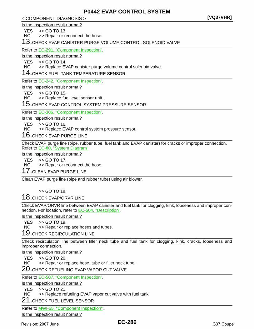
[VQ37VHR]P0442 EVAP CONTROL SYSTEM
< COMPONENT DIAGNOSIS >Is the inspection result normal?YES >> GO TO 13.NO >> Repair or reconnect the hose.
13.CHECK EVAP CANISTER PURGE VOLUME CONTROL SOLENOID VALVE
Refer to EC-291, "Component Inspection".Is the inspection result normal?YES >> GO TO 14.NO >> Replace EVAP canister purge volume control solenoid valve.
14.CHECK FUEL TANK TEMPERATURE SENSOR
Refer to EC-242, "Component Inspection".Is the inspection result normal?YES >> GO TO 15.NO >> Replace fuel level sensor unit.
15.CHECK EVAP CONTROL SYSTEM PRESSURE SENSOR
Refer to EC-306, "Component Inspection".Is the inspection result normal?YES >> GO TO 16.NO >> Replace EVAP control system pressure sensor.
16.CHECK EVAP PURGE LINE
Check EVAP purge line (pipe, rubber tube, fuel tank and EVAP canister) for cracks or improper connection.Refer to EC-80, "System Diagram".Is the inspection result normal?YES >> GO TO 17.NO >> Repair or reconnect the hose.
17.CLEAN EVAP PURGE LINE
Clean EVAP purge line (pipe and rubber tube) using air blower.
>> GO TO 18.
18.CHECK EVAP/ORVR LINE
Check EVAP/ORVR line between EVAP canister and fuel tank for clogging, kink, looseness and improper con-nection. For location, refer to EC-504, "Description".Is the inspection result normal?YES >> GO TO 19.NO >> Repair or replace hoses and tubes.
19.CHECK RECIRCULATION LINE
Check recirculation line between filler neck tube and fuel tank for clogging, kink, cracks, looseness andimproper connection.Is the inspection result normal?YES >> GO TO 20.NO >> Repair or replace hose, tube or filler neck tube.
20.CHECK REFUELING EVAP VAPOR CUT VALVE
Refer to EC-507, "Component Inspection".Is the inspection result normal?YES >> GO TO 21.NO >> Replace refueling EVAP vapor cut valve with fuel tank.
21.CHECK FUEL LEVEL SENSOR
Refer to MWI-55, "Component Inspection".Is the inspection result normal?
EC-286Revision: 2007 June G37 Coupe

P0442 EVAP CONTROL SYSTEM[VQ37VHR]
C
D
E
F
G
H
I
J
K
L
M
A
C
N
P
O
< COMPONENT DIAGNOSIS >
E
YES >> GO TO 22.NO >> Replace fuel level sensor unit.
22.CHECK INTERMITTENT INCIDENT
Refer to GI-38, "Intermittent Incident".
>> INSPECTION END
Component Inspection INFOID:0000000001734107
1.CHECK FUEL TANL VACUUM RELIEF VALVE
1. Turn ignition switch OFF.2. Remove fuel filler cap.3. Wipe clean valve housing.
4. Check valve opening pressure and vacuum.
Is the inspection result normal?YES >> INSPECTION ENDNO >> GO TO 2.
2.REPLACE FUEL FILLER CAP
Replace fuel filler cap.CAUTION:Use only a genuine fuel filler cap as a replacement. If an incorrect fuel filler cap is used, the MIL maycome on.
>> INSPECTION END
SEF445Y
Pressure: 15.3 - 20.0 kPa (0.156 - 0.204 kg/cm2, 2.22 - 2.90 psi)
Vacuum: −6.0 to −3.3 kPa (−0.061 to −0.034 kg/cm2, −0.87 to −0.48 psi)
SEF943S
EC-287Revision: 2007 June G37 Coupe

[VQ37VHR]P0443 EVAP CANISTER PURGE VOLUME CONTROL SOLENOID VALVE
< COMPONENT DIAGNOSIS >
P0443 EVAP CANISTER PURGE VOLUME CONTROL SOLENOID VALVE
Description INFOID:0000000001734108
The EVAP canister purge volume control solenoid valve uses a ON/OFF duty to control the flow rate of fuel vapor from the EVAP canis-ter. The EVAP canister purge volume control solenoid valve ismoved by ON/OFF pulses from the ECM. The longer the ON pulse,the greater the amount of fuel vapor that will flow through the valve.
DTC Logic INFOID:0000000001734109
DTC DETECTION LOGIC
DTC CONFIRMATION PROCEDURE
1.PRECONDITIONING
If DTC Confirmation Procedure has been previously conducted, always perform the following before conduct-ing the next test.1. Turn ignition switch OFF and wait at least 10 seconds.2. Turn ignition switch ON.3. Turn ignition switch OFF and wait at least 10 seconds.TESTING CONDITION:Always perform test at a temperature of 5°C (41°F) or more.Do you have CONSULT-IIIYES >> GO TO 2.NO >> GO TO 3.
2.PERFORM DTC CONFIRMATION PROCEDURE
With CONSULT-III1. Start engine and warm it up to normal operating temperature.2. Turn ignition switch OFF and wait at least 10 seconds.3. Turn ignition switch ON.4. Turn ignition switch OFF and wait at least 10 seconds.5. Turn ignition switch ON.6. Select “PURG VOL CN/V P1444” of “EVAPORATIVE SYSTEM” in “DTC WORK SUPPORT” mode with
CONSULT-III.7. Touch “START”.8. Start engine and let it idle until “TESTING” on CONSULT-III changes to “COMPLETED”. (It will take
approximately 10 seconds.)If “TESTING” is not displayed after 5 minutes, retry from step 2.
9. Touch “SELF-DIAG RESULTS”.Which is displayed on CONSULT-III screen?
JMBIA0069ZZ
DTC No. Trouble diagnosis name DTC detecting condition Possible cause
P0443EVAP canister purge volume control solenoid valve
The canister purge flow is detected during the specified driving conditions, even when EVAP canister purge volume control solenoid valve is completely closed.
• EVAP control system pressure sensor• EVAP canister purge volume control so-
lenoid valve(The valve is stuck open.)
• EVAP canister vent control valve• EVAP canister• Hoses
(Hoses are connected incorrectly or clogged.)
EC-288Revision: 2007 June G37 Coupe

P0443 EVAP CANISTER PURGE VOLUME CONTROL SOLENOID VALVE[VQ37VHR]
C
D
E
F
G
H
I
J
K
L
M
A
C
N
P
O
< COMPONENT DIAGNOSIS >
E
OK >> INSPECTION ENDNG >> Go to EC-289, "Diagnosis Procedure".
3.PERFORM DTC CONFIRMATION PROCEDURE
With GST1. Start engine and warm it up to normal operating temperature.2. Turn ignition switch OFF and wait at least 10 seconds.3. Turn ignition switch ON.4. Turn ignition switch OFF and wait at least 10 seconds.5. Start engine and let it idle for at least 20 seconds.6. Check 1st trip DTC.Is 1st trip DTC displayed?YES >> Go to EC-289, "Diagnosis Procedure".NO >> INSPECTION END
Diagnosis Procedure INFOID:0000000001734110
1.CHECK EVAP CANISTER PURGE VOLUME CONTROL SOLENOID VALVE POWER SUPPLY CIRCUIT
1. Turn ignition switch OFF.2. Disconnect EVAP canister purge volume control solenoid valve harness connector.3. Turn ignition switch ON.4. Check the voltage between EVAP canister purge volume control solenoid valve harness connector and
ground.
Is the inspection result normal?YES >> GO TO 3.NO >> GO TO 2.
2.DETECT MALFUNCTIONING PART
Check the following.• Harness connectors E106, M6• Harness connectors M116, F103• Harness for open or short between EVAP canister purge volume control solenoid valve and IPDM E/R• Harness for open or short between EVAP canister purge volume control solenoid valve and ECM
>> Repair open circuit or short to ground or short to power in harness or connectors.
3.CHECK EVAP CANISTER PURGE VOLUME CONTROL SOLENOID VALVE OUTPUT SIGNAL CIRCUITFOR OPEN AND SHORT
1. Turn ignition switch OFF.2. Disconnect ECM harness connector.3. Check the continuity between EVAP canister purge volume control solenoid valve harness connector and
ECM harness connector.
4. Also check harness for short to ground and short to power.Is the inspection result normal?YES >> GO TO 5.NO >> GO TO 4.
4.DETECT MALFUNCTIONING PART
EVAP canister purge volume control solenoid valveGround Voltage
Connector Terminal
F7 1 Ground Battery voltage
EVAP canister purge volume control solenoid valve ECMContinuity
Connector Terminal Connector Terminal
F7 2 F101 21 Existed
EC-289Revision: 2007 June G37 Coupe

[VQ37VHR]P0443 EVAP CANISTER PURGE VOLUME CONTROL SOLENOID VALVE
< COMPONENT DIAGNOSIS >Check the following.• Harness connectors F104, F105• Harness for open or short between EVAP canister purge volume control solenoid valve and ECM
>> Repair open circuit or short to ground or short to power in harness or connectors.
5.CHECK EVAP CONTROL SYSTEM PRESSURE SENSOR CONNECTOR
1. Disconnect EVAP control system pressure sensor harness connector.2. Check connectors for water.
Is the inspection result normal?YES >> GO TO 6.NO >> Replace EVAP control system pressure sensor.
6.CHECK EVAP CONTROL SYSTEM PRESSURE SENSOR
Refer to EC-306, "Component Inspection".Is the inspection result normal?YES-1 >> With CONSULT-III: GO TO 7.YES-2 >> Without CONSULT-III: GO TO 8.NO >> Replace EVAP control system pressure sensor.
7.CHECK EVAP CANISTER PURGE VOLUME CONTROL SOLENOID VALVE
With CONSULT-III1. Turn ignition switch OFF.2. Reconnect harness connectors disconnected.3. Start engine.4. Perform “PURG VOL CONT/V” in “ACTIVE TEST” mode with CONSULT-III. Check that engine speed var-
ies according to the valve opening.Does engine speed vary according to the valve opening?YES >> GO TO 9.NO >> GO TO 8.
8.CHECK EVAP CANISTER PURGE VOLUME CONTROL SOLENOID VALVE
Refer to EC-291, "Component Inspection".Is the inspection result normal?YES >> GO TO 9.NO >> Replace EVAP canister purge volume control solenoid valve.
9.CHECK RUBBER TUBE FOR CLOGGING
1. Disconnect rubber tube connected to EVAP canister vent control valve.2. Check the rubber tube for clogging.Is the inspection result normal?YES >> GO TO 10.NO >> Clean the rubber tube using an air blower.
10.CHECK EVAP CANISTER VENT CONTROL VALVE
Refer to EC-298, "Component Inspection".Is the inspection result normal?YES >> GO TO 11.NO >> Replace EVAP canister vent control valve.
11.CHECK IF EVAP CANISTER SATURATED WITH WATER
1. Remove EVAP canister with EVAP canister vent control valve and EVAP control system pressure sensorattached.
Water should not exist.
EC-290Revision: 2007 June G37 Coupe

P0443 EVAP CANISTER PURGE VOLUME CONTROL SOLENOID VALVE[VQ37VHR]
C
D
E
F
G
H
I
J
K
L
M
A
C
N
P
O
< COMPONENT DIAGNOSIS >
E
2. Check if water will drain from EVAP canister (1).
Does water drain from the EVAP canister?YES >> GO TO 12.NO >> GO TO 14.
12.CHECK EVAP CANISTER
Weigh the EVAP canister with the EVAP canister vent control valve and EVAP control system pressure sensorattached.The weight should be less than 2.2 kg (4.9 lb).Is the inspection result normal?YES >> GO TO 14.NO >> GO TO 13.
13.DETECT MALFUNCTIONING PART
Check the following.• EVAP canister for damage• EVAP hose between EVAP canister and vehicle frame for clogging or poor connection
>> Repair hose or replace EVAP canister.
14.CHECK INTERMITTENT INCIDENT
Refer to GI-38, "Intermittent Incident".
>> INSPECTION END
Component Inspection INFOID:0000000001734111
1.CHECK EVAP CANISTER PURGE VOLUME CONTROL SOLENOID VALVE
With CONSULT-III1. Turn ignition switch OFF.2. Reconnect all harness connectors disconnected.3. Disconnect EVAP purge hoses connected to EVAP canister purge volume control solenoid valve.4. Turn ignition switch ON.5. Select “PURG VOL CONT/V” in “ACTIVE TEST” mode with CONSULT-III.6. Touch “Qd” and “Qu” on CONSULT-III screen to adjust “PURG
VOL CONT/V” opening and check air passage continuity ofEVAP canister purge volume control solenoid valve under thefollowing conditions.
Without CONSULT-III1. Turn ignition switch OFF.2. Disconnect EVAP canister purge volume control solenoid valve harness connector.3. Disconnect EVAP purge hoses connected to EVAP canister purge volume control solenoid valve.
2 : EVAP canister vent control valve
PBIB2731E
Condition(PURG VOL CONT/V value)
Air passage continuity between (A) and (B)
100% Existed
0% Not existed
JMBIA0068ZZ
EC-291Revision: 2007 June G37 Coupe
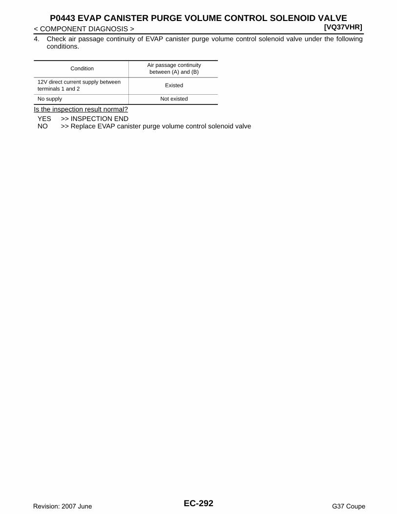
[VQ37VHR]P0443 EVAP CANISTER PURGE VOLUME CONTROL SOLENOID VALVE
< COMPONENT DIAGNOSIS >4. Check air passage continuity of EVAP canister purge volume control solenoid valve under the following
conditions.
Is the inspection result normal?YES >> INSPECTION ENDNO >> Replace EVAP canister purge volume control solenoid valve
ConditionAir passage continuity between (A) and (B)
12V direct current supply between terminals 1 and 2
Existed
No supply Not existed
EC-292Revision: 2007 June G37 Coupe
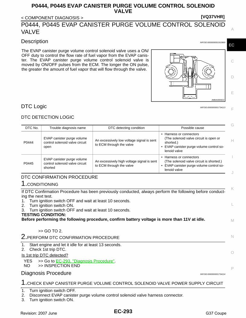
P0444, P0445 EVAP CANISTER PURGE VOLUME CONTROL SOLENOID VALVE
[VQ37VHR]
C
D
E
F
G
H
I
J
K
L
M
A
C
N
P
O
< COMPONENT DIAGNOSIS >
E
P0444, P0445 EVAP CANISTER PURGE VOLUME CONTROL SOLENOIDVALVE
Description INFOID:0000000001910869
The EVAP canister purge volume control solenoid valve uses a ON/OFF duty to control the flow rate of fuel vapor from the EVAP canis-ter. The EVAP canister purge volume control solenoid valve ismoved by ON/OFF pulses from the ECM. The longer the ON pulse,the greater the amount of fuel vapor that will flow through the valve.
DTC Logic INFOID:0000000001734113
DTC DETECTION LOGIC
DTC CONFIRMATION PROCEDURE
1.CONDITIONING
If DTC Confirmation Procedure has been previously conducted, always perform the following before conduct-ing the next test.1. Turn ignition switch OFF and wait at least 10 seconds.2. Turn ignition switch ON.3. Turn ignition switch OFF and wait at least 10 seconds.TESTING CONDITION:Before performing the following procedure, confirm battery voltage is more than 11V at idle.
>> GO TO 2.
2.PERFORM DTC CONFIRMATION PROCEDURE
1. Start engine and let it idle for at least 13 seconds.2. Check 1st trip DTC.Is 1st trip DTC detected?YES >> Go to EC-293, "Diagnosis Procedure".NO >> INSPECTION END
Diagnosis Procedure INFOID:0000000001734114
1.CHECK EVAP CANISTER PURGE VOLUME CONTROL SOLENOID VALVE POWER SUPPLY CIRCUIT
1. Turn ignition switch OFF.2. Disconnect EVAP canister purge volume control solenoid valve harness connector.3. Turn ignition switch ON.
JMBIA0069ZZ
DTC No. Trouble diagnosis name DTC detecting condition Possible cause
P0444EVAP canister purge volume control solenoid valve circuit open
An excessively low voltage signal is sent to ECM through the valve
• Harness or connectors(The solenoid valve circuit is open or shorted.)
• EVAP canister purge volume control so-lenoid valve
P0445EVAP canister purge volume control solenoid valve circuit shorted
An excessively high voltage signal is sent to ECM through the valve
• Harness or connectors(The solenoid valve circuit is shorted.)
• EVAP canister purge volume control so-lenoid valve
EC-293Revision: 2007 June G37 Coupe

[VQ37VHR]
P0444, P0445 EVAP CANISTER PURGE VOLUME CONTROL SOLENOID VALVE
< COMPONENT DIAGNOSIS >4. Check the voltage between EVAP canister purge volume control solenoid valve harness connector and
ground.
Is the inspection result normal?YES >> GO TO 3.NO >> GO TO 2.
2.DETECT MALFUNCTIONING PART
Check the following.• Harness connectors E106, M6• Harness connectors M116, F103• Harness for open or short between EVAP canister purge volume control solenoid valve and IPDM E/R• Harness for open or short between EVAP canister purge volume control solenoid valve and ECM
>> Repair open circuit or short to ground or short to power in harness or connectors.
3.CHECK EVAP CANISTER PURGE VOLUME CONTROL SOLENOID VALVE OUTPUT SIGNAL CIRCUITFOR OPEN AND SHORT
1. Turn ignition switch OFF.2. Disconnect ECM harness connector.3. Check the continuity between EVAP canister purge volume control solenoid valve harness connector and
ECM harness connector.
4. Also check harness for short to ground and short to power.Is the inspection result normal?YES-1 >> With CONSULT-III: GO TO 5.YES-2 >> Without CONSULT-III: GO TO 6.NO >> GO TO 4.
4.DETECT MALFUNCTIONING PART
Check the following.• Harness connectors F104, F105• Harness for open or short between EVAP canister purge volume control solenoid valve and ECM
>> Repair open circuit or short to ground or short to power in harness or connectors.
5.CHECK EVAP CANISTER PURGE VOLUME CONTROL SOLENOID VALVE OPERATION
With CONSULT-III1. Reconnect all harness connectors disconnected.2. Start engine.3. Perform “PURG VOL CONT/V” in “ACTIVE TEST” mode with CONSULT-III. Check that engine speed var-
ies according to the valve opening.Does engine speed vary according to the valve opening?YES >> GO TO 7.NO >> GO TO 6.
6.CHECK EVAP CANISTER PURGE VOLUME CONTROL SOLENOID VALVE
Refer to EC-295, "Component Inspection".
EVAP canister purge vol-ume control solenoid valve Ground Voltage
Connector Terminal
F7 1 Ground Battery voltage
EVAP canister purge vol-ume control solenoid valve
ECMContinuity
Connector Terminal Connector Terminal
F7 2 F101 21 Existed
EC-294Revision: 2007 June G37 Coupe

P0444, P0445 EVAP CANISTER PURGE VOLUME CONTROL SOLENOID VALVE
[VQ37VHR]
C
D
E
F
G
H
I
J
K
L
M
A
C
N
P
O
< COMPONENT DIAGNOSIS >
E
Is the inspection result normal?YES >> GO TO 7.NO >> Replace EVAP canister purge volume control solenoid valve.
7.CHECK INTERMITTENT INCIDENT
Refer to GI-38, "Intermittent Incident".
>> INSPECTION END
Component Inspection INFOID:0000000001910870
1.CHECK EVAP CANISTER PURGE VOLUME CONTROL SOLENOID VALVE
With CONSULT-III1. Turn ignition switch OFF.2. Reconnect all harness connectors disconnected.3. Disconnect EVAP purge hoses connected to EVAP canister purge volume control solenoid valve.4. Turn ignition switch ON.5. Select “PURG VOL CONT/V” in “ACTIVE TEST” mode with CONSULT-III.6. Touch “Qd” and “Qu” on CONSULT-III screen to adjust “PURG
VOL CONT/V” opening and check air passage continuity ofEVAP canister purge volume control solenoid valve under thefollowing conditions.
Without CONSULT-III1. Turn ignition switch OFF.2. Disconnect EVAP canister purge volume control solenoid valve harness connector.3. Disconnect EVAP purge hoses connected to EVAP canister purge volume control solenoid valve.4. Check air passage continuity of EVAP canister purge volume control solenoid valve under the following
conditions.
Is the inspection result normal?YES >> INSPECTION ENDNO >> Replace EVAP canister purge volume control solenoid valve
Condition(PURG VOL CONT/V value)
Air passage continuity between (A) and (B)
100% Existed
0% Not existed
JMBIA0068ZZ
ConditionAir passage continuity between (A) and (B)
12V direct current supply between terminals 1 and 2
Existed
No supply Not existed
EC-295Revision: 2007 June G37 Coupe

[VQ37VHR]P0447 EVAP CANISTER VENT CONTROL VALVE
< COMPONENT DIAGNOSIS >
P0447 EVAP CANISTER VENT CONTROL VALVE
Description INFOID:0000000001734116
The EVAP canister vent control valve is located on the EVAP canis-ter and is used to seal the canister vent.This solenoid valve responds to signals from the ECM. When theECM sends an ON signal, the coil in the solenoid valve is energized.A plunger will then move to seal the canister vent. The ability to sealthe vent is necessary for the on board diagnosis of other evaporativeemission control system components.This solenoid valve is used only for diagnosis, and usually remainsopened.When the vent is closed, under normal purge conditions, the evapo-rative emission control system is depressurized and allows “EVAPControl System” diagnosis.
DTC Logic INFOID:0000000001734117
DTC DETECTION LOGIC
DTC CONFIRMATION PROCEDURE
1.PRECONDITIONING
If DTC Confirmation Procedure has been previously conducted, always perform the following before conduct-ing the next test.1. Turn ignition switch OFF and wait at least 10 seconds.2. Turn ignition switch ON.3. Turn ignition switch OFF and wait at least 10 seconds.TESTING CONDITION:Before performing the following procedure, confirm battery voltage is more than 11V at idle.
>> GO TO 2.
2.PERFORM DTC CONFIRMATION PROCEDURE
1. Start engine and wait at least 8 seconds.2. Check 1st trip DTC.Is 1st trip DTC detected?YES >> Go to EC-296, "Diagnosis Procedure".NO >> INSPECTION END
Diagnosis Procedure INFOID:0000000001734118
1.INSPECTION START
Do you have CONSULT-III?Do you have CONSULT-III?YES >> GO TO 2.NO >> GO TO 3.
2.CHECK EVAP CANISTER VENT CONTROL VALVE CIRCUIT
With CONSULT-III1. Turn ignition switch OFF and then turn ON.2. Select “VENT CONTROL/V” in “ACTIVE TEST” mode with CONSULT-III.
PBIB1263E
DTC No. Trouble diagnosis name DTC detecting condition Possible cause
P0447EVAP canister vent con-trol valve circuit open
An improper voltage signal is sent to ECM through EVAP canister vent control valve.
• Harness or connectors(The valve circuit is open or shorted.)
• EVAP canister vent control valve
EC-296Revision: 2007 June G37 Coupe

P0447 EVAP CANISTER VENT CONTROL VALVE[VQ37VHR]
C
D
E
F
G
H
I
J
K
L
M
A
C
N
P
O
< COMPONENT DIAGNOSIS >
E
3. Touch “ON/OFF” on CONSULT-III screen.4. Check for operating sound of the valve.
Is the inspection result normal?YES >> GO TO 7.NO >> GO TO 3.
3.CHECK EVAP CANISTER VENT CONTROL VALVE POWER SUPPLY CIRCUIT
1. Turn ignition switch OFF.2. Disconnect EVAP canister vent control valve harness connector.3. Turn ignition switch ON.4. Check the voltage between EVAP canister vent control valve harness connector and ground.
Is the inspection result normal?YES >> GO TO 5.NO >> GO TO 4.
4.DETECT MALFUNCTIONING PART
Check the following.• Harness connectors E3, F1• Harness connectors F103, M116• Harness connectors M7, B1• Harness for open or short between EVAP canister vent control valve and IPDM E/R
>> Repair open circuit or short to ground or short to power in harness or connectors.
5.CHECK EVAP CANISTER VENT CONTROL VALVE OUTPUT SIGNAL CIRCUIT FOR OPEN AND SHORT
1. Turn ignition switch OFF.2. Disconnect ECM harness connector.3. Check the continuity between EVAP canister vent control valve harness connector and ECM harness con-
nector.
4. Also check harness for short to ground and short to power.Is the inspection result normal?YES >> GO TO 7.NO >> GO TO 6.
6.DETECT MALFUNCTIONING PART
Check the following.• Harness connectors B1, M7• Harness for open or short between EVAP canister vent control valve and ECM
>> Repair open circuit or short to ground or short to power in harness or connectors.
7.CHECK RUBBER TUBE FOR CLOGGING
1. Disconnect rubber tube connected to EVAP canister vent control valve.2. Check the rubber tube for clogging.
Clicking sound should be heard.
EVAP canister vent con-trol valve Ground Voltage
Connector Terminal
B31 1 Ground Battery voltage
EVAP canister vent control valve
ECMContinuity
Connector Terminal Connector Terminal
B31 2 M107 121 Existed
EC-297Revision: 2007 June G37 Coupe

[VQ37VHR]P0447 EVAP CANISTER VENT CONTROL VALVE
< COMPONENT DIAGNOSIS >Is the inspection result normal?YES >> GO TO 8.NO >> Clean the rubber tube using an air blower.
8.CHECK EVAP CANISTER VENT CONTROL VALVE
Refer to EC-298, "Component Inspection".Is the inspection result normal?YES >> GO TO 9.NO >> Replace EVAP canister vent control valve.
9.CHECK INTERMITTENT INCIDENT
Refer to GI-38, "Intermittent Incident".
>> INSPECTION END
Component Inspection INFOID:0000000001734119
1.CHECK EVAP CANISTER VENT CONTROL VALVE-I
1. Turn ignition switch OFF.2. Remove EVAP canister vent control valve from EVAP canister.3. Check portion (A) of EVAP canister vent control valve for being
rusted.Is it rusted?YES >> Replace EVAP canister vent control valveNO >> GO TO 2.
2.CHECK EVAP CANISTER VENT CONTROL VALVE-II
With CONSULT-III1. Reconnect harness connectors disconnected.2. Turn ignition switch ON.3. Perform “VENT CONTROL/V” in “ACTIVE TEST” mode.4. Check air passage continuity and operation delay time.
Make sure new O-ring is installed properly.
Operation takes less than 1 second.
Without CONSULT-III1. Disconnect EVAP canister vent control valve harness connector.2. Check air passage continuity and operation delay time under the
following conditions.Make sure new O-ring is installed properly.
Operation takes less than 1 second.
Is the inspection result normal?
JMBIA0168ZZ
Condition VENT CONTROL/V Air passage continuity between (A) and (B)
ON Not existed
OFF Existed
Condition Air passage continuity between (A) and (B)
12V direct current supply between terminals 1 and 2
Not existed
OFF Existed
JMBIA0169ZZ
EC-298Revision: 2007 June G37 Coupe

P0447 EVAP CANISTER VENT CONTROL VALVE[VQ37VHR]
C
D
E
F
G
H
I
J
K
L
M
A
C
N
P
O
< COMPONENT DIAGNOSIS >
E
YES >> GO TO 3.NO >> Replace EVAP canister vent control valve
3.CHECK EVAP CANISTER VENT CONTROL VALVE-III
With CONSULT-III1. Clean the air passage [portion (A) to (B)] of EVAP canister vent control valve using an air blower.2. Perform “VENT CONTROL/V” in “ACTIVE TEST” mode.3. Check air passage continuity and operation delay time.
Make sure new O-ring is installed properly.
Operation takes less than 1 second.
Without CONSULT-III1. Clean the air passage [portion (A) to (B)] of EVAP canister vent
control valve using an air blower.2. Check air passage continuity and operation delay time under the
following conditions.Make sure new O-ring is installed properly.
Operation takes less than 1 second.
Is the inspection result normal?YES >> INSPECTION ENDNO >> Replace EVAP canister vent control valve
Condition VENT CONTROL/V Air passage continuity between (A) and (B)
ON Not existed
OFF Existed
Condition Air passage continuity between (A) and (B)
12V direct current supply between terminals 1 and 2
Not existed
OFF Existed
JMBIA0169ZZ
EC-299Revision: 2007 June G37 Coupe

[VQ37VHR]P0448 EVAP CANISTER VENT CONTROL VALVE
< COMPONENT DIAGNOSIS >
P0448 EVAP CANISTER VENT CONTROL VALVE
Description INFOID:0000000001910881
The EVAP canister vent control valve is located on the EVAP canis-ter and is used to seal the canister vent.This solenoid valve responds to signals from the ECM. When theECM sends an ON signal, the coil in the solenoid valve is energized.A plunger will then move to seal the canister vent. The ability to sealthe vent is necessary for the on board diagnosis of other evaporativeemission control system components.This solenoid valve is used only for diagnosis, and usually remainsopened.When the vent is closed, under normal purge conditions, the evapo-rative emission control system is depressurized and allows “EVAPControl System” diagnosis.
DTC Logic INFOID:0000000001734121
DTC DETECTION LOGIC
DTC CONFIRMATION PROCEDURE
1.PRECONDITIONING
If DTC Confirmation Procedure has been previously conducted, always perform the following before conduct-ing the next test.1. Turn ignition switch OFF and wait at least 10 seconds.2. Turn ignition switch ON.3. Turn ignition switch OFF and wait at least 10 seconds.
>> GO TO 2.
2.PERFORM DTC CONFIRMATION PROCEDURE
With CONSULT-III1. Turn ignition switch ON and wait at least 5 seconds.2. Turn ignition switch OFF and wait at least 10 seconds.3. Turn ignition switch ON and select “DATA MONITOR” mode with CONSULT-III.4. Start engine and let it idle for at least 1 minute. 5. Repeat next procedures five times.- Increase the engine speed up to 3,000 to 3,500 rpm and keep it for 2 minutes.
Never exceed 2 minutes.- Fully released accelerator pedal and keep engine idle for about 5 seconds.6. Repeat next procedure 27 times.- Quickly increase the engine speed up to 3,000 to 3,500 rpm or more and keep it for 25 to 30 seconds.
PBIB1263E
DTC No. Trouble diagnosis name DTC detecting condition Possible cause
P0448EVAP canister vent con-trol valve close
EVAP canister vent control valve remains closed under specified driving conditions.
• EVAP canister vent control valve• EVAP control system pressure sensor
and the circuit• Blocked rubber tube to EVAP canister
vent control valve• EVAP canister is saturated with water
EC-300Revision: 2007 June G37 Coupe

P0448 EVAP CANISTER VENT CONTROL VALVE[VQ37VHR]
C
D
E
F
G
H
I
J
K
L
M
A
C
N
P
O
< COMPONENT DIAGNOSIS >
E
- Fully released accelerator pedal and keep engine idle for at least 35 seconds.
7. Check 1st trip DTC.With GST
Follow the procedure “With CONSULT-III” above.Is 1st trip DTC detected?YES >> Go to EC-301, "Diagnosis Procedure".NO >> INSPECTION END
Diagnosis Procedure INFOID:0000000001734122
1.CHECK RUBBER TUBE
1. Turn ignition switch OFF.2. Disconnect rubber tube connected to EVAP canister vent control valve.3. Check the rubber tube for clogging.Is the inspection result normal?YES >> GO TO 2.NO >> Clean rubber tube using an air blower.
2.CHECK EVAP CANISTER VENT CONTROL VALVE
Refer to EC-302, "Component Inspection".Is the inspection result normal?YES >> GO TO 3.NO >> Replace EVAP canister vent control valve.
3.CHECK IF EVAP CANISTER SATURATED WITH WATER
1. Remove EVAP canister with EVAP canister vent control valve and EVAP control system pressure sensorattached.
2. Check if water will drain from the EVAP canister (1).
Does water drain from EVAP canister?YES >> GO TO 4.NO >> GO TO 6.
4.CHECK EVAP CANISTER
Weigh the EVAP canister with the EVAP canister vent control valve and EVAP control system pressure sensorattached.The weight should be less than 2.2 kg (4.9 lb).Is the inspection result normal?YES >> GO TO 6.NO >> GO TO 5.
5.DETECT MALFUNCTIONING PART
PBIB0972E
2 : EVAP canister vent control valve
PBIB2731E
EC-301Revision: 2007 June G37 Coupe

[VQ37VHR]P0448 EVAP CANISTER VENT CONTROL VALVE
< COMPONENT DIAGNOSIS >Check the following.• EVAP canister for damage• EVAP hose between EVAP canister and vehicle frame for clogging or poor connection
>> Repair hose or replace EVAP canister.
6.CHECK EVAP CONTROL SYSTEM PRESSURE SENSOR CONNECTOR
1. Disconnect EVAP control system pressure sensor harness connector.2. Check connectors for water.
Is the inspection result normal?YES >> GO TO 7.NO >> Replace EVAP control system pressure sensor.
7.CHECK EVAP CONTROL SYSTEM PRESSURE SENSOR
Refer to EC-306, "Component Inspection".Is the inspection result normal?YES >> GO TO 8.NO >> Replace EVAP control system pressure sensor.
8.CHECK INTERMITTENT INCIDENT
Refer to GI-38, "Intermittent Incident".
>> INSPECTION END
Component Inspection INFOID:0000000001910882
1.CHECK EVAP CANISTER VENT CONTROL VALVE-I
1. Turn ignition switch OFF.2. Remove EVAP canister vent control valve from EVAP canister.3. Check portion (A) of EVAP canister vent control valve for being
rusted.Is it rusted?YES >> Replace EVAP canister vent control valveNO >> GO TO 2.
2.CHECK EVAP CANISTER VENT CONTROL VALVE-II
With CONSULT-III1. Reconnect harness connectors disconnected.2. Turn ignition switch ON.3. Perform “VENT CONTROL/V” in “ACTIVE TEST” mode.
Water should not exist.
JMBIA0168ZZ
EC-302Revision: 2007 June G37 Coupe

P0448 EVAP CANISTER VENT CONTROL VALVE[VQ37VHR]
C
D
E
F
G
H
I
J
K
L
M
A
C
N
P
O
< COMPONENT DIAGNOSIS >
E
4. Check air passage continuity and operation delay time.Make sure new O-ring is installed properly.
Operation takes less than 1 second.
Without CONSULT-III1. Disconnect EVAP canister vent control valve harness connector.2. Check air passage continuity and operation delay time under the
following conditions.Make sure new O-ring is installed properly.
Operation takes less than 1 second.
Is the inspection result normal?YES >> GO TO 3.NO >> Replace EVAP canister vent control valve
3.CHECK EVAP CANISTER VENT CONTROL VALVE-III
With CONSULT-III1. Clean the air passage [portion (A) to (B)] of EVAP canister vent control valve using an air blower.2. Perform “VENT CONTROL/V” in “ACTIVE TEST” mode.3. Check air passage continuity and operation delay time.
Make sure new O-ring is installed properly.
Operation takes less than 1 second.
Without CONSULT-III1. Clean the air passage [portion (A) to (B)] of EVAP canister vent
control valve using an air blower.2. Check air passage continuity and operation delay time under the
following conditions.Make sure new O-ring is installed properly.
Operation takes less than 1 second.
Is the inspection result normal?YES >> INSPECTION ENDNO >> Replace EVAP canister vent control valve
Condition VENT CONTROL/V Air passage continuity between (A) and (B)
ON Not existed
OFF Existed
Condition Air passage continuity between (A) and (B)
12V direct current supply between terminals 1 and 2
Not existed
OFF Existed
JMBIA0169ZZ
Condition VENT CONTROL/V Air passage continuity between (A) and (B)
ON Not existed
OFF Existed
Condition Air passage continuity between (A) and (B)
12V direct current supply between terminals 1 and 2
Not existed
OFF Existed
JMBIA0169ZZ
EC-303Revision: 2007 June G37 Coupe

[VQ37VHR]P0451 EVAP CONTROL SYSTEM PRESSURE SENSOR
< COMPONENT DIAGNOSIS >
P0451 EVAP CONTROL SYSTEM PRESSURE SENSOR
Description INFOID:0000000001734124
The EVAP control system pressure sensor detects pressure in thepurge line. The sensor output voltage to the ECM increases as pres-sure increases.
DTC Logic INFOID:0000000001734125
DTC DETECTION LOGIC
DTC CONFIRMATION PROCEDURE
1.PRECONDITIONING
If DTC Confirmation Procedure has been previously conducted, always perform the following before conduct-ing the next test.1. Turn ignition switch OFF and wait at least 10 seconds.2. Turn ignition switch ON.3. Turn ignition switch OFF and wait at least 10 seconds.
>> GO TO 2.
2.PERFORM DTC CONFIRMATION PROCEDURE
1. Turn ignition switch OFF and wait at least 10 seconds.2. Start engine and wait at least 40 seconds.
NOTE:Do not depress accelerator pedal even slightly.
3. Check 1st trip DTC.Is 1st trip DTC detected?YES >> Go to EC-304, "Diagnosis Procedure".NO >> INSPECTION END
Diagnosis Procedure INFOID:0000000001734126
1.CHECK GROUND CONNECTION
PBIB3370E
DTC No. Trouble diagnosis name DTC detecting condition Possible cause
P0451EVAP control system pressure sensor perfor-mance
ECM detects a sloshing signal from the EVAP control system pressure sensor
• Harness or connectors(EVAP control system pressure sensor circuit is shorted.)[CKP sensor (POS) circuit is shorted.](APP sensor 2 circuit is shorted.)(Refrigerant pressure sensor circuit is shorted.)(Brake booster pressure sensor circuit is shorted)
• EVAP control system pressure sensor• Crankshaft position sensor (POS)• Accelerator pedal position sensor• Refrigerant pressure sensor• Brake booster pressure sensor
EC-304Revision: 2007 June G37 Coupe

P0451 EVAP CONTROL SYSTEM PRESSURE SENSOR[VQ37VHR]
C
D
E
F
G
H
I
J
K
L
M
A
C
N
P
O
< COMPONENT DIAGNOSIS >
E
1. Turn ignition switch OFF.2. Check ground connection M95. Refer to Ground Inspection in GI-41, "Circuit Inspection".Is the inspection result normal?YES >> GO TO 2.NO >> Repair or replace ground connection.
2.CHECK EVAP CONTROL SYSTEM PRESSURE SENSOR CONNECTOR FOR WATER
1. Disconnect EVAP control system pressure sensor harness connector.2. Check sensor harness connector for water.
Is the inspection result normal?YES >> GO TO 3.NO >> Repair or replace harness connector.
3.CHECK EVAP CONTROL SYSTEM PRESSURE SENSOR POWER SUPPLY CIRCUIT
1. Turn ignition switch ON.2. Check the voltage between EVAP control system pressure sensor harness connector and ground.
Is the inspection result normal?YES >> GO TO 8.NO >> GO TO 4.
4.CHECK SENSOR POWER SUPPLY CIRCUIT
Check harness for short to power and short to ground, between the following terminals.
Is the inspection result normal?YES >> GO TO 5.NO >> Repair short to ground or short to power in harness or connectors.
5.CHECK COMPONENTS
Check the following.• Crankshaft position sensor (POS) (Refer to EC-267, "Component Inspection".)• Brake booster pressure sensor (Refer to EC-352, "Component Inspection".)• Refrigerant pressure sensor (Refer to HAC-85, "Diagnosis Procedure".)Is the inspection result normal?YES >> GO TO 6.NO >> Replace malfunctioning component.
6.CHECK APP SENSOR
Refer to EC-460, "Component Inspection".Is the inspection result normal?YES >> GO TO 9.
Water should not exist.
EVAP control system pressure sensor Ground Voltage
Connector Terminal
B30 3 Ground Approx. 5V
ECM Sensor
Connector Terminal Name Connector Terminal
F10145 Brake booster pressure sensor E48 1
46 CKP sensor (POS) F2 1
M107
103 APP sensor E112 6
107 EVAP control system pressure sensor B30 3
111 Refrigerant pressure sensor E77 3
EC-305Revision: 2007 June G37 Coupe

[VQ37VHR]P0451 EVAP CONTROL SYSTEM PRESSURE SENSOR
< COMPONENT DIAGNOSIS >NO >> GO TO 7.
7.REPLACE ACCELERATOR PEDAL ASSEMBLY
1. Replace accelerator pedal assembly2. Go to EC-460, "Special Repair Requirement".
>> INSPECTION END
8.CHECK EVAP CONTROL SYSTEM PRESSURE SENSOR
Refer to EC-306, "Component Inspection".Is the inspection result normal?YES >> GO TO 9.NO >> Replace EVAP control system pressure sensor.
9.CHECK INTERMITTENT INCIDENT
Refer to GI-38, "Intermittent Incident".
>> INSPECTION END
Component Inspection INFOID:0000000001734127
1.CHECK EVAP CONTROL SYSTEM PRESSURE SENSOR
1. Turn ignition switch OFF.2. Remove EVAP control system pressure sensor with its harness connector connected from EVAP canister.
Always replace O-ring with a new one.3. Install a vacuum pump to EVAP control system pressure sensor.4. Turn ignition switch ON and check output voltage between ECM harness connector and ground under the
following conditions.
CAUTION:• Always calibrate the vacuum pump gauge when using it.• Do not apply below -93.3 kPa (-0.952 kg/cm2, -13.53 psi) or pressure over 101.3 kPa (1.033 kg/
cm2, 14.69 psi).Is the inspection result normal?YES >> INSPECTION ENDNO >> Replace EVAP control system pressure sensor
ECMGround
Condition
[Applied vacuum kPa (kg/cm2, psi)]Voltage
Connector Terminal
M107 102 GroundNot applied 1.8 - 4.8V
-26.7 (-0.272, -3.87) 2.1 to 2.5V lower than above value
EC-306Revision: 2007 June G37 Coupe

P0452 EVAP CONTROL SYSTEM PRESSURE SENSOR[VQ37VHR]
C
D
E
F
G
H
I
J
K
L
M
A
C
N
P
O
< COMPONENT DIAGNOSIS >
E
P0452 EVAP CONTROL SYSTEM PRESSURE SENSOR
Description INFOID:0000000001910884
The EVAP control system pressure sensor detects pressure in thepurge line. The sensor output voltage to the ECM increases as pres-sure increases.
DTC Logic INFOID:0000000001734129
DTC DETECTION LOGIC
DTC CONFIRMATION PROCEDURE
1.PRECONDITIONING
If DTC Confirmation Procedure has been previously conducted, always perform the following before conduct-ing the next test.1. Turn ignition switch OFF and wait at least 10 seconds.2. Turn ignition switch ON.3. Turn ignition switch OFF and wait at least 10 seconds.TESTING CONDITION:Always perform test at a temperature of 5°C (41°F) or more.
>> GO TO 2.
2.PERFORM DTC CONFIRMATION PROCEDURE
With CONSULT-III1. Start engine and warm it up to normal operating temperature.2. Turn ignition switch OFF and wait at least 10 seconds.3. Turn ignition switch ON.4. Turn ignition switch OFF and wait at least 10 seconds.5. Turn ignition switch ON.6. Select “DATA MONITOR” mode with CONSULT-III.7. Make sure that “FUEL T/TMP SE” is more than 0°C (32°F).8. Start engine and wait at least 20 seconds.9. Check 1st trip DTC.
PBIB3370E
DTC No. Trouble diagnosis name DTC detecting condition Possible cause
P0452EVAP control system pressure sensor low in-put
An excessively low voltage from the sensor is sent to ECM.
• Harness or connectors(EVAP control system pressure sensor circuit is open or shorted.)[CKP sensor (POS) circuit is shorted.](APP sensor 2 circuit is shorted.)(Refrigerant pressure sensor circuit is shorted.)(Brake booster pressure sensor circuit is shorted)
• EVAP control system pressure sensor• Crankshaft position sensor (POS)• Accelerator pedal position sensor• Refrigerant pressure sensor• Brake booster pressure sensor
EC-307Revision: 2007 June G37 Coupe

[VQ37VHR]P0452 EVAP CONTROL SYSTEM PRESSURE SENSOR
< COMPONENT DIAGNOSIS >
With GST1. Start engine and warm it up to normal operating temperature.2. Set voltmeter probes to ECM harness connector and ground as follows.
3. Make sure that the voltage is less than 4.2V.4. Turn ignition switch OFF and wait at least 10 seconds.5. Turn ignition switch ON.6. Turn ignition switch OFF and wait at least 10 seconds.7. Start engine and wait at least 20 seconds.8. Check 1st trip DTC.Is 1st trip DTC detected?YES >> Go to EC-308, "Diagnosis Procedure".NO >> INSPECTION END
Diagnosis Procedure INFOID:0000000001734130
1.CHECK GROUND CONNECTION
1. Turn ignition switch OFF.2. Check ground connection M95. Refer to Ground Inspection in GI-41, "Circuit Inspection".Is the inspection result normal?YES >> GO TO 2.NO >> Repair or replace ground connection.
2.CHECK CONNECTOR
1. Disconnect EVAP control system pressure sensor harness connector.2. Check sensor harness connector for water.
Is the inspection result normal?YES >> GO TO 3.NO >> Repair or replace harness connector.
3.CHECK EVAP CONTROL SYSTEM PRESSURE SENSOR POWER SUPPLY CIRCUIT-I
1. Turn ignition switch ON.2. Check the voltage between EVAP control system pressure sensor harness connector and ground.
Is the inspection result normal?YES >> GO TO 10.NO >> GO TO 4.
4.CHECK EVAP CONTROL SYSTEM PRESSURE SENSOR POWER SUPPLY CIRCUIT-II
1. Turn ignition switch OFF.2. Disconnect ECM harness connector.3. Check the continuity between EVAP control system pressure sensor harness connector and ECM har-
ness connector.
ECMGround
Connector Terminal
M107106
(Fuel tank temperature sensor signal)Ground
Water should not exist.
EVAP control system pressure sensor Ground Voltage
Connector Terminal
B30 3 Ground Approx. 5V
EC-308Revision: 2007 June G37 Coupe

P0452 EVAP CONTROL SYSTEM PRESSURE SENSOR[VQ37VHR]
C
D
E
F
G
H
I
J
K
L
M
A
C
N
P
O
< COMPONENT DIAGNOSIS >
E
Is the inspection result normal?YES >> GO TO 6.NO >> GO TO 5.
5.DETECT MALFUNCTIONING PART
Check the following.• Harness connectors M7, B1• Harness for open between ECM and EVAP control system pressure sensor
>> Repair open circuit.
6.CHECK EVAP CONTROL SYSTEM PRESSURE SENSOR POWER SUPPLY CIRCUIT-III
Check harness for short to power and short to ground, between the following terminals.
Is the inspection result normal?YES >> GO TO 7.NO >> Repair short to ground or short to power in harness or connectors.
7.CHECK COMPONENTS
Check the following.• Crankshaft position sensor (POS) (Refer to EC-267, "Component Inspection".)• Brake booster pressure sensor (Refer to EC-352, "Component Inspection".)• Refrigerant pressure sensor (Refer to HAC-85, "Diagnosis Procedure".)Is the inspection result normal?YES >> GO TO 8.NO >> Replace malfunctioning component.
8.CHECK APP SENSOR
Refer to EC-460, "Component Inspection".Is the inspection result normal?YES >> GO TO 15.NO >> GO TO 9.
9.REPLACE ACCELERATOR PEDAL ASSEMBLY
1. Replace accelerator pedal assembly2. Go to EC-460, "Special Repair Requirement".
>> INSPECTION END
10.CHECK EVAP CONTROL SYSTEM PRESSURE SENSOR GROUND CIRCUIT FOR OPEN ANDSHORT
1. Turn ignition switch OFF.
EVAP control system pressure sensor
ECMContinuity
Connector Terminal Connector Terminal
B30 3 M107 107 Existed
ECM Sensor
Connector Terminal Name Connector Terminal
F10145 Brake booster pressure sensor E48 1
46 CKP sensor (POS) F2 1
M107
103 APP sensor E112 6
107 EVAP control system pressure sensor B30 3
111 Refrigerant pressure sensor E77 3
EC-309Revision: 2007 June G37 Coupe

[VQ37VHR]P0452 EVAP CONTROL SYSTEM PRESSURE SENSOR
< COMPONENT DIAGNOSIS >2. Disconnect ECM harness connector.3. Check the continuity between EVAP control system pressure sensor harness connector and ECM har-
ness connector.
4. Also check harness for short to ground and short to power.Is the inspection result normal?YES >> GO TO 12.NO >> GO TO 11.
11.DETECT MALFUNCTIONING PART
Check the following.• Harness connectors B1, M7• Harness for open or short between EVAP control system pressure sensor and ECM
>> Repair open circuit or short to ground or short to power in harness or connectors.
12.CHECK EVAP CONTROL SYSTEM PRESSURE SENSOR INPUT SIGNAL CIRCUIT FOR OPEN ANDSHORT
1. Check the continuity between EVAP control system pressure sensor harness connector and ECM har-ness connector.
2. Also check harness for short to ground and short to power.Is the inspection result normal?YES >> GO TO 14.NO >> GO TO 13.
13.DETECT MALFUNCTIONING PART
Check the following.• Harness connectors B1, M7• Harness for open or short between EVAP control system pressure sensor and ECM
>> Repair open circuit or short to ground or short to power in harness or connectors.
14.CHECK EVAP CONTROL SYSTEM PRESSURE SENSOR
Refer to EC-310, "Component Inspection".Is the inspection result normal?YES >> GO TO 15.NO >> Replace EVAP control system pressure sensor.
15.CHECK INTERMITTENT INCIDENT
Refer to GI-38, "Intermittent Incident".
>> INSPECTION END
Component Inspection INFOID:0000000001734131
1.CHECK EVAP CONTROL SYSTEM PRESSURE SENSOR
EVAP control system pressure sensor
ECMContinuity
Connector Terminal Connector Terminal
B30 1 M107 112 Existed
EVAP control system pressure sensor
ECMContinuity
Connector Terminal Connector Terminal
B30 2 M107 102 Existed
EC-310Revision: 2007 June G37 Coupe
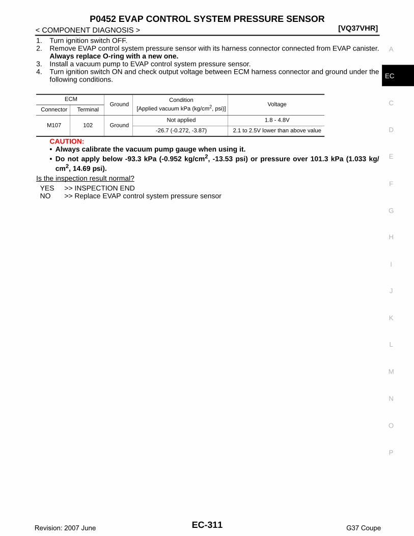
P0452 EVAP CONTROL SYSTEM PRESSURE SENSOR[VQ37VHR]
C
D
E
F
G
H
I
J
K
L
M
A
C
N
P
O
< COMPONENT DIAGNOSIS >
E
1. Turn ignition switch OFF.2. Remove EVAP control system pressure sensor with its harness connector connected from EVAP canister.
Always replace O-ring with a new one.3. Install a vacuum pump to EVAP control system pressure sensor.4. Turn ignition switch ON and check output voltage between ECM harness connector and ground under the
following conditions.
CAUTION:• Always calibrate the vacuum pump gauge when using it.• Do not apply below -93.3 kPa (-0.952 kg/cm2, -13.53 psi) or pressure over 101.3 kPa (1.033 kg/
cm2, 14.69 psi).Is the inspection result normal?YES >> INSPECTION ENDNO >> Replace EVAP control system pressure sensor
ECMGround
Condition
[Applied vacuum kPa (kg/cm2, psi)]Voltage
Connector Terminal
M107 102 GroundNot applied 1.8 - 4.8V
-26.7 (-0.272, -3.87) 2.1 to 2.5V lower than above value
EC-311Revision: 2007 June G37 Coupe

[VQ37VHR]P0453 EVAP CONTROL SYSTEM PRESSURE SENSOR
< COMPONENT DIAGNOSIS >
P0453 EVAP CONTROL SYSTEM PRESSURE SENSOR
Description INFOID:0000000001910888
The EVAP control system pressure sensor detects pressure in thepurge line. The sensor output voltage to the ECM increases as pres-sure increases.
DTC Logic INFOID:0000000001734133
DTC DETECTION LOGIC
DTC CONFIRMATION PROCEDURE
1.PRECONDITIONING
If DTC Confirmation Procedure has been previously conducted, always perform the following before conduct-ing the next test.1. Turn ignition switch OFF and wait at least 10 seconds.2. Turn ignition switch ON.3. Turn ignition switch OFF and wait at least 10 seconds.TESTING CONDITION:Always perform test at a temperature of 5°C (41°F) or more.
>> GO TO 2.
2.PERFORM DTC CONFIRMATION PROCEDURE
With CONSULT-III1. Start engine and warm it up to normal operating temperature.2. Turn ignition switch OFF and wait at least 10 seconds.3. Turn ignition switch ON.4. Turn ignition switch OFF and wait at least 10 seconds.5. Turn ignition switch ON.6. Select “DATA MONITOR” mode with CONSULT-III.
PBIB3370E
DTC No. Trouble diagnosis name DTC detecting condition Possible cause
P0453EVAP control system pressure sensor high in-put
An excessively high voltage from the sensor is sent to ECM.
• Harness or connectors(EVAP control system pressure sensor circuit is open or shorted.)[CKP sensor (POS) circuit is shorted.](APP sensor 2 circuit is shorted.)(Refrigerant pressure sensor circuit is shorted.)(Brake booster pressure sensor circuit is shorted)
• EVAP control system pressure sensor• Crankshaft position sensor (POS)• Accelerator pedal position sensor• Refrigerant pressure sensor• Brake booster pressure sensor• EVAP canister vent control valve• EVAP canister• Rubber hose from EVAP canister vent
control valve to vehicle frame
EC-312Revision: 2007 June G37 Coupe

P0453 EVAP CONTROL SYSTEM PRESSURE SENSOR[VQ37VHR]
C
D
E
F
G
H
I
J
K
L
M
A
C
N
P
O
< COMPONENT DIAGNOSIS >
E
7. Make sure that “FUEL T/TMP SE” is more than 0°C (32°F).8. Start engine and wait at least 20 seconds.9. Check 1st trip DTC.
With GST1. Start engine and warm it up to normal operating temperature.2. Set voltmeter probes to ECM harness connector and ground as follows.
3. Make sure that the voltage is less than 4.2V.4. Turn ignition switch OFF and wait at least 10 seconds.5. Turn ignition switch ON.6. Turn ignition switch OFF and wait at least 10 seconds.7. Start engine and wait at least 20 seconds.8. Check 1st trip DTC.Is 1st trip DTC detected?YES >> Go to EC-313, "Diagnosis Procedure".NO >> INSPECTION END
Diagnosis Procedure INFOID:0000000001734134
1.CHECK GROUND CONNECTION
1. Turn ignition switch OFF.2. Check ground connection M95. Refer to Ground Inspection in GI-41, "Circuit Inspection".Is the inspection result normal?YES >> GO TO 2.NO >> Repair or replace ground connection.
2.CHECK CONNECTOR
1. Disconnect EVAP control system pressure sensor harness connector.2. Check sensor harness connector for water.
Is the inspection result normal?YES >> GO TO 3.NO >> Repair or replace harness connector.
3.CHECK EVAP CONTROL SYSTEM PRESSURE SENSOR POWER SUPPLY CIRCUIT
1. Turn ignition switch ON.2. Check the voltage between EVAP control system pressure sensor harness connector and ground.
Is the inspection result normal?YES >> GO TO 10.NO >> GO TO 4.
4.CHECK EVAP CONTROL SYSTEM PRESSURE SENSOR POWER SUPPLY CIRCUIT-II
1. Turn ignition switch OFF.2. Disconnect ECM harness connector.3. Check the continuity between EVAP control system pressure sensor harness connector and ECM har-
ness connector.
ECMGround
Connector Terminal
M107106
(Fuel tank temperature sensor signal)Ground
Water should not exist.
EVAP control system pressure sensorGround Voltage
Connector Terminal
B30 3 Ground Approx. 5V
EC-313Revision: 2007 June G37 Coupe

[VQ37VHR]P0453 EVAP CONTROL SYSTEM PRESSURE SENSOR
< COMPONENT DIAGNOSIS >
Is the inspection result normal?YES >> GO TO 6.NO >> GO TO 5.
5.DETECT MALFUNCTIONING PART
Check the following.• Harness connectors M7, B1• Harness for open between ECM and EVAP control system pressure sensor
>> Repair open circuit.
6.CHECK EVAP CONTROL SYSTEM PRESSURE SENSOR POWER SUPPLY CIRCUIT-III
Check harness for short to power and short to ground, between the following terminals.
Is the inspection result normal?YES >> GO TO 7.NO >> Repair short to ground or short to power in harness or connectors.
7.CHECK COMPONENTS
Check the following.• Crankshaft position sensor (POS) (Refer to EC-267, "Component Inspection".)• Brake booster pressure sensor (Refer to EC-352, "Component Inspection".)• Refrigerant pressure sensor (Refer to HAC-85, "Diagnosis Procedure".)Is the inspection result normal?YES >> GO TO 8.NO >> Replace malfunctioning component.
8.CHECK APP SENSOR
Refer to EC-460, "Component Inspection".Is the inspection result normal?YES >> GO TO 20.NO >> GO TO 9.
9.REPLACE ACCELERATOR PEDAL ASSEMBLY
1. Replace accelerator pedal assembly2. Go to EC-460, "Special Repair Requirement".
>> INSPECTION END
10.CHECK EVAP CONTROL SYSTEM PRESSURE SENSOR GROUND CIRCUIT FOR OPEN ANDSHORT
1. Turn ignition switch OFF.2. Disconnect ECM harness connector.
EVAP control system pressure sensor ECMContinuity
Connector Terminal Connector Terminal
B30 3 M107 107 Existed
ECM Sensor
Connector Terminal Name Connector Terminal
F10145 Brake booster pressure sensor E48 1
46 CKP sensor (POS) F2 1
M107
103 APP sensor E112 6
107 EVAP control system pressure sensor B30 3
111 Refrigerant pressure sensor E77 3
EC-314Revision: 2007 June G37 Coupe

P0453 EVAP CONTROL SYSTEM PRESSURE SENSOR[VQ37VHR]
C
D
E
F
G
H
I
J
K
L
M
A
C
N
P
O
< COMPONENT DIAGNOSIS >
E
3. Check the continuity between EVAP control system pressure sensor harness connector and ECM har-ness connector.
4. Also check harness for short to ground and short to power.Is the inspection result normal?YES >> GO TO 12.NO >> GO TO 11.
11.DETECT MALFUNCTIONING PART
Check the following.• Harness connectors B1, M7• Harness for open or short between EVAP control system pressure sensor and ECM
>> Repair open circuit or short to ground or short to power in harness or connectors.
12.CHECK EVAP CONTROL SYSTEM PRESSURE SENSOR INPUT SIGNAL CIRCUIT FOR OPEN ANDSHORT
1. Check the continuity between EVAP control system pressure sensor harness connector and ECM har-ness connector.
2. Also check harness for short to ground and short to power.Is the inspection result normal?YES >> GO TO 14.NO >> GO TO 13.
13.DETECT MALFUNCTIONING PART
Check the following.• Harness connectors B1, M7• Harness for open or short between EVAP control system pressure sensor and ECM
>> Repair open circuit or short to ground or short to power in harness or connectors.
14.CHECK RUBBER TUBE
1. Disconnect rubber tube connected to EVAP canister vent control valve.2. Check the rubber tube for clogging.Is the inspection result normal?YES >> GO TO 15.NO >> Clean the rubber tube using an air blower, repair or replace rubber tube.
15.CHECK EVAP CANISTER VENT CONTROL VALVE
Refer to EC-298, "Component Inspection".Is the inspection result normal?YES >> GO TO 16.NO >> Replace EVAP canister vent control valve.
16.CHECK EVAP CONTROL SYSTEM PRESSURE SENSOR
Refer to EC-316, "Component Inspection".Is the inspection result normal?
EVAP control system pressure sensor ECMContinuity
Connector Terminal Connector Terminal
B30 1 M107 112 Existed
EVAP control system pressure sensor ECMContinuity
Connector Terminal Connector Terminal
B30 2 M107 102 Existed
EC-315Revision: 2007 June G37 Coupe

[VQ37VHR]P0453 EVAP CONTROL SYSTEM PRESSURE SENSOR
< COMPONENT DIAGNOSIS >YES >> GO TO 17.NO >> Replace EVAP control system pressure sensor.
17.CHECK IF EVAP CANISTER SATURATED WITH WATER
1. Remove EVAP canister with EVAP canister vent control valve and EVAP control system pressure sensorattached.
2. Check if water will drain from the EVAP canister (1).
Does water drain from EVAP canister?YES >> GO TO 18.NO >> GO TO 20.
18.CHECK EVAP CANISTER
Weigh the EVAP canister with the EVAP canister vent control valve and EVAP control system pressure sensorattached.The weight should be less than 2.2 kg (4.9 lb).Is the inspection result normal?YES >> GO TO 20.NO >> GO TO 19.
19.DETECT MALFUNCTIONING PART
Check the following.• EVAP canister for damage• EVAP hose between EVAP canister and vehicle frame for clogging or poor connection
>> Repair hose or replace EVAP canister.
20.CHECK INTERMITTENT INCIDENT
Refer to GI-38, "Intermittent Incident".
>> INSPECTION END
Component Inspection INFOID:0000000001734135
1.CHECK EVAP CONTROL SYSTEM PRESSURE SENSOR
1. Turn ignition switch OFF.2. Remove EVAP control system pressure sensor with its harness connector connected from EVAP canister.
Always replace O-ring with a new one.3. Install a vacuum pump to EVAP control system pressure sensor.4. Turn ignition switch ON and check output voltage between ECM harness connector and ground under the
following conditions.
CAUTION:• Always calibrate the vacuum pump gauge when using it.• Do not apply below -93.3 kPa (-0.952 kg/cm2, -13.53 psi) or pressure over 101.3 kPa (1.033 kg/
cm2, 14.69 psi).
2 : EVAP canister vent control valve
PBIB2731E
ECMGround
Condition
[Applied vacuum kPa (kg/cm2, psi)]Voltage
Connector Terminal
M107 102 GroundNot applied 1.8 - 4.8V
-26.7 (-0.272, -3.87) 2.1 to 2.5V lower than above value
EC-316Revision: 2007 June G37 Coupe
P0453 EVAP CONTROL SYSTEM PRESSURE SENSOR[VQ37VHR]
C
D
E
F
G
H
I
J
K
L
M
A
C
N
P
O
< COMPONENT DIAGNOSIS >
E
Is the inspection result normal?YES >> INSPECTION ENDNO >> Replace EVAP control system pressure sensor
EC-317Revision: 2007 June G37 Coupe

[VQ37VHR]P0455 EVAP CONTROL SYSTEM
< COMPONENT DIAGNOSIS >
P0455 EVAP CONTROL SYSTEM
DTC Logic INFOID:0000000001734136
DTC DETECTION LOGICThis diagnosis detects a very large leak (fuel filler cap fell off etc.) in EVAP system between the fuel tank andEVAP canister purge volume control solenoid valve.
CAUTION:• Use only a genuine NISSAN fuel filler cap as a replacement. If an incorrect fuel filler cap is used, the
MIL may come on.• If the fuel filler cap is not tightened properly, the MIL may come on.• Use only a genuine NISSAN rubber tube as a replacement.
DTC CONFIRMATION PROCEDURE
1.PRECONDITIONING
CAUTION:
DTC No. Trouble diagnosis name DTC detecting condition Possible cause
P0455EVAP control system gross leak detected
EVAP control system has a very large leak such as fuel filler cap fell off, EVAP control system does not operate properly.
• Fuel filler cap remains open or fails to close.
• Incorrect fuel tank vacuum relief valve• Incorrect fuel filler cap used• Foreign matter caught in fuel filler cap.• Leak is in line between intake manifold
and EVAP canister purge volume control solenoid valve.
• Foreign matter caught in EVAP canister vent control valve.
• EVAP canister or fuel tank leaks• EVAP purge line (pipe and rubber tube)
leaks• EVAP purge line rubber tube bent.• Loose or disconnected rubber tube• EVAP canister vent control valve and the
circuit• EVAP canister purge volume control so-
lenoid valve and the circuit• Fuel tank temperature sensor• O-ring of EVAP canister vent control
valve is missing or damaged.• EVAP control system pressure sensor• Refueling EVAP vapor cut valve• ORVR system leaks
PBIB1026E
EC-318Revision: 2007 June G37 Coupe

P0455 EVAP CONTROL SYSTEM[VQ37VHR]
C
D
E
F
G
H
I
J
K
L
M
A
C
N
P
O
< COMPONENT DIAGNOSIS >
E
Never remove fuel filler cap during the DTC Confirmation Procedure.If DTC Confirmation Procedure has been previously conducted, always perform the following before conduct-ing the next test.1. Turn ignition switch OFF and wait at least 10 seconds.2. Turn ignition switch ON.3. Turn ignition switch OFF and wait at least 10 seconds.NOTE:Make sure that EVAP hoses are connected to EVAP canister purge volume control solenoid valveproperly.TESTING CONDITION:• Perform “DTC WORK SUPPORT” when the fuel level is between 1/4 and 3/4 full, and vehicle is placed
on flat level surface.• Open engine hood before conducting the following procedures.Do you have CONSULT-III?YES >> GO TO 2.NO >> GO TO 4.
2.PERFORM DTC CONFIRMATION PROCEDURE
With CONSULT-III1. Tighten fuel filler cap securely until ratcheting sound is heard.2. Turn ignition switch ON.3. Turn ignition switch OFF and wait at least 10 seconds.4. Turn ignition switch ON and select “DATA MONITOR” mode with CONSULT-III.5. Make sure that the following conditions are met.
COOLAN TEMP/S: 0 - 70°C (32 - 158°F)INT/A TEMP SE: 0 - 60°C (32 - 140°F)
6. Select “EVAP SML LEAK P0442/P1442” of “EVAPORATIVE SYSTEM” in “DTC WORK SUPPORT” modewith CONSULT-III.Follow the instruction displayed.NOTE:If the engine speed cannot be maintained within the range displayed on the CONSULT-III screen, go toEC-13, "BASIC INSPECTION : Special Repair Requirement".
Which is displayed on CONSULT-III screen?OK >> Go to EC-320, "Diagnosis Procedure".NG >> GO TO 3.
3.CHECK DTC
Check DTC.Which DTC is detected?P0455 >> Go to EC-326, "Diagnosis Procedure".P0442 >> Go to EC-283, "Diagnosis Procedure".
4.PERFORM DTC CONFIRMATION PROCEDURE
With GSTNOTE:Be sure to read the explanation of Driving Pattern in EC-557, "How to Set SRT Code" before driving vehicle.1. Start engine.2. Drive vehicle according to Driving Pattern.3. Stop vehicle.4. Turn ignition switch OFF, wait at least 10 seconds and then turn ON.5. Check 1st trip DTC.Is 1st trip DTC detected?YES-1 >> P0455: Go to EC-326, "Diagnosis Procedure".YES-2 >> P0442: Go to EC-283, "Diagnosis Procedure".YES-3 >> P0441: Go to EC-279, "Diagnosis Procedure".NO >> INSPECTION END
EC-319Revision: 2007 June G37 Coupe

[VQ37VHR]P0455 EVAP CONTROL SYSTEM
< COMPONENT DIAGNOSIS >
Diagnosis Procedure INFOID:0000000001734137
1.CHECK FUEL FILLER CAP DESIGN
1. Turn ignition switch OFF.2. Check for genuine NISSAN fuel filler cap design.Is the inspection result normal?YES >> GO TO 2.NO >> Replace with genuine NISSAN fuel filler cap.
2.CHECK FUEL FILLER CAP INSTALLATION
Check that the cap is tightened properly by rotating the cap clockwise.Is the inspection result normal?YES >> GO TO 3.NO >> Open fuel filler cap, then clean cap and fuel filler neck threads using air blower. Retighten until
ratcheting sound is heard.
3.CHECK FUEL FILLER CAP FUNCTION
Check for air releasing sound while opening the fuel filler cap.Is the inspection result normal?YES >> GO TO 5.NO >> GO TO 4.
4.CHECK FUEL TANK VACUUM RELIEF VALVE
Refer to EC-507, "Component Inspection".Is the inspection result normal?YES >> GO TO 5.NO >> Replace fuel filler cap with a genuine one.
5.CHECK EVAP PURGE LINE
Check EVAP purge line (pipe, rubber tube, fuel tank and EVAP canister) for cracks, improper connection ordisconnection.Refer to EC-80, "System Diagram".Is the inspection result normal?YES >> GO TO 6.NO >> Repair or reconnect the hose.
6.CLEAN EVAP PURGE LINE
Clean EVAP purge line (pipe and rubber tube) using air blower.
>> GO TO 7.
7.CHECK EVAP CANISTER VENT CONTROL VALVE
Check the following.• EVAP canister vent control valve is installed properly.
Refer to EC-604, "Removal and Installation".• EVAP canister vent control valve.
Refer to EC-298, "Component Inspection".Is the inspection result normal?YES >> GO TO 8.NO >> Repair or replace EVAP canister vent control valve and O-ring.
SEF915U
EC-320Revision: 2007 June G37 Coupe

P0455 EVAP CONTROL SYSTEM[VQ37VHR]
C
D
E
F
G
H
I
J
K
L
M
A
C
N
P
O
< COMPONENT DIAGNOSIS >
E
8.CHECK FOR EVAP LEAK
Refer to EC-602, "Inspection".Is there any leak in EVAP line?YES >> Repair or replace.NO-1 >> With CONSULT-III: GO TO 9.NO-2 >> Without CONSULT-III: GO TO 10.
9.CHECK EVAP CANISTER PURGE VOLUME CONTROL SOLENOID VALVE OPERATION
With CONSULT-III1. Disconnect vacuum hose connected to EVAP canister purge volume control solenoid valve at EVAP ser-
vice port.2. Start engine and let it idle.3. Select “PURG VOL CONT/V” in “ACTIVE TEST” mode.4. Touch “Qu” on CONSULT-III screen to increase “PURG VOL CONT/V” opening to 100%.5. Check vacuum hose for vacuum.
Is the inspection result normal?YES >> GO TO 12.NO >> GO TO 11.
10.CHECK EVAP CANISTER PURGE VOLUME CONTROL SOLENOID VALVE OPERATION
Without CONSULT-III1. Start engine and warm it up to normal operating temperature.2. Stop engine.3. Disconnect vacuum hose connected to EVAP canister purge volume control solenoid valve at EVAP ser-
vice port.4. Start engine and let it idle for at least 80 seconds.5. Check vacuum hose for vacuum when revving engine up to 2,000 rpm.
Is the inspection result normal?YES >> GO TO 13.NO >> GO TO 11.
11.CHECK VACUUM HOSE
Check vacuum hoses for clogging or disconnection. Refer to EC-80, "System Diagram".Is the inspection result normal?YES-1 >> With CONSULT-III: GO TO 12.YES-2 >> Without CONSULT-III: GO TO 13.NO >> Repair or reconnect the hose.
12.CHECK EVAP CANISTER PURGE VOLUME CONTROL SOLENOID VALVE
With CONSULT-III1. Start engine.2. Perform “PURG VOL CONT/V” in “ACTIVE TEST” mode with CONSULT-III. Check that engine speed var-
ies according to the valve opening.Does engine speed vary according to the valve opening?YES >> GO TO 14.NO >> GO TO 13.
13.CHECK EVAP CANISTER PURGE VOLUME CONTROL SOLENOID VALVE
Refer to EC-291, "Component Inspection".Is the inspection result normal?YES >> GO TO 14.NO >> Replace EVAP canister purge volume control solenoid valve.
Vacuum should exist.
Vacuum should exist.
EC-321Revision: 2007 June G37 Coupe

[VQ37VHR]P0455 EVAP CONTROL SYSTEM
< COMPONENT DIAGNOSIS >
14.CHECK FUEL TANK TEMPERATURE SENSOR
Refer to EC-242, "Component Inspection".Is the inspection result normal?YES >> GO TO 15.NO >> Replace fuel level sensor unit.
15.CHECK EVAP CONTROL SYSTEM PRESSURE SENSOR
Refer to EC-306, "Component Inspection".Is the inspection result normal?YES >> GO TO 16.NO >> Replace EVAP control system pressure sensor.
16.CHECK EVAP/ORVR LINE
Check EVAP/ORVR line between EVAP canister and fuel tank for clogging, kink, looseness and improper con-nection. For location, refer to EC-504, "Description".Is the inspection result normal?YES >> GO TO 17.NO >> Repair or replace hoses and tubes.
17.CHECK RECIRCULATION LINE
Check recirculation line between filler neck tube and fuel tank for clogging, kink, cracks, looseness andimproper connection.Is the inspection result normal?YES >> GO TO 18.NO >> Repair or replace hose, tube or filler neck tube.
18.CHECK REFUELING EVAP VAPOR CUT VALVE
Refer to EC-507, "Component Inspection".Is the inspection result normal?YES >> GO TO 19.NO >> Replace refueling EVAP vapor cut valve with fuel tank.
19.CHECK INTERMITTENT INCIDENT
Refer to GI-38, "Intermittent Incident".
>> INSPECTION END
Component Inspection INFOID:0000000001910877
1.CHECK FUEL TANL VACUUM RELIEF VALVE
1. Turn ignition switch OFF.2. Remove fuel filler cap.3. Wipe clean valve housing.
SEF445Y
EC-322Revision: 2007 June G37 Coupe

P0455 EVAP CONTROL SYSTEM[VQ37VHR]
C
D
E
F
G
H
I
J
K
L
M
A
C
N
P
O
< COMPONENT DIAGNOSIS >
E
4. Check valve opening pressure and vacuum.
Is the inspection result normal?YES >> INSPECTION ENDNO >> GO TO 2.
2.REPLACE FUEL FILLER CAP
Replace fuel filler cap.CAUTION:Use only a genuine fuel filler cap as a replacement. If an incorrect fuel filler cap is used, the MIL maycome on.
>> INSPECTION END
Pressure: 15.3 - 20.0 kPa (0.156 - 0.204 kg/cm2, 2.22 - 2.90 psi)
Vacuum: −6.0 to −3.3 kPa (−0.061 to −0.034 kg/cm2, −0.87 to −0.48 psi)
SEF943S
EC-323Revision: 2007 June G37 Coupe

[VQ37VHR]P0456 EVAP CONTROL SYSTEM
< COMPONENT DIAGNOSIS >
P0456 EVAP CONTROL SYSTEM
DTC Logic INFOID:0000000001734139
DTC DETECTION LOGICNOTE:If DTC P0456 is displayed with DTC P0442, first perform the trouble diagnosis for DTC P0456.This diagnosis detects very small leaks in the EVAP line between fuel tank and EVAP canister purge volumecontrol solenoid valve, using the intake manifold vacuum in the same way as conventional EVAP small leakdiagnosis.If ECM judges a leak which corresponds to a very small leak, the very small leak P0456 will be detected.If ECM judges a leak equivalent to a small leak, EVAP small leak P0442 will be detected.If ECM judges there are no leaks, the diagnosis will be OK.
CAUTION:• Use only a genuine NISSAN fuel filler cap as a replacement. If an incorrect fuel filler cap is used, the
MIL may come on.
DTC No. Trouble diagnosis name DTC detecting condition Possible cause
P0456
Evaporative emission control system very small leak (negative pressure check)
• EVAP system has a very small leak.• EVAP system does not operate prop-
erly.
• Incorrect fuel tank vacuum relief valve• Incorrect fuel filler cap used• Fuel filler cap remains open or fails to close.• Foreign matter caught in fuel filler cap.• Leak is in line between intake manifold and EVAP
canister purge volume control solenoid valve.• Foreign matter caught in EVAP canister vent con-
trol valve.• EVAP canister or fuel tank leaks• EVAP purge line (pipe and rubber tube) leaks• EVAP purge line rubber tube bent• Loose or disconnected rubber tube• EVAP canister vent control valve and the circuit• EVAP canister purge volume control solenoid
valve and the circuit• Fuel tank temperature sensor• O-ring of EVAP canister vent control valve is miss-
ing or damaged• EVAP canister is saturated with water• EVAP control system pressure sensor• Refueling EVAP vapor cut valve• ORVR system leaks• Fuel level sensor and the circuit• Foreign matter caught in EVAP canister purge vol-
ume control solenoid valve
PBIB1026E
EC-324Revision: 2007 June G37 Coupe

P0456 EVAP CONTROL SYSTEM[VQ37VHR]
C
D
E
F
G
H
I
J
K
L
M
A
C
N
P
O
< COMPONENT DIAGNOSIS >
E
• If the fuel filler cap is not tightened properly, the MIL may come on.• Use only a genuine NISSAN rubber tube as a replacement.
DTC CONFIRMATION PROCEDURE
1.INSPECTION START
Do you have CONSULT-III?Do you have CONSULT-III?YES >> GO TO 2.NO >> GO TO 4.
2.PRECONDITIONING
If DTC Confirmation Procedure has been previously conducted, always perform the following before conduct-ing the next test.1. Turn ignition switch OFF and wait at least 10 seconds.2. Turn ignition switch ON.3. Turn ignition switch OFF and wait at least 10 seconds.NOTE:After repair, make sure that the hoses and clips are installed properly.TESTING CONDITION:• Open engine hood before conducting following procedure.• If any of following conditions are met just before the DTC confirmation procedure, leave the vehicle
for more than 1 hour.- Fuel filler cap is removed.- Fuel is refilled or drained.- EVAP component parts is/are removed.• Before performing the following procedure, confirm that battery voltage is more than 11V at idle.• Make sure that EVAP hoses are connected to EVAP canister purge volume control solenoid valve
properly.
>> GO TO 3.
3.PERFORM DTC CONFIRMATION PROCEDURE
With CONSULT-III1. Turn ignition switch ON and select “DATA MONITOR” mode with CONSULT-III.2. Make sure the following conditions are met.
FUEL LEVEL SE: 0.25 - 1.4VCOOLAN TEMP/S: 0 - 32°C (32 - 90°F)FUEL T/TMP SE: 0 - 35°C (32 - 95°F)INT A/TEMP SE: More than 0°C (32°F)If NG, turn ignition switch OFF and leave the vehicle in a cool place (soak the vehicle) or refilling/drainingfuel until the output voltage condition of the “FUEL LEVEL SE” meets within the range above and leavethe vehicle for more than 1 hour. Then start from step 1).
3. Turn ignition switch OFF and wait at least 10 seconds.4. Turn ignition switch ON.5. Select “EVAP V/S LEAK P0456/P1456” of “EVAPORATIVE SYSTEM” in “DTC WORK SUPPORT” mode
with CONSULT-III.Follow the instruction displayed.NOTE:If the engine speed cannot be maintained within the range displayed on CONSULT-III screen, go toEC-13, "BASIC INSPECTION : Special Repair Requirement".
Which is displayed on CONSULT-III screen?OK >> INSPECTION ENDNG >> Go to EC-326, "Diagnosis Procedure".
4.PERFORM COMPONENT FUNCTION CHECK
Perform component function check. Refer to EC-326, "Component Function Check".NOTE:Use component function check to check the overall function of the EVAP very small leak function. During thischeck, a 1st trip DTC might not be confirmed.
EC-325Revision: 2007 June G37 Coupe

[VQ37VHR]P0456 EVAP CONTROL SYSTEM
< COMPONENT DIAGNOSIS >Is the inspection result normal?YES >> INSPECTION ENDNO >> Go to EC-326, "Diagnosis Procedure".
Component Function Check INFOID:0000000001734140
1.PERFORM COMPONENT FUNCTION CHECK
With GSTCAUTION:• Do not use compressed air, doing so may damage the EVAP system.• Do not start engine.• Do not exceeded 4.12 kPa (0.042 kg/cm2, 0.6 psi).1. Attach the EVAP service port adapter securely to the EVAP service port.2. Set the pressure pump and a hose.3. Also set a vacuum gauge via 3-way connector and a hose.4. Turn ignition switch ON.5. Connect GST and select Service $08.6. Using Service $08 control the EVAP canister vent control valve
(close).7. Apply pressure and make sure the following conditions are sat-
isfied.Pressure to be applied: 2.7 kPa (0.028 kg/cm2, 0.39 psi)Time to be waited after the pressure drawn in to the EVAPsystem and the pressure to be dropped: 60 seconds andthe pressure should not be dropped more than 0.4 kPa(0.004 kg/cm2, 0.06 psi).
Is the inspection result normal?YES >> GO TO 2.NO >> Go to EC-326, "Diagnosis Procedure".
2.RELEASE PRESSURE
1. Disconnect GST.2. Start engine and warm it up to normal operating temperature.3. Turn ignition switch OFF and wait at least 10 seconds.4. Turn ignition switch ON.5. Turn ignition switch OFF and wait at least 10 seconds.6. Restart engine and let it idle for 90 seconds.7. Keep engine speed at 2,000 rpm for 30 seconds.8. Turn ignition switch OFF.
NOTE:For more information, refer to GST Instruction Manual.
>> INSPECTION END
Diagnosis Procedure INFOID:0000000001734141
1.CHECK FUEL FILLER CAP DESIGN
1. Turn ignition switch OFF.
SEF462UI
EC-326Revision: 2007 June G37 Coupe

P0456 EVAP CONTROL SYSTEM[VQ37VHR]
C
D
E
F
G
H
I
J
K
L
M
A
C
N
P
O
< COMPONENT DIAGNOSIS >
E
2. Check for genuine NISSAN fuel filler cap design.Is the inspection result normal?YES >> GO TO 2.NO >> Replace with genuine NISSAN fuel filler cap.
2.CHECK FUEL FILLER CAP INSTALLATION
Check that the cap is tightened properly by rotating the cap clockwise.Is the inspection result normal?YES >> GO TO 3.NO >> Open fuel filler cap, then clean cap and fuel filler neck threads using air blower. Retighten until
ratcheting sound is heard.
3.CHECK FUEL FILLER CAP FUNCTION
Check for air releasing sound while opening the fuel filler cap.Is the inspection result normal?YES >> GO TO 5.NO >> GO TO 4.
4.CHECK FUEL TANK VACUUM RELIEF VALVE
Refer to EC-507, "Component Inspection".Is the inspection result normal?YES >> GO TO 5.NO >> Replace fuel filler cap with a genuine one.
5.CHECK FOR EVAP LEAK
Refer to EC-602, "Inspection".Is there any leak in EVAP line?YES >> Repair or replace.NO >> GO TO 6.
6.CHECK EVAP CANISTER VENT CONTROL VALVE
Check the following.• EVAP canister vent control valve is installed properly.
Refer to EC-604, "Removal and Installation".• EVAP canister vent control valve.
Refer to EC-298, "Component Inspection".Is the inspection result normal?YES >> GO TO 7.NO >> Repair or replace EVAP canister vent control valve and O-ring.
7.CHECK IF EVAP CANISTER SATURATED WITH WATER
1. Remove EVAP canister with EVAP canister vent control valve and EVAP control system pressure sensorattached.
SEF915U
EC-327Revision: 2007 June G37 Coupe

[VQ37VHR]P0456 EVAP CONTROL SYSTEM
< COMPONENT DIAGNOSIS >2. Check if water will drain from EVAP canister (1).
Does water drain from the EVAP canister?YES >> GO TO 8.NO-1 >> With CONSULT-III: GO TO 10.NO-2 >> Without CONSULT-III: GO TO 11.
8.CHECK EVAP CANISTER
Weigh the EVAP canister with the EVAP canister vent control valve and EVAP control system pressure sensorattached.The weight should be less than 2.2 kg (4.9 lb).Is the inspection result normal?YES-1 >> With CONSULT-III: GO TO 10.YES-2 >> Without CONSULT-III: GO TO 11.NO >> GO TO 9.
9.DETECT MALFUNCTIONING PART
Check the following.• EVAP canister for damage• EVAP hose between EVAP canister and vehicle frame for clogging or poor connection
>> Repair hose or replace EVAP canister.
10.CHECK EVAP CANISTER PURGE VOLUME CONTROL SOLENOID VALVE OPERATION
With CONSULT-III1. Disconnect vacuum hose connected to EVAP canister purge volume control solenoid valve at EVAP ser-
vice port.2. Start engine and let it idle.3. Select “PURG VOL CONT/V” in “ACTIVE TEST” mode.4. Touch “Qu” on CONSULT-III screen to increase “PURG VOL CONT/V” opening to 100%.5. Check vacuum hose for vacuum.
Is the inspection result normal?YES >> GO TO 13.NO >> GO TO 12.
11.CHECK EVAP CANISTER PURGE VOLUME CONTROL SOLENOID VALVE OPERATION
Without CONSULT-III1. Start engine and warm it up to normal operating temperature.2. Stop engine.3. Disconnect vacuum hose connected to EVAP canister purge volume control solenoid valve at EVAP ser-
vice port.4. Start engine and let it idle for at least 80 seconds.5. Check vacuum hose for vacuum when revving engine up to 2,000 rpm.
Is the inspection result normal?YES >> GO TO 14.NO >> GO TO 12.
12.CHECK VACUUM HOSE
Check vacuum hoses for clogging or disconnection. Refer to EC-80, "System Diagram".
2 : EVAP canister vent control valve
PBIB2731E
Vacuum should exist.
Vacuum should exist.
EC-328Revision: 2007 June G37 Coupe

P0456 EVAP CONTROL SYSTEM[VQ37VHR]
C
D
E
F
G
H
I
J
K
L
M
A
C
N
P
O
< COMPONENT DIAGNOSIS >
E
Is the inspection result normal?YES >> GO TO 13.NO >> Repair or reconnect the hose.
13.CHECK EVAP CANISTER PURGE VOLUME CONTROL SOLENOID VALVE
Refer to EC-291, "Component Inspection".Is the inspection result normal?YES >> GO TO 14.NO >> Replace EVAP canister purge volume control solenoid valve.
14.CHECK FUEL TANK TEMPERATURE SENSOR
Refer to EC-242, "Component Inspection".Is the inspection result normal?YES >> GO TO 15.NO >> Replace fuel level sensor unit.
15.CHECK EVAP CONTROL SYSTEM PRESSURE SENSOR
Refer to EC-306, "Component Inspection".Is the inspection result normal?YES >> GO TO 16.NO >> Replace EVAP control system pressure sensor.
16.CHECK EVAP PURGE LINE
Check EVAP purge line (pipe, rubber tube, fuel tank and EVAP canister) for cracks or improper connection.Refer to EC-80, "System Diagram".Is the inspection result normal?YES >> GO TO 17.NO >> Repair or reconnect the hose.
17.CLEAN EVAP PURGE LINE
Clean EVAP purge line (pipe and rubber tube) using air blower.
>> GO TO 18.
18.CHECK EVAP/ORVR LINE
Check EVAP/ORVR line between EVAP canister and fuel tank for clogging, kink, looseness and improper con-nection. For location, refer to EC-504, "Description".Is the inspection result normal?YES >> GO TO 19.NO >> Repair or replace hoses and tubes.
19.CHECK RECIRCULATION LINE
Check recirculation line between filler neck tube and fuel tank for clogging, kink, cracks, looseness andimproper connection.Is the inspection result normal?YES >> GO TO 20.NO >> Repair or replace hose, tube or filler neck tube.
20.CHECK REFUELING EVAP VAPOR CUT VALVE
Refer to EC-507, "Component Inspection".Is the inspection result normal?YES >> GO TO 21.NO >> Replace refueling EVAP vapor cut valve with fuel tank.
21.CHECK FUEL LEVEL SENSOR
Refer to MWI-55, "Component Inspection".Is the inspection result normal?
EC-329Revision: 2007 June G37 Coupe

[VQ37VHR]P0456 EVAP CONTROL SYSTEM
< COMPONENT DIAGNOSIS >YES >> GO TO 22.NO >> Replace fuel level sensor unit.
22.CHECK INTERMITTENT INCIDENT
Refer to GI-38, "Intermittent Incident".
>> INSPECTION END
Component Inspection INFOID:0000000001910878
1.CHECK FUEL TANL VACUUM RELIEF VALVE
1. Turn ignition switch OFF.2. Remove fuel filler cap.3. Wipe clean valve housing.
4. Check valve opening pressure and vacuum.
Is the inspection result normal?YES >> INSPECTION ENDNO >> GO TO 2.
2.REPLACE FUEL FILLER CAP
Replace fuel filler cap.CAUTION:Use only a genuine fuel filler cap as a replacement. If an incorrect fuel filler cap is used, the MIL maycome on.
>> INSPECTION END
SEF445Y
Pressure: 15.3 - 20.0 kPa (0.156 - 0.204 kg/cm2, 2.22 - 2.90 psi)
Vacuum: −6.0 to −3.3 kPa (−0.061 to −0.034 kg/cm2, −0.87 to −0.48 psi)
SEF943S
EC-330Revision: 2007 June G37 Coupe

P0460 FUEL LEVEL SENSOR[VQ37VHR]
C
D
E
F
G
H
I
J
K
L
M
A
C
N
P
O
< COMPONENT DIAGNOSIS >
E
P0460 FUEL LEVEL SENSOR
Description INFOID:0000000001734143
The fuel level sensor is mounted in the fuel level sensor unit.The sensor detects a fuel level in the fuel tank and transmits a signal to the “unified meter and A/C amp.”. The“unified meter and A/C amp.” sends the fuel level sensor signal to the ECM through CAN communication line.It consists of two parts, one is mechanical float and the other is variable resistor. Fuel level sensor output volt-age changes depending on the movement of the fuel mechanical float.
DTC Logic INFOID:0000000001734144
DTC DETECTION LOGICNOTE:• If DTC P0460 is displayed with DTC U1000 or U1001, first perform the trouble diagnosis for DTC
U1000, U1001.Refer to EC-146, "DTC Logic".• If DTC P0460 is displayed with DTC U1010, first perform the trouble diagnosis for DTC U1010. Refer
to EC-147, "DTC Logic".When the vehicle is parked, naturally the fuel level in the fuel tank is stable. It means that output signal of thefuel level sensor does not change. If ECM senses sloshing signal from the sensor, fuel level sensor malfunc-tion is detected.
DTC CONFIRMATION PROCEDURE
1.PRECONDITIONING
If DTC Confirmation Procedure has been previously conducted, always perform the following before conduct-ing the next test. 1. Turn ignition switch OFF and wait at least 10 seconds.2. Turn ignition switch ON.3. Turn ignition switch OFF and wait at least 10 seconds.
>> GO TO 2.
2.PERFORM DTC CONFIRMATION PROCEDURE
1. Start engine and wait maximum of 2 consecutive minutes.2. Check 1st trip DTC.Is 1st trip DTC detected?YES >> Go to EC-331, "Diagnosis Procedure".NO >> INSPECTION END
Diagnosis Procedure INFOID:0000000001734145
1.CHECK DTC WITH “UNIFIED METER AND A/C AMP.”
Refer to MWI-37, "CONSULT-III Function (METER/M&A)".Is the inspection result normal?YES >> GO TO 2.NO >> Go to MWI-54, "Component Function Check".
2.CHECK INTERMITTENT INCIDENT
Refer to GI-38, "Intermittent Incident".
DTC No. Trouble diagnosis name DTC detecting condition Possible cause
P0460Fuel level sensor circuit noise
Even though the vehicle is parked, a signal be-ing varied is sent from the fuel level sensor to ECM.
• Harness or connectors(The CAN communication line is open or shorted)
• Harness or connectors(The sensor circuit is open or shorted)
• Unified meter and A/C amp.• Fuel level sensor
EC-331Revision: 2007 June G37 Coupe

[VQ37VHR]P0460 FUEL LEVEL SENSOR
< COMPONENT DIAGNOSIS >
>> INSPECTION END
EC-332Revision: 2007 June G37 Coupe

P0461 FUEL LEVEL SENSOR[VQ37VHR]
C
D
E
F
G
H
I
J
K
L
M
A
C
N
P
O
< COMPONENT DIAGNOSIS >
E
P0461 FUEL LEVEL SENSOR
Description INFOID:0000000001910891
The fuel level sensor is mounted in the fuel level sensor unit.The sensor detects a fuel level in the fuel tank and transmits a signal to the “unified meter and A/C amp.”. The“unified meter and A/C amp.” sends the fuel level sensor signal to the ECM through CAN communication line.It consists of two parts, one is mechanical float and the other is variable resistor. Fuel level sensor output volt-age changes depending on the movement of the fuel mechanical float.
DTC Logic INFOID:0000000001734147
DTC DETECTION LOGICNOTE:• If DTC P0461 is displayed with DTC U1000 or U1001, first perform the trouble diagnosis for DTC
U1000, U1001.Refer to EC-146, "DTC Logic".• If DTC P0461 is displayed with DTC U1010, first perform the trouble diagnosis for DTC U1010. Refer
to EC-147, "DTC Logic".Driving long distances naturally affect fuel gauge level.This diagnosis detects the fuel gauge malfunction of the gauge not moving even after a long distance hasbeen driven.
DTC CONFIRMATION PROCEDURE
1.PERFORM COMPONENT FUNCTION CHECK
Perform component function check. Refer to EC-333, "Component Function Check".Use component function check to check the overall function of the fuel level sensor function. During thischeck, a 1st trip DTC might not be confirmed.Is the inspection result normal?YES >> INSPECTION ENDNO >> Go to EC-334, "Diagnosis Procedure".
Component Function Check INFOID:0000000001734148
1.PRECONDITIONING
WARNING:When performing following procedure, be sure to observe the handling of the fuel. Refer to FL-5,"Removal and Installation".TESTING CONDITION:Before starting component function check, preparation of draining fuel and refilling fuel is required.Do you have CONSULT-III?YES >> GO TO 2.NO >> GO TO 3.
2.PERFORM COMPONENT FUNCTION CHECK
With CONSULT-IIINOTE:Start from step 10, if it is possible to confirm that the fuel cannot be drained by 30 (7-7/8 US gal, 6-5/8 Imp gal) in advance.
DTC No. Trouble diagnosis name DTC detecting condition Possible cause
P0461Fuel level sensor circuit range/performance
The output signal of the fuel level sensor does not change within the specified range even though the vehicle has been driven a long dis-tance.
• Harness or connectors(The CAN communication line is open or shorted)
• Harness or connectors(The sensor circuit is open or shorted)
• Unified meter and A/C amp.• Fuel level sensor
EC-333Revision: 2007 June G37 Coupe

[VQ37VHR]P0461 FUEL LEVEL SENSOR
< COMPONENT DIAGNOSIS >1. Prepare a fuel container and a spare hose.2. Release fuel pressure from fuel line, refer to EC-601, "Inspection".3. Remove the fuel feed hose on the fuel level sensor unit.4. Connect a spare fuel hose where the fuel feed hose was removed.5. Turn ignition switch OFF and wait at least 10 seconds then turn ON.6. Select “FUEL LEVEL SE” in “DATA MONITOR” mode with CONSULT-III.7. Check “FUEL LEVEL SE” output voltage and note it.8. Select “FUEL PUMP RELAY” in “ACTIVE TEST” mode with CONSULT-III.9. Touch “ON” and drain fuel approximately 30 (7-7/8 US gal, 6-5/8 Imp gal) and stop it.10. Check “FUEL LEVEL SE” output voltage and note it.11. Fill fuel into the fuel tank for 30 (7-7/8 US gal, 6-5/8 Imp gal).12. Check “FUEL LEVEL SE” output voltage and note it.13. Confirm whether the voltage changes more than 0.03V during step 7 to 10 and 10 to 12.Is the inspection result normal?YES >> INSPECTION ENDNO >> Go to EC-334, "Diagnosis Procedure".
3.PERFORM COMPONENT FUNCTION CHECK
Without CONSULT-IIINOTE:Start from step 8, if it is possible to confirm that the fuel cannot be drained by 30 (7-7/8 US gal, 6-5/8Imp gal) in advance.1. Prepare a fuel container and a spare hose.2. Release fuel pressure from fuel line. Refer to EC-601, "Inspection".3. Remove the fuel feed hose on the fuel level sensor unit.4. Connect a spare fuel hose where the fuel feed hose was removed.5. Turn ignition switch ON.6. Drain fuel by 30 (7-7/8 US gal, 6-5/8 Imp gal) from the fuel tank using proper equipment.7. Confirm that the fuel gauge indication varies.8. Fill fuel into the fuel tank for 30 (7-7/8 US gal, 6-5/8 Imp gal).9. Confirm that the fuel gauge indication varies.Is the inspection result normal?YES >> INSPECTION ENDNO >> Go to EC-334, "Diagnosis Procedure".
Diagnosis Procedure INFOID:0000000001910892
1.CHECK DTC WITH “UNIFIED METER AND A/C AMP.”
Refer to MWI-37, "CONSULT-III Function (METER/M&A)".Is the inspection result normal?YES >> GO TO 2.NO >> Go to MWI-54, "Component Function Check".
2.CHECK INTERMITTENT INCIDENT
Refer to GI-38, "Intermittent Incident".
>> INSPECTION END
EC-334Revision: 2007 June G37 Coupe

P0462, P0463 FUEL LEVEL SENSOR[VQ37VHR]
C
D
E
F
G
H
I
J
K
L
M
A
C
N
P
O
< COMPONENT DIAGNOSIS >
E
P0462, P0463 FUEL LEVEL SENSOR
Description INFOID:0000000001910893
The fuel level sensor is mounted in the fuel level sensor unit.The sensor detects a fuel level in the fuel tank and transmits a signal to the “unified meter and A/C amp.”. The“unified meter and A/C amp.” sends the fuel level sensor signal to the ECM through CAN communication line.It consists of two parts, one is mechanical float and the other is variable resistor. Fuel level sensor output volt-age changes depending on the movement of the fuel mechanical float.
DTC Logic INFOID:0000000001734151
DTC DETECTION LOGICNOTE:• If DTC P0462 or P0463 is displayed with DTC U1000 or U1001, first perform the trouble diagnosis for
DTC U1000, U1001.Refer to EC-146, "DTC Logic".• If DTC P0462 or P0463 is displayed with DTC U1010, first perform the trouble diagnosis for DTC
U1010.Refer to EC-147, "DTC Logic".This diagnosis indicates the former, to detect open or short circuit malfunction.
DTC CONFIRMATION PROCEDURE
1.PRECONDITIONING
If DTC Confirmation Procedure has been previously conducted, always perform the following before conduct-ing the next test. 1. Turn ignition switch OFF and wait at least 10 seconds.2. Turn ignition switch ON.3. Turn ignition switch OFF and wait at least 10 seconds.TESTING CONDITION:Before performing the following procedure, confirm that battery voltage is more than 11V at ignitionswitch ON.
>> GO TO 2.
2.PERFORM DTC CONFIRMATION PROCEDURE
1. Turn ignition switch ON and wait at least 5 seconds.2. Check 1st trip DTC.Is 1st trip DTC detected?YES >> Go to EC-335, "Diagnosis Procedure".NO >> INSPECTION END
Diagnosis Procedure INFOID:0000000001910894
1.CHECK DTC WITH “UNIFIED METER AND A/C AMP.”
Refer to MWI-37, "CONSULT-III Function (METER/M&A)".Is the inspection result normal?YES >> GO TO 2.NO >> Go to MWI-54, "Component Function Check".
2.CHECK INTERMITTENT INCIDENT
DTC No. Trouble diagnosis name DTC detecting condition Possible cause
P0462Fuel level sensor circuit low input
An excessively low voltage from the sensor is sent to ECM.
• Harness or connectors(The CAN communication line is open or shorted)
• Harness or connectors(The sensor circuit is open or shorted)
• Unified meter and A/C amp.• Fuel level sensor
P0463Fuel level sensor circuit high input
An excessively high voltage from the sensor is sent to ECM.
EC-335Revision: 2007 June G37 Coupe

[VQ37VHR]P0462, P0463 FUEL LEVEL SENSOR
< COMPONENT DIAGNOSIS >Refer to GI-38, "Intermittent Incident".
>> INSPECTION END
EC-336Revision: 2007 June G37 Coupe

P0500 VSS[VQ37VHR]
C
D
E
F
G
H
I
J
K
L
M
A
C
N
P
O
< COMPONENT DIAGNOSIS >
E
P0500 VSS
Description INFOID:0000000001734153
The vehicle speed signal is sent to the “unified meter and A/C amp.” from the “ABS actuator and electric unit(control unit)” by CAN communication line. The “unified meter and A/C amp.” then sends a signal to the ECMby CAN communication line.
DTC Logic INFOID:0000000001734154
DTC DETECTION LOGICNOTE:• If DTC P0500 is displayed with DTC U1000 or U1001, first perform the trouble diagnosis for DTC
U1000, U1001. Refer to EC-146, "DTC Logic".• If DTC P0500 is displayed with DTC U1010, first perform the trouble diagnosis for DTC U1010. Refer
to EC-147, "DTC Logic".
DTC CONFIRMATION PROCEDURE
1.INSPECTION START
Do you have CONSULT-III?Do you have CONSULT-III?YES >> GO TO 2.NO >> GO TO 5.
2.PRECONDITIONING
If DTC Confirmation Procedure has been previously conducted, always perform the following before conduct-ing the next test. 1. Turn ignition switch OFF and wait at least 10 seconds.2. Turn ignition switch ON.3. Turn ignition switch OFF and wait at least 10 seconds.
>> GO TO 3.
3.CHECK VEHICLE SPEED SENSOR FUNCTION
NOTE:This procedure may be conducted with the drive wheels lifted in the shop or by driving the vehicle. If aroad test is expected to be easier, it is unnecessary to lift the vehicle.
With CONSULT-III1. Start engine (VDC switch OFF).2. Read “VHCL SPEED SE” in “DATA MONITOR” mode with CONSULT-III. The vehicle speed on CON-
SULT-III should exceed 10 km/h (6 MPH) when rotating wheels with suitable gear position.Is the inspection result normal?YES >> GO TO 4.NO >> Go to EC-338, "Diagnosis Procedure".
4.PERFORM DTC CONFIRMATION PROCEDURE
1. Select “DATA MONITOR” mode with CONSULT-III.
DTC No. Trouble diagnosis name DTC detecting condition Possible cause
P0500 Vehicle speed sensorThe almost 0 km/h (0 MPH) signal from vehicle speed sensor is sent to ECM even when vehicle is being driven.
• Harness or connectors(The CAN communication line is open or short-ed)
• Harness or connectors(The vehicle speed signal circuit is open or shorted)
• Wheel sensor• Unified meter and A/C amp.• ABS actuator and electric unit (control unit)
EC-337Revision: 2007 June G37 Coupe

[VQ37VHR]P0500 VSS
< COMPONENT DIAGNOSIS >2. Warm engine up to normal operating temperature.3. Maintain the following conditions for at least 50 consecutive seconds.
CAUTION:Always drive vehicle at a safe speed.
4. Check 1st trip DTC.Is 1st trip DTC detected?YES >> Go to EC-338, "Diagnosis Procedure".NO >> INSPECTION END
5.PERFORM COMPONENT FUNCTION CHECK
Perform component function check. Refer to EC-338, "Component Function Check".Use component function check to check the overall function of the vehicle speed sensor circuit. During thischeck, a 1st trip DTC might not be confirmed.Is the inspection result normal?YES >> INSPECTION ENDNO >> Go to EC-338, "Diagnosis Procedure".
Component Function Check INFOID:0000000001734155
1.PERFORM COMPONENT FUNCTION CHECK
With GST1. Lift up drive wheels.2. Start engine.3. Read vehicle speed sensor signal in Service $01 with GST.
The vehicle speed sensor on GST should be able to exceed 10 km/h (6 MPH) when rotating wheels withsuitable gear position.
Is the inspection result normal?YES >> INSPECTION ENDNO >> Go to EC-338, "Diagnosis Procedure".
Diagnosis Procedure INFOID:0000000001734156
1.CHECK DTC WITH “ABS ACTUATOR AND ELECTRIC UNIT (CONTROL UNIT)”
Refer to BRC-26, "CONSULT-III Function".Is the inspection result normal?YES >> GO TO 2.NO >> Repair or replace.
2.CHECK DTC WITH “UNIFIED METER AND A/C AMP.”
Refer to MWI-37, "CONSULT-III Function (METER/M&A)".
>> INSPECTION END
ENG SPEED 1,800 - 6,000 rpm
COOLAN TEMP/S More than 70°C (158°F)
B/FUEL SCHDL 5.0 - 31.8 msec
Selector leverExcept P or N position (A/T)Except Neutral position (M/T)
PW/ST SIGNAL OFF
EC-338Revision: 2007 June G37 Coupe

P0506 ISC SYSTEM[VQ37VHR]
C
D
E
F
G
H
I
J
K
L
M
A
C
N
P
O
< COMPONENT DIAGNOSIS >
E
P0506 ISC SYSTEM
Description INFOID:0000000001734157
The ECM controls the engine idle speed to a specified level through the fine adjustment of the air, which is letinto the intake manifold, by operating the electric throttle control actuator. The operating of the throttle valve isvaried to allow for optimum control of the engine idling speed. The crankshaft position sensor (POS) detectsthe actual engine speed and sends a signal to the ECM.The ECM controls the electric throttle control actuator so that the engine speed coincides with the target valuememorized in the ECM. The target engine speed is the lowest speed at which the engine can operate steadily.The optimum value stored in the ECM is determined by taking into consideration various engine conditions,such as during warming up, deceleration, and engine load (air conditioner, power steering and cooling fanoperation, etc.).
DTC Logic INFOID:0000000001734158
DTC DETECTION LOGICNOTE:If DTC P0506 is displayed with other DTC, first perform the trouble diagnosis for the other DTC.
DTC CONFIRMATION PROCEDURE
1.PRECONDITIONING
If DTC Confirmation Procedure has been previously conducted, always perform the following before conduct-ing the next test. 1. Turn ignition switch OFF and wait at least 10 seconds.2. Turn ignition switch ON.3. Turn ignition switch OFF and wait at least 10 seconds.If the target idle speed is out of the specified value, perform EC-19, "IDLE AIR VOLUME LEARNING :Special Repair Requirement", before conducting DTC Confirmation Procedure.TESTING CONDITION:• Before performing the following procedure, confirm that battery voltage is more than 11V at idle.• Always perform the test at a temperature above −10°C(14°F).
>> GO TO 2.
2.PERFORM DTC CONFIRMATION PROCEDURE
1. Start engine and warm it up to normal operating temperature.2. Turn ignition switch OFF and wait at least 10 seconds.3. Turn ignition switch ON.4. Turn ignition switch OFF and wait at least 10 seconds.5. Restart engine and run it for at least 1 minute at idle speed.6. Check 1st trip DTC.Is 1st trip DTC detected?YES >> Go to EC-339, "Diagnosis Procedure".NO >> INSPECTION END
Diagnosis Procedure INFOID:0000000001734159
1.CHECK INTAKE AIR LEAK
1. Start engine and let it idle.2. Listen for an intake air leak after the mass air flow sensor.Is intake air leak detected?
DTC No. Trouble diagnosis name DTC detecting condition Possible cause
P0506Idle speed control sys-tem RPM lower than ex-pected
The idle speed is less than the target idle speed by 100 rpm or more.
• Electric throttle control actuator• Intake air leak
EC-339Revision: 2007 June G37 Coupe

[VQ37VHR]P0506 ISC SYSTEM
< COMPONENT DIAGNOSIS >YES >> Discover air leak location and repair.NO >> GO TO 2.
2.REPLACE ECM
1. Stop engine.2. Replace ECM.3. Go to EC-16, "ADDITIONAL SERVICE WHEN REPLACING CONTROL UNIT (ECM) : Special Repair
Requirement".
>> INSPECTION END
EC-340Revision: 2007 June G37 Coupe

P0507 ISC SYSTEM[VQ37VHR]
C
D
E
F
G
H
I
J
K
L
M
A
C
N
P
O
< COMPONENT DIAGNOSIS >
E
P0507 ISC SYSTEM
Description INFOID:0000000001910897
The ECM controls the engine idle speed to a specified level through the fine adjustment of the air, which is letinto the intake manifold, by operating the electric throttle control actuator. The operating of the throttle valve isvaried to allow for optimum control of the engine idling speed. The crankshaft position sensor (POS) detectsthe actual engine speed and sends a signal to the ECM.The ECM controls the electric throttle control actuator so that the engine speed coincides with the target valuememorized in the ECM. The target engine speed is the lowest speed at which the engine can operate steadily.The optimum value stored in the ECM is determined by taking into consideration various engine conditions,such as during warming up, deceleration, and engine load (air conditioner, power steering and cooling fanoperation, etc.).
DTC Logic INFOID:0000000001734161
DTC DETECTION LOGICNOTE:If DTC P0507 is displayed with other DTC, first perform the trouble diagnosis for the other DTC.
DTC CONFIRMATION PROCEDURE
1.PRECONDITIONING
If DTC Confirmation Procedure has been previously conducted, always perform the following before conduct-ing the next test. 1. Turn ignition switch OFF and wait at least 10 seconds.2. Turn ignition switch ON.3. Turn ignition switch OFF and wait at least 10 seconds.If the target idle speed is out of the specified value, perform EC-19, "IDLE AIR VOLUME LEARNING :Special Repair Requirement", before conducting DTC Confirmation Procedure.TESTING CONDITION:• Before performing the following procedure, confirm that battery voltage is more than 11V at idle.• Always perform the test at a temperature above −10°C(14°F).
>> GO TO 2.
2.PERFORM DTC CONFIRMATION PROCEDURE
1. Start engine and warm it up to normal operating temperature.2. Turn ignition switch OFF and wait at least 10 seconds.3. Turn ignition switch ON.4. Turn ignition switch OFF and wait at least 10 seconds.5. Start engine and run it for at least 1 minute at idle speed.6. Check 1st trip DTC.Is 1st trip DTC detected?YES >> Go to EC-341, "Diagnosis Procedure".NO >> INSPECTION END
Diagnosis Procedure INFOID:0000000001734162
1.CHECK PCV HOSE CONNECTION
Confirm that PCV hose is connected correctly.Is the inspection result normal?YES >> GO TO 2.
DTC No. Trouble diagnosis name DTC detecting condition Possible cause
P0507Idle speed control sys-tem RPM higher than expected
The idle speed is more than the target idle speed by 200 rpm or more.
• Electric throttle control actuator• Intake air leak• PCV system
EC-341Revision: 2007 June G37 Coupe

[VQ37VHR]P0507 ISC SYSTEM
< COMPONENT DIAGNOSIS >NO >> Repair or replace.
2.CHECK INTAKE AIR LEAK
1. Start engine and let it idle.2. Listen for an intake air leak after the mass air flow sensor.Is intake air leak detected?YES >> Discover air leak location and repair.NO >> GO TO 3.
3.REPLACE ECM
1. Stop engine.2. Replace ECM.3. Go to EC-16, "ADDITIONAL SERVICE WHEN REPLACING CONTROL UNIT (ECM) : Special Repair
Requirement".
>> INSPECTION END
EC-342Revision: 2007 June G37 Coupe

P0524 ENGINE OIL PRESSURE[VQ37VHR]
C
D
E
F
G
H
I
J
K
L
M
A
C
N
P
O
< COMPONENT DIAGNOSIS >
E
P0524 ENGINE OIL PRESSURE
DTC Logic INFOID:0000000001903474
DTC DETECTION LOGICNOTE:If DTC P0524 is displayed with DTC P0075 or P0081, first perform the trouble diagnosis for DTC P0075,P0081. Refer to EC-162, "DTC Logic"
DTC CONFIRMATION PROCEDURE
1.PRECONDITIONING-I
If DTC Confirmation Procedure has been previously conducted, always perform the following before conduct-ing the next test. 1. Turn ignition switch OFF and wait at least 10 seconds.2. Turn ignition switch ON.3. Turn ignition switch OFF and wait at least 10 seconds.TESTING CONDITION:Before performing the following procedure, confirm that battery voltage is between 10V and 16V atidle.
>> GO TO 2.
2.PRECONDITIONING-II
Check oil level and oil pressure. Refer to LU-6, "Inspection".Is the inspection result normal?YES >> GO TO 3.NO >> Go to LU-6, "Inspection".
3.PERFORM DTC CONFIRMATION PROCEDURE
With CONSULT-III1. Select “DATA MONITOR” mode with CONSULT-III.2. Maintain the following conditions for at least 20 consecutive seconds.
CAUTION:Always drive at a safe speed.
3. Check 1st trip DTC.With GST
Follow the procedure “With CONSULT-III” above.
DTC No.Trouble diagnosis
nameDetecting condition Possible cause
P0524Engine oil pressure too low
Engine oil pressure is low because there is a gap between angle of target and phase-control angle.
• Engine oil pressure or level too low• Crankshaft position sensor (POS)• Camshaft position sensor (PHASE)• Intake valve control solenoid valve• Accumulation of debris to the signal pick-up
portion of the camshaft• Timing chain installation• Foreign matter caught in the oil groove for in-
take valve timing control
ENG SPEED More than 1,700 rpm
COOLAN TEMP/S More than 70°C (158°F)
Selector lever 1st or 2nd position
Driving location uphillDriving vehicle uphill(Increased engine load will help maintain the driving conditions required for this test.)
EC-343Revision: 2007 June G37 Coupe

[VQ37VHR]P0524 ENGINE OIL PRESSURE
< COMPONENT DIAGNOSIS >Is 1st trip DTC detected?YES >> Go to EC-344, "Diagnosis Procedure"NO >> INSPECTION END
Diagnosis Procedure INFOID:0000000001910863
1.CHECK OIL PRESSURE WARNING LAMP
1. Start engine.2. Check oil pressure warning lamp and confirm it is not illumi-
nated.Is oil pressure warning lamp illuminated?YES >> Go to LU-6, "Inspection".NO >> GO TO 2.
2.CHECK INTAKE VALVE TIMING CONTROL SOLENOID VALVE
Refer to EC-153, "Component Inspection".Is the inspection result normal?YES >> GO TO 3.NO >> Replace malfunctioning intake valve timing control solenoid valve.
3.CHECK CRANKSHAFT POSITION SENSOR (POS)
Refer to EC-267, "Component Inspection".Is the inspection result normal?YES >> GO TO 4.NO >> Replace crankshaft position sensor (POS).
4.CHECK CAMSHAFT POSITION SENSOR (PHASE)
Refer to EC-271, "Component Inspection".Is the inspection result normal?YES >> GO TO 5.NO >> Replace malfunctioning camshaft position sensor (PHASE).
5.CHECK CAMSHAFT (INTAKE)
Check the following.• Accumulation of debris to the signal plate of camshaft front end• Chipping signal plate of camshaft front endIs the inspection result normal?YES >> GO TO 6.NO >> Remove debris and clean the signal plate of camshaft
front end or replace camshaft.
6.CHECK TIMING CHAIN INSTALLATION
Check service records for any recent repairs that may cause timing chain misaligned.Are there any service records that may cause timing chain misaligned?YES >> Check timing chain installation. Refer to EM-49, "Removal and Installation".NO >> GO TO 7.
PBIA8559J
JMBIA0962ZZ
EC-344Revision: 2007 June G37 Coupe

P0524 ENGINE OIL PRESSURE[VQ37VHR]
C
D
E
F
G
H
I
J
K
L
M
A
C
N
P
O
< COMPONENT DIAGNOSIS >
E
7.CHECK LUBRICATION CIRCUIT
Perform “Inspection of Camshaft Sprocket (INT) Oil Groove”. Refer to EM-93, "Inspection".Is the inspection result normal?YES >> GO TO 8.NO >> Clean lubrication line.
8.CHECK INTERMITTENT INCIDENT
Refer to GI-38, "Intermittent Incident".
>> INSPECTION END
Component Inspection INFOID:0000000001910742
1.CHECK INTAKE VALVE TIMING CONTROL SOLENOID VALVE-I
1. Turn ignition switch OFF.2. Disconnect intake valve timing control solenoid valve harness connector.3. Check resistance between intake valve timing control solenoid valve terminals as follows.
Is the inspection result normal?YES >> GO TO 2.NO >> Replace malfunctioning intake valve timing control solenoid valve.
2.CHECK INTAKE VALVE TIMING CONTROL SOLENOID VALVE-II
1. Remove intake valve timing control solenoid valve.2. Provide 12V DC between intake valve timing control solenoid
valve terminals 1 and 2, and then interrupt it. Make sure that theplunger moves as shown in the figure.CAUTION:Do not apply 12V DC continuously for 5 seconds or more.Doing so may result in damage to the coil in intake valvetiming control solenoid valve.NOTE:Always replace O-ring when intake valve timing controlsolenoid valve is removed.
Is the inspection result normal?YES >> INSPECTION ENDNO >> Replace malfunctioning intake valve timing control solenoid valve.
Terminals Resistance
1 and 2 7.0 - 7.7 Ω [at 20°C (68°F)]
1 or 2 and ground∞Ω
(Continuity should not exist)
JMBIA0079ZZ
EC-345Revision: 2007 June G37 Coupe

[VQ37VHR]P0550 PSP SENSOR
< COMPONENT DIAGNOSIS >
P0550 PSP SENSOR
Description INFOID:0000000001734163
Power steering pressure (PSP) sensor is installed to the power steering high-pressure tube and detects apower steering load.This sensor is a potentiometer which transforms the power steering load into output voltage, and emits thevoltage signal to the ECM. The ECM controls the electric throttle control actuator and adjusts the throttle valveopening angle to increase the engine speed and adjusts the idle speed for the increased load.
DTC Logic INFOID:0000000001734164
DTC DETECTION LOGICNOTE:If DTC P0550 is displayed with DTC P0643, first perform the trouble diagnosis for DTC P0643. Refer toEC-358, "DTC Logic".
DTC CONFIRMATION PROCEDURE
1.PRECONDITIONING
If DTC Confirmation Procedure has been previously conducted, always perform the following before conduct-ing the next test. 1. Turn ignition switch OFF and wait at least 10 seconds.2. Turn ignition switch ON.3. Turn ignition switch OFF and wait at least 10 seconds.
>> GO TO 2.
2.PERFORM DTC CONFIRMATION PROCEDURE
1. Start engine and let it idle for at least 5 seconds.2. Check 1st trip DTC.Is 1st trip DTC detected?YES >> Go to EC-346, "Diagnosis Procedure".NO >> INSPECTION END
Diagnosis Procedure INFOID:0000000001734165
1.CHECK GROUND CONNECTION
1. Turn ignition switch OFF.2. Check ground connection M95. Refer to Ground Inspection in GI-41, "Circuit Inspection".Is the inspection result normal?YES >> GO TO 2.NO >> Repair or replace ground connection.
2.CHECK PSP SENSOR POWER SUPPLY CIRCUIT
1. Disconnect power steering pressure (PSP) sensor harness connector.2. Turn ignition switch ON.3. Check the voltage between PSP sensor harness connector and ground.
DTC No. Trouble diagnosis name DTC detecting condition Possible cause
P0550Power steering pressure sensor circuit
An excessively low or high voltage from the sensor is sent to ECM.
• Harness or connectors(The sensor circuit is open or shorted)
• Power steering pressure sensor
PSP sensorGround Voltage
Connector Terminal
F35 3 Ground Approx. 5V
EC-346Revision: 2007 June G37 Coupe

P0550 PSP SENSOR[VQ37VHR]
C
D
E
F
G
H
I
J
K
L
M
A
C
N
P
O
< COMPONENT DIAGNOSIS >
E
Is the inspection result normal?YES >> GO TO 3.NO >> Repair open circuit or short to ground or short to power in harness or connectors.
3.CHECK PSP SENSOR GROUND CIRCUIT FOR OPEN AND SHORT
1. Turn ignition switch OFF.2. Disconnect ECM harness connector.3. Check the continuity between PSP sensor harness connector and ECM harness connector.
4. Also check harness for short to ground and short to power.Is the inspection result normal?YES >> GO TO 4.NO >> Repair open circuit or short to ground short to power in harness or connectors.
4.CHECK PSP SENSOR INPUT SIGNAL CIRCUIT FOR OPEN AND SHORT
1. Check the continuity between PSP sensor harness connector and ECM harness connector.
2. Also check harness for short to ground and short to power.Is the inspection result normal?YES >> GO TO 5.NO >> Repair open circuit or short to ground or short to power in harness or connectors.
5.CHECK PSP SENSOR
Refer to EC-347, "Component Inspection".Is the inspection result normal?YES >> GO TO 6.NO >> Replace PSP sensor.
6.CHECK INTERMITTENT INCIDENT
Refer to GI-38, "Intermittent Incident".
>> INSPECTION END
Component Inspection INFOID:0000000001734166
1.CHECK POWER STEERING PRESSURE SENSOR
1. Turn ignition switch OFF.2. Reconnect all harness connectors disconnected.3. Start engine and let it idle.4. Check the voltage between ECM harness connector and ground under the following conditions.
Is the inspection result normal?YES >> INSPECTION END
PSP sensor ECMContinuity
Connector Terminal Connector Terminal
F35 1 F102 96 Existed
PSP sensor ECMContinuity
Connector Terminal Connector Terminal
F35 2 F102 87 Existed
ECMGround Condition Voltage
Connector Terminal
F102 87 Ground Steering wheelBeing turned 0.5 - 4.5V
Not being turned 0.4 - 0.8V
EC-347Revision: 2007 June G37 Coupe

[VQ37VHR]P0550 PSP SENSOR
< COMPONENT DIAGNOSIS >NO >> Replace power steering pressure sensor.
EC-348Revision: 2007 June G37 Coupe

P0555 BRAKE BOOSTER PRESSURE SENSOR[VQ37VHR]
C
D
E
F
G
H
I
J
K
L
M
A
C
N
P
O
< COMPONENT DIAGNOSIS >
E
P0555 BRAKE BOOSTER PRESSURE SENSOR
Description INFOID:0000000001736749
Brake booster pressure sensor is connected to brake booster by ahose. It detects brake booster pressure and sends the voltage signalto the ECM. The sensor uses a silicon diaphragm which is sensitiveto the change in pressure. As the pressure increases, the voltagerises.
DTC Logic INFOID:0000000001736751
DTC DETECTION LOGIC
DTC CONFIRMATION PROCEDURE
1.PRECONDITIONING
If DTC Confirmation Procedure has been previously conducted, always perform the following before conduct-ing the next test. 1. Turn ignition switch OFF and wait at least 10 seconds.2. Turn ignition switch ON.3. Turn ignition switch OFF and wait at least 10 seconds.
>> GO TO 2.
2.PERFORM DTC CONFIRMATION PROCEDURE
1. Start engine and let it idle for 10 seconds.2. Check DTC.Is DTC detected?YES >> Go to EC-349, "Diagnosis Procedure".NO >> INSPECTION END
Diagnosis Procedure INFOID:0000000001736752
1.CHECK GROUND CONNECTION
1. Turn ignition switch OFF.2. Check ground connection M95. Refer to Ground Inspection in GI-41, "Circuit Inspection".Is the inspection result normal?
JMBIA0878ZZ
DTC No. Trouble diagnosis name DTC detecting condition Possible cause
P0555Brake booster pressure sensor circuit
• An excessively low voltage from the sensor is sent to ECM.
• An excessively high voltage from the sensor is sent to ECM.
• Harness or connectors(The sensor circuit is open or shorted.)[CKP sensor (POS) circuit is shorted.](APP sensor 2 circuit is shorted)(EVAP control system pressure sensor circuit is shorted.)(Refrigerant pressure sensor circuit is shorted.)
• Brake booster pressure sensor• Crankshaft position sensor (POS)• Accelerator pedal position sensor• EVAP control system pressure sensor• Refrigerant pressure sensor
EC-349Revision: 2007 June G37 Coupe

[VQ37VHR]P0555 BRAKE BOOSTER PRESSURE SENSOR
< COMPONENT DIAGNOSIS >YES >> GO TO 2.NO >> Repair or replace ground connection.
2.CHECK BRAKE BOOSTER PRESSURE SENSOR POWER SUPPLY CIRCUIT
1. Disconnect brake booster pressure sensor harness connector.2. Turn ignition switch ON.3. Check the voltage between brake booster pressure sensor harness connector and ground.
Is the inspection result normal?YES >> GO TO 9.NO >> GO TO 3.
3.CHECK BRAKE BOOSTER PRESSURE SENSOR POWER SUPPLY CIRCUIT-II
1. Turn ignition switch OFF.2. Disconnect ECM harness connector.3. Check the continuity between Brake booster pressure sensor harness connector and ECM harness con-
nector.
Is the inspection result normal?YES >> GO TO 5.NO >> GO TO 4.
4.DETECT MALFUNCTIONING PART
Check the following.• Harness connectors F1, E3• Harness for open between ECM and brake booster pressure sensor
>> Repair open circuit.
5.CHECK BRAKE BOOSTER PRESSURE SENSOR POWER SUPPLY CIRCUIT-III
Check harness for short to power and short to ground, between the following terminals.
Is the inspection result normal?YES >> GO TO 6.NO >> Repair short to ground or short to power in harness or connectors.
6.CHECK COMPONENTS
Check the following.• Crankshaft position sensor (POS) (Refer to EC-267, "Component Inspection".)• EVAP control system pressure sensor (Refer to EC-306, "Component Inspection".)
Brake booster pressure sensorGround Voltage
Connector Terminal
E48 1 Ground Approx. 5V
Brake booster pres-sure sensor
ECMContinuity
Connector Terminal Connector Terminal
E48 1 F101 45 Existed
ECM Sensor
Connector Terminal Name Connector Terminal
F10145 Brake booster pressure sensor E48 1
46 CKP sensor (POS) F2 1
M107
103 APP sensor E112 6
107 EVAP control system pressure sensor B30 3
111 Refrigerant pressure sensor E77 3
EC-350Revision: 2007 June G37 Coupe

P0555 BRAKE BOOSTER PRESSURE SENSOR[VQ37VHR]
C
D
E
F
G
H
I
J
K
L
M
A
C
N
P
O
< COMPONENT DIAGNOSIS >
E
• Refrigerant pressure sensor (Refer to HAC-85, "Component Function Check".)Is the inspection result normal?YES >> GO TO 7.NO >> Replace malfunctioning component.
7.CHECK APP SENSOR
Refer to EC-460, "Component Inspection".Is the inspection result normal?YES >> GO TO 14.NO >> GO TO 8.
8.REPLACE ACCELERATOR PEDAL ASSEMBLY
1. Replace accelerator pedal assembly2. Go to EC-460, "Special Repair Requirement".
>> INSPECTION END
9.CHECK BRAKE BOOSTER PRESSURE SENSOR GROUND CIRCUIT FOR OPEN AND SHORT
1. Turn ignition switch OFF.2. Disconnect ECM harness connector.3. Check the continuity between brake booster pressure sensor harness connector and ECM harness con-
nector.
4. Also check harness for short to ground and power.Is the inspection result normal?YES >> GO TO 11.NO >> GO TO 10.
10.DETECT MALFUNCTIONING PART
Check the following.• Harness connectors F1, E3• Harness for open or short between brake booster pressure sensor and ECM
>> Repair open circuit or short to ground or short to power in harness or connectors.
11.CHECK BRAKE BOOSTER PRESSURE SENSOR INPUT SIGNAL CIRCUIT FOR OPEN AND SHORT
1. Check the continuity between brake booster pressure sensor harness connector and ECM harness con-nector.
2. Also check harness for short to ground and power.Is the inspection result normal?YES >> GO TO 13.NO >> GO TO 12.
12.DETECT MALFUNCTIONING PART
Check the following.• Harness connectors F1, E3• Harness for open or short between brake booster pressure sensor and ECM
Brake booster pressure sensor ECMContinuity
Connector Terminal Connector Terminal
E48 3 F101 36 Existed
Brake booster pressure sensor ECMContinuity
Connector Terminal Connector Terminal
E48 2 F101 39 Existed
EC-351Revision: 2007 June G37 Coupe

[VQ37VHR]P0555 BRAKE BOOSTER PRESSURE SENSOR
< COMPONENT DIAGNOSIS >>> Repair open circuit or short to ground or short to power in harness or connectors.
13.CHECK BRAKE BOOSTER PRESSURE SENSOR
Refer to EC-352, "Component Inspection".Is the inspection result normal?YES >> GO TO 14.NO >> Replace brake booster pressure sensor.
14.CHECK INTERMITTENT INCIDENT
Refer to GI-38, "Intermittent Incident".
>> INSPECTION END
Component Inspection INFOID:0000000001736753
1.CHECK BRAKE BOOSTER PRESSURE SENSOR-I
1. Turn ignition switch OFF.2. Start engine and warm it up to normal operating temperature.3. Turn ignition switch OFF, wait at least 5 seconds and then turn ON.4. Check the voltage between ECM harness connector terminals as follows.
NOTE:• To avoid the influence of intake manifold vacuum, check the voltage 1 or more minutes past after engine
is stopped.• Because the sensor is absolute pressure sensor, output value may differ depends on atmospheric pres-
sure and altitude.5. Measure the atmospheric pressure.
NOTE:As the atmospheric pressure described on the synoptic chart is the value at sea level, compensate thepressure with the following chart.
6. Check the manifold absolute pressure sensor value corresponding to the atmospheric pressure.
ECM
Connector+ –
Terminal Terminal
F101 39 36
Altitude Compensated pressure
0m 0hPa
200m -24hPa
400m -47hPa
600m -70hPa
800m -92hPa
1000m -114hPa
1500m -168hPa
2000m -218hPa
EC-352Revision: 2007 June G37 Coupe

P0555 BRAKE BOOSTER PRESSURE SENSOR[VQ37VHR]
C
D
E
F
G
H
I
J
K
L
M
A
C
N
P
O
< COMPONENT DIAGNOSIS >
E
Is the inspection result normal?YES >> GO TO 2.NO >> Replace brake booster pressure sensor.
2.CHECK BRAKE BOOSTER PRESSURE SENSOR-II
1. Turn ignition switch OFF.2. Remove brake booster pressure sensor with its harness connected.3. Connect the hose of vacuum pump (A) to brake booster pres-
sure sensor (1).
4. Turn ignition switch ON.5. Check the voltage between ECM harness connector terminals as follows.
6. Check that the difference of the voltage when engine is stopped and that when negative pressure isapplied with vacuum pump is within the following limits.
Is the inspection result normal?YES >> INSPECTION ENDNO >> Replace brake booster pressure sensor.
Atmospheric pressure Voltage
800hPa 3.1 – 3.7V
850hPa 3.3 – 3.9V
900hPa 3.5 – 4.1V
950hPa 3.8 – 4.3V
1000hPa 4.0 – 4.6V
1050hPa 4.2 - 4.8V
JMBIA0870GB
JMBIA0872ZZ
ECM
+ –
Connector Terminal Connector Terminal
F101 39 F101 36
Vacuum Voltage difference
-40kPa(-300mmHg) 1.5 – 2.0V
-53.3kPa(-400mmHg) 2.0 – 2.6V
-66.7kPa(-500mmHg) 2.6 – 3.2V
-80kPa(-600mmHg) 3.2 – 3.8V
EC-353Revision: 2007 June G37 Coupe

[VQ37VHR]P0603 ECM POWER SUPPLY
< COMPONENT DIAGNOSIS >
P0603 ECM POWER SUPPLY
Description INFOID:0000000001734167
Battery voltage is supplied to the ECM even when the ignition switchis turned OFF for the ECM memory function of the DTC memory, theair-fuel ratio feedback compensation value memory, the idle air vol-ume learning value memory, etc.
DTC Logic INFOID:0000000001734168
DTC DETECTION LOGIC
DTC CONFIRMATION PROCEDURE
1.PRECONDITIONING
If DTC Confirmation Procedure has been previously conducted, always perform the following before conduct-ing the next test. 1. Turn ignition switch OFF and wait at least 10 seconds.2. Turn ignition switch ON.3. Turn ignition switch OFF and wait at least 10 seconds.
>> GO TO 2.
2.PERFORM DTC CONFIRMATION PROCEDURE
1. Turn ignition switch ON and wait at least 1 second.2. Start engine and let it idle for 1 second.3. Turn ignition switch OFF, wait at least 10 seconds, and then turn ON.4. Repeat steps 2 and 3 for four times.5. Check 1st trip DTC.Is 1st trip DTC detected?YES >> Go to EC-354, "Diagnosis Procedure".NO >> INSPECTION END
Diagnosis Procedure INFOID:0000000001734169
1.CHECK ECM POWER SUPPLY
1. Turn ignition switch OFF.2. Disconnect ECM harness connector.3. Check the voltage between ECM harness connector and ground.
JMBIA0057ZZ
DTC No. Trouble diagnosis name DTC detecting condition Possible cause
P0603ECM power supply cir-cuit
ECM back-up RAM system does not function properly.
• Harness or connectors[ECM power supply (back-up) circuit is open or shorted.]
• ECM
ECMGround Voltage
Connector Terminal
F102 93 Ground Battery voltage
EC-354Revision: 2007 June G37 Coupe
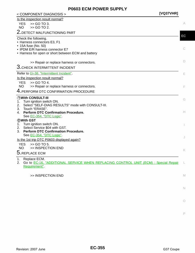
P0603 ECM POWER SUPPLY[VQ37VHR]
C
D
E
F
G
H
I
J
K
L
M
A
C
N
P
O
< COMPONENT DIAGNOSIS >
E
Is the inspection result normal?YES >> GO TO 3.NO >> GO TO 2.
2.DETECT MALFUNCTIONING PART
Check the following.• Harness connectors E3, F1• 15A fuse (No. 50)• IPDM E/R harness connector E7• Harness for open or short between ECM and battery
>> Repair or replace harness or connectors.
3.CHECK INTERMITTENT INCIDENT
Refer to GI-38, "Intermittent Incident".Is the inspection result normal?YES >> GO TO 4.NO >> Repair or replace harness or connectors.
4.PERFORM DTC CONFIRMATION PROCEDURE
With CONSULT-III1. Turn ignition switch ON.2. Select “SELF-DIAG RESULTS” mode with CONSULT-III.3. Touch “ERASE”.4. Perform DTC Confirmation Procedure.
See EC-354, "DTC Logic".With GST
1. Turn ignition switch ON.2. Select Service $04 with GST.3. Perform DTC Confirmation Procedure.
See EC-354, "DTC Logic".Is the 1st trip DTC P0603 displayed again?YES >> GO TO 5.NO >> INSPECTION END
5.REPLACE ECM
1. Replace ECM.2. Go to EC-16, "ADDITIONAL SERVICE WHEN REPLACING CONTROL UNIT (ECM) : Special Repair
Requirement".
>> INSPECTION END
EC-355Revision: 2007 June G37 Coupe

[VQ37VHR]P0605 ECM
< COMPONENT DIAGNOSIS >
P0605 ECM
Description INFOID:0000000001734170
The ECM consists of a microcomputer and connectors for signalinput and output and for power supply. The ECM controls the engine.
DTC Logic INFOID:0000000001734171
DTC DETECTION LOGIC
DTC CONFIRMATION PROCEDURE
1.PRECONDITIONING
If DTC Confirmation Procedure has been previously conducted, always perform the following before conduct-ing the next test. 1. Turn ignition switch OFF and wait at least 10 seconds.2. Turn ignition switch ON.3. Turn ignition switch OFF and wait at least 10 seconds.
>> GO TO 2.
2.PERFORM DTC CONFIRMATION PROCEDURE FOR MALFUNCTION A
1. Turn ignition switch ON.2. Check 1st trip DTC.Is 1st trip DTC detected?YES >> Go to EC-357, "Diagnosis Procedure".NO >> GO TO 3.
3.PERFORM DTC CONFIRMATION PROCEDURE FOR MALFUNCTION B
1. Turn ignition switch ON and wait at least 1 second.2. Turn ignition switch OFF, wait at least 10 seconds, and then turn ON.3. Check 1st trip DTC.Is 1st trip DTC detected?YES >> Go to EC-357, "Diagnosis Procedure".NO >> GO TO 4.
4.PERFORM DTC CONFIRMATION PROCEDURE FOR MALFUNCTION C
1. Turn ignition switch ON and wait at least 1 second.2. Turn ignition switch OFF, wait at least 10 seconds, and then turn ON.3. Repeat step 2 for 32 times.4. Check 1st trip DTC.Is 1st trip DTC detected?
JMBIA0057ZZ
DTC No. Trouble diagnosis name DTC detecting condition Possible cause
P0605 Engine control module
A) ECM calculation function is malfunctioning.
• ECMB) ECM EEP-ROM system is malfunctioning.
C) ECM self shut-off function is malfunctioning.
EC-356Revision: 2007 June G37 Coupe

P0605 ECM[VQ37VHR]
C
D
E
F
G
H
I
J
K
L
M
A
C
N
P
O
< COMPONENT DIAGNOSIS >
E
YES >> Go to EC-357, "Diagnosis Procedure".NO >> INSPECTION END
Diagnosis Procedure INFOID:0000000001734172
1.INSPECTION START
With CONSULT-III1. Turn ignition switch ON.2. Select “SELF-DIAG RESULTS” mode with CONSULT-III.3. Touch “ERASE”.4. Perform DTC Confirmation Procedure.
See EC-356, "DTC Logic".With GST
1. Turn ignition switch ON.2. Select Service $04 with GST.3. Perform DTC Confirmation Procedure.
See EC-356, "DTC Logic".Is the 1st trip DTC P0605 displayed again?YES >> GO TO 2.NO >> INSPECTION END
2.REPLACE ECM
1. Replace ECM.2. Go to EC-16, "ADDITIONAL SERVICE WHEN REPLACING CONTROL UNIT (ECM) : Special Repair
Requirement".
>> INSPECTION END
EC-357Revision: 2007 June G37 Coupe

[VQ37VHR]P0643 SENSOR POWER SUPPLY
< COMPONENT DIAGNOSIS >
P0643 SENSOR POWER SUPPLY
DTC Logic INFOID:0000000001734173
DTC DETECTION LOGIC
DTC CONFIRMATION PROCEDURE
1.PRECONDITIONING
If DTC Confirmation Procedure has been previously conducted, always perform the following before conduct-ing the next test. 1. Turn ignition switch OFF and wait at least 10 seconds.2. Turn ignition switch ON.3. Turn ignition switch OFF and wait at least 10 seconds.TESTING CONDITION:Before performing the following procedure, confirm that battery voltage is more than 10V at idle.
>> GO TO 2.
2.PERFORM DTC CONFIRMATION PROCEDURE
1. Start engine and let it idle for 1 second.2. Check DTC.Is DTC detected?YES >> Go to EC-358, "Diagnosis Procedure".NO >> INSPECTION END
Diagnosis Procedure INFOID:0000000001734174
1.CHECK GROUND CONNECTION
1. Turn ignition switch OFF.2. Check ground connection M95. Refer to Ground Inspection in GI-41, "Circuit Inspection".Is the inspection result normal?YES >> GO TO 2.NO >> Repair or replace ground connection.
2.CHECK ACCELERATOR PEDAL POSITION SENSOR 1 POWER SUPPLY CIRCUIT
1. Disconnect accelerator pedal position (APP) sensor harness connector.2. Turn ignition switch ON.3. Check the voltage between APP sensor harness connector and ground.
DTC No.Trouble diagnosis
nameDTC detecting condition Possible cause
P0643Sensor power supply circuit short
ECM detects a voltage of power source for sensor is excessively low or high.
• Harness or connectors(APP sensor 1 circuit is shorted.)(TP sensor circuit is shorted.)[CMP sensor (PHASE) (bank 1) circuit is shorted.][Manifold absolute pressure (MAP) sensor circuit is shorted.](PSP sensor circuit is shorted.)[CMP sensor (PHASE) (bank 2) circuit is shorted.][Battery current sensor circuit is shorted/]
• Accelerator pedal position sensor• Throttle position sensor• Camshaft position sensor (PHASE) (bank 1)• Manifold absolute pressure (MAP) sensor• Power steering pressure sensor• Camshaft position sensor (PHASE) (bank 2)• Battery current sensor
EC-358Revision: 2007 June G37 Coupe

P0643 SENSOR POWER SUPPLY[VQ37VHR]
C
D
E
F
G
H
I
J
K
L
M
A
C
N
P
O
< COMPONENT DIAGNOSIS >
EIs the inspection result normal?YES >> GO TO 7.NO >> GO TO 3.
3.CHECK SENSOR POWER SUPPLY CIRCUITS
Check harness for short to power and short to ground, between the following terminals.
Is the inspection result normal?YES >> GO TO 4.NO >> Repair short to ground or short to power in harness or connectors.
4.CHECK COMPONENTS
Check the following.• Camshaft position sensor (PHASE) (bank 1) (Refer to EC-271, "Component Inspection".)• Manifold absolute pressure (MAP) sensor (Refer to EC-178, "Component Inspection".)• Power steering pressure sensor (Refer to EC-347, "Component Inspection".)• Camshaft position sensor (PHASE) (bank 2) (Refer to EC-271, "Component Inspection".)• Battery current sensor (Refer to EC-410, "Component Inspection".)Is the inspection result normal?YES >> GO TO 5.NO >> Replace malfunctioning component.
5.CHECK TP SENSOR
Refer to EC-189, "Component Inspection".Is the inspection result normal?YES >> GO TO 9.NO >> GO TO 6.
6.REPLACE ELECTRIC THROTTLE CONTROL ACTUATOR
1. Replace electric throttle control actuator.2. Go to EC-189, "Special Repair Requirement".
>> INSPECTION END
7.CHECK APP SENSOR
Refer to EC-460, "Component Inspection".Is the inspection result normal?YES >> GO TO 9.
APP sensorGround Voltage
Connector Terminal
E112 5 Ground Approx. 5V
ECM Sensor
Connector Terminal Name Connector Terminal
F10143 Electric throttle control actuator (bank 2) F27 1
44 Electric throttle control actuator (bank 1) F6 6
F102
60
CMP sensor (PHASE) (bank 1) F5 1
Manifold absolute pressure (MAP) sen-sor
F50 1
PSP sensor F35 3
64CMP sensor (PHASE) (bank 2) F18 1
Battery current sensor E21 1
M107 99 APP sensor E112 5
EC-359Revision: 2007 June G37 Coupe

[VQ37VHR]P0643 SENSOR POWER SUPPLY
< COMPONENT DIAGNOSIS >NO >> GO TO 8.
8.REPLACE ACCELERATOR PEDAL ASSEMBLY
1. Replace accelerator pedal assembly.2. Go to EC-460, "Special Repair Requirement".
>> INSPECTION END
9.CHECK INTERMITTENT INCIDENT
Refer to GI-38, "Intermittent Incident".
>> INSPECTION END
EC-360Revision: 2007 June G37 Coupe

P0850 PNP SWITCH[VQ37VHR]
C
D
E
F
G
H
I
J
K
L
M
A
C
N
P
O
< COMPONENT DIAGNOSIS >
E
P0850 PNP SWITCH
Description INFOID:0000000001734175
When the selector lever position is P or N (A/T), Neutral position (M/T), park/neutral position (PNP) switch isON.ECM detects the position because the continuity of the line (the ON signal) exists.
DTC Logic INFOID:0000000001734176
DTC DETECTION LOGIC
DTC CONFIRMATION PROCEDURE
1.INSPECTION START
Do you have CONSULT-III?Do you have CONSULT-III?YES >> GO TO 2.NO >> GO TO 5.
2.PRECONDITIONING
If DTC Confirmation Procedure has been previously conducted, always perform the following before conduct-ing the next test. 1. Turn ignition switch OFF and wait at least 10 seconds.2. Turn ignition switch ON.3. Turn ignition switch OFF and wait at least 10 seconds.
>> GO TO 3.
3.CHECK PNP SWITCH FUNCTION
With CONSULT-III1. Turn ignition switch ON.2. Select “P/N POSI SW” in “DATA MONITOR” mode with CONSULT-III. Then check the “P/N POSI SW” sig-
nal under the following conditions.
Is the inspection result normal?YES >> GO TO 4.NO >> Go to EC-362, "Diagnosis Procedure".
4.PERFORM DTC CONFIRMATION PROCEDURE
1. Select “DATA MONITOR” mode with CONSULT-III.2. Start engine and warm it up to normal operating temperature.3. Maintain the following conditions for at least 50 consecutive seconds.
CAUTION:Always drive vehicle at a safe speed.
DTC No. Trouble diagnosis name DTC detecting condition Possible cause
P0850Park/neutral position switch
The signal of the park/neutral position (PNP) switch is not changed in the process of engine starting and driving.
• Harness or connectors[The park/neutral position (PNP) switch circuit is open or shorted.]
• Park/neutral position (PNP) switch• TCM (A/T models)
Position (Selector lever) Known-good signal
N or P position (A/T)Neutral position (M/T)
ON
Except above position OFF
EC-361Revision: 2007 June G37 Coupe

[VQ37VHR]P0850 PNP SWITCH
< COMPONENT DIAGNOSIS >
4. Check 1st trip DTC.Is 1st trip DTC detected?YES >> Go to EC-362, "Diagnosis Procedure".NO >> INSPECTION END
5.PERFORM COMPONENT FUNCTION CHECK
Perform component function check. Refer to EC-362, "Component Function Check".NOTE:Use component function check the overall function of the park/neutral position (PNP) switch circuit. During thischeck, a 1st trip DTC might not be confirmed.Is the inspection result normal?YES >> INSPECTION ENDNO >> Go to EC-362, "Diagnosis Procedure".
Component Function Check INFOID:0000000001734177
1.PERFORM COMPONENT FUNCTION CHECK
1. Turn ignition switch ON.2. Check the voltage between ECM harness connector and ground.
Is the inspection result normal?YES >> INSPECTION ENDNO >> Go to EC-362, "Diagnosis Procedure".
Diagnosis Procedure INFOID:0000000001734178
1.INSPECTION START
Check which type of transmission the vehicle is equipped with.Which type of transmission?A/T >> GO TO 2.M/T >> GO TO 7.
2.CHECK DTC WITH TCM
Refer to TM-108, "Diagnosis Description".Is the inspection result normal?YES >> GO TO 3.NO >> Repair or replace.
3.CHECK STARTING SYSTEM
Turn ignition switch OFF, then turn it to START.Does starter motor operate?YES >> GO TO 4.
ENG SPEED 1,400 - 6,375 rpm
COOLAN TEMP/S More than 70°C (158°F)
B/FUEL SCHDL 2.0 - 31.8 msec
VHCL SPEED SE More than 64 km/h (40 mph)
Selector lever Suitable position
ECMGround Condition Voltage
Connector Terminal
M107 109 Ground Selector lever
P or N (A/T)Neutral (M/T)
Approx. 0V
Except above Battery voltage
EC-362Revision: 2007 June G37 Coupe

P0850 PNP SWITCH[VQ37VHR]
C
D
E
F
G
H
I
J
K
L
M
A
C
N
P
O
< COMPONENT DIAGNOSIS >
E
NO >> Check DTC with BCM. Refer to DLK-50, "COMMON ITEM : CONSULT-III Function (BCM - COM-MON ITEM)".
4.CHECK PNP SWITCH INPUT SIGNAL CIRCUIT FOR OPEN AND SHORT
1. Turn ignition switch OFF.2. Disconnect A/T assembly harness connector.3. Disconnect ECM harness connector.4. Check the continuity between A/T assembly harness connector and ECM harness connector.
5. Also check harness for short to ground and short to power.Is the inspection result normal?YES >> GO TO 6.NO >> GO TO 5.
5.DETECT MALFUNCTIONING PART
Check the following.• Harness connectors F1, E3• Harness connectors E106, M6• Harness for open or short between A/T assembly and ECM
>> Repair open circuit or short to ground or short to power in harness or connectors.
6.CHECK INTERMITTENT INCIDENT
Refer to GI-38, "Intermittent Incident".
>> INSPECTION END
7.CHECK PNP SWITCH POWER SUPPLY CIRCUIT
1. Turn ignition switch OFF.2. Disconnect park/neutral position (PNP) switch harness connector.3. Turn ignition switch ON.4. Check the voltage between PNP switch harness connector and ground.
Is the inspection result normal?YES >> GO TO 9.NO >> GO TO 8.
8.DETECT MALFUNCTIONING PART
Check the following.• Harness connectors E3, F1• 10A fuse (No. 43)• IPDM E/R harness connector E7• Harness for open or short between PNP switch and fuse
>> Repair open circuit or short to ground or short to power in harness or connectors.
9.CHECK PNP SWITCH INPUT SIGNAL CIRCUIT FOR OPEN AND SHORT
1. Turn ignition switch OFF.2. Disconnect ECM harness connector.3. Check the continuity between PNP switch harness connector and ECM harness connector.
A/T assembly ECMContinuity
Connector Terminal Connector Terminal
F51 9 M107 109 Existed
PNP switchGround Voltage
Connector Terminal
F55 2 Ground Battery voltage
EC-363Revision: 2007 June G37 Coupe

[VQ37VHR]P0850 PNP SWITCH
< COMPONENT DIAGNOSIS >
4. Also check harness for short to ground and short to power.Is the inspection result normal?YES >> GO TO 11.NO >> GO TO 10.
10.DETECT MALFUNCTIONING PART
Check the following.• Harness connectors F103, M116• Harness for open or short between PNP switch and ECM
>> Repair open circuit or short to ground or short to power in harness or connectors.
11.CHECK PNP SWITCH
Refer to TM-9, "Component Inspection".Is the inspection result normal?YES >> GO TO 12.NO >> Replace PNP switch.
12.CHECK INTERMITTENT INCIDENT
Refer to GI-38, "Intermittent Incident".Is the inspection result normal?YES >> Replace IPDM E/R.NO >> Repair or replace.
PNP switch ECMContinuity
Connector Terminal Connector Terminal
F55 1 M107 109 Existed
EC-364Revision: 2007 June G37 Coupe

P100A, P100B VVEL SYSTEM[VQ37VHR]
C
D
E
F
G
H
I
J
K
L
M
A
C
N
P
O
< COMPONENT DIAGNOSIS >
E
P100A, P100B VVEL SYSTEM
DTC Logic INFOID:0000000001830767
DTC DETECTION LOGICNOTE:If DTC P100A or P100B is displayed with DTC P1090 or P1093, first perform the trouble diagnosis for DTCP1090 or P1093. Refer to EC-378, "DTC Logic".
DTC CONFIRMATION PROCEDURE
1.PRECONDITIONING
If DTC Confirmation Procedure has been previously conducted, always perform the following before conduct-ing the next test. 1. Turn ignition switch OFF and wait at least 10 seconds.2. Turn ignition switch ON.3. Turn ignition switch OFF and wait at least 10 seconds.TESTING CONDITION:Before performing the following procedure, confirm that battery voltage is more than 10V at idle.
>> GO TO 2.
2.PERFORM DTC CONFIRMATION PROCEDURE
1. Start engine.2. Depress the accelerator pedal rapidly half or more under no load and then release it.3. Wait at idle for 5 seconds or more.4. Repeat steps 2 to 3 for three times.5. Check 1st trip DTC.Is DTC detected?YES >> Go to EC-365, "Diagnosis Procedure".NO >> INSPECTION END
Diagnosis Procedure INFOID:0000000001830768
1.CHECK GROUND CONNECTION
1. Turn ignition switch OFF.2. Check ground connection M95. Refer to Ground Inspection in GI-41, "Circuit Inspection".Is the inspection result normal?YES >> GO TO 2.NO >> Repair or replace ground connection.
2.VVEL ACTUATOR MOTOR OUTPUT SIGNAL CIRCUIT FOR OPEN AND SHORT
1. Disconnect VVEL control module harness connector.2. Disconnect VVEL actuator motor harness connector.3. Check the continuity between VVEL control module harness connector and VVEL actuator motor harness
connector.
DTC No. Trouble diagnosis name DTC detecting condition Possible cause
P100A VVEL response malfunction (bank 1)
Actual event response to target is poor.
• Harness or connectors(VVEL actuator motor circuit is open or shorted.)
• VVEL actuator motor• VVEL actuator sub assembly• VVEL ladder assembly• VVEL control module
P100B VVEL response malfunction (bank 2)
EC-365Revision: 2007 June G37 Coupe

[VQ37VHR]P100A, P100B VVEL SYSTEM
< COMPONENT DIAGNOSIS >
4. Also check harness for short to ground and power.Is the inspection result normal?YES >> GO TO 4.NO >> GO TO 3.
3.DETECT MALFUNCTIONING PART
Check the following.• Harness connectors F1, E3• Harness for open or short between VVEL actuator motor and VVEL control module
>> Repair open circuit or short to ground or short to power in harness or connectors.
4.CHECK VVEL ACTUATOR MOTOR
Refer to EC-367, "Component Inspection (VVEL ACTUATOR MOTOR)".Is the inspection result normal?YES >> GO TO 6.NO >> GO TO 5.
5.REPLACE VVEL ACTUATOR SUB ASSEMBLY
1. Replace VVEL actuator sub assembly.2. Go to EC-368, "Special Repair Requirement".
>> INSPECTION END
6.CHECK INTERMITTENT INCIDENT
Refer to GI-38, "Intermittent Incident".Is the inspection result normal?YES >> GO TO 7.NO >> Repair or replace.
7.REPLACE VVEL CONTROL MODULE
1. Replace VVEL control module.2. Go to EC-17, "ADDITIONAL SERVICE WHEN REPLACING CONTROL UNIT (VVEL CONTROL MOD-
ULE) : Special Repair Requirement".
>> GO TO 8.
8.PERFORM DTC CONFIRMATION PROCEDURE
With CONSULT-III1. Turn ignition switch ON.2. Select “SELF-DIAG RESULTS” mode with CONSULT-III.3. Touch “ERASE”.4. Perform DTC Confirmation Procedure.
DTC No.VVEL control module VVEL actuator motor
ContinuityBank Connector Terminal Connector Terminal
P100A 1
E15
12
F48
1 Existed
2 Not existed
251 Not existed
2 Existed
P100B 2
2
F49
1 Existed
2 Not existed
151 Not existed
2 Existed
EC-366Revision: 2007 June G37 Coupe

P100A, P100B VVEL SYSTEM[VQ37VHR]
C
D
E
F
G
H
I
J
K
L
M
A
C
N
P
O
< COMPONENT DIAGNOSIS >
E
See EC-365, "DTC Logic". With GST
1. Turn ignition switch ON.2. Select Service $04 with GST.3. Perform DTC Confirmation Procedure.
See EC-365, "DTC Logic".Is the DTC P100A or P100B displayed again?YES >> GO TO 9.NO >> INSPECTION END
9.CHECK VVEL ACTUATOR SUB ASSEMBLY
Refer to EC-368, "Component Inspection (VVEL ACTUATOR SUB ASSEMBLY)".Is the inspection result normal?YES >> GO TO 11.NO >> GO TO 10.
10.REPLACE VVEL ACTUATOR SUB ASSEMBLY
1. Replace VVEL actuator sub assembly.2. Go to EC-368, "Special Repair Requirement".
>> INSPECTION END
11.CHECK VVEL LADDER ASSEMBLY
Refer to EM-93, "Inspection".Is the inspection result normal?YES >> GO TO 13.NO >> GO TO 12.
12.REPLACE CYLINDER HEAD, VVEL LADDER ASSEMBLY AND VVEL ACTUATOR SUB ASSEMBLY
1. Replace cylinder head, VVEL ladder assembly and VVEL actuator sub assembly.2. Go to EC-368, "Special Repair Requirement".
>> INSPECTION END
13.CHECK INTERMITTENT INCIDENT
Refer to GI-38, "Intermittent Incident".
>> INSPECTION END
Component Inspection (VVEL ACTUATOR MOTOR) INFOID:0000000001830770
1.CHECK VVEL ACTUATOR MOTOR
1. Turn ignition switch OFF.2. Disconnect VVEL actuator motor harness connector.3. Check resistance between VVEL actuator motor terminals as follows.
Is the inspection result normal?YES >> INSPECTION ENDNO >> GO TO 2.
2.REPLACE VVEL ACTUATOR SUB ASSEMBLY
1. Replace VVEL actuator sub assembly.2. Go to EC-368, "Special Repair Requirement".
VVEL actuator motorResistance
Terminal
1 and 2 16Ω or less
EC-367Revision: 2007 June G37 Coupe

[VQ37VHR]P100A, P100B VVEL SYSTEM
< COMPONENT DIAGNOSIS >
>> INSPECTION END
Component Inspection (VVEL ACTUATOR SUB ASSEMBLY) INFOID:0000000001830771
1.CHECK VVEL ACTUATOR SUB ASSEMBLY
1. Turn ignition switch OFF.2. Remove VVEL actuator sub assembly. Refer to EM-84, "Disassembly and Assembly".3. Turn the ball screw shaft to check that it works smoothly.Is the inspection result normal?YES >> INSPECTION ENDNO >> GO TO 2.
2.REPLACE VVEL ACTUATOR SUB ASSEMBLY
1. Replace VVEL actuator sub assembly.2. Go to EC-368, "Special Repair Requirement".
>> INSPECTION END
Special Repair Requirement INFOID:0000000001830773
1.PERFORM VVEL CONTROL SHAFT POSITION SENSOR ADJUSTMENT
Refer to EC-21, "VVEL CONTROL SHAFT POSITION SENSOR ADJUSTMENT : Special Repair Require-ment".
>> GO TO 2.
2.PERFORM IDLE AIR VOLUME LEARNING
Refer to EC-19, "IDLE AIR VOLUME LEARNING : Special Repair Requirement".
>> END
EC-368Revision: 2007 June G37 Coupe

P1087, P1088 VVEL SYSTEM[VQ37VHR]
C
D
E
F
G
H
I
J
K
L
M
A
C
N
P
O
< COMPONENT DIAGNOSIS >
E
P1087, P1088 VVEL SYSTEM
DTC Logic INFOID:0000000001736759
DTC DETECTION LOGICNOTE:If DTC P1087 or P1088 is displayed with DTC P1090 or P1093.Perform the trouble diagnosis for DTC P1090 or P1093. Refer to EC-374, "DTC Logic".
DTC No. Trouble diagnosis name DTC detecting condition Possible cause
P1087VVEL small event angle malfunction (bank 1)
The event angle of VVEL control shaft is always small.
• Harness or connectors(VVEL actuator motor circuit is open or shorted.)
• VVEL actuator motor• VVEL actuator sub assembly• VVEL ladder assembly• VVEL control module
P1088VVEL small event angle malfunction (bank 2)
EC-369Revision: 2007 June G37 Coupe

[VQ37VHR]P1089, P1092 VVEL CONTROL SHAFT POSITION SENSOR
< COMPONENT DIAGNOSIS >
P1089, P1092 VVEL CONTROL SHAFT POSITION SENSOR
Description INFOID:0000000001736764
VVEL control shaft position sensor (1) is placed on VVEL actuatorsub assembly and detects the control shaft position angle.A magnet is pressed into the arm on the edge of control shaft.The magnetic field changes as the magnet rotates together with thearm resulting in the output voltage change of the sensor.VVEL control module detects the actual position angle through thevoltage change and sends the signal to ECM.
DTC Logic INFOID:0000000001736765
DTC DETECTION LOGICNOTE:If DTC P1089 or P1092 is displayed with DTC P1608, first perform the trouble diagnosis for DTC P1608.Refer to EC-451, "DTC Logic".
DTC CONFIRMATION PROCEDURE
1.PRECONDITIONING
If DTC Confirmation Procedure has been previously conducted, always perform the following before conduct-ing the next test. 1. Turn ignition switch OFF and wait at least 10 seconds.2. Turn ignition switch ON.3. Turn ignition switch OFF and wait at least 10 seconds.TESTING CONDITION:Before performing the following procedure, confirm that battery voltage is more than 10V at idle.
>> GO TO 2.
2.PERFORM DTC CONFIRMATION PROCEDURE
1. Start engine and let it idle for 1 second.2. Check DTC.Is DTC detected?YES >> Go to EC-370, "Diagnosis Procedure".NO >> INSPECTION END
Diagnosis Procedure INFOID:0000000001736766
1.CHECK GROUND CONNECTION
1. Turn ignition switch OFF.2. Check ground connection M95. Refer to Ground Inspection in GI-41, "Circuit Inspection".
JMBIA0835ZZ
DTC No. Trouble diagnosis name DTC detecting condition Possible cause
P1089VVEL control shaft position sensor (bank 1) circuit
• An excessively low voltage from the sensor is sent to VVEL control module.
• An excessively high voltage from the sensor is sent to VVEL control module.
• Rationally incorrect voltage is sent to VVEL control module compared with the signals from VVEL control shaft po-sition sensor 1 and VVEL control shaft position sensor 2.
• Harness or connectors(VVEL control shaft position sensor circuit is open or shorted.)
• VVEL control shaft position sensor• VVEL control module
P1092VVEL control shaft position sensor (bank 2) circuit
EC-370Revision: 2007 June G37 Coupe

P1089, P1092 VVEL CONTROL SHAFT POSITION SENSOR[VQ37VHR]
C
D
E
F
G
H
I
J
K
L
M
A
C
N
P
O
< COMPONENT DIAGNOSIS >
E
Is the inspection result normal?YES >> GO TO 2.NO >> Repair or replace ground connection.
2.VVEL CONTROL SHAFT POSITION SENSOR POWER SUPPLY CIRCUIT
1. Disconnect VVEL control shaft position sensor harness connector.2. Turn ignition switch ON.3. Check the voltage between VVEL control shaft position sensor harness connector and ground.
Is the inspection result normal?YES >> GO TO 4.NO >> GO TO 3.
3.DETECT MALFUNCTIONING PART
Check the following.• Harness connectors F1, E3• Harness for open or short between VVEL control shaft position sensor and VVEL control module
>> Repair open circuit or short to ground or short to power in harness or connectors.
4.CHECK VVEL CONTROL SHAFT POSITION SENSOR GROUND CIRCUIT FOR OPEN AND SHORT
1. Turn ignition switch OFF.2. Disconnect VVEL control module harness connector.3. Check the continuity between VVEL control shaft position sensor harness connector and VVEL control
module harness connector.
4. Also check harness for short to ground and power.Is the inspection result normal?YES >> GO TO 6.NO >> GO TO 5.
5.DETECT MALFUNCTIONING PART
Check the following.• Harness connectors F1, E3• Harness for open or short between VVEL control shaft position sensor and VVEL control module
>> Repair open circuit or short to ground or short to power in harness or connectors.
6.VVEL CONTROL SHAFT POSITION SENSOR INPUT SIGNAL CIRCUIT FOR OPEN AND SHORT
1. Check the continuity between VVEL control shaft position sensor harness connector and VVEL controlmodule harness connector.
DTC No.VVEL control shaft position sensor
Ground VoltageBank Connector Terminal
P1089 1 F463
Ground Approx. 5V6
P1092 2 F473
6
DTC No.VVEL control shaft position sensor VVEL control module
ContinuityBank Connector Terminal Connector Terminal
P1089 1 F462
E15
4
Existed5 17
P1092 2 F472 6
5 19
EC-371Revision: 2007 June G37 Coupe

[VQ37VHR]P1089, P1092 VVEL CONTROL SHAFT POSITION SENSOR
< COMPONENT DIAGNOSIS >
2. Also check harness for short to ground and power.Is the inspection result normal?YES >> GO TO 8.NO >> GO TO 7.
7.DETECT MALFUNCTIONING PART
Check the following.• Harness connectors F1, E3• Harness for open or short between VVEL control shaft position sensor and VVEL control module
>> Repair open circuit or short to ground or short to power in harness or connectors.
8.CHECK INTERMITTENT INCIDENT
Refer to GI-38, "Intermittent Incident".Is the inspection result normal?YES >> GO TO 9.NO >> Repair or replace.
9.REPLACE VVEL CONTROL MODULE
1. Replace VVEL control module.2. Go to EC-17, "ADDITIONAL SERVICE WHEN REPLACING CONTROL UNIT (VVEL CONTROL MOD-
ULE) : Special Repair Requirement".
>> GO TO 10.
10.PERFORM DTC CONFIRMATION PROCEDURE
With CONSULT-III1. Turn ignition switch ON.2. Select “SELF-DIAG RESULTS” mode with CONSULT-III.3. Touch “ERASE”.4. Perform DTC Confirmation Procedure.
See EC-370, "DTC Logic". With GST
1. Turn ignition switch ON.2. Select Service $04 with GST.3. Perform DTC Confirmation Procedure.
See EC-370, "DTC Logic".Is the DTC P1089 or P1092 displayed again?YES >> GO TO 11.NO >> INSPECTION END
11.REPLACE VVEL ACTUATOR SUB ASSEMBLY
1. Replace VVEL actuator sub assembly.2. Go to EC-373, "Special Repair Requirement".
>> INSPECTION END
DTC No.VVEL control shaft position sensor VVEL control module
ContinuityBank Connector Terminal Connector Terminal
P1089 1 F461
E15
3
Existed4 16
P1092 2 F471 5
4 18
EC-372Revision: 2007 June G37 Coupe

P1089, P1092 VVEL CONTROL SHAFT POSITION SENSOR[VQ37VHR]
C
D
E
F
G
H
I
J
K
L
M
A
C
N
P
O
< COMPONENT DIAGNOSIS >
E
Special Repair Requirement INFOID:0000000001910901
1.PERFORM VVEL CONTROL SHAFT POSITION SENSOR ADJUSTMENT
Refer to EC-21, "VVEL CONTROL SHAFT POSITION SENSOR ADJUSTMENT : Special Repair Require-ment".
>> GO TO 2.
2.PERFORM IDLE AIR VOLUME LEARNING
Refer to EC-19, "IDLE AIR VOLUME LEARNING : Special Repair Requirement".
>> END
EC-373Revision: 2007 June G37 Coupe

[VQ37VHR]P1090, P1093 VVEL ACTUATOR MOTOR
< COMPONENT DIAGNOSIS >
P1090, P1093 VVEL ACTUATOR MOTOR
Description INFOID:0000000001766510
The VVEL actuator motor rotates the control shaft according to the control signal from the VVEL control mod-ule. The VVEL control module judges whether the VVEL actuator motor controls the angle properly by theVVEL control shaft position sensor signal.
DTC Logic INFOID:0000000001736768
DTC DETECTION LOGICNOTE:If DTC P1090 or P1093 is displayed with DTC P1091, first perform the trouble diagnosis for DTC P1091.Refer to EC-378, "DTC Logic".
DTC CONFIRMATION PROCEDURE
1.PRECONDITIONING
If DTC Confirmation Procedure has been previously conducted, always perform the following before conduct-ing the next test. 1. Turn ignition switch OFF and wait at least 10 seconds.2. Turn ignition switch ON.3. Turn ignition switch OFF and wait at least 10 seconds.TESTING CONDITION:Before performing the following procedure, confirm that battery voltage is more than 10V at idle.
>> GO TO 2.
2.PERFORM DTC CONFIRMATION PROCEDURE
1. Start engine and let it idle for 10 second.2. Keep the engine speed at about 3500rpm for at least 10 seconds under no load.3. Check DTC.Is DTC detected?YES >> Go to EC-374, "Diagnosis Procedure".NO >> INSPECTION END
Diagnosis Procedure INFOID:0000000001736769
1.CHECK GROUND CONNECTION
1. Turn ignition switch OFF.2. Check ground connection M95. Refer to Ground Inspection in GI-41, "Circuit Inspection".Is the inspection result normal?YES >> GO TO 2.NO >> Repair or replace ground connection.
2.VVEL ACTUATOR MOTOR OUTPUT SIGNAL CIRCUIT FOR OPEN AND SHORT
1. Disconnect VVEL control module harness connector.2. Disconnect VVEL actuator motor harness connector.3. Check the continuity between VVEL control module harness connector and VVEL actuator motor harness
connector.
DTC No. Trouble diagnosis name DTC detecting condition Possible cause
P1090 VVEL system performance (bank 1)
• Event angle difference between the actual and the target is detected.
• Abnormal current is sent to VVEL actuator motor.
• Harness or connectors(VVEL actuator motor circuit is open or shorted.)
• VVEL actuator motor• VVEL actuator sub assembly• VVEL ladder assembly• VVEL control module
P1093 VVEL system performance (bank 2)
EC-374Revision: 2007 June G37 Coupe
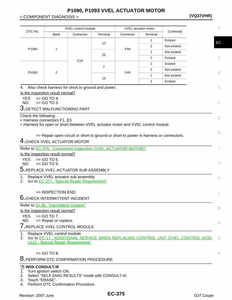
P1090, P1093 VVEL ACTUATOR MOTOR[VQ37VHR]
C
D
E
F
G
H
I
J
K
L
M
A
C
N
P
O
< COMPONENT DIAGNOSIS >
E
4. Also check harness for short to ground and power.Is the inspection result normal?YES >> GO TO 4.NO >> GO TO 3.
3.DETECT MALFUNCTIONING PART
Check the following.• Harness connectors F1, E3• Harness for open or short between VVEL actuator motor and VVEL control module
>> Repair open circuit or short to ground or short to power in harness or connectors.
4.CHECK VVEL ACTUATOR MOTOR
Refer to EC-376, "Component Inspection (VVEL ACTUATOR MOTOR)".Is the inspection result normal?YES >> GO TO 6.NO >> GO TO 5.
5.REPLACE VVEL ACTUATOR SUB ASSEMBLY
1. Replace VVEL actuator sub assembly.2. Go to EC-377, "Special Repair Requirement".
>> INSPECTION END
6.CHECK INTERMITTENT INCIDENT
Refer to GI-38, "Intermittent Incident".Is the inspection result normal?YES >> GO TO 7.NO >> Repair or replace.
7.REPLACE VVEL CONTROL MODULE
1. Replace VVEL control module.2. Go to EC-17, "ADDITIONAL SERVICE WHEN REPLACING CONTROL UNIT (VVEL CONTROL MOD-
ULE) : Special Repair Requirement".
>> GO TO 8.
8.PERFORM DTC CONFIRMATION PROCEDURE
With CONSULT-III1. Turn ignition switch ON.2. Select “SELF-DIAG RESULTS” mode with CONSULT-III.3. Touch “ERASE”.4. Perform DTC Confirmation Procedure.
DTC No.VVEL control module VVEL actuator motor
ContinuityBank Connector Terminal Connector Terminal
P1090 1
E15
12
F48
1 Existed
2 Not existed
251 Not existed
2 Existed
P1093 2
2
F49
1 Existed
2 Not existed
151 Not existed
2 Existed
EC-375Revision: 2007 June G37 Coupe

[VQ37VHR]P1090, P1093 VVEL ACTUATOR MOTOR
< COMPONENT DIAGNOSIS >See EC-374, "DTC Logic".
With GST1. Turn ignition switch ON.2. Select Service $04 with GST.3. Perform DTC Confirmation Procedure.
See EC-374, "DTC Logic".Is the DTC P1090 or P1093 displayed again?YES >> GO TO 9.NO >> INSPECTION END
9.CHECK VVEL ACTUATOR SUB ASSEMBLY
Refer to EC-377, "Component Inspection (VVEL ACTUATOR SUB ASSEMBLY)".Is the inspection result normal?YES >> GO TO 11.NO >> GO TO 10.
10.REPLACE VVEL ACTUATOR SUB ASSEMBLY
1. Replace VVEL actuator sub assembly.2. Go to EC-377, "Special Repair Requirement".
>> INSPECTION END
11.CHECK VVEL LADDER ASSEMBLY
Refer to EM-93, "Inspection".Is the inspection result normal?YES >> GO TO 13.NO >> GO TO 12.
12.REPLACE CYLINDER HEAD, VVEL LADDER ASSEMBLY AND VVEL ACTUATOR SUB ASSEMBLY
1. Replace cylinder head, VVEL ladder assembly and VVEL actuator sub assembly.2. Go to EC-377, "Special Repair Requirement".
>> INSPECTION END
13.CHECK INTERMITTENT INCIDENT
Refer to GI-38, "Intermittent Incident".
>> INSPECTION END
Component Inspection (VVEL ACTUATOR MOTOR) INFOID:0000000001910899
1.CHECK VVEL ACTUATOR MOTOR
1. Turn ignition switch OFF.2. Disconnect VVEL actuator motor harness connector.3. Check resistance between VVEL actuator motor terminals as follows.
Is the inspection result normal?YES >> INSPECTION ENDNO >> GO TO 2.
2.REPLACE VVEL ACTUATOR SUB ASSEMBLY
1. Replace VVEL actuator sub assembly.2. Go to EC-377, "Special Repair Requirement".
VVEL actuator motorResistance
Terminal
1 and 2 16Ω or less
EC-376Revision: 2007 June G37 Coupe

P1090, P1093 VVEL ACTUATOR MOTOR[VQ37VHR]
C
D
E
F
G
H
I
J
K
L
M
A
C
N
P
O
< COMPONENT DIAGNOSIS >
E
>> INSPECTION END
Component Inspection (VVEL ACTUATOR SUB ASSEMBLY) INFOID:0000000001910900
1.CHECK VVEL ACTUATOR SUB ASSEMBLY
1. Turn ignition switch OFF.2. Remove VVEL actuator sub assembly. Refer to EM-84, "Disassembly and Assembly".3. Turn the ball screw shaft to check that it works smoothly.Is the inspection result normal?YES >> INSPECTION ENDNO >> GO TO 2.
2.REPLACE VVEL ACTUATOR SUB ASSEMBLY
1. Replace VVEL actuator sub assembly.2. Go to EC-377, "Special Repair Requirement".
>> INSPECTION END
Special Repair Requirement INFOID:0000000001910902
1.PERFORM VVEL CONTROL SHAFT POSITION SENSOR ADJUSTMENT
Refer to EC-21, "VVEL CONTROL SHAFT POSITION SENSOR ADJUSTMENT : Special Repair Require-ment".
>> GO TO 2.
2.PERFORM IDLE AIR VOLUME LEARNING
Refer to EC-19, "IDLE AIR VOLUME LEARNING : Special Repair Requirement".
>> END
EC-377Revision: 2007 June G37 Coupe

[VQ37VHR]P1091 VVEL ACTUATOR MOTOR RELAY
< COMPONENT DIAGNOSIS >
P1091 VVEL ACTUATOR MOTOR RELAY
Description INFOID:0000000001736773
Power supply for the VVEL actuator motor is provided to the VVEL control module via VVEL actuator motorrelay. VVEL actuator motor relay is ON/OFF controlled by the VVEL control module. In addition, when theVVEL actuator motor relay cannot be controlled by the VVEL control module for some reason, it ON/OFF con-trolled by ECM.
DTC Logic INFOID:0000000001736774
DTC DETECTION LOGIC
DTC CONFIRMATION PROCEDURE
1.PRECONDITIONING
If DTC Confirmation Procedure has been previously conducted, always perform the following before conduct-ing the next test. 1. Turn ignition switch OFF and wait at least 10 seconds.2. Turn ignition switch ON.3. Turn ignition switch OFF and wait at least 10 seconds.TESTING CONDITION:Before performing the following procedure, confirm that battery voltage is more than 10V at idle.
>> GO TO 2.
2.PERFORM DTC CONFIRMATION PROCEDURE
1. Turn ignition switch ON and wait at least 1 seconds.2. Turn ignition switch OFF and wait at least 10 seconds.3. Turn ignition switch ON and wait at least 1 seconds.4. Check DTC.Is DTC detected?YES >> Go to EC-378, "Diagnosis Procedure".NO >> INSPECTION END
Diagnosis Procedure INFOID:0000000001736775
1.VVEL ACTUATOR MOTOR RELAY POWER SUPPLY CIRCUIT-I
1. Turn ignition switch OFF.2. Check the voltage between VVEL actuator motor relay harness connector and ground.
Is the inspection result normal?YES >> GO TO 3.NO >> GO TO 2.
DTC No. Trouble diagnosis name DTC detecting condition Possible cause
P1091 VVEL actuator motor relay circuit
• VVEL control module detects the VVEL actuator motor relay is stuck OFF.
• VVEL control module detects the VVEL actuator motor relay is stuck ON.
• Harness or connectors(VVEL actuator motor relay circuit is open or shorted.)(Abort circuit is open or shorted.)
• VVEL actuator motor relay• VVEL control module• ECM
VVEL actuator motor relayGround Voltage
Connector Terminal
E162
Ground Battery voltage5
EC-378Revision: 2007 June G37 Coupe

P1091 VVEL ACTUATOR MOTOR RELAY[VQ37VHR]
C
D
E
F
G
H
I
J
K
L
M
A
C
N
P
O
< COMPONENT DIAGNOSIS >
E
2.DETECT MALFUNCTIONING PART
Check the following.• 50A fusible link (letter N)• Harness for open or short between VVEL actuator motor relay and battery
>> Repair open circuit or short to ground or short to power in harness or connectors.
3.VVEL ACTUATOR MOTOR RELAY POWER SUPPLY CIRCUIT-II
1. Disconnect VVEL control module harness connector.2. Disconnect VVEL actuator motor relay harness connector.3. Check the continuity between VVEL actuator motor relay harness connector and VVEL control module
harness connector.
4. Also check harness for short to ground and power.Is the inspection result normal?YES >> GO TO 4.NO >> Repair open circuit or short to ground or short to power in harness or connectors.
4.VVEL ACTUATOR MOTOR RELAY INPUT SIGNAL CIRCUIT FOR OPEN AND SHORT
1. Check the continuity between VVEL actuator motor relay harness connector and VVEL control moduleharness connector.
2. Also check harness for short to ground and power.Is the inspection result normal?YES >> GO TO 5.NO >> Repair open circuit or short to ground or short to power in harness or connectors.
5.CHECK VVEL ACTUATOR MOTOR RELAY
Refer to EC-380, "Component Inspection".Is the inspection result normal?YES >> GO TO 6.NO >> Replace VVEL actuator motor relay.
6.CHECK ABORT CIRCUIT FOR OPEN AND SHORT
1. Disconnect ECM harness connector.2. Check the continuity between VVEL control module harness connector and ECM harness connector.
3. Also check harness for short to ground and power.Is the inspection result normal?YES >> GO TO 7.NO >> Repair open circuit or short to ground or short to power in harness or connectors.
7.CHECK INTERMITTENT INCIDENT
VVEL control module VVEL actuator motor relayContinuity
Connector Terminal Connector Terminal
E15 23 E16 1 Existed
VVEL control module VVEL actuator motor relayContinuity
Bank Connector Terminal Connector Terminal
1E15
13E16 3 Existed
2 1
VVEL control module ECMContinuity
Connector Terminal Connector Terminal
E15 21 F101 28 Existed
EC-379Revision: 2007 June G37 Coupe

[VQ37VHR]P1091 VVEL ACTUATOR MOTOR RELAY
< COMPONENT DIAGNOSIS >Refer to GI-38, "Intermittent Incident".Is the inspection result normal?YES >> GO TO 8.NO >> Repair or replace.
8.REPLACE VVEL CONTROL MODULE
1. Replace VVEL control module.2. Go to EC-17, "ADDITIONAL SERVICE WHEN REPLACING CONTROL UNIT (VVEL CONTROL MOD-
ULE) : Special Repair Requirement".
>> GO TO 9.
9.PERFORM DTC CONFIRMATION PROCEDURE
With CONSULT-III1. Turn ignition switch ON.2. Select “SELF-DIAG RESULTS” mode with CONSULT-III.3. Touch “ERASE”.4. Perform DTC Confirmation Procedure.
See EC-378, "DTC Logic". With GST
1. Turn ignition switch ON.2. Select Service $04 with GST.3. Perform DTC Confirmation Procedure.
See EC-378, "DTC Logic".Is the DTC P1091 displayed again?YES >> GO TO 10.NO >> INSPECTION END
10.REPLACE ECM
1. Replace ECM.2. Go to EC-16, "ADDITIONAL SERVICE WHEN REPLACING CONTROL UNIT (ECM) : Special Repair
Requirement".
>> INSPECTION END
Component Inspection INFOID:0000000001736776
1.CHECK VVEL ACTUATOR MOTOR RELAY
1. Turn ignition switch OFF.2. Remove VVEL actuator motor relay.3. Check the continuity between VVEL actuator motor relay termi-
nals under the following conditions.
Is the inspection result normal?YES >> INSPECTION ENDNO >> Replace VVEL actuator motor relay.
Terminal Condition Continuity
3 and 5
12V direct current supply between terminals 1 and 2
Existed
No current supply Not existed
JMBIA0876ZZ
EC-380Revision: 2007 June G37 Coupe
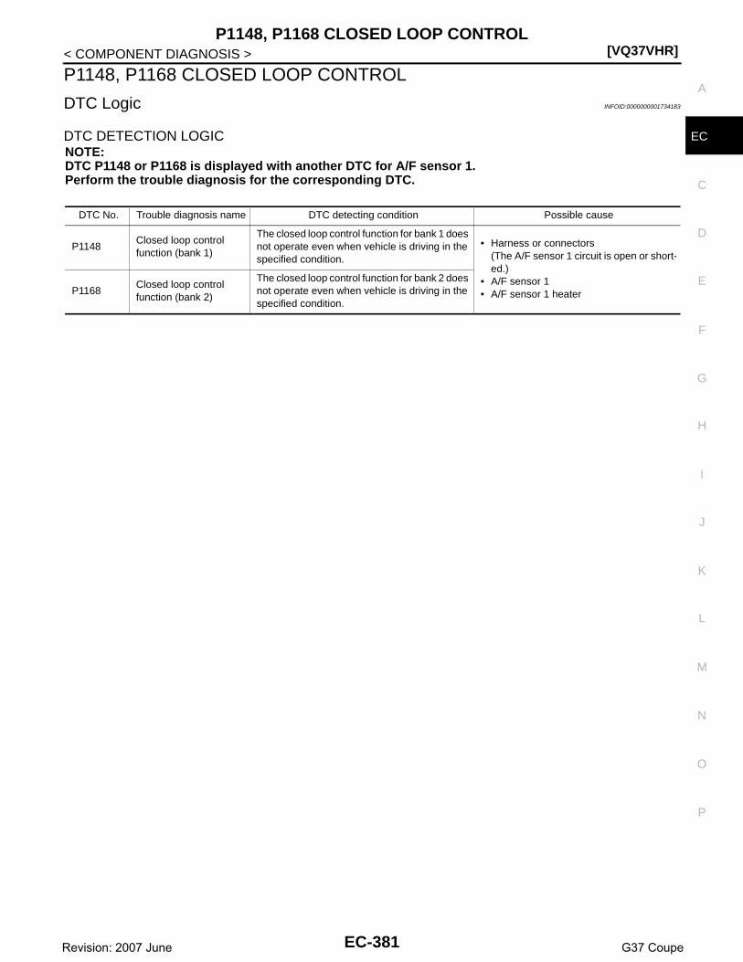
P1148, P1168 CLOSED LOOP CONTROL[VQ37VHR]
C
D
E
F
G
H
I
J
K
L
M
A
C
N
P
O
< COMPONENT DIAGNOSIS >
E
P1148, P1168 CLOSED LOOP CONTROL
DTC Logic INFOID:0000000001734183
DTC DETECTION LOGICNOTE:DTC P1148 or P1168 is displayed with another DTC for A/F sensor 1.Perform the trouble diagnosis for the corresponding DTC.
DTC No. Trouble diagnosis name DTC detecting condition Possible cause
P1148Closed loop control function (bank 1)
The closed loop control function for bank 1 does not operate even when vehicle is driving in the specified condition.
• Harness or connectors(The A/F sensor 1 circuit is open or short-ed.)
• A/F sensor 1• A/F sensor 1 heaterP1168
Closed loop control function (bank 2)
The closed loop control function for bank 2 does not operate even when vehicle is driving in the specified condition.
EC-381Revision: 2007 June G37 Coupe

[VQ37VHR]P1211 TCS CONTROL UNIT
< COMPONENT DIAGNOSIS >
P1211 TCS CONTROL UNIT
Description INFOID:0000000001734184
The malfunction information related to TCS is transferred through the CAN communication line from “ABSactuator and electric unit (control unit)” to ECM.Be sure to erase the malfunction information such as DTC not only for “ABS actuator and electric unit(control unit)” but also for ECM after TCS related repair.
DTC Logic INFOID:0000000001734185
DTC DETECTION LOGICFreeze frame data is not stored in the ECM for this self-diagnosis.
DTC CONFIRMATION PROCEDURE
1.PRECONDITIONING
TESTING CONDITION:Before performing the following procedure, confirm that battery voltage is more than 10.5V at idle.
>> GO TO 2.
2.PERFORM DTC CONFIRMATION PROCEDURE
1. Start engine and let it idle for at least 60 seconds.2. Check 1st trip DTC.Is 1st trip DTC detected?YES >> EC-382, "Diagnosis Procedure"NO >> INSPECTION END
Diagnosis Procedure INFOID:0000000001734186
Go to BRC-4, "Work Flow".
DTC No. Trouble diagnosis name DTC detecting condition Possible cause
P1211 TCS control unitECM receives a malfunction information from“ABS actuator and electric unit (control unit)”.
• ABS actuator and electric unit (control unit)
• TCS related parts
EC-382Revision: 2007 June G37 Coupe
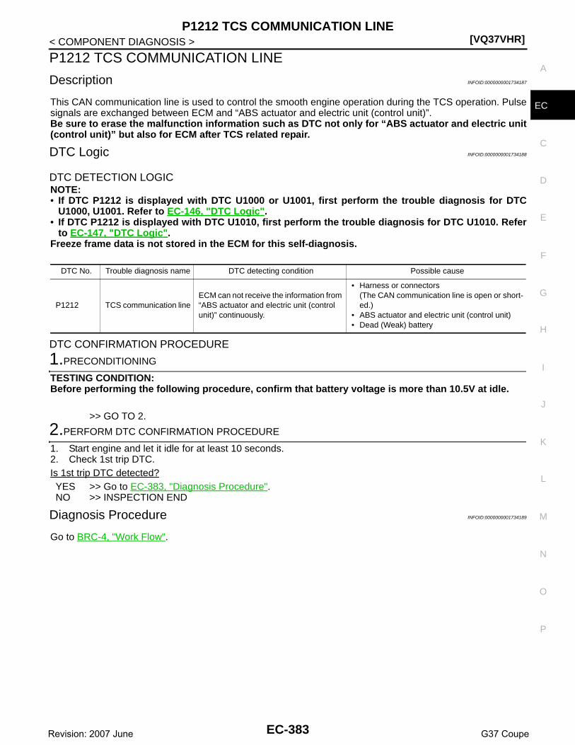
P1212 TCS COMMUNICATION LINE[VQ37VHR]
C
D
E
F
G
H
I
J
K
L
M
A
C
N
P
O
< COMPONENT DIAGNOSIS >
E
P1212 TCS COMMUNICATION LINE
Description INFOID:0000000001734187
This CAN communication line is used to control the smooth engine operation during the TCS operation. Pulsesignals are exchanged between ECM and “ABS actuator and electric unit (control unit)”.Be sure to erase the malfunction information such as DTC not only for “ABS actuator and electric unit(control unit)” but also for ECM after TCS related repair.
DTC Logic INFOID:0000000001734188
DTC DETECTION LOGICNOTE:• If DTC P1212 is displayed with DTC U1000 or U1001, first perform the trouble diagnosis for DTC
U1000, U1001. Refer to EC-146, "DTC Logic".• If DTC P1212 is displayed with DTC U1010, first perform the trouble diagnosis for DTC U1010. Refer
to EC-147, "DTC Logic".Freeze frame data is not stored in the ECM for this self-diagnosis.
DTC CONFIRMATION PROCEDURE
1.PRECONDITIONING
TESTING CONDITION:Before performing the following procedure, confirm that battery voltage is more than 10.5V at idle.
>> GO TO 2.
2.PERFORM DTC CONFIRMATION PROCEDURE
1. Start engine and let it idle for at least 10 seconds.2. Check 1st trip DTC.Is 1st trip DTC detected?YES >> Go to EC-383, "Diagnosis Procedure".NO >> INSPECTION END
Diagnosis Procedure INFOID:0000000001734189
Go to BRC-4, "Work Flow".
DTC No. Trouble diagnosis name DTC detecting condition Possible cause
P1212 TCS communication lineECM can not receive the information from “ABS actuator and electric unit (control unit)” continuously.
• Harness or connectors(The CAN communication line is open or short-ed.)
• ABS actuator and electric unit (control unit)• Dead (Weak) battery
EC-383Revision: 2007 June G37 Coupe

[VQ37VHR]P1217 ENGINE OVER TEMPERATURE
< COMPONENT DIAGNOSIS >
P1217 ENGINE OVER TEMPERATURE
DTC Logic INFOID:0000000001734190
DTC DETECTION LOGICNOTE:• If DTC P1217 is displayed with DTC U1000 or U1001, first perform the trouble diagnosis for DTC
U1000, U1001. Refer to EC-146, "DTC Logic".• If DTC P1217 is displayed with DTC U1010, first perform the trouble diagnosis for DTC U1010. Refer
to EC-147, "DTC Logic".If the cooling fan or another component in the cooling system malfunctions, engine coolant temperature willrise.When the engine coolant temperature reaches an abnormally high temperature condition, a malfunction isindicated.
CAUTION:When a malfunction is indicated, be sure to replace the coolant. Refer to CO-8, "Draining" and CO-9,"Refilling". Also, replace the engine oil. Refer to LU-7, "Draining"and LU-8, "Refilling".1. Fill radiator with coolant up to specified level with a filling speed of 2 liters per minute. Be sure to
use coolant with the proper mixture ratio. Refer to MA-11, "Anti-Freeze Coolant Mixture Ratio".2. After refilling coolant, run engine to ensure that no water-flow noise is emitted.
DTC CONFIRMATION PROCEDURE
1.PERFORM COMPONENT FUNCTION CHECK
Perform component function check. Refer to EC-384, "Component Function Check".NOTE:Use component function check to check the overall function of the cooling fan. During this check, a DTC mightnot be confirmed.Is the inspection result normal?YES >> INSPECTION ENDNO >> Go to EC-385, "Diagnosis Procedure".
Component Function Check INFOID:0000000001734191
1.PERFORM COMPONENT FUNCTION CHECK-I
WARNING:Never remove the radiator cap when the engine is hot. Serious burns could be caused by high pres-sure fluid escaping from the radiator.Wrap a thick cloth around cap. Carefully remove the cap by turning it a quarter turn to allow built-uppressure to escape. Then turn the cap all the way off.
DTC No. Trouble diagnosis name DTC detecting condition Possible cause
P1217Engine over tempera-ture (Overheat)
• Cooling fan does not operate properly (Over-heat).
• Cooling fan system does not operate proper-ly (Overheat).
• Engine coolant was not added to the system using the proper filling method.
• Engine coolant is not within the specified range.
• Harness or connectors(The cooling fan circuit is open or short-ed.)
• IPDM E/R• Cooling fan control module• Cooling fan motor• Radiator hose• Radiator• Radiator cap• Water pump• Thermostat
EC-384Revision: 2007 June G37 Coupe

P1217 ENGINE OVER TEMPERATURE[VQ37VHR]
C
D
E
F
G
H
I
J
K
L
M
A
C
N
P
O
< COMPONENT DIAGNOSIS >
E
Check the coolant level in the reservoir tank and radiator.Allow engine to cool before checking coolant level.Is the coolant level in the reservoir tank and/or radiator below theproper range?YES >> Go to EC-385, "Diagnosis Procedure".NO >> GO TO 2.
2.PERFORM COMPONENT FUNCTION CHECK-II
Confirm whether customer filled the coolant or not.Did customer fill the coolant?YES >> Go to EC-385, "Diagnosis Procedure".NO >> GO TO 3.
3.PERFORM COMPONENT FUNCTION CHECK-III
With CONSULT-III1. Turn ignition switch ON.2. Perform “FAN DUTY CONTROL” in “ACTIVE TEST” mode with CONSULT-III.3. Make sure that cooling fan speed varies according to the percent.
Without CONSULT-IIIPerform IPDM E/R auto active test and check cooling fan motors operation, refer to PCS-11, "DiagnosisDescription".Is the inspection result normal?YES >> INSPECTION ENDNO >> Go to EC-385, "Diagnosis Procedure".
Diagnosis Procedure INFOID:0000000001734192
1.CHECK COOLING FAN OPERATION
With CONSULT-III1. Turn ignition switch ON.2. Perform “FAN DUTY CONTROL” in “ACTIVE TEST” mode with CONSULT-III.3. Make sure that cooling fan speed varies according to the percent.
Without CONSULT-III1. Perform IPDM E/R auto active test and check cooling fan motors operation, refer to PCS-11, "Diagnosis
Description".2. Make sure that cooling fan operates.Is the inspection result normal?YES >> GO TO 2.NO >> Go to EC-481, "Diagnosis Procedure".
2.CHECK COOLING SYSTEM FOR LEAK-I
Check cooling system for leak. Refer to CO-8, "Inspection".Is leakage detected?YES >> GO TO 3.NO >> GO TO 4.
3.CHECK COOLING SYSTEM FOR LEAK-II
Check the following for leak.• Hose• Radiator• Water pump
SEF621W
EC-385Revision: 2007 June G37 Coupe

[VQ37VHR]P1217 ENGINE OVER TEMPERATURE
< COMPONENT DIAGNOSIS >>> Repair or replace malfunctioning part.
4.CHECK RADIATOR CAP
Check radiator cap. Refer to CO-12, "RADIATOR CAP : Inspection".Is the inspection result normal?YES >> GO TO 5.NO >> Replace radiator cap.
5.CHECK THERMOSTAT
Check thermostat. Refer to CO-23, "Inspection".Is the inspection result normal?YES >> GO TO 6.NO >> Replace thermostat
6.CHECK ENGINE COOLANT TEMPERATURE SENSOR
Refer to EC-186, "Component Inspection".Is the inspection result normal?YES >> GO TO 7.NO >> Replace engine coolant temperature sensor.
7.CHECK MAIN 12 CAUSES
If the cause cannot be isolated, check the following.
*1: Turn the ignition switch ON.
*2: Engine running at 3,000 rpm for 10 minutes.
*3: Drive at 90 km/h (55 MPH) for 30 minutes and then let idle for 10 minutes.
*4: After 60 minutes of cool down time.
Engine Step Inspection item Equipment Standard Reference page
OFF 1 • Blocked radiator• Blocked condenser• Blocked radiator grille• Blocked bumper
• Visual No blocking —
2 • Coolant mixture • Coolant tester 50 - 50% coolant mixture
3 • Coolant level • Visual Coolant up to MAX level in reservoir tank and radiator filler neck
CO-8, "Inspection"
4 • Radiator cap • Pressure tester 107 kPa
(1.1 kg/cm2, 16 psi) (Limit)
CO-12, "RADIATOR CAP : Inspection"
ON*2 5 • Coolant leaks • Visual No leaks CO-8, "Inspection"
ON*2 6 • Thermostat • Touch the upper and lower radiator hoses
Both hoses should be hot CO-23, "Inspection"
ON*1 7 • Cooling fan • CONSULT-III Operating EC-481, "Component Function Check"
OFF 8 • Combustion gas leak • Color checker chemical tester 4 Gas analyzer
Negative —
ON*3 9 • Coolant temperature gauge
• Visual Gauge less than 3/4 when driving
—
• Coolant overflow to res-ervoir tank
• Visual No overflow during driving and idling
CO-8, "Inspection"
OFF*4 10 • Coolant return from res-ervoir tank to radiator
• Visual Should be initial level in reservoir tank
CO-8, "Inspection"
OFF 11 • Cylinder head • Straight gauge feeler gauge
0.1 mm (0.004 in) Maxi-mum distortion (warping)
EM-106, "Inspection"
12 • Cylinder block and pis-tons
• Visual No scuffing on cylinder walls or piston
EM-120, "Inspection"
EC-386Revision: 2007 June G37 Coupe

P1217 ENGINE OVER TEMPERATURE[VQ37VHR]
C
D
E
F
G
H
I
J
K
L
M
A
C
N
P
O
< COMPONENT DIAGNOSIS >
E
For more information, refer to CO-3, "Troubleshooting Chart".
>> INSPECTION END
EC-387Revision: 2007 June G37 Coupe

[VQ37VHR]P1225, P1234 TP SENSOR
< COMPONENT DIAGNOSIS >
P1225, P1234 TP SENSOR
Description INFOID:0000000001910843
Electric throttle control actuator consists of throttle control motor,throttle position sensor, etc. The throttle position sensor responds tothe throttle valve movement. The throttle position sensor has two sensors. These sensors are akind of potentiometers which transform the throttle valve position intooutput voltage, and emit the voltage signal to the ECM. In addition,these sensors detect the opening and closing speed of the throttlevalve and feed the voltage signals to the ECM. The ECM judges thecurrent opening angle of the throttle valve from these signals and theECM controls the throttle control motor to make the throttle valveopening angle properly in response to driving condition.
DTC Logic INFOID:0000000001734194
DTC DETECTION LOGIC
DTC CONFIRMATION PROCEDURE
1.PRECONDITIONING
If DTC Confirmation Procedure has been previously conducted, always perform the following before conduct-ing the next test. 1. Turn ignition switch OFF and wait at least 10 seconds.2. Turn ignition switch ON.3. Turn ignition switch OFF and wait at least 10 seconds.TESTING CONDITION:Before performing the following procedure, confirm that battery voltage is more than 10V at idle.
>> GO TO 2.
2.PERFORM DTC CONFIRMATION PROCEDURE
1. Turn ignition switch ON.2. Turn ignition switch OFF and wait at least 10 seconds.3. Turn ignition switch ON.4. Check 1st trip DTC.Is 1st trip DTC detected?YES >> Go to EC-388, "Diagnosis Procedure".NO >> INSPECTION END
Diagnosis Procedure INFOID:0000000001734195
1.CHECK ELECTRIC THROTTLE CONTROL ACTUATOR VISUALLY
1. Turn ignition switch OFF.2. Remove the intake air duct.
PBIB0145E
DTC No. Trouble diagnosis name DTC detecting condition Possible cause
P1225Closed throttle position learning per-formance (bank 1) Closed throttle position learning value
is excessively low.• Electric throttle control actuator
(TP sensor 1 and 2)P1234
Closed throttle position learning per-formance (bank 2)
EC-388Revision: 2007 June G37 Coupe

P1225, P1234 TP SENSOR[VQ37VHR]
C
D
E
F
G
H
I
J
K
L
M
A
C
N
P
O
< COMPONENT DIAGNOSIS >
E
3. Check if foreign matter is caught between the throttle valve (1)and the housing.
Is the inspection result normal?YES >> GO TO 2.NO >> Remove the foreign matter and clean the electric throttle
control actuator inside.
2.REPLACE ELECTRIC THROTTLE CONTROL ACTUATOR
1. Replace malfunctioning electric throttle control actuator.2. Go to EC-389, "Special Repair Requirement".
>> INSPECTION END
Special Repair Requirement INFOID:0000000001910847
1.PERFORM THROTTLE VALVE CLOSED POSITION LEARNING
Refer to EC-18, "THROTTLE VALVE CLOSED POSITION LEARNING : Special Repair Requirement"
>> GO TO 2.
2.PERFORM IDLE AIR VOLUME LEARNING
Refer to EC-19, "IDLE AIR VOLUME LEARNING : Special Repair Requirement"
>> END
JMBIA0025ZZ
EC-389Revision: 2007 June G37 Coupe
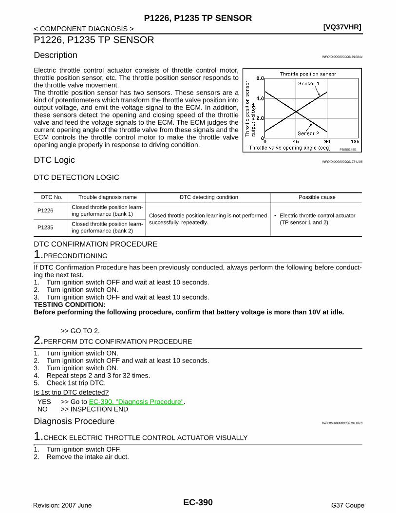
[VQ37VHR]P1226, P1235 TP SENSOR
< COMPONENT DIAGNOSIS >
P1226, P1235 TP SENSOR
Description INFOID:0000000001910844
Electric throttle control actuator consists of throttle control motor,throttle position sensor, etc. The throttle position sensor responds tothe throttle valve movement. The throttle position sensor has two sensors. These sensors are akind of potentiometers which transform the throttle valve position intooutput voltage, and emit the voltage signal to the ECM. In addition,these sensors detect the opening and closing speed of the throttlevalve and feed the voltage signals to the ECM. The ECM judges thecurrent opening angle of the throttle valve from these signals and theECM controls the throttle control motor to make the throttle valveopening angle properly in response to driving condition.
DTC Logic INFOID:0000000001734198
DTC DETECTION LOGIC
DTC CONFIRMATION PROCEDURE
1.PRECONDITIONING
If DTC Confirmation Procedure has been previously conducted, always perform the following before conduct-ing the next test. 1. Turn ignition switch OFF and wait at least 10 seconds.2. Turn ignition switch ON.3. Turn ignition switch OFF and wait at least 10 seconds.TESTING CONDITION:Before performing the following procedure, confirm that battery voltage is more than 10V at idle.
>> GO TO 2.
2.PERFORM DTC CONFIRMATION PROCEDURE
1. Turn ignition switch ON.2. Turn ignition switch OFF and wait at least 10 seconds.3. Turn ignition switch ON.4. Repeat steps 2 and 3 for 32 times.5. Check 1st trip DTC.Is 1st trip DTC detected?YES >> Go to EC-390, "Diagnosis Procedure".NO >> INSPECTION END
Diagnosis Procedure INFOID:0000000001911018
1.CHECK ELECTRIC THROTTLE CONTROL ACTUATOR VISUALLY
1. Turn ignition switch OFF.2. Remove the intake air duct.
PBIB0145E
DTC No. Trouble diagnosis name DTC detecting condition Possible cause
P1226Closed throttle position learn-ing performance (bank 1) Closed throttle position learning is not performed
successfully, repeatedly.• Electric throttle control actuator
(TP sensor 1 and 2)P1235
Closed throttle position learn-ing performance (bank 2)
EC-390Revision: 2007 June G37 Coupe

P1226, P1235 TP SENSOR[VQ37VHR]
C
D
E
F
G
H
I
J
K
L
M
A
C
N
P
O
< COMPONENT DIAGNOSIS >
E
3. Check if foreign matter is caught between the throttle valve (1)and the housing.
Is the inspection result normal?YES >> GO TO 2.NO >> Remove the foreign matter and clean the electric throttle
control actuator inside.
2.REPLACE ELECTRIC THROTTLE CONTROL ACTUATOR
1. Replace malfunctioning electric throttle control actuator.2. Go to EC-391, "Special Repair Requirement".
>> INSPECTION END
Special Repair Requirement INFOID:0000000001910848
1.PERFORM THROTTLE VALVE CLOSED POSITION LEARNING
Refer to EC-18, "THROTTLE VALVE CLOSED POSITION LEARNING : Special Repair Requirement"
>> GO TO 2.
2.PERFORM IDLE AIR VOLUME LEARNING
Refer to EC-19, "IDLE AIR VOLUME LEARNING : Special Repair Requirement"
>> END
JMBIA0025ZZ
EC-391Revision: 2007 June G37 Coupe

[VQ37VHR]P1233, P2101 ELECTRIC THROTTLE CONTROL FUNCTION
< COMPONENT DIAGNOSIS >
P1233, P2101 ELECTRIC THROTTLE CONTROL FUNCTION
Description INFOID:0000000001734201
Electric throttle control actuator consists of throttle control motor, throttle position sensor, etc.The throttle control motor is operated by the ECM and it opens and closes the throttle valve.The current opening angle of the throttle valve is detected by the throttle position sensor and it provides feed-back to the ECM to control the throttle control motor to make the throttle valve opening angle properly inresponse to driving condition.
DTC Logic INFOID:0000000001734202
DTC DETECTION LOGICNOTE:If DTC P1233 or P2101 is displayed with DTC P1238, P1290, P2100 or 2119, first perform the troublediagnosis for DTC P1238, P2119 or P1290, P2100. Refer to EC-399, "DTC Logic" or EC-404, "DTCLogic".
DTC CONFIRMATION PROCEDURE
1.PRECONDITIONING
If DTC Confirmation Procedure has been previously conducted, always perform the following before conduct-ing the next test. 1. Turn ignition switch OFF and wait at least 10 seconds.2. Turn ignition switch ON.3. Turn ignition switch OFF and wait at least 10 seconds.TESTING CONDITION:Before performing the following procedure, confirm that battery voltage is more than 11V when engineis running.
>> GO TO 2.
2.PERFORM DTC CONFIRMATION PROCEDURE
1. Turn ignition switch ON and wait at least 2 seconds.2. Start engine and let it idle for 5 seconds.3. Check DTC.Is DTC detected?YES >> Go to EC-392, "Diagnosis Procedure".NO >> INSPECTION END
Diagnosis Procedure INFOID:0000000001734203
1.CHECK GROUND CONNECTION
1. Turn ignition switch OFF.2. Check ground connection M95. Refer to Ground Inspection in GI-41, "Circuit Inspection".Is the inspection result normal?YES >> GO TO 2.NO >> Repair or replace ground connection.
2.CHECK THROTTLE CONTROL MOTOR RELAY INPUT SIGNAL CIRCUIT-I
Check the voltage between ECM harness connector and ground.
DTC No. Trouble diagnosis name DTC detecting condition Possible cause
P1233Electric throttle control performance (bank 2) Electric throttle control function does not oper-
ate properly.
• Harness or connectors(Throttle control motor circuit is open or shorted)
• Electric throttle control actuatorP2101Electric throttle control performance (bank 1)
EC-392Revision: 2007 June G37 Coupe
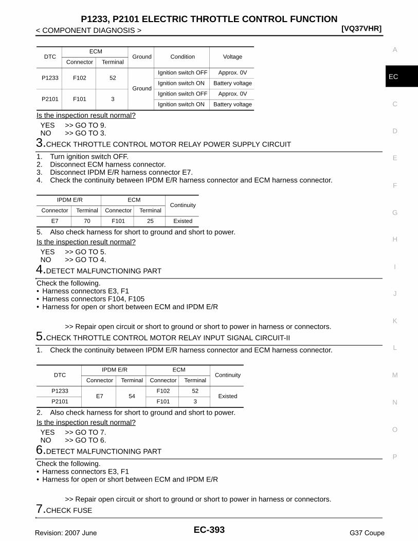
P1233, P2101 ELECTRIC THROTTLE CONTROL FUNCTION[VQ37VHR]
C
D
E
F
G
H
I
J
K
L
M
A
C
N
P
O
< COMPONENT DIAGNOSIS >
E
Is the inspection result normal?YES >> GO TO 9.NO >> GO TO 3.
3.CHECK THROTTLE CONTROL MOTOR RELAY POWER SUPPLY CIRCUIT
1. Turn ignition switch OFF.2. Disconnect ECM harness connector.3. Disconnect IPDM E/R harness connector E7.4. Check the continuity between IPDM E/R harness connector and ECM harness connector.
5. Also check harness for short to ground and short to power.Is the inspection result normal?YES >> GO TO 5.NO >> GO TO 4.
4.DETECT MALFUNCTIONING PART
Check the following.• Harness connectors E3, F1• Harness connectors F104, F105• Harness for open or short between ECM and IPDM E/R
>> Repair open circuit or short to ground or short to power in harness or connectors.
5.CHECK THROTTLE CONTROL MOTOR RELAY INPUT SIGNAL CIRCUIT-II
1. Check the continuity between IPDM E/R harness connector and ECM harness connector.
2. Also check harness for short to ground and short to power.Is the inspection result normal?YES >> GO TO 7.NO >> GO TO 6.
6.DETECT MALFUNCTIONING PART
Check the following.• Harness connectors E3, F1• Harness for open or short between ECM and IPDM E/R
>> Repair open circuit or short to ground or short to power in harness or connectors.
7.CHECK FUSE
DTCECM
Ground Condition VoltageConnector Terminal
P1233 F102 52
Ground
Ignition switch OFF Approx. 0V
Ignition switch ON Battery voltage
P2101 F101 3Ignition switch OFF Approx. 0V
Ignition switch ON Battery voltage
IPDM E/R ECMContinuity
Connector Terminal Connector Terminal
E7 70 F101 25 Existed
DTCIPDM E/R ECM
ContinuityConnector Terminal Connector Terminal
P1233E7 54
F102 52Existed
P2101 F101 3
EC-393Revision: 2007 June G37 Coupe
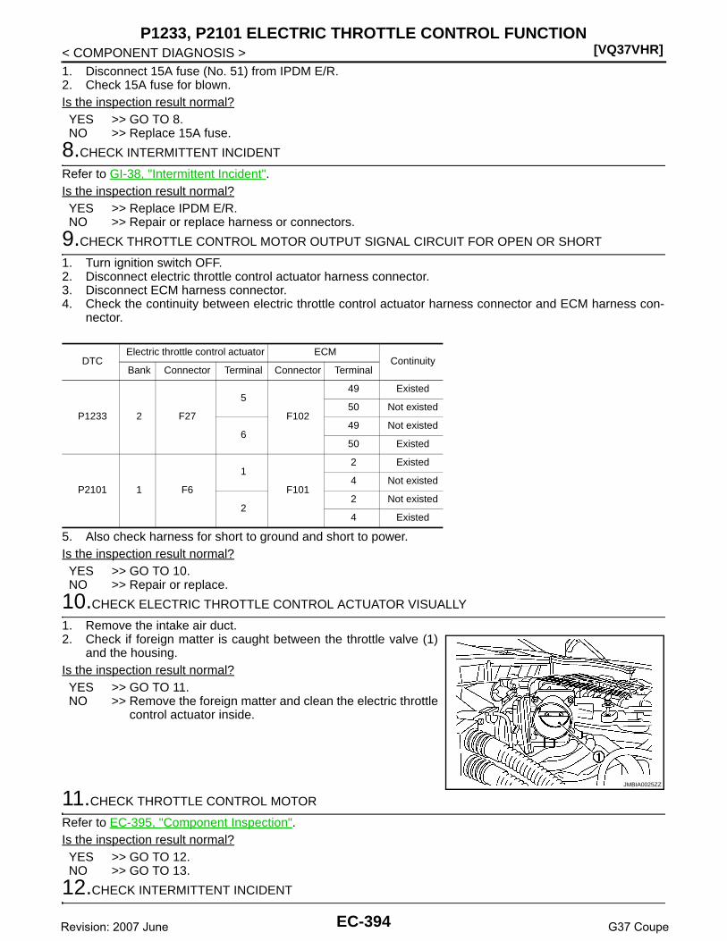
[VQ37VHR]P1233, P2101 ELECTRIC THROTTLE CONTROL FUNCTION
< COMPONENT DIAGNOSIS >1. Disconnect 15A fuse (No. 51) from IPDM E/R.2. Check 15A fuse for blown.Is the inspection result normal?YES >> GO TO 8.NO >> Replace 15A fuse.
8.CHECK INTERMITTENT INCIDENT
Refer to GI-38, "Intermittent Incident".Is the inspection result normal?YES >> Replace IPDM E/R.NO >> Repair or replace harness or connectors.
9.CHECK THROTTLE CONTROL MOTOR OUTPUT SIGNAL CIRCUIT FOR OPEN OR SHORT
1. Turn ignition switch OFF.2. Disconnect electric throttle control actuator harness connector.3. Disconnect ECM harness connector.4. Check the continuity between electric throttle control actuator harness connector and ECM harness con-
nector.
5. Also check harness for short to ground and short to power.Is the inspection result normal?YES >> GO TO 10.NO >> Repair or replace.
10.CHECK ELECTRIC THROTTLE CONTROL ACTUATOR VISUALLY
1. Remove the intake air duct.2. Check if foreign matter is caught between the throttle valve (1)
and the housing.Is the inspection result normal?YES >> GO TO 11.NO >> Remove the foreign matter and clean the electric throttle
control actuator inside.
11.CHECK THROTTLE CONTROL MOTOR
Refer to EC-395, "Component Inspection".Is the inspection result normal?YES >> GO TO 12.NO >> GO TO 13.
12.CHECK INTERMITTENT INCIDENT
DTCElectric throttle control actuator ECM
ContinuityBank Connector Terminal Connector Terminal
P1233 2 F27
5
F102
49 Existed
50 Not existed
649 Not existed
50 Existed
P2101 1 F6
1
F101
2 Existed
4 Not existed
22 Not existed
4 Existed
JMBIA0025ZZ
EC-394Revision: 2007 June G37 Coupe

P1233, P2101 ELECTRIC THROTTLE CONTROL FUNCTION[VQ37VHR]
C
D
E
F
G
H
I
J
K
L
M
A
C
N
P
O
< COMPONENT DIAGNOSIS >
E
Refer to GI-38, "Intermittent Incident".Is the inspection result normal?YES >> GO TO 13.NO >> Repair or replace harness or connectors.
13.REPLACE ELECTRIC THROTTLE CONTROL ACTUATOR
1. Replace malfunction electric throttle control actuator.2. Go to EC-395, "Special Repair Requirement".
>> INSPECTION END
Component Inspection INFOID:0000000001734204
1.CHECK THROTTLE CONTROL MOTOR
1. Turn ignition switch OFF.2. Disconnect electric throttle control actuator harness connector.3. Check resistance between electric throttle control actuator terminals as follows.
Is the inspection result normal?YES >> INSPECTION ENDNO >> GO TO 2.
2.REPLACE ELECTRIC THROTTLE CONTROL ACTUATOR
1. Replace malfunctioning electric throttle control actuator.2. Go to EC-395, "Special Repair Requirement".
>> INSPECTION END
Special Repair Requirement INFOID:0000000001910849
1.PERFORM THROTTLE VALVE CLOSED POSITION LEARNING
Refer to EC-18, "THROTTLE VALVE CLOSED POSITION LEARNING : Special Repair Requirement"
>> GO TO 2.
2.PERFORM IDLE AIR VOLUME LEARNING
Refer to EC-19, "IDLE AIR VOLUME LEARNING : Special Repair Requirement"
>> END
Electric throttle control actuatorResistance
Bank Terminals
1 1 and 2Approx. 1 - 15 Ω [at 25°C (77°F)]
2 5 and 6
EC-395Revision: 2007 June G37 Coupe
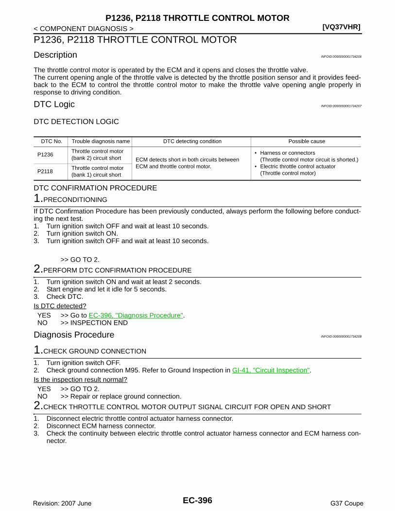
[VQ37VHR]P1236, P2118 THROTTLE CONTROL MOTOR
< COMPONENT DIAGNOSIS >
P1236, P2118 THROTTLE CONTROL MOTOR
Description INFOID:0000000001734206
The throttle control motor is operated by the ECM and it opens and closes the throttle valve.The current opening angle of the throttle valve is detected by the throttle position sensor and it provides feed-back to the ECM to control the throttle control motor to make the throttle valve opening angle properly inresponse to driving condition.
DTC Logic INFOID:0000000001734207
DTC DETECTION LOGIC
DTC CONFIRMATION PROCEDURE
1.PRECONDITIONING
If DTC Confirmation Procedure has been previously conducted, always perform the following before conduct-ing the next test. 1. Turn ignition switch OFF and wait at least 10 seconds.2. Turn ignition switch ON.3. Turn ignition switch OFF and wait at least 10 seconds.
>> GO TO 2.
2.PERFORM DTC CONFIRMATION PROCEDURE
1. Turn ignition switch ON and wait at least 2 seconds.2. Start engine and let it idle for 5 seconds.3. Check DTC.Is DTC detected?YES >> Go to EC-396, "Diagnosis Procedure".NO >> INSPECTION END
Diagnosis Procedure INFOID:0000000001734208
1.CHECK GROUND CONNECTION
1. Turn ignition switch OFF.2. Check ground connection M95. Refer to Ground Inspection in GI-41, "Circuit Inspection".Is the inspection result normal?YES >> GO TO 2.NO >> Repair or replace ground connection.
2.CHECK THROTTLE CONTROL MOTOR OUTPUT SIGNAL CIRCUIT FOR OPEN AND SHORT
1. Disconnect electric throttle control actuator harness connector.2. Disconnect ECM harness connector.3. Check the continuity between electric throttle control actuator harness connector and ECM harness con-
nector.
DTC No. Trouble diagnosis name DTC detecting condition Possible cause
P1236Throttle control motor (bank 2) circuit short ECM detects short in both circuits between
ECM and throttle control motor.
• Harness or connectors(Throttle control motor circuit is shorted.)
• Electric throttle control actuator(Throttle control motor)P2118
Throttle control motor (bank 1) circuit short
EC-396Revision: 2007 June G37 Coupe

P1236, P2118 THROTTLE CONTROL MOTOR[VQ37VHR]
C
D
E
F
G
H
I
J
K
L
M
A
C
N
P
O
< COMPONENT DIAGNOSIS >
E
4. Also check harness for short to ground and short to power.Is the inspection result normal?YES >> GO TO 3.NO >> Repair or replace.
3.CHECK THROTTLE CONTROL MOTOR
Refer to EC-397, "Component Inspection".Is the inspection result normal?YES >> GO TO 4.NO >> GO TO 5.
4.CHECK INTERMITTENT INCIDENT
Refer to GI-38, "Intermittent Incident".Is the inspection result normal?YES >> GO TO 5.NO >> Repair or replace harness or connectors.
5.REPLACE ELECTRIC THROTTLE CONTROL ACTUATOR
1. Replace malfunctioning electric throttle control actuator.2. Go to EC-398, "Special Repair Requirement".
>> INSPECTION END
Component Inspection INFOID:0000000001911020
1.CHECK THROTTLE CONTROL MOTOR
1. Turn ignition switch OFF.2. Disconnect electric throttle control actuator harness connector.3. Check resistance between electric throttle control actuator terminals as follows.
Is the inspection result normal?YES >> INSPECTION ENDNO >> GO TO 2.
2.REPLACE ELECTRIC THROTTLE CONTROL ACTUATOR
1. Replace malfunctioning electric throttle control actuator.2. Go to EC-398, "Special Repair Requirement".
DTCElectric throttle control actuator ECM
ContinuityBank Connector Terminal Connector Terminal
P1236 2 F27
5
F102
49 Existed
50 Not existed
649 Not existed
50 Existed
P2118 1 F6
1
F101
2 Existed
4 Not existed
22 Not existed
4 Existed
Electric throttle control actuatorResistance
Bank Terminals
1 1 and 2Approx. 1 - 15 Ω [at 25°C (77°F)]
2 5 and 6
EC-397Revision: 2007 June G37 Coupe

[VQ37VHR]P1236, P2118 THROTTLE CONTROL MOTOR
< COMPONENT DIAGNOSIS >
>> INSPECTION END
Special Repair Requirement INFOID:0000000001910850
1.PERFORM THROTTLE VALVE CLOSED POSITION LEARNING
Refer to EC-18, "THROTTLE VALVE CLOSED POSITION LEARNING : Special Repair Requirement"
>> GO TO 2.
2.PERFORM IDLE AIR VOLUME LEARNING
Refer to EC-19, "IDLE AIR VOLUME LEARNING : Special Repair Requirement"
>> END
EC-398Revision: 2007 June G37 Coupe

P1238, P2119 ELECTRIC THROTTLE CONTROL ACTUATOR[VQ37VHR]
C
D
E
F
G
H
I
J
K
L
M
A
C
N
P
O
< COMPONENT DIAGNOSIS >
E
P1238, P2119 ELECTRIC THROTTLE CONTROL ACTUATOR
Description INFOID:0000000001734211
Electric throttle control actuator consists of throttle control motor, throttle position sensor, etc.The throttle control motor is operated by the ECM and it opens and closes the throttle valve.The throttle position sensor detects the throttle valve position, and the opening and closing speed of the throt-tle valve and feeds the voltage signals to the ECM. The ECM judges the current opening angle of the throttlevalve from these signals and the ECM controls the throttle control motor to make the throttle valve openingangle properly in response to driving condition.
DTC Logic INFOID:0000000001734212
DTC DETECTION LOGIC
DTC CONFIRMATION PROCEDURE
1.PRECONDITIONING
If DTC Confirmation Procedure has been previously conducted, always perform the following before conduct-ing the next test. 1. Turn ignition switch OFF and wait at least 10 seconds.2. Turn ignition switch ON.3. Turn ignition switch OFF and wait at least 10 seconds.
>> GO TO 2.
2.PERFORM DTC CONFIRMATION PROCEDURE FOR MALFUNCTION A AND B
1. Turn ignition switch ON and wait at least 1 second.2. Shift selector lever to D position (A/T) or 1st position (M/T) and wait at least 3 seconds.3. Shift selector lever to P position (A/T) or Neutral position (M/T).4. Turn ignition switch OFF and wait at least 10 seconds.5. Turn ignition switch ON and wait at least 1 second.6. Shift selector lever to D position (A/T) or 1st position (M/T) and wait at least 3 seconds.7. Shift selector lever to P position (A/T) or Neutral position (M/T).8. Turn ignition switch OFF, wait at least 10 seconds, and then turn ON.9. Check DTC.Is DTC detected?YES >> Go to EC-400, "Diagnosis Procedure".NO >> GO TO 3.
3.PERFORM DTC CONFIRMATION PROCEDURE FOR MALFUNCTION C
1. Turn ignition switch ON and wait at least 1 second.2. Shift selector lever to D position (A/T) or 1st position (M/T) and wait at least 3 seconds.3. Shift selector lever to P position (A/T) or Neutral position (M/T).
DTC No. Trouble diagnosis name DTC detecting condition Possible cause
P1238Electric throttle control actuator (bank 2)
A)Electric throttle control actuator does not func-tion properly due to the return spring malfunc-tion.
• Electric throttle control actuator
B)Throttle valve opening angle in fail-safe mode is not in specified range.
C) ECM detect the throttle valve is stuck open.
P2119Electric throttle control actuator (bank 1)
A)Electric throttle control actuator does not func-tion properly due to the return spring malfunc-tion.
B)Throttle valve opening angle in fail-safe mode is not in specified range.
C) ECM detect the throttle valve is stuck open.
EC-399Revision: 2007 June G37 Coupe

[VQ37VHR]P1238, P2119 ELECTRIC THROTTLE CONTROL ACTUATOR
< COMPONENT DIAGNOSIS >4. Start engine and let it idle for 3 seconds.5. Check DTC.Is DTC detected?YES >> Go to EC-400, "Diagnosis Procedure".NO >> INSPECTION END
Diagnosis Procedure INFOID:0000000001911019
1.CHECK ELECTRIC THROTTLE CONTROL ACTUATOR VISUALLY
1. Turn ignition switch OFF.2. Remove the intake air duct.3. Check if foreign matter is caught between the throttle valve (1)
and the housing.Is the inspection result normal?YES >> GO TO 2.NO >> Remove the foreign matter and clean the electric throttle
control actuator inside.
2.REPLACE ELECTRIC THROTTLE CONTROL ACTUATOR
1. Replace malfunctioning electric throttle control actuator.2. Go to EC-400, "Special Repair Requirement".
>> INSPECTION END
Special Repair Requirement INFOID:0000000001910851
1.PERFORM THROTTLE VALVE CLOSED POSITION LEARNING
Refer to EC-18, "THROTTLE VALVE CLOSED POSITION LEARNING : Special Repair Requirement"
>> GO TO 2.
2.PERFORM IDLE AIR VOLUME LEARNING
Refer to EC-19, "IDLE AIR VOLUME LEARNING : Special Repair Requirement"
>> END
JMBIA0025ZZ
EC-400Revision: 2007 June G37 Coupe

P1239, P2135 TP SENSOR[VQ37VHR]
C
D
E
F
G
H
I
J
K
L
M
A
C
N
P
O
< COMPONENT DIAGNOSIS >
E
P1239, P2135 TP SENSOR
Description INFOID:0000000001910845
Electric throttle control actuator consists of throttle control motor,throttle position sensor, etc. The throttle position sensor responds tothe throttle valve movement. The throttle position sensor has two sensors. These sensors are akind of potentiometers which transform the throttle valve position intooutput voltage, and emit the voltage signal to the ECM. In addition,these sensors detect the opening and closing speed of the throttlevalve and feed the voltage signals to the ECM. The ECM judges thecurrent opening angle of the throttle valve from these signals and theECM controls the throttle control motor to make the throttle valveopening angle properly in response to driving condition.
DTC Logic INFOID:0000000001734216
DTC DETECTION LOGICNOTE:If DTC P1239 or P2135 is displayed with DTC P0643, first perform the trouble diagnosis for DTC P0643.Refer to EC-358, "DTC Logic".
DTC CONFIRMATION PROCEDURE
1.PRECONDITIONING
If DTC Confirmation Procedure has been previously conducted, always perform the following before conduct-ing the next test. 1. Turn ignition switch OFF and wait at least 10 seconds.2. Turn ignition switch ON.3. Turn ignition switch OFF and wait at least 10 seconds.TESTING CONDITION:Before performing the following procedure, confirm that battery voltage is more than 10V at idle.
>> GO TO 2.
2.PERFORM DTC CONFIRMATION PROCEDURE
1. Start engine and let it idle for 1 second.2. Check DTC.Is DTC detected?YES >> Go to EC-401, "Diagnosis Procedure".NO >> INSPECTION END
Diagnosis Procedure INFOID:0000000001734217
1.CHECK GROUND CONNECTION
1. Turn ignition switch OFF.2. Check ground connection M95. Refer to Ground Inspection in GI-41, "Circuit Inspection".Is the inspection result normal?YES >> GO TO 2.
PBIB0145E
DTC No. Trouble diagnosis name DTC detecting condition Possible cause
P1239Throttle position sensor (bank 2) circuit range/performance Rationally incorrect voltage is sent to ECM
compared with the signals from TP sensor 1 and TP sensor 2.
• Harness or connector(TP sensor 1 and 2 circuit is open or shorted.)
• Electric throttle control actuator(TP sensor 1 and 2)P2135
Throttle position sensor (bank 1) circuit range/performance
EC-401Revision: 2007 June G37 Coupe

[VQ37VHR]P1239, P2135 TP SENSOR
< COMPONENT DIAGNOSIS >NO >> Repair or replace ground connection.
2.CHECK THROTTLE POSITION SENSOR POWER SUPPLY CIRCUIT-I
1. Disconnect electric throttle control actuator harness connector.2. Turn ignition switch ON.3. Check the voltage between electric throttle control actuator harness connector and ground.
Is the inspection result normal?YES >> GO TO 3.NO >> Repair open circuit or short to ground or short to power in harness or connectors.
3.CHECK THROTTLE POSITION SENSOR GROUND CIRCUIT FOR OPEN AND SHORT
1. Turn ignition switch OFF.2. Disconnect ECM harness connector.3. Check the continuity between electric throttle control actuator harness connector and ECM harness con-
nector.
4. Also check harness for short to ground and short to power.Is the inspection result normal?YES >> GO TO 4.NO >> Repair open circuit or short to ground or short to power in harness or connectors.
4.CHECK THROTTLE POSITION SENSOR INPUT SIGNAL CIRCUIT FOR OPEN AND SHORT
1. Check the continuity between electric throttle control actuator harness connector and ECM harness con-nector.
2. Also check harness for short to ground and short to power.Is the inspection result normal?YES >> GO TO 5.NO >> Repair open circuit or short to ground or short to power in harness or connectors.
5.CHECK THROTTLE POSITION SENSOR
Refer to EC-403, "Component Inspection".Is the inspection result normal?YES >> GO TO 7.NO >> GO TO 6.
6.REPLACE ELECTRIC THROTTLE CONTROL ACTUATOR
1. Replace malfunctioning electric throttle control actuator.
DTCElectric throttle control actuator
Ground VoltageBank Connector Terminal
P1239 2 F27 1Ground Approx. 5V
P2135 1 F6 6
DTCElectric throttle control actuator ECM
ContinuityBank Connector Terminal Connector Terminal
P1239 2 F27 4F101
48Existed
P2135 1 F6 3 40
DTCElectric throttle control actuator ECM
ContinuityBank Connector Terminal Connector Terminal
P1239 2 F272
F101
31
Existed3 35
P2135 1 F64 30
5 34
EC-402Revision: 2007 June G37 Coupe
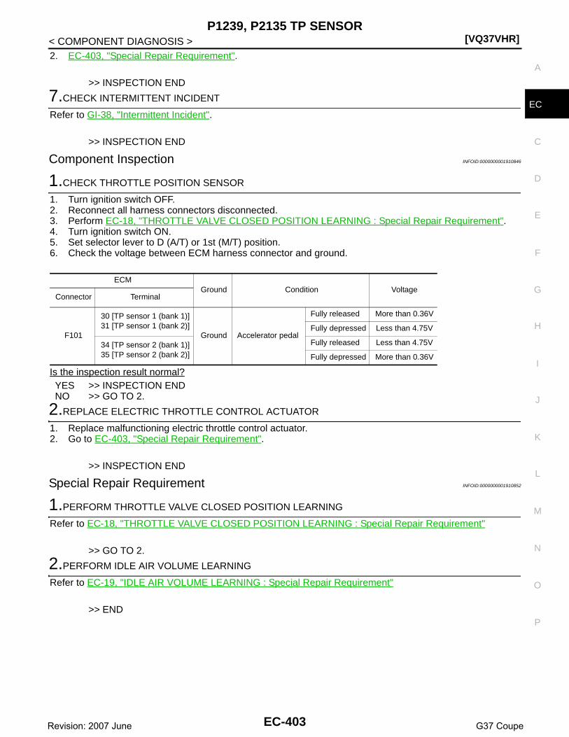
P1239, P2135 TP SENSOR[VQ37VHR]
C
D
E
F
G
H
I
J
K
L
M
A
C
N
P
O
< COMPONENT DIAGNOSIS >
E
2. EC-403, "Special Repair Requirement".
>> INSPECTION END
7.CHECK INTERMITTENT INCIDENT
Refer to GI-38, "Intermittent Incident".
>> INSPECTION END
Component Inspection INFOID:0000000001910846
1.CHECK THROTTLE POSITION SENSOR
1. Turn ignition switch OFF.2. Reconnect all harness connectors disconnected.3. Perform EC-18, "THROTTLE VALVE CLOSED POSITION LEARNING : Special Repair Requirement".4. Turn ignition switch ON.5. Set selector lever to D (A/T) or 1st (M/T) position. 6. Check the voltage between ECM harness connector and ground.
Is the inspection result normal?YES >> INSPECTION ENDNO >> GO TO 2.
2.REPLACE ELECTRIC THROTTLE CONTROL ACTUATOR
1. Replace malfunctioning electric throttle control actuator.2. Go to EC-403, "Special Repair Requirement".
>> INSPECTION END
Special Repair Requirement INFOID:0000000001910852
1.PERFORM THROTTLE VALVE CLOSED POSITION LEARNING
Refer to EC-18, "THROTTLE VALVE CLOSED POSITION LEARNING : Special Repair Requirement"
>> GO TO 2.
2.PERFORM IDLE AIR VOLUME LEARNING
Refer to EC-19, "IDLE AIR VOLUME LEARNING : Special Repair Requirement"
>> END
ECMGround Condition Voltage
Connector Terminal
F101
30 [TP sensor 1 (bank 1)]31 [TP sensor 1 (bank 2)]
Ground Accelerator pedal
Fully released More than 0.36V
Fully depressed Less than 4.75V
34 [TP sensor 2 (bank 1)]35 [TP sensor 2 (bank 2)]
Fully released Less than 4.75V
Fully depressed More than 0.36V
EC-403Revision: 2007 June G37 Coupe

[VQ37VHR]P1290, P2100, P2103 THROTTLE CONTROL MOTOR RELAY
< COMPONENT DIAGNOSIS >
P1290, P2100, P2103 THROTTLE CONTROL MOTOR RELAY
Description INFOID:0000000001734220
Power supply for the throttle control motor is provided to the ECM via throttle control motor relay. The throttlecontrol motor relay is ON/OFF controlled by the ECM. When the ignition switch is turned ON, the ECM sendsan ON signal to throttle control motor relay and battery voltage is provided to the ECM. When the ignitionswitch is turned OFF, the ECM sends an OFF signal to throttle control motor relay and battery voltage is notprovided to the ECM.
DTC Logic INFOID:0000000001734221
DTC DETECTION LOGIC
DTC CONFIRMATION PROCEDURE
1.PRECONDITIONING
If DTC Confirmation Procedure has been previously conducted, always perform the following before conduct-ing the next test. 1. Turn ignition switch OFF and wait at least 10 seconds.2. Turn ignition switch ON.3. Turn ignition switch OFF and wait at least 10 seconds.TESTING CONDITION:Before performing the following procedure, confirm that battery voltage is more than 8V.Which DTC is detected?P1290, P2100>>GO TO 2.P2103 >> GO TO 3.
2.PERFORM DTC CONFIRMATION PROCEDURE FOR DTC P1290 AND P2100
1. Turn ignition switch ON and wait at least 2 seconds.2. Start engine and let it idle for 5 seconds.3. Check DTC.Is DTC detected?YES >> Go to EC-404, "Diagnosis Procedure".NO >> INSPECTION END
3.PERFORM DTC CONFIRMATION PROCEDURE FOR DTC P2103
1. Turn ignition switch ON and wait at least 1 second.2. Check DTC.Is DTC detected?YES >> Go to EC-404, "Diagnosis Procedure".NO >> INSPECTION END
Diagnosis Procedure INFOID:0000000001734222
1.CHECK THROTTLE CONTROL MOTOR RELAY POWER SUPPLY CIRCUIT
1. Turn ignition switch OFF.2. Disconnect ECM harness connector.
DTC No. Trouble diagnosis name DTC detecting condition Possible cause
P1290Throttle control motor relay circuit open (bank 2) ECM detects a voltage of power source for
throttle control motor is excessively low.
• Harness or connectors(Throttle control motor relay circuit is open)
• Throttle control motor relayP2100Throttle control motor relay circuit open (bank 1)
P2103Throttle control motor relay circuit short
ECM detect the throttle control motor relay is stuck ON.
• Harness or connectors(Throttle control motor relay circuit is shorted)
• Throttle control motor relay
EC-404Revision: 2007 June G37 Coupe

P1290, P2100, P2103 THROTTLE CONTROL MOTOR RELAY[VQ37VHR]
C
D
E
F
G
H
I
J
K
L
M
A
C
N
P
O
< COMPONENT DIAGNOSIS >
E
3. Disconnect IPDM E/R harness connector E7.4. Check the continuity between IPDM E/R harness connector and ECM harness connector.
5. Also check harness for short to ground and short to power.Is the inspection result normal?YES >> GO TO 3.NO >> GO TO 2.
2.DETECT MALFUNCTIONING PART
Check the following.• Harness connectors E3, F1• Harness connectors F104, F105• Harness for open or short between ECM and IPDM E/R
>> Repair open circuit or short to ground or short to power in harness or connectors.
3.CHECK THROTTLE CONTROL MOTOR RELAY INPUT SIGNAL CIRCUIT
1. Check the continuity between IPDM E/R sensor harness connector and ECM harness connector.
2. Also check harness for short to ground and short to power.Is the inspection result normal?YES >> GO TO 5.NO >> GO TO 4.
4.DETECT MALFUNCTIONING PART
Check the following.• Harness connectors E3, F1• Harness for open or short between ECM and IPDM E/R
>> Repair open circuit or short to ground or short to power in harness or connectors.
5.CHECK FUSE
1. Disconnect 15A fuse (No. 51) from IPDM E/R.2. Check 15A fuse for blown.Is the inspection result normal?YES >> GO TO 6.NO >> Replace 15A fuse.
6.CHECK INTERMITTENT INCIDENT
Refer to GI-38, "Intermittent Incident".Is the inspection result normal?YES >> Replace IPDM E/R.NO >> Repair or replace harness or connectors.
IPDM E/R ECMContinuity
Connector Terminal Connector Terminal
E7 70 F101 25 Existed
DTCIPDM E/R ECM
ContinuityConnector Terminal Connector Terminal
P1290
E7 54
F102 52
ExistedP2100 F101 3
P2103F101 3
F102 52
EC-405Revision: 2007 June G37 Coupe

[VQ37VHR]P1421 COLD START CONTROL
< COMPONENT DIAGNOSIS >
P1421 COLD START CONTROL
Description INFOID:0000000001734223
ECM controls ignition timing and engine idle speed when engine is started with prewarming up condition.This control promotes the activation of three way catalyst by heating the catalyst and reduces emissions.
DTC Logic INFOID:0000000001734224
DTC DETECTION LOGICNOTE:• If DTC P1421 is displayed with other DTC, first perform the trouble diagnosis for other DTC.
DTC CONFIRMATION PROCEDURE
1.PRECONDITIONING
If DTC Confirmation Procedure has been previously conducted, always perform the following before conduct-ing the next test. 1. Turn ignition switch OFF and wait at least 10 seconds.2. Turn ignition switch ON.3. Turn ignition switch OFF and wait at least 10 seconds.TESTING CONDITION:Before performing the following procedure, confirm that battery voltage is more than 11V at idle.
>> GO TO 2.
2.PERFORM DTC CONFIRMATION PROCEDURE
With CONSULT-III1. Turn ignition switch OFF and wait at least 10 seconds.2. Turn ignition switch ON.3. Select “DATA MONITOR” mode with CONSULT-III.4. Check the indication of “COOLAN TEMP/S”.
If it is between 4°C (39°F) and 36°C (97°F), go to the following steps.If it is below 4°C (39°F), warm engine up to more than 4°C (39°F) and retry from step 1.If it is above 36°C (97°F), cool engine down to less than 36°C (97°F) and retry from step 1.
5. Start engine and let it idle for 5 minutes.6. Check 1st trip DTC.
With GSTFollow the procedure “With CONSULT-III” above.Is 1st trip DTC detected?YES >> Go to EC-406, "Diagnosis Procedure".NO >> INSPECTION END
Diagnosis Procedure INFOID:0000000001734225
1.PERFORM IDLE AIR VOLUME LEARNING
Perform EC-19, "IDLE AIR VOLUME LEARNING : Special Repair Requirement".Is Idle Air Volume Learning carried out successfully?YES >> GO TO 2.NO >> Follow the instruction of Idle Air Volume Learning.
2.CHECK INTAKE SYSTEM
DTC No. Trouble diagnosis name DTC detecting condition Possible cause
P1421Cold start emission reduction strategy monitoring
ECM does not control ignition timing and engine idle speed properly when engine is started with prewarming up condition.
• Lack of intake air volume• Fuel injection system• ECM
EC-406Revision: 2007 June G37 Coupe

P1421 COLD START CONTROL[VQ37VHR]
C
D
E
F
G
H
I
J
K
L
M
A
C
N
P
O
< COMPONENT DIAGNOSIS >
E
Check for the cause of intake air volume lacking. Refer to the following.• Crushed intake air passage• Intake air passage cloggingIs the inspection result normal?YES >> GO TO 3.NO >> Repair or replace malfunctioning part
3.CHECK FUEL INJECTION SYSTEM FUNCTION
Perform DTC Confirmation Procedure for DTC P0171, P0174. Refer to EC-232, "DTC Logic".Is the inspection result normal?YES >> GO TO 4.NO >> Go to EC-233, "Diagnosis Procedure" for DTC P0171, P0174.
4.PERFORM DTC CONFIRMATION PROCEDURE
With CONSULT-III1. Turn ignition switch ON.2. Select “SELF DIAG RESULTS” mode with CONSULT-III.3. Touch “ERASE”.4. Perform DTC Confirmation Procedure.
See EC-406, "DTC Logic".With GST
1. Turn ignition switch ON.2. Select Service $04 with GST.3. Perform DTC Confirmation Procedure.
See EC-406, "DTC Logic".Is the 1st trip DTC P1421 displayed again?YES >> GO TO 5.NO >> INSPECTION END
5.REPLACE ECM
1. Replace ECM.2. Go to EC-16, "ADDITIONAL SERVICE WHEN REPLACING CONTROL UNIT (ECM) : Special Repair
Requirement".
>> INSPECTION END
EC-407Revision: 2007 June G37 Coupe

[VQ37VHR]P1550 BATTERY CURRENT SENSOR
< COMPONENT DIAGNOSIS >
P1550 BATTERY CURRENT SENSOR
Description INFOID:0000000001734226
The power generation voltage variable control enables fuel consumption to be decreased by reducing theengine load which is caused by the power generation of the generator. The battery current sensor is installedto the battery cable at the negative terminal. The sensor measures the charging/discharging current of the bat-tery. Based on the sensor signal, ECM judges whether or not the power generation voltage variable control isperformed. When performing the power generation voltage variable control, ECM calculates the target powergeneration voltage based on the sensor signal. And ECM sends the calculated value as the power generationcommand value to IPDM E/R. For the details of the power generation voltage variable control, refer to CHG-8,"System Description".CAUTION:Do not connect the electrical component or the ground wire directly to the battery terminal. The con-nection causes the malfunction of the power generation voltage variable control, and then the batterydischarge may occur.
DTC Logic INFOID:0000000001734227
DTC DETECTION LOGICNOTE:If DTC P1550 is displayed with DTC P0643, first perform the trouble diagnosis for P0643. Refer to EC-358,"DTC Logic".
DTC CONFIRMATION PROCEDURE
1.PRECONDITIONING
If DTC Confirmation Procedure has been previously conducted, always perform the following before conduct-ing the next test. 1. Turn ignition switch OFF and wait at least 10 seconds.2. Turn ignition switch ON.3. Turn ignition switch OFF and wait at least 10 seconds.TESTING CONDITION:Before performing the following procedure, confirm that battery voltage is more than 8V at idle.
>> GO TO 2.
2.PERFORM DTC CONFIRMATION PROCEDURE
1. Start engine and wait at least 10 seconds.2. Check 1st trip DTC.Is 1st trip DTC detected?YES >> Go to EC-408, "Diagnosis Procedure".NO >> INSPECTION END
Diagnosis Procedure INFOID:0000000001734228
1.CHECK GROUND CONNECTION
1. Turn ignition switch OFF.2. Check ground connection M95. Refer to Ground Inspection in GI-41, "Circuit Inspection".Is the inspection result normal?YES >> GO TO 2.NO >> Repair or replace ground connection.
DTC No. Trouble diagnosis name DTC detecting condition Possible cause
P1550Battery current sensor circuit range/performance
The output voltage of the battery current sensor remains within the specified range while engine is running.
• Harness or connectors(Battery current sensor circuit is open or shorted.)
• Battery current sensor
EC-408Revision: 2007 June G37 Coupe

P1550 BATTERY CURRENT SENSOR[VQ37VHR]
C
D
E
F
G
H
I
J
K
L
M
A
C
N
P
O
< COMPONENT DIAGNOSIS >
E
2.CHECK BATTERY CURRENT SENSOR POWER SUPPLY CIRCUIT-I
1. Disconnect battery current sensor harness connector.2. Turn ignition switch ON.3. Check the voltage between battery current sensor harness connector and ground.
Is the inspection result normal?YES >> GO TO 5.NO >> GO TO 3.
3.CHECK BATTERY CURRENT SENSOR POWER SUPPLY CIRCUIT-II
1. Turn ignition switch OFF.2. Disconnect ECM harness connector.3. Check the continuity between battery current sensor harness connector and ECM harness connector.
4. Also check harness for short to ground and short to power.Is the inspection result normal?YES >> GO TO 5.NO >> GO TO 4.
4.DETECT MALFUNCTIONING PART
Check the following.• Harness connectors F1, E3• Harness for open or short between battery current sensor and ECM
>> Repair open circuit or short to ground or short to power in harness connectors.
5.CHECK BATTERY CURRENT SENSOR GROUND CIRCUIT FOR OPEN AND SHORT
1. Turn ignition switch OFF.2. Disconnect ECM harness connector.3. Check the continuity between battery current sensor harness connector and ECM harness connector.
4. Also check harness for short to ground and short to power.Is the inspection result normal?YES >> GO TO 7.NO >> GO TO 6.
6.DETECT MALFUNCTIONING PART
Check the following.• Harness connectors F1, E3• Harness for open or short between battery current sensor and ECM
>> Repair open circuit or short to ground or short to power in harness or connectors.
7.CHECK BATTERY CURRENT SENSOR INPUT SIGNAL CIRCUIT FOR OPEN AND SHORT
Battery current sensorGround Voltage
Connector Terminal
E21 1 Ground Approx. 5V
Battery current sensor ECMContinuity
Connector Terminal Connector Terminal
E21 1 F102 64 Existed
Battery current sensor ECMContinuity
Connector Terminal Connector Terminal
E21 2 F102 95 Existed
EC-409Revision: 2007 June G37 Coupe

[VQ37VHR]P1550 BATTERY CURRENT SENSOR
< COMPONENT DIAGNOSIS >1. Check the continuity between battery current sensor harness connector and ECM harness connector.
2. Also check harness for short to ground and short to power.Is the inspection result normal?YES >> GO TO 9.NO >> GO TO 8.
8.DETECT MALFUNCTIONING PART
Check the following.• Harness connectors F1, E3• Harness for open or short between battery current sensor and ECM
>> Repair open circuit or short to ground or short to power in harness or connectors.
9.CHECK BATTERY CURRENT SENSOR
Refer to EC-410, "Component Inspection".Is the inspection result normal?YES >> GO TO 10.NO >> Replace battery negative cable assembly.
10.CHECK INTERMITTENT INCIDENT
Refer to GI-38, "Intermittent Incident".
>> INSPECTION END
Component Inspection INFOID:0000000001734229
1.CHECK BATTERY CURRENT SENSOR
1. Turn ignition switch OFF.2. Reconnect harness connectors disconnected.3. Disconnect battery negative cable (1).
4. Install jumper cable (A) between battery negative terminal andbody ground.
5. Turn ignition switch ON.6. Check the voltage between ECM harness connector and
ground.
Before measuring the terminal voltage, confirm that the battery is fully charged. Refer to PG-3, "How to Handle Battery".
Is the inspection result normal?YES >> INSPECTION ENDNO >> Replace battery negative cable assembly.
Battery current sensor ECMContinuity
Connector Terminal Connector Terminal
E21 3 F102 91 Existed
: To body ground
ECMGround Voltage
Connector Terminal
F10291
(Battery current sensor signal)Ground Approx. 2.5V
JMBIA0027ZZ
EC-410Revision: 2007 June G37 Coupe

P1551, P1552 BATTERY CURRENT SENSOR[VQ37VHR]
C
D
E
F
G
H
I
J
K
L
M
A
C
N
P
O
< COMPONENT DIAGNOSIS >
E
P1551, P1552 BATTERY CURRENT SENSOR
Description INFOID:0000000001911021
The power generation voltage variable control enables fuel consumption to be decreased by reducing theengine load which is caused by the power generation of the generator. The battery current sensor is installedto the battery cable at the negative terminal. The sensor measures the charging/discharging current of the bat-tery. Based on the sensor signal, ECM judges whether or not the power generation voltage variable control isperformed. When performing the power generation voltage variable control, ECM calculates the target powergeneration voltage based on the sensor signal. And ECM sends the calculated value as the power generationcommand value to IPDM E/R. For the details of the power generation voltage variable control, refer to CHG-8,"System Description".CAUTION:Do not connect the electrical component or the ground wire directly to the battery terminal. The con-nection causes the malfunction of the power generation voltage variable control, and then the batterydischarge may occur.
DTC Logic INFOID:0000000001734231
DTC DETECTION LOGICNOTE:If DTC P1551 or P1552 is displayed with DTC P0643, first perform the trouble diagnosis for DTC P0643. Referto EC-358, "DTC Logic".
DTC CONFIRMATION PROCEDURE
1.PRECONDITIONING
If DTC Confirmation Procedure has been previously conducted, always perform the following before conduct-ing the next test. 1. Turn ignition switch OFF and wait at least 10 seconds.2. Turn ignition switch ON.3. Turn ignition switch OFF and wait at least 10 seconds.TESTING CONDITION:Before performing the following procedure, confirm that battery voltage is more than 8V with ignitionswitch ON
>> GO TO 2.
2.PERFORM DTC CONFIRMATION PROCEDURE
1. Turn ignition switch ON and wait at least 10 seconds.2. Check 1st trip DTC.Is 1st trip DTC detected?YES >> Go to EC-411, "Diagnosis Procedure".NO >> INSPECTION END
Diagnosis Procedure INFOID:0000000001911024
1.CHECK GROUND CONNECTION
1. Turn ignition switch OFF.2. Check ground connection M95. Refer to Ground Inspection in GI-41, "Circuit Inspection".Is the inspection result normal?YES >> GO TO 2.
DTC No. Trouble diagnosis name DTC detecting condition Possible cause
P1551Battery current sensor circuit low input
An excessively low voltage from the sen-sor is sent to ECM.
• Harness or connectors(Battery current sensor circuit is open or shorted.)
• Battery current sensorP1552Battery current sensor circuit high input
An excessively high voltage from the sen-sor is sent to ECM.
EC-411Revision: 2007 June G37 Coupe

[VQ37VHR]P1551, P1552 BATTERY CURRENT SENSOR
< COMPONENT DIAGNOSIS >NO >> Repair or replace ground connection.
2.CHECK BATTERY CURRENT SENSOR POWER SUPPLY CIRCUIT-I
1. Disconnect battery current sensor harness connector.2. Turn ignition switch ON.3. Check the voltage between battery current sensor harness connector and ground.
Is the inspection result normal?YES >> GO TO 5.NO >> GO TO 3.
3.CHECK BATTERY CURRENT SENSOR POWER SUPPLY CIRCUIT-II
1. Turn ignition switch OFF.2. Disconnect ECM harness connector.3. Check the continuity between battery current sensor harness connector and ECM harness connector.
4. Also check harness for short to ground and short to power.Is the inspection result normal?YES >> GO TO 5.NO >> GO TO 4.
4.DETECT MALFUNCTIONING PART
Check the following.• Harness connectors F1, E3• Harness for open or short between battery current sensor and ECM
>> Repair open circuit or short to ground or short to power in harness connectors.
5.CHECK BATTERY CURRENT SENSOR GROUND CIRCUIT FOR OPEN AND SHORT
1. Turn ignition switch OFF.2. Disconnect ECM harness connector.3. Check the continuity between battery current sensor harness connector and ECM harness connector.
4. Also check harness for short to ground and short to power.Is the inspection result normal?YES >> GO TO 7.NO >> GO TO 6.
6.DETECT MALFUNCTIONING PART
Check the following.• Harness connectors F1, E3• Harness for open or short between battery current sensor and ECM
>> Repair open circuit or short to ground or short to power in harness or connectors.
Battery current sensorGround Voltage
Connector Terminal
E21 1 Ground Approx. 5V
Battery current sensor ECMContinuity
Connector Terminal Connector Terminal
E21 1 F102 64 Existed
Battery current sensor ECMContinuity
Connector Terminal Connector Terminal
E21 2 F102 95 Existed
EC-412Revision: 2007 June G37 Coupe
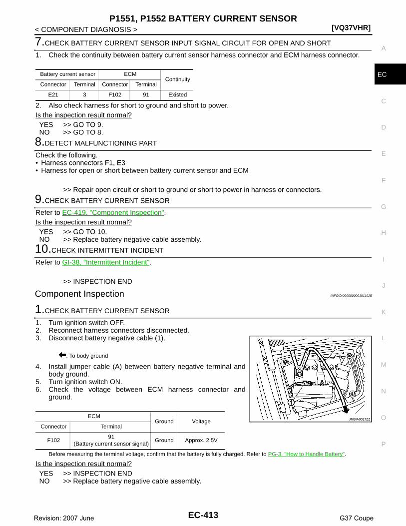
P1551, P1552 BATTERY CURRENT SENSOR[VQ37VHR]
C
D
E
F
G
H
I
J
K
L
M
A
C
N
P
O
< COMPONENT DIAGNOSIS >
E
7.CHECK BATTERY CURRENT SENSOR INPUT SIGNAL CIRCUIT FOR OPEN AND SHORT
1. Check the continuity between battery current sensor harness connector and ECM harness connector.
2. Also check harness for short to ground and short to power.Is the inspection result normal?YES >> GO TO 9.NO >> GO TO 8.
8.DETECT MALFUNCTIONING PART
Check the following.• Harness connectors F1, E3• Harness for open or short between battery current sensor and ECM
>> Repair open circuit or short to ground or short to power in harness or connectors.
9.CHECK BATTERY CURRENT SENSOR
Refer to EC-419, "Component Inspection".Is the inspection result normal?YES >> GO TO 10.NO >> Replace battery negative cable assembly.
10.CHECK INTERMITTENT INCIDENT
Refer to GI-38, "Intermittent Incident".
>> INSPECTION END
Component Inspection INFOID:0000000001911025
1.CHECK BATTERY CURRENT SENSOR
1. Turn ignition switch OFF.2. Reconnect harness connectors disconnected.3. Disconnect battery negative cable (1).
4. Install jumper cable (A) between battery negative terminal andbody ground.
5. Turn ignition switch ON.6. Check the voltage between ECM harness connector and
ground.
Before measuring the terminal voltage, confirm that the battery is fully charged. Refer to PG-3, "How to Handle Battery".
Is the inspection result normal?YES >> INSPECTION ENDNO >> Replace battery negative cable assembly.
Battery current sensor ECMContinuity
Connector Terminal Connector Terminal
E21 3 F102 91 Existed
: To body ground
ECMGround Voltage
Connector Terminal
F10291
(Battery current sensor signal)Ground Approx. 2.5V
JMBIA0027ZZ
EC-413Revision: 2007 June G37 Coupe

[VQ37VHR]P1553 BATTERY CURRENT SENSOR
< COMPONENT DIAGNOSIS >
P1553 BATTERY CURRENT SENSOR
Description INFOID:0000000001911022
The power generation voltage variable control enables fuel consumption to be decreased by reducing theengine load which is caused by the power generation of the generator. The battery current sensor is installedto the battery cable at the negative terminal. The sensor measures the charging/discharging current of the bat-tery. Based on the sensor signal, ECM judges whether or not the power generation voltage variable control isperformed. When performing the power generation voltage variable control, ECM calculates the target powergeneration voltage based on the sensor signal. And ECM sends the calculated value as the power generationcommand value to IPDM E/R. For the details of the power generation voltage variable control, refer to CHG-8,"System Description".CAUTION:Do not connect the electrical component or the ground wire directly to the battery terminal. The con-nection causes the malfunction of the power generation voltage variable control, and then the batterydischarge may occur.
DTC Logic INFOID:0000000001734235
DTC DETECTION LOGICNOTE:If DTC P1553 is displayed with DTC P0643, first perform the trouble diagnosis for P0643. Refer to EC-358,"DTC Logic".
DTC CONFIRMATION PROCEDURE
1.PRECONDITIONING
If DTC Confirmation Procedure has been previously conducted, always perform the following before conduct-ing the next test. 1. Turn ignition switch OFF and wait at least 10 seconds.2. Turn ignition switch ON.3. Turn ignition switch OFF and wait at least 10 seconds.TESTING CONDITION:Before performing the following procedure, confirm that battery voltage is more than 8V at idle.
>> GO TO 2.
2.PERFORM DTC CONFIRMATION PROCEDURE
1. Start engine and wait at least 10 seconds.2. Check 1st trip DTC.Is 1st trip DTC detected?YES >> Go to EC-414, "Diagnosis Procedure".NO >> INSPECTION END
Diagnosis Procedure INFOID:0000000001911026
1.CHECK GROUND CONNECTION
1. Turn ignition switch OFF.2. Check ground connection M95. Refer to Ground Inspection in GI-41, "Circuit Inspection".Is the inspection result normal?YES >> GO TO 2.NO >> Repair or replace ground connection.
DTC No. Trouble diagnosis name DTC detecting condition Possible cause
P1553Battery current sensor perfor-mance
The signal voltage transmitted from the sensor to ECM is higher than the amount of the maximum power generation.
• Harness or connectors(Battery current sensor circuit is open or shorted.)
• Battery current sensor
EC-414Revision: 2007 June G37 Coupe

P1553 BATTERY CURRENT SENSOR[VQ37VHR]
C
D
E
F
G
H
I
J
K
L
M
A
C
N
P
O
< COMPONENT DIAGNOSIS >
E
2.CHECK BATTERY CURRENT SENSOR POWER SUPPLY CIRCUIT-I
1. Disconnect battery current sensor harness connector.2. Turn ignition switch ON.3. Check the voltage between battery current sensor harness connector and ground.
Is the inspection result normal?YES >> GO TO 5.NO >> GO TO 3.
3.CHECK BATTERY CURRENT SENSOR POWER SUPPLY CIRCUIT-II
1. Turn ignition switch OFF.2. Disconnect ECM harness connector.3. Check the continuity between battery current sensor harness connector and ECM harness connector.
4. Also check harness for short to ground and short to power.Is the inspection result normal?YES >> GO TO 5.NO >> GO TO 4.
4.DETECT MALFUNCTIONING PART
Check the following.• Harness connectors F1, E3• Harness for open or short between battery current sensor and ECM
>> Repair open circuit or short to ground or short to power in harness connectors.
5.CHECK BATTERY CURRENT SENSOR GROUND CIRCUIT FOR OPEN AND SHORT
1. Turn ignition switch OFF.2. Disconnect ECM harness connector.3. Check the continuity between battery current sensor harness connector and ECM harness connector.
4. Also check harness for short to ground and short to power.Is the inspection result normal?YES >> GO TO 7.NO >> GO TO 6.
6.DETECT MALFUNCTIONING PART
Check the following.• Harness connectors F1, E3• Harness for open or short between battery current sensor and ECM
>> Repair open circuit or short to ground or short to power in harness or connectors.
7.CHECK BATTERY CURRENT SENSOR INPUT SIGNAL CIRCUIT FOR OPEN AND SHORT
Battery current sensorGround Voltage
Connector Terminal
E21 1 Ground Approx. 5V
Battery current sensor ECMContinuity
Connector Terminal Connector Terminal
E21 1 F102 64 Existed
Battery current sensor ECMContinuity
Connector Terminal Connector Terminal
E21 2 F102 95 Existed
EC-415Revision: 2007 June G37 Coupe

[VQ37VHR]P1553 BATTERY CURRENT SENSOR
< COMPONENT DIAGNOSIS >1. Check the continuity between battery current sensor harness connector and ECM harness connector.
2. Also check harness for short to ground and short to power.Is the inspection result normal?YES >> GO TO 9.NO >> GO TO 8.
8.DETECT MALFUNCTIONING PART
Check the following.• Harness connectors F1, E3• Harness for open or short between battery current sensor and ECM
>> Repair open circuit or short to ground or short to power in harness or connectors.
9.CHECK BATTERY CURRENT SENSOR
Refer to EC-419, "Component Inspection".Is the inspection result normal?YES >> GO TO 10.NO >> Replace battery negative cable assembly.
10.CHECK INTERMITTENT INCIDENT
Refer to GI-38, "Intermittent Incident".
>> INSPECTION END
Component Inspection INFOID:0000000001911027
1.CHECK BATTERY CURRENT SENSOR
1. Turn ignition switch OFF.2. Reconnect harness connectors disconnected.3. Disconnect battery negative cable (1).
4. Install jumper cable (A) between battery negative terminal andbody ground.
5. Turn ignition switch ON.6. Check the voltage between ECM harness connector and
ground.
Before measuring the terminal voltage, confirm that the battery is fully charged. Refer to PG-3, "How to Handle Battery".
Is the inspection result normal?YES >> INSPECTION ENDNO >> Replace battery negative cable assembly.
Battery current sensor ECMContinuity
Connector Terminal Connector Terminal
E21 3 F102 91 Existed
: To body ground
ECMGround Voltage
Connector Terminal
F10291
(Battery current sensor signal)Ground Approx. 2.5V
JMBIA0027ZZ
EC-416Revision: 2007 June G37 Coupe

P1554 BATTERY CURRENT SENSOR[VQ37VHR]
C
D
E
F
G
H
I
J
K
L
M
A
C
N
P
O
< COMPONENT DIAGNOSIS >
E
P1554 BATTERY CURRENT SENSOR
Description INFOID:0000000001911023
The power generation voltage variable control enables fuel consumption to be decreased by reducing theengine load which is caused by the power generation of the generator. The battery current sensor is installedto the battery cable at the negative terminal. The sensor measures the charging/discharging current of the bat-tery. Based on the sensor signal, ECM judges whether or not the power generation voltage variable control isperformed. When performing the power generation voltage variable control, ECM calculates the target powergeneration voltage based on the sensor signal. And ECM sends the calculated value as the power generationcommand value to IPDM E/R. For the details of the power generation voltage variable control, refer to CHG-8,"System Description".CAUTION:Do not connect the electrical component or the ground wire directly to the battery terminal. The con-nection causes the malfunction of the power generation voltage variable control, and then the batterydischarge may occur.
DTC Logic INFOID:0000000001734239
DTC DETECTION LOGICNOTE:If DTC P1554 is displayed with DTC P0643, first perform the trouble diagnosis for DTC P0643. Refer to EC-358, "DTC Logic".
DTC CONFIRMATION PROCEDURE
1.PERFORM COMPONENT FUNCTION CHECK
Perform component function check. Refer to EC-417, "Component Function Check".NOTE:Use component function check to check the overall function of the battery current sensor circuit. During thischeck, a 1st trip DTC might not be confirmed.Is the inspection result normal?YES >> INSPECTION ENDNO >> Go to EC-418, "Diagnosis Procedure".
Component Function Check INFOID:0000000001734240
1.PRECONDITIONING
TESTING CONDITION:• Before performing the following procedure, confirm that battery voltage is more than 12.8V at idle.• Before performing the following procedure, confirm that all load switches and A/C switch are turned
OFF.
>> GO TO 2.
2.PERFORM COMPONENT FUNCTION CHECK
With CONSULT-III1. Start engine and let it idle.2. Select “BAT CUR SEN” in “DATA MONITOR” mode with CONSULT-III.3. Check “BAT CUR SEN” indication for 10 seconds.
“BAT CUR SEN” should be above 2,300mV at least once.Without CONSULT-III
1. Start engine and let it idle.
DTC No. Trouble diagnosis name DTC detecting condition Possible cause
P1554Battery current sensor perfor-mance
The output voltage of the battery current sensor is lower than the specified value while the battery voltage is high enough.
• Harness or connectors(Battery current sensor circuit is open or shorted.)
• Battery current sensor
EC-417Revision: 2007 June G37 Coupe

[VQ37VHR]P1554 BATTERY CURRENT SENSOR
< COMPONENT DIAGNOSIS >2. Check the voltage between ECM harness connector and ground.
Is the inspection result normal?YES >> INSPECTION ENDNO >> Go to EC-418, "Diagnosis Procedure"
Diagnosis Procedure INFOID:0000000001911028
1.CHECK GROUND CONNECTION
1. Turn ignition switch OFF.2. Check ground connection M95. Refer to Ground Inspection in GI-41, "Circuit Inspection".Is the inspection result normal?YES >> GO TO 2.NO >> Repair or replace ground connection.
2.CHECK BATTERY CURRENT SENSOR POWER SUPPLY CIRCUIT-I
1. Disconnect battery current sensor harness connector.2. Turn ignition switch ON.3. Check the voltage between battery current sensor harness connector and ground.
Is the inspection result normal?YES >> GO TO 5.NO >> GO TO 3.
3.CHECK BATTERY CURRENT SENSOR POWER SUPPLY CIRCUIT-II
1. Turn ignition switch OFF.2. Disconnect ECM harness connector.3. Check the continuity between battery current sensor harness connector and ECM harness connector.
4. Also check harness for short to ground and short to power.Is the inspection result normal?YES >> GO TO 5.NO >> GO TO 4.
4.DETECT MALFUNCTIONING PART
Check the following.• Harness connectors F1, E3• Harness for open or short between battery current sensor and ECM
>> Repair open circuit or short to ground or short to power in harness connectors.
5.CHECK BATTERY CURRENT SENSOR GROUND CIRCUIT FOR OPEN AND SHORT
1. Turn ignition switch OFF.2. Disconnect ECM harness connector.
ECMGround Voltage
Connector Terminal
F10291
(Battery current sensor signal)Ground Above 2.3V at least once
Battery current sensorGround Voltage
Connector Terminal
E21 1 Ground Approx. 5V
Battery current sensor ECMContinuity
Connector Terminal Connector Terminal
E21 1 F102 64 Existed
EC-418Revision: 2007 June G37 Coupe

P1554 BATTERY CURRENT SENSOR[VQ37VHR]
C
D
E
F
G
H
I
J
K
L
M
A
C
N
P
O
< COMPONENT DIAGNOSIS >
E
3. Check the continuity between battery current sensor harness connector and ECM harness connector.
4. Also check harness for short to ground and short to power.Is the inspection result normal?YES >> GO TO 7.NO >> GO TO 6.
6.DETECT MALFUNCTIONING PART
Check the following.• Harness connectors F1, E3• Harness for open or short between battery current sensor and ECM
>> Repair open circuit or short to ground or short to power in harness or connectors.
7.CHECK BATTERY CURRENT SENSOR INPUT SIGNAL CIRCUIT FOR OPEN AND SHORT
1. Check the continuity between battery current sensor harness connector and ECM harness connector.
2. Also check harness for short to ground and short to power.Is the inspection result normal?YES >> GO TO 9.NO >> GO TO 8.
8.DETECT MALFUNCTIONING PART
Check the following.• Harness connectors F1, E3• Harness for open or short between battery current sensor and ECM
>> Repair open circuit or short to ground or short to power in harness or connectors.
9.CHECK BATTERY CURRENT SENSOR
Refer to EC-419, "Component Inspection".Is the inspection result normal?YES >> GO TO 10.NO >> Replace battery negative cable assembly.
10.CHECK INTERMITTENT INCIDENT
Refer to GI-38, "Intermittent Incident".
>> INSPECTION END
Component Inspection INFOID:0000000001911029
1.CHECK BATTERY CURRENT SENSOR
1. Turn ignition switch OFF.2. Reconnect harness connectors disconnected.
Battery current sensor ECMContinuity
Connector Terminal Connector Terminal
E21 2 F102 95 Existed
Battery current sensor ECMContinuity
Connector Terminal Connector Terminal
E21 3 F102 91 Existed
EC-419Revision: 2007 June G37 Coupe
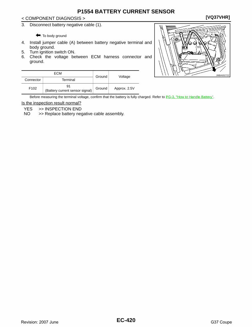
[VQ37VHR]P1554 BATTERY CURRENT SENSOR
< COMPONENT DIAGNOSIS >3. Disconnect battery negative cable (1).
4. Install jumper cable (A) between battery negative terminal andbody ground.
5. Turn ignition switch ON.6. Check the voltage between ECM harness connector and
ground.
Before measuring the terminal voltage, confirm that the battery is fully charged. Refer to PG-3, "How to Handle Battery".
Is the inspection result normal?YES >> INSPECTION ENDNO >> Replace battery negative cable assembly.
: To body ground
ECMGround Voltage
Connector Terminal
F10291
(Battery current sensor signal)Ground Approx. 2.5V
JMBIA0027ZZ
EC-420Revision: 2007 June G37 Coupe

P1564 ASCD STEERING SWITCH[VQ37VHR]
C
D
E
F
G
H
I
J
K
L
M
A
C
N
P
O
< COMPONENT DIAGNOSIS >
E
P1564 ASCD STEERING SWITCH
Description INFOID:0000000001734243
ASCD steering switch has variant values of electrical resistance for each button. ECM reads voltage variationof switch, and determines which button is operated.Refer to EC-62, "System Description" for the ASCD function.
DTC Logic INFOID:0000000001734244
DTC DETECTION LOGICNOTE:If DTC P1564 is displayed with DTC P0605, first perform the trouble diagnosis for DTC P0605. Refer toEC-356, "DTC Logic".
DTC CONFIRMATION PROCEDURE
1.PRECONDITIONING
If DTC Confirmation Procedure has been previously conducted, always perform the following before conduct-ing the next test. 1. Turn ignition switch OFF and wait at least 10 seconds.2. Turn ignition switch ON.3. Turn ignition switch OFF and wait at least 10 seconds.
>> GO TO 2.
2.PERFORM DTC CONFIRMATION PROCEDURE
1. Turn ignition switch ON and wait at least 10 seconds.2. Press MAIN switch for at least 10 seconds, then release it and wait at least 10 seconds.3. Press CANCEL switch for at least 10 seconds, then release it and wait at least 10 seconds.4. Press RESUME/ACCELERATE switch for at least 10 seconds, then release it and wait at least 10 sec-
onds.5. Press SET/COAST switch for at least 10 seconds, then release it and wait at least 10 seconds.6. Check DTC.Is DTC detected?YES >> Go to EC-421, "Diagnosis Procedure".NO >> INSPECTION END
Diagnosis Procedure INFOID:0000000001734245
1.CHECK GROUND CONNECTION
1. Turn ignition switch OFF.2. Check ground connection M95. Refer to Ground Inspection in GI-41, "Circuit Inspection".Is the inspection result normal?YES >> GO TO 2.NO >> Repair or replace ground connection.
2.CHECK ASCD STEERING SWITCH CIRCUIT
With CONSULT-III
DTC No.Trouble diagnosis
nameDTC detecting condition Possible cause
P1564 ASCD steering switch
• An excessively high voltage signal from the ASCD steering switch is sent to ECM.
• ECM detects that input signal from the ASCD steering switch is out of the specified range.
• ECM detects that the ASCD steering switch is stuck ON.
• Harness or connectors(The switch circuit is open or shorted.)
• ASCD steering switch• ECM
EC-421Revision: 2007 June G37 Coupe

[VQ37VHR]P1564 ASCD STEERING SWITCH
< COMPONENT DIAGNOSIS >1. Turn ignition switch ON.2. Select “MAIN SW”, “CANCEL SW”, “RESUME/ACC SW” and “SET SW” in “DATA MONITOR” mode with
CONSULT-III.3. Check each item indication under the following conditions.
Without CONSULT-III1. Turn ignition switch ON.2. Check the voltage between ECM harness connector and ground.
Is the inspection result normal?YES >> GO TO 8.NO >> GO TO 3.
3.CHECK ASCD STEERING SWITCH GROUND CIRCUIT FOR OPEN AND SHORT
1. Turn ignition switch OFF.2. Disconnect ECM harness connector.3. Disconnect combination switch harness connector M303.4. Check the continuity between combination switch and ECM harness connector.
5. Also check harness for short to ground and short to power.Is the inspection result normal?YES >> GO TO 5.NO >> GO TO 4.
4.DETECT MALFUNCTIONING PART
Check the following.• Combination switch (spiral cable)• Harness for open and short between ECM and combination switch
>> Repair open circuit or short to ground or short to power in harness or connectors.
5.CHECK ASCD STEERING SWITCH INPUT SIGNAL CIRCUIT FOR OPEN AND SHORT
1. Check the continuity between combination switch and ECM harness connector.
Monitor item Condition Indication
MAIN SW MAIN switchPressed ON
Released OFF
CANCEL SW CANCEL switchPressed ON
Released OFF
RESUME/ACC SWRESUME/ACCEL-ERATE switch
Pressed ON
Released OFF
SET SW SET/COAST switchPressed ON
Released OFF
ECMGround Condition Voltage
Connector Terminal
M107101
(ASCD steering switch signal)Ground
MAIN switch: Pressed Approx. 0V
CANCEL switch: Pressed Approx. 1V
SET/COAST switch: Pressed Approx. 2V
RESUME/ACCELERATE switch: Pressed Approx. 3V
All ASCD steering switches: Released Approx. 4V
Combination switch ECMContinuity
Terminal Connector Terminal
16 M107 108 Existed
EC-422Revision: 2007 June G37 Coupe
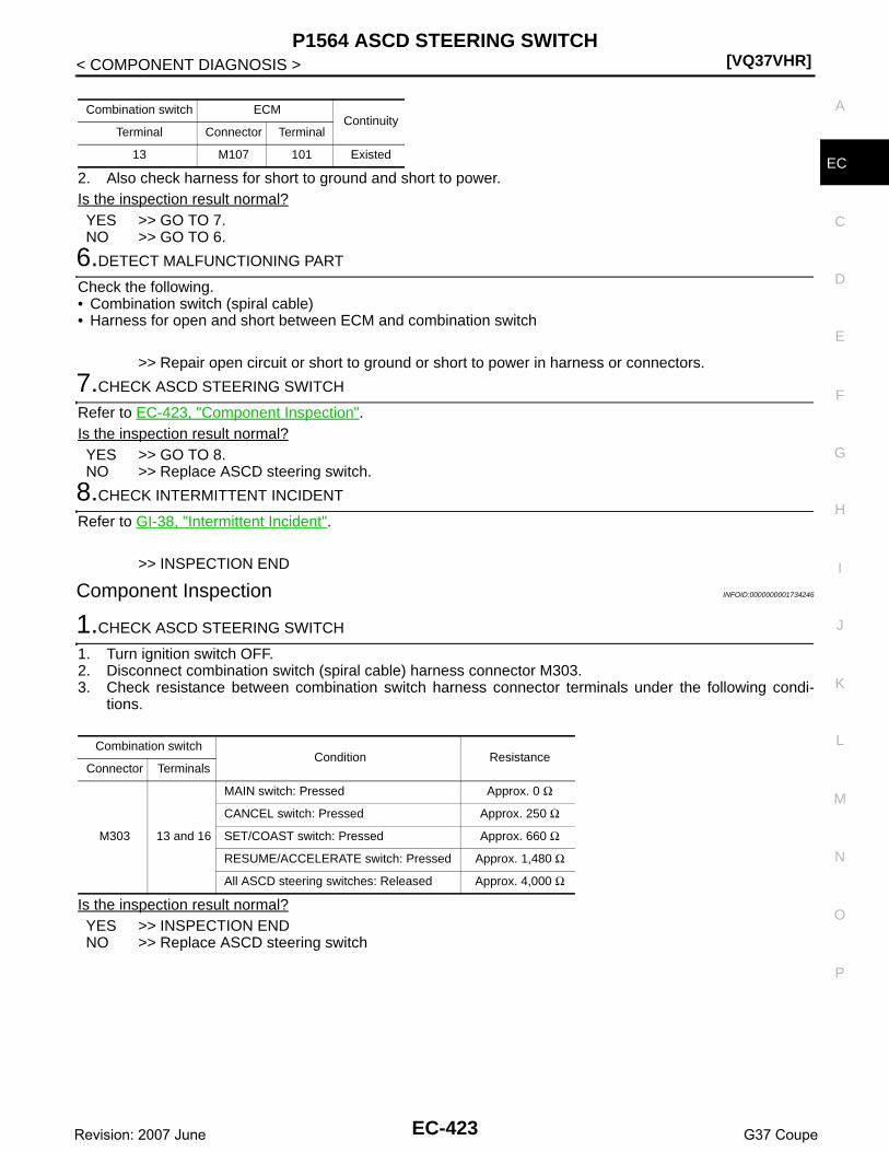
P1564 ASCD STEERING SWITCH[VQ37VHR]
C
D
E
F
G
H
I
J
K
L
M
A
C
N
P
O
< COMPONENT DIAGNOSIS >
E2. Also check harness for short to ground and short to power.Is the inspection result normal?YES >> GO TO 7.NO >> GO TO 6.
6.DETECT MALFUNCTIONING PART
Check the following.• Combination switch (spiral cable)• Harness for open and short between ECM and combination switch
>> Repair open circuit or short to ground or short to power in harness or connectors.
7.CHECK ASCD STEERING SWITCH
Refer to EC-423, "Component Inspection".Is the inspection result normal?YES >> GO TO 8.NO >> Replace ASCD steering switch.
8.CHECK INTERMITTENT INCIDENT
Refer to GI-38, "Intermittent Incident".
>> INSPECTION END
Component Inspection INFOID:0000000001734246
1.CHECK ASCD STEERING SWITCH
1. Turn ignition switch OFF.2. Disconnect combination switch (spiral cable) harness connector M303.3. Check resistance between combination switch harness connector terminals under the following condi-
tions.
Is the inspection result normal?YES >> INSPECTION ENDNO >> Replace ASCD steering switch
Combination switch ECMContinuity
Terminal Connector Terminal
13 M107 101 Existed
Combination switchCondition Resistance
Connector Terminals
M303 13 and 16
MAIN switch: Pressed Approx. 0 Ω
CANCEL switch: Pressed Approx. 250 Ω
SET/COAST switch: Pressed Approx. 660 Ω
RESUME/ACCELERATE switch: Pressed Approx. 1,480 Ω
All ASCD steering switches: Released Approx. 4,000 Ω
EC-423Revision: 2007 June G37 Coupe

[VQ37VHR]P1564 ICC STEERING SWITCH
< COMPONENT DIAGNOSIS >
P1564 ICC STEERING SWITCH
Description INFOID:0000000001734247
ICC steering switch has variant values of electrical resistance for each button. ECM reads voltage variation ofswitch, and determines which button is operated.Refer to CCS-15, "System Description" for the ICC function.
DTC Logic INFOID:0000000001734248
DTC DETECTION LOGICNOTE:If DTC P1564 is displayed with DTC P0605, first perform the trouble diagnosis for DTC P0605. Refer toEC-356, "DTC Logic".
DTC CONFIRMATION PROCEDURE
1.PRECONDITIONING
If DTC Confirmation Procedure has been previously conducted, always perform the following before conduct-ing the next test. 1. Turn ignition switch OFF and wait at least 10 seconds.2. Turn ignition switch ON.3. Turn ignition switch OFF and wait at least 10 seconds.
>> GO TO 2.
2.PERFORM DTC CONFIRMATION PROCEDURE
1. Turn ignition switch ON and wait at least 10 seconds.2. Press MAIN switch for at least 10 seconds, then release it and wait at least 10 seconds.3. Press CANCEL switch for at least 10 seconds, then release it and wait at least 10 seconds.4. Press RESUME/ACCELERATE switch for at least 10 seconds, then release it and wait at least 10 sec-
onds.5. Press SET/COAST switch for at least 10 seconds, then release it and wait at least 10 seconds.6. Press DISTANCE switch for at least 10 seconds, then release it and wait at least 10 seconds.7. Check DTC.Is DTC detected?YES >> Go to EC-424, "Diagnosis Procedure".NO >> INSPECTION END
Diagnosis Procedure INFOID:0000000001734249
1.CHECK GROUND CONNECTION
1. Turn ignition switch OFF.2. Check ground connection M95. Refer to Ground Inspection in GI-41, "Circuit Inspection".Is the inspection result normal?YES >> GO TO 2.NO >> Repair or replace ground connection.
2.CHECK ICC STEERING SWITCH CIRCUIT
With CONSULT-III
DTC No.Trouble diagnosis
nameDTC detecting condition Possible cause
P1564 ICC steering switch
• An excessively high voltage signal from the ICC steering switch is sent to ECM.
• ECM detects that input signal from the ICC steering switch is out of the specified range.
• ECM detects that the ICC steering switch is stuck ON.
• Harness or connectors(The switch circuit is open or shorted.)
• ICC steering switch• ECM
EC-424Revision: 2007 June G37 Coupe
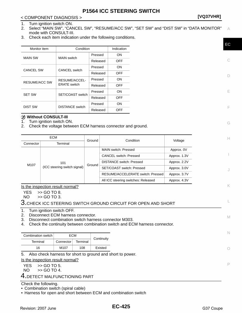
P1564 ICC STEERING SWITCH[VQ37VHR]
C
D
E
F
G
H
I
J
K
L
M
A
C
N
P
O
< COMPONENT DIAGNOSIS >
E
1. Turn ignition switch ON.2. Select “MAIN SW”, “CANCEL SW”, “RESUME/ACC SW”, “SET SW” and “DIST SW” in “DATA MONITOR”
mode with CONSULT-III.3. Check each item indication under the following conditions.
Without CONSULT-III1. Turn ignition switch ON.2. Check the voltage between ECM harness connector and ground.
Is the inspection result normal?YES >> GO TO 8.NO >> GO TO 3.
3.CHECK ICC STEERING SWITCH GROUND CIRCUIT FOR OPEN AND SHORT
1. Turn ignition switch OFF.2. Disconnect ECM harness connector.3. Disconnect combination switch harness connector M303.4. Check the continuity between combination switch and ECM harness connector.
5. Also check harness for short to ground and short to power.Is the inspection result normal?YES >> GO TO 5.NO >> GO TO 4.
4.DETECT MALFUNCTIONING PART
Check the following.• Combination switch (spiral cable)• Harness for open and short between ECM and combination switch
Monitor item Condition Indication
MAIN SW MAIN switchPressed ON
Released OFF
CANCEL SW CANCEL switchPressed ON
Released OFF
RESUME/ACC SWRESUME/ACCEL-ERATE switch
Pressed ON
Released OFF
SET SW SET/COAST switchPressed ON
Released OFF
DIST SW DISTANCE switchPressed ON
Released OFF
ECMGround Condition Voltage
Connector Terminal
M107101
(ICC steering switch signal)Ground
MAIN switch: Pressed Approx. 0V
CANCEL switch: Pressed Approx. 1.3V
DISTANCE switch: Pressed Approx. 2.2V
SET/COAST switch: Pressed Approx. 3.0V
RESUME/ACCELERATE switch: Pressed Approx. 3.7V
All ICC steering switches: Released Approx. 4.3V
Combination switch ECMContinuity
Terminal Connector Terminal
16 M107 108 Existed
EC-425Revision: 2007 June G37 Coupe

[VQ37VHR]P1564 ICC STEERING SWITCH
< COMPONENT DIAGNOSIS >>> Repair open circuit or short to ground or short to power in harness or connectors.
5.CHECK ICC STEERING SWITCH INPUT SIGNAL CIRCUIT FOR OPEN AND SHORT
1. Check the continuity between combination switch and ECM harness connector.
2. Also check harness for short to ground and short to power.Is the inspection result normal?YES >> GO TO 7.NO >> GO TO 6.
6.DETECT MALFUNCTIONING PART
Check the following.• Combination switch (spiral cable)• Harness for open and short between ECM and combination switch
>> Repair open circuit or short to ground or short to power in harness or connectors.
7.CHECK ICC STEERING SWITCH
Refer to EC-426, "Component Inspection".Is the inspection result normal?YES >> GO TO 8.NO >> Replace ICC steering switch.
8.CHECK INTERMITTENT INCIDENT
Refer to GI-38, "Intermittent Incident".
>> INSPECTION END
Component Inspection INFOID:0000000001734250
1.CHECK ICC STEERING SWITCH
1. Turn ignition switch OFF.2. Disconnect combination switch (spiral cable) harness connector M303.3. Check resistance between combination switch harness connector terminals under the following condi-
tions.
Is the inspection result normal?YES >> INSPECTION ENDNO >> Replace ICC steering switch
Combination switch ECMContinuity
Terminal Connector Terminal
13 M107 101 Existed
Combination switchCondition Resistance
Connector Terminals
M303 13 and 16
MAIN switch: Pressed Approx. 0 Ω
CANCEL switch: Pressed Approx. 310 Ω
DISTANCE switch: Pressed Approx. 740 Ω
SET/COAST switch: Pressed Approx. 1,400 Ω
RESUME/ACCELERATE switch: Pressed Approx. 2,600 Ω
All ICC steering switches: Released Approx. 5,500 Ω
EC-426Revision: 2007 June G37 Coupe

P1568 ICC FUNCTION[VQ37VHR]
C
D
E
F
G
H
I
J
K
L
M
A
C
N
P
O
< COMPONENT DIAGNOSIS >
E
P1568 ICC FUNCTION
DTC Logic INFOID:0000000001734251
DTC DETECTION LOGICNOTE:• If DTC P1568 is displayed with DTC U1000 or U1001, first perform the trouble diagnosis for DTC
U1000, U1001. Refer to EC-146, "DTC Logic".• If DTC P1568 is displayed with DTC U1010, first perform the trouble diagnosis for DTC U1010. Refer
to EC-147, "DTC Logic".• If DTC P1568 is displayed with DTC P0605, first perform the trouble diagnosis for DTC P0605. Refer
to EC-356, "DTC Logic".
DTC CONFIRMATION PROCEDURE
1.PRECONDITIONING
If DTC Confirmation Procedure has been previously conducted, always perform the following before conduct-ing the next test. 1. Turn ignition switch OFF and wait at least 10 seconds.2. Turn ignition switch ON.3. Turn ignition switch OFF and wait at least 10 seconds.TESTING CONDITION:Step 4 may be conducted with the drive wheels lifted in the shop or by driving the vehicle. If a road testis expected to be easier, it is unnecessary to lift the vehicle.
>> GO TO 2.
2.PERFORM DTC CONFIRMATION PROCEDURE
1. Turn ignition switch ON.2. Press MAIN switch on ICC steering switch.3. Drive the vehicle at more than 40 km/h (25 MPH).
CAUTION:Always drive vehicle at a safe speed.
4. Press SET/COAST switch.5. Check DTC.Is DTC detected?YES >> Go to EC-427, "Diagnosis Procedure".NO >> INSPECTION END
Diagnosis Procedure INFOID:0000000001734252
1.REPLACE ICC SENSOR INTEGRATED UNIT
1. Replace ICC sensor integrated unit.2. Perform CCS-11, "ACTION TEST : Special Repair Requirement (Vehicle-To-Vehicle Distance Control
Mode)".3. Check DTC of ICC sensor integrated unit. Refer to CCS-22, "Diagnosis Description".
>> INSPECTION END
DTC No.Trouble Diagnosis
NameDTC Detecting Condition Possible Cause
P1568 ICC functionECM detects a difference between signals from ICC sensor integrated unit is out of spec-ified range.
• Harness or connectors(The CAN communication line is open or shorted.)
• ICC sensor integrated unit• ECM
EC-427Revision: 2007 June G37 Coupe

[VQ37VHR]P1572 ASCD BRAKE SWITCH
< COMPONENT DIAGNOSIS >
P1572 ASCD BRAKE SWITCH
Description INFOID:0000000001734253
When the brake pedal is depressed, ASCD brake switch is turned OFF and stop lamp switch is turned ON.ECM detects the state of the brake pedal by this input of two kinds (ON/OFF signal).Refer to EC-62, "System Description" for the ASCD function.
DTC Logic INFOID:0000000001734254
DTC DETECTION LOGICNOTE:• If DTC P1572 is displayed with DTC P0605, first perform the trouble diagnosis for DTC P0605. Refer
to EC-356, "DTC Logic".• This self-diagnosis has the one trip detection logic. When malfunction A is detected, DTC is not
stored in ECM memory. And in that case, 1st trip DTC and 1st trip freeze frame data are displayed.1st trip DTC is erased when ignition switch OFF. And even when malfunction A is detected in twoconsecutive trips, DTC is not stored in ECM memory.
DTC CONFIRMATION PROCEDURE
1.PRECONDITIONING
If DTC Confirmation Procedure has been previously conducted, always perform the following before conduct-ing the next test. 1. Turn ignition switch OFF and wait at least 10 seconds.2. Turn ignition switch ON.3. Turn ignition switch OFF and wait at least 10 seconds.NOTE:Procedure for malfunction B is not described here. It takes extremely long time to complete procedure for mal-function B. By performing procedure for malfunction A, the incident that causes malfunction B can bedetected.
>> GO TO 2.
2.PERFORM DTC CONFIRMATION PROCEDURE FOR MALFUNCTION A
With CONSULT-III1. Start engine (VDC switch OFF).2. Select “DATA MONITOR” mode with CONSULT-III.3. Press MAIN switch and make sure that CRUISE lamp lights up.4. Drive the vehicle for at least 5 consecutive seconds under the following conditions.
CAUTION:Always drive vehicle at a safe speed.NOTE:This procedure may be conducted with the drive wheels lifted in the shop or by driving the vehicle.If a road test is expected to be easier, it is unnecessary to lift the vehicle.
DTC No.Trouble diagnosis
nameDTC detecting condition Possible cause
P1572 ASCD brake switch
A)
When the vehicle speed is above 30 km/h (19 MPH), ON signals from the stop lamp switch and the ASCD brake switch are sent to the ECM at the same time.
• Harness or connectors(The stop lamp switch circuit is shorted.)
• Harness or connectors(The ASCD brake switch circuit is shorted.)
• Stop lamp switch• ASCD brake switch• Incorrect stop lamp switch installation• Incorrect ASCD brake switch installation• ECM
B)ASCD brake switch signal is not sent to ECM for extremely long time while the ve-hicle is driving.
VHCL SPEED SE More than 30 km/h (19 mph)
Selector lever Suitable position
EC-428Revision: 2007 June G37 Coupe

P1572 ASCD BRAKE SWITCH[VQ37VHR]
C
D
E
F
G
H
I
J
K
L
M
A
C
N
P
O
< COMPONENT DIAGNOSIS >
E
5. Check 1st trip DTC.With GST
Follow the procedure “With CONSULT-III” above.Is 1st trip DTC detected?YES >> Go to EC-429, "Diagnosis Procedure".NO >> GO TO 3.
3.PERFORM DTC CONFIRMATION PROCEDURE
With CONSULT-III1. Drive the vehicle for at least 5 consecutive seconds under the following conditions.
CAUTION:Always drive vehicle at a safe speed.NOTE:This procedure may be conducted with the drive wheels lifted in the shop or by driving the vehicle.If a road test is expected to be easier, it is unnecessary to lift the vehicle.
2. Check 1st trip DTC.With GST
Follow the procedure “With CONSULT-III” above.Is 1st trip DTC detected?YES >> Go to EC-429, "Diagnosis Procedure".NO >> INSPECTION END
Diagnosis Procedure INFOID:0000000001734255
1.CHECK OVERALL FUNCTION-I
With CONSULT-III1. Turn ignition switch ON.2. Select “BRAKE SW1” in “DATA MONITOR” mode with CONSULT-III.3. Check “BRAKE SW1” indication under the following conditions.
Without CONSULT-III1. Turn ignition switch ON.2. Check the voltage between ECM harness connector and ground.
Is the inspection result normal?YES >> GO TO 2.NO-1 >> A/T models: GO TO 3.NO-2 >> M/T models: GO TO 8.
2.CHECK OVERALL FUNCTION-II
With CONSULT-III
VHCL SPEED SE More than 30 km/h (19 mph)
Selector lever Suitable position
Driving locationDepress the brake pedal for more than five seconds so as not to come off from the above-mentioned vehicle speed.
Monitor item Condition Indication
BRAKE SW1Brake pedal (A/T)Brake pedal and clutch pedal (M/T)
Slightly depressed OFF
Fully released ON
ECMGround Condition Voltage
Connector Terminal
M107126
(ASCD brake switch signal)Ground
Brake pedal (A/T)Brake pedal and clutch pedal (M/T)
Slightly depressed Approx. 0V
Fully released Battery voltage
EC-429Revision: 2007 June G37 Coupe

[VQ37VHR]P1572 ASCD BRAKE SWITCH
< COMPONENT DIAGNOSIS >Select “BRAKE SW2” and check indication under the following conditions.
Without CONSULT-IIICheck the voltage between ECM harness connector and ground.
Is the inspection result normal?YES >> GO TO 21.NO >> GO TO 16.
3.CHECK ASCD BRAKE SWITCH POWER SUPPLY CIRCUIT
1. Turn ignition switch OFF.2. Disconnect ASCD brake switch harness connector.3. Turn ignition switch ON.4. Check the voltage between ASCD brake switch harness connector and ground.
Is the inspection result normal?YES >> GO TO 5.NO >> GO TO 4.
4.DETECT MALFUNCTIONING PART
Check the following.• Fuse block (J/B) connector E103• 10A fuse (No. 3)• Harness for open or short between ASCD brake switch and fuse
>> Repair open circuit or short to ground in harness or connectors.
5.CHECK ASCD BRAKE SWITCH INPUT SIGNAL CIRCUIT FOR OPEN AND SHORT
1. Turn ignition switch OFF.2. Disconnect ECM harness connector.3. Check the continuity between ASCD brake switch harness connector and ECM harness connector.
4. Also check harness for short to ground and short to power.Is the inspection result normal?YES >> GO TO 7.NO >> GO TO 6.
6.DETECT MALFUNCTIONING PART
Check the following.• Harness connectors E106, M6
Monitor item Condition Indication
BRAKE SW2 Brake pedalSlightly depressed ON
Fully released OFF
ECMGround Condition Voltage
Connector Terminal
M107122
(Stop lamp switch signal)Ground Brake pedal
Slightly depressed Battery voltage
Fully released Approx. 0V
ASCD brake switchGround Voltage
Connector Terminal
E109 1 Ground Battery voltage
ASCD brake switch ECMContinuity
Connector Terminal Connector Terminal
E109 2 M107 126 Existed
EC-430Revision: 2007 June G37 Coupe

P1572 ASCD BRAKE SWITCH[VQ37VHR]
C
D
E
F
G
H
I
J
K
L
M
A
C
N
P
O
< COMPONENT DIAGNOSIS >
E
• Harness for open or short between ECM and ASCD brake switch
>> Repair open circuit or short to ground or short to power in harness or connectors.
7.CHECK ASCD BRAKE SWITCH
Refer to EC-433, "Component Inspection (ASCD Brake Switch)"Is the inspection result normal?YES >> GO TO 21.NO >> Replace ASCD brake switch.
8.CHECK ASCD BRAKE SWITCH CIRCUIT
1. Turn ignition switch OFF.2. Disconnect ASCD brake switch harness connector.3. Turn ignition switch ON.4. Check the voltage between ASCD brake switch harness connector and ground.
Is the inspection result normal?YES >> GO TO 13.NO >> GO TO 9.
9.CHECK ASCD BRAKE SWITCH POWER SUPPLY CIRCUIT
1. Turn ignition switch OFF.2. Disconnect ASCD clutch switch harness connector.3. Turn ignition switch ON.4. Check the voltage between ASCD clutch switch harness connector and ground.
Is the inspection result normal?YES >> GO TO 11.NO >> GO TO 10.
10.DETECT MALFUNCTIONING PART
Check the following.• Fuse block (J/B) connector E103• 10A fuse (No. 3)• Harness for open or short between ASCD clutch switch and fuse
>> Repair open circuit or short to ground in harness or connectors.
11.CHECK ASCD BRAKE SWITCH INPUT SIGNAL CIRCUIT FOR OPEN AND SHORT
1. Turn ignition switch OFF.2. Check the continuity between ASCD clutch switch harness connector and ASCD brake switch harness
connector.
3. Also check harness for short to ground and short to power.
ASCD brake switchGround Condition Voltage
Connector Terminal
E109 1 Ground Brake pedalSlightly depressed Approx. 0V
Fully released Battery voltage
ASCD clutch switchGround Voltage
Connector Terminal
E108 1 Ground Battery voltage
ASCD clutch switch ASCD brake switchContinuity
Connector Terminal Connector Terminal
E108 2 E109 1 Existed
EC-431Revision: 2007 June G37 Coupe

[VQ37VHR]P1572 ASCD BRAKE SWITCH
< COMPONENT DIAGNOSIS >Is the inspection result normal?YES >> GO TO 12.NO >> Repair open circuit or short to ground or short to power in harness or connectors.
12.CHECK ASCD CLUTCH SWITCH
Refer to EC-434, "Component Inspection (ASCD Clutch Switch)".Is the inspection result normal?YES >> GO TO 21.NO >> Replace ASCD clutch switch.
13.CHECK ASCD BRAKE SWITCH INPUT SIGNAL CIRCUIT FOR OPEN AND SHORT
1. Turn ignition switch OFF.2. Disconnect ECM harness connector.3. Check the continuity between ASCD brake switch harness connector and ECM harness connector.
4. Also check harness for short to ground and short to power.Is the inspection result normal?YES >> GO TO 15.NO >> GO TO 14.
14.DETECT MALFUNCTIONING PART
Check the following.• Harness connectors E106, M6• Harness for open or short between ECM and ASCD brake switch
>> Repair open circuit or short to ground or short to power in harness or connectors.
15.CHECK ASCD BRAKE SWITCH
Refer to EC-433, "Component Inspection (ASCD Brake Switch)".Is the inspection result normal?YES >> GO TO 21.NO >> Replace ASCD brake switch.
16.CHECK STOP LAMP SWITCH POWER SUPPLY CIRCUIT
1. Turn ignition switch OFF.2. Disconnect stop lamp switch harness connector.3. Check the voltage between stop lamp switch harness connector and ground.
Is the inspection result normal?YES >> GO TO 18.NO >> GO TO 17.
17.DETECT MALFUNCTIONING PART
Check the following.• Fuse block (J/B) connector E103• 10A fuse (No. 7)• Harness for open or short between stop lamp switch and battery
>> Repair open circuit or short to ground or short to power in harness or connectors.
ASCD brake switch ECMContinuity
Connector Terminal Connector Terminal
E109 1 M107 126 Existed
Stop lamp switchGround Voltage
Connector Terminal
E110 1 Ground Battery voltage
EC-432Revision: 2007 June G37 Coupe

P1572 ASCD BRAKE SWITCH[VQ37VHR]
C
D
E
F
G
H
I
J
K
L
M
A
C
N
P
O
< COMPONENT DIAGNOSIS >
E
18.CHECK STOP LAMP SWITCH INPUT SIGNAL CIRCUIT FOR OPEN AND SHORT
1. Disconnect ECM harness connector.2. Check the continuity between stop lamp switch harness connector and ECM harness connector.
3. Also check harness for short to ground and short to power.Is the inspection result normal?YES >> GO TO 20.NO >> GO TO 19.
19.DETECT MALFUNCTIONING PART
Check the following.• Fuse block (J/B) connectors E103, M2• Harness for open or short between ECM and stop lamp switch
>> Repair open circuit or short to ground or short to power in harness or connectors.
20.CHECK STOP LAMP SWITCH
Refer to EC-434, "Component Inspection (Stop Lamp Switch)"Is the inspection result normal?YES >> GO TO 21.NO >> Replace stop lamp switch.
21.CHECK INTERMITTENT INCIDENT
Refer to GI-38, "Intermittent Incident".
>> INSPECTION END
Component Inspection (ASCD Brake Switch) INFOID:0000000001734256
1.CHECK ASCD BRAKE SWITCH-I
1. Turn ignition switch OFF.2. Disconnect ASCD brake switch harness connector.3. Check the continuity between ASCD brake switch terminals under the following conditions.
Is the inspection result normal?YES >> INSPECTION ENDNO >> GO TO 2.
2.CHECK ASCD BRAKE SWITCH-II
1. Adjust ASCD brake switch installation. Refer to BR-7, "Inspection and Adjustment".2. Check the continuity between ASCD brake switch terminals under the following conditions.
Is the inspection result normal?
Stop lamp switch ECMContinuity
Connector Terminal Connector Terminal
E110 2 M107 122 Existed
Terminals Condition Continuity
1 and 2 Brake pedalFully released Existed
Slightly depressed Not existed
Terminals Condition Continuity
1 and 2 Brake pedalFully released Existed
Slightly depressed Not existed
EC-433Revision: 2007 June G37 Coupe

[VQ37VHR]P1572 ASCD BRAKE SWITCH
< COMPONENT DIAGNOSIS >YES >> INSPECTION ENDNO >> Replace ASCD brake switch.
Component Inspection (ASCD Clutch Switch) INFOID:0000000001734257
1.CHECK ASCD CLUTCH SWITCH-I
1. Turn ignition switch OFF.2. Disconnect ASCD clutch switch harness connector.3. Check the continuity between ASCD clutch switch terminals under the following conditions.
Is the inspection result normal?YES >> INSPECTION ENDNO >> GO TO 2.
2.CHECK ASCD CLUTCH SWITCH-II
1. Adjust ASCD clutch switch installation. Refer to CL-5, "Inspection and Adjustment".2. Check the continuity between ASCD clutch switch terminals under the following conditions.
Is the inspection result normal?YES >> INSPECTION ENDNO >> Replace ASCD clutch switch.
Component Inspection (Stop Lamp Switch) INFOID:0000000001734258
1.CHECK STOP LAMP SWITCH-I
1. Turn ignition switch OFF.2. Disconnect stop lamp switch harness connector.3. Check the continuity between stop lamp switch terminals under the following conditions.
Is the inspection result normal?YES >> INSPECTION ENDNO >> GO TO 2.
2.CHECK STOP LAMP SWITCH-II
1. Adjust stop lamp switch installation. Refer to BR-7, "Inspection and Adjustment".2. Check the continuity between stop lamp switch terminals under the following conditions.
Is the inspection result normal?YES >> INSPECTION ENDNO >> Replace stop lamp switch.
Terminals Condition Continuity
1 and 2 Clutch pedalFully released Existed
Slightly depressed Not existed
Terminals Condition Continuity
1 and 2 Clutch pedalFully released Existed
Slightly depressed Not existed
Terminals Condition Continuity
1 and 2 Brake pedalFully released Not existed
Slightly depressed Existed
Terminals Condition Continuity
1 and 2 Brake pedalFully released Not existed
Slightly depressed Existed
EC-434Revision: 2007 June G37 Coupe

P1572 ICC BRAKE SWITCH[VQ37VHR]
C
D
E
F
G
H
I
J
K
L
M
A
C
N
P
O
< COMPONENT DIAGNOSIS >
E
P1572 ICC BRAKE SWITCH
Description INFOID:0000000001734259
When the brake pedal is depressed, ICC brake switch is turned OFF and stop lamp switch is turned ON. ECMdetects the state of the brake pedal by this input of two kinds (ON/OFF signal).Refer to CCS-15, "System Description" for the ICC function.
DTC Logic INFOID:0000000001734260
DTC DETECTION LOGICNOTE:• If DTC P1572 is displayed with DTC P0605, first perform the trouble diagnosis for DTC P0605. Refer
to EC-356, "DTC Logic".• This self-diagnosis has the one trip detection logic. When malfunction A is detected, DTC is not
stored in ECM memory. And in that case, 1st trip DTC and 1st trip freeze frame data are displayed.1st trip DTC is erased when ignition switch OFF. And even when malfunction A is detected in twoconsecutive trips, DTC is not stored in ECM memory.
DTC CONFIRMATION PROCEDURE
1.PRECONDITIONING
If DTC Confirmation Procedure has been previously conducted, always perform the following before conduct-ing the next test. 1. Turn ignition switch OFF and wait at least 10 seconds.2. Turn ignition switch ON.3. Turn ignition switch OFF and wait at least 10 seconds.NOTE:Procedure for malfunction B is not described here. It takes extremely long time to complete procedure for mal-function B. By performing procedure for malfunction A, the incident that causes malfunction B can bedetected.
>> GO TO 2.
2.PERFORM DTC CONFIRMATION PROCEDURE
With CONSULT-III1. Start engine (VDC switch OFF).2. Select “DATA MONITOR” mode with CONSULT-III.3. Press MAIN switch and make sure that CRUISE lamp lights up.4. Drive the vehicle for at least 5 consecutive seconds under the following conditions.
CAUTION:Always drive vehicle at a safe speed.NOTE:This procedure may be conducted with the drive wheels lifted in the shop or by driving the vehicle.If a road test is expected to be easier, it is unnecessary to lift the vehicle.
DTC No.Trouble diagnosis
nameDTC detecting condition Possible cause
P1572 ICC brake switch
A)ON signals from the stop lamp switch and the ICC brake switch are sent to ECM at the same time.
• Harness or connectors(The stop lamp switch circuit is shorted.)
• Harness or connectors(The ICC brake switch circuit is shorted.)
• Stop lamp switch• ICC brake switch• ICC brake hold relay• Incorrect stop lamp switch installation• Incorrect ICC brake switch installation• ECM
B)ICC brake switch signal is not sent to ECM for extremely long time while the vehicle is driving
EC-435Revision: 2007 June G37 Coupe

[VQ37VHR]P1572 ICC BRAKE SWITCH
< COMPONENT DIAGNOSIS >
5. Check 1st trip DTC.With GST
Follow the procedure “With CONSULT-III” above.Is 1st trip DTC detected?YES >> Go to EC-436, "Diagnosis Procedure".NO >> GO TO 3.
3.PERFORM DTC CONFIRMATION PROCEDURE
With CONSULT-III1. Drive the vehicle for at least 5 consecutive seconds under the following conditions.
CAUTION:Always drive vehicle at a safe speed.NOTE:This procedure may be conducted with the drive wheels lifted in the shop or by driving the vehicle.If a road test is expected to be easier, it is unnecessary to lift the vehicle.
2. Check 1st trip DTC.With GST
Follow the procedure “With CONSULT-III” above.Is 1st trip DTC detected?YES >> Go to EC-436, "Diagnosis Procedure".NO >> INSPECTION END
Diagnosis Procedure INFOID:0000000001734261
1.CHECK OVERALL FUNCTION-I
With CONSULT-III1. Turn ignition switch ON.2. Select “BRAKE SW1” in “DATA MONITOR” mode with CONSULT-III.3. Check “BRAKE SW1” indication under the following conditions.
Without CONSULT-III1. Turn ignition switch ON.2. Check the voltage between ECM harness connector and ground.
Is the inspection result normal?YES >> GO TO 2.NO-1 >> A/T models: GO TO 3.
VHCL SPEED SE More than 30 km/h (19 mph)
Selector lever Suitable position
VHCL SPEED SE More than 30 km/h (19 mph)
Selector lever Suitable position
Driving locationDepress the brake pedal for more than five seconds so as not to come off from the above-mentioned vehicle speed.
Monitor item Condition Indication
BRAKE SW1Brake pedal (A/T)Brake pedal and clutch pedal (M/T)
Slightly depressed OFF
Fully released ON
ECMGround Condition Voltage
Connector Terminal
M107126
(ICC brake switch signal)Ground
Brake pedal (A/T)Brake pedal and clutch pedal (M/T)
Slightly depressed Approx. 0V
Fully released Battery voltage
EC-436Revision: 2007 June G37 Coupe

P1572 ICC BRAKE SWITCH[VQ37VHR]
C
D
E
F
G
H
I
J
K
L
M
A
C
N
P
O
< COMPONENT DIAGNOSIS >
E
NO-2 >> M/T models: GO TO 8.
2.CHECK OVERALL FUNCTION-II
With CONSULT-IIISelect “BRAKE SW2” and check indication under the following conditions.
Without CONSULT-IIICheck the voltage between ECM harness connector and ground.
Is the inspection result normal?YES >> GO TO 22.NO >> GO TO 16.
3.CHECK ICC BRAKE SWITCH POWER SUPPLY CIRCUIT
1. Turn ignition switch OFF.2. Disconnect ICC brake switch harness connector.3. Turn ignition switch ON.4. Check the voltage between ICC brake switch harness connector and ground.
Is the inspection result normal?YES >> GO TO 5.NO >> GO TO 4.
4.DETECT MALFUNCTIONING PART
Check the following.• Fuse block (J/B) connector E103• 10A fuse (No. 3)• Harness for open or short between ICC brake switch and fuse
>> Repair open circuit or short to ground in harness or connectors.
5.CHECK ICC BRAKE SWITCH INPUT SIGNAL CIRCUIT FOR OPEN AND SHORT-II
1. Turn ignition switch OFF.2. Disconnect ECM harness connector.3. Check the continuity between ICC brake switch harness connector and ECM harness connector.
4. Also check harness for short to ground and short to power.Is the inspection result normal?YES >> GO TO 7.
Monitor item Condition Indication
BRAKE SW2 Brake pedalSlightly depressed ON
Fully released OFF
ECMGround Condition Voltage
Connector Terminal
M107122
(Stop lamp switch signal)Ground Brake pedal
Slightly depressed Battery voltage
Fully released Approx. 0V
ICC brake switchGround Voltage
Connector Terminal
E114 1 Ground Battery voltage
ICC brake switch ECMContinuity
Connector Terminal Connector Terminal
E114 2 M107 126 Existed
EC-437Revision: 2007 June G37 Coupe

[VQ37VHR]P1572 ICC BRAKE SWITCH
< COMPONENT DIAGNOSIS >NO >> GO TO 6.
6.DETECT MALFUNCTIONING PART
Check the following.• Harness connectors E106, M6• Harness for open or short between ICC brake switch and ECM
>> Repair open circuit or short to ground or short to power in harness or connectors.
7.CHECK ICC BRAKE SWITCH
Refer to EC-441, "Component Inspection (ICC Brake Switch)".Is the inspection result normal?YES >> GO TO 22.NO >> Replace ICC brake switch.
8.CHECK ICC BRAKE SWITCH CIRCUIT
1. Turn ignition switch OFF.2. Disconnect ICC brake switch harness connector.3. Turn ignition switch ON.4. Check the voltage between ICC brake switch harness connector and ground.
Is the inspection result normal?YES >> GO TO 13.NO >> GO TO 9.
9.CHECK ICC BRAKE SWITCH POWER SUPPLY CIRCUIT
1. Turn ignition switch OFF.2. Disconnect ICC clutch switch harness connector.3. Turn ignition switch ON.4. Check the voltage between ICC clutch switch harness connector and ground.
Is the inspection result normal?YES >> GO TO 11.NO >> GO TO 10.
10.DETECT MALFUNCTIONING PART
Check the following.• Fuse block (J/B) connector E103• 10A fuse (No. 3)• Harness for open or short between ICC clutch switch and fuse
>> Repair open circuit or short to ground in harness or connectors.
11.CHECK ICC BRAKE SWITCH INPUT SIGNAL CIRCUIT FOR OPEN AND SHORT
1. Turn ignition switch OFF.2. Check the continuity between ICC clutch switch harness connector and ICC brake switch harness con-
nector.
ICC brake switchGround Condition Voltage
Connector Terminal
E114 1 Ground Brake pedalSlightly depressed Approx. 0V
Fully released Battery voltage
ICC clutch switchGround Voltage
Connector Terminal
E113 1 Ground Battery voltage
EC-438Revision: 2007 June G37 Coupe

P1572 ICC BRAKE SWITCH[VQ37VHR]
C
D
E
F
G
H
I
J
K
L
M
A
C
N
P
O
< COMPONENT DIAGNOSIS >
E3. Also check harness for short to ground and short to power.Is the inspection result normal?YES >> GO TO 12.NO >> Repair open circuit or short to ground or short to power in harness or connectors.
12.CHECK ICC CLUTCH SWITCH
Refer to EC-441, "Component Inspection (ICC Clutch Switch)".Is the inspection result normal?YES >> GO TO 22.NO >> Replace ICC clutch switch.
13.CHECK ICC BRAKE SWITCH INPUT SIGNAL CIRCUIT FOR OPEN AND SHORT
1. Turn ignition switch OFF.2. Disconnect ECM harness connector.3. Check the continuity between ICC brake switch harness connector and ECM harness connector.
4. Also check harness for short to ground and short to power.Is the inspection result normal?YES >> GO TO 15.NO >> GO TO 14.
14.DETECT MALFUNCTIONING PART
Check the following.• Harness connectors E106, M6• Harness for open or short between ICC brake switch and ECM
>> Repair open circuit or short to ground or short to power in harness or connectors.
15.CHECK ICC BRAKE SWITCH
Refer to EC-441, "Component Inspection (ICC Brake Switch)".Is the inspection result normal?YES >> GO TO 22.NO >> Replace ICC brake switch.
16.CHECK STOP LAMP SWITCH POWER SUPPLY CIRCUIT
1. Turn ignition switch OFF.2. Disconnect stop lamp switch harness connector.3. Disconnect ICC brake hold relay harness connector.4. Check the voltage between stop lamp switch harness connector and ground.
5. Check the voltage between ICC brake hold relay harness connector and ground.
ICC clutch switch ICC brake switchContinuity
Connector Terminal Connector Terminal
E113 2 E114 1 Existed
ICC brake switch ECMContinuity
Connector Terminal Connector Terminal
E114 1 M107 126 Existed
Stop lamp switchGround Voltage
Connector Terminal
E110 1 Ground Battery voltage
EC-439Revision: 2007 June G37 Coupe
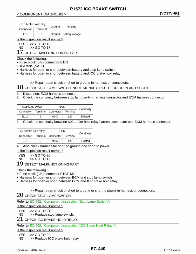
[VQ37VHR]P1572 ICC BRAKE SWITCH
< COMPONENT DIAGNOSIS >
Is the inspection result normal?YES >> GO TO 18.NO >> GO TO 17.
17.DETECT MALFUNCTIONING PART
Check the following.• Fuse block (J/B) connector E103• 10A fuse (No. 7)• Harness for open or short between battery and stop lamp switch• Harness for open or short between battery and ICC brake hold relay
>> Repair open circuit or short to ground in harness or connectors.
18.CHECK STOP LAMP SWITCH INPUT SIGNAL CIRCUIT FOR OPEN AND SHORT
1. Disconnect ECM harness connector.2. Check the continuity between stop lamp switch harness connector and ECM harness connector.
3. Check the continuity between ICC brake hold relay harness connector and ECM harness connector.
4. Also check harness for short to ground and short to power.Is the inspection result normal?YES >> GO TO 20.NO >> GO TO 19.
19.DETECT MALFUNCTIONING PART
Check the following.• Fuse block (J/B) connector E103, M2• Harness for open or short between ECM and stop lamp switch• Harness for open or short between ECM and ICC brake hold relay
>> Repair open circuit or short to ground or short to power in harness or connectors.
20.CHECK STOP LAMP SWITCH
Refer to EC-442, "Component Inspection (Stop Lamp Switch)".Is the inspection result normal?YES >> GO TO 21.NO >> Replace stop lamp switch.
21.CHECK ICC BRAKE HOLD RELAY
Refer to EC-442, "Component Inspection (ICC Brake Hold Relay)".Is the inspection result normal?YES >> GO TO 22.NO >> Replace ICC brake hold relay.
ICC brake hold relayGround Voltage
Connector Terminal
E51 3 Ground Battery voltage
Stop lamp switch ECMContinuity
Connector Terminal Connector Terminal
E110 2 M107 122 Existed
ICC brake hold relay ECMContinuity
Connector Terminal Connector Terminal
E51 5 M107 122 Existed
EC-440Revision: 2007 June G37 Coupe
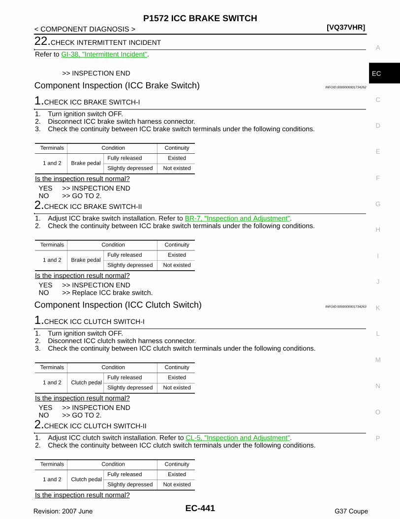
P1572 ICC BRAKE SWITCH[VQ37VHR]
C
D
E
F
G
H
I
J
K
L
M
A
C
N
P
O
< COMPONENT DIAGNOSIS >
E
22.CHECK INTERMITTENT INCIDENT
Refer to GI-38, "Intermittent Incident".
>> INSPECTION END
Component Inspection (ICC Brake Switch) INFOID:0000000001734262
1.CHECK ICC BRAKE SWITCH-I
1. Turn ignition switch OFF.2. Disconnect ICC brake switch harness connector.3. Check the continuity between ICC brake switch terminals under the following conditions.
Is the inspection result normal?YES >> INSPECTION ENDNO >> GO TO 2.
2.CHECK ICC BRAKE SWITCH-II
1. Adjust ICC brake switch installation. Refer to BR-7, "Inspection and Adjustment".2. Check the continuity between ICC brake switch terminals under the following conditions.
Is the inspection result normal?YES >> INSPECTION ENDNO >> Replace ICC brake switch.
Component Inspection (ICC Clutch Switch) INFOID:0000000001734263
1.CHECK ICC CLUTCH SWITCH-I
1. Turn ignition switch OFF.2. Disconnect ICC clutch switch harness connector.3. Check the continuity between ICC clutch switch terminals under the following conditions.
Is the inspection result normal?YES >> INSPECTION ENDNO >> GO TO 2.
2.CHECK ICC CLUTCH SWITCH-II
1. Adjust ICC clutch switch installation. Refer to CL-5, "Inspection and Adjustment".2. Check the continuity between ICC clutch switch terminals under the following conditions.
Is the inspection result normal?
Terminals Condition Continuity
1 and 2 Brake pedalFully released Existed
Slightly depressed Not existed
Terminals Condition Continuity
1 and 2 Brake pedalFully released Existed
Slightly depressed Not existed
Terminals Condition Continuity
1 and 2 Clutch pedalFully released Existed
Slightly depressed Not existed
Terminals Condition Continuity
1 and 2 Clutch pedalFully released Existed
Slightly depressed Not existed
EC-441Revision: 2007 June G37 Coupe

[VQ37VHR]P1572 ICC BRAKE SWITCH
< COMPONENT DIAGNOSIS >YES >> INSPECTION ENDNO >> Replace ICC clutch switch.
Component Inspection (Stop Lamp Switch) INFOID:0000000001911037
1.CHECK STOP LAMP SWITCH-I
1. Turn ignition switch OFF.2. Disconnect stop lamp switch harness connector.3. Check the continuity between stop lamp switch terminals under the following conditions.
Is the inspection result normal?YES >> INSPECTION ENDNO >> GO TO 2.
2.CHECK STOP LAMP SWITCH-II
1. Adjust stop lamp switch installation. Refer to BR-7, "Inspection and Adjustment".2. Check the continuity between stop lamp switch terminals under the following conditions.
Is the inspection result normal?YES >> INSPECTION ENDNO >> Replace stop lamp switch.
Component Inspection (ICC Brake Hold Relay) INFOID:0000000001734265
1.CHECK ICC BRAKE HOLD RELAY
1. Turn ignition switch OFF.2. Remove ICC brake hold relay.3. Check the continuity between ICC brake hold relay terminals
under the following conditions.
Is the inspection result normal?YES >> INSPECTION ENDNO >> Replace ICC brake hold relay
Terminals Condition Continuity
1 and 2 Brake pedalFully released Not existed
Slightly depressed Existed
Terminals Condition Continuity
1 and 2 Brake pedalFully released Not existed
Slightly depressed Existed
Terminals Condition Continuity
3 and 512V direct current supply between terminals 1 and 2 Existed
No current supply Not existed
JMBIA0848ZZ
EC-442Revision: 2007 June G37 Coupe

P1574 ASCD VEHICLE SPEED SENSOR[VQ37VHR]
C
D
E
F
G
H
I
J
K
L
M
A
C
N
P
O
< COMPONENT DIAGNOSIS >
E
P1574 ASCD VEHICLE SPEED SENSOR
Description INFOID:0000000001734266
The ECM receives two vehicle speed sensor signals via CAN communication line. One is sent from “unifiedmeter and A/C amp.”, and the other is from TCM (Transmission control module). The ECM uses these signalsfor ASCD control. Refer to EC-62, "System Description" for ASCD functions.
DTC Logic INFOID:0000000001734267
DTC DETECTION LOGICNOTE:• If DTC P1574 is displayed with DTC U1000, U1001, first perform the trouble diagnosis for DTC U1000,
U1001. Refer to EC-146, "DTC Logic".• If DTC P1574 is displayed with DTC U1010, first perform the trouble diagnosis for DTC U1010. Refer
to EC-147, "DTC Logic".• If DTC P1574 is displayed with DTC P0500, first perform the trouble diagnosis for DTC P0500. Refer
to EC-337, "DTC Logic".• If DTC P1574 is displayed with DTC P0605, first perform the trouble diagnosis for DTC P0605. Refer
to EC-356, "DTC Logic".
DTC CONFIRMATION PROCEDURE
1.PRECONDITIONING
If DTC Confirmation Procedure has been previously conducted, always perform the following before conduct-ing the next test. 1. Turn ignition switch OFF and wait at least 10 seconds.2. Turn ignition switch ON.3. Turn ignition switch OFF and wait at least 10 seconds.
>> GO TO 2.
2.PERFORM DTC CONFIRMATION PROCEDURE
1. Start engine (VDC switch OFF).2. Drive the vehicle at more than 40 km/h (25 MPH).
CAUTION:Always drive vehicle at a safe speed.NOTE:This procedure may be conducted with the drive wheels lifted in the shop or by driving the vehicle.If a road test is expected to be easier, it is unnecessary to lift the vehicle.
3. Check DTC.Is DTC detected?YES >> Go to EC-443, "Diagnosis Procedure".NO >> INSPECTION END
Diagnosis Procedure INFOID:0000000001734268
1.CHECK DTC WITH TCM
Check DTC with TCM. Refer to TM-111, "Diagnosis Description".
DTC No.Trouble diagnosis
nameDTC detecting condition Possible cause
P1574ASCD vehicle speed sensor
ECM detects a difference between two vehicle speed signals is out of the specified range.
• Harness or connectors(The CAN communication line is open or shorted.)
• Unified meter and A/C amp.• ABS actuator and electric unit (control unit)• Wheel sensor• TCM• ECM
EC-443Revision: 2007 June G37 Coupe

[VQ37VHR]P1574 ASCD VEHICLE SPEED SENSOR
< COMPONENT DIAGNOSIS >Is the inspection result normal?YES >> GO TO 2.NO >> Perform trouble shooting relevant to DTC indicated.
2.CHECK DTC WITH “ABS ACTUATOR AND ELECTRIC UNIT (CONTROL UNIT)”
Refer to BRC-26, "CONSULT-III Function".Is the inspection result normal?YES >> GO TO 3.NO >> Repair or replace.
3.CHECK DTC WITH “UNIFIED METER AND A/C AMP.”
Refer to MWI-37, "CONSULT-III Function (METER/M&A)".
>> INSPECTION END
EC-444Revision: 2007 June G37 Coupe

P1574 ICC VEHICLE SPEED SENSOR[VQ37VHR]
C
D
E
F
G
H
I
J
K
L
M
A
C
N
P
O
< COMPONENT DIAGNOSIS >
E
P1574 ICC VEHICLE SPEED SENSOR
Description INFOID:0000000001734269
The ECM receives two vehicle speed signals via CAN communication line. One is sent from “unified meter andA/C amp.”, and the other is from TCM (Transmission control module). The ECM uses these signals for ICCcontrol. Refer to CCS-15, "System Description" for ICC functions.
DTC Logic INFOID:0000000001734270
DTC DETECTION LOGICNOTE:• If DTC P1574 is displayed with DTC U1000, U1001, first perform the trouble diagnosis for DTC U1000,
U1001. Refer to EC-146, "DTC Logic".• If DTC P1574 is displayed with DTC U1010, first perform the trouble diagnosis for DTC U1010. Refer
to EC-147, "DTC Logic".• If DTC P1574 is displayed with DTC P0500, first perform the trouble diagnosis for DTC P0500. Refer
to EC-337, "DTC Logic".• If DTC P1574 is displayed with DTC P0605, first perform the trouble diagnosis for DTC P0605. Refer
to EC-356, "DTC Logic".
DTC CONFIRMATION PROCEDURE
1.PRECONDITIONING
If DTC Confirmation Procedure has been previously conducted, always turn ignition switch OFF and wait atleast 10 seconds before conducting the next test.
>> GO TO 2.
2.PERFORM DTC CONFIRMATION PROCEDURE
1. Start engine (VDC switch OFF).2. Drive the vehicle at more than 40 km/h (25 MPH).
CAUTION:Always drive vehicle at a safe speed.NOTE:This procedure may be conducted with the drive wheels lifted in the shop or by driving the vehicle.If a road test is expected to be easier, it is unnecessary to lift the vehicle.
3. Check DTC.Is DTC detected?YES >> Go to EC-445, "Diagnosis Procedure".NO >> INSPECTION END
Diagnosis Procedure INFOID:0000000001734271
1.CHECK DTC WITH TCM
Check DTC with TCM. Refer to TM-111, "Diagnosis Description".Is the inspection result normal?YES >> GO TO 2.
DTC No.Trouble diagnosis
nameDTC detecting condition Possible cause
P1574ICC vehicle speed sensor
ECM detects a difference between two vehicle speed signals is out of the specified range.
• Harness or connectors(The CAN communication line is open or shorted.)
• Unified meter and A/C amp.• ABS actuator and electric unit (control unit)• Wheel sensor• TCM• ECM
EC-445Revision: 2007 June G37 Coupe
[VQ37VHR]P1574 ICC VEHICLE SPEED SENSOR
< COMPONENT DIAGNOSIS >NO >> Perform trouble shooting relevant to DTC indicated.
2.CHECK DTC WITH “ABS ACTUATOR AND ELECTRIC UNIT (CONTROL UNIT)”
Refer to BRC-26, "CONSULT-III Function".Is the inspection result normal?YES >> GO TO 3.NO >> Repair or replace.
3.CHECK DTC WITH “UNIFIED METER AND A/C AMP.”
Check combination meter function.Refer to MWI-37, "CONSULT-III Function (METER/M&A)".
>> INSPECTION END
EC-446Revision: 2007 June G37 Coupe

P1606 VVEL CONTROL MODULE[VQ37VHR]
C
D
E
F
G
H
I
J
K
L
M
A
C
N
P
O
< COMPONENT DIAGNOSIS >
E
P1606 VVEL CONTROL MODULE
Description INFOID:0000000001736777
The VVEL control module consists of a microcomputer and connec-tors for signal input and output and for power supply. The VVEL con-trol module controls VVEL system.
DTC Logic INFOID:0000000001736778
DTC DETECTION LOGIC
DTC CONFIRMATION PROCEDURE
1.PRECONDITIONING
If DTC Confirmation Procedure has been previously conducted, always perform the following before conduct-ing the next test. 1. Turn ignition switch OFF and wait at least 10 seconds.2. Turn ignition switch ON.3. Turn ignition switch OFF and wait at least 10 seconds.TESTING CONDITION:Before performing the following procedure, confirm that battery voltage is more than 10V at idle.
>> GO TO 2.
2.PERFORM DTC CONFIRMATION PROCEDURE
1. Turn ignition switch ON and wait at least 1 second.2. Check DTC.Is DTC detected?YES >> Go to EC-447, "Diagnosis Procedure".NO >> INSPECTION END
Diagnosis Procedure INFOID:0000000001736779
1.PERFORM DTC CONFIRMATION PROCEDURE
With CONSULT-III1. Turn ignition switch ON.2. Select “SELF-DIAG RESULTS” mode with CONSULT-III.3. Touch “ERASE”.4. Perform DTC Confirmation Procedure.
See EC-447, "DTC Logic". With GST
1. Turn ignition switch ON.2. Select Service $04 with GST.3. Perform DTC Confirmation Procedure.
JMBIA0879ZZ
DTC No. Trouble diagnosis name DTC detecting condition Possible cause
P1606 VVEL control module
• VVEL control module calculation function is malfunctioning.
• VVEL EEP-ROM system is malfunc-tioning.
• VVEL control module
EC-447Revision: 2007 June G37 Coupe
[VQ37VHR]P1606 VVEL CONTROL MODULE
< COMPONENT DIAGNOSIS >See EC-447, "DTC Logic".
Is the DTC P1606 displayed again?YES >> GO TO 2.NO >> INSPECTION END
2.REPLACE VVEL CONTROL MODULE
1. Replace VVEL control module.2. Go to EC-17, "ADDITIONAL SERVICE WHEN REPLACING CONTROL UNIT (VVEL CONTROL MOD-
ULE) : Special Repair Requirement".
>> INSPECTION END
EC-448Revision: 2007 June G37 Coupe

P1607 VVEL CONTROL MODULE[VQ37VHR]
C
D
E
F
G
H
I
J
K
L
M
A
C
N
P
O
< COMPONENT DIAGNOSIS >
E
P1607 VVEL CONTROL MODULE
Description INFOID:0000000001910908
The VVEL control module consists of a microcomputer and connec-tors for signal input and output and for power supply. The VVEL con-trol module controls VVEL system.
DTC Logic INFOID:0000000001736781
DTC DETECTION LOGIC
DTC CONFIRMATION PROCEDURE
1.PRECONDITIONING
If DTC Confirmation Procedure has been previously conducted, always perform the following before conduct-ing the next test. 1. Turn ignition switch OFF and wait at least 10 seconds.2. Turn ignition switch ON.3. Turn ignition switch OFF and wait at least 10 seconds.TESTING CONDITION:Before performing the following procedure, confirm that battery voltage is more than 10V at idle.
>> GO TO 2.
2.PERFORM DTC CONFIRMATION PROCEDURE
1. Start engine and let it idle for at least 1 second.2. Check DTC.Is DTC detected?YES >> Go to EC-449, "Diagnosis Procedure".NO >> INSPECTION END
Diagnosis Procedure INFOID:0000000001736782
1.PERFORM DTC CONFIRMATION PROCEDURE
With CONSULT-III1. Turn ignition switch ON.2. Select “SELF-DIAG RESULTS” mode with CONSULT-III.3. Touch “ERASE”.4. Perform DTC Confirmation Procedure.
See EC-449, "DTC Logic". With GST
1. Turn ignition switch ON.2. Select Service $04 with GST.3. Perform DTC Confirmation Procedure.
See EC-449, "DTC Logic".
JMBIA0879ZZ
DTC No. Trouble diagnosis name DTC detecting condition Possible cause
P1607 VVEL control module circuit• The internal circuit of the VVEL con-
trol module is malfunctioning.• VVEL control module
EC-449Revision: 2007 June G37 Coupe

[VQ37VHR]P1607 VVEL CONTROL MODULE
< COMPONENT DIAGNOSIS >Is the DTC P1607 displayed again?YES >> GO TO 2.NO >> INSPECTION END
2.REPLACE VVEL CONTROL MODULE
1. Replace VVEL control module.2. Go to EC-17, "ADDITIONAL SERVICE WHEN REPLACING CONTROL UNIT (VVEL CONTROL MOD-
ULE) : Special Repair Requirement".
>> INSPECTION END
EC-450Revision: 2007 June G37 Coupe

P1608 VVEL SENSOR POWER SUPPLY[VQ37VHR]
C
D
E
F
G
H
I
J
K
L
M
A
C
N
P
O
< COMPONENT DIAGNOSIS >
E
P1608 VVEL SENSOR POWER SUPPLY
DTC Logic INFOID:0000000001736783
DTC DETECTION LOGIC
DTC CONFIRMATION PROCEDURE
1.PRECONDITIONING
If DTC Confirmation Procedure has been previously conducted, always perform the following before conduct-ing the next test. 1. Turn ignition switch OFF and wait at least 10 seconds.2. Turn ignition switch ON.3. Turn ignition switch OFF and wait at least 10 seconds.TESTING CONDITION:Before performing the following procedure, confirm that battery voltage is more than 10V at idle.
>> GO TO 2.
2.PERFORM DTC CONFIRMATION PROCEDURE
1. Turn ignition switch ON and wait at least 1 second.2. Check DTC.Is DTC detected?YES >> Go to EC-451, "Diagnosis Procedure".NO >> INSPECTION END
Diagnosis Procedure INFOID:0000000001736784
1.CHECK GROUND CONNECTION
1. Turn ignition switch OFF.2. Check ground connection M95. Refer to Ground Inspection in GI-41, "Circuit Inspection".Is the inspection result normal?YES >> GO TO 2.NO >> Repair or replace ground connection.
2.VVEL CONTROL SHAFT POSITION SENSOR POWER SUPPLY CIRCUIT
1. Disconnect VVEL control shaft position sensor harness connector.2. Turn ignition switch ON.3. Check the voltage between VVEL control shaft position sensor harness connector and ground.
Is the inspection result normal?YES >> GO TO 7.NO >> GO TO 3.
DTC No. Trouble diagnosis name DTC detecting condition Possible cause
P1608 VVEL sensor power supply circuitVVEL control module detects a voltage of power source for sensor is excessively low or high.
• Harness or connectors(VVEL control shaft position sensor power supply circuit is open or shorted.)
• VVEL control shaft position sensor• VVEL control module
VVEL control shaft position sensorGround Voltage
Bank Connector Terminal
1 F463
Ground Approx. 5V6
2 F473
6
EC-451Revision: 2007 June G37 Coupe

[VQ37VHR]P1608 VVEL SENSOR POWER SUPPLY
< COMPONENT DIAGNOSIS >
3.CHECK VVEL CONTROL SHAFT POSITION SENSOR POWER SUPPLY CIRCUIT FOR OPEN ANDSHORT
1. Turn ignition switch OFF.2. Disconnect VVEL control module harness connector.3. Check the continuity between VVEL control shaft position sensor harness connector and VVEL control
module harness connector.
4. Also check harness for short to ground and power.Is the inspection result normal?YES >> GO TO 5.NO >> GO TO 4.
4.DETECT MALFUNCTIONING PART
Check the following.• Harness connectors F1, E3• Harness for open or short between VVEL control shaft position sensor and VVEL control module
>> Repair open circuit or short to ground or short to power in harness or connectors.
5.CHECK INTERMITTENT INCIDENT
Refer to GI-38, "Intermittent Incident".Is the inspection result normal?YES >> GO TO 6.NO >> Repair or replace.
6.REPLACE VVEL CONTROL MODULE
1. Replace VVEL control module.2. Go to EC-17, "ADDITIONAL SERVICE WHEN REPLACING CONTROL UNIT (VVEL CONTROL MOD-
ULE) : Special Repair Requirement".
>> INSPECTION END
7.CHECK INTERMITTENT INCIDENT
Refer to GI-38, "Intermittent Incident".Is the inspection result normal?YES >> GO TO 8.NO >> Repair or replace.
8.REPLACE VVEL ACTUATOR SUB ASSEMBLY
1. Replace VVEL actuator sub assembly.2. Go to EC-452, "Special Repair Requirement".
>> INSPECTION END
Special Repair Requirement INFOID:0000000001910907
1.PERFORM VVEL CONTROL SHAFT POSITION SENSOR ADJUSTMENT
VVEL control shaft position sensor VVEL control moduleContinuity
Bank Connector Terminal Connector Terminal
1 F463
E15
9
Existed6 22
2 F473 7
6 20
EC-452Revision: 2007 June G37 Coupe

P1608 VVEL SENSOR POWER SUPPLY[VQ37VHR]
C
D
E
F
G
H
I
J
K
L
M
A
C
N
P
O
< COMPONENT DIAGNOSIS >
E
Refer to EC-21, "VVEL CONTROL SHAFT POSITION SENSOR ADJUSTMENT : Special Repair Require-ment".
>> GO TO 2.
2.PERFORM IDLE AIR VOLUME LEARNING
Refer to EC-19, "IDLE AIR VOLUME LEARNING : Special Repair Requirement".
>> END
EC-453Revision: 2007 June G37 Coupe

[VQ37VHR]P1715 INPUT SPEED SENSOR (TURBINE REVOLUTION SENSOR)
< COMPONENT DIAGNOSIS >
P1715 INPUT SPEED SENSOR (TURBINE REVOLUTION SENSOR)
Description INFOID:0000000001734272
ECM receives turbine revolution sensor signal from TCM through CAN communication line. ECM uses thissignal for engine control.
DTC Logic INFOID:0000000001734273
DTC DETECTION LOGICNOTE:• If DTC P1715 is displayed with DTC U1000, U1001 first perform the trouble diagnosis for DTC U1000,
U1001. Refer to EC-146, "DTC Logic".• If DTC P1715 is displayed with DTC U1010, first perform the trouble diagnosis for DTC U1010. Refer
to EC-147, "DTC Logic".• If DTC P1715 is displayed with DTC P0605, first perform the trouble diagnosis for DTC P0605. Refer
to EC-356, "DTC Logic".• If DTC P1715 is displayed with DTC P0335, first perform the trouble diagnosis for DTC P0335. Refer
to EC-264, "DTC Logic".• If DTC P1715 is displayed with DTC P0340, first perform the trouble diagnosis for DTC P0340. Refer
to EC-268, "DTC Logic".
Diagnosis Procedure INFOID:0000000001734274
1.CHECK DTC WITH TCM
Check DTC with TCM. Refer to TM-111, "Diagnosis Description".Is the inspection result normal?YES >> GO TO 2.NO >> Perform trouble shooting relevant to DTC indicated.
2.REPLACE TCM
Replace TCM.
>> INSPECTION END
DTC No. Trouble diagnosis name DTC detecting condition Possible cause
P1715
Input speed sensor(Turbine revolution sen-sor)(TCM output)
Turbine revolution sensor signal is differ-ent from the theoretical value calculated by ECM from revolution sensor signal and engine rpm signal.
• Harness or connectors(The CAN communication line is open or short-ed)
• Harness or connectors(Turbine revolution sensor circuit is open or shorted)
• TCM
EC-454Revision: 2007 June G37 Coupe

P1805 BRAKE SWITCH[VQ37VHR]
C
D
E
F
G
H
I
J
K
L
M
A
C
N
P
O
< COMPONENT DIAGNOSIS >
E
P1805 BRAKE SWITCH
Description INFOID:0000000001734275
Brake switch signal is applied to the ECM through the stop lamp switch when the brake pedal is depressed.This signal is used mainly to decrease the engine speed when the vehicle is driving.
DTC Logic INFOID:0000000001734276
DTC DETECTION LOGIC
DTC CONFIRMATION PROCEDURE
1.PERFORM DTC CONFIRMATION PROCEDURE
1. Turn ignition switch ON.2. Fully depress the brake pedal for at least 5 seconds.3. Erase the DTC.4. Check 1st trip DTC.Is 1st trip DTC detected?YES >> Go to EC-455, "Diagnosis Procedure".NO >> INSPECTION END
Diagnosis Procedure INFOID:0000000001734277
1.CHECK STOP LAMP SWITCH CIRCUIT
1. Turn ignition switch OFF.2. Check the stop lamp when depressing and releasing the brake pedal.
Is the inspection result normal?YES >> GO TO 4.NO >> GO TO 2.
2.CHECK STOP LAMP SWITCH POWER SUPPLY CIRCUIT
1. Disconnect stop lamp switch harness connector.2. Check the voltage between stop lamp switch harness connector and ground.
Is the inspection result normal?YES >> GO TO 4.NO >> GO TO 3.
3.DETECT MALFUNCTIONING PART
Check the following.• Fuse block (J/B) connector E103• 10A fuse (No. 7)
DTC No. Trouble diagnosis name DTC detecting condition Possible cause
P1805 Brake switchA brake switch signal is not sent to ECM for ex-tremely long time while the vehicle is driving.
• Harness or connectors(Stop lamp switch circuit is open or short-ed.)
• Stop lamp switch
Brake pedal Stop lamp
Fully released Not illuminated
Slightly depressed Illuminated
Stop lamp switchGround Voltage
Connector Terminal
E110 1 Ground Battery voltage
EC-455Revision: 2007 June G37 Coupe

[VQ37VHR]P1805 BRAKE SWITCH
< COMPONENT DIAGNOSIS >• Harness for open or short between stop lamp switch and battery
>> Repair open circuit or short to ground or short to power in harness or connectors.
4.CHECK STOP LAMP SWITCH INPUT SIGNAL CIRCUIT FOR OPEN AND SHORT
1. Disconnect stop lamp switch harness connector.2. Disconnect ECM harness connector.3. Check the continuity between stop lamp switch harness connector and ECM harness connector.
4. Also check harness for short to ground and short to power.Is the inspection result normal?YES >> GO TO 6.NO >> GO TO 5.
5.DETECT MALFUNCTIONING PART
Check the following.• Fuse block (J/B) connector E103, M2• Harness for open or short between ECM and stop lamp switch
>> Repair open circuit or short to ground or short to power in harness or connectors.
6.CHECK STOP LAMP SWITCH
Refer to EC-456, "Component Inspection (Stop Lamp Switch)".Is the inspection result normal?YES >> GO TO 7.NO >> Replace stop lamp switch.
7.CHECK INTERMITTENT INCIDENT
Refer to GI-38, "Intermittent Incident".
>> INSPECTION END
Component Inspection (Stop Lamp Switch) INFOID:0000000001911038
1.CHECK STOP LAMP SWITCH-I
1. Turn ignition switch OFF.2. Disconnect stop lamp switch harness connector.3. Check the continuity between stop lamp switch terminals under the following conditions.
Is the inspection result normal?YES >> INSPECTION ENDNO >> GO TO 2.
2.CHECK STOP LAMP SWITCH-II
1. Adjust stop lamp switch installation. Refer to BR-7, "Inspection and Adjustment".2. Check the continuity between stop lamp switch terminals under the following conditions.
Stop lamp switch ECMContinuity
Connector Terminal Connector Terminal
E110 2 M107 122 Existed
Terminals Condition Continuity
1 and 2 Brake pedalFully released Not existed
Slightly depressed Existed
EC-456Revision: 2007 June G37 Coupe

P1805 BRAKE SWITCH[VQ37VHR]
C
D
E
F
G
H
I
J
K
L
M
A
C
N
P
O
< COMPONENT DIAGNOSIS >
EIs the inspection result normal?YES >> INSPECTION ENDNO >> Replace stop lamp switch.
Terminals Condition Continuity
1 and 2 Brake pedalFully released Not existed
Slightly depressed Existed
EC-457Revision: 2007 June G37 Coupe

[VQ37VHR]P2122, P2123 APP SENSOR
< COMPONENT DIAGNOSIS >
P2122, P2123 APP SENSOR
Description INFOID:0000000001734279
The accelerator pedal position sensor is installed on the upper endof the accelerator pedal assembly. The sensor detects the accelera-tor position and sends a signal to the ECM.Accelerator pedal position sensor has two sensors. These sensorsare a kind of potentiometers which transform the accelerator pedalposition into output voltage, and emit the voltage signal to the ECM.In addition, these sensors detect the opening and closing speed ofthe accelerator pedal and feed the voltage signals to the ECM. TheECM judges the current opening angle of the accelerator pedal fromthese signals and controls the throttle control motor based on thesesignals.Idle position of the accelerator pedal is determined by the ECMreceiving the signal from the accelerator pedal position sensor. The ECM uses this signal for the engine oper-ation such as fuel cut.
DTC Logic INFOID:0000000001734280
DTC DETECTION LOGICNOTE:If DTC P2122 or P2123 is displayed with DTC P0643, first perform the trouble diagnosis for DTC P0643.Refer to EC-358, "DTC Logic".
DTC CONFIRMATION PROCEDURE
1.PRECONDITIONING
If DTC Confirmation Procedure has been previously conducted, always perform the following before conduct-ing the next test. 1. Turn ignition switch OFF and wait at least 10 seconds.2. Turn ignition switch ON.3. Turn ignition switch OFF and wait at least 10 seconds.TESTING CONDITION:Before performing the following procedure, confirm that battery voltage is more than 10V at idle.
>> GO TO 2.
2.PERFORM DTC CONFIRMATION PROCEDURE
1. Start engine and let it idle for 1 second.2. Check DTC.Is DTC detected?YES >> Go to EC-458, "Diagnosis Procedure".NO >> INSPECTION END
Diagnosis Procedure INFOID:0000000001734281
1.CHECK GROUND CONNECTION
1. Turn ignition switch OFF.2. Check ground connection M95. Refer to Ground Inspection in GI-41, "Circuit Inspection".
PBIB1741E
DTC No. Trouble diagnosis name DTC detecting condition Possible cause
P2122Accelerator pedal posi-tion sensor 1 circuit low input
An excessively low voltage from the APP sen-sor 1 is sent to ECM. • Harness or connectors
(APP sensor 1 circuit is open or shorted.)• Accelerator pedal position sensor
(APP sensor 1)P2123Accelerator pedal posi-tion sensor 1 circuit high input
An excessively high voltage from the APP sen-sor 1 is sent to ECM.
EC-458Revision: 2007 June G37 Coupe

P2122, P2123 APP SENSOR[VQ37VHR]
C
D
E
F
G
H
I
J
K
L
M
A
C
N
P
O
< COMPONENT DIAGNOSIS >
E
Is the inspection result normal?YES >> GO TO 2.NO >> Repair or replace ground connection.
2.CHECK APP SENSOR 1 POWER SUPPLY CIRCUIT
1. Disconnect accelerator pedal position (APP) sensor harness connector.2. Turn ignition switch ON.3. Check the voltage between APP sensor harness connector and ground.
Is the inspection result normal?YES >> GO TO 4.NO >> GO TO 3.
3.DETECT MALFUNCTIONING PART
Check the following.• Harness connectors M6, E106• Harness for open or short between ECM and accelerator pedal position sensor
>> Repair open circuit or short to ground or short to power in harness or connectors.
4.CHECK APP SENSOR 1 GROUND CIRCUIT FOR OPEN AND SHORT
1. Turn ignition switch OFF.2. Disconnect ECM harness connector.3. Check the continuity between APP sensor harness connector and ECM harness connector.
4. Also check harness for short to ground and short to power.Is the inspection result normal?YES >> GO TO 6.NO >> GO TO 5.
5.DETECT MALFUNCTIONING PART
Check the following.• Harness connectors M6, E106• Harness for open or short between ECM and accelerator pedal position sensor
>> Repair open circuit or short to ground or short to power in harness or connectors.
6.CHECK APP SENSOR INPUT SIGNAL CIRCUIT FOR OPEN AND SHORT
1. Check the continuity between APP sensor harness connector and ECM harness connector.
2. Also check harness for short to ground and short to power.Is the inspection result normal?YES >> GO TO 8.NO >> GO TO 7.
APP sensorGround Voltage
Connector Terminal
E112 5 Ground Approx. 5V
APP sensor ECMContinuity
Connector Terminal Connector Terminal
E112 4 M107 100 Existed
APP sensor ECMContinuity
Connector Terminal Connector Terminal
E112 3 M107 97 Existed
EC-459Revision: 2007 June G37 Coupe
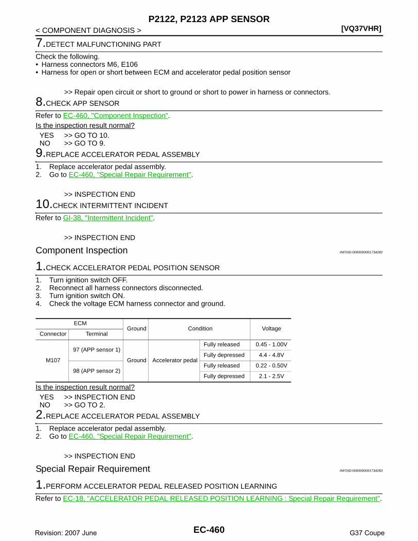
[VQ37VHR]P2122, P2123 APP SENSOR
< COMPONENT DIAGNOSIS >
7.DETECT MALFUNCTIONING PART
Check the following.• Harness connectors M6, E106• Harness for open or short between ECM and accelerator pedal position sensor
>> Repair open circuit or short to ground or short to power in harness or connectors.
8.CHECK APP SENSOR
Refer to EC-460, "Component Inspection".Is the inspection result normal?YES >> GO TO 10.NO >> GO TO 9.
9.REPLACE ACCELERATOR PEDAL ASSEMBLY
1. Replace accelerator pedal assembly.2. Go to EC-460, "Special Repair Requirement".
>> INSPECTION END
10.CHECK INTERMITTENT INCIDENT
Refer to GI-38, "Intermittent Incident".
>> INSPECTION END
Component Inspection INFOID:0000000001734282
1.CHECK ACCELERATOR PEDAL POSITION SENSOR
1. Turn ignition switch OFF.2. Reconnect all harness connectors disconnected.3. Turn ignition switch ON.4. Check the voltage ECM harness connector and ground.
Is the inspection result normal?YES >> INSPECTION ENDNO >> GO TO 2.
2.REPLACE ACCELERATOR PEDAL ASSEMBLY
1. Replace accelerator pedal assembly.2. Go to EC-460, "Special Repair Requirement".
>> INSPECTION END
Special Repair Requirement INFOID:0000000001734283
1.PERFORM ACCELERATOR PEDAL RELEASED POSITION LEARNING
Refer to EC-18, "ACCELERATOR PEDAL RELEASED POSITION LEARNING : Special Repair Requirement".
ECMGround Condition Voltage
Connector Terminal
M107
97 (APP sensor 1)
Ground Accelerator pedal
Fully released 0.45 - 1.00V
Fully depressed 4.4 - 4.8V
98 (APP sensor 2)Fully released 0.22 - 0.50V
Fully depressed 2.1 - 2.5V
EC-460Revision: 2007 June G37 Coupe

P2122, P2123 APP SENSOR[VQ37VHR]
C
D
E
F
G
H
I
J
K
L
M
A
C
N
P
O
< COMPONENT DIAGNOSIS >
E
>> GO TO 2.
2.PERFORM THROTTLE VALVE CLOSED POSITION LEARNING
Refer to EC-18, "THROTTLE VALVE CLOSED POSITION LEARNING : Special Repair Requirement".
>> GO TO 3.
3.PERFORM IDLE AIR VOLUME LEARNING
Refer to EC-19, "IDLE AIR VOLUME LEARNING : Special Repair Requirement".
>> END
EC-461Revision: 2007 June G37 Coupe

[VQ37VHR]P2127, P2128 APP SENSOR
< COMPONENT DIAGNOSIS >
P2127, P2128 APP SENSOR
Description INFOID:0000000001911130
The accelerator pedal position sensor is installed on the upper endof the accelerator pedal assembly. The sensor detects the accelera-tor position and sends a signal to the ECM.Accelerator pedal position sensor has two sensors. These sensorsare a kind of potentiometers which transform the accelerator pedalposition into output voltage, and emit the voltage signal to the ECM.In addition, these sensors detect the opening and closing speed ofthe accelerator pedal and feed the voltage signals to the ECM. TheECM judges the current opening angle of the accelerator pedal fromthese signals and controls the throttle control motor based on thesesignals.Idle position of the accelerator pedal is determined by the ECMreceiving the signal from the accelerator pedal position sensor. The ECM uses this signal for the engine oper-ation such as fuel cut.
DTC Logic INFOID:0000000001734285
DTC DETECTION LOGIC
DTC CONFIRMATION PROCEDURE
1.PRECONDITIONING
If DTC Confirmation Procedure has been previously conducted, always perform the following before conduct-ing the next test. 1. Turn ignition switch OFF and wait at least 10 seconds.2. Turn ignition switch ON.3. Turn ignition switch OFF and wait at least 10 seconds.TESTING CONDITION:Before performing the following procedure, confirm that battery voltage is more than 10V at idle.
>> GO TO 2.
2.PERFORM DTC CONFIRMATION PROCEDURE
1. Start engine and let it idle for 1 second.2. Check DTC.Is DTC detected?YES >> Go to EC-463, "Diagnosis Procedure".NO >> INSPECTION END
PBIB1741E
DTC No. Trouble diagnosis name DTC detecting condition Possible cause
P2127Accelerator pedal posi-tion sensor 2 circuit low input
An excessively low voltage from the APP sen-sor 2 is sent to ECM.
• Harness or connectors(APP sensor 2 circuit is open or shorted.)[CKP sensor (POS) circuit is shorted.](EVAP control system pressure sensor circuit is shorted.)(Refrigerant pressure sensor circuit is shorted.)
• Accelerator pedal position sensor (APP sensor 2)(Brake booster pressure sensor circuit is shorted)
• Crankshaft position sensor (POS)• EVAP control system pressure sensor• Refrigerant pressure sensor• Brake booster pressure sensor
P2128Accelerator pedal posi-tion sensor 2 circuit high input
An excessively high voltage from the APP sen-sor 2 is sent to ECM.
EC-462Revision: 2007 June G37 Coupe

P2127, P2128 APP SENSOR[VQ37VHR]
C
D
E
F
G
H
I
J
K
L
M
A
C
N
P
O
< COMPONENT DIAGNOSIS >
E
Diagnosis Procedure INFOID:0000000001734286
1.CHECK GROUND CONNECTION
1. Turn ignition switch OFF.2. Check ground connection M95. Refer to Ground Inspection in GI-41, "Circuit Inspection".Is the inspection result normal?YES >> GO TO 2.NO >> Repair or replace ground connection.
2.CHECK APP SENSOR 2 POWER SUPPLY CIRCUIT-I
1. Disconnect accelerator pedal position (APP) sensor harness connector.2. Turn ignition switch ON.3. Check the voltage between APP sensor harness connector and ground.
Is the inspection result normal?YES >> GO TO 7.NO >> GO TO 3.
3.CHECK APP SENSOR 2 POWER SUPPLY CIRCUIT-II
1. Turn ignition switch OFF.2. Disconnect ECM harness connector.3. Check the continuity between APP sensor harness connector and ECM harness connector.
Is the inspection result normal?YES >> GO TO 5.NO >> GO TO 4.
4.DETECT MALFUNCTIONING PART
Check the following.• Harness connectors M6, E106• Harness for open or short between ECM and accelerator pedal position sensor
>> Repair open circuit.
5.CHECK APP SENSOR 2 POWER SUPPLY CIRCUIT-III
Check harness for short to power and short to ground, between the following terminals.
Is the inspection result normal?YES >> GO TO 6.
APP sensorGround Voltage
Connector Terminal
E112 6 Ground Approx. 5V
APP sensor ECMContinuity
Connector Terminal Connector Terminal
E112 6 M107 103 Existed
ECM Sensor
Connector Terminal Name Connector Terminal
F10145 Brake booster pressure sensor E48 1
46 CKP sensor (POS) F2 1
M107
103 APP sensor E112 6
107 EVAP control system pressure sensor B30 3
111 Refrigerant pressure sensor E77 3
EC-463Revision: 2007 June G37 Coupe

[VQ37VHR]P2127, P2128 APP SENSOR
< COMPONENT DIAGNOSIS >NO >> Repair short to ground or short to power in harness or connectors.
6.CHECK COMPONENTS
Check the following.• Crankshaft position sensor (POS) (Refer to EC-267, "Component Inspection".)• Brake booster pressure sensor (Refer to EC-352, "Component Inspection".)• EVAP control system pressure sensor (Refer to EC-306, "Component Inspection".)• Refrigerant pressure sensor (Refer to HAC-85, "Diagnosis Procedure".)Is the inspection result normal?YES >> GO TO 13.NO >> Replace malfunctioning component.
7.CHECK APP SENSOR 2 GROUND CIRCUIT FOR OPEN AND SHORT
1. Turn ignition switch OFF.2. Disconnect ECM harness connector.3. Check the continuity between APP sensor harness connector and ECM harness connector.
4. Also check harness for short to ground and short to power.Is the inspection result normal?YES >> GO TO 9.NO >> GO TO 8.
8.DETECT MALFUNCTIONING PART
Check the following.• Harness connectors M6, E106• Harness for open or short between ECM and accelerator pedal position sensor
>> Repair open circuit or short to ground or short to power in harness or connectors.
9.CHECK APP SENSOR 2 INPUT SIGNAL CIRCUIT FOR OPEN AND SHORT
1. Check the continuity between APP sensor harness connector and ECM harness connector.
2. Also check harness for short to ground and short to power.Is the inspection result normal?YES >> GO TO 11.NO >> GO TO 10.
10.DETECT MALFUNCTIONING PART
Check the following.• Harness connectors M6, E106• Harness for open or short between ECM and accelerator pedal position sensor
>> Repair open circuit or short to ground or short to power in harness or connectors.
11.CHECK APP SENSOR
Refer to EC-465, "Component Inspection".Is the inspection result normal?YES >> GO TO 13.NO >> GO TO 12.
APP sensor ECMContinuity
Connector Terminal Connector Terminal
E112 2 M107 104 Existed
APP sensor ECMContinuity
Connector Terminal Connector Terminal
E112 1 M107 98 Existed
EC-464Revision: 2007 June G37 Coupe
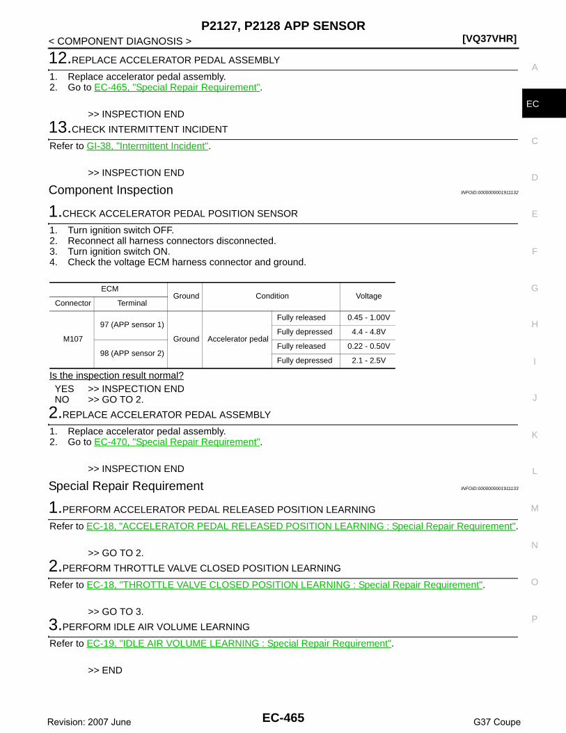
P2127, P2128 APP SENSOR[VQ37VHR]
C
D
E
F
G
H
I
J
K
L
M
A
C
N
P
O
< COMPONENT DIAGNOSIS >
E
12.REPLACE ACCELERATOR PEDAL ASSEMBLY
1. Replace accelerator pedal assembly.2. Go to EC-465, "Special Repair Requirement".
>> INSPECTION END
13.CHECK INTERMITTENT INCIDENT
Refer to GI-38, "Intermittent Incident".
>> INSPECTION END
Component Inspection INFOID:0000000001911132
1.CHECK ACCELERATOR PEDAL POSITION SENSOR
1. Turn ignition switch OFF.2. Reconnect all harness connectors disconnected.3. Turn ignition switch ON.4. Check the voltage ECM harness connector and ground.
Is the inspection result normal?YES >> INSPECTION ENDNO >> GO TO 2.
2.REPLACE ACCELERATOR PEDAL ASSEMBLY
1. Replace accelerator pedal assembly.2. Go to EC-470, "Special Repair Requirement".
>> INSPECTION END
Special Repair Requirement INFOID:0000000001911133
1.PERFORM ACCELERATOR PEDAL RELEASED POSITION LEARNING
Refer to EC-18, "ACCELERATOR PEDAL RELEASED POSITION LEARNING : Special Repair Requirement".
>> GO TO 2.
2.PERFORM THROTTLE VALVE CLOSED POSITION LEARNING
Refer to EC-18, "THROTTLE VALVE CLOSED POSITION LEARNING : Special Repair Requirement".
>> GO TO 3.
3.PERFORM IDLE AIR VOLUME LEARNING
Refer to EC-19, "IDLE AIR VOLUME LEARNING : Special Repair Requirement".
>> END
ECMGround Condition Voltage
Connector Terminal
M107
97 (APP sensor 1)
Ground Accelerator pedal
Fully released 0.45 - 1.00V
Fully depressed 4.4 - 4.8V
98 (APP sensor 2)Fully released 0.22 - 0.50V
Fully depressed 2.1 - 2.5V
EC-465Revision: 2007 June G37 Coupe

[VQ37VHR]P2138 APP SENSOR
< COMPONENT DIAGNOSIS >
P2138 APP SENSOR
Description INFOID:0000000001911131
The accelerator pedal position sensor is installed on the upper endof the accelerator pedal assembly. The sensor detects the accelera-tor position and sends a signal to the ECM.Accelerator pedal position sensor has two sensors. These sensorsare a kind of potentiometers which transform the accelerator pedalposition into output voltage, and emit the voltage signal to the ECM.In addition, these sensors detect the opening and closing speed ofthe accelerator pedal and feed the voltage signals to the ECM. TheECM judges the current opening angle of the accelerator pedal fromthese signals and controls the throttle control motor based on thesesignals.Idle position of the accelerator pedal is determined by the ECMreceiving the signal from the accelerator pedal position sensor. The ECM uses this signal for the engine oper-ation such as fuel cut.
DTC Logic INFOID:0000000001734290
DTC DETECTION LOGICNOTE:If DTC P2138 is displayed with DTC P0643, first perform the trouble diagnosis for DTC P0643. Refer toEC-358, "DTC Logic".
DTC CONFIRMATION PROCEDURE
1.PRECONDITIONING
If DTC Confirmation Procedure has been previously conducted, always perform the following before conduct-ing the next test. 1. Turn ignition switch OFF and wait at least 10 seconds.2. Turn ignition switch ON.3. Turn ignition switch OFF and wait at least 10 seconds.TESTING CONDITION:Before performing the following procedure, confirm that battery voltage is more than 10V at idle.
>> GO TO 2.
2.PERFORM DTC CONFIRMATION PROCEDURE
1. Start engine and let it idle for 1 second.2. Check DTC.Is DTC detected?
PBIB1741E
DTC No. Trouble diagnosis name DTC detecting condition Possible cause
P2138Accelerator pedal posi-tion sensor circuit range/performance
Rationally incorrect voltage is sent to ECM compared with the signals from APP sensor 1 and APP sensor 2.
• Harness or connectors(APP sensor 2 circuit is open or shorted.)[CKP sensor (POS) circuit is shorted.](EVAP control system pressure sensor circuit is shorted.)(Refrigerant pressure sensor circuit is shorted.)
• Accelerator pedal position sensor (APP sensor 2)(Brake booster pressure sensor circuit is shorted)
• Crankshaft position sensor (POS)• EVAP control system pressure sensor• Brake booster pressure sensor• Refrigerant pressure sensor
EC-466Revision: 2007 June G37 Coupe

P2138 APP SENSOR[VQ37VHR]
C
D
E
F
G
H
I
J
K
L
M
A
C
N
P
O
< COMPONENT DIAGNOSIS >
E
YES >> Go to EC-467, "Diagnosis Procedure".NO >> INSPECTION END
Diagnosis Procedure INFOID:0000000001734291
1.CHECK GROUND CONNECTION
1. Turn ignition switch OFF.2. Check ground connection M95. Refer to Ground Inspection in GI-41, "Circuit Inspection".Is the inspection result normal?YES >> GO TO 2.NO >> Repair or replace ground connection.
2.CHECK APP SENSOR 1 POWER SUPPLY CIRCUIT
1. Disconnect accelerator pedal position (APP) sensor harness connector.2. Turn ignition switch ON.3. Check the voltage between APP sensor harness connector and ground.
Is the inspection result normal?YES >> GO TO 4.NO >> GO TO 3.
3.DETECT MALFUNCTIONING PART
Check the following.• Harness connectors M6, E106• Harness for open or short between ECM and accelerator pedal position sensor
>> Repair open circuit or short to ground or short to power in harness or connectors.
4.CHECK APP SENSOR 2 POWER SUPPLY CIRCUIT-I
1. Turn ignition switch ON.2. Check the voltage between APP sensor harness connector and ground.
Is the inspection result normal?YES >> GO TO 9.NO >> GO TO 5.
5.CHECK APP SENSOR 2 POWER SUPPLY CIRCUIT-II
1. Turn ignition switch OFF.2. Disconnect ECM harness connector.3. Check the continuity between APP sensor harness connector and ECM harness connector.
Is the inspection result normal?YES >> GO TO 7.NO >> GO TO 6.
APP sensorGround Voltage
Connector Terminal
E112 5 Ground Approx. 5V
APP sensorGround Voltage
Connector Terminal
E112 6 Ground Approx. 5V
APP sensor ECMContinuity
Connector Terminal Connector Terminal
E112 6 M107 103 Existed
EC-467Revision: 2007 June G37 Coupe

[VQ37VHR]P2138 APP SENSOR
< COMPONENT DIAGNOSIS >
6.DETECT MALFUNCTIONING PART
Check the following.• Harness connectors M6, E106• Harness for open or short between ECM and accelerator pedal position sensor
>> Repair open circuit.
7.CHECK APP SENSOR 2 POWER SUPPLY CIRCUIT-III
Check harness for short to power and short to ground, between the following terminals.
Is the inspection result normal?YES >> GO TO 8.NO >> Repair short to ground or short to power in harness or connectors.
8.CHECK COMPONENTS
Check the following.• Crankshaft position sensor (POS) (Refer to EC-267, "Component Inspection".)• Brake booster pressure sensor (Refer to EC-352, "Component Inspection".)• EVAP control system pressure sensor (Refer to EC-306, "Component Inspection".)• Refrigerant pressure sensor (Refer to HAC-85, "Diagnosis Procedure".)Is the inspection result normal?YES >> GO TO 15.NO >> Replace malfunctioning component.
9.CHECK APP SENSOR GROUND CIRCUIT FOR OPEN AND SHORT
1. Turn ignition switch OFF.2. Disconnect ECM harness connector.3. Check the continuity between APP sensor harness connector and ECM harness connector.
4. Also check harness for short to ground and short to power.Is the inspection result normal?YES >> GO TO 11.NO >> GO TO 10.
10.DETECT MALFUNCTIONING PART
Check the following.• Harness connectors M6, E106• Harness for open or short between ECM and accelerator pedal position sensor
>> Repair open circuit or short to ground or short to power in harness or connectors.
11.CHECK APP SENSOR INPUT SIGNAL CIRCUIT FOR OPEN AND SHORT
ECM Sensor
Connector Terminal Name Connector Terminal
F10145 Brake booster pressure sensor E48 1
46 CKP sensor (POS) F2 1
M107
103 APP sensor E112 6
107 EVAP control system pressure sensor B30 3
111 Refrigerant pressure sensor E77 3
APP sensor ECMContinuity
Connector Terminal Connector Terminal
E1124
M107100
Existed2 104
EC-468Revision: 2007 June G37 Coupe

P2138 APP SENSOR[VQ37VHR]
C
D
E
F
G
H
I
J
K
L
M
A
C
N
P
O
< COMPONENT DIAGNOSIS >
E
1. Check the continuity between APP sensor harness connector and ECM harness connector.
2. Also check harness for short to ground and short to power.Is the inspection result normal?YES >> GO TO 13.NO >> GO TO 12.
12.DETECT MALFUNCTIONING PART
Check the following.• Harness connectors M6, E106• Harness for open or short between ECM and accelerator pedal position sensor
>> Repair open circuit or short to ground or short to power in harness or connectors.
13.CHECK APP SENSOR
Refer to EC-469, "Component Inspection".Is the inspection result normal?YES >> GO TO 15.NO >> GO TO 14.
14.REPLACE ACCELERATOR PEDAL ASSEMBLY
1. Replace accelerator pedal assembly.2. Go to EC-470, "Special Repair Requirement".
>> INSPECTION END
15.CHECK INTERMITTENT INCIDENT
Refer to GI-38, "Intermittent Incident".
>> INSPECTION END
Component Inspection INFOID:0000000001911134
1.CHECK ACCELERATOR PEDAL POSITION SENSOR
1. Turn ignition switch OFF.2. Reconnect all harness connectors disconnected.3. Turn ignition switch ON.4. Check the voltage ECM harness connector and ground.
Is the inspection result normal?YES >> INSPECTION ENDNO >> GO TO 2.
2.REPLACE ACCELERATOR PEDAL ASSEMBLY
APP sensor ECMContinuity
Connector Terminal Connector Terminal
E1123
M10797
Existed1 98
ECMGround Condition Voltage
Connector Terminal
M107
97 (APP sensor 1)
Ground Accelerator pedal
Fully released 0.45 - 1.00V
Fully depressed 4.4 - 4.8V
98 (APP sensor 2)Fully released 0.22 - 0.50V
Fully depressed 2.1 - 2.5V
EC-469Revision: 2007 June G37 Coupe

[VQ37VHR]P2138 APP SENSOR
< COMPONENT DIAGNOSIS >1. Replace accelerator pedal assembly.2. Go to EC-470, "Special Repair Requirement".
>> INSPECTION END
Special Repair Requirement INFOID:0000000001911135
1.PERFORM ACCELERATOR PEDAL RELEASED POSITION LEARNING
Refer to EC-18, "ACCELERATOR PEDAL RELEASED POSITION LEARNING : Special Repair Requirement".
>> GO TO 2.
2.PERFORM THROTTLE VALVE CLOSED POSITION LEARNING
Refer to EC-18, "THROTTLE VALVE CLOSED POSITION LEARNING : Special Repair Requirement".
>> GO TO 3.
3.PERFORM IDLE AIR VOLUME LEARNING
Refer to EC-19, "IDLE AIR VOLUME LEARNING : Special Repair Requirement".
>> END
EC-470Revision: 2007 June G37 Coupe

P2A00, P2A03 A/F SENSOR 1[VQ37VHR]
C
D
E
F
G
H
I
J
K
L
M
A
C
N
P
O
< COMPONENT DIAGNOSIS >
E
P2A00, P2A03 A/F SENSOR 1
Description INFOID:0000000001911129
The air fuel ratio (A/F) sensor 1 is a planar one-cell limit current sen-sor. The sensor element of the A/F sensor 1 is composed an elec-trode layer, which transports ions. It has a heater in the element.The sensor is capable of precise measurement = 1, but also in thelean and rich range. Together with its control electronics, the sensoroutputs a clear, continuous signal throughout a wide range.The exhaust gas components diffuse through the diffusion layer atthe sensor cell. An electrode layer is applied voltage, and this currentrelative oxygen density in lean. Also this current relative hydrocar-bon density in rich.
Therefore, the A/F sensor 1 is able to indicate air fuel ratio by thiselectrode layer of current. In addition, a heater is integrated in thesensor to ensure the required operating temperature of about 800°C(1,472°F).
DTC Logic INFOID:0000000001734295
DTC DETECTION LOGICTo judge the malfunction, the A/F signal computed by ECM from the A/F sensor 1 signal is monitored not to beshifted to LEAN side or RICH side.
DTC CONFIRMATION PROCEDURE
1.PRECONDITIONING
If DTC Confirmation Procedure has been previously conducted, always perform the following before conduct-ing the next test. 1. Turn ignition switch OFF and wait at least 10 seconds.2. Turn ignition switch ON.3. Turn ignition switch OFF and wait at least 10 seconds.TESTING CONDITION:Before performing the following procedure, confirm that battery voltage is more than 11V at idle.
>> GO TO 2.
2.PERFORM DTC CONFIRMATION PROCEDURE
1. Clear the mixture ratio self-learning value. Refer to EC-22, "MIXTURE RATIO SELF-LEARNING VALUECLEAR : Special Repair Requirement".
2. Turn ignition switch OFF and wait at least 10 seconds.
JMBIA0112GB
PBIB3354E
DTC No. Trouble diagnosis name DTC detecting condition Possible Cause
P2A00Air fuel ratio (A/F) sensor 1 (bank 1) circuit range/per-formance
• The output voltage computed by ECM from the A/F sensor 1 signal is shifted to the lean side for a specified period.
• The A/F signal computed by ECM from the A/F sensor 1 signal is shifted to the rich side for a specified period.
• A/F sensor 1• A/F sensor 1 heater• Fuel pressure• Fuel injector• Intake air leaksP2A03
Air fuel ratio (A/F) sensor 1 (bank 2) circuit range/per-formance
EC-471Revision: 2007 June G37 Coupe

[VQ37VHR]P2A00, P2A03 A/F SENSOR 1
< COMPONENT DIAGNOSIS >3. Turn ignition switch ON.4. Turn ignition switch OFF and wait at least 10 seconds.5. Start engine and keep the engine speed between 3,500 and 4,000 rpm for 1 minute under no load.6. Let engine idle for 1 minute.7. Keep engine speed between 2,500 and 3,000 rpm for 20 minutes.8. Check 1st trip DTC.Is 1st trip DTC detected?YES >> Go to EC-472, "Diagnosis Procedure".NO >> INSPECTION END
Diagnosis Procedure INFOID:0000000001734296
1.CHECK GROUND CONNECTION
1. Turn ignition switch OFF.2. Check ground connection M95. Refer to Ground Inspection in GI-41, "Circuit Inspection".Is the inspection result normal?YES >> GO TO 2.NO >> Repair or replace ground connection.
2.RETIGHTEN A/F SENSOR 1
1. Loosen and retighten the A/F sensor 1. Refer to EM-33, "Removal and Installation".
>> GO TO 3.
3.CHECK FOR INTAKE AIR LEAK
1. Start engine and run it at idle.2. Listen for an intake air leak after the mass air flow sensor.Is intake air leak detected?YES >> Repair or replace.NO >> GO TO 4.
4.CLEAR THE MIXTURE RATIO SELF-LEARNING VALUE
1. Clear the mixture ratio self-learning value. Refer to EC-22, "MIXTURE RATIO SELF-LEARNING VALUECLEAR : Special Repair Requirement".
2. Run engine for at least 10 minutes at idle speed.Is the 1st trip DTC P0171, P0172, P0174 or P0175 detected? Is it difficult to start engine?YES >> Perform trouble diagnosis for DTC P0171, P0174 or P0172, P0175. Refer to EC-233, "Diagnosis
Procedure" or EC-237, "Diagnosis Procedure".NO >> GO TO 5.
5.CHECK HARNESS CONNECTOR
1. Turn ignition switch OFF.2. Disconnect A/F sensor 1 harness connector.3. Check harness connector for water.
Is the inspection result normal?YES >> GO TO 6.NO >> Repair or replace harness connector.
6.CHECK A/F SENSOR 1 POWER SUPPLY CIRCUIT
1. Turn ignition switch ON.2. Check the voltage between A/F sensor 1 harness connector and ground.
Water should not exit.
EC-472Revision: 2007 June G37 Coupe

P2A00, P2A03 A/F SENSOR 1[VQ37VHR]
C
D
E
F
G
H
I
J
K
L
M
A
C
N
P
O
< COMPONENT DIAGNOSIS >
E
Is the inspection result normal?YES >> GO TO 8.NO >> GO TO 7.
7.DETECT MALFUNCTIONING PART
Check the following.• Harness connectors E3, F1• IPDM E/R harness connector E7• 15A fuse (No. 46)• Harness for open or short between A/F sensor 1 and fuse
>> Repair or replace harness or connectors.
8.CHECK A/F SENSOR 1 INPUT SIGNAL CIRCUIT FOR OPEN AND SHORT
1. Turn ignition switch OFF.2. Disconnect ECM harness connector.3. Check the continuity between A/F sensor 1 harness connector and ECM harness connector.
4. Check the continuity between A/F sensor 1 harness connector or ECM harness connector and ground.
5. Also check harness for short to power.Is the inspection result normal?YES >> GO TO 9.NO >> Repair open circuit or short to ground or short to power in harness or connectors.
9.CHECK A/F SENSOR 1 HEATER
Refer to EC-157, "Component Inspection".Is the inspection result normal?YES >> GO TO 10.NO >> GO TO 11.
10.CHECK INTERMITTENT INCIDENT
Perform GI-38, "Intermittent Incident".Is the inspection result normal?YES >> GO TO 11.
DTCA/F sensor 1
Ground VoltageBank Connector Terminal
P2A00 1 F3 4Ground Battery voltage
P2A03 2 F20 4
DTCA/F sensor 1 ECM
ContinuityBank Connector Terminal Connector Terminal
P2A00 1 F31
F102
57
Existed2 61
P2A03 2 F201 65
2 66
DTCA/F sensor 1 ECM
Ground ContinuityBank Connector Terminal Connector Terminal
P2A00 1 F31
F102
57
Ground Not existed2 61
P2A03 2 F201 65
2 66
EC-473Revision: 2007 June G37 Coupe

[VQ37VHR]P2A00, P2A03 A/F SENSOR 1
< COMPONENT DIAGNOSIS >NO >> Repair or replace.
11.REPLACE AIR FUEL RATIO (A/F) SENSOR 1
Replace air fuel ratio (A/F) sensor 1.CAUTION:• Discard any A/F sensor which has been dropped from a height of more than 0.5 m (19.7 in) onto a
hard surface such as a concrete floor; use a new one.• Before installing new A/F sensor, clean exhaust system threads using Oxygen Sensor Thread
Cleaner tool J-43897-18 or J-43897-12 and approved anti-seize lubricant.Do you have CONSULT-III?YES >> GO TO 12.NO >> GO TO 13.
12.CONFIRM A/F ADJUSTMENT DATA
With CONSULT-III1. Turn ignition switch ON.2. Select “A/F ADJ-B1” and “A/F ADJ-B2” in “DATA MONITOR” mode with CONSULT-III.3. Make sure that “0.000” is displayed on CONSULT-III screen.Is “0.000” displayed?YES >> INSPECTION ENDNO >> GO TO 13.
13.CLEAR THE MIXTURE RATIO SELF-LEARNING VALUE
Clear the mixture ratio self-learning value. Refer to EC-22, "MIXTURE RATIO SELF-LEARNING VALUECLEAR : Special Repair Requirement".Do you have CONSULT-III?YES >> GO TO 14.NO >> INSPECTION END
14.CONFIRM A/F ADJUSTMENT DATA
With CONSULT-III1. Turn ignition switch ON.2. Select “A/F ADJ-B1” and “A/F ADJ-B2” in “DATA MONITOR” mode with CONSULT-III.3. Make sure that “0.000” is displayed on CONSULT-III screen.
>> INSPECTION END
EC-474Revision: 2007 June G37 Coupe

ASCD BRAKE SWITCH[VQ37VHR]
C
D
E
F
G
H
I
J
K
L
M
A
C
N
P
O
< COMPONENT DIAGNOSIS >
E
ASCD BRAKE SWITCH
Description INFOID:0000000001911042
When the brake pedal is depressed, ASCD brake switch is turned OFF and stop lamp switch is turned ON.ECM detects the state of the brake pedal by this input of two kinds (ON/OFF signal).Refer to EC-62, "System Description" for the ASCD function.
Component Function Check INFOID:0000000001734298
1.CHECK ASCD BRAKE SWITCH FUNCTION
With CONSULT-III1. Turn ignition switch ON.2. Select “BRAKE SW1” in “DATA MONITOR” mode with CONSULT-III.3. Check “BRAKE SW1” indication under the following conditions.
Without CONSULT-III1. Turn ignition switch ON.2. Check the voltage between ECM harness connector and ground.
Is the inspection result normal?YES >> INSPECTION ENDNO >> Go to EC-475, "Diagnosis Procedure".
Diagnosis Procedure INFOID:0000000001734299
1.INSPECTION START
Check which type of transmission the vehicle is equipped with.Which type of transmission?A/T >> GO TO 2.M/T >> GO TO 7.
2.CHECK ASCD BRAKE SWITCH POWER SUPPLY CIRCUIT
1. Turn ignition switch OFF.2. Disconnect ASCD brake switch harness connector.3. Turn ignition switch ON.4. Check the voltage between ASCD brake switch harness connector and ground.
Is the inspection result normal?YES >> GO TO 4.NO >> GO TO 3.
3.DETECT MALFUNCTIONING PART
Check the following.
Monitor item Condition Indication
BRAKE SW1Brake pedal (A/T)Brake pedal and clutch pedal (M/T)
Slightly depressed OFF
Fully released ON
ECMGround Condition Voltage
Connector Terminal
M107126
(ASCD brake switch signal)Ground
Brake pedal (A/T)Brake pedal and clutch pedal (M/T)
Slightly depressed Approx. 0V
Fully released Battery voltage
ASCD brake switchGround Voltage
Connector Terminal
E109 1 Ground Battery voltage
EC-475Revision: 2007 June G37 Coupe

[VQ37VHR]ASCD BRAKE SWITCH
< COMPONENT DIAGNOSIS >• Fuse block (J/B) connector E103• 10A fuse (No. 3)• Harness for open or short between ASCD brake switch and fuse
>> Repair open circuit or short to ground in harness or connectors.
4.CHECK ASCD BRAKE SWITCH INPUT SIGNAL CIRCUIT FOR OPEN AND SHORT
1. Turn ignition switch OFF.2. Disconnect ECM harness connector.3. Check the continuity between ASCD brake switch harness connector and ECM harness connector.
4. Also check harness for short to ground and short to power.Is the inspection result normal?YES >> GO TO 6.NO >> GO TO 5.
5.DETECT MALFUNCTIONING PART
Check the following.• Harness connectors E106, M6• Harness for open or short between ECM and ASCD brake switch
>> Repair open circuit or short to ground or short to power in harness or connectors.
6.CHECK ASCD BRAKE SWITCH
Refer to EC-478, "Component Inspection (ASCD Brake Switch)"Is the inspection result normal?YES >> GO TO 15.NO >> Replace ASCD brake switch.
7.CHECK ASCD BRAKE SWITCH CIRCUIT
1. Turn ignition switch OFF.2. Disconnect ASCD brake switch harness connector.3. Turn ignition switch ON.4. Check the voltage between ASCD brake switch harness connector and ground.
Is the inspection result normal?YES >> GO TO 12.NO >> GO TO 8.
8.CHECK ASCD BRAKE SWITCH POWER SUPPLY CIRCUIT
1. Turn ignition switch OFF.2. Disconnect ASCD clutch switch harness connector.3. Turn ignition switch ON.4. Check the voltage between ASCD clutch switch harness connector and ground.
ASCD brake switch ECMContinuity
Connector Terminal Connector Terminal
E109 2 M107 126 Existed
ASCD brake switchGround Condition Voltage
Connector Terminal
E109 1 Ground Brake pedalSlightly depressed Approx. 0V
Fully released Battery voltage
EC-476Revision: 2007 June G37 Coupe

ASCD BRAKE SWITCH[VQ37VHR]
C
D
E
F
G
H
I
J
K
L
M
A
C
N
P
O
< COMPONENT DIAGNOSIS >
EIs the inspection result normal?YES >> GO TO 10.NO >> GO TO 9.
9.DETECT MALFUNCTIONING PART
Check the following.• Fuse block (J/B) connector E103• 10A fuse (No. 3)• Harness for open or short between ASCD clutch switch and fuse
>> Repair open circuit or short to ground in harness or connectors.
10.CHECK ASCD BRAKE SWITCH INPUT SIGNAL CIRCUIT FOR OPEN AND SHORT
1. Turn ignition switch OFF.2. Check the continuity between ASCD clutch switch harness connector and ASCD brake switch harness
connector.
3. Also check harness for short to ground and short to power.Is the inspection result normal?YES >> GO TO 11.NO >> Repair open circuit or short to ground or short to power in harness or connectors.
11.CHECK ASCD CLUTCH SWITCH
Refer to EC-478, "Component Inspection (ASCD Clutch Switch)".Is the inspection result normal?YES >> GO TO 15.NO >> Replace ASCD clutch switch.
12.CHECK ASCD BRAKE SWITCH INPUT SIGNAL CIRCUIT FOR OPEN AND SHORT
1. Turn ignition switch OFF.2. Disconnect ECM harness connector.3. Check the continuity between ASCD brake switch harness connector and ECM harness connector.
4. Also check harness for short to ground and short to power.Is the inspection result normal?YES >> GO TO 14.NO >> GO TO 13.
13.DETECT MALFUNCTIONING PART
Check the following.• Harness connectors E106, M6• Harness for open or short between ECM and ASCD brake switch
>> Repair open circuit or short to ground or short to power in harness or connectors.
ASCD clutch switchGround Voltage
Connector Terminal
E108 1 Ground Battery voltage
ASCD clutch switch ASCD brake switchContinuity
Connector Terminal Connector Terminal
E108 2 E109 1 Existed
ASCD brake switch ECMContinuity
Connector Terminal Connector Terminal
E109 1 M107 126 Existed
EC-477Revision: 2007 June G37 Coupe

[VQ37VHR]ASCD BRAKE SWITCH
< COMPONENT DIAGNOSIS >
14.CHECK ASCD BRAKE SWITCH
Refer to EC-478, "Component Inspection (ASCD Brake Switch)".Is the inspection result normal?YES >> GO TO 15.NO >> Replace ASCD brake switch.
15.CHECK INTERMITTENT INCIDENT
Refer to GI-38, "Intermittent Incident".
>> INSPECTION END
Component Inspection (ASCD Brake Switch) INFOID:0000000001911043
1.CHECK ASCD BRAKE SWITCH-I
1. Turn ignition switch OFF.2. Disconnect ASCD brake switch harness connector.3. Check the continuity between ASCD brake switch terminals under the following conditions.
Is the inspection result normal?YES >> INSPECTION ENDNO >> GO TO 2.
2.CHECK ASCD BRAKE SWITCH-II
1. Adjust ASCD brake switch installation. Refer to BR-7, "Inspection and Adjustment".2. Check the continuity between ASCD brake switch terminals under the following conditions.
Is the inspection result normal?YES >> INSPECTION ENDNO >> Replace ASCD brake switch.
Component Inspection (ASCD Clutch Switch) INFOID:0000000001911044
1.CHECK ASCD CLUTCH SWITCH-I
1. Turn ignition switch OFF.2. Disconnect ASCD clutch switch harness connector.3. Check the continuity between ASCD clutch switch terminals under the following conditions.
Is the inspection result normal?YES >> INSPECTION ENDNO >> GO TO 2.
2.CHECK ASCD CLUTCH SWITCH-II
1. Adjust ASCD clutch switch installation. Refer to CL-5, "Inspection and Adjustment".2. Check the continuity between ASCD clutch switch terminals under the following conditions.
Terminals Condition Continuity
1 and 2 Brake pedalFully released Existed
Slightly depressed Not existed
Terminals Condition Continuity
1 and 2 Brake pedalFully released Existed
Slightly depressed Not existed
Terminals Condition Continuity
1 and 2 Clutch pedalFully released Existed
Slightly depressed Not existed
EC-478Revision: 2007 June G37 Coupe

ASCD BRAKE SWITCH[VQ37VHR]
C
D
E
F
G
H
I
J
K
L
M
A
C
N
P
O
< COMPONENT DIAGNOSIS >
EIs the inspection result normal?YES >> INSPECTION ENDNO >> Replace ASCD clutch switch.
Terminals Condition Continuity
1 and 2 Clutch pedalFully released Existed
Slightly depressed Not existed
EC-479Revision: 2007 June G37 Coupe

[VQ37VHR]ASCD INDICATOR
< COMPONENT DIAGNOSIS >
ASCD INDICATOR
Description INFOID:0000000001734302
ASCD indicator lamp illuminates to indicate ASCD operation status. Lamp has two indicators, CRUISE andSET, and is integrated in combination meter.CRUISE lamp illuminates when MAIN switch on ASCD steering switch is turned ON to indicated that ASCDsystem is ready for operation.SET lamp illuminates when following conditions are met. • CRUISE lamp is illuminated.• SET/COAST switch on ASCD steering switch is turned ON while vehicle speed is within the range of ASCD
setting.SET lamp remains lit during ASCD control.Refer to EC-62, "System Description" for the ASCD function.
Component Function Check INFOID:0000000001734303
1.CHECK ASCD INDICATOR FUNCTION
Check ASCD indicator under the following conditions.
Is the inspection result normal?YES >> INSPECTION ENDNO >> Go to EC-480, "Diagnosis Procedure".
Diagnosis Procedure INFOID:0000000001734304
1.CHECK DTC
Check that DTC U1000 or U1001 is not displayed.Is the inspection result normal?YES >> GO TO 2.NO >> Perform trouble diagnosis for DTC U1000, U1001. Refer to EC-146, "Diagnosis Procedure".
2.CHECK DTC WITH “UNIFIED METER AND A/C AMP.”
Refer to MWI-37, "CONSULT-III Function (METER/M&A)".Is the inspection result normal?YES >> GO TO 3.NO >> Repair or replace.
3.CHECK INTERMITTENT INCIDENT
Refer to GI-38, "Intermittent Incident".Is the inspection result normal?YES >> Replace combination meter.NO >> Repair or replace.
ASCD INDICATOR CONDITION SPECIFICATION
CRUISE LAMP • Ignition switch: ON• MAIN switch: Pressed at the
1st time →at the 2nd time
ON → OFF
SET LAMP
• MAIN switch: ON• When vehicle speed is be-
tween 40 km/h (25 MPH) and 144 km/h (89 MPH)
• ASCD: Operating ON
• ASCD: Not operating OFF
EC-480Revision: 2007 June G37 Coupe

COOLING FAN[VQ37VHR]
C
D
E
F
G
H
I
J
K
L
M
A
C
N
P
O
< COMPONENT DIAGNOSIS >
E
COOLING FAN
Description INFOID:0000000001734305
COOLING FAN CONTROL MODULECooling fan control module receives ON/OFF pulse duty signal from IPDM E/R. Corresponding to this ON/OFFpulse duty signal, cooling fan control module sends cooling fan motor operating voltage to cooling fan motor.The revolution speed of cooling fan motor is controlled by duty cycle of the voltage.
COOLING FAN MOTORCooling fan motor receives cooling fan motor operating voltage from cooling fan control module. The revolu-tion speed of cooling fan motor is controlled by duty cycle of the voltage.
Component Function Check INFOID:0000000001734306
1.CHECK COOLING FAN FUNCTION
With CONSULT-III1. Turn ignition switch ON.2. Perform “FAN DUTY CONTROL” in “ACTIVE TEST” mode with CONSULT-III.3. Make sure that cooling fan speed varies according to the percent.
Without CONSULT-III1. Perform IPDM E/R auto active test and check cooling fan motors operation, refer to PCS-11, "Diagnosis
Description".2. Make sure that cooling fan operates.Is the inspection result normal?YES >> INSPECTION ENDNO >> Go to EC-481, "Diagnosis Procedure".
Diagnosis Procedure INFOID:0000000001734307
1.CHECK COOLING FAN CONTROL MODULE POWER SUPPLY CIRCUIT-I
1. Turn ignition switch OFF.2. Disconnect cooling fan control module harness connector E37.3. Turn ignition switch ON.4. Check the voltage between cooling fan control module harness connector and ground.
Is the inspection result normal?YES >> GO TO 2.NO >> GO TO 7.
2.CHECK COOLING FAN CONTROL MODULE GROUND CIRCUIT
1. Turn ignition switch OFF.2. Check the continuity between cooling fan control module harness connector and ground.
3. Also check harness for short to power.Is the inspection result normal?YES >> GO TO 3.NO >> Repair open circuit or short to power in harness or connectors.
Cooling fan control moduleGround Voltage
Connector Terminal
E37 3 Ground Battery voltage
Cooling fan control moduleGround Continuity
Connector Terminal
E37 1 Ground Existed
EC-481Revision: 2007 June G37 Coupe

[VQ37VHR]COOLING FAN
< COMPONENT DIAGNOSIS >
3.CHECK IPDM E/R GROUND CIRCUIT
1. Disconnect IPDM E/R harness connectors E5, E6.2. Check the continuity between IPDM E/R harness connector and ground.
3. Also check harness for short to power.Is the inspection result normal?YES >> GO TO 4.NO >> Repair open circuit or short to power in harness or connectors.
4.CHECK COOLING FAN CONTROL SIGNAL CIRCUIT
1. Disconnect IPDM E/R harness connector E9.2. Check the continuity between IPDM E/R harness connector and cooling fan control module harness con-
nector.
3. Also check harness for short to ground and short to power.Is the inspection result normal?YES >> GO TO 5.NO >> Repair open circuit or short to ground or short to power in harness or connectors.
5.CHECK COOLING FAN CONTROL MODULE OUTPUT SIGNAL CIRCUIT
1. Reconnect all harness connectors disconnected.2. Disconnect cooling fan control module harness connectors E301, E302.3. Turn ignition switch ON.4. Check the voltage between cooling fan control module harness connector and ground.
Is the inspection result normal?YES >> GO TO 6.NO >> Replace cooling fan control module.
6.CHECK COOLING FAN MOTORS -1 AND -2
Refer to EC-483, "Component Inspection (Cooling Fan Motor)".Is the inspection result normal?YES >> GO TO 11.NO >> Replace cooling fan motor.
7.CHECK COOLING FAN CONTROL MODULE POWER SUPPLY CIRCUIT-II
1. Turn ignition switch OFF.2. Disconnect cooling fan relay harness connector.3. Turn ignition switch ON.4. Check the voltage between cooling fan relay harness connector and ground.
IPDM E/RGround Continuity
Connector Terminal
E5 12Ground Existed
E6 41
IPDM E/R Cooling fan control moduleContinuity
Connector Terminal Connector Terminal
E9 97 E37 2 Existed
Cooling fan control moduleGround Voltage
Connector Terminal
E301 4Ground Battery voltage
E302 6
EC-482Revision: 2007 June G37 Coupe

COOLING FAN[VQ37VHR]
C
D
E
F
G
H
I
J
K
L
M
A
C
N
P
O
< COMPONENT DIAGNOSIS >
E
Is the inspection result normal?YES >> GO TO 9.NO >> GO TO 8.
8.DETECT MALFUNCTIONING PART
Check the following.• 10A fuse (No. 42)• IPDM E/R harness connector E7• 50A fusible link (letter F)• Harness for open or short between cooling fan relay and fuse• Harness for open or short between cooling fan relay and battery
>> Repair open circuit or short to ground or short to power in harness or connectors.
9.CHECK COOLING FAN CONTROL MODULE POWER SUPPLY CIRCUIT-III
1. Turn ignition switch OFF.2. Disconnect IPDM E/R harness connector E6.3. Check the continuity between cooling fan relay harness connector and IPDM E/R harness connector.
4. Check the continuity between cooling fan relay harness connector and cooling fan control module harnessconnector.
5. Also check harness for short to ground and short to power.Is the inspection result normal?YES >> GO TO 10.NO >> Repair open circuit or short to ground or short to power in harness or connectors.
10.CHECK COOLING FAN RELAY
Refer to EC-484, "Component Inspection (Cooling Fan Relay)".Is the inspection result normal?YES >> GO TO 11.NO >> Replace cooling fan relay.
11.CHECK INTERMITTENT INCIDENT
Perform GI-38, "Intermittent Incident".Is the inspection result normal?YES >> Replace IPDM E/R.NO >> Repair or replace harness connectors.
Component Inspection (Cooling Fan Motor) INFOID:0000000001734308
1.CHECK COOLING FAN MOTOR
1. Turn ignition switch OFF.
Cooling fan relayGround Voltage
Connector Terminal
E171
Ground Battery voltage3
Cooling fan relay IPDM E/RContinuity
Connector Terminal Connector Terminal
E17 2 E6 42 Existed
Cooling fan relay Cooling fan control moduleContinuity
Connector Terminal Connector Terminal
E17 5 E37 3 Existed
EC-483Revision: 2007 June G37 Coupe

[VQ37VHR]COOLING FAN
< COMPONENT DIAGNOSIS >2. Disconnect cooling fan control module harness connectors E301, E302.3. Supply cooling fan control module terminals with battery voltage and check operation.
Is the inspection result normal?YES >> INSPECTION ENDNO >> Replace cooling fan motor.
Component Inspection (Cooling Fan Relay) INFOID:0000000001734309
1.CHECK COOLING FAN RELAY
1. Turn ignition switch OFF.2. Remove cooling fan relay.3. Check the continuity between cooling fan relay terminals under
the following conditions.
Is the inspection result normal?YES >> INSPECTION ENDNO >> Replace cooling fan relay.
Cooling fan control module
OperationMotor Connector
Terminal
(+) (–)
1 E301 4 5Cooling fan operates.
2 E302 6 7
Terminals Conditions Continuity
3 and 512V direct current supply between terminals 1 and 2 Existed
No current supply Not existed
JMBIA0876ZZ
EC-484Revision: 2007 June G37 Coupe

ELECTRICAL LOAD SIGNAL[VQ37VHR]
C
D
E
F
G
H
I
J
K
L
M
A
C
N
P
O
< COMPONENT DIAGNOSIS >
E
ELECTRICAL LOAD SIGNAL
Description INFOID:0000000001734310
The electrical load signal (Headlamp switch signal, rear window defogger switch signal, etc.) is transferredthrough the CAN communication line from BCM to ECM via IPDM E/R.
Component Function Check INFOID:0000000001734311
1.CHECK REAR WINDOW DEFOGGER SWITCH FUNCTION
1. Turn ignition switch ON.2. Connect CONSULT-III and select “DATA MONITOR” mode.3. Select “LOAD SIGNAL” and check indication under the following conditions.
Is the inspection result normal?YES >> GO TO 2.NO >> Go to EC-485, "Diagnosis Procedure".
2.CHECK LIGHTING SWITCH FUNCTION
Check “LOAD SIGNAL” indication under the following conditions.
Is the inspection result normal?YES >> GO TO 3.NO >> Go to EC-485, "Diagnosis Procedure".
3.CHECK HEATER FAN CONTROL SWITCH FUNCTION
Select “HEATER FAN SW” and check indication under the following conditions.
Is the inspection result normal?YES >> INSPECTION ENDNO >> Go to EC-485, "Diagnosis Procedure".
Diagnosis Procedure INFOID:0000000001734312
1.INSPECTION START
Confirm the malfunctioning circuit (rear window defogger, headlamp or heater fan). Refer to EC-485, "Compo-nent Function Check".Which circuit is related to the incident?Rear window defogger>>GO TO 2.Headlamp>>GO TO 3.Heater fan>>GO TO 4.
2.CHECK REAR WINDOW DEFOGGER SYSTEM
Refer to DEF-3, "Work Flow".
Monitor item Condition Indication
LOAD SIGNAL Rear window defogger switchON ON
OFF OFF
Monitor item Condition Indication
LOAD SIGNAL Lighting switchON at 2nd position ON
OFF OFF
Monitor item Condition Indication
HEATER FAN SW Heater fan control switchON ON
OFF OFF
EC-485Revision: 2007 June G37 Coupe

[VQ37VHR]ELECTRICAL LOAD SIGNAL
< COMPONENT DIAGNOSIS >>> INSPECTION END
3.CHECK HEADLAMP SYSTEM
Refer to EXL-5, "Work Flow".
>> INSPECTION END
4.CHECK HEATER FAN CONTROL SYSTEM
Refer to HAC-5, "Work Flow".
>> INSPECTION END
EC-486Revision: 2007 June G37 Coupe
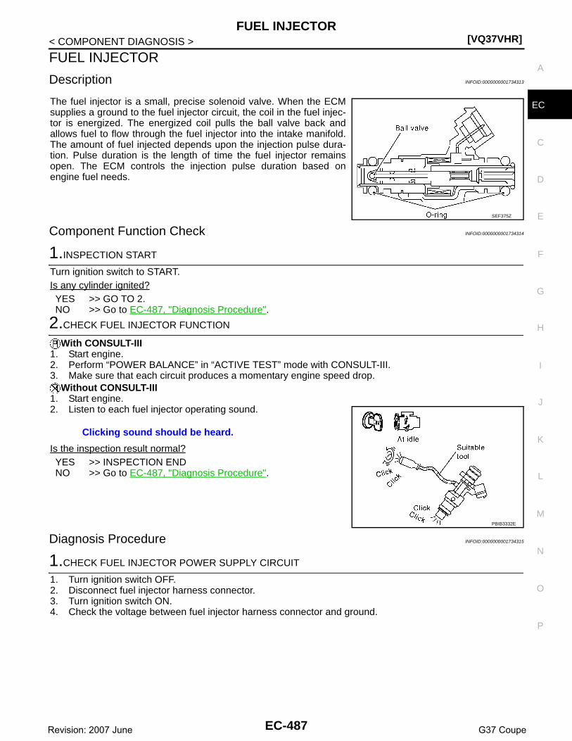
FUEL INJECTOR[VQ37VHR]
C
D
E
F
G
H
I
J
K
L
M
A
C
N
P
O
< COMPONENT DIAGNOSIS >
E
FUEL INJECTOR
Description INFOID:0000000001734313
The fuel injector is a small, precise solenoid valve. When the ECMsupplies a ground to the fuel injector circuit, the coil in the fuel injec-tor is energized. The energized coil pulls the ball valve back andallows fuel to flow through the fuel injector into the intake manifold.The amount of fuel injected depends upon the injection pulse dura-tion. Pulse duration is the length of time the fuel injector remainsopen. The ECM controls the injection pulse duration based onengine fuel needs.
Component Function Check INFOID:0000000001734314
1.INSPECTION START
Turn ignition switch to START.Is any cylinder ignited?YES >> GO TO 2.NO >> Go to EC-487, "Diagnosis Procedure".
2.CHECK FUEL INJECTOR FUNCTION
With CONSULT-III1. Start engine.2. Perform “POWER BALANCE” in “ACTIVE TEST” mode with CONSULT-III.3. Make sure that each circuit produces a momentary engine speed drop.
Without CONSULT-III1. Start engine.2. Listen to each fuel injector operating sound.
Is the inspection result normal?YES >> INSPECTION ENDNO >> Go to EC-487, "Diagnosis Procedure".
Diagnosis Procedure INFOID:0000000001734315
1.CHECK FUEL INJECTOR POWER SUPPLY CIRCUIT
1. Turn ignition switch OFF.2. Disconnect fuel injector harness connector.3. Turn ignition switch ON.4. Check the voltage between fuel injector harness connector and ground.
SEF375Z
Clicking sound should be heard.
PBIB3332E
EC-487Revision: 2007 June G37 Coupe

[VQ37VHR]FUEL INJECTOR
< COMPONENT DIAGNOSIS >
Is the inspection result normal?YES >> GO TO 3.NO >> GO TO 2.
2.DETECT MALFUNCTIONING PART
Check the following.• Harness connectors E3, F1• Harness connectors F10, F120• IPDM E/R harness connector E7• 10A fuse (No. 44)• Harness for open or short between fuel injector and fuse
>> Repair open circuit or short to ground or short to power in harness or connectors.
3.CHECK FUEL INJECTOR OUTPUT SIGNAL CIRCUIT FOR OPEN AND SHORT
1. Turn ignition switch OFF.2. Disconnect ECM harness connector.3. Check the continuity between fuel injector harness connector and ECM harness connector.
4. Also check harness for short to ground and short to power.Is the inspection result normal?YES >> GO TO 5.NO >> GO TO 4
4.DETECT MALFUNCTIONING PART
Check the following.• Harness connectors F106, F107• Harness connectors F10, F120• Harness for open or short between fuel injector and ECM
>> Repair open circuit or short to ground or short to power in harness or connectors.
5.CHECK FUEL INJECTOR
Refer to EC-489, "Component Inspection".Is the inspection result normal?
Fuel injectorGround Voltage
Cylinder Connector Terminal
1 F121 1
Ground Battery voltage
2 F122 1
3 F123 1
4 F124 1
5 F125 1
6 F126 1
Fuel injector ECMContinuity
Cylinder Connector Terminal Connector Terminal
1 F121 2
F102
89
Existed
2 F122 2 85
3 F123 2 81
4 F124 2 90
5 F125 2 86
6 F126 2 82
EC-488Revision: 2007 June G37 Coupe

FUEL INJECTOR[VQ37VHR]
C
D
E
F
G
H
I
J
K
L
M
A
C
N
P
O
< COMPONENT DIAGNOSIS >
E
YES >> GO TO 6.NO >> Replace malfunctioning fuel injector.
6.CHECK INTERMITTENT INCIDENT
Refer to GI-38, "Intermittent Incident".Is the inspection result normal?YES >> Replace IPDM E/R.NO >> Repair open circuit or short to ground or short to power in harness or connectors.
Component Inspection INFOID:0000000001734316
1.CHECK FUEL INJECTOR
1. Turn ignition switch OFF.2. Disconnect fuel injector harness connector.3. Check resistance between fuel injector terminals as follows.
Is the inspection result normal?YES >> INSPECTION ENDNO >> Replace malfunctioning fuel injector.
Terminals Resistance
1 and 2 11.1 - 14.3 Ω [at 10 - 60°C (60 - 140°F)]
EC-489Revision: 2007 June G37 Coupe

[VQ37VHR]FUEL PUMP
< COMPONENT DIAGNOSIS >
FUEL PUMP
Description INFOID:0000000001734317
*: ECM determines the start signal status by the signals of engine speed and battery voltage.
The ECM activates the fuel pump for several seconds after the ignition switch is turned ON to improve enginestartability. If the ECM receives a engine speed signal from the camshaft position sensor (PHASE), it knowsthat the engine is rotating, and causes the pump to operate. If the engine speed signal is not received whenthe ignition switch is ON, the engine stalls. The ECM stops pump operation and prevents battery discharging,thereby improving safety. The ECM does not directly drive the fuel pump. It controls the ON/OFF fuel pumprelay, which in turn controls the fuel pump.
Component Function Check INFOID:0000000001734318
1.CHECK FUEL PUMP FUNCTION
1. Turn ignition switch ON.2. Pinch fuel feed hose (1) with two fingers.
Is the inspection result normal?YES >> INSPECTION ENDNO >> EC-490, "Diagnosis Procedure".
Diagnosis Procedure INFOID:0000000001734319
1.CHECK FUEL PUMP POWER SUPPLY CIRCUIT-I
1. Turn ignition switch OFF.2. Disconnect ECM harness connector.3. Turn ignition switch ON.4. Check the voltage between ECM harness connector and ground.
Is the inspection result normal?YES >> GO TO 4.NO >> GO TO 2.
2.CHECK FUEL PUMP POWER SUPPLY CIRCUIT-II
Sensor Input signal to ECM ECM Function Actuator
Crankshaft position sensor (POS)Camshaft position sensor (PHASE)
Engine speed*Fuel pump control
Fuel pump relay↓Fuel pumpBattery Battery voltage*
Condition Fuel pump operation
Ignition switch is turned to ON. Operates for 1 second.
Engine running and cranking Operates.
When engine is stopped Stops in 1.5 seconds.
Except as shown above Stops.
Fuel pressure pulsation should be felt on the fuel feed hose for 1 second after ignition switch is turned ON.
JMBIA0849ZZ
ECMGround Voltage
Connector Terminal
F101 22 Ground Battery voltage
EC-490Revision: 2007 June G37 Coupe

FUEL PUMP[VQ37VHR]
C
D
E
F
G
H
I
J
K
L
M
A
C
N
P
O
< COMPONENT DIAGNOSIS >
E
Check the voltage between IPDM E/R harness connector and ground.
Is the inspection result normal?YES >> GO TO 3.NO >> GO TO 10.
3.DETECT MALFUNCTIONING PART
Check the following.• Harness connectors E3, F1• Harness connectors F104, F105• Harness for open or short between IPDM E/R and ECM
>> Repair open circuit or short to ground or short to power in harness or connectors.
4.CHECK FUEL PUMP POWER SUPPLY CIRCUIT-III
1. Turn ignition switch OFF.2. Reconnect all harness connectors disconnected.3. Disconnect “fuel level sensor unit and fuel pump” harness connector.4. Turn ignition switch ON.5. Check the voltage between “fuel level sensor unit and fuel pump” harness connector and ground.
Is the inspection result normal?YES >> GO TO 8.NO >> GO TO 5.
5.CHECK 15A FUSE
1. Turn ignition switch OFF.2. Disconnect 15A fuse (No. 41) from IPDM E/R.3. Check 15A fuse.Is the inspection result normal?YES >> GO TO 6.NO >> Replace fuse.
6.CHECK FUEL PUMP POWER SUPPLY CIRCUIT-IV
1. Disconnect IPDM E/R harness connector E5.2. Check the continuity between IPDM E/R harness connector and “fuel level sensor unit and fuel pump”
harness connector.
3. Also check harness for short to ground and short to power.Is the inspection result normal?YES >> GO TO 10.NO >> GO TO 7.
IPDM E/RGround Voltage
Connector Terminal
E7 77 Ground Battery voltage
Fuel level sensor unit and fuel pump Ground Voltage
Connector Terminal
B22 1 GroundBattery voltage should exist for 1 second after ignition switch is turned ON.
IPDM E/RFuel level sensor unit
and fuel pump Continuity
Connector Terminal Connector Terminal
E5 13 B22 1 Existed
EC-491Revision: 2007 June G37 Coupe

[VQ37VHR]FUEL PUMP
< COMPONENT DIAGNOSIS >
7.DETECT MALFUNCTIONING PART
Check the following.• Harness connectors E104, B4• IPDM E/R harness connector E5• Harness for open or short between IPDM E/R and “fuel level sensor unit and fuel pump”
>> Repair open circuit or short to power in harness or connectors.
8.CHECK FUEL PUMP GROUND CIRCUIT
1. Turn ignition switch OFF.2. Disconnect dropping resistor harness connector.3. Check the continuity between “fuel level sensor unit and fuel pump” harness connector and ground.
4. Also check harness for short to power.Is the inspection result normal?YES >> GO TO 9.NO >> Repair open circuit or short to power in harness or connectors.
9.CHECK FUEL PUMP
Refer to EC-492, "Component Inspection".Is the inspection result normal?YES >> GO TO 10.NO >> Replace fuel pump.
10.CHECK INTERMITTENT INCIDENT
Refer to GI-38, "Intermittent Incident".Is the inspection result normal?YES >> Replace IPDM E/R.NO >> Repair or replace harness or connectors.
Component Inspection INFOID:0000000001734320
1.CHECK FUEL PUMP
1. Turn ignition switch OFF.2. Disconnect “fuel level sensor unit and fuel pump” harness connector.3. Check resistance between “fuel level sensor unit and fuel pump” terminals as follows.
Is the inspection result normal?YES >> INSPECTION ENDNO >> Replace “fuel level sensor unit and fuel pump”
Fuel level sensor unit and fuel pump Ground Continuity
Connector Terminal
B22 3 Ground Existed
Terminals Resistance
1 and 3 0.2 - 5.0 Ω [at 25°C (77°F)]
EC-492Revision: 2007 June G37 Coupe

ICC BRAKE SWITCH[VQ37VHR]
C
D
E
F
G
H
I
J
K
L
M
A
C
N
P
O
< COMPONENT DIAGNOSIS >
E
ICC BRAKE SWITCH
Description INFOID:0000000001911045
When the brake pedal is depressed, ICC brake switch is turned OFF and stop lamp switch is turned ON. ECMdetects the state of the brake pedal by this input of two kinds (ON/OFF signal).Refer to CCS-15, "System Description" for the ICC function.
Component Function Check INFOID:0000000001734322
1.CHECK ICC BRAKE SWITCH FUNCTION
With CONSULT-III1. Turn ignition switch ON.2. Select “BRAKE SW1” in “DATA MONITOR” mode with CONSULT-III.3. Check “BRAKE SW1” indication under the following conditions.
Without CONSULT-III1. Turn ignition switch ON.2. Check the voltage between ECM harness connector and ground.
Is the inspection result normal?YES >> INSPECTION ENDNO >> Go to EC-493, "Diagnosis Procedure".
Diagnosis Procedure INFOID:0000000001734323
1.INSPECTION START
Check which type of transmission the vehicle is equipped with.Which type of transmission?A/T >> GO TO 2.M/T >> GO TO 7.
2.CHECK ICC BRAKE SWITCH POWER SUPPLY CIRCUIT
1. Turn ignition switch OFF.2. Disconnect ICC brake switch harness connector.3. Turn ignition switch ON.4. Check the voltage between ICC brake switch harness connector and ground.
Is the inspection result normal?YES >> GO TO 4.NO >> GO TO 3.
3.DETECT MALFUNCTIONING PART
Monitor item Condition Indication
BRAKE SW1Brake pedal (A/T)Brake pedal and clutch pedal (M/T)
Slightly depressed OFF
Fully released ON
ECMGround Condition Voltage
Connector Terminal
M107126
(ICC brake switch signal)Ground
Brake pedal (A/T)Brake pedal and clutch pedal (M/T)
Slightly depressed Approx. 0V
Fully released Battery voltage
ICC brake switchGround Voltage
Connector Terminal
E114 1 Ground Battery voltage
EC-493Revision: 2007 June G37 Coupe

[VQ37VHR]ICC BRAKE SWITCH
< COMPONENT DIAGNOSIS >Check the following.• Fuse block (J/B) connector E103• 10A fuse (No. 3)• Harness for open or short between ICC brake switch and fuse
>> Repair open circuit or short to ground in harness or connectors.
4.CHECK ICC BRAKE SWITCH INPUT SIGNAL CIRCUIT FOR OPEN AND SHORT-II
1. Turn ignition switch OFF.2. Disconnect ECM harness connector.3. Check the continuity between ICC brake switch harness connector and ECM harness connector.
4. Also check harness for short to ground and short to power.Is the inspection result normal?YES >> GO TO 6.NO >> GO TO 5.
5.DETECT MALFUNCTIONING PART
Check the following.• Harness connectors E106, M6• Harness for open or short between ICC brake switch and ECM
>> Repair open circuit or short to ground or short to power in harness or connectors.
6.CHECK ICC BRAKE SWITCH
Refer to EC-496, "Component Inspection (ICC Brake Switch)".Is the inspection result normal?YES >> GO TO 15.NO >> Replace ICC brake switch.
7.CHECK ICC BRAKE SWITCH CIRCUIT
1. Turn ignition switch OFF.2. Disconnect ICC brake switch harness connector.3. Turn ignition switch ON.4. Check the voltage between ICC brake switch harness connector and ground.
Is the inspection result normal?YES >> GO TO 12.NO >> GO TO 8.
8.CHECK ICC BRAKE SWITCH POWER SUPPLY CIRCUIT
1. Turn ignition switch OFF.2. Disconnect ICC clutch switch harness connector.3. Turn ignition switch ON.4. Check the voltage between ICC clutch switch harness connector and ground.
ICC brake switch ECMContinuity
Connector Terminal Connector Terminal
E114 2 M107 126 Existed
ICC brake switchGround Condition Voltage
Connector Terminal
E114 1 Ground Brake pedalSlightly depressed Approx. 0V
Fully released Battery voltage
EC-494Revision: 2007 June G37 Coupe

ICC BRAKE SWITCH[VQ37VHR]
C
D
E
F
G
H
I
J
K
L
M
A
C
N
P
O
< COMPONENT DIAGNOSIS >
EIs the inspection result normal?YES >> GO TO 10.NO >> GO TO 9.
9.DETECT MALFUNCTIONING PART
Check the following.• Fuse block (J/B) connector E103• 10A fuse (No. 3)• Harness for open or short between ICC clutch switch and fuse
>> Repair open circuit or short to ground in harness or connectors.
10.CHECK ICC BRAKE SWITCH INPUT SIGNAL CIRCUIT FOR OPEN AND SHORT
1. Turn ignition switch OFF.2. Check the continuity between ICC clutch switch harness connector and ICC brake switch harness con-
nector.
3. Also check harness for short to ground and short to power.Is the inspection result normal?YES >> GO TO 11.NO >> Repair open circuit or short to ground or short to power in harness or connectors.
11.CHECK ICC CLUTCH SWITCH
Refer to EC-496, "Component Inspection (ICC Clutch Switch)".Is the inspection result normal?YES >> GO TO 15.NO >> Replace ICC clutch switch.
12.CHECK ICC BRAKE SWITCH INPUT SIGNAL CIRCUIT FOR OPEN AND SHORT
1. Turn ignition switch OFF.2. Disconnect ECM harness connector.3. Check the continuity between ICC brake switch harness connector and ECM harness connector.
4. Also check harness for short to ground and short to power.Is the inspection result normal?YES >> GO TO 14.NO >> GO TO 13.
13.DETECT MALFUNCTIONING PART
Check the following.• Harness connectors E106, M6• Harness for open or short between ICC brake switch and ECM
>> Repair open circuit or short to ground or short to power in harness or connectors.
ICC clutch switchGround Voltage
Connector Terminal
E113 1 Ground Battery voltage
ICC clutch switch ICC brake switchContinuity
Connector Terminal Connector Terminal
E113 2 E114 1 Existed
ICC brake switch ECMContinuity
Connector Terminal Connector Terminal
E109 1 M107 126 Existed
EC-495Revision: 2007 June G37 Coupe

[VQ37VHR]ICC BRAKE SWITCH
< COMPONENT DIAGNOSIS >
14.CHECK ICC BRAKE SWITCH
Refer to EC-496, "Component Inspection (ICC Brake Switch)".Is the inspection result normal?YES >> GO TO 15.NO >> Replace ICC brake switch.
15.CHECK INTERMITTENT INCIDENT
Refer to GI-38, "Intermittent Incident".
>> INSPECTION END
Component Inspection (ICC Brake Switch) INFOID:0000000001911046
1.CHECK ICC BRAKE SWITCH-I
1. Turn ignition switch OFF.2. Disconnect ICC brake switch harness connector.3. Check the continuity between ICC brake switch terminals under the following conditions.
Is the inspection result normal?YES >> INSPECTION ENDNO >> GO TO 2.
2.CHECK ICC BRAKE SWITCH-II
1. Adjust ICC brake switch installation. Refer to BR-7, "Inspection and Adjustment".2. Check the continuity between ICC brake switch terminals under the following conditions.
Is the inspection result normal?YES >> INSPECTION ENDNO >> Replace ICC brake switch.
Component Inspection (ICC Clutch Switch) INFOID:0000000001911047
1.CHECK ICC CLUTCH SWITCH-I
1. Turn ignition switch OFF.2. Disconnect ICC clutch switch harness connector.3. Check the continuity between ICC clutch switch terminals under the following conditions.
Is the inspection result normal?YES >> INSPECTION ENDNO >> GO TO 2.
2.CHECK ICC CLUTCH SWITCH-II
1. Adjust ICC clutch switch installation. Refer to CL-5, "Inspection and Adjustment".2. Check the continuity between ICC clutch switch terminals under the following conditions.
Terminals Condition Continuity
1 and 2 Brake pedalFully released Existed
Slightly depressed Not existed
Terminals Condition Continuity
1 and 2 Brake pedalFully released Existed
Slightly depressed Not existed
Terminals Condition Continuity
1 and 2 Clutch pedalFully released Existed
Slightly depressed Not existed
EC-496Revision: 2007 June G37 Coupe

ICC BRAKE SWITCH[VQ37VHR]
C
D
E
F
G
H
I
J
K
L
M
A
C
N
P
O
< COMPONENT DIAGNOSIS >
EIs the inspection result normal?YES >> INSPECTION ENDNO >> Replace ICC clutch switch.
Terminals Condition Continuity
1 and 2 Clutch pedalFully released Existed
Slightly depressed Not existed
EC-497Revision: 2007 June G37 Coupe

[VQ37VHR]IGNITION SIGNAL
< COMPONENT DIAGNOSIS >
IGNITION SIGNAL
Description INFOID:0000000001734326
The ignition signal from the ECM is sent to and amplified by the power transistor. The power transistor turnsON and OFF the ignition coil primary circuit. This ON/OFF operation induces the proper high voltage in the coilsecondary circuit.
Component Function Check INFOID:0000000001734327
1.INSPECTION START
Turn ignition switch OFF, and restart engine.Does the engine start?YES-1 >> With CONSULT-III: GO TO 2.YES-2 >> Without CONSULT-III: GO TO 3.No >> Go to EC-498, "Diagnosis Procedure".
2.CHECK IGNITION SIGNAL FUNCTION
With CONSULT-III1. Perform “POWER BALANCE” in “ACTIVE TEST” mode with CONSULT-III.2. Make sure that each circuit produces a momentary engine speed drop.Is the inspection result normal?YES >> INSPECTION ENDNO >> Go to EC-498, "Diagnosis Procedure".
3.CHECK IGNITION SIGNAL FUNCTION
Without CONSULT-III1. Let engine idle.2. Read the voltage signal between ECM harness connector and ground with an oscilloscope.
NOTE:
The pulse cycle changes depending on rpm at idle.
Is the inspection result normal?YES >> INSPECTION ENDNO >> Go to EC-498, "Diagnosis Procedure".
Diagnosis Procedure INFOID:0000000001734328
1.CHECK IGNITION COIL POWER SUPPLY CIRCUIT-I
1. Turn ignition switch OFF, wait at least 10 seconds and then turn ON.2. Check the voltage between ECM harness connector and ground.
ECMGround Voltage signal
Connector Terminal
F101
11
Ground
12
15
16
19
20 JMBIA0035GB
ECMGround Voltage
Connector Terminal
M107 125 Ground Battery voltage
EC-498Revision: 2007 June G37 Coupe

IGNITION SIGNAL[VQ37VHR]
C
D
E
F
G
H
I
J
K
L
M
A
C
N
P
O
< COMPONENT DIAGNOSIS >
E
Is the inspection result normal?YES >> GO TO 2.NO >> Go to EC-140, "Diagnosis Procedure".
2.CHECK IGNITION COIL POWER SUPPLY CIRCUIT-II
1. Turn ignition switch OFF.2. Disconnect condenser harness connector.3. Turn ignition switch ON.4. Check the voltage between condenser harness connector and ground.
Is the inspection result normal?YES >> GO TO 5.NO >> GO TO 3.
3.CHECK IGNITION COIL POWER SUPPLY CIRCUIT-III
1. Turn ignition switch OFF.2. Disconnect IPDM E/R harness connector E7.3. Check the continuity between IPDM E/R harness connector and condenser harness connector.
4. Also check harness for short to ground and short to power.Is the inspection result normal?YES >> Go to EC-140, "Diagnosis Procedure".NO >> GO TO 4.
4.DETECT MALFUNCTIONING PART
Check the following.• Harness connectors E3, F1• Harness for open or short between IPDM E/R and condenser
>> Repair open circuit or short to ground or short to power in harness or connectors.
5.CHECK CONDENSER GROUND CIRCUIT FOR OPEN AND SHORT
1. Turn ignition switch OFF.2. Check the continuity between condenser harness connector and ground.
3. Also check harness for short to power.Is the inspection result normal?YES >> GO TO 6.NO >> Repair open circuit or short to power in harness or connectors.
6.CHECK CONDENSER
Refer to EC-502, "Component Inspection (Condenser)"Is the inspection result normal?YES >> GO TO 7.NO >> Replace condenser.
CondenserGround Voltage
Connector Terminal
F8 1 Ground Battery voltage
IPDM E/R CondenserContinuity
Connector Terminal Connector Terminal
E7 53 F8 1 Existed
CondenserGround Continuity
Connector Terminal
F8 2 Ground Existed
EC-499Revision: 2007 June G37 Coupe

[VQ37VHR]IGNITION SIGNAL
< COMPONENT DIAGNOSIS >
7.CHECK IGNITION COIL POWER SUPPLY CIRCUIT-IV
1. Reconnect all harness connectors disconnected.2. Disconnect ignition coil harness connector.3. Turn ignition switch ON.4. Check the voltage between ignition coil harness connector and ground.
Is the inspection result normal?YES >> GO TO 9.NO >> GO TO 8.
8.DETECT MALFUNCTIONING PART
Check the following.• Harness connector F1• Harness for open or short between ignition coil and harness connector F1
>> Repair or replace harness or connectors.
9.CHECK IGNITION COIL GROUND CIRCUIT FOR OPEN AND SHORT
1. Turn ignition switch OFF.2. Check the continuity between ignition coil harness connector and ground.
3. Also check harness for short to power.Is the inspection result normal?YES >> GO TO 10.NO >> Repair open circuit or short to power in harness or connectors.
10.CHECK IGNITION COIL OUTPUT SIGNAL CIRCUIT FOR OPEN AND SHORT
1. Disconnect ECM harness connector.2. Check the continuity between ignition coil harness connector and ECM harness connector.
Ignition coilGround Voltage
Cylinder Connector Terminal
1 F11 3
Ground Battery voltage
2 F12 3
3 F13 3
4 F14 3
5 F15 3
6 F16 3
Ignition coilGround Continuity
Cylinder Connector Terminal
1 F11 2
Ground Existed
2 F12 2
3 F13 2
4 F14 2
5 F15 2
6 F16 2
EC-500Revision: 2007 June G37 Coupe

IGNITION SIGNAL[VQ37VHR]
C
D
E
F
G
H
I
J
K
L
M
A
C
N
P
O
< COMPONENT DIAGNOSIS >
E
3. Also check harness for short to ground and short to power.Is the inspection result normal?YES >> GO TO 12.NO >> GO TO 11.
11.DETECT MALFUNCTIONING PART
Check the following.• Harness connectors F104, F105• Harness for open or short between ignition coil and ECM
>> Repair open circuit or short to ground or short to power in harness or connectors.
12.CHECK IGNITION COIL WITH POWER TRANSISTOR
Refer to EC-501, "Component Inspection (Ignition Coil with Power Transistor)".Is the inspection result normal?YES >> GO TO 13.NO >> Replace malfunctioning ignition coil with power transistor.
13.CHECK INTERMITTENT INCIDENT
Refer to GI-38, "Intermittent Incident".
>> INSPECTION END
Component Inspection (Ignition Coil with Power Transistor) INFOID:0000000001734329
1.CHECK IGNITION COIL WITH POWER TRANSISTOR-I
1. Turn ignition switch OFF.2. Disconnect ignition coil harness connector.3. Check resistance between ignition coil terminals as follows.
Is the inspection result normal?YES >> GO TO 2.NO >> Replace malfunctioning ignition coil with power transistor.
2.CHECK IGNITION COIL WITH POWER TRANSISTOR-II
CAUTION:Do the following procedure in the place where ventilation is good without the combustible.1. Turn ignition switch OFF.2. Reconnect all harness connectors disconnected.
Ignition coil ECMContinuity
Cylinder Connector Terminal Connector Terminal
1 F11 1
F101
20
Existed
2 F12 1 16
3 F13 1 12
4 F14 1 11
5 F15 1 15
6 F16 1 19
Terminals Resistance [at 25°C (77°F)]
1 and 2 Except 0 or ∞Ω
1 and 3Except 0 Ω
2 and 3
EC-501Revision: 2007 June G37 Coupe

[VQ37VHR]IGNITION SIGNAL
< COMPONENT DIAGNOSIS >3. Remove fuel pump fuse (1) in IPDM E/R (2) to release fuel pres-
sure.NOTE:Do not use CONSULT-III to release fuel pressure, or fuel pres-sure applies again during the following procedure.
4. Start engine.5. After engine stalls, crank it two or three times to release all fuel
pressure.6. Turn ignition switch OFF.7. Remove all ignition coil harness connectors to avoid the electri-
cal discharge from the ignition coils.8. Remove ignition coil and spark plug of the cylinder to be
checked.9. Crank engine for 5 seconds or more to remove combustion gas in the cylinder.10. Connect spark plug and harness connector to ignition coil.11. Fix ignition coil using a rope etc. with gap of 13 - 17 mm (0.52 -
0.66 in) between the edge of the spark plug and grounded metalportion as shown in the figure.
12. Crank engine for about three seconds, and check whether sparkis generated between the spark plug and the grounded metalportion.
CAUTION:• Do not approach to the spark plug and the ignition coil
within 50 cm (19.7 in). Be careful not to get an electricalshock while checking, because the electrical dischargevoltage becomes 20kV or more.
• It might cause to damage the ignition coil if the gap of more than 17 mm 0.66 in) is taken.NOTE:When the gap is less than 13 mm (0.52 in), the spark might be generated even if the coil is mal-functioning.
Is the inspection result normal?YES >> INSPECTION ENDNO >> Replace malfunctioning ignition coil with power transistor.
Component Inspection (Condenser) INFOID:0000000001734330
1.CHECK CONDENSER
1. Turn ignition switch OFF.2. Disconnect condenser harness connector.3. Check resistance between condenser terminals as follows.
Is the inspection result normal?YES >> INSPECTION ENDNO >> Replace condenser.
Spark should be generated.
JMBIA0021ZZ
JMBIA0066GB
Terminals Resistance
1 and 2 Above 1 MΩ [at 25°C (77°F)]
EC-502Revision: 2007 June G37 Coupe
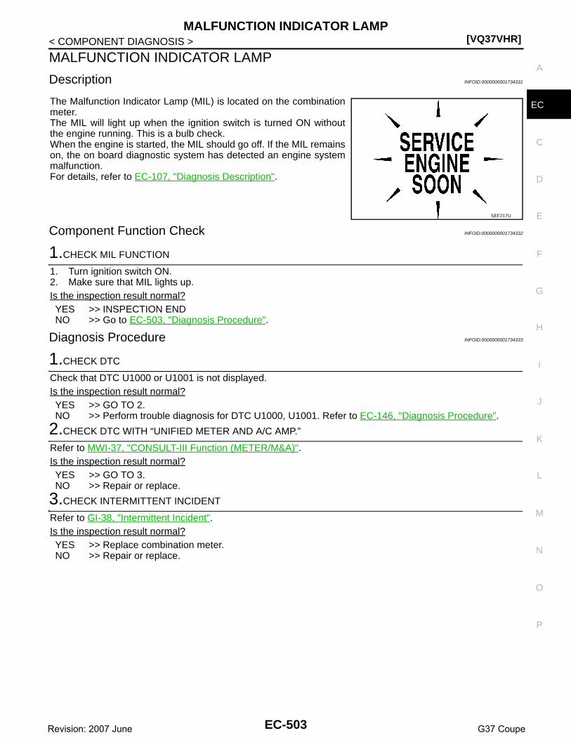
MALFUNCTION INDICATOR LAMP[VQ37VHR]
C
D
E
F
G
H
I
J
K
L
M
A
C
N
P
O
< COMPONENT DIAGNOSIS >
E
MALFUNCTION INDICATOR LAMP
Description INFOID:0000000001734331
The Malfunction Indicator Lamp (MIL) is located on the combinationmeter.The MIL will light up when the ignition switch is turned ON withoutthe engine running. This is a bulb check.When the engine is started, the MIL should go off. If the MIL remainson, the on board diagnostic system has detected an engine systemmalfunction.For details, refer to EC-107, "Diagnosis Description".
Component Function Check INFOID:0000000001734332
1.CHECK MIL FUNCTION
1. Turn ignition switch ON.2. Make sure that MIL lights up.Is the inspection result normal?YES >> INSPECTION ENDNO >> Go to EC-503, "Diagnosis Procedure".
Diagnosis Procedure INFOID:0000000001734333
1.CHECK DTC
Check that DTC U1000 or U1001 is not displayed.Is the inspection result normal?YES >> GO TO 2.NO >> Perform trouble diagnosis for DTC U1000, U1001. Refer to EC-146, "Diagnosis Procedure".
2.CHECK DTC WITH “UNIFIED METER AND A/C AMP.”
Refer to MWI-37, "CONSULT-III Function (METER/M&A)".Is the inspection result normal?YES >> GO TO 3.NO >> Repair or replace.
3.CHECK INTERMITTENT INCIDENT
Refer to GI-38, "Intermittent Incident".Is the inspection result normal?YES >> Replace combination meter.NO >> Repair or replace.
SEF217U
EC-503Revision: 2007 June G37 Coupe

[VQ37VHR]ON BOARD REFUELING VAPOR RECOVERY (ORVR)
< COMPONENT DIAGNOSIS >
ON BOARD REFUELING VAPOR RECOVERY (ORVR)
Description INFOID:0000000001734334
From the beginning of refueling, the air and vapor inside the fuel tank go through refueling EVAP vapor cutvalve and EVAP/ORVR line to the EVAP canister. The vapor is absorbed by the EVAP canister and the air isreleased to the atmosphere.When the refueling has reached the full level of the fuel tank, the refueling EVAP vapor cut valve is closed andrefueling is stopped because of auto shut-off. The vapor which was absorbed by the EVAP canister is purgedduring driving.WARNING:When conducting inspections below, be sure to observe the following:• Put a “CAUTION: FLAMMABLE” sign in workshop.• Do not smoke while servicing fuel system. Keep open flames and sparks away from work area.• Be sure to furnish the workshop with a CO2 fire extinguisher.CAUTION:• Before removing fuel line parts, carry out the following procedures:- Put drained fuel in an explosion-proof container and put lid on securely.- Release fuel pressure from fuel line. Refer to EC-601, "Inspection".- Disconnect battery ground cable.• Always replace O-ring when the fuel gauge retainer is removed.• Do not kink or twist hose and tube when they are installed.• Do not tighten hose and clamps excessively to avoid damaging hoses.• After installation, run engine and check for fuel leaks at connection.• Do not attempt to top off the fuel tank after the fuel pump nozzle shuts off automatically.
Continued refueling may cause fuel overflow, resulting in fuel spray and possibly a fire.
Component Function Check INFOID:0000000001734335
1.CHECK ORVR FUNCTION
Check whether the following symptoms are present.• Fuel odor from EVAP canister is strong.• Cannot refuel/Fuel odor from the fuel filler opening is strong while refueling.Is any symptom present?YES >> Go to EC-504, "Diagnosis Procedure".NO >> INSPECTION END
Diagnosis Procedure INFOID:0000000001734336
1.INSPECTION START
Check whether the following symptoms are present.A: Fuel odor from EVAP canister is strong.
PBIB1068E
EC-504Revision: 2007 June G37 Coupe
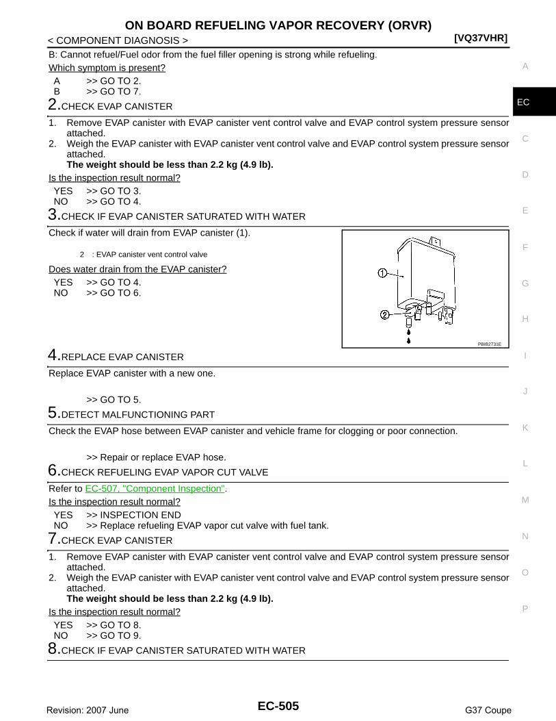
ON BOARD REFUELING VAPOR RECOVERY (ORVR)[VQ37VHR]
C
D
E
F
G
H
I
J
K
L
M
A
C
N
P
O
< COMPONENT DIAGNOSIS >
E
B: Cannot refuel/Fuel odor from the fuel filler opening is strong while refueling.Which symptom is present?A >> GO TO 2.B >> GO TO 7.
2.CHECK EVAP CANISTER
1. Remove EVAP canister with EVAP canister vent control valve and EVAP control system pressure sensorattached.
2. Weigh the EVAP canister with EVAP canister vent control valve and EVAP control system pressure sensorattached.The weight should be less than 2.2 kg (4.9 lb).
Is the inspection result normal?YES >> GO TO 3.NO >> GO TO 4.
3.CHECK IF EVAP CANISTER SATURATED WITH WATER
Check if water will drain from EVAP canister (1).
Does water drain from the EVAP canister?YES >> GO TO 4.NO >> GO TO 6.
4.REPLACE EVAP CANISTER
Replace EVAP canister with a new one.
>> GO TO 5.
5.DETECT MALFUNCTIONING PART
Check the EVAP hose between EVAP canister and vehicle frame for clogging or poor connection.
>> Repair or replace EVAP hose.
6.CHECK REFUELING EVAP VAPOR CUT VALVE
Refer to EC-507, "Component Inspection".Is the inspection result normal?YES >> INSPECTION ENDNO >> Replace refueling EVAP vapor cut valve with fuel tank.
7.CHECK EVAP CANISTER
1. Remove EVAP canister with EVAP canister vent control valve and EVAP control system pressure sensorattached.
2. Weigh the EVAP canister with EVAP canister vent control valve and EVAP control system pressure sensorattached.The weight should be less than 2.2 kg (4.9 lb).
Is the inspection result normal?YES >> GO TO 8.NO >> GO TO 9.
8.CHECK IF EVAP CANISTER SATURATED WITH WATER
2 : EVAP canister vent control valve
PBIB2731E
EC-505Revision: 2007 June G37 Coupe

[VQ37VHR]ON BOARD REFUELING VAPOR RECOVERY (ORVR)
< COMPONENT DIAGNOSIS >Check if water will drain from EVAP canister (1).
Does water drain from the EVAP canister?YES >> GO TO 9.NO >> GO TO 11.
9.REPLACE EVAP CANISTER
Replace EVAP canister with a new one.
>> GO TO 10.
10.DETECT MALFUNCTIONING PART
Check the EVAP hose between EVAP canister and vehicle frame for clogging or poor connection.
>> Repair or replace EVAP hose.
11.CHECK VENT HOSES AND VENT TUBES
Check hoses and tubes between EVAP canister and refueling control valve for clogging, kink, looseness andimproper connection.Is the inspection result normal?YES >> GO TO 12.NO >> Repair or replace hoses and tubes.
12.CHECK FILLER NECK TUBE
Check recirculation line for clogging, dents and cracks. Is the inspection result normal?YES >> GO TO 13.NO >> Replace filler neck tube.
13.CHECK REFUELING EVAP VAPOR CUT VALVE
Refer to EC-507, "Component Inspection".Is the inspection result normal?YES >> GO TO 14.NO >> Replace refueling EVAP vapor cut valve with fuel tank.
14.CHECK FUEL FILLER TUBE
Check filler neck tube and hose connected to the fuel tank for clogging, dents and cracks.Is the inspection result normal?YES >> GO TO 15.NO >> Replace fuel filler tube.
15.CHECK ONE-WAY FUEL VALVE-I
Check one-way valve for clogging.Is the inspection result normal?YES >> GO TO 16.NO >> Repair or replace one-way fuel valve with fuel tank.
16.CHECK ONE-WAY FUEL VALVE-II
1. Make sure that fuel is drained from the tank.2. Remove fuel filler tube and hose.
2 : EVAP canister vent control valve
PBIB2731E
EC-506Revision: 2007 June G37 Coupe

ON BOARD REFUELING VAPOR RECOVERY (ORVR)[VQ37VHR]
C
D
E
F
G
H
I
J
K
L
M
A
C
N
P
O
< COMPONENT DIAGNOSIS >
E
3. Check one-way fuel valve for operation as follows.When a stick is inserted, the valve should open, when removingstick it should close.Do not drop any material into the tank.
Is the inspection result normal?YES >> INSPECTION ENDNO >> Replace fuel filler tube or replace one-way fuel valve
with fuel tank.
Component Inspection INFOID:0000000001734337
1.INSPECTION START
Do you have CONSULT-III?Do you have CONSULT-III?YES >> GO TO 2.NO >> GO TO 3.
2.CHECK REFUELING EVAP VAPOR CUT VALVE
With CONSULT-III1. Turn ignition switch OFF.2. Remove fuel tank. Refer to FL-10, "Removal and Installation".3. Drain fuel from the tank as follows:- Remove fuel feed hose located on the fuel gauge retainer.- Connect a spare fuel hose, one side to fuel gauge retainer where the hose was removed and the other
side to a fuel container.- Drain fuel using “FUEL PUMP RELAY” in “ACTIVE TEST” mode with CONSULT-III.4. Check refueling EVAP vapor cut valve for being stuck to close as follows.
Blow air into the refueling EVAP vapor cut valve (from the end of EVAP/ORVR line hose), and check thatthe air flows freely into the tank.
5. Check refueling EVAP vapor cut valve for being stuck to open as follows.- Connect vacuum pump to hose end.- Remove fuel gauge retainer with fuel gauge unit.
Always replace O-ring with new one.- Put fuel tank upside down.- Apply vacuum pressure to hose end [−13.3 kPa (−0.136 kg/cm3, −1.93 psi)] with fuel gauge retainer
remaining open and check that the pressure is applicable.
Is the inspection result normal?YES >> INSPECTION END
SEF665U
PBIB1035E
EC-507Revision: 2007 June G37 Coupe

[VQ37VHR]ON BOARD REFUELING VAPOR RECOVERY (ORVR)
< COMPONENT DIAGNOSIS >NO >> Replace refueling EVAP vapor cut valve with fuel tank.
3.CHECK REFUELING EVAP VAPOR CUT VALVE
Without CONSULT-III1. Turn ignition switch OFF.2. Remove fuel tank. Refer to FL-10, "Removal and Installation".3. Drain fuel from the tank as follows:- Remove fuel gauge retainer.- Drain fuel from the tank using a handy pump into a fuel container.4. Check refueling EVAP vapor cut valve for being stuck to close as follows.
Blow air into the refueling EVAP vapor cut valve (from the end of EVAP/ORVR line hose), and check thatthe air flows freely into the tank.
5. Check refueling EVAP vapor cut valve for being stuck to open as follows.- Connect vacuum pump to hose end.- Remove fuel gauge retainer with fuel gauge unit.
Always replace O-ring with new one.- Put fuel tank upside down.- Apply vacuum pressure to hose end [−13.3 kPa (−0.136 kg/cm3, −1.93 psi)] with fuel gauge retainer
remaining open and check that the pressure is applicable.
Is the inspection result normal?YES >> INSPECTION ENDNO >> Replace refueling EVAP vapor cut valve with fuel tank.
PBIB1035E
EC-508Revision: 2007 June G37 Coupe

POSITIVE CRANKCASE VENTILATION[VQ37VHR]
C
D
E
F
G
H
I
J
K
L
M
A
C
N
P
O
< COMPONENT DIAGNOSIS >
E
POSITIVE CRANKCASE VENTILATION
Description INFOID:0000000001734338
This system returns blow-by gas to the intake manifold.The positive crankcase ventilation (PCV) valve is provided to conduct crankcase blow-by gas to the intakemanifold.During partial throttle operation of the engine, the intake manifold sucks the blow-by gas through the PCVvalve.Normally, the capacity of the valve is sufficient to handle any blow-by and a small amount of ventilating air.The ventilating air is then drawn from the air inlet tubes into the crankcase. In this process the air passesthrough the hose connecting air inlet tubes to rocker cover.Under full-throttle condition, the manifold vacuum is insufficient to draw the blow-by flow through the valve.The flow goes through the hose connection in the reverse direction.On vehicles with an excessively high blow-by, the valve does notmeet the requirement. This is because some of the flow will gothrough the hose connection to the air inlet tubes under all condi-tions.
Component Inspection INFOID:0000000001734339
1.CHECK PCV VALVE
1. PCV valve 2. Electric throttle control actuator 3. Mass air flow sensor
A. Normal condition B. Hi-load condition
: Fresh air
: Blow-by air
JMBIA0858ZZ
PBIB1588E
EC-509Revision: 2007 June G37 Coupe

[VQ37VHR]POSITIVE CRANKCASE VENTILATION
< COMPONENT DIAGNOSIS >With engine running at idle, remove PCV valve from rocker cover. Aproperly working valve makes a hissing noise as air passes throughit. A strong vacuum should be felt immediately when a finger isplaced over valve inlet.Is the inspection result normal?YES >> INSPECTION ENDNO >> Replace PCV valve.
PBIB1589E
EC-510Revision: 2007 June G37 Coupe

REFRIGERANT PRESSURE SENSOR[VQ37VHR]
C
D
E
F
G
H
I
J
K
L
M
A
C
N
P
O
< COMPONENT DIAGNOSIS >
E
REFRIGERANT PRESSURE SENSOR
Description INFOID:0000000001734340
The refrigerant pressure sensor is installed at the condenser of the air conditioner system. The sensor uses anelectrostatic volume pressure transducer to convert refrigerant pressure to voltage. The voltage signal is sentto ECM, and ECM controls cooling fan system.
Component Function Check INFOID:0000000001734341
1.CHECK REFRIGERANT PRESSURE SENSOR FUNCTION
1. Start engine and warm it up to normal operating temperature.2. Turn A/C switch and blower fan switch ON.3. Check the voltage between ECM harness connector and ground.
Is the inspection result normal?YES >> INSPECTION ENDNO >> Go to EC-511, "Diagnosis Procedure".
Diagnosis Procedure INFOID:0000000001734342
1.CHECK GROUND CONNECTION
1. Turn A/C switch and blower fan switch OFF.2. Turn ignition switch OFF.3. Check ground connection M95. Refer to Ground Inspection in GI-41, "Circuit Inspection".Is the inspection result normal?YES >> GO TO 2.NO >> Repair or replace ground connection.
2.CHECK REFRIGERANT PRESSURE SENSOR POWER SUPPLY CIRCUIT
1. Disconnect refrigerant pressure sensor harness connector.2. Turn ignition switch ON.3. Check the voltage between refrigerant pressure sensor harness connector and ground.
Is the inspection result normal?YES >> GO TO 4.NO >> GO TO 3.
PBIB2657E
ECMGround Voltage
Connector Terminal
M107105
(Refrigerant pressure sensor signal)Ground 1.0 - 4.0V
Refrigerant pressure sensorGround Voltage
Connector Terminal
E77 3 Ground Approx. 5V
EC-511Revision: 2007 June G37 Coupe

[VQ37VHR]REFRIGERANT PRESSURE SENSOR
< COMPONENT DIAGNOSIS >
3.DETECT MALFUNCTIONING PART
Check the following.• Harness connectors M6, E106• Harness for open or short between ECM and refrigerant pressure sensor
>> Repair open circuit or short to ground or short to power in harness or connectors.
4.CHECK REFRIGERANT PRESSURE SENSOR GROUND CIRCUIT FOR OPEN AND SHORT
1. Turn ignition switch OFF.2. Disconnect ECM harness connector.3. Check the continuity between refrigerant pressure sensor harness connector and ECM harness connec-
tor.
4. Also check harness for short to ground and short to power.Is the inspection result normal?YES >> GO TO 6.NO >> GO TO 5.
5.DETECT MALFUNCTIONING PART
Check the following.• Harness connectors M6, E106• Harness for open or short between ECM and refrigerant pressure sensor
>> Repair open circuit or short to ground or short to power in harness or connectors.
6.CHECK REFRIGERANT PRESSURE SENSOR INPUT SIGNAL CIRCUIT FOR OPEN AND SHORT
1. Check the continuity between refrigerant pressure sensor harness connector and ECM harness connec-tor.
2. Also check harness for short to ground and short to power.Is the inspection result normal?YES >> GO TO 8.NO >> GO TO 7.
7.DETECT MALFUNCTIONING PART
Check the following.• Harness connectors M6, E106• Harness for open or short between ECM and refrigerant pressure sensor
>> Repair open circuit or short to ground or short to power in harness or connectors.
8.CHECK INTERMITTENT INCIDENT
Refer to GI-38, "Intermittent Incident".Is the inspection result normal?YES >> Replace refrigerant pressure sensor.NO >> Repair or replace.
Refrigerant pressure sensor ECMContinuity
Connector Terminal Connector Terminal
E77 1 M107 116 Existed
Refrigerant pressure sensor ECMContinuity
Connector Terminal Connector Terminal
E77 2 M107 105 Existed
EC-512Revision: 2007 June G37 Coupe

ECM[VQ37VHR]
C
D
E
F
G
H
I
J
K
L
M
A
C
N
P
O
< ECU DIAGNOSIS >
E
ECU DIAGNOSISECM
Reference Value INFOID:0000000001734347
VALUES ON THE DIAGNOSIS TOOLNOTE:• Specification data are reference values.• Specification data are output/input values which are detected or supplied by the ECM at the connector.
* Specification data may not be directly related to their components signals/values/operations.i.e. Adjust ignition timing with a timing light before monitoring IGN TIMING, because the monitor may showthe specification data in spite of the ignition timing not being adjusted to the specification data. this IGN TIM-ING monitors the data calculated by the ECM according to the signals input from the camshaft position sen-sor and other ignition timing related sensors.
CONSULT-III MONITOR ITEM
Monitor Item Condition Values/Status
ENG SPEED • Run engine and compare CONSULT-III value with the tachometer indication.Almost the same speed as the tachometer indication
MAS A/F SE-B1 See EC-132, "Description".
MAS A/F SE-B2 See EC-132, "Description".
B/FUEL SCHDL See EC-132, "Description".
A/F ALPHA-B1 See EC-132, "Description".
A/F ALPHA-B2 See EC-132, "Description".
COOLAN TEMP/S • Ignition switch: ONIndicates engine coolant temperature
A/F SEN1 (B1) • Engine: After warming up Maintaining engine speed at 2,000 rpm Fluctuates around 2.2 V
A/F SEN1 (B2) • Engine: After warming up Maintaining engine speed at 2,000 rpm Fluctuates around 2.2 V
HO2S2 (B1)
• Revving engine from idle up to 3,000 rpm quickly after the following conditions are met.
- Engine: After warming up- After keeping engine speed between 3,500 and 4,000 rpm for 1 minute and at
idle for 1 minute under no load
0 - 0.3V ←→ Approx. 0.6 - 1.0V
HO2S2 (B2)
• Revving engine from idle up to 3,000 rpm quickly after the following conditions are met.
- Engine: After warming up- After keeping engine speed between 3,500 and 4,000 rpm for 1 minute and at
idle for 1 minute under no load
0 - 0.3V ←→ Approx. 0.6 - 1.0V
HO2S2 MNTR (B1)
• Revving engine from idle up to 3,000 rpm quickly after the following conditions are met.
- Engine: After warming up- After keeping engine speed between 3,500 and 4,000 rpm for 1 minute and at
idle for 1 minute under no load
LEAN ←→ RICH
HO2S2 MNTR (B2)
• Revving engine from idle up to 3,000 rpm quickly after the following conditions are met.
- Engine: After warming up- After keeping engine speed between 3,500 and 4,000 rpm for 1 minute and at
idle for 1 minute under no load
LEAN ←→ RICH
VHCL SPEED SE• Turn drive wheels and compare CONSULT-III value with the speedometer indi-
cation.Almost the same speed as speedometer indication
BATTERY VOLT • Ignition switch: ON (Engine stopped) 11 - 14V
ACCEL SEN 1• Ignition switch: ON
(Engine stopped)
Accelerator pedal: Fully released 0.45 - 1.00V
Accelerator pedal: Fully depressed 4.4 - 4.8V
ACCEL SEN 2*1 • Ignition switch: ON(Engine stopped)
Accelerator pedal: Fully released 0.45 - 1.00V
Accelerator pedal: Fully depressed 4.3 - 4.8V
EC-513Revision: 2007 June G37 Coupe

[VQ37VHR]ECM
< ECU DIAGNOSIS >
TP SEN 1-B1• Ignition switch: ON
(Engine stopped)• Selector lever: D (A/T) or 1st (M/T)
Accelerator pedal: Fully released More than 0.36V
Accelerator pedal: Fully depressed Less than 4.75V
TP SEN 2-B1*1• Ignition switch: ON
(Engine stopped)• Selector lever: D (A/T) or 1st (M/T)
Accelerator pedal: Fully released More than 0.36V
Accelerator pedal: Fully depressed Less than 4.75V
FUEL T/TMP SE • Ignition switch: ONIndicates fuel tank tempera-ture
INT/A TEMP SE • Ignition switch: ONIndicates intake air temper-ature
EVAP SYS PRES • Ignition switch: ON Approx. 1.8 - 4.8V
FUEL LEVEL SE • Ignition switch: ONDepending on fuel level of fuel tank
START SIGNAL • Ignition switch: ON → START → ON OFF → ON → OFF
CLSD THL POS• Ignition switch: ON
(Engine stopped)
Accelerator pedal: Fully released ON
Accelerator pedal: Slightly depressed OFF
AIR COND SIG• Engine: After warming up, idle the
engine
Air conditioner switch: OFF OFF
Air conditioner switch: ON(Compressor operates.)
ON
P/N POSI SW • Ignition switch: ONSelector lever: P or N (A/T), Neutral (M/T) ON
Selector lever: Except above OFF
PW/ST SIGNAL• Engine: After warming up, idle the
engine
Steering wheel: Not being turned OFF
Steering wheel: Being turned ON
LOAD SIGNAL • Ignition switch: ON
Rear window defogger switch: ONand/orLighting switch: 2nd position
ON
Rear window defogger switch and lighting switch: OFF
OFF
IGNITION SW • Ignition switch: ON → OFF → ON ON → OFF → ON
HEATER FAN SW• Engine: After warming up, idle the
engine
Heater fan switch: ON ON
Heater fan switch: OFF OFF
BOOST VCUM SW• Always a certain value is displayed.• This items are not efficient for CV36 models.
BRAKE SW • Ignition switch: ONBrake pedal: Fully released OFF
Brake pedal: Slightly depressed ON
INJ PULSE-B1
• Engine: After warming up• Selector lever: P or N (A/T), Neu-
tral (M/T)• Air conditioner switch: OFF• No load
Idle 2.0 - 3.0 msec
2,000 rpm 1.9 - 2.9 msec
INJ PULSE-B2
• Engine: After warming up• Selector lever: P or N (A/T), Neu-
tral (M/T)• Air conditioner switch: OFF• No load
Idle 2.0 - 3.0 msec
2,000 rpm 1.9 - 2.9 msec
IGN TIMING
• Engine: After warming up• Selector lever: P or N (A/T), Neu-
tral (M/T)• Air conditioner switch: OFF• No load
Idle 7° BTDC
2,000 rpm 25° - 45° BTDC
Monitor Item Condition Values/Status
EC-514Revision: 2007 June G37 Coupe

ECM[VQ37VHR]
C
D
E
F
G
H
I
J
K
L
M
A
C
N
P
O
< ECU DIAGNOSIS >
ECAL/LD VALUE
• Engine: After warming up• Selector lever: P or N (A/T), Neu-
tral (M/T)• Air conditioner switch: OFF• No load
Idle 5% - 35%
2,500 rpm 5% - 35%
MASS AIRFLOW
• Engine: After warming up• Selector lever: P or N (A/T), Neu-
tral (M/T)• Air conditioner switch: OFF• No load
Idle 2.0 - 6.0 g·m/s
2,500 rpm 7.0 - 20.0 g·m/s
PURG VOL C/V
• Engine: After warming up• Selector lever: P or N (A/T), Neu-
tral (M/T)• Air conditioner switch: OFF• No load
Idle(Accelerator pedal: Not depressed even slightly, after engine starting.)
0%
2,000 rpm —
INT/V SOL (B1)
• Engine: After warming up• Selector lever: P or N (A/T), Neu-
tral (M/T)• Air conditioner switch: OFF• No load
Idle 0% - 2%
2,000 rpm Approx. 0% - 50%
INT/V SOL (B2)
• Engine: After warming up• Selector lever: P or N (A/T), Neu-
tral (M/T)• Air conditioner switch: OFF• No load
Idle 0% - 2%
2,000 rpm Approx. 0% - 50%
TP SEN 1-B2• Ignition switch: ON
(Engine stopped)• Selector lever: D (A/T) or 1st (M/T)
Accelerator pedal: Fully released More than 0.36V
Accelerator pedal: Fully depressed Less than 4.75V
TP SEN 2-B2*1• Ignition switch: ON
(Engine stopped)• Selector lever: D (A/T) or 1st (M/T)
Accelerator pedal: Fully released More than 0.36V
Accelerator pedal: Fully depressed Less than 4.75V
AIR COND RLY• Engine: After warming up, idle the
engine
Air conditioner switch: OFF OFF
Air conditioner switch: ON(Compressor operates)
ON
FUEL PUMP RLY
• For 1 seconds after turning ignition switch: ON• Engine running or cranking
ON
• Except above OFF
VENT CONT/V • Ignition switch: ON OFF
THRTL RELAY • Ignition switch: ON ON
HO2S2 HTR (B1)
• Engine speed: Below 3,600 rpm after the following conditions are met.- Engine: After warming up- Keeping the engine speed between 3,500 and 4,000 rpm for 1 minute and at
idle for 1 minute under no load
ON
• Engine speed: Above 3,600 rpm OFF
HO2S2 HTR (B2)
• Engine speed: Below 3,600 rpm after the following conditions are met.- Engine: After warming up- Keeping the engine speed between 3,500 and 4,000 rpm for 1 minute and at
idle for 1 minute under no load
ON
• Engine speed: Above 3,600 rpm OFF
I/P PULLY SPD • Vehicle speed: More than 20 km/h (12 MPH)Almost the same speed as the tachometer indication
VEHICLE SPEED• Turn drive wheels and compare CONSULT-III value with the speedometer indi-
cation.Almost the same speed as the speedometer indication
Monitor Item Condition Values/Status
EC-515Revision: 2007 June G37 Coupe
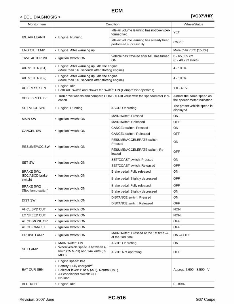
[VQ37VHR]ECM
< ECU DIAGNOSIS >
IDL A/V LEARN • Engine: Running
Idle air volume learning has not been per-formed yet.
YET
Idle air volume learning has already been performed successfully.
CMPLT
ENG OIL TEMP • Engine: After warming up More than 70°C (158°F)
TRVL AFTER MIL • Ignition switch: ONVehicle has traveled after MIL has turned ON.
0 - 65,535 km(0 - 40,723 miles)
A/F S1 HTR (B1)• Engine: After warming up, idle the engine
(More than 140 seconds after starting engine)4 - 100%
A/F S1 HTR (B2)• Engine: After warming up, idle the engine
(More than 140 seconds after starting engine)4 - 100%
AC PRESS SEN• Engine: Idle• Both A/C switch and blower fan switch: ON (Compressor operates)
1.0 - 4.0V
VHCL SPEED SE• Turn drive wheels and compare CONSULT-III value with the speedometer indi-
cation.Almost the same speed as the speedometer indication
SET VHCL SPD • Engine: Running ASCD: OperatingThe preset vehicle speed is displayed
MAIN SW • Ignition switch: ONMAIN switch: Pressed ON
MAIN switch: Released OFF
CANCEL SW • Ignition switch: ONCANCEL switch: Pressed ON
CANCEL switch: Released OFF
RESUME/ACC SW • Ignition switch: ON
RESUME/ACCELERATE switch: Pressed
ON
RESUME/ACCELERATE switch: Re-leased
OFF
SET SW • Ignition switch: ONSET/COAST switch: Pressed ON
SET/COAST switch: Released OFF
BRAKE SW1(ICC/ASCD brake switch)
• Ignition switch: ONBrake pedal: Fully released ON
Brake pedal: Slightly depressed OFF
BRAKE SW2(Stop lamp switch)
• Ignition switch: ONBrake pedal: Fully released OFF
Brake pedal: Slightly depressed ON
DIST SW • Ignition switch: ONDISTANCE switch: Pressed ON
DISTANCE switch: Released OFF
VHCL SPD CUT • Ignition switch: ON NON
LO SPEED CUT • Ignition switch: ON NON
AT OD MONITOR • Ignition switch: ON OFF
AT OD CANCEL • Ignition switch: ON OFF
CRUISE LAMP • Ignition switch: ONMAIN switch: Pressed at the 1st time → at the 2nd time
ON → OFF
SET LAMP
• MAIN switch: ON• When vehicle speed is between 40
km/h (25 MPH) and 144 km/h (89 MPH)
ASCD: Operating ON
ASCD: Not operating OFF
BAT CUR SEN
• Engine speed: Idle
• Battery: Fully charged*2
• Selector lever: P or N (A/T), Neutral (M/T)• Air conditioner switch: OFF• No load
Approx. 2,600 - 3,500mV
ALT DUTY • Engine: Idle 0 - 80%
Monitor Item Condition Values/Status
EC-516Revision: 2007 June G37 Coupe

ECM[VQ37VHR]
C
D
E
F
G
H
I
J
K
L
M
A
C
N
P
O
< ECU DIAGNOSIS >
E
*1: Accelerator pedal position sensor 2 signal and throttle position sensor 2 signal are converted by ECM internally. Thus, they differfrom ECM terminals voltage signal.
*2: Before measuring the terminal voltage, confirm that the battery is fully charged. Refer to PG-3, "How to Handle Battery".
TERMINAL LAYOUT
PHYSICAL VALUES
NOTE:• ECM is located behind the instrument assist lower panel. For this inspection, remove passenger side instru-
ment lower panel.• Specification data are reference values and are measured between each terminal and ground.• Pulse signal is measured by CONSULT-III.
VVEL POSITION SEN-B1
• Engine: After warming up• Selector lever: P or N (A/T), Neu-
tral (M/T)• Air conditioner switch: OFF• No load
Idle Approx. 0.25 - 1.40V
When revving engine up to 2,000 rpm quickly
Approx. 0.25 - 4.75V
VVEL POSITION SEN-B2
• Engine: After warming up• Selector lever: P or N (A/T), Neu-
tral (M/T)• Air conditioner switch: OFF• No load
Idle Approx. 0.25 - 1.40V
When revving engine up to 2,000 rpm quickly
Approx. 0.25 - 4.75V
VVEL TIM-B1
• Engine: After warming up• Selector lever: P or N (A/T), Neu-
tral (M/T)• Air conditioner switch: OFF• No load
Idle Approx. 0 - 20 deg
When revving engine up to 2,000 rpm quickly
Approx. 0 - 90 deg
VVEL TIM-B2
• Engine: After warming up• Selector lever: P or N (A/T), Neu-
tral (M/T)• Air conditioner switch: OFF• No load
Idle Approx. 0 - 20 deg
When revving engine up to 2,000 rpm quickly
Approx. 0 - 90 deg
VVEL LEARN• Ignition switch: OFF → ON
(After warming up)
VVEL learning has not been performed yet.
YET
VVEL learning has already been per-formed successfully.
DONE
VVEL SEN LEARN-B1
• VVEL learning has already been performed successfuly Approx. 0.30 - 0.80V
VVEL SEN LEARN-B2
• VVEL learning has already been performed successfuly Approx. 0.30 - 0.80V
ALT DUTY • Engine: Idle 0 - 80%
A/F ADJ B1 • Engine: Running −0.330 - 0.330
A/F ADJ B2 • Engine: Running −0.330 - 0.330
FAN DUTY • Engine: Running 0 - 100%
ALT DUTY SIG• Power generation voltage variable control: Operating ON
• Power generation voltage variable control: Not operating OFF
Monitor Item Condition Values/Status
JMBIA0070ZZ
EC-517Revision: 2007 June G37 Coupe

[VQ37VHR]ECM
< ECU DIAGNOSIS >
Terminal No.(Wire color)
Description
ConditionValue
(Approx.)+ -– Signal name
Input/Output
1(W)
128(B)
A/F sensor 1 heater(bank 1)
Output
[Engine is running]• Warm-up condition• Idle speed
(More than 140 seconds after starting engine)
2.9 - 8.8V
2(G)
128(B)
Throttle control motor (Open) (bank 1)
Output
[Ignition switch: ON]• Engine stopped• Selector lever: D (A/T) or 1st (M/T)• Accelerator pedal: Fully depressed
0 - 14V
[Ignition switch: ON]• Engine stopped• Selector lever: D (A/T) or 1st (M/T)• Accelerator pedal: Fully released
0 - 14V
3(R)
128(B)
Throttle control motor re-lay power supply (bank 1)
Input [Ignition switch: ON]BATTERY VOLTAGE(11 - 14V)
4(BR)
128(B)
Throttle control motor (Close) (bank 1)
Output
[Ignition switch: ON]• Engine stopped• Selector lever: D (A/T) or 1st (M/T)• Accelerator pedal: In the middle of re-
leasing operation
0 - 14V
5(GR)
128(B)
A/F sensor 1 heater(bank 2)
Output
[Engine is running]• Warm-up condition• Idle speed
(More than 140 seconds after starting engine)
2.9 - 8.8V
8(B)
— ECM ground — — —
JMBIA0030GB
JMBIA0031GB
JMBIA0032GB
JMBIA0033GB
JMBIA0030GB
EC-518Revision: 2007 June G37 Coupe

ECM[VQ37VHR]
C
D
E
F
G
H
I
J
K
L
M
A
C
N
P
O
< ECU DIAGNOSIS >
E11(GR)
128(B)
Ignition signal No. 4
Output
[Engine is running]• Warm-up condition• Idle speed
NOTE:The pulse cycle changes depending on rpm at idle
0 - 0.2V
12(L)
Ignition signal No. 3
15(V)
Ignition signal No. 5
16(G)
Ignition signal No. 2
[Engine is running]• Warm-up condition• Engine speed: 2,000 rpm
0.1 - 0.4V
19(SB)
Ignition signal No. 6
20(Y)
Ignition signal No. 1
17(P)
128(B)
Heated oxygen sensor 2 heater (bank 1)
Output
[Engine is running]• Engine speed: Below 3,600 rpm after
the following conditions are met- Engine: after warming up- Keeping the engine speed between
3,500 and 4,000 rpm for 1 minute and at idle for 1 minute under no load
10V
[Ignition switch: ON]• Engine stopped[Engine is running]• Engine speed: Above 3,600 rpm
BATTERY VOLTAGE(11 - 14V)
18(W)
128(B)
Intake valve timing con-trol solenoid valve (bank 1)
Output
[Engine is running]• Warm-up condition• Idle speed
BATTERY VOLTAGE(11 - 14V)
[Engine is running]• Warm-up condition• Engine speed: 2,000rpm
7 - 12V
Terminal No.(Wire color)
Description
ConditionValue
(Approx.)+ -– Signal name
Input/Output
JMBIA0035GB
JMBIA0036GB
JMBIA0037GB
JMBIA0038GB
EC-519Revision: 2007 June G37 Coupe

[VQ37VHR]ECM
< ECU DIAGNOSIS >
21(GR)
128(B)
EVAP canister purge vol-ume control solenoid valve
Output
[Engine is running]• Idle speed• Accelerator pedal: Not depressed even
slightly, after engine starting
BATTERY VOLTAGE
(11 - 14V)
[Engine is running]• Engine speed: About 2,000 rpm (More
than 100 seconds after starting engine)
BATTERY VOLTAGE
(11 - 14V)
22(R)
128(B)
Fuel pump relay Output
[Ignition switch: ON]• For 1 second after turning ignition switch
ON[Engine is running]
0 - 1.5V
[Ignition switch: ON]• More than 1 second after turning ignition
switch ON
BATTERY VOLTAGE(11 - 14V)
24(P)
128(B)
ECM relay(Self shut-off)
Output
[Engine is running][Ignition switch: OFF]• A few seconds after turning ignition
switch OFF
0 - 1.5V
[Ignition switch: OFF]• More than a few seconds after turning
ignition switch OFF
BATTERY VOLTAGE(11 - 14V)
25(O)
128(B)
Throttle control motor re-lay
Output[Ignition switch: ON → OFF]
0 - 1.0V ↓BATTERY VOLTAGE (11 - 14V) ↓0V
[Ignition switch: ON] 0 - 1.0V
28(BR)
128(B)
VVEL actuator motor re-lay abort signal[VVEL control module]
Output[Engine is running]• Warm-up condition• Idle speed
0V
29(G)
128(B)
Intake valve timing con-trol solenoid valve (bank 2)
Output
[Engine is running]• Warm-up condition• Idle speed
BATTERY VOLTAGE(11 - 14V)
[Engine is running]• Warm-up condition• Engine speed: 2,000rpm
7 - 12V
Terminal No.(Wire color)
Description
ConditionValue
(Approx.)+ -– Signal name
Input/Output
JMBIA0039GB
JMBIA0040GB
JMBIA0038GB
EC-520Revision: 2007 June G37 Coupe
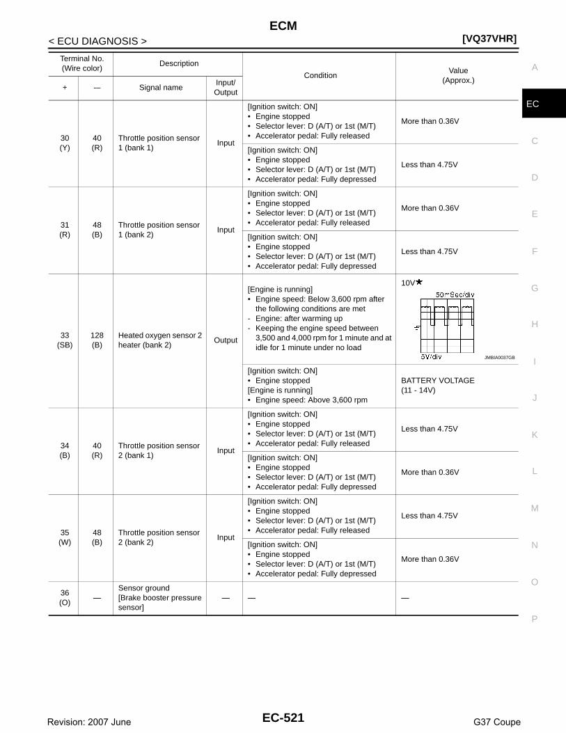
ECM[VQ37VHR]
C
D
E
F
G
H
I
J
K
L
M
A
C
N
P
O
< ECU DIAGNOSIS >
E
30(Y)
40(R)
Throttle position sensor 1 (bank 1)
Input
[Ignition switch: ON]• Engine stopped• Selector lever: D (A/T) or 1st (M/T)• Accelerator pedal: Fully released
More than 0.36V
[Ignition switch: ON]• Engine stopped• Selector lever: D (A/T) or 1st (M/T)• Accelerator pedal: Fully depressed
Less than 4.75V
31(R)
48(B)
Throttle position sensor 1 (bank 2)
Input
[Ignition switch: ON]• Engine stopped• Selector lever: D (A/T) or 1st (M/T)• Accelerator pedal: Fully released
More than 0.36V
[Ignition switch: ON]• Engine stopped• Selector lever: D (A/T) or 1st (M/T)• Accelerator pedal: Fully depressed
Less than 4.75V
33(SB)
128(B)
Heated oxygen sensor 2 heater (bank 2)
Output
[Engine is running]• Engine speed: Below 3,600 rpm after
the following conditions are met- Engine: after warming up- Keeping the engine speed between
3,500 and 4,000 rpm for 1 minute and at idle for 1 minute under no load
10V
[Ignition switch: ON]• Engine stopped[Engine is running]• Engine speed: Above 3,600 rpm
BATTERY VOLTAGE(11 - 14V)
34(B)
40(R)
Throttle position sensor 2 (bank 1)
Input
[Ignition switch: ON]• Engine stopped• Selector lever: D (A/T) or 1st (M/T)• Accelerator pedal: Fully released
Less than 4.75V
[Ignition switch: ON]• Engine stopped• Selector lever: D (A/T) or 1st (M/T)• Accelerator pedal: Fully depressed
More than 0.36V
35(W)
48(B)
Throttle position sensor 2 (bank 2)
Input
[Ignition switch: ON]• Engine stopped• Selector lever: D (A/T) or 1st (M/T)• Accelerator pedal: Fully released
Less than 4.75V
[Ignition switch: ON]• Engine stopped• Selector lever: D (A/T) or 1st (M/T)• Accelerator pedal: Fully depressed
More than 0.36V
36(O)
—Sensor ground[Brake booster pressure sensor]
— — —
Terminal No.(Wire color)
Description
ConditionValue
(Approx.)+ -– Signal name
Input/Output
JMBIA0037GB
EC-521Revision: 2007 June G37 Coupe

[VQ37VHR]ECM
< ECU DIAGNOSIS >
37(W)
128(B)
Crankshaft position sen-sor (POS)
Input
[Engine is running]• Warm-up condition• Idle speed
NOTE:The pulse cycle changes depending on rpm at idle
4.0 - 5.0
[Engine is running]• Engine speed: 2,000 rpm
4.0 - 5.0
38(O)
96(P)
Manifold absolute pres-sure (MAP) sensor
Input
[Engine is running]• Warm-up condition• Idle speed
1.2V
[Engine is running]• Warm-up condition• Engine speed: 2,000 rpm
1.5V
39(P)
36(O)
Brake booster pressure sensor
Input
[Engine is running]• Warm-up condition• Idle speed• Brake pedal: Fully released
1.2V
[Engine is running]• Warm-up condition• Idle speed• Brake pedal: Fully depressed
3.0V
40(R)
—Sensor ground[Throttle position sensor (bank 1)]
— — —
43(G)
48(B)
Sensor power supply[Throttle position sensor (bank 2)]
— [Ignition switch: ON] 5V
44(L)
40(R)
Sensor power supply[Throttle position sensor (bank 1)]
— [Ignition switch: ON] 5V
45(LG)
36(O)
Sensor power supply[Brake booster pressure sensor]
— [Ignition switch: ON] 5V
46(R)
128(B)
Sensor power supply[Crankshaft position sensor (POS)]
— [Ignition switch: ON] 5V
47(Y)
—Sensor ground[Crankshaft position sensor (POS)]
— — —
48(B)
—Sensor ground[Throttle position sensor (bank 2)]
— — —
Terminal No.(Wire color)
Description
ConditionValue
(Approx.)+ -– Signal name
Input/Output
JMBIA0041GB
JMBIA0042GB
EC-522Revision: 2007 June G37 Coupe

ECM[VQ37VHR]
C
D
E
F
G
H
I
J
K
L
M
A
C
N
P
O
< ECU DIAGNOSIS >
E
49(GR)
128(B)
Throttle control motor (Close) (bank 2)
Output
[Ignition switch: ON]• Engine stopped• Selector lever: D (A/T) or 1st (M/T)• Accelerator pedal: In the middle of re-
leasing operation
0 - 14V
50(V)
128(B)
Throttle control motor (Open) (bank 2)
Output
[Ignition switch: ON]• Engine stopped• Selector lever: D (A/T) or 1st (M/T)• Accelerator pedal: Fully depressed
0 - 14V
[Ignition switch: ON]• Engine stopped• Selector lever: D (A/T) or 1st (M/T)• Accelerator pedal: Fully released
0 - 14V
52(R)
128(B)
Throttle control motor re-lay power supply (bank 2)
Input [Ignition switch: ON]BATTERY VOLTAGE(11 - 14V)
53(W)
128(B)
Ignition switch Input
[Ignition switch: OFF] 0V
[Ignition switch: ON]BATTERY VOLTAGE(11 - 14V)
54(Y)
—CAN communication line[VVEL control module]
Input/output
— —
55(LG)
—CAN communication line[VVEL control module]
Input/output
— —
57(L)
128(B)
A/F sensor 1 (bank 1) Input [Ignition switch: ON] 2.2V
59(O)
128(B)
Camshaft position sen-sor (PHASE) (bank 1)
Input
[Engine is running]• Warm-up condition• Idle speed
NOTE:The pulse cycle changes depending on rpm at idle
3.0 - 5.0
[Engine is running]• Engine speed: 2,000 rpm
3.0 - 5.0
Terminal No.(Wire color)
Description
ConditionValue
(Approx.)+ -– Signal name
Input/Output
JMBIA0033GB
JMBIA0031GB
JMBIA0032GB
JMBIA0045GB
JMBIA0046GB
EC-523Revision: 2007 June G37 Coupe

[VQ37VHR]ECM
< ECU DIAGNOSIS >
60(G)
128(B)
Sensor power supply[Camshaft position sen-sor (PHASE) (bank 1), Manifold absolute pres-sure (MAP) sensor, Pow-er steering pressure sensor]
— [Ignition switch: ON] 5V
61(R)
128(B)
A/F sensor 1 (bank 1) Input[Engine is running]• Warm-up condition• Engine speed: 2,000 rpm
1.8VOutput voltage varies with air fuel ratio.
63(L)
128(B)
Camshaft position sen-sor (PHASE) (bank 2)
Input
[Engine is running]• Warm-up condition• Idle speed
NOTE:The pulse cycle changes depending on rpm at idle
3.0 - 5.0
[Engine is running]• Engine speed: 2,000 rpm
3.0 - 5.0
64(SB)
128(B)
Sensor power supply[Camshaft position sen-sor (PHASE) (bank 2), Battery current sensor]
— [Ignition switch: ON] 5V
65(LG)
128(B)
A/F sensor 1 (bank 2) Input [Ignition switch: ON] 2.2V
66(V)
128(B)
A/F sensor 1 (bank 2) Input[Engine is running]• Warm-up condition• Engine speed: 2,000 rpm
1.8VOutput voltage varies with air fuel ratio.
67(P)
128(B)
Intake air temperature sensor (bank 1)
Input [Engine is running]0 - 4.8VOutput voltage varies with intake air temperature.
68(LG)
—
Sensor ground[Mass air flow sensor (bank 1), Intake air tem-perature sensor (bank 1)]
— — —
69(W)
128(B)
Knock sensor (bank 2) Input[Engine is running]• Idle speed 2.5V*1
71(Y)
128(B)
Engine coolant tempera-ture sensor
Input [Engine is running]0 - 4.8VOutput voltage varies with engine coolant temperature.
72(—)
—Sensor ground(Knock sensor)
— — —
73(W)
128(B)
Knock sensor (bank 1) Input[Engine is running]• Idle speed 2.5V*1
Terminal No.(Wire color)
Description
ConditionValue
(Approx.)+ -– Signal name
Input/Output
JMBIA0045GB
JMBIA0046GB
EC-524Revision: 2007 June G37 Coupe

ECM[VQ37VHR]
C
D
E
F
G
H
I
J
K
L
M
A
C
N
P
O
< ECU DIAGNOSIS >
E
76(W)
128(B)
Heated oxygen sensor 2 (bank 1)
Input
[Engine is running]• Revving engine from idle to 3,000 rpm
quickly after the following conditions are met
- Engine: after warming up- Keeping the engine speed between
3,500 and 4,000 rpm for 1 minute and at idle for 1 minute under no load
0 - 1.0V
77(SB)
68(LG)
Mass air flow sensor (bank 1)
Input
[Engine is running]• Warm-up condition• Idle speed
0.7 - 1.2V
[Engine is running]• Warm-up condition• Engine speed: 2,500 rpm
1.3 - 1.7V
78(G)
84(B)
Engine oil temperature sensor
Input [Engine is running]0 - 4.8VOutput voltage varies with engine oil temperature.
79(BR)
94(Y)
Mass air flow sensor (bank 2)
Input
[Engine is running]• Warm-up condition• Idle speed
0.7 - 1.2V
[Engine is running]• Warm-up condition• Engine speed: 2,500 rpm
1.3 - 1.7V
80(O)
128(B)
Heated oxygen sensor 2 (bank 2)
Input
[Engine is running]• Revving engine from idle to 3,000 rpm
quickly after the following conditions are met
- Engine: after warming up- Keeping the engine speed between
3,500 and 4,000 rpm for 1 minute and at idle for 1 minute under no load
0 - 1.0V
81(R)
128(B)
Fuel injector No. 3
Output
[Engine is running]• Warm-up condition• Idle speed
NOTE:The pulse cycle changes depending on rpm at idle
BATTERY VOLTAGE
(11 - 14V)
82(V)
Fuel injector No. 6
85(BR)
Fuel injector No. 2
86(W)
Fuel injector No. 5
[Engine is running]• Warm-up condition• Engine speed: 2,000 rpm
BATTERY VOLTAGE
(11 - 14V)
89(GR)
Fuel injector No. 1
90(O)
Fuel injector No. 4
83(LG)
94(Y)
Intake air temperature sensor (bank 2)
Input [Engine is running]0 - 4.8VOutput voltage varies with intake air temperature.
Terminal No.(Wire color)
Description
ConditionValue
(Approx.)+ -– Signal name
Input/Output
JMBIA0047GB
JMBIA0048GB
EC-525Revision: 2007 June G37 Coupe

[VQ37VHR]ECM
< ECU DIAGNOSIS >
84(B)
—
Sensor ground(Heated oxygen sensor 2, Engine coolant tem-perature sensor, Engine oil temperature sensor)
— — —
87(Y)
96(P)
Power steering pressure sensor
Output
[Engine is running]• Steering wheel: Being turned
0.5 - 4.5V
[Engine is running]• Steering wheel: Not being turned
0.4 - 0.8V
91(SB)
95(G)
Battery current sensor Input[Engine is running]
• Battery: Fully charged*2
• Idle speed2.6 - 3.5V
92(G)
—Sensor ground[Camshaft position sen-sor (PHASE) (bank 2)]
— — —
93(P)
128(B)
Power supply for ECM (Back-up)
Input [Ignition switch: OFF]BATTERY VOLTAGE(11 - 14V)
94(Y)
—Sensor ground[Mass air flow sensor (bank 2)]
— — —
95(G)
—Sensor ground(Battery current sensor)
— — —
96(P)
—
Sensor ground[Camshaft position sen-sor (PHASE) (bank 1),Manifold absolute pressure (MAP) sensor, Power steering pressure sensor]
— — —
97(R)
100(W)
Accelerator pedal posi-tion sensor 1
Input
[Ignition switch: ON]• Engine stopped• Accelerator pedal: Fully released
0.45 - 1.00V
[Ignition switch: ON]• Engine stopped• Accelerator pedal: Fully depressed
4.2 - 4.8V
98(P)
104(GR)
Accelerator pedal posi-tion sensor 2
Input
[Ignition switch: ON]• Engine stopped• Accelerator pedal: Fully released
0.22 - 0.50V
[Ignition switch: ON]• Engine stopped• Accelerator pedal: Fully depressed
2.1 - 2.5V
99(L)
100(W)
Sensor power supply(Accelerator pedal posi-tion sensor 1)
— [Ignition switch: ON] 5V
100(W)
—Sensor ground(Accelerator pedal posi-tion sensor 1)
— — —
Terminal No.(Wire color)
Description
ConditionValue
(Approx.)+ -– Signal name
Input/Output
EC-526Revision: 2007 June G37 Coupe

ECM[VQ37VHR]
C
D
E
F
G
H
I
J
K
L
M
A
C
N
P
O
< ECU DIAGNOSIS >
E
101(SB)
108(Y)
ICC steering switch(models with ICC sys-tem)
Input
[Ignition switch: ON]• ICC steering switch: OFF
4.3V
[Ignition switch: ON]• MAIN switch: Pressed
0V
[Ignition switch: ON]• CANCEL switch: Pressed
1.3V
[Ignition switch: ON]• RESUME/ACCELERATE switch:
Pressed3.7V
[Ignition switch: ON]• SET/COAST switch: Pressed
3V
[Ignition switch: ON]• DISTANCE switch: Pressed
2.2V
101(SB)
108(Y)
ASCD steering switch(models with ASCD sys-tem)
Input
[Ignition switch: ON]• ASCD steering switch: OFF
4V
[Ignition switch: ON]• MAIN switch: Pressed
0V
[Ignition switch: ON]• CANCEL switch: Pressed
1V
[Ignition switch: ON]• RESUME/ACCELERATE switch:
Pressed3V
[Ignition switch: ON]• SET/COAST switch: Pressed
2V
102(GR)
112(SB)
EVAP control system pressure sensor
Input [Ignition switch: ON] 1.8 - 4.8V
103(G)
104(GR)
Sensor power supply(Accelerator pedal posi-tion sensor 2)
— [Ignition switch: ON] 5V
104(GR)
—Sensor ground(Accelerator pedal posi-tion sensor 2)
— — —
105(L)
116(P)
Refrigerant pressure sensor
Input
[Engine is running]• Warm-up condition• Both A/C switch and blower fan motor
switch: ON (Compressor operates)
1.0 - 4.0V
106(W)
128(B)
Fuel tank temperature sensor
Input [Engine is running]0 - 4.8VOutput voltage varies with fuel tank temperature.
107(BR)
112(SB)
Sensor power supply(EVAP control system pressure sensor)
— [Ignition switch: ON] 5V
108(Y)
—Sensor ground(ASCD/ICC steering switch)
— — —
109(G)
128(B)
PNP switch Input
[Ignition switch: ON]• Selector lever: P or N (A/T), Neutral (M/
T)
BATTERY VOLTAGE(11 - 14V)
[Ignition switch: ON]• Selector lever: Except above
0V
Terminal No.(Wire color)
Description
ConditionValue
(Approx.)+ -– Signal name
Input/Output
EC-527Revision: 2007 June G37 Coupe
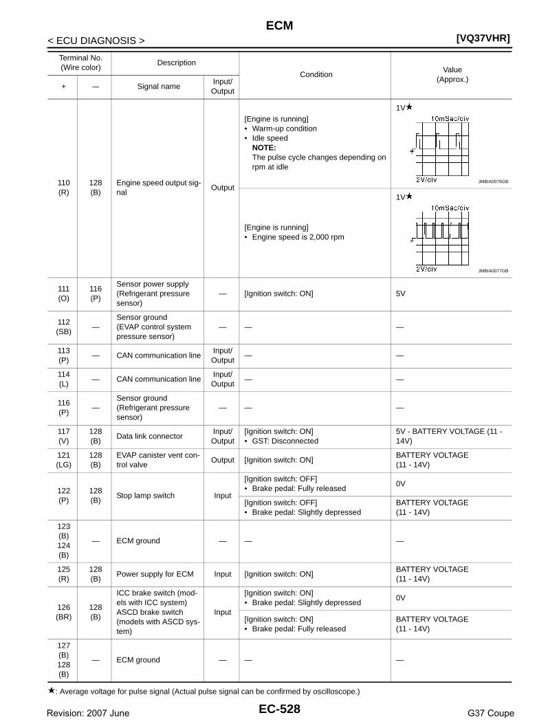
[VQ37VHR]ECM
< ECU DIAGNOSIS >
: Average voltage for pulse signal (Actual pulse signal can be confirmed by oscilloscope.)
110(R)
128(B)
Engine speed output sig-nal
Output
[Engine is running]• Warm-up condition• Idle speed
NOTE:The pulse cycle changes depending on rpm at idle
1V
[Engine is running]• Engine speed is 2,000 rpm
1V
111(O)
116(P)
Sensor power supply(Refrigerant pressure sensor)
— [Ignition switch: ON] 5V
112(SB)
—Sensor ground(EVAP control system pressure sensor)
— — —
113(P)
— CAN communication lineInput/Output
— —
114(L)
— CAN communication lineInput/Output
— —
116(P)
—Sensor ground(Refrigerant pressure sensor)
— — —
117(V)
128(B)
Data link connectorInput/Output
[Ignition switch: ON]• GST: Disconnected
5V - BATTERY VOLTAGE (11 - 14V)
121(LG)
128(B)
EVAP canister vent con-trol valve
Output [Ignition switch: ON]BATTERY VOLTAGE(11 - 14V)
122(P)
128(B)
Stop lamp switch Input
[Ignition switch: OFF]• Brake pedal: Fully released
0V
[Ignition switch: OFF]• Brake pedal: Slightly depressed
BATTERY VOLTAGE(11 - 14V)
123(B)124(B)
— ECM ground — — —
125(R)
128(B)
Power supply for ECM Input [Ignition switch: ON]BATTERY VOLTAGE(11 - 14V)
126(BR)
128(B)
ICC brake switch (mod-els with ICC system)ASCD brake switch (models with ASCD sys-tem)
Input
[Ignition switch: ON]• Brake pedal: Slightly depressed
0V
[Ignition switch: ON]• Brake pedal: Fully released
BATTERY VOLTAGE(11 - 14V)
127(B)128(B)
— ECM ground — — —
Terminal No.(Wire color)
Description
ConditionValue
(Approx.)+ -– Signal name
Input/Output
JMBIA0076GB
JMBIA0077GB
EC-528Revision: 2007 June G37 Coupe

ECM[VQ37VHR]
C
D
E
F
G
H
I
J
K
L
M
A
C
N
P
O
< ECU DIAGNOSIS >
E
*1: This may vary depending on internal resistance of the tester.
**2: Before measuring the terminal voltage, confirm that the battery is fully charged. Refer to PG-3, "How to Handle Battery".
Wiring Diagram - ENGINE CONTROL SYSTEM - INFOID:0000000001734348
Click here to view the eWD.
JCBWA0348GB
EC-529Revision: 2007 June G37 Coupe

[VQ37VHR]ECM
< ECU DIAGNOSIS >
JCBWA0349GB
EC-530Revision: 2007 June G37 Coupe

ECM[VQ37VHR]
C
D
E
F
G
H
I
J
K
L
M
A
C
N
P
O
< ECU DIAGNOSIS >
E
JCBWA0350GB
EC-531Revision: 2007 June G37 Coupe

[VQ37VHR]ECM
< ECU DIAGNOSIS >
JCBWA0351GB
EC-532Revision: 2007 June G37 Coupe

ECM[VQ37VHR]
C
D
E
F
G
H
I
J
K
L
M
A
C
N
P
O
< ECU DIAGNOSIS >
E
JCBWA0352GB
EC-533Revision: 2007 June G37 Coupe

[VQ37VHR]ECM
< ECU DIAGNOSIS >
JCBWA0353GB
EC-534Revision: 2007 June G37 Coupe

ECM[VQ37VHR]
C
D
E
F
G
H
I
J
K
L
M
A
C
N
P
O
< ECU DIAGNOSIS >
E
JCBWA0354GB
EC-535Revision: 2007 June G37 Coupe

[VQ37VHR]ECM
< ECU DIAGNOSIS >
JCBWA0355GB
EC-536Revision: 2007 June G37 Coupe

ECM[VQ37VHR]
C
D
E
F
G
H
I
J
K
L
M
A
C
N
P
O
< ECU DIAGNOSIS >
E
JCBWA0356GB
EC-537Revision: 2007 June G37 Coupe

[VQ37VHR]ECM
< ECU DIAGNOSIS >
JCBWA0357GB
EC-538Revision: 2007 June G37 Coupe

ECM[VQ37VHR]
C
D
E
F
G
H
I
J
K
L
M
A
C
N
P
O
< ECU DIAGNOSIS >
E
JCBWA0358GB
EC-539Revision: 2007 June G37 Coupe
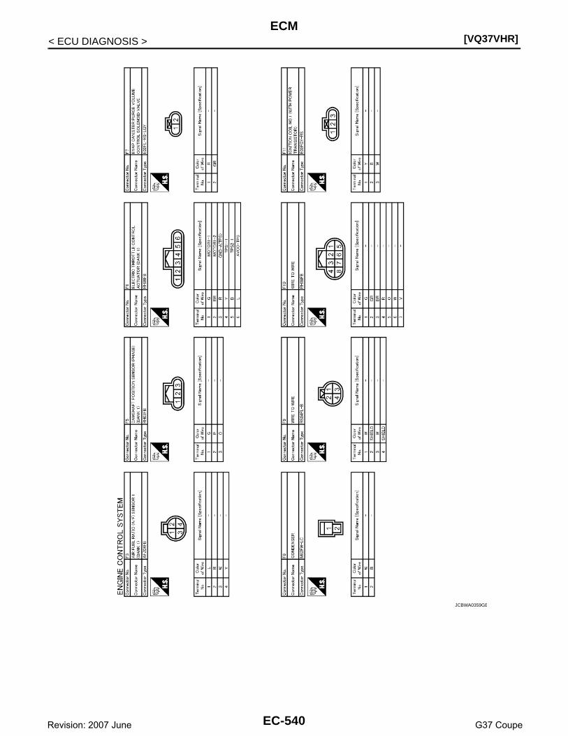
[VQ37VHR]ECM
< ECU DIAGNOSIS >
JCBWA0359GB
EC-540Revision: 2007 June G37 Coupe

ECM[VQ37VHR]
C
D
E
F
G
H
I
J
K
L
M
A
C
N
P
O
< ECU DIAGNOSIS >
E
JCBWA0360GB
EC-541Revision: 2007 June G37 Coupe

[VQ37VHR]ECM
< ECU DIAGNOSIS >
JCBWA0361GB
EC-542Revision: 2007 June G37 Coupe
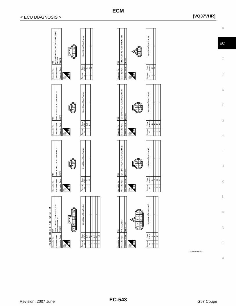
ECM[VQ37VHR]
C
D
E
F
G
H
I
J
K
L
M
A
C
N
P
O
< ECU DIAGNOSIS >
E
JCBWA0362GB
EC-543Revision: 2007 June G37 Coupe

[VQ37VHR]ECM
< ECU DIAGNOSIS >
JCBWA0363GB
EC-544Revision: 2007 June G37 Coupe

ECM[VQ37VHR]
C
D
E
F
G
H
I
J
K
L
M
A
C
N
P
O
< ECU DIAGNOSIS >
E
JCBWA0364GB
EC-545Revision: 2007 June G37 Coupe

[VQ37VHR]ECM
< ECU DIAGNOSIS >
JCBWA0365GB
EC-546Revision: 2007 June G37 Coupe

ECM[VQ37VHR]
C
D
E
F
G
H
I
J
K
L
M
A
C
N
P
O
< ECU DIAGNOSIS >
E
JCBWA0366GB
EC-547Revision: 2007 June G37 Coupe

[VQ37VHR]ECM
< ECU DIAGNOSIS >
Fail Safe INFOID:0000000001734349
NON DTC RELATED ITEM
JCBWA0367GB
EC-548Revision: 2007 June G37 Coupe

ECM[VQ37VHR]
C
D
E
F
G
H
I
J
K
L
M
A
C
N
P
O
< ECU DIAGNOSIS >
E
DTC RELATED ITEM
Engine operating condi-tion in fail-safe mode
Detected items RemarksReference
page
Engine speed will not rise more than 2,500 rpm due to the fuel cut
Malfunction indicator lamp circuit
When there is an open circuit on MIL circuit, the ECM cannot warn the driver by lighting up MIL when there is malfunction on engine control system.Therefore, when electrical controlled throttle and part of ECM related diagnoses are continuously detected as NG for 5 trips, ECM warns the driver that engine control system malfunctions and MIL circuit is open by means of operating fail-safe function.The fail-safe function also operates when above diagnoses except MIL circuit are detected and demands the driver to repair the malfunction.
EC-503
DTC No. Detected items Engine operating condition in fail-safe mode
U0113U1003U1011U1024
Can communication circuitVVEL actuator motor relay is turned off, and VVEL value is become at a minimam angle.Engine speed will not rise more than 3,500 rpm due to the fuel cut.
P0011P0021
Intake valve timing control The signal is not energized to the intake valve timing control solenoid valve and the valve control does not function.
P0102P0103P010CP010D
Mass air flow sensor circuit Engine speed will not rise more than 2,400 rpm due to the fuel cut.
P0117P0118
Engine coolant tempera-ture sensor circuit
Engine coolant temperature will be determined by ECM based on the following condition.CONSULT-III displays the engine coolant temperature decided by ECM.
ConditionEngine coolant temperature decided
(CONSULT-III display)
Just as ignition switch is turned ON or START
40°C (104°F)
Approx 4 minutes or more after en-gine starting
80°C (176°F)
Except as shown above40 - 80°C (104 - 176°F)(Depends on the time)
When the fail-safe system for engine coolant temperature sensor is activated, the cooling fan operates while engine is running.
P0122P0123P0222P0223P0227P0228P1239P2132P2133P2135
Throttle position sensor The ECM controls the electric throttle control actuator in regulating the throttle opening in order for the idle position to be within +10 degrees.The ECM regulates the opening speed of the throttle valve to be slower than the normal condition.So, the acceleration will be poor.
P0500 Vehicle speed sensor When the fail-safe system for vehicle speed sensor is activated, the cooling fan operates (Highest) while engine is running.
P0524 Engine oil pressureThe signal is not energized to the intake valve timing control solenoid valve and the valve control does not function.Engine speed will not rise more than 2,400 rpm due to the fuel cut.
P0605 ECM (When ECM calculation function is malfunctioning:)ECM stops the electric throttle control actuator control, throttle valve is maintained at a fixed opening (approx. 5 degrees) by the return spring.ECM deactivates ASCD operation.
P0643 Sensor power supply ECM stops the electric throttle control actuator control, throttle valve is maintained at a fixed opening (approx. 5 degrees) by the return spring.
EC-549Revision: 2007 June G37 Coupe
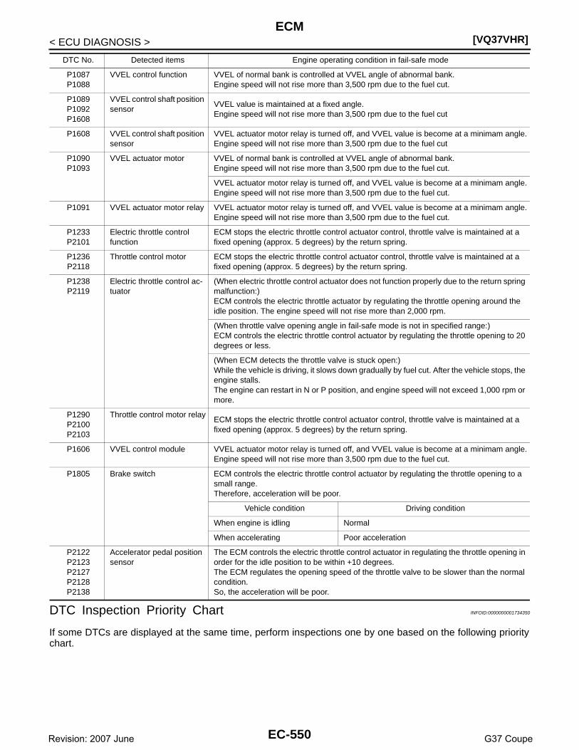
[VQ37VHR]ECM
< ECU DIAGNOSIS >
DTC Inspection Priority Chart INFOID:0000000001734350
If some DTCs are displayed at the same time, perform inspections one by one based on the following prioritychart.
P1087P1088
VVEL control function VVEL of normal bank is controlled at VVEL angle of abnormal bank.Engine speed will not rise more than 3,500 rpm due to the fuel cut.
P1089P1092P1608
VVEL control shaft position sensor
VVEL value is maintained at a fixed angle.Engine speed will not rise more than 3,500 rpm due to the fuel cut
P1608 VVEL control shaft position sensor
VVEL actuator motor relay is turned off, and VVEL value is become at a minimam angle.Engine speed will not rise more than 3,500 rpm due to the fuel cut
P1090P1093
VVEL actuator motor VVEL of normal bank is controlled at VVEL angle of abnormal bank.Engine speed will not rise more than 3,500 rpm due to the fuel cut.
VVEL actuator motor relay is turned off, and VVEL value is become at a minimam angle.Engine speed will not rise more than 3,500 rpm due to the fuel cut.
P1091 VVEL actuator motor relay VVEL actuator motor relay is turned off, and VVEL value is become at a minimam angle.Engine speed will not rise more than 3,500 rpm due to the fuel cut.
P1233P2101
Electric throttle control function
ECM stops the electric throttle control actuator control, throttle valve is maintained at a fixed opening (approx. 5 degrees) by the return spring.
P1236P2118
Throttle control motor ECM stops the electric throttle control actuator control, throttle valve is maintained at a fixed opening (approx. 5 degrees) by the return spring.
P1238P2119
Electric throttle control ac-tuator
(When electric throttle control actuator does not function properly due to the return spring malfunction:)ECM controls the electric throttle actuator by regulating the throttle opening around the idle position. The engine speed will not rise more than 2,000 rpm.
(When throttle valve opening angle in fail-safe mode is not in specified range:)ECM controls the electric throttle control actuator by regulating the throttle opening to 20 degrees or less.
(When ECM detects the throttle valve is stuck open:)While the vehicle is driving, it slows down gradually by fuel cut. After the vehicle stops, the engine stalls.The engine can restart in N or P position, and engine speed will not exceed 1,000 rpm or more.
P1290P2100P2103
Throttle control motor relayECM stops the electric throttle control actuator control, throttle valve is maintained at a fixed opening (approx. 5 degrees) by the return spring.
P1606 VVEL control module VVEL actuator motor relay is turned off, and VVEL value is become at a minimam angle.Engine speed will not rise more than 3,500 rpm due to the fuel cut.
P1805 Brake switch ECM controls the electric throttle control actuator by regulating the throttle opening to a small range.Therefore, acceleration will be poor.
Vehicle condition Driving condition
When engine is idling Normal
When accelerating Poor acceleration
P2122P2123P2127P2128P2138
Accelerator pedal position sensor
The ECM controls the electric throttle control actuator in regulating the throttle opening in order for the idle position to be within +10 degrees.The ECM regulates the opening speed of the throttle valve to be slower than the normal condition.So, the acceleration will be poor.
DTC No. Detected items Engine operating condition in fail-safe mode
EC-550Revision: 2007 June G37 Coupe

ECM[VQ37VHR]
C
D
E
F
G
H
I
J
K
L
M
A
C
N
P
O
< ECU DIAGNOSIS >
E
Priority Detected items (DTC)
1 • U0113 U1003 CAN communication line• U1000 U1001 CAN communication line• U1010 CAN communication• U1011 CAN communication• U1024 VVEL CAN communication line• P0101 P0102 P0103 P010B P010C P010D Mass air flow sensor• P010A Manifold absolute pressure (MAP) sensor• P0112 P0113 P0127 Intake air temperature sensor• P0117 P0118 P0125 Engine coolant temperature sensor• P0122 P0123 P0222 P0223 P0227 P0228 P1225 P1226 P1234 P1235 P1239 P2132 P2133 P2135 Throttle position sensor• P0128 Thermostat function• P0181 P0182 P0183 Fuel tank temperature sensor• P0196 P0197 P0198 Engine oil temperature sensor• P0327 P0328 P0332 P0333 Knock sensor• P0335 Crankshaft position sensor (POS)• P0340 P0345 Camshaft position sensor (PHASE)• P0460 P0461 P0462 P0463 Fuel level sensor• P0500 Vehicle speed sensor• P0555 Brake booster pressure sensor• P0605 ECM• P0643 Sensor power supply• P0700 TCM• P0705 P0850 Park/neutral position (PNP) switch• P1089 P1092 P1608 VVEL control shaft position sensor• P1606 P1607 VVEL control module• P0705 P0850 Park/neutral position (PNP) switch• P1550 P1551 P1552 P1553 P1554 Battery current sensor• P1610 - P1615 NATS• P2122 P2123 P2127 P2128 P2138 Accelerator pedal position sensor
EC-551Revision: 2007 June G37 Coupe

[VQ37VHR]ECM
< ECU DIAGNOSIS >
DTC Index INFOID:0000000001734351
×:Applicable —: Not applicable
2 • P0031 P0032 P0051 P0052 Air fuel ratio (A/F) sensor 1 heater• P0037 P0038 P0057 P0058 Heated oxygen sensor 2 heater• P0075 P0081 Intake valve timing control solenoid valve• P0130 P0131 P0132 P0133 P0150 P0151 P0152 P0153 P2A00 P2A03 Air fuel ratio (A/F) sensor 1• P0137 P0138 P0139 P0157 P0158 P0159 Heated oxygen sensor 2• P0441 EVAP control system purge flow monitoring• P0443 P0444 P0445 EVAP canister purge volume control solenoid valve• P0447 P0448 EVAP canister vent control valve• P0451 P0452 P0453 EVAP control system pressure sensor• P0550 Power steering pressure sensor• P0603 ECM power supply• P0710 P0717 P0720 P0731 P0732 P0733 P0734 P0735 P0740 P0744 P0745 P1730 P1752 P1757 P1762 P1767 P1772
P1774 A/T related sensors, solenoid valves and switches• P1087 P1088 VVEL system• P1090 P1093 VVEL actuator motor• P1091 VVEL actuator motor relay• P1217 Engine over temperature (OVERHEAT)• P1233 P2101 Electric throttle control function• P1236 P2118 Throttle control motor• P1290 P2100 P2103 Throttle control motor relay• P1805 Brake switch
3 • P0011 P0021 Intake valve timing control• P0171 P0172 P0174 P0175 Fuel injection system function• P0300 - P0306 Misfire• P0420 P0430 Three way catalyst function• P0442 P0456 EVAP control system (SMALL LEAK, VERY SMALL LEAK)• P0455 EVAP control system (GROSS LEAK)• P0506 P0507 Idle speed control system• P0524 Engine oil pressure• P100A P100B VVEL system• P1148 P1168 Closed loop control• P1211 TCS control unit• P1212 TCS communication line• P1238 P2119 Electric throttle control actuator• P1421 Cold start control• P1564 ICC steering switch / ASCD steering switch• P1568 ICC command value• P1572 ICC brake switch / ASCD brake switch• P1574 ICC vehicle speed sensor / ASCD vehicle speed sensor• P1715 Turbine revolution sensor
Priority Detected items (DTC)
DTC*1
Items (CONSULT-III screen terms)
SRT code Trip MILReference
pageCONSULT-III
GST*2 ECM*3
U0113 0113 CAN COMM CIRCUIT —1 (A/T models)2 (M/T models)
× (A/T models)— (M/T models)
EC-144
U1000 1000*4 CAN COMM CIRCUIT —1 (A/T models)2 (M/T models)
× (A/T models)— (M/T models)
EC-146
U1001 1001*4 CAN COMM CIRCUIT —1 (with ASCD)
1 or 2 (with ICC)— EC-146
U1003 1003 CAN COMM CIRCUIT — 2 — EC-144
U1010 1010 CONTROL UNIT(CAN) —1 (A/T models)2 (M/T models)
× (A/T models)— (M/T models)
EC-147
U1011 1011 CONTROL UNIT (CAN) —1 (A/T models)2 (M/T models)
× (A/T models)— (M/T models)
EC-148
U1024 1024 VVEL CAN COMM CIRCUIT — 1 × EC-149
EC-552Revision: 2007 June G37 Coupe

ECM[VQ37VHR]
C
D
E
F
G
H
I
J
K
L
M
A
C
N
P
O
< ECU DIAGNOSIS >
EP0000 0000
NO DTC IS DETECTED. FURTHER TESTING MAY BE REQUIRED.
— — Flashing*7 —
P0011 0011 INT/V TIM CONT-B1 — 2 × EC-151
P0021 0021 INT/V TIM CONT-B2 — 2 × EC-151
P0031 0031 A/F SEN1 HTR (B1) — 2 × EC-155
P0032 0032 A/F SEN1 HTR (B1) — 2 × EC-155
P0037 0037 HO2S2 HTR (B1) — 2 × EC-158
P0038 0038 HO2S2 HTR (B1) — 2 × EC-158
P0051 0051 A/F SEN1 HTR (B2) — 2 × EC-155
P0052 0052 A/F SEN1 HTR (B2) — 2 × EC-155
P0057 0057 HO2S2 HTR (B2) — 2 × EC-158
P0058 0058 HO2S2 HTR (B2) — 2 × EC-158
P0075 0075 INT/V TIM V/CIR-B1 — 2 × EC-162
P0081 0081 INT/V TIM V/CIR-B2 — 2 × EC-162
P0101 0101 MAF SEN/CIRCUIT-B1 — 2 × EC-165
P0102 0102 MAF SEN/CIRCUIT-B1 — 1 × EC-172
P0103 0103 MAF SEN/CIRCUIT-B1 — 1 × EC-172
P010A 010A ABSL PRES SEN/CIRC — 2 × EC-177
P010B 010B MAF SEN/CIRCUIT-B2 — 2 × EC-165
P010C 010C MAF SEN/CIRCUIT-B2 — 1 × EC-172
P010D 010D MAF SEN/CIRCUIT-B2 — 1 × EC-172
P0112 0112 IAT SEN/CIRCUIT-B1 — 2 × EC-181
P0113 0113 IAT SEN/CIRCUIT-B1 — 2 × EC-181
P0117 0117 ECT SEN/CIRC — 1 × EC-184
P0118 0118 ECT SEN/CIRC — 1 × EC-184
P0122 0122 TP SEN 2/CIRC-B1 — 1 × EC-187
P0123 0123 TP SEN 2/CIRC-B1 — 1 × EC-187
P0125 0125 ECT SENSOR — 2 × EC-190
P0127 0127 IAT SENSOR-B1 — 2 × EC-193
P0128 0128 THERMSTAT FNCTN — 2 × EC-195
P0130 0130 A/F SENSOR1 (B1) — 2 × EC-197
P0131 0131 A/F SENSOR1 (B1) — 2 × EC-201
P0132 0132 A/F SENSOR1 (B1) — 2 × EC-204
P0133 0133 A/F SENSOR1 (B1) × 2 × EC-207
P0137 0137 HO2S2 (B1) × 2 × EC-212
P0138 0138 HO2S2 (B1) × 2 × EC-218
P0139 0139 HO2S2 (B1) × 2 × EC-226
P0150 0150 A/F SENSOR1 (B2) — 2 × EC-197
P0151 0151 A/F SENSOR1 (B2) — 2 × EC-201
P0152 0152 A/F SENSOR1 (B2) — 2 × EC-204
P0153 0153 A/F SENSOR1 (B2) × 2 × EC-207
P0157 0157 HO2S2 (B2) × 2 × EC-212
DTC*1
Items (CONSULT-III screen terms)
SRT code Trip MILReference
pageCONSULT-III
GST*2 ECM*3
EC-553Revision: 2007 June G37 Coupe

[VQ37VHR]ECM
< ECU DIAGNOSIS >
P0158 0158 HO2S2 (B2) × 2 × EC-218
P0159 0159 HO2S2 (B2) × 2 × EC-226
P0171 0171 FUEL SYS-LEAN-B1 — 2 × EC-232
P0172 0172 FUEL SYS-RICH-B1 — 2 × EC-236
P0174 0174 FUEL SYS-LEAN-B2 — 2 × EC-232
P0175 0175 FUEL SYS-RICH-B2 — 2 × EC-236
P0181 0181 FTT SENSOR — 2 × EC-240
P0182 0182 FTT SEN/CIRCUIT — 2 × EC-243
P0183 0183 FTT SEN/CIRCUIT — 2 × EC-243
P0196 0196 EOT SENSOR — 2 × EC-246
P0197 0197 EOT SEN/CIRC — 2 × EC-249
P0198 0198 EOT SEN/CIRC — 2 × EC-249
P0222 0222 TP SEN 1/CIRC-B1 — 1 × EC-252
P0223 0223 TP SEN 1/CIRC-B1 — 1 × EC-252
P0227 0227 TP SEN 2/CIRC-B2 — 1 × EC-187
P0228 0228 TP SEN 2/CIRC-B2 — 1 × EC-187
P0300 0300 MULTI CYL MISFIRE — 2 × EC-255
P0301 0301 CYL 1 MISFIRE — 2 × EC-255
P0302 0302 CYL 2 MISFIRE — 2 × EC-255
P0303 0303 CYL 3 MISFIRE — 2 × EC-255
P0304 0304 CYL 4 MISFIRE — 2 × EC-255
P0305 0305 CYL 5 MISFIRE — 2 × EC-255
P0306 0306 CYL 6 MISFIRE — 2 × EC-255
P0327 0327 KNOCK SEN/CIRC-B1 — 2 — EC-261
P0328 0328 KNOCK SEN/CIRC-B1 — 2 — EC-261
P0332 0332 KNOCK SEN/CIRC-B2 — 2 — EC-261
P0333 0333 KNOCK SEN/CIRC-B2 — 2 — EC-261
P0335 0335 CKP SEN/CIRCUIT — 2 × EC-264
P0340 0340 CMP SEN/CIRC-B1 — 2 × EC-268
P0345 0345 CMP SEN/CIRC-B2 — 2 × EC-268
P0420 0420 TW CATALYST SYS-B1 × 2 × EC-272
P0430 0430 TW CATALYST SYS-B2 × 2 × EC-272
P0441 0441 EVAP PURG FLOW/MON × 2 × EC-277
P0442 0442 EVAP SMALL LEAK × 2 × EC-282
P0443 0443 PURG VOLUME CONT/V — 2 × EC-288
P0444 0444 PURG VOLUME CONT/V — 2 × EC-293
P0445 0445 PURG VOLUME CONT/V — 2 × EC-293
P0447 0447 VENT CONTROL VALVE — 2 × EC-296
P0448 0448 VENT CONTROL VALVE — 2 × EC-300
P0451 0451 EVAP SYS PRES SEN — 2 × EC-304
P0452 0452 EVAP SYS PRES SEN — 2 × EC-307
P0453 0453 EVAP SYS PRES SEN — 2 × EC-312
DTC*1
Items (CONSULT-III screen terms)
SRT code Trip MILReference
pageCONSULT-III
GST*2 ECM*3
EC-554Revision: 2007 June G37 Coupe

ECM[VQ37VHR]
C
D
E
F
G
H
I
J
K
L
M
A
C
N
P
O
< ECU DIAGNOSIS >
EP0455 0455 EVAP GROSS LEAK — 2 × EC-318
P0456 0456 EVAP VERY SML LEAK ×*6 2 × EC-324
P0460 0460 FUEL LEV SEN SLOSH — 2 × EC-331
P0461 0461 FUEL LEVEL SENSOR — 2 × EC-333
P0462 0462 FUEL LEVL SEN/CIRC — 2 × EC-335
P0463 0463 FUEL LEVL SEN/CIRC — 2 × EC-335
P0500 0500 VEH SPEED SEN/CIRC*5 — 2 × EC-337
P0506 0506 ISC SYSTEM — 2 × EC-339
P0507 0507 ISC SYSTEM — 2 × EC-341
P0524 0524 ENGINE OIL PRESSURE — 2 × EC-343
P0550 0550 PW ST P SEN/CIRC — 2 — EC-346
P0555 0555 BRAKE BSTR PRES SEN/CIRC — 2 × EC-349
P0603 0603 ECM BACK UP/CIRCUIT — 2 × EC-354
P0605 0605 ECM — 1 or 2 × or — EC-356
P0643 0643 SENSOR POWER/CIRC — 1 × EC-358
P0700 0700 TCM — 1 × TM-121
P0705 0705 PNP SW/CIRC — 2 × TM-122
P0710 0710 ATF TEMP SEN/CIRC — 2 × TM-144
P0717 0717 TURBINE SENSOR — 2 × TM-124
P0720 0720 VEH SPD SEN/CIR AT*5 — 2 × TM-125
P0731 0731 A/T 1ST GR FNCTN — 2 × TM-130
P0732 0732 A/T 2ND GR FNCTN — 2 × TM-132
P0733 0733 A/T 3RD GR FNCTN — 2 × TM-134
P0734 0734 A/T 4TH GR FNCTN — 2 × TM-136
P0735 0735 A/T 5TH GR FNCTN — 2 × TM-138
P0740 0740 TCC SOLENOID/CIRC — 2 × TM-140
P0744 0744 A/T TCC S/V FNCTN — 2 × TM-141
P0745 0745 L/PRESS SOL/CIRC — 2 × TM-142
P0850 0850 P-N POS SW/CIRCUIT — 2 × EC-361
P100A 100A VVEL SYSTEM-B1 — 2 × EC-365
P100B 100B VVEL SYSTEM-B2 — 2 × EC-365
P1087 1087 VVEL SYSTEM-B1 — 1 × EC-369
P1088 1088 VVEL SYSTEM-B2 — 1 × EC-369
P1089 1089 VVEL POS SEN/CIRC-B1 — 1 × EC-370
P1090 1090 VVEL ACTR MOT-B1 — 1 × EC-374
P1091 1091 VVEL ACTR MOT PWR — 1 or 2 × EC-378
P1092 1092 VVEL POS SEN/CIRC-B2 — 1 × EC-370
P1093 1093 VVEL ACTR MOT-B2 — 1 × EC-374
P1148 1148 CLOSED LOOP-B1 — 1 × EC-381
P1168 1168 CLOSED LOOP-B2 — 1 × EC-381
P1211 1211 TCS C/U FUNCTN — 2 — EC-382
P1212 1212 TCS/CIRC — 2 — EC-383
DTC*1
Items (CONSULT-III screen terms)
SRT code Trip MILReference
pageCONSULT-III
GST*2 ECM*3
EC-555Revision: 2007 June G37 Coupe

[VQ37VHR]ECM
< ECU DIAGNOSIS >
P1217 1217 ENG OVER TEMP — 1 × EC-384
P1225 1225 CTP LEARNING-B1 — 2 — EC-388
P1226 1226 CTP LEARNING-B1 — 2 — EC-390
P1233 1233 ETC FNCTN/CIRC-B2 — 1 × EC-392
P1234 1234 CTP LEARNING-B2 — 2 — EC-388
P1235 1235 CTP LEARNING-B2 — 2 — EC-390
P1236 1236 ETC MOT-B2 — 1 × EC-396
P1238 1238 ETC ACTR-B2 — 1 × EC-399
P1239 1239 TP SENSOR-B2 — 1 × EC-401
P1290 1290 ETC MOT PWR-B2 — 1 × EC-404
P1421 1421 COLD START CONTROL — 2 × EC-406
P1550 1550 BAT CURRENT SENSOR — 2 — EC-408
P1551 1551 BAT CURRENT SENSOR — 2 — EC-411
P1552 1552 BAT CURRENT SENSOR — 2 — EC-411
P1553 1553 BAT CURRENT SENSOR — 2 — EC-414
P1554 1554 BAT CURRENT SENSOR — 2 — EC-417
P1564 1564 ASCD SW — 1 —
EC-421(with ASCD)
EC-424(with ICC)
P1568 1568 ICC COMMAND VALUE — 1 — EC-427
P1572 1572 ASCD BRAKE SW — 1 —
EC-428(with ASCD)
EC-435(with ICC)
P1574 1574 ASCD VHL SPD SEN — 1 —
EC-443(with ASCD)
EC-445(with ICC)
P1606 1606 VVEL CONTROL MODULE — 1 or 2 × or — EC-447
P1607 1607 VVEL CONTROL MODULE — 1 × EC-449
P1608 1608 VVEL SENSOR POWER/CIRC — 1 × EC-451
P1610 1610 LOCK MODE — 2 — SEC-38
P1611 1611 ID DISCARD IMM-ECM — 2 — SEC-39
P1612 1612 CHAIN OF ECM-IMMU — 2 — SEC-41
P1615 1615 DIFFERENCE OF KEY — 2 — SEC-45
P1715 1715 IN PULY SPEED — 2 — EC-454
P1730 1730 A/T INTERLOCK — 1 × TM-148
P1752 1752 I/C SOLENOID/CIRC — 1 × TM-150
P1757 1757 FR/B SOLENOID/CIRC — 1 × TM-151
P1762 1762 D/C SOLENOID/CIRC — 1 × TM-152
P1767 1767 HLR/C SOL/CIRC — 1 × TM-153
P1772 1772 LC/B SOLENOID/CIRC — 1 × TM-154
P1774 1774 LC/B SOLENOID FNCT — 1 × TM-155
P1805 1805 BRAKE SW/CIRCUIT — 2 — EC-455
DTC*1
Items (CONSULT-III screen terms)
SRT code Trip MILReference
pageCONSULT-III
GST*2 ECM*3
EC-556Revision: 2007 June G37 Coupe

ECM[VQ37VHR]
C
D
E
F
G
H
I
J
K
L
M
A
C
N
P
O
< ECU DIAGNOSIS >
E
*1: 1st trip DTC No. is the same as DTC No.
*2: This number is prescribed by SAE J2012.
*3: In Diagnostic Test Mode II (Self-diagnostic results), this number is controlled by NISSAN.
*4: The troubleshooting for this DTC needs CONSULT-III.
*5: When the fail-safe operations for both self-diagnoses occur, the MIL illuminates.
*6: SRT code will not be set if the self-diagnostic result is NG.
*7: When the ECM is in the mode of displaying SRT status, MIL may flash. For the details, refer to “How to Display SRT Status”.
How to Set SRT Code INFOID:0000000001734352
To set all SRT codes, self-diagnosis for the items indicated above must be performed one or more times. Eachdiagnosis may require a long period of actual driving under various conditions.
WITH CONSULT-IIIPerform corresponding DTC Confirmation Procedure one by one based on Performance Priority in the tableon “SRT Item”.
WITHOUT CONSULT-IIIThe most efficient driving pattern in which SRT codes can be properly set is explained on the next page. Thedriving pattern should be performed one or more times to set all SRT codes.
P2100 2100 ETC MOT PWR-B1 — 1 × EC-404
P2101 2101 ETC FNCTN/CIRC-B1 — 1 × EC-392
P2103 2103 ETC MOT PWR — 1 × EC-404
P2118 2118 ETC MOT-B1 — 1 × EC-396
P2119 2119 ETC ACTR-B1 — 1 × EC-399
P2122 2122 APP SEN 1/CIRC — 1 × EC-458
P2123 2123 APP SEN 1/CIRC — 1 × EC-458
P2127 2127 APP SEN 2/CIRC — 1 × EC-462
P2128 2128 APP SEN 2/CIRC — 1 × EC-462
P2132 2132 TP SEN 1/CIRC-B2 — 1 × EC-252
P2133 2133 TP SEN 1/CIRC-B2 — 1 × EC-252
P2135 2135 TP SENSOR-B1 — 1 × EC-401
P2138 2138 APP SENSOR — 1 × EC-466
P2A00 2A00 A/F SENSOR1 (B1) — 2 × EC-471
P2A03 2A03 A/F SENSOR1 (B2) — 2 × EC-471
DTC*1
Items (CONSULT-III screen terms)
SRT code Trip MILReference
pageCONSULT-III
GST*2 ECM*3
EC-557Revision: 2007 June G37 Coupe

[VQ37VHR]ECM
< ECU DIAGNOSIS >
DRIVING PATTERN
• The time required for each diagnosis varies with road surface conditions, weather, altitude, individual drivinghabits, etc.Zone A refers to the range where the time, required for the diagnosis under normal conditions*, is the short-est.Zone B refers to the range where the diagnosis can still be performed if the diagnosis is not completed withinzone A.
*: Normal conditions refer to the following:
PBIB3455E
EC-558Revision: 2007 June G37 Coupe

ECM[VQ37VHR]
C
D
E
F
G
H
I
J
K
L
M
A
C
N
P
O
< ECU DIAGNOSIS >
E
• Sea level• Flat road• Ambient air temperature: 20 - 30°C (68 - 86°F)• Diagnosis is performed as quickly as possible under normal conditions.
Under different conditions [For example: ambient air temperature other than 20 - 30°C (68 - 86°F)], diagno-sis may also be performed.
Pattern 1:• The engine is started at the engine coolant temperature of −10 to 35°C (14 to 95°F)
(where the voltage between the ECM terminal 71 and ground is 3.0 - 4.3V).• The engine must be operated at idle speed until the engine coolant temperature is greater than 70°C
(158°F) (where the voltage between the ECM terminal 71 and ground is lower than 1.4V).• The engine is started at the fuel tank temperature of warmer than 0°C (32°F) (where the voltage
between the ECM terminal 106 and ground is less than 4.1V).Pattern 2:• When steady-state driving is performed again even after it is interrupted, each diagnosis can be conducted.
In this case, the time required for diagnosis may be extended.Pattern 3:• Operate vehicle following the driving pattern shown in the figure.• Release the accelerator pedal during decelerating vehicle speed
from 90 km/h (56 MPH) to 0 km/h (0 MPH).Pattern 4:• The accelerator pedal must be held very steady during steady-
state driving.• If the accelerator pedal is moved, the test must be conducted all
over again.*1: Depress the accelerator pedal until vehicle speed is 90 km/h (56MPH), then release the accelerator pedal and keep it released formore than 10 seconds. Depress the accelerator pedal until vehiclespeed is 90 km/h (56 MPH) again.*2: Checking the vehicle speed with GST is advised.
Suggested Transmission Gear Position for A/T ModelsSet the selector lever in the D position with the overdrive switch turned ON.
Suggested Upshift Speeds for M/T ModelsShown below are suggested vehicle speeds for shifting into a higher gear. These suggestions relate to fueleconomy and vehicle performance. Actual upshift speeds will vary according to road conditions, the weatherand individual driving habits.
Unit: km/h (MPH)
Suggested Maximum Speed in Each GearDownshift to a lower gear if the engine is not running smoothly, or if you need to accelerate.Do not exceed the maximum suggested speed (shown below) in any gear. For level road driving, use the high-est gear suggested for that speed. Always observe posted speed limits and drive according to the road condi-tions to ensure sage operation. Do not over-rev the engine when shifting to a lower gear as it may causeengine damage or loss of vehicle control.
PBIB2244E
Gear changeFor normal acceleration in low altitude areas
[less than 1,219 m (4,000 ft)]For quick acceleration in low altitude areas or in
high altitude areas [over 1,219 m (4,000 ft)]
1st to 2nd 13 (8) 24 (15)
2nd to 3rd 26 (16) 40 (25)
3rd to 4th 40 (25) 64 (40)
4th to 5th 50 (30) 72 (45)
5th to 6th 53 (33) 80 (50)
Gear km/h (MPH)
1st 63 (39)
2nd 103 (64)
3rd 148 (92)
4th —
EC-559Revision: 2007 June G37 Coupe
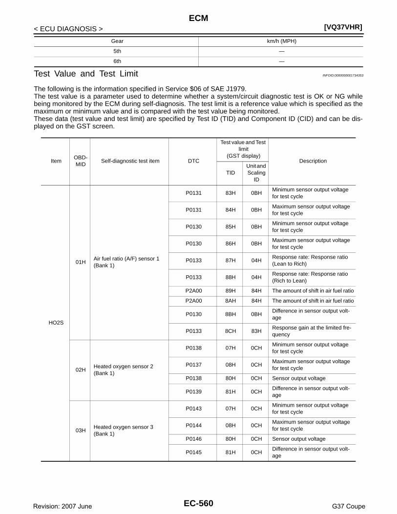
[VQ37VHR]ECM
< ECU DIAGNOSIS >
Test Value and Test Limit INFOID:0000000001734353
The following is the information specified in Service $06 of SAE J1979.The test value is a parameter used to determine whether a system/circuit diagnostic test is OK or NG whilebeing monitored by the ECM during self-diagnosis. The test limit is a reference value which is specified as themaximum or minimum value and is compared with the test value being monitored.These data (test value and test limit) are specified by Test ID (TID) and Component ID (CID) and can be dis-played on the GST screen.
5th —
6th —
Gear km/h (MPH)
ItemOBD-MID
Self-diagnostic test item DTC
Test value and Test limit
(GST display)Description
TIDUnit and Scaling
ID
HO2S
01HAir fuel ratio (A/F) sensor 1 (Bank 1)
P0131 83H 0BHMinimum sensor output voltage for test cycle
P0131 84H 0BHMaximum sensor output voltage for test cycle
P0130 85H 0BHMinimum sensor output voltage for test cycle
P0130 86H 0BHMaximum sensor output voltage for test cycle
P0133 87H 04HResponse rate: Response ratio (Lean to Rich)
P0133 88H 04HResponse rate: Response ratio (Rich to Lean)
P2A00 89H 84H The amount of shift in air fuel ratio
P2A00 8AH 84H The amount of shift in air fuel ratio
P0130 8BH 0BHDifference in sensor output volt-age
P0133 8CH 83HResponse gain at the limited fre-quency
02HHeated oxygen sensor 2 (Bank 1)
P0138 07H 0CHMinimum sensor output voltage for test cycle
P0137 08H 0CHMaximum sensor output voltage for test cycle
P0138 80H 0CH Sensor output voltage
P0139 81H 0CHDifference in sensor output volt-age
03HHeated oxygen sensor 3 (Bank 1)
P0143 07H 0CHMinimum sensor output voltage for test cycle
P0144 08H 0CHMaximum sensor output voltage for test cycle
P0146 80H 0CH Sensor output voltage
P0145 81H 0CHDifference in sensor output volt-age
EC-560Revision: 2007 June G37 Coupe

ECM[VQ37VHR]
C
D
E
F
G
H
I
J
K
L
M
A
C
N
P
O
< ECU DIAGNOSIS >
E
HO2S
05HAir fuel ratio (A/F) sensor 1 (Bank 2)
P0151 83H 0BHMinimum sensor output voltage for test cycle
P0151 84H 0BHMaximum sensor output voltage for test cycle
P0150 85H 0BHMinimum sensor output voltage for test cycle
P0150 86H 0BHMaximum sensor output voltage for test cycle
P0153 87H 04HResponse rate: Response ratio (Lean to Rich)
P0153 88H 04HResponse rate: Response ratio (Rich to Lean)
P2A03 89H 84H The amount of shift in air fuel ratio
P2A03 8AH 84H The amount of shift in air fuel ratio
P0150 8BH 0BHDifference in sensor output volt-age
P0153 8CH 83HResponse gain at the limited fre-quency
06HHeated oxygen sensor 2(Bank 2)
P0158 07H 0CHMinimum sensor output voltage for test cycle
P0157 08H 0CHMaximum sensor output voltage for test cycle
P0158 80H 0CH Sensor output voltage
P0159 81H 0CHDifference in sensor output volt-age
07HHeated oxygen sensor 3 (Bank2)
P0163 07H 0CHMinimum sensor output voltage for test cycle
P0164 08H 0CHMaximum sensor output voltage for test cycle
P0166 80H 0CH Sensor output voltage
P0165 81H 0CHDifference in sensor output volt-age
CATA-LYST
21HThree way catalyst function (Bank1)
P0420 80H 01H O2 storage index
P0420 82H 01HSwitching time lag engine exhaust index value
P2423 83H 0CHDifference in 3rd O2 sensor out-put voltage
P2423 84H 84HO2 storage index in HC trap cata-lyst
22HThree way catalyst function (Bank2)
P0430 80H 01H O2 storage index
P0430 82H 01HSwitching time lag engine exhaust index value
P2424 83H 0CHDifference in 3rd O2 sensor out-put voltage
P2424 84H 84HO2 storage index in HC trap cata-lyst
ItemOBD-MID
Self-diagnostic test item DTC
Test value and Test limit
(GST display)Description
TIDUnit and Scaling
ID
EC-561Revision: 2007 June G37 Coupe

[VQ37VHR]ECM
< ECU DIAGNOSIS >
EGR SYSTEM
31H EGR function
P0400 80H 96HLow Flow Faults: EGR temp change rate (short term)
P0400 81H 96HLow Flow Faults: EGR temp change rate (long term)
P0400 82H 96HLow Flow Faults: Difference be-tween max EGR temp and EGR temp under idling condition
P0400 83H 96H Low Flow Faults: Max EGR temp
P1402 84H 96HHigh Flow Faults: EGR temp in-crease rate
EVAP SYSTEM
39HEVAP control system leak (Cap Off)
P0455 80H 0CHDifference in pressure sensor out-put voltage before and after pull down
3BHEVAP control system leak (Small leak)
P0442 80H 05HLeak area index (for more than 0.04inch)
3CHEVAP control system (Very small leak)
P0456 80H 05HLeak area index (for more than 0.02inch)
P0456 81H FDHMaximum internal pressure of EVAP system during monitoring
3DH Purge flow system P0441 83H 0CHDifference in pressure sensor out-put voltage before and after vent control value close
O2 SEN-SOR HEATER
41HA/F sensor 1 heater (Bank 1)
Low Input:P0031High Input:P0032
81H 0BHConverted value of Heater electric current to voltage
42HHeated oxygen sensor 2 (Bank 1)
Low Input:P0037High Input:P0038
80H 0CHConverted value of Heater electric current to voltage
43HHeated oxygen sensor 3 (Bank 1)
P0043 80H 0CHConverted value of Heater electric current to voltage
45HA/F sensor 1 heater (Bank 2)
Low Input:P0051High Input:P0052
81H 0BHConverted value of Heater electric current to voltage
46HHeated oxygen sensor 2 (Bank 2)
Low Input:P0057High Input:P0058
80H 0CHConverted value of Heater electric current to voltage
47HHeated oxygen sensor 3 (Bank 2)
P0063 80H 0CHConverted value of Heater electric current to voltage
SEC-OND-ARY AIR
71H Secondary Air system
P0411 80H 01HSecondary Air Injection System Incorrect Flow Detected
Bank1: P0491Bank2: P0492
81H 01HSecondary Air Injection System Insufficient Flow
P2445 82H 01HSecondary Air Injection System Pump Stuck Off
P2448 83H 01HSecondary Air Injection System High Airflow
Bank1: P2440Bank2: P2442
84H 01HSecondary Air Injection System Switching Valve Stuck Open
P2440 85H 01HSecondary Air Injection System Switching Valve Stuck Open
P2444 86H 01HSecondary Air Injection System Pump Stuck On
ItemOBD-MID
Self-diagnostic test item DTC
Test value and Test limit
(GST display)Description
TIDUnit and Scaling
ID
EC-562Revision: 2007 June G37 Coupe

ECM[VQ37VHR]
C
D
E
F
G
H
I
J
K
L
M
A
C
N
P
O
< ECU DIAGNOSIS >
E
FUEL SYSTEM
81HFuel injection system function (Bank 1)
P0171 or P0172 80H 2FH Long term fuel trim
P0171 or P0172 81H 24HThe number of lambda control clamped
82HFuel injection system function (Bank 2)
P0174 or P0175 80H 2FH Long term fuel trim
P0174 or P0175 81H 24HThe number of lambda control clamped
MISFIRE A1H Multiple Cylinder Misfire
P0301 80H 24HMisfiring counter at 1000rev of the first cylinder
P0302 81H 24HMisfiring counter at 1000rev of the second cylinder
P0303 82H 24HMisfiring counter at 1000rev of the third cylinder
P0304 83H 24HMisfiring counter at 1000rev of the fourth cylinder
P0305 84H 24HMisfiring counter at 1000rev of the fifth cylinder
P0306 85H 24HMisfiring counter at 1000rev of the sixth cylinder
P0307 86H 24HMisfiring counter at 1000rev of the seventh cylinder
P0308 87H 24HMisfiring counter at 1000rev of the eighth cylinder
P0300 88H 24HMisfiring counter at 1000rev of the multiple cylinders
P0301 89H 24HMisfiring counter at 200rev of the first cylinder
P0302 8AH 24HMisfiring counter at 200rev of the second cylinder
P0303 8BH 24HMisfiring counter at 200rev of the third cylinder
P0304 8CH 24HMisfiring counter at 200rev of the fourth cylinder
P0305 8DH 24HMisfiring counter at 200rev of the fifth cylinder
P0306 8EH 24HMisfiring counter at 200rev of the fifth cylinder
P0307 8FH 24HMisfiring counter at 200rev of the fifth cylinder
P0308 90H 24HMisfiring counter at 200rev of the fifth cylinder
P0300 91H 24HMisfiring counter at 1000rev of the single cylinder
P0300 92H 24HMisfiring counter at 200rev of the single cylinder
P0300 93H 24HMisfiring counter at 200rev of the multiple cylinders
ItemOBD-MID
Self-diagnostic test item DTC
Test value and Test limit
(GST display)Description
TIDUnit and Scaling
ID
EC-563Revision: 2007 June G37 Coupe

[VQ37VHR]ECM
< ECU DIAGNOSIS >
MISFIRE
A2H No.1 Cylinder Misfire
P0301 0BH 24HEWMA (Exponential Weighted Moving Average) misfire counts for last 10 driving cycles
P0301 0CH 24HMisfire counts for last/current driv-ing cycles
A3H No.2 Cylinder Misfire
P0302 0BH 24HEWMA (Exponential Weighted Moving Average) misfire counts for last 10 driving cycles
P0302 0CH 24HMisfire counts for last/current driv-ing cycles
A4H No.3 Cylinder Misfire
P0303 0BH 24HEWMA (Exponential Weighted Moving Average) misfire counts for last 10 driving cycles
P0303 0CH 24HMisfire counts for last/current driv-ing cycles
A5H No.4 Cylinder Misfire
P0304 0BH 24HEWMA (Exponential Weighted Moving Average) misfire counts for last 10 driving cycles
P0304 0CH 24HMisfire counts for last/current driv-ing cycles
A6H No.5 Cylinder Misfire
P0305 0BH 24HEWMA (Exponential Weighted Moving Average) misfire counts for last 10 driving cycles
P0305 0CH 24HMisfire counts for last/current driv-ing cycles
A7H No.6 Cylinder Misfire
P0306 0BH 24HEWMA (Exponential Weighted Moving Average) misfire counts for last 10 driving cycles
P0306 0CH 24HMisfire counts for last/current driv-ing cycles
A8H No.7 Cylinder Misfire
P0307 0BH 24HEWMA (Exponential Weighted Moving Average) misfire counts for last 10 driving cycles
P0307 0CH 24HMisfire counts for last/current driv-ing cycles
A9H No.8 Cylinder Misfire
P0308 0BH 24HEWMA (Exponential Weighted Moving Average) misfire counts for last 10 driving cycles
P0308 0CH 24HMisfire counts for last/current driv-ing cycles
ItemOBD-MID
Self-diagnostic test item DTC
Test value and Test limit
(GST display)Description
TIDUnit and Scaling
ID
EC-564Revision: 2007 June G37 Coupe

VVEL CONTROL MODULE[VQ37VHR]
C
D
E
F
G
H
I
J
K
L
M
A
C
N
P
O
< ECU DIAGNOSIS >
E
VVEL CONTROL MODULE
Reference Value INFOID:0000000001903105
TERMINAL LAYOUT
PHYSICAL VALUESNOTE:• VVEL control module is located behind the IPDM E/R. For this inspection, remove hoodledge cover (RH).• Specification data are reference values and are measured between each terminal and ground.• Pulse signal is measured by CONSULT-III.
JMBIA0857ZZ
Terminal No. Description
ConditionValue
(Approx.)+ -– Signal nameInput/Output
1(W)
14(B)
VVEL actuator motor relay power supply (bank 2)
Input [Ignition switch: ON]BATTERY VOLTAGE(11 - 14V)
2(L/B)
14(B)
VVEL actuator motor (High lift) (bank 2)
Output
[Engine is running]• Warm-up condition• Idle speed
0 - 14V
[Engine is running]• Warm-up condition• When revving engine up to 2,000
rpm quickly
0 - 14V
3(G)
4(W)
VVEL control shaft posi-tion sensor 2 (bank 1)
Input
[Engine is running]• Warm-up condition• Idle speed
Approx.0.25 - 1.40V
[Engine is running]• Warm-up condition• When revving engine up to 2,000
rpm quickly
Approx.0.25 - 4.75V
4(W)
—Sensor ground[VVEL control shaft posi-tion sensor 2 (bank 1)]
— — —
JMBIA0854ZZ
JMBIA0855ZZ
EC-565Revision: 2007 June G37 Coupe

[VQ37VHR]VVEL CONTROL MODULE
< ECU DIAGNOSIS >
5(R)
6(B)
VVEL control shaft posi-tion sensor 2 (bank 2)
Input
[Engine is running]• Warm-up condition• Idle speed
Approx.0.25 - 1.40V
[Engine is running]• Warm-up condition• When revving engine up to 2,000
rpm quickly
Approx.0.25 - 4.75V
6(B)
—Sensor ground[VVEL control shaft posi-tion sensor 2 (bank 2)]
— — —
7(SB)
6(B)
Sensor power supply[VVEL control shaft posi-tion sensor 2 (bank 2)]
— [Ignition switch: ON] 5V
8(O)
14(B)
Power supply for VVEL control module
— [Ignition switch: ON]BATTERY VOLTAGE(11 - 14V)
9(LG)
4(W)
Sensor power supply[VVEL control shaft posi-tion sensor 2 (bank 1)]
— [Ignition switch: ON] 5V
11(G)
—CAN communication line[ECM]
Input/Output
— —
12(G)
14(B)
VVEL actuator motor (High lift) (bank 1)
Output
[Engine is running]• Warm-up condition• Idle speed
0 - 14V
[Engine is running]• Warm-up condition• When revving engine up to 2,000
rpm quickly
0 - 14V
13(W)
14(B)
VVEL actuator motor relay power supply (bank 1)
Input [Ignition switch: ON]BATTERY VOLTAGE(11 - 14V)
14(B)
— — —[Engine is running]• Idle speed
—
Terminal No. Description
ConditionValue
(Approx.)+ -– Signal nameInput/Output
JMBIA0854ZZ
JMBIA0855ZZ
EC-566Revision: 2007 June G37 Coupe

VVEL CONTROL MODULE[VQ37VHR]
C
D
E
F
G
H
I
J
K
L
M
A
C
N
P
O
< ECU DIAGNOSIS >
E
15(L/Y)
14(B)
VVEL actuator motor (Low lift) (bank 2)
Output
[Engine is running]• Warm-up condition• Idle speed
0 - 14V
[Engine is running]• Warm-up condition• When revving engine up to 2,000
rpm quickly
0 - 14V
16(R)
17(L)
VVEL control shaft posi-tion sensor 1 (bank 1)
Input
[Engine is running]• Warm-up condition• Idle speed
3.50 - 4.75V
[Engine is running]• Warm-up condition• When revving engine up to 2,000
rpm quickly
0.25 - 4.75V
17(L)
—Sensor ground[VVEL control shaft posi-tion sensor 1 (bank 1)]
— — —
18(G)
19(W)
VVEL control shaft posi-tion sensor 1 (bank 2)
Input
[Engine is running]• Warm-up condition• Idle speed
3.50 - 4.75V
[Engine is running]• Warm-up condition• When revving engine up to 2,000
rpm quickly
0.25 - 4.75V
19(W)
—Sensor ground[VVEL control shaft posi-tion sensor 1 (bank 2)]
— — —
20(BR)
19(W)
Sensor power supply[VVEL control shaft posi-tion sensor 1 (bank 2)]
— [Ignition switch: ON] 5V
21(V)
14(B)
VVEL actuator motor relay abort signal
Input[Engine is running]• Warm-up condition• Idle speed
0V
22(P)
17(L)
Sensor power supply[VVEL position sensor 1 (bank 1)]
— [Ignition switch: ON] 5V
23(Y)
14(B)
VVEL control motor relay Output[Ignition switch: OFF]
BATTERY VOLTAGE(11 - 14V)
[Ignition switch: ON] 0 - 1.0V
24(L)
— CAN communication lineInput/Output
— —
Terminal No. Description
ConditionValue
(Approx.)+ -– Signal nameInput/Output
JMBIA0854ZZ
JMBIA0855ZZ
EC-567Revision: 2007 June G37 Coupe

[VQ37VHR]VVEL CONTROL MODULE
< ECU DIAGNOSIS >
: Average voltage for pulse signal (Actual pulse signal can be confirmed by oscilloscope.)
25(BR)
14(B)
VVEL control motor (Low lift) (bank 1)
Output
[Engine is running]• Warm-up condition• Idle speed
0 - 14V
[Engine is running]• Warm-up condition• When revving engine up to 2,000
rpm quickly
0 - 14V
Terminal No. Description
ConditionValue
(Approx.)+ -– Signal nameInput/Output
JMBIA0854ZZ
JMBIA0855ZZ
EC-568Revision: 2007 June G37 Coupe

VVEL CONTROL MODULE[VQ37VHR]
C
D
E
F
G
H
I
J
K
L
M
A
C
N
P
O
< ECU DIAGNOSIS >
E
Wiring Diagram - ENGINE CONTROL SYSTEM - INFOID:0000000001911753
Click here to view the eWD.
JCBWA0348GB
EC-569Revision: 2007 June G37 Coupe
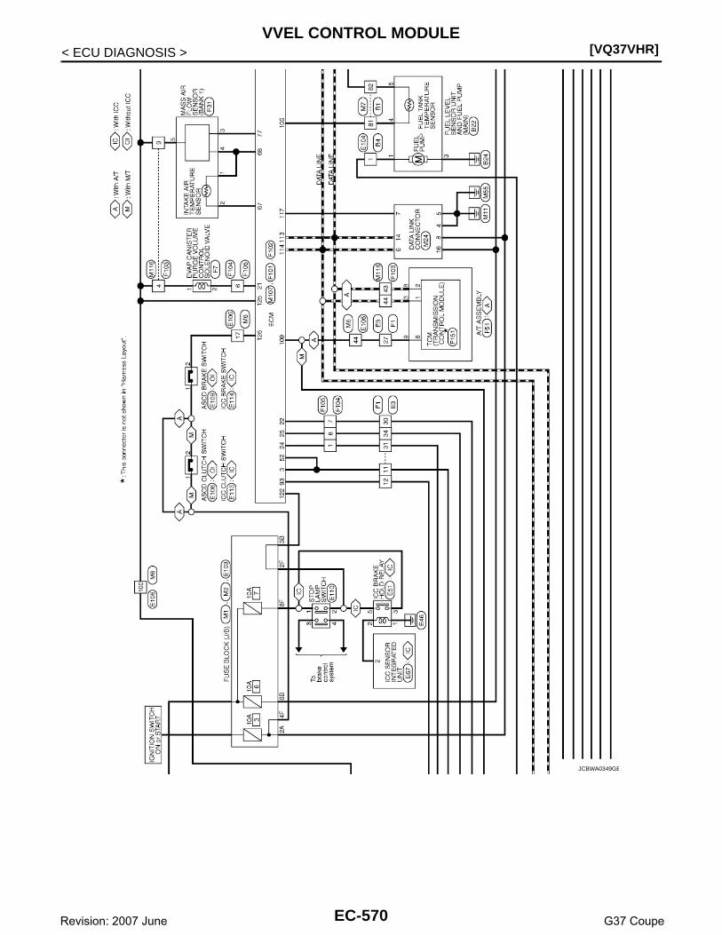
[VQ37VHR]VVEL CONTROL MODULE
< ECU DIAGNOSIS >
JCBWA0349GB
EC-570Revision: 2007 June G37 Coupe
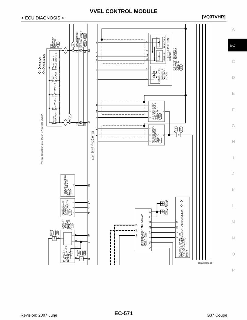
VVEL CONTROL MODULE[VQ37VHR]
C
D
E
F
G
H
I
J
K
L
M
A
C
N
P
O
< ECU DIAGNOSIS >
E
JCBWA0350GB
EC-571Revision: 2007 June G37 Coupe

[VQ37VHR]VVEL CONTROL MODULE
< ECU DIAGNOSIS >
JCBWA0351GB
EC-572Revision: 2007 June G37 Coupe

VVEL CONTROL MODULE[VQ37VHR]
C
D
E
F
G
H
I
J
K
L
M
A
C
N
P
O
< ECU DIAGNOSIS >
E
JCBWA0352GB
EC-573Revision: 2007 June G37 Coupe

[VQ37VHR]VVEL CONTROL MODULE
< ECU DIAGNOSIS >
JCBWA0353GB
EC-574Revision: 2007 June G37 Coupe

VVEL CONTROL MODULE[VQ37VHR]
C
D
E
F
G
H
I
J
K
L
M
A
C
N
P
O
< ECU DIAGNOSIS >
E
JCBWA0354GB
EC-575Revision: 2007 June G37 Coupe

[VQ37VHR]VVEL CONTROL MODULE
< ECU DIAGNOSIS >
JCBWA0355GB
EC-576Revision: 2007 June G37 Coupe

VVEL CONTROL MODULE[VQ37VHR]
C
D
E
F
G
H
I
J
K
L
M
A
C
N
P
O
< ECU DIAGNOSIS >
E
JCBWA0356GB
EC-577Revision: 2007 June G37 Coupe

[VQ37VHR]VVEL CONTROL MODULE
< ECU DIAGNOSIS >
JCBWA0357GB
EC-578Revision: 2007 June G37 Coupe

VVEL CONTROL MODULE[VQ37VHR]
C
D
E
F
G
H
I
J
K
L
M
A
C
N
P
O
< ECU DIAGNOSIS >
E
JCBWA0358GB
EC-579Revision: 2007 June G37 Coupe

[VQ37VHR]VVEL CONTROL MODULE
< ECU DIAGNOSIS >
JCBWA0359GB
EC-580Revision: 2007 June G37 Coupe

VVEL CONTROL MODULE[VQ37VHR]
C
D
E
F
G
H
I
J
K
L
M
A
C
N
P
O
< ECU DIAGNOSIS >
E
JCBWA0360GB
EC-581Revision: 2007 June G37 Coupe

[VQ37VHR]VVEL CONTROL MODULE
< ECU DIAGNOSIS >
JCBWA0361GB
EC-582Revision: 2007 June G37 Coupe

VVEL CONTROL MODULE[VQ37VHR]
C
D
E
F
G
H
I
J
K
L
M
A
C
N
P
O
< ECU DIAGNOSIS >
E
JCBWA0362GB
EC-583Revision: 2007 June G37 Coupe

[VQ37VHR]VVEL CONTROL MODULE
< ECU DIAGNOSIS >
JCBWA0363GB
EC-584Revision: 2007 June G37 Coupe

VVEL CONTROL MODULE[VQ37VHR]
C
D
E
F
G
H
I
J
K
L
M
A
C
N
P
O
< ECU DIAGNOSIS >
E
JCBWA0364GB
EC-585Revision: 2007 June G37 Coupe
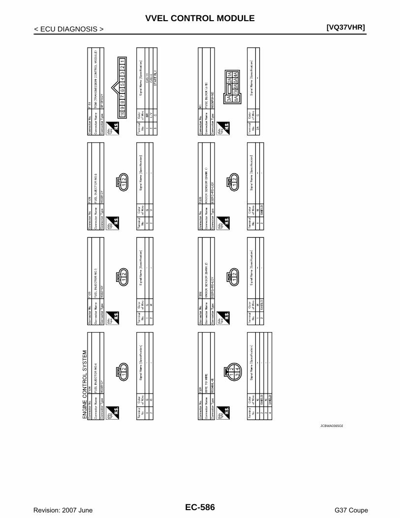
[VQ37VHR]VVEL CONTROL MODULE
< ECU DIAGNOSIS >
JCBWA0365GB
EC-586Revision: 2007 June G37 Coupe

VVEL CONTROL MODULE[VQ37VHR]
C
D
E
F
G
H
I
J
K
L
M
A
C
N
P
O
< ECU DIAGNOSIS >
E
JCBWA0366GB
EC-587Revision: 2007 June G37 Coupe

[VQ37VHR]VVEL CONTROL MODULE
< ECU DIAGNOSIS >
JCBWA0367GB
EC-588Revision: 2007 June G37 Coupe

ENGINE CONTROL SYSTEM SYMPTOMS[VQ37VHR]
C
D
E
F
G
H
I
J
K
L
M
A
C
N
P
O
< SYMPTOM DIAGNOSIS >
E
SYMPTOM DIAGNOSISENGINE CONTROL SYSTEM SYMPTOMS
Symptom Table INFOID:0000000001734354
SYSTEM — BASIC ENGINE CONTROL SYSTEM
SYMPTOM
Reference page
HA
RD
/NO
STA
RT
/RE
STA
RT
(E
XC
P. H
A)
EN
GIN
E S
TALL
HE
SIT
AT
ION
/SU
RG
ING
/FLA
T S
PO
T
SP
AR
K K
NO
CK
/DE
TO
NA
TIO
N
LAC
K O
F P
OW
ER
/PO
OR
AC
CE
LER
AT
ION
HIG
H ID
LE/L
OW
IDLE
RO
UG
H ID
LE/H
UN
TIN
G
IDLI
NG
VIB
RA
TIO
N
SLO
W/N
O R
ET
UR
N T
O ID
LE
OV
ER
HE
AT
S/W
AT
ER
TE
MP
ER
AT
UR
E H
IGH
EX
CE
SS
IVE
FU
EL
CO
NS
UM
PT
ION
EX
CE
SS
IVE
OIL
CO
NS
UM
PT
ION
BA
TT
ER
Y D
EA
D (
UN
DE
R C
HA
RG
E)
Warranty symptom code AA AB AC AD AE AF AG AH AJ AK AL AM HA
Fuel Fuel pump circuit 1 1 2 3 2 2 2 3 2 EC-490
Fuel pressure regulator system 3 3 4 4 4 4 4 4 4 4 EC-601
Fuel injector circuit 1 1 2 3 2 2 2 2 EC-487
Evaporative emission system 3 3 4 4 4 4 4 4 4 4 EC-81
Air Positive crankcase ventilation sys-tem 3 3
4 4 4 4 4 4 4 4 1 EC-509
Incorrect idle speed adjustment 1 1 1 1 1 EC-13
Electric throttle control actuator 1 1 2 3 3 2 2 2 2 2 2EC-392, EC-399
Ignition Incorrect ignition timing adjustment 3 3 1 1 1 1 1 1 EC-13
Ignition circuit 1 1 2 2 2 2 2 2 EC-498
Main power supply and ground circuit 2 2 3 3 3 3 3 2 3 EC-140
Mass air flow sensor circuit
1
1 2
2
2 2 2 2
EC-165, EC-172
Engine coolant temperature sensor circuit
3
3 3EC-184, EC-190
Air fuel ratio (A/F) sensor 1 circuit
EC-197, EC-201, EC-204, EC-207, EC-471
Throttle position sensor circuit
2 2
EC-187, EC-252, EC-388, EC-390, EC-401
Accelerator pedal position sensor circuit 3 2 1EC-458, EC-462, EC-466
Knock sensor circuit 2 3 EC-261
EC-589Revision: 2007 June G37 Coupe

[VQ37VHR]ENGINE CONTROL SYSTEM SYMPTOMS
< SYMPTOM DIAGNOSIS >
1 - 6: The numbers refer to the order of inspection.
(continued on next page)
SYSTEM — ENGINE MECHANICAL & OTHER
Engine oil temperature sensor 4 1 3EC-246, EC-249
Crankshaft position sensor (POS) circuit 2 2 EC-264
Camshaft position sensor (PHASE) circuit 3 2 EC-268
Vehicle speed signal circuit 2 3 3 3 EC-337
Power steering pressure sensor circuit 2 3 3 EC-346
ECM 2 2 3 3 3 3 3 3 3 3 3EC-354, EC-356
Intake valve timing control solenoid valve cir-cuit
3 2 1 3 2 2 3 3 EC-162
Manifold abslute pressure (MAP) sensor 3 EC-177
Brake booster pressure sensor 3 EC-349
VVEL control module 3 4 4 3EC-447,EC-449
VVEL actuator motor 3 4 4 3 EC-374
VVEL actuator motor relay 3 4 4 3 EC-378
VVEL actuator shaft position sensor 3 4 4 3 EC-370
PNP switch circuit 3 3 3 3 3 EC-361
Refrigerant pressure sensor circuit 2 3 3 4 EC-511
Electrical load signal circuit 3 EC-485
Air conditioner circuit 2 2 3 3 3 3 3 3 3 3 2 HAC-5
ABS actuator and electric unit (control unit) 4 BRC-4
SYMPTOM
Reference page
HA
RD
/NO
STA
RT
/RE
STA
RT
(E
XC
P. H
A)
EN
GIN
E S
TALL
HE
SIT
AT
ION
/SU
RG
ING
/FLA
T S
PO
T
SP
AR
K K
NO
CK
/DE
TO
NA
TIO
N
LAC
K O
F P
OW
ER
/PO
OR
AC
CE
LER
AT
ION
HIG
H ID
LE/L
OW
IDLE
RO
UG
H ID
LE/H
UN
TIN
G
IDLI
NG
VIB
RA
TIO
N
SLO
W/N
O R
ET
UR
N T
O ID
LE
OV
ER
HE
AT
S/W
AT
ER
TE
MP
ER
AT
UR
E H
IGH
EX
CE
SS
IVE
FU
EL
CO
NS
UM
PT
ION
EX
CE
SS
IVE
OIL
CO
NS
UM
PT
ION
BA
TT
ER
Y D
EA
D (
UN
DE
R C
HA
RG
E)
Warranty symptom code AA AB AC AD AE AF AG AH AJ AK AL AM HA
EC-590Revision: 2007 June G37 Coupe

ENGINE CONTROL SYSTEM SYMPTOMS[VQ37VHR]
C
D
E
F
G
H
I
J
K
L
M
A
C
N
P
O
< SYMPTOM DIAGNOSIS >
E
SYMPTOM
Reference page
HA
RD
/NO
STA
RT
/RE
STA
RT
(E
XC
P. H
A)
EN
GIN
E S
TALL
HE
SIT
AT
ION
/SU
RG
ING
/FLA
T S
PO
T
SP
AR
K K
NO
CK
/DE
TO
NA
TIO
N
LAC
K O
F P
OW
ER
/PO
OR
AC
CE
LER
AT
ION
HIG
H ID
LE/L
OW
IDLE
RO
UG
H ID
LE/H
UN
TIN
G
IDLI
NG
VIB
RA
TIO
N
SLO
W/N
O R
ET
UR
N T
O ID
LE
OV
ER
HE
AT
S/W
AT
ER
TE
MP
ER
AT
UR
E H
IGH
EX
CE
SS
IVE
FU
EL
CO
NS
UM
PT
ION
EX
CE
SS
IVE
OIL
CO
NS
UM
PT
ION
BA
TT
ER
Y D
EA
D (
UN
DE
R C
HA
RG
E)
Warranty symptom code AA AB AC AD AE AF AG AH AJ AK AL AM HA
Fuel Fuel tank5
5
FL-11
Fuel piping 5 5 5 5 5 5 FL-4
Vapor lock —
Valve deposit
5 5 5 5 5 5 5
—
Poor fuel (Heavy weight gasoline, Low octane)
—
Air Air duct
5 5 5 5 5 5
EM-27
Air cleaner EM-27
Air leakage from air duct(Mass air flow sensor — electric throttle control actuator)
5 5 5 5
EM-27
Electric throttle control actuator EM-28
Air leakage from intake manifold/Collector/Gasket
EM-32
Cranking Battery
1 1 1 1 1 1
1
1
PG-96
Generator circuitCHG-22, CHG-23
Starter circuit 3 STR-17
Signal plate 6 EM-120
PNP switch 4TM-9, TM-122
Engine Cylinder head5 5 5 5 5 5 5 5 EM-106
Cylinder head gasket 4 3
Cylinder block
6 6 6 6 6 6 6 6
4
EM-120
Piston
Piston ring
Connecting rod
Bearing
Crankshaft
EC-591Revision: 2007 June G37 Coupe

[VQ37VHR]ENGINE CONTROL SYSTEM SYMPTOMS
< SYMPTOM DIAGNOSIS >
1 - 6: The numbers refer to the order of inspection.
Valve mecha-nism
Timing chain
5 5 5 5 5 5 5 5
EM-62
Camshaft EM-93
Intake valve timing control EM-62
Intake valve3 EM-106
Exhaust valve
Exhaust Exhaust manifold/Tube/Muffler/Gasket 5 5 5 5 5 5 5 5 EX-4, EX-6
Three way catalyst
Lubrica-tion
Oil pan/Oil strainer/Oil pump/Oil filter/Oil gallery/Oil cooler 5 5 5 5 5 5 5 5
LU-9, LU-11, LU-12, LU-13
Oil level (Low)/Filthy oil ,LU-6
CoolingRadiator/Hose/Radiator filler cap
5 5 5 5 5 5 5 4 5
CO-12, CO-12
Thermostat 5 CO-23
Water pump CO-21
Water gallery CO-25
Cooling fan
5
CO-18
Coolant level (Low)/Contaminat-ed coolant
CO-8
IVIS (INFINITI Vehicle Immobilizer System — NATS)
1 1 SEC-5
SYMPTOM
Reference page
HA
RD
/NO
STA
RT
/RE
STA
RT
(E
XC
P. H
A)
EN
GIN
E S
TALL
HE
SIT
AT
ION
/SU
RG
ING
/FLA
T S
PO
T
SP
AR
K K
NO
CK
/DE
TO
NA
TIO
N
LAC
K O
F P
OW
ER
/PO
OR
AC
CE
LER
AT
ION
HIG
H ID
LE/L
OW
IDLE
RO
UG
H ID
LE/H
UN
TIN
G
IDLI
NG
VIB
RA
TIO
N
SLO
W/N
O R
ET
UR
N T
O ID
LE
OV
ER
HE
AT
S/W
AT
ER
TE
MP
ER
AT
UR
E H
IGH
EX
CE
SS
IVE
FU
EL
CO
NS
UM
PT
ION
EX
CE
SS
IVE
OIL
CO
NS
UM
PT
ION
BA
TT
ER
Y D
EA
D (
UN
DE
R C
HA
RG
E)
Warranty symptom code AA AB AC AD AE AF AG AH AJ AK AL AM HA
EC-592Revision: 2007 June G37 Coupe

NORMAL OPERATING CONDITION[VQ37VHR]
C
D
E
F
G
H
I
J
K
L
M
A
C
N
P
O
< SYMPTOM DIAGNOSIS >
E
NORMAL OPERATING CONDITION
Description INFOID:0000000001734355
FUEL CUT CONTROL (AT NO LOAD AND HIGH ENGINE SPEED)If the engine speed is above 1,400 rpm under no load (for example, the selector lever position is neutral andengine speed is over 1,400 rpm) fuel will be cut off after some time. The exact time when the fuel is cut off var-ies based on engine speed. However, if the engine speed is above 4,000 rpm, fuel will be cut off in a few sec-onds. Fuel cut will be operated until the engine speed reaches 1,000 rpm, then fuel cut will be cancelled.NOTE:This function is different from deceleration control listed under Multiport Fuel Injection (MFI) System, EC-34,"System Description".
TORQUE CUT CONTROL (AT HIGH ENGINE OIL TEMPERATURE)ECM receives engine oil temperature signal from engine oil temperature sensor.To avoid VVEL performance, ECM performs the engine torque cut control at high engine oil temperature.If engine oil temperature is too high, engine oil viscosity will change. As a result, engine oil pressure isdecreased. This control is to control the VVEL operating angle by operating the VVEL actuator sub assembly.If this control is operated, engine performance will decrease, then maximum engine speed is reduced a little,for example.NOTE:If the engine oil temperature sensor is deteriorated, its characteristic will change.In this case, the operating temperature for engine torque cut control might be decrease.Perform Component Inspection of the engine oil temperature sensor to check for the deterioration.Refer to EC-248, "Component Inspection".
EC-593Revision: 2007 June G37 Coupe

[VQ37VHR]PRECAUTIONS
< PRECAUTION >
PRECAUTIONPRECAUTIONS
Precaution for Supplemental Restraint System (SRS) "AIR BAG" and "SEAT BELT PRE-TENSIONER" INFOID:0000000001912134
The Supplemental Restraint System such as “AIR BAG” and “SEAT BELT PRE-TENSIONER”, used alongwith a front seat belt, helps to reduce the risk or severity of injury to the driver and front passenger for certaintypes of collision. This system includes seat belt switch inputs and dual stage front air bag modules. The SRSsystem uses the seat belt switches to determine the front air bag deployment, and may only deploy one frontair bag, depending on the severity of a collision and whether the front occupants are belted or unbelted.Information necessary to service the system safely is included in the “SRS AIRBAG” and “SEAT BELT” of thisService Manual.WARNING:• To avoid rendering the SRS inoperative, which could increase the risk of personal injury or death in
the event of a collision which would result in air bag inflation, all maintenance must be performed byan authorized NISSAN/INFINITI dealer.
• Improper maintenance, including incorrect removal and installation of the SRS, can lead to personalinjury caused by unintentional activation of the system. For removal of Spiral Cable and Air BagModule, see the “SRS AIRBAG”.
• Do not use electrical test equipment on any circuit related to the SRS unless instructed to in thisService Manual. SRS wiring harnesses can be identified by yellow and/or orange harnesses or har-ness connectors.
Precaution for Procedure without Cowl Top Cover INFOID:0000000001912135
When performing the procedure after removing cowl top cover, coverthe lower end of windshield with urethane, etc.
Precautions For Xenon Headlamp Service INFOID:0000000001912136
WARNING:Comply with the following warnings to prevent any serious accident.• Disconnect the battery cable (negative terminal) or the power supply fuse before installing, remov-
ing, or touching the xenon headlamp (bulb included). The xenon headlamp contains high-voltagegenerated parts.
• Never work with wet hands.• Check the xenon headlamp ON-OFF status after assembling it to the vehicle. Never turn the xenon
headlamp ON in other conditions. Connect the power supply to the vehicle-side connector.(Turning it ON outside the lamp case may cause fire or visual impairments.)
• Never touch the bulb glass immediately after turning it OFF. It is extremely hot. CAUTION:Comply with the following cautions to prevent any error and malfunction.• Install the xenon bulb securely. (Insufficient bulb socket installation may melt the bulb, the connec-
tor, the housing, etc. by high-voltage leakage or corona discharge.)• Never perform HID circuit inspection with a tester.• Never touch the xenon bulb glass with hands. Never put oil and grease on it.• Dispose of the used xenon bulb after packing it in thick vinyl without breaking it. • Never wipe out dirt and contamination with organic solvent (thinner, gasoline, etc.).
PIIB3706J
EC-594Revision: 2007 June G37 Coupe

PRECAUTIONS[VQ37VHR]
C
D
E
F
G
H
I
J
K
L
M
A
C
N
P
O
< PRECAUTION >
E
On Board Diagnostic (OBD) System of Engine and A/T INFOID:0000000001734359
The ECM has an on board diagnostic system. It will light up the malfunction indicator lamp (MIL) to warn thedriver of a malfunction causing emission deterioration.CAUTION:• Be sure to turn the ignition switch OFF and disconnect the negative battery cable before any repair
or inspection work. The open/short circuit of related switches, sensors, solenoid valves, etc. willcause the MIL to light up.
• Be sure to connect and lock the connectors securely after work. A loose (unlocked) connector willcause the MIL to light up due to the open circuit. (Be sure the connector is free from water, grease,dirt, bent terminals, etc.)
• Certain systems and components, especially those related to OBD, may use a new style slide-lock-ing type harness connector. For description and how to disconnect, refer to PG-86, "Description".
• Be sure to route and secure the harnesses properly after work. The interference of the harness witha bracket, etc. may cause the MIL to light up due to the short circuit.
• Be sure to connect rubber tubes properly after work. A misconnected or disconnected rubber tubemay cause the MIL to light up due to the malfunction of the EVAP system or fuel injection system,etc.
• Be sure to erase the unnecessary malfunction information (repairs completed) from the ECM andTCM (Transmission control module) before returning the vehicle to the customer.
General Precautions INFOID:0000000001734360
• Always use a 12 volt battery as power source.• Do not attempt to disconnect battery cables while engine is
running.• Before connecting or disconnecting the ECM harness con-
nector, turn ignition switch OFF and disconnect negative bat-tery cable. Failure to do so may damage the ECM becausebattery voltage is applied to ECM even if ignition switch isturned OFF.
• Before removing parts, turn ignition switch OFF and then dis-connect battery ground cable.
• Do not disassemble ECM.• If a battery cable is disconnected, the memory will return to
the ECM value.The ECM will now start to self-control at its initial value.Engine operation can vary slightly when the terminal is dis-connected. However, this is not an indication of a malfunc-tion. Do not replace parts because of a slight variation.
• If the battery is disconnected, the following emission-relateddiagnostic information will be lost within 24 hours.
- Diagnostic trouble codes- 1st trip diagnostic trouble codes- Freeze frame data- 1st trip freeze frame data- System readiness test (SRT) codes- Test values
SEF289H
JMBIA0057ZZ
EC-595Revision: 2007 June G37 Coupe

[VQ37VHR]PRECAUTIONS
< PRECAUTION >• When connecting ECM harness connector (A), fasten (B) it
securely with a lever as far as it will go as shown in the figure.
• When connecting or disconnecting pin connectors into orfrom ECM, take care not to damage pin terminals (bend orbreak).Make sure that there are not any bends or breaks on ECM pinterminal, when connecting pin connectors.
• Securely connect ECM harness connectors.A poor connection can cause an extremely high (surge) volt-age to develop in coil and condenser, thus resulting in dam-age to ICs.
• Keep engine control system harness at least 10 cm (4 in) awayfrom adjacent harness, to prevent engine control system mal-functions due to receiving external noise, degraded operationof ICs, etc.
• Keep engine control system parts and harness dry.• Before replacing ECM, perform ECM Terminals and Reference
Value inspection and make sure ECM functions properly.Refer to EC-513, "Reference Value".
• Handle mass air flow sensor carefully to avoid damage.• Do not clean mass air flow sensor with any type of detergent.• Do not disassemble electric throttle control actuator.• Even a slight leak in the air intake system can cause serious
incidents.• Do not shock or jar the camshaft position sensor (PHASE),
crankshaft position sensor (POS).
• After performing each TROUBLE DIAGNOSIS, perform DTCConfirmation Procedure or Component Function Check.The DTC should not be displayed in the DTC ConfirmationProcedure if the repair is completed. The Component Func-tion Check should be a good result if the repair is completed.
1. ECM
C. Loosen
JMBIA0029ZZ
PBIB0090E
MEF040D
SEF217U
EC-596Revision: 2007 June G37 Coupe

PRECAUTIONS[VQ37VHR]
C
D
E
F
G
H
I
J
K
L
M
A
C
N
P
O
< PRECAUTION >
E
• When measuring ECM signals with a circuit tester, never allowthe two tester probes to contact.Accidental contact of probes will cause a short circuit anddamage the ECM power transistor.
• Do not use ECM ground terminals when measuring input/out-put voltage. Doing so may result in damage to the ECM’s tran-sistor. Use a ground other than ECM terminals, such as theground.
• B1 indicates the bank 1, B2 indicates the bank 2 as shown inthe figure.
• Do not operate fuel pump when there is no fuel in lines.• Tighten fuel hose clamps to the specified torque.
• Do not depress accelerator pedal when starting.• Immediately after starting, do not rev up engine unnecessar-
ily.• Do not rev up engine just prior to shutdown.
SEF348N
SEC893C
SEF709Y
EC-597Revision: 2007 June G37 Coupe
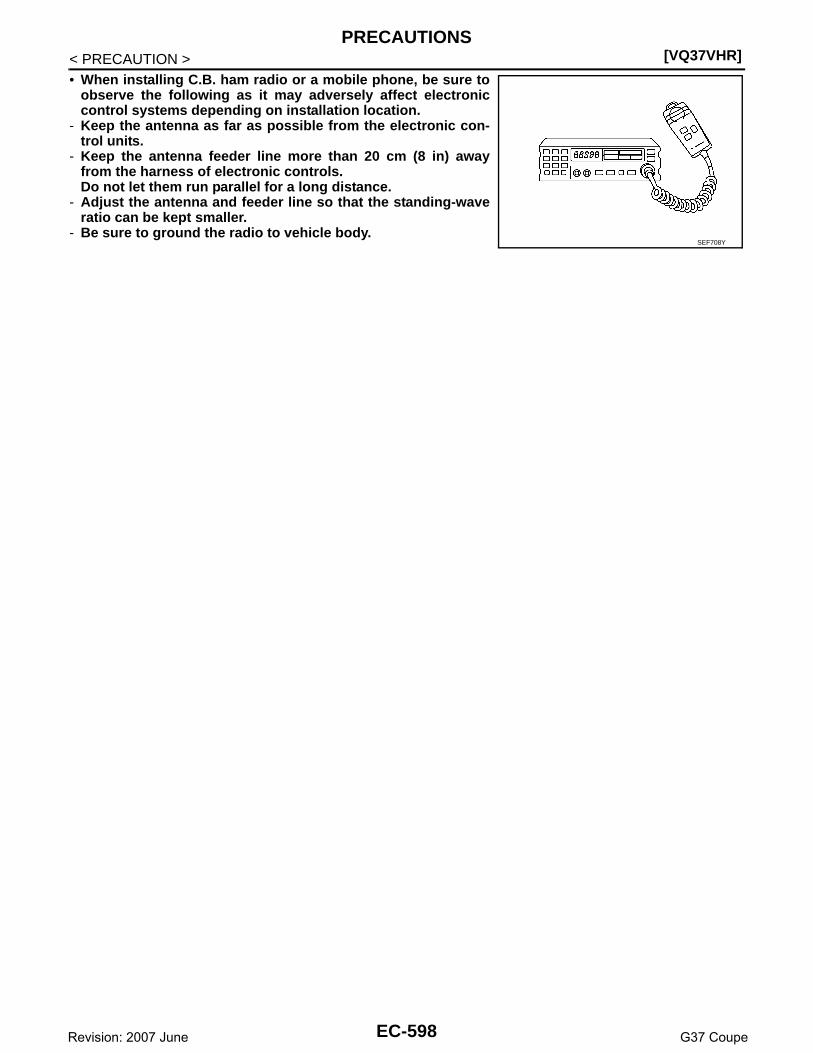
[VQ37VHR]PRECAUTIONS
< PRECAUTION >• When installing C.B. ham radio or a mobile phone, be sure to
observe the following as it may adversely affect electroniccontrol systems depending on installation location.
- Keep the antenna as far as possible from the electronic con-trol units.
- Keep the antenna feeder line more than 20 cm (8 in) awayfrom the harness of electronic controls.Do not let them run parallel for a long distance.
- Adjust the antenna and feeder line so that the standing-waveratio can be kept smaller.
- Be sure to ground the radio to vehicle body.SEF708Y
EC-598Revision: 2007 June G37 Coupe

PREPARATION[VQ37VHR]
C
D
E
F
G
H
I
J
K
L
M
A
C
N
P
O
< PREPARATION >
E
PREPARATIONPREPARATION
Special Service Tools INFOID:0000000001734361
NOTE:The actual shapes of Kent-Moore tools may differ from those of special service tools illustrated here.
Commercial Service Tools INFOID:0000000001734362
Tool number(Kent-Moore No.)Tool name
Description
(J-44321)Fuel pressure gauge kit
Checking fuel pressure
LEC642
Tool name(Kent-Moore No.)
Description
Leak detector i.e.: (J-41416)
Locating the EVAP leak
EVAP service port adapteri.e.: (J-41413-OBD)
Applying positive pressure through EVAP service port
Fuel filler cap adapteri.e.: (MLR-8382)
Checking fuel tank vacuum relief valve opening pressure
Socket wrench Removing and installing engine coolant tempera-ture sensor
S-NT703
S-NT704
S-NT815
S-NT705
EC-599Revision: 2007 June G37 Coupe

[VQ37VHR]PREPARATION
< PREPARATION >
Oxygen sensor thread cleaneri.e.: (J-43897-18)(J-43897-12)
Reconditioning the exhaust system threads before installing a new oxygen sensor. Use with anti-seize lubricant shown below.a: 18 mm diameter with pitch 1.5 mm for Zirco-nia Oxygen Sensorb: 12 mm diameter with pitch 1.25 mm for Tita-nia Oxygen Sensor
Anti-seize lubricant
i.e.: (PermatexTM 133AR or equivalent meeting MIL specifica-tion MIL-A-907)
Lubricating oxygen sensor thread cleaning tool when reconditioning exhaust system threads.
Tool name(Kent-Moore No.)
Description
AEM488
S-NT779
EC-600Revision: 2007 June G37 Coupe

FUEL PRESSURE[VQ37VHR]
C
D
E
F
G
H
I
J
K
L
M
A
C
N
P
O
< ON-VEHICLE MAINTENANCE >
E
ON-VEHICLE MAINTENANCEFUEL PRESSURE
Inspection INFOID:0000000001734363
FUEL PRESSURE RELEASE
With CONSULT-III
1. Turn ignition switch ON.2. Perform “FUEL PRESSURE RELEASE” in “WORK SUPPORT” mode with CONSULT-III.3. Start engine.4. After engine stalls, crank it two or three times to release all fuel pressure.5. Turn ignition switch OFF.
Without CONSULT-III
1. Remove fuel pump fuse (1) located in IPDM E/R (2).2. Start engine.3. After engine stalls, crank it two or three times to release all fuel
pressure.4. Turn ignition switch OFF.5. Reinstall fuel pump fuse after servicing fuel system.
FUEL PRESSURE CHECKCAUTION:Before disconnecting fuel line, release fuel pressure from fuel line to eliminate danger.NOTE:• Prepare pans or saucers under the disconnected fuel line because the fuel may spill out. The fuel
pressure cannot be completely released because CV36 models do not have fuel return system.• Use Fuel Pressure Gauge Kit (J-44321) to check fuel pressure.1. Release fuel pressure to zero.2. Install the inline fuel quick disconnected fitting (A) between fuel
damper (1) and injector tube.3. Connect the fuel pressure test gauge (quick connector adapter
hose) (B) to the inline fuel quick disconnected fitting.4. Turn ignition switch ON and check for fuel leakage.5. Start engine and check for fuel leakage.6. Read the indication of fuel pressure gauge.
7. If result is unsatisfactory, check fuel hoses and fuel tubes forclogging.If OK, Replace “fuel filter and fuel pump assembly”.If NG, Repair or replace.
JMBIA0021ZZ
At idling : Approximately 350 kPa (3.57 kg/cm2, 51 psi)JMBIA0028ZZ
EC-601Revision: 2007 June G37 Coupe

[VQ37VHR]EVAP LEAK CHECK
< ON-VEHICLE MAINTENANCE >
EVAP LEAK CHECK
Inspection INFOID:0000000001734364
CAUTION:• Do not use compressed air or a high pressure pump.• Do not exceed 4.12 kPa (0.042 kg/cm2, 0.6 psi) of pressure in EVAP system.NOTE:• Do not start engine.• Improper installation of EVAP service port adapter to the EVAP service port may cause a leak.
WITH CONSULT-III1. To locate the EVAP leak, install EVAP service port adapter and
pressure pump to EVAP service port.2. Turn ignition switch ON.3. Select the “EVAP SYSTEM CLOSE” of “WORK SUPPORT”
mode with CONSULT-III.4. Touch “START”. A bar graph (Pressure indicating display) will
appear on the screen.5. Apply positive pressure to the EVAP system until the pressure
indicator reaches the middle of the bar graph.6. Remove EVAP service port adapter and hose with pressure
pump.7. Locate the leak using a leak detector. Refer to EC-80, "System
Diagram".
WITHOUT CONSULT-III1. To locate the EVAP leak, install EVAP service port adapter and
pressure pump to EVAP service port.2. Apply battery voltage between the terminals of EVAP canister
vent control valve to make a closed EVAP system.3. To locate the leak, deliver positive pressure to the EVAP system
until pressure gauge points reach 1.38 to 2.76 kPa (0.014 to0.028 kg/cm2, 0.2 to 0.4 psi).
4. Remove EVAP service port adapter and hose with pressurepump.
SEF462UA
SEF200U
SEF462UA
EC-602Revision: 2007 June G37 Coupe

EVAP LEAK CHECK[VQ37VHR]
C
D
E
F
G
H
I
J
K
L
M
A
C
N
P
O
< ON-VEHICLE MAINTENANCE >
E
5. Locate the leak using a leak detector. Refer to EC-80, "SystemDiagram".
SEF200U
EC-603Revision: 2007 June G37 Coupe

[VQ37VHR]EVAP CANISTER
< ON-VEHICLE REPAIR >
ON-VEHICLE REPAIREVAP CANISTER
Exploded View INFOID:0000000001734365
Removal and Installation INFOID:0000000001734366
REMOVAL1. Lift up the vehicle.2. Remove EVAP canister fixing bolt.3. Remove EVAP canister.NOTE:The EVAP canister vent control valve and EVAP canister system pressure sensor can be removed withoutremoving the EVAP canister.
INSTALLATIONInstall in the reverse order of removal.NOTE:Tighten EVAP canister fixing bolt to the specified torque.
DISASSEMBLY1. Turn EVAP canister vent control valve counterclockwise.
2. Remove the EVAP canister vent control valve.
1. EVAP canister system pressure sen-sor
2. O-ring 3. EVAP canister
4. O-ring 5. EVAP canister vent control valve
Refer to GI-3, "Contents" for symbols not described on the above.
JMBIA0049GB
A : Lock
B : Unlock
PBIB2730E
EC-604Revision: 2007 June G37 Coupe

EVAP CANISTER[VQ37VHR]
C
D
E
F
G
H
I
J
K
L
M
A
C
N
P
O
< ON-VEHICLE REPAIR >
E
ASSEMBLYAssemble in the reverse order of disassembly.CAUTION:Always replace O-ring with a new one.
Inspection INFOID:0000000001734367
Check EVAP canister as follows:1. Block port (B).2. Blow air into port (A) and check that it flows freely out of port (C).3. Release blocked port (B).4. Apply vacuum pressure to port (B) and check that vacuum pres-
sure exists at the ports (A) and (C). 5. Block port (A) and (B).6. Apply pressure to port (C) and check that there is no leakage.
PBIB2728E
EC-605Revision: 2007 June G37 Coupe

[VQ37VHR]SERVICE DATA AND SPECIFICATIONS (SDS)
< SERVICE DATA AND SPECIFICATIONS (SDS)
SERVICE DATA AND SPECIFICATIONS (SDS)SERVICE DATA AND SPECIFICATIONS (SDS)
Idle Speed INFOID:0000000001734368
*: Under the following conditions
• A/C switch: OFF
• Electric load: OFF (Lights, heater fan & rear window defogger)
• Steering wheel: Kept in straight-ahead position
Ignition Timing INFOID:0000000001734369
*: Under the following conditions
• A/C switch: OFF
• Electric load: OFF (Lights, heater fan & rear window defogger)
• Steering wheel: Kept in straight-ahead position
Calculated Load Value INFOID:0000000001734370
Mass Air Flow Sensor INFOID:0000000001734371
*: Engine is warmed up to normal operating temperature and running under no load.
Transmission Condition Specification
A/T No load* (in P or N position) 650 ±50 rpm
M/T No load* (in Neutral position) 650 ±50 rpm
Transmission Condition Specification
A/T No load* (in P or N position) 10 ± 5° BTDC
M/T No load* (in Neutral position) 10 ± 5° BTDC
Condition Specification (Using CONSULT-III or GST)
At idle 5 – 35 %
At 2,500 rpm 5 – 35 %
Supply voltage Battery voltage (11 – 14 V)
Output voltage at idle 0.7 – 1.2 V*
Mass air flow (Using CONSULT-III or GST)2.0 – 6.0 g·m/sec at idle*
7.0 – 20.0 g·m/sec at 2,500 rpm*
EC-606Revision: 2007 June G37 Coupe