Embed Size (px)
Citation preview
ENGI 8926: Mechanical Design Project IIDownhole Turbine for Drilling
Research and Conceptual Design
Supervisor: Dr. J. Yang
G5Downhole:Bret KennyLida LiuPiek Suan SawChintan Sharma
February 6, 2014
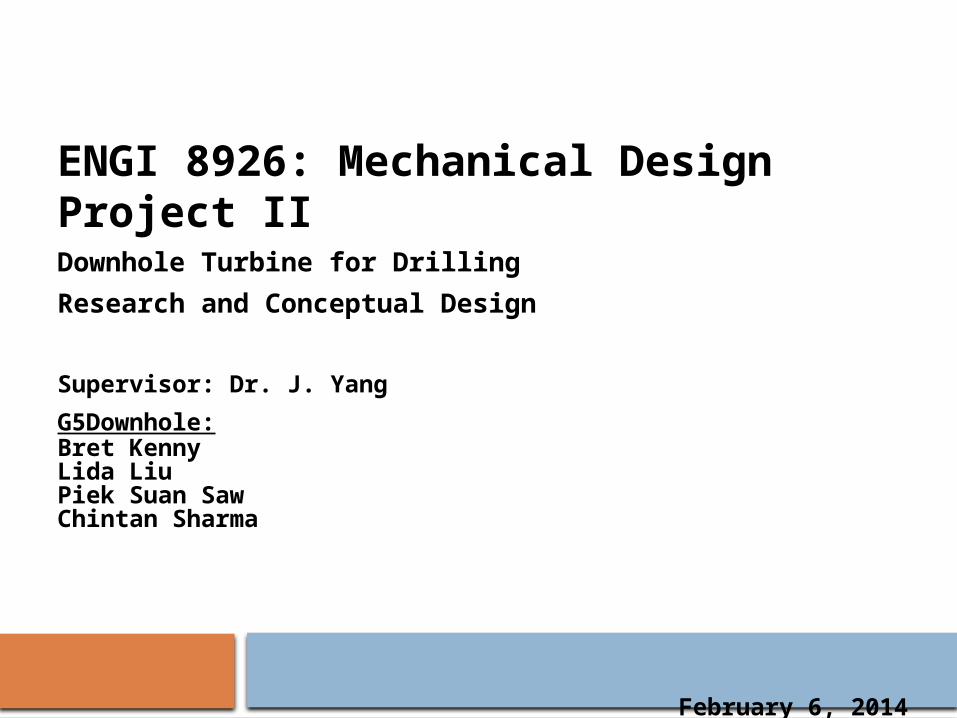
Agenda
Drilling 101 Project Overview Design Constraints Solution Alternatives Concept Selection Conclusion Forward Plan
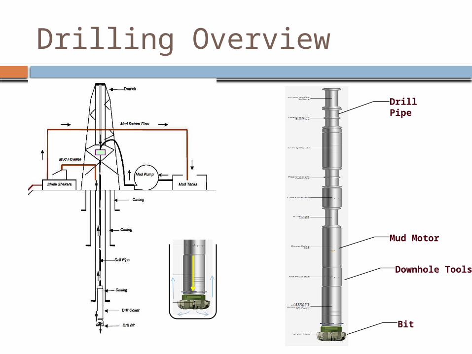
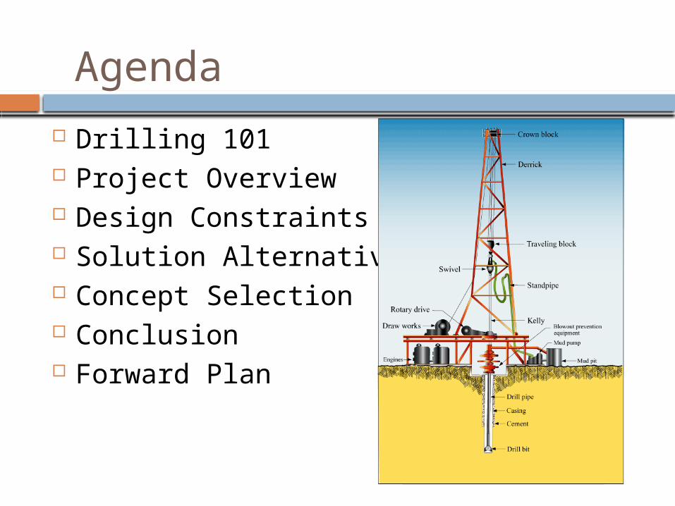
Drilling Overview
Drill Pipe
Mud Motor
Downhole Tools
Bit
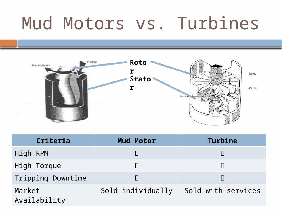
Mud Motors vs. Turbines
Criteria Mud Motor Turbine
High RPM
High Torque
Tripping Downtime
Market Availability Sold individually Sold with services
Rotor
Stator
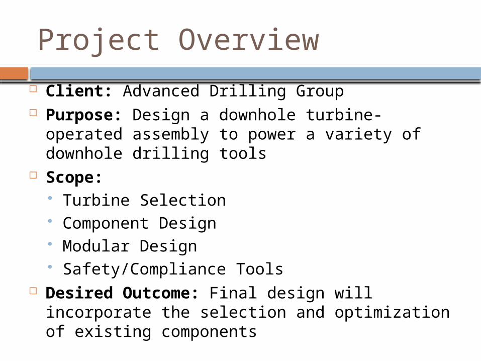
Project Overview
Client: Advanced Drilling Group Purpose: Design a downhole turbine-operated assembly to
power a variety of downhole drilling tools Scope:
Turbine Selection Component Design Modular Design Safety/Compliance Tools
Desired Outcome: Final design will incorporate the selection and optimization of existing components
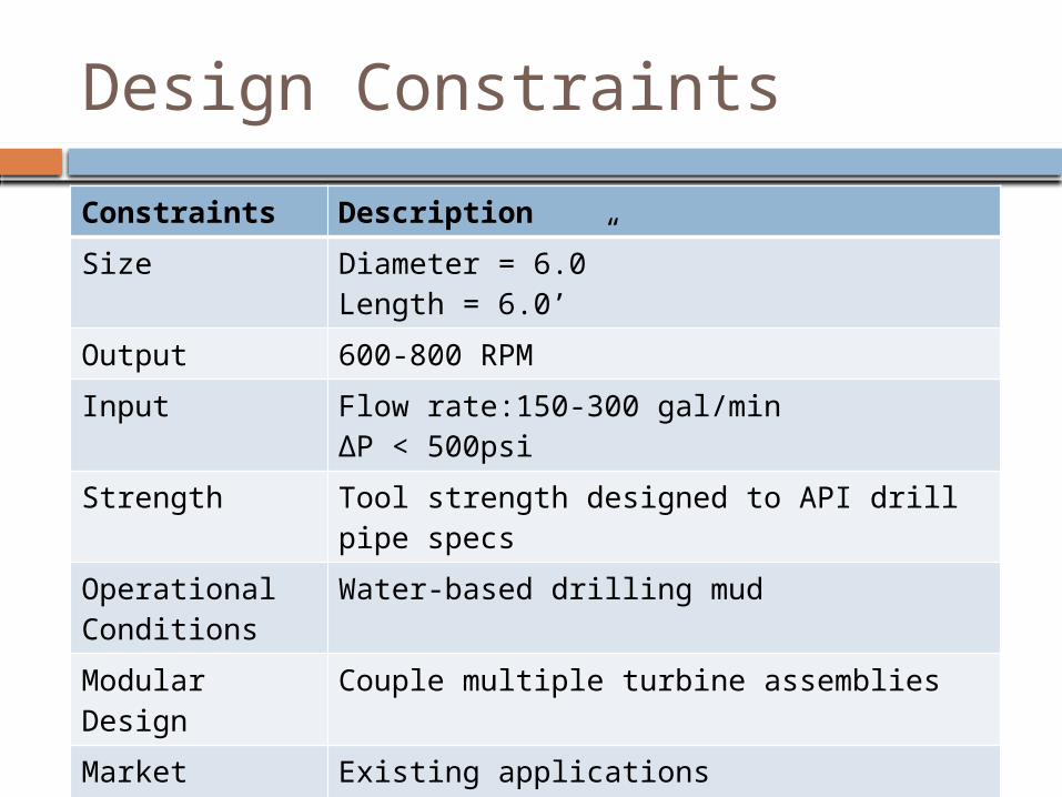
Design Constraints
Constraints Description
Size Diameter = 6.0”Length = 6.0’
Output 600-800 RPM
Input Flow rate:150-300 gal/min∆P < 500psi
Strength Tool strength designed to API drill pipe specs
Operational Conditions
Water-based drilling mud
Modular Design Couple multiple turbine assemblies
Market Availability Existing applications
Cost Minimize
Health, Safety & Environment
Pressure build-up mitigation device, compliance tool
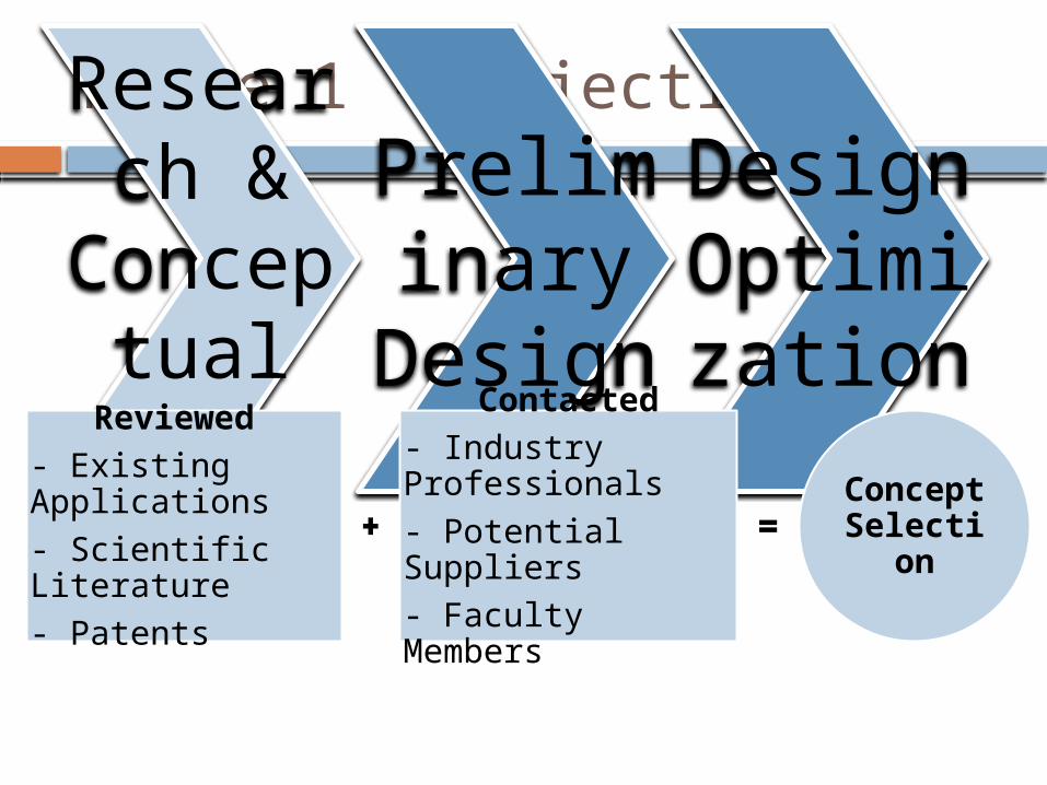
Phase 1 - ObjectivesResearch &
Conceptual
Design
Preliminary
Design
Design Optimization
Reviewed
- Existing Applications
- Scientific Literature
- Patents
Contacted
- Industry Professionals
- Potential Suppliers
- Faculty Members
Concept Selection
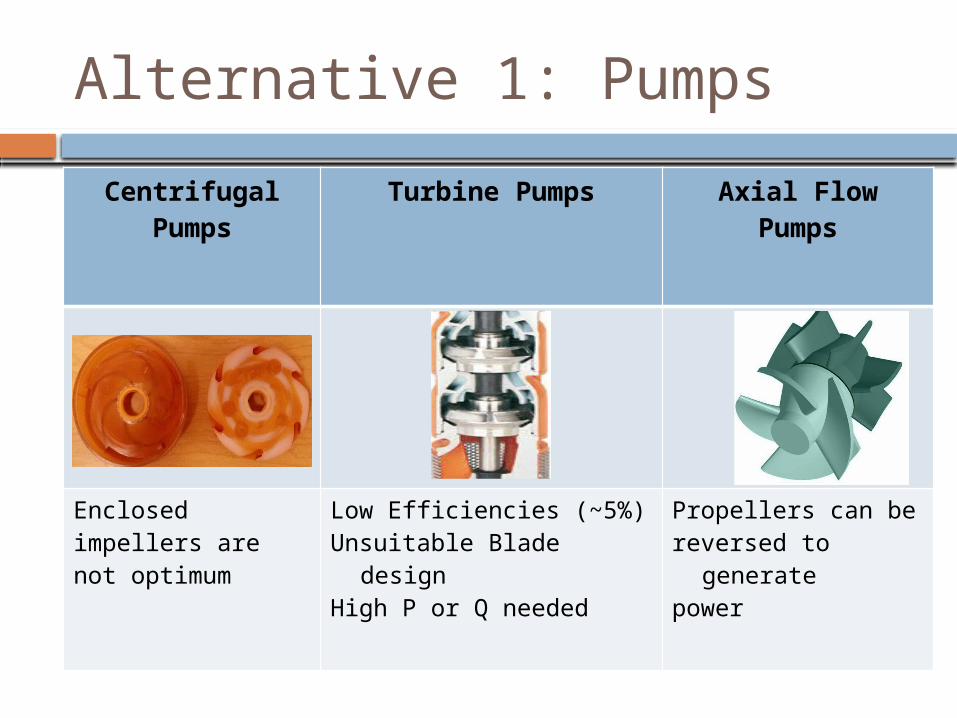
Alternative 1: Pumps
Centrifugal Pumps Turbine Pumps Axial Flow Pumps
Enclosed impellers are not optimum
Low Efficiencies (~5%) Unsuitable Blade designHigh P or Q needed
Propellers can bereversed to generatepower
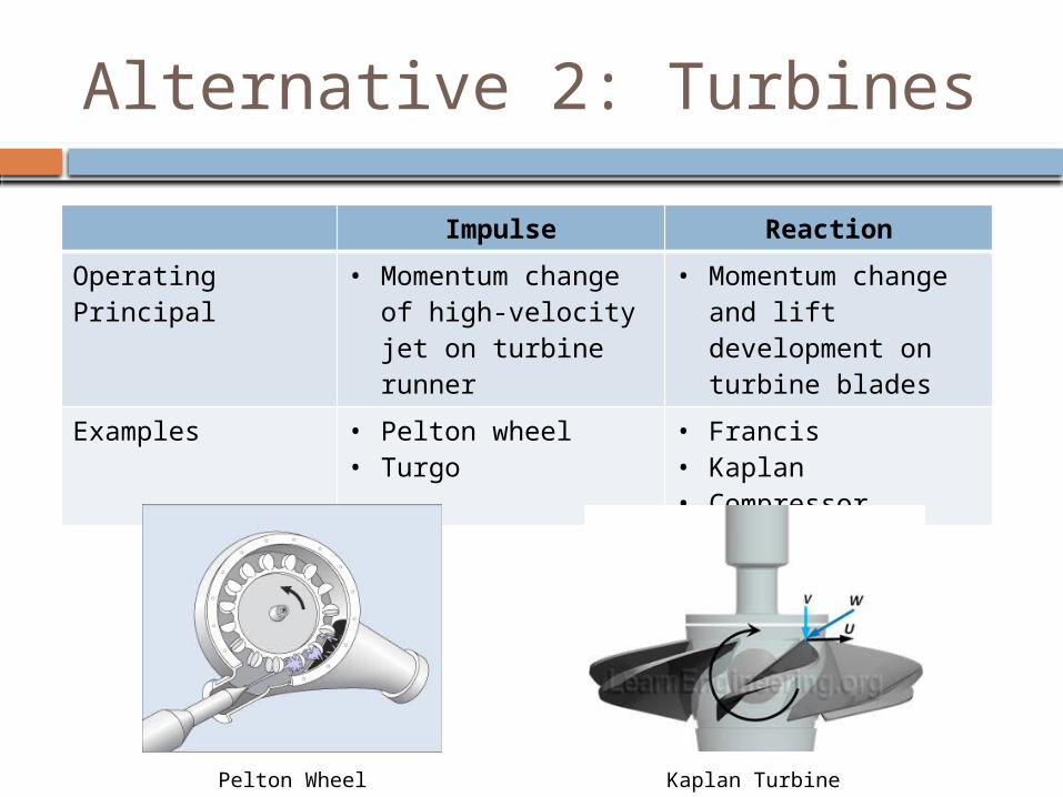
Alternative 2: Turbines
Impulse Reaction
Operating Principal • Momentum change of high-velocity jet on turbine runner
• Momentum change and lift development on turbine blades
Examples • Pelton wheel• Turgo
• Francis• Kaplan• Compressor
Pelton Wheel Kaplan Turbine
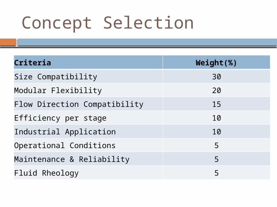
Concept Selection
Criteria Weight(%)
Size Compatibility 30
Modular Flexibility 20
Flow Direction Compatibility 15
Efficiency per stage 10
Industrial Application 10
Operational Conditions 5
Maintenance & Reliability 5
Fluid Rheology 5
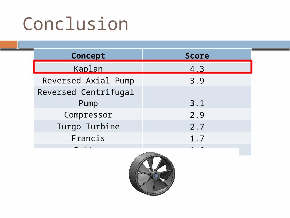
Conclusion
Concept Score
Kaplan 4.3Reversed Axial Pump 3.9
Reversed Centrifugal Pump 3.1Compressor 2.9
Turgo Turbine 2.7Francis 1.7Pelton 1.6
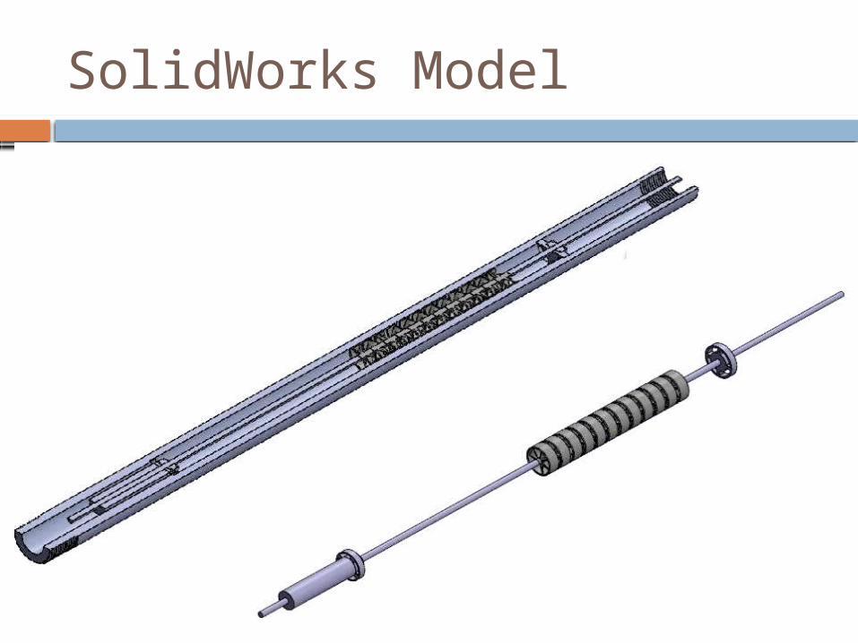
SolidWorks Model
Completed In-progress To be completed
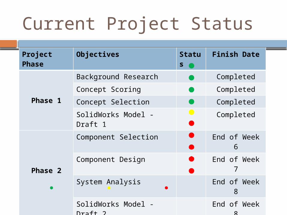
Current Project Status
Project Phase Objectives Status Finish Date
Phase 1
Background Research Completed
Concept Scoring Completed
Concept Selection Completed
SolidWorks Model - Draft 1 Completed
Phase 2
Component Selection End of Week 6
Component Design End of Week 7
System Analysis End of Week 8
SolidWorks Model - Draft 2 End of Week 8
Phase 3 System Optimization End of Week 11
SolidWorks Model - Final End of Week 11
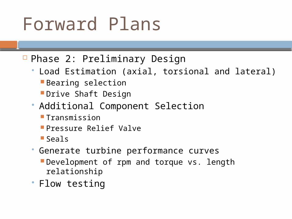
Forward Plans
Phase 2: Preliminary Design Load Estimation (axial, torsional and lateral)
Bearing selection Drive Shaft Design
Additional Component Selection Transmission Pressure Relief Valve Seals
Generate turbine performance curves Development of rpm and torque vs. length relationship
Flow testing

Thank You!Questions?
http://g5downhole.weebly.com